WHEATON SCIENCE PRODUCTS R 2 P ROLLER APPARATUS PRODUCTION & MODULAR W348880-X W348881-X W348882-X W348884-X W348885-X 100V – 230V INSTRUCTION MANUAL INCLUDES INSTRUCTIONS FOR OPTIONS BATTERY BACK-UP OPTION W348898 TEMPERATURE OPTION W348890 Wheaton Science Products 1501 North Tenth Street Millville, NJ. 08332 USA. (856) 825-1100 FAX (856) 825-1368 www.wheatonsci.com ©2004 Wheaton Science Products 50087666 Rev. 02/21/11 Specifications subject to change without prior notice

Welcome message from author
This document is posted to help you gain knowledge. Please leave a comment to let me know what you think about it! Share it to your friends and learn new things together.
Transcript

WHEATON SCIENCE PRODUCTS
R2P ROLLER APPARATUS PRODUCTION & MODULAR
W348880-X W348881-X W348882-X W348884-X W348885-X
100V – 230V
INSTRUCTION MANUAL
INCLUDES INSTRUCTIONS FOR OPTIONS
BATTERY BACK-UP OPTION W348898
TEMPERATURE OPTION
W348890
Wheaton Science Products 1501 North Tenth Street
Millville, NJ. 08332 USA. (856) 825-1100
FAX (856) 825-1368
www.wheatonsci.com ©2004 Wheaton Science Products 50087666 Rev. 02/21/11 Specifications subject to change without prior notice

©2004 Wheaton Science Products 50087666 Rev. 02/21/11 Specifications subject to change without prior notice
2
WARRANTY Wheaton Science Products warrants this product to be free from defects in material and workmanship
for a period of one (1) year from the date of shipment. If repair or adjustment is necessary within the
warranty period and has not been the result of mishandling or abuse, the unit may be returned prepaid,
provided that return authorization has been obtained. Wheaton Science Products will correct the defect
or adjust the unit at no charge.
Items returned for repair or adjustment should be packed very carefully to prevent damage and should
also be insured against carrier damage. Should the unit arrive damaged as a result of transit, a claim will
need to be made against the carrier. The shipping carton should not be discarded but retained until
inspection by a representative of the carrier is made.
Wheaton Science Products will repair or adjust out of warranty products at a nominal charge.
©2004 Wheaton Science Products 50087666 Rev. 02/21/11 Specifications subject to change without prior notice
3
GENERAL SAFETY INSTRUCTIONS NOTE: EVEN THE SAFEST EQUIPMENT CAN CAUSE INJURY IF THE USER IS CARELESS. 1. KNOW YOUR INSTRUMENT - Read the operating manual carefully. Learn the equipment's application and
limitations. 2. GROUND ALL EQUIPMENT - If electrical, this instrument is equipped with a grounding type plug. The
green/yellow conductor in the cord is the grounding wire and should never be connected to a live terminal. 3. AVOID DANGEROUS ENVIRONMENT - Electrical instruments designed to process liquids must be operated
with extreme caution. If liquid comes in contact with internal electrical components or wires, fire or electrical shock may occur. Adequate surrounding work space should be provided during use. Do not operate electrical instrumentation in a combustible atmosphere.
4. WORK SURFACE - Keep well lighted. Be certain the work surface is clean, level and sturdy enough to
support the weight of the unit, particularly if it is to be filled with liquid. 5. WEAR PROPER APPAREL - Do not wear loose clothing, neckties or jewelry that might get caught in moving
parts. Non-slip footwear is recommended. Wear protective hair covering to contain long hair. 6. WEAR SAFETY GOGGLES - Wear safety goggles at all times. Everyday eyeglasses only have impact
resistant lenses, they are NOT safety glasses. 7. DON'T OVERREACH - Keep proper footing and balance at all times. 8. MAINTAIN INSTRUMENT WITH CARE - Keep screws tight and unit clean. Check periodically for worn or
damaged parts. Inspect the plug and cord before each use. Do not operate this instrument if there are signs of damage.
9. AVOID ACCIDENTAL START UP - If electrical, always make sure the switch is in the "OFF" position before
plugging instrument into outlet. 10. DISCONNECT INSTRUMENT - Always disconnect the instrument from the power source
before servicing. 11. DO NOT BLOCK COOLING VENTS IF PROVIDED 12. DO NOT OPERATE THIS EQUIPMENT IN ANY MANNER NOT SPECIFIED IN THIS MANUAL 13. KEEP THE OPERATING MANUAL FOR THE INSTRUMENT IN A SAFE PLACE NEAR THE INSTRUMENT
FOR QUICK AND EASY REFERENCE. 14. IT IS RECOMMENDED THAT A FIRE EXTINGUISHER ALWAYS BE LOCATED IN AREAS WHERE
ELECTRICAL INSTRUMENTS ARE BEING USED. WSP-305

©2004 Wheaton Science Products 50087666 Rev. 02/21/11 Specifications subject to change without prior notice
4
SAFETY SYMBOLS USED IN THIS MANUAL
A Warning symbol indicates attention to an operation, which can cause operator injury, improper function of or damage to the equipment and possible problems with the process.
A Danger symbol indicates attention to an operation, which could cause electrocution or severe injury or death.
©2004 Wheaton Science Products 50087666 Rev. 02/21/11 Specifications subject to change without prior notice
5
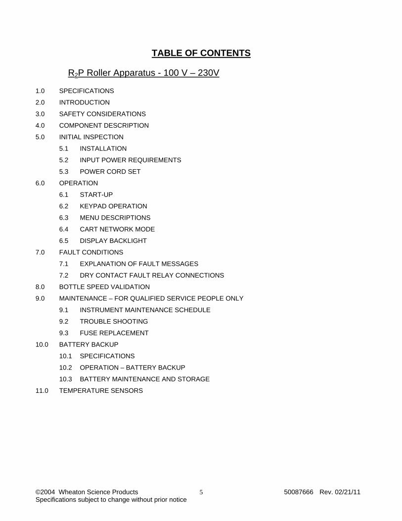
TABLE OF CONTENTS R2P Roller Apparatus - 100 V – 230V 1.0 SPECIFICATIONS
2.0 INTRODUCTION
3.0 SAFETY CONSIDERATIONS
4.0 COMPONENT DESCRIPTION
5.0 INITIAL INSPECTION
5.1 INSTALLATION
5.2 INPUT POWER REQUIREMENTS
5.3 POWER CORD SET
6.0 OPERATION
6.1 START-UP
6.2 KEYPAD OPERATION
6.3 MENU DESCRIPTIONS
6.4 CART NETWORK MODE
6.5 DISPLAY BACKLIGHT
7.0 FAULT CONDITIONS
7.1 EXPLANATION OF FAULT MESSAGES
7.2 DRY CONTACT FAULT RELAY CONNECTIONS
8.0 BOTTLE SPEED VALIDATION
9.0 MAINTENANCE – FOR QUALIFIED SERVICE PEOPLE ONLY
9.1 INSTRUMENT MAINTENANCE SCHEDULE
9.2 TROUBLE SHOOTING
9.3 FUSE REPLACEMENT
10.0 BATTERY BACKUP
10.1 SPECIFICATIONS
10.2 OPERATION – BATTERY BACKUP
10.3 BATTERY MAINTENANCE AND STORAGE
11.0 TEMPERATURE SENSORS
©2004 Wheaton Science Products 50087666 Rev. 02/21/11 Specifications subject to change without prior notice
6
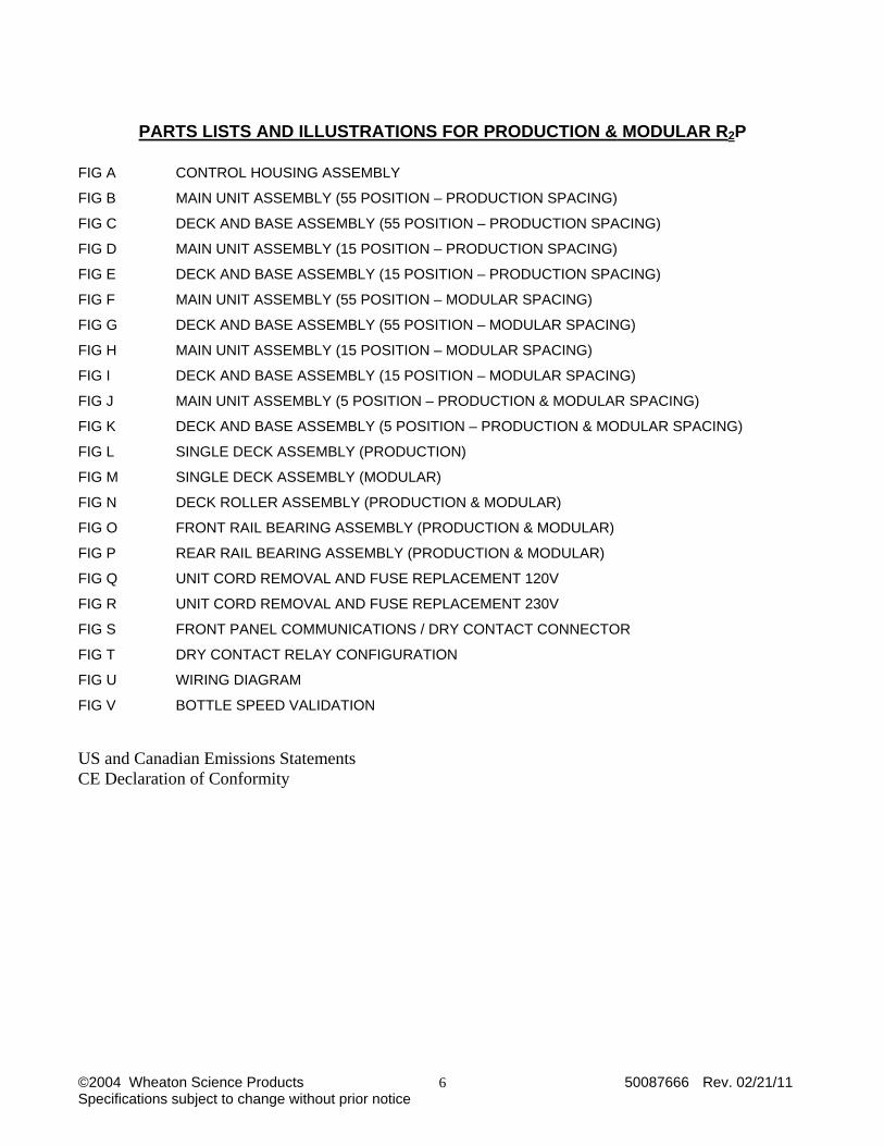
PARTS LISTS AND ILLUSTRATIONS FOR PRODUCTION & MODULAR R2P
FIG A CONTROL HOUSING ASSEMBLY
FIG B MAIN UNIT ASSEMBLY (55 POSITION – PRODUCTION SPACING)
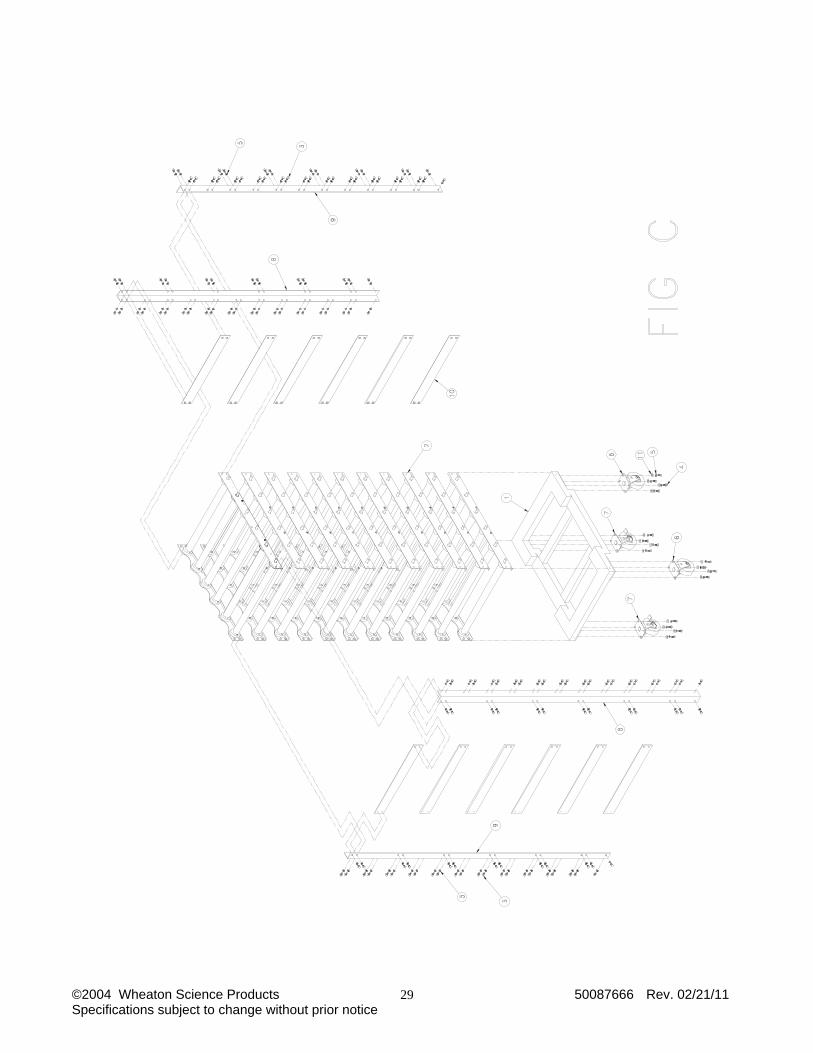
FIG C DECK AND BASE ASSEMBLY (55 POSITION – PRODUCTION SPACING)
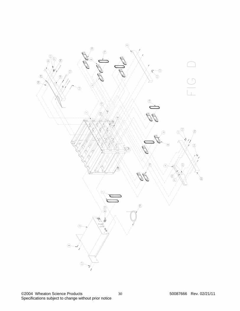
FIG D MAIN UNIT ASSEMBLY (15 POSITION – PRODUCTION SPACING)
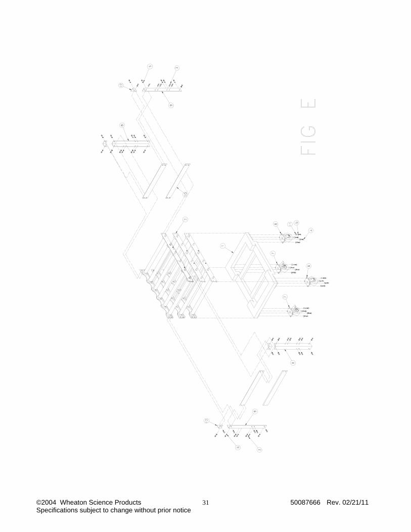
FIG E DECK AND BASE ASSEMBLY (15 POSITION – PRODUCTION SPACING)
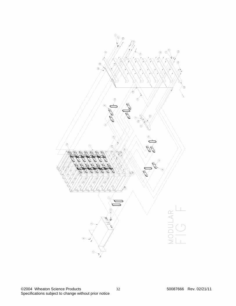
FIG F MAIN UNIT ASSEMBLY (55 POSITION – MODULAR SPACING)
FIG G DECK AND BASE ASSEMBLY (55 POSITION – MODULAR SPACING)
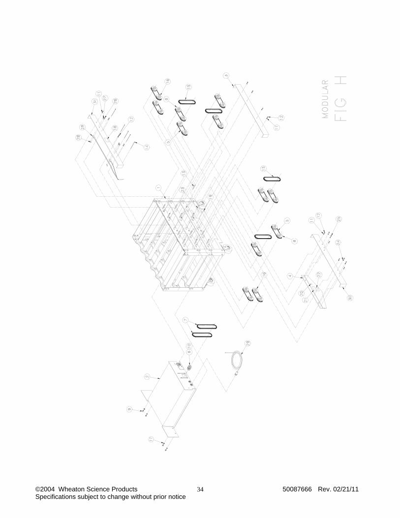
FIG H MAIN UNIT ASSEMBLY (15 POSITION – MODULAR SPACING)
FIG I DECK AND BASE ASSEMBLY (15 POSITION – MODULAR SPACING)
FIG J MAIN UNIT ASSEMBLY (5 POSITION – PRODUCTION & MODULAR SPACING)
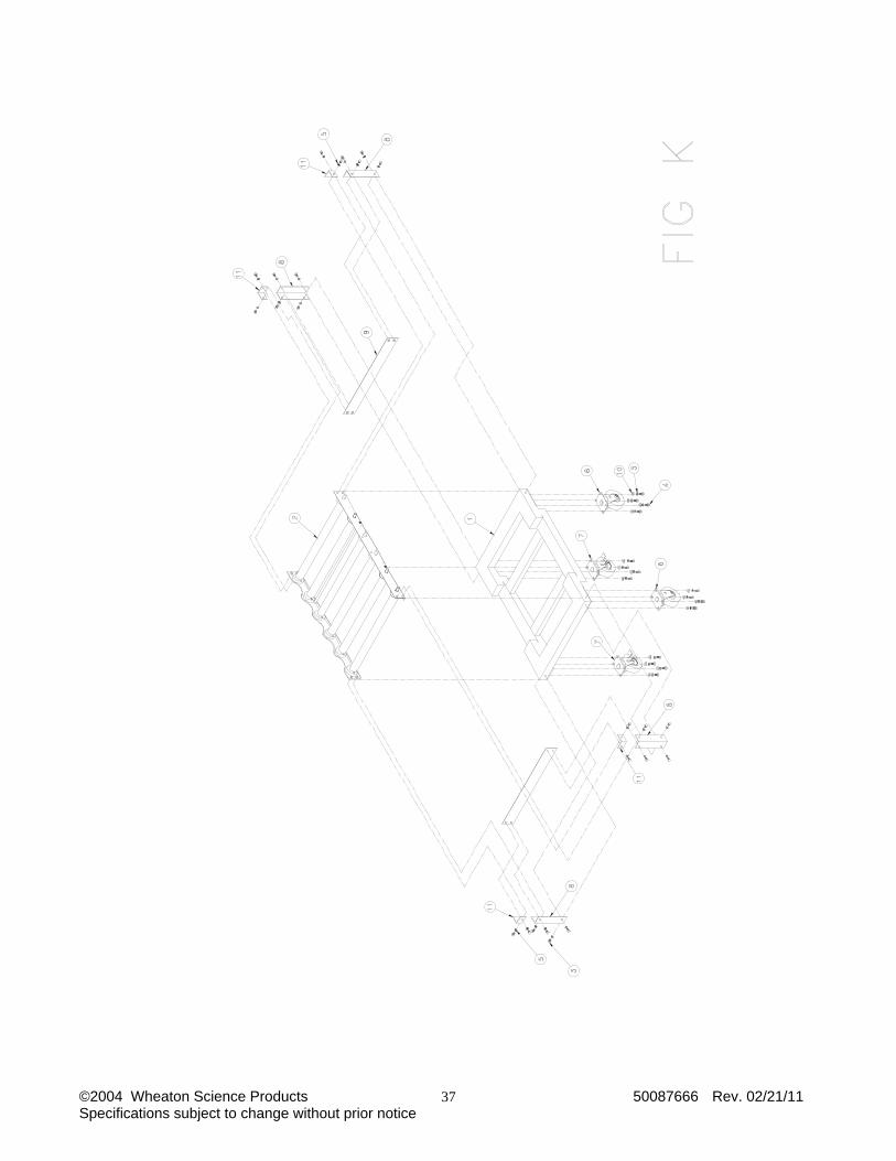
FIG K DECK AND BASE ASSEMBLY (5 POSITION – PRODUCTION & MODULAR SPACING)
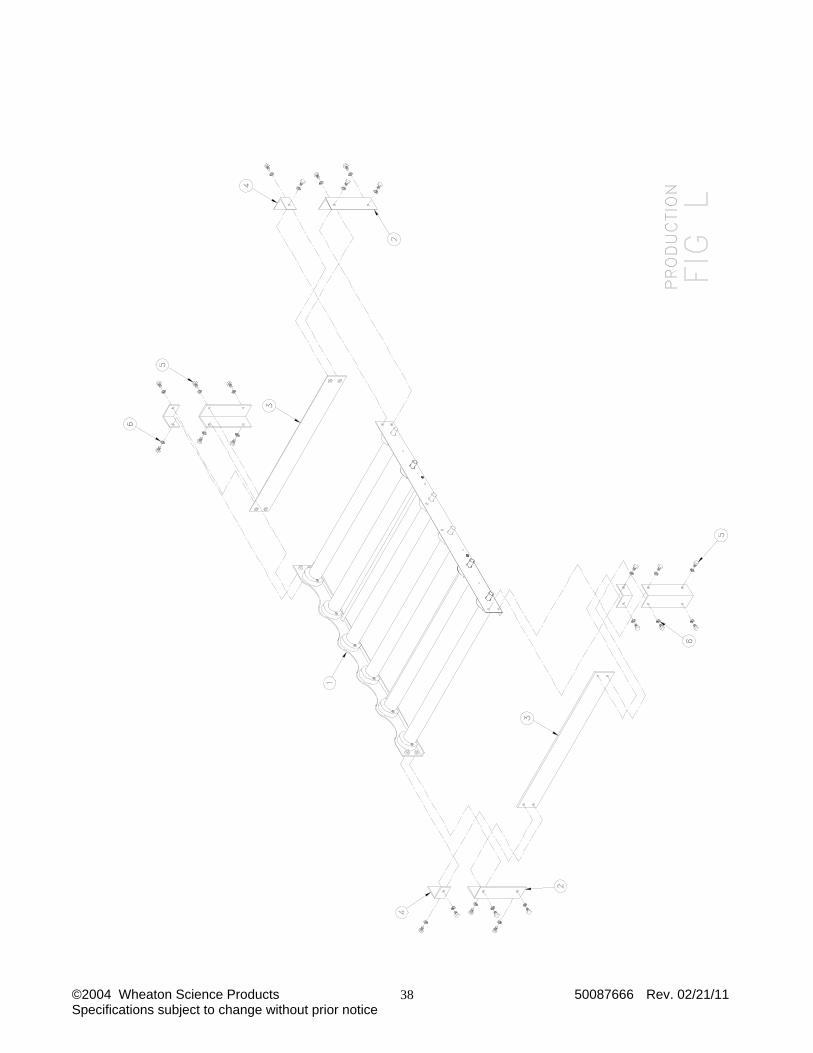
FIG L SINGLE DECK ASSEMBLY (PRODUCTION)
FIG M SINGLE DECK ASSEMBLY (MODULAR)
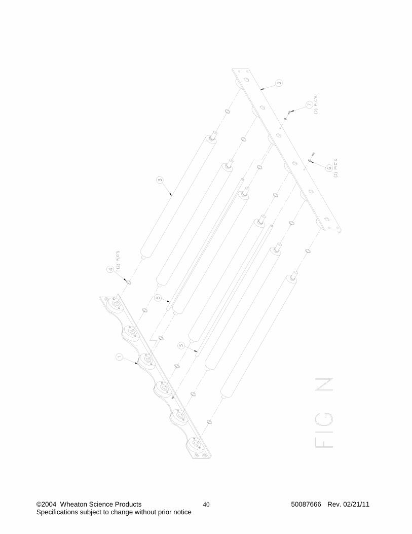
FIG N DECK ROLLER ASSEMBLY (PRODUCTION & MODULAR)
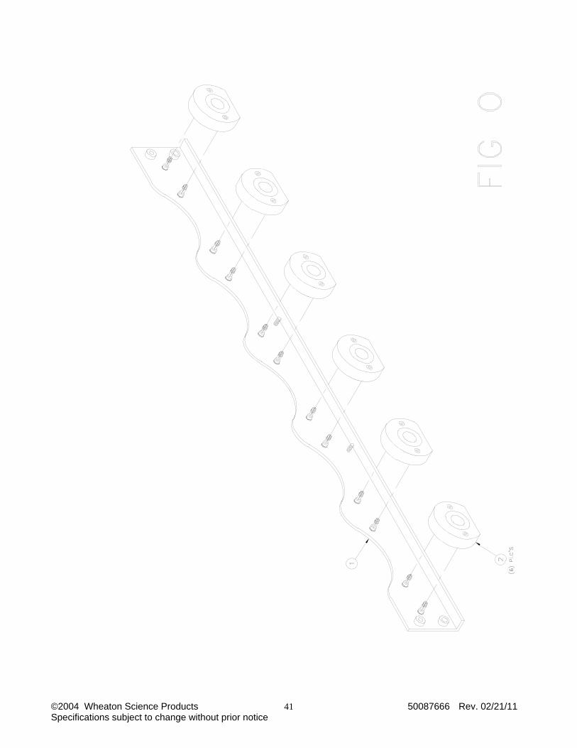
FIG O FRONT RAIL BEARING ASSEMBLY (PRODUCTION & MODULAR)
FIG P REAR RAIL BEARING ASSEMBLY (PRODUCTION & MODULAR)
FIG Q UNIT CORD REMOVAL AND FUSE REPLACEMENT 120V
FIG R UNIT CORD REMOVAL AND FUSE REPLACEMENT 230V
FIG S FRONT PANEL COMMUNICATIONS / DRY CONTACT CONNECTOR
FIG T DRY CONTACT RELAY CONFIGURATION
FIG U WIRING DIAGRAM
FIG V BOTTLE SPEED VALIDATION
US and Canadian Emissions Statements CE Declaration of Conformity

©2004 Wheaton Science Products 50087666 Rev. 02/21/11 Specifications subject to change without prior notice
7
1.0 SPECIFICATIONS – Modular R2P Roller Apparatus - 100 V – 230V OPERATING VOLTAGE: 100-253 VAC 50/60 Hz POWER CONSUMPTION 100V – 230V: 35 Watts FUSE 100V - 120V: 1.0 AT 3AG 250V FUSE 230V: (2) 0.630 AT 5x20mm BOTTLE SPEED: 0.25 to 8.75 RPM* INSTALLATION CATEGORY: Class II ENVIRONMENTAL: Operating temperature: 15 °C to 40 °C Humidity: 80% up to 31°C. 50% at 40°C. Altitude limit 2000 meters * Assuming 110 mm diameter bottles NETWORK COMMUNICATION SPEED: 9600 BAUD DIMENSIONS AND CAPACITIES CATALOG.# DESCRIPTION POSITIONS WIDTH x DEPTH x HEIGHT WEIGHT W348880-X Base w/ 1 deck 5 31 X 24 ½ X 13 ½ inches 52 lbs
W348881-X Base w/ 3 decks 15 31 X 24 ½ X 27 inches 85 lbs
W348882-X Base w/ 11 decks 55 31 X 24 ½ X 74 ¾ inches 217 lbs
W348884-X Base w/ 3 decks 15 31 X 24 ½ X 27 inches 52 lbs
W348885-X Base w/ 9 decks 45 31 X 24 ½ X 70 inches 185 lbs
W348888 Extra Deck Prod 5 31 X 24 ½ X 6 inches 16 ½ lbs
WL055984 Extra Deck Mod 5 31 X 24 ½ X 7 1/8 inches 16 ½ lbs
W348898 Battery Back-up Option N/A N/A 20 lbs

©2004 Wheaton Science Products 50087666 Rev. 02/21/11 Specifications subject to change without prior notice
8
2.0 INTRODUCTION The R2P Roller Apparatus is a major step forward from the basic roller apparatus of the past. Just about every aspect of roller bottle culture can be controlled and documented. The microprocessor controller, digital display and powerful brushless DC motor, allows smooth and precise control of bottle rotation speed. Easy, user defined soft start and soft stop and user defined reversal of rotation, if desired, round out the bottle control. Optional temperature sensor assemblies allow monitoring of temperature for up to four locations on the unit. Optional battery back up allows 18 hours of normal operation if main power is lost. An eye level control box is an option that allows the display and keypad to be mounted at a convenient height and moved out of the way when loading or unloading bottles. A rotation alarm is standard and will warn of a belt or motor failure. The roller can be used as a stand-alone or quickly and inexpensively connected to a network of up to 255 units* when used with the new WSP C.A.R.T2 (Computer Aided Roller Technology) software for Windows®. The roller base utilizes large diameter casters to allow easier movement of a loaded unit. Its bottom control and motor drive are mounted in a slide out tray for easy maintenance and battery checks. As a modular system, it can grow from 5 positions to 55 positions to cover the full range of standard roller bottle quantities. The R2P Roller Apparatus can accommodate bottles 110-121 mm in diameter and up to 550 mm in length, with a bottle speed range of 0.25 to 8.75 rpm assuming 110 mm bottles. * Up to 255 units with single channel converter box. With optional 8 channel multiplexer, up to 2047 units can be
controlled. 3.0 SAFETY CONSIDERATIONS
DANGER ! IMPROPER GROUNDING CAN RESULT IN ELECTRICAL SHOCK. IN THE EVENT OF A SHORT CIRCUIT, GROUNDING REDUCES THE RISK OF SHOCK. THIS INSTRUMENT MUST BE GROUNDED. 1. This instrument is equipped with a cord having a grounding wire and an appropriate
grounding plug. The plug must be used with an outlet that has been installed and grounded in accordance with all local codes and ordinances. The outlet must have the same configuration as the plug. DO NOT USE AN ADAPTER.
2. Do not modify the line cord that has been provided. If it does not fit the available outlet, contact your nearest WSP distributor for the proper line cord for your area.
©2004 Wheaton Science Products 50087666 Rev. 02/21/11 Specifications subject to change without prior notice
9
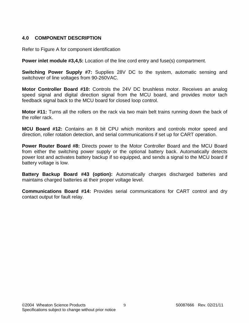
4.0 COMPONENT DESCRIPTION Refer to Figure A for component identification Power inlet module #3,4,5: Location of the line cord entry and fuse(s) compartment. Switching Power Supply #7: Supplies 28V DC to the system, automatic sensing and switchover of line voltages from 90-260VAC. Motor Controller Board #10: Controls the 24V DC brushless motor. Receives an analog speed signal and digital direction signal from the MCU board, and provides motor tach feedback signal back to the MCU board for closed loop control. Motor #11: Turns all the rollers on the rack via two main belt trains running down the back of the roller rack. MCU Board #12: Contains an 8 bit CPU which monitors and controls motor speed and direction, roller rotation detection, and serial communications if set up for CART operation. Power Router Board #8: Directs power to the Motor Controller Board and the MCU Board from either the switching power supply or the optional battery back. Automatically detects power lost and activates battery backup if so equipped, and sends a signal to the MCU board if battery voltage is low. Battery Backup Board #43 (option): Automatically charges discharged batteries and maintains charged batteries at their proper voltage level. Communications Board #14: Provides serial communications for CART control and dry contact output for fault relay.
©2004 Wheaton Science Products 50087666 Rev. 02/21/11 Specifications subject to change without prior notice
10
5.0 INITIAL INSPECTION When you receive your Roller Apparatus, inspect it for any obvious damage that may have occurred during shipment. If any damage is found, notify the carrier at once. Warranty information is shown in the front of this manual. Check to confirm that there are no broken switches, displays or pulleys and that the unit is not dented or scratched. 5.1 Installation Install the unit where there will be adequate room for the unit to operate. Provide enough clearance around the unit to keep items away from the rotating belts and pulleys. 5.2 Input Power Requirements This equipment is designed to operate from a nominal 100V – 230V single-phase AC power source at 47 to 63 Hz. The line voltage / fuse label located on the lower rear of the unit shows the nominal input voltage set for the unit at the factory. 5.3 Power Cord Set This unit has been shipped from the factory with a power line cord that has a plug appropriate for your area. If the wrong power cord has been shipped for your particular application, contact your nearest WSP dealer for the proper cord. The R2P Roller Apparatus has been equipped with a 3-wire grounding type power cord. The unit is only grounded when it is plugged into an appropriate receptacle. Do not operate the unit without adequate grounding protection.
©2004 Wheaton Science Products 50087666 Rev. 02/21/11 Specifications subject to change without prior notice
11
6.0 OPERATION
CAUTION: Keep hands and fingers away from rotating parts of the machine. Do not remove any safety guards or operate the machine without the safety guards.
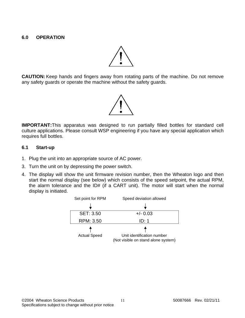
IMPORTANT:This apparatus was designed to run partially filled bottles for standard cell culture applications. Please consult WSP engineering if you have any special application which requires full bottles. 6.1 Start-up 1. Plug the unit into an appropriate source of AC power. 3. Turn the unit on by depressing the power switch. 4. The display will show the unit firmware revision number, then the Wheaton logo and then
start the normal display (see below) which consists of the speed setpoint, the actual RPM, the alarm tolerance and the ID# (if a CART unit). The motor will start when the normal display is initiated.
Set point for RPM
Speed deviation allowed
SET: 3.50 +/- 0.03 RPM: 3.50 ID: 1
Actual Speed
Unit identification number (Not visible on stand alone system)
©2004 Wheaton Science Products 50087666 Rev. 02/21/11 Specifications subject to change without prior notice
12
6.2 Keypad Operation The keypad operation has been designed for very simple and quick operation. The four keys operations are: MODE - Use the "MODE" key to move the display through the Menus which allow viewing
or changing the parameters of the roller apparatus.
UP ARROW - Use the "UP ARROW" key (after using the mode key to view a specific menu such as SETPOINT) to increase or change the value on that screen.
DOWN ARROW - Use the "DOWN ARROW" key (after using the mode key to view a specific menu such as setpoint) to decrease or change the value on that screen.
ENTER - Use the "ENTER" key to enter the new value once it has been changed. Press "ENTER" again to return to the Normal screen display.
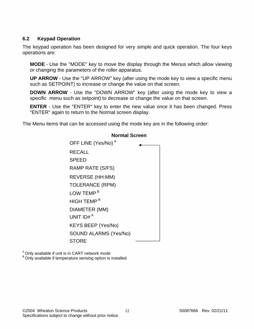
The Menu items that can be accessed using the mode key are in the following order:
Normal Screen OFF LINE (Yes/No) A
RECALL SPEED RAMP RATE (S/FS)
REVERSE (HH:MM) TOLERANCE (RPM)
LOW TEMP B HIGH TEMP B DIAMETER (MM) UNIT ID# A
KEYS BEEP (Yes/No) SOUND ALARMS (Yes/No)STORE
A Only available if unit is in CART network mode B Only available if temperature sensing option is installed

©2004 Wheaton Science Products 50087666 Rev. 02/21/11 Specifications subject to change without prior notice
13
6.3 Menu Descriptions OFF LINE Use the arrow keys to change the status from YES (off line) to NO (on line)
Note: This item is for use with CART software and network control. If the unit is configured for stand-alone operation this menu is not shown.
RECALL Will recall settings, which have been stored. This will only show those registers which have information stored in them (see “STORE”)
SPEED Will set the speed set point (Range 0.00 – 9.99)
RAMP RATE Sets the time (in seconds) required to change from one speed to another. Used for soft start or soft stop (Range 0.0 – 20.0)
REVERSE Sets the time in Hours and minutes (HH:MM) that the unit will reverse direction. Set to 00:00 for no reversing action. NOTE: The ramp for soft start and stop works during reversing intervals.
TOLERANCE Sets the speed range tolerance for the alarm. If the speed exceeds this range, the alarm will be triggered (Range is 0.00 -1.00)
LOW TEMP (if a temperature option is installed) Sets the low temperature limit. If the measured temperature drops below this point an alarm will be triggered.
HIGH TEMP (if a temperature option is installed) Sets the high temperature limit. If the measured temperature is above this point an alarm will be triggered.
DIAMETER Provides the bottle size being used so the display can accurately display the bottle speed.
UNIT ID# Provides a unique unit identifier for CART software for Windows (0-2047) NOTE: This menu will not be shown if the unit is configured for stand-alone operation.
KEYS BEEP Sounds a beep when a key is pressed
SOUND ALARMS
Turns on or off the audible alarm on the unit. NOTE: This will NOT disable the software alarm, visual display alarm or the alarm relay output.
STORE The last menu item is used to store all previously set parameters in non-volatile RAM. Up to 10 settings can be stored (0-9) Settings can be retrieved by using RECALL.

©2004 Wheaton Science Products 50087666 Rev. 02/21/11 Specifications subject to change without prior notice
14
6.4 CART Network Mode The R2P Roller Apparatus can be connected to a network and be controlled and monitored by a remote computer using the Wheaton CART2 TM software for Windows. All operational settings can be made from either the unit keypad or the remote computer. A standard unit comes ready from the factory to be connected to a CART network system with no additional modifications or accessories necessary. Once set to network mode, the R2P Roller Apparatus will start communicating to a host computer automatically. 6.5 Display Back light Operation In normal operation, the display back light will turn on when a key is pressed on the keypad. The back light will turn off after about I minute of no keys pressed. The display back light will blink on/off during a fault condition for a visual indication of a roller apparatus that has a problem. In order to conserve power, the back light will not operate if the roller apparatus is running in battery backup mode. 7.0 FAULT CONDITIONS The R2P Roller Apparatus monitors several different parameters to ensure proper operation. If a problem exists, a FAULT CONDITION will be displayed on the screen. To temporarily view the current running status of the unit while the unit is in fault condition, press the UP arrow key. Following is a description of possible fault conditions. 7.1 Explanation of Fault Messages
BELT1, BELT2 Two magnetic sensors located at the top most deck each sense the rotation of one half of the belt and roller drive train. A fault condition will exist If either half of the drive train fails to rotate due to a broken belt or jammed roller.
TOL This message will be displayed of the bottle rotation speed falls outside the programmed speed tolerance (see section 5.3)
TEMP If equipped with temperature sensing, this message will be displayed if the measured temperature fall outside either the LOW or HIGH temperature settings.
BATTERY LOW
If equipped with Battery Backup option, unit will monitor battery voltage and display this message if the battery voltage drops below 21.19 volts. Unit will only monitor battery voltage while running in battery backup mode.
LMT Motor current limit. Will indicate if the motor is jammed.
POWER FAIL If equipped with Battery Backup option, unit will display message if primary power is lost.
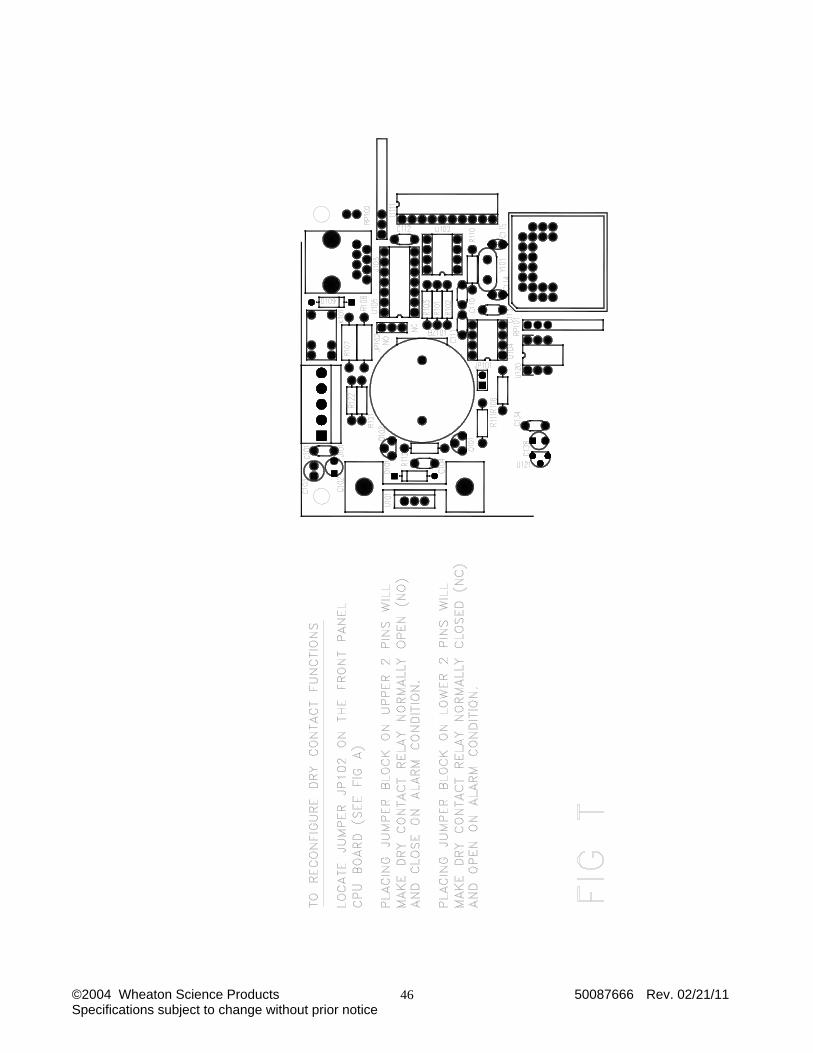
7.2 Dry Contact Fault Relay Connections A dry contact relay is available for interface to remote process monitoring equipment through the two RJ45 connectors on the front panel of the unit. Both connectors are wired in parallel and provide the same function. If a fault condition exists, the relay will activate. The relay will deactivate when the fault condition clears. The dry contacts can be configured for normally open (NO) or normally closed (NC) operation. See figures S and T for dry contact pin locations on the front panel connectors and configuration.

©2004 Wheaton Science Products 50087666 Rev. 02/21/11 Specifications subject to change without prior notice
15
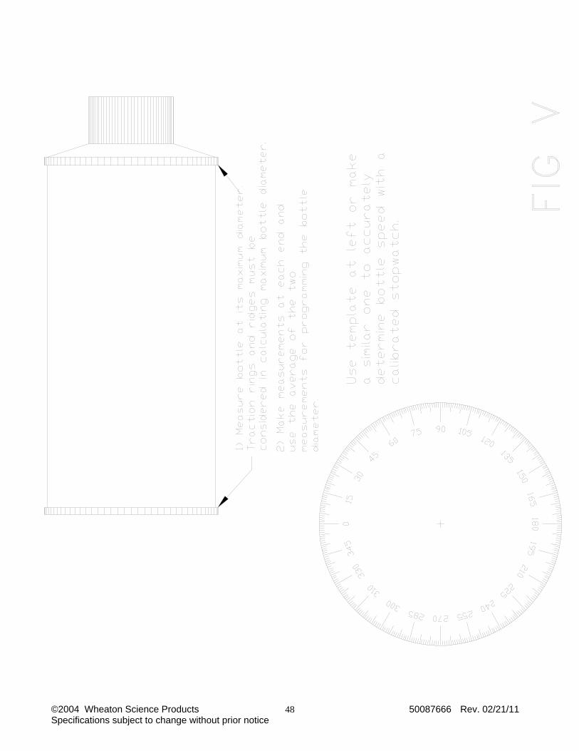
8.0 BOTTLE SPEED VALIDATION The R2P Roller Apparatus is designed to accurately display actual bottle rotation speed. Once a bottle diameter has been programmed, the unit will automatically calculate and adjust itself to roll the bottle correctly at its set speed. Different bottle manufacturers naturally produce bottles of different bottle diameters. It is not recommended that bottles of different manufacturers be mixed on the same unit if an accurate bottle speed is to be obtained. Refer to figure V and the steps below to setup and validate proper bottle speed. 1) The R2P Roller Apparatus relies on the MAXIMUM bottle diameter for proper bottle speed
indications. Traction rings and ridges must be considered in calculating the maximum bottle diameter.
2) Carefully measure, with a pair of calibrated calipers, the maximum diameter of as sample bottle to be rolled. If traction rings or ridges are at both ends of the bottle, measure both ends and take the average.
3) Use measurement obtained in step 2 for the bottle diameter to be entered into the unit. Refer to section 6.3 for programming the bottle diameter into the unit.
To validate the bottle speed, make a mark on the roller unit frame and another on a sample bottle to be tested, or better, make a 360 template and attach it to a bottle cap as shown in figure V. Start the unit and set to a desired speed. Using a calibrated stopwatch, record the number of bottle revolutions in one minute and compare with the indicated speed on the display (see section 6.1) NOTE: The speed control and feedback used on the New WSP Roller is completely digital. Once the speed indicator is properly set and validated, it will not drift over time, or temperature. Additional calibration is unnecessary although most protocols require periodic validation checks.
©2004 Wheaton Science Products 50087666 Rev. 02/21/11 Specifications subject to change without prior notice
16
9.0 MAINTENANCE - FOR QUALIFIED SERVICE PERSONNEL ONLY
CAUTION ! A fully loaded roller apparatus is extremely heavy, care should be taken when moving the equipment.
DANGER! NEVER ATTEMPT TO PERFORM REPAIRS IF THIS INSTRUMENT IS PLUGGED IN! IN ORDER TO AVOID SERIOUS ELECTRIC SHOCK OR ELECTROCUTION, THIS INSTRUMENT MUST BE DISCONNECTED FROM THE SOURCE OF AC POWER BEFORE MAINTENANCE. As with any piece of laboratory equipment, periodic inspection for worn and/or damaged parts should be performed on a regular basis. 9.1 Instrument Maintenance Schedule
Item Action Interval Roller Bearings Roller bearings are greaseless and require no lubrication.
Inspection is required for physical damage only. Once a year
Rubber Rollers Check rollers for residue buildup. Rollers can be wiped with Alcohol or a common household spray cleaner.
At each harvest interval
Nuts, Bolts msc. Hardware
Check for general tightness, replace missing hardware Once a year
Drive Belts (black)
Replace belts if frayed or internal cords are showing Once a year
Horizontal Belts (clear)
Replace belts if excessively yellow or cracked Every six months
Pulleys Check for tightness on roller shafts, replace if damaged. Once a year Batteries Optional
Check that they are securely mounted and connected Once a year

©2004 Wheaton Science Products 50087666 Rev. 02/21/11 Specifications subject to change without prior notice
17
9.2 Trouble Shooting
DANGER! NEVER ATTEMPT TO PERFORM REPAIRS IF THIS INSTRUMENT IS PLUGGED IN ! TO AVOID SERIOUS ELECTRIC SHOCK OR ELECTROCUTION, THIS INSTRUMENT MUST BE DISCONNECTED FROM THE SOURCE OF AC POWER BEFORE REMOVAL OF ANY PROTECTIVE COVERS.
Unit will not operate: Cause: Fuse blown. Remedy: Replace fuse with proper size and type. (see fuse replacement) Cause: Supply voltage low or at zero. Remedy: Check house receptacle with a voltmeter. Cause: On/Off power switch in "off" position. Remedy: Switch power switch to "on" position.
Motor runs but roller(s) will not turn; Cause: Drive and/or deck gear pulley(s) loose. Remedy: Tighten gear pulley(s) with allen wrench. Cause: Belt(s) worn or broken. Remedy: Replace defective belts.
Switch on but motor fails to rotate; Cause: Speed control set too low. Remedy: Increase motor speed as required. Cause: Motor control board defective. Remedy: Replace defective board.
Switch on but motor fails to rotate; Cause: Drive motor defective. Remedy: Replace defective motor.
Motor fails to maintain constant rotation speed; Cause: Motor control board defective. Remedy: Replace defective board. Cause: Drive motor defective. Remedy: Replace defective motor.
Display speed (RPM) reading does not match calibration value; Cause: Diameter value set wrong
Remedy: Set the Diameter value correctly. NOTE: Some bottles have traction rings or ridges, which has a larger diameter than the main bottle. If so you must measure the diameter at this section. Always measure the bottle at its maximum diameter. See section 8.0
©2004 Wheaton Science Products 50087666 Rev. 02/21/11 Specifications subject to change without prior notice
18
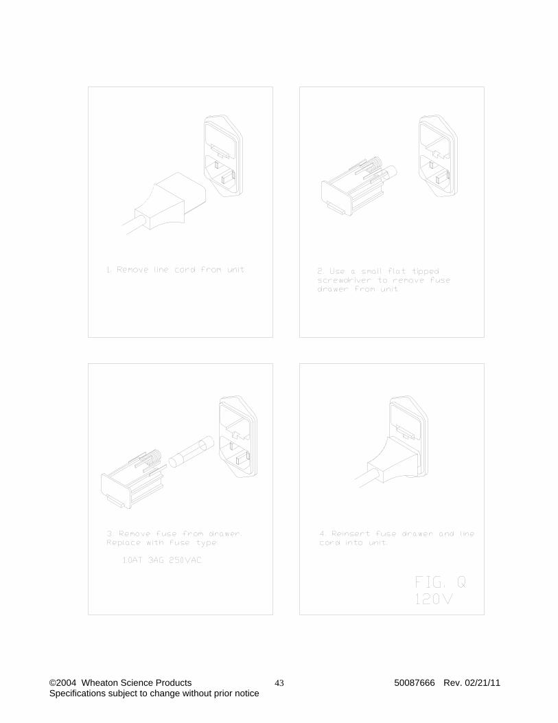
9.3 Fuse Replacement (see figures Q, R)
DANGER! BE CERTAIN THE UNIT IS DISCONNECTED FROM THE AC POWER SOURCE.
1. Disconnect the cord-set from the AC power source.
2. Locate power input connector/voltage selector module
3. Remove the fuse drawer by using a small flat screwdriver to lift the tab.
4. Replace with new fuses:
100 - 120 VAC unit (gray fuse drawer) use 1 ¼ x ¼ (3AG), 250V, 1.0 AT fuses, be sure the correct cord set is used. 230 VAC unit (black fuse drawer) use 5 x 20 mm 0.630 AT fuses, be sure the correct cord set is used. 10.0 BATTERY BACK-UP The Battery Backup option on the new R2P Roller Apparatus provides 18 hours of full operation if primary power to the unit fails. Full functionality of the unit is maintained. All programmed settings via the front panel keypad are accessible, and full motor speed is available under battery backup. If the unit is connected to the CART® network and is under remote computer control, full communications is maintained. To conserve battery power, the display backlight and the audible alarm are disabled during operation in battery backup mode. 10.1 Specifications (Battery Backup) This integrated system consists of two sealed lead acid batteries and automatic charging system. Batteries are charged whenever power is applied and the unit is switched ON.
Batteries used: (2) Yuasa NP12-12 12V, 12AH
Battery duration:18 hours at 5.00 RPM bottle speed assuming 110mm bottles. Longer at slower speeds, shorter at faster speeds.
Battery recharge time: about 12 hours for fully discharged batteries, shorter for partially discharged batteries.
Battery life expectancy: about 3 years assuming battery storage and operation in a 37 C incubator.
10.2 Operation (Battery Backup) The battery backup system utilizes two sealed lead acid batteries, which must be maintained in a fully charged state to insure proper auxiliary operation. The charging circuitry charges the batteries whenever the roller apparatus is plugged in and the power switch is ON. If primary power is lost while a roller apparatus is in normal operation, the charger circuitry will automatically switch the roller apparatus to operate on its internal batteries. Once primary power is restored, the charger will automatically switch the apparatus back to mains power operation.
©2004 Wheaton Science Products 50087666 Rev. 02/21/11 Specifications subject to change without prior notice
19
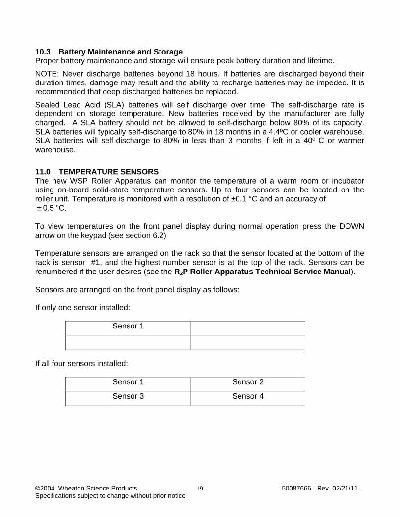
10.3 Battery Maintenance and Storage Proper battery maintenance and storage will ensure peak battery duration and lifetime. NOTE: Never discharge batteries beyond 18 hours. If batteries are discharged beyond their duration times, damage may result and the ability to recharge batteries may be impeded. It is recommended that deep discharged batteries be replaced. Sealed Lead Acid (SLA) batteries will self discharge over time. The self-discharge rate is dependent on storage temperature. New batteries received by the manufacturer are fully charged. A SLA battery should not be allowed to self-discharge below 80% of its capacity. SLA batteries will typically self-discharge to 80% in 18 months in a 4.4ºC or cooler warehouse. SLA batteries will self-discharge to 80% in less than 3 months if left in a 40º C or warmer warehouse. 11.0 TEMPERATURE SENSORS The new WSP Roller Apparatus can monitor the temperature of a warm room or incubator using on-board solid-state temperature sensors. Up to four sensors can be located on the roller unit. Temperature is monitored with a resolution of ±0.1 °C and an accuracy of ±0.5 C. To view temperatures on the front panel display during normal operation press the DOWN arrow on the keypad (see section 6.2) Temperature sensors are arranged on the rack so that the sensor located at the bottom of the rack is sensor #1, and the highest number sensor is at the top of the rack. Sensors can be renumbered if the user desires (see the R2P Roller Apparatus Technical Service Manual). Sensors are arranged on the front panel display as follows: If only one sensor installed:
Sensor 1
If all four sensors installed:
Sensor 1 Sensor 2
Sensor 3 Sensor 4
©2004 Wheaton Science Products 50087666 Rev. 02/21/11 Specifications subject to change without prior notice
20
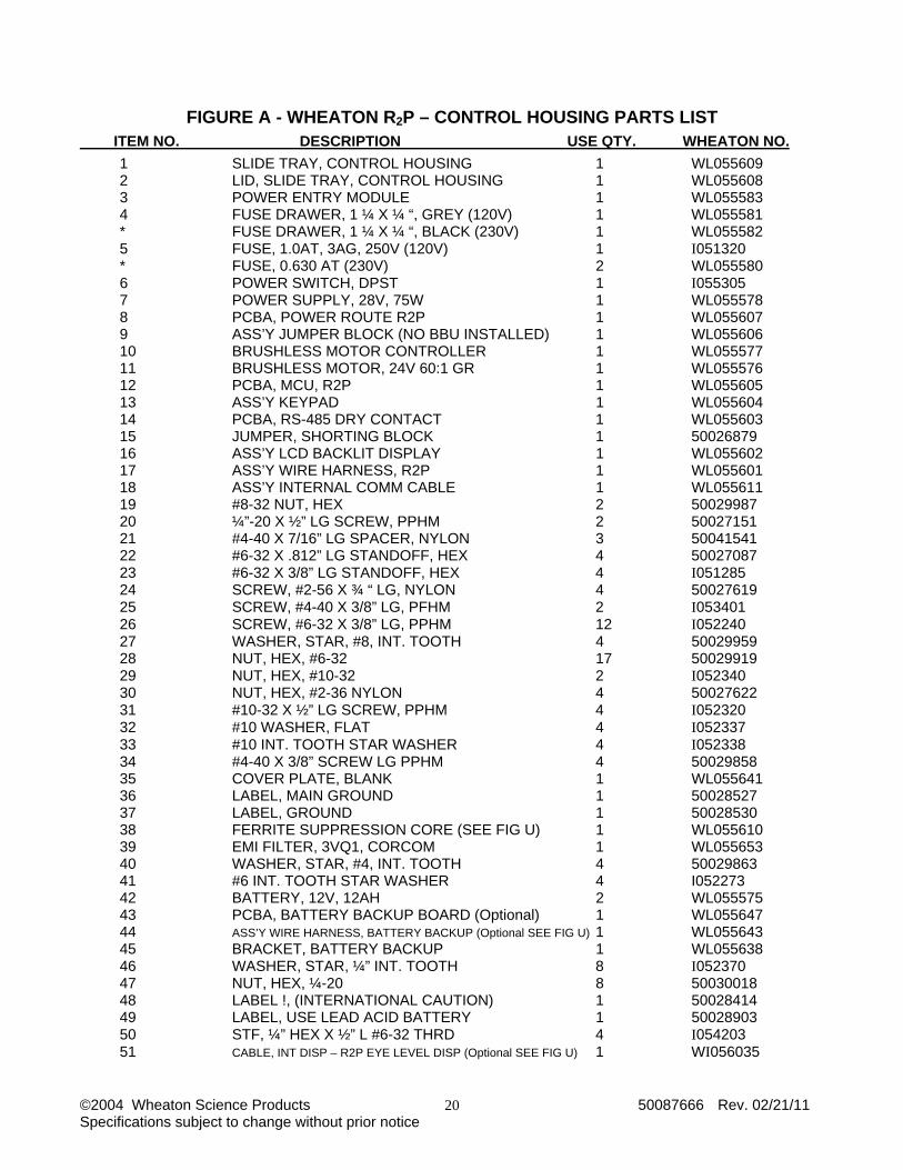
FIGURE A - WHEATON R2P – CONTROL HOUSING PARTS LIST
ITEM NO. DESCRIPTION USE QTY. WHEATON NO.
1 SLIDE TRAY, CONTROL HOUSING 1 WL055609 2 LID, SLIDE TRAY, CONTROL HOUSING 1 WL055608 3 POWER ENTRY MODULE 1 WL055583 4 FUSE DRAWER, 1 ¼ X ¼ “, GREY (120V) 1 WL055581 * FUSE DRAWER, 1 ¼ X ¼ “, BLACK (230V) 1 WL055582 5 FUSE, 1.0AT, 3AG, 250V (120V) 1 I051320 * FUSE, 0.630 AT (230V) 2 WL055580 6 POWER SWITCH, DPST 1 I055305 7 POWER SUPPLY, 28V, 75W 1 WL055578 8 PCBA, POWER ROUTE R2P 1 WL055607 9 ASS’Y JUMPER BLOCK (NO BBU INSTALLED) 1 WL055606 10 BRUSHLESS MOTOR CONTROLLER 1 WL055577 11 BRUSHLESS MOTOR, 24V 60:1 GR 1 WL055576 12 PCBA, MCU, R2P 1 WL055605 13 ASS’Y KEYPAD 1 WL055604 14 PCBA, RS-485 DRY CONTACT 1 WL055603 15 JUMPER, SHORTING BLOCK 1 50026879 16 ASS’Y LCD BACKLIT DISPLAY 1 WL055602 17 ASS’Y WIRE HARNESS, R2P 1 WL055601 18 ASS’Y INTERNAL COMM CABLE 1 WL055611 19 #8-32 NUT, HEX 2 50029987 20 ¼”-20 X ½” LG SCREW, PPHM 2 50027151 21 #4-40 X 7/16” LG SPACER, NYLON 3 50041541 22 #6-32 X .812” LG STANDOFF, HEX 4 50027087 23 #6-32 X 3/8” LG STANDOFF, HEX 4 I051285 24 SCREW, #2-56 X ¾ “ LG, NYLON 4 50027619 25 SCREW, #4-40 X 3/8” LG, PFHM 2 I053401 26 SCREW, #6-32 X 3/8” LG, PPHM 12 I052240 27 WASHER, STAR, #8, INT. TOOTH 4 50029959 28 NUT, HEX, #6-32 17 50029919 29 NUT, HEX, #10-32 2 I052340 30 NUT, HEX, #2-36 NYLON 4 50027622 31 #10-32 X ½” LG SCREW, PPHM 4 I052320 32 #10 WASHER, FLAT 4 I052337 33 #10 INT. TOOTH STAR WASHER 4 I052338 34 #4-40 X 3/8” SCREW LG PPHM 4 50029858 35 COVER PLATE, BLANK 1 WL055641 36 LABEL, MAIN GROUND 1 50028527 37 LABEL, GROUND 1 50028530 38 FERRITE SUPPRESSION CORE (SEE FIG U) 1 WL055610 39 EMI FILTER, 3VQ1, CORCOM 1 WL055653 40 WASHER, STAR, #4, INT. TOOTH 4 50029863 41 #6 INT. TOOTH STAR WASHER 4 I052273 42 BATTERY, 12V, 12AH 2 WL055575 43 PCBA, BATTERY BACKUP BOARD (Optional) 1 WL055647 44 ASS’Y WIRE HARNESS, BATTERY BACKUP (Optional SEE FIG U) 1 WL055643 45 BRACKET, BATTERY BACKUP 1 WL055638 46 WASHER, STAR, ¼” INT. TOOTH 8 I052370 47 NUT, HEX, ¼-20 8 50030018 48 LABEL !, (INTERNATIONAL CAUTION) 1 50028414 49 LABEL, USE LEAD ACID BATTERY 1 50028903 50 STF, ¼” HEX X ½” L #6-32 THRD 4 I054203 51 CABLE, INT DISP – R2P EYE LEVEL DISP (Optional SEE FIG U) 1 WI056035

©2004 Wheaton Science Products 50087666 Rev. 02/21/11 Specifications subject to change without prior notice
21
FIGURE B - WHEATON R2P – MAIN UNIT ASSEMBLY (55 POS. PRODUCTION) ITEM NO. DESCRIPTION USE QTY. WHEATON NO. 1 ASS’Y BASE W/UPRIGHTS & DECKS 1 WL055620 2 ASS’Y DRIVE UNIT (120V) 1 WL055598 ASS’Y DRIVE UNIT (230V) 1 WL055599 3 BELT GUARD 2 WL055632 4 CAB, MOTOR BELT GUARD 1 50026982 5 BELT, ROUND ENDLESS, 4 ½” DIA. 44 I052737 6 PULLEY, WELDED W/ 3/8” I.D. HOLE 1 I054216 7 BELT, DRIVE 225L025 2 I052719 8 PULLEY, TOOTHED 86 I052714 9 SCREW, HEX HEAD, ¼-20 X ½ LG 4 I052363 10 SCREW, SET, #10-32 X ¼” LG 4 I052353 11 WASHER, STAR, #6 INT. TOOTH 24 I052273 12 SCREW, #6-32 X 3/8” LG., PPHM 24 I052240 13 SPACER, 3/8” HEX 6-32 THD 24 I051433 14 TIE, CABLE 4 I051479 15 BELT, TIMING, 187L025 20 I051188 16 PULLEY, TOOTHED W/MAGNET 2 I050990 17 ¼-20 LOCK WASHER 4 I052370 18 LABEL, PINCH CRUSH 2 50028829 19 LABEL “!” (INTERNATIONAL CAUTION) 1 50028414 20 LABEL, CE MARK (230V ONLY) 1 50028416 21 LABEL, MET NRTL LISTED 1 50028394 22 LABEL, WHEATON SERIAL NUMBER 1 50030538 23 LABEL, FUSE/LINE VOLTAGE 1 50028826 24 WASHER, STAR, #8, INT. TOOTH 4 50029959 25 SCREW, #8-32 C 3/8” LG., PPHM 4 50029922 26 SCREW, #4-40 C 3/8” LG., PPHM 4 50029858 27 WASHER, STAR, #4, INT. TOOTH 4 50029863 28 NUT, HEX #4-40 4 50029894 29 ASSY, CABLE, ROT. ALM 1 WL055629
FIGURE C - WHEATON R2P – DECK & BASE ASSEMBLY (55 POS. PRODUCTION) ITEM NO. DESCRIPTION USE QTY. WHEATON NO. 1 BASE, 55 POSITION ROLLER APPARATUS 1 WL055621 2 ASSEMBLY, DECK 11 WL055614 3 SCREW, HEX HEAD, ¼-20 X ½” LG. 144 I052363 4 SCREW, HEX HEAD, ¼-20 X ¾” LG. 16 50030016 5 WASHER, STAR, ¼ INT. TOOTH 160 I052370 6 CASTER, SWIVEL 2 WL055588 7 CASTER, SWIVEL LOCKING 2 WL055587 8 UPRIGHT RAIL, LF & RR 2 WL055628 9 UPRIGHT RAIL LR & RF 2 WL055627 10 RAIL, SIDE SUPPORT 12 I052861 11 WASHER, PLAIN ¼ X 5/8, SS, ANSI 16 50027727

©2004 Wheaton Science Products 50087666 Rev. 02/21/11 Specifications subject to change without prior notice
22
FIGURE D - WHEATON R2P – MAIN UNIT ASSEMBLY (15 POS. PRODUCTION) ITEM NO. DESCRIPTION USE QTY. WHEATON NO. 1 ASS’Y BASE W/UPRIGHTS & DECKS 1 WL055619 2 ASS’Y DRIVE UNIT (120V) 1 WL055598 ASS’Y DRIVE UNIT (230V) 1 WL055599 3 GUARD, DECK BELT 1 WL055631 4 CAB, MOTOR BELT GUARD 1 50026982 5 BELT, ROUND ENDLESS, 4 ½” DIA. 12 I052737 6 PULLEY, WELDED W/ 3/8” I.D. HOLE 1 I054216 7 BELT, DRIVE 225L025 2 I052719 8 PULLEY, TOOTHED 22 I052714 9 SCREW, HEX HEAD, ¼-20 X ½ LG 4 I052363 10 SCREW, SET, #10-32 X ¼” LG 4 I052353 11 WASHER, STAR, #6 INT. TOOTH 12 I052273 12 SCREW, #6-32 X 3/8” LG., PPHM 12 I052240 13 SPACER, 3/8” HEX 6-32 THD 12 I051433 14 TIE, CABLE 5 I051479 15 BELT, TIMING, 187L025 4 I051188 16 PULLEY, TOOTHED W/MAGNET 2 I050990 17 ¼-20 LOCK WASHER 4 I052370 18 LABEL, PINCH CRUSH 1 50028829 19 LABEL “!” (INTERNATIONAL CAUTION) 1 50028414 20 LABEL, CE MARK (230V ONLY) 1 50028416 21 LABEL, MET NRTL LISTED 1 50028394 22 LABEL, WHEATON SERIAL NUMBER 1 50030538 23 LABEL, FUSE/LINE VOLTAGE 1 50028826 24 WASHER, STAR, #8, INT. TOOTH 4 50029959 25 SCREW, #8-32 C 3/8” LG., PPHM 4 50029922 26 SCREW, #4-40 C 3/8” LG., PPHM 4 50029858 27 WASHER, STAR, #4, INT. TOOTH 4 50029863 28 NUT, HEX #4-40 4 50029894 29 ASSY, CABLE, ROT. ALM 1 WL055629 30 GUARD, DECK BELT (BOTTOM) 1 WL055637 31 GUARD, DECK BELT (ROT. ALM) 1 WL055636
FIGURE E - WHEATON R2P – DECK & BASE ASSEMBLY (15 POS. PRODUCTION) ITEM NO. DESCRIPTION USE QTY. WHEATON NO. 1 BASE, 15 POSITION ROLLER APPARATUS 1 WL055621 2 ASSEMBLY, DECK 3 WL055614 3 SCREW, HEX HEAD, ¼-20 X ½” LG. 48 I052363 4 SCREW, HEX HEAD, ¼-20 X ¾” LG. 16 50030016 5 WASHER, STAR, ¼ INT. TOOTH 64 I052370 6 CASTER, SWIVEL 2 WL055588 7 CASTER, SWIVEL LOCKING 2 WL055587 8 UPRIGHT RAIL, LF & RR 2 WL055628 9 UPRIGHT RAIL LR & RF 2 WL055627 10 RAIL, SIDE SUPPORT 4 I052861 11 WASHER, PLAIN ¼ X 5/8, SS, ANSI 16 50027727 12 RAIL, UPRIGHT, CORNER PIECE 4 WL055622

©2004 Wheaton Science Products 50087666 Rev. 02/21/11 Specifications subject to change without prior notice
23
FIGURE F - WHEATON R2P – MAIN UNIT ASSEMBLY (55 POS. MODULAR) ITEM NO. DESCRIPTION USE QTY. WHEATON NO. 1 ASS’Y BASE W/UPRIGHTS & DECKS 1 WL055619 2 ASS’Y DRIVE UNIT (120V) 1 WL055598 ASS’Y DRIVE UNIT (230V) 1 WL055599 3 GUARD, DECK BELT (ROT. ALM) 1 WL055636 4 CAB, MOTOR BELT GUARD 1 50026982 5 BELT, ROUND ENDLESS, 4 ½” DIA. 44 I052737 6 PULLEY, WELDED W/ 3/8” I.D. HOLE 1 I054216 7 BELT, DRIVE 225L025 2 I052719 8 PULLEY, TOOTHED 86 I052714 9 SCREW, HEX HEAD, ¼-20 X ½ LG 4 I052363 10 SCREW, SET, #10-32 X ¼” LG 4 I052353 11 WASHER, STAR, #6 INT. TOOTH 24 I052273 12 SCREW, #6-32 X 3/8” LG., PPHM 24 I052240 13 SPACER, 3/8” HEX 6-32 THD 24 I051433 14 TIE, CABLE 5 I051479 15 BELT, TIMING, 110L025 20 I052734 16 PULLEY, TOOTHED W/MAGNET 2 I050990 17 ¼-20 LOCK WASHER 4 I052370 18 LABEL, PINCH CRUSH 2 50028829 19 LABEL “!” (INTERNATIONAL CAUTION) 1 50028414 20 LABEL, CE MARK (230V ONLY) 1 50028416 21 LABEL, MET NRTL LISTED 1 50028394 22 LABEL, WHEATON SERIAL NUMBER 1 50030538 23 LABEL, FUSE/LINE VOLTAGE 1 50028826 24 WASHER, STAR, #8, INT. TOOTH 4 50029959 25 SCREW, #8-32 C 3/8” LG., PPHM 4 50029922 26 SCREW, #4-40 C 3/8” LG., PPHM 4 50029858 27 WASHER, STAR, #4, INT. TOOTH 4 50029863 28 NUT, HEX #4-40 4 50029894 29 ASSY, CABLE, ROT. ALM 1 WL055629 30 GUARD, DECK BELT (BOTTOM) 1 WL055637 31 GUARD, DECK BELT 7 WL055631
FIGURE G - WHEATON R2P – DECK & BASE ASSEMBLY (55 POS. MODULAR) ITEM NO. DESCRIPTION USE QTY. WHEATON NO. 1 BASE, 55 POSITION ROLLER APPARATUS 1 WL055621 2 ASSEMBLY, DECK 11 WL055614 3 SCREW, HEX HEAD, ¼-20 X ½” LG. 144 I052363 4 SCREW, HEX HEAD, ¼-20 X ¾” LG. 16 50030016 5 WASHER, STAR, ¼ INT. TOOTH 160 I052370 6 CASTER, SWIVEL 2 WL055588 7 CASTER, SWIVEL LOCKING 2 WL055587 8 RAIL, UPRIGHT DECK 32 WL055983 9 RAIL, UPRIGHT, CORNER PIECE 4 WL055627 10 RAIL, SIDE SUPPORT 12 I052861 11 WASHER, PLAIN ¼ X 5/8, SS, ANSI 16 50027727 12 RAIL, UPRIGHT BASE 4 WL055623

©2004 Wheaton Science Products 50087666 Rev. 02/21/11 Specifications subject to change without prior notice
24
FIGURE H - WHEATON R2P – MAIN UNIT ASSEMBLY (15 POS. MODULAR) ITEM NO. DESCRIPTION USE QTY. WHEATON NO. 1 ASS’Y BASE W/UPRIGHTS & DECKS 1 WL055618 2 ASS’Y DRIVE UNIT (120V) 1 WL055598 ASS’Y DRIVE UNIT (230V) 1 WL055599 3 GUARD, DECK BELT 1 WL055631 4 CAB, MOTOR BELT GUARD 1 50026982 5 BELT, ROUND ENDLESS, 4 ½” DIA. 12 I052737 6 PULLEY, WELDED W/ 3/8” I.D. HOLE 1 I054216 7 BELT, DRIVE 225L025 2 I052719 8 PULLEY, TOOTHED 22 I052714 9 SCREW, HEX HEAD, ¼-20 X ½ LG 4 I052363 10 SCREW, SET, #10-32 X ¼” LG 4 I052353 11 WASHER, STAR, #6 INT. TOOTH 12 I052273 12 SCREW, #6-32 X 3/8” LG., PPHM 12 I052240 13 SPACER, 3/8” HEX 6-32 THD 12 I051433 14 TIE, CABLE 5 I051479 15 BELT, TIMING, 110L025 4 I052734 16 PULLEY, TOOTHED W/MAGNET 2 I050990 17 ¼-20 LOCK WASHER 4 I052370 18 LABEL, PINCH CRUSH 1 50028829 19 LABEL “!” (INTERNATIONAL CAUTION) 1 50028414 20 LABEL, CE MARK (230V ONLY) 1 50028416 21 LABEL, MET NRTL LISTED 1 50028394 22 LABEL, WHEATON SERIAL NUMBER 1 50030538 23 LABEL, FUSE/LINE VOLTAGE 1 50028826 24 WASHER, STAR, #8, INT. TOOTH 4 50029959 25 SCREW, #8-32 C 3/8” LG., PPHM 4 50029922 26 SCREW, #4-40 C 3/8” LG., PPHM 4 50029858 27 WASHER, STAR, #4, INT. TOOTH 4 50029863 28 NUT, HEX #4-40 4 50029894 29 ASSY, CABLE, ROT. ALM 1 WL055629 30 GUARD, DECK BELT (BOTTOM) 1 WL055637 31 GUARD, DECK BELT (ROT. ALM) 1 WL055636
FIGURE I - WHEATON R2P – DECK & BASE ASSEMBLY (15 POS. MODULAR) ITEM NO. DESCRIPTION USE QTY. WHEATON NO. 1 BASE, 15 POSITION ROLLER APPARATUS 1 WL055621 2 ASSEMBLY, DECK 3 WL055614 3 SCREW, HEX HEAD, ¼-20 X ½” LG. 48 I052363 4 SCREW, HEX HEAD, ¼-20 X ¾” LG. 16 50030016 5 WASHER, STAR, ¼ INT. TOOTH 64 I052370 6 CASTER, SWIVEL 2 WL055588 7 CASTER, SWIVEL LOCKING 2 WL055587 8 UPRIGHT RAIL, BASE 4 WL055623 9 UPRIGHT RAIL, DECK 8 WL055983 10 RAIL, SIDE SUPPORT 4 I052861 11 WASHER, PLAIN ¼ X 5/8, SS, ANSI 16 50027727 12 RAIL, UPRIGHT, CORNER PIECE 4 WL055622
©2004 Wheaton Science Products 50087666 Rev. 02/21/11 Specifications subject to change without prior notice
25
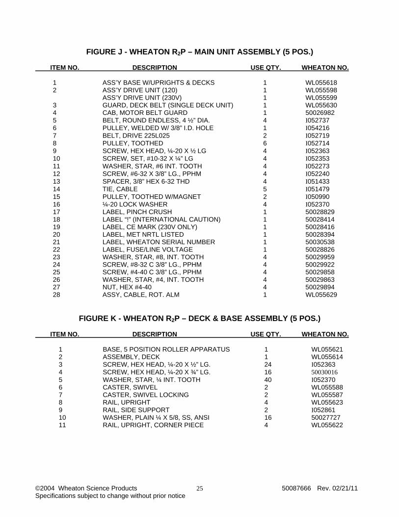
FIGURE J - WHEATON R2P – MAIN UNIT ASSEMBLY (5 POS.) ITEM NO. DESCRIPTION USE QTY. WHEATON NO. 1 ASS’Y BASE W/UPRIGHTS & DECKS 1 WL055618 2 ASS’Y DRIVE UNIT (120) 1 WL055598 ASS’Y DRIVE UNIT (230V) 1 WL055599 3 GUARD, DECK BELT (SINGLE DECK UNIT) 1 WL055630 4 CAB, MOTOR BELT GUARD 1 50026982 5 BELT, ROUND ENDLESS, 4 ½” DIA. 4 I052737 6 PULLEY, WELDED W/ 3/8” I.D. HOLE 1 I054216 7 BELT, DRIVE 225L025 2 I052719 8 PULLEY, TOOTHED 6 I052714 9 SCREW, HEX HEAD, ¼-20 X ½ LG 4 I052363 10 SCREW, SET, #10-32 X ¼” LG 4 I052353 11 WASHER, STAR, #6 INT. TOOTH 4 I052273 12 SCREW, #6-32 X 3/8” LG., PPHM 4 I052240 13 SPACER, 3/8” HEX 6-32 THD 4 I051433 14 TIE, CABLE 5 I051479 15 PULLEY, TOOTHED W/MAGNET 2 I050990 16 ¼-20 LOCK WASHER 4 I052370 17 LABEL, PINCH CRUSH 1 50028829 18 LABEL “!” (INTERNATIONAL CAUTION) 1 50028414 19 LABEL, CE MARK (230V ONLY) 1 50028416 20 LABEL, MET NRTL LISTED 1 50028394 21 LABEL, WHEATON SERIAL NUMBER 1 50030538 22 LABEL, FUSE/LINE VOLTAGE 1 50028826 23 WASHER, STAR, #8, INT. TOOTH 4 50029959 24 SCREW, #8-32 C 3/8” LG., PPHM 4 50029922 25 SCREW, #4-40 C 3/8” LG., PPHM 4 50029858 26 WASHER, STAR, #4, INT. TOOTH 4 50029863 27 NUT, HEX #4-40 4 50029894 28 ASSY, CABLE, ROT. ALM 1 WL055629
FIGURE K - WHEATON R2P – DECK & BASE ASSEMBLY (5 POS.) ITEM NO. DESCRIPTION USE QTY. WHEATON NO. 1 BASE, 5 POSITION ROLLER APPARATUS 1 WL055621 2 ASSEMBLY, DECK 1 WL055614 3 SCREW, HEX HEAD, ¼-20 X ½” LG. 24 I052363 4 SCREW, HEX HEAD, ¼-20 X ¾” LG. 16 50030016 5 WASHER, STAR, ¼ INT. TOOTH 40 I052370 6 CASTER, SWIVEL 2 WL055588 7 CASTER, SWIVEL LOCKING 2 WL055587 8 RAIL, UPRIGHT 4 WL055623 9 RAIL, SIDE SUPPORT 2 I052861 10 WASHER, PLAIN ¼ X 5/8, SS, ANSI 16 50027727 11 RAIL, UPRIGHT, CORNER PIECE 4 WL055622

©2004 Wheaton Science Products 50087666 Rev. 02/21/11 Specifications subject to change without prior notice
26
FIGURE L - WHEATON R2P APPARATUS – SINGLE DECK ASSEMBLY PRODUCTION ITEM NO. DESCRIPTION USE QTY. WHEATON NO. 1 ASSEMBLY, DECK 1 WL055614 2 RAIL, UPRIGHT, SINGLE DECK 4 WL055657 3 RAIL, SIDE SUPPORT 2 I052861 4 RAIL, UPRIGHT, CORNER PIECE 4 WL055622 5 SCREW, HEX HEAD, ¼-20 C ½” LG. 24 I052363 6 WASHER, STAR, ¼ INT. TOOTH 24 I052370
FIGURE M - WHEATON R2P APPARATUS – SINGLE DECK ASSEMBLY MODULAR ITEM NO. DESCRIPTION USE QTY. WHEATON NO. 1 ASSEMBLY, DECK 1 WL055614 2 RAIL, UPRIGHT, SINGLE DECK 4 WL055983 3 RAIL, SIDE SUPPORT 2 I052861 4 RAIL, UPRIGHT, CORNER PIECE 4 WL055622 5 SCREW, HEX HEAD, ¼-20 C ½” LG. 24 I052363 6 WASHER, STAR, ¼ INT. TOOTH 24 I052370
FIGURE N - WHEATON R2P APPARATUS – DECK ROLLER ASSEMBLY ITEM NO. DESCRIPTION USE QTY. WHEATON NO. 1 ASSEMBLY, FRONT RAIL W/ BEARING 1 WL055613 2 ASSEMBLY, REAR RAIL W/ BEARING 1 WL055612 3 ASSEMBLY, ROLLER / SHAFT 6 I054128 4 WASHER, NYLON 12 50028196 5 ROD, SUPPORT 2 I052885 6 WASHER, #8, INT. TOOTH, STAR 2 50029959 7 SCREW, 8-32 X 3/8” LG., PPHM 2 50029922
FIGURE O - WHEATON R2P APPARATUS – FRONT RAIL BEARING ASSEMBLY ITEM NO. DESCRIPTION USE QTY. WHEATON NO. 1 RAIL, FRONT SUPPORT 1 WL055617 2 BEARING, SLOTTED MTG. 6 WL055615
FIGURE P - WHEATON R2P APPARATUS – REAR RAIL BEARING ASSEMBLY ITEM NO. DESCRIPTION USE QTY. WHEATON NO. 1 RAIL, REAR SUPPORT 1 WL055616 2 BEARING, SLOTTED MTG. 6 WL055615

©2004 Wheaton Science Products 50087666 Rev. 02/21/11 Specifications subject to change without prior notice
27

©2004 Wheaton Science Products 50087666 Rev. 02/21/11 Specifications subject to change without prior notice
28
©2004 Wheaton Science Products 50087666 Rev. 02/21/11 Specifications subject to change without prior notice
29
©2004 Wheaton Science Products 50087666 Rev. 02/21/11 Specifications subject to change without prior notice
30
©2004 Wheaton Science Products 50087666 Rev. 02/21/11 Specifications subject to change without prior notice
31
©2004 Wheaton Science Products 50087666 Rev. 02/21/11 Specifications subject to change without prior notice
32

©2004 Wheaton Science Products 50087666 Rev. 02/21/11 Specifications subject to change without prior notice
33
©2004 Wheaton Science Products 50087666 Rev. 02/21/11 Specifications subject to change without prior notice
34

©2004 Wheaton Science Products 50087666 Rev. 02/21/11 Specifications subject to change without prior notice
35

©2004 Wheaton Science Products 50087666 Rev. 02/21/11 Specifications subject to change without prior notice
36
©2004 Wheaton Science Products 50087666 Rev. 02/21/11 Specifications subject to change without prior notice
37
©2004 Wheaton Science Products 50087666 Rev. 02/21/11 Specifications subject to change without prior notice
38

©2004 Wheaton Science Products 50087666 Rev. 02/21/11 Specifications subject to change without prior notice
39
©2004 Wheaton Science Products 50087666 Rev. 02/21/11 Specifications subject to change without prior notice
40
©2004 Wheaton Science Products 50087666 Rev. 02/21/11 Specifications subject to change without prior notice
41

©2004 Wheaton Science Products 50087666 Rev. 02/21/11 Specifications subject to change without prior notice
42
©2004 Wheaton Science Products 50087666 Rev. 02/21/11 Specifications subject to change without prior notice
43

©2004 Wheaton Science Products 50087666 Rev. 02/21/11 Specifications subject to change without prior notice
44

©2004 Wheaton Science Products 50087666 Rev. 02/21/11 Specifications subject to change without prior notice
45
©2004 Wheaton Science Products 50087666 Rev. 02/21/11 Specifications subject to change without prior notice
46

©2004 Wheaton Science Products 50087666 Rev. 02/21/11 Specifications subject to change without prior notice
47
©2004 Wheaton Science Products 50087666 Rev. 02/21/11 Specifications subject to change without prior notice
48
©2004 Wheaton Science Products 50087666 Rev. 02/21/11 Specifications subject to change without prior notice
49
NOTICE
Canada This Class A digital apparatus meets all requirements of the Canadian Interference-Causing Equipment Regulations. Cet appareil numerique de la classe A respecte toutes les exigences du Reglement sur le material du Canada
United States This device complies with Part 15 of the FCC Rules. Operation is subject to the following two conditions: (1) This device may not cause harmful interference, and (2) this device must accept any interference received, including interference that may cause undesired operation. NOTE: This equipment has been tested and found to comply with the limits for a Class A digital device, pursuant to Part 15 of the FCC rules. These limits are designed to provide reasonable protection against harmful interference when the equipment is operated in a commercial environment. This equipment generates, uses and can radiate radio frequency energy and, if not installed and used in accordance with the instruction manual, may cause harmful interference to radio communications. Operation of this equipment in a residential area is likely to cause harmful interference in which case the user will be required to correct the interference at his own expense.

©2004 Wheaton Science Products 50087666 Rev. 02/21/11 Specifications subject to change without prior notice
50
12.0 WHEATON SCIENCE PRODUCTS
12.1 Declaration of Conformity We, Wheaton Science Products
An Alcan Packaging Company 1501 North Tenth Street Millville, NJ 08332-2093 USA
declare that the device described below - marked with CE - fulfills the relevant fundamental EMC and safety requirements specified by the appropriate EU - Directive, with respect to the design and construction of the commercialized version. This declaration is invalid if modifications are performed on the device which have not been certified by Wheaton Science Products. Designation of the device: R2P Roller Apparatus Relevant Directives: EMC 89/336/EEC as amended by 92/31EEC and 93/68/EEC Standards: EN 50082-1
EN 55011 (CISPR 11): 1991 EN 55011 (CISPR 22): 1991 EN 61326: 1997 EN 61000-4-2: 1995 EN 61000-4-3: 1995 EN 61000-4-4: 1995 EN 61000-4-5: 1995 EN 61000-4-6: 1996 EN 61000-4-8: 1993 EN 61000-4-11: 1994
Relevant Directives: LVD 73/23/EEC as amended by 93/68/EEC Standards: EN 61010-1; 1993, including Amendment 1 and 2
February 22, 2011 Nicholas R. DeBello, Date Vice President Quality Management Systems

©2004 Wheaton Science Products 50087666 Rev. 02/21/11 Specifications subject to change without prior notice
51
Related Documents


