SIEMENS SIEMENS SIEMENS What's new in NX 10.0.3

Welcome message from author
This document is posted to help you gain knowledge. Please leave a comment to let me know what you think about it! Share it to your friends and learn new things together.
Transcript
SIEMENSSIEMENSSIEMENS
What's new in NX10.0.3

Contents
Teamcenter Integration for NX . . . . . . . . . . . . . . . . . . . . . . . . . . . . . . . . . . . . . . . . . . . . 1-1
Table editor layout . . . . . . . . . . . . . . . . . . . . . . . . . . . . . . . . . . . . . . . . . . . . . . . . . . . . . 1-1Import assembly into Teamcenter . . . . . . . . . . . . . . . . . . . . . . . . . . . . . . . . . . . . . . . . . . . 1-3UTF-8 encoding supported . . . . . . . . . . . . . . . . . . . . . . . . . . . . . . . . . . . . . . . . . . . . . . . 1-4Using Teamcenter multifield keys . . . . . . . . . . . . . . . . . . . . . . . . . . . . . . . . . . . . . . . . . . . 1-5Work with objects in all Teamcenter MFK domains . . . . . . . . . . . . . . . . . . . . . . . . . . . . . . . 1-6MFK for part families . . . . . . . . . . . . . . . . . . . . . . . . . . . . . . . . . . . . . . . . . . . . . . . . . . . . 1-7Operation descriptors . . . . . . . . . . . . . . . . . . . . . . . . . . . . . . . . . . . . . . . . . . . . . . . . . . . 1-8Active Workspace data synchronization . . . . . . . . . . . . . . . . . . . . . . . . . . . . . . . . . . . . . . . 1-8Reconnect to Teamcenter . . . . . . . . . . . . . . . . . . . . . . . . . . . . . . . . . . . . . . . . . . . . . . . . 1-9Display names . . . . . . . . . . . . . . . . . . . . . . . . . . . . . . . . . . . . . . . . . . . . . . . . . . . . . . . . 1-9Localizable attributes . . . . . . . . . . . . . . . . . . . . . . . . . . . . . . . . . . . . . . . . . . . . . . . . . . 1-10Drawing booklets in Teamcenter . . . . . . . . . . . . . . . . . . . . . . . . . . . . . . . . . . . . . . . . . . . 1-10
Configuring Item Types for a Booklet Rule part . . . . . . . . . . . . . . . . . . . . . . . . . . . . . . 1-10Configuring revisions for drawing parts in drawing booklets . . . . . . . . . . . . . . . . . . . . . . 1-11
Fundamentals . . . . . . . . . . . . . . . . . . . . . . . . . . . . . . . . . . . . . . . . . . . . . . . . . . . . . . . 2-1
New NX look . . . . . . . . . . . . . . . . . . . . . . . . . . . . . . . . . . . . . . . . . . . . . . . . . . . . . . . . . 2-1Help and search enhancements . . . . . . . . . . . . . . . . . . . . . . . . . . . . . . . . . . . . . . . . . . . . 2-2Resource bar enhancements . . . . . . . . . . . . . . . . . . . . . . . . . . . . . . . . . . . . . . . . . . . . . . 2-3Customize line widths . . . . . . . . . . . . . . . . . . . . . . . . . . . . . . . . . . . . . . . . . . . . . . . . . . . 2-3Creating output geometry for measurement features . . . . . . . . . . . . . . . . . . . . . . . . . . . . . . 2-5Collaborating on NX issues . . . . . . . . . . . . . . . . . . . . . . . . . . . . . . . . . . . . . . . . . . . . . . . 2-7Hosting custom windows in NX . . . . . . . . . . . . . . . . . . . . . . . . . . . . . . . . . . . . . . . . . . . . 2-10Zoom operation enhancements . . . . . . . . . . . . . . . . . . . . . . . . . . . . . . . . . . . . . . . . . . . 2-10Customize dialog box enhancements . . . . . . . . . . . . . . . . . . . . . . . . . . . . . . . . . . . . . . . 2-11Ribbon bar enhancements . . . . . . . . . . . . . . . . . . . . . . . . . . . . . . . . . . . . . . . . . . . . . . . 2-13Cue and Status line enhancements . . . . . . . . . . . . . . . . . . . . . . . . . . . . . . . . . . . . . . . . . 2-15User Interface Preferences enhancements . . . . . . . . . . . . . . . . . . . . . . . . . . . . . . . . . . . . 2-15View Section enhancements . . . . . . . . . . . . . . . . . . . . . . . . . . . . . . . . . . . . . . . . . . . . . 2-15CSYS and View Triad enhancements . . . . . . . . . . . . . . . . . . . . . . . . . . . . . . . . . . . . . . . 2-18Rendering enhancements . . . . . . . . . . . . . . . . . . . . . . . . . . . . . . . . . . . . . . . . . . . . . . . 2-19Displaying facets . . . . . . . . . . . . . . . . . . . . . . . . . . . . . . . . . . . . . . . . . . . . . . . . . . . . . 2-21Roles enhancements . . . . . . . . . . . . . . . . . . . . . . . . . . . . . . . . . . . . . . . . . . . . . . . . . . 2-21Touchscreen gestures for NX . . . . . . . . . . . . . . . . . . . . . . . . . . . . . . . . . . . . . . . . . . . . . 2-22Accessing image files from Teamcenter . . . . . . . . . . . . . . . . . . . . . . . . . . . . . . . . . . . . . . 2-27Saving display settings in a bookmark for the displayed part . . . . . . . . . . . . . . . . . . . . . . . . 2-28System attributes in NX . . . . . . . . . . . . . . . . . . . . . . . . . . . . . . . . . . . . . . . . . . . . . . . . . 2-28
CAD . . . . . . . . . . . . . . . . . . . . . . . . . . . . . . . . . . . . . . . . . . . . . . . . . . . . . . . . . . . . . . . 3-1
Sketching . . . . . . . . . . . . . . . . . . . . . . . . . . . . . . . . . . . . . . . . . . . . . . . . . . . . . . . . . . . 3-1Resize Chamfer Curve . . . . . . . . . . . . . . . . . . . . . . . . . . . . . . . . . . . . . . . . . . . . . . . 3-1
What's new in NX 10 3
Contents
Curve Finder options . . . . . . . . . . . . . . . . . . . . . . . . . . . . . . . . . . . . . . . . . . . . . . . . . 3-22D Synchronous Technology settings . . . . . . . . . . . . . . . . . . . . . . . . . . . . . . . . . . . . . 3-3Optimize 2D Curve . . . . . . . . . . . . . . . . . . . . . . . . . . . . . . . . . . . . . . . . . . . . . . . . . . 3-4Creating sketch splines . . . . . . . . . . . . . . . . . . . . . . . . . . . . . . . . . . . . . . . . . . . . . . . 3-5Trimming sketch recipe curves . . . . . . . . . . . . . . . . . . . . . . . . . . . . . . . . . . . . . . . . . . 3-6Creating WAVE links in a sketch . . . . . . . . . . . . . . . . . . . . . . . . . . . . . . . . . . . . . . . . . 3-7
Part Module . . . . . . . . . . . . . . . . . . . . . . . . . . . . . . . . . . . . . . . . . . . . . . . . . . . . . . . . . . 3-8Part Module enhancements in the Part Navigator . . . . . . . . . . . . . . . . . . . . . . . . . . . . . 3-8Save linked part module enhancement . . . . . . . . . . . . . . . . . . . . . . . . . . . . . . . . . . . . . 3-9Update Input References and Update Output References enhancements . . . . . . . . . . . . . 3-9Shared Body enhancement . . . . . . . . . . . . . . . . . . . . . . . . . . . . . . . . . . . . . . . . . . . 3-10
Modeling . . . . . . . . . . . . . . . . . . . . . . . . . . . . . . . . . . . . . . . . . . . . . . . . . . . . . . . . . . . 3-11Fill Surface enhancements . . . . . . . . . . . . . . . . . . . . . . . . . . . . . . . . . . . . . . . . . . . . 3-11Section Surface enhancements . . . . . . . . . . . . . . . . . . . . . . . . . . . . . . . . . . . . . . . . 3-12Aero Design . . . . . . . . . . . . . . . . . . . . . . . . . . . . . . . . . . . . . . . . . . . . . . . . . . . . . . 3-12Face Blend enhancements . . . . . . . . . . . . . . . . . . . . . . . . . . . . . . . . . . . . . . . . . . . . 3-15Edge Blend enhancements . . . . . . . . . . . . . . . . . . . . . . . . . . . . . . . . . . . . . . . . . . . 3-18Edge Blend enhancement (10.0.1) . . . . . . . . . . . . . . . . . . . . . . . . . . . . . . . . . . . . . . 3-19Replace Face enhancement . . . . . . . . . . . . . . . . . . . . . . . . . . . . . . . . . . . . . . . . . . . 3-20Wrap/Unwrap Curve enhancements . . . . . . . . . . . . . . . . . . . . . . . . . . . . . . . . . . . . . 3-21Offset Curve in Face enhancements . . . . . . . . . . . . . . . . . . . . . . . . . . . . . . . . . . . . . 3-23Preview a failed or missing face during feature edit . . . . . . . . . . . . . . . . . . . . . . . . . . . 3-23Rollback data to memory to improve Modeling performance . . . . . . . . . . . . . . . . . . . . . 3-26Offset 3D Curve enhancements . . . . . . . . . . . . . . . . . . . . . . . . . . . . . . . . . . . . . . . . 3-26Enhancements to patterns with extracted bodies . . . . . . . . . . . . . . . . . . . . . . . . . . . . . 3-27Detect Primitives . . . . . . . . . . . . . . . . . . . . . . . . . . . . . . . . . . . . . . . . . . . . . . . . . . 3-28Paint Facet Body . . . . . . . . . . . . . . . . . . . . . . . . . . . . . . . . . . . . . . . . . . . . . . . . . . 3-29Law Extension enhancements . . . . . . . . . . . . . . . . . . . . . . . . . . . . . . . . . . . . . . . . . 3-30Fit Surface enhancements . . . . . . . . . . . . . . . . . . . . . . . . . . . . . . . . . . . . . . . . . . . . 3-31Trim Sheet enhancements . . . . . . . . . . . . . . . . . . . . . . . . . . . . . . . . . . . . . . . . . . . . 3-32Synchronous Modeling Blend option . . . . . . . . . . . . . . . . . . . . . . . . . . . . . . . . . . . . . 3-32Trim and Extend . . . . . . . . . . . . . . . . . . . . . . . . . . . . . . . . . . . . . . . . . . . . . . . . . . . 3-33Extend Sheet . . . . . . . . . . . . . . . . . . . . . . . . . . . . . . . . . . . . . . . . . . . . . . . . . . . . . 3-34Expressions enhancements . . . . . . . . . . . . . . . . . . . . . . . . . . . . . . . . . . . . . . . . . . . 3-35Expression groups . . . . . . . . . . . . . . . . . . . . . . . . . . . . . . . . . . . . . . . . . . . . . . . . . 3-36Interpart expression format . . . . . . . . . . . . . . . . . . . . . . . . . . . . . . . . . . . . . . . . . . . 3-37SNAP . . . . . . . . . . . . . . . . . . . . . . . . . . . . . . . . . . . . . . . . . . . . . . . . . . . . . . . . . . 3-38
NX Realize Shape . . . . . . . . . . . . . . . . . . . . . . . . . . . . . . . . . . . . . . . . . . . . . . . . . . . . 3-39Import Subdivision Geometry . . . . . . . . . . . . . . . . . . . . . . . . . . . . . . . . . . . . . . . . . . 3-39Project Cage enhancements . . . . . . . . . . . . . . . . . . . . . . . . . . . . . . . . . . . . . . . . . . 3-40Split Face enhancements . . . . . . . . . . . . . . . . . . . . . . . . . . . . . . . . . . . . . . . . . . . . . 3-43Extrude Cage enhancements . . . . . . . . . . . . . . . . . . . . . . . . . . . . . . . . . . . . . . . . . . 3-44Revolve Cage . . . . . . . . . . . . . . . . . . . . . . . . . . . . . . . . . . . . . . . . . . . . . . . . . . . . 3-45Loft Cage . . . . . . . . . . . . . . . . . . . . . . . . . . . . . . . . . . . . . . . . . . . . . . . . . . . . . . . 3-46Sweep Cage . . . . . . . . . . . . . . . . . . . . . . . . . . . . . . . . . . . . . . . . . . . . . . . . . . . . . 3-47Tube cage . . . . . . . . . . . . . . . . . . . . . . . . . . . . . . . . . . . . . . . . . . . . . . . . . . . . . . . 3-48Transform Cage enhancements . . . . . . . . . . . . . . . . . . . . . . . . . . . . . . . . . . . . . . . . 3-49Primitive Shape enhancement . . . . . . . . . . . . . . . . . . . . . . . . . . . . . . . . . . . . . . . . . 3-51Cage Polyline . . . . . . . . . . . . . . . . . . . . . . . . . . . . . . . . . . . . . . . . . . . . . . . . . . . . 3-51
4 What's new in NX 10
Contents
Contents
Extract Cage Polyline . . . . . . . . . . . . . . . . . . . . . . . . . . . . . . . . . . . . . . . . . . . . . . . 3-53Copy Cage . . . . . . . . . . . . . . . . . . . . . . . . . . . . . . . . . . . . . . . . . . . . . . . . . . . . . . 3-53Sew Cage . . . . . . . . . . . . . . . . . . . . . . . . . . . . . . . . . . . . . . . . . . . . . . . . . . . . . . . 3-55NX Realize Shape preferences enhancements . . . . . . . . . . . . . . . . . . . . . . . . . . . . . . 3-56
Assemblies . . . . . . . . . . . . . . . . . . . . . . . . . . . . . . . . . . . . . . . . . . . . . . . . . . . . . . . . . 3-59Visual Reporting . . . . . . . . . . . . . . . . . . . . . . . . . . . . . . . . . . . . . . . . . . . . . . . . . . . 3-59Preserving broken interpart expressions . . . . . . . . . . . . . . . . . . . . . . . . . . . . . . . . . . . 3-60Mirror Assemblies Wizard . . . . . . . . . . . . . . . . . . . . . . . . . . . . . . . . . . . . . . . . . . . . 3-61Extraction Path customizing . . . . . . . . . . . . . . . . . . . . . . . . . . . . . . . . . . . . . . . . . . . 3-62Replacing a part families component . . . . . . . . . . . . . . . . . . . . . . . . . . . . . . . . . . . . . 3-62Default location for component drag handles . . . . . . . . . . . . . . . . . . . . . . . . . . . . . . . . 3-63Moving a component along a vector and projected distance . . . . . . . . . . . . . . . . . . . . . 3-63Add a component to the XC-YC plane by drag and drop . . . . . . . . . . . . . . . . . . . . . . . . 3-64Support for monolithic JT files . . . . . . . . . . . . . . . . . . . . . . . . . . . . . . . . . . . . . . . . . . 3-64WAVE-linking product interface enhancement . . . . . . . . . . . . . . . . . . . . . . . . . . . . . . . 3-64Updating assembly structures in the Assembly Navigator . . . . . . . . . . . . . . . . . . . . . . . 3-65Interpart expression format . . . . . . . . . . . . . . . . . . . . . . . . . . . . . . . . . . . . . . . . . . . 3-66General Relinker enhancement (10.0.2) . . . . . . . . . . . . . . . . . . . . . . . . . . . . . . . . . . . 3-67Product Interface enhancement (10.0.2) . . . . . . . . . . . . . . . . . . . . . . . . . . . . . . . . . . . 3-67
Drafting . . . . . . . . . . . . . . . . . . . . . . . . . . . . . . . . . . . . . . . . . . . . . . . . . . . . . . . . . . . 3-67Designing using Layout . . . . . . . . . . . . . . . . . . . . . . . . . . . . . . . . . . . . . . . . . . . . . . 3-68Restructure of the Drafting customer defaults . . . . . . . . . . . . . . . . . . . . . . . . . . . . . . . 3-81Dimension user interface enhancements (10.0.2) . . . . . . . . . . . . . . . . . . . . . . . . . . . . 3-83Borders and Zones enhancements . . . . . . . . . . . . . . . . . . . . . . . . . . . . . . . . . . . . . . 3-84Title Block enhancements . . . . . . . . . . . . . . . . . . . . . . . . . . . . . . . . . . . . . . . . . . . . 3-87Fit support for angled text in tables . . . . . . . . . . . . . . . . . . . . . . . . . . . . . . . . . . . . . . 3-88Section View command . . . . . . . . . . . . . . . . . . . . . . . . . . . . . . . . . . . . . . . . . . . . . . 3-89Placing section views (10.0.2) . . . . . . . . . . . . . . . . . . . . . . . . . . . . . . . . . . . . . . . . . 3-91Section Line command . . . . . . . . . . . . . . . . . . . . . . . . . . . . . . . . . . . . . . . . . . . . . . 3-92View enhancements . . . . . . . . . . . . . . . . . . . . . . . . . . . . . . . . . . . . . . . . . . . . . . . . 3-94View break enhancements . . . . . . . . . . . . . . . . . . . . . . . . . . . . . . . . . . . . . . . . . . . . 3-94Part Navigator enhancement for drafting views (10.0.2) . . . . . . . . . . . . . . . . . . . . . . . . 3-95Single-sided dimensions . . . . . . . . . . . . . . . . . . . . . . . . . . . . . . . . . . . . . . . . . . . . . 3-96Linear dimension measurement types . . . . . . . . . . . . . . . . . . . . . . . . . . . . . . . . . . . . 3-98Ordinate dimension enhancements . . . . . . . . . . . . . . . . . . . . . . . . . . . . . . . . . . . . . 3-100Automatic line breaks . . . . . . . . . . . . . . . . . . . . . . . . . . . . . . . . . . . . . . . . . . . . . . 3-102Jogs on linear dimensions . . . . . . . . . . . . . . . . . . . . . . . . . . . . . . . . . . . . . . . . . . . 3-103Foreshortening symbols . . . . . . . . . . . . . . . . . . . . . . . . . . . . . . . . . . . . . . . . . . . . 3-104Adding segments to a composite Feature Control Frame . . . . . . . . . . . . . . . . . . . . . . 3-106Leader enhancements and feature control frame display enhancements . . . . . . . . . . . . 3-107Adding symbols and text to datum references . . . . . . . . . . . . . . . . . . . . . . . . . . . . . . 3-110Movable datum targets, new terminator types . . . . . . . . . . . . . . . . . . . . . . . . . . . . . . 3-111Weld Symbol enhancements (10.0.2) . . . . . . . . . . . . . . . . . . . . . . . . . . . . . . . . . . . 3-111Balloon enhancement . . . . . . . . . . . . . . . . . . . . . . . . . . . . . . . . . . . . . . . . . . . . . . 3-112Editing property tracking for inherited PMI . . . . . . . . . . . . . . . . . . . . . . . . . . . . . . . . 3-113Inheriting PMI into a Drafting section view . . . . . . . . . . . . . . . . . . . . . . . . . . . . . . . . 3-114API function for Drawing Booklets . . . . . . . . . . . . . . . . . . . . . . . . . . . . . . . . . . . . . . 3-115Multiple overlapping template regions . . . . . . . . . . . . . . . . . . . . . . . . . . . . . . . . . . . 3-116Drawing booklet enhancement . . . . . . . . . . . . . . . . . . . . . . . . . . . . . . . . . . . . . . . . 3-117
What's new in NX 10 5
Contents
Contents
Specifying Item Type for custom symbols . . . . . . . . . . . . . . . . . . . . . . . . . . . . . . . . 3-117Product and Manufacturing Information (PMI) . . . . . . . . . . . . . . . . . . . . . . . . . . . . . . . . . 3-118
Dimension user interface enhancements (10.0.2) . . . . . . . . . . . . . . . . . . . . . . . . . . . 3-118Adding segments to a composite Feature Control Frame . . . . . . . . . . . . . . . . . . . . . . 3-119Adding symbols and text to datum references . . . . . . . . . . . . . . . . . . . . . . . . . . . . . . 3-120Leader enhancements and feature control frame display enhancements . . . . . . . . . . . . 3-121Enable Resize preference . . . . . . . . . . . . . . . . . . . . . . . . . . . . . . . . . . . . . . . . . . . 3-124Single-sided dimensions . . . . . . . . . . . . . . . . . . . . . . . . . . . . . . . . . . . . . . . . . . . . 3-125Linear dimension measurement types . . . . . . . . . . . . . . . . . . . . . . . . . . . . . . . . . . . 3-126Jogs on linear dimensions . . . . . . . . . . . . . . . . . . . . . . . . . . . . . . . . . . . . . . . . . . . 3-128Movable datum targets, new terminator types . . . . . . . . . . . . . . . . . . . . . . . . . . . . . . 3-129Weld Symbol enhancements (10.0.2) . . . . . . . . . . . . . . . . . . . . . . . . . . . . . . . . . . . 3-130Specifying Item Type for custom symbols . . . . . . . . . . . . . . . . . . . . . . . . . . . . . . . . 3-131Inheriting PMI into a Drafting section view . . . . . . . . . . . . . . . . . . . . . . . . . . . . . . . . 3-131Editing property tracking for inherited PMI . . . . . . . . . . . . . . . . . . . . . . . . . . . . . . . . 3-133Information on leader termination points . . . . . . . . . . . . . . . . . . . . . . . . . . . . . . . . . . 3-133Creating PMI objects from a JT file . . . . . . . . . . . . . . . . . . . . . . . . . . . . . . . . . . . . . 3-134
Data Reuse . . . . . . . . . . . . . . . . . . . . . . . . . . . . . . . . . . . . . . . . . . . . . . . . . . . . . . . . 3-135Favorites and Ribbon Bar in the Reuse Library . . . . . . . . . . . . . . . . . . . . . . . . . . . . . 3-135Teamcenter library integration . . . . . . . . . . . . . . . . . . . . . . . . . . . . . . . . . . . . . . . . . 3-136Reuse library configuration enhancements . . . . . . . . . . . . . . . . . . . . . . . . . . . . . . . . 3-137Teamcenter classification reuse library enhancements . . . . . . . . . . . . . . . . . . . . . . . . 3-140Fastener assembly configuration library . . . . . . . . . . . . . . . . . . . . . . . . . . . . . . . . . . 3-141Index search from Reuse Navigator . . . . . . . . . . . . . . . . . . . . . . . . . . . . . . . . . . . . . 3-142Preferred Data . . . . . . . . . . . . . . . . . . . . . . . . . . . . . . . . . . . . . . . . . . . . . . . . . . . 3-142Product Template Studio user interface enhancement . . . . . . . . . . . . . . . . . . . . . . . . 3-143
Ship Structure . . . . . . . . . . . . . . . . . . . . . . . . . . . . . . . . . . . . . . . . . . . . . . . . . . . . . . 3-146Copy Basic Design Objects . . . . . . . . . . . . . . . . . . . . . . . . . . . . . . . . . . . . . . . . . . 3-146Mirror Ship Structure . . . . . . . . . . . . . . . . . . . . . . . . . . . . . . . . . . . . . . . . . . . . . . . 3-147Edge reinforcement and stiffener enhancements . . . . . . . . . . . . . . . . . . . . . . . . . . . . 3-148Paint Parameters enhancements . . . . . . . . . . . . . . . . . . . . . . . . . . . . . . . . . . . . . . 3-149Prevent circular dependencies in a basic design . . . . . . . . . . . . . . . . . . . . . . . . . . . . 3-150Ship Structure performance enhancements . . . . . . . . . . . . . . . . . . . . . . . . . . . . . . . 3-150Weight and Center of Gravity . . . . . . . . . . . . . . . . . . . . . . . . . . . . . . . . . . . . . . . . . 3-152Material Estimation . . . . . . . . . . . . . . . . . . . . . . . . . . . . . . . . . . . . . . . . . . . . . . . . 3-153Unfolded Minimum Rectangle . . . . . . . . . . . . . . . . . . . . . . . . . . . . . . . . . . . . . . . . . 3-154Edit Context Attributes . . . . . . . . . . . . . . . . . . . . . . . . . . . . . . . . . . . . . . . . . . . . . . 3-155Edit Stock enhancements . . . . . . . . . . . . . . . . . . . . . . . . . . . . . . . . . . . . . . . . . . . 3-155Pinjig . . . . . . . . . . . . . . . . . . . . . . . . . . . . . . . . . . . . . . . . . . . . . . . . . . . . . . . . . 3-156Plate Template enhancements . . . . . . . . . . . . . . . . . . . . . . . . . . . . . . . . . . . . . . . . 3-157Section Drawing . . . . . . . . . . . . . . . . . . . . . . . . . . . . . . . . . . . . . . . . . . . . . . . . . . 3-159Expansion Drawing . . . . . . . . . . . . . . . . . . . . . . . . . . . . . . . . . . . . . . . . . . . . . . . . 3-161Annotate Ship Drawing . . . . . . . . . . . . . . . . . . . . . . . . . . . . . . . . . . . . . . . . . . . . . 3-162
Routing . . . . . . . . . . . . . . . . . . . . . . . . . . . . . . . . . . . . . . . . . . . . . . . . . . . . . . . . . . . 3-164Stock enhancements . . . . . . . . . . . . . . . . . . . . . . . . . . . . . . . . . . . . . . . . . . . . . . . 3-164Spline Path enhancement . . . . . . . . . . . . . . . . . . . . . . . . . . . . . . . . . . . . . . . . . . . 3-169Pipe Welding commands . . . . . . . . . . . . . . . . . . . . . . . . . . . . . . . . . . . . . . . . . . . . 3-170Pipe Welding Joint . . . . . . . . . . . . . . . . . . . . . . . . . . . . . . . . . . . . . . . . . . . . . . . . 3-171Transform Path enhancements . . . . . . . . . . . . . . . . . . . . . . . . . . . . . . . . . . . . . . . . 3-172
6 What's new in NX 10
Contents
Contents
Placing connecting parts on flanges . . . . . . . . . . . . . . . . . . . . . . . . . . . . . . . . . . . . 3-173Part placement enhancements . . . . . . . . . . . . . . . . . . . . . . . . . . . . . . . . . . . . . . . . 3-176Moving a measurement holder . . . . . . . . . . . . . . . . . . . . . . . . . . . . . . . . . . . . . . . . 3-177Quick Path (10.0.2) . . . . . . . . . . . . . . . . . . . . . . . . . . . . . . . . . . . . . . . . . . . . . . . . 3-178Align Stock (10.0.2) . . . . . . . . . . . . . . . . . . . . . . . . . . . . . . . . . . . . . . . . . . . . . . . . 3-179Stock orientation enhancement (10.0.2) . . . . . . . . . . . . . . . . . . . . . . . . . . . . . . . . . . 3-180
Sheet Metal . . . . . . . . . . . . . . . . . . . . . . . . . . . . . . . . . . . . . . . . . . . . . . . . . . . . . . . . 3-181Flange enhancement . . . . . . . . . . . . . . . . . . . . . . . . . . . . . . . . . . . . . . . . . . . . . . 3-181Unbend and Rebend enhancements . . . . . . . . . . . . . . . . . . . . . . . . . . . . . . . . . . . . 3-182Convert to Sheet Metal enhancements . . . . . . . . . . . . . . . . . . . . . . . . . . . . . . . . . . . 3-183Specifying a target body for creating normal cutouts . . . . . . . . . . . . . . . . . . . . . . . . . 3-184Specifying a target face for creating bends and jogs . . . . . . . . . . . . . . . . . . . . . . . . . . 3-185Gusset enhancements . . . . . . . . . . . . . . . . . . . . . . . . . . . . . . . . . . . . . . . . . . . . . . 3-186Bend Taper enhancements . . . . . . . . . . . . . . . . . . . . . . . . . . . . . . . . . . . . . . . . . . 3-189Bridge Bend enhancements (10.0.2) . . . . . . . . . . . . . . . . . . . . . . . . . . . . . . . . . . . . 3-193Bead and Dimple enhancements (10.0.2) . . . . . . . . . . . . . . . . . . . . . . . . . . . . . . . . . 3-196Export Flat Pattern enhancements (10.0.2) . . . . . . . . . . . . . . . . . . . . . . . . . . . . . . . . 3-197
Flexible Printed Circuit Design . . . . . . . . . . . . . . . . . . . . . . . . . . . . . . . . . . . . . . . . . . . 3-197Flat Solid enhancements . . . . . . . . . . . . . . . . . . . . . . . . . . . . . . . . . . . . . . . . . . . . 3-197Bridge Transition enhancements (10.0.2) . . . . . . . . . . . . . . . . . . . . . . . . . . . . . . . . . 3-200
PCB Exchange . . . . . . . . . . . . . . . . . . . . . . . . . . . . . . . . . . . . . . . . . . . . . . . . . . . . . 3-203Common BOM for ECAD and MCAD PCA design (10.0.2) . . . . . . . . . . . . . . . . . . . . . 3-203Support of a Flat Solid version of a flexible PCB . . . . . . . . . . . . . . . . . . . . . . . . . . . . 3-203Multi-Height Area Creation . . . . . . . . . . . . . . . . . . . . . . . . . . . . . . . . . . . . . . . . . . . 3-204Automatic Component Creation (10.0.2) . . . . . . . . . . . . . . . . . . . . . . . . . . . . . . . . . . 3-205Component Report (10.0.2) . . . . . . . . . . . . . . . . . . . . . . . . . . . . . . . . . . . . . . . . . . 3-206Markers stored as faceted geometry . . . . . . . . . . . . . . . . . . . . . . . . . . . . . . . . . . . . 3-206Selectable markers (10.0.2) . . . . . . . . . . . . . . . . . . . . . . . . . . . . . . . . . . . . . . . . . . 3-207Visualize Primary Pins . . . . . . . . . . . . . . . . . . . . . . . . . . . . . . . . . . . . . . . . . . . . . . 3-208Primary pin information on components . . . . . . . . . . . . . . . . . . . . . . . . . . . . . . . . . . 3-209Refresh Primary Pin Mismatch Info . . . . . . . . . . . . . . . . . . . . . . . . . . . . . . . . . . . . . 3-209Primary Pin Comparison Report enhancement (10.0.2) . . . . . . . . . . . . . . . . . . . . . . . 3-210Area layer mapping enhancements (10.0.2) . . . . . . . . . . . . . . . . . . . . . . . . . . . . . . . 3-210Filtering external layers (10.0.2) . . . . . . . . . . . . . . . . . . . . . . . . . . . . . . . . . . . . . . . 3-211Remove Holes with Size filter . . . . . . . . . . . . . . . . . . . . . . . . . . . . . . . . . . . . . . . . . 3-212Filtering entities by ownership . . . . . . . . . . . . . . . . . . . . . . . . . . . . . . . . . . . . . . . . . 3-213Creation of idealized part . . . . . . . . . . . . . . . . . . . . . . . . . . . . . . . . . . . . . . . . . . . . 3-214Creating a Space Systems Thermal solution . . . . . . . . . . . . . . . . . . . . . . . . . . . . . . . 3-214Home tab enhancements . . . . . . . . . . . . . . . . . . . . . . . . . . . . . . . . . . . . . . . . . . . . 3-215PCB Exchange version . . . . . . . . . . . . . . . . . . . . . . . . . . . . . . . . . . . . . . . . . . . . . 3-215Importing holes as curves or cutouts . . . . . . . . . . . . . . . . . . . . . . . . . . . . . . . . . . . . 3-216Automatically importing geometry into reference sets (10.0.2) . . . . . . . . . . . . . . . . . . . 3-216Creation of CAE items . . . . . . . . . . . . . . . . . . . . . . . . . . . . . . . . . . . . . . . . . . . . . . 3-217
Vehicle Design . . . . . . . . . . . . . . . . . . . . . . . . . . . . . . . . . . . . . . . . . . . . . . . . . . . . . . 3-217Pedestrian Protection enhancements . . . . . . . . . . . . . . . . . . . . . . . . . . . . . . . . . . . . 3-217Vehicle Packaging option renamed . . . . . . . . . . . . . . . . . . . . . . . . . . . . . . . . . . . . . 3-220H-point Design Tool enhancements . . . . . . . . . . . . . . . . . . . . . . . . . . . . . . . . . . . . . 3-220
Human Modeling . . . . . . . . . . . . . . . . . . . . . . . . . . . . . . . . . . . . . . . . . . . . . . . . . . . . 3-223Human Modeling enhancements (10.0.3) . . . . . . . . . . . . . . . . . . . . . . . . . . . . . . . . . 3-223
What's new in NX 10 7
Contents
Contents
CAM NX 9.0.1 — NX 10.0.3 . . . . . . . . . . . . . . . . . . . . . . . . . . . . . . . . . . . . . . . . . . . . . . . 4-1
General enhancements . . . . . . . . . . . . . . . . . . . . . . . . . . . . . . . . . . . . . . . . . . . . . . . . . . 4-1Creating the IPW in the background . . . . . . . . . . . . . . . . . . . . . . . . . . . . . . . . . . . . . . 4-1Verification settings and playback enhancements . . . . . . . . . . . . . . . . . . . . . . . . . . . . . 4-2Displaying cutter paths - starting in NX 9.0.1 . . . . . . . . . . . . . . . . . . . . . . . . . . . . . . . . . 4-3Displaying cutter paths - starting in NX 9.0.2 . . . . . . . . . . . . . . . . . . . . . . . . . . . . . . . . . 4-4Connecting tool path segments after edits . . . . . . . . . . . . . . . . . . . . . . . . . . . . . . . . . . 4-7Trimming tool paths in the Tool Path Editor . . . . . . . . . . . . . . . . . . . . . . . . . . . . . . . . . . 4-9IPW rendering improvements (10.0.1) . . . . . . . . . . . . . . . . . . . . . . . . . . . . . . . . . . . . 4-11IPW tolerances moved into the part (10.0.1) . . . . . . . . . . . . . . . . . . . . . . . . . . . . . . . . 4-11Generating the IPW with the operation (10.0.1) . . . . . . . . . . . . . . . . . . . . . . . . . . . . . . 4-12Toolpath verification and analysis consolidation (10.0.1) . . . . . . . . . . . . . . . . . . . . . . . . 4-13Tool Path Analysis (10.0.3) . . . . . . . . . . . . . . . . . . . . . . . . . . . . . . . . . . . . . . . . . . . . 4-13Generating changed operations only (10.0.3) . . . . . . . . . . . . . . . . . . . . . . . . . . . . . . . 4-14Gouge checking operations on parts that have non-uniform stock (10.0.3) . . . . . . . . . . . . 4-14Minimum Clearance settings in non cutting moves (10.0.3) . . . . . . . . . . . . . . . . . . . . . . 4-15Controlling simulation tolerances (10.0.3) . . . . . . . . . . . . . . . . . . . . . . . . . . . . . . . . . . 4-16Automating manufacturing process documents (10.0.3) . . . . . . . . . . . . . . . . . . . . . . . . 4-16Managing your machine tool library (10.0.3) . . . . . . . . . . . . . . . . . . . . . . . . . . . . . . . . 4-18Using the latest libraries in native NX (10.0.3) . . . . . . . . . . . . . . . . . . . . . . . . . . . . . . . 4-19Updating library resources based on the revision rule (10.0.3) . . . . . . . . . . . . . . . . . . . . 4-20
Milling . . . . . . . . . . . . . . . . . . . . . . . . . . . . . . . . . . . . . . . . . . . . . . . . . . . . . . . . . . . . . 4-21Automatic cut pattern direction . . . . . . . . . . . . . . . . . . . . . . . . . . . . . . . . . . . . . . . . . 4-21Cavity Mill Cutting Parameters (10.0.1) . . . . . . . . . . . . . . . . . . . . . . . . . . . . . . . . . . . 4-23Improving surface finish on corners and fillets Curve/Point drive method . . . . . . . . . . . . . 4-23Performance enhancements for Floor Wall operations using a 3D IPW . . . . . . . . . . . . . . 4-26Cut regions and cut order in Flowcut Single operations . . . . . . . . . . . . . . . . . . . . . . . . . 4-26Cut region control for Flowcut Reference Tool . . . . . . . . . . . . . . . . . . . . . . . . . . . . . . . 4-27Flowcut Region Management (10.0.1) . . . . . . . . . . . . . . . . . . . . . . . . . . . . . . . . . . . . 4-30Corner smoothing for Z-level non-steep cut patterns (10.0.1) . . . . . . . . . . . . . . . . . . . . . 4-31Adding center passes in Flowcut operations (10.0.1) . . . . . . . . . . . . . . . . . . . . . . . . . . 4-32Using Steep Overlap and Follow Periphery in Flowcut operations (10.0.1) . . . . . . . . . . . . 4-33Corner smoothing . . . . . . . . . . . . . . . . . . . . . . . . . . . . . . . . . . . . . . . . . . . . . . . . . . 4-34Using a boundary with the Area Milling drive method . . . . . . . . . . . . . . . . . . . . . . . . . . 4-35Contact tool position on Area Milling boundaries . . . . . . . . . . . . . . . . . . . . . . . . . . . . . 4-38Boundary projection for Area Milling (10.0.1) . . . . . . . . . . . . . . . . . . . . . . . . . . . . . . . . 4-42Minimum cut length for Area Milling (10.0.1) . . . . . . . . . . . . . . . . . . . . . . . . . . . . . . . . 4-43Cut region overlap in Area Milling (10.0.1) . . . . . . . . . . . . . . . . . . . . . . . . . . . . . . . . . 4-43Divide a cut region using a line (10.0.1) . . . . . . . . . . . . . . . . . . . . . . . . . . . . . . . . . . . 4-44Creating gouge free traverse moves in Zlevel operations (10.0.1) . . . . . . . . . . . . . . . . . 4-45Create smooth noncutting motions in Zlevel operations (10.0.1) . . . . . . . . . . . . . . . . . . . 4-46Tilt Tool Axis enhancements (10.0.1) . . . . . . . . . . . . . . . . . . . . . . . . . . . . . . . . . . . . . 4-47Swarf Blade tool axis enhancement . . . . . . . . . . . . . . . . . . . . . . . . . . . . . . . . . . . . . 4-48Completely machine both sides of a blade without edge rolling (10.0.1) . . . . . . . . . . . . . . 4-49Allowed violations of part geometry (10.0.1) . . . . . . . . . . . . . . . . . . . . . . . . . . . . . . . . 4-52Processor enhancements (10.0.2) . . . . . . . . . . . . . . . . . . . . . . . . . . . . . . . . . . . . . . . 4-54Undercut Machining in 3-axis Milling (10.0.2) . . . . . . . . . . . . . . . . . . . . . . . . . . . . . . . 4-55Machine to depth first for multiple pockets (10.0.2) . . . . . . . . . . . . . . . . . . . . . . . . . . . . 4-56Generating Non Cutting Moves only (10.0.3) . . . . . . . . . . . . . . . . . . . . . . . . . . . . . . . . 4-56
8 What's new in NX 10
Contents
Contents
Toward Drive enhancement (10.0.3) . . . . . . . . . . . . . . . . . . . . . . . . . . . . . . . . . . . . . 4-57Processor enhancements (10.0.3) . . . . . . . . . . . . . . . . . . . . . . . . . . . . . . . . . . . . . . . 4-58
Turning . . . . . . . . . . . . . . . . . . . . . . . . . . . . . . . . . . . . . . . . . . . . . . . . . . . . . . . . . . . . 4-59Part Boundary dialog box enhancements . . . . . . . . . . . . . . . . . . . . . . . . . . . . . . . . . . 4-59Tracking points for centerline drilling tools (10.0.2) . . . . . . . . . . . . . . . . . . . . . . . . . . . . 4-60
Hole machining . . . . . . . . . . . . . . . . . . . . . . . . . . . . . . . . . . . . . . . . . . . . . . . . . . . . . . 4-63Boss milling and threading operations . . . . . . . . . . . . . . . . . . . . . . . . . . . . . . . . . . . . 4-63Milling chamfers on holes . . . . . . . . . . . . . . . . . . . . . . . . . . . . . . . . . . . . . . . . . . . . . 4-64Radial Groove Milling (10.0.1) . . . . . . . . . . . . . . . . . . . . . . . . . . . . . . . . . . . . . . . . . 4-67Drilling interrupted holes (10.0.2) . . . . . . . . . . . . . . . . . . . . . . . . . . . . . . . . . . . . . . . 4-69Intersection Strategy (10.0.2) . . . . . . . . . . . . . . . . . . . . . . . . . . . . . . . . . . . . . . . . . . 4-70Machining through holes and blind holes together . . . . . . . . . . . . . . . . . . . . . . . . . . . . 4-74Enhancements to control drilling depth Controlling drilling depth . . . . . . . . . . . . . . . . . . 4-78Enhancements to optimize drill sequencingOptimizing drill sequencing . . . . . . . . . . . . . . 4-83Controlling the width for zig and zig zag hole patterns (10.0.1) . . . . . . . . . . . . . . . . . . . . 4-88Reduce transfer motions and machining time for drilling programs (10.0.1) . . . . . . . . . . . 4-91Controlling non cutting moves for an optimized program group (10.0.1) . . . . . . . . . . . . . . 4-93Reduce transfer motions and machining time for hole machining programs (10.0.2) . . . . . 4-93Tracking points for drilling tools . . . . . . . . . . . . . . . . . . . . . . . . . . . . . . . . . . . . . . . . . 4-95Tracking points for chamfering tools (10.0.1) . . . . . . . . . . . . . . . . . . . . . . . . . . . . . . . . 4-98Specifying tracking points for chamfered tools . . . . . . . . . . . . . . . . . . . . . . . . . . . . . . 4-100Controlling retract moves for canned drilling cycles (10.0.1) . . . . . . . . . . . . . . . . . . . . 4-100Feature group enhancements (10.0.1) . . . . . . . . . . . . . . . . . . . . . . . . . . . . . . . . . . . 4-105Feature recognition enhancements (10.0.1) . . . . . . . . . . . . . . . . . . . . . . . . . . . . . . . 4-106Machining unmodeled threads with gouge checking . . . . . . . . . . . . . . . . . . . . . . . . . . 4-107Allowed violations of part geometry (10.0.1) . . . . . . . . . . . . . . . . . . . . . . . . . . . . . . . 4-109Drilling deep holes (10.0.2) . . . . . . . . . . . . . . . . . . . . . . . . . . . . . . . . . . . . . . . . . . 4-111Back Countersinking tool (10.0.3) . . . . . . . . . . . . . . . . . . . . . . . . . . . . . . . . . . . . . . 4-113Countersinking the backs of holes (10.0.3) . . . . . . . . . . . . . . . . . . . . . . . . . . . . . . . . 4-114Drilling unmodeled holes (10.0.3) . . . . . . . . . . . . . . . . . . . . . . . . . . . . . . . . . . . . . . 4-114Positioning step drills (10.0.3) . . . . . . . . . . . . . . . . . . . . . . . . . . . . . . . . . . . . . . . . . 4-115
Robotic Machining . . . . . . . . . . . . . . . . . . . . . . . . . . . . . . . . . . . . . . . . . . . . . . . . . . . 4-117Robotic machining (10.0.2) . . . . . . . . . . . . . . . . . . . . . . . . . . . . . . . . . . . . . . . . . . 4-117Robotic machining updates (10.0.3) . . . . . . . . . . . . . . . . . . . . . . . . . . . . . . . . . . . . 4-119
Integrated Simulation and Verification - ISV . . . . . . . . . . . . . . . . . . . . . . . . . . . . . . . . . . 4-121Finding machine, tool, and device components in a CAM or CMM setup . . . . . . . . . . . . 4-121Saving and retrieving simulation settings . . . . . . . . . . . . . . . . . . . . . . . . . . . . . . . . . 4-122Axis dynamic capabilities in the Machine Tool Navigator (10.0.1) . . . . . . . . . . . . . . . . . 4-123Channels settings moved (10.0.1) . . . . . . . . . . . . . . . . . . . . . . . . . . . . . . . . . . . . . . 4-124Toolpath verification and analysis consolidation (10.0.1) . . . . . . . . . . . . . . . . . . . . . . . 4-125Simulation enhancements (10.0.3) . . . . . . . . . . . . . . . . . . . . . . . . . . . . . . . . . . . . . 4-125Controlling simulations (10.0.2) . . . . . . . . . . . . . . . . . . . . . . . . . . . . . . . . . . . . . . . . 4-126Controlling simulation tolerances (10.0.3) . . . . . . . . . . . . . . . . . . . . . . . . . . . . . . . . . 4-128
Postprocessing . . . . . . . . . . . . . . . . . . . . . . . . . . . . . . . . . . . . . . . . . . . . . . . . . . . . . 4-128MoriAPT CLSF . . . . . . . . . . . . . . . . . . . . . . . . . . . . . . . . . . . . . . . . . . . . . . . . . . . 4-128Post Configurator (10.0.1) . . . . . . . . . . . . . . . . . . . . . . . . . . . . . . . . . . . . . . . . . . . 4-129Post Configurator improvements (10.0.2) . . . . . . . . . . . . . . . . . . . . . . . . . . . . . . . . . 4-131Post Configurator improvements (10.0.3) . . . . . . . . . . . . . . . . . . . . . . . . . . . . . . . . . 4-132
Feature-based Machining . . . . . . . . . . . . . . . . . . . . . . . . . . . . . . . . . . . . . . . . . . . . . . 4-133
What's new in NX 10 9
Contents
Contents
Machining through holes and blind holes together . . . . . . . . . . . . . . . . . . . . . . . . . . . 4-133Feature recognition for coaxial interrupted holes (10.0.1) . . . . . . . . . . . . . . . . . . . . . . 4-136Feature recognition enhancements (10.0.1) . . . . . . . . . . . . . . . . . . . . . . . . . . . . . . . 4-137
CAE . . . . . . . . . . . . . . . . . . . . . . . . . . . . . . . . . . . . . . . . . . . . . . . . . . . . . . . . . . . . . . . 5-1
Advanced Simulation . . . . . . . . . . . . . . . . . . . . . . . . . . . . . . . . . . . . . . . . . . . . . . . . . . . 5-1Solver version support (10.0.2) . . . . . . . . . . . . . . . . . . . . . . . . . . . . . . . . . . . . . . . . . . 5-1General capabilities . . . . . . . . . . . . . . . . . . . . . . . . . . . . . . . . . . . . . . . . . . . . . . . . . 5-7Fields . . . . . . . . . . . . . . . . . . . . . . . . . . . . . . . . . . . . . . . . . . . . . . . . . . . . . . . . . . 5-20Expressions . . . . . . . . . . . . . . . . . . . . . . . . . . . . . . . . . . . . . . . . . . . . . . . . . . . . . . 5-26Materials . . . . . . . . . . . . . . . . . . . . . . . . . . . . . . . . . . . . . . . . . . . . . . . . . . . . . . . . 5-32Geometry idealization and abstraction . . . . . . . . . . . . . . . . . . . . . . . . . . . . . . . . . . . . 5-40Meshing . . . . . . . . . . . . . . . . . . . . . . . . . . . . . . . . . . . . . . . . . . . . . . . . . . . . . . . . 5-45Boundary Conditions . . . . . . . . . . . . . . . . . . . . . . . . . . . . . . . . . . . . . . . . . . . . . . . . 5-69Solutions . . . . . . . . . . . . . . . . . . . . . . . . . . . . . . . . . . . . . . . . . . . . . . . . . . . . . . . . 5-88Nastran support enhancements . . . . . . . . . . . . . . . . . . . . . . . . . . . . . . . . . . . . . . . . 5-94NX Multiphysics enhancements . . . . . . . . . . . . . . . . . . . . . . . . . . . . . . . . . . . . . . . 5-119Abaqus support enhancements . . . . . . . . . . . . . . . . . . . . . . . . . . . . . . . . . . . . . . . . 5-152ANSYS support enhancements . . . . . . . . . . . . . . . . . . . . . . . . . . . . . . . . . . . . . . . . 5-174LS-DYNA support enhancements . . . . . . . . . . . . . . . . . . . . . . . . . . . . . . . . . . . . . . 5-188Samcef solver environment . . . . . . . . . . . . . . . . . . . . . . . . . . . . . . . . . . . . . . . . . . 5-195NX Thermal and Flow, Electronic Systems Cooling, and Space Systems Thermalenhancements . . . . . . . . . . . . . . . . . . . . . . . . . . . . . . . . . . . . . . . . . . . . . . . . . 5-202
NX Laminate Composites . . . . . . . . . . . . . . . . . . . . . . . . . . . . . . . . . . . . . . . . . . . 5-232Durability . . . . . . . . . . . . . . . . . . . . . . . . . . . . . . . . . . . . . . . . . . . . . . . . . . . . . . . 5-248NX FE Model Correlation . . . . . . . . . . . . . . . . . . . . . . . . . . . . . . . . . . . . . . . . . . . . 5-248Post-processing . . . . . . . . . . . . . . . . . . . . . . . . . . . . . . . . . . . . . . . . . . . . . . . . . . 5-249Teamcenter Integration for Simulation . . . . . . . . . . . . . . . . . . . . . . . . . . . . . . . . . . . 5-255NX Open for CAE . . . . . . . . . . . . . . . . . . . . . . . . . . . . . . . . . . . . . . . . . . . . . . . . . 5-258
Design Simulation . . . . . . . . . . . . . . . . . . . . . . . . . . . . . . . . . . . . . . . . . . . . . . . . . . . 5-259General capabilities . . . . . . . . . . . . . . . . . . . . . . . . . . . . . . . . . . . . . . . . . . . . . . . 5-259Solutions . . . . . . . . . . . . . . . . . . . . . . . . . . . . . . . . . . . . . . . . . . . . . . . . . . . . . . . 5-262Boundary conditions . . . . . . . . . . . . . . . . . . . . . . . . . . . . . . . . . . . . . . . . . . . . . . . 5-264Post-processing . . . . . . . . . . . . . . . . . . . . . . . . . . . . . . . . . . . . . . . . . . . . . . . . . . 5-264
Functions and Graphing . . . . . . . . . . . . . . . . . . . . . . . . . . . . . . . . . . . . . . . . . . . . . . . 5-265Plotting a stacked graph . . . . . . . . . . . . . . . . . . . . . . . . . . . . . . . . . . . . . . . . . . . . 5-265Plotting 2D functions to a 3D graph . . . . . . . . . . . . . . . . . . . . . . . . . . . . . . . . . . . . . 5-267Capturing an image from a graph . . . . . . . . . . . . . . . . . . . . . . . . . . . . . . . . . . . . . . 5-270Save to AFU command renamed . . . . . . . . . . . . . . . . . . . . . . . . . . . . . . . . . . . . . . 5-270Plotting unlimited number of functions to a single 2D graph . . . . . . . . . . . . . . . . . . . . . 5-270Editing multiple functions simultaneously . . . . . . . . . . . . . . . . . . . . . . . . . . . . . . . . . 5-271Additional math operations available for functions . . . . . . . . . . . . . . . . . . . . . . . . . . . 5-271Updating axis limits of graphs when using overlays . . . . . . . . . . . . . . . . . . . . . . . . . . 5-272Managing graphics windows . . . . . . . . . . . . . . . . . . . . . . . . . . . . . . . . . . . . . . . . . . 5-273General functions and graphing enhancements . . . . . . . . . . . . . . . . . . . . . . . . . . . . . 5-273
Inspection and validation . . . . . . . . . . . . . . . . . . . . . . . . . . . . . . . . . . . . . . . . . . . . . . . 6-1
Check-Mate . . . . . . . . . . . . . . . . . . . . . . . . . . . . . . . . . . . . . . . . . . . . . . . . . . . . . . . . . . 6-1Check-Mate checkers and functions . . . . . . . . . . . . . . . . . . . . . . . . . . . . . . . . . . . . . . 6-1
10 What's new in NX 10
Contents
Contents
CMM Inspection Programming NX 9.0.1 — NX 10.0 . . . . . . . . . . . . . . . . . . . . . . . . . . . . . . 6-2CMM general enhancements . . . . . . . . . . . . . . . . . . . . . . . . . . . . . . . . . . . . . . . . . . . 6-2Path statuses in the Inspection Navigator . . . . . . . . . . . . . . . . . . . . . . . . . . . . . . . . . . . 6-4DMIS Equator and mirroring postprocessors . . . . . . . . . . . . . . . . . . . . . . . . . . . . . . . . . 6-5Tip type and tool selection . . . . . . . . . . . . . . . . . . . . . . . . . . . . . . . . . . . . . . . . . . . . . 6-6Sub-operation inheritance from feature methods . . . . . . . . . . . . . . . . . . . . . . . . . . . . . . 6-7Collision avoidance enhancements . . . . . . . . . . . . . . . . . . . . . . . . . . . . . . . . . . . . . . . 6-7Data analysis options . . . . . . . . . . . . . . . . . . . . . . . . . . . . . . . . . . . . . . . . . . . . . . . . 6-8Creating plane and cylinder features from multiple faces . . . . . . . . . . . . . . . . . . . . . . . . 6-11Specifying user-defined events (UDEs) . . . . . . . . . . . . . . . . . . . . . . . . . . . . . . . . . . . 6-12Inspection Navigator default object name improvements . . . . . . . . . . . . . . . . . . . . . . . . 6-12MCOSMOS postprocessor (10.0.1) . . . . . . . . . . . . . . . . . . . . . . . . . . . . . . . . . . . . . . 6-15CMM general enhancements (10.0.1) . . . . . . . . . . . . . . . . . . . . . . . . . . . . . . . . . . . . 6-15CMM general enhancements (10.0.2) . . . . . . . . . . . . . . . . . . . . . . . . . . . . . . . . . . . . 6-16CMM general enhancements (10.0.3) . . . . . . . . . . . . . . . . . . . . . . . . . . . . . . . . . . . . 6-17
Tooling Design . . . . . . . . . . . . . . . . . . . . . . . . . . . . . . . . . . . . . . . . . . . . . . . . . . . . . . . 7-1
General enhancements . . . . . . . . . . . . . . . . . . . . . . . . . . . . . . . . . . . . . . . . . . . . . . . . . . 7-1Bill of Material enhancements . . . . . . . . . . . . . . . . . . . . . . . . . . . . . . . . . . . . . . . . . . . 7-1Added functionality in Face Color Management . . . . . . . . . . . . . . . . . . . . . . . . . . . . . . . 7-3
Electrode Design . . . . . . . . . . . . . . . . . . . . . . . . . . . . . . . . . . . . . . . . . . . . . . . . . . . . . . 7-3Create Box . . . . . . . . . . . . . . . . . . . . . . . . . . . . . . . . . . . . . . . . . . . . . . . . . . . . . . . 7-3
CAM Data Preparation . . . . . . . . . . . . . . . . . . . . . . . . . . . . . . . . . . . . . . . . . . . . . . . . . . 7-4Guided Extension enhancements . . . . . . . . . . . . . . . . . . . . . . . . . . . . . . . . . . . . . . . . 7-4
Mold Wizard . . . . . . . . . . . . . . . . . . . . . . . . . . . . . . . . . . . . . . . . . . . . . . . . . . . . . . . . . 7-6Create Box . . . . . . . . . . . . . . . . . . . . . . . . . . . . . . . . . . . . . . . . . . . . . . . . . . . . . . . 7-6Stock Size enhancements . . . . . . . . . . . . . . . . . . . . . . . . . . . . . . . . . . . . . . . . . . . . . 7-7Standard parts reuse enhancement . . . . . . . . . . . . . . . . . . . . . . . . . . . . . . . . . . . . . . . 7-8Motion Simulation commands . . . . . . . . . . . . . . . . . . . . . . . . . . . . . . . . . . . . . . . . . . . 7-9Cooling enhancements . . . . . . . . . . . . . . . . . . . . . . . . . . . . . . . . . . . . . . . . . . . . . . 7-11Design Ejector Pin . . . . . . . . . . . . . . . . . . . . . . . . . . . . . . . . . . . . . . . . . . . . . . . . . 7-12Design Parting Surface enhancement . . . . . . . . . . . . . . . . . . . . . . . . . . . . . . . . . . . . 7-13
Progressive Die Wizard . . . . . . . . . . . . . . . . . . . . . . . . . . . . . . . . . . . . . . . . . . . . . . . . . 7-14Standard parts reuse enhancement . . . . . . . . . . . . . . . . . . . . . . . . . . . . . . . . . . . . . . 7-14Shim . . . . . . . . . . . . . . . . . . . . . . . . . . . . . . . . . . . . . . . . . . . . . . . . . . . . . . . . . . . 7-14Stripper Venting . . . . . . . . . . . . . . . . . . . . . . . . . . . . . . . . . . . . . . . . . . . . . . . . . . . 7-15Hem Fixer . . . . . . . . . . . . . . . . . . . . . . . . . . . . . . . . . . . . . . . . . . . . . . . . . . . . . . . 7-16Unfolding Simulation . . . . . . . . . . . . . . . . . . . . . . . . . . . . . . . . . . . . . . . . . . . . . . . . 7-16Backing Pad . . . . . . . . . . . . . . . . . . . . . . . . . . . . . . . . . . . . . . . . . . . . . . . . . . . . . 7-17Slug Retention . . . . . . . . . . . . . . . . . . . . . . . . . . . . . . . . . . . . . . . . . . . . . . . . . . . . 7-17General Insert . . . . . . . . . . . . . . . . . . . . . . . . . . . . . . . . . . . . . . . . . . . . . . . . . . . . 7-18Concurrent Design enhancement . . . . . . . . . . . . . . . . . . . . . . . . . . . . . . . . . . . . . . . 7-19Strip Layout enhancement . . . . . . . . . . . . . . . . . . . . . . . . . . . . . . . . . . . . . . . . . . . . 7-19Burring Insert Design enhancement . . . . . . . . . . . . . . . . . . . . . . . . . . . . . . . . . . . . . . 7-20Universal Unform enhancements . . . . . . . . . . . . . . . . . . . . . . . . . . . . . . . . . . . . . . . 7-21Direct Unfolding enhancements . . . . . . . . . . . . . . . . . . . . . . . . . . . . . . . . . . . . . . . . 7-22Prebend enhancement . . . . . . . . . . . . . . . . . . . . . . . . . . . . . . . . . . . . . . . . . . . . . . 7-22Component Drawing enhancement . . . . . . . . . . . . . . . . . . . . . . . . . . . . . . . . . . . . . . 7-22Create Box . . . . . . . . . . . . . . . . . . . . . . . . . . . . . . . . . . . . . . . . . . . . . . . . . . . . . . 7-23
What's new in NX 10 11
Contents
Contents
Stock Size enhancements . . . . . . . . . . . . . . . . . . . . . . . . . . . . . . . . . . . . . . . . . . . . 7-23Motion Simulation commands . . . . . . . . . . . . . . . . . . . . . . . . . . . . . . . . . . . . . . . . . . 7-24
Die Engineering . . . . . . . . . . . . . . . . . . . . . . . . . . . . . . . . . . . . . . . . . . . . . . . . . . . . . . 7-26Using a new die surface in an existing stamping die workflow . . . . . . . . . . . . . . . . . . . . 7-26Addendum Section enhancements . . . . . . . . . . . . . . . . . . . . . . . . . . . . . . . . . . . . . . 7-27Develop Trim Line enhancements . . . . . . . . . . . . . . . . . . . . . . . . . . . . . . . . . . . . . . . 7-28Stamping Output enhancements . . . . . . . . . . . . . . . . . . . . . . . . . . . . . . . . . . . . . . . . 7-28Process Update Manager . . . . . . . . . . . . . . . . . . . . . . . . . . . . . . . . . . . . . . . . . . . . 7-29Stamping Carryover enhancements . . . . . . . . . . . . . . . . . . . . . . . . . . . . . . . . . . . . . . 7-29
Die Validation . . . . . . . . . . . . . . . . . . . . . . . . . . . . . . . . . . . . . . . . . . . . . . . . . . . . . . . 7-30Defining a spindle slider (10.0.2) . . . . . . . . . . . . . . . . . . . . . . . . . . . . . . . . . . . . . . . . 7-30Set Press Model enhancement (10.0.2) . . . . . . . . . . . . . . . . . . . . . . . . . . . . . . . . . . . 7-31
OmniCAD for NX . . . . . . . . . . . . . . . . . . . . . . . . . . . . . . . . . . . . . . . . . . . . . . . . . . . . . 7-31OmniCAD commands enhancements . . . . . . . . . . . . . . . . . . . . . . . . . . . . . . . . . . . . 7-31Flow Blend (10.0.1) . . . . . . . . . . . . . . . . . . . . . . . . . . . . . . . . . . . . . . . . . . . . . . . . . 7-32
Weld Assistant . . . . . . . . . . . . . . . . . . . . . . . . . . . . . . . . . . . . . . . . . . . . . . . . . . . . . . . 7-33Fillet Weld enhancements . . . . . . . . . . . . . . . . . . . . . . . . . . . . . . . . . . . . . . . . . . . . 7-33Weld Point Wizard . . . . . . . . . . . . . . . . . . . . . . . . . . . . . . . . . . . . . . . . . . . . . . . . . 7-35Solid Weld Point Display . . . . . . . . . . . . . . . . . . . . . . . . . . . . . . . . . . . . . . . . . . . . . 7-37Converting legacy welds . . . . . . . . . . . . . . . . . . . . . . . . . . . . . . . . . . . . . . . . . . . . . 7-37Converting legacy welds (10.0.1) . . . . . . . . . . . . . . . . . . . . . . . . . . . . . . . . . . . . . . . 7-38Converting legacy welds (10.0.3) . . . . . . . . . . . . . . . . . . . . . . . . . . . . . . . . . . . . . . . 7-39Weld Advisor enhancements . . . . . . . . . . . . . . . . . . . . . . . . . . . . . . . . . . . . . . . . . . 7-40Joint Mark enhancements . . . . . . . . . . . . . . . . . . . . . . . . . . . . . . . . . . . . . . . . . . . . 7-40
Structure Welding . . . . . . . . . . . . . . . . . . . . . . . . . . . . . . . . . . . . . . . . . . . . . . . . . . . . . 7-44Skip welding joint . . . . . . . . . . . . . . . . . . . . . . . . . . . . . . . . . . . . . . . . . . . . . . . . . . 7-44Inheriting welding characteristics . . . . . . . . . . . . . . . . . . . . . . . . . . . . . . . . . . . . . . . . 7-45Weld attributes in 4GD . . . . . . . . . . . . . . . . . . . . . . . . . . . . . . . . . . . . . . . . . . . . . . 7-46
Data translation . . . . . . . . . . . . . . . . . . . . . . . . . . . . . . . . . . . . . . . . . . . . . . . . . . . . . . 8-1
NX to JT . . . . . . . . . . . . . . . . . . . . . . . . . . . . . . . . . . . . . . . . . . . . . . . . . . . . . . . . . . . . 8-1Support for assembly level color and translucency overrides in JT files . . . . . . . . . . . . . . . 8-1Support for NX lightweight representation in JT files . . . . . . . . . . . . . . . . . . . . . . . . . . . . 8-3NX to JT translator enhancements (10.0.3) . . . . . . . . . . . . . . . . . . . . . . . . . . . . . . . . . . 8-3
Support for ESKD standard entities in NX translators . . . . . . . . . . . . . . . . . . . . . . . . . . . . . . 8-72D Exchange translator and AutoCAD DXF/DWG translator enhancements . . . . . . . . . . . . . . 8-8Exporting center lines and center marks . . . . . . . . . . . . . . . . . . . . . . . . . . . . . . . . . . . . . . 8-8Support for PMI data in NX translators . . . . . . . . . . . . . . . . . . . . . . . . . . . . . . . . . . . . . . . . 8-9Support for international characters in NX data translators . . . . . . . . . . . . . . . . . . . . . . . . . 8-10Support for multifield keys in NXJT and MCAD translators . . . . . . . . . . . . . . . . . . . . . . . . . 8-10Exporting crosshatching as grouped geometry (10.0.1) . . . . . . . . . . . . . . . . . . . . . . . . . . . 8-10Exporting imported DXF/DWG blocks and block attributes (10.0.2) . . . . . . . . . . . . . . . . . . . 8-11
System administration . . . . . . . . . . . . . . . . . . . . . . . . . . . . . . . . . . . . . . . . . . . . . . . . . 9-1
Internationalization and Localization . . . . . . . . . . . . . . . . . . . . . . . . . . . . . . . . . . . . . . . . . 9-1Using local language in NX applications . . . . . . . . . . . . . . . . . . . . . . . . . . . . . . . . . . . . 9-1
4th Generation Design (4GD) . . . . . . . . . . . . . . . . . . . . . . . . . . . . . . . . . . . . . . . . . . . . 10-1
12 What's new in NX 10
Contents
Contents
Overriding geometry in 4GD . . . . . . . . . . . . . . . . . . . . . . . . . . . . . . . . . . . . . . . . . . . . . . 10-1Sorting 4GD components in the Assembly Navigator . . . . . . . . . . . . . . . . . . . . . . . . . . . . . 10-1Mirror Assemblies Wizard . . . . . . . . . . . . . . . . . . . . . . . . . . . . . . . . . . . . . . . . . . . . . . . 10-2Visual Reports . . . . . . . . . . . . . . . . . . . . . . . . . . . . . . . . . . . . . . . . . . . . . . . . . . . . . . . 10-2Modifying a subset using a Teamcenter option set . . . . . . . . . . . . . . . . . . . . . . . . . . . . . . . 10-3Weld attributes in 4GD . . . . . . . . . . . . . . . . . . . . . . . . . . . . . . . . . . . . . . . . . . . . . . . . . 10-4Datum locator features in 4GD (10.0.2) . . . . . . . . . . . . . . . . . . . . . . . . . . . . . . . . . . . . . . 10-4Locator References (10.0.2) . . . . . . . . . . . . . . . . . . . . . . . . . . . . . . . . . . . . . . . . . . . . . . 10-5Weld features in 4GD (10.0.3) . . . . . . . . . . . . . . . . . . . . . . . . . . . . . . . . . . . . . . . . . . . . 10-5
Mechatronics Concept Designer . . . . . . . . . . . . . . . . . . . . . . . . . . . . . . . . . . . . . . . . . 11-1
System Navigator enhancements . . . . . . . . . . . . . . . . . . . . . . . . . . . . . . . . . . . . . . . . . . 11-1Physics Navigator enhancements . . . . . . . . . . . . . . . . . . . . . . . . . . . . . . . . . . . . . . . . . . 11-1Exchange rigid bodies during simulations . . . . . . . . . . . . . . . . . . . . . . . . . . . . . . . . . . . . . 11-1Collision Body enhancements . . . . . . . . . . . . . . . . . . . . . . . . . . . . . . . . . . . . . . . . . . . . 11-2Collision Sensor enhancements . . . . . . . . . . . . . . . . . . . . . . . . . . . . . . . . . . . . . . . . . . . 11-2Joint motion restrictions . . . . . . . . . . . . . . . . . . . . . . . . . . . . . . . . . . . . . . . . . . . . . . . . . 11-2Curve on Curve Joint . . . . . . . . . . . . . . . . . . . . . . . . . . . . . . . . . . . . . . . . . . . . . . . . . . 11-3Point on Curve Joint . . . . . . . . . . . . . . . . . . . . . . . . . . . . . . . . . . . . . . . . . . . . . . . . . . . 11-3Path constraint joint . . . . . . . . . . . . . . . . . . . . . . . . . . . . . . . . . . . . . . . . . . . . . . . . . . . 11-4Spring Damper . . . . . . . . . . . . . . . . . . . . . . . . . . . . . . . . . . . . . . . . . . . . . . . . . . . . . . 11-5Display Changer . . . . . . . . . . . . . . . . . . . . . . . . . . . . . . . . . . . . . . . . . . . . . . . . . . . . . 11-5View simulation enhancements . . . . . . . . . . . . . . . . . . . . . . . . . . . . . . . . . . . . . . . . . . . 11-5Runtime Inspector enhancements . . . . . . . . . . . . . . . . . . . . . . . . . . . . . . . . . . . . . . . . . . 11-6Cam Profile enhancements . . . . . . . . . . . . . . . . . . . . . . . . . . . . . . . . . . . . . . . . . . . . . . 11-6Transport Surface enhancements . . . . . . . . . . . . . . . . . . . . . . . . . . . . . . . . . . . . . . . . . . 11-7Electronic Cam enhancements . . . . . . . . . . . . . . . . . . . . . . . . . . . . . . . . . . . . . . . . . . . . 11-7Operation enhancements . . . . . . . . . . . . . . . . . . . . . . . . . . . . . . . . . . . . . . . . . . . . . . . 11-8ECAD integration enhancements . . . . . . . . . . . . . . . . . . . . . . . . . . . . . . . . . . . . . . . . . . 11-8SCOUT integration enhancements . . . . . . . . . . . . . . . . . . . . . . . . . . . . . . . . . . . . . . . . . 11-9SIZER integration enhancements . . . . . . . . . . . . . . . . . . . . . . . . . . . . . . . . . . . . . . . . . . 11-9Shared memory signal mapping enhancements . . . . . . . . . . . . . . . . . . . . . . . . . . . . . . . 11-10Tag Form and Tag Table . . . . . . . . . . . . . . . . . . . . . . . . . . . . . . . . . . . . . . . . . . . . . . . 11-10Read-Write Device . . . . . . . . . . . . . . . . . . . . . . . . . . . . . . . . . . . . . . . . . . . . . . . . . . . 11-11
Line Designer . . . . . . . . . . . . . . . . . . . . . . . . . . . . . . . . . . . . . . . . . . . . . . . . . . . . . . . 12-1
Line Designer application overview . . . . . . . . . . . . . . . . . . . . . . . . . . . . . . . . . . . . . . . . . 12-1Line Designer enhancements in NX 10.0.1 . . . . . . . . . . . . . . . . . . . . . . . . . . . . . . . . . . . . 12-2Fast placement coordinates pop-up (10.0.1) . . . . . . . . . . . . . . . . . . . . . . . . . . . . . . . . . . . 12-3Disconnect Components (10.0.1) . . . . . . . . . . . . . . . . . . . . . . . . . . . . . . . . . . . . . . . . . . 12-3Drag and drop resources (10.0.1) . . . . . . . . . . . . . . . . . . . . . . . . . . . . . . . . . . . . . . . . . . 12-4Line Designer enhancements in NX 10.0.2 . . . . . . . . . . . . . . . . . . . . . . . . . . . . . . . . . . . . 12-4Assembly Load Options enhancement (10.0.3) . . . . . . . . . . . . . . . . . . . . . . . . . . . . . . . . . 12-5Plant Navigator enhancements(10.0.3) . . . . . . . . . . . . . . . . . . . . . . . . . . . . . . . . . . . . . . 12-6Viewing occurrence attributes in the Plant Navigator (10.0.3) . . . . . . . . . . . . . . . . . . . . . . . 12-7Renaming components (10.0.3) . . . . . . . . . . . . . . . . . . . . . . . . . . . . . . . . . . . . . . . . . . . 12-8Factory Resource Library enhancements (10.0.3) . . . . . . . . . . . . . . . . . . . . . . . . . . . . . . . 12-8
Programming Tools . . . . . . . . . . . . . . . . . . . . . . . . . . . . . . . . . . . . . . . . . . . . . . . . . . 13-1
What's new in NX 10 13
Contents
Contents
Python . . . . . . . . . . . . . . . . . . . . . . . . . . . . . . . . . . . . . . . . . . . . . . . . . . . . . . . . . . . . 13-1SNAP . . . . . . . . . . . . . . . . . . . . . . . . . . . . . . . . . . . . . . . . . . . . . . . . . . . . . . . . . . . . . 13-1UTF-8 character encoding . . . . . . . . . . . . . . . . . . . . . . . . . . . . . . . . . . . . . . . . . . . . . . . 13-3GRIP supports internationalized characters . . . . . . . . . . . . . . . . . . . . . . . . . . . . . . . . . . . 13-3Block UI Styler . . . . . . . . . . . . . . . . . . . . . . . . . . . . . . . . . . . . . . . . . . . . . . . . . . . . . . . 13-4
New properties for blocks . . . . . . . . . . . . . . . . . . . . . . . . . . . . . . . . . . . . . . . . . . . . . 13-4Changing a displayed part . . . . . . . . . . . . . . . . . . . . . . . . . . . . . . . . . . . . . . . . . . . . 13-5
Browse 10.0.3 enhancements . . . . . . . . . . . . . . . . . . . . . . . . . . . . . . . . . . . . . . . . . . . 14-1
Browse all 10.0.3 enhancements . . . . . . . . . . . . . . . . . . . . . . . . . . . . . . . . . . . . . . . . . . 14-1Human Modeling enhancements (10.0.3) . . . . . . . . . . . . . . . . . . . . . . . . . . . . . . . . . . . . . 14-2Tool Path Analysis (10.0.3) . . . . . . . . . . . . . . . . . . . . . . . . . . . . . . . . . . . . . . . . . . . . . . 14-3Generating changed operations only (10.0.3) . . . . . . . . . . . . . . . . . . . . . . . . . . . . . . . . . . 14-3Gouge checking operations on parts that have non-uniform stock (10.0.3) . . . . . . . . . . . . . . 14-4Minimum Clearance settings in non cutting moves (10.0.3) . . . . . . . . . . . . . . . . . . . . . . . . . 14-5Controlling simulation tolerances (10.0.3) . . . . . . . . . . . . . . . . . . . . . . . . . . . . . . . . . . . . . 14-5Automating manufacturing process documents (10.0.3) . . . . . . . . . . . . . . . . . . . . . . . . . . . 14-6Managing your machine tool library (10.0.3) . . . . . . . . . . . . . . . . . . . . . . . . . . . . . . . . . . . 14-7Using the latest libraries in native NX (10.0.3) . . . . . . . . . . . . . . . . . . . . . . . . . . . . . . . . . . 14-8Updating library resources based on the revision rule (10.0.3) . . . . . . . . . . . . . . . . . . . . . . . 14-9Generating Non Cutting Moves only (10.0.3) . . . . . . . . . . . . . . . . . . . . . . . . . . . . . . . . . 14-10Toward Drive enhancement (10.0.3) . . . . . . . . . . . . . . . . . . . . . . . . . . . . . . . . . . . . . . . 14-11Processor enhancements (10.0.3) . . . . . . . . . . . . . . . . . . . . . . . . . . . . . . . . . . . . . . . . 14-12Back Countersinking tool (10.0.3) . . . . . . . . . . . . . . . . . . . . . . . . . . . . . . . . . . . . . . . . . 14-13Countersinking the backs of holes (10.0.3) . . . . . . . . . . . . . . . . . . . . . . . . . . . . . . . . . . . 14-14Drilling unmodeled holes (10.0.3) . . . . . . . . . . . . . . . . . . . . . . . . . . . . . . . . . . . . . . . . . 14-14Positioning step drills (10.0.3) . . . . . . . . . . . . . . . . . . . . . . . . . . . . . . . . . . . . . . . . . . . 14-15Robotic machining updates (10.0.3) . . . . . . . . . . . . . . . . . . . . . . . . . . . . . . . . . . . . . . . 14-17Simulation enhancements (10.0.3) . . . . . . . . . . . . . . . . . . . . . . . . . . . . . . . . . . . . . . . . 14-19Post Configurator improvements (10.0.3) . . . . . . . . . . . . . . . . . . . . . . . . . . . . . . . . . . . . 14-20CMM general enhancements (10.0.3) . . . . . . . . . . . . . . . . . . . . . . . . . . . . . . . . . . . . . . 14-20Converting legacy welds (10.0.3) . . . . . . . . . . . . . . . . . . . . . . . . . . . . . . . . . . . . . . . . . 14-22NX to JT translator enhancements (10.0.3) . . . . . . . . . . . . . . . . . . . . . . . . . . . . . . . . . . 14-23Weld features in 4GD (10.0.3) . . . . . . . . . . . . . . . . . . . . . . . . . . . . . . . . . . . . . . . . . . . 14-27Assembly Load Options enhancement (10.0.3) . . . . . . . . . . . . . . . . . . . . . . . . . . . . . . . . 14-28Plant Navigator enhancements(10.0.3) . . . . . . . . . . . . . . . . . . . . . . . . . . . . . . . . . . . . . 14-29Viewing occurrence attributes in the Plant Navigator (10.0.3) . . . . . . . . . . . . . . . . . . . . . . 14-30Renaming components (10.0.3) . . . . . . . . . . . . . . . . . . . . . . . . . . . . . . . . . . . . . . . . . . 14-31Factory Resource Library enhancements (10.0.3) . . . . . . . . . . . . . . . . . . . . . . . . . . . . . . 14-31
14 What's new in NX 10
Contents
Chapter 1: Teamcenter Integration for NX
Table editor layout
What is it?
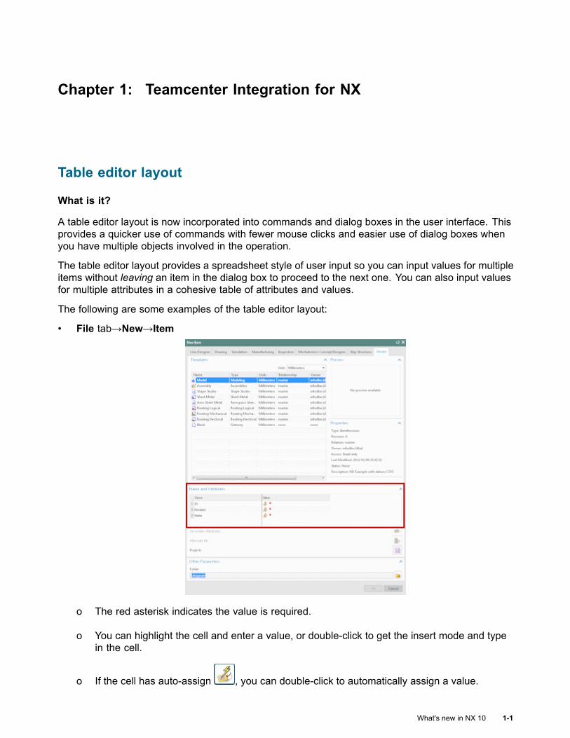
A table editor layout is now incorporated into commands and dialog boxes in the user interface. Thisprovides a quicker use of commands with fewer mouse clicks and easier use of dialog boxes whenyou have multiple objects involved in the operation.
The table editor layout provides a spreadsheet style of user input so you can input values for multipleitems without leaving an item in the dialog box to proceed to the next one. You can also input valuesfor multiple attributes in a cohesive table of attributes and values.
The following are some examples of the table editor layout:
• File tab→New→Item
o The red asterisk indicates the value is required.
o You can highlight the cell and enter a value, or double-click to get the insert mode and typein the cell.
o If the cell has auto-assign , you can double-click to automatically assign a value.
What's new in NX 10 1-1
Chapter 1: Teamcenter Integration for NX
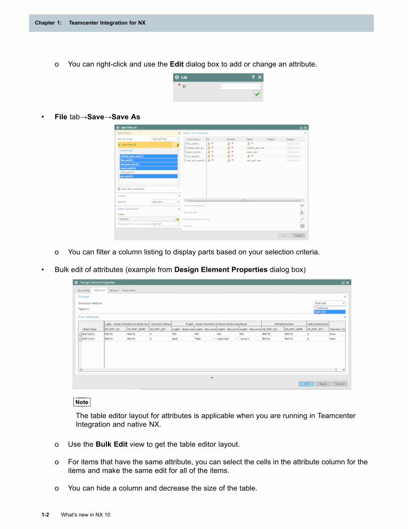
o You can right-click and use the Edit dialog box to add or change an attribute.
• File tab→Save→Save As
o You can filter a column listing to display parts based on your selection criteria.
• Bulk edit of attributes (example from Design Element Properties dialog box)
Note
The table editor layout for attributes is applicable when you are running in TeamcenterIntegration and native NX.
o Use the Bulk Edit view to get the table editor layout.
o For items that have the same attribute, you can select the cells in the attribute column for theitems and make the same edit for all of the items.
o You can hide a column and decrease the size of the table.
1-2 What's new in NX 10
Chapter 1: Teamcenter Integration for NX
Teamcenter Integration for NX
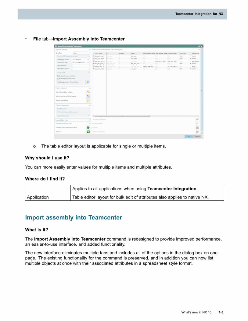
• File tab→Import Assembly into Teamcenter
o The table editor layout is applicable for single or multiple items.
Why should I use it?
You can more easily enter values for multiple items and multiple attributes.
Where do I find it?
Application
Applies to all applications when using Teamcenter Integration.
Table editor layout for bulk edit of attributes also applies to native NX.
Import assembly into Teamcenter
What is it?
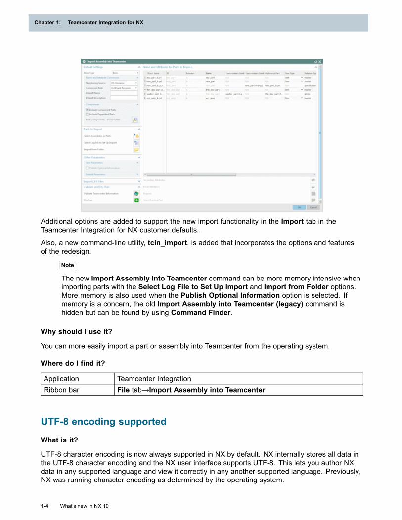
The Import Assembly into Teamcenter command is redesigned to provide improved performance,an easier-to-use interface, and added functionality.
The new interface eliminates multiple tabs and includes all of the options in the dialog box on onepage. The existing functionality for the command is preserved, and in addition you can now listmultiple objects at once with their associated attributes in a spreadsheet style format.
What's new in NX 10 1-3
Teamcenter Integration for NX
Chapter 1: Teamcenter Integration for NX
Additional options are added to support the new import functionality in the Import tab in theTeamcenter Integration for NX customer defaults.
Also, a new command-line utility, tcin_import, is added that incorporates the options and featuresof the redesign.
Note
The new Import Assembly into Teamcenter command can be more memory intensive whenimporting parts with the Select Log File to Set Up Import and Import from Folder options.More memory is also used when the Publish Optional Information option is selected. Ifmemory is a concern, the old Import Assembly into Teamcenter (legacy) command ishidden but can be found by using Command Finder.
Why should I use it?
You can more easily import a part or assembly into Teamcenter from the operating system.
Where do I find it?
Application Teamcenter IntegrationRibbon bar File tab→Import Assembly into Teamcenter
UTF-8 encoding supported
What is it?
UTF-8 character encoding is now always supported in NX by default. NX internally stores all data inthe UTF-8 character encoding and the NX user interface supports UTF-8. This lets you author NXdata in any supported language and view it correctly in any another supported language. Previously,NX was running character encoding as determined by the operating system.
1-4 What's new in NX 10
Chapter 1: Teamcenter Integration for NX
Teamcenter Integration for NX
You can enter data in NX and have it stored in Teamcenter regardless of the language of the characterset that is used, as long as character encoding for the character set is supported by Teamcenter.
The Teamcenter setup may or may not support UFT-8 character encoding, which can cause issues ifNX supports encoding of a character set and Teamcenter does not. In these cases, an error messagenotifies you that the character set is not supported by Teamcenter.
If you are running NX against a Teamcenter database that supports UTF-8 character encoding,all characters that are supported by UTF-8 are valid. If you are running NX against a non-UTF-8Teamcenter database, then validation occurs before NX accepts the characters. At key locationsin NX, user input is immediately evaluated as being valid input for the character encoding that issupported by your Teamcenter installation. At other locations, user input is evaluated when youperform a Save or Save As on the item.
There are many places within NX where data is input, so only the most common or key data inputlocations are immediately evaluated. For example, in the New Item dialog box, the ID, Name, andRevision, boxes are immediately evaluated for language compliance.
Why should I use it?
You can enter data in NX regardless of the language and have it stored correctly in Teamcenter,especially multi-byte characters, provided that Teamcenter supports the character encoding.
Where do I find it?
Application Applies to all applications when using Teamcenter Integration.
Using Teamcenter multifield keys
What is it?
Teamcenter multifield keys are typically used for non-design data such as documents and are rarelyused for the design data itself. When there are many types of documents associated with a design,multifield keys provides a convenient way in Teamcenter to assign the same item ID to all of thevarious documents while using a second field to differentiate between the types of documents. It isthe combination of a Teamcenter’s object item ID and the item type that provides the unique key inTeamcenter for identifying a particular document associated with a design’s item ID. For example,the multifield key can be defined as Item ID, Item Type where the item type could be requirements,certification, data sheet, quality tests, analysis results, and so on.
For design data, each design item typically represents a unique component in the product, which inturn must be uniquely identified in downstream configurations by a single key, such as manufacturingsystems, procurement systems, ERP, and so on. Therefore, using multifield keys for design itemsposes definite risks to end-to-end business processes.
Using the Teamcenter concept of domains, you can have design data exist in a domain where only asingle key (item ID) is used to identify uniqueness. And you can have a second domain for documentdata where a multifield key (item ID, item type) is used to identify uniqueness. By using this method,design data cannot become ambiguous or pose risks to downstream systems, while all documentdata can be managed using the same item ID as the design data to which it is associated.
What's new in NX 10 1-5
Teamcenter Integration for NX
Chapter 1: Teamcenter Integration for NX
Caution
Using multifield keys for design data should be carefully considered prior to actual use withina production environment. Prior to implementing multifield keys you should assess yourbusiness processes and take every step to remove the risk of introducing ambiguity into theway design data is identified and managed.
Work with objects in all Teamcenter MFK domainsWhat is it?
NX utilizes Teamcenter multifield key (MFK) functionality so that you can now view and work withobjects that are in all Teamcenter domains, not just the default domain.
The Teamcenter MFK is a set of key attributes that serve as the unique identifier for an item object.These can include item_id, object_name, supplier_code, and so on. The Teamcenter Part Identifierproperty on an object contains the names and values of all key properties for the MFK. The NXpart attribute DB_PART_MFKID corresponds to the Teamcenter Part Identifier property and isautomatically added to all parts as a hard-coded attribute.
In Teamcenter, you can add customizations which include properties and creation descriptors to theitem type in the BMIDE so that you can further identify and differentiate parts to utilize the MFKfunctionality. These customizations, or key properties, comprise the MFK.
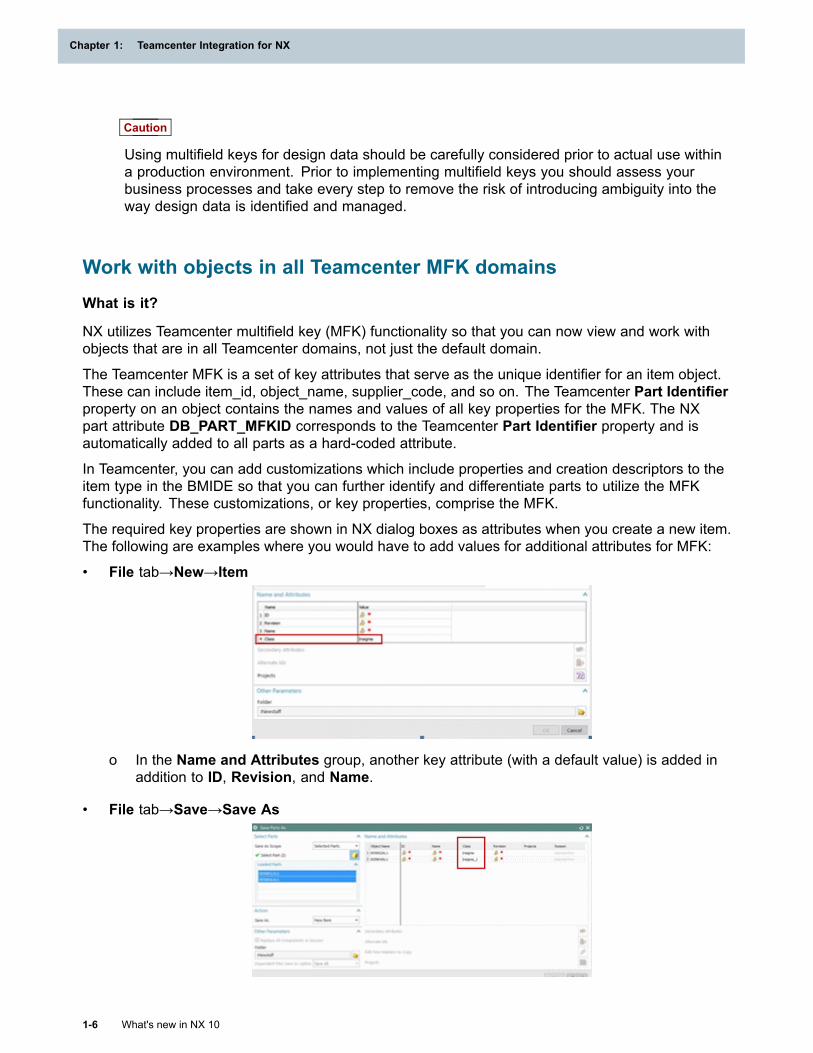
The required key properties are shown in NX dialog boxes as attributes when you create a new item.The following are examples where you would have to add values for additional attributes for MFK:
• File tab→New→Item
o In the Name and Attributes group, another key attribute (with a default value) is added inaddition to ID, Revision, and Name.
• File tab→Save→Save As
1-6 What's new in NX 10
Chapter 1: Teamcenter Integration for NX
Teamcenter Integration for NX
o In the Name and Attributes group, another key attribute column is added in addition to ID,Name, Revision, Projects, and Reason.
Command line programs, such as utilities, are also updated to accept the Teamcenter Part Identifier(contains the MFK) as input.
You can configure NX so that NX data is only in the Teamcenter default domain where all NX itemshave only item_id as the key attribute. In this configuration, NX accepts the item ID as the uniqueidentifier and NX runs as it did prior to NX 10.
Why should I use it?
You can use the Teamcenter MFK functionality to more specifically identify an item with a domainin Teamcenter.
Where do I find it?
Prerequisite Your site is setup to utilize the MFK functionality.
MFK for part families
What is it?
Teamcenter multifield key functionality (MFK) is now supported by NX and the part family functionalityalso supports MFK. Any Teamcenter customization attributes or creation descriptors created forMFK are added in the Part Families dialog box and spreadsheet. This lets you easily find whichattributes are required for part creation.
In the Part Families dialog box, the MFK attributes are added and identified as required for partcreation in the new Category column. As with the existing required attributes, the attributes specificto MFK cannot be deleted, reordered, or copy/pasted.
In the spreadsheet, when you use item names for components and materials, you specifythe attributes of the MFK with a user-friendly format. For example, for an MFK specified as:”%#MFK#%,=mfk9Const=C,item_id=MFKC2–AA00054,object_type=MFK9C2T1”, you enter it as(where Alt+Enter is the keyboard entry):
• mkf9Const=C Alt+Enter
• item_id=MFKC2–AA00054 Alt+Enter
• object_type=MFK9C2T1
In addition, part attributes mapped from Teamcenter can now have both internal names and displaynames. If an attribute has different display and internal names, in the spreadsheet the part familycolumn is changed to show display_name(internal_name). The same combination is also shown forthe attribute in the Available Columns and Chosen Columns list.
Why should I use it?
You can ensure that all part family members have the required MFK attributes.
What's new in NX 10 1-7
Teamcenter Integration for NX
Chapter 1: Teamcenter Integration for NX
Where do I find it?
Application Teamcenter IntegrationDialog box Part Families
Operation descriptors
What is it?
In Teamcenter, you can add operation descriptors to a business object in the BMIDE, such as Item,Item Revision, Item Master Form, and so on, to let you customize the inputs that are collected basedon the operation performed, such as creating a new part or performing a Save As on an existing part.
When you add Teamcenter operation descriptors, these are now reflected in NX where you needto input values for these properties when you are creating an object. Teamcenter can designateoperation descriptors as required or not required, but NX displays only the descriptors that arerequired.
The operation descriptors are shown as additional attributes and are in addition to the typical requiredattributes. For example, when you create a new item, you could have the following required attributes:
ID (typical required attribute)
Revision (typical required attribute)
Name (typical required attribute)
Make or Buy (operation descriptor)
Why should I use it?
You can use operation descriptors to require values for additional attributes for specific NX operations.
Where do I find it?
Prerequisite You must be creating a new object or performing a Save As.
Active Workspace data synchronization
What is it?
Active Workspace is enhanced to support data synchronization between NX and Active Workspacewhen you are using Active Workspace in NX.
Data synchronization ensures that when object level information for a part, assembly, or other item ismodified in NX, Active Workspace is automatically refreshed to show the change and vice versa.For example, if you check out a part in Active Workspace, it is shown as checked out in NX, or ifyou add a component to an assembly in NX, Active Workspace refreshes and the BOM for theassembly is automatically updated.
1-8 What's new in NX 10
Chapter 1: Teamcenter Integration for NX
Teamcenter Integration for NX
Why should I use it?
When you use Active Workspace in NX, you are provided with more up-to-date and accurateinformation.
Where do I find it?
Application Active Workspace in NX
Reconnect to Teamcenter
What is it?
If you lose your connection to Teamcenter, NX automatically reconnects to enable you to continueworking. A disconnection can occur due to an idle session, a timeout policy at your site, a server thatgoes down due to network problems, or other issues.
A message is displayed when you are reconnected. You have the option of continuing the currentsession or exiting the session. If you continue, depending on the last NX command you initiated,the command may have not completed before you were disconnected and you may have to runthat command again.
This functionality is available only when you are running Teamcenter 4–tier deployment architecture.
In addition, depending on the setup at your site, NX may attempt to connect to a new Teamcenterserver, especially if you lost connection due to a network problem.
Why should I use it?
You can automatically reconnect to a Teamcenter server if connection is lost.
Display names
What is it?
The display names (not the internal names) that are defined for properties in Teamcenter are used inNX. The properties are defined in the Teamcenter BMIDE and shown in NX as attributes on dialogboxes. Previously, the attribute names used in NX were determined by the Teamcenter mapping filedefinition.
This provides a consistent naming between properties in Teamcenter and the corresponding attributesin NX. The most noticable attributes affected are ID and Revision for item ID and item revision asthese are used throughout NX. All dialog boxes that contain attributes are affected, such as NewItem, Save Parts As, and Import Assembly into Teamcenter.
In addition, the attribute names in NX are localized if the localization language is supported.
Why should I use it?
You can more easily locate similar attributes in Teamcenter and NX due to the consistent display ofattribute names.
What's new in NX 10 1-9
Teamcenter Integration for NX
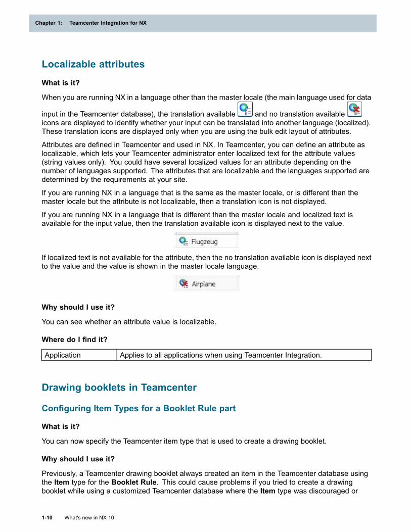
Chapter 1: Teamcenter Integration for NX
Localizable attributes
What is it?
When you are running NX in a language other than the master locale (the main language used for data
input in the Teamcenter database), the translation available and no translation availableicons are displayed to identify whether your input can be translated into another language (localized).These translation icons are displayed only when you are using the bulk edit layout of attributes.
Attributes are defined in Teamcenter and used in NX. In Teamcenter, you can define an attribute aslocalizable, which lets your Teamcenter administrator enter localized text for the attribute values(string values only). You could have several localized values for an attribute depending on thenumber of languages supported. The attributes that are localizable and the languages supported aredetermined by the requirements at your site.
If you are running NX in a language that is the same as the master locale, or is different than themaster locale but the attribute is not localizable, then a translation icon is not displayed.
If you are running NX in a language that is different than the master locale and localized text isavailable for the input value, then the translation available icon is displayed next to the value.
If localized text is not available for the attribute, then the no translation available icon is displayed nextto the value and the value is shown in the master locale language.
Why should I use it?
You can see whether an attribute value is localizable.
Where do I find it?
Application Applies to all applications when using Teamcenter Integration.
Drawing booklets in Teamcenter
Configuring Item Types for a Booklet Rule part
What is it?
You can now specify the Teamcenter item type that is used to create a drawing booklet.
Why should I use it?
Previously, a Teamcenter drawing booklet always created an item in the Teamcenter database usingthe Item type for the Booklet Rule. This could cause problems if you tried to create a drawingbooklet while using a customized Teamcenter database where the Item type was discouraged or
1-10 What's new in NX 10
Chapter 1: Teamcenter Integration for NX
Teamcenter Integration for NX
unavailable. Now that you can specify which item type is used, you can create drawing bookletsthat comply with your database rules.
Where do I find it?
Application DraftingCommand Finder Customer DefaultsLocation in dialogbox
Drafting→Drawing Automation→General tab→Item Typesgroup→Booklet Rule
Configuring revisions for drawing parts in drawing booklets
What is it?
When you edit a drawing booklet, you can now designate the Teamcenter revision for the drawingparts.
If the part used as the basis for the booklet has the part attributeDRAWING_BOOKLET_ITEM_REVISION, its setting is assigned to the following:
• A new booklet and its drawings.
• New drawings that are created when an existing booklet is edited.
If the attribute DRAWING_BOOKLET_ITEM_REVISION is not used:
• Teamcenter revision rules determine the default revision.
• The assigned revision matches the revision number of the drawing booklet.
Where do I find it?
Application Drafting
Menu
Menu→Tools→Drawing Automation→Edit Drawing Booklet
Menu→Tools→Drawing Automation→Create Drawing Booklet
What's new in NX 10 1-11
Teamcenter Integration for NX

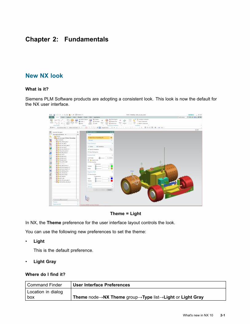
Chapter 2: Fundamentals
New NX look
What is it?
Siemens PLM Software products are adopting a consistent look. This look is now the default forthe NX user interface.
Theme = Light
In NX, the Theme preference for the user interface layout controls the look.
You can use the following new preferences to set the theme:
• Light
This is the default preference.
• Light Gray
Where do I find it?
Command Finder User Interface PreferencesLocation in dialogbox Theme node→NX Theme group→Type list→Light or Light Gray
What's new in NX 10 2-1
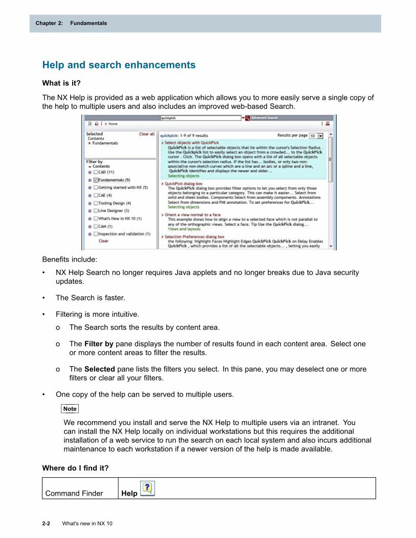
Chapter 2: Fundamentals
Help and search enhancementsWhat is it?
The NX Help is provided as a web application which allows you to more easily serve a single copy ofthe help to multiple users and also includes an improved web-based Search.
Benefits include:
• NX Help Search no longer requires Java applets and no longer breaks due to Java securityupdates.
• The Search is faster.
• Filtering is more intuitive.
o The Search sorts the results by content area.
o The Filter by pane displays the number of results found in each content area. Select oneor more content areas to filter the results.
o The Selected pane lists the filters you select. In this pane, you may deselect one or morefilters or clear all your filters.
• One copy of the help can be served to multiple users.
Note
We recommend you install and serve the NX Help to multiple users via an intranet. Youcan install the NX Help locally on individual workstations but this requires the additionalinstallation of a web service to run the search on each local system and also incurs additionalmaintenance to each workstation if a newer version of the help is made available.
Where do I find it?
Command Finder Help
2-2 What's new in NX 10
Chapter 2: Fundamentals
Fundamentals
Resource bar enhancements
What is it?
You can now use the Resource Bar Options menu to control the location, display behavior, and
content of the Resource bar. NX displays the Resource Bar Options menu on the top left cornerof the Resource bar with the following options.
Pin Open Turns on or off the auto-hide behavior of the navigators or palettes. This option
replaces the and buttons in pre-NX 10 versions.
Maximize tab Maximizes or restores the selected navigator or palette. The maximizednavigator or palette covers the graphics window.
Left Positions the Resource bar to the left of the graphics window.
Right Positions the Resource bar to the right of the graphics window.
Overlap on SecondMonitor
Positions the Resource bar on a second monitor at the edge nearest the NXwindow. If you maximize an application on the second monitor, the Resourcebar is overlapped.
Dock on SecondMonitor
Docks the Resource bar on a second monitor in a reserved space at the edgenearest the NX window. Applications that you maximize on the second monitorwill not overlap the Resource bar.
Tabs Lets you hide or display the selected tab.
Tip
To hide a tab or undock a navigator or palette, right-click the tab and choose the option youwant. To show a hidden tab, right-click in an empty space on the Resource bar, and selectthe tab.
Customize line widthsYou can customize the line widths in NX using customer defaults and user preferences.
You can:
• Specify labels for each line width in NX.
• Set the pixel width to display the corresponding new line width in NX. You can also set multiplelines with the same pixel width.
• Map the legacy line widths such as Thin, Normal, and Thick to the current line widths in NX.
• Set the scale factor for the line widths for printing.
• Define labels and pixel widths for the line for plotting and for PDF export.
What's new in NX 10 2-3
Fundamentals
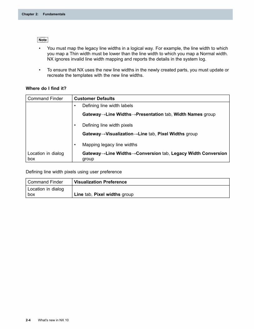
Chapter 2: Fundamentals
Note
• You must map the legacy line widths in a logical way. For example, the line width to whichyou map a Thin width must be lower than the line width to which you map a Normal width.NX ignores invalid line width mapping and reports the details in the system log.
• To ensure that NX uses the new line widths in the newly created parts, you must update orrecreate the templates with the new line widths.
Where do I find it?
Command Finder Customer Defaults
Location in dialogbox
• Defining line width labels
Gateway→Line Widths→Presentation tab, Width Names group
• Defining line width pixels
Gateway→Visualization→Line tab, Pixel Widths group
• Mapping legacy line widths
Gateway→Line Widths→Conversion tab, Legacy Width Conversiongroup
Defining line width pixels using user preference
Command Finder Visualization PreferenceLocation in dialogbox Line tab, Pixel widths group
2-4 What's new in NX 10
Chapter 2: Fundamentals
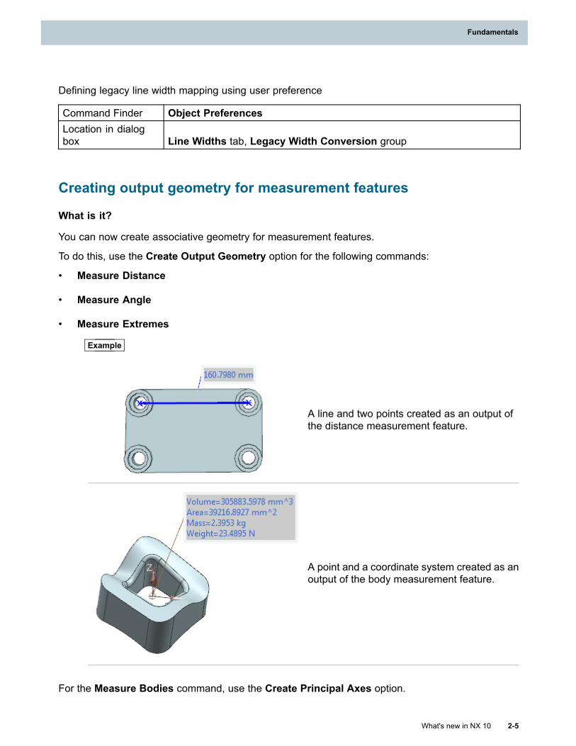
Fundamentals
Defining legacy line width mapping using user preference
Command Finder Object PreferencesLocation in dialogbox Line Widths tab, Legacy Width Conversion group
Creating output geometry for measurement features
What is it?
You can now create associative geometry for measurement features.
To do this, use the Create Output Geometry option for the following commands:
• Measure Distance
• Measure Angle
• Measure Extremes
Example
A line and two points created as an output ofthe distance measurement feature.
A point and a coordinate system created as anoutput of the body measurement feature.
For the Measure Bodies command, use the Create Principal Axes option.
What's new in NX 10 2-5
Fundamentals

Chapter 2: Fundamentals
Why should I use it?
Use the associative geometry to:
• Get visual feedback for the measurement features.
• Make associative references to the output geometry.
2-6 What's new in NX 10
Chapter 2: Fundamentals
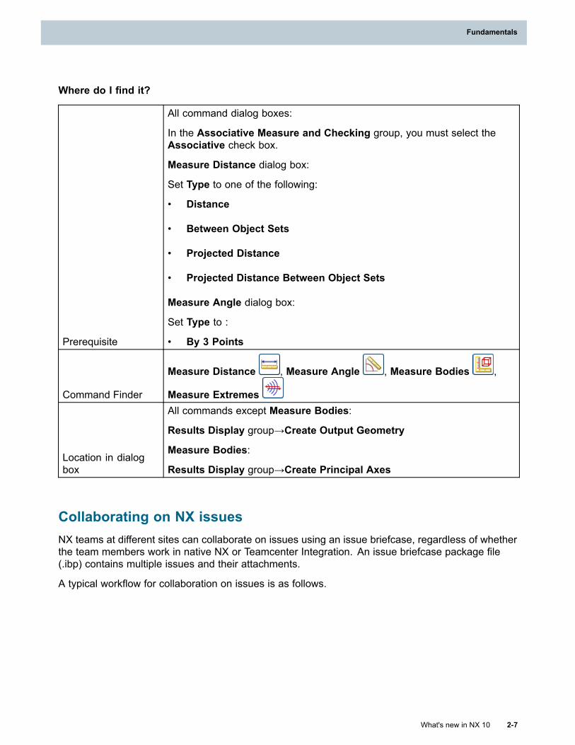
Fundamentals
Where do I find it?
Prerequisite
All command dialog boxes:
In the Associative Measure and Checking group, you must select theAssociative check box.
Measure Distance dialog box:
Set Type to one of the following:
• Distance
• Between Object Sets
• Projected Distance
• Projected Distance Between Object Sets
Measure Angle dialog box:
Set Type to :
• By 3 Points
Command Finder
Measure Distance , Measure Angle , Measure Bodies ,
Measure Extremes
Location in dialogbox
All commands except Measure Bodies:
Results Display group→Create Output Geometry
Measure Bodies:
Results Display group→Create Principal Axes
Collaborating on NX issuesNX teams at different sites can collaborate on issues using an issue briefcase, regardless of whetherthe team members work in native NX or Teamcenter Integration. An issue briefcase package file(.ibp) contains multiple issues and their attachments.
A typical workflow for collaboration on issues is as follows.
What's new in NX 10 2-7
Fundamentals
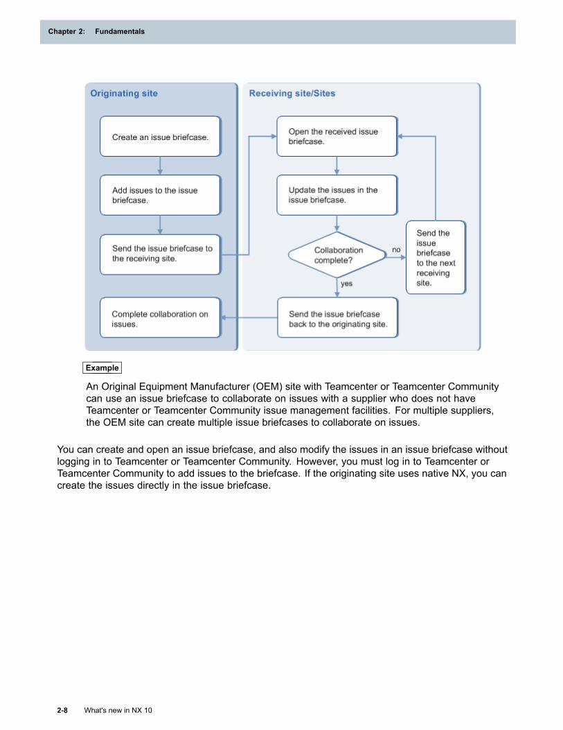
Chapter 2: Fundamentals
Example
An Original Equipment Manufacturer (OEM) site with Teamcenter or Teamcenter Communitycan use an issue briefcase to collaborate on issues with a supplier who does not haveTeamcenter or Teamcenter Community issue management facilities. For multiple suppliers,the OEM site can create multiple issue briefcases to collaborate on issues.
You can create and open an issue briefcase, and also modify the issues in an issue briefcase withoutlogging in to Teamcenter or Teamcenter Community. However, you must log in to Teamcenter orTeamcenter Community to add issues to the briefcase. If the originating site uses native NX, you cancreate the issues directly in the issue briefcase.
2-8 What's new in NX 10
Chapter 2: Fundamentals
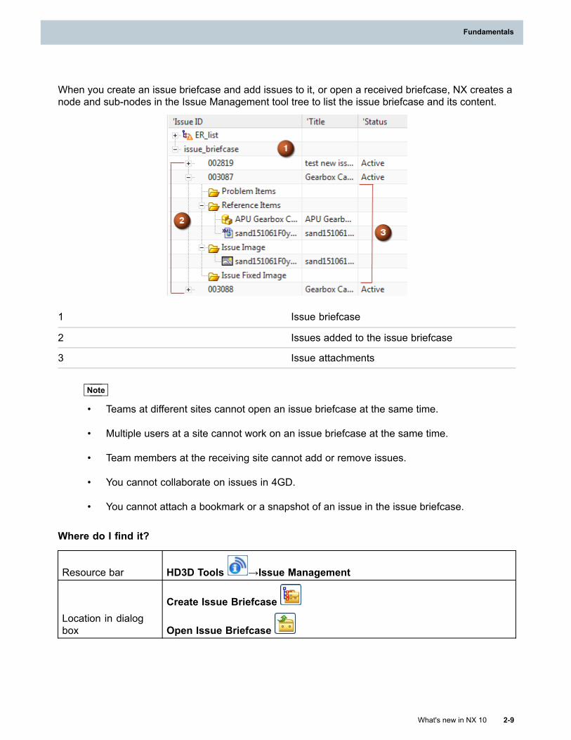
Fundamentals
When you create an issue briefcase and add issues to it, or open a received briefcase, NX creates anode and sub-nodes in the Issue Management tool tree to list the issue briefcase and its content.
1 Issue briefcase
2 Issues added to the issue briefcase
3 Issue attachments
Note
• Teams at different sites cannot open an issue briefcase at the same time.
• Multiple users at a site cannot work on an issue briefcase at the same time.
• Team members at the receiving site cannot add or remove issues.
• You cannot collaborate on issues in 4GD.
• You cannot attach a bookmark or a snapshot of an issue in the issue briefcase.
Where do I find it?
Resource bar HD3D Tools →Issue Management
Location in dialogbox
Create Issue Briefcase
Open Issue Briefcase
What's new in NX 10 2-9
Fundamentals
Chapter 2: Fundamentals
Hosting custom windows in NX
What is it?
You can now create custom Resource bar tabs to host your own windows. Use the following new NXOpen APIs, which are in the ResourceBarManager class, to define and control the window.
CreateCreates a tab, which is added to the Resource bar when you set the visibility.
RegisterActivationCallbackActivates and displays the custom window when you click the tab.
ActivateTabActivates and displays the custom window immediately; you do not need to click the tab.
GetWindowHandleCreates an NX docking window, which is used as the parent to host your custom window.
SetTabAvailabilityControls the visibility of the tab in the Resource bar area.
DestroyRemoves your custom window and tab from NX.
You can specify a title and bitmap for your custom tab. Your custom window has standard Resourcebar capabilities, such as the ability to dock and undock the window.
Note
The application that is being hosted controls the behavior inside the host window.
Why should I use it?
Use the APIs to seamlessly integrate third-party applications and dialog boxes into NX. For example,if you have your own add-in application or navigator that you use in conjunction with NX, youno longer need a separate window.
Where do I find it?
The new NX Open APIs are in the new ResourceBarManager class.
Zoom operation enhancements
What is it?
The default direction in which to scroll the mouse wheel to zoom in and zoom out, is changed.
• To zoom in, scroll forward.
You can also hold the left and middle mouse buttons or hold Ctrl and the middle mouse buttonand move the mouse forward to zoom in.
2-10 What's new in NX 10
Chapter 2: Fundamentals
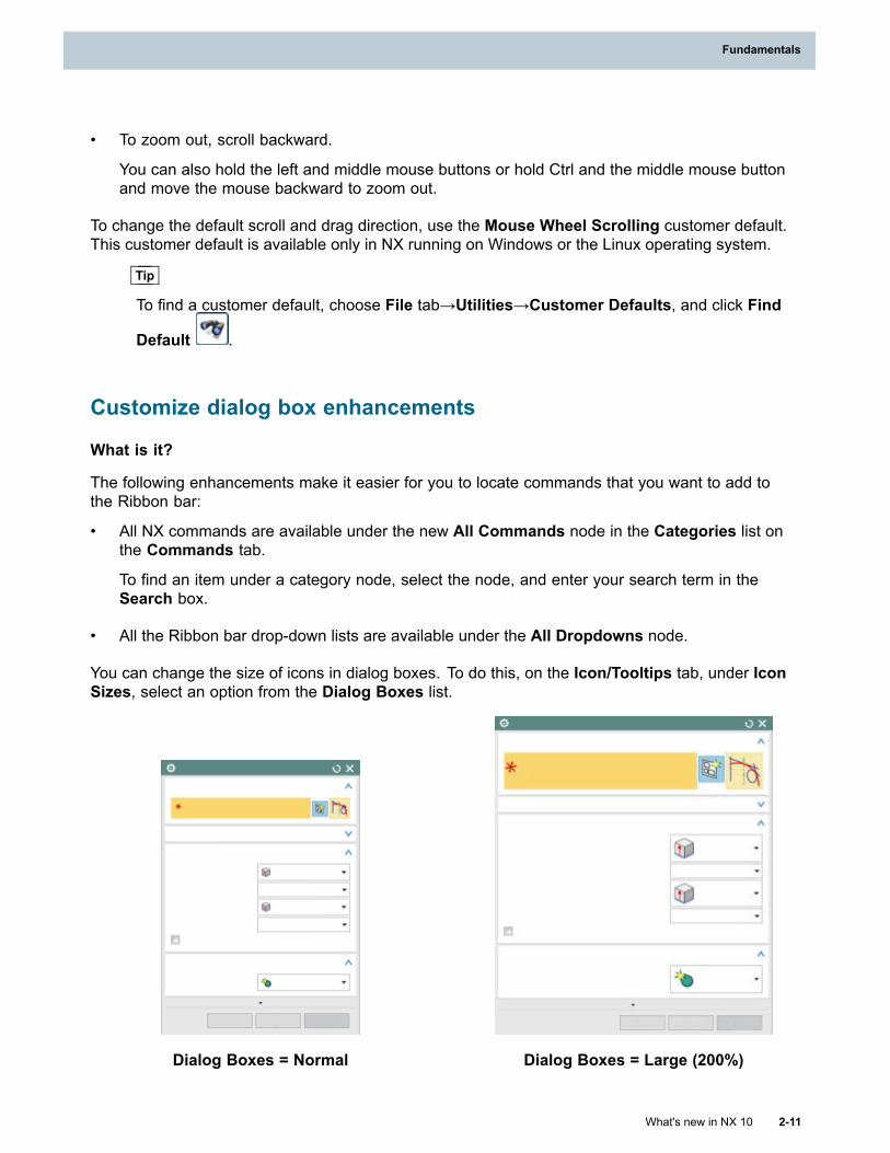
Fundamentals
• To zoom out, scroll backward.
You can also hold the left and middle mouse buttons or hold Ctrl and the middle mouse buttonand move the mouse backward to zoom out.
To change the default scroll and drag direction, use the Mouse Wheel Scrolling customer default.This customer default is available only in NX running on Windows or the Linux operating system.
Tip
To find a customer default, choose File tab→Utilities→Customer Defaults, and click Find
Default .
Customize dialog box enhancements
What is it?
The following enhancements make it easier for you to locate commands that you want to add tothe Ribbon bar:
• All NX commands are available under the new All Commands node in the Categories list onthe Commands tab.
To find an item under a category node, select the node, and enter your search term in theSearch box.
• All the Ribbon bar drop-down lists are available under the All Dropdowns node.
You can change the size of icons in dialog boxes. To do this, on the Icon/Tooltips tab, under IconSizes, select an option from the Dialog Boxes list.
Dialog Boxes = Normal Dialog Boxes = Large (200%)
What's new in NX 10 2-11
Fundamentals
Chapter 2: Fundamentals
Usability enhancements include the following:
• The Layout and Roles tabs are removed. These options are now available in the User InterfacePreferences dialog box.
• The Options tab is now called Icon/Tooltips.
• The new Tabs/Bars tab lists all the tabs and bars in the NX interface. To show or hide a tab or abar, select or clear the check box next to its name in the list.
2-12 What's new in NX 10
Chapter 2: Fundamentals
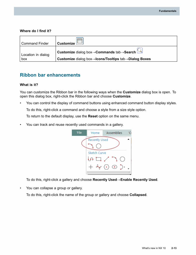
Fundamentals
Where do I find it?
Command Finder Customize
Location in dialogbox
Customize dialog box→Commands tab→Search
Customize dialog box→Icons/Tooltips tab→Dialog Boxes
Ribbon bar enhancements
What is it?
You can customize the Ribbon bar in the following ways when the Customize dialog box is open. Toopen this dialog box, right-click the Ribbon bar and choose Customize.
• You can control the display of command buttons using enhanced command button display styles.
To do this, right-click a command and choose a style from a size style option.
To return to the default display, use the Reset option on the same menu.
• You can track and reuse recently used commands in a gallery.
To do this, right-click a gallery and choose Recently Used→Enable Recently Used.
• You can collapse a group or gallery.
To do this, right-click the name of the group or gallery and choose Collapsed.
What's new in NX 10 2-13
Fundamentals
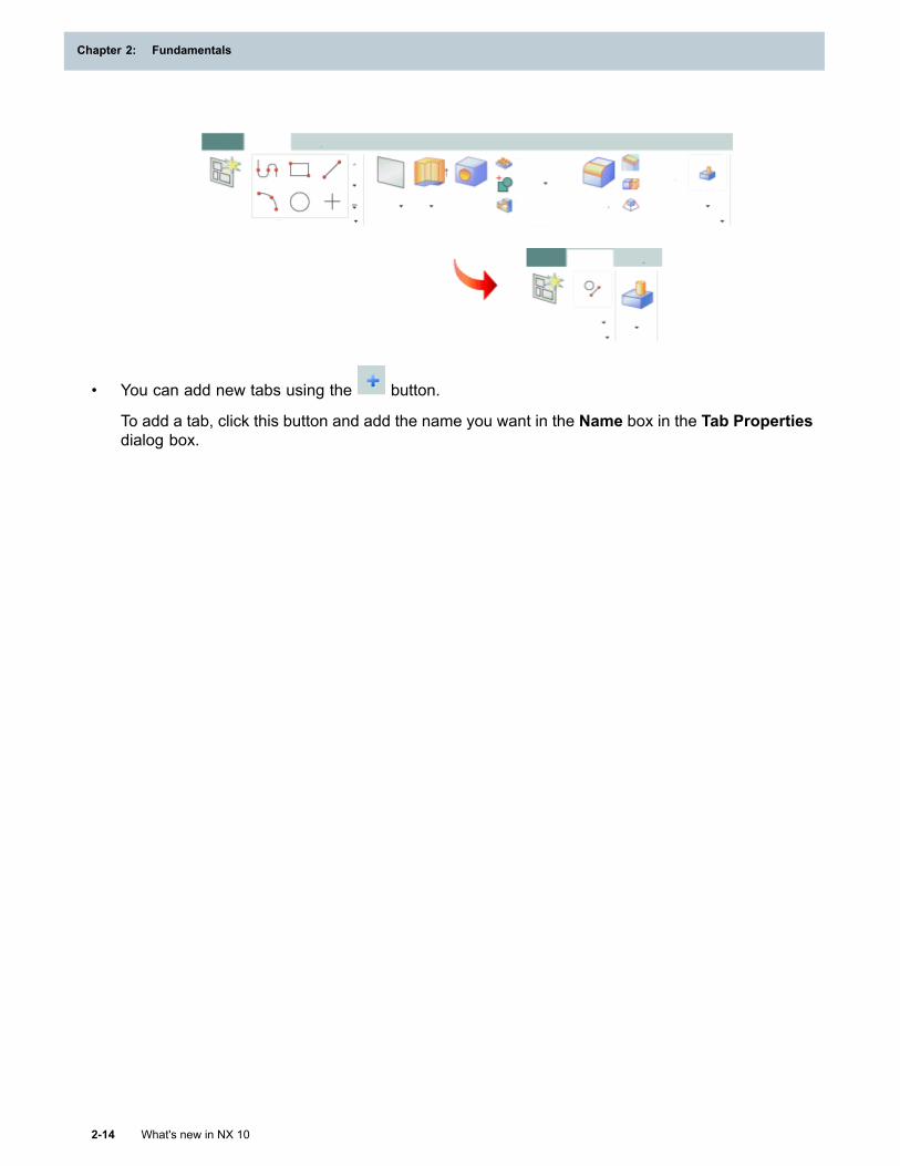
Chapter 2: Fundamentals
• You can add new tabs using the button.
To add a tab, click this button and add the name you want in the Name box in the Tab Propertiesdialog box.
2-14 What's new in NX 10
Chapter 2: Fundamentals
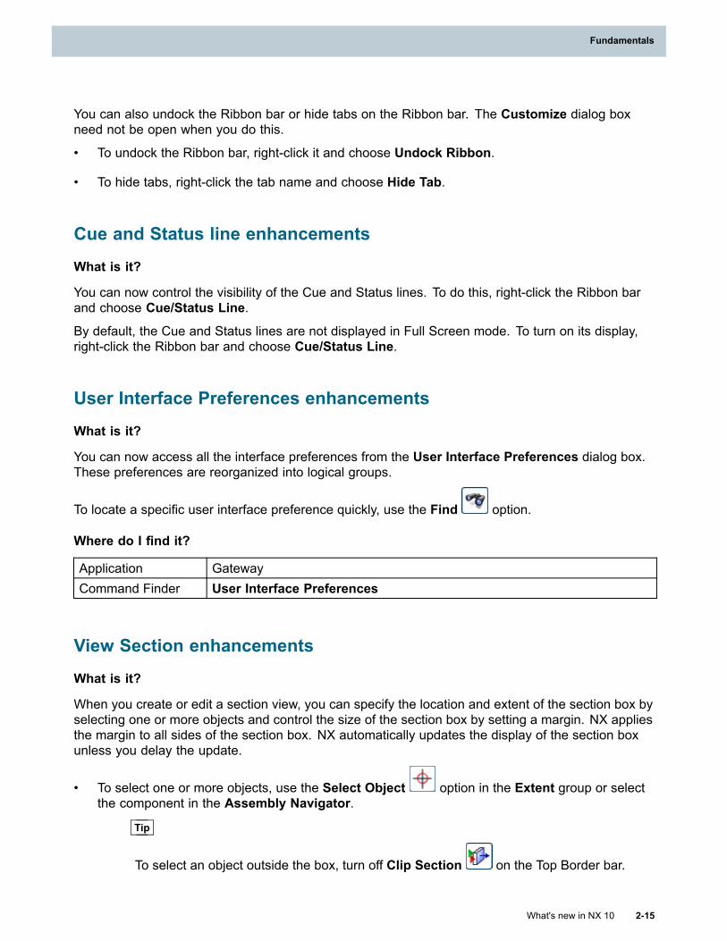
Fundamentals
You can also undock the Ribbon bar or hide tabs on the Ribbon bar. The Customize dialog boxneed not be open when you do this.
• To undock the Ribbon bar, right-click it and choose Undock Ribbon.
• To hide tabs, right-click the tab name and choose Hide Tab.
Cue and Status line enhancements
What is it?
You can now control the visibility of the Cue and Status lines. To do this, right-click the Ribbon barand choose Cue/Status Line.
By default, the Cue and Status lines are not displayed in Full Screen mode. To turn on its display,right-click the Ribbon bar and choose Cue/Status Line.
User Interface Preferences enhancements
What is it?
You can now access all the interface preferences from the User Interface Preferences dialog box.These preferences are reorganized into logical groups.
To locate a specific user interface preference quickly, use the Find option.
Where do I find it?
Application GatewayCommand Finder User Interface Preferences
View Section enhancements
What is it?
When you create or edit a section view, you can specify the location and extent of the section box byselecting one or more objects and control the size of the section box by setting a margin. NX appliesthe margin to all sides of the section box. NX automatically updates the display of the section boxunless you delay the update.
• To select one or more objects, use the Select Object option in the Extent group or selectthe component in the Assembly Navigator.
Tip
To select an object outside the box, turn off Clip Section on the Top Border bar.
What's new in NX 10 2-15
Fundamentals
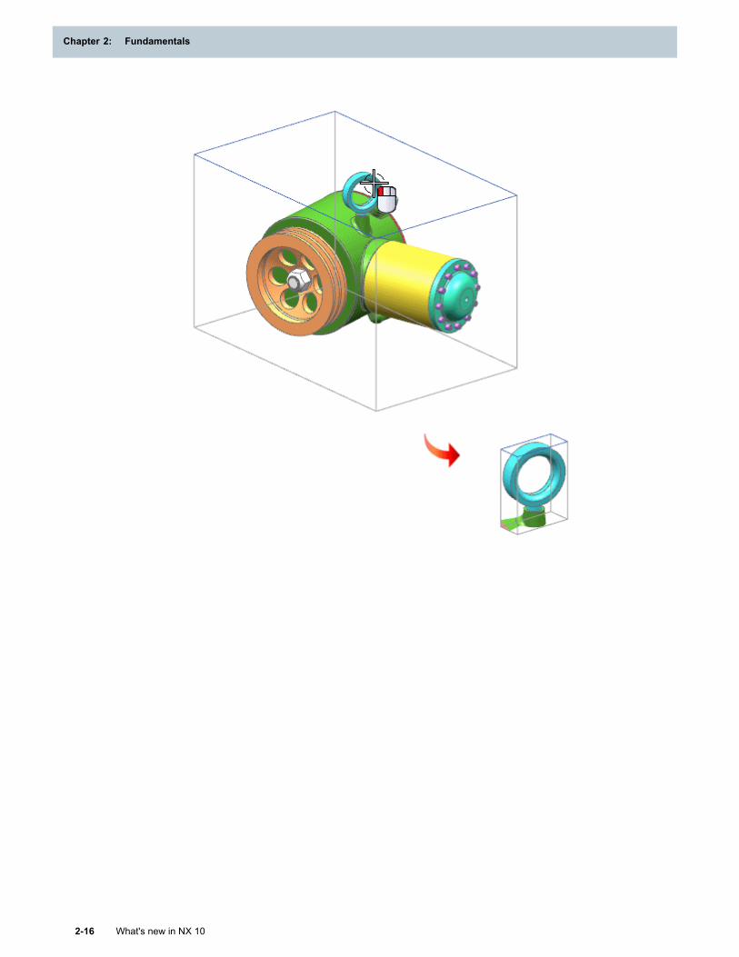
Chapter 2: Fundamentals
2-16 What's new in NX 10
Chapter 2: Fundamentals
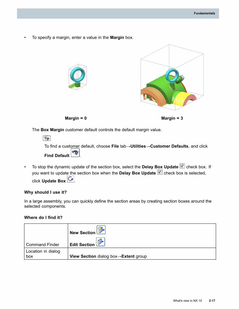
Fundamentals
• To specify a margin, enter a value in the Margin box.
Margin = 0 Margin = 3
The Box Margin customer default controls the default margin value.
Tip
To find a customer default, choose File tab→Utilities→Customer Defaults, and click
Find Default .
• To stop the dynamic update of the section box, select the Delay Box Update check box. Ifyou want to update the section box when the Delay Box Update check box is selected,
click Update Box .
Why should I use it?
In a large assembly, you can quickly define the section areas by creating section boxes around theselected components.
Where do I find it?
Command Finder
New Section
Edit SectionLocation in dialogbox View Section dialog box→Extent group
What's new in NX 10 2-17
Fundamentals
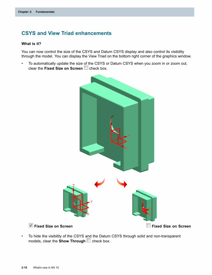
Chapter 2: Fundamentals
CSYS and View Triad enhancements
What is it?
You can now control the size of the CSYS and Datum CSYS display and also control its visibilitythrough the model. You can display the View Triad on the bottom right corner of the graphics window.
• To automatically update the size of the CSYS or Datum CSYS when you zoom in or zoom out,clear the Fixed Size on Screen check box.
Fixed Size on Screen Fixed Size on Screen
• To hide the visibility of the CSYS and the Datum CSYS through solid and non-transparentmodels, clear the Show Through check box.
2-18 What's new in NX 10
Chapter 2: Fundamentals
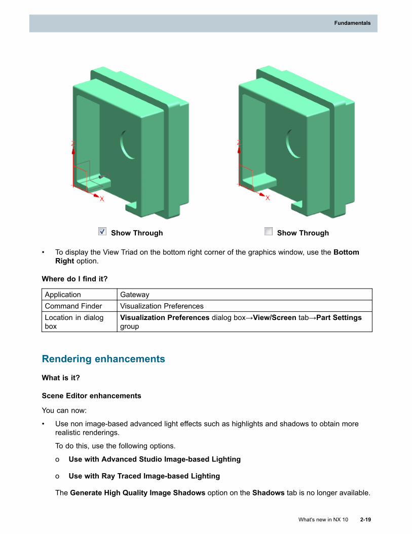
Fundamentals
Show Through Show Through
• To display the View Triad on the bottom right corner of the graphics window, use the BottomRight option.
Where do I find it?
Application GatewayCommand Finder Visualization PreferencesLocation in dialogbox
Visualization Preferences dialog box→View/Screen tab→Part Settingsgroup
Rendering enhancements
What is it?
Scene Editor enhancements
You can now:
• Use non image-based advanced light effects such as highlights and shadows to obtain morerealistic renderings.
To do this, use the following options.
o Use with Advanced Studio Image-based Lighting
o Use with Ray Traced Image-based Lighting
The Generate High Quality Image Shadows option on the Shadows tab is no longer available.
What's new in NX 10 2-19
Fundamentals
Chapter 2: Fundamentals
• Align the direction of the environment image with the floor plane direction.
To do this, set the following.
o Up Vector = Align with Floor Plane
• Use the same stage settings such as size, offset, and floor plane for different system scenes.
NX retains the stage settings when you change the system scene.
System Scenes and System Materials enhancements
You can now use various industry specific visualization system scenes and system materials. Thesystem scenes are organized under the new Indoor, Outdoor, and Studio categories.
English and Metric materials are no longer available.
Studio Task enhancements
You can now access the following commonly used commands using the Studio Task shortcut menu.
• Select All Objects with this Material
• Edit Material
• Remove Material Assignment
• Apply Selected Material
• Inherit Material
Where do I find it?
Scene Editor
Command Finder Scene Editor
Location in dialogbox
Lights tab→Use with Advanced Studio Image-based Lighting and Usewith Ray Traced Image-based Lighting
Global Illumination tab→Up Vector list→Align with Floor Plane
System Scenes and System Materials
Resource bar System Scenes tab, System Materials tab
Command Finder System Scenes , System Materials
Studio Task
Command Finder Studio Task
2-20 What's new in NX 10
Chapter 2: Fundamentals
Fundamentals
Graphics window Right-click the object→[command]
Displaying facets
What is it?
You can now:
• Control the amount of memory that NX uses for the display facet cache.
To do this, use the Facet Cache Memory option. You can set the default value using the FacetCache Memory Level customer default.
• Save display facets for advanced visualization views of solid bodies in the part file.
To do this, use the Save Advanced Display Facets option. You can set the default value usingthe Save Advanced Display Facets customer default.
Tip
To find a customer default, choose File tab→Utilities→Customer Defaults, and click Find
Default .
Why should I use it?
Use these settings for faster rendering of solid bodies.
Where do I find it?
Command Finder Visualization Performance Preferences
Location in dialogbox
General Graphics tab:
Session Settings group→Shaded Views sub group →Facet CacheMemory
Part Settings group→Save Advanced Display Facets
Roles enhancements
What is it?
The icon for the Roles tab has changed from to .
The System Defaults category is now called Content. The icons for the roles are updated. Anew Layout role in this category replaces the Power Drafting Essentials and Power DraftingAdvanced roles. The Layout role provides a wider set of commands required for 2D conceptualdesign in the Drafting application.
What's new in NX 10 2-21
Fundamentals
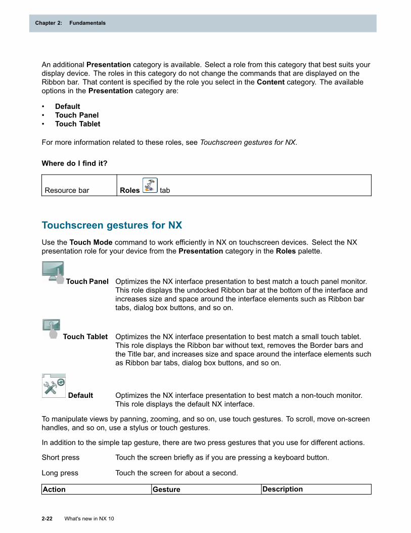
Chapter 2: Fundamentals
An additional Presentation category is available. Select a role from this category that best suits yourdisplay device. The roles in this category do not change the commands that are displayed on theRibbon bar. That content is specified by the role you select in the Content category. The availableoptions in the Presentation category are:
• Default• Touch Panel• Touch Tablet
For more information related to these roles, see Touchscreen gestures for NX.
Where do I find it?
Resource bar Roles tab
Touchscreen gestures for NXUse the Touch Mode command to work efficiently in NX on touchscreen devices. Select the NXpresentation role for your device from the Presentation category in the Roles palette.
Touch Panel Optimizes the NX interface presentation to best match a touch panel monitor.This role displays the undocked Ribbon bar at the bottom of the interface andincreases size and space around the interface elements such as Ribbon bartabs, dialog box buttons, and so on.
Touch Tablet Optimizes the NX interface presentation to best match a small touch tablet.This role displays the Ribbon bar without text, removes the Border bars andthe Title bar, and increases size and space around the interface elements suchas Ribbon bar tabs, dialog box buttons, and so on.
Default Optimizes the NX interface presentation to best match a non-touch monitor.This role displays the default NX interface.
To manipulate views by panning, zooming, and so on, use touch gestures. To scroll, move on-screenhandles, and so on, use a stylus or touch gestures.
In addition to the simple tap gesture, there are two press gestures that you use for different actions.
Short press Touch the screen briefly as if you are pressing a keyboard button.
Long press Touch the screen for about a second.
Action Gesture Description
2-22 What's new in NX 10
Chapter 2: Fundamentals
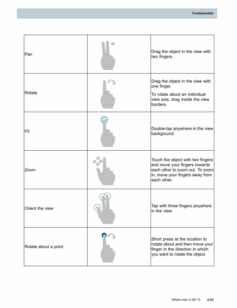
Fundamentals
Pan Drag the object in the view withtwo fingers.
Rotate
Drag the object in the view withone finger.
To rotate about an individualview axis, drag inside the viewborders.
Fit Double-tap anywhere in the viewbackground.
Zoom
Touch the object with two fingersand move your fingers towardseach other to zoom out. To zoomin, move your fingers away fromeach other.
Orient the view Tap with three fingers anywherein the view.
Rotate about a point
Short press at the location torotate about and then move yourfinger in the direction in whichyou want to rotate the object.
What's new in NX 10 2-23
Fundamentals
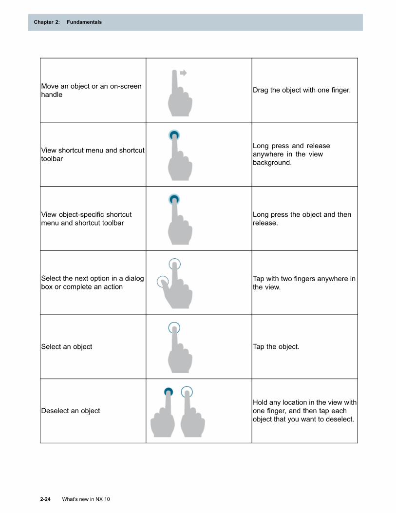
Chapter 2: Fundamentals
Move an object or an on-screenhandle Drag the object with one finger.
View shortcut menu and shortcuttoolbar
Long press and releaseanywhere in the viewbackground.
View object-specific shortcutmenu and shortcut toolbar
Long press the object and thenrelease.
Select the next option in a dialogbox or complete an action
Tap with two fingers anywhere inthe view.
Select an object Tap the object.
Deselect an objectHold any location in the view withone finger, and then tap eachobject that you want to deselect.
2-24 What's new in NX 10
Chapter 2: Fundamentals
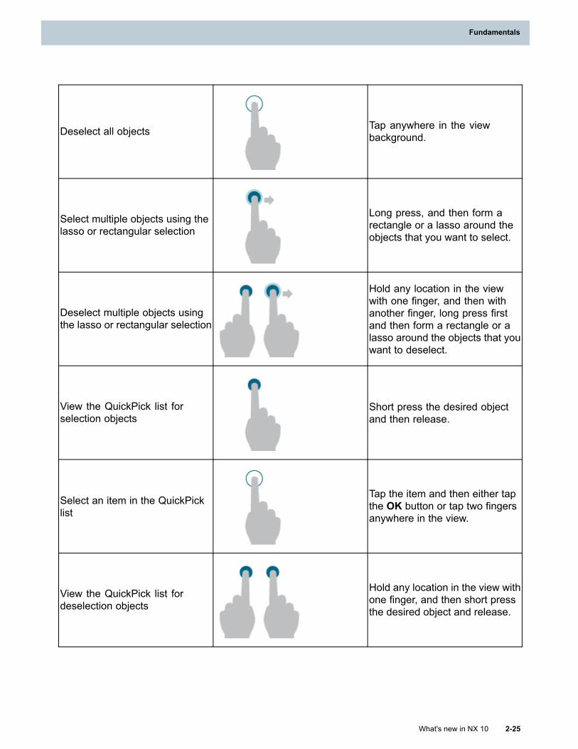
Fundamentals
Deselect all objects Tap anywhere in the viewbackground.
Select multiple objects using thelasso or rectangular selection
Long press, and then form arectangle or a lasso around theobjects that you want to select.
Deselect multiple objects usingthe lasso or rectangular selection
Hold any location in the viewwith one finger, and then withanother finger, long press firstand then form a rectangle or alasso around the objects that youwant to deselect.
View the QuickPick list forselection objects
Short press the desired objectand then release.
Select an item in the QuickPicklist
Tap the item and then either tapthe OK button or tap two fingersanywhere in the view.
View the QuickPick list fordeselection objects
Hold any location in the view withone finger, and then short pressthe desired object and release.
What's new in NX 10 2-25
Fundamentals
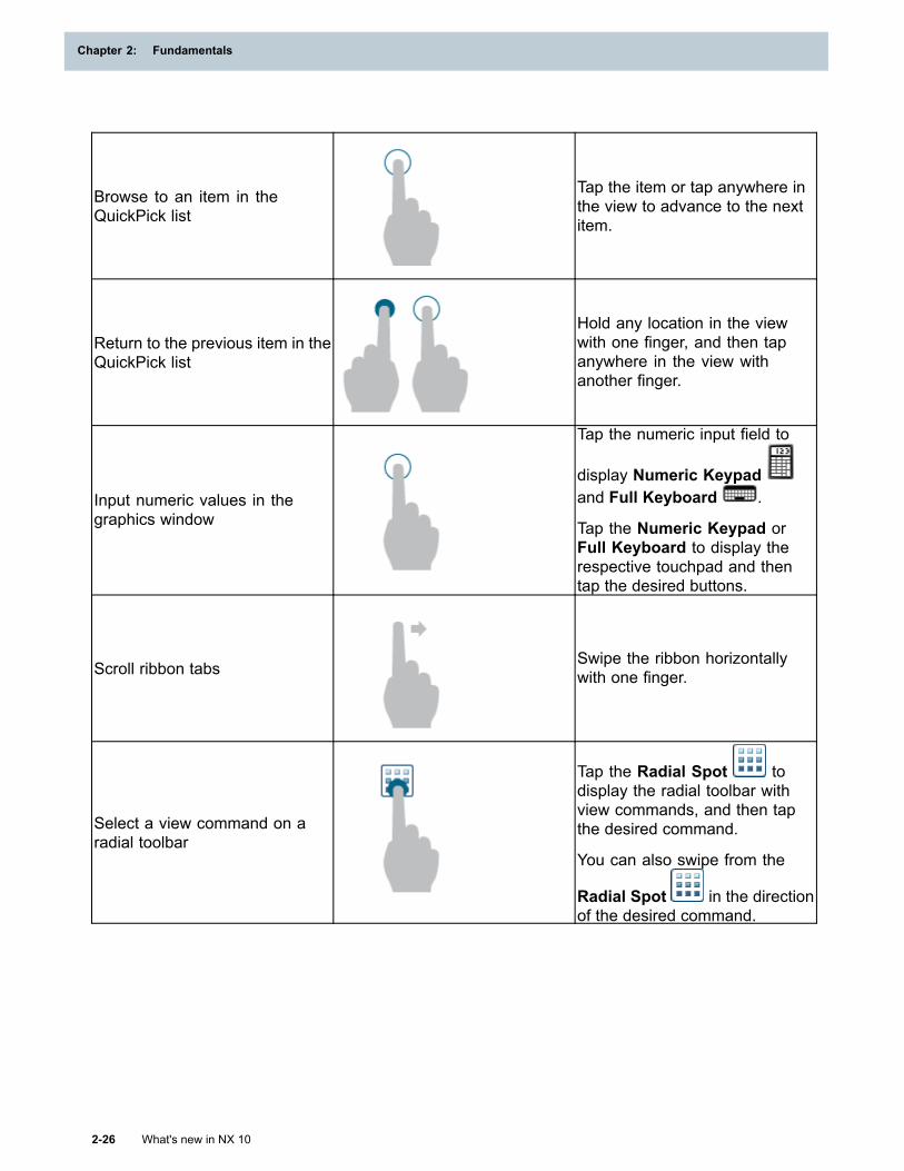
Chapter 2: Fundamentals
Browse to an item in theQuickPick list
Tap the item or tap anywhere inthe view to advance to the nextitem.
Return to the previous item in theQuickPick list
Hold any location in the viewwith one finger, and then tapanywhere in the view withanother finger.
Input numeric values in thegraphics window
Tap the numeric input field to
display Numeric Keypadand Full Keyboard .
Tap the Numeric Keypad orFull Keyboard to display therespective touchpad and thentap the desired buttons.
Scroll ribbon tabs Swipe the ribbon horizontallywith one finger.
Select a view command on aradial toolbar
Tap the Radial Spot todisplay the radial toolbar withview commands, and then tapthe desired command.
You can also swipe from the
Radial Spot in the directionof the desired command.
2-26 What's new in NX 10
Chapter 2: Fundamentals
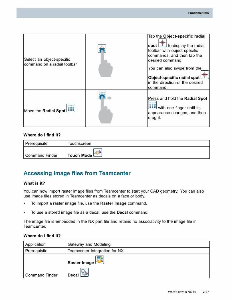
Fundamentals
Select an object-specificcommand on a radial toolbar
Tap the Object-specific radial
spot to display the radialtoolbar with object specificcommands, and then tap thedesired command.
You can also swipe from the
Object-specific radial spotin the direction of the desiredcommand.
Move the Radial Spot
Press and hold the Radial Spot
with one finger until itsappearance changes, and thendrag it.
Where do I find it?
Prerequisite Touchscreen
Command Finder Touch Mode
Accessing image files from TeamcenterWhat is it?
You can now import raster image files from Teamcenter to start your CAD geometry. You can alsouse image files stored in Teamcenter as decals on a face or body.
• To import a raster image file, use the Raster Image command.
• To use a stored image file as a decal, use the Decal command.
The image file is embedded in the NX part file and retains no associativity to the image file inTeamcenter.
Where do I find it?
Application Gateway and ModelingPrerequisite Teamcenter Integration for NX
Command Finder
Raster Image
Decal
What's new in NX 10 2-27
Fundamentals
Chapter 2: Fundamentals
Saving display settings in a bookmark for the displayed partWhat is it?
Bookmarks are enhanced in the following ways.
• Bookmarks are now available in an HD3D tool.
• Bookmarks now capture many display settings of the current displayed part.
Applying a bookmark does not change the current application. For example, suppose you createa bookmark in the Modeling application and then switch to the Drafting application. If you openyour bookmark, NX returns to the display state and displayed part captured by the bookmark butremains in the Drafting application.
Why should I use it?
Use bookmarks to quickly return to previous displayed states. For example, as you analyze yourmodel, you can create a bookmark whenever you find a problem. Later, when you discuss yourresults with others, you can open each bookmark to show the problems that you found.
Where do I find it?
Resource Bar HD3D Tools→Bookmarks
System attributes in NXNX now provides system attributes related to material and mass properties and their templates.
You can use the customer defaults categorized under Gateway→Materials/Mass→Attributes tab tolet NX set the system attributes. You can also set the title aliases such that they appear in the dialogboxes with the titles set in the previous releases. NX uses the same default strings for the title aliasesas the pre-NX 10 default strings for the titles.
Tip
To find a customer default, choose File tab→Utilities→Customer Defaults, and click Find
Default .
NX 10 title for system attributes NX 10 default for title aliases (pre-NX 10 default title)NX_Density MassPropDensityNX_Mass MassPropMassNX_Weight MassPropWeightNX_Volume MassPropVolumeNX_Area MassPropAreaNX_Material MaterialNX_ObjectMaterial ObjectMaterialNX_MaterialMultipleAssigned MaterialMultipleAssignedNX_MaterialMissingAssignments MaterialMissingAssignments
2-28 What's new in NX 10
Chapter 2: Fundamentals
Fundamentals
NX_MaterialPreferred MaterialPreferred
Note
As system attributes may affect applications that use existing titles, you can use NX Open APIto set the system attributes using the aliases set in the customer default.
What's new in NX 10 2-29
Fundamentals

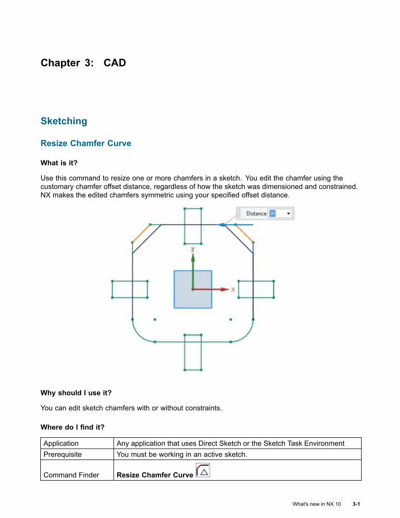
Chapter 3: CAD
Sketching
Resize Chamfer Curve
What is it?
Use this command to resize one or more chamfers in a sketch. You edit the chamfer using thecustomary chamfer offset distance, regardless of how the sketch was dimensioned and constrained.NX makes the edited chamfers symmetric using your specified offset distance.
Why should I use it?
You can edit sketch chamfers with or without constraints.
Where do I find it?
Application Any application that uses Direct Sketch or the Sketch Task EnvironmentPrerequisite You must be working in an active sketch.
Command Finder Resize Chamfer Curve
What's new in NX 10 3-1
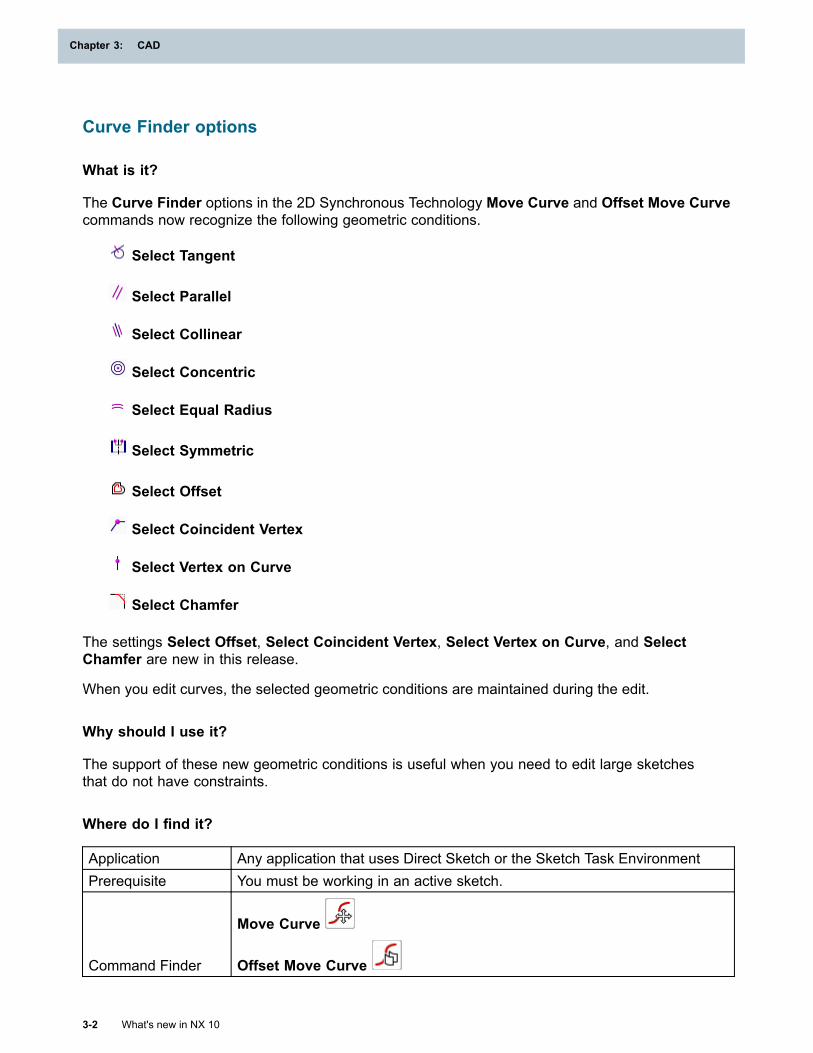
Chapter 3: CAD
Curve Finder options
What is it?
The Curve Finder options in the 2D Synchronous Technology Move Curve and Offset Move Curvecommands now recognize the following geometric conditions.
Select Tangent
Select Parallel
Select Collinear
Select Concentric
Select Equal Radius
Select Symmetric
Select Offset
Select Coincident Vertex
Select Vertex on Curve
Select Chamfer
The settings Select Offset, Select Coincident Vertex, Select Vertex on Curve, and SelectChamfer are new in this release.
When you edit curves, the selected geometric conditions are maintained during the edit.
Why should I use it?
The support of these new geometric conditions is useful when you need to edit large sketchesthat do not have constraints.
Where do I find it?
Application Any application that uses Direct Sketch or the Sketch Task EnvironmentPrerequisite You must be working in an active sketch.
Command Finder
Move Curve
Offset Move Curve
3-2 What's new in NX 10
Chapter 3: CAD
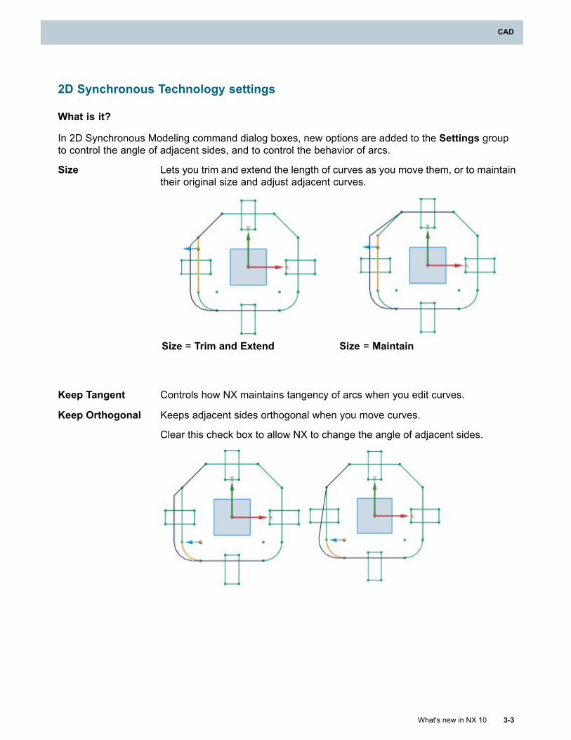
CAD
2D Synchronous Technology settings
What is it?
In 2D Synchronous Modeling command dialog boxes, new options are added to the Settings groupto control the angle of adjacent sides, and to control the behavior of arcs.
Size Lets you trim and extend the length of curves as you move them, or to maintaintheir original size and adjust adjacent curves.
Size = Trim and Extend Size = Maintain
Keep Tangent Controls how NX maintains tangency of arcs when you edit curves.
Keep Orthogonal Keeps adjacent sides orthogonal when you move curves.
Clear this check box to allow NX to change the angle of adjacent sides.
What's new in NX 10 3-3
CAD
Chapter 3: CAD
Where do I find it?
Application Any application that uses Direct Sketch or the Sketch Task Environment.Prerequisite You must be working in an active sketch.
Command Finder
Move Curve
Offset Move Curve
Resize Curve
Optimize 2D Curve
What is it?
Use Optimize 2D Curve to clean up and simplify imported 2D curve geometry and points, lettingyou work more efficiently with migrated 2D data.
You can specify Distance Threshold and Angle Threshold limit values to restrict which pointsand curves are optimized.
The optimize process:
• Cleans up curves and points
o Removes overlapping curve chains (connected sets of curves that are part of other curvechains).
o Removes small curve segments whose length is within the specified distance threshold.
o Removes selected points if the Include Point option is active.
• Simplifies splines and conic curves
o Replaces splines or conic curves with lines that meet the distance threshold.
o Converts splines or conic curves to arcs that meet the distance threshold.
o Refits splines to remove C0 knot points or self-intersections when needed.
o Splits splines at their C0 knot points when they are 1 degree polylines.
• Connects and merges splines and lines
o Removes gaps between lines that fall within the specified distance threshold.
o Removes overlaps between lines that fall within the specified distance threshold.
o Merges connected collinear lines.
o Removes gaps between splines or conic curves and other curves if the gap is within thespecified distance threshold.
3-4 What's new in NX 10
Chapter 3: CAD
CAD
o Removes overlaps between splines or conic curves and other curves if the gap is withinthe specified distance threshold.
o Removes the gap or overhead between the end of a curve and the middle of a curve (pointon curve) if the gap or overhead is within the specified distance threshold.
• Aligns arcs and circles
o Merges connecting arcs and circles with the same radius within the specified distancethreshold.
o Recreates arcs that are tangent to two curves within the angle threshold with the same radius.
o When two such arcs are tangent to each other, recreates the arc with the larger radiusfirst using the same radius.
o When an arc is tangent to one curve within the angle threshold, recreates the arc tangent tothe curve with the same radius.
o If a circle is concentric to an arc within distance threshold, it is made concentric to the arc.
• Updates downstream features that reference the selected curves after the optimization if theyare outside a sketch.
• Creates a new sketch if the Create Sketch option is selected and there is no sketch currentlyactive.
You can perform the optimization on a sketch before or after you import it.
Why should I use it?
Imported curve geometry that is not first optimized may be of insufficient quality for synchronous edit.
Where do I find it?
Application Modeling
Command Finder Optimize 2D Curve
Creating sketch splines
What is it?
NX is enhanced to allow more control over spline poles when you create or edit splines in a sketch.
What's new in NX 10 3-5
CAD
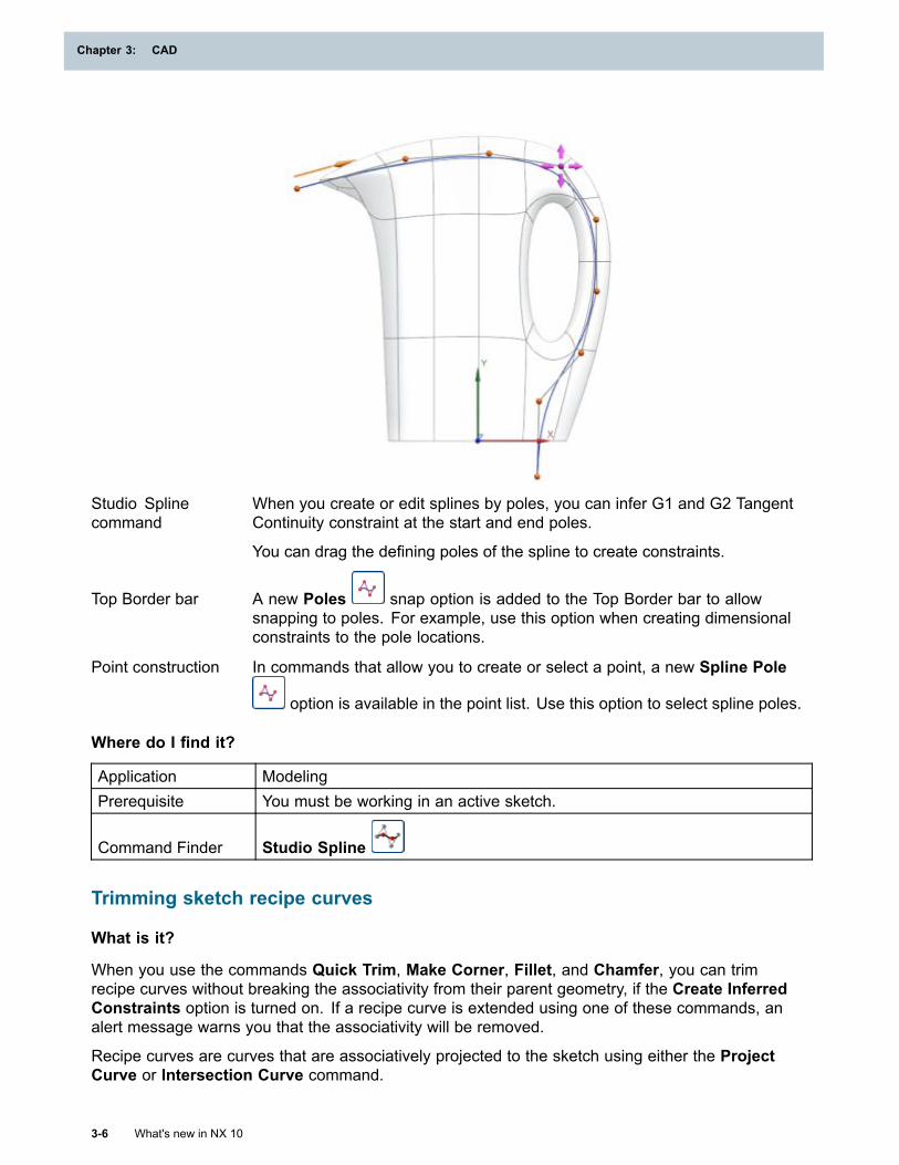
Chapter 3: CAD
Studio Splinecommand
When you create or edit splines by poles, you can infer G1 and G2 TangentContinuity constraint at the start and end poles.
You can drag the defining poles of the spline to create constraints.
Top Border bar A new Poles snap option is added to the Top Border bar to allowsnapping to poles. For example, use this option when creating dimensionalconstraints to the pole locations.
Point construction In commands that allow you to create or select a point, a new Spline Pole
option is available in the point list. Use this option to select spline poles.
Where do I find it?
Application ModelingPrerequisite You must be working in an active sketch.
Command Finder Studio Spline
Trimming sketch recipe curves
What is it?
When you use the commands Quick Trim, Make Corner, Fillet, and Chamfer, you can trimrecipe curves without breaking the associativity from their parent geometry, if the Create InferredConstraints option is turned on. If a recipe curve is extended using one of these commands, analert message warns you that the associativity will be removed.
Recipe curves are curves that are associatively projected to the sketch using either the ProjectCurve or Intersection Curve command.
3-6 What's new in NX 10
Chapter 3: CAD
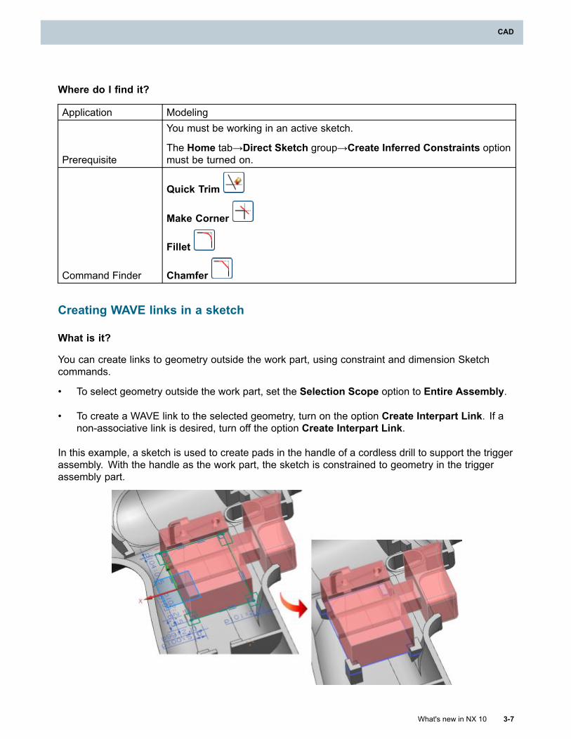
CAD
Where do I find it?
Application Modeling
Prerequisite
You must be working in an active sketch.
The Home tab→Direct Sketch group→Create Inferred Constraints optionmust be turned on.
Command Finder
Quick Trim
Make Corner
Fillet
Chamfer
Creating WAVE links in a sketch
What is it?
You can create links to geometry outside the work part, using constraint and dimension Sketchcommands.
• To select geometry outside the work part, set the Selection Scope option to Entire Assembly.
• To create a WAVE link to the selected geometry, turn on the option Create Interpart Link. If anon-associative link is desired, turn off the option Create Interpart Link.
In this example, a sketch is used to create pads in the handle of a cordless drill to support the triggerassembly. With the handle as the work part, the sketch is constrained to geometry in the triggerassembly part.
What's new in NX 10 3-7
CAD
Chapter 3: CAD
Why should I use it?
These options allow you to create associative or non-associative links from a sketch to geometry inanother assembly component.
Where do I find it?
The options Selection Scope and Create Interpart Link are located in the Top Border bar when youcreate sketch dimensions or geometric constraints.
Application ModelingPrerequisite You must be working in an active sketch in an assembly.
Command Finder
Rapid Dimension
Geometric Constraints
Part Module
Part Module enhancements in the Part Navigator
What is it?
In the Part Navigator, you can now:
• Right-click a part module and choose Activate, Show Only, and Expand. This new shortcutactivates the selected part module, shows only objects in the part module, and expands the partmodule features to make the part module easier to work on. You can also double-click on apart module to invoke this command.
• Drag features from one part module to another part module to reorder or reorganize the structurein a part module.
• Drag features into an existing part module to add structure to a part.
• Delete a part module without deleting its features to remove structure from a part.
• Drag a part module into another part module to nest them. You can also drag a nested partmodule out of part module to un-nest the part modules. This functionality replaces the Nest Partmodule and Un-nest Part Module commands.
• Update out of date linked part modules when you click the out-of-date icon in the Up to Datecolumn. When you click the out-of-date icon for a feature, NX updates that feature and anyout-of-date parents. When you click the out-of-date icon for a part module, NX updates thatpart module, all its member features, and any out of date parents.
3-8 What's new in NX 10
Chapter 3: CAD
CAD
Save linked part module enhancement
What is it?
Linked part module files can no longer be saved in an active state. When you save a linked partmodule part, NX determines if the linked part module is active. If the linked part module is active,NX will automatically:
1. Deactivate the linked part module.
2. Save the linked part module file.
3. Activate the linked part module.
Note
When NX deactivates the linked part module, the module may update if it has pendingchanges. For a complex linked part module, this could take some time, and all the normalramifications of an update will be encountered. Beyond the linked part module itself, normalNX interpart update behavior will apply.
Where do I find it?
Application Modeling, Sheet Metal Design, and Shape Studio
Command Finder Save
Update Input References and Update Output References enhancements
What is it?
The Update Input References and Update Output References commands check if the latestversion of the parent is loaded into memory.
While working on linked part module parts, the Update Input References command now does thefollowing:
• If the main part is closed, NX will display the following message which gives you the opportunityto open a read only version of it:
The operation attempted cannot be executed because the corresponding Linked Part Module
file is not loaded in the session.
Do you want to load the corresponding Linked Part Module file?
• If the main part is open but it's not the latest version on disk, NX displays the following messagewhich can open a read only version of it:
The command will load the latest disk version of the main and/or associated linked part
module parts. Unsaved changes in locally loaded parts will be lost.
Do you want to continue with the operation?
While working on main parts, the Update Output References command now does the following:
What's new in NX 10 3-9
CAD
Chapter 3: CAD
• If the linked part module part is closed, NX displays the following message which gives you theopportunity to open a read only version of it:
The operation attempted cannot be executed because the corresponding Linked Part Module
file is not loaded in the session.
Do you want to load the corresponding Linked Part Module file?
• If the linked part module part is open but it's not the latest version on disk, NX displays thefollowing message which can open a read only version of it:
The command will load the latest disk version of the main and/or associated linked part
module parts. Unsaved changes in locally loaded parts will be lost.
Do you want to continue with the operation?
Where do I find it?
Application Modeling, Sheet Metal Design, and Shape Studio
Command Finder
Update Input References
Update Output References
Shared Body enhancement
What is it?
When you activate a part module that contains a Shared Body, all the modifiable objects areemphasized. This makes it easier to locate shared bodies in the graphics window.
In this example, the five pockets are modifiable objects in a part module.
3-10 What's new in NX 10
Chapter 3: CAD
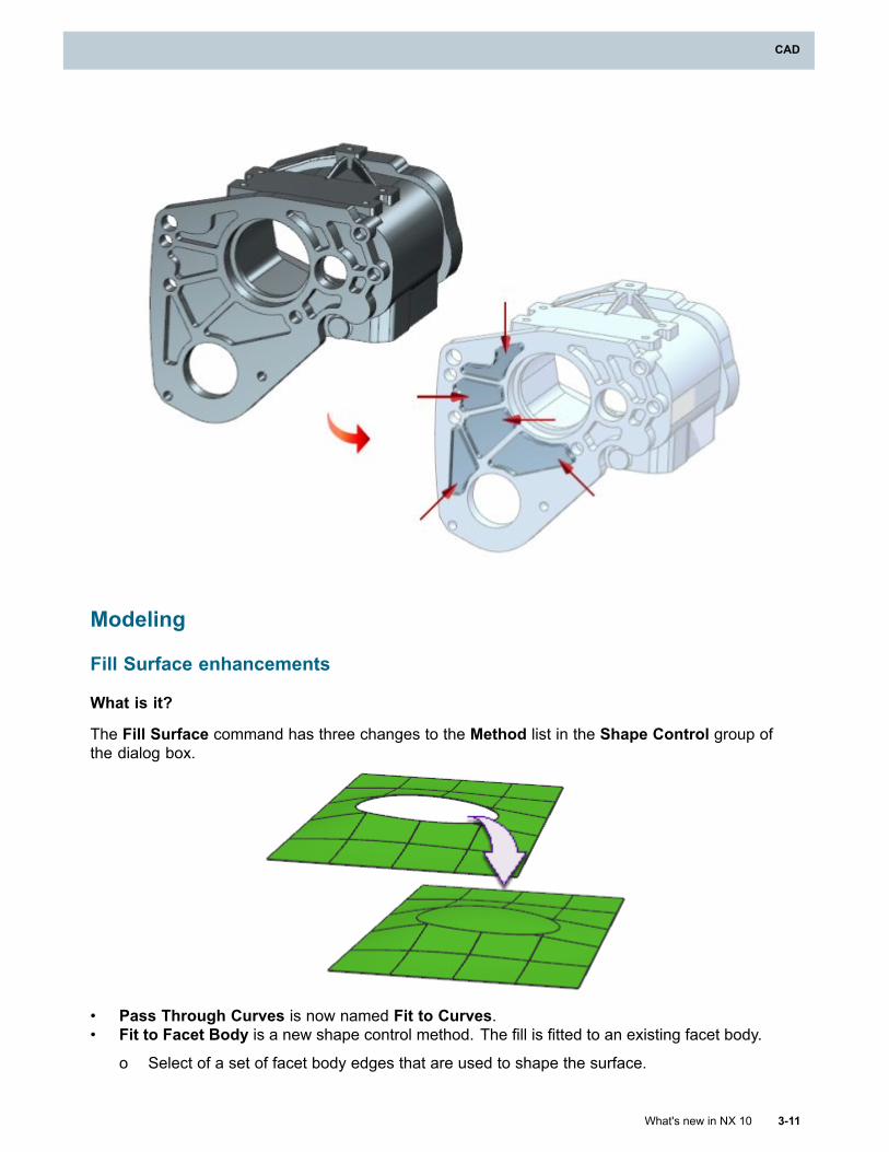
CAD
Modeling
Fill Surface enhancements
What is it?
The Fill Surface command has three changes to the Method list in the Shape Control group ofthe dialog box.
• Pass Through Curves is now named Fit to Curves.• Fit to Facet Body is a new shape control method. The fill is fitted to an existing facet body.
o Select of a set of facet body edges that are used to shape the surface.
What's new in NX 10 3-11
CAD
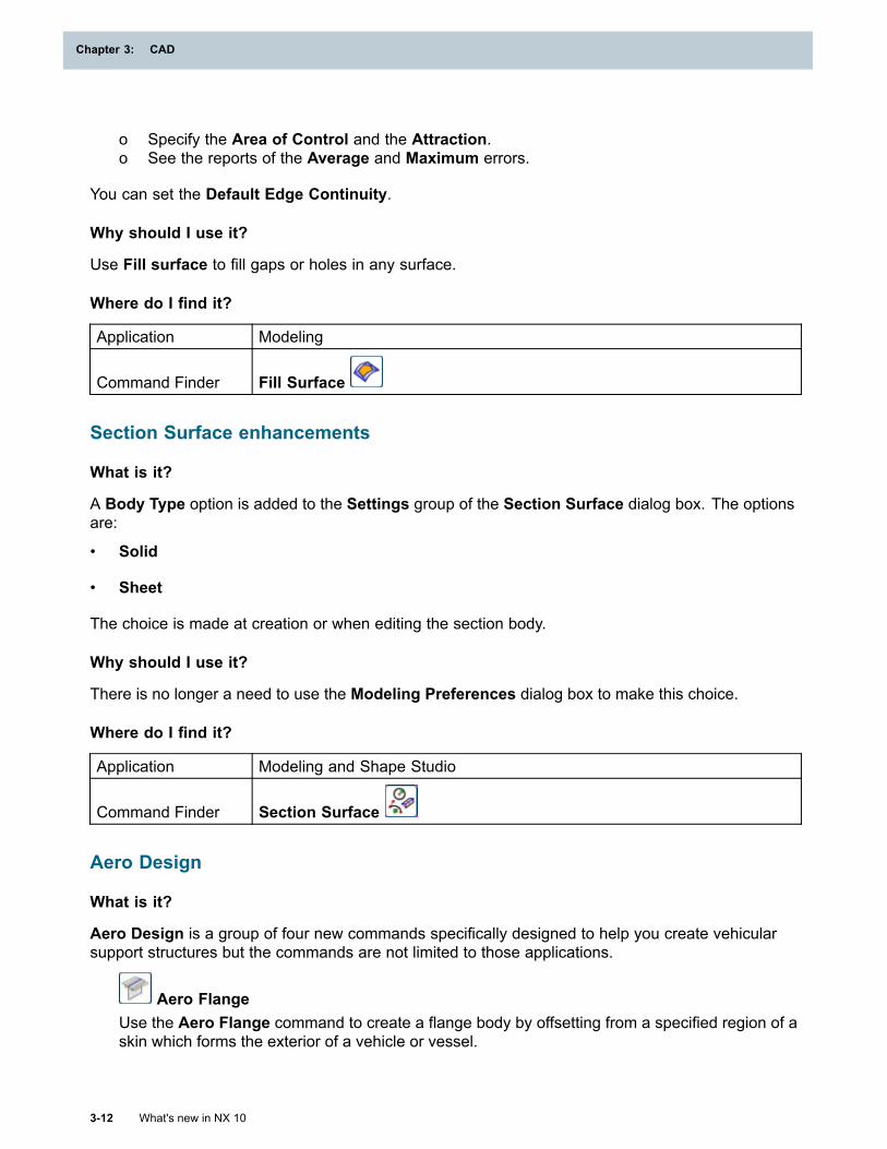
Chapter 3: CAD
o Specify the Area of Control and the Attraction.o See the reports of the Average and Maximum errors.
You can set the Default Edge Continuity.
Why should I use it?
Use Fill surface to fill gaps or holes in any surface.
Where do I find it?
Application Modeling
Command Finder Fill Surface
Section Surface enhancements
What is it?
A Body Type option is added to the Settings group of the Section Surface dialog box. The optionsare:
• Solid
• Sheet
The choice is made at creation or when editing the section body.
Why should I use it?
There is no longer a need to use the Modeling Preferences dialog box to make this choice.
Where do I find it?
Application Modeling and Shape Studio
Command Finder Section Surface
Aero Design
What is it?
Aero Design is a group of four new commands specifically designed to help you create vehicularsupport structures but the commands are not limited to those applications.
Aero FlangeUse the Aero Flange command to create a flange body by offsetting from a specified region of askin which forms the exterior of a vehicle or vessel.
3-12 What's new in NX 10
Chapter 3: CAD
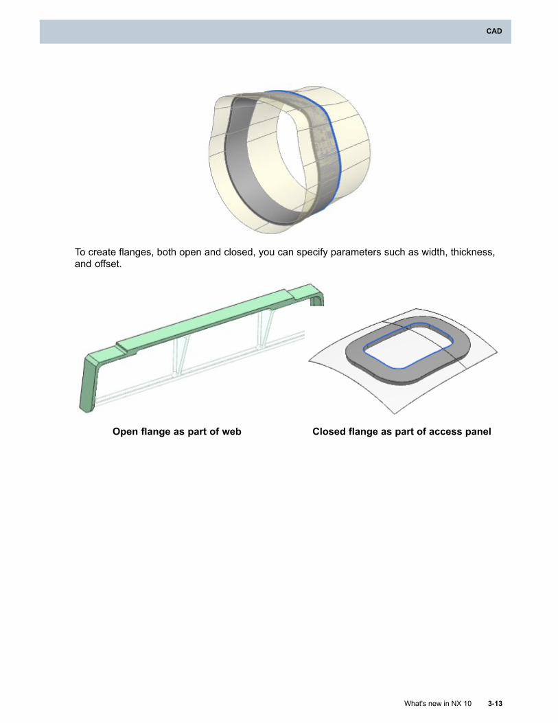
CAD
To create flanges, both open and closed, you can specify parameters such as width, thickness,and offset.
Open flange as part of web Closed flange as part of access panel
What's new in NX 10 3-13
CAD
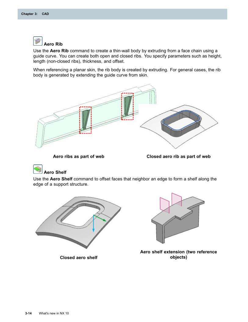
Chapter 3: CAD
Aero RibUse the Aero Rib command to create a thin-wall body by extruding from a face chain using aguide curve. You can create both open and closed ribs. You specify parameters such as height,length (non-closed ribs), thickness, and offset.
When referencing a planar skin, the rib body is created by extruding. For general cases, the ribbody is generated by extending the guide curve from skin.
Aero ribs as part of web Closed aero rib as part of web
Aero ShelfUse the Aero Shelf command to offset faces that neighbor an edge to form a shelf along theedge of a support structure.
Closed aero shelfAero shelf extension (two reference
objects)
3-14 What's new in NX 10
Chapter 3: CAD
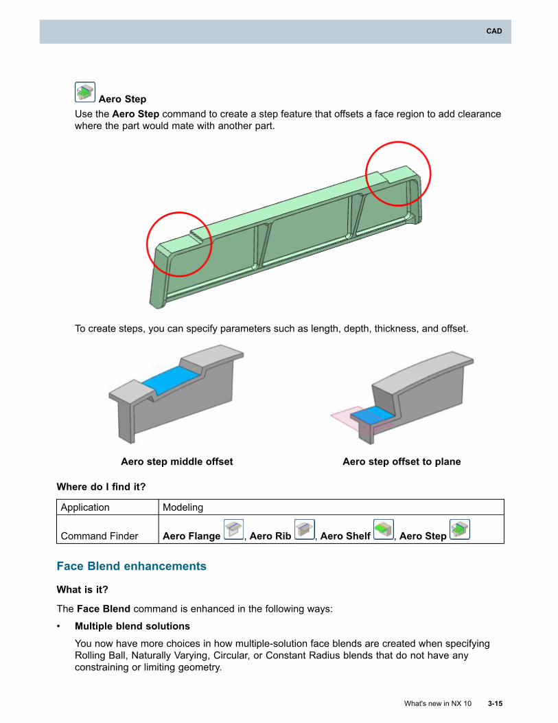
CAD
Aero StepUse the Aero Step command to create a step feature that offsets a face region to add clearancewhere the part would mate with another part.
To create steps, you can specify parameters such as length, depth, thickness, and offset.
Aero step middle offset Aero step offset to plane
Where do I find it?
Application Modeling
Command Finder Aero Flange , Aero Rib , Aero Shelf , Aero Step
Face Blend enhancements
What is it?
The Face Blend command is enhanced in the following ways:
• Multiple blend solutionsYou now have more choices in how multiple-solution face blends are created when specifyingRolling Ball, Naturally Varying, Circular, or Constant Radius blends that do not have anyconstraining or limiting geometry.
What's new in NX 10 3-15
CAD
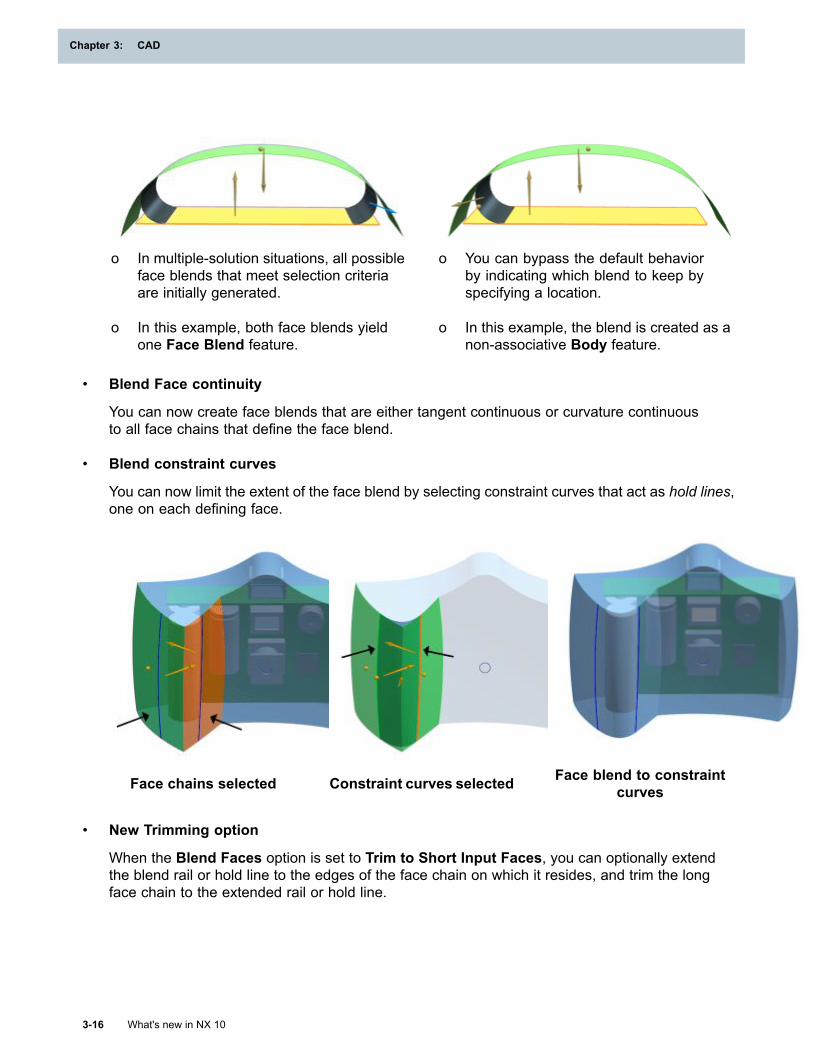
Chapter 3: CAD
o In multiple-solution situations, all possibleface blends that meet selection criteriaare initially generated.
o In this example, both face blends yieldone Face Blend feature.
o You can bypass the default behaviorby indicating which blend to keep byspecifying a location.
o In this example, the blend is created as anon-associative Body feature.
• Blend Face continuity
You can now create face blends that are either tangent continuous or curvature continuousto all face chains that define the face blend.
• Blend constraint curves
You can now limit the extent of the face blend by selecting constraint curves that act as hold lines,one on each defining face.
Face chains selected Constraint curves selected Face blend to constraintcurves
• New Trimming option
When the Blend Faces option is set to Trim to Short Input Faces, you can optionally extendthe blend rail or hold line to the edges of the face chain on which it resides, and trim the longface chain to the extended rail or hold line.
3-16 What's new in NX 10
Chapter 3: CAD
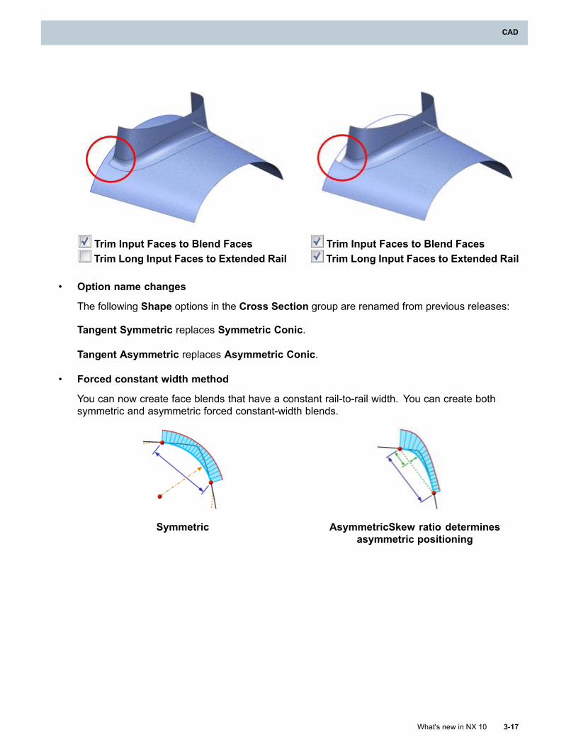
CAD
Trim Input Faces to Blend FacesTrim Long Input Faces to Extended Rail
Trim Input Faces to Blend FacesTrim Long Input Faces to Extended Rail
• Option name changes
The following Shape options in the Cross Section group are renamed from previous releases:
Tangent Symmetric replaces Symmetric Conic.
Tangent Asymmetric replaces Asymmetric Conic.
• Forced constant width method
You can now create face blends that have a constant rail-to-rail width. You can create bothsymmetric and asymmetric forced constant-width blends.
Symmetric AsymmetricSkew ratio determinesasymmetric positioning
What's new in NX 10 3-17
CAD
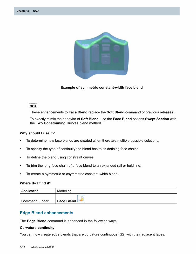
Chapter 3: CAD
Example of symmetric constant-width face blend
Note
These enhancements to Face Blend replace the Soft Blend command of previous releases.
To exactly mimic the behavior of Soft Blend, use the Face Blend options Swept Section withthe Two Constraining Curves blend method.
Why should I use it?
• To determine how face blends are created when there are multiple possible solutions.
• To specify the type of continuity the blend has to its defining face chains.
• To define the blend using constraint curves.
• To trim the long face chain of a face blend to an extended rail or hold line.
• To create a symmetric or asymmetric constant-width blend.
Where do I find it?
Application Modeling
Command Finder Face Blend
Edge Blend enhancements
The Edge Blend command is enhanced in the following ways:
Curvature continuity
You can now create edge blends that are curvature continuous (G2) with their adjacent faces.
3-18 What's new in NX 10
Chapter 3: CAD
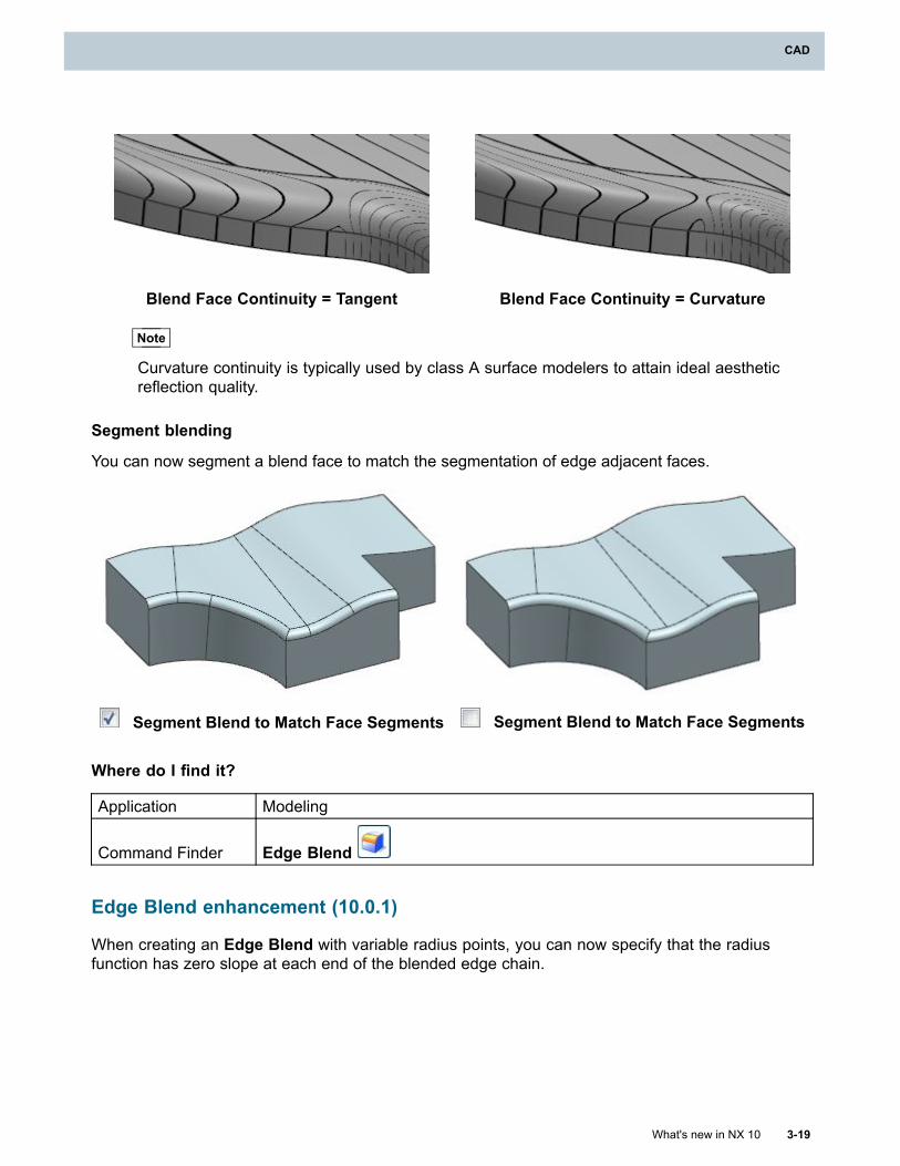
CAD
Blend Face Continuity = Tangent Blend Face Continuity = Curvature
Note
Curvature continuity is typically used by class A surface modelers to attain ideal aestheticreflection quality.
Segment blending
You can now segment a blend face to match the segmentation of edge adjacent faces.
Segment Blend to Match Face Segments Segment Blend to Match Face Segments
Where do I find it?
Application Modeling
Command Finder Edge Blend
Edge Blend enhancement (10.0.1)
When creating an Edge Blend with variable radius points, you can now specify that the radiusfunction has zero slope at each end of the blended edge chain.
What's new in NX 10 3-19
CAD
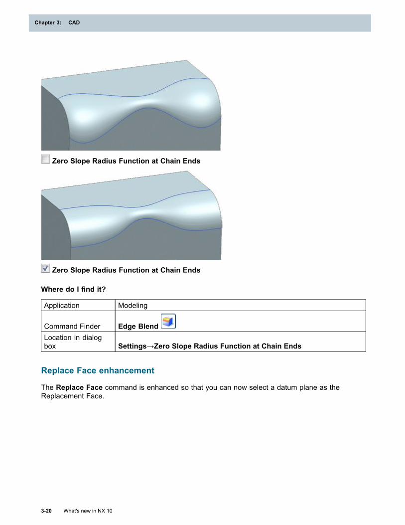
Chapter 3: CAD
Zero Slope Radius Function at Chain Ends
Zero Slope Radius Function at Chain Ends
Where do I find it?
Application Modeling
Command Finder Edge BlendLocation in dialogbox Settings→Zero Slope Radius Function at Chain Ends
Replace Face enhancement
The Replace Face command is enhanced so that you can now select a datum plane as theReplacement Face.
3-20 What's new in NX 10
Chapter 3: CAD
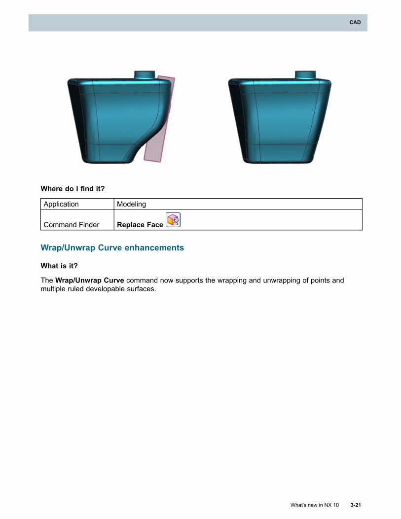
CAD
Where do I find it?
Application Modeling
Command Finder Replace Face
Wrap/Unwrap Curve enhancements
What is it?
The Wrap/Unwrap Curve command now supports the wrapping and unwrapping of points andmultiple ruled developable surfaces.
What's new in NX 10 3-21
CAD
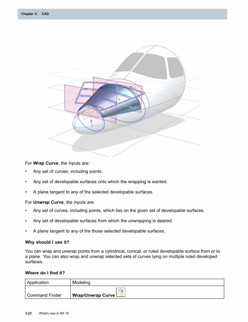
Chapter 3: CAD
For Wrap Curve, the inputs are:
• Any set of curves, including points.
• Any set of developable surfaces onto which the wrapping is wanted.
• A plane tangent to any of the selected developable surfaces.
For Unwrap Curve, the inputs are:
• Any set of curves, including points, which lies on the given set of developable surfaces.
• Any set of developable surfaces from which the unwrapping is desired.
• A plane tangent to any of the those selected developable surfaces.
Why should I use it?
You can wrap and unwrap points from a cylindrical, conical, or ruled developable surface from or toa plane. You can also wrap and unwrap selected sets of curves lying on multiple ruled developedsurfaces.
Where do I find it?
Application Modeling
Command Finder Wrap/Unwrap Curve
3-22 What's new in NX 10
Chapter 3: CAD
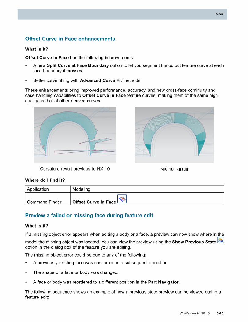
CAD
Offset Curve in Face enhancements
What is it?
Offset Curve in Face has the following improvements:• A new Split Curve at Face Boundary option to let you segment the output feature curve at each
face boundary it crosses.
• Better curve fitting with Advanced Curve Fit methods.
These enhancements bring improved performance, accuracy, and new cross-face continuity andcase handling capabilities to Offset Curve in Face feature curves, making them of the same highquality as that of other derived curves.
Curvature result previous to NX 10 NX 10 Result
Where do I find it?
Application Modeling
Command Finder Offset Curve in Face
Preview a failed or missing face during feature edit
What is it?
If a missing object error appears when editing a body or a face, a preview can now show where in the
model the missing object was located. You can view the preview using the Show Previous Stateoption in the dialog box of the feature you are editing.
The missing object error could be due to any of the following:
• A previously existing face was consumed in a subsequent operation.
• The shape of a face or body was changed.
• A face or body was reordered to a different position in the Part Navigator.
The following sequence shows an example of how a previous state preview can be viewed during afeature edit:
What's new in NX 10 3-23
CAD
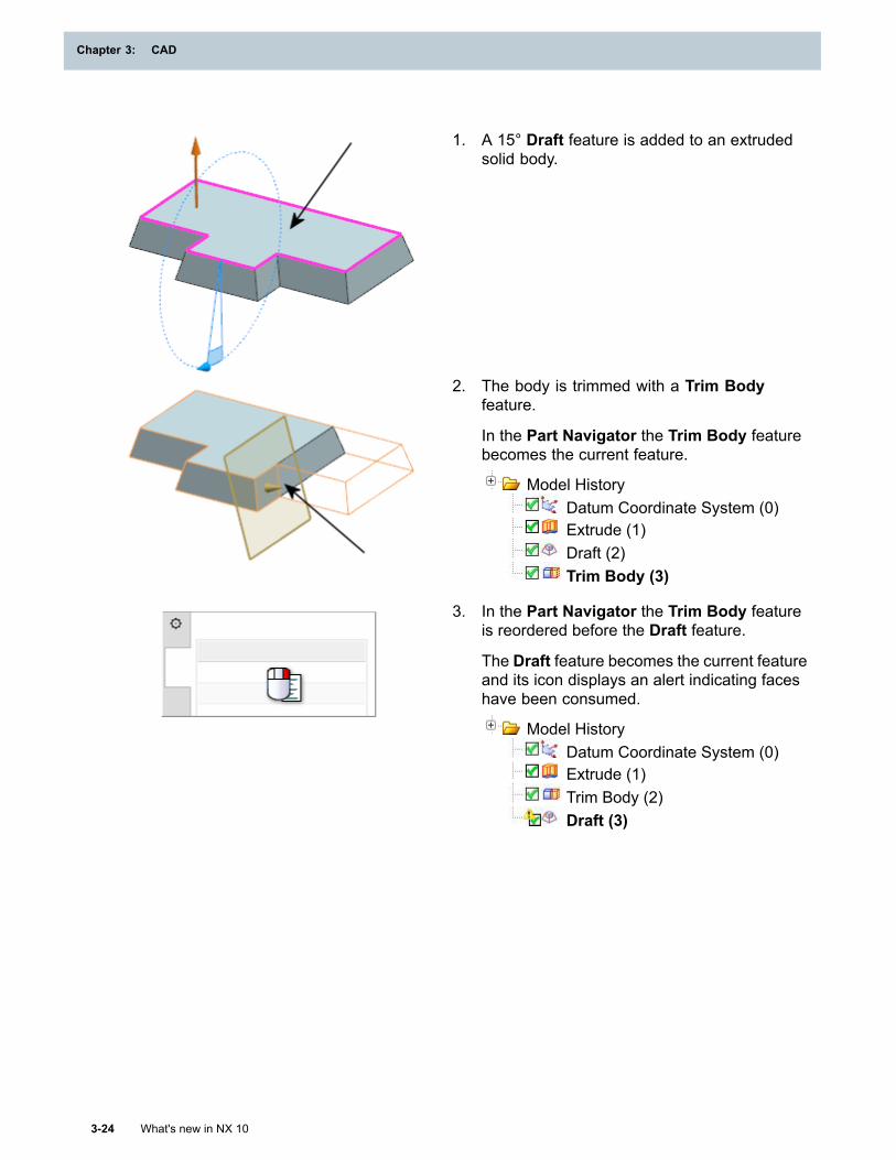
Chapter 3: CAD
1. A 15° Draft feature is added to an extrudedsolid body.
2. The body is trimmed with a Trim Bodyfeature.
In the Part Navigator the Trim Body featurebecomes the current feature.
Model HistoryDatum Coordinate System (0)Extrude (1)Draft (2)Trim Body (3)
3. In the Part Navigator the Trim Body featureis reordered before the Draft feature.
The Draft feature becomes the current featureand its icon displays an alert indicating faceshave been consumed.
Model HistoryDatum Coordinate System (0)Extrude (1)Trim Body (2)Draft (3)
3-24 What's new in NX 10
Chapter 3: CAD
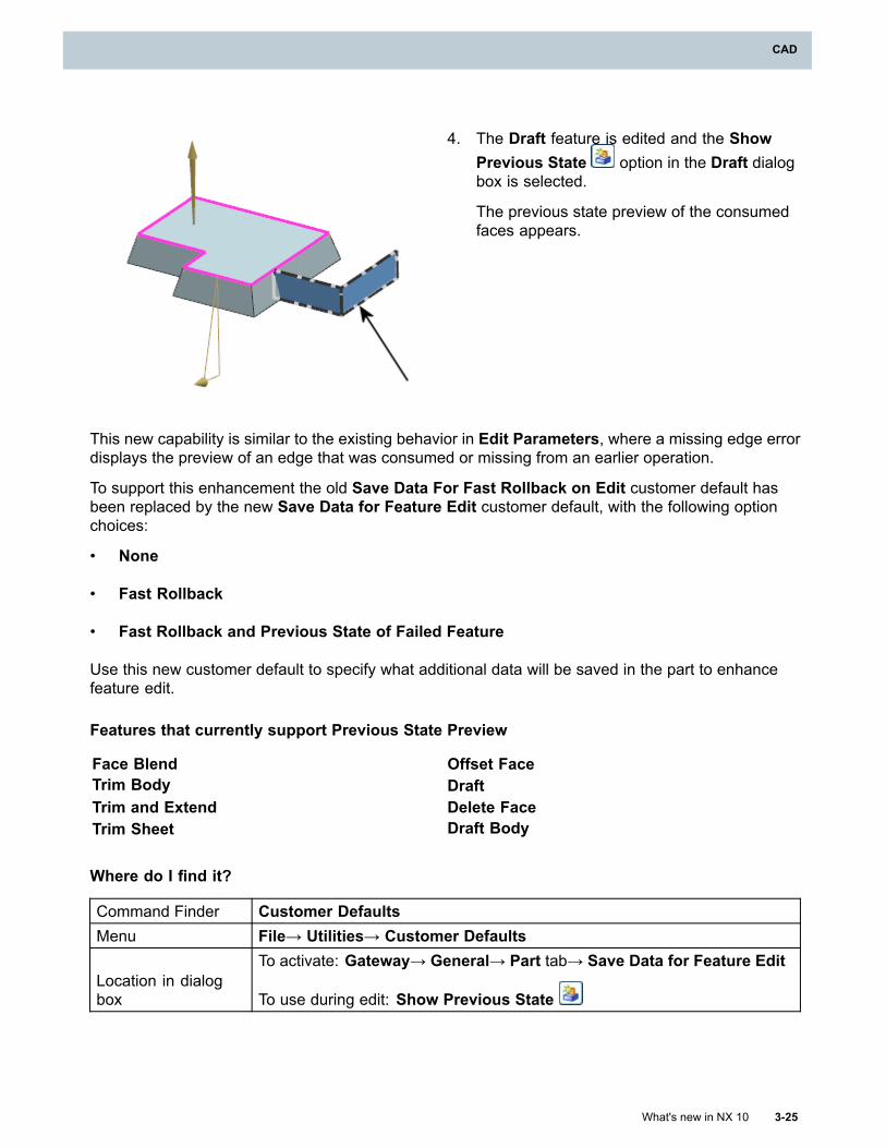
CAD
4. The Draft feature is edited and the ShowPrevious State option in the Draft dialogbox is selected.
The previous state preview of the consumedfaces appears.
This new capability is similar to the existing behavior in Edit Parameters, where a missing edge errordisplays the preview of an edge that was consumed or missing from an earlier operation.
To support this enhancement the old Save Data For Fast Rollback on Edit customer default hasbeen replaced by the new Save Data for Feature Edit customer default, with the following optionchoices:
• None
• Fast Rollback
• Fast Rollback and Previous State of Failed Feature
Use this new customer default to specify what additional data will be saved in the part to enhancefeature edit.
Features that currently support Previous State Preview
Face Blend Offset FaceTrim Body DraftTrim and Extend Delete FaceTrim Sheet Draft Body
Where do I find it?
Command Finder Customer DefaultsMenu File→ Utilities→ Customer Defaults
Location in dialogbox
To activate: Gateway→ General→ Part tab→ Save Data for Feature Edit
To use during edit: Show Previous State
What's new in NX 10 3-25
CAD
Chapter 3: CAD
Rollback data to memory to improve Modeling performance
What is it?
Use the Load Rollback Data to Memory customer default to allow NX to rollback its available data tomemory instead of to the hard disk, thus improving the overall performance of Modeling operations.
The memory requirements of NX will rise accordingly while this customer default is enabled, and it isnot recommended for systems with insufficient installed physical memory.
The amount of data that is rolled back is controlled by the current hardware configuration.
Why should I use it?
Most Rollback data will remain in memory while this customer default is enabled, reducing the time ittakes to read and write to disk and increasing the speed of Modeling.
Where do I find it?
Customer Defaults Load Rollback Data to Memory
MenuFile→ Utilities→ Customer Defaults→ Modeling → General→ Updatetab→ Load Rollback Data to Memory
Offset 3D Curve enhancements
What is it?
The former 3D Curve Offset command has been enhanced and renamed to Offset 3D Curve, andhas been moved to the Derived Curve Group within the Modeling application.
The enhancements include:
• An Associative option to create associative Offset 3D Curve features.
• Advanced Curve Fit methods and options:
o Degree and Segments method to specify the output curves using values for the degree andthe number of segments.
o Degree and Tolerance method to specify the output curves using values for the degreeand tolerance.
o Keep Parameterization method to inherit the parameters for degree, number of segments,and the pole and knot structure from the input curve (or in the case of an Intersection Curve,the input surface) and apply them to the output curve.
o Auto Fit method to specify the minimum and maximum degree, the maximum number ofsegments, and the tolerance of the output curve.
• A Join Curves option to either maintain individual B-splines in the output curve, or join themin a single B-spline.
• A dynamic Preview mode available during both feature creation and edit.
3-26 What's new in NX 10
Chapter 3: CAD
CAD
These improvements bring Offset 3D Curve to the same level of capability and completeness asthat of the Offset Curve command.
Where do I find it?
Application Modeling
Command Finder Offset 3D Curve
Enhancements to patterns with extracted bodies
What is it?
The Pattern Feature and Pattern Geometry commands now copy both positive and negativeextracted symbolic threads and threads on positive holes for downstream operations.
• When extracting Mirrored Body and Body types, if the Copy Threads check box is selected, thepositive or negative disposition of the extracted symbolic threads is maintained in subsequentpatterning of those threads.
• This includes WAVE linked extracted geometry.
• This enhances Pattern Feature so that you can now copy extracted hole threads using eitherthe Variational or the Simple pattern method. Previously only Variational was available forcopying extracted threads.
Why should I use it?
To ensure correct patterning and mirroring behavior when extracting geometry and patterning it.
Where do I find it?
Application Modeling
Command Finder Extract Geometry , Pattern Feature ,
Pattern Geometry
Location in dialog box
Extract Geometry dialog box:
Type list→Mirror Body, Body options→CopyThreads
Pattern Feature dialog box:
Pattern Method group, Method
Pattern Geometry dialog box:
Settings group→Copy Threads
What's new in NX 10 3-27
CAD
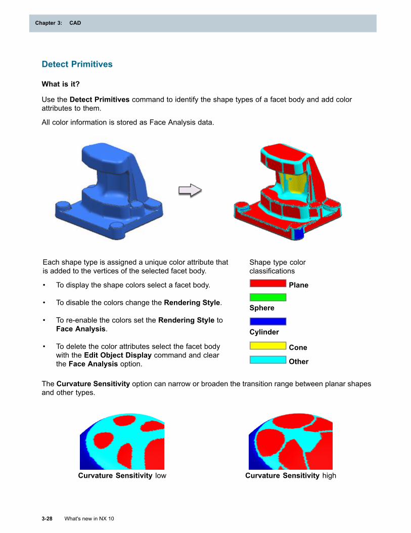
Chapter 3: CAD
Detect Primitives
What is it?
Use the Detect Primitives command to identify the shape types of a facet body and add colorattributes to them.
All color information is stored as Face Analysis data.
Each shape type is assigned a unique color attribute thatis added to the vertices of the selected facet body.
• To display the shape colors select a facet body.
• To disable the colors change the Rendering Style.
• To re-enable the colors set the Rendering Style toFace Analysis.
• To delete the color attributes select the facet bodywith the Edit Object Display command and clearthe Face Analysis option.
Shape type colorclassifications
Plane
Sphere
Cylinder
Cone
Other
The Curvature Sensitivity option can narrow or broaden the transition range between planar shapesand other types.
Curvature Sensitivity low Curvature Sensitivity high
3-28 What's new in NX 10
Chapter 3: CAD
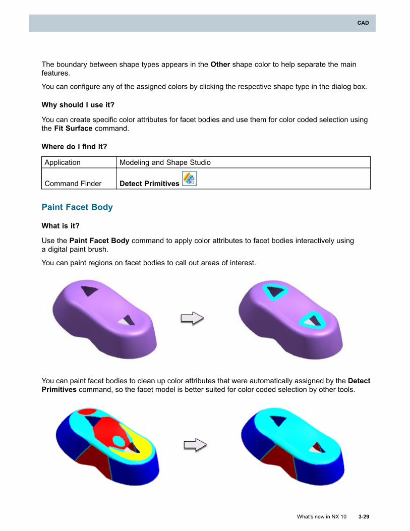
CAD
The boundary between shape types appears in the Other shape color to help separate the mainfeatures.
You can configure any of the assigned colors by clicking the respective shape type in the dialog box.
Why should I use it?
You can create specific color attributes for facet bodies and use them for color coded selection usingthe Fit Surface command.
Where do I find it?
Application Modeling and Shape Studio
Command Finder Detect Primitives
Paint Facet Body
What is it?
Use the Paint Facet Body command to apply color attributes to facet bodies interactively usinga digital paint brush.
You can paint regions on facet bodies to call out areas of interest.
You can paint facet bodies to clean up color attributes that were automatically assigned by the DetectPrimitives command, so the facet model is better suited for color coded selection by other tools.
What's new in NX 10 3-29
CAD
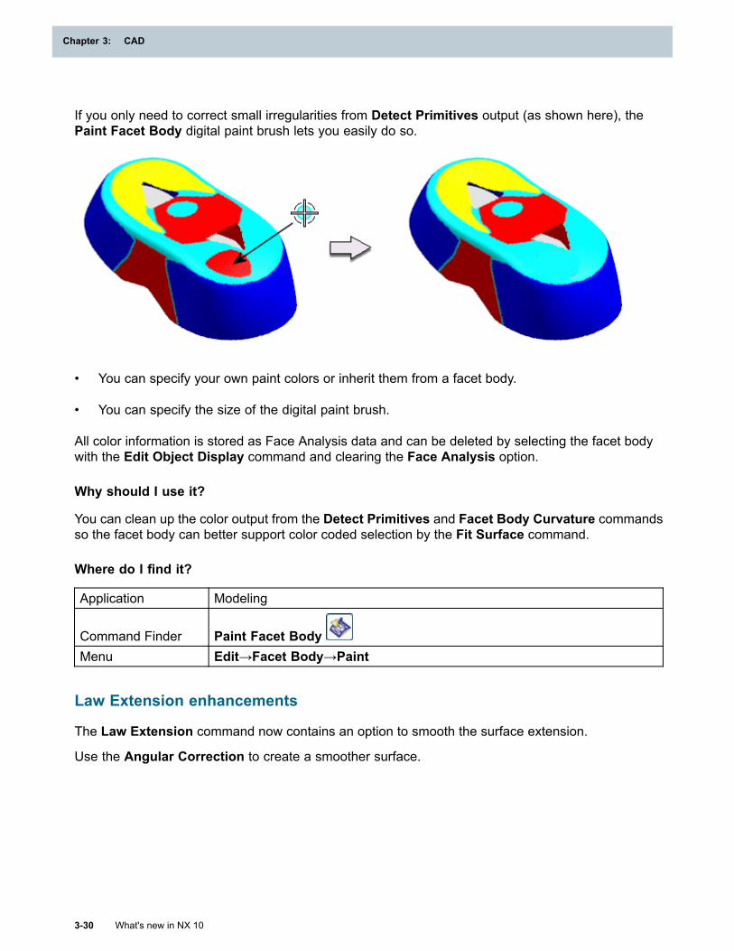
Chapter 3: CAD
If you only need to correct small irregularities from Detect Primitives output (as shown here), thePaint Facet Body digital paint brush lets you easily do so.
• You can specify your own paint colors or inherit them from a facet body.
• You can specify the size of the digital paint brush.
All color information is stored as Face Analysis data and can be deleted by selecting the facet bodywith the Edit Object Display command and clearing the Face Analysis option.
Why should I use it?
You can clean up the color output from the Detect Primitives and Facet Body Curvature commandsso the facet body can better support color coded selection by the Fit Surface command.
Where do I find it?
Application Modeling
Command Finder Paint Facet BodyMenu Edit→Facet Body→Paint
Law Extension enhancements
The Law Extension command now contains an option to smooth the surface extension.
Use the Angular Correction to create a smoother surface.
3-30 What's new in NX 10
Chapter 3: CAD
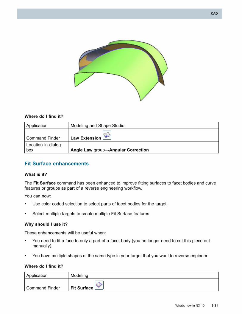
CAD
Where do I find it?
Application Modeling and Shape Studio
Command Finder Law ExtensionLocation in dialogbox Angle Law group→Angular Correction
Fit Surface enhancements
What is it?
The Fit Surface command has been enhanced to improve fitting surfaces to facet bodies and curvefeatures or groups as part of a reverse engineering workflow.
You can now:
• Use color coded selection to select parts of facet bodies for the target.
• Select multiple targets to create multiple Fit Surface features.
Why should I use it?
These enhancements will be useful when:
• You need to fit a face to only a part of a facet body (you no longer need to cut this piece outmanually).
• You have multiple shapes of the same type in your target that you want to reverse engineer.
Where do I find it?
Application Modeling
Command Finder Fit Surface
What's new in NX 10 3-31
CAD
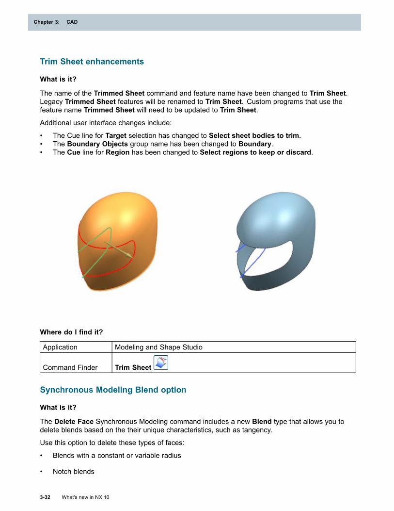
Chapter 3: CAD
Trim Sheet enhancements
What is it?
The name of the Trimmed Sheet command and feature name have been changed to Trim Sheet.Legacy Trimmed Sheet features will be renamed to Trim Sheet. Custom programs that use thefeature name Trimmed Sheet will need to be updated to Trim Sheet.
Additional user interface changes include:
• The Cue line for Target selection has changed to Select sheet bodies to trim.• The Boundary Objects group name has been changed to Boundary.• The Cue line for Region has been changed to Select regions to keep or discard.
Where do I find it?
Application Modeling and Shape Studio
Command Finder Trim Sheet
Synchronous Modeling Blend option
What is it?
The Delete Face Synchronous Modeling command includes a new Blend type that allows you todelete blends based on the their unique characteristics, such as tangency.
Use this option to delete these types of faces:
• Blends with a constant or variable radius
• Notch blends
3-32 What's new in NX 10
Chapter 3: CAD
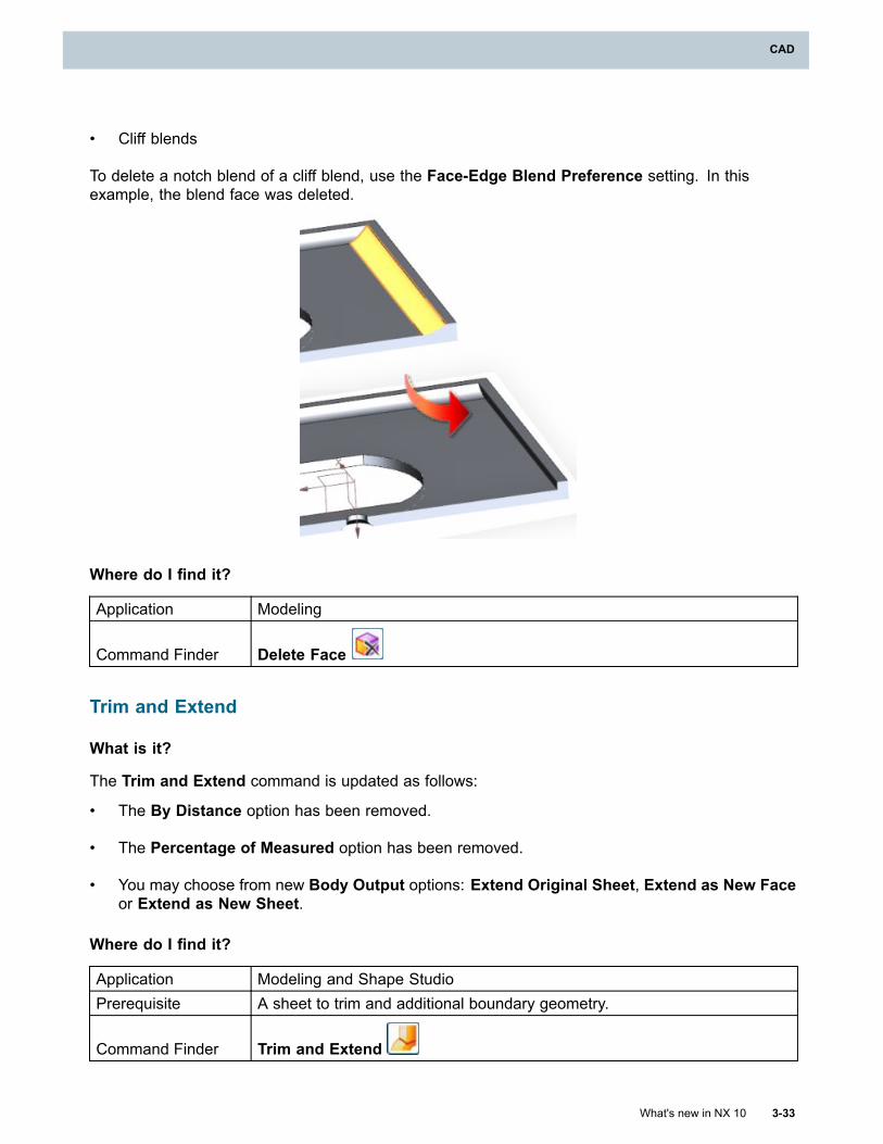
CAD
• Cliff blends
To delete a notch blend of a cliff blend, use the Face-Edge Blend Preference setting. In thisexample, the blend face was deleted.
Where do I find it?
Application Modeling
Command Finder Delete Face
Trim and Extend
What is it?
The Trim and Extend command is updated as follows:
• The By Distance option has been removed.
• The Percentage of Measured option has been removed.
• You may choose from new Body Output options: Extend Original Sheet, Extend as New Faceor Extend as New Sheet.
Where do I find it?
Application Modeling and Shape StudioPrerequisite A sheet to trim and additional boundary geometry.
Command Finder Trim and Extend
What's new in NX 10 3-33
CAD
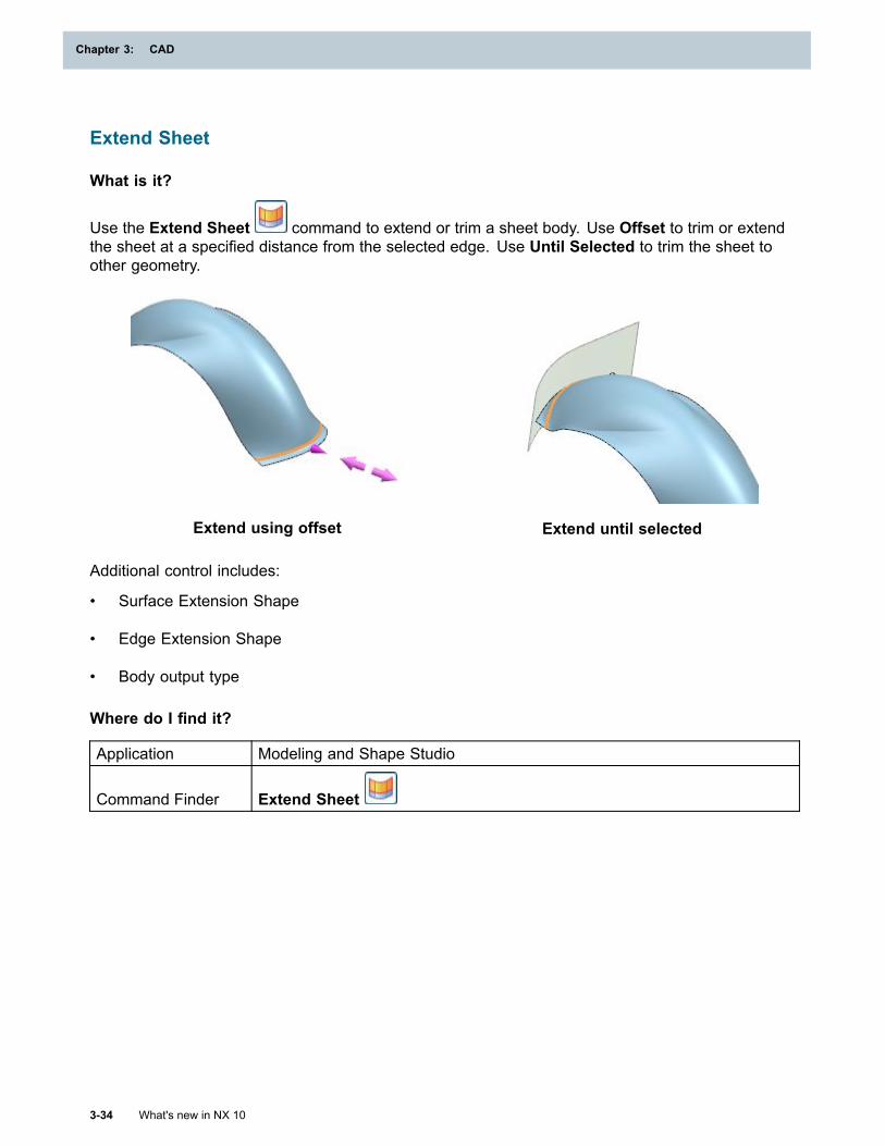
Chapter 3: CAD
Extend Sheet
What is it?
Use the Extend Sheet command to extend or trim a sheet body. Use Offset to trim or extendthe sheet at a specified distance from the selected edge. Use Until Selected to trim the sheet toother geometry.
Extend using offset Extend until selected
Additional control includes:
• Surface Extension Shape
• Edge Extension Shape
• Body output type
Where do I find it?
Application Modeling and Shape Studio
Command Finder Extend Sheet
3-34 What's new in NX 10
Chapter 3: CAD
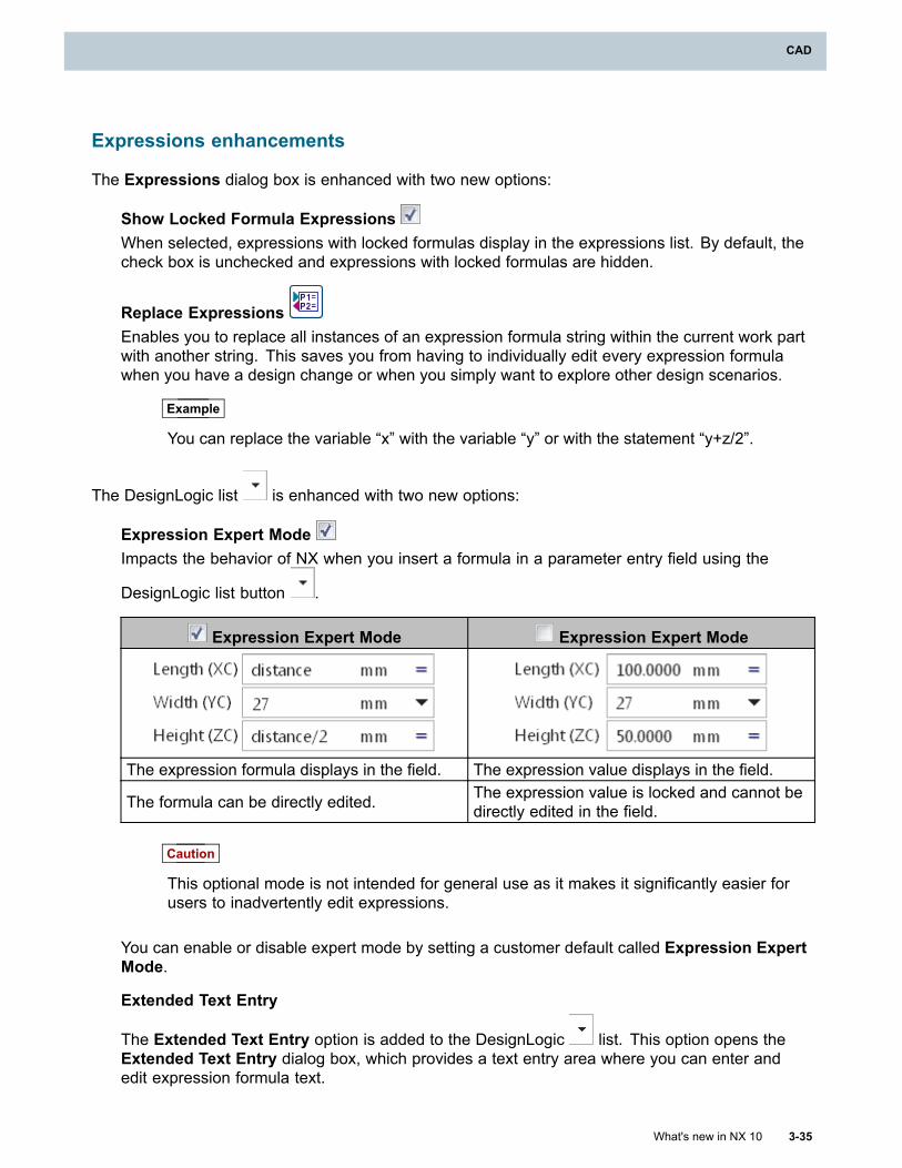
CAD
Expressions enhancements
The Expressions dialog box is enhanced with two new options:
Show Locked Formula ExpressionsWhen selected, expressions with locked formulas display in the expressions list. By default, thecheck box is unchecked and expressions with locked formulas are hidden.
Replace ExpressionsEnables you to replace all instances of an expression formula string within the current work partwith another string. This saves you from having to individually edit every expression formulawhen you have a design change or when you simply want to explore other design scenarios.
Example
You can replace the variable “x” with the variable “y” or with the statement “y+z/2”.
The DesignLogic list is enhanced with two new options:
Expression Expert ModeImpacts the behavior of NX when you insert a formula in a parameter entry field using the
DesignLogic list button .
Expression Expert Mode Expression Expert Mode
The expression formula displays in the field. The expression value displays in the field.
The formula can be directly edited. The expression value is locked and cannot bedirectly edited in the field.
Caution
This optional mode is not intended for general use as it makes it significantly easier forusers to inadvertently edit expressions.
You can enable or disable expert mode by setting a customer default called Expression ExpertMode.
Extended Text Entry
The Extended Text Entry option is added to the DesignLogic list. This option opens theExtended Text Entry dialog box, which provides a text entry area where you can enter andedit expression formula text.
What's new in NX 10 3-35
CAD
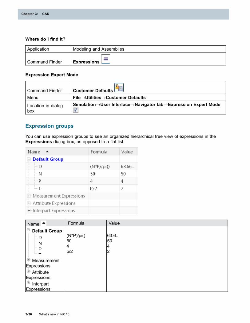
Chapter 3: CAD
Where do I find it?
Application Modeling and Assemblies
Command Finder Expressions
Expression Expert Mode
Command Finder Customer DefaultsMenu File→Utilities→Customer Defaults
Location in dialogbox
Simulation→User Interface→Navigator tab→Expression Expert Mode
Expression groups
You can use expression groups to see an organized hierarchical tree view of expressions in theExpressions dialog box, as opposed to a flat list.
Name Formula Value
Default GroupDNPT
MeasurementExpressions
AttributeExpressions
InterpartExpressions
(N*P)/pi()504p/2
63.6...5042
3-36 What's new in NX 10
Chapter 3: CAD
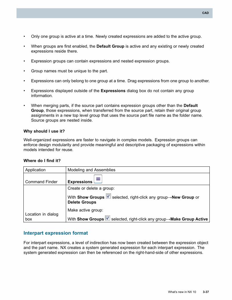
CAD
• Only one group is active at a time. Newly created expressions are added to the active group.
• When groups are first enabled, the Default Group is active and any existing or newly createdexpressions reside there.
• Expression groups can contain expressions and nested expression groups.
• Group names must be unique to the part.
• Expressions can only belong to one group at a time. Drag expressions from one group to another.
• Expressions displayed outside of the Expressions dialog box do not contain any groupinformation.
• When merging parts, if the source part contains expression groups other than the DefaultGroup, those expressions, when transferred from the source part, retain their original groupassignments in a new top level group that uses the source part file name as the folder name.Source groups are nested inside.
Why should I use it?
Well-organized expressions are faster to navigate in complex models. Expression groups canenforce design modularity and provide meaningful and descriptive packaging of expressions withinmodels intended for reuse.
Where do I find it?
Application Modeling and Assemblies
Command Finder Expressions
Location in dialogbox
Create or delete a group:
With Show Groups selected, right-click any group→New Group orDelete Groups
Make active group:
With Show Groups selected, right-click any group→Make Group Active
Interpart expression format
For interpart expressions, a level of indirection has now been created between the expression objectand the part name. NX creates a system generated expression for each interpart expression. Thesystem generated expression can then be referenced on the right-hand-side of other expressions.
What's new in NX 10 3-37
CAD
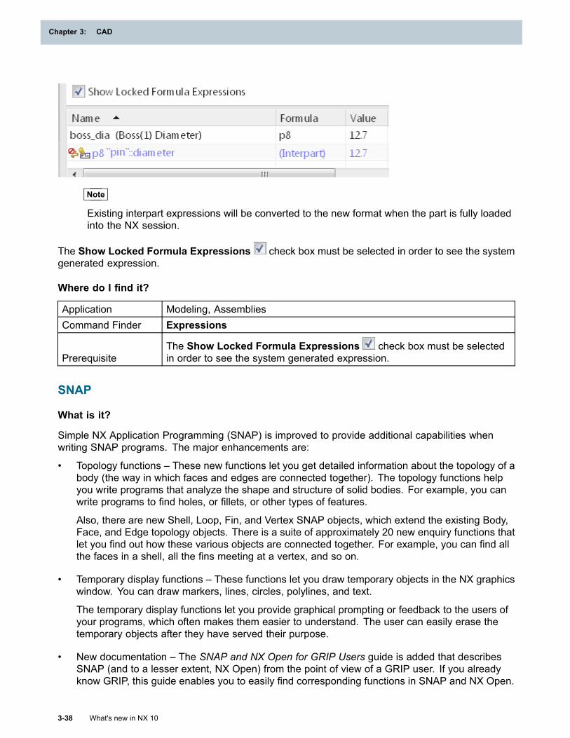
Chapter 3: CAD
Note
Existing interpart expressions will be converted to the new format when the part is fully loadedinto the NX session.
The Show Locked Formula Expressions check box must be selected in order to see the systemgenerated expression.
Where do I find it?
Application Modeling, AssembliesCommand Finder Expressions
PrerequisiteThe Show Locked Formula Expressions check box must be selectedin order to see the system generated expression.
SNAP
What is it?
Simple NX Application Programming (SNAP) is improved to provide additional capabilities whenwriting SNAP programs. The major enhancements are:
• Topology functions – These new functions let you get detailed information about the topology of abody (the way in which faces and edges are connected together). The topology functions helpyou write programs that analyze the shape and structure of solid bodies. For example, you canwrite programs to find holes, or fillets, or other types of features.
Also, there are new Shell, Loop, Fin, and Vertex SNAP objects, which extend the existing Body,Face, and Edge topology objects. There is a suite of approximately 20 new enquiry functions thatlet you find out how these various objects are connected together. For example, you can find allthe faces in a shell, all the fins meeting at a vertex, and so on.
• Temporary display functions – These functions let you draw temporary objects in the NX graphicswindow. You can draw markers, lines, circles, polylines, and text.
The temporary display functions let you provide graphical prompting or feedback to the users ofyour programs, which often makes them easier to understand. The user can easily erase thetemporary objects after they have served their purpose.
• New documentation – The SNAP and NX Open for GRIP Users guide is added that describesSNAP (and to a lesser extent, NX Open) from the point of view of a GRIP user. If you alreadyknow GRIP, this guide enables you to easily find corresponding functions in SNAP and NX Open.
3-38 What's new in NX 10
Chapter 3: CAD
CAD
In addition, there are other enhancements including new functions to:
• Calculate points on a B-surface very quickly
• Create curves that replicate the shapes of edges
• Analyze the convexity across an edge
• Check whether a point lies inside a body or a face
• Convert between degrees and radians
• Access the NX Work View and other standard NX views
Why should I use it?
You can write programs that can provide additional functionality and features.
Where do I find it?
The SNAP and NX Open for GRIP Users guide is in the Programming Tools section of the NX Help.
Detailed descriptions of the new functions with examples are in the SNAP Reference Guide. The newfunctions can be found in the following namespaces and classes:
• Topology objects and functions: new Snap.Topology namespace; additions to Snap.NX.Body,Snap.NX.Face, and Snap.NX.Edge
• Temporary display functions: Snap.Draw class
• Fast calculation of points on a B-surface: Snap.Geom.Surface.Bsurface.Position
• Create curves from edges: Snap.NX.Edge.ToCurve
• Analyze edge convexity: Snap.NX.Edge.Convexity
• Point containment: Snap.NX.Body.ContainsPoint and Snap.NX.Face.ContainsPoint
• Convert between degrees and radians: Snap.Math class
• Work view: Snap.Globals.WorkView
• NX standard views: Snap.NX.View.Standard class
NX Realize Shape
Import Subdivision Geometry
What is it?
Use the Import Subdivision Geometry command to import subdivision geometry (not largetessellated data files) which has been exported by other applications using the Wavefront *.obj format.
What's new in NX 10 3-39
CAD
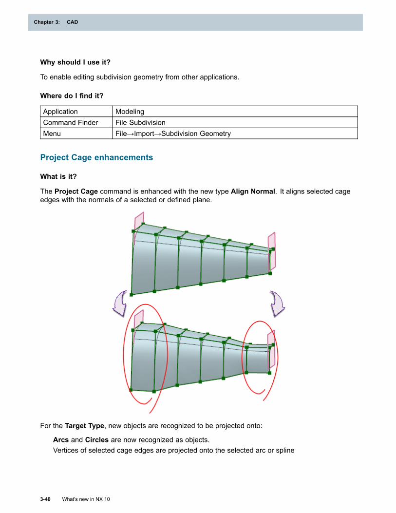
Chapter 3: CAD
Why should I use it?
To enable editing subdivision geometry from other applications.
Where do I find it?
Application ModelingCommand Finder File SubdivisionMenu File→Import→Subdivision Geometry
Project Cage enhancements
What is it?
The Project Cage command is enhanced with the new type Align Normal. It aligns selected cageedges with the normals of a selected or defined plane.
For the Target Type, new objects are recognized to be projected onto:
Arcs and Circles are now recognized as objects.Vertices of selected cage edges are projected onto the selected arc or spline
3-40 What's new in NX 10
Chapter 3: CAD
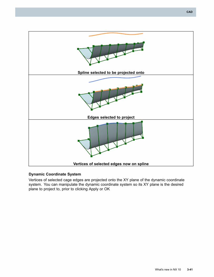
CAD
Spline selected to be projected onto
Edges selected to project
Vertices of selected edges now on spline
Dynamic Coordinate SystemVertices of selected cage edges are projected onto the XY plane of the dynamic coordinatesystem. You can manipulate the dynamic coordinate system so its XY plane is the desiredplane to project to, prior to clicking Apply or OK
What's new in NX 10 3-41
CAD
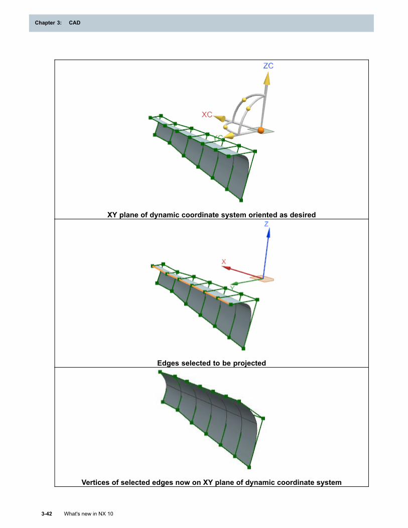
Chapter 3: CAD
XY plane of dynamic coordinate system oriented as desired
Edges selected to be projected
Vertices of selected edges now on XY plane of dynamic coordinate system
3-42 What's new in NX 10
Chapter 3: CAD
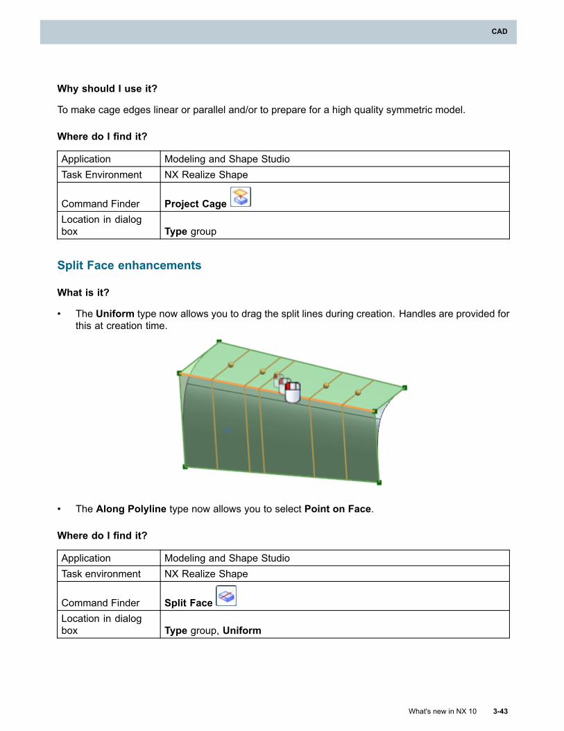
CAD
Why should I use it?
To make cage edges linear or parallel and/or to prepare for a high quality symmetric model.
Where do I find it?
Application Modeling and Shape StudioTask Environment NX Realize Shape
Command Finder Project CageLocation in dialogbox Type group
Split Face enhancements
What is it?
• The Uniform type now allows you to drag the split lines during creation. Handles are provided forthis at creation time.
• The Along Polyline type now allows you to select Point on Face.
Where do I find it?
Application Modeling and Shape StudioTask environment NX Realize Shape
Command Finder Split FaceLocation in dialogbox Type group, Uniform
What's new in NX 10 3-43
CAD
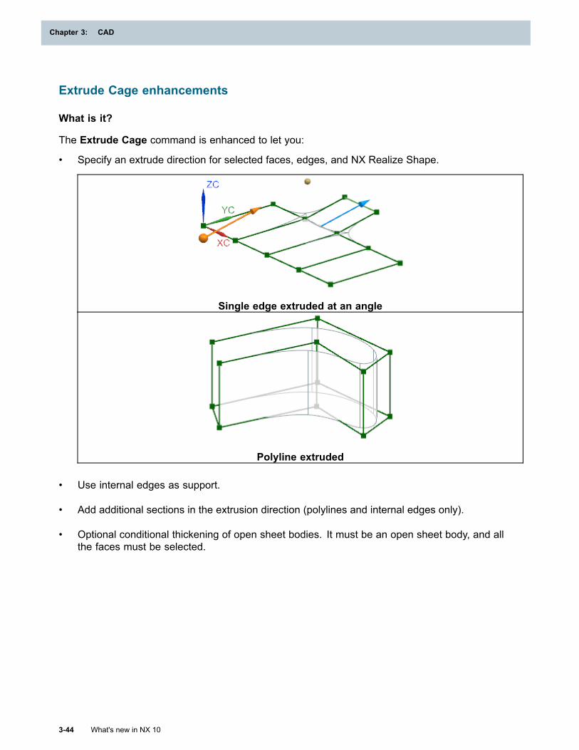
Chapter 3: CAD
Extrude Cage enhancements
What is it?
The Extrude Cage command is enhanced to let you:
• Specify an extrude direction for selected faces, edges, and NX Realize Shape.
Single edge extruded at an angle
Polyline extruded
• Use internal edges as support.
• Add additional sections in the extrusion direction (polylines and internal edges only).
• Optional conditional thickening of open sheet bodies. It must be an open sheet body, and allthe faces must be selected.
3-44 What's new in NX 10
Chapter 3: CAD
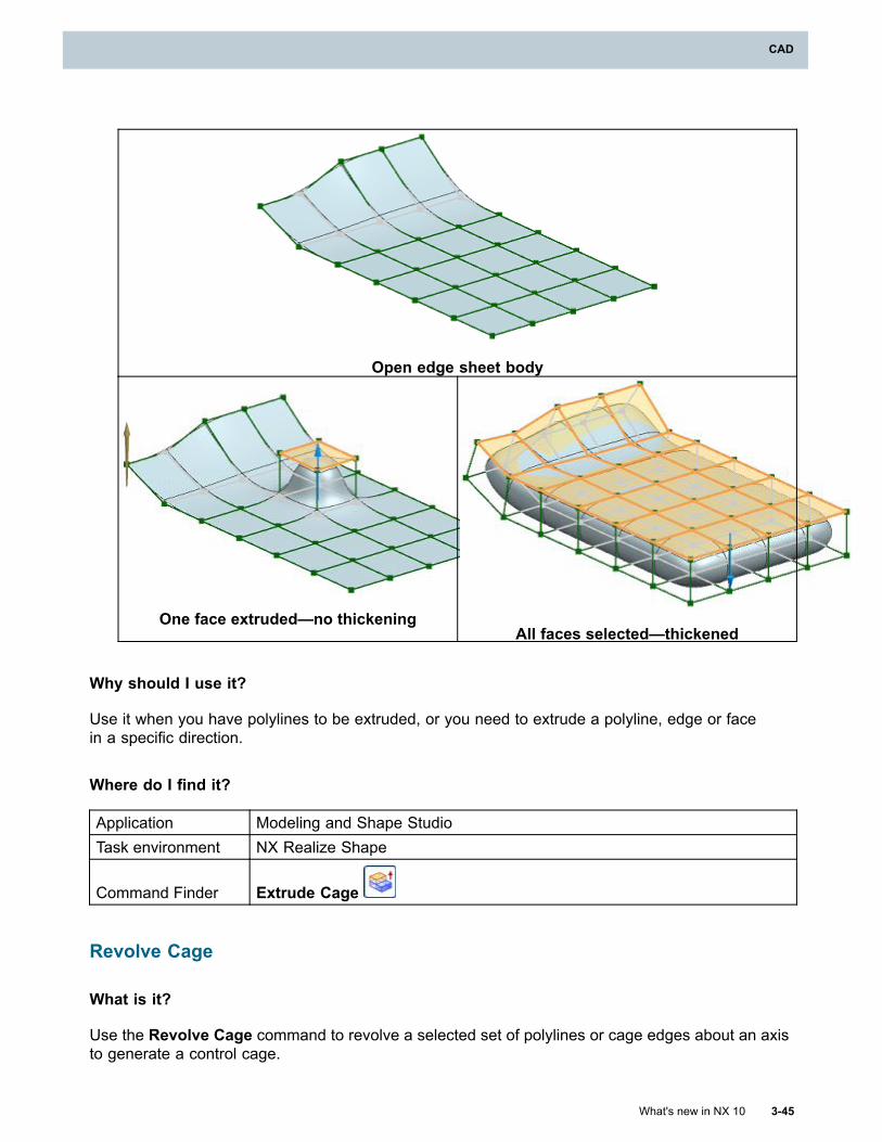
CAD
Open edge sheet body
One face extruded—no thickeningAll faces selected—thickened
Why should I use it?
Use it when you have polylines to be extruded, or you need to extrude a polyline, edge or facein a specific direction.
Where do I find it?
Application Modeling and Shape StudioTask environment NX Realize Shape
Command Finder Extrude Cage
Revolve Cage
What is it?
Use the Revolve Cage command to revolve a selected set of polylines or cage edges about an axisto generate a control cage.
What's new in NX 10 3-45
CAD
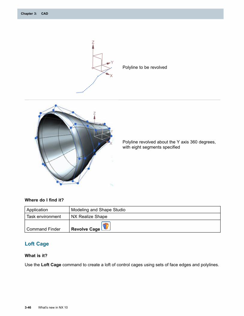
Chapter 3: CAD
Polyline to be revolved
Polyline revolved about the Y axis 360 degrees,with eight segments specified
Where do I find it?
Application Modeling and Shape StudioTask environment NX Realize Shape
Command Finder Revolve Cage
Loft Cage
What is it?
Use the Loft Cage command to create a loft of control cages using sets of face edges and polylines.
3-46 What's new in NX 10
Chapter 3: CAD
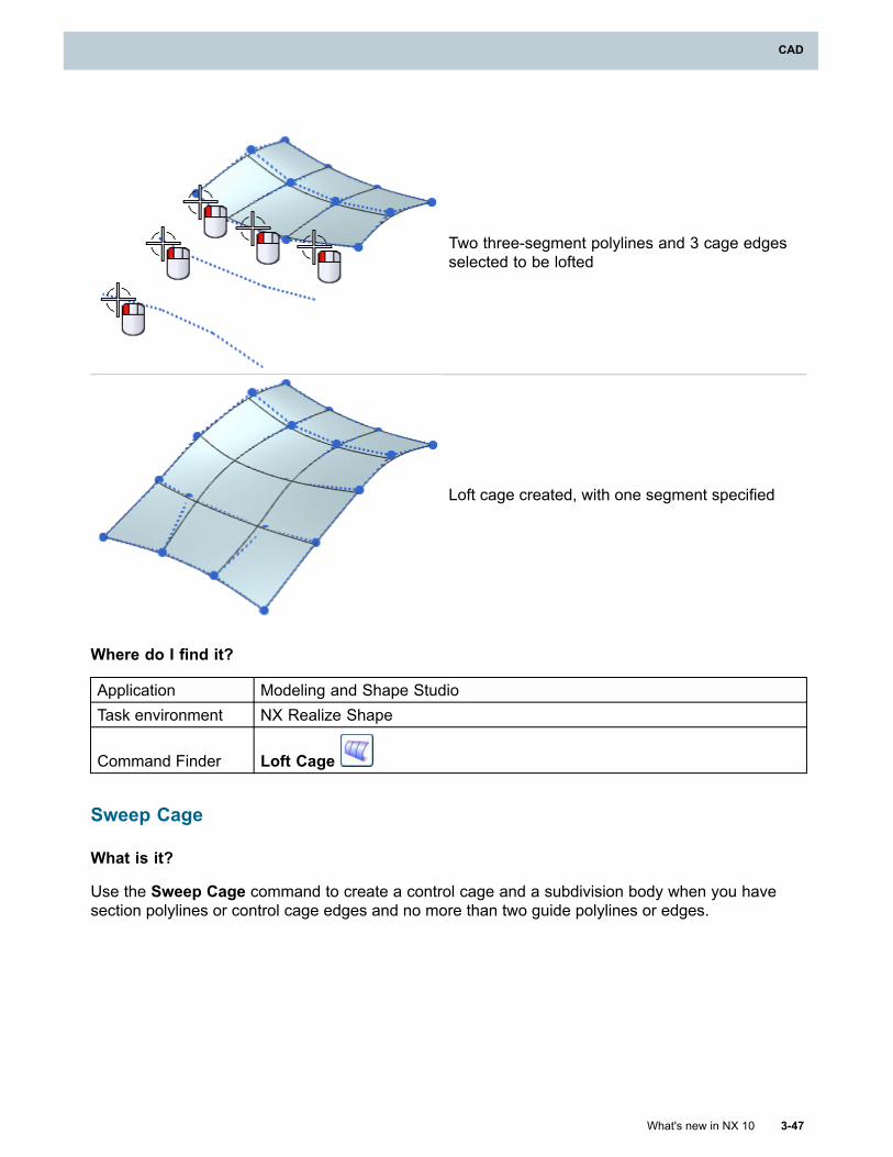
CAD
Two three-segment polylines and 3 cage edgesselected to be lofted
Loft cage created, with one segment specified
Where do I find it?
Application Modeling and Shape StudioTask environment NX Realize Shape
Command Finder Loft Cage
Sweep Cage
What is it?
Use the Sweep Cage command to create a control cage and a subdivision body when you havesection polylines or control cage edges and no more than two guide polylines or edges.
What's new in NX 10 3-47
CAD
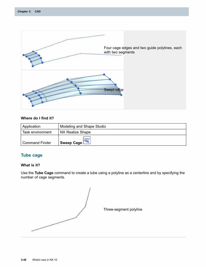
Chapter 3: CAD
Four cage edges and two guide polylines, eachwith two segments
Swept cage
Where do I find it?
Application Modeling and Shape StudioTask environment NX Realize Shape
Command Finder Sweep Cage
Tube cage
What is it?
Use the Tube Cage command to create a tube using a polyline as a centerline and by specifying thenumber of cage segments.
Three-segment polyline
3-48 What's new in NX 10
Chapter 3: CAD
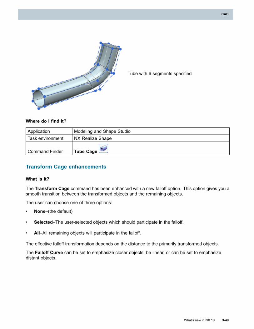
CAD
Tube with 6 segments specified
Where do I find it?
Application Modeling and Shape StudioTask environment NX Realize Shape
Command Finder Tube Cage
Transform Cage enhancements
What is it?
The Transform Cage command has been enhanced with a new falloff option. This option gives you asmooth transition between the transformed objects and the remaining objects.
The user can choose one of three options:
• None–(the default)
• Selected–The user-selected objects which should participate in the falloff.
• All–All remaining objects will participate in the falloff.
The effective falloff transformation depends on the distance to the primarily transformed objects.
The Falloff Curve can be set to emphasize closer objects, be linear, or can be set to emphasizedistant objects.
What's new in NX 10 3-49
CAD
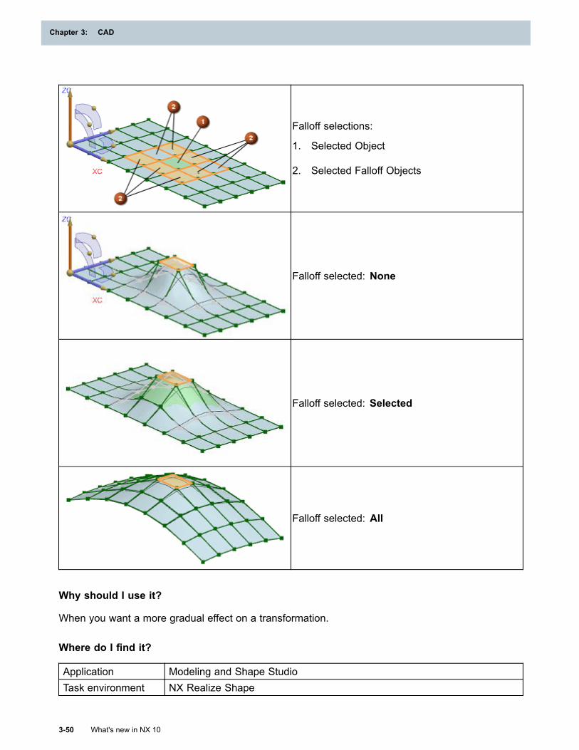
Chapter 3: CAD
Falloff selections:
1. Selected Object
2. Selected Falloff Objects
Falloff selected: None
Falloff selected: Selected
Falloff selected: All
Why should I use it?
When you want a more gradual effect on a transformation.
Where do I find it?
Application Modeling and Shape StudioTask environment NX Realize Shape
3-50 What's new in NX 10
Chapter 3: CAD
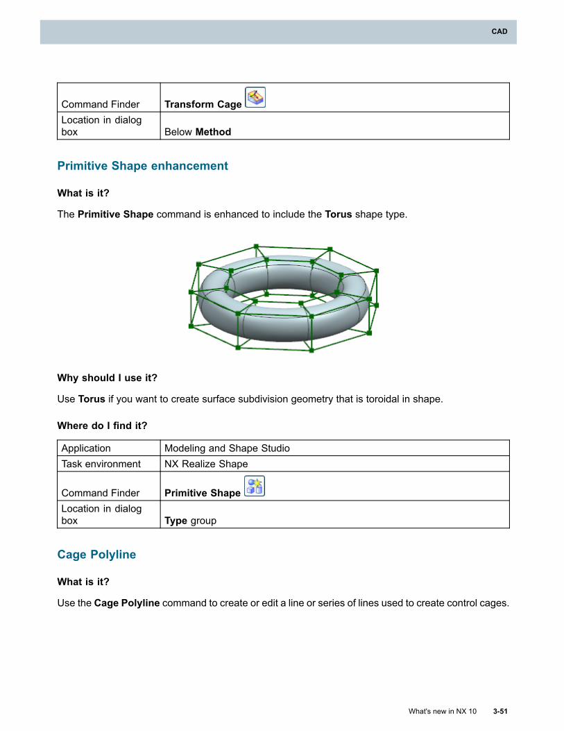
CAD
Command Finder Transform CageLocation in dialogbox Below Method
Primitive Shape enhancement
What is it?
The Primitive Shape command is enhanced to include the Torus shape type.
Why should I use it?
Use Torus if you want to create surface subdivision geometry that is toroidal in shape.
Where do I find it?
Application Modeling and Shape StudioTask environment NX Realize Shape
Command Finder Primitive ShapeLocation in dialogbox Type group
Cage Polyline
What is it?
Use the Cage Polyline command to create or edit a line or series of lines used to create control cages.
What's new in NX 10 3-51
CAD
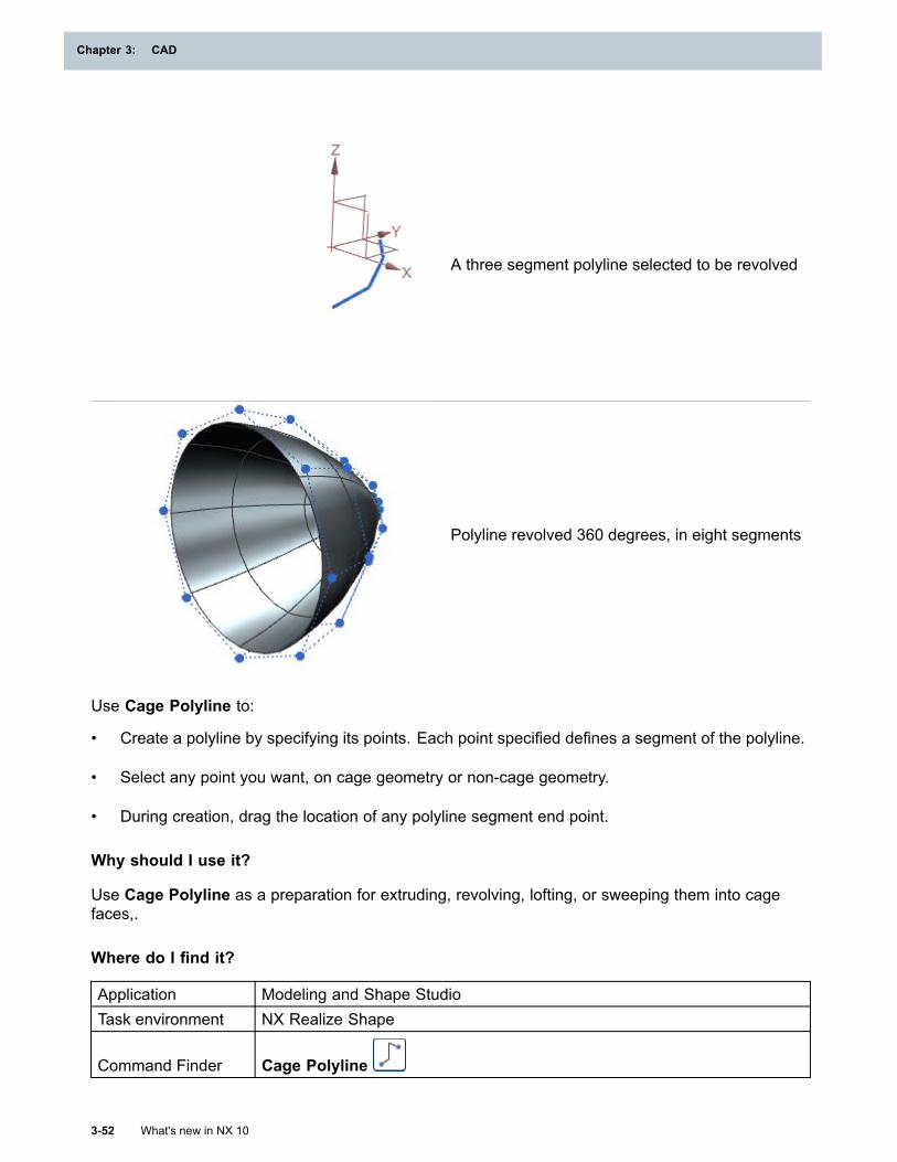
Chapter 3: CAD
A three segment polyline selected to be revolved
Polyline revolved 360 degrees, in eight segments
Use Cage Polyline to:
• Create a polyline by specifying its points. Each point specified defines a segment of the polyline.
• Select any point you want, on cage geometry or non-cage geometry.
• During creation, drag the location of any polyline segment end point.
Why should I use it?
Use Cage Polyline as a preparation for extruding, revolving, lofting, or sweeping them into cagefaces,.
Where do I find it?
Application Modeling and Shape StudioTask environment NX Realize Shape
Command Finder Cage Polyline
3-52 What's new in NX 10
Chapter 3: CAD
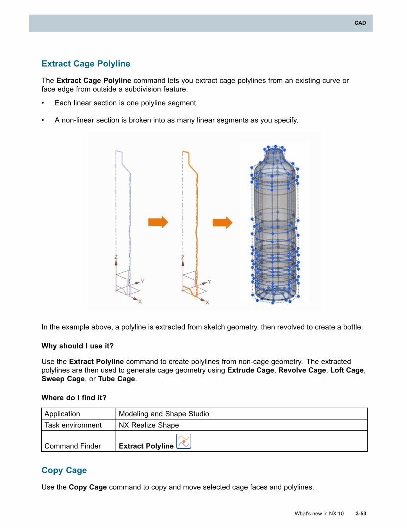
CAD
Extract Cage Polyline
The Extract Cage Polyline command lets you extract cage polylines from an existing curve orface edge from outside a subdivision feature.
• Each linear section is one polyline segment.
• A non-linear section is broken into as many linear segments as you specify.
In the example above, a polyline is extracted from sketch geometry, then revolved to create a bottle.
Why should I use it?
Use the Extract Polyline command to create polylines from non-cage geometry. The extractedpolylines are then used to generate cage geometry using Extrude Cage, Revolve Cage, Loft Cage,Sweep Cage, or Tube Cage.
Where do I find it?
Application Modeling and Shape StudioTask environment NX Realize Shape
Command Finder Extract Polyline
Copy Cage
Use the Copy Cage command to copy and move selected cage faces and polylines.
What's new in NX 10 3-53
CAD
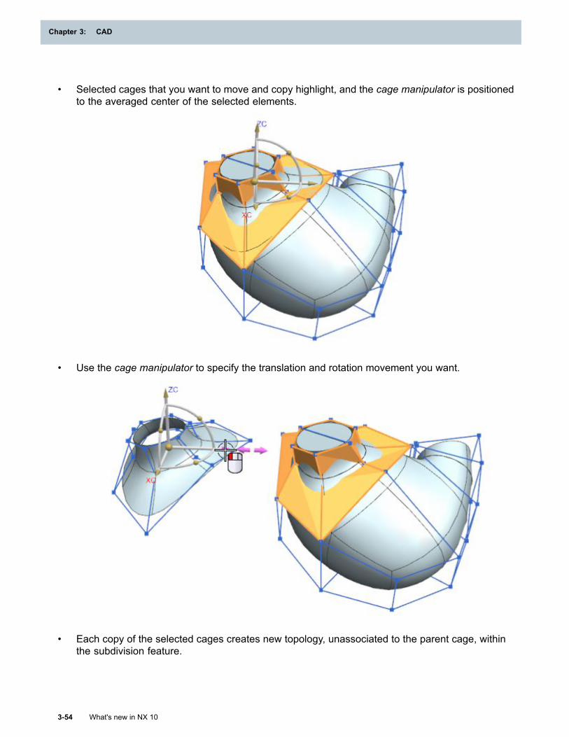
Chapter 3: CAD
• Selected cages that you want to move and copy highlight, and the cage manipulator is positionedto the averaged center of the selected elements.
• Use the cage manipulator to specify the translation and rotation movement you want.
• Each copy of the selected cages creates new topology, unassociated to the parent cage, withinthe subdivision feature.
3-54 What's new in NX 10
Chapter 3: CAD
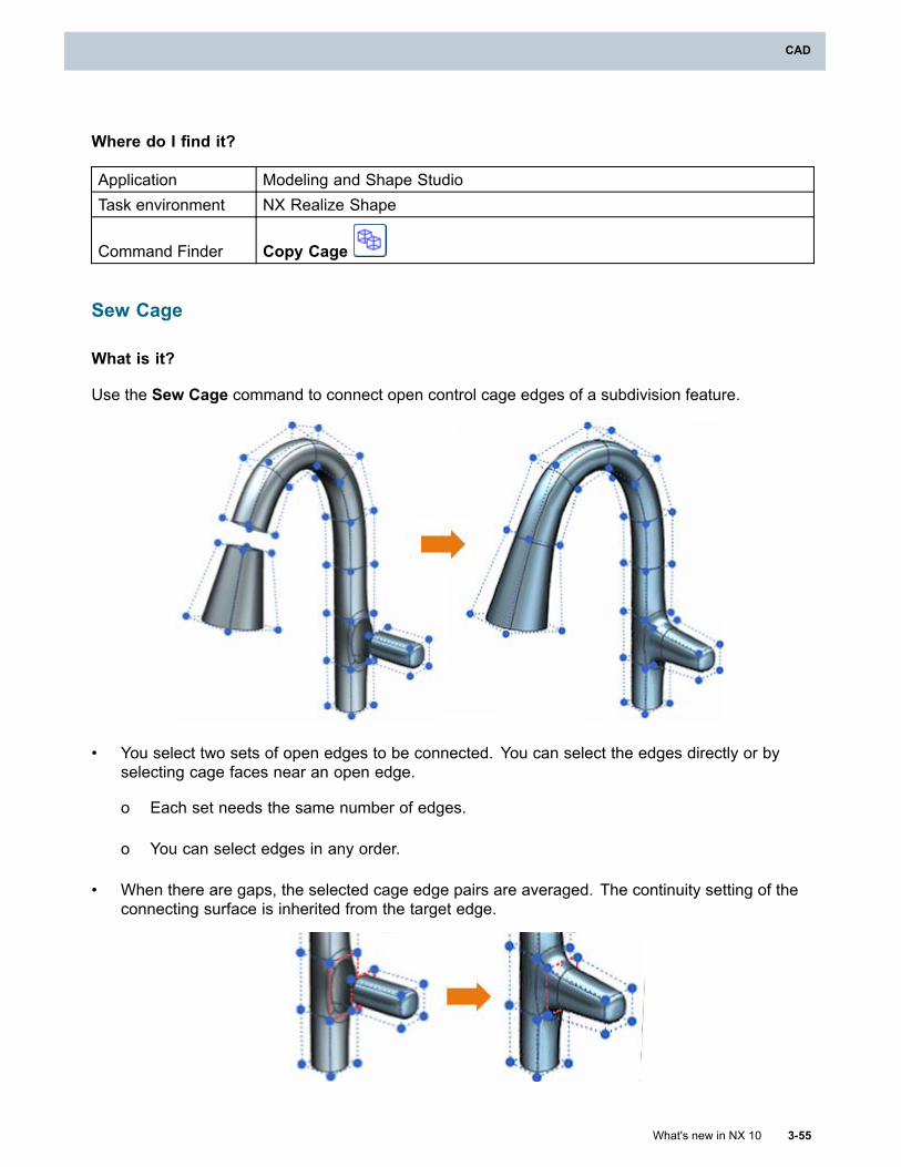
CAD
Where do I find it?
Application Modeling and Shape StudioTask environment NX Realize Shape
Command Finder Copy Cage
Sew Cage
What is it?
Use the Sew Cage command to connect open control cage edges of a subdivision feature.
• You select two sets of open edges to be connected. You can select the edges directly or byselecting cage faces near an open edge.
o Each set needs the same number of edges.
o You can select edges in any order.
• When there are gaps, the selected cage edge pairs are averaged. The continuity setting of theconnecting surface is inherited from the target edge.
What's new in NX 10 3-55
CAD
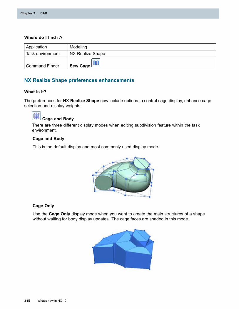
Chapter 3: CAD
Where do I find it?
Application ModelingTask environment NX Realize Shape
Command Finder Sew Cage
NX Realize Shape preferences enhancements
What is it?
The preferences for NX Realize Shape now include options to control cage display, enhance cageselection and display weights.
Cage and BodyThere are three different display modes when editing subdivision feature within the taskenvironment.
Cage and Body
This is the default display and most commonly used display mode.
Cage Only
Use the Cage Only display mode when you want to create the main structures of a shapewithout waiting for body display updates. The cage faces are shaded in this mode.
3-56 What's new in NX 10
Chapter 3: CAD
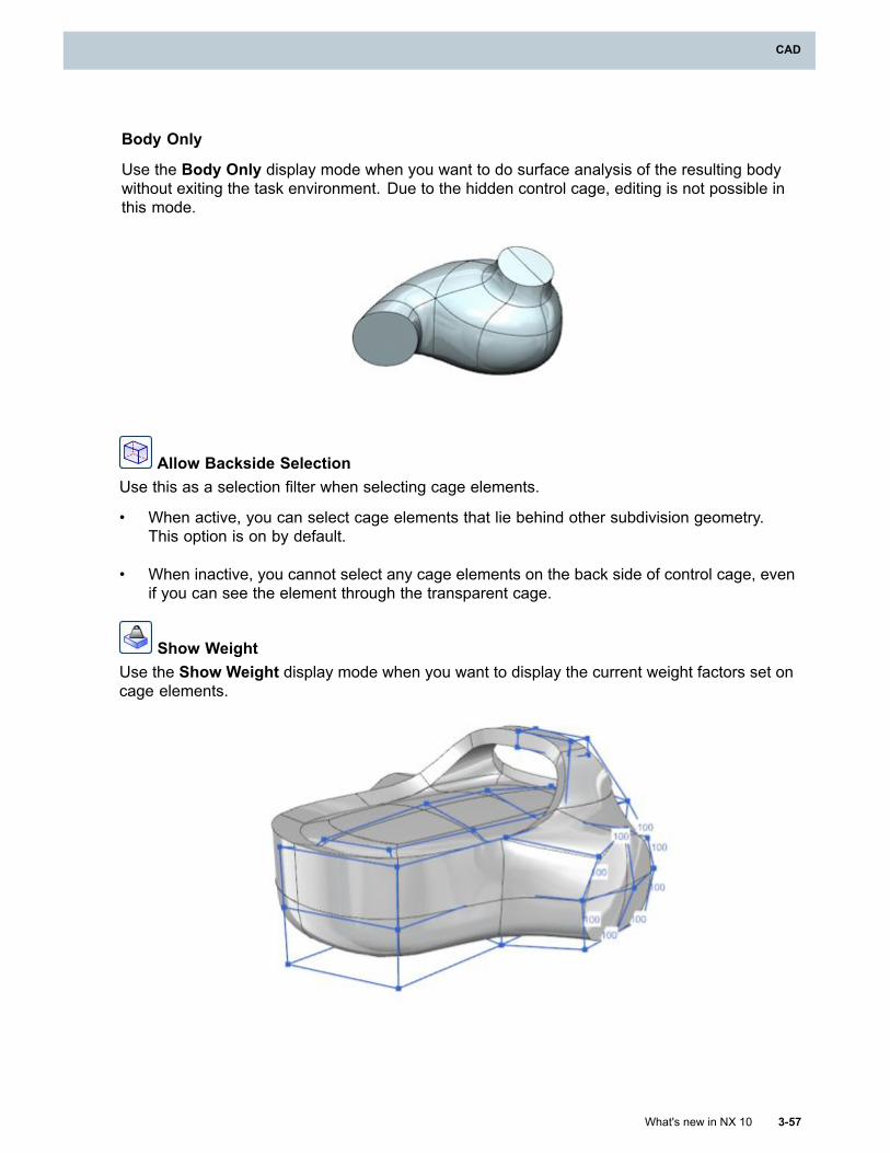
CAD
Body Only
Use the Body Only display mode when you want to do surface analysis of the resulting bodywithout exiting the task environment. Due to the hidden control cage, editing is not possible inthis mode.
Allow Backside SelectionUse this as a selection filter when selecting cage elements.
• When active, you can select cage elements that lie behind other subdivision geometry.This option is on by default.
• When inactive, you cannot select any cage elements on the back side of control cage, evenif you can see the element through the transparent cage.
Show WeightUse the Show Weight display mode when you want to display the current weight factors set oncage elements.
What's new in NX 10 3-57
CAD
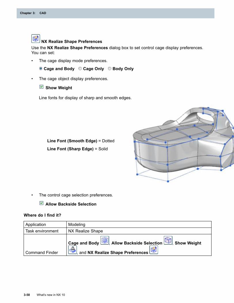
Chapter 3: CAD
NX Realize Shape PreferencesUse the NX Realize Shape Preferences dialog box to set control cage display preferences.You can set:
• The cage display mode preferences.
Cage and Body Cage Only Body Only
• The cage object display preferences.
Show Weight
Line fonts for display of sharp and smooth edges.
Line Font (Smooth Edge) = Dotted
Line Font (Sharp Edge) = Solid
• The control cage selection preferences.
Allow Backside Selection
Where do I find it?
Application ModelingTask environment NX Realize Shape
Command Finder
Cage and Body , Allow Backside Selection , Show Weight
, and NX Realize Shape Preferences
3-58 What's new in NX 10
Chapter 3: CAD
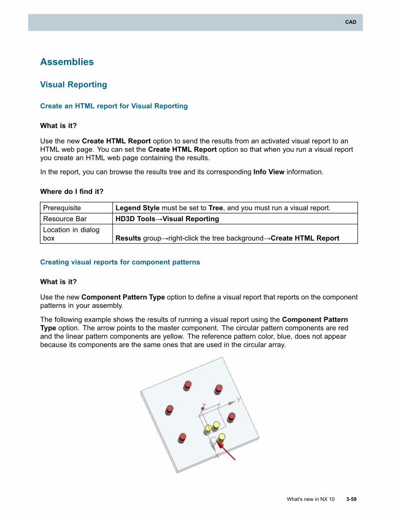
CAD
Assemblies
Visual Reporting
Create an HTML report for Visual Reporting
What is it?
Use the new Create HTML Report option to send the results from an activated visual report to anHTML web page. You can set the Create HTML Report option so that when you run a visual reportyou create an HTML web page containing the results.
In the report, you can browse the results tree and its corresponding Info View information.
Where do I find it?
Prerequisite Legend Style must be set to Tree, and you must run a visual report.Resource Bar HD3D Tools→Visual ReportingLocation in dialogbox Results group→right-click the tree background→Create HTML Report
Creating visual reports for component patterns
What is it?
Use the new Component Pattern Type option to define a visual report that reports on the componentpatterns in your assembly.
The following example shows the results of running a visual report using the Component PatternType option. The arrow points to the master component. The circular pattern components are redand the linear pattern components are yellow. The reference pattern color, blue, does not appearbecause its components are the same ones that are used in the circular array.
What's new in NX 10 3-59
CAD
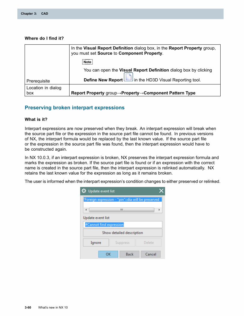
Chapter 3: CAD
Where do I find it?
Prerequisite
In the Visual Report Definition dialog box, in the Report Property group,you must set Source to Component Property.
Note
You can open the Visual Report Definition dialog box by clicking
Define New Report in the HD3D Visual Reporting tool.
Location in dialogbox Report Property group→Property→Component Pattern Type
Preserving broken interpart expressions
What is it?
Interpart expressions are now preserved when they break. An interpart expression will break whenthe source part file or the expression in the source part file cannot be found. In previous versionsof NX, the interpart formula would be replaced by the last known value. If the source part fileor the expression in the source part file was found, then the interpart expression would have tobe constructed again.
In NX 10.0.3, if an interpart expression is broken, NX preserves the interpart expression formula andmarks the expression as broken. If the source part file is found or if an expression with the correctname is created in the source part file, then the interpart expression is relinked automatically. NXretains the last known value for the expression as long as it remains broken.
The user is informed when the interpart expression’s condition changes to either preserved or relinked.
3-60 What's new in NX 10
Chapter 3: CAD
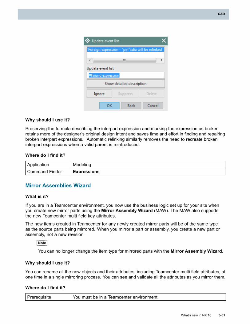
CAD
Why should I use it?
Preserving the formula describing the interpart expression and marking the expression as brokenretains more of the designer’s original design intent and saves time and effort in finding and repairingbroken interpart expressions. Automatic relinking similarly removes the need to recreate brokeninterpart expressions when a valid parent is reintroduced.
Where do I find it?
Application ModelingCommand Finder Expressions
Mirror Assemblies Wizard
What is it?
If you are in a Teamcenter environment, you now use the business logic set up for your site whenyou create new mirror parts using the Mirror Assembly Wizard (MAW). The MAW also supportsthe new Teamcenter multi field key attributes.
The new items created in Teamcenter for any newly created mirror parts will be of the same typeas the source parts being mirrored. When you mirror a part or assembly, you create a new part orassembly, not a new revision.
Note
You can no longer change the item type for mirrored parts with the Mirror Assembly Wizard.
Why should I use it?
You can rename all the new objects and their attributes, including Teamcenter multi field attributes, atone time in a single mirroring process. You can see and validate all the attributes as you mirror them.
Where do I find it?
Prerequisite You must be in a Teamcenter environment.
What's new in NX 10 3-61
CAD
Chapter 3: CAD
Command Finder Mirror Assembly
Extraction Path customizing
What is it?
When creating an extraction path in assembly sequencing, use the new Guide Path Manually optionto influence the direction of the path that is created. This lets you drag a copy of the components to alocation in the extraction path. NX then attempts to calculate and create a valid path in that direction.
Why should I use it?
The Guide Path Manually option is useful when the extraction path may be complicated by thepresence and location of other components. By guiding the components in a recommended direction,you provide NX with information that helps define a path that would otherwise be time-consuming ordifficult to find.
Where do I find it?
Application AssembliesCommand Finder Extraction Path
Location in dialogbox
Located in the version of the Extraction Path dialog box that appears after
you click Generate Result .
Replacing a part families component
What is it?
The Part Families functionality has been enhanced to ensure that drawing data (such as dimensions,occurrence notes, callouts) and occurrence properties (such as color and visibility settings) arepreserved in certain situations when creating assembly part family members. Prior to this change,drawing data would be retained and occurrence properties deleted when the assembly part familymember creation required some component of the template assembly to be substituted with anothercomponent. This data loss would occur even when the substituted parts were versions of each other.
Why should I use it?
This enhancement is relevant to users that require better associativity support when creatingassembly part family members.
Where do I find it?
Application AssembliesCommand Finder Part FamiliesMenu Menu→Tools→Part Families
3-62 What's new in NX 10
Chapter 3: CAD
CAD
Default location for component drag handles
What is it?
You can now specify a default location for the drag handles of components that do not have auser-defined drag handle location. To do this, set the Drag Handle Location customer default toeither Center of Bounding Box or to Origin of Component.
For parts modeled at the global origin, the component origin is a preferred default location for adrag handle. For parts modeled in their location in the assembly, the origin of a component mightbe quite a distance from the part geometry. In these cases, a CSYS or datum CSYS on the part isa preferred location.
You can now use the following drag handle shortcut menu options to quickly snap the drag handle tothe desired location:
• Snap Handle to CSYS
• Snap Handle to Component Center
• Snap Handle to Component Origin
If you select multiple components, the default drag handle location is always at the center of thecombined bounding box of all selected components.
Note
A user-defined drag handle location takes precedence over the location set by the customerdefault.
Why should I use it?
When you design a manufacturing line within a plant, you can quickly and precisely place componentsbased on their origin or a CSYS.
Where do I find it?
Command Finder Customer DefaultsLocation in dialog box Assemblies→Positioning→Interface tab
Command Finder Assemblies Preferences
Moving a component along a vector and projected distance
What is it?
You can now move a component along a vector and by a projected distance between two objects orpoints that are projected on the motion vector. To do this, set the Motion type option to ProjectedDistance, and set the following options:
• Specify Vector: Lets you specify a vector for the projected axis.
• Select Start Point or Object: Lets you select the point from which to measure the distance.
What's new in NX 10 3-63
CAD
Chapter 3: CAD
• Select End Point or Object: Lets you select the end point for measuring the distance.
Where do I find it?
Command Finder Move Component
Location in dialogbox
Transform group→Motion
Transform group→Specify Vector
Transform group→Select Start Point or Object
Transform group→Select End Point or Object
Add a component to the XC-YC plane by drag and drop
What is it?
You can use the Position on XC-YC Plane customer default to enable quickly placing of newcomponents by drag and drop to the XC-YC plane.
Tip
To find a customer default, choose File tab→Utilities→Customer Defaults, and click Find
Default .
Why should I use it?
To quickly place components at Z=0 to simulate objects being placed on a floor.
Support for monolithic JT files
What is it?
A monolithic JT file is a JT file that contains the entire product structure. When you add a monolithicJT file as a component to an NX assembly, NX now creates JT faceted bodies. In previous releases,NX created legacy NX faceted bodies.
WAVE-linking product interface enhancement
What is it?
When you use the graphics window to select an object that has a product interface, the productinterface is now selected for the following WAVE commands:
• WAVE Geometry Linker
• Copy Geometry to Component
• Copy Geometry to Part
• Copy Geometry to New Part
3-64 What's new in NX 10
Chapter 3: CAD
CAD
When you use one of the copy commands, the object you select must correspond exactly witha product interface in order to link to the product interface. The WAVE mode object types thatcorrespond with product interface object types are:
• Body
• Datum
• Point
• Sketch
• Composite curve
Note
Edges and faces do not link to a product interface because those WAVE mode object types donot correspond to product interface object types.
Why should I use it?
The behavior of these commands is now consistent with the behavior of other WAVE commands.Previously, when you used the graphics window to select geometry that has a product interface, someWAVE commands selected the product interface while others selected the object geometry. Mostusers prefer to link to the product interface instead of the geometry because, if the product interface isremapped to new geometry, the associated WAVE link also updates to point to the new geometry.
Where do I find it?
WAVE Geometry Linker
Command Finder WAVE Geometry Linker
Copying geometry
Prerequisite Make sure that WAVE Mode is active in the Assembly Navigator.
Assembly NavigatorRight-click on a component→WAVE→Copy Geometry to Component,Copy Geometry to Part, or Copy Geometry to New Part
Updating assembly structures in the Assembly Navigator
What is it?
The Update Structure on Expand customer default check box is now selected by default. Thisensures the following occurs when you expand nodes for unloaded subassemblies in the AssemblyNavigator:
• The expanded assembly structure is up-to-date.
• The bounding boxes are correct.
• The attributes are up-to-date.
What's new in NX 10 3-65
CAD
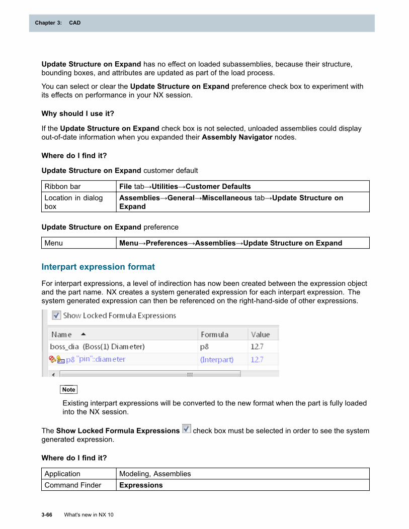
Chapter 3: CAD
Update Structure on Expand has no effect on loaded subassemblies, because their structure,bounding boxes, and attributes are updated as part of the load process.
You can select or clear the Update Structure on Expand preference check box to experiment withits effects on performance in your NX session.
Why should I use it?
If the Update Structure on Expand check box is not selected, unloaded assemblies could displayout-of-date information when you expanded their Assembly Navigator nodes.
Where do I find it?
Update Structure on Expand customer default
Ribbon bar File tab→Utilities→Customer DefaultsLocation in dialogbox
Assemblies→General→Miscellaneous tab→Update Structure onExpand
Update Structure on Expand preference
Menu Menu→Preferences→Assemblies→Update Structure on Expand
Interpart expression format
For interpart expressions, a level of indirection has now been created between the expression objectand the part name. NX creates a system generated expression for each interpart expression. Thesystem generated expression can then be referenced on the right-hand-side of other expressions.
Note
Existing interpart expressions will be converted to the new format when the part is fully loadedinto the NX session.
The Show Locked Formula Expressions check box must be selected in order to see the systemgenerated expression.
Where do I find it?
Application Modeling, AssembliesCommand Finder Expressions
3-66 What's new in NX 10
Chapter 3: CAD
CAD
PrerequisiteThe Show Locked Formula Expressions check box must be selectedin order to see the system generated expression.
General Relinker enhancement (10.0.2)
What is it?
You can now use the General Relinker command to search for the linked feature or product interfaceuser names in the target part. When NX finds a matching name in the source part, NX reestablishesthe link to the new source part. If no linked feature or product interface names are found, the objectnames that match the search string in the source part will be used and NX reestablishes the link tothe new source part.
Where do I find it?
Command Finder General Relinker
Product Interface enhancement (10.0.2)
What is it?
The following Product Interface command capabilities are enhanced.
• Consistent three-way highlighting between selected objects in the graphics window, and both theProduct Interface and Model History lists in the Part Navigator.
• Consistent parent child highlighting between selected objects in the graphics window, and boththe Product Interface and Model History lists in the Part Navigator.
• A Product Interface cannot be created when a part module or sketch is active.
Where do I find it?
Command Finder Product Interface
Drafting
What's new in NX 10 3-67
CAD
Chapter 3: CAD
Designing using Layout
Layout process in NX
Layout describes a conceptual 2D design environment where an engineer or designer can exploreconcepts in 2D by creating layouts of a part or assembly. The task is not to produce a finisheddrawing, but to provide an alternate way of solving design problems whose key characteristics arerepresented in 2D. You can use it for rapid prototyping of a design or part.
The layout process lets you do concept design without modeling 3D geometry, but it achieves therequirements that will drive the 3D design.
In NX, the Layout tab centralizes main commands in the following groups for exploring conceptsin 2D.
• View commands
• Sketch and 2D Component commands
• Dimension and Annotation commands
2D components are rigid reusable objects dedicated for 2D design that you can use to quickly andeasily create a layout. In the context of the 2D design, 2D components are analogous to 3D parts.
Using the layout process, you can:
• Create and organize 2D components into a hierarchical structure in the Part Navigator.
• Edit an active 2D component including nesting other 2D components. Other 2D componentswith same definition can be immediately updated or you can delay the update and lock 2Dcomponents to not apply the changes.
• Drag and drop from the Reuse Library to add existing 2D components to your layout.
• Apply different settings to each 2D component to manage the visibility of 2D components,geometry, dimensions, and annotations or apply them to all 2D components.
• Replace existing 2D components with one other 2D component.
• Break associativity between the 2D component and its definition or smash it into its constituentobjects.
• Document your layout for design review or production.
• Move a 2D component to a new view.
• Copy 2D components to 3D modeling space or create an assembly to continue your design in 3D.
• Publish 2D component definitions to Teamcenter or a disk drive for sharing with other engineers.
3-68 What's new in NX 10
Chapter 3: CAD
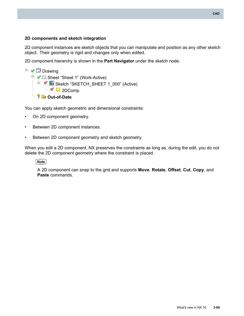
CAD
2D components and sketch integration
2D component instances are sketch objects that you can manipulate and position as any other sketchobject. Their geometry is rigid and changes only when edited.
2D component hierarchy is shown in the Part Navigator under the sketch node.
DrawingSheet “Sheet 1” (Work-Active)
Sketch “SKETCH_SHEET 1_000” (Active)2DComp
Out-of-Date
You can apply sketch geometric and dimensional constraints:
• On 2D component geometry.
• Between 2D component instances.
• Between 2D component geometry and sketch geometry.
When you edit a 2D component, NX preserves the constraints as long as, during the edit, you do notdelete the 2D component geometry where the constraint is placed.
Note
A 2D component can snap to the grid and supports Move, Rotate, Offset, Cut, Copy, andPaste commands.
What's new in NX 10 3-69
CAD
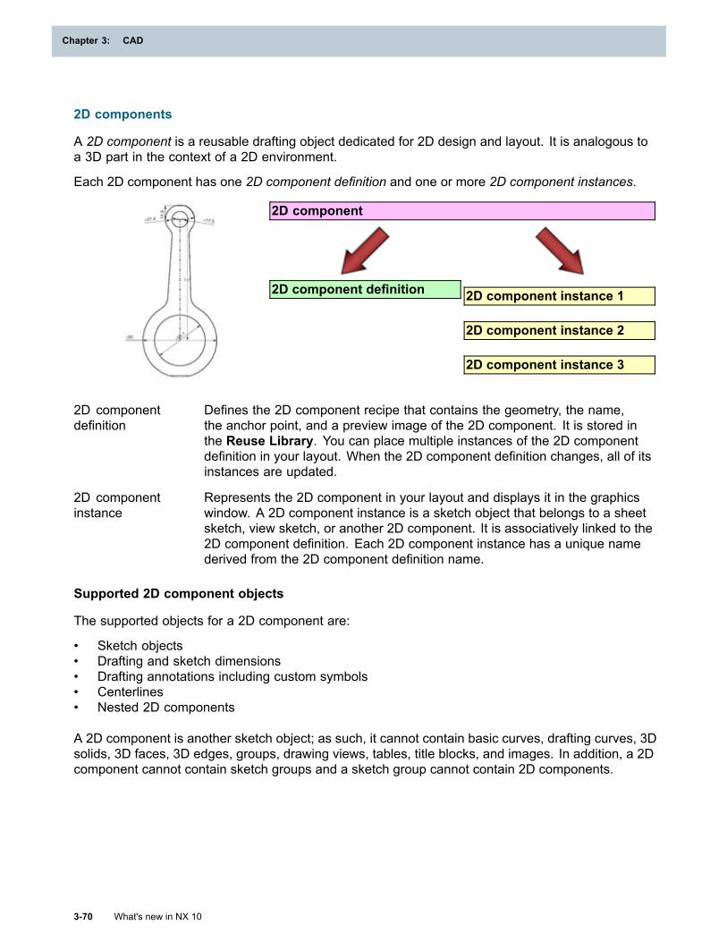
Chapter 3: CAD
2D components
A 2D component is a reusable drafting object dedicated for 2D design and layout. It is analogous toa 3D part in the context of a 2D environment.
Each 2D component has one 2D component definition and one or more 2D component instances.
2D component
2D component definition 2D component instance 1
2D component instance 2
2D component instance 3
2D componentdefinition
Defines the 2D component recipe that contains the geometry, the name,the anchor point, and a preview image of the 2D component. It is stored inthe Reuse Library. You can place multiple instances of the 2D componentdefinition in your layout. When the 2D component definition changes, all of itsinstances are updated.
2D componentinstance
Represents the 2D component in your layout and displays it in the graphicswindow. A 2D component instance is a sketch object that belongs to a sheetsketch, view sketch, or another 2D component. It is associatively linked to the2D component definition. Each 2D component instance has a unique namederived from the 2D component definition name.
Supported 2D component objects
The supported objects for a 2D component are:
• Sketch objects• Drafting and sketch dimensions• Drafting annotations including custom symbols• Centerlines• Nested 2D components
A 2D component is another sketch object; as such, it cannot contain basic curves, drafting curves, 3Dsolids, 3D faces, 3D edges, groups, drawing views, tables, title blocks, and images. In addition, a 2Dcomponent cannot contain sketch groups and a sketch group cannot contain 2D components.
3-70 What's new in NX 10
Chapter 3: CAD
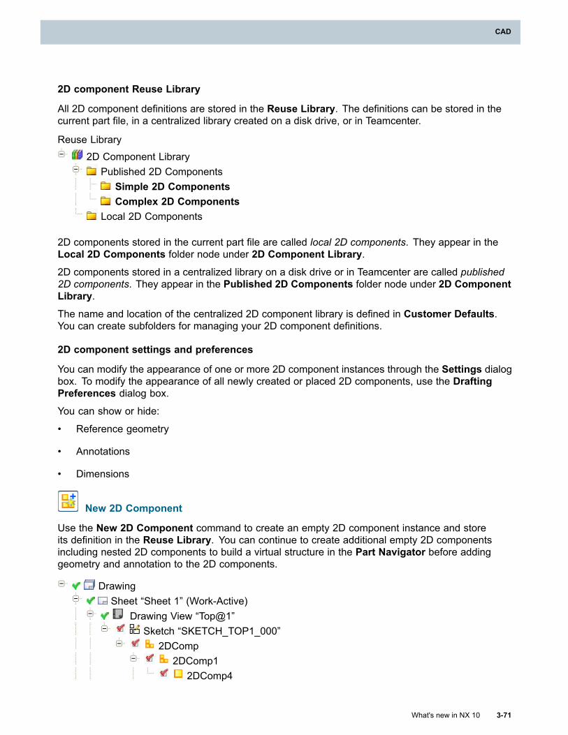
CAD
2D component Reuse Library
All 2D component definitions are stored in the Reuse Library. The definitions can be stored in thecurrent part file, in a centralized library created on a disk drive, or in Teamcenter.
Reuse Library
2D Component LibraryPublished 2D Components
Simple 2D ComponentsComplex 2D Components
Local 2D Components
2D components stored in the current part file are called local 2D components. They appear in theLocal 2D Components folder node under 2D Component Library.
2D components stored in a centralized library on a disk drive or in Teamcenter are called published2D components. They appear in the Published 2D Components folder node under 2D ComponentLibrary.
The name and location of the centralized 2D component library is defined in Customer Defaults.You can create subfolders for managing your 2D component definitions.
2D component settings and preferences
You can modify the appearance of one or more 2D component instances through the Settings dialogbox. To modify the appearance of all newly created or placed 2D components, use the DraftingPreferences dialog box.
You can show or hide:
• Reference geometry
• Annotations
• Dimensions
New 2D Component
Use the New 2D Component command to create an empty 2D component instance and storeits definition in the Reuse Library. You can continue to create additional empty 2D componentsincluding nested 2D components to build a virtual structure in the Part Navigator before addinggeometry and annotation to the 2D components.
DrawingSheet “Sheet 1” (Work-Active)
Drawing View “Top@1”Sketch “SKETCH_TOP1_000”
2DComp2DComp1
2DComp4
What's new in NX 10 3-71
CAD
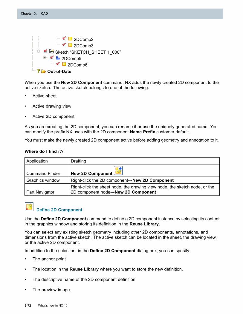
Chapter 3: CAD
2DComp22DComp3
Sketch “SKETCH_SHEET 1_000”2DComp5
2DComp6Out-of-Date
When you use the New 2D Component command, NX adds the newly created 2D component to theactive sketch. The active sketch belongs to one of the following:
• Active sheet
• Active drawing view
• Active 2D component
As you are creating the 2D component, you can rename it or use the uniquely generated name. Youcan modify the prefix NX uses with the 2D component Name Prefix customer default.
You must make the newly created 2D component active before adding geometry and annotation to it.
Where do I find it?
Application Drafting
Command Finder New 2D ComponentGraphics window Right-click the 2D component→New 2D Component
Part NavigatorRight-click the sheet node, the drawing view node, the sketch node, or the2D component node→New 2D Component
Define 2D Component
Use the Define 2D Component command to define a 2D component instance by selecting its contentin the graphics window and storing its definition in the Reuse Library.
You can select any existing sketch geometry including other 2D components, annotations, anddimensions from the active sketch. The active sketch can be located in the sheet, the drawing view,or the active 2D component.
In addition to the selection, in the Define 2D Component dialog box, you can specify:
• The anchor point.
• The location in the Reuse Library where you want to store the new definition.
• The descriptive name of the 2D component definition.
• The preview image.
3-72 What's new in NX 10
Chapter 3: CAD
CAD
NX creates a 2D component definition in the Reuse Library that contains all copied sketch geometryincluding constraints and nested 2D components. If the selection contained a sketch group, thecontent of the sketch group is moved to the 2D component. The group stays empty.
In the graphics window, NX replaces the selected objects by the 2D component instance of thenewly created 2D component. All constraints and dimensions between the 2D component and othergeometry are maintained. In the Part Navigator, NX creates a new 2D component node under thesketch node of the sheet or the drawing view or under the parent 2D component node.
Where do I find it?
Application Drafting
Command Finder Define 2D ComponentGraphics window Right-click selection→Define 2D ComponentPart Navigator Right-click the 2D component node→Define 2D Component
Reuse LibraryRight-click a folder node or a subfolder node under the 2D ComponentLibrary→Define 2D Component
What's new in NX 10 3-73
CAD

CAD
Replace 2D Component
Use the Replace 2D Component command to replace the selected 2D component instances withanother 2D component definition.
You can replace:
• One 2D component instance.
• All instances of the selected 2D component.
• Instances of different 2D components.
• Nested 2D component instances. This causes the parent 2D component definitions to changeand the 2D component instances that use them to update.
When the association between the 2D component instance and its definition is broken, the Replace2D Component command can replace the orphan 2D component with an existing 2D componentdefinition. The association can be broken, if, for example, the 2D component instance of a local 2Dcomponent is copied from one part to another without publishing the 2D component definition or if thepart file of a published 2D component is deleted from the system drive or from Teamcenter.
You can replace locked 2D components as long as their parents are not locked. The replacedinstances are not locked. You cannot replace an active 2D component. You must first exit or finishediting the 2D component before replacing it.
Where do I find it?
Application DraftingPrerequisite The 2D component must not be active.
Command Finder Replace 2D ComponentGraphics window Right-click the 2D component→ReplacePart Navigator Right-click the 2D component node→Replace
Make 2D Component Unique
Use the Make 2D Component Unique command to create a new 2D component definition for theselected 2D component instance. In the Make 2D Component Unique dialog box, you specify:
• The location in the Reuse Library where you want to store the new definition.
• The descriptive name of the 2D component definition.
• The optional preview image.
When you create a new 2D component definition, the nested 2D components of the selected instancekeep the same definitions they had prior to the command. Making a nested 2D component instanceunique changes the definition of its parent and updates its instantiated components.
What's new in NX 10 3-75
CAD
Chapter 3: CAD
When the association between the 2D component instance and its definition is broken, the Make 2DComponent Unique command creates a new 2D component definition for the orphan 2D component.The association can be broken, if, for example, the 2D component instance of a local 2D componentis copied from one part to another without publishing the 2D component definition or if the part file of apublished 2D component is deleted from the system drive or from Teamcenter.
You can make a locked 2D component unique as long as its parent is not locked. You cannot makean active 2D component unique. You must first exit or finish editing the 2D component before makingit unique.
Where do I find it?
Application DraftingPrerequisite The 2D component must not be active.
Command Finder Make 2D Component UniqueGraphics window Right-click the 2D component→Make UniquePart Navigator Right-click the 2D component node→Make Unique
Smash 2D Component
Use the Smash 2D Component command to break an instance of a 2D component into itsconstituent pieces. NX inserts the constituent pieces into the parent sketch.
If you smash a 2D component instance that has nested 2D components, the nested 2D componentsare not smashed, but they are placed in the top level sketch or the parent 2D component. You cansmash locked 2D components as long as their parents are not locked.
Constraints, dimensions, and annotations applied to the smashed 2D component are maintained.
Instances are smashed the way they are currently being displayed. If the instance is out-of-date thesmashed objects match the out-of-date instance. If the annotations, dimensions, and referencecurves are not visible due to defined style options, they are copied but remain hidden in the smashedinstance.
You cannot smash an active 2D component. You must first exit or finish editing the 2D componentbefore smashing it.
Where do I find it?
Application DraftingPrerequisite The 2D component must not be active.
Command Finder Smash 2D ComponentGraphics window Right-click the 2D component→SmashPart Navigator Right-click the 2D component node→Smash
3-76 What's new in NX 10
Chapter 3: CAD

Chapter 3: CAD
Publish 2D Component
Use the Publish 2D Component command to create an external part file containing the 2Dcomponent definition. You can publish one 2D component definition or all 2D component definitionsthat are stored in the Local 2D Components folder or its subfolders.
In the Publish 2D Component dialog box, you specify one destination location where all 2Dcomponent definitions will be saved. When you publish a 2D component definition that containsnested 2D components, NX also publishes the nested 2D component definitions in the samedestination location.
In the Customer Defaults dialog box, you or your company can specify:
• The name and location of the published 2D component library.
• If the published 2D components are stored either on a disk drive or in Teamcenter.
In native NX, the external 2D component part files have distinct names that end with .2dc.prt. InTeamcenter Integration, the published 2D components are items with unique names across theTeamcenter database.
Where do I find it?
Application Drafting
Reuse Library
Right-click the Local 2D Components folder node or a subfoldernode→Publish 2D Component
Right-click a 2D component in the Local 2D Components folder→Publish
Customer Defaults
Command Finder Customer DefaultsLocation in dialogbox Gateway→Reuse Library→2D Component Library tab
Create Assembly from Layout
Use the Create Assembly from Layout command to create an assembly that replicates the 2Dcomponent geometry and hierarchy of your layout. This enables you to continue your design in 3Din the Modeling application.
You specify:
• The top level sketch that contains the layout. The sketch can be either in the sheet or the drawingview.
• A part file where NX creates the assembly containing the component parts. The units of theassembly part must be the same as the units of the layout part.
NX creates:
3-78 What's new in NX 10
Chapter 3: CAD
CAD
• The assembly structure that replicates the 2D component hierarchy of your layout.
• A new part for each 2D component definition that is used in the selected layout. The units of thecreated component parts are the same as the units of the layout part. The name of the createdcomponent part file is the same as the name of the 2D component definition.
Note
If a file or an item with the same name already exists in the destination folder or in theTeamcenter database, NX does not create the part. Instead, you get a warning message.
The geometry of the 2D definition is used to create all component parts, even if the 2D componentinstance is locked or out-of-date. This may cause differences between the layout and the assembly ifthe layout contains out-of-date instances.
In the assembly, NX does not create parts from orphan 2D component instances as they do not havea definition. If you have orphan 2D components use the Make 2D Component Unique command tocreate 2D component definitions for them before creating the assembly.
Transferred annotations become assorted parts.
Sketches in Modeling
The layout top level sketch is copied to the assembly part sketch, while each 2D component definitionsketch is copied to the corresponding component part sketch. The sketches include all geometry,geometric constraints, and dimensional constraints from the original sketches.
All sketches are created in the XY plane of their corresponding new part and their origin is placedat the origin of the absolute coordinate system. If the original top level sketch is in a drawing view,the drawing view orientation is used to define the plane. The sketch origin in a component partcorresponds to the position of the 2D component anchor point. The XY orientation of the createdsketch matches the XY orientation of the 2D component sketch. The display settings of the 2Dcomponent geometry is preserved in the component part sketch.
Where do I find it?
Application Drafting
Command Finder Create Assembly from Layout
What's new in NX 10 3-79
CAD

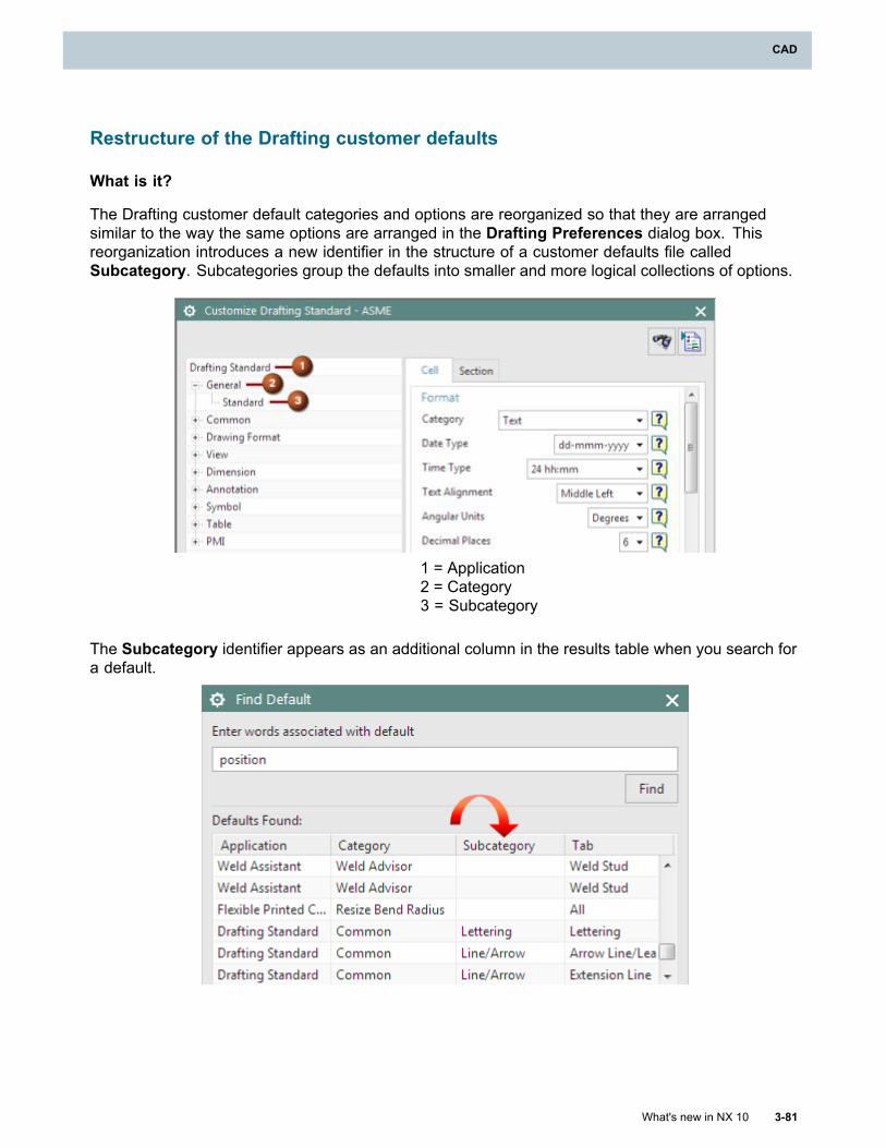
CAD
Restructure of the Drafting customer defaults
What is it?
The Drafting customer default categories and options are reorganized so that they are arrangedsimilar to the way the same options are arranged in the Drafting Preferences dialog box. Thisreorganization introduces a new identifier in the structure of a customer defaults file calledSubcategory. Subcategories group the defaults into smaller and more logical collections of options.
1 = Application2 = Category3 = Subcategory
The Subcategory identifier appears as an additional column in the results table when you search fora default.
What's new in NX 10 3-81
CAD
Chapter 3: CAD
Most drafting options are now located under the Drafting Standard customer default option. Inthe Customer Defaults dialog box, from the Drafting→General/Setup node, you must select anappropriate Drafting standard, and then click Customize Standard to access and change theseoptions.
Additionally, you can now use the Find Default tool to search for a default like in the CustomizeStandard mode.
Drafting customer default files
Due to this reorganization, most drafting customer default settings are now located in, andcontrolled by, the appropriate drafting standards file. For example, if the Drafting Standardfor your part is set to ISO, then most of the drafting custom default settings are located in thenx_ISO_Drafting_Standard_Shipped.dpv file.
Tip
If you have customized your Drafting default settings, or have created unique drafting standarddefault files (e.g. a custom version of the nx_ISO_Drafting_Standard_Shipped.dpv file),
you must use the Import Drafting Standard tool to migrate all of your Drafting customerdefault settings into NX 10. To access this tool, you must click the Customize Standard buttonon the Drafting→General/Setup node in the Customer Defaults dialog box.
If you have customized your customer defaults file (i.e. nx9_user.dpv) then you must use both
the Import Drafting Standard tool and the Import Defaults tool, located in theManage Current Settings dialog box, to import all of your customized user default settings.
Where do I find it?
Access and change existing Drafting customer default settings
Command Finder Customer DefaultsMenu File→Utilities→Customer DefaultsLocation in dialogbox
Drafting→General/Setup node→Standard tab→select a standard from theDrafting Standard list→click Customize Standard
Import your existing drafting customer defaults settings
Command Finder Customer DefaultsMenu File→Utilities→Customer Defaults
Location in dialogbox
Drafting→General/Setup node→Standard tab→select a standard fromthe Drafting Standard list→click Customize Standard and then click the
Import Drafting Standard button
3-82 What's new in NX 10
Chapter 3: CAD
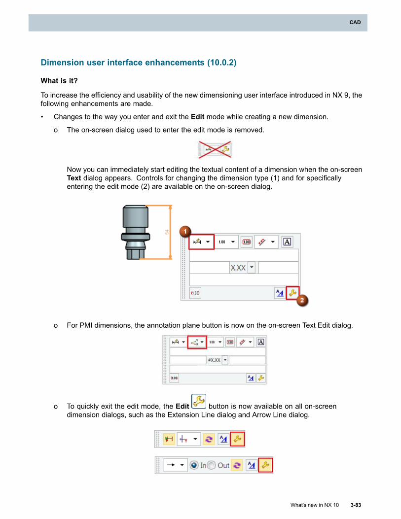
CAD
Dimension user interface enhancements (10.0.2)
What is it?
To increase the efficiency and usability of the new dimensioning user interface introduced in NX 9, thefollowing enhancements are made.
• Changes to the way you enter and exit the Edit mode while creating a new dimension.
o The on-screen dialog used to enter the edit mode is removed.
Now you can immediately start editing the textual content of a dimension when the on-screenText dialog appears. Controls for changing the dimension type (1) and for specificallyentering the edit mode (2) are available on the on-screen dialog.
o For PMI dimensions, the annotation plane button is now on the on-screen Text Edit dialog.
o To quickly exit the edit mode, the Edit button is now available on all on-screendimension dialogs, such as the Extension Line dialog and Arrow Line dialog.
What's new in NX 10 3-83
CAD
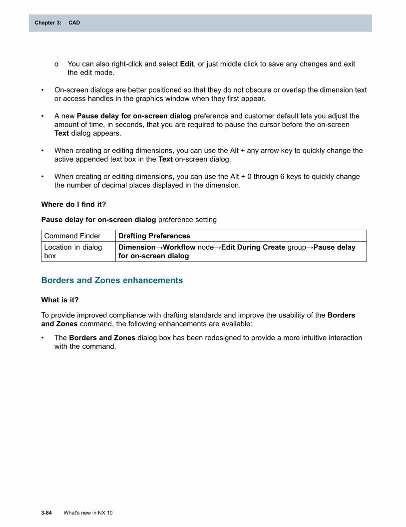
Chapter 3: CAD
o You can also right-click and select Edit, or just middle click to save any changes and exitthe edit mode.
• On-screen dialogs are better positioned so that they do not obscure or overlap the dimension textor access handles in the graphics window when they first appear.
• A new Pause delay for on-screen dialog preference and customer default lets you adjust theamount of time, in seconds, that you are required to pause the cursor before the on-screenText dialog appears.
• When creating or editing dimensions, you can use the Alt + any arrow key to quickly change theactive appended text box in the Text on-screen dialog.
• When creating or editing dimensions, you can use the Alt + 0 through 6 keys to quickly changethe number of decimal places displayed in the dimension.
Where do I find it?
Pause delay for on-screen dialog preference setting
Command Finder Drafting PreferencesLocation in dialogbox
Dimension→Workflow node→Edit During Create group→Pause delayfor on-screen dialog
Borders and Zones enhancements
What is it?
To provide improved compliance with drafting standards and improve the usability of the Bordersand Zones command, the following enhancements are available:
• The Borders and Zones dialog box has been redesigned to provide a more intuitive interactionwith the command.
3-84 What's new in NX 10
Chapter 3: CAD
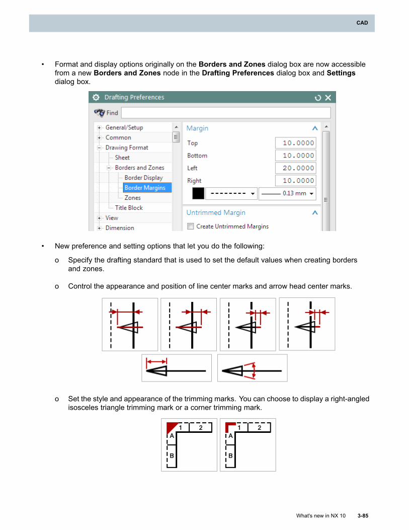
CAD
• Format and display options originally on the Borders and Zones dialog box are now accessiblefrom a new Borders and Zones node in the Drafting Preferences dialog box and Settingsdialog box.
• New preference and setting options that let you do the following:
o Specify the drafting standard that is used to set the default values when creating bordersand zones.
o Control the appearance and position of line center marks and arrow head center marks.
o Set the style and appearance of the trimming marks. You can choose to display a right-angledisosceles triangle trimming mark or a corner trimming mark.
What's new in NX 10 3-85
CAD
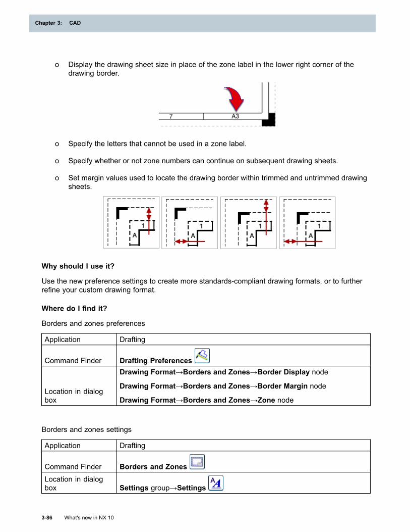
Chapter 3: CAD
o Display the drawing sheet size in place of the zone label in the lower right corner of thedrawing border.
o Specify the letters that cannot be used in a zone label.
o Specify whether or not zone numbers can continue on subsequent drawing sheets.
o Set margin values used to locate the drawing border within trimmed and untrimmed drawingsheets.
Why should I use it?
Use the new preference settings to create more standards-compliant drawing formats, or to furtherrefine your custom drawing format.
Where do I find it?
Borders and zones preferences
Application Drafting
Command Finder Drafting Preferences
Location in dialogbox
Drawing Format→Borders and Zones→Border Display node
Drawing Format→Borders and Zones→Border Margin node
Drawing Format→Borders and Zones→Zone node
Borders and zones settings
Application Drafting
Command Finder Borders and ZonesLocation in dialogbox Settings group→Settings
3-86 What's new in NX 10
Chapter 3: CAD
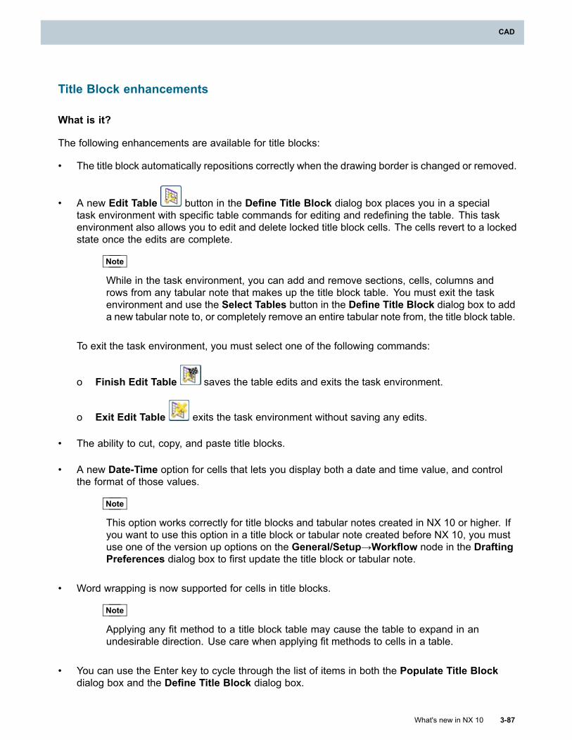
CAD
Title Block enhancements
What is it?
The following enhancements are available for title blocks:
• The title block automatically repositions correctly when the drawing border is changed or removed.
• A new Edit Table button in the Define Title Block dialog box places you in a specialtask environment with specific table commands for editing and redefining the table. This taskenvironment also allows you to edit and delete locked title block cells. The cells revert to a lockedstate once the edits are complete.
Note
While in the task environment, you can add and remove sections, cells, columns androws from any tabular note that makes up the title block table. You must exit the taskenvironment and use the Select Tables button in the Define Title Block dialog box to adda new tabular note to, or completely remove an entire tabular note from, the title block table.
To exit the task environment, you must select one of the following commands:
o Finish Edit Table saves the table edits and exits the task environment.
o Exit Edit Table exits the task environment without saving any edits.
• The ability to cut, copy, and paste title blocks.
• A new Date-Time option for cells that lets you display both a date and time value, and controlthe format of those values.
Note
This option works correctly for title blocks and tabular notes created in NX 10 or higher. Ifyou want to use this option in a title block or tabular note created before NX 10, you mustuse one of the version up options on the General/Setup→Workflow node in the DraftingPreferences dialog box to first update the title block or tabular note.
• Word wrapping is now supported for cells in title blocks.
Note
Applying any fit method to a title block table may cause the table to expand in anundesirable direction. Use care when applying fit methods to cells in a table.
• You can use the Enter key to cycle through the list of items in both the Populate Title Blockdialog box and the Define Title Block dialog box.
What's new in NX 10 3-87
CAD
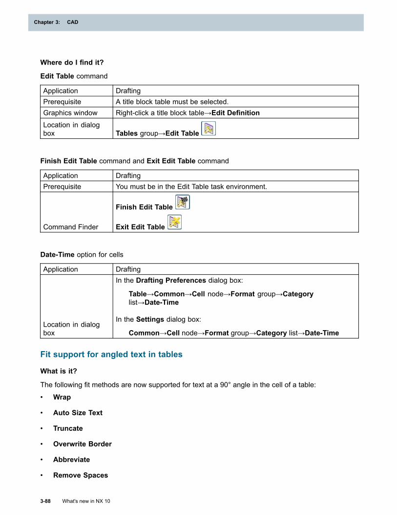
Chapter 3: CAD
Where do I find it?
Edit Table command
Application DraftingPrerequisite A title block table must be selected.Graphics window Right-click a title block table→Edit DefinitionLocation in dialogbox Tables group→Edit Table
Finish Edit Table command and Exit Edit Table command
Application DraftingPrerequisite You must be in the Edit Table task environment.
Command Finder
Finish Edit Table
Exit Edit Table
Date-Time option for cells
Application Drafting
Location in dialogbox
In the Drafting Preferences dialog box:
Table→Common→Cell node→Format group→Categorylist→Date-Time
In the Settings dialog box:
Common→Cell node→Format group→Category list→Date-Time
Fit support for angled text in tables
What is it?
The following fit methods are now supported for text at a 90° angle in the cell of a table:
• Wrap
• Auto Size Text
• Truncate
• Overwrite Border
• Abbreviate
• Remove Spaces
3-88 What's new in NX 10
Chapter 3: CAD
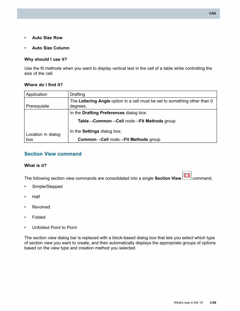
CAD
• Auto Size Row
• Auto Size Column
Why should I use it?
Use the fit methods when you want to display vertical text in the cell of a table while controlling thesize of the cell.
Where do I find it?
Application Drafting
PrerequisiteThe Lettering Angle option in a cell must be set to something other than 0degrees.
Location in dialogbox
In the Drafting Preferences dialog box:
Table→Common→Cell node→Fit Methods group
In the Settings dialog box:
Common→Cell node→Fit Methods group
Section View command
What is it?
The following section view commands are consolidated into a single Section View command.
• Simple/Stepped
• Half
• Revolved
• Folded
• Unfolded Point to Point
The section view dialog bar is replaced with a block-based dialog box that lets you select which typeof section view you want to create, and then automatically displays the appropriate groups of optionsbased on the view type and creation method you selected.
What's new in NX 10 3-89
CAD
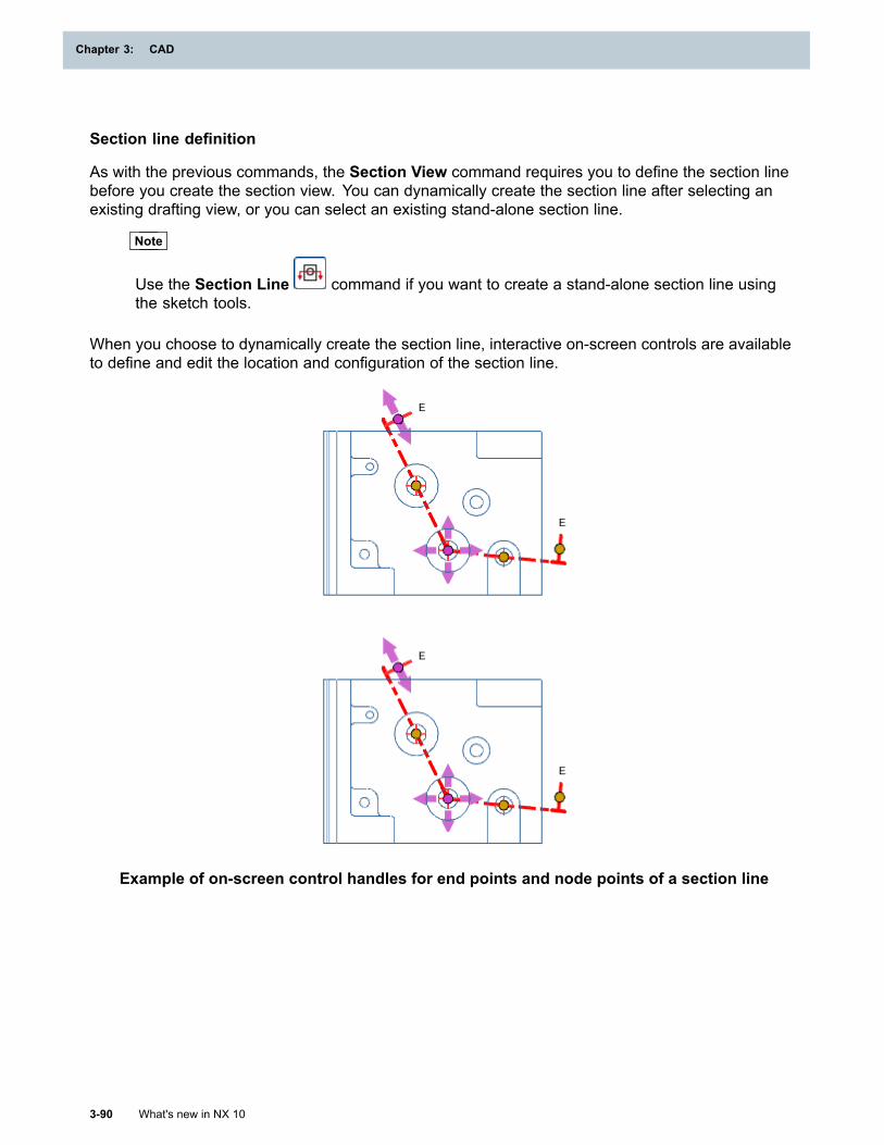
Chapter 3: CAD
Section line definition
As with the previous commands, the Section View command requires you to define the section linebefore you create the section view. You can dynamically create the section line after selecting anexisting drafting view, or you can select an existing stand-alone section line.
Note
Use the Section Line command if you want to create a stand-alone section line usingthe sketch tools.
When you choose to dynamically create the section line, interactive on-screen controls are availableto define and edit the location and configuration of the section line.
Example of on-screen control handles for end points and node points of a section line
3-90 What's new in NX 10
Chapter 3: CAD
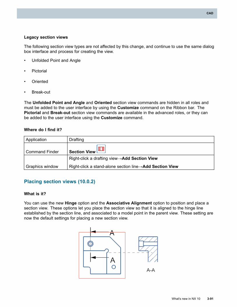
CAD
Legacy section views
The following section view types are not affected by this change, and continue to use the same dialogbox interface and process for creating the view.
• Unfolded Point and Angle
• Pictorial
• Oriented
• Break-out
The Unfolded Point and Angle and Oriented section view commands are hidden in all roles andmust be added to the user interface by using the Customize command on the Ribbon bar. ThePictorial and Break-out section view commands are available in the advanced roles, or they canbe added to the user interface using the Customize command.
Where do I find it?
Application Drafting
Command Finder Section View
Graphics window
Right-click a drafting view→Add Section View
Right-click a stand-alone section line→Add Section View
Placing section views (10.0.2)
What is it?
You can use the new Hinge option and the Associative Alignment option to position and place asection view. These options let you place the section view so that it is aligned to the hinge lineestablished by the section line, and associated to a model point in the parent view. These setting arenow the default settings for placing a new section view.
What's new in NX 10 3-91
CAD
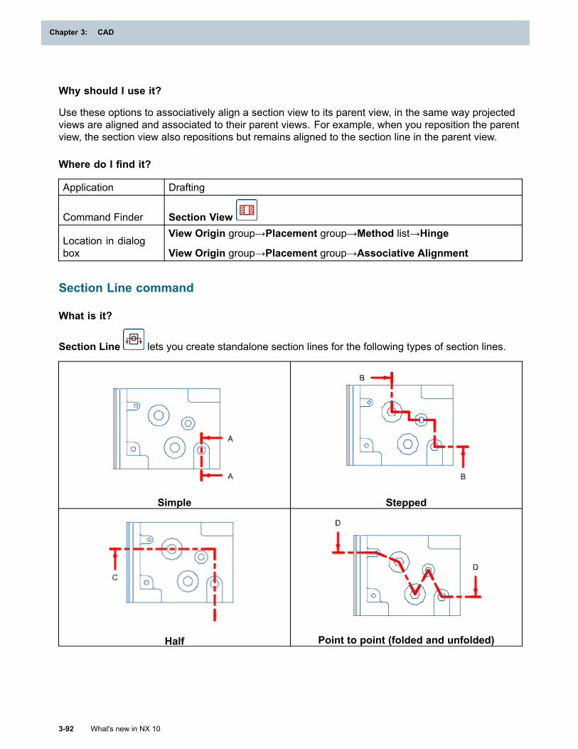
Chapter 3: CAD
Why should I use it?
Use these options to associatively align a section view to its parent view, in the same way projectedviews are aligned and associated to their parent views. For example, when you reposition the parentview, the section view also repositions but remains aligned to the section line in the parent view.
Where do I find it?
Application Drafting
Command Finder Section View
Location in dialogbox
View Origin group→Placement group→Method list→Hinge
View Origin group→Placement group→Associative Alignment
Section Line command
What is it?
Section Line lets you create standalone section lines for the following types of section lines.
Simple Stepped
Half Point to point (folded and unfolded)
3-92 What's new in NX 10
Chapter 3: CAD
CAD
The Section Line command always creates section lines in a sketch that has the following uniquecharacteristics:
• Any dimensions created in the sketch are for reference only, and are not visible outside of thesketch environment.
• You can constrain the sketch curves to geometry in the associated view only. If you want to addconstraints to geometry outside of the view, including geometry in other sketches associated tothe view, you must add reference geometry to the sketch.
• Only one continuous section line can exist in the sketch.
• The sketch is not visible in the Part Navigator. You must edit the section line to enter thesketch environment.
When editing a section line, you cannot change the parent view. You cannot add sketch-basedsection lines to views that contain view breaks. If you want to add associative section lines to adrawing view with an Exact (Pre-NX 8.5) representation, you must turn on extracted edges.
Why should I use it?
Use the Section Line command when you want greater control over the definition of the sectionline. You can also use the Section Line command to create a stand-alone section line that is notassociated to a section view.
Note
Use the Section View command if you want to simultaneously create both a section lineand an associated section view.
Where do I find it?
Create a stand-alone section line
Application Drafting
Command Finder Section LineGraphics window Right-click a drafting view→Add Section Line
Edit a section line
Application Drafting
Graphics window
Right-click a section line→Edit
Double-click a section line
What's new in NX 10 3-93
CAD
Chapter 3: CAD
View enhancements
What is it?
The following enhancements are available for smart lightweight drafting views:
• You can create break-out section views from smart lightweight views.
• Crosshatch patterns are correctly rendered when they are hidden behind bodies in a sectionedsmart lightweight view.
• You can import PMI lightweight section views onto a drawing as smart lightweight section views.
• You can suppress the display of all hidden edges that are not referenced in a smart lightweightview. Alternately, you can display hidden edges that are referenced by associated annotation orwhen view dependent edits are applied to the hidden edge.
Also, the Work in Progress interruption mechanism has been enhanced to provide a quickerresponse when stopping a view update process.
Why should I use it?
Smart lightweight drafting views improve performance and memory efficiency when working with largeassembly drawings. These enhancements enable a wider use of smart lightweight views in drawings.
Where do I find it?
Set the view type to display a smart lightweight view
Application Drafting
Location in dialogbox
In the Drafting Preferences dialog box:
View→Common node→Setting group→Representation
In the Settings dialog box:
Common node→Setting group→Representation
View break enhancements
What is it?
When you break a view that has a radial dimension partially outside of the view break, NX displaysthe radial dimension with the view break. The radial dimension is partially outside if its leaderterminate point is outside of the view break. The selected curve for the radial dimension can be anarc, circle, spline, or conic.
This enhancement applies to any radial dimensions, whether their settings specify Radius to Centeror not, with arrows pointing in or out. It applies both to drafting radial dimensions created on thedrawing and to inherited PMI radial dimensions shown on the drawing.
In previous releases, the radial dimension was hidden when the center of the arc or circle wasinside the view break.
3-94 What's new in NX 10
Chapter 3: CAD
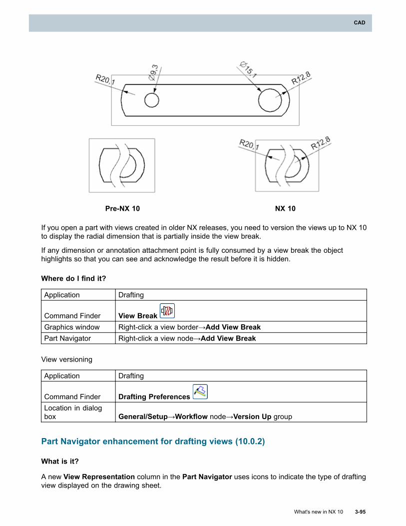
CAD
Pre-NX 10 NX 10
If you open a part with views created in older NX releases, you need to version the views up to NX 10to display the radial dimension that is partially inside the view break.
If any dimension or annotation attachment point is fully consumed by a view break the objecthighlights so that you can see and acknowledge the result before it is hidden.
Where do I find it?
Application Drafting
Command Finder View BreakGraphics window Right-click a view border→Add View BreakPart Navigator Right-click a view node→Add View Break
View versioning
Application Drafting
Command Finder Drafting PreferencesLocation in dialogbox General/Setup→Workflow node→Version Up group
Part Navigator enhancement for drafting views (10.0.2)
What is it?
A new View Representation column in the Part Navigator uses icons to indicate the type of draftingview displayed on the drawing sheet.
What's new in NX 10 3-95
CAD
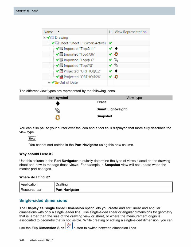
Chapter 3: CAD
The different view types are represented by the following icons.
Icon symbol View typeExact
Smart Lightweight
Snapshot
You can also pause your cursor over the icon and a tool tip is displayed that more fully describes theview type.
Note
You cannot sort entries in the Part Navigator using this new column.
Why should I use it?
Use this column in the Part Navigator to quickly determine the type of views placed on the drawingsheet and how to manage those views. For example, a Snapshot view will not update when themaster part changes.
Where do I find it?
Application DraftingResource bar Part Navigator
Single-sided dimensions
The Display as Single Sided Dimension option lets you create and edit linear and angulardimensions with only a single leader line. Use single-sided linear or angular dimensions for geometrythat is larger than the size of the drawing view or sheet, or where the measurement origin isassociated to geometry that is not visible. While creating or editing a single-sided dimension, you can
use the Flip Dimension Side button to switch between dimension lines.
3-96 What's new in NX 10
Chapter 3: CAD
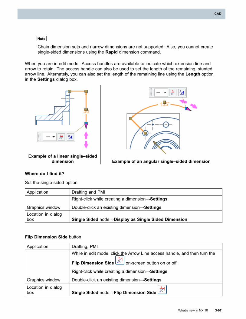
CAD
Note
Chain dimension sets and narrow dimensions are not supported. Also, you cannot createsingle-sided dimensions using the Rapid dimension command.
When you are in edit mode. Access handles are available to indicate which extension line andarrow to retain. The access handle can also be used to set the length of the remaining, stuntedarrow line. Alternately, you can also set the length of the remaining line using the Length optionin the Settings dialog box.
Example of a linear single–sideddimension Example of an angular single–sided dimension
Where do I find it?
Set the single sided option
Application Drafting and PMI
Graphics window
Right-click while creating a dimension→Settings
Double-click an existing dimension→SettingsLocation in dialogbox Single Sided node→Display as Single Sided Dimension
Flip Dimension Side button
Application Drafting, PMI
Graphics window
While in edit mode, click the Arrow Line access handle, and then turn the
Flip Dimension Side on-screen button on or off.
Right-click while creating a dimension→Settings
Double-click an existing dimension→SettingsLocation in dialogbox Single Sided node→Flip Dimension Side
What's new in NX 10 3-97
CAD
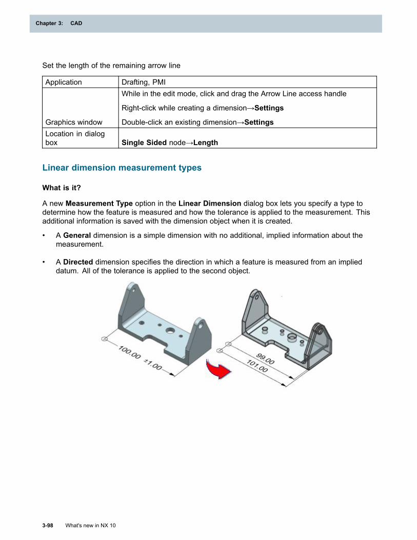
Chapter 3: CAD
Set the length of the remaining arrow line
Application Drafting, PMI
Graphics window
While in the edit mode, click and drag the Arrow Line access handle
Right-click while creating a dimension→Settings
Double-click an existing dimension→SettingsLocation in dialogbox Single Sided node→Length
Linear dimension measurement types
What is it?
A new Measurement Type option in the Linear Dimension dialog box lets you specify a type todetermine how the feature is measured and how the tolerance is applied to the measurement. Thisadditional information is saved with the dimension object when it is created.
• A General dimension is a simple dimension with no additional, implied information about themeasurement.
• A Directed dimension specifies the direction in which a feature is measured from an implieddatum. All of the tolerance is applied to the second object.
3-98 What's new in NX 10
Chapter 3: CAD
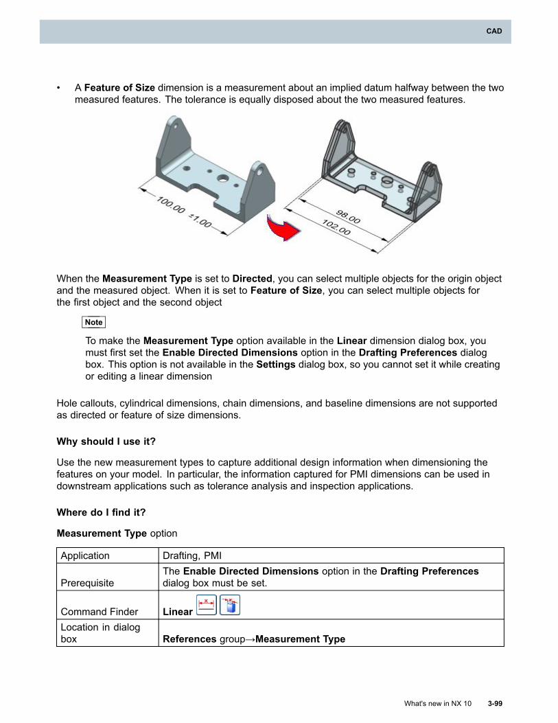
CAD
• A Feature of Size dimension is a measurement about an implied datum halfway between the twomeasured features. The tolerance is equally disposed about the two measured features.
When the Measurement Type is set to Directed, you can select multiple objects for the origin objectand the measured object. When it is set to Feature of Size, you can select multiple objects forthe first object and the second object
Note
To make the Measurement Type option available in the Linear dimension dialog box, youmust first set the Enable Directed Dimensions option in the Drafting Preferences dialogbox. This option is not available in the Settings dialog box, so you cannot set it while creatingor editing a linear dimension
Hole callouts, cylindrical dimensions, chain dimensions, and baseline dimensions are not supportedas directed or feature of size dimensions.
Why should I use it?
Use the new measurement types to capture additional design information when dimensioning thefeatures on your model. In particular, the information captured for PMI dimensions can be used indownstream applications such as tolerance analysis and inspection applications.
Where do I find it?
Measurement Type option
Application Drafting, PMI
PrerequisiteThe Enable Directed Dimensions option in the Drafting Preferencesdialog box must be set.
Command Finder LinearLocation in dialogbox References group→Measurement Type
What's new in NX 10 3-99
CAD
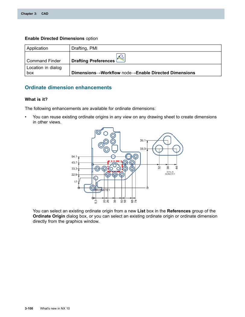
Chapter 3: CAD
Enable Directed Dimensions option
Application Drafting, PMI
Command Finder Drafting PreferencesLocation in dialogbox Dimensions→Workflow node→Enable Directed Dimensions
Ordinate dimension enhancements
What is it?
The following enhancements are available for ordinate dimensions:
• You can reuse existing ordinate origins in any view on any drawing sheet to create dimensionsin other views.
You can select an existing ordinate origin from a new List box in the References group of theOrdinate Origin dialog box, or you can select an existing ordinate origin or ordinate dimensiondirectly from the graphics window.
3-100 What's new in NX 10
Chapter 3: CAD
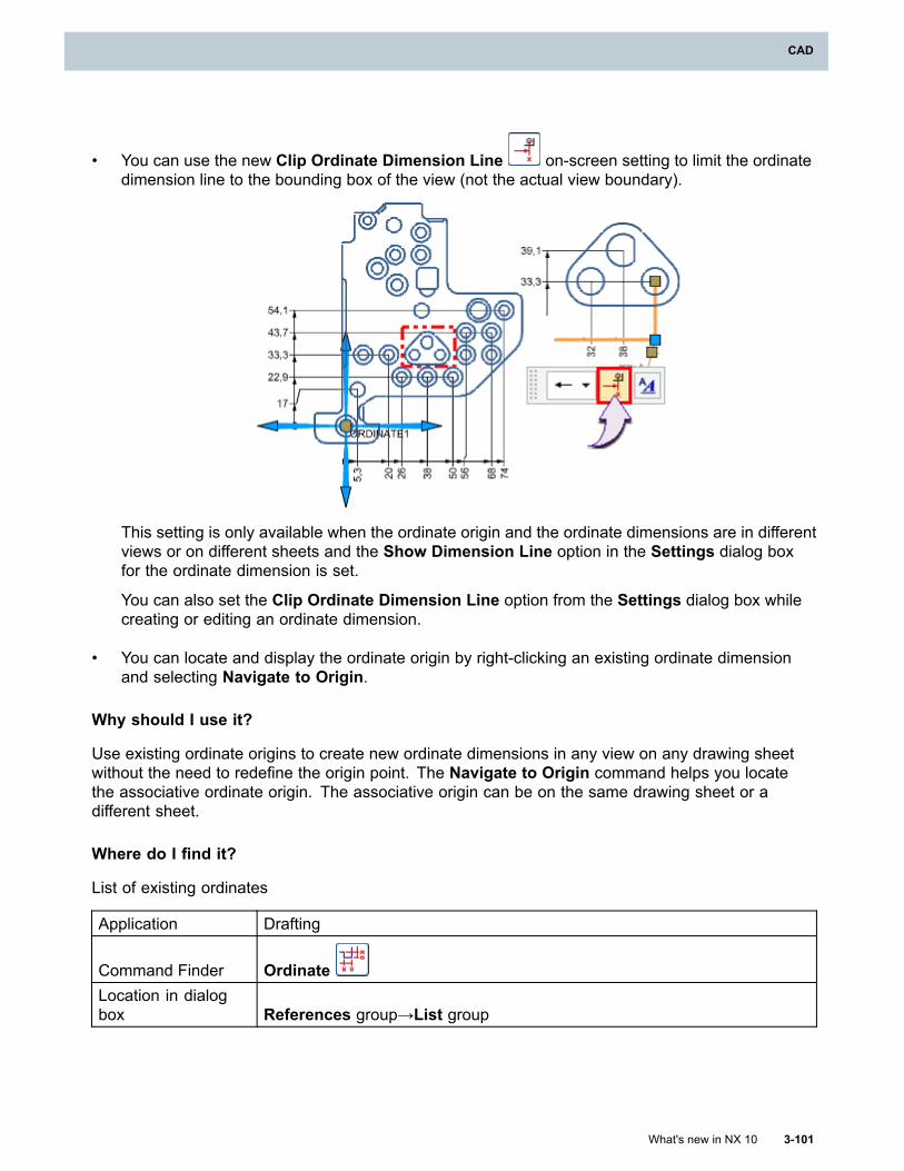
CAD
• You can use the new Clip Ordinate Dimension Line on-screen setting to limit the ordinatedimension line to the bounding box of the view (not the actual view boundary).
This setting is only available when the ordinate origin and the ordinate dimensions are in differentviews or on different sheets and the Show Dimension Line option in the Settings dialog boxfor the ordinate dimension is set.
You can also set the Clip Ordinate Dimension Line option from the Settings dialog box whilecreating or editing an ordinate dimension.
• You can locate and display the ordinate origin by right-clicking an existing ordinate dimensionand selecting Navigate to Origin.
Why should I use it?
Use existing ordinate origins to create new ordinate dimensions in any view on any drawing sheetwithout the need to redefine the origin point. The Navigate to Origin command helps you locatethe associative ordinate origin. The associative origin can be on the same drawing sheet or adifferent sheet.
Where do I find it?
List of existing ordinates
Application Drafting
Command Finder OrdinateLocation in dialogbox References group→List group
What's new in NX 10 3-101
CAD
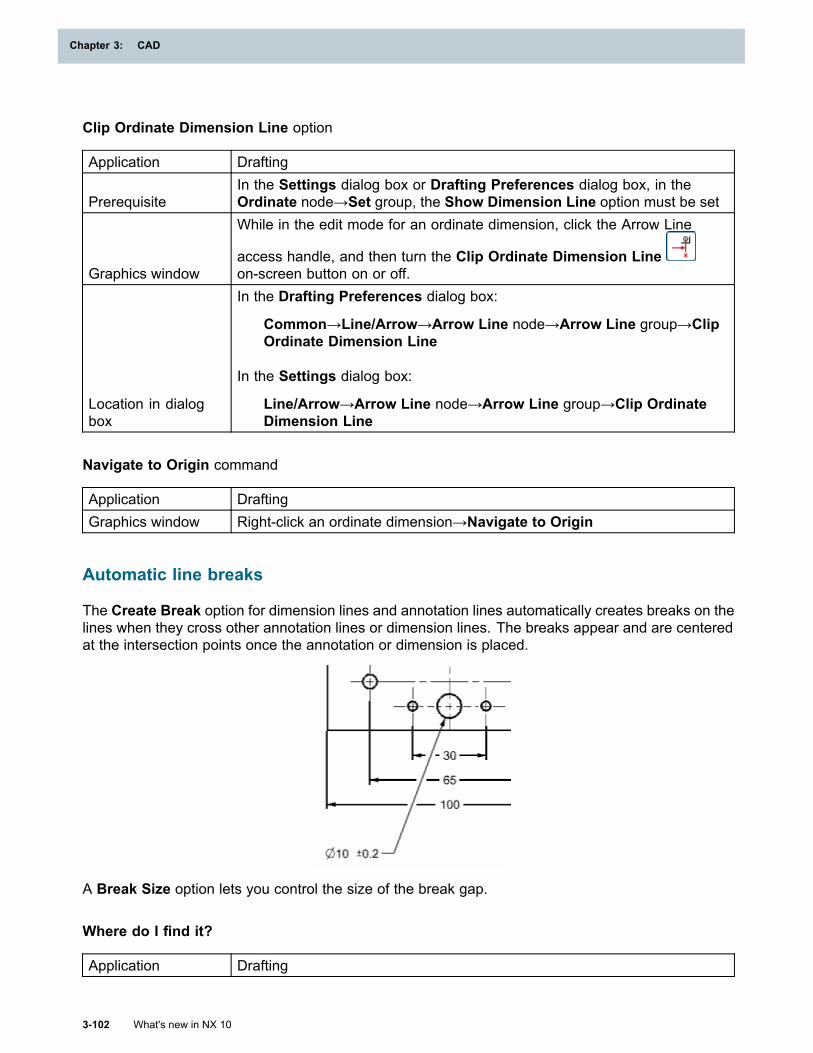
Chapter 3: CAD
Clip Ordinate Dimension Line option
Application Drafting
PrerequisiteIn the Settings dialog box or Drafting Preferences dialog box, in theOrdinate node→Set group, the Show Dimension Line option must be set
Graphics window
While in the edit mode for an ordinate dimension, click the Arrow Line
access handle, and then turn the Clip Ordinate Dimension Lineon-screen button on or off.
Location in dialogbox
In the Drafting Preferences dialog box:
Common→Line/Arrow→Arrow Line node→Arrow Line group→ClipOrdinate Dimension Line
In the Settings dialog box:
Line/Arrow→Arrow Line node→Arrow Line group→Clip OrdinateDimension Line
Navigate to Origin command
Application DraftingGraphics window Right-click an ordinate dimension→Navigate to Origin
Automatic line breaks
The Create Break option for dimension lines and annotation lines automatically creates breaks on thelines when they cross other annotation lines or dimension lines. The breaks appear and are centeredat the intersection points once the annotation or dimension is placed.
A Break Size option lets you control the size of the break gap.
Where do I find it?
Application Drafting
3-102 What's new in NX 10
Chapter 3: CAD
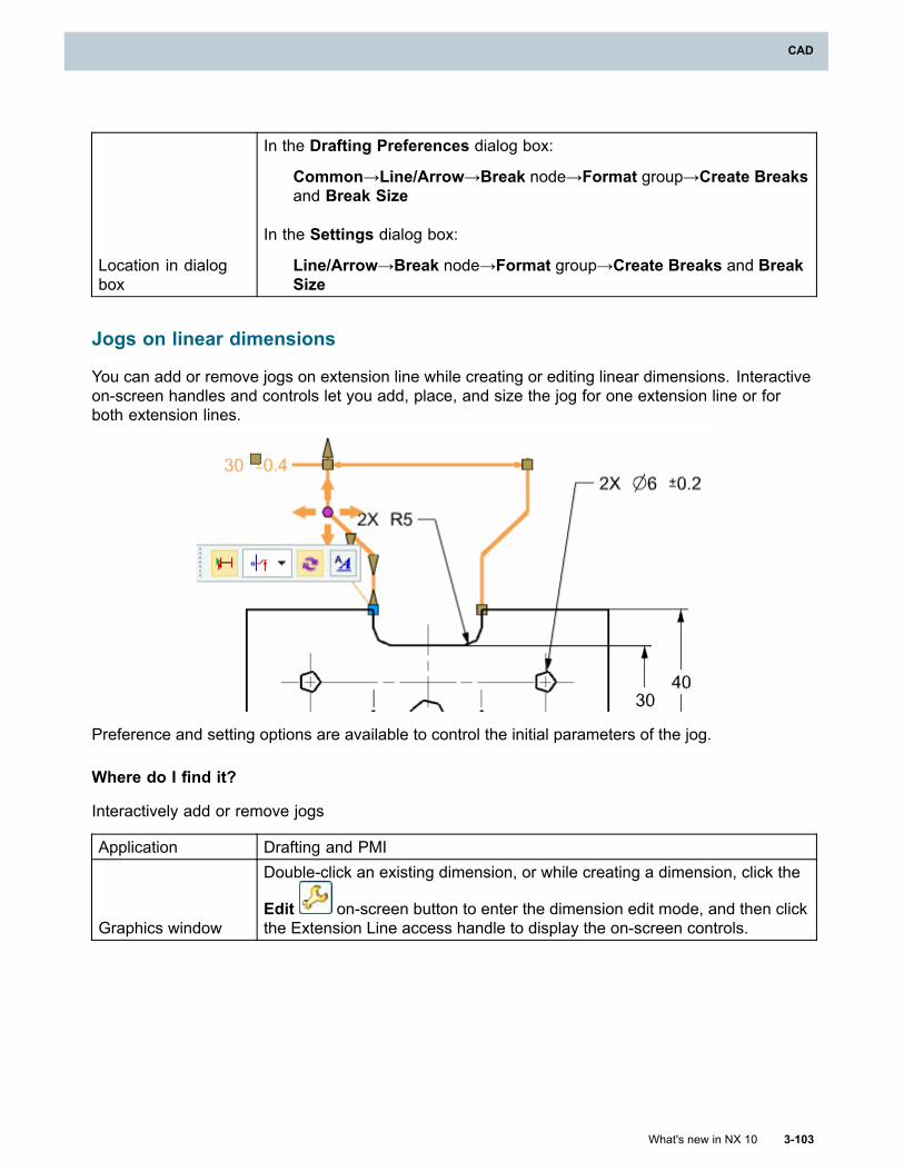
CAD
Location in dialogbox
In the Drafting Preferences dialog box:
Common→Line/Arrow→Break node→Format group→Create Breaksand Break Size
In the Settings dialog box:
Line/Arrow→Break node→Format group→Create Breaks and BreakSize
Jogs on linear dimensions
You can add or remove jogs on extension line while creating or editing linear dimensions. Interactiveon-screen handles and controls let you add, place, and size the jog for one extension line or forboth extension lines.
Preference and setting options are available to control the initial parameters of the jog.
Where do I find it?
Interactively add or remove jogs
Application Drafting and PMI
Graphics window
Double-click an existing dimension, or while creating a dimension, click the
Edit on-screen button to enter the dimension edit mode, and then clickthe Extension Line access handle to display the on-screen controls.
What's new in NX 10 3-103
CAD
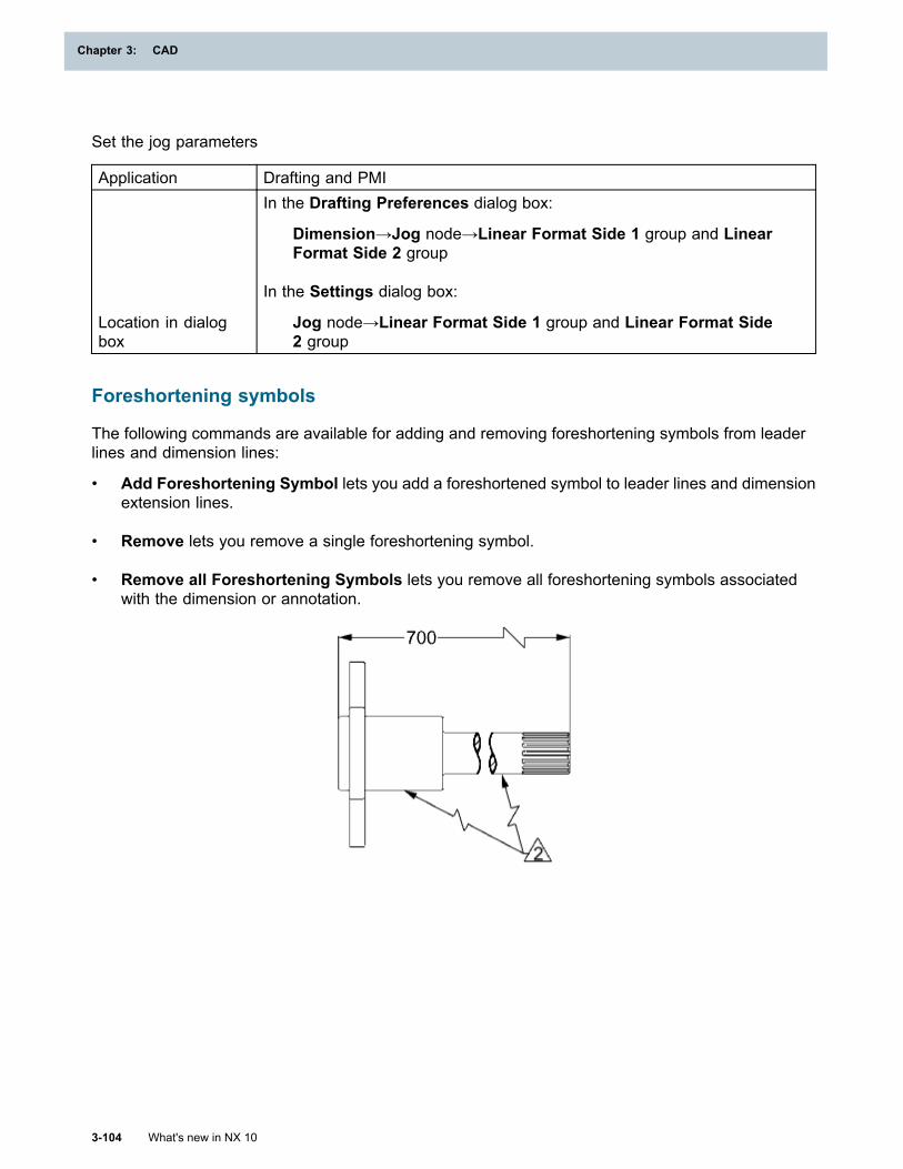
Chapter 3: CAD
Set the jog parameters
Application Drafting and PMI
Location in dialogbox
In the Drafting Preferences dialog box:
Dimension→Jog node→Linear Format Side 1 group and LinearFormat Side 2 group
In the Settings dialog box:
Jog node→Linear Format Side 1 group and Linear Format Side2 group
Foreshortening symbols
The following commands are available for adding and removing foreshortening symbols from leaderlines and dimension lines:
• Add Foreshortening Symbol lets you add a foreshortened symbol to leader lines and dimensionextension lines.
• Remove lets you remove a single foreshortening symbol.
• Remove all Foreshortening Symbols lets you remove all foreshortening symbols associatedwith the dimension or annotation.
3-104 What's new in NX 10
Chapter 3: CAD
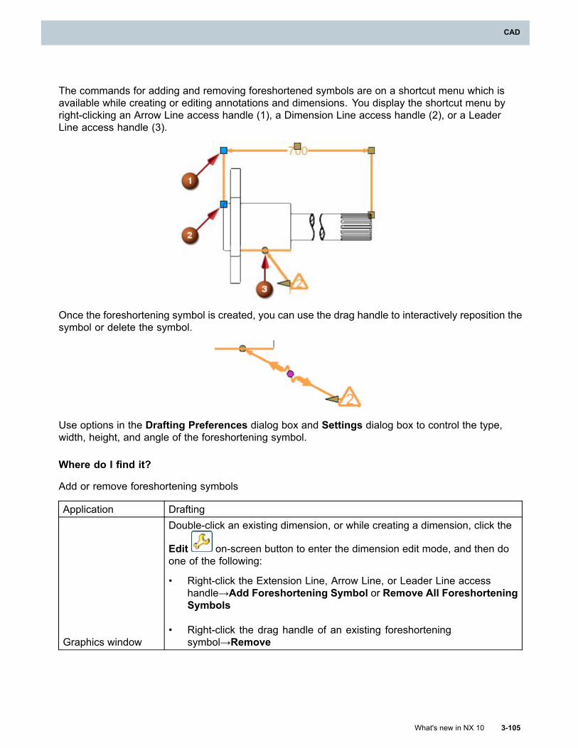
CAD
The commands for adding and removing foreshortened symbols are on a shortcut menu which isavailable while creating or editing annotations and dimensions. You display the shortcut menu byright-clicking an Arrow Line access handle (1), a Dimension Line access handle (2), or a LeaderLine access handle (3).
Once the foreshortening symbol is created, you can use the drag handle to interactively reposition thesymbol or delete the symbol.
Use options in the Drafting Preferences dialog box and Settings dialog box to control the type,width, height, and angle of the foreshortening symbol.
Where do I find it?
Add or remove foreshortening symbols
Application Drafting
Graphics window
Double-click an existing dimension, or while creating a dimension, click the
Edit on-screen button to enter the dimension edit mode, and then doone of the following:
• Right-click the Extension Line, Arrow Line, or Leader Line accesshandle→Add Foreshortening Symbol or Remove All ForeshorteningSymbols
• Right-click the drag handle of an existing foreshorteningsymbol→Remove
What's new in NX 10 3-105
CAD
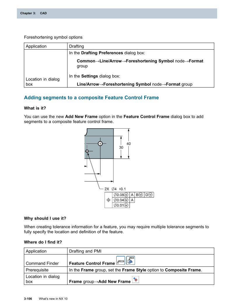
Chapter 3: CAD
Foreshortening symbol options
Application Drafting
Location in dialogbox
In the Drafting Preferences dialog box:
Common→Line/Arrow→Foreshortening Symbol node→Formatgroup
In the Settings dialog box:
Line/Arrow→Foreshortening Symbol node→Format group
Adding segments to a composite Feature Control Frame
What is it?
You can use the new Add New Frame option in the Feature Control Frame dialog box to addsegments to a composite feature control frame.
Why should I use it?
When creating tolerance information for a feature, you may require multiple tolerance segments tofully specify the location and definition of the feature.
Where do I find it?
Application Drafting and PMI
Command Finder Feature Control FramePrerequisite In the Frame group, set the Frame Style option to Composite Frame.Location in dialogbox Frame group→Add New Frame
3-106 What's new in NX 10
Chapter 3: CAD
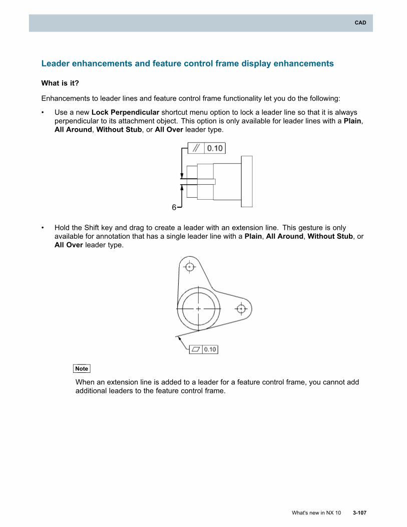
CAD
Leader enhancements and feature control frame display enhancements
What is it?
Enhancements to leader lines and feature control frame functionality let you do the following:
• Use a new Lock Perpendicular shortcut menu option to lock a leader line so that it is alwaysperpendicular to its attachment object. This option is only available for leader lines with a Plain,All Around, Without Stub, or All Over leader type.
• Hold the Shift key and drag to create a leader with an extension line. This gesture is onlyavailable for annotation that has a single leader line with a Plain, All Around, Without Stub, orAll Over leader type.
Note
When an extension line is added to a leader for a feature control frame, you cannot addadditional leaders to the feature control frame.
What's new in NX 10 3-107
CAD
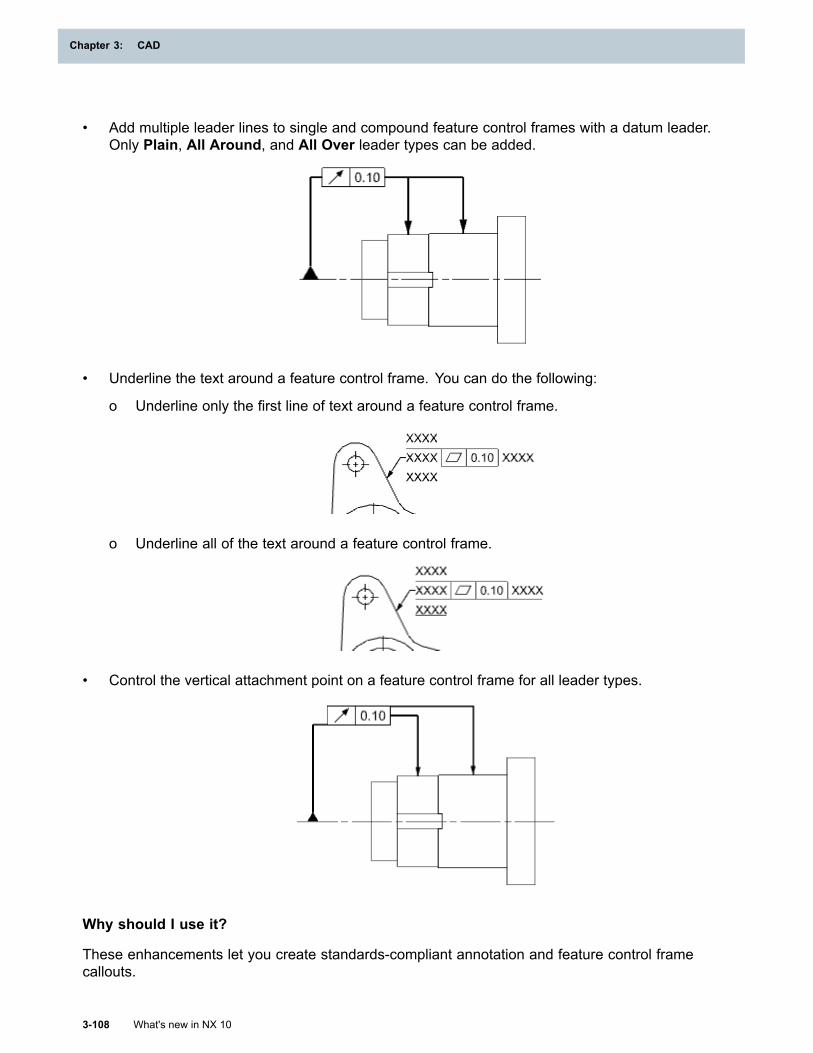
Chapter 3: CAD
• Add multiple leader lines to single and compound feature control frames with a datum leader.Only Plain, All Around, and All Over leader types can be added.
• Underline the text around a feature control frame. You can do the following:
o Underline only the first line of text around a feature control frame.
o Underline all of the text around a feature control frame.
• Control the vertical attachment point on a feature control frame for all leader types.
Why should I use it?
These enhancements let you create standards-compliant annotation and feature control framecallouts.
3-108 What's new in NX 10
Chapter 3: CAD
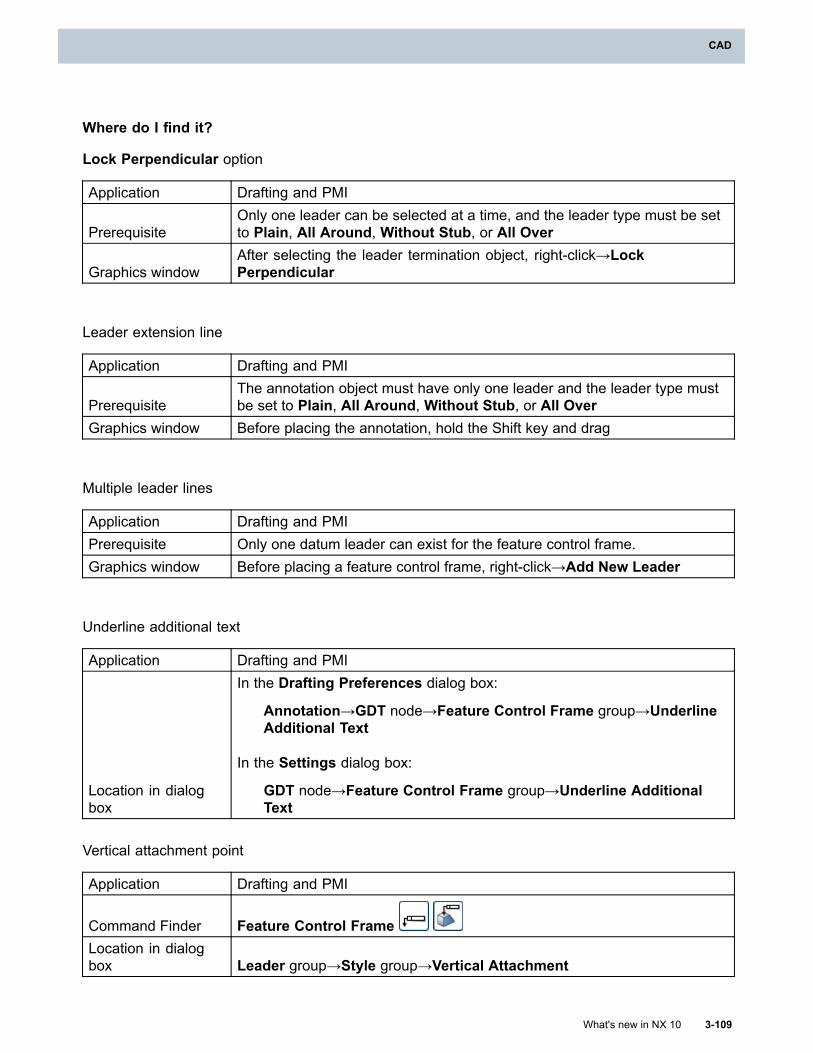
CAD
Where do I find it?
Lock Perpendicular option
Application Drafting and PMI
PrerequisiteOnly one leader can be selected at a time, and the leader type must be setto Plain, All Around, Without Stub, or All Over
Graphics windowAfter selecting the leader termination object, right-click→LockPerpendicular
Leader extension line
Application Drafting and PMI
PrerequisiteThe annotation object must have only one leader and the leader type mustbe set to Plain, All Around, Without Stub, or All Over
Graphics window Before placing the annotation, hold the Shift key and drag
Multiple leader lines
Application Drafting and PMIPrerequisite Only one datum leader can exist for the feature control frame.Graphics window Before placing a feature control frame, right-click→Add New Leader
Underline additional text
Application Drafting and PMI
Location in dialogbox
In the Drafting Preferences dialog box:
Annotation→GDT node→Feature Control Frame group→UnderlineAdditional Text
In the Settings dialog box:
GDT node→Feature Control Frame group→Underline AdditionalText
Vertical attachment point
Application Drafting and PMI
Command Finder Feature Control FrameLocation in dialogbox Leader group→Style group→Vertical Attachment
What's new in NX 10 3-109
CAD
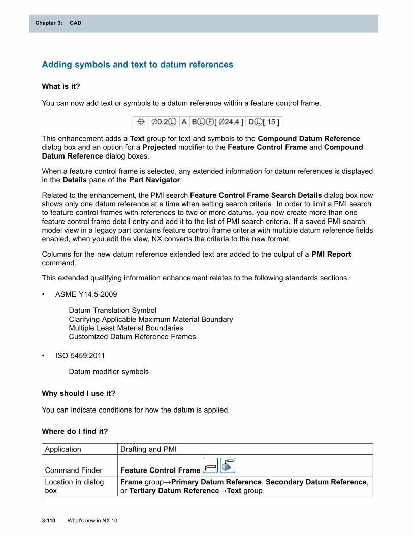
Chapter 3: CAD
Adding symbols and text to datum references
What is it?
You can now add text or symbols to a datum reference within a feature control frame.
This enhancement adds a Text group for text and symbols to the Compound Datum Referencedialog box and an option for a Projected modifier to the Feature Control Frame and CompoundDatum Reference dialog boxes.
When a feature control frame is selected, any extended information for datum references is displayedin the Details pane of the Part Navigator.
Related to the enhancement, the PMI search Feature Control Frame Search Details dialog box nowshows only one datum reference at a time when setting search criteria. In order to limit a PMI searchto feature control frames with references to two or more datums, you now create more than onefeature control frame detail entry and add it to the list of PMI search criteria. If a saved PMI searchmodel view in a legacy part contains feature control frame criteria with multiple datum reference fieldsenabled, when you edit the view, NX converts the criteria to the new format.
Columns for the new datum reference extended text are added to the output of a PMI Reportcommand.
This extended qualifying information enhancement relates to the following standards sections:
• ASME Y14.5-2009
Datum Translation SymbolClarifying Applicable Maximum Material BoundaryMultiple Least Material BoundariesCustomized Datum Reference Frames
• ISO 5459:2011
Datum modifier symbols
Why should I use it?
You can indicate conditions for how the datum is applied.
Where do I find it?
Application Drafting and PMI
Command Finder Feature Control FrameLocation in dialogbox
Frame group→Primary Datum Reference, Secondary Datum Reference,or Tertiary Datum Reference→Text group
3-110 What's new in NX 10
Chapter 3: CAD
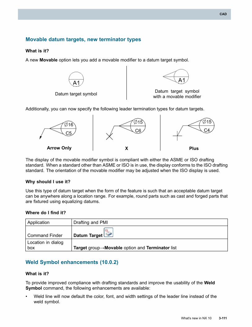
CAD
Movable datum targets, new terminator types
What is it?
A new Movable option lets you add a movable modifier to a datum target symbol.
Datum target symbol Datum target symbolwith a movable modifier
Additionally, you can now specify the following leader termination types for datum targets.
Arrow Only X Plus
The display of the movable modifier symbol is compliant with either the ASME or ISO draftingstandard. When a standard other than ASME or ISO is in use, the display conforms to the ISO draftingstandard. The orientation of the movable modifier may be adjusted when the ISO display is used.
Why should I use it?
Use this type of datum target when the form of the feature is such that an acceptable datum targetcan be anywhere along a location range. For example, round parts such as cast and forged parts thatare fixtured using equalizing datums.
Where do I find it?
Application Drafting and PMI
Command Finder Datum TargetLocation in dialogbox Target group→Movable option and Terminator list
Weld Symbol enhancements (10.0.2)
What is it?
To provide improved compliance with drafting standards and improve the usability of the WeldSymbol command, the following enhancements are available:
• Weld line will now default the color, font, and width settings of the leader line instead of theweld symbol.
What's new in NX 10 3-111
CAD
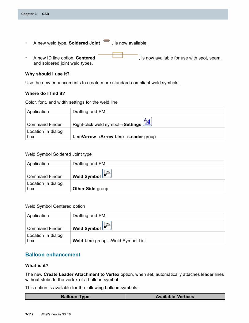
Chapter 3: CAD
• A new weld type, Soldered Joint , is now available.
• A new ID line option, Centered , is now available for use with spot, seam,and soldered joint weld types.
Why should I use it?
Use the new enhancements to create more standard-compliant weld symbols.
Where do I find it?
Color, font, and width settings for the weld line
Application Drafting and PMI
Command Finder Right-click weld symbol→SettingsLocation in dialogbox Line/Arrow→Arrow Line→Leader group
Weld Symbol Soldered Joint type
Application Drafting and PMI
Command Finder Weld SymbolLocation in dialogbox Other Side group
Weld Symbol Centered option
Application Drafting and PMI
Command Finder Weld SymbolLocation in dialogbox Weld Line group→Weld Symbol List
Balloon enhancement
What is it?
The new Create Leader Attachment to Vertex option, when set, automatically attaches leader lineswithout stubs to the vertex of a balloon symbol.
This option is available for the following balloon symbols:
Balloon Type Available Vertices
3-112 What's new in NX 10
Chapter 3: CAD
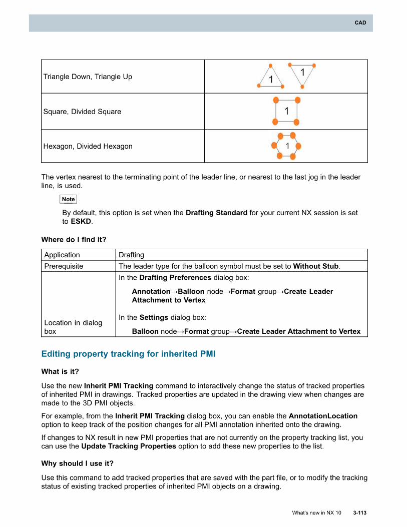
CAD
Triangle Down, Triangle Up
Square, Divided Square
Hexagon, Divided Hexagon
The vertex nearest to the terminating point of the leader line, or nearest to the last jog in the leaderline, is used.
Note
By default, this option is set when the Drafting Standard for your current NX session is setto ESKD.
Where do I find it?
Application DraftingPrerequisite The leader type for the balloon symbol must be set to Without Stub.
Location in dialogbox
In the Drafting Preferences dialog box:
Annotation→Balloon node→Format group→Create LeaderAttachment to Vertex
In the Settings dialog box:
Balloon node→Format group→Create Leader Attachment to Vertex
Editing property tracking for inherited PMI
What is it?
Use the new Inherit PMI Tracking command to interactively change the status of tracked propertiesof inherited PMI in drawings. Tracked properties are updated in the drawing view when changes aremade to the 3D PMI objects.
For example, from the Inherit PMI Tracking dialog box, you can enable the AnnotationLocationoption to keep track of the position changes for all PMI annotation inherited onto the drawing.
If changes to NX result in new PMI properties that are not currently on the property tracking list, youcan use the Update Tracking Properties option to add these new properties to the list.
Why should I use it?
Use this command to add tracked properties that are saved with the part file, or to modify the trackingstatus of existing tracked properties of inherited PMI objects on a drawing.
What's new in NX 10 3-113
CAD
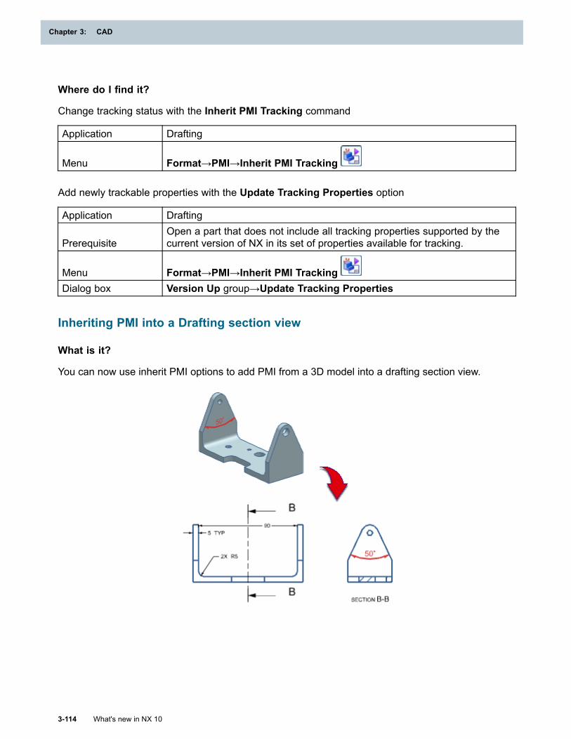
Chapter 3: CAD
Where do I find it?
Change tracking status with the Inherit PMI Tracking command
Application Drafting
Menu Format→PMI→Inherit PMI Tracking
Add newly trackable properties with the Update Tracking Properties option
Application Drafting
PrerequisiteOpen a part that does not include all tracking properties supported by thecurrent version of NX in its set of properties available for tracking.
Menu Format→PMI→Inherit PMI TrackingDialog box Version Up group→Update Tracking Properties
Inheriting PMI into a Drafting section view
What is it?
You can now use inherit PMI options to add PMI from a 3D model into a drafting section view.
3-114 What's new in NX 10
Chapter 3: CAD
CAD
You can add PMI to the following drafting section views:
SimpleSteppedHalfPictorialHalf Pictorial
All other section views are not supported.
The inherit PMI options set for the parent view are applied when you create the section view.
Note
For existing drafting section views in parts created in earlier versions of NX, you must versionup the views before the inherit PMI options are available.
(Drafting Preferences dialog box→General/Setup→Workflow→Version Up group)
Why should I use it?
You can inherit PMI in a drafting section view instead of creating a PMI lightweight section view andthen adding that view to your drawing. This approach lets you take advantage of reusing existinginformation and of bi-directionally editing your annotations.
Where do I find it?
Application Drafting
Graphics window
Right-click the border of an existing Drafting section view→Settings
→Common→PMI
API function for Drawing Booklets
What is it?
A new NX Open API, Drafting::DrawingAutomationWizard, lets you create and edit drawing bookletsin a batch mode. Using this routine in conjunction with a User Exit allows you to suspend startingthe booklet functionality until you reach a predefined time and place, or once you terminate thecurrent NX session.
The User Exit registers a callback via theJA_DRAWING_AUTOMATION_WIZARD_set_continue_processing routine and, when the Finishbutton is selected in the Drawing Booklet wizard, the callback is executed.
Note
This callback mechanism is only supported in managed mode.
An interruption routine (JA_DRAWING_AUTOMATION_WIZARD_set_continue_processing) isalso provided that lets you suspend the process before it is started. This interruption routine lets youcontrol whether or not booklet drawings will be created after control returns to NX from the callback. Ifset to TRUE, the booklet will get created immediately. If set to FALSE, no drawings are created, and youcan use the data returned by the callback to subsequently create the drawings themselves.
What's new in NX 10 3-115
CAD
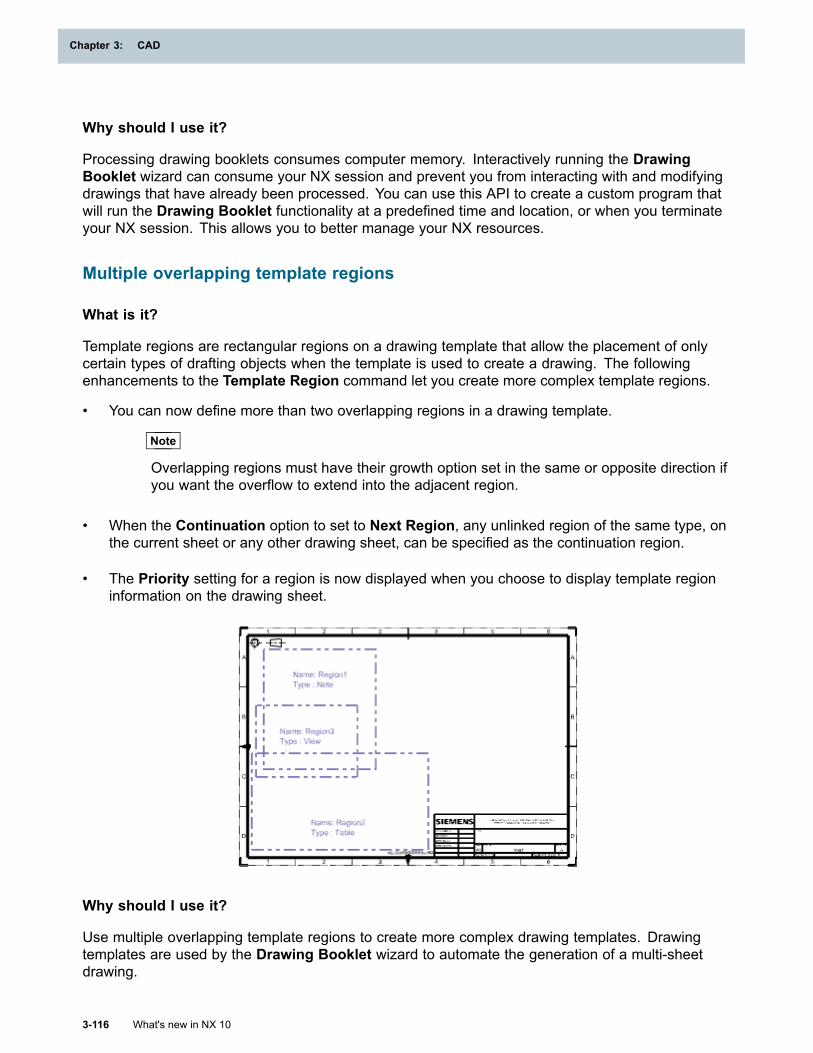
Chapter 3: CAD
Why should I use it?
Processing drawing booklets consumes computer memory. Interactively running the DrawingBooklet wizard can consume your NX session and prevent you from interacting with and modifyingdrawings that have already been processed. You can use this API to create a custom program thatwill run the Drawing Booklet functionality at a predefined time and location, or when you terminateyour NX session. This allows you to better manage your NX resources.
Multiple overlapping template regions
What is it?
Template regions are rectangular regions on a drawing template that allow the placement of onlycertain types of drafting objects when the template is used to create a drawing. The followingenhancements to the Template Region command let you create more complex template regions.
• You can now define more than two overlapping regions in a drawing template.
Note
Overlapping regions must have their growth option set in the same or opposite direction ifyou want the overflow to extend into the adjacent region.
• When the Continuation option to set to Next Region, any unlinked region of the same type, onthe current sheet or any other drawing sheet, can be specified as the continuation region.
• The Priority setting for a region is now displayed when you choose to display template regioninformation on the drawing sheet.
Why should I use it?
Use multiple overlapping template regions to create more complex drawing templates. Drawingtemplates are used by the Drawing Booklet wizard to automate the generation of a multi-sheetdrawing.
3-116 What's new in NX 10
Chapter 3: CAD
CAD
Where do I find it?
Application Drafting
PrerequisiteYou must be in a drawing template, which was created using the Mark asTemplate command.
Command Finder Template Region
Drawing booklet enhancement
What is it?
You can now create or edit drawing booklets with no primary content. These booklets contain emptydrawing sheets with no associated models.
• In native NX and in Teamcenter Integration, this will create an empty drawing with no referencesto components.
• In 4GD, this will create an empty drawing with no references to subsets.
To create an empty drawing , use the Create Drawing Booklet wizard but do not select any objectsfor the Primary Content option.
Why should I use it?
You can create empty drawings and then edit the drawings to customize the contents displayedon the sheets. For example, some drawing sheets can show components, and other sheets cancontain related notes.
Where do I find it?
Application Any application except DraftingPrerequisite You must be in an assembly fileCommand Finder Create Drawing Booklet
MenuTools→Drawing Automation→Create Drawing Booklet or Edit DrawingBooklet
Location in dialogbox Scope page→Primary Content group→Select Object
Specifying Item Type for custom symbols
What is it?
In a Teamcenter Integration environment, new options in the Define Custom Symbol dialog box andthe Define Symbol from Catalog dialog box let you specify an Item Type in addition to specifyingthe name, revision, and number for the symbol.
You can select the item type from a list of types that are available in the database. This list is typicallythe same as the list you see when the Blank template is selected in the File New dialog box.
What's new in NX 10 3-117
CAD
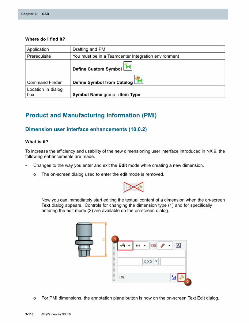
Chapter 3: CAD
Where do I find it?
Application Drafting and PMIPrerequisite You must be in a Teamcenter Integration environment
Command Finder
Define Custom Symbol
Define Symbol from CatalogLocation in dialogbox Symbol Name group→Item Type
Product and Manufacturing Information (PMI)
Dimension user interface enhancements (10.0.2)
What is it?
To increase the efficiency and usability of the new dimensioning user interface introduced in NX 9, thefollowing enhancements are made.
• Changes to the way you enter and exit the Edit mode while creating a new dimension.
o The on-screen dialog used to enter the edit mode is removed.
Now you can immediately start editing the textual content of a dimension when the on-screenText dialog appears. Controls for changing the dimension type (1) and for specificallyentering the edit mode (2) are available on the on-screen dialog.
o For PMI dimensions, the annotation plane button is now on the on-screen Text Edit dialog.
3-118 What's new in NX 10
Chapter 3: CAD
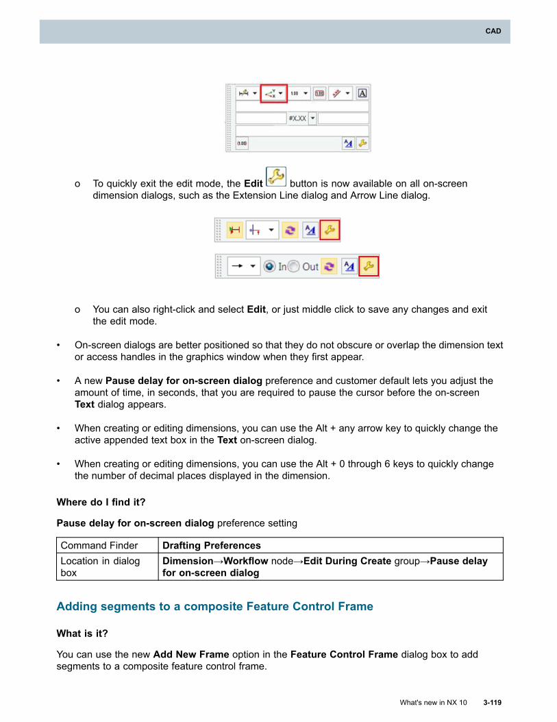
CAD
o To quickly exit the edit mode, the Edit button is now available on all on-screendimension dialogs, such as the Extension Line dialog and Arrow Line dialog.
o You can also right-click and select Edit, or just middle click to save any changes and exitthe edit mode.
• On-screen dialogs are better positioned so that they do not obscure or overlap the dimension textor access handles in the graphics window when they first appear.
• A new Pause delay for on-screen dialog preference and customer default lets you adjust theamount of time, in seconds, that you are required to pause the cursor before the on-screenText dialog appears.
• When creating or editing dimensions, you can use the Alt + any arrow key to quickly change theactive appended text box in the Text on-screen dialog.
• When creating or editing dimensions, you can use the Alt + 0 through 6 keys to quickly changethe number of decimal places displayed in the dimension.
Where do I find it?
Pause delay for on-screen dialog preference setting
Command Finder Drafting PreferencesLocation in dialogbox
Dimension→Workflow node→Edit During Create group→Pause delayfor on-screen dialog
Adding segments to a composite Feature Control Frame
What is it?
You can use the new Add New Frame option in the Feature Control Frame dialog box to addsegments to a composite feature control frame.
What's new in NX 10 3-119
CAD
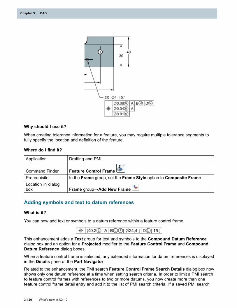
Chapter 3: CAD
Why should I use it?
When creating tolerance information for a feature, you may require multiple tolerance segments tofully specify the location and definition of the feature.
Where do I find it?
Application Drafting and PMI
Command Finder Feature Control FramePrerequisite In the Frame group, set the Frame Style option to Composite Frame.Location in dialogbox Frame group→Add New Frame
Adding symbols and text to datum references
What is it?
You can now add text or symbols to a datum reference within a feature control frame.
This enhancement adds a Text group for text and symbols to the Compound Datum Referencedialog box and an option for a Projected modifier to the Feature Control Frame and CompoundDatum Reference dialog boxes.
When a feature control frame is selected, any extended information for datum references is displayedin the Details pane of the Part Navigator.
Related to the enhancement, the PMI search Feature Control Frame Search Details dialog box nowshows only one datum reference at a time when setting search criteria. In order to limit a PMI searchto feature control frames with references to two or more datums, you now create more than onefeature control frame detail entry and add it to the list of PMI search criteria. If a saved PMI search
3-120 What's new in NX 10
Chapter 3: CAD
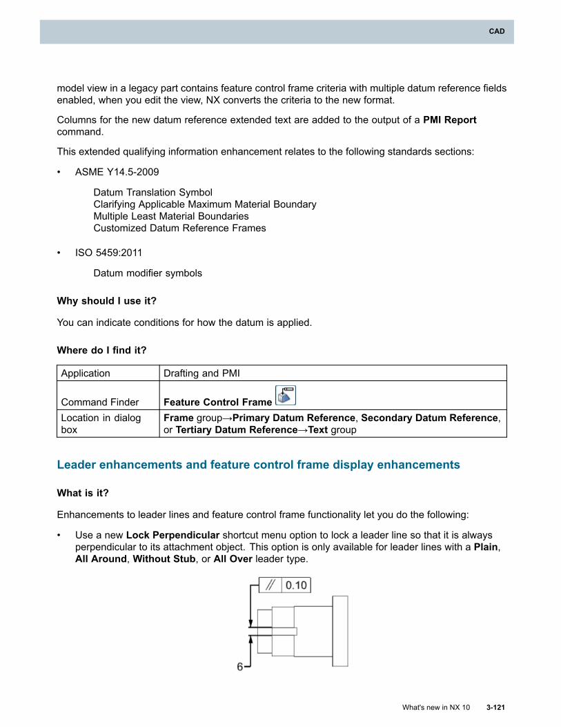
CAD
model view in a legacy part contains feature control frame criteria with multiple datum reference fieldsenabled, when you edit the view, NX converts the criteria to the new format.
Columns for the new datum reference extended text are added to the output of a PMI Reportcommand.
This extended qualifying information enhancement relates to the following standards sections:
• ASME Y14.5-2009
Datum Translation SymbolClarifying Applicable Maximum Material BoundaryMultiple Least Material BoundariesCustomized Datum Reference Frames
• ISO 5459:2011
Datum modifier symbols
Why should I use it?
You can indicate conditions for how the datum is applied.
Where do I find it?
Application Drafting and PMI
Command Finder Feature Control FrameLocation in dialogbox
Frame group→Primary Datum Reference, Secondary Datum Reference,or Tertiary Datum Reference→Text group
Leader enhancements and feature control frame display enhancements
What is it?
Enhancements to leader lines and feature control frame functionality let you do the following:
• Use a new Lock Perpendicular shortcut menu option to lock a leader line so that it is alwaysperpendicular to its attachment object. This option is only available for leader lines with a Plain,All Around, Without Stub, or All Over leader type.
What's new in NX 10 3-121
CAD
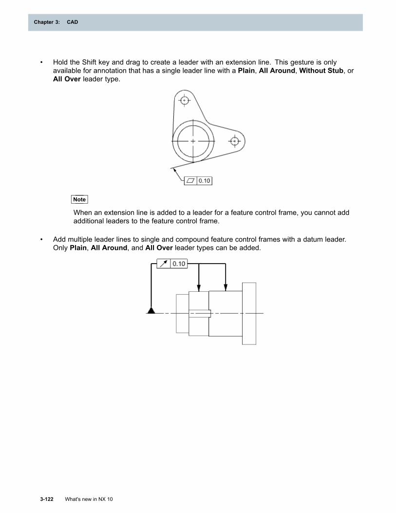
Chapter 3: CAD
• Hold the Shift key and drag to create a leader with an extension line. This gesture is onlyavailable for annotation that has a single leader line with a Plain, All Around, Without Stub, orAll Over leader type.
Note
When an extension line is added to a leader for a feature control frame, you cannot addadditional leaders to the feature control frame.
• Add multiple leader lines to single and compound feature control frames with a datum leader.Only Plain, All Around, and All Over leader types can be added.
3-122 What's new in NX 10
Chapter 3: CAD
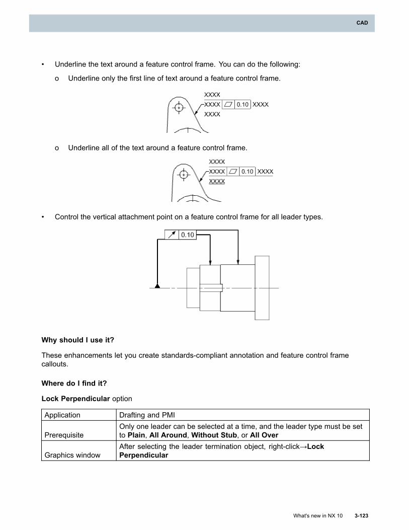
CAD
• Underline the text around a feature control frame. You can do the following:
o Underline only the first line of text around a feature control frame.
o Underline all of the text around a feature control frame.
• Control the vertical attachment point on a feature control frame for all leader types.
Why should I use it?
These enhancements let you create standards-compliant annotation and feature control framecallouts.
Where do I find it?
Lock Perpendicular option
Application Drafting and PMI
PrerequisiteOnly one leader can be selected at a time, and the leader type must be setto Plain, All Around, Without Stub, or All Over
Graphics windowAfter selecting the leader termination object, right-click→LockPerpendicular
What's new in NX 10 3-123
CAD
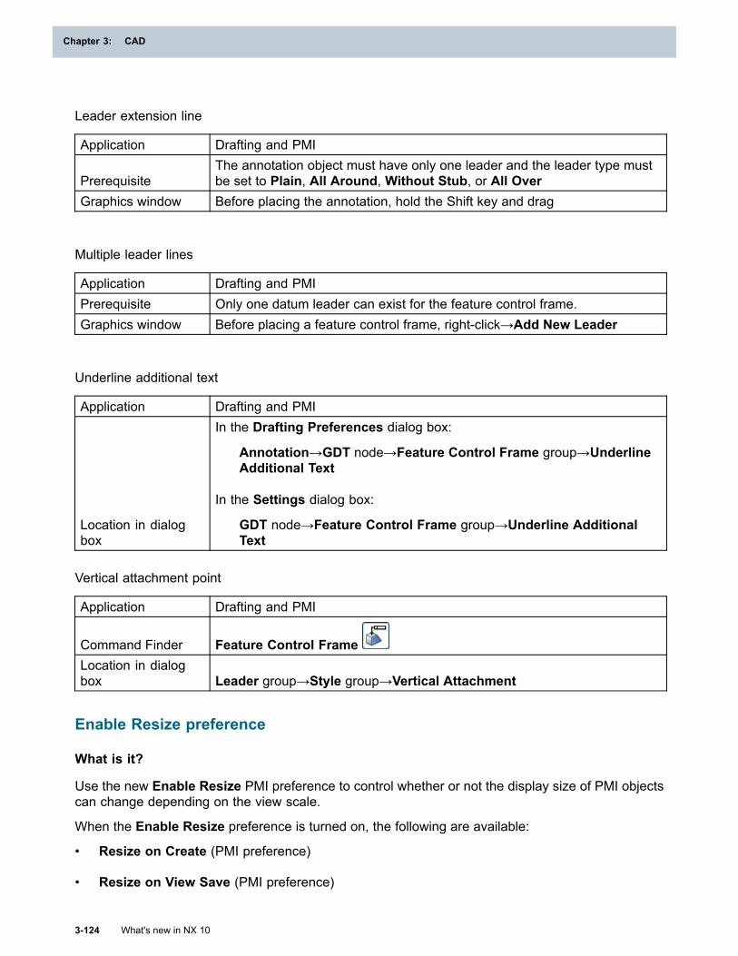
Chapter 3: CAD
Leader extension line
Application Drafting and PMI
PrerequisiteThe annotation object must have only one leader and the leader type mustbe set to Plain, All Around, Without Stub, or All Over
Graphics window Before placing the annotation, hold the Shift key and drag
Multiple leader lines
Application Drafting and PMIPrerequisite Only one datum leader can exist for the feature control frame.Graphics window Before placing a feature control frame, right-click→Add New Leader
Underline additional text
Application Drafting and PMI
Location in dialogbox
In the Drafting Preferences dialog box:
Annotation→GDT node→Feature Control Frame group→UnderlineAdditional Text
In the Settings dialog box:
GDT node→Feature Control Frame group→Underline AdditionalText
Vertical attachment point
Application Drafting and PMI
Command Finder Feature Control FrameLocation in dialogbox Leader group→Style group→Vertical Attachment
Enable Resize preference
What is it?
Use the new Enable Resize PMI preference to control whether or not the display size of PMI objectscan change depending on the view scale.
When the Enable Resize preference is turned on, the following are available:
• Resize on Create (PMI preference)
• Resize on View Save (PMI preference)
3-124 What's new in NX 10
Chapter 3: CAD
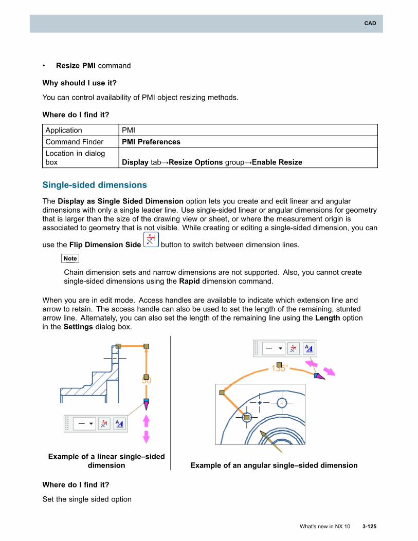
CAD
• Resize PMI command
Why should I use it?
You can control availability of PMI object resizing methods.
Where do I find it?
Application PMICommand Finder PMI PreferencesLocation in dialogbox Display tab→Resize Options group→Enable Resize
Single-sided dimensions
The Display as Single Sided Dimension option lets you create and edit linear and angulardimensions with only a single leader line. Use single-sided linear or angular dimensions for geometrythat is larger than the size of the drawing view or sheet, or where the measurement origin isassociated to geometry that is not visible. While creating or editing a single-sided dimension, you can
use the Flip Dimension Side button to switch between dimension lines.
Note
Chain dimension sets and narrow dimensions are not supported. Also, you cannot createsingle-sided dimensions using the Rapid dimension command.
When you are in edit mode. Access handles are available to indicate which extension line andarrow to retain. The access handle can also be used to set the length of the remaining, stuntedarrow line. Alternately, you can also set the length of the remaining line using the Length optionin the Settings dialog box.
Example of a linear single–sideddimension Example of an angular single–sided dimension
Where do I find it?
Set the single sided option
What's new in NX 10 3-125
CAD
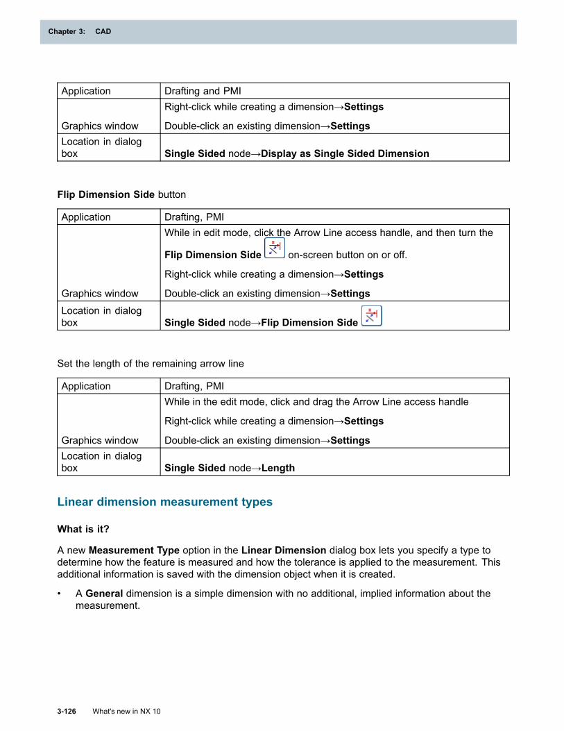
Chapter 3: CAD
Application Drafting and PMI
Graphics window
Right-click while creating a dimension→Settings
Double-click an existing dimension→SettingsLocation in dialogbox Single Sided node→Display as Single Sided Dimension
Flip Dimension Side button
Application Drafting, PMI
Graphics window
While in edit mode, click the Arrow Line access handle, and then turn the
Flip Dimension Side on-screen button on or off.
Right-click while creating a dimension→Settings
Double-click an existing dimension→SettingsLocation in dialogbox Single Sided node→Flip Dimension Side
Set the length of the remaining arrow line
Application Drafting, PMI
Graphics window
While in the edit mode, click and drag the Arrow Line access handle
Right-click while creating a dimension→Settings
Double-click an existing dimension→SettingsLocation in dialogbox Single Sided node→Length
Linear dimension measurement types
What is it?
A new Measurement Type option in the Linear Dimension dialog box lets you specify a type todetermine how the feature is measured and how the tolerance is applied to the measurement. Thisadditional information is saved with the dimension object when it is created.
• A General dimension is a simple dimension with no additional, implied information about themeasurement.
3-126 What's new in NX 10
Chapter 3: CAD
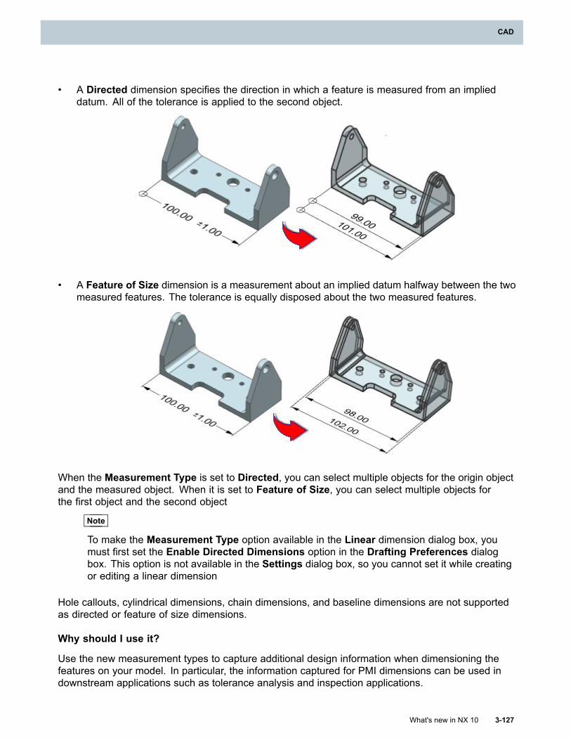
CAD
• A Directed dimension specifies the direction in which a feature is measured from an implieddatum. All of the tolerance is applied to the second object.
• A Feature of Size dimension is a measurement about an implied datum halfway between the twomeasured features. The tolerance is equally disposed about the two measured features.
When the Measurement Type is set to Directed, you can select multiple objects for the origin objectand the measured object. When it is set to Feature of Size, you can select multiple objects forthe first object and the second object
Note
To make the Measurement Type option available in the Linear dimension dialog box, youmust first set the Enable Directed Dimensions option in the Drafting Preferences dialogbox. This option is not available in the Settings dialog box, so you cannot set it while creatingor editing a linear dimension
Hole callouts, cylindrical dimensions, chain dimensions, and baseline dimensions are not supportedas directed or feature of size dimensions.
Why should I use it?
Use the new measurement types to capture additional design information when dimensioning thefeatures on your model. In particular, the information captured for PMI dimensions can be used indownstream applications such as tolerance analysis and inspection applications.
What's new in NX 10 3-127
CAD
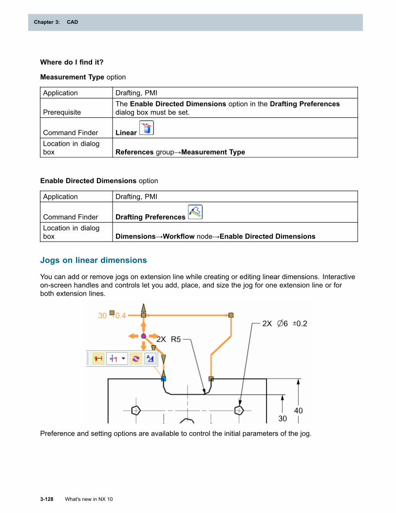
Chapter 3: CAD
Where do I find it?
Measurement Type option
Application Drafting, PMI
PrerequisiteThe Enable Directed Dimensions option in the Drafting Preferencesdialog box must be set.
Command Finder LinearLocation in dialogbox References group→Measurement Type
Enable Directed Dimensions option
Application Drafting, PMI
Command Finder Drafting PreferencesLocation in dialogbox Dimensions→Workflow node→Enable Directed Dimensions
Jogs on linear dimensions
You can add or remove jogs on extension line while creating or editing linear dimensions. Interactiveon-screen handles and controls let you add, place, and size the jog for one extension line or forboth extension lines.
Preference and setting options are available to control the initial parameters of the jog.
3-128 What's new in NX 10
Chapter 3: CAD
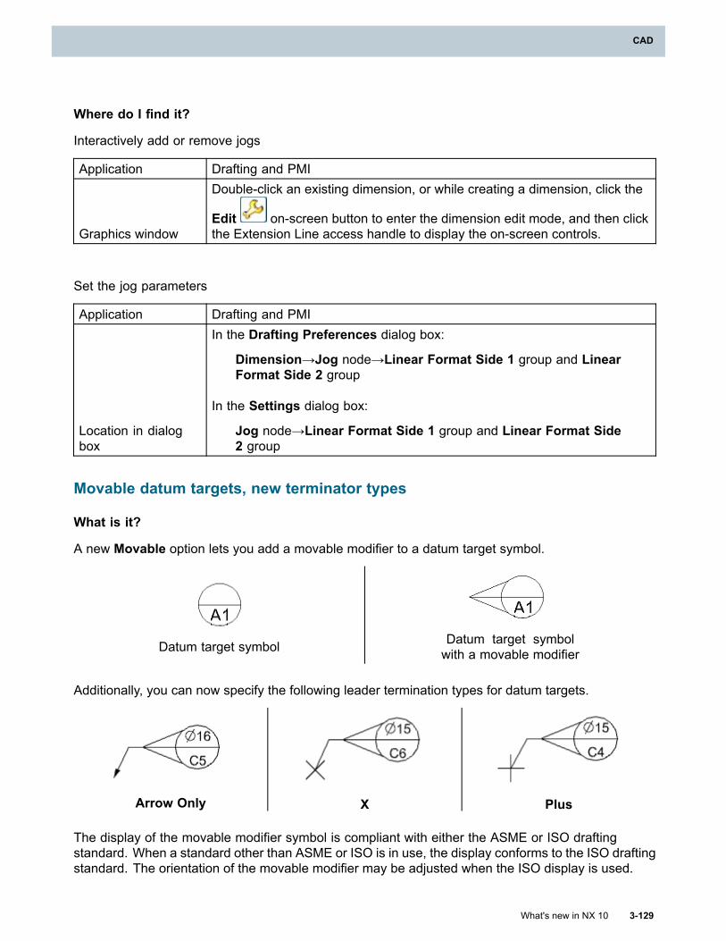
CAD
Where do I find it?
Interactively add or remove jogs
Application Drafting and PMI
Graphics window
Double-click an existing dimension, or while creating a dimension, click the
Edit on-screen button to enter the dimension edit mode, and then clickthe Extension Line access handle to display the on-screen controls.
Set the jog parameters
Application Drafting and PMI
Location in dialogbox
In the Drafting Preferences dialog box:
Dimension→Jog node→Linear Format Side 1 group and LinearFormat Side 2 group
In the Settings dialog box:
Jog node→Linear Format Side 1 group and Linear Format Side2 group
Movable datum targets, new terminator types
What is it?
A new Movable option lets you add a movable modifier to a datum target symbol.
Datum target symbol Datum target symbolwith a movable modifier
Additionally, you can now specify the following leader termination types for datum targets.
Arrow Only X Plus
The display of the movable modifier symbol is compliant with either the ASME or ISO draftingstandard. When a standard other than ASME or ISO is in use, the display conforms to the ISO draftingstandard. The orientation of the movable modifier may be adjusted when the ISO display is used.
What's new in NX 10 3-129
CAD
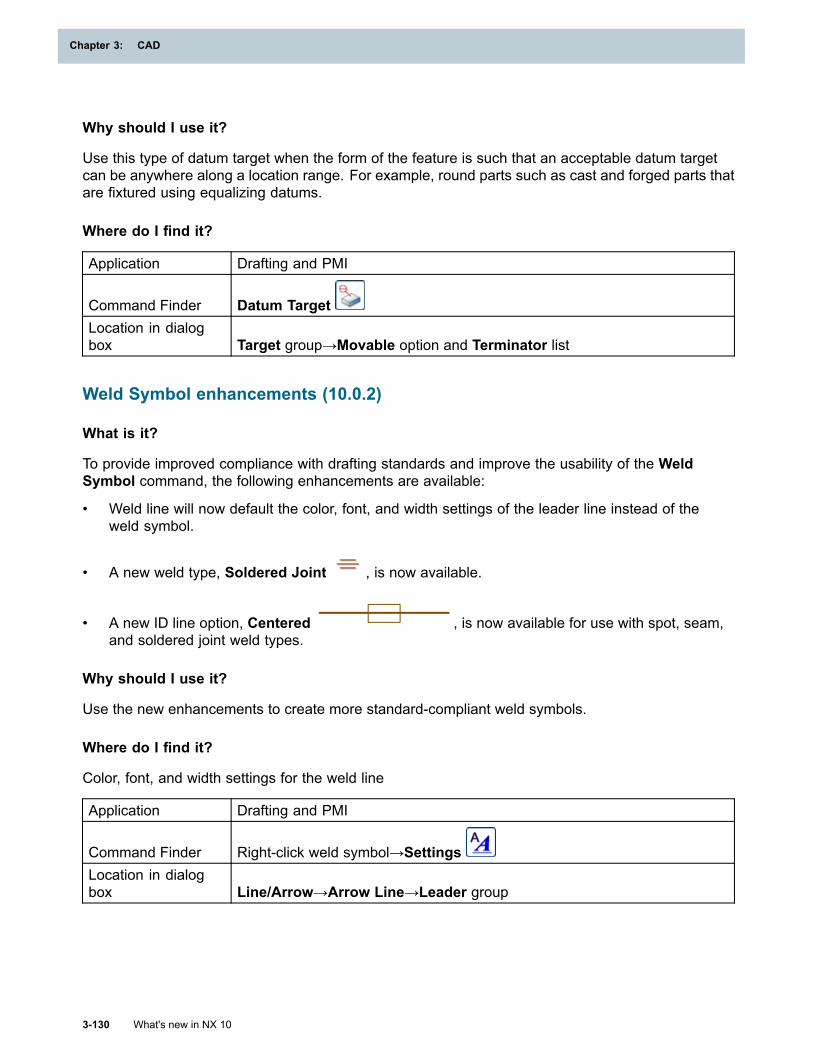
Chapter 3: CAD
Why should I use it?
Use this type of datum target when the form of the feature is such that an acceptable datum targetcan be anywhere along a location range. For example, round parts such as cast and forged parts thatare fixtured using equalizing datums.
Where do I find it?
Application Drafting and PMI
Command Finder Datum TargetLocation in dialogbox Target group→Movable option and Terminator list
Weld Symbol enhancements (10.0.2)
What is it?
To provide improved compliance with drafting standards and improve the usability of the WeldSymbol command, the following enhancements are available:
• Weld line will now default the color, font, and width settings of the leader line instead of theweld symbol.
• A new weld type, Soldered Joint , is now available.
• A new ID line option, Centered , is now available for use with spot, seam,and soldered joint weld types.
Why should I use it?
Use the new enhancements to create more standard-compliant weld symbols.
Where do I find it?
Color, font, and width settings for the weld line
Application Drafting and PMI
Command Finder Right-click weld symbol→SettingsLocation in dialogbox Line/Arrow→Arrow Line→Leader group
3-130 What's new in NX 10
Chapter 3: CAD
CAD
Weld Symbol Soldered Joint type
Application Drafting and PMI
Command Finder Weld SymbolLocation in dialogbox Other Side group
Weld Symbol Centered option
Application Drafting and PMI
Command Finder Weld SymbolLocation in dialogbox Weld Line group→Weld Symbol List
Specifying Item Type for custom symbols
What is it?
In a Teamcenter Integration environment, new options in the Define Custom Symbol dialog box andthe Define Symbol from Catalog dialog box let you specify an Item Type in addition to specifyingthe name, revision, and number for the symbol.
You can select the item type from a list of types that are available in the database. This list is typicallythe same as the list you see when the Blank template is selected in the File New dialog box.
Where do I find it?
Application Drafting and PMIPrerequisite You must be in a Teamcenter Integration environment
Command Finder Define Custom SymbolLocation in dialogbox Symbol Name group→Item Type
Inheriting PMI into a Drafting section view
What is it?
You can now use inherit PMI options to add PMI from a 3D model into a drafting section view.
What's new in NX 10 3-131
CAD
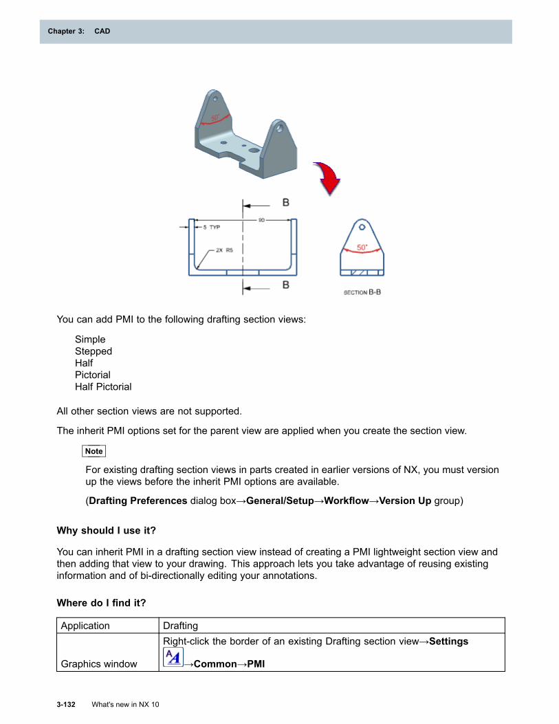
Chapter 3: CAD
You can add PMI to the following drafting section views:
SimpleSteppedHalfPictorialHalf Pictorial
All other section views are not supported.
The inherit PMI options set for the parent view are applied when you create the section view.
Note
For existing drafting section views in parts created in earlier versions of NX, you must versionup the views before the inherit PMI options are available.
(Drafting Preferences dialog box→General/Setup→Workflow→Version Up group)
Why should I use it?
You can inherit PMI in a drafting section view instead of creating a PMI lightweight section view andthen adding that view to your drawing. This approach lets you take advantage of reusing existinginformation and of bi-directionally editing your annotations.
Where do I find it?
Application Drafting
Graphics window
Right-click the border of an existing Drafting section view→Settings
→Common→PMI
3-132 What's new in NX 10
Chapter 3: CAD
CAD
Editing property tracking for inherited PMI
What is it?
Use the new Inherit PMI Tracking command to interactively change the status of tracked propertiesof inherited PMI in drawings. Tracked properties are updated in the drawing view when changes aremade to the 3D PMI objects.
For example, from the Inherit PMI Tracking dialog box, you can enable the AnnotationLocationoption to keep track of the position changes for all PMI annotation inherited onto the drawing.
If changes to NX result in new PMI properties that are not currently on the property tracking list, youcan use the Update Tracking Properties option to add these new properties to the list.
Why should I use it?
Use this command to add tracked properties that are saved with the part file, or to modify the trackingstatus of existing tracked properties of inherited PMI objects on a drawing.
Where do I find it?
Change tracking status with the Inherit PMI Tracking command
Application Drafting
Menu Format→PMI→Inherit PMI Tracking
Add newly trackable properties with the Update Tracking Properties option
Application Drafting
PrerequisiteOpen a part that does not include all tracking properties supported by thecurrent version of NX in its set of properties available for tracking.
Menu Format→PMI→Inherit PMI TrackingDialog box Version Up group→Update Tracking Properties
Information on leader termination points
What is it?
For PMI and Drafting annotation and custom symbols, the XYZ coordinates of leader and extensionline terminators that terminate on geometry are now displayed when object information is requestedfor the selected objects. The coordinate information is displayed as Termination Point data. Forexample:
Layer 1Type PMI Linear Dimension
Extension Line 1Color 186 (Red)Font SolidDensity ThinTermination Point XC = 14.900000000 X = 14.900000000
What's new in NX 10 3-133
CAD
Chapter 3: CAD
YC = 0.000000000 Y = 0.000000000ZC = 13.000000000 Z = 13.000000000
Reporting of terminator coordinates is subject to the following constraints:
• If the object does not have any leaders, no information is output.
• Information is output for each leader line or extension line of the object that is used and whichterminates on geometry or supplemental geometry. No leader termination information is outputfor leaders that terminate on other PMI or annotation.
• Since the objective is to report the coordinates of the terminator geometry, the point reporteddoes not take into account any gaps between the end of the extension line and the geometry.
Why should I use it?
You may want to use information regarding where the leaders or extension lines connect to geometryin downstream processes.
Where do I find it?
Application Gateway and Drafting
Prerequisite
The model or drawing must contain PMI or Drafting annotation or customsymbols, or Feature or Sketch dimensions displayed as PMI, that haveleaders or extension lines terminating on geometry.
Report windowCreate an information report on the above objects using the ObjectInformation command and then search for Termination Point.
Creating PMI objects from a JT file
What is it?
When you open a JT file in NX, you can create real PMI objects from data in the file. Types of PMIthat can be created as real NX PMI from a JT file include all the following:
PMI object type PMI object subtypeAnnotation NoteBalloon *PMI Centerline *PMI Centermark *Coordinate Note *Datum Feature SymbolDatum Target
Dimension
AngularArc Length *Chamfer *DiametralFolded Radius *Limits & Fits *LinearRadial
3-134 What's new in NX 10
Chapter 3: CAD
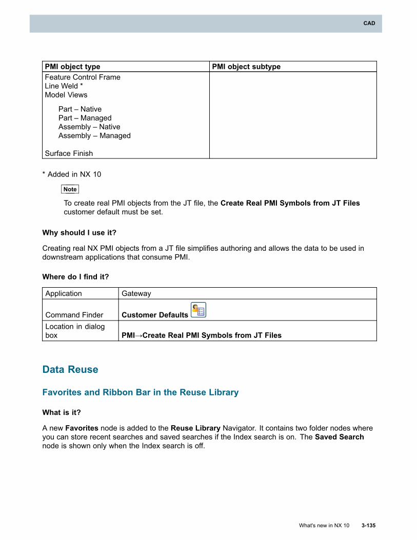
CAD
PMI object type PMI object subtypeFeature Control FrameLine Weld *Model Views
Part – NativePart – ManagedAssembly – NativeAssembly – Managed
Surface Finish
* Added in NX 10
Note
To create real PMI objects from the JT file, the Create Real PMI Symbols from JT Filescustomer default must be set.
Why should I use it?
Creating real NX PMI objects from a JT file simplifies authoring and allows the data to be used indownstream applications that consume PMI.
Where do I find it?
Application Gateway
Command Finder Customer DefaultsLocation in dialogbox PMI→Create Real PMI Symbols from JT Files
Data Reuse
Favorites and Ribbon Bar in the Reuse Library
What is it?
A new Favorites node is added to the Reuse Library Navigator. It contains two folder nodes whereyou can store recent searches and saved searches if the Index search is on. The Saved Searchnode is shown only when the Index search is off.
What's new in NX 10 3-135
CAD

Chapter 3: CAD
When you perform an Index search in the Reuse Library, the search result is displayed, and thesearch criteria is saved in the Recent Search node automatically. The node will remember theprevious 30 entries. If you want to save the search criteria permanently, you can save a recent searchin the Saved Search node, and specify a custom name and image to represent it.
It is not necessary to have the Index Search Server in order to add objects to and use objectsfrom the Saved Search node
You can add saved searches and objects to either a Ribbon Tab or a Border Bar. The searchresult will be shown for the search.
Why should I use it?
You can create reuse library searches based on multiple criteria, and save them for future use.
Where do I find it?
Resource bar Reuse Library
Teamcenter library integration
What is it?
You can now use the Reuse Library Management command to access the Teamcenter libraryhierarchy. You can browse and search for library elements and publish them to the Teamcenterlibrary. The Teamcenter library lets you create different library content based on design context.
3-136 What's new in NX 10
Chapter 3: CAD
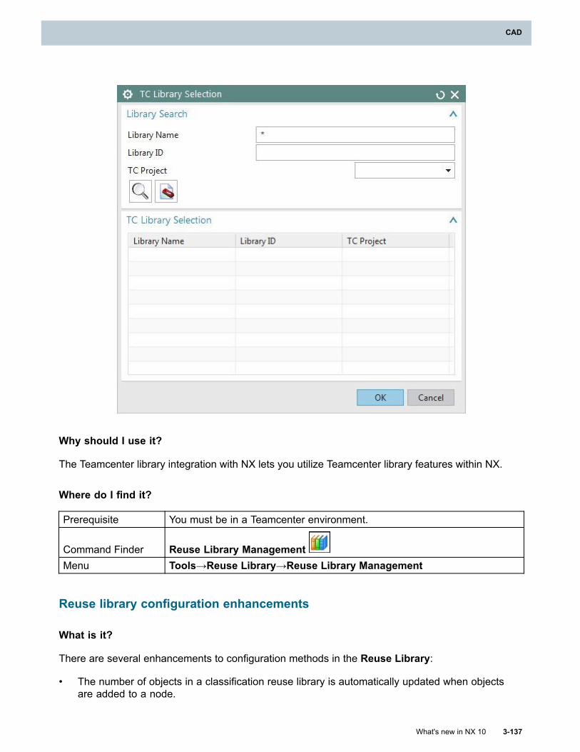
CAD
Why should I use it?
The Teamcenter library integration with NX lets you utilize Teamcenter library features within NX.
Where do I find it?
Prerequisite You must be in a Teamcenter environment.
Command Finder Reuse Library ManagementMenu Tools→Reuse Library→Reuse Library Management
Reuse library configuration enhancements
What is it?
There are several enhancements to configuration methods in the Reuse Library:
• The number of objects in a classification reuse library is automatically updated when objectsare added to a node.
What's new in NX 10 3-137
CAD
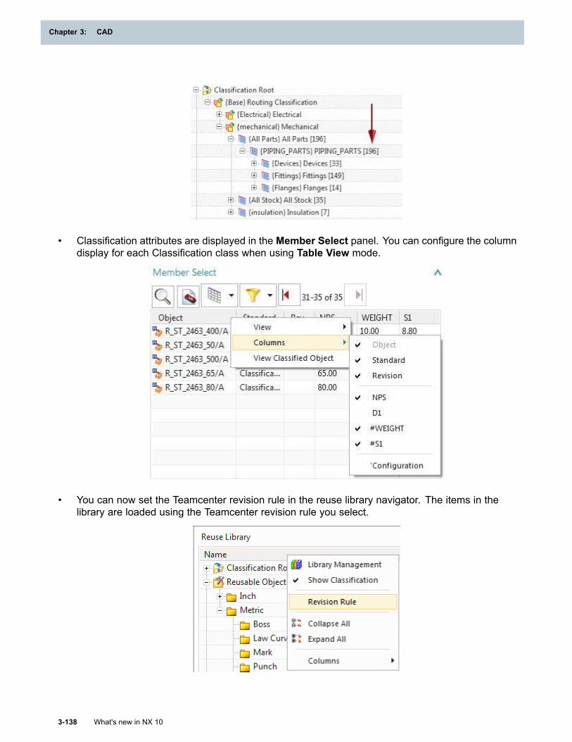
Chapter 3: CAD
• Classification attributes are displayed in the Member Select panel. You can configure the columndisplay for each Classification class when using Table View mode.
• You can now set the Teamcenter revision rule in the reuse library navigator. The items in thelibrary are loaded using the Teamcenter revision rule you select.
3-138 What's new in NX 10
Chapter 3: CAD
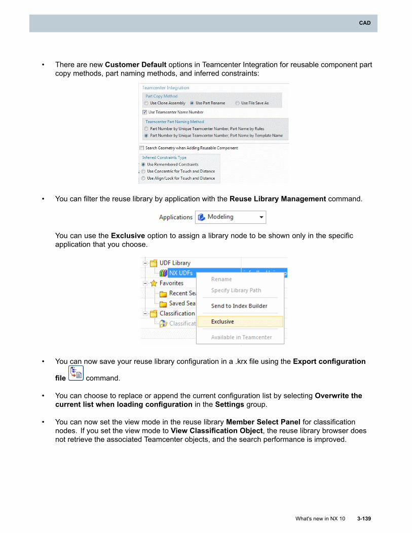
CAD
• There are new Customer Default options in Teamcenter Integration for reusable component partcopy methods, part naming methods, and inferred constraints:
• You can filter the reuse library by application with the Reuse Library Management command.
You can use the Exclusive option to assign a library node to be shown only in the specificapplication that you choose.
• You can now save your reuse library configuration in a .krx file using the Export configuration
file command.
• You can choose to replace or append the current configuration list by selecting Overwrite thecurrent list when loading configuration in the Settings group.
• You can now set the view mode in the reuse library Member Select Panel for classificationnodes. If you set the view mode to View Classification Object, the reuse library browser doesnot retrieve the associated Teamcenter objects, and the search performance is improved.
What's new in NX 10 3-139
CAD
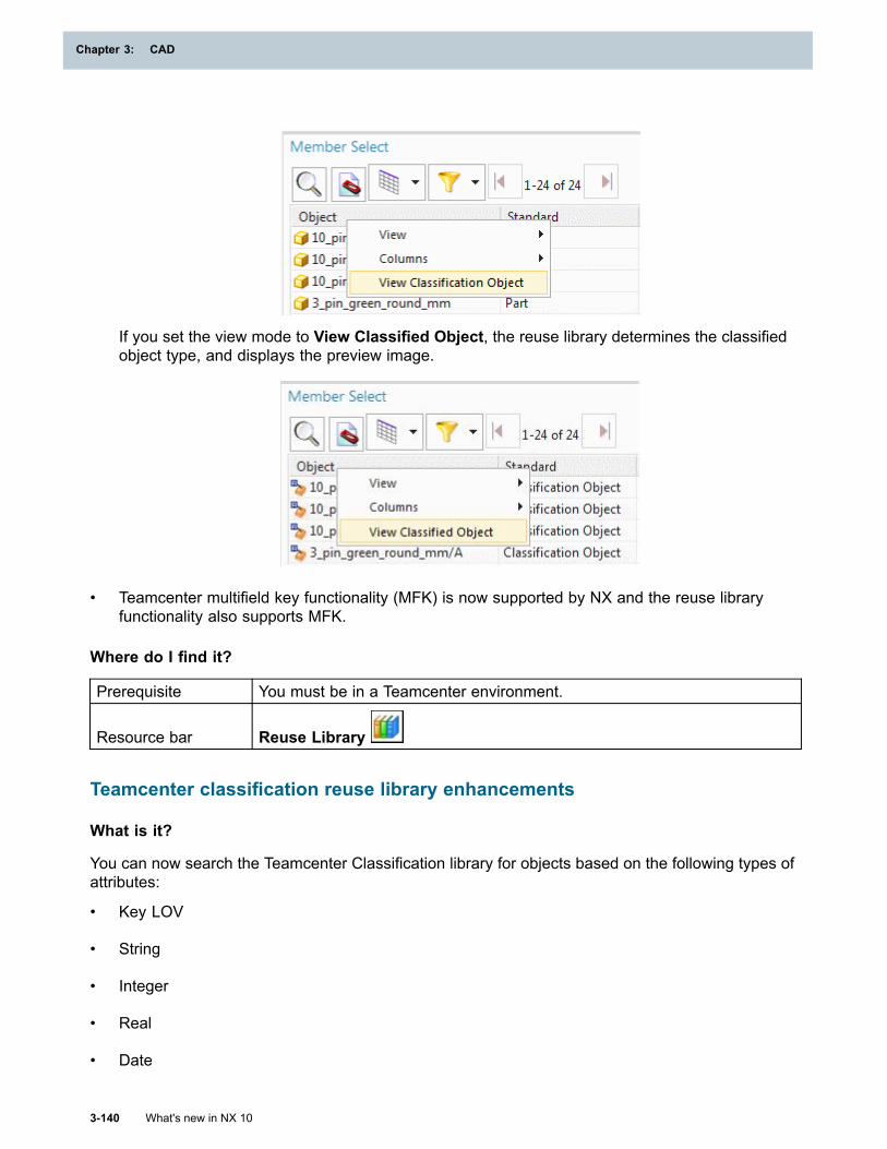
Chapter 3: CAD
If you set the view mode to View Classified Object, the reuse library determines the classifiedobject type, and displays the preview image.
• Teamcenter multifield key functionality (MFK) is now supported by NX and the reuse libraryfunctionality also supports MFK.
Where do I find it?
Prerequisite You must be in a Teamcenter environment.
Resource bar Reuse Library
Teamcenter classification reuse library enhancements
What is it?
You can now search the Teamcenter Classification library for objects based on the following types ofattributes:
• Key LOV
• String
• Integer
• Real
• Date
3-140 What's new in NX 10
Chapter 3: CAD
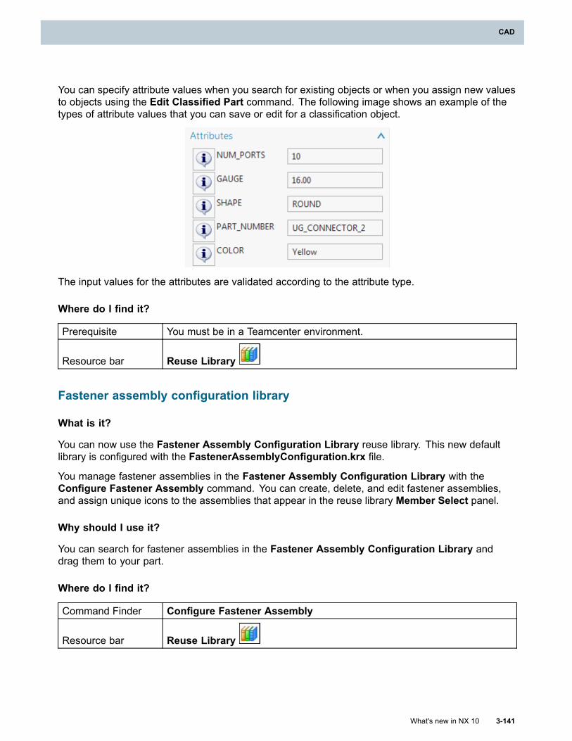
CAD
You can specify attribute values when you search for existing objects or when you assign new valuesto objects using the Edit Classified Part command. The following image shows an example of thetypes of attribute values that you can save or edit for a classification object.
The input values for the attributes are validated according to the attribute type.
Where do I find it?
Prerequisite You must be in a Teamcenter environment.
Resource bar Reuse Library
Fastener assembly configuration library
What is it?
You can now use the Fastener Assembly Configuration Library reuse library. This new defaultlibrary is configured with the FastenerAssemblyConfiguration.krx file.
You manage fastener assemblies in the Fastener Assembly Configuration Library with theConfigure Fastener Assembly command. You can create, delete, and edit fastener assemblies,and assign unique icons to the assemblies that appear in the reuse library Member Select panel.
Why should I use it?
You can search for fastener assemblies in the Fastener Assembly Configuration Library anddrag them to your part.
Where do I find it?
Command Finder Configure Fastener Assembly
Resource bar Reuse Library
What's new in NX 10 3-141
CAD
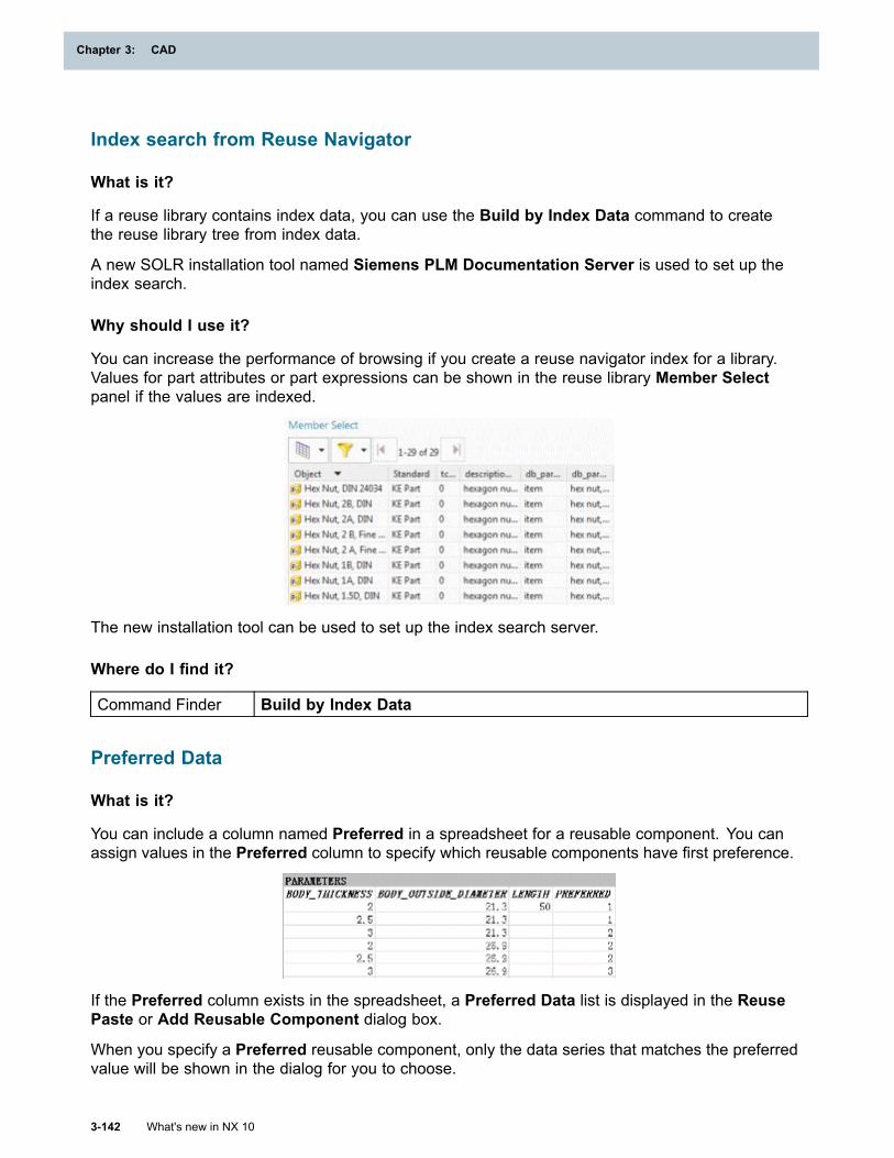
Chapter 3: CAD
Index search from Reuse Navigator
What is it?
If a reuse library contains index data, you can use the Build by Index Data command to createthe reuse library tree from index data.
A new SOLR installation tool named Siemens PLM Documentation Server is used to set up theindex search.
Why should I use it?
You can increase the performance of browsing if you create a reuse navigator index for a library.Values for part attributes or part expressions can be shown in the reuse library Member Selectpanel if the values are indexed.
The new installation tool can be used to set up the index search server.
Where do I find it?
Command Finder Build by Index Data
Preferred Data
What is it?
You can include a column named Preferred in a spreadsheet for a reusable component. You canassign values in the Preferred column to specify which reusable components have first preference.
If the Preferred column exists in the spreadsheet, a Preferred Data list is displayed in the ReusePaste or Add Reusable Component dialog box.
When you specify a Preferred reusable component, only the data series that matches the preferredvalue will be shown in the dialog for you to choose.
3-142 What's new in NX 10
Chapter 3: CAD
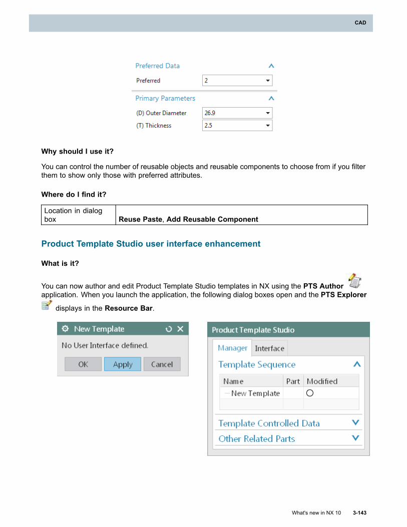
CAD
Why should I use it?
You can control the number of reusable objects and reusable components to choose from if you filterthem to show only those with preferred attributes.
Where do I find it?
Location in dialogbox Reuse Paste, Add Reusable Component
Product Template Studio user interface enhancement
What is it?
You can now author and edit Product Template Studio templates in NX using the PTS Authorapplication. When you launch the application, the following dialog boxes open and the PTS Explorer
displays in the Resource Bar.
What's new in NX 10 3-143
CAD
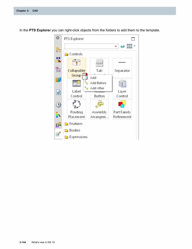
Chapter 3: CAD
In the PTS Explorer you can right-click objects from the folders to add them to the template.
3-144 What's new in NX 10
Chapter 3: CAD
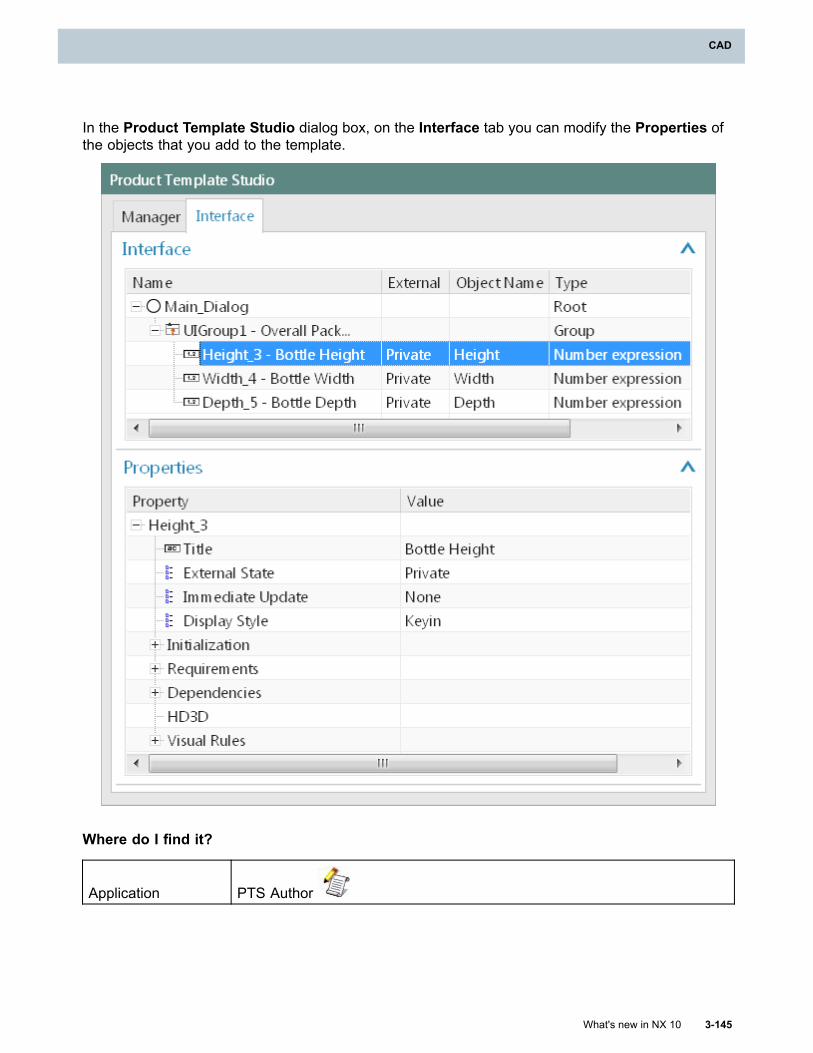
CAD
In the Product Template Studio dialog box, on the Interface tab you can modify the Properties ofthe objects that you add to the template.
Where do I find it?
Application PTS Author
What's new in NX 10 3-145
CAD
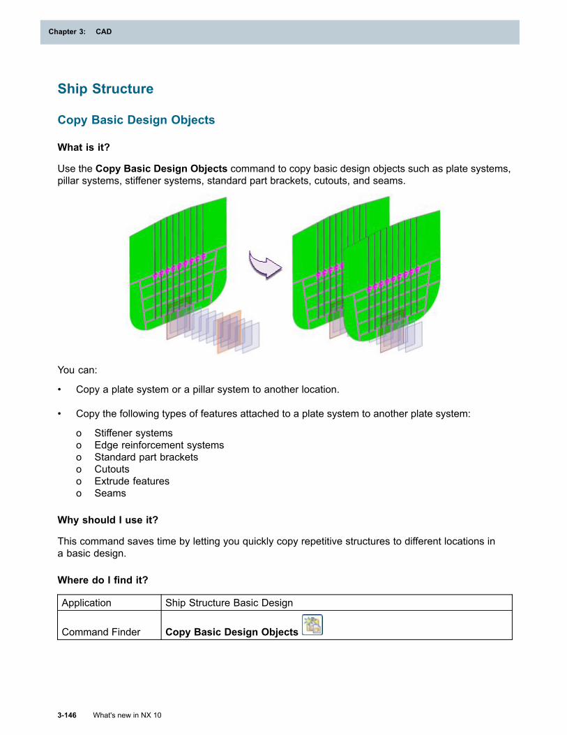
Chapter 3: CAD
Ship Structure
Copy Basic Design Objects
What is it?
Use the Copy Basic Design Objects command to copy basic design objects such as plate systems,pillar systems, stiffener systems, standard part brackets, cutouts, and seams.
You can:
• Copy a plate system or a pillar system to another location.
• Copy the following types of features attached to a plate system to another plate system:
o Stiffener systemso Edge reinforcement systemso Standard part bracketso Cutoutso Extrude featureso Seams
Why should I use it?
This command saves time by letting you quickly copy repetitive structures to different locations ina basic design.
Where do I find it?
Application Ship Structure Basic Design
Command Finder Copy Basic Design Objects
3-146 What's new in NX 10
Chapter 3: CAD

CAD
Mirror Ship Structure
What is it?
Use the Mirror Ship Structure command to mirror detailed design elements or components througha plane. The resulting features in the mirrored design elements or components are not associated tothe source features and you can edit them independently.
You can:
• Mirror the following types of features:
o Plateo Stiffenero Edge Reinforcemento Pillaro Standard part brackets and collar plateso Cutouto Corner Cuto Edge Cuto Along Guide Cuto Plate Chamfero Extrudeo End Cuto Profile Cutout
• Specify a mirror plane or use the default longitudinal vertical center plane of the ship.
• Generate a report in an XML file that lists which parts were successfully mirrored, which partsfailed, the duration of the operation, and other detailed information.
What's new in NX 10 3-147
CAD
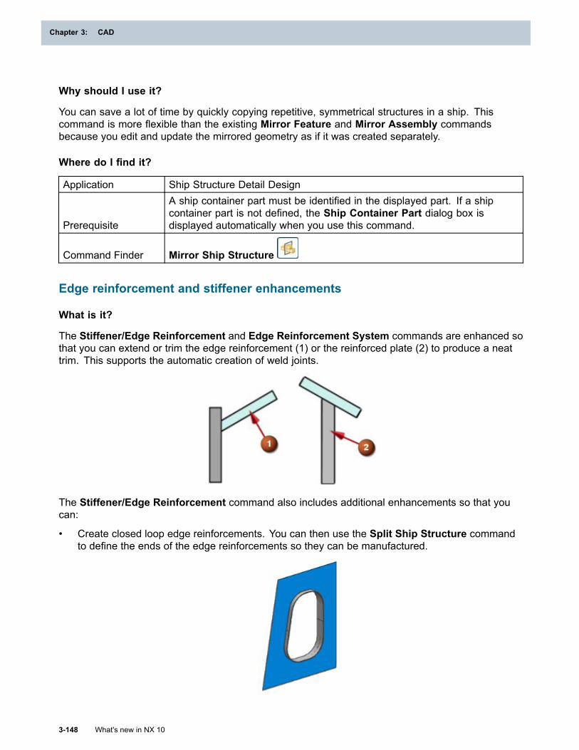
Chapter 3: CAD
Why should I use it?
You can save a lot of time by quickly copying repetitive, symmetrical structures in a ship. Thiscommand is more flexible than the existing Mirror Feature and Mirror Assembly commandsbecause you edit and update the mirrored geometry as if it was created separately.
Where do I find it?
Application Ship Structure Detail Design
Prerequisite
A ship container part must be identified in the displayed part. If a shipcontainer part is not defined, the Ship Container Part dialog box isdisplayed automatically when you use this command.
Command Finder Mirror Ship Structure
Edge reinforcement and stiffener enhancements
What is it?
The Stiffener/Edge Reinforcement and Edge Reinforcement System commands are enhanced sothat you can extend or trim the edge reinforcement (1) or the reinforced plate (2) to produce a neattrim. This supports the automatic creation of weld joints.
The Stiffener/Edge Reinforcement command also includes additional enhancements so that youcan:
• Create closed loop edge reinforcements. You can then use the Split Ship Structure commandto define the ends of the edge reinforcements so they can be manufactured.
3-148 What's new in NX 10
Chapter 3: CAD
CAD
• Use the same On Edge and On Face placement types that are available with the EdgeReinforcement System command. This replaces the existing offset value option.
Why should I use it?
The enhancements let you create structures that support downstream operations such as weldingand manufacturing and they provide consistency between commands in Ship Structure Basic Designand Ship Structure Detail Design applications.
Where do I find it?
Application Ship Structure Basic Design
Command Finder Edge Reinforcement System
Application Ship Structure Detail Design
Command Finder Stiffener/Edge Reinforcement
Paint Parameters enhancements
What is it?
The Paint Parameters command is enhanced so that you can copy parameters from standardparts and additional types of features.
You can select the following types of features in the Ship Structure Basic Design application:
• Profile Cutout• Cutout• Standard Part (brackets and collar plates)
You can select the following type of feature in the Ship Structure Manufacturing application:
• Excess Material
You can select additional types of objects in the Ship Structure Detail Design application:
• Profile Cutout features• Cutout features• Plate Chamfer features• Along Guide Cut features• Standard Part (bracket and collar plate components or design elements)
Why should I use it?
You can save time by applying the same parameters to multiple features at once.
What's new in NX 10 3-149
CAD
Chapter 3: CAD
Where do I find it?
ApplicationShip Structure Basic Design, Ship Structure Detail Design, and ShipStructure Manufacturing
Command Finder Paint Parameters
Prevent circular dependencies in a basic design
What is it?
The commands in the Ship Structure Basic Design application are enhanced to prevent circulardependencies. In previous versions, when you defined boundaries and seams to establishrelationships between plate systems, a circular dependency could produce the following errormessage:
There is an object which depends on itself.
Why should I use it?
You no longer have to create duplicate plate systems to work around circular dependencies.
Where do I find it?
Application Ship Structure Basic Design
Command Finder
The enhancements do not change any command dialog boxes. They affectthe processing that occurs in the background when you use a command thatcreates or updates plate systems.
Ship Structure performance enhancements
What is it?
The following enhancements are implemented to improve performance when you use the ShipStructure Basic Design and Ship Structure Detail Design applications:
• Unnecessary interpart updates are eliminated. For example, when you add a corner cut to aplate, the stiffeners that are placed on the plate no longer update.
3-150 What's new in NX 10
Chapter 3: CAD
CAD
• Standard Part enhancements:
o In the Ship Structure Basic Design application, the Standard Part dialog box includes a Typeoption to let you adopt an existing curve. This improves performance because the necessaryparameters and attributes are assigned to simple curves and the standard part templatesdo not have to be loaded. The detailed standard part is generated when you transition thebasic design to the detailed design.
o The Standard Part reference set is removed from the standard part template. Using theexisting Model reference set improves performance when you design in context, generate adrawing, and search by volume.
o The standard part templates and parameters are simplified.
o The option to create standard parts across plates with multiple thicknesses is disabled bydefault.
• Enhancements specific to the Ship Structure Basic Design application:
o When you create a plate system, a solid body is no longer generated since it is not referencedby other structures.
o A Mounting Method option is added to the Stiffener System dialog box and the setting issaved so that it can be used when you transition parts to the detailed design.
o The time it takes to display the Stiffener System dialog box is reduced.
• Transition Parts enhancements:
o The automatic update of the detailed design is eliminated when you edit a feature in thebasic design. The links from the basic design to the detail design are isolated so the updateonly occurs when you transition the parts.
o Updates are minimized when you transition parts to the detailed design using the UpdateExisting option.
• Stiffener/Edge Reinforcement enhancements:
o Updates that occur when you access the Stiffener/Edge Reinforcement dialog box areeliminated.
o The time it takes to create hull stiffeners using the Normal to Surface orientation method isreduced.
• Redundant updates are reduced when you access spreadsheet-driven steel features.
• Unnecessary updates are eliminated when you fully load parts.
• Performance is improved in the Teamcenter Integration for NX interface.
Why should I use it?
The enhancements reduce the time it takes to create and update ship structures.
What's new in NX 10 3-151
CAD
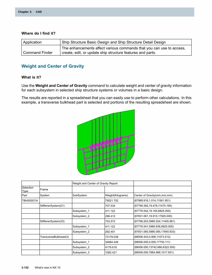
Chapter 3: CAD
Where do I find it?
Application Ship Structure Basic Design and Ship Structure Detail Design
Command FinderThe enhancements affect various commands that you can use to access,create, edit, or update ship structure features and parts.
Weight and Center of Gravity
What is it?
Use theWeight and Center of Gravity command to calculate weight and center of gravity informationfor each subsystem in selected ship structure systems or volumes in a basic design.
The results are reported in a spreadsheet that you can easily use to perform other calculations. In thisexample, a transverse bulkhead part is selected and portions of the resulting spreadsheet are shown.
Weight and Center of Gravity ReportSelectionType: Frame
Part System SubSystem Weight(Kilograms) Center of Gravity(mm,mm,mm)
TBH00007/A 79521.702 (87989.916,1.014,11561.951)
StiffenerSystem(21) 707.534 (87799.382,19.478,11475.195)
Subsystem_1 411.122 (87776.542,19.164,6825.000)
Subsystem_2 296.412 (87831.061,19.915,17925.000)
StiffenerSystem(33) 703.573 (87799.203,5980.524,11405.981)
Subsystem_1 411.122 (87776.541,5980.836,6825.000)
Subsystem_2 292.451 (87831.060,5980.085,17845.833)
TransverseBulkhead(3) 73178.038 (88006.443,0.906,11573.512)
Subsystem_1 34684.448 (88006.000,0.000,17750.111)
Subsystem_2 4179.618 (88006.000,13742.666,6322.555)
Subsystem_3 1082.421 (88006.000,7884.968,1017.651)
3-152 What's new in NX 10
Chapter 3: CAD
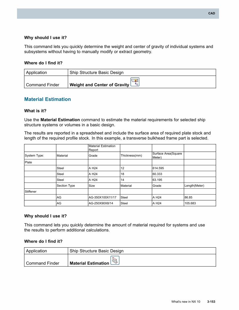
CAD
Why should I use it?
This command lets you quickly determine the weight and center of gravity of individual systems andsubsystems without having to manually modify or extract geometry.
Where do I find it?
Application Ship Structure Basic Design
Command Finder Weight and Center of Gravity
Material Estimation
What is it?
Use the Material Estimation command to estimate the material requirements for selected shipstructure systems or volumes in a basic design.
The results are reported in a spreadsheet and include the surface area of required plate stock andlength of the required profile stock. In this example, a transverse bulkhead frame part is selected.
Material EstimationReport
System Type: Material Grade Thickness(mm) Surface Area(SquareMeter)
Plate
Steel A H24 12 614.595
Steel A H24 18 60.333
Steel A H24 14 63.195
Section Type Size Material Grade Length(Meter)
Stiffener
AG AG-350X100X11/17 Steel A H24 86.85
AG AG-250X90X8/14 Steel A H24 105.683
Why should I use it?
This command lets you quickly determine the amount of material required for systems and usethe results to perform additional calculations.
Where do I find it?
Application Ship Structure Basic Design
Command Finder Material Estimation
What's new in NX 10 3-153
CAD
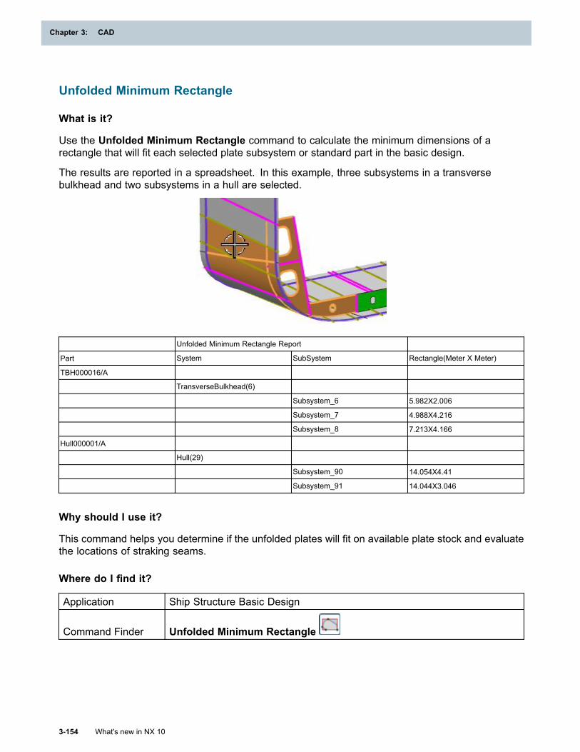
Chapter 3: CAD
Unfolded Minimum Rectangle
What is it?
Use the Unfolded Minimum Rectangle command to calculate the minimum dimensions of arectangle that will fit each selected plate subsystem or standard part in the basic design.
The results are reported in a spreadsheet. In this example, three subsystems in a transversebulkhead and two subsystems in a hull are selected.
Unfolded Minimum Rectangle Report
Part System SubSystem Rectangle(Meter X Meter)
TBH000016/A
TransverseBulkhead(6)
Subsystem_6 5.982X2.006
Subsystem_7 4.988X4.216
Subsystem_8 7.213X4.166
Hull000001/A
Hull(29)
Subsystem_90 14.054X4.41
Subsystem_91 14.044X3.046
Why should I use it?
This command helps you determine if the unfolded plates will fit on available plate stock and evaluatethe locations of straking seams.
Where do I find it?
Application Ship Structure Basic Design
Command Finder Unfolded Minimum Rectangle
3-154 What's new in NX 10
Chapter 3: CAD
CAD
Edit Context Attributes
What is it?
Use the Edit Context Attributes command to modify the attribute assigned to systems, subsystems,and standard parts in the basic design that defines their purpose in the ship. This attribute is inheritedby the detailed parts when the basic design is transitioned to the detailed design.
For example, if a stiffener system contributes to the longitudinal strength of the ship, you can changethe value of its context attribute to Longitudinal Strength. After the stiffener system is transitionedto the detailed design, the resulting stiffeners can be identified so that you can apply appropriatenames, welds, and inspection requirements.
The title of the context attribute is SAW_SUB_NAME. You can define the allowed values in an XMLfile located at %NXSHIP_DIR%\data\NX_ShipAttribute.xml. When you edit the context attribute,you can select one of the values from a list in the dialog box.
For example, the default list for a stiffener system includes:
• Default Stiffener System• Longitudinal• Transverse• Vertical• Foundation• Header
Why should I use it?
Use context attributes to apply ship characteristics to systems, subsystems, and standard parts earlyin the design process so that they can be used in downstream rules to name detailed parts, add endcuts, add profile cutouts, create collar plates, or create welds.
Where do I find it?
Application Ship Structure Basic Design
Command Finder Edit Context Attributes
Edit Stock enhancements
What is it?
The Edit Stock command is enhanced so that you can change the Tightness parameter for non-splitplate systems and subsystems.
Why should I use it?
You can apply a unique tightness parameter to selected subsystems within a basic design withouthaving to change the work part and edit features individually.
What's new in NX 10 3-155
CAD
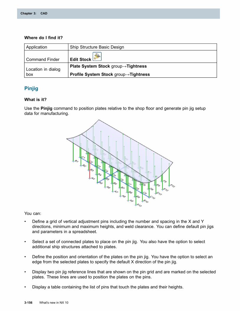
Chapter 3: CAD
Where do I find it?
Application Ship Structure Basic Design
Command Finder Edit Stock
Location in dialogbox
Plate System Stock group→Tightness
Profile System Stock group→Tightness
Pinjig
What is it?
Use the Pinjig command to position plates relative to the shop floor and generate pin jig setupdata for manufacturing.
You can:
• Define a grid of vertical adjustment pins including the number and spacing in the X and Ydirections, minimum and maximum heights, and weld clearance. You can define default pin jigsand parameters in a spreadsheet.
• Select a set of connected plates to place on the pin jig. You also have the option to selectadditional ship structures attached to plates.
• Define the position and orientation of the plates on the pin jig. You have the option to select anedge from the selected plates to specify the default X direction of the pin jig.
• Display two pin jig reference lines that are shown on the pin grid and are marked on the selectedplates. These lines are used to position the plates on the pins.
• Display a table containing the list of pins that touch the plates and their heights.
3-156 What's new in NX 10
Chapter 3: CAD
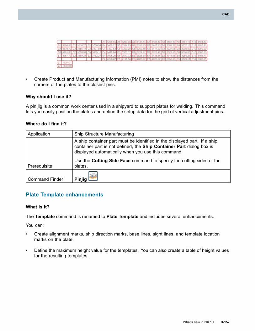
CAD
• Create Product and Manufacturing Information (PMI) notes to show the distances from thecorners of the plates to the closest pins.
Why should I use it?
A pin jig is a common work center used in a shipyard to support plates for welding. This commandlets you easily position the plates and define the setup data for the grid of vertical adjustment pins.
Where do I find it?
Application Ship Structure Manufacturing
Prerequisite
A ship container part must be identified in the displayed part. If a shipcontainer part is not defined, the Ship Container Part dialog box isdisplayed automatically when you use this command.
Use the Cutting Side Face command to specify the cutting sides of theplates.
Command Finder Pinjig
Plate Template enhancements
What is it?
The Template command is renamed to Plate Template and includes several enhancements.
You can:
• Create alignment marks, ship direction marks, base lines, sight lines, and template locationmarks on the plate.
• Define the maximum height value for the templates. You can also create a table of height valuesfor the resulting templates.
What's new in NX 10 3-157
CAD
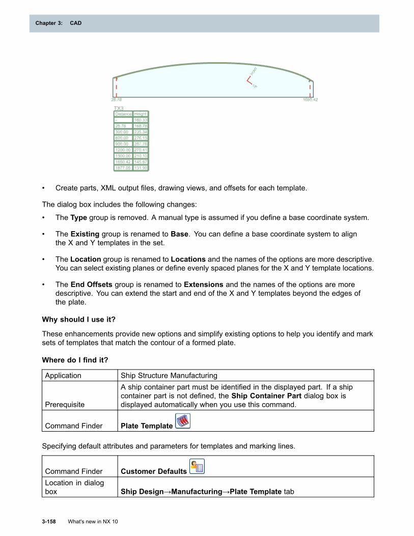
Chapter 3: CAD
• Create parts, XML output files, drawing views, and offsets for each template.
The dialog box includes the following changes:
• The Type group is removed. A manual type is assumed if you define a base coordinate system.
• The Existing group is renamed to Base. You can define a base coordinate system to alignthe X and Y templates in the set.
• The Location group is renamed to Locations and the names of the options are more descriptive.You can select existing planes or define evenly spaced planes for the X and Y template locations.
• The End Offsets group is renamed to Extensions and the names of the options are moredescriptive. You can extend the start and end of the X and Y templates beyond the edges ofthe plate.
Why should I use it?
These enhancements provide new options and simplify existing options to help you identify and marksets of templates that match the contour of a formed plate.
Where do I find it?
Application Ship Structure Manufacturing
Prerequisite
A ship container part must be identified in the displayed part. If a shipcontainer part is not defined, the Ship Container Part dialog box isdisplayed automatically when you use this command.
Command Finder Plate Template
Specifying default attributes and parameters for templates and marking lines.
Command Finder Customer DefaultsLocation in dialogbox Ship Design→Manufacturing→Plate Template tab
3-158 What's new in NX 10
Chapter 3: CAD
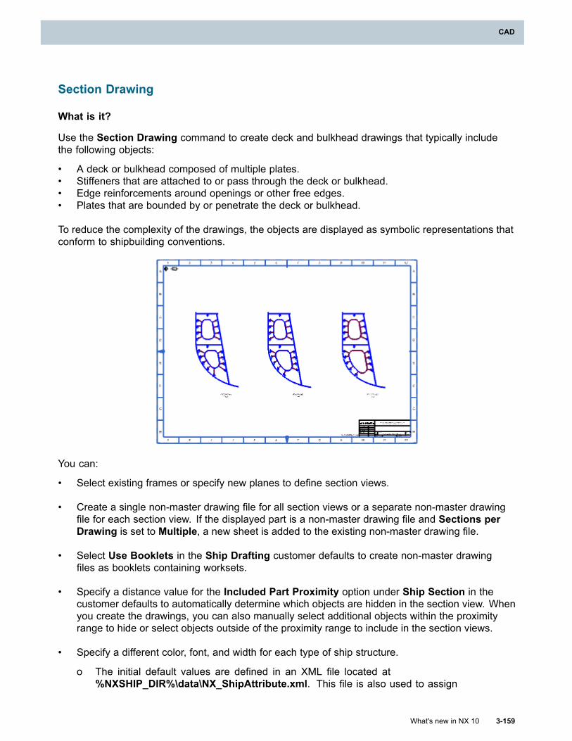
CAD
Section Drawing
What is it?
Use the Section Drawing command to create deck and bulkhead drawings that typically includethe following objects:
• A deck or bulkhead composed of multiple plates.• Stiffeners that are attached to or pass through the deck or bulkhead.• Edge reinforcements around openings or other free edges.• Plates that are bounded by or penetrate the deck or bulkhead.
To reduce the complexity of the drawings, the objects are displayed as symbolic representations thatconform to shipbuilding conventions.
You can:
• Select existing frames or specify new planes to define section views.
• Create a single non-master drawing file for all section views or a separate non-master drawingfile for each section view. If the displayed part is a non-master drawing file and Sections perDrawing is set to Multiple, a new sheet is added to the existing non-master drawing file.
• Select Use Booklets in the Ship Drafting customer defaults to create non-master drawingfiles as booklets containing worksets.
• Specify a distance value for the Included Part Proximity option under Ship Section in thecustomer defaults to automatically determine which objects are hidden in the section view. Whenyou create the drawings, you can also manually select additional objects within the proximityrange to hide or select objects outside of the proximity range to include in the section views.
• Specify a different color, font, and width for each type of ship structure.
o The initial default values are defined in an XML file located at%NXSHIP_DIR%\data\NX_ShipAttribute.xml. This file is also used to assign
What's new in NX 10 3-159
CAD
Chapter 3: CAD
the classification type and subtype to ship structures using the SAW_NAME andSAW_SUB_NAME attributes.
o You can change the default color, font, and width for each type of ship structure from the ShipDrafting→View→Ship Structure Lines node in the Drafting Preferences dialog box.
o You can edit the color, font, and width of ship structures in existing section views from theView→Ship Structure Lines node in the Settings dialog box.
o You can use custom line fonts specified in the font definition file at%NXSHIP_DIR%\shipdrafting\symbol\ShipLineFontSettings.fdf. By default,this file includes a new RAILWAY font that is available in the Ship Structure applications.
Why should I use it?
Create drawings for multiple decks and bulkheads that are simplified and easier to annotate.
Where do I find it?
Application Ship Structure Detail Design
Command Finder Section Drawing
Settings to use booklets and define the part proximity
Command Finder Customer Defaults
Location in dialogbox
Ship Drafting→General
Ship Drafting→Ship Section
Color, font, and width preferences
Application Drafting
Command Finder Drafting PreferencesLocation in dialogbox Ship Drafting→View→Ship Structure Lines node
3-160 What's new in NX 10
Chapter 3: CAD
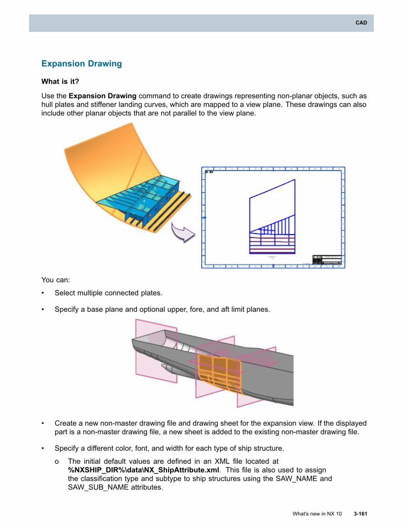
CAD
Expansion Drawing
What is it?
Use the Expansion Drawing command to create drawings representing non-planar objects, such ashull plates and stiffener landing curves, which are mapped to a view plane. These drawings can alsoinclude other planar objects that are not parallel to the view plane.
You can:
• Select multiple connected plates.
• Specify a base plane and optional upper, fore, and aft limit planes.
• Create a new non-master drawing file and drawing sheet for the expansion view. If the displayedpart is a non-master drawing file, a new sheet is added to the existing non-master drawing file.
• Specify a different color, font, and width for each type of ship structure.
o The initial default values are defined in an XML file located at%NXSHIP_DIR%\data\NX_ShipAttribute.xml. This file is also used to assignthe classification type and subtype to ship structures using the SAW_NAME andSAW_SUB_NAME attributes.
What's new in NX 10 3-161
CAD
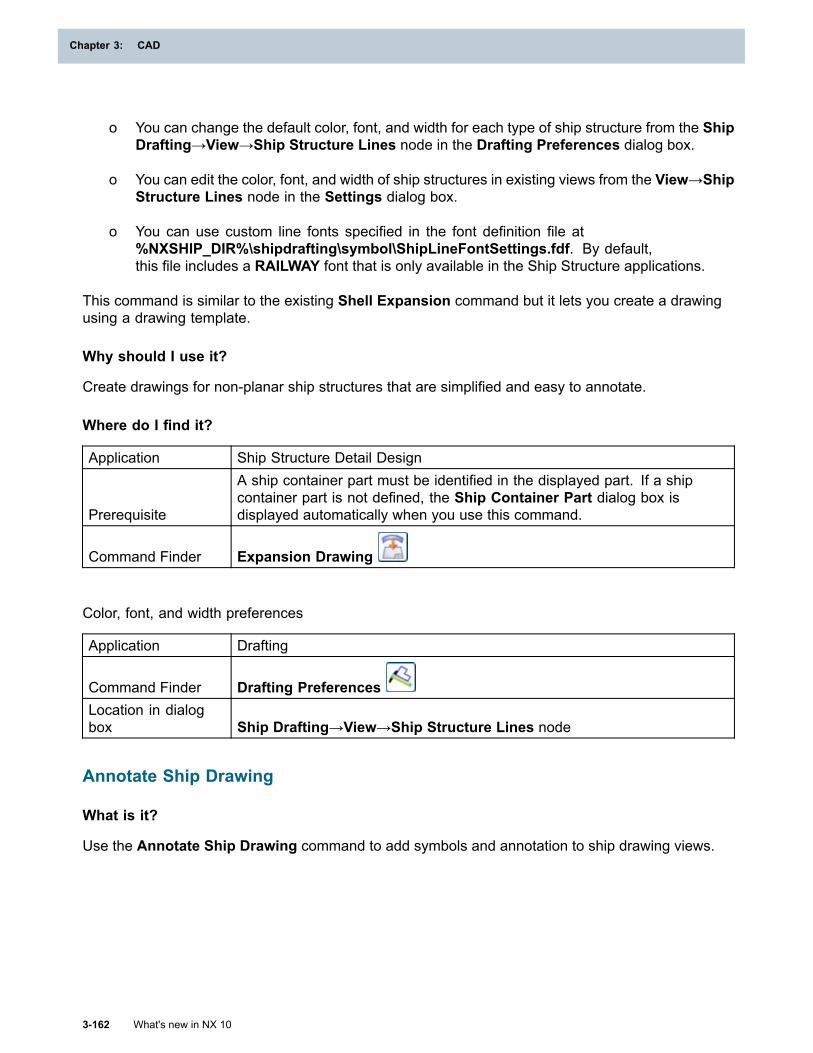
Chapter 3: CAD
o You can change the default color, font, and width for each type of ship structure from the ShipDrafting→View→Ship Structure Lines node in the Drafting Preferences dialog box.
o You can edit the color, font, and width of ship structures in existing views from the View→ShipStructure Lines node in the Settings dialog box.
o You can use custom line fonts specified in the font definition file at%NXSHIP_DIR%\shipdrafting\symbol\ShipLineFontSettings.fdf. By default,this file includes a RAILWAY font that is only available in the Ship Structure applications.
This command is similar to the existing Shell Expansion command but it lets you create a drawingusing a drawing template.
Why should I use it?
Create drawings for non-planar ship structures that are simplified and easy to annotate.
Where do I find it?
Application Ship Structure Detail Design
Prerequisite
A ship container part must be identified in the displayed part. If a shipcontainer part is not defined, the Ship Container Part dialog box isdisplayed automatically when you use this command.
Command Finder Expansion Drawing
Color, font, and width preferences
Application Drafting
Command Finder Drafting PreferencesLocation in dialogbox Ship Drafting→View→Ship Structure Lines node
Annotate Ship Drawing
What is it?
Use the Annotate Ship Drawing command to add symbols and annotation to ship drawing views.
3-162 What's new in NX 10
Chapter 3: CAD
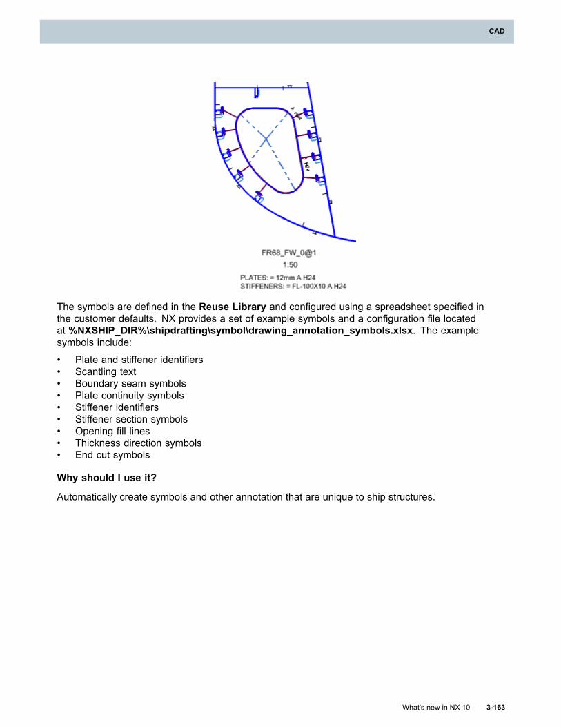
CAD
The symbols are defined in the Reuse Library and configured using a spreadsheet specified inthe customer defaults. NX provides a set of example symbols and a configuration file locatedat %NXSHIP_DIR%\shipdrafting\symbol\drawing_annotation_symbols.xlsx. The examplesymbols include:
• Plate and stiffener identifiers• Scantling text• Boundary seam symbols• Plate continuity symbols• Stiffener identifiers• Stiffener section symbols• Opening fill lines• Thickness direction symbols• End cut symbols
Why should I use it?
Automatically create symbols and other annotation that are unique to ship structures.
What's new in NX 10 3-163
CAD
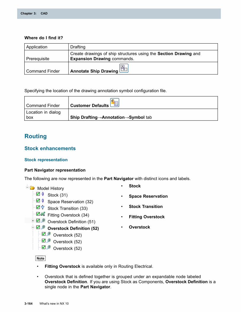
Chapter 3: CAD
Where do I find it?
Application Drafting
PrerequisiteCreate drawings of ship structures using the Section Drawing andExpansion Drawing commands.
Command Finder Annotate Ship Drawing
Specifying the location of the drawing annotation symbol configuration file.
Command Finder Customer DefaultsLocation in dialogbox Ship Drafting→Annotation→Symbol tab
Routing
Stock enhancements
Stock representation
Part Navigator representation
The following are now represented in the Part Navigator with distinct icons and labels.
Model HistoryStock (31)Space Reservation (32)Stock Transition (33)Fitting Overstock (34)Overstock Definition (51)Overstock Definition (52)
Overstock (52)Overstock (52)Overstock (52)
• Stock
• Space Reservation
• Stock Transition
• Fitting Overstock
• Overstock
Note
• Fitting Overstock is available only in Routing Electrical.
• Overstock that is defined together is grouped under an expandable node labeledOverstock Definition. If you are using Stock as Components, Overstock Definition is asingle node in the Part Navigator.
3-164 What's new in NX 10
Chapter 3: CAD
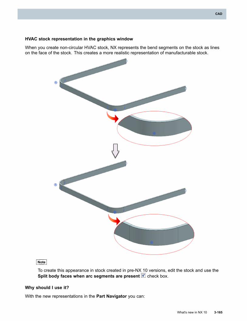
CAD
HVAC stock representation in the graphics window
When you create non-circular HVAC stock, NX represents the bend segments on the stock as lineson the face of the stock. This creates a more realistic representation of manufacturable stock.
Note
To create this appearance in stock created in pre-NX 10 versions, edit the stock and use theSplit body faces when arc segments are present check box.
Why should I use it?
With the new representations in the Part Navigator you can:
What's new in NX 10 3-165
CAD
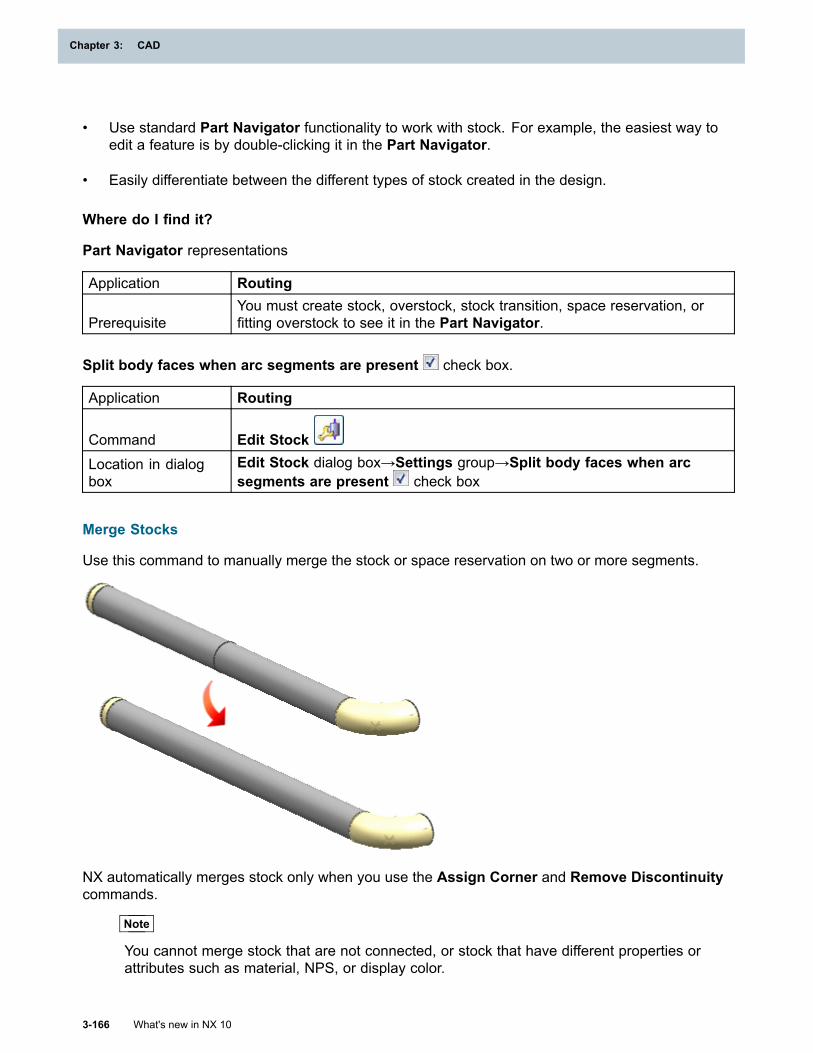
Chapter 3: CAD
• Use standard Part Navigator functionality to work with stock. For example, the easiest way toedit a feature is by double-clicking it in the Part Navigator.
• Easily differentiate between the different types of stock created in the design.
Where do I find it?
Part Navigator representations
Application Routing
PrerequisiteYou must create stock, overstock, stock transition, space reservation, orfitting overstock to see it in the Part Navigator.
Split body faces when arc segments are present check box.
Application Routing
Command Edit StockLocation in dialogbox
Edit Stock dialog box→Settings group→Split body faces when arcsegments are present check box
Merge Stocks
Use this command to manually merge the stock or space reservation on two or more segments.
NX automatically merges stock only when you use the Assign Corner and Remove Discontinuitycommands.
Note
You cannot merge stock that are not connected, or stock that have different properties orattributes such as material, NPS, or display color.
3-166 What's new in NX 10
Chapter 3: CAD
CAD
Where do I find it?
Application Routing
Command Finder Merge Stocks
Upgrading pre-NX 10 stock
The data model has changed for the following from NX 10 onwards:
• Stock
• Overstock
• Space Reservation
• Stock Transition
• Fitting Overstock
Note
Fitting Overstock is available only in Routing Electrical.
In NX 10 or later, you must upgrade stock to the new data model in order to use any Routingcommand on a part or assembly which has stock saved in pre-NX 10 versions.
Batch upgrade
Use the refile_part utility to upgrade stock in large assemblies to the new data model. The refile_partutility can be used for upgrading both Legacy Stock and Stock as Components.
Note
If stock components from the assembly are missing, then the refile_part utility fails. Torecreate missing stock components while using the refile_part utility to upgrade stocks to thenew data model, use the –recreate_missing_stock_components option.
Use case refile_part syntaxUpgrading the stocks in assemblies while usingTeamcenter Integration
ugmanager_refile_program -u=<username> -p=<password> -recreate_missing_stock_components -folder=RefiledParts
Upgrading the stocks in assemblies while usingnative NX
refile_part.exe –y -recreate_missing_stock_components –d <folder location>
Upgrading the stocks in a single harnessassembly part file while using native NX
refile_part.exe –y –recreate_missing_stock_components <folder location of file>\<file name>
Upgrading assemblies with Legacy Stock
When you open a part or assembly which has Legacy Stock saved in pre-NX 10 versions in NX10, NX automatically upgrades the Legacy Stock so that it is compatible with the new data model.This upgrade happens during part loading when you open the part or assembly and save the part
What's new in NX 10 3-167
CAD
Chapter 3: CAD
or assembly after it loads. Subsequent attempts to open and load the part or assembly are fasteras the stock is upgraded only once.
If you want to defer the stock upgrade, use the Defer Legacy Stock Conversion During Part Loadcustomer default. If you defer the upgrade, you must use the Upgrade Stocks command to upgradethe stock before you make any changes to the design.
Tip
To find a customer default, choose File tab→Utilities→Customer Defaults, and click Find
Default .
Upgrading assemblies with Stock as Components
For stock saved in pre-NX 10 versions as Stock as Components, use the Upgrade Stocks commandto upgrade the stock to the new data model. When you use this command, you can also recreateany stock components that are missing and cannot be loaded.
Where do I find it?
Application Routing
Command Finder Upgrade StocksCommand line input refile_part
Recreate Inaccessible Stock Components
Use this command to recreate the following components if they are missing and cannot be loadedin the assembly:
• Stock
• Overstock
• Space Reservation
• Stock Transition
• Fitting Overstock
Note
Fitting Overstock is available only in Routing Electrical.
Where do I find it?
Application RoutingPrerequisite All stock in the part or assembly must be converted to the new data model.
Command Finder Recreate Inaccessible Stock Components
3-168 What's new in NX 10
Chapter 3: CAD
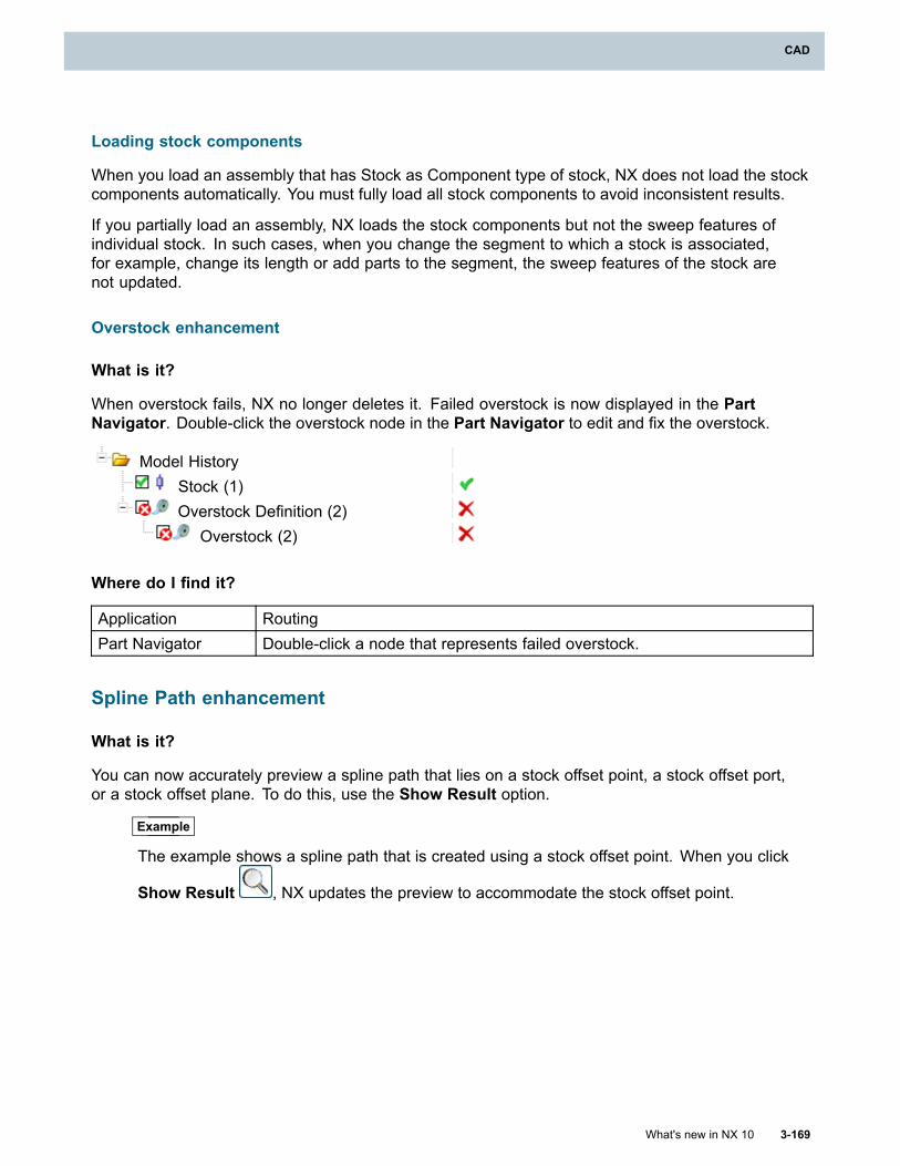
CAD
Loading stock components
When you load an assembly that has Stock as Component type of stock, NX does not load the stockcomponents automatically. You must fully load all stock components to avoid inconsistent results.
If you partially load an assembly, NX loads the stock components but not the sweep features ofindividual stock. In such cases, when you change the segment to which a stock is associated,for example, change its length or add parts to the segment, the sweep features of the stock arenot updated.
Overstock enhancement
What is it?
When overstock fails, NX no longer deletes it. Failed overstock is now displayed in the PartNavigator. Double-click the overstock node in the Part Navigator to edit and fix the overstock.
Model HistoryStock (1)Overstock Definition (2)
Overstock (2)
Where do I find it?
Application RoutingPart Navigator Double-click a node that represents failed overstock.
Spline Path enhancement
What is it?
You can now accurately preview a spline path that lies on a stock offset point, a stock offset port,or a stock offset plane. To do this, use the Show Result option.
Example
The example shows a spline path that is created using a stock offset point. When you click
Show Result , NX updates the preview to accommodate the stock offset point.
What's new in NX 10 3-169
CAD
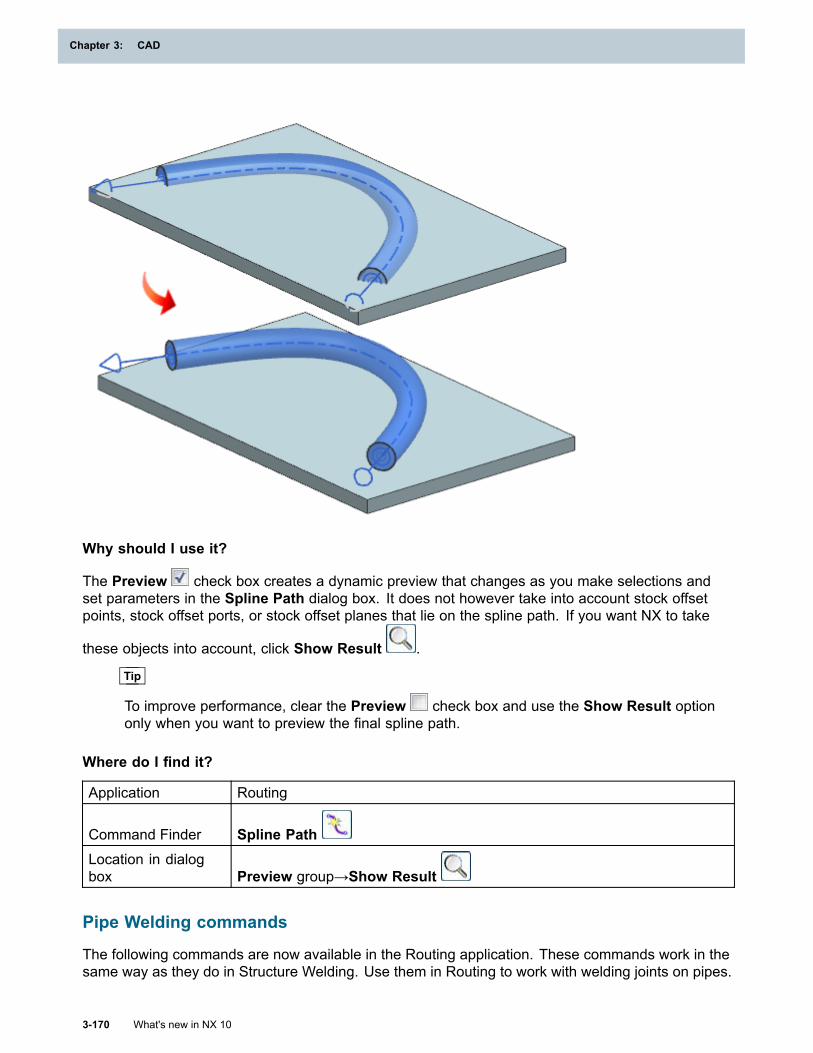
Chapter 3: CAD
Why should I use it?
The Preview check box creates a dynamic preview that changes as you make selections andset parameters in the Spline Path dialog box. It does not however take into account stock offsetpoints, stock offset ports, or stock offset planes that lie on the spline path. If you want NX to take
these objects into account, click Show Result .
Tip
To improve performance, clear the Preview check box and use the Show Result optiononly when you want to preview the final spline path.
Where do I find it?
Application Routing
Command Finder Spline PathLocation in dialogbox Preview group→Show Result
Pipe Welding commands
The following commands are now available in the Routing application. These commands work in thesame way as they do in Structure Welding. Use them in Routing to work with welding joints on pipes.
3-170 What's new in NX 10
Chapter 3: CAD
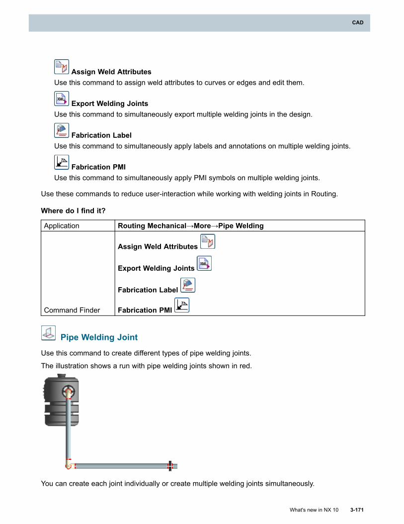
CAD
Assign Weld AttributesUse this command to assign weld attributes to curves or edges and edit them.
Export Welding JointsUse this command to simultaneously export multiple welding joints in the design.
Fabrication LabelUse this command to simultaneously apply labels and annotations on multiple welding joints.
Fabrication PMIUse this command to simultaneously apply PMI symbols on multiple welding joints.
Use these commands to reduce user-interaction while working with welding joints in Routing.
Where do I find it?
Application Routing Mechanical→More→Pipe Welding
Command Finder
Assign Weld Attributes
Export Welding Joints
Fabrication Label
Fabrication PMI
Pipe Welding Joint
Use this command to create different types of pipe welding joints.
The illustration shows a run with pipe welding joints shown in red.
You can create each joint individually or create multiple welding joints simultaneously.
What's new in NX 10 3-171
CAD
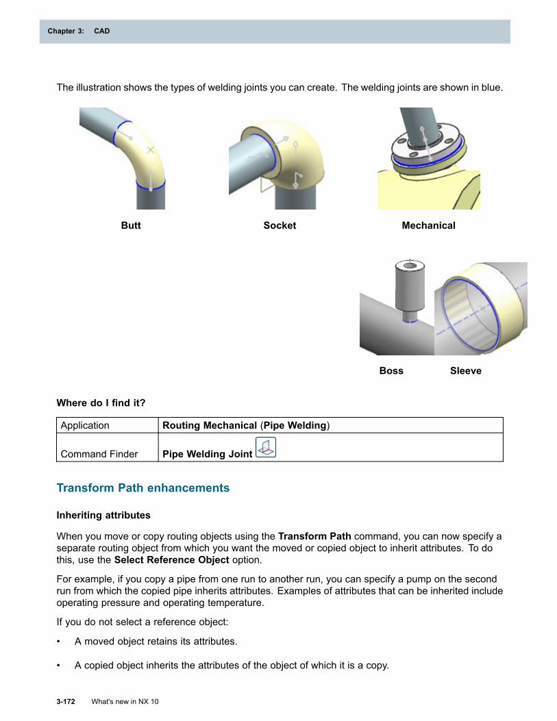
Chapter 3: CAD
The illustration shows the types of welding joints you can create. The welding joints are shown in blue.
Butt Socket Mechanical
Boss Sleeve
Where do I find it?
Application Routing Mechanical (Pipe Welding)
Command Finder Pipe Welding Joint
Transform Path enhancements
Inheriting attributes
When you move or copy routing objects using the Transform Path command, you can now specify aseparate routing object from which you want the moved or copied object to inherit attributes. To dothis, use the Select Reference Object option.
For example, if you copy a pipe from one run to another run, you can specify a pump on the secondrun from which the copied pipe inherits attributes. Examples of attributes that can be inherited includeoperating pressure and operating temperature.
If you do not select a reference object:
• A moved object retains its attributes.
• A copied object inherits the attributes of the object of which it is a copy.
3-172 What's new in NX 10
Chapter 3: CAD
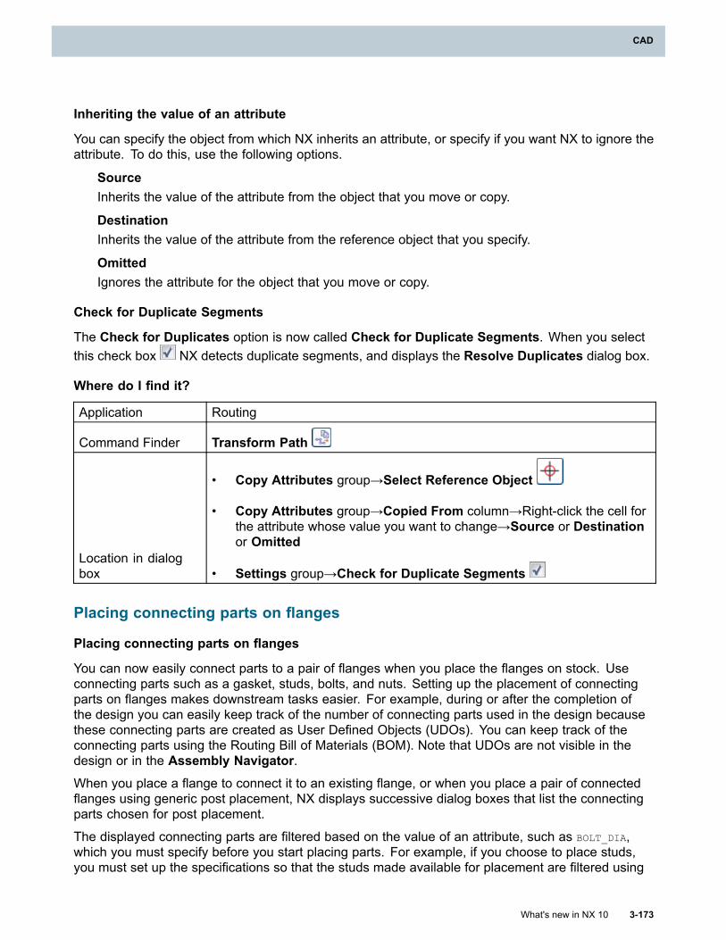
CAD
Inheriting the value of an attribute
You can specify the object from which NX inherits an attribute, or specify if you want NX to ignore theattribute. To do this, use the following options.
SourceInherits the value of the attribute from the object that you move or copy.
DestinationInherits the value of the attribute from the reference object that you specify.
OmittedIgnores the attribute for the object that you move or copy.
Check for Duplicate Segments
The Check for Duplicates option is now called Check for Duplicate Segments. When you selectthis check box NX detects duplicate segments, and displays the Resolve Duplicates dialog box.
Where do I find it?
Application Routing
Command Finder Transform Path
Location in dialogbox
• Copy Attributes group→Select Reference Object
• Copy Attributes group→Copied From column→Right-click the cell forthe attribute whose value you want to change→Source or Destinationor Omitted
• Settings group→Check for Duplicate Segments
Placing connecting parts on flanges
Placing connecting parts on flanges
You can now easily connect parts to a pair of flanges when you place the flanges on stock. Useconnecting parts such as a gasket, studs, bolts, and nuts. Setting up the placement of connectingparts on flanges makes downstream tasks easier. For example, during or after the completion ofthe design you can easily keep track of the number of connecting parts used in the design becausethese connecting parts are created as User Defined Objects (UDOs). You can keep track of theconnecting parts using the Routing Bill of Materials (BOM). Note that UDOs are not visible in thedesign or in the Assembly Navigator.When you place a flange to connect it to an existing flange, or when you place a pair of connectedflanges using generic post placement, NX displays successive dialog boxes that list the connectingparts chosen for post placement.
The displayed connecting parts are filtered based on the value of an attribute, such as BOLT_DIA,which you must specify before you start placing parts. For example, if you choose to place studs,you must set up the specifications so that the studs made available for placement are filtered using
What's new in NX 10 3-173
CAD
Chapter 3: CAD
the BOLT_DIA attribute. NX matches the value of the bolt diameter of studs with the value of thesame attribute on the flanges.
The list of results for bolts or studs is filtered further based on the value of the BOLT_LEN attribute.NX calculates the minimum required bolt length using information on the flanges and the gasket, ifselected, including any user-specified length adjustment. The bolts or studs that are listed have theshortest length that meets this calculation of minimum length. The calculations and the minimumrequired bolt length are also displayed in the selection dialog box for bolts or studs.
To enable filtering of the connecting parts for placement on other parts such as a globe valve, youmust add an attribute, such as the BOLT_DIA attribute, to the part table file (PTB file) of the family ofglobe valve parts, and create a specification using the Connection Post Placement dialog box tofilter the parts by the specified attribute.
After you place the connected parts in the design, they appear in the Routing BOM.
Note
• Connected parts appear in the Routing BOM, only if you select the options in theCompatibility Table dialog box→Report in BOM group.
• Generic post placement works only when you place a part on stock.
Example
Workflow for placing bolts and nuts on a valve part that is placed on stock.
3-174 What's new in NX 10
Chapter 3: CAD
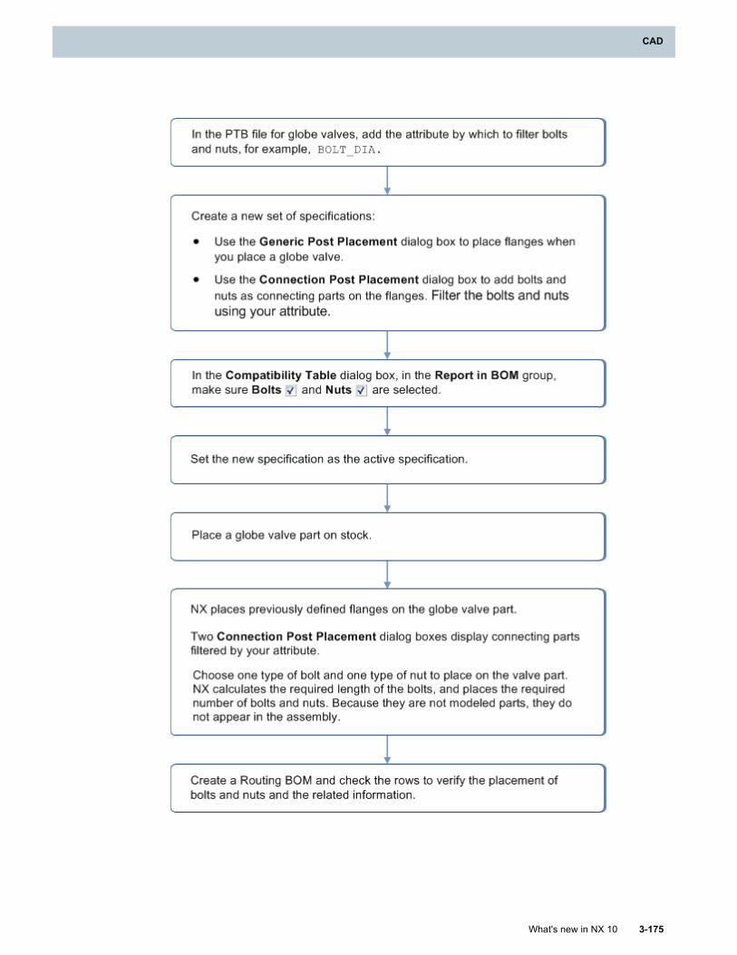
CAD
What's new in NX 10 3-175
CAD
Chapter 3: CAD
Part placement enhancements
Maintaining pipe length
NX cuts the pipe to accommodate the flange that you place on it and maintains the overall length ofthe pipe when you place the flange in the following conditions:
• You place a flange that has two parallel ports facing opposite directions, such as a weld neckflange or a socket weld flange.
• You place the flange at the end of the pipe.
In earlier versions, NX maintained the overall length of the pipe only if you placed flanges inthe middle of a pipe.
Note
Blind flanges have a single port. When you place a blind flange at the end of a pipe, it addsto the length of the pipe.
Placement solutions
The sequence in which NX provides placement solutions is improved. The sequence is basedon the following:
• The PREFERRED_PORT attribute.
• The type of port available on the part—Fitting, Fixture, or Multi—changes the order of placementdepending on:
o Whether you place the part in Routing Mechanical, Routing Electrical, or Routing Logical.
o The object on which you place the part.
• The CROSS_SECTION attribute and the CONNECTION_TYPE attribute when the part is placedon a Fitting port.
• The Value of the FLOW_DIRECTION attribute of the port. The value of this attribute is definedwhen you qualify a port using the Qualify Part dialog box. The part may be placed in one of thefollowing conditions:
o The object on which you place it is a part of a run. The run must have a defined direction offlow and the part you place must have a defined FLOW DIRECTION property.
o You place the part on a Fitting port with a FLOW DIRECTION property.
Anchor-based placement solutions
When you use an anchor-based solution to place a part, the Status line displays the name of theanchor that NX uses for the part placement. To set this up, you must specify a name to the anchorwhile qualifying the part. For example, assume that you are qualifying a part to use an anchor-basedsolution for placement, and you specify the name of the anchor as ANCH_1234. When you place thispart, the Status line displays Anchor: ANCH_1234.If, while qualifying a part with an anchor-based solution, you retain the default anchor name, then NXdisplays :Anchor: in the Status line, when you place that part.
3-176 What's new in NX 10
Chapter 3: CAD
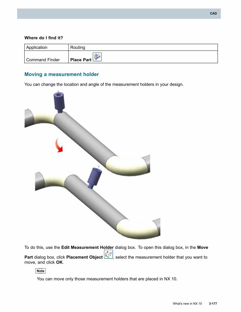
CAD
Where do I find it?
Application Routing
Command Finder Place Part
Moving a measurement holder
You can change the location and angle of the measurement holders in your design.
To do this, use the Edit Measurement Holder dialog box. To open this dialog box, in the Move
Part dialog box, click Placement Object , select the measurement holder that you want tomove, and click OK.
Note
You can move only those measurement holders that are placed in NX 10.
What's new in NX 10 3-177
CAD
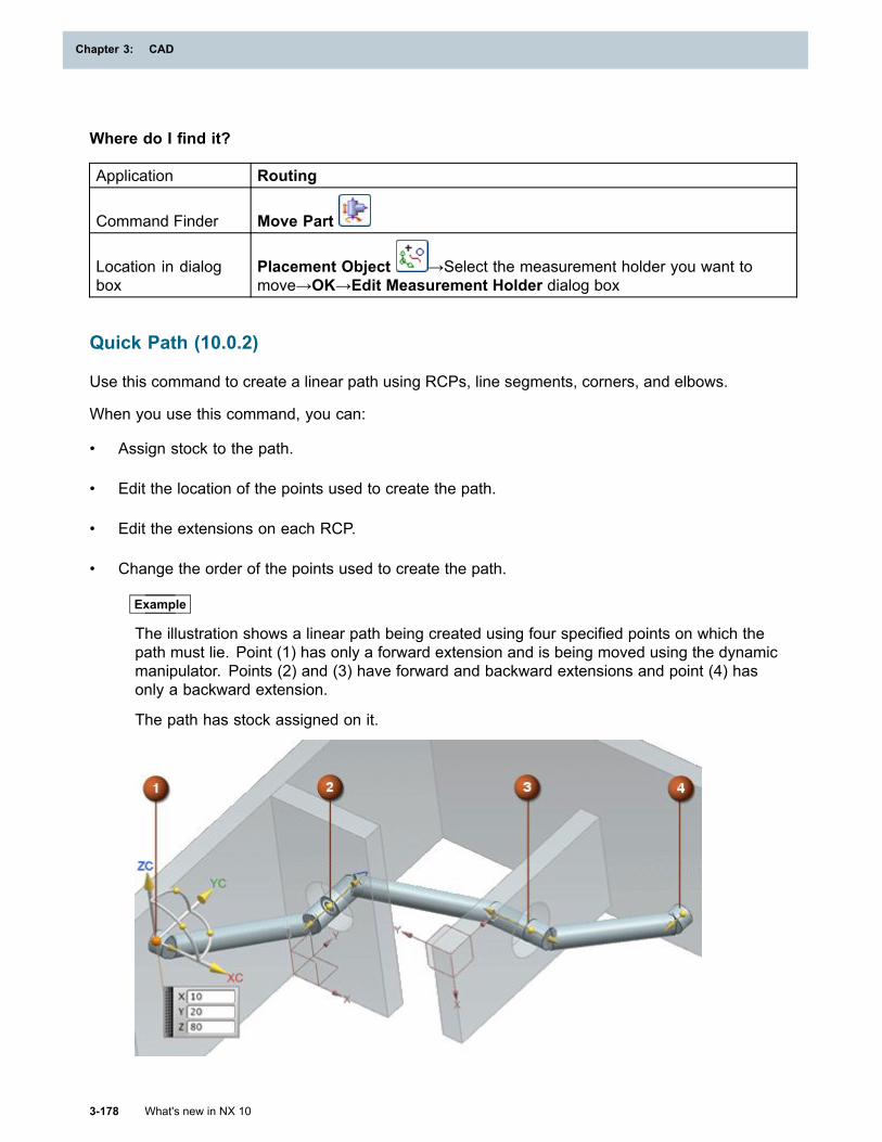
Chapter 3: CAD
Where do I find it?
Application Routing
Command Finder Move Part
Location in dialogbox
Placement Object →Select the measurement holder you want tomove→OK→Edit Measurement Holder dialog box
Quick Path (10.0.2)
Use this command to create a linear path using RCPs, line segments, corners, and elbows.
When you use this command, you can:
• Assign stock to the path.
• Edit the location of the points used to create the path.
• Edit the extensions on each RCP.
• Change the order of the points used to create the path.
Example
The illustration shows a linear path being created using four specified points on which thepath must lie. Point (1) has only a forward extension and is being moved using the dynamicmanipulator. Points (2) and (3) have forward and backward extensions and point (4) hasonly a backward extension.
The path has stock assigned on it.
3-178 What's new in NX 10
Chapter 3: CAD
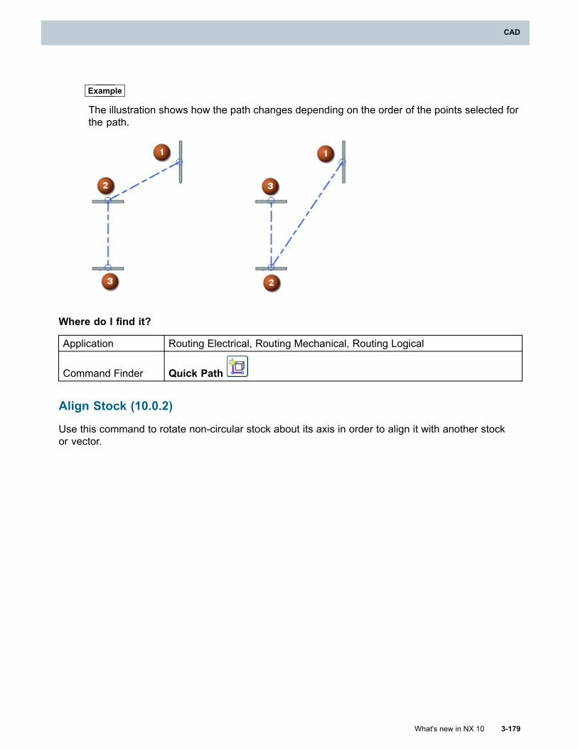
CAD
Example
The illustration shows how the path changes depending on the order of the points selected forthe path.
Where do I find it?
Application Routing Electrical, Routing Mechanical, Routing Logical
Command Finder Quick Path
Align Stock (10.0.2)
Use this command to rotate non-circular stock about its axis in order to align it with another stockor vector.
What's new in NX 10 3-179
CAD
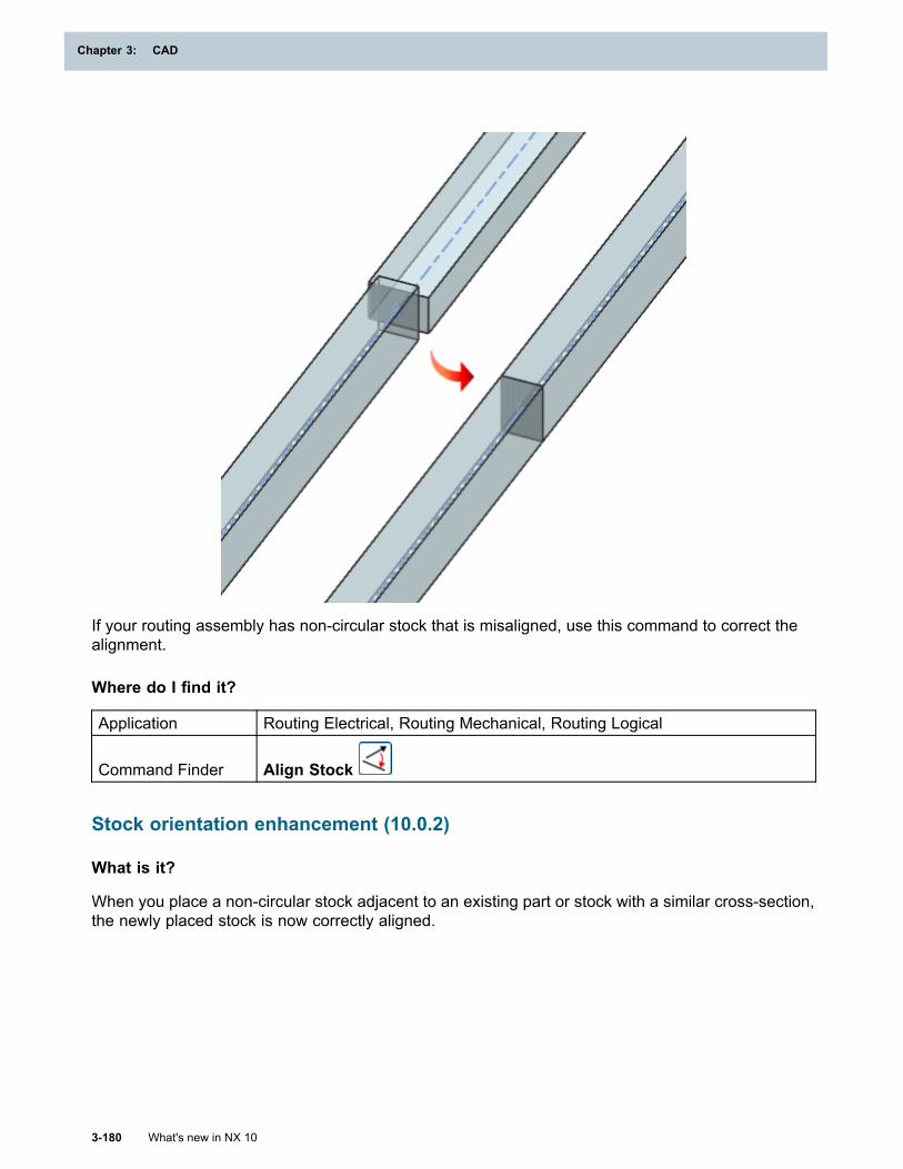
Chapter 3: CAD
If your routing assembly has non-circular stock that is misaligned, use this command to correct thealignment.
Where do I find it?
Application Routing Electrical, Routing Mechanical, Routing Logical
Command Finder Align Stock
Stock orientation enhancement (10.0.2)
What is it?
When you place a non-circular stock adjacent to an existing part or stock with a similar cross-section,the newly placed stock is now correctly aligned.
3-180 What's new in NX 10
Chapter 3: CAD
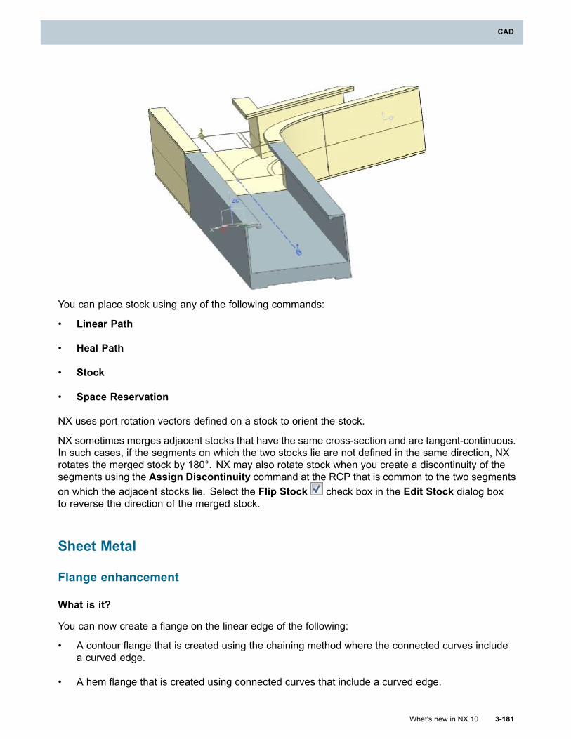
CAD
You can place stock using any of the following commands:
• Linear Path
• Heal Path
• Stock
• Space Reservation
NX uses port rotation vectors defined on a stock to orient the stock.
NX sometimes merges adjacent stocks that have the same cross-section and are tangent-continuous.In such cases, if the segments on which the two stocks lie are not defined in the same direction, NXrotates the merged stock by 180°. NX may also rotate stock when you create a discontinuity of thesegments using the Assign Discontinuity command at the RCP that is common to the two segmentson which the adjacent stocks lie. Select the Flip Stock check box in the Edit Stock dialog boxto reverse the direction of the merged stock.
Sheet Metal
Flange enhancement
What is it?
You can now create a flange on the linear edge of the following:
• A contour flange that is created using the chaining method where the connected curves includea curved edge.
• A hem flange that is created using connected curves that include a curved edge.
What's new in NX 10 3-181
CAD
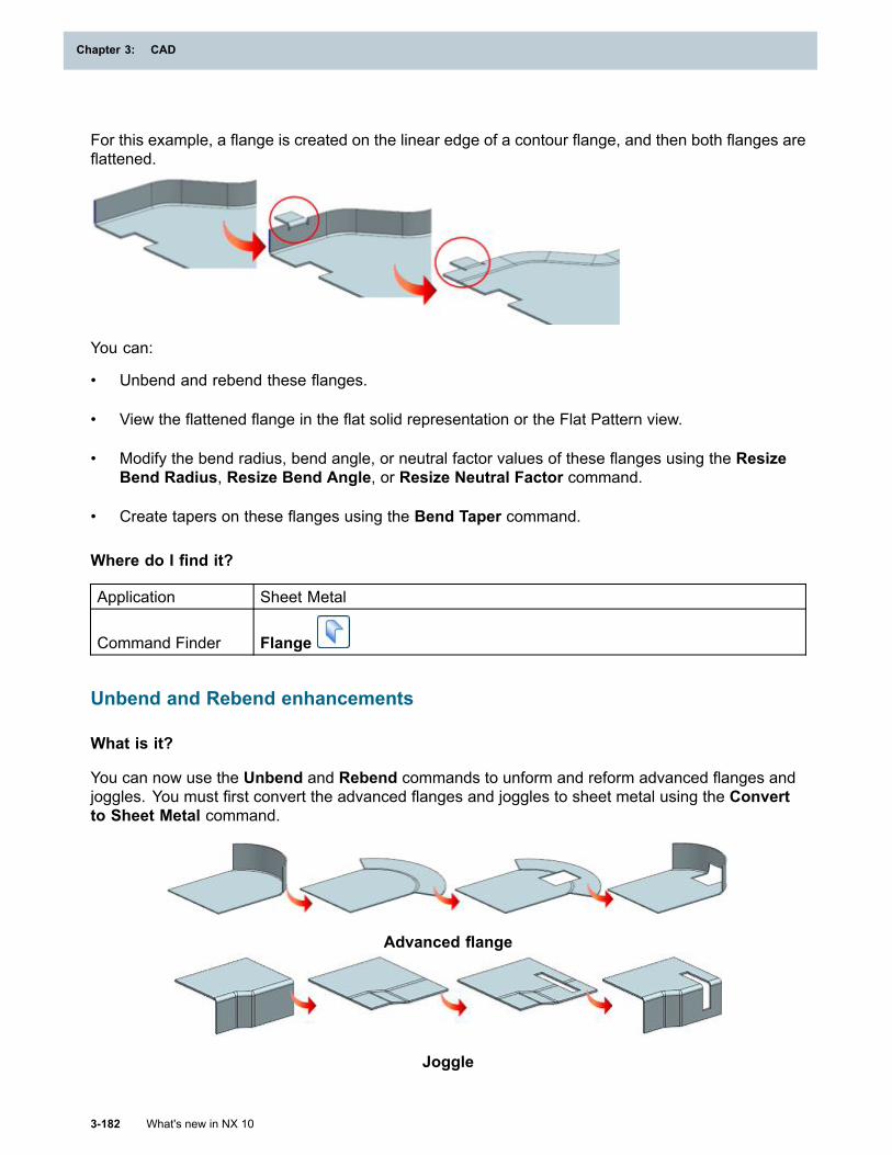
Chapter 3: CAD
For this example, a flange is created on the linear edge of a contour flange, and then both flanges areflattened.
You can:
• Unbend and rebend these flanges.
• View the flattened flange in the flat solid representation or the Flat Pattern view.
• Modify the bend radius, bend angle, or neutral factor values of these flanges using the ResizeBend Radius, Resize Bend Angle, or Resize Neutral Factor command.
• Create tapers on these flanges using the Bend Taper command.
Where do I find it?
Application Sheet Metal
Command Finder Flange
Unbend and Rebend enhancements
What is it?
You can now use the Unbend and Rebend commands to unform and reform advanced flanges andjoggles. You must first convert the advanced flanges and joggles to sheet metal using the Convertto Sheet Metal command.
Advanced flange
Joggle
3-182 What's new in NX 10
Chapter 3: CAD
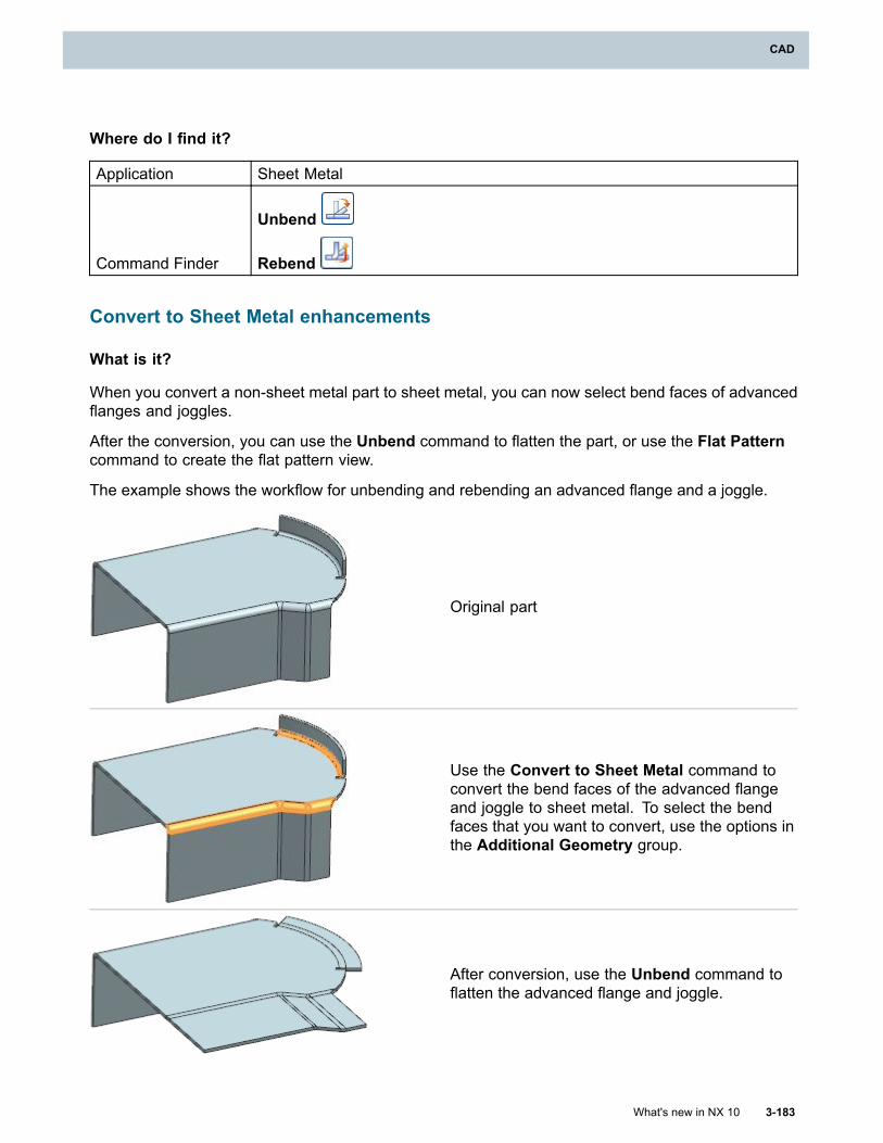
CAD
Where do I find it?
Application Sheet Metal
Command Finder
Unbend
Rebend
Convert to Sheet Metal enhancements
What is it?
When you convert a non-sheet metal part to sheet metal, you can now select bend faces of advancedflanges and joggles.
After the conversion, you can use the Unbend command to flatten the part, or use the Flat Patterncommand to create the flat pattern view.
The example shows the workflow for unbending and rebending an advanced flange and a joggle.
Original part
Use the Convert to Sheet Metal command toconvert the bend faces of the advanced flangeand joggle to sheet metal. To select the bendfaces that you want to convert, use the options inthe Additional Geometry group.
After conversion, use the Unbend command toflatten the advanced flange and joggle.
What's new in NX 10 3-183
CAD

Chapter 3: CAD
Where do I find it?
Application Sheet Metal
Command Finder Convert to Sheet MetalLocation in dialogbox Additional Geometry group
Specifying a target body for creating normal cutouts
What is it?
You can now specify the target body on which you want to create the normal cutout feature.
If the part has a single sheet metal body, NX infers it as the target body.
The example shows the workflow for creating a normal cutout on a target body in a part that hasmultiple sheet metal bodies.
Original sheet metal part
Specify the normal cutout section.
For this example, Limits = Through All.
Select the target body.
3-184 What's new in NX 10
Chapter 3: CAD
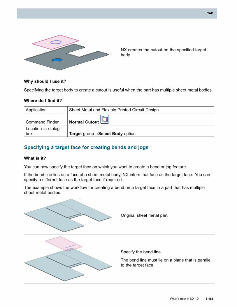
CAD
NX creates the cutout on the specified targetbody.
Why should I use it?
Specifying the target body to create a cutout is useful when the part has multiple sheet metal bodies.
Where do I find it?
Application Sheet Metal and Flexible Printed Circuit Design
Command Finder Normal CutoutLocation in dialogbox Target group→Select Body option
Specifying a target face for creating bends and jogs
What is it?
You can now specify the target face on which you want to create a bend or jog feature.
If the bend line lies on a face of a sheet metal body, NX infers that face as the target face. You canspecify a different face as the target face if required.
The example shows the workflow for creating a bend on a target face in a part that has multiplesheet metal bodies.
Original sheet metal part
Specify the bend line.
The bend line must lie on a plane that is parallelto the target face.
What's new in NX 10 3-185
CAD
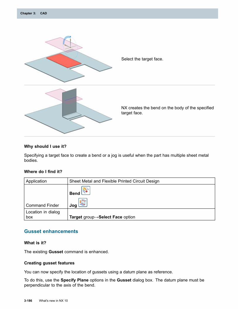
Chapter 3: CAD
Select the target face.
NX creates the bend on the body of the specifiedtarget face.
Why should I use it?
Specifying a target face to create a bend or a jog is useful when the part has multiple sheet metalbodies.
Where do I find it?
Application Sheet Metal and Flexible Printed Circuit Design
Command Finder
Bend
JogLocation in dialogbox Target group→Select Face option
Gusset enhancements
What is it?
The existing Gusset command is enhanced.
Creating gusset features
You can now specify the location of gussets using a datum plane as reference.
To do this, use the Specify Plane options in the Gusset dialog box. The datum plane must beperpendicular to the axis of the bend.
3-186 What's new in NX 10
Chapter 3: CAD
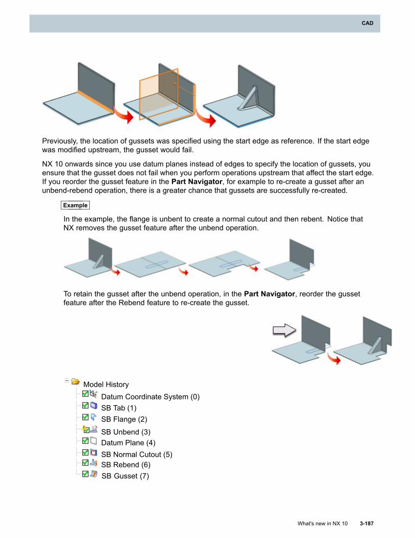
CAD
Previously, the location of gussets was specified using the start edge as reference. If the start edgewas modified upstream, the gusset would fail.
NX 10 onwards since you use datum planes instead of edges to specify the location of gussets, youensure that the gusset does not fail when you perform operations upstream that affect the start edge.If you reorder the gusset feature in the Part Navigator, for example to re-create a gusset after anunbend-rebend operation, there is a greater chance that gussets are successfully re-created.
Example
In the example, the flange is unbent to create a normal cutout and then rebent. Notice thatNX removes the gusset feature after the unbend operation.
To retain the gusset after the unbend operation, in the Part Navigator, reorder the gussetfeature after the Rebend feature to re-create the gusset.
Model HistoryDatum Coordinate System (0)SB Tab (1)SB Flange (2)
SB Unbend (3)Datum Plane (4)SB Normal Cutout (5)SB Rebend (6)SB Gusset (7)
What's new in NX 10 3-187
CAD
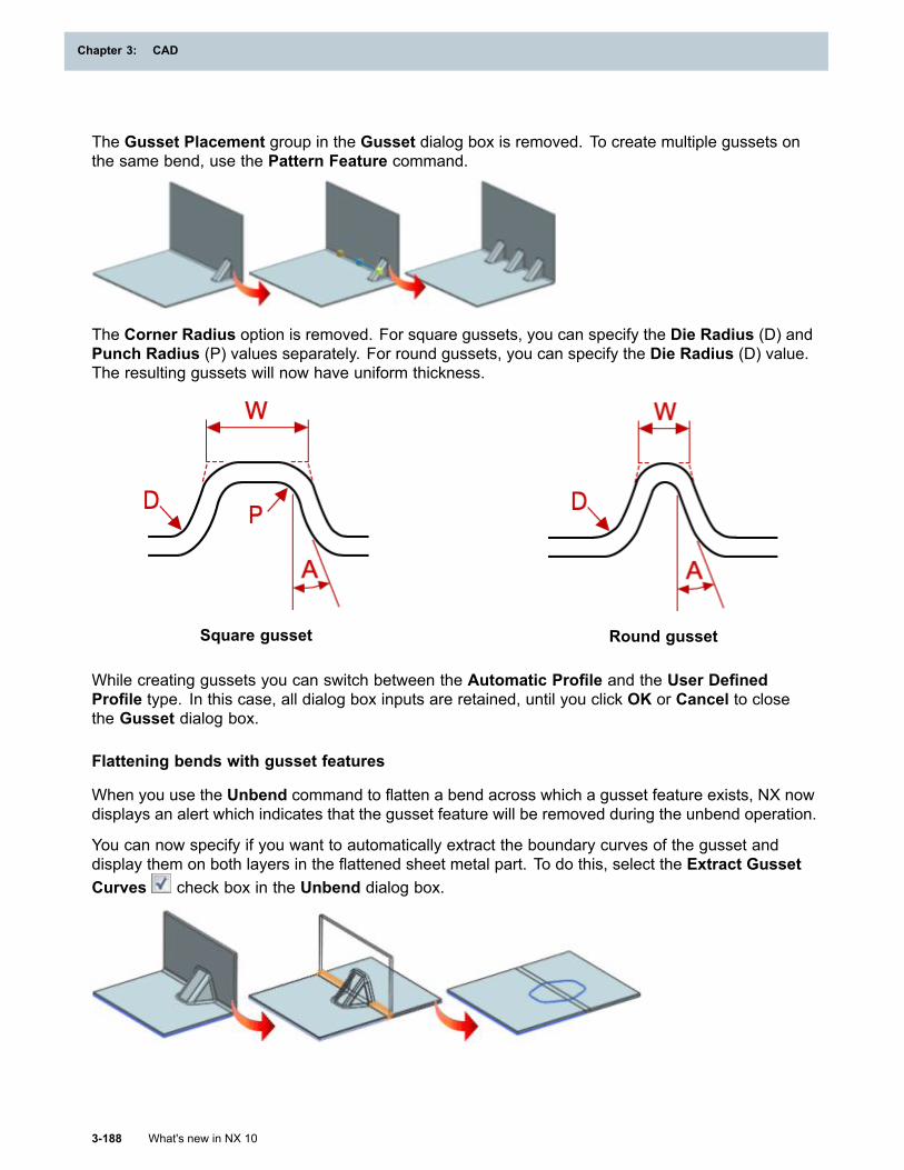
Chapter 3: CAD
The Gusset Placement group in the Gusset dialog box is removed. To create multiple gussets onthe same bend, use the Pattern Feature command.
The Corner Radius option is removed. For square gussets, you can specify the Die Radius (D) andPunch Radius (P) values separately. For round gussets, you can specify the Die Radius (D) value.The resulting gussets will now have uniform thickness.
Square gusset Round gusset
While creating gussets you can switch between the Automatic Profile and the User DefinedProfile type. In this case, all dialog box inputs are retained, until you click OK or Cancel to closethe Gusset dialog box.
Flattening bends with gusset features
When you use the Unbend command to flatten a bend across which a gusset feature exists, NX nowdisplays an alert which indicates that the gusset feature will be removed during the unbend operation.
You can now specify if you want to automatically extract the boundary curves of the gusset anddisplay them on both layers in the flattened sheet metal part. To do this, select the Extract GussetCurves check box in the Unbend dialog box.
3-188 What's new in NX 10
Chapter 3: CAD
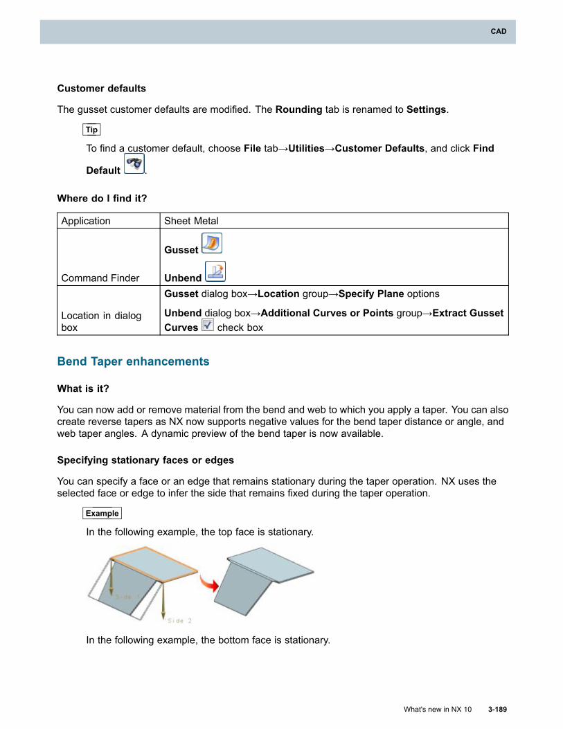
CAD
Customer defaults
The gusset customer defaults are modified. The Rounding tab is renamed to Settings.
Tip
To find a customer default, choose File tab→Utilities→Customer Defaults, and click Find
Default .
Where do I find it?
Application Sheet Metal
Command Finder
Gusset
Unbend
Location in dialogbox
Gusset dialog box→Location group→Specify Plane options
Unbend dialog box→Additional Curves or Points group→Extract GussetCurves check box
Bend Taper enhancements
What is it?
You can now add or remove material from the bend and web to which you apply a taper. You can alsocreate reverse tapers as NX now supports negative values for the bend taper distance or angle, andweb taper angles. A dynamic preview of the bend taper is now available.
Specifying stationary faces or edges
You can specify a face or an edge that remains stationary during the taper operation. NX uses theselected face or edge to infer the side that remains fixed during the taper operation.
Example
In the following example, the top face is stationary.
In the following example, the bottom face is stationary.
What's new in NX 10 3-189
CAD
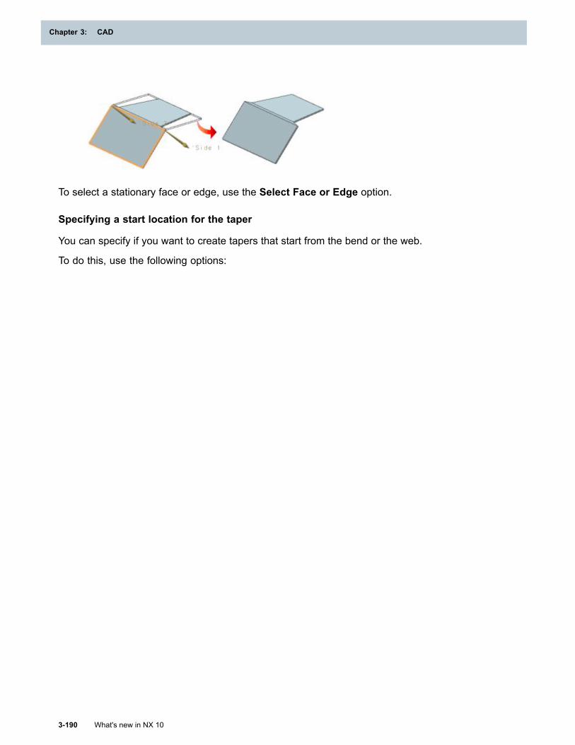
Chapter 3: CAD
To select a stationary face or edge, use the Select Face or Edge option.
Specifying a start location for the taper
You can specify if you want to create tapers that start from the bend or the web.
To do this, use the following options:
3-190 What's new in NX 10
Chapter 3: CAD
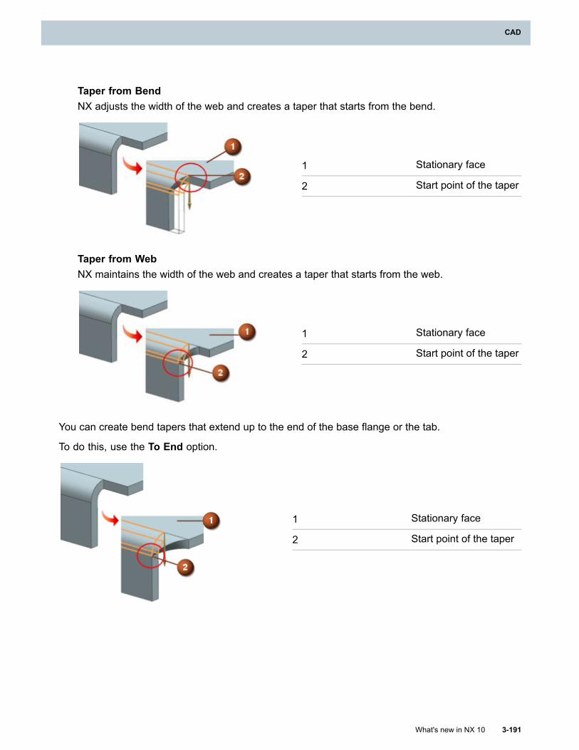
CAD
Taper from BendNX adjusts the width of the web and creates a taper that starts from the bend.
1 Stationary face
2 Start point of the taper
Taper from WebNX maintains the width of the web and creates a taper that starts from the web.
1 Stationary face
2 Start point of the taper
You can create bend tapers that extend up to the end of the base flange or the tab.
To do this, use the To End option.
1 Stationary face
2 Start point of the taper
What's new in NX 10 3-191
CAD
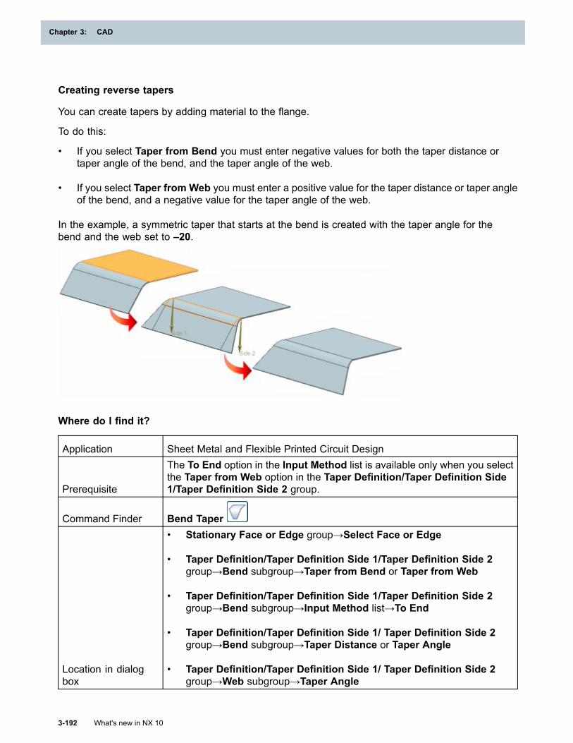
Chapter 3: CAD
Creating reverse tapers
You can create tapers by adding material to the flange.
To do this:
• If you select Taper from Bend you must enter negative values for both the taper distance ortaper angle of the bend, and the taper angle of the web.
• If you select Taper from Web you must enter a positive value for the taper distance or taper angleof the bend, and a negative value for the taper angle of the web.
In the example, a symmetric taper that starts at the bend is created with the taper angle for thebend and the web set to –20.
Where do I find it?
Application Sheet Metal and Flexible Printed Circuit Design
Prerequisite
The To End option in the Input Method list is available only when you selectthe Taper from Web option in the Taper Definition/Taper Definition Side1/Taper Definition Side 2 group.
Command Finder Bend Taper
Location in dialogbox
• Stationary Face or Edge group→Select Face or Edge
• Taper Definition/Taper Definition Side 1/Taper Definition Side 2group→Bend subgroup→Taper from Bend or Taper from Web
• Taper Definition/Taper Definition Side 1/Taper Definition Side 2group→Bend subgroup→Input Method list→To End
• Taper Definition/Taper Definition Side 1/ Taper Definition Side 2group→Bend subgroup→Taper Distance or Taper Angle
• Taper Definition/Taper Definition Side 1/ Taper Definition Side 2group→Web subgroup→Taper Angle
3-192 What's new in NX 10
Chapter 3: CAD
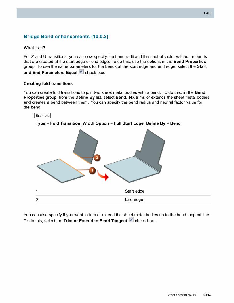
CAD
Bridge Bend enhancements (10.0.2)
What is it?
For Z and U transitions, you can now specify the bend radii and the neutral factor values for bendsthat are created at the start edge or end edge. To do this, use the options in the Bend Propertiesgroup. To use the same parameters for the bends at the start edge and end edge, select the Startand End Parameters Equal check box.
Creating fold transitions
You can create fold transitions to join two sheet metal bodies with a bend. To do this, in the BendProperties group, from the Define By list, select Bend. NX trims or extends the sheet metal bodiesand creates a bend between them. You can specify the bend radius and neutral factor value forthe bend.
Example
Type = Fold Transition, Width Option = Full Start Edge, Define By = Bend
1 Start edge
2 End edge
You can also specify if you want to trim or extend the sheet metal bodies up to the bend tangent line.To do this, select the Trim or Extend to Bend Tangent check box.
What's new in NX 10 3-193
CAD
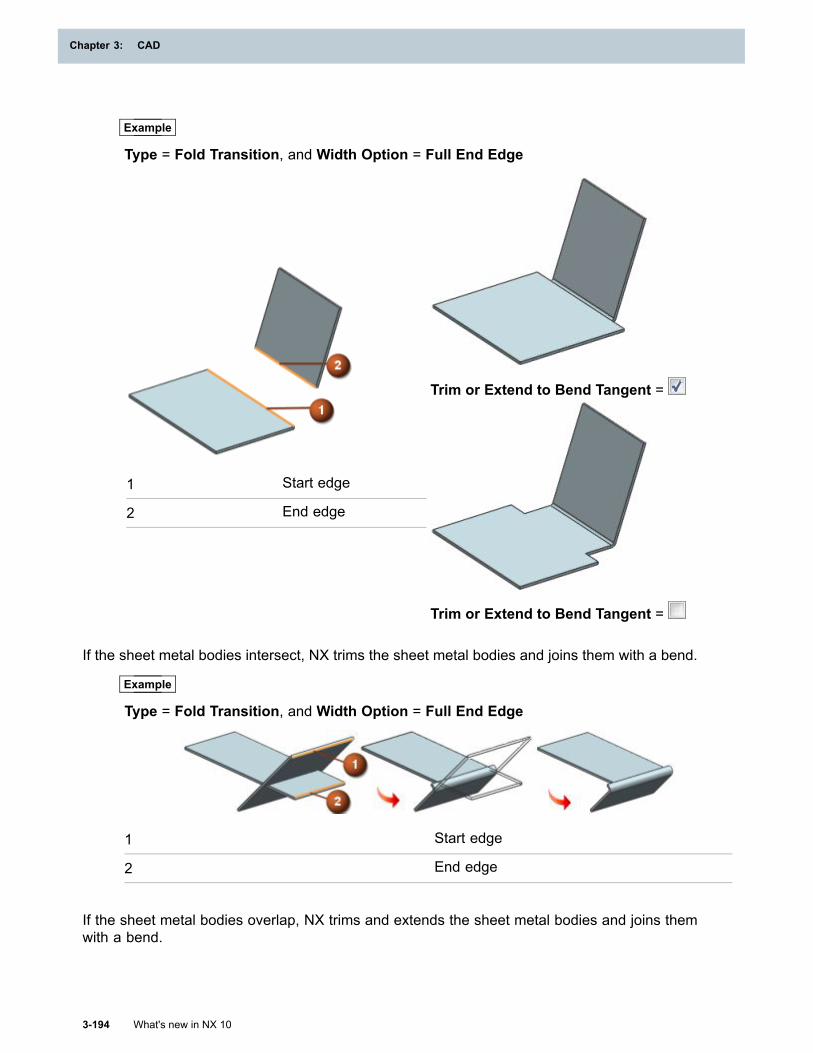
Chapter 3: CAD
Example
Type = Fold Transition, and Width Option = Full End Edge
Trim or Extend to Bend Tangent =
1 Start edge
2 End edge
Trim or Extend to Bend Tangent =
If the sheet metal bodies intersect, NX trims the sheet metal bodies and joins them with a bend.
Example
Type = Fold Transition, and Width Option = Full End Edge
1 Start edge
2 End edge
If the sheet metal bodies overlap, NX trims and extends the sheet metal bodies and joins themwith a bend.
3-194 What's new in NX 10
Chapter 3: CAD
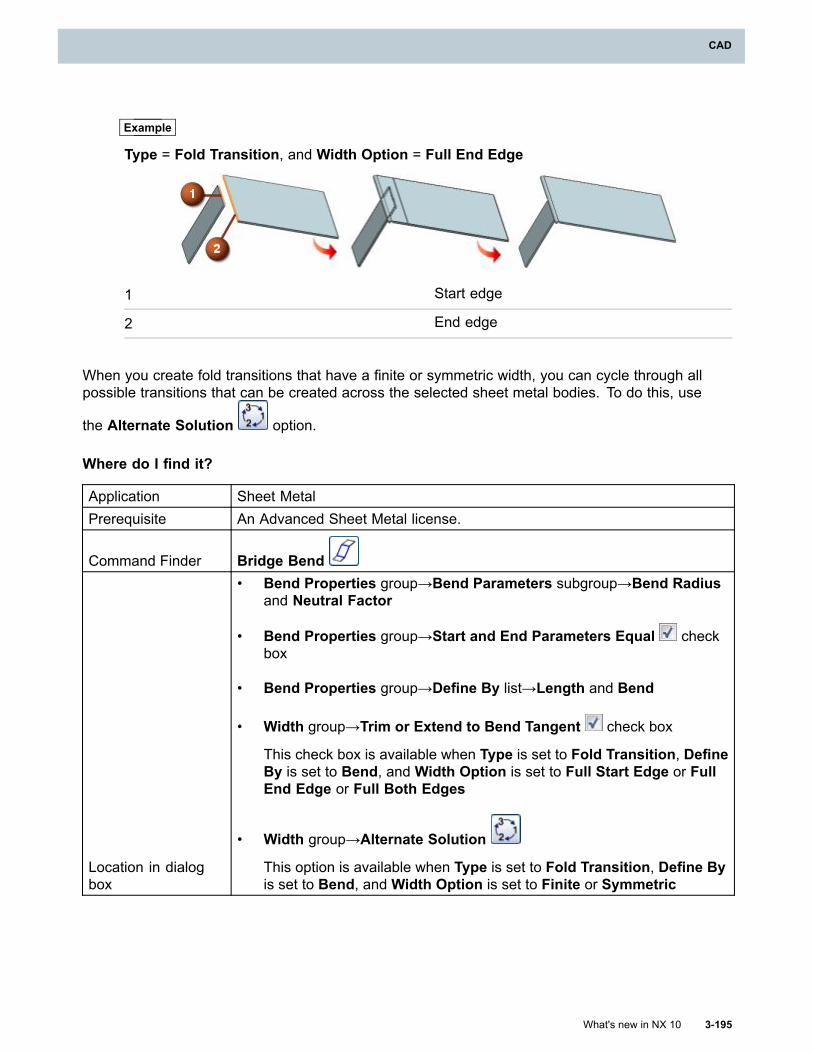
CAD
Example
Type = Fold Transition, and Width Option = Full End Edge
1 Start edge
2 End edge
When you create fold transitions that have a finite or symmetric width, you can cycle through allpossible transitions that can be created across the selected sheet metal bodies. To do this, use
the Alternate Solution option.
Where do I find it?
Application Sheet MetalPrerequisite An Advanced Sheet Metal license.
Command Finder Bridge Bend
Location in dialogbox
• Bend Properties group→Bend Parameters subgroup→Bend Radiusand Neutral Factor
• Bend Properties group→Start and End Parameters Equal checkbox
• Bend Properties group→Define By list→Length and Bend
• Width group→Trim or Extend to Bend Tangent check box
This check box is available when Type is set to Fold Transition, DefineBy is set to Bend, and Width Option is set to Full Start Edge or FullEnd Edge or Full Both Edges
• Width group→Alternate Solution
This option is available when Type is set to Fold Transition, Define Byis set to Bend, and Width Option is set to Finite or Symmetric
What's new in NX 10 3-195
CAD
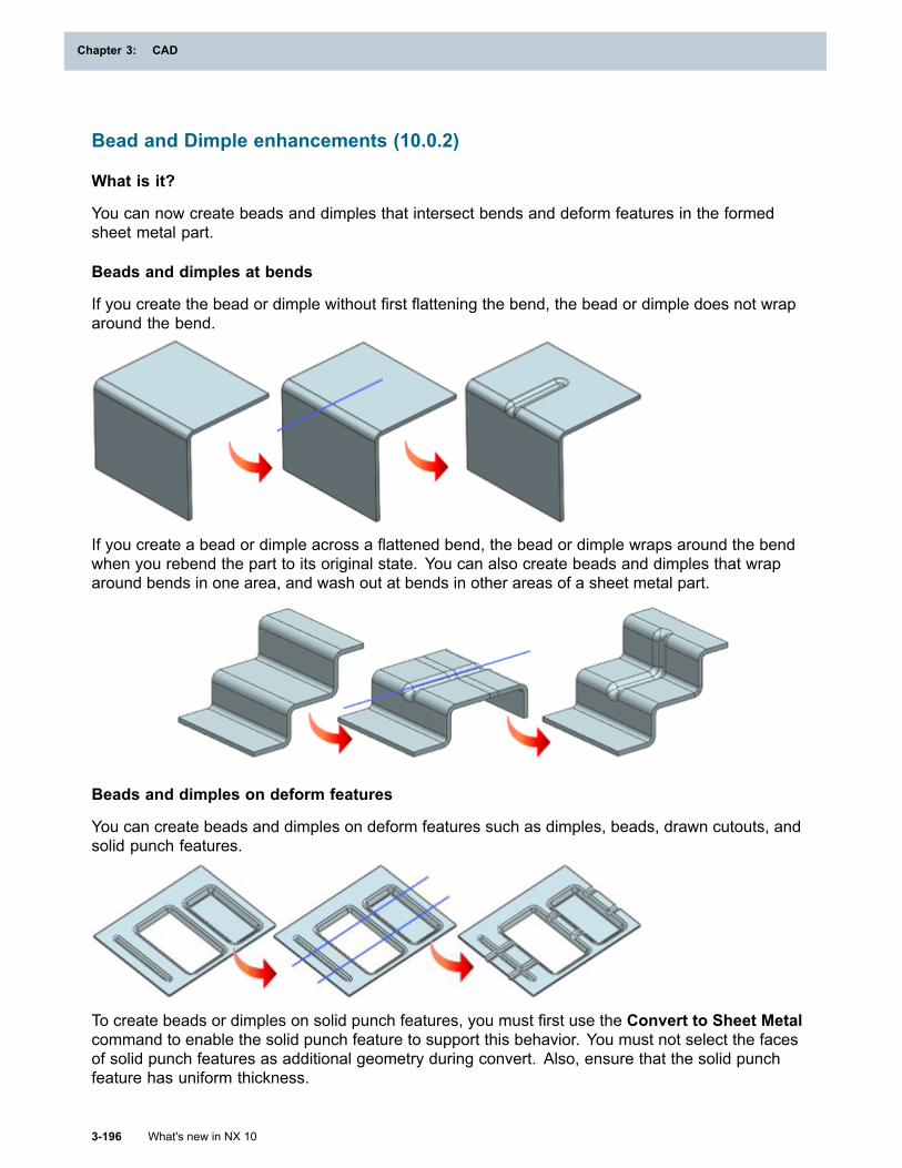
Chapter 3: CAD
Bead and Dimple enhancements (10.0.2)
What is it?
You can now create beads and dimples that intersect bends and deform features in the formedsheet metal part.
Beads and dimples at bends
If you create the bead or dimple without first flattening the bend, the bead or dimple does not wraparound the bend.
If you create a bead or dimple across a flattened bend, the bead or dimple wraps around the bendwhen you rebend the part to its original state. You can also create beads and dimples that wraparound bends in one area, and wash out at bends in other areas of a sheet metal part.
Beads and dimples on deform features
You can create beads and dimples on deform features such as dimples, beads, drawn cutouts, andsolid punch features.
To create beads or dimples on solid punch features, you must first use the Convert to Sheet Metalcommand to enable the solid punch feature to support this behavior. You must not select the facesof solid punch features as additional geometry during convert. Also, ensure that the solid punchfeature has uniform thickness.
3-196 What's new in NX 10
Chapter 3: CAD
CAD
Why should I use it?
You can create beads or dimples at bends on sheet metal parts without flattening the bend, which isuseful when manufacturing certain types of brackets and parts used in the automotive industry.
Where do I find it?
Application Sheet Metal
Command Finder
Bead
Dimple
Export Flat Pattern enhancements (10.0.2)
What is it?
• When you export flat pattern data in the DXF format, NX now exports the flat pattern curves to thelayers specified in the Sheet Metal Preferences dialog box.
Tip
To find the layer preferences for flat pattern curves, choose File tab→Preferences→SheetMetal and click the Flat Pattern Display tab.
• Exporting flat pattern data in the GEO format is now faster.
Where do I find it?
Application Sheet MetalPrerequisite A Flat Pattern feature must be present in the work part.
Command Finder Export Flat Pattern
Flexible Printed Circuit Design
Flat Solid enhancements
What is it?
You can now represent PCB components and restriction areas on the flat solid of an FPCD part.
Representing components on the flat solid
NX creates a copy of the PCB component, replicates the PCB Exchange attributes, and transformsthe PCB component on the flat solid. The replicated attributes are non-associative.
To indicate the location of a PCB component on the flat solid, you can represent it as a solid body ora coordinate system.
What's new in NX 10 3-197
CAD
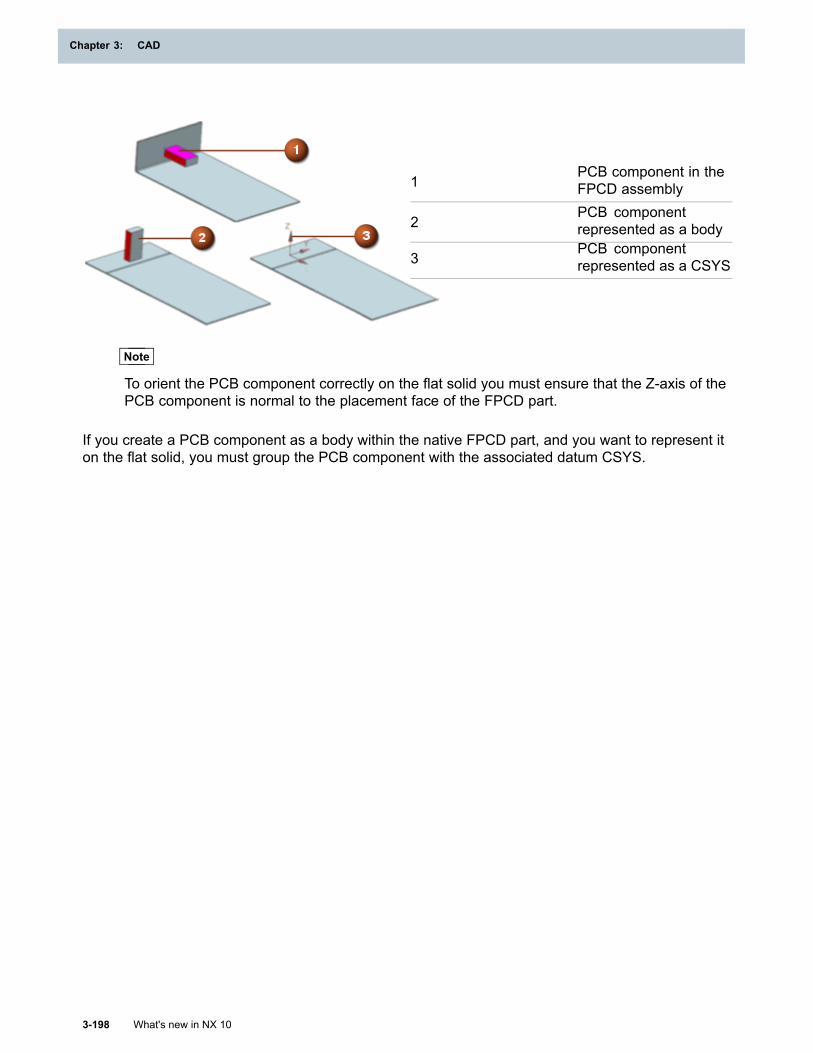
Chapter 3: CAD
1PCB component in theFPCD assembly
2PCB componentrepresented as a body
3PCB componentrepresented as a CSYS
Note
To orient the PCB component correctly on the flat solid you must ensure that the Z-axis of thePCB component is normal to the placement face of the FPCD part.
If you create a PCB component as a body within the native FPCD part, and you want to represent iton the flat solid, you must group the PCB component with the associated datum CSYS.
3-198 What's new in NX 10
Chapter 3: CAD
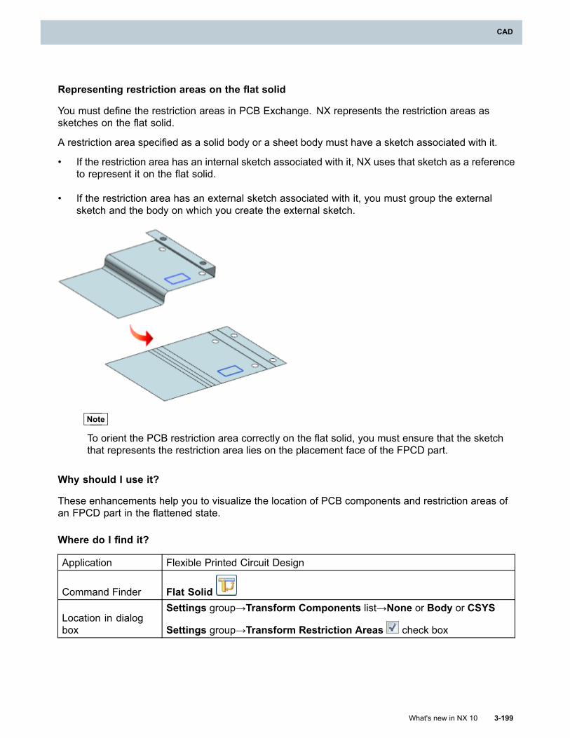
CAD
Representing restriction areas on the flat solid
You must define the restriction areas in PCB Exchange. NX represents the restriction areas assketches on the flat solid.
A restriction area specified as a solid body or a sheet body must have a sketch associated with it.
• If the restriction area has an internal sketch associated with it, NX uses that sketch as a referenceto represent it on the flat solid.
• If the restriction area has an external sketch associated with it, you must group the externalsketch and the body on which you create the external sketch.
Note
To orient the PCB restriction area correctly on the flat solid, you must ensure that the sketchthat represents the restriction area lies on the placement face of the FPCD part.
Why should I use it?
These enhancements help you to visualize the location of PCB components and restriction areas ofan FPCD part in the flattened state.
Where do I find it?
Application Flexible Printed Circuit Design
Command Finder Flat Solid
Location in dialogbox
Settings group→Transform Components list→None or Body or CSYS
Settings group→Transform Restriction Areas check box
What's new in NX 10 3-199
CAD
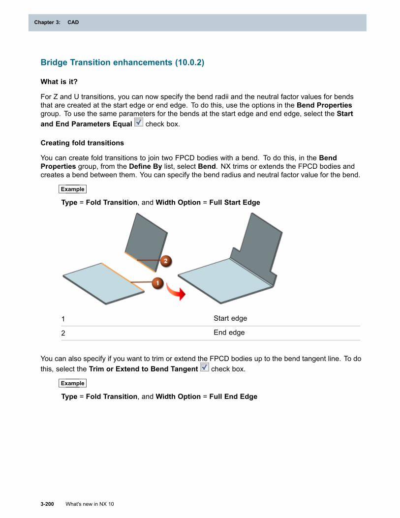
Chapter 3: CAD
Bridge Transition enhancements (10.0.2)
What is it?
For Z and U transitions, you can now specify the bend radii and the neutral factor values for bendsthat are created at the start edge or end edge. To do this, use the options in the Bend Propertiesgroup. To use the same parameters for the bends at the start edge and end edge, select the Startand End Parameters Equal check box.
Creating fold transitions
You can create fold transitions to join two FPCD bodies with a bend. To do this, in the BendProperties group, from the Define By list, select Bend. NX trims or extends the FPCD bodies andcreates a bend between them. You can specify the bend radius and neutral factor value for the bend.
Example
Type = Fold Transition, and Width Option = Full Start Edge
1 Start edge
2 End edge
You can also specify if you want to trim or extend the FPCD bodies up to the bend tangent line. To dothis, select the Trim or Extend to Bend Tangent check box.
Example
Type = Fold Transition, and Width Option = Full End Edge
3-200 What's new in NX 10
Chapter 3: CAD
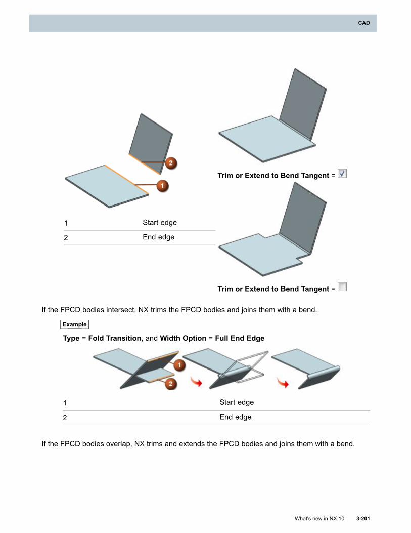
CAD
Trim or Extend to Bend Tangent =
1 Start edge
2 End edge
Trim or Extend to Bend Tangent =
If the FPCD bodies intersect, NX trims the FPCD bodies and joins them with a bend.
Example
Type = Fold Transition, and Width Option = Full End Edge
1 Start edge
2 End edge
If the FPCD bodies overlap, NX trims and extends the FPCD bodies and joins them with a bend.
What's new in NX 10 3-201
CAD
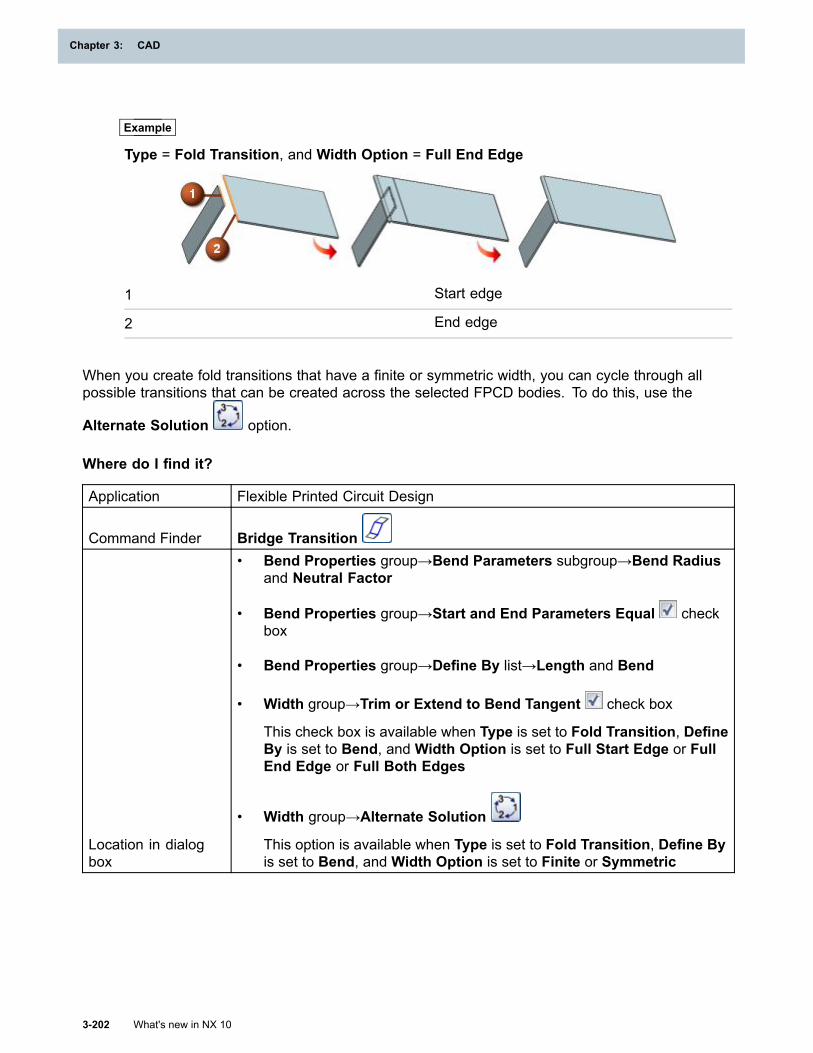
Chapter 3: CAD
Example
Type = Fold Transition, and Width Option = Full End Edge
1 Start edge
2 End edge
When you create fold transitions that have a finite or symmetric width, you can cycle through allpossible transitions that can be created across the selected FPCD bodies. To do this, use the
Alternate Solution option.
Where do I find it?
Application Flexible Printed Circuit Design
Command Finder Bridge Transition
Location in dialogbox
• Bend Properties group→Bend Parameters subgroup→Bend Radiusand Neutral Factor
• Bend Properties group→Start and End Parameters Equal checkbox
• Bend Properties group→Define By list→Length and Bend
• Width group→Trim or Extend to Bend Tangent check box
This check box is available when Type is set to Fold Transition, DefineBy is set to Bend, and Width Option is set to Full Start Edge or FullEnd Edge or Full Both Edges
• Width group→Alternate Solution
This option is available when Type is set to Fold Transition, Define Byis set to Bend, and Width Option is set to Finite or Symmetric
3-202 What's new in NX 10
Chapter 3: CAD
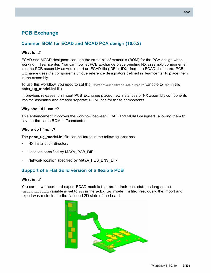
CAD
PCB Exchange
Common BOM for ECAD and MCAD PCA design (10.0.2)
What is it?
ECAD and MCAD designers can use the same bill of materials (BOM) for the PCA design whenworking in Teamcenter. You can now let PCB Exchange place pending NX assembly componentsinto the PCB assembly as you import an ECAD file (IDF or IDX) from the ECAD designers. PCBExchange uses the components unique reference designators defined in Teamcenter to place themin the assembly.
To use this workflow, you need to set the NxWriteTcCheckPendingOnImport variable to Yes in thepcbx_ug_model.ini file.
In previous releases, on import PCB Exchange placed new instances of NX assembly componentsinto the assembly and created separate BOM lines for these components.
Why should I use it?
This enhancement improves the workflow between ECAD and MCAD designers, allowing them tosave to the same BOM in Teamcenter.
Where do I find it?
The pcbx_ug_model.ini file can be found in the following locations:
• NX installation directory
• Location specified by MAYA_PCB_DIR
• Network location specified by MAYA_PCB_ENV_DIR
Support of a Flat Solid version of a flexible PCB
What is it?
You can now import and export ECAD models that are in their bent state as long as theNxFlexFlatSolid variable is set to Yes in the pcbx_ug_model.ini file. Previously, the import andexport was restricted to the flattened 2D state of the board.
What's new in NX 10 3-203
CAD
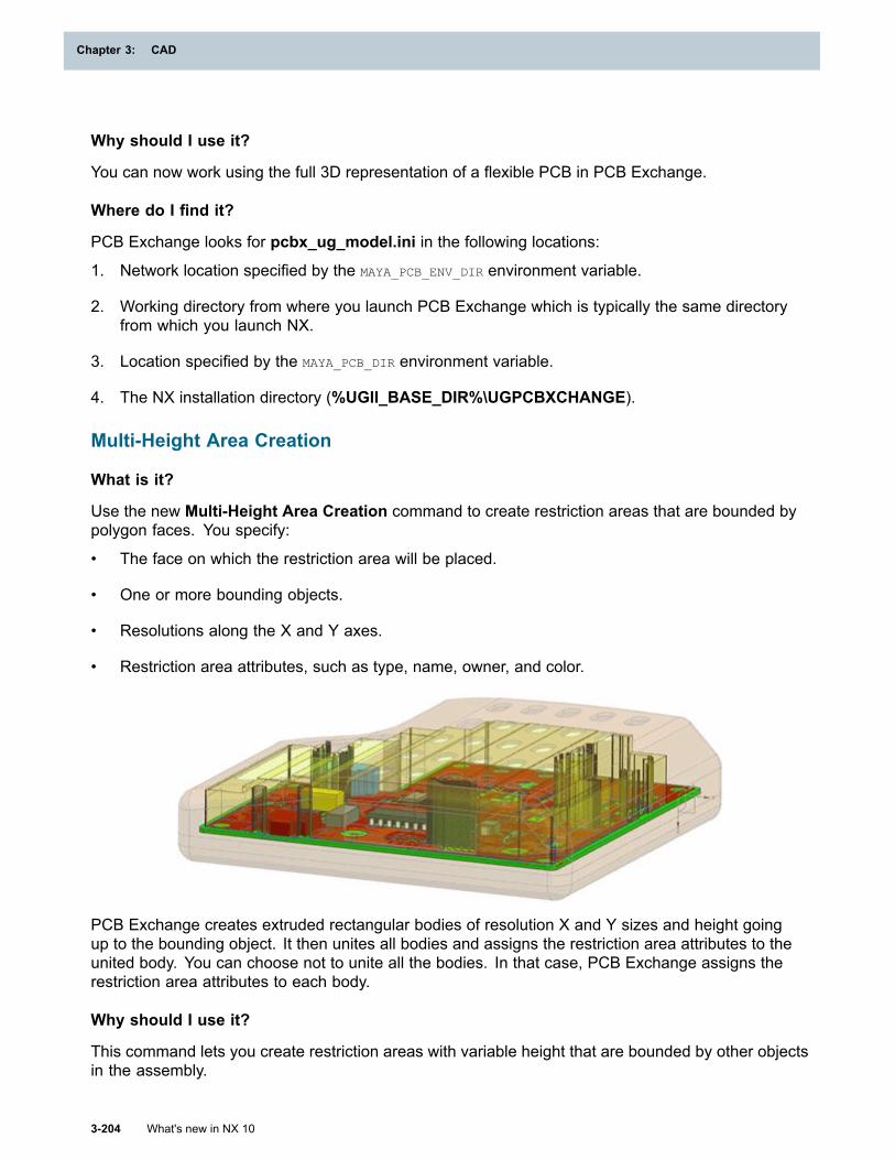
Chapter 3: CAD
Why should I use it?
You can now work using the full 3D representation of a flexible PCB in PCB Exchange.
Where do I find it?
PCB Exchange looks for pcbx_ug_model.ini in the following locations:
1. Network location specified by the MAYA_PCB_ENV_DIR environment variable.
2. Working directory from where you launch PCB Exchange which is typically the same directoryfrom which you launch NX.
3. Location specified by the MAYA_PCB_DIR environment variable.
4. The NX installation directory (%UGII_BASE_DIR%\UGPCBXCHANGE).
Multi-Height Area Creation
What is it?
Use the new Multi-Height Area Creation command to create restriction areas that are bounded bypolygon faces. You specify:
• The face on which the restriction area will be placed.
• One or more bounding objects.
• Resolutions along the X and Y axes.
• Restriction area attributes, such as type, name, owner, and color.
PCB Exchange creates extruded rectangular bodies of resolution X and Y sizes and height goingup to the bounding object. It then unites all bodies and assigns the restriction area attributes to theunited body. You can choose not to unite all the bodies. In that case, PCB Exchange assigns therestriction area attributes to each body.
Why should I use it?
This command lets you create restriction areas with variable height that are bounded by other objectsin the assembly.
3-204 What's new in NX 10
Chapter 3: CAD
CAD
Where do I find it?
Application PCB Exchange
Command Finder Multi-Height Area Creation
Automatic Component Creation (10.0.2)
What is it?
Use the new Automatic Component Creation command to automatically assign componentattributes to assembly components that satisfy one of the following:
• The component is placed in the layer specified by the NxWriteLayerComponent variable.
• The component has the DB_PART_TYPE attribute equal to one of the comma-separated valuesspecified by the NxWriteAutoComponentTypes variable.
Both variables are stored in the pcbx_ug_model.ini file.
This command sets the following component attributes:
• The placement owner
• The package name
• The part number
• The reference designator
Why should I use it?
This command helps you to quickly set component attributes to multiple assembly components.
Where do I find it?
Application PCB Exchange
Command Finder Automatic Component Creation
The pcbx_ug_model.ini files can be found in the following locations:
• NX installation directory
• Location specified by MAYA_PCB_DIR
• Network location specified by MAYA_PCB_ENV_DIR
What's new in NX 10 3-205
CAD
Chapter 3: CAD
Component Report (10.0.2)
What is it?
Use the new Component Report command to display the PC Component Information report in theNX Web Browser. For each component, the report lists the following:
• The reference designator, the package name, and the part number
• The side of the printed circuit board on which the component is placed
• The location and rotation of the component's coordinate system
• The MCAD primary pin location
• The placement ownership
The report also lists components that do not yet have attributes, if they satisfy certain conditions, forexample, if they are located on a specified layer, or if their name starts with a specified prefix.
The component report is stored in the following formats:
• An HTML file: pcbx_<board_assembly_name>_components.htm
• A CSV file: pcbx_<board_assembly_name>_comp_report.csv
<board_assembly_name> is the name of the board in NX. The CSV file contains the same informationas the HTML file in a tabular format. Both files are saved in the read/write directory that you specify inthe Read/Write Directory box in the PCB Exchange Settings dialog box.
Why should I use it?
The component report is a shorter version of the validation report. Use it to speed up the reportgeneration for complex and very large models when you are interested in components.
Where do I find it?
Application PCB Exchange
Command Finder Component Report
Markers stored as faceted geometry
What is it?
Markers are now stored as faceted geometry in .stl files that are stored in the%UGII_BASE_DIR%\UGPCBXCHANGE\data folder. By default, NX uses the faceted geometrystored in mark.stl to display markers as a pushpin.
3-206 What's new in NX 10
Chapter 3: CAD
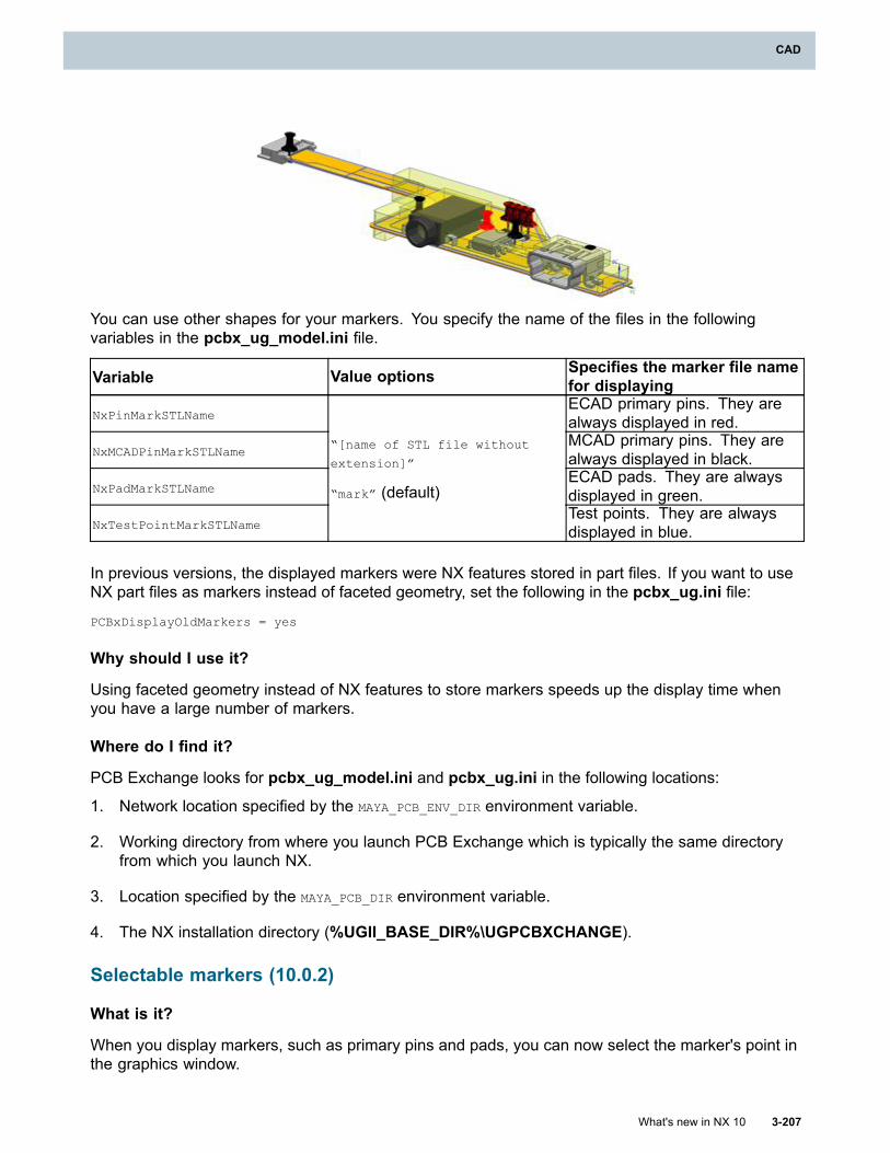
CAD
You can use other shapes for your markers. You specify the name of the files in the followingvariables in the pcbx_ug_model.ini file.
Variable Value options Specifies the marker file namefor displaying
NxPinMarkSTLNameECAD primary pins. They arealways displayed in red.
NxMCADPinMarkSTLNameMCAD primary pins. They arealways displayed in black.
NxPadMarkSTLNameECAD pads. They are alwaysdisplayed in green.
NxTestPointMarkSTLName
“[name of STL file without
extension]”
“mark” (default)Test points. They are alwaysdisplayed in blue.
In previous versions, the displayed markers were NX features stored in part files. If you want to useNX part files as markers instead of faceted geometry, set the following in the pcbx_ug.ini file:
PCBxDisplayOldMarkers = yes
Why should I use it?
Using faceted geometry instead of NX features to store markers speeds up the display time whenyou have a large number of markers.
Where do I find it?
PCB Exchange looks for pcbx_ug_model.ini and pcbx_ug.ini in the following locations:
1. Network location specified by the MAYA_PCB_ENV_DIR environment variable.
2. Working directory from where you launch PCB Exchange which is typically the same directoryfrom which you launch NX.
3. Location specified by the MAYA_PCB_DIR environment variable.
4. The NX installation directory (%UGII_BASE_DIR%\UGPCBXCHANGE).
Selectable markers (10.0.2)
What is it?
When you display markers, such as primary pins and pads, you can now select the marker's point inthe graphics window.
What's new in NX 10 3-207
CAD
Chapter 3: CAD
In previous versions, the displayed markers were not selectable. You could only view their locationon the model in the graphics window.
Why should I use it?
You can now measure distances between the MCAD and ECAD primary pin locations.
Where do I find it?
Application PCB Exchange
Command Finder
Show ECAD Primary Pin , Show MCAD Primary Pin , Show
ECAD Primary Pad , Show Test Points , or Visualize Primary
Pins
Visualize Primary Pins
What is it?
Use the new Visualize Primary Pins command to display MCAD and ECAD primary pin markersfor the selected components.
In the Visualize Primary Pins dialog box, you can:
• Select components from the graphics window or the Assembly Navigator.
• Select components that have the same Teamcenter item type defined by the DB_PART_TYPEattribute.
• Display the information regarding the alignment of MCAD and ECAD primary pins in theInformation window.
• Reset the current selection and display of markers to be able to display markers of othercomponents without exiting the dialog box.
Why should I use it?
This command lets you easily see if the MCAD and ECAD primary pin markers for a selectedcomponent are defined, aligned, or mismatched.
Where do I find it?
Application PCB Exchange
Command Finder Visualize Primary Pins
3-208 What's new in NX 10
Chapter 3: CAD
CAD
Primary pin information on components
What is it?
The PC Design Navigator command now displays the information regarding MCAD and ECADprimary pin markers for components in the Primary Pin column. You can find the following valuesin the Primary Pin column.
Match Indicates that the MCAD primary pin location matches the ECAD primary pinlocation for the given component.
Mismatch Indicates that the MCAD primary pin location does not match with the ECADprimary pin location for the given component.
No ECAD Pin Indicates the given component does not have an ECAD primary pin defined.
No MCAD Pin Indicates the given component does not have an MCAD primary pin defined.
In the PC Design Navigator dialog box, you can choose to display the MCAD and ECAD primarypin markers on the model.
Why should I use it?
You now have primary pin information for all your components directly in the PC Design Navigatordialog box.
Where do I find it?
Application PCB Exchange
Command Finder PC Design NavigatorLocation in dialogbox Components tab→right-click a row→Visualize Primary Pin
Refresh Primary Pin Mismatch Info
What is it?
Use the new Refresh Primary Pin Mismatch Info command to display the Primary Pin ComparisonReport in the NX Web Browser. The report for each component lists the following:
• The package name
• The part number
• The result of the primary pin comparison
Match Indicates that the MCAD primary pin location matches the ECAD primarypin location for the given component.
Mismatch Indicates that the MCAD primary pin location does not match with theECAD primary pin location for the given component.
No ECAD Pin Indicates the given component does not have an ECAD primary pindefined.
What's new in NX 10 3-209
CAD
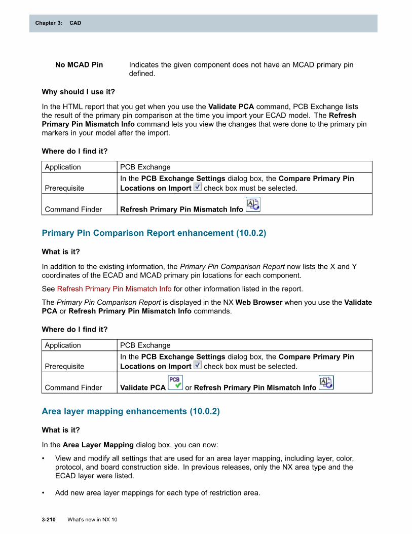
Chapter 3: CAD
No MCAD Pin Indicates the given component does not have an MCAD primary pindefined.
Why should I use it?
In the HTML report that you get when you use the Validate PCA command, PCB Exchange liststhe result of the primary pin comparison at the time you import your ECAD model. The RefreshPrimary Pin Mismatch Info command lets you view the changes that were done to the primary pinmarkers in your model after the import.
Where do I find it?
Application PCB Exchange
PrerequisiteIn the PCB Exchange Settings dialog box, the Compare Primary PinLocations on Import check box must be selected.
Command Finder Refresh Primary Pin Mismatch Info
Primary Pin Comparison Report enhancement (10.0.2)
What is it?
In addition to the existing information, the Primary Pin Comparison Report now lists the X and Ycoordinates of the ECAD and MCAD primary pin locations for each component.
See Refresh Primary Pin Mismatch Info for other information listed in the report.
The Primary Pin Comparison Report is displayed in the NXWeb Browser when you use the ValidatePCA or Refresh Primary Pin Mismatch Info commands.
Where do I find it?
Application PCB Exchange
PrerequisiteIn the PCB Exchange Settings dialog box, the Compare Primary PinLocations on Import check box must be selected.
Command Finder Validate PCA or Refresh Primary Pin Mismatch Info
Area layer mapping enhancements (10.0.2)
What is it?
In the Area Layer Mapping dialog box, you can now:
• View and modify all settings that are used for an area layer mapping, including layer, color,protocol, and board construction side. In previous releases, only the NX area type and theECAD layer were listed.
• Add new area layer mappings for each type of restriction area.
3-210 What's new in NX 10
Chapter 3: CAD
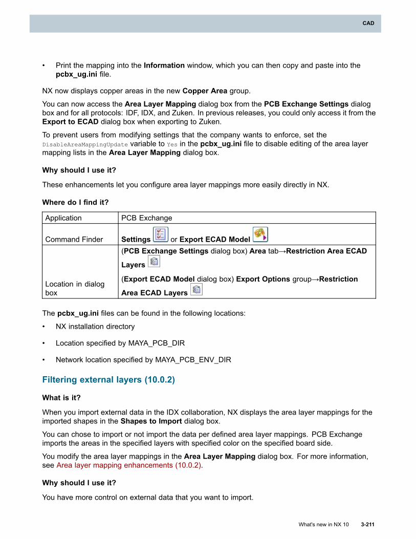
CAD
• Print the mapping into the Information window, which you can then copy and paste into thepcbx_ug.ini file.
NX now displays copper areas in the new Copper Area group.
You can now access the Area Layer Mapping dialog box from the PCB Exchange Settings dialogbox and for all protocols: IDF, IDX, and Zuken. In previous releases, you could only access it from theExport to ECAD dialog box when exporting to Zuken.
To prevent users from modifying settings that the company wants to enforce, set theDisableAreaMappingUpdate variable to Yes in the pcbx_ug.ini file to disable editing of the area layermapping lists in the Area Layer Mapping dialog box.
Why should I use it?
These enhancements let you configure area layer mappings more easily directly in NX.
Where do I find it?
Application PCB Exchange
Command Finder Settings or Export ECAD Model
Location in dialogbox
(PCB Exchange Settings dialog box) Area tab→Restriction Area ECAD
Layers
(Export ECAD Model dialog box) Export Options group→Restriction
Area ECAD Layers
The pcbx_ug.ini files can be found in the following locations:
• NX installation directory
• Location specified by MAYA_PCB_DIR
• Network location specified by MAYA_PCB_ENV_DIR
Filtering external layers (10.0.2)
What is it?
When you import external data in the IDX collaboration, NX displays the area layer mappings for theimported shapes in the Shapes to Import dialog box.
You can chose to import or not import the data per defined area layer mappings. PCB Exchangeimports the areas in the specified layers with specified color on the specified board side.
You modify the area layer mappings in the Area Layer Mapping dialog box. For more information,see Area layer mapping enhancements (10.0.2).
Why should I use it?
You have more control on external data that you want to import.
What's new in NX 10 3-211
CAD
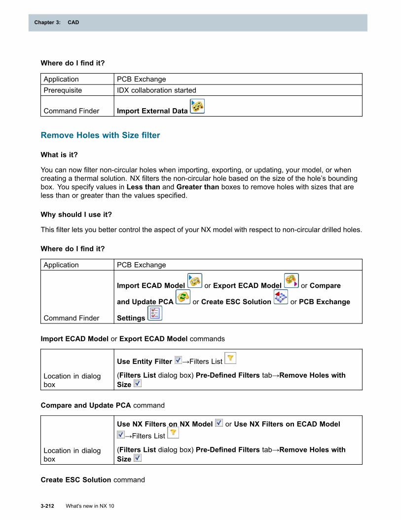
Chapter 3: CAD
Where do I find it?
Application PCB ExchangePrerequisite IDX collaboration started
Command Finder Import External Data
Remove Holes with Size filter
What is it?
You can now filter non-circular holes when importing, exporting, or updating, your model, or whencreating a thermal solution. NX filters the non-circular hole based on the size of the hole’s boundingbox. You specify values in Less than and Greater than boxes to remove holes with sizes that areless than or greater than the values specified.
Why should I use it?
This filter lets you better control the aspect of your NX model with respect to non-circular drilled holes.
Where do I find it?
Application PCB Exchange
Command Finder
Import ECAD Model or Export ECAD Model or Compare
and Update PCA or Create ESC Solution or PCB Exchange
Settings
Import ECAD Model or Export ECAD Model commands
Location in dialogbox
Use Entity Filter →Filters List
(Filters List dialog box) Pre-Defined Filters tab→Remove Holes withSize
Compare and Update PCA command
Location in dialogbox
Use NX Filters on NX Model or Use NX Filters on ECAD Model→Filters List
(Filters List dialog box) Pre-Defined Filters tab→Remove Holes withSize
Create ESC Solution command
3-212 What's new in NX 10
Chapter 3: CAD
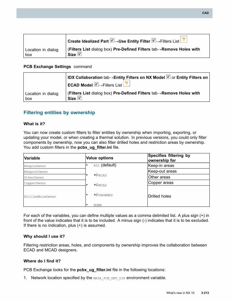
CAD
Location in dialogbox
Create Idealized Part →Use Entity Filter →Filters List
(Filters List dialog box) Pre-Defined Filters tab→Remove Holes withSize
PCB Exchange Settings command
Location in dialogbox
IDX Collaboration tab→Entity Filters on NX Model or Entity Filters on
ECAD Model →Filters List
(Filters List dialog box) Pre-Defined Filters tab→Remove Holes withSize
Filtering entities by ownership
What is it?
You can now create custom filters to filter entities by ownership when importing, exporting, orupdating your model, or when creating a thermal solution. In previous versions, you could only filtercomponents by ownership, now you can also filter drilled holes and restriction areas by ownership.You add custom filters in the pcbx_ug_filter.ini file.
Variable Value options Specifies filtering byownership for
KeepinOwner Keep-in areasKeepoutOwner Keep-out areasOtherOwner Other areasCopperOwner Copper areas
DrilledHoleOwner
• ALL (default)
• +/-ECAD
• +/-MCAD
• +/-UNOWNED
• NONE
Drilled holes
For each of the variables, you can define multiple values as a comma delimited list. A plus sign (+) infront of the value indicates that it is to be included. A minus sign (-) indicates that it is to be excluded.If there is no indication, plus (+) is assumed.
Why should I use it?
Filtering restriction areas, holes, and components by ownership improves the collaboration betweenECAD and MCAD designers.
Where do I find it?
PCB Exchange looks for the pcbx_ug_filter.ini file in the following locations:
1. Network location specified by the MAYA_PCB_ENV_DIR environment variable.
What's new in NX 10 3-213
CAD
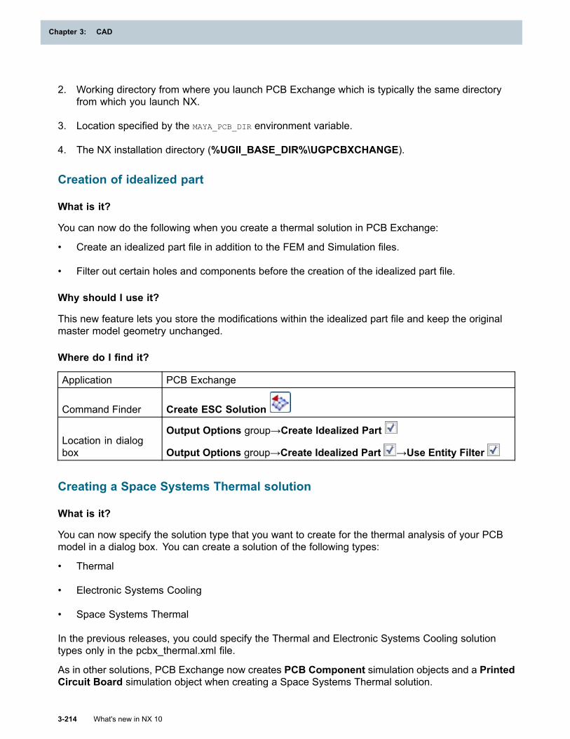
Chapter 3: CAD
2. Working directory from where you launch PCB Exchange which is typically the same directoryfrom which you launch NX.
3. Location specified by the MAYA_PCB_DIR environment variable.
4. The NX installation directory (%UGII_BASE_DIR%\UGPCBXCHANGE).
Creation of idealized part
What is it?
You can now do the following when you create a thermal solution in PCB Exchange:
• Create an idealized part file in addition to the FEM and Simulation files.
• Filter out certain holes and components before the creation of the idealized part file.
Why should I use it?
This new feature lets you store the modifications within the idealized part file and keep the originalmaster model geometry unchanged.
Where do I find it?
Application PCB Exchange
Command Finder Create ESC Solution
Location in dialogbox
Output Options group→Create Idealized Part
Output Options group→Create Idealized Part →Use Entity Filter
Creating a Space Systems Thermal solution
What is it?
You can now specify the solution type that you want to create for the thermal analysis of your PCBmodel in a dialog box. You can create a solution of the following types:
• Thermal
• Electronic Systems Cooling
• Space Systems Thermal
In the previous releases, you could specify the Thermal and Electronic Systems Cooling solutiontypes only in the pcbx_thermal.xml file.
As in other solutions, PCB Exchange now creates PCB Component simulation objects and a PrintedCircuit Board simulation object when creating a Space Systems Thermal solution.
3-214 What's new in NX 10
Chapter 3: CAD
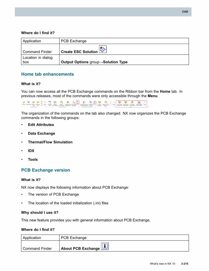
CAD
Where do I find it?
Application PCB Exchange
Command Finder Create ESC SolutionLocation in dialogbox Output Options group→Solution Type
Home tab enhancements
What is it?
You can now access all the PCB Exchange commands on the Ribbon bar from the Home tab. Inprevious releases, most of the commands were only accessible through the Menu.
The organization of the commands on the tab also changed. NX now organizes the PCB Exchangecommands in the following groups:
• Edit Attributes
• Data Exchange
• Thermal/Flow Simulation
• IDX
• Tools
PCB Exchange version
What is it?
NX now displays the following information about PCB Exchange:
• The version of PCB Exchange
• The location of the loaded initialization (.ini) files
Why should I use it?
This new feature provides you with general information about PCB Exchange.
Where do I find it?
Application PCB Exchange
Command Finder About PCB Exchange
What's new in NX 10 3-215
CAD
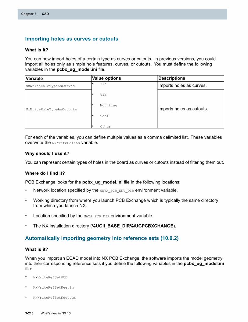
Chapter 3: CAD
Importing holes as curves or cutouts
What is it?
You can now import holes of a certain type as curves or cutouts. In previous versions, you couldimport all holes only as simple hole features, curves, or cutouts. You must define the followingvariables in the pcbx_ug_model.ini file.
Variable Value options DescriptionsNxWriteHoleTypeAsCurves Imports holes as curves.
NxWriteHoleTypeAsCutouts
• Pin
• Via
• Mounting
• Tool
• Other
Imports holes as cutouts.
For each of the variables, you can define multiple values as a comma delimited list. These variablesoverwrite the NxWriteHoleAs variable.
Why should I use it?
You can represent certain types of holes in the board as curves or cutouts instead of filtering them out.
Where do I find it?
PCB Exchange looks for the pcbx_ug_model.ini file in the following locations:
• Network location specified by the MAYA_PCB_ENV_DIR environment variable.
• Working directory from where you launch PCB Exchange which is typically the same directoryfrom which you launch NX.
• Location specified by the MAYA_PCB_DIR environment variable.
• The NX installation directory (%UGII_BASE_DIR%\UGPCBXCHANGE).
Automatically importing geometry into reference sets (10.0.2)
What is it?
When you import an ECAD model into NX PCB Exchange, the software imports the model geometryinto their corresponding reference sets if you define the following variables in the pcbx_ug_model.inifile:
• NxWriteRefSetPCB
• NxWriteRefSetKeepin
• NxWriteRefSetKeepout
3-216 What's new in NX 10
Chapter 3: CAD
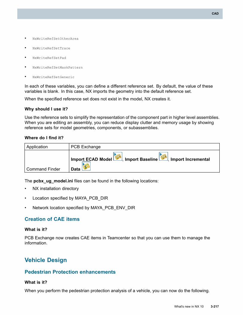
CAD
• NxWriteRefSetOtherArea
• NxWriteRefSetTrace
• NxWriteRefSetPad
• NxWriteRefSetMaskPattern
• NxWriteRefSetGeneric
In each of these variables, you can define a different reference set. By default, the value of thesevariables is blank. In this case, NX imports the geometry into the default reference set.
When the specified reference set does not exist in the model, NX creates it.
Why should I use it?
Use the reference sets to simplify the representation of the component part in higher level assemblies.When you are editing an assembly, you can reduce display clutter and memory usage by showingreference sets for model geometries, components, or subassemblies.
Where do I find it?
Application PCB Exchange
Command Finder
Import ECAD Model , Import Baseline , Import Incremental
Data
The pcbx_ug_model.ini files can be found in the following locations:
• NX installation directory
• Location specified by MAYA_PCB_DIR
• Network location specified by MAYA_PCB_ENV_DIR
Creation of CAE items
What is it?
PCB Exchange now creates CAE items in Teamcenter so that you can use them to manage theinformation.
Vehicle Design
Pedestrian Protection enhancements
What is it?
When you perform the pedestrian protection analysis of a vehicle, you can now do the following.
What's new in NX 10 3-217
CAD
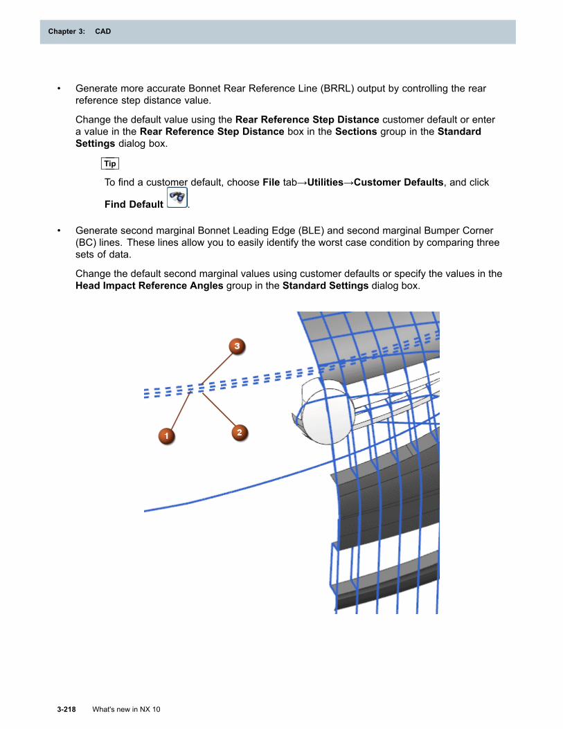
Chapter 3: CAD
• Generate more accurate Bonnet Rear Reference Line (BRRL) output by controlling the rearreference step distance value.
Change the default value using the Rear Reference Step Distance customer default or entera value in the Rear Reference Step Distance box in the Sections group in the StandardSettings dialog box.
Tip
To find a customer default, choose File tab→Utilities→Customer Defaults, and click
Find Default .
• Generate second marginal Bonnet Leading Edge (BLE) and second marginal Bumper Corner(BC) lines. These lines allow you to easily identify the worst case condition by comparing threesets of data.
Change the default second marginal values using customer defaults or specify the values in theHead Impact Reference Angles group in the Standard Settings dialog box.
3-218 What's new in NX 10
Chapter 3: CAD
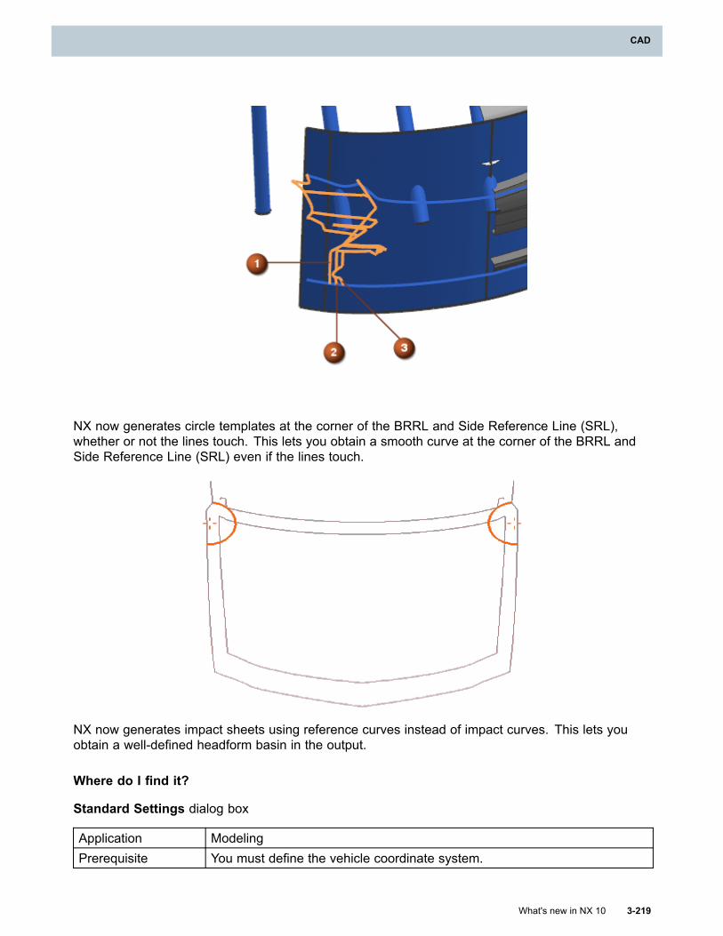
CAD
NX now generates circle templates at the corner of the BRRL and Side Reference Line (SRL),whether or not the lines touch. This lets you obtain a smooth curve at the corner of the BRRL andSide Reference Line (SRL) even if the lines touch.
NX now generates impact sheets using reference curves instead of impact curves. This lets youobtain a well-defined headform basin in the output.
Where do I find it?
Standard Settings dialog box
Application ModelingPrerequisite You must define the vehicle coordinate system.
What's new in NX 10 3-219
CAD
Chapter 3: CAD
Command Finder Pedestrian Protection
Location in dialogbox
Pedestrian Protection dialog box→Edit Standards Settings
→Standard Settings dialog box
Second marginal values customer defaults
Command Finder Customer Defaults
Location in dialogbox
Vehicle Design – General Packaging→Pedestrian Protection→GlobalTechnical Regulation Standards tab, European Standards tab, JapaneseStandards tab, Korean Standards tab, or Chinese Standards tab
Vehicle Packaging option renamed
What is it?
The Pedal Plane Angle (A47) option name is changed to Shoe Plane Angle (A47).
Where do I find it?
Standard Settings dialog box
Application ModelingPrerequisite You must define the vehicle coordinate system.
Command Finder Vehicle Packaging
Location in dialogbox
Create Vehicle Packaging wizard→Occupant List step→Create
→Create wizard (for selected occupant)→H-Point Designstep→Position Method group
H-point Design Tool enhancements
What is it?
You can now use the H-point Design Tool command to:
• Establish key vehicle reference points such as SgRP (Seating Reference Point) and Heal point incompliance with the SAE J4002 Feb2010 standards.
• Specify the pedal type as suspended curved, suspended flat, or treadle. To do this, use theSelect Pedal Type drop-down list in the Accelerator Shoe step.
3-220 What's new in NX 10
Chapter 3: CAD
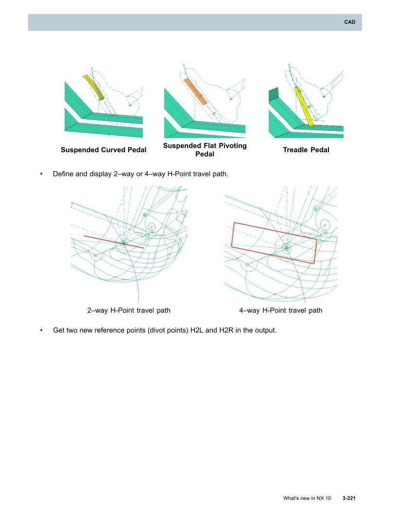
CAD
Suspended Curved Pedal Suspended Flat PivotingPedal Treadle Pedal
• Define and display 2–way or 4–way H-Point travel path.
2–way H-Point travel path 4–way H-Point travel path
• Get two new reference points (divot points) H2L and H2R in the output.
What's new in NX 10 3-221
CAD
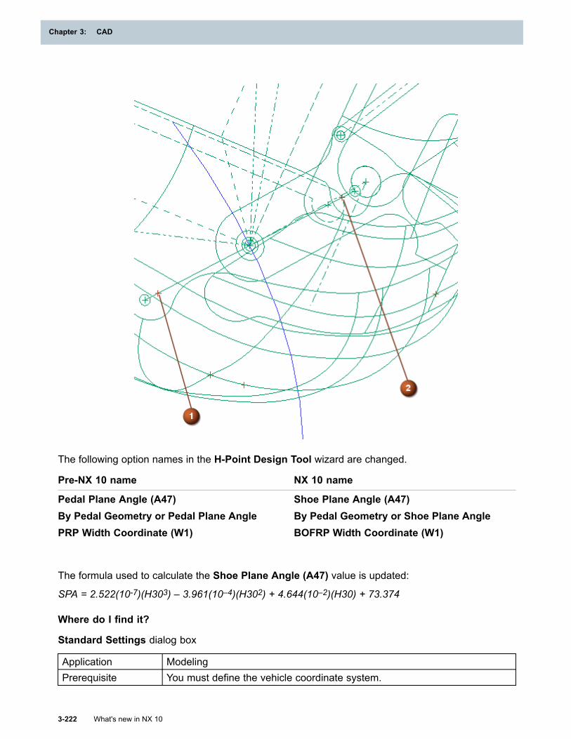
Chapter 3: CAD
The following option names in the H-Point Design Tool wizard are changed.
Pre-NX 10 name NX 10 name
Pedal Plane Angle (A47) Shoe Plane Angle (A47)By Pedal Geometry or Pedal Plane Angle By Pedal Geometry or Shoe Plane AnglePRP Width Coordinate (W1) BOFRP Width Coordinate (W1)
The formula used to calculate the Shoe Plane Angle (A47) value is updated:
SPA = 2.522(10-7)(H303) – 3.961(10–4)(H302) + 4.644(10–2)(H30) + 73.374
Where do I find it?
Standard Settings dialog box
Application ModelingPrerequisite You must define the vehicle coordinate system.
3-222 What's new in NX 10
Chapter 3: CAD
CAD
Command Finder H-point Design Tool
Human Modeling
Human Modeling enhancements (10.0.3)
What is it?
You can now use additional anthropometric databases to create or modify human models. Thefollowing population data sources are added.
CDN_LF_97Anthropometric data from the Canadian Land Forces (1997).
ChineseAnthropometric data representing Chinese adults in the age group of 18-60 for males and 18-55for females. GB 10000-88, 1989.
NA_AutoAnthropometric data representing the North American automotive working population.
JAPANESE_2006Anthropometric data specified by the International Standard: ISO7250-1 (2008), ISO/TR 7250-2(2010).
KOREAN_2003Anthropometric data specified by the International Standard: ISO7250-1 (2008), ISO/TR 7250-2(2010).
Why should I use it?
Use of regional anthropometric data to scale the human models allows you to evaluate how yourdesign concept accommodates populations from around the globe.
Where do I find it?
Application Modeling
Command Finder Human
Edit Human dialogbar Modify Human
What's new in NX 10 3-223
CAD

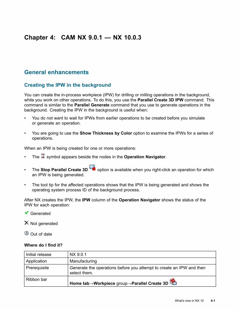
Chapter 4: CAM NX 9.0.1 — NX 10.0.3
General enhancements
Creating the IPW in the background
You can create the in-process workpiece (IPW) for drilling or milling operations in the background,while you work on other operations. To do this, you use the Parallel Create 3D IPW command. Thiscommand is similar to the Parallel Generate command that you use to generate operations in thebackground. Creating the IPW in the background is useful when:
• You do not want to wait for IPWs from earlier operations to be created before you simulateor generate an operation.
• You are going to use the Show Thickness by Color option to examine the IPWs for a series ofoperations.
When an IPW is being created for one or more operations:
• The symbol appears beside the nodes in the Operation Navigator.
• The Stop Parallel Create 3D option is available when you right-click an operation for whichan IPW is being generated.
• The tool tip for the affected operations shows that the IPW is being generated and shows theoperating system process ID of the background process.
After NX creates the IPW, the IPW column of the Operation Navigator shows the status of theIPW for each operation:
Generated
Not generated
Out of date
Where do I find it?
Initial release NX 9.0.1Application ManufacturingPrerequisite Generate the operations before you attempt to create an IPW and then
select them.Ribbon bar
Home tab→Workpiece group→Parallel Create 3D
What's new in NX 10 4-1
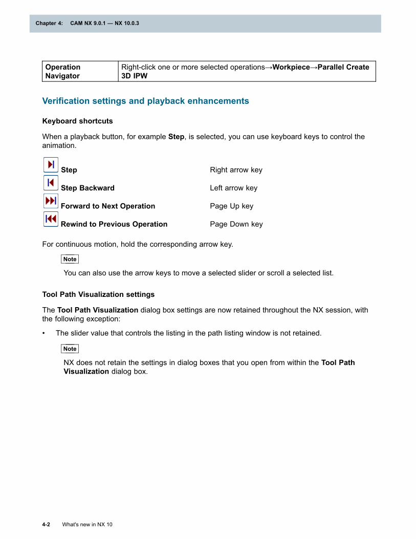
Chapter 4: CAM NX 9.0.1 — NX 10.0.3
OperationNavigator
Right-click one or more selected operations→Workpiece→Parallel Create3D IPW
Verification settings and playback enhancements
Keyboard shortcuts
When a playback button, for example Step, is selected, you can use keyboard keys to control theanimation.
Step Right arrow key
Step Backward Left arrow key
Forward to Next Operation Page Up key
Rewind to Previous Operation Page Down key
For continuous motion, hold the corresponding arrow key.
Note
You can also use the arrow keys to move a selected slider or scroll a selected list.
Tool Path Visualization settings
The Tool Path Visualization dialog box settings are now retained throughout the NX session, withthe following exception:
• The slider value that controls the listing in the path listing window is not retained.
Note
NX does not retain the settings in dialog boxes that you open from within the Tool PathVisualization dialog box.
4-2 What's new in NX 10
Chapter 4: CAM NX 9.0.1 — NX 10.0.3
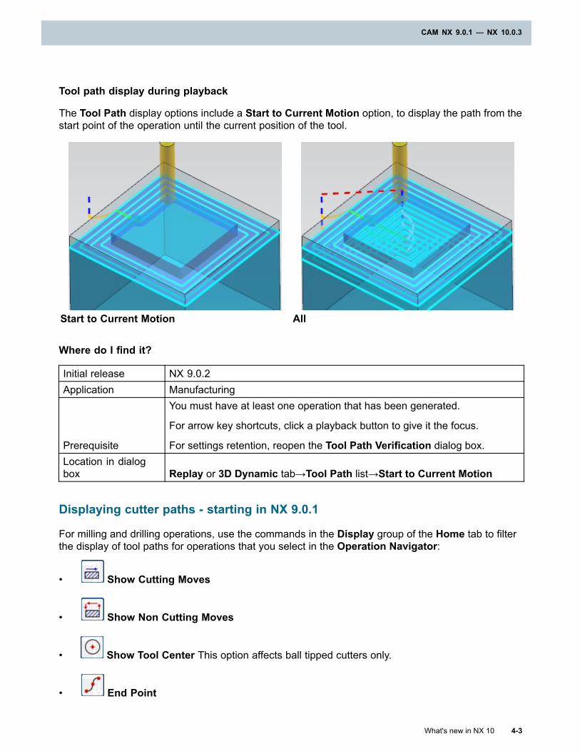
CAM NX 9.0.1 — NX 10.0.3
Tool path display during playback
The Tool Path display options include a Start to Current Motion option, to display the path from thestart point of the operation until the current position of the tool.
Start to Current Motion All
Where do I find it?
Initial release NX 9.0.2Application Manufacturing
Prerequisite
You must have at least one operation that has been generated.
For arrow key shortcuts, click a playback button to give it the focus.
For settings retention, reopen the Tool Path Verification dialog box.Location in dialogbox Replay or 3D Dynamic tab→Tool Path list→Start to Current Motion
Displaying cutter paths - starting in NX 9.0.1
For milling and drilling operations, use the commands in the Display group of the Home tab to filterthe display of tool paths for operations that you select in the Operation Navigator:
• Show Cutting Moves
• Show Non Cutting Moves
• Show Tool Center This option affects ball tipped cutters only.
• End Point
What's new in NX 10 4-3
CAM NX 9.0.1 — NX 10.0.3
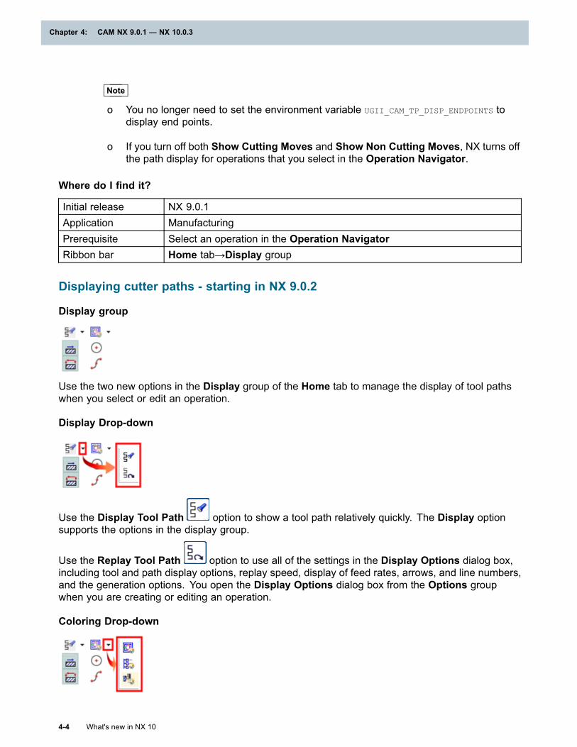
Chapter 4: CAM NX 9.0.1 — NX 10.0.3
Note
o You no longer need to set the environment variable UGII_CAM_TP_DISP_ENDPOINTS todisplay end points.
o If you turn off both Show Cutting Moves and Show Non Cutting Moves, NX turns offthe path display for operations that you select in the Operation Navigator.
Where do I find it?
Initial release NX 9.0.1Application ManufacturingPrerequisite Select an operation in the Operation NavigatorRibbon bar Home tab→Display group
Displaying cutter paths - starting in NX 9.0.2
Display group
Use the two new options in the Display group of the Home tab to manage the display of tool pathswhen you select or edit an operation.
Display Drop-down
Use the Display Tool Path option to show a tool path relatively quickly. The Display optionsupports the options in the display group.
Use the Replay Tool Path option to use all of the settings in the Display Options dialog box,including tool and path display options, replay speed, display of feed rates, arrows, and line numbers,and the generation options. You open the Display Options dialog box from the Options groupwhen you are creating or editing an operation.
Coloring Drop-down
4-4 What's new in NX 10
Chapter 4: CAM NX 9.0.1 — NX 10.0.3
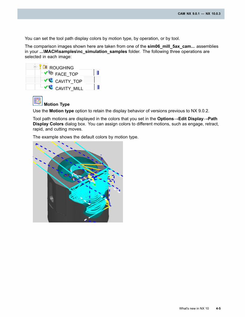
CAM NX 9.0.1 — NX 10.0.3
You can set the tool path display colors by motion type, by operation, or by tool.
The comparison images shown here are taken from one of the sim06_mill_5ax_cam... assembliesin your ...\MACH\samples\nc_simulation_samples folder. The following three operations areselected in each image:
ROUGHINGFACE_TOPCAVITY_TOPCAVITY_MILL
Motion TypeUse the Motion type option to retain the display behavior of versions previous to NX 9.0.2.
Tool path motions are displayed in the colors that you set in the Options→Edit Display→PathDisplay Colors dialog box. You can assign colors to different motions, such as engage, retract,rapid, and cutting moves.
The example shows the default colors by motion type.
What's new in NX 10 4-5
CAM NX 9.0.1 — NX 10.0.3
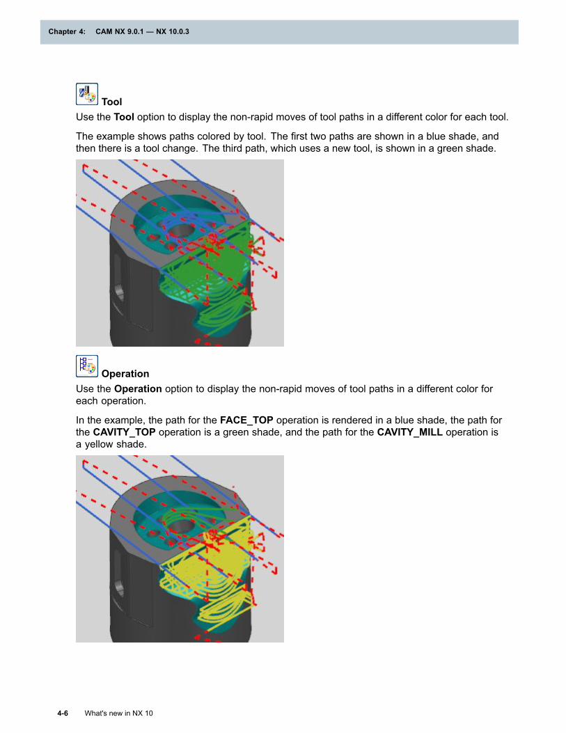
Chapter 4: CAM NX 9.0.1 — NX 10.0.3
ToolUse the Tool option to display the non-rapid moves of tool paths in a different color for each tool.
The example shows paths colored by tool. The first two paths are shown in a blue shade, andthen there is a tool change. The third path, which uses a new tool, is shown in a green shade.
OperationUse the Operation option to display the non-rapid moves of tool paths in a different color foreach operation.
In the example, the path for the FACE_TOP operation is rendered in a blue shade, the path forthe CAVITY_TOP operation is a green shade, and the path for the CAVITY_MILL operation isa yellow shade.
4-6 What's new in NX 10
Chapter 4: CAM NX 9.0.1 — NX 10.0.3
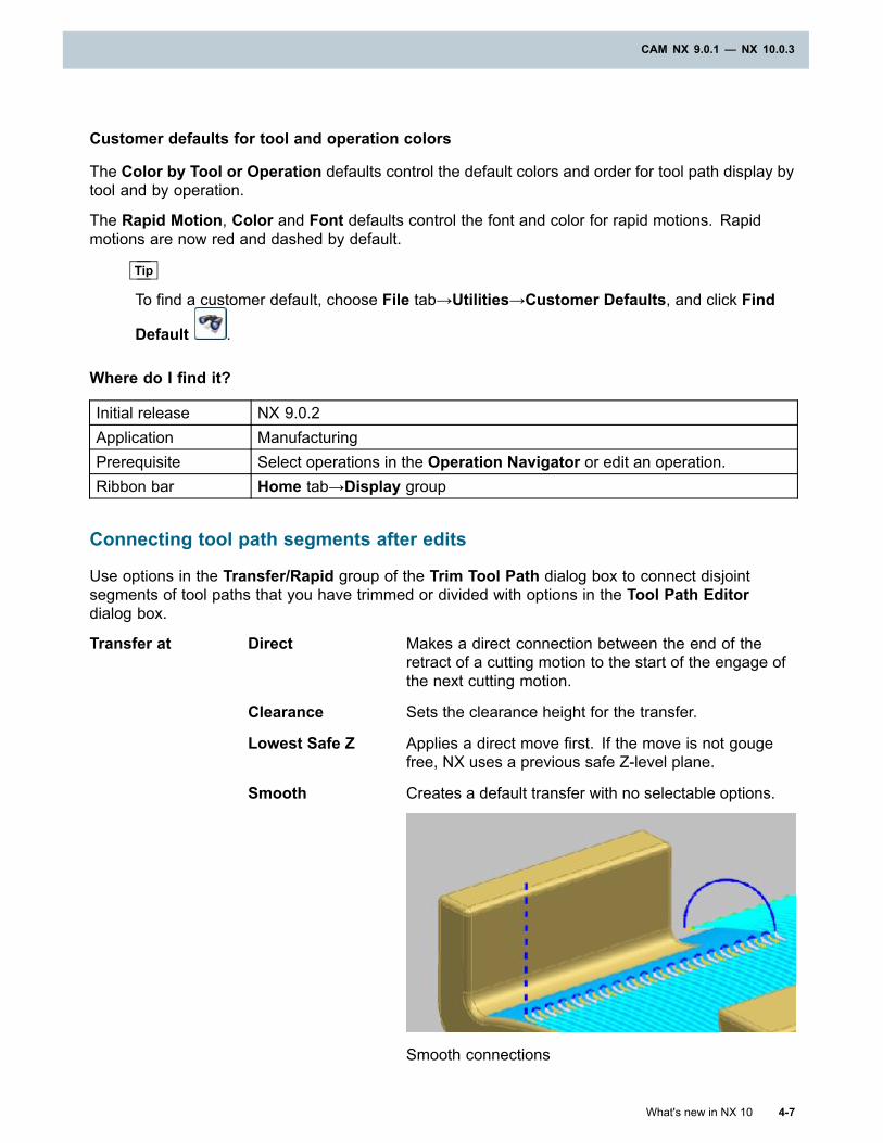
CAM NX 9.0.1 — NX 10.0.3
Customer defaults for tool and operation colors
The Color by Tool or Operation defaults control the default colors and order for tool path display bytool and by operation.
The Rapid Motion, Color and Font defaults control the font and color for rapid motions. Rapidmotions are now red and dashed by default.
Tip
To find a customer default, choose File tab→Utilities→Customer Defaults, and click Find
Default .
Where do I find it?
Initial release NX 9.0.2Application ManufacturingPrerequisite Select operations in the Operation Navigator or edit an operation.Ribbon bar Home tab→Display group
Connecting tool path segments after edits
Use options in the Transfer/Rapid group of the Trim Tool Path dialog box to connect disjointsegments of tool paths that you have trimmed or divided with options in the Tool Path Editordialog box.
Transfer at Direct Makes a direct connection between the end of theretract of a cutting motion to the start of the engage ofthe next cutting motion.
Clearance Sets the clearance height for the transfer.
Lowest Safe Z Applies a direct move first. If the move is not gougefree, NX uses a previous safe Z-level plane.
Smooth Creates a default transfer with no selectable options.
Smooth connections
What's new in NX 10 4-7
CAM NX 9.0.1 — NX 10.0.3
Chapter 4: CAM NX 9.0.1 — NX 10.0.3
Plane Lets you define a plane for transfer moves for each trimthat you perform.
Transfer using None Does not use any specific transfer motions.
Ramp on Shape Creates a ramping engage move that follows the shapeof the first cutting motions.
Lift and Plunge Produces engages and retracts with vertical moves.
Enter a Lift and Plunge Height.
Height Sets the height at which the transfer takes place.
4-8 What's new in NX 10
Chapter 4: CAM NX 9.0.1 — NX 10.0.3
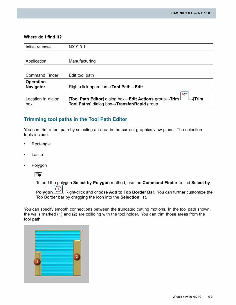
CAM NX 9.0.1 — NX 10.0.3
Where do I find it?
Initial release NX 9.0.1
Application Manufacturing
Command Finder Edit tool pathOperationNavigator Right-click operation→Tool Path→Edit
Location in dialogbox
[Tool Path Editor] dialog box→Edit Actions group→Trim →[TrimTool Paths] dialog box→Transfer/Rapid group
Trimming tool paths in the Tool Path Editor
You can trim a tool path by selecting an area in the current graphics view plane. The selectiontools include:
• Rectangle
• Lasso
• Polygon
Tip
To add the polygon Select by Polygon method, use the Command Finder to find Select by
Polygon . Right-click and choose Add to Top Border Bar. You can further customize theTop Border bar by dragging the icon into the Selection list.
You can specify smooth connections between the truncated cutting motions. In the tool path shown,the walls marked (1) and (2) are colliding with the tool holder. You can trim those areas from thetool path.
What's new in NX 10 4-9
CAM NX 9.0.1 — NX 10.0.3
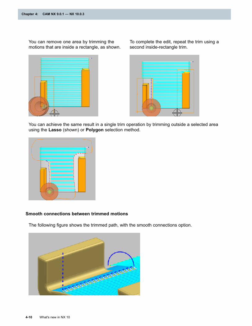
Chapter 4: CAM NX 9.0.1 — NX 10.0.3
You can remove one area by trimming themotions that are inside a rectangle, as shown.
To complete the edit, repeat the trim using asecond inside-rectangle trim.
You can achieve the same result in a single trim operation by trimming outside a selected areausing the Lasso (shown) or Polygon selection method.
Smooth connections between trimmed motions
The following figure shows the trimmed path, with the smooth connections option.
4-10 What's new in NX 10
Chapter 4: CAM NX 9.0.1 — NX 10.0.3
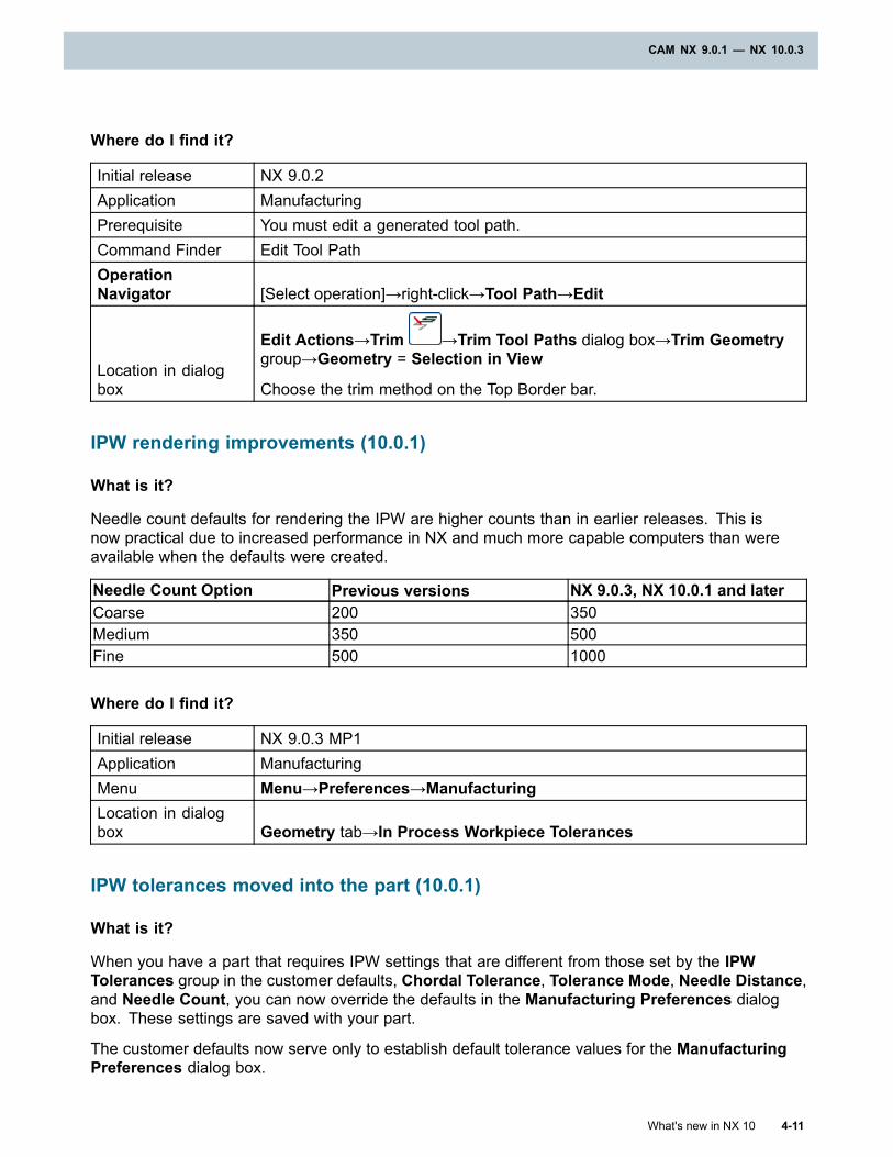
CAM NX 9.0.1 — NX 10.0.3
Where do I find it?
Initial release NX 9.0.2Application ManufacturingPrerequisite You must edit a generated tool path.Command Finder Edit Tool PathOperationNavigator [Select operation]→right-click→Tool Path→Edit
Location in dialogbox
Edit Actions→Trim →Trim Tool Paths dialog box→Trim Geometrygroup→Geometry = Selection in View
Choose the trim method on the Top Border bar.
IPW rendering improvements (10.0.1)
What is it?
Needle count defaults for rendering the IPW are higher counts than in earlier releases. This isnow practical due to increased performance in NX and much more capable computers than wereavailable when the defaults were created.
Needle Count Option Previous versions NX 9.0.3, NX 10.0.1 and laterCoarse 200 350Medium 350 500Fine 500 1000
Where do I find it?
Initial release NX 9.0.3 MP1Application ManufacturingMenu Menu→Preferences→ManufacturingLocation in dialogbox Geometry tab→In Process Workpiece Tolerances
IPW tolerances moved into the part (10.0.1)
What is it?
When you have a part that requires IPW settings that are different from those set by the IPWTolerances group in the customer defaults, Chordal Tolerance, Tolerance Mode, Needle Distance,and Needle Count, you can now override the defaults in the Manufacturing Preferences dialogbox. These settings are saved with your part.
The customer defaults now serve only to establish default tolerance values for the ManufacturingPreferences dialog box.
What's new in NX 10 4-11
CAM NX 9.0.1 — NX 10.0.3
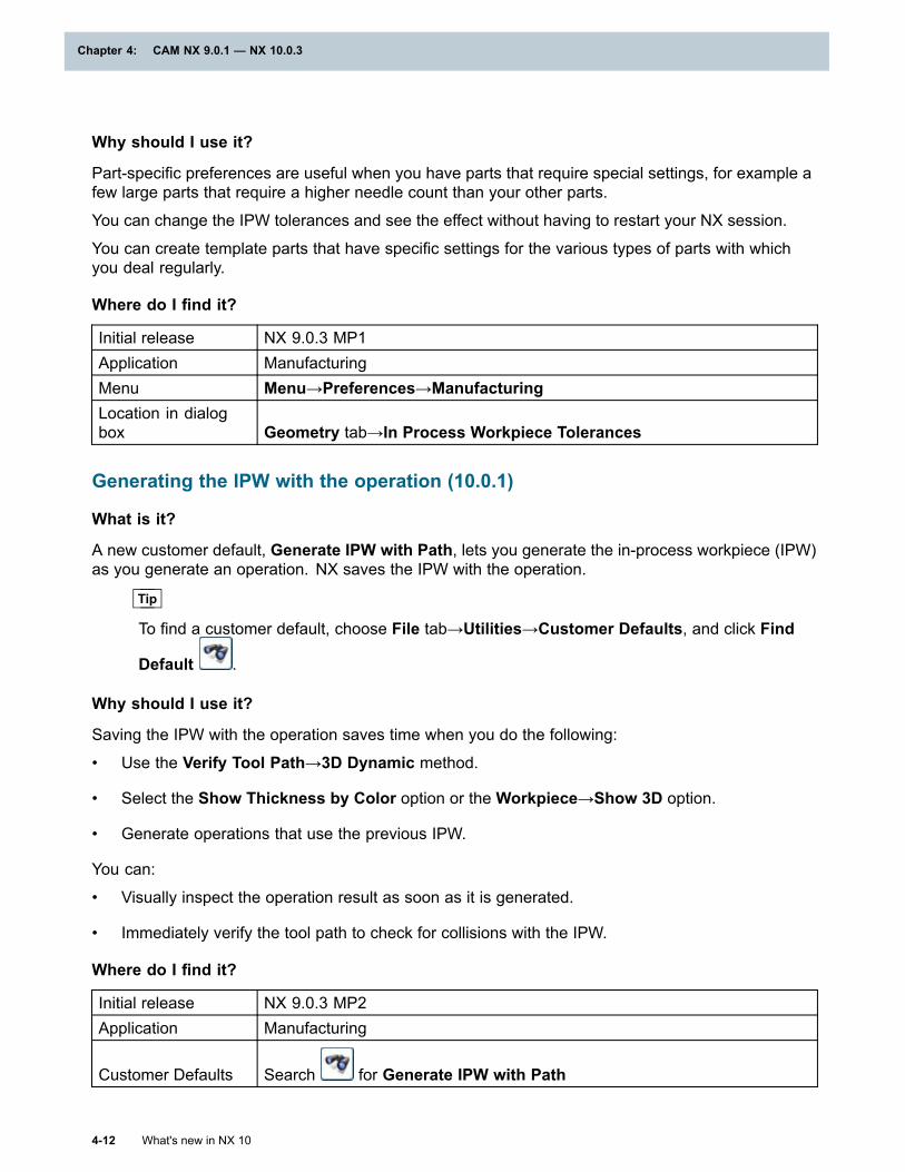
Chapter 4: CAM NX 9.0.1 — NX 10.0.3
Why should I use it?
Part-specific preferences are useful when you have parts that require special settings, for example afew large parts that require a higher needle count than your other parts.
You can change the IPW tolerances and see the effect without having to restart your NX session.
You can create template parts that have specific settings for the various types of parts with whichyou deal regularly.
Where do I find it?
Initial release NX 9.0.3 MP1Application ManufacturingMenu Menu→Preferences→ManufacturingLocation in dialogbox Geometry tab→In Process Workpiece Tolerances
Generating the IPW with the operation (10.0.1)
What is it?
A new customer default, Generate IPW with Path, lets you generate the in-process workpiece (IPW)as you generate an operation. NX saves the IPW with the operation.
Tip
To find a customer default, choose File tab→Utilities→Customer Defaults, and click Find
Default .
Why should I use it?
Saving the IPW with the operation saves time when you do the following:
• Use the Verify Tool Path→3D Dynamic method.
• Select the Show Thickness by Color option or the Workpiece→Show 3D option.
• Generate operations that use the previous IPW.
You can:
• Visually inspect the operation result as soon as it is generated.
• Immediately verify the tool path to check for collisions with the IPW.
Where do I find it?
Initial release NX 9.0.3 MP2Application Manufacturing
Customer Defaults Search for Generate IPW with Path
4-12 What's new in NX 10
Chapter 4: CAM NX 9.0.1 — NX 10.0.3
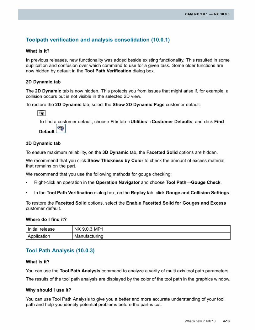
CAM NX 9.0.1 — NX 10.0.3
Toolpath verification and analysis consolidation (10.0.1)
What is it?
In previous releases, new functionality was added beside existing functionality. This resulted in someduplication and confusion over which command to use for a given task. Some older functions arenow hidden by default in the Tool Path Verification dialog box.
2D Dynamic tab
The 2D Dynamic tab is now hidden. This protects you from issues that might arise if, for example, acollision occurs but is not visible in the selected 2D view.
To restore the 2D Dynamic tab, select the Show 2D Dynamic Page customer default.
Tip
To find a customer default, choose File tab→Utilities→Customer Defaults, and click Find
Default .
3D Dynamic tab
To ensure maximum reliability, on the 3D Dynamic tab, the Facetted Solid options are hidden.
We recommend that you click Show Thickness by Color to check the amount of excess materialthat remains on the part.
We recommend that you use the following methods for gouge checking:
• Right-click an operation in the Operation Navigator and choose Tool Path→Gouge Check.
• In the Tool Path Verification dialog box, on the Replay tab, click Gouge and Collision Settings.
To restore the Facetted Solid options, select the Enable Facetted Solid for Gouges and Excesscustomer default.
Where do I find it?
Initial release NX 9.0.3 MP1Application Manufacturing
Tool Path Analysis (10.0.3)
What is it?
You can use the Tool Path Analysis command to analyze a varity of multi axis tool path parameters.
The results of the tool path analysis are displayed by the color of the tool path in the graphics window.
Why should I use it?
You can use Tool Path Analysis to give you a better and more accurate understanding of your toolpath and help you identify potential problems before the part is cut.
What's new in NX 10 4-13
CAM NX 9.0.1 — NX 10.0.3
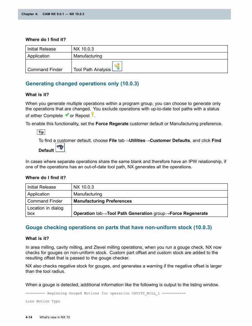
Chapter 4: CAM NX 9.0.1 — NX 10.0.3
Where do I find it?
Initial Release NX 10.0.3Application Manufacturing
Command Finder Tool Path Analysis
Generating changed operations only (10.0.3)
What is it?
When you generate multiple operations within a program group, you can choose to generate onlythe operations that are changed. You exclude operations with up-to-date tool paths with a statusof either Complete or Repost .
To enable this functionality, set the Force Regerate customer default or Manufacturing preference.
Tip
To find a customer default, choose File tab→Utilities→Customer Defaults, and click Find
Default .
In cases where separate operations share the same blank and therefore have an IPW relationship, ifone of the operations has an out-of-date tool path, NX generates all the operations.
Where do I find it?
Initial Release NX 10.0.3Application ManufacturingCommand Finder Manufacturing PreferencesLocation in dialogbox Operation tab→Tool Path Generation group→Force Regenerate
Gouge checking operations on parts that have non-uniform stock (10.0.3)
What is it?
In area milling, cavity milling, and Zlevel milling operations, when you run a gouge check, NX nowchecks for gouges on non-uniform stock. Custom part offset and custom stock are added to theresulting offset that is passed to the gouge checker.
NX also checks negative stock for gouges, and generates a warning if the negative offset is largerthan the tool radius.
When a gouge is detected, additional information like the following is output to the listing window.
========= Beginning Gouged Motions for operation CAVITY_MILL_1 ===========
Line Motion Type
4-14 What's new in NX 10
Chapter 4: CAM NX 9.0.1 — NX 10.0.3
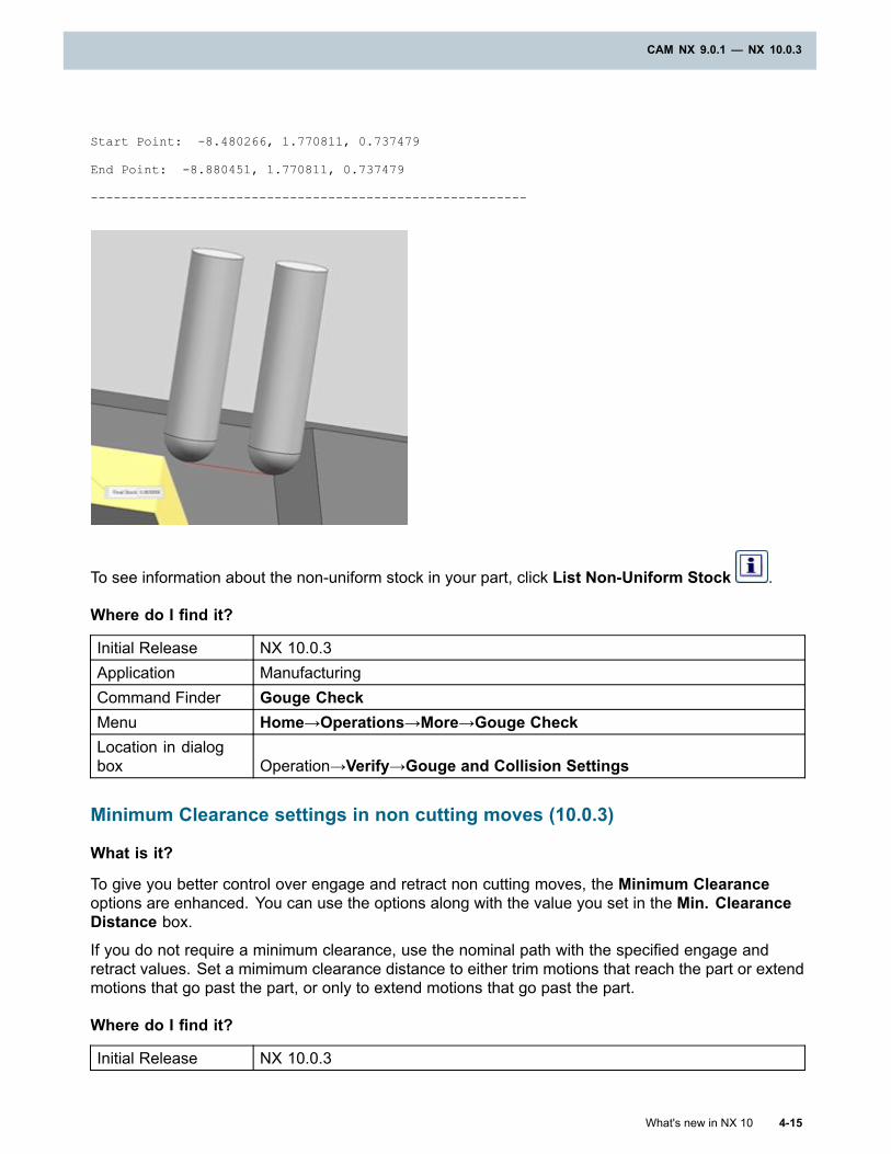
CAM NX 9.0.1 — NX 10.0.3
Start Point: -8.480266, 1.770811, 0.737479
End Point: -8.880451, 1.770811, 0.737479
---------------------------------------------------------
To see information about the non-uniform stock in your part, click List Non-Uniform Stock .
Where do I find it?
Initial Release NX 10.0.3Application ManufacturingCommand Finder Gouge CheckMenu Home→Operations→More→Gouge CheckLocation in dialogbox Operation→Verify→Gouge and Collision Settings
Minimum Clearance settings in non cutting moves (10.0.3)
What is it?
To give you better control over engage and retract non cutting moves, the Minimum Clearanceoptions are enhanced. You can use the options along with the value you set in the Min. ClearanceDistance box.
If you do not require a minimum clearance, use the nominal path with the specified engage andretract values. Set a mimimum clearance distance to either trim motions that reach the part or extendmotions that go past the part, or only to extend motions that go past the part.
Where do I find it?
Initial Release NX 10.0.3
What's new in NX 10 4-15
CAM NX 9.0.1 — NX 10.0.3
Chapter 4: CAM NX 9.0.1 — NX 10.0.3
Application Manufacturing
Command Finder Show Non Cutting MovesLocation in dialogbox Open Area group
Controlling simulation tolerances (10.0.3)
Separate options are available to control the tolerances for tilting and facet accuracy. Thisenhancement lets you specify a tighter tolerance for faceting and a looser tolerance for tilting.Increasing the tilt tolerance to a value of 0.1 or 0.15 can give acceptable quality while significantlyimproving performance.
• Chordal Tolerance controls the tolerance for circular motions and the tolerance for tool, IPW,and blank faceting. The default value is 0.05 mm.
In previous releases, this option also controlled the tilting tolerance.
• Tilt Tolerance controls the tolerance for tool axis tilting, and the default value is 0.05 mm.
NX approximates 5-axis movements with angular steps. This tolerance specifies the maximumdeviation from the plane, for each step, as the tool axis changes.
The Chordal Tolerance and Tilt Tolerance settings are saved with the part file. You can changethe values in two locations:
• In Customer Defaults to change the system defaults. These settings affect only new parts.
• In Manufacturing Preferences to change the values for an open part.
Tip
To find a customer default, choose File tab→Utilities→Customer Defaults, and click Find
Default .
To find the preferences, choose Menu→Preferences→Manufacturing→Geometry→InProcess Workpiece Tolerances.
Automating manufacturing process documents (10.0.3)
Maintaining job process sheets requires synchronizing multiple inputs as the NC program changes.
To create job process sheets that NX can automatically update, use the Documentationoperation and the Work Instructions command.
In a typical workflow you create a Documentation operation that includes job process sheets for theoverall program, and place it at the beginning of the program. At this level you might create a jobprocess sheet for the tool list, a sheet for the operation list, and a sheet for the setup information.You then use the Work Instructions command to create and attach job process sheets to individualCAM operations.
4-16 What's new in NX 10
Chapter 4: CAM NX 9.0.1 — NX 10.0.3
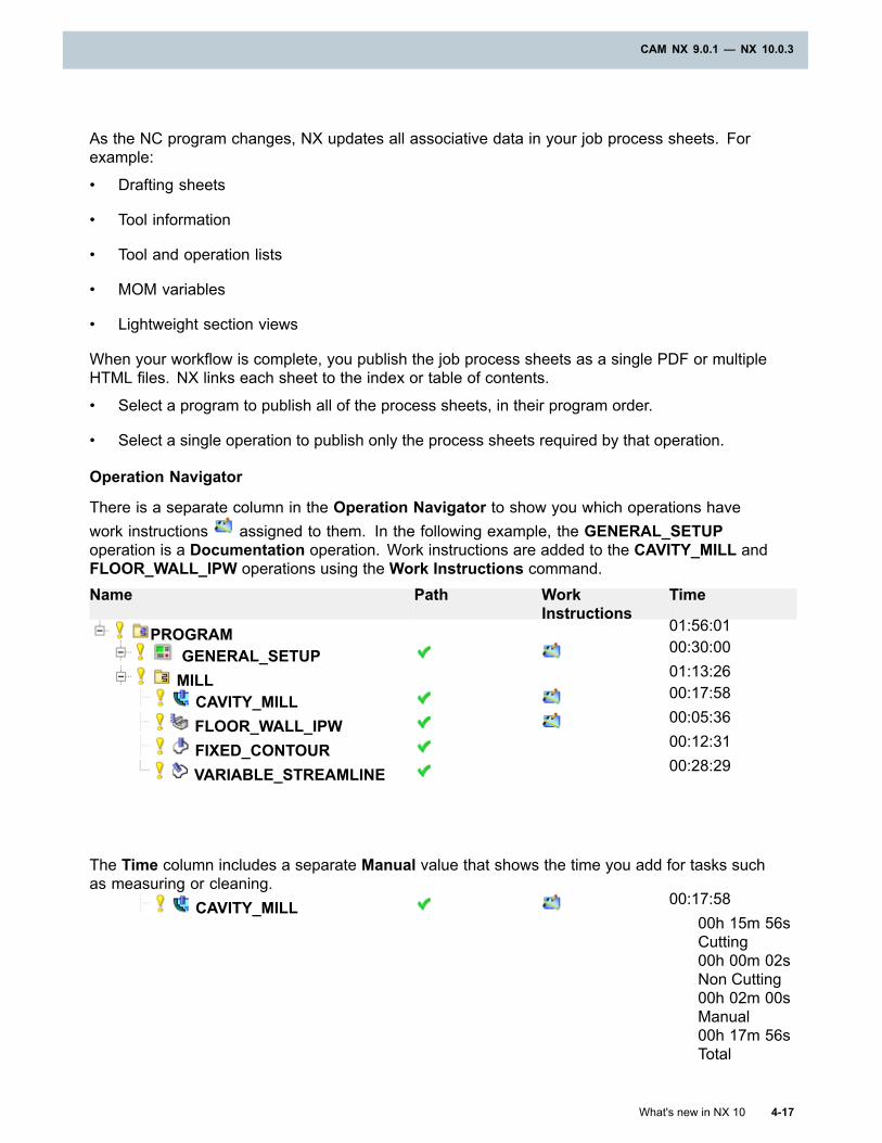
CAM NX 9.0.1 — NX 10.0.3
As the NC program changes, NX updates all associative data in your job process sheets. Forexample:
• Drafting sheets
• Tool information
• Tool and operation lists
• MOM variables
• Lightweight section views
When your workflow is complete, you publish the job process sheets as a single PDF or multipleHTML files. NX links each sheet to the index or table of contents.
• Select a program to publish all of the process sheets, in their program order.
• Select a single operation to publish only the process sheets required by that operation.
Operation Navigator
There is a separate column in the Operation Navigator to show you which operations havework instructions assigned to them. In the following example, the GENERAL_SETUPoperation is a Documentation operation. Work instructions are added to the CAVITY_MILL andFLOOR_WALL_IPW operations using the Work Instructions command.Name Path Work
InstructionsTime
PROGRAM 01:56:01
GENERAL_SETUP 00:30:00
MILL 01:13:26
CAVITY_MILL 00:17:58
FLOOR_WALL_IPW 00:05:36
FIXED_CONTOUR 00:12:31
VARIABLE_STREAMLINE 00:28:29
The Time column includes a separate Manual value that shows the time you add for tasks suchas measuring or cleaning.
CAVITY_MILL 00:17:5800h 15m 56sCutting00h 00m 02sNon Cutting00h 02m 00sManual00h 17m 56sTotal
What's new in NX 10 4-17
CAM NX 9.0.1 — NX 10.0.3
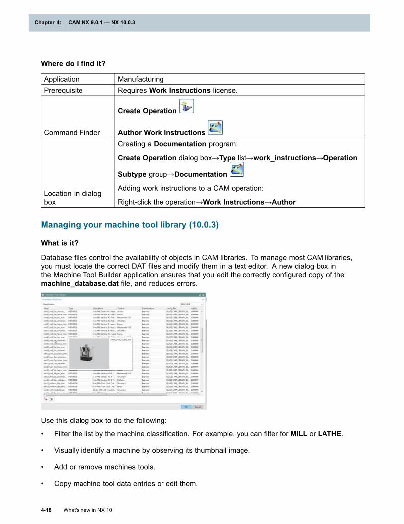
Chapter 4: CAM NX 9.0.1 — NX 10.0.3
Where do I find it?
Application ManufacturingPrerequisite Requires Work Instructions license.
Command Finder
Create Operation
Author Work Instructions
Location in dialogbox
Creating a Documentation program:
Create Operation dialog box→Type list→work_instructions→Operation
Subtype group→Documentation
Adding work instructions to a CAM operation:
Right-click the operation→Work Instructions→Author
Managing your machine tool library (10.0.3)
What is it?
Database files control the availability of objects in CAM libraries. To manage most CAM libraries,you must locate the correct DAT files and modify them in a text editor. A new dialog box inthe Machine Tool Builder application ensures that you edit the correctly configured copy of themachine_database.dat file, and reduces errors.
Use this dialog box to do the following:
• Filter the list by the machine classification. For example, you can filter for MILL or LATHE.
• Visually identify a machine by observing its thumbnail image.
• Add or remove machines tools.
• Copy machine tool data entries or edit them.
4-18 What's new in NX 10
Chapter 4: CAM NX 9.0.1 — NX 10.0.3
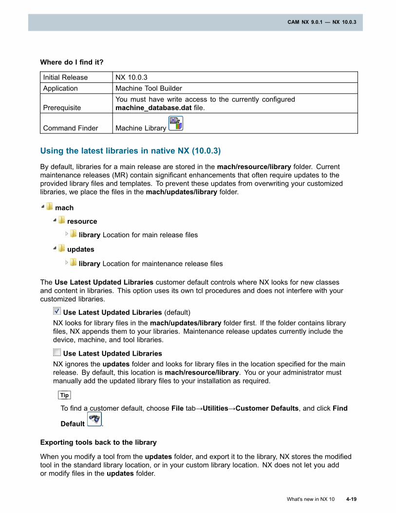
CAM NX 9.0.1 — NX 10.0.3
Where do I find it?
Initial Release NX 10.0.3Application Machine Tool Builder
PrerequisiteYou must have write access to the currently configuredmachine_database.dat file.
Command Finder Machine Library
Using the latest libraries in native NX (10.0.3)
By default, libraries for a main release are stored in the mach/resource/library folder. Currentmaintenance releases (MR) contain significant enhancements that often require updates to theprovided library files and templates. To prevent these updates from overwriting your customizedlibraries, we place the files in the mach/updates/library folder.
mach
resource
library Location for main release files
updates
library Location for maintenance release files
The Use Latest Updated Libraries customer default controls where NX looks for new classesand content in libraries. This option uses its own tcl procedures and does not interfere with yourcustomized libraries.
Use Latest Updated Libraries (default)NX looks for library files in the mach/updates/library folder first. If the folder contains libraryfiles, NX appends them to your libraries. Maintenance release updates currently include thedevice, machine, and tool libraries.
Use Latest Updated LibrariesNX ignores the updates folder and looks for library files in the location specified for the mainrelease. By default, this location is mach/resource/library. You or your administrator mustmanually add the updated library files to your installation as required.
Tip
To find a customer default, choose File tab→Utilities→Customer Defaults, and click Find
Default .
Exporting tools back to the library
When you modify a tool from the updates folder, and export it to the library, NX stores the modifiedtool in the standard library location, or in your custom library location. NX does not let you addor modify files in the updates folder.
What's new in NX 10 4-19
CAM NX 9.0.1 — NX 10.0.3
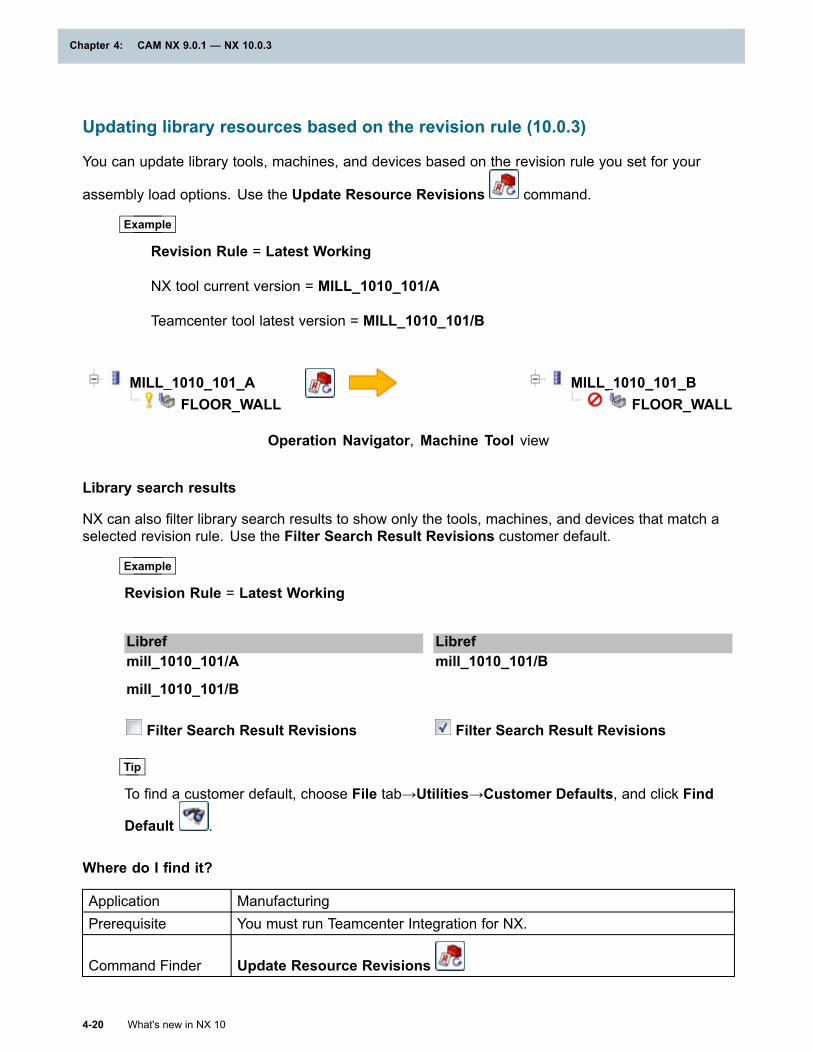
Chapter 4: CAM NX 9.0.1 — NX 10.0.3
Updating library resources based on the revision rule (10.0.3)
You can update library tools, machines, and devices based on the revision rule you set for your
assembly load options. Use the Update Resource Revisions command.
Example
Revision Rule = Latest Working
NX tool current version = MILL_1010_101/A
Teamcenter tool latest version = MILL_1010_101/B
MILL_1010_101_AFLOOR_WALL
MILL_1010_101_BFLOOR_WALL
Operation Navigator, Machine Tool view
Library search results
NX can also filter library search results to show only the tools, machines, and devices that match aselected revision rule. Use the Filter Search Result Revisions customer default.
Example
Revision Rule = Latest Working
Libref Librefmill_1010_101/A
mill_1010_101/B
mill_1010_101/B
Filter Search Result Revisions Filter Search Result Revisions
Tip
To find a customer default, choose File tab→Utilities→Customer Defaults, and click Find
Default .
Where do I find it?
Application ManufacturingPrerequisite You must run Teamcenter Integration for NX.
Command Finder Update Resource Revisions
4-20 What's new in NX 10
Chapter 4: CAM NX 9.0.1 — NX 10.0.3
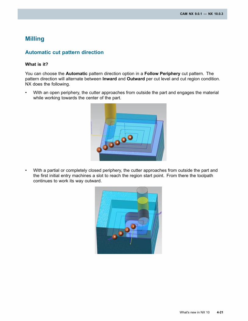
CAM NX 9.0.1 — NX 10.0.3
Milling
Automatic cut pattern direction
What is it?
You can choose the Automatic pattern direction option in a Follow Periphery cut pattern. Thepattern direction will alternate between Inward and Outward per cut level and cut region condition.NX does the following.
• With an open periphery, the cutter approaches from outside the part and engages the materialwhile working towards the center of the part.
• With a partial or completely closed periphery, the cutter approaches from outside the part andthe first initial entry machines a slot to reach the region start point. From there the toolpathcontinues to work its way outward.
What's new in NX 10 4-21
CAM NX 9.0.1 — NX 10.0.3
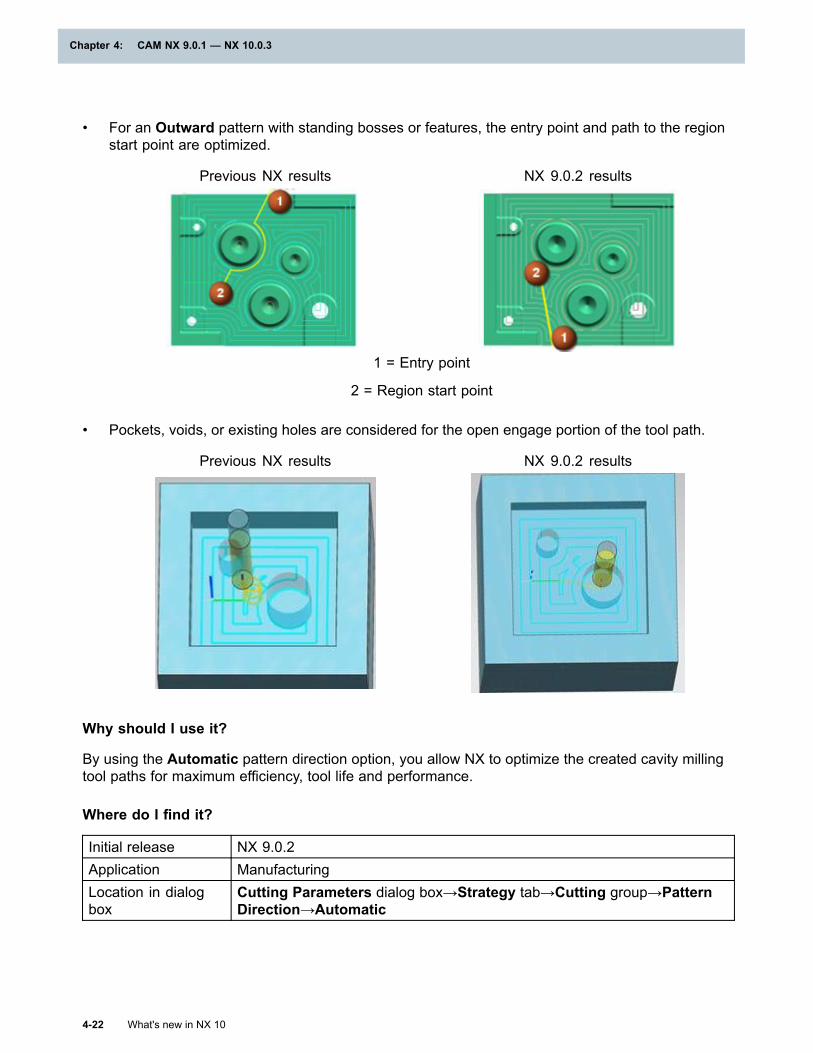
Chapter 4: CAM NX 9.0.1 — NX 10.0.3
• For an Outward pattern with standing bosses or features, the entry point and path to the regionstart point are optimized.
Previous NX results NX 9.0.2 results
1 = Entry point
2 = Region start point
• Pockets, voids, or existing holes are considered for the open engage portion of the tool path.
Previous NX results NX 9.0.2 results
Why should I use it?
By using the Automatic pattern direction option, you allow NX to optimize the created cavity millingtool paths for maximum efficiency, tool life and performance.
Where do I find it?
Initial release NX 9.0.2Application ManufacturingLocation in dialogbox
Cutting Parameters dialog box→Strategy tab→Cutting group→PatternDirection→Automatic
4-22 What's new in NX 10
Chapter 4: CAM NX 9.0.1 — NX 10.0.3
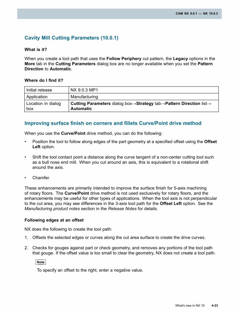
CAM NX 9.0.1 — NX 10.0.3
Cavity Mill Cutting Parameters (10.0.1)
What is it?
When you create a tool path that uses the Follow Periphery cut pattern, the Legacy options in theMore tab in the Cutting Parameters dialog box are no longer available when you set the PatternDirection to Automatic.
Where do I find it?
Initial release NX 9.0.3 MP1Application ManufacturingLocation in dialogbox
Cutting Parameters dialog box→Strategy tab→Pattern Direction list→Automatic
Improving surface finish on corners and fillets Curve/Point drive method
When you use the Curve/Point drive method, you can do the following:
• Position the tool to follow along edges of the part geometry at a specified offset using the OffsetLeft option.
• Shift the tool contact point a distance along the curve tangent of a non-center cutting tool suchas a bull nose end mill. When you cut around an axis, this is equivalent to a rotational shiftaround the axis.
• Chamfer.
These enhancements are primarily intended to improve the surface finish for 5-axis machiningof rotary floors. The Curve/Point drive method is not used exclusively for rotary floors, and theenhancements may be useful for other types of applications. When the tool axis is not perpendicularto the cut area, you may see differences in the 3-axis tool path for the Offset Left option. See theManufacturing product notes section in the Release Notes for details.
Following edges at an offset
NX does the following to create the tool path:
1. Offsets the selected edges or curves along the cut area surface to create the drive curves.
2. Checks for gouges against part or check geometry, and removes any portions of the tool paththat gouge. If the offset value is too small to clear the geometry, NX does not create a tool path.
Note
To specify an offset to the right, enter a negative value.
What's new in NX 10 4-23
CAM NX 9.0.1 — NX 10.0.3
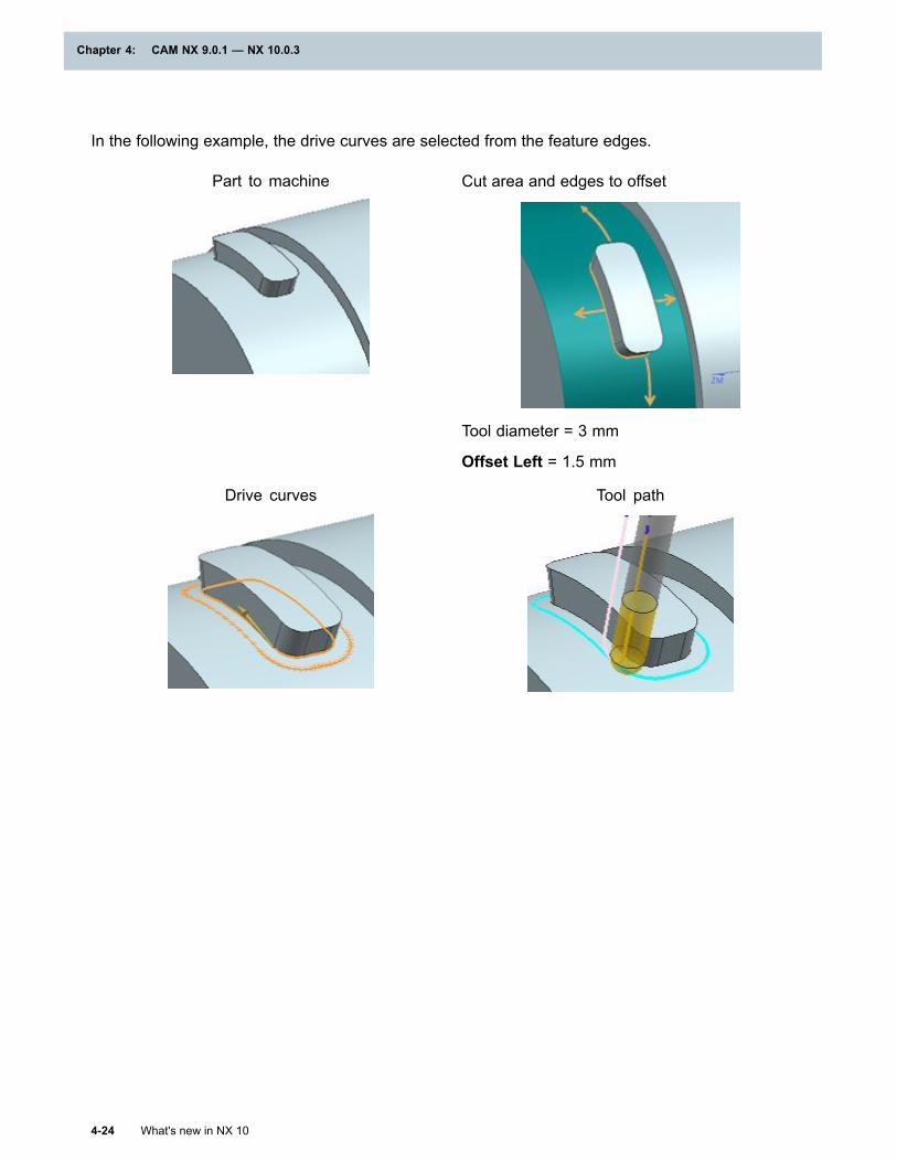
Chapter 4: CAM NX 9.0.1 — NX 10.0.3
In the following example, the drive curves are selected from the feature edges.
Part to machine Cut area and edges to offset
Tool diameter = 3 mm
Offset Left = 1.5 mm
Drive curves Tool path
4-24 What's new in NX 10
Chapter 4: CAM NX 9.0.1 — NX 10.0.3
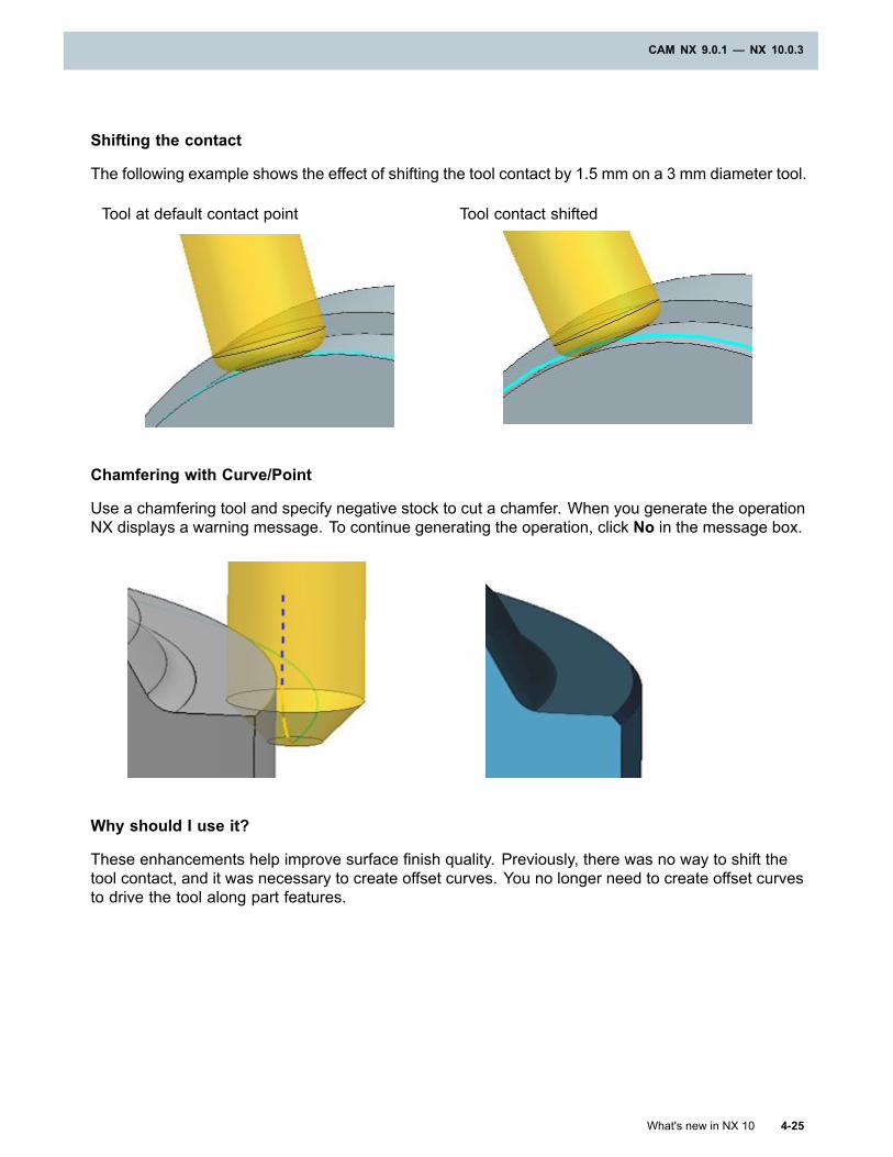
CAM NX 9.0.1 — NX 10.0.3
Shifting the contact
The following example shows the effect of shifting the tool contact by 1.5 mm on a 3 mm diameter tool.
Tool at default contact point Tool contact shifted
Chamfering with Curve/Point
Use a chamfering tool and specify negative stock to cut a chamfer. When you generate the operationNX displays a warning message. To continue generating the operation, click No in the message box.
Why should I use it?
These enhancements help improve surface finish quality. Previously, there was no way to shift thetool contact, and it was necessary to create offset curves. You no longer need to create offset curvesto drive the tool along part features.
What's new in NX 10 4-25
CAM NX 9.0.1 — NX 10.0.3
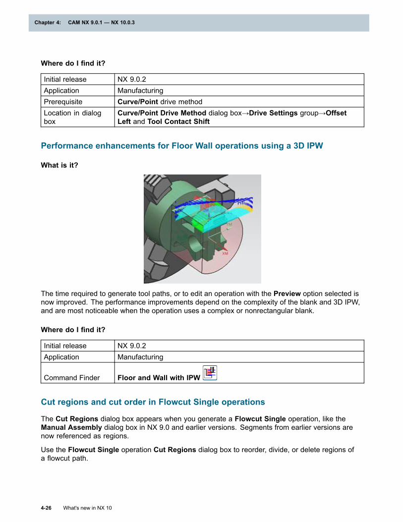
Chapter 4: CAM NX 9.0.1 — NX 10.0.3
Where do I find it?
Initial release NX 9.0.2Application ManufacturingPrerequisite Curve/Point drive methodLocation in dialogbox
Curve/Point Drive Method dialog box→Drive Settings group→OffsetLeft and Tool Contact Shift
Performance enhancements for Floor Wall operations using a 3D IPW
What is it?
The time required to generate tool paths, or to edit an operation with the Preview option selected isnow improved. The performance improvements depend on the complexity of the blank and 3D IPW,and are most noticeable when the operation uses a complex or nonrectangular blank.
Where do I find it?
Initial release NX 9.0.2Application Manufacturing
Command Finder Floor and Wall with IPW
Cut regions and cut order in Flowcut Single operations
The Cut Regions dialog box appears when you generate a Flowcut Single operation, like theManual Assembly dialog box in NX 9.0 and earlier versions. Segments from earlier versions arenow referenced as regions.
Use the Flowcut Single operation Cut Regions dialog box to reorder, divide, or delete regions ofa flowcut path.
4-26 What's new in NX 10
Chapter 4: CAM NX 9.0.1 — NX 10.0.3
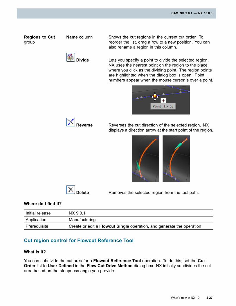
CAM NX 9.0.1 — NX 10.0.3
Regions to Cutgroup
Name column Shows the cut regions in the current cut order. Toreorder the list, drag a row to a new position. You canalso rename a region in this column.
Divide Lets you specify a point to divide the selected region.NX uses the nearest point on the region to the placewhere you click as the dividing point. The region pointsare highlighted when the dialog box is open. Pointnumbers appear when the mouse cursor is over a point.
Reverse Reverses the cut direction of the selected region. NXdisplays a direction arrow at the start point of the region.
Delete Removes the selected region from the tool path.
Where do I find it?
Initial release NX 9.0.1Application ManufacturingPrerequisite Create or edit a Flowcut Single operation, and generate the operation
Cut region control for Flowcut Reference Tool
What is it?
You can subdivide the cut area for a Flowcut Reference Tool operation. To do this, set the CutOrder list to User Defined in the Flow Cut Drive Method dialog box. NX initially subdivides the cutarea based on the steepness angle you provide.
What's new in NX 10 4-27
CAM NX 9.0.1 — NX 10.0.3
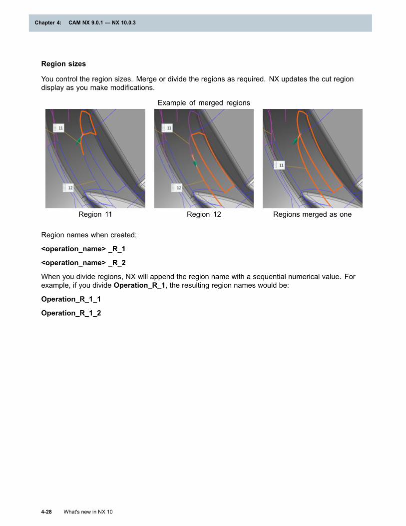
Chapter 4: CAM NX 9.0.1 — NX 10.0.3
Region sizes
You control the region sizes. Merge or divide the regions as required. NX updates the cut regiondisplay as you make modifications.
Example of merged regions
Region 11 Region 12 Regions merged as one
Region names when created:
<operation_name> _R_1
<operation_name> _R_2
When you divide regions, NX will append the region name with a sequential numerical value. Forexample, if you divide Operation_R_1, the resulting region names would be:
Operation_R_1_1
Operation_R_1_2
4-28 What's new in NX 10
Chapter 4: CAM NX 9.0.1 — NX 10.0.3
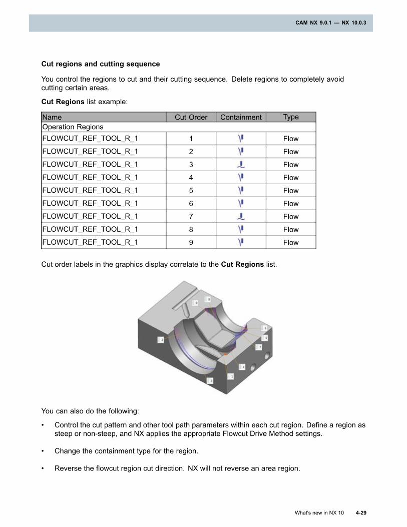
CAM NX 9.0.1 — NX 10.0.3
Cut regions and cutting sequence
You control the regions to cut and their cutting sequence. Delete regions to completely avoidcutting certain areas.
Cut Regions list example:
Name Cut Order Containment TypeOperation RegionsFLOWCUT_REF_TOOL_R_1 1 Flow
FLOWCUT_REF_TOOL_R_1 2 Flow
FLOWCUT_REF_TOOL_R_1 3 Flow
FLOWCUT_REF_TOOL_R_1 4 Flow
FLOWCUT_REF_TOOL_R_1 5 Flow
FLOWCUT_REF_TOOL_R_1 6 Flow
FLOWCUT_REF_TOOL_R_1 7 Flow
FLOWCUT_REF_TOOL_R_1 8 Flow
FLOWCUT_REF_TOOL_R_1 9 Flow
Cut order labels in the graphics display correlate to the Cut Regions list.
You can also do the following:
• Control the cut pattern and other tool path parameters within each cut region. Define a region assteep or non-steep, and NX applies the appropriate Flowcut Drive Method settings.
• Change the containment type for the region.
• Reverse the flowcut region cut direction. NX will not reverse an area region.
What's new in NX 10 4-29
CAM NX 9.0.1 — NX 10.0.3
Chapter 4: CAM NX 9.0.1 — NX 10.0.3
Editing updates
You can now do the following:
• Drag regions to change the cut order.
• Undo changes from the current editing session.
• Save the current cutting sequence. NX saves the edits with the operation each time it generatesthe operation, and uses the saved sequence to produce the updated tool paths.
Why should I use it?
Managing regions can improve cutting efficiency, improve the part surface finish, and improve cutterwear and performance.
Where do I find it?
Initial release NX 9.0.2Application ManufacturingPrerequisite A Flowcut Reference Tool operation
Location in dialogbox
Flowcut Ref Tool dialog box→Drive Method group→Method row→Edit
Flow Cut Drive Method dialog box→Output group→Cut Order→Userdefined→OK
Flowcut Ref Tool dialog box→Actions group→Generate →CutRegions dialog box
Flowcut Region Management (10.0.1)
What is it?
In a Flowcut operation, you can create, visualize, edit, and save cut regions without generating thetool path. Cut Region options will be available in the Flow Cut geometry group.
You Can:
• Generate the tool path based on the saved cut regions within the operation.
• View the regions graphically.
• Import inactive regions from previous sessions into the current session.
When changes are made to the parameters of a region, NX displays a message and marks the regionwith an Invalid icon in the region list until the operation is regenerated.
4-30 What's new in NX 10
Chapter 4: CAM NX 9.0.1 — NX 10.0.3
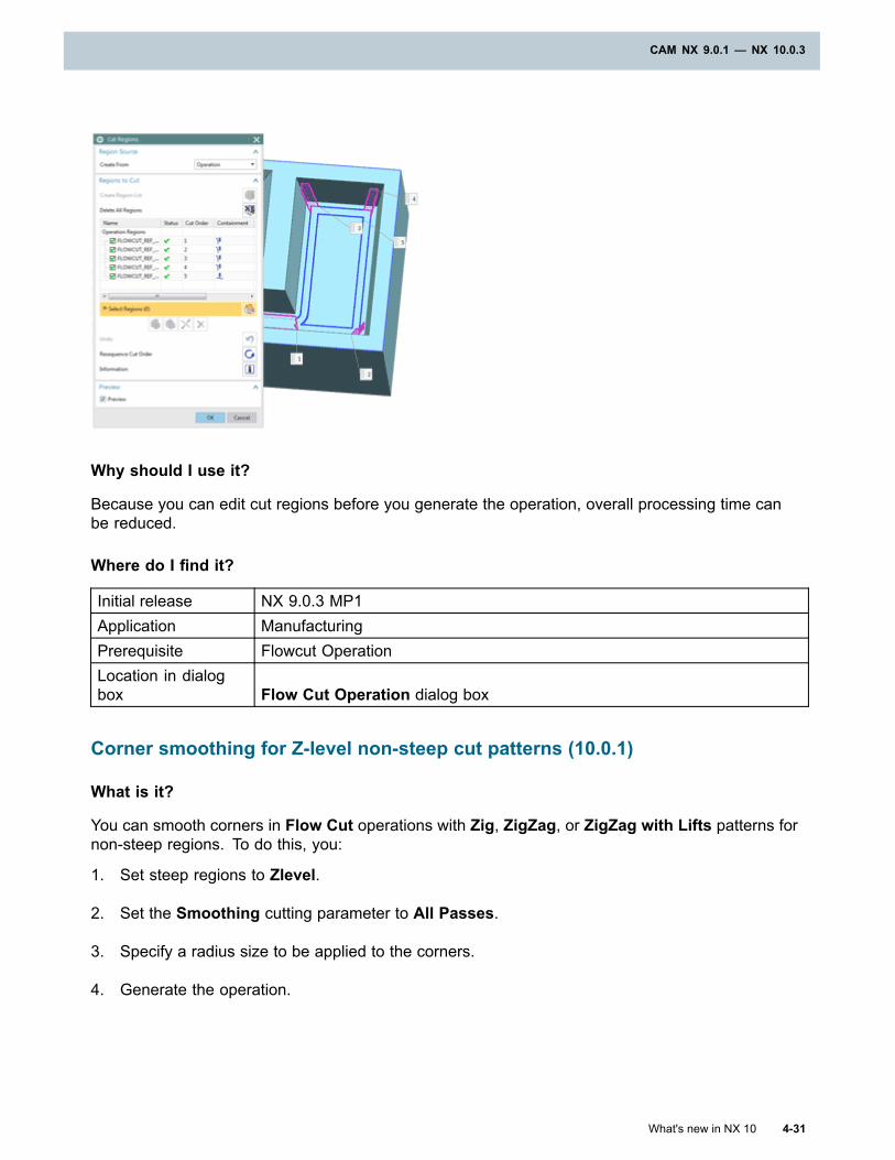
CAM NX 9.0.1 — NX 10.0.3
Why should I use it?
Because you can edit cut regions before you generate the operation, overall processing time canbe reduced.
Where do I find it?
Initial release NX 9.0.3 MP1Application ManufacturingPrerequisite Flowcut OperationLocation in dialogbox Flow Cut Operation dialog box
Corner smoothing for Z-level non-steep cut patterns (10.0.1)
What is it?
You can smooth corners in Flow Cut operations with Zig, ZigZag, or ZigZag with Lifts patterns fornon-steep regions. To do this, you:
1. Set steep regions to Zlevel.
2. Set the Smoothing cutting parameter to All Passes.
3. Specify a radius size to be applied to the corners.
4. Generate the operation.
What's new in NX 10 4-31
CAM NX 9.0.1 — NX 10.0.3
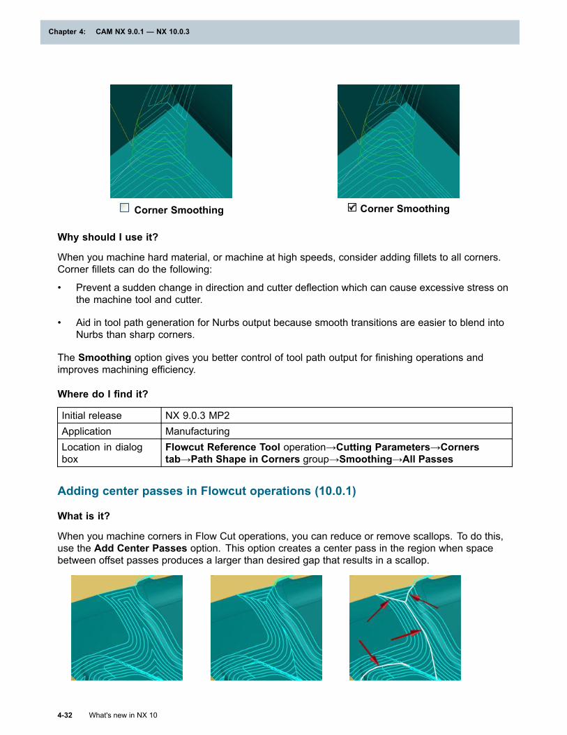
Chapter 4: CAM NX 9.0.1 — NX 10.0.3
Corner Smoothing Corner Smoothing
Why should I use it?
When you machine hard material, or machine at high speeds, consider adding fillets to all corners.Corner fillets can do the following:
• Prevent a sudden change in direction and cutter deflection which can cause excessive stress onthe machine tool and cutter.
• Aid in tool path generation for Nurbs output because smooth transitions are easier to blend intoNurbs than sharp corners.
The Smoothing option gives you better control of tool path output for finishing operations andimproves machining efficiency.
Where do I find it?
Initial release NX 9.0.3 MP2Application ManufacturingLocation in dialogbox
Flowcut Reference Tool operation→Cutting Parameters→Cornerstab→Path Shape in Corners group→Smoothing→All Passes
Adding center passes in Flowcut operations (10.0.1)
What is it?
When you machine corners in Flow Cut operations, you can reduce or remove scallops. To do this,use the Add Center Passes option. This option creates a center pass in the region when spacebetween offset passes produces a larger than desired gap that results in a scallop.
4-32 What's new in NX 10
Chapter 4: CAM NX 9.0.1 — NX 10.0.3
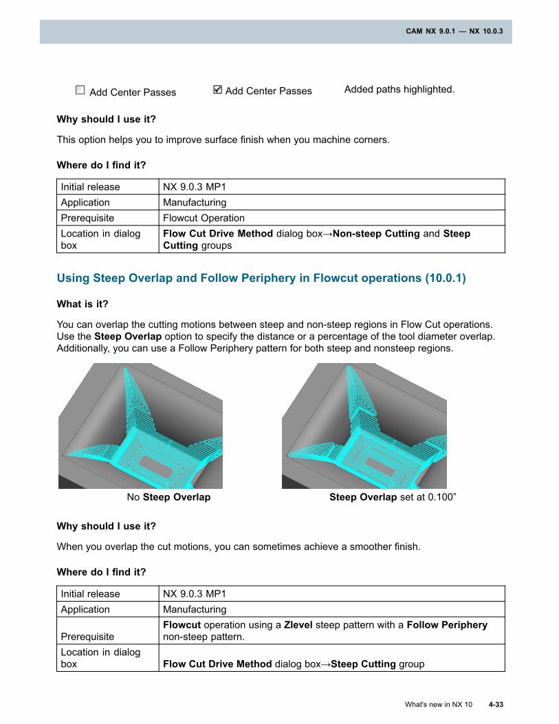
CAM NX 9.0.1 — NX 10.0.3
Add Center Passes Add Center Passes Added paths highlighted.
Why should I use it?
This option helps you to improve surface finish when you machine corners.
Where do I find it?
Initial release NX 9.0.3 MP1Application ManufacturingPrerequisite Flowcut OperationLocation in dialogbox
Flow Cut Drive Method dialog box→Non-steep Cutting and SteepCutting groups
Using Steep Overlap and Follow Periphery in Flowcut operations (10.0.1)
What is it?
You can overlap the cutting motions between steep and non-steep regions in Flow Cut operations.Use the Steep Overlap option to specify the distance or a percentage of the tool diameter overlap.Additionally, you can use a Follow Periphery pattern for both steep and nonsteep regions.
No Steep Overlap Steep Overlap set at 0.100”
Why should I use it?
When you overlap the cut motions, you can sometimes achieve a smoother finish.
Where do I find it?
Initial release NX 9.0.3 MP1Application Manufacturing
PrerequisiteFlowcut operation using a Zlevel steep pattern with a Follow Peripherynon-steep pattern.
Location in dialogbox Flow Cut Drive Method dialog box→Steep Cutting group
What's new in NX 10 4-33
CAM NX 9.0.1 — NX 10.0.3
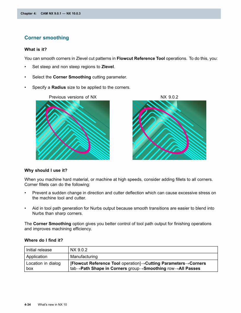
Chapter 4: CAM NX 9.0.1 — NX 10.0.3
Corner smoothing
What is it?
You can smooth corners in Zlevel cut patterns in Flowcut Reference Tool operations. To do this, you:
• Set steep and non steep regions to Zlevel.
• Select the Corner Smoothing cutting parameter.
• Specify a Radius size to be applied to the corners.
Previous versions of NX NX 9.0.2
Why should I use it?
When you machine hard material, or machine at high speeds, consider adding fillets to all corners.Corner fillets can do the following:
• Prevent a sudden change in direction and cutter deflection which can cause excessive stress onthe machine tool and cutter.
• Aid in tool path generation for Nurbs output because smooth transitions are easier to blend intoNurbs than sharp corners.
The Corner Smoothing option gives you better control of tool path output for finishing operationsand improves machining efficiency.
Where do I find it?
Initial release NX 9.0.2Application ManufacturingLocation in dialogbox
[Flowcut Reference Tool operation]→Cutting Parameters→Cornerstab→Path Shape in Corners group→Smoothing row→All Passes
4-34 What's new in NX 10
Chapter 4: CAM NX 9.0.1 — NX 10.0.3
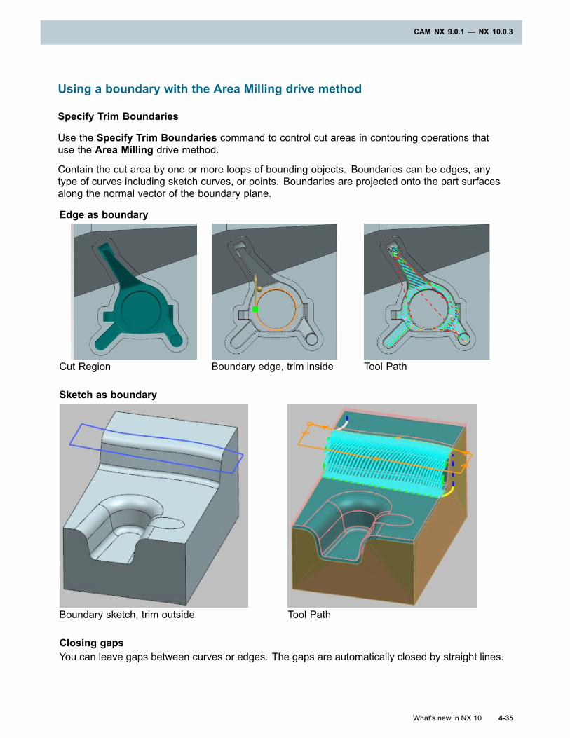
CAM NX 9.0.1 — NX 10.0.3
Using a boundary with the Area Milling drive method
Specify Trim Boundaries
Use the Specify Trim Boundaries command to control cut areas in contouring operations thatuse the Area Milling drive method.
Contain the cut area by one or more loops of bounding objects. Boundaries can be edges, anytype of curves including sketch curves, or points. Boundaries are projected onto the part surfacesalong the normal vector of the boundary plane.
Edge as boundary
Cut Region Boundary edge, trim inside Tool Path
Sketch as boundary
Boundary sketch, trim outside Tool Path
Closing gapsYou can leave gaps between curves or edges. The gaps are automatically closed by straight lines.
What's new in NX 10 4-35
CAM NX 9.0.1 — NX 10.0.3
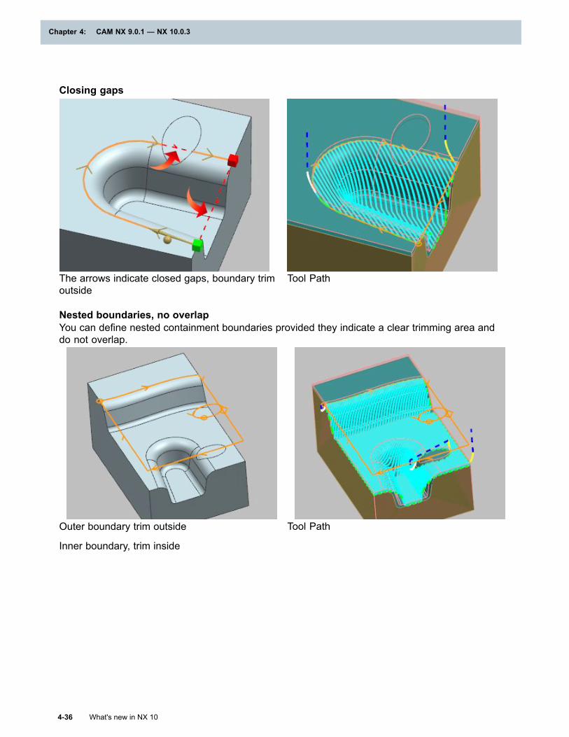
Chapter 4: CAM NX 9.0.1 — NX 10.0.3
Closing gaps
The arrows indicate closed gaps, boundary trimoutside
Tool Path
Nested boundaries, no overlapYou can define nested containment boundaries provided they indicate a clear trimming area anddo not overlap.
Outer boundary trim outside
Inner boundary, trim inside
Tool Path
4-36 What's new in NX 10
Chapter 4: CAM NX 9.0.1 — NX 10.0.3
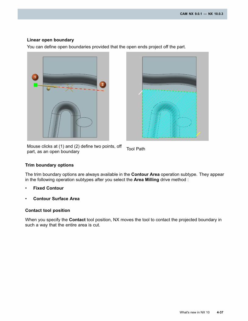
CAM NX 9.0.1 — NX 10.0.3
Linear open boundaryYou can define open boundaries provided that the open ends project off the part.
Mouse clicks at (1) and (2) define two points, offpart, as an open boundary Tool Path
Trim boundary options
The trim boundary options are always available in the Contour Area operation subtype. They appearin the following operation subtypes after you select the Area Milling drive method :
• Fixed Contour
• Contour Surface Area
Contact tool position
When you specify the Contact tool position, NX moves the tool to contact the projected boundary insuch a way that the entire area is cut.
What's new in NX 10 4-37
CAM NX 9.0.1 — NX 10.0.3
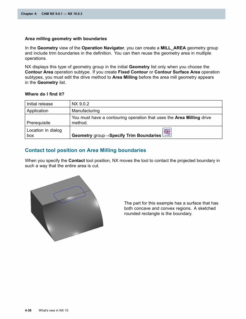
Chapter 4: CAM NX 9.0.1 — NX 10.0.3
Area milling geometry with boundaries
In the Geometry view of the Operation Navigator, you can create a MILL_AREA geometry groupand include trim boundaries in the definition. You can then reuse the geometry area in multipleoperations.
NX displays this type of geometry group in the initial Geometry list only when you choose theContour Area operation subtype. If you create Fixed Contour or Contour Surface Area operationsubtypes, you must edit the drive method to Area Milling before the area mill geometry appearsin the Geometry list.
Where do I find it?
Initial release NX 9.0.2Application Manufacturing
PrerequisiteYou must have a contouring operation that uses the Area Milling drivemethod.
Location in dialogbox Geometry group→Specify Trim Boundaries
Contact tool position on Area Milling boundaries
When you specify the Contact tool position, NX moves the tool to contact the projected boundary insuch a way that the entire area is cut.
The part for this example has a surface that hasboth concave and convex regions. A sketchedrounded rectangle is the boundary.
4-38 What's new in NX 10
Chapter 4: CAM NX 9.0.1 — NX 10.0.3
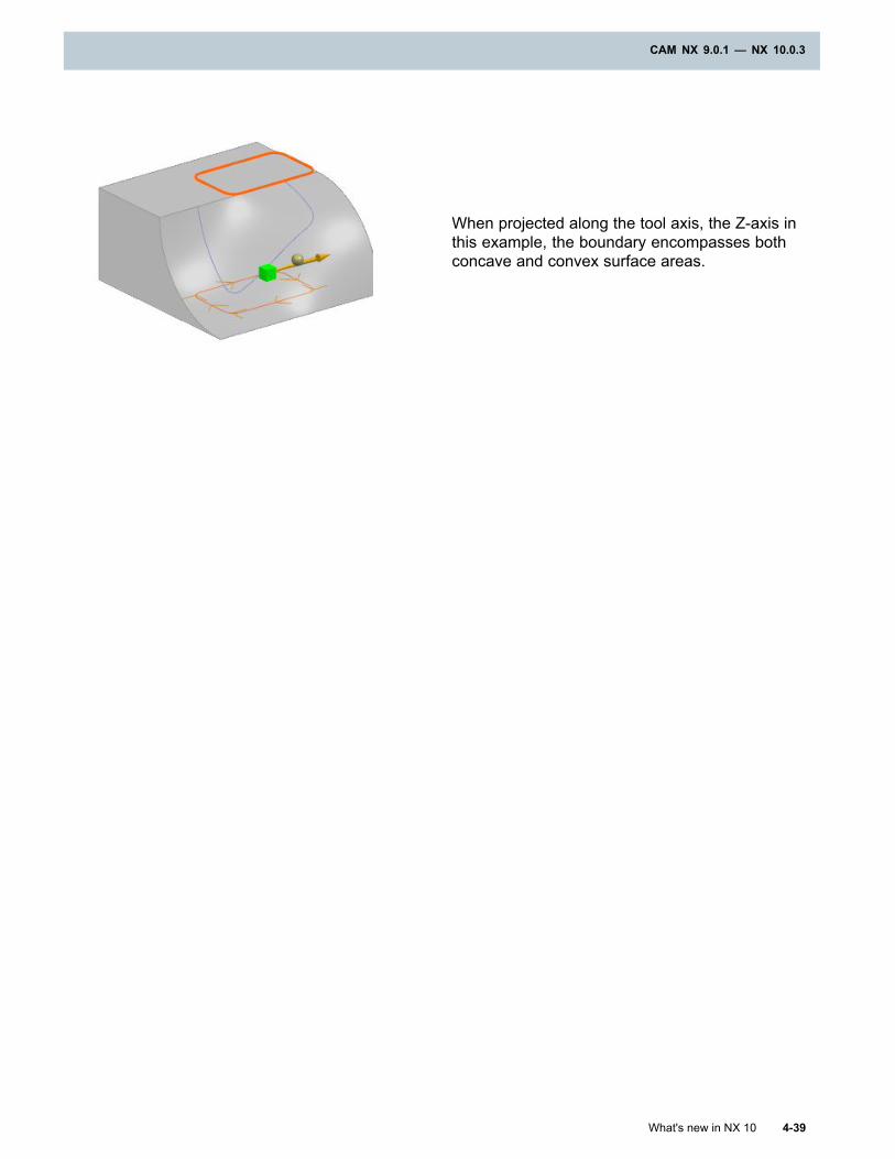
CAM NX 9.0.1 — NX 10.0.3
When projected along the tool axis, the Z-axis inthis example, the boundary encompasses bothconcave and convex surface areas.
What's new in NX 10 4-39
CAM NX 9.0.1 — NX 10.0.3
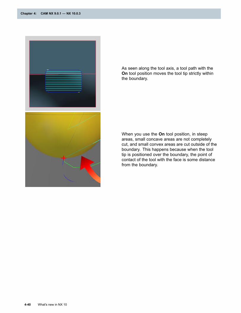
Chapter 4: CAM NX 9.0.1 — NX 10.0.3
As seen along the tool axis, a tool path with theOn tool position moves the tool tip strictly withinthe boundary.
When you use the On tool position, in steepareas, small concave areas are not completelycut, and small convex areas are cut outside of theboundary. This happens because when the tooltip is positioned over the boundary, the point ofcontact of the tool with the face is some distancefrom the boundary.
4-40 What's new in NX 10
Chapter 4: CAM NX 9.0.1 — NX 10.0.3
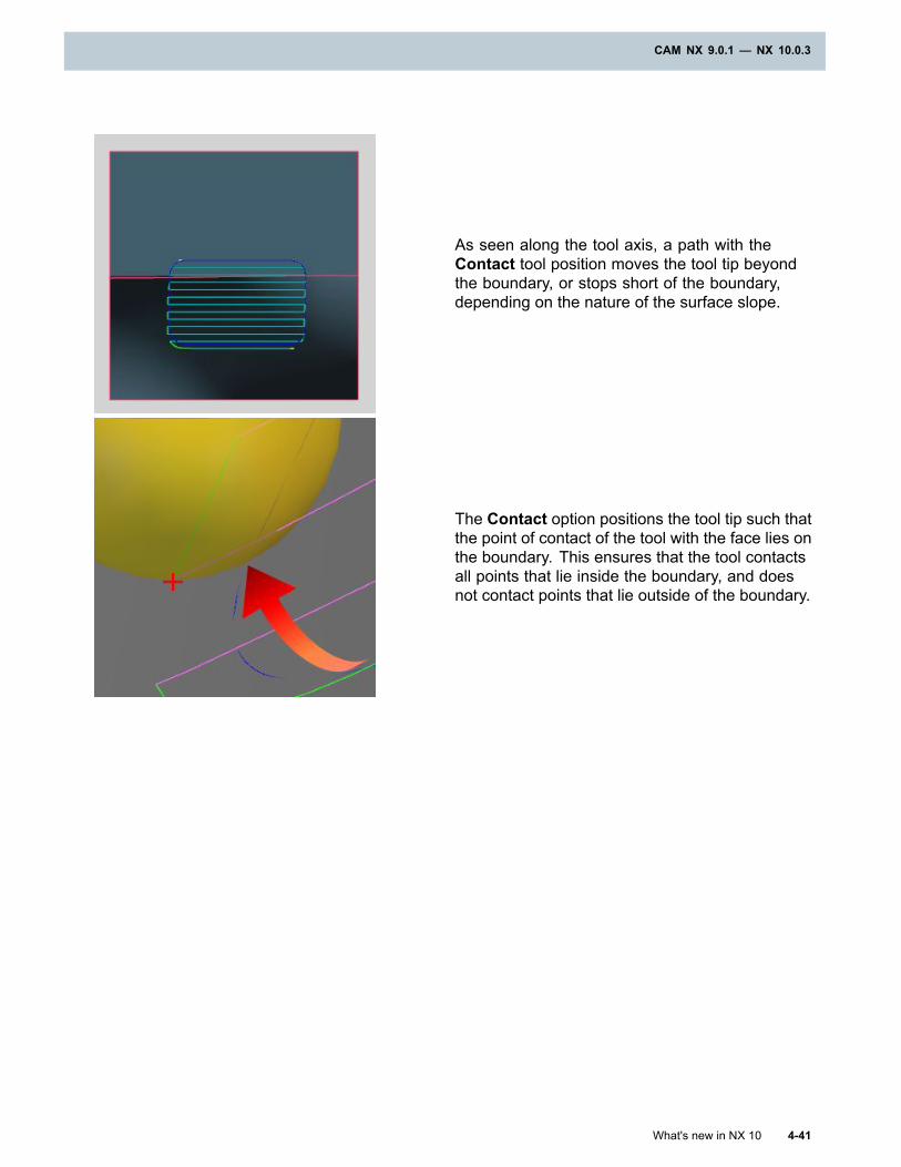
CAM NX 9.0.1 — NX 10.0.3
As seen along the tool axis, a path with theContact tool position moves the tool tip beyondthe boundary, or stops short of the boundary,depending on the nature of the surface slope.
The Contact option positions the tool tip such thatthe point of contact of the tool with the face lies onthe boundary. This ensures that the tool contactsall points that lie inside the boundary, and doesnot contact points that lie outside of the boundary.
What's new in NX 10 4-41
CAM NX 9.0.1 — NX 10.0.3
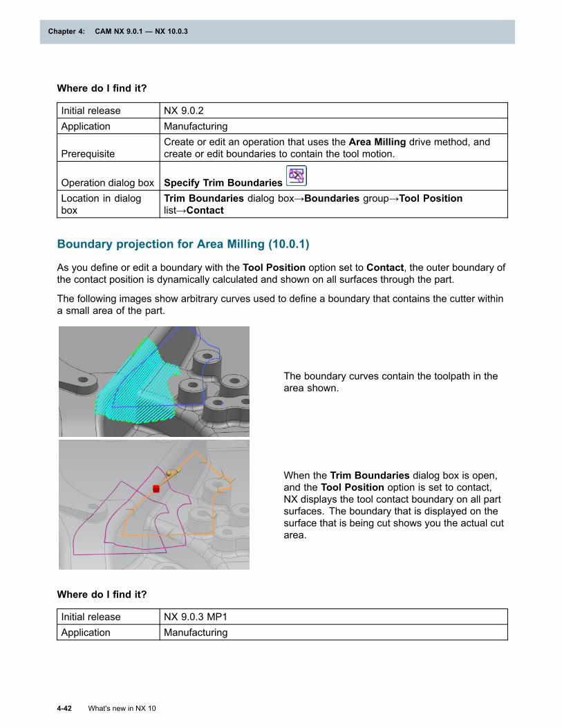
Chapter 4: CAM NX 9.0.1 — NX 10.0.3
Where do I find it?
Initial release NX 9.0.2Application Manufacturing
PrerequisiteCreate or edit an operation that uses the Area Milling drive method, andcreate or edit boundaries to contain the tool motion.
Operation dialog box Specify Trim BoundariesLocation in dialogbox
Trim Boundaries dialog box→Boundaries group→Tool Positionlist→Contact
Boundary projection for Area Milling (10.0.1)
As you define or edit a boundary with the Tool Position option set to Contact, the outer boundary ofthe contact position is dynamically calculated and shown on all surfaces through the part.
The following images show arbitrary curves used to define a boundary that contains the cutter withina small area of the part.
The boundary curves contain the toolpath in thearea shown.
When the Trim Boundaries dialog box is open,and the Tool Position option is set to contact,NX displays the tool contact boundary on all partsurfaces. The boundary that is displayed on thesurface that is being cut shows you the actual cutarea.
Where do I find it?
Initial release NX 9.0.3 MP1Application Manufacturing
4-42 What's new in NX 10
Chapter 4: CAM NX 9.0.1 — NX 10.0.3
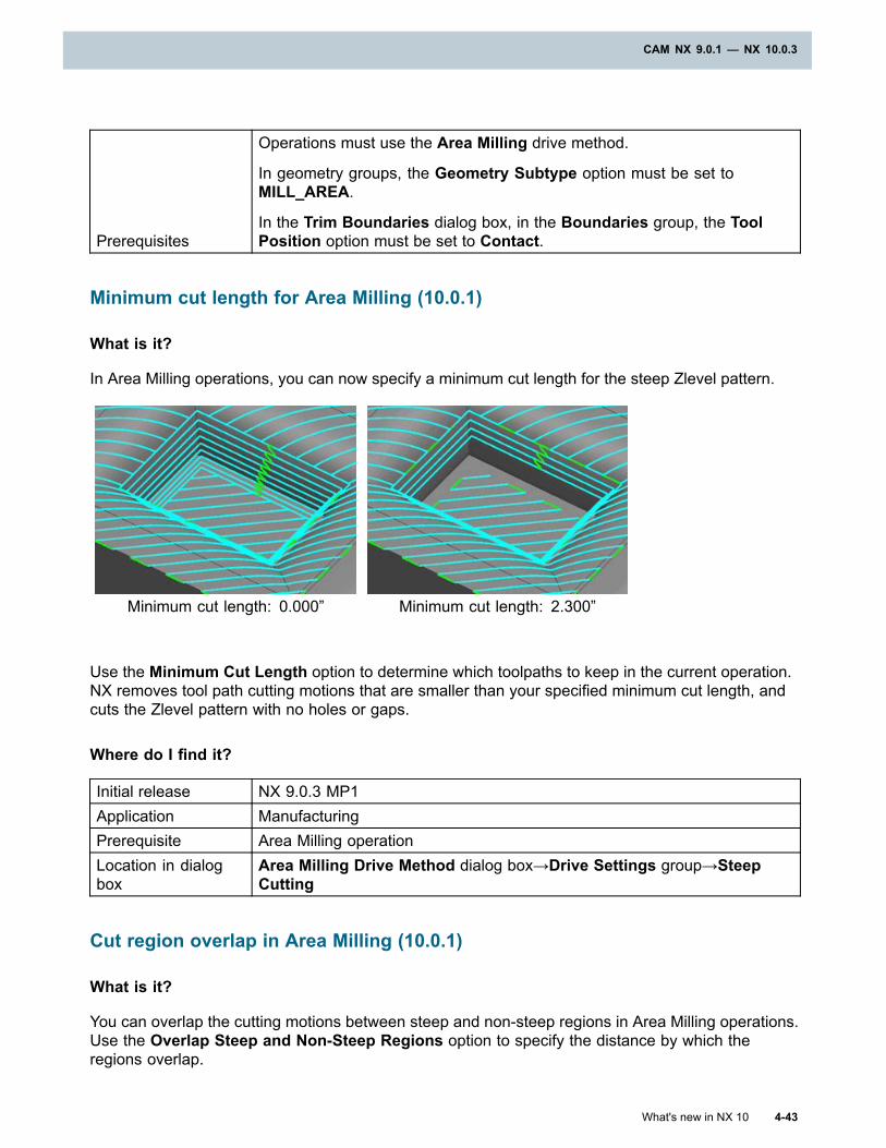
CAM NX 9.0.1 — NX 10.0.3
Prerequisites
Operations must use the Area Milling drive method.
In geometry groups, the Geometry Subtype option must be set toMILL_AREA.
In the Trim Boundaries dialog box, in the Boundaries group, the ToolPosition option must be set to Contact.
Minimum cut length for Area Milling (10.0.1)
What is it?
In Area Milling operations, you can now specify a minimum cut length for the steep Zlevel pattern.
Minimum cut length: 0.000” Minimum cut length: 2.300”
Use the Minimum Cut Length option to determine which toolpaths to keep in the current operation.NX removes tool path cutting motions that are smaller than your specified minimum cut length, andcuts the Zlevel pattern with no holes or gaps.
Where do I find it?
Initial release NX 9.0.3 MP1Application ManufacturingPrerequisite Area Milling operationLocation in dialogbox
Area Milling Drive Method dialog box→Drive Settings group→SteepCutting
Cut region overlap in Area Milling (10.0.1)
What is it?
You can overlap the cutting motions between steep and non-steep regions in Area Milling operations.Use the Overlap Steep and Non-Steep Regions option to specify the distance by which theregions overlap.
What's new in NX 10 4-43
CAM NX 9.0.1 — NX 10.0.3
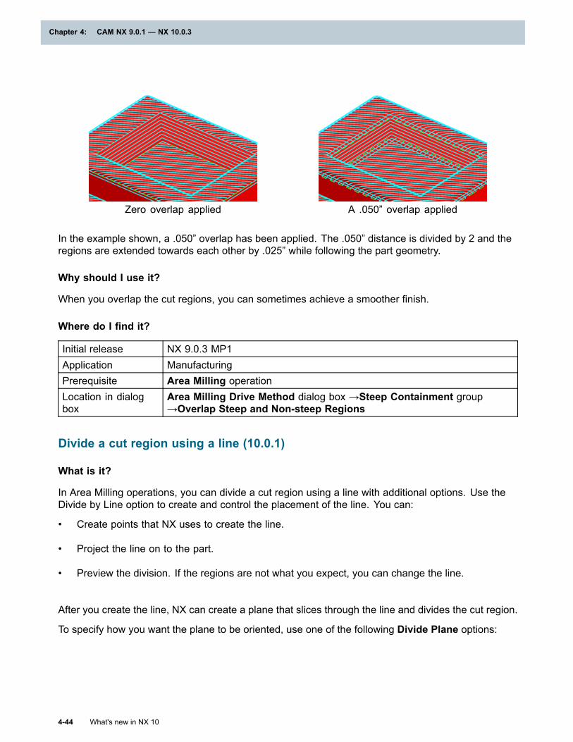
Chapter 4: CAM NX 9.0.1 — NX 10.0.3
Zero overlap applied A .050” overlap applied
In the example shown, a .050” overlap has been applied. The .050” distance is divided by 2 and theregions are extended towards each other by .025” while following the part geometry.
Why should I use it?
When you overlap the cut regions, you can sometimes achieve a smoother finish.
Where do I find it?
Initial release NX 9.0.3 MP1Application ManufacturingPrerequisite Area Milling operationLocation in dialogbox
Area Milling Drive Method dialog box →Steep Containment group→Overlap Steep and Non-steep Regions
Divide a cut region using a line (10.0.1)
What is it?
In Area Milling operations, you can divide a cut region using a line with additional options. Use theDivide by Line option to create and control the placement of the line. You can:
• Create points that NX uses to create the line.
• Project the line on to the part.
• Preview the division. If the regions are not what you expect, you can change the line.
After you create the line, NX can create a plane that slices through the line and divides the cut region.
To specify how you want the plane to be oriented, use one of the following Divide Plane options:
4-44 What's new in NX 10
Chapter 4: CAM NX 9.0.1 — NX 10.0.3
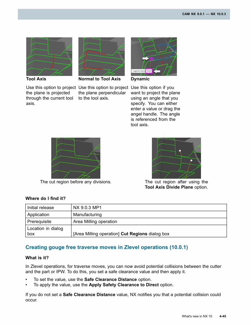
CAM NX 9.0.1 — NX 10.0.3
Tool Axis
Use this option to projectthe plane is projectedthrough the current toolaxis.
Normal to Tool Axis
Use this option to projectthe plane perpendicularto the tool axis.
Dynamic
Use this option if youwant to project the planeusing an angle that youspecify. You can eitherenter a value or drag theangel handle. The angleis referenced from thetool axis.
The cut region before any divisions. The cut region after using theTool Axis Divide Plane option.
Where do I find it?
Initial release NX 9.0.3 MP1Application ManufacturingPrerequisite Area Milling operationLocation in dialogbox [Area Milling operation] Cut Regions dialog box
Creating gouge free traverse moves in Zlevel operations (10.0.1)
What is it?
In Zlevel operations, for traverse moves, you can now avoid potential collisions between the cutterand the part or IPW. To do this, you set a safe clearance value and then apply it.
• To set the value, use the Safe Clearance Distance option.• To apply the value, use the Apply Safety Clearance to Direct option.
If you do not set a Safe Clearance Distance value, NX notifies you that a potential collision couldoccur.
What's new in NX 10 4-45
CAM NX 9.0.1 — NX 10.0.3
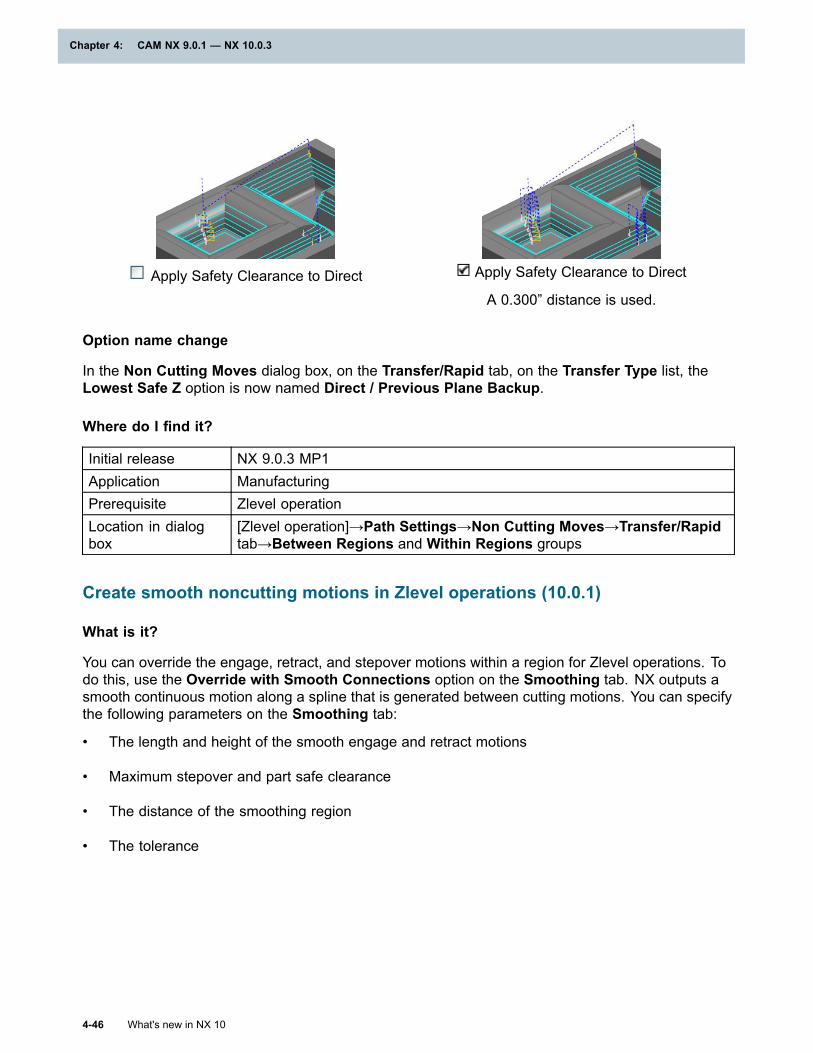
Chapter 4: CAM NX 9.0.1 — NX 10.0.3
Apply Safety Clearance to Direct Apply Safety Clearance to Direct
A 0.300” distance is used.
Option name change
In the Non Cutting Moves dialog box, on the Transfer/Rapid tab, on the Transfer Type list, theLowest Safe Z option is now named Direct / Previous Plane Backup.
Where do I find it?
Initial release NX 9.0.3 MP1Application ManufacturingPrerequisite Zlevel operationLocation in dialogbox
[Zlevel operation]→Path Settings→Non Cutting Moves→Transfer/Rapidtab→Between Regions and Within Regions groups
Create smooth noncutting motions in Zlevel operations (10.0.1)
What is it?
You can override the engage, retract, and stepover motions within a region for Zlevel operations. Todo this, use the Override with Smooth Connections option on the Smoothing tab. NX outputs asmooth continuous motion along a spline that is generated between cutting motions. You can specifythe following parameters on the Smoothing tab:
• The length and height of the smooth engage and retract motions
• Maximum stepover and part safe clearance
• The distance of the smoothing region
• The tolerance
4-46 What's new in NX 10
Chapter 4: CAM NX 9.0.1 — NX 10.0.3
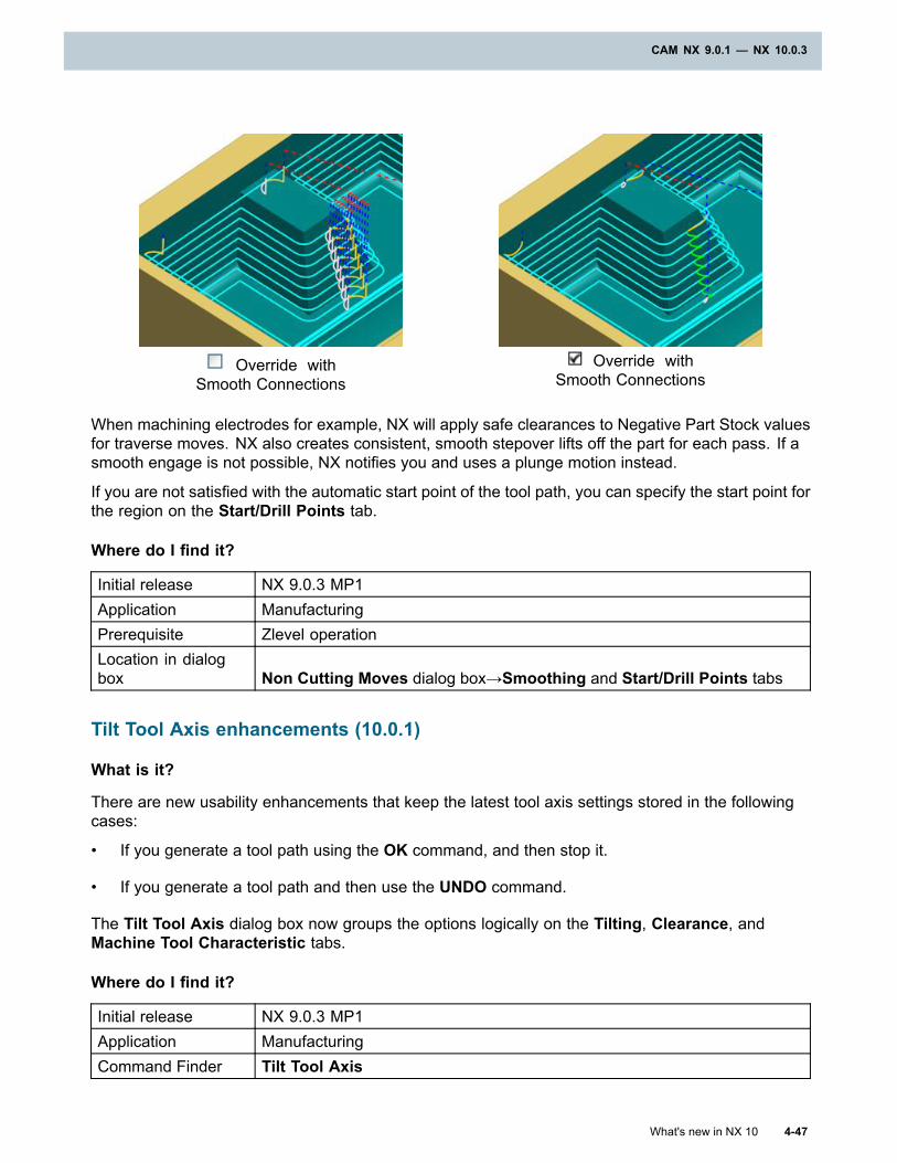
CAM NX 9.0.1 — NX 10.0.3
Override withSmooth Connections
Override withSmooth Connections
When machining electrodes for example, NX will apply safe clearances to Negative Part Stock valuesfor traverse moves. NX also creates consistent, smooth stepover lifts off the part for each pass. If asmooth engage is not possible, NX notifies you and uses a plunge motion instead.
If you are not satisfied with the automatic start point of the tool path, you can specify the start point forthe region on the Start/Drill Points tab.
Where do I find it?
Initial release NX 9.0.3 MP1Application ManufacturingPrerequisite Zlevel operationLocation in dialogbox Non Cutting Moves dialog box→Smoothing and Start/Drill Points tabs
Tilt Tool Axis enhancements (10.0.1)
What is it?
There are new usability enhancements that keep the latest tool axis settings stored in the followingcases:
• If you generate a tool path using the OK command, and then stop it.
• If you generate a tool path and then use the UNDO command.
The Tilt Tool Axis dialog box now groups the options logically on the Tilting, Clearance, andMachine Tool Characteristic tabs.
Where do I find it?
Initial release NX 9.0.3 MP1Application ManufacturingCommand Finder Tilt Tool Axis
What's new in NX 10 4-47
CAM NX 9.0.1 — NX 10.0.3
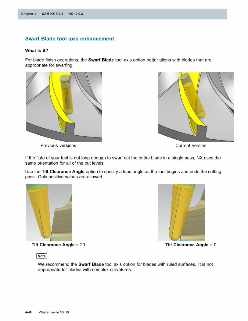
Chapter 4: CAM NX 9.0.1 — NX 10.0.3
Swarf Blade tool axis enhancement
What is it?
For blade finish operations, the Swarf Blade tool axis option better aligns with blades that areappropriate for swarfing.
Previous versions Current version
If the flute of your tool is not long enough to swarf cut the entire blade in a single pass, NX uses thesame orientation for all of the cut levels.
Use the Tilt Clearance Angle option to specify a lead angle as the tool begins and ends the cuttingpass. Only positive values are allowed.
Tilt Clearance Angle = 20 Tilt Clearance Angle = 0
Note
We recommend the Swarf Blade tool axis option for blades with ruled surfaces. It is notappropriate for blades with complex curvatures.
4-48 What's new in NX 10
Chapter 4: CAM NX 9.0.1 — NX 10.0.3
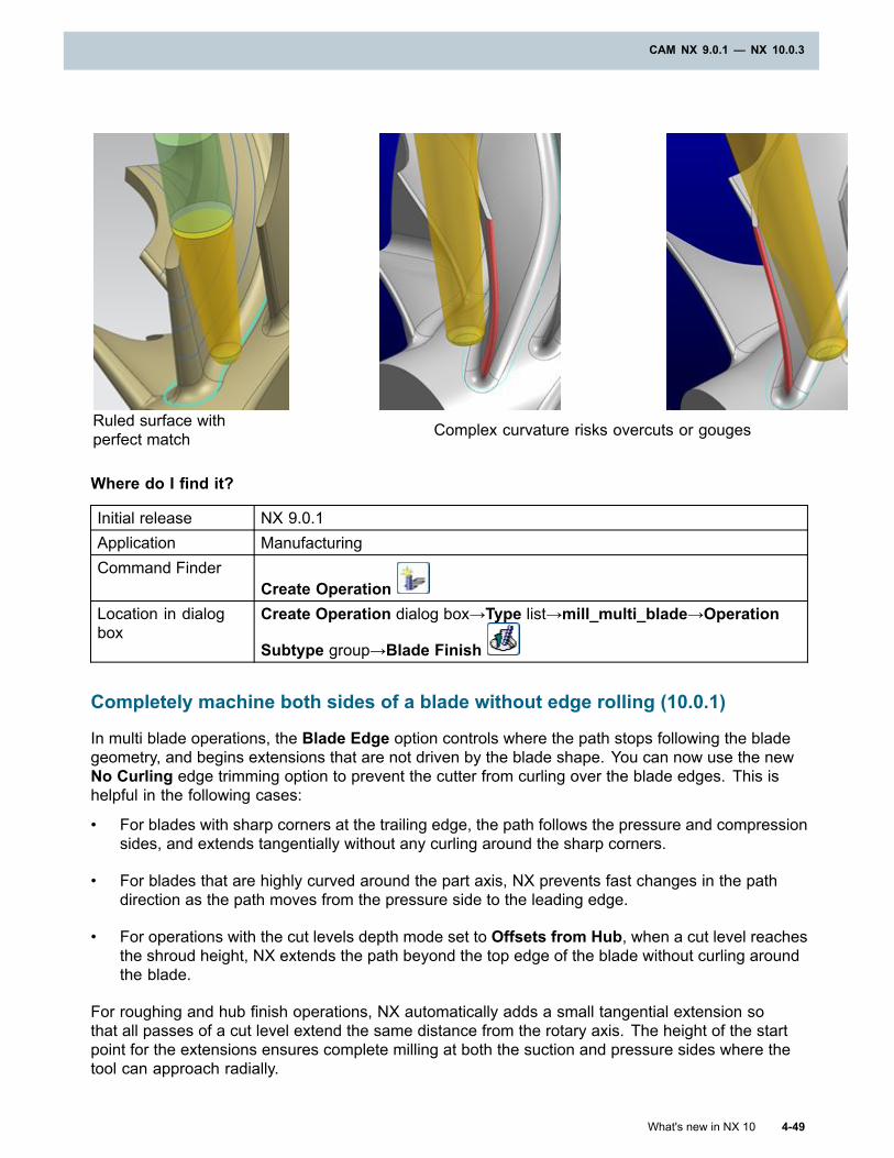
CAM NX 9.0.1 — NX 10.0.3
Ruled surface withperfect match Complex curvature risks overcuts or gouges
Where do I find it?
Initial release NX 9.0.1Application ManufacturingCommand Finder
Create OperationLocation in dialogbox
Create Operation dialog box→Type list→mill_multi_blade→Operation
Subtype group→Blade Finish
Completely machine both sides of a blade without edge rolling (10.0.1)
In multi blade operations, the Blade Edge option controls where the path stops following the bladegeometry, and begins extensions that are not driven by the blade shape. You can now use the newNo Curling edge trimming option to prevent the cutter from curling over the blade edges. This ishelpful in the following cases:
• For blades with sharp corners at the trailing edge, the path follows the pressure and compressionsides, and extends tangentially without any curling around the sharp corners.
• For blades that are highly curved around the part axis, NX prevents fast changes in the pathdirection as the path moves from the pressure side to the leading edge.
• For operations with the cut levels depth mode set to Offsets from Hub, when a cut level reachesthe shroud height, NX extends the path beyond the top edge of the blade without curling aroundthe blade.
For roughing and hub finish operations, NX automatically adds a small tangential extension sothat all passes of a cut level extend the same distance from the rotary axis. The height of the startpoint for the extensions ensures complete milling at both the suction and pressure sides where thetool can approach radially.
What's new in NX 10 4-49
CAM NX 9.0.1 — NX 10.0.3

Chapter 4: CAM NX 9.0.1 — NX 10.0.3
For all operations, you can also enter an Extension value to add your defined tangential extensionafter the automatic one.
4-50 What's new in NX 10
Chapter 4: CAM NX 9.0.1 — NX 10.0.3
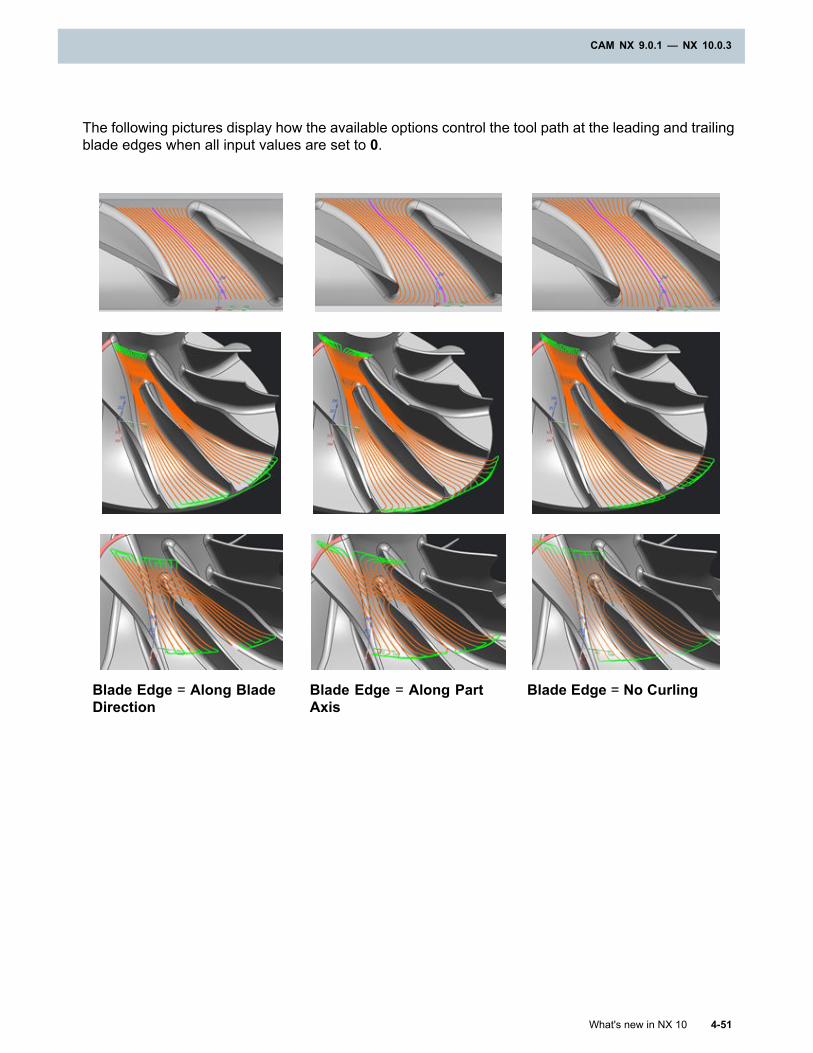
CAM NX 9.0.1 — NX 10.0.3
The following pictures display how the available options control the tool path at the leading and trailingblade edges when all input values are set to 0.
Blade Edge = Along BladeDirection
Blade Edge = Along PartAxis
Blade Edge = No Curling
What's new in NX 10 4-51
CAM NX 9.0.1 — NX 10.0.3
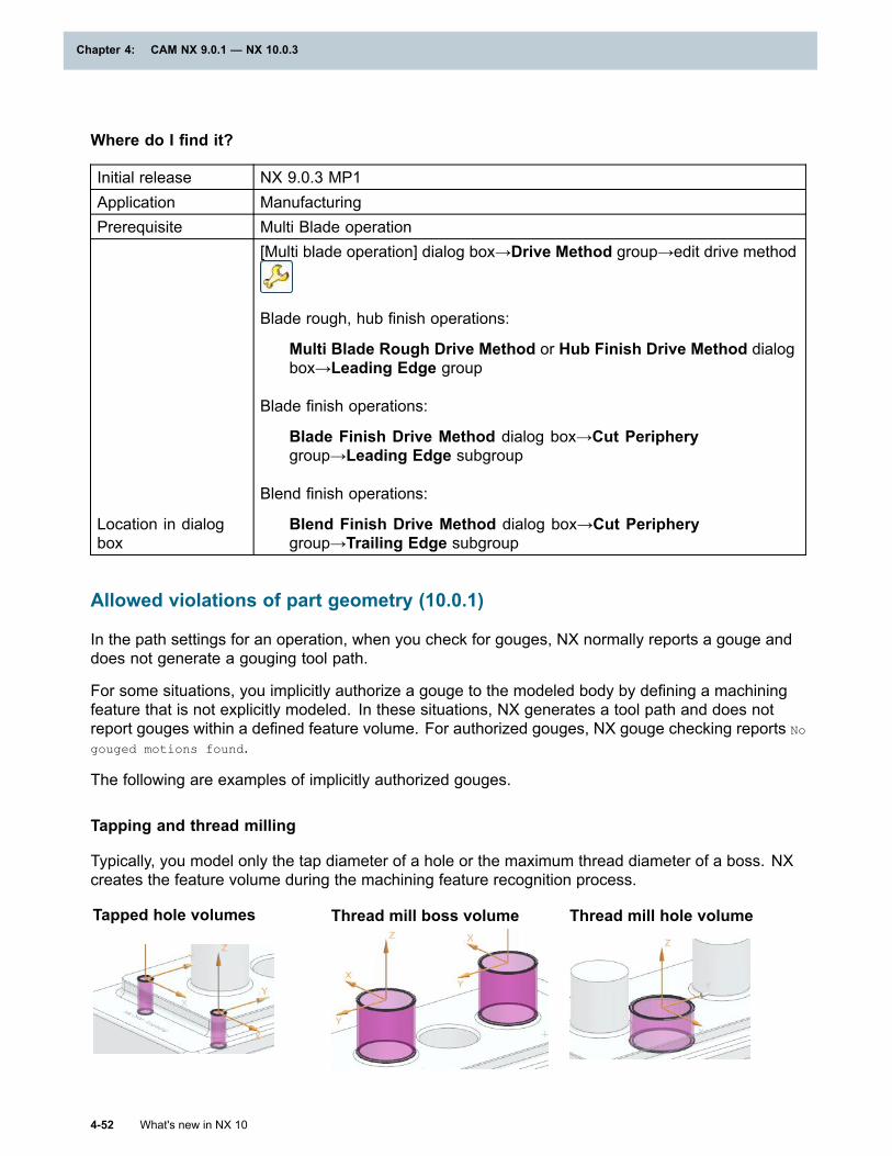
Chapter 4: CAM NX 9.0.1 — NX 10.0.3
Where do I find it?
Initial release NX 9.0.3 MP1Application ManufacturingPrerequisite Multi Blade operation
Location in dialogbox
[Multi blade operation] dialog box→Drive Method group→edit drive method
Blade rough, hub finish operations:
Multi Blade Rough Drive Method or Hub Finish Drive Method dialogbox→Leading Edge group
Blade finish operations:
Blade Finish Drive Method dialog box→Cut Peripherygroup→Leading Edge subgroup
Blend finish operations:
Blend Finish Drive Method dialog box→Cut Peripherygroup→Trailing Edge subgroup
Allowed violations of part geometry (10.0.1)
In the path settings for an operation, when you check for gouges, NX normally reports a gouge anddoes not generate a gouging tool path.
For some situations, you implicitly authorize a gouge to the modeled body by defining a machiningfeature that is not explicitly modeled. In these situations, NX generates a tool path and does notreport gouges within a defined feature volume. For authorized gouges, NX gouge checking reports No
gouged motions found.
The following are examples of implicitly authorized gouges.
Tapping and thread milling
Typically, you model only the tap diameter of a hole or the maximum thread diameter of a boss. NXcreates the feature volume during the machining feature recognition process.
Tapped hole volumes Thread mill boss volume Thread mill hole volume
4-52 What's new in NX 10
Chapter 4: CAM NX 9.0.1 — NX 10.0.3
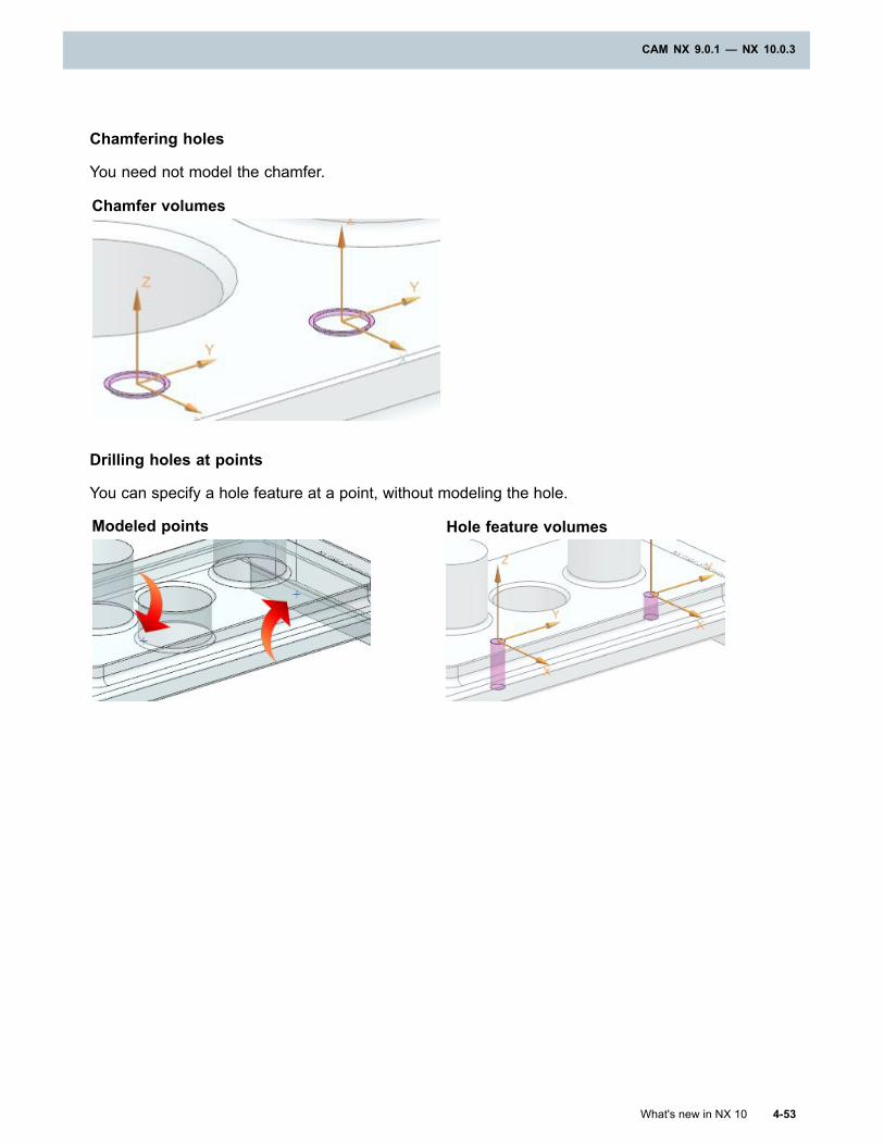
CAM NX 9.0.1 — NX 10.0.3
Chamfering holes
You need not model the chamfer.
Chamfer volumes
Drilling holes at points
You can specify a hole feature at a point, without modeling the hole.
Modeled points Hole feature volumes
What's new in NX 10 4-53
CAM NX 9.0.1 — NX 10.0.3
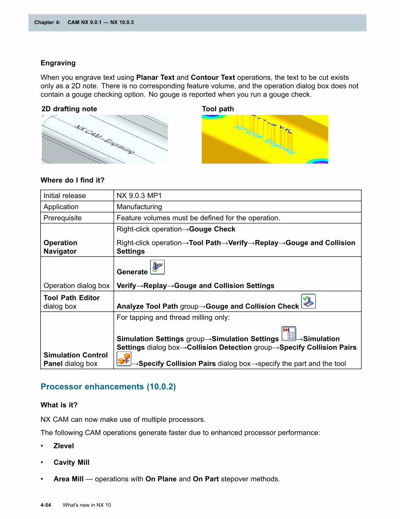
Chapter 4: CAM NX 9.0.1 — NX 10.0.3
Engraving
When you engrave text using Planar Text and Contour Text operations, the text to be cut existsonly as a 2D note. There is no corresponding feature volume, and the operation dialog box does notcontain a gouge checking option. No gouge is reported when you run a gouge check.
2D drafting note Tool path
Where do I find it?
Initial release NX 9.0.3 MP1Application ManufacturingPrerequisite Feature volumes must be defined for the operation.
OperationNavigator
Right-click operation→Gouge Check
Right-click operation→Tool Path→Verify→Replay→Gouge and CollisionSettings
Operation dialog box
Generate
Verify→Replay→Gouge and Collision SettingsTool Path Editordialog box Analyze Tool Path group→Gouge and Collision Check
Simulation ControlPanel dialog box
For tapping and thread milling only:
Simulation Settings group→Simulation Settings →SimulationSettings dialog box→Collision Detection group→Specify Collision Pairs
→Specify Collision Pairs dialog box→specify the part and the tool
Processor enhancements (10.0.2)
What is it?
NX CAM can now make use of multiple processors.
The following CAM operations generate faster due to enhanced processor performance:
• Zlevel
• Cavity Mill
• Area Mill — operations with On Plane and On Part stepover methods.
4-54 What's new in NX 10
Chapter 4: CAM NX 9.0.1 — NX 10.0.3
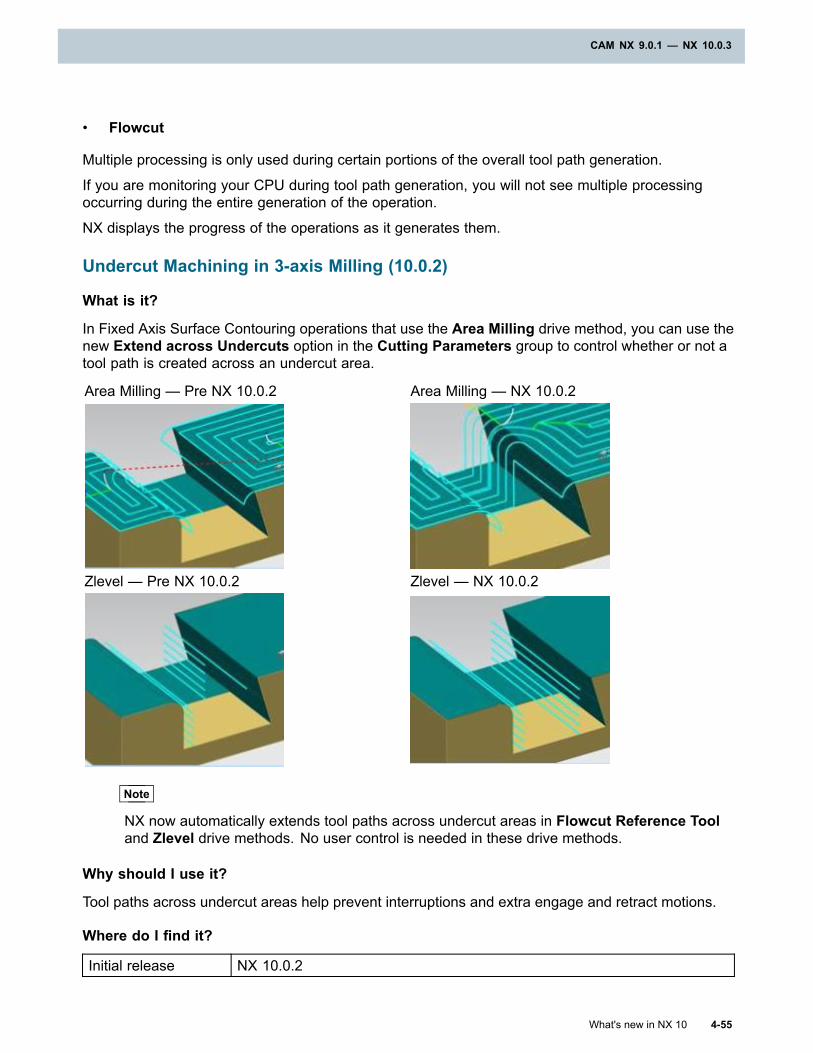
CAM NX 9.0.1 — NX 10.0.3
• Flowcut
Multiple processing is only used during certain portions of the overall tool path generation.
If you are monitoring your CPU during tool path generation, you will not see multiple processingoccurring during the entire generation of the operation.
NX displays the progress of the operations as it generates them.
Undercut Machining in 3-axis Milling (10.0.2)
What is it?
In Fixed Axis Surface Contouring operations that use the Area Milling drive method, you can use thenew Extend across Undercuts option in the Cutting Parameters group to control whether or not atool path is created across an undercut area.
Area Milling — Pre NX 10.0.2 Area Milling — NX 10.0.2
Zlevel — Pre NX 10.0.2 Zlevel — NX 10.0.2
Note
NX now automatically extends tool paths across undercut areas in Flowcut Reference Tooland Zlevel drive methods. No user control is needed in these drive methods.
Why should I use it?
Tool paths across undercut areas help prevent interruptions and extra engage and retract motions.
Where do I find it?
Initial release NX 10.0.2
What's new in NX 10 4-55
CAM NX 9.0.1 — NX 10.0.3
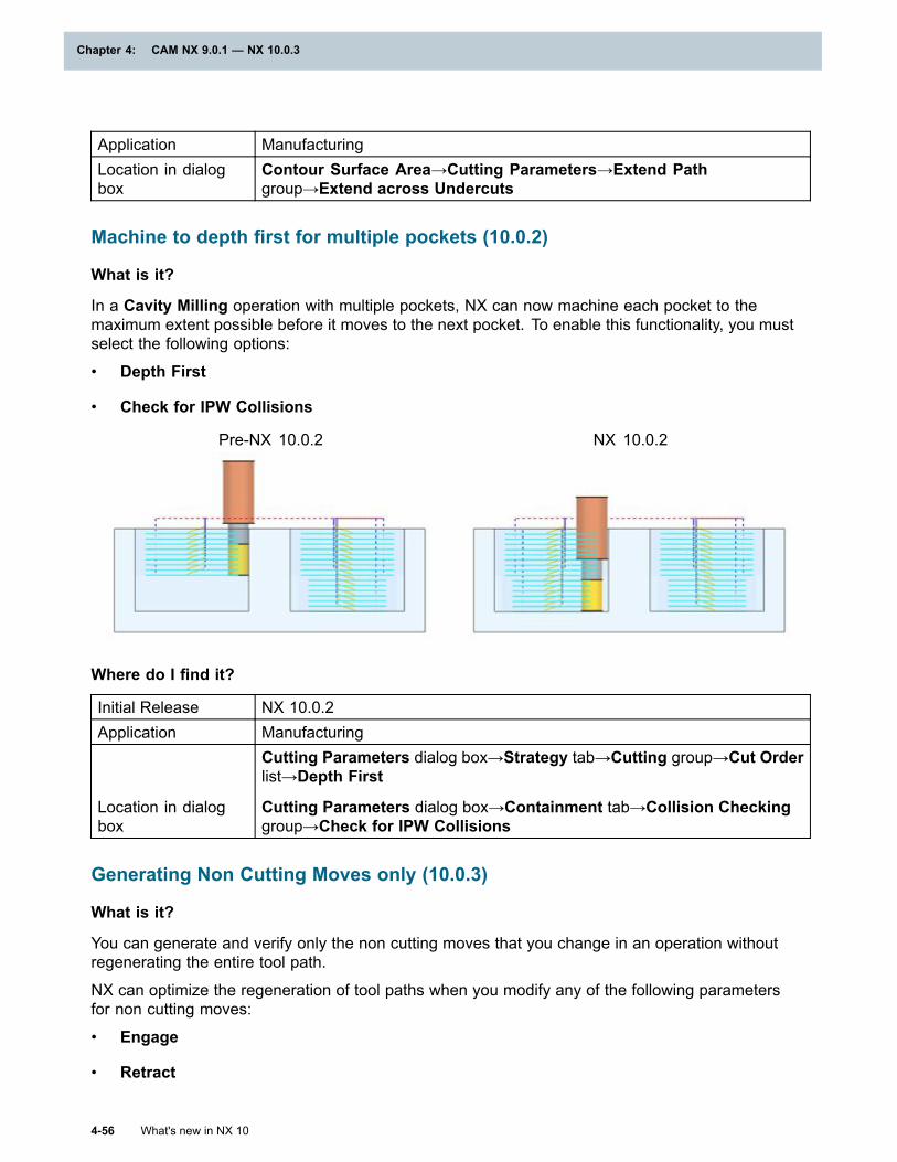
Chapter 4: CAM NX 9.0.1 — NX 10.0.3
Application ManufacturingLocation in dialogbox
Contour Surface Area→Cutting Parameters→Extend Pathgroup→Extend across Undercuts
Machine to depth first for multiple pockets (10.0.2)
What is it?
In a Cavity Milling operation with multiple pockets, NX can now machine each pocket to themaximum extent possible before it moves to the next pocket. To enable this functionality, you mustselect the following options:
• Depth First
• Check for IPW Collisions
Pre-NX 10.0.2 NX 10.0.2
Where do I find it?
Initial Release NX 10.0.2Application Manufacturing
Location in dialogbox
Cutting Parameters dialog box→Strategy tab→Cutting group→Cut Orderlist→Depth First
Cutting Parameters dialog box→Containment tab→Collision Checkinggroup→Check for IPW Collisions
Generating Non Cutting Moves only (10.0.3)
What is it?
You can generate and verify only the non cutting moves that you change in an operation withoutregenerating the entire tool path.
NX can optimize the regeneration of tool paths when you modify any of the following parametersfor non cutting moves:
• Engage
• Retract
4-56 What's new in NX 10
Chapter 4: CAM NX 9.0.1 — NX 10.0.3
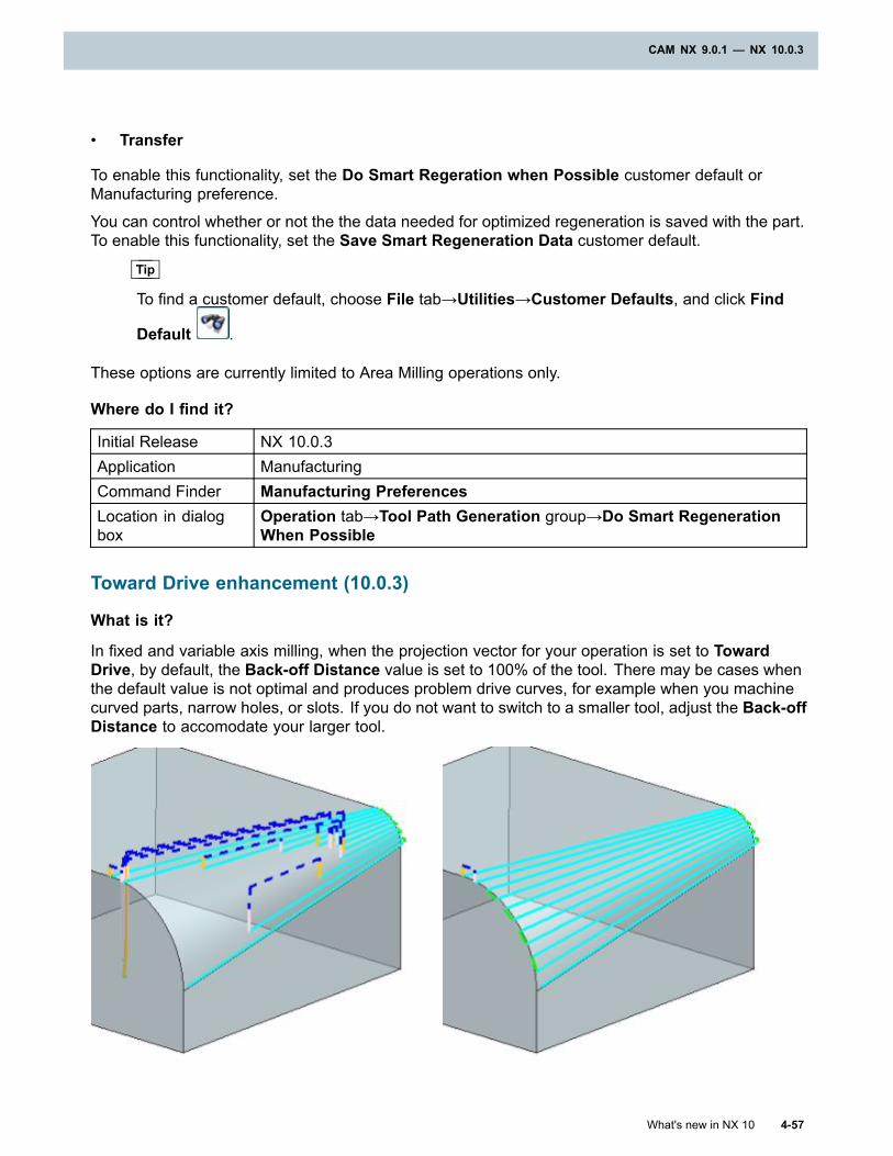
CAM NX 9.0.1 — NX 10.0.3
• Transfer
To enable this functionality, set the Do Smart Regeration when Possible customer default orManufacturing preference.
You can control whether or not the the data needed for optimized regeneration is saved with the part.To enable this functionality, set the Save Smart Regeneration Data customer default.
Tip
To find a customer default, choose File tab→Utilities→Customer Defaults, and click Find
Default .
These options are currently limited to Area Milling operations only.
Where do I find it?
Initial Release NX 10.0.3Application ManufacturingCommand Finder Manufacturing PreferencesLocation in dialogbox
Operation tab→Tool Path Generation group→Do Smart RegenerationWhen Possible
Toward Drive enhancement (10.0.3)
What is it?
In fixed and variable axis milling, when the projection vector for your operation is set to TowardDrive, by default, the Back-off Distance value is set to 100% of the tool. There may be cases whenthe default value is not optimal and produces problem drive curves, for example when you machinecurved parts, narrow holes, or slots. If you do not want to switch to a smaller tool, adjust the Back-offDistance to accomodate your larger tool.
What's new in NX 10 4-57
CAM NX 9.0.1 — NX 10.0.3

Chapter 4: CAM NX 9.0.1 — NX 10.0.3
Back off Distance = 100 (% Tool) Back off Distance = 200 (% Tool)
Back off Distance = 100 (% Tool) Back off Distance = 10 (% Tool)
Where do I find it?
Initial Release NX 10.0.3Application ManufacturingLocation in dialogbox Streamline Drive dialog box→Projection Vector group
Processor enhancements (10.0.3)
What is it?
NX CAM 10.0.3 includes enhancements that provide greater use of multiple processors.
Multiple processing is only used during certain portions of the overall tool path generation. Whenmultiple processors are being used, NX displays the message Building Traces (new) in the Statusbar.
Note
The degree of performance improvement varies according to the complexity of the partgeometry, operation type, and computer configuration.
Where do I find it?
Initial Release NX 10.0.3
4-58 What's new in NX 10
Chapter 4: CAM NX 9.0.1 — NX 10.0.3
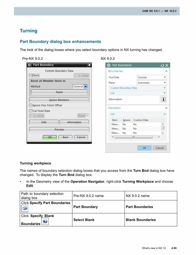
CAM NX 9.0.1 — NX 10.0.3
Turning
Part Boundary dialog box enhancements
The look of the dialog boxes where you select boundary options in NX turning has changed.
Pre-NX 9.0.2 NX 9.0.2
Turning workpiece
The names of boundary selection dialog boxes that you access from the Turn Bnd dialog box havechanged. To display the Turn Bnd dialog box:
• In the Geometry view of the Operation Navigator, right-click Turning Workpiece and chooseEdit.
Path to boundary selectiondialog box Pre-NX 9.0.2 name NX 9.0.2 name
Click Specify Part BoundariesPart Boundary Part Boundaries
Click Specify Blank
BoundariesSelect Blank Blank Boundaries
What's new in NX 10 4-59
CAM NX 9.0.1 — NX 10.0.3
Chapter 4: CAM NX 9.0.1 — NX 10.0.3
Turning operation
The name of boundary selection dialog boxes that you access from a turning operation have changed.
• Right-click any turning operation and choose Edit.
Path to boundary selectiondialog box Pre-NX 9.0.2 name NX 9.0.2 name
Geometry group→CustomPart Boundary Data Part Boundary Part Boundaries
Teach Mode operation
The names of boundary selection dialog boxes that you access from a Profile Move type of TeachMode operation have changed.
1. Create a Teach Mode operation.
2. In the Teach Mode dialog box, in the Sub-Operations group, click Add New Sub-Operation
.
3. In the Create Teachmode Subop dialog box, from the Move Type list, select Profile Move.
Path to boundary selectiondialog box Pre-NX 9.0.2 name NX 9.0.2 name
Path Settings group→DriveGeometry list→New DriveCurve
Select Drive Geometry Part Boundaries
Start and Stop group→StartPosition list→CheckCurve→Start Check Geometry
Select Start Check Geometry Start Check Boundary
Start and Stop group→StartPosition list→CheckCurve→Stop Check Geometry
Select Stop Check Geometry End Check Boundary
Where do I find it?
Initial release NX 9.0.2Application Manufacturing
Tracking points for centerline drilling tools (10.0.2)
A tracking point is the internal reference point on the tool that NX uses to calculate tool paths.
Drilling tools have two system-defined tracking points at the center line, SYS_CL_SHOULDERand SYS_CL_TIP.
4-60 What's new in NX 10
Chapter 4: CAM NX 9.0.1 — NX 10.0.3
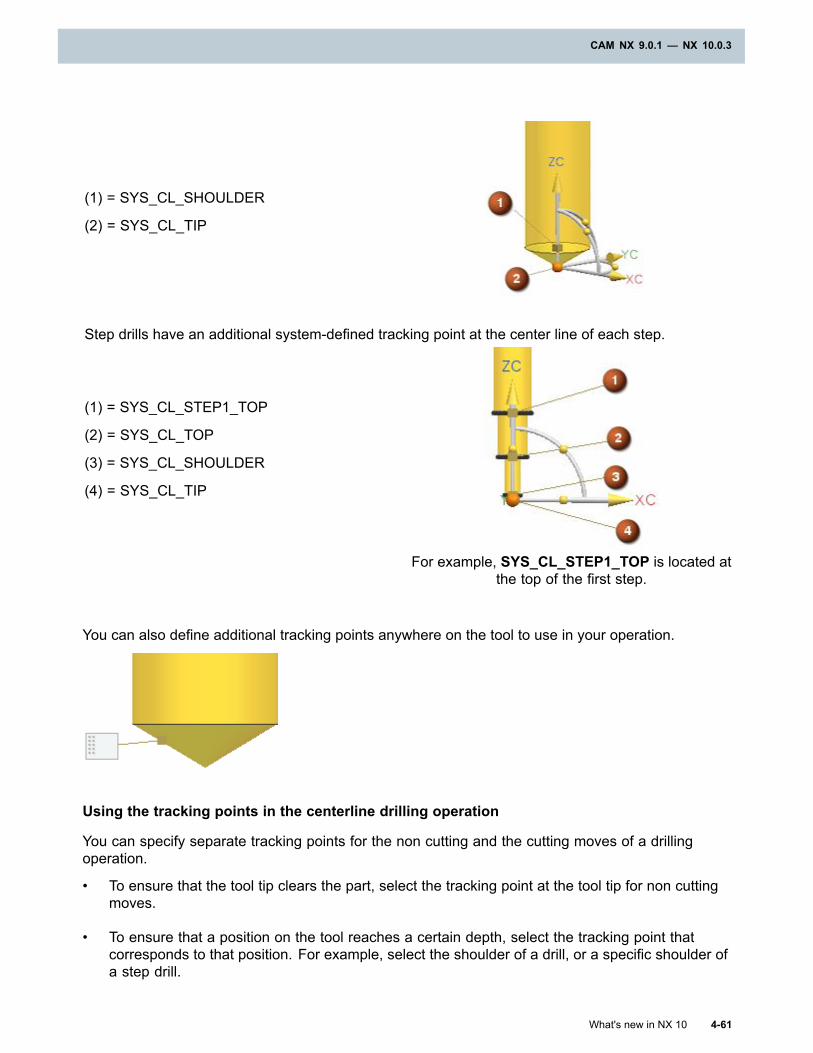
CAM NX 9.0.1 — NX 10.0.3
(1) = SYS_CL_SHOULDER
(2) = SYS_CL_TIP
Step drills have an additional system-defined tracking point at the center line of each step.
(1) = SYS_CL_STEP1_TOP
(2) = SYS_CL_TOP
(3) = SYS_CL_SHOULDER
(4) = SYS_CL_TIP
For example, SYS_CL_STEP1_TOP is located atthe top of the first step.
You can also define additional tracking points anywhere on the tool to use in your operation.
Using the tracking points in the centerline drilling operation
You can specify separate tracking points for the non cutting and the cutting moves of a drillingoperation.
• To ensure that the tool tip clears the part, select the tracking point at the tool tip for non cuttingmoves.
• To ensure that a position on the tool reaches a certain depth, select the tracking point thatcorresponds to that position. For example, select the shoulder of a drill, or a specific shoulder ofa step drill.
What's new in NX 10 4-61
CAM NX 9.0.1 — NX 10.0.3
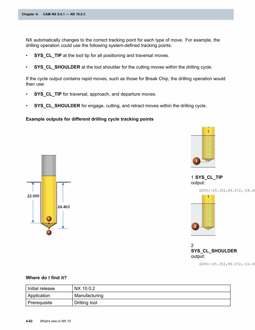
Chapter 4: CAM NX 9.0.1 — NX 10.0.3
NX automatically changes to the correct tracking point for each type of move. For example, thedrilling operation could use the following system-defined tracking points:
• SYS_CL_TIP at the tool tip for all positioning and traversal moves.
• SYS_CL_SHOULDER at the tool shoulder for the cutting moves within the drilling cycle.
If the cycle output contains rapid moves, such as those for Break Chip, the drilling operation wouldthen use:
• SYS_CL_TIP for traversal, approach, and departure moves.
• SYS_CL_SHOULDER for engage, cutting, and retract moves within the drilling cycle.
Example outputs for different drilling cycle tracking points
1 SYS_CL_TIPoutput:
GOTO/-25.352,89.572,-24.403
2SYS_CL_SHOULDERoutput:
GOTO/-25.352,89.572,-22.000
Where do I find it?
Initial release NX 10.0.2Application ManufacturingPrerequisite Drilling tool
4-62 What's new in NX 10
Chapter 4: CAM NX 9.0.1 — NX 10.0.3
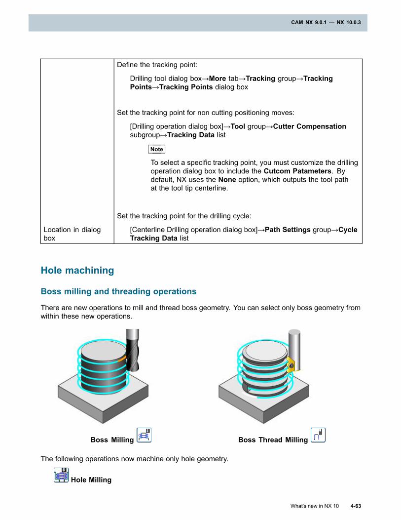
CAM NX 9.0.1 — NX 10.0.3
Location in dialogbox
Define the tracking point:
Drilling tool dialog box→More tab→Tracking group→TrackingPoints→Tracking Points dialog box
Set the tracking point for non cutting positioning moves:
[Drilling operation dialog box]→Tool group→Cutter Compensationsubgroup→Tracking Data list
Note
To select a specific tracking point, you must customize the drillingoperation dialog box to include the Cutcom Patameters. Bydefault, NX uses the None option, which outputs the tool pathat the tool tip centerline.
Set the tracking point for the drilling cycle:
[Centerline Drilling operation dialog box]→Path Settings group→CycleTracking Data list
Hole machining
Boss milling and threading operations
There are new operations to mill and thread boss geometry. You can select only boss geometry fromwithin these new operations.
Boss Milling Boss Thread Milling
The following operations now machine only hole geometry.
Hole Milling
What's new in NX 10 4-63
CAM NX 9.0.1 — NX 10.0.3
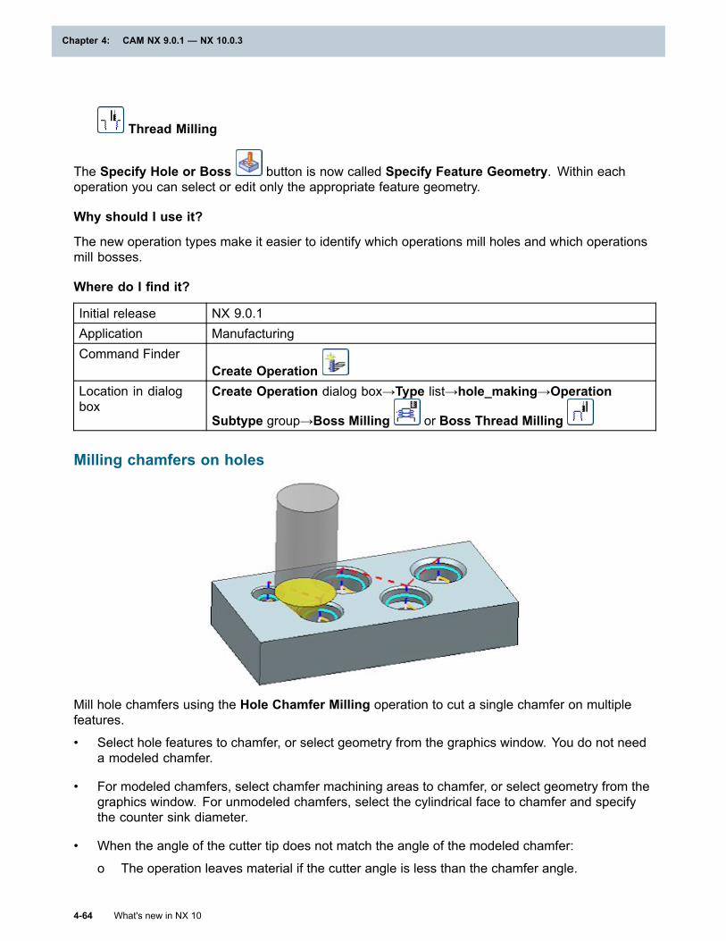
Chapter 4: CAM NX 9.0.1 — NX 10.0.3
Thread Milling
The Specify Hole or Boss button is now called Specify Feature Geometry. Within eachoperation you can select or edit only the appropriate feature geometry.
Why should I use it?
The new operation types make it easier to identify which operations mill holes and which operationsmill bosses.
Where do I find it?
Initial release NX 9.0.1Application ManufacturingCommand Finder
Create OperationLocation in dialogbox
Create Operation dialog box→Type list→hole_making→Operation
Subtype group→Boss Milling or Boss Thread Milling
Milling chamfers on holes
Mill hole chamfers using the Hole Chamfer Milling operation to cut a single chamfer on multiplefeatures.
• Select hole features to chamfer, or select geometry from the graphics window. You do not needa modeled chamfer.
• For modeled chamfers, select chamfer machining areas to chamfer, or select geometry from thegraphics window. For unmodeled chamfers, select the cylindrical face to chamfer and specifythe counter sink diameter.
• When the angle of the cutter tip does not match the angle of the modeled chamfer:
o The operation leaves material if the cutter angle is less than the chamfer angle.
4-64 What's new in NX 10
Chapter 4: CAM NX 9.0.1 — NX 10.0.3

CAM NX 9.0.1 — NX 10.0.3
o The tool gouges if the cutter angle is greater than the chamfer angle. NX reports the gouges.
What's new in NX 10 4-65
CAM NX 9.0.1 — NX 10.0.3
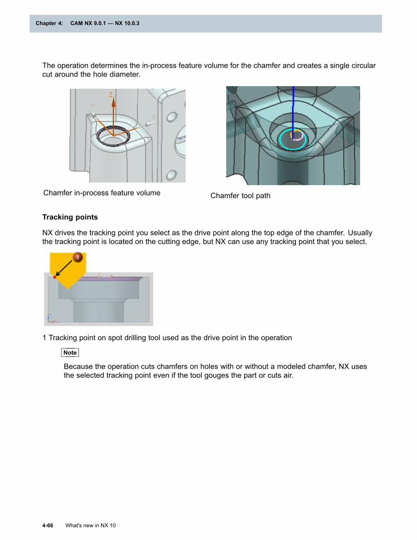
Chapter 4: CAM NX 9.0.1 — NX 10.0.3
The operation determines the in-process feature volume for the chamfer and creates a single circularcut around the hole diameter.
Chamfer in-process feature volume Chamfer tool path
Tracking points
NX drives the tracking point you select as the drive point along the top edge of the chamfer. Usuallythe tracking point is located on the cutting edge, but NX can use any tracking point that you select.
1 Tracking point on spot drilling tool used as the drive point in the operation
Note
Because the operation cuts chamfers on holes with or without a modeled chamfer, NX usesthe selected tracking point even if the tool gouges the part or cuts air.
4-66 What's new in NX 10
Chapter 4: CAM NX 9.0.1 — NX 10.0.3
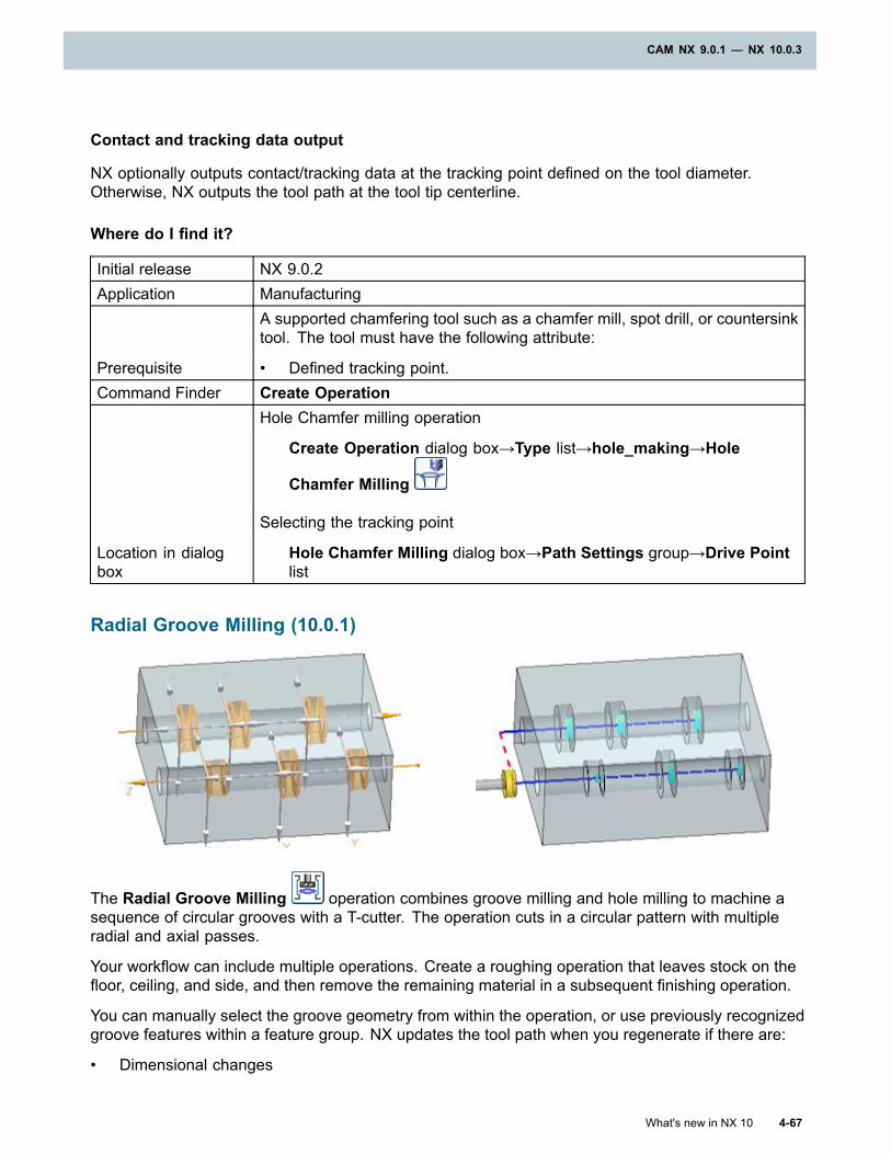
CAM NX 9.0.1 — NX 10.0.3
Contact and tracking data output
NX optionally outputs contact/tracking data at the tracking point defined on the tool diameter.Otherwise, NX outputs the tool path at the tool tip centerline.
Where do I find it?
Initial release NX 9.0.2Application Manufacturing
Prerequisite
A supported chamfering tool such as a chamfer mill, spot drill, or countersinktool. The tool must have the following attribute:
• Defined tracking point.Command Finder Create Operation
Location in dialogbox
Hole Chamfer milling operation
Create Operation dialog box→Type list→hole_making→Hole
Chamfer Milling
Selecting the tracking point
Hole Chamfer Milling dialog box→Path Settings group→Drive Pointlist
Radial Groove Milling (10.0.1)
The Radial Groove Milling operation combines groove milling and hole milling to machine asequence of circular grooves with a T-cutter. The operation cuts in a circular pattern with multipleradial and axial passes.
Your workflow can include multiple operations. Create a roughing operation that leaves stock on thefloor, ceiling, and side, and then remove the remaining material in a subsequent finishing operation.
You can manually select the groove geometry from within the operation, or use previously recognizedgroove features within a feature group. NX updates the tool path when you regenerate if there are:
• Dimensional changes
What's new in NX 10 4-67
CAM NX 9.0.1 — NX 10.0.3
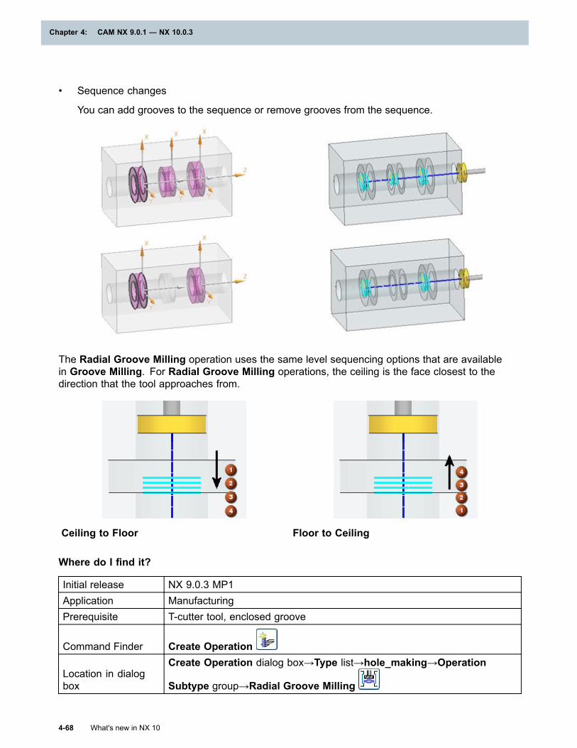
Chapter 4: CAM NX 9.0.1 — NX 10.0.3
• Sequence changes
You can add grooves to the sequence or remove grooves from the sequence.
The Radial Groove Milling operation uses the same level sequencing options that are availablein Groove Milling. For Radial Groove Milling operations, the ceiling is the face closest to thedirection that the tool approaches from.
Ceiling to Floor Floor to Ceiling
Where do I find it?
Initial release NX 9.0.3 MP1Application ManufacturingPrerequisite T-cutter tool, enclosed groove
Command Finder Create Operation
Location in dialogbox
Create Operation dialog box→Type list→hole_making→Operation
Subtype group→Radial Groove Milling
4-68 What's new in NX 10
Chapter 4: CAM NX 9.0.1 — NX 10.0.3
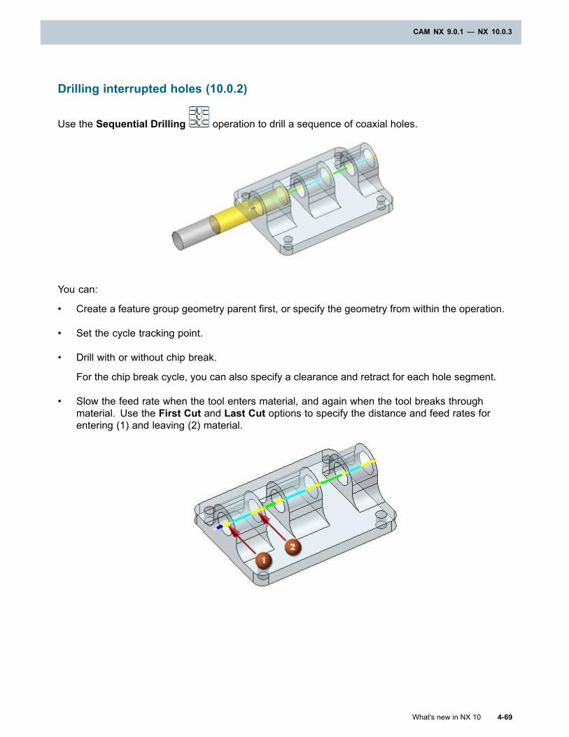
CAM NX 9.0.1 — NX 10.0.3
Drilling interrupted holes (10.0.2)
Use the Sequential Drilling operation to drill a sequence of coaxial holes.
You can:
• Create a feature group geometry parent first, or specify the geometry from within the operation.
• Set the cycle tracking point.
• Drill with or without chip break.
For the chip break cycle, you can also specify a clearance and retract for each hole segment.
• Slow the feed rate when the tool enters material, and again when the tool breaks throughmaterial. Use the First Cut and Last Cut options to specify the distance and feed rates forentering (1) and leaving (2) material.
What's new in NX 10 4-69
CAM NX 9.0.1 — NX 10.0.3
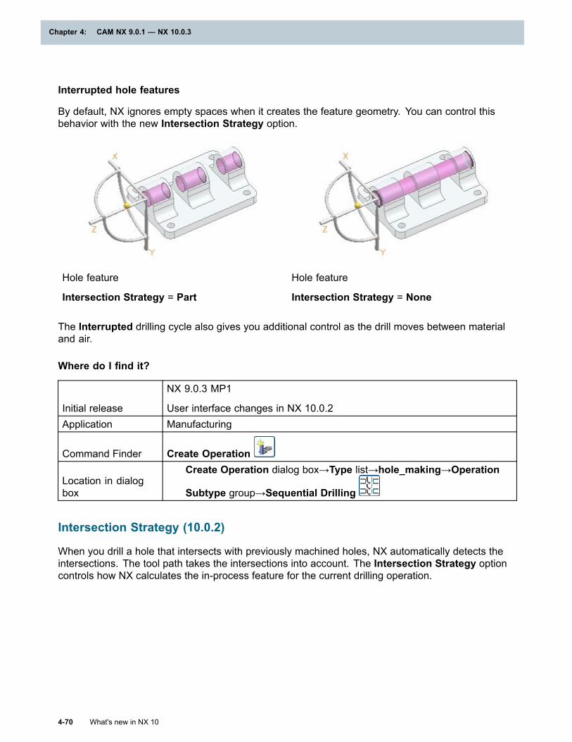
Chapter 4: CAM NX 9.0.1 — NX 10.0.3
Interrupted hole features
By default, NX ignores empty spaces when it creates the feature geometry. You can control thisbehavior with the new Intersection Strategy option.
Hole feature
Intersection Strategy = Part
Hole feature
Intersection Strategy = None
The Interrupted drilling cycle also gives you additional control as the drill moves between materialand air.
Where do I find it?
Initial release
NX 9.0.3 MP1
User interface changes in NX 10.0.2Application Manufacturing
Command Finder Create Operation
Location in dialogbox
Create Operation dialog box→Type list→hole_making→Operation
Subtype group→Sequential Drilling
Intersection Strategy (10.0.2)
When you drill a hole that intersects with previously machined holes, NX automatically detects theintersections. The tool path takes the intersections into account. The Intersection Strategy optioncontrols how NX calculates the in-process feature for the current drilling operation.
4-70 What's new in NX 10
Chapter 4: CAM NX 9.0.1 — NX 10.0.3
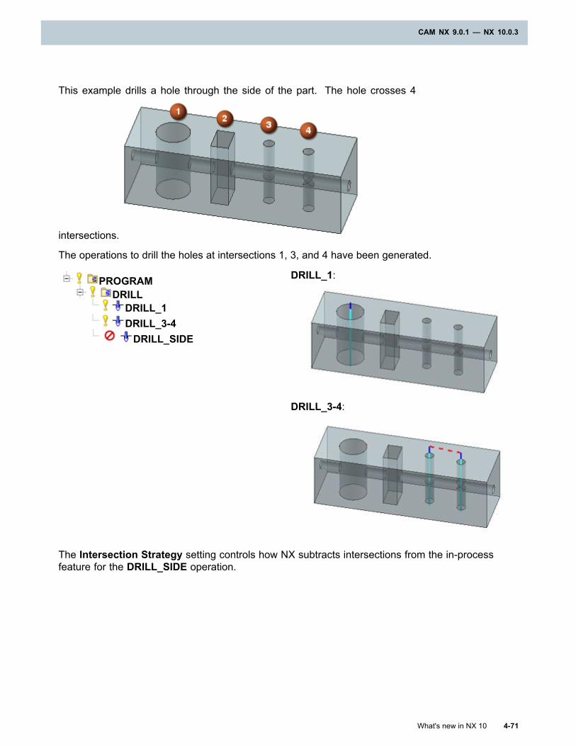
CAM NX 9.0.1 — NX 10.0.3
This example drills a hole through the side of the part. The hole crosses 4
intersections.
The operations to drill the holes at intersections 1, 3, and 4 have been generated.
DRILL_1:PROGRAMDRILL
DRILL_1DRILL_3-4DRILL_SIDE
DRILL_3-4:
The Intersection Strategy setting controls how NX subtracts intersections from the in-processfeature for the DRILL_SIDE operation.
What's new in NX 10 4-71
CAM NX 9.0.1 — NX 10.0.3
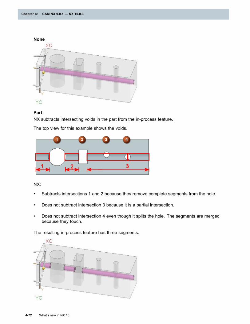
Chapter 4: CAM NX 9.0.1 — NX 10.0.3
None
PartNX subtracts intersecting voids in the part from the in-process feature.
The top view for this example shows the voids.
NX:
• Subtracts intersections 1 and 2 because they remove complete segments from the hole.
• Does not subtract intersection 3 because it is a partial intersection.
• Does not subtract intersection 4 even though it splits the hole. The segments are mergedbecause they touch.
The resulting in-process feature has three segments.
4-72 What's new in NX 10
Chapter 4: CAM NX 9.0.1 — NX 10.0.3
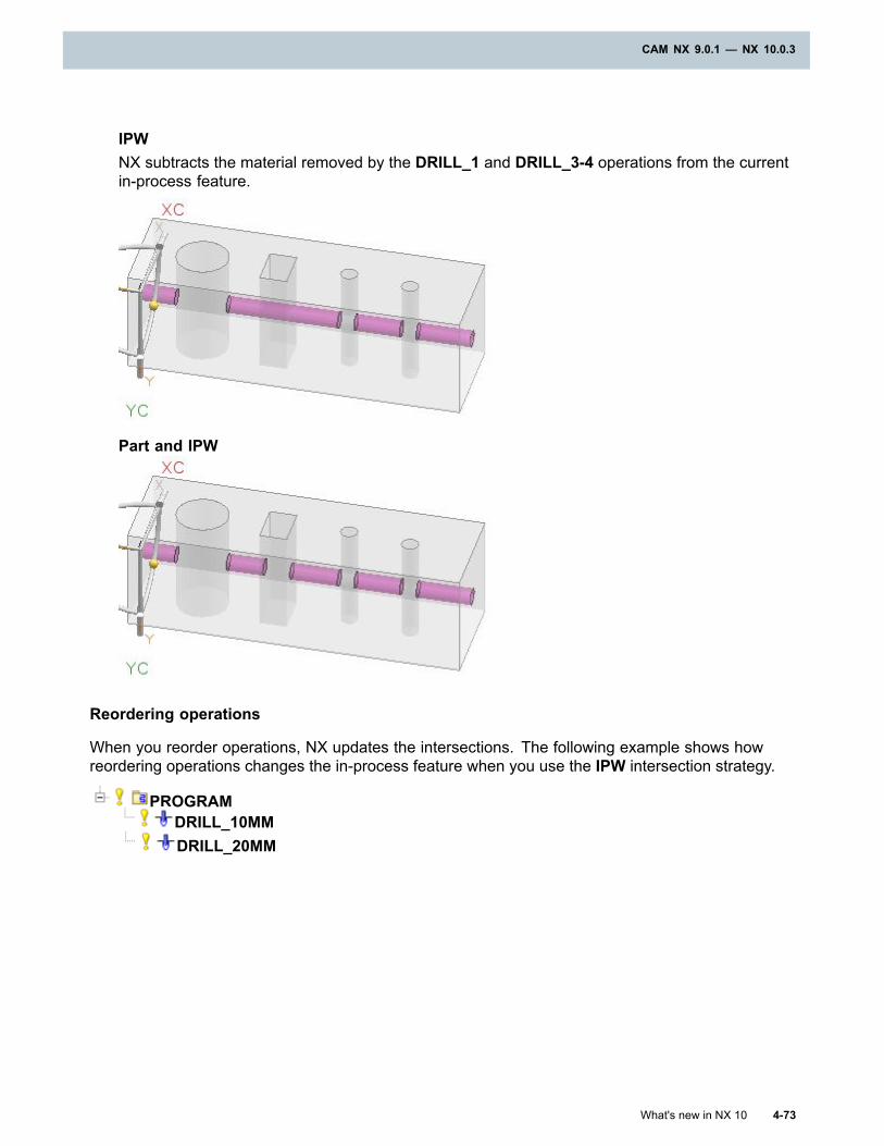
CAM NX 9.0.1 — NX 10.0.3
IPWNX subtracts the material removed by the DRILL_1 and DRILL_3-4 operations from the currentin-process feature.
Part and IPW
Reordering operations
When you reorder operations, NX updates the intersections. The following example shows howreordering operations changes the in-process feature when you use the IPW intersection strategy.
PROGRAMDRILL_10MMDRILL_20MM
What's new in NX 10 4-73
CAM NX 9.0.1 — NX 10.0.3
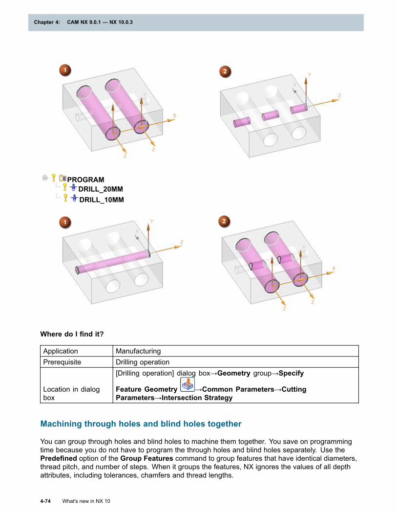
Chapter 4: CAM NX 9.0.1 — NX 10.0.3
PROGRAMDRILL_20MMDRILL_10MM
Where do I find it?
Application ManufacturingPrerequisite Drilling operation
Location in dialogbox
[Drilling operation] dialog box→Geometry group→Specify
Feature Geometry →Common Parameters→CuttingParameters→Intersection Strategy
Machining through holes and blind holes together
You can group through holes and blind holes to machine them together. You save on programmingtime because you do not have to program the through holes and blind holes separately. Use thePredefined option of the Group Features command to group features that have identical diameters,thread pitch, and number of steps. When it groups the features, NX ignores the values of all depthattributes, including tolerances, chamfers and thread lengths.
4-74 What's new in NX 10
Chapter 4: CAM NX 9.0.1 — NX 10.0.3
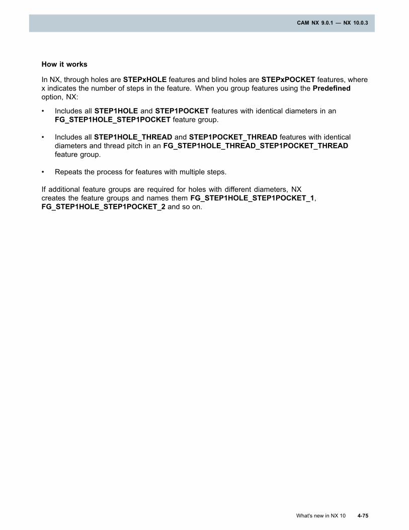
CAM NX 9.0.1 — NX 10.0.3
How it works
In NX, through holes are STEPxHOLE features and blind holes are STEPxPOCKET features, wherex indicates the number of steps in the feature. When you group features using the Predefinedoption, NX:
• Includes all STEP1HOLE and STEP1POCKET features with identical diameters in anFG_STEP1HOLE_STEP1POCKET feature group.
• Includes all STEP1HOLE_THREAD and STEP1POCKET_THREAD features with identicaldiameters and thread pitch in an FG_STEP1HOLE_THREAD_STEP1POCKET_THREADfeature group.
• Repeats the process for features with multiple steps.
If additional feature groups are required for holes with different diameters, NXcreates the feature groups and names them FG_STEP1HOLE_STEP1POCKET_1,FG_STEP1HOLE_STEP1POCKET_2 and so on.
What's new in NX 10 4-75
CAM NX 9.0.1 — NX 10.0.3
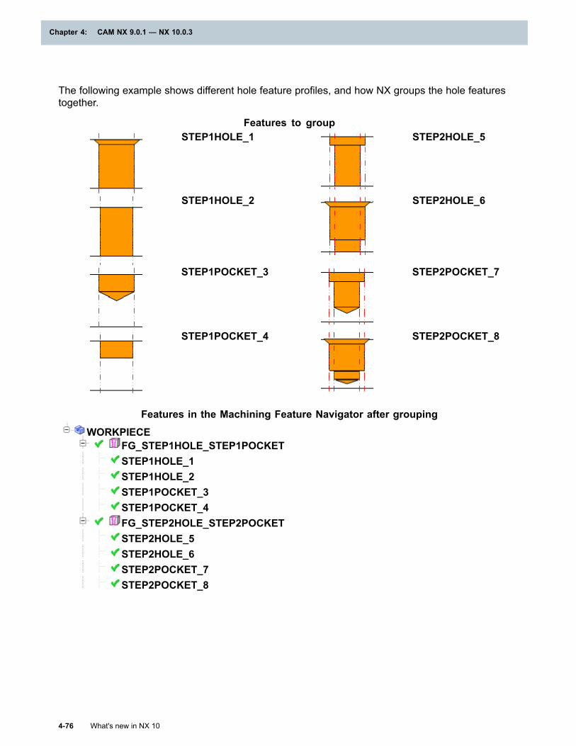
Chapter 4: CAM NX 9.0.1 — NX 10.0.3
The following example shows different hole feature profiles, and how NX groups the hole featurestogether.
Features to groupSTEP1HOLE_1 STEP2HOLE_5
STEP1HOLE_2 STEP2HOLE_6
STEP1POCKET_3 STEP2POCKET_7
STEP1POCKET_4 STEP2POCKET_8
Features in the Machining Feature Navigator after groupingWORKPIECE
FG_STEP1HOLE_STEP1POCKETSTEP1HOLE_1STEP1HOLE_2STEP1POCKET_3STEP1POCKET_4FG_STEP2HOLE_STEP2POCKETSTEP2HOLE_5STEP2HOLE_6STEP2POCKET_7STEP2POCKET_8
4-76 What's new in NX 10
Chapter 4: CAM NX 9.0.1 — NX 10.0.3

CAM NX 9.0.1 — NX 10.0.3
Sample part
Features selected for FG_STEP1HOLE_STEP1POCKET
Drilling operation for FG_STEP1HOLE_STEP1POCKET
The Group Features command also has the following options:
• None groups features whether or not the attributes are identical.
• All groups features only if all of the attributes are identical.
Where do I find it?
Initial release NX 9.0.2Application Manufacturing
Machining FeatureNavigator
Right-click in the background→Group Features
Grouping selected features
Right-click selected features→Group FeaturesLocation in dialogbox Group by group→Identical Attributes list →Predefined
What's new in NX 10 4-77
CAM NX 9.0.1 — NX 10.0.3
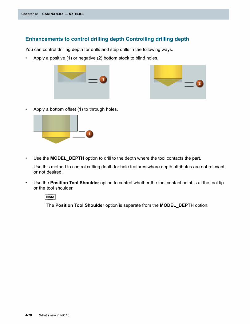
Chapter 4: CAM NX 9.0.1 — NX 10.0.3
Enhancements to control drilling depth Controlling drilling depth
You can control drilling depth for drills and step drills in the following ways.
• Apply a positive (1) or negative (2) bottom stock to blind holes.
• Apply a bottom offset (1) to through holes.
• Use the MODEL_DEPTH option to drill to the depth where the tool contacts the part.
Use this method to control cutting depth for hole features where depth attributes are not relevantor not desired.
• Use the Position Tool Shoulder option to control whether the tool contact point is at the tool tipor the tool shoulder.
Note
The Position Tool Shoulder option is separate from the MODEL_DEPTH option.
4-78 What's new in NX 10
Chapter 4: CAM NX 9.0.1 — NX 10.0.3
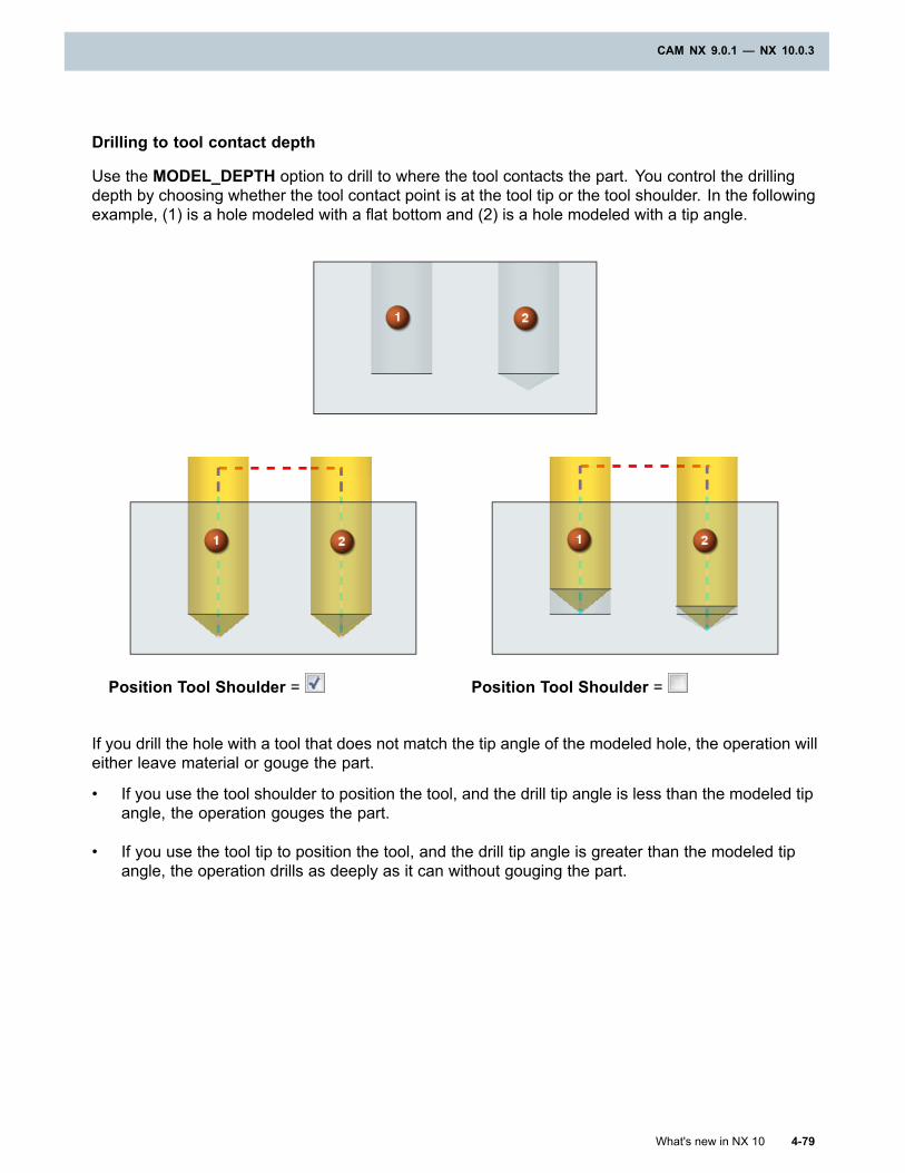
CAM NX 9.0.1 — NX 10.0.3
Drilling to tool contact depth
Use the MODEL_DEPTH option to drill to where the tool contacts the part. You control the drillingdepth by choosing whether the tool contact point is at the tool tip or the tool shoulder. In the followingexample, (1) is a hole modeled with a flat bottom and (2) is a hole modeled with a tip angle.
Position Tool Shoulder = Position Tool Shoulder =
If you drill the hole with a tool that does not match the tip angle of the modeled hole, the operation willeither leave material or gouge the part.
• If you use the tool shoulder to position the tool, and the drill tip angle is less than the modeled tipangle, the operation gouges the part.
• If you use the tool tip to position the tool, and the drill tip angle is greater than the modeled tipangle, the operation drills as deeply as it can without gouging the part.
What's new in NX 10 4-79
CAM NX 9.0.1 — NX 10.0.3
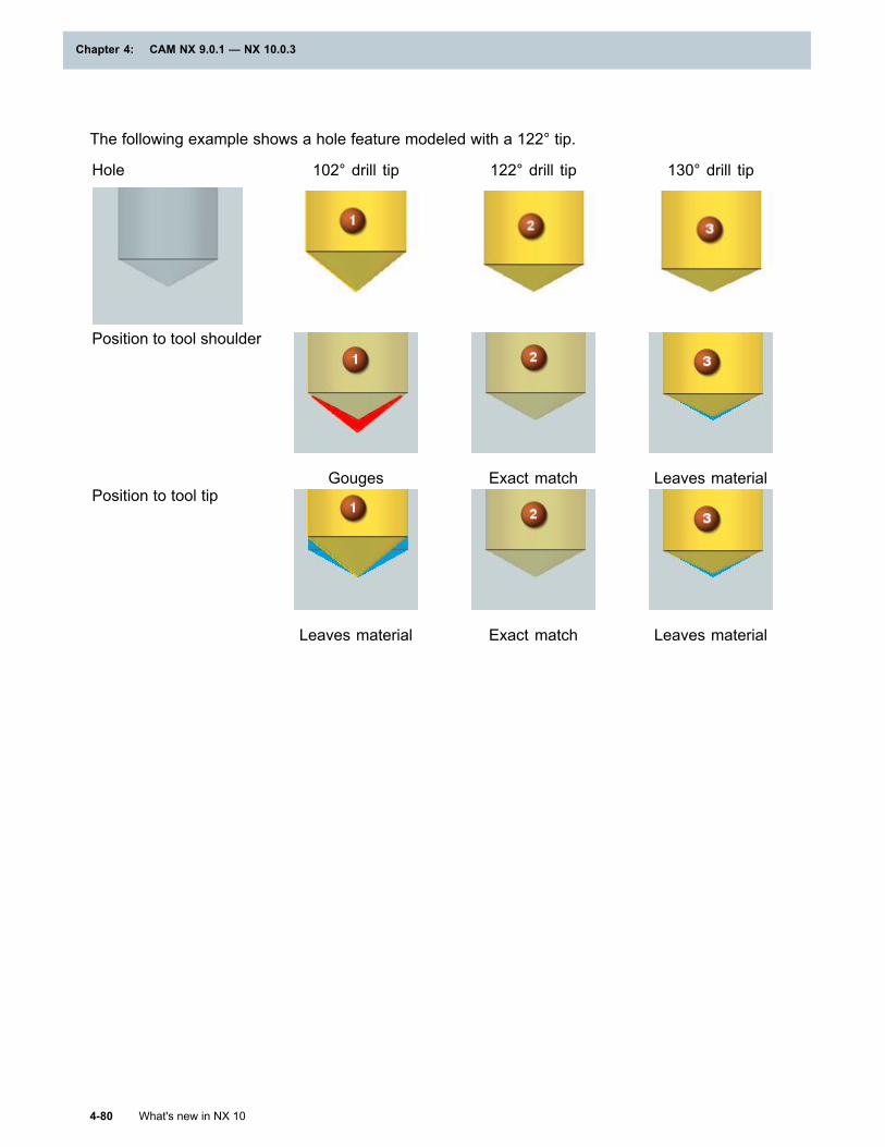
Chapter 4: CAM NX 9.0.1 — NX 10.0.3
The following example shows a hole feature modeled with a 122° tip.
Hole 102° drill tip 122° drill tip 130° drill tip
Position to tool shoulder
Gouges Exact match Leaves materialPosition to tool tip
Leaves material Exact match Leaves material
4-80 What's new in NX 10
Chapter 4: CAM NX 9.0.1 — NX 10.0.3
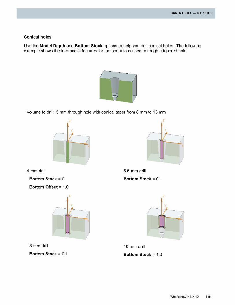
CAM NX 9.0.1 — NX 10.0.3
Conical holes
Use the Model Depth and Bottom Stock options to help you drill conical holes. The followingexample shows the in-process features for the operations used to rough a tapered hole.
Volume to drill: 5 mm through hole with conical taper from 8 mm to 13 mm
4 mm drill
Bottom Stock = 0
Bottom Offset = 1.0
5.5 mm drill
Bottom Stock = 0.1
8 mm drill
Bottom Stock = 0.1
10 mm drill
Bottom Stock = 1.0
What's new in NX 10 4-81
CAM NX 9.0.1 — NX 10.0.3
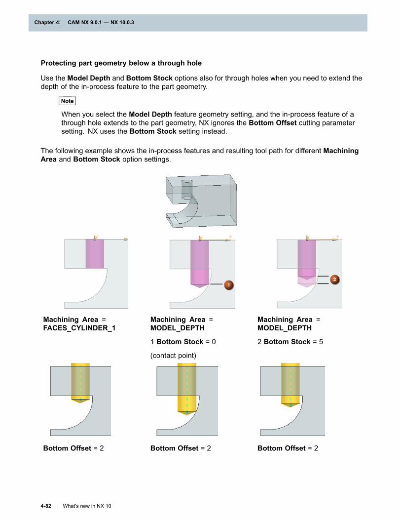
Chapter 4: CAM NX 9.0.1 — NX 10.0.3
Protecting part geometry below a through hole
Use the Model Depth and Bottom Stock options also for through holes when you need to extend thedepth of the in-process feature to the part geometry.
Note
When you select the Model Depth feature geometry setting, and the in-process feature of athrough hole extends to the part geometry, NX ignores the Bottom Offset cutting parametersetting. NX uses the Bottom Stock setting instead.
The following example shows the in-process features and resulting tool path for different MachiningArea and Bottom Stock option settings.
Machining Area =FACES_CYLINDER_1
Machining Area =MODEL_DEPTH
1 Bottom Stock = 0
(contact point)
Machining Area =MODEL_DEPTH
2 Bottom Stock = 5
Bottom Offset = 2 Bottom Offset = 2 Bottom Offset = 2
4-82 What's new in NX 10
Chapter 4: CAM NX 9.0.1 — NX 10.0.3
CAM NX 9.0.1 — NX 10.0.3
Where do I find it?
Initial release NX 9.0.2Application ManufacturingLocation in dialogbox
Drilling to model depth
Feature Geometry dialog box→Common Parametersgroup→Machining Area list →MODEL_DEPTH
Positioning to the tool shoulder or tool tip
Feature Geometry dialog box→Common Parameters group→CuttingParameters subgroup→Position Tool Shoulder
Adding bottom stock to blind holes
Feature Geometry dialog box→Common Parameters group→CuttingParameters subgroup→Bottom Stock
Adding bottom offset to through holes
[Drilling operation] dialog box→Cutting Parameters→CuttingParameters dialog box→Strategy tab→Extend Path group→BottomOffset
Enhancements to optimize drill sequencingOptimizing drill sequencing
You can optimize the drilling sequence in the following ways:
• Machine parts with holes arranged in a grid using a zig or zig-zag pattern to minimize tooltravel. Whenever possible, NX keeps the transition motions parallel to the axis or vector thatyou specify as the primary pattern direction.
• Reverse the order of the listed hole or boss locations.
• Select a hole feature and make it the start or end location of the cutting sequence.
To see the machining order without generating the operation, preview the hole sequence.
What's new in NX 10 4-83
CAM NX 9.0.1 — NX 10.0.3
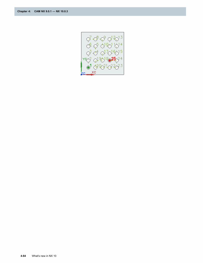
Chapter 4: CAM NX 9.0.1 — NX 10.0.3
4-84 What's new in NX 10
Chapter 4: CAM NX 9.0.1 — NX 10.0.3
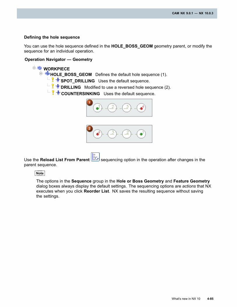
CAM NX 9.0.1 — NX 10.0.3
Defining the hole sequence
You can use the hole sequence defined in the HOLE_BOSS_GEOM geometry parent, or modify thesequence for an individual operation.
Operation Navigator — Geometry
WORKPIECEHOLE_BOSS_GEOM Defines the default hole sequence (1).
SPOT_DRILLING Uses the default sequence.DRILLING Modified to use a reversed hole sequence (2).COUNTERSINKING Uses the default sequence.
Use the Reload List From Parent sequencing option in the operation after changes in theparent sequence.
Note
The options in the Sequence group in the Hole or Boss Geometry and Feature Geometrydialog boxes always display the default settings. The sequencing options are actions that NXexecutes when you click Reorder List. NX saves the resulting sequence without savingthe settings.
What's new in NX 10 4-85
CAM NX 9.0.1 — NX 10.0.3
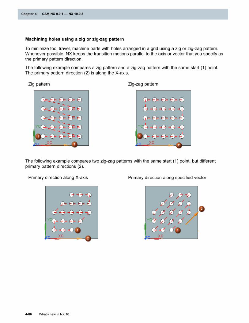
Chapter 4: CAM NX 9.0.1 — NX 10.0.3
Machining holes using a zig or zig-zag pattern
To minimize tool travel, machine parts with holes arranged in a grid using a zig or zig-zag pattern.Whenever possible, NX keeps the transition motions parallel to the axis or vector that you specify asthe primary pattern direction.
The following example compares a zig pattern and a zig-zag pattern with the same start (1) point.The primary pattern direction (2) is along the X-axis.
Zig pattern Zig-zag pattern
The following example compares two zig-zag patterns with the same start (1) point, but differentprimary pattern directions (2).
Primary direction along X-axis Primary direction along specified vector
4-86 What's new in NX 10
Chapter 4: CAM NX 9.0.1 — NX 10.0.3
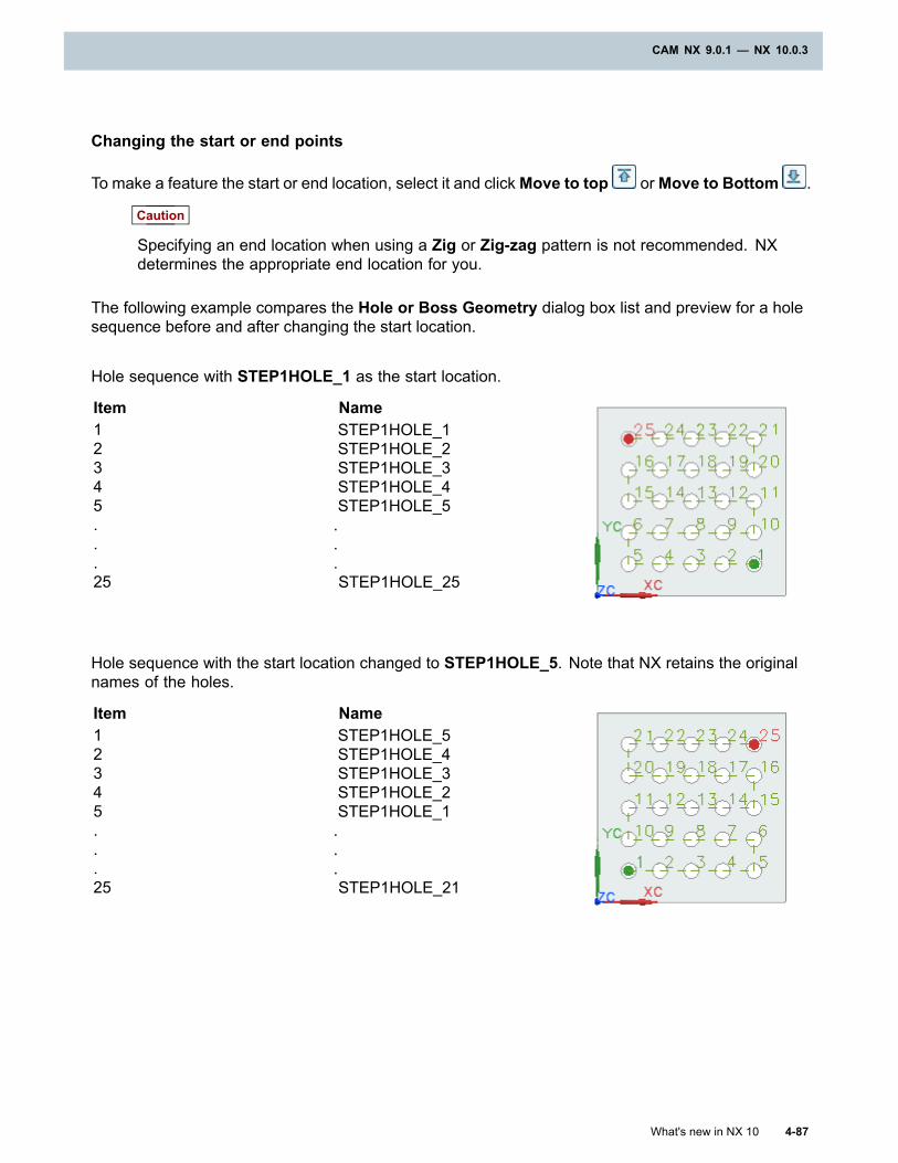
CAM NX 9.0.1 — NX 10.0.3
Changing the start or end points
To make a feature the start or end location, select it and clickMove to top orMove to Bottom .
Caution
Specifying an end location when using a Zig or Zig-zag pattern is not recommended. NXdetermines the appropriate end location for you.
The following example compares the Hole or Boss Geometry dialog box list and preview for a holesequence before and after changing the start location.
Hole sequence with STEP1HOLE_1 as the start location.
Item Name12345...25
STEP1HOLE_1STEP1HOLE_2STEP1HOLE_3STEP1HOLE_4STEP1HOLE_5...STEP1HOLE_25
Hole sequence with the start location changed to STEP1HOLE_5. Note that NX retains the originalnames of the holes.
Item Name12345...25
STEP1HOLE_5STEP1HOLE_4STEP1HOLE_3STEP1HOLE_2STEP1HOLE_1...STEP1HOLE_21
What's new in NX 10 4-87
CAM NX 9.0.1 — NX 10.0.3
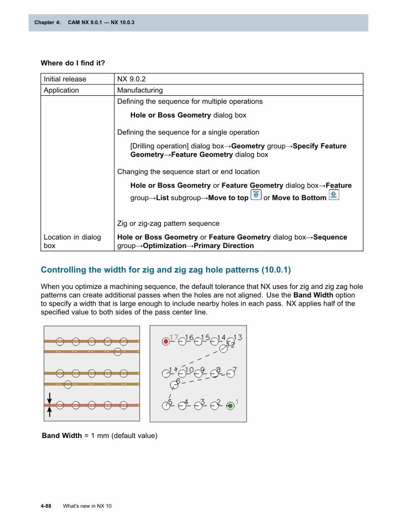
Chapter 4: CAM NX 9.0.1 — NX 10.0.3
Where do I find it?
Initial release NX 9.0.2Application Manufacturing
Location in dialogbox
Defining the sequence for multiple operations
Hole or Boss Geometry dialog box
Defining the sequence for a single operation
[Drilling operation] dialog box→Geometry group→Specify FeatureGeometry→Feature Geometry dialog box
Changing the sequence start or end location
Hole or Boss Geometry or Feature Geometry dialog box→Featuregroup→List subgroup→Move to top or Move to Bottom
Zig or zig-zag pattern sequence
Hole or Boss Geometry or Feature Geometry dialog box→Sequencegroup→Optimization→Primary Direction
Controlling the width for zig and zig zag hole patterns (10.0.1)
When you optimize a machining sequence, the default tolerance that NX uses for zig and zig zag holepatterns can create additional passes when the holes are not aligned. Use the Band Width optionto specify a width that is large enough to include nearby holes in each pass. NX applies half of thespecified value to both sides of the pass center line.
Band Width = 1 mm (default value)
4-88 What's new in NX 10
Chapter 4: CAM NX 9.0.1 — NX 10.0.3
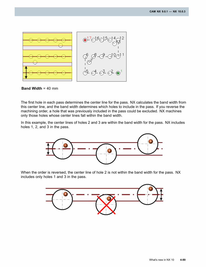
CAM NX 9.0.1 — NX 10.0.3
Band Width = 40 mm
The first hole in each pass determines the center line for the pass. NX calculates the band width fromthis center line, and the band width determines which holes to include in the pass. If you reverse themachining order, a hole that was previously included in the pass could be excluded. NX machinesonly those holes whose center lines fall within the band width.
In this example, the center lines of holes 2 and 3 are within the band width for the pass. NX includesholes 1, 2, and 3 in the pass.
When the order is reversed, the center line of hole 2 is not within the band width for the pass. NXincludes only holes 1 and 3 in the pass.
What's new in NX 10 4-89
CAM NX 9.0.1 — NX 10.0.3
Chapter 4: CAM NX 9.0.1 — NX 10.0.3
Note
You must enter the Band Width value each time you optimize the sequence.
The options in the Sequence group in the Hole or Boss Geometry and Feature Geometrydialog boxes always display the default settings. The sequencing options are actions that NXexecutes when you click Reorder List. NX saves the resulting sequence without savingthe settings.
4-90 What's new in NX 10
Chapter 4: CAM NX 9.0.1 — NX 10.0.3
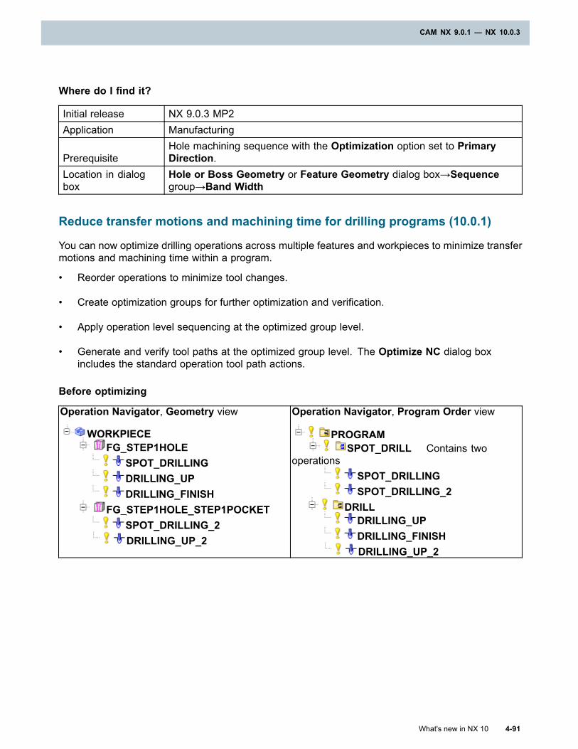
CAM NX 9.0.1 — NX 10.0.3
Where do I find it?
Initial release NX 9.0.3 MP2Application Manufacturing
PrerequisiteHole machining sequence with the Optimization option set to PrimaryDirection.
Location in dialogbox
Hole or Boss Geometry or Feature Geometry dialog box→Sequencegroup→Band Width
Reduce transfer motions and machining time for drilling programs (10.0.1)
You can now optimize drilling operations across multiple features and workpieces to minimize transfermotions and machining time within a program.
• Reorder operations to minimize tool changes.
• Create optimization groups for further optimization and verification.
• Apply operation level sequencing at the optimized group level.
• Generate and verify tool paths at the optimized group level. The Optimize NC dialog boxincludes the standard operation tool path actions.
Before optimizing
Operation Navigator, Geometry view
WORKPIECEFG_STEP1HOLE
SPOT_DRILLINGDRILLING_UPDRILLING_FINISH
FG_STEP1HOLE_STEP1POCKETSPOT_DRILLING_2DRILLING_UP_2
Operation Navigator, Program Order view
PROGRAMSPOT_DRILL Contains two
operationsSPOT_DRILLINGSPOT_DRILLING_2
DRILLDRILLING_UPDRILLING_FINISHDRILLING_UP_2
What's new in NX 10 4-91
CAM NX 9.0.1 — NX 10.0.3
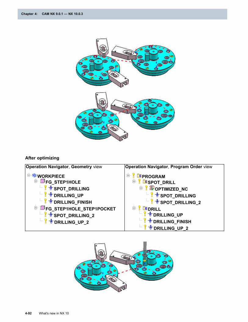
Chapter 4: CAM NX 9.0.1 — NX 10.0.3
After optimizing
Operation Navigator, Geometry view
WORKPIECEFG_STEP1HOLE
SPOT_DRILLINGDRILLING_UPDRILLING_FINISH
FG_STEP1HOLE_STEP1POCKETSPOT_DRILLING_2DRILLING_UP_2
Operation Navigator, Program Order view
PROGRAMSPOT_DRILL
OPTIMIZED_NCSPOT_DRILLINGSPOT_DRILLING_2
DRILLDRILLING_UPDRILLING_FINISHDRILLING_UP_2
4-92 What's new in NX 10
Chapter 4: CAM NX 9.0.1 — NX 10.0.3
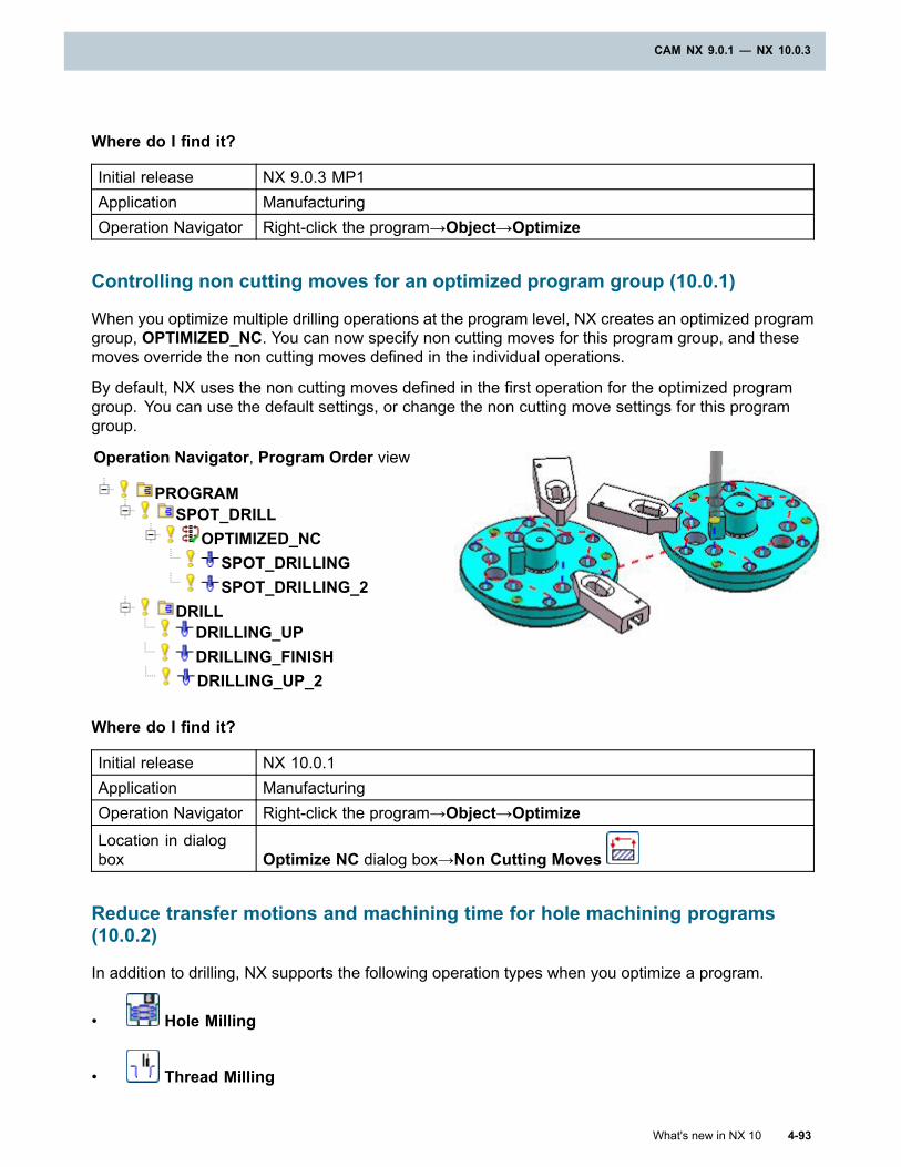
CAM NX 9.0.1 — NX 10.0.3
Where do I find it?
Initial release NX 9.0.3 MP1Application ManufacturingOperation Navigator Right-click the program→Object→Optimize
Controlling non cutting moves for an optimized program group (10.0.1)
When you optimize multiple drilling operations at the program level, NX creates an optimized programgroup, OPTIMIZED_NC. You can now specify non cutting moves for this program group, and thesemoves override the non cutting moves defined in the individual operations.
By default, NX uses the non cutting moves defined in the first operation for the optimized programgroup. You can use the default settings, or change the non cutting move settings for this programgroup.
Operation Navigator, Program Order view
PROGRAMSPOT_DRILL
OPTIMIZED_NCSPOT_DRILLINGSPOT_DRILLING_2
DRILLDRILLING_UPDRILLING_FINISHDRILLING_UP_2
Where do I find it?
Initial release NX 10.0.1Application ManufacturingOperation Navigator Right-click the program→Object→OptimizeLocation in dialogbox Optimize NC dialog box→Non Cutting Moves
Reduce transfer motions and machining time for hole machining programs(10.0.2)
In addition to drilling, NX supports the following operation types when you optimize a program.
• Hole Milling
• Thread Milling
What's new in NX 10 4-93
CAM NX 9.0.1 — NX 10.0.3
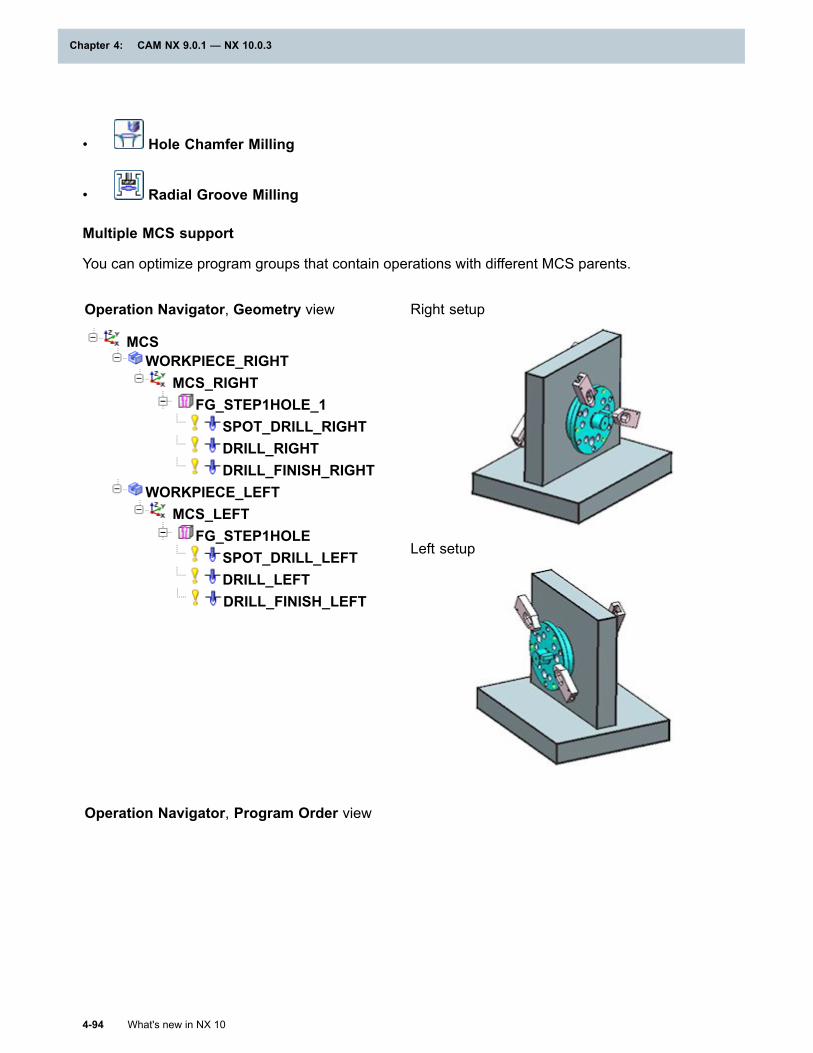
Chapter 4: CAM NX 9.0.1 — NX 10.0.3
• Hole Chamfer Milling
• Radial Groove Milling
Multiple MCS support
You can optimize program groups that contain operations with different MCS parents.
Operation Navigator, Geometry view
MCSWORKPIECE_RIGHT
MCS_RIGHTFG_STEP1HOLE_1
SPOT_DRILL_RIGHTDRILL_RIGHTDRILL_FINISH_RIGHT
WORKPIECE_LEFTMCS_LEFT
FG_STEP1HOLESPOT_DRILL_LEFTDRILL_LEFTDRILL_FINISH_LEFT
Right setup
Left setup
Operation Navigator, Program Order view
4-94 What's new in NX 10
Chapter 4: CAM NX 9.0.1 — NX 10.0.3
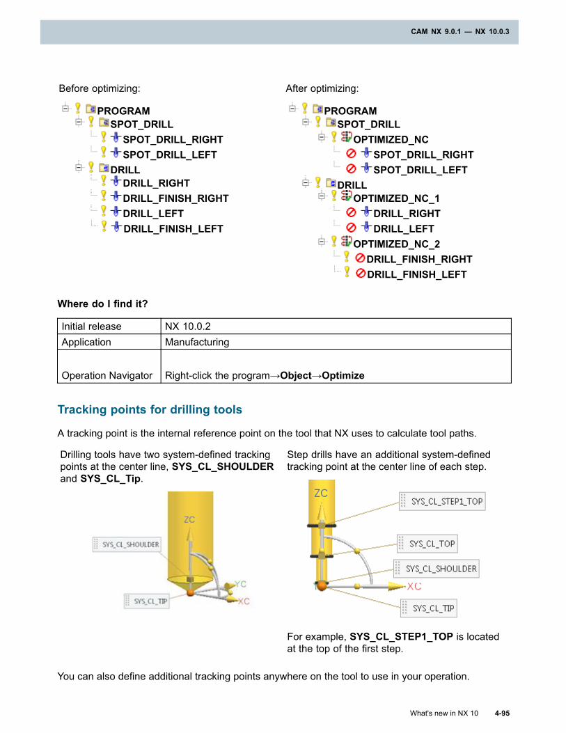
CAM NX 9.0.1 — NX 10.0.3
Before optimizing:
PROGRAMSPOT_DRILL
SPOT_DRILL_RIGHTSPOT_DRILL_LEFT
DRILLDRILL_RIGHTDRILL_FINISH_RIGHTDRILL_LEFTDRILL_FINISH_LEFT
After optimizing:
PROGRAMSPOT_DRILL
OPTIMIZED_NCSPOT_DRILL_RIGHTSPOT_DRILL_LEFT
DRILLOPTIMIZED_NC_1
DRILL_RIGHTDRILL_LEFT
OPTIMIZED_NC_2DRILL_FINISH_RIGHTDRILL_FINISH_LEFT
Where do I find it?
Initial release NX 10.0.2Application Manufacturing
Operation Navigator Right-click the program→Object→Optimize
Tracking points for drilling tools
A tracking point is the internal reference point on the tool that NX uses to calculate tool paths.
Drilling tools have two system-defined trackingpoints at the center line, SYS_CL_SHOULDERand SYS_CL_Tip.
Step drills have an additional system-definedtracking point at the center line of each step.
For example, SYS_CL_STEP1_TOP is locatedat the top of the first step.
You can also define additional tracking points anywhere on the tool to use in your operation.
What's new in NX 10 4-95
CAM NX 9.0.1 — NX 10.0.3
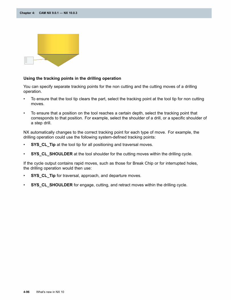
Chapter 4: CAM NX 9.0.1 — NX 10.0.3
Using the tracking points in the drilling operation
You can specify separate tracking points for the non cutting and the cutting moves of a drillingoperation.
• To ensure that the tool tip clears the part, select the tracking point at the tool tip for non cuttingmoves.
• To ensure that a position on the tool reaches a certain depth, select the tracking point thatcorresponds to that position. For example, select the shoulder of a drill, or a specific shoulder ofa step drill.
NX automatically changes to the correct tracking point for each type of move. For example, thedrilling operation could use the following system-defined tracking points:
• SYS_CL_Tip at the tool tip for all positioning and traversal moves.
• SYS_CL_SHOULDER at the tool shoulder for the cutting moves within the drilling cycle.
If the cycle output contains rapid moves, such as those for Break Chip or for interrupted holes,the drilling operation would then use:
• SYS_CL_Tip for traversal, approach, and departure moves.
• SYS_CL_SHOULDER for engage, cutting, and retract moves within the drilling cycle.
4-96 What's new in NX 10
Chapter 4: CAM NX 9.0.1 — NX 10.0.3
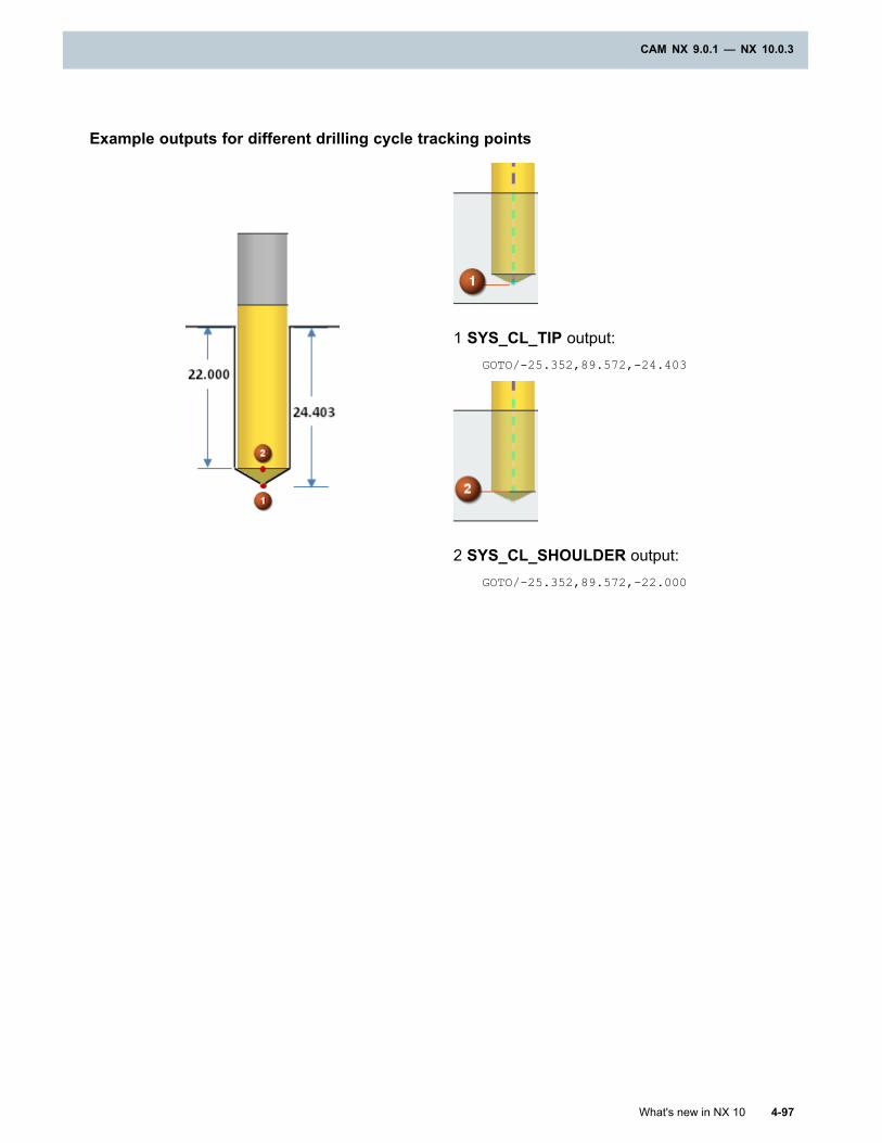
CAM NX 9.0.1 — NX 10.0.3
Example outputs for different drilling cycle tracking points
1 SYS_CL_TIP output:GOTO/-25.352,89.572,-24.403
2 SYS_CL_SHOULDER output:GOTO/-25.352,89.572,-22.000
What's new in NX 10 4-97
CAM NX 9.0.1 — NX 10.0.3
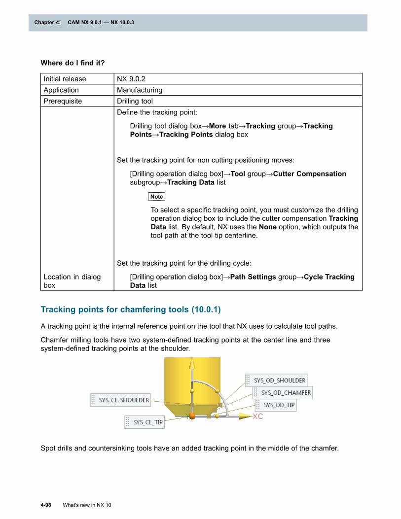
Chapter 4: CAM NX 9.0.1 — NX 10.0.3
Where do I find it?
Initial release NX 9.0.2Application ManufacturingPrerequisite Drilling tool
Location in dialogbox
Define the tracking point:
Drilling tool dialog box→More tab→Tracking group→TrackingPoints→Tracking Points dialog box
Set the tracking point for non cutting positioning moves:
[Drilling operation dialog box]→Tool group→Cutter Compensationsubgroup→Tracking Data list
Note
To select a specific tracking point, you must customize the drillingoperation dialog box to include the cutter compensation TrackingData list. By default, NX uses the None option, which outputs thetool path at the tool tip centerline.
Set the tracking point for the drilling cycle:
[Drilling operation dialog box]→Path Settings group→Cycle TrackingData list
Tracking points for chamfering tools (10.0.1)
A tracking point is the internal reference point on the tool that NX uses to calculate tool paths.
Chamfer milling tools have two system-defined tracking points at the center line and threesystem-defined tracking points at the shoulder.
Spot drills and countersinking tools have an added tracking point in the middle of the chamfer.
4-98 What's new in NX 10
Chapter 4: CAM NX 9.0.1 — NX 10.0.3
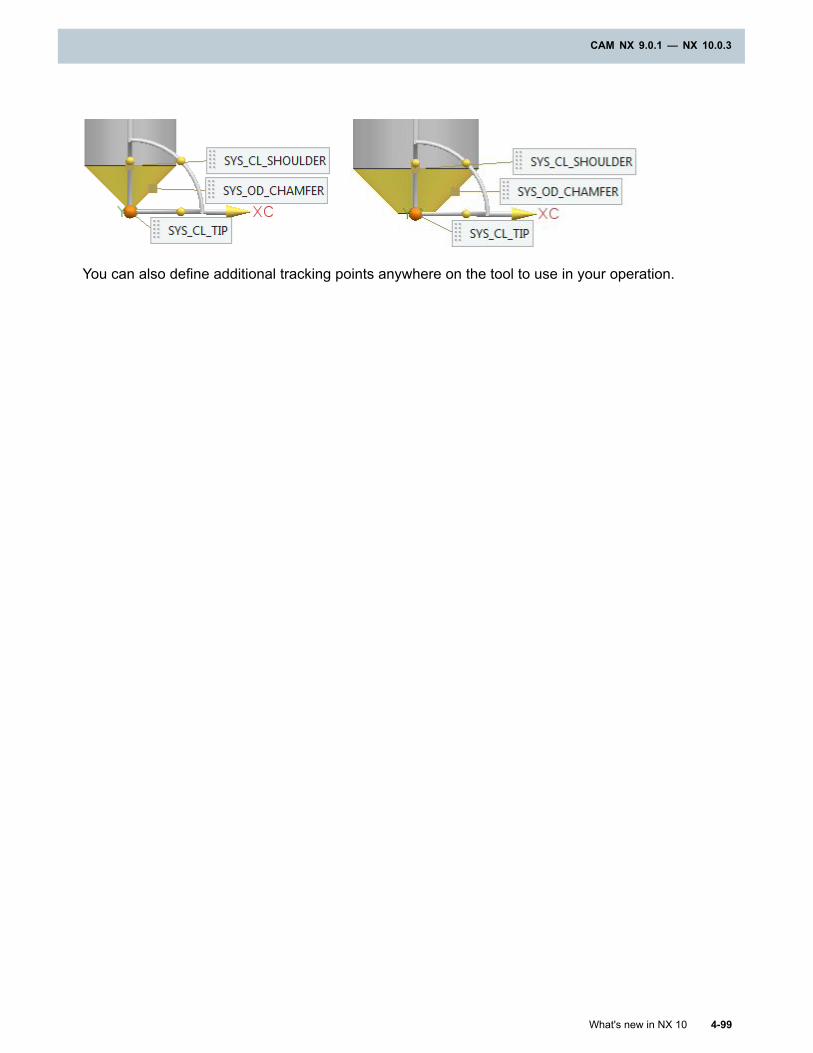
CAM NX 9.0.1 — NX 10.0.3
You can also define additional tracking points anywhere on the tool to use in your operation.
What's new in NX 10 4-99
CAM NX 9.0.1 — NX 10.0.3
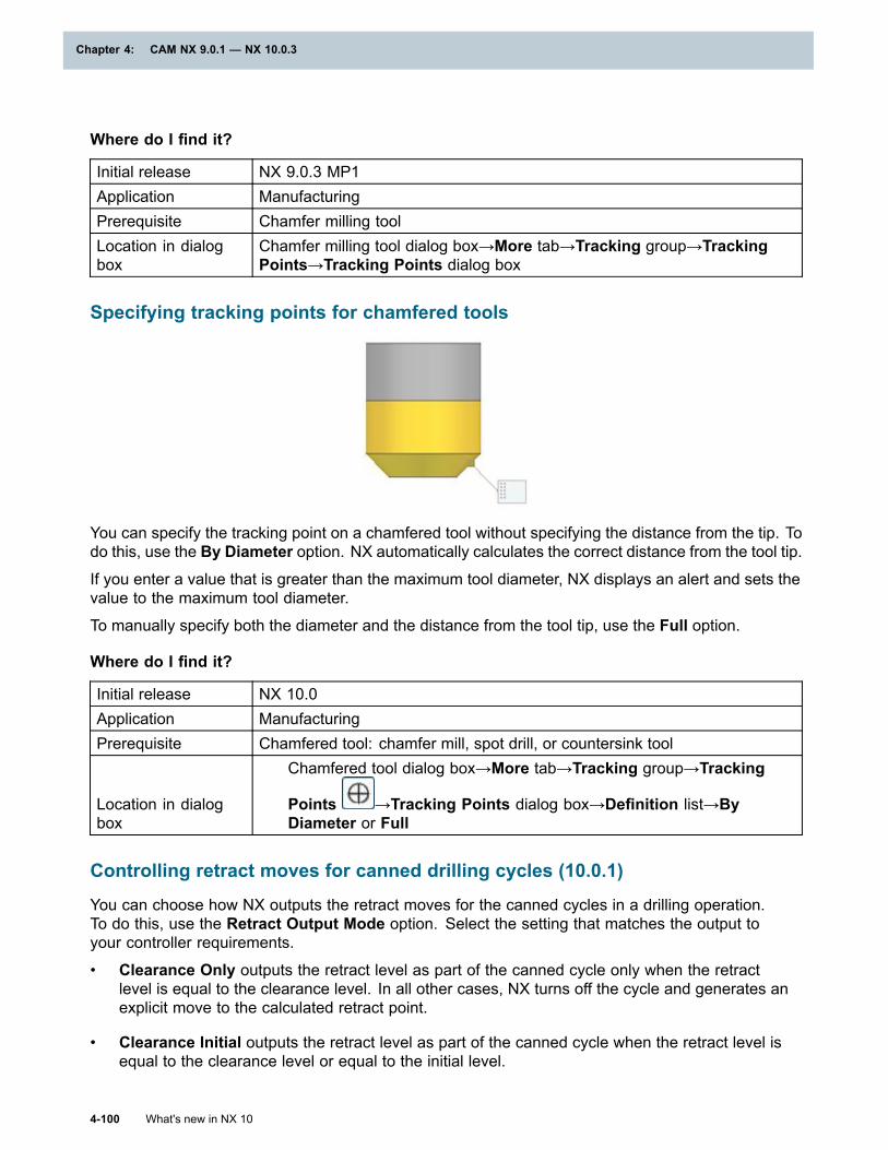
Chapter 4: CAM NX 9.0.1 — NX 10.0.3
Where do I find it?
Initial release NX 9.0.3 MP1Application ManufacturingPrerequisite Chamfer milling toolLocation in dialogbox
Chamfer milling tool dialog box→More tab→Tracking group→TrackingPoints→Tracking Points dialog box
Specifying tracking points for chamfered tools
You can specify the tracking point on a chamfered tool without specifying the distance from the tip. Todo this, use the By Diameter option. NX automatically calculates the correct distance from the tool tip.
If you enter a value that is greater than the maximum tool diameter, NX displays an alert and sets thevalue to the maximum tool diameter.
To manually specify both the diameter and the distance from the tool tip, use the Full option.
Where do I find it?
Initial release NX 10.0Application ManufacturingPrerequisite Chamfered tool: chamfer mill, spot drill, or countersink tool
Location in dialogbox
Chamfered tool dialog box→More tab→Tracking group→Tracking
Points →Tracking Points dialog box→Definition list→ByDiameter or Full
Controlling retract moves for canned drilling cycles (10.0.1)
You can choose how NX outputs the retract moves for the canned cycles in a drilling operation.To do this, use the Retract Output Mode option. Select the setting that matches the output toyour controller requirements.
• Clearance Only outputs the retract level as part of the canned cycle only when the retractlevel is equal to the clearance level. In all other cases, NX turns off the cycle and generates anexplicit move to the calculated retract point.
• Clearance Initial outputs the retract level as part of the canned cycle when the retract level isequal to the clearance level or equal to the initial level.
4-100 What's new in NX 10
Chapter 4: CAM NX 9.0.1 — NX 10.0.3
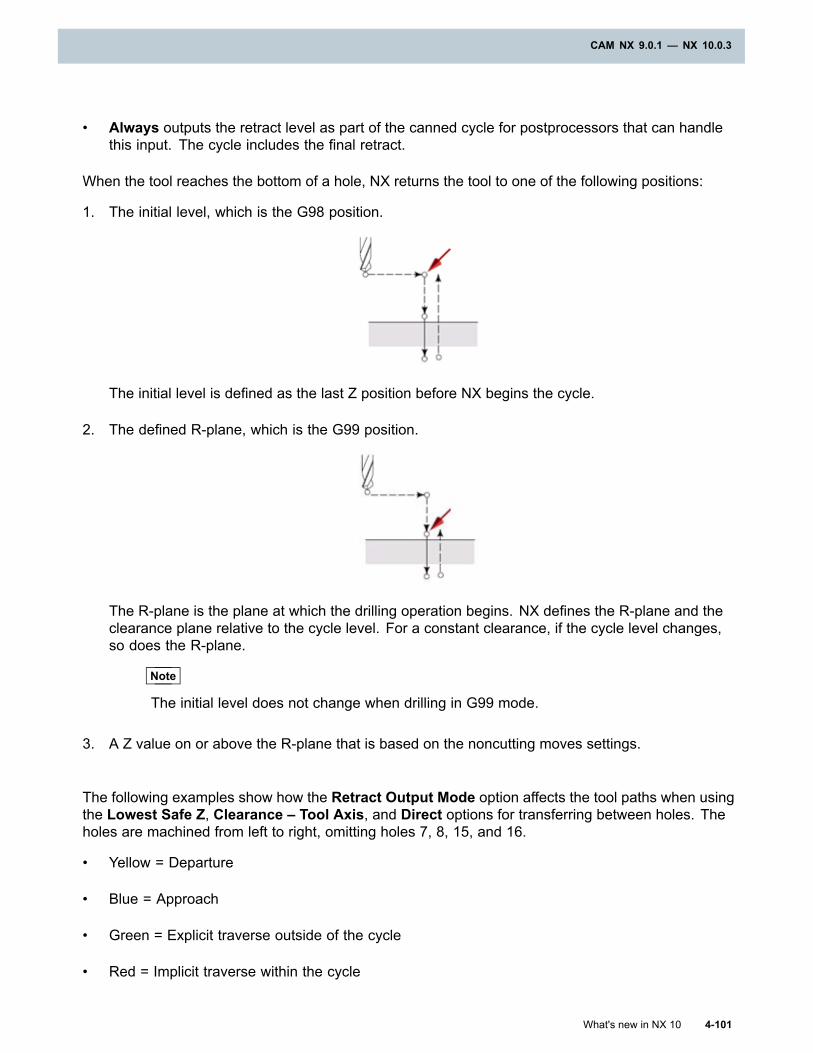
CAM NX 9.0.1 — NX 10.0.3
• Always outputs the retract level as part of the canned cycle for postprocessors that can handlethis input. The cycle includes the final retract.
When the tool reaches the bottom of a hole, NX returns the tool to one of the following positions:
1. The initial level, which is the G98 position.
The initial level is defined as the last Z position before NX begins the cycle.
2. The defined R-plane, which is the G99 position.
The R-plane is the plane at which the drilling operation begins. NX defines the R-plane and theclearance plane relative to the cycle level. For a constant clearance, if the cycle level changes,so does the R-plane.
Note
The initial level does not change when drilling in G99 mode.
3. A Z value on or above the R-plane that is based on the noncutting moves settings.
The following examples show how the Retract Output Mode option affects the tool paths when usingthe Lowest Safe Z, Clearance – Tool Axis, and Direct options for transferring between holes. Theholes are machined from left to right, omitting holes 7, 8, 15, and 16.
• Yellow = Departure
• Blue = Approach
• Green = Explicit traverse outside of the cycle
• Red = Implicit traverse within the cycle
What's new in NX 10 4-101
CAM NX 9.0.1 — NX 10.0.3
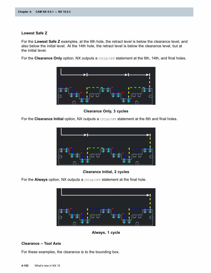
Chapter 4: CAM NX 9.0.1 — NX 10.0.3
Lowest Safe Z
For the Lowest Safe Z examples, at the 6th hole, the retract level is below the clearance level, andalso below the initial level. At the 14th hole, the retract level is below the clearance level, but atthe initial level.
For the Clearance Only option, NX outputs a CYCLE/OFF statement at the 6th, 14th, and final holes.
Clearance Only, 3 cycles
For the Clearance Initial option, NX outputs a CYCLE/OFF statement at the 6th and final holes.
Clearance Initial, 2 cycles
For the Always option, NX outputs a CYCLE/OFF statement at the final hole.
Always, 1 cycle
Clearance – Tool Axis
For these examples, the clearance is to the bounding box.
4-102 What's new in NX 10
Chapter 4: CAM NX 9.0.1 — NX 10.0.3
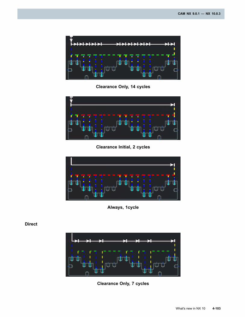
CAM NX 9.0.1 — NX 10.0.3
Clearance Only, 14 cycles
Clearance Initial, 2 cycles
Always, 1cycle
Direct
Clearance Only, 7 cycles
What's new in NX 10 4-103
CAM NX 9.0.1 — NX 10.0.3
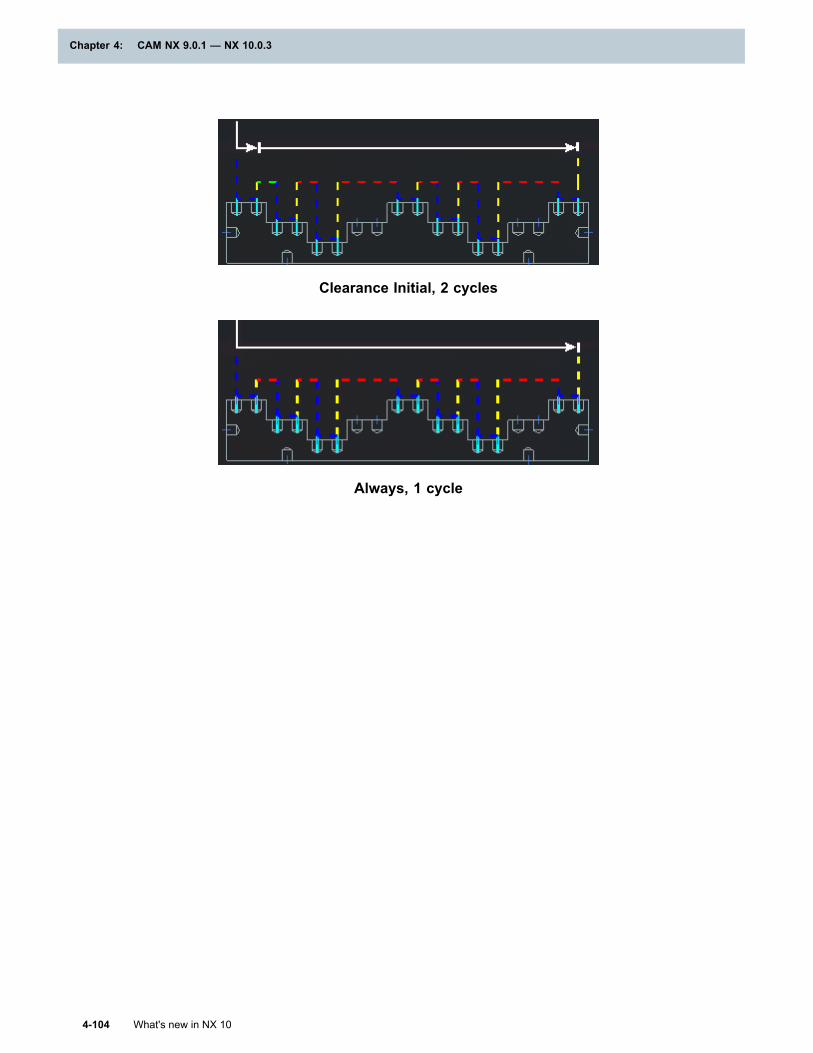
Chapter 4: CAM NX 9.0.1 — NX 10.0.3
Clearance Initial, 2 cycles
Always, 1 cycle
4-104 What's new in NX 10
Chapter 4: CAM NX 9.0.1 — NX 10.0.3
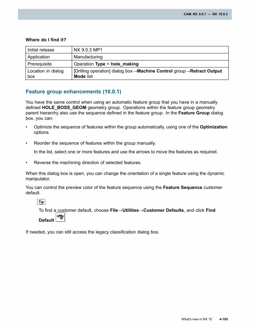
CAM NX 9.0.1 — NX 10.0.3
Where do I find it?
Initial release NX 9.0.3 MP1Application ManufacturingPrerequisite Operation Type = hole_makingLocation in dialogbox
[Drilling operation] dialog box→Machine Control group→Retract OutputMode list
Feature group enhancements (10.0.1)
You have the same control when using an automatic feature group that you have in a manuallydefined HOLE_BOSS_GEOM geometry group. Operations within the feature group geometryparent hierarchy also use the sequence defined in the feature group. In the Feature Group dialogbox, you can:
• Optimize the sequence of features within the group automatically, using one of the Optimizationoptions.
• Reorder the sequence of features within the group manually.
In the list, select one or more features and use the arrows to move the features as required.
• Reverse the machining direction of selected features.
When this dialog box is open, you can change the orientation of a single feature using the dynamicmanipulator.
You can control the preview color of the feature sequence using the Feature Sequence customerdefault.
Tip
To find a customer default, choose File→Utilities→Customer Defaults, and click Find
Default .
If needed, you can still access the legacy classification dialog box.
What's new in NX 10 4-105
CAM NX 9.0.1 — NX 10.0.3
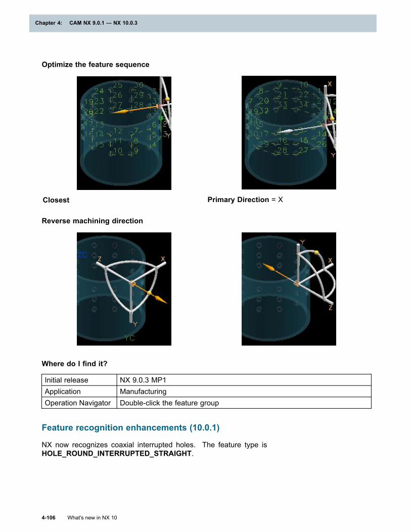
Chapter 4: CAM NX 9.0.1 — NX 10.0.3
Optimize the feature sequence
Closest Primary Direction = X
Reverse machining direction
Where do I find it?
Initial release NX 9.0.3 MP1Application ManufacturingOperation Navigator Double-click the feature group
Feature recognition enhancements (10.0.1)
NX now recognizes coaxial interrupted holes. The feature type isHOLE_ROUND_INTERRUPTED_STRAIGHT.
4-106 What's new in NX 10
Chapter 4: CAM NX 9.0.1 — NX 10.0.3
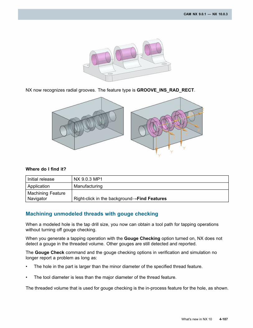
CAM NX 9.0.1 — NX 10.0.3
NX now recognizes radial grooves. The feature type is GROOVE_INS_RAD_RECT.
Where do I find it?
Initial release NX 9.0.3 MP1Application ManufacturingMachining FeatureNavigator Right-click in the background→Find Features
Machining unmodeled threads with gouge checking
When a modeled hole is the tap drill size, you now can obtain a tool path for tapping operationswithout turning off gouge checking.
When you generate a tapping operation with the Gouge Checking option turned on, NX does notdetect a gouge in the threaded volume. Other gouges are still detected and reported.
The Gouge Check command and the gouge checking options in verification and simulation nolonger report a problem as long as:
• The hole in the part is larger than the minor diameter of the specified thread feature.
• The tool diameter is less than the major diameter of the thread feature.
The threaded volume that is used for gouge checking is the in-process feature for the hole, as shown.
What's new in NX 10 4-107
CAM NX 9.0.1 — NX 10.0.3
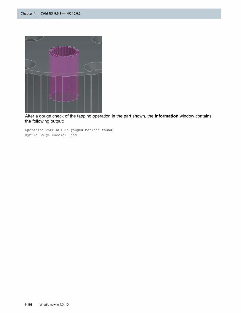
Chapter 4: CAM NX 9.0.1 — NX 10.0.3
After a gouge check of the tapping operation in the part shown, the Information window containsthe following output:
Operation TAPPING: No gouged motions found.
Hybrid Gouge Checker used.
4-108 What's new in NX 10
Chapter 4: CAM NX 9.0.1 — NX 10.0.3
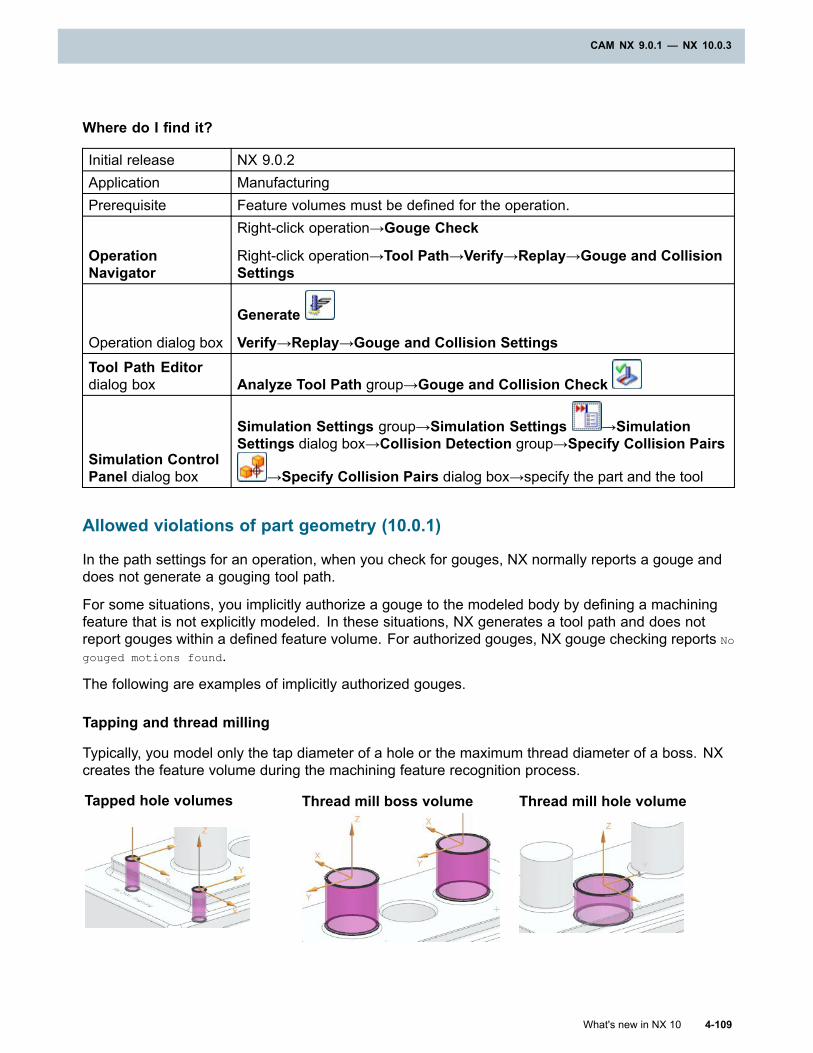
CAM NX 9.0.1 — NX 10.0.3
Where do I find it?
Initial release NX 9.0.2Application ManufacturingPrerequisite Feature volumes must be defined for the operation.
OperationNavigator
Right-click operation→Gouge Check
Right-click operation→Tool Path→Verify→Replay→Gouge and CollisionSettings
Operation dialog box
Generate
Verify→Replay→Gouge and Collision SettingsTool Path Editordialog box Analyze Tool Path group→Gouge and Collision Check
Simulation ControlPanel dialog box
Simulation Settings group→Simulation Settings →SimulationSettings dialog box→Collision Detection group→Specify Collision Pairs
→Specify Collision Pairs dialog box→specify the part and the tool
Allowed violations of part geometry (10.0.1)
In the path settings for an operation, when you check for gouges, NX normally reports a gouge anddoes not generate a gouging tool path.
For some situations, you implicitly authorize a gouge to the modeled body by defining a machiningfeature that is not explicitly modeled. In these situations, NX generates a tool path and does notreport gouges within a defined feature volume. For authorized gouges, NX gouge checking reports No
gouged motions found.
The following are examples of implicitly authorized gouges.
Tapping and thread milling
Typically, you model only the tap diameter of a hole or the maximum thread diameter of a boss. NXcreates the feature volume during the machining feature recognition process.
Tapped hole volumes Thread mill boss volume Thread mill hole volume
What's new in NX 10 4-109
CAM NX 9.0.1 — NX 10.0.3
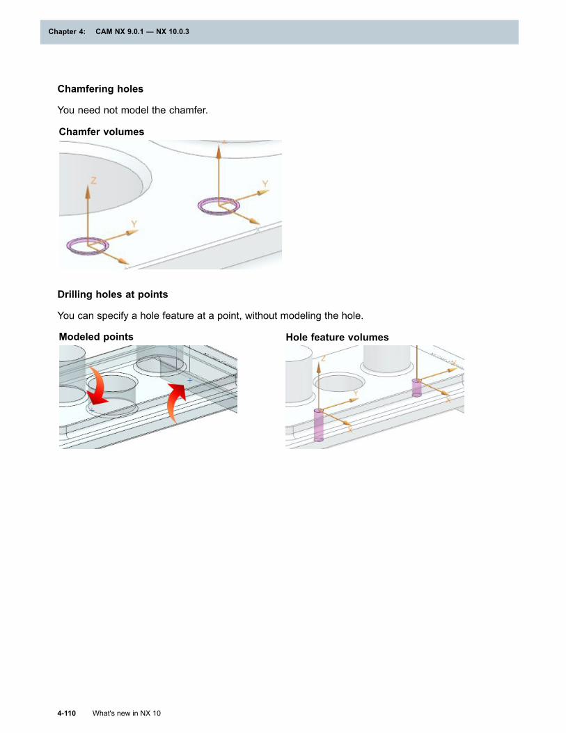
Chapter 4: CAM NX 9.0.1 — NX 10.0.3
Chamfering holes
You need not model the chamfer.
Chamfer volumes
Drilling holes at points
You can specify a hole feature at a point, without modeling the hole.
Modeled points Hole feature volumes
4-110 What's new in NX 10
Chapter 4: CAM NX 9.0.1 — NX 10.0.3
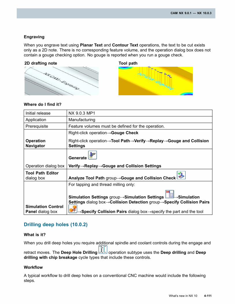
CAM NX 9.0.1 — NX 10.0.3
Engraving
When you engrave text using Planar Text and Contour Text operations, the text to be cut existsonly as a 2D note. There is no corresponding feature volume, and the operation dialog box does notcontain a gouge checking option. No gouge is reported when you run a gouge check.
2D drafting note Tool path
Where do I find it?
Initial release NX 9.0.3 MP1Application ManufacturingPrerequisite Feature volumes must be defined for the operation.
OperationNavigator
Right-click operation→Gouge Check
Right-click operation→Tool Path→Verify→Replay→Gouge and CollisionSettings
Operation dialog box
Generate
Verify→Replay→Gouge and Collision SettingsTool Path Editordialog box Analyze Tool Path group→Gouge and Collision Check
Simulation ControlPanel dialog box
For tapping and thread milling only:
Simulation Settings group→Simulation Settings →SimulationSettings dialog box→Collision Detection group→Specify Collision Pairs
→Specify Collision Pairs dialog box→specify the part and the tool
Drilling deep holes (10.0.2)
What is it?
When you drill deep holes you require additional spindle and coolant controls during the engage and
retract moves. The Deep Hole Drilling operation subtype uses the Deep drilling and Deepdrilling with chip breakage cycle types that include these controls.
Workflow
A typical workflow to drill deep holes on a conventional CNC machine would include the followingsteps.
What's new in NX 10 4-111
CAM NX 9.0.1 — NX 10.0.3
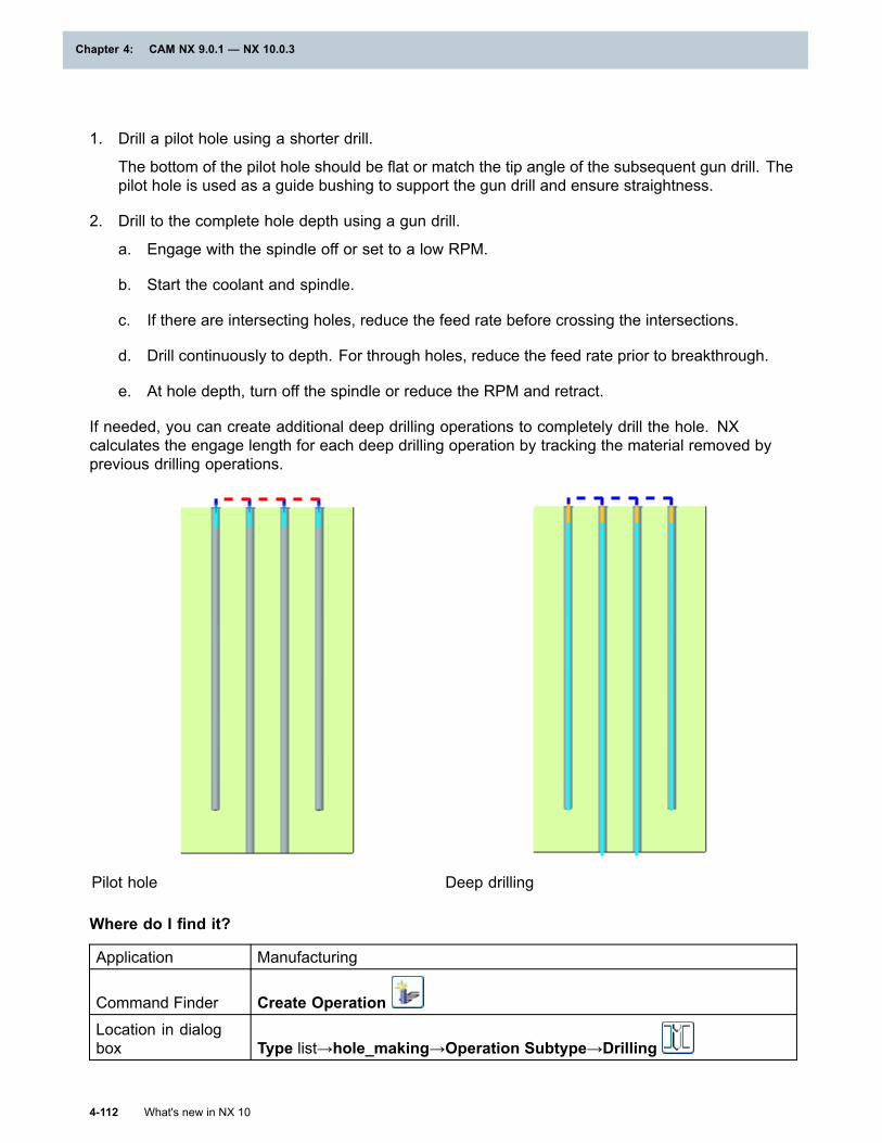
Chapter 4: CAM NX 9.0.1 — NX 10.0.3
1. Drill a pilot hole using a shorter drill.
The bottom of the pilot hole should be flat or match the tip angle of the subsequent gun drill. Thepilot hole is used as a guide bushing to support the gun drill and ensure straightness.
2. Drill to the complete hole depth using a gun drill.
a. Engage with the spindle off or set to a low RPM.
b. Start the coolant and spindle.
c. If there are intersecting holes, reduce the feed rate before crossing the intersections.
d. Drill continuously to depth. For through holes, reduce the feed rate prior to breakthrough.
e. At hole depth, turn off the spindle or reduce the RPM and retract.
If needed, you can create additional deep drilling operations to completely drill the hole. NXcalculates the engage length for each deep drilling operation by tracking the material removed byprevious drilling operations.
Pilot hole Deep drilling
Where do I find it?
Application Manufacturing
Command Finder Create OperationLocation in dialogbox Type list→hole_making→Operation Subtype→Drilling
4-112 What's new in NX 10
Chapter 4: CAM NX 9.0.1 — NX 10.0.3
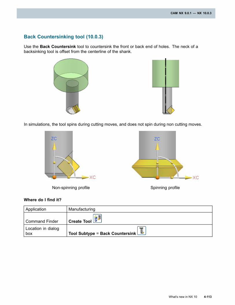
CAM NX 9.0.1 — NX 10.0.3
Back Countersinking tool (10.0.3)
Use the Back Countersink tool to countersink the front or back end of holes. The neck of abacksinking tool is offset from the centerline of the shank.
In simulations, the tool spins during cutting moves, and does not spin during non cutting moves.
Non-spinning profile Spinning profile
Where do I find it?
Application Manufacturing
Command Finder Create ToolLocation in dialogbox Tool Subtype = Back Countersink
What's new in NX 10 4-113
CAM NX 9.0.1 — NX 10.0.3
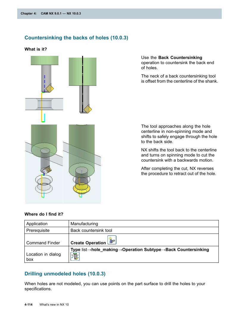
Chapter 4: CAM NX 9.0.1 — NX 10.0.3
Countersinking the backs of holes (10.0.3)
What is it?
Use the Back Countersinkingoperation to countersink the back endof holes.
The neck of a back countersinking toolis offset from the centerline of the shank.
The tool approaches along the holecenterline in non-spinning mode andshifts to safely engage through the holeto the back side.
NX shifts the tool back to the centerlineand turns on spinning mode to cut thecountersink with a backwards motion.
After completing the cut, NX reversesthe procedure to retract out of the hole.
Where do I find it?
Application ManufacturingPrerequisite Back countersink tool
Command Finder Create Operation
Location in dialogbox
Type list→hole_making→Operation Subtype→Back Countersinking
Drilling unmodeled holes (10.0.3)
When holes are not modeled, you can use points on the part surface to drill the holes to yourspecifications.
4-114 What's new in NX 10
Chapter 4: CAM NX 9.0.1 — NX 10.0.3
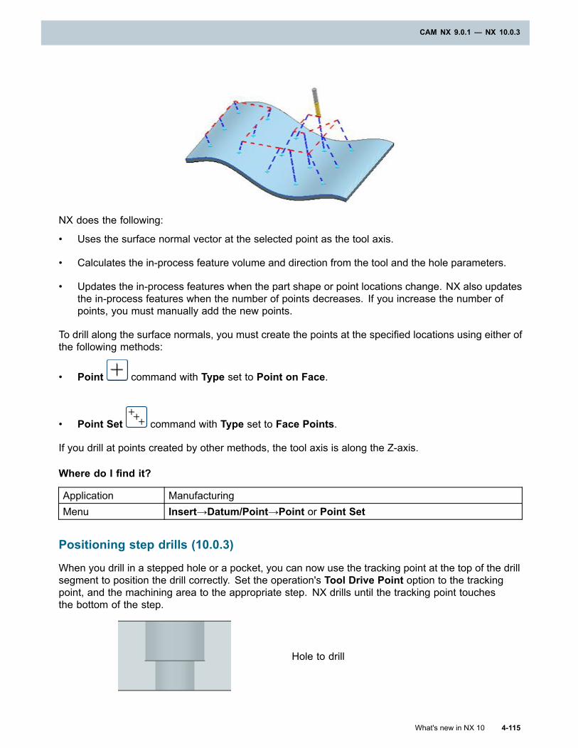
CAM NX 9.0.1 — NX 10.0.3
NX does the following:
• Uses the surface normal vector at the selected point as the tool axis.
• Calculates the in-process feature volume and direction from the tool and the hole parameters.
• Updates the in-process features when the part shape or point locations change. NX also updatesthe in-process features when the number of points decreases. If you increase the number ofpoints, you must manually add the new points.
To drill along the surface normals, you must create the points at the specified locations using either ofthe following methods:
• Point command with Type set to Point on Face.
• Point Set command with Type set to Face Points.
If you drill at points created by other methods, the tool axis is along the Z-axis.
Where do I find it?
Application ManufacturingMenu Insert→Datum/Point→Point or Point Set
Positioning step drills (10.0.3)
When you drill in a stepped hole or a pocket, you can now use the tracking point at the top of the drillsegment to position the drill correctly. Set the operation's Tool Drive Point option to the trackingpoint, and the machining area to the appropriate step. NX drills until the tracking point touchesthe bottom of the step.
Hole to drill
What's new in NX 10 4-115
CAM NX 9.0.1 — NX 10.0.3

Chapter 4: CAM NX 9.0.1 — NX 10.0.3
Tool Drive Point = SYS_CL_TOP
Machining Area = FACES_CYLINDER_1
Result
4-116 What's new in NX 10
Chapter 4: CAM NX 9.0.1 — NX 10.0.3
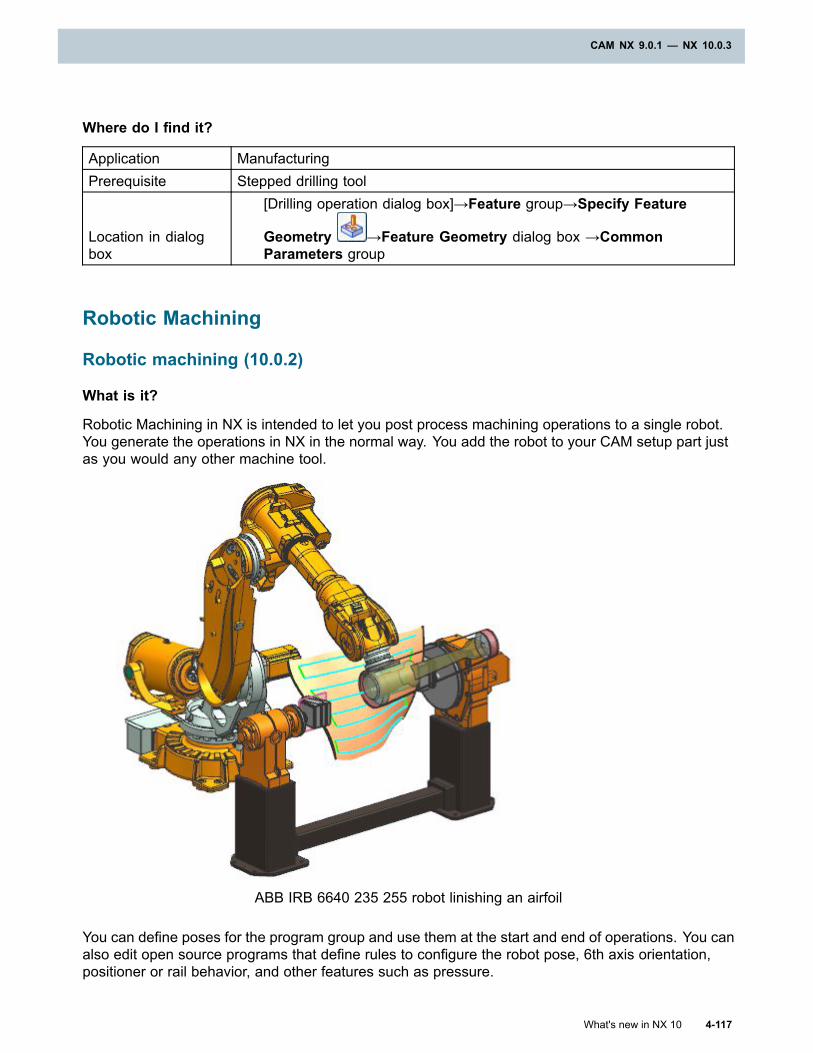
CAM NX 9.0.1 — NX 10.0.3
Where do I find it?
Application ManufacturingPrerequisite Stepped drilling tool
Location in dialogbox
[Drilling operation dialog box]→Feature group→Specify Feature
Geometry →Feature Geometry dialog box →CommonParameters group
Robotic Machining
Robotic machining (10.0.2)
What is it?
Robotic Machining in NX is intended to let you post process machining operations to a single robot.You generate the operations in NX in the normal way. You add the robot to your CAM setup part justas you would any other machine tool.
ABB IRB 6640 235 255 robot linishing an airfoil
You can define poses for the program group and use them at the start and end of operations. You canalso edit open source programs that define rules to configure the robot pose, 6th axis orientation,positioner or rail behavior, and other features such as pressure.
What's new in NX 10 4-117
CAM NX 9.0.1 — NX 10.0.3
Chapter 4: CAM NX 9.0.1 — NX 10.0.3
NX supports the following types of robots:
• ABB
• Fanuc
• Kuka
You can retrieve a robot from the library using the Replace Machine command. You can also createa robot model in Machine Tool Builder, where you can:
• Examine and edit robot kinematics, including hard and soft limits.
• Preview motion.
• Switch configurations.
• Add components to the work cell.
• Define collision pairs.
After you add your robot to an operation In NX, you can work with it as you would with any machinetool. You can, for example:
• Apply user-defined events (UDEs) to implement robotic rules.
• Simulate the tool path with tool path based simulation.
• Check for collisions, axis limit violations, and singularity conditions.
• View the IPW for milling operations that use standard milling tools.
• Post process to create code to be run on the robot controller.
Note
Robotic Machining is not adequate for processes like riveting and welding. It does not supportrobots that work in conjunction with each other in the same cell.
Why should I use it?
Robots are cheaper, easier to set up, and more flexible than 5-axis milling machines. That makesthem ideal for some machining tasks like linishing, polishing, and deburring. Traditionally, onesoftware is responsible for the path generation and different software is used to control roboticbehavior. NX provides a single environment, benefiting from associativity, advanced path generationprocessors, and automation capabilities.
Where do I find it?
Initial Release NX 10.0.2Application Manufacturing
Prerequisite
A simulation license is required to simulate all robots.
A separate license is required for each post processor.
4-118 What's new in NX 10
Chapter 4: CAM NX 9.0.1 — NX 10.0.3
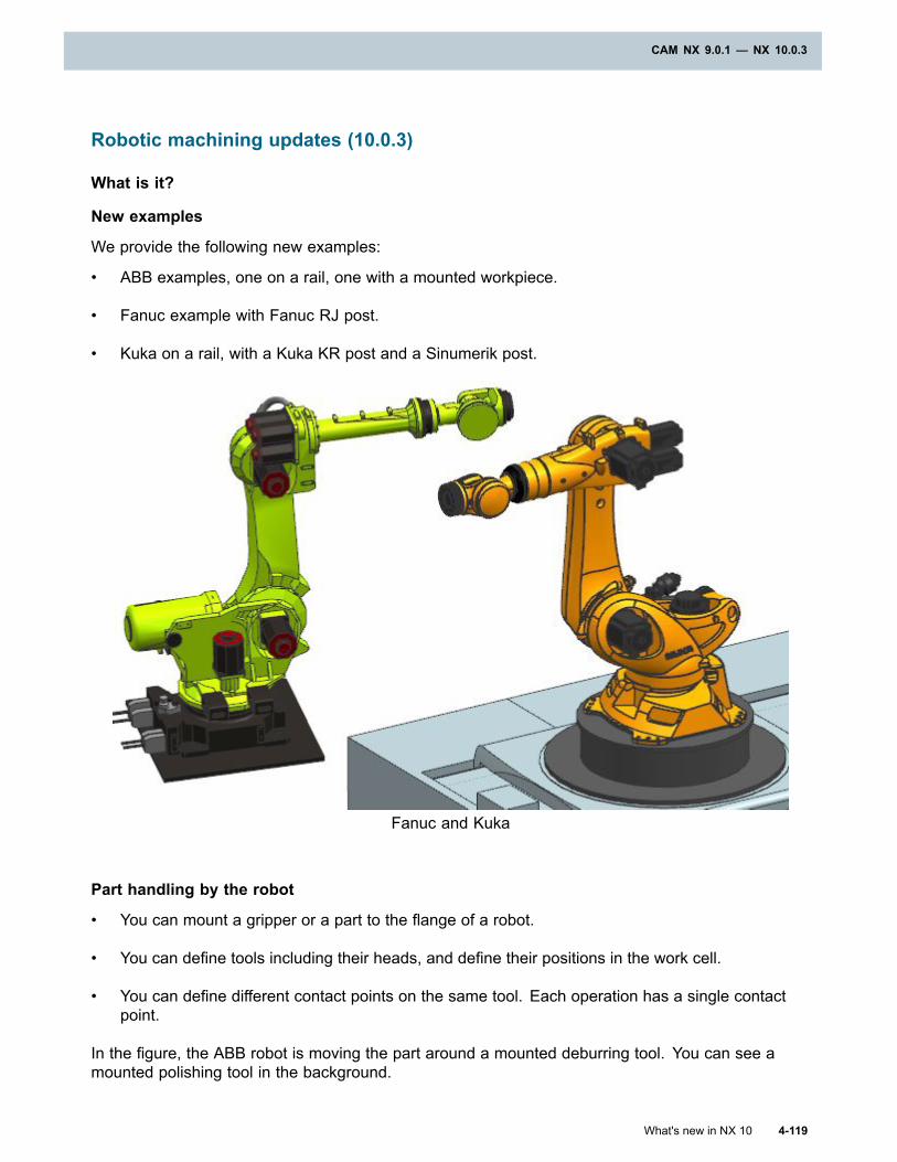
CAM NX 9.0.1 — NX 10.0.3
Robotic machining updates (10.0.3)
What is it?
New examples
We provide the following new examples:
• ABB examples, one on a rail, one with a mounted workpiece.
• Fanuc example with Fanuc RJ post.
• Kuka on a rail, with a Kuka KR post and a Sinumerik post.
Fanuc and Kuka
Part handling by the robot
• You can mount a gripper or a part to the flange of a robot.
• You can define tools including their heads, and define their positions in the work cell.
• You can define different contact points on the same tool. Each operation has a single contactpoint.
In the figure, the ABB robot is moving the part around a mounted deburring tool. You can see amounted polishing tool in the background.
What's new in NX 10 4-119
CAM NX 9.0.1 — NX 10.0.3
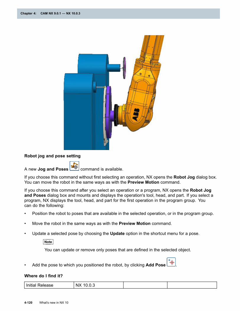
Chapter 4: CAM NX 9.0.1 — NX 10.0.3
Robot jog and pose setting
A new Jog and Poses command is available.
If you choose this command without first selecting an operation, NX opens the Robot Jog dialog box.You can move the robot in the same ways as with the Preview Motion command.
If you choose this command after you select an operation or a program, NX opens the Robot Jogand Poses dialog box and mounts and displays the operation's tool, head, and part. If you select aprogram, NX displays the tool, head, and part for the first operation in the program group. Youcan do the following:
• Position the robot to poses that are available in the selected operation, or in the program group.
• Move the robot in the same ways as with the Preview Motion command.
• Update a selected pose by choosing the Update option in the shortcut menu for a pose.
Note
You can update or remove only poses that are defined in the selected object.
• Add the pose to which you positioned the robot, by clicking Add Pose .
Where do I find it?
Initial Release NX 10.0.3
4-120 What's new in NX 10
Chapter 4: CAM NX 9.0.1 — NX 10.0.3
CAM NX 9.0.1 — NX 10.0.3
PrerequisiteDisplay the RoboticMachining group
Application ManufacturingCommand Finder Robot Jog
Ribbon bar
Manufacturing→Home→RoboticMachining→Jog and
Poses
Integrated Simulation and Verification - ISV
Finding machine, tool, and device components in a CAM or CMM setup
What is it?
In native NX, when you open a part that contains a CAM setup, NX Manufacturing has to find thecomponent parts for machine tools that you added for simulation. In previous releases, when theassembly load options Load list was set to the default From Folder, NX searched for componentparts in the folder specified by the following environment variable:
UGII_CAM_LIBRARY_INSTALLED_MACHINES_DIR
Beginning in NX 10, NX extends the search to the library tools and devices folders specified bythe following variables:
• UGII_CAM_LIBRARY_TOOL_DIR
• UGII_CAM_LIBRARY_DEVICE_DIR
In CMM inspection, the search is extended to the folders specified by the following variables:
• UGII_INSPECTION_LIBRARY_INSTALLED_MACHINES_DIR
• UGII_INSPECTION_LIBRARY_TOOL_DIR
• UGII_INSPECTION_LIBRARY_DEVICE_DIR
Why should I use it?
You can accept the default assembly load option Load list setting, From Folder, even when yourCAM setup includes machine tools, solid cutting tools, and devices.
Note
If you modify the standard locations, you must correctly set the variables shown.
What's new in NX 10 4-121
CAM NX 9.0.1 — NX 10.0.3
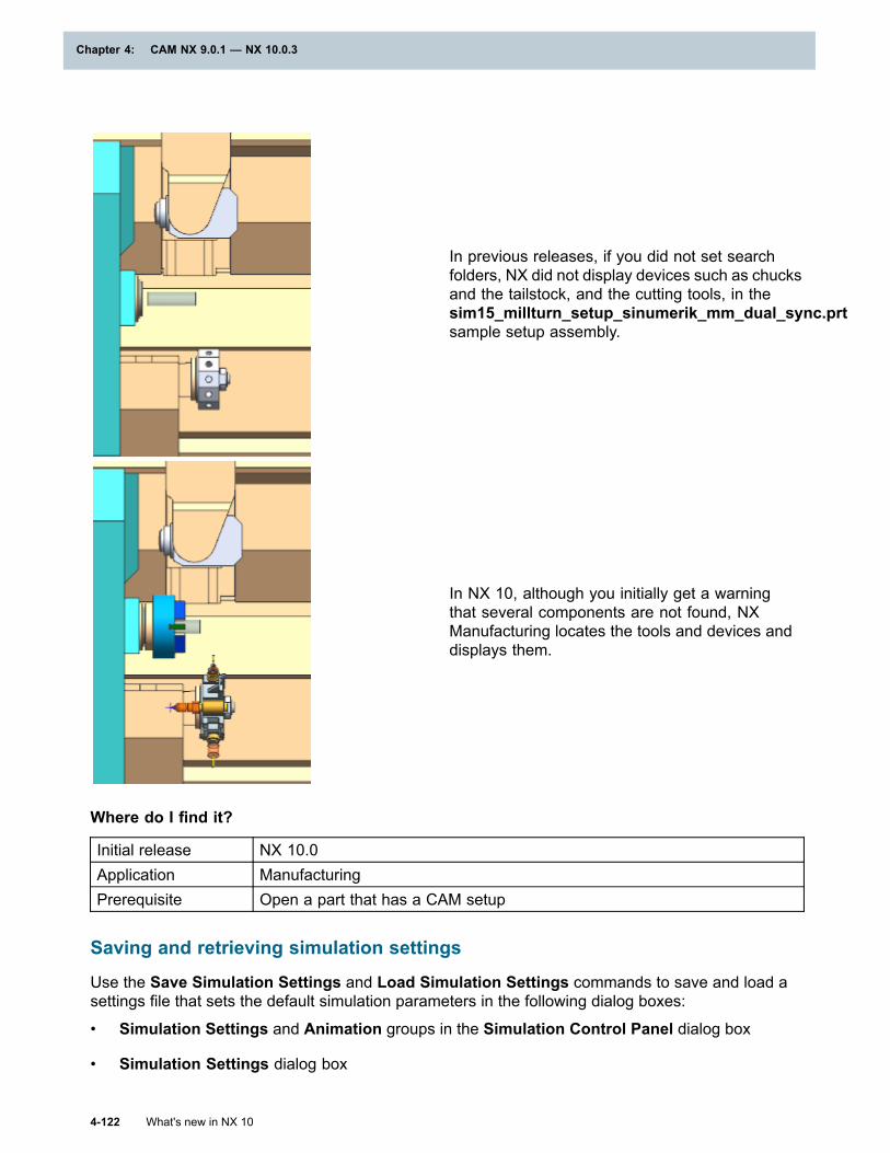
Chapter 4: CAM NX 9.0.1 — NX 10.0.3
In previous releases, if you did not set searchfolders, NX did not display devices such as chucksand the tailstock, and the cutting tools, in thesim15_millturn_setup_sinumerik_mm_dual_sync.prtsample setup assembly.
In NX 10, although you initially get a warningthat several components are not found, NXManufacturing locates the tools and devices anddisplays them.
Where do I find it?
Initial release NX 10.0Application ManufacturingPrerequisite Open a part that has a CAM setup
Saving and retrieving simulation settings
Use the Save Simulation Settings and Load Simulation Settings commands to save and load asettings file that sets the default simulation parameters in the following dialog boxes:
• Simulation Settings and Animation groups in the Simulation Control Panel dialog box
• Simulation Settings dialog box
4-122 What's new in NX 10
Chapter 4: CAM NX 9.0.1 — NX 10.0.3
CAM NX 9.0.1 — NX 10.0.3
• Collision Pairs dialog box
You may have different simulation tasks, such as fast and rough checks, or long detailed checks. Youcan save time by saving common simulation parameters in different settings files and loading the onethat you want when you need it. The files are saved to and retrieved from the folder specified by theSaved Simulation Settings Directory simulation customer default.
Tip
To find a customer default, choose File tab→Utilities→Customer Defaults, and click Find
Default .
The file name of the current settings file is shown in the Current Settings row of the ManageSettings group. If you do not specify a settings file, NX displays the label None.
Where do I find it?
Initial release NX 9.0.1Application ManufacturingLocation in dialogbox
Simulation Control Panel dialog box→Simulation Settings
group→Manage Settings subgroup→Load Simulation Settings and
Save Simulation Settings
Axis dynamic capabilities in the Machine Tool Navigator (10.0.1)
What is it?
Dynamic properties of axes are now stored in a common location, the NX machine tool assembly.You enter the properties from the Machine Tool Navigator, using the Edit→Axis command. TheMachine Tool Navigator is available in the Manufacturing and Machine Tool Builder applications.
The following properties are new in NX.
For rotary axes and spindles For linear axesMax Acceleration [deg/s^2]
Max Deceleration [deg/s^2]
Jerk Limit [deg/s^3]
Jump Velocity [deg/s]
Kv
Fine Precision [deg]
Coarse Precision [deg]
Max Acceleration [mm/s^2]
Max Deceleration [mm/s^2]
Jerk Limit [mm/s^3]
Jump Velocity [mm/s]
Kv
Fine Precision [mm]
Coarse Precision [mm]
Units of mm for linear axes are shown. For English units, in replaces mm.
What's new in NX 10 4-123
CAM NX 9.0.1 — NX 10.0.3
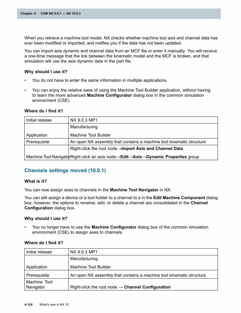
Chapter 4: CAM NX 9.0.1 — NX 10.0.3
When you retrieve a machine tool model, NX checks whether machine tool axis and channel data hasever been modified or imported, and notifies you if the data has not been updated.
You can import axis dynamic and channel data from an MCF file or enter it manually. You will receivea one-time message that the link between the kinematic model and the MCF is broken, and thatsimulation will use the axis dynamic data in the part file.
Why should I use it?
• You do not have to enter the same information in multiple applications.
• You can enjoy the relative ease of using the Machine Tool Builder application, without havingto learn the more advanced Machine Configurator dialog box in the common simulationenvironment (CSE).
Where do I find it?
Initial release NX 9.0.3 MP1
Application
Manufacturing
Machine Tool BuilderPrerequisite An open NX assembly that contains a machine tool kinematic structure
Machine Tool Navigator
Right-click the root node→Import Axis and Channel Data
Right-click an axis node→Edit→Axis→Dynamic Properties group
Channels settings moved (10.0.1)
What is it?
You can now assign axes to channels in the Machine Tool Navigator in NX.
You can still assign a device or a tool holder to a channel to a in the Edit Machine Component dialogbox; however, the options to rename, add, or delete a channel are consolidated in the ChannelConfiguration dialog box.
Why should I use it?
• You no longer have to use the Machine Configurator dialog box of the common simulationenvironment (CSE) to assign axes to channels.
Where do I find it?
Initial release NX 9.0.3 MP1
Application
Manufacturing
Machine Tool Builder
Prerequisite An open NX assembly that contains a machine tool kinematic structureMachine ToolNavigator Right-click the root node → Channel Configuration
4-124 What's new in NX 10
Chapter 4: CAM NX 9.0.1 — NX 10.0.3
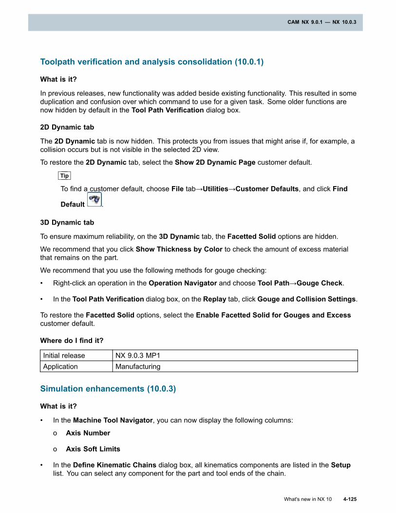
CAM NX 9.0.1 — NX 10.0.3
Toolpath verification and analysis consolidation (10.0.1)
What is it?
In previous releases, new functionality was added beside existing functionality. This resulted in someduplication and confusion over which command to use for a given task. Some older functions arenow hidden by default in the Tool Path Verification dialog box.
2D Dynamic tab
The 2D Dynamic tab is now hidden. This protects you from issues that might arise if, for example, acollision occurs but is not visible in the selected 2D view.
To restore the 2D Dynamic tab, select the Show 2D Dynamic Page customer default.
Tip
To find a customer default, choose File tab→Utilities→Customer Defaults, and click Find
Default .
3D Dynamic tab
To ensure maximum reliability, on the 3D Dynamic tab, the Facetted Solid options are hidden.
We recommend that you click Show Thickness by Color to check the amount of excess materialthat remains on the part.
We recommend that you use the following methods for gouge checking:
• Right-click an operation in the Operation Navigator and choose Tool Path→Gouge Check.
• In the Tool Path Verification dialog box, on the Replay tab, click Gouge and Collision Settings.
To restore the Facetted Solid options, select the Enable Facetted Solid for Gouges and Excesscustomer default.
Where do I find it?
Initial release NX 9.0.3 MP1Application Manufacturing
Simulation enhancements (10.0.3)
What is it?
• In the Machine Tool Navigator, you can now display the following columns:
o Axis Number
o Axis Soft Limits
• In the Define Kinematic Chains dialog box, all kinematics components are listed in the Setuplist. You can select any component for the part and tool ends of the chain.
What's new in NX 10 4-125
CAM NX 9.0.1 — NX 10.0.3
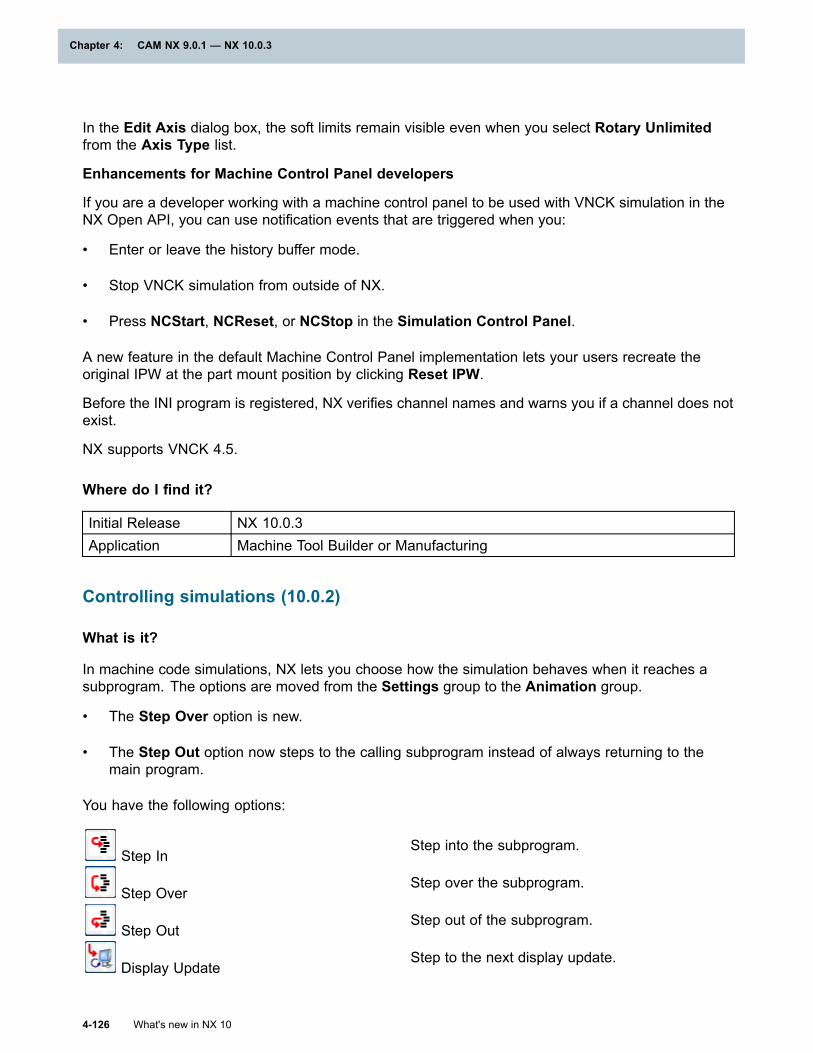
Chapter 4: CAM NX 9.0.1 — NX 10.0.3
In the Edit Axis dialog box, the soft limits remain visible even when you select Rotary Unlimitedfrom the Axis Type list.
Enhancements for Machine Control Panel developers
If you are a developer working with a machine control panel to be used with VNCK simulation in theNX Open API, you can use notification events that are triggered when you:
• Enter or leave the history buffer mode.
• Stop VNCK simulation from outside of NX.
• Press NCStart, NCReset, or NCStop in the Simulation Control Panel.
A new feature in the default Machine Control Panel implementation lets your users recreate theoriginal IPW at the part mount position by clicking Reset IPW.
Before the INI program is registered, NX verifies channel names and warns you if a channel does notexist.
NX supports VNCK 4.5.
Where do I find it?
Initial Release NX 10.0.3Application Machine Tool Builder or Manufacturing
Controlling simulations (10.0.2)
What is it?
In machine code simulations, NX lets you choose how the simulation behaves when it reaches asubprogram. The options are moved from the Settings group to the Animation group.
• The Step Over option is new.
• The Step Out option now steps to the calling subprogram instead of always returning to themain program.
You have the following options:
Step InStep into the subprogram.
Step OverStep over the subprogram.
Step OutStep out of the subprogram.
Display UpdateStep to the next display update.
4-126 What's new in NX 10
Chapter 4: CAM NX 9.0.1 — NX 10.0.3
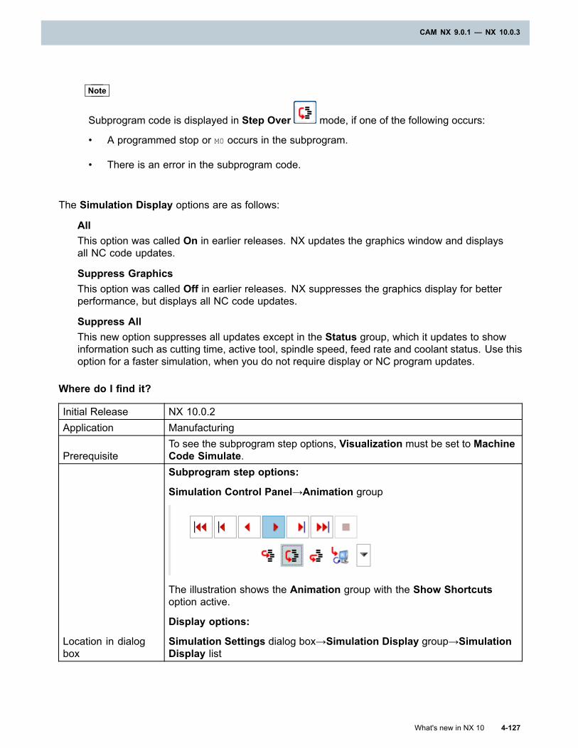
CAM NX 9.0.1 — NX 10.0.3
Note
Subprogram code is displayed in Step Over mode, if one of the following occurs:
• A programmed stop or M0 occurs in the subprogram.
• There is an error in the subprogram code.
The Simulation Display options are as follows:
AllThis option was called On in earlier releases. NX updates the graphics window and displaysall NC code updates.
Suppress GraphicsThis option was called Off in earlier releases. NX suppresses the graphics display for betterperformance, but displays all NC code updates.
Suppress AllThis new option suppresses all updates except in the Status group, which it updates to showinformation such as cutting time, active tool, spindle speed, feed rate and coolant status. Use thisoption for a faster simulation, when you do not require display or NC program updates.
Where do I find it?
Initial Release NX 10.0.2Application Manufacturing
PrerequisiteTo see the subprogram step options, Visualization must be set to MachineCode Simulate.
Location in dialogbox
Subprogram step options:
Simulation Control Panel→Animation group
The illustration shows the Animation group with the Show Shortcutsoption active.
Display options:
Simulation Settings dialog box→Simulation Display group→SimulationDisplay list
What's new in NX 10 4-127
CAM NX 9.0.1 — NX 10.0.3
Chapter 4: CAM NX 9.0.1 — NX 10.0.3
Controlling simulation tolerances (10.0.3)
Separate options are available to control the tolerances for tilting and facet accuracy. Thisenhancement lets you specify a tighter tolerance for faceting and a looser tolerance for tilting.Increasing the tilt tolerance to a value of 0.1 or 0.15 can give acceptable quality while significantlyimproving performance.
• Chordal Tolerance controls the tolerance for circular motions and the tolerance for tool, IPW,and blank faceting. The default value is 0.05 mm.
In previous releases, this option also controlled the tilting tolerance.
• Tilt Tolerance controls the tolerance for tool axis tilting, and the default value is 0.05 mm.
NX approximates 5-axis movements with angular steps. This tolerance specifies the maximumdeviation from the plane, for each step, as the tool axis changes.
The Chordal Tolerance and Tilt Tolerance settings are saved with the part file. You can changethe values in two locations:
• In Customer Defaults to change the system defaults. These settings affect only new parts.
• In Manufacturing Preferences to change the values for an open part.
Tip
To find a customer default, choose File tab→Utilities→Customer Defaults, and click Find
Default .
To find the preferences, choose Menu→Preferences→Manufacturing→Geometry→InProcess Workpiece Tolerances.
Postprocessing
MoriAPT CLSF
NX can now output the CLSF for single channel Mori Seiki machine tools in the MoriAPT formatdeveloped by Mori Seiki. DMG/Mori Seiki provides a controller-based postprocessor and simulationpackage for their CNC machines.
When you output your machining data in the MoriAPT format, you can cut parts on Mori Seikimachines without having to create a postprocessor or postprocess the data in NX.
4-128 What's new in NX 10
Chapter 4: CAM NX 9.0.1 — NX 10.0.3
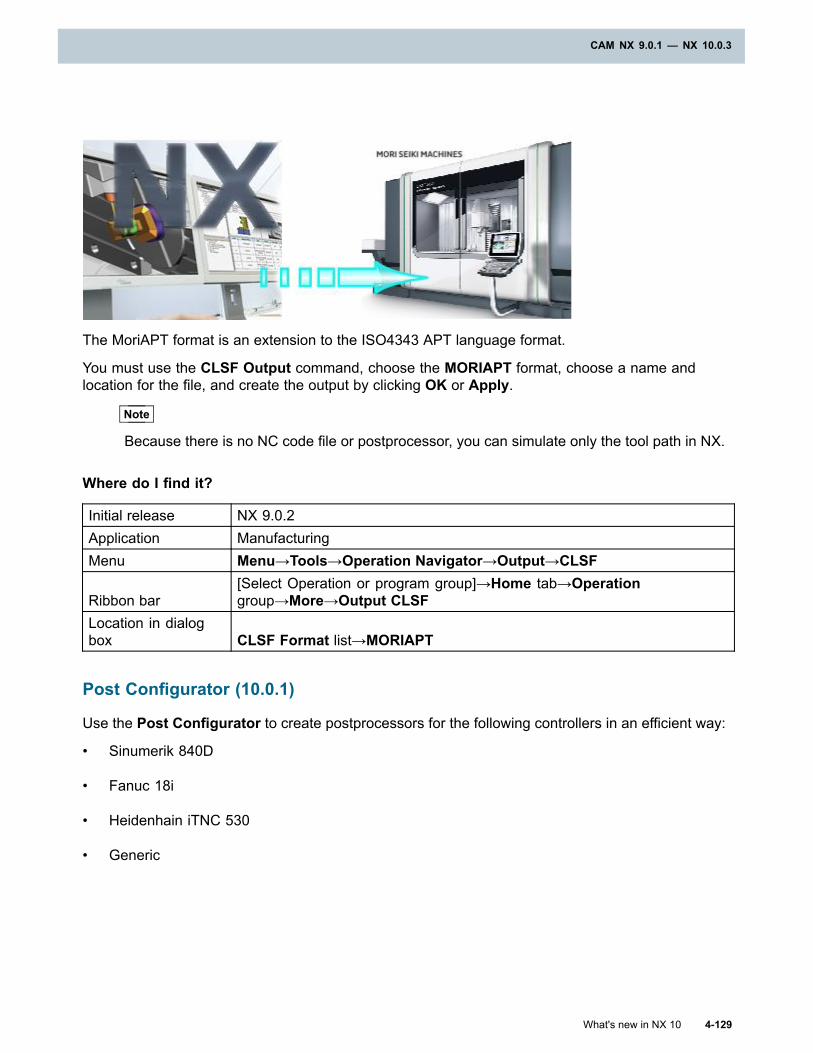
CAM NX 9.0.1 — NX 10.0.3
The MoriAPT format is an extension to the ISO4343 APT language format.
You must use the CLSF Output command, choose the MORIAPT format, choose a name andlocation for the file, and create the output by clicking OK or Apply.
Note
Because there is no NC code file or postprocessor, you can simulate only the tool path in NX.
Where do I find it?
Initial release NX 9.0.2Application ManufacturingMenu Menu→Tools→Operation Navigator→Output→CLSF
Ribbon bar[Select Operation or program group]→Home tab→Operationgroup→More→Output CLSF
Location in dialogbox CLSF Format list→MORIAPT
Post Configurator (10.0.1)
Use the Post Configurator to create postprocessors for the following controllers in an efficient way:
• Sinumerik 840D
• Fanuc 18i
• Heidenhain iTNC 530
• Generic
What's new in NX 10 4-129
CAM NX 9.0.1 — NX 10.0.3
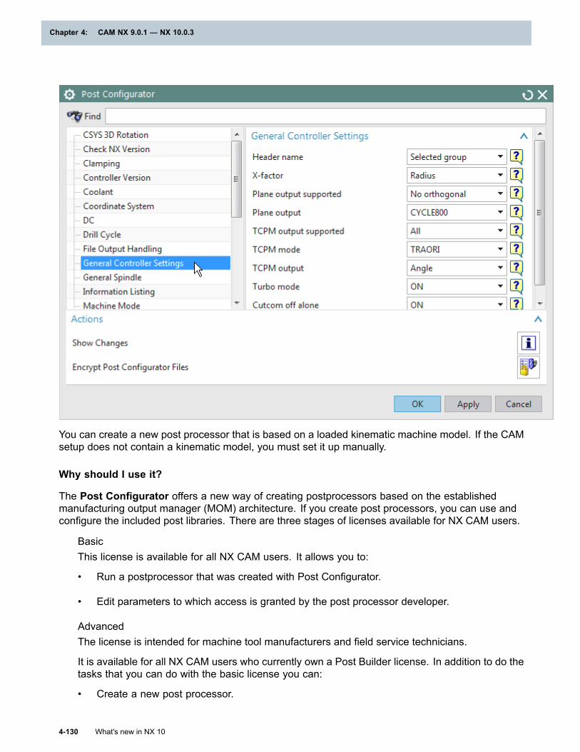
Chapter 4: CAM NX 9.0.1 — NX 10.0.3
You can create a new post processor that is based on a loaded kinematic machine model. If the CAMsetup does not contain a kinematic model, you must set it up manually.
Why should I use it?
The Post Configurator offers a new way of creating postprocessors based on the establishedmanufacturing output manager (MOM) architecture. If you create post processors, you can use andconfigure the included post libraries. There are three stages of licenses available for NX CAM users.
BasicThis license is available for all NX CAM users. It allows you to:
• Run a postprocessor that was created with Post Configurator.
• Edit parameters to which access is granted by the post processor developer.
AdvancedThe license is intended for machine tool manufacturers and field service technicians.
It is available for all NX CAM users who currently own a Post Builder license. In addition to do thetasks that you can do with the basic license you can:
• Create a new post processor.
4-130 What's new in NX 10
Chapter 4: CAM NX 9.0.1 — NX 10.0.3
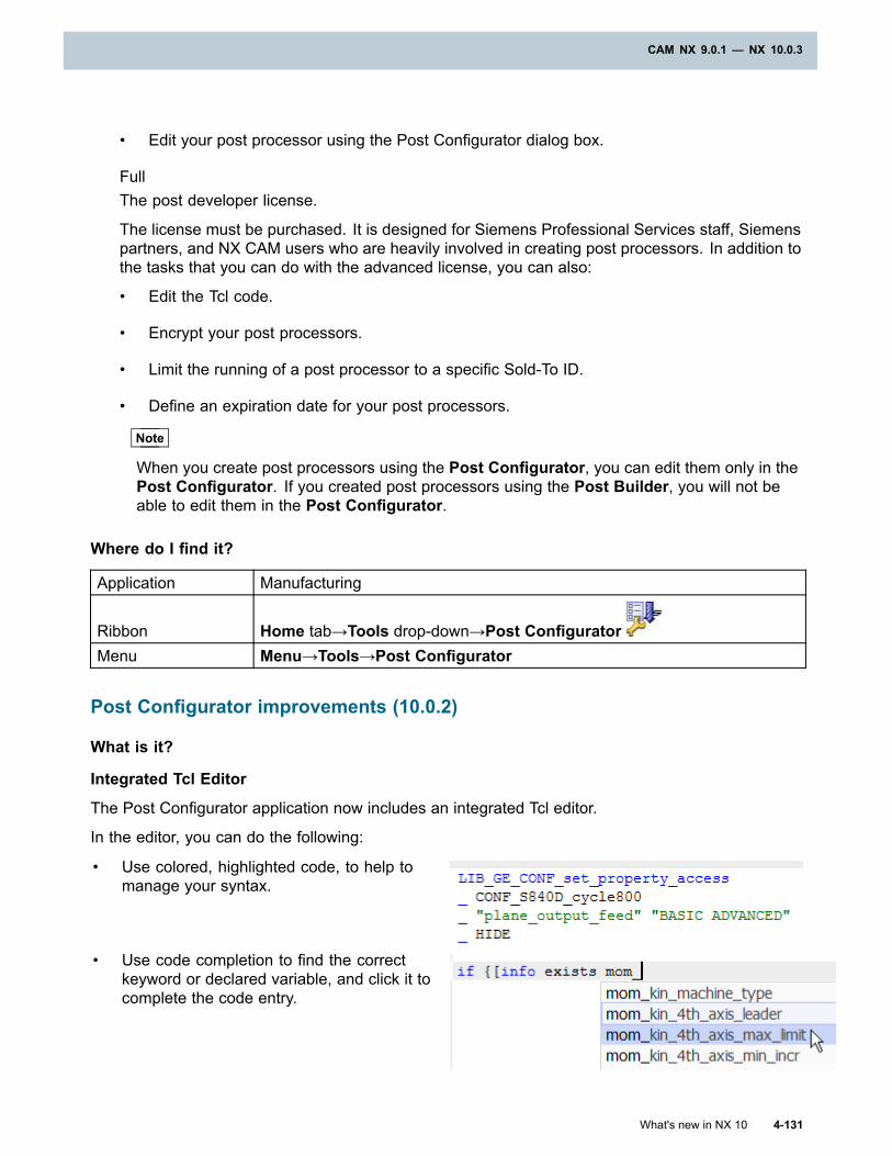
CAM NX 9.0.1 — NX 10.0.3
• Edit your post processor using the Post Configurator dialog box.
FullThe post developer license.
The license must be purchased. It is designed for Siemens Professional Services staff, Siemenspartners, and NX CAM users who are heavily involved in creating post processors. In addition tothe tasks that you can do with the advanced license, you can also:
• Edit the Tcl code.
• Encrypt your post processors.
• Limit the running of a post processor to a specific Sold-To ID.
• Define an expiration date for your post processors.
Note
When you create post processors using the Post Configurator, you can edit them only in thePost Configurator. If you created post processors using the Post Builder, you will not beable to edit them in the Post Configurator.
Where do I find it?
Application Manufacturing
Ribbon Home tab→Tools drop-down→Post ConfiguratorMenu Menu→Tools→Post Configurator
Post Configurator improvements (10.0.2)
What is it?
Integrated Tcl Editor
The Post Configurator application now includes an integrated Tcl editor.
In the editor, you can do the following:
• Use colored, highlighted code, to help tomanage your syntax.
• Use code completion to find the correctkeyword or declared variable, and click it tocomplete the code entry.
What's new in NX 10 4-131
CAM NX 9.0.1 — NX 10.0.3
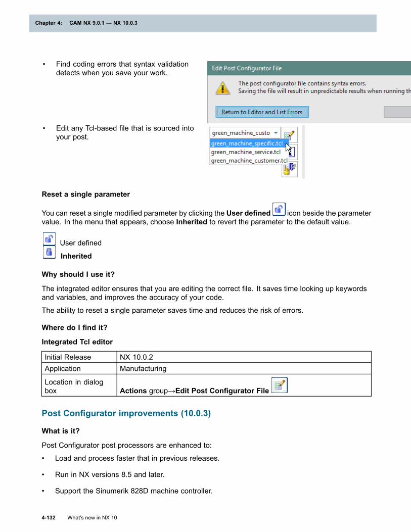
Chapter 4: CAM NX 9.0.1 — NX 10.0.3
• Find coding errors that syntax validationdetects when you save your work.
• Edit any Tcl-based file that is sourced intoyour post.
Reset a single parameter
You can reset a single modified parameter by clicking the User defined icon beside the parametervalue. In the menu that appears, choose Inherited to revert the parameter to the default value.
User defined
Inherited
Why should I use it?
The integrated editor ensures that you are editing the correct file. It saves time looking up keywordsand variables, and improves the accuracy of your code.
The ability to reset a single parameter saves time and reduces the risk of errors.
Where do I find it?
Integrated Tcl editor
Initial Release NX 10.0.2Application Manufacturing
Location in dialogbox Actions group→Edit Post Configurator File
Post Configurator improvements (10.0.3)
What is it?
Post Configurator post processors are enhanced to:
• Load and process faster that in previous releases.
• Run in NX versions 8.5 and later.
• Support the Sinumerik 828D machine controller.
4-132 What's new in NX 10
Chapter 4: CAM NX 9.0.1 — NX 10.0.3
CAM NX 9.0.1 — NX 10.0.3
• Support turning, mill turns, and turn mills with minimal extra input.
The configuration objects list has several subgroups, and you can define more in your post.Subgroups make it faster to navigate to options.
A new data type, POINT, makes it more intuitive to support the post processor.
NX Open is supported; you can use a journal to create and to encrypt post processors.
Where do I find it?
Initial Release NX 10.0.3Application ManufacturingCommand Finder Post Configurator
Feature-based Machining
Machining through holes and blind holes together
You can group through holes and blind holes to machine them together. You save on programmingtime because you do not have to program the through holes and blind holes separately. Use thePredefined option of the Group Features command to group features that have identical diameters,thread pitch, and number of steps. When it groups the features, NX ignores the values of all depthattributes, including tolerances, chamfers and thread lengths.
How it works
In NX, through holes are STEPxHOLE features and blind holes are STEPxPOCKET features, wherex indicates the number of steps in the feature. When you group features using the Predefinedoption, NX:
• Includes all STEP1HOLE and STEP1POCKET features with identical diameters in anFG_STEP1HOLE_STEP1POCKET feature group.
• Includes all STEP1HOLE_THREAD and STEP1POCKET_THREAD features with identicaldiameters and thread pitch in an FG_STEP1HOLE_THREAD_STEP1POCKET_THREADfeature group.
• Repeats the process for features with multiple steps.
If additional feature groups are required for holes with different diameters, NXcreates the feature groups and names them FG_STEP1HOLE_STEP1POCKET_1,FG_STEP1HOLE_STEP1POCKET_2 and so on.
What's new in NX 10 4-133
CAM NX 9.0.1 — NX 10.0.3

Chapter 4: CAM NX 9.0.1 — NX 10.0.3
The following example shows different hole feature profiles, and how NX groups the hole featurestogether.
Features to groupSTEP1HOLE_1 STEP2HOLE_5
STEP1HOLE_2 STEP2HOLE_6
STEP1POCKET_3 STEP2POCKET_7
STEP1POCKET_4 STEP2POCKET_8
Features in the Machining Feature Navigator after groupingWORKPIECE
FG_STEP1HOLE_STEP1POCKETSTEP1HOLE_1STEP1HOLE_2STEP1POCKET_3STEP1POCKET_4FG_STEP2HOLE_STEP2POCKETSTEP2HOLE_5STEP2HOLE_6STEP2POCKET_7STEP2POCKET_8
4-134 What's new in NX 10
Chapter 4: CAM NX 9.0.1 — NX 10.0.3
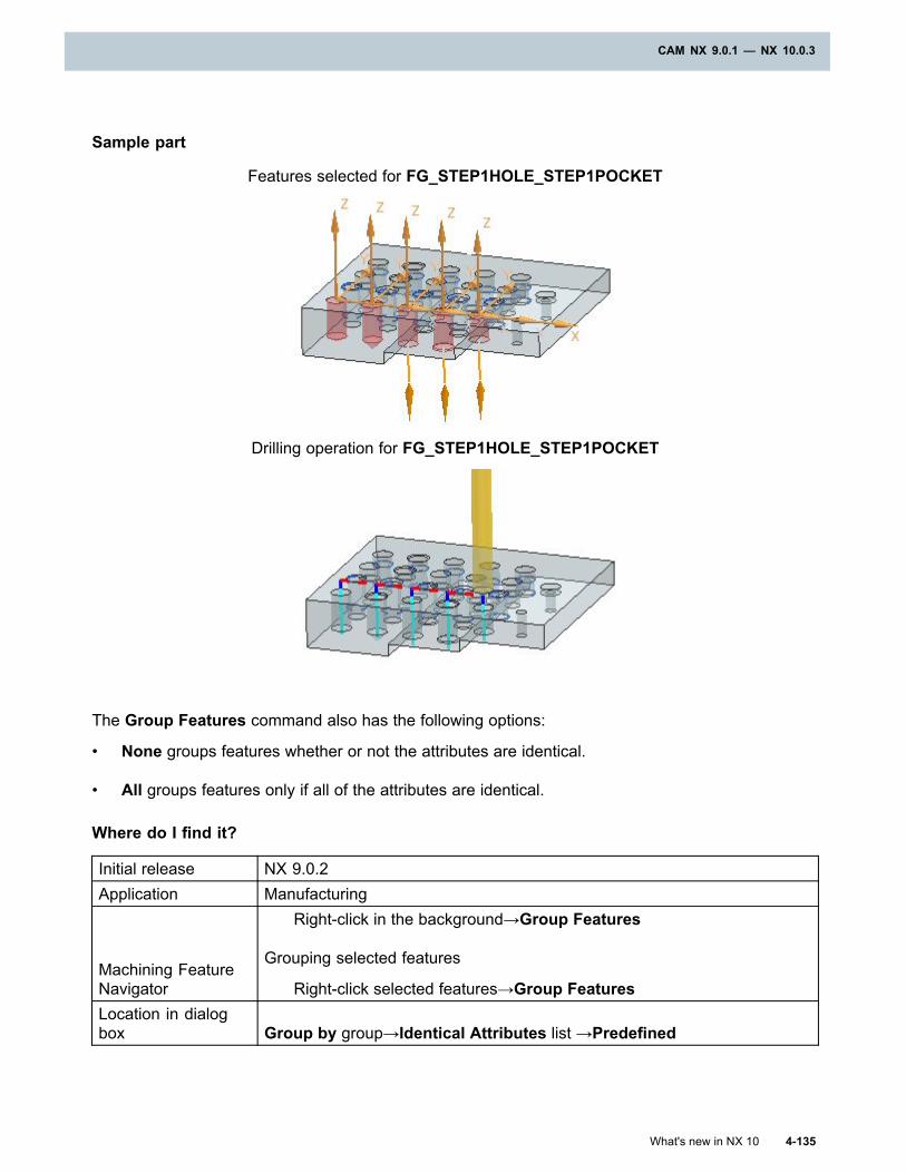
CAM NX 9.0.1 — NX 10.0.3
Sample part
Features selected for FG_STEP1HOLE_STEP1POCKET
Drilling operation for FG_STEP1HOLE_STEP1POCKET
The Group Features command also has the following options:
• None groups features whether or not the attributes are identical.
• All groups features only if all of the attributes are identical.
Where do I find it?
Initial release NX 9.0.2Application Manufacturing
Machining FeatureNavigator
Right-click in the background→Group Features
Grouping selected features
Right-click selected features→Group FeaturesLocation in dialogbox Group by group→Identical Attributes list →Predefined
What's new in NX 10 4-135
CAM NX 9.0.1 — NX 10.0.3
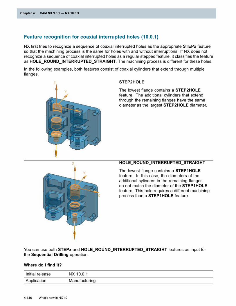
Chapter 4: CAM NX 9.0.1 — NX 10.0.3
Feature recognition for coaxial interrupted holes (10.0.1)
NX first tries to recognize a sequence of coaxial interrupted holes as the appropriate STEPx featureso that the machining process is the same for holes with and without interruptions. If NX does notrecognize a sequence of coaxial interrupted holes as a regular stepped feature, it classifies the featureas HOLE_ROUND_INTERRUPTED_STRAIGHT. The machining process is different for these holes.
In the following examples, both features consist of coaxial cylinders that extend through multipleflanges.
STEP2HOLE
The lowest flange contains a STEP2HOLEfeature. The additional cylinders that extendthrough the remaining flanges have the samediameter as the largest STEP2HOLE diameter.
HOLE_ROUND_INTERRUPTED_STRAIGHT
The lowest flange contains a STEP1HOLEfeature. In this case, the diameters of theadditional cylinders in the remaining flangesdo not match the diameter of the STEP1HOLEfeature. This hole requires a different machiningprocess than a STEP1HOLE feature.
You can use both STEPx and HOLE_ROUND_INTERRUPTED_STRAIGHT features as input forthe Sequential Drilling operation.
Where do I find it?
Initial release NX 10.0.1Application Manufacturing
4-136 What's new in NX 10
Chapter 4: CAM NX 9.0.1 — NX 10.0.3
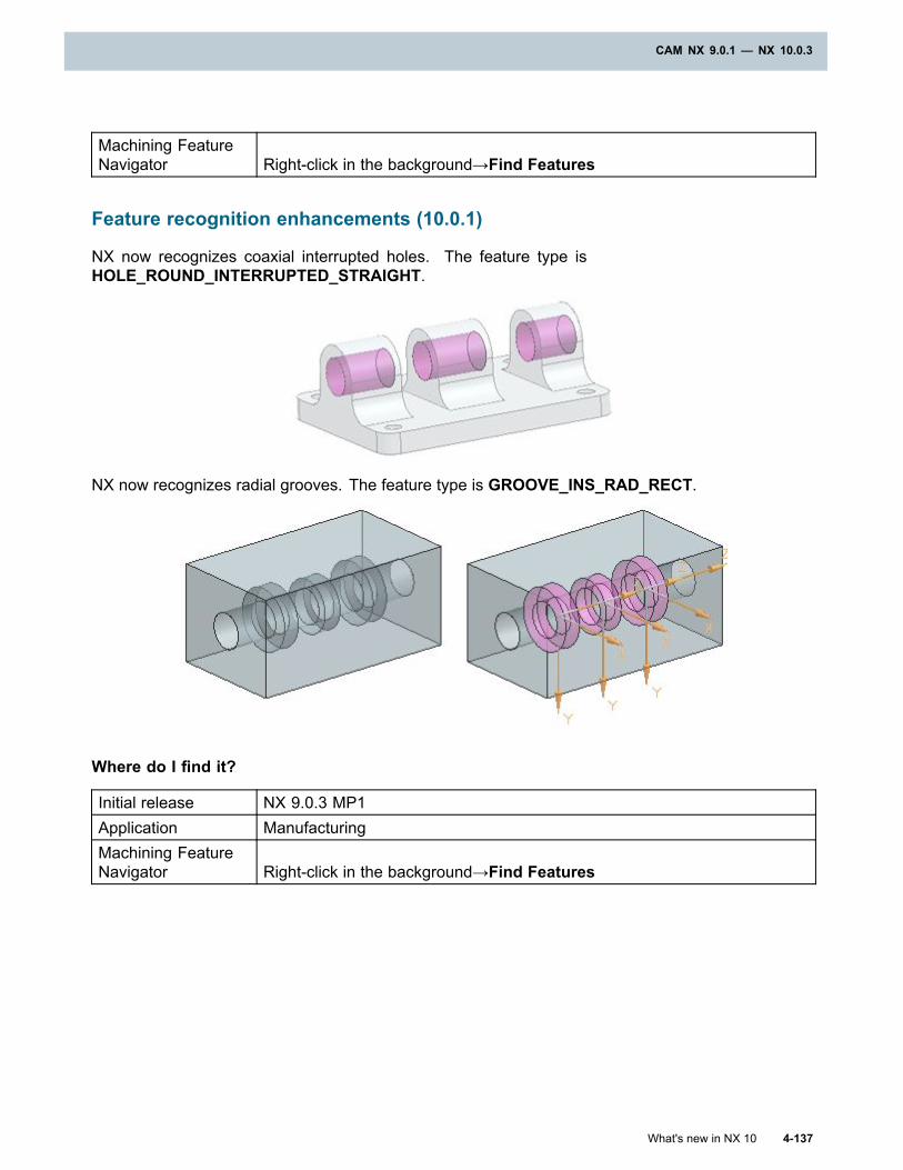
CAM NX 9.0.1 — NX 10.0.3
Machining FeatureNavigator Right-click in the background→Find Features
Feature recognition enhancements (10.0.1)
NX now recognizes coaxial interrupted holes. The feature type isHOLE_ROUND_INTERRUPTED_STRAIGHT.
NX now recognizes radial grooves. The feature type is GROOVE_INS_RAD_RECT.
Where do I find it?
Initial release NX 9.0.3 MP1Application ManufacturingMachining FeatureNavigator Right-click in the background→Find Features
What's new in NX 10 4-137
CAM NX 9.0.1 — NX 10.0.3

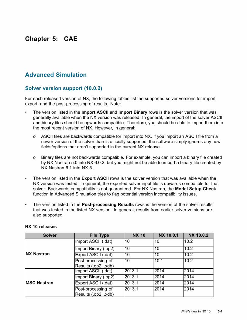
Chapter 5: CAE
Advanced Simulation
Solver version support (10.0.2)
For each released version of NX, the following tables list the supported solver versions for import,export, and the post-processing of results. Note:
• The version listed in the Import ASCII and Import Binary rows is the solver version that wasgenerally available when the NX version was released. In general, the import of the solver ASCIIand binary files should be upwards compatible. Therefore, you should be able to import them intothe most recent version of NX. However, in general:
o ASCII files are backwards compatible for import into NX. If you import an ASCII file from anewer version of the solver than is officially supported, the software simply ignores any newfields/options that aren't supported in the current NX release.
o Binary files are not backwards compatible. For example, you can import a binary file createdby NX Nastran 5.0 into NX 6.0.2, but you might not be able to import a binary file created byNX Nastran 6.1 into NX 5.
• The version listed in the Export ASCII rows is the solver version that was available when theNX version was tested. In general, the exported solver input file is upwards compatible for thatsolver. Backwards compatibility is not guaranteed. For NX Nastran, the Model Setup Checkfunction in Advanced Simulation tries to flag potential version incompatibility issues.
• The version listed in the Post-processing Results rows is the version of the solver resultsthat was tested in the listed NX version. In general, results from earlier solver versions arealso supported.
NX 10 releases
Solver File Type NX 10 NX 10.0.1 NX 10.0.2Import ASCII (.dat) 10 10 10.2Import Binary (.op2) 10 10 10.2Export ASCII (.dat) 10 10 10.2NX NastranPost-processing ofResults (.op2, .xdb)
10 10.1 10.2
Import ASCII (.dat) 2013.1 2014 2014Import Binary (.op2) 2013.1 2014 2014Export ASCII (.dat) 2013.1 2014 2014MSC NastranPost-processing ofResults (.op2, .xdb)
2013.1 2014 2014
What's new in NX 10 5-1
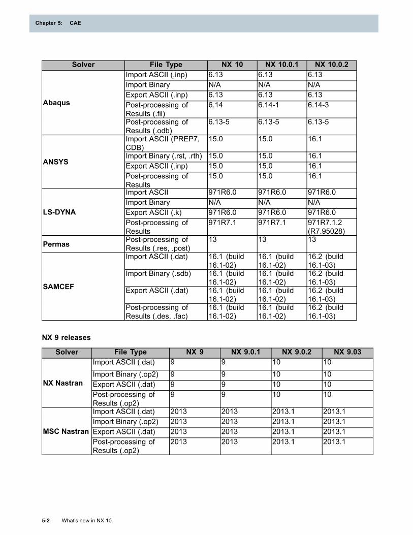
Chapter 5: CAE
Solver File Type NX 10 NX 10.0.1 NX 10.0.2Import ASCII (.inp) 6.13 6.13 6.13Import Binary N/A N/A N/AExport ASCII (.inp) 6.13 6.13 6.13Post-processing ofResults (.fil)
6.14 6.14-1 6.14-3Abaqus
Post-processing ofResults (.odb)
6.13-5 6.13-5 6.13-5
Import ASCII (PREP7,CDB)
15.0 15.0 16.1
Import Binary (.rst, .rth) 15.0 15.0 16.1Export ASCII (.inp) 15.0 15.0 16.1ANSYS
Post-processing ofResults
15.0 15.0 16.1
Import ASCII 971R6.0 971R6.0 971R6.0Import Binary N/A N/A N/AExport ASCII (.k) 971R6.0 971R6.0 971R6.0LS-DYNAPost-processing ofResults
971R7.1 971R7.1 971R7.1.2(R7.95028)
Permas Post-processing ofResults (.res, .post)
13 13 13
Import ASCII (.dat) 16.1 (build16.1-02)
16.1 (build16.1-02)
16.2 (build16.1-03)
Import Binary (.sdb) 16.1 (build16.1-02)
16.1 (build16.1-02)
16.2 (build16.1-03)
Export ASCII (.dat) 16.1 (build16.1-02)
16.1 (build16.1-02)
16.2 (build16.1-03)
SAMCEF
Post-processing ofResults (.des, .fac)
16.1 (build16.1-02)
16.1 (build16.1-02)
16.2 (build16.1-03)
NX 9 releases
Solver File Type NX 9 NX 9.0.1 NX 9.0.2 NX 9.03Import ASCII (.dat) 9 9 10 10Import Binary (.op2) 9 9 10 10Export ASCII (.dat) 9 9 10 10NX NastranPost-processing ofResults (.op2)
9 9 10 10
Import ASCII (.dat) 2013 2013 2013.1 2013.1Import Binary (.op2) 2013 2013 2013.1 2013.1Export ASCII (.dat) 2013 2013 2013.1 2013.1MSC NastranPost-processing ofResults (.op2)
2013 2013 2013.1 2013.1
5-2 What's new in NX 10
Chapter 5: CAE
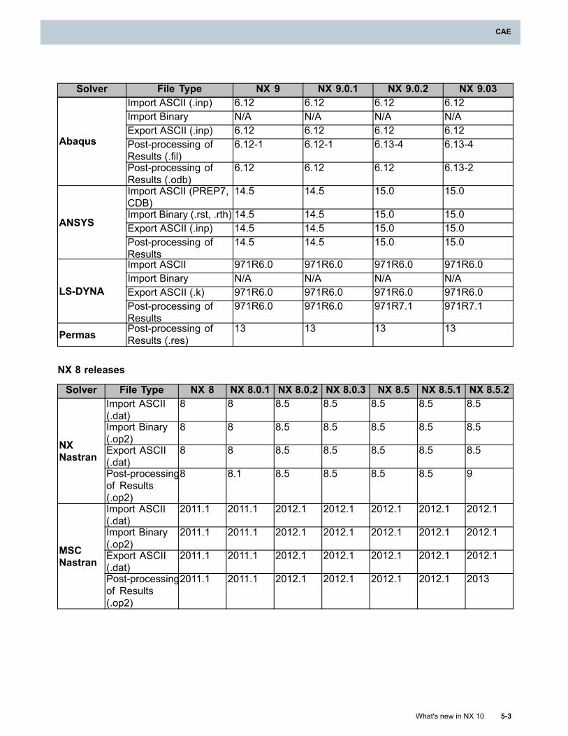
CAE
Solver File Type NX 9 NX 9.0.1 NX 9.0.2 NX 9.03Import ASCII (.inp) 6.12 6.12 6.12 6.12Import Binary N/A N/A N/A N/AExport ASCII (.inp) 6.12 6.12 6.12 6.12Post-processing ofResults (.fil)
6.12-1 6.12-1 6.13-4 6.13-4Abaqus
Post-processing ofResults (.odb)
6.12 6.12 6.12 6.13-2
Import ASCII (PREP7,CDB)
14.5 14.5 15.0 15.0
Import Binary (.rst, .rth) 14.5 14.5 15.0 15.0Export ASCII (.inp) 14.5 14.5 15.0 15.0ANSYS
Post-processing ofResults
14.5 14.5 15.0 15.0
Import ASCII 971R6.0 971R6.0 971R6.0 971R6.0Import Binary N/A N/A N/A N/AExport ASCII (.k) 971R6.0 971R6.0 971R6.0 971R6.0LS-DYNAPost-processing ofResults
971R6.0 971R6.0 971R7.1 971R7.1
Permas Post-processing ofResults (.res)
13 13 13 13
NX 8 releases
Solver File Type NX 8 NX 8.0.1 NX 8.0.2 NX 8.0.3 NX 8.5 NX 8.5.1 NX 8.5.2Import ASCII(.dat)
8 8 8.5 8.5 8.5 8.5 8.5
Import Binary(.op2)
8 8 8.5 8.5 8.5 8.5 8.5
Export ASCII(.dat)
8 8 8.5 8.5 8.5 8.5 8.5NXNastran
Post-processingof Results(.op2)
8 8.1 8.5 8.5 8.5 8.5 9
Import ASCII(.dat)
2011.1 2011.1 2012.1 2012.1 2012.1 2012.1 2012.1
Import Binary(.op2)
2011.1 2011.1 2012.1 2012.1 2012.1 2012.1 2012.1
Export ASCII(.dat)
2011.1 2011.1 2012.1 2012.1 2012.1 2012.1 2012.1MSCNastran
Post-processingof Results(.op2)
2011.1 2011.1 2012.1 2012.1 2012.1 2012.1 2013
What's new in NX 10 5-3
CAE
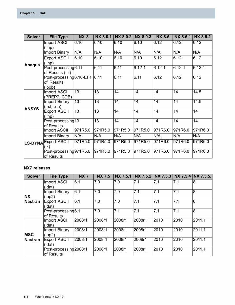
Chapter 5: CAE
Solver File Type NX 8 NX 8.0.1 NX 8.0.2 NX 8.0.3 NX 8.5 NX 8.5.1 NX 8.5.2Import ASCII(.inp)
6.10 6.10 6.10 6.10 6.12 6.12 6.12
Import Binary N/A N/A N/A N/A N/A N/A N/AExport ASCII(.inp)
6.10 6.10 6.10 6.10 6.12 6.12 6.12
Post-processingof Results (.fil)
6.11 6.11 6.11 6.12-1 6.12-1 6.12-1 6.12-1Abaqus
Post-processingof Results(.odb)
6.10-EF1 6.11 6.11 6.11 6.12 6.12 6.12
Import ASCII(PREP7, CDB)
13 13 14 14 14 14 14.5
Import Binary(.rst, .rth)
13 13 14 14 14 14 14.5
Export ASCII(.inp)
13 13 14 14 14 14 14ANSYS
Post-processingof Results
13 13 14 14 14 14 14
Import ASCII 971R5.0 971R5.0 971R5.0 971R5.0 971R6.0 971R6.0 971R6.0Import Binary N/A N/A N/A N/A N/A N/A N/AExport ASCII(.k)
971R5.0 971R5.0 971R5.0 971R5.0 971R6.0 971R6.0 971R6.0LS-DYNA
Post-processingof Results
971R5.0 971R5.0 971R5.0 971R5.0 971R6.0 971R6.0 971R6.0
NX7 releases
Solver File Type NX 7 NX 7.5 NX 7.5.1 NX 7.5.2 NX 7.5.3 NX 7.5.4 NX 7.5.5.Import ASCII(.dat)
6.1 7.0 7.0 7.1 7.1 7.1 8
Import Binary(.op2)
6.1 7.0 7.0 7.1 7.1 7.1 8
Export ASCII(.dat)
6.1 7.0 7.0 7.1 7.1 7.1 8NXNastran
Post-processingof Results
6.1 7.0 7.1 7.1 7.1 7.1 8
Import ASCII(.dat)
2008r1 2008r1 2008r1 2008r1 2010 2010 2011.1
Import Binary(.op2)
2008r1 2008r1 2008r1 2008r1 2010 2010 2011.1
Export ASCII(.dat)
2008r1 2008r1 2008r1 2008r1 2010 2010 2011.1MSCNastran
Post-processingof Results
2008r1 2008r1 2008r1 2008r1 2010 2010 2011.1
5-4 What's new in NX 10
Chapter 5: CAE
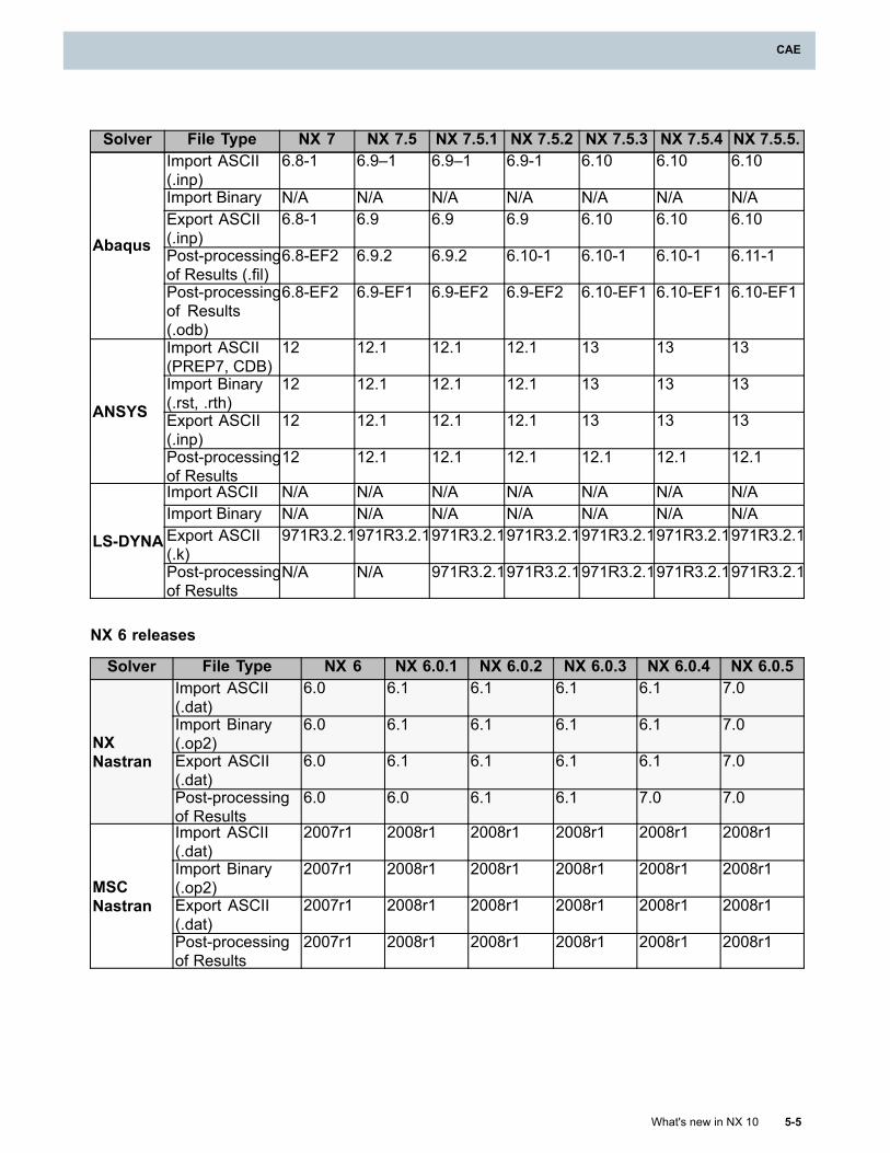
CAE
Solver File Type NX 7 NX 7.5 NX 7.5.1 NX 7.5.2 NX 7.5.3 NX 7.5.4 NX 7.5.5.Import ASCII(.inp)
6.8-1 6.9–1 6.9–1 6.9-1 6.10 6.10 6.10
Import Binary N/A N/A N/A N/A N/A N/A N/AExport ASCII(.inp)
6.8-1 6.9 6.9 6.9 6.10 6.10 6.10
Post-processingof Results (.fil)
6.8-EF2 6.9.2 6.9.2 6.10-1 6.10-1 6.10-1 6.11-1Abaqus
Post-processingof Results(.odb)
6.8-EF2 6.9-EF1 6.9-EF2 6.9-EF2 6.10-EF1 6.10-EF1 6.10-EF1
Import ASCII(PREP7, CDB)
12 12.1 12.1 12.1 13 13 13
Import Binary(.rst, .rth)
12 12.1 12.1 12.1 13 13 13
Export ASCII(.inp)
12 12.1 12.1 12.1 13 13 13ANSYS
Post-processingof Results
12 12.1 12.1 12.1 12.1 12.1 12.1
Import ASCII N/A N/A N/A N/A N/A N/A N/AImport Binary N/A N/A N/A N/A N/A N/A N/AExport ASCII(.k)
971R3.2.1971R3.2.1971R3.2.1971R3.2.1971R3.2.1971R3.2.1971R3.2.1LS-DYNA
Post-processingof Results
N/A N/A 971R3.2.1971R3.2.1971R3.2.1971R3.2.1971R3.2.1
NX 6 releases
Solver File Type NX 6 NX 6.0.1 NX 6.0.2 NX 6.0.3 NX 6.0.4 NX 6.0.5Import ASCII(.dat)
6.0 6.1 6.1 6.1 6.1 7.0
Import Binary(.op2)
6.0 6.1 6.1 6.1 6.1 7.0
Export ASCII(.dat)
6.0 6.1 6.1 6.1 6.1 7.0NXNastran
Post-processingof Results
6.0 6.0 6.1 6.1 7.0 7.0
Import ASCII(.dat)
2007r1 2008r1 2008r1 2008r1 2008r1 2008r1
Import Binary(.op2)
2007r1 2008r1 2008r1 2008r1 2008r1 2008r1
Export ASCII(.dat)
2007r1 2008r1 2008r1 2008r1 2008r1 2008r1MSCNastran
Post-processingof Results
2007r1 2008r1 2008r1 2008r1 2008r1 2008r1
What's new in NX 10 5-5
CAE
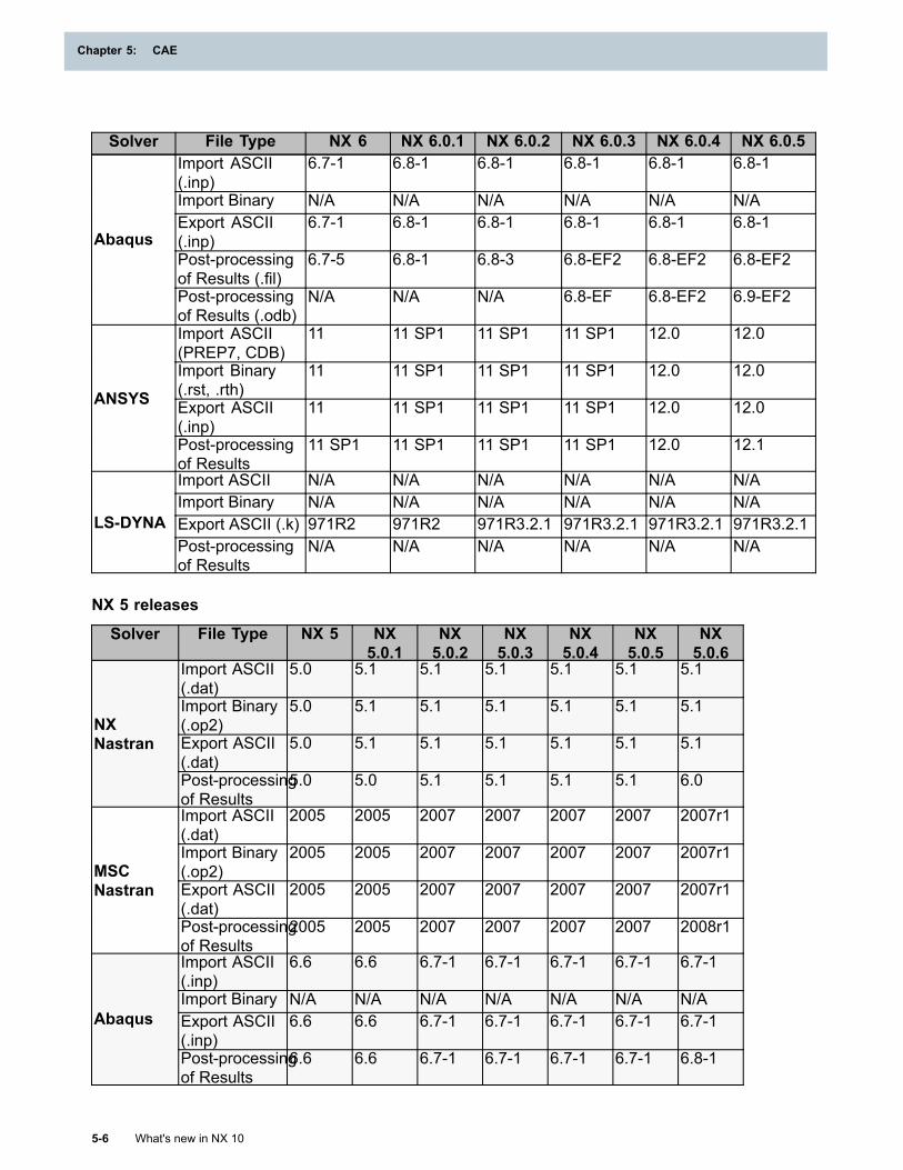
Chapter 5: CAE
Solver File Type NX 6 NX 6.0.1 NX 6.0.2 NX 6.0.3 NX 6.0.4 NX 6.0.5Import ASCII(.inp)
6.7-1 6.8-1 6.8-1 6.8-1 6.8-1 6.8-1
Import Binary N/A N/A N/A N/A N/A N/AExport ASCII(.inp)
6.7-1 6.8-1 6.8-1 6.8-1 6.8-1 6.8-1
Post-processingof Results (.fil)
6.7-5 6.8-1 6.8-3 6.8-EF2 6.8-EF2 6.8-EF2Abaqus
Post-processingof Results (.odb)
N/A N/A N/A 6.8-EF 6.8-EF2 6.9-EF2
Import ASCII(PREP7, CDB)
11 11 SP1 11 SP1 11 SP1 12.0 12.0
Import Binary(.rst, .rth)
11 11 SP1 11 SP1 11 SP1 12.0 12.0
Export ASCII(.inp)
11 11 SP1 11 SP1 11 SP1 12.0 12.0ANSYS
Post-processingof Results
11 SP1 11 SP1 11 SP1 11 SP1 12.0 12.1
Import ASCII N/A N/A N/A N/A N/A N/AImport Binary N/A N/A N/A N/A N/A N/AExport ASCII (.k) 971R2 971R2 971R3.2.1 971R3.2.1 971R3.2.1 971R3.2.1LS-DYNAPost-processingof Results
N/A N/A N/A N/A N/A N/A
NX 5 releases
Solver File Type NX 5 NX5.0.1
NX5.0.2
NX5.0.3
NX5.0.4
NX5.0.5
NX5.0.6
Import ASCII(.dat)
5.0 5.1 5.1 5.1 5.1 5.1 5.1
Import Binary(.op2)
5.0 5.1 5.1 5.1 5.1 5.1 5.1
Export ASCII(.dat)
5.0 5.1 5.1 5.1 5.1 5.1 5.1NXNastran
Post-processingof Results
5.0 5.0 5.1 5.1 5.1 5.1 6.0
Import ASCII(.dat)
2005 2005 2007 2007 2007 2007 2007r1
Import Binary(.op2)
2005 2005 2007 2007 2007 2007 2007r1
Export ASCII(.dat)
2005 2005 2007 2007 2007 2007 2007r1MSCNastran
Post-processingof Results
2005 2005 2007 2007 2007 2007 2008r1
Import ASCII(.inp)
6.6 6.6 6.7-1 6.7-1 6.7-1 6.7-1 6.7-1
Import Binary N/A N/A N/A N/A N/A N/A N/AExport ASCII(.inp)
6.6 6.6 6.7-1 6.7-1 6.7-1 6.7-1 6.7-1Abaqus
Post-processingof Results
6.6 6.6 6.7-1 6.7-1 6.7-1 6.7-1 6.8-1
5-6 What's new in NX 10
Chapter 5: CAE
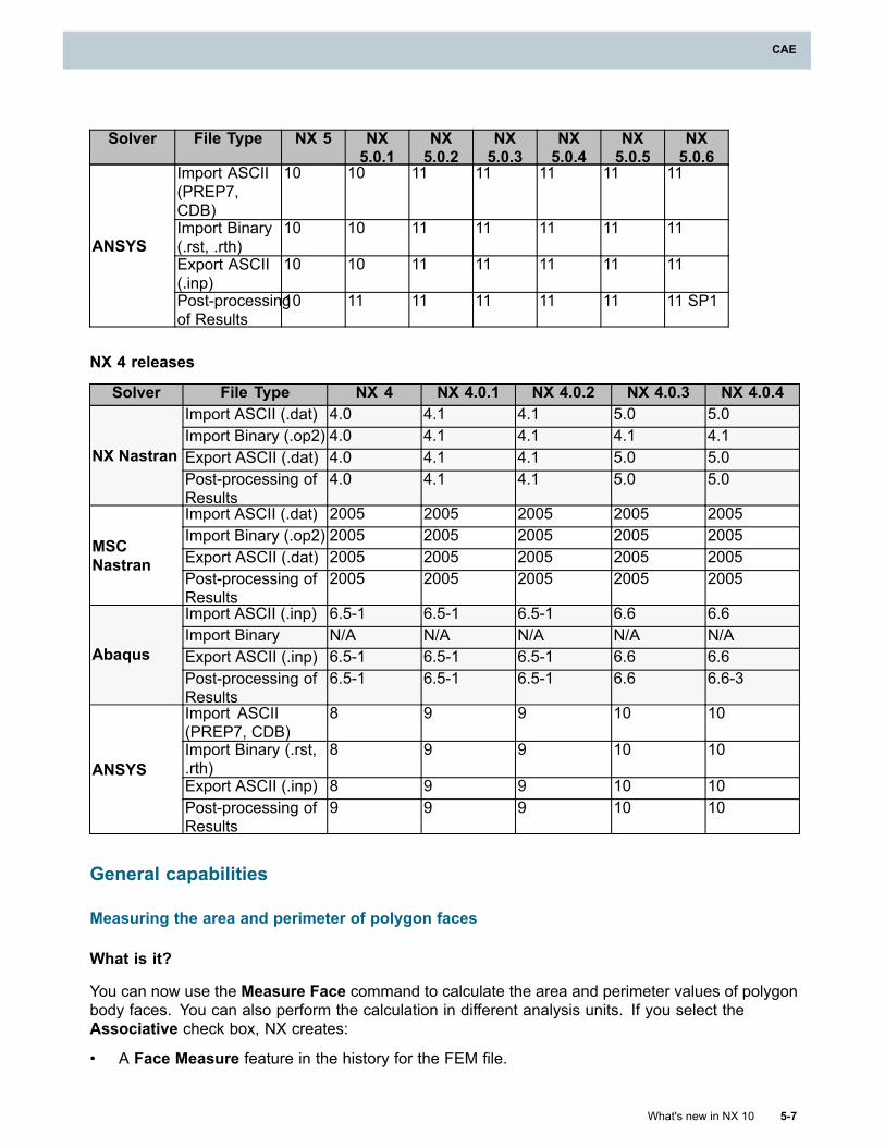
CAE
Solver File Type NX 5 NX5.0.1
NX5.0.2
NX5.0.3
NX5.0.4
NX5.0.5
NX5.0.6
Import ASCII(PREP7,CDB)
10 10 11 11 11 11 11
Import Binary(.rst, .rth)
10 10 11 11 11 11 11
Export ASCII(.inp)
10 10 11 11 11 11 11ANSYS
Post-processingof Results
10 11 11 11 11 11 11 SP1
NX 4 releases
Solver File Type NX 4 NX 4.0.1 NX 4.0.2 NX 4.0.3 NX 4.0.4Import ASCII (.dat) 4.0 4.1 4.1 5.0 5.0Import Binary (.op2) 4.0 4.1 4.1 4.1 4.1Export ASCII (.dat) 4.0 4.1 4.1 5.0 5.0NX NastranPost-processing ofResults
4.0 4.1 4.1 5.0 5.0
Import ASCII (.dat) 2005 2005 2005 2005 2005Import Binary (.op2) 2005 2005 2005 2005 2005Export ASCII (.dat) 2005 2005 2005 2005 2005
MSCNastran
Post-processing ofResults
2005 2005 2005 2005 2005
Import ASCII (.inp) 6.5-1 6.5-1 6.5-1 6.6 6.6Import Binary N/A N/A N/A N/A N/AExport ASCII (.inp) 6.5-1 6.5-1 6.5-1 6.6 6.6AbaqusPost-processing ofResults
6.5-1 6.5-1 6.5-1 6.6 6.6-3
Import ASCII(PREP7, CDB)
8 9 9 10 10
Import Binary (.rst,.rth)
8 9 9 10 10
Export ASCII (.inp) 8 9 9 10 10ANSYS
Post-processing ofResults
9 9 9 10 10
General capabilities
Measuring the area and perimeter of polygon faces
What is it?
You can now use the Measure Face command to calculate the area and perimeter values of polygonbody faces. You can also perform the calculation in different analysis units. If you select theAssociative check box, NX creates:
• A Face Measure feature in the history for the FEM file.
What's new in NX 10 5-7
CAE
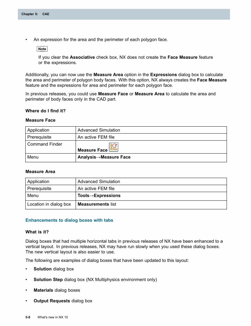
Chapter 5: CAE
• An expression for the area and the perimeter of each polygon face.
Note
If you clear the Associative check box, NX does not create the Face Measure featureor the expressions.
Additionally, you can now use the Measure Area option in the Expressions dialog box to calculatethe area and perimeter of polygon body faces. With this option, NX always creates the Face Measurefeature and the expressions for area and perimeter for each polygon face.
In previous releases, you could use Measure Face or Measure Area to calculate the area andperimeter of body faces only in the CAD part.
Where do I find it?
Measure Face
Application Advanced SimulationPrerequisite An active FEM fileCommand Finder
Measure FaceMenu Analysis→Measure Face
Measure Area
Application Advanced SimulationPrerequisite An active FEM fileMenu Tools→Expressions
Location in dialog box Measurements list
Enhancements to dialog boxes with tabs
What is it?
Dialog boxes that had multiple horizontal tabs in previous releases of NX have been enhanced to avertical layout. In previous releases, NX may have run slowly when you used these dialog boxes.The new vertical layout is also easier to use.
The following are examples of dialog boxes that have been updated to this layout:
• Solution dialog box
• Solution Step dialog box (NX Multiphysics environment only)
• Materials dialog boxes
• Output Requests dialog box
5-8 What's new in NX 10
Chapter 5: CAE
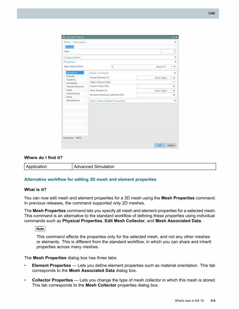
CAE
Where do I find it?
Application Advanced Simulation
Alternative workflow for editing 3D mesh and element properties
What is it?
You can now edit mesh and element properties for a 3D mesh using the Mesh Properties command.In previous releases, the command supported only 2D meshes.
TheMesh Properties command lets you specify all mesh and element properties for a selected mesh.This command is an alternative to the standard workflow of defining these properties using individualcommands such as Physical Properties, Edit Mesh Collector, and Mesh Associated Data.
Note
This command affects the properties only for the selected mesh, and not any other meshesor elements. This is different from the standard workflow, in which you can share and inheritproperties across many meshes.
The Mesh Properties dialog box has three tabs:
• Element Properties— Lets you define element properties such as material orientation. This tabcorresponds to the Mesh Associated Data dialog box.
• Collector Properties— Lets you change the type of mesh collector in which this mesh is stored.This tab corresponds to the Mesh Collector properties dialog box.
What's new in NX 10 5-9
CAE
Chapter 5: CAE
• Physical Properties — Lets you define physical properties such as default thickness,nonstructural mass, and material properties. This tab corresponds to the Physical PropertyTable dialog box.
You can define the same properties for several selected meshes at the same time. To do this, selectthe meshes and then open the Mesh Properties dialog box.
Where do I find it?
Application Advanced SimulationPrerequisites A FEM file as the work part and displayed part
The Simulation Navigator set to Mesh ViewCommand Finder
Mesh PropertiesGraphics window Right-click one or more 2D or 3D meshes → Mesh PropertiesSimulation Navigator Right-click one or more 2D or 3D meshes → Edit Mesh Properties
Additional grouping in Mesh View of Simulation Navigator
What is it?
When you view your meshes in the Mesh View of the Simulation Navigator, meshes are nowgrouped according to their mesh type in addition to their element family.
5-10 What's new in NX 10
Chapter 5: CAE
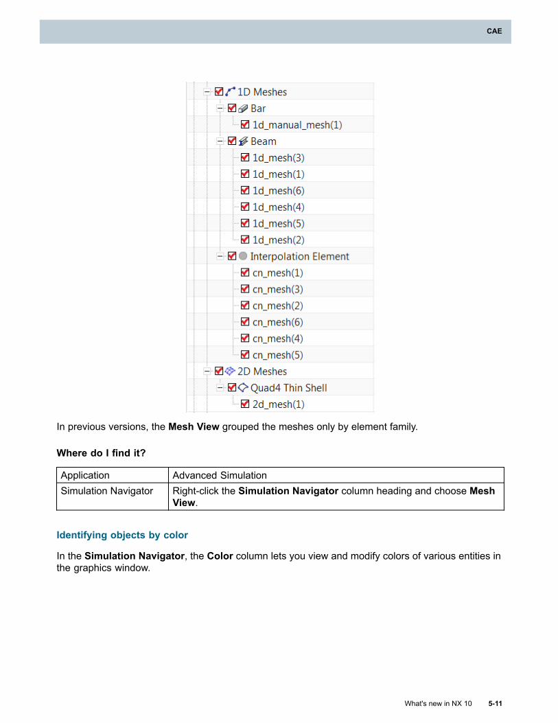
CAE
In previous versions, the Mesh View grouped the meshes only by element family.
Where do I find it?
Application Advanced SimulationSimulation Navigator Right-click the Simulation Navigator column heading and choose Mesh
View.
Identifying objects by color
In the Simulation Navigator, the Color column lets you view and modify colors of various entities inthe graphics window.
What's new in NX 10 5-11
CAE
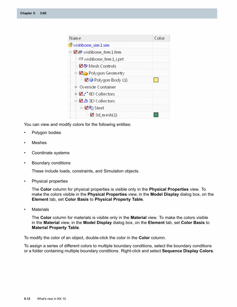
Chapter 5: CAE
You can view and modify colors for the following entities:
• Polygon bodies
• Meshes
• Coordinate systems
• Boundary conditions
These include loads, constraints, and Simulation objects.
• Physical properties
The Color column for physical properties is visible only in the Physical Properties view. Tomake the colors visible in the Physical Properties view, in the Model Display dialog box, on theElement tab, set Color Basis to Physical Property Table.
• Materials
The Color column for materials is visible only in the Material view. To make the colors visiblein the Material view, in the Model Display dialog box, on the Element tab, set Color Basis toMaterial Property Table.
To modify the color of an object, double-click the color in the Color column.
To assign a series of different colors to multiple boundary conditions, select the boundary conditionsor a folder containing multiple boundary conditions. Right-click and select Sequence Display Colors.
5-12 What's new in NX 10
Chapter 5: CAE
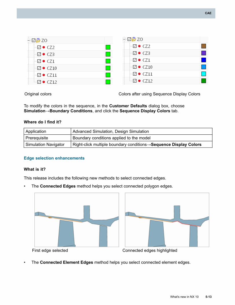
CAE
Original colors Colors after using Sequence Display Colors
To modify the colors in the sequence, in the Customer Defaults dialog box, chooseSimulation→Boundary Conditions, and click the Sequence Display Colors tab.
Where do I find it?
Application Advanced Simulation, Design SimulationPrerequisite Boundary conditions applied to the modelSimulation Navigator Right-click multiple boundary conditions→Sequence Display Colors
Edge selection enhancements
What is it?
This release includes the following new methods to select connected edges.
• The Connected Edges method helps you select connected polygon edges.
First edge selected Connected edges highlighted
• The Connected Element Edges method helps you select connected element edges.
What's new in NX 10 5-13
CAE
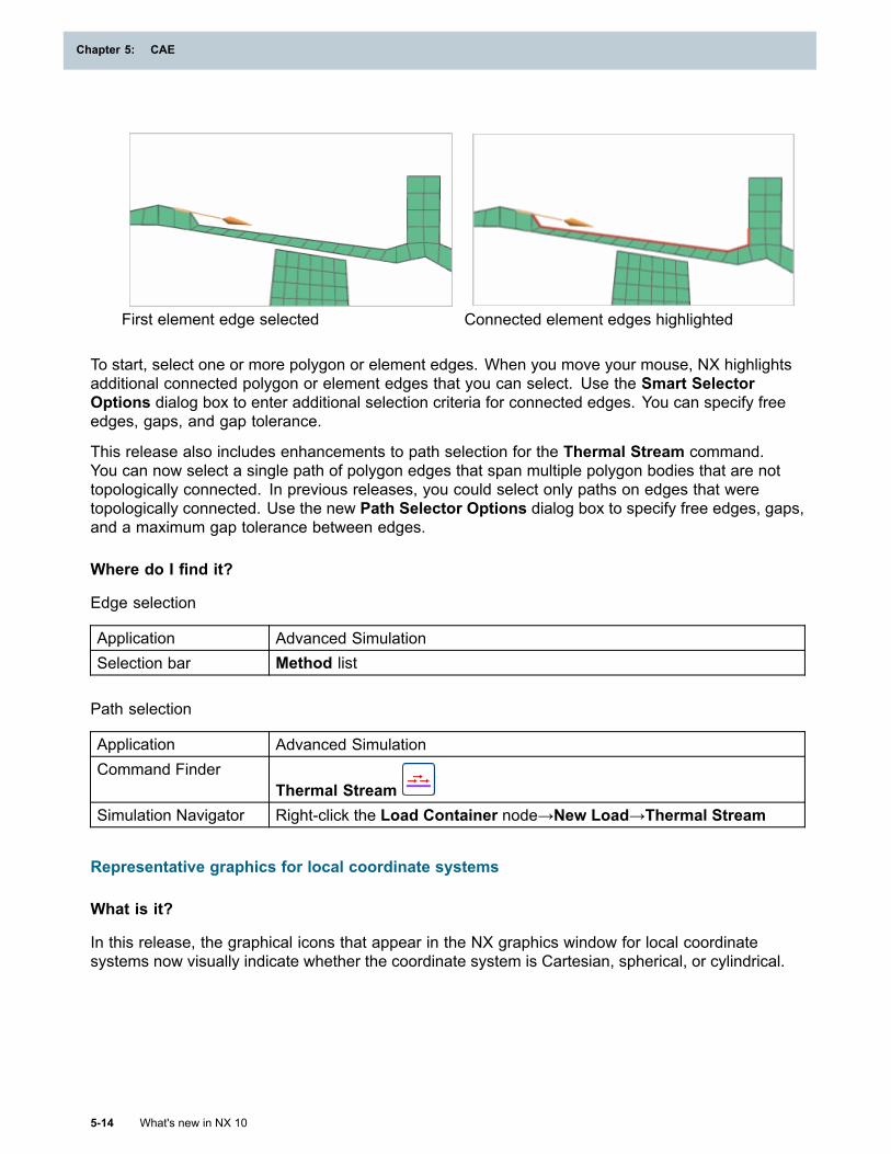
Chapter 5: CAE
First element edge selected Connected element edges highlighted
To start, select one or more polygon or element edges. When you move your mouse, NX highlightsadditional connected polygon or element edges that you can select. Use the Smart SelectorOptions dialog box to enter additional selection criteria for connected edges. You can specify freeedges, gaps, and gap tolerance.
This release also includes enhancements to path selection for the Thermal Stream command.You can now select a single path of polygon edges that span multiple polygon bodies that are nottopologically connected. In previous releases, you could select only paths on edges that weretopologically connected. Use the new Path Selector Options dialog box to specify free edges, gaps,and a maximum gap tolerance between edges.
Where do I find it?
Edge selection
Application Advanced SimulationSelection bar Method list
Path selection
Application Advanced SimulationCommand Finder
Thermal StreamSimulation Navigator Right-click the Load Container node→New Load→Thermal Stream
Representative graphics for local coordinate systems
What is it?
In this release, the graphical icons that appear in the NX graphics window for local coordinatesystems now visually indicate whether the coordinate system is Cartesian, spherical, or cylindrical.
5-14 What's new in NX 10
Chapter 5: CAE
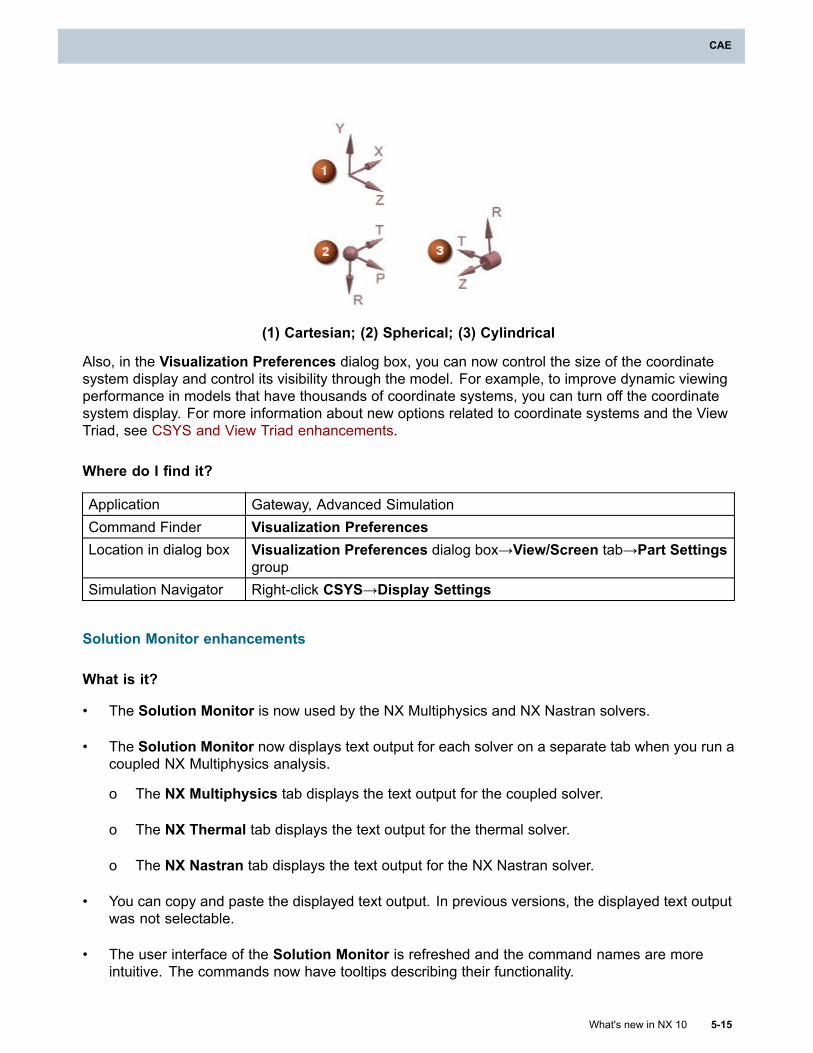
CAE
(1) Cartesian; (2) Spherical; (3) Cylindrical
Also, in the Visualization Preferences dialog box, you can now control the size of the coordinatesystem display and control its visibility through the model. For example, to improve dynamic viewingperformance in models that have thousands of coordinate systems, you can turn off the coordinatesystem display. For more information about new options related to coordinate systems and the ViewTriad, see CSYS and View Triad enhancements.
Where do I find it?
Application Gateway, Advanced SimulationCommand Finder Visualization PreferencesLocation in dialog box Visualization Preferences dialog box→View/Screen tab→Part Settings
groupSimulation Navigator Right-click CSYS→Display Settings
Solution Monitor enhancements
What is it?
• The Solution Monitor is now used by the NX Multiphysics and NX Nastran solvers.
• The Solution Monitor now displays text output for each solver on a separate tab when you run acoupled NX Multiphysics analysis.
o The NX Multiphysics tab displays the text output for the coupled solver.
o The NX Thermal tab displays the text output for the thermal solver.
o The NX Nastran tab displays the text output for the NX Nastran solver.
• You can copy and paste the displayed text output. In previous versions, the displayed text outputwas not selectable.
• The user interface of the Solution Monitor is refreshed and the command names are moreintuitive. The commands now have tooltips describing their functionality.
What's new in NX 10 5-15
CAE
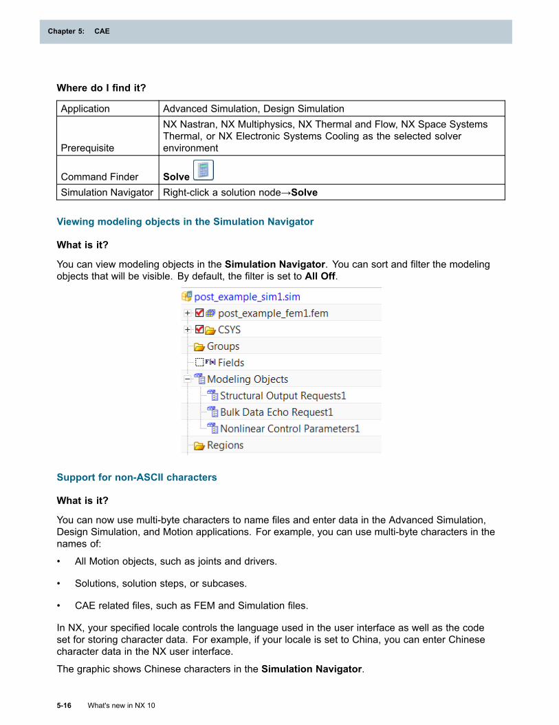
Chapter 5: CAE
Where do I find it?
Application Advanced Simulation, Design Simulation
Prerequisite
NX Nastran, NX Multiphysics, NX Thermal and Flow, NX Space SystemsThermal, or NX Electronic Systems Cooling as the selected solverenvironment
Command Finder SolveSimulation Navigator Right-click a solution node→Solve
Viewing modeling objects in the Simulation Navigator
What is it?
You can view modeling objects in the Simulation Navigator. You can sort and filter the modelingobjects that will be visible. By default, the filter is set to All Off.
Support for non-ASCII characters
What is it?
You can now use multi-byte characters to name files and enter data in the Advanced Simulation,Design Simulation, and Motion applications. For example, you can use multi-byte characters in thenames of:
• All Motion objects, such as joints and drivers.
• Solutions, solution steps, or subcases.
• CAE related files, such as FEM and Simulation files.
In NX, your specified locale controls the language used in the user interface as well as the codeset for storing character data. For example, if your locale is set to China, you can enter Chinesecharacter data in the NX user interface.
The graphic shows Chinese characters in the Simulation Navigator.
5-16 What's new in NX 10
Chapter 5: CAE

CAE
NX follows the Unicode international standard to store multi-byte character data, using UTF–8encoding. Although NX supports the use of multi-byte characters, many third party software packagesthat interface with NX, such as finite element solvers, support only ASCII character data.
Caution
NX does not provide an error message if the solver receives unsupported characters. Youmust verify that your solvers will support your desired locale before implementing localization.
Solver support for multi-byte characters
Solver Unicode support Solve withnon-ASCIIentities
Solve withnon-ASCII file
names
Export withnon-ASCII filenames andentities
Importwith
non-ASCIIfile names
andentities
NXNastran
No Yes Yes Yes Yes
MSCNastran
No No No Yes Yes
Abaqus No No Yes Yes YesANSYS No No No Yes YesNXNastranDesign
No Yes Yes Yes Yes
NXMultiphysics(Structural)
No Yes Yes N/A Yes
NXMultiphysics(Thermal/Mapping/Coupled)
No No No N/A Yes
What's new in NX 10 5-17
CAE
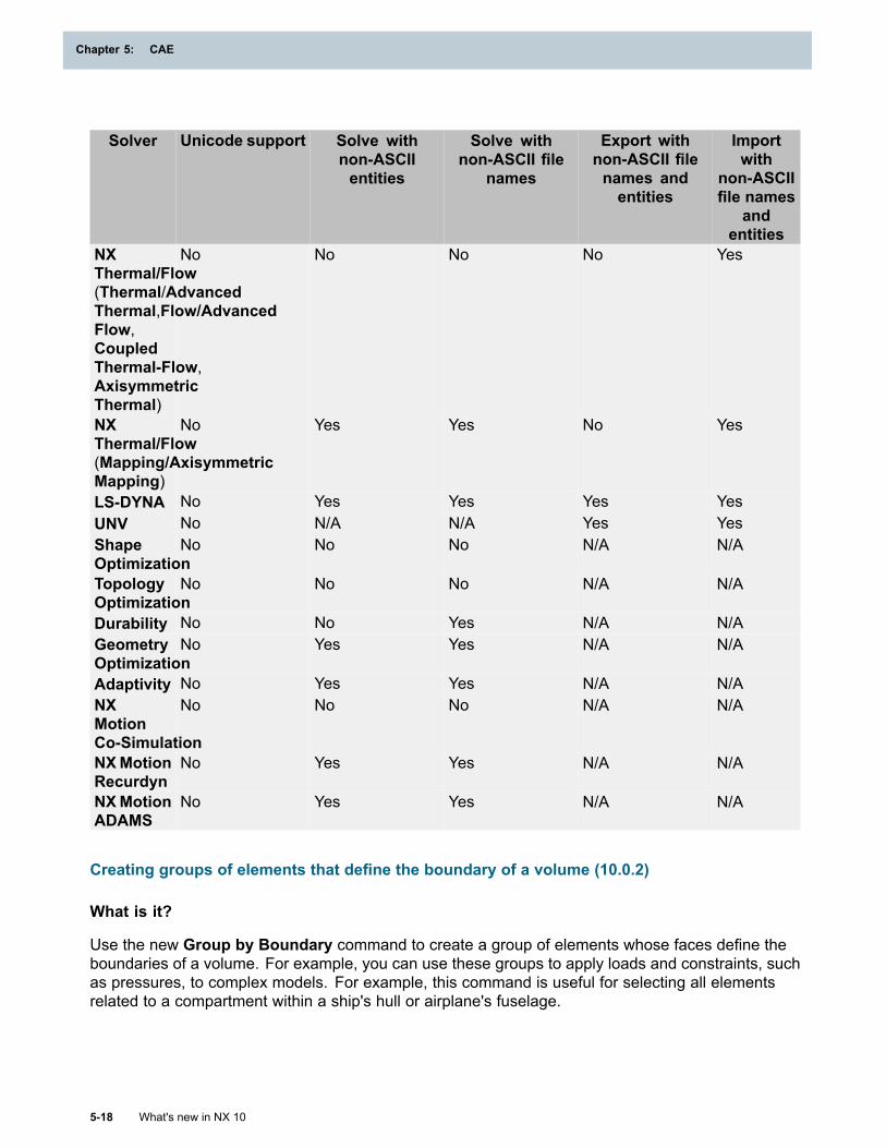
Chapter 5: CAE
Solver Unicode support Solve withnon-ASCIIentities
Solve withnon-ASCII file
names
Export withnon-ASCII filenames andentities
Importwith
non-ASCIIfile names
andentities
NXThermal/Flow(Thermal/AdvancedThermal,Flow/AdvancedFlow,CoupledThermal-Flow,AxisymmetricThermal)
No No No No Yes
NXThermal/Flow(Mapping/AxisymmetricMapping)
No Yes Yes No Yes
LS-DYNA No Yes Yes Yes YesUNV No N/A N/A Yes YesShapeOptimization
No No No N/A N/A
TopologyOptimization
No No No N/A N/A
Durability No No Yes N/A N/AGeometryOptimization
No Yes Yes N/A N/A
Adaptivity No Yes Yes N/A N/ANXMotionCo-Simulation
No No No N/A N/A
NXMotionRecurdyn
No Yes Yes N/A N/A
NXMotionADAMS
No Yes Yes N/A N/A
Creating groups of elements that define the boundary of a volume (10.0.2)
What is it?
Use the new Group by Boundary command to create a group of elements whose faces define theboundaries of a volume. For example, you can use these groups to apply loads and constraints, suchas pressures, to complex models. For example, this command is useful for selecting all elementsrelated to a compartment within a ship's hull or airplane's fuselage.
5-18 What's new in NX 10
Chapter 5: CAE
CAE
Determining the elements to place in the group
In the Group Elements by Boundary dialog box, you first select a seed element with the appropriateorientation. As a best practice, you should select an element whose normal points into the interior ofthe volume or compartment.
When you click Find Elements, the software evaluates the elements that surround the seed element.If the software detects free element edges, it further evaluates the region to determine whether thefree edges represent the outer boundary of the volume or an internal feature of the volume thatshould be ignored. The software only examines visible elements within the model.
Tip
Before using this command, use the Show and Hide command to limit your display to thearea of interest.
When the software finds appropriate elements, it places them in a group:
• To separate the elements into groups based on the direction of an element's normal, select theCreate two groups based on normals check box.
• To create a single group for all the elements, regardless of the direction of their normals, clear theCreate two groups based on normals check box.
Automatically excluding non-manifold elements that define features
When the software searches for related, connected elements, it automatically excludes elementswhose edges are non-manifold and that define features within the volume, such as a rib or a fin. Ifan element extends into a volume, and both faces of the element are interior to the volume, thesoftware excludes the element. When you click OK or Apply, the software automatically places theexcluded elements in a separate group in the Simulation Navigator. By default, the name of thatgroup is Non-Manifold Connected.
Tip
To view these elements in the graphics window, click the Preview Removed Elements button.
Modifying groups
You can modify groups of boundary elements just as you can modify other types of groups.
• You can add elements to a previewed group, before you create the group. In the GroupElements by Boundary dialog box, click Preview Groups and then click the appropriate Select
Element button to select the element or elements to add.
• You can add or remove elements from an existing group of boundary elements. Use the EditGroup command in the Simulation Navigator to add or remove elements from a selected group.
Where do I find it?
Group by Boundary
Application Advanced SimulationPrerequisite A FEM file as the displayed part and the work part
What's new in NX 10 5-19
CAE
Chapter 5: CAE
Command FinderGroup by Boundary
Group by Boundary defaults
Menu File→Utilities→Customer DefaultsLocation in dialog box Simulation→Grouping
Fields
Complex data support
What is it?
When you create a table field, you can now define tabular data that has a complex dependentdomain. You can:
• Import the tabular data from a text file.
• Edit or create the tabular data in an external spreadsheet application.
• Enter the tabular data directly.
Just like table fields with real domains, table fields with complex dependent domains are defined fromthe Table Field dialog box. To specify a complex dependent domain, you must first access theunfiltered listing of dependent domains.
The software accepts complex data in the real/imaginary format which is the default, or themagnitude/phase format. To switch to the magnitude/phase format, in the Table Field dialog box, inthe Data Points table, right-click the (Real) or (Imaginary) column heading and choose DisplayMagnitude/Phase.
Where do I find it?
Application Advanced SimulationSimulation Navigator Right-click Fields→New Field→TableLocation in dialog box
Table Field dialog box→ClickRemove complex domains filter →1–Dlist→Other→Independent domains list→select ComplexNumber
Extrapolation options
What is it?
You can now specify the extrapolation method when any Delaunay method is selected as theinterpolation method in the Table Field dialog box. In earlier versions of NX, you could specify theextrapolation method only when Linear was selected as the interpolation method.
5-20 What's new in NX 10
Chapter 5: CAE
CAE
When you select a Delaunay method as the interpolation method in the Table Field dialog box, youhave the following extrapolation options: Undefined and Constant.
• Select Undefined if you do not want the software to assign a value to the dependent domain ofpoints whose independent domain lies outside the cloud of points defined by the tabular data.
• Select Constant if you want the software to do the following:
1. Identify the location on the surface of the cloud of points that is closest to the point whoseindependent domain lies outside the cloud of points.
2. Interpolate the tabular data to calculate the value for the dependent domain at that locationon the surface of the cloud of points.
3. Use the interpolated value as the table lookup value for the point whose independent domainlies outside the cloud of points.
The Constant option in NX 10 is equivalent to the default behavior when a Delaunay method isselected as the interpolation method in earlier versions of NX.
Where do I find it?
Application Advanced SimulationSimulation Navigator Right-click Fields→New Field→TableLocation in dialog box Table Field dialog box→Interpolation list→Delaunay – Fast or
Delaunay – Medium or Delaunay – Accurate→Values Outside Tablelist→Constant or Undefined
Graphical table editing
What is it?
When you create a spatial field, you can now obtain the coordinates for the tabular data directly fromthe graphics window. In previous versions of NX, you had to explicitly enter the coordinates for thetabular data. After you select a point in the graphics window, you must enter the correspondingvalue of the dependent domain.
To support the new functionality, the new Points in Table dialog box is available. You type the valueof the dependent domain for the selected point in the Value field in this dialog box.
What's new in NX 10 5-21
CAE
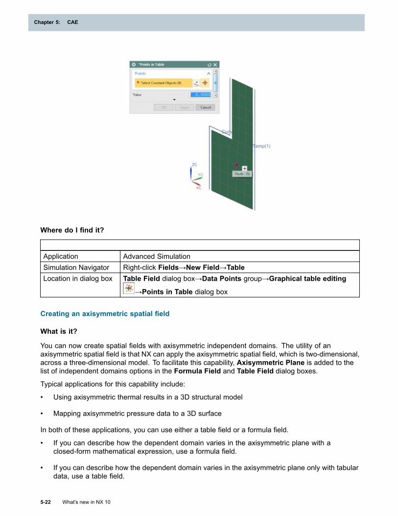
Chapter 5: CAE
Where do I find it?
Application Advanced SimulationSimulation Navigator Right-click Fields→New Field→TableLocation in dialog box Table Field dialog box→Data Points group→Graphical table editing
→Points in Table dialog box
Creating an axisymmetric spatial field
What is it?
You can now create spatial fields with axisymmetric independent domains. The utility of anaxisymmetric spatial field is that NX can apply the axisymmetric spatial field, which is two-dimensional,across a three-dimensional model. To facilitate this capability, Axisymmetric Plane is added to thelist of independent domains options in the Formula Field and Table Field dialog boxes.
Typical applications for this capability include:
• Using axisymmetric thermal results in a 3D structural model
• Mapping axisymmetric pressure data to a 3D surface
In both of these applications, you can use either a table field or a formula field.
• If you can describe how the dependent domain varies in the axisymmetric plane with aclosed-form mathematical expression, use a formula field.
• If you can describe how the dependent domain varies in the axisymmetric plane only with tabulardata, use a table field.
5-22 What's new in NX 10
Chapter 5: CAE
CAE
Where do I find it?
Application Advanced SimulationPrerequisite In the New FEM or New FEM and Simulation dialog box, in the Solver
Environment group, from the 2D Solid Option list, select ZX Plane, ZAxis or XY Plane, X Axis.
Simulation Navigator Right-click Fields→New Field→Expression or TableLocation in dialog box Formula Field or Table Field dialog box→Domain group→Independent
list→Axisymmetric Plane
4D field support
What is it?
Beginning with NX 10, you can create 4D fields. 4D fields are formula fields or table fields whoseindependent domain includes both spatial coordinates and a single non-spatial variable like time,temperature, or frequency. Mathematically, 4D fields allow you to model functional relationshipsof the form:
f = f(x1,x2,x3,α)
where x1, x2, and x3 represent a set of Cartesian, cylindrical, spherical, or parametric spatialcoordinates, and α represents a non-spatial variable like time, temperature, or frequency.
You can use 4D fields to define the following boundary conditions:
• Acceleration
• Heat flux
• Heat generation
• Nodal pressure
• Pressure
• Radiation
• Temperature load
• Convection
• Enforced displacement
• Thermal constraints
In earlier releases, you could define the magnitude of these boundary conditions only as a function ofa single non-spatial variable and define the distribution of these boundary conditions as a function ofspatial coordinates. The value of the boundary condition that NX applies at a node is the productof the two functions.
What's new in NX 10 5-23
CAE
Chapter 5: CAE
For example, suppose the magnitude is defined as a function of time and the distribution is definedas a function of Cartesian coordinates. The value of the boundary condition applied to node i attime to is as follows:
bci = f(to) g(xi,yi,zi)
where:
• bci is the boundary condition value for node i at time to
• f(to) is the time-dependent function for the magnitude at time to
• g(xi,yi,zi) is the spatial function for the distribution
• (xi,yi,zi) are the Cartesian coordinates for node i
You can define the functional relationships using either formula fields or table fields, or both a formulafield and a table field.
The 4D field capability allows you to define both magnitude and distribution with a single function.Thus, for the previous example, the value of the boundary condition applied to node i at time to is:
bci = h(xi,yi,zi,to)
You can define the functional relationship using either a formula field or a table field.
If the 4D functional relationship can be expressed as a closed-form mathematical relationship, youcan create the 4D field as a formula field. When NX evaluates the formula field for a given set ofspatial and non-spatial values, it simply evaluates the expression that relates the independent anddependent domains at the given values. Because the evaluation is direct, formula fields are notsubject to interpolation errors.
If the 4D functional relationship can only be approximated by a set of tabular data that relatesthe independent and dependent domains, you can create the 4D field as a table field. When NXevaluates the table field for a given set of spatial and non-spatial values at which a tabular data pointdoes not exist, it interpolates the tabular data to obtain the corresponding dependent domain value.
You can select the interpolation method that NX uses to look up values. The interpolation methodsapplicable to 4D table fields are:
• Nearest neighbor and approximate nearest neighbor methods
• Renka’s modified Shepard method
• Inverse distance weighting method
These interpolation methods treat the non-spatial variable as a spatial variable in the interpolationcalculations. This is true even though the dimensions of the non-spatial variable typically differfrom the dimensions of the spatial variables.
If the table look up is only at locations where a data point is defined, the 4D interpolation effectivelybecomes an interpolation over only the non-spatial variable. For such a case, errors arising fromtreating the non-spatial variable as a spatial variable do not occur. However, for all other cases, youshould first consider the following alternatives:
• If you can relate the independent and dependent domains with a closed-form mathematicalrelationship, create a 4D formula field instead of a 4D table field.
5-24 What's new in NX 10
Chapter 5: CAE
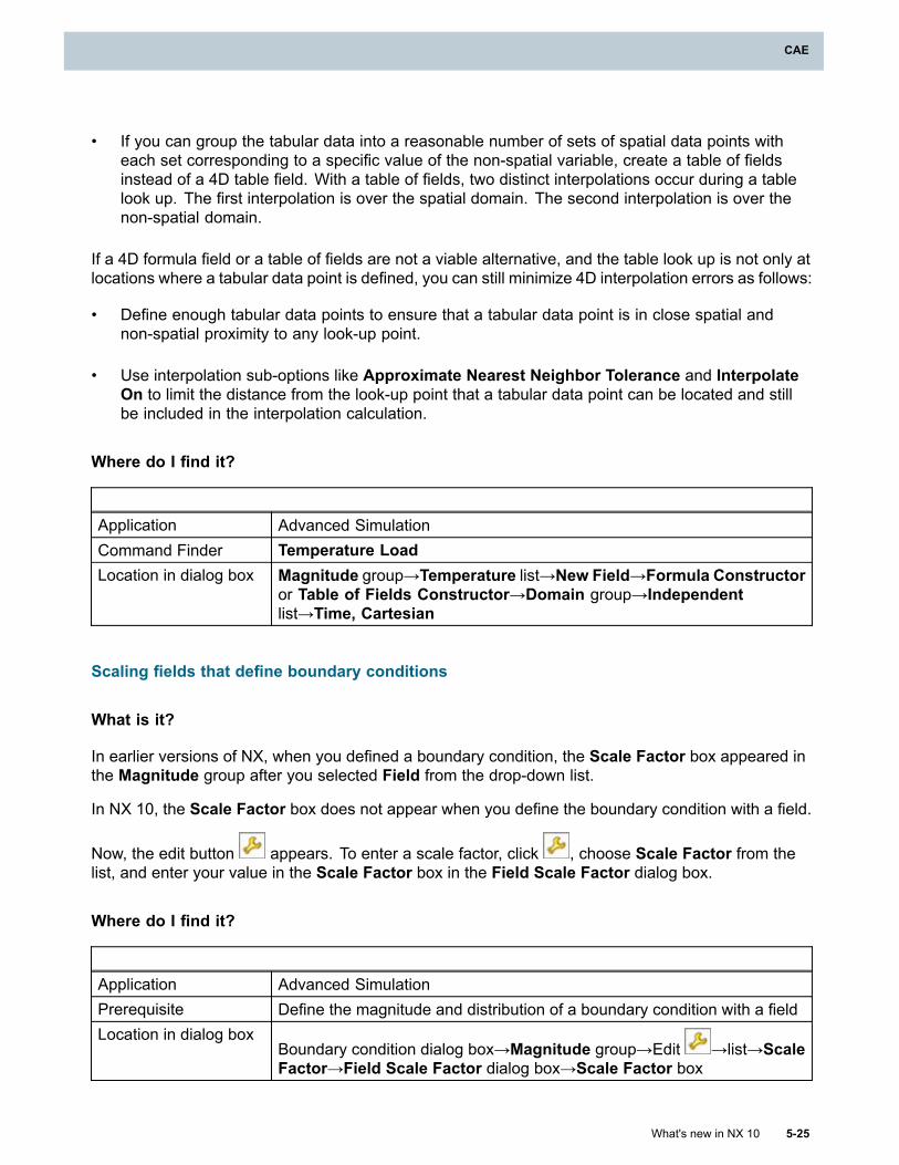
CAE
• If you can group the tabular data into a reasonable number of sets of spatial data points witheach set corresponding to a specific value of the non-spatial variable, create a table of fieldsinstead of a 4D table field. With a table of fields, two distinct interpolations occur during a tablelook up. The first interpolation is over the spatial domain. The second interpolation is over thenon-spatial domain.
If a 4D formula field or a table of fields are not a viable alternative, and the table look up is not only atlocations where a tabular data point is defined, you can still minimize 4D interpolation errors as follows:
• Define enough tabular data points to ensure that a tabular data point is in close spatial andnon-spatial proximity to any look-up point.
• Use interpolation sub-options like Approximate Nearest Neighbor Tolerance and InterpolateOn to limit the distance from the look-up point that a tabular data point can be located and stillbe included in the interpolation calculation.
Where do I find it?
Application Advanced SimulationCommand Finder Temperature LoadLocation in dialog box Magnitude group→Temperature list→New Field→Formula Constructor
or Table of Fields Constructor→Domain group→Independentlist→Time, Cartesian
Scaling fields that define boundary conditions
What is it?
In earlier versions of NX, when you defined a boundary condition, the Scale Factor box appeared inthe Magnitude group after you selected Field from the drop-down list.
In NX 10, the Scale Factor box does not appear when you define the boundary condition with a field.
Now, the edit button appears. To enter a scale factor, click , choose Scale Factor from thelist, and enter your value in the Scale Factor box in the Field Scale Factor dialog box.
Where do I find it?
Application Advanced SimulationPrerequisite Define the magnitude and distribution of a boundary condition with a fieldLocation in dialog box
Boundary condition dialog box→Magnitude group→Edit →list→ScaleFactor→Field Scale Factor dialog box→Scale Factor box
What's new in NX 10 5-25
CAE
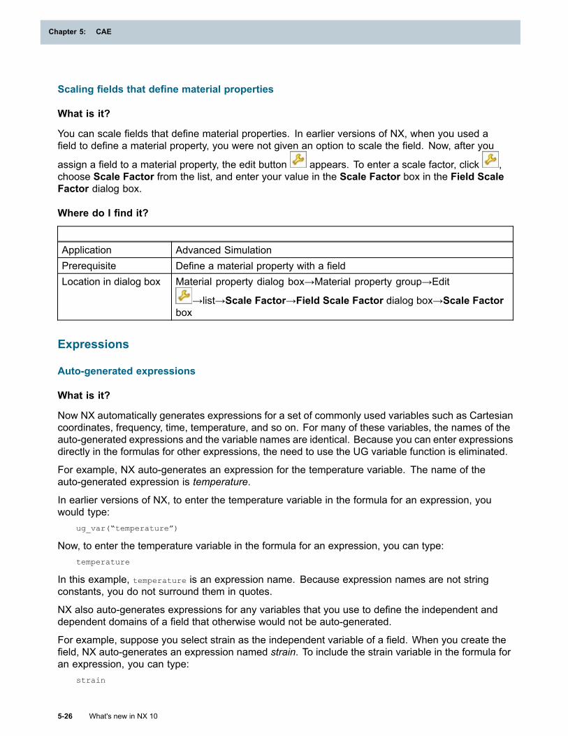
Chapter 5: CAE
Scaling fields that define material properties
What is it?
You can scale fields that define material properties. In earlier versions of NX, when you used afield to define a material property, you were not given an option to scale the field. Now, after you
assign a field to a material property, the edit button appears. To enter a scale factor, click ,choose Scale Factor from the list, and enter your value in the Scale Factor box in the Field ScaleFactor dialog box.
Where do I find it?
Application Advanced SimulationPrerequisite Define a material property with a fieldLocation in dialog box Material property dialog box→Material property group→Edit
→list→Scale Factor→Field Scale Factor dialog box→Scale Factorbox
Expressions
Auto-generated expressions
What is it?
Now NX automatically generates expressions for a set of commonly used variables such as Cartesiancoordinates, frequency, time, temperature, and so on. For many of these variables, the names of theauto-generated expressions and the variable names are identical. Because you can enter expressionsdirectly in the formulas for other expressions, the need to use the UG variable function is eliminated.
For example, NX auto-generates an expression for the temperature variable. The name of theauto-generated expression is temperature.
In earlier versions of NX, to enter the temperature variable in the formula for an expression, youwould type:
ug_var(“temperature”)
Now, to enter the temperature variable in the formula for an expression, you can type:temperature
In this example, temperature is an expression name. Because expression names are not stringconstants, you do not surround them in quotes.
NX also auto-generates expressions for any variables that you use to define the independent anddependent domains of a field that otherwise would not be auto-generated.
For example, suppose you select strain as the independent variable of a field. When you create thefield, NX auto-generates an expression named strain. To include the strain variable in the formula foran expression, you can type:
strain
5-26 What's new in NX 10
Chapter 5: CAE
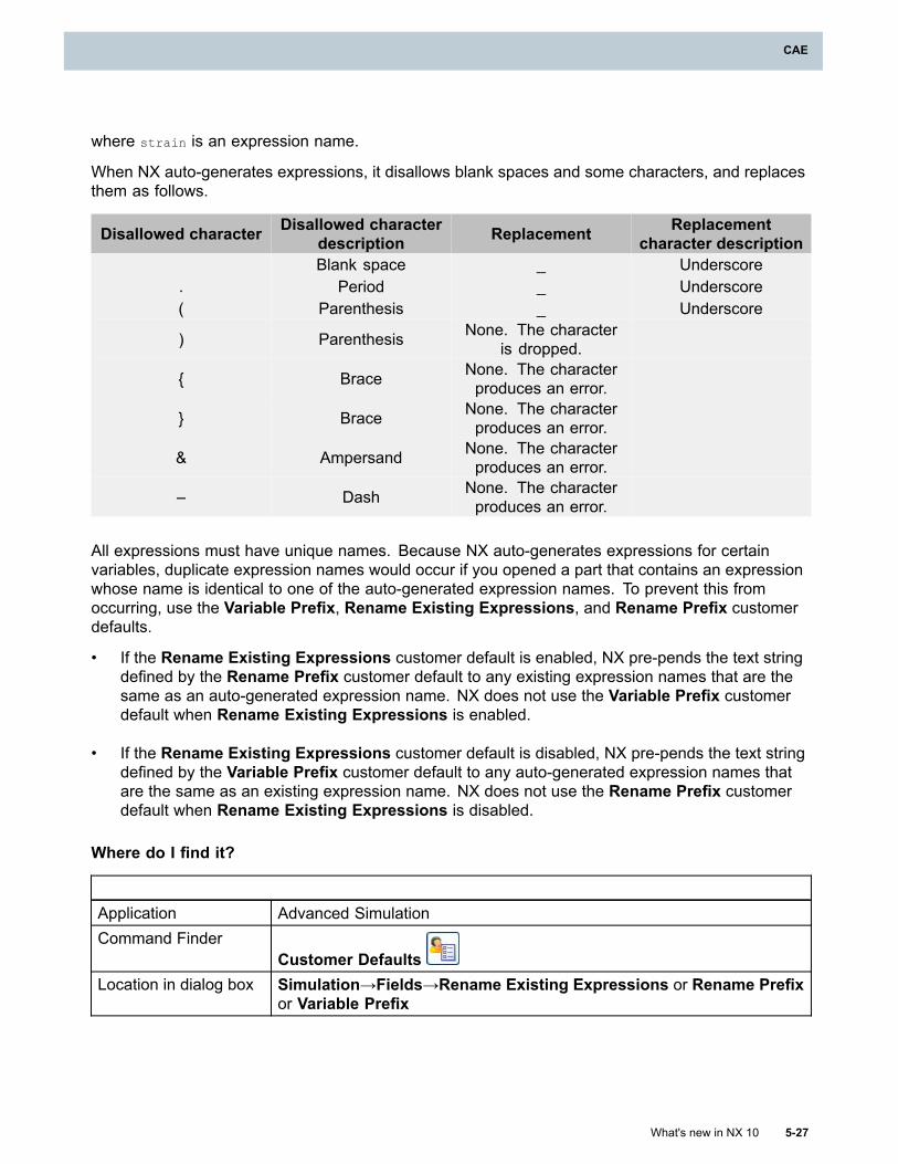
CAE
where strain is an expression name.
When NX auto-generates expressions, it disallows blank spaces and some characters, and replacesthem as follows.
Disallowed character Disallowed characterdescription Replacement Replacement
character descriptionBlank space _ Underscore
. Period _ Underscore( Parenthesis _ Underscore
) Parenthesis None. The characteris dropped.
{ Brace None. The characterproduces an error.
} Brace None. The characterproduces an error.
& Ampersand None. The characterproduces an error.
– Dash None. The characterproduces an error.
All expressions must have unique names. Because NX auto-generates expressions for certainvariables, duplicate expression names would occur if you opened a part that contains an expressionwhose name is identical to one of the auto-generated expression names. To prevent this fromoccurring, use the Variable Prefix, Rename Existing Expressions, and Rename Prefix customerdefaults.
• If the Rename Existing Expressions customer default is enabled, NX pre-pends the text stringdefined by the Rename Prefix customer default to any existing expression names that are thesame as an auto-generated expression name. NX does not use the Variable Prefix customerdefault when Rename Existing Expressions is enabled.
• If the Rename Existing Expressions customer default is disabled, NX pre-pends the text stringdefined by the Variable Prefix customer default to any auto-generated expression names thatare the same as an existing expression name. NX does not use the Rename Prefix customerdefault when Rename Existing Expressions is disabled.
Where do I find it?
Application Advanced SimulationCommand Finder
Customer DefaultsLocation in dialog box Simulation→Fields→Rename Existing Expressions or Rename Prefix
or Variable Prefix
What's new in NX 10 5-27
CAE
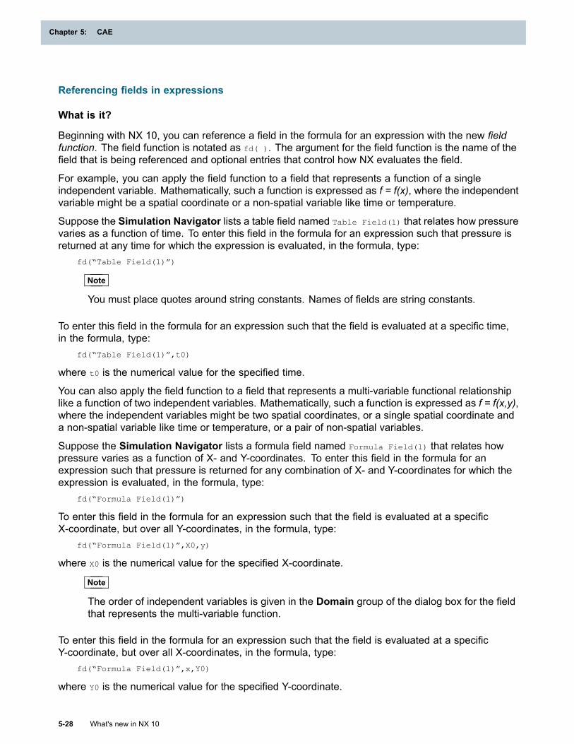
Chapter 5: CAE
Referencing fields in expressions
What is it?
Beginning with NX 10, you can reference a field in the formula for an expression with the new fieldfunction. The field function is notated as fd( ). The argument for the field function is the name of thefield that is being referenced and optional entries that control how NX evaluates the field.
For example, you can apply the field function to a field that represents a function of a singleindependent variable. Mathematically, such a function is expressed as f = f(x), where the independentvariable might be a spatial coordinate or a non-spatial variable like time or temperature.
Suppose the Simulation Navigator lists a table field named Table Field(1) that relates how pressurevaries as a function of time. To enter this field in the formula for an expression such that pressure isreturned at any time for which the expression is evaluated, in the formula, type:
fd(“Table Field(1)”)
Note
You must place quotes around string constants. Names of fields are string constants.
To enter this field in the formula for an expression such that the field is evaluated at a specific time,in the formula, type:
fd(“Table Field(1)”,t0)
where t0 is the numerical value for the specified time.
You can also apply the field function to a field that represents a multi-variable functional relationshiplike a function of two independent variables. Mathematically, such a function is expressed as f = f(x,y),where the independent variables might be two spatial coordinates, or a single spatial coordinate anda non-spatial variable like time or temperature, or a pair of non-spatial variables.
Suppose the Simulation Navigator lists a formula field named Formula Field(1) that relates howpressure varies as a function of X- and Y-coordinates. To enter this field in the formula for anexpression such that pressure is returned for any combination of X- and Y-coordinates for which theexpression is evaluated, in the formula, type:
fd(“Formula Field(1)”)
To enter this field in the formula for an expression such that the field is evaluated at a specificX-coordinate, but over all Y-coordinates, in the formula, type:
fd(“Formula Field(1)”,X0,y)
where X0 is the numerical value for the specified X-coordinate.
Note
The order of independent variables is given in the Domain group of the dialog box for the fieldthat represents the multi-variable function.
To enter this field in the formula for an expression such that the field is evaluated at a specificY-coordinate, but over all X-coordinates, in the formula, type:
fd(“Formula Field(1)”,x,Y0)
where Y0 is the numerical value for the specified Y-coordinate.
5-28 What's new in NX 10
Chapter 5: CAE
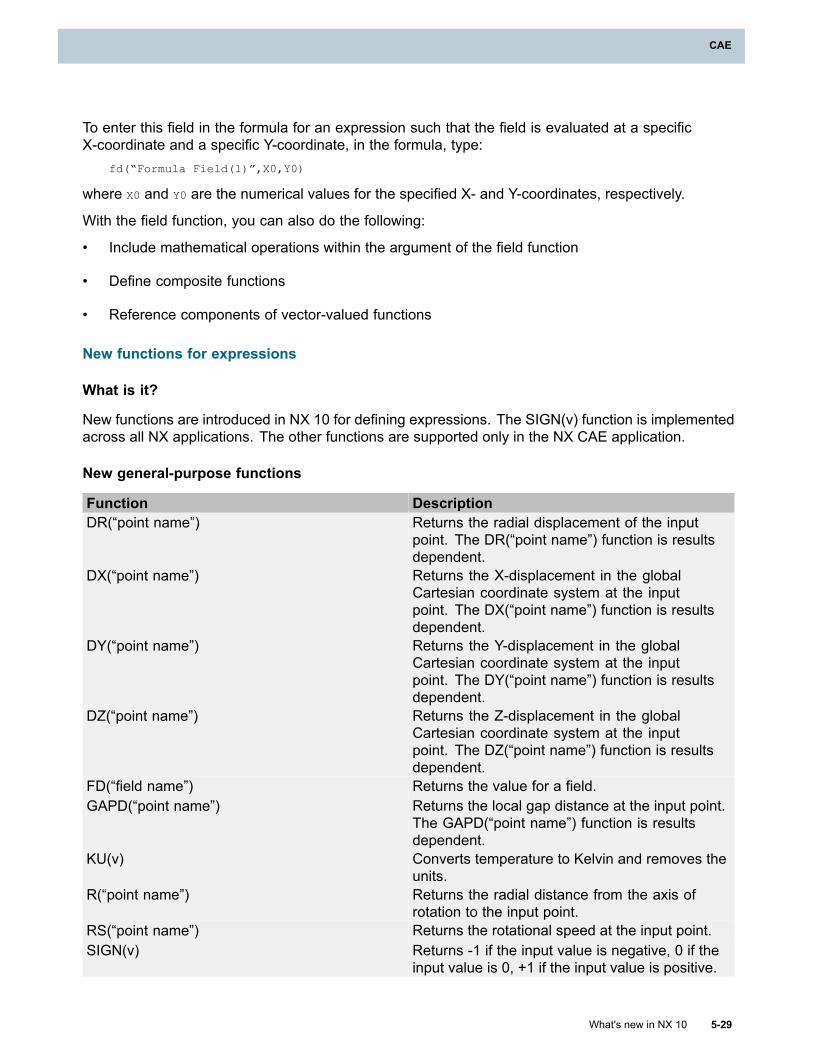
CAE
To enter this field in the formula for an expression such that the field is evaluated at a specificX-coordinate and a specific Y-coordinate, in the formula, type:
fd(“Formula Field(1)”,X0,Y0)
where X0 and Y0 are the numerical values for the specified X- and Y-coordinates, respectively.
With the field function, you can also do the following:
• Include mathematical operations within the argument of the field function
• Define composite functions
• Reference components of vector-valued functions
New functions for expressions
What is it?
New functions are introduced in NX 10 for defining expressions. The SIGN(v) function is implementedacross all NX applications. The other functions are supported only in the NX CAE application.
New general-purpose functions
Function DescriptionDR(“point name”) Returns the radial displacement of the input
point. The DR(“point name”) function is resultsdependent.
DX(“point name”) Returns the X-displacement in the globalCartesian coordinate system at the inputpoint. The DX(“point name”) function is resultsdependent.
DY(“point name”) Returns the Y-displacement in the globalCartesian coordinate system at the inputpoint. The DY(“point name”) function is resultsdependent.
DZ(“point name”) Returns the Z-displacement in the globalCartesian coordinate system at the inputpoint. The DZ(“point name”) function is resultsdependent.
FD(“field name”) Returns the value for a field.GAPD(“point name”) Returns the local gap distance at the input point.
The GAPD(“point name”) function is resultsdependent.
KU(v) Converts temperature to Kelvin and removes theunits.
R(“point name”) Returns the radial distance from the axis ofrotation to the input point.
RS(“point name”) Returns the rotational speed at the input point.SIGN(v) Returns -1 if the input value is negative, 0 if the
input value is 0, +1 if the input value is positive.
What's new in NX 10 5-29
CAE
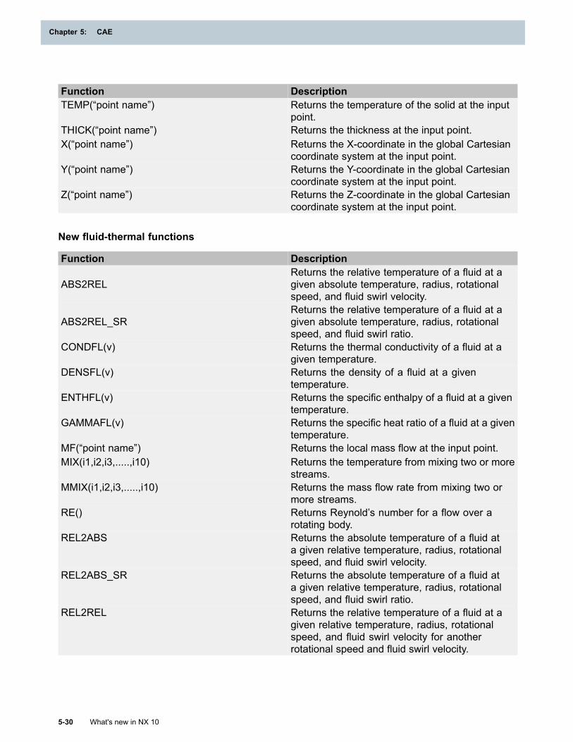
Chapter 5: CAE
Function DescriptionTEMP(“point name”) Returns the temperature of the solid at the input
point.THICK(“point name”) Returns the thickness at the input point.X(“point name”) Returns the X-coordinate in the global Cartesian
coordinate system at the input point.Y(“point name”) Returns the Y-coordinate in the global Cartesian
coordinate system at the input point.Z(“point name”) Returns the Z-coordinate in the global Cartesian
coordinate system at the input point.
New fluid-thermal functions
Function Description
ABS2RELReturns the relative temperature of a fluid at agiven absolute temperature, radius, rotationalspeed, and fluid swirl velocity.
ABS2REL_SRReturns the relative temperature of a fluid at agiven absolute temperature, radius, rotationalspeed, and fluid swirl ratio.
CONDFL(v) Returns the thermal conductivity of a fluid at agiven temperature.
DENSFL(v) Returns the density of a fluid at a giventemperature.
ENTHFL(v) Returns the specific enthalpy of a fluid at a giventemperature.
GAMMAFL(v) Returns the specific heat ratio of a fluid at a giventemperature.
MF(“point name”) Returns the local mass flow at the input point.MIX(i1,i2,i3,.....,i10) Returns the temperature from mixing two or more
streams.MMIX(i1,i2,i3,.....,i10) Returns the mass flow rate from mixing two or
more streams.RE() Returns Reynold’s number for a flow over a
rotating body.REL2ABS Returns the absolute temperature of a fluid at
a given relative temperature, radius, rotationalspeed, and fluid swirl velocity.
REL2ABS_SR Returns the absolute temperature of a fluid ata given relative temperature, radius, rotationalspeed, and fluid swirl ratio.
REL2REL Returns the relative temperature of a fluid at agiven relative temperature, radius, rotationalspeed, and fluid swirl velocity for anotherrotational speed and fluid swirl velocity.
5-30 What's new in NX 10
Chapter 5: CAE
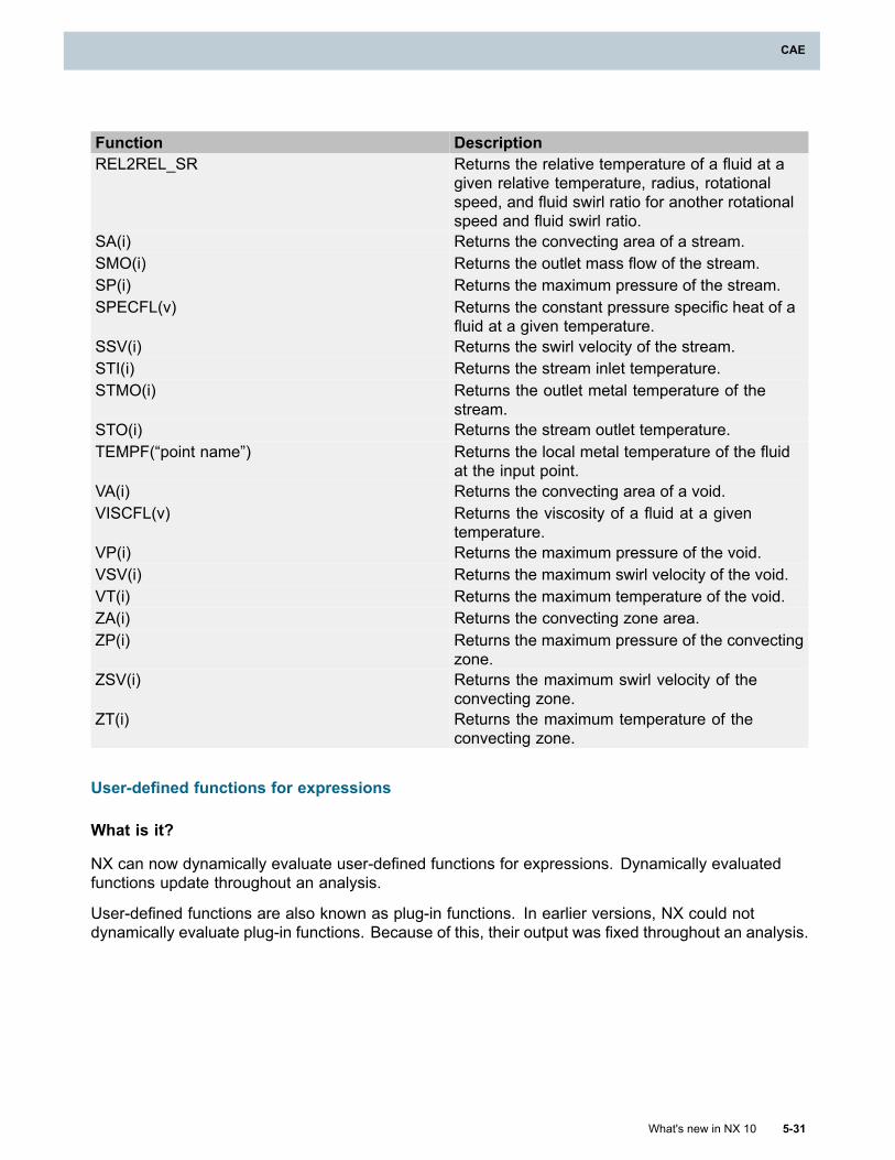
CAE
Function DescriptionREL2REL_SR Returns the relative temperature of a fluid at a
given relative temperature, radius, rotationalspeed, and fluid swirl ratio for another rotationalspeed and fluid swirl ratio.
SA(i) Returns the convecting area of a stream.SMO(i) Returns the outlet mass flow of the stream.SP(i) Returns the maximum pressure of the stream.SPECFL(v) Returns the constant pressure specific heat of a
fluid at a given temperature.SSV(i) Returns the swirl velocity of the stream.STI(i) Returns the stream inlet temperature.STMO(i) Returns the outlet metal temperature of the
stream.STO(i) Returns the stream outlet temperature.TEMPF(“point name”) Returns the local metal temperature of the fluid
at the input point.VA(i) Returns the convecting area of a void.VISCFL(v) Returns the viscosity of a fluid at a given
temperature.VP(i) Returns the maximum pressure of the void.VSV(i) Returns the maximum swirl velocity of the void.VT(i) Returns the maximum temperature of the void.ZA(i) Returns the convecting zone area.ZP(i) Returns the maximum pressure of the convecting
zone.ZSV(i) Returns the maximum swirl velocity of the
convecting zone.ZT(i) Returns the maximum temperature of the
convecting zone.
User-defined functions for expressions
What is it?
NX can now dynamically evaluate user-defined functions for expressions. Dynamically evaluatedfunctions update throughout an analysis.
User-defined functions are also known as plug-in functions. In earlier versions, NX could notdynamically evaluate plug-in functions. Because of this, their output was fixed throughout an analysis.
What's new in NX 10 5-31
CAE
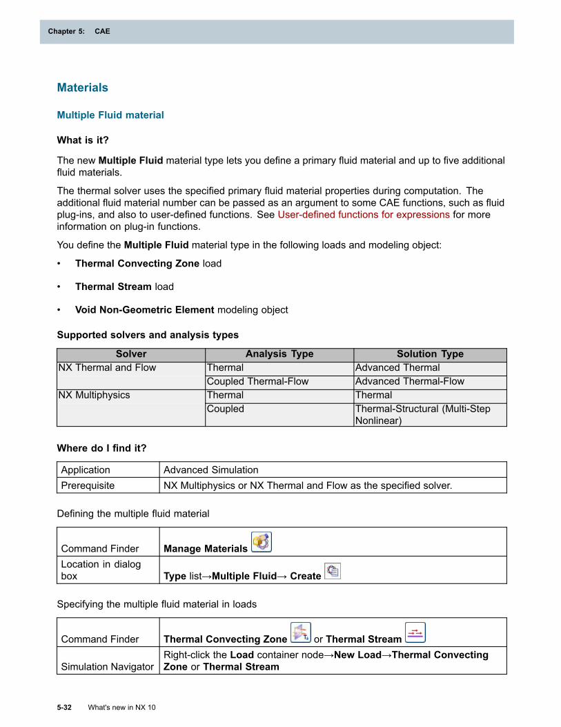
Chapter 5: CAE
Materials
Multiple Fluid material
What is it?
The new Multiple Fluid material type lets you define a primary fluid material and up to five additionalfluid materials.
The thermal solver uses the specified primary fluid material properties during computation. Theadditional fluid material number can be passed as an argument to some CAE functions, such as fluidplug-ins, and also to user-defined functions. See User-defined functions for expressions for moreinformation on plug-in functions.
You define the Multiple Fluid material type in the following loads and modeling object:
• Thermal Convecting Zone load
• Thermal Stream load
• Void Non-Geometric Element modeling object
Supported solvers and analysis types
Solver Analysis Type Solution TypeThermal Advanced ThermalNX Thermal and FlowCoupled Thermal-Flow Advanced Thermal-FlowThermal ThermalNX MultiphysicsCoupled Thermal-Structural (Multi-Step
Nonlinear)
Where do I find it?
Application Advanced SimulationPrerequisite NX Multiphysics or NX Thermal and Flow as the specified solver.
Defining the multiple fluid material
Command Finder Manage MaterialsLocation in dialogbox Type list→Multiple Fluid→ Create
Specifying the multiple fluid material in loads
Command Finder Thermal Convecting Zone or Thermal Stream
Simulation NavigatorRight-click the Load container node→New Load→Thermal ConvectingZone or Thermal Stream
5-32 What's new in NX 10
Chapter 5: CAE
CAE
Location in dialogbox Fluid Materials list
Specifying the multiple fluid material in the modeling object
Command Finder Modeling ObjectsSimulation Navigator Right-click the Modeling Objects node→Modeling ObjectsLocation in dialogbox
Type list→Void Non-Geometric Element→Create→Environmentgroup→Fluid Materials list
Norton-Bailey Power Law creep support in NX Multiphysics
What is it?
You can now use the Norton-Bailey Power Law creep model in Multi-step Nonlinear solutions whenNX Multiphysics is the specified solver.
You select this model in the Materials dialog box, on the Creep page, using theTemperature-Dependent Time Hardening (Norton-Bailey) Power Law (Type 301) option. Thisoption corresponds to the new MATCRP bulk data entry, which is an alternate method for selecting theNorton-Bailey creep model. It lets you define the coefficients of the power law equation as eitherconstant or temperature dependent.
In the Materials dialog box, you define the A, B, and D coefficients of this creep model in theConstant Multiplier (a), SIGMA Exponent (b), and Hardening Exponent (d) boxes.
• To define creep at a single temperature, enter real values for the coefficients.
• To define creep as temperature dependent, define a table field for the coefficients. The tablecorresponds to the TABLEM1 bulk data entry.
Checking system units
A Check Unit System option is added to the new Type 301 power law as well as to the existing TimeHardening (Norton-Bailey) Power Law Type 300. This option checks for inconsistent units in thesolution and the creep coefficients. NX checks when the solver input file is exported and alerts you ifthe solution units are not consistent with the creep coefficient units. NX cannot convert the creepcoefficient units when it exports the solver input file.
Controlling creep effects
For NX Multiphysics, you can now turn off creep effects at the solution level and subcase level. Formore information, see Controlling plasticity and creep effects.
Where do I find it?
Application Advanced Simulation
What's new in NX 10 5-33
CAE
Chapter 5: CAE
Prerequisites NX Multiphysics as the specified solver and an active Multi-step Nonlinearsolution
or
NX Nastran as the specified solver and an active SOL 601,106 AdvancedNonlinear Statics solution
Command FinderManage Materials
Location in dialog boxCreate Material →Creep page
Samcef damage properties
What is it?
The Samcef damage material models predict the fibers breaking, the matrix cracking, and thede-cohesion between fibers and the matrix. Delamination between two plies is also taken into account.
When you create orthotropic materials, you can use options on the new Damage page in theOrthotropic Material dialog box to model Intra-laminar failure. You can define a progressivedamage model for a general orthotropic ply, for an enhanced ply (NCF), as well as for woven fabrics.
For these material models, you can specify properties such as:
• Nonlinear behavior in fiber direction.
• Damage evolution in the matrix, including coupling effects in shear and transverse directions.
• Plasticity behavior in the matrix.
You can also use the Manage Materials dialog box to create Damage Interface materials forcohesive elements.
Where do I find it?
Damage Interface material
Application Advanced SimulationPrerequisite Samcef as the specified solver.Command Finder
Manage MaterialsLocation in dialog box
Type list→Damage Interface→Create Material
Damage material model for orthotropic materials
Application Advanced SimulationPrerequisite Samcef as the specified solver.
5-34 What's new in NX 10
Chapter 5: CAE
CAE
Command FinderManage Materials
Location in dialog boxType list→Orthotropic→Create Material →Damage page
Adding material properties to existing library definitions
What is it?
You can now add material properties to existing material library definitions using a correctly structuredXML file. You can define these custom properties so that they appear in the materials dialog boxes onexisting material property tabs or on new tabs. The custom properties always appear in new groupson the dialog box. If you define a property on a new tab and do not specify a name for the tab,the new tab is displayed as DefaultTabName.
You add material properties using an XML file with a .udmpx extension.
The DTD for this customization capability resides in the NX installation structure as\..\ugii\materials\usermaterialsdefinitions.dtd. The DTD defines the structure and legal elementsof the XML file that you must provide.
Your users will be able to populate and edit these custom properties using the NX material dialogboxes, provided the NX session has the customization. To make the custom properties availableto your users, you can place this XML file in any UGOPEN_STARTUP_DIR folder, such asUGII_USER_DIR\\startup, UGII_SITE_DIR\\ startup, and UGII_VENDER_DIR\\startup.
If a material defined and saved in NX contains a user-defined property, the property remains in thematerial object even when another NX session that does not have the customization opens the part.
What's new in NX 10 5-35
CAE
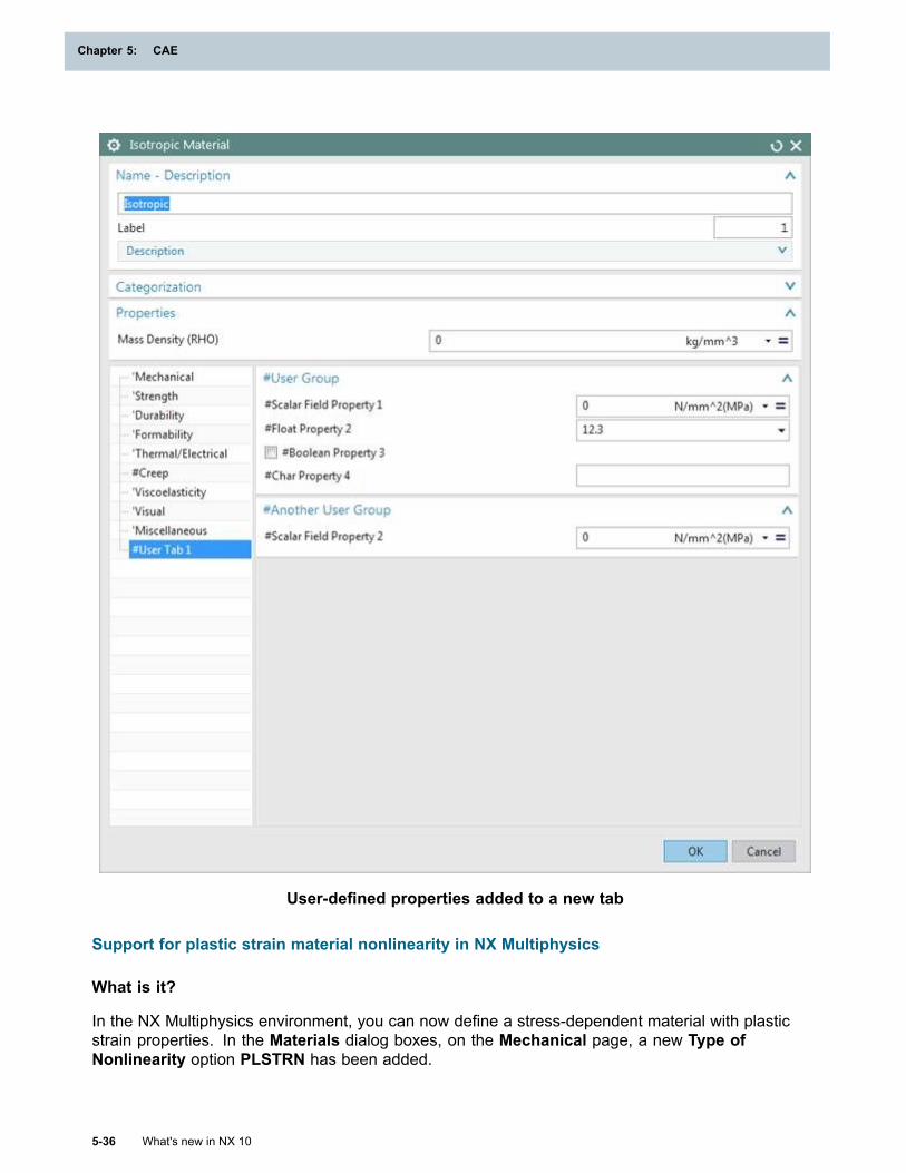
Chapter 5: CAE
User-defined properties added to a new tab
Support for plastic strain material nonlinearity in NX Multiphysics
What is it?
In the NX Multiphysics environment, you can now define a stress-dependent material with plasticstrain properties. In the Materials dialog boxes, on the Mechanical page, a new Type ofNonlinearity option PLSTRN has been added.
5-36 What's new in NX 10
Chapter 5: CAE
CAE
This option corresponds to the MATS1 bulk data entry with TYPE=PLSTRN. For more information, seeMATS1 in the NX Nastran Quick Reference Guide.
Where do I find it?
Application Advanced SimulationPrerequisites NX Multiphysics as the specified solver
An active Multistep Nonlinear solutionCommand Finder
Manage MaterialsLocation in dialog box
Create Material →Mechanical page→Stress-Strain RelatedProperties group→Type of Nonlinearity=PLSTRN
Support for stress-strain related properties in orthotropic and anisotropic materials
What is it?
You can now specify stress-strain properties for orthotropic and anisotropic materials. The Materialsdialog boxes include the Stress-Strain Related Properties group of options when you create anew orthotropic or anisotropic material.
For the corresponding syntax for each solver, see Stress-strain input as engineering or truestress-strain.
Where do I find it?
Application Advanced SimulationPrerequisite NX Nastran, MSC Nastran, ANSYS, Abaqus, or LS-DYNA as the specified
solver.Command Finder
Manage MaterialsLocation in dialog box
Create Material →Mechanical page→Stress-Strain RelatedProperties group
Stress-strain input as engineering or true stress-strain
What is it?
You can now specify stress-strain data for nonlinear materials as either engineering stress-strainor true stress-strain.
When writing out the solver input file, NX converts the stress-strain data depending on the specifiedsolver. When NX Nastran is the solver, NX additionally takes into account the type of solution andthe setting of the Type of Nonlinearity option. The output stress-strain data is in the same unitsas the input stress-strain data. The units of Young’s Modulus should be consistent with the inputstress-strain data.
What's new in NX 10 5-37
CAE
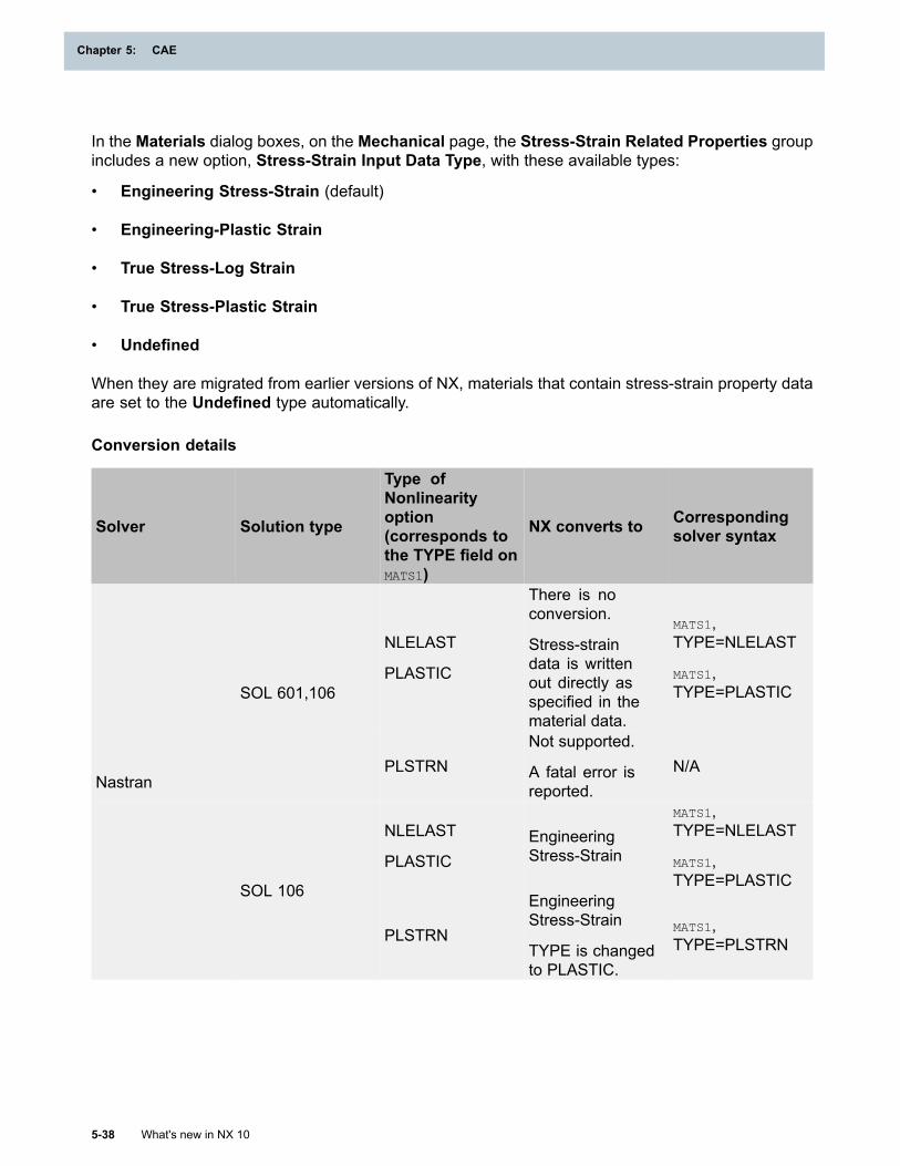
Chapter 5: CAE
In the Materials dialog boxes, on the Mechanical page, the Stress-Strain Related Properties groupincludes a new option, Stress-Strain Input Data Type, with these available types:
• Engineering Stress-Strain (default)
• Engineering-Plastic Strain
• True Stress-Log Strain
• True Stress-Plastic Strain
• Undefined
When they are migrated from earlier versions of NX, materials that contain stress-strain property dataare set to the Undefined type automatically.
Conversion details
Solver Solution type
Type ofNonlinearityoption(corresponds tothe TYPE field onMATS1)
NX converts to Correspondingsolver syntax
NLELAST
PLASTIC
There is noconversion.
Stress-straindata is writtenout directly asspecified in thematerial data.
MATS1,TYPE=NLELAST
MATS1,TYPE=PLASTICSOL 601,106
PLSTRNNot supported.
A fatal error isreported.
N/A
NLELAST
PLASTICEngineeringStress-Strain
MATS1,TYPE=NLELAST
MATS1,TYPE=PLASTIC
Nastran
SOL 106
PLSTRN
EngineeringStress-Strain
TYPE is changedto PLASTIC.
MATS1,TYPE=PLSTRN
5-38 What's new in NX 10
Chapter 5: CAE
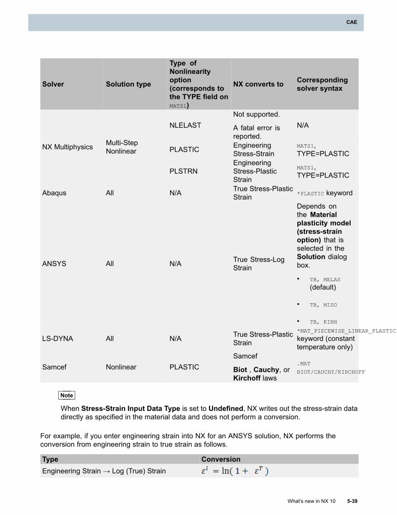
CAE
Solver Solution type
Type ofNonlinearityoption(corresponds tothe TYPE field onMATS1)
NX converts to Correspondingsolver syntax
NLELASTNot supported.
A fatal error isreported.
N/A
PLASTIC EngineeringStress-Strain
MATS1,TYPE=PLASTIC
NX Multiphysics Multi-StepNonlinear
PLSTRNEngineeringStress-PlasticStrain
MATS1,TYPE=PLASTIC
Abaqus All N/A True Stress-PlasticStrain *PLASTIC keyword
ANSYS All N/A True Stress-LogStrain
Depends onthe Materialplasticity model(stress-strainoption) that isselected in theSolution dialogbox.
• TB, MELAS
(default)
• TB, MISO
• TB, KINH
LS-DYNA All N/A True Stress-PlasticStrain
*MAT_PIECEWISE_LINEAR_PLASTICITY
keyword (constanttemperature only)
Samcef Nonlinear PLASTICSamcef
Biot , Cauchy, orKirchoff laws
.MAT
BIOT/CAUCHY/KIRCHOFF
Note
When Stress-Strain Input Data Type is set to Undefined, NX writes out the stress-strain datadirectly as specified in the material data and does not perform a conversion.
For example, if you enter engineering strain into NX for an ANSYS solution, NX performs theconversion from engineering strain to true strain as follows.
Type ConversionEngineering Strain → Log (True) Strain
What's new in NX 10 5-39
CAE
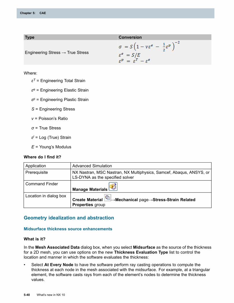
Chapter 5: CAE
Type Conversion
Engineering Stress → True Stress
Where:
εT = Engineering Total Strain
εe = Engineering Elastic Strain
εp = Engineering Plastic Strain
S = Engineering Stress
v = Poisson’s Ratio
σ = True Stress
εl = Log (True) Strain
E = Young’s Modulus
Where do I find it?
Application Advanced SimulationPrerequisite NX Nastran, MSC Nastran, NX Multiphysics, Samcef, Abaqus, ANSYS, or
LS-DYNA as the specified solverCommand Finder
Manage MaterialsLocation in dialog box
Create Material →Mechanical page→Stress-Strain RelatedProperties group
Geometry idealization and abstraction
Midsurface thickness source enhancements
What is it?
In the Mesh Associated Data dialog box, when you select Midsurface as the source of the thicknessfor a 2D mesh, you can use options on the new Thickness Evaluation Type list to control thelocation and manner in which the software evaluates the thickness:
• Select At Every Node to have the software perform ray casting operations to compute thethickness at each node in the mesh associated with the midsurface. For example, at a triangularelement, the software casts rays from each of the element’s nodes to determine the thicknessvalues.
5-40 What's new in NX 10
Chapter 5: CAE
CAE
• Select At Element Centroid to have the software perform a single ray casting operation at thecentroid of each element to determine the thickness value. With this option, the software thenassigns the same thickness value to all of the element’s nodes. The At Element Centroidoption offers slightly improved performance over the At Every Node option as the softwareperforms fewer calculations.
• Select Average Feature Thickness to have the software extract the average thickness value formidsurface face pairs defined with the Midsurface by Face Pairs, Offset Midsurface, or theUser Defined Midsurface commands. This option is the fastest way to evaluate the thicknessas the software does not have to perform any ray casting calculations. It is the recommendedoption for constant thickness parts.
Where do I find it?
Application Advanced SimulationPrerequisite A FEM file as the displayed part and work partCommand Finder
Mesh Associated DataLocation in dialog box Element Properties group
Excluding geometry from abstraction
What is it?
Use the new Freeze Geometry command to designate faces that should be excluded from mostautomatic or manual geometry abstraction processes. When you use the Freeze Geometrycommand on a set of faces:
• The software does not perform any automatic abstraction or geometry cleanup operations onthose faces during 2D or 3D meshing.
• You cannot select those faces for use with most polygon geometry commands. For example,you cannot use the Stitch Edge command to modify a face on which you have previously usedthe Freeze Geometry command.
You can continue to use the Split Edge and Merge Edge commands on faces that you select withthe Freeze Geometry command.
New Freeze_Geometry node in the Simulation Navigator
NX stores the faces that you select as a Freeze_Geometry recipe in the CAE Geometry Recipesfolder in the Simulation Navigator.
What's new in NX 10 5-41
CAE
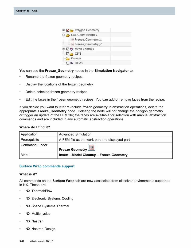
Chapter 5: CAE
You can use the Freeze_Geometry nodes in the Simulation Navigator to:
• Rename the frozen geometry recipes.
• Display the locations of the frozen geometry.
• Delete selected frozen geometry recipes.
• Edit the faces in the frozen geometry recipes. You can add or remove faces from the recipe.
If you decide you want to later re-include frozen geometry in abstraction operations, delete theappropriate Freeze_Geometry node. Deleting the node will not change the polygon geometryor trigger an update of the FEM file; the faces are available for selection with manual abstractioncommands and are included in any automatic abstraction operations.
Where do I find it?
Application Advanced SimulationPrerequisite A FEM file as the work part and displayed partCommand Finder
Freeze GeometryMenu Insert→Model Cleanup→Freeze Geometry
Surface Wrap commands support
What is it?
All commands on the Surface Wrap tab are now accessible from all solver environments supportedin NX. These are:
• NX Thermal/Flow
• NX Electronic Systems Cooling
• NX Space Systems Thermal
• NX Multiphysics
• NX Nastran
• NX Nastran Design
5-42 What's new in NX 10
Chapter 5: CAE
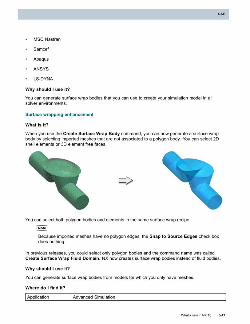
CAE
• MSC Nastran
• Samcef
• Abaqus
• ANSYS
• LS-DYNA
Why should I use it?
You can generate surface wrap bodies that you can use to create your simulation model in allsolver environments.
Surface wrapping enhancement
What is it?
When you use the Create Surface Wrap Body command, you can now generate a surface wrapbody by selecting imported meshes that are not associated to a polygon body. You can select 2Dshell elements or 3D element free faces.
You can select both polygon bodies and elements in the same surface wrap recipe.
Note
Because imported meshes have no polygon edges, the Snap to Source Edges check boxdoes nothing.
In previous releases, you could select only polygon bodies and the command name was calledCreate Surface Wrap Fluid Domain. NX now creates surface wrap bodies instead of fluid bodies.
Why should I use it?
You can generate surface wrap bodies from models for which you only have meshes.
Where do I find it?
Application Advanced Simulation
What's new in NX 10 5-43
CAE
Chapter 5: CAE
Prerequisite Import a meshed model into a FEM.
Command Finder Create Surface Wrap Body
Simulation NavigatorRight-click the Surface Wrap Recipes node→New Surface Wrap FluidDomain
Location in dialogbox Surface Wrap Boundaries group
Synchronizing polygon body names to the CAD part
What is it?
Use the new Synchronize to CAD Name command in the Simulation Navigator to synchronizethe names of bodies in a part file and the names of the corresponding polygon bodies. This allowsyou to rename selected polygon bodies to be consistent with the names of the corresponding bodiesin the associated CAD part.
Note
You can only use the Synchronize to CAD Name command if the associated CAD partis loaded.
You cannot use the Synchronize to CAD Name command to rename:
• A polygon fluid body.
• A polygon body that is created from 2D elements or from 3D element free faces using the Facefrom Mesh command.
Where do I find it?
Application Advanced SimulationPrerequisite A FEM file as the displayed part and work part
The CAD part associated with the FEM file loadedSimulation Navigator In the Polygon Geometry folder, right-click one or more Polygon Body
nodes→Synchronize to CAD Name
Automatic stitching of NX Ship Design parts (10.0.2)
What is it?
Ship models contain numerous separate sheet bodies that intersect but that are not topologicallyconnected. These separate bodies must be fully stitched prior to any CAE analysis.
This release includes enhancements to both the Ship Structure Basic Design and AdvancedSimulation applications that facilitate the preparation of a model of a ship for finite element analysis.These enhancements include:
• A new CAE Preparation command in the Ship Structure Basic Design application.
5-44 What's new in NX 10
Chapter 5: CAE
CAE
• Automatic stitching enhancements for ship models in the Advanced Simulation application.
CAE Preparation command in Ship Structure Basic Design
Use the new CAE Preparation command to prepare ship basic design data for structural analysis inthe Advanced Simulation application. This command creates special Ship Trim Body features thatstore data about edge pairs within the model.
Automatic stitching enhancements for ship models in Advanced Simulation
When you create a new FEM file on a part that contains Ship Trim Body features, AdvancedSimulation uses the edge pairing information to eliminate as many free edges as possible. During thisprocess, NX uses an edge-to-edge stitching technique to stitch appropriate free edges that belong todifferent bodies. You cannot control the automatic stitching process.
In most cases, this automatic stitching process eliminates many, but not all, free edges. After youcreate the FEM file, review the results of the automatic stitching. You can then use commands, suchas Stitch Edge, to eliminate the remaining free edges in the model.
Where do I find it?
Application Ship Structure Basic DesignPrerequisite Teamcenter Integration for NXCommand Finder
CAE Preparation
Meshing
Adaptive meshing enhancements
What is it?
This release introduces a new adaptive meshing capability into NX. This capability builds upon theadaptive analysis solution process that was available in previous releases. These enhancementsinclude:
• An expanded range of supported analysis types, including both thermal and multi-physicsanalyses.
• Global and local refinement options for the mesh.
• The ability to exclude certain regions of the mesh from the adaptivity process.
In Advanced Simulation, you can use the Adaptivity solution process to set up and run adaptivemeshing.
Benefits of the adaptive meshing process
Adaptive analysis automates the lengthy and repetitive process of running multiple finite elementanalyses with different mesh densities. The mesh refinement is determined by stress, strain energy,and temperature error estimates associated with element stress and strain discontinuities. Based on
What's new in NX 10 5-45
CAE
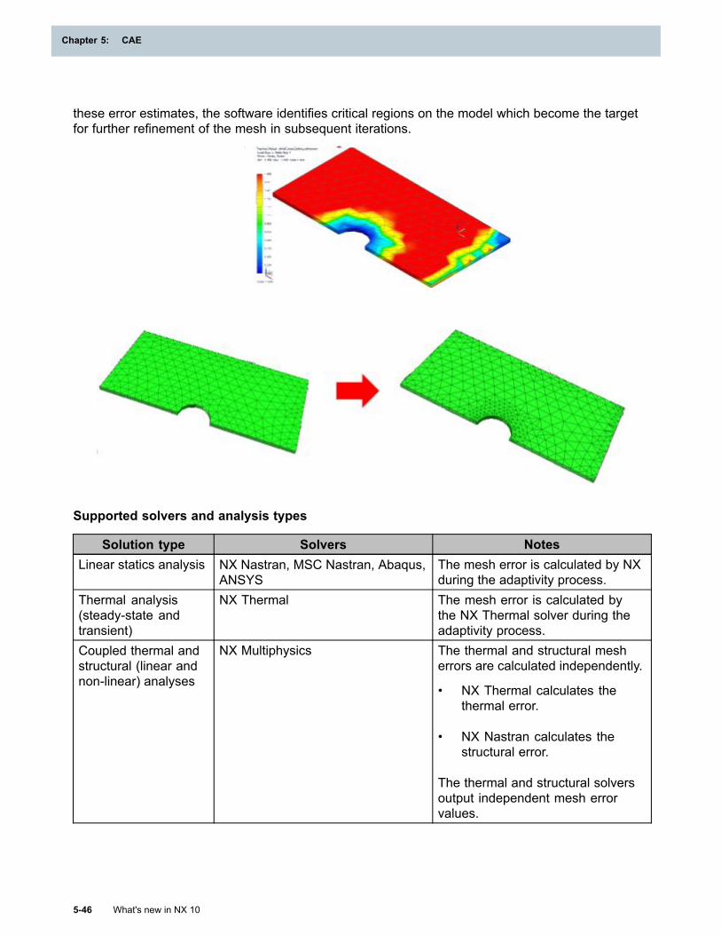
Chapter 5: CAE
these error estimates, the software identifies critical regions on the model which become the targetfor further refinement of the mesh in subsequent iterations.
Supported solvers and analysis types
Solution type Solvers NotesLinear statics analysis NX Nastran, MSC Nastran, Abaqus,
ANSYSThe mesh error is calculated by NXduring the adaptivity process.
Thermal analysis(steady-state andtransient)
NX Thermal The mesh error is calculated bythe NX Thermal solver during theadaptivity process.
Coupled thermal andstructural (linear andnon-linear) analyses
NX Multiphysics The thermal and structural mesherrors are calculated independently.
• NX Thermal calculates thethermal error.
• NX Nastran calculates thestructural error.
The thermal and structural solversoutput independent mesh errorvalues.
5-46 What's new in NX 10
Chapter 5: CAE
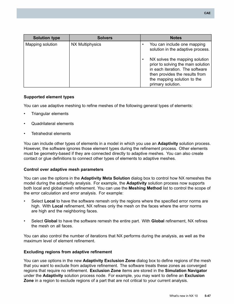
CAE
Solution type Solvers NotesMapping solution NX Multiphysics • You can include one mapping
solution in the adaptive process.
• NX solves the mapping solutionprior to solving the main solutionin each iteration. The softwarethen provides the results fromthe mapping solution to theprimary solution.
Supported element types
You can use adaptive meshing to refine meshes of the following general types of elements:
• Triangular elements
• Quadrilateral elements
• Tetrahedral elements
You can include other types of elements in a model in which you use an Adaptivity solution process.However, the software ignores those element types during the refinement process. Other elementsmust be geometry-based if they are connected directly to adaptive meshes. You can also createcontact or glue definitions to connect other types of elements to adaptive meshes.
Control over adaptive mesh parameters
You can use the options in the Adaptivity Meta Solution dialog box to control how NX remeshes themodel during the adaptivity analysis. For example, the Adaptivity solution process now supportsboth local and global mesh refinement. You can use the Meshing Method list to control the scope ofthe error calculation and error analysis. For example:
• Select Local to have the software remesh only the regions where the specified error norms arehigh. With Local refinement, NX refines only the mesh on the faces where the error normsare high and the neighboring faces.
• Select Global to have the software remesh the entire part. With Global refinement, NX refinesthe mesh on all faces.
You can also control the number of iterations that NX performs during the analysis, as well as themaximum level of element refinement.
Excluding regions from adaptive refinement
You can use options in the new Adaptivity Exclusion Zone dialog box to define regions of the meshthat you want to exclude from adaptive refinement. The software treats these zones as convergedregions that require no refinement. Exclusion Zone items are stored in the Simulation Navigatorunder the Adaptivity solution process node. For example, you may want to define an ExclusionZone in a region to exclude regions of a part that are not critical to your current analysis.
What's new in NX 10 5-47
CAE
Chapter 5: CAE
Note
These regions may still remesh due to changes in the meshes on neighboring regions.However, changes to the mesh in an exclusion zone are not influenced by the error estimatesin that region.
Accuracy parameters
In the Adaptivity Setup dialog box, you must define the accuracy parameters for the adaptivityprocess. These parameters, which are also known as error estimates, are the criteria that thesoftware uses to determine whether the solution has converged. The accuracy parameters that thesoftware uses depend upon the analysis type of your solution. For example:
• For structural analyses, NX Nastran generates strain energy norm errors, stress energy normerrors, or both error values.
• For thermal analyses, NX Thermal generates temperature error norm results.
For example, for NX Thermal analyses, the solver supports an output estimate of the local error in thetemperature on nodes and elements at each output time. The software uses the maximum error ateach node over all integration time steps, along with the time at which the maximum occurs, as theinput for refining the mesh.
Adaptive meshing output
When the software completes the final iteration, it saves several different types of output. Thisoutput includes:
• The solution results, including the error listing for the final iteration only.
• The final mesh.
• A summary of the adaptive analysis that provides detailed information, including:
o The maximum actual value for each accuracy parameter at each iteration.
o The total number of iterations.
o The total number of elements and nodes in the mesh at each iteration.
o Whether or not the solution converged.
Viewing adaptivity results in NX Post Processing
After the Adaptivity iterations complete, you can review the results of the adaptive solution in thePost-Processing Navigator. For example, you can create contour plots of the strain energy error aswell as the stress or temperature errors. You can also create contour plots of the mesh refinementlevel results.
When you create a contour plot of the mesh refinement level results, the software generates abanded display that indicates the level of refinement necessary at each node based on the computederror results from the adaptive analysis.
5-48 What's new in NX 10
Chapter 5: CAE
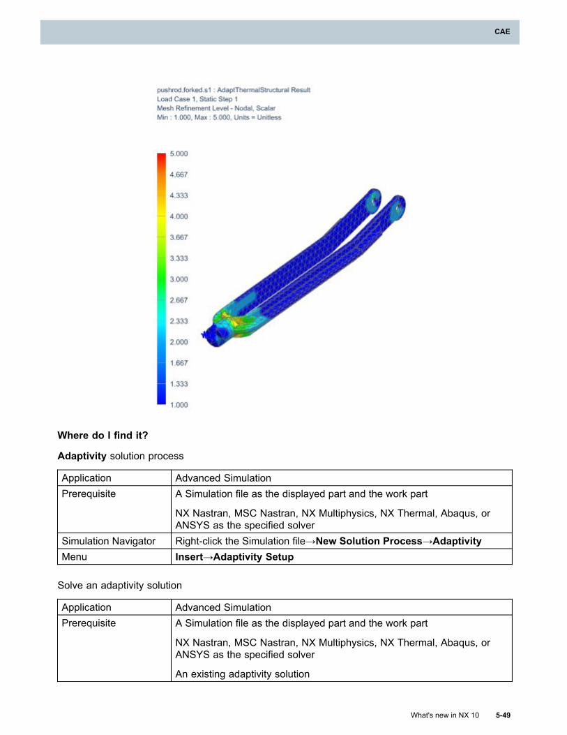
CAE
Where do I find it?
Adaptivity solution process
Application Advanced SimulationPrerequisite A Simulation file as the displayed part and the work part
NX Nastran, MSC Nastran, NX Multiphysics, NX Thermal, Abaqus, orANSYS as the specified solver
Simulation Navigator Right-click the Simulation file→New Solution Process→AdaptivityMenu Insert→Adaptivity Setup
Solve an adaptivity solution
Application Advanced SimulationPrerequisite A Simulation file as the displayed part and the work part
NX Nastran, MSC Nastran, NX Multiphysics, NX Thermal, Abaqus, orANSYS as the specified solver
An existing adaptivity solution
What's new in NX 10 5-49
CAE
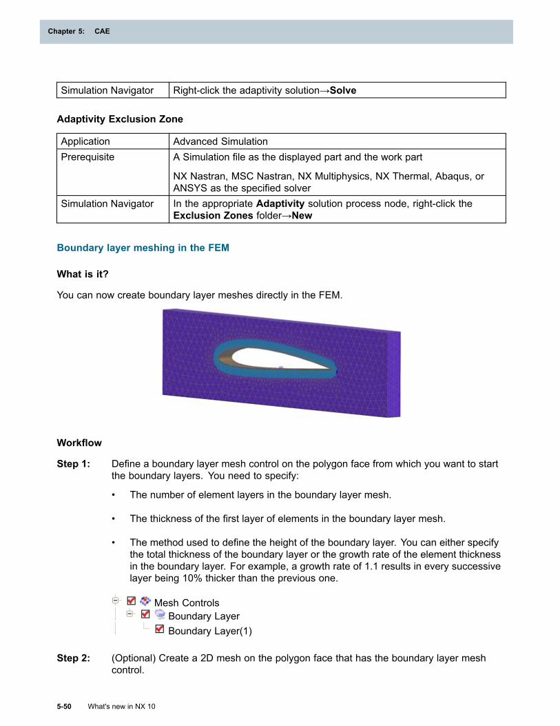
Chapter 5: CAE
Simulation Navigator Right-click the adaptivity solution→Solve
Adaptivity Exclusion Zone
Application Advanced SimulationPrerequisite A Simulation file as the displayed part and the work part
NX Nastran, MSC Nastran, NX Multiphysics, NX Thermal, Abaqus, orANSYS as the specified solver
Simulation Navigator In the appropriate Adaptivity solution process node, right-click theExclusion Zones folder→New
Boundary layer meshing in the FEM
What is it?
You can now create boundary layer meshes directly in the FEM.
Workflow
Step 1: Define a boundary layer mesh control on the polygon face from which you want to startthe boundary layers. You need to specify:
• The number of element layers in the boundary layer mesh.
• The thickness of the first layer of elements in the boundary layer mesh.
• The method used to define the height of the boundary layer. You can either specifythe total thickness of the boundary layer or the growth rate of the element thicknessin the boundary layer. For example, a growth rate of 1.1 results in every successivelayer being 10% thicker than the previous one.
Mesh ControlsBoundary LayerBoundary Layer(1)
Step 2: (Optional) Create a 2D mesh on the polygon face that has the boundary layer meshcontrol.
5-50 What's new in NX 10
Chapter 5: CAE
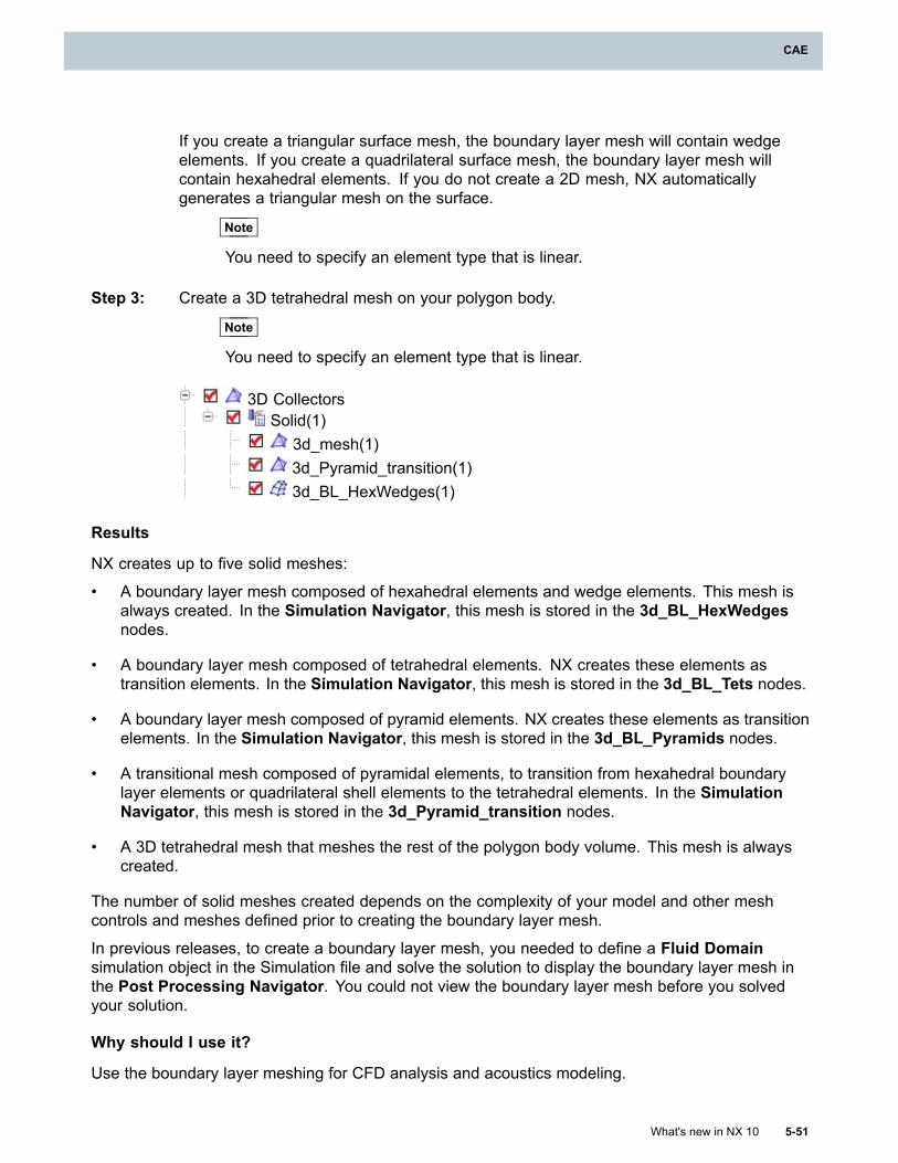
CAE
If you create a triangular surface mesh, the boundary layer mesh will contain wedgeelements. If you create a quadrilateral surface mesh, the boundary layer mesh willcontain hexahedral elements. If you do not create a 2D mesh, NX automaticallygenerates a triangular mesh on the surface.
Note
You need to specify an element type that is linear.
Step 3: Create a 3D tetrahedral mesh on your polygon body.
Note
You need to specify an element type that is linear.
3D CollectorsSolid(1)
3d_mesh(1)3d_Pyramid_transition(1)3d_BL_HexWedges(1)
Results
NX creates up to five solid meshes:
• A boundary layer mesh composed of hexahedral elements and wedge elements. This mesh isalways created. In the Simulation Navigator, this mesh is stored in the 3d_BL_HexWedgesnodes.
• A boundary layer mesh composed of tetrahedral elements. NX creates these elements astransition elements. In the Simulation Navigator, this mesh is stored in the 3d_BL_Tets nodes.
• A boundary layer mesh composed of pyramid elements. NX creates these elements as transitionelements. In the Simulation Navigator, this mesh is stored in the 3d_BL_Pyramids nodes.
• A transitional mesh composed of pyramidal elements, to transition from hexahedral boundarylayer elements or quadrilateral shell elements to the tetrahedral elements. In the SimulationNavigator, this mesh is stored in the 3d_Pyramid_transition nodes.
• A 3D tetrahedral mesh that meshes the rest of the polygon body volume. This mesh is alwayscreated.
The number of solid meshes created depends on the complexity of your model and other meshcontrols and meshes defined prior to creating the boundary layer mesh.
In previous releases, to create a boundary layer mesh, you needed to define a Fluid Domainsimulation object in the Simulation file and solve the solution to display the boundary layer mesh inthe Post Processing Navigator. You could not view the boundary layer mesh before you solvedyour solution.
Why should I use it?
Use the boundary layer meshing for CFD analysis and acoustics modeling.
What's new in NX 10 5-51
CAE
Chapter 5: CAE
Where do I find it?
Application Advanced SimulationPrerequisite A FEM as the work part
Command Finder Mesh Control
Simulation NavigatorRight-click the Mesh Controls node→New Mesh Control or New MeshControl Definition
Graphics window Right-click a polygon face→Mesh ControlLocation in dialogbox Density Type→Boundary Layer
Multi-block decomposition technique for 2D meshing
What is it?
Use the new Attempt Multi-Block Decomposition option in the 2D Mesh dialog box to improvequadrilateral meshes on largely orthogonal surfaces (surfaces with a number of 90° corners). Whenyou select this option, NX breaks up faces into a cluster of convex regions and then generatesmeshes on each convex region. In general, the resulting meshes are more orthogonal in nature. Ifyou select both the Attempt Multi-Block Decomposition and the Attempt Free Mapped Meshingoptions, NX creates a structured mesh on more regions of your model.
The graphics show the difference between a surface meshed with quadrilateral elements (1) and thesame set of surfaces meshed using the new Attempt Multi-Block Decomposition option (2).
5-52 What's new in NX 10
Chapter 5: CAE
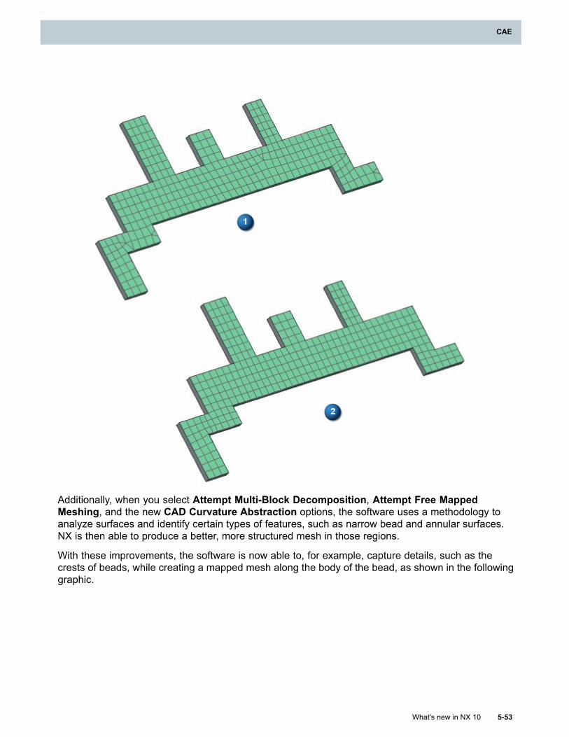
CAE
Additionally, when you select Attempt Multi-Block Decomposition, Attempt Free MappedMeshing, and the new CAD Curvature Abstraction options, the software uses a methodology toanalyze surfaces and identify certain types of features, such as narrow bead and annular surfaces.NX is then able to produce a better, more structured mesh in those regions.
With these improvements, the software is now able to, for example, capture details, such as thecrests of beads, while creating a mapped mesh along the body of the bead, as shown in the followinggraphic.
What's new in NX 10 5-53
CAE
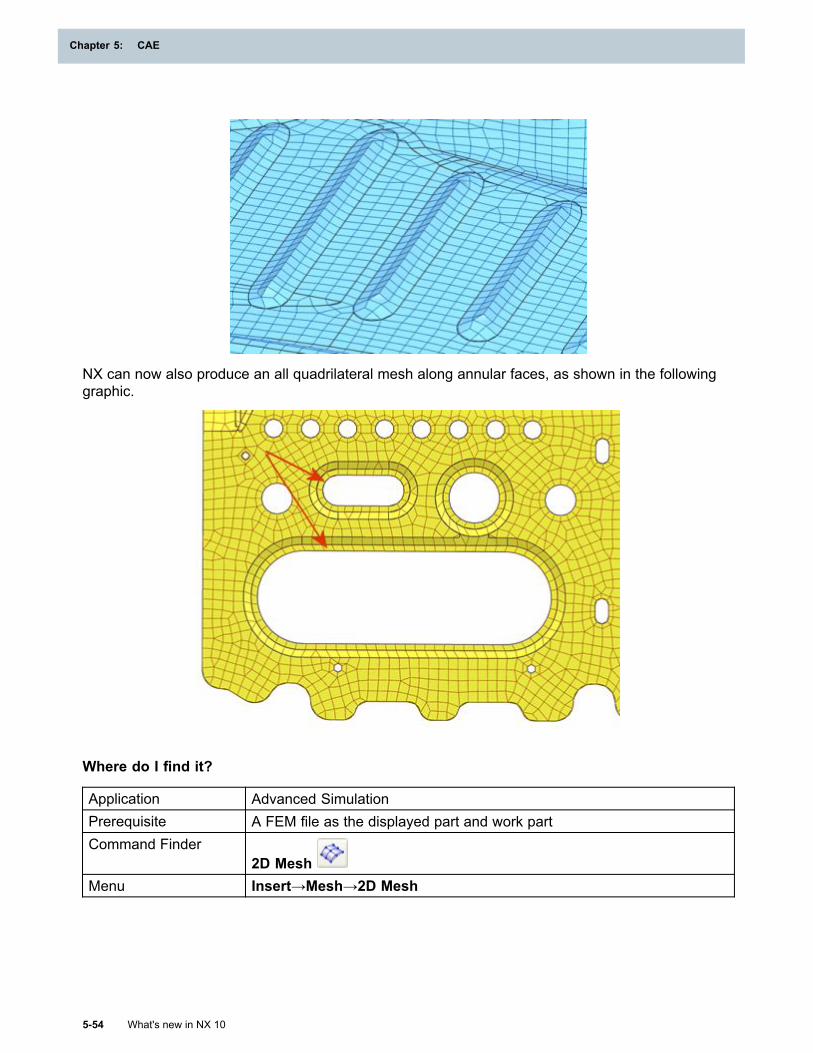
Chapter 5: CAE
NX can now also produce an all quadrilateral mesh along annular faces, as shown in the followinggraphic.
Where do I find it?
Application Advanced SimulationPrerequisite A FEM file as the displayed part and work partCommand Finder
2D MeshMenu Insert→Mesh→2D Mesh
5-54 What's new in NX 10
Chapter 5: CAE
CAE
Improved feature preservation and abstraction in 2D meshing
What is it?
Use the new CAD Curvature Abstraction option in the 2D Mesh dialog box to improve quadrilateralmeshes on relatively thin-walled parts with curvature, such as automotive body panels. When youselect this option, the software uses a new methodology to abstract the geometry in your model. Thismethodology uses a curvature analysis to improve the quality of the quadrilateral elements in yourmodel by preserving the representation of part features during the geometry abstraction process.
In previous releases, the geometry abstraction process treated an entire polygon body as a singleentity during the abstraction process. In NX 10, the abstraction process analyzes groups of adjacentfaces that have similar curvature. Where possible, it merges those individual faces together. Forsmaller, sliver faces within the model, such as tiny faces along fillets, the software more aggressivelymerges those faces with adjacent faces. This new process aims to preserve the boundaries offeatures while eliminating very small faces that are interior to features. This results in fewer smallelements in the mesh that violate the specified Minimum Element Length value.
Note
The CAD Curvature Abstraction option is valid only for free meshes with quadrilateralelements.
Where do I find it?
Application Advanced SimulationPrerequisite A FEM file as the displayed part and work part
The associated CAE part loadedCommand Finder
2D MeshMenu Insert→Mesh→2D MeshLocation in dialog box Model Cleanup group
Support for 2D seed mesh creation in NX Multiphysics
What is it?
In the NX Multiphysics environment, when you create a mesh for a structural analysis, you can nowcreate 2D seed meshes to control the placement of nodes on subsequent 3D meshes. In the 2DMesh or the 2D Mapped Mesh dialog box, you can select either the Linear Quadrilateral Seed orLinear Triangle Seed options from the Type list to create the seed mesh. These seed meshes havethe following characteristics:
• They can only be used to create solid meshes.
• They do not have any associated physical properties or mesh associated data.
• They are not written out to the solver input file when you export or solve your model.
In previous releases, you could create only 3D meshes for models in which NX Multiphysics wasthe specified solver.
What's new in NX 10 5-55
CAE
Chapter 5: CAE
Where do I find it?
Application Advanced SimulationPrerequisite A FEM file as the displayed part and work part
NX Multiphysics as the specified solver
Structural as the specified analysis typeCommand Finder
2D Mesh or 2D Mapped MeshMenu Insert→Mesh→2D Mesh
Updated support for 3D manual swept meshes
What is it?
You can now use the 3D Swept Mesh command to automatically or manually create hexahedralmeshes between selected faces. Use the new Automatic Between and Manual Between options inthe Type list to sweep a structured 3D mesh between two solid meshes. For example, you can usethese options to create a mesh of brick or wedge elements even if you do not have any geometryto define a body.
Swept meshes that you create with the Automatic Between and Manual Between options canupdate either as the geometry updates, or as the parameters of the neighboring meshes change. NXnow creates a mesh recipe for manual hexahedral meshes in the Simulation Navigator. You canuse this recipe to modify the swept mesh. NX also uses this mesh recipe to update the manual sweptmesh when changes occur to adjacent meshes or in the underlying geometry.
In previous releases, you used the 3D Sweep Between command to manually create hexahedralmeshes. However, those meshes were entirely FE-based and did not update.
In the example, (1) shows an assembly of blocks that are all meshed separately. (2) shows sweptmeshes created using the Manual Between option. (3) shows how the swept meshes update whenthe size of the meshes on the blocks update.
5-56 What's new in NX 10
Chapter 5: CAE
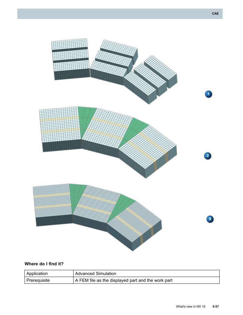
CAE
Where do I find it?
Application Advanced SimulationPrerequisite A FEM file as the displayed part and the work part
What's new in NX 10 5-57
CAE
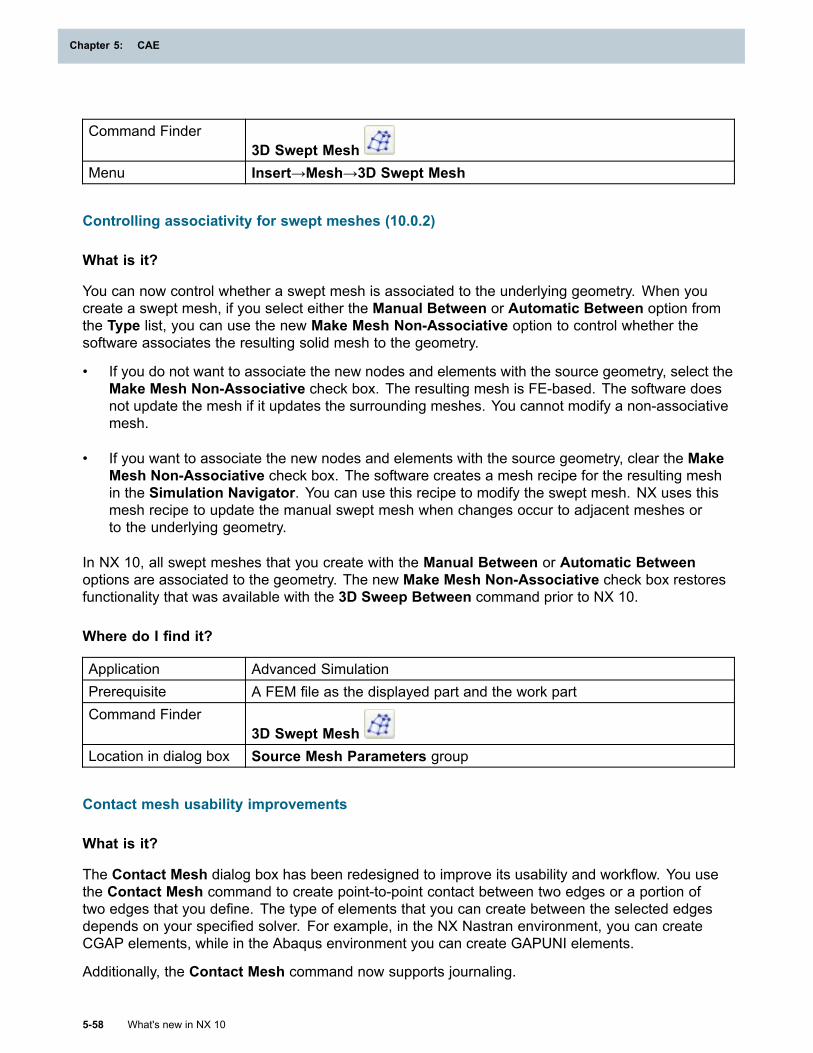
Chapter 5: CAE
Command Finder3D Swept Mesh
Menu Insert→Mesh→3D Swept Mesh
Controlling associativity for swept meshes (10.0.2)
What is it?
You can now control whether a swept mesh is associated to the underlying geometry. When youcreate a swept mesh, if you select either the Manual Between or Automatic Between option fromthe Type list, you can use the new Make Mesh Non-Associative option to control whether thesoftware associates the resulting solid mesh to the geometry.
• If you do not want to associate the new nodes and elements with the source geometry, select theMake Mesh Non-Associative check box. The resulting mesh is FE-based. The software doesnot update the mesh if it updates the surrounding meshes. You cannot modify a non-associativemesh.
• If you want to associate the new nodes and elements with the source geometry, clear the MakeMesh Non-Associative check box. The software creates a mesh recipe for the resulting meshin the Simulation Navigator. You can use this recipe to modify the swept mesh. NX uses thismesh recipe to update the manual swept mesh when changes occur to adjacent meshes orto the underlying geometry.
In NX 10, all swept meshes that you create with the Manual Between or Automatic Betweenoptions are associated to the geometry. The new Make Mesh Non-Associative check box restoresfunctionality that was available with the 3D Sweep Between command prior to NX 10.
Where do I find it?
Application Advanced SimulationPrerequisite A FEM file as the displayed part and the work partCommand Finder
3D Swept MeshLocation in dialog box Source Mesh Parameters group
Contact mesh usability improvements
What is it?
The Contact Mesh dialog box has been redesigned to improve its usability and workflow. You usethe Contact Mesh command to create point-to-point contact between two edges or a portion oftwo edges that you define. The type of elements that you can create between the selected edgesdepends on your specified solver. For example, in the NX Nastran environment, you can createCGAP elements, while in the Abaqus environment you can create GAPUNI elements.
Additionally, the Contact Mesh command now supports journaling.
5-58 What's new in NX 10
Chapter 5: CAE
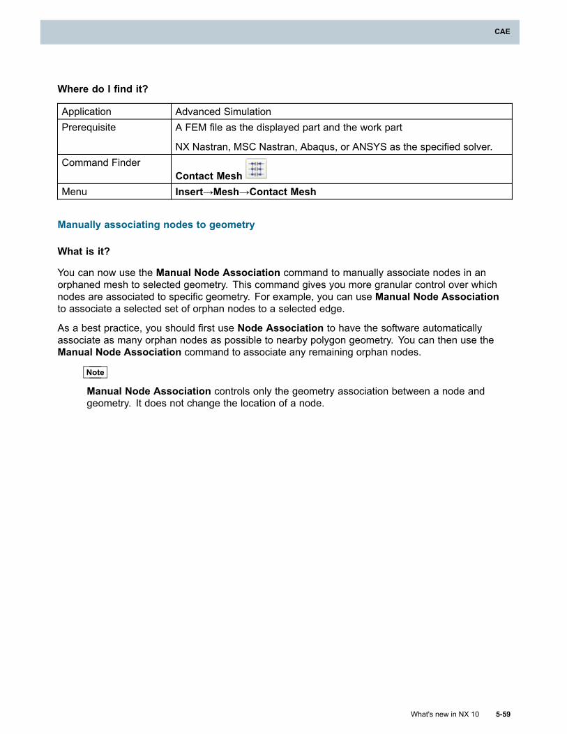
CAE
Where do I find it?
Application Advanced SimulationPrerequisite A FEM file as the displayed part and the work part
NX Nastran, MSC Nastran, Abaqus, or ANSYS as the specified solver.Command Finder
Contact MeshMenu Insert→Mesh→Contact Mesh
Manually associating nodes to geometry
What is it?
You can now use the Manual Node Association command to manually associate nodes in anorphaned mesh to selected geometry. This command gives you more granular control over whichnodes are associated to specific geometry. For example, you can use Manual Node Associationto associate a selected set of orphan nodes to a selected edge.
As a best practice, you should first use Node Association to have the software automaticallyassociate as many orphan nodes as possible to nearby polygon geometry. You can then use theManual Node Association command to associate any remaining orphan nodes.
Note
Manual Node Association controls only the geometry association between a node andgeometry. It does not change the location of a node.
What's new in NX 10 5-59
CAE
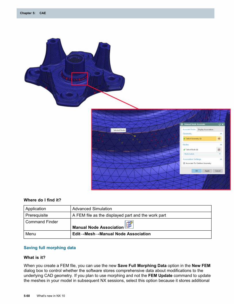
Chapter 5: CAE
Where do I find it?
Application Advanced SimulationPrerequisite A FEM file as the displayed part and the work partCommand Finder
Manual Node AssociationMenu Edit→Mesh→Manual Node Association
Saving full morphing data
What is it?
When you create a FEM file, you can use the new Save Full Morphing Data option in the New FEMdialog box to control whether the software stores comprehensive data about modifications to theunderlying CAD geometry. If you plan to use morphing and not the FEM Update command to updatethe meshes in your model in subsequent NX sessions, select this option because it stores additional
5-60 What's new in NX 10
Chapter 5: CAE
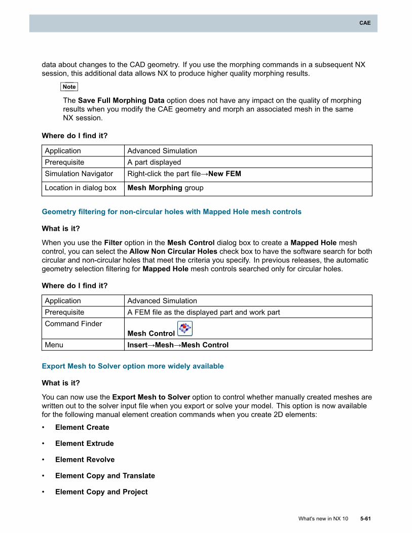
CAE
data about changes to the CAD geometry. If you use the morphing commands in a subsequent NXsession, this additional data allows NX to produce higher quality morphing results.
Note
The Save Full Morphing Data option does not have any impact on the quality of morphingresults when you modify the CAE geometry and morph an associated mesh in the sameNX session.
Where do I find it?
Application Advanced SimulationPrerequisite A part displayedSimulation Navigator Right-click the part file→New FEM
Location in dialog box Mesh Morphing group
Geometry filtering for non-circular holes with Mapped Hole mesh controls
What is it?
When you use the Filter option in the Mesh Control dialog box to create a Mapped Hole meshcontrol, you can select the Allow Non Circular Holes check box to have the software search for bothcircular and non-circular holes that meet the criteria you specify. In previous releases, the automaticgeometry selection filtering for Mapped Hole mesh controls searched only for circular holes.
Where do I find it?
Application Advanced SimulationPrerequisite A FEM file as the displayed part and work partCommand Finder
Mesh ControlMenu Insert→Mesh→Mesh Control
Export Mesh to Solver option more widely available
What is it?
You can now use the Export Mesh to Solver option to control whether manually created meshes arewritten out to the solver input file when you export or solve your model. This option is now availablefor the following manual element creation commands when you create 2D elements:
• Element Create
• Element Extrude
• Element Revolve
• Element Copy and Translate
• Element Copy and Project
What's new in NX 10 5-61
CAE
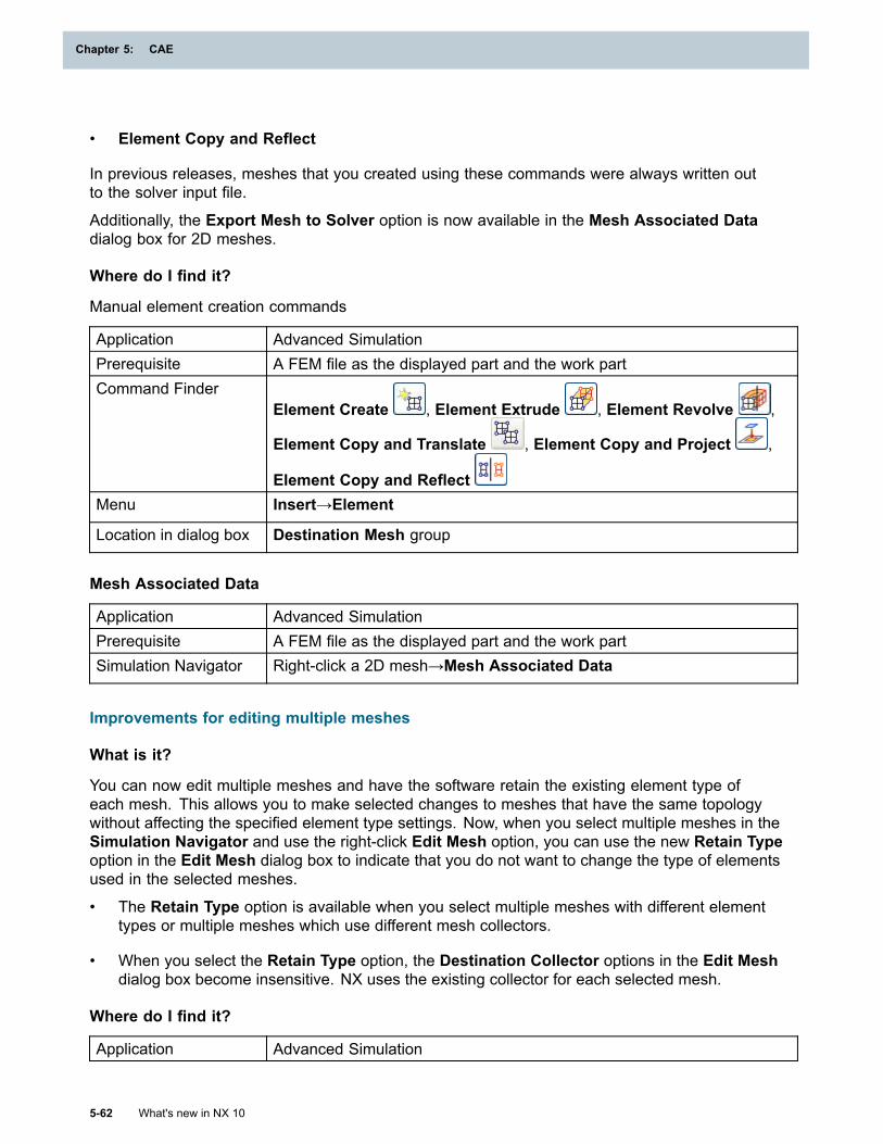
Chapter 5: CAE
• Element Copy and Reflect
In previous releases, meshes that you created using these commands were always written outto the solver input file.
Additionally, the Export Mesh to Solver option is now available in the Mesh Associated Datadialog box for 2D meshes.
Where do I find it?
Manual element creation commands
Application Advanced SimulationPrerequisite A FEM file as the displayed part and the work partCommand Finder
Element Create , Element Extrude , Element Revolve ,
Element Copy and Translate , Element Copy and Project ,
Element Copy and ReflectMenu Insert→Element
Location in dialog box Destination Mesh group
Mesh Associated Data
Application Advanced SimulationPrerequisite A FEM file as the displayed part and the work partSimulation Navigator Right-click a 2D mesh→Mesh Associated Data
Improvements for editing multiple meshes
What is it?
You can now edit multiple meshes and have the software retain the existing element type ofeach mesh. This allows you to make selected changes to meshes that have the same topologywithout affecting the specified element type settings. Now, when you select multiple meshes in theSimulation Navigator and use the right-click Edit Mesh option, you can use the new Retain Typeoption in the Edit Mesh dialog box to indicate that you do not want to change the type of elementsused in the selected meshes.
• The Retain Type option is available when you select multiple meshes with different elementtypes or multiple meshes which use different mesh collectors.
• When you select the Retain Type option, the Destination Collector options in the Edit Meshdialog box become insensitive. NX uses the existing collector for each selected mesh.
Where do I find it?
Application Advanced Simulation
5-62 What's new in NX 10
Chapter 5: CAE
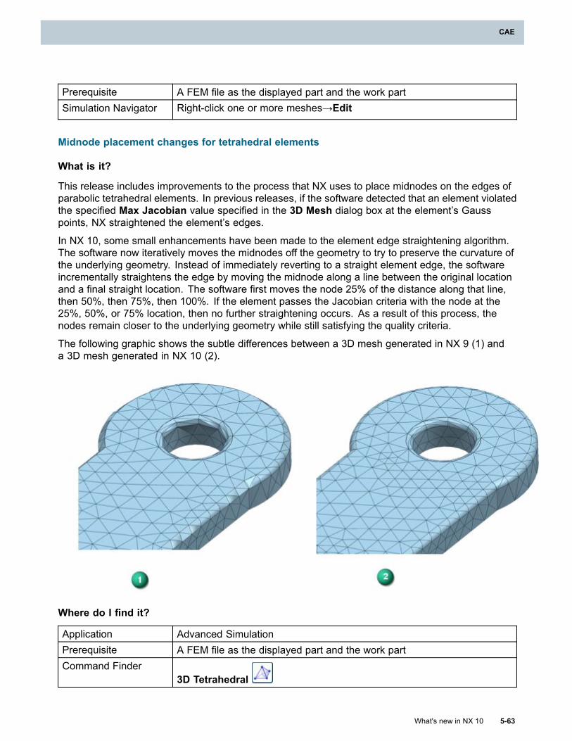
CAE
Prerequisite A FEM file as the displayed part and the work partSimulation Navigator Right-click one or more meshes→Edit
Midnode placement changes for tetrahedral elements
What is it?
This release includes improvements to the process that NX uses to place midnodes on the edges ofparabolic tetrahedral elements. In previous releases, if the software detected that an element violatedthe specified Max Jacobian value specified in the 3D Mesh dialog box at the element’s Gausspoints, NX straightened the element’s edges.
In NX 10, some small enhancements have been made to the element edge straightening algorithm.The software now iteratively moves the midnodes off the geometry to try to preserve the curvature ofthe underlying geometry. Instead of immediately reverting to a straight element edge, the softwareincrementally straightens the edge by moving the midnode along a line between the original locationand a final straight location. The software first moves the node 25% of the distance along that line,then 50%, then 75%, then 100%. If the element passes the Jacobian criteria with the node at the25%, 50%, or 75% location, then no further straightening occurs. As a result of this process, thenodes remain closer to the underlying geometry while still satisfying the quality criteria.
The following graphic shows the subtle differences between a 3D mesh generated in NX 9 (1) anda 3D mesh generated in NX 10 (2).
Where do I find it?
Application Advanced SimulationPrerequisite A FEM file as the displayed part and the work partCommand Finder
3D Tetrahedral
What's new in NX 10 5-63
CAE
Chapter 5: CAE
Menu Insert→Mesh→3D
Jacobian calculation changes for Nastran tetrahedral elements
What is it?
The Jacobian element quality check in the NX Nastran and MSC Nastran environments nowcalculates the Jacobian values for tetrahedral elements only at their Gauss points. In previousreleases, NX calculated an element’s Jacobian values at its Gauss points and at its corner nodes.
Neither NX Nastran nor MSC Nastran fails to solve due to Jacobian errors at an element’scorner nodes; Nastran only fails to solve if Jacobian errors occur at an element’s Gauss points.Consequently, in the Nastran environments, the Element Quality Checks command no longerevaluates Jacobian values at an element’s corner nodes.
Note
NX Nastran and MSC Nastran still list warnings for high Jacobian values at an element’s cornernodes to the .f06 file. To view these warnings, you can review the .f06 file after the solve.
Where do I find it?
Application Advanced SimulationPrerequisite A FEM file as the displayed part and the work part
NX Nastran or MSC Nastran as the specified solverCommand Finder
Element Quality ChecksMenu Analysis→Finite Element Model Check→Element Quality
Creating plane strain and plane stress elements parallel to axisymmetric plane
What is it?
You can now create plane strain and plane stress elements on a plane that is parallel to theaxisymmetric plane, we well as on the axisymmetric plane itself. To create these elements on aparallel plane, use a mesh creation command, such as 2D Mesh, or manual element creationcommands, such as Element Create and Element Translate. This change gives you greaterflexibility when you create models. In previous releases, you could create plane strain and planestress elements directly on the axisymmetric plane only.
Where do I find it?
Application Advanced Simulation
5-64 What's new in NX 10
Chapter 5: CAE

CAE
Prerequisite A FEM file as the displayed part and the work part
NX Nastran, NX Multiphysics, Abaqus, ANSYS, NX Electronic SystemsCooling, NX Thermal and Flow, or NX Space Systems Thermal as thespecified solver
Axisymmetric Structural or Axisymmetric Thermal as the analysistype, or Structural or Thermal as the analysis type with the 2D SolidOption set to any option other than None
Changes to 0D element creation
What is it?
Beginning in this release, point-based meshes that you create on a face or an edge with the 0D Meshcommand now follow the underlying mesh on the edge or face. For example, if you use the 0D Meshcommand to define a series of elements along an edge, NX generates those 0D elements only afteryou generate a beam mesh along that edge. Similarly, if you use 0D Mesh to define an element at alocation on a face, NX generates the 0D element after you create the mesh on that face.
Additionally, NX no longer creates a mesh point when you create a 0D element. In previous releases,NX created a mesh point for every node that was associated with a 0D element. This causedperformance issues during the mesh update process when changes occurred to the underlyingCAD geometry.
Where do I find it?
Application Advanced SimulationPrerequisite A FEM file as the displayed part and the work partCommand Finder
0D MeshMenu Insert→Mesh→0D Mesh
Batch Meshing enhancements
What is it?
The NX Batch Meshing utility has been updated to include many of the enhancements to the 2Dmeshing capabilities from this release. The following table details the new batch meshing parametersand their use.
What's new in NX 10 5-65
CAE
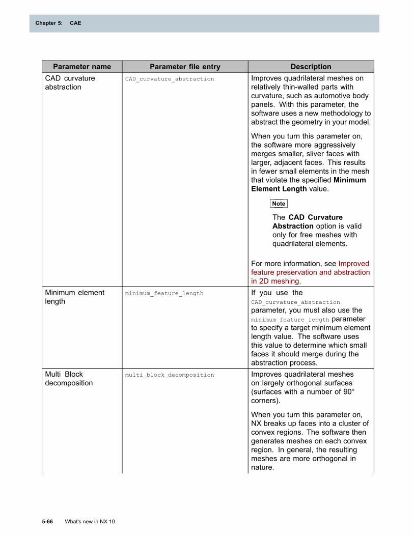
Chapter 5: CAE
Parameter name Parameter file entry DescriptionCAD curvatureabstraction
CAD_curvature_abstraction Improves quadrilateral meshes onrelatively thin-walled parts withcurvature, such as automotive bodypanels. With this parameter, thesoftware uses a new methodology toabstract the geometry in your model.
When you turn this parameter on,the software more aggressivelymerges smaller, sliver faces withlarger, adjacent faces. This resultsin fewer small elements in the meshthat violate the specified MinimumElement Length value.
Note
The CAD CurvatureAbstraction option is validonly for free meshes withquadrilateral elements.
For more information, see Improvedfeature preservation and abstractionin 2D meshing.
Minimum elementlength
minimum_feature_length If you use theCAD_curvature_abstraction
parameter, you must also use theminimum_feature_length parameterto specify a target minimum elementlength value. The software usesthis value to determine which smallfaces it should merge during theabstraction process.
Multi Blockdecomposition
multi_block_decomposition Improves quadrilateral mesheson largely orthogonal surfaces(surfaces with a number of 90°corners).
When you turn this parameter on,NX breaks up faces into a cluster ofconvex regions. The software thengenerates meshes on each convexregion. In general, the resultingmeshes are more orthogonal innature.
5-66 What's new in NX 10
Chapter 5: CAE
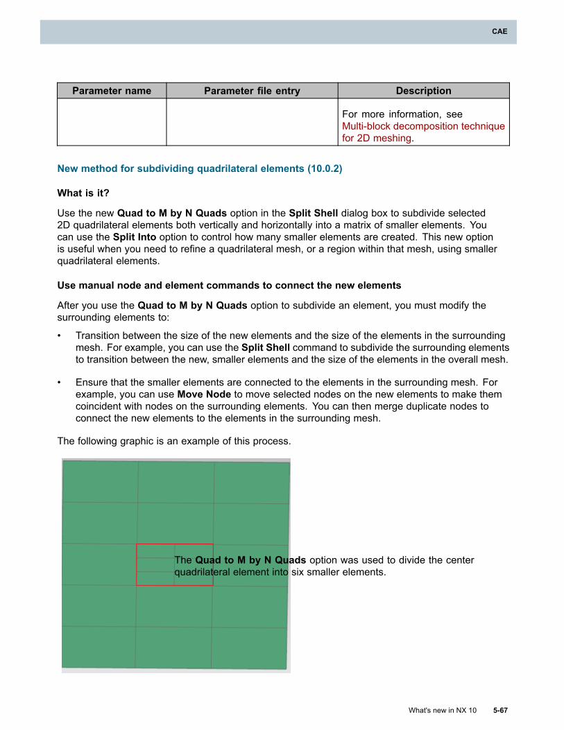
CAE
Parameter name Parameter file entry Description
For more information, seeMulti-block decomposition techniquefor 2D meshing.
New method for subdividing quadrilateral elements (10.0.2)
What is it?
Use the new Quad to M by N Quads option in the Split Shell dialog box to subdivide selected2D quadrilateral elements both vertically and horizontally into a matrix of smaller elements. Youcan use the Split Into option to control how many smaller elements are created. This new optionis useful when you need to refine a quadrilateral mesh, or a region within that mesh, using smallerquadrilateral elements.
Use manual node and element commands to connect the new elements
After you use the Quad to M by N Quads option to subdivide an element, you must modify thesurrounding elements to:
• Transition between the size of the new elements and the size of the elements in the surroundingmesh. For example, you can use the Split Shell command to subdivide the surrounding elementsto transition between the new, smaller elements and the size of the elements in the overall mesh.
• Ensure that the smaller elements are connected to the elements in the surrounding mesh. Forexample, you can use Move Node to move selected nodes on the new elements to make themcoincident with nodes on the surrounding elements. You can then merge duplicate nodes toconnect the new elements to the elements in the surrounding mesh.
The following graphic is an example of this process.
The Quad to M by N Quads option was used to divide the centerquadrilateral element into six smaller elements.
What's new in NX 10 5-67
CAE
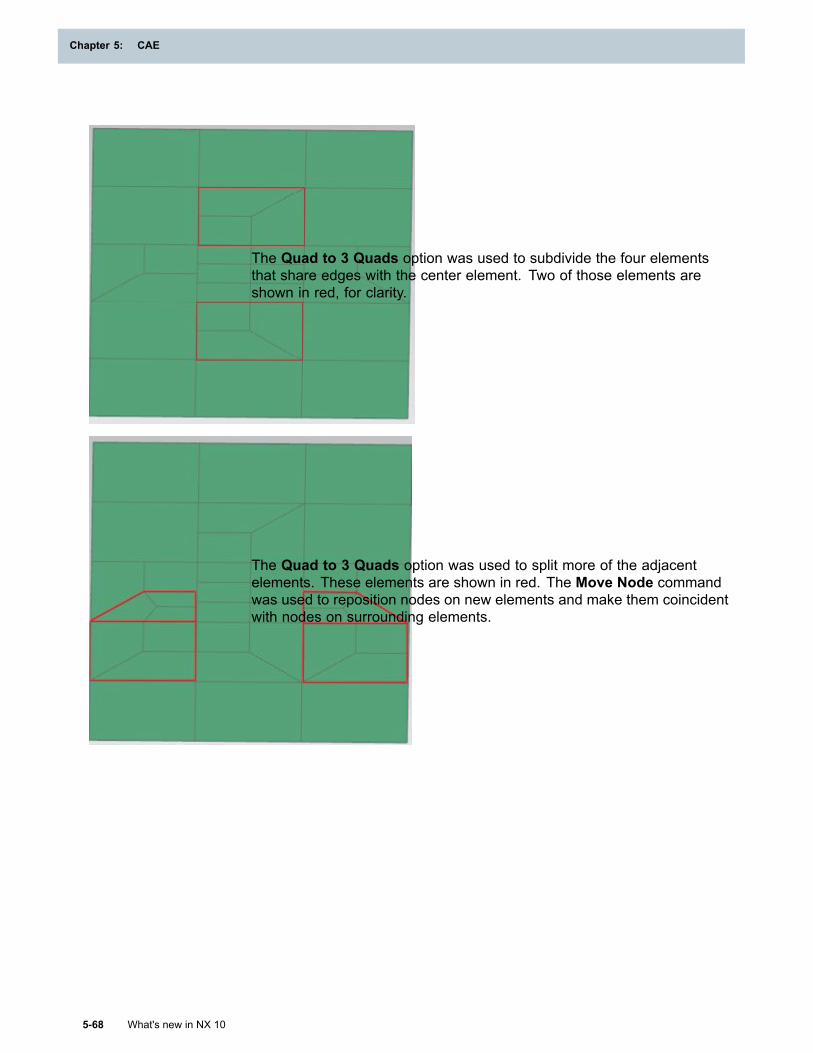
Chapter 5: CAE
The Quad to 3 Quads option was used to subdivide the four elementsthat share edges with the center element. Two of those elements areshown in red, for clarity.
The Quad to 3 Quads option was used to split more of the adjacentelements. These elements are shown in red. The Move Node commandwas used to reposition nodes on new elements and make them coincidentwith nodes on surrounding elements.
5-68 What's new in NX 10
Chapter 5: CAE
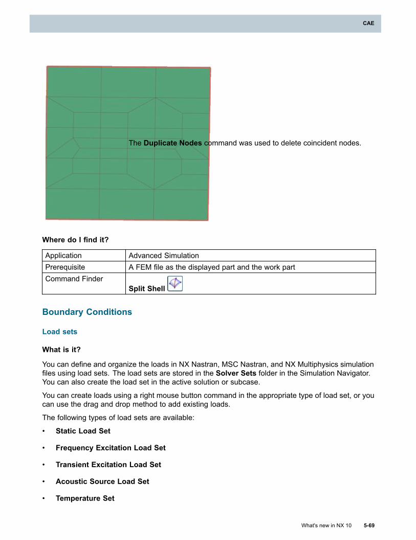
CAE
The Duplicate Nodes command was used to delete coincident nodes.
Where do I find it?
Application Advanced SimulationPrerequisite A FEM file as the displayed part and the work partCommand Finder
Split Shell
Boundary Conditions
Load sets
What is it?
You can define and organize the loads in NX Nastran, MSC Nastran, and NX Multiphysics simulationfiles using load sets. The load sets are stored in the Solver Sets folder in the Simulation Navigator.You can also create the load set in the active solution or subcase.
You can create loads using a right mouse button command in the appropriate type of load set, or youcan use the drag and drop method to add existing loads.
The following types of load sets are available:
• Static Load Set
• Frequency Excitation Load Set
• Transient Excitation Load Set
• Acoustic Source Load Set
• Temperature Set
What's new in NX 10 5-69
CAE
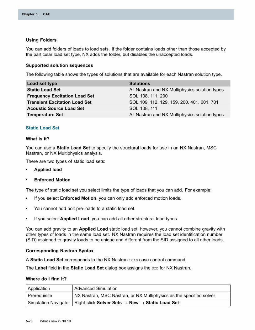
Chapter 5: CAE
Using Folders
You can add folders of loads to load sets. If the folder contains loads other than those accepted bythe particular load set type, NX adds the folder, but disables the unaccepted loads.
Supported solution sequences
The following table shows the types of solutions that are available for each Nastran solution type.
Load set type SolutionsStatic Load Set All Nastran and NX Multiphysics solution typesFrequency Excitation Load Set SOL 108, 111, 200Transient Excitation Load Set SOL 109, 112, 129, 159, 200, 401, 601, 701Acoustic Source Load Set SOL 108, 111Temperature Set All Nastran and NX Multiphysics solution types
Static Load Set
What is it?
You can use a Static Load Set to specify the structural loads for use in an NX Nastran, MSCNastran, or NX Multiphysics analysis.
There are two types of static load sets:
• Applied load
• Enforced Motion
The type of static load set you select limits the type of loads that you can add. For example:
• If you select Enforced Motion, you can only add enforced motion loads.
• You cannot add bolt pre-loads to a static load set.
• If you select Applied Load, you can add all other structural load types.
You can add gravity to an Applied Load static load set; however, you cannot combine gravity withother types of loads in the same load set. NX Nastran requires the load set identification number(SID) assigned to gravity loads to be unique and different from the SID assigned to all other loads.
Corresponding Nastran Syntax
A Static Load Set corresponds to the NX Nastran LOAD case control command.
The Label field in the Static Load Set dialog box assigns the SID for NX Nastran.
Where do I find it?
Application Advanced SimulationPrerequisite NX Nastran, MSC Nastran, or NX Multiphysics as the specified solverSimulation Navigator Right-click Solver Sets → New → Static Load Set
5-70 What's new in NX 10
Chapter 5: CAE
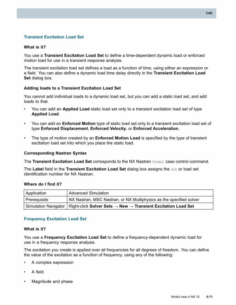
CAE
Transient Excitation Load Set
What is it?
You use a Transient Excitation Load Set to define a time-dependent dynamic load or enforcedmotion load for use in a transient response analysis.
The transient excitation load set defines a load as a function of time, using either an expression ora field. You can also define a dynamic load time delay directly in the Transient Excitation LoadSet dialog box.
Adding loads to a Transient Excitation Load Set
You cannot add individual loads to a dynamic load set, but you can add a static load set, and addloads to that.
• You can add an Applied Load static load set only to a transient excitation load set of typeApplied Load.
• You can add an Enforced Motion type of static load set only to a transient excitation load set oftype Enforced Displacement, Enforced Velocity, or Enforced Acceleration.
• The type of motion created by an Enforced Motion Load is specified by the type of transientexcitation load set into which you place the static load.
Corresponding Nastran Syntax
The Transient Excitation Load Set corresponds to the NX Nastran TLOAD1 case control command.
The Label field in the Transient Excitation Load Set dialog box assigns the SID or load setidentification number for NX Nastran.
Where do I find it?
Application Advanced SimulationPrerequisite NX Nastran, MSC Nastran, or NX Multiphysics as the specified solverSimulation Navigator Right-click Solver Sets→ New→ Transient Excitation Load Set
Frequency Excitation Load Set
What is it?
You use a Frequency Excitation Load Set to define a frequency-dependent dynamic load foruse in a frequency response analysis.
The excitation you create is applied over all frequencies for all degrees of freedom. You can definethe value of the excitation as a function of frequency, using any of the following:
• A complex expression
• A field
• Magnitude and phase
What's new in NX 10 5-71
CAE
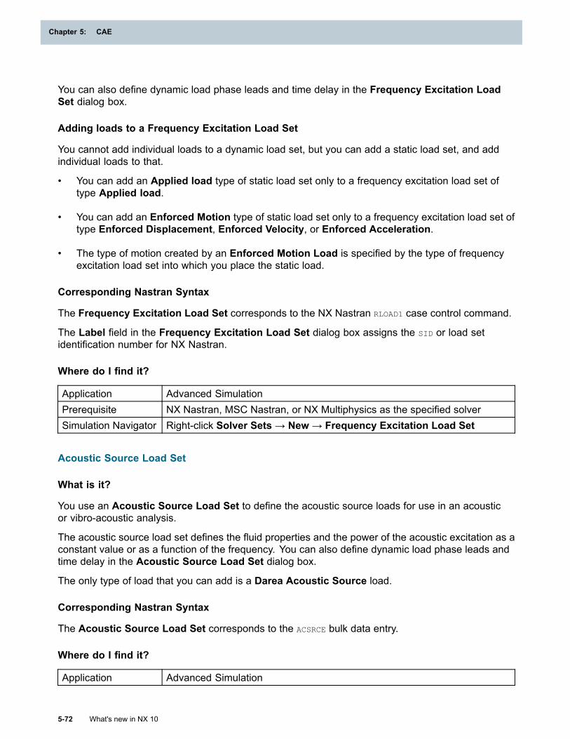
Chapter 5: CAE
You can also define dynamic load phase leads and time delay in the Frequency Excitation LoadSet dialog box.
Adding loads to a Frequency Excitation Load Set
You cannot add individual loads to a dynamic load set, but you can add a static load set, and addindividual loads to that.
• You can add an Applied load type of static load set only to a frequency excitation load set oftype Applied load.
• You can add an Enforced Motion type of static load set only to a frequency excitation load set oftype Enforced Displacement, Enforced Velocity, or Enforced Acceleration.
• The type of motion created by an Enforced Motion Load is specified by the type of frequencyexcitation load set into which you place the static load.
Corresponding Nastran Syntax
The Frequency Excitation Load Set corresponds to the NX Nastran RLOAD1 case control command.
The Label field in the Frequency Excitation Load Set dialog box assigns the SID or load setidentification number for NX Nastran.
Where do I find it?
Application Advanced SimulationPrerequisite NX Nastran, MSC Nastran, or NX Multiphysics as the specified solverSimulation Navigator Right-click Solver Sets→ New→ Frequency Excitation Load Set
Acoustic Source Load Set
What is it?
You use an Acoustic Source Load Set to define the acoustic source loads for use in an acousticor vibro-acoustic analysis.
The acoustic source load set defines the fluid properties and the power of the acoustic excitation as aconstant value or as a function of the frequency. You can also define dynamic load phase leads andtime delay in the Acoustic Source Load Set dialog box.
The only type of load that you can add is a Darea Acoustic Source load.
Corresponding Nastran Syntax
The Acoustic Source Load Set corresponds to the ACSRCE bulk data entry.
Where do I find it?
Application Advanced Simulation
5-72 What's new in NX 10
Chapter 5: CAE
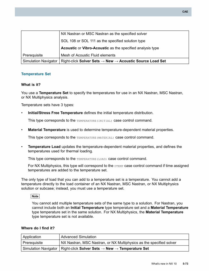
CAE
Prerequisite
NX Nastran or MSC Nastran as the specified solver
SOL 108 or SOL 111 as the specified solution type
Acoustic or Vibro-Acoustic as the specified analysis type
Mesh of Acoustic Fluid elementsSimulation Navigator Right-click Solver Sets→ New→ Acoustic Source Load Set
Temperature Set
What is it?
You use a Temperature Set to specify the temperatures for use in an NX Nastran, MSC Nastran,or NX Multiphysics analysis.
Temperature sets have 3 types:
• Initial/Stress Free Temperature defines the initial temperature distribution.
This type corresponds to the TEMPERATURE(INITIAL) case control command.
• Material Temperature is used to determine temperature-dependent material properties.
This type corresponds to the TEMPERATURE(MATERIAL) case control command.
• Temperature Load updates the temperature-dependent material properties, and defines thetemperatures used for thermal loading.
This type corresponds to the TEMPERATURE(LOAD) case control command.
For NX Multiphysics, this type will correspond to the DTEMP case control command if time assignedtemperatures are added to the temperature set.
The only type of load that you can add to a temperature set is a temperature. You cannot add atemperature directly to the load container of an NX Nastran, MSC Nastran, or NX Multiphysicssolution or subcase; instead, you must use a temperature set.
Note
You cannot add multiple temperature sets of the same type to a solution. For Nastran, youcannot include both an Initial Temperature type temperature set and a Material Temperaturetype temperature set in the same solution. For NX Multiphysics, the Material Temperaturetype temperature set is not available.
Where do I find it?
Application Advanced SimulationPrerequisite NX Nastran, MSC Nastran, or NX Multiphysics as the specified solverSimulation Navigator Right-click Solver Sets → New → Temperature Set
What's new in NX 10 5-73
CAE
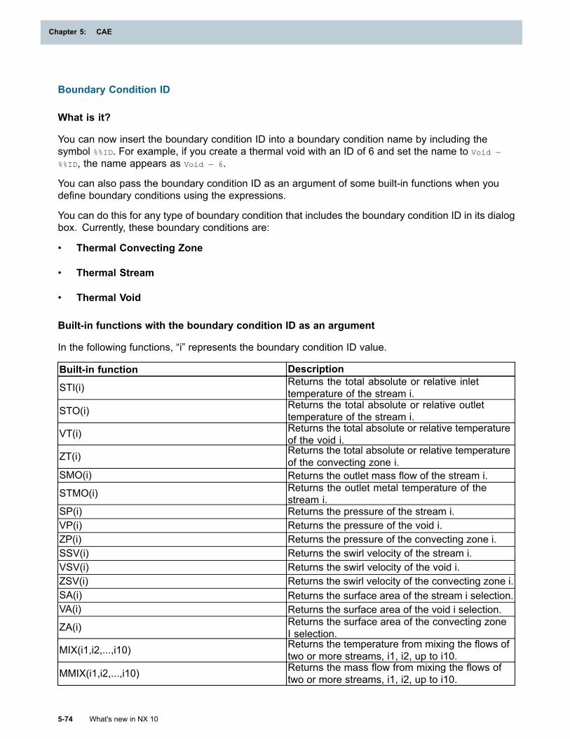
Chapter 5: CAE
Boundary Condition ID
What is it?
You can now insert the boundary condition ID into a boundary condition name by including thesymbol %%ID. For example, if you create a thermal void with an ID of 6 and set the name to Void —
%%ID, the name appears as Void — 6.
You can also pass the boundary condition ID as an argument of some built-in functions when youdefine boundary conditions using the expressions.
You can do this for any type of boundary condition that includes the boundary condition ID in its dialogbox. Currently, these boundary conditions are:
• Thermal Convecting Zone
• Thermal Stream
• Thermal Void
Built-in functions with the boundary condition ID as an argument
In the following functions, “i” represents the boundary condition ID value.
Built-in function Description
STI(i) Returns the total absolute or relative inlettemperature of the stream i.
STO(i) Returns the total absolute or relative outlettemperature of the stream i.
VT(i) Returns the total absolute or relative temperatureof the void i.
ZT(i) Returns the total absolute or relative temperatureof the convecting zone i.
SMO(i) Returns the outlet mass flow of the stream i.
STMO(i) Returns the outlet metal temperature of thestream i.
SP(i) Returns the pressure of the stream i.VP(i) Returns the pressure of the void i.ZP(i) Returns the pressure of the convecting zone i.SSV(i) Returns the swirl velocity of the stream i.VSV(i) Returns the swirl velocity of the void i.ZSV(i) Returns the swirl velocity of the convecting zone i.SA(i) Returns the surface area of the stream i selection.VA(i) Returns the surface area of the void i selection.
ZA(i) Returns the surface area of the convecting zoneI selection.
MIX(i1,i2,...,i10) Returns the temperature from mixing the flows oftwo or more streams, i1, i2, up to i10.
MMIX(i1,i2,...,i10) Returns the mass flow from mixing the flows oftwo or more streams, i1, i2, up to i10.
5-74 What's new in NX 10
Chapter 5: CAE
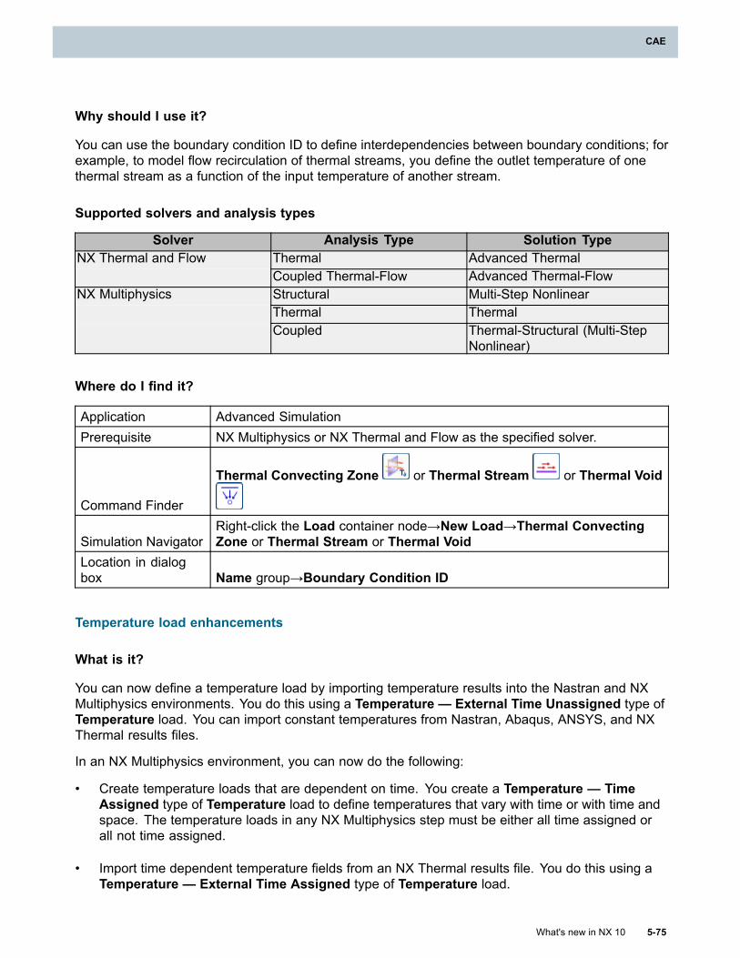
CAE
Why should I use it?
You can use the boundary condition ID to define interdependencies between boundary conditions; forexample, to model flow recirculation of thermal streams, you define the outlet temperature of onethermal stream as a function of the input temperature of another stream.
Supported solvers and analysis types
Solver Analysis Type Solution TypeThermal Advanced ThermalNX Thermal and FlowCoupled Thermal-Flow Advanced Thermal-FlowStructural Multi-Step NonlinearThermal Thermal
NX Multiphysics
Coupled Thermal-Structural (Multi-StepNonlinear)
Where do I find it?
Application Advanced SimulationPrerequisite NX Multiphysics or NX Thermal and Flow as the specified solver.
Command Finder
Thermal Convecting Zone or Thermal Stream or Thermal Void
Simulation NavigatorRight-click the Load container node→New Load→Thermal ConvectingZone or Thermal Stream or Thermal Void
Location in dialogbox Name group→Boundary Condition ID
Temperature load enhancements
What is it?
You can now define a temperature load by importing temperature results into the Nastran and NXMultiphysics environments. You do this using a Temperature — External Time Unassigned type ofTemperature load. You can import constant temperatures from Nastran, Abaqus, ANSYS, and NXThermal results files.
In an NX Multiphysics environment, you can now do the following:
• Create temperature loads that are dependent on time. You create a Temperature — TimeAssigned type of Temperature load to define temperatures that vary with time or with time andspace. The temperature loads in any NX Multiphysics step must be either all time assigned orall not time assigned.
• Import time dependent temperature fields from an NX Thermal results file. You do this using aTemperature — External Time Assigned type of Temperature load.
What's new in NX 10 5-75
CAE
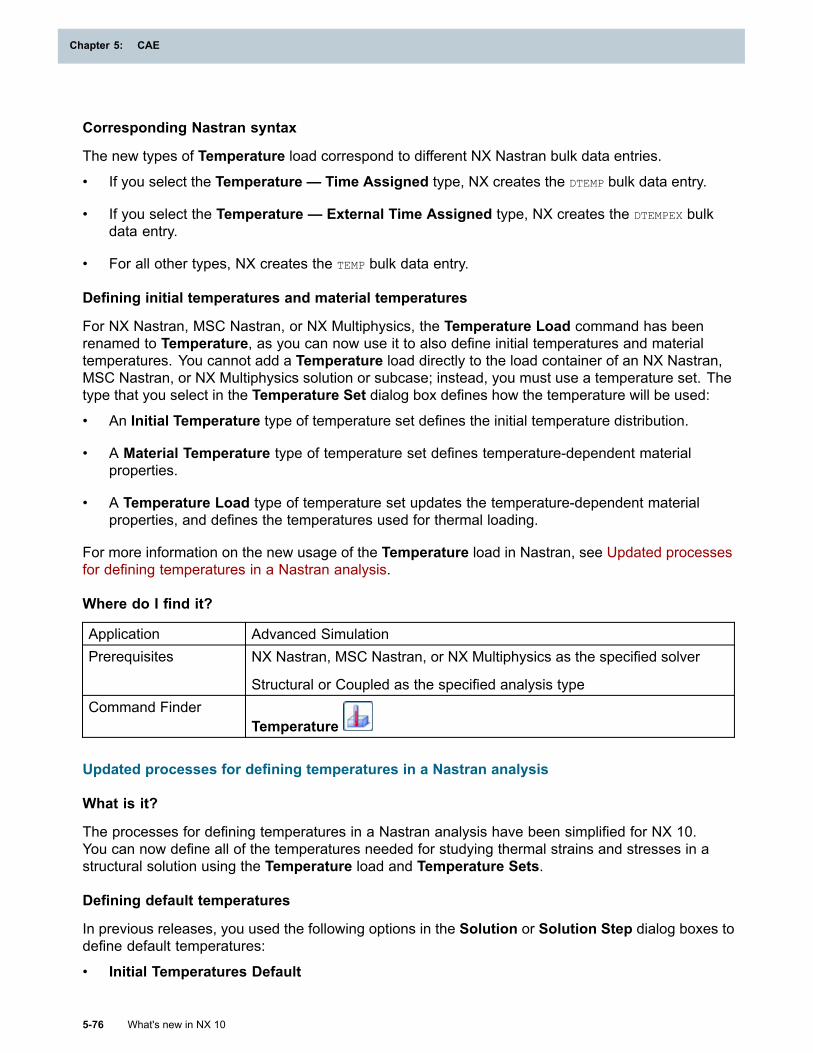
Chapter 5: CAE
Corresponding Nastran syntax
The new types of Temperature load correspond to different NX Nastran bulk data entries.
• If you select the Temperature — Time Assigned type, NX creates the DTEMP bulk data entry.
• If you select the Temperature — External Time Assigned type, NX creates the DTEMPEX bulkdata entry.
• For all other types, NX creates the TEMP bulk data entry.
Defining initial temperatures and material temperatures
For NX Nastran, MSC Nastran, or NX Multiphysics, the Temperature Load command has beenrenamed to Temperature, as you can now use it to also define initial temperatures and materialtemperatures. You cannot add a Temperature load directly to the load container of an NX Nastran,MSC Nastran, or NX Multiphysics solution or subcase; instead, you must use a temperature set. Thetype that you select in the Temperature Set dialog box defines how the temperature will be used:
• An Initial Temperature type of temperature set defines the initial temperature distribution.
• A Material Temperature type of temperature set defines temperature-dependent materialproperties.
• A Temperature Load type of temperature set updates the temperature-dependent materialproperties, and defines the temperatures used for thermal loading.
For more information on the new usage of the Temperature load in Nastran, see Updated processesfor defining temperatures in a Nastran analysis.
Where do I find it?
Application Advanced SimulationPrerequisites NX Nastran, MSC Nastran, or NX Multiphysics as the specified solver
Structural or Coupled as the specified analysis typeCommand Finder
Temperature
Updated processes for defining temperatures in a Nastran analysis
What is it?
The processes for defining temperatures in a Nastran analysis have been simplified for NX 10.You can now define all of the temperatures needed for studying thermal strains and stresses in astructural solution using the Temperature load and Temperature Sets.
Defining default temperatures
In previous releases, you used the following options in the Solution or Solution Step dialog boxes todefine default temperatures:
• Initial Temperatures Default
5-76 What's new in NX 10
Chapter 5: CAE
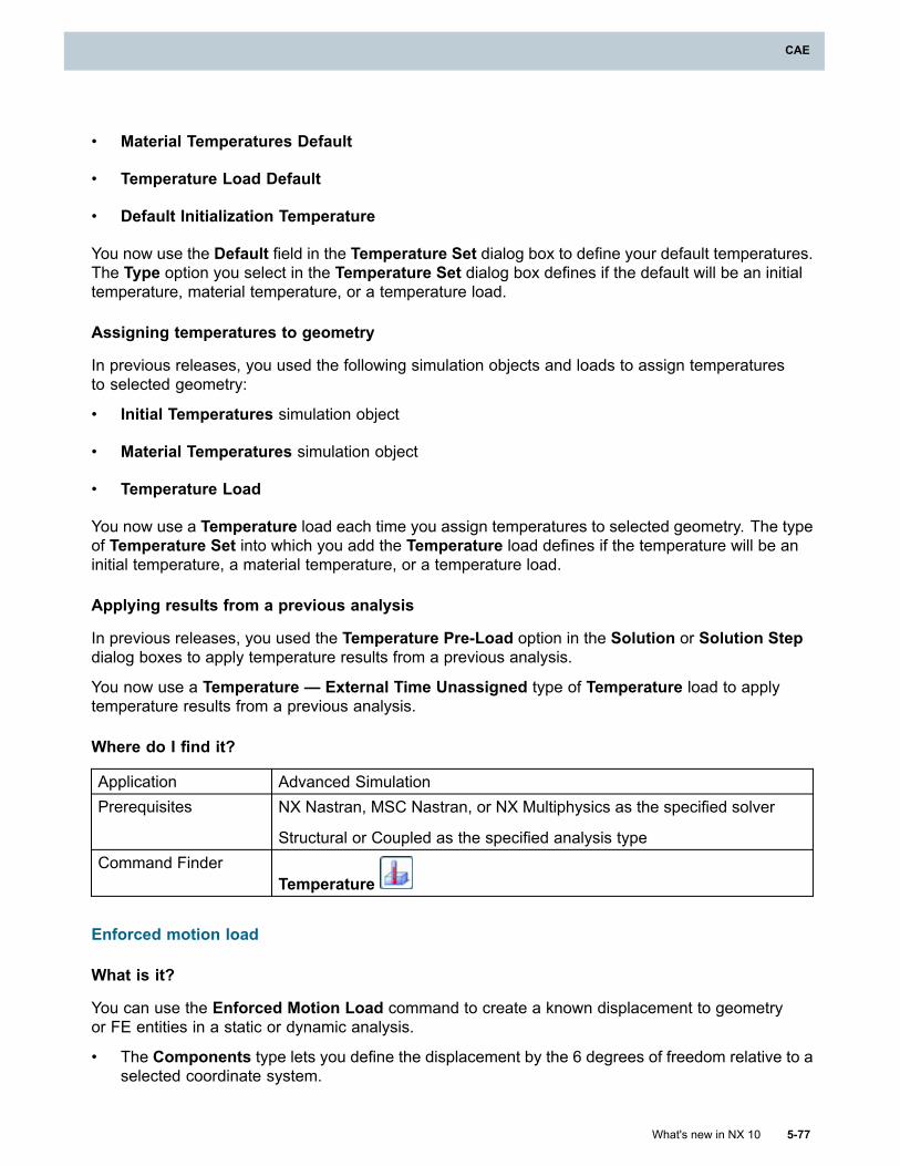
CAE
• Material Temperatures Default
• Temperature Load Default
• Default Initialization Temperature
You now use the Default field in the Temperature Set dialog box to define your default temperatures.The Type option you select in the Temperature Set dialog box defines if the default will be an initialtemperature, material temperature, or a temperature load.
Assigning temperatures to geometry
In previous releases, you used the following simulation objects and loads to assign temperaturesto selected geometry:
• Initial Temperatures simulation object
• Material Temperatures simulation object
• Temperature Load
You now use a Temperature load each time you assign temperatures to selected geometry. The typeof Temperature Set into which you add the Temperature load defines if the temperature will be aninitial temperature, a material temperature, or a temperature load.
Applying results from a previous analysis
In previous releases, you used the Temperature Pre-Load option in the Solution or Solution Stepdialog boxes to apply temperature results from a previous analysis.
You now use a Temperature — External Time Unassigned type of Temperature load to applytemperature results from a previous analysis.
Where do I find it?
Application Advanced SimulationPrerequisites NX Nastran, MSC Nastran, or NX Multiphysics as the specified solver
Structural or Coupled as the specified analysis typeCommand Finder
Temperature
Enforced motion load
What is it?
You can use the Enforced Motion Load command to create a known displacement to geometryor FE entities in a static or dynamic analysis.
• The Components type lets you define the displacement by the 6 degrees of freedom relative to aselected coordinate system.
What's new in NX 10 5-77
CAE
Chapter 5: CAE
• The Magnitude and Direction type lets you define the magnitude of the displacement in asingle direction.
• The Normal type lets you define the constraint by specifying a displacement magnitude and a +/–direction that is normal to the selected geometry or element faces.
Using enforced motions in dynamic analysis
In a dynamic analysis, you can use the Enforced Motion Load command to also define a knownvelocity or acceleration.
In Nastran, you use the SPCD bulk data entry to define the enforced motion. You use the TLOAD1 orTLOAD2 bulk data entries to define a transient response excitation with a reference to the SPCD entries.You define the motion as a displacement, velocity, or acceleration with the TYPE field in the TLOAD1
or TLOAD2 bulk data entries.
In NX, you create an Enforced Displacement, Enforced Velocity, or Enforced Acceleration typeof Transient Excitation Load Set. You add the Enforced Motion Load to the load set to define thetype of motion used.
In Nastran, you use the RLOAD1 or RLOAD2 bulk data entries to define a frequency response excitationwith a reference to the SPCD entries. You define the motion as a displacement, velocity, or accelerationwith the TYPE field in the RLOAD1 or RLOAD2 bulk data entries.
In NX, you create an Enforced Displacement, Enforced Velocity, or Enforced Acceleration typeof Frequency Excitation Load Set. You add the Enforced Motion Load to the load set to define thetype of motion used.
Where do I find it?
Application Advanced SimulationPrerequisites NX Nastran, MSC Nastran, or NX Multiphysics as the specified solverCommand finder
Enforced Motion Load
Pressure load enhancements
What is it?
For Pressure loads of the type On Axisymmetric Elements (Normal to Edge) XY and OnAxisymmetric Elements (Normal to Edge) ZX, you can now define the pressure by specifyingthe total load to apply.
NX converts the total load to a pressure when it writes the input file:
Pressure = Total Force / Area of the 360° revolved edge
Where do I find it?
Application Advanced SimulationPrerequisites NX Nastran, MSC Nastran, or NX Multiphysics as the specified solver
Axisymmetric Structural as the specified analysis type
5-78 What's new in NX 10
Chapter 5: CAE
CAE
Command FinderPressure
Edge load enhancements
What is it?
For edge loads of the type Edge Load on Plane Strain and Stress Elements (Normal to Edge) XYand Edge Load on Plane Strain and Stress Elements (Normal to Edge) ZX, you can now specifythe total load to apply. With the Constant and Spatial distribution types, you define the load usingpressure units, whereas with the new Total distribution type, the load is defined using force units.
NX converts the total load to a pressure when it writes the input file:
Pressure = Total Force / Element Edge Length x Element Thickness
Where do I find it?
Application Advanced SimulationPrerequisites NX Nastran, MSC Nastran, or NX Multiphysics as the specified solver
Axisymmetric Structural as the specified analysis typeCommand Finder
Edge Load
Dynamic load time delay
What is it?
You can now create time delays for dynamic loads, using the Dynamic Load Time Delay modelingobject. The same time delay can be applied to every excitation selected, or you can specify uniquevalues for individual DOF components. The nodes affected can be individually selected, or chosenas a group.
You can define load time delay while creating a Frequency Excitation, Transient Excitation, orAcoustic Source Load Set. When defined with the load set, the delay can be created as a DynamicLoad Time Delay modeling object, or as a simple expression. If you use an expression, the delay isapplied to all excitations in the load set.
Corresponding Nastran Syntax
The Dynamic Load Time Delay command corresponds to the NX Nastran DELAY bulk data entry.
Where do I find it?
Application Advanced SimulationPrerequisites NX Nastran, MSC Nastran, or NX Multiphysics as the specified solverCommand Finder
Modeling ObjectsLocation in dialog box Type list → Dynamic Load Time Delay
What's new in NX 10 5-79
CAE
Chapter 5: CAE
Dynamic load phase lead
What is it?
You can now create phase leads for dynamic loads, using the Dynamic Load Phase Lead modelingobject. Apply the same angle of lead to every excitation selected, or specify unique values forindividual DOF components. You can select the affected nodes individually or as a group.
You can define load phase lead while creating a Frequency Excitation, or an Acoustic SourceLoad Set. When defined with the load set, the delay can be created as a Dynamic Load PhaseLead modeling object, or as a simple expression. If you use an expression, the delay is applied to allexcitations in the load set.
Corresponding Nastran Syntax
The Dynamic Load Phase Lead command corresponds to the NX Nastran DPHASE bulk data entry.
Where do I find it?
Application Advanced SimulationPrerequisites NX Nastran, MSC Nastran, or NX Multiphysics as the specified solverCommand Finder
Modeling ObjectsLocation in dialog box Type list → Dynamic Load Phase Lead
Darea Nodal Force and Moment load
What is it?
You can use the Darea Nodal Force and Moment load to create both forces and moments in whichthe values can vary at each node. You define the forces and moments by the six DOF componentsrelative to the nodal displacement coordinate system.
By selecting the Unique DOF Values option, you can access the Edit By Node dialog box andenter unique values for each node.
Corresponding Nastran Syntax
The Darea Nodal Force and Moment command corresponds to the NX Nastran DAREA bulk data entry.
Where do I find it?
Application Advanced SimulationPrerequisites NX Nastran or MSC Nastran as the specified solverCommand Finder
Darea Nodal Force and Moment
5-80 What's new in NX 10
Chapter 5: CAE
CAE
Acoustic source load
What is it?
Acoustic waves are longitudinal waves generated by the volumetric expansion or contraction of themedium (for example, air or water), caused by excitation of the system. You can use the new DareaAcoustic Source command and Acoustic Source Load Set to simulate a stationary acousticsource in the space that emits pulsating pressure waves. You can use this source for acousticor vibro-acoustic analysis.
Examples of acoustic sources include:
• A small speaker in a small rigid box emitting sound at low frequency.
• An engine inside an anechoic chamber.
• An engine exhaust pipe outlet.
The sound waves emitted from an acoustic source form a uniform spherical envelope.
Using the Darea Acoustic Source command, you define the spatial distribution of the acousticsource by selecting nodes in a fluid mesh. To enable the acoustic source, enter 1 in the DOF1box. To disable the acoustic source, enter 0.
You can use the Unique DOF Values option to enable or disable the acoustic source for each nodeindependently. This way, you can study the contribution of each acoustic source independently, for anacoustic or vibro-acoustic system that has multiple acoustic sources.
You must create the acoustic source in an Acoustic Source Load Set. This load set has anexcitation value (real value only) that defines the TP field on the ACSRCE bulk data entry. For moreinformation, see Acoustic Source Load Set.
Corresponding Nastran Syntax
The Darea Acoustic Source command corresponds to the DAREA bulk data entry.
The Acoustic Source Load Set command corresponds to the ACSRCE bulk data entry.
Where do I find it?
Application Advanced SimulationPrerequisites NX Nastran or MSC Nastran as the specified solver.
SOL 108 or SOL 111 as the specified solution type.
Acoustic or Vibro-Acoustic as the specified analysis type.
Mesh of Acoustic Fluid elements.Command Finder
Darea Acoustic Source
What's new in NX 10 5-81
CAE
Chapter 5: CAE
Bolt Pre-Load enhancements
What is it?
When defining Bolt Pre-Load for NX Nastran solutions 106, 129, and 601, as well as NX Multiphysics,you now define the bolt geometry from polygon bodies or 3D elements. You define the bolt plane froma point, a node, or a mesh point, and the bolt axis.
Force on 2D elements
In NX Multiphysics, you can also now create bolt pre-loads on 2D elements. You define the boltgeometry from polygon faces or 2D elements. You define the bolt plane from a point, a node, or amesh point, and the bolt axis.
Corresponding Nastran Syntax
The changes in how the Bolt Pre-Load is defined correspond to a change in the option used on theNastran BOLT bulk data entry. The Bolt Pre-Load for these solutions now uses the ETYPE=3 option. Inprevious releases, the ETYPE=2 option was used.
Where do I find it?
Application Advanced SimulationCommand finder
Bolt Pre-Load
Abaqus axisymmetric contact analysis (10.0.1)
What is it?
This release includes expanded support for contact analyses in the Abaqus environment. Youcan now perform a number of different types of contact analyses in axisymmetric structural andthermal models. In previous releases, contact analyses in the Abaqus environment were limited tonon-axisymmetric models.
The following table summarizes the commands that are now available for axisymmetric structuraland thermal solutions:
Abaquselement
Description Analysis typessupported
Corresponding Abaquskeywords
Edge-to-Edge
Contact
Defines contactconditions betweenselected polygon edgesor element edges.
Axisymmetric structural *CONTACT PAIR
*SURFACE
5-82 What's new in NX 10
Chapter 5: CAE
CAE
Abaquselement
Description Analysis typessupported
Corresponding Abaquskeywords
ContactInterference
Defines time-dependentallowable interferencesfor contact pairs andelements.
You can use ContactInterference to modelinterference fits (pressfits) when there are largeoverclosures between thecontacting surfaces inthe initial configuration ofthe model. The definedcontact interferencescan result in stressesand strains as the solverresolves the overclosurebetween the contactingsurfaces.
Axisymmetric structural *CONTACT PAIR
*CONTACT INTERFERENCE
Contact with
Clearance
Defines precise clearanceor overclosure valuesfor the nodes on theslave (target) surfacein a contact pair. Anoverclosure value allowsyou to specify anyinitial penetration forthe contacting surfaces.
Axisymmetric structural *CONTACT PAIR
*CLEARANCE
Surface-to-SurfaceThermalConductance
Models conductiveheat transfer betweenproximate or contactingsurfaces. You can modelthe conductive heattransfer as a function of:
• The clearancebetween thecontacting surfaces.
• The contact pressureat the interfacebetween thecontacting surfaces.
• Both the clearanceand the contactpressure.
Axisymmetric thermal *GAP CONDUCTANCE
What's new in NX 10 5-83
CAE
Chapter 5: CAE
Where do I find it?
Application Advanced SimulationPrerequisite A Simulation file as the displayed part and the work part
Abaqus as the specified solver
Axisymmetric Structural or Axisymmetric Thermal as the analysis type
General Analysis or Heat Transfer as the solution type
ANSYS axisymmetric contact analysis (10.0.1)
What is it?
This release includes support for contact analyses in ANSYS axisymmetric structural and thermalsolutions. In previous releases, contact was supported only in non-axisymmetric solutions.
Axisymmetric structural solutions
You can now use the Structural Contact command to analyze contact between the edges of planarelements in axisymmetric models. You use the Structural Contact and the Region dialog boxes todefine contact and sliding between a 2D target edge and a deformable surface. When you export orsolve the solution, the software creates the appropriate CONTA172 elements to define the deformablesurface and TARGE169 elements to define the target surface.
Axisymmetric thermal solutions
You can now use the Thermal Contact command to define thermal contact conduction betweencontacting surfaces in axisymmetric models using the edges of planar elements. You use theThermal Contact and the Region dialog boxes to define the contact between the edges, as well asselect the edges, points, or nodes that define the contacting edges.
After you define the contacting surfaces, use the CONTA174/172 Real Constants dialog box todefine the required thermal contact properties. You can define the following properties:
• Thermal contact conductance (TCC), which allows you to take into account the conductive heattransfer between the contact and target surfaces.
Note
Currently, NX supports only a constant Thermal contact conductance value. You cannotvary the Thermal contact conductance with temperature, pressure, or time.
• The Stefan-Boltzmann constant (SBCT), which you can use to model radiative heat transfer. Ifyou do not specify a value for the Stefan-Boltzmann constant, the radiation effect is excludedfrom the thermal contact calculations.
• The Radiation view factor (RDVF), which you can use to define the radiation view factor fornear-field radiation.
Where do I find it?
Structural Contact
5-84 What's new in NX 10
Chapter 5: CAE
CAE
Application Advanced SimulationPrerequisite A Simulation file as the displayed part and the work part
ANSYS as the specified solver
Axisymmetric Structural as the analysis type
Linear Statics or Nonlinear Statics as the solution typeCommand Finder
Structural Contact
Thermal Contact
Application Advanced SimulationPrerequisite A Simulation file as the displayed part and the work part
ANSYS as the specified solver
Axisymmetric Thermal as the analysis type
Steady State Thermal as the solution typeCommand Finder
Thermal Contact
Constraint equation support in Abaqus and ANSYS thermal solutions (10.0.1)
What is it?
You can now create constraint equations between the temperature degrees-of-freedom of thermalelements in both the Abaqus and ANSYS thermal environments. In previous releases, you could onlycreate constraint equations in the Abaqus and ANSYS structural environments.
Constraint equations for Abaqus thermal solutions
In the Abaqus thermal environment, use the new Manual Coupling command to define theindependent and dependent coupling parameters between selected nodes. When you export or solveyour model, NX creates the appropriate *EQUATION commands in your Abaqus input file.
Constraint equations for ANSYS thermal solutions
In the ANSYS thermal environment, the Manual Thermal Coupling command has been enhanced toallow you to create constraint equations as well as define sets of coupled degrees-of-freedom. Usethe new CE option in the Type list of the Manual Thermal Coupling dialog box to define couplingbetween the temperature degrees-of-freedom within the model. When you export or solve yourmodel, the software creates the appropriate CE keywords in your ANSYS input file.
Where do I find it?
Application Advanced Simulation
What's new in NX 10 5-85
CAE
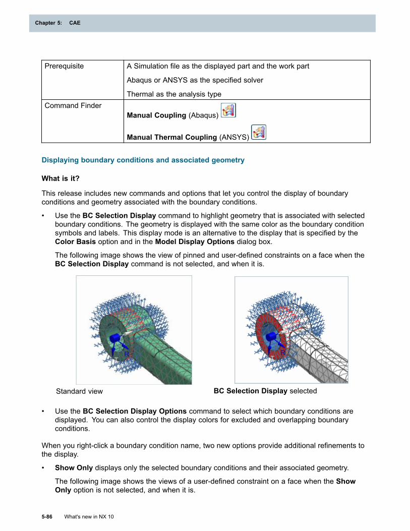
Chapter 5: CAE
Prerequisite A Simulation file as the displayed part and the work part
Abaqus or ANSYS as the specified solver
Thermal as the analysis typeCommand Finder
Manual Coupling (Abaqus)
Manual Thermal Coupling (ANSYS)
Displaying boundary conditions and associated geometry
What is it?
This release includes new commands and options that let you control the display of boundaryconditions and geometry associated with the boundary conditions.
• Use the BC Selection Display command to highlight geometry that is associated with selectedboundary conditions. The geometry is displayed with the same color as the boundary conditionsymbols and labels. This display mode is an alternative to the display that is specified by theColor Basis option and in the Model Display Options dialog box.
The following image shows the view of pinned and user-defined constraints on a face when theBC Selection Display command is not selected, and when it is.
Standard view BC Selection Display selected
• Use the BC Selection Display Options command to select which boundary conditions aredisplayed. You can also control the display colors for excluded and overlapping boundaryconditions.
When you right-click a boundary condition name, two new options provide additional refinements tothe display.
• Show Only displays only the selected boundary conditions and their associated geometry.
The following image shows the views of a user-defined constraint on a face when the ShowOnly option is not selected, and when it is.
5-86 What's new in NX 10
Chapter 5: CAE
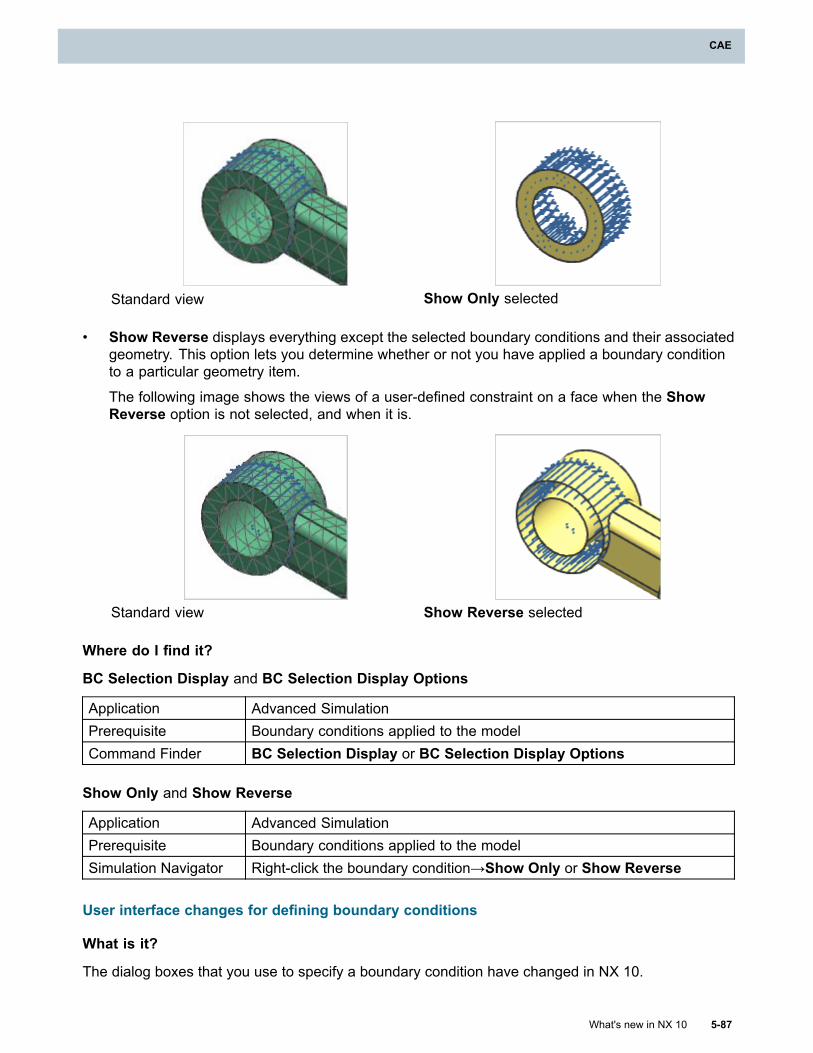
CAE
Standard view Show Only selected
• Show Reverse displays everything except the selected boundary conditions and their associatedgeometry. This option lets you determine whether or not you have applied a boundary conditionto a particular geometry item.
The following image shows the views of a user-defined constraint on a face when the ShowReverse option is not selected, and when it is.
Standard view Show Reverse selected
Where do I find it?
BC Selection Display and BC Selection Display Options
Application Advanced SimulationPrerequisite Boundary conditions applied to the modelCommand Finder BC Selection Display or BC Selection Display Options
Show Only and Show Reverse
Application Advanced SimulationPrerequisite Boundary conditions applied to the modelSimulation Navigator Right-click the boundary condition→Show Only or Show Reverse
User interface changes for defining boundary conditions
What is it?
The dialog boxes that you use to specify a boundary condition have changed in NX 10.
What's new in NX 10 5-87
CAE
Chapter 5: CAE
• In earlier versions of NX, to specify the magnitude of a boundary condition, you first select eitherExpression or Field from the drop-down list in the Magnitude group. If you select Field, you arethen presented with a second drop-down list. From this list, you select how you want to define thefield. For many boundary conditions in NX 10, you specify the boundary condition from a singleentry box regardless of whether you want to define it with an expression or a field.
• In earlier versions of NX, the magnitude and distribution of a boundary condition are definedseparately. The magnitude is defined in the Magnitude group, and the distribution is definedin the Distribution group. For many boundary conditions in NX 10, both the magnitude anddistribution of the boundary condition are defined by a single expression or field entry in theMagnitude group.
• In earlier versions of NX, the Scale Factor box appears in the Magnitude group once you selectField from the drop-down list. In NX 10, the Scale Factor box does not appear when you definethe boundary condition with a field. Instead, an edit button appears in the entry box. If you clickthe edit button, an option list appears. If you select Scale Factor from the list, the new FieldScale Factor dialog box opens from which you can enter the scale factor.
Where do I find it?
Entering a scale factor
Application Advanced SimulationPrerequisite Define the magnitude and distribution of a boundary condition with a fieldLocation in dialog box
[Boundary condition] dialog box → Magnitude group → edit → list →Scale Factor→ Field Scale Factor dialog box → Table Field box
Solutions
Updating a solution from a condition sequence
What is it?
You can now modify a condition sequence (such as add, modify, and remove time points), and thenuse the new Update from Condition Sequence command to update the solution that was created bythat condition sequence. In the previous release, you could not edit a condition sequence and updatethe steps in the solution that was created from the condition sequence.
The Update from Condition Sequence command makes corresponding changes to the time stepsin the solution.
• If you add new time points to the condition sequence, the update command adds new conditionsequence-associated time steps to the solution.
• If you change the time values in the condition sequence, the update command updates thesolution step with the new time values.
• If you remove time points from the condition sequence, the update command deletes the solutionsteps associated with those time points.
5-88 What's new in NX 10
Chapter 5: CAE
CAE
Updating a solution with a different condition sequence
For a solution that was created from a condition sequence, you can also use a different conditionsequence to update the solution. For example, suppose you use condition sequence CS-A to createSolution 123. Later, you create condition sequence CS-B. You can use the Update from ConditionSequence command to update Solution 123 with condition sequence CS-B.
Where do I find it?
Application Advanced SimulationPrerequisite A Simulation file as the work part and displayed part
A solution created from a condition sequence, using the New Solutionfrom Condition Sequence command
Simulation Navigator Right-click the solution→Update from Condition Sequence
Scaling loads using the Subcase/Step Association Manager
What is it?
You can now scale static loads directly in the Subcase/Step Association Manager in the followingenvironments:
• NX Multiphysics Structural and Coupled environments
• NX Nastran Structural (solution 101 only)
A new Switch to Scaling View button allows you to add a real number as a scale factor for individualloads and for defined load sets. A scale factor defined for a load set applies to all static loads in thatset. The following graphic shows the scaling view; the highlighted value shows a scale factor of 10applied to a force load in a subcase.
What's new in NX 10 5-89
CAE
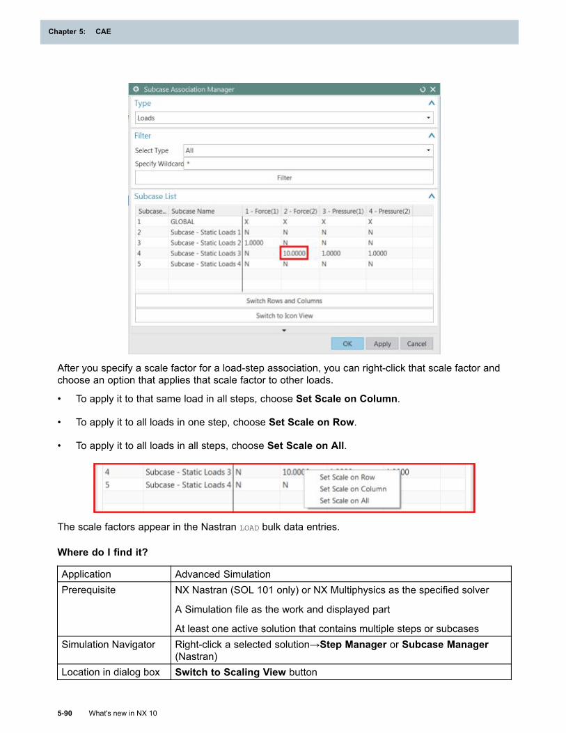
Chapter 5: CAE
After you specify a scale factor for a load-step association, you can right-click that scale factor andchoose an option that applies that scale factor to other loads.
• To apply it to that same load in all steps, choose Set Scale on Column.
• To apply it to all loads in one step, choose Set Scale on Row.
• To apply it to all loads in all steps, choose Set Scale on All.
The scale factors appear in the Nastran LOAD bulk data entries.
Where do I find it?
Application Advanced SimulationPrerequisite NX Nastran (SOL 101 only) or NX Multiphysics as the specified solver
A Simulation file as the work and displayed part
At least one active solution that contains multiple steps or subcasesSimulation Navigator Right-click a selected solution→Step Manager or Subcase Manager
(Nastran)Location in dialog box Switch to Scaling View button
5-90 What's new in NX 10
Chapter 5: CAE
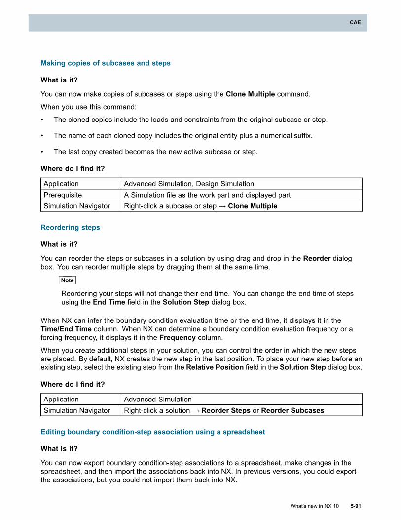
CAE
Making copies of subcases and steps
What is it?
You can now make copies of subcases or steps using the Clone Multiple command.
When you use this command:
• The cloned copies include the loads and constraints from the original subcase or step.
• The name of each cloned copy includes the original entity plus a numerical suffix.
• The last copy created becomes the new active subcase or step.
Where do I find it?
Application Advanced Simulation, Design SimulationPrerequisite A Simulation file as the work part and displayed partSimulation Navigator Right-click a subcase or step → Clone Multiple
Reordering steps
What is it?
You can reorder the steps or subcases in a solution by using drag and drop in the Reorder dialogbox. You can reorder multiple steps by dragging them at the same time.
Note
Reordering your steps will not change their end time. You can change the end time of stepsusing the End Time field in the Solution Step dialog box.
When NX can infer the boundary condition evaluation time or the end time, it displays it in theTime/End Time column. When NX can determine a boundary condition evaluation frequency or aforcing frequency, it displays it in the Frequency column.
When you create additional steps in your solution, you can control the order in which the new stepsare placed. By default, NX creates the new step in the last position. To place your new step before anexisting step, select the existing step from the Relative Position field in the Solution Step dialog box.
Where do I find it?
Application Advanced SimulationSimulation Navigator Right-click a solution → Reorder Steps or Reorder Subcases
Editing boundary condition-step association using a spreadsheet
What is it?
You can now export boundary condition-step associations to a spreadsheet, make changes in thespreadsheet, and then import the associations back into NX. In previous versions, you could exportthe associations, but you could not import them back into NX.
What's new in NX 10 5-91
CAE
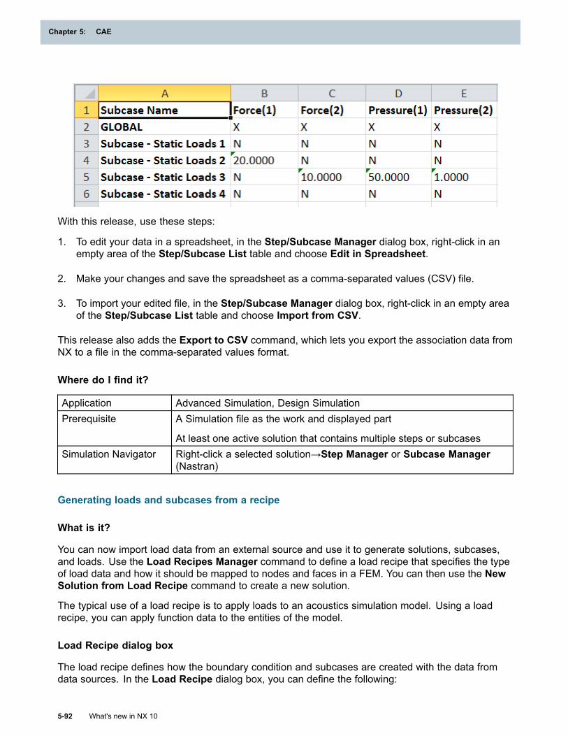
Chapter 5: CAE
With this release, use these steps:
1. To edit your data in a spreadsheet, in the Step/Subcase Manager dialog box, right-click in anempty area of the Step/Subcase List table and choose Edit in Spreadsheet.
2. Make your changes and save the spreadsheet as a comma-separated values (CSV) file.
3. To import your edited file, in the Step/Subcase Manager dialog box, right-click in an empty areaof the Step/Subcase List table and choose Import from CSV.
This release also adds the Export to CSV command, which lets you export the association data fromNX to a file in the comma-separated values format.
Where do I find it?
Application Advanced Simulation, Design SimulationPrerequisite A Simulation file as the work and displayed part
At least one active solution that contains multiple steps or subcasesSimulation Navigator Right-click a selected solution→Step Manager or Subcase Manager
(Nastran)
Generating loads and subcases from a recipe
What is it?
You can now import load data from an external source and use it to generate solutions, subcases,and loads. Use the Load Recipes Manager command to define a load recipe that specifies the typeof load data and how it should be mapped to nodes and faces in a FEM. You can then use the NewSolution from Load Recipe command to create a new solution.
The typical use of a load recipe is to apply loads to an acoustics simulation model. Using a loadrecipe, you can apply function data to the entities of the model.
Load Recipe dialog box
The load recipe defines how the boundary condition and subcases are created with the data fromdata sources. In the Load Recipe dialog box, you can define the following:
5-92 What's new in NX 10
Chapter 5: CAE
CAE
Data SourcesYou can add multiple data sources in the load recipe using the Add button. For the selected datasource, a format handler is available, where you can specify how the data from the data sourcesis interpreted. Only the universal (.unv) file type is supported.
Load ConditionsYou can specify the load conditions that are used for the creation of subcases by enabling ordisabling a load condition.
WaterfallYou can get an overview of the available tracking values.
MappingYou can map a function from the data sources to a node or face of the model. You can select aload from the available load types.
You can map the loads to the target using these methods:
• Automatic Entity (AE)— Maps a function from the data sources to the defined entity labeland the component.
• Manual Function (MF) — Maps a function with the specified function name from the datasources to the one on the model, even though it may not have the correct entity and DOFannotations.
• Manual Entity (ME)— Maps a function from the data sources to the specified entity and thecomponent, but ignores the entity label of the target.
Load Recipes Manager
The Load Recipes Manager is a collector of load recipes that you can use to create, delete, oredit the load recipes.
• You can attach the function from the data sources to the node or to the face by using varioustabs on the Load Recipe dialog box.
• You can define the recipe with the data from an external source and apply it to the model.
• You can create subcases and loads based on the available data in the external source andassign loads to the subcases.
Creating solutions from a load recipe
You can create a solution from a load recipe using the New Solution from Load Recipe command.The Solution dialog box lists only those analysis types and solution types that the load recipesupports. NX generates the loads and places them in the boundary condition containers, dependingon the load type defined in the load recipes. For multiple subcases, you can create the foldersin the boundary condition container. Each of these folders contains all the loads necessary forcreating one subcase.
What's new in NX 10 5-93
CAE

Chapter 5: CAE
Update solution from a load recipe
You can update a solution from a load recipe using the New Solution from Load Recipe command.It updates the subcases with the related boundary conditions and table fields, depending on optionsthat you select in the Solution dialog box.
Where do I find it?
Importing, editing, or creating load recipes
Application Advanced SimulationPrerequisites NX Nastran as the specified solver
A Simulation file as the work part and displayed partCommand Finder
Load RecipesMenu Insert→Load Recipes
Creating a new solution from a load recipe
Application Advanced SimulationPrerequisites NX Nastran as the specified solver
A Simulation file as the work part and displayed partMenu Insert→New Solution from Load RecipesSimulation Navigator Right-click the Simulation node→New Solution from Load Recipes
Nastran support enhancements
NX Nastran acoustics analysis support in NX
What is it?
This release includes significant enhancements to support NX Nastran acoustic and vibro-acousticanalysis.
Acoustic and Vibro-Acoustic solutions
When you create a new NX Nastran solution, two new analysis types are available:
• Acoustic — only acoustic elements (3D) are available in this environment.
• Vibro-Acoustic — both acoustic elements (3D) and structural elements are available in thisenvironment.
Supported NX Nastran solutions
The following solution types are supported with both acoustic and vibro-acoustic solutions:
• SOL 103 – Real Eigenvalues
5-94 What's new in NX 10
Chapter 5: CAE
CAE
• SOL 107 – Direct Complex Eigenvalues
• SOL 108 – Direct Frequency Response
• SOL 110 – Modal Complex Eigenvalues
• SOL 111 – Modal Frequency Response
Supported acoustics capabilities
Acoustic AbsorberYou can create an Acoustic Absorber simulation object in acoustic or vibro-acoustic solutions.An acoustic absorber is applied on free faces of the fluid elements. It allows you to define anacoustic surface impedance (or its reciprocal admittance). The Acoustic Absorber correspondsto the Nastran CAABSF and PAABSF bulk data entries.
PanelYou can create a Panel simulation object in vibro-acoustic solutions. A panel contains 2Dstructural elements. It corresponds to the PANEL bulk data entry. It can be used to computecontributions of structural panels to acoustic pressure results.
Fluid-Structure Interface Modeling ParametersFor a vibro-acoustic solution, to specify the acoustic and structural elements that need to becoupled, create a Fluid-Structure Interface Modeling Parameters modeling object, whichcorresponds to the ACMODL bulk data entry. You can define the wetted surface by selecting theacoustic and structural elements to be coupled. You can create multiple modeling objects, but canselect only one modeling object per solution (on the Bulk Data tab of the Solution dialog box).
Fluid-Structure Interaction Control ParametersFor a vibro-acoustic solution, to define parameters for the fluid-structure interaction, createa Fluid-Structure Interaction Control Parameters modeling object, which corresponds tothe FLSTCNT case control command.
Modal DampingFor a vibro-acoustic SOL 111 solution, you can define modal damping separately for the structuraland the acoustic model. You can define modal damping groups on the:
• Case Control tab of the Solution dialog box
• Solution Step dialog box for each subcase
You can define uniform structural damping and uniform fluid damping in the damping parametergroups on the Parameters tab of the Solution dialog box. These options correspond to theKDAMP,KDAMPFL and G,GFL parameters.
Modal Contributions for Structural, Acoustic and Vibro-Acoustic analysis typesYou can define the modal contribution parameters in structural, acoustic, or vibro-acousticsolutions, in their Output Requests. The Modal Contribution output request corresponds tothe MODCON case control command.
In a vibro-acoustic solution, you can request modal contributions separately for the structuralmodes and the fluid modes.
What's new in NX 10 5-95
CAE
Chapter 5: CAE
You can request SORT1 and SORT2 output formats. However, only contributions in SORT2format are supported for display in the NX XY Function Navigator. The SORT1 output can bein the form of PRINT and/or PUNCH. NX Nastran will then write the results to the f06 or tothe PCH file, respectively.
Panel Contributions for Acoustic and Vibro-Acoustic analysis typesYou can request the panel contributions in acoustic or vibro-acoustic solutions in their OutputRequests. These are the contributions from structural panels to pressure results on acousticfluid nodes for the solution. The Panel Contribution output request corresponds to the PANCON
case control command.
Where do I find it?
Creating an acoustic or vibro-acoustic analysis
Application Advanced SimulationPrerequisites NX Nastran as the specified solver
A Simulation file as the work part and displayed partMenu Insert →SolutionLocation in dialog box Solution dialog box→ Analysis Type list→select Acoustic or
Vibro-Acoustic
Creating an acoustic absorber
Application Advanced SimulationPrerequisites NX Nastran as the specified solver
A Simulation file as the work part and displayed part
An active Acoustic or Vibro-Acoustic solutionSimulation Navigator Right-click the Simulation Object node→New Simulation
Object→Acoustic AbsorberCommand Finder
Acoustic Absorber
Creating a panel
Application Advanced SimulationPrerequisites NX Nastran as the specified solver
A Simulation file as the work part and the displayed part
An active Acoustic or Vibro-Acoustic solutionSimulation Navigator Right-click the Simulation Object node→New Simulation Object→PanelCommand Finder
Panel
Creating a fluid-structure interface
5-96 What's new in NX 10
Chapter 5: CAE
CAE
Application Advanced SimulationPrerequisites NX Nastran as the specified solver
A Simulation file as the work part and displayed part
An active or Vibro-Acoustic solutionMenu Insert→Modeling Objects→Fluid-Structure Interaction Modeling
Parameters or Fluid-Structure Interface Modeling ParametersLocation in dialog box Modeling Objects Manager dialog box→Type list→Fluid-Structure
Interface Modeling Parameters or Fluid-Structure Interaction ControlParameters
Analyzing vibro-acoustic contribution data
What is it?
After you solve a vibro-acoustic model, you can analyze the panel contribution data and modalcontribution data using the XY Function Navigator.
You can plot the result curves for a particular subcase, type, or degree of freedom for all contributiondata.
Analyzing contribution data
You can request the following types of contribution results in the Nastran solution.
Panel ContributionsPanel contribution curves express the contribution of a given vibrating structural panel (the sumof all its nodes) to the pressure response at a given acoustic node. Panels must be part of thewetted surface. You can request this contribution using the Panel Contribution output requestfor the solution by selecting the Panels for Contributions option.
Structural Mode ContributionsStructural mode contributions express the contribution of a given structural mode to theresponse at a given node and degree of freedom. You can request this contribution using theModal Contribution output request for the solution by selecting the Structural Modes forContributions option.
Acoustic Mode ContributionsAcoustic mode contributions express the contribution of a given acoustic mode to the responseat a given node and degree of freedom. You can request this contribution using the ModalContribution output request for the solution by selecting the Fluid Modes for Contributionsoption.
The OP2 result file from the NX Nastran solution will contain the requested contribution data.
XY plotting from OP2 SORT2 results
In NX, you can analyze the NX Nastran SORT2 results using the XY Function Navigator. Theresults are grouped by response node, response type, degree of freedom, and subcase.
What's new in NX 10 5-97
CAE
Chapter 5: CAE
Where do I find it?
Application Advanced SimulationPrerequisites NX Nastran as the specified solver
A loaded Nastran OP2 SORT2 results file in the XY Function NavigatorXY Function Navigator Right-click the Nastran OP2 Files- Sort2 Results→Open or Open
DirectoryGraphics window Right-click the desired contribution curve and click XY Plot
Generating loads and subcases from a recipe
What is it?
You can now import load data from an external source and use it to generate solutions, subcases,and loads. Use the Load Recipes Manager command to define a load recipe that specifies the typeof load data and how it should be mapped to nodes and faces in a FEM. You can then use the NewSolution from Load Recipe command to create a new solution.
The typical use of a load recipe is to apply loads to an acoustics simulation model. Using a loadrecipe, you can apply function data to the entities of the model.
Load Recipe dialog box
The load recipe defines how the boundary condition and subcases are created with the data fromdata sources. In the Load Recipe dialog box, you can define the following:
Data SourcesYou can add multiple data sources in the load recipe using the Add button. For the selected datasource, a format handler is available, where you can specify how the data from the data sourcesis interpreted. Only the universal (.unv) file type is supported.
Load ConditionsYou can specify the load conditions that are used for the creation of subcases by enabling ordisabling a load condition.
WaterfallYou can get an overview of the available tracking values.
MappingYou can map a function from the data sources to a node or face of the model. You can select aload from the available load types.
You can map the loads to the target using these methods:
• Automatic Entity (AE)— Maps a function from the data sources to the defined entity labeland the component.
• Manual Function (MF) — Maps a function with the specified function name from the datasources to the one on the model, even though it may not have the correct entity and DOFannotations.
5-98 What's new in NX 10
Chapter 5: CAE
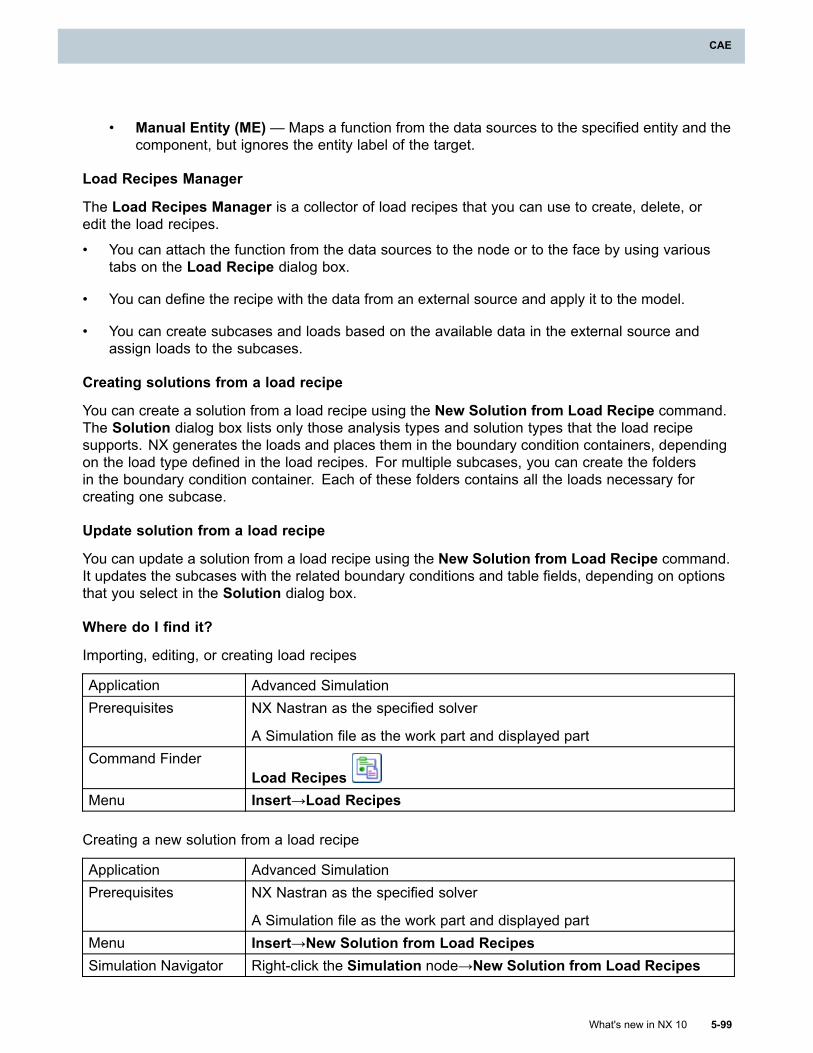
CAE
• Manual Entity (ME)— Maps a function from the data sources to the specified entity and thecomponent, but ignores the entity label of the target.
Load Recipes Manager
The Load Recipes Manager is a collector of load recipes that you can use to create, delete, oredit the load recipes.
• You can attach the function from the data sources to the node or to the face by using varioustabs on the Load Recipe dialog box.
• You can define the recipe with the data from an external source and apply it to the model.
• You can create subcases and loads based on the available data in the external source andassign loads to the subcases.
Creating solutions from a load recipe
You can create a solution from a load recipe using the New Solution from Load Recipe command.The Solution dialog box lists only those analysis types and solution types that the load recipesupports. NX generates the loads and places them in the boundary condition containers, dependingon the load type defined in the load recipes. For multiple subcases, you can create the foldersin the boundary condition container. Each of these folders contains all the loads necessary forcreating one subcase.
Update solution from a load recipe
You can update a solution from a load recipe using the New Solution from Load Recipe command.It updates the subcases with the related boundary conditions and table fields, depending on optionsthat you select in the Solution dialog box.
Where do I find it?
Importing, editing, or creating load recipes
Application Advanced SimulationPrerequisites NX Nastran as the specified solver
A Simulation file as the work part and displayed partCommand Finder
Load RecipesMenu Insert→Load Recipes
Creating a new solution from a load recipe
Application Advanced SimulationPrerequisites NX Nastran as the specified solver
A Simulation file as the work part and displayed partMenu Insert→New Solution from Load RecipesSimulation Navigator Right-click the Simulation node→New Solution from Load Recipes
What's new in NX 10 5-99
CAE
Chapter 5: CAE
PBEAR physical property table enhancements
What is it?
This release includes a number of enhancements for the PBEAR physical property table. In NXNastran, you use the PBEAR bulk data entry to define the stiffness and damping matrices for bearingconnections that you define with the CBEAR bulk data entry for rotor dynamics analyses.
You can use new options in the PBEAR dialog box to do the following:
• Define axial stiffness and viscous damping terms in the translation direction, and radial stiffnessand viscous damping terms in the direction of rotation.
• Specify whether the components of the stiffness and viscous damping matrices are constant orvary as a function of speed, speed and relative displacement, or speed and relative force.
• Specify composite relative displacements and forces.
• Set nominal values for stiffness and viscous damping.
Support for new stiffness and damping terms
You now have more flexibility in terms of how you define the stiffness and damping terms for CBEARelements. In previous releases, you could define the translational stiffness and viscous damping forCBEAR elements in the plane normal to the rotor’s axis. Now, you can define the following:
• Axial stiffness and viscous damping terms in the translation direction.
• Radial stiffness and damping terms in the direction of rotation.
• The stiffness and damping of the cross coupling axial translational direction with othertranslational directions.
These enhancements allow you to create bearings that have combined radial and axial dependence.
Defining stiffness and damping components as constant or varying values
You can use the new Field Independent Domain option in the PBEAR dialog box to define stiffnessand viscous damping matrices as a constant value or as a function of the following:
• Rotor speed.
• Rotor speed and relative displacement.
• Rotor speed and relative force.
Defining composite relative displacements and forces
Composite relative displacements are linear combinations of radial and axial relative displacements.You can now use the options on the new Composite Coefficient tab to define linear combinations ofaxial and radial relative displacements or axial and radial relative forces when the stiffness or viscousdamping matrices vary with respect to rotor speed and relative displacement or relative force.
5-100 What's new in NX 10
Chapter 5: CAE
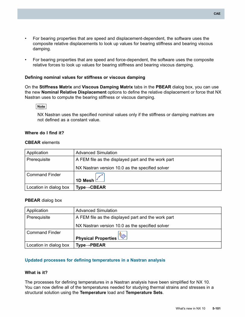
CAE
• For bearing properties that are speed and displacement-dependent, the software uses thecomposite relative displacements to look up values for bearing stiffness and bearing viscousdamping.
• For bearing properties that are speed and force-dependent, the software uses the compositerelative forces to look up values for bearing stiffness and bearing viscous damping.
Defining nominal values for stiffness or viscous damping
On the Stiffness Matrix and Viscous Damping Matrix tabs in the PBEAR dialog box, you can usethe new Nominal Relative Displacement options to define the relative displacement or force that NXNastran uses to compute the bearing stiffness or viscous damping.
Note
NX Nastran uses the specified nominal values only if the stiffness or damping matrices arenot defined as a constant value.
Where do I find it?
CBEAR elements
Application Advanced SimulationPrerequisite A FEM file as the displayed part and the work part
NX Nastran version 10.0 as the specified solverCommand Finder
1D MeshLocation in dialog box Type→CBEAR
PBEAR dialog box
Application Advanced SimulationPrerequisite A FEM file as the displayed part and the work part
NX Nastran version 10.0 as the specified solverCommand Finder
Physical PropertiesLocation in dialog box Type→PBEAR
Updated processes for defining temperatures in a Nastran analysis
What is it?
The processes for defining temperatures in a Nastran analysis have been simplified for NX 10.You can now define all of the temperatures needed for studying thermal strains and stresses in astructural solution using the Temperature load and Temperature Sets.
What's new in NX 10 5-101
CAE
Chapter 5: CAE
Defining default temperatures
In previous releases, you used the following options in the Solution or Solution Step dialog boxes todefine default temperatures:
• Initial Temperatures Default
• Material Temperatures Default
• Temperature Load Default
• Default Initialization Temperature
You now use the Default field in the Temperature Set dialog box to define your default temperatures.The Type option you select in the Temperature Set dialog box defines if the default will be an initialtemperature, material temperature, or a temperature load.
Assigning temperatures to geometry
In previous releases, you used the following simulation objects and loads to assign temperaturesto selected geometry:
• Initial Temperatures simulation object
• Material Temperatures simulation object
• Temperature Load
You now use a Temperature load each time you assign temperatures to selected geometry. The typeof Temperature Set into which you add the Temperature load defines if the temperature will be aninitial temperature, a material temperature, or a temperature load.
Applying results from a previous analysis
In previous releases, you used the Temperature Pre-Load option in the Solution or Solution Stepdialog boxes to apply temperature results from a previous analysis.
You now use a Temperature — External Time Unassigned type of Temperature load to applytemperature results from a previous analysis.
Where do I find it?
Application Advanced SimulationPrerequisites NX Nastran, MSC Nastran, or NX Multiphysics as the specified solver
Structural or Coupled as the specified analysis typeCommand Finder
Temperature
5-102 What's new in NX 10
Chapter 5: CAE
CAE
Improved support for residual vector results
What is it?
This release includes improved support for the calculation of residual vectors.
• NX now supports the import of the RESVEC case control command from both NX Nastran and MSCNastran input files. NX can import the RESVEC command from both .dat and .op2 files.
• NX now supports the NODAMP describer for the RESVEC case control command. If you do not wantto compute residual vectors for the degree-of-freedom in which viscous damping is defined onCBUSHI, CDAMPI, and CVISC elements, select the new NODAMP option in the Viscous Damping liston the Residual Vector tab. In previous releases, NX only supported the DAMPLOD describer.
For more information on residual vectors, see the NX Nastran Basic Dynamics User’s Guide.
Where do I find it?
Application Advanced SimulationPrerequisite A Simulation file as the displayed part and the work part
NX Nastran or MSC Nastran as the specified solverCommand Finder
Modeling ObjectsLocation in Dialog Box Type list→ Structural Output Requests→Residual Vector tab
Response Simulation support for composite elements
What is it?
You can now include composite elements in a Response Simulation analysis. For Random type ofevents, you can now generate RMS and LCR stress contour results when the dynamic solutionresults file contains ply stress and/or homogeneous stress modes. In previous releases, ResponseSimulation did not support composite elements.
In the Evaluate RMS Results and Evaluate LCR Results dialog boxes, you can select Stress asthe Result Type. The composite elements in the model are evaluated with respect to the ply resultcoordinate system.
Where do I find it?
Application Advanced SimulationPrerequisites NX Nastran as the specified solver
A Simulation file as the work part and displayed part
An active Response Simulation solution processCommand Finder
Evaluate RMS Results
Evaluate LCR Results
What's new in NX 10 5-103
CAE
Chapter 5: CAE
Import improvements for models with material orientation vectors
What is it?
Larger finite element models can contain thousands of 3D elements, each with their own materialorientation vector. When you create a Nastran input file from that model, the thousands of 3Delements become thousands of PSOLID bulk data entries, each possibly referencing a separateCORDM coordinate system bulk data entry. When you import an input file like this into NX, NX tries tocreate separate mesh collectors in the Simulation Navigator for each of these coordinate systemsand PSOLID entries. This process of creating thousands of separate mesh collectors can seriouslydegrade the import performance.
You can use the Import 3D MOVs as field data option in the Import Simulation dialog box toautomatically create spatial fields to represent the individual material orientation vectors. Importing3D material orientation vectors as spatial fields can significantly improve import performance.However, importing the material orientation vectors as spatial fields can result in a loss of detail.
This release includes a new Number of PSOLID properties for spatial field creation customerdefault. Use this default to specify the threshold number of PSOLID properties that a solver input filemust contain for NX to automatically create spatial fields to represent the material orientation vectorsfor 3D elements. NX creates the spatial fields when the number of PSOLID properties in the Nastraninput file exceed this threshold value.
Where do I find it?
Import 3D MOVs as field data option
Application Advanced SimulationPrerequisite A FEM file as the displayed part and the work part
NX Nastran as the specified solver
Structural as the specified analysis typeMenu File→Import→SimulationLocation in dialog box Data Compaction Options group
Number of PSOLID properties for spatial field creation customer default
Menu File→Utilities→Customer DefaultsLocation in dialog box Nastran→General tab
Updates to Geometry Check options
What is it?
You can now use the Geometry Check Options modeling object to run optional quality checks onNastran plane strain, plane stress, and axisymmetric elements. You can now have Nastran performthe following optional checks when you solve your model:
• Minimum and maximum interior angle (TRX_IAMN, TRX_IAMX, QDX_IAMN, QDX_IAMX)
• Aspect ratio (TRX_AR, QDX_AR)
5-104 What's new in NX 10
Chapter 5: CAE
CAE
• Skew (QDX_SKEW)
• Taper (QDX_TAPR)
• Edge point length ratio (TRX_EPLR, QDX_EPLR)
Where do I find it?
Application Advanced SimulationPrerequisite A Simulation file as the displayed part and the work part
NX Nastran or MSC Nastran as the specified solverCommand Finder
Modeling ObjectsLocation in Dialog Box Type list→Geometry Check Options
Import now available for NX Nastran SOL 401 solutions
What is it?
You can now import NX Nastran SOL 401 input files into Advanced Simulation. For SOL 401 inputfiles, select NX MULTIPHYSICS as the solver in the Import dialog box. You can import SOL 401solutions from both .dat and .op2 files. If you select the Create new solution option in the ImportSimulation dialog box, NX imports the data into a new solution with NX Multiphysics as the specifiedsolver and the Analysis Type set to Structural.
Additionally, you can also use the Append Merge option in the Solver Deck Append dialog boxto import, append, and merge data from a SOL 401 input file, which is the source file, into an NXMultiphysics FEM or Simulation file, which is the destination file.
Importing NX Multiphysics solutions that were previously exported from NX
Currently, you cannot use a Round Trip Parameters modeling object to preserve the order andformat of bulk data that you import from a SOL 401 solution for later export. However, if you exportan NX Multiphysics solution from NX and later import that same solution back into NX, the twosolutions should be equivalent. A solve on the imported solution should generate the same resultsas a solve on the original solution.
Note
Some minor differences may exist between the two solutions. For example, how a solutionappears in the Simulation Navigator may be slightly different. For example, loads andboundary conditions could be listed within a specific Step instead of with the global solution.
The following are not supported for re-import into NX following a previous export:
• The setting for the Ignore Material Temperature Dependence option on Solution Control tabin the Solution dialog box.
• The Augmented Time Step modeling object dialog box.
What's new in NX 10 5-105
CAE
Chapter 5: CAE
Where do I find it?
Application Advanced SimulationPrerequisite A FEM or Simulation file as the displayed part and the work part
NX Multiphysics as the specified solverMenu File→Import→Simulation
Import improvements for Nastran
What is it?
This release includes several new options on the Import Simulation dialog box. These new optionsprovide you with additional control over how NX imports data from your Nastran input file.
New data checking options
Use the new Data Checking option in the Import Simulation dialog box to control the degree towhich NX evaluates the validity of the file you are importing.
• Select Minimal to perform the lowest level of mesh validity checking. With this option, NXassumes that the input file is ready to solve, and NX only performs minor checks during theimport. The Minimal option offers the fastest import performance.
• Select Nominal to have NX check for basic issues with the input file. For example, NX checksto ensure that nodes and elements that are referenced by loads are included in the file. TheNominal option offers a balance between file validity checking and import performance.
• Select Extended to perform the highest level of mesh validity checking. NX checks for theexistence of each node on every element that is included in the input file. The Extended optioncan increase the processing time for importing an input file, particularly in larger models. Inaddition, NX checks each element for duplicate nodes.
Note
If you select any of the Selective Import options, NX performs Extended data checking.
New option for importing multi-point constraints
Use the new Import MPCs as Multi-MPCs option to improve the import performance for models thatcontain a large number (greater than 10,000) of multi-point constraints. When you select this option,NX imports the individual MPCs as a single Multi-MPC type of Manual Coupling constraint insteadof numerous individual MPC type constraints. This option offers faster import times for a large modelat the expense of a more detailed representation of your input file in NX.
This release also includes a new Number of MPCs for Multi-MPC Creation customer default. Youcan use this default to specify the threshold number of multi-point constraints that a solver input filemust contain before NX imports them as Multi-MPC couplings instead of individual MPC couplings.
Where do I find it?
Import Simulation dialog box
5-106 What's new in NX 10
Chapter 5: CAE
CAE
Application Advanced SimulationPrerequisite A FEM or Simulation file as the displayed part and the work part
NX Nastran or MSC Nastran as the specified solverMenu File→Import→Simulation
Number of MPCs for Multi-MPC Creation customer default
Menu File→Utilities→Customer DefaultsLocation in dialog box Nastran→General tab
Export improvements for Nastran
What is it?
This release includes several new options on the Export Simulation dialog box. These new optionsprovide you with additional control over how NX exports data from your NX to your Nastran input file.
Control over exported temperature unit system
In this release, you can now control the units used for temperatures in your model during export. Thisgives you the flexibility to define temperatures in a different unit system, such as Kelvin, than the restof your model, which may be in metric or British units. In previous releases, you could only specify adifferent unit system for temperatures during import.
In the Export Simulation dialog box, use the new Specify temperature units list to select the unitsystem to use for temperatures in the Nastran input file that you export. If you select a different unitsystem for temperatures, the software converts units for temperature values in your model duringthe export. These values include, for example:
• Temperature and Radiation loads
• Initial Temperature and Material Temperature simulation objects
• Thermal Constraints and Convection constraints
• Material properties that have temperature units, such as values for the Thermal ExpansionCoefficient and Phase Change Temperature
Special export processing for input files that contain large ID values
NX now automatically detects large ID values within your Nastran input file and performs specialprocessing during export. In previous releases, NX could export input files that contained large IDs,however, if the bulk data entry associated with the large ID was written using the small field format,then the export operation aborted.
• In Nastran, an ID value is defined as large when it requires more than eight digits, namely anID greater than 99999999.
• In NX, node and element ID values cannot exceed 2^31-1 or 2147483647. However, you can useoptions in the Formatting Options group of the Export Simulation dialog box to offset theseID values by up to this same maximum limit.
What's new in NX 10 5-107
CAE
Chapter 5: CAE
Therefore, the largest ID value that NX can export for a Nastran input file is 2*(2^31-1), or4294967294.
In NX 10, when you export an NX Nastran input file that contains large IDs, NX now does the following:
• Automatically exports the bulk data entry using the large field format.
Note
If you use Solver Syntax Preview to preview the format of a bulk data entry with a largeID, NX also uses the large field format to preview the entry.
• Writes out the NASTRAN SYSTEM(525)=1 system cell in the Nastran section of the input file.
• Issues a warning or error message, as appropriate, during the export of the following types ofsolutions:
o Warning message: SOL 101 Superelement, SOL 103 Superelement
o Error message: SOL 103 Response Simulation, SOL 200 Model Update, SOL 103 with theSolution Process menu set to either Correlation or Laminate Dynamics
To obtain a 64-bit binary file for NX Nastran, you should solve the input file with the ILP64 version ofNX Nastran. In NX 10, this is the version that the UGII_NX_NASTRAN environment variable referencesby default.
For MSC Nastran input files that contain large ID values, NX automatically exports the associatedbulk data entries using the large field format. NX does not do any other special processing when itexports MSC Nastran input files. This is because MSC Nastran does not require any specific bulkdata entries or system cells to handle large integer ID values.
Control over the use of THRU formatting
In previous releases, when you exported a Nastran input file, the software always took advantage ofthe Nastran THRU format for applicable bulk data entries. In general, using the THRU format reduces thesize of the exported input file.
Now, you can use the new Use THRU Format option on the Formatting options tab to controlwhether you want to use the THRU format. If you clear this check box, NX will not use the THRU formatwhen it exports the following bulk data entries:
• ACCEL1
• ASET1
• BLSEG
• BNDFIX1
• BNDFREE1
• BOLT
• BSET1
5-108 What's new in NX 10
Chapter 5: CAE
CAE
• BSURF
• CSET1
• GROUP
• EBDSET
• MATCID
• NSM1
• NSML1
• OMIT1
• PLOAD2
• PLOAD4
• QBDY3
• QSET1
• QVOL
• RADBC
• ROTORB
• ROTORG
• RVDOF1
• SPC1
• SPOINT
• SUPORT1
• TEMPP1
• TEMPRB
• USET1
Note
The Use THRU Format option applies only to bulk data entries and does not affect howthe SET case control command is exported.
Where do I find it?
Application Advanced Simulation
What's new in NX 10 5-109
CAE
Chapter 5: CAE
Prerequisite A FEM or Simulation file as the displayed part and the work part
NX Nastran or MSC Nastran as the specified solverMenu File→Export→Simulation
Controlling the organization of an exported input file
What is it?
When you use export a Nastran input file from NX, you can now control how the data in that exportedfile is organized. Beginning in this release, you can specify a pattern file for the software to use as aguide for organizing data during the export operation. A pattern file is a file that you have previouslyexported from NX and might have rearranged to your preference.
For example, you can use a pattern file to establish the following:
• The order in which you want NX to export entities, such as parameters. For example, you cancreate a pattern file in which the Nastran PARAM cards always appear at the end of the bulk datasection of the input file.
• How included files are used during the export. For example, if you always want to export theGRID bulk data entries that define nodes in a separate file, you can create a pattern file in whichthe nodal data is stored in a separate grid.dat file and simply referenced in the pattern file withan INCLUDE statement.
• The format to use for bulk data entry fields.
After you create a pattern file, you can use options in the Round Trip Parameters modeling objectdialog box to specify the following:
• The pattern file that you want to scan for information and organizational structure.
• Whether you want to export data using the same included files as the pattern file.
When you later export a solution that references this Round Trip Parameters modeling object thatyou specify on the General tab in the Solution dialog box, NX uses the pattern file to configurethe data in the exported file.
Where do I find it?
Application Advanced SimulationPrerequisite A Simulation file as the displayed part and the work part
An NX Nastran or MSC Nastran solution activeCommand Finder
Modeling Objects
5-110 What's new in NX 10
Chapter 5: CAE
CAE
Creating node and element groups from an appended file
What is it?
When you append a Nastran input file to an existing FEM or Simulation file, you can use the newCreate group from appended file option to create a group of the nodes and elements that NXimports from the input file. This option is available when you select Append or Append Merge fromthe Import Behavior list in the Solver Deck Append dialog box.
During the import and append process, NX checks the ID of each imported nodes and element withthe IDs of the nodes and elements in the existing FEM and Simulation file.
• If NX does not find a conflict between the imported ID and the existing ID values, NX addsthe node or element to the group.
• If NX finds a conflict, NX uses the options you select in the Merge Conflict Resolution Optionsin the Solver Deck Append dialog box to determine whether to include the node or element inthe NX group.
o If you select Ignore File Data, NX does not add the node or element to the group.
o If you select Modify With File Data, NX adds the node or element to the group.
o If you select Add File Data, NX adds the node or element to the group and uses the specifiedLabel Offset value to increment the ID value from the solver input file.
Where do I find it?
Application Advanced SimulationPrerequisite A FEM or Simulation file as the displayed part and the work part
NX Nastran or MSC Nastran as the specified solverMenu File→AppendLocation in dialog box General Options group in the File Append or File Merge dialog box
Import and export support improvements for Nastran
What is it?
This release includes support enhancements for Nastran:
• Bulk data entries and case control commands
• Parameters
• System cells
Bulk data and case control command support updates
The following table details the changes in bulk data and case control command support for thisrelease.
What's new in NX 10 5-111
CAE
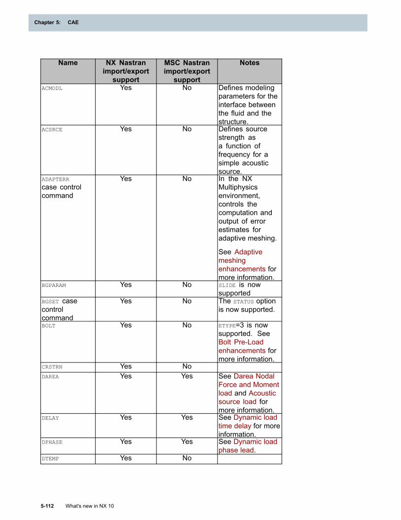
Chapter 5: CAE
Name NX Nastranimport/export
support
MSC Nastranimport/export
support
Notes
ACMODL Yes No Defines modelingparameters for theinterface betweenthe fluid and thestructure.
ACSRCE Yes No Defines sourcestrength asa function offrequency for asimple acousticsource.
ADAPTERR
case controlcommand
Yes No In the NXMultiphysicsenvironment,controls thecomputation andoutput of errorestimates foradaptive meshing.
See Adaptivemeshingenhancements formore information.
BGPARAM Yes No SLIDE is nowsupported
BGSET casecontrolcommand
Yes No The STATUS optionis now supported.
BOLT Yes No ETYPE=3 is nowsupported. SeeBolt Pre-Loadenhancements formore information.
CRSTRN Yes NoDAREA Yes Yes See Darea Nodal
Force and Momentload and Acousticsource load formore information.
DELAY Yes Yes See Dynamic loadtime delay for moreinformation.
DPHASE Yes Yes See Dynamic loadphase lead.
DTEMP Yes No
5-112 What's new in NX 10
Chapter 5: CAE

CAE
DTEMP casecontrolcommand
Yes No
DTEMPEX Yes NoELSTRN casecontrolcommand
Yes No Requests elasticstrain at grid pointson elements.
FLSTCNT
case controlcommand
Yes No
GCRSTRN
case controlcommand
Yes No
GELSTRN
case controlcommand
Yes No Requests elasticstrain at gausspoints.
GPLSTRN
case controlcommand
Yes No Requests grid pointstrains for printingonly.
GSTRAIN
case controlcommand
Yes No Requests strain atgauss points.
GSTRESS
case controlcommand
Yes No Requests stress atgauss points.
GTHSTRN
case controlcommand
Yes* (For theNX Multiphysicsenvironment only)
No Requests thermalstrain at gausspoints.
Gauss point outputis only available inthe NX Multiphysicsenvironment.See Additionalstructural outputs.
MAT10 Yes Yes NX now supportsthe GAMMA, TIDBULK,TIDRHO, TIDGE, andTIDGAMMA fields.
MATCRP Yes No For moreinformation, seeNorton-BaileyPower Law creepsupport in NXMultiphysics.
MATOVR Yes No
What's new in NX 10 5-113
CAE
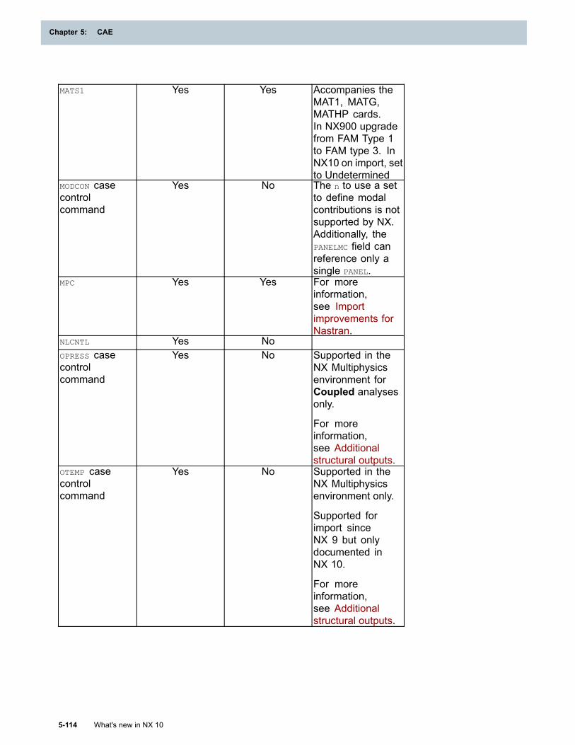
Chapter 5: CAE
MATS1 Yes Yes Accompanies theMAT1, MATG,MATHP cards.In NX900 upgradefrom FAM Type 1to FAM type 3. InNX10 on import, setto Undetermined
MODCON casecontrolcommand
Yes No The n to use a setto define modalcontributions is notsupported by NX.Additionally, thePANELMC field canreference only asingle PANEL.
MPC Yes Yes For moreinformation,see Importimprovements forNastran.
NLCNTL Yes NoOPRESS casecontrolcommand
Yes No Supported in theNX Multiphysicsenvironment forCoupled analysesonly.
For moreinformation,see Additionalstructural outputs.
OTEMP casecontrolcommand
Yes No Supported in theNX Multiphysicsenvironment only.
Supported forimport sinceNX 9 but onlydocumented inNX 10.
For moreinformation,see Additionalstructural outputs.
5-114 What's new in NX 10
Chapter 5: CAE
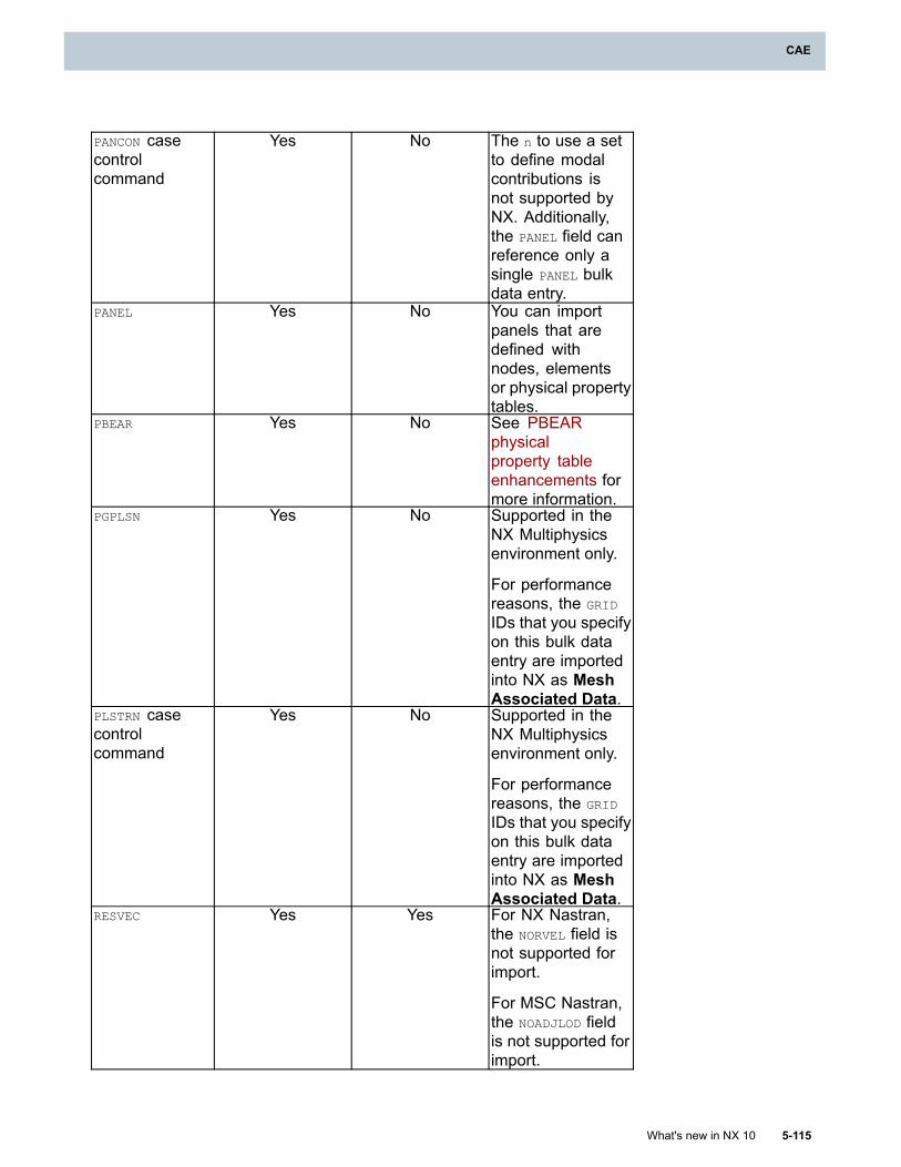
CAE
PANCON casecontrolcommand
Yes No The n to use a setto define modalcontributions isnot supported byNX. Additionally,the PANEL field canreference only asingle PANEL bulkdata entry.
PANEL Yes No You can importpanels that aredefined withnodes, elementsor physical propertytables.
PBEAR Yes No See PBEARphysicalproperty tableenhancements formore information.
PGPLSN Yes No Supported in theNX Multiphysicsenvironment only.
For performancereasons, the GRID
IDs that you specifyon this bulk dataentry are importedinto NX as MeshAssociated Data.
PLSTRN casecontrolcommand
Yes No Supported in theNX Multiphysicsenvironment only.
For performancereasons, the GRID
IDs that you specifyon this bulk dataentry are importedinto NX as MeshAssociated Data.
RESVEC Yes Yes For NX Nastran,the NORVEL field isnot supported forimport.
For MSC Nastran,the NOADJLOD fieldis not supported forimport.
What's new in NX 10 5-115
CAE
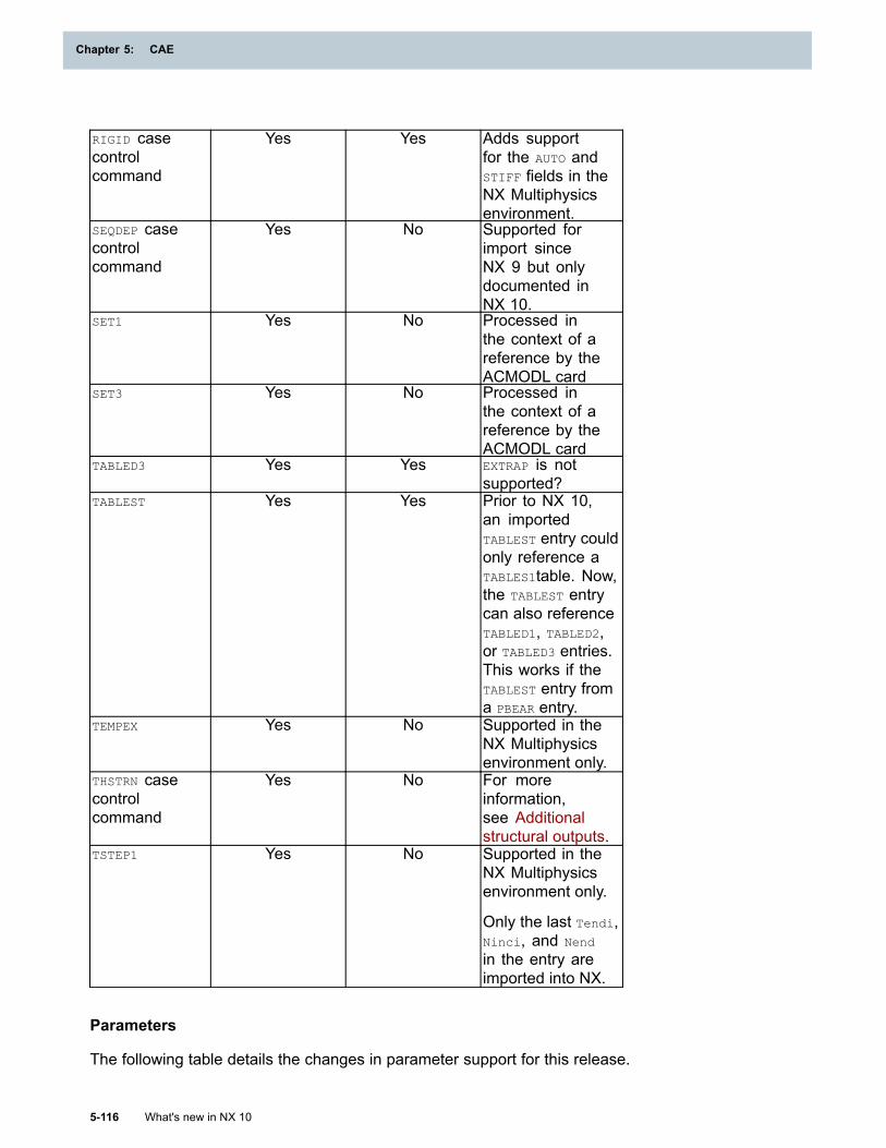
Chapter 5: CAE
RIGID casecontrolcommand
Yes Yes Adds supportfor the AUTO andSTIFF fields in theNX Multiphysicsenvironment.
SEQDEP casecontrolcommand
Yes No Supported forimport sinceNX 9 but onlydocumented inNX 10.
SET1 Yes No Processed inthe context of areference by theACMODL card
SET3 Yes No Processed inthe context of areference by theACMODL card
TABLED3 Yes Yes EXTRAP is notsupported?
TABLEST Yes Yes Prior to NX 10,an importedTABLEST entry couldonly reference aTABLES1table. Now,the TABLEST entrycan also referenceTABLED1, TABLED2,or TABLED3 entries.This works if theTABLEST entry froma PBEAR entry.
TEMPEX Yes No Supported in theNX Multiphysicsenvironment only.
THSTRN casecontrolcommand
Yes No For moreinformation,see Additionalstructural outputs.
TSTEP1 Yes No Supported in theNX Multiphysicsenvironment only.
Only the last Tendi,Ninci, and Nend
in the entry areimported into NX.
Parameters
The following table details the changes in parameter support for this release.
5-116 What's new in NX 10
Chapter 5: CAE
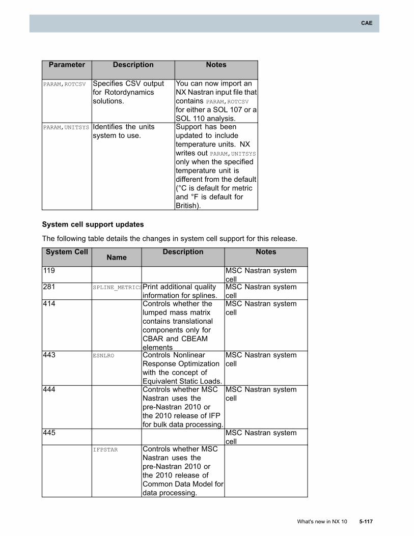
CAE
Parameter Description Notes
PARAM,ROTCSV Specifies CSV outputfor Rotordynamicssolutions.
You can now import anNX Nastran input file thatcontains PARAM,ROTCSV
for either a SOL 107 or aSOL 110 analysis.
PARAM,UNITSYS Identifies the unitssystem to use.
Support has beenupdated to includetemperature units. NXwrites out PARAM,UNITSYSonly when the specifiedtemperature unit isdifferent from the default(°C is default for metricand °F is default forBritish).
System cell support updates
The following table details the changes in system cell support for this release.
System CellName
Description Notes
119 MSC Nastran systemcell
281 SPLINE_METRICSPrint additional qualityinformation for splines.
MSC Nastran systemcell
414 Controls whether thelumped mass matrixcontains translationalcomponents only forCBAR and CBEAMelements
MSC Nastran systemcell
443 ESNLRO Controls NonlinearResponse Optimizationwith the concept ofEquivalent Static Loads.
MSC Nastran systemcell
444 Controls whether MSCNastran uses thepre-Nastran 2010 orthe 2010 release of IFPfor bulk data processing.
MSC Nastran systemcell
445 MSC Nastran systemcell
IFPSTAR Controls whether MSCNastran uses thepre-Nastran 2010 orthe 2010 release ofCommon Data Model fordata processing.
What's new in NX 10 5-117
CAE
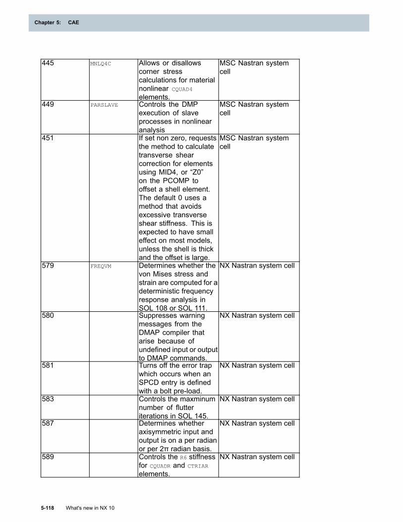
Chapter 5: CAE
445 MNLQ4C Allows or disallowscorner stresscalculations for materialnonlinear CQUAD4
elements.
MSC Nastran systemcell
449 PARSLAVE Controls the DMPexecution of slaveprocesses in nonlinearanalysis
MSC Nastran systemcell
451 If set non zero, requeststhe method to calculatetransverse shearcorrection for elementsusing MID4, or “Z0”on the PCOMP tooffset a shell element.The default 0 uses amethod that avoidsexcessive transverseshear stiffness. This isexpected to have smalleffect on most models,unless the shell is thickand the offset is large.
MSC Nastran systemcell
579 FREQVM Determines whether thevon Mises stress andstrain are computed for adeterministic frequencyresponse analysis inSOL 108 or SOL 111.
NX Nastran system cell
580 Suppresses warningmessages from theDMAP compiler thatarise because ofundefined input or outputto DMAP commands.
NX Nastran system cell
581 Turns off the error trapwhich occurs when anSPCD entry is definedwith a bolt pre-load.
NX Nastran system cell
583 Controls the maxminumnumber of flutteriterations in SOL 145.
NX Nastran system cell
587 Determines whetheraxisymmetric input andoutput is on a per radianor per 2π radian basis.
NX Nastran system cell
589 Controls the R6 stiffnessfor CQUADR and CTRIAR
elements.
NX Nastran system cell
5-118 What's new in NX 10
Chapter 5: CAE
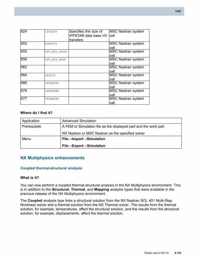
CAE
624 IFPBUFF Specifies the size ofIFPSTAR data base I/Otransfers
MSC Nastran systemcell
653 NONUPIV MSC Nastran systemcell
655 GPU_MIN_FRONT MSC Nastran systemcell
656 GPU_MIN_RANK MSC Nastran systemcell
662 MSC Nastran systemcell
664 SEGLOG MSC Nastran systemcell
666 CNTBKCMP MSC Nastran systemcell
676 LMFBKCMP MSC Nastran systemcell
677 FFOBKCMP MSC Nastran systemcell
Where do I find it?
Application Advanced SimulationPrerequisite A FEM or Simulation file as the displayed part and the work part
NX Nastran or MSC Nastran as the specified solverMenu File→Import→Simulation
File→Export→Simulation
NX Multiphysics enhancements
Coupled thermal-structural analysis
What is it?
You can now perform a coupled thermal-structural analysis in the NX Multiphysics environment. Thisis in addition to the Structural, Thermal, and Mapping analysis types that were available in theprevious release of the NX Multiphysics environment.
The Coupled analysis type links a structural solution from the NX Nastran SOL 401 Multi-StepNonlinear solver and a thermal solution from the NX Thermal solver. The results from the thermalsolution, for example, temperatures, affect the structural solution, and the results from the structuralsolution, for example, displacements, affect the thermal solution.
What's new in NX 10 5-119
CAE
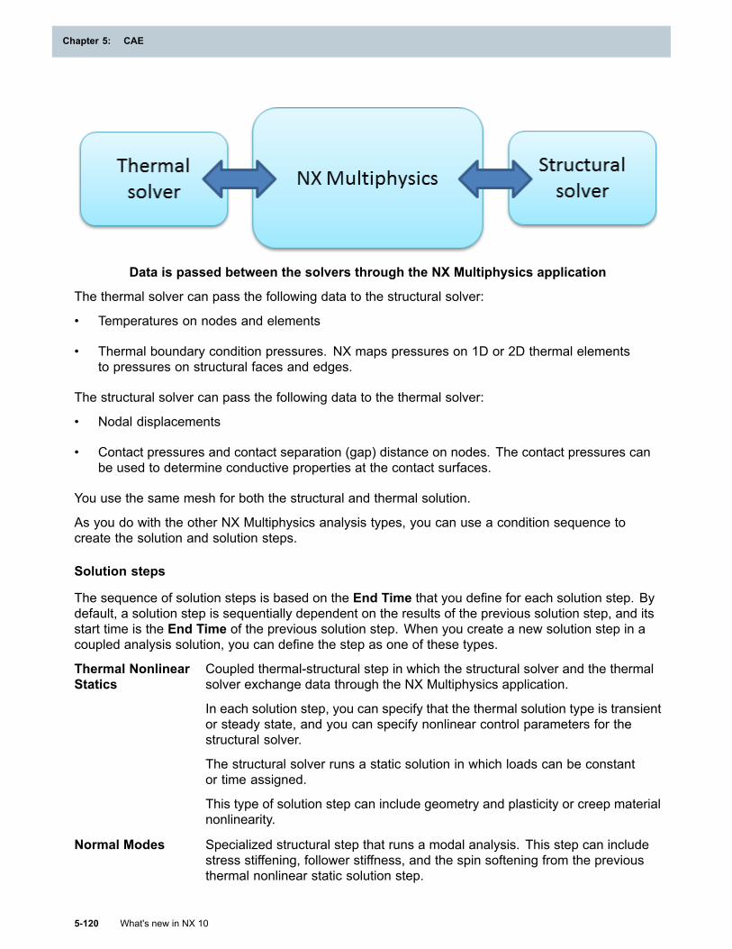
Chapter 5: CAE
Data is passed between the solvers through the NX Multiphysics application
The thermal solver can pass the following data to the structural solver:
• Temperatures on nodes and elements
• Thermal boundary condition pressures. NX maps pressures on 1D or 2D thermal elementsto pressures on structural faces and edges.
The structural solver can pass the following data to the thermal solver:
• Nodal displacements
• Contact pressures and contact separation (gap) distance on nodes. The contact pressures canbe used to determine conductive properties at the contact surfaces.
You use the same mesh for both the structural and thermal solution.
As you do with the other NX Multiphysics analysis types, you can use a condition sequence tocreate the solution and solution steps.
Solution steps
The sequence of solution steps is based on the End Time that you define for each solution step. Bydefault, a solution step is sequentially dependent on the results of the previous solution step, and itsstart time is the End Time of the previous solution step. When you create a new solution step in acoupled analysis solution, you can define the step as one of these types.
Thermal NonlinearStatics
Coupled thermal-structural step in which the structural solver and the thermalsolver exchange data through the NX Multiphysics application.
In each solution step, you can specify that the thermal solution type is transientor steady state, and you can specify nonlinear control parameters for thestructural solver.
The structural solver runs a static solution in which loads can be constantor time assigned.
This type of solution step can include geometry and plasticity or creep materialnonlinearity.
Normal Modes Specialized structural step that runs a modal analysis. This step can includestress stiffening, follower stiffness, and the spin softening from the previousthermal nonlinear static solution step.
5-120 What's new in NX 10
Chapter 5: CAE
CAE
Preload Specialized structural step for a Bolt Pre-Load, including contact and glue, orTemperature load. Preload steps must have an End Time of 0. Any solutionstep that precedes a Preload step must also have an End Time of 0. You canhave only one Preload step in a solution.
Time step control
Within a Thermal Nonlinear Statics or Preload solution step, the thermal solver and the structuralsolver perform their respective solves at each time step. The thermal solver is always the startingsolver. You can control the time steps taken by each solver separately. You control the time steps in asolution step by specifying the End Time and Number of Increments for that step.
The time steps for a solution step correspond to the TSTEP1 NX Nastran bulk data entry.
Alternatively, with Thermal Nonlinear Statics steps, you can specify a constant Step Size in termsof time. By default, the thermal solver uses Automatic adaptive time stepping.
Coupling times
The structural solver and the thermal solver exchange data at coupling times. You can control thetime step increment at which NX Multiphysics exchanges data between the solvers, up to the solutionstep End Time. The End Time is always a coupling time. By default, the coupling times are at eachof the thermal solver time steps. To change the coupling time basis, you can use the CouplingTime Option in the Coupled Solution Parameters for the solution. Coupling times are addedautomatically as common integration time points for both solvers.
At each coupling time, temperatures on nodes and elements (from the thermal solution) are passedto the structural solver. You can specify that additional types of data are passed at each coupling timeusing the options in the Coupled Solution Parameters for the solution.
Sequential or iterative coupling
In the Coupled Solution Parameters for the solution, you can specify the coupling Mode:
Sequential The structural solver and the thermal solver pass information to each otheronce per coupling time and do not attempt to converge together. NX solves thefirst solution until convergence is obtained, and then solves the other solutionusing the values from the first solution.
Iterative The structural solver and the thermal solver pass information to each other forseveral iterations, until the variables that are being passed converge. Thismethod requires you to specify the Iteration Limit, Convergence Criterion,Convergence Norm, and Relaxation values. Coupled convergence occurswhen both temperatures and displacements have converged.
Output of solution data
During the course of a coupled analysis, the structural solver and the thermal solver perform manysolves. You may want to output data for post processing at each of these solution points or only atcertain points, such as at the End Time of the solution step. You can control this output in theSolution Step dialog box on the Time Step Definition page, under the Output Control group.
What's new in NX 10 5-121
CAE
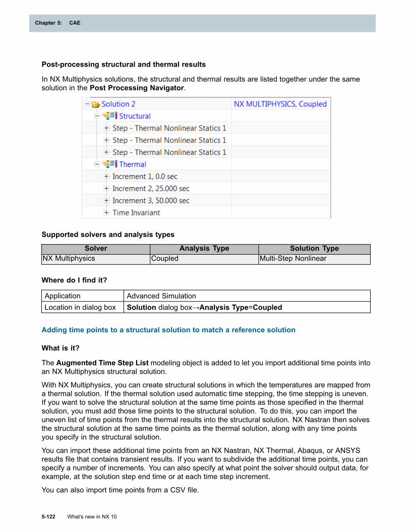
Chapter 5: CAE
Post-processing structural and thermal results
In NX Multiphysics solutions, the structural and thermal results are listed together under the samesolution in the Post Processing Navigator.
Supported solvers and analysis types
Solver Analysis Type Solution TypeNX Multiphysics Coupled Multi-Step Nonlinear
Where do I find it?
Application Advanced SimulationLocation in dialog box Solution dialog box→Analysis Type=Coupled
Adding time points to a structural solution to match a reference solution
What is it?
The Augmented Time Step List modeling object is added to let you import additional time points intoan NX Multiphysics structural solution.
With NX Multiphysics, you can create structural solutions in which the temperatures are mapped froma thermal solution. If the thermal solution used automatic time stepping, the time stepping is uneven.If you want to solve the structural solution at the same time points as those specified in the thermalsolution, you must add those time points to the structural solution. To do this, you can import theuneven list of time points from the thermal results into the structural solution. NX Nastran then solvesthe structural solution at the same time points as the thermal solution, along with any time pointsyou specify in the structural solution.
You can import these additional time points from an NX Nastran, NX Thermal, Abaqus, or ANSYSresults file that contains transient results. If you want to subdivide the additional time points, you canspecify a number of increments. You can also specify at what point the solver should output data, forexample, at the solution step end time or at each time step increment.
You can also import time points from a CSV file.
5-122 What's new in NX 10
Chapter 5: CAE
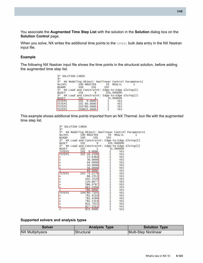
CAE
You associate the Augmented Time Step List with the solution in the Solution dialog box on theSolution Control page.
When you solve, NX writes the additional time points to the TSTEP1 bulk data entry in the NX Nastraninput file.
Example
The following NX Nastran input file shows the time points in the structural solution, before addingthe augmented time step list.
This example shows additional time points imported from an NX Thermal .bun file with the augmentedtime step list.
Supported solvers and analysis types
Solver Analysis Type Solution TypeNX Multiphysics Structural Multi-Step Nonlinear
What's new in NX 10 5-123
CAE
Chapter 5: CAE
Where do I find it?
Application Advanced SimulationLocation in dialog box Solution dialog box→Solution Control page
Step Association Manager
What is it?
The Step Association Manager command is now available in the NX Multiphysics environment.Use this command to:
• Manage which boundary conditions are associated with a given solution step.
• Change multiple boundary condition assignments across solution steps.
• Add a scale factor to a load in a particular solution step.
• Export information about the boundary condition assignments to an HTML page or a spreadsheet,make changes in the spreadsheet, and import the changes back into NX.
For small models, and during the initial creation of the model, the standard methods of assigningindividual boundary conditions to the active solution or step may be adequate. These methods,however, may become unwieldy when you want to edit or refine a model that contains a largenumber of defined boundary conditions, boundary conditions that are organized into multiple folders,simulations that contain multiple solutions, and solutions that contain multiple solution steps orsubcases. Use the Step Association Manager to manage and document the distribution of multipleboundary conditions across steps within a solution.
Supported solvers and analysis types
Solver Analysis Type Solution TypeStructural Multi-Step NonlinearThermal Thermal
NX Multiphysics
Coupled Thermal-Structural (Multi-StepNonlinear)
Where do I find it?
Application Advanced SimulationCommand Finder
Step Association Manager
New boundary conditions supported in NX Multiphysics
What is it?
NX Multiphysics has added support for the following loads and boundary conditions:
• Moment
5-124 What's new in NX 10
Chapter 5: CAE
CAE
• Enforced Motion Load
• Enforced Displacement
• Surface-to-Surface Contact
• Edge-to-Edge Contact
• Edge-to-Edge Gluing
• Material Override
• Override Set — Thermal Properties
• Solid Motion Effects
Some loads and constraints that were previously available only in structural or only in thermalsolutions are now available in both. You can create Surface-to-Surface Gluing in thermal solutions.Thermal Convecting Zone, Thermal Stream, and Thermal Void loads that you create in thermaland coupled solutions, can be added to structural solutions to define pressure only. You can use all ofthe loads and constraints for structural and thermal solutions in the new Coupled type of analysis.
Initial Temperatures are no longer available as simulation object types. You now define them withtemperature loads and a temperature set. For more information on defining initial temperatures, seeUpdated processes for defining temperatures in a Nastran analysis.
Where do I find it?
Application Advanced SimulationPrerequisites NX Multiphysics as the specified solver
Controlling plasticity and creep effects
What is it?
You can control plasticity and creep effects at both the solution and the step level.
Solution level
In the Solution dialog box, the Material Nonlinearity option must be turned on for any plasticityor creep effects to exist in the solution. You can control creep and plasticity using a NonlinearControl Parameters modeling object.
You can also disable the creep and plasticity effects for individual elements or for physical propertytables by including a Material Override simulation object in the solution.
Step level
In the Solution Step dialog box, you can separately control creep and plasticity using a NonlinearControl Parameters modeling object.
What's new in NX 10 5-125
CAE
Chapter 5: CAE
Corresponding Nastran syntax
The Material Nonlinearity option for the solution corresponds to the NX Nastran MATNL parameter.
The Nonlinear Control Parameters for creep and plasticity correspond to the NX Nastran CREEP andPLASTIC parameters on the NLCNTL bulk entry.
The Material Override simulation object corresponds to the NX Nastran MATOVR bulk entry.
Supported solvers and analysis types
Solver Analysis Type Solution TypeStructural Multi-Step NonlinearNX MultiphysicsCoupled Thermal-Structural (Multi-Step
Nonlinear)
Where do I find it?
Application Advanced SimulationPrerequisites NX Multiphysics as the specified solver
Structural or Coupled as the specified analysis typeCommand finder Material OverrideLocation in dialog box Solution dialog box → Solution Control page → Material Nonlinearity
check box
Solution dialog box → Solution Control page → Nonlinear ControlParameters list → Plasticity Effects or Creep Effects
Solution Step dialog box → Step Control page → Nonlinear ControlParameters list → Plasticity Effects or Creep Effects
Norton-Bailey Power Law creep support in NX Multiphysics
What is it?
You can now use the Norton-Bailey Power Law creep model in Multi-step Nonlinear solutions whenNX Multiphysics is the specified solver.
You select this model in the Materials dialog box, on the Creep page, using theTemperature-Dependent Time Hardening (Norton-Bailey) Power Law (Type 301) option. Thisoption corresponds to the new MATCRP bulk data entry, which is an alternate method for selecting theNorton-Bailey creep model. It lets you define the coefficients of the power law equation as eitherconstant or temperature dependent.
In the Materials dialog box, you define the A, B, and D coefficients of this creep model in theConstant Multiplier (a), SIGMA Exponent (b), and Hardening Exponent (d) boxes.
• To define creep at a single temperature, enter real values for the coefficients.
5-126 What's new in NX 10
Chapter 5: CAE
CAE
• To define creep as temperature dependent, define a table field for the coefficients. The tablecorresponds to the TABLEM1 bulk data entry.
Checking system units
A Check Unit System option is added to the new Type 301 power law as well as to the existing TimeHardening (Norton-Bailey) Power Law Type 300. This option checks for inconsistent units in thesolution and the creep coefficients. NX checks when the solver input file is exported and alerts you ifthe solution units are not consistent with the creep coefficient units. NX cannot convert the creepcoefficient units when it exports the solver input file.
Controlling creep effects
For NX Multiphysics, you can now turn off creep effects at the solution level and subcase level. Formore information, see Controlling plasticity and creep effects.
Where do I find it?
Application Advanced SimulationPrerequisites NX Multiphysics as the specified solver and an active Multi-step Nonlinear
solution
or
NX Nastran as the specified solver and an active SOL 601,106 AdvancedNonlinear Statics solution
Command FinderManage Materials
Location in dialog boxCreate Material →Creep page
Support for plastic strain material nonlinearity in NX Multiphysics
What is it?
In the NX Multiphysics environment, you can now define a stress-dependent material with plasticstrain properties. In the Materials dialog boxes, on the Mechanical page, a new Type ofNonlinearity option PLSTRN has been added.
This option corresponds to the MATS1 bulk data entry with TYPE=PLSTRN. For more information, seeMATS1 in the NX Nastran Quick Reference Guide.
Where do I find it?
Application Advanced SimulationPrerequisites NX Multiphysics as the specified solver
An active Multistep Nonlinear solutionCommand Finder
Manage Materials
What's new in NX 10 5-127
CAE
Chapter 5: CAE
Location in dialog boxCreate Material →Mechanical page→Stress-Strain RelatedProperties group→Type of Nonlinearity=PLSTRN
Support for 2D seed mesh creation in NX Multiphysics
What is it?
In the NX Multiphysics environment, when you create a mesh for a structural analysis, you can nowcreate 2D seed meshes to control the placement of nodes on subsequent 3D meshes. In the 2DMesh or the 2D Mapped Mesh dialog box, you can select either the Linear Quadrilateral Seed orLinear Triangle Seed options from the Type list to create the seed mesh. These seed meshes havethe following characteristics:
• They can only be used to create solid meshes.
• They do not have any associated physical properties or mesh associated data.
• They are not written out to the solver input file when you export or solve your model.
In previous releases, you could create only 3D meshes for models in which NX Multiphysics wasthe specified solver.
Where do I find it?
Application Advanced SimulationPrerequisite A FEM file as the displayed part and work part
NX Multiphysics as the specified solver
Structural as the specified analysis typeCommand Finder
2D Mesh or 2D Mapped MeshMenu Insert→Mesh→2D Mesh
Support for the generalized plane strain formulation
What is it?
NX Multiphysics now supports the new generalized plane strain element formulation, which wasintroduced in the NX Nastran 10 release. You can use this new formulation with the following planestrain element types:
• Plane Strain Linear Triangle (CPLSTN3)
• Plane Strain Linear Quadrilateral (CPLSTN4)
• Plane Strain Parabolic Triangle (CPLSTN6)
• Plane Strain Parabolic Quadrilateral (CPLSTN8)
5-128 What's new in NX 10
Chapter 5: CAE
CAE
In NX, you use the Generalized Plane Strain physical property table to specify this new elementformulation and associate it with the elements. The options in this dialog box correspond to the NXNastran PGPLSN bulk data entry. For example, you can specify:
• The isotopic (MAT1) or orthotropic (MAT3) material to use.
• The element’s thickness in its undeformed state.
• Optional additive normal stiffness and rotational stiffness values.
Defining a controlling node to add additional degrees-of-freedom
With the PGPLSN entry in NX Nastran, you can define a control grid point (node) that adds threeadditional degrees-of-freedom to the element:
• One translational degree-of-freedom along the element’s thickness direction.
• Two rotational degrees-of-freedom around the element’s two in-plane axes.
The control grid point is the location where NX Nastran applies any out-of-plane loads or enforceddisplacements to the associated elements.
In NX, you can use the Generalized Plane Strain Control Node option in the Mesh AssociatedData dialog box to select the appropriate node to use as the control grid point.
Generalized plane strain formulation is for specialized applications
The generalized plane strain formulation is applicable only to small strain, small deflection structuralanalyses. These structural analyses include linear static, creep, and plasticity analyses, andcombination creep and plasticity analysis. Analysis with the generalized plane strain formulation ishighly specialized and is typically used to evaluate the behavior of gas turbine compressor andturbine blades. For such an analysis, you mesh the cross section of the blade with the appropriateplane strain elements and then create a Generalized Plane Strain physical property table to definethe properties for those elements.
Where do I find it?
Generalized Plane Strain physical property table
Application Advanced SimulationPrerequisite A FEM file as the displayed part and the work part
NX Multiphysics as the specified solver
2D Solid Option set to ZX Plane, Z Axis or XY Plane, X AxisCommand Finder
Physical Properties
Mesh Associated Data
Application Advanced Simulation
What's new in NX 10 5-129
CAE
Chapter 5: CAE
Prerequisite A FEM file as the displayed part and the work part
NX Multiphysics as the specified solver
2D Solid Option set to ZX Plane, Z Axis or XY Plane, X AxisCommand Finder
Mesh Associated Data
Checking the completeness of NX Multiphysics solutions
What is it?
You can now use the Model Setup command to check the completeness of structural and coupledthermal-structural solutions in the NX Multiphysics environment before you solve. In the NXMultiphysics environment, the Model Setup commands checks to ensure that:
• A material is specified.
• The material orientation is defined.
• A physical property table for the elements is specified.
• The model has loads or constraints applied.
For coupled thermal and structural solutions, Model Setup performs some checks specific to thermalanalyses, such as the following:
• Whether the appropriate element data is specified.
• Whether the appropriate modeling objects are specified when required.
• Whether all geometry is meshed.
Additionally, if the model contains laminate composites, the Model Setup check issues warnings orerror messages related to the laminates, if necessary.
Where do I find it?
Application Advanced SimulationPrerequisite A FEM or Simulation file as the displayed part and the work part
NX Multiphysics as the specified solverCommand Finder Model Setup
Additional structural outputs
What is it?
You can now request contact results and additional strain results for an NX Multiphysics structuraland coupled analysis.
For contact results, you may choose to include the contact pressure, contact force, contact status,and the minimum value of separation distance between source and target elements.
5-130 What's new in NX 10
Chapter 5: CAE
CAE
The following stress and strain results are now available:
• Creep Strain
• Plastic Strain
• Elastic Strain
• Thermal Strain
• Gauss Point Creep Strain
• Gauss Point Plastic Strain
• Gauss Point Elastic Strain
• Gauss Point Strain
• Gauss Point Thermal Strain
• Gauss Point Stress
To control whether these options are selected by default, use the Results Options tab for NXMultiphysics in the Customer Defaults dialog box.
Supported solvers and analysis types
Solver Analysis Type Solution TypeStructural Multi-Step NonlinearNX MultiphysicsCoupled Thermal-Structural (Multi-Step
Nonlinear)
Where do I find it?
Structural Output Requests
Application Advanced SimulationPrerequisites NX Multiphysics as the specified solverCommand Finder
Modeling ObjectsLocation in dialog box Type list →Structural Output Requests
Results Options customer defaults
Menu File → Utilities →Customer DefaultsLocation in dialog box Simulation →NX MULTIPHYSICS → Results Options
What's new in NX 10 5-131
CAE
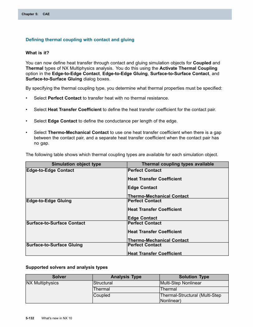
Chapter 5: CAE
Defining thermal coupling with contact and gluing
What is it?
You can now define heat transfer through contact and gluing simulation objects for Coupled andThermal types of NX Multiphysics analysis. You do this using the Activate Thermal Couplingoption in the Edge-to-Edge Contact, Edge-to-Edge Gluing, Surface-to-Surface Contact, andSurface-to-Surface Gluing dialog boxes.
By specifying the thermal coupling type, you determine what thermal properties must be specified:
• Select Perfect Contact to transfer heat with no thermal resistance.
• Select Heat Transfer Coefficient to define the heat transfer coefficient for the contact pair.
• Select Edge Contact to define the conductance per length of the edge.
• Select Thermo-Mechanical Contact to use one heat transfer coefficient when there is a gapbetween the contact pair, and a separate heat transfer coefficient when the contact pair hasno gap.
The following table shows which thermal coupling types are available for each simulation object.
Simulation object type Thermal coupling types availableEdge-to-Edge Contact Perfect Contact
Heat Transfer Coefficient
Edge Contact
Thermo-Mechanical ContactEdge-to-Edge Gluing Perfect Contact
Heat Transfer Coefficient
Edge ContactSurface-to-Surface Contact Perfect Contact
Heat Transfer Coefficient
Thermo-Mechanical ContactSurface-to-Surface Gluing Perfect Contact
Heat Transfer Coefficient
Supported solvers and analysis types
Solver Analysis Type Solution TypeStructural Multi-Step NonlinearThermal Thermal
NX Multiphysics
Coupled Thermal-Structural (Multi-StepNonlinear)
5-132 What's new in NX 10
Chapter 5: CAE
CAE
Where do I find it?
Application Advanced SimulationPrerequisites NX Multiphysics as the specified solverCommand Finder
Edge-to-Edge Contact
Edge-to-Edge Gluing
Surface-to-Surface Contact
Surface-to-Surface Gluing
Preload solution step
What is it?
You can now create a Preload type of solution step for structural and coupled NX Multiphysicssolutions.
Bolt Pre-Load and a Temperature Load type of temperature set are the only loads that you caninclude in the preload solution step. You can add an optional constraints container to the solutionstep, and add any structural constraints to that.
The Preload solution step is the only step in an NX Multiphysics solution where you can add aBolt Pre-Load Load. You cannot add it to other types of solution steps or directly to the solutionload container.
In the Time Step Definition of the preload step, the End Time is always 0. You can use multipleincrements if the solution does not converge correctly with the Number of Increments set to 1.
Supported solvers and analysis types
Solver Analysis Type Solution TypeStructural Multi-Step NonlinearNX MultiphysicsCoupled Thermal-Structural (Multi-Step
Nonlinear)
Where do I find it?
Application Advanced SimulationPrerequisites NX Multiphysics as the specified solverLocation in dialog box Solution Step dialog box → Step list → Step — Preload
What's new in NX 10 5-133
CAE
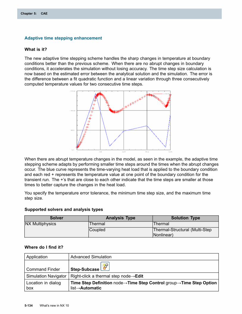
Chapter 5: CAE
Adaptive time stepping enhancement
What is it?
The new adaptive time stepping scheme handles the sharp changes in temperature at boundaryconditions better than the previous scheme. When there are no abrupt changes in boundaryconditions, it accelerates the simulation without losing accuracy. The time step size calculation isnow based on the estimated error between the analytical solution and the simulation. The error isthe difference between a fit quadratic function and a linear variation through three consecutivelycomputed temperature values for two consecutive time steps.
When there are abrupt temperature changes in the model, as seen in the example, the adaptive timestepping scheme adapts by performing smaller time steps around the times when the abrupt changesoccur. The blue curve represents the time-varying heat load that is applied to the boundary conditionand each red + represents the temperature value at one point of the boundary condition for thetransient run. The +’s that are close to each other indicate that the time steps are smaller at thosetimes to better capture the changes in the heat load.
You specify the temperature error tolerance, the minimum time step size, and the maximum timestep size.
Supported solvers and analysis types
Solver Analysis Type Solution TypeThermal ThermalNX MultiphysicsCoupled Thermal-Structural (Multi-Step
Nonlinear)
Where do I find it?
Application Advanced Simulation
Command Finder Step-SubcaseSimulation Navigator Right-click a thermal step node→EditLocation in dialogbox
Time Step Definition node→Time Step Control group→Time Step Optionlist→Automatic
5-134 What's new in NX 10
Chapter 5: CAE
CAE
Solution Monitor enhancements
What is it?
• The Solution Monitor is now used by the NX Multiphysics and NX Nastran solvers.
• The Solution Monitor now displays text output for each solver on a separate tab when you run acoupled NX Multiphysics analysis.
o The NX Multiphysics tab displays the text output for the coupled solver.
o The NX Thermal tab displays the text output for the thermal solver.
o The NX Nastran tab displays the text output for the NX Nastran solver.
• You can copy and paste the displayed text output. In previous versions, the displayed text outputwas not selectable.
• The user interface of the Solution Monitor is refreshed and the command names are moreintuitive. The commands now have tooltips describing their functionality.
Where do I find it?
Application Advanced Simulation, Design Simulation
Prerequisite
NX Nastran, NX Multiphysics, NX Thermal and Flow, NX Space SystemsThermal, or NX Electronic Systems Cooling as the selected solverenvironment
Command Finder SolveSimulation Navigator Right-click a solution node→Solve
Multi-layer shell support
What is it?
You can now use multi-layer shell elements to model thin geometries, such as panels and layers, inthe NX Multiphysics solver environment.
In the Thin Shell physical property table, you can now specify a thin shell to be treated as amulti-layer shell by selecting the Divide Thickness into Uniform Layers option. NX divides the shellthickness that you specify equally into a specified number of layers.
When you define multi-layer shells, you can now select one or more layers to which you apply theboundary condition in the Temperature and Thermal Loads dialog boxes.
Why should I use it?
Using multi-layer shell elements, you can obtain a detailed picture of the conduction through thegeometry without using thin solid (3D) elements. Multi-layer shell elements present a smallerconductance matrix than solid elements.
What's new in NX 10 5-135
CAE
Chapter 5: CAE
Supported solvers and analysis types
Solver Analysis Type Solution TypeNX Multiphysics Thermal Thermal
Where do I find it?
Thin Shell physical property
Application Advanced Simulation
Prerequisite
NX Multiphysics as the specified solver.
A FEM file as the displayed part and work part.
Command Finder Physical PropertiesMenu Insert→Physical Properties
Location in dialogbox
Type list→Thin Shell→Create→Thickness group→ Divide Thicknessinto Uniform Layers
Load and constraint
Application Advanced SimulationPrerequisite NX Multiphysics as the specified solver.
Command Finder Thermal Loads or Temperature
Simulation Navigator
Right-click the Loads node→New Load→Thermal Loads
Right-click the Constraint Set node→New Constraint→TemperatureLocation in dialog box Multi-Layer Shells group
Enhancements to thin shell
What is it?
The following enhancements are now available for thin shell elements in the NX Multiphysics thermalenvironment:
• Material Orientation is now added to both element associated data and mesh associated data.
• The Thin Shell physical property now supports orthotropic materials. In the previous release,you could choose only isotropic materials.
• You can now divide a specified thickness into equal layers in order to model uniform multi-layershell elements in the Thin Shell dialog box.
Supported solvers and analysis types
Solver Analysis Type Solution Type
5-136 What's new in NX 10
Chapter 5: CAE
CAE
NX Multiphysics Thermal Thermal
Where do I find it?
Application Advanced Simulation
Prerequisite
NX Multiphysics as the specified solver.
A FEM file as the displayed part and work part.
Element and mesh associated data
Command Finder Element Modify Associated Data or Mesh Associated DataLocation in dialogbox Material Orientation group
Thin Shell physical property
Command Finder Physical PropertiesLocation in dialogbox Type list→Thin Shell→Create
Plane strain element support
What is it?
The NX Multiphysics thermal and coupled solutions now support the following 2D element types inboth the XY and the ZX planes:
• Plane Strain Linear Quadrilateral
• Plane Strain Parabolic Quadrilateral
• Plane Strain Linear Triangle
• Plane Strain Parabolic Triangle
Although there is no element associated data related to the plain strain elements, the materialorientation angle is supported as mesh associated data.
The plain strain elements are either tied to a Plane Property or to a Generalized Plane StrainProperty physical property defined at the mesh collector level. In the physical property, you canspecify either isotropic or orthotropic materials.
Supported solvers and analysis types
Solver Analysis Type Solution Type
What's new in NX 10 5-137
CAE
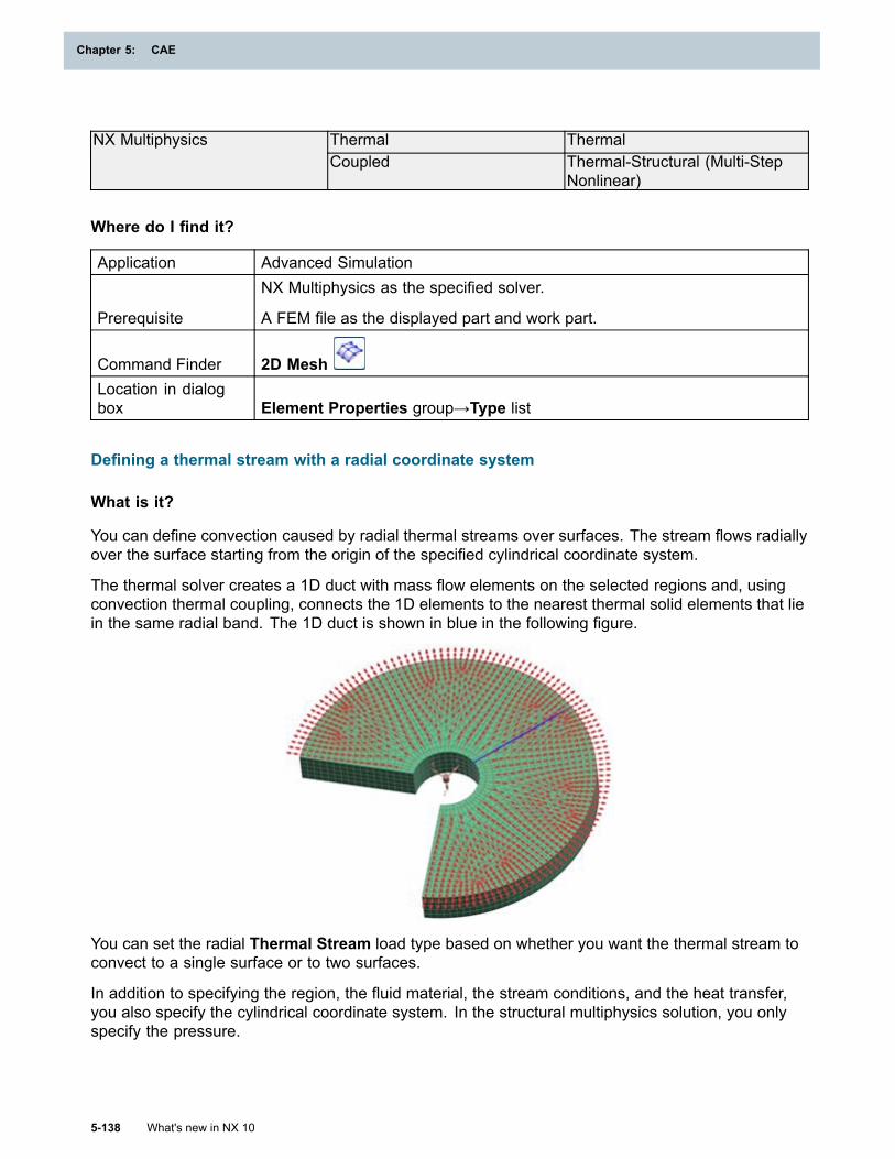
Chapter 5: CAE
Thermal ThermalNX MultiphysicsCoupled Thermal-Structural (Multi-Step
Nonlinear)
Where do I find it?
Application Advanced Simulation
Prerequisite
NX Multiphysics as the specified solver.
A FEM file as the displayed part and work part.
Command Finder 2D MeshLocation in dialogbox Element Properties group→Type list
Defining a thermal stream with a radial coordinate system
What is it?
You can define convection caused by radial thermal streams over surfaces. The stream flows radiallyover the surface starting from the origin of the specified cylindrical coordinate system.
The thermal solver creates a 1D duct with mass flow elements on the selected regions and, usingconvection thermal coupling, connects the 1D elements to the nearest thermal solid elements that liein the same radial band. The 1D duct is shown in blue in the following figure.
You can set the radial Thermal Stream load type based on whether you want the thermal stream toconvect to a single surface or to two surfaces.
In addition to specifying the region, the fluid material, the stream conditions, and the heat transfer,you also specify the cylindrical coordinate system. In the structural multiphysics solution, you onlyspecify the pressure.
5-138 What's new in NX 10
Chapter 5: CAE
CAE
Why should I use it?
The load provides an automated way to include the effects of convection and advection in a thermalmodel. It improves your efficiency by regrouping many thermal simulation boundary conditionsin a single command.
Supported solvers and analysis types
Solver Analysis Type Solution TypeThermal Advanced ThermalNX Thermal and FlowCoupled Thermal-Flow Advanced Thermal-FlowStructural Multi-Step NonlinearThermal Thermal
NX Multiphysics
Coupled Thermal-Structural (Multi-StepNonlinear)
Where do I find it?
Application Advanced SimulationPrerequisite The specified solver must be NX Multiphysics or NX Thermal and Flow.
Command Finder Thermal StreamSimulation Navigator Right-click the Load container node→New Load→Thermal StreamLocation in dialogbox
Type list→One-Sided Stream on Faces (Cylindrical Components) orTwo-Sided Stream on Faces (Cylindrical Components)
Solid Motion Effects simulation object enhancement
What is it?
Use the Spinning - All Elements type of Solid Motion Effects simulation object to model thethermal effects of a spinning model. All elements in the model spin together.
You select the spinning axis, and specify the number of calculations per spin, N. The thermal solvercalculates the view factors and thermal couplings that result from NX spinning the model N times,each time rotating the spinning model by 360/N degrees. The thermal solver then averages the viewfactors and thermal couplings of these N positions.
The view factors include the following:
• Solar, earth, and albedo view factors from orbital heating.
• Heat flux view factors from radiative heating.
• Black body and ray-traced view factors from the deterministic and hemicube methods.
• Ray-traced view factors, radiative couplings, and heat loads from the Monte Carlo method.
What's new in NX 10 5-139
CAE
Chapter 5: CAE
Note
Best accuracy is obtained when N is greater than the number of elements around thecircumference of the spinning part. This is especially true for thermal coupling calculations.
The Spinning type of Solid Motion Effects simulation object from the previous releases is nowcalled Spinning - Selected Elements.
Why should I use it?
The Spinning - All Elements type of Solid Motion Effects simulation object can be used, forexample, to model a spinning spacecraft that spins rapidly around a specified axis.
Supported solvers and analysis types
Solver Analysis Type Solution TypeNX Electronic Systems Cooling Coupled Thermal-Flow NX Advanced Thermal/Flow with
ESCNX Space Systems Thermal Thermal Space Systems Thermal
Thermal Advanced ThermalNX Thermal and FlowCoupled Thermal-Flow Advanced Thermal-FlowThermal ThermalNX MultiphysicsCoupled Thermal-Structural (Multi-Step
Nonlinear)
Where do I find it?
Application Advanced Simulation
Command Finder Solid Motion Effects
Simulation NavigatorRight-click the Simulation Object container node→New SimulationObject→Solid Motion Effects
Location in dialogbox Type list→Spinning - All Elements or Spinning - Selected Elements
Varying capacitance for Void Non Geometric Element modeling object
What is it?
You can now define a time-varying or temperature-varying capacitance when you create a VoidNon-Geometric Element modeling object. To define the capacitance, you can specify thecapacitance value or the volume value. Both quantities can vary with time or temperature.
In previous releases, you could specify only a constant capacitance value.
Why should I use it?
You can use time-varying capacitance, for example, to model the capacitance of fuel in aircraft wings.The fuel mass and thus the capacitance varies with time over a flight profile.
5-140 What's new in NX 10
Chapter 5: CAE
CAE
Supported solvers and analysis types
Solver Analysis Type Solution TypeThermal Advanced ThermalNX Thermal and FlowCoupled Thermal-Flow Advanced Thermal-FlowThermal ThermalNX MultiphysicsCoupled Thermal-Structural (Multi-Step
Nonlinear)
Where do I find it?
Application Advanced SimulationPrerequisite NX Multiphysics or NX Thermal and Flow as the specified solver.
Command Finder Modeling ObjectsSimulation Navigator Right-click the Modeling Objects node→Modeling ObjectsLocation in dialogbox
Type list→Void Non-Geometric Element→Create→Calculation Methodgroup
Multiple Fluid material
What is it?
The new Multiple Fluid material type lets you define a primary fluid material and up to five additionalfluid materials.
The thermal solver uses the specified primary fluid material properties during computation. Theadditional fluid material number can be passed as an argument to some CAE functions, such as fluidplug-ins, and also to user-defined functions. See User-defined functions for expressions for moreinformation on plug-in functions.
You define the Multiple Fluid material type in the following loads and modeling object:
• Thermal Convecting Zone load
• Thermal Stream load
• Void Non-Geometric Element modeling object
Supported solvers and analysis types
Solver Analysis Type Solution TypeThermal Advanced ThermalNX Thermal and FlowCoupled Thermal-Flow Advanced Thermal-FlowThermal ThermalNX MultiphysicsCoupled Thermal-Structural (Multi-Step
Nonlinear)
What's new in NX 10 5-141
CAE
Chapter 5: CAE
Where do I find it?
Application Advanced SimulationPrerequisite NX Multiphysics or NX Thermal and Flow as the specified solver.
Defining the multiple fluid material
Command Finder Manage MaterialsLocation in dialogbox Type list→Multiple Fluid→ Create
Specifying the multiple fluid material in loads
Command Finder Thermal Convecting Zone or Thermal Stream
Simulation NavigatorRight-click the Load container node→New Load→Thermal ConvectingZone or Thermal Stream
Location in dialogbox Fluid Materials list
Specifying the multiple fluid material in the modeling object
Command Finder Modeling ObjectsSimulation Navigator Right-click the Modeling Objects node→Modeling ObjectsLocation in dialogbox
Type list→Void Non-Geometric Element→Create→Environmentgroup→Fluid Materials list
Local temperature error estimate result sets
What is it?
You can now recover local temperature error estimate results. The thermal solver generatestemperature error estimate results which estimate the local spatial discretization errors due to themesh used for the simulation of conduction.
After you solve the model, the following result types appear under the solution node in the PostProcessing Navigator:
• Temperature Error Estimates - Nodal
• Temperature Error Estimates - Elemental
• Time of Maximum Error Estimates - Nodal
• Time of Maximum Error Estimates - Elemental
• Maximum Temp Error Estimates - Nodal
5-142 What's new in NX 10
Chapter 5: CAE
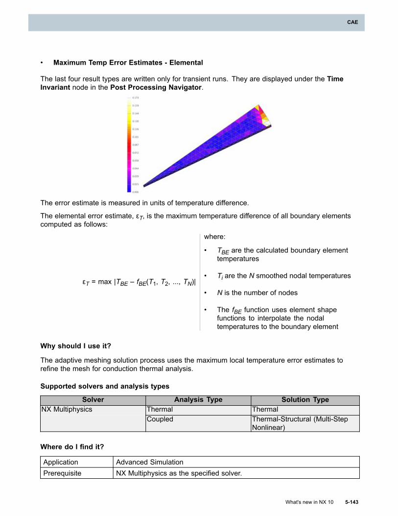
CAE
• Maximum Temp Error Estimates - Elemental
The last four result types are written only for transient runs. They are displayed under the TimeInvariant node in the Post Processing Navigator.
The error estimate is measured in units of temperature difference.
The elemental error estimate, εT, is the maximum temperature difference of all boundary elementscomputed as follows:
εT = max |TBE – fBE(T1, T2, ..., TN)|
where:
• TBE are the calculated boundary elementtemperatures
• Ti are the N smoothed nodal temperatures
• N is the number of nodes
• The fBE function uses element shapefunctions to interpolate the nodaltemperatures to the boundary element
Why should I use it?
The adaptive meshing solution process uses the maximum local temperature error estimates torefine the mesh for conduction thermal analysis.
Supported solvers and analysis types
Solver Analysis Type Solution TypeThermal ThermalNX MultiphysicsCoupled Thermal-Structural (Multi-Step
Nonlinear)
Where do I find it?
Application Advanced SimulationPrerequisite NX Multiphysics as the specified solver.
What's new in NX 10 5-143
CAE
Chapter 5: CAE
Command Finder Modeling ObjectsSimulation Navigator Right-click the Modeling Objects node→Modeling Objects
Location in dialogbox
Type list→Thermal Output Requests→Create→Thermal tab→ LocalTemperature Error Estimate
Envelope results for thermal post processing
What is it?
Time invariant results from transient thermal solutions are now located under the Time Invariantnode in the Post Processing Navigator.
ironSolution 1
ThermalIncrement 1, 0.0 sec...Increment 61, 600.000 secTime Invariant
Max Temperature - ElementalMin Temperature - ElementalTime at Max Temperature - ElementalTime at Min Temperature - Elemental
The time invariant thermal results include the following:
• Maximum and minimum elemental temperature over the complete transient run and the timesat which they occur.
• Maximum thermal error estimates at each element over the complete transient run and thetimes at which they occur.
• Absorbed, incident, reflected, or transmitted radiative fluxes at each element when these valuesare constant over the complete transient run.
In previous releases, these results were displayed in the first or last time step.
Supported solvers and analysis types
Solver Analysis Type Solution TypeNX Electronic Systems Cooling Coupled Thermal-Flow Electronic Systems Cooling
NX Advanced Thermal/Flow withESC
NX Space Systems Thermal Thermal Space Systems Thermal
5-144 What's new in NX 10
Chapter 5: CAE
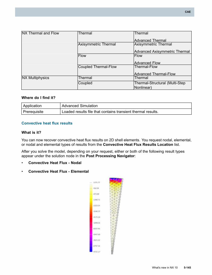
CAE
Thermal Thermal
Advanced ThermalAxisymmetric Thermal Axisymmetric Thermal
Advanced Axisymmetric ThermalFlow Flow
Advanced Flow
NX Thermal and Flow
Coupled Thermal-Flow Thermal-Flow
Advanced Thermal-FlowThermal ThermalNX MultiphysicsCoupled Thermal-Structural (Multi-Step
Nonlinear)
Where do I find it?
Application Advanced SimulationPrerequisite Loaded results file that contains transient thermal results.
Convective heat flux results
What is it?
You can now recover convective heat flux results on 2D shell elements. You request nodal, elemental,or nodal and elemental types of results from the Convective Heat Flux Results Location list.
After you solve the model, depending on your request, either or both of the following result typesappear under the solution node in the Post Processing Navigator:
• Convective Heat Flux - Nodal
• Convective Heat Flux - Elemental
What's new in NX 10 5-145
CAE
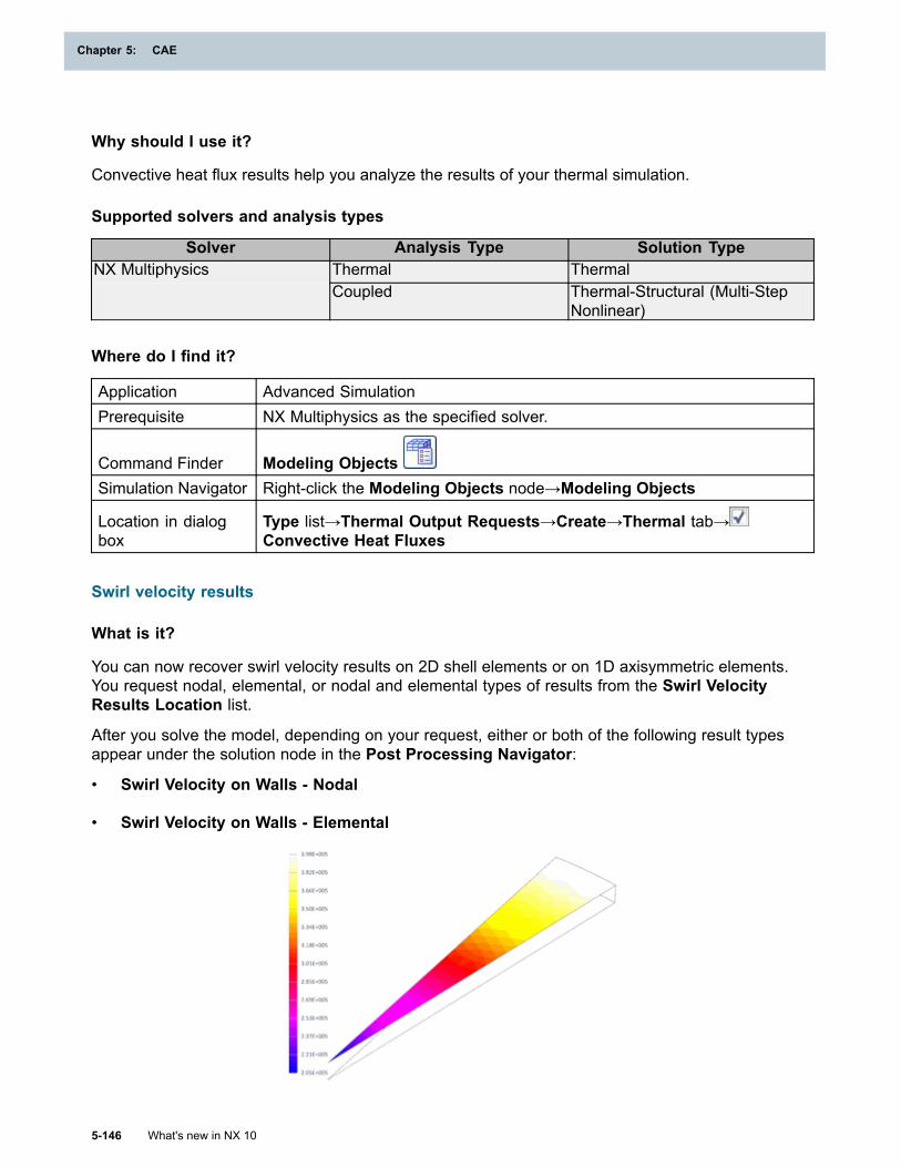
Chapter 5: CAE
Why should I use it?
Convective heat flux results help you analyze the results of your thermal simulation.
Supported solvers and analysis types
Solver Analysis Type Solution TypeThermal ThermalNX MultiphysicsCoupled Thermal-Structural (Multi-Step
Nonlinear)
Where do I find it?
Application Advanced SimulationPrerequisite NX Multiphysics as the specified solver.
Command Finder Modeling ObjectsSimulation Navigator Right-click the Modeling Objects node→Modeling Objects
Location in dialogbox
Type list→Thermal Output Requests→Create→Thermal tab→Convective Heat Fluxes
Swirl velocity results
What is it?
You can now recover swirl velocity results on 2D shell elements or on 1D axisymmetric elements.You request nodal, elemental, or nodal and elemental types of results from the Swirl VelocityResults Location list.
After you solve the model, depending on your request, either or both of the following result typesappear under the solution node in the Post Processing Navigator:
• Swirl Velocity on Walls - Nodal
• Swirl Velocity on Walls - Elemental
5-146 What's new in NX 10
Chapter 5: CAE
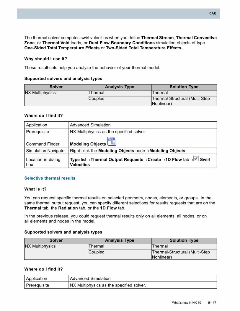
CAE
The thermal solver computes swirl velocities when you define Thermal Stream, Thermal ConvectiveZone, or Thermal Void loads, or Duct Flow Boundary Conditions simulation objects of typeOne-Sided Total Temperature Effects or Two-Sided Total Temperature Effects.
Why should I use it?
These result sets help you analyze the behavior of your thermal model.
Supported solvers and analysis types
Solver Analysis Type Solution TypeThermal ThermalNX MultiphysicsCoupled Thermal-Structural (Multi-Step
Nonlinear)
Where do I find it?
Application Advanced SimulationPrerequisite NX Multiphysics as the specified solver.
Command Finder Modeling ObjectsSimulation Navigator Right-click the Modeling Objects node→Modeling Objects
Location in dialogbox
Type list→Thermal Output Requests→Create→1D Flow tab→ SwirlVelocities
Selective thermal results
What is it?
You can request specific thermal results on selected geometry, nodes, elements, or groups. In thesame thermal output request, you can specify different selections for results requests that are on theThermal tab, the Radiation tab, or the 1D Flow tab.
In the previous release, you could request thermal results only on all elements, all nodes, or onall elements and nodes in the model.
Supported solvers and analysis types
Solver Analysis Type Solution TypeThermal ThermalNX MultiphysicsCoupled Thermal-Structural (Multi-Step
Nonlinear)
Where do I find it?
Application Advanced SimulationPrerequisite NX Multiphysics as the specified solver.
What's new in NX 10 5-147
CAE
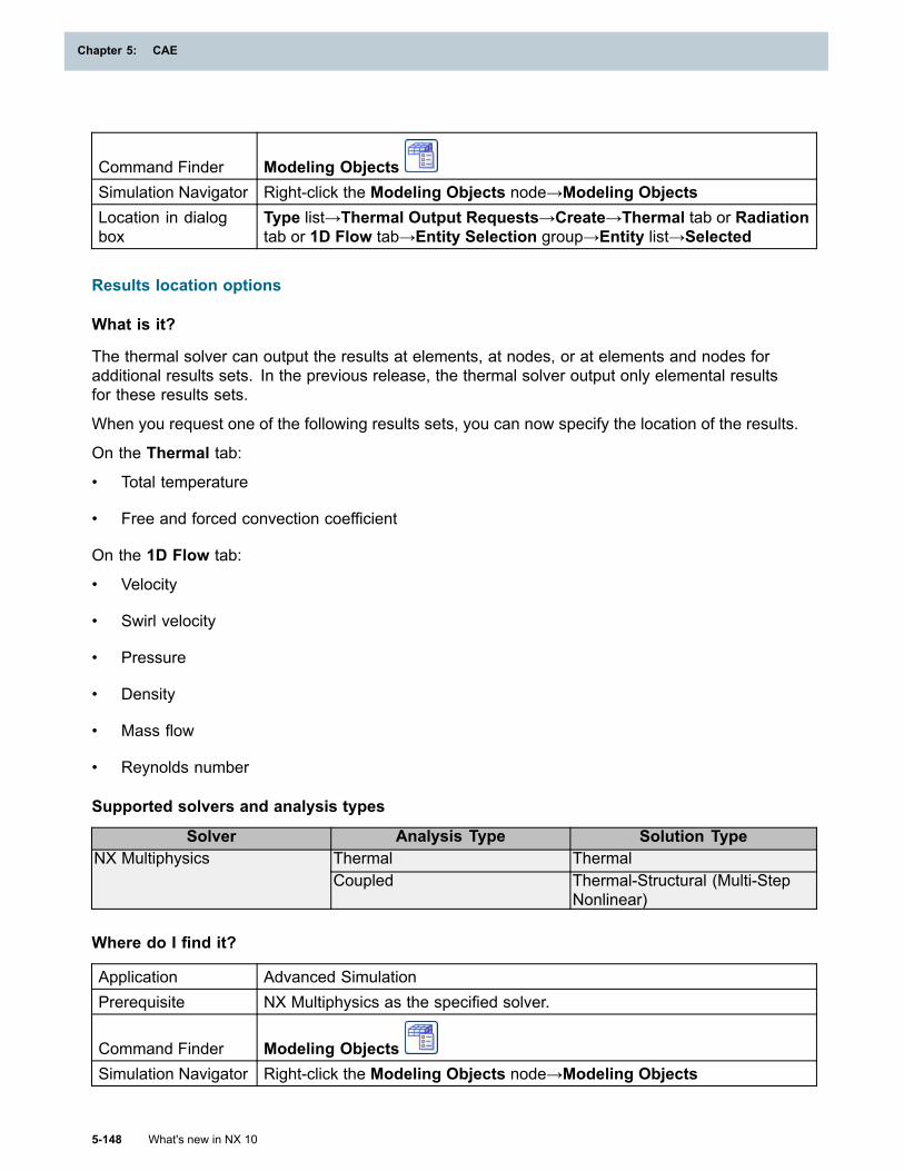
Chapter 5: CAE
Command Finder Modeling ObjectsSimulation Navigator Right-click the Modeling Objects node→Modeling ObjectsLocation in dialogbox
Type list→Thermal Output Requests→Create→Thermal tab or Radiationtab or 1D Flow tab→Entity Selection group→Entity list→Selected
Results location options
What is it?
The thermal solver can output the results at elements, at nodes, or at elements and nodes foradditional results sets. In the previous release, the thermal solver output only elemental resultsfor these results sets.
When you request one of the following results sets, you can now specify the location of the results.
On the Thermal tab:
• Total temperature
• Free and forced convection coefficient
On the 1D Flow tab:
• Velocity
• Swirl velocity
• Pressure
• Density
• Mass flow
• Reynolds number
Supported solvers and analysis types
Solver Analysis Type Solution TypeThermal ThermalNX MultiphysicsCoupled Thermal-Structural (Multi-Step
Nonlinear)
Where do I find it?
Application Advanced SimulationPrerequisite NX Multiphysics as the specified solver.
Command Finder Modeling ObjectsSimulation Navigator Right-click the Modeling Objects node→Modeling Objects
5-148 What's new in NX 10
Chapter 5: CAE
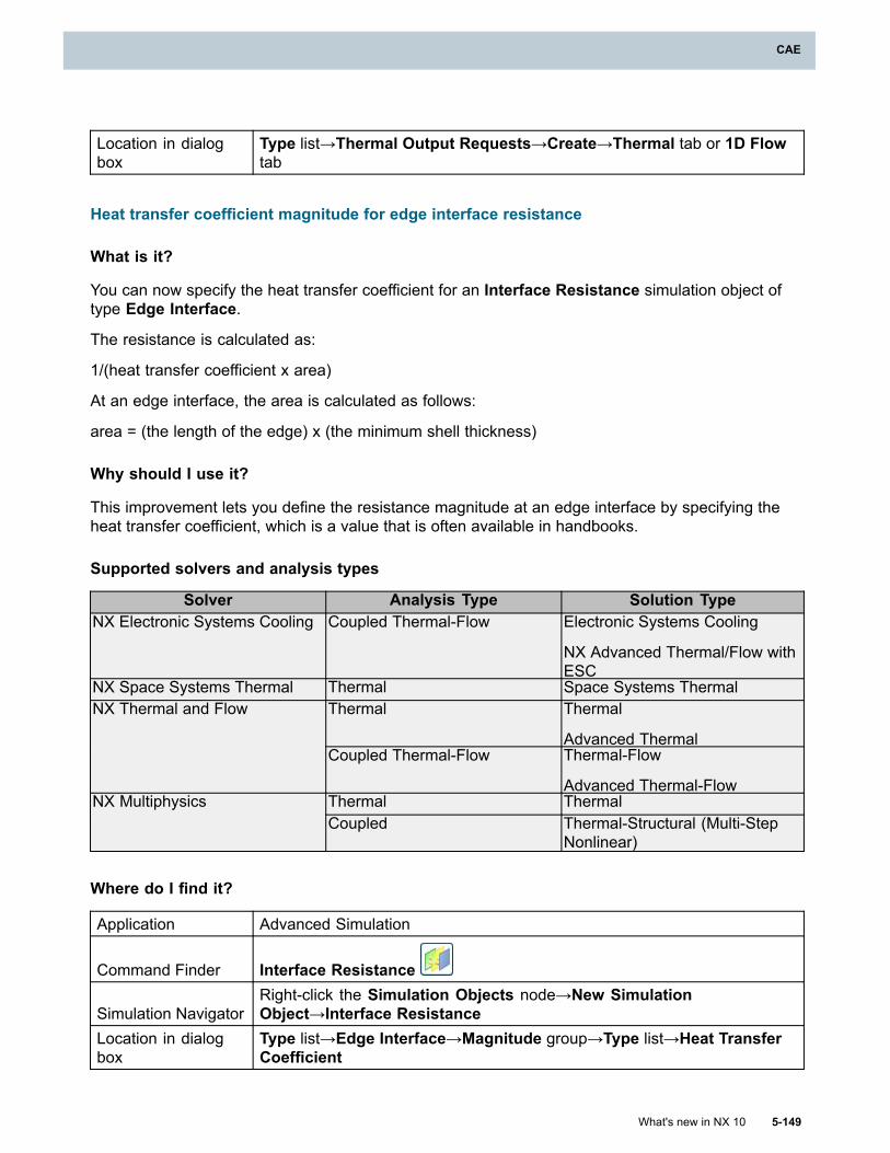
CAE
Location in dialogbox
Type list→Thermal Output Requests→Create→Thermal tab or 1D Flowtab
Heat transfer coefficient magnitude for edge interface resistance
What is it?
You can now specify the heat transfer coefficient for an Interface Resistance simulation object oftype Edge Interface.
The resistance is calculated as:
1/(heat transfer coefficient x area)
At an edge interface, the area is calculated as follows:
area = (the length of the edge) x (the minimum shell thickness)
Why should I use it?
This improvement lets you define the resistance magnitude at an edge interface by specifying theheat transfer coefficient, which is a value that is often available in handbooks.
Supported solvers and analysis types
Solver Analysis Type Solution TypeNX Electronic Systems Cooling Coupled Thermal-Flow Electronic Systems Cooling
NX Advanced Thermal/Flow withESC
NX Space Systems Thermal Thermal Space Systems ThermalThermal Thermal
Advanced Thermal
NX Thermal and Flow
Coupled Thermal-Flow Thermal-Flow
Advanced Thermal-FlowThermal ThermalNX MultiphysicsCoupled Thermal-Structural (Multi-Step
Nonlinear)
Where do I find it?
Application Advanced Simulation
Command Finder Interface Resistance
Simulation NavigatorRight-click the Simulation Objects node→New SimulationObject→Interface Resistance
Location in dialogbox
Type list→Edge Interface→Magnitude group→Type list→Heat TransferCoefficient
What's new in NX 10 5-149
CAE
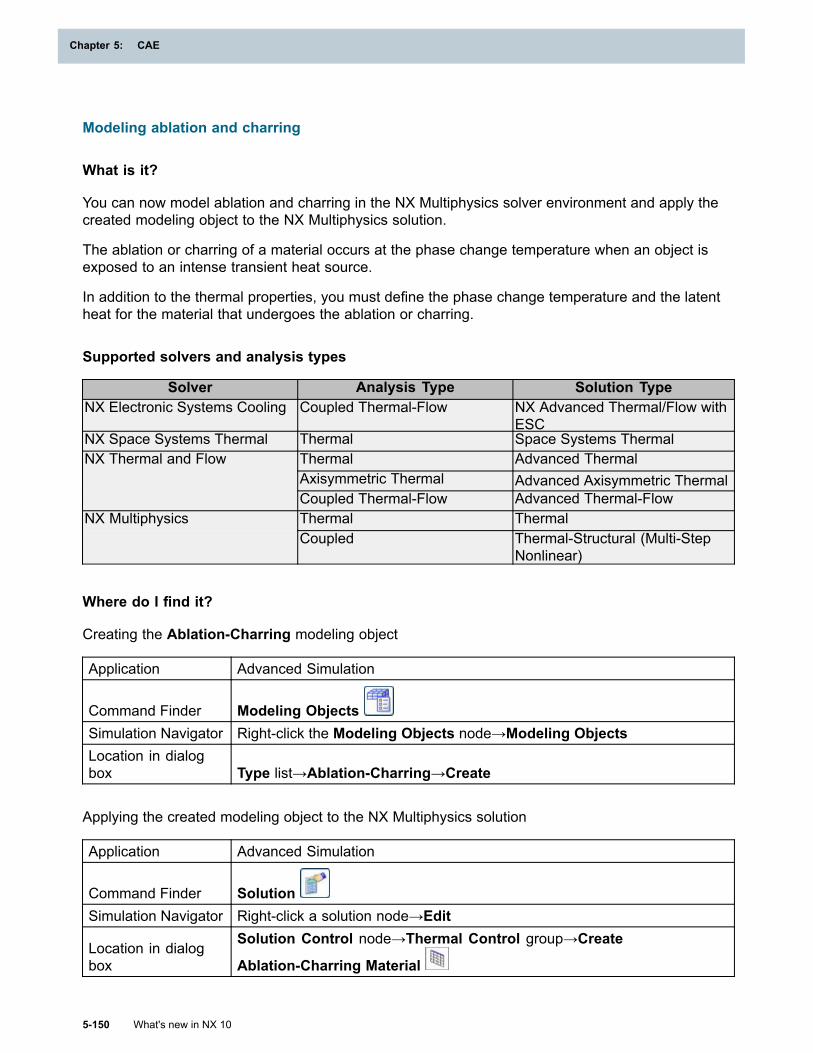
Chapter 5: CAE
Modeling ablation and charring
What is it?
You can now model ablation and charring in the NX Multiphysics solver environment and apply thecreated modeling object to the NX Multiphysics solution.
The ablation or charring of a material occurs at the phase change temperature when an object isexposed to an intense transient heat source.
In addition to the thermal properties, you must define the phase change temperature and the latentheat for the material that undergoes the ablation or charring.
Supported solvers and analysis types
Solver Analysis Type Solution TypeNX Electronic Systems Cooling Coupled Thermal-Flow NX Advanced Thermal/Flow with
ESCNX Space Systems Thermal Thermal Space Systems Thermal
Thermal Advanced ThermalAxisymmetric Thermal Advanced Axisymmetric Thermal
NX Thermal and Flow
Coupled Thermal-Flow Advanced Thermal-FlowThermal ThermalNX MultiphysicsCoupled Thermal-Structural (Multi-Step
Nonlinear)
Where do I find it?
Creating the Ablation-Charring modeling object
Application Advanced Simulation
Command Finder Modeling ObjectsSimulation Navigator Right-click the Modeling Objects node→Modeling ObjectsLocation in dialogbox Type list→Ablation-Charring→Create
Applying the created modeling object to the NX Multiphysics solution
Application Advanced Simulation
Command Finder SolutionSimulation Navigator Right-click a solution node→Edit
Location in dialogbox
Solution Control node→Thermal Control group→Create
Ablation-Charring Material
5-150 What's new in NX 10
Chapter 5: CAE
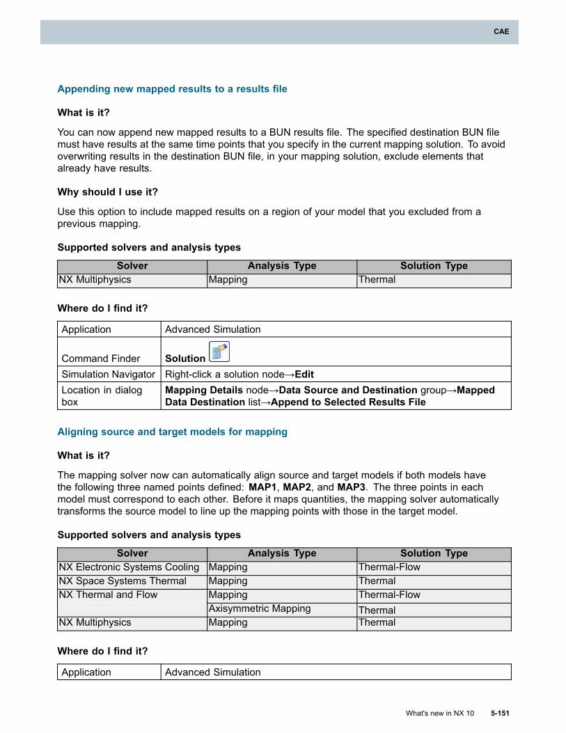
CAE
Appending new mapped results to a results file
What is it?
You can now append new mapped results to a BUN results file. The specified destination BUN filemust have results at the same time points that you specify in the current mapping solution. To avoidoverwriting results in the destination BUN file, in your mapping solution, exclude elements thatalready have results.
Why should I use it?
Use this option to include mapped results on a region of your model that you excluded from aprevious mapping.
Supported solvers and analysis types
Solver Analysis Type Solution TypeNX Multiphysics Mapping Thermal
Where do I find it?
Application Advanced Simulation
Command Finder SolutionSimulation Navigator Right-click a solution node→EditLocation in dialogbox
Mapping Details node→Data Source and Destination group→MappedData Destination list→Append to Selected Results File
Aligning source and target models for mapping
What is it?
The mapping solver now can automatically align source and target models if both models havethe following three named points defined: MAP1, MAP2, and MAP3. The three points in eachmodel must correspond to each other. Before it maps quantities, the mapping solver automaticallytransforms the source model to line up the mapping points with those in the target model.
Supported solvers and analysis types
Solver Analysis Type Solution TypeNX Electronic Systems Cooling Mapping Thermal-FlowNX Space Systems Thermal Mapping Thermal
Mapping Thermal-FlowNX Thermal and FlowAxisymmetric Mapping Thermal
NX Multiphysics Mapping Thermal
Where do I find it?
Application Advanced Simulation
What's new in NX 10 5-151
CAE
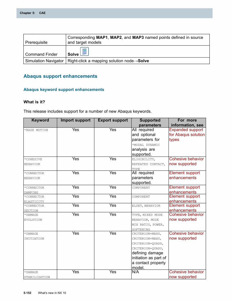
Chapter 5: CAE
PrerequisiteCorresponding MAP1, MAP2, and MAP3 named points defined in sourceand target models
Command Finder SolveSimulation Navigator Right-click a mapping solution node→Solve
Abaqus support enhancements
Abaqus keyword support enhancements
What is it?
This release includes support for a number of new Abaqus keywords.
Keyword Import support Export support Supportedparameters
For moreinformation, see
*BASE MOTION Yes Yes All requiredand optionalparameters for*MODAL DYNAMIC
analysis aresupported.
Expanded supportfor Abaqus solutiontypes
*COHESIVE
BEHAVIOR
Yes Yes ELIGIBILITY,REPEATED CONTACT,TYPE
Cohesive behaviornow supported
*CONNECTOR
BEHAVIOR
Yes Yes All requiredparameterssupported.
Element supportenhancements
*CONNECTOR
DAMPING
Yes Yes COMPONENT Element supportenhancements
*CONNECTOR
ELASTICITY
Yes Yes COMPONENT Element supportenhancements
*CONNECTOR
SECTION
Yes Yes ELSET, BEHAVIOR Element supportenhancements
*DAMAGE
EVOLOTION
Yes Yes TYPE, MIXED MODE
BEHAVIOR, MODEMIX RATIO, POWER,SOFTENING
Cohesive behaviornow supported
*DAMAGE
INITIATION
Yes Yes CRITERION=MAXS,CRITERION=MAXU,CRITERION=QUADS,CRITERION=QUADU,defining damageinitiation as part ofa contact propertymodel.
Cohesive behaviornow supported
*DAMAGE
STABILIZATION
Yes Yes N/A Cohesive behaviornow supported
5-152 What's new in NX 10
Chapter 5: CAE
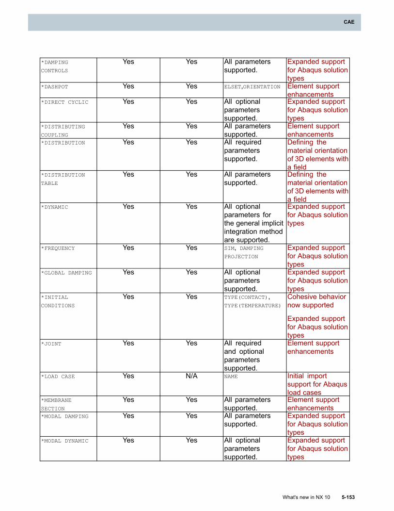
CAE
*DAMPING
CONTROLS
Yes Yes All parameterssupported.
Expanded supportfor Abaqus solutiontypes
*DASHPOT Yes Yes ELSET,ORIENTATION Element supportenhancements
*DIRECT CYCLIC Yes Yes All optionalparameterssupported.
Expanded supportfor Abaqus solutiontypes
*DISTRIBUTING
COUPLING
Yes Yes All parameterssupported.
Element supportenhancements
*DISTRIBUTION Yes Yes All requiredparameterssupported.
Defining thematerial orientationof 3D elements witha field
*DISTRIBUTION
TABLE
Yes Yes All parameterssupported.
Defining thematerial orientationof 3D elements witha field
*DYNAMIC Yes Yes All optionalparameters forthe general implicitintegration methodare supported.
Expanded supportfor Abaqus solutiontypes
*FREQUENCY Yes Yes SIM, DAMPING
PROJECTION
Expanded supportfor Abaqus solutiontypes
*GLOBAL DAMPING Yes Yes All optionalparameterssupported.
Expanded supportfor Abaqus solutiontypes
*INITIAL
CONDITIONS
Yes Yes TYPE(CONTACT),TYPE(TEMPERATURE)
Cohesive behaviornow supported
Expanded supportfor Abaqus solutiontypes
*JOINT Yes Yes All requiredand optionalparameterssupported.
Element supportenhancements
*LOAD CASE Yes N/A NAME Initial importsupport for Abaqusload cases
*MEMBRANE
SECTION
Yes Yes All parameterssupported.
Element supportenhancements
*MODAL DAMPING Yes Yes All parameterssupported.
Expanded supportfor Abaqus solutiontypes
*MODAL DYNAMIC Yes Yes All optionalparameterssupported.
Expanded supportfor Abaqus solutiontypes
What's new in NX 10 5-153
CAE
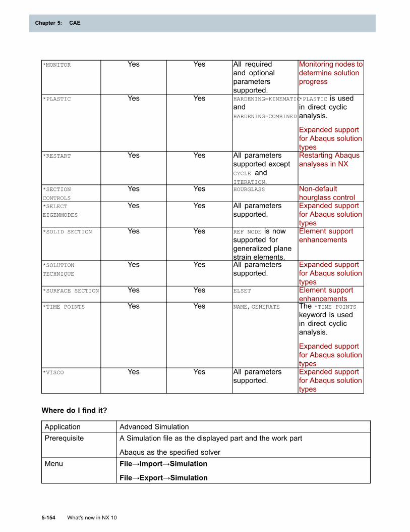
Chapter 5: CAE
*MONITOR Yes Yes All requiredand optionalparameterssupported.
Monitoring nodes todetermine solutionprogress
*PLASTIC Yes Yes HARDENING=KINEMATIC
andHARDENING=COMBINED
*PLASTIC is usedin direct cyclicanalysis.
Expanded supportfor Abaqus solutiontypes
*RESTART Yes Yes All parameterssupported exceptCYCLE andITERATION.
Restarting Abaqusanalyses in NX
*SECTION
CONTROLS
Yes Yes HOURGLASS Non-defaulthourglass control
*SELECT
EIGENMODES
Yes Yes All parameterssupported.
Expanded supportfor Abaqus solutiontypes
*SOLID SECTION Yes Yes REF NODE is nowsupported forgeneralized planestrain elements.
Element supportenhancements
*SOLUTION
TECHNIQUE
Yes Yes All parameterssupported.
Expanded supportfor Abaqus solutiontypes
*SURFACE SECTION Yes Yes ELSET Element supportenhancements
*TIME POINTS Yes Yes NAME, GENERATE The *TIME POINTS
keyword is usedin direct cyclicanalysis.
Expanded supportfor Abaqus solutiontypes
*VISCO Yes Yes All parameterssupported.
Expanded supportfor Abaqus solutiontypes
Where do I find it?
Application Advanced SimulationPrerequisite A Simulation file as the displayed part and the work part
Abaqus as the specified solverMenu File→Import→Simulation
File→Export→Simulation
5-154 What's new in NX 10
Chapter 5: CAE
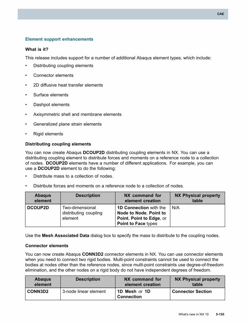
CAE
Element support enhancements
What is it?
This release includes support for a number of additional Abaqus element types, which include:
• Distributing coupling elements
• Connector elements
• 2D diffusive heat transfer elements
• Surface elements
• Dashpot elements
• Axisymmetric shell and membrane elements
• Generalized plane strain elements
• Rigid elements
Distributing coupling elements
You can now create Abaqus DCOUP2D distributing coupling elements in NX. You can use adistributing coupling element to distribute forces and moments on a reference node to a collectionof nodes. DCOUP2D elements have a number of different applications. For example, you canuse a DCOUP2D element to do the following:
• Distribute mass to a collection of nodes.
• Distribute forces and moments on a reference node to a collection of nodes.
Abaquselement
Description NX command forelement creation
NX Physical propertytable
DCOUP2D Two-dimensionaldistributing couplingelement
1D Connection with theNode to Node, Point toPoint, Point to Edge, orPoint to Face types
N/A
Use the Mesh Associated Data dialog box to specify the mass to distribute to the coupling nodes.
Connector elements
You can now create Abaqus CONN3D2 connector elements in NX. You can use connector elementswhen you need to connect two rigid bodies. Multi-point constraints cannot be used to connect thebodies at nodes other than the reference nodes, since multi-point constraints use degree-of-freedomelimination, and the other nodes on a rigid body do not have independent degrees of freedom.
Abaquselement
Description NX command forelement creation
NX Physical propertytable
CONN3D2 3-node linear element 1D Mesh or 1DConnection
Connector Section
What's new in NX 10 5-155
CAE
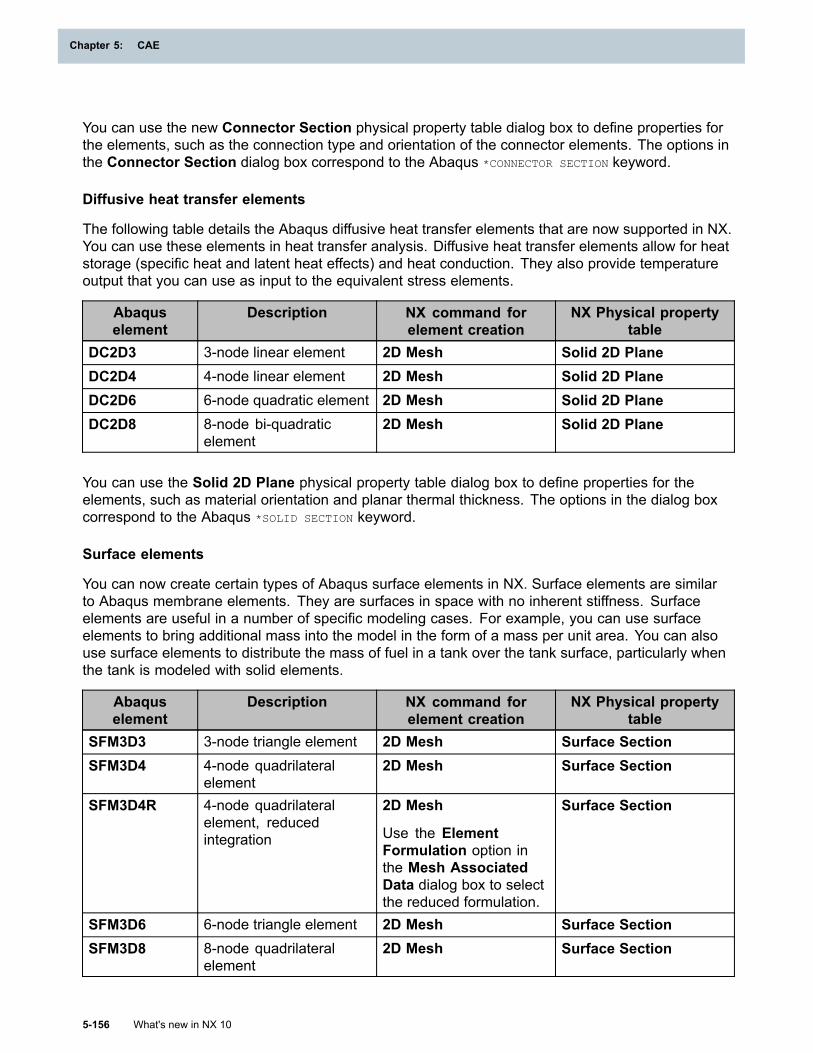
Chapter 5: CAE
You can use the new Connector Section physical property table dialog box to define properties forthe elements, such as the connection type and orientation of the connector elements. The options inthe Connector Section dialog box correspond to the Abaqus *CONNECTOR SECTION keyword.
Diffusive heat transfer elements
The following table details the Abaqus diffusive heat transfer elements that are now supported in NX.You can use these elements in heat transfer analysis. Diffusive heat transfer elements allow for heatstorage (specific heat and latent heat effects) and heat conduction. They also provide temperatureoutput that you can use as input to the equivalent stress elements.
Abaquselement
Description NX command forelement creation
NX Physical propertytable
DC2D3 3-node linear element 2D Mesh Solid 2D PlaneDC2D4 4-node linear element 2D Mesh Solid 2D PlaneDC2D6 6-node quadratic element 2D Mesh Solid 2D PlaneDC2D8 8-node bi-quadratic
element2D Mesh Solid 2D Plane
You can use the Solid 2D Plane physical property table dialog box to define properties for theelements, such as material orientation and planar thermal thickness. The options in the dialog boxcorrespond to the Abaqus *SOLID SECTION keyword.
Surface elements
You can now create certain types of Abaqus surface elements in NX. Surface elements are similarto Abaqus membrane elements. They are surfaces in space with no inherent stiffness. Surfaceelements are useful in a number of specific modeling cases. For example, you can use surfaceelements to bring additional mass into the model in the form of a mass per unit area. You can alsouse surface elements to distribute the mass of fuel in a tank over the tank surface, particularly whenthe tank is modeled with solid elements.
Abaquselement
Description NX command forelement creation
NX Physical propertytable
SFM3D3 3-node triangle element 2D Mesh Surface SectionSFM3D4 4-node quadrilateral
element2D Mesh Surface Section
SFM3D4R 4-node quadrilateralelement, reducedintegration
2D Mesh
Use the ElementFormulation option inthe Mesh AssociatedData dialog box to selectthe reduced formulation.
Surface Section
SFM3D6 6-node triangle element 2D Mesh Surface SectionSFM3D8 8-node quadrilateral
element2D Mesh Surface Section
5-156 What's new in NX 10
Chapter 5: CAE
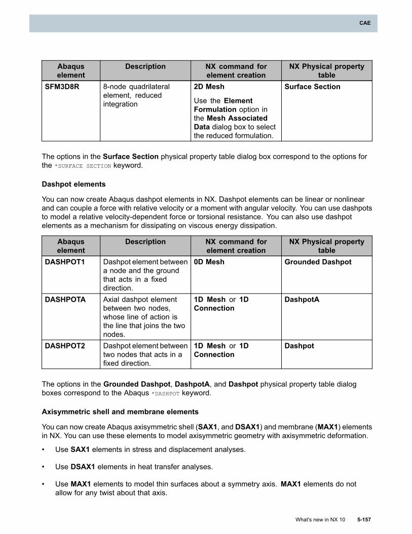
CAE
Abaquselement
Description NX command forelement creation
NX Physical propertytable
SFM3D8R 8-node quadrilateralelement, reducedintegration
2D Mesh
Use the ElementFormulation option inthe Mesh AssociatedData dialog box to selectthe reduced formulation.
Surface Section
The options in the Surface Section physical property table dialog box correspond to the options forthe *SURFACE SECTION keyword.
Dashpot elements
You can now create Abaqus dashpot elements in NX. Dashpot elements can be linear or nonlinearand can couple a force with relative velocity or a moment with angular velocity. You can use dashpotsto model a relative velocity-dependent force or torsional resistance. You can also use dashpotelements as a mechanism for dissipating on viscous energy dissipation.
Abaquselement
Description NX command forelement creation
NX Physical propertytable
DASHPOT1 Dashpot element betweena node and the groundthat acts in a fixeddirection.
0D Mesh Grounded Dashpot
DASHPOTA Axial dashpot elementbetween two nodes,whose line of action isthe line that joins the twonodes.
1D Mesh or 1DConnection
DashpotA
DASHPOT2 Dashpot element betweentwo nodes that acts in afixed direction.
1D Mesh or 1DConnection
Dashpot
The options in the Grounded Dashpot, DashpotA, and Dashpot physical property table dialogboxes correspond to the Abaqus *DASHPOT keyword.
Axisymmetric shell and membrane elements
You can now create Abaqus axisymmetric shell (SAX1, and DSAX1) and membrane (MAX1) elementsin NX. You can use these elements to model axisymmetric geometry with axisymmetric deformation.
• Use SAX1 elements in stress and displacement analyses.
• Use DSAX1 elements in heat transfer analyses.
• Use MAX1 elements to model thin surfaces about a symmetry axis. MAX1 elements do notallow for any twist about that axis.
What's new in NX 10 5-157
CAE
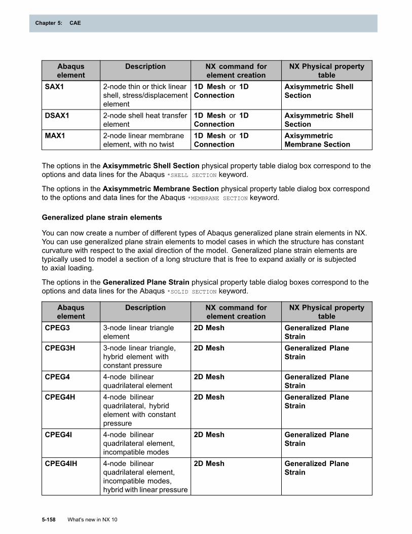
Chapter 5: CAE
Abaquselement
Description NX command forelement creation
NX Physical propertytable
SAX1 2-node thin or thick linearshell, stress/displacementelement
1D Mesh or 1DConnection
Axisymmetric ShellSection
DSAX1 2-node shell heat transferelement
1D Mesh or 1DConnection
Axisymmetric ShellSection
MAX1 2-node linear membraneelement, with no twist
1D Mesh or 1DConnection
AxisymmetricMembrane Section
The options in the Axisymmetric Shell Section physical property table dialog box correspond to theoptions and data lines for the Abaqus *SHELL SECTION keyword.
The options in the Axisymmetric Membrane Section physical property table dialog box correspondto the options and data lines for the Abaqus *MEMBRANE SECTION keyword.
Generalized plane strain elements
You can now create a number of different types of Abaqus generalized plane strain elements in NX.You can use generalized plane strain elements to model cases in which the structure has constantcurvature with respect to the axial direction of the model. Generalized plane strain elements aretypically used to model a section of a long structure that is free to expand axially or is subjectedto axial loading.
The options in the Generalized Plane Strain physical property table dialog boxes correspond to theoptions and data lines for the Abaqus *SOLID SECTION keyword.
Abaquselement
Description NX command forelement creation
NX Physical propertytable
CPEG3 3-node linear triangleelement
2D Mesh Generalized PlaneStrain
CPEG3H 3-node linear triangle,hybrid element withconstant pressure
2D Mesh Generalized PlaneStrain
CPEG4 4-node bilinearquadrilateral element
2D Mesh Generalized PlaneStrain
CPEG4H 4-node bilinearquadrilateral, hybridelement with constantpressure
2D Mesh Generalized PlaneStrain
CPEG4I 4-node bilinearquadrilateral element,incompatible modes
2D Mesh Generalized PlaneStrain
CPEG4IH 4-node bilinearquadrilateral element,incompatible modes,hybrid with linear pressure
2D Mesh Generalized PlaneStrain
5-158 What's new in NX 10
Chapter 5: CAE
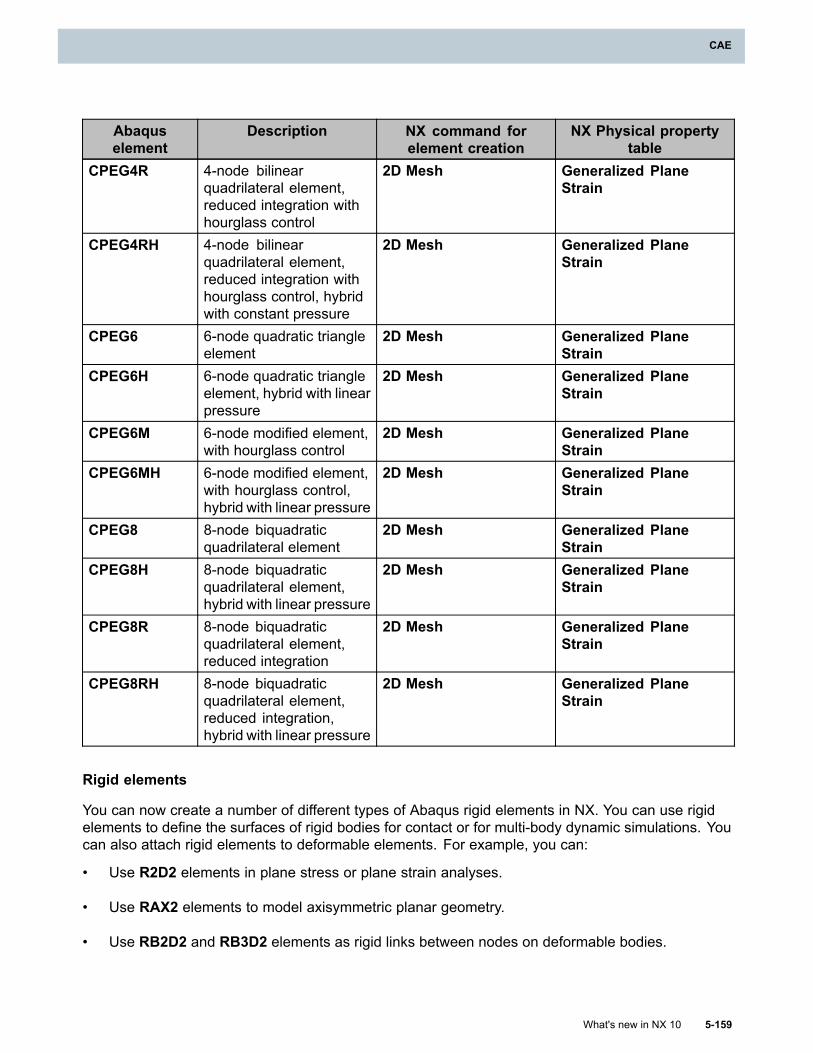
CAE
Abaquselement
Description NX command forelement creation
NX Physical propertytable
CPEG4R 4-node bilinearquadrilateral element,reduced integration withhourglass control
2D Mesh Generalized PlaneStrain
CPEG4RH 4-node bilinearquadrilateral element,reduced integration withhourglass control, hybridwith constant pressure
2D Mesh Generalized PlaneStrain
CPEG6 6-node quadratic triangleelement
2D Mesh Generalized PlaneStrain
CPEG6H 6-node quadratic triangleelement, hybrid with linearpressure
2D Mesh Generalized PlaneStrain
CPEG6M 6-node modified element,with hourglass control
2D Mesh Generalized PlaneStrain
CPEG6MH 6-node modified element,with hourglass control,hybrid with linear pressure
2D Mesh Generalized PlaneStrain
CPEG8 8-node biquadraticquadrilateral element
2D Mesh Generalized PlaneStrain
CPEG8H 8-node biquadraticquadrilateral element,hybrid with linear pressure
2D Mesh Generalized PlaneStrain
CPEG8R 8-node biquadraticquadrilateral element,reduced integration
2D Mesh Generalized PlaneStrain
CPEG8RH 8-node biquadraticquadrilateral element,reduced integration,hybrid with linear pressure
2D Mesh Generalized PlaneStrain
Rigid elements
You can now create a number of different types of Abaqus rigid elements in NX. You can use rigidelements to define the surfaces of rigid bodies for contact or for multi-body dynamic simulations. Youcan also attach rigid elements to deformable elements. For example, you can:
• Use R2D2 elements in plane stress or plane strain analyses.
• Use RAX2 elements to model axisymmetric planar geometry.
• Use RB2D2 and RB3D2 elements as rigid links between nodes on deformable bodies.
What's new in NX 10 5-159
CAE
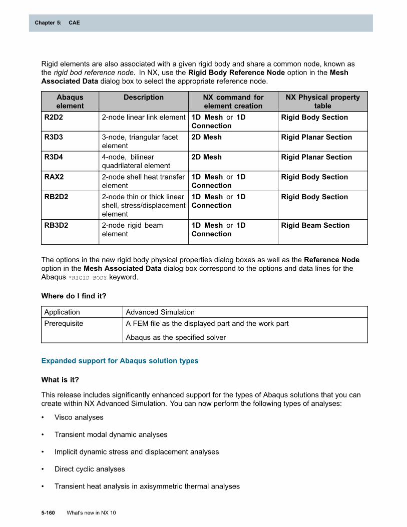
Chapter 5: CAE
Rigid elements are also associated with a given rigid body and share a common node, known asthe rigid bod reference node. In NX, use the Rigid Body Reference Node option in the MeshAssociated Data dialog box to select the appropriate reference node.
Abaquselement
Description NX command forelement creation
NX Physical propertytable
R2D2 2-node linear link element 1D Mesh or 1DConnection
Rigid Body Section
R3D3 3-node, triangular facetelement
2D Mesh Rigid Planar Section
R3D4 4-node, bilinearquadrilateral element
2D Mesh Rigid Planar Section
RAX2 2-node shell heat transferelement
1D Mesh or 1DConnection
Rigid Body Section
RB2D2 2-node thin or thick linearshell, stress/displacementelement
1D Mesh or 1DConnection
Rigid Body Section
RB3D2 2-node rigid beamelement
1D Mesh or 1DConnection
Rigid Beam Section
The options in the new rigid body physical properties dialog boxes as well as the Reference Nodeoption in the Mesh Associated Data dialog box correspond to the options and data lines for theAbaqus *RIGID BODY keyword.
Where do I find it?
Application Advanced SimulationPrerequisite A FEM file as the displayed part and the work part
Abaqus as the specified solver
Expanded support for Abaqus solution types
What is it?
This release includes significantly enhanced support for the types of Abaqus solutions that you cancreate within NX Advanced Simulation. You can now perform the following types of analyses:
• Visco analyses
• Transient modal dynamic analyses
• Implicit dynamic stress and displacement analyses
• Direct cyclic analyses
• Transient heat analysis in axisymmetric thermal analyses
5-160 What's new in NX 10
Chapter 5: CAE
CAE
Visco analyses
You can now create Visco type steps in an Abaqus General Analysis solution to calculate a transientstatic response in a solution that includes time-dependent material behavior. Time-dependentmaterial behavior includes:
• Creep
• Swelling
• Viscoelasticity
For example, you can create a Visco step to analyze quasi-static creep and swelling problems, whichoccur over fairly long periods of time. You can also use a Visco step to analyze both viscoelasticand two-layer viscoplastic materials.
Note
You can use all material models that are valid in a static analysis procedure in a Viscoanalysis step.
Use the options on the new Visco Step Setup tab in the Solution Step dialog box to specifyoptions to control the quasi-static step as well as optional creep and damping parameters.For example, you can specify the following:
• Options to control time incrementation.
• The method to control explicit creep integration.
• Whether to have Abaqus automatically stabilize minor, local instabilities.
The options on the Visco Step Setup tab correspond to the parameters for the Abaqus *VISCO
keyword.
Transient modal dynamic analyses
Use the new Transient Modal Dynamic Step type to analyze a transient linear dynamic problemusing modal superposition. In a transient modal dynamic analysis, Abaqus calculates the responseof the model as a function of time based upon time-dependent loading. The structure’s responseis based on a subset of the modes of the system. You must first extract these modes using aneigenfrequency extraction procedure.
You can either use the modes that Abaqus extracted in a prior eigenfrequency step or you canspecify different modes.
The options on the Transient Modal Dynamic Step Setup tab correspond to the parameters forthe Abaqus *MODAL DYNAMIC keyword.
Implicit dynamic stress and displacement analyses
Use the new Implicit Dynamic type of Solution Step to perform Abaqus implicit, direct integrationanalyses in NX. You can use an Implicit Dynamic step to perform:
• Dynamic stress and displacement analysis using explicit integration.
What's new in NX 10 5-161
CAE
Chapter 5: CAE
• Adiabatic stress analysis.
In these analyses, Abaqus uses implicit time integration to calculate the transient dynamic responseof a system. You can use implicit direct integration dynamic analysis to study nonlinear transientdynamic response.
Use the options on the new Implicit Dynamic Step Setup tab in the Solution Step dialog box tospecify the options for the analysis. For example, you can specify the following:
• The time incrementation for the dynamic stress and/or displacement analysis.
• The time integration method to use.
• The time incrementation scheme to use when contact impacts or releases occur during theanalysis.
The options on the Implicit Dynamic Step Setup tab correspond to the parameters for the Abaqus*DYNAMIC keyword.
Direct cyclic analyses
Use the new Direct Cyclic type of step in the Solution Step dialog box to perform a direct cyclicprocedure for nonlinear, non-isothermal, quasi-static analyses. You can use a Direct Cyclic analysisto predict the following:
• Progressive damage and failure for ductile bulk materials.
• Delamination or debonding growth at the interfaces in laminate composites in low-cycle fatigueanalyses.
Use the options on the Cyclic Step Setup tab in the Solution Step dialog box to control, for example:
• Time incrementation.
• The number and increment of the Fourier terms.
• The time integration accuracy of the creep integration.
Additionally, you can use the new Time Points modeling object to specify the time points at whichAbaqus evaluates the structural response.
The options on the Cyclic Step Setup tab correspond to the parameters for the Abaqus *DIRECT
CYCLIC keyword. The options in the Time Points dialog box correspond to the parameters for theAbaqus *TIME POINTS keyword.
Transient heat analysis in axisymmetric thermal analyses
When you create a Heat Transfer solution in Abaqus Axisymmetric Thermal analyses, you can nowcreate both steady-state and transient heat transfer steps. In previous releases, only steady-stateheat transfer analysis was supported in the axisymmetric environment.
• Create a Steady State Analysis step to omit the specific heat term in the governing heat transferequation.
5-162 What's new in NX 10
Chapter 5: CAE
CAE
• Create a Transient Analysis step to perform a transient heat transfer analysis. In transientsteps, Abaqus performs time integration with the backward Euler method in the pure conductionelements. You can use a Transient Analysis step to control uncoupled heat transfer with atransient response analysis.
You can use this transient capability to model solid body heat conduction with general,temperature-dependent conductivity, internal energy (including latent heat effects), and both generalconvection and radiation boundary conditions.
Note that:
• If you do not include specific heat data in your material (*SPECIFIC HEAT keyword), Abaqus issuesan error message when you solve the solution.
• If the Iterative solver method is used, you might not be able to generate numerical results if yourhardware does not support multiprocessing or your Abaqus solver license does not allow you torun parallel execution. If that is the case, you will get an error message.
Additionally, in the Solution dialog box, you can use the new Initial Conditions option to specifyan Initial Temperature value for the model. In previous releases, this value was hardcoded by thesoftware, and you could not modify it.
Where do I find it?
Application Advanced SimulationPrerequisite A Simulation file as the displayed part and the work part
Abaqus as the specified solverSimulation Navigator Right-click a Simulation→New Solution
Initial import support for Abaqus load cases
What is it?
NX now provides initial import support for the Abaqus *LOAD CASE and *END LOAD CASE keywords. InAbaqus, a load case refers to a set of loads, boundary conditions, and base motions that define aparticular loading condition. For example, in a simplified model, the operational environment ofan airplane might be broken into five load cases: (1) take-off, (2) climb, (3) cruise, (4) descent,and (5) landing.
You can use this initial support to import load cases that are associated with static perturbationsteps into NX.
• If the input file contains a single load case in one solution step, NX imports all loads andconstraints in the load case and associates them with the solution step in the SimulationNavigator.
• If the input file contains multiple load cases in one solution step, NX imports all loads andconstraints in the load cases. Each imported load or constraint is named after the associatedload case and step number, such as Boundary3_in_LoadCase2_Step5.
o Only loads and constraints in the first load case of the step are associated with the solutionstep in the Simulation Navigator.
What's new in NX 10 5-163
CAE
Chapter 5: CAE
o NX places the loads and constraints from all subsequent load cases in either the LoadContainer or the Constraint Container in the Simulation Navigator. You can then addthese loads and constraints to the appropriate solutions or solution steps.
For example, you import an Abaqus input file that contains two static perturbation steps, and eachstep has two load cases:
• Solution Step 1: LoadCaseA and LoadCaseB
• Solution Step 2: LoadCaseC and LoadCaseD
During the import process, NX creates two steps in the Simulation Navigator. The loads andconstraints associated with load cases A, B, C, and D are imported as follows:
• All loads and constraints from load case A and C are imported and associated with steps 1 and2, respectively. This occurs because load case A and load case C are the first load case ineach step.
• All loads and constraints from load cases B and D are imported and placed in the LoadContainer or the Constraint Container in the Simulation Navigator.
In previous releases, NX ignored any *LOAD CASE and *END LOAD CASE keywords in an importedinput file.
Where do I find it?
Application Advanced SimulationPrerequisite A Simulation file as the displayed part and the work part
Abaqus as the specified solverMenu File→Import→Simulation
Improved support for importing Abaqus assemblies
What is it?
In Abaqus, you can define a finite element model as an assembly of individual part instances.Assemblies allow you to reuse part instance definitions, which is particularly helpful when creatinglarge, complex models.
In NX 9, NX offered initial support for a number of the Abaqus assembly keywords, such as*PART/*END PART, *ASSEMBLY/*END ASSEMBLY, and *INSTANCE/*END INSTANCE. NX now imports load,constraint, and solution step data associated with part instances in an Abaqus assembly model.
Where do I find it?
Application Advanced SimulationPrerequisite A Simulation file as the displayed part and the work part
Abaqus as the specified solverMenu File→Import→Simulation
5-164 What's new in NX 10
Chapter 5: CAE
CAE
Monitoring nodes to determine solution progress
What is it?
In Abaqus, you can monitor the progress of an overall solution through a selected node ordegree-of-freedom. Use the new Monitor modeling object dialog box to:• Select a specific node and degree-of-freedom to monitor.
Note
The degree-of-freedom you select must be valid for the selected node. For example, if thenode you select belongs to a membrane element, the only active degrees-of-freedom are1, 2, 3. If the degree-of-freedom you select is not valid, Abaqus issues an error messageand the solve does not run.
• Control the frequency with which the software outputs the status of the node or degree-of-freedom.
After you create a Monitor modeling object, you can use the new Monitor Request options in theStep dialog box to associate the appropriate modeling object with the step.
You can change the node or degree-of-freedom that you are monitoring in individual steps by creatingmultiple Monitor modeling objects.When you solve the solution, Abaqus prints information about the node you are monitoring in theAbaqus status file (job-name.sta). The status file is a text file that contains information about theprogress of an analysis. You can examine the status file as Abaqus solves the solution.
The options in the Monitor dialog box correspond to the options for the Abaqus *MONITOR keyword.
Where do I find it?
Application Advanced SimulationPrerequisite A Simulation file as the displayed part and the work part
Abaqus as the specified solverCommand Finder
Modeling Objects
Non-default hourglass control
What is it?
You can use the new Hourglass Control options in the Mesh Associated Data dialog box to selecta non-default hourglass control approach for:
• Shell elements.
• Membrane elements (S4R and M3D4R elements).
Use the Hourglass Control options to select the appropriate method for hourglass control.• Select the Stiffness method to base the hourglass control on the assumed enhanced strain
method. You can then enter separate scaling factors for the hourglass stiffness to use with theelement’s displacement and rotational degrees-of-freedom.
What's new in NX 10 5-165
CAE
Chapter 5: CAE
• Select the Enhanced method to define hourglass control that is based on the assumed enhancedstrain method. This formulation provides improved coarse mesh accuracy with slightly highercomputational cost and performs better for nonlinear material response at high strain levels whencompared with the default total stiffness formulation.
The new Hourglass Control options correspond to parameters for the Abaqus *SECTION CONTROLS
keyword.
Where do I find it?
Application Advanced SimulationPrerequisite A FEM file as the displayed part and the work part
Abaqus as the specified solverCommand Finder
Mesh Associated Data
Restarting Abaqus analyses in NX
What is it?
You can now restart Abaqus solutions from NX. For example, you can solve a solution that usessaved data from a previous analysis of the same finite element model. For complex solutions thatcontain multiple steps, you want to run the analysis in stages rather than analyze all steps within alengthy, single solve. Running an analysis in stages allows you to examine the results and confirmthat the solution is proceeding as you expected before you continue with the next step.
Note
When you restart a solution, you cannot change any of the basic model definition dataassociated with that solution, such as the mesh or the associated materials.
You can use new options to:
• Write out the necessary information to restart the analysis at a later time.
• Read in existing restart files so that you can restart the analysis.
Files required to restart a solution
To restart an analysis, you must first request that the files required for a restart be written out whenyou first solve a solution. These restart files allow you to complete an analysis to a certain point in thesolve and then restart and continue the analysis in a subsequent solve.
Abaqus requires the following files for a restart:
• Restart file (.res)
• Analysis database (.mdl and .stt)
• Part (.prt)
• Output database (.odb)
5-166 What's new in NX 10
Chapter 5: CAE
CAE
• Linear dynamics and substructure database (.sim)
Writing out the necessary information to later perform a restart
Use the new Restart Output Control options on the Output tab in the Solution Step dialog box towrite out restart information for a given step. You can:
• Indicate that the restart output is the same as restart data requested in a previous step
• Use the new Restart modeling object to define the options that control the restart of an analysis.
You can write out restart information from the following types of Abaqus steps:
• General
• Static Perturbation
• Visco
• Implicit Dynamics
The options in the Restart dialog box correspond to the options for the Abaqus *RESTART keyword.
Reading existing restart information into a solution
To restart an analysis, you must read in the appropriate, existing restart information to your currentsolution. Use the options on the new Restart tab the Solution dialog box to specify the restartinformation to read in. For example, you can:
• Specify the name of the solution that you want to restart.
• Indicate whether you want to restart from the last available step or increment.
• Specify whether you want to resume the initial analysis or re-run the analysis from the beginning.
Where do I find it?
Application Advanced SimulationPrerequisite A Simulation file as the displayed part and the work part
Abaqus as the specified solver
Structural as the specified analysis typeCommand Finder
Modeling ObjectsLocation in dialog box Type→Restart
What's new in NX 10 5-167
CAE
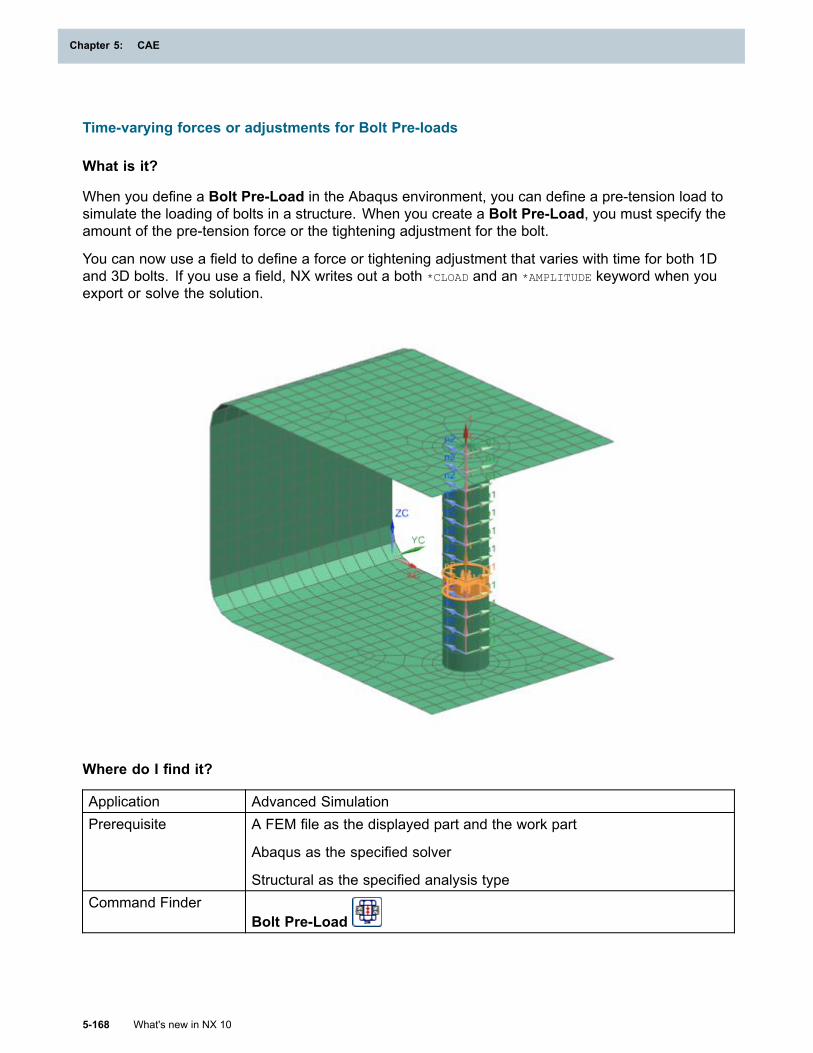
Chapter 5: CAE
Time-varying forces or adjustments for Bolt Pre-loads
What is it?
When you define a Bolt Pre-Load in the Abaqus environment, you can define a pre-tension load tosimulate the loading of bolts in a structure. When you create a Bolt Pre-Load, you must specify theamount of the pre-tension force or the tightening adjustment for the bolt.
You can now use a field to define a force or tightening adjustment that varies with time for both 1Dand 3D bolts. If you use a field, NX writes out a both *CLOAD and an *AMPLITUDE keyword when youexport or solve the solution.
Where do I find it?
Application Advanced SimulationPrerequisite A FEM file as the displayed part and the work part
Abaqus as the specified solver
Structural as the specified analysis typeCommand Finder
Bolt Pre-Load
5-168 What's new in NX 10
Chapter 5: CAE
CAE
Defining the material orientation of 3D elements with a field
What is it?
You can now define the material orientation vector of Abaqus 3D elements using a spatial field.This means that you can use the Spatial Field option to define the spatially varying distribution oforientation angles on the layers of Abaqus composite solid continuum elements and compositeshell elements from within NX.
In previous releases, the Spatial Field option was available only when you imported an Abaqus inputfile that used the *DISTRIBUTION keyword to define material orientation vector data for solid elementsas a field.
Where do I find it?
Application Advanced SimulationPrerequisite A FEM file as the displayed part and the work part
Abaqus as the specified solverCommand Finder
Mesh Associated DataLocation in dialog box Material Orientation Method list→Spatial Field
Cohesive behavior now supported
What is it?
When you define contact in the Abaqus environment, you can now model cohesive behavior for thecontacting surfaces. In Abaqus, cohesive behavior is a generalized traction-separation behaviorfor surfaces. Cohesive behavior is defined as a surface-based contact property for contact pairs.Surface-based cohesive behavior is primarily intended for situations in which the interface thicknessis negligibly small. For example, you can use cohesive behavior when you model the following:
• The delamination at interfaces in terms of traction versus separation.
• Two sticky surfaces that come into contact with each other during an analysis. Sticky surfaces aresurfaces or parts of surfaces that are not initially in contact but which may bond together whenthey come into contact with each other. Subsequently, the bond may damage and fail.
Surface-based cohesive behavior has the following characteristics:
• It allows you to specify cohesive data, such as the fracture energy as a function of the ratio ofnormal to shear displacements at the interface.
• It assumes a linear elastic traction-separation law prior to damage.
• It assumes that the failure of the cohesive bond is characterized by progressive degradation ofthe cohesive stiffness, which is driven by a damage process.
• It allows specification of post-failure cohesive behavior if failed nodes re-enter contact.
What's new in NX 10 5-169
CAE
Chapter 5: CAE
Defining cohesive behavior for contact pairs
You can use the new Cohesive Behavior modeling object to define properties for the surface-basedcohesive behavior. For example, you can define the traction-separation response behavior as well asspecify the set of nodes affected by the cohesive behavior. After you define the Cohesive Behaviormodeling object, select the new Include Cohesive Behavior check box in the Contact Pair dialogbox to include the modeling object in the solution.
Defining damage modeling
When you include cohesive behavior in a solution, you can also include damage modeling to simulatethe degradation and eventual failure of the bond between two cohesive surfaces. You specify damagebehavior as part of the interaction properties for the surfaces. Cohesive surfaces can have only onedamage initiation criterion and only one damage evolution law.
• Use the Damage Initiation modeling object to specify parameters to define the initiation ofdamage. Damage initiation occurs at the beginning of degradation of the cohesive response at acontact point. You can use options in the Damage Initiation dialog box to define the damageinitiation criteria, such as the maximum separation or stresses.
• Use the Damage Evolution modeling object to specify the material properties that define theevolution of damage. For example, you can define the evolution of damage in terms of the energyrequired for failure (fracture energy) after the initiation of damage.
• Use the Damage Stabilization modeling object to specify the viscosity coefficients for thedamage model. These coefficients are used in the viscous regularization scheme for the damagemodel.
Where do I find it?
Application Advanced SimulationPrerequisite A Simulation file as the displayed part and the work part
Abaqus as the specified solverCommand Finder
Modeling ObjectsLocation in dialog box Type→Cohesive Behavior
Support for nodal temperature output
What is it?
You can use the new Structural Output Requests dialog box to report nodal temperature data in astructural solution. On the Thermal tab, select NT-Nodal Temperature. This option corresponds tothe Abaqus NT output variable which outputs all temperature values at a given node.
• For continuum elements, there is only one temperature value per node (NT11).
• For shell and beam elements, there are multiple temperature values per node (NT11, NT12,and so on).
5-170 What's new in NX 10
Chapter 5: CAE
CAE
Where do I find it?
Application Advanced SimulationPrerequisite A Simulation file as the displayed part and the work part
Abaqus as the specified solverCommand Finder
Modeling ObjectsLocation in dialog box Type→Abaqus Structural Output Requests
Specifying temperature units on import and export
What is it?
In this release, you can control the units used for temperatures in your model during import andexport. This gives you the flexibility to define temperatures in a different unit system, such as Kelvin,than the rest of your model, which may be in metric or British units. In the Import Simulation orExport Simulation dialog box, use the new Specify temperature units list to select the unit systemto use for temperatures in the model.
In previous releases, for example, if the imported unit system for your model was British units, NXimported all temperature values in the input file as °F. Similarly, if the imported unit system was metric,all temperature values were interpreted as °C.
Where do I find it?
Import Simulation dialog box
Application Advanced SimulationPrerequisite A Simulation file is the displayed part and the work part
Abaqus is the specified solverMenu File→Import→Simulation
File→Export→Simulation
Improvements for appending and merging Abaqus data
What is it?
This release contains improvements when you use the Append Merge option in the Solver DeckAppend dialog box to import data. Now, if your source Abaqus input file has a different analysis typeor a different setting from the destination NX FEM or Simulation file for the 2D Solid Option, NXnow imports, appends, and merges the data. In previous releases, depending on the combination ofthe type of analysis and the 2D Solid Option setting in the source and destination files, NX oftencould not import and append the data.
Where do I find it?
Application Advanced Simulation
What's new in NX 10 5-171
CAE
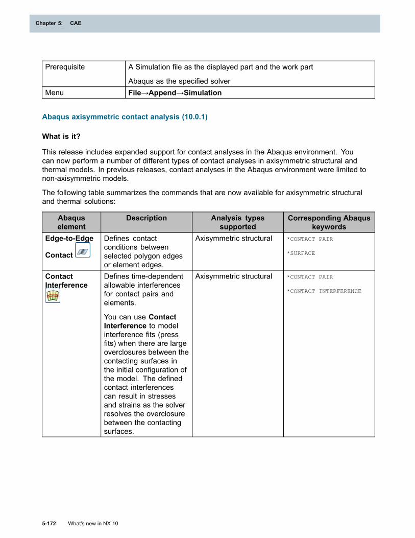
Chapter 5: CAE
Prerequisite A Simulation file as the displayed part and the work part
Abaqus as the specified solverMenu File→Append→Simulation
Abaqus axisymmetric contact analysis (10.0.1)
What is it?
This release includes expanded support for contact analyses in the Abaqus environment. Youcan now perform a number of different types of contact analyses in axisymmetric structural andthermal models. In previous releases, contact analyses in the Abaqus environment were limited tonon-axisymmetric models.
The following table summarizes the commands that are now available for axisymmetric structuraland thermal solutions:
Abaquselement
Description Analysis typessupported
Corresponding Abaquskeywords
Edge-to-Edge
Contact
Defines contactconditions betweenselected polygon edgesor element edges.
Axisymmetric structural *CONTACT PAIR
*SURFACE
ContactInterference
Defines time-dependentallowable interferencesfor contact pairs andelements.
You can use ContactInterference to modelinterference fits (pressfits) when there are largeoverclosures between thecontacting surfaces inthe initial configuration ofthe model. The definedcontact interferencescan result in stressesand strains as the solverresolves the overclosurebetween the contactingsurfaces.
Axisymmetric structural *CONTACT PAIR
*CONTACT INTERFERENCE
5-172 What's new in NX 10
Chapter 5: CAE
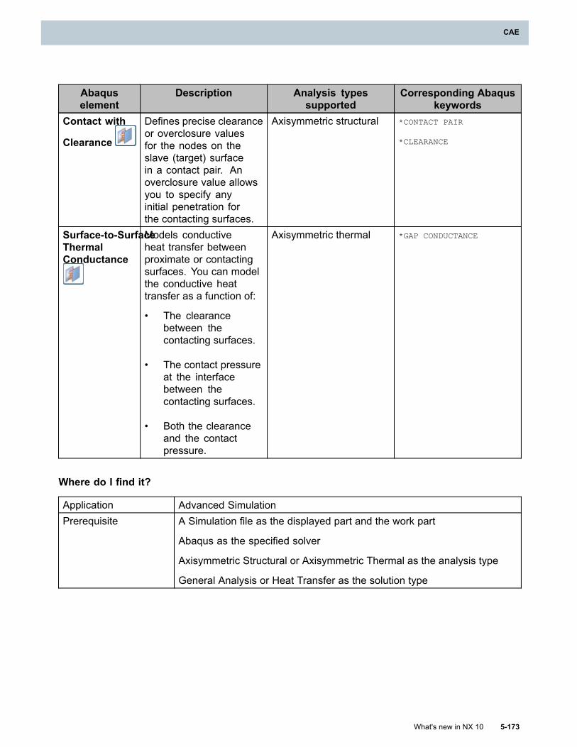
CAE
Abaquselement
Description Analysis typessupported
Corresponding Abaquskeywords
Contact with
Clearance
Defines precise clearanceor overclosure valuesfor the nodes on theslave (target) surfacein a contact pair. Anoverclosure value allowsyou to specify anyinitial penetration forthe contacting surfaces.
Axisymmetric structural *CONTACT PAIR
*CLEARANCE
Surface-to-SurfaceThermalConductance
Models conductiveheat transfer betweenproximate or contactingsurfaces. You can modelthe conductive heattransfer as a function of:
• The clearancebetween thecontacting surfaces.
• The contact pressureat the interfacebetween thecontacting surfaces.
• Both the clearanceand the contactpressure.
Axisymmetric thermal *GAP CONDUCTANCE
Where do I find it?
Application Advanced SimulationPrerequisite A Simulation file as the displayed part and the work part
Abaqus as the specified solver
Axisymmetric Structural or Axisymmetric Thermal as the analysis type
General Analysis or Heat Transfer as the solution type
What's new in NX 10 5-173
CAE
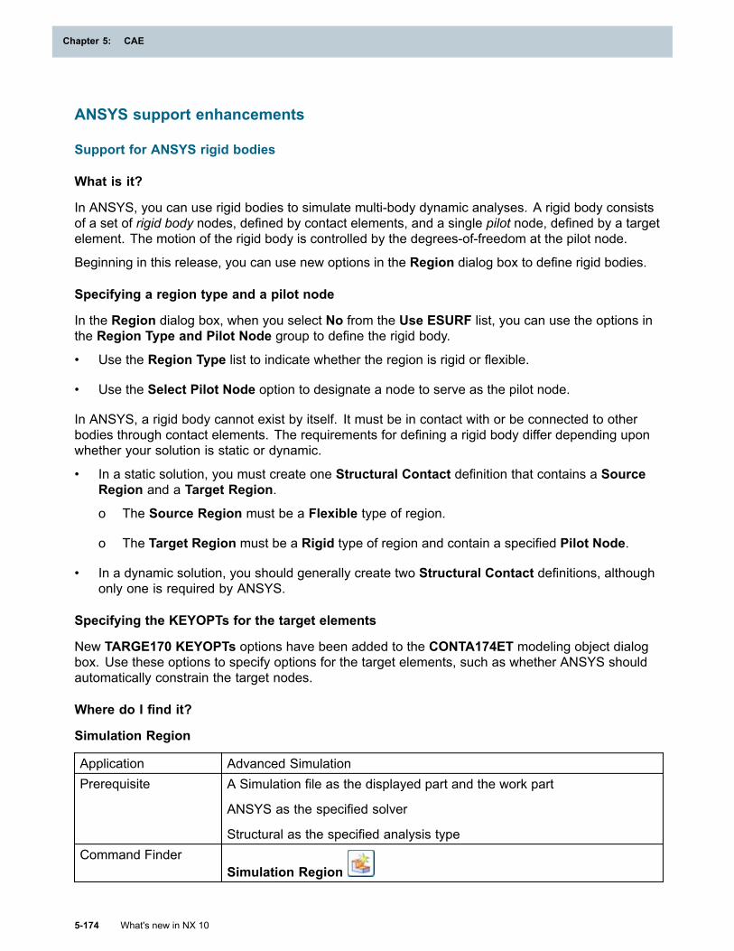
Chapter 5: CAE
ANSYS support enhancements
Support for ANSYS rigid bodies
What is it?
In ANSYS, you can use rigid bodies to simulate multi-body dynamic analyses. A rigid body consistsof a set of rigid body nodes, defined by contact elements, and a single pilot node, defined by a targetelement. The motion of the rigid body is controlled by the degrees-of-freedom at the pilot node.
Beginning in this release, you can use new options in the Region dialog box to define rigid bodies.
Specifying a region type and a pilot node
In the Region dialog box, when you select No from the Use ESURF list, you can use the options inthe Region Type and Pilot Node group to define the rigid body.
• Use the Region Type list to indicate whether the region is rigid or flexible.
• Use the Select Pilot Node option to designate a node to serve as the pilot node.
In ANSYS, a rigid body cannot exist by itself. It must be in contact with or be connected to otherbodies through contact elements. The requirements for defining a rigid body differ depending uponwhether your solution is static or dynamic.
• In a static solution, you must create one Structural Contact definition that contains a SourceRegion and a Target Region.
o The Source Region must be a Flexible type of region.
o The Target Region must be a Rigid type of region and contain a specified Pilot Node.
• In a dynamic solution, you should generally create two Structural Contact definitions, althoughonly one is required by ANSYS.
Specifying the KEYOPTs for the target elements
New TARGE170 KEYOPTs options have been added to the CONTA174ET modeling object dialogbox. Use these options to specify options for the target elements, such as whether ANSYS shouldautomatically constrain the target nodes.
Where do I find it?
Simulation Region
Application Advanced SimulationPrerequisite A Simulation file as the displayed part and the work part
ANSYS as the specified solver
Structural as the specified analysis typeCommand Finder
Simulation Region
5-174 What's new in NX 10
Chapter 5: CAE
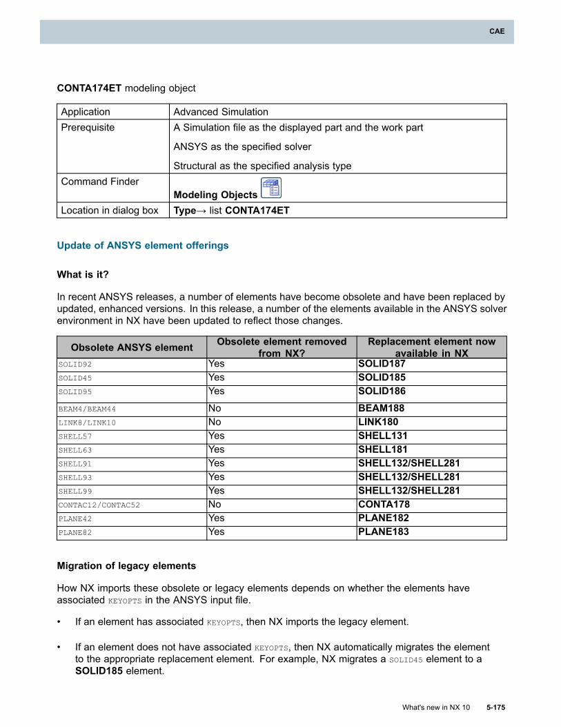
CAE
CONTA174ET modeling object
Application Advanced SimulationPrerequisite A Simulation file as the displayed part and the work part
ANSYS as the specified solver
Structural as the specified analysis typeCommand Finder
Modeling ObjectsLocation in dialog box Type→ list CONTA174ET
Update of ANSYS element offerings
What is it?
In recent ANSYS releases, a number of elements have become obsolete and have been replaced byupdated, enhanced versions. In this release, a number of the elements available in the ANSYS solverenvironment in NX have been updated to reflect those changes.
Obsolete ANSYS element Obsolete element removedfrom NX?
Replacement element nowavailable in NX
SOLID92 Yes SOLID187SOLID45 Yes SOLID185SOLID95 Yes SOLID186BEAM4/BEAM44 No BEAM188LINK8/LINK10 No LINK180SHELL57 Yes SHELL131SHELL63 Yes SHELL181SHELL91 Yes SHELL132/SHELL281SHELL93 Yes SHELL132/SHELL281SHELL99 Yes SHELL132/SHELL281CONTAC12/CONTAC52 No CONTA178PLANE42 Yes PLANE182PLANE82 Yes PLANE183
Migration of legacy elements
How NX imports these obsolete or legacy elements depends on whether the elements haveassociated KEYOPTS in the ANSYS input file.
• If an element has associated KEYOPTS, then NX imports the legacy element.
• If an element does not have associated KEYOPTS, then NX automatically migrates the elementto the appropriate replacement element. For example, NX migrates a SOLID45 element to aSOLID185 element.
What's new in NX 10 5-175
CAE
Chapter 5: CAE
A new Keyopts option has been added to the Mesh Associated Data dialog box to help you migrateobsolete elements to their replacements. For a legacy element, you can use this option to assign theappropriate replacement KEYOPTS modeling object to the element.
New customer defaults for legacy elements
This release also includes new customer defaults that you can use to facilitate the import of olderANSYS input files that may contain these obsolete or legacy elements. For each type of legacyelement, you can use these options to specify whether they should be imported as the correspondingreplacement element type or as legacy element type.
Where do I find it?
Mesh Associated Data
Application Advanced SimulationPrerequisite A FEM file as the displayed part and the work part
ANSYS as the specified solverSimulation Navigator Right-click a mesh→Edit Mesh Associated Data
Customer defaults
Menu File→Utilities→Customer DefaultsLocation in dialog box Simulation→ANSYS→Legacy Elements tab
New customer defaults for ANSYS element KEYOPTS
What is it?
Use the new ANSYS KEYOPTS customer defaults to set the default values for the KEYOPTS optionsfor the following element types:
• BEAM188
• SHELL131 and SHELL132
• SHELL181 and SHELL281
• PLANE55
• PLANE77
• PLANE182 and PLANE183
• SOLID185
• SOLID186
• SOLID187
• SOLID226 and SOLID227
5-176 What's new in NX 10
Chapter 5: CAE
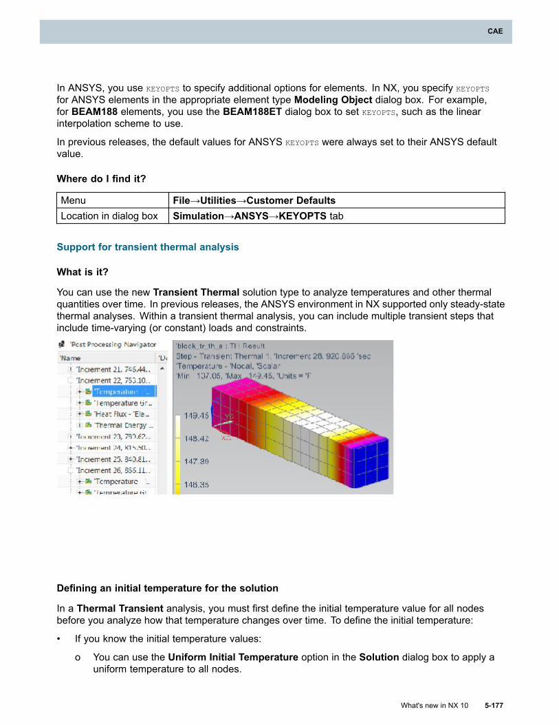
CAE
In ANSYS, you use KEYOPTS to specify additional options for elements. In NX, you specify KEYOPTS
for ANSYS elements in the appropriate element type Modeling Object dialog box. For example,for BEAM188 elements, you use the BEAM188ET dialog box to set KEYOPTS, such as the linearinterpolation scheme to use.
In previous releases, the default values for ANSYS KEYOPTS were always set to their ANSYS defaultvalue.
Where do I find it?
Menu File→Utilities→Customer DefaultsLocation in dialog box Simulation→ANSYS→KEYOPTS tab
Support for transient thermal analysis
What is it?
You can use the new Transient Thermal solution type to analyze temperatures and other thermalquantities over time. In previous releases, the ANSYS environment in NX supported only steady-statethermal analyses. Within a transient thermal analysis, you can include multiple transient steps thatinclude time-varying (or constant) loads and constraints.
Defining an initial temperature for the solution
In a Thermal Transient analysis, you must first define the initial temperature value for all nodesbefore you analyze how that temperature changes over time. To define the initial temperature:
• If you know the initial temperature values:
o You can use the Uniform Initial Temperature option in the Solution dialog box to apply auniform temperature to all nodes.
What's new in NX 10 5-177
CAE
Chapter 5: CAE
o You can create an Initial Temperatures simulation object to apply different initialtemperatures to selected nodes. For those nodes, the temperature value you specify inthe Initial Temperatures dialog box overrides the value you specify in the Uniform InitialTemperature box.
• If you do not know the initial temperature values, you can include a Steady State Thermal stepin your analysis immediately before the Transient step to calculate the temperature values.
Specifying parameters to control time increments
In addition to specifying the initial temperatures, you must also use the new Transient Parametersmodeling object to define the time increment options.
Defining solution options
You can use options in the Solution dialog box to define options for the transient thermal solution.For example, you can define the following:
• Whether the loads should be ramped or stepped during the analysis, or whether the softwareshould determine this automatically.
• Nonlinear transient solution options, which correspond to the ANSYS THOPT command.
• How often ANSYS outputs the solution results.
Using a transient time table
If you set the Automatic Time Stepping option to On in the Transient Parameters dialog box, youcan create a Transient Time Table modeling object to define an array of key times at which the timestepping changes. Use a Transient Time Table when the time stepping is not constant.
The options in this dialog box correspond to the ANSYS TSRES array command.
Where do I find it?
Transient Thermal
Application Advanced SimulationPrerequisite A Simulation file as the displayed part and the work part
ANSYS as the specified solver
Thermal as the specified Analysis Type
Transient Thermal as the specified Solution Type
Transient Parameters and Transient Time Table modeling objects
Application Advanced Simulation
5-178 What's new in NX 10
Chapter 5: CAE
CAE
Prerequisite A Simulation file as the displayed part and the work part
ANSYS as the specified solver
Thermal as the specified Analysis Type
Transient Thermal as the specified Solution TypeCommand Finder
Modeling Objects
Support for transient dynamic analysis
What is it?
You can now perform ANSYS transient dynamics analyses in Advanced Simulation. You usetransient dynamic analysis, also called time-history analysis, to determine the dynamic response ofa structure when time-dependent loads are applied. You can use a transient dynamic analysis todetermine the time-varying displacements, strains, stresses, and forces in a structure as it respondsto a combination of loads.
Note
In a transient dynamic analysis, the time scale of the loading is such that the inertia or dampingeffects are considered to be important.
NX supports the following methods to perform an ANSYS transient dynamic analysis:
• The full method.
• The mode superposition method.
The following table summarizes these two method.
Solutionmethod
Description Support fornonlinearities?
Full Method Uses the full systemmatrices to calculatethe transient response,with no matrix reduction.
Yes
Solutions caninclude all typesof nonlinearities,such as plasticity,large deflections,and large strains.
ModeSuperposition
Sums the factoredmodeshapes (eigenvectors)from a modal analysis tocalculate the structure'sresponse.
No
This solution canbe used only forlinear systems.
Where do I find it?
Application Advanced Simulation
What's new in NX 10 5-179
CAE
Chapter 5: CAE
Prerequisite A Simulation file as the displayed part and the work part
ANSYS as the specified solver
Structural as the specified Analysis Type
Transient Dynamic-Full Method or Transient Dynamic-ModeSuperposition as the specified Solution Type
Support for thermal-structural multiphysics analysis
What is it?
Use the new Coupled Fields Thermal-Structural solution type to perform coupled thermal-structuralanalyses in the ANSYS structural environment. NX currently supports coupled-field analysis usingthe direct method. The direct method typically involves one analysis that uses a coupled-field type ofelement that contains all necessary degrees-of-freedom. ANSYS handles the coupling by calculatingelement matrices or element load vectors that contain all necessary terms.
For more information, see the ANSYS Coupled-Field Analysis Guide.
Supported elements and properties
In this initial release, the Coupled Fields Thermal-Structural solution offers more complete elementsupport for the structural portion of the solve than for the coupled portion of the solve and morelimited support for the thermal portion of the solve. Currently, you can use all structural elements (0D,1D, 2D, 3D) available in NX for the structural solve. However, you can only use SOLID226 (20-nodehexadedral) or SOLID227 (10-node tetrahedral) elements to perform coupled fields analysis. Theseare the only types of elements that can, for example, accept both thermal and structural types of loadsand boundary conditions and compute heat transfer.
Supported loads and constraints
The following thermal loads, constraints, and simulation objects have been added to the ANSYSstructural environment to facilitate Coupled Fields Thermal-Structural analyses:
• Thermal Constraints and Convection
• Heat Flux, Radiation and Heat Generation
• Automatic Thermal Coupling and Manual Thermal Coupling
Note
ANSYS issues a warning message in the diagnostic file if your input file contains loads orconstraints that are applied to the wrong element types. You cannot define thermal loads,constraints, and simulation objects on structural elements. You can apply thermal loads only toSOLID 226 and SOLID227 elements.
In a Coupled Fields Thermal-Structural solution, you use the Structural Contact dialog box todefine both structural and thermal contact. You use the CONTA174 Real Constants modelingobject to define the appropriate options for both structural and thermal contact in a Coupled FieldsThermal-Structural solution.
5-180 What's new in NX 10
Chapter 5: CAE
CAE
Specifying options for the solution and steps
When you define a Coupled Fields Thermal-Structural solution, use the options on the newMulti-Fields Parameters tab in the Solution dialog box to specify the following:
• Options to control the stagger iterations that the software performs. A stagger iteration is aniteration in which the implicit coupling of the individual physics solutions takes place. Theseoptions correspond to the ANSYS MFITER command.
• Options to control the relaxation values for the load transfer variables at a surface or volumeinterface. These options control how much of the change in a load is transferred in each staggeriteration and correspond to the ANSYS MFRELAX command.
Where do I find it?
Application Advanced SimulationPrerequisite A Simulation file as the displayed part and the work part
ANSYS as the specified solver
Structural as the specified Analysis Type
Coupled Thermal Fields-Structural as the specified Solution Type
Data compaction options for import
What is it?
This release includes changes to how ANSYS handles extended data verification during importand new options for compacting imported data.
Extended data checking now occurs on all imported files
When you import an ANSYS input file, NX now always performs extended data checking. Forexample, NX checks for the existence of each node on a given element in your input file. In previousreleases, you used the Extended data checking option in the Import Simulation dialog box tocontrol whether the software performed the more comprehensive level of data validation.
New data compaction options
You can use the new Data Compaction options in the Import Simulation dialog box to access anumber of options that let you control how the software writes out the ANSYS input file.
• Use the new Import MPCs as Multi-MPCs option to improve the import performance for modelsthat contain a large number of multi-point constraints. When you select this option, NX importsthe individual MPCs as a single Multi-MPC type of Manual Coupling constraint instead ofnumerous individual CE type of Manual Coupling constraints. This option offers faster importtimes for a large model at the expense of a more detailed representation of your input file in NX.
This release also includes a new Number of MPCs for Multi-MPC Creation customer default.Use this default to specify the threshold number of multi-point constraints that a solver input filemust contain before NX imports them as Multi-MPC couplings instead of individual CE couplings
What's new in NX 10 5-181
CAE
Chapter 5: CAE
• Use the Compact displacement coordinate systems option to improve import performancefor models that contain numerous NROTAT commands. By default, NX creates a displacementcoordinate system for every NROTAT command during import. This can result in numerous,duplicate displacement coordinate systems in your NX model. Select this option to have NXidentify identical nodal rotations and compact them into a single displacement coordinate system.If the rotation angle between nodes is less than or equal to the specified Material orientationcomparison angle option, NX compacts the associated displacement coordinate systems.
• Use the Compact SHELL/PLANE element physical properties option to improve importperformance for models that have shell or planar elements with variable thickness values. Modelsthat have varying thickness values often contain a very large number of physical property tables,which correspond to the ANSYS Real Constants and the SECDATA command. When you selectthis option, NX combines the individual property tables and stores the thickness data either as athickness field or as element associated data.
Where do I find it?
Import Simulation dialog box
Application Advanced SimulationPrerequisite A Simulation file as the displayed part and the work part
ANSYS as the specified solverMenu File→Import→Simulation
Number of MPCs for Multi-MPC Creation customer default
Menu File→Utilities→Customer DefaultsLocation in dialog box ANSYS→General tab
Specifying temperature units on import and export
What is it?
You can now control the units used for temperatures in your model during import and export. Thisgives you the flexibility to define temperatures in a different unit system, such as Kelvin, than therest of your model, which may be in metric or British units. In the Import Simulation or ExportSimulation dialog box, use the new Specify temperature units list to select the unit system touse for temperatures in the model.
In previous releases, for example, if the imported unit system for your model was British units, NXimported all temperature values in the input file as °F. Similarly, if the imported unit system was metric,all temperature values were interpreted as °C.
Where do I find it?
Application Advanced SimulationPrerequisite A Simulation file as the displayed part and the work part
ANSYS as the specified solver
5-182 What's new in NX 10
Chapter 5: CAE
CAE
Menu File→Import→Simulation
File→Export→Simulation
ANSYS command support enhancements
What is it?
This release includes support for a number of new ANSYS commands.
Command Description Import support Export support Supportedparameters
ALPHAD Defines themass matrixmultiplier fordamping.
Yes Yes VALUE
ANTYPE, TRANS Specifiesthat thesolution istransient.
Yes Yes All otherparameters(Status, LDSTEP,
SUBSTEP, Action)are not currentlysupported by NX.
BETAD Defines thestiffnessmatrixmultiplier fordamping.
Yes Yes VALUE
DELTIM Specifiesthe time stepsizes to usefor a solutionstep.
Yes Yes DTIME, DTMIN,
DTMAX, Carry
Carry is notcurrentlysupported in NX.
DMPRAT Specifiesa constantdampingratio
Yes Yes Ratio,
IC Specifiesinitialconditionsat nodes.
Yes Yes NODE, Lab, VALUE,
VALUE2, NEND,
NINC
NENED, NINC arenot currentlysupported by NX.Use the ANSYSdefault value forthese parametersof NENED=1 andNINC=1.
What's new in NX 10 5-183
CAE
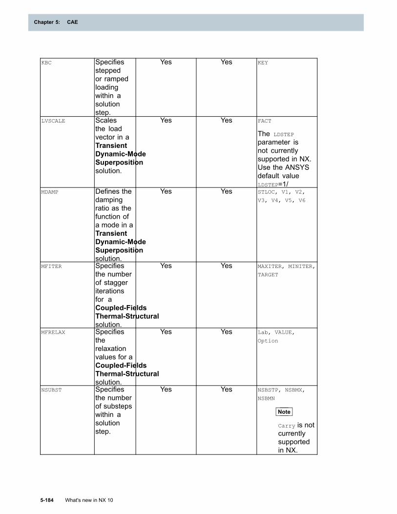
Chapter 5: CAE
KBC Specifiessteppedor rampedloadingwithin asolutionstep.
Yes Yes KEY
LVSCALE Scalesthe loadvector in aTransientDynamic-ModeSuperpositionsolution.
Yes Yes FACT
The LDSTEP
parameter isnot currentlysupported in NX.Use the ANSYSdefault valueLDSTEP=1/
MDAMP Defines thedampingratio as thefunction ofa mode in aTransientDynamic-ModeSuperpositionsolution.
Yes Yes STLOC, V1, V2,
V3, V4, V5, V6
MFITER Specifiesthe numberof staggeriterationsfor aCoupled-FieldsThermal-Structuralsolution.
Yes Yes MAXITER, MINITER,
TARGET
MFRELAX Specifiestherelaxationvalues for aCoupled-FieldsThermal-Structuralsolution.
Yes Yes Lab, VALUE,
Option
NSUBST Specifiesthe numberof substepswithin asolutionstep.
Yes Yes NSBSTP, NSBMX,
NSBMN
Note
Carry is notcurrentlysupportedin NX.
5-184 What's new in NX 10
Chapter 5: CAE
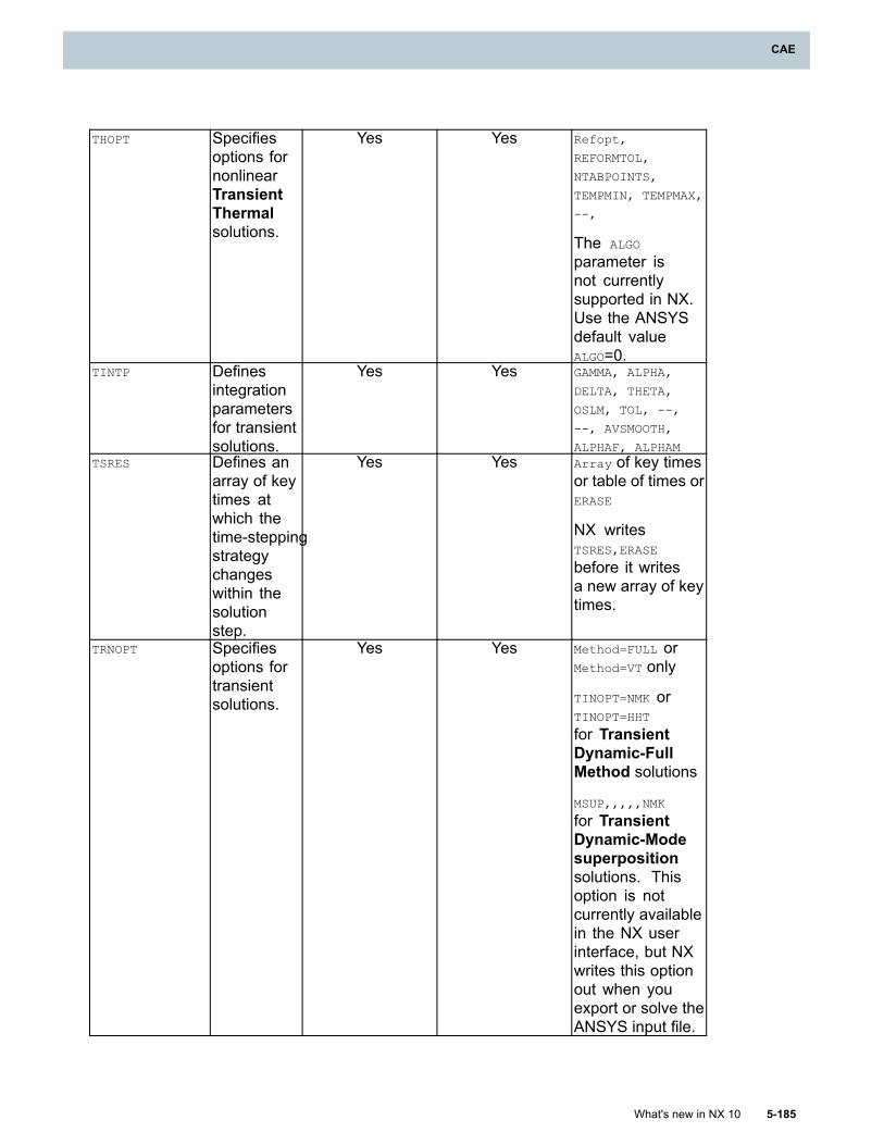
CAE
THOPT Specifiesoptions fornonlinearTransientThermalsolutions.
Yes Yes Refopt,
REFORMTOL,
NTABPOINTS,
TEMPMIN, TEMPMAX,
--,
The ALGO
parameter isnot currentlysupported in NX.Use the ANSYSdefault valueALGO=0.
TINTP Definesintegrationparametersfor transientsolutions.
Yes Yes GAMMA, ALPHA,
DELTA, THETA,
OSLM, TOL, --,
--, AVSMOOTH,
ALPHAF, ALPHAMTSRES Defines an
array of keytimes atwhich thetime-steppingstrategychangeswithin thesolutionstep.
Yes Yes Array of key timesor table of times orERASE
NX writesTSRES,ERASE
before it writesa new array of keytimes.
TRNOPT Specifiesoptions fortransientsolutions.
Yes Yes Method=FULL orMethod=VT only
TINOPT=NMK orTINOPT=HHT
for TransientDynamic-FullMethod solutions
MSUP,,,,,NMK
for TransientDynamic-Modesuperpositionsolutions. Thisoption is notcurrently availablein the NX userinterface, but NXwrites this optionout when youexport or solve theANSYS input file.
What's new in NX 10 5-185
CAE
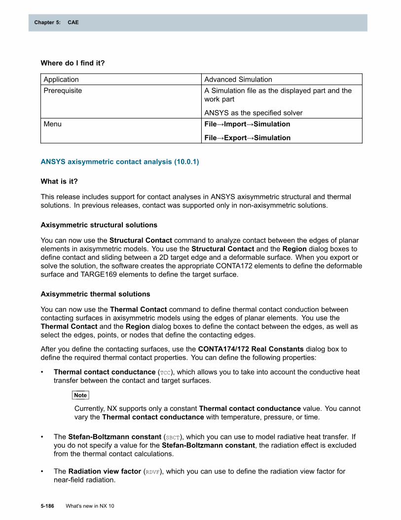
Chapter 5: CAE
Where do I find it?
Application Advanced SimulationPrerequisite A Simulation file as the displayed part and the
work part
ANSYS as the specified solverMenu File→Import→Simulation
File→Export→Simulation
ANSYS axisymmetric contact analysis (10.0.1)
What is it?
This release includes support for contact analyses in ANSYS axisymmetric structural and thermalsolutions. In previous releases, contact was supported only in non-axisymmetric solutions.
Axisymmetric structural solutions
You can now use the Structural Contact command to analyze contact between the edges of planarelements in axisymmetric models. You use the Structural Contact and the Region dialog boxes todefine contact and sliding between a 2D target edge and a deformable surface. When you export orsolve the solution, the software creates the appropriate CONTA172 elements to define the deformablesurface and TARGE169 elements to define the target surface.
Axisymmetric thermal solutions
You can now use the Thermal Contact command to define thermal contact conduction betweencontacting surfaces in axisymmetric models using the edges of planar elements. You use theThermal Contact and the Region dialog boxes to define the contact between the edges, as well asselect the edges, points, or nodes that define the contacting edges.
After you define the contacting surfaces, use the CONTA174/172 Real Constants dialog box todefine the required thermal contact properties. You can define the following properties:
• Thermal contact conductance (TCC), which allows you to take into account the conductive heattransfer between the contact and target surfaces.
Note
Currently, NX supports only a constant Thermal contact conductance value. You cannotvary the Thermal contact conductance with temperature, pressure, or time.
• The Stefan-Boltzmann constant (SBCT), which you can use to model radiative heat transfer. Ifyou do not specify a value for the Stefan-Boltzmann constant, the radiation effect is excludedfrom the thermal contact calculations.
• The Radiation view factor (RDVF), which you can use to define the radiation view factor fornear-field radiation.
5-186 What's new in NX 10
Chapter 5: CAE
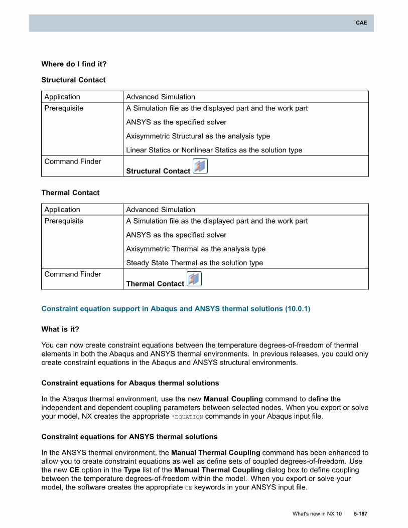
CAE
Where do I find it?
Structural Contact
Application Advanced SimulationPrerequisite A Simulation file as the displayed part and the work part
ANSYS as the specified solver
Axisymmetric Structural as the analysis type
Linear Statics or Nonlinear Statics as the solution typeCommand Finder
Structural Contact
Thermal Contact
Application Advanced SimulationPrerequisite A Simulation file as the displayed part and the work part
ANSYS as the specified solver
Axisymmetric Thermal as the analysis type
Steady State Thermal as the solution typeCommand Finder
Thermal Contact
Constraint equation support in Abaqus and ANSYS thermal solutions (10.0.1)
What is it?
You can now create constraint equations between the temperature degrees-of-freedom of thermalelements in both the Abaqus and ANSYS thermal environments. In previous releases, you could onlycreate constraint equations in the Abaqus and ANSYS structural environments.
Constraint equations for Abaqus thermal solutions
In the Abaqus thermal environment, use the new Manual Coupling command to define theindependent and dependent coupling parameters between selected nodes. When you export or solveyour model, NX creates the appropriate *EQUATION commands in your Abaqus input file.
Constraint equations for ANSYS thermal solutions
In the ANSYS thermal environment, the Manual Thermal Coupling command has been enhanced toallow you to create constraint equations as well as define sets of coupled degrees-of-freedom. Usethe new CE option in the Type list of the Manual Thermal Coupling dialog box to define couplingbetween the temperature degrees-of-freedom within the model. When you export or solve yourmodel, the software creates the appropriate CE keywords in your ANSYS input file.
What's new in NX 10 5-187
CAE
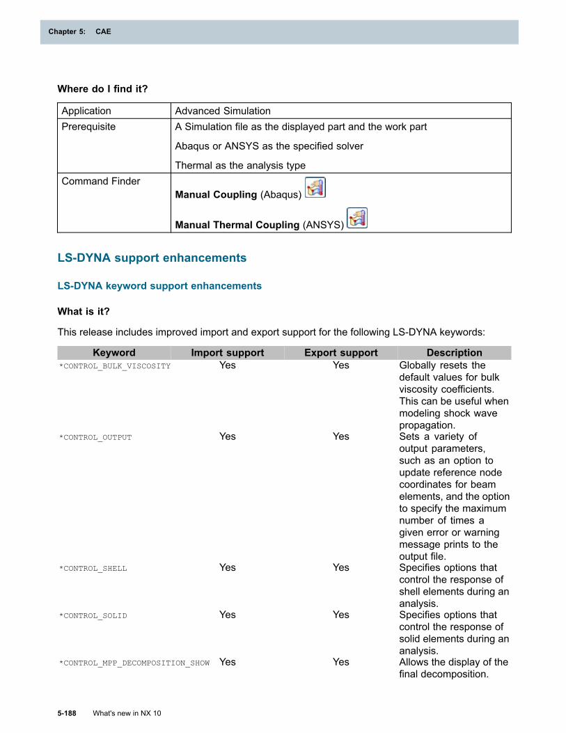
Chapter 5: CAE
Where do I find it?
Application Advanced SimulationPrerequisite A Simulation file as the displayed part and the work part
Abaqus or ANSYS as the specified solver
Thermal as the analysis typeCommand Finder
Manual Coupling (Abaqus)
Manual Thermal Coupling (ANSYS)
LS-DYNA support enhancements
LS-DYNA keyword support enhancements
What is it?
This release includes improved import and export support for the following LS-DYNA keywords:
Keyword Import support Export support Description*CONTROL_BULK_VISCOSITY Yes Yes Globally resets the
default values for bulkviscosity coefficients.This can be useful whenmodeling shock wavepropagation.
*CONTROL_OUTPUT Yes Yes Sets a variety ofoutput parameters,such as an option toupdate reference nodecoordinates for beamelements, and the optionto specify the maximumnumber of times agiven error or warningmessage prints to theoutput file.
*CONTROL_SHELL Yes Yes Specifies options thatcontrol the response ofshell elements during ananalysis.
*CONTROL_SOLID Yes Yes Specifies options thatcontrol the response ofsolid elements during ananalysis.
*CONTROL_MPP_DECOMPOSITION_SHOW Yes Yes Allows the display of thefinal decomposition.
5-188 What's new in NX 10
Chapter 5: CAE
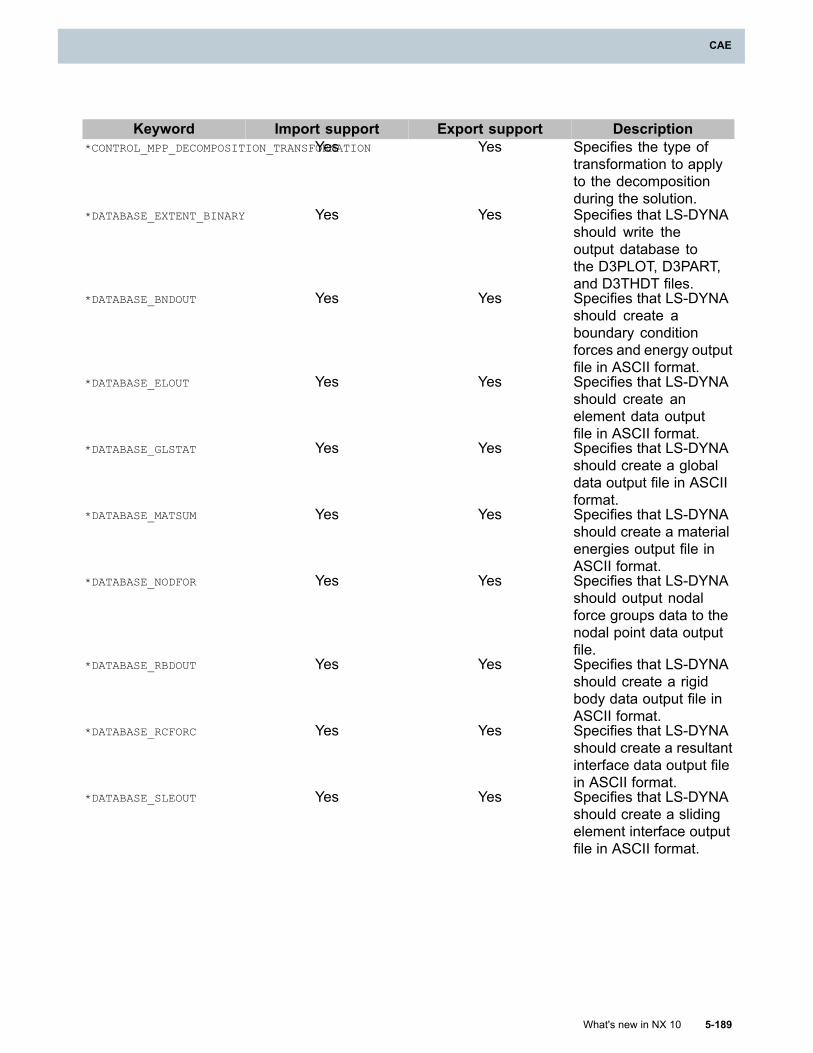
CAE
Keyword Import support Export support Description*CONTROL_MPP_DECOMPOSITION_TRANSFORMATIONYes Yes Specifies the type of
transformation to applyto the decompositionduring the solution.
*DATABASE_EXTENT_BINARY Yes Yes Specifies that LS-DYNAshould write theoutput database tothe D3PLOT, D3PART,and D3THDT files.
*DATABASE_BNDOUT Yes Yes Specifies that LS-DYNAshould create aboundary conditionforces and energy outputfile in ASCII format.
*DATABASE_ELOUT Yes Yes Specifies that LS-DYNAshould create anelement data outputfile in ASCII format.
*DATABASE_GLSTAT Yes Yes Specifies that LS-DYNAshould create a globaldata output file in ASCIIformat.
*DATABASE_MATSUM Yes Yes Specifies that LS-DYNAshould create a materialenergies output file inASCII format.
*DATABASE_NODFOR Yes Yes Specifies that LS-DYNAshould output nodalforce groups data to thenodal point data outputfile.
*DATABASE_RBDOUT Yes Yes Specifies that LS-DYNAshould create a rigidbody data output file inASCII format.
*DATABASE_RCFORC Yes Yes Specifies that LS-DYNAshould create a resultantinterface data output filein ASCII format.
*DATABASE_SLEOUT Yes Yes Specifies that LS-DYNAshould create a slidingelement interface outputfile in ASCII format.
What's new in NX 10 5-189
CAE
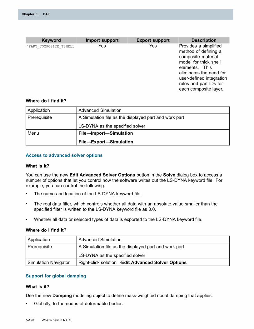
Chapter 5: CAE
Keyword Import support Export support Description*PART_COMPOSITE_TSHELL Yes Yes Provides a simplified
method of defining acomposite materialmodel for thick shellelements. Thiseliminates the need foruser-defined integrationrules and part IDs foreach composite layer.
Where do I find it?
Application Advanced SimulationPrerequisite A Simulation file as the displayed part and work part
LS-DYNA as the specified solverMenu File→Import→Simulation
File→Export→Simulation
Access to advanced solver options
What is it?
You can use the new Edit Advanced Solver Options button in the Solve dialog box to access anumber of options that let you control how the software writes out the LS-DYNA keyword file. Forexample, you can control the following:
• The name and location of the LS-DYNA keyword file.
• The real data filter, which controls whether all data with an absolute value smaller than thespecified filter is written to the LS-DYNA keyword file as 0.0.
• Whether all data or selected types of data is exported to the LS-DYNA keyword file.
Where do I find it?
Application Advanced SimulationPrerequisite A Simulation file as the displayed part and work part
LS-DYNA as the specified solverSimulation Navigator Right-click solution→Edit Advanced Solver Options
Support for global damping
What is it?
Use the new Damping modeling object to define mass-weighted nodal damping that applies:
• Globally, to the nodes of deformable bodies.
5-190 What's new in NX 10
Chapter 5: CAE
CAE
• To the center of mass of rigid bodies.
You can use the options in the Damping dialog box to globally damp low frequency structural modesas well as rigid body modes. For example, you can use options to:
• Select a table-based field to define the loading curve that defines the system damping constant.
• Specify scaling factors on the global X, Y, and Z translational and rotational damping forces.
After you create a Damping modeling object, you can use the new Damping tab in the Solutiondialog box to specify which Damping modeling object to include in the solution.
The options in the Damping dialog box correspond to the LS-DYNA *DAMPING_GLOBAL keyword.
Where do I find it?
Application Advanced SimulationPrerequisite A Simulation file as the displayed part and work part
LS-DYNA as the specified solverCommand Finder
Modeling ObjectsLocation in dialog box Type list →Damping
Expanded support for *CONTROL and *DATABASE keywords
What is it?
This release includes improved support for the LS-DYNA *CONTROL and *DATABASE keywords.
Improved support for the *CONTROL keyword
This release includes expanded support in NX for the LS-DYNA *CONTROL keyword. The Controlsmodeling object dialog box has been updated with a number of new options. For example, you can:
• Use the options on the new Bulk Viscosity tab to change the default values for bulk viscositycoefficients. This can be useful when you model shock wave propagation.
• Use the options on the new Output tab to set a variety of output parameters for LS-DYNA. Forexample, you can specify options to update reference node coordinates for beam elements and tocontrol the maximum number of times a given error or warning message prints to the output file.
• Use the options on the new Shell tab to specify options for shell elements. For example, you canset a maximum allowable for warp value for shell elements. If the warp value for shell elements inyour model exceeds this limit, LS-DYNA prints a warning message.
For a list of all newly supported *CONTROL keywords, see Selectively importing and exporting LS-DYNAdata.
Improved support for the *DATABASE keyword
This release also includes expanded support for the LS-DYNA *DATABASE keyword. The Databasemodeling object dialog box has been updated with a number of new options. For example, you can:
What's new in NX 10 5-191
CAE
Chapter 5: CAE
• Use the options on the Extent Binary tab to control some of the data written to the LS-DYNAbinary output databases (d3plot, d3thdt, and d3part). You can, for example, choose to includeoutput at additional integration points for shell and solid elements. You can also control whetherstress or strain tensor data is written to the binary databases.
• Use the options on the General Option tab to control which ASCII output databases are createdby LS-DYNA during the solve.
For a list of all newly supported *DATABASE keywords, see Selectively importing and exportingLS-DYNA data.
Where do I find it?
Application Advanced SimulationPrerequisite A Simulation file as the displayed part
LS-DYNA as the specified solverCommand Finder
Modeling ObjectsLocation in dialog box Type→Controls or Database
Selectively importing and exporting LS-DYNA data
What is it?
You can now selectively import and export LS-DYNA data from NX.
• In the Import Simulation dialog box, use the options in the new Selective Import group tocontrol which specific commands NX imports from the specified input file. For example, you canclear the Materials check box if you do not want to import any LS-DYNA materials keywords.
• In the Export Simulation dialog box, use the options in the new Export Options group to controlwhich parts of your NX model file are exported to the LS-DYNA keyword file.
Additionally, you can use the new Import unsupported keywords option in the Import Simulationdialog box to import LS-DYNA keywords that are not currently supported in NX as either commentedor uncommented user defined text. For example, you can use this new option to import LS-DYNAload and constraints keywords as uncommented user defined text. If you later solve your LS-DYNAsolution from NX, LS-DYNA should solve the file and produce correct results.
Where do I find it?
Application Advanced SimulationPrerequisite A Simulation file as the displayed part and work part
LS-DYNA as the specified solverMenu File→Import→Simulation
File→Export→Simulation
5-192 What's new in NX 10
Chapter 5: CAE
CAE
Merging parts of an LS-DYNA input file into an existing NX model
What is it?
You can now use options in the Solver Deck Append dialog box to merge entities within an existingLS-DYNA input file into an existing NX model. These options allow you to import portions of an inputdeck into an existing model, as long as the missing portions of the input file already exist in NX.
For example, you can:
• Import only elements from an input file into an NX FEM that already contains nodes.
• Import group definitions that reference nodes and elements where the nodes and elementsalready exist in NX.
• Import loads and constraints into a model that already contains a mesh.
In previous releases, you could append an LS-DYNA solver input file into an existing NX model only ifthe input file being appended was a complete, valid, standalone file.
Controlling import behavior
You can use the options in the Import Behavior list to control how NX imports and appends the datafrom the LS-DYNA input file:
• Select Append to import a solver input data file into an existing FEM or Simulation file andappend the solver data to the existing data. The solver input data file that you import must becomplete and valid.
• Select Append Merge to import data from an incomplete solver data input file into an existingFEM or Simulation file and merge that data into the existing NX file. The solver data input filethat you import does not need to be complete.
When you use the Merge Entities option to append data, NX does not modify any entities thatwere present in NX prior to the merge. For example, NX does not modify the following:
o Solution attributes.
o Values in existing loads, boundary conditions, simulation objects, or modeling objects.
o The content of existing NX groups.
Ability to create a new solution
Use options in the Create Solution list to control whether the source LS-DYNA input file data isappended into a new solution in NX. In previous releases, the appended entities were not placed ina new solution.
• Select No if you do not want to create a new solution. All loads and boundary conditions areplaced in the appropriate containers in the Simulation Navigator, but they are not referencedin the current solution. Any appended modeling objects are also not referenced in the currentsolution.
What's new in NX 10 5-193
CAE
Chapter 5: CAE
• Select Yes to create a new solution. All loads and boundary conditions are placed in theappropriate containers in the Simulation Navigator and referenced in the current solution. Anyappended modeling objects are also referenced in the new solution.
Options for handling data conflicts
This release also includes options that let you control how NX handles conflicts between nodes,materials, and physical property data in the LS–DYNA input file and the destination FEM orSimulation file.
• Select Ignore Deck Data if you do not want to append an entity from the solver input file when itconflicts with an existing entity in the NX destination file. For example, if both the source solverinput file and destination NX file have a coordinate system with an ID of 15, NX does not appendthe coordinate system from the solver input file.
• Select Modify Using Deck Data to replace the node, material, or physical property data in theNX destination file with the data from the source solver input file.
• Select Append Deck Data to specify a numerical offset to increment the label (ID) when conflictsoccur. If NX detects a conflict between an entity in the source input file and the destination NXfile, it uses the offset to change the ID of the entity in the source input file during the append.The software also updates any references to that entity in the source file. For example, if youappend an ELEMENT_SHELL(4) element that originally referenced nodes 1 and 2, and thosenodes are renumbered with an offset of 1000 because of a conflict, the software updates theELEMENT_SHELL(4) element to reference nodes 1001 and 1002.
Where do I find it?
Application Advanced SimulationPrerequisite A FEM or Simulation file as the displayed part and work part
LS-DYNA as the specified solverMenu File→Append
Inflated laminates in LS-DYNA (10.0.1)
What is it?
The Extrude Laminate and Fill Laminate commands are now supported in the LS-DYNAenvironment.
The extruded 3D mesh consists of ELEMENT_TSHELL wedge or hexahedral elements and theply drop-offs consist of ELEMENT_SOLID tetrahedral, wedge, or hexahedral elements. BecauseLS_DYNA does not support pyramids, pyramids are split into tetrahedral elements.
For both commands, NX creates a 3D mesh collector that has a Solid Laminate physical propertyassigned to it. NX automatically sets the Stacking Recipe in the Solid Laminate Modeler dialogbox to Inherited from Layup.
All the plies of the extruded solid laminate have the same ply failure theory and inter-laminar failuretheory that you selected in the Laminate Modeler dialog box.
5-194 What's new in NX 10
Chapter 5: CAE
CAE
Where do I find it?
Application Advanced SimulationPrerequisite You must work in the FEM within the LS-DYNA solver environment.
Command Finder Extrude Laminate or Fill Laminate
Samcef solver environment
Samcef solver environment
What is it?
This release provides support in NX Advanced Simulation of the new Samcef solver environment.When you work in the Samcef environment, you can:
• Create a Samcef model, export it, and perform a Samcef linear static, modal, buckling, ornonlinear static analysis. You can then post-process the results using NX Post-processing.
• Preview the real contact and glue conditions computed by Samcef, using the Ancillary Displaymode.
• Specify materials such as progressive composite damage material models.
• Create cohesive elements to model the interface between two layers, define a damage interfacematerial and analyze phenomena such as delamination.
• Import a Samcef model or post-process results from other Samcef analysis types that are not yetsupported in the NX Samcef solver environment.
Supported element types
NX supports a selection of Samcef 0D, 1D, 2D, and 3D elements and their associated physicalproperties:
• 0D lumped mass, grounded bushing, and spring elements.
• 1D beam and rod elements, as well as 1D connection elements (rigid links and averagedkinematic constraints).
• 2D Mindlin thin shell, Heterosis shell, 2D membrane or shell membrane, metallic or composite.
• 3D solid and solid shell, metallic and composite elements.
3D cohesive elements.
NX supports linear and quadratic elements, true pyramid transition (Tet to Hex transition), and mixedorder transition.
NX automatically groups the elements in mesh collectors and meshes according to their types,physical properties, and materials.
What's new in NX 10 5-195
CAE
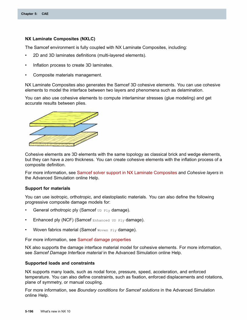
Chapter 5: CAE
NX Laminate Composites (NXLC)
The Samcef environment is fully coupled with NX Laminate Composites, including:
• 2D and 3D laminates definitions (multi-layered elements).
• Inflation process to create 3D laminates.
• Composite materials management.
NX Laminate Composites also generates the Samcef 3D cohesive elements. You can use cohesiveelements to model the interface between two layers and phenomena such as delamination.
You can also use cohesive elements to compute interlaminar stresses (glue modeling) and getaccurate results between plies.
Cohesive elements are 3D elements with the same topology as classical brick and wedge elements,but they can have a zero thickness. You can create cohesive elements with the inflation process of acomposite definition.
For more information, see Samcef solver support in NX Laminate Composites and Cohesive layers inthe Advanced Simulation online Help.
Support for materials
You can use isotropic, orthotropic, and elastoplastic materials. You can also define the followingprogressive composite damage models for:
• General orthotropic ply (Samcef UD Ply damage).
• Enhanced ply (NCF) (Samcef Enhanced UD Ply damage).
• Woven fabrics material (Samcef Woven Ply damage).
For more information, see Samcef damage properties
NX also supports the damage interface material model for cohesive elements. For more information,see Samcef Damage Interface material in the Advanced Simulation online Help.
Supported loads and constraints
NX supports many loads, such as nodal force, pressure, speed, acceleration, and enforcedtemperature. You can also define constraints, such as fixation, enforced displacements and rotations,plane of symmetry, or manual coupling.
For more information, see Boundary conditions for Samcef solutions in the Advanced Simulationonline Help.
5-196 What's new in NX 10
Chapter 5: CAE
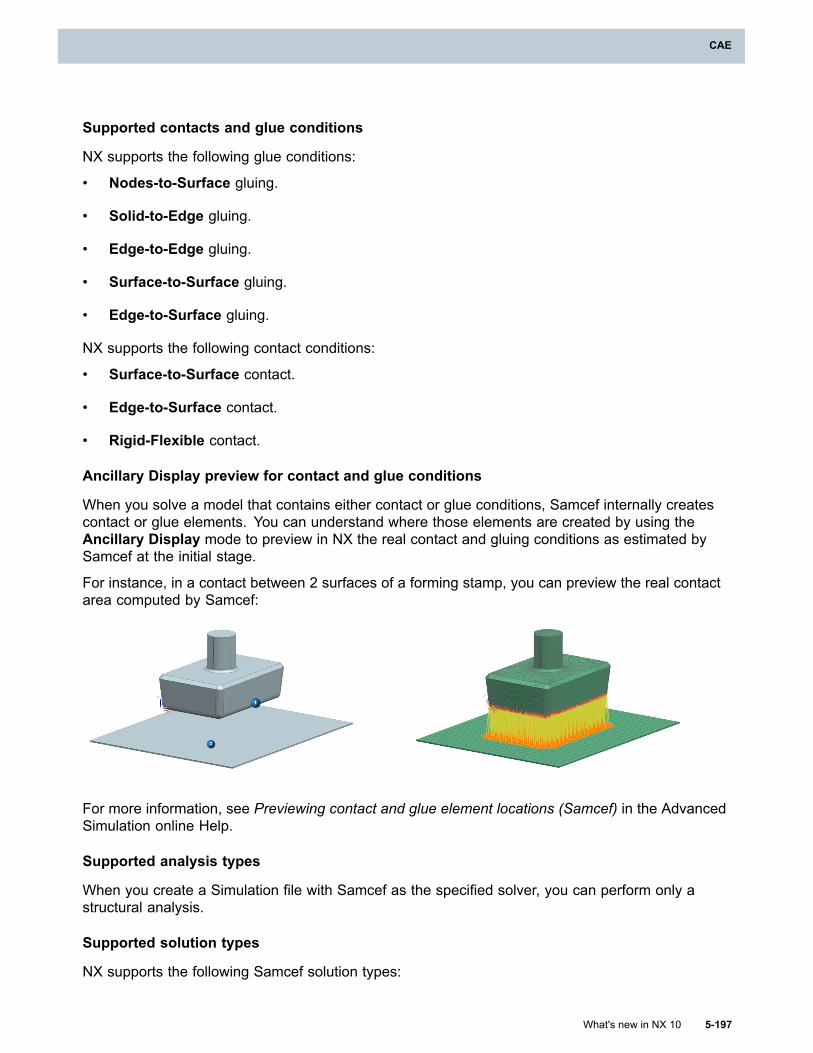
CAE
Supported contacts and glue conditions
NX supports the following glue conditions:
• Nodes-to-Surface gluing.
• Solid-to-Edge gluing.
• Edge-to-Edge gluing.
• Surface-to-Surface gluing.
• Edge-to-Surface gluing.
NX supports the following contact conditions:
• Surface-to-Surface contact.
• Edge-to-Surface contact.
• Rigid-Flexible contact.
Ancillary Display preview for contact and glue conditions
When you solve a model that contains either contact or glue conditions, Samcef internally createscontact or glue elements. You can understand where those elements are created by using theAncillary Display mode to preview in NX the real contact and gluing conditions as estimated bySamcef at the initial stage.
For instance, in a contact between 2 surfaces of a forming stamp, you can preview the real contactarea computed by Samcef:
For more information, see Previewing contact and glue element locations (Samcef) in the AdvancedSimulation online Help.
Supported analysis types
When you create a Simulation file with Samcef as the specified solver, you can perform only astructural analysis.
Supported solution types
NX supports the following Samcef solution types:
What's new in NX 10 5-197
CAE
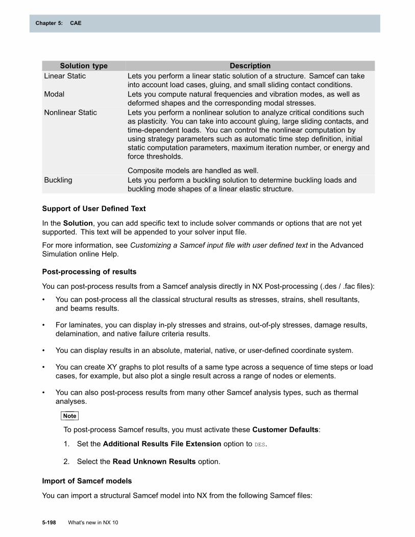
Chapter 5: CAE
Solution type DescriptionLinear Static Lets you perform a linear static solution of a structure. Samcef can take
into account load cases, gluing, and small sliding contact conditions.Modal Lets you compute natural frequencies and vibration modes, as well as
deformed shapes and the corresponding modal stresses.Nonlinear Static Lets you perform a nonlinear solution to analyze critical conditions such
as plasticity. You can take into account gluing, large sliding contacts, andtime-dependent loads. You can control the nonlinear computation byusing strategy parameters such as automatic time step definition, initialstatic computation parameters, maximum iteration number, or energy andforce thresholds.
Composite models are handled as well.Buckling Lets you perform a buckling solution to determine buckling loads and
buckling mode shapes of a linear elastic structure.
Support of User Defined Text
In the Solution, you can add specific text to include solver commands or options that are not yetsupported. This text will be appended to your solver input file.
For more information, see Customizing a Samcef input file with user defined text in the AdvancedSimulation online Help.
Post-processing of results
You can post-process results from a Samcef analysis directly in NX Post-processing (.des / .fac files):
• You can post-process all the classical structural results as stresses, strains, shell resultants,and beams results.
• For laminates, you can display in-ply stresses and strains, out-of-ply stresses, damage results,delamination, and native failure criteria results.
• You can display results in an absolute, material, native, or user-defined coordinate system.
• You can create XY graphs to plot results of a same type across a sequence of time steps or loadcases, for example, but also plot a single result across a range of nodes or elements.
• You can also post-process results from many other Samcef analysis types, such as thermalanalyses.
Note
To post-process Samcef results, you must activate these Customer Defaults:
1. Set the Additional Results File Extension option to DES.
2. Select the Read Unknown Results option.
Import of Samcef models
You can import a structural Samcef model into NX from the following Samcef files:
5-198 What's new in NX 10
Chapter 5: CAE
CAE
• ASCII formatted files (.dat), also known as Samcef Bank files.
• Binary formatted files database (.sdb), also known as Samcef SDB files.
You can import the nodes, elements, physical properties and materials. The import supports unitsconversion and can create groups or regions. Elements are automatically grouped in mesh collectorsand meshes according to their types, physical properties, and materials.
NX does not import Samcef composite data such as the plies (.PLI) and the laminates (.LAM).
NX stores unsupported data in User Defined Text objects.
For more information, see Import overview in the Advanced Simulation online Help.
Where do I find it?
Application Advanced SimulationPrerequisite A FEM or Simulation file as the work part and displayed part
Samcef as the specified solver
Samcef solver support in NX Laminate Composites
What is it?
You can access most NX Laminate Composites commands and functionality in the Samcef solverenvironment.
All laminate commands are supported except the following:
• Solid Laminate Physical Property
• Ply Materials
Ply IDs in all laminate physical properties and global layups must have unique values. In other solverenvironments, ply IDs in different laminate physical properties can have the same values.
In the Samcef environment, you can create cohesive layers between extruded plies to modeldelamination. See Cohesive layers for more information.
Where do I find it?
Application Advanced Simulation
Prerequisite
A FEM file as the work part and displayed part
Samcef as the specified solver
Samcef support enhancements (10.0.1)
This release includes a number of improvements to the Samcef solver environment.
What's new in NX 10 5-199
CAE
Chapter 5: CAE
Creating and solving solutions
• A new Compute curvature for Mindlin shells and beams option has been added to theAdvanced Parameters tab in the Solution dialog box for all Samcef solutions. When you selectthis option, Samcef introduces a curvature based on nodes into the element by computing theshell’s curvature from mean nodal normals.
• In the Advanced Solver Options dialog box, use the new Sorted Data (Nodes/Elements)option to sort the nodes and elements labels in the Samcef input file when you export or solveyour solution.
• On x86_64 Linux and Windows 64-bit operating systems, you can use two versions of the Samcefsolver: the i4 version, which uses 32-bit integers and is limited to 8GB of memory, and the i8
version, which uses 64-bit integers and is limited to 16TB of memory. Samcef automaticallyuses the i8 version of the solver, which improves performance on large models while remainingcompatible with results from the i4 version of the solver.
• When you restart a solution that has existing results, the process by which the software deletesexisting result files and any intermediate files has been improved.
NX Laminate Composites
This release contains improved support for Samcef models in the NX Laminate Composites toolset.
• You can now use the Ply Materials command to assign material properties to laminateplies. This command was not supported for Samcef models in the NX 10 release.
• You can now use the Advanced Post Report command to quickly identify critical elementand ply data over many solutions. The enveloping, filtering, and sorting tools help you to find thecritical element and ply data that you want without reviewing all the solver ply data.
Post-processing
In the Post Processing Navigator:
• The listing and names of the Samcef stress and strain result types in the Post ProcessingNavigator are now more clear. (1) shows an example of Samcef results listed in the PostProcessing Navigator in NX 10. (2) shows the same results listed in the NX 10.0.1 release.
5-200 What's new in NX 10
Chapter 5: CAE
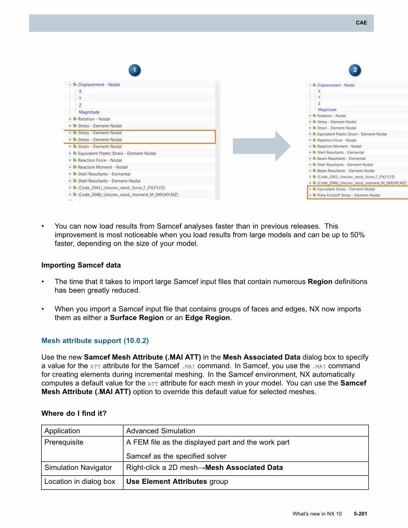
CAE
• You can now load results from Samcef analyses faster than in previous releases. Thisimprovement is most noticeable when you load results from large models and can be up to 50%faster, depending on the size of your model.
Importing Samcef data
• The time that it takes to import large Samcef input files that contain numerous Region definitionshas been greatly reduced.
• When you import a Samcef input file that contains groups of faces and edges, NX now importsthem as either a Surface Region or an Edge Region.
Mesh attribute support (10.0.2)
Use the new Samcef Mesh Attribute (.MAI ATT) in the Mesh Associated Data dialog box to specifya value for the ATT attribute for the Samcef .MAI command. In Samcef, you use the .MAI commandfor creating elements during incremental meshing. In the Samcef environment, NX automaticallycomputes a default value for the ATT attribute for each mesh in your model. You can use the SamcefMesh Attribute (.MAI ATT) option to override this default value for selected meshes.
Where do I find it?
Application Advanced SimulationPrerequisite A FEM file as the displayed part and the work part
Samcef as the specified solverSimulation Navigator Right-click a 2D mesh→Mesh Associated Data
Location in dialog box Use Element Attributes group
What's new in NX 10 5-201
CAE
Chapter 5: CAE
NX Thermal and Flow, Electronic Systems Cooling, and Space Systems Thermalenhancements
General capabilities
Solution Monitor enhancements
What is it?
• The Solution Monitor is now used by the NX Multiphysics and NX Nastran solvers.
• The Solution Monitor now displays text output for each solver on a separate tab when you run acoupled NX Multiphysics analysis.
o The NX Multiphysics tab displays the text output for the coupled solver.
o The NX Thermal tab displays the text output for the thermal solver.
o The NX Nastran tab displays the text output for the NX Nastran solver.
• You can copy and paste the displayed text output. In previous versions, the displayed text outputwas not selectable.
• The user interface of the Solution Monitor is refreshed and the command names are moreintuitive. The commands now have tooltips describing their functionality.
Where do I find it?
Application Advanced Simulation, Design Simulation
Prerequisite
NX Nastran, NX Multiphysics, NX Thermal and Flow, NX Space SystemsThermal, or NX Electronic Systems Cooling as the selected solverenvironment
Command Finder SolveSimulation Navigator Right-click a solution node→Solve
Expression and 4D field support for boundary conditions
What is it?
The thermal solver supports expressions and 4D fields defined on boundary conditions. Theexpressions can contain variables, fields, and functions that the thermal solver can evaluate at solvetime. See Expressions for more information.
The flow solver supports only 4D fields that are defined on boundary conditions.
You can now define the magnitude of certain boundary conditions as a function of both space andanother independent variable. For example, you can define a total conductance in the ThermalCoupling simulation object to vary in space and with temperature.
A 4D field is either a heterogeneous table or a table of fields. A heterogeneous table is one wherethe dependent variable is a function of both space and a non-spatial quantity, for example, time. A
5-202 What's new in NX 10
Chapter 5: CAE
CAE
table of fields is constructed by defining a distinct spatial field for each value of the independentnon-spatial variable.
Why should I use it?
This enhancement provides the ability to:
• Use solver-evaluated quantities when you define thermal boundary conditions. You can alsodefine interdependencies between boundary conditions, for example, when you want to definethe outlet temperature of one Thermal Stream load as the input temperature of another.
• Define boundary conditions that vary both in space and time simultaneously. Previously, themagnitude could vary spatially and the spatially-varying magnitude was scaled as a function oftime. Now, at each node, your magnitude can vary in time independently of other nodes.
Aligning source and target models for mapping
What is it?
The mapping solver now can automatically align source and target models if both models havethe following three named points defined: MAP1, MAP2, and MAP3. The three points in eachmodel must correspond to each other. Before it maps quantities, the mapping solver automaticallytransforms the source model to line up the mapping points with those in the target model.
Supported solvers and analysis types
Solver Analysis Type Solution TypeNX Electronic Systems Cooling Mapping Thermal-FlowNX Space Systems Thermal Mapping Thermal
Mapping Thermal-FlowNX Thermal and FlowAxisymmetric Mapping Thermal
NX Multiphysics Mapping Thermal
Where do I find it?
Application Advanced Simulation
PrerequisiteCorresponding MAP1, MAP2, and MAP3 named points defined in sourceand target models
Command Finder SolveSimulation Navigator Right-click a mapping solution node→Solve
Thermal capabilities
Defining a thermal stream with a radial coordinate system
What is it?
You can define convection caused by radial thermal streams over surfaces. The stream flows radiallyover the surface starting from the origin of the specified cylindrical coordinate system.
What's new in NX 10 5-203
CAE
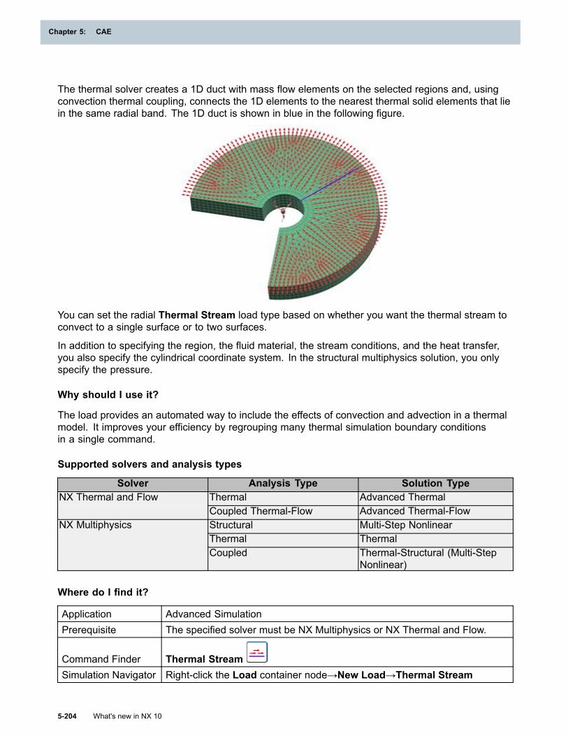
Chapter 5: CAE
The thermal solver creates a 1D duct with mass flow elements on the selected regions and, usingconvection thermal coupling, connects the 1D elements to the nearest thermal solid elements that liein the same radial band. The 1D duct is shown in blue in the following figure.
You can set the radial Thermal Stream load type based on whether you want the thermal stream toconvect to a single surface or to two surfaces.
In addition to specifying the region, the fluid material, the stream conditions, and the heat transfer,you also specify the cylindrical coordinate system. In the structural multiphysics solution, you onlyspecify the pressure.
Why should I use it?
The load provides an automated way to include the effects of convection and advection in a thermalmodel. It improves your efficiency by regrouping many thermal simulation boundary conditionsin a single command.
Supported solvers and analysis types
Solver Analysis Type Solution TypeThermal Advanced ThermalNX Thermal and FlowCoupled Thermal-Flow Advanced Thermal-FlowStructural Multi-Step NonlinearThermal Thermal
NX Multiphysics
Coupled Thermal-Structural (Multi-StepNonlinear)
Where do I find it?
Application Advanced SimulationPrerequisite The specified solver must be NX Multiphysics or NX Thermal and Flow.
Command Finder Thermal StreamSimulation Navigator Right-click the Load container node→New Load→Thermal Stream
5-204 What's new in NX 10
Chapter 5: CAE
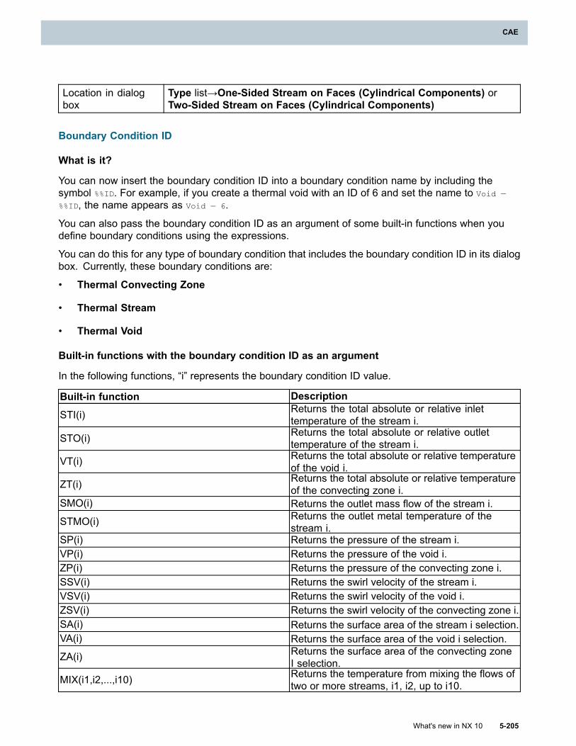
CAE
Location in dialogbox
Type list→One-Sided Stream on Faces (Cylindrical Components) orTwo-Sided Stream on Faces (Cylindrical Components)
Boundary Condition ID
What is it?
You can now insert the boundary condition ID into a boundary condition name by including thesymbol %%ID. For example, if you create a thermal void with an ID of 6 and set the name to Void —
%%ID, the name appears as Void — 6.
You can also pass the boundary condition ID as an argument of some built-in functions when youdefine boundary conditions using the expressions.
You can do this for any type of boundary condition that includes the boundary condition ID in its dialogbox. Currently, these boundary conditions are:
• Thermal Convecting Zone
• Thermal Stream
• Thermal Void
Built-in functions with the boundary condition ID as an argument
In the following functions, “i” represents the boundary condition ID value.
Built-in function Description
STI(i) Returns the total absolute or relative inlettemperature of the stream i.
STO(i) Returns the total absolute or relative outlettemperature of the stream i.
VT(i) Returns the total absolute or relative temperatureof the void i.
ZT(i) Returns the total absolute or relative temperatureof the convecting zone i.
SMO(i) Returns the outlet mass flow of the stream i.
STMO(i) Returns the outlet metal temperature of thestream i.
SP(i) Returns the pressure of the stream i.VP(i) Returns the pressure of the void i.ZP(i) Returns the pressure of the convecting zone i.SSV(i) Returns the swirl velocity of the stream i.VSV(i) Returns the swirl velocity of the void i.ZSV(i) Returns the swirl velocity of the convecting zone i.SA(i) Returns the surface area of the stream i selection.VA(i) Returns the surface area of the void i selection.
ZA(i) Returns the surface area of the convecting zoneI selection.
MIX(i1,i2,...,i10) Returns the temperature from mixing the flows oftwo or more streams, i1, i2, up to i10.
What's new in NX 10 5-205
CAE
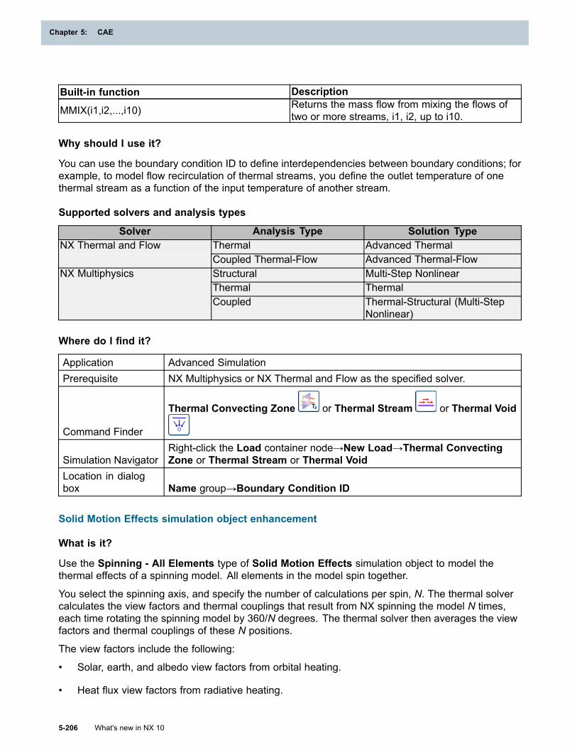
Chapter 5: CAE
Built-in function Description
MMIX(i1,i2,...,i10) Returns the mass flow from mixing the flows oftwo or more streams, i1, i2, up to i10.
Why should I use it?
You can use the boundary condition ID to define interdependencies between boundary conditions; forexample, to model flow recirculation of thermal streams, you define the outlet temperature of onethermal stream as a function of the input temperature of another stream.
Supported solvers and analysis types
Solver Analysis Type Solution TypeThermal Advanced ThermalNX Thermal and FlowCoupled Thermal-Flow Advanced Thermal-FlowStructural Multi-Step NonlinearThermal Thermal
NX Multiphysics
Coupled Thermal-Structural (Multi-StepNonlinear)
Where do I find it?
Application Advanced SimulationPrerequisite NX Multiphysics or NX Thermal and Flow as the specified solver.
Command Finder
Thermal Convecting Zone or Thermal Stream or Thermal Void
Simulation NavigatorRight-click the Load container node→New Load→Thermal ConvectingZone or Thermal Stream or Thermal Void
Location in dialogbox Name group→Boundary Condition ID
Solid Motion Effects simulation object enhancement
What is it?
Use the Spinning - All Elements type of Solid Motion Effects simulation object to model thethermal effects of a spinning model. All elements in the model spin together.
You select the spinning axis, and specify the number of calculations per spin, N. The thermal solvercalculates the view factors and thermal couplings that result from NX spinning the model N times,each time rotating the spinning model by 360/N degrees. The thermal solver then averages the viewfactors and thermal couplings of these N positions.
The view factors include the following:
• Solar, earth, and albedo view factors from orbital heating.
• Heat flux view factors from radiative heating.
5-206 What's new in NX 10
Chapter 5: CAE
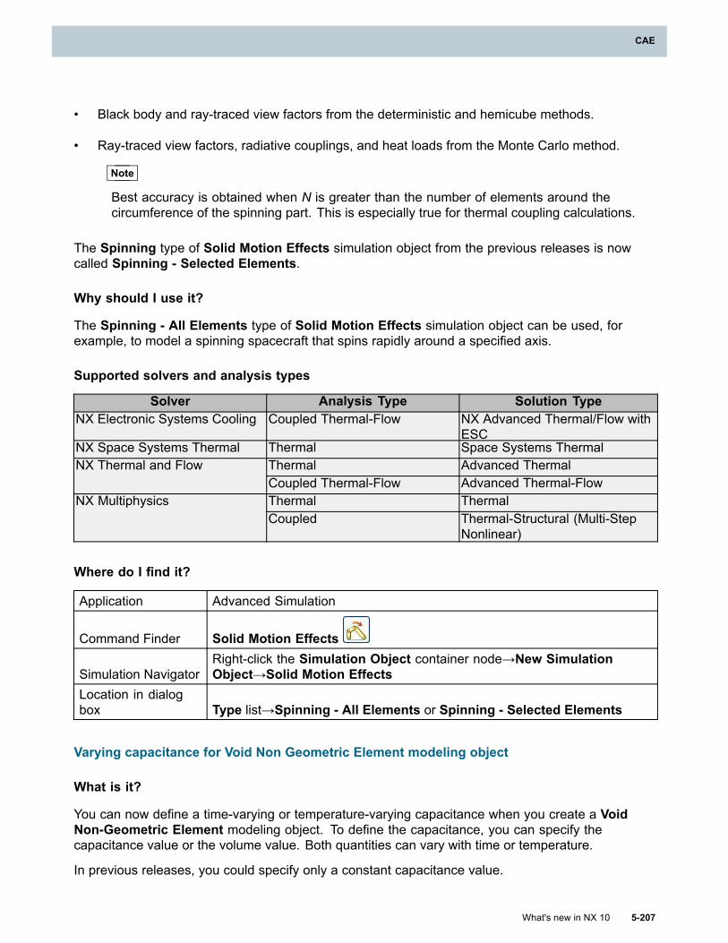
CAE
• Black body and ray-traced view factors from the deterministic and hemicube methods.
• Ray-traced view factors, radiative couplings, and heat loads from the Monte Carlo method.
Note
Best accuracy is obtained when N is greater than the number of elements around thecircumference of the spinning part. This is especially true for thermal coupling calculations.
The Spinning type of Solid Motion Effects simulation object from the previous releases is nowcalled Spinning - Selected Elements.
Why should I use it?
The Spinning - All Elements type of Solid Motion Effects simulation object can be used, forexample, to model a spinning spacecraft that spins rapidly around a specified axis.
Supported solvers and analysis types
Solver Analysis Type Solution TypeNX Electronic Systems Cooling Coupled Thermal-Flow NX Advanced Thermal/Flow with
ESCNX Space Systems Thermal Thermal Space Systems Thermal
Thermal Advanced ThermalNX Thermal and FlowCoupled Thermal-Flow Advanced Thermal-FlowThermal ThermalNX MultiphysicsCoupled Thermal-Structural (Multi-Step
Nonlinear)
Where do I find it?
Application Advanced Simulation
Command Finder Solid Motion Effects
Simulation NavigatorRight-click the Simulation Object container node→New SimulationObject→Solid Motion Effects
Location in dialogbox Type list→Spinning - All Elements or Spinning - Selected Elements
Varying capacitance for Void Non Geometric Element modeling object
What is it?
You can now define a time-varying or temperature-varying capacitance when you create a VoidNon-Geometric Element modeling object. To define the capacitance, you can specify thecapacitance value or the volume value. Both quantities can vary with time or temperature.
In previous releases, you could specify only a constant capacitance value.
What's new in NX 10 5-207
CAE
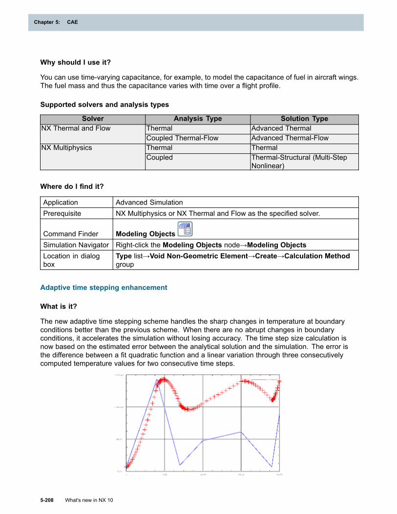
Chapter 5: CAE
Why should I use it?
You can use time-varying capacitance, for example, to model the capacitance of fuel in aircraft wings.The fuel mass and thus the capacitance varies with time over a flight profile.
Supported solvers and analysis types
Solver Analysis Type Solution TypeThermal Advanced ThermalNX Thermal and FlowCoupled Thermal-Flow Advanced Thermal-FlowThermal ThermalNX MultiphysicsCoupled Thermal-Structural (Multi-Step
Nonlinear)
Where do I find it?
Application Advanced SimulationPrerequisite NX Multiphysics or NX Thermal and Flow as the specified solver.
Command Finder Modeling ObjectsSimulation Navigator Right-click the Modeling Objects node→Modeling ObjectsLocation in dialogbox
Type list→Void Non-Geometric Element→Create→Calculation Methodgroup
Adaptive time stepping enhancement
What is it?
The new adaptive time stepping scheme handles the sharp changes in temperature at boundaryconditions better than the previous scheme. When there are no abrupt changes in boundaryconditions, it accelerates the simulation without losing accuracy. The time step size calculation isnow based on the estimated error between the analytical solution and the simulation. The error isthe difference between a fit quadratic function and a linear variation through three consecutivelycomputed temperature values for two consecutive time steps.
5-208 What's new in NX 10
Chapter 5: CAE
CAE
When there are abrupt temperature changes in the model, as seen in the example, the adaptive timestepping scheme adapts by performing smaller time steps around the times when the abrupt changesoccur. The blue curve represents the time-varying heat load that is applied to the boundary conditionand each red + represents the temperature value at one point of the boundary condition for thetransient run. The +’s that are close to each other indicate that the time steps are smaller at thosetimes to better capture the changes in the heat load.
You specify the temperature error tolerance, the minimum time step size, and the maximum timestep size.
Supported solvers and analysis types
Solver Analysis Type Solution TypeNX Space Systems Thermal Thermal Space Systems Thermal
Thermal Thermal
Advanced Thermal
NX Thermal and Flow
Axisymmetric Thermal Axisymmetric Thermal
Advanced Axisymmetric Thermal
Where do I find it?
Application Advanced Simulation
Command Finder SolutionSimulation Navigator Right-click a solution node→EditLocation in dialogbox
Transient Setup node→Time Integration Control group→Time StepOption list→Automatic
Local temperature error estimate result sets
What is it?
You can now recover local temperature error estimate results. The thermal solver generatestemperature error estimate results which estimate the local spatial discretization errors due to themesh used for the simulation of conduction.
After you solve the model, the following result types appear under the solution node in the PostProcessing Navigator:
• Temperature Error Estimates - Nodal
• Temperature Error Estimates - Elemental
• Time of Maximum Error Estimates - Nodal
• Time of Maximum Error Estimates - Elemental
• Maximum Temp Error Estimates - Nodal
• Maximum Temp Error Estimates - Elemental
What's new in NX 10 5-209
CAE
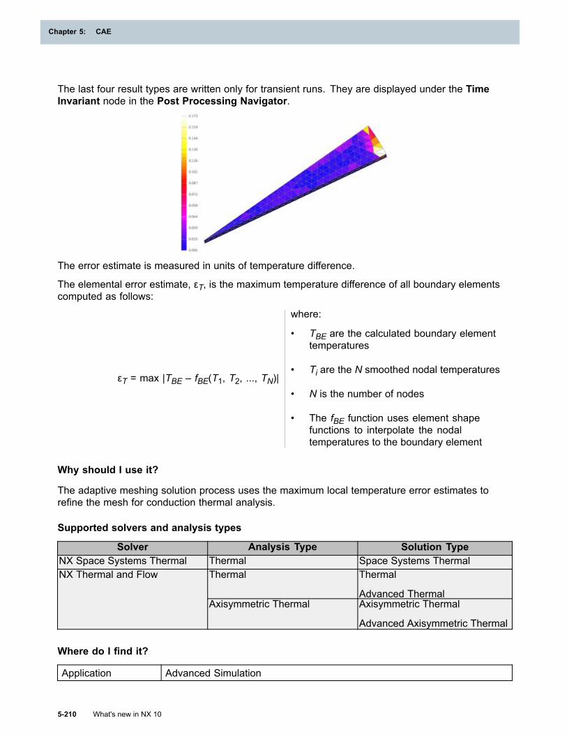
Chapter 5: CAE
The last four result types are written only for transient runs. They are displayed under the TimeInvariant node in the Post Processing Navigator.
The error estimate is measured in units of temperature difference.
The elemental error estimate, εT, is the maximum temperature difference of all boundary elementscomputed as follows:
εT = max |TBE – fBE(T1, T2, ..., TN)|
where:
• TBE are the calculated boundary elementtemperatures
• Ti are the N smoothed nodal temperatures
• N is the number of nodes
• The fBE function uses element shapefunctions to interpolate the nodaltemperatures to the boundary element
Why should I use it?
The adaptive meshing solution process uses the maximum local temperature error estimates torefine the mesh for conduction thermal analysis.
Supported solvers and analysis types
Solver Analysis Type Solution TypeNX Space Systems Thermal Thermal Space Systems Thermal
Thermal Thermal
Advanced Thermal
NX Thermal and Flow
Axisymmetric Thermal Axisymmetric Thermal
Advanced Axisymmetric Thermal
Where do I find it?
Application Advanced Simulation
5-210 What's new in NX 10
Chapter 5: CAE
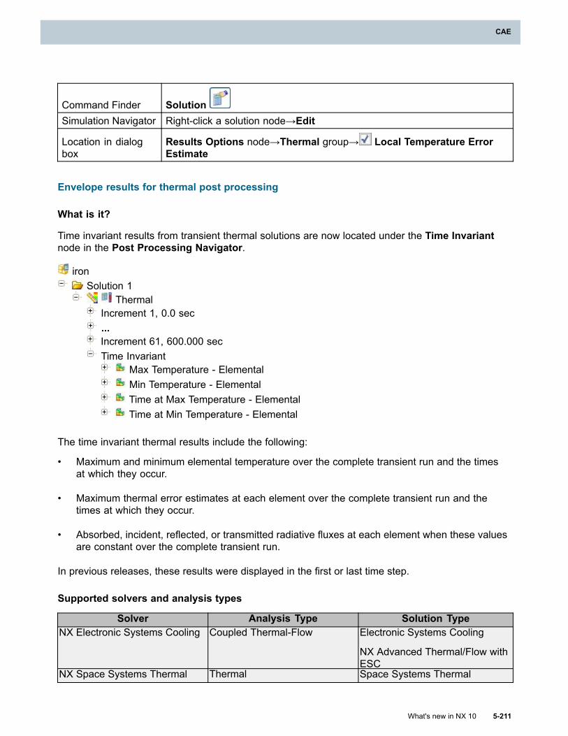
CAE
Command Finder SolutionSimulation Navigator Right-click a solution node→Edit
Location in dialogbox
Results Options node→Thermal group→ Local Temperature ErrorEstimate
Envelope results for thermal post processing
What is it?
Time invariant results from transient thermal solutions are now located under the Time Invariantnode in the Post Processing Navigator.
ironSolution 1
ThermalIncrement 1, 0.0 sec...Increment 61, 600.000 secTime Invariant
Max Temperature - ElementalMin Temperature - ElementalTime at Max Temperature - ElementalTime at Min Temperature - Elemental
The time invariant thermal results include the following:
• Maximum and minimum elemental temperature over the complete transient run and the timesat which they occur.
• Maximum thermal error estimates at each element over the complete transient run and thetimes at which they occur.
• Absorbed, incident, reflected, or transmitted radiative fluxes at each element when these valuesare constant over the complete transient run.
In previous releases, these results were displayed in the first or last time step.
Supported solvers and analysis types
Solver Analysis Type Solution TypeNX Electronic Systems Cooling Coupled Thermal-Flow Electronic Systems Cooling
NX Advanced Thermal/Flow withESC
NX Space Systems Thermal Thermal Space Systems Thermal
What's new in NX 10 5-211
CAE
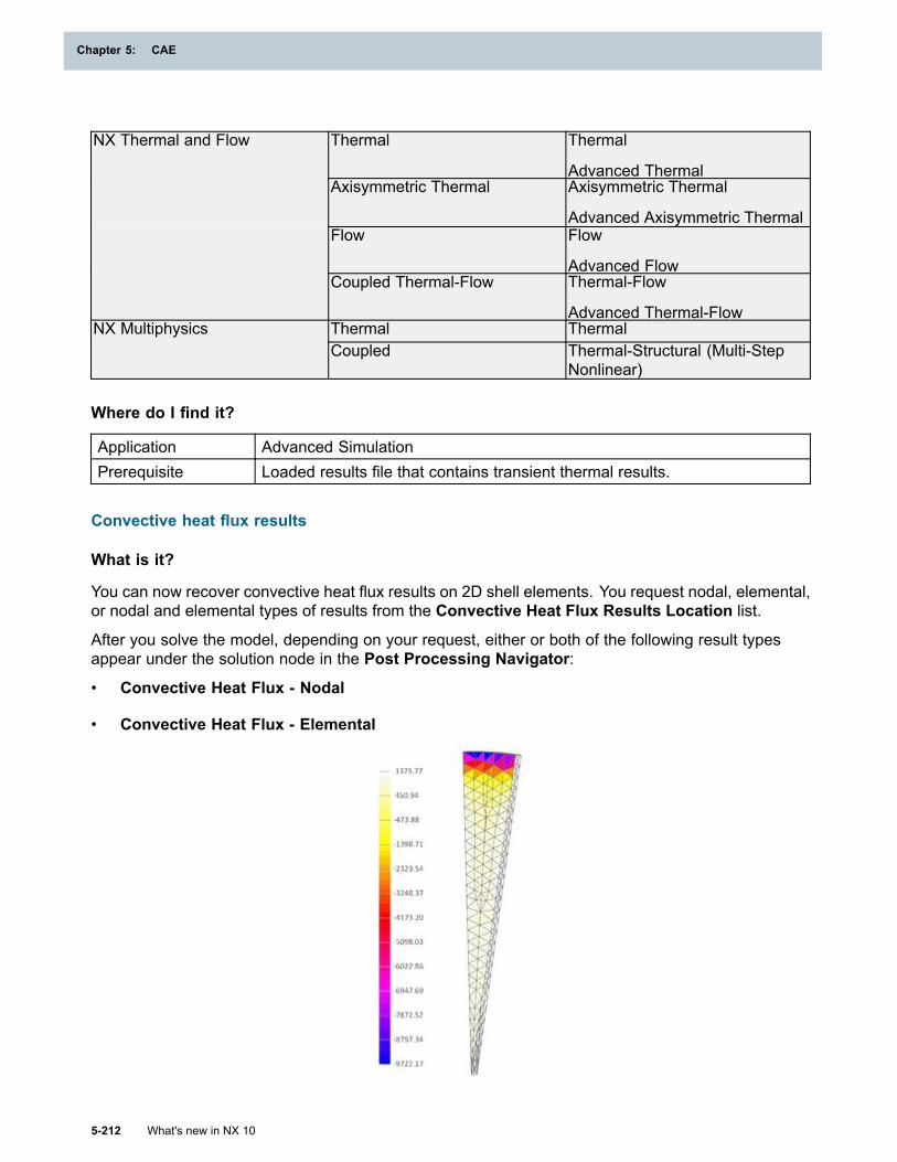
Chapter 5: CAE
Thermal Thermal
Advanced ThermalAxisymmetric Thermal Axisymmetric Thermal
Advanced Axisymmetric ThermalFlow Flow
Advanced Flow
NX Thermal and Flow
Coupled Thermal-Flow Thermal-Flow
Advanced Thermal-FlowThermal ThermalNX MultiphysicsCoupled Thermal-Structural (Multi-Step
Nonlinear)
Where do I find it?
Application Advanced SimulationPrerequisite Loaded results file that contains transient thermal results.
Convective heat flux results
What is it?
You can now recover convective heat flux results on 2D shell elements. You request nodal, elemental,or nodal and elemental types of results from the Convective Heat Flux Results Location list.
After you solve the model, depending on your request, either or both of the following result typesappear under the solution node in the Post Processing Navigator:
• Convective Heat Flux - Nodal
• Convective Heat Flux - Elemental
5-212 What's new in NX 10
Chapter 5: CAE
CAE
Why should I use it?
Convective heat flux results help you analyze the results of your thermal simulation.
Supported solvers and analysis types
Solver Analysis Type Solution TypeNX Electronic Systems Cooling Coupled Thermal-Flow Electronic Systems Cooling
NX Advanced Thermal/Flow withESC
NX Space Systems Thermal Thermal Space Systems ThermalThermal Thermal
Advanced ThermalAxisymmetric Thermal Axisymmetric Thermal
Advanced Axisymmetric Thermal
NX Thermal and Flow
Coupled Thermal-Flow Thermal-Flow
Advanced Thermal-Flow
Where do I find it?
Application Advanced Simulation
Command Finder SolutionSimulation Navigator Right-click a solution node→EditLocation in dialogbox Results Options node→Thermal group→ Convective Heat Fluxes
Swirl velocity results
What is it?
You can now recover swirl velocity results on 2D shell elements or on 1D axisymmetric elements.You request nodal, elemental, or nodal and elemental types of results from the Swirl VelocityResults Location list.
After you solve the model, depending on your request, either or both of the following result typesappear under the solution node in the Post Processing Navigator:
• Swirl Velocity on Walls - Nodal
• Swirl Velocity on Walls - Elemental
What's new in NX 10 5-213
CAE
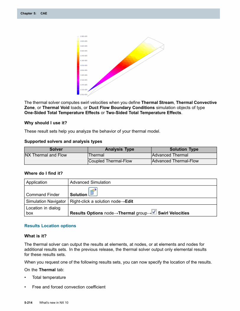
Chapter 5: CAE
The thermal solver computes swirl velocities when you define Thermal Stream, Thermal ConvectiveZone, or Thermal Void loads, or Duct Flow Boundary Conditions simulation objects of typeOne-Sided Total Temperature Effects or Two-Sided Total Temperature Effects.
Why should I use it?
These result sets help you analyze the behavior of your thermal model.
Supported solvers and analysis types
Solver Analysis Type Solution TypeThermal Advanced ThermalNX Thermal and FlowCoupled Thermal-Flow Advanced Thermal-Flow
Where do I find it?
Application Advanced Simulation
Command Finder SolutionSimulation Navigator Right-click a solution node→EditLocation in dialogbox Results Options node→Thermal group→ Swirl Velocities
Results Location options
What is it?
The thermal solver can output the results at elements, at nodes, or at elements and nodes foradditional results sets. In the previous release, the thermal solver output only elemental resultsfor these results sets.
When you request one of the following results sets, you can now specify the location of the results.
On the Thermal tab:
• Total temperature
• Free and forced convection coefficient
5-214 What's new in NX 10
Chapter 5: CAE
CAE
On the 1D Flow tab:
• Velocity
• Swirl velocity
• Pressure
• Density
• Mass flow
• Reynolds number
Supported solvers and analysis types
Solver Analysis Type Solution TypeNX Electronic Systems Cooling Coupled Thermal-Flow Electronic Systems Cooling
NX Advanced Thermal/Flow withESC
NX Space Systems Thermal Thermal Space Systems ThermalThermal Thermal
Advanced ThermalAxisymmetric Thermal Axisymmetric Thermal
Advanced Axisymmetric Thermal
NX Thermal and Flow
Coupled Thermal-Flow Thermal-Flow
Advanced Thermal-Flow
Where do I find it?
Application Advanced Simulation
Command Finder SolutionSimulation Navigator Right-click a solution node→EditLocation in dialogbox Results Options node→Thermal group or 1D Flow group
Heat transfer coefficient magnitude for edge interface resistance
What is it?
You can now specify the heat transfer coefficient for an Interface Resistance simulation object oftype Edge Interface.
The resistance is calculated as:
1/(heat transfer coefficient x area)
At an edge interface, the area is calculated as follows:
What's new in NX 10 5-215
CAE
Chapter 5: CAE
area = (the length of the edge) x (the minimum shell thickness)
Why should I use it?
This improvement lets you define the resistance magnitude at an edge interface by specifying theheat transfer coefficient, which is a value that is often available in handbooks.
Supported solvers and analysis types
Solver Analysis Type Solution TypeNX Electronic Systems Cooling Coupled Thermal-Flow Electronic Systems Cooling
NX Advanced Thermal/Flow withESC
NX Space Systems Thermal Thermal Space Systems ThermalThermal Thermal
Advanced Thermal
NX Thermal and Flow
Coupled Thermal-Flow Thermal-Flow
Advanced Thermal-FlowThermal ThermalNX MultiphysicsCoupled Thermal-Structural (Multi-Step
Nonlinear)
Where do I find it?
Application Advanced Simulation
Command Finder Interface Resistance
Simulation NavigatorRight-click the Simulation Objects node→New SimulationObject→Interface Resistance
Location in dialogbox
Type list→Edge Interface→Magnitude group→Type list→Heat TransferCoefficient
Multiple Fluid material
What is it?
The new Multiple Fluid material type lets you define a primary fluid material and up to five additionalfluid materials.
The thermal solver uses the specified primary fluid material properties during computation. Theadditional fluid material number can be passed as an argument to some CAE functions, such as fluidplug-ins, and also to user-defined functions. See User-defined functions for expressions for moreinformation on plug-in functions.
You define the Multiple Fluid material type in the following loads and modeling object:
• Thermal Convecting Zone load
• Thermal Stream load
5-216 What's new in NX 10
Chapter 5: CAE
CAE
• Void Non-Geometric Element modeling object
Supported solvers and analysis types
Solver Analysis Type Solution TypeThermal Advanced ThermalNX Thermal and FlowCoupled Thermal-Flow Advanced Thermal-FlowThermal ThermalNX MultiphysicsCoupled Thermal-Structural (Multi-Step
Nonlinear)
Where do I find it?
Application Advanced SimulationPrerequisite NX Multiphysics or NX Thermal and Flow as the specified solver.
Defining the multiple fluid material
Command Finder Manage MaterialsLocation in dialogbox Type list→Multiple Fluid→ Create
Specifying the multiple fluid material in loads
Command Finder Thermal Convecting Zone or Thermal Stream
Simulation NavigatorRight-click the Load container node→New Load→Thermal ConvectingZone or Thermal Stream
Location in dialogbox Fluid Materials list
Specifying the multiple fluid material in the modeling object
Command Finder Modeling ObjectsSimulation Navigator Right-click the Modeling Objects node→Modeling ObjectsLocation in dialogbox
Type list→Void Non-Geometric Element→Create→Environmentgroup→Fluid Materials list
PCB Component and Printed Circuit Board simulation object support
What is it?
In NX Space Systems Thermal solver environment, you can create:
• Printed Circuit Board and PCB Component simulation objects.
What's new in NX 10 5-217
CAE
Chapter 5: CAE
• A PCB Stack physical property along with the PCB Layer and PCB Via modeling objects.
Why should I use it?
These new features let you easily define the thermal resistor models for printed circuit boards (PCBs)and electronic components in spacecraft applications.
Supported solvers and analysis types
Solver Analysis Type Solution TypeNX Electronic Systems Cooling Coupled Thermal-Flow Electronic Systems Cooling
NX Advanced Thermal/Flow withESC
NX Space Systems Thermal Thermal Space Systems Thermal
Where do I find it?
Simulation objects
Application Advanced Simulation
Command Finder Printed Circuit Board or PCB Component
Simulation NavigatorRight-click the Simulation Objects node→New SimulationObject→Printed Circuit Board or PCB Component
PCB Stack physical property
Application Advanced Simulation
Command Finder Physical PropertiesMenu Insert→Physical PropertiesLocation in dialogbox Type→PCB Stack→Create
Orbit Visualizer enhancements
What is it?
The Orbit Visualizer now does the following:
• Keeps the spacecraft in view when you zoom, pan, or rotate the model.
• Lets you keep either the spacecraft or the planet in the center of the view with the new Lookat view option.
• Displays elements of each mesh of the spacecraft model in a random and different color.
• Lets you make the element edges visible or invisible with the new Element Edges display option.
5-218 What's new in NX 10
Chapter 5: CAE
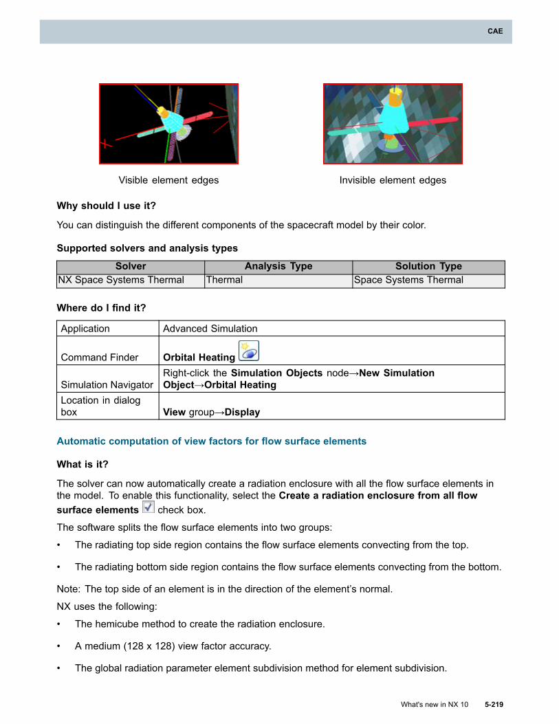
CAE
Visible element edges Invisible element edges
Why should I use it?
You can distinguish the different components of the spacecraft model by their color.
Supported solvers and analysis types
Solver Analysis Type Solution TypeNX Space Systems Thermal Thermal Space Systems Thermal
Where do I find it?
Application Advanced Simulation
Command Finder Orbital Heating
Simulation NavigatorRight-click the Simulation Objects node→New SimulationObject→Orbital Heating
Location in dialogbox View group→Display
Automatic computation of view factors for flow surface elements
What is it?
The solver can now automatically create a radiation enclosure with all the flow surface elements inthe model. To enable this functionality, select the Create a radiation enclosure from all flowsurface elements check box.
The software splits the flow surface elements into two groups:
• The radiating top side region contains the flow surface elements convecting from the top.
• The radiating bottom side region contains the flow surface elements convecting from the bottom.
Note: The top side of an element is in the direction of the element’s normal.
NX uses the following:
• The hemicube method to create the radiation enclosure.
• A medium (128 x 128) view factor accuracy.
• The global radiation parameter element subdivision method for element subdivision.
What's new in NX 10 5-219
CAE
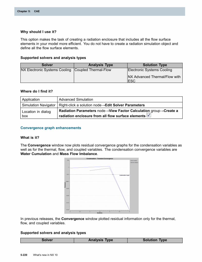
Chapter 5: CAE
Why should I use it?
This option makes the task of creating a radiation enclosure that includes all the flow surfaceelements in your model more efficient. You do not have to create a radiation simulation object anddefine all the flow surface elements.
Supported solvers and analysis types
Solver Analysis Type Solution TypeNX Electronic Systems Cooling Coupled Thermal-Flow Electronic Systems Cooling
NX Advanced Thermal/Flow withESC
Where do I find it?
Application Advanced SimulationSimulation Navigator Right-click a solution node→Edit Solver Parameters
Location in dialogbox
Radiation Parameters node→View Factor Calculation group→Create aradiation enclosure from all flow surface elements
Convergence graph enhancements
What is it?
The Convergence window now plots residual convergence graphs for the condensation variables aswell as for the thermal, flow, and coupled variables. The condensation convergence variables areWater Cumulation and Mass Flow Imbalance.
In previous releases, the Convergence window plotted residual information only for the thermal,flow, and coupled variables.
Supported solvers and analysis types
Solver Analysis Type Solution Type
5-220 What's new in NX 10
Chapter 5: CAE
CAE
Thermal Thermal
Advanced Thermal
NX Thermal and Flow
Coupled Thermal-Flow Thermal-Flow
Advanced Thermal-Flow
Where do I find it?
Application Advanced SimulationPrerequisite An open simulation file
Command Finder SolveSimulation Navigator Right-click the Solution node→SolveLocation in dialogbox Solution Monitor dialog box→Graph→Convergence
Ignoring radiative environment in radiation modeling
What is it?
When you define a radiative ambient and set a radiative environment temperature, and clear theInclude Radiative Environment check box in the Radiation dialog box, the solver now ignoresany radiative exchange between the enclosure parts and the environment.
In the previous release, the solver automatically modeled radiative exchange between any part of theenclosure and the environment even if you cleared this check box.
Why should I use it?
Although you may have modeled the radiative environment in the enclosure, you can now excludethe environment in radiation modeling.
Supported solvers and analysis types
Solver Analysis Type Solution TypeNX Electronic Systems Cooling Coupled Thermal-Flow Electronic Systems Cooling
NX Advanced Thermal/Flow withESC
NX Space Systems Thermal Thermal Space Systems ThermalThermal Thermal
Advanced Thermal
NX Thermal and Flow
Coupled Thermal-Flow Thermal-Flow
Advanced Thermal-FlowThermal ThermalNX MultiphysicsCoupled Thermal-Structural (Multi-Step
Nonlinear)
What's new in NX 10 5-221
CAE
Chapter 5: CAE
Where do I find it?
Application Advanced Simulation
Command Finder RadiationSimulation Navigator Right-click Simulation Objects→New Simulation Object→RadiationLocation in dialogbox Parameters group→Include Radiative Environment
Flow capabilities
Parallel flow solver enhancements
What is it?
The parallel flow solver now supports the following:
• Homogeneous gas mixture and tracer fluids
• High speed flows (fully coupled pressure-velocity parallel flow solver scheme)
• Shear stress transport (SST) and K-omega turbulence models
• Non-Newtonian fluids
You can also restart from a previous solution, and run the parallel flow solver using just one process.
Supported solvers and analysis types
Solver Analysis Type Solution TypeNX Electronic Systems Cooling Coupled Thermal-Flow Electronic Systems Cooling
NX Advanced Thermal/Flow withESC
Flow Flow
Advanced Flow
NX Thermal and Flow
Coupled Thermal-Flow Thermal-Flow
Advanced Thermal-Flow
Where do I find it?
Application Advanced Simulation
Command Finder SolutionSimulation Navigator Right-click a solution node→EditLocation in dialogbox Solution Details node→Flow Solver Selection list→Parallel Solver
5-222 What's new in NX 10
Chapter 5: CAE
CAE
Two-phase, immiscible fluid simulation enhancements
What is it?
You can now do the following:
• Solve two-phase, immiscible fluid simulations in coupled thermal-flow analyses.
• Simulate fluid flow problems for a mixture of any two immiscible fluid constituents.
• Simulate open volume enclosures.
• Specify the surface tension.
• Specify the tracked fluid area fraction of the mixture at ambient condition.
Immiscible fluid mixture
In previous versions, the fluid constituents were limited to a liquid and a gas. Now, you can alsospecify two liquids or two gases, as long as the two fluids are immiscible.
In the Immiscible Fluid Mixture modeling object, you define one fluid as the tracked fluid andthe other as the complementary fluid.
You also specify the surface tension between the tracked fluid and the complementary fluid.
When you post process the results, a volume fraction value close to one indicates that the mixtureis mostly composed of the tracked fluid whereas a value close to zero indicates that the mixture ismostly composed of the complementary fluid.
Open volume enclosures
To simulate an open volume enclosure, you specify the tracked fluid area fraction of the mixturethat enters the enclosure in the following ways:
• Specify it locally, for each inflow boundary condition, when you specify the Inlet Flow type, theOpening type, or the Static Pressure type of Flow Boundary Condition simulation object.
• Specify it globally, for all inflow boundary conditions, in the Ambient Conditions node of theSolution dialog box.
The mixture leaves the enclosure on faces where you specify the Outlet Flow type, the Openingtype, the Convective Outflow type, or the Static Pressure type of Flow Boundary Conditionsimulation object. The flow solver computes the tracked fluid area fraction for the mixture thatleaves the enclosure.
In previous versions, the two-phase, immiscible fluid mixture was restricted to a closed containersuch that the volume of the mixture was constant.
Additional text changes
The following option names have changed to support the enhanced functionality.
What's new in NX 10 5-223
CAE
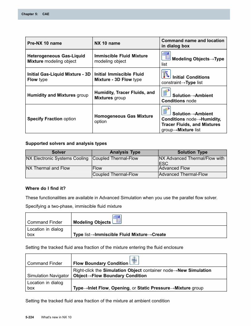
Chapter 5: CAE
Pre-NX 10 name NX 10 name Command name and locationin dialog box
Heterogeneous Gas-LiquidMixture modeling object
Immiscible Fluid Mixturemodeling object Modeling Objects→Type
list
Initial Gas-Liquid Mixture - 3DFlow type
Initial Immiscible FluidMixture - 3D Flow type Initial Conditions
constraint→Type list
Humidity and Mixtures group Humidity, Tracer Fluids, andMixtures group Solution→Ambient
Conditions node
Specify Fraction option Homogeneous Gas Mixtureoption
Solution→AmbientConditions node→Humidity,Tracer Fluids, and Mixturesgroup→Mixture list
Supported solvers and analysis types
Solver Analysis Type Solution TypeNX Electronic Systems Cooling Coupled Thermal-Flow NX Advanced Thermal/Flow with
ESCFlow Advanced FlowNX Thermal and FlowCoupled Thermal-Flow Advanced Thermal-Flow
Where do I find it?
These functionalities are available in Advanced Simulation when you use the parallel flow solver.
Specifying a two-phase, immiscible fluid mixture
Command Finder Modeling ObjectsLocation in dialogbox Type list→Immiscible Fluid Mixture→Create
Setting the tracked fluid area fraction of the mixture entering the fluid enclosure
Command Finder Flow Boundary Condition
Simulation NavigatorRight-click the Simulation Object container node→New SimulationObject→Flow Boundary Condition
Location in dialogbox Type→Inlet Flow, Opening, or Static Pressure→Mixture group
Setting the tracked fluid area fraction of the mixture at ambient condition
5-224 What's new in NX 10
Chapter 5: CAE
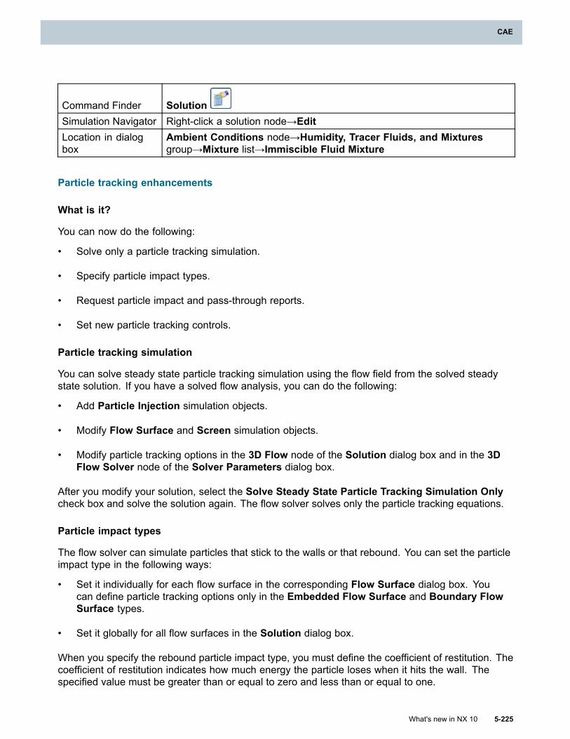
CAE
Command Finder SolutionSimulation Navigator Right-click a solution node→EditLocation in dialogbox
Ambient Conditions node→Humidity, Tracer Fluids, and Mixturesgroup→Mixture list→Immiscible Fluid Mixture
Particle tracking enhancements
What is it?
You can now do the following:
• Solve only a particle tracking simulation.
• Specify particle impact types.
• Request particle impact and pass-through reports.
• Set new particle tracking controls.
Particle tracking simulation
You can solve steady state particle tracking simulation using the flow field from the solved steadystate solution. If you have a solved flow analysis, you can do the following:
• Add Particle Injection simulation objects.
• Modify Flow Surface and Screen simulation objects.
• Modify particle tracking options in the 3D Flow node of the Solution dialog box and in the 3DFlow Solver node of the Solver Parameters dialog box.
After you modify your solution, select the Solve Steady State Particle Tracking Simulation Onlycheck box and solve the solution again. The flow solver solves only the particle tracking equations.
Particle impact types
The flow solver can simulate particles that stick to the walls or that rebound. You can set the particleimpact type in the following ways:
• Set it individually for each flow surface in the corresponding Flow Surface dialog box. Youcan define particle tracking options only in the Embedded Flow Surface and Boundary FlowSurface types.
• Set it globally for all flow surfaces in the Solution dialog box.
When you specify the rebound particle impact type, you must define the coefficient of restitution. Thecoefficient of restitution indicates how much energy the particle loses when it hits the wall. Thespecified value must be greater than or equal to zero and less than or equal to one.
What's new in NX 10 5-225
CAE

Chapter 5: CAE
Particle impact and pass-through reports
You can request a particle impact report in the Flow Surface simulation object and a pass-throughreport in the Screen simulation object. Only the Embedded Flow Surface and Boundary FlowSurface types have this option.
When you request the reports, the flow solver generates theParticleAndImpactTrackingSummary.dat file which contains two tables:
• The Particle Tracking Summary table lists the number of injected and ejected particles in totalfor your model and per boundary condition.
• The Particle Surface Impact and Screen Pass-Through Tracking Report table lists thenumber of particles that impact walls in your model per injection boundary condition and thenumber of particles that pass through screens per injection boundary condition.
The file is generated in the simulation’s run directory.
Optionally, you can output particle impact and pass-through results to the ParaView format. SeeParaView output option.
Particle tracking controls
New options are available in the flow solver parameters for particle tracking simulation.
Steady StateSimulation Timelist
Specifies the particle tracking simulation time. You can match the injectionduration or specify an alternate total time for the particle tracking simulation.The value that you specify must be greater than the injection duration.
Neglect StochasticDrag Terms option
Neglects the Brownian and turbulent diffusivity terms in the particle trackingequations. Usually, you select this check box in conjunction with the UseCunningham Correction Factor check box.
Use CunninghamCorrection Factoroption
Applies the computed Cunningham correction factor to the particle tractionforce estimate. The Cunningham correction factor represents the reductionin the force exerted upon the particle by the flow due to the breakdown ofthe no-slip condition on the particle surface. The no-slip condition is invalidwhen the mean free path of the fluid molecules is of the same order as theparticle length scale. This option is valid only for ideal gases. The flow solvercomputes the correction factor using the following constants that you specify:
• Sutherland constant for the viscosity of the gas
• Slip correction reference temperature, pressure, and dynamic viscosity ofthe gas
In addition, the following table lists the name changes in the 3D Flow Solver node of the SolverParameters dialog box.
Pre-NX 10 name NX 10 nameSteady State Particle Controls group Particle Tracking Controls groupInjection Duration box Steady State Injection Duration boxOutput Option list Steady State Output Option list
5-226 What's new in NX 10
Chapter 5: CAE
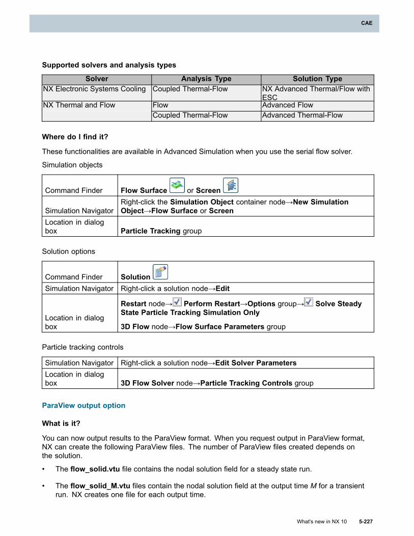
CAE
Supported solvers and analysis types
Solver Analysis Type Solution TypeNX Electronic Systems Cooling Coupled Thermal-Flow NX Advanced Thermal/Flow with
ESCFlow Advanced FlowNX Thermal and FlowCoupled Thermal-Flow Advanced Thermal-Flow
Where do I find it?
These functionalities are available in Advanced Simulation when you use the serial flow solver.
Simulation objects
Command Finder Flow Surface or Screen
Simulation NavigatorRight-click the Simulation Object container node→New SimulationObject→Flow Surface or Screen
Location in dialogbox Particle Tracking group
Solution options
Command Finder SolutionSimulation Navigator Right-click a solution node→Edit
Location in dialogbox
Restart node→ Perform Restart→Options group→ Solve SteadyState Particle Tracking Simulation Only
3D Flow node→Flow Surface Parameters group
Particle tracking controls
Simulation Navigator Right-click a solution node→Edit Solver ParametersLocation in dialogbox 3D Flow Solver node→Particle Tracking Controls group
ParaView output option
What is it?
You can now output results to the ParaView format. When you request output in ParaView format,NX can create the following ParaView files. The number of ParaView files created depends onthe solution.
• The flow_solid.vtu file contains the nodal solution field for a steady state run.
• The flow_solid_M.vtu files contain the nodal solution field at the output time M for a transientrun. NX creates one file for each output time.
What's new in NX 10 5-227
CAE
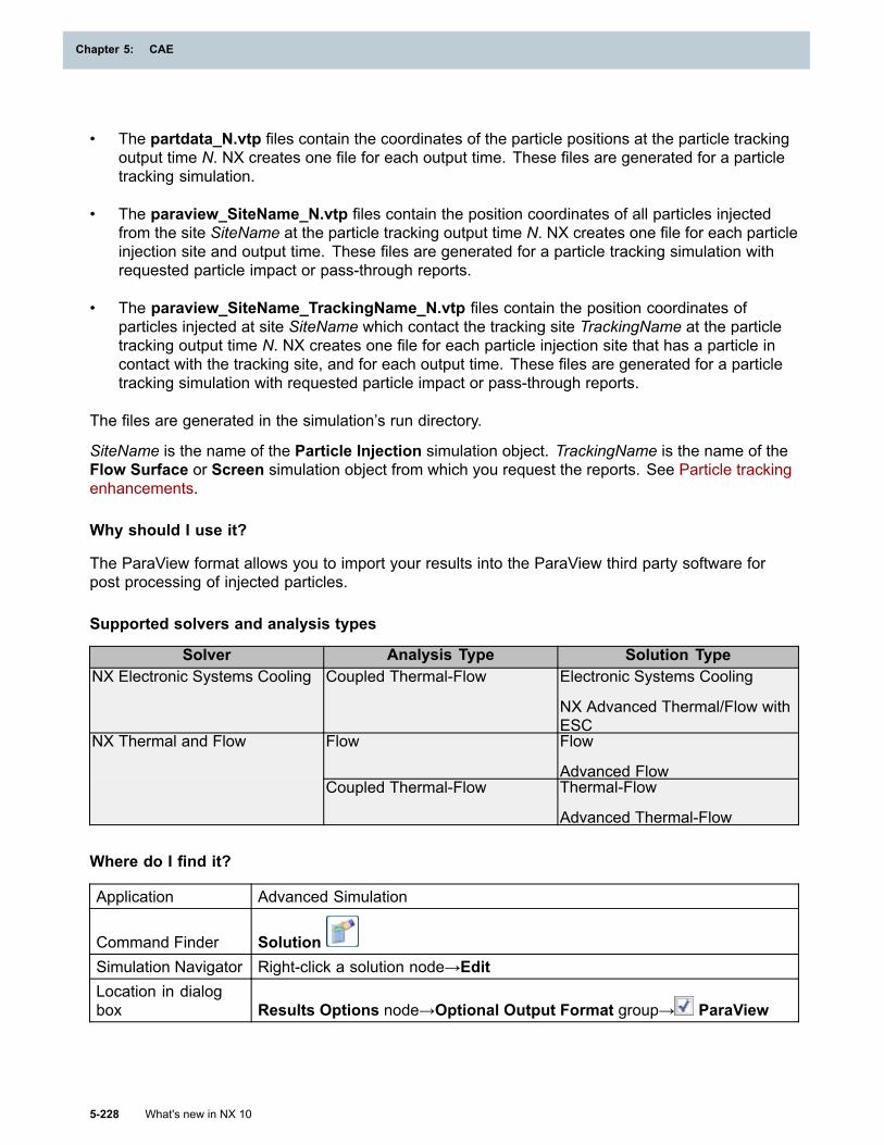
Chapter 5: CAE
• The partdata_N.vtp files contain the coordinates of the particle positions at the particle trackingoutput time N. NX creates one file for each output time. These files are generated for a particletracking simulation.
• The paraview_SiteName_N.vtp files contain the position coordinates of all particles injectedfrom the site SiteName at the particle tracking output time N. NX creates one file for each particleinjection site and output time. These files are generated for a particle tracking simulation withrequested particle impact or pass-through reports.
• The paraview_SiteName_TrackingName_N.vtp files contain the position coordinates ofparticles injected at site SiteName which contact the tracking site TrackingName at the particletracking output time N. NX creates one file for each particle injection site that has a particle incontact with the tracking site, and for each output time. These files are generated for a particletracking simulation with requested particle impact or pass-through reports.
The files are generated in the simulation’s run directory.
SiteName is the name of the Particle Injection simulation object. TrackingName is the name of theFlow Surface or Screen simulation object from which you request the reports. See Particle trackingenhancements.
Why should I use it?
The ParaView format allows you to import your results into the ParaView third party software forpost processing of injected particles.
Supported solvers and analysis types
Solver Analysis Type Solution TypeNX Electronic Systems Cooling Coupled Thermal-Flow Electronic Systems Cooling
NX Advanced Thermal/Flow withESC
Flow Flow
Advanced Flow
NX Thermal and Flow
Coupled Thermal-Flow Thermal-Flow
Advanced Thermal-Flow
Where do I find it?
Application Advanced Simulation
Command Finder SolutionSimulation Navigator Right-click a solution node→EditLocation in dialogbox Results Options node→Optional Output Format group→ ParaView
5-228 What's new in NX 10
Chapter 5: CAE
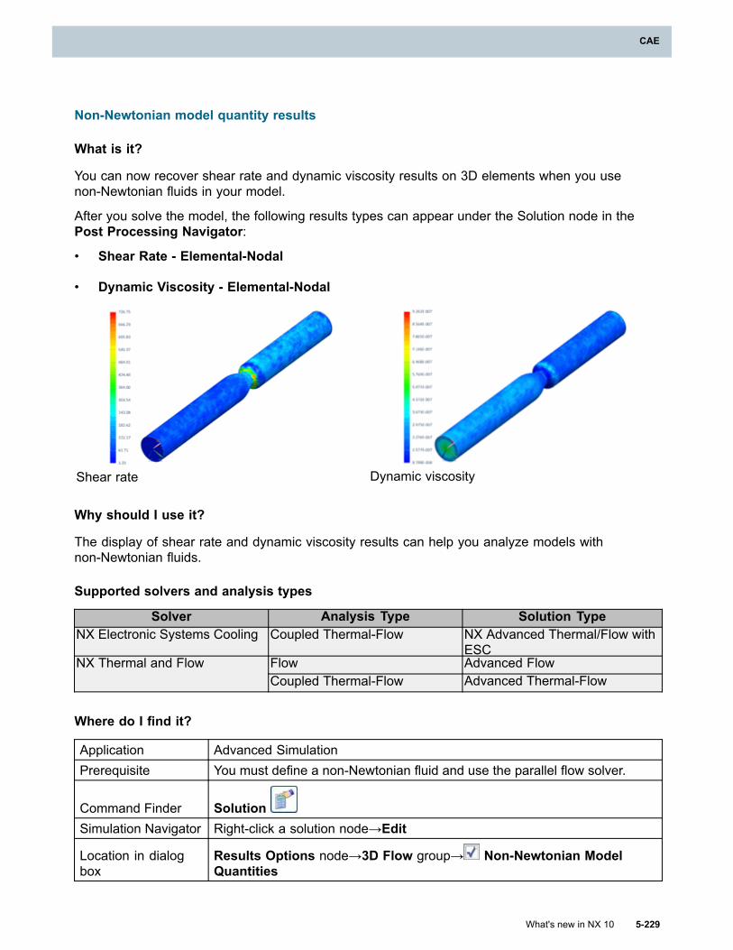
CAE
Non-Newtonian model quantity results
What is it?
You can now recover shear rate and dynamic viscosity results on 3D elements when you usenon-Newtonian fluids in your model.
After you solve the model, the following results types can appear under the Solution node in thePost Processing Navigator:
• Shear Rate - Elemental-Nodal
• Dynamic Viscosity - Elemental-Nodal
Shear rate Dynamic viscosity
Why should I use it?
The display of shear rate and dynamic viscosity results can help you analyze models withnon-Newtonian fluids.
Supported solvers and analysis types
Solver Analysis Type Solution TypeNX Electronic Systems Cooling Coupled Thermal-Flow NX Advanced Thermal/Flow with
ESCFlow Advanced FlowNX Thermal and FlowCoupled Thermal-Flow Advanced Thermal-Flow
Where do I find it?
Application Advanced SimulationPrerequisite You must define a non-Newtonian fluid and use the parallel flow solver.
Command Finder SolutionSimulation Navigator Right-click a solution node→Edit
Location in dialogbox
Results Options node→3D Flow group→ Non-Newtonian ModelQuantities
What's new in NX 10 5-229
CAE
Chapter 5: CAE
Restart option for the parallel flow solver
What is it?
You can now restart a flow or coupled thermal-flow solution that you previously solved using theparallel flow solver. You can restart only those solutions for which you created backup files. Yourequest the creation of backup files from the Create Backup Files list. The following options areavailable.
For Pausedor CompletedSolution
Creates backup files for both steady state and transient solutions when youpause the solution or when the solution finishes.
At SpecifiedNumber ofIterations
Creates a backup file for a steady state solution at every N number ofiterations. N is the value that you specify in the Number of Iterations box.
At ResultsSampling Times
Creates a backup file for a transient solution at each results sampling time.You set the sampling times on the Transient Setup node in the ResultsSampling group.
Never Does not create backup files. You cannot restart solutions if you use this option.
The parallel flow solver backup files are flow.restart and flow.struct. They contain all the necessaryinformation for restarting the simulation from the point at which the backup files were updated. Theinformation they contain includes, but is not limited to, flow field variables, mass flow rates, andgradient vectors. NX creates the files in same run directory that contains all the other flow solutionfiles.
You cannot modify the original mesh of the model for which you want to restart the solution. You canhowever make the following changes to your solution:
• Add or remove boundary condition simulation objects.
• Modify the boundary condition values.
• Modify the time step size, relaxation factors, time integration accuracy, and advanced parameters.
• Change the flow type, for example, from incompressible to high speed flow.
• Change the turbulence model.
• Change the number of processes for a parallel run.
• Add meshed geometry or flow enclosures as long as the original mesh is not altered in anyway,for example, by reordering nodes or elements.
Note
You cannot restart solutions using the parallel flow solver that were solved using the parallelflow solver from previous NX releases or using the serial flow solver.
Why should I use it?
Perform a restart when you want to:
5-230 What's new in NX 10
Chapter 5: CAE
CAE
• Pause, inspect, and if necessary modify your solution before continuing the solve.
• Restart your solution with incremental changes in the boundary conditions.
• Restart a simulation that diverged or crashed previously.
Supported solvers and analysis types
Solver Analysis Type Solution TypeNX Electronic Systems Cooling Coupled Thermal-Flow Electronic Systems Cooling
NX Advanced Thermal/Flow withESC
Flow Flow
Advanced Flow
NX Thermal and Flow
Coupled Thermal-Flow Thermal-Flow
Advanced Thermal-Flow
Where do I find it?
Application Advanced SimulationPrerequisite You must use the parallel flow solver.
Command Finder SolutionSimulation Navigator Right-click a solution node→Edit
Location in dialogbox
(To create backup files) Restart node→Parallel Flow Solver RestartBackup File Options group→Create Backup Files
(To restart from backup files) Restart node→ Perform Restart
CGNS results file options (10.0.1)
What is it?
You can now request transient flow results in the CGNS format to be written in one of the followingways:
• One CGNS results file: The results file contains results from all transient output times.
• Multiple CGNS results files: Each results file contains results from one transient output time.
In previous releases, NX always wrote a single CGNS results file containing results from all transientoutput times.
Why should I use it?
You can now obtain the results from each transient output time in its own CGNS results file. You dothis by requesting multiple CGNS files. You can continue to request a single CGNS file that containsall the results from all transient output times.
What's new in NX 10 5-231
CAE
Chapter 5: CAE
Supported solvers and analysis types
Solver Analysis Type Solution TypeNX Electronic Systems Cooling Coupled Thermal-Flow Electronic Systems Cooling
NX Advanced Thermal/Flow withESC
Flow Flow
Advanced Flow
NX Thermal and Flow
Coupled Thermal-Flow Thermal-Flow
Advanced Thermal-Flow
Where do I find it?
Application Advanced Simulation
Command Finder SolutionSimulation Navigator Right-click a solution node→Edit
Location in dialogbox
Results Options page→Optional Output Format group→CGNS→Transient Results list
NX Laminate Composites
Samcef solver support in NX Laminate Composites
What is it?
You can access most NX Laminate Composites commands and functionality in the Samcef solverenvironment.
All laminate commands are supported except the following:
• Solid Laminate Physical Property
• Ply Materials
Ply IDs in all laminate physical properties and global layups must have unique values. In other solverenvironments, ply IDs in different laminate physical properties can have the same values.
In the Samcef environment, you can create cohesive layers between extruded plies to modeldelamination. See Cohesive layers for more information.
Where do I find it?
Application Advanced Simulation
Prerequisite
A FEM file as the work part and displayed part
Samcef as the specified solver
5-232 What's new in NX 10
Chapter 5: CAE
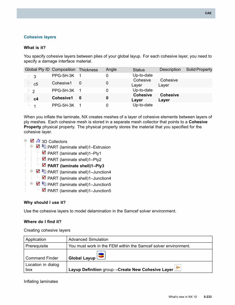
CAE
Cohesive layers
What is it?
You specify cohesive layers between plies of your global layup. For each cohesive layer, you need tospecify a damage interface material.
Global Ply ID Composition Thickness Angle Status Description Solid Property
3 PPG-5H-3K 1 0 Up-to-date
c5 Cohesive1 0 0CohesiveLayer
CohesiveLayer
2 PPG-5H-3K 1 0 Up-to-date
c4 Cohesive1 0 0 CohesiveLayer
CohesiveLayer
1 PPG-5H-3K 1 0 Up-to-date
When you inflate the laminate, NX creates meshes of a layer of cohesive elements between layers ofply meshes. Each cohesive mesh is stored in a separate mesh collector that points to a CohesiveProperty physical property. The physical property stores the material that you specified for thecohesive layer.
3D CollectorsPART (laminate shell)1–ExtrusionPART (laminate shell)1–Ply1PART (laminate shell)1–Ply2PART (laminate shell)1–Ply3PART (laminate shell)1–Junction4PART (laminate shell)1–Junction4PART (laminate shell)1–Junction5PART (laminate shell)1–Junction5
Why should I use it?
Use the cohesive layers to model delamination in the Samcef solver environment.
Where do I find it?
Creating cohesive layers
Application Advanced SimulationPrerequisite You must work in the FEM within the Samcef solver environment.
Command Finder Global LayupLocation in dialogbox Layup Definition group→Create New Cohesive Layer
Inflating laminates
What's new in NX 10 5-233
CAE
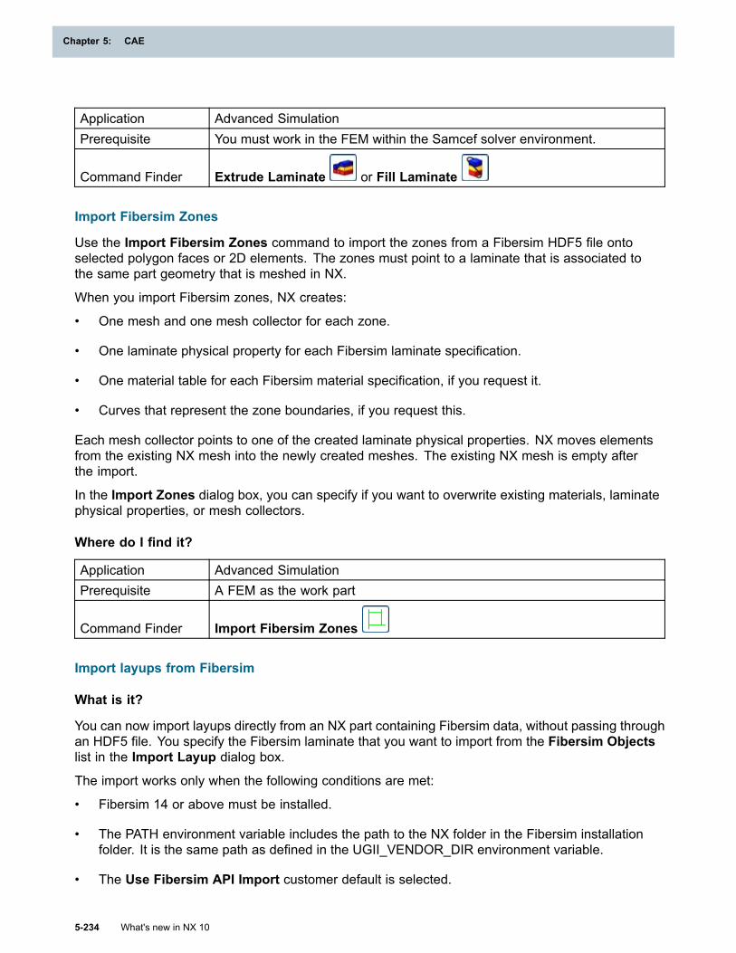
Chapter 5: CAE
Application Advanced SimulationPrerequisite You must work in the FEM within the Samcef solver environment.
Command Finder Extrude Laminate or Fill Laminate
Import Fibersim Zones
Use the Import Fibersim Zones command to import the zones from a Fibersim HDF5 file ontoselected polygon faces or 2D elements. The zones must point to a laminate that is associated tothe same part geometry that is meshed in NX.
When you import Fibersim zones, NX creates:
• One mesh and one mesh collector for each zone.
• One laminate physical property for each Fibersim laminate specification.
• One material table for each Fibersim material specification, if you request it.
• Curves that represent the zone boundaries, if you request this.
Each mesh collector points to one of the created laminate physical properties. NX moves elementsfrom the existing NX mesh into the newly created meshes. The existing NX mesh is empty afterthe import.
In the Import Zones dialog box, you can specify if you want to overwrite existing materials, laminatephysical properties, or mesh collectors.
Where do I find it?
Application Advanced SimulationPrerequisite A FEM as the work part
Command Finder Import Fibersim Zones
Import layups from Fibersim
What is it?
You can now import layups directly from an NX part containing Fibersim data, without passing throughan HDF5 file. You specify the Fibersim laminate that you want to import from the Fibersim Objectslist in the Import Layup dialog box.
The import works only when the following conditions are met:
• Fibersim 14 or above must be installed.
• The PATH environment variable includes the path to the NX folder in the Fibersim installationfolder. It is the same path as defined in the UGII_VENDOR_DIR environment variable.
• The Use Fibersim API Import customer default is selected.
5-234 What's new in NX 10
Chapter 5: CAE
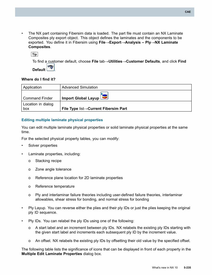
CAE
• The NX part containing Fibersim data is loaded. The part file must contain an NX LaminateComposites ply export object. This object defines the laminates and the components to beexported. You define it in Fibersim using File→Export→Analysis – Ply→NX LaminateComposites.
Tip
To find a customer default, choose File tab→Utilities→Customer Defaults, and click Find
Default .
Where do I find it?
Application Advanced Simulation
Command Finder Import Global LayupLocation in dialogbox File Type list→Current Fibersim Part
Editing multiple laminate physical properties
You can edit multiple laminate physical properties or solid laminate physical properties at the sametime.
For the selected physical property tables, you can modify:
• Solver properties
• Laminate properties, including:
o Stacking recipe
o Zone angle tolerance
o Reference plane location for 2D laminate properties
o Reference temperature
o Ply and interlaminar failure theories including user-defined failure theories, interlaminarallowables, shear stress for bonding, and normal stress for bonding
• Ply Layup. You can reverse either the plies and their ply IDs or just the plies keeping the originalply ID sequence.
• Ply IDs. You can relabel the ply IDs using one of the following:
o A start label and an increment between ply IDs. NX relabels the existing ply IDs starting withthe given start label and increments each subsequent ply ID by the increment value.
o An offset. NX relabels the existing ply IDs by offsetting their old value by the specified offset.
The following table lists the significance of icons that can be displayed in front of each property in theMultiple Edit Laminate Properties dialog box.
What's new in NX 10 5-235
CAE
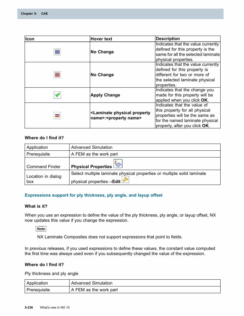
Chapter 5: CAE
Icon Hover text Description
No Change
Indicates that the value currentlydefined for this property is thesame for all the selected laminatephysical properties.
No Change
Indicates that the value currentlydefined for this property isdifferent for two or more ofthe selected laminate physicalproperties.
Apply ChangeIndicates that the change youmade for this property will beapplied when you click OK.
<Laminate physical propertyname>:<property name>
Indicates that the value ofthis property for all physicalproperties will be the same asfor the named laminate physicalproperty, after you click OK.
Where do I find it?
Application Advanced SimulationPrerequisite A FEM as the work part
Command Finder Physical Properties
Location in dialogbox
Select multiple laminate physical properties or multiple solid laminate
physical properties→Edit
Expressions support for ply thickness, ply angle, and layup offset
What is it?
When you use an expression to define the value of the ply thickness, ply angle, or layup offset, NXnow updates this value if you change the expression.
Note
NX Laminate Composites does not support expressions that point to fields.
In previous releases, if you used expressions to define these values, the constant value computedthe first time was always used even if you subsequently changed the value of the expression.
Where do I find it?
Ply thickness and ply angle
Application Advanced SimulationPrerequisite A FEM as the work part
5-236 What's new in NX 10
Chapter 5: CAE
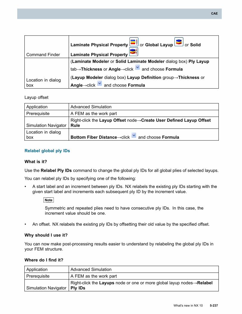
CAE
Command Finder
Laminate Physical Property or Global Layup or Solid
Laminate Physical Property
Location in dialogbox
(Laminate Modeler or Solid Laminate Modeler dialog box) Ply Layup
tab→Thickness or Angle→click and choose Formula
(Layup Modeler dialog box) Layup Definition group→Thickness or
Angle→click and choose Formula
Layup offset
Application Advanced SimulationPrerequisite A FEM as the work part
Simulation NavigatorRight-click the Layup Offset node→Create User Defined Layup OffsetRule
Location in dialogbox Bottom Fiber Distance→click and choose Formula
Relabel global ply IDs
What is it?
Use the Relabel Ply IDs command to change the global ply IDs for all global plies of selected layups.
You can relabel ply IDs by specifying one of the following:
• A start label and an increment between ply IDs. NX relabels the existing ply IDs starting with thegiven start label and increments each subsequent ply ID by the increment value.
Note
Symmetric and repeated plies need to have consecutive ply IDs. In this case, theincrement value should be one.
• An offset. NX relabels the existing ply IDs by offsetting their old value by the specified offset.
Why should I use it?
You can now make post-processing results easier to understand by relabeling the global ply IDs inyour FEM structure.
Where do I find it?
Application Advanced SimulationPrerequisite A FEM as the work part
Simulation NavigatorRight-click the Layups node or one or more global layup nodes→RelabelPly IDs
What's new in NX 10 5-237
CAE
Chapter 5: CAE
Inflated laminates in LS-DYNA (10.0.1)
What is it?
The Extrude Laminate and Fill Laminate commands are now supported in the LS-DYNAenvironment.
The extruded 3D mesh consists of ELEMENT_TSHELL wedge or hexahedral elements and theply drop-offs consist of ELEMENT_SOLID tetrahedral, wedge, or hexahedral elements. BecauseLS_DYNA does not support pyramids, pyramids are split into tetrahedral elements.
For both commands, NX creates a 3D mesh collector that has a Solid Laminate physical propertyassigned to it. NX automatically sets the Stacking Recipe in the Solid Laminate Modeler dialogbox to Inherited from Layup.All the plies of the extruded solid laminate have the same ply failure theory and inter-laminar failuretheory that you selected in the Laminate Modeler dialog box.
Where do I find it?
Application Advanced SimulationPrerequisite You must work in the FEM within the LS-DYNA solver environment.
Command Finder Extrude Laminate or Fill Laminate
New laminate material options for LS-DYNA
What is it?
This release includes new options in the Laminate Modeler and the Solid Laminate Modeler dialogboxes that control how NX exports the laminate material to LS-DYNA.
• Use the new Shell/Solid Formulation option to specify the shell or solid formulation outputformat when you export the laminate to the LS-DYNA solver.
o Select Layered to export the laminate as layered properties.
o Select Homogenous to export the laminate as unlayered, homogeneous properties withequivalent orthotropic materials. With this option, NX computes the equivalent properties of asingle ply. Exporting 3D laminates as homogeneous properties rather than layered propertiesmay shorten the solution time. The homogeneous approach is suitable for balanced andsymmetric laminates
• Use the new NX Orthotropic Materials Mapping option to map the NX orthotropic materialto an appropriate LS-DYNA material type, such as *MAT_ORTHOTROPIC_ELASTIC (MAT_002) or*MAT_COMPOSITE_LAYUP (MAT_116).
Where do I find it?
Application Advanced SimulationPrerequisite A FEM file as the displayed part and work part
LS-DYNA as the specified solver
5-238 What's new in NX 10
Chapter 5: CAE
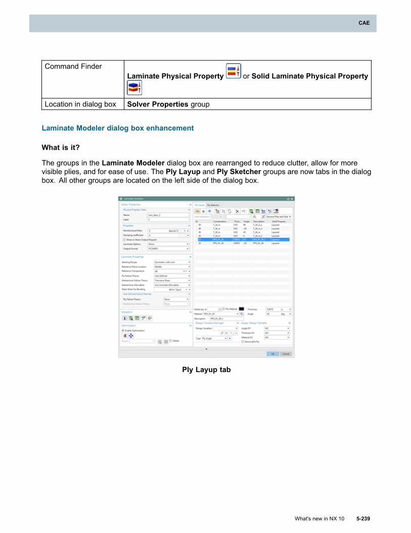
CAE
Command FinderLaminate Physical Property or Solid Laminate Physical Property
Location in dialog box Solver Properties group
Laminate Modeler dialog box enhancement
What is it?
The groups in the Laminate Modeler dialog box are rearranged to reduce clutter, allow for morevisible plies, and for ease of use. The Ply Layup and Ply Sketcher groups are now tabs in the dialogbox. All other groups are located on the left side of the dialog box.
Ply Layup tab
What's new in NX 10 5-239
CAE
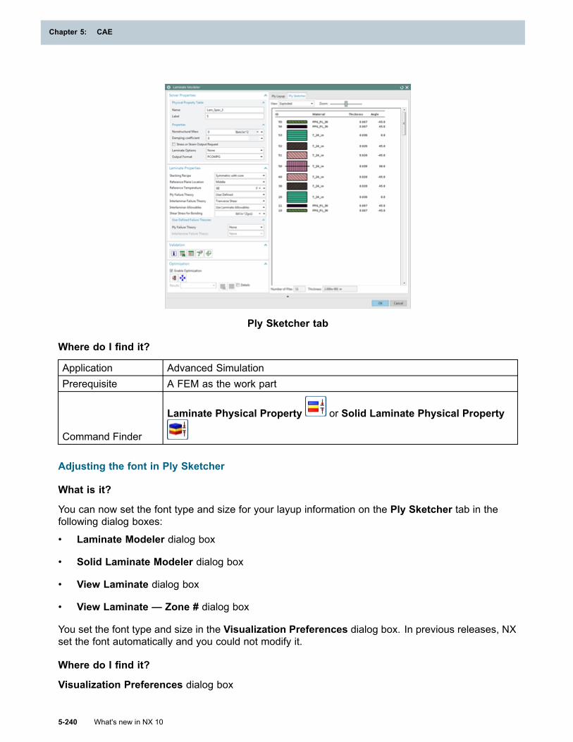
Chapter 5: CAE
Ply Sketcher tab
Where do I find it?
Application Advanced SimulationPrerequisite A FEM as the work part
Command Finder
Laminate Physical Property or Solid Laminate Physical Property
Adjusting the font in Ply Sketcher
What is it?
You can now set the font type and size for your layup information on the Ply Sketcher tab in thefollowing dialog boxes:
• Laminate Modeler dialog box
• Solid Laminate Modeler dialog box
• View Laminate dialog box
• View Laminate — Zone # dialog box
You set the font type and size in the Visualization Preferences dialog box. In previous releases, NXset the font automatically and you could not modify it.
Where do I find it?
Visualization Preferences dialog box
5-240 What's new in NX 10
Chapter 5: CAE
CAE
Application All
Command Finder Visualization PreferencesLocation in dialogbox Color/Font tab
Laminate Modeler dialog box and Solid Laminate Modeler dialog box
Application Advanced SimulationPrerequisite A FEM as the work part
Command Finder
Laminate Physical Property or Solid Laminate Physical Property
View Laminate dialog box and View Laminate — Zone # dialog box
Application Advanced Simulation
Command Finder View LaminateSimulation Navigator (FEM) Right-click the Zones or Zone # node→View Laminate
Element-nodal results in laminate post reporting
What is it?
When the results from the structural solver are element-nodal results, you can now output thelaminate post reporting results as element-nodal results.
In previous versions, NX averaged the element-nodal results for each element before it used themto compute the laminate post reporting results.
Why should I use it?
You can display the results from the laminate post reporting in the same way as you display thestructural results.
Where do I find it?
Application Advanced SimulationPrerequisite Element-nodal structural results
Command Finder Spreadsheet Report or Graphical Report
Simulation NavigatorRight-click the Spreadsheet Report node or the Graphical Reportnode→Edit
Location in dialogbox Options tab→Input Selection group→Element Nodal Results
What's new in NX 10 5-241
CAE
Chapter 5: CAE
Multithreaded draping process
What is it?
To improve the draping performance for the woven and unidirectional solvers, you can enablemultithreading which uses shared-memory parallelization.
Set the number of execution threads using the Number of Execution Threads for Multithreadingcustomer default. Multithreading is enabled when the number of execution threads is greater than one.
Tip
To find a customer default, choose File tab→Utilities→Customer Defaults, and click Find
Default .
Where do I find it?
Application Advanced SimulationPrerequisite A FEM as the work part
Command Finder Update Global Layups and Zones
Simulation NavigatorRight-click the Layups node or one or more layup nodes or one or moreply nodes→Update
Specifying ply directions using a coordinate system
What is it?
When you align fibers for draping, in the Draping Data dialog box, you can now specify a coordinatesystem instead of a vector.
For the unidirectional draping solver, the primary fiber direction is aligned with the X-axis (1).
For the woven draping solver, the primary fiber direction is aligned with the X-axis (1) and thesecondary fiber direction is aligned with the Y-axis (2).
5-242 What's new in NX 10
Chapter 5: CAE
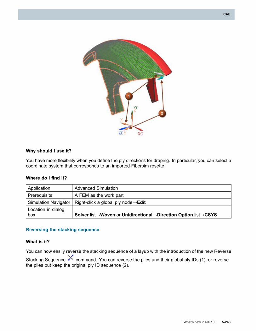
CAE
Why should I use it?
You have more flexibility when you define the ply directions for draping. In particular, you can select acoordinate system that corresponds to an imported Fibersim rosette.
Where do I find it?
Application Advanced SimulationPrerequisite A FEM as the work partSimulation Navigator Right-click a global ply node→EditLocation in dialogbox Solver list→Woven or Unidirectional→Direction Option list→CSYS
Reversing the stacking sequence
What is it?
You can now easily reverse the stacking sequence of a layup with the introduction of the new Reverse
Stacking Sequence command. You can reverse the plies and their global ply IDs (1), or reversethe plies but keep the original ply ID sequence (2).
What's new in NX 10 5-243
CAE
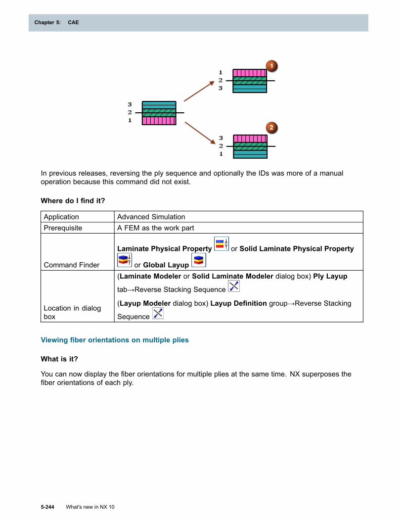
Chapter 5: CAE
In previous releases, reversing the ply sequence and optionally the IDs was more of a manualoperation because this command did not exist.
Where do I find it?
Application Advanced SimulationPrerequisite A FEM as the work part
Command Finder
Laminate Physical Property or Solid Laminate Physical Property
or Global Layup
Location in dialogbox
(Laminate Modeler or Solid Laminate Modeler dialog box) Ply Layup
tab→Reverse Stacking Sequence
(Layup Modeler dialog box) Layup Definition group→Reverse Stacking
Sequence
Viewing fiber orientations on multiple plies
What is it?
You can now display the fiber orientations for multiple plies at the same time. NX superposes thefiber orientations of each ply.
5-244 What's new in NX 10
Chapter 5: CAE
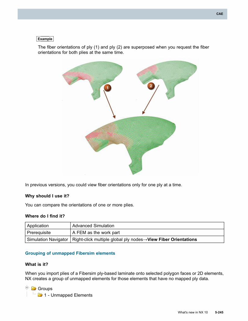
CAE
Example
The fiber orientations of ply (1) and ply (2) are superposed when you request the fiberorientations for both plies at the same time.
In previous versions, you could view fiber orientations only for one ply at a time.
Why should I use it?
You can compare the orientations of one or more plies.
Where do I find it?
Application Advanced SimulationPrerequisite A FEM as the work partSimulation Navigator Right-click multiple global ply nodes→View Fiber Orientations
Grouping of unmapped Fibersim elements
What is it?
When you import plies of a Fibersim ply-based laminate onto selected polygon faces or 2D elements,NX creates a group of unmapped elements for those elements that have no mapped ply data.
Groups1 - Unmapped Elements
What's new in NX 10 5-245
CAE
Chapter 5: CAE
Where do I find it?
Application Advanced Simulation
Command Finder Import Layup
Ply description in the spreadsheet
What is it?
When you export or import a ply layup to or from a spreadsheet application, the ply description isalso exported or imported.
In previous releases, for each ply, only the material name, ply thickness, and ply angle were importedor exported.
Where do I find it?
Application Advanced SimulationPrerequisite A FEM as the work part
Command Finder
Laminate Physical Property or Global Layup or Solid
Laminate Physical Property
Location in dialogbox
(Laminate Modeler or Solid Laminate Modeler dialog box) Ply Layup
tab→Export Layup to Spreadsheet or Import Layup from
Spreadsheet
(Layup Modeler dialog box) Layup Definition group→Export Layup to
Spreadsheet or Import Layup from Spreadsheet
Generating multiple graphical reports
What is it?
You can now generate results from multiple graphical reports at the same time.
In previous releases, you could generate results for only one graphical report at a time.
Why should I use it?
You save time when you want to generate results for multiple graphical reports.
Where do I find it?
Application Advanced SimulationPrerequisite You must select multiple graphical nodes in the Simulation Navigator.Simulation Navigator Right-click multiple graphical report nodes→Generate Result File
5-246 What's new in NX 10
Chapter 5: CAE
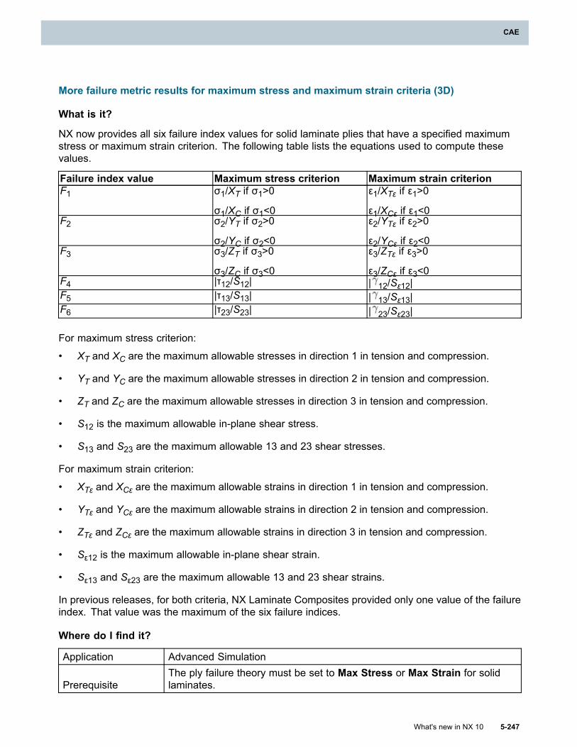
CAE
More failure metric results for maximum stress and maximum strain criteria (3D)
What is it?
NX now provides all six failure index values for solid laminate plies that have a specified maximumstress or maximum strain criterion. The following table lists the equations used to compute thesevalues.
Failure index value Maximum stress criterion Maximum strain criterionF1 σ1/XT if σ1>0
σ1/XC if σ1<0
ε1/XTε if ε1>0
ε1/XCε if ε1<0F2 σ2/YT if σ2>0
σ2/YC if σ2<0
ε2/YTε if ε2>0
ε2/YCε if ε2<0F3 σ3/ZT if σ3>0
σ3/ZC if σ3<0
ε3/ZTε if ε3>0
ε3/ZCε if ε3<0F4 |τ12/S12| | 12/Sε12|F5 |τ13/S13| | 13/Sε13|F6 |τ23/S23| | 23/Sε23|
For maximum stress criterion:
• XT and XC are the maximum allowable stresses in direction 1 in tension and compression.
• YT and YC are the maximum allowable stresses in direction 2 in tension and compression.
• ZT and ZC are the maximum allowable stresses in direction 3 in tension and compression.
• S12 is the maximum allowable in-plane shear stress.
• S13 and S23 are the maximum allowable 13 and 23 shear stresses.
For maximum strain criterion:
• XTε and XCε are the maximum allowable strains in direction 1 in tension and compression.
• YTε and YCε are the maximum allowable strains in direction 2 in tension and compression.
• ZTε and ZCε are the maximum allowable strains in direction 3 in tension and compression.
• Sε12 is the maximum allowable in-plane shear strain.
• Sε13 and Sε23 are the maximum allowable 13 and 23 shear strains.
In previous releases, for both criteria, NX Laminate Composites provided only one value of the failureindex. That value was the maximum of the six failure indices.
Where do I find it?
Application Advanced Simulation
PrerequisiteThe ply failure theory must be set to Max Stress or Max Strain for solidlaminates.
What's new in NX 10 5-247
CAE
Chapter 5: CAE
Command Finder Spreadsheet Report or Graphical Report
Simulation NavigatorRight-click the Spreadsheet Report node or the Graphical Reportnode→Edit
Location in dialogbox
Options tab→Output Control group→ Failure Index or Strength Ratioor Margin of Safety
Durability
Saving geometry in durability results files
What is it?
When you run a durability solution process, NX can now generate the solver results in BUN files,which contain the geometry. To enable this functionality, set the Save Geometry in Results Filescustomer default.
In previous versions, NX generated durability solver results only in BUD files.
BUN files are larger in size than BUD files.
Why should I use it?
NX Post Processing can use either BUD or BUN files to display durability result sets. If you use BUDfiles, you need to load the parent solution result file to display durability result sets.
Because BUN files also contain geometry you can display durability results in NX Post Processingwithout loading the parent solution result file.
Where do I find it?
Application Advanced Simulation
Command Finder Customer DefaultsLocation in dialogbox
Simulation→NX ADVANCED DURABILITY→Solver Parameterstab→Save Geometry in Results Files check box
NX FE Model Correlation
Enhancements to the correlation metric 2D heat map display (10.0.2)
What is it?
The 2D heat map display now shows the following:
• Correlation metric name, date, and time (1).
• Reference and work solution names (2).
• Mode frequency (3).
5-248 What's new in NX 10
Chapter 5: CAE
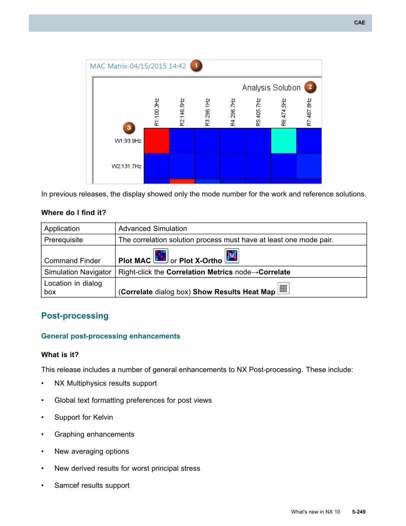
CAE
In previous releases, the display showed only the mode number for the work and reference solutions.
Where do I find it?
Application Advanced SimulationPrerequisite The correlation solution process must have at least one mode pair.
Command Finder Plot MAC or Plot X-OrthoSimulation Navigator Right-click the Correlation Metrics node→CorrelateLocation in dialogbox (Correlate dialog box) Show Results Heat Map
Post-processing
General post-processing enhancements
What is it?
This release includes a number of general enhancements to NX Post-processing. These include:
• NX Multiphysics results support
• Global text formatting preferences for post views
• Support for Kelvin
• Graphing enhancements
• New averaging options
• New derived results for worst principal stress
• Samcef results support
What's new in NX 10 5-249
CAE
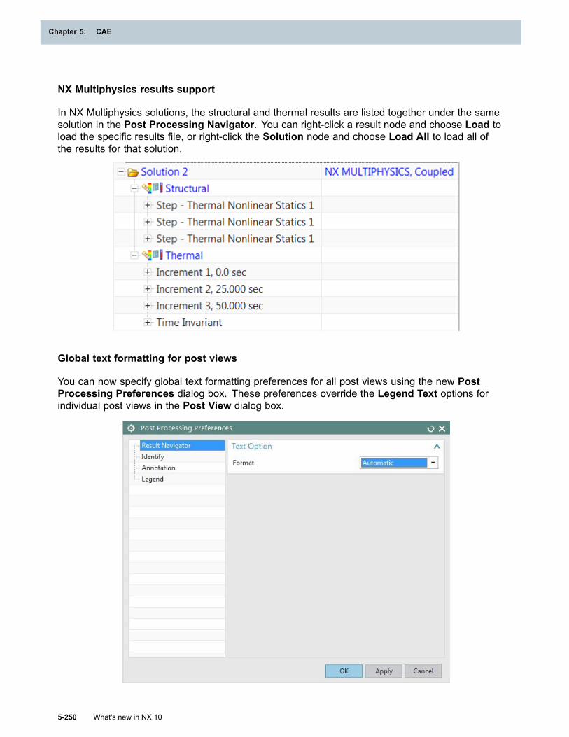
Chapter 5: CAE
NX Multiphysics results support
In NX Multiphysics solutions, the structural and thermal results are listed together under the samesolution in the Post Processing Navigator. You can right-click a result node and choose Load toload the specific results file, or right-click the Solution node and choose Load All to load all ofthe results for that solution.
Global text formatting for post views
You can now specify global text formatting preferences for all post views using the new PostProcessing Preferences dialog box. These preferences override the Legend Text options forindividual post views in the Post View dialog box.
5-250 What's new in NX 10
Chapter 5: CAE
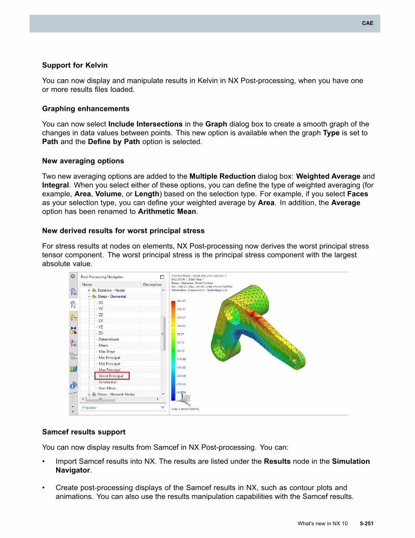
CAE
Support for Kelvin
You can now display and manipulate results in Kelvin in NX Post-processing, when you have oneor more results files loaded.
Graphing enhancements
You can now select Include Intersections in the Graph dialog box to create a smooth graph of thechanges in data values between points. This new option is available when the graph Type is set toPath and the Define by Path option is selected.
New averaging options
Two new averaging options are added to the Multiple Reduction dialog box: Weighted Average andIntegral. When you select either of these options, you can define the type of weighted averaging (forexample, Area, Volume, or Length) based on the selection type. For example, if you select Facesas your selection type, you can define your weighted average by Area. In addition, the Averageoption has been renamed to Arithmetic Mean.
New derived results for worst principal stress
For stress results at nodes on elements, NX Post-processing now derives the worst principal stresstensor component. The worst principal stress is the principal stress component with the largestabsolute value.
Samcef results support
You can now display results from Samcef in NX Post-processing. You can:
• Import Samcef results into NX. The results are listed under the Results node in the SimulationNavigator.
• Create post-processing displays of the Samcef results in NX, such as contour plots andanimations. You can also use the results manipulation capabilities with the Samcef results.
What's new in NX 10 5-251
CAE
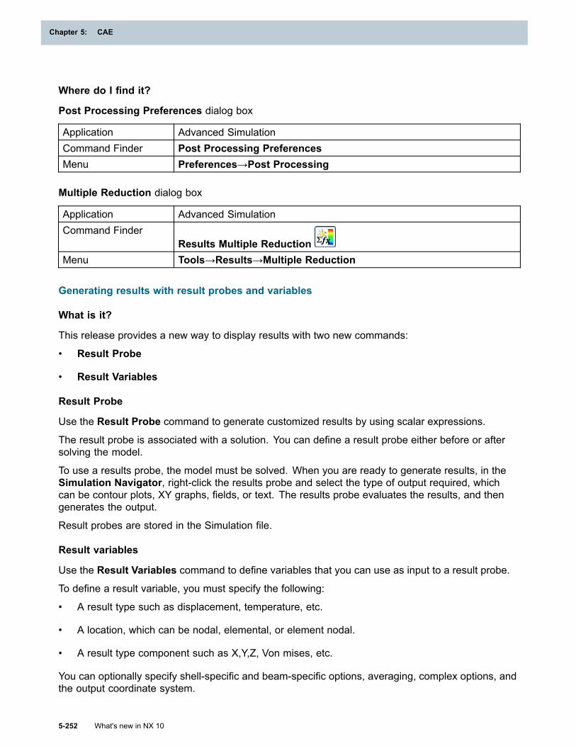
Chapter 5: CAE
Where do I find it?
Post Processing Preferences dialog box
Application Advanced SimulationCommand Finder Post Processing PreferencesMenu Preferences→Post Processing
Multiple Reduction dialog box
Application Advanced SimulationCommand Finder
Results Multiple ReductionMenu Tools→Results→Multiple Reduction
Generating results with result probes and variables
What is it?
This release provides a new way to display results with two new commands:
• Result Probe
• Result Variables
Result Probe
Use the Result Probe command to generate customized results by using scalar expressions.
The result probe is associated with a solution. You can define a result probe either before or aftersolving the model.
To use a results probe, the model must be solved. When you are ready to generate results, in theSimulation Navigator, right-click the results probe and select the type of output required, whichcan be contour plots, XY graphs, fields, or text. The results probe evaluates the results, and thengenerates the output.
Result probes are stored in the Simulation file.
Result variables
Use the Result Variables command to define variables that you can use as input to a result probe.
To define a result variable, you must specify the following:
• A result type such as displacement, temperature, etc.
• A location, which can be nodal, elemental, or element nodal.
• A result type component such as X,Y,Z, Von mises, etc.
You can optionally specify shell-specific and beam-specific options, averaging, complex options, andthe output coordinate system.
5-252 What's new in NX 10
Chapter 5: CAE
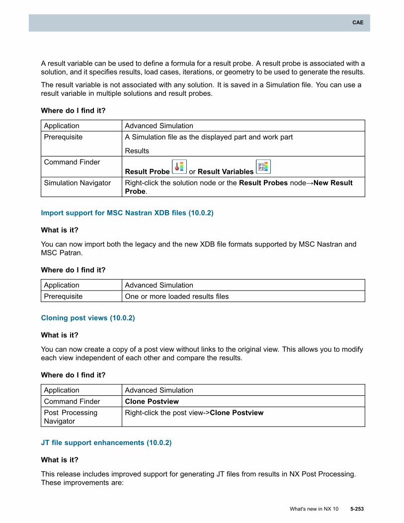
CAE
A result variable can be used to define a formula for a result probe. A result probe is associated with asolution, and it specifies results, load cases, iterations, or geometry to be used to generate the results.
The result variable is not associated with any solution. It is saved in a Simulation file. You can use aresult variable in multiple solutions and result probes.
Where do I find it?
Application Advanced SimulationPrerequisite A Simulation file as the displayed part and work part
ResultsCommand Finder
Result Probe or Result VariablesSimulation Navigator Right-click the solution node or the Result Probes node→New Result
Probe.
Import support for MSC Nastran XDB files (10.0.2)
What is it?
You can now import both the legacy and the new XDB file formats supported by MSC Nastran andMSC Patran.
Where do I find it?
Application Advanced SimulationPrerequisite One or more loaded results files
Cloning post views (10.0.2)
What is it?
You can now create a copy of a post view without links to the original view. This allows you to modifyeach view independent of each other and compare the results.
Where do I find it?
Application Advanced SimulationCommand Finder Clone PostviewPost ProcessingNavigator
Right-click the post view->Clone Postview
JT file support enhancements (10.0.2)
What is it?
This release includes improved support for generating JT files from results in NX Post Processing.These improvements are:
What's new in NX 10 5-253
CAE
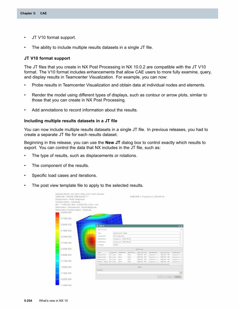
Chapter 5: CAE
• JT V10 format support.
• The ability to include multiple results datasets in a single JT file.
JT V10 format support
The JT files that you create in NX Post Processing in NX 10.0.2 are compatible with the JT V10format. The V10 format includes enhancements that allow CAE users to more fully examine, query,and display results in Teamcenter Visualization. For example, you can now:
• Probe results in Teamcenter Visualization and obtain data at individual nodes and elements.
• Render the model using different types of displays, such as contour or arrow plots, similar tothose that you can create in NX Post Processing.
• Add annotations to record information about the results.
Including multiple results datasets in a JT file
You can now include multiple results datasets in a single JT file. In previous releases, you had tocreate a separate JT file for each results dataset.
Beginning in this release, you can use the New JT dialog box to control exactly which results toexport. You can control the data that NX includes in the JT file, such as:
• The type of results, such as displacements or rotations.
• The component of the results.
• Specific load cases and iterations.
• The post view template file to apply to the selected results.
5-254 What's new in NX 10
Chapter 5: CAE
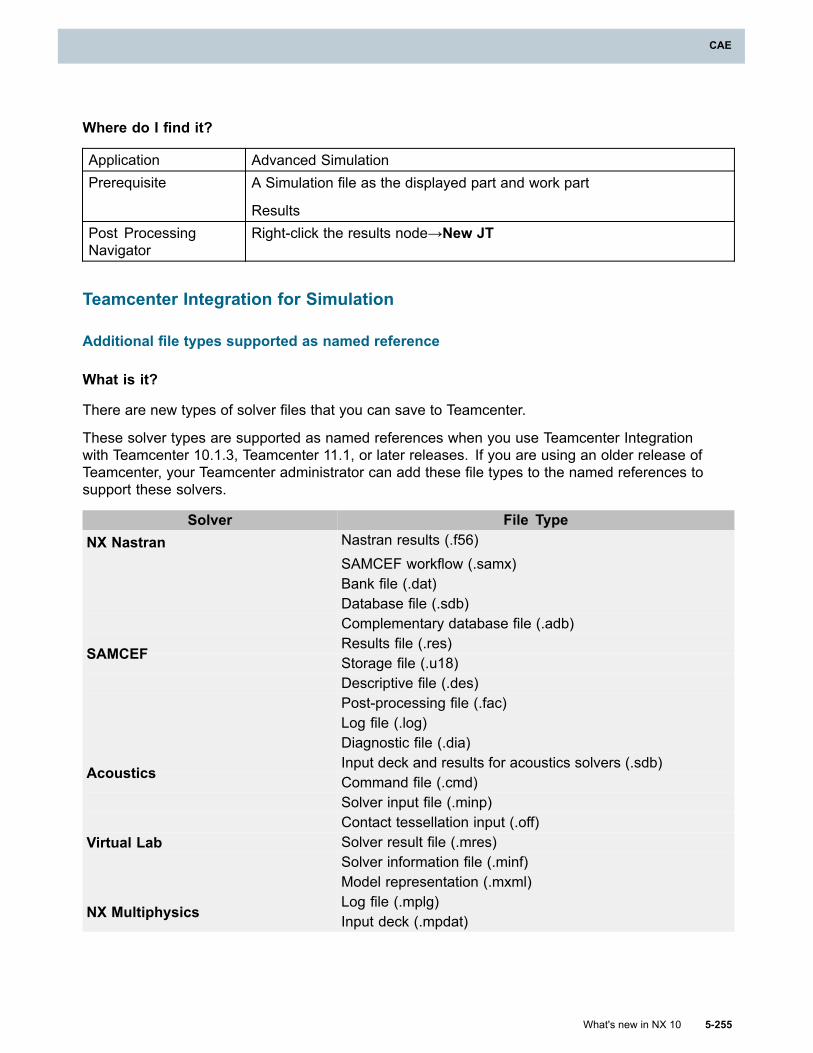
CAE
Where do I find it?
Application Advanced SimulationPrerequisite A Simulation file as the displayed part and work part
ResultsPost ProcessingNavigator
Right-click the results node→New JT
Teamcenter Integration for Simulation
Additional file types supported as named reference
What is it?
There are new types of solver files that you can save to Teamcenter.
These solver types are supported as named references when you use Teamcenter Integrationwith Teamcenter 10.1.3, Teamcenter 11.1, or later releases. If you are using an older release ofTeamcenter, your Teamcenter administrator can add these file types to the named references tosupport these solvers.
Solver File TypeNX Nastran Nastran results (.f56)
SAMCEF workflow (.samx)Bank file (.dat)Database file (.sdb)Complementary database file (.adb)Results file (.res)Storage file (.u18)Descriptive file (.des)Post-processing file (.fac)Log file (.log)
SAMCEF
Diagnostic file (.dia)Input deck and results for acoustics solvers (.sdb)
Acoustics Command file (.cmd)Solver input file (.minp)Contact tessellation input (.off)Solver result file (.mres)Solver information file (.minf)
Virtual Lab
Model representation (.mxml)Log file (.mplg)
NX Multiphysics Input deck (.mpdat)
What's new in NX 10 5-255
CAE
Chapter 5: CAE
Assigning custom item types for CAE parts during import
What is it?
When you use the Import Assembly into Teamcenter command, if you have custom item types forCAE parts, you can now select the item types for the type of file you import. You select the item typesfrom the following columns in the Import Assembly into Teamcenter dialog box:
• The Item Type column for the master part file.
• The CAEGeometry Item Type column for the idealized part file.
• The CAEModel Item Type column for the FEM file.
• The CAEAnalysis Item Type column for the simulation file.
The Import customer defaults control the default item types assigned during import.
Where do I find it?
Customer Default
Application Advanced Simulation, Design Simulation
Command Finder Customer DefaultsLocation in dialogbox Teamcenter Integration for NX→ Import/Export Assembly→ Import
Command
Application Advanced Simulation, Design Simulation
Command Finder Import Assembly into Teamcenter
Adding related CAE parts during export
What is it?
When you export an NX assembly from Teamcenter, and there are related CAE parts, you cannow add those CAE models to the export assembly operation. To add the CAE models, select theappropriate option for CAE under Related Parts on the Non Masters/Associated Files tab in theExport Assembly dialog box. The available options are:
• Simulations, FEMs, and Idealized Parts
• FEMs and Idealized Parts
• Idealized Parts
The default setting is None.
5-256 What's new in NX 10
Chapter 5: CAE
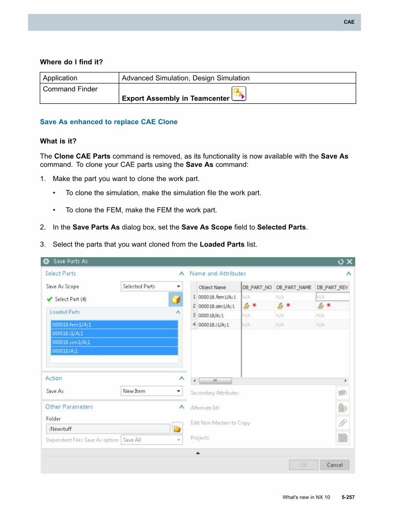
CAE
Where do I find it?
Application Advanced Simulation, Design SimulationCommand Finder
Export Assembly in Teamcenter
Save As enhanced to replace CAE Clone
What is it?
The Clone CAE Parts command is removed, as its functionality is now available with the Save Ascommand. To clone your CAE parts using the Save As command:
1. Make the part you want to clone the work part.
• To clone the simulation, make the simulation file the work part.
• To clone the FEM, make the FEM the work part.
2. In the Save Parts As dialog box, set the Save As Scope field to Selected Parts.
3. Select the parts that you want cloned from the Loaded Parts list.
What's new in NX 10 5-257
CAE
Chapter 5: CAE
Note
You can generate new items or revisions for the idealized part and master part only if theyare fully loaded.
Where do I find it?
Application Advanced Simulation, Design SimulationPrerequisite A FEM or simulation as the work partCommand Finder
Save As
Support for non-master CAE items is removed
What is it?
NX 5 introduced the Simulation Process Management data model. In this data model, NX saves themaster part file, idealized part file, FEM file, and simulation file into separate item revisions. Startingwith NX 10, you must use the Simulation Process Management data model.
Prior to NX 5, the old Teamcenter data model saved the CAE files as datasets under a master CADitem revision. If you are using the old Teamcenter data model, you must migrate legacy data priorto accessing that data with NX 10. To do this, you can use the ugnx_caemigrate_tc command-lineutility in NX 9 or an earlier release.
NX Open for CAE
Python
What is it?
The Python programming language is added as a language binding for NX Open. This allows NXusers to record and replay NX workflows in the Python language. Advanced users can create orextend NX Open Python journals to develop NX Open applications in Python. These applications canuse any of the features of the Python programming language including classes, looping constructs,control statements, and callbacks. Python journals can be recorded and replayed on Windows,Linux, and Mac.
Some of the features provided with NX Open Python include:
• Block Styler support with Python code generation of saved dialog boxes
• Same NX Open API as in the other supported languages
• Wrappers implemented in Python for the NX Open UF API
Why should I use it?
You can use the Python programming language for multi-platform journal recording and replayingin NX.
5-258 What's new in NX 10
Chapter 5: CAE
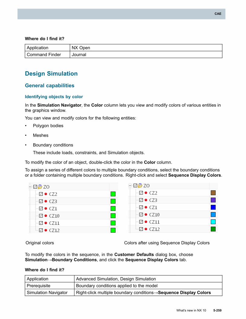
CAE
Where do I find it?
Application NX OpenCommand Finder Journal
Design Simulation
General capabilities
Identifying objects by color
In the Simulation Navigator, the Color column lets you view and modify colors of various entities inthe graphics window.
You can view and modify colors for the following entities:
• Polygon bodies
• Meshes
• Boundary conditions
These include loads, constraints, and Simulation objects.
To modify the color of an object, double-click the color in the Color column.To assign a series of different colors to multiple boundary conditions, select the boundary conditionsor a folder containing multiple boundary conditions. Right-click and select Sequence Display Colors.
Original colors Colors after using Sequence Display Colors
To modify the colors in the sequence, in the Customer Defaults dialog box, chooseSimulation→Boundary Conditions, and click the Sequence Display Colors tab.
Where do I find it?
Application Advanced Simulation, Design SimulationPrerequisite Boundary conditions applied to the modelSimulation Navigator Right-click multiple boundary conditions→Sequence Display Colors
What's new in NX 10 5-259
CAE
Chapter 5: CAE
Solution Monitor enhancements
What is it?
• The Solution Monitor is now used by the NX Multiphysics and NX Nastran solvers.
• You can copy and paste the displayed text output. In previous versions, the displayed text outputwas not selectable.
• The user interface of the Solution Monitor is refreshed and the command names are moreintuitive. The commands now have tooltips describing their functionality.
Where do I find it?
Application Advanced Simulation, Design Simulation
Prerequisite
NX Nastran, NX Multiphysics, NX Thermal and Flow, NX Space SystemsThermal, or NX Electronic Systems Cooling as the selected solverenvironment
Command Finder SolveSimulation Navigator Right-click a solution node→Solve
Support for non-ASCII characters
What is it?
You can now use multi-byte characters to name files and enter data in the Advanced Simulation,Design Simulation, and Motion applications. For example, you can use multi-byte characters in thenames of:
• All Motion objects, such as joints and drivers.
• Solutions, solution steps, or subcases.
• CAE related files, such as FEM and Simulation files.
In NX, your specified locale controls the language used in the user interface as well as the codeset for storing character data. For example, if your locale is set to China, you can enter Chinesecharacter data in the NX user interface.
The graphic shows Chinese characters in the Simulation Navigator.
5-260 What's new in NX 10
Chapter 5: CAE
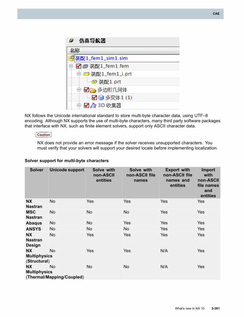
CAE
NX follows the Unicode international standard to store multi-byte character data, using UTF–8encoding. Although NX supports the use of multi-byte characters, many third party software packagesthat interface with NX, such as finite element solvers, support only ASCII character data.
Caution
NX does not provide an error message if the solver receives unsupported characters. Youmust verify that your solvers will support your desired locale before implementing localization.
Solver support for multi-byte characters
Solver Unicode support Solve withnon-ASCIIentities
Solve withnon-ASCII file
names
Export withnon-ASCII filenames andentities
Importwith
non-ASCIIfile names
andentities
NXNastran
No Yes Yes Yes Yes
MSCNastran
No No No Yes Yes
Abaqus No No Yes Yes YesANSYS No No No Yes YesNXNastranDesign
No Yes Yes Yes Yes
NXMultiphysics(Structural)
No Yes Yes N/A Yes
NXMultiphysics(Thermal/Mapping/Coupled)
No No No N/A Yes
What's new in NX 10 5-261
CAE
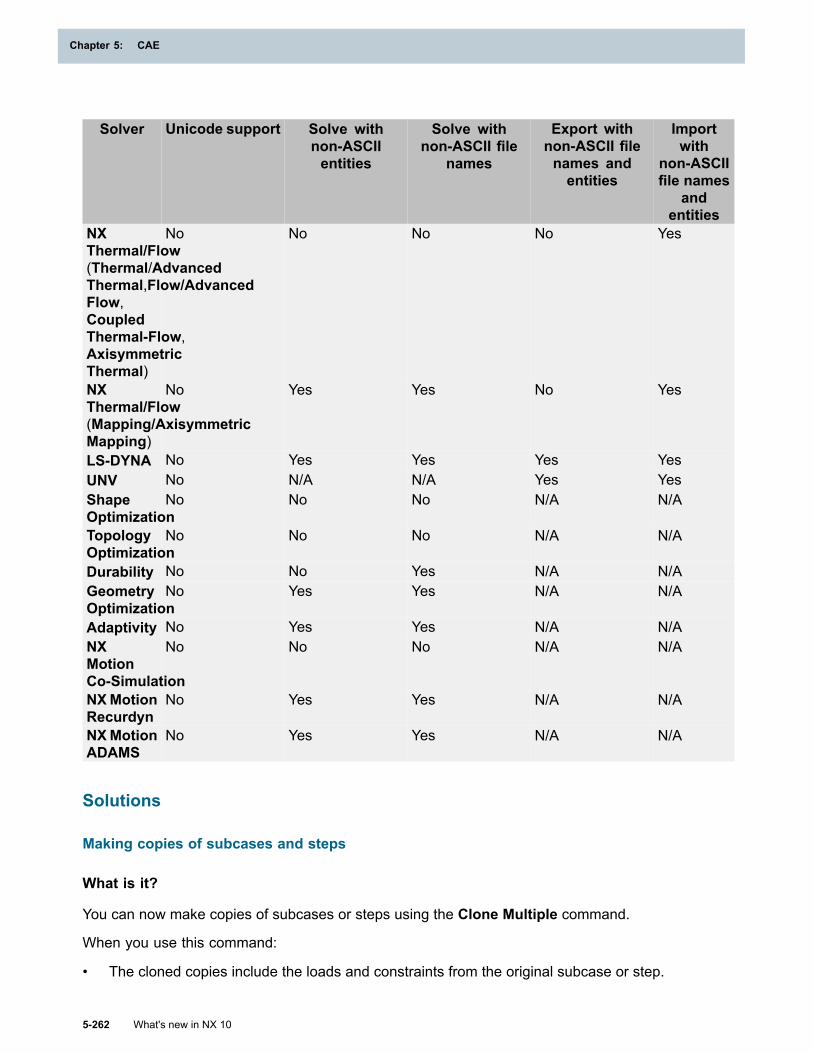
Chapter 5: CAE
Solver Unicode support Solve withnon-ASCIIentities
Solve withnon-ASCII file
names
Export withnon-ASCII filenames andentities
Importwith
non-ASCIIfile names
andentities
NXThermal/Flow(Thermal/AdvancedThermal,Flow/AdvancedFlow,CoupledThermal-Flow,AxisymmetricThermal)
No No No No Yes
NXThermal/Flow(Mapping/AxisymmetricMapping)
No Yes Yes No Yes
LS-DYNA No Yes Yes Yes YesUNV No N/A N/A Yes YesShapeOptimization
No No No N/A N/A
TopologyOptimization
No No No N/A N/A
Durability No No Yes N/A N/AGeometryOptimization
No Yes Yes N/A N/A
Adaptivity No Yes Yes N/A N/ANXMotionCo-Simulation
No No No N/A N/A
NXMotionRecurdyn
No Yes Yes N/A N/A
NXMotionADAMS
No Yes Yes N/A N/A
Solutions
Making copies of subcases and steps
What is it?
You can now make copies of subcases or steps using the Clone Multiple command.
When you use this command:
• The cloned copies include the loads and constraints from the original subcase or step.
5-262 What's new in NX 10
Chapter 5: CAE
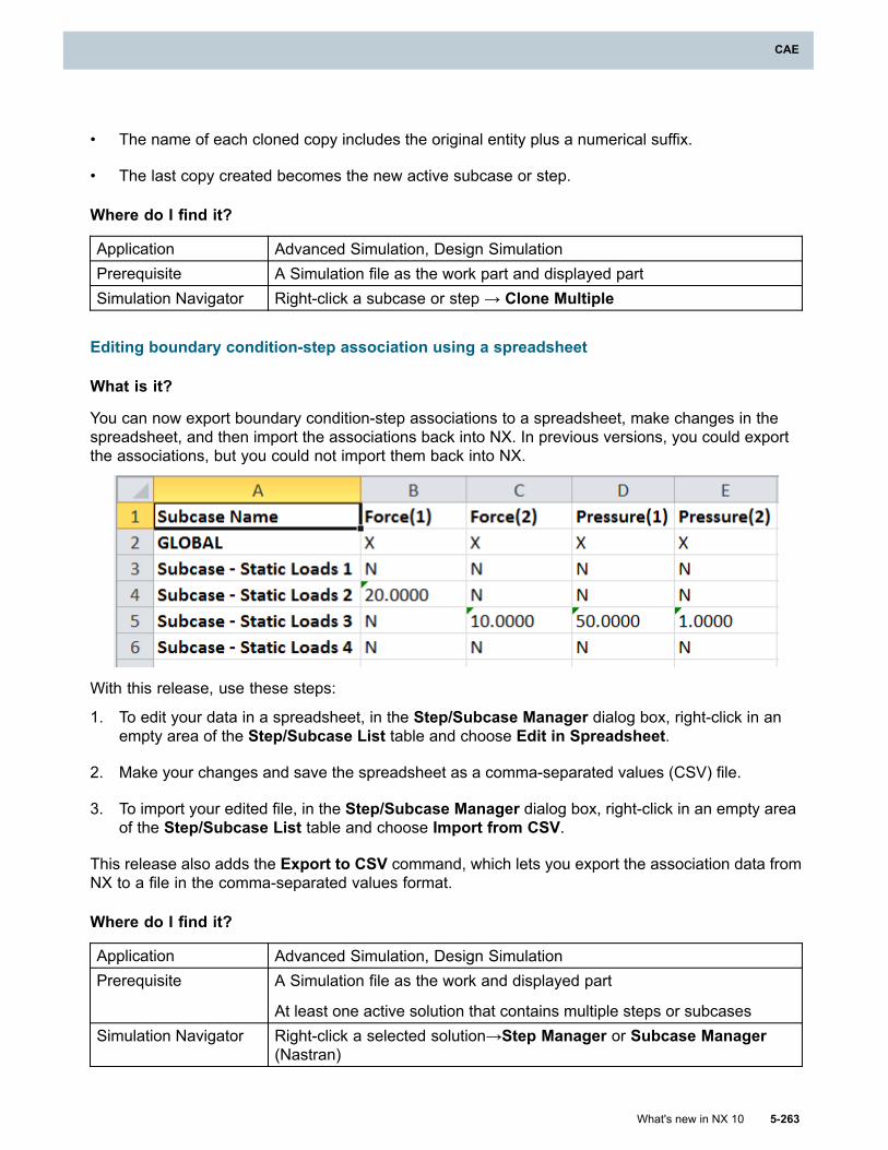
CAE
• The name of each cloned copy includes the original entity plus a numerical suffix.
• The last copy created becomes the new active subcase or step.
Where do I find it?
Application Advanced Simulation, Design SimulationPrerequisite A Simulation file as the work part and displayed partSimulation Navigator Right-click a subcase or step → Clone Multiple
Editing boundary condition-step association using a spreadsheet
What is it?
You can now export boundary condition-step associations to a spreadsheet, make changes in thespreadsheet, and then import the associations back into NX. In previous versions, you could exportthe associations, but you could not import them back into NX.
With this release, use these steps:
1. To edit your data in a spreadsheet, in the Step/Subcase Manager dialog box, right-click in anempty area of the Step/Subcase List table and choose Edit in Spreadsheet.
2. Make your changes and save the spreadsheet as a comma-separated values (CSV) file.
3. To import your edited file, in the Step/Subcase Manager dialog box, right-click in an empty areaof the Step/Subcase List table and choose Import from CSV.
This release also adds the Export to CSV command, which lets you export the association data fromNX to a file in the comma-separated values format.
Where do I find it?
Application Advanced Simulation, Design SimulationPrerequisite A Simulation file as the work and displayed part
At least one active solution that contains multiple steps or subcasesSimulation Navigator Right-click a selected solution→Step Manager or Subcase Manager
(Nastran)
What's new in NX 10 5-263
CAE
Chapter 5: CAE
Boundary conditions
Temperature load enhancements
What is it?
You can now define a temperature load by importing temperature results. You do this using aTemperature — External Time Unassigned type of Temperature load. You can import constanttemperatures from Nastran, Abaqus, ANSYS, and NX Thermal results files.
Corresponding Nastran syntax
The new types of Temperature load correspond to different NX Nastran bulk data entries.
• If you select the Temperature — External Time Assigned type, NX creates the DTEMPEX bulkdata entry.
• For all other types, NX creates the TEMP bulk data entry.
Where do I find it?
Application Design SimulationPrerequisites Structural as the specified analysis typeCommand Finder
Temperature Load
Post-processing
General post-processing enhancements
What is it?
This release includes a number of general enhancements to NX Post-processing. These include:
• Support for Kelvin
• Graphing enhancements
• New derived results for worst principal stress
Support for Kelvin
You can now display and manipulate results in Kelvin in NX Post-processing, when you have oneor more results files loaded.
Graphing enhancements
You can now select Include Intersections in the Graph dialog box to create a smooth graph of thechanges in data values between points. This new option is available when the graph Type is set toPath and the Define by Path option is selected.
5-264 What's new in NX 10
Chapter 5: CAE
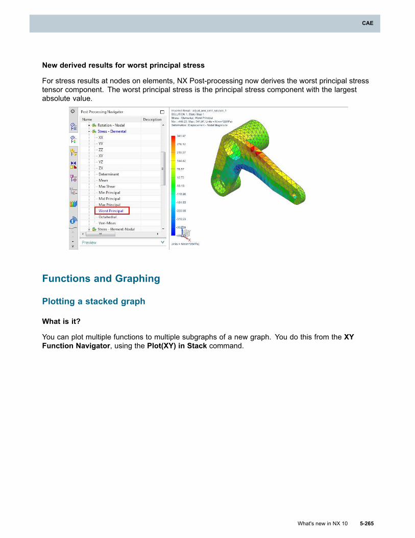
CAE
New derived results for worst principal stress
For stress results at nodes on elements, NX Post-processing now derives the worst principal stresstensor component. The worst principal stress is the principal stress component with the largestabsolute value.
Functions and Graphing
Plotting a stacked graph
What is it?
You can plot multiple functions to multiple subgraphs of a new graph. You do this from the XYFunction Navigator, using the Plot(XY) in Stack command.
What's new in NX 10 5-265
CAE
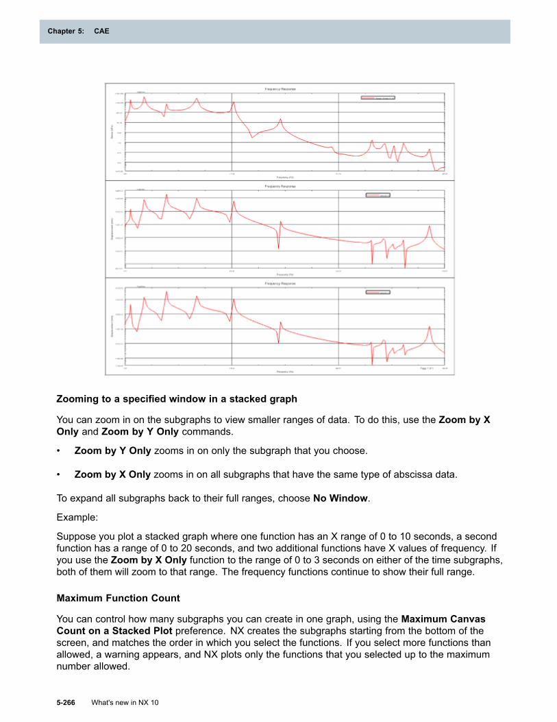
Chapter 5: CAE
Zooming to a specified window in a stacked graph
You can zoom in on the subgraphs to view smaller ranges of data. To do this, use the Zoom by XOnly and Zoom by Y Only commands.
• Zoom by Y Only zooms in on only the subgraph that you choose.
• Zoom by X Only zooms in on all subgraphs that have the same type of abscissa data.
To expand all subgraphs back to their full ranges, choose No Window.
Example:
Suppose you plot a stacked graph where one function has an X range of 0 to 10 seconds, a secondfunction has a range of 0 to 20 seconds, and two additional functions have X values of frequency. Ifyou use the Zoom by X Only function to the range of 0 to 3 seconds on either of the time subgraphs,both of them will zoom to that range. The frequency functions continue to show their full range.
Maximum Function Count
You can control how many subgraphs you can create in one graph, using the Maximum CanvasCount on a Stacked Plot preference. NX creates the subgraphs starting from the bottom of thescreen, and matches the order in which you select the functions. If you select more functions thanallowed, a warning appears, and NX plots only the functions that you selected up to the maximumnumber allowed.
5-266 What's new in NX 10
Chapter 5: CAE
CAE
Why should I use it?
You can display multiple functions simultaneously using any one of the following commands:Plot(XY) in Stack, Plot(XY), Plot(XYZ), and Overlay. The advantage of using the Plot(XY) in Stackcommand is that it is the only one that allows you to include functions that have unique abscissaunits, and it allows you to zoom in on a single function.
Where do I find it?
Plot(XY) in Stack
Application Advanced SimulationXY Function Navigator Right-click selected multiple functions → Plot(XY) in Stack
XY Plot Preferences
Menu File → Preferences → XY PlotLocation in dialog box XY Plot Preferences dialog box → Maximum Canvas Count on a
Stacked Plot
Plotting 2D functions to a 3D graph
What is it?
You can plot multiple 2D functions to unique XY planes of a 3D graph. You do this using the Plot(XYZ)command. Each function you select must have identical data types for every axis.
What's new in NX 10 5-267
CAE
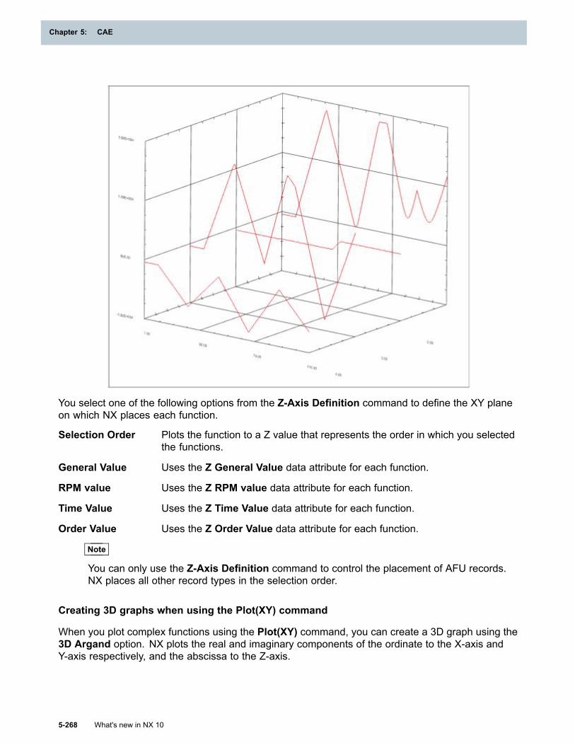
Chapter 5: CAE
You select one of the following options from the Z-Axis Definition command to define the XY planeon which NX places each function.
Selection Order Plots the function to a Z value that represents the order in which you selectedthe functions.
General Value Uses the Z General Value data attribute for each function.
RPM value Uses the Z RPM value data attribute for each function.
Time Value Uses the Z Time Value data attribute for each function.
Order Value Uses the Z Order Value data attribute for each function.
Note
You can only use the Z-Axis Definition command to control the placement of AFU records.NX places all other record types in the selection order.
Creating 3D graphs when using the Plot(XY) command
When you plot complex functions using the Plot(XY) command, you can create a 3D graph using the3D Argand option. NX plots the real and imaginary components of the ordinate to the X-axis andY-axis respectively, and the abscissa to the Z-axis.
5-268 What's new in NX 10
Chapter 5: CAE
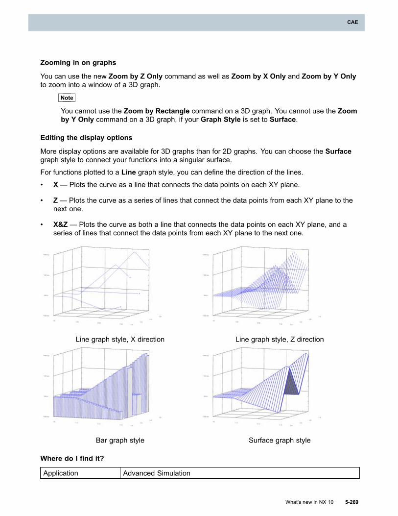
CAE
Zooming in on graphs
You can use the new Zoom by Z Only command as well as Zoom by X Only and Zoom by Y Onlyto zoom into a window of a 3D graph.
Note
You cannot use the Zoom by Rectangle command on a 3D graph. You cannot use the Zoomby Y Only command on a 3D graph, if your Graph Style is set to Surface.
Editing the display options
More display options are available for 3D graphs than for 2D graphs. You can choose the Surfacegraph style to connect your functions into a singular surface.
For functions plotted to a Line graph style, you can define the direction of the lines.• X— Plots the curve as a line that connects the data points on each XY plane.
• Z— Plots the curve as a series of lines that connect the data points from each XY plane to thenext one.
• X&Z — Plots the curve as both a line that connects the data points on each XY plane, and aseries of lines that connect the data points from each XY plane to the next one.
Line graph style, X direction Line graph style, Z direction
Bar graph style Surface graph style
Where do I find it?
Application Advanced Simulation
What's new in NX 10 5-269
CAE
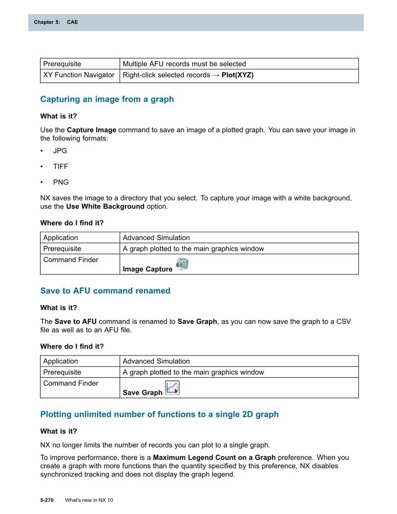
Chapter 5: CAE
Prerequisite Multiple AFU records must be selectedXY Function Navigator Right-click selected records → Plot(XYZ)
Capturing an image from a graph
What is it?
Use the Capture Image command to save an image of a plotted graph. You can save your image inthe following formats:
• JPG
• TIFF
• PNG
NX saves the image to a directory that you select. To capture your image with a white background,use the Use White Background option.
Where do I find it?
Application Advanced SimulationPrerequisite A graph plotted to the main graphics windowCommand Finder
Image Capture
Save to AFU command renamed
What is it?
The Save to AFU command is renamed to Save Graph, as you can now save the graph to a CSVfile as well as to an AFU file.
Where do I find it?
Application Advanced SimulationPrerequisite A graph plotted to the main graphics windowCommand Finder
Save Graph
Plotting unlimited number of functions to a single 2D graph
What is it?
NX no longer limits the number of records you can plot to a single graph.
To improve performance, there is a Maximum Legend Count on a Graph preference. When youcreate a graph with more functions than the quantity specified by this preference, NX disablessynchronized tracking and does not display the graph legend.
5-270 What's new in NX 10
Chapter 5: CAE
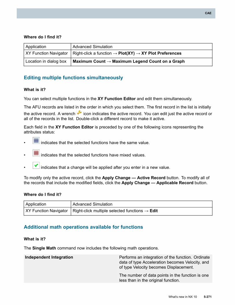
CAE
Where do I find it?
Application Advanced SimulationXY Function Navigator Right-click a function → Plot(XY)→ XY Plot Preferences
Location in dialog box Maximum Count→ Maximum Legend Count on a Graph
Editing multiple functions simultaneously
What is it?
You can select multiple functions in the XY Function Editor and edit them simultaneously.
The AFU records are listed in the order in which you select them. The first record in the list is initiallythe active record. A wrench icon indicates the active record. You can edit just the active record orall of the records in the list. Double-click a different record to make it active.
Each field in the XY Function Editor is preceded by one of the following icons representing theattributes status:
• indicates that the selected functions have the same value.
• indicates that the selected functions have mixed values.
• indicates that a change will be applied after you enter in a new value.
To modify only the active record, click the Apply Change — Active Record button. To modify all ofthe records that include the modified fields, click the Apply Change — Applicable Record button.
Where do I find it?
Application Advanced SimulationXY Function Navigator Right-click multiple selected functions → Edit
Additional math operations available for functions
What is it?
The Single Math command now includes the following math operations.
Independent Integration Performs an integration of the function. Ordinatedata of type Acceleration becomes Velocity, andof type Velocity becomes Displacement.
The number of data points in the function is oneless than in the original function.
What's new in NX 10 5-271
CAE
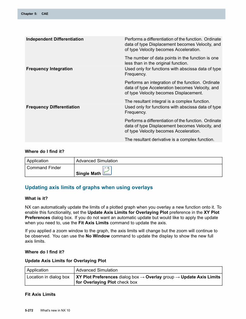
Chapter 5: CAE
Independent Differentiation Performs a differentiation of the function. Ordinatedata of type Displacement becomes Velocity, andof type Velocity becomes Acceleration.
The number of data points in the function is oneless than in the original function.
Frequency Integration Used only for functions with abscissa data of typeFrequency.
Performs an integration of the function. Ordinatedata of type Acceleration becomes Velocity, andof type Velocity becomes Displacement.
The resultant integral is a complex function.Frequency Differentiation Used only for functions with abscissa data of type
Frequency.
Performs a differentiation of the function. Ordinatedata of type Displacement becomes Velocity, andof type Velocity becomes Acceleration.
The resultant derivative is a complex function.
Where do I find it?
Application Advanced SimulationCommand Finder
Single Math
Updating axis limits of graphs when using overlays
What is it?
NX can automatically update the limits of a plotted graph when you overlay a new function onto it. Toenable this functionality, set the Update Axis Limits for Overlaying Plot preference in the XY PlotPreferences dialog box. If you do not want an automatic update but would like to apply the updatewhen you need to, use the Fit Axis Limits command to update the axis.
If you applied a zoom window to the graph, the axis limits will change but the zoom will continue tobe observed. You can use the No Window command to update the display to show the new fullaxis limits.
Where do I find it?
Update Axis Limits for Overlaying Plot
Application Advanced SimulationLocation in dialog box XY Plot Preferences dialog box → Overlay group → Update Axis Limits
for Overlaying Plot check box
Fit Axis Limits
5-272 What's new in NX 10
Chapter 5: CAE
CAE
Application Advanced SimulationPrerequisite A function plotted that exceeds the current axis limitsCommand Finder
Editing → Right-click the graph background → Fit Axis Limits
Managing graphics windows
What is it?
On Windows machines, there are new options for managing the display of multiple graphics windows.The new Graphics Window Manager lists all of your independent graphics windows with options tocontrol their screen position.
Close Closes the selected window.
Make Floating Restores a docked graphics window to float independently in the foreground.
Make Current Docks the selected window in front of the main graphics window.
Make Main GraphicsWindow Current
Moves the main graphics window in front of any docked graphics windows.
You can also tile or cascade your graphics windows. Use the following commands in the Windowdrop-down list to tile or cascade your separate graphics windows as well as your main graphicswindow:
• Cascade
• Tile Horizontally
• Tile Vertically
Where do I find it?
Application Advanced SimulationPrerequisite One or more graphs plotted to separate graphics windowsCommand Finder Graphics Window Manager
General functions and graphing enhancements
What is it?
• You can maximize the display of independent graph windows.
• You can move the display of a graph from an independent graph window to be superimposed onthe NX graphics window. To do this, use the Send to NX Window command.
• The Curve Options dialog box is now named Display Options. The thickness options haveincreased to include 9 standard thicknesses.
What's new in NX 10 5-273
CAE

Chapter 5: CAE
• The spacing of dashed lines is now based on the plot’s dimensions. In previous releases, thiswas based on the distance between data points, which could make dashed lines appear solidwhen data points were close together.
5-274 What's new in NX 10
Chapter 5: CAE
Chapter 6: Inspection and validation
Check-Mate
Check-Mate checkers and functions
What is it?
Check-Mate is enhanced to include the new function, mqc_checkWeldPointConnectedParts. You canfind it in the mqc_weld_checker_func.dfa source file.
The following new Check-Mate checkers are provided with this release.
Checker name CategoriesNumber of Hidden Objects Get Information→ModelingConnected Parts Welding→Weld Point
The following checkers have been enhanced.
Checker name Categories EnhancementReport Solid Bodywithout Density Setting
GetInformation→Modeling
Adds an option to include sheet bodies.
Report Solid Body withDefault Density Setting
GetInformation→Modeling
Adds an option to include sheet bodies.
Report Solid Body withSpecified Density Setting
GetInformation→Modeling
Adds an option to include sheet bodies.
Report Out-of-DateFeatures
GetInformation→Modeling
Adds an option to check internal features.
The following functions have been moved from mqc_checker_func.dfa to mqc_obsolete_func.dfa.
• mqc_checkViewScale
• mqc_checkViewNames
• mqc_checkCategoryLayer
• mqc_checkLayerCategory
• mqc_checkRequiredCategory
• mqc_checkCategoryObjectMapping
• mqc_checkRefSetsCsysName
• mqc_checkObjectInCategory
What's new in NX 10 6-1
Chapter 6: Inspection and validation
• mqc_checkRequiredRefSets
• mqc_checkRefSetsObjectType
The mqc_report_blanked_entity function, which was in the Get Information→Modeling category, isnow hidden in the Set Up Tests dialog box. It is replaced by the mqc_report_hidden_objects functionbecause the obsolete term blanked entity has been replaced by the term hidden object in NX.
The hidden checker is only invisible in the category list box of the Tests tab in the Set Up Tests dialogbox. If you have already used the hidden checker, you are not affected by this change.
Please see the ugcheckmate.dat file in the Check-Mate kit for additional details.
Where do I find it?
Resource bar HD3D Tools →Check-Mate
CMM Inspection Programming NX 9.0.1 — NX 10.0
CMM general enhancements
General enhancements — NX 9.0.1
View Vector name change
When you set the tolerance type to Perpendicularity or Parallelism in the ToleranceOperation dialog box, the View Vector group is renamed Tolerance Zone Width Direction. Thenew name better reflects the DMIS standard for this vector: “[The] direction vector along which theview dependent parallel [or perpendicular sic] plane tolerance zone width is to be applied.”
Coordinate tolerance nominal values displayed
To support CMM software that requires DMIS CORTOL values to evaluate coordinate tolerances, theTolerance Operation dialog box now shows the nominal X, Y, or Z axis value of the feature centerpoint in the currently aligned Part Coordinate System (PCS).
Improved graphics when defining a PCS from datums
When you define an alignment command in the Alignment dialog box using the Define PCS fromDatums alignment type, NX now indicates which feature is assigned to which letter. In previousreleases, NX only highlighted the feature assigned to the datums after you set the alignment directionor origin. The datum feature is now highlighted when you select it from the Datum Letter list or typeits value in the Datum Letter box.
Where do I find it?
Initial release NX 9.0.1Application CMM Inspection Programming
6-2 What's new in NX 10
Chapter 6: Inspection and validation
Inspection and validation
Prerequisite
• To define a tolerance operation, create an appropriate inspection feature.
• To create a PCS from datums, create appropriate inspection featuresand datums from those features.
Command Finder
Perpendicularity
Parallelism
Coordinate Tolerance
Alignment
General enhancements — NX 9.0.2
Overriding direct dimension tolerance values defined in PMI
Direct dimension tolerance values defined in a master model may not reflect the design intent.For example, an acceptable angle on the part may be 89.998 degrees instead of the 90 degreesprescribed in a drawing, with acceptable measurement variation causing the angle tolerance to fail. Inthe Tolerance Operation dialog box, in the Parameters group, you can override direct dimensionNominal, Upper, and Lower tolerance values linked to PMI.
When you override these values, the Inherited icon changes to a Locally defined icon toindicate that the PMI value has been overridden. To recall the PMI value, click the unlock icon andchoose Inherited from PMI.
Collision avoidance progress bar
When you run collision avoidance on inspection paths, a progress bar reports the percentagecomplete and displays each action.
Performing analysis... 28% PATH_CYLINDER_TOP - Find Sensor
Where do I find it?
Initial release NX 9.0.2Application CMM Inspection Programming
Prerequisite
• To define a dimensional tolerance operation, create an appropriateinspection feature.
• To apply collision avoidance, in the Inspection Navigator, select oneor more inspection paths.
Command Finder Collision Avoidance
What's new in NX 10 6-3
Inspection and validation
Chapter 6: Inspection and validation
General enhancements — NX 9.0.3 MP1
New method added to the NX Open API
A GetRoot method has been added to the InspectionSetup class to return the root of the specifiedbranch root, such as the Machine or Program group name.
Feature selection when adding tolerances
In previous versions, when you added a tolerance to a highlighted feature in the InspectionNavigator, the highlight jumped to the newly added tolerance. To add additional tolerances to thefeature, you had to highlight the feature again.
The feature now remains highlighted after you add a tolerance. After you add a tolerance to a feature,you no longer have to reselect the feature before you add an additional tolerance. The selectionhighlight remains on the feature and does not move to the tolerance you create.
Modifying duplicate feature names
In previous versions, if you entered a duplicate inspection feature name in a feature dialog box, NX:
1. Displayed a message stating that the name was already in use.
2. Closed the feature dialog box when you closed the message.
3. Applied a default name to the feature.
To change the default name, you had to double-click it in the Inspection Navigator and enter yourpreferred name.
After you close the message, the feature dialog box now remains open with the duplicate name intactso that you can modify the text to create a unique name.
Pattern features
You can now pre-select features in the Inspection Operation Navigator to create a pattern feature.For example, you can select all hole features in your model. NX populates the feature list withthe selected features.
You can modify the feature list before you complete the pattern. If you select other operation types bymistake, NX does not add them to the feature list.
Where do I find it?
Initial release NX 9.0.3 MP1Application CMM Inspection Programming
Path statuses in the Inspection Navigator
What is it?
The Path column in the Inspection Navigator now provides additional status information.
Icon Meaning
6-4 What's new in NX 10
Chapter 6: Inspection and validation
Inspection and validation
• Next to an inspection feature, this icon indicates that there is no path or constructionfor the feature.
• Next to an inspection path, this icon indicates that the path contains no measurements.Next to an inspection path, this icon indicates that:
• The total number of points in the path is greater than zero but less than the minimumnumber of points specified for the feature type in the DMIS 5.2 standard.
• The path consists of a single arc scan on a cylinder, cone, or torus.
• The path consists of a single line scan on a plane, cylinder, or cone.
Why should I use it?
Review the Path column to quickly identify potential program problems.
Where do I find it?
Initial release NX 9.0.1Application CMM Inspection ProgrammingPrerequisite You must create inspection features and paths.Inspection Navigator Path column
DMIS Equator and mirroring postprocessors
What is it?
Special postprocessors are available, including one for use with the Equator 300 included in themachine library.
There are also three DMIS 3.0 postprocessors that work with CMM Inspection Execution to mirrorcoordinates and vectors from symmetrically opposite parts such as two car doors.
• DMIS 3.0 Mirror XZ Plane
• DMIS 3.0 Mirror YZ Plane
• DMIS 3.0 Mirror XY Plane
Versions of these postprocessors for NX 8.5.3 and NX 8.5.2 are also available from GTAC.
Why should I use it?
Mirroring DMIS content reduces the amount of work required to apply tolerances to symmetricalsides of a part or assembly.
Where do I find it?
Initial release NX 9.0.1Application CMM Inspection Programming
What's new in NX 10 6-5
Inspection and validation
Chapter 6: Inspection and validation
Prerequisite You must define mirrored sensors in your inspection program.
Command Finder Post Process
Tip type and tool selection
What is it?
A Sensor Tip Type list has been added to the Sensor group in many dialog boxes. From theInspection Method dialog box, this list allows you to specify a preferred sensor tip for each type ofinspection feature. When you create or generate inspection path sub-operations, CMM InspectionProgramming selects the preferred tip for each feature type by default.
Sensor tip types include the following.
• Any in the Inspection Method dialog box allows CMM Inspection Programming to determinethe appropriate tip for the feature type, in accordance with the default or selected feature type’ssensor strategy. When selected in the Link PMI and Create Paths dialog boxes, the applicationuses the preferred tip from the feature methods.
• Sphere uses a spherical tip.• Cylinder uses a cylindrical tip for sheet metal
edge and surface measurements.
Why should I use it?
Setting an appropriate default sensor type for each type of inspection feature in the InspectionMethod dialog box is faster than setting or resetting the sensors manually in each inspection pathsub-operation.
Where do I find it?
Initial release NX 9.0.1Application CMM Inspection ProgrammingPrerequisite You must load the probes specified in your inspection methods.
Location in dialogbox
Sensor group in the following dialog boxes:
• Inspection Method
• Create Sub-Operation
• Link PMI
• Create Paths
6-6 What's new in NX 10
Chapter 6: Inspection and validation
Inspection and validation
Sub-operation inheritance from feature methods
What is it?
Inspection paths created using the Link PMI and Create Paths dialog boxes now inheritsub-operation types from inspection feature methods.
Feature Type Supported Sub-operation typesCylinder Point Set, Scan HelixCircle Point Set, Scan Arc, Scan Curve, 5–axis Scan CurveArc, line Point Set, Scan Arc, Scan Curve, 5–axis Scan CurveCurve Point Set, Scan Curve, 5-axis Scan Curve
Note
• If the default sub-operation type in the method is set to Scan Arc or Scan Helix, themethods’s Scan Mode value determines whether the path uses 3-axis or 5-axis motion.
• If the default sub-operation type is Scan Line, Scan Curve, or 5-axis Scan Curve, theScan Mode value in the method is ignored.
Why should I use it?
When you specify a default sub-operation and scan mode value for each inspection feature’s method,you can quickly generate inspection paths with the appropriate sub-operations from the Link PMI andCreate Paths dialog boxes.
Where do I find it?
Initial release NX 9.0.1Application CMM Inspection Programming
Inspection NavigatorHome tab→Top Border bar→Method View →double-click the featuremethod
Collision avoidance enhancements
What is it?
Two groups in the Collision Avoidance dialog box are enhanced.
Avoidance Methods group
Two options are added to the Avoidance Methods group.
• Move Measurement Point moves measurement points to safe locations on plane, cylinder,and cone inspection features if they are causing collisions because they are too close to othergeometry.
What's new in NX 10 6-7
Inspection and validation
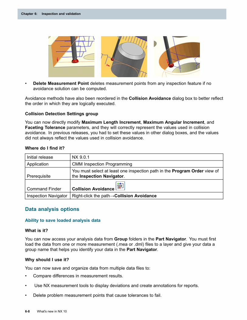
Chapter 6: Inspection and validation
• Delete Measurement Point deletes measurement points from any inspection feature if noavoidance solution can be computed.
Avoidance methods have also been reordered in the Collision Avoidance dialog box to better reflectthe order in which they are logically executed.
Collision Detection Settings group
You can now directly modify Maximum Length Increment, Maximum Angular Increment, andFaceting Tolerance parameters, and they will correctly represent the values used in collisionavoidance. In previous releases, you had to set these values in other dialog boxes, and the valuesdid not always reflect the values used in collision avoidance.
Where do I find it?
Initial release NX 9.0.1Application CMM Inspection Programming
PrerequisiteYou must select at least one inspection path in the Program Order view ofthe Inspection Navigator.
Command Finder Collision AvoidanceInspection Navigator Right-click the path→Collision Avoidance
Data analysis options
Ability to save loaded analysis data
What is it?
You can now access your analysis data from Group folders in the Part Navigator. You must firstload the data from one or more measurement (.mea or .dml) files to a layer and give your data agroup name that helps you identify your data in the Part Navigator.
Why should I use it?
You can now save and organize data from multiple data files to:
• Compare differences in measurement results.
• Use NX measurement tools to display deviations and create annotations for reports.
• Delete problem measurement points that cause tolerances to fail.
6-8 What's new in NX 10
Chapter 6: Inspection and validation
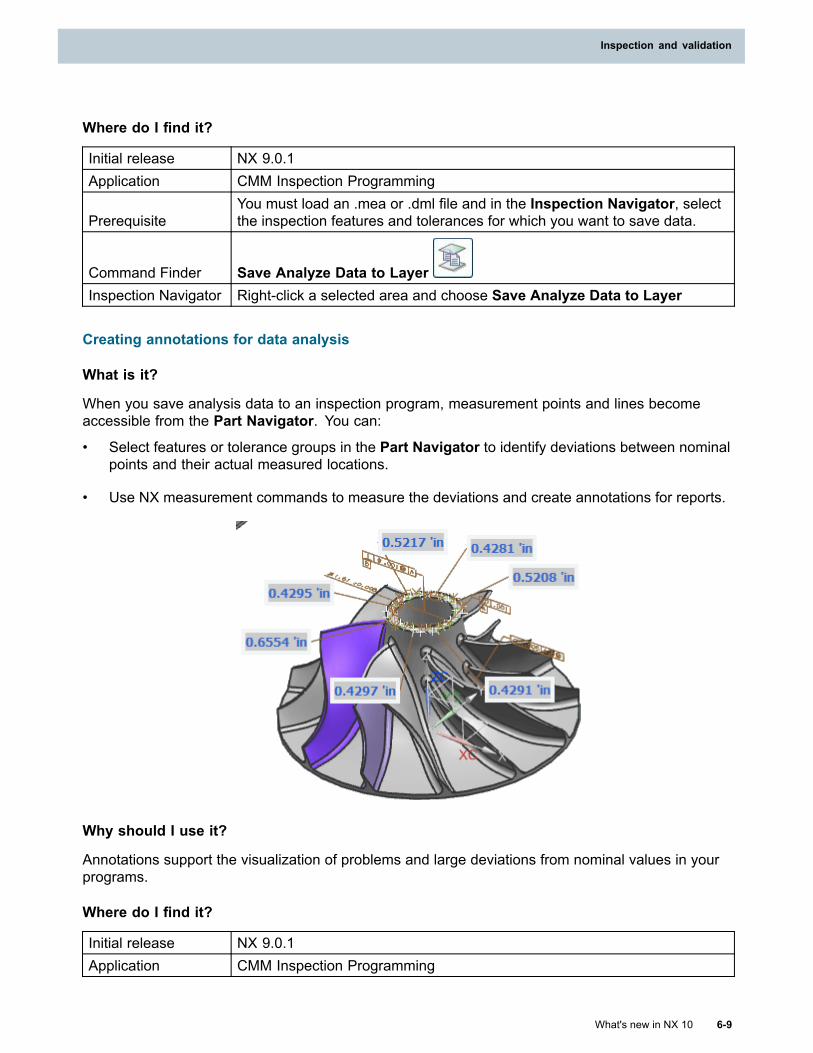
Inspection and validation
Where do I find it?
Initial release NX 9.0.1Application CMM Inspection Programming
PrerequisiteYou must load an .mea or .dml file and in the Inspection Navigator, selectthe inspection features and tolerances for which you want to save data.
Command Finder Save Analyze Data to LayerInspection Navigator Right-click a selected area and choose Save Analyze Data to Layer
Creating annotations for data analysis
What is it?
When you save analysis data to an inspection program, measurement points and lines becomeaccessible from the Part Navigator. You can:
• Select features or tolerance groups in the Part Navigator to identify deviations between nominalpoints and their actual measured locations.
• Use NX measurement commands to measure the deviations and create annotations for reports.
Why should I use it?
Annotations support the visualization of problems and large deviations from nominal values in yourprograms.
Where do I find it?
Initial release NX 9.0.1Application CMM Inspection Programming
What's new in NX 10 6-9
Inspection and validation
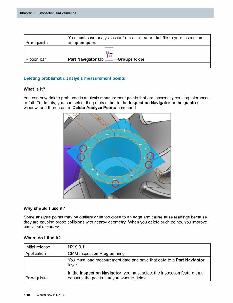
Chapter 6: Inspection and validation
PrerequisiteYou must save analysis data from an .mea or .dml file to your inspectionsetup program.
Ribbon bar Part Navigator tab →Groups folder
Deleting problematic analysis measurement points
What is it?
You can now delete problematic analysis measurement points that are incorrectly causing tolerancesto fail. To do this, you can select the points either in the Inspection Navigator or the graphicswindow, and then use the Delete Analyze Points command.
Why should I use it?
Some analysis points may be outliers or lie too close to an edge and cause false readings becausethey are causing probe collisions with nearby geometry. When you delete such points, you improvestatistical accuracy.
Where do I find it?
Initial release NX 9.0.1Application CMM Inspection Programming
Prerequisite
You must load measurement data and save that data to a Part Navigatorlayer.
In the Inspection Navigator, you must select the inspection feature thatcontains the points that you want to delete.
6-10 What's new in NX 10
Chapter 6: Inspection and validation
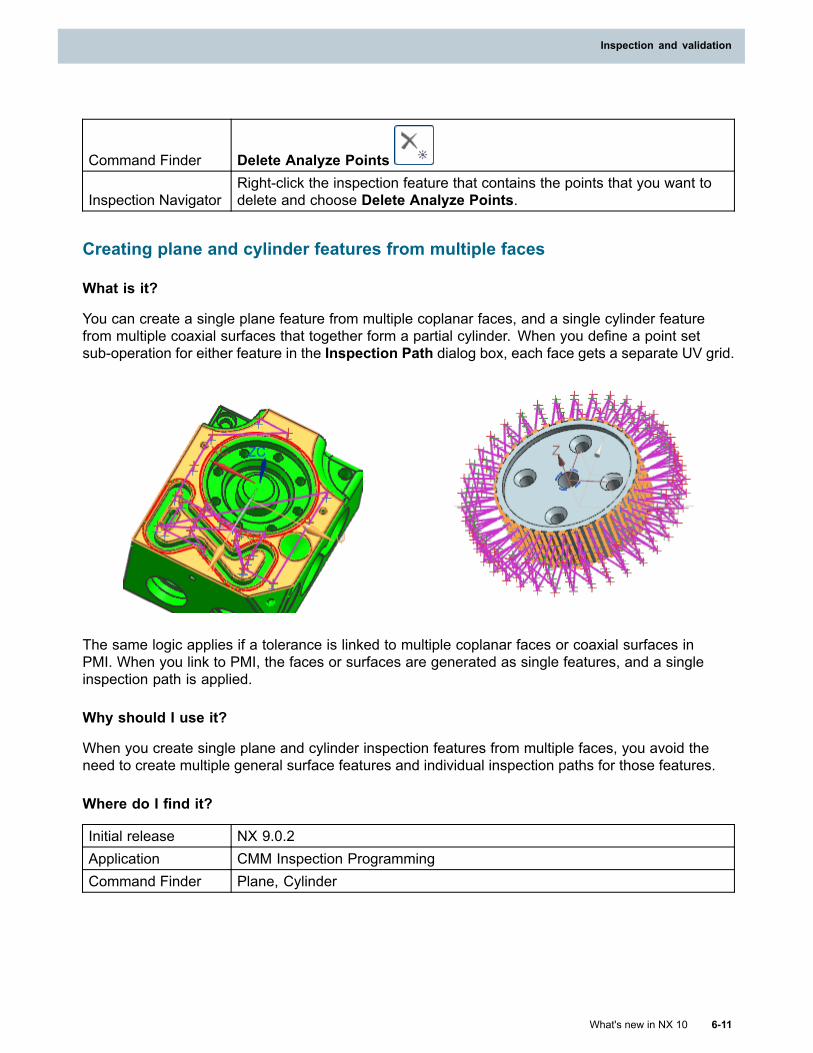
Inspection and validation
Command Finder Delete Analyze Points
Inspection NavigatorRight-click the inspection feature that contains the points that you want todelete and choose Delete Analyze Points.
Creating plane and cylinder features from multiple faces
What is it?
You can create a single plane feature from multiple coplanar faces, and a single cylinder featurefrom multiple coaxial surfaces that together form a partial cylinder. When you define a point setsub-operation for either feature in the Inspection Path dialog box, each face gets a separate UV grid.
The same logic applies if a tolerance is linked to multiple coplanar faces or coaxial surfaces inPMI. When you link to PMI, the faces or surfaces are generated as single features, and a singleinspection path is applied.
Why should I use it?
When you create single plane and cylinder inspection features from multiple faces, you avoid theneed to create multiple general surface features and individual inspection paths for those features.
Where do I find it?
Initial release NX 9.0.2Application CMM Inspection ProgrammingCommand Finder Plane, Cylinder
What's new in NX 10 6-11
Inspection and validation
Chapter 6: Inspection and validation
Location in dialogbox
Creating a single plane feature from multiple coplanar faces:
Plane Inspection Feature dialog box→Geometry group→Select Plane orBase Point
Creating a single cylinder feature from multiple coaxial faces:
Cylinder Inspection Feature dialog box→Geometry group→SelectCylinder or Base Point
Specifying user-defined events (UDEs)
What is it?
You can specify user-defined events (UDEs) to create dialog boxes that let you quickly insert customcode into your post-processed DMIS inspection programs. If you use UDEs, you do not have towrite the same code in each program.
When you post process your program, the manufacturing output manager (MOM):
1. Looks for event parameters generated from UDE dialog boxes. Dialog box parameters aredefined in a ude.cdl file.
2. Handles these event parameters to output custom DMIS code. Event handlers are definedin a ude.tcl file.
ude.cdl→ude.tcl→Custom DMIS code
Why should I use it?
A custom code event might include a command that CMM Inspection Programming does not support,or a complex function that otherwise takes too much work to define for every inspection program.UDEs make custom code reusable.
Where do I find it?
Initial release NX 9.0.2Application CMM Inspection Programming
Prerequisite
Define your dialog boxes in the ude.cdl file and event handlers in theude.tcl file, using a text editor. Restart NX to insert them into your inspectionprograms.
Inspection NavigatorRight-click the object before which you want the event tooccur→Object→Start Events or End Events
Inspection Navigator default object name improvements
The default names and structure of objects in the Inspection Navigator, including inspectionfeatures, paths, constructed and extract features, and tolerances, are improved.
Inspection feature names
In previous versions, all default inspection feature names used the following string:
6-12 What's new in NX 10
Chapter 6: Inspection and validation
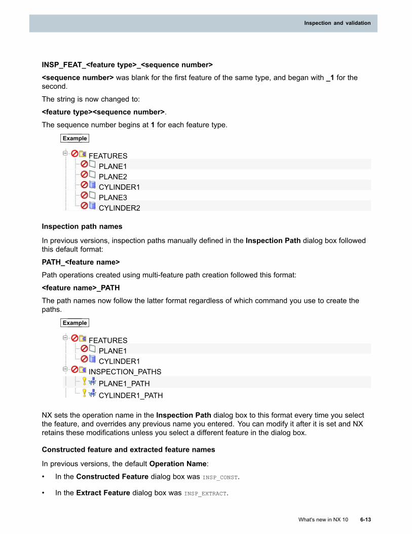
Inspection and validation
INSP_FEAT_<feature type>_<sequence number><sequence number> was blank for the first feature of the same type, and began with _1 for thesecond.
The string is now changed to:
<feature type><sequence number>.The sequence number begins at 1 for each feature type.
Example
FEATURESPLANE1PLANE2CYLINDER1PLANE3CYLINDER2
Inspection path names
In previous versions, inspection paths manually defined in the Inspection Path dialog box followedthis default format:
PATH_<feature name>Path operations created using multi-feature path creation followed this format:
<feature name>_PATHThe path names now follow the latter format regardless of which command you use to create thepaths.
Example
FEATURESPLANE1CYLINDER1
INSPECTION_PATHSPLANE1_PATHCYLINDER1_PATH
NX sets the operation name in the Inspection Path dialog box to this format every time you selectthe feature, and overrides any previous name you entered. You can modify it after it is set and NXretains these modifications unless you select a different feature in the dialog box.
Constructed feature and extracted feature names
In previous versions, the default Operation Name:• In the Constructed Feature dialog box was INSP_CONST.
• In the Extract Feature dialog box was INSP_EXTRACT.
What's new in NX 10 6-13
Inspection and validation
Chapter 6: Inspection and validation
Constructed feature and extract feature operation names now derive from the name in the dialogbox’s Design Feature Name text box, with the text strings _CONST or _EXTRACT appended. Thename of the constructed or extract feature updates if you modify the Design Feature Name.
Example
Name of an existing feature selected fromthe Select Design Feature list in the ExtractFeature dialog box if the Design FeatureMode = Select Existing, or a manuallydefined name if the Design Feature Mode =Create New:
MY_PT1
Constructed feature name:
MY_PT1_CONST
Name of an existing feature selected fromthe Select Design Feature list in the ExtractFeature dialog box:
TOP_PLANE1
Extract feature name:
TOP_PLANE1_EXTRACT
Tolerance operation names
Default tolerance operation names now use the following format:
<feature name>_<dmis tolerance token string>
Example
If a feature is named CYLINDER1 and a diameter tolerance is created, the tolerance is bydefault named CYLINDER1_DIAM.
DMIS tokens include the following.
ANGL CPROFL FLAT RADANGLB CPOFS PARLEL STRGHTANGLR CRNOUT PERP SYMCIRLTY CYLCTY POS TRNOUTCOMPOS DATDEF PROFL WIDTHCONCEN DIAM PROFPCORTOL DISTB PROFS
Where do I find it?
Initial release NX 9.0.3 MP1Application CMM Inspection Programming
6-14 What's new in NX 10
Chapter 6: Inspection and validation
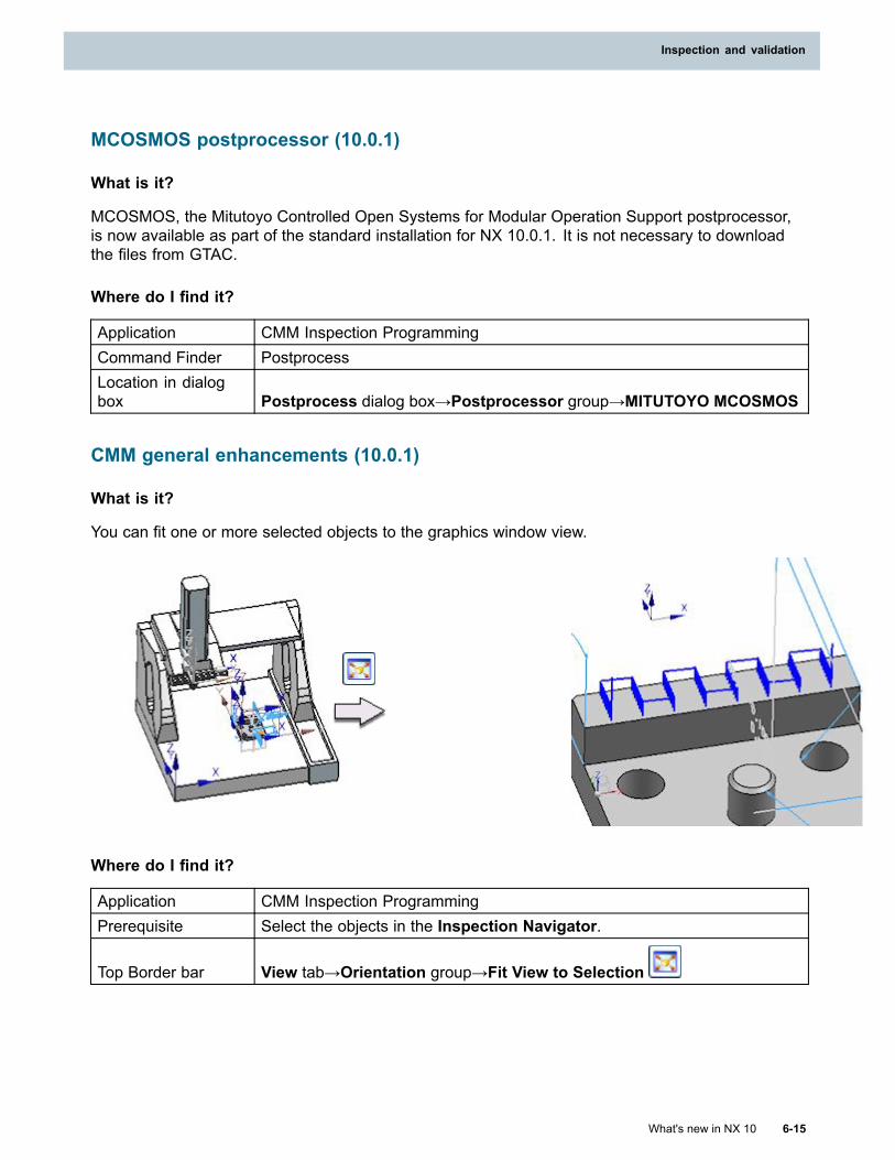
Inspection and validation
MCOSMOS postprocessor (10.0.1)
What is it?
MCOSMOS, the Mitutoyo Controlled Open Systems for Modular Operation Support postprocessor,is now available as part of the standard installation for NX 10.0.1. It is not necessary to downloadthe files from GTAC.
Where do I find it?
Application CMM Inspection ProgrammingCommand Finder PostprocessLocation in dialogbox Postprocess dialog box→Postprocessor group→MITUTOYO MCOSMOS
CMM general enhancements (10.0.1)
What is it?
You can fit one or more selected objects to the graphics window view.
Where do I find it?
Application CMM Inspection ProgrammingPrerequisite Select the objects in the Inspection Navigator.
Top Border bar View tab→Orientation group→Fit View to Selection
What's new in NX 10 6-15
Inspection and validation
Chapter 6: Inspection and validation
CMM general enhancements (10.0.2)
What is it?
Default sensor naming convention
Sensors have a new default naming convention when you create them from the inspection path orby linking PMI. The default name is now the tool name followed by the A and B angles. If there aremultiple tips, NX also appends the tip number.
Example
NX creates the sensor T1_4MM_A45_B90 if you set the following parameters for a cylinderpath in the Inspection Path dialog box:
Operation Characteristics group
Probe = T1_4MM
Sub-Operations group→Point_Set→Point Set dialog box→Sensor group
Sensor Selection = Specify Probe Angles
A Angle = 45
B Angle = 90
For the same cylinder path, if you select the star probe T2_STAR with tips TIP1 throughTIP5, NX creates a sensor for each tip used in the path. If the path uses tips 1, 2, 3, and 5,NX creates the following sensors:
T2_STAR_A45_B90_TIP1
T2_STAR_A45_B90_TIP2
T2_STAR_A45_B90_TIP3
T2_STAR_A45_B90_TIP5
Datum support
CMM Inspection Programming supports both compound datums and direct datums. You control bothusing the datum options in the Tolerance Operation dialog box.
• To specify a compound datum, A and B, enter A-B.
• To specify a direct datum, enter F([feature name]) or FA([feature name]).
Enter F for the nominal feature, or FA for the actual feature. For example, to reference the actualCYLINDER1 feature, enter: FA(CYLINDER1).
6-16 What's new in NX 10
Chapter 6: Inspection and validation
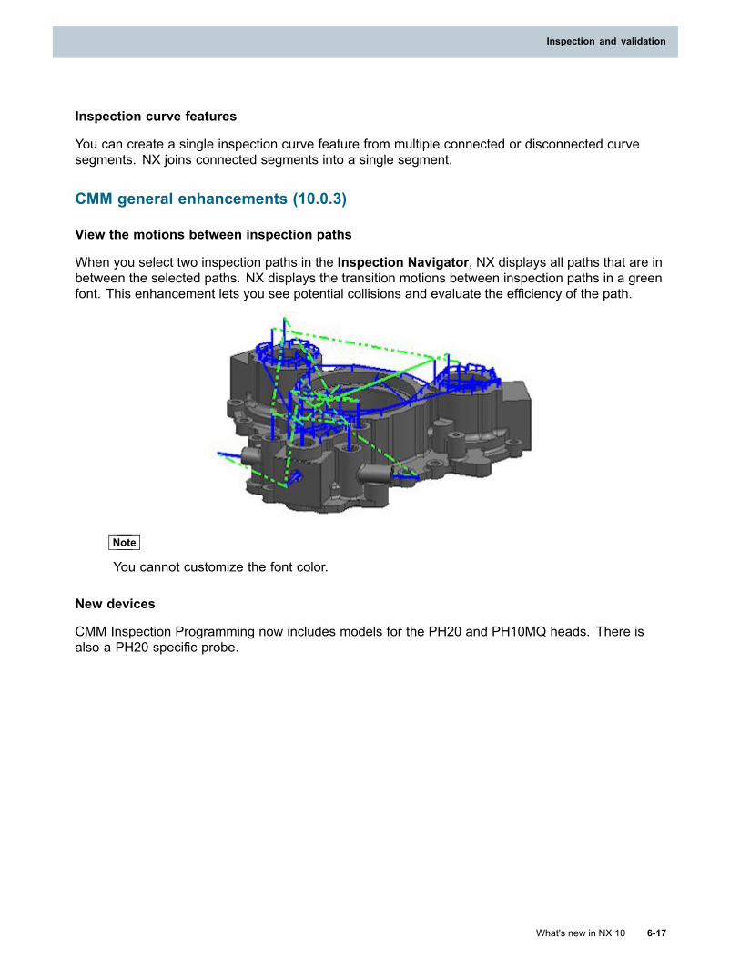
Inspection and validation
Inspection curve features
You can create a single inspection curve feature from multiple connected or disconnected curvesegments. NX joins connected segments into a single segment.
CMM general enhancements (10.0.3)
View the motions between inspection paths
When you select two inspection paths in the Inspection Navigator, NX displays all paths that are inbetween the selected paths. NX displays the transition motions between inspection paths in a greenfont. This enhancement lets you see potential collisions and evaluate the efficiency of the path.
Note
You cannot customize the font color.
New devices
CMM Inspection Programming now includes models for the PH20 and PH10MQ heads. There isalso a PH20 specific probe.
What's new in NX 10 6-17
Inspection and validation
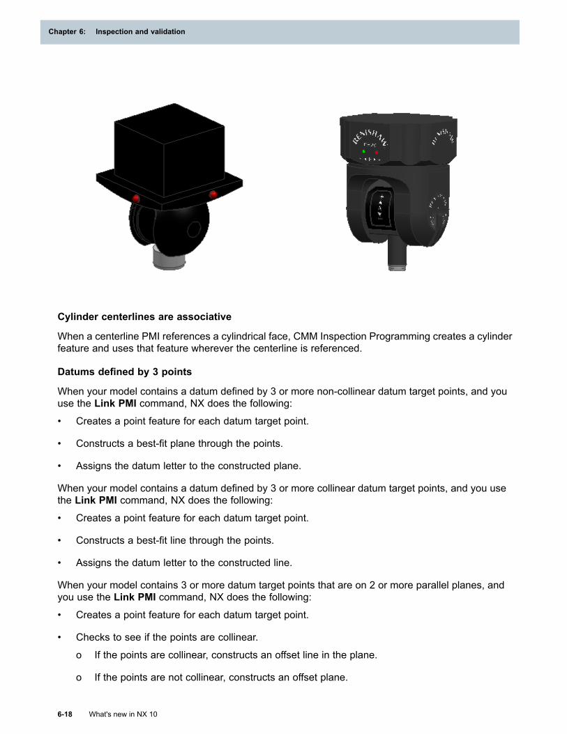
Chapter 6: Inspection and validation
Cylinder centerlines are associative
When a centerline PMI references a cylindrical face, CMM Inspection Programming creates a cylinderfeature and uses that feature wherever the centerline is referenced.
Datums defined by 3 points
When your model contains a datum defined by 3 or more non-collinear datum target points, and youuse the Link PMI command, NX does the following:
• Creates a point feature for each datum target point.
• Constructs a best-fit plane through the points.
• Assigns the datum letter to the constructed plane.
When your model contains a datum defined by 3 or more collinear datum target points, and you usethe Link PMI command, NX does the following:
• Creates a point feature for each datum target point.
• Constructs a best-fit line through the points.
• Assigns the datum letter to the constructed line.
When your model contains 3 or more datum target points that are on 2 or more parallel planes, andyou use the Link PMI command, NX does the following:
• Creates a point feature for each datum target point.
• Checks to see if the points are collinear.
o If the points are collinear, constructs an offset line in the plane.
o If the points are not collinear, constructs an offset plane.
6-18 What's new in NX 10
Chapter 6: Inspection and validation

Inspection and validation
• Assigns the datum letter to the constructed offset line or plane.
Where do I find it?
Application CMM Inspection Programming
What's new in NX 10 6-19
Inspection and validation

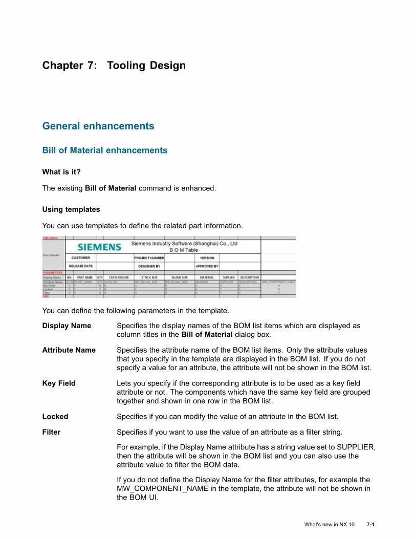
Chapter 7: Tooling Design
General enhancements
Bill of Material enhancements
What is it?
The existing Bill of Material command is enhanced.
Using templates
You can use templates to define the related part information.
You can define the following parameters in the template.
Display Name Specifies the display names of the BOM list items which are displayed ascolumn titles in the Bill of Material dialog box.
Attribute Name Specifies the attribute name of the BOM list items. Only the attribute valuesthat you specify in the template are displayed in the BOM list. If you do notspecify a value for an attribute, the attribute will not be shown in the BOM list.
Key Field Lets you specify if the corresponding attribute is to be used as a key fieldattribute or not. The components which have the same key field are groupedtogether and shown in one row in the BOM list.
Locked Specifies if you can modify the value of an attribute in the BOM list.
Filter Specifies if you want to use the value of an attribute as a filter string.
For example, if the Display Name attribute has a string value set to SUPPLIER,then the attribute will be shown in the BOM list and you can also use theattribute value to filter the BOM data.
If you do not define the Display Name for the filter attributes, for example theMW_COMPONENT_NAME in the template, the attribute will not be shown inthe BOM UI.
What's new in NX 10 7-1
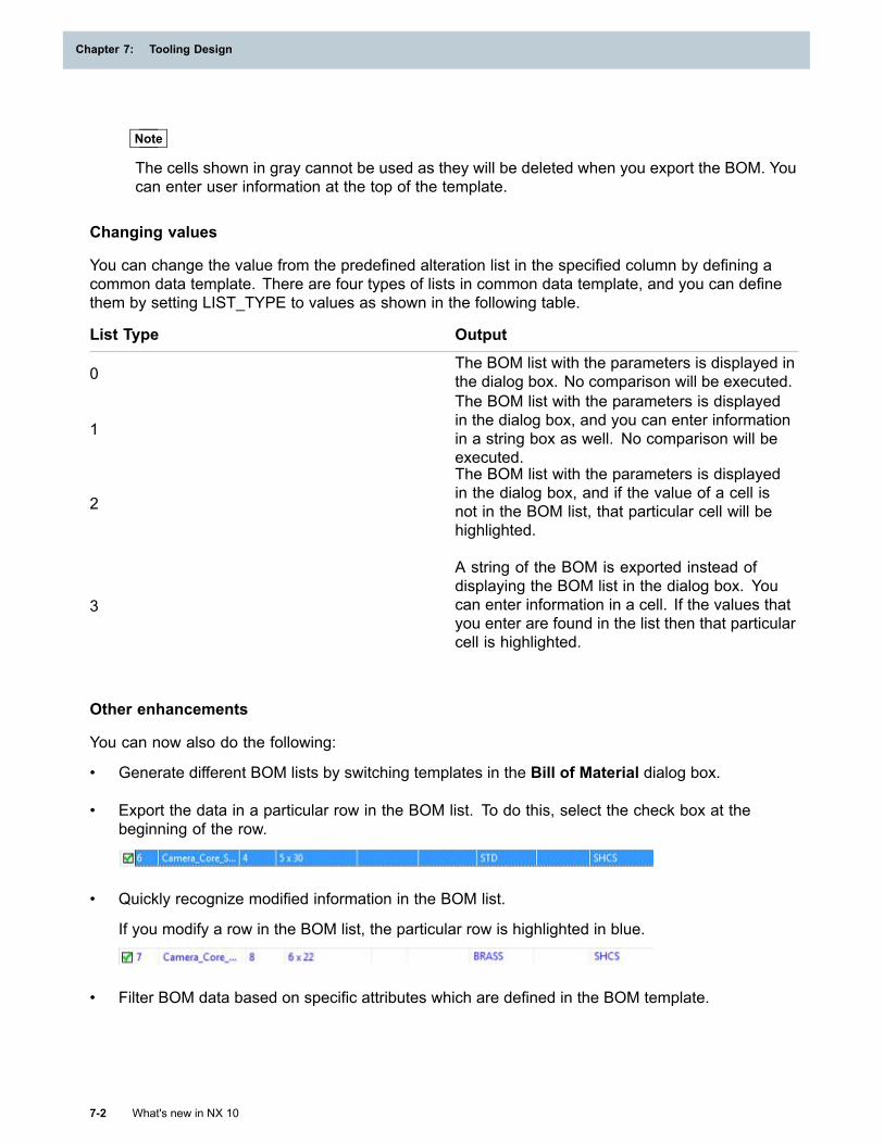
Chapter 7: Tooling Design
Note
The cells shown in gray cannot be used as they will be deleted when you export the BOM. Youcan enter user information at the top of the template.
Changing values
You can change the value from the predefined alteration list in the specified column by defining acommon data template. There are four types of lists in common data template, and you can definethem by setting LIST_TYPE to values as shown in the following table.
List Type Output
0The BOM list with the parameters is displayed inthe dialog box. No comparison will be executed.
1
The BOM list with the parameters is displayedin the dialog box, and you can enter informationin a string box as well. No comparison will beexecuted.
2
The BOM list with the parameters is displayedin the dialog box, and if the value of a cell isnot in the BOM list, that particular cell will behighlighted.
3
A string of the BOM is exported instead ofdisplaying the BOM list in the dialog box. Youcan enter information in a cell. If the values thatyou enter are found in the list then that particularcell is highlighted.
Other enhancements
You can now also do the following:
• Generate different BOM lists by switching templates in the Bill of Material dialog box.
• Export the data in a particular row in the BOM list. To do this, select the check box at thebeginning of the row.
• Quickly recognize modified information in the BOM list.
If you modify a row in the BOM list, the particular row is highlighted in blue.
• Filter BOM data based on specific attributes which are defined in the BOM template.
7-2 What's new in NX 10
Chapter 7: Tooling Design
Tooling Design
Why should I use it?
These enhancements help you to generate BOM with a formatted bill of material template in Excel.You can specify different part attributes in different columns of the template, specify one or more partattributes to be a key field, a lock status, or to filter the column.
Where do I find it?
Application Mold Wizard, Progressive Die Wizard, and Electrode Design
Command Finder Bill of Material
Added functionality in Face Color Management
What is it?
• Color bitmaps identify the colors and attributes for the current part. The information is drawnfrom your specified color spreadsheet. The bitmaps are available in a separate column in theFace Color Management dialog box.
• Colors and attributes can be applied to non-circular holes.
• A new Select Sub-Hole Face Automatically option is available to help you select complexholes more efficiently.
• The Show Face Without Any Manufacturing Information and Show Face With Same
Manufacturing Information options are available as buttons instead of check boxes.
Why should I use it?
Because colors are associated with manufacturing methods, the ability to assign colors to objects is avaluable way to provide instructions for downstream applications, including drawings.
Where do I find it?
Application Mold Wizard, Progressive Die Wizard, Electrode Design
Command Finder Face Color Management
Electrode Design
Create Box
Use this command to create a block or cylinder which envelopes the selected objects. This commandreplaces the previous box feature based on Knowledge Fusion.
What's new in NX 10 7-3
Tooling Design
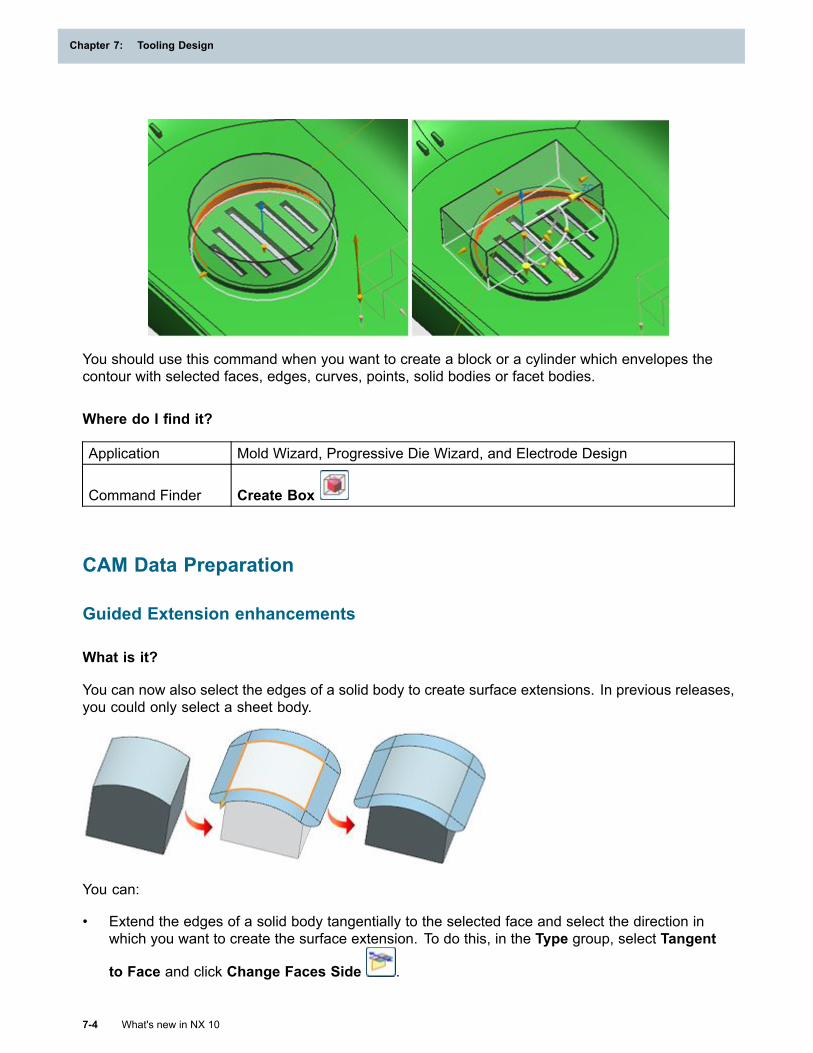
Chapter 7: Tooling Design
You should use this command when you want to create a block or a cylinder which envelopes thecontour with selected faces, edges, curves, points, solid bodies or facet bodies.
Where do I find it?
Application Mold Wizard, Progressive Die Wizard, and Electrode Design
Command Finder Create Box
CAM Data Preparation
Guided Extension enhancements
What is it?
You can now also select the edges of a solid body to create surface extensions. In previous releases,you could only select a sheet body.
You can:
• Extend the edges of a solid body tangentially to the selected face and select the direction inwhich you want to create the surface extension. To do this, in the Type group, select Tangent
to Face and click Change Faces Side .
7-4 What's new in NX 10
Chapter 7: Tooling Design
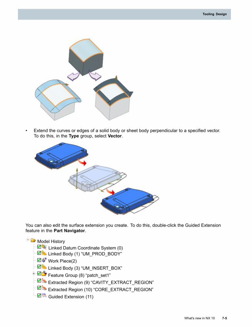
Tooling Design
• Extend the curves or edges of a solid body or sheet body perpendicular to a specified vector.To do this, in the Type group, select Vector.
You can also edit the surface extension you create. To do this, double-click the Guided Extensionfeature in the Part Navigator.
Model HistoryLinked Datum Coordinate System (0)Linked Body (1) “UM_PROD_BODY”Work Piece(2)Linked Body (3) “UM_INSERT_BOX”Feature Group (8) “patch_set1”Extracted Region (9) “CAVITY_EXTRACT_REGION”Extracted Region (10) “CORE_EXTRACT_REGION”Guided Extension (11)
What's new in NX 10 7-5
Tooling Design
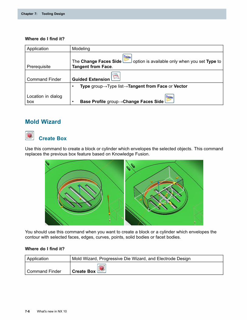
Chapter 7: Tooling Design
Where do I find it?
Application Modeling
PrerequisiteThe Change Faces Side option is available only when you set Type toTangent from Face.
Command Finder Guided Extension
Location in dialogbox
• Type group→Type list→Tangent from Face or Vector
• Base Profile group→Change Faces Side
Mold Wizard
Create Box
Use this command to create a block or cylinder which envelopes the selected objects. This commandreplaces the previous box feature based on Knowledge Fusion.
You should use this command when you want to create a block or a cylinder which envelopes thecontour with selected faces, edges, curves, points, solid bodies or facet bodies.
Where do I find it?
Application Mold Wizard, Progressive Die Wizard, and Electrode Design
Command Finder Create Box
7-6 What's new in NX 10
Chapter 7: Tooling Design
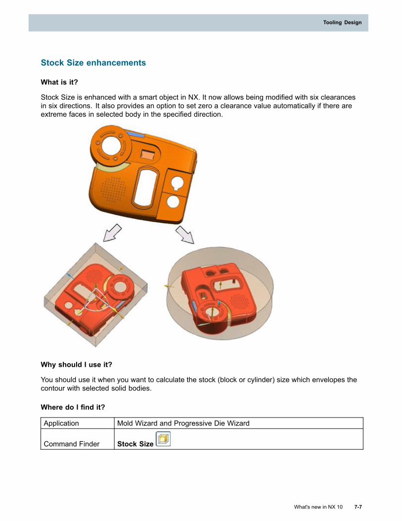
Tooling Design
Stock Size enhancements
What is it?
Stock Size is enhanced with a smart object in NX. It now allows being modified with six clearancesin six directions. It also provides an option to set zero a clearance value automatically if there areextreme faces in selected body in the specified direction.
Why should I use it?
You should use it when you want to calculate the stock (block or cylinder) size which envelopes thecontour with selected solid bodies.
Where do I find it?
Application Mold Wizard and Progressive Die Wizard
Command Finder Stock Size
What's new in NX 10 7-7
Tooling Design
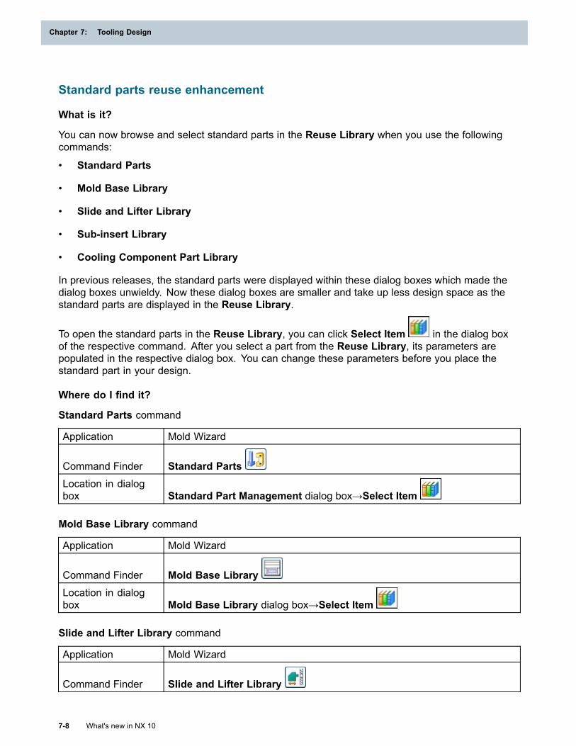
Chapter 7: Tooling Design
Standard parts reuse enhancement
What is it?
You can now browse and select standard parts in the Reuse Library when you use the followingcommands:
• Standard Parts
• Mold Base Library
• Slide and Lifter Library
• Sub-insert Library
• Cooling Component Part Library
In previous releases, the standard parts were displayed within these dialog boxes which made thedialog boxes unwieldy. Now these dialog boxes are smaller and take up less design space as thestandard parts are displayed in the Reuse Library.
To open the standard parts in the Reuse Library, you can click Select Item in the dialog boxof the respective command. After you select a part from the Reuse Library, its parameters arepopulated in the respective dialog box. You can change these parameters before you place thestandard part in your design.
Where do I find it?
Standard Parts command
Application Mold Wizard
Command Finder Standard PartsLocation in dialogbox Standard Part Management dialog box→Select Item
Mold Base Library command
Application Mold Wizard
Command Finder Mold Base LibraryLocation in dialogbox Mold Base Library dialog box→Select Item
Slide and Lifter Library command
Application Mold Wizard
Command Finder Slide and Lifter Library
7-8 What's new in NX 10
Chapter 7: Tooling Design
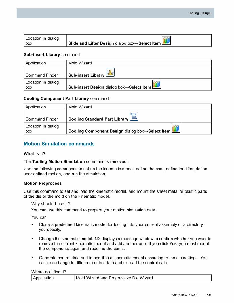
Tooling Design
Location in dialogbox Slide and Lifter Design dialog box→Select Item
Sub-insert Library command
Application Mold Wizard
Command Finder Sub-insert LibraryLocation in dialogbox Sub-insert Design dialog box→Select Item
Cooling Component Part Library command
Application Mold Wizard
Command Finder Cooling Standard Part LibraryLocation in dialogbox Cooling Component Design dialog box→Select Item
Motion Simulation commands
What is it?
The Tooling Motion Simulation command is removed.
Use the following commands to set up the kinematic model, define the cam, define the lifter, defineuser defined motion, and run the simulation.
Motion Preprocess
Use this command to set and load the kinematic model, and mount the sheet metal or plastic partsof the die or the mold on the kinematic model.
Why should I use it?You can use this command to prepare your motion simulation data.
You can:
• Clone a predefined kinematic model for tooling into your current assembly or a directoryyou specify.
• Change the kinematic model. NX displays a message window to confirm whether you want toremove the current kinematic model and add another one. If you click Yes, you must mountthe components again and redefine the cams.
• Generate control data and import it to a kinematic model according to the die settings. Youcan also change to different control data and re-read the control data.
Where do I find it?Application Mold Wizard and Progressive Die Wizard
What's new in NX 10 7-9
Tooling Design
Chapter 7: Tooling Design
Command Finder Motion Preprocess
Define Cam
Use this command to create, edit, or delete a linear cam, a rotary cam, a rocker cam, a user-definedcam, or cushion programming. You can select solid bodies, sheet bodies, or faceted bodies that havesolid or sheet bodies associated with it, and use them to define the cam.
Why should I use it?A predefined kinematic model contains kinematic data about basic cam actions. You can use thiscommand to define the kinematic data for various types of cams. NX automatically calculates andstores the cam data in the kinematic model.
Where do I find it?Application Mold Wizard and Progressive Die Wizard
Command Finder Define Cam
Define Lifter
Use this command to create, edit, or delete a generic lifter or a lifter on a lifter. You can selectsolid bodies, sheet bodies, or faceted bodies that have solid or sheet bodies associated with it, anduse them to define the lifter.
Why should I use it?A predefined kinematic model contains kinematic data about basic lifter actions. You can usethis command to define the kinematic data for various types of lifter actions. NX automaticallycalculates and stores the lifter data in the kinematic model.
Where do I find it?Application Progressive Die Wizard and Mold Wizard
Command Finder Define Lifter
User Defined Motion
Use this command to add user defined motion data to your kinematic model.
Why should I use it?You can define:
• Linear movement along a specific vector.
• Angular movement about a specific axis.
The motion curve is a set of 360 values, one for each timing angle 0-359, that determines how farto move along or about the axis at each point of the simulation. You can use the simple motioncurves created by NX, or supply your own values using a comma separated values (CSV) file.
7-10 What's new in NX 10
Chapter 7: Tooling Design
Tooling Design
Where do I find it?Application Progressive Die Wizard
Command Finder User Defined Motion
Run Simulation
In Progressive Die Wizard, use this command to view an animation that shows the kinematics ofall the automatic and user-identified components in the model.
Why should I use it?You can:
• View the die components and sheet metal parts within the model and check for collisionsand interference.
• Detect and analyze the collision at each angle of the simulation.
Where do I find it?Application Mold Wizard and Progressive Die Wizard
Command Finder Run Simulation
Cooling enhancements
What is it?
Cooling CircuitsClassification of cooling fittings is introduced, once an inlet is selected, the circuit will searchthe intersected channels if they have the same MW_COOLING_CHANNEL_TYPE attributeaccording to the inlet channel.
New color setting is set to cooling circuit channels.
You can specify if you want to create a concept symbol or create a component directly.
These enhancements let you flexibly add the classified cooling standard parts. Different color canbe set to channels in a circuit. Adding parts directly can reduce the time to add component.
Cooling FittingsClassification of cooling fittings is introduced. You can now specify if you want to create a conceptsymbol or directly create a component.
These enhancements let you flexibly add the classified cooling standard parts. Adding partsdirectly can reduce the time to add component.
Direct ChannelYou can now create cooling baffle or cooling channel directly by selecting the specific type.
This enhancement helps you to specify the channel type can create a baffle direction.
What's new in NX 10 7-11
Tooling Design
Chapter 7: Tooling Design
Define ChannelClassification of cooling fittings is introduced. You can define the channel into the type by readingthe register file definition.
You can flexibly define the channel into the classified types.
Where do I find it?
Application Mold Wizard
Command Finder
Cooling Circuits
Cooling Fittings
Direct Channel
Define Channel
Design Ejector Pin
Use the Design Ejector Pin command to command to insert standard ejector components in toyour mold assembly.
You can:
• Search and select your ejector components from the Reuse Library.
• Search for sleeve regions to install sleeve pins and recommend ejector length automatically.
• Specify points for positioning ejector positions.
• Edit X and Y ejector pin position values.
• Quickly edit and remove ejectors.
• Assign symbols to ejector pins.
Where do I find it?
Application Mold Wizard
Command Finder Design Ejector Pin
7-12 What's new in NX 10
Chapter 7: Tooling Design
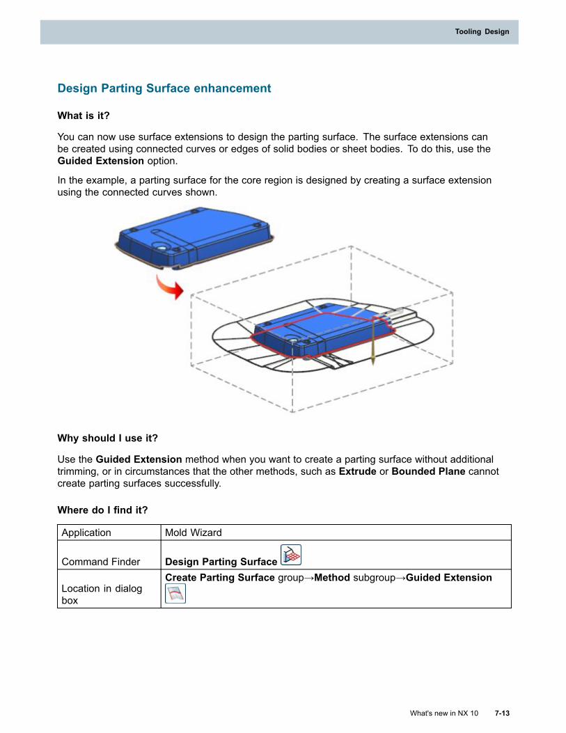
Tooling Design
Design Parting Surface enhancement
What is it?
You can now use surface extensions to design the parting surface. The surface extensions canbe created using connected curves or edges of solid bodies or sheet bodies. To do this, use theGuided Extension option.
In the example, a parting surface for the core region is designed by creating a surface extensionusing the connected curves shown.
Why should I use it?
Use the Guided Extension method when you want to create a parting surface without additionaltrimming, or in circumstances that the other methods, such as Extrude or Bounded Plane cannotcreate parting surfaces successfully.
Where do I find it?
Application Mold Wizard
Command Finder Design Parting Surface
Location in dialogbox
Create Parting Surface group→Method subgroup→Guided Extension
What's new in NX 10 7-13
Tooling Design
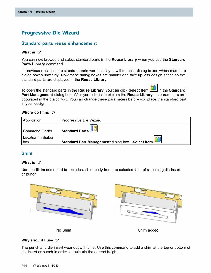
Chapter 7: Tooling Design
Progressive Die Wizard
Standard parts reuse enhancement
What is it?
You can now browse and select standard parts in the Reuse Library when you use the StandardParts Library command.
In previous releases, the standard parts were displayed within these dialog boxes which made thedialog boxes unwieldy. Now these dialog boxes are smaller and take up less design space as thestandard parts are displayed in the Reuse Library.
To open the standard parts in the Reuse Library, you can click Select Item in the StandardPart Management dialog box. After you select a part from the Reuse Library, its parameters arepopulated in the dialog box. You can change these parameters before you place the standard partin your design.
Where do I find it?
Application Progressive Die Wizard
Command Finder Standard PartsLocation in dialogbox Standard Part Management dialog box→Select Item
Shim
What is it?
Use the Shim command to extrude a shim body from the selected face of a piercing die insertor punch.
No Shim Shim added
Why should I use it?
The punch and die insert wear out with time. Use this command to add a shim at the top or bottom ofthe insert or punch in order to maintain the correct height.
7-14 What's new in NX 10
Chapter 7: Tooling Design
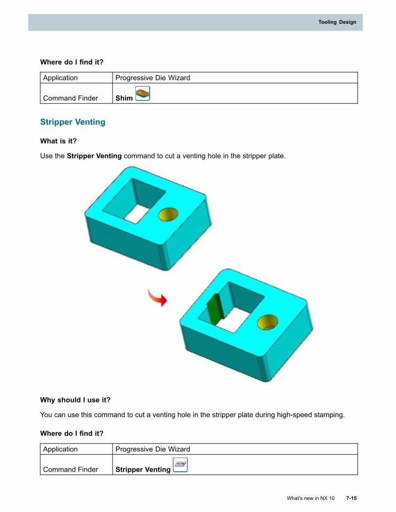
Tooling Design
Where do I find it?
Application Progressive Die Wizard
Command Finder Shim
Stripper Venting
What is it?
Use the Stripper Venting command to cut a venting hole in the stripper plate.
Why should I use it?
You can use this command to cut a venting hole in the stripper plate during high-speed stamping.
Where do I find it?
Application Progressive Die Wizard
Command Finder Stripper Venting
What's new in NX 10 7-15
Tooling Design
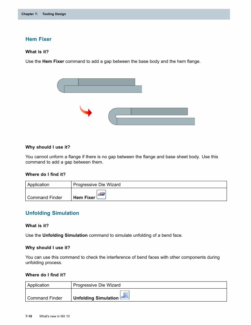
Chapter 7: Tooling Design
Hem Fixer
What is it?
Use the Hem Fixer command to add a gap between the base body and the hem flange.
Why should I use it?
You cannot unform a flange if there is no gap between the flange and base sheet body. Use thiscommand to add a gap between them.
Where do I find it?
Application Progressive Die Wizard
Command Finder Hem Fixer
Unfolding Simulation
What is it?
Use the Unfolding Simulation command to simulate unfolding of a bend face.
Why should I use it?
You can use this command to check the interference of bend faces with other components duringunfolding process.
Where do I find it?
Application Progressive Die Wizard
Command Finder Unfolding Simulation
7-16 What's new in NX 10
Chapter 7: Tooling Design
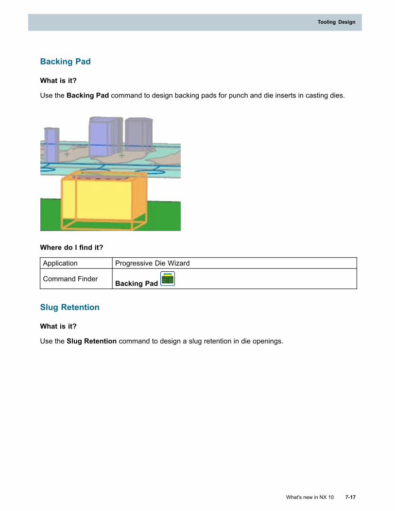
Tooling Design
Backing Pad
What is it?
Use the Backing Pad command to design backing pads for punch and die inserts in casting dies.
Where do I find it?
Application Progressive Die Wizard
Command Finder Backing Pad
Slug Retention
What is it?
Use the Slug Retention command to design a slug retention in die openings.
What's new in NX 10 7-17
Tooling Design
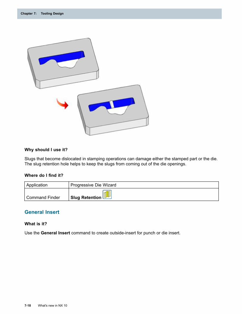
Chapter 7: Tooling Design
Why should I use it?
Slugs that become dislocated in stamping operations can damage either the stamped part or the die.The slug retention hole helps to keep the slugs from coming out of the die openings.
Where do I find it?
Application Progressive Die Wizard
Command Finder Slug Retention
General Insert
What is it?
Use the General Insert command to create outside-insert for punch or die insert.
7-18 What's new in NX 10
Chapter 7: Tooling Design
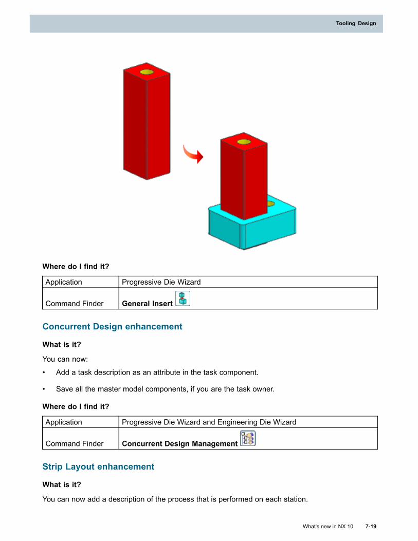
Tooling Design
Where do I find it?
Application Progressive Die Wizard
Command Finder General Insert
Concurrent Design enhancement
What is it?
You can now:
• Add a task description as an attribute in the task component.
• Save all the master model components, if you are the task owner.
Where do I find it?
Application Progressive Die Wizard and Engineering Die Wizard
Command Finder Concurrent Design Management
Strip Layout enhancement
What is it?
You can now add a description of the process that is performed on each station.
What's new in NX 10 7-19
Tooling Design
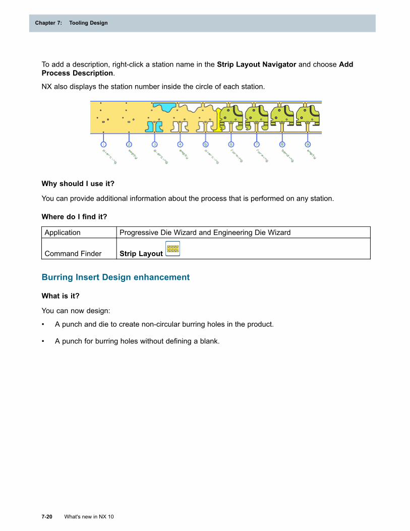
Chapter 7: Tooling Design
To add a description, right-click a station name in the Strip Layout Navigator and choose AddProcess Description.
NX also displays the station number inside the circle of each station.
Why should I use it?
You can provide additional information about the process that is performed on any station.
Where do I find it?
Application Progressive Die Wizard and Engineering Die Wizard
Command Finder Strip Layout
Burring Insert Design enhancement
What is it?
You can now design:
• A punch and die to create non-circular burring holes in the product.
• A punch for burring holes without defining a blank.
7-20 What's new in NX 10
Chapter 7: Tooling Design
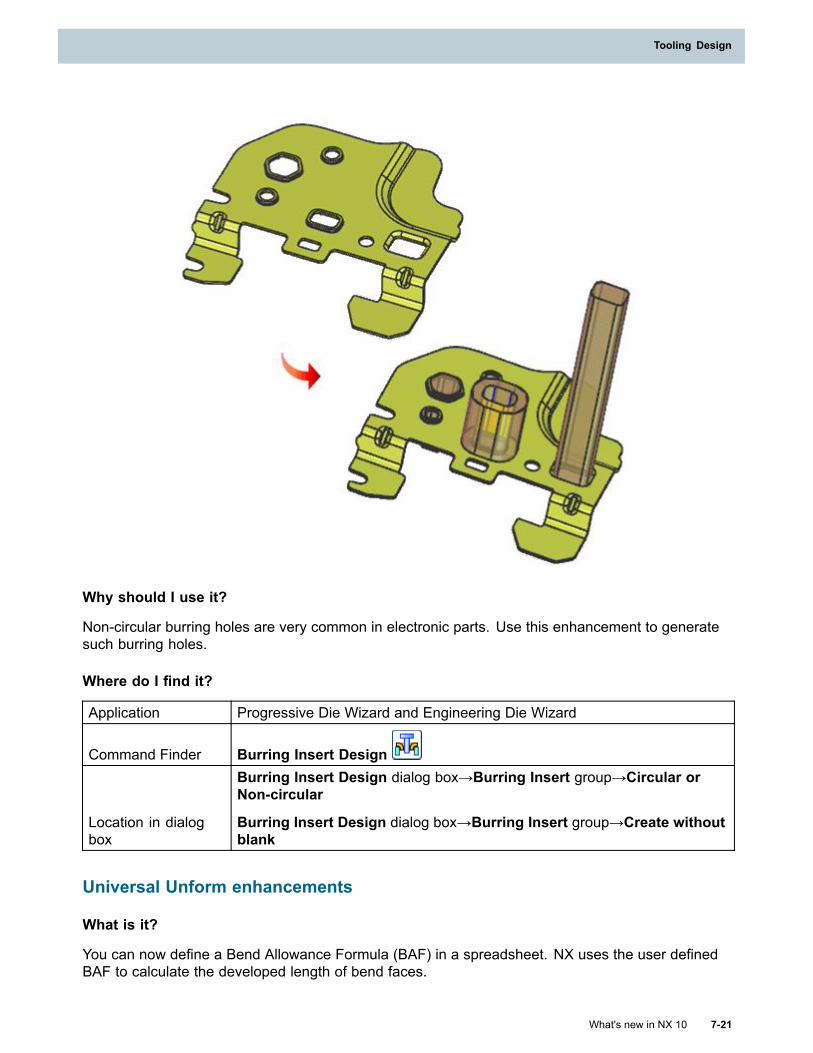
Tooling Design
Why should I use it?
Non-circular burring holes are very common in electronic parts. Use this enhancement to generatesuch burring holes.
Where do I find it?
Application Progressive Die Wizard and Engineering Die Wizard
Command Finder Burring Insert Design
Location in dialogbox
Burring Insert Design dialog box→Burring Insert group→Circular orNon-circular
Burring Insert Design dialog box→Burring Insert group→Create withoutblank
Universal Unform enhancements
What is it?
You can now define a Bend Allowance Formula (BAF) in a spreadsheet. NX uses the user definedBAF to calculate the developed length of bend faces.
What's new in NX 10 7-21
Tooling Design
Chapter 7: Tooling Design
Where do I find it?
Application Progressive Die Wizard and Engineering Die Wizard
Command Finder Universal UnformLocation in dialogbox
Universal Unform dialog box→Define Bend group→Developed LengthCalculation
Direct Unfolding enhancements
What is it?
You can now define a Bend Allowance Formula (BFA) in a spreadsheet. NX uses the user definedBAF from the spreadsheet to calculate the developed length of bend faces.
Where do I find it?
Application Progressive Die Wizard and Engineering Die Wizard
Command Finder Direct UnfoldingLocation in dialogbox
Direct Unfolding dialog box→Define Neutral Factor group→DevelopedLength Calculation
Prebend enhancement
What is it?
When you create a prebend, NX now combines the two Extrude and Divide Face features into asingle Prebend feature in the Part Navigator.
Where do I find it?
Application Progressive Die Wizard and Engineering Die Wizard
Command Finder
Direct Unfolding
Bend Operation
Component Drawing enhancement
What is it?
You can now pass the selected part attributes to the Master Model drawing part.
Where do I find it?
Application Progressive Die Wizard and Engineering Die Wizard
7-22 What's new in NX 10
Chapter 7: Tooling Design
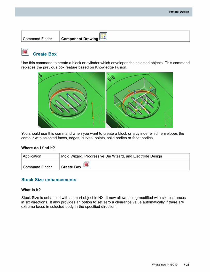
Tooling Design
Command Finder Component Drawing
Create Box
Use this command to create a block or cylinder which envelopes the selected objects. This commandreplaces the previous box feature based on Knowledge Fusion.
You should use this command when you want to create a block or a cylinder which envelopes thecontour with selected faces, edges, curves, points, solid bodies or facet bodies.
Where do I find it?
Application Mold Wizard, Progressive Die Wizard, and Electrode Design
Command Finder Create Box
Stock Size enhancements
What is it?
Stock Size is enhanced with a smart object in NX. It now allows being modified with six clearancesin six directions. It also provides an option to set zero a clearance value automatically if there areextreme faces in selected body in the specified direction.
What's new in NX 10 7-23
Tooling Design
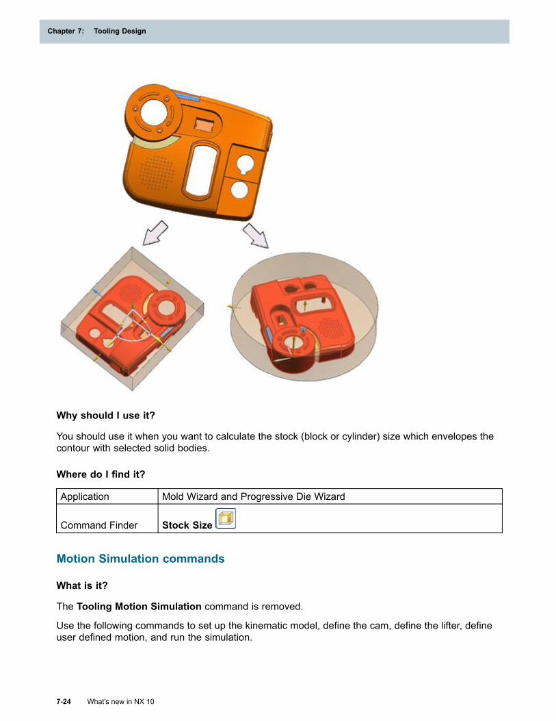
Chapter 7: Tooling Design
Why should I use it?
You should use it when you want to calculate the stock (block or cylinder) size which envelopes thecontour with selected solid bodies.
Where do I find it?
Application Mold Wizard and Progressive Die Wizard
Command Finder Stock Size
Motion Simulation commands
What is it?
The Tooling Motion Simulation command is removed.
Use the following commands to set up the kinematic model, define the cam, define the lifter, defineuser defined motion, and run the simulation.
7-24 What's new in NX 10
Chapter 7: Tooling Design
Tooling Design
Motion Preprocess
Use this command to set and load the kinematic model, and mount the sheet metal or plastic partsof the die or the mold on the kinematic model.
Why should I use it?You can use this command to prepare your motion simulation data.
You can:
• Clone a predefined kinematic model for tooling into your current assembly or a directoryyou specify.
• Change the kinematic model. NX displays a message window to confirm whether you want toremove the current kinematic model and add another one. If you click Yes, you must mountthe components again and redefine the cams.
• Generate control data and import it to a kinematic model according to the die settings. Youcan also change to different control data and re-read the control data.
Where do I find it?Application Mold Wizard and Progressive Die Wizard
Command Finder Motion Preprocess
Define Cam
Use this command to create, edit, or delete a linear cam, a rotary cam, a rocker cam, a user-definedcam, or cushion programming. You can select solid bodies, sheet bodies, or faceted bodies that havesolid or sheet bodies associated with it, and use them to define the cam.
Why should I use it?A predefined kinematic model contains kinematic data about basic cam actions. You can use thiscommand to define the kinematic data for various types of cams. NX automatically calculates andstores the cam data in the kinematic model.
Where do I find it?Application Mold Wizard and Progressive Die Wizard
Command Finder Define Cam
Define Lifter
Use this command to create, edit, or delete a generic lifter or a lifter on a lifter. You can selectsolid bodies, sheet bodies, or faceted bodies that have solid or sheet bodies associated with it, anduse them to define the lifter.
Why should I use it?A predefined kinematic model contains kinematic data about basic lifter actions. You can usethis command to define the kinematic data for various types of lifter actions. NX automaticallycalculates and stores the lifter data in the kinematic model.
What's new in NX 10 7-25
Tooling Design
Chapter 7: Tooling Design
Where do I find it?Application Progressive Die Wizard and Mold Wizard
Command Finder Define Lifter
User Defined Motion
Use this command to add user defined motion data to your kinematic model.
Why should I use it?You can define:
• Linear movement along a specific vector.
• Angular movement about a specific axis.
The motion curve is a set of 360 values, one for each timing angle 0-359, that determines how farto move along or about the axis at each point of the simulation. You can use the simple motioncurves created by NX, or supply your own values using a comma separated values (CSV) file.
Where do I find it?Application Progressive Die Wizard
Command Finder User Defined Motion
Run Simulation
In Progressive Die Wizard, use this command to view an animation that shows the kinematics ofall the automatic and user-identified components in the model.
Why should I use it?You can:
• View the die components and sheet metal parts within the model and check for collisionsand interference.
• Detect and analyze the collision at each angle of the simulation.
Where do I find it?Application Mold Wizard and Progressive Die Wizard
Command Finder Run Simulation
Die Engineering
Using a new die surface in an existing stamping die workflow
This workflow shows how to use a new or modified die surface in an existing stamping die workflow.
7-26 What's new in NX 10
Chapter 7: Tooling Design
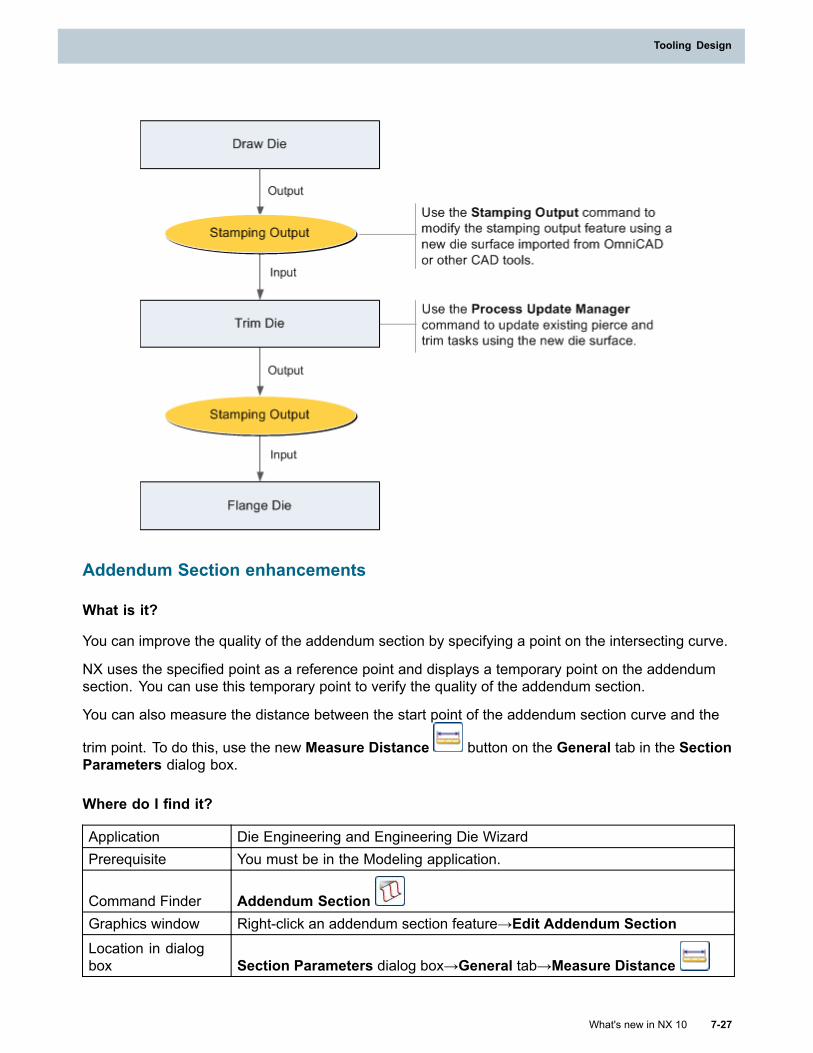
Tooling Design
Addendum Section enhancements
What is it?
You can improve the quality of the addendum section by specifying a point on the intersecting curve.
NX uses the specified point as a reference point and displays a temporary point on the addendumsection. You can use this temporary point to verify the quality of the addendum section.
You can also measure the distance between the start point of the addendum section curve and the
trim point. To do this, use the new Measure Distance button on the General tab in the SectionParameters dialog box.
Where do I find it?
Application Die Engineering and Engineering Die WizardPrerequisite You must be in the Modeling application.
Command Finder Addendum SectionGraphics window Right-click an addendum section feature→Edit Addendum SectionLocation in dialogbox Section Parameters dialog box→General tab→Measure Distance
What's new in NX 10 7-27
Tooling Design
Chapter 7: Tooling Design
Develop Trim Line enhancements
What is it?
You can generate the trim line profile using the FEM method that uses the One-Step solver.
When you use this command, you can also:
• Select sheet material either from the NX material library or local material library.
• Define density, thickness, Poisson’s ratio, Yield stress, and so on.
• Specify solver parameters such as convergence level, iteration steps, and so on to increasethe accuracy of the trim line profile.
Where do I find it?
Application Die Engineering and Engineering Die WizardPrerequisite You must be in the Modeling application.
Command Finder Develop Trim Line
Stamping Output enhancements
What is it?
You can update a die surface in OmniCAD or another CAD tool, import the surface into NX, and use itin the next stamping operation without changing the existing stamping die workflow.
Use the new Stamping Output command to modify or create a stamping output feature that usesthe imported die surface. The stamping output feature includes the legacy surface and the newdie surface.
To use the new die surface in the next stamping operation, you must update existing dependentfeatures such as pierce and trim tasks that use the legacy die surface. Use the Process UpdateManager command to manage the existing pierce and trim tasks.
Why should I use it?
To meet manufacturing requirements, you can use an updated die surface from another CAD tool in anexisting stamping die workflow. This capability helps to reduce design time and increase productivity.
Where do I find it?
Application Die EngineeringPrerequisite You must be in the Modeling application.
Command Finder Stamping Output
7-28 What's new in NX 10
Chapter 7: Tooling Design
Tooling Design
Process Update Manager
Use the Process Update Manager command to display and update existing pierce and trim tasksafter you modify the stamping output feature.
In a stamping die workflow, when you modify the stamping output feature using a new die face, youmust update the existing pierce and trim tasks that use the old die face.
When you use the Process Update Manager command, you can:
• Select the type of task that you want to update. Depending on the selected pierce or trim tasktype, NX maps the existing tasks to the new die face and displays a list in the dialog box. Thelist includes the name of the task, the stamping operation associated with the task, and thestatus of the task.
• Update the existing tasks by selecting each task from the list. NX changes the status of theupdated tasks to Completed.
• View and compare the old and new die faces in the graphics window by setting the displaystatus of the die faces.
• View existing tasks for a single operation or all stamping operations.
Where do I find it?
Application Die EngineeringPrerequisite You must be in the Modeling application.
Command Finder Process Update Manager
Stamping Carryover enhancements
What is it?
You can copy a stamping output feature that includes existing and new die surfaces, from theprevious stamping operation to the current stamping operation.
This helps you to perform die engineering tasks on a new die surface and quickly complete thenew design workflow.
Where do I find it?
Application Die EngineeringPrerequisite You must be in the Modeling application.
Command Finder Stamping Carryover
What's new in NX 10 7-29
Tooling Design
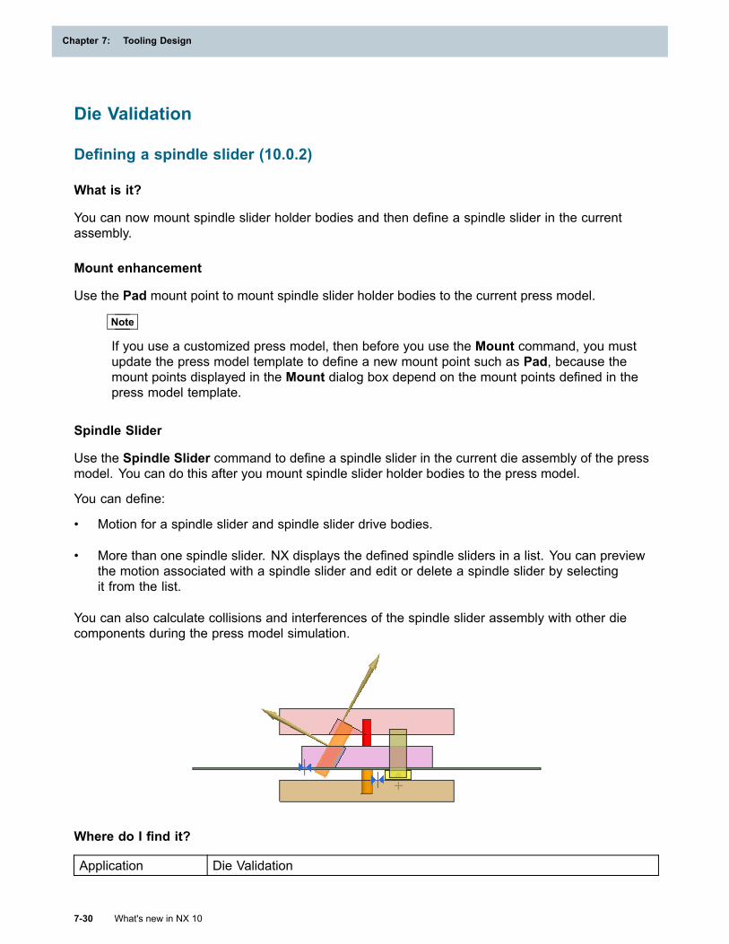
Chapter 7: Tooling Design
Die Validation
Defining a spindle slider (10.0.2)
What is it?
You can now mount spindle slider holder bodies and then define a spindle slider in the currentassembly.
Mount enhancement
Use the Pad mount point to mount spindle slider holder bodies to the current press model.
Note
If you use a customized press model, then before you use the Mount command, you mustupdate the press model template to define a new mount point such as Pad, because themount points displayed in the Mount dialog box depend on the mount points defined in thepress model template.
Spindle Slider
Use the Spindle Slider command to define a spindle slider in the current die assembly of the pressmodel. You can do this after you mount spindle slider holder bodies to the press model.
You can define:
• Motion for a spindle slider and spindle slider drive bodies.
• More than one spindle slider. NX displays the defined spindle sliders in a list. You can previewthe motion associated with a spindle slider and edit or delete a spindle slider by selectingit from the list.
You can also calculate collisions and interferences of the spindle slider assembly with other diecomponents during the press model simulation.
Where do I find it?
Application Die Validation
7-30 What's new in NX 10
Chapter 7: Tooling Design
Tooling Design
Prerequisite
You must be in the Modeling application.
For the Spindle Slider command, the spindle slider, holder, and drive bodiesmust be mounted to the press model to determine the contact driven motionbetween the spindle slider and the other bodies.
Command Finder Mount and Spindle Slider
Location in dialogbox
Mount dialog box:
Selection Steps group→Mount option→Mount Selected Bodies Onlist→Pad
Set Press Model enhancement (10.0.2)
What is it?
You can now attach different press models to the current assembly.
Use the Press Model Path option to set a folder path for the different press models and to view allthe press models in the Available Press Models list. You can then attach a desired press model tothe current assembly by selecting the model from the list.
Where do I find it?
Application Die ValidationPrerequisite You must be in the Modeling application.
Command Finder Set Press ModelLocation in dialogbox Settings group→Press Model Path
OmniCAD for NX
OmniCAD commands enhancements
What is it?
You can morph objects in the NX CAD environment using the following integrated OmniCADcommands. When you use these commands, NX now creates features for each of these commands.
OmniFreeTransformer
Use this command to morph objects using points and curves as constraints.
OmniMeshTransformer
Use this command to morph objects using CAE Meshes, STL files, or pointclouds.
To edit a feature, double-click it in the Part Navigator.
What's new in NX 10 7-31
Tooling Design
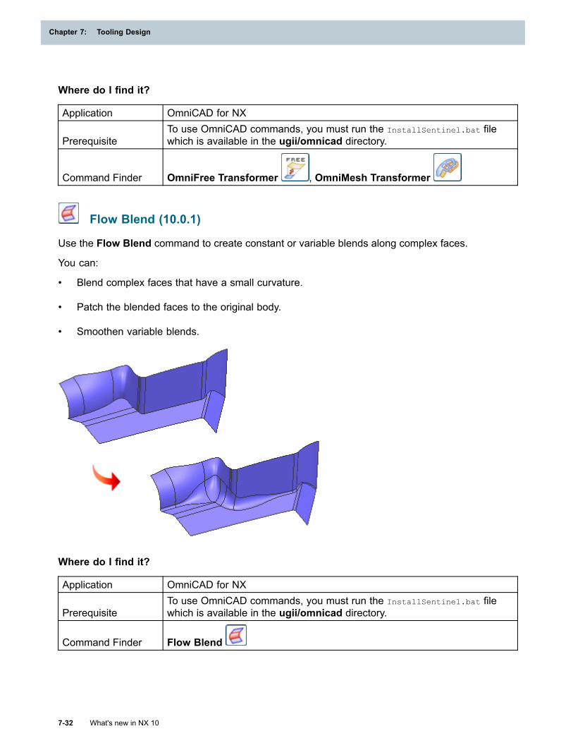
Chapter 7: Tooling Design
Where do I find it?
Application OmniCAD for NX
PrerequisiteTo use OmniCAD commands, you must run the InstallSentinel.bat filewhich is available in the ugii/omnicad directory.
Command Finder OmniFree Transformer , OmniMesh Transformer
Flow Blend (10.0.1)
Use the Flow Blend command to create constant or variable blends along complex faces.
You can:
• Blend complex faces that have a small curvature.
• Patch the blended faces to the original body.
• Smoothen variable blends.
Where do I find it?
Application OmniCAD for NX
PrerequisiteTo use OmniCAD commands, you must run the InstallSentinel.bat filewhich is available in the ugii/omnicad directory.
Command Finder Flow Blend
7-32 What's new in NX 10
Chapter 7: Tooling Design
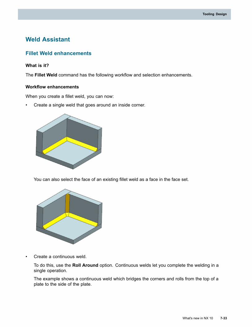
Tooling Design
Weld Assistant
Fillet Weld enhancements
What is it?
The Fillet Weld command has the following workflow and selection enhancements.
Workflow enhancements
When you create a fillet weld, you can now:
• Create a single weld that goes around an inside corner.
You can also select the face of an existing fillet weld as a face in the face set.
• Create a continuous weld.
To do this, use the Roll Around option. Continuous welds let you complete the welding in asingle operation.
The example shows a continuous weld which bridges the corners and rolls from the top of aplate to the side of the plate.
What's new in NX 10 7-33
Tooling Design
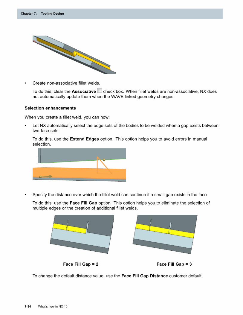
Chapter 7: Tooling Design
• Create non-associative fillet welds.
To do this, clear the Associative check box. When fillet welds are non-associative, NX doesnot automatically update them when the WAVE linked geometry changes.
Selection enhancements
When you create a fillet weld, you can now:
• Let NX automatically select the edge sets of the bodies to be welded when a gap exists betweentwo face sets.
To do this, use the Extend Edges option. This option helps you to avoid errors in manualselection.
• Specify the distance over which the fillet weld can continue if a small gap exists in the face.
To do this, use the Face Fill Gap option. This option helps you to eliminate the selection ofmultiple edges or the creation of additional fillet welds.
Face Fill Gap = 2 Face Fill Gap = 3
To change the default distance value, use the Face Fill Gap Distance customer default.
7-34 What's new in NX 10
Chapter 7: Tooling Design
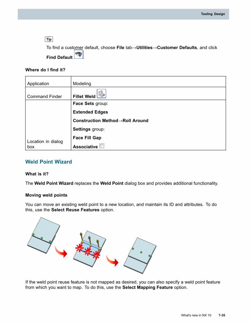
Tooling Design
Tip
To find a customer default, choose File tab→Utilities→Customer Defaults, and click
Find Default .
Where do I find it?
Application Modeling
Command Finder Fillet Weld
Location in dialogbox
Face Sets group:
Extended Edges
Construction Method→Roll Around
Settings group:
Face Fill Gap
Associative
Weld Point Wizard
What is it?
TheWeld Point Wizard replaces theWeld Point dialog box and provides additional functionality.
Moving weld points
You can move an existing weld point to a new location, and maintain its ID and attributes. To dothis, use the Select Reuse Features option.
If the weld point reuse feature is not mapped as desired, you can also specify a weld point featurefrom which you want to map. To do this, use the Select Mapping Feature option.
What's new in NX 10 7-35
Tooling Design
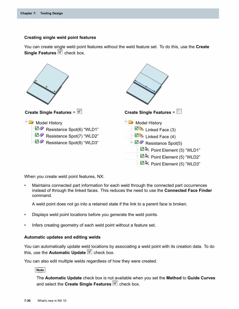
Chapter 7: Tooling Design
Creating single weld point features
You can create single weld point features without the weld feature set. To do this, use the CreateSingle Features check box.
Create Single Features =
Model HistoryResistance Spot(6) “WLD1”Resistance Spot(7) “WLD2”Resistance Spot(8) “WLD3”
Create Single Features =
Model HistoryLinked Face (3)Linked Face (4)Resistance Spot(5)
Point Element (5) ”WLD1”Point Element (5) ”WLD2”Point Element (5) ”WLD3”
When you create weld point features, NX:
• Maintains connected part information for each weld through the connected part occurrencesinstead of through the linked faces. This reduces the need to use the Connected Face Findercommand.
A weld point does not go into a retained state if the link to a parent face is broken.
• Displays weld point locations before you generate the weld points.
• Infers creating geometry of each weld point without a feature set.
Automatic updates and editing welds
You can automatically update weld locations by associating a weld point with its creation data. To dothis, use the Automatic Update check box.
You can also edit multiple welds regardless of how they were created.
Note
The Automatic Update check box is not available when you set the Method to Guide Curvesand select the Create Single Features check box.
7-36 What's new in NX 10
Chapter 7: Tooling Design
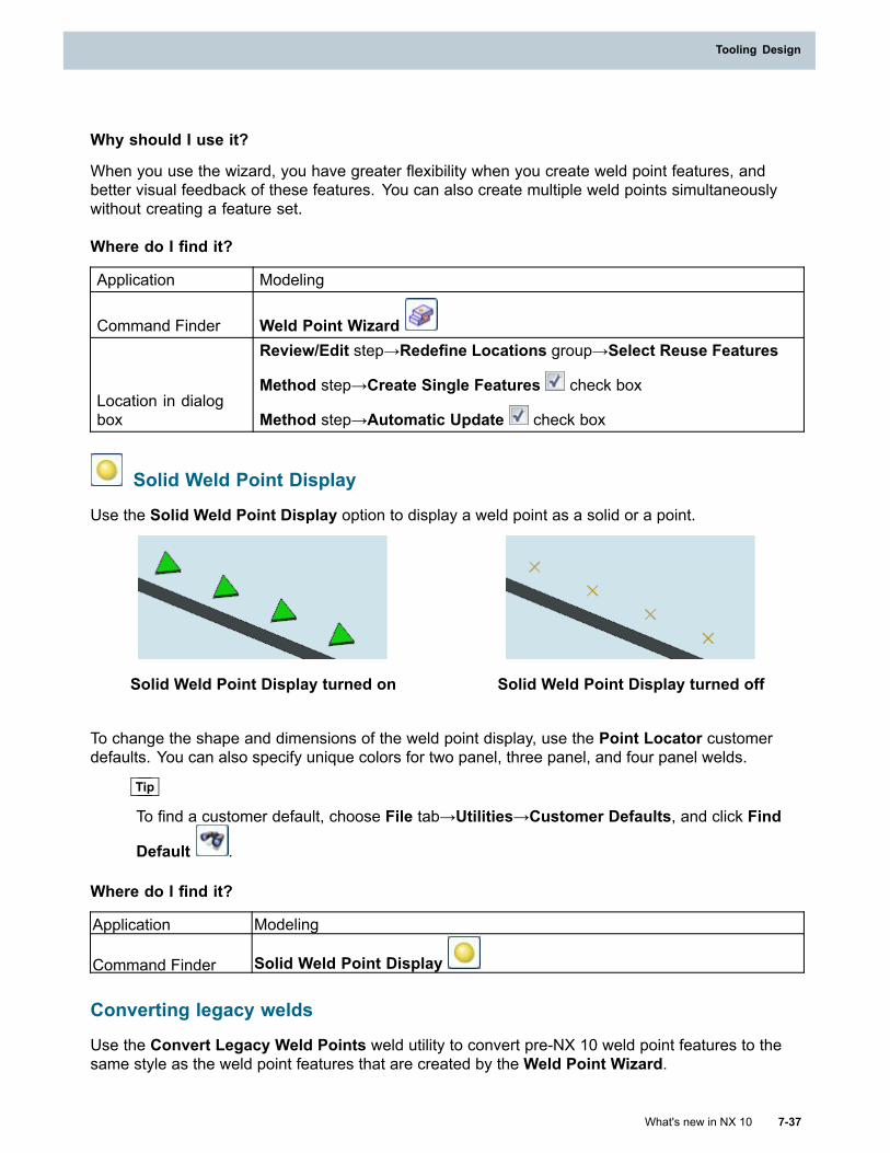
Tooling Design
Why should I use it?
When you use the wizard, you have greater flexibility when you create weld point features, andbetter visual feedback of these features. You can also create multiple weld points simultaneouslywithout creating a feature set.
Where do I find it?
Application Modeling
Command Finder Weld Point Wizard
Location in dialogbox
Review/Edit step→Redefine Locations group→Select Reuse Features
Method step→Create Single Features check box
Method step→Automatic Update check box
Solid Weld Point Display
Use the Solid Weld Point Display option to display a weld point as a solid or a point.
Solid Weld Point Display turned on Solid Weld Point Display turned off
To change the shape and dimensions of the weld point display, use the Point Locator customerdefaults. You can also specify unique colors for two panel, three panel, and four panel welds.
Tip
To find a customer default, choose File tab→Utilities→Customer Defaults, and click Find
Default .
Where do I find it?
Application Modeling
Command Finder Solid Weld Point Display
Converting legacy welds
Use the Convert Legacy Weld Points weld utility to convert pre-NX 10 weld point features to thesame style as the weld point features that are created by the Weld Point Wizard.
What's new in NX 10 7-37
Tooling Design
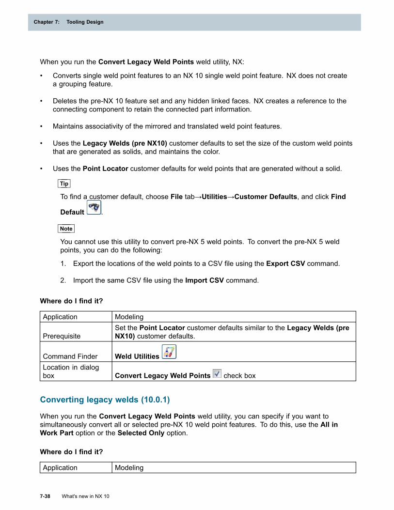
Chapter 7: Tooling Design
When you run the Convert Legacy Weld Points weld utility, NX:
• Converts single weld point features to an NX 10 single weld point feature. NX does not createa grouping feature.
• Deletes the pre-NX 10 feature set and any hidden linked faces. NX creates a reference to theconnecting component to retain the connected part information.
• Maintains associativity of the mirrored and translated weld point features.
• Uses the Legacy Welds (pre NX10) customer defaults to set the size of the custom weld pointsthat are generated as solids, and maintains the color.
• Uses the Point Locator customer defaults for weld points that are generated without a solid.
Tip
To find a customer default, choose File tab→Utilities→Customer Defaults, and click Find
Default .
Note
You cannot use this utility to convert pre-NX 5 weld points. To convert the pre-NX 5 weldpoints, you can do the following:
1. Export the locations of the weld points to a CSV file using the Export CSV command.
2. Import the same CSV file using the Import CSV command.
Where do I find it?
Application Modeling
PrerequisiteSet the Point Locator customer defaults similar to the Legacy Welds (preNX10) customer defaults.
Command Finder Weld UtilitiesLocation in dialogbox Convert Legacy Weld Points check box
Converting legacy welds (10.0.1)
When you run the Convert Legacy Weld Points weld utility, you can specify if you want tosimultaneously convert all or selected pre-NX 10 weld point features. To do this, use the All inWork Part option or the Selected Only option.
Where do I find it?
Application Modeling
7-38 What's new in NX 10
Chapter 7: Tooling Design
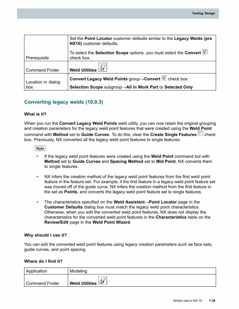
Tooling Design
Prerequisite
Set the Point Locator customer defaults similar to the Legacy Welds (preNX10) customer defaults.
To select the Selection Scope options, you must select the Convertcheck box.
Command Finder Weld Utilities
Location in dialogbox
Convert Legacy Weld Points group→Convert check box
Selection Scope subgroup→All in Work Part or Selected Only
Converting legacy welds (10.0.3)
What is it?
When you run the Convert Legacy Weld Points weld utility, you can now retain the original groupingand creation parameters for the legacy weld point features that were created using the Weld Pointcommand with Method set to Guide Curves. To do this, clear the Create Single Features checkbox. Previously, NX converted all the legacy weld point features to single features.
Note
• If the legacy weld point features were created using the Weld Point command but withMethod set to Guide Curves and Spacing Method set to Mid Point, NX converts themto single features.
• NX infers the creation method of the legacy weld point features from the first weld pointfeature in the feature set. For example, if the first feature in a legacy weld point feature setwas moved off of the guide curve, NX infers the creation method from the first feature inthe set as Points, and converts the legacy weld point feature set to single features.
• The characteristics specified on the Weld Assistant→Point Locator page in theCustomer Defaults dialog box must match the legacy weld point characteristics.Otherwise, when you edit the converted weld point features, NX does not display thecharacteristics for the converted weld point features in the Characteristics table on theReview/Edit page in the Weld Point Wizard.
Why should I use it?
You can edit the converted weld point features using legacy creation parameters such as face sets,guide curves, and point spacing.
Where do I find it?
Application Modeling
Command Finder Weld Utilities
What's new in NX 10 7-39
Tooling Design
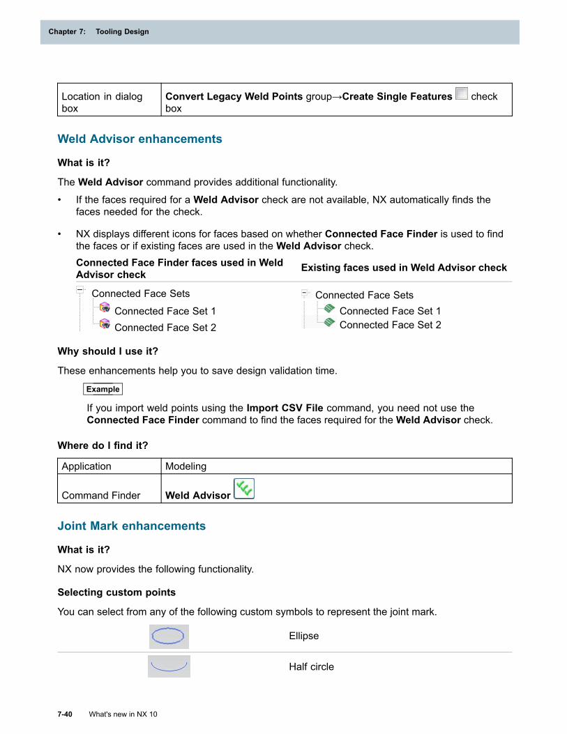
Chapter 7: Tooling Design
Location in dialogbox
Convert Legacy Weld Points group→Create Single Features checkbox
Weld Advisor enhancements
What is it?
The Weld Advisor command provides additional functionality.• If the faces required for a Weld Advisor check are not available, NX automatically finds the
faces needed for the check.
• NX displays different icons for faces based on whether Connected Face Finder is used to findthe faces or if existing faces are used in the Weld Advisor check.Connected Face Finder faces used in WeldAdvisor check Existing faces used in Weld Advisor check
Connected Face Sets
Connected Face Set 1Connected Face Set 2
Connected Face SetsConnected Face Set 1Connected Face Set 2
Why should I use it?
These enhancements help you to save design validation time.
Example
If you import weld points using the Import CSV File command, you need not use theConnected Face Finder command to find the faces required for theWeld Advisor check.
Where do I find it?
Application Modeling
Command Finder Weld Advisor
Joint Mark enhancements
What is it?
NX now provides the following functionality.
Selecting custom points
You can select from any of the following custom symbols to represent the joint mark.
Ellipse
Half circle
7-40 What's new in NX 10
Chapter 7: Tooling Design

Tooling Design
Line
In previous releases, you had to create custom symbols, and configure NX to display the customsymbols in the Reuse Library.
Creating joint marks through translation
You can create joint marks by translating existing joint marks. To do this, use the Translate option.
Moving joint marks
You can move an existing joint mark to a new location, and maintain its ID and attributes. To do this,use the Select Reuse Feature option.
What's new in NX 10 7-41
Tooling Design
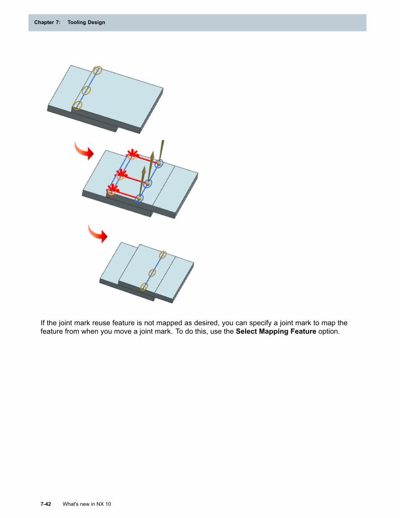
Chapter 7: Tooling Design
If the joint mark reuse feature is not mapped as desired, you can specify a joint mark to map thefeature from when you move a joint mark. To do this, use the Select Mapping Feature option.
7-42 What's new in NX 10
Chapter 7: Tooling Design
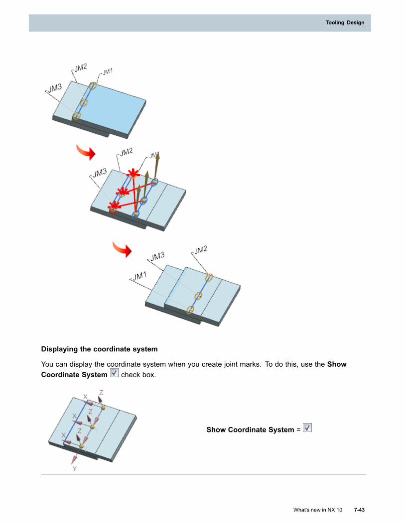
Tooling Design
Displaying the coordinate system
You can display the coordinate system when you create joint marks. To do this, use the ShowCoordinate System check box.
Show Coordinate System =
What's new in NX 10 7-43
Tooling Design
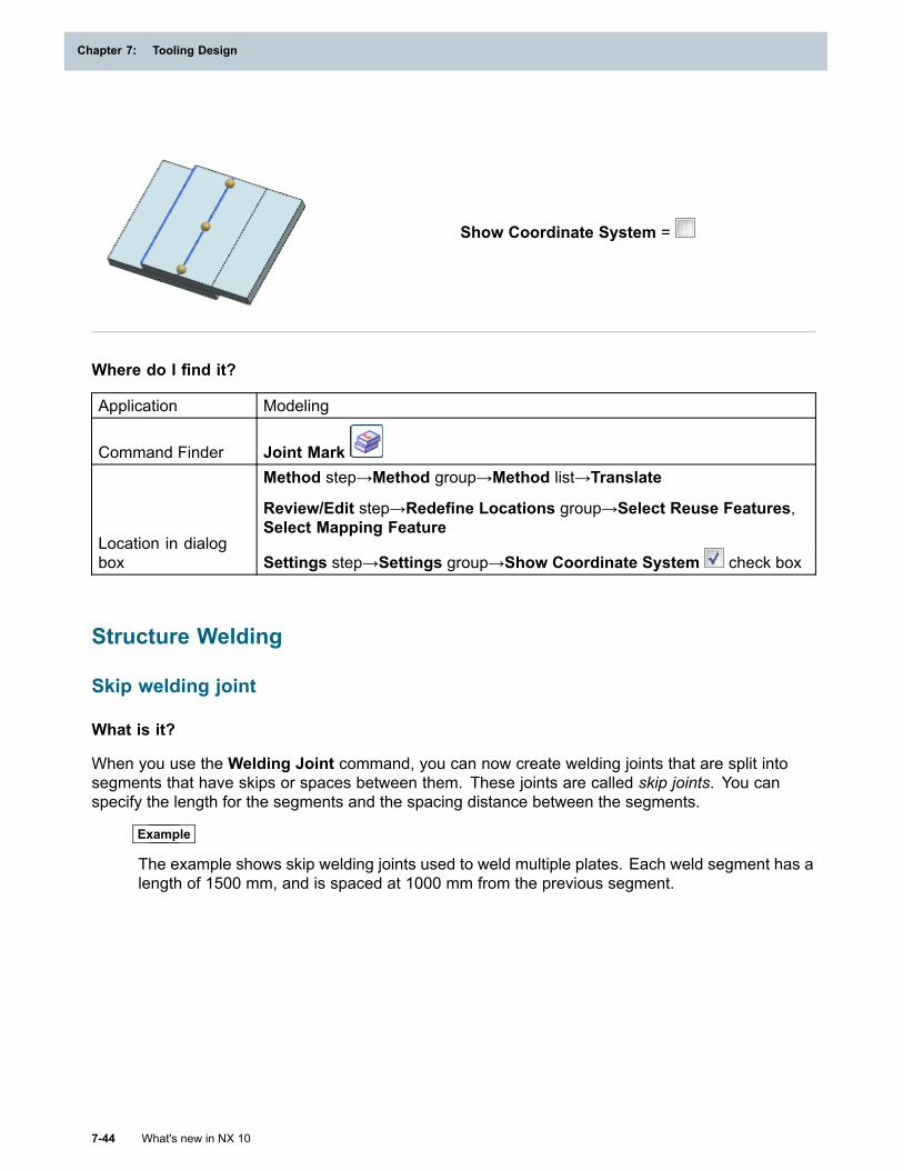
Chapter 7: Tooling Design
Show Coordinate System =
Where do I find it?
Application Modeling
Command Finder Joint Mark
Location in dialogbox
Method step→Method group→Method list→Translate
Review/Edit step→Redefine Locations group→Select Reuse Features,Select Mapping Feature
Settings step→Settings group→Show Coordinate System check box
Structure Welding
Skip welding joint
What is it?
When you use the Welding Joint command, you can now create welding joints that are split intosegments that have skips or spaces between them. These joints are called skip joints. You canspecify the length for the segments and the spacing distance between the segments.
Example
The example shows skip welding joints used to weld multiple plates. Each weld segment has alength of 1500 mm, and is spaced at 1000 mm from the previous segment.
7-44 What's new in NX 10
Chapter 7: Tooling Design
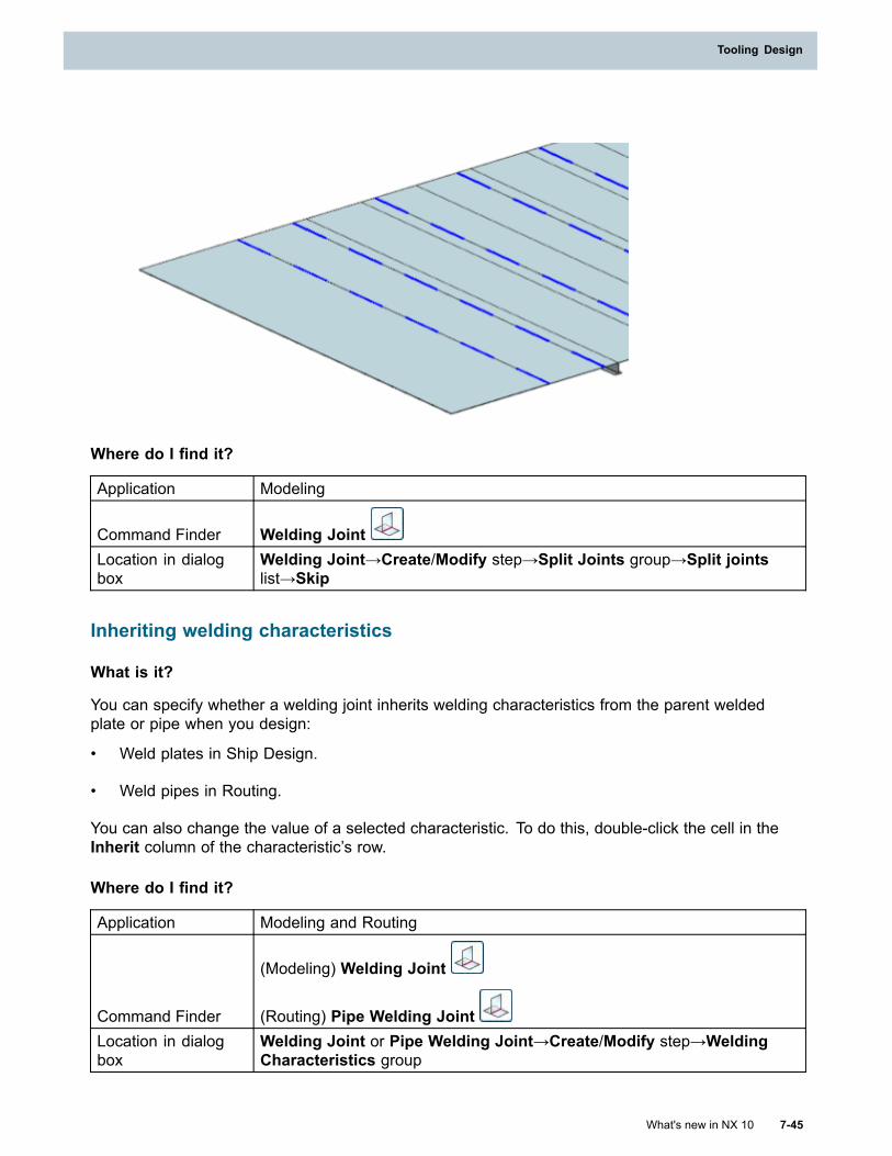
Tooling Design
Where do I find it?
Application Modeling
Command Finder Welding JointLocation in dialogbox
Welding Joint→Create/Modify step→Split Joints group→Split jointslist→Skip
Inheriting welding characteristics
What is it?
You can specify whether a welding joint inherits welding characteristics from the parent weldedplate or pipe when you design:
• Weld plates in Ship Design.
• Weld pipes in Routing.
You can also change the value of a selected characteristic. To do this, double-click the cell in theInherit column of the characteristic’s row.
Where do I find it?
Application Modeling and Routing
Command Finder
(Modeling) Welding Joint
(Routing) Pipe Welding JointLocation in dialogbox
Welding Joint or Pipe Welding Joint→Create/Modify step→WeldingCharacteristics group
What's new in NX 10 7-45
Tooling Design
Chapter 7: Tooling Design
Weld attributes in 4GD
When you create a weld design feature in 4GD, you can add custom attributes to the feature fromTeamcenter using Attribute Groups and Managed Attribute Groups.
To do this, you must set the following Welding Characteristics customer default:
HasAttributeGroup = TRUE
Tip
To find a customer default, choose File tab→Utilities→Customer Defaults, and click Find
Default .
If you change weld attributes in Teamcenter, you must load the part fully to synchronize the changesto the weld design feature.
7-46 What's new in NX 10
Chapter 7: Tooling Design
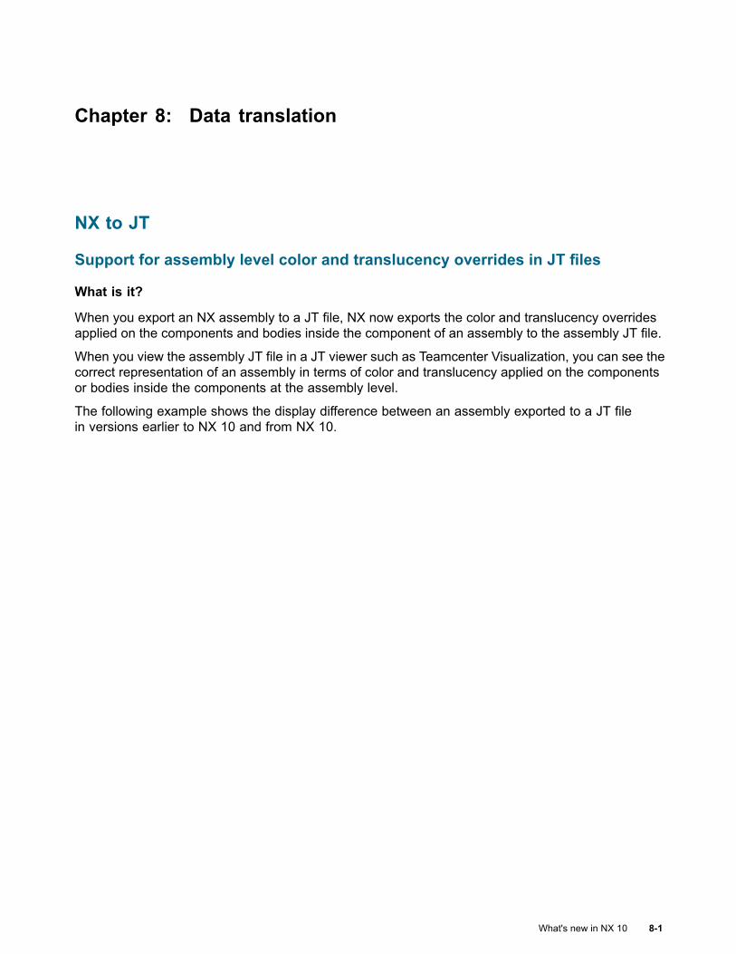
Chapter 8: Data translation
NX to JT
Support for assembly level color and translucency overrides in JT files
What is it?
When you export an NX assembly to a JT file, NX now exports the color and translucency overridesapplied on the components and bodies inside the component of an assembly to the assembly JT file.
When you view the assembly JT file in a JT viewer such as Teamcenter Visualization, you can see thecorrect representation of an assembly in terms of color and translucency applied on the componentsor bodies inside the components at the assembly level.
The following example shows the display difference between an assembly exported to a JT filein versions earlier to NX 10 and from NX 10.
What's new in NX 10 8-1
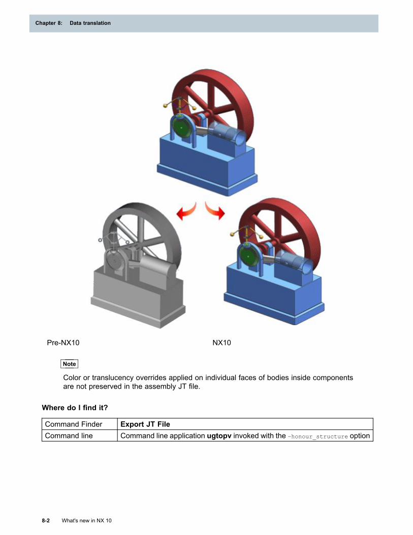
Chapter 8: Data translation
Pre-NX10 NX10
Note
Color or translucency overrides applied on individual faces of bodies inside componentsare not preserved in the assembly JT file.
Where do I find it?
Command Finder Export JT FileCommand line Command line application ugtopv invoked with the –honour_structure option
8-2 What's new in NX 10
Chapter 8: Data translation
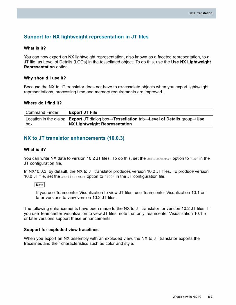
Data translation
Support for NX lightweight representation in JT files
What is it?
You can now export an NX lightweight representation, also known as a faceted representation, to aJT file, as Level of Details (LODs) in the tessellated object. To do this, use the Use NX LightweightRepresentation option.
Why should I use it?
Because the NX to JT translator does not have to re-tesselate objects when you export lightweightrepresentations, processing time and memory requirements are improved.
Where do I find it?
Command Finder Export JT FileLocation in the dialogbox
Export JT dialog box→Tessellation tab→Level of Details group→UseNX Lightweight Representation
NX to JT translator enhancements (10.0.3)
What is it?
You can write NX data to version 10.2 JT files. To do this, set the JtFileFormat option to “10” in theJT configuration file.
In NX10.0.3, by default, the NX to JT translator produces version 10.2 JT files. To produce version10.0 JT file, set the JtFileFormat option to “100” in the JT configuration file.
Note
If you use Teamcenter Visualization to view JT files, use Teamcenter Visualization 10.1 orlater versions to view version 10.2 JT files.
The following enhancements have been made to the NX to JT translator for version 10.2 JT files. Ifyou use Teamcenter Visualization to view JT files, note that only Teamcenter Visualization 10.1.5or later versions support these enhancements.
Support for exploded view tracelines
When you export an NX assembly with an exploded view, the NX to JT translator exports thetracelines and their characteristics such as color and style.
What's new in NX 10 8-3
Data translation
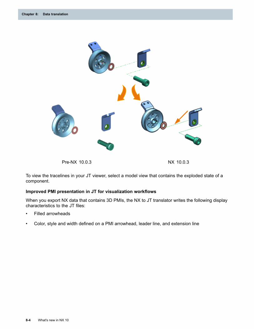
Chapter 8: Data translation
Pre-NX 10.0.3 NX 10.0.3
To view the tracelines in your JT viewer, select a model view that contains the exploded state of acomponent.
Improved PMI presentation in JT for visualization workflows
When you export NX data that contains 3D PMIs, the NX to JT translator writes the following displaycharacteristics to the JT files:
• Filled arrowheads
• Color, style and width defined on a PMI arrowhead, leader line, and extension line
8-4 What's new in NX 10
Chapter 8: Data translation

Data translation
Pre-NX 10.0.3 NX 10.0.3
Note
• The listed PMI display characteristics are not supported for drafting dimensions andannotations.
• Filled text characters are not supported and these appear as an outline of text in the JT file.
Support for rendering style in model views
The NX to JT translator now writes the rendering style of the model view to the JT file. The followingrendering styles are supported in JT:
• Shaded
• Shaded with Edges
• Static Wireframe
• Wireframe with Hidden Edges
• Wireframe with Dim Edges
What's new in NX 10 8-5
Data translation

Chapter 8: Data translation
Pre-NX 10.0.3 NX 10.0.3
Support for background color in model views
The NX to JT translator now writes the background color defined for a model view in an NX part tothe JT file.
8-6 What's new in NX 10
Chapter 8: Data translation
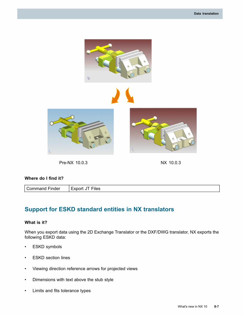
Data translation
Pre-NX 10.0.3 NX 10.0.3
Where do I find it?
Command Finder Export JT Files
Support for ESKD standard entities in NX translators
What is it?
When you export data using the 2D Exchange Translator or the DXF/DWG translator, NX exports thefollowing ESKD data:
• ESKD symbols
• ESKD section lines
• Viewing direction reference arrows for projected views
• Dimensions with text above the stub style
• Limits and fits tolerance types
What's new in NX 10 8-7
Data translation
Chapter 8: Data translation
Where do I find it?
Command Finder
Export AutoCAD DXF/DWG File
Export 2D Exchange File
2D Exchange translator and AutoCAD DXF/DWG translatorenhancements
What is it?
When you use the 2D Exchange translator to export NX data to a 2D part file or use the AutoCADDXF/DWG translator to export data to the 2D format, the translator exports:
• Wireframe edges with face colors.
• Pictorial and half-pictorial section lines.
• Newly added NX Drafting and GD&T symbols such as Independency, Continuous Feature,Statistical, Orientation Constraint, Datum Translation, Fit Function, and Safety Compliance.
• Copyright, Registered Trademark, Farad and Centerline symbols added in NX using block fontcharacters.
The 2D Exchange translator also adds the following information about dimension translation to the2D Exchange log file.
• Summary of dimensions available in input part.
• Summary of dimensions exported to the 2D part.
• Dimensions exported as grouped data.
The information about dimensions exported as grouped contains dimension type, measurementvalues, the associated view of the dimension, the name of the drawing Sheet on which thedimension exists, and the reason why the dimension is converted to grouped data.
Where do I find it?
Command Finder
Export 2D Exchange File
Export AutoCAD DXF/DWG File
Exporting center lines and center marks
AutoCAD DXF/DWG translator
When you export NX data that contains centerlines to DXF/DWG file, you can now create acustomized centerline font to match its display properties in NX. To do this, set the following keywordin the settings file.
8-8 What's new in NX 10
Chapter 8: Data translation
Data translation
EXPORT_CENTERLINE_AS=CUSTOM
To get the exact display, you can also export the centerlines as block reference to DXF file. To do this,set the following keyword in the settings file.
EXPORT_CENTERLINE_AS=BLOCK
You can use this option to export centerline as lines, arcs and/or splines with same display as that ofNX. A centerline font consists of a unique combination of dashes, gaps and long-dashes.
By default, the settings file does not contain this option. You must add this option to the settings file,or else the translator exports the centerlines with the CENTER font to the DXF file
2D Exchange translator
You can now export linear 3D Centerline, linear PMI Centerline, and PMI Center Marks as real in the2D part. The exported centerlines retain the properties such as display, dimension, and association.
When you export drawings to the 2D part file, the translator exports:
• Linear 3D and PMI centerlines as 2D centerlines.
• PMI Center Marks as Center Marks in the 2D part.
Where do I find it?
Command Finder
Export AutoCAD DXF/DWG File
Export 2D Exchange File
Support for PMI data in NX translators
What is it?
When you export data using the 2D Exchange Translator or the DXF/DWG translator, NX exportsthe following PMI and additional data:
• PMI annotations
• Specialized PMI
• Security markings
• Section views
Where do I find it?
Command Finder
Export AutoCAD DXF/DWG File
Export 2D Exchange File
What's new in NX 10 8-9
Data translation
Chapter 8: Data translation
Support for international characters in NX data translators
What is it?
NX supports international characters for the following entities:
• Names of files, objects, interface labels, and options in the settings file
• Attribute titles and values
• Messages in the log file
Note
Before you export data to CAD tools that do not support international characters, you mustreplace non-English characters with English characters in the parts, and rename the partsin NX.
Support for multifield keys in NXJT and MCAD translators
What is it?
You can now export multifield key based NX items to other CAD formats. NX generates names for theoutput and log files using multifield key values.
Multifield keys
Multifield keys are identifiers assigned to each object to ensure their uniqueness in the database. Theunique identifier is composed of a domain name and a combination of the object’s properties. Forexample, the default multifield key for item business objects is Item{item_id}. For more information,see Teamcenter Help.
Exporting crosshatching as grouped geometry (10.0.1)
What is it?
You can now export crosshatching as grouped geometry to a 2D NX Part, DXF, or DWG file. To dothis, you must set the following keyword in the settings file.
CONVERT_CROSSHATCH_AS_GEOMETRY = yes
Note
This keyword setting overrides the default crosshatch mapping defined in the DXF/DWG and2D Exchange translators.
Why should I use it?
When the crosshatch pattern assigned to the crosshatching in the NX file is not available in AutoCAD,the crosshatching display in AutoCAD may not match the display in NX. In this case, export thecrosshatching as grouped geometry to get the exact display in AutoCAD.
8-10 What's new in NX 10
Chapter 8: Data translation
Data translation
Where do I find it?
Command Finder
Export 2D Exchange File
Export AutoCAD DXF/DWG File
Exporting imported DXF/DWG blocks and block attributes (10.0.2)
What is it?
When you export NX data, the DXF/DWG translator now exports the imported DXF/DWG blocks andblock attributes back to DXF/DWG files as blocks and block attributes.
The translator imports the DXF/DWG blocks and block attributes as groups and drafting notes intoNX, and in previous releases, the translator used to export these groups and drafting notes toDXF/DWG files as groups and MText.
Where do I find it?
Command Finder Export AutoCAD DXF/DWG File
What's new in NX 10 8-11
Data translation

Chapter 9: System administration
Internationalization and Localization
Using local language in NX applications
What is it?
You can now enter part names, attributes, parameters, file names, design notes, and so on in all locallanguage in NX applications.
What's new in NX 10 9-1

Chapter 10: 4th Generation Design (4GD)
Overriding geometry in 4GD
What is it?
4GD is enhanced in the following ways:
• The Assembly Cut, Promote, Define Deformable Part, and Deform Component commandsare now available.
• You can create an override part for a reuse design element or subordinate in the context of thecollaborative design.
You can use the Create Override Part command to create an empty override part. After you createan override, you can choose the shape you want to edit in the Assembly Navigator.
Why should I use it?
Use these commands when you want to change the shape of an object in the context of thecollaborative design.
Where do I find it?
Command Finder
Assembly Cut
Promote
Define Deformable Part
Deform Component
Create Override Part
Sorting 4GD components in the Assembly Navigator
What is it?
You can now sort components in the Assembly Navigator if you are working in a 4GD environment.In a workset, you can sort partitions, subsets, and design elements by alphabetical, alphanumerical,and chronological order. You can also create a user-defined order for design elements and subsets.
What's new in NX 10 10-1
Chapter 10: 4th Generation Design (4GD)
Why should I use it?
Sorting 4GD objects in the Assembly Navigator can make it easier to find and focus on the objectsof most interest. Being able to sort 4GD objects lets you:
• Find design elements (DE) more easily.
• Put the subset of most interest at the top of a list.
• Group related design elements together.
• Find new design elements in a subset.
Where do I find it?
Prerequisite You must be in a Teamcenter environment and have 4GD installed.Command Finder Reorder ComponentsMenu Assemblies→Navigator Order→Edit Orders in Part
Mirror Assemblies WizardWhat is it?
If you are in a Teamcenter environment, you now use the business logic set up for your site whenyou create new mirror parts using the Mirror Assembly Wizard (MAW). The MAW also supportsthe new Teamcenter multi field key attributes.
The new items created in Teamcenter for any newly created mirror parts will be of the same typeas the source parts being mirrored. When you mirror a part or assembly, you create a new part orassembly, not a new revision.
Note
You can no longer change the item type for mirrored parts with the Mirror Assembly Wizard.
Why should I use it?
You can rename all the new objects and their attributes, including Teamcenter multi field attributes, atone time in a single mirroring process. You can see and validate all the attributes as you mirror them.
Where do I find it?
Prerequisite You must be in a Teamcenter environment.Command Finder Mirror Assembly
Visual ReportsWhat is it?
There are three new out of the box visual reports for 4GD objects:
10-2 What's new in NX 10
Chapter 10: 4th Generation Design (4GD)
4th Generation Design (4GD)
• Design Model Element Has Higher Revision ID
Use this report to display the list of Design Model Elements (DE) with higher revision ID thatare currently loaded in your session.
• Design Model Element Source Item Revision Has Higher Revision
Use this report to display the list of Design Model Elements (DE) with higher revisions thatare currently loaded in your session.
• Compare Realized Objects in Two Subsets
Use this report to display the list of Design Model Elements (DE) that are currently loaded in yoursession and the names of two loaded subsets for the reporting scope.
Where do I find it?
Prerequisite You must be in a Teamcenter environment and have 4GD installed.Command Finder Start Visual Reporting
Resource bar HD3D Tools→Visual Reporting
Modifying a subset using a Teamcenter option set
What is it?
The Subset Navigator now includes the options that are listed in the active Teamcenter transferoption set. The transfer option set contains global search options that are applied to the entiresubset search recipe. You can modify your subset search results by changing the status of one ormore of these options.
Why should I use it?
You can configure the search results of a recipe in different ways without modifying the contentsof your recipe.
Where do I find it?
PrerequisiteYou must be in 4GD, in the subset task environment, and have an activesubset search recipe.
Resource bar Subset NavigatorLocation in dialogbox Recipe group
What's new in NX 10 10-3
4th Generation Design (4GD)
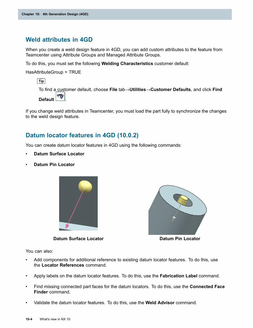
Chapter 10: 4th Generation Design (4GD)
Weld attributes in 4GDWhen you create a weld design feature in 4GD, you can add custom attributes to the feature fromTeamcenter using Attribute Groups and Managed Attribute Groups.
To do this, you must set the following Welding Characteristics customer default:
HasAttributeGroup = TRUE
Tip
To find a customer default, choose File tab→Utilities→Customer Defaults, and click Find
Default .
If you change weld attributes in Teamcenter, you must load the part fully to synchronize the changesto the weld design feature.
Datum locator features in 4GD (10.0.2)You can create datum locator features in 4GD using the following commands:
• Datum Surface Locator
• Datum Pin Locator
Datum Surface Locator Datum Pin Locator
You can also:
• Add components for additional reference to existing datum locator features. To do this, usethe Locator References command.
• Apply labels on the datum locator features. To do this, use the Fabrication Label command.
• Find missing connected part faces for the datum locators. To do this, use the Connected FaceFinder command.
• Validate the datum locator features. To do this, use the Weld Advisor command.
10-4 What's new in NX 10
Chapter 10: 4th Generation Design (4GD)
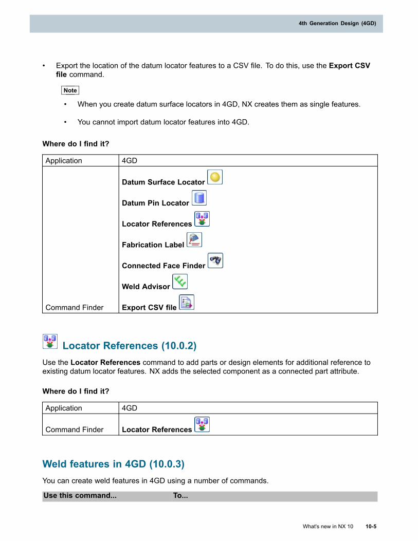
4th Generation Design (4GD)
• Export the location of the datum locator features to a CSV file. To do this, use the Export CSVfile command.
Note
• When you create datum surface locators in 4GD, NX creates them as single features.
• You cannot import datum locator features into 4GD.
Where do I find it?
Application 4GD
Command Finder
Datum Surface Locator
Datum Pin Locator
Locator References
Fabrication Label
Connected Face Finder
Weld Advisor
Export CSV file
Locator References (10.0.2)Use the Locator References command to add parts or design elements for additional reference toexisting datum locator features. NX adds the selected component as a connected part attribute.
Where do I find it?
Application 4GD
Command Finder Locator References
Weld features in 4GD (10.0.3)You can create weld features in 4GD using a number of commands.
Use this command... To...
What's new in NX 10 10-5
4th Generation Design (4GD)
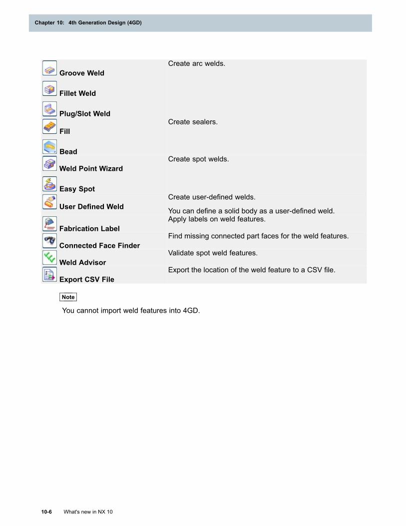
Chapter 10: 4th Generation Design (4GD)
Groove Weld
Fillet Weld
Plug/Slot Weld
Create arc welds.
Fill
Bead
Create sealers.
Weld Point Wizard
Easy Spot
Create spot welds.
User Defined WeldCreate user-defined welds.
You can define a solid body as a user-defined weld.
Fabrication LabelApply labels on weld features.
Connected Face FinderFind missing connected part faces for the weld features.
Weld AdvisorValidate spot weld features.
Export CSV FileExport the location of the weld feature to a CSV file.
Note
You cannot import weld features into 4GD.
10-6 What's new in NX 10
Chapter 10: 4th Generation Design (4GD)
Chapter 11: Mechatronics Concept Designer
System Navigator enhancementsThe System Navigator is enhanced so that you can:
• Manually edit letter codes and index for logical models.
• Restore the index of logical nodes with the Reapply Naming Rule command.
Where do I find it?
Application Mechatronics Concept Designer
Resource bar System Navigator
Physics Navigator enhancementsThe Physics Navigator is enhanced so that you can:
• Change the owner of physics objects between the top assembly and parts within the assembly.
• Find the owner component for an object that is selected in the physics navigator.
• Select an object in the physics navigator and make the owner component the work part.
In addition, collision bodies are now displayed as a child of the rigid body.
Where do I find it?
Application Mechatronics Concept Designer
Resource bar Physics Navigator
Exchange rigid bodies during simulationsUse the Object Transformer command to exchange rigid bodies during a simulation. Use thiswith an Object Source to change rigid bodies in an assembly line. Trigger the exchange usinga Collision Sensor.
Where do I find it?
Application Mechatronics Concept Designer
What's new in NX 10 11-1
Chapter 11: Mechatronics Concept Designer
Command Finder Object Transformer
Collision Body enhancementsUse Collision Body enhancements to do the following:
• Set collision bodies to stick together during simulations.
• Create a cylinder collision shape to detect contact between geometry during simulations.
Where do I find it?
Application Mechatronics Concept Designer
Command Finder Collision Body
Collision Sensor enhancementsUse the Highlight on Collision check box to indicate when a collision sensor detects contact with arigid body having a matching collision category.
Where do I find it?
Application Mechatronics Concept Designer
Command Finder Collision Sensor
Joint motion restrictionsApply motion limits directly to joints. You can specify linear or angular limits. Use this enhancement tostop angular motion after less than or greater than one full rotation.
Where do I find it?
Application Mechatronics Concept Designer
Command Finder
Hinge Joint
Sliding Joint
11-2 What's new in NX 10
Chapter 11: Mechatronics Concept Designer
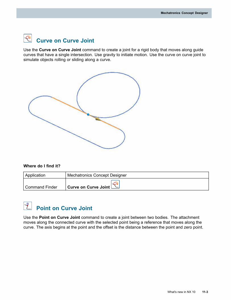
Mechatronics Concept Designer
Curve on Curve JointUse the Curve on Curve Joint command to create a joint for a rigid body that moves along guidecurves that have a single intersection. Use gravity to initiate motion. Use the curve on curve joint tosimulate objects rolling or sliding along a curve.
Where do I find it?
Application Mechatronics Concept Designer
Command Finder Curve on Curve Joint
Point on Curve JointUse the Point on Curve Joint command to create a joint between two bodies. The attachmentmoves along the connected curve with the selected point being a reference that moves along thecurve. The axis begins at the point and the offset is the distance between the point and zero point.
What's new in NX 10 11-3
Mechatronics Concept Designer
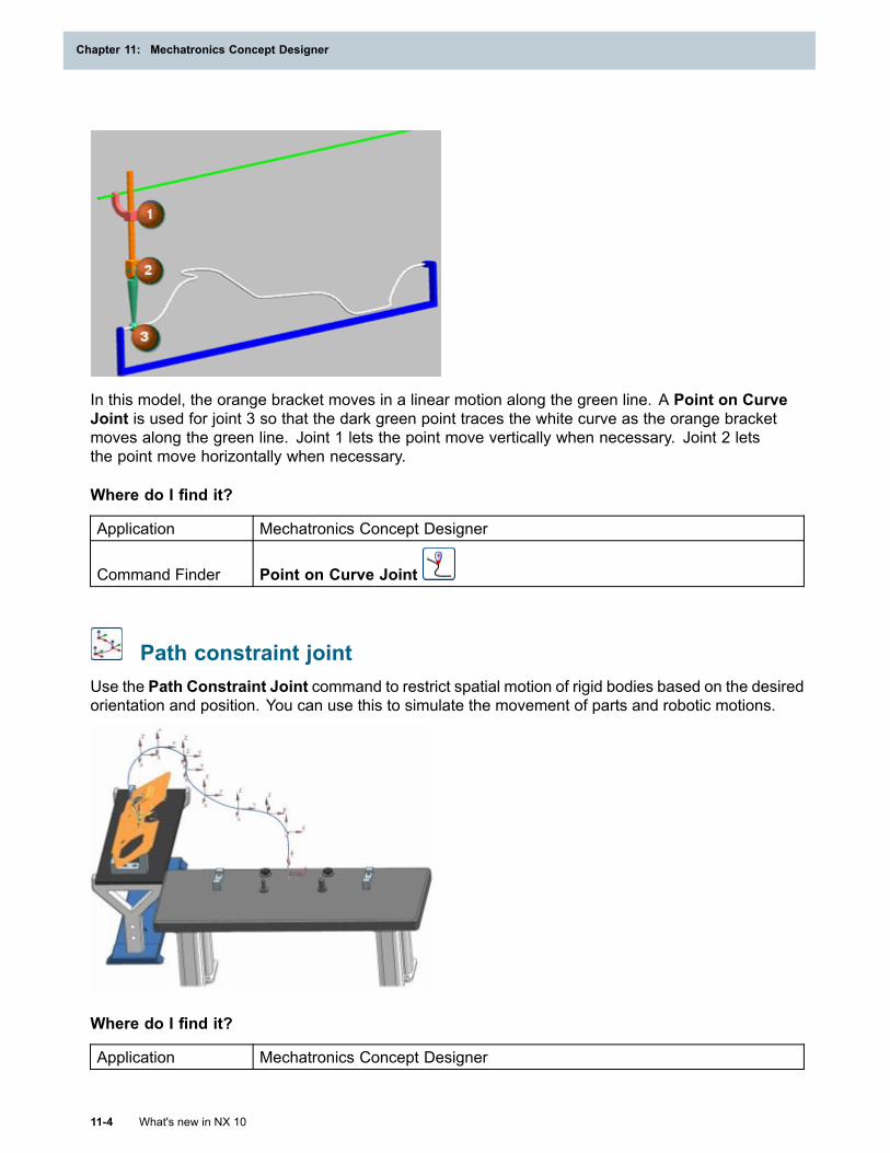
Chapter 11: Mechatronics Concept Designer
In this model, the orange bracket moves in a linear motion along the green line. A Point on CurveJoint is used for joint 3 so that the dark green point traces the white curve as the orange bracketmoves along the green line. Joint 1 lets the point move vertically when necessary. Joint 2 letsthe point move horizontally when necessary.
Where do I find it?
Application Mechatronics Concept Designer
Command Finder Point on Curve Joint
Path constraint jointUse the Path Constraint Joint command to restrict spatial motion of rigid bodies based on the desiredorientation and position. You can use this to simulate the movement of parts and robotic motions.
Where do I find it?
Application Mechatronics Concept Designer
11-4 What's new in NX 10
Chapter 11: Mechatronics Concept Designer
Mechatronics Concept Designer
Command Finder Path Constraint Joint
Spring DamperUse the Spring Damper command to apply a spring force to exert force or torque on a joint. Set therelaxed position parameter to specify the position where the force is zero.
Where do I find it?
Application Mechatronics Concept Designer
Command Finder Spring Damper
Display ChangerUse the Display Changer command to change the display properties of a rigid body during asimulation. Attach a display changer to a collision sensor to set the display property of the triggeredbody, including color, translucency, and visibility.
Where do I find it?
Application Mechatronics Concept Designer
Command Finder Display Changer
View simulation enhancementsSimulations are enhanced so that you can:
• Set the time scale to speed up or slow down runtime simulations.
• Create snap shots of a simulation to be used as restart points. Use this so that you do not haveto view the simulation from the 00:00 time stamp.
• Increment simulations by operation, time based intervals or run simulations until a designatedoperation.
• View the start time, the stop time and the current time of a simulation in the sequence editor.
Where do I find it?
Application Mechatronics Concept Designer
What's new in NX 10 11-5
Mechatronics Concept Designer
Chapter 11: Mechatronics Concept Designer
Command Finder
Time Scale
Snap Shot
Forward One Step
Forward One Operation
Runtime Inspector enhancementsUse Runtime Inspector enhancements to do the following:
• Choose parameters that you want to graph during simulations.
• Export parameter graphical data as .csv files.
• Add objects to the runtime inspector view by right-clicking, and then from the list choosing Add toInspector.
• View and select the simulation restart times that you created using the Snap Shot command.Use this so that you do not have to view simulations from the 00:00 time stamp.
Where do I find it?
Application Mechatronics Concept Designer
Resource bar Runtime Inspector
Cam Profile enhancementsUse the Cam Profile command to create motion relationships. The command is enhanced so thatyou can:
• Select different transversal segments, including third order polynomials, fifth order polynomials,sixth order polynomials, and modified acceleration sine, to connect motion segments in a camprofile.
• Use the Optimize command to select a transversal segment based on velocity, acceleration, orjerk characteristics.
• Edit transversal segment properties in the table view, including the transversal segment type,slopes, curvature, jerk, lambda, and optimization type.
• Use the multiple cam profile table to add, edit, and delete cam profiles in a model.
11-6 What's new in NX 10
Chapter 11: Mechatronics Concept Designer
Mechatronics Concept Designer
Cyclic and relative cyclic behavior
• Cyclic behavior runs the same motion profile multiple times. Use cyclic behavior when the slavevalue is the same at the master axis minimum and maximum value. Motion segments are notrestricted by the master axis minimum and maximum value. You can wrap motion segments sothat part of the segment is applied at the beginning and part is applied at the end.
• Relative cyclic behavior runs the same motion profile multiple times. The slave value at the end ofthe first cycle is the slave value at the start of the next cycle. Motion segments are not restrictedby the master axis minimum and maximum value. You can wrap motion segments so that part ofthe segment is applied at the beginning and part is applied at the end.
Where do I find it?
Application Mechatronics Concept Designer
Command Finder Cam Profile
Transport Surface enhancementsTransport Surface is enhanced so that you can:
• Apply actuators to transport surfaces as you do for joints. Applying actuators lets you controltransport surfaces with operations and runtime expressions. Use the start position subgroup withposition actuators to set the initial position of a conveyor.
• Use transport surfaces with curved planar surfaces.
Where do I find it?
Application Mechatronics Concept Designer
Command Finder
Speed Control
Position Control
Electronic Cam enhancementsElectronic Cam is enhanced so that you can:
• Use a runtime parameter to control the slave axis by setting the master to Signal.
• Minimize disturbances on the physical axis by setting the master axis to Virtual Axis.
• Select an existing Transport Surface as the slave axis.
What's new in NX 10 11-7
Mechatronics Concept Designer
Chapter 11: Mechatronics Concept Designer
Where do I find it?
Application Mechatronics Concept Designer
Command Finder Electronic Cam
Operation enhancementsUse the Operation command to create time and event based changes. The command is enhancedso that you can:
Export time based data
Use this to export timing and operations data including
• Step number
• Number of preceding operations
• Operation start time
• Duration of the operation
• Total time elapsed at the end of an operation
• Conditional objects and parameter names assigned to operations
Use new operator syntax
Use this to change runtime parameter values when a condition is met. Use the new operators todo the following:
• += X : Use this to increment by the value X.
• —= X : Use this to decrement by the value X.
• *= X : Use this to multiply by X.
• ! : Use this to apply a boolean NOT.
Where do I find it?
Application Mechatronics Concept Designer
Command Finder Operation
ECAD integration enhancementsECAD integration is enhanced so that you can:
11-8 What's new in NX 10
Chapter 11: Mechatronics Concept Designer
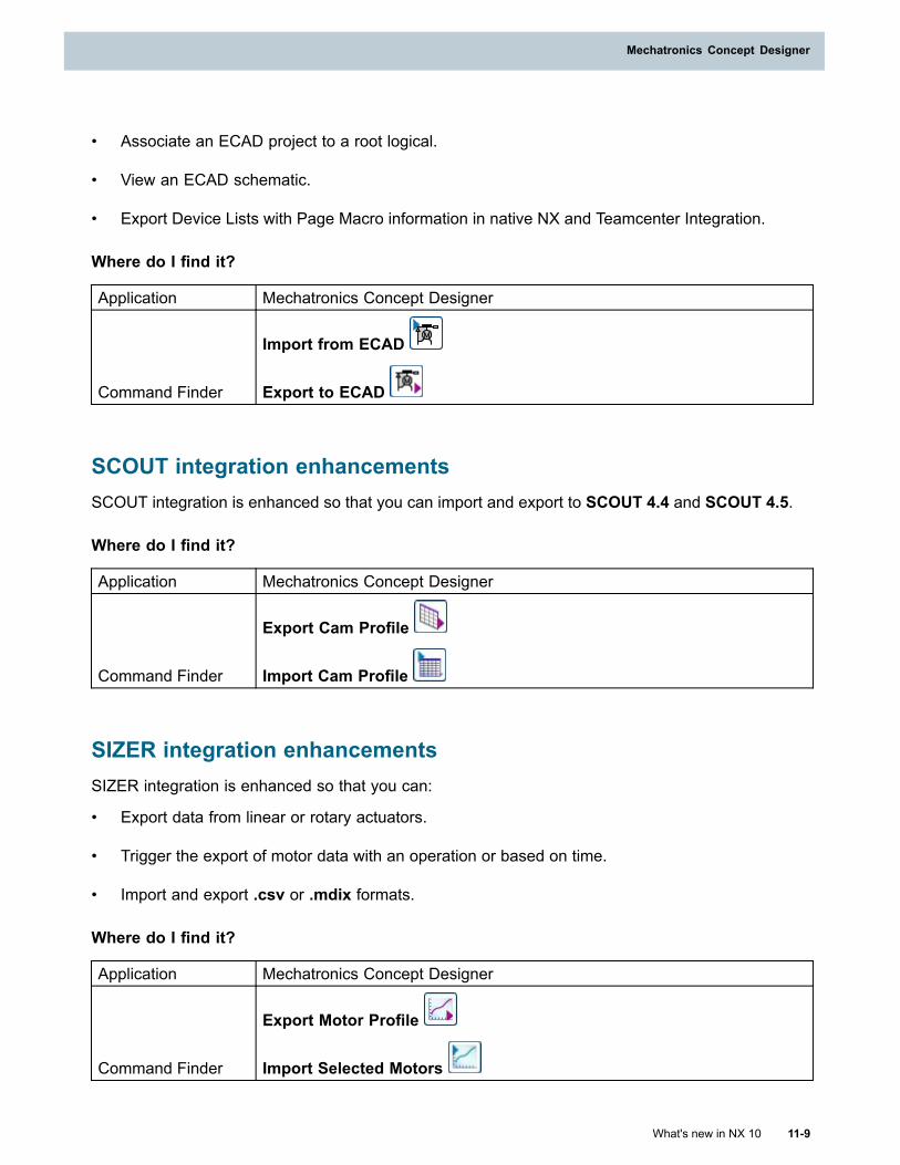
Mechatronics Concept Designer
• Associate an ECAD project to a root logical.
• View an ECAD schematic.
• Export Device Lists with Page Macro information in native NX and Teamcenter Integration.
Where do I find it?
Application Mechatronics Concept Designer
Command Finder
Import from ECAD
Export to ECAD
SCOUT integration enhancementsSCOUT integration is enhanced so that you can import and export to SCOUT 4.4 and SCOUT 4.5.
Where do I find it?
Application Mechatronics Concept Designer
Command Finder
Export Cam Profile
Import Cam Profile
SIZER integration enhancementsSIZER integration is enhanced so that you can:
• Export data from linear or rotary actuators.
• Trigger the export of motor data with an operation or based on time.
• Import and export .csv or .mdix formats.
Where do I find it?
Application Mechatronics Concept Designer
Command Finder
Export Motor Profile
Import Selected Motors
What's new in NX 10 11-9
Mechatronics Concept Designer
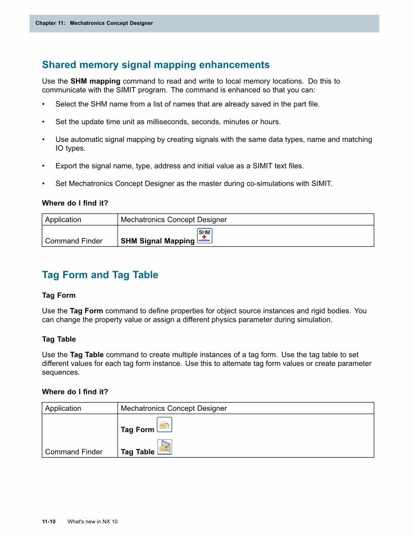
Chapter 11: Mechatronics Concept Designer
Shared memory signal mapping enhancementsUse the SHM mapping command to read and write to local memory locations. Do this tocommunicate with the SIMIT program. The command is enhanced so that you can:
• Select the SHM name from a list of names that are already saved in the part file.
• Set the update time unit as milliseconds, seconds, minutes or hours.
• Use automatic signal mapping by creating signals with the same data types, name and matchingIO types.
• Export the signal name, type, address and initial value as a SIMIT text files.
• Set Mechatronics Concept Designer as the master during co-simulations with SIMIT.
Where do I find it?
Application Mechatronics Concept Designer
Command Finder SHM Signal Mapping
Tag Form and Tag Table
Tag Form
Use the Tag Form command to define properties for object source instances and rigid bodies. Youcan change the property value or assign a different physics parameter during simulation.
Tag Table
Use the Tag Table command to create multiple instances of a tag form. Use the tag table to setdifferent values for each tag form instance. Use this to alternate tag form values or create parametersequences.
Where do I find it?
Application Mechatronics Concept Designer
Command Finder
Tag Form
Tag Table
11-10 What's new in NX 10
Chapter 11: Mechatronics Concept Designer
Mechatronics Concept Designer
Read-Write Device
Read-Write Device
Use the Read-Write Device command to assign values determined by tag forms and tag tables.Trigger the device in read mode to retrieve tag values from the rigid body. Trigger the device inwrite mode to assign a value to a rigid body.
Where do I find it?
Application Mechatronics Concept Designer
Command Finder Read-Write Device
What's new in NX 10 11-11
Mechatronics Concept Designer

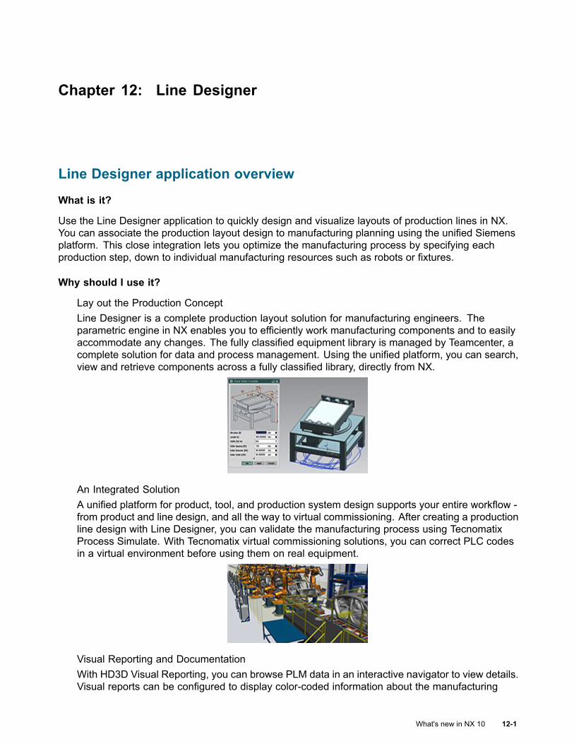
Chapter 12: Line Designer
Line Designer application overview
What is it?
Use the Line Designer application to quickly design and visualize layouts of production lines in NX.You can associate the production layout design to manufacturing planning using the unified Siemensplatform. This close integration lets you optimize the manufacturing process by specifying eachproduction step, down to individual manufacturing resources such as robots or fixtures.
Why should I use it?
Lay out the Production ConceptLine Designer is a complete production layout solution for manufacturing engineers. Theparametric engine in NX enables you to efficiently work manufacturing components and to easilyaccommodate any changes. The fully classified equipment library is managed by Teamcenter, acomplete solution for data and process management. Using the unified platform, you can search,view and retrieve components across a fully classified library, directly from NX.
An Integrated SolutionA unified platform for product, tool, and production system design supports your entire workflow -from product and line design, and all the way to virtual commissioning. After creating a productionline design with Line Designer, you can validate the manufacturing process using TecnomatixProcess Simulate. With Tecnomatix virtual commissioning solutions, you can correct PLC codesin a virtual environment before using them on real equipment.
Visual Reporting and DocumentationWith HD3D Visual Reporting, you can browse PLM data in an interactive navigator to view details.Visual reports can be configured to display color-coded information about the manufacturing
What's new in NX 10 12-1
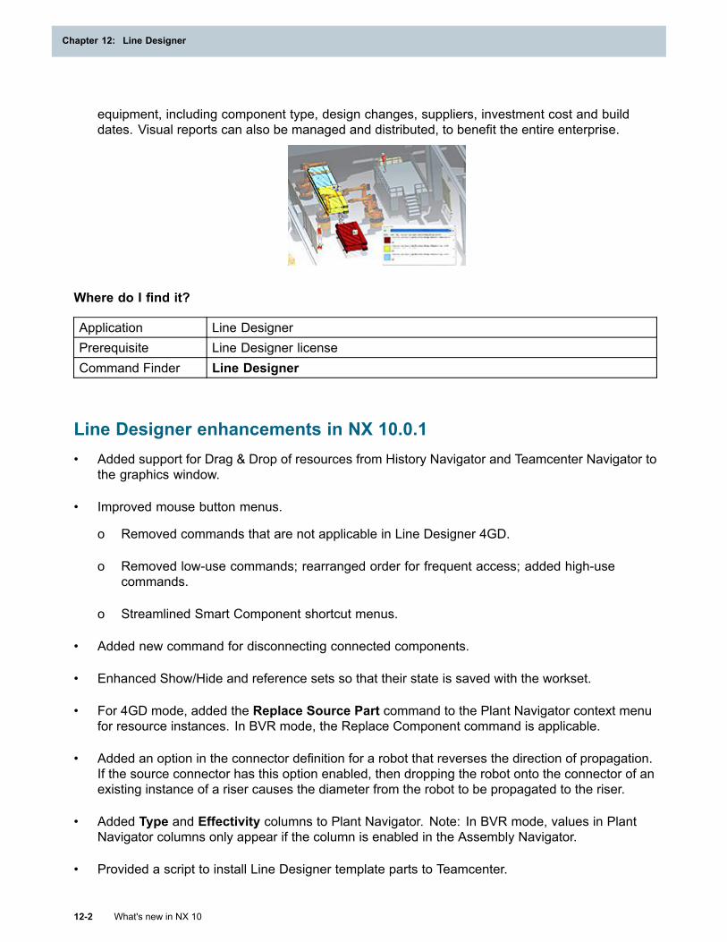
Chapter 12: Line Designer
equipment, including component type, design changes, suppliers, investment cost and builddates. Visual reports can also be managed and distributed, to benefit the entire enterprise.
Where do I find it?
Application Line DesignerPrerequisite Line Designer licenseCommand Finder Line Designer
Line Designer enhancements in NX 10.0.1• Added support for Drag & Drop of resources from History Navigator and Teamcenter Navigator to
the graphics window.
• Improved mouse button menus.
o Removed commands that are not applicable in Line Designer 4GD.
o Removed low-use commands; rearranged order for frequent access; added high-usecommands.
o Streamlined Smart Component shortcut menus.
• Added new command for disconnecting connected components.
• Enhanced Show/Hide and reference sets so that their state is saved with the workset.
• For 4GD mode, added the Replace Source Part command to the Plant Navigator context menufor resource instances. In BVR mode, the Replace Component command is applicable.
• Added an option in the connector definition for a robot that reverses the direction of propagation.If the source connector has this option enabled, then dropping the robot onto the connector of anexisting instance of a riser causes the diameter from the robot to be propagated to the riser.
• Added Type and Effectivity columns to Plant Navigator. Note: In BVR mode, values in PlantNavigator columns only appear if the column is enabled in the Assembly Navigator.
• Provided a script to install Line Designer template parts to Teamcenter.
12-2 What's new in NX 10
Chapter 12: Line Designer
Line Designer
Fast placement coordinates pop-up (10.0.1)
What is it?
The Fast Placement capability in Line Designer has been enhanced:
• Added Z-coordinate to the coordinate pop-up.
• Added capability to edit X, Y, Z coordinate values in the coordinate pop-up.
Why should I use it?
You can use the coordinate display and editing capability to more precisely place components evenwhile in the Fast Placement mode.
Where do I find it?
Application Line DesignerPrerequisite Fast Placement mode must be enabled.
Disconnect Components (10.0.1)
What is it?
The Disconnect Components command removes a connection between components that wascreated with the Connect Components command.
• If assembly constraints between the components exist, the assembly constraints are removed.
• Position and expression values of the components are not changed.
Why should I use it?
Disconnect components if you want to replace one of the components or change its location relativeto the other component.
Where do I find it?
Application Line Designer
Command Finder
Disconnect Components
What's new in NX 10 12-3
Line Designer
Chapter 12: Line Designer
Drag and drop resources (10.0.1)What is it?
In addition to adding resources to a layout from the Reuse Library, you can now drag and dropresources from the History Navigator and Teamcenter Navigator to the graphics window to createa new instance.
Why should I use it?
With this capability, you can take advantage of ready accessibility to existing resource instanceswhen adding similar instances.
Where do I find it?
Application Line Designer
NavigatorResource instances listed in the History Navigator and TeamcenterNavigator.
Line Designer enhancements in NX 10.0.2• Enhanced mouse button context menus to improve usability:
o Added Select Content to Plant Navigator context menus for Viewed Partition Scheme nodesother than Production Unit (plant, line, zone, station) nodes.
o Improved graphics window context menus.
• Enhanced Plant Navigator for resources authoring:
o Enhanced right mouse button functionality for root nodes that do not have sub-assemblies:
■ Added support for Add Connector and Properties
o Enhanced right mouse button functionality for root nodes that have a sub-assembly:
■ Added support for Edit Reusable Component and Properties
o Now root node columns can continue to show the same information both before and afteradding a sub-assembly to the same component.
• Additions to the Factory Resource Library (included with Teamcenter version 10.1.4):
o More conveyors
o Another robot
o Safety fence post and sections, as a part family
• Enhanced Connect Component to offer more options. When making connections, you can nowchoose from three connection types:
o Move and connect with offset
12-4 What's new in NX 10
Chapter 12: Line Designer
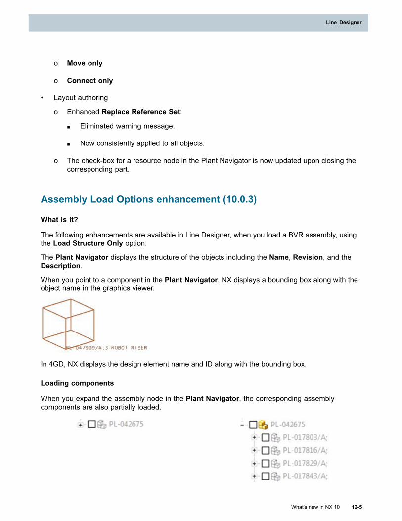
Line Designer
o Move only
o Connect only
• Layout authoring
o Enhanced Replace Reference Set:
■ Eliminated warning message.
■ Now consistently applied to all objects.
o The check-box for a resource node in the Plant Navigator is now updated upon closing thecorresponding part.
Assembly Load Options enhancement (10.0.3)
What is it?
The following enhancements are available in Line Designer, when you load a BVR assembly, usingthe Load Structure Only option.
The Plant Navigator displays the structure of the objects including the Name, Revision, and theDescription.
When you point to a component in the Plant Navigator, NX displays a bounding box along with theobject name in the graphics viewer.
In 4GD, NX displays the design element name and ID along with the bounding box.
Loading components
When you expand the assembly node in the Plant Navigator, the corresponding assemblycomponents are also partially loaded.
What's new in NX 10 12-5
Line Designer
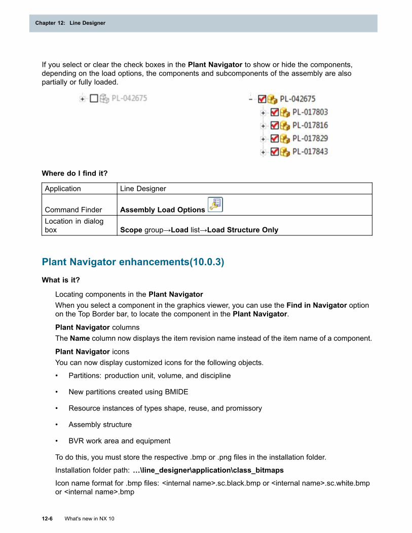
Chapter 12: Line Designer
If you select or clear the check boxes in the Plant Navigator to show or hide the components,depending on the load options, the components and subcomponents of the assembly are alsopartially or fully loaded.
Where do I find it?
Application Line Designer
Command Finder Assembly Load OptionsLocation in dialogbox Scope group→Load list→Load Structure Only
Plant Navigator enhancements(10.0.3)What is it?
Locating components in the Plant NavigatorWhen you select a component in the graphics viewer, you can use the Find in Navigator optionon the Top Border bar, to locate the component in the Plant Navigator.
Plant Navigator columnsThe Name column now displays the item revision name instead of the item name of a component.
Plant Navigator iconsYou can now display customized icons for the following objects.
• Partitions: production unit, volume, and discipline
• New partitions created using BMIDE
• Resource instances of types shape, reuse, and promissory
• Assembly structure
• BVR work area and equipment
To do this, you must store the respective .bmp or .png files in the installation folder.
Installation folder path: …\line_designer\application\class_bitmaps
Icon name format for .bmp files: <internal name>.sc.black.bmp or <internal name>.sc.white.bmpor <internal name>.bmp
12-6 What's new in NX 10
Chapter 12: Line Designer
Line Designer
Icon name format for .png files: <internal name>.sc.black.png or <internal name>.sc.white.png or<internal name>.png
To find the internal name in Teamcenter, right-click an object and choose Viewproperties→Multi-field key information→Object type. The value of the object type is theinternal name, which is the name of the customized icon.
Where do I find it?
Application Line Designer
Top Borderbar Find in Navigator
Viewing occurrence attributes in the Plant Navigator (10.0.3)
What is it?
When you load an assembly, you can now view the following occurrence attributes and their status inthe Plant Navigator:
• Occurrence Name
• Occurrence Type
• Callout (in NX) or Find No for sorting (in Teamcenter)
• Custom Occurrence Note
Note
NX does not automatically display the Custom Occurrence Note in the Columnconfiguration dialog box. In Teamcenter, the System Administrator must add the internalname of the Custom Occurrence Note using the PS_structure_change_condition
preference.
You need to turn on the columns for the occurrence attributes in the Plant Navigator. In the Columnconfiguration dialog box, select the occurrence attribute that you want to display as a column.
Use the Report This Column shortcut menu option to generate a report of these attributes.
Where do I find it?
Application Line DesignerPlant Navigator Right-click the title bar→Configure→ColumnsLocation in dialogbox Column configuration dialog box→Occurrence Properties node
What's new in NX 10 12-7
Line Designer
Chapter 12: Line Designer
Renaming components (10.0.3)
What is it?
You can now change the ItemRevision Name of components in the Plant Navigator column. Tochange this value, use the Rename shortcut menu option or press the F2 key.
To rename the Item Revision Name of an Item Type, you must map the attribute REV_NAME inthe mapping file for dataset type UGMASTER.
Example
REV_NAME mapped for Item Type MELine{Item type= "MELine"
"REV_NAME":ItemRevision.object_name/description="Revision Name"
}
The Rename dialog box also displays the occurrence name of the component if it is updatedin Teamcenter.
Where do I find it?
Application Line DesignerPrerequisite The attribute REV_NAME must be included in the mapping file.Graphics window Right-click a component in the Plant Navigator→Rename
Factory Resource Library enhancements (10.0.3)
What is it?
The following additional components are available in the Factory Resource Library.
Item ID Name Classfrl10_008 Grid Box Conveyor Material Handlingfrl2020_007 Grid Box Conveyor Conveyors→Package Conveyors
frl90_001 Space ConsumptionBlock Space Consumption (new class)
frl90_002 Space ConsumptionSketch Space Consumption (new class)
frl4050_001 PTS Fence Assembly Industrial→Fence Objects
You can now use the existing frl801050_002 robot in Process Simulate. A new JT file with kinematicsparameters, and a motion parameters file is added for this robot.
Note
These enhancements are available with MRL 3.1.5 (available with Teamcenter 10.1.5).
12-8 What's new in NX 10
Chapter 12: Line Designer
Line Designer
Where do I find it?
Application Line DesignerResource bar Reuse Library
What's new in NX 10 12-9
Line Designer

Chapter 13: Programming Tools
PythonWhat is it?
The Python programming language is added as a language binding for NX Open. This allows NXusers to record and replay NX workflows in the Python language. Advanced users can create orextend NX Open Python journals to develop NX Open applications in Python. These applications canuse any of the features of the Python programming language including classes, looping constructs,control statements, and callbacks. Python journals can be recorded and replayed on Windows,Linux, and Mac.
Some of the features provided with NX Open Python include:
• Block Styler support with Python code generation of saved dialog boxes
• Same NX Open API as in the other supported languages
• Wrappers implemented in Python for the NX Open UF API
Why should I use it?
You can use the Python programming language for multi-platform journal recording and replayingin NX.
Where do I find it?
Application NX OpenCommand Finder Journal
SNAPWhat is it?
Simple NX Application Programming (SNAP) is improved to provide additional capabilities whenwriting SNAP programs. The major enhancements are:
• Topology functions – These new functions let you get detailed information about the topology of abody (the way in which faces and edges are connected together). The topology functions helpyou write programs that analyze the shape and structure of solid bodies. For example, you canwrite programs to find holes, or fillets, or other types of features.
Also, there are new Shell, Loop, Fin, and Vertex SNAP objects, which extend the existing Body,Face, and Edge topology objects. There is a suite of approximately 20 new enquiry functions thatlet you find out how these various objects are connected together. For example, you can find allthe faces in a shell, all the fins meeting at a vertex, and so on.
What's new in NX 10 13-1
Chapter 13: Programming Tools
• Temporary display functions – These functions let you draw temporary objects in the NX graphicswindow. You can draw markers, lines, circles, polylines, and text.
The temporary display functions let you provide graphical prompting or feedback to the users ofyour programs, which often makes them easier to understand. The user can easily erase thetemporary objects after they have served their purpose.
• New documentation – The SNAP and NX Open for GRIP Users guide is added that describesSNAP (and to a lesser extent, NX Open) from the point of view of a GRIP user. If you alreadyknow GRIP, this guide enables you to easily find corresponding functions in SNAP and NX Open.
In addition, there are other enhancements including new functions to:
• Calculate points on a B-surface very quickly
• Create curves that replicate the shapes of edges
• Analyze the convexity across an edge
• Check whether a point lies inside a body or a face
• Convert between degrees and radians
• Access the NX Work View and other standard NX views
Why should I use it?
You can write programs that can provide additional functionality and features.
Where do I find it?
The SNAP and NX Open for GRIP Users guide is in the Programming Tools section of the NX Help.
Detailed descriptions of the new functions with examples are in the SNAP Reference Guide. The newfunctions can be found in the following namespaces and classes:
• Topology objects and functions: new Snap.Topology namespace; additions to Snap.NX.Body,Snap.NX.Face, and Snap.NX.Edge
• Temporary display functions: Snap.Draw class
• Fast calculation of points on a B-surface: Snap.Geom.Surface.Bsurface.Position
• Create curves from edges: Snap.NX.Edge.ToCurve
• Analyze edge convexity: Snap.NX.Edge.Convexity
• Point containment: Snap.NX.Body.ContainsPoint and Snap.NX.Face.ContainsPoint
• Convert between degrees and radians: Snap.Math class
• Work view: Snap.Globals.WorkView
• NX standard views: Snap.NX.View.Standard class
13-2 What's new in NX 10
Chapter 13: Programming Tools
Programming Tools
UTF-8 character encoding
What is it?
NX now internally stores all character data in the UTF-8 character encoding. On Windows, the NXuser interface also supports UTF-8, which enables you to set your user interface to the language ofyour choice. On Linux, the user interface is restricted to support characters that are in your localeand also supported by the fonts in the Ugnx10 resource file. For additional information, see UTF-8encoding supported.
NX Open also supports the use of UTF-8 character encoding and NX Open programs can send andreceive UTF-8 data. By default, NX Open supports handling data in the user’s locale. To convert yourprogram to send and receive all data as UTF-8, use the following function:
UF_TEXT_set_mode(UF_TEXT_ALL_UTF8)
When you use this function, ensure you have modified your program to properly handle UTF-8data that is passed.
In addition, buffer lengths for most character buffers are modified to support the new NX bufferlengths for UTF-8.
Why should I use it?
You can create programs using UTF-8 character encoding.
Where do I find it?
Application NX Open
GRIP supports internationalized characters
What is it?
GRIP now supports non-ASCII strings in addition to ASCII strings, which enables GRIP to supportinternationalized characters. Mixed ASCII and non-ASCII strings are also supported.
Internationalized characters are applied in NX Open GRIP programs by using a source file with aUTF-8 starting byte order mark (BOM), thereby enabling GRIP programs to use any character.The BOM is a series of bytes at the beginning of a text file that specifies the encoding of the datacontained in the text file and a specific BOM signature marks the text file as containing UTF-8 data. Ifthis signature is not present, the file contains locale data.
Without the UTF-8 BOM file, GRIP programs can still use any characters in the user’s locale.However, GRIP was not enhanced to the new character-based string lengths provided for UTF-8functionality and GRIP programs still enforce byte-based limits on data. For example, string variablesare limited to 256 bytes.
The following functions are enhanced to enable GRIP programs to support internationalizedcharacters while still providing existing behavior when dealing with ASCII data.
CHRSTR – Supports any Unicode value for a string. ASCII values still return the ASCII character.
What's new in NX 10 13-3
Programming Tools
Chapter 13: Programming Tools
LENF – Returns the length of a string in characters. There is no function to return the lengthof a string in bytes.
SUBSTR – Expects the position to be based on the number of characters and the length toextract to be based on a number of characters.
REPSTR – Uses a character count to find and search character strings, no matter how manybytes are in a character.
Why should I use it?
You can create GRIP programs using internationalized characters.
Where do I find it?
Application NX Open GRIP
Block UI Styler
New properties for blocks
You can set additional properties for the following blocks:
Block Property name Description
Enumeration block EnableRecentOptions Displays recently used options atthe top of the drop-down list.
Angular Dimension block MinRadius Specifies the minimum radius ofthe angular dimension handlethat NX allows on screen.
NX sets the default value ofthe m_minRadius attribute of theangular dimension interpreterobject to 1.05. The MinRadiusproperty lets you override thedefault value.
13-4 What's new in NX 10
Chapter 13: Programming Tools
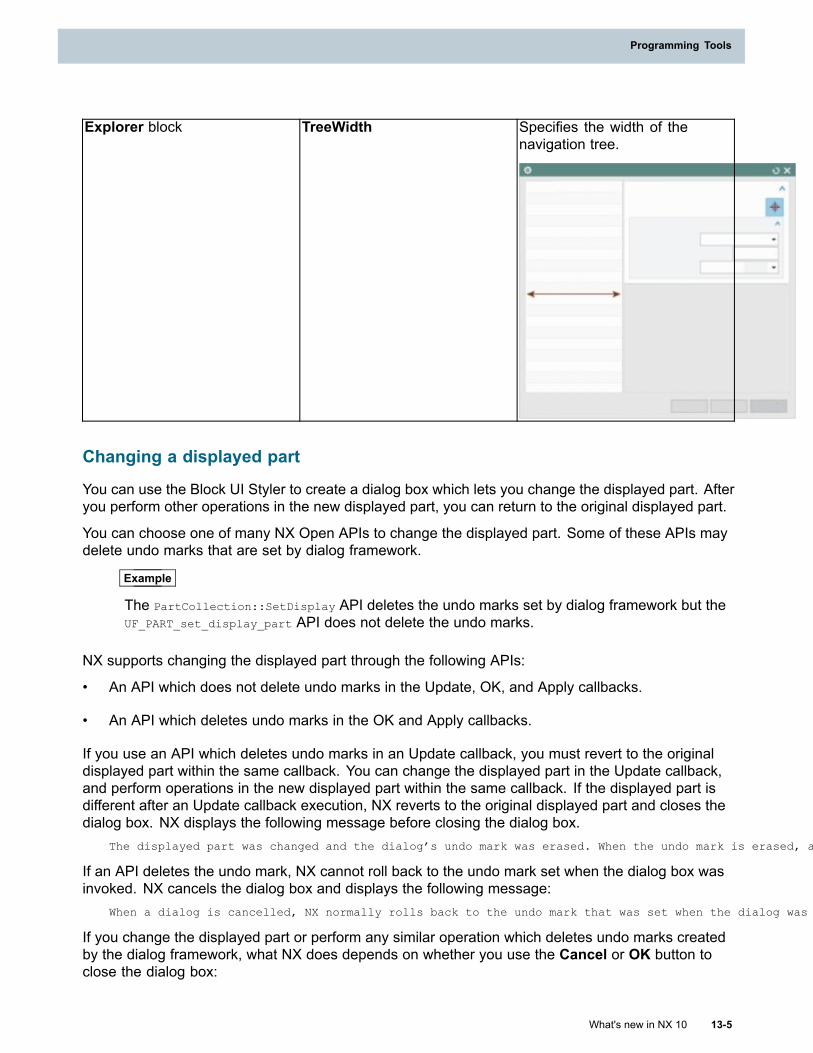
Programming Tools
Explorer block TreeWidth Specifies the width of thenavigation tree.
Changing a displayed part
You can use the Block UI Styler to create a dialog box which lets you change the displayed part. Afteryou perform other operations in the new displayed part, you can return to the original displayed part.
You can choose one of many NX Open APIs to change the displayed part. Some of these APIs maydelete undo marks that are set by dialog framework.
Example
The PartCollection::SetDisplay API deletes the undo marks set by dialog framework but theUF_PART_set_display_part API does not delete the undo marks.
NX supports changing the displayed part through the following APIs:
• An API which does not delete undo marks in the Update, OK, and Apply callbacks.
• An API which deletes undo marks in the OK and Apply callbacks.
If you use an API which deletes undo marks in an Update callback, you must revert to the originaldisplayed part within the same callback. You can change the displayed part in the Update callback,and perform operations in the new displayed part within the same callback. If the displayed part isdifferent after an Update callback execution, NX reverts to the original displayed part and closes thedialog box. NX displays the following message before closing the dialog box.
The displayed part was changed and the dialog’s undo mark was erased. When the undo mark is erased, a change of displayed part is allowed only within an OK or Apply callback. NX has changed the displayed part back to the original and will close (cancel) the dialog.
If an API deletes the undo mark, NX cannot roll back to the undo mark set when the dialog box wasinvoked. NX cancels the dialog box and displays the following message:
When a dialog is cancelled, NX normally rolls back to the undo mark that was set when the dialog was invoked. The undo mark set for this dialog was erased when the displayed part was changed, so a rollback to revert any actions performed on the dialog could not occur.
If you change the displayed part or perform any similar operation which deletes undo marks createdby the dialog framework, what NX does depends on whether you use the Cancel or OK button toclose the dialog box:
What's new in NX 10 13-5
Programming Tools
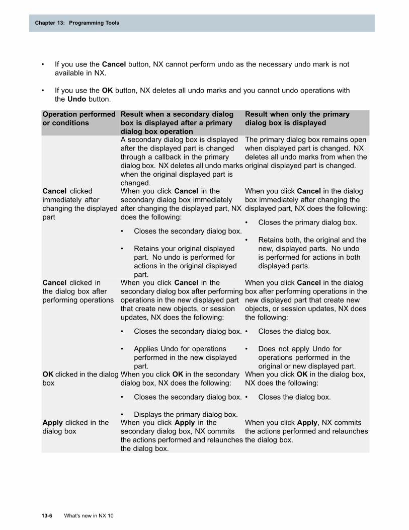
Chapter 13: Programming Tools
• If you use the Cancel button, NX cannot perform undo as the necessary undo mark is notavailable in NX.
• If you use the OK button, NX deletes all undo marks and you cannot undo operations withthe Undo button.
Operation performedor conditions
Result when a secondary dialogbox is displayed after a primarydialog box operation
Result when only the primarydialog box is displayed
A secondary dialog box is displayedafter the displayed part is changedthrough a callback in the primarydialog box. NX deletes all undo markswhen the original displayed part ischanged.
The primary dialog box remains openwhen displayed part is changed. NXdeletes all undo marks from when theoriginal displayed part is changed.
Cancel clickedimmediately afterchanging the displayedpart
When you click Cancel in thesecondary dialog box immediatelyafter changing the displayed part, NXdoes the following:
• Closes the secondary dialog box.
• Retains your original displayedpart. No undo is performed foractions in the original displayedpart.
When you click Cancel in the dialogbox immediately after changing thedisplayed part, NX does the following:
• Closes the primary dialog box.
• Retains both, the original and thenew, displayed parts. No undois performed for actions in bothdisplayed parts.
Cancel clicked inthe dialog box afterperforming operations
When you click Cancel in thesecondary dialog box after performingoperations in the new displayed partthat create new objects, or sessionupdates, NX does the following:
• Closes the secondary dialog box.
• Applies Undo for operationsperformed in the new displayedpart.
When you click Cancel in the dialogbox after performing operations in thenew displayed part that create newobjects, or session updates, NX doesthe following:
• Closes the dialog box.
• Does not apply Undo foroperations performed in theoriginal or new displayed part.
OK clicked in the dialogbox
When you click OK in the secondarydialog box, NX does the following:
• Closes the secondary dialog box.
• Displays the primary dialog box.
When you click OK in the dialog box,NX does the following:
• Closes the dialog box.
Apply clicked in thedialog box
When you click Apply in thesecondary dialog box, NX commitsthe actions performed and relaunchesthe dialog box.
When you click Apply, NX commitsthe actions performed and relaunchesthe dialog box.
13-6 What's new in NX 10
Chapter 13: Programming Tools
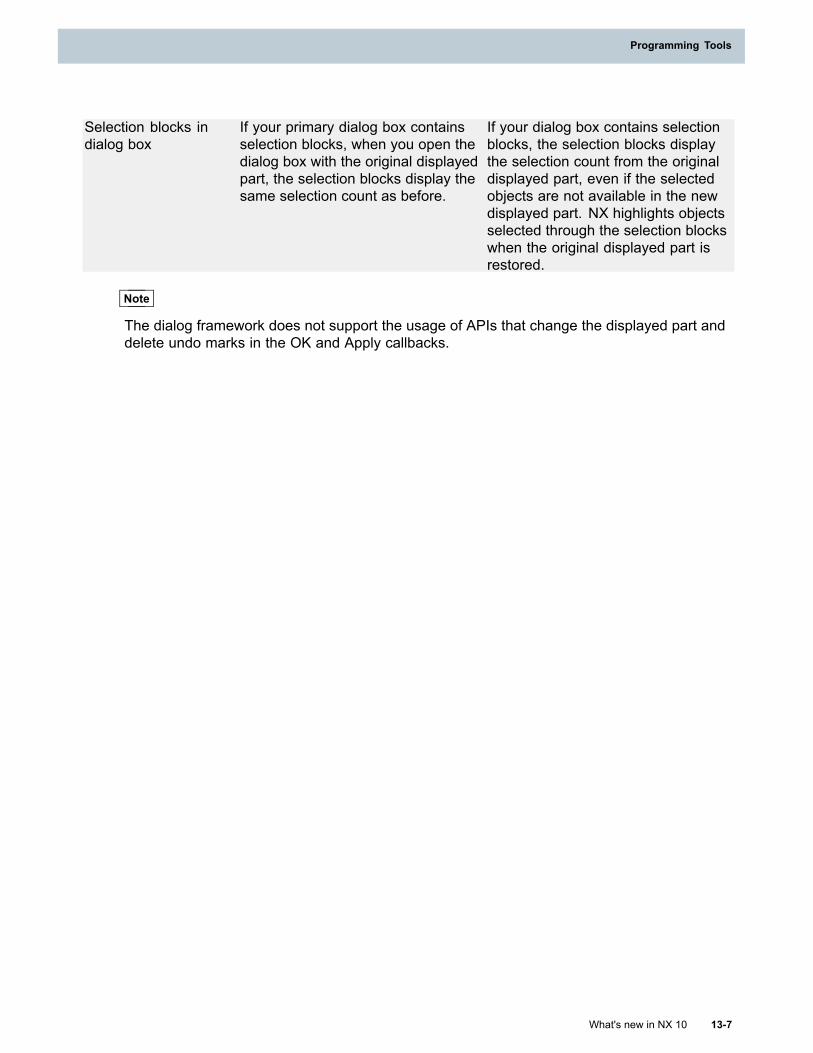
Programming Tools
Selection blocks indialog box
If your primary dialog box containsselection blocks, when you open thedialog box with the original displayedpart, the selection blocks display thesame selection count as before.
If your dialog box contains selectionblocks, the selection blocks displaythe selection count from the originaldisplayed part, even if the selectedobjects are not available in the newdisplayed part. NX highlights objectsselected through the selection blockswhen the original displayed part isrestored.
Note
The dialog framework does not support the usage of APIs that change the displayed part anddelete undo marks in the OK and Apply callbacks.
What's new in NX 10 13-7
Programming Tools

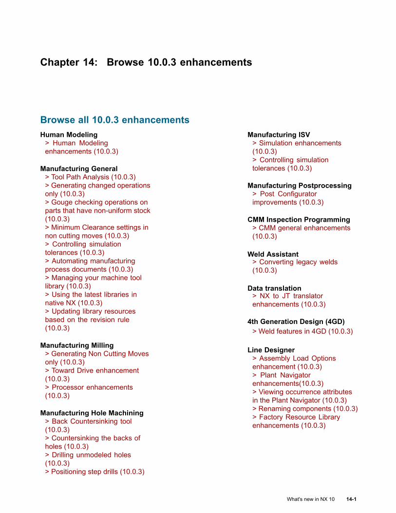
Chapter 14: Browse 10.0.3 enhancements
Browse all 10.0.3 enhancementsHuman Modeling> Human Modelingenhancements (10.0.3)
Manufacturing General> Tool Path Analysis (10.0.3)> Generating changed operationsonly (10.0.3)> Gouge checking operations onparts that have non-uniform stock(10.0.3)> Minimum Clearance settings innon cutting moves (10.0.3)> Controlling simulationtolerances (10.0.3)> Automating manufacturingprocess documents (10.0.3)> Managing your machine toollibrary (10.0.3)> Using the latest libraries innative NX (10.0.3)> Updating library resourcesbased on the revision rule(10.0.3)
Manufacturing Milling> Generating Non Cutting Movesonly (10.0.3)> Toward Drive enhancement(10.0.3)> Processor enhancements(10.0.3)
Manufacturing Hole Machining> Back Countersinking tool(10.0.3)> Countersinking the backs ofholes (10.0.3)> Drilling unmodeled holes(10.0.3)> Positioning step drills (10.0.3)
Manufacturing ISV> Simulation enhancements(10.0.3)> Controlling simulationtolerances (10.0.3)
Manufacturing Postprocessing> Post Configuratorimprovements (10.0.3)
CMM Inspection Programming> CMM general enhancements(10.0.3)
Weld Assistant> Converting legacy welds(10.0.3)
Data translation> NX to JT translatorenhancements (10.0.3)
4th Generation Design (4GD)> Weld features in 4GD (10.0.3)
Line Designer> Assembly Load Optionsenhancement (10.0.3)> Plant Navigatorenhancements(10.0.3)> Viewing occurrence attributesin the Plant Navigator (10.0.3)> Renaming components (10.0.3)> Factory Resource Libraryenhancements (10.0.3)
What's new in NX 10 14-1
Chapter 14: Browse 10.0.3 enhancements
Manufacturing RoboticMachining> Robotic machining updates(10.0.3)
Human Modeling enhancements (10.0.3)
What is it?
You can now use additional anthropometric databases to create or modify human models. Thefollowing population data sources are added.
CDN_LF_97Anthropometric data from the Canadian Land Forces (1997).
ChineseAnthropometric data representing Chinese adults in the age group of 18-60 for males and 18-55for females. GB 10000-88, 1989.
NA_AutoAnthropometric data representing the North American automotive working population.
JAPANESE_2006Anthropometric data specified by the International Standard: ISO7250-1 (2008), ISO/TR 7250-2(2010).
KOREAN_2003Anthropometric data specified by the International Standard: ISO7250-1 (2008), ISO/TR 7250-2(2010).
Why should I use it?
Use of regional anthropometric data to scale the human models allows you to evaluate how yourdesign concept accommodates populations from around the globe.
Where do I find it?
Application Modeling
Command Finder Human
Edit Human dialogbar Modify Human
14-2 What's new in NX 10
Chapter 14: Browse 10.0.3 enhancements
Browse 10.0.3 enhancements
Tool Path Analysis (10.0.3)
What is it?
You can use the Tool Path Analysis command to analyze a varity of multi axis tool path parameters.
The results of the tool path analysis are displayed by the color of the tool path in the graphics window.
Why should I use it?
You can use Tool Path Analysis to give you a better and more accurate understanding of your toolpath and help you identify potential problems before the part is cut.
Where do I find it?
Initial Release NX 10.0.3Application Manufacturing
Command Finder Tool Path Analysis
Generating changed operations only (10.0.3)
What is it?
When you generate multiple operations within a program group, you can choose to generate onlythe operations that are changed. You exclude operations with up-to-date tool paths with a statusof either Complete or Repost .
To enable this functionality, set the Force Regerate customer default or Manufacturing preference.
Tip
To find a customer default, choose File tab→Utilities→Customer Defaults, and click Find
Default .
In cases where separate operations share the same blank and therefore have an IPW relationship, ifone of the operations has an out-of-date tool path, NX generates all the operations.
Where do I find it?
Initial Release NX 10.0.3Application ManufacturingCommand Finder Manufacturing PreferencesLocation in dialogbox Operation tab→Tool Path Generation group→Force Regenerate
What's new in NX 10 14-3
Browse 10.0.3 enhancements
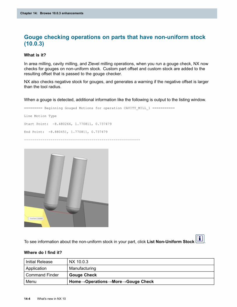
Chapter 14: Browse 10.0.3 enhancements
Gouge checking operations on parts that have non-uniform stock(10.0.3)
What is it?
In area milling, cavity milling, and Zlevel milling operations, when you run a gouge check, NX nowchecks for gouges on non-uniform stock. Custom part offset and custom stock are added to theresulting offset that is passed to the gouge checker.
NX also checks negative stock for gouges, and generates a warning if the negative offset is largerthan the tool radius.
When a gouge is detected, additional information like the following is output to the listing window.
========= Beginning Gouged Motions for operation CAVITY_MILL_1 ===========
Line Motion Type
Start Point: -8.480266, 1.770811, 0.737479
End Point: -8.880451, 1.770811, 0.737479
---------------------------------------------------------
To see information about the non-uniform stock in your part, click List Non-Uniform Stock .
Where do I find it?
Initial Release NX 10.0.3Application ManufacturingCommand Finder Gouge CheckMenu Home→Operations→More→Gouge Check
14-4 What's new in NX 10
Chapter 14: Browse 10.0.3 enhancements
Browse 10.0.3 enhancements
Location in dialogbox Operation→Verify→Gouge and Collision Settings
Minimum Clearance settings in non cutting moves (10.0.3)
What is it?
To give you better control over engage and retract non cutting moves, the Minimum Clearanceoptions are enhanced. You can use the options along with the value you set in the Min. ClearanceDistance box.
If you do not require a minimum clearance, use the nominal path with the specified engage andretract values. Set a mimimum clearance distance to either trim motions that reach the part or extendmotions that go past the part, or only to extend motions that go past the part.
Where do I find it?
Initial Release NX 10.0.3Application Manufacturing
Command Finder Show Non Cutting MovesLocation in dialogbox Open Area group
Controlling simulation tolerances (10.0.3)Separate options are available to control the tolerances for tilting and facet accuracy. Thisenhancement lets you specify a tighter tolerance for faceting and a looser tolerance for tilting.Increasing the tilt tolerance to a value of 0.1 or 0.15 can give acceptable quality while significantlyimproving performance.
• Chordal Tolerance controls the tolerance for circular motions and the tolerance for tool, IPW,and blank faceting. The default value is 0.05 mm.
In previous releases, this option also controlled the tilting tolerance.
• Tilt Tolerance controls the tolerance for tool axis tilting, and the default value is 0.05 mm.
NX approximates 5-axis movements with angular steps. This tolerance specifies the maximumdeviation from the plane, for each step, as the tool axis changes.
The Chordal Tolerance and Tilt Tolerance settings are saved with the part file. You can changethe values in two locations:
• In Customer Defaults to change the system defaults. These settings affect only new parts.
• In Manufacturing Preferences to change the values for an open part.
What's new in NX 10 14-5
Browse 10.0.3 enhancements
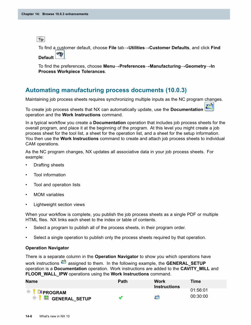
Chapter 14: Browse 10.0.3 enhancements
Tip
To find a customer default, choose File tab→Utilities→Customer Defaults, and click Find
Default .
To find the preferences, choose Menu→Preferences→Manufacturing→Geometry→InProcess Workpiece Tolerances.
Automating manufacturing process documents (10.0.3)Maintaining job process sheets requires synchronizing multiple inputs as the NC program changes.
To create job process sheets that NX can automatically update, use the Documentationoperation and the Work Instructions command.
In a typical workflow you create a Documentation operation that includes job process sheets for theoverall program, and place it at the beginning of the program. At this level you might create a jobprocess sheet for the tool list, a sheet for the operation list, and a sheet for the setup information.You then use the Work Instructions command to create and attach job process sheets to individualCAM operations.
As the NC program changes, NX updates all associative data in your job process sheets. Forexample:
• Drafting sheets
• Tool information
• Tool and operation lists
• MOM variables
• Lightweight section views
When your workflow is complete, you publish the job process sheets as a single PDF or multipleHTML files. NX links each sheet to the index or table of contents.
• Select a program to publish all of the process sheets, in their program order.
• Select a single operation to publish only the process sheets required by that operation.
Operation Navigator
There is a separate column in the Operation Navigator to show you which operations havework instructions assigned to them. In the following example, the GENERAL_SETUPoperation is a Documentation operation. Work instructions are added to the CAVITY_MILL andFLOOR_WALL_IPW operations using the Work Instructions command.Name Path Work
InstructionsTime
PROGRAM 01:56:01
GENERAL_SETUP 00:30:00
14-6 What's new in NX 10
Chapter 14: Browse 10.0.3 enhancements
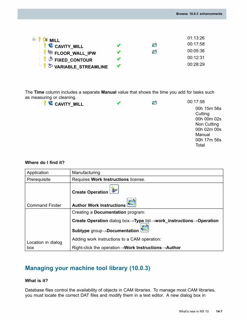
Browse 10.0.3 enhancements
MILL 01:13:26
CAVITY_MILL 00:17:58
FLOOR_WALL_IPW 00:05:36
FIXED_CONTOUR 00:12:31
VARIABLE_STREAMLINE 00:28:29
The Time column includes a separate Manual value that shows the time you add for tasks suchas measuring or cleaning.
CAVITY_MILL 00:17:5800h 15m 56sCutting00h 00m 02sNon Cutting00h 02m 00sManual00h 17m 56sTotal
Where do I find it?
Application ManufacturingPrerequisite Requires Work Instructions license.
Command Finder
Create Operation
Author Work Instructions
Location in dialogbox
Creating a Documentation program:
Create Operation dialog box→Type list→work_instructions→Operation
Subtype group→Documentation
Adding work instructions to a CAM operation:
Right-click the operation→Work Instructions→Author
Managing your machine tool library (10.0.3)
What is it?
Database files control the availability of objects in CAM libraries. To manage most CAM libraries,you must locate the correct DAT files and modify them in a text editor. A new dialog box in
What's new in NX 10 14-7
Browse 10.0.3 enhancements
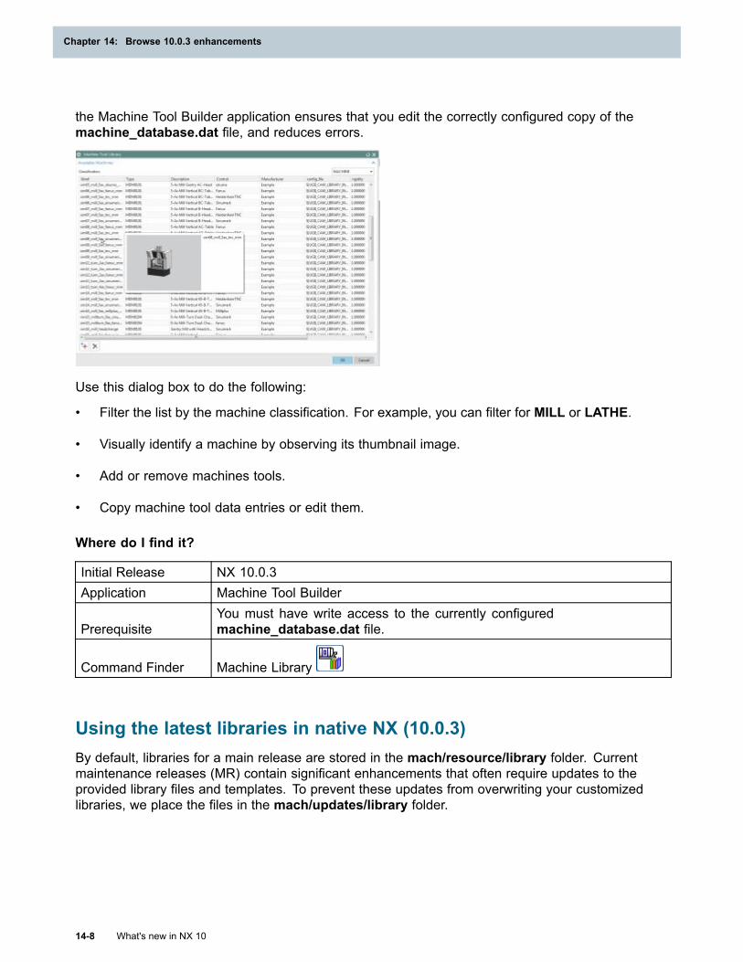
Chapter 14: Browse 10.0.3 enhancements
the Machine Tool Builder application ensures that you edit the correctly configured copy of themachine_database.dat file, and reduces errors.
Use this dialog box to do the following:
• Filter the list by the machine classification. For example, you can filter for MILL or LATHE.
• Visually identify a machine by observing its thumbnail image.
• Add or remove machines tools.
• Copy machine tool data entries or edit them.
Where do I find it?
Initial Release NX 10.0.3Application Machine Tool Builder
PrerequisiteYou must have write access to the currently configuredmachine_database.dat file.
Command Finder Machine Library
Using the latest libraries in native NX (10.0.3)By default, libraries for a main release are stored in the mach/resource/library folder. Currentmaintenance releases (MR) contain significant enhancements that often require updates to theprovided library files and templates. To prevent these updates from overwriting your customizedlibraries, we place the files in the mach/updates/library folder.
14-8 What's new in NX 10
Chapter 14: Browse 10.0.3 enhancements
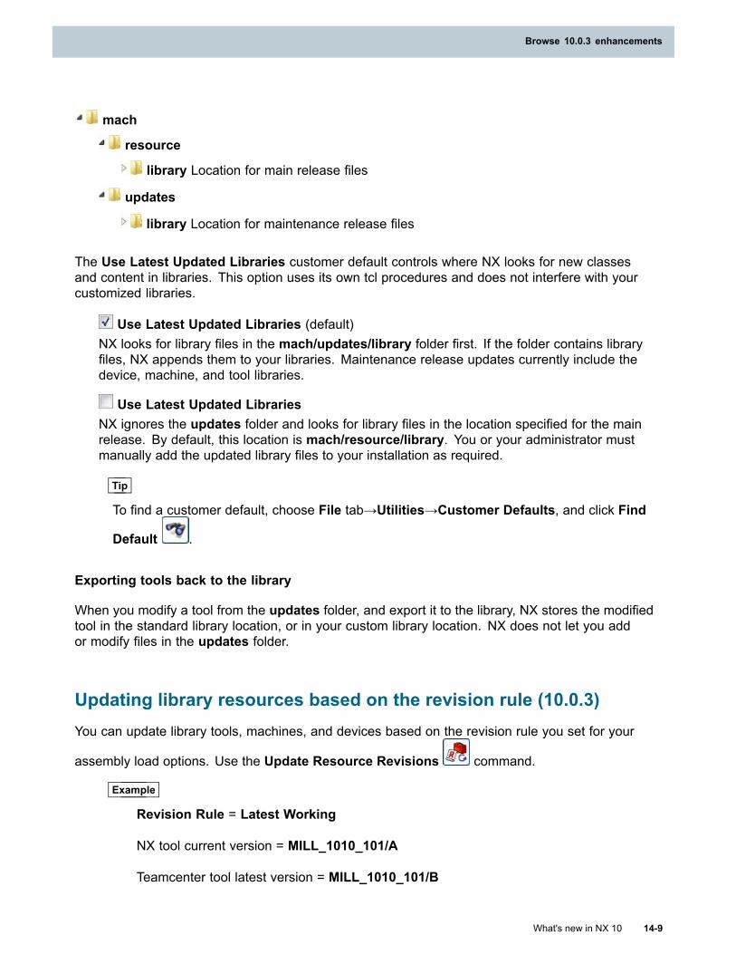
Browse 10.0.3 enhancements
mach
resource
library Location for main release files
updates
library Location for maintenance release files
The Use Latest Updated Libraries customer default controls where NX looks for new classesand content in libraries. This option uses its own tcl procedures and does not interfere with yourcustomized libraries.
Use Latest Updated Libraries (default)NX looks for library files in the mach/updates/library folder first. If the folder contains libraryfiles, NX appends them to your libraries. Maintenance release updates currently include thedevice, machine, and tool libraries.
Use Latest Updated LibrariesNX ignores the updates folder and looks for library files in the location specified for the mainrelease. By default, this location is mach/resource/library. You or your administrator mustmanually add the updated library files to your installation as required.
Tip
To find a customer default, choose File tab→Utilities→Customer Defaults, and click Find
Default .
Exporting tools back to the library
When you modify a tool from the updates folder, and export it to the library, NX stores the modifiedtool in the standard library location, or in your custom library location. NX does not let you addor modify files in the updates folder.
Updating library resources based on the revision rule (10.0.3)You can update library tools, machines, and devices based on the revision rule you set for your
assembly load options. Use the Update Resource Revisions command.
Example
Revision Rule = Latest Working
NX tool current version = MILL_1010_101/A
Teamcenter tool latest version = MILL_1010_101/B
What's new in NX 10 14-9
Browse 10.0.3 enhancements
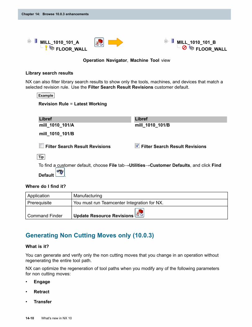
Chapter 14: Browse 10.0.3 enhancements
MILL_1010_101_AFLOOR_WALL
MILL_1010_101_BFLOOR_WALL
Operation Navigator, Machine Tool view
Library search results
NX can also filter library search results to show only the tools, machines, and devices that match aselected revision rule. Use the Filter Search Result Revisions customer default.
Example
Revision Rule = Latest Working
Libref Librefmill_1010_101/A
mill_1010_101/B
mill_1010_101/B
Filter Search Result Revisions Filter Search Result Revisions
Tip
To find a customer default, choose File tab→Utilities→Customer Defaults, and click Find
Default .
Where do I find it?
Application ManufacturingPrerequisite You must run Teamcenter Integration for NX.
Command Finder Update Resource Revisions
Generating Non Cutting Moves only (10.0.3)What is it?
You can generate and verify only the non cutting moves that you change in an operation withoutregenerating the entire tool path.
NX can optimize the regeneration of tool paths when you modify any of the following parametersfor non cutting moves:
• Engage
• Retract
• Transfer
14-10 What's new in NX 10
Chapter 14: Browse 10.0.3 enhancements
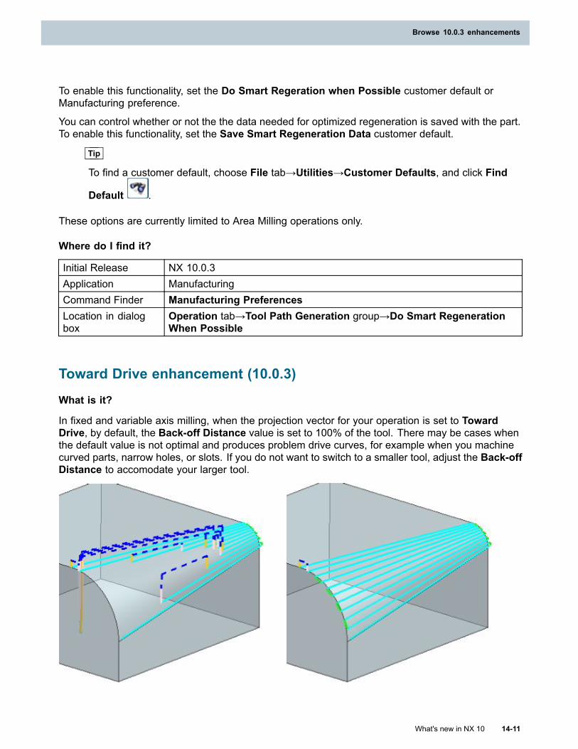
Browse 10.0.3 enhancements
To enable this functionality, set the Do Smart Regeration when Possible customer default orManufacturing preference.
You can control whether or not the the data needed for optimized regeneration is saved with the part.To enable this functionality, set the Save Smart Regeneration Data customer default.
Tip
To find a customer default, choose File tab→Utilities→Customer Defaults, and click Find
Default .
These options are currently limited to Area Milling operations only.
Where do I find it?
Initial Release NX 10.0.3Application ManufacturingCommand Finder Manufacturing PreferencesLocation in dialogbox
Operation tab→Tool Path Generation group→Do Smart RegenerationWhen Possible
Toward Drive enhancement (10.0.3)
What is it?
In fixed and variable axis milling, when the projection vector for your operation is set to TowardDrive, by default, the Back-off Distance value is set to 100% of the tool. There may be cases whenthe default value is not optimal and produces problem drive curves, for example when you machinecurved parts, narrow holes, or slots. If you do not want to switch to a smaller tool, adjust the Back-offDistance to accomodate your larger tool.
What's new in NX 10 14-11
Browse 10.0.3 enhancements

Chapter 14: Browse 10.0.3 enhancements
Back off Distance = 100 (% Tool) Back off Distance = 200 (% Tool)
Back off Distance = 100 (% Tool) Back off Distance = 10 (% Tool)
Where do I find it?
Initial Release NX 10.0.3Application ManufacturingLocation in dialogbox Streamline Drive dialog box→Projection Vector group
Processor enhancements (10.0.3)
What is it?
NX CAM 10.0.3 includes enhancements that provide greater use of multiple processors.
Multiple processing is only used during certain portions of the overall tool path generation. Whenmultiple processors are being used, NX displays the message Building Traces (new) in the Statusbar.
Note
The degree of performance improvement varies according to the complexity of the partgeometry, operation type, and computer configuration.
Where do I find it?
Initial Release NX 10.0.3
14-12 What's new in NX 10
Chapter 14: Browse 10.0.3 enhancements
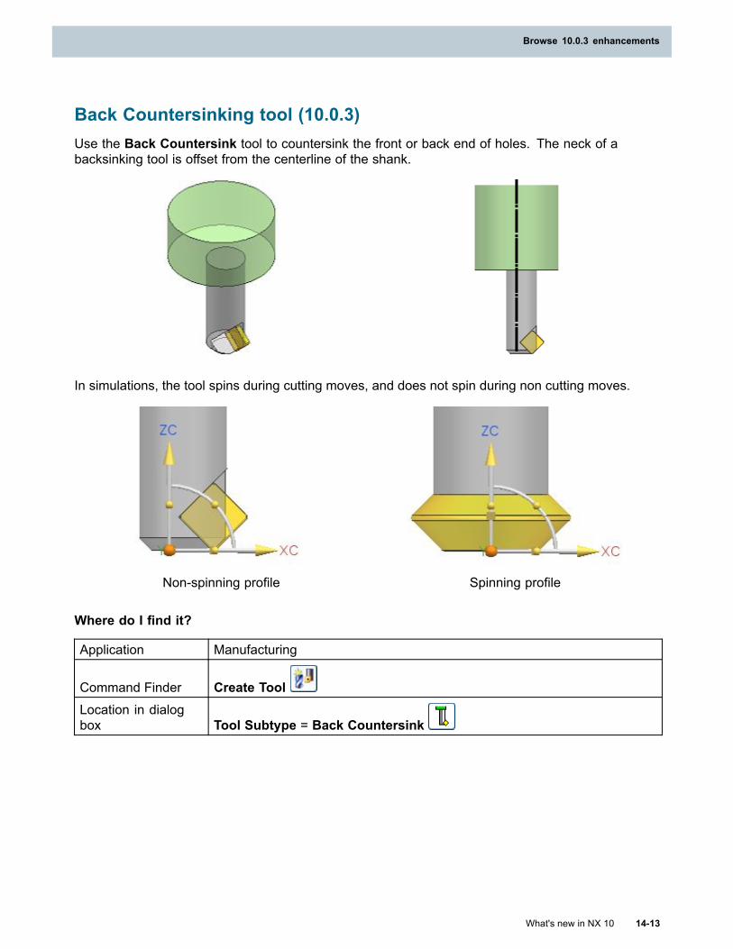
Browse 10.0.3 enhancements
Back Countersinking tool (10.0.3)Use the Back Countersink tool to countersink the front or back end of holes. The neck of abacksinking tool is offset from the centerline of the shank.
In simulations, the tool spins during cutting moves, and does not spin during non cutting moves.
Non-spinning profile Spinning profile
Where do I find it?
Application Manufacturing
Command Finder Create ToolLocation in dialogbox Tool Subtype = Back Countersink
What's new in NX 10 14-13
Browse 10.0.3 enhancements
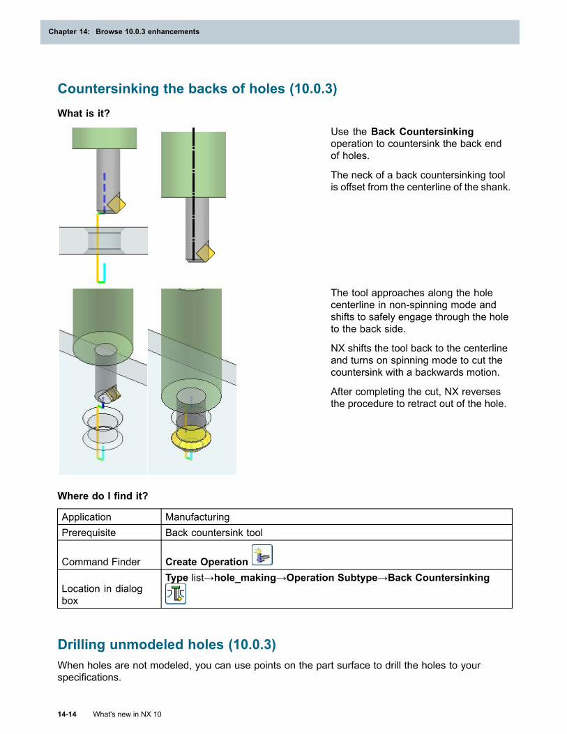
Chapter 14: Browse 10.0.3 enhancements
Countersinking the backs of holes (10.0.3)What is it?
Use the Back Countersinkingoperation to countersink the back endof holes.
The neck of a back countersinking toolis offset from the centerline of the shank.
The tool approaches along the holecenterline in non-spinning mode andshifts to safely engage through the holeto the back side.
NX shifts the tool back to the centerlineand turns on spinning mode to cut thecountersink with a backwards motion.
After completing the cut, NX reversesthe procedure to retract out of the hole.
Where do I find it?
Application ManufacturingPrerequisite Back countersink tool
Command Finder Create Operation
Location in dialogbox
Type list→hole_making→Operation Subtype→Back Countersinking
Drilling unmodeled holes (10.0.3)When holes are not modeled, you can use points on the part surface to drill the holes to yourspecifications.
14-14 What's new in NX 10
Chapter 14: Browse 10.0.3 enhancements
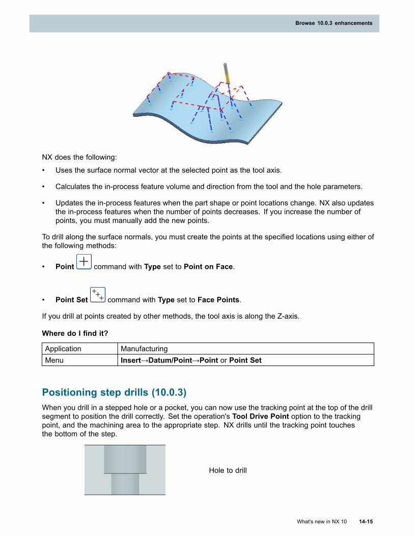
Browse 10.0.3 enhancements
NX does the following:
• Uses the surface normal vector at the selected point as the tool axis.
• Calculates the in-process feature volume and direction from the tool and the hole parameters.
• Updates the in-process features when the part shape or point locations change. NX also updatesthe in-process features when the number of points decreases. If you increase the number ofpoints, you must manually add the new points.
To drill along the surface normals, you must create the points at the specified locations using either ofthe following methods:
• Point command with Type set to Point on Face.
• Point Set command with Type set to Face Points.
If you drill at points created by other methods, the tool axis is along the Z-axis.
Where do I find it?
Application ManufacturingMenu Insert→Datum/Point→Point or Point Set
Positioning step drills (10.0.3)When you drill in a stepped hole or a pocket, you can now use the tracking point at the top of the drillsegment to position the drill correctly. Set the operation's Tool Drive Point option to the trackingpoint, and the machining area to the appropriate step. NX drills until the tracking point touchesthe bottom of the step.
Hole to drill
What's new in NX 10 14-15
Browse 10.0.3 enhancements
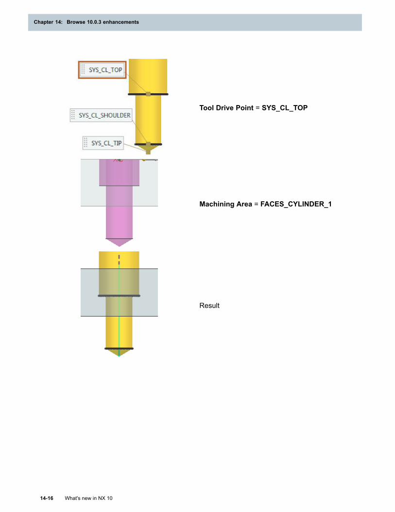
Chapter 14: Browse 10.0.3 enhancements
Tool Drive Point = SYS_CL_TOP
Machining Area = FACES_CYLINDER_1
Result
14-16 What's new in NX 10
Chapter 14: Browse 10.0.3 enhancements
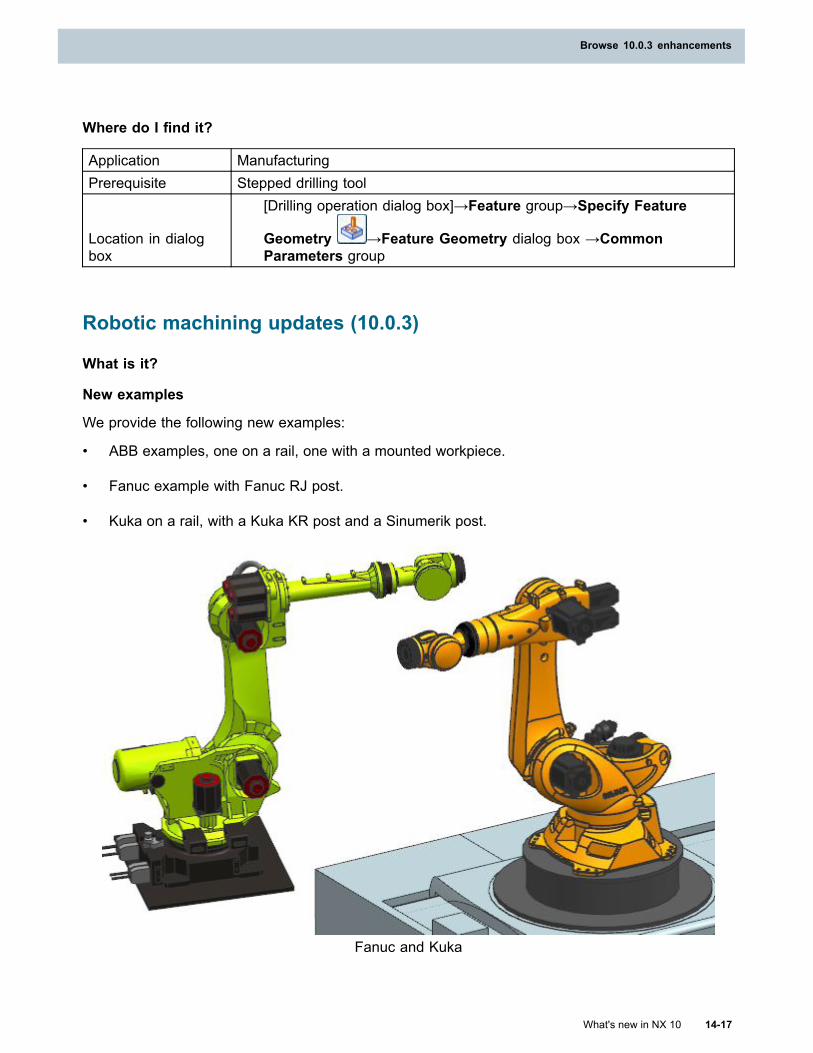
Browse 10.0.3 enhancements
Where do I find it?
Application ManufacturingPrerequisite Stepped drilling tool
Location in dialogbox
[Drilling operation dialog box]→Feature group→Specify Feature
Geometry →Feature Geometry dialog box →CommonParameters group
Robotic machining updates (10.0.3)
What is it?
New examples
We provide the following new examples:
• ABB examples, one on a rail, one with a mounted workpiece.
• Fanuc example with Fanuc RJ post.
• Kuka on a rail, with a Kuka KR post and a Sinumerik post.
Fanuc and Kuka
What's new in NX 10 14-17
Browse 10.0.3 enhancements
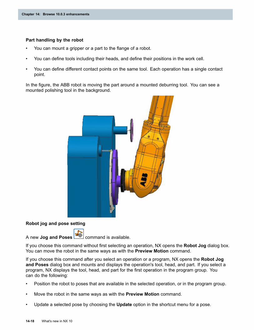
Chapter 14: Browse 10.0.3 enhancements
Part handling by the robot
• You can mount a gripper or a part to the flange of a robot.
• You can define tools including their heads, and define their positions in the work cell.
• You can define different contact points on the same tool. Each operation has a single contactpoint.
In the figure, the ABB robot is moving the part around a mounted deburring tool. You can see amounted polishing tool in the background.
Robot jog and pose setting
A new Jog and Poses command is available.
If you choose this command without first selecting an operation, NX opens the Robot Jog dialog box.You can move the robot in the same ways as with the Preview Motion command.
If you choose this command after you select an operation or a program, NX opens the Robot Jogand Poses dialog box and mounts and displays the operation's tool, head, and part. If you select aprogram, NX displays the tool, head, and part for the first operation in the program group. Youcan do the following:
• Position the robot to poses that are available in the selected operation, or in the program group.
• Move the robot in the same ways as with the Preview Motion command.
• Update a selected pose by choosing the Update option in the shortcut menu for a pose.
14-18 What's new in NX 10
Chapter 14: Browse 10.0.3 enhancements
Browse 10.0.3 enhancements
Note
You can update or remove only poses that are defined in the selected object.
• Add the pose to which you positioned the robot, by clicking Add Pose .
Where do I find it?
Initial Release NX 10.0.3
PrerequisiteDisplay the RoboticMachining group
Application ManufacturingCommand Finder Robot Jog
Ribbon bar
Manufacturing→Home→RoboticMachining→Jog and
Poses
Simulation enhancements (10.0.3)
What is it?
• In the Machine Tool Navigator, you can now display the following columns:
o Axis Number
o Axis Soft Limits
• In the Define Kinematic Chains dialog box, all kinematics components are listed in the Setuplist. You can select any component for the part and tool ends of the chain.
In the Edit Axis dialog box, the soft limits remain visible even when you select Rotary Unlimitedfrom the Axis Type list.
Enhancements for Machine Control Panel developers
If you are a developer working with a machine control panel to be used with VNCK simulation in theNX Open API, you can use notification events that are triggered when you:
• Enter or leave the history buffer mode.
• Stop VNCK simulation from outside of NX.
• Press NCStart, NCReset, or NCStop in the Simulation Control Panel.
A new feature in the default Machine Control Panel implementation lets your users recreate theoriginal IPW at the part mount position by clicking Reset IPW.
Before the INI program is registered, NX verifies channel names and warns you if a channel does notexist.
What's new in NX 10 14-19
Browse 10.0.3 enhancements
Chapter 14: Browse 10.0.3 enhancements
NX supports VNCK 4.5.
Where do I find it?
Initial Release NX 10.0.3Application Machine Tool Builder or Manufacturing
Post Configurator improvements (10.0.3)
What is it?
Post Configurator post processors are enhanced to:
• Load and process faster that in previous releases.
• Run in NX versions 8.5 and later.
• Support the Sinumerik 828D machine controller.
• Support turning, mill turns, and turn mills with minimal extra input.
The configuration objects list has several subgroups, and you can define more in your post.Subgroups make it faster to navigate to options.
A new data type, POINT, makes it more intuitive to support the post processor.
NX Open is supported; you can use a journal to create and to encrypt post processors.
Where do I find it?
Initial Release NX 10.0.3Application ManufacturingCommand Finder Post Configurator
CMM general enhancements (10.0.3)
View the motions between inspection paths
When you select two inspection paths in the Inspection Navigator, NX displays all paths that are inbetween the selected paths. NX displays the transition motions between inspection paths in a greenfont. This enhancement lets you see potential collisions and evaluate the efficiency of the path.
14-20 What's new in NX 10
Chapter 14: Browse 10.0.3 enhancements
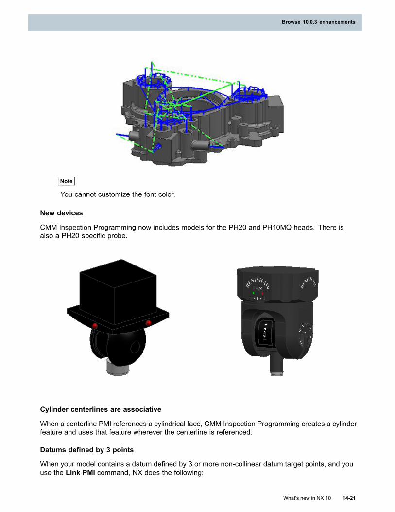
Browse 10.0.3 enhancements
Note
You cannot customize the font color.
New devices
CMM Inspection Programming now includes models for the PH20 and PH10MQ heads. There isalso a PH20 specific probe.
Cylinder centerlines are associative
When a centerline PMI references a cylindrical face, CMM Inspection Programming creates a cylinderfeature and uses that feature wherever the centerline is referenced.
Datums defined by 3 points
When your model contains a datum defined by 3 or more non-collinear datum target points, and youuse the Link PMI command, NX does the following:
What's new in NX 10 14-21
Browse 10.0.3 enhancements
Chapter 14: Browse 10.0.3 enhancements
• Creates a point feature for each datum target point.
• Constructs a best-fit plane through the points.
• Assigns the datum letter to the constructed plane.
When your model contains a datum defined by 3 or more collinear datum target points, and you usethe Link PMI command, NX does the following:
• Creates a point feature for each datum target point.
• Constructs a best-fit line through the points.
• Assigns the datum letter to the constructed line.
When your model contains 3 or more datum target points that are on 2 or more parallel planes, andyou use the Link PMI command, NX does the following:
• Creates a point feature for each datum target point.
• Checks to see if the points are collinear.
o If the points are collinear, constructs an offset line in the plane.
o If the points are not collinear, constructs an offset plane.
• Assigns the datum letter to the constructed offset line or plane.
Where do I find it?
Application CMM Inspection Programming
Converting legacy welds (10.0.3)
What is it?
When you run the Convert Legacy Weld Points weld utility, you can now retain the original groupingand creation parameters for the legacy weld point features that were created using the Weld Pointcommand with Method set to Guide Curves. To do this, clear the Create Single Features checkbox. Previously, NX converted all the legacy weld point features to single features.
14-22 What's new in NX 10
Chapter 14: Browse 10.0.3 enhancements
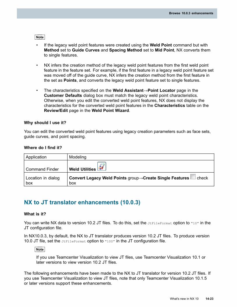
Browse 10.0.3 enhancements
Note
• If the legacy weld point features were created using the Weld Point command but withMethod set to Guide Curves and Spacing Method set to Mid Point, NX converts themto single features.
• NX infers the creation method of the legacy weld point features from the first weld pointfeature in the feature set. For example, if the first feature in a legacy weld point feature setwas moved off of the guide curve, NX infers the creation method from the first feature inthe set as Points, and converts the legacy weld point feature set to single features.
• The characteristics specified on the Weld Assistant→Point Locator page in theCustomer Defaults dialog box must match the legacy weld point characteristics.Otherwise, when you edit the converted weld point features, NX does not display thecharacteristics for the converted weld point features in the Characteristics table on theReview/Edit page in the Weld Point Wizard.
Why should I use it?
You can edit the converted weld point features using legacy creation parameters such as face sets,guide curves, and point spacing.
Where do I find it?
Application Modeling
Command Finder Weld Utilities
Location in dialogbox
Convert Legacy Weld Points group→Create Single Features checkbox
NX to JT translator enhancements (10.0.3)
What is it?
You can write NX data to version 10.2 JT files. To do this, set the JtFileFormat option to “10” in theJT configuration file.
In NX10.0.3, by default, the NX to JT translator produces version 10.2 JT files. To produce version10.0 JT file, set the JtFileFormat option to “100” in the JT configuration file.
Note
If you use Teamcenter Visualization to view JT files, use Teamcenter Visualization 10.1 orlater versions to view version 10.2 JT files.
The following enhancements have been made to the NX to JT translator for version 10.2 JT files. Ifyou use Teamcenter Visualization to view JT files, note that only Teamcenter Visualization 10.1.5or later versions support these enhancements.
What's new in NX 10 14-23
Browse 10.0.3 enhancements
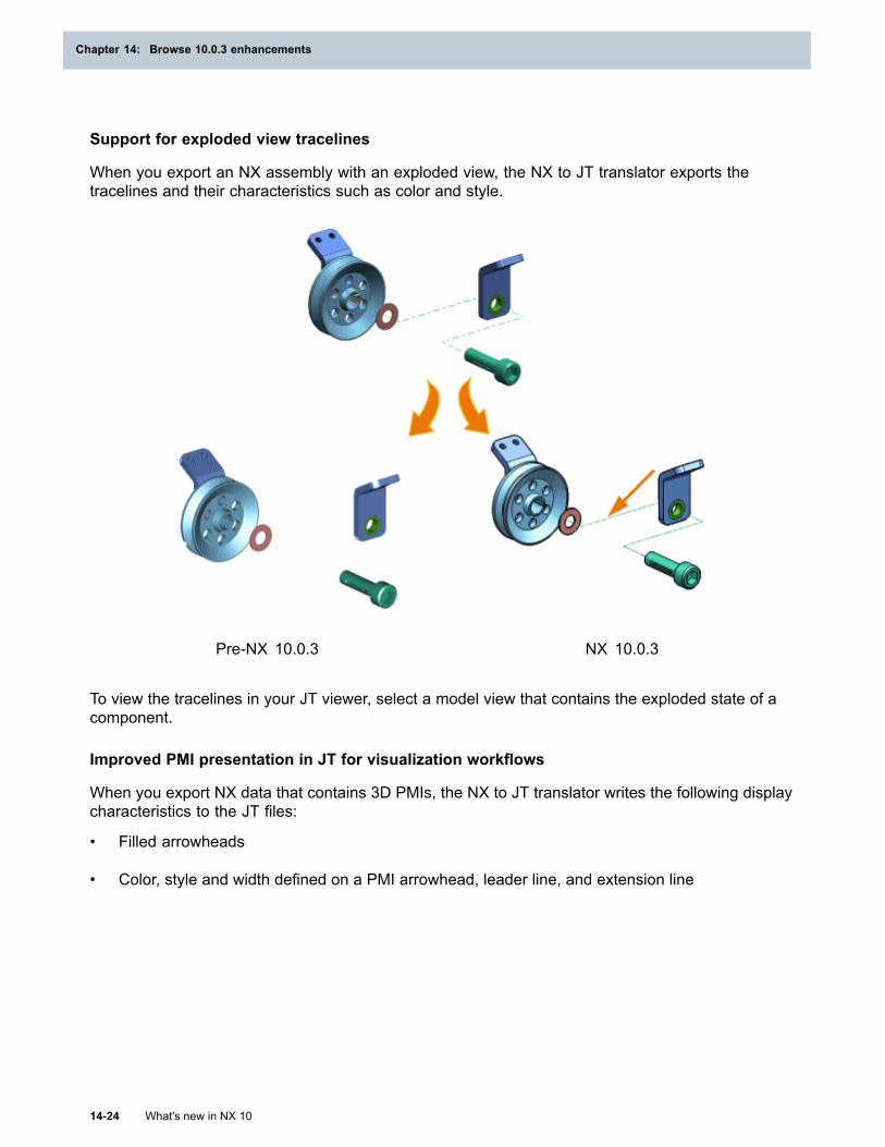
Chapter 14: Browse 10.0.3 enhancements
Support for exploded view tracelines
When you export an NX assembly with an exploded view, the NX to JT translator exports thetracelines and their characteristics such as color and style.
Pre-NX 10.0.3 NX 10.0.3
To view the tracelines in your JT viewer, select a model view that contains the exploded state of acomponent.
Improved PMI presentation in JT for visualization workflows
When you export NX data that contains 3D PMIs, the NX to JT translator writes the following displaycharacteristics to the JT files:
• Filled arrowheads
• Color, style and width defined on a PMI arrowhead, leader line, and extension line
14-24 What's new in NX 10
Chapter 14: Browse 10.0.3 enhancements
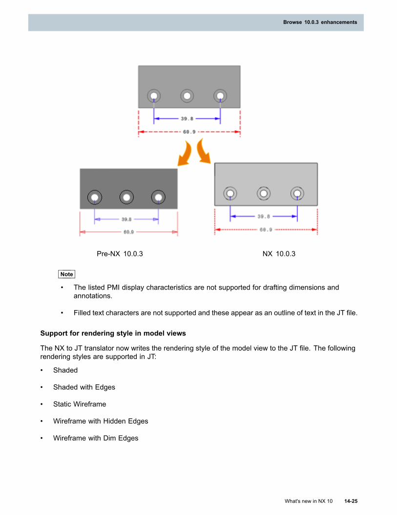
Browse 10.0.3 enhancements
Pre-NX 10.0.3 NX 10.0.3
Note
• The listed PMI display characteristics are not supported for drafting dimensions andannotations.
• Filled text characters are not supported and these appear as an outline of text in the JT file.
Support for rendering style in model views
The NX to JT translator now writes the rendering style of the model view to the JT file. The followingrendering styles are supported in JT:
• Shaded
• Shaded with Edges
• Static Wireframe
• Wireframe with Hidden Edges
• Wireframe with Dim Edges
What's new in NX 10 14-25
Browse 10.0.3 enhancements
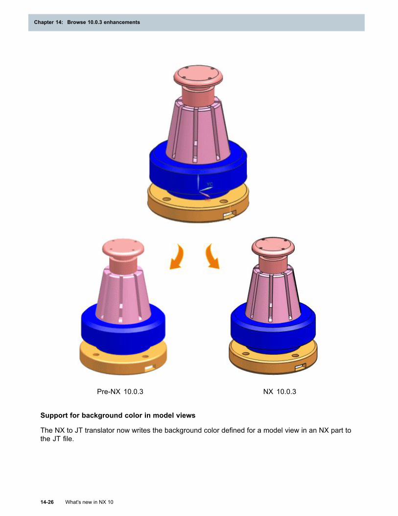
Chapter 14: Browse 10.0.3 enhancements
Pre-NX 10.0.3 NX 10.0.3
Support for background color in model views
The NX to JT translator now writes the background color defined for a model view in an NX part tothe JT file.
14-26 What's new in NX 10
Chapter 14: Browse 10.0.3 enhancements
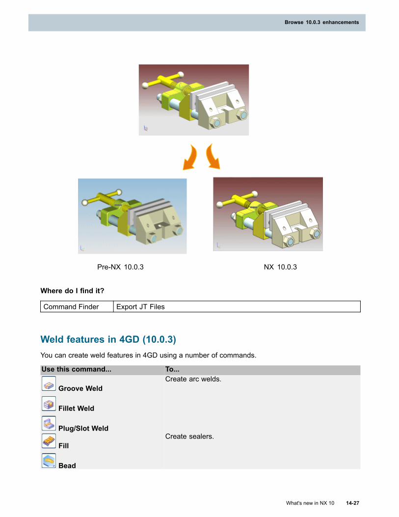
Browse 10.0.3 enhancements
Pre-NX 10.0.3 NX 10.0.3
Where do I find it?
Command Finder Export JT Files
Weld features in 4GD (10.0.3)You can create weld features in 4GD using a number of commands.
Use this command... To...
Groove Weld
Fillet Weld
Plug/Slot Weld
Create arc welds.
Fill
Bead
Create sealers.
What's new in NX 10 14-27
Browse 10.0.3 enhancements
Chapter 14: Browse 10.0.3 enhancements
Weld Point Wizard
Easy Spot
Create spot welds.
User Defined WeldCreate user-defined welds.
You can define a solid body as a user-defined weld.
Fabrication LabelApply labels on weld features.
Connected Face FinderFind missing connected part faces for the weld features.
Weld AdvisorValidate spot weld features.
Export CSV FileExport the location of the weld feature to a CSV file.
Note
You cannot import weld features into 4GD.
Assembly Load Options enhancement (10.0.3)
What is it?
The following enhancements are available in Line Designer, when you load a BVR assembly, usingthe Load Structure Only option.
The Plant Navigator displays the structure of the objects including the Name, Revision, and theDescription.
When you point to a component in the Plant Navigator, NX displays a bounding box along with theobject name in the graphics viewer.
In 4GD, NX displays the design element name and ID along with the bounding box.
Loading components
When you expand the assembly node in the Plant Navigator, the corresponding assemblycomponents are also partially loaded.
14-28 What's new in NX 10
Chapter 14: Browse 10.0.3 enhancements
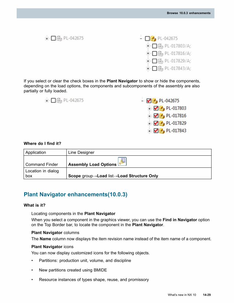
Browse 10.0.3 enhancements
If you select or clear the check boxes in the Plant Navigator to show or hide the components,depending on the load options, the components and subcomponents of the assembly are alsopartially or fully loaded.
Where do I find it?
Application Line Designer
Command Finder Assembly Load OptionsLocation in dialogbox Scope group→Load list→Load Structure Only
Plant Navigator enhancements(10.0.3)
What is it?
Locating components in the Plant NavigatorWhen you select a component in the graphics viewer, you can use the Find in Navigator optionon the Top Border bar, to locate the component in the Plant Navigator.
Plant Navigator columnsThe Name column now displays the item revision name instead of the item name of a component.
Plant Navigator iconsYou can now display customized icons for the following objects.
• Partitions: production unit, volume, and discipline
• New partitions created using BMIDE
• Resource instances of types shape, reuse, and promissory
What's new in NX 10 14-29
Browse 10.0.3 enhancements
Chapter 14: Browse 10.0.3 enhancements
• Assembly structure
• BVR work area and equipment
To do this, you must store the respective .bmp or .png files in the installation folder.
Installation folder path: …\line_designer\application\class_bitmaps
Icon name format for .bmp files: <internal name>.sc.black.bmp or <internal name>.sc.white.bmpor <internal name>.bmp
Icon name format for .png files: <internal name>.sc.black.png or <internal name>.sc.white.png or<internal name>.png
To find the internal name in Teamcenter, right-click an object and choose Viewproperties→Multi-field key information→Object type. The value of the object type is theinternal name, which is the name of the customized icon.
Where do I find it?
Application Line Designer
Top Borderbar Find in Navigator
Viewing occurrence attributes in the Plant Navigator (10.0.3)
What is it?
When you load an assembly, you can now view the following occurrence attributes and their status inthe Plant Navigator:
• Occurrence Name
• Occurrence Type
• Callout (in NX) or Find No for sorting (in Teamcenter)
• Custom Occurrence Note
Note
NX does not automatically display the Custom Occurrence Note in the Columnconfiguration dialog box. In Teamcenter, the System Administrator must add the internalname of the Custom Occurrence Note using the PS_structure_change_condition
preference.
You need to turn on the columns for the occurrence attributes in the Plant Navigator. In the Columnconfiguration dialog box, select the occurrence attribute that you want to display as a column.
Use the Report This Column shortcut menu option to generate a report of these attributes.
14-30 What's new in NX 10
Chapter 14: Browse 10.0.3 enhancements
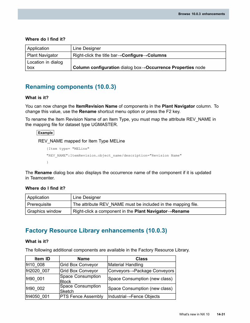
Browse 10.0.3 enhancements
Where do I find it?
Application Line DesignerPlant Navigator Right-click the title bar→Configure→ColumnsLocation in dialogbox Column configuration dialog box→Occurrence Properties node
Renaming components (10.0.3)What is it?
You can now change the ItemRevision Name of components in the Plant Navigator column. Tochange this value, use the Rename shortcut menu option or press the F2 key.To rename the Item Revision Name of an Item Type, you must map the attribute REV_NAME inthe mapping file for dataset type UGMASTER.
Example
REV_NAME mapped for Item Type MELine{Item type= "MELine"
"REV_NAME":ItemRevision.object_name/description="Revision Name"
}
The Rename dialog box also displays the occurrence name of the component if it is updatedin Teamcenter.
Where do I find it?
Application Line DesignerPrerequisite The attribute REV_NAME must be included in the mapping file.Graphics window Right-click a component in the Plant Navigator→Rename
Factory Resource Library enhancements (10.0.3)What is it?
The following additional components are available in the Factory Resource Library.
Item ID Name Classfrl10_008 Grid Box Conveyor Material Handlingfrl2020_007 Grid Box Conveyor Conveyors→Package Conveyors
frl90_001 Space ConsumptionBlock Space Consumption (new class)
frl90_002 Space ConsumptionSketch Space Consumption (new class)
frl4050_001 PTS Fence Assembly Industrial→Fence Objects
What's new in NX 10 14-31
Browse 10.0.3 enhancements
Chapter 14: Browse 10.0.3 enhancements
You can now use the existing frl801050_002 robot in Process Simulate. A new JT file with kinematicsparameters, and a motion parameters file is added for this robot.
Note
These enhancements are available with MRL 3.1.5 (available with Teamcenter 10.1.5).
Where do I find it?
Application Line DesignerResource bar Reuse Library
14-32 What's new in NX 10
Chapter 14: Browse 10.0.3 enhancements

Siemens Industry Software
HeadquartersGranite Park One5800 Granite ParkwaySuite 600Plano, TX 75024USA+1 972 987 3000
AmericasGranite Park One5800 Granite ParkwaySuite 600Plano, TX 75024USA+1 314 264 8499
EuropeStephenson HouseSir William Siemens SquareFrimley, CamberleySurrey, GU16 8QD+44 (0) 1276 413200
Asia-PacificSuites 4301-4302, 43/FAIA Kowloon Tower, Landmark East100 How Ming StreetKwun Tong, KowloonHong Kong+852 2230 3308
About Siemens PLM Software
Siemens PLM Software, a business unit of the SiemensIndustry Automation Division, is a leading global providerof product lifecycle management (PLM) software andservices with 7 million licensed seats and 71,000 customersworldwide. Headquartered in Plano, Texas, SiemensPLM Software works collaboratively with companiesto deliver open solutions that help them turn moreideas into successful products. For more informationon Siemens PLM Software products and services, visitwww.siemens.com/plm.
© 2015 Siemens Product Lifecycle ManagementSoftware Inc. Siemens and the Siemens logo areregistered trademarks of Siemens AG. D-Cubed,Femap, Geolus, GO PLM, I-deas, Insight, JT, NX,Parasolid, Solid Edge, Teamcenter, Tecnomatix andVelocity Series are trademarks or registered trademarksof Siemens Product Lifecycle Management SoftwareInc. or its subsidiaries in the United States and in othercountries. All other trademarks, registered trademarksor service marks belong to their respective holders.
Related Documents