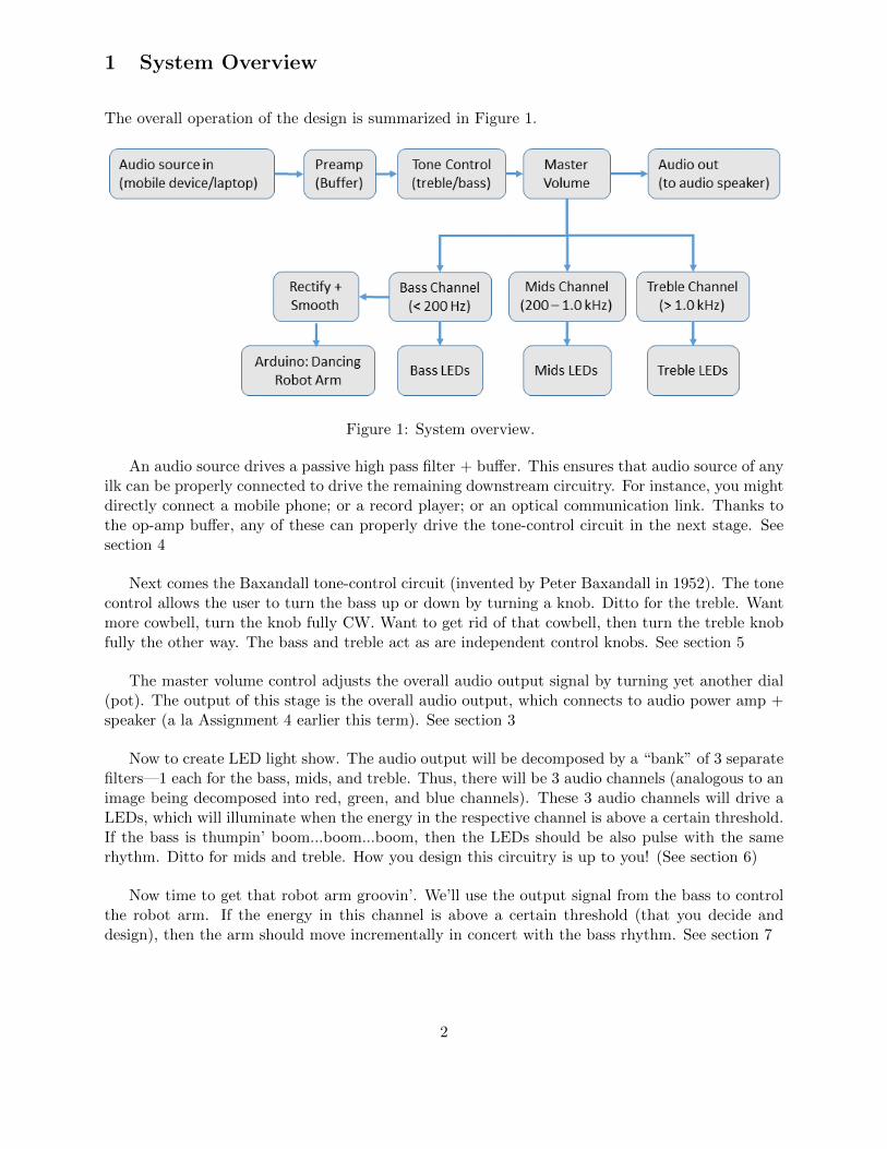
Final Design Project Dance Party—Audio Control, Light Show, and Dancing Robot Arm ENGN/PHYS 207—Fall 2018 What You’ll Build and Test 1. Audio gear: Active tone control circuit (amplify or de-amplify bass and treble independently); passive master volume control. 2. Light show: LED lights synced to energy of in each of bass, mids, and treble frequency 3. Dancing Robot Arm: Arduino control of robot arm, synced to the bass (or treble), dancing to the beat Skills and Concepts You’ll Integrate • Passive dc circuits (volume control) • Active filters (tone control) • LEDs illuminated with digital switches (light show) • ADC measurement and PWM control of servo motors (Robot arm) • Optoelectronic communication link (remote data transmission; optional) This is the final project for Engn/Phys 207. This is an integrative project, and successful completion of it will call upon most (all) of your new-found circuits knowledge and skills. In this light, I will be available to provide hints and for consultation, but will purposely be much less directly helpful than usual. A non-trivial part of your grade will be based on your degree of independence in carrying out this project. Of course you will collaborate closely with your team mate(s), per usual. You are allowed to work as a team with a maximum of 4 team members . Each team member MUST be fully engaged and directly involved in all aspects of the project. You are asked/required to keep the level of cross-fertilization of circuit building, measurement techniques, debugging, discussion about the project, etc. to an absolute minimum with other teams. Again, the point of between-team isolation is to demonstrate the competency within your own team. Your team will collaborate to produce a single final report. As a reminder, there are NO revisions possible for the final report. Thus, take special care to demonstrate your mastery in communicating effectively. To help guide your style, depth, prose, presentation, etc., assume that your target audience is a colleague at a science/engineering competent friend who knows relatively little about circuit design. Without further ado, ladies and gentlemen, it is time to unveil the requirements and constraints of your soon-to-be music + lights + dancing robot show! 1

Welcome message from author
This document is posted to help you gain knowledge. Please leave a comment to let me know what you think about it! Share it to your friends and learn new things together.
Transcript
Final Design ProjectDance Party—Audio Control, Light Show, and Dancing Robot Arm
ENGN/PHYS 207—Fall 2018
What You’ll Build and Test
1. Audio gear: Active tone control circuit (amplify or de-amplify bass and treble independently);passive master volume control.
2. Light show: LED lights synced to energy of in each of bass, mids, and treble frequency
3. Dancing Robot Arm: Arduino control of robot arm, synced to the bass (or treble), dancingto the beat
Skills and Concepts You’ll Integrate
• Passive dc circuits (volume control)
• Active filters (tone control)
• LEDs illuminated with digital switches (light show)
• ADC measurement and PWM control of servo motors (Robot arm)
• Optoelectronic communication link (remote data transmission; optional)
This is the final project for Engn/Phys 207. This is an integrative project, and successfulcompletion of it will call upon most (all) of your new-found circuits knowledge and skills. Inthis light, I will be available to provide hints and for consultation, but will purposely be muchless directly helpful than usual. A non-trivial part of your grade will be based on your degree ofindependence in carrying out this project. Of course you will collaborate closely with your teammate(s), per usual.
You are allowed to work as a team with a maximum of 4 team members. Eachteam member MUST be fully engaged and directly involved in all aspects of the project. You areasked/required to keep the level of cross-fertilization of circuit building, measurement techniques,debugging, discussion about the project, etc. to an absolute minimum with other teams. Again,the point of between-team isolation is to demonstrate the competency within your own team.
Your team will collaborate to produce a single final report. As a reminder, there are NOrevisions possible for the final report. Thus, take special care to demonstrate your mastery incommunicating effectively. To help guide your style, depth, prose, presentation, etc., assume thatyour target audience is a colleague at a science/engineering competent friend who knows relativelylittle about circuit design.
Without further ado, ladies and gentlemen, it is time to unveil the requirements and constraintsof your soon-to-be music + lights + dancing robot show!
1
1 System Overview
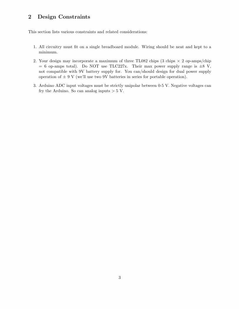
The overall operation of the design is summarized in Figure 1.
Figure 1: System overview.
An audio source drives a passive high pass filter + buffer. This ensures that audio source of anyilk can be properly connected to drive the remaining downstream circuitry. For instance, you mightdirectly connect a mobile phone; or a record player; or an optical communication link. Thanks tothe op-amp buffer, any of these can properly drive the tone-control circuit in the next stage. Seesection 4
Next comes the Baxandall tone-control circuit (invented by Peter Baxandall in 1952). The tonecontrol allows the user to turn the bass up or down by turning a knob. Ditto for the treble. Wantmore cowbell, turn the knob fully CW. Want to get rid of that cowbell, then turn the treble knobfully the other way. The bass and treble act as are independent control knobs. See section 5
The master volume control adjusts the overall audio output signal by turning yet another dial(pot). The output of this stage is the overall audio output, which connects to audio power amp +speaker (a la Assignment 4 earlier this term). See section 3
Now to create LED light show. The audio output will be decomposed by a “bank” of 3 separatefilters—1 each for the bass, mids, and treble. Thus, there will be 3 audio channels (analogous to animage being decomposed into red, green, and blue channels). These 3 audio channels will drive aLEDs, which will illuminate when the energy in the respective channel is above a certain threshold.If the bass is thumpin’ boom...boom...boom, then the LEDs should be also pulse with the samerhythm. Ditto for mids and treble. How you design this circuitry is up to you! (See section 6)
Now time to get that robot arm groovin’. We’ll use the output signal from the bass to controlthe robot arm. If the energy in this channel is above a certain threshold (that you decide anddesign), then the arm should move incrementally in concert with the bass rhythm. See section 7
2
2 Design Constraints
This section lists various constraints and related considerations:
1. All circuitry must fit on a single breadboard module. Wiring should be neat and kept to aminimum.
2. Your design may incorporate a maximum of three TL082 chips (3 chips × 2 op-amps/chip= 6 op-amps total). Do NOT use TLC227x. Their max power supply range is ±8 V,not compatible with 9V battery supply for. You can/should design for dual power supplyoperation of ± 9 V (we’ll use two 9V batteries in series for portable operation).
3. Arduino ADC input voltages must be strictly unipolar between 0-5 V. Negative voltages canfry the Arduino. So can analog inputs > 5 V.
3
3 Master Volume Control
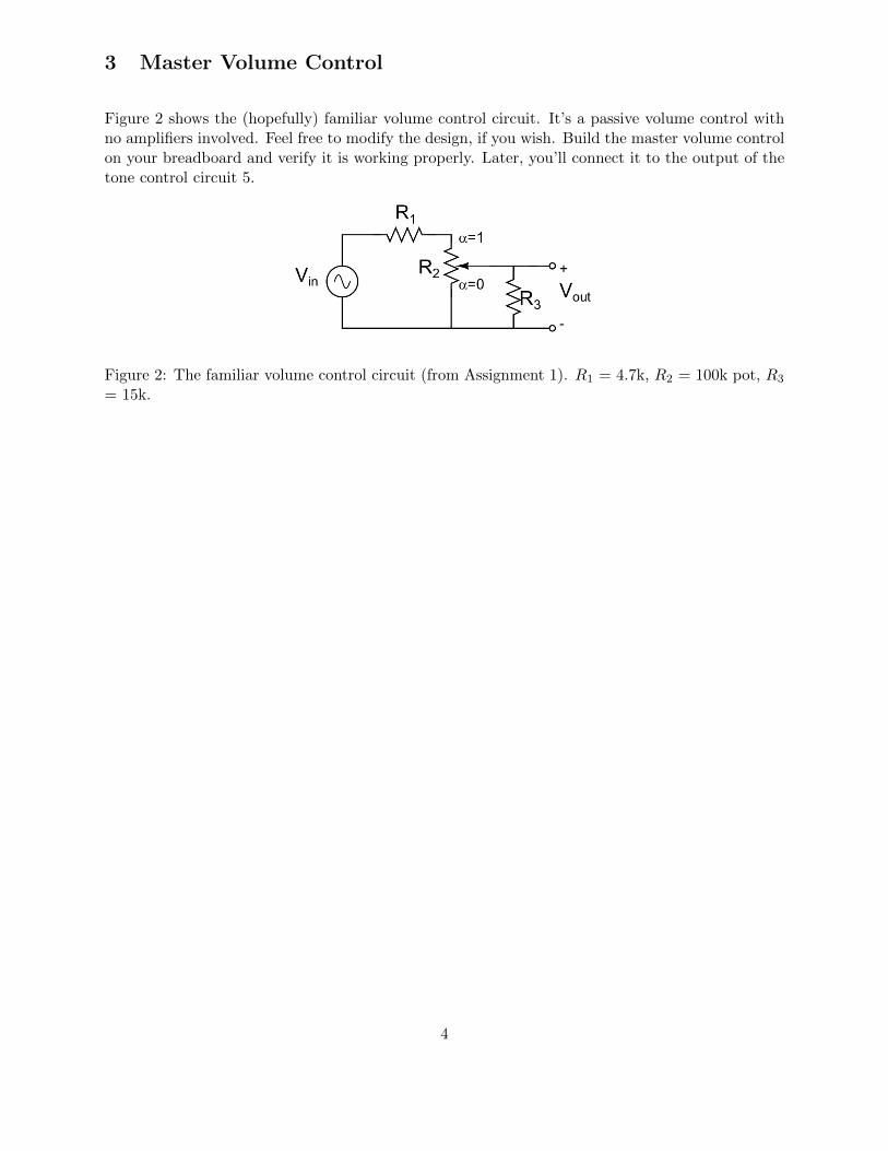
Figure 2 shows the (hopefully) familiar volume control circuit. It’s a passive volume control withno amplifiers involved. Feel free to modify the design, if you wish. Build the master volume controlon your breadboard and verify it is working properly. Later, you’ll connect it to the output of thetone control circuit 5.
Figure 2: The familiar volume control circuit (from Assignment 1). R1 = 4.7k, R2 = 100k pot, R3
= 15k.
4
4 Input Pre-amp
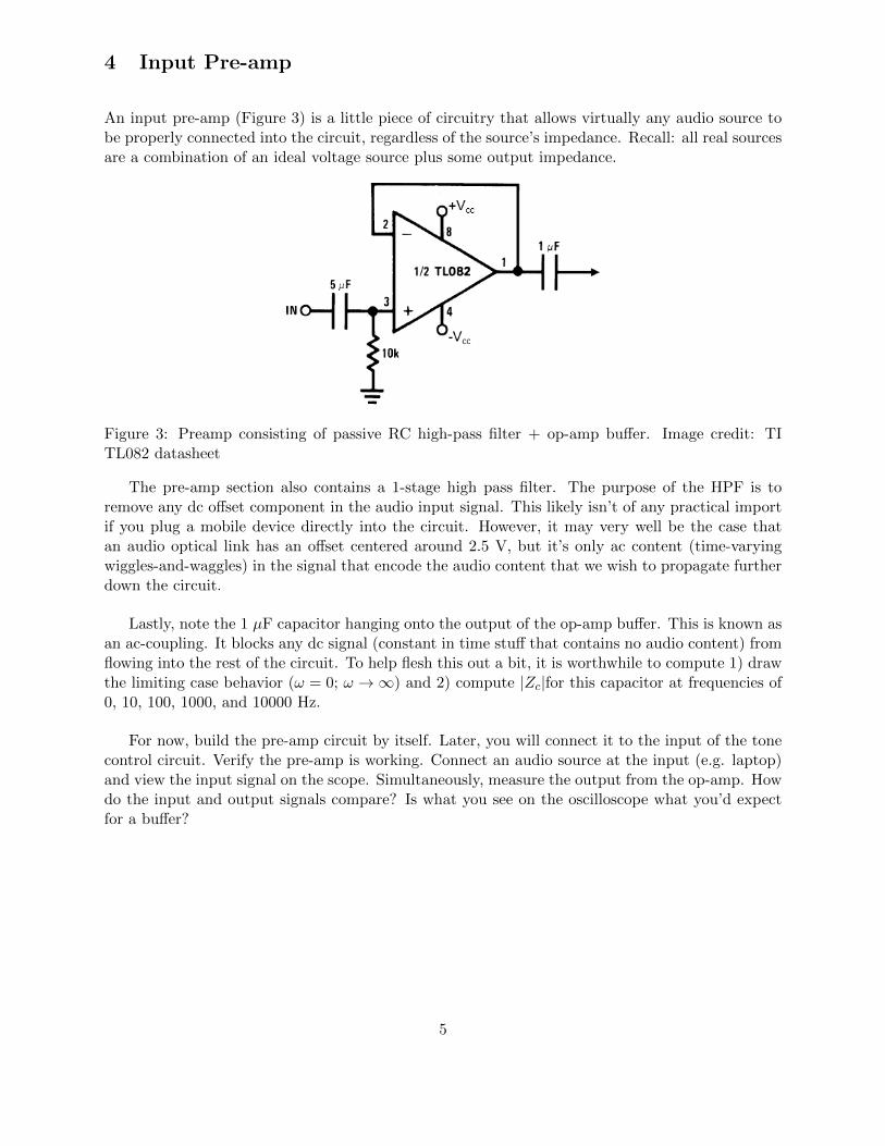
An input pre-amp (Figure 3) is a little piece of circuitry that allows virtually any audio source tobe properly connected into the circuit, regardless of the source’s impedance. Recall: all real sourcesare a combination of an ideal voltage source plus some output impedance.
Figure 3: Preamp consisting of passive RC high-pass filter + op-amp buffer. Image credit: TITL082 datasheet
The pre-amp section also contains a 1-stage high pass filter. The purpose of the HPF is toremove any dc offset component in the audio input signal. This likely isn’t of any practical importif you plug a mobile device directly into the circuit. However, it may very well be the case thatan audio optical link has an offset centered around 2.5 V, but it’s only ac content (time-varyingwiggles-and-waggles) in the signal that encode the audio content that we wish to propagate furtherdown the circuit.
Lastly, note the 1 µF capacitor hanging onto the output of the op-amp buffer. This is known asan ac-coupling. It blocks any dc signal (constant in time stuff that contains no audio content) fromflowing into the rest of the circuit. To help flesh this out a bit, it is worthwhile to compute 1) drawthe limiting case behavior (ω = 0; ω →∞) and 2) compute |Zc|for this capacitor at frequencies of0, 10, 100, 1000, and 10000 Hz.
For now, build the pre-amp circuit by itself. Later, you will connect it to the input of the tonecontrol circuit. Verify the pre-amp is working. Connect an audio source at the input (e.g. laptop)and view the input signal on the scope. Simultaneously, measure the output from the op-amp. Howdo the input and output signals compare? Is what you see on the oscilloscope what you’d expectfor a buffer?
5
5 Tone Control Circuit (Baxandall)
5.1 Background
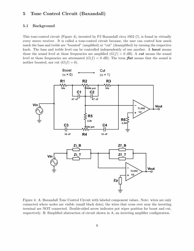
This tone-control circuit (Figure 4), invented by PJ Baxandall circa 1952 (!), is found in virtuallyevery stereo receiver. It is called a tone-control circuit because, the user can control how muchmuch the bass and treble are “boosted” (amplified) or “cut” (deamplified) by turning the respectiveknob. The bass and treble level can be controlled independently of one another. A boost meansthose the sound level at those frequencies are amplified (G(f) > 0 dB). A cut means the soundlevel at those frequencies are attenuated (G(f) < 0 dB). The term flat means that the sound isneither boosted, nor cut (G(f) = 0).
Figure 4: A: Baxandall Tone Control Circuit with labeled component values. Note: wires are onlyconnected where nodes are visible (small black dots); the wires that cross over near the invertingterminal are NOT connected. Double-sided arrow indicates pot wiper position for boost and cut,respectively. B: Simplified abstraction of circuit shown in A, an inverting amplifier configuration.
6
5.2 Theoretical Considerations
Before venturing on, one helpful bit of information: remember this circuit is used for controllingaudible frequencies. For humans, the audible frequency range is about 10 Hz (deep bass) to 10 kHz(high treble). Amazing that the human ear can perceive frequencies over 3 orders of magnitude!
On first glance, the Baxandall tone control circuit can be (probably is) intimidating. Fear not,dear 207er! You have all the knowledge you need to build the circuit and analyze its performance,both experimentally and theoretically. Here are a few hints to get you started:
• Firstly, note that you can conceptually approach this circuit by casting it in a simplified form(see Figure 4B), and breaking it down into two distinct parts:
1. “Subcircuit” that controls the treble alone with impedance elements ZiT and ZfT(ignoring the other 2 impedance elements)
2. Bass subcircuit with impedance elements ZiB and ZfB alone.
In reality the bass and treble sections are connected (more on that later), but for now try tounderstand the two crucial working principles:
1. How do resistors and capacitors combine to 1) work on just the bass frequencies (basssubcircuit) or just the treble frequencies; and 2) how do the R’s and C’s combine to seta cutoff frequency? Drawing limiting cases for “low” and “high” frequencies is highlyrecommended as always.
Low and high are were in quotes above because the cutoff frequency quantifies what wemean by low and high in this context, which depends on the cutoff frequencies, whichyou can estimate with a back of the envelope calculation.
2. What’s the action of the pot? How does turning the knob one way amplify the signal,while turning the pot the other direction has the opposite effect, attenuating the signal.Again, sketching out the circuit for either condition (α = 0 or 1) is highly recommended.
• Now time to dig deeper into the full theoretical treatment. If you look closely, you’ll seethe components for the bass control are wired as an inverting amplifier. The monster circuitdiagram in Figure 4A can be compactly represented as 2 parallel combinations of impedanceelements wired in an inverting amp configuration. Of course, there’s a bit of work involvedto writing out ZiT = . . . , etc. But for now, use the simplified schematic in panel B to showthat the transfer function can be conveniently written as follows:
Vout
Vin= H(f) = −
(ZfB
ZiB
)(ZfT
ZiT
)(ZiB + ZiT
ZfB + ZfT
)(1)
Note the first two terms by themselves should look familiar. The first term has to do withonly the bass, the second term, with only the treble. The third term is a sort of “mixture”term. If the bass and treble are ideally independent of one another, what should be theapproximate magnitude of the mixture term? To help you answer this question, and intuitthe three terms above, you might think about the decibel gain G(f) = 20 log10 |H(f)|.
7
5.3 Build, Measure, and Test
Build the Baxandall tone control circuit. Take a sufficient number of measurements such that youcan quantify device performance and compare to theory. Make sure you acquire sufficient datapoints to fully asses its performance over the human audible frequency range. You are required totake measurements for various 3 out of 5 possible bass and treble settings listed below. For all 3,you must measure the magnitude response (decibel gain). For (at least) one of the 3 settings, youmust measure the phase response.
Possible bass and treble settings for measurement include:
1. full bass boost, full treble boost: αbass = 0, αtreble = 0
2. full bass boost, full treble cut: αbass = 0, αtreble = 1
3. full bass cut, full treble boost: αbass = 1, αtreble = 0
4. full bass cut, full treble cut: αbass = 1, αtreble = 1
5. flat bass, flat treble: αbass = 0.5, αtreble = 0.5
For the test drive, connect the input to an audio source (e.g., laptop). Connect the output ofthe tone control circuit to an audio amplifier and speaker. As you play music, turn the bass andtreble knobs. If all is working properly, you should hear a clear audible difference...hopefully verysatisfying!
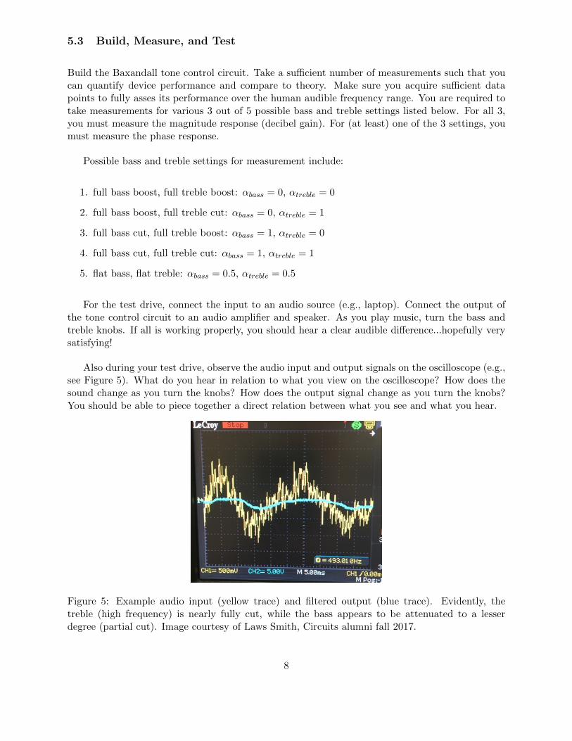
Also during your test drive, observe the audio input and output signals on the oscilloscope (e.g.,see Figure 5). What do you hear in relation to what you view on the oscilloscope? How does thesound change as you turn the knobs? How does the output signal change as you turn the knobs?You should be able to piece together a direct relation between what you see and what you hear.
Figure 5: Example audio input (yellow trace) and filtered output (blue trace). Evidently, thetreble (high frequency) is nearly fully cut, while the bass appears to be attenuated to a lesserdegree (partial cut). Image courtesy of Laws Smith, Circuits alumni fall 2017.
8
6 LED light show: frequency channels and digital control
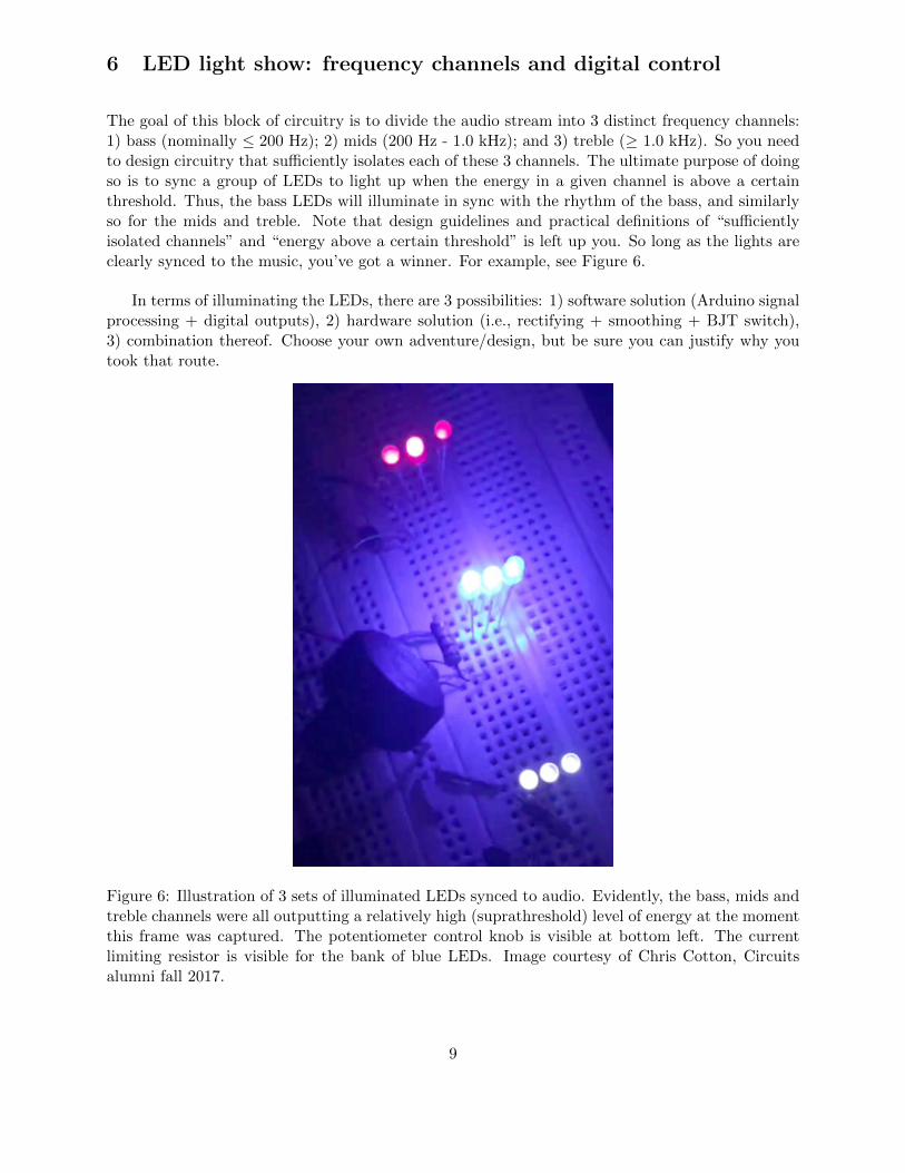
The goal of this block of circuitry is to divide the audio stream into 3 distinct frequency channels:1) bass (nominally ≤ 200 Hz); 2) mids (200 Hz - 1.0 kHz); and 3) treble (≥ 1.0 kHz). So you needto design circuitry that sufficiently isolates each of these 3 channels. The ultimate purpose of doingso is to sync a group of LEDs to light up when the energy in a given channel is above a certainthreshold. Thus, the bass LEDs will illuminate in sync with the rhythm of the bass, and similarlyso for the mids and treble. Note that design guidelines and practical definitions of “sufficientlyisolated channels” and “energy above a certain threshold” is left up you. So long as the lights areclearly synced to the music, you’ve got a winner. For example, see Figure 6.
In terms of illuminating the LEDs, there are 3 possibilities: 1) software solution (Arduino signalprocessing + digital outputs), 2) hardware solution (i.e., rectifying + smoothing + BJT switch),3) combination thereof. Choose your own adventure/design, but be sure you can justify why youtook that route.
Figure 6: Illustration of 3 sets of illuminated LEDs synced to audio. Evidently, the bass, mids andtreble channels were all outputting a relatively high (suprathreshold) level of energy at the momentthis frame was captured. The potentiometer control knob is visible at bottom left. The currentlimiting resistor is visible for the bank of blue LEDs. Image courtesy of Chris Cotton, Circuitsalumni fall 2017.
9
7 Dancing Robot Arm: Arduino measurement and control
The main idea here is to use the energy in the bass frequency channel to make a robot arm dance.In essence, the robot arm dances when the bass is pumping. No doubt you recognize the similarityof these part of the design to the EMG robot arm assignment we did earlier. Wonderful, great—perhaps call upon your EMG robot arm design to inform the audio solution. Whatever design andmethodology, you should be able to justify why you took this approach. So long as the robot armclearly moves to the beat, you’ve got a winner!
Note: the instructor will provide some Arduino code templates that might make for cool an-imated sequences of the robot arm. You are encouraged to have some fun with it and adjust totaste!
Figure 7: Dancing robots? Cool!.
10
8 Final Report
1. Final circuit diagram (3 pages max). Clearly delineate individual functional blocks andall component values shown by each component a la Assignment 6. Also include a clearlyannotated photo of the actual implementation. Similarly, clearly delineate functional blocksand relate them to what’s on the schematic. For instance, you could color code a dotted greenline about the 1st block in both schematic and actual circuit; blue line for the 2nd block, etc.
2. Design rationale (4 pages max). Create sub-sections for each functional block. Describein plain terms what the job of each functional block is. Include fundamental equations usedin determining its design, as appropriate (cutoff frequencies, voltage gain, etc). Describe thewhat and why of your design. For example:
Stage [D] is the bass channel. It consists of a passive 2-stage low pass filter with acutoff frequency (f = 1/2πR1C1) of 200 Hz. We chose a 2-stage filter because forthe relatively hard cutoff slope of 40 dB/dec. The 2-stage filter was advantageousin practical terms because we found that a 1-stage filter did not appropriately dis-criminate between bass from middle frequencies. We chose a passive filter becauseof its simplicity, and because there was no need to further amplify the signal toactivate the LEDs.
Also include a section describing how the various functional block were integrated into theoverall design.
Each subsection should should also include some suggestions for an improved design, whereappropriate.
If you are search of inspiration or guidelines for how to write this section, review the circuitsdesign description of the muon detector paper by Axani et al 2016, sections V (pages 14-20).
3. Tone Control Full-on Analysis (4 pages max): Specific to the tone control design andanalysis, make a beautiful figure(s) to compare theory vs. experiment. As a prerequisite,you’ll need to work through the full theoretical treatment to find the transfer function as afunction of bass and treble pot positions, and plug in for the 3 pairs of values you tested. Ofcourse be sure to remark upon general trends in results vs. theory and quantitatively supportany claims you make.
Be sure to also include in this section some intuitive explanation how the tone control works.
By now, you well know how to make beautiful comparison between experiment and theory.Should you need further inspiration/guidelines, check out Figure 7 in Axani’s 2018 follow-uppaper: Axani 2018. In terms of organization, where you place this section is up to you. Itcould sensibly be placed after the Proof of Concept as a deep dive into circuit analysis.
4. Proof of concept. (2 pages max) Preferably post a video of your circuit in action. Thesystem is really about live lights + music+ dancing—things in motion are better shown asvideos. Alternately, show a series of figures. Either way, this section should establish thatyour design achieved the main objectives of being able to control the tone; the master volume;pulsing lights based on the time-varying energy in the bass, mids, and treble channels; andhaving the robot arm jam out in rhythm.
5. Appendix.
11
(a) Include any circuits/math computations and details otherwise that you deem relevant.
(b) Arduino code
6. Group Collaboration Statement. State clearly the main contributions of each teammember. Highlight any areas where a team member was particularly helpful. For example“Joe and Sue were the lead Arduino programmers, while Bobby and Jane were the leads ontheoretical analysis of the tone control.” Having said that, please recall that this is a teameffort and all team members should be fully engaged in all aspects of the project,including drafting the final report . Finally, the collaboration statement should allocatepoints according to total contribution of each team member. For example, if you work ona team of 4, then there are 400 total points possible. If everyone contributed equally, thanassign each member 100. If the overall report scores a 95, each team member will be awardedan ultimate grade of 95. By contrast, let’s say one team member was particularly outstanding,so the team might decide a breakdown of 115 + 95 + 95 +95 (= 400). Here, 3 team membersare awarding 5 of their points to the outstanding individual. Let’s say the report scores a 100(hooray!). Then the first member will receive a final score 115 (A++); the others will scorea 95 (solid A).
Each team member must also submit a confidential assessment, which only the instructorwill see (submitted directly to the instructor). The rationale for requiring the individualevaluations is that, from time to time, team members may respectfully disagree on the relativeeffort and meritorious contributions.
Last but not least: please×3 be absolutely sure to clean up your lab station. Clearly state inyour team collaboration statement something to the effect of: “We certify our lab station isclean, all components put away in the proper bins, left the lab as we found it at the beginningof the term.”
Congratulations!! You’ve made it to the end. Hopefully a melodious farewell to Circuits fall2018
12
Related Documents