Management and Production Engineering Review Volume 3 • Number 3 • September 2012 • pp. 86–91 DOI: 10.2478/v10270-012-0028-7 WHAT IF THEY ARE NOT WELD-ABLE? Hongyan Zhang, Ahalapitiya H. Jayatissa, Samuel Durbin, Genze Ma The University of Toledo, Toledo, USA Corresponding author: Hongyan Zhang Department of Mechanical Industrial and Manufacturing Engineering The University of Toledo Ohio 43606 USA phone: (001) 419-530-6019 e-mail: [email protected] Received: 25 May 2012 Abstract Accepted: 18 August 2012 Many light metals, such as aluminum and magnesium alloys, are promised to provide sig- nificant weight reduction for automobiles. However, the difficulties in welding these metals seriously hinder their large-scale applications. A new, hybrid mechanical joining process is proposed to avoid the inherited metallurgical complications in welding. By spinning and pressing a solid rivet into the metals, a joint is formed with the locking from the rivet, a stirred/mixed zone around the rivet, and solid bonding at the faying interface. This rivet- ing process combines the actions of friction-stir welding in which metals of different sheets are mechanically mixed, and self-piercing riveting process which embeds a rivet in the sheets. Experiments have shown that such a friction-stir riveting process can produce joints of compa- rable strength to those created by other joining means, and can be applied to difficult-to-weld metals and dissimilar metals, such as aluminum-to-aluminum, magnesium-to-magnesium, and aluminum-to-magnesium. Keywords hybrid mechanical joining, friction-stir-welding, riveting, magnesium, aluminum. Introduction In addition to structural optimization, adopting new, light-weight materials is an effective means of reducing vehicles’ weight, in order to lower emission and raise fuel efficiency. In the last two decades, aluminum alloys have been introduced to automo- bile body construction and significant weight sav- ings have been achieved [1]. Unlike steels which have been used as automotive body structural materials since the birth of the automobile industry, aluminum alloys are relatively new to the automotive manu- facturing, especially the welding process. Resistance spot welding, the most popular joining method in au- tomobile body construction, of aluminum alloys has proven difficult to perform mainly because of their volatile physical properties. Aluminum has high ther- mal expansion in both solid and liquid states, and large volume expansion at melting. The high elec- trical conductivity of such alloys requires the use of low alloyed copper for electrodes which is usually soft with low wear resistance. In addition, the high elec- trical conductivity, together with the high thermal conductivity of aluminum, requires the use of high electric current in a short period of time in order to concentrate the Joule heat in the weld area. Con- sequently, welding aluminum alloys generally suf- fers short electrode life and inconsistent weld quality mainly due to expulsion which is ejection of liquid metal from the faying interface, and is inadequate for certain large volume productions. In general, welding aluminum requires much tighter process control than welding steels, and aluminum welding is often aug- mented with adhesives. Alternative joining methods to welding aluminum alloys have been developed, and the most noticeable is probably friction-stir weld- ing, in which a rotating cylindrical-shouldered tool with a profiled probe advances into the metals to be joined. The mixed zone created by the stirring ac- tion of the probe forms a joint. This process has been 86

Welcome message from author
This document is posted to help you gain knowledge. Please leave a comment to let me know what you think about it! Share it to your friends and learn new things together.
Transcript
Management and Production Engineering Review
Volume 3 • Number 3 • September 2012 • pp. 86–91DOI: 10.2478/v10270-012-0028-7
WHAT IF THEY ARE NOT WELD-ABLE?
Hongyan Zhang, Ahalapitiya H. Jayatissa, Samuel Durbin, Genze Ma
The University of Toledo, Toledo, USA
Corresponding author:
Hongyan Zhang
Department of Mechanical
Industrial and Manufacturing Engineering
The University of Toledo
Ohio 43606 USA
phone: (001) 419-530-6019
e-mail: [email protected]
Received: 25 May 2012 Abstract
Accepted: 18 August 2012 Many light metals, such as aluminum and magnesium alloys, are promised to provide sig-nificant weight reduction for automobiles. However, the di!culties in welding these metalsseriously hinder their large-scale applications. A new, hybrid mechanical joining process isproposed to avoid the inherited metallurgical complications in welding. By spinning andpressing a solid rivet into the metals, a joint is formed with the locking from the rivet, astirred/mixed zone around the rivet, and solid bonding at the faying interface. This rivet-ing process combines the actions of friction-stir welding in which metals of di"erent sheetsare mechanically mixed, and self-piercing riveting process which embeds a rivet in the sheets.Experiments have shown that such a friction-stir riveting process can produce joints of compa-rable strength to those created by other joining means, and can be applied to di!cult-to-weldmetals and dissimilar metals, such as aluminum-to-aluminum, magnesium-to-magnesium, andaluminum-to-magnesium.
Keywords
hybrid mechanical joining, friction-stir-welding, riveting, magnesium, aluminum.
Introduction
In addition to structural optimization, adoptingnew, light-weight materials is an e!ective means ofreducing vehicles’ weight, in order to lower emissionand raise fuel e"ciency. In the last two decades,aluminum alloys have been introduced to automo-bile body construction and significant weight sav-ings have been achieved [1]. Unlike steels which havebeen used as automotive body structural materialssince the birth of the automobile industry, aluminumalloys are relatively new to the automotive manu-facturing, especially the welding process. Resistancespot welding, the most popular joining method in au-tomobile body construction, of aluminum alloys hasproven di"cult to perform mainly because of theirvolatile physical properties. Aluminum has high ther-mal expansion in both solid and liquid states, andlarge volume expansion at melting. The high elec-trical conductivity of such alloys requires the use of
low alloyed copper for electrodes which is usually softwith low wear resistance. In addition, the high elec-trical conductivity, together with the high thermalconductivity of aluminum, requires the use of highelectric current in a short period of time in order toconcentrate the Joule heat in the weld area. Con-sequently, welding aluminum alloys generally suf-fers short electrode life and inconsistent weld qualitymainly due to expulsion which is ejection of liquidmetal from the faying interface, and is inadequate forcertain large volume productions. In general, weldingaluminum requires much tighter process control thanwelding steels, and aluminum welding is often aug-mented with adhesives. Alternative joining methodsto welding aluminum alloys have been developed, andthe most noticeable is probably friction-stir weld-ing, in which a rotating cylindrical-shouldered toolwith a profiled probe advances into the metals to bejoined. The mixed zone created by the stirring ac-tion of the probe forms a joint. This process has been
86
Management and Production Engineering Review
fairly successful in joining aluminum and other met-als. However, friction stir welding allows very littleflexibility in the welding process and fixtures, mak-ing it di"cult to be adopted in automobile assembly,especially for joining sheet metals. Another process,self-piercing riveting forms a joint by pressing a semi-tubular rivet into the sheets supported on a die. Therivet pierces and then flares into the sheets, form-ing a mechanical interlock between the sheets. Theself-piercing riveted joints created through a dynamicpressing mechanism have similar or higher mechani-cal strengths than aluminum spot welds [2].Magnesium alloys have similar electrical, thermal
and mechanical properties as aluminum alloys andtherefore, welding magnesium alloys is also a chal-lenge. As a matter of fact, the electrode life is ex-tremely short when welding certain magnesium al-loys, and expulsion is nearly unavoidable [3]. In ad-dition, their fairly low ductility makes self-piercingriveting process inapplicable to such alloys [4]. Al-though there are significant barriers to using Mgsheet materials in automobile body construction, itis predicted that the use of Mg will grow by at leastan order of magnitude more in 10 years becauseof their high potential in vehicle light-weighting [5].Therefore, developing a practical and reliable joiningmethod is an essential step in enabling the use of Mgalloys for automobile weight reduction.Based on a preliminary work of one of the au-
thors [6], a new mechanical joining technique was de-veloped. Taking the advantages of friction-stir weld-ing and conventional mechanical riveting, the processinvolves spinning and pressing a solid rivet intotwo sheets of same or dissimilar metals. The em-bedded rivet provides a mechanical interlock be-tween the sheets, augmented by a ‘welded’ portionof the sheets resulted from mechanical mixing, anda small amount of solid bonding at the faying inter-face.
Friction-stir riveting process
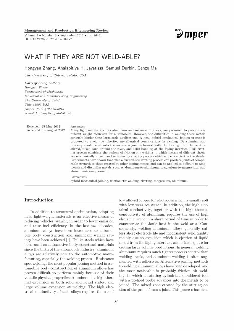
The most crucial part in friction-stir riveting isthe rivet. Through a large number of trials on theshape and material of rivets, one robust design hasbeen achieved. Figure 1 shows three di!erent viewsof the identical friction stir rivet of this design: onthe left is a top view revealing a plus sign that al-lows the driver to spin the rivet as it pushing therivet into sheet metal; the middle one, as side viewof the rivet, reveals the profile of the rivet; and theone on the right is a bottom view of the rivet.Figure 2 shows the setup for a friction-stir rivet-
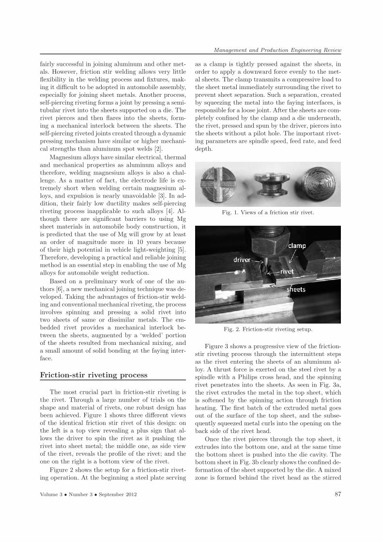
ing operation. At the beginning a steel plate serving
as a clamp is tightly pressed against the sheets, inorder to apply a downward force evenly to the met-al sheets. The clamp transmits a compressive load tothe sheet metal immediately surrounding the rivet toprevent sheet separation. Such a separation, createdby squeezing the metal into the faying interfaces, isresponsible for a loose joint. After the sheets are com-pletely confined by the clamp and a die underneath,the rivet, pressed and spun by the driver, pierces intothe sheets without a pilot hole. The important rivet-ing parameters are spindle speed, feed rate, and feeddepth.
Fig. 1. Views of a friction stir rivet.
Fig. 2. Friction-stir riveting setup.
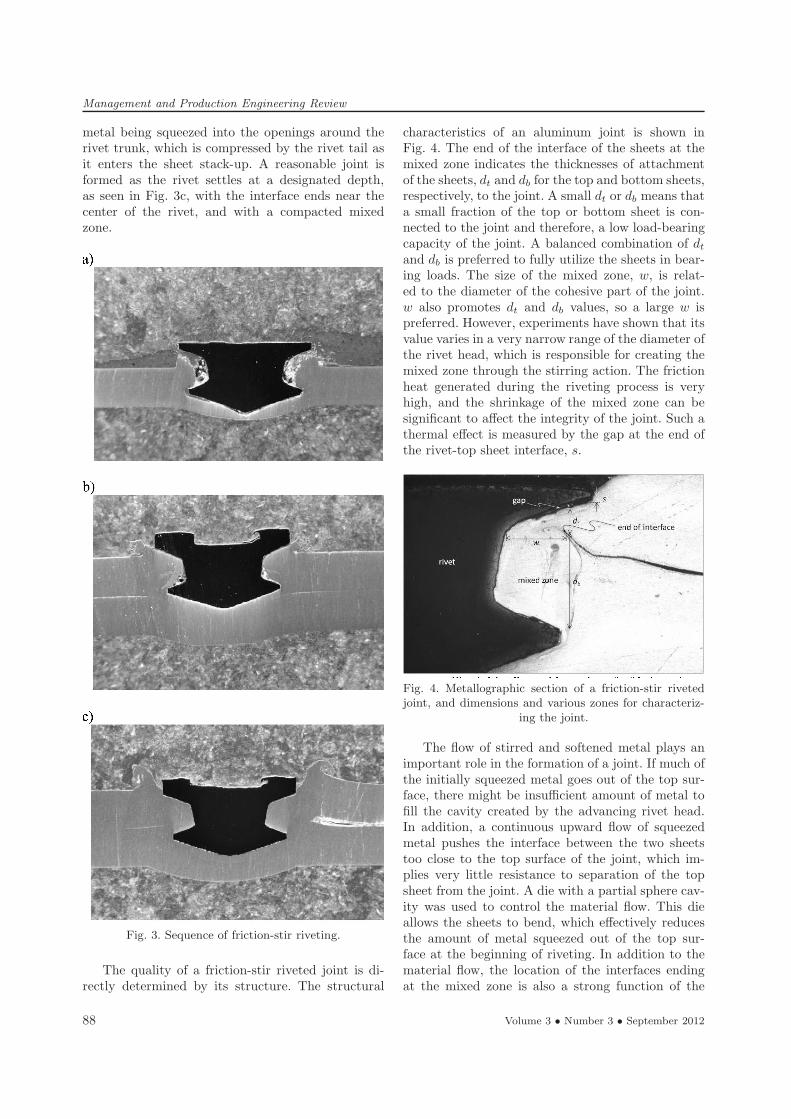
Figure 3 shows a progressive view of the friction-stir riveting process through the intermittent stepsas the rivet entering the sheets of an aluminum al-loy. A thrust force is exerted on the steel rivet by aspindle with a Philips cross head, and the spinningrivet penetrates into the sheets. As seen in Fig. 3a,the rivet extrudes the metal in the top sheet, whichis softened by the spinning action through frictionheating. The first batch of the extruded metal goesout of the surface of the top sheet, and the subse-quently squeezed metal curls into the opening on theback side of the rivet head.Once the rivet pierces through the top sheet, it
extrudes into the bottom one, and at the same timethe bottom sheet is pushed into the die cavity. Thebottom sheet in Fig. 3b clearly shows the confined de-formation of the sheet supported by the die. A mixedzone is formed behind the rivet head as the stirred
Volume 3 • Number 3 • September 2012 87
Management and Production Engineering Review
metal being squeezed into the openings around therivet trunk, which is compressed by the rivet tail asit enters the sheet stack-up. A reasonable joint isformed as the rivet settles at a designated depth,as seen in Fig. 3c, with the interface ends near thecenter of the rivet, and with a compacted mixedzone.
Fig. 3. Sequence of friction-stir riveting.
The quality of a friction-stir riveted joint is di-rectly determined by its structure. The structural
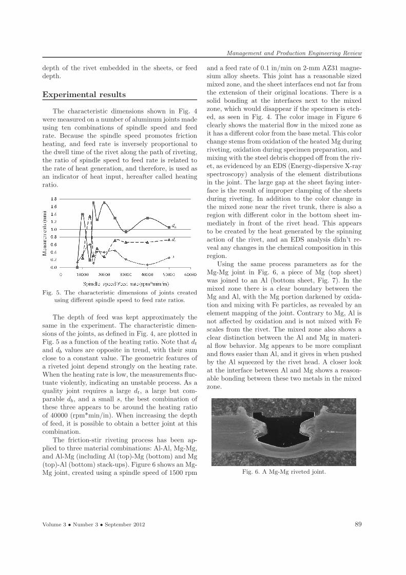
characteristics of an aluminum joint is shown inFig. 4. The end of the interface of the sheets at themixed zone indicates the thicknesses of attachmentof the sheets, dt and db for the top and bottom sheets,respectively, to the joint. A small dt or db means thata small fraction of the top or bottom sheet is con-nected to the joint and therefore, a low load-bearingcapacity of the joint. A balanced combination of dt
and db is preferred to fully utilize the sheets in bear-ing loads. The size of the mixed zone, w, is relat-ed to the diameter of the cohesive part of the joint.w also promotes dt and db values, so a large w ispreferred. However, experiments have shown that itsvalue varies in a very narrow range of the diameter ofthe rivet head, which is responsible for creating themixed zone through the stirring action. The frictionheat generated during the riveting process is veryhigh, and the shrinkage of the mixed zone can besignificant to a!ect the integrity of the joint. Such athermal e!ect is measured by the gap at the end ofthe rivet-top sheet interface, s.
Fig. 4. Metallographic section of a friction-stir rivetedjoint, and dimensions and various zones for characteriz-
ing the joint.
The flow of stirred and softened metal plays animportant role in the formation of a joint. If much ofthe initially squeezed metal goes out of the top sur-face, there might be insu"cient amount of metal tofill the cavity created by the advancing rivet head.In addition, a continuous upward flow of squeezedmetal pushes the interface between the two sheetstoo close to the top surface of the joint, which im-plies very little resistance to separation of the topsheet from the joint. A die with a partial sphere cav-ity was used to control the material flow. This dieallows the sheets to bend, which e!ectively reducesthe amount of metal squeezed out of the top sur-face at the beginning of riveting. In addition to thematerial flow, the location of the interfaces endingat the mixed zone is also a strong function of the
88 Volume 3 • Number 3 • September 2012
Management and Production Engineering Review
depth of the rivet embedded in the sheets, or feeddepth.
Experimental results
The characteristic dimensions shown in Fig. 4were measured on a number of aluminum joints madeusing ten combinations of spindle speed and feedrate. Because the spindle speed promotes frictionheating, and feed rate is inversely proportional tothe dwell time of the rivet along the path of riveting,the ratio of spindle speed to feed rate is related tothe rate of heat generation, and therefore, is used asan indicator of heat input, hereafter called heatingratio.
Fig. 5. The characteristic dimensions of joints createdusing di!erent spindle speed to feed rate ratios.
The depth of feed was kept approximately thesame in the experiment. The characteristic dimen-sions of the joints, as defined in Fig. 4, are plotted inFig. 5 as a function of the heating ratio. Note that dt
and db values are opposite in trend, with their sumclose to a constant value. The geometric features ofa riveted joint depend strongly on the heating rate.When the heating rate is low, the measurements fluc-tuate violently, indicating an unstable process. As aquality joint requires a large dt, a large but com-parable db, and a small s, the best combination ofthese three appears to be around the heating ratioof 40000 (rpm*min/in). When increasing the depthof feed, it is possible to obtain a better joint at thiscombination.The friction-stir riveting process has been ap-
plied to three material combinations: Al-Al, Mg-Mg,and Al-Mg (including Al (top)-Mg (bottom) and Mg(top)-Al (bottom) stack-ups). Figure 6 shows an Mg-Mg joint, created using a spindle speed of 1500 rpm
and a feed rate of 0.1 in/min on 2-mm AZ31 magne-sium alloy sheets. This joint has a reasonable sizedmixed zone, and the sheet interfaces end not far fromthe extension of their original locations. There is asolid bonding at the interfaces next to the mixedzone, which would disappear if the specimen is etch-ed, as seen in Fig. 4. The color image in Figure 6clearly shows the material flow in the mixed zone asit has a di!erent color from the base metal. This colorchange stems from oxidation of the heated Mg duringriveting, oxidation during specimen preparation, andmixing with the steel debris chopped o! from the riv-et, as evidenced by an EDS (Energy-dispersive X-rayspectroscopy) analysis of the element distributionsin the joint. The large gap at the sheet faying inter-face is the result of improper clamping of the sheetsduring riveting. In addition to the color change inthe mixed zone near the rivet trunk, there is also aregion with di!erent color in the bottom sheet im-mediately in front of the rivet head. This appearsto be created by the heat generated by the spinningaction of the rivet, and an EDS analysis didn’t re-veal any changes in the chemical composition in thisregion.Using the same process parameters as for the
Mg-Mg joint in Fig. 6, a piece of Mg (top sheet)was joined to an Al (bottom sheet, Fig. 7). In themixed zone there is a clear boundary between theMg and Al, with the Mg portion darkened by oxida-tion and mixing with Fe particles, as revealed by anelement mapping of the joint. Contrary to Mg, Al isnot a!ected by oxidation and is not mixed with Fescales from the rivet. The mixed zone also shows aclear distinction between the Al and Mg in materi-al flow behavior. Mg appears to be more compliantand flows easier than Al, and it gives in when pushedby the Al squeezed by the rivet head. A closer lookat the interface between Al and Mg shows a reason-able bonding between these two metals in the mixedzone.
Fig. 6. A Mg-Mg riveted joint.
Volume 3 • Number 3 • September 2012 89
Management and Production Engineering Review
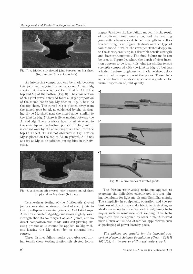
Fig. 7. A friction-stir riveted joint between an Mg sheet(top) and an Al sheet (bottom).
An interesting comparison can be made betweenthis joint and a joint formed also on Al and Mgsheets, but in a reversed stack-up, that is, Al on thetop and Mg at the bottom (Fig. 8). The cross sectionof this joint reveals that Al takes a larger proportionof the mixed zone than Mg does in Fig. 7, both asthe top sheet. The stirred Mg is pushed away fromthe mixed zone by Al, as evidenced by the thicken-ing of the Mg sheet near the mixed zone. Similar tothe joint in Fig. 7 there is little mixing between theAl and Mg. There is also a layer of Al attached tothe rivet tip in the bottom portion of the joint. Itis carried over by the advancing rivet head from thetop (Al) sheet. This is not observed in Fig. 7 whenMg is placed on the top of Al. In general, Al is notas easy as Mg to be softened during friction-stir riv-eting.
Fig. 8. A friction-stir riveted joint between an Al sheet(top) and an Mg sheet (bottom).
Tensile-shear testing of the friction-stir rivetedjoints shows similar strength level of such joints tothat of self-piercing riveted joints on Al-Al stack-ups.A test on a riveted Mg-Mg joint shows slightly lowerstrength than its counterpart of Al-Al joints, and nodirect comparison was made with self-piercing riv-eting process as it cannot be applied to Mg with-out heating the Mg sheets by an external heatsource.Three distinct failure modes were observed dur-
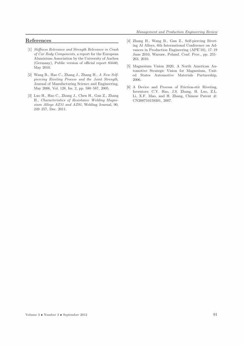
ing tensile-shear testing friction-stir riveted joints.
Figure 9a shows the first failure mode; it is the resultof insu"cient rivet penetration, and the resultingjoint su!ers from a weak tensile strength as well asfracture toughness. Figure 9b shows another type offailure mode in which the rivet penetrates deeply in-to the sheets, resulting in a desirable tensile strengthand fracture toughness. The final failure mode canbe seen in Figure 9c, where the depth of rivet inser-tion appears to be ideal; this joint has similar tensilestrength compared with the joint in Fig. 9b but hasa higher fracture toughness, with a large sheet defor-mation before separation of the pieces. These char-acteristic fracture modes may serve as a guidance forvisual inspection of joint quality.
Fig. 9. Failure modes of riveted joints.
The friction-stir riveting technique appears toovercome the di"culties encountered in other join-ing techniques for light metals and dissimilar metals.The simplicity in equipment, operation and the ro-bustness of this process make friction-stir riveting anideal alternative to the more traditional joining tech-niques such as resistance spot welding. This tech-nique can also be applied to other di"cult-to-weldmetals such as Cu and others for applications suchas packaging of power battery packs.
The authors are grateful for the financial sup-port of National Science Foundation (Grant: CMMI1050362) in the course of this exploratory work.
90 Volume 3 • Number 3 • September 2012
Management and Production Engineering Review
References
[1] Sti!ness Relevance and Strength Relevance in Crashof Car Body Components, a report for the EuropeanAluminium Association by the University of Aachen(Germany), Public version of o"cial report 83440,May 2010.
[2] Wang B., Hao C., Zhang J., Zhang H., A New Self-piercing Riveting Process and the Joint Strength,Journal of Manufacturing Science and Engineering,May 2006, Vol. 128, Iss. 2, pp. 580–587, 2005.
[3] Luo H., Hao C., Zhang J., Chen H., Gan Z., ZhangH., Characteristics of Resistance Welding Magne-sium Alloys AZ31 and AZ91, Welding Journal, 90,249–257, Dec. 2011.
[4] Zhang H., Wang B., Gan Z., Self-piercing Rivet-ing Al Alloys, 6th International Conference on Ad-vances in Production Engineering (APE’10), 17–19June 2010, Warsaw, Poland. Conf. Proc., pp. 255–263, 2010.
[5] Magnesium Vision 2020, A North American Au-tomotive Strategic Vision for Magnesium, Unit-ed States Automotive Materials Partnership,2006.
[6] A Device and Process of Friction-stir Riveting,Inventors: C.Y. Hao, J.S. Zhang, H. Luo, Z.L.Li, X.F. Mao, and H. Zhang, Chinese Patent #:CN200710159201, 2007.
Volume 3 • Number 3 • September 2012 91
Related Documents


![One platform Multiple options...GOST Butt weld DIN Butt weld ANSI Butt weld Socket weld Female 1 pipe thread F-con. ) butt weld GOST Butt weld [mm] [in.] D A SOC FTP F G D A SOC FTP](https://static.cupdf.com/doc/110x72/5fe23d7adfe1ef18be65fa23/one-platform-multiple-options-gost-butt-weld-din-butt-weld-ansi-butt-weld-socket.jpg)