WGB2-36 Page Conseil International des Grands Réseaux Électriques International Council On Large Electric Systems Guide for Application of Direct Real-Time Monitoring Systems WGB2-36

WGB2-36 Page 1 Conseil International des Grands Réseaux Électriques International Council On Large Electric Systems Guide for Application of Direct Real-Time.
Dec 18, 2015
Welcome message from author
This document is posted to help you gain knowledge. Please leave a comment to let me know what you think about it! Share it to your friends and learn new things together.
Transcript
WGB2-36Page 1
Conseil International des Grands Réseaux Électriques
International Council On Large Electric Systems
Guide for Application of Direct Real-Time Monitoring Systems
WGB2-36

WGB2-36Page 2
The dawn of a new era for power systems
Recent changes in power systems generation (renewables, intermittent, distributed), T&D (nodal pricing, market coupling in Europe, intra-day market) and « prosumers » (DSM, EV) push all actors at the dawn of a new era in Power systems.
Potential of dynamic line rating in that respect :
- connect more renewables on existing T&D
- more capacity intra-day when available (>50%)
WGB2-36Page 3
OBJECTIVE of the CIGRE brochure
To provide guidance for TSO’s about RTM systems :
1) how can they be used to increase the reliability and the economics of system dispatch;
2) How to select appropriate RTM equipment
N.B. Only deals with direct monitoring systems.

WGB2-36Page 4
REAL TIME MONITORINGThe real-time rating of the line is a function of position of the conductor in space which in turn, affects safety of the public as well as the integrity of the line. This position is determined by the sag of the conductor.
Sag
Clearance required

WGB2-36Page 5
REAL TIME MONITORING
Sag is a function of the conductor temperature (average between core and surface all along a span or section), the conductor construction and the line tension.
Devices that determine RTM rating evaluate the sag and thus the critical clearance along the line.
WGB2-36Page 6
DETERMINING LINE RATINGstep 1 : determine effective weather conditions
The monitored parameter (tension, sag, clearance, wind vibration, angle of inclination or spot temperature) is converted to conductor mean temperature by means of a model).
The calculated real-time mean conductor temperature is then combined with the air temperature, solar heat input, wind speed, wind direction and line current in TB 207 to calculate effective weather data (including the perpendicular wind speed).

WGB2-36Page 7
Example of “Effective perpendicular wind speed”
Effective weather data are weather data that justify the field measurement in critical spans.
WGB2-36Page 8
DETERMINING LINE RATINGstep 2 : evaluate ampacity of the line
Taking into account some weather persistence and thermal time constant of the conductor, the ampacity is evaluated for the next 10 to 60 minutes based on the most recent real-time measurements and their trends.
The worst rating condition (either maximum temperature or maximum sag/minimum clearance) has to be taken into account if they give different answers (which is generally the case after some years of line operation).

WGB2-36Page 9
SENSOROUTPUTS
SENSOR ALGORITHMSSTATE CHANGE EQUATIONCALIBRATION
CONDUCTOR “MEAN“ TEMPERATURE
HEAT BALANCE ALGORITHMBASED ON CIGRE TB207
EFFECTIVE WEATHER DATA- Perpendicular wind speed
- Ambient temperature- Solar heating
SENSOR ALGORITHMS WORST CASE AMPACITY
MAX SAGMAX TEMP.
LINE CURRENT
SINGLE-SPOTMEASURED
WEATHER DATA
CONDUCTOR DATA AS DESIGNED
LINE DATA
SECTION
REPEATED FOR EACH LINE SECTION
FLOW CHART FOR
RATING

WGB2-36Page 10
Existing RTM DEVICES and their principle of operation
ABOVE : inclination; BELOW: camera and target

WGB2-36Page 11
MEASURING DEVICES (CONT)
1 2
3 4
1: Conductor replica; 2: Conductor vibration frequency; 3: Sonar; 4: tension
WGB2-36Page 12
ERRORS
Errors in conductor data
Errors in section topological data, span length error
Errors on ruling span concept: hypothesis behind ruling span are numerous and includes constant data (weather, conductor temperature and conductor data) and no horizontal tension supported by suspension insulators
Varying weather data along span/section
Nonlinear behavior of conductor
Current can vary by 2-3% over line length.
Emissivity 2-3% rating error if 0.1 error in assumption.
Solar assumptions can make a large difference to rating.
The maximum error in potential ampacity that is permissible for operators is 10%. The errors sources are :
WGB2-36Page 13
ERRORS MITIGATION
redundancies in measurement
repeated calibrations
weather data measured at conductor level
conductor replica
learning process based on observations, experience
Apply different sag-tension relationship methods, like detailed in CIGRE brochure N° 324. [4]
Apply safe buffer estimation
Apply conservative assumptions in ampacity evaluation
Back up observations (for example certifying ampacity margin when it comes close to zero)
WGB2-36Page 14
ACCURACY REQUIREMENTS
Conductor vibration frequency sensoro Take care of sampling rate (adapted to
max permissible sag error).
Temperature sensorso Take care to avoid heat sink and variable
wind angle effects
Tension sensor or spot position in spaceo Take care of conductor/span data

WGB2-36Page 15
NUMBER OF SENSORS
The line length. The number of sensors will not be the same for a 50 km line and for a 5 km line, but the number of the long line will not be 10 times the number of the short one.
The surroundings: urban or rural areas, crossings with main roads, commercial areas….
The homogeneity or not of the climatic environment:o § line orientation with predominating wind,o § existing wind corridors,o § forest crossings,o § difference of altitude
The number of critical spans in every section of the line.
Typically 2 by section

WGB2-36Page 16
INFORMATION TO THE OPERATOR (HMI)
line load (MVA or Amp). The line load has to be refreshed very regularly, typically every 10 s
real-time rating (MVA or Amp.)
count down or remaining time (min.). This value is displayed if the time is less than 1or 2 hours per example. Otherwise the time can be considered as infinite. A curve giving remaining time vs line load can be displayed to help the operator to verify that the prepared strategies in (N-1) contingency are appropriate.

WGB2-36Page 17
EXAMPLE OF DISPLAY
WGB2-36Page 18
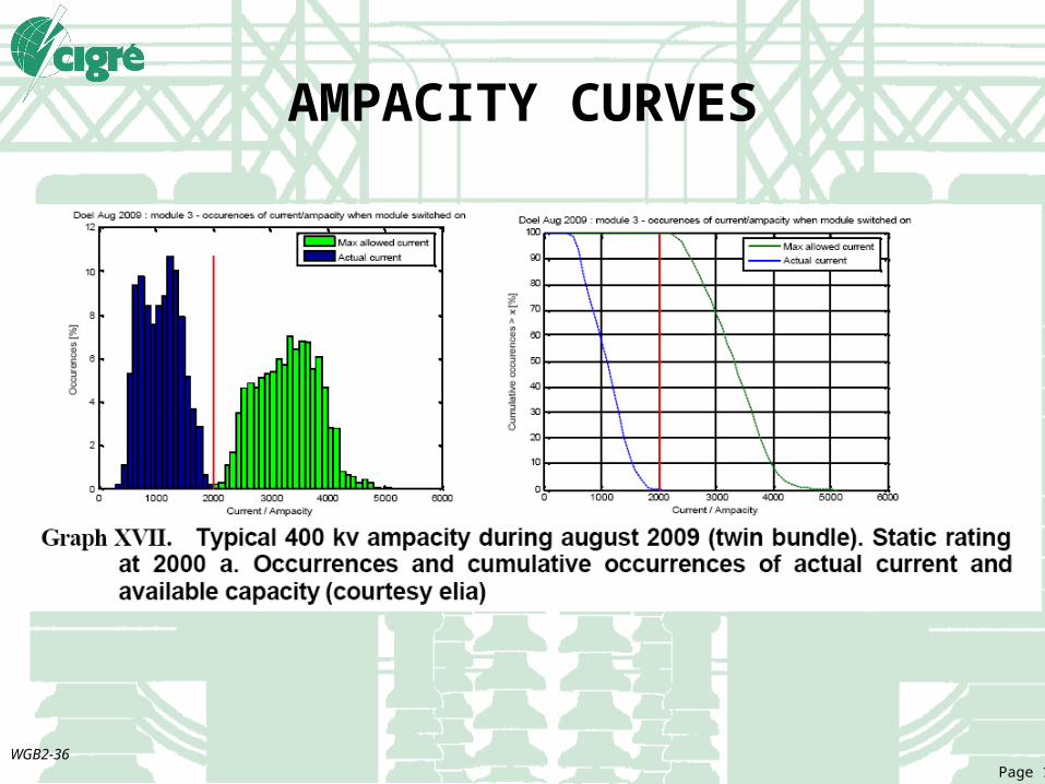
AMPACITY CURVES
WGB2-36Page 19
CASE STUDIES
Actual case studies indicated benefits as follows:o Delay in construction of new substation
(CEMIG)o Delay in strengthening of 138kV line (CEMIG)o Increased line capacity for renewable
generation. (ELIA and RTE)o AEP increased capacity required for wind
generationo KCPL (USA) 16% increase in line rating for 167
hours
WGB2-36Page 20
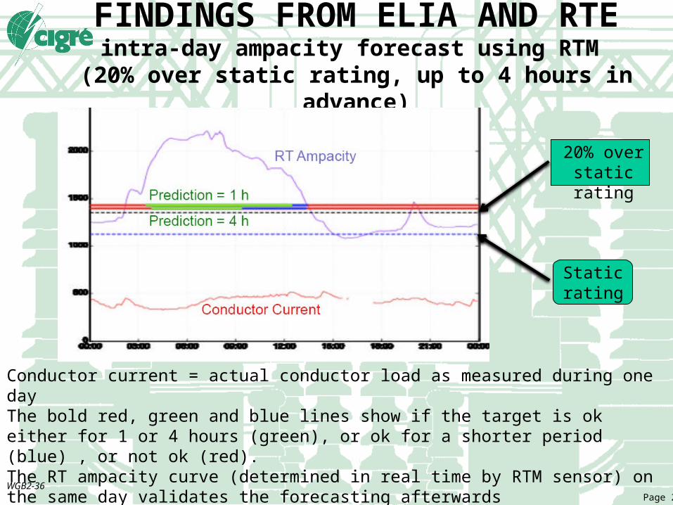
FINDINGS FROM ELIA AND RTEintra-day ampacity forecast using RTM
(20% over static rating, up to 4 hours in advance)
Conductor current = actual conductor load as measured during one dayThe bold red, green and blue lines show if the target is ok either for 1 or 4 hours (green), or ok for a shorter period (blue) , or not ok (red).The RT ampacity curve (determined in real time by RTM sensor) on the same day validates the forecasting afterwards
20% over static rating
Static rating

WGB2-36Page 21
FINDINGS FROM AEPline capacity versus wind farm generation
Red line : previously constrained wind farm output (static rating) (173 MVA)Reference black line : wind farm generation during the period of observationLowest observed additional line capability with RTM in service (blue) (+ 24%)average power line real time rating as evaluated by RTM (green) (+35% with 2% curtailment)
WGB2-36Page 22
BENEFITS OF RTM
Contingency managemento Allow more time for operators to make decisions.
Deferral or elimination of capital expenditure
Dispatch of generation during capacity deficiencies.
Mitigation of reliability concerns
Reducing wind power curtailment
Use of higher daytime ampacity
Reduced congestion charges (more efficient optimal generation dispatching in nodal and interconnected market)
WGB2-36Page 23
CONCLUSIONRTM systems ensure the line will not contravene the statutory (clearance) or annealing (conductor temperature) limits imposed.
It does not permit the line to run “hotter” than designed but will allow operators to make use of the better than “as design” conservative weather conditions to increase the load above static rating.
Direct RTM (except temperature sensor) may detect any excessive sagging
Related Documents