70 � CONGRESO MUNDIAl DE FUNDICIÓN Pre-congreso 23 - 24 de Abril 2012, Saltillo, Coahuila Congreso 25 -27 Abril 2012, Monterrey, Nuevo León On The Austempering Behaviour and Toughness of Austempered Engineering Grade Ductile Iron Castings S. E. Kisakurek, Professor, Istanbul University, Istanbul, Turkey A. Ozel, Associate Professor, Sakarya University, Sakarya, Turkey Y. Yalcin, Associate Professor, Kocetepe University, Afyon, Turkey A. Turk, Associate Professor, Sakarya University, Sakarya Turkey H. Akbulut, Professor, Sakarya University, Sakarya, Turkey S. C. Okumus, Associate Professor, Sakarya University, Sakarya, Turkey ABSTRACT Austempering behaviour of engineering grade ductile iron castings have been studied by measuring the effects of the as-cast structure, the chemical composition, nodule count and the heat treatment parameters, austenitising temperature, austenitising time, austempering temperature and austempering time, on the hardness, impact touhness and microstructure developments in austempering process Method of factorial experimentation was employed to identify the relative effects of the heat treatment parameters on toughness variations, as well as, changes occurred in nodular characteristics during austempering. Finally, results of part of the studies on ductile/brittle transition behaviour of austempered GGG40 and GGG80 grade castings were briefly presented. Keywords: Austempered ductile iron, austempering, bainite, hardenability, austemperability, austenite, bainitic ductile iron, toughness INTRODUCTION Over the past three decades intensive efforts have been expended by the industry and the academe to earn the Austempered Ductile Iron (ADI) its present status. Most of the studies of 1980s 1-10 and of 90s 11-23 were concerned with understanding the austempering process, paying particular attention to the effects of as-cast structure, chemical composition and heat treatment parameters on the structure and mechanical properties obtainable by austempering treatment. The concerns of the researchers of the last decade were mostly ware, surface hardening, corrosion, fatigue properties, etc., of ADIs. 24

Welcome message from author
This document is posted to help you gain knowledge. Please leave a comment to let me know what you think about it! Share it to your friends and learn new things together.
Transcript

70� CONGRESO MUNDIAl
DE FUNDICIÓN
Pre-congreso 23 - 24 de Abril 2012, Saltillo, Coahuila
Congreso 25 -27 Abril 2012, Monterrey, Nuevo León
On The
Austempering
Behaviour and
Toughness of
Austempered
Engineering Grade
Ductile Iron Castings S. E. Kisakurek, Professor, Istanbul University, Istanbul, Turkey
A. Ozel, Associate Professor, Sakarya University, Sakarya, Turkey
Y. Yalcin, Associate Professor, Kocetepe University, Afyon, Turkey
A. Turk, Associate Professor, Sakarya University, Sakarya Turkey
H. Akbulut, Professor, Sakarya University, Sakarya, Turkey
S. C. Okumus, Associate Professor, Sakarya University, Sakarya, Turkey ABSTRACT
Austempering behaviour of engineering grade ductile iron castings have been studied by measuring the effects of the
as-cast structure, the chemical composition, nodule count and
the heat treatment parameters, austenitising temperature,
austenitising time, austempering temperature and
austempering time, on the hardness, impact touhness and
microstructure developments in austempering process
Method of factorial experimentation was employed to
identify the relative effects of the heat treatment
parameters on toughness variations, as well as, changes
occurred in nodular characteristics during austempering.
Finally, results of part of the studies on ductile/brittle transition behaviour of austempered GGG40 and GGG80
grade castings were briefly presented.
Keywords: Austempered ducti le iron, austempering, ba inite, hardenabil i ty, austemperabil i ty, austenite,
ba init ic duct i le iron, toughness
INTRODUCTION Over the past three decades intensive efforts have been
expended by the industry and the academe to earn the
Austempered Ductile Iron (ADI) its present status. Most of
the studies of 1980s1-10 and of 90s11-23 were concerned with
understanding the austempering process, paying particular
attention to the effects of as-cast structure, chemical
composition and heat treatment parameters on the structure
and mechanical properties obtainable by austempering
treatment. The concerns of the researchers of the last decade
were mostly ware, surface hardening, corrosion, fatigue
properties, etc., of ADIs.24
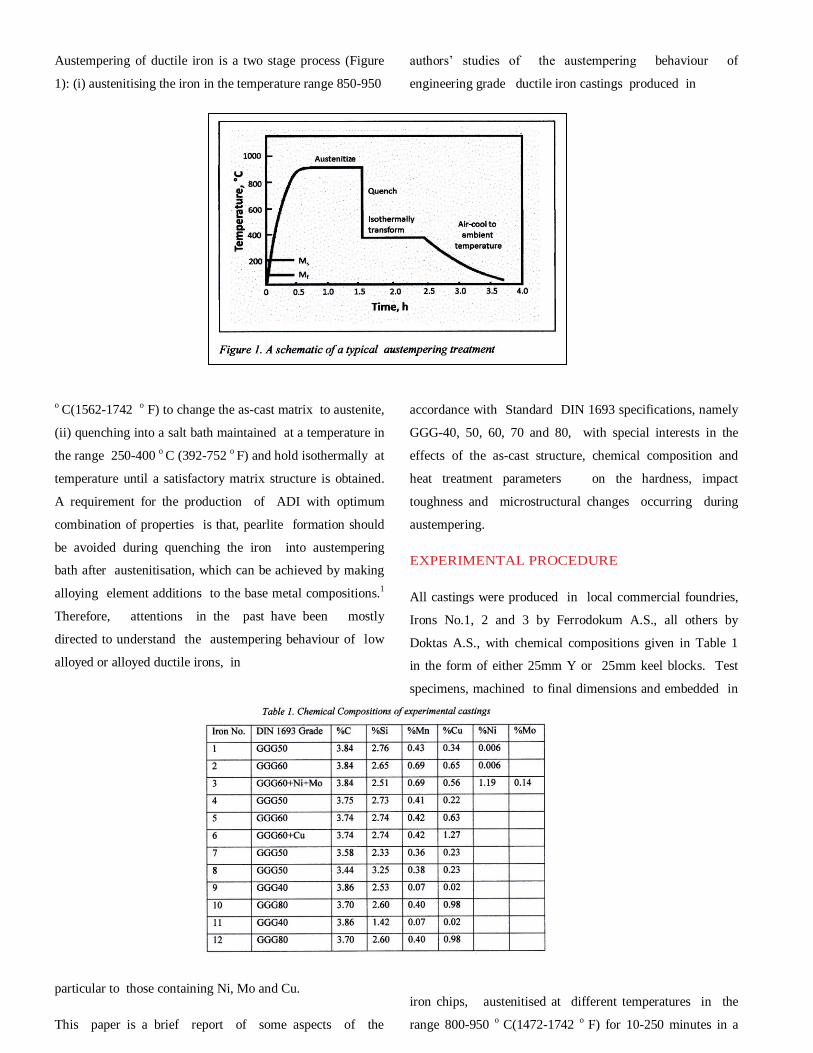
Austempering of ductile iron is a two stage process (Figure
1): (i) austenitising the iron in the temperature range 850-950
o C(1562-1742 o F) to change the as-cast matrix to austenite,
(ii) quenching into a salt bath maintained at a temperature in
the range 250-400 o C (392-752 o F) and hold isothermally at
temperature until a satisfactory matrix structure is obtained.
A requirement for the production of ADI with optimum
combination of properties is that, pearlite formation should
be avoided during quenching the iron into austempering
bath after austenitisation, which can be achieved by making
alloying element additions to the base metal compositions.1
Therefore, attentions in the past have been mostly
directed to understand the austempering behaviour of low
alloyed or alloyed ductile irons, in
particular to those containing Ni, Mo and Cu.
This paper is a brief report of some aspects of the
authors’ studies of the austempering behaviour of
engineering grade ductile iron castings produced in
accordance with Standard DIN 1693 specifications, namely
GGG-40, 50, 60, 70 and 80, with special interests in the
effects of the as-cast structure, chemical composition and
heat treatment parameters on the hardness, impact
toughness and microstructural changes occurring during
austempering.
EXPERIMENTAL PROCEDURE
All castings were produced in local commercial foundries,
Irons No.1, 2 and 3 by Ferrodokum A.S., all others by
Doktas A.S., with chemical compositions given in Table 1
in the form of either 25mm Y or 25mm keel blocks. Test
specimens, machined to final dimensions and embedded in
piles of cast
iron chips, austenitised at different temperatures in the
range 800-950 o C(1472-1742 o F) for 10-250 minutes in a
muffle furnace in air atmosphere, then rapidly transferred
into a salt bath mixture of 50/50 KNaNO3, maintained at a
temperature in the range 225-450 o C(437-842 o F), to
austemper isothermally. Austempered samples were
subsequently allowed to cool in air.
Un-notched Charpy impact specimens were prepared
according to ASTM A 327-72 Standard Specification,
Impact and hardness tests were conducted on
Trebel Charpy Impact and Ernst Brinell HB30D2 test
equipments, respectively. Metallographic examinations
were done by an Olympus BHM 313U microscope, x-ray
studies by a Phillips PW3710 diffractometer.
RESULTS AND DISCUSSION
STRUCTURE AND PROPERTIES OF DUCTILE IRONS
IN AS-CAST CONDITON
The matrix structure of the castings were typical of the
respective grades; namely, either ferritic, or ferritic-pearlitic,
or pearlitic-ferritic or pearlitic. Nodule counts were in the
range 106-175mm-2, and average nodule diameters in the
range 25-44 m; nodule shape factor was better than 0.90,
except for iron No.1, which was in the range 0.59-0.80.
EFFECT OF HEAT TREATMENT PARAMETERS ON
THE HARDNESS-AUSTEMPERING TIME AND
IMPACT ENERGY-AUSTEMPERING TIME
RELATIONSHIPS
Ductile irons No. 1(GGG-50), No.2(GGG-60) and
No.3(GGG-60+1.19Ni+0.14Mo) were cast, with as-cast
properties and microstructures as given in Table 2, to
examine their austempering behaviour by hardness and
unnotched impact toughness measurements through the time
frame 30 -120 minutes in austempering time at 250, 300,
350 and 400 o C ( 482, 572, 662, 752 o F) after austenitising
for 30 and 100 minutes at 850 and 900 o C(1562-1652 o F).
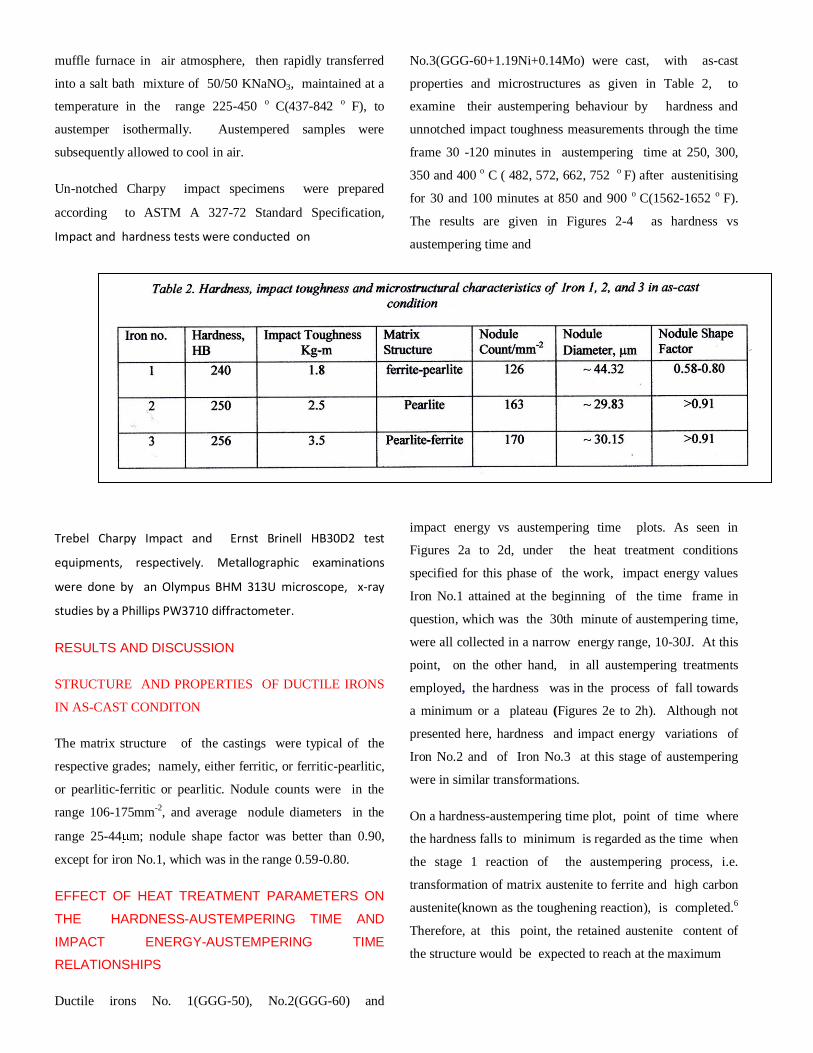
The results are given in Figures 2-4 as hardness vs
austempering time and
impact energy vs austempering time plots. As seen in
Figures 2a to 2d, under the heat treatment conditions
specified for this phase of the work, impact energy values
Iron No.1 attained at the beginning of the time frame in
question, which was the 30th minute of austempering time,
were all collected in a narrow energy range, 10-30J. At this
point, on the other hand, in all austempering treatments
employed, the hardness was in the process of fall towards
a minimum or a plateau (Figures 2e to 2h). Although not
presented here, hardness and impact energy variations of
Iron No.2 and of Iron No.3 at this stage of austempering
were in similar transformations.
On a hardness-austempering time plot, point of time where
the hardness falls to minimum is regarded as the time when
the stage 1 reaction of the austempering process, i.e.
transformation of matrix austenite to ferrite and high carbon
austenite(known as the toughening reaction), is completed.6
Therefore, at this point, the retained austenite content of
the structure would be expected to reach at the maximum
level that the treatment condition would allow.6,7 As the
maximum toughness is correlated with the maximum
amount of retained austenite in the matrix,7 the fall of the
hardness to the minimum would also be expected to have
occured in concurrence with the rise of the impact toughness
to the maximum. However, in majority of the hardness and
toughness vs austempering time plots presented in Figure 2
there were time lags in between the events of the fall of the
hardness to the minimum and the reach of the toughness at
the maximum. Suggesting that, retained austenite content of
the structure develops to its maximum level not when the
hardness falls to the minimum but some time later in the
austempering time.
As seen by comparison between the impact energy-
austempering plots in Figures 2a-2d and hardness-
austempering time plots in Figures 2e-2h, under all
austempering treatment conditions Iron No.2 entered the
time frame, 30-120 minute austempering time, with higher
impact toughness than Iron No.1, therefore, with greater
amounts of retained austenite in its structure, as the impact
toughness was related to the retained austenite content of the
structure,7, 23 This also means, Iron 2 arrived at this stage of
the treatment with a greater austempering rate than Iron
No.1. Major differences between Iron No.1 and Iron No.2
were in chemical compositions and nodular characteristics.
As seen in Table 1, carbon and silicon contents of these two
irons were comparable. Mn and Cu contents of Iron No. 2
were nearly double the amounts of the same in Iron No.1;
0.69wt% Mn and 0.65wt% Cu in Iron No. 2 against 0.43wt%
Mn and 0.34wt% Cu in Iron No.1. Available information
on the role that manganese plays in austempering ductile
irons were limited, however, it is well known that it
segregates to cell boundaries during solidification of the
ductile iron where it delays the transformation of austenite,
and also that, increasing its concentration from 0.07wt% to
0.74wt% results in reductions in impact strength.7 Therefore,
higher austempering rate of Iron No.2 compared to that of
Iron No.1 at the 30. minute of austempering time couldn’t
be accounted for simply by the Mn content difference
between these two irons. As pointed out above, as moved
from Iron No.1 to Iron No.2, not only the Mn content but,
simultaneously, the copper content was also increased. Cu is
one of the popular elements added into ductile irons to avoid
pearlite formation during quenching the castings into the
austempering bath after austenitisation,7 therefore, with the
knowledge available, the austempering rate difference
between Iron No.1 and Iron No.2 couldn’t have been related
to the difference between the chemical compositions of
these irons, either.
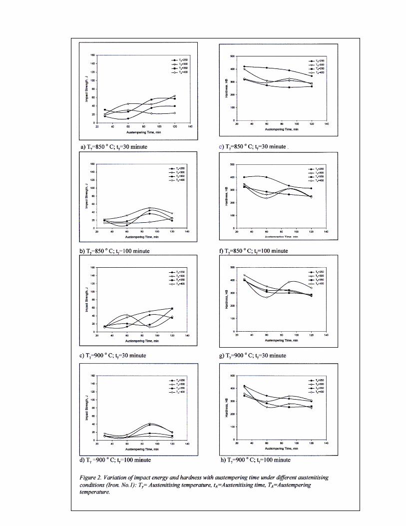
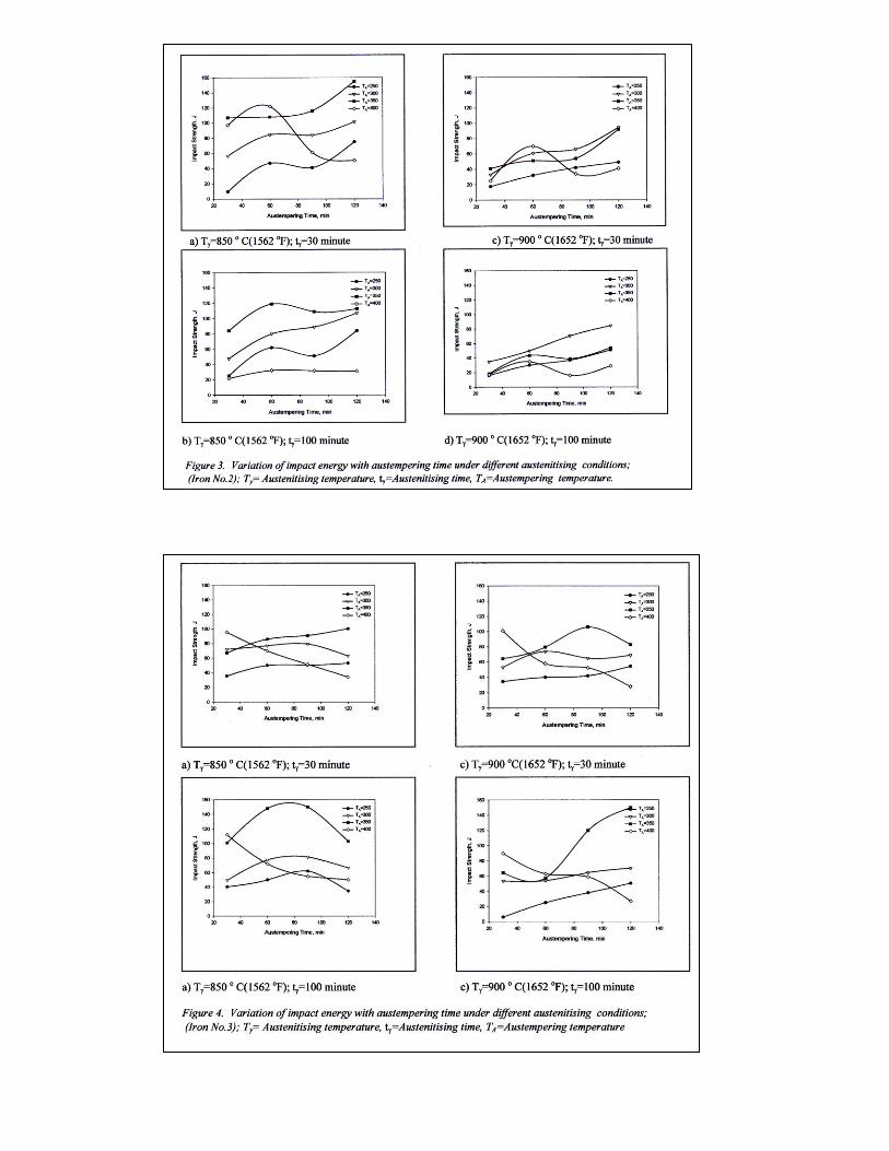
As to the austempering rates of Iron No.2 and that of Iron
No.3, comparison between the data of Figure 3 and Figure
4 shows that, of the 16 austempering conditions applied in
the experiments, in 15 of them Iron No.3 entered into the
time frame 30-120 minute in austempering time with greater
toughnesses than Iron No.1, suggesting that, again by
deduction similar to that made above when the impact
energies of Iron No.1 and Iron No.2 were related to the rate,
Iron No.3 completed the first 30 minutes of the isothermal
austempering treatment at a greater rate than Iron No.2.
C, Si, Mn and Cu contents and nodular characteristics of
these irons were very similar to each other, as could be seen
in Table 1 and Table 2. The only major difference between
them appeared to be the additional 1.19wt% Ni and
0.14wt% Mo contents of Iron 3, which was deliberately
created to measure the effect of combined addition of these
elements into the composition. Thus, the apparent rate
difference between Iron No.2 and No.3 could be readily
related to the Ni and Mo contents of Iron No.3.
Figures 2-4 indicate that there were differences in the
maximum impact toughness Irons No.1, No.2 and No.3
achieved by austempering; the toughness of Iron No.2 and
No.3 were both remarkably higher than that of Iron No.1,
which could have arisen from the differences in chemical
compositions and nodule counts. There were also differences
between the maximum toughness values Iron No.2 and Iron
No.3 attained during austempering. As seen in Figures 3 and
4, when austempered after the both were austenitised at 850 o
C(1562 o F) for 30 minutes, the maximum toughness
achieved by Iron No.2 was greater than that of Iron No.3.
However, when austempered after austenitised for 100
minutes at 850 o C(1562 o F) and 30 and 100 minutes at 900 o
C(1652 o F), Iron No.2 was ahead. Indicating that,
1.19wt% Ni and 0.14wt% Mo addition to ductile iron which

also contained some amount of Mn and Cu can benefit from
austempering tretment by significant amount, provided that
appropriate conditions were selected.
The magnitude of the relative effects of heat treatment
parameters on the toughnes variations recorded by
austempering heat treatment could be estimated by factorial
analysis of the experimental results.25 Table 3 shows the
factorial design of experiments and the results of analysis
of the effects of austenitising temperature(factor A),
austenitising time(factor B), austempering temperature(factor
C) and austempering time(factor D), by varying each factor at
two levels, as 800-900 o C(1562-1652 o F), 30-100 minutes,
250-350 o C(482-662 o F) and 30-120 minutes, respectively,
on the maximum impact toughness of Iron No.2.
Results and effects are given in the fifth and sixth columns
of Table 3 show that the most effective factors in
increasing the impact energy of austempered Iron No.2
were austempering temperature and austempering time.
Increasing the austenitising temperature and/or the
austenitising time decreased the toughness. In decreasing
order of effectiveness, austenitising temperature was the
third factor in the queue, increasing the level of this factor
resulted in significant reduction in toughness. The least
effective factor was austenitising time, increase of which
also caused reduction in toughness, but to a lesser extent.
Therefore, the optimum condition to develop an ADI with
maximum toughness was to austemper Iron No.2 at 350 o C
for 120 minutes after austenitising at 850 o C for 30 minutes.
EFFECT OF COPPER CONTENT
The effect of Cu content on the development of retained
austenite proportion of the austempered structure was
studied on Irons No.4, No.5 and No.6, cast to meet the
Standard Specifications for Grade-50, Grade-60 and Grade-
60 + 1.27 Cu ductile irons, respectively. As the castings
were poured from a single melt by simply modifying the
copper content of the melt between the taps, carbon, silicon
and manganese contents could be kept constant in all
members of the group. Chemical composition of each
casting was given in Table 1, hardness and structural
characteristics in the as-cast state, as
measured by auto-image analyser, are outlined in Table 4.
All three irons were given equal austempering treatments;
austenitised for 60 minutes at 850 o C(1472 o 2F) and 900 o
C(1562 o F), and then austempered at 350 o C(662 o F) for
10 to 100 minutes. Results are presented in Table 5.
Data shows, when irons were austenitised at 850 o C(1562 o
F), largest fraction of retained austenite in the structure was
obtained within the first 25-50 minutes of the austempering
process, however, when austenitised at 900 o C(1652 o F)
prior to austempering, retained austenite proportion of the
structure rised to its highest level at a later point in
austempering time, in a time frame starting at,

approximately, the 50. minute of the treatment. The increase
with austenitising temperature in the amount of retained
austenite was, on the average, 26vol%. Other than that, there
was no evidence to suggest that retained austenite content
increased with copper content.
EFFECT OF NODULE COUNT AND NODULE SIZE
Irons No.7 and No. 8, cast to meet the Standard DIN 1693
Specificaitons for GGG-50 grade ductile iron, were planned
to investigate the effects of nodular characterisitics, e.g.
nodule count and nodule size, on austempering behaviour.
They were both poured from a single melt: Iron No.8,
however, in addition to the
standard laddle treatment applied to both, was also given in-
mold treatment to modify its nodular characteristics. As seen
in Table 1, only difference in the chemical compositions of
these two irons were in their silicon contents; there was
2.33wt% Si in Iron No.7 and 3.25 wt% Si in Iron No.8,
which stemmed purely from the additional in-mold
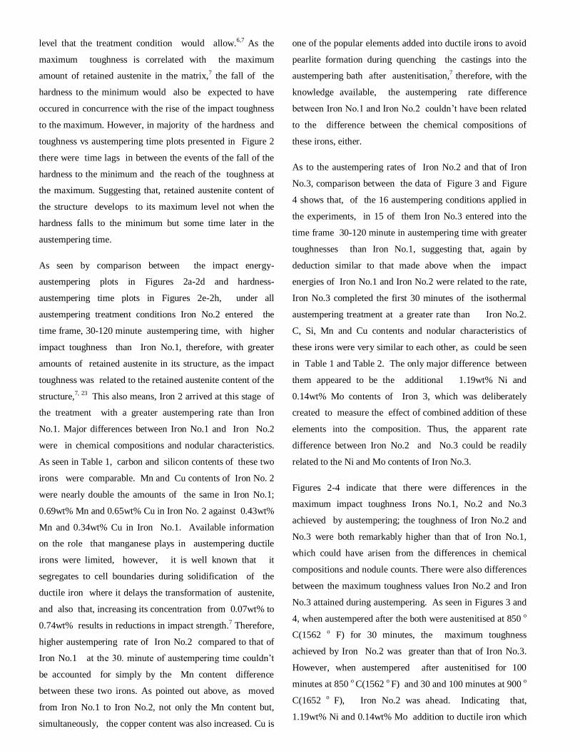
treatment applied to Iron 8. Table 6 lists the hardness,
impact toughness and microstructural characteristics, of
the castings, Figure 5 compares the microstructures of both
irons in unetched and etched conditions
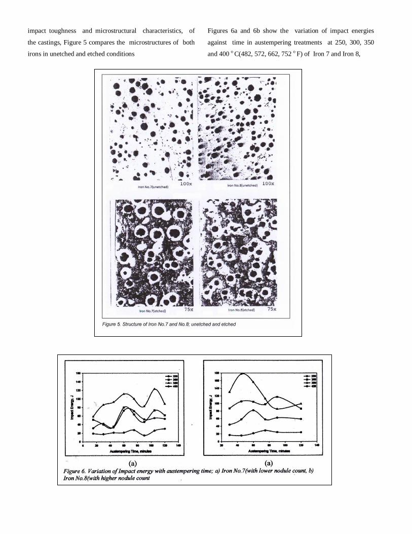
Figures 6a and 6b show the variation of impact energies
against time in austempering treatments at 250, 300, 350
and 400 o C(482, 572, 662, 752 o F) of Iron 7 and Iron 8,
respectively, after austenitised at 850 o C(1562 o F) for 60
minutes. A major difference between the austempering
behaviours of these irons was the change of the optimum
temperature to obtain the maximum toughness: In Iron No.7
maximum toughness was achieved at 325 o C(617 o F), in
Iron No.8 at 350 o C(572 o F). Maximum toughness achieved
by Iron No.8(175J) was remarkably higher than that
obtained by Iron 7(125J). There are evidences that, increasing
the silicon content increased the optimum temperature for
maximum ductility, increased fracture toughness by
increasing the retained austenite content of the matrix and
increased the impact strength of ADI.7 Therefore, the
increase in impact toughness, as moved from Iron No.7 to
Iron No.8, was, at least partly, due to the higher silicon
content of the latter. No published data
were available suggesting direct relationship between the
nodule count and the impact toughness, or ductility, of ADIs,
although works on ductile iron castings has shown that
increasing the nodule count effectively improved the tensile
elongation of ductile irons, but room temperature impact
toughness was independent of the nodule count for all matrix
structures .5 Therefore, the nodule count-impact toughness
relationship requires further research to identify the
individual effect of the nodule count.
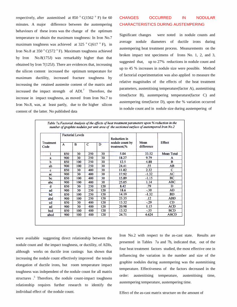
CHANGES OCCURRED IN NODULAR
CHARACTERISTICS DURING AUSTEMPERING
Significant changes were noted in nodule counts and
average nodule diameters of ductile irons during
austempering heat treatment process. Measurements on the
broken impact test specimens of Irons No. 1, 2, and 3,
suggested that, up to 27% reductions in nodule count and
up to 45 % increases in nodule size were possible. Method
of factorial experimentation was also applied to measure the
relative magnitudes of the effects of the heat treatment
parameters, austenitising temperature(factor A), austenitising
time(factor B), austempering temperature(factor C) and
austempering time(factor D), upon the % variation occurred
in nodule count and in nodule size during austempering of
Iron No.2 with respect to the as-cast state. Results are
presented in Tables 7a and 7b, indicated that, out of the
four heat treatment factors studied, the most effective one in
influencing the variation in the number and size of the
graphite nodules during austempering was the austenitising
temperature. Effectiveness of the factors decreased in the
order: austenitising temperature, austenitising time,
austempering temperature, austempering time.
Effect of the as-cast matrix structure on the amount of

changes occurred in nodule count and nodule size, with
respect to the as-cast state, during austempering were also
searched. Irons No.9 and No.10 were prepared to meet the
Standard DIN 1693 specifications for GGG-40 (fully ferritic)
and GGG-80 (fully pearlitic) ductile irons. One surface of
each sample, of dimensions 10mmx10mmx110mm, was
marked,
so that nodule count and nodule size measurements before
and after the treatments could be done on the same surface
of the same specimen. Irons were austenitised at 850 o C
(1562 o C) and then austempered at 350 o C (572 o F) for
different times. Results are presented in Figures 7a and 7b,
as estimated number of graphite nodules per unit volume of
casting vs austempering time, and
% increase in average diameter of volume distribution of
graphite nodules vs austempering time plots. Increase in the
% reduction in nodule count and % increase in average
nodule size, as moved from pearlitic to ferritic iron was
noticable. Changes occurred in nodule counts and nodule size
can well be accounted for, at least qualitatively, by Oswald
Ripening mechanis,26 which is an observed phenomenon in
solid solutions, which describes the change of an
inhomogeneous structure over time. In other words, over
time, small particles, graphite nodules in this case, dissolve,
and redeposit onto larger particles.
DUCTILE/BRITTLE TRANSITON BEHAVIOUR OF
AUSTEMPERED DUCTILE IRONS
In this phase of the studies ductile/brittle transition
behaviour of the whole series of engineering grade ductile
iron castings, were examined. Specimens, following
austenitisation for 100 minutes at 900 o C (1652 o F), were
isothermally austempered at 250, 300, 350 and 400 o C(482,
572, 662, and 752 o F) for 7 to 210 minutes. For below-zero
impact tests, specimens were refrigerated in ethyl alcohol in
a Lab-Plant Refrigerated Immersion Probe, RP-100. For
above-zero tests, specimens were heated in distilled water.
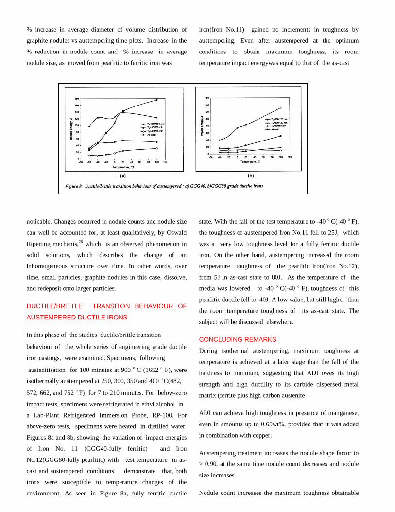
Figures 8a and 8b, showing the variation of impact energies
of Iron No. 11 (GGG40-fully ferritic) and Iron
No.12(GGG80-fully pearlitic) with test temperature in as-
cast and austempered conditions, demonstrate that, both
irons were susceptible to temperature changes of the
environment. As seen in Figure 8a, fully ferritic ductile
iron(Iron No.11) gained no increments in toughness by
austempering. Even after austempered at the optimum
conditions to obtain maximum toughness, its room
temperature impact energywas equal to that of the as-cast
state. With the fall of the test temperature to -40 o C(-40 o F),
the toughness of austempered Iron No.11 fell to 25J, which
was a very low toughness level for a fully ferritic ductile
iron. On the other hand, austempering increased the room
temperature toughness of the pearlitic iron(Iron No.12),
from 5J in as-cast state to 80J. As the temperature of the
media was lowered to -40 o C(-40 o F), toughness of this
pearlitic ductile fell to 40J. A low value, but still higher than
the room temperature toughness of its as-cast state. The
subject will be discussed elsewhere.
CONCLUDING REMARKS
During isothermal austempering, maximum toughness at
temperature is achieved at a later stage than the fall of the
hardness to minimum, suggesting that ADI owes its high
strength and high ductility to its carbide dispersed metal
matrix (ferrite plus high carbon austenite
ADI can achieve high toughness in presence of manganese,
even in amounts up to 0.65wt%, provided that it was added
in combination with copper.
Austempering treatment increases the nodule shape factor to
> 0.90, at the same time nodule count decreases and nodule
size increases.
Nodule count increases the maximum toughness obtainable
from a given austempering treatment.
ADI is susceptible to ductile/brittle transition.
REFERENCES
1. Dorazil, E., Barta, B., Munsterova,E., Stransky,L,
Huvar,A., AFS. Int. Cast Metals Research J., 1982,
V.7, No.2, pp.52-60
2. Janowak, J. F., Gundlach, R. B., AFS Transactions,
1983, v.91, pp. 377-381.
3. Voigt, R.C., AFS Transactions, 1983, v.91, pp.253-
262.
4. Janowak, J.F., Morton, P.A., AFS Transactions,
1984, v.92, pp.489-492.
5. Voight, R.C. and Loper, C.R., J..Heat Treating,
1984, No.4, Vol.3, pp.291-309.
6. Moore, D.J., Rouns, T.N., Rundman, K.B., J. Heat
Treat., 1985, V.4 , pp.7-23.
7. P.A.Blackmore, R.A.Harding, J.Heat.Treat., 1984,
v.3, pp.310-325.
8. Moore, D.J., Rouns, T.N., Rundman, K.B., AFS
Transactions, 85-103, pp.705-717.
9. Gilbert, G.N.J., Report No. 1666, BCIRA, July
1986.
10. Rouns, T.N. and Rundman, K.B., AFS
Transactions, 1987, v.95, pp.851-875.
11. Viau, R., Gagne, M., Thibau, R., AFS
Transactions, 87-77, pp.171-178.
12. Rundman, K.B., Moore, D.J., Hayrynen, K.L.,
Dubensky, W.J, Rouns, T.N., J.Heat Treat.,
1988,v.5,pp.79-95.
13. White, P., Report No. 1787, BCIRA, pp.381
14. Grech, M and Young, J.M., Mater. Sci. and Tech.,
1990, v.6, pp.415-421.
15. Krishnaraj, D., Narasimhan, H.N.L., Seshan,S.,
AFS Transactions, 92-100, pp.105-112.
16. Darwish, N and Elliott, R., Mater. Sci. and Tech.,
1993, v.9, pp.572-585.
17. Darwish, N and Elliott, R., Mater. Sci. and Tech.,
1993, v.9, pp.586-602.
18. Darwish, N and Elliott, R., Mater. Sci. and Tech.,
1993, v.9, pp.882-889.
19. Bahmani, M., Elliott, R., Mater. Sci. Tech., 1994,
v.10, pp. 1050-1056.
20. Korichi, J,.Priestner,R., Mater Sci.Tech., 1995,
v.11, pp.901-907.
21. Krishnaraj, D., Seshan,S., AFS Trans., 95-119,
pp.767-776.
22. Hamid Ali, A.S. and Elliott, R., Mater. Sci. and
Tech., 1996, v.12, pp.780-787.
23. Hamid Ali, A.S., Elliott, R., Mater. Sci. Tech.,
1997, v.13, pp.24-30
24. A.A. Nofal, Jekova,, L., Journal of the University
of Chemical Technology and Metallurgy, 2009,
vol.44, pp.213-228
25. Duckworth, W.E., “Statistical Techniques in
Technological Researché, p.60-86, Methuen
and Co., 1968, London.
26. Oriani, R.A., Acta Met., 1964, v.12, p.1399.,

CHEMISTRY EFFECT ON PROPERTIES (SAMPLE-
HEAD2) This is another sample of subhead (HEAD2.) There may be several second level subheadings and within each second level heading, there may be third level subheads (Head3). “Body” text style is used for the main text. You may have several third level subheadings and within each third level subheading, you may have fourth level subheadings (Head4). “Body” text style is used for the main text as shown. Yield Stress (Sample Head3) Predicted Values (Sample Head4) Here is another sub-subheading (Head4). You may have several fourth level subheadings. Use “body” text style. Bullet Styles (Unord list & Ord
list) • An unordered bullet, no numbers (Times 10) • This unordered list has no numbers 1. An ordered bullet list, uses numbers (Times 10) 2. This ordered list contains numbers.
Lists should be flush left. FIGURE
S Figure captions should be a complete sentence and be located below each figure (left justified) in Figure caption format (Figure Arial 9 BF Ital) see example below. The figure should be located in the text after it is cited. Do not use a list of figures at the end of the paper. Do not wrap text around artwork. If artwork spans two columns, see the last page.
www.wfc2012.com
Related Documents


