Note: Please note receipt of all addenda on your bid form. Page 1 of 3 WESTERN CONNECTICUT STATE UNIVERSITY ADDENDUM NO. 3 TO GRASSO RESIDENCE HALL HVAC IMPROVEMENTS/UNIT REPLACEMENT BID NO. 2019-MRC-0014 DATE: APRIL 18, 2019 The following addendum will expand, amend, revise and clarify the specifications bearing the above title, dated February 22, 2019, and will become a part of them – not replace them. All information in the original contract documents still apply unless specifically omitted or revised by the addendum. Below is a list of RFI’s received, along with the subsequent responses submitted by Kohler Ronan LLC, the consultant-of-record for this project. HV-1 Controls: 1.) DWG: M002 shows an existing duct mounted damper in the supply air. Our records do not show that this damper exists today. Can confirm if this damper is existing to be re-used? KR Response: Damper does not exist. Refer to revised Flow and Control Diagram 2/M002. 2.) DWG: M002 shows an existing duct mounted damper in the supply air. Since this unit serves multiple floors, is it necessary to have a supply air damper at each floor? Does this damper need to be a smoke damper? KR Response: Refer to revised Flow and Control Diagram 2/M002. Dampers are not required 3.) DWG: M002 shows new temperature, humidity and static pressure sensors on the Outdoor air. Are these sensors necessary for this system? KR Response: Provide sensors as indicated on drawings. 4.) DWG: M002 shows new Air Flow Measuring Stations (F) in the supply air. Are these Air Flow Measuring Stations necessary for this system? KR Response: Provide sensors as indicated on drawings. 5.) DWG: M002 shows a new Outdoor Air-Cooled Condensing Unit. Is there an existing underground conduit dedicated for control wires today? If not, someone will need to provide trenching and conduit from building to Outdoor Air-Cooled Condensing Unit location for control wiring. KR Response: There is no existing conduit. No trenching is required. Route control wiring/conduit along same path as electrical conduit and mechanical refrigerant piping to condensing unit. Coordinate with mechanical and electrical contractors.

Welcome message from author
This document is posted to help you gain knowledge. Please leave a comment to let me know what you think about it! Share it to your friends and learn new things together.
Transcript

Note: Please note receipt of all addenda on your bid form.
Page 1 of 3
WESTERN CONNECTICUT STATE UNIVERSITY
ADDENDUM NO. 3 TO
GRASSO RESIDENCE HALL HVAC IMPROVEMENTS/UNIT REPLACEMENT BID NO. 2019-MRC-0014
DATE: APRIL 18, 2019
The following addendum will expand, amend, revise and clarify the specifications bearing the above title, dated February 22, 2019, and will become a part of them – not replace them. All information in the original contract documents still apply unless specifically omitted or revised by the addendum. Below is a list of RFI’s received, along with the subsequent responses submitted by Kohler Ronan LLC, the consultant-of-record for this project.
HV-1 Controls:
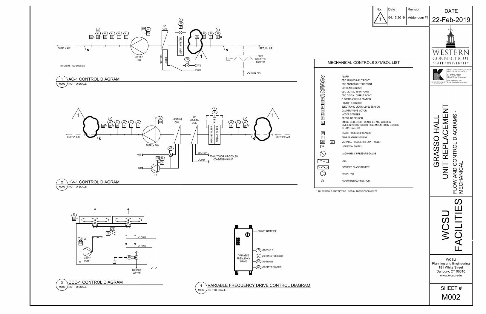
1.) DWG: M002 shows an existing duct mounted damper in the supply air. Our records do not show that this damper exists today. Can confirm if this damper is existing to be re-used?
KR Response: Damper does not exist. Refer to revised Flow and Control Diagram 2/M002.
2.) DWG: M002 shows an existing duct mounted damper in the supply air. Since this unit serves multiple floors, is it necessary to have a supply air damper at each floor? Does this damper need to be a smoke damper?
KR Response: Refer to revised Flow and Control Diagram 2/M002. Dampers are not required
3.) DWG: M002 shows new temperature, humidity and static pressure sensors on the Outdoor air. Are these sensors necessary for this system?
KR Response: Provide sensors as indicated on drawings.
4.) DWG: M002 shows new Air Flow Measuring Stations (F) in the supply air. Are these Air Flow Measuring Stations necessary for this system?
KR Response: Provide sensors as indicated on drawings.
5.) DWG: M002 shows a new Outdoor Air-Cooled Condensing Unit. Is there an existing underground conduit dedicated for control wires today? If not, someone will need to provide trenching and conduit from building to Outdoor Air-Cooled Condensing Unit location for control wiring.
KR Response: There is no existing conduit. No trenching is required. Route control wiring/conduit along same path as electrical conduit and mechanical refrigerant piping to condensing unit. Coordinate with mechanical and electrical contractors.
Note: Please note receipt of all addenda on your bid form.
Page 2 of 3
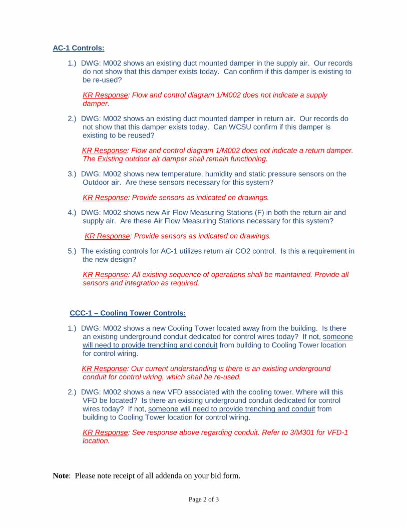
AC-1 Controls:
1.) DWG: M002 shows an existing duct mounted damper in the supply air. Our records do not show that this damper exists today. Can confirm if this damper is existing to be re-used?
KR Response: Flow and control diagram 1/M002 does not indicate a supply damper.
2.) DWG: M002 shows an existing duct mounted damper in return air. Our records do not show that this damper exists today. Can WCSU confirm if this damper is existing to be reused?
KR Response: Flow and control diagram 1/M002 does not indicate a return damper. The Existing outdoor air damper shall remain functioning.
3.) DWG: M002 shows new temperature, humidity and static pressure sensors on the Outdoor air. Are these sensors necessary for this system?
KR Response: Provide sensors as indicated on drawings.
4.) DWG: M002 shows new Air Flow Measuring Stations (F) in both the return air and supply air. Are these Air Flow Measuring Stations necessary for this system?
KR Response: Provide sensors as indicated on drawings.
5.) The existing controls for AC-1 utilizes return air CO2 control. Is this a requirement in the new design?
KR Response: All existing sequence of operations shall be maintained. Provide all sensors and integration as required.
CCC-1 – Cooling Tower Controls:
1.) DWG: M002 shows a new Cooling Tower located away from the building. Is there an existing underground conduit dedicated for control wires today? If not, someone will need to provide trenching and conduit from building to Cooling Tower location for control wiring.
KR Response: Our current understanding is there is an existing underground conduit for control wiring, which shall be re-used.
2.) DWG: M002 shows a new VFD associated with the cooling tower. Where will this VFD be located? Is there an existing underground conduit dedicated for control wires today? If not, someone will need to provide trenching and conduit from building to Cooling Tower location for control wiring.
KR Response: See response above regarding conduit. Refer to 3/M301 for VFD-1 location.
Note: Please note receipt of all addenda on your bid form.
Page 3 of 3
List of “Drawings Addendum #1” Plans as part of this addendum:
E-301 Condensing Unit Plan – Electrical
M-002 Flow and Control Diagrams – Mechanical
M-003 First Floor Key Plan – Mechanical
M-600 Details – Mechanical
M-603 Details – Mechanical
MD-301 Cooling Tower Demolition Plan - Mechanical
END OF ADDENDUM

MAIN SERVICESWITCHBOARD (ETR)
CORE DRILLTHROUGH EXISTINGBUILDING WALL
FOLLOWMECHANICAL PIPINGROUTE UNTIL THISPOINT AND BRANCHOFF
CORE DRILLTHROUGH EXISTINGBUILDING WALL
1
2
ACCU-1
ROUTE CONDUITTIGHT TO CEILING
GFI
WP
EXISTINGPANELBOARD (ETR)
PULLBOX
3
MAIN ELECTRICROOM
ROUTE ALONG WITH ACCU-1FEEDER TO MAIN ELECTRICROOM
CONDUIT SHALL BE CONCEALED AND LOCATED ABOVE FINISHED CEILING. ROUTECONDUIT ALONGSIDE NEW MECHANICAL REFRIGERATION PIPING.
PATCH CEILING TO MATCH EXISTING CONDITIONS.
PROVIDE 3#12+G IN 3/4"C FROM EXISTING PANELBOARD LOCATED IN EXISTINGELECTRICAL ROOM. CONNECT TO SPARE 20A-1P CIRCUIT BREAKER
ELECTRICAL KEY NOTES
1
2
3
1
DATE
22-Feb-2019
WCSU
Planning and Engineering
181 White Street
Danbury, CT 06810
www.wcsu.edu
FA
CIL
IT
IE
S
WC
SU
93 Lake Avenue, Danbury, CT 06810
203.778.1017 F 203.778.1018
171 Madison Avenue,
New York, NY 10016
212.695.2422 F 212.695.2423
www.kohlerronan.com
E-mail [email protected]
No. Date Revision
Scale: 1/4"=1'-0"CONDENSING UNIT PLAN
E3011
SHEET #
E301
CO
ND
EN
SIN
G U
NIT
P
LA
N -
EL
EC
TR
IC
AL
GR
AS
SO
H
AL
L
UN
IT
R
EP
LA
CE
ME
NT
1 04.00.2019 Addendum #1
VFD SPEED CONTROL
VFD ENABLE
VFD SPEED FEEDBACK
VFD STATUSDI
DO
AO
AI
VARIABLE
FREQUENCY
DRIVE
BACNET INTERFACE
M002
4
NOT TO SCALE
VARIABLE FREQUENCY DRIVE CONTROL DIAGRAM
VFD
P
MECHANICAL CONTROLS SYMBOL LIST
DI
AI
AO
DO
T
A
M
F
VS
* ALL SYMBOLS MAY NOT BE USED IN THESE DOCUMENTS.
L
ALARM
DDC ANALOG INPUT POINT
DDC ANALOG OUTPUT POINT
CURRENT SENSOR
DDC DIGITAL INPUT POINT
DDC DIGITAL OUTPUT POINT
FLOW MEASURING STATION
HUMIDITY SENSOR
ELECTRONIC LIQUID LEVEL SENSOR
DAMPER/VALVE MOTOR
PRESSURE SENSOR
TEMPERATURE SENSOR
VARIABLE FREQUENCY CONTROLLER
MAGNAHELIC PRESSURE GAUGE
COIL
OPPOSED BLADE DAMPER
PUMP / FAN
M002
2
NOT TO SCALE
HV-1 CONTROL DIAGRAM
M002
1
NOT TO SCALE
AC-1 CONTROL DIAGRAM
M002
3
NOT TO SCALE
CCC-1 CONTROL DIAGRAM
CS
RETURN AIR
OUTSIDE AIR
M
AI
P
ME
RV
-13 F
ILT
ER
A
DX
COIL
DO
CWS
CWR
AI
P
ME
RV
-13 F
ILT
ER
A
SUPPLY
FAN
CS
SUPPLY AIR
DUCT
MOUNTED
DAMPER
ME
RV
-8 F
ILT
ER
OUTSIDE AIR
HEATING
COIL
AO
HWS
HWR
SUPPLY FAN
DX
COOLING
COIL
TO OUTDOOR AIR-COOLED
CONDENSING UNIT
SUPPLY AIR
SUCTION
LIQUID
CS
SPRAY
PUMP
4" CWR
4" CWS
MAKEUP
WATER
VIBRATION SWITCHVB
MS MOTOR STARTER
SD
SMOKE DETECTOR; FURNISHED AND WIRED BY
DIVISION 26 CONTRACTOR AND MOUNTED BY DIVISION
23 CONTRACTOR
STATIC PRESSURE SENSOR
SP
T
A
AI
SP
AI
H
AI
MS
AI
T
AI
H
AI
F
AI
CS
VS
AI
A
AI
SP
AI
SP
HARDWIRED CONNECTION
SD
NOTE: LIMIT HARD WIRED
T
AI
H
AI
F
AI
A
AI
SP
AI
SPSD T
A
AI
SP
AI
H
AI
DI
VB
MS
DI
AO
L
SU
CT
IO
N
LIQ
UID
VFD
CS
AI
H
CS
VS
DI
P-1
1
CO
2
1
1
DATE
22-Feb-2019
WCSU
Planning and Engineering
181 White Street
Danbury, CT 06810
www.wcsu.edu
FA
CIL
IT
IE
S
WC
SU
93 Lake Avenue, Danbury, CT 06810
203.778.1017 F 203.778.1018
171 Madison Avenue,
New York, NY 10016
212.695.2422 F 212.695.2423
www.kohlerronan.com
E-mail [email protected]
No. Date Revision
SHEET #
M002
FL
OW
A
ND
C
ON
TR
OL
D
IA
GR
AM
S -
ME
CH
AN
IC
AL
GR
AS
SO
H
AL
L
UN
IT
R
EP
LA
CE
ME
NT
1
04.15.2019 Addendum #1
AutoCAD SHX Text
~
AutoCAD SHX Text
~
AutoCAD SHX Text
~
AutoCAD SHX Text
~
AutoCAD SHX Text
~
AutoCAD SHX Text
~

MD300
3
M301
1
M300
3
PROPOSED PATH FROM ACCU-1 TO HV-1. ALL PIPING
RUNNING THROUGH FINISHED SPACES SHALL BE
CONCEALED AND ABOVE FINISHED CEILINGS.
MD301
2
M301
3
REFRIGERANT PIPING IS SHOWN DIAGRAMMATICALLY ONLY.
CONTRACTOR SHALL BE RESPONSIBLE FOR SIZING AND
ROUTING PIPING PER MANUFACTURER'S REQUIREMENTS.
1
DATE
22-Feb-2019
WCSU
Planning and Engineering
181 White Street
Danbury, CT 06810
www.wcsu.edu
FA
CIL
IT
IE
S
WC
SU
93 Lake Avenue, Danbury, CT 06810
203.778.1017 F 203.778.1018
171 Madison Avenue,
New York, NY 10016
212.695.2422 F 212.695.2423
www.kohlerronan.com
E-mail [email protected]
No. Date Revision
SHEET #
M003
FIR
ST
F
LO
OR
K
EY
P
LA
N - M
EC
HA
NIC
AL
Scale: 1/32"=1'-0"
FIRST FLOOR KEY PLAN
M003
1
GR
AS
SO
H
AL
L
UN
IT
R
EP
LA
CE
ME
NT
1
04.15.2019 Addendum #1
AutoCAD SHX Text
UP
1. REFER TO PLANS FOR ORIENTATION OF PIPING CONNECTIONS.
NOTES:
UNION/FLANGE.
TYPICAL FOR ALL
CONNECTIONS.
BALANCING
VALVE.
4" CWR
1-1/4" MAKE-UP
WATER.
MAKE-UP WATER
VALVE
3" OVERFLOW
4" CWS
2" DRAIN
BUTTERFLY VALVE.
TYPICAL.
HOUSEKEEPING PAD
AT GRADE.
NEOPRENE PAD.
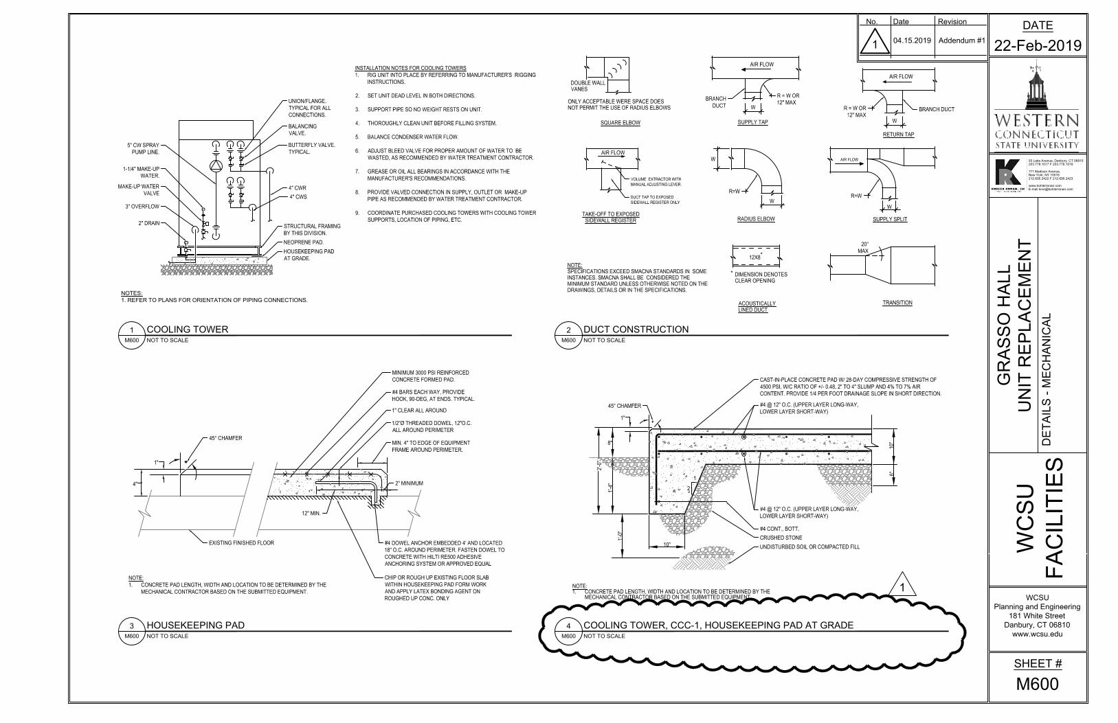
INSTALLATION NOTES FOR COOLING TOWERS
1. RIG UNIT INTO PLACE BY REFERRING TO MANUFACTURER'S RIGGING
INSTRUCTIONS.
2. SET UNIT DEAD LEVEL IN BOTH DIRECTIONS.
3. SUPPORT PIPE SO NO WEIGHT RESTS ON UNIT.
4. THOROUGHLY CLEAN UNIT BEFORE FILLING SYSTEM.
5. BALANCE CONDENSER WATER FLOW.
6. ADJUST BLEED VALVE FOR PROPER AMOUNT OF WATER TO BE
WASTED, AS RECOMMENDED BY WATER TREATMENT CONTRACTOR.
7. GREASE OR OIL ALL BEARINGS IN ACCORDANCE WITH THE
MANUFACTURER'S RECOMMENDATIONS.
8. PROVIDE VALVED CONNECTION IN SUPPLY, OUTLET OR MAKE-UP
PIPE AS RECOMMENDED BY WATER TREATMENT CONTRACTOR.
9. COORDINATE PURCHASED COOLING TOWERS WITH COOLING TOWER
SUPPORTS, LOCATION OF PIPING, ETC.
*
*
DOUBLE WALL
VANES
ONLY ACCEPTABLE WERE SPACE DOES
NOT PERMIT THE USE OF RADIUS ELBOWS
AIR FLOW
SUPPLY TAP
AIR FLOW
TAKE-OFF TO EXPOSED
SIDEWALL REGISTER
ACOUSTICALLY
LINED DUCT
DIMENSION DENOTES
CLEAR OPENING
12X8
RADIUS ELBOW
W
W
AIR FLOW
RETURN TAP
AIR FLOW
W
SUPPLY SPLIT
20°
MAX
TRANSITION
NOTE:
SPECIFICATIONS EXCEED SMACNA STANDARDS IN SOME
INSTANCES. SMACNA SHALL BE CONSIDERED THE
MINIMUM STANDARD UNLESS OTHERWISE NOTED ON THE
DRAWINGS, DETAILS OR IN THE SPECIFICATIONS.
SQUARE ELBOW
DUCT TAP TO EXPOSED
SIDEWALL REGISTER ONLY
BRANCH
DUCT
VOLUME EXTRACTOR WITH
MANUAL ADJUSTING LEVER.
R = W OR
12" MAX
R=W
R=W
R = W OR
12" MAX
BRANCH DUCT
STRUCTURAL FRAMING
BY THIS DIVISION.
W
W
2'-0"
8"
1'-4"
1'-0"
10"
10"
6"
1
2
NOTE:
1. CONCRETE PAD LENGTH, WIDTH AND LOCATION TO BE DETERMINED BY THE
MECHANICAL CONTRACTOR BASED ON THE SUBMITTED EQUIPMENT.
1"
45° CHAMFER
CAST-IN-PLACE CONCRETE PAD W/ 28-DAY COMPRESSIVE STRENGTH OF
4500 PSI, W/C RATIO OF +/- 0.48, 2" TO 4" SLUMP AND 4% TO 7% AIR
CONTENT. PROVIDE 1/4 PER FOOT DRAINAGE SLOPE IN SHORT DIRECTION.
#4 @ 12" O.C. (UPPER LAYER LONG-WAY,
LOWER LAYER SHORT-WAY)
#4 @ 12" O.C. (UPPER LAYER LONG-WAY,
LOWER LAYER SHORT-WAY)
#4 CONT., BOTT.
CRUSHED STONE
UNDISTURBED SOIL OR COMPACTED FILL
M600
4
NOT TO SCALE
COOLING TOWER, CCC-1, HOUSEKEEPING PAD AT GRADE
M600
2
NOT TO SCALE
DUCT CONSTRUCTION
M600
1
NOT TO SCALE
COOLING TOWER
M600
3
NOT TO SCALE
HOUSEKEEPING PAD
NOTE:
1. CONCRETE PAD LENGTH, WIDTH AND LOCATION TO BE DETERMINED BY THE
MECHANICAL CONTRACTOR BASED ON THE SUBMITTED EQUIPMENT.
MINIMUM 3000 PSI REINFORCED
CONCRETE FORMED PAD.
45° CHAMFER
#4 BARS EACH WAY, PROVIDE
HOOK, 90-DEG, AT ENDS. TYPICAL.
1" CLEAR ALL AROUND
EXISTING FINISHED FLOOR #4 DOWEL ANCHOR EMBEDDED 4' AND LOCATED
18" O.C. AROUND PERIMETER. FASTEN DOWEL TO
CONCRETE WITH HILTI RE500 ADHESIVE
ANCHORING SYSTEM OR APPROVED EQUAL
CHIP OR ROUGH UP EXISTING FLOOR SLAB
WITHIN HOUSEKEEPING PAD FORM WORK
AND APPLY LATEX BONDING AGENT ON
ROUGHED UP CONC. ONLY
1"
4"
12" MIN.
2" MINIMUM
1/2"Ø THREADED DOWEL, 12"O.C.
ALL AROUND PERIMETER
MIN. 4" TO EDGE OF EQUIPMENT
FRAME AROUND PERIMETER.
5" CW SPRAY
PUMP LINE.
1
DATE
22-Feb-2019
WCSU
Planning and Engineering
181 White Street
Danbury, CT 06810
www.wcsu.edu
FA
CIL
IT
IE
S
WC
SU
93 Lake Avenue, Danbury, CT 06810
203.778.1017 F 203.778.1018
171 Madison Avenue,
New York, NY 10016
212.695.2422 F 212.695.2423
www.kohlerronan.com
E-mail [email protected]
No. Date Revision
SHEET #
M600
DE
TA
IL
S - M
EC
HA
NIC
AL
GR
AS
SO
H
AL
L
UN
IT
R
EP
LA
CE
ME
NT
1
04.15.2019 Addendum #1
M603
1
NOT TO SCALE
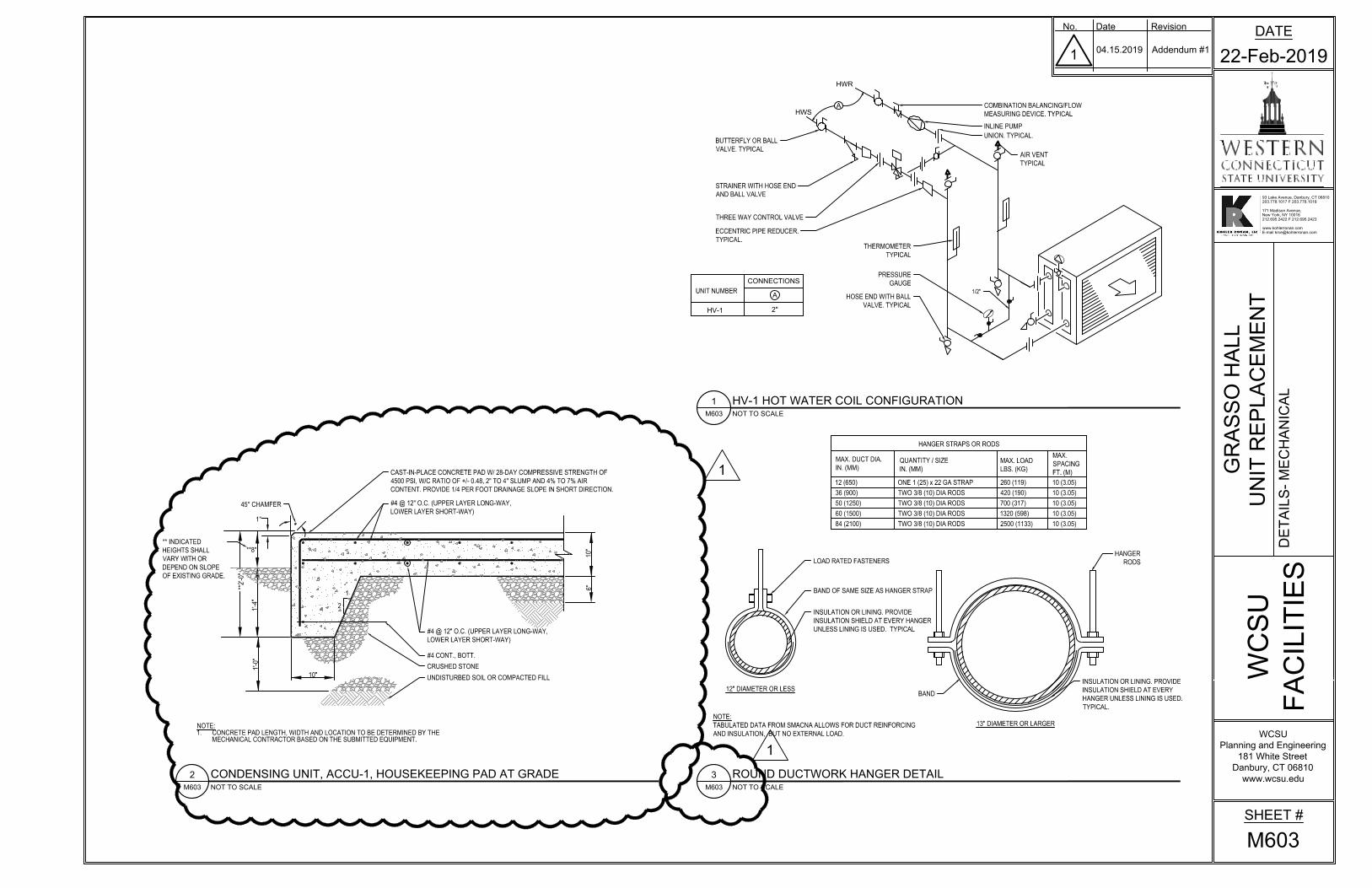
HV-1 HOT WATER COIL CONFIGURATION
HWR
HWS
2"
HV-1
CONNECTIONS
A
UNIT NUMBER
AIR VENT
TYPICAL
HOSE END WITH BALL
VALVE. TYPICAL
1/2"
BUTTERFLY OR BALL
VALVE. TYPICAL
PRESSURE
GAUGE
THERMOMETER
TYPICAL
COMBINATION BALANCING/FLOW
MEASURING DEVICE. TYPICAL
THREE WAY CONTROL VALVE
A
NOTE:
TABULATED DATA FROM SMACNA ALLOWS FOR DUCT REINFORCING
AND INSULATION, BUT NO EXTERNAL LOAD.
QUANTITY / SIZE
IN. (MM)
MAX. DUCT DIA.
IN. (MM)
MAX. LOAD
LBS. (KG)
MAX.
SPACING
FT. (M)
BAND
HANGER
RODS
INSULATION OR LINING. PROVIDE
INSULATION SHIELD AT EVERY
HANGER UNLESS LINING IS USED.
TYPICAL.
LOAD RATED FASTENERS
BAND OF SAME SIZE AS HANGER STRAP
INSULATION OR LINING. PROVIDE
INSULATION SHIELD AT EVERY HANGER
UNLESS LINING IS USED. TYPICAL
12 (650)
36 (900)
50 (1250)
60 (1500)
84 (2100)
ONE 1 (25) x 22 GA STRAP
TWO 3/8 (10) DIA RODS
TWO 3/8 (10) DIA RODS
TWO 3/8 (10) DIA RODS
TWO 3/8 (10) DIA RODS
260 (119)
420 (190)
700 (317)
1320 (598)
2500 (1133)
10 (3.05)
10 (3.05)
10 (3.05)
10 (3.05)
10 (3.05)
M603
3
NOT TO SCALE
ROUND DUCTWORK HANGER DETAIL
HANGER STRAPS OR RODS
13" DIAMETER OR LARGER
12" DIAMETER OR LESS
ECCENTRIC PIPE REDUCER.
TYPICAL.
UNION. TYPICAL.
INLINE PUMP
STRAINER WITH HOSE END
AND BALL VALVE
**2'-0"
**8"
1'-4"
1'-0"
10"
10"
6"
1
2
NOTE:
1. CONCRETE PAD LENGTH, WIDTH AND LOCATION TO BE DETERMINED BY THE
MECHANICAL CONTRACTOR BASED ON THE SUBMITTED EQUIPMENT.
1"
45° CHAMFER
CAST-IN-PLACE CONCRETE PAD W/ 28-DAY COMPRESSIVE STRENGTH OF
4500 PSI, W/C RATIO OF +/- 0.48, 2" TO 4" SLUMP AND 4% TO 7% AIR
CONTENT. PROVIDE 1/4 PER FOOT DRAINAGE SLOPE IN SHORT DIRECTION.
#4 @ 12" O.C. (UPPER LAYER LONG-WAY,
LOWER LAYER SHORT-WAY)
#4 @ 12" O.C. (UPPER LAYER LONG-WAY,
LOWER LAYER SHORT-WAY)
#4 CONT., BOTT.
CRUSHED STONE
UNDISTURBED SOIL OR COMPACTED FILL
M603
2
NOT TO SCALE
CONDENSING UNIT, ACCU-1, HOUSEKEEPING PAD AT GRADE
1
1
** INDICATED
HEIGHTS SHALL
VARY WITH OR
DEPEND ON SLOPE
OF EXISTING GRADE.
DATE
22-Feb-2019
WCSU
Planning and Engineering
181 White Street
Danbury, CT 06810
www.wcsu.edu
FA
CIL
IT
IE
S
WC
SU
93 Lake Avenue, Danbury, CT 06810
203.778.1017 F 203.778.1018
171 Madison Avenue,
New York, NY 10016
212.695.2422 F 212.695.2423
www.kohlerronan.com
E-mail [email protected]
No. Date Revision
SHEET #
M603
DE
TA
IL
S- M
EC
HA
NIC
AL
GR
AS
SO
H
AL
L
UN
IT
R
EP
LA
CE
ME
NT
1
04.15.2019 Addendum #1

XXXXXXXXXXXXXXXXXXXXXXX
XX
XX
XX
XX
XX
XX
X X X X X X X X X X X X X X X X X X X X X X X
XX
XX
XX
XX
XX
XX
XX
XX
XX
XX
XX
XX
XX
X
XXXXXXXXXXXXXXXXXXXXXXX
XX
XX
XX
XX
XX
XX
XX
X
X X X X X X X X X X X X X X X X X X X X X X X
5" CWS
5" CWR
X
X
X
XX
X X
4" CWR
X
X
XX
X
XX
X
XX
X X
XX
XX
XX
X X
XX
XX
XX
X
X
4" CWS
X
X
XX
X
XX
X
X
X
XX
X X
X
XX
X X
UNDERGROUND 5" CWS/R PIPING
TO AND FROM COOLING TOWER
AND MER TO REMAIN.
CCC-1
DRAIN DOWN TOWER AND DISCONNECT
POWER. REMOVE EXISTING COOLING
TOWER CCC-1 IN ITS ENTIRETY.
X
X
X
X
X
X
X
X
X
X
EXISTING FENCED ENCLOSURE.
REMOVE ALL ABOVE GROUND
CWS/R PIPING TO COOLING
TOWER. DISCONNECT AT CPVC
TRANSITION.
REMOVE INDICATED PORTION
OF DRAIN AND 3" BLOWDOWN
LINE AND DRAIN.
REMOVE ABOVE GROUND
PORTION OF 1" MAKEUP
WATER LINE.
REMOVE 4" SPRAY PUMP PIPING
AND SPAY PUMP IN ITS ENTIRETY.
MD
301
1
EXISTING HOUSEKEEPING
PAD TO BE DEMOLISHED IN
ITS ENTIRETY.
1
XX
XX
XX
XX
XX
XX
X X
XXXXXXXXXXXX
XX
XX
XX
XX
X
X X X X X X X X X X X X
XX
XX
XX
XX
X
X X X X X X X X X X
XX
XX
XX
XX
XX
XX
XX
XX
XX
XX
XX
XX
XX
XX
XX
XX
XXX
XX
XX
XX
XX
XX
XX
XX
XX
XX
XX
XX
XX
XX
XX
XX
XX
X
X
X X X X X
XXXXX
X
X
X
X X
XXX
X
X
X
X X X X X
XXXXX
X
X X
XXX
X
XX
XX
X
XX
XX
XX
XX
X
XX
XX
XX
X
XX
X
1" C
WS
X
REMOVE EXISTING 1"
CONDENSER MAKEUP WATER
LINE AT GROUND PENETRATION.
REMOVE THE ENTIRETY OF
EXISTING 4" SPRAY PUMP LINE.
X
X
X
X
X
REMOVE EXISTING 3" BLOWDOWN.
REMOVE EXISTING
DRAINAGE PIPING BACK
TO INDICATED LOCATION.
EXISTING UNDERGROUND 1" CW
MAKEUP LINE TO MER TO REMAIN.
EXISTING UNDERGROUND CPVC
5" CWS/R TO MER TO REMAIN.
4" C
WR
CCC-1
5" C
WR
5" C
WS
REMOVE THE ENTIRETY OF
EXISTING 4" & 5" CWS/R PIPING.
REMOVED BACK TO CPVC
TRANSITION.
DRAIN DOWN, DISCONNECT
POWER SUPPLY AND REMOVE
EXISTING CCC-1 IN ITS ENTIRETY.
DATE
22-Feb-2019
WCSU
Planning and Engineering
181 White Street
Danbury, CT 06810
www.wcsu.edu
FA
CIL
IT
IE
S
WC
SU
93 Lake Avenue, Danbury, CT 06810
203.778.1017 F 203.778.1018
171 Madison Avenue,
New York, NY 10016
212.695.2422 F 212.695.2423
www.kohlerronan.com
E-mail [email protected]
No. Date Revision
SHEET #
MD301
CO
OL
IN
G T
OW
ER
D
EM
OL
IT
IO
N P
LA
N -
ME
CH
AN
IC
AL
Scale: 1/4"=1'-0"
COOLING TOWER - DEMOLITION
MD301
2
Scale: 1/4"=1'-0"
COOLING TOWER ELEVATION - DEMOLITION
MD301
1
GR
AS
SO
H
AL
L
UN
IT
R
EP
LA
CE
ME
NT
1
04.15.2019 Addendum #1
Related Documents