3456 Korean J. Chem. Eng., 33(12), 3456-3464 (2016) DOI: 10.1007/s11814-016-0190-7 pISSN: 0256-1115 eISSN: 1975-7220 INVITED REVIEW PAPER † To whom correspondence should be addressed. E-mail: [email protected] Copyright by The Korean Institute of Chemical Engineers. Well-pattern investigation and selection by surfactant-polymer flooding performance in heterogeneous reservoir consisting of interbedded low-permeability layer Si Le Van and Bo Hyun Chon † Department of Energy Resources Engineering, Inha University, Incheon 22212, Korea (Received 19 March 2016 • accepted 30 June 2016) Abstract-Surfactant-polymer (SP) flooding has been demonstrated to be one of the most efficient methods of recov- ering the residual oil in the enhanced oil recovery (EOR) stage. However, the uses of SP flooding in horizontal or verti- cal well patterns are still being disputed from either technical or economic points of view, particularly in complicated reservoir systems. We investigated the successful application of SP flooding for many well-pattern combinations in a heterogeneous reservoir. A quarter five-spot pattern reservoir model is proposed with three different permeable layers; in particular, the interbedded layer has a much lower permeability than the other layers. The combinations of horizon- tal injectors and producers possess the most successful EOR processes, especially when the wells are interchangeably located in the high-permeability layers. However, the short-length horizontal-well combination is more preferable than the full-length horizontal-well pattern from the results of a comprehensive evaluation. Keywords: Surfactant Polymer Flooding, Enhanced Oil Recovery, Horizontal Well, Well Patterns, Heterogeneous Reser- voir INTRODUCTION Chemical flooding has been employed widely as the most effec- tive method to extract oil remaining in a reservoir when water flooding generally can only recover 30-50% of the original oil in place (OOIP) [1]. Among the uses of alkaline-surfactant-polymer (ASP) flooding, single injection or combined injection, which re- spectively correspond to the injection of only one chemical agent or the use of a solution of more than one agent for the flooding pro- cesses, can be utilized. An alkali is suitably employed for acid-oil reservoirs since it can generate an in-situ surfactant as a result of the reaction activities with the natural acid components of oil, there- after reducing the interfacial tension (IFT) between oil and water. The use of a synthetic surfactant also aims to decrease the IFT to an ultralow value; in particular, the addition of a surfactant to an alkaline solution significantly increases the capillary number to a higher level than that of a single solution [2]. The injection of a poly- mer solution can considerably improve the mobility ratio between the displacing fluid and the oil as a result of the formation of a vis- cous solution fluid, thereby improving the sweep efficiency [3]. However, the success of chemical flooding depends on the charac- teristics of the agents used, the reservoir conditions, and the pro- duction/injection strategies. Sheng [4] reviewed ASP flooding and very clearly stated the criteria for chemical injection in a reservoir, such as the temperature, formation water salinity, permeability, and oil viscosity [4]. It was concluded that the chemical enhanced oil recovery (EOR) applications in sandstone reservoirs provide a higher efficiency than carbonate reservoirs owing to the high chemical adsorption of the carbonate rock. In addition, a polymer can be applied with a reservoir temperature up to 120 o C, as indicated by the wide thermal range of polymer utilization. Within the tem- perature limit, the adsorption level of polymer is inversely correlated with salinity and reservoir temperature [5]. Arabloo et al. [6] inves- tigated the characterized viscous fingering phenomena in multilay- ered heavy oil systems by using a natural surfactant for various patterns; they observed a decrease in the bypassed oil level accord- ing to the increase in the dimensionless distance traveled by the front for all heterogeneous systems [6]. The existence of low-per- meability objects also makes the reservoir complicated in terms of the geological conditions and presumably influences the EOR per- formance. Various shale geometry models in a five-spot well pat- tern were designed to verify the effects on polymer flooding in heavy oil systems by the experimental and numerical works of Moham- madi et al.; the results illustrated the importance of designing the injector so that the mean direction of the injected fluid flow is par- allel to most of the shale barrier objects [7,8]. The layer orientations also impact the flooding project, especially when the permeable lev- els of the layers are highly deviated. Meybodi et al. [9] used glass micromodels to determine the important effects of different per- meable layer orientations on the polymer flooding performance in a five-spot pattern [9]. The results demonstrated the strong influ- ence of the local heterogeneity near the injection regions on the oil recovery; in particular, the best oil recovery performance was achieved when the liquid was injected from a low-permeable portion rather than from a high-permeability layer for polymer flooding. In addi- tion, various numerical works have been carried out to identify spe- cial issues that were restricted by experiments. By using the CMG (STARS) simulator, Sinha et al. [10] found that the numerical results agreed with laboratory data for surfactant and polymer flooding; however, a high deviation was observed for ASP flooding owing

Welcome message from author
This document is posted to help you gain knowledge. Please leave a comment to let me know what you think about it! Share it to your friends and learn new things together.
Transcript

3456
Korean J. Chem. Eng., 33(12), 3456-3464 (2016)DOI: 10.1007/s11814-016-0190-7
pISSN: 0256-1115eISSN: 1975-7220
INVITED REVIEW PAPER
†To whom correspondence should be addressed.E-mail: [email protected] by The Korean Institute of Chemical Engineers.
Well-pattern investigation and selection by surfactant-polymer flooding performance in heterogeneous reservoir consisting of interbedded low-permeability layer
Si Le Van and Bo Hyun Chon†
Department of Energy Resources Engineering, Inha University, Incheon 22212, Korea(Received 19 March 2016 • accepted 30 June 2016)
Abstract−Surfactant-polymer (SP) flooding has been demonstrated to be one of the most efficient methods of recov-ering the residual oil in the enhanced oil recovery (EOR) stage. However, the uses of SP flooding in horizontal or verti-cal well patterns are still being disputed from either technical or economic points of view, particularly in complicatedreservoir systems. We investigated the successful application of SP flooding for many well-pattern combinations in aheterogeneous reservoir. A quarter five-spot pattern reservoir model is proposed with three different permeable layers;in particular, the interbedded layer has a much lower permeability than the other layers. The combinations of horizon-tal injectors and producers possess the most successful EOR processes, especially when the wells are interchangeablylocated in the high-permeability layers. However, the short-length horizontal-well combination is more preferable thanthe full-length horizontal-well pattern from the results of a comprehensive evaluation.
Keywords: Surfactant Polymer Flooding, Enhanced Oil Recovery, Horizontal Well, Well Patterns, Heterogeneous Reser-voir
INTRODUCTION
Chemical flooding has been employed widely as the most effec-tive method to extract oil remaining in a reservoir when waterflooding generally can only recover 30-50% of the original oil inplace (OOIP) [1]. Among the uses of alkaline-surfactant-polymer(ASP) flooding, single injection or combined injection, which re-spectively correspond to the injection of only one chemical agent orthe use of a solution of more than one agent for the flooding pro-cesses, can be utilized. An alkali is suitably employed for acid-oilreservoirs since it can generate an in-situ surfactant as a result ofthe reaction activities with the natural acid components of oil, there-after reducing the interfacial tension (IFT) between oil and water.The use of a synthetic surfactant also aims to decrease the IFT toan ultralow value; in particular, the addition of a surfactant to analkaline solution significantly increases the capillary number to ahigher level than that of a single solution [2]. The injection of a poly-mer solution can considerably improve the mobility ratio betweenthe displacing fluid and the oil as a result of the formation of a vis-cous solution fluid, thereby improving the sweep efficiency [3].However, the success of chemical flooding depends on the charac-teristics of the agents used, the reservoir conditions, and the pro-duction/injection strategies. Sheng [4] reviewed ASP flooding andvery clearly stated the criteria for chemical injection in a reservoir,such as the temperature, formation water salinity, permeability, andoil viscosity [4]. It was concluded that the chemical enhanced oilrecovery (EOR) applications in sandstone reservoirs provide a higherefficiency than carbonate reservoirs owing to the high chemical
adsorption of the carbonate rock. In addition, a polymer can beapplied with a reservoir temperature up to 120 oC, as indicated bythe wide thermal range of polymer utilization. Within the tem-perature limit, the adsorption level of polymer is inversely correlatedwith salinity and reservoir temperature [5]. Arabloo et al. [6] inves-tigated the characterized viscous fingering phenomena in multilay-ered heavy oil systems by using a natural surfactant for variouspatterns; they observed a decrease in the bypassed oil level accord-ing to the increase in the dimensionless distance traveled by thefront for all heterogeneous systems [6]. The existence of low-per-meability objects also makes the reservoir complicated in terms ofthe geological conditions and presumably influences the EOR per-formance. Various shale geometry models in a five-spot well pat-tern were designed to verify the effects on polymer flooding in heavyoil systems by the experimental and numerical works of Moham-madi et al.; the results illustrated the importance of designing theinjector so that the mean direction of the injected fluid flow is par-allel to most of the shale barrier objects [7,8]. The layer orientationsalso impact the flooding project, especially when the permeable lev-els of the layers are highly deviated. Meybodi et al. [9] used glassmicromodels to determine the important effects of different per-meable layer orientations on the polymer flooding performance ina five-spot pattern [9]. The results demonstrated the strong influ-ence of the local heterogeneity near the injection regions on the oilrecovery; in particular, the best oil recovery performance was achievedwhen the liquid was injected from a low-permeable portion ratherthan from a high-permeability layer for polymer flooding. In addi-tion, various numerical works have been carried out to identify spe-cial issues that were restricted by experiments. By using the CMG(STARS) simulator, Sinha et al. [10] found that the numerical resultsagreed with laboratory data for surfactant and polymer flooding;however, a high deviation was observed for ASP flooding owing

Well-pattern investigation and selection by surfactant-polymer flooding performance in heterogeneous reservoir consisting …… 3457
Korean J. Chem. Eng.(Vol. 33, No. 12)
to the complex mechanisms when adding the alkali [10]. Ngoc etal. [11] proposed a new approach for evaluating the uncertainty ofa surfactant-polymer (SP) flooding project by using GOCAD inconjunction with CMG’s CMOST and STARS software; they iden-tified the most important factors influencing the NPV by a sensi-tivity analysis including the chemical concentration, polymer slug,and injection schedules [11].
Regarding the well patterns, the utilization of horizontal wellsfor the recovery of trapped oil in the enhanced oil recovery stagehas been developed as the significant well pattern for installationin reservoirs. The improvements in horizontal-well technologieshave been demonstrated to be technically and economically attrac-tive compared to the use of only conventional vertical wells [12,13].Many previous works investigated the success of horizontal-wellpatterns on water flooding and achieved considerable conclusions.Popa and Turta [14] found that the pressure loss along a horizon-tal section of the well will influence the sweep efficiency of waterflooding, regardless of the well pattern. Popa and Clipea [15] alsoclarified the uniform degree of the fluid flux within the reservoirby verifying different pressure drawdowns between the heel andthe toe of the horizontal section for either injectors or producers.Algharaib and Ertekin [16], on water-flooding processes, con-cluded that an increase in the length of a horizontal well does notcause the additional oil recovery to increase linearly, whereas it isunnecessary to have a long horizontal well for recovering the oiltrapped in a heterogeneous reservoir [17]. Hadia et al. [18] con-cluded the unimportant placement of horizontal producer on theoil production performance; however, the results of this work mightbe more applicable in a homogeneous reservoir than in the het-erogeneous system. AI-Abbas and Shedid [19] pointed out the suc-cessful applications of steam associated with surfactant flooding onthe heavy crude oil by horizontal wells, enlarging the feasibility ofthe combination of chemical with other methods to recover resid-ual oil in unconventional reservoirs.
This work focuses on the utilization of horizontal wells for SPflooding in a complicated three-layered sandstone reservoir, in whicha less permeable layer is interbedded between highly permeableones. The proposed heterogeneous reservoirs will complicate theEOR processes owing to the unstable and unpredictable perfor-mance [20,21]. Many well combinations will be suggested for installa-tion, including altering the horizontal-section length and the locationsof the horizontal sections of the wells. It is known that two apposedhorizontal wells are the most favorable configuration [22-24]; how-ever, the length of the well and, obviously, the long project life causedby the long horizontal well and injectivity reduction (when inject-ing a polymer) need to be involved in consideration since they sig-nificantly affect the overall evaluation of the project [25].
RESERVOIR DESCRIPTION
A quarter five-spot pattern sandstone reservoir model was builtin the STARS black-oil simulator for a field scale of 183×183×21m3 with 15×15×8 grid blocks in Cartesian coordinates. The reser-voir porosity was assumed to be constant throughout the reser-voir; however, the permeability changed vertically, correspondingto different layers. The reservoir consists of three layers in total, as
presented in Table 1, where two highly permeable layers (500 and800 md) are interbedded by a less permeable layer (100 md). Theratio of the vertical to horizontal permeability is also equal betweenlayers and set to 0.1 uniformly throughout the entire reservoir.
A reservoir temperature of 38 oC was proposed following thenormal thermal gradient of the earth and remains within the rangeof the polymer utilization threshold [4]. At the start of the simula-tion, the oil saturation was set to 50% of the pore volume with awater-flooding residual-oil saturation as high as 35% for the entirereservoir. The rock was described as water-wet rock condition. Fig.1 shows the relative permeability curves of the reservoir as a pre-sentation of the water-wet rock reservoir characteristic. The reser-voir conditions and input parameters used for the simulation arepartially taken from the previous work of Najafabadi et al. [26].
The application of a quarter five-spot pattern has been regularlyproved to be effective on enhancing oil recovery, even being muchmore suitable than the line-drive pattern [27]. In regard to the experi-mental processes, the uses of this pattern have become more pop-ular and effective in terms of visual observation compared to theconventional core flooding displacement [28]. Therefore, the deploy-ments of different well configurations in a quarter five-spot pat-tern as in this work will promisingly result in the efficient EOR pro-cesses as well as the applicable conclusions compared to other pat-terns.
Table 1. Reservoir description and input parametersGridPorosityHorizontal permeability
- Layer 1- Layer 2- Layer 3
Initial oil saturationDepthReservoir pressureReservoir temperatureOil gravityOil viscosity (under reservoir conditions)
15×15×80.2
800 md100 md500 md0.5396.34 m4.13 MPa38 oC32.4 oAPI4.5 cp
Fig. 1. Relative permeability curves.

3458 S. L. Van and B. H. Chon
December, 2016
WELL COMBINATIONS: CASE STUDIES
1. Base Case (V-V)The combination of a conventional vertical injector and pro-
ducer wells is proposed as the base case, with two wells fully per-forated throughout the reservoir thickness. The distance betweenthe two wells is approximately 241.5 m, and the well radius is 0.15m and the same for both wells. The wellhead locations of the in-jector and producer are fixed for the other cases.2. Vertical-horizontal (V-H) and Horizontal-vertical (H-V) Cases
In the V-H case, the producer is installed as a horizontal well,whereas the injector is still a vertical well. The horizontal produceris located in layers 1 and 3, and the corresponding well combina-tions are denoted as V-H1 and V-H3, respectively. The horizontalsection is designed to reach nearly the end of the Y axis in the grid —namely, full-length horizontal (to distinguish it from short-lengthhorizontal discussed later).
In contrast to the V-H case, the producer in the H-V case isvertical, and the injector is a full-length horizontal well. However,the horizontal section of the injector in the H-V case will be locatedin layers 1, 2, and 3, corresponding to well combinations H1-V,H2-V, and H3-V, respectively.
Fig. 2 illustrates the V-H1 and H3-V well configurations as rep-resentatives of the V-H and H-V cases.3. Horizontal-horizontal Case
In this case, both the injector and producer are horizontal wells.The well combinations are divided into four groups on the basis ofthe alterations in the lengths of the horizontal sections as follows:
■ H-H: Full-length horizontal injector and producer. The installedwell combinations are created by interchanging the locations of theinjector and producer, where the horizontal section of the injectoris located in layers 1, 2, and 3, whereas that of the producer is onlylocated in layers 1 and 3, as summarized in Table 2.
■ H-HS: Full-length horizontal injector and short-length hori-zontal producer. A “short” length means that the length of the hori-zontal section is half of the “full” length. Similar to H-H, the variouscombinations of this group are created by interchanging the welllocations (Table 3).
■ HS-H: Opposite to the H-HS group. The horizontal produceris full-length. The well combinations of this group are HS1-H1,HS1-H3, HS2-H1, HS2-H3, HS3-H1, and HS3-H3.
■ HS-HS: Both the horizontal injector and producer are short-length. The well-pattern combinations belonging to this group are
Fig. 2. (a) V-H1 and (b) H3-V well combinations.
Table 3. Well combinations of the H-HS groupProducer
Injector Layer 1 Layer 3
Layer 1 H1-HS1 H1-HS3Layer 2 H2-HS1 H2-HS3Layer 3 H3-HS1 H3-HS3
Table 2. Well combinations of the H-H groupProducer
Injector Layer 1 Layer 3
Layer 1 H1-H1 H1-H3Layer 2 H2-H1 H2-H3Layer 3 H3-H1 H3-H3
Fig. 3. Chemical characteristics used for simulation: (a) IFT rela-tionship and (b) viscosity behavior of the polymer.
Well-pattern investigation and selection by surfactant-polymer flooding performance in heterogeneous reservoir consisting …… 3459
Korean J. Chem. Eng.(Vol. 33, No. 12)
HS1-HS1, HS1-HS3, HS2-HS1, HS2-HS3, HS3-HS1, and HS3-HS3.
RESULTS AND DISCUSSION
The same flooding strategy is applied for all simulations, in whichthe reservoir is flooded with water since January 1st of 2000 with-out any solvent agents. After one year, 0.83 vol% surfactant was in-jected with make-up water as the pre-flushing agent to reduce thecapillary forces between the oil and the water in the pores [29,30].The same amount of surfactant and 400 ppm water-soluble poly-mer were contemporarily added to the make-up water on the firstday of 2002 and added for two years. After that, the EOR processesceased the addition of polymer to the displacing fluids. The utili-zation of a soluble polymer helped to increase the viscosity of theinjected liquids considerably; hence, there was an improvement inthe mobility ratio between the displacing and displaced fluids inthe reservoir and the extraction of drastically trapped oil in thepore spaces [31-33]. The designed chemical concentrations werescreened for simulation on the basis of the characteristics of thechemical solution, such as the IFT reduction and solution mobil-ity ratio. Fig. 3 illustrates the IFT relationship and viscosity behav-ior that were applied in this study. The maximum liquid rate ofboth the injector and producer was set to be 477 m3/day, the max-imum bottom-hole pressure (BHP) of the injector was 6.9 MPa,and the minimum BHP of the producer was 0.69 MPa.
The simulation results for the base case were considered first
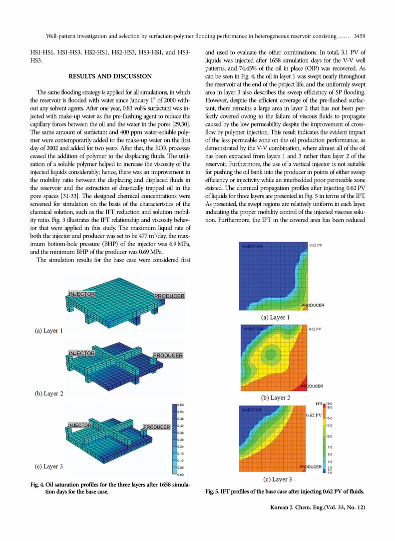
and used to evaluate the other combinations. In total, 3.1 PV ofliquids was injected after 1658 simulation days for the V-V wellpatterns, and 74.45% of the oil in place (OIP) was recovered. Ascan be seen in Fig. 4, the oil in layer 1 was swept nearly throughoutthe reservoir at the end of the project life, and the uniformly sweptarea in layer 3 also describes the sweep efficiency of SP flooding.However, despite the efficient coverage of the pre-flushed surfac-tant, there remains a large area in layer 2 that has not been per-fectly covered owing to the failure of viscous fluids to propagatecaused by the low permeability despite the improvement of cross-flow by polymer injection. This result indicates the evident impactof the less permeable zone on the oil production performance, asdemonstrated by the V-V combination, where almost all of the oilhas been extracted from layers 1 and 3 rather than layer 2 of thereservoir. Furthermore, the use of a vertical injector is not suitablefor pushing the oil bank into the producer in points of either sweepefficiency or injectivity while an interbedded poor permeable zoneexisted. The chemical propagation profiles after injecting 0.62 PVof liquids for three layers are presented in Fig. 5 in terms of the IFT.As presented, the swept regions are relatively uniform in each layer,indicating the proper mobility control of the injected viscous solu-tion. Furthermore, the IFT in the covered area has been reduced
Fig. 4. Oil saturation profiles for the three layers after 1658 simula-tion days for the base case. Fig. 5. IFT profiles of the base case after injecting 0.62 PV of fluids.

3460 S. L. Van and B. H. Chon
December, 2016
to an ultralow value, as evidently indicated by the effective surfac-tant and salinity designs corresponding to the reservoir fluid prop-erties and wetting conditions.
The well combinations of V-H case show unsuccessful EORperformance despite the use of a horizontal producer instead of avertical producer. As presented in Fig. 6, a maximum of 68.22% ofthe OIP was recovered after injecting 3.7 PV of liquids by the V-H3
well configuration, whereas the oil recovery is 63.01% for the V-H1combination. The flow patterns of the fluids in the reservoir arealso diverse in comparison with the base case, as illustrated in Fig.7. The moveable fluids in the layer in which the producing well islocated tend to converge to the toe of the horizontal section fromthe vertical injector rather than the upper point oriented towardsthe heel, and the flow still uniformly pervades throughout the restof the layers.
The argument is similar for the H-V case, in which the fluidsflow towards the vertical producing well via fluid channels fromthe toe of the injection well, as easily visualized from 2001 to 2002for all combinations. Nevertheless, alteration of the well pattern forthe injector results in better EOR performance than that of the V-H case. In detail, H3-V resulted a higher injectivity than V-H3,with 4 PV of fluids injected in 1569 simulation days and 76.65%of the OIP recovered. Although H2-V exhibited the worst perfor-mance, it was still better than a couple of combinations of the V-Hcase with an oil recovery of 68.72%, as shown in Fig. 8. These sim-ulation results evidently show the advantage of a horizontal injec-tor for the improvement of EOR performance rather than thehorizontal production well.
The oil production performance is greatly improved when con-jugating both the injector and producer to be the horizontal wells,as in the horizontal-horizontal case. However, the increase in theoil extracted depends on the relationship between the placementof the injector and producer. Presumably, installing both horizon-tal wells in the same layer just effectively recovers the oil trappedin that layer; however, placing a producing well in a different layerwith an injection well might result in better performance as a con-sequence of fully propagating the displacing fluids throughout thereservoir. Further, the areas of swept regions principally depend onthe crossflow of the fluids, especially when injecting viscous liq-uids, featured by the shear-thinning behavior of polymer solution[34,35].
As evidently illustrated in Fig. 9, relatively high oil recoverieswere mostly achieved when the injector was placed in layer 1 andthe producer was located in layer 3, and vice-versa, for all groups.For instance, H1-H3 gives the highest produced oil volume with85.88% of the OIP, whereas the recovery factor of H3-HS1 is 83.76%,
Fig. 7. Oil saturation profiles in 2002, 2003, and 2004 for V-H3combination, demonstrating the convergence of fluids ori-ented towards the toe of the horizontal producer.
Fig. 8. Oil production for the combinations of the H-V case com-pared to the base case.
Fig. 6. Oil production for the V-H case compared to the base case.

Well-pattern investigation and selection by surfactant-polymer flooding performance in heterogeneous reservoir consisting …… 3461
Korean J. Chem. Eng.(Vol. 33, No. 12)
nearly higher 10% than that of the base case. Similar to the H-Vand V-H cases, a flow channel still occurs when two horizontalwells are placed in the same layer, particularly at the time beforeinjecting the viscous liquids, as presented in Fig. 10.
The installation of two wells in the same layer dramatically restrictsthe propagation of the displacing fluids to the other layers becauseof the interbedded layer. As observed in Fig. 11, the injected solu-tion can effectively sweep oil within the injector regions in HS1-HS1; however, at a farther distance, the oil is just predominantlyswept in layer 1 compared to the other locations. In contrast, whenthe producer is located in layer 3, the swept oil regions are broaderthan the other layers in the HS1-HS3 combination, and as the con-sequence, the injectivity is lower than that of HS1-HS3. This abso-lutely confirms the relevance of the installation of horizontal wellsin different layers rather than in the same layer in order to enhancethe sweep efficiency by SP flooding.
Obviously, in comparison with the other cases, the installationof horizontal injector and producer wells is absolutely the mostattractive configuration for the deployment of an EOR project forthis type of reservoir. In general, full-length horizontal wells achievethe highest oil production; however, the deviations between H-Hand the other groups are not very high to take biased. As can beseen from Fig. 9, the HS1-HS3 combination recovered approxi-mately 2% less of the OIP than that of the highest combination,even though both horizontal wells are half of the length of the H-Hconfiguration, which demonstrates that it is unnecessary to lengthenvery long horizontal wells. Therefore, the short-horizontal-well com-bination seems to be the best selection, as comprehensively evalu-
ated in terms of either technical or economic points of view.To validate the simulated results, the grid dimensions are also
examined since they might significantly affect to the running datain the case of an inappropriate grid design. A test grid with dimen-sions of 30×30×8 was designed and substituted for the old struc-ture while retaining the same reservoir model size and well distances.Fig. 12 presents the simulation results for the HS1-HS3 and H1-HS3 combinations for two different grid dimensions. As shown,there are small deviations in the oil rates for both combinations forthe two grid dimensions; however, the final oil recoveries are approxi-mately equal for each of the well combinations. The difference inthe oil recovery factors of both combinations is approximately 0.3%,demonstrating that the first design with grid dimensions of 15×15×8 is valid compared to the tested grid structure with the newdimensions.
The operational parameters of the initial well designs are alsotaken into account as factors that affect the flooding performance.This work investigates the effects of different perforation intervalsby simply changing the block numbers of the perforation. Presum-ably, a higher perforation density will generate a more uniform fluidflow profile; therefore, a better sweep efficiency will be attained. How-ever, the improvement in the EOR performance depends on thereservoir fluid properties, particularly in the region adjacent to theinjector. In this work, three cases were redesigned for simulationwith perforation intervals of 24.4 m, 12.2 m, and 6.1 m for the HS1-HS3 well combination. Owing to the good agreement of the resultsfor the 15×15×8 and 30×30×8 grid dimensions, the denser gridwill be applied for the different well completion conditions.
Fig. 9. Oil production performance for combinations belonging to the horizontal–horizontal case compared to that of the V-V case: (a) H-H,(b) H-HS, (c) HS-H, and (d) HS-HS.

3462 S. L. Van and B. H. Chon
December, 2016
The results in Fig. 13 show the effects of different perforationintervals on the oil rate; however, the ultimate oil recoveries at thefinal rate of 15.9 m3/day for the three cases are relatively similar. Alarge deviation between the oil rate curves begins after approximately1.6 PV of injected volume; this is approximately the time at whichthe polymer is beginning to be added to the injected solution. As
the perforation density increases, the increase in the oil rate afterimproving the mobility ratio is postponed to the peak. The improve-ment in the uniform fluid flow profile generated by the denser per-foration sweeps the oil more thoroughly, especially at the regionnear the injector, thereby resulting in a slower response at the pro-ducing well. Nevertheless, from the nearly equal ultimate oil recov-eries of three cases, it is not necessary to design a very close per-foration interval for the purpose of improving the EOR perfor-mance. This implies that various manners of the production per-formance for proposing the well perforation interval should beconsidered since the injected liquids have been appropriately designedaccording to the reservoir condition.
Fig. 11. Oil saturation profiles after 911 and 1277 simulation daysfor (a) HS1-HS3 and (b) HS1-HS1.
Fig. 13. Oil production performance of HS1-HS3 for three differ-ent perforation intervals.
Fig. 10. Oil saturation profiles of the H1-H1 combination after (a)547, (b) 670, and (c) 790 simulation days.
Fig. 12. A comparison of the effects of different grid dimensions onthe simulation results: (a) oil saturation profiles of H1-HS3after injecting 2.8 PV of fluids and (b) oil production per-formance of HS1-HS3 and H1-HS3.

Well-pattern investigation and selection by surfactant-polymer flooding performance in heterogeneous reservoir consisting …… 3463
Korean J. Chem. Eng.(Vol. 33, No. 12)
It is extremely important to investigate fully the impacts of thereservoir structure on the EOR performance, particularly when theheterogeneity determines many aspects of a project, such as thewell installation, completion design, and injection strategies. Sincenumerical studies have demonstrated mostly validated results forSP flooding processes, the results and conclusions of this workpromise to contribute significantly in terms of considering andselecting the possible well patterns for the deployment of a chemi-cal flooding project in complicated heterogeneous reservoir sys-tems.
CONCLUSION
Various well-pattern combinations have been investigated todetermine the most effective configuration for deploying the EORproject of SP flooding. The novelty of this work involves a hetero-geneous reservoir that consists of a less permeable interbeddedlayer. Even though the crossflow of fluids has been improved as aresult of the injection of a polymer solution, the profiles of the fluidflows are still not uniform, and therefore cause varied EOR perfor-mance for different well configurations.
In the H-V and V-H cases, the utilization of a horizontal injec-tor results in a significant improvement in the EOR performancerather than the utilization of a vertical injector with an existing inter-bedded low-permeability layer. However, fluid channels alwaysoccur from/to the toe of the horizontal section due to the pres-sure drawdown and ineffective crossflow, thereby causing a failedEOR process with a large remaining unswept area.
The employment of two horizontal wells has given predomi-nant results, compared to the other cases, especially when two fac-ing wells are installed in different layers excluding the interbeddedlayer. In addition, two short-length horizontal wells are more pref-erable for deployment than full-length horizontal wells from aneconomic point of view, since these two combinations have a verylow deviation in the ultimate oil recovery.
Simulation results have also been obtained with different densergrid dimensions, demonstrating the proper grid structure designfor obtaining accurate results. After investigating the effects of thechange in the perforation interval, it is not necessary to utilize adesign with a high perforation density to obtain better EOR per-formance, even though the closer interval results in a more uni-form fluid profile in the region near the injection well.
Understanding the impacts of the specific complicated reservoiron the efficiency of EOR significantly contributes to the decision-making for well-pattern installation and optimizing the project.
ACKNOWLEDGEMENT
This work was supported by Inha University Research Grant.
REFERENCES
1. M. S. Benzagouta, I. M. AlNashef, W. Karnanda and K. Al-Khidir,Korean J. Chem. Eng., 30, 2108 (2013).
2. Z. Wu, X. Yue, T. Cheng, J. Yu and H. Yang, J. Petroleum Explora-tion and Production Technol., 4, 9 (2013).
3. K. M. Ko, B. H. Chon, S. B. Jang and H. Y. Jang, J. Ind. Eng. Chem.,20, 228 (2014).
4. J. J. Sheng, SPE 165358 the SPE Western Regional & AAPG pacificSection Meeting, 2013 Joint Technical Conference, California, U.S.A.(2013).
5. G. Sodeifian, R. Daroughegi and J. Aalaie, Korean J. Chem. Eng.,32, 2484 (2015).
6. M. Arabloo, A. Shokrollahi, M. H. Ghazanfari and D. Rashtchian,Chem. Eng. Res. Des., 96, 23 (2015).
7. S. Mohammadi, M. Masihi and M. H. Ghazanfari, Transport inPorous Media, 91, 973 (2012).
8. S. Mohammadi, R. Kharrat, M. Masihi, M. H. Ghazanfari and M.Saidian, Petroleum Sci. Technol., 32, 1404 (2014).
9. H. E. Meybodi, R. Kharrat and M. H. Ghazanfari, SPE 113820 the2009 SPE Europec/EAGE Annual Conference and Exhibition,Rome, Italy (2008).
10. A. K. Sinha, A. Bera, V. Raipuria, A. Kumar, A. Mandal and T.Kumar, Petroleum Sci. Technol., 33, 1229 (2015).
11. N. T. B. Ngoc, Z. Chen, L. X. Nghiem, D. T. Q. Cuong and C. Yang,SPE-172003-MS the Abu Dhabi International Petroleum Exhibi-tion and Conference, Abu Dhabi, UAE (2014).
12. H. Ferreira, D. D. Mamora and R. A. Startzman, SPE 35208-MSthe SPE Permian Basin Oil and Gas Recovery Conference, Mid-land, Texas (1996).
13. A. M. El-Abbas, E. M. El-Sallaly, M. H. Sayyouh, M. H. El-Bata-nony, T. M. Darwich and S. M. Desouky, SPE 50431 the SPE Inter-national Conference on Horizontal Well Technology, Calgary,Alberta (1998).
14. C. G. Popa and A. T. Turta, SPE 78989 the SPE Thermal Opera-tions and Heavy Oil Symposium and International Well Technol-ogy Conference, Calgary, Alberta (2002).
15. C. G. Popa and M. Clippea, SPE 50400 the SPE International Con-ference on Horizontal Well Technology, Calgary, Alberta (1998).
16. M. Algharaib and T. Ertekin, SPE 52196 the SPE Mid-ContinentOperations Symposium, Oklahoma City, Oklahoma (1999).
17. M. Algharaib and R. B. C. Gharbi, SPE 93743 the Middle East OilShow (MEOS), Bahrain (2005).
18. N. Hadia, L. Chaudhari, S. K. Mitra, M. Vinjamur and R. Singh, J.Petroleum Sci. Eng., 56, 303 (2007).
19. A. A. EI-Abbas and S. A. Shedid, SPE 68767 the SPE Asia PacificOil and Gas Conference, Jakarta, Indonesia (2001).
20. R. B. Gharbl, E. J. Peters, A. Elkamel and N. Afzal, SPE 38320 theSPE Western Regional Meeting, Long Beach, California (1997).
21. Y. Liu, Petroleum Exploration and Development, 35, 619 (2008).22. J. J. Taber and R. S. Seright, SPE 23952 the SPE Permian Basin Oil
and Gas Recovery Conference, Midland, Texas (1992).23. Z. Ling, L. Wang, Y. Hu and B. Li, Petroleum Exploration and Devel-
opment, 35, 85 (2008).24. K. S. Lee, Energy Procedia, 16, 889 (2012).25. H. Dakhlia, W. J. Wu, M. T. Lim, M. Delshad, G. A. Pope and K.
Sephrnoori, PETSOC the Annual Technical Meeting of ThePetroleum Society of CIM, Alberta, Cannada (1995).
26. N. F. Najafabadi, M. Delshad, C. Han and K. Sepehrnoori, J. Petro-leum Sci. Eng., 86, 257 (2012).
27. A. F. Alajmi, R. Gharbi and M. Algharaib, J. Petroleum Sci. Eng.,122, 524 (2014).

3464 S. L. Van and B. H. Chon
December, 2016
28. S. Mohammadi, M. H. Ghazanfari and M. Masihi, J. Petroleum Sci.Eng., 110, 40 (2013).
29. T. Sharma, G. S. Kumar, B. H. Chon and J. S. Sangwai, PetroleumSci. Technol., 33, 1595 (2015).
30. S. Liu, R. F. Li, C. A. Miller and G. J. Hirasaki, SPE J., 15, 282 (2010).31. E. Carrero, N. V. Queipo, S. Pintos and L. E. Zerpa, J. Petroleum
Sci. Eng., 58, 30 (2007).
32. Reservoir Engineering Research Program, Technical Document forUTCHEM 9.0, Austin, Texas 78712 (2000).
33. H. Son, H. Kim, G. Lee, J. Kim and W. Sung, Korean J. Chem.Eng., 32, 338 (2014).
34. K. S. Lee, Energies, 4, 1112 (2011).35. S. B. Jang and B. H. Chon, Geosystem Engineering, 17, 150 (2014).
Related Documents