Activity Task Fee Estimate Well Line Road Extension Project Engineering-Design (Phase I) Engineering Scope Estimation Prepared for Escambia County 1.0 Atlernative Concept Development $14,801.00 $14,801.00 2.0 Wetland Delineation Wetland Delineation $14,267.00 Gyrotrack Permitting $3,348.00 UMAM Assessment $5,748.00 $23,363.00 3.0 Survey Roadway (Not To Exceed) $72,753.00 Stormwater Ponds (Not To Exceed) $65,000.00 $137,753.00 4.0 Subsurface Utility Engineering (SUE) (Limiting Amount) $15,000.00 $15,000.00 5.0 Geotechnical Roadway $10,280.00 Roadway $10,280.00 Stormwater Ponds $61,705.00 Bridges $17,965.00 $89,950.00 6.0 Traffic Study $0.00 $0.00 7.0 Engineering Design/Analysis Roadway Design $54,797.00 Drainage Design $91,417.00 Structural Design $47,721.00 Utilities $4,024.00 Signing and Pavement Markings $0.00 Signalization $0.00 $197,959.00 8.0 Construction Plans $53,736.00 $53,736.00 9.0 Bidding $0.00 $0.00 10.0 Environmental/Permitting Stormwater Permitting $14,392.00 Wetland Permitting $41,177.00 $55,569.00 11.0 Construction Assistance $0.00 $0.00 $588,131.00 1. Payment shall be made on a lump sum basis with the exception of the Geotechnical and Subsurface Utility Engineering. Invoices shall be submitted to the County monthly and shall reflect amounts due based on percent complete for each task. Additional services shall be invoiced based on actual time charged and direct hourly rates at a 3.1 multiplier. 2. Normal expenses include out-of-pocket expenditures such as copying, plans reproduction, telephone and express mail have been included in the above costs. Permit fees have not been included and shall b bill d tl Total be billed separately. 3. Each task including expenses, has been estimated and any overage/underage shall be applied to the remaining tasks with a maximum not-to-exceed total fee without County authorization.

Welcome message from author
This document is posted to help you gain knowledge. Please leave a comment to let me know what you think about it! Share it to your friends and learn new things together.
Transcript
ActivityTask Fee
Estimate
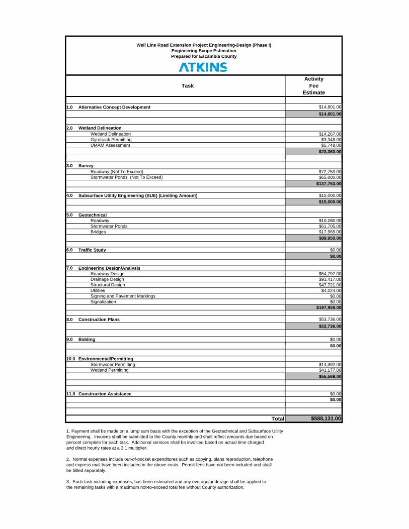
Well Line Road Extension Project Engineering-Design (Phase I)Engineering Scope EstimationPrepared for Escambia County
1.0 Atlernative Concept Development $14,801.00$14,801.00
2.0 Wetland Delineation
Wetland Delineation $14,267.00Gyrotrack Permitting $3,348.00UMAM Assessment $5,748.00
$23,363.00
3.0 SurveyRoadway (Not To Exceed) $72,753.00Stormwater Ponds (Not To Exceed) $65,000.00
$137,753.00
4.0 Subsurface Utility Engineering (SUE) (Limiting Amount) $15,000.00$15,000.00
5.0 Geotechnical Roadway $10,280.00Roadway $10,280.00Stormwater Ponds $61,705.00Bridges $17,965.00
$89,950.00
6.0 Traffic Study $0.00$0.00
7.0 Engineering Design/AnalysisRoadway Design $54,797.00Drainage Design $91,417.00St t l D i $47 721 00Structural Design $47,721.00Utilities $4,024.00Signing and Pavement Markings $0.00Signalization $0.00
$197,959.00
8.0 Construction Plans $53,736.00$53,736.00
9.0 Bidding $0.00$0 00$0.00
10.0 Environmental/PermittingStormwater Permitting $14,392.00Wetland Permitting $41,177.00
$55,569.00
11.0 Construction Assistance $0.00$0.00
$588,131.00
1. Payment shall be made on a lump sum basis with the exception of the Geotechnical and Subsurface UtilityEngineering. Invoices shall be submitted to the County monthly and shall reflect amounts due based on percent complete for each task. Additional services shall be invoiced based on actual time charged and direct hourly rates at a 3.1 multiplier.
2. Normal expenses include out-of-pocket expenditures such as copying, plans reproduction, telephoneand express mail have been included in the above costs. Permit fees have not been included and shallb bill d t l
Total
be billed separately.
3. Each task including expenses, has been estimated and any overage/underage shall be applied to the remaining tasks with a maximum not-to-exceed total fee without County authorization.
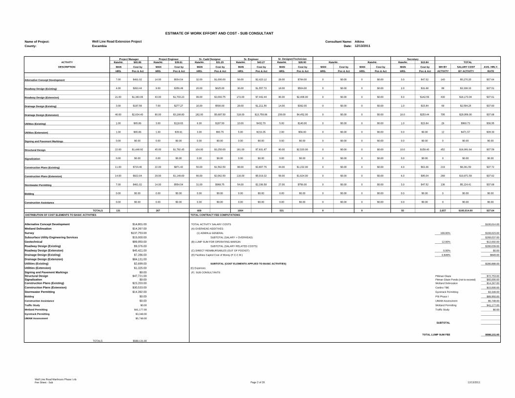
ESTIMATE OF WORK EFFORT AND COST - SUB CONSULTANT
Name of Project: Consultant Name: AtkinsCounty: Escambia Date:
Project Manager Project Engineer Sr. Cadd Designer Sr. Engineer Secretary ACTIVITY Rate/Hr. $65.86 Rate/Hr. $39.61 Rate/Hr. $31.25 Rate/Hr. $43.27 Rate/Hr. $28.00 Rate/Hr. Rate/Hr. Rate/Hr. $15.84 TOTAL
DESCRIPTION MAN Cost by MAN Cost by MAN Cost by MAN Cost by MAN Cost by MAN Cost by MAN Cost by MAN Cost by MH BY SALARY COST AVG. HRLY.HRS. Pos & Act HRS. Pos & Act HRS. Pos & Act HRS. Pos & Act HRS. Pos & Act HRS. Pos & Act HRS. Pos & Act HRS. Pos & Act ACTIVITY BY ACTIVITY RATE
Atlernative Concept Development 7.00 $461.02 14.00 $554.54 32.00 $1,000.00 56.00 $2,423.12 28.00 $784.00 0 $0.00 0 $0.00 3.0 $47.52 140 $5,270.20 $37.64
Roadway Design (Existing) 4.00 $263.44 9.00 $356.49 20.00 $625.00 36.00 $1,557.72 18.00 $504.00 0 $0.00 0 $0.00 2.0 $31.68 89 $3,338.33 $37.51
Roadway Design (Extension) 21.00 $1,383.06 43.00 $1,703.23 99.00 $3,093.75 172.00 $7,442.44 86.00 $2,408.00 0 $0.00 0 $0.00 9.0 $142.56 430 $16,173.04 $37.61
Drainage Design (Existing) 3.00 $197.58 7.00 $277.27 16.00 $500.00 28.00 $1,211.56 14.00 $392.00 0 $0.00 0 $0.00 1.0 $15.84 69 $2,594.25 $37.60
Drainage Design (Extension) 40.00 $2,634.40 80.00 $3,168.80 182.00 $5,687.50 318.00 $13,759.86 159.00 $4,452.00 0 $0.00 0 $0.00 16.0 $253.44 795 $29,956.00 $37.68
Utilities (Existing) 1.00 $65.86 3.00 $118.83 6.00 $187.50 10.00 $432.70 5.00 $140.00 0 $0.00 0 $0.00 1.0 $15.84 26 $960.73 $36.95
Utilities (Extension) 1.00 $65.86 1.00 $39.61 3.00 $93.75 5.00 $216.35 2.00 $56.00 0 $0.00 0 $0.00 0.0 $0.00 12 $471.57 $39.30
Signing and Pavement Markings 0.00 $0.00 0.00 $0.00 0.00 $0.00 0.00 $0.00 0.00 $0.00 0 $0.00 0 $0.00 0.0 $0.00 0 $0.00 $0.00
Structural Design 22.00 $1,448.92 45.00 $1,782.45 104.00 $3,250.00 181.00 $7,831.87 90.00 $2,520.00 0 $0.00 0 $0.00 10.0 $158.40 452 $16,991.64 $37.59
Signalization 0.00 $0.00 0.00 $0.00 0.00 $0.00 0.00 $0.00 0.00 $0.00 0 $0.00 0 $0.00 0.0 $0.00 0 $0.00 $0.00
Construction Plans (Existing) 11.00 $724.46 22.00 $871.42 50.00 $1,562.50 88.00 $3,807.76 44.00 $1,232.00 0 $0.00 0 $0.00 4.0 $63.36 219 $8,261.50 $37.72
Construction Plans (Extension) 14.00 $922.04 29.00 $1,148.69 66.00 $2,062.50 116.00 $5,019.32 58.00 $1,624.00 0 $0.00 0 $0.00 6.0 $95.04 289 $10,871.59 $37.62
Stormwater Permitting 7.00 $461.02 14.00 $554.54 31.00 $968.75 54.00 $2,336.58 27.00 $756.00 0 $0.00 0 $0.00 3.0 $47.52 136 $5,124.41 $37.68
Bidding 0.00 $0.00 0.00 $0.00 0.00 $0.00 0.00 $0.00 0.00 $0.00 0 $0.00 0 $0.00 0.0 $0.00 0 $0.00 $0.00
Construction Assistance 0.00 $0.00 0.00 $0.00 0.00 $0.00 0.00 $0.00 0.00 $0.00 0 $0.00 0 $0.00 0.0 $0.00 0 $0.00 $0.00
TOTALS 131 267 609 1064 531 0 0 55 2,657 $100,014.00 $37.64
DISTRIBUTION OF COST ELEMENTS TO BASIC ACTIVITIES TOTAL CONTRACT FEE COMPUTATIONS
Atlernative Concept Development $14,801.00 TOTAL ACTIVITY SALARY COSTS $100,014.00
Wetland Delineation $14,267.00 (A) OVERHEAD ADDITIVES:
Survey $137,753.00 (1) ADMIN.& GENERAL 168.00% $168,023.00
Subsurface Utility Engineering Services $15,000.00 SUBTOTAL (SALARY + OVERHEAD) $268,037.00
Geotechnical $89,950.00 (B) LUMP SUM FOR OPERATING MARGIN 12.00% $12,002.00
Roadway Design (Existing) $9,376.00 SUBTOTAL (SALARY RELATED COSTS) $280,039.00
Roadway Design (Extension) $45,421.00 (C) DIRECT REIMBURSABLES (OUT OF POCKET) 0.00% $0.00
Drainage Design (Existing) $7,286.00 (D) Facilities Capitol Cost of Money (F.C.C.M.) 0.849% $849.00
Drainage Design (Extension) $84,131.00Utilities (Existing) $2,699.00 SUBTOTAL (COST ELEMENTS APPLIED TO BASIC ACTIVITIES) $280,888.00
Utilities (Extension) $1,325.00 (E) Expenses
Signing and Pavement Markings $0.00 (F) SUB CONSULTANTSStructural Design $47,721.00 Pittman Glaze $72,753.00Signalization $0.00 Pitman Glaze Ponds (not to exceed) $65,000.00Construction Plans (Existing) $23,203.00 Wetland Delineation $14,267.00
Construction Plans (Extension) $30,533.00 Cardno TBE $15,000.00
Stormwater Permitting $14,392.00 Gyrotrack Permitting $3,348.00
Bidding $0.00 PSI Phase I $89,950.00
Construction Assistance $0.00 UMAM Assessment $5,748.00
Traffic Study $0.00 Wetland Permitting $41,177.00
Wetland Permitting $41,177.00 Traffic Study $0.00
Gyrotrack Permitting $3,348.00
UMAM Assessment $5,748.00
SUBTOTAL
TOTAL LUMP SUM FEE $588,131.00
TOTALS $588,131.00
Well Line Road Extension Project
Sr. Designer/Technician
12/13/2011
Well Line Road Manhours Phase I.xls Fee Sheet - Sub Page 2 of 26 12/13/2011

Atlernative Concept Development (New Alignment)Task No. Task Units No of
UnitsHours/
UnitTotal Hours Comments
1 Conceptual Design LS 1 40 40 Develop three alternative alignments for new roadway section
2 Conceptual Meeting LS 1 40 40Meet the County & primary property owner to determine the preferred alignment, typical section, right of way, & stormwater pond design. Includes preparing aerial plots and other meeting drawings
3 Public Notifications LS 1 6 6 Prepare one notification letter to the property owners about field work.
4 Prepare Mailing Lists LS 1 24 24 Prepare a mailing list and send letter to property owners
5 Public Assistance/Follow-up LS 1 30 30 Meet with any property owner to answer questions or discuss concerns
140Atlernative Concept Development (New Alignment)
Well Line Road Manhours Phase I.xls Atlernative Concept Development Page 3 of 26 12/13/2011

Roadway Design (Existing)Task No. Task Units No of
UnitsHours/
UnitTotal Hours Comments
1 Typical Section LS 1 4 4 Development of the roadway typicals (30%)
2 Pavement Design LS 1 0 0 Provided by COUNTY
3 Roadway Geometry LS 1 30 30Efforts required for establishing the master design files for the horizontal and vertical geometry, drainage structure features, utilities (including conflict location identification and adjustments), etc. (30%)
4 Cross Section Design Files LS 1 25 25 60hrs/mile (30% Plans)
5 Traffic Control Analysis LS 1 8 8 Develop the TCP (30%)
6 Design Report LS 1 12 12 Roadway Documentation (30%)
7 Quantities LS 1 0 0 30% Submittal to the County - No Quantities
8 Other Roadway Analysis LS 1 0 0
79
9 Field & Technical Reviews LS 1 4 4 1 field and 1 technical meetings @ 2 hrs each per submittal to discuss roadway items
10 Quality Assurance/Quality Control LS % 2% 2
11 Independent Peer Review LS % 2% 2
12 Supervision LS % 2% 2
Roadway Design (Existing) 89
Well Line Road Manhours Phase I.xlsRoadway Design (Existing) Page 4 of 26 12/13/2011

Roadway Design (Existing B)Task No. Task Units No of
UnitsHours/
UnitTotal Hours Comments
1 Typical Section LS 1 0 0
2 Pavement Design LS 1 0 0
3 Roadway Geometry LS 1 0 0
4 Cross Section Design Files LS 1 0 0
5 Traffic Control Analysis LS 1 0 0
6 Design Report LS 1 0 0
7 Quantities LS 1 0 0
8 Other Roadway Analysis LS 1 0 0
0
9 Field & Technical Reviews LS 1 0 0
10 Quality Assurance/Quality Control LS % 2% 0
11 Independent Peer Review LS % 2% 0
12 Supervision LS % 2% 0
Roadway Design (Existing B) 0
Well Line Road Manhours Phase I.xlsRoadway Design (Existing B) Page 5 of 26 12/13/2011

Roadway Design (Extension)Task No. Task Units No of
UnitsHours/
UnitTotal Hours Comments
1 Typical Section LS 1 8 8 Development of the roadway typicals (30% + Permitting Set)
2 Pavement Design LS 1 0 0 Obtain Pavement Design from County
3 Roadway Geometry LS 1 200 200Efforts required for establishing the master design files for the horizontal and vertical geometry, drainage structure features, utilities (including conflict location identification and adjustments), etc.
4 Cross Section Design Files LS 1 90 90 1.8 miles x 50hrs/mile (30% + Permitting)
5 Traffic Control Analysis LS 1 40 40 Traffic Control only needed at intersection with Jacks Branch and existing Well Line (30% + Permitting)
6 Design Report LS 1 24 24 Roadway Documentation
7 Quantities LS 1 28 28 1 submittals @ 28 hrs per submittal - (30%)
8 Other Roadway Analysis LS 1 0 0
390
9 Field & Technical Reviews LS 1 16 16 1 field and 1 technical meetings @ 2 hrs each per submittal to discuss roadway items
10 Quality Assurance/Quality Control LS % 2% 8
11 Independent Peer Review LS % 2% 8
12 Supervision LS % 2% 8
Roadway Design (Extension) 430
Well Line Road Manhours Phase I.xlsRoadway Design (Extension) Page 6 of 26 12/13/2011

Drainage Design (Existing)Task No. Task Units No of
UnitsHours/
UnitTotal Hours Comments
1 Design of Cross Drains EA 3 4.8 14 2 culverts will use BDI Report @ 3 hrs, 3 Design @ 6 hrs
2 Design of Roadway Ditches Per Ditch Mile 1.3 12 15 1.3 miles each side of the road
3 Design of Stormwater Pond EA 0 0 0
4 Design of Storm Drains EA 5 2.5 13 10 structures from Forrest Rd to Well Line Rd
5 Drainage Design Documentation Report LS 1 20 20
6 Bridge Hydraulic Analysis Report EA 0 0 0
7 Other Drainage Analysis LS 0 0 0
62
8 Field Reviews LS 1 6 6 3 Field Reviews 4 hrs each
9 Technical Meetings LS 1 0 0 See Permitting
10 Quality Assurance/Quality Control LS % 2% 1
11 Independent Peer Review LS % 2% 1
12 Supervision LS % 2% 1
Drainage Design (Existing) 71
Well Line Road Manhours Phase I.xlsDrainage Design (Existing) 7 of 26 12/13/2011

Drainage Design (Existing B)Task No. Task Units No of
UnitsHours/
UnitTotal Hours Comments
1 Design of Cross Drains EA 0 0 0
2 Design of Roadway Ditches Per Ditch Mile 0 0 0
3 Design of Stormwater Pond EA 0 0 0
4 Design of Storm Drains EA 0 0 0
5 Drainage Design Documentation Report LS 0 0 0
6 Bridge Hydraulic Analysis Report EA 0 0 0
7 Other Drainage Analysis LS 0 0 0
0
8 Field Reviews LS 1 0 0
9 Technical Meetings LS 1 0 0
10 Quality Assurance/Quality Control LS % 2% 0
11 Independent Peer Review LS % 2% 0
12 Supervision LS % 2% 0
Drainage Design (Existing B) 0
Well Line Road Manhours Phase I.xlsDrainage Design (Existing B) 8 of 26 12/13/2011

Drainage Design (Extension)(30% + Permitting)Task No. Task Units No of
UnitsHours/
UnitTotal Hours Comments
1 Design of Cross Drains EA 2 16 32 2 culverts@ 24 hrs
2 Design of Roadway Ditches Per Ditch Mile 4.1 15 62 1.8 miles each side of the road plus 800 ft on Jacks Branch Rd and 500 ft of Madrid Rd.
3 Design of Stormwater Pond EA 6 36 216
4 Design of Storm Drains EA 0 0 0
5 Drainage Design Documentation Report LS 0 0 0
6 Bridge Hydraulic Analysis Report EA 440 1 440 2 crossing for wetlands and Jack Branch Crossings
7 Other Drainage Analysis LS 0 0 0
750
8 Field Reviews LS 1 0 0
9 Technical Meetings LS 1 0 0
10 Quality Assurance/Quality Control LS % 2% 15
11 Independent Peer Review LS % 2% 15
12 Supervision LS % 2% 15Drainage Design (Extension)(30% + Permitting) 795
Well Line Road Manhours Phase I.xlsDrainage Design (Extension) 9 of 26 12/13/2011

Utilities (Existing) Task No. Task Units No of
UnitsHours/
Unit Total Hours Comments
1 Kickoff Meeting LS 1 6 67 Utilities (IP, Gas, Power, Telephone, Water, Cable, Sewer) + 2 hrs to prepare + 3 engineers X 2 hr meeting
2 Identify Existing UAO(s) LS 1 0 0
3 Make Utility Contacts LS 1 0 0
4 Preliminary Utility Meeting LS 1 5 5 2 hrs to prepare meeting & 1 meeting (3 eng X 2 hrs)
5 Individual/Field Meetings LS 1 3 3 To discuss utility issues with Culvert crossings, wells locations, etc.
6 Collect and Review Plans and Data from UAO(s) LS 1 0 0
7 Subordination of Easements Coordination LS 1 4 4 IP Wells separate coordination
8 Utility Design LS 1 0 0
9 Utility Design Meeting LS 1 7 7 @30%, 10hr to prepare + 3 eng x 2 hr meeting
10 Review Utility Markups and Work Schedules, and Processing of Schedules and Agreements LS 1 0 0 File any markups, wait for County to proceed past
30%
11 Utility Coordination/Follow-up LS 1 0 0
12 Utility Constructability Review LS 1 0 0
13 Processing Utility Work by Highway Contractor (UWHC) LS 1 0 0
14 Contract Plans to UAO(s) LS 1 0 0
15 Certification/Close-Out LS 1 0 0
16 Other Utilities LS 1 0 0
Utilities (Existing) 25
Well Line Road Manhours Phase I.xlsUtilities (Existing) Page 10 of 26 12/13/2011

Utilities (Existing B) Task No. Task Units No of
UnitsHours/
Unit Total Hours Comments
1 Kickoff Meeting LS 1 0 0
2 Identify Existing UAO(s) LS 1 0 0
3 Make Utility Contacts LS 1 0 0
4 Preliminary Utility Meeting LS 1 0 0
5 Individual/Field Meetings LS 1 0 0
6 Collect and Review Plans and Data from UAO(s) LS 1 0 0
7 Subordination of Easements Coordination LS 1 0 0
8 Utility Design LS 1 0 0
9 Utility Design Meeting LS 1 0 0
10 Review Utility Markups and Work Schedules, and Processing of Schedules and Agreements LS 1 0 0Processing of Schedules and Agreements
11 Utility Coordination/Follow-up LS 1 0 0
12 Utility Constructability Review LS 1 0 0
13 Processing Utility Work by Highway Contractor (UWHC) LS 1 0 0
14 Contract Plans to UAO(s) LS 1 0 0
15 Certification/Close-Out LS 1 0 0
16 Other Utilities LS 1 0 0
Utilities (Existing B) 0
Well Line Road Manhours Phase I.xlsUtilities (Existing B) Page 11 of 26 12/13/2011

Utilities (Extension) (30%)Task No. Task Units No of
UnitsHours/
Unit Total Hours Comments
1 Kickoff Meeting LS 1 0 0
2 Identify Existing UAO(s) LS 1 0 0
3 Make Utility Contacts LS 1 0 0
4 Preliminary Utility Meeting LS 1 0 0
5 Individual/Field Meetings LS 1 0 0
6 Collect and Review Plans and Data from UAO(s) LS 1 0 0
7 Subordination of Easements Coordination LS 1 0 0
8 Utility Design LS 1 0 0
9 Utility Design Meeting LS 1 12 12 Hold one meeting with utilities to discuss needs in future, discuss utility cooridor location and width.
10 Review Utility Markups and Work Schedules, and Processing of Schedules and Agreements LS 1 0 0
11 Utility Coordination/Follow-up LS 1 0 0
12 Utility Constructability Review LS 1 0 0
13 Processing Utility Work by Highway Contractor (UWHC) LS 1 0 0
14 Contract Plans to UAO(s) LS 1 0 0
15 Certification/Close-Out LS 1 0 0
16 Other Utilities LS 1 0 0
Utilities (Extension) (30%) 12
Well Line Road Manhours Phase I.xlsUtilities (Extension) Page 12 of 26 12/13/2011

Structures ‐ Medium Span Concrete Bridge TotalTask No. Task Units No. of
UnitsHours/
UnitNo. of Sheets
Total Hours Comments
General Layout Design and Plans PHASE II13.1 Overall Bridge Final Geometry LS 1 0 013.2 Expansion/Contraction Analysis EA Unit 0 0 013.3 General Plan and Elevation Sheet 0 0 0 013.4 Construction Staging Sheet 0 0 0 013.5 Approach Slab Plan and Details Sheet 0 0 0 013.6 Miscellaneous Details Sheet 0 0 0 0
End Bent Design and Plans
13.7 End Bent Geometry EA End Bent 0 0 0
13.8 Wingwall Design and Geometry EA End Bent 0 0 0
13.9 End Bent Structural Design EA Design 0 0 013.10 End Bent Plan and Elevation Sheet 0 0 0 013.11 End Bent Details Sheet 0 0 0 0 "
Intermediate Bent Design and Plans13.12 Bent Geometry EA Bent 0 0 013.13 Bent Stability Analysis EA Design 0 0 013.14 Bent Structural Design EA Design 0 0 013.15 Bent Plan and Elevation Sheet 0 0 0 013.16 Bent Details Sheet 0 0 0 0
Pier Design and Plans13.17 Pier Geometry EA Pier 0 0 013.18 Pier Stability Analysis EA Design 0 0 013.19 Pier Structural Design EA Design 0 0 013.20 Pier Plan and Elevation Sheet 0 0 0 013.21 Pier Details Sheet 0 0 0 0 "
Miscellaneous Substructure Design and Plans13.22 Foundation Layout Sheet 0 0 0 0
Superstructure Deck Design and Plans
13.23 Finish Grade Elevation (FGE) Calculation LS 1 0 0
13.24 Finish Grade Elevations Sheet 0 0 0 0
13.25 Bridge Deck Design EA Section 0 0 0
13.26 Bridge Deck Reinforcing and Concrete Quantities EA Unit 0 0 0
13.27 Diaphragm Design/Jacking Loads EA Section 0 0 0
13.28 Superstructure Plan Sheet 0 0 0 013.29 Superstructure Section Sheet 0 0 0 0
13.30 Miscellaneous Superstructure Details Sheet 0 0 0 0
Reinforcing Bar Lists13.31 Preparation of Reinforcing Bar List Sheet 0 0 0 0
Continuous Concrete Girder Design13.32 Section Properties LS 1 0 013.33 Material Properties LS 1 0 013.34 Construction Sequence EA Unit 0 0 013.35 Tendon Layouts EA Unit 0 0 013.36 Live Load Analysis EA Unit 0 0 013.37 Temperature Gradient EA Unit 0 0 013.38 Time Dependent Analysis EA Unit 0 0 013.39 Stress Summary EA Unit 0 0 013.40 Ultimate Moments EA Unit 0 0 013.41 Ultimate Shear EA Unit 0 0 013.42 Construction Loading EA Unit 0 0 013.43 Framing Plan Sheet 0 0 0 0
13.44 Girder Elevation, including Grouting Plan and Vent Locations Sheet 0 0 0 0
13.45 Girder Details Sheet 0 0 0 013.46 Erection Sequence Sheet 0 0 0 013.47 Splice Details Sheet 0 0 0 013.48 Girder Deflections and Camber Sheet 0 0 0 0
Simple Span Concrete Design13.49 Prestressed Beam EA Design 0 0 0 beam redesign for latest LRFD and LRFR,adjust spacing13.50 Prestressed Beam Schedules Sheet 0 0 0 013.51 Framing Plan Sheet 0 0 0 0
Load Rating13.52 Load Ratings Per Beam 0 0 0 beam redesign for latest LRFD and LRFR
0 0Structures - Medium Span Concrete Bridge Total
Well Line Road Manhours Phase I.xlsStructures Medium Span Concrete Page 13 of 26 12/13/2011

Structures ‐ MiscellaneousTask No. Task Unit No. of
UnitsHours/
UnitNo. of Sheets
Total Hours Comments
Concrete Box Culvert
18.1 Concrete Box Culverts EA 0 40 0 0
18.2 Concrete Box Culverts Extensions EA Extension 0 0 0 0
Strain Poles
Initial Config 0 0 0 0EA Add'l Config
0 0 0 0
Initial Config 0 0 0 0EA Add'l Config
0 0 0 0
Mast Arms
18.5 Mast Arms EA Pole 0 12 0
Overhead/Cantilever Sign Structures
18.6 Cantilever Sign Structures EA Design 0 0 0 0
18.7 Overhead Span Sign Structures EA Design 0 0 0 0
18.8 Special (Long Span) Overhead Sign Structures EA Design 0 0 0 0
18.9 Monotube Overhead Sign Structure EA Design 0 0 0 0
18.10 Bridge Mounted Signs (Attached to Superstr.) EA Design 0 0 0 0
High Mast Lighting
18.11 High Mast Lighting Structures EA Design 0 0 0 0
Sound Barrier Walls (Ground Mount)
18.12 Horizontal Wall Geometry EA Wall 0 0 0 0
18.13 Vertical Wall Geometry EA Wall 0 0 0 0
18.14 Summary of Quantities - Aesthetic Requirements Sheet 0 0 0 0
18.15 Control Drawings Sheet 0 0 0 0
18.16 Design for Wall Height Covered by Standards EA Design 0 0 0 0
18.17 Design for Wall Height Not Covered by Standards
EA Design 0 0 0 0
18.18 Aesthetic Details LS 1 0 1 0
Special Structures
18.19 Fender System LS 1 0 0
18.20 Fender System Access LS 1 0 0
18.21 Special Structures LS 1 0 0
18.22 Other Structures LS 1 0 0
1 0
18.3 Steel Strain Poles
18.4 Concrete Strain Poles
Structures - Miscellaneous
Well Line Road Manhours Phase I.xlsStructures Miscellaneous Page 14 of 26 12/13/2011

Structures ‐ Bridge Development Report TotalTask No. Task Units No of
UnitsHours/
UnitNo. of Sheets
Total Hours Comments
General Requirement PHASE 110.1 Bridge Geometry LS 1 24 2410.2 Ship Impact Data Collection LS 1 0 010.3 Ship Impact Criteria EA 0 0 0
Superstructure Alternatives10.4 Short Span Concrete Bridge EA ALT 0 0 010.5 Medium Span Concrete Bridge EA ALT 1 60 6010.6 Long Span Concrete Bridge EA ALT 0 0 010.7 Structural Steel Bridge EA ALT 0 0 0
Foundation & Substructure Alternatives10.8 Pier/Bent EA Type 2 24 4810.9 Shallow Foundations EA Type 0 0 0
10.10 Deep FoundationsEA
Foundation Type
2 12 24
Movable Span10.11 Data Collection and Design Criteria LS 1 0 010.12 Movable Span Geometrics and Clearances LS 1 0 010.13 Deck System Evaluation LS 1 0 010.14 Framing Plan Development LS 1 0 010.15 Main Girder Preliminary Design LS 1 0 010.16 Conceptual Span Balance/Counterweight LS 1 0 010.17 Support System Development LS 1 0 010.18 Drive Power Calculations LS 1 0 010.19 Drive System Development LS 1 0 010.20 Power and Control Development LS 1 0 010.21 Conceptual Pier Design LS 1 0 010.22 Foundation Analysis (FL PIER) LS 1 0 010.23 Tender Visibility Study LS 1 0 0
Other BDR Issues10.24 Aesthetics LS 1 0 010.25 TCP/Staged Construction Requirements LS 1 0 010.26 Constructibility Requirements LS 1 0 010.27 Abutment Slope/Wall Evaluation LS 2 20 4010.28 Quantity and Cost Estimates EA ALT 2 8 1610.29 Quantity and Cost Estimates - Movable Span LS 1 0 010.30 Wall Type Justification LS 2 10 20
Report Preparation10.31 Exhibits EA SHT 0 0 010.32 Exhibits - Movable Span EA SHT 0 0 010.33 Report Preparation LS 1 40 4010.34 Report Preparation - Movable Span LS 1 0 010.35 BDR Submittal Package LS 1 0 0
272Add the following hours if 30% plans are the final deliverable.
10.36 General Notes Sheets Sheet 1 4 1 410.37 Plan and Elevation Sheets Sheet 4 24 4 9610.38 Construction Staging Sheet 0 0 0 010.39 Superstructure Section Sheets Sheet 2 8 2 1610.40 Substructure Sections Sheets Sheet 4 16 4 6410.41 Movable Span - General Notes Sheets Sheet 0 0 0 010.42 Movable Span - Plan and Elevation Sheets Sheet 0 0 0 010.43 Movable Span - Clearance Diagram Sheet 0 0 0 010.44 Movable Span - Bascule Pier Layouts Sheet 0 0 0 010.45 Movable Span - Bascule Leaf Section Sheet 0 0 0 010.46 Movable Span - Bascule Leaf Framing Plan Sheet 0 0 0 010.47 Movable Span - Machinery Layouts Sheet 0 0 0 010.48 Movable Span - Control Logic Diagram Sheet 0 0 0 0
11 18011 452
Bridge Development Report Subtotal
SubtotalStructures - Bridge Development Report Total
Well Line Road Manhours Phase I.xlsStructures-BDR Page 15 of 26 12/13/2011

0Construction Plans (Existing) 0
Task No. Task Scale Units No. of
UnitsHours/
UnitNo. of Sheets
Total Hours Comments
1 Key Sheet Sheet 1 4 1 4
2 Typical Section Sheets Sheet 1 7 1 7 Well Line Rd. and New connection for Well Line Rd. to Highway 29
3 General Notes Sheet 1 4 1 4 Set up only
4 Summary of Quantities Sheet 1 3.5 1 4 Set up only
5 Summary of Drainage Structures Sheet 1 4 1 4 Set up only
6 Project Layout Sheet 1 4 1 4 560
7 Plan/Profile Sheet Sheet 7 3 7 21 40 scale on 11x17 shts is 560 ft./sht x 1.3 miles + 2 shts for Forrest Rd. and Morris Rd.
8 Intersection Layout Sheet Sheet 1 12 1 12 Highway 29
9 Miscellaneous Detail Sheets Sheet 1 4 1 4 Roadway details
10 Drainage Structure Sheet (Per Structure) EA 7 2 14 5 Ex. Culverts and 10 structures for routing runoff from Forrest Rd.
11 Miscellaneous Drainage Detail Sheets Sheet 1 12 1 12
12 Stormwater Ponds Plans Sheet Sheet 0 0 0 0
13 Stormwater Pond Cross Sections EA 0 0 0
14 Roadway Soil Survey Sheet Sheet 0 0 0 0 Provided by Geotech
15 Roadway Cross Sections EA 38.5 1.8 69 1.3 miles @ 100 ft cross sections includes 800 ft of Forrest and Morris Rd.
16 Traffic Control Plan Sheets Sheet 7 4 7 28 2 TCP Phases @ 100 scale 1400 ft. per sheet include 2 sheet for Highway 29
17 Traffic Control Cross Section Sheets EA 0 0.5 0
Well Line Road Manhours Phase I.xlsConstruction Plans (Existing) Page 16 of 26 12/13/2011

Task No. Task Scale Units No. of
UnitsHours/
UnitNo. of Sheets
Total Hours Comments
18 Traffic Control Detail Sheets Sheet 1 4 1 4 Details and Notes
19 Utility Adjustment Sheets Sheet 0 4 0 0 Not needed at Phase I
20 SWPPP Sheet 0 5 0 0
21 Project Control Sheet Sheet 1 6 1 6 Survey including benchmarks and reference points
22 Environmental Detail Sheets LS 1 8 8 wetland impact limits points
24 205
23 Cost Estimate EA 1 4 4 1 submittals @ 4 hrs per submittal
24 Review Meeting EA 1 2 2 1 review meetings @ 2 hrs each per submittal to discuss comments on the construciton plans
25 Quality Assurance/Quality Control LS % 2% 426 Supervision LS % 2% 4
Construction Plans (Existing) 24 219
Well Line Road Manhours Phase I.xlsConstruction Plans (Existing) Page 17 of 26 12/13/2011

0Construction Plans (Existing B) 0
Task No. Task Scale Units No. of
UnitsHours/
UnitNo. of Sheets
Total Hours Comments
1 Key Sheet Sheet 0 0 0 0
2 Typical Section Sheets Sheet 0 0 0 0
3 General Notes Sheet 0 0 0 0
4 Summary of Quantities Sheet 0 0 0 0
5 Summary of Drainage Structures Sheet 0 0 0 0
6 Project Layout Sheet 0 0 0 0
7 Plan/Profile Sheet Sheet 0 0 0 0
8 Intersection Layout Sheet Sheet 0 0 0 0
9 Miscellaneous Detail Sheets Sheet 0 0 0 0
10 Drainage Structure Sheet (Per Structure) EA 0 0 0
11 Miscellaneous Drainage Detail Sheets Sheet 0 0 0 0
12 Stormwater Ponds Plans Sheet Sheet 0 0 0 0
13 Stormwater Pond Cross Sections EA 0 0 0
14 Roadway Soil Survey Sheet Sheet 0 0 0 0
15 Roadway Cross Sections EA 0 0 0
16 Traffic Control Plan Sheets Sheet 0 0 0 0
17 Traffic Control Cross Section Sheets EA 0 0 0
Well Line Road Manhours Phase I.xlsConstruction Plans (Existing B) Page 18 of 26 12/13/2011

Task No. Task Scale Units No. of
UnitsHours/
UnitNo. of Sheets
Total Hours Comments
18 Traffic Control Detail Sheets Sheet 0 0 0 0
19 Utility Adjustment Sheets Sheet 0 0 0 0
20 SWPPP Sheet 0 0 0 0
21 Project Control Sheet Sheet 0 0 0 0
22 Environmental Detail Sheets LS 0 0 0
0 0
23 Cost Estimate EA 0 0 0
24 Review Meeting EA 0 0 0
25 Quality Assurance/Quality Control LS % 2% 026 Supervision LS % 2% 0
Construction Plans (Existing B) 0 0
Well Line Road Manhours Phase I.xlsConstruction Plans (Existing B) Page 19 of 26 12/13/2011
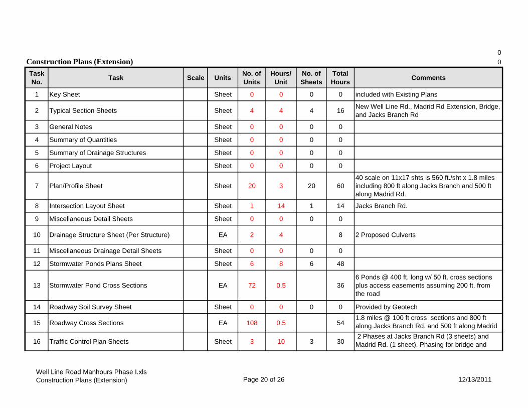
0Construction Plans (Extension) 0
Task No. Task Scale Units No. of
UnitsHours/
UnitNo. of Sheets
Total Hours Comments
1 Key Sheet Sheet 0 0 0 0 included with Existing Plans
2 Typical Section Sheets Sheet 4 4 4 16 New Well Line Rd., Madrid Rd Extension, Bridge, and Jacks Branch Rd
3 General Notes Sheet 0 0 0 0
4 Summary of Quantities Sheet 0 0 0 0
5 Summary of Drainage Structures Sheet 0 0 0 0
6 Project Layout Sheet 0 0 0 0
7 Plan/Profile Sheet Sheet 20 3 20 6040 scale on 11x17 shts is 560 ft./sht x 1.8 miles including 800 ft along Jacks Branch and 500 ft along Madrid Rd.
8 Intersection Layout Sheet Sheet 1 14 1 14 Jacks Branch Rd.
9 Miscellaneous Detail Sheets Sheet 0 0 0 0
10 Drainage Structure Sheet (Per Structure) EA 2 4 8 2 Proposed Culverts
11 Miscellaneous Drainage Detail Sheets Sheet 0 0 0 0
12 Stormwater Ponds Plans Sheet Sheet 6 8 6 48
13 Stormwater Pond Cross Sections EA 72 0.5 366 Ponds @ 400 ft. long w/ 50 ft. cross sections plus access easements assuming 200 ft. from the road
14 Roadway Soil Survey Sheet Sheet 0 0 0 0 Provided by Geotech
15 Roadway Cross Sections EA 108 0.5 541.8 miles @ 100 ft cross sections and 800 ft along Jacks Branch Rd. and 500 ft along Madrid Rd
16 Traffic Control Plan Sheets Sheet 3 10 3 30 2 Phases at Jacks Branch Rd (3 sheets) and Madrid Rd. (1 sheet), Phasing for bridge and
l t t ti
Well Line Road Manhours Phase I.xlsConstruction Plans (Extension) Page 20 of 26 12/13/2011

Task No. Task Scale Units No. of
UnitsHours/
UnitNo. of Sheets
Total Hours Comments
17 Traffic Control Cross Section Sheets EA 5 0.5 3 5 misc
18 Traffic Control Detail Sheets Sheet 0 0 0 0
19 Utility Adjustment Sheets Sheet 0 4 0 040 scale on 11x17 shts is 560 ft./sht x 1.8 miles and 2 sheets for Jacks Branch Rd includes SUE
20 SWPPP Sheet 0 0 0 0
21 Project Control Sheet Sheet 0 0 0 0 Survey including benchmarks and reference points
22 Environmental Detail Sheets LS 1 8 8 wetland impact limits points
34 277
23 Cost Estimate EA 0 0 0 Included as part of Construction Plans (Existing)
24 Review Meeting EA 0 0 0 Included as part of Construction Plans (Existing)
25 Quality Assurance/Quality Control LS % 2% 626 Supervision LS % 2% 6
Construction Plans (Extension) 34 289
Well Line Road Manhours Phase I.xlsConstruction Plans (Extension) Page 21 of 26 12/13/2011

Stormwater Permitting (Extension)Task No. Task Units No. of
UnitsHours/ Units
Total Hours Comments
1 Pre-Application Meeting LS 1 31 31 Prepare for meeting 24 hrs + 4 hr meeting + 3 hr travel time
2 Prepare and submit Stormwater Permit Package LS 1 75 75 includes narrative, drawings, permit, and documentation
3 Comments/RAI LS 1 24 24
130
4 Technical Meetings LS 1 0 0 Meetings are listed below
5 Quality Assurance/Quality Control LS % 2% 3
6 Supervision LS % 2% 3
Stormwater Permitting (Extension) 136
Well Line Road Manhours Phase I.xlsStormwater Permits Page 22 of 26 12/13/2011

Signing and Pavement Markings
Task No. Task Scale Units No of
UnitsHours/
UnitNo. of Sheets
Total Hours Comments
1 Design of Signing and Pavement Markings LS 0 40 0 0 Well Line Rd., Jacks Branch Rd., Highway 29, & side streets (30%)
2 Tabulation of Quantities Sheet 0 8 0 0
3 General Notes/Pay Item Notes Sheet 0 4 0 0
4 Plan Sheet Sheet 0 4 0 0 100 scale 1400 ft. per sheet include 2 sheets for Highway 29 and 2 sheets for Jacks Branch Rd.
5 Details EA 0 8 0
6 Design of Multi Post Signs and Guide Sign Worksheet(s) EA 0 8 0 4 @Highway 29 and 3 @ Jacks Branch Road
7 Sign Panel Design EA 0 0 0
8 Cross Sections EA 0 0 0
9 Special Service Point Details EA 0 0 0
10 Field Reviews LS 0 8 0 2 hrs to prepare + 6 hrs review
0 0
11 Quality Assurance/Quality Control LS % 2% 0
12 Supervision LS % 3% 0
Signing and Pavement Markings 0 0
Well Line Road Manhours Phase I.xlsSigning & Marking Plans Page 23 of 26 12/13/2011
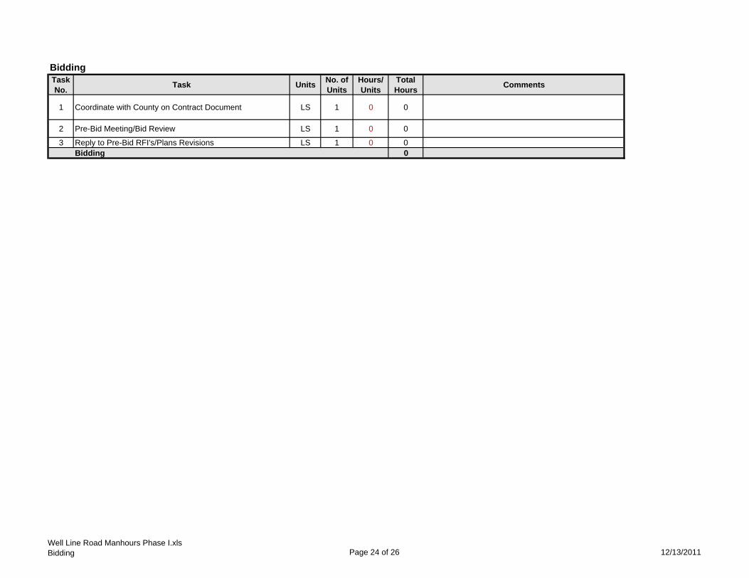
BiddingTask No. Task Units No. of
UnitsHours/ Units
Total Hours Comments
1 Coordinate with County on Contract Document LS 1 0 0
2 Pre-Bid Meeting/Bid Review LS 1 0 0
3 Reply to Pre-Bid RFI's/Plans Revisions LS 1 0 0Bidding 0
Well Line Road Manhours Phase I.xlsBidding Page 24 of 26 12/13/2011

Construction AdministrationTask No.
Task Units No. of Units
Hours/ Units
Total Hours
Comments
1 Contract Maintenance LS 1 0 0
2 Plans Review LS 1 0 0
3 RFI/Change Orders/As built reviews LS 1 0 0
4 SWPPP Inspection LS 1 0 0 1 visit per week, 2 hours per visit, assume 104 visits
5 Coordination LS 1 0 0Construction Administration 0
Well Line Road Manhours Phase I.xlsConstruction Administration Page 25 of 26 12/13/2011

Signalization Plans Task No.
Task Units No. of Units
Hours/ Units
Total Hours
Comments
1.0 Reference and Master Signalization Design File PI 8 02.0 Overhead Street Name Sign Design EA 4 03.0 Pole Elevation Analysis LS 4 04.0 Traffic Signal Operation Report LS 8 05.0 Quantities LS 8 06.0 Cost Estimate LS 8 07.0 Technical Special Provisions LS 8 08.0 Other Signalization Analysis LS 0 09.0 Key Sheet Sheet 4 010.0 Tabulation of Quantities Sheet 8 011.0 General Notes/Pay Item Notes Sheet 6 012.0 Plan Sheet Sheet 64 013.0 Guide Sign Worksheet EA 4 0
14.0 Special Details Sheet 8 0
15.0 Mast Arm/Monotube Tabulation Sheet PI 8 00
16.00 Field Reviews LS 0 017.00 Technical Meetings LS 4 0 Gulf Power and County18.00 Quality Assurance/Quality Control LS % 2% 019.00 Independent Peer Review LS % 2% 020.00 Supervision LS % 3% 0
021.00 Coordination LS % 5% 0
0Signalization Plans
Well Line Road Manhours Phase I.xlsSignalization Page 26 of 26 12/13/2011

Providing Professional Surveying Services Since 1976 Licensed in Florida and Alabama
700 North Ninth Avenue, Pensacola, FL 32501 ph (850) 434-6666 fx (850) 434-6661
www.pittmanglaze.com email: [email protected]
December 13, 2011
Kevin Morgan
Atkins
2114 Airport Boulevard
Pensacola, FL 32504
Ref: Proposed (Well Line Road from Brookshill Drive to Jacks Branch Road, approx. 14,000’+/-)
Dear Mr. Morgan:
In response to your request for an estimate to supply surveying services for the referenced project, we
submit the following:
A. CONTROL
1. Establish right-of-ways on Well Line Road and Jacks Branch Road
Field Crew 20 hrs. $2,600.00
Drafting/calculations/research 10 hrs. $550.00
Professional Land Surveyor/Supervision 4 hrs. $360.00
Total $3,510.00
2. Establish Horizontal and vertical control NAD 83 and NAVD 88 Datum
Field Crew 18 hrs. $2,340.00
Drafting/calculations/research 3 hrs. $165.00
Professional Land Surveyor/Supervision 2 hrs. $180.00
Total $2,685.00
3. Research and establish Land divisions(Run Section Lines) and create legal descriptions for
transfer of title of proposed right-of-way
Field Crew 16 hrs. $2,080.00
Drafting/calculations/research 10 hrs. $550.00
Professional Land Surveyor/Supervision 4 hrs. $360.00
Total $2,990.00
B. TOPO
1. Well Line Road from Brookshill Road to Madrid (50; grid) right-of way to right-of-way – from Santa
Rosa Road to Madrid expand Topo 10’ north of right-of way , from Santa Rosa Road to 600’ west
expand to 50’ south of Well Line Road right-of way approx. 3,300’+/-
Field Crew 58 hrs. $7,540.00
Drafting/calculations/research 26 hrs. $1,430.00
Professional Land Surveyor/Supervision 6 hrs. $540.00
Total $9,510.00

Providing Professional Surveying Services Since 1976 Licensed in Florida and Alabama
700 North Ninth Avenue, Pensacola, FL 32501 ph (850) 434-6666 fx (850) 434-6661
www.pittmanglaze.com email: [email protected]
2. Jacks Branch Road - right-of-way to right-of-way 500’ on both sides of proposed intersection
Field Crew 18 hrs. $2,340.00
Drafting/calculations/research 7 hrs. $385.00
Professional Land Surveyor/Supervision 3 hrs. $270.00
Total $2,995.00
C. PROPOSED ROAD
100’ GRID, 70’ BOTH SIDES OF CENTERLINE
1. Cut and grind 12,000+/- foot centerline, 6’ wide
Performed by Milligan Ford, Inc. (Subcontractor) $8,808.00
2. Cut grid lines (100’ grid, approximately 100 grid lines, 140’ wide, 14,000 linear feet)
Field Crew 96 hrs. $12,480.00
Drafting/calculations/research 13 hrs. $715.00
Professional Land Surveyor/Supervision 8 hrs. $720.00
Total $13,915.00
3. Stake Centerline, set Bench Marks
Field Crew 40 hrs. $5,200.00
Drafting/calculations/research 10 hrs. $550.00
Professional Land Surveyor/Supervision 5 hrs. $450.00
Total $6,200.00
4. Locate Soil Borings ( 180+/-)
Field Crew 16 hrs. $2,080.00
Drafting/calculations/research 6 hrs. $330.00
Professional Land Surveyor/Supervision 3 hrs. $270.00
Total $2,680.00
5. Four (4) cross sections 100’ and 200’ both ways from proposed bridge
Field Crew 24 hrs. $3,120.00
Drafting/calculations/research 8 hrs. $440.00
Professional Land Surveyor/Supervision 2 hrs. $180.00
Total $3,740.00
6. Wetland location (within proposed right-of-way)
Field Crew 16 hrs. $2,080.00
Drafting/calculations/research 4 hrs. $220.00
Professional Land Surveyor/Supervision 2 hrs. $180.00
Total $2,480.00

Providing Professional Surveying Services Since 1976 Licensed in Florida and Alabama
700 North Ninth Avenue, Pensacola, FL 32501 ph (850) 434-6666 fx (850) 434-6661
www.pittmanglaze.com email: [email protected]
7. Topo shots – 100’ grid, 50’ shots
Field Crew 80 hrs. $10,400.00
Drafting/calculations/research 32 hrs. $1,760.00
Professional Land Surveyor/Supervision 12 hrs. $1,808.00
Total $13,240.00
Grand Total $72,753.00
D. MISC
1. Proposed Ponds (per acre & linear feet)
a. Line Cutting
Performed by Milligan Ford, Inc. (subcontractor) @ $0.75 per linear feet
b. Boundary, Topo and Legal Description @ $1,700 per acre
2. Legal Descriptions of any misc. easements @ $250 each
We appreciate this opportunity to present this proposal to you and we would look forward to working
with you on the project. If you have any questions, please don’t hesitate to call me.
Thank you,
David D. Glaze, P. S. M.
DDG/bo
To accept proposal and execute notice to proceed please sign, date, and return.___________________________
Signature and Date
*Surveyor not responsible for acquiring underground utility location, but will locate all utilities flagged by clients’
representatives
TERMS: Net tenth of month following purchase, unless specified otherwise. All accounts 30 days past due will be subjected to a monthly service
charge of one and one half percent, with a minimum of $0.50 until paid. This represents an annual percentage interest rate of eighteen percent.


1
Morgan, Kevin M
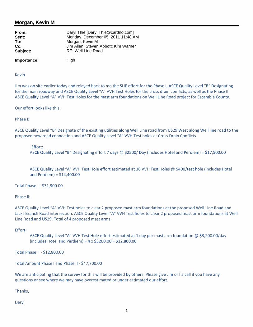
From: Daryl Thie [[email protected]]Sent: Monday, December 05, 2011 11:48 AMTo: Morgan, Kevin MCc: Jim Allen; Steven Abbott; Kim WarnerSubject: RE: Well Line Road
Importance: High
Kevin Jim was on site earlier today and relayed back to me the SUE effort for the Phase I, ASCE Quality Level “B” Designating for the main roadway and ASCE Quality Level “A” VVH Test Holes for the cross drain conflicts; as well as the Phase II ASCE Quality Level “A” VVH Test Holes for the mast arm foundations on Well Line Road project for Escambia County. Our effort looks like this: Phase I: ASCE Quality Level “B” Designate of the existing utilities along Well Line road from US29 West along Well line road to the proposed new road connection and ASCE Quality Level “A” VVH Test holes at Cross Drain Conflicts. Effort:
ASCE Quality Level “B” Designating effort 7 days @ $2500/ Day (includes Hotel and Perdiem) = $17,500.00
ASCE Quality Level “A” VVH Test Hole effort estimated at 36 VVH Test Holes @ $400/test hole (includes Hotel and Perdiem) = $14,400.00
Total Phase I ‐ $31,900.00 Phase II: ASCE Quality Level “A” VVH Test holes to clear 2 proposed mast arm foundations at the proposed Well Line Road and Jacks Branch Road intersection. ASCE Quality Level “A” VVH Test holes to clear 2 proposed mast arm foundations at Well Line Road and US29. Total of 4 proposed mast arms. Effort:
ASCE Quality Level “A” VVH Test Hole effort estimated at 1 day per mast arm foundation @ $3,200.00/day (includes Hotel and Perdiem) = 4 x $3200.00 = $12,800.00
Total Phase II ‐ $12,800.00 Total Amount Phase I and Phase II ‐ $47,700.00 We are anticipating that the survey for this will be provided by others. Please give Jim or I a call if you have any questions or see where we may have overestimated or under estimated our effort. Thanks, Daryl

2
Daryl I. Thie, PLS Cardno TBE Senior Project Manager 725 SE Baya Drive, Suite 106 Lake City, FL 32025 Phone: 386.755.2626 Extension: 201 Cell: 904.509.0378 Fax: 386.755.2507 Email:[email protected] Web:www.CardnoTBE.com
From: Jim Allen Sent: Tuesday, November 29, 2011 6:57 PM To: Daryl Thie; Steven Abbott Subject: Fwd: Well Line Road New project with Atkins. Thanks, Jim Sent from my Verizon Wireless Phone
----- Forwarded message ----- From: "Morgan, Kevin M" <[email protected]> Date: Tue, Nov 29, 2011 3:30 pm Subject: Well Line Road To: "Jim Allen" <[email protected]>
Jim, We are working on a scope and fee for Well Line Road Extension for Escambia County. Well Line Road is located Jacks Branch Road and US 29 in the northwestern part of the County. The County is proposing to extend the existing road to Jacks Branch Road. As part of our scope we will prepare a Phase 1 design which will be a 30% set of plans (30% plans will be more like a 60% design). Phase 2 will be to take the plans to 100% submittal. The plans will include widening the existing roadway to standard lanes with shoulders, culvert replacements, and intersection improvements. Through the undeveloped area to Jacks Branch Road will be a 2 lane typical with a median. I need a Phase 1 and 2 scope. Phase 1 is to locate the utilities along the existing roadway and for the intersection of US 29 and also Jacks Branch. Phase 2 would be mast arms at both intersections and any other items that you can think of to get to 100%. Attached is a map (36x60) of the project. Dark Along Well Line the dark purple is proposed and the pink is existing. Note that there are several wells located along the roadway which may have transfer pipes which will need to be located. Kevin M. Morgan, P.E. Senior Engineer - Transportation Design ATKINS 2114 Airport Boulevard, Suite 1450, Pensacola, Florida, 32504 | Tel: +1 (850) 478 9844 Ext. 4561236 | Fax: +1 (850) 478 0620 | Cell: +1 (850) 596 1502 | Email: [email protected] | Web: www.atkinsglobal.com/northamerica www.atkinsglobal.com This electronic mail communication may contain privileged, confidential, and/or proprietary information which is the property of The Atkins North America

3
Corporation, WS Atkins plc or one of its affiliates. If you are not the intended recipient or an authorized agent of the intended recipient please delete this communication and notify the sender that you have received it in error. A list of wholly owned Atkins Group companies can be found at http://www.atkinsglobal.com/site-services/group-company-registration-details Consider the environment. Please don't print this email unless you really need to. _____________________________________________________________________ This message has been checked for all known viruses by MessageLabs.

Scope of Services
Well Line Road Widening/Construction Project
Environmental Services
December 6, 2011
This scope addresses environmental permitting and supporting activities for the Escambia County’s (EC) proposed Well Line Road Widening/Construction Project, located in Sections 3, 4, 5 Township 1N, Range 31W, Escambia County, Florida. The following activities are described in relation to roadway design features under consideration by the ATKINS Transportation Design Group, herein referred to in this document as the ATKINS project manager. The proposed project area will encompass improvements along existing Well Line Road to five (5) culvert crossings, and construction of approximately three (3) additional culvert/bridge crossings for the new section of Well Line Road. ATKINS Environmental will complete Northwest Florida Water Management District (NWFWMD) Florida Department of Environmental Protection (FDEP) Environmental Resource Permit (WRP) and U.S. Army Corps of Engineers (USACE) permitting activities for the Well Line Road Resurfacing Project, to include the following subtask items:
1. Prepare and submit request to NWFWMD/FDEP/USACE for gyro‐trac clearing of proposed new Well Line Road alignment for survey access.
2. Conduct onsite wetland jurisdictional determination for proposed Well Line Road surveying wetlands within the entire 100’ ROW area.
3. Prepare a wetland functional assessment (UMAM) for potential wetland impact areas within the Well Line Road Project area.
4. Attend a pre‐application meeting with EC, ATKINS project manager, NWFWMD/FDEP and/or USACE, if appropriate;
5. Conduct coordination with the ATKINS project engineer; 6. Prepare and submit Joint Application for Environmental Resource Permit for both existing
and proposed improvements; 7. Conduct agency site visits; Conduct limited agency coordination. 8. Prepare one (1) response each to Requests for Additional Information (RAIs) from USACE
and NWFWMD/FDEP;
Task 1: Request for clearing (Gyro‐Trac) impacts for survey access from NWFWMD/FDEP/USACE
ATKINS Sciences Staff will prepare and submit the Joint Application for Environmental Resource Permit/Authorization to Use State‐Owned Submerged Lands/Federal Dredge and Fill Permit in Northwest Florida and supporting documentation as a request for temporary wetland impacts associated with the clearing through gyro‐trac for survey access through the proposed 100’ Well Line Road alignment.

Task 2: Jurisdictional Wetland Delineation
ATKINS Sciences Staff will conduct a wetland jurisdictional determination to delineate the limits of wetlands within the proposed project limits, based on right‐of‐way data/project limit information provided by the ATKINS project manager identifying the specific project area.
ATKINS Sciences Staff shall set flags at the location of the jurisdictional wetland boundary as determined by biological and physical wetland indicators (hydrophytic vegetation, hydric soils and hydrology). All flags will be labeled and their position recorded with a Trimble Pro XR Global Positioning System (GPS), a sub‐meter accuracy instrument. The ATKINS project manager is responsible for surveying the locations of any flagged wetland delineation markers. ATKINS will coordinate with the survey contractor to ensure all wetland boundary markers are surveyed, however, ATKINS will not be responsible for creating a specific purpose survey.
Task 3: Wetland Functional Assessment (UMAM)
ATKINS Sciences Staff will prepare a wetland functional assessment, if required, of the project site using UMAM for NWFWMD/FDEP and the USACE. The Uniform Mitigation Assessment Method (UMAM) is used to quantify proposed wetland impacts and assess functional loss to determine sufficient compensation. The UMAM method is then applied to quantify whether wetland functions gained from proposed mitigation will be sufficient to compensate for wetland impacts. UMAM data is further analyzed for USACE and NWFWMD/FDEP based on the unified wetland methodology and discount rates for time lag, preservation factor, and risk. Assessment areas within the project site will be classified using Florida Land Use, Cover, and Forms Classification System (FLUCFCS) types. In addition, this assessment will include a secondary/indirect impact analysis which is required by the USACE. The secondary impact analysis requires extensive GIS processing and evaluation of adjacent wetland habitats, which are included in the UMAM assessment.
Task 4: NWFWMD/FDEP Environmental Resource Permit (ERP) and USACE 404 Permitting
ATKINS Sciences Staff will prepare and submit the Joint Application for Environmental Resource Permit/Authorization to Use State‐Owned Submerged Lands/Federal Dredge and Fill Permit in Northwest Florida and supporting documentation to the agencies on behalf of Escambia County. The permit application will include permit drawings, as required by the agencies. Permit drawings will be provided by the ATKINS project manager. All planning, survey, and design files provided by the ATKINS project manager will be submitted in State Plane Florida North Zone, NAD83 (Feet). Escambia County will be responsible for all permitting fees₁.
ATKINS Sciences Staff will conduct coordination with the ATKINS project manager throughout the permitting process to address engineering and design related aspects of wetland impact avoidance and
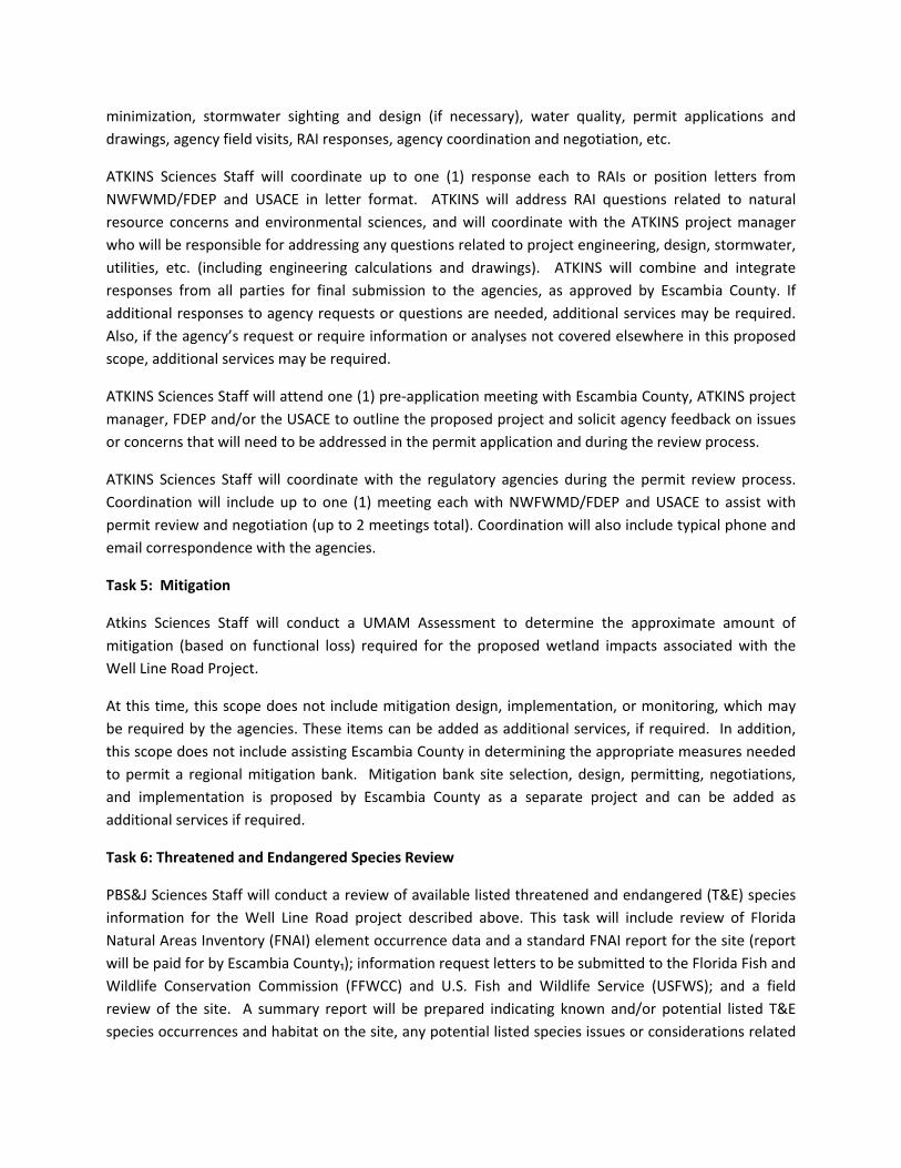
minimization, stormwater sighting and design (if necessary), water quality, permit applications and drawings, agency field visits, RAI responses, agency coordination and negotiation, etc.
ATKINS Sciences Staff will coordinate up to one (1) response each to RAIs or position letters from NWFWMD/FDEP and USACE in letter format. ATKINS will address RAI questions related to natural resource concerns and environmental sciences, and will coordinate with the ATKINS project manager who will be responsible for addressing any questions related to project engineering, design, stormwater, utilities, etc. (including engineering calculations and drawings). ATKINS will combine and integrate responses from all parties for final submission to the agencies, as approved by Escambia County. If additional responses to agency requests or questions are needed, additional services may be required. Also, if the agency’s request or require information or analyses not covered elsewhere in this proposed scope, additional services may be required.
ATKINS Sciences Staff will attend one (1) pre‐application meeting with Escambia County, ATKINS project manager, FDEP and/or the USACE to outline the proposed project and solicit agency feedback on issues or concerns that will need to be addressed in the permit application and during the review process.
ATKINS Sciences Staff will coordinate with the regulatory agencies during the permit review process. Coordination will include up to one (1) meeting each with NWFWMD/FDEP and USACE to assist with permit review and negotiation (up to 2 meetings total). Coordination will also include typical phone and email correspondence with the agencies.
Task 5: Mitigation
Atkins Sciences Staff will conduct a UMAM Assessment to determine the approximate amount of mitigation (based on functional loss) required for the proposed wetland impacts associated with the Well Line Road Project.
At this time, this scope does not include mitigation design, implementation, or monitoring, which may be required by the agencies. These items can be added as additional services, if required. In addition, this scope does not include assisting Escambia County in determining the appropriate measures needed to permit a regional mitigation bank. Mitigation bank site selection, design, permitting, negotiations, and implementation is proposed by Escambia County as a separate project and can be added as additional services if required.
Task 6: Threatened and Endangered Species Review
PBS&J Sciences Staff will conduct a review of available listed threatened and endangered (T&E) species information for the Well Line Road project described above. This task will include review of Florida Natural Areas Inventory (FNAI) element occurrence data and a standard FNAI report for the site (report will be paid for by Escambia County₁); information request letters to be submitted to the Florida Fish and Wildlife Conservation Commission (FFWCC) and U.S. Fish and Wildlife Service (USFWS); and a field review of the site. A summary report will be prepared indicating known and/or potential listed T&E species occurrences and habitat on the site, any potential listed species issues or considerations related

to site development, and recommendations for any more detailed species‐specific surveys or listed species permitting that may be required (if any). Field work / site visits under this scope will be limited to two (2) field days, surveying the proposed ROW/project area collecting data on any observed listed species. The scope for this task does not include specialized surveys or monitoring of particular listed species, seasonal surveys, agency coordination (other than the information request letters described above), listed species permitting or approvals, or any listed species mitigation activities.
If listed species, such as gopher tortoise, are observed within the project area, Atkins Sciences can perform any permitting, relocation or mitigation activities as required by the wildlife agencies. These activities can be added as additional services, if required.
Additional Information
This scope does not include listed species consultations, permitting, monitoring, management plans, or mitigation plans for listed species. Also, this scope does not include an environmental assessment, which is typically completed for the USACE based on project submittals (for NEPA compliance).
Finally, this scope does not include mitigation design, implementation, or monitoring, which may be required by the agencies. Additional mitigation bank design, negotiations, implementation, and site selection will be conducted with Escambia County as a separate project. These items can be added as additional services if required.

Deliverables under this task are:
ATKINS Sciences shall:
1) Prepare and submit a gyro‐trac/ clearing request to FDEP/NWFWMD/USACE for survey access.
2) Set flags at the location of the jurisdictional wetland boundary.
3) Attend a pre‐application meeting/site visit
4) Complete an ERP Joint Application for Works in Waters of the State
5) Prepare RAI responses (up to 1 per agency, 2 total);
6) Complete a threatened and endangered species review summary report
Estimated Fee Summary by Task ₂ Phase I Phase IB
1) Request Package for Survey Clearing $3,348 ‐‐
2) Jurisdictional Wetland Delineation $14,267 $1,946
3) UMAM Assessment $5,748 $784
4) NWFWMD/FDEP ERP and USACE Permitting $30,957 $4,222
5) Mitigation Assessment ‐‐ ‐‐
6) Threatened and Endangered Species Review $8,020 $1,094
Subtotal $62,340 $8,046
Expenses $2,200 $300
Total $64,540 $8,346
1 Permit Application fees, FNAI Report fees, and printing of permit and/or construction plan sets have not been included and shall be billed separately.
2 Tasks have been estimated and any overage/underage shall be applied to the remaining tasks.
Related Documents