Well Drilling in Sub Saharan Africa Dokimoi Ergatai Water Access Group Final Design Report May 11, 2007 Advisor: Dr. Whitmoyer Group Members: Erik Blosser Brian Syvertson Thomas Betteridge

Welcome message from author
This document is posted to help you gain knowledge. Please leave a comment to let me know what you think about it! Share it to your friends and learn new things together.
Transcript

Well Drilling in Sub Saharan Africa
Dokimoi Ergatai Water Access Group
Final Design Report May 11, 2007
Advisor: Dr. Whitmoyer
Group Members: Erik Blosser
Brian Syvertson
Thomas Betteridge
Abstract
In many developing countries throughout the world, water is a scarce resource. Often,
limited water sources cause hours of traveling a day or difficulties in growing crops during the
dry season. Alleviation of this problem is achieved through the design of an inexpensive well
drilling system. In order for the system to be sustainable it must be easily reproducible and use
materials which are available to rural West Africa. This project will continue the work begun by
a previous senior project on a percussion well drilling system. The current project focuses on the
manufacturability of the well drilling components, reducing the cost, and using appropriate
materials in the rig construction. The team consists of team leader Thomas Betteridge and team
members Brian Syvertson and Erik Blosser. The Faculty Advisor for the project is Dr. Timothy
Whitmoyer.
2

Table of Contents
Acknowledgments …………………………………………………………………… 4 1) Introduction 1.1 Problem ………………………………………………………………………………. 5 1.2 Objectives …………………………………………………………………………….. 5 1.3 Literature Review …………………………………………………………………….. 5 1.4 Solution ………………………………………………………………………………. 7 2) Design Process 2.1 Rig Frame …………………………………………………………………………….. 8 2.2 Clay Cutter ……………………………………………………………………………. 8 2.3 Rock Bit ………………………………………………………………………………. 9 2.4 Bailer …………………………………………………………………………………. 9 2.5 Jar and Jar Loops ……………………………………………………………………... 9 3) Implementation 3.1 Construction ………………………………………………………………………….. 10 3.1.1 Rig Frame …………………………………………………………………………... 10 3.1.2 Clay Cutter …………………………………………………………………………. 11 3.1.3 Rock Bit …………………………………………………………………………….. 12 3.1.4 Bailer ……………………………………………………………………………….. 12 3.1.5 Jar and Jar Loops …………………………………………………………………… 12 3.2 Operation ……………………………………………………………………………... 13 3.2.1 Siting ……………………………………………………………………………….. 13 3.2.2 Setup ………………………………………………………………………………... 13 3.2.3 Drilling ……………………………………………………………………………… 14 3.2.4 Finishing ……………………………………………………………………………. 14 3.3 Evaluation and Testing ……………………………………………………………….. 15 4) Schedule …………………………………………………………………………….. 16 5) Budget ……………………………………………………………………………….. 17 6) Conclusions 6.1 Level of Success ……………………………………………………………………… 20 6.2 Comments on Objectives …………………………………………………………….. 20 6.3 Lessons Learned ……………………………………………………………………… 20 7) Future Work ………………………………………………………………………. 21 8) References ………………………………………………………………………….. 22 Appendix A. Rock Bit Specifications B. Gantt Chart C. CAD Drawings D. Construction and Drilling Procedure Manual
3

Acknowledgements
Dr. Whitmoyer Advice and recommendations, knowledge of dynamics
Dr. Pratt General project guidance
John Meyer Manufacturing insight, facilities management
Dr. Vader Project focus, knowledge of mechanical systems and
appropriate technology
Dr. Van Dyke knowledge of mechanical design, and finite-element
analysis
Anthony Beers Knowledge from last years project and guidance for
improvement
Joseph Longnecker Consulting on Burkina Faso materials
Professor Erickson Drilling location
4

1) Introduction 1.1 Problem
Seventy percent of Africa’s poor live in rural areas and are dependent on agriculture for
their food and income. The problem is that Africa is arid in many areas therefore farmers do not
have enough water to grow large crops or to drink. The solution seems simple; drill more wells.
The problem is that most of the farmers live on less than two dollars a day. This means that they
cannot afford their own personal well. We set out to find a way to make an affordable well
drilling process so that farmers could use it and increase their crop size and have adequate
drinking water. The increased crop size would allow them to escape the poverty that they have
been trapped inside and it will also help to alleviate the malnutrition in the continent.
1.2 Objectives
1. Redesign the rig components using only materials locally available in Burkina Faso.
2. Simplify the frame design so that complicated cuts using a horizontal milling machine are
unnecessary.
3. Redesign the rock bit, reducing the weight to less than 100 pounds.
4. Reduce the total amount of welding necessary by 30%.
5. Keep the well drilling rig cost under $400 US.
6. Construct a well with a well casing and a water output of 50 gallons per hour.
7. Write a series of procedures for manufacturing the redesigned parts, the correct method
of rig use, and the well construction.
1.3 Literature Review
The technique used in percussion well drilling has been used for the past four thousand
years. The early Chinese used this method coupled with bamboo tools to drill wells of 3000 ft
depth. A modern rig the Bycrus- Erie model 22-w was equipped with a diesel engine and a large
pitman arm to create the necessary vertical motion. This rig was towed behind a truck. A lot of
other designs mount the rig on the back of trucks making the technology very mobile. This
mobility comes at the cost of being unable to operate in adverse terrain. The most innovative
design, the down in the hole hammer method, uses a heavy tool which is lowered into the
borehole and has a flat plate covered with carbide buttons that rotate and move up and down
5
rapidly to remove anything in its path. The design uses a blast of air to bring the crushed rock to
the surface.
Many crude forms of percussion drilling have been implemented over the centuries. In
Pennsylvania, early oil prospectors created percussion rigs by combining the crook of an oak tree
with a pine log. A cable was attached to the free end of the log and then many smaller cables
were attached to the main line so that many men could manually operate the rig simultaneously.
The resulting reciprocal motion was able to penetrate the bedrock into the oil producing layers.
Motorized shell auger rigs are standard equipment in many geotechnical studies preformed by
environmental engineers and civil. This rig design is very versatile, robust, and portable.
Conventional bits and bailers are use with U-100 tubes to retrieve undisturbed soil samples for
field testing in laboratory settings. This provides ways for soil mechanics tests, aquifer surveys,
and well contamination testing to be achieved. Companies have produced light weight, portable,
and motorized rigs for the purpose of arid zone well construction. One rig designed by Consallen
is sturdy, small and requires little fuel to run. To increase sustainability many organizations have
produced configurations of hand powered drilling equipment. Hand auguring rigs seem to have
taken their form from the shell and auger rigs. These auger rigs often use a form of percussion
drilling like bailing as a secondary means of making progress through various soils. Percussion
systems have been designed for development work by native peoples and missionaries. These
rigs usually consist of a crude tripod and drill strings made from salvaged steel parts welded
together. The “spudding” motion is achieved by a team of villagers pulling directly on the cable
with one end tied to an immovable object like a tree and the other going over a pulley at the top
of the tripod and then down into the borehole to the drilling tool.
We found that many materials that are very common and inexpensive in the US are very
hard to obtain in rural West Africa. If materials are hard to obtain they are very expensive. We
did extensive research to find materials that are inexpensive in rural West Africa. We found that
angle iron and rebar are two of the most inexpensive choices for materials. Pipe, especially of a
large diameter, can be very expensive. Solid bar stock is also very expensive and should not be
used if it can be prevented. Pulleys may not be available in rural West Africa, but bicycles were
found to be in great abundance. So a design that utilizes a bicycle rim would be better than a
traditional manufactured pulley.
6

We found that many of the farmers in rural West Africa live on less than $2 a day. In
Burkina Faso the figure is less than $1 a day. The drilling methods that are currently used in rural
West Africa are expensive due to the materials or rigs needed for the drilling process. Simple
percussion well drilling apparatuses have been produced, but are very crude in nature. These
designs are untested before use and therefore pose a safety hazard. We are designing our rig to be
similar to the simple percussion well drilling apparatuses, but it will have the testing and analysis
needed for safe operation.
We are refining the current rig so that it falls between the shell and auger rigs and the
before mentioned development rigs. We increased the manufacturability of the tripod using local
parts and available technology. Currently there is a great need for a low cost efficient percussion
well-drilling rig in West Africa. Our project will fully satisfy this need and allow many farmers
to increase their crop yield due to the increased irrigation abilities. Since percussion type drilling
has been around for hundreds of years, the drilling process has been refined leaving only room to
make improvements on the tools used to drill the well. Our goal is to make efficient and durable
components that are comparable to modern bits that are currently on the market.
1.4 Solution
We have developed and manufactured a rig design that meets the needs of farmers in
rural West Africa. The rig has been made from materials that are available in rural West Africa
and requires simple manufacturing processes. The rig cost was kept low to make it an affordable
option for farmers. The rig can be utilized to drill many wells before repair or replacement of the
components, therefore the cost per well for the rig can be greatly reduced from the actual cost to
manufacture the rig. We were able to reduce the welding in our design by 67% compared to last
years design. This decrease in welding will allow for faster and more economical manufacture of
our rig. Large amounts of welding in rural West Africa can be hard to accomplish, because the
electrical grid is not adequate enough to allow for large draws of amperage at one time. If a
generator is going to be used, we wanted to reduce the amount of fuel used during the
manufacturing process for the rig. We were able to design and manufacture a rig that could be
reproduced by anyone with mechanical intuition in rural West Africa.
7

2) Design Process 2.1 Rig Frame
The frame has been redesigned to fix several problems in the previous project’s design,
which required the use of a horizontal milling machine and wooden legs. A horizontal milling
machine is not commonly found in Burkina Faso, and would therefore hinder the local
manufacturing of the rig. Additionally, large wooden posts are uncommon in parts of Burkina
Faso due to the deforestation and small trees. Termites could also cause a problem, reducing the
durability of the legs or requiring an extra coating. In order to solve these problems, we
redesigned the frame to have legs made of steel pipe and only cuts for perpendicular holes. We
made straw models to help us analyze the designs we were considering (see EDR). We decided
on a three-legged design made from ten foot sections of two inch pipe. In order to get a tripod-
like form, and eliminate the need for a horizontal milling machine, two of the legs were bent to
thirty degrees, one foot from the end of the pipe. All three legs had one inch holes drilled into
them near the top of the legs in order to allow a cross pin to slide through and connect the frame
together. The cross pin was made of three ½ inch rebar pieces, each one foot long, welded
together in a triangle. On one end of the pin, the rebar has a plate welded to it to prevent the pin
from sliding completely through the holes in the legs. A cotter pin was placed through the cross
pin in order to hold the frame in place. We ran rough calculations to see if the pin would hold
and found that it would easily hold the amount of weight that it would be subjected to.
2.2 Clay Cutter
The clay cutter also needed to be redesigned due to some flaws in the previous design.
Last year’s clay cutter was made of five pipes of one inch diameter welded together with a
cutting shoe at the bottom. This design was chosen because the project group happened to have
the one inch pipes left over from another project. However, purchasing new one inch pipes
would prove too expensive. Another problem was that the cutting shoe fell off during drilling
and had to be reattached. To fix these problems, we designed the clay cutter to be made of two
four foot lengths of two inch angle iron. The two angle iron were welded together lengthwise in a
cross shape. Their corners were overlapped a half an inch to provide a large enough surface for
welding. At the bottom of the angle iron, four steel plates were welded on in order to extend the
“arms” of the cross. These plates extend out to three inches from the center of the cross. Around
8
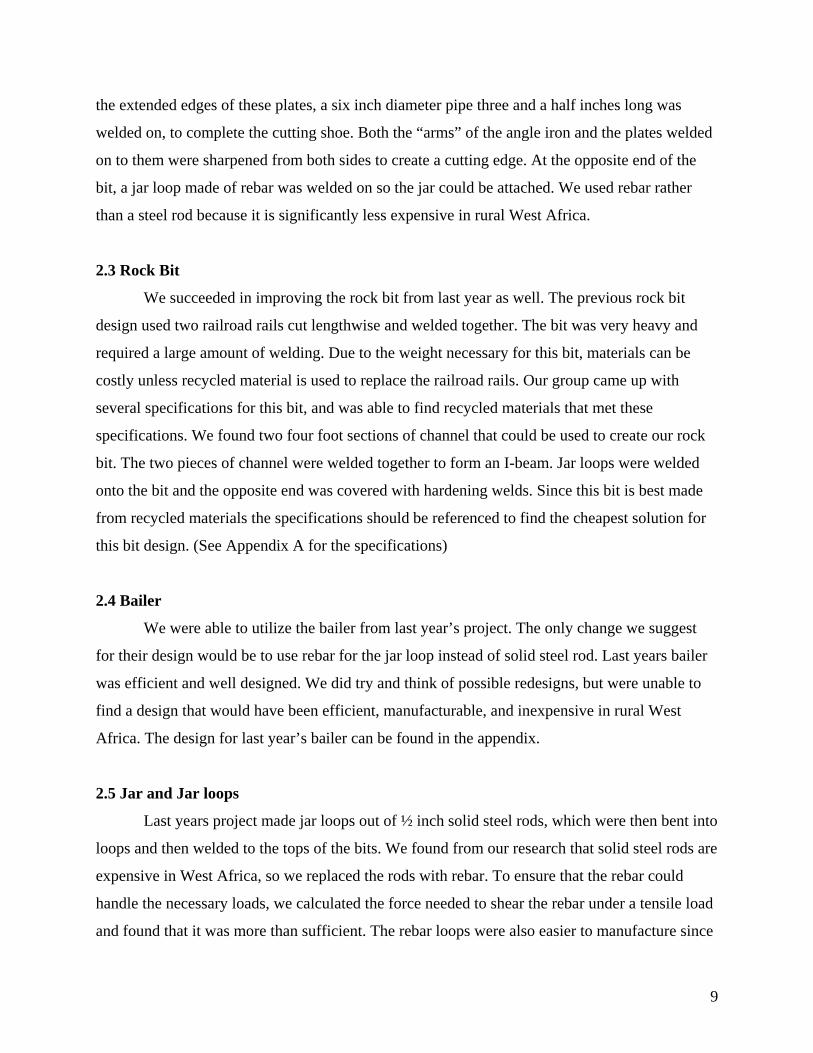
the extended edges of these plates, a six inch diameter pipe three and a half inches long was
welded on, to complete the cutting shoe. Both the “arms” of the angle iron and the plates welded
on to them were sharpened from both sides to create a cutting edge. At the opposite end of the
bit, a jar loop made of rebar was welded on so the jar could be attached. We used rebar rather
than a steel rod because it is significantly less expensive in rural West Africa.
2.3 Rock Bit
We succeeded in improving the rock bit from last year as well. The previous rock bit
design used two railroad rails cut lengthwise and welded together. The bit was very heavy and
required a large amount of welding. Due to the weight necessary for this bit, materials can be
costly unless recycled material is used to replace the railroad rails. Our group came up with
several specifications for this bit, and was able to find recycled materials that met these
specifications. We found two four foot sections of channel that could be used to create our rock
bit. The two pieces of channel were welded together to form an I-beam. Jar loops were welded
onto the bit and the opposite end was covered with hardening welds. Since this bit is best made
from recycled materials the specifications should be referenced to find the cheapest solution for
this bit design. (See Appendix A for the specifications)
2.4 Bailer
We were able to utilize the bailer from last year’s project. The only change we suggest
for their design would be to use rebar for the jar loop instead of solid steel rod. Last years bailer
was efficient and well designed. We did try and think of possible redesigns, but were unable to
find a design that would have been efficient, manufacturable, and inexpensive in rural West
Africa. The design for last year’s bailer can be found in the appendix.
2.5 Jar and Jar loops
Last years project made jar loops out of ½ inch solid steel rods, which were then bent into
loops and then welded to the tops of the bits. We found from our research that solid steel rods are
expensive in West Africa, so we replaced the rods with rebar. To ensure that the rebar could
handle the necessary loads, we calculated the force needed to shear the rebar under a tensile load
and found that it was more than sufficient. The rebar loops were also easier to manufacture since
9

rebar is a more ductile material than the solid steel rods were. We did not need to heat the rebar
to bend it around the jig.
3) Implementation
3.1 Construction The construction of our rig was a learning process from the very beginning. This section
will describe some of the problems we faced in construction, and the changes we had to make to
our designs. It will also show decisions we made on how to best manufacture the components.
For specific instructions on constructing our rig, please see The Construction and Drilling
Procedure Manual in Appendix D.
3.1.1 Frame
During the frame construction we encountered a few problems. First we found that the
mechanical pipe bender was not capable of bending 2 inch pipe. This is not because it did not
have the correct bending dies, but because enough of a mechanical advantage could not be
produced to put enough force on the pipe to bend it. We had three guys pulling on a 4 foot lever
arm and the pipe did not bend. We went then decided to use a torch to heat up the pipe to allow
for easier bending. We used a test piece of 2 inch pipe to better understand how the heating
would affect the bending process. We found that the pipe bent much easier when it was heated.
It only required one person when the pipe was heated. We kinked the test pipe during this bend
so we then decided to use 1 inch pipe to better understand the bending process. We found that
you can only bend the pipe to ¾ of the dies radius. If you bend more than this the pipe tends to
kink. We then applied the knowledge we found from the two tests and were able to successfully
bend the 2 inch pipes with the help of the torch. We designed an apparatus to help us determine
when the pipes had been bent to 30 degrees. This was just 2, 2ft long boards nailed together at
30 degrees from each other. This allowed us to quickly determine the angle of the bent pipes.
The second problem we encountered was that we could not use the drill press to drill the
1 1/8 inch holes for the cross pin. This was because, with the bends in the pipe, there was no
way to stabilize the pipes for the drilling process. We solved this by returning to the traditional
hand drill. We clamped pipes to either side of the pipe to prevent rolling and then someone
supported the pipe at the other end. The person doing the drilling used a punch to give a place to
10

start the hole. This method worked well and produced relatively straight holes. The drill press
would have been more accurate, but this piece of machinery in West Africa would have been
hard to find. Using a hand drill was similar to what would be done in West Africa.
The original design for the pulley we found was not feasible if a pulley was unavailable.
Since we wanted the rig to be versatile and to be made from locally available materials and parts,
we wanted to be able to incorporate a bicycle rim. We quickly saw once the frame was erected
that our idea of hanging the rim off the top pin with pieces of angle iron was impractical. We had
to then brainstorm and come up with an appropriate redesign. We decided upon welding
brackets to the frame legs. This would limit the amount of material needed and also put the force
directly into the two legs that would hold the forces. We then had to figure out the optimum
location of the brackets and after some trial and error with cardboard brackets on the set up rig,
we found the ideal location. We then welded pieces of angle iron onto the legs and then drilled
the necessary holes to mount the bicycle rim.
To help hold the center leg down we developed an anchoring system. This was
comprised of five pieces of rebar. Four of the pieces were bent into a U shape, these were the
stakes. We then drilled a ¾ inch hole in the bottom of the center leg so that we could insert the
straight rebar piece. The stakes are then driven down into the soil anchoring the cross pin of
rebar and the center leg.
3.1.2 Clay Cutter
We encountered a small design snag during the construction of the clay cutter. Welding
the two pieces of angle iron together was not an issue, but we found that we had beads of weld
right where we needed to weld the extender plates. The extender plates were supposed to be
butted right against the angle iron and make the fins large enough to hit the inside of the 6 inch
pipe used for the cutting shoe. The problem we quickly found was that during the design process
we did not consider the space needed for the weld. We were able to quickly solve this issue by
reducing the length of the extender plates. After consulting John Meyer we used filler welding
rods to fill in the large gap that was created between the edge of the angle iron and the extender
plates. We used deep penetrating rods on the other sides. Now we know to consider how things
will be manufactured when we are designing a component.
11
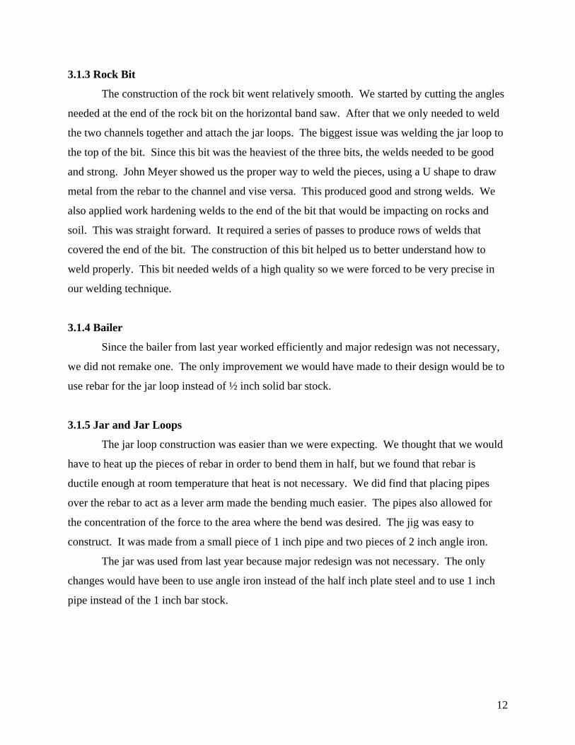
3.1.3 Rock Bit
The construction of the rock bit went relatively smooth. We started by cutting the angles
needed at the end of the rock bit on the horizontal band saw. After that we only needed to weld
the two channels together and attach the jar loops. The biggest issue was welding the jar loop to
the top of the bit. Since this bit was the heaviest of the three bits, the welds needed to be good
and strong. John Meyer showed us the proper way to weld the pieces, using a U shape to draw
metal from the rebar to the channel and vise versa. This produced good and strong welds. We
also applied work hardening welds to the end of the bit that would be impacting on rocks and
soil. This was straight forward. It required a series of passes to produce rows of welds that
covered the end of the bit. The construction of this bit helped us to better understand how to
weld properly. This bit needed welds of a high quality so we were forced to be very precise in
our welding technique.
3.1.4 Bailer
Since the bailer from last year worked efficiently and major redesign was not necessary,
we did not remake one. The only improvement we would have made to their design would be to
use rebar for the jar loop instead of ½ inch solid bar stock.
3.1.5 Jar and Jar Loops
The jar loop construction was easier than we were expecting. We thought that we would
have to heat up the pieces of rebar in order to bend them in half, but we found that rebar is
ductile enough at room temperature that heat is not necessary. We did find that placing pipes
over the rebar to act as a lever arm made the bending much easier. The pipes also allowed for
the concentration of the force to the area where the bend was desired. The jig was easy to
construct. It was made from a small piece of 1 inch pipe and two pieces of 2 inch angle iron.
The jar was used from last year because major redesign was not necessary. The only
changes would have been to use angle iron instead of the half inch plate steel and to use 1 inch
pipe instead of the 1 inch bar stock.
12

3.2 Operation This section describes the total operation of our drilling rig. It talks about siting, setup,
drilling, and finishing. For a more detailed procedure of the setup and drilling please refer to the
Construction and Drilling Procedure Manual in Appendix D.
3.2.1 Siting
The first step for operating a percussion well drilling system is to site a proper location.
Siting is a process that determines the best possible place to drill, and finding out what exactly
you are drilling into. This starts with researching geographical maps of the area, if possible, to
determine what kind of soil is in the ground at your site. Next you may want to drill a small
borehole to analyze the different soil you have and to locate the depth of the water table.
For the purposes of our project, we simplified this process. The main goal for our project
was the test our rig, so siting the perfect site was not a high priority for this year. We found few
geological maps of Messiah College to see what was in the ground. After looking over these and
knowing that last year’s project ran into problems with rocks on campus grounds, we decided to
find another drilling location. As college students confined to this area, our possibilities were
limited. However, we were able to find land to use at Professor Erikson’s farm. The most
important step for siting our location was to find a spot where we had enough space to setup and
operate the rig. In addition, we needed room to put our bits and other materials aside. After
choosing a spot with ample space, the next step is to setup the rig.
3.2.2 Setup
The setup of our rig is a quick and simple process. It can be assembled for the first time
in less than 10 minutes, or in as little as 5 minutes if you’ve done it before. The only tools you
need are a socket and a wrench, or two wrenches if a socket is not available, and a posthole
digger. You may need a hammer or mallet, but a cinderblock or the rock bit can be used just as
easily. Additionally, you will want to set aside a 5-gallon bucket of water to be used in creating
the proper soil consistency at the bottom of the hole. Once the rig is set up, and a preliminary
borehole is made, we are ready to start drilling.
13

3.2.3 Drilling
The drilling process in percussion well drilling is referred to as spudding. This is the
process by which the rope is pulled on, and a bit is lifted and lowered in and out of the soil at the
bottom of the hole. The same process occurs for all the bits. The clay cutter will break up softer
soils, whereas the rock bit will break up rocks and sandstone. The spudding of the bailer will
remove the broken up material at the bottom of the hole. One person easily operated our clay
cutter, however it became very tiring after just a few minutes. We suggest using at least two or
three people. The bailer and the rock bit are heavier, so more people will be needed to help with
those as well. We suggest using at least three people. However, it is important to realize that the
more people you use, the more coordination between them you will need. The more controlled
the drilling process is, the easier and more efficient that it will be. It needs to be noted that a
work casing may need to be used if the soil being drilled through is extremely prone to cave-ins.
3.2.4 Finishing
To allow for a serviceable well, it is necessary to implement a well casing. For this
application, PVC pipe would be the best material to use. First you need to cut slits in the bottom
of the pipe to create a well screen. The well screen will act as a filter for the water entering the
pipe. Multiple sections of pipe are necessary to reach the bottom of hole. These sections may be
threaded, but can also be glued together. With the pipe in place, we need to fill the hole. The first
layer is stones. They should be poured in up to slightly above the water level and the well screen.
The next layer is clay, or soil you are drilling through. The final layer is cement. The cement
should be poured up to top of the hole, and then a cement ring is made around the top for
convenience and sanitary reasons. It allows people to rest their buckets on the cement rather than
on the ground.
14
3.3 Evaluation and Testing We were not able to perform the desired testing because there is no soil similar to West
Africa in the area. We would have like to test the rig in sandy soils, but we were only able to test
the rig in clay soils. Even though we were not able to test the rig in the appropriate soils, we still
were able to glean some valuable information. We drilled for over 20 hours and during this
entire time the frame showed no signs of fatigue or deflection. The bits performed well in the
poor soil and we were able to obtain a rate of approximately 2 feet per hour. We were only able
to maintain this rate for 6 feet because we hit a large rock and had issues with our well filling
with water. The well filled with water not because we hit the water table, but because the soil
where we were drilling did not drain and there had been a lot of rain.
The bits did not show signs of significant wear. The surfaces that were impacted did
become slightly deformed, but not to the point of needing repair.
We found during our testing of our rig that the jar needed to be slightly redesigned. The
problem was that our rope was being destroyed by the jar loops attached to the bits. This was
because we had attempted to weld rebar in the jar loops to prevent the jar top pin (where the rope
is attached) from impacting the jar loop, but since the welds were small and they were subjected
to a large amount of force they sheared off. Instead of trying to re-weld in the rebar pieces we
decided it would be easier to add a bar through the actual jar to protect the upper pin. This
required a hole drilled through the jar and then a rebar pieced place through the plates and
welded. This design did not place as much stress on the welds and also allowed us to produce a
larger weld because we could weld around the entire piece of rebar. We tested this design and
found that the rope was not impacted by the jar loop. The rebar piece that we welded into the jar
also was able to withstand the impacts that occurred between the rebar and the jar loop.
After testing last year’s bailer we found a possible redesign. It is not a major change, but
last years project utilized a 6 inch cutting shoe. This means that there is 6 inches between the
bottom of the bit and the one way valve. The problem that we were encountering was that since
the valve was so high there was too much broken up material at the bottom of the hole that was
not picked up by the bailer. If the cutting shoe was smaller, maybe 3 inches, it would be able to
pick up more material during each bailing operation. The 3 inch shoe would also offer enough
protection for the valve. We found that the pulley design that we implemented was very
efficient. The pulley worked well and showed no signs of failure. The only problem with the
15

design was that the rope tended to fall off the pulley while we were changing the bits or
emptying the bailer. The rope falling off was not a problem while drilling and was not hard to
put back on, but it did pose an annoyance. Larger sidewalls on the rim or some kind of a guard
would eliminate this problem.
We wanted to test the bailer in sandy soil so we dumped sand down our hole. We then
proceeded to bail the sand we dumped down back out from the hole. We found that the bailer
was able to pick up the sand adequately. More testing of the bailer should be performed but
through our testing we feel that the bailer will perform well in sandy soils.
The rock bit that was designed and manufactured was tested during the drilling process.
We were able to break up rocks of varying size with the rock bit. The bit showed no signs of
wear during the testing process. Further testing of the bit should be performed, but from the
testing that we performed it was adequate for percussion well drilling.
4) Schedule We began the year focusing on redesigning the bits from last year’s project. If we
accomplished this first, we would be able to test them on last year’s frame while making our
own. This way we could get testing started early, and still be constructing at the same time.
The time it took to manufacture the components of our rig took longer than we had
previously expected. When we attempted to build parts of the rig we needed to learn new skills,
like different welding techniques, which added to the total time. We also had trouble testing our
rig this past spring because of the poor weather we had. It seemed to rain or snow every time we
wanted to test our rig. The weather was completely outside our control so we had to try and plan
accordingly. When it rained we worked on our final design report or our final presentation so
that we were at least being productive. Our Gantt chart can be found in Appendix B. Here you
can see our projected time and the actual time that it took.
16

5) Budget The following tables show the materials we used to manufacture our rig, including two
separate costs. The first cost column is how much we paid for it (GIK=Gift in Kind), the second
column is how much we estimate that it would cost a normal person to purchase the exact
materials that we used for our drilling rig. Many materials can be recycled, or taken from scrap,
so that would decrease this cost even more.
Frame Cost to Us Source Actual Cost
30 ft of 2" pipe $90.00 Glosser Steel $90.00
15 ft rebar (pin, stakes) GIK MC Machine Shop $4.50
bike rim GIK MC Machine Shop $20.00
2 ft of 2” angle iron $4.00 Glosser Steel $4.00
cotter pin GIK 2006 Project $0.50
100 ft manilla rope $23.00 Knot and Rope Supply $23.00
scrap steel plate (pin) scrap MC Machine Shop $0.50
Total $117.00 $142.50
Clay Cutter Cost to Us Source Actual Cost
8 ft of 2” angle iron $16.00 Glosser Steel $20.00
6 in cutting shoe GIK MC Machine Shop $10.00
scrap plate steel GIK MC Machine Shop $15.00
jar loop - 4ft of ½” rebar GIK MC Machine Shop $1.20
Total $16.00 $46.20
Rock Bit Cost to Us Source Actual Cost
8 ft channel GIK Glosser Steel $28.00
jar loop - 4ft rebar GIK MC Machine Shop $1.20
Total $0.00 $29.20
17
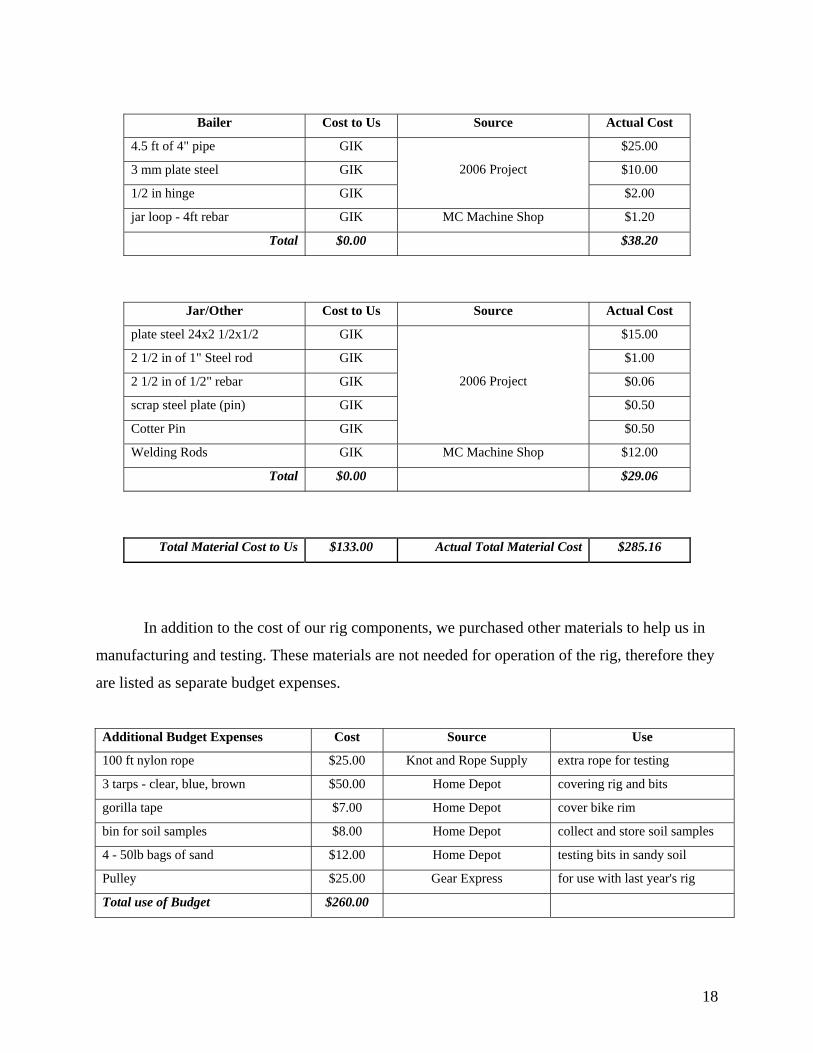
Bailer Cost to Us Source Actual Cost
4.5 ft of 4" pipe GIK $25.00
3 mm plate steel GIK $10.00
1/2 in hinge GIK
2006 Project
$2.00
jar loop - 4ft rebar GIK MC Machine Shop $1.20
Total $0.00 $38.20
Jar/Other Cost to Us Source Actual Cost
plate steel 24x2 1/2x1/2 GIK $15.00
2 1/2 in of 1" Steel rod GIK $1.00
2 1/2 in of 1/2" rebar GIK $0.06
scrap steel plate (pin) GIK $0.50
Cotter Pin GIK
2006 Project
$0.50
Welding Rods GIK MC Machine Shop $12.00
Total $0.00 $29.06
Total Material Cost to Us $133.00 Actual Total Material Cost $285.16
In addition to the cost of our rig components, we purchased other materials to help us in
manufacturing and testing. These materials are not needed for operation of the rig, therefore they
are listed as separate budget expenses.
Additional Budget Expenses Cost Source Use
100 ft nylon rope $25.00 Knot and Rope Supply extra rope for testing
3 tarps - clear, blue, brown $50.00 Home Depot covering rig and bits
gorilla tape $7.00 Home Depot cover bike rim
bin for soil samples $8.00 Home Depot collect and store soil samples
4 - 50lb bags of sand $12.00 Home Depot testing bits in sandy soil
Pulley $25.00 Gear Express for use with last year's rig
Total use of Budget $260.00
18
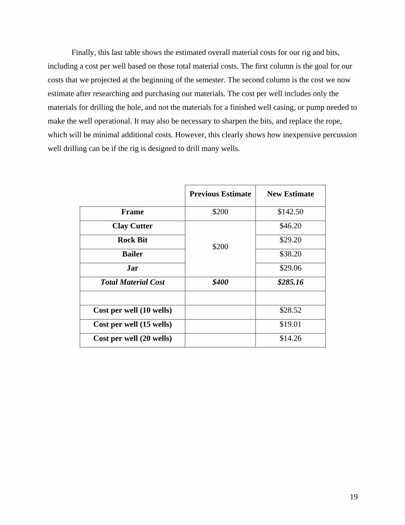
Finally, this last table shows the estimated overall material costs for our rig and bits,
including a cost per well based on those total material costs. The first column is the goal for our
costs that we projected at the beginning of the semester. The second column is the cost we now
estimate after researching and purchasing our materials. The cost per well includes only the
materials for drilling the hole, and not the materials for a finished well casing, or pump needed to
make the well operational. It may also be necessary to sharpen the bits, and replace the rope,
which will be minimal additional costs. However, this clearly shows how inexpensive percussion
well drilling can be if the rig is designed to drill many wells.
Previous Estimate New Estimate
Frame $200 $142.50
Clay Cutter $46.20
Rock Bit $29.20
Bailer $38.20
Jar
$200
$29.06
Total Material Cost $400 $285.16
Cost per well (10 wells) $28.52
Cost per well (15 wells) $19.01
Cost per well (20 wells) $14.26
19
6) Conclusion 6.1 Level of Success
The percussion well drilling team was able to design and manufacture a percussion well
drilling rig. We also were able to test the rig to ensure our design was feasible. We had a few
issues during the manufacture and testing phases, but nothing that was too hard for us to move
past. The biggest problem was the drill site that available to test our rig. It was not adequate for
our needs, but we did not have a good alternative. If we had more time a trip to a sandy area
would have been essential to furthering our testing, but since we only had a finite amount of time
it was acceptable that we were not able to achieve this.
6.2 Comments on Objectives
We were able to make our rig from locally available materials. We were able to redesign
our rig so that it used affordable materials in rural West Africa. Also the manufacture of our rig
is feasible in rural West Africa. The tools necessary to construct our rig can be found in rural
West Africa. We were successful in setting up specifications for the rock bit so that it can be
manufactured in rural West Africa at an affordable rate. We reduced the welding from last year
by 67%. Reducing the welding was very important to us because in rural West Africa it is
difficult to weld large beads. The electrical grid is not strong enough to sustain the large
amperage draws of welding. Inhabitants of rural West Africa often use gas powered generators
to perform welding jobs. The gas can be expensive so any reduction in welding helps to reduce
the cost and the time of construction. We managed to keep the rig cost under $300 which is
below our objective of $400. We wanted to construct a well with a well casing, but we found
that this part of the well drilling process was beyond the scope of our project. If we were able to
drill in a location similar to rural West Africa it would have been a good idea to finish the well
with a well casing, but since we were never to hit the water table we were not able to attempt a
well casing. Please see our Construction and Drilling Procedure Manual in Appendix D. This
will help anyone who desires to reproduce our rig and implement it to drill their own wells.
6.3 Lessons learned
We learned that things take much longer than planned. Our design took more than twice as long
as we expected. We also learned that no matter how extensive your design is there are always
20
issues when it comes to actually manufacturing. Welds will get in the way in the most
unexpected places. Planning for the unexpected is necessary even if you feel that you know
what the future will hold. Allowing extra time throughout the project would have allowed us to
stay on schedule. We learned that selecting a proper drill site is necessary for productive
drilling.
7) Future work The rig needs further testing to ensure reliability. Since the rig has been designed for
rural West Africa, it should be tested there or in soils that are very similar to what is going to be
encountered there. We were not able to find soils around Messiah College that were suitable for
the type of drilling found in Africa. Therefore, complete testing was not accomplished. Since
our rig will be produced and used by people who do not have knowledge of the drilling process
or the proper rig manufacture, a group of individuals should try and build and use our rig based
solely upon our manual.
We attempted to minimize the cost of our rig as much as possible. The major costs of the
rig are the 10 foot pipes used for the legs and the 4 inch pipe used for the bailer. The pipes for
the legs are by far the biggest cost and have the largest potential for reducing cost. We think it
likely that a cheaper substitute for the 2 inch pipe may be found.
We also recommend that a fishing bit be created. This is necessary for when the rope
breaks and bits are lost down the hole. The fishing bit would then be attached to the rope and
lowered down to hook the lost bit. One possible design could use three pieces of rebar bent into
hooks and arranged at 120 degrees from each other.
We also had a problem during testing with the rope falling off the pulley. This could be
fixed with a higher rim or a guard on the sides of the wheel.
During testing we found that the hole created was around 11 to 12 inches in diameter.
This is far too big. It can be used for a well but requires extra work and unnecessary time wasted.
One reason for the large size of our hole may be that we made our start hole with the post hole
digger too big. The may have allowed the bit to swing around in the started hole, keeping the
same diameter all the way down. Making a smaller hole with the post hole digger may solve this
problem. If the bit still swings too much with a smaller start hole, however, the clay cutter shoe
diameter may need to be decreased.
21
Finally, more research and testing will need to go into the well finishing process. The
well casing process will need to be worked out with that cost included in the final well price.
Also, for sandy soils that cave in while digging, a larger work casing will need to be added as the
hole gets deeper to prevent it from filling back up. This process will also need to be researched
further and the rig will need to be tested to ensure that it can hold the weight of lifting out the
work casing. A work casing will also add more cost to overall rig cost.
8) References Detay, Micheal. Water Wells: Implementation, Maintenance and Restoration. Wiley 1997.
Ward, Giger, and McCarty. Groundwater Quality. NCGR 1985.
Tilton, Josiah. GWAM- Drilling Water Wells by Hand. 2001
Groundwater Hydrology. Third edition, 2005.
Wells and Boreholes: A Field Guide to Drilling Wells and Boreholes. 1992.
22

Appendix
23
Appendix A
Rock Bit Specifications - Strong and durable
- Weight near 100 lbs
- Little or no welding required
- Simple manufacturing
- Inexpensive or recycled material
- Cross Section must be less than 6” in diameter
- Length should be between 4 and 6 ft

ID Task Name Duration Start Finish
1 Paperwork 185 days? Mon 8/28/06 Fri 5/11/07
2 Project Proposal 16 days? Mon 8/28/06 Mon 9/18/06
3 Specification 26 days? Mon 9/18/06 Mon 10/23/06
4 EDR 35 days? Mon 10/23/06 Fri 12/8/06
5 First Draft 11 days? Mon 10/23/06 Mon 11/6/06
6 Final Draft 25 days? Mon 11/6/06 Fri 12/8/06
7 FDR 80 days? Mon 1/22/07 Fri 5/11/07
8 First Draft 57 days? Mon 1/22/07 Tue 4/10/07
9 Final Draft 24 days? Tue 4/10/07 Fri 5/11/07
10 Construction Manual 54 days? Tue 2/27/07 Fri 5/11/07
11 Construction Manual (Previous Estimate) 21 days? Mon 4/9/07 Mon 5/7/07
12 Presentations 115 days? Mon 11/20/06 Fri 4/27/07
13 Fall Oral Presentation 11 days? Mon 11/20/06 Mon 12/4/06
14 Spring Oral Presentation 16 days? Mon 2/26/07 Mon 3/19/07
15 MEB Scholarship Day 1 day? Fri 4/27/07 Fri 4/27/07
16 Research 16 days? Mon 9/4/06 Mon 9/25/06
17 project from previous year 16 days? Mon 9/4/06 Mon 9/25/06
18 locate parts from previous project 11 days? Mon 9/4/06 Mon 9/18/06
19 Frame 129 days? Mon 9/18/06 Thu 3/15/07
20 Design 90 days? Mon 9/18/06 Fri 1/19/07
21 Design (Previous Estimate) 81 days? Mon 9/18/06 Mon 1/8/07
22 Construction 23 days? Tue 2/13/07 Thu 3/15/07
23 Construction (Previous Estimate) 16 days? Mon 1/8/07 Mon 1/29/07
24 Clay Cutter 102 days? Mon 10/2/06 Tue 2/20/07
25 Design 92 days? Mon 10/2/06 Tue 2/6/07
26 Design (Previous Estimate) 71 days? Mon 10/2/06 Mon 1/8/07
27 Construction 11 days? Tue 2/6/07 Tue 2/20/07
28 Construction (Previous Estimate) 16 days? Mon 1/8/07 Mon 1/29/07
29 Bailer 67 days? Mon 10/9/06 Tue 1/9/07
30 Acquired Bailer from 2006 Project 67 days? Mon 10/9/06 Tue 1/9/07
31 Rock Bit 97 days? Mon 10/9/06 Tue 2/20/07
32 Design 75 days? Mon 10/9/06 Fri 1/19/07
33 Design (Previous Estimate) 66 days? Mon 10/9/06 Mon 1/8/07
34 Construction 23 days? Fri 1/19/07 Tue 2/20/07
35 Construction (Previous Estimate) 16 days? Mon 1/8/07 Mon 1/29/07
36 Testing 60 days? Mon 1/29/07 Fri 4/20/07
37 Fatigue Tests 27 days? Thu 3/15/07 Fri 4/20/07
38 Fatigue Tests (Previous Estimate) 60 days? Mon 1/29/07 Fri 4/20/07
39 Drilling in various materials 27 days? Thu 3/15/07 Fri 4/20/07
40 Drilling in various materials (Previous Estimate) 60 days? Mon 1/29/07 Fri 4/20/07
41 Useful life of rope, bits 27 days? Thu 3/15/07 Fri 4/20/07
42 Useful life of cable tools (Previous Estimate) 60 days? Mon 1/29/07 Fri 4/20/07
43 Well Drilling 76 days? Mon 1/8/07 Mon 4/23/07
44 locate drilling site(s) 11 days? Mon 1/15/07 Mon 1/29/07
45 locate drilling site(s) (Previous Estimate) 11 days? Mon 1/8/07 Mon 1/22/07
46 acquire needed drilling equipment 11 days? Mon 1/22/07 Mon 2/5/07
47 acquire needed equipment (Previous Estimate) 11 days? Mon 1/15/07 Mon 1/29/07
48 prepare site 6 days? Mon 2/5/07 Mon 2/12/07
49 prepare site (Previous Estimate) 6 days? Mon 1/29/07 Mon 2/5/07
50 Drill 51 days? Mon 2/12/07 Mon 4/23/07
51 Drill (Previous Estimate) 56 days? Mon 2/5/07 Mon 4/23/07
4/27
M F T S W S T M F T S W S T M F T S WJul 16, '06 Aug 27, '06 Oct 8, '06 Nov 19, '06 Dec 31, '06 Feb 11, '07 Mar 25, '07 May 6, '07
Task
Split
Progress
Milestone
Summary
Project Summary
External Tasks
External Milestone
Deadline
Appendix BProject: Percussion Well DrillingGroup: Water Access IIDate: 5/11/07
Current EstimatesPrevious Estimate

Appendix C
CAD Drawings
Clay Cutter
Frame
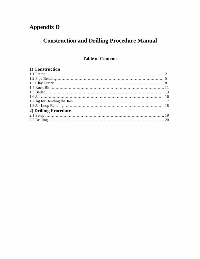
Appendix D
Construction and Drilling Procedure Manual
Table of Contents
1) Construction 1.1 Frame ……………………………………………………………………………… 2 1.2 Pipe Bending ……………………………………………………………………… 5 1.3 Clay Cutter ………………………………………………………………………… 8 1.4 Rock Bit …………………………………………………………………………… 11 1.5 Bailer ……………………………………………………………………………… 13 1.6 Jar …………………………………………………………………………………. 16 1.7 Jig for Bending the Jars …………………………………………………………… 17 1.8 Jar Loop Bending …………………………………………………………………. 18 2) Drilling Procedure 2.1 Setup ………………………………………………………………………………. 19 2.2 Drilling ……………………………………………………………………………. 20

2
1.1 Frame Materials: Quantity: 2” steel pipe (10 ft) 3 1/2” rebar (1 ft) 3 1/2” rebar (2 ft) 5 Steel plate (2”x 2”) 1 2” angle iron (6”) 2 20” dia. bike rim 1 Cotter pin 1 Equipment: Drill 1 1/8”, 3/16” & 3/4” drill bits Pipe bender Torch Tape measure Arc welder Band saw Procedure:
1. Bend two of the pipes to a 30 degree angle at a point 20 inches from the end. (See pipe bending procedure)
2. Drill a 11/8 inch hole through each of the three pipes at a point 3 inches from the
end. The hole should be drilled in the bent ends of the bent pipe in a way which allows all the holes to line up when the pipe are laying flat on the ground.

3
3. Weld the three 1 foot rebar lengths together in a triangular shape to create a cross
pin.
4. Weld the steel plate onto one end of the cross pin. This keeps the pin from sliding out.
5. Drill a 3/16 inch hole for the cotter pin near the other end of the cross pin. 6. Drill a ¾ inch hole 3 inches from the bottom end of the straight pipe. This is for
the anchoring stakes. 7. Bend four of the 2 foot rebar lengths into U shapes. These are the anchoring
stakes.

4
8. Weld the two angle iron brackets on the inside of the bent legs approximately 12
inches from the pin hole. **It is very important to make sure these brackets are parallel and that the rim will clear the center leg when the rig is set up.**
9. Drill a hole in each bracket 2 inches from the bottom of the bracket making sure that they line up when the rig is set up. These should be just big enough to fit the bike rim axle through and tighten it with a nut.

5
1.2 Pipe Bending
1. Mark the center of the bend approximately 20 inches from the end. 2. Mark the top of the bend approximately 15 inches from the end. 3. Place 2 inch pipe into pipe bender
4. Heat a 10 inch section of pipe to be bent to a cherry red
5. Slide heated section of pipe into bending dies

6
6. Bend pipe to approximately 10 degrees
7. Slide more pipe into bender 8. Repeat step 2 , 4 & 5 if needed until pipe is bent to 30 degrees making sure to
slowly walk the bend down the pipe. Meaning heat a 10 inch section with the edge starting at the center of the previous bend.
7
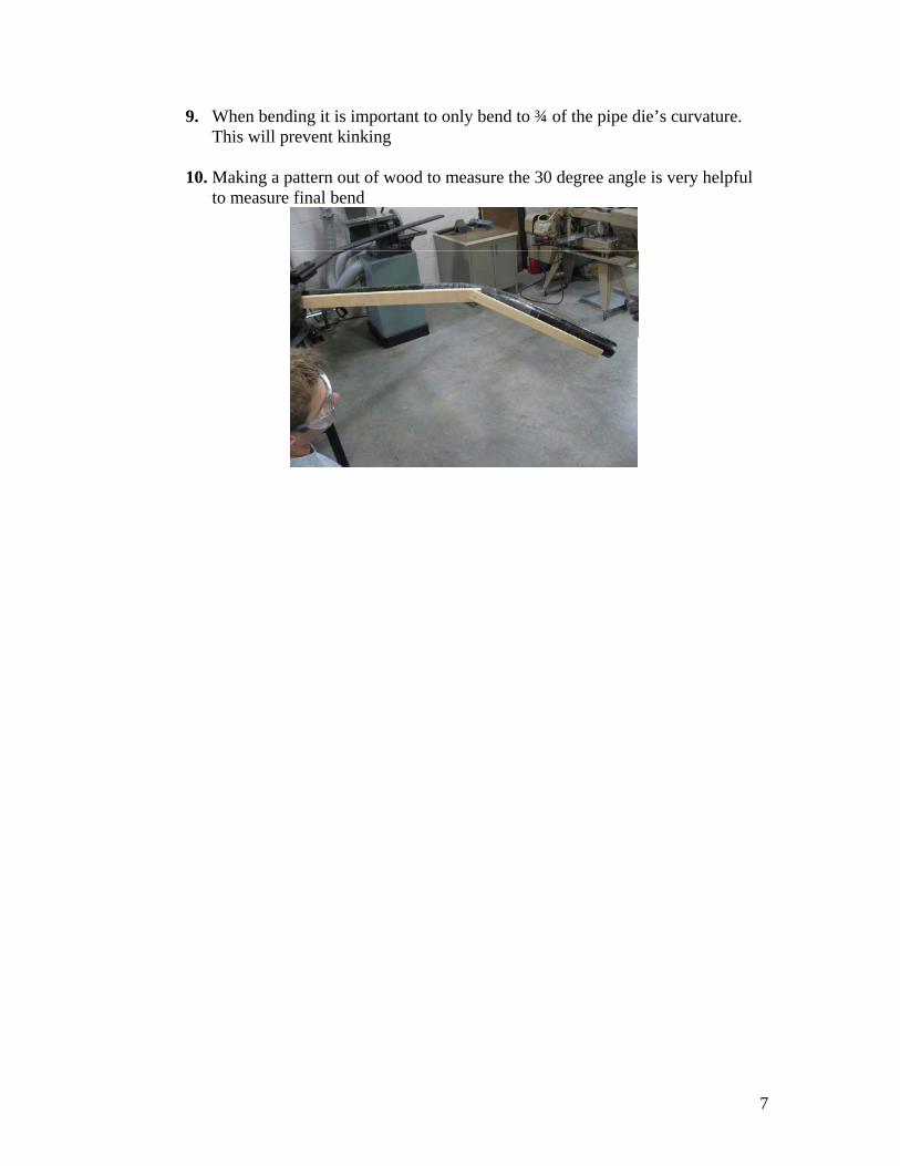
9. When bending it is important to only bend to ¾ of the pipe die’s curvature. This will prevent kinking
10. Making a pattern out of wood to measure the 30 degree angle is very helpful
to measure final bend
8
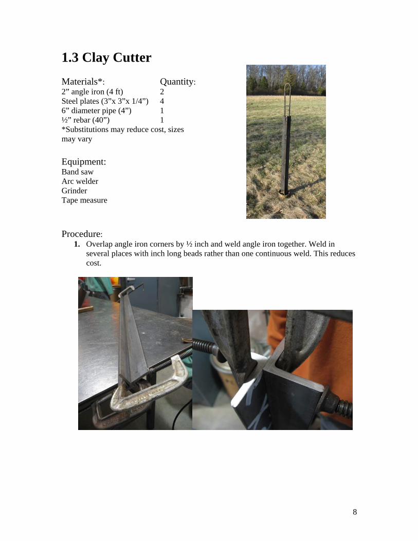
1.3 Clay Cutter Materials*: Quantity: 2” angle iron (4 ft) 2 Steel plates (3”x 3”x 1/4”) 4 6” diameter pipe (4”) 1 ½” rebar (40”) 1 *Substitutions may reduce cost, sizes may vary Equipment: Band saw Arc welder Grinder Tape measure
Procedure:
1. Overlap angle iron corners by ½ inch and weld angle iron together. Weld in several places with inch long beads rather than one continuous weld. This reduces cost.

9
2. Weld a steel plate to each of the four flanges at one end of the angle iron. The plates should be overlapping the angle iron flange as much as possible and welded very securely. Plates should be measured to fit tightly inside the inner diameter of the pipe and cut accordingly before welding.
3. Grind the cutting edges of the plates to sharpen them.
4. Grind the cutting edge of the pipe to sharpen it.

10
5. Fit the end of the angle iron with the plates into the 6 inch pipe. Line the non-
cutting edges of the plates up with the non-cutting edge of the pipe. This keeps the plates inset about 1 inch from the cutting end of the pipe.
6. Weld the plates and the pipe together.
7. Bend the rebar to create a jar loop (see jar loop bending procedure). 8. Overlap the jar loop and bit about 3 inches and weld together.

11
1.4 Rock Bit Materials*: Quantity: Steel channel (4 ft) 2 ½” rebar (40”) 1 *Use whatever materials are cheapest. Look at the Rock Bit Requirements to see the specifications necessary. Equipment: Arc welder Band saw
Procedure: 1. Cut the corners off one end of both channels. This creates a smaller impact
surface, increasing the force.
2. Weld channels back to back. Weld in several places with inch long beads rather
than one continuous weld. This reduces cost.
12
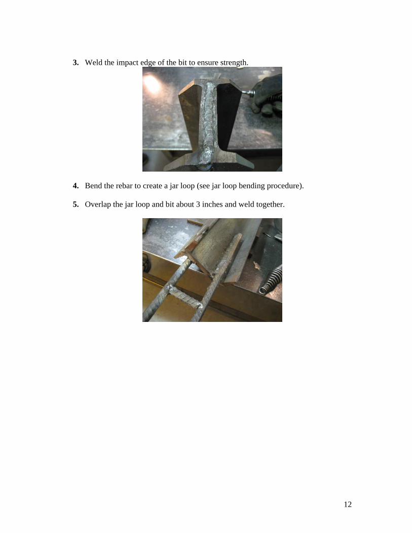
3. Weld the impact edge of the bit to ensure strength.
4. Bend the rebar to create a jar loop (see jar loop bending procedure). 5. Overlap the jar loop and bit about 3 inches and weld together.

13
1.5 Bailer Materials: Quantity: 4” steel pipe (4 ½ ft) 1 3 mm plate steel 25 sq. in. 1 ½ inch hinge 1 Equipment: Arc welder Grinder Hack saw Measuring tape Clamp Procedure:
1. Cut 4 inch steel pipe to four feet (use hack saw).
2. Cut a 3 inch long segment from remaining four inch pipe.
3. Bevel inside edge of one end of the 3 inch section of pipe. Use approximately 30-45 degree taper. (This is necessary to allow the bailer to penetrate the soil with less resistance from wall thickness)
4. Cut a 4 ½ inch disc from the 3mm steel.
5. Cut a section in the shape shown below out of the disc (a ring and disc will
remain).

14
6. On the section of the ring where the cutting began, grind half of the thickness away from a 1 ½ inch length. (This will allow the hinge to sit flush against and aid in the assembly process)
7. On the remaining disc cut ¼ inch of two sides away as shown. (The removal of
this material will help the valve open and close inside the 4 inch steel pipe.)
8. Weld the hinge to one end of the flap. (Clamp so its line of symmetry is the same as that of the plates).
9. Tack weld the 3mm steel ring to the end of the 3 inch section that has not been
beveled on the side.
10. Tack weld the flap with a hinge onto the 3 inch section (Tack on the reverse side of the hinge).
11. Line up the 4 foot length of 4 inch pipe and the newly constructed 3” section and
clamp with a c-clamp at the center of the pipe.

15
12. Tack weld in four equidistant locations around the pipe.
13. Remove clamp and proceed to weld the two sections together.
14. Bend the rebar to create a jar loop (see jar loop bending procedure). 15. Overlap the jar loop and bit about 3 inches on the inside of the pouring end and
weld together.
16. Cut a V-shaped spout for improved pouring between jars (cut need only be approximate) – use grinder with a cutting wheel.
16
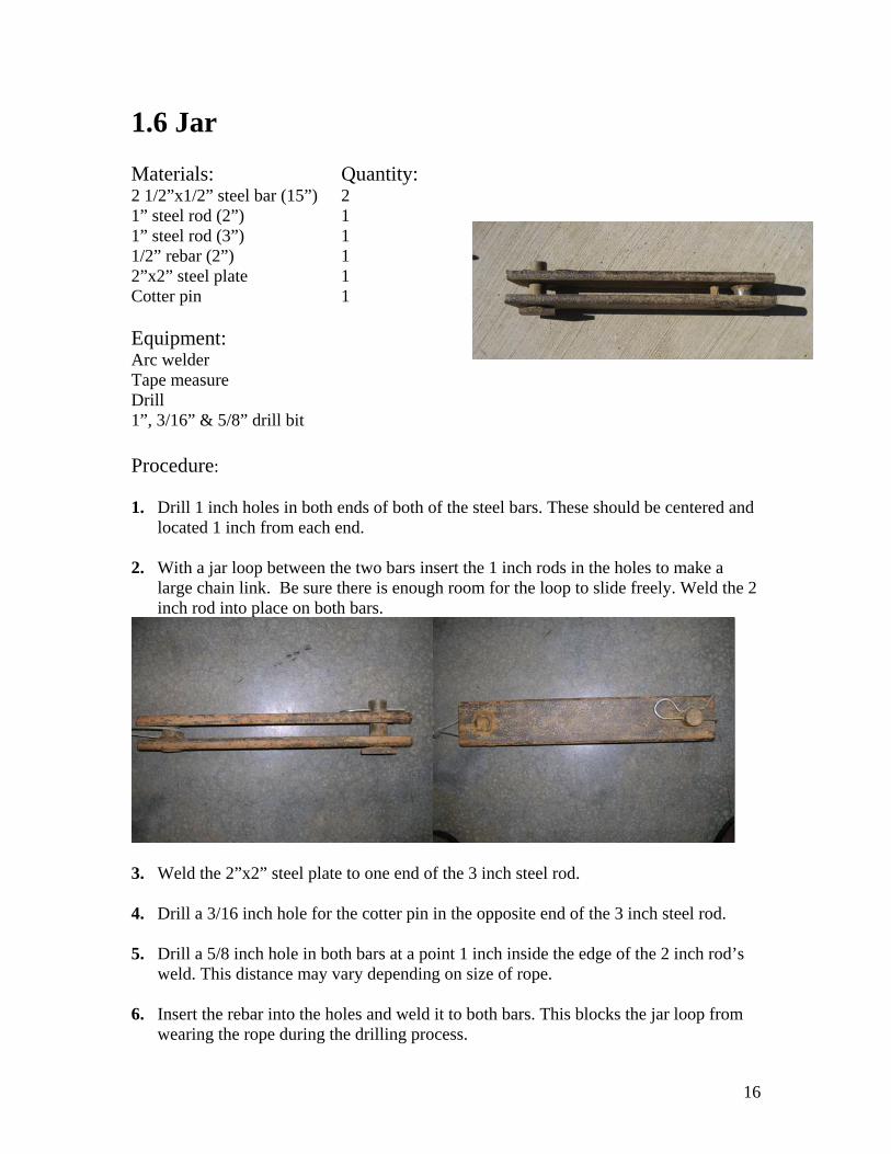
1.6 Jar Materials: Quantity: 2 1/2”x1/2” steel bar (15”) 2 1” steel rod (2”) 1 1” steel rod (3”) 1 1/2” rebar (2”) 1 2”x2” steel plate 1 Cotter pin 1 Equipment: Arc welder Tape measure Drill 1”, 3/16” & 5/8” drill bit
Procedure: 1. Drill 1 inch holes in both ends of both of the steel bars. These should be centered and
located 1 inch from each end.
2. With a jar loop between the two bars insert the 1 inch rods in the holes to make a large chain link. Be sure there is enough room for the loop to slide freely. Weld the 2 inch rod into place on both bars.
3. Weld the 2”x2” steel plate to one end of the 3 inch steel rod. 4. Drill a 3/16 inch hole for the cotter pin in the opposite end of the 3 inch steel rod. 5. Drill a 5/8 inch hole in both bars at a point 1 inch inside the edge of the 2 inch rod’s
weld. This distance may vary depending on size of rope. 6. Insert the rebar into the holes and weld it to both bars. This blocks the jar loop from
wearing the rope during the drilling process.

17
1.7 Jig for Bending the Jars Materials: Quantity: 2” angle iron (6 in) 1 2” angle iron (4 in) 1 1” pipe (2 in) 1 Equipment: Arc welder Vise Band saw Procedure:
1. Weld a piece of 1 inch pipe onto the outside center of the 6 inch angle iron.
2. Weld on the 4 inch angle iron at a 90 degree angle to the 6 inch angle iron making sure that the gap between the pipe and the angle iron is slightly larger than the piece of rebar to be used.

18
1.8 Jar Loop Bending
Procedure:
1. Mark the center of the rebar (20 inches). The bend should be at this point.
2. Clamp the jig in vise.
3. Place rebar in jig and bend around 1 inch pipe to approximately 30 degrees. (Use a 1 inch pipe to concentrate the force close to where the bend is to occur. This pipe will also give you a lever arm which will make the bending much easier.)
4. Flip rebar around in jig and bend another 30 degrees.
5. Repeat step 2 & 3 until rebar is completely bent in half.
6. If needed tighten the bend by clamping and squishing the rebar in a vise until a U shape is formed.

19
2) Drilling Procedure (see video for illustrations)
2.1 Setup 1. Align the legs on the ground so that the three holes at the top are lined up
2. Place the cross pin through the holes, and put in the cotter pin
3. Using 2-3 people, slowly raise up the frame and spread out the legs
4. Insert the pulley into the brackets (you will need to move one bent leg out of the
way), and hand tighten the nuts, leaving room for the legs to move
5. Adjust the legs so that each leg roughly forms a 60 degree angle with the ground (you
can use the wooden pattern you made to measure the pipe bend), and to ensure that the
pulley is sitting straight up and down
6. Tighten the pulley using the socket and wrench (or two wrenches)
7. Dig a 2-3 inch hole (based on the placement of the hole drilled in the bottom for the
stakes) with the post hole digger at the base of the straight leg and place the leg down in
8. Place the long, straight piece of rebar through the hole at the bottom of the straight
leg
9. Take the rebar stakes and hammer them into the ground, using any available heavy
tool, such as a sledgehammer, cinderblock or the rock bit
10. Place the rope over the top of the pulley
11. Tie the end of the rope that will go down the hole, around the top of the jar
12. Allow the jar to hang over the pulley and locate the center position of the hole
13. Using the post hole digger, dig a 6” diameter borehole, approximately 2 ft deep

20
2.2 Drilling 1. With the clay cutter resting on the ground, attach its jar loop to the bottom of the jar,
making sure that the cotter pin is firmly in place
2. Slowly pull on the rope to lift the bit off the ground, and lower it into the bottom of
the existing borehole
3. Spud the bit by pulling on the rope to lift it out of the soil at the bottom of the hole
(about 2-3ft high), then let it drop freely, but controlled, back to the bottom; Repeat this
motion until you have broken up at least 1 ft of soil, adding water as needed to maintain a
muddy consistency
4. Lift the bit out the hole and off to the side, allowing it to rest on the ground
5. Detach it from the jar, and set it aside
6. Attach the bailer as you did with the clay cutter in Step 1
7. Repeat Steps 2 and 3 until you feel the bailer has collected enough material
8. Repeat step 4 and allow the bit to lay flat on the ground off to the side of drilling rig,
possibly on a tarp
9. Lift the bottom end of the bailer, allowing the material to flow out the top onto the
tarp
10. Repeat Steps 6-8 until all possible material is removed from the hole
11. If the ground is still soft, switch back to the clay cutter and repeat Steps 2-10
12. When the clay cutter hits rock or harder soil, you will want to switch to the rock bit
and repeat Steps 2-10
Related Documents