WELL CONSTRUCTION, LITHOLOGY, AND GEOPHYSICAL LOGS FOR BOREHOLES IN BEAR CREEK VALLEY NEAR OAK RIDGE, TENNESSEE by Zelda Chapman Bailey and Dorothea Barrows Withington U.S. GEOLOGICAL SURVEY Water-Resources Investigations Report 88-4068 Prepared in cooperation with the DEPARTMENT OF ENERGY Nashville, Tennessee 1988

Welcome message from author
This document is posted to help you gain knowledge. Please leave a comment to let me know what you think about it! Share it to your friends and learn new things together.
Transcript
WELL CONSTRUCTION, LITHOLOGY, AND GEOPHYSICAL LOGS FOR BOREHOLES IN BEAR CREEK VALLEY NEAR OAK RIDGE, TENNESSEE
by Zelda Chapman Bailey and Dorothea Barrows Withington
U.S. GEOLOGICAL SURVEY
Water-Resources Investigations Report 88-4068
Prepared in cooperation with the
DEPARTMENT OF ENERGY
Nashville, Tennessee
1988

DEPARTMENT OI THE INTERIOR
DONALD PAUL MODEL, Secretary
U.S. GEOLOGICAL SURVEY
Dallas L. Peck, Director
For additional information write to:
District Chief U.S. Geological Survey A-413 Federal Building U.S. Courthouse Nashville, Tennessee 37203
Copies of mis report can be purchased from:
U.S. Geological SurveyBooks and Open-File Reports SectionFederal Center, Bldg. 810Box 25425Denver, Colorado 80225

CONTENTS
Abstract 1Introduction 1
Geologic setting 3 Acknowledgments 3
Well construction 3Well locations and general lithology 7Lithology 7
Boreholes at the base of Chestnut Ridge 13 Boreholes along Pine Ridge 14
Geophysical logs 14Boreholes at the base of Chestnut Ridge 16 Boreholes along Pine Ridge 19
Summary 20References cited 21
PLATES(in pocket)
1. Diagrams showing comparison of zones delineated from lithologic samples and from geophysical logs 2-7. Diagrams showing well construction, combined zones, and geophysical logs for well:
2. GW-230 at site 2UT3. GW-232 at site 2E4. GW-239 at site 2W5. GW-214atsite3S6. GW-208 at site 4E7. GW-211atsite4W
ILLUSTRATIONS
1. Map showing study area and drilling-site locations 22. Map showing bedrock geology of study area 43. Generalized geologic section through Bear Creek Valley 5
4-8. Maps showing well locations and geology at sites:4. IN and IS 85. 3N and 3S 96. 4E and 2W 107. 2Eand2UT 118. 4W 12
9. Photograph showing examples of structure observed on acoustic-televiewer logs 17

TABLES
1. Construction and locations of wells and test holes 62. Geophysical logs made in boreholes in Bear Creek Valley 15
FACTORS FOR CONVERTING INCH-POUND UNITS TO THE INTERNATIONAL SYSTEM OF UNITS <SD
Multiply by To obtain
inch (in.) 25.4 millimeter (mm)foot (ft) 0.3048 meter (m)gallon per minute (gal/min) 3.785 liter per minute (L/min)
To convert degree Fahrenheit (°F) to degree Celsius (°C) (0.556) ("F -32 ) = °C
Sea level: In this report "sea level" refers to the National Geodetic Vertical Datum of 1929 (NGVD of 1929) a geodetic datum derived from a general ad justment of the first-order level nets of both the United States and Canada, formerly called "Mean Sea Level of 1929."
The use of trade, product, industry, or firm names in this report is for iden tification or location purposes only, and does not constitute endorsement of products by the U.S. Geological Survey, nor impute responsibility for any present or potential effects on the natural resources.
IV

WELL CONSTRUCTION, LITHOLOGY,AND GEOPHYSICAL LOGS
FOR BOREHOLES IN BEAR CREEKVALLEY NEAR OAK RIDGE, TENNESSEE
by Zelda Chapman Bailey and Dorothea Barrows Withington
ABSTRACT INTRODUCTION
Twenty-four wells were constructed at nine The U.S. Geological Survey, in coopera-sites in Bear Creek Valley to provide geologic tion with the U.S. Department of Energyand hydrologic information. Lithologic samples (DOE), is conducting a hydrogeologic study ofand suites of geophysical logs were obtained Bear Creek Valley in the Oak Ridge Reserva-from the deepest boreholes at six of the sites, tion, Tennessee. The purpose of the study is toTwo of these boreholes at the base of Chestnut describe the ground-water flow system andRidge were completed in the Maynardville determine the potential extent of contaminantLimestone and two were completed in the migration. Observation wells were drilled atNolichucky Shale. Two boreholes along Pine nine sites (fig. 1) around the perimeter of the val-Ridge were completed in the Rome Formation, ley to provide information on lithology, geologic
structure, and hydrologic boundaries of theZones of similar lithology within a ground-water flow system. Wells at two of the
borehole were delineated from rock cuttings and sites were drilled by contractors to DOE; therefined by examination of geophysical logs. The remaining wells were drilled by the Geologicalcontact between the Maynardville Limestone Survey and the U.S. Army Corps of Engineers,and Nolichucky Shale was identified in two of the Mobile District. Geophysical logs were obtainedboreholes. Fractures and cavities were readily in six of the boreholes. Drilling began in Octo-identifiable on the acoustic-televiewer and ber 1985 and drilling and logging were com-caliper logs. Distinct water-bearing intervals pleted in May 1986. were also identified from the temperature, fluid resistance, and resistivity logs. Depths at whichthe drilling encountered a thrust fault were iden- The purpose of this report is to providetifed in two boreholes in the Rome Formation information on well locations and construction,from both rock cuttings and from geophysical and on interpretations made from lithologiclogs. samples and geophysical logs.

US
GS
-3N
ST
UD
Y
[CLI
NC
H
RIV
ER
US
GS
-3S
fTE
NN
FS
SF
F
VA
LL
EY
AU
TH
OR
ITY
W
AT
TS
J B
AH
H
ES
EH
VO
1R
1
RE
SE
RV
AT
ION
I
, :,
.,,,.,,.:^
.,:
. ..
. 'S
tail
.^S^,,
,..:
,.,:
.:,,
, ,,.$
:,
OA
KR
lD
PIN
E
RID
GE
U
SG
S-4
W
BE
AR
C
RE
EK
Be
ar
OA
K
RID
GE
CH
ES
TN
UT
RID
GE
.IC
«O-I
M
BO
TT
R/p
,-
p-<
^
US
fiS
-4F
\
I *
h
Y
-
-^/
Y2L:«
....
T
, |
\:^
:f-^ftiS
:"aS
lv-^
' .
\
US
GS
-2
0USG
S-1S
USGS
.2W£i)r-
\'
| U
NIV
ER
SIT
Y
OF
3
X
TE
NN
ES
SE
E
/If
FO
RE
ST
RY
1
EX
PE
RIM
EN
T
1 S
TA
TIO
N
gi JJ-U
SG
S-2
UT
*.-
1 J
(?0
S °°
'k^
S
3 M
ILE
S
Stu
dy
are
a
TE
NN
ES
SE
E
EX
PL
AN
AT
ION
A A
' L
ine
of
ge
olo
gic
secti
on
D
rilli
ng
sit
e a
nd
d
esig
nati
on
US
GS
-1N
Fig
ure
1.
S
tudy are
a
an
d drilli
ng-s
ite lo
cations.

E 10
.000
E 20
,000
E 30
,000
E 40
,000
E 60
,000
E 70
,000
N
30,0
00
Geolo
gy
mo
difi
ed
fr
om
an
d A
.B.
Hoos
and
Z.C
. B
aile
y,
1986
, an
d W
.M.
McM
ast
er
1963
§0
3 M
ILE
SI
EX
PL
AN
AT
ION
Copper
Rid
ge D
olo
mite
Mayn
ard
ville
Lim
est
on
e
Nolic
huck
y S
ha
le
Mary
ville
Lim
est
one
Ro
ge
rsvi
lle S
ha
le a
nd
Ru
tled
ge
Lim
est
on
e
Pum
pki
n V
alle
y S
hale
R
ome
Form
atio
n
Ge
olo
gy
un
diff
ere
ntia
ted
A
pp
roxi
ma
te g
eolo
gic
co
nta
ct
Thru
st f
ault
Drilli
ng s
ite
Co
ord
ina
tes
rela
te t
o T
enne
ssee
Val
ley
Au
tho
rity
S-1
6A
grid
sy
stem
Jun
e 19
74
(4)<
OC
zo
o
(5)°
DC
C
Q o
Fig
ure
2.
Be
dro
ck geolo
gy
of
stu
dy
are
a.

Geologic Setting vision of drilling operations was provided byDavid A. Webster, and assistance in geophysical
Bear Creek Valley and adjacent ridges are log interpretation by Patrick Tucci, both of theunderlain by rocks of Cambrian age (fig. 2) that U.S. Geological Survey, strike approximately north 55 degrees east. The dip of the rock varies from 30 to 70 degrees to thesoutheast, but the average dip is about 45 degrees WELL CONSTRUCTION (fig. 3). A series of thrust faults, also dippingsoutheast, intersect the northwest flank of Pine Nine sites (fig. 1) were selected and threeRidge. Pine Ridge is underlain by interbedded wells were to be drilled at each site to providesandstone, siltstone, and shale of the Rome For- vertical hydraulic-potential data: one shallowmation. Bear Creek Valley is underlain by six well in the regolith, and two wells in bedrock atformations that compose the Conasauga Group, about 100 and 400 feet in depth. Problems en-From oldest to youngest these formations are: countered during drilling resulted in one' sitePumpkin Valley Shale, Rutledge Limestone, having only one well and two sites havingRogersville Shale, Maryville Limestone, boreholes drilled that had to be abandoned. ANolichucky Shale, and Maynardville Limestone, total of 24 wells were constructed and an addi-The Maynardville Limestone contains solution tional 3 boreholes were drilled but wells were notcavities. Chestnut Ridge is underlain by massive, installed. Drilling-site names and well namessiliceous dolomite of the Knox Group and con- were assigned from a naming system used bytains solution and karst features. The Copper MMES staff for wells in Bear Creek Valley. Fol-Ridge Dolomite is the oldest formation in the lowing are general descriptions of drilling,Knox Group and overlies the Maynardville casing, and grouting procedures. Location coor-Limestone. Regolith, consisting of soil and dinates and specific construction information forweathered rock, overlies the bedrock and ranges each well and test hole are summarized infrom 0 to 80 feet thick. table 1.
Holes for the shallow wells were augered toAcknowledgments the top of bedrock. A 2-inch PVC casing with 5
feet of slotted PVC screen at the bottom was in-The assistance and contributions of several stalled in each hole. Sand was poured into the
people were particularly valuable to the project annulus around the screen to about 1 foot above and are greatly appreciated. Dr. C. Stephen the top of the screen, and a 1-foot deep layer of Haase and George Gillis, Martin Marietta Ener- bentonite pellets was poured into the annulus to gy Systems, Inc. (MMES), provided the drilling form a seal. A Portland Type 1 cement slurry was for five wells at two of the drilling sites, logisti- then poured into the annulus around the casing cal support during the Geological Survey drill- to form a seal from the top of the bentonite to ing, and surveying for grid coordinates and ground surface, elevations of the wells. In addition to drilling onDOE property, permission was granted by Ten- Holes for the deeper wells were first nessee Valley Authority and University of Ten- augered to the top of bedrock and 8-inch nessee to drill and collect data on their diameter PVC surface casing was grouted into properties. Geophysical logging was conducted the holes to seal water and surface material out by Gerald E. Idler, U.S. Geological Survey, who of the borehole during drilling. The underlying provides logging services for the Southeastern bedrock was then drilled by either air hammer or Region. Assistance during logging and super- mud-rotary drilling methods. Casing, generally

PIN
E
RID
GE
CH
ES
TN
UT
R
IDG
E
RO
ME
F
OR
MA
TIO
NC
ON
AS
AU
GA
G
RO
UP
300
KN
OX
G
RO
UP
Mo
difie
d
fro
m
Z.C
. B
aile
y,
19
88
50
0
I
10
00
F
EE
T
_J
EX
PL
AN
AT
ION
- G
eo
log
ic co
nta
ct
Fig
ure
3
.--G
en
era
lize
d g
eo
log
ic se
ctio
n th
rough
Bear
Cre
ek
Valle
y.

Tabl
e \.-
-Con
stru
ctio
n an
d lo
catio
ns o
f wel
ls an
d te
st h
oles
Site
U
SQS
1N 18 2W 2E 2UT
4E 4W 3S 3N
Wel
l na
me
GW
-162
GW
-163
GW
-164
GW
-165
GW
-166
GW
-167
GW
-168
GW
-239
GW
-169
GW
-170
GW
-232
GW
-171
GW
-172
GW
-230
GW
-235
GW
-206
GW
-207
GW
-208
GW
-209
GW
-210
GW
-211
GW
-212
GW
-213
GW
-238
GW
-260
GW
-214
GW
-215
Coo
rdin
ates
N
orth
Ea
st
(feet
))*
3133
131
334
3132
8
2780
727
835
2870
328
698
2871
5
2854
528
545
2854
6
2840
328
359
2838
928
416
3160
331
596
3161
2
3177
531
765
3179
9
2778
727
746
2783
827
773
2780
2
2946
8
4448
144
483
4447
0
4454
744
531
6514
665
167
6508
9
6685
466
843
6686
3
6965
469
579
6961
769
712
6401
964
023
6400
7
2769
927
700
2769
8
9119
9119
9116
9121
9119
9204
Dep
th
(feet
)
125.
022
5.0
405.
0
325.
038
5.0
30.1
135.
543
3.3
34.8
157.
041
1.7
31.2
133.
940
6.4
68.0
16.9
109.
741
2.8
48.1
124.
041
0.0
13.9
128.
012
9.0
134.
04
30
.0
15.2
Gro
und
elev
atio
n (fe
et a
bove
se
a le
vel)
1,03
6.4
1,03
7.0
1,03
6.4
1,09
0.4
1,09
2.0
92
9.7
92
9.4
92
8.8
92
9.9
93
0.7
92
9.5
91
8.5
923.
191
9.8
92
0.0
89
4.6
89
4.7
89
4.5
79
3.0
79
2.9
793.
1
75
0.9
751.
075
1.0
75
0.9
75
0.8
75
4.5
Mea
surin
g po
int
(feet
abo
ve
sea
leve
l)
1,03
7.6
1,03
9.6
1,03
8.5
1,09
1.4
1,09
3.3
931.
493
0.9
930.
5
93
1.5
*9
32
.493
1.2
920.
192
4.8
920.
8
Ope
n S
cree
ned
inte
rval
in
terv
al
(feet
bel
ow
(feet
bel
ow
land
sur
face
) la
nd s
urfa
ce)
92
.0-
208.0
-37
8.0
-
276.
0 -
380.
0 -
25.0
104.0
-40
4.0
-
28.7
-104.0
-401.0
-
25.8
-105.0
-3
41
.0-
125.
022
5.0
405.
0
325.
038
5.0
30.1
26
.0 -
30.
113
5.4
433.
0
34.8
29
.7 -
34.
815
6.9
411.
7
31.2
2
6.8
-31
.213
3.8
406.
4
Cas
ing
mat
eria
l
Stee
lSt
eel
Stee
l
Stee
lS
teel
PVC
Stee
lSt
eel
PVC
Ste
elSt
eel
PVC
Stee
lSt
eel
Cas
ing
diam
eter
(in
ches
)
6.00
6.00
6.00
6.00
6.0
0
2.00
4.00
4.00
2.00
4.0
04.
00
2.00
4.00
4.00
hole
aba
ndon
ed
894,
6b89
8.8°
901.
3
799.
479
9.1
796.
3
751.
1
10.8
-100.0
-40
4.0
-
42
.0-
104.0
-40
4.0
-
8.4
-
16.9
11.8
-16.9
109.
741
2.8
48.1
43
.0
48.
112
4.0
410.
0
13.9
9.
4 -
13.9
PVC
PVC
Stee
l
PVC
Ste
elSt
eel
PVC
2.00
4.0
04.
00
2.00
4.0
04.
00
2.00
hole
aba
ndon
ed75
2.1
100.0
-12
9.0
Stee
l4.
00ho
le a
band
oned
753.
9
754.
8
414.
6 -
9.6
-
430.
0
15.2
10
.6 -
15.
2
Stee
l
PVC
4.00
2.00
Dril
ling
met
hod
A *
auge
r M
= m
ud r
otar
y H
« ai
r ha
mm
er
M M M M M A H H A H H A H H H A M H A H H A H H H H A
* C
oord
inat
es r
elat
e to
the
S-1
6A g
rid s
yste
m.
* M
easu
ring
poin
t w
as 9
31.9
pri
or to
May
26,
198
7.M
easu
ring
poin
t w
as 8
95.0
pri
or t
o N
ovem
ber
2. 1
987.
c
Mea
surin
g po
int
was
901
.81
prio
r to
Oct
ober
20.
1986
.

steel, was set in the hole and the annulus was pressure grouted with Portland cement to ground surface. The grout used in wells GW- 165, GW-166, and GW-230 also contained Haliburton Flo Seal and calcium chloride to prevent the grout from flowing out of the an nulus through fractures and solution cavities. After the grout hardened, an open interval was drilled below the cased interval. Cuttings were cleared from the hole by using compressed air.
WELL LOCATIONS AND GENERAL LITHOLOGY
Drilling sites, selected to supplement data from wells already drilled in the valley by other investigators, are primarily located where data were lacking for the hydrologic boundaries at each end of the valley and along the ridges.
Wells at site IS, on Chestnut Ridge, were drilled in the Copper Ridge Dolomite (fig. 4) by MMES contractors, and the open intervals in each of the two wells intersect cavities or large fractures. The wells at site IN (fig. 4) on Pine Ridge were also drilled by MMES contractors. The shallow well at site IN (GW-162) is open to the lower member of the Pumpkin Valley Shale; the two deeper wells (GW-163 and GW-164) are in the Rome Formation (Haase and others, 1986, p. 39). No geophysical logs were obtained from the wells at these sites. Lithologic descriptions of these wells are included in Haase and others, 1987.
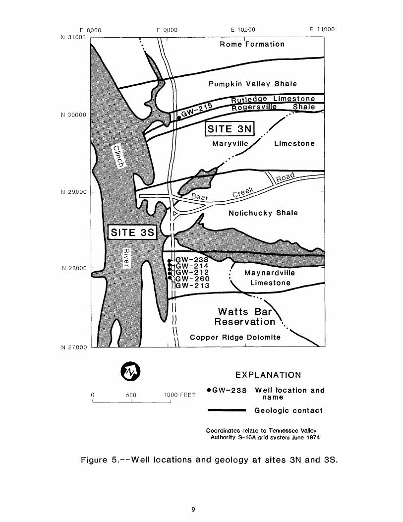
All wells at four sites (3S, 2W, 2E, and 2UT) along the base of Chestnut Ridge are com pleted in the Maynardville Limestone (figs. 5-7) except for the deepest wells at sites 3S (GW-214, fig. 5) and 2W (G W-239, fig. 6), which were com pleted in the underlying Nolichucky Shale. Three boreholes, one at site 2UT (GW-235, fig. 7) and two at site 3S (GW-213 and GW-260), were abandoned either because of large cavities that could not be sealed off from the well casing
or because casing could not be installed through the cavities. Cavities in borehole GW-235, at site 2UT, were encountered between 5 and 14 feet below land surface, between 24 and 27 feet, between 34 and 42 feet, and between 50 and 52 feet. The cavity encountered from 5 to 14 feet below land surface also extended horizontally several feet from the borehole, which made grouting infeasible. The cavity and borehole were filled with rock and gravel to prevent col lapse and were abandoned.
The well drilled at site 3N (GW-215, fig. 5) is in regolith, probably formed from the Rogersville Shale. No wells were drilled in bedrock at this site.
Wells at sites 4E and 4W (figs. 6 and 8) were drilled in water gaps in Pine Ridge near the mapped trace of a thrust fault (McMaster, 1963). The wells at site 4E are completed in the Rome Formation, because the Rome is present on both sides of the fault. Wells at site 4W probably in tersect the fault and possibly a block of Con- asauga Group. The structure in this area has been interpreted differently by several inves tigators (summarized in Exxon Nuclear Com pany, Inc., 1978, p. 3.6-27 through 33), but there is general agreement that a fault exists and that a block of Conasauga Group (formations not identified) on the northwest side of the fault con tacts the Rome Formation.
LITHOLOGY
Rock cuttings were collected at about 10- foot intervals from the deep boreholes at sk of the sites; cuttings were not collected at sites IN, IS, and 3N. The amount of sample collected was generally adequate for description, and the size of the chips ranged from powder to 0.4 inch. Lithologic descriptions included in the following sections are generalized to support grouping the rock into consistent zones delineated by changes

E 42,000 N 31.500
E 44.000 E 45,000
N 31,000 -
N 30,000 -
N 29,000 -
N 28.000 -
N 27500
Pine Ridge
Pumpkin Valley ShaleGW-164-«V
SITE 1NRutledge Limestone
Rogersville //ShaleMaryville Limestone
Nolichucky
LimestoneBear
Maynardville
Copper Ridge Dolomite
SITE 1S
zr~^r = z=:^ GW.-166
GW-165VChestnut Ridge
500l
1000 FEET I
EXPLANATION
GW-165 Well location and name
Geologic contact
Coordinates relate to Tennessee Valley Authority S-16A grid system June 1974
Figure 4. Well locations and geology at sites 1N and 1S,
E 8,000 N 31,000
E 9,000 E 10,000 E 1 1,000
N 30,000
N 29,000 -
N 28,000 -
N 27,000
Rome Formation
Pumpkin Valley Shale
utledge Limestone
SITE 3NLimestone
Nolichucky Shale
SITE 3S
W-238 JhGW-214 8HGW-212 «hGW-i MGW-213
Maynardviile Limestone
Watts Bar Reservation
Copper Ridge Dolomite
500 I
EXPLANATION
1000 FEET i
GW-238 Well location and name
Geologic contact
Coordinates relate to Tennessee Valley Authority S-16A grid system June 1974
Figure 5. Well locations and geology at sites 3N and 3S.

E 63,000 N 32,500
N 32.000 -
E 64.000 E 65,000 E 66,000
N 31,000 -
N 30,000 -
N 29,000 -
N 28,500
Rome Formation
GW-208^..-.
** Rome Formation
ISITE 4E
Pumpkin Valley Shale
Rutledge Limestone
Rogersville Shale
Maryville Limestone
Nolichucky Shale
SITE 2WGW-167 GW-168
GW-239-*
Maynardville Limestone
500 1000 FEET
EXPLANATION
GW-239 Well location and name
Geologic contact
- Fault Dashedwhere approximate
Coordinates relate to Tennessee Valley Authority S-16A grid system June 1974
Figure 6. Well locations and geology at sites 4E and 2W.
10

E 65
,000
N
30,000
E 66
,000
E 67
,000
E 68,000
E 69,000
E 71,000
N 29
,000
-
N 28,000
-
N 27
,000
Nolic
hucky ; M
ayn
ard
vill
eLim
esto
ne *
GW
-171
//
/.G
W-2
35^^
GW
-230
GW
-172
GW
-17C
T-
^G
W-2
32
Univ
ers
ity o
f T
en
ne
sse
e
// A
gricu
ltura
l E
xpe
rim
en
t S
tatio
n
(Kn
ox G
roup)
Co
pp
er
Rid
ge
D
olo
mite
50
01
00
0
FE
ET
EX
PLA
NA
TIO
N
GW
-23
5
Well
location a
nd
na
me
Ge
olo
gic
co
nta
ct
Co
ord
ina
tes
rela
te t
o T
en
ne
sse
e V
alle
y A
utho
rity
S-1
6A
grid
sys
tem
Jun
e 19
74
Fig
ure
7
. W
ell lo
cations a
nd
ge
olo
gy a
t site
s
2E and
2U
T.

E 26,000 N 34,000
E 27,000 E 28,000 E 29.000
N 33.000
N 32,000 -
N 31,000
Rome Formation
*'-T~~>
Conasaugai JlGroup (undifferentiated)
GW-211 GW-209 GW-210
Pumpkin Valley Shale (Conasauga Group)
500 i
1000 FEET
EXPLANATION
GW-210 Well location and name
Geologic contact
- Fault Dashedwhere approximate
Coordinates relate to Tennessee Valley Authority S-16A grid system June 1974
Figure 8. Well locations and geology at site 4W.
12

in lithology, texture, cementation, or color (pi. GW-232, at site 2E, was sampled at inter-1). Depth intervals of zones are approximate due vals approximating 20 feet from 34 to 415 feetto the lack of continuous sampling. (pi. 1). Regolith overlies the bedrock from land
surface to a depth of 33 feet. From 33 to 94 feet, the lithology consists of pelletal limestone and minor fossil fragments. Fractures or cavities are
Boreholes at the Base of Chestnut Ridge indicated by the presence of weathered rock frag ments. There is a distinct lithologic break at 94
The deepest boreholes at sites 2UT and 2E feet; between 94 and 140 feet, the predominant (wells GW-230 and GW-232) were completed in lithology is fossiliferous limestone. Fro,n 140 to the Maynardville Limestone (fig. 7). Wells GW- 204 feet, there is a color change within the fos- 214 at site 3S and GW-239 at site 2W (figs. 5 and siliferous limestone, from dusky yellow brown to 6) were completed in the Nolichucky Shale. The light olive gray. The lithology between 204 and limestone in all four wells is interbedded 250 feet is a cryptocrystalline limestone matrix pelletal-oolitic wackestone and micrite. Minor supporting pellets up to 0.005 inch in diameter, fossil fragments, such as trilobite shell fragments The lower limit of this interval is not exact, per- and fossil hash, are found in the finer crystalline haps indicating a gradational contact. From lithologies. Recrystallization in the coarser about 250 feet to the bottom of the hole (415 lithologies gives some of the limestone a sparry feet), the rocks are micrites that display no struc- appearance. The Nolichucky Shale in GW-214 ture. and GW-239 is typically interbedded, very fine grained, and greenish-gray or fine-grained and Samples in GW-239, at site 2W, begin at 40 dusky yellowish-brown shale and siltstone. feet and continue at approximately 20-foot inter
vals to 400 feet (pi. 1). Regolith overlies theLithologic samples for GW-230, at site bedrock from land surface to a depth of 30 feet.
2UT, began at 20 feet and ended at about 405 feet The limestone from 30 to 320 feet consists of below land surface (pi. 1). The sampling inter- pelletal-oolitic limestone interbedded with val was irregular for the first 100 feet, although micrite. The limestone between 100 and 150 feet the sampling interval throughout the borehole is a denser cryptocrystalline micrite. Near 150 approximates 10 feet. The borehole is entirely feet, the sample consists predominantly of mud within the Maynardville Limestone, which con- and minor amounts of limestone chips, which is sists predominantly of pelletal-oolitic limestone evidence of a cavity. Shale and siltstone of the with interbeds of micritic limestone. Regolith Maynardville Limestone contacts the overlies the bedrock from land surface to a depth Nolichucky Shale at 320 feet. The contact be- of 30 feet. Between land surface and 110 feet, tween the limestone and the shale-siltstone is micrite is the predominant lithology. The upper gradational. The sample collected at 320 feet 5 5 feet of this zone has numerous cavities or solu- contains both limestone and shale chips, but tion openings. A major lithologic change at shale predominates below 340 feet. The lithol- about 110 feet may correspond to a fracture ogy below 340 feet is interbeded fine to very fine- along a bedding plane. The predominant grained shale and siltstone. lithologic type between 110 and 375 feet isoosparite, although the interval between 205 and Samples were collected from GW-214, at225 feet consists of a coarse crystalline sparry site 3S, at 10-foot intervals from 75 to 380 feetlimestone. The open-hole interval, between 375 (pi. 1). Regolith overlies the bedrock from landand 405 feet, consists of a coarser crystalline surface to a depth of 18 feet. The limestone,micrite. which consists of micrite, probably begins at the
13

bottom of the regolith and continues to about ment. The lithology from 112 to 245 feet is in- 189 feet. Numerous cavities within this interval terbedded fine-grained shale and fine-grained are evident from samples that consist primarily sandstone, and there is no carbonate reaction in of mud and weathered chips. At approximately the rock. At 245 feet, faulting is evident from the 189 feet, there is a change in lithology; from 189 mylanitic texture of the shale. Between 245 and to 240 feet, the samples are predominantly mud 404 feet, the section consists of fine-grained mixed with chips of both limestone and minor shale. Within this interval, the shale is grayish- quantities of shale. From 240 to approximately red between 245 and 270 feet and blackish red 320 feet, shale is more abundant in the samples, below 270 feet, and below 320 feet, the samples are exclusivelyshale. The Maynardville Limestone contacts the GW-211, at site 4W, was sampled at ap- shale and siltstone of the Nolichucky Shale at 320 proximately 10-foot intervals from 10 to 404 feet feet. (pi. 1). Lithology consists of interbedded shale,
siltstone, and minor amounts of fine-grainedsandstone. The interbedding makes exact loca-
Boreholes Along Pine Ridge tions of changes in lithology difficult to identify.Regolith overlies the bedrock from land surface
The boreholes at site 4E (fig. 6), located ad- to a depth of 37 feet. Underlying the regolith to jacent to East Fork Poplar Creek in a gap in Pine a depth of 100 feet, the section consists of fine- Ridge, were drilled in the Rome Formation near to medium-grained siltstone and sandstone and the mapped trace of a thrust fault (McMaster, silica cement. At 100 feet, there is evidence of 1963). The boreholes at site 4W (fig. 8) were faulting similar to that found in samples from drilled in a gap in Pine Ridge near Bear Creek GW-208. Shale is the predominant lithology and near the trace of the same thrust fault. The below 100 feet. Type of cement is the major dis- lithologies of the two sites are significantly dif- tinction throughout this interval, and color also ferent from each other and from those drilled changes. Between 100 and 170 feet, the rock is along Chestnut Ridge. Rock cuttings from the cemented with carbonate and consists of inter- deep wells at sites 4E and 4W show distinct bedded blackish-red and grayish-red shale, lithologic sequences. The lithology of each There is no evidence of carbonate cement from borehole probably represents a different 170 to 240 feet. Carbonate cement is present in stratigraphic section of the Rome Formation, the grayish-brown and dark-red very fine- however, lithologic evidence is too tenuous to grained shale between 240 and 340 feet. From identify their exact locations in the section. 340 feet to the bottom of the open-hole interval
(410 feet), the noncarbonate rock is interbeddedGW-208, at site 4E, was sampled at 10-foot grayish-black and olive-black shale,
intervals from 60 to about 404 feet (pi. 1). Lithology is interbedded shale, siltstone, andfine-grained sandstone having little or no car- GEOPHYSICAL LOGS bonate cement. Regolith overlies the bedrockfrom land surface to a depth of 24 feet. Samples Geophysical logs were obtained in the were not collected between 24 and 60 feet. Be- same deep boreholes (table 2) for which lithol- tween 60 and 112 feet, the rocks are composed of ogy was described. All boreholes were logged in a very fine- to fine-grained shale and minor the open hole prior to installation of casing, ex- amounts of very fine-grained sandstone. Within cept for well GW-239, which was logged after this interval there is interstitial glauconite at 92 casing was set and the open interval below the feet, and all the samples contain carbonate ce- casing had been drilled. Logs were obtained in
14

Tab
le 2
. Geo
phys
ical
logs
mad
e in
bor
ehol
es in
Bea
r C
reek
Val
ley
Wel
l na
me
GW
-208
GW
-21
1
GW
-21
4
GW
-230
GW
-232
GW
-239
6
Dep
th
oflo
ggin
g T
empe
ratu
re(d
egre
es
(feet
) C
elsi
us)
40
4
X
40
4
X
414.6
341
X
401
X
43
3
Bor
ehol
e ge
ophy
sica
l lo
g (in
dica
ted
by X
)
Flui
d C
alip
er
resi
stan
ce
(ohm
s)
(inch
es)
X X
X X X
X X
X
X X
Gam
ma
(cou
nts
per
seco
nd)
X X X X X X
Neu
tron
G
amm
a-ga
mm
a (d
ensi
ty,
in
(cou
nts
gram
s pe
r pe
r cu
bic
seco
nd)
X X X X X X
cent
imet
er)
X X X X X
Ele
ctric
16
64
(o
hm-m
eter
s)
X X X X X
X X X X X
Spo
ntan
eous
po
tent
ial
(mill
ivol
ts)
X X X X X
Aco
ustic
A
cous
tic
velo
city
te
levi
ewer
(m
icro
se
cond
spe
r fo
ot)
X X
X
X X
X
X
X
X
Logg
ed t
hrou
gh s
teel
cas
ing
from
lan
d su
rfac
e to
dep
th o
f 40
4 fe
et.

air-rotary drilled boreholes, therefore, no drill- between plates. Zones designated on the plates ing mud was present to affect log interpretation, are a combination of lithologic and geophysical Logs were not obtained for some wells because zones for each borehole, of equipment malfunctions at the time of log ging, or, in the case of GW-239, because some Boreholes at the Base of Chestnut Ridge types of logs are not applicable in cased wells.The logs, shown on plates 2 through 7, were used The geophysical logs for the four deepto refine the lithologic zones delineated by boreholes drilled at the base of Chestnut Ridgesample descriptions and allowed additional in- (pi. 2-5) indicate numerous fracture zones in theterpretations based on continuous lithologic and Maynardville Limestone, and, for two of thehydrologic information in the borehole (pi. 1). wells (GW-214 and GW-239), the contact with
the Nolichucky Shale. Geophysical zones desig-In general, interpretations of geophysical nated on plate 1 primarily represent sections of
logs can be made as follows: deflections to the the ATV log that were either intensely fractured right for caliper logs indicate increasing well- or massive and generally unfractured. These bore diameter, which is frequently caused by zones, which represent changes in geologic or fractures; for temperature logs, increasing water hydrologic properties, correlate well with sig- temperature; for fluid-resistance logs, fresher nificant deflections on the other geophysical logs water; for gamma and spontaneous-potential and with most changes in lithology identified logs, increasing shale-clay content; for neutron from the rock cuttings. The generally low counts logs, decreasing porosity; for gamma-gamma and per second on the natural gamma logs are indica- acoustic velocity logs, increasing density; and for tive of limestone, and are typical of all the long- and short-normal resistivity logs, fresher boreholes logged in the Maynardville Lime- water or limestone-sandstone as opposed to stone, shale.
GW-230, drilled entirely in theThe acoustic borehole televiewer produces Maynardville Limestone, was logged from land
a photographic image representing the pattern surface to a depth of 341 feet. The upper 55 feet of acoustic reflectivity on the borehole wall, of the logs are affected by the steel surface Fractures are represented on the acoustic- casings. Three major zones and a minor zone televiewer (ATV) log by black lines that result within the second zone were identified from from almost no reflectance of the acoustic signal lithologic descriptions. These same zone boun- back to the receiver (fig. 9 A). Bedding-plane daries are identifiable as geophysical zones (pi. orientation can also be seen in the closely spaced, 1), but additional zones were also identified from curved striations on the logs. Because magnetic patterns in the ATV log and deflections in the north is at each side of the log and south is in the other geophysical logs (pi. 2). Mud-filled frac- center, a curved line that peaks at the middle axis tures to a depth of 110 feet are indicated primari- of the log represents beds that dip from south to ly by the gamma and neutron logs. Rock north (fig. 9 B). Massive and generally unfrac- between 110 and 145 feet is denser and less frac tured rock is represented by white areas on the tured. An influx of water below 145 feet is indi- log, which are produced by an almost complete cated by changes in water temperature, fluid reflectance of the acoustic signal off the borehole resistance, and resistivity, and an intensely frac- wall (fig. 9 B). tured interval is seen on the ATV log at this
depth (fig. 9 A). Fractures continue to charac-Identical scales and positioning of logs on terize the rock to a depth of 225 feet. Fractures
plates 2 through 7 facilitates direct comparisons are primarily horizontal between 145 and 183
16

NO
RT
H
143-
EA
ST
S
OU
TH
W
ES
TN
OR
TH
N
OR
TH
199
-1:
EA
ST
SO
UT
H
WE
ST
UJ
OK
<UJ
Jr
iii
_."-
M
Q-
ZI
<
UJ
>
Q
O _i
UJ CQ B
EX
PL
AN
AT
ION
Lo
g
fro
m
bo
reh
ole
G
W-2
30
Sh
ow
ing
fr
ac
ture
s
at
146
feet
(dip
pin
g
no
rth
to
so
uth
) an
d
15
0
feet
(ho
rizo
nta
l)
Lo
g
fro
m
bo
reh
ole
G
W-2
08
Sh
ow
ing
tra
nsit
ion
fr
om
le
ss
den
se
(dark
, le
ss re
fle
cti
ve
) ro
ck (2
00
to
210 fe
et)
to
d
ense
r (l
igh
t,
mo
re re
fle
cti
ve
) ro
ck (2
10
to 215 f
eet)
. S
ecti
on
al
so
sho
ws
dip
of b
eds
fro
m
no
rth
east
to s
ou
thw
es
t
Lo
g f
rom
bo
reh
ole
GW
-211
Sh
ow
ing
p
ossib
le t
hru
st-
fau
lt
zon
e (d
ark
), (
83
to
87 fe
et)
NO
RT
H
NO
RT
H
73 -
EA
ST
S
OU
TH
W
ES
T
NO
RT
H
Fig
ure
9. E
xam
ple
s
of
str
uctu
re
observ
ed
on a
co
ustic-t
ele
vie
we
r lo
gs.

feet, and dip from north to south between 183 to a gradual increase in temperature and fluid and 220 feet. Increased porosity due to fractures resistance. The fractures between 275 and 280 between 145 and 183 feet is indicated by the feet corresponds to a sharp decrease in fluid neutron log, and clay filling in the fractures is in- resistance that continues to the bottom of the dicated by the gamma and resistivity logs. hole. This change in fluid resistance and water Uniform fluid resistance indicates a more temperature indicates an influx of water from a uniform mixing of water between 183 and 250 different water-bearing zone below 280 feet. Be- feet, and fractures are also identifiable on the tween 275 and 401 feet, the fracture density in- gamma-gamma (decreased density) and acous- creases, and, although the change was not tic-velocity (decreased velocity) logs. Below 220 enough to delineate a separate lithologic zone, feet, the rocks are again dense and only one frac- the color of the rock samples also changes at ture is identified on the ATV log at 270 feet, about 275 feet. There is a dense, unfractured Temperature increases and fluid resistance subzone from 310 to 325 feet, and below this in- decreases sharply below the fracture. The three terval the fluid resistance decreases sharply. The lithologic and five geophysical zones (pi. 1) can four lithologic zones (and one subzone) and five be combined into three major zones (pi. 2) based geophysical zones (and one subzone) were corn- on lithology and degree of fracturing. There are bined into five zones (pi. 3) based on lithology at least three and possibly four distinct changes and degree of fracturing, in the fluid-resistance log that are associatedwith major fractures and may represent distinct GW-239 was logged after the steel wellwater-bearing zones. Some of the major deflec- casing was set from land surface to a depth of 404tions on the geophysical logs not accounted for feet, and the open interval was drilled from 404by zone changes can be correlated to specific to 433 feet below land surface. Only nuclearfractures within the zones. logs, which are essentially unaffected by the steel
casing, were obtained. Deflections in the logs atGW-232, drilled entirely in the 405 feet result from the probe moving from cased
Maynardville Limestone, was logged from land to uncased borehole (pi. 4). The ATV log was surface to a depth of 401 feet. The upper 33 feet not obtained at this borehole, but deflections in of the logs are affected by surface casing, the logs that were obtained delineate fractured Lithologic descriptions identified five zones (pi. and unfractured zones that correspond almost 1). The first three zones (33 to 94,94 to 204, and exactly to the four lithologic zones (pi. 1). 204 to 250 feet) and a subzone boundary at 140 Lithologic descriptions combined with the low feet are identifiable on the geophysical logs (pi. counts per second on the gamma log provide 3). The bottom of the third zone (250 feet) is evidence that the upper 320 feet are drilled in the near a fracture within dense rock, although the Maynardville Limestone. Low density and clay- bottom of the corresponding fourth geophysical filled fractures in the uppermost zone, from 30 zone is at 275 feet. Uniform water temperature to 105 feet, are indicated on the gamma-gamma and generally uniform fluid resistance to a depth and neutron logs. The same logs show very dense of about 280 feet indicate circulation and mixing rock and low porosity for the zone from 105 to of water. There is a pure, dense limestone from 160 feet. Although density (gamma-gamma log) about 204 to 240 feet that is clearly indicated by gradually increases in the zone from 160 to 320 the low counts per second on the gamma log, feet, there are individual spikes on the gamma decreased porosity on the neutron log, and in- and neutron logs that indicate clay-filled frac- creased resistivity on the long- and short-normal tures. The lithologic samples and higher gamma log. This limestone is bounded on the top and counts, increased porosity (neutron log), and bottom by fractures (ATV log) and corresponds lower density (gamma-gamma log), indicate that
18

the remainder of the borehole is in the pearance on the ATV log, which may result fromNolichucky Shale. The four zones on plate 4 are incompetent shale layers caving into thethe same as the geophysical zones, and are near- borehole. The change to Nolichucky Shale atly identical to the lithologic zones. 320 feet is indicated by the higher counts per
second on the gamma log and increased porosityGW-214, was logged from land surface to a on the neutron log. The four zones identified by
depth of 410 feet. Some logs were not obtained geophysical logs were the zones selected to rep-for this borehole because of equipment malfunc- resent the major zones on plate 5. The lithologictions. Lithologic samples and the geophysical zone at 240 feet was not included, logs indicate that the upper 320 feet are drilledin the Maynardville Limestone and the Boreholes Along Pine Ridge remainder of the borehole is in the NolichuckyShale. A PVC surface casing was set to a depth Logs for each deep borehole drilled along of 13 feet, but further drilling indicated that the Pine Ridge (pi. 6-7) show significantly different top of unweathered bedrock is at a depth of 18 lithologic sequences from the wells on the op- feet. An estimated water yield of 450 gal/min posite side of the valley, and from each other, was produced from the uncased interval, from 13 Both wells were drilled near the mapped trace of to 18 feet, during drilling. Four zones are iden- a thrust fault, and the lithologic samples and tified by both lithology and geophysics (pi. 1), but geophysical logs were used to identify the fault in only two boundaries correspond. The first zone, the subsurface. Geophysical zones (pi. 1) identified from lithologic samples to a depth of generally represent sections of the ATV logs that 189 feet, can be divided into two geophysical were either light or dark in tone (fig. 9 B). Few zones. The first geophysical zone, from 24 to 110 fractures were seen on these logs in comparison feet, is dense limestone, although some in- with the logs of wells in the Maynardville Lime- dividual fractures show on the ATV and caliper stone. In addition, the gamma logs generally logs (pi. 5). These fractures are clay filled (from show higher ranges of counts per second, which gamma and neutron logs). The second geophysi- indicates a different lithology than that seen on cal zone, from 110 to about 190 feet has an in- logs for the Maynardville Limestone, creased number of mud-filled fractures, asindicated on the ATV and caliper logs, and from GW-208 was logged from land surface to ahigher counts per second on the gamma log, in- depth of 404 feet. The upper 24 feet of the logscreased porosity on the neutron logs, and lower are affected by PVC surface casing. The wellresistivity on the long- and short-normal log. constructed in this borehole and the shallowerMud filled fractures were inferred from the bedrock well at this site (GW-207) are flowinglithologic samples within an otherwise uniform wells. The mixing of water throughout thislithology. Although there are lithologic changes borehole is apparent from the logs of fluid resis-below 190 feet, they are not detected by the long- tance and water temperature (pi. 6). A few frac-and short-normal logs; the resistivity indicates tures are evident, but the majority of dark linesuniform water quality. The third geophysical on the ATV log show dip of bedding. The fourzone, from 190 to 320 feet, corresponds to two zones delineated from the geophysical logs cor-lithologic zones; however, if the bottom of the respond almost exactly to zones identified bysecond lithologic zone (240 feet) is projected on lithology (pi. 1). Bedding in the zone that ex-the geophysical logs, slight deflections are tends to a depth of 110 feet below land surfacenotable. The interbedded nature of this zone is dips from north to south, and the interbedded na-evident in the alternating deflections on the ture of rocks in this zone is indicated on thegamma and neutron logs, and in a "gouged" ap- gamma and neutron logs. Bedding in the second
19

zone (110 to 245 feet), observed on the ATV log, tion, the ATV and caliper logs show a large frac- dips from northeast to southwest (fig. 9 B), which ture from 83 to 88 feet (fig. 9 C), and most of the is normal to regional dip. Within this zone, all other logs also show significant deflections at this the logs show relatively uniform lithology except depth. Increased flow of water during drilling for a more porous shale from 170 to 215 feet, was associated with several of the fractures indi- which is observed on the neutron and gamma cated on the logs at 116,166,220,295,345 to 355, logs. Evidence found in the lithologic samples and 385 to 395 feet below land surface, indicates a possible fault at about 245 feet, and Temperature and fluid resistance logs indicate the major deflections on the geophysical logs an influx of warmer, more conductive water at 50, corroborate the lithologic evidence. The inter- 145, 220, 240, 275, and 300 feet. Although the val from 245 to 280 feet, possibly the thrust fault, shallow and intermediate depth wells at this site has a generally gouged and irregular appearance flow, the well installed in this borehole does not on the ATV log, and contains intervals of bed- flow, possibly because the water-bearing zone ding that dip north to south. An increase in was cased. Deflections on the gamma log from water yield from this zone was detected during 295 to 310 feet and from 320 to 340 feet look rep- drilling, and therefore, most of the inflow in the resentative of limestone, but lithologic samples borehole is probably from this zone. From 280 show shale and carbonate cement. Within these to 360 feet, the dip continues to be from north to intervals, the water quality is significantly dif- south. Within this interval the fluid resistance ferent than in the upper zones, as seen on the continues to decrease, which may indicate that resistivity and fluid resistance logs. From 340 to the thrust fault impedes the flow of water from 404 feet, the fluid resistance log remains un- below the thrust to the upper zones. There is a changed, but the other logs are indicative of the return to uniformity in the geophysical logs from fractured shale described from the lithologic 360 to 404 feet and no pattern of dip is apparent samples. A combination of the lithologic and on the ATV log; however, these differences rela- geophysical zones produced the six zones on live to the preceeding zones are not great enough plate 7. to designate a separate zone. The four zones on plate 6 are the same as the major geophysicalzones and generally correspond to the lithologic SUM MARY zones.
Twenty-four wells were constructed at nineGW-211 was logged from land surface to a sites in Bear Creek Valley to provide geologic
depth of 404 feet. The upper 37 feet of the logs and hydrologic information. Lithologic samples are affected by a steel surface casing. Five zones and suites of geophysical logs were obtained were identified from the lithologic samples and from the deepest boreholes at six of the sites, the geophysical logs, but only three of the zone The lithologic samples and geophysical logs boundaries are in general agreement (pi. 1). provided significant information on structure, More fractures are indicated on the logs for this stratigraphy, and water-bearing intervals, well than for GW-208, and water-bearing inter vals are indicated by sharper deflections and Two of the logged boreholes at the base of changes in slope on the water temperature and Chestnut Ridge were completed in the fluid resistance logs (pi. 7). The dark areas on Maynardville Limestone, and in two other the ATV log show bedding that dips primarily boreholes the contact between the Maynardville from north to south. Examination of the rock Limestone and Nolichucky Shale was identified, cuttings indicate that the thrust fault may be at The two boreholes along Pine Ridge were com- about 90 to 100 feet below land surface. In addi- pleted in the Rome Formation, and the probable
20

location of a thrust fault was identified in each borehole.
Zones of similar lithology within a borehole were delineated from rock cuttings and refined by examination of geophysical logs. There was generally a good correspondence be tween the zones identified from lithologic samples and those independently identified from
the geophysical logs. Fractures and cavities in the Maynardville Limestone were identified on the acoustic-televiewer and caliper logs, and orientation of bedding in the Rome Formation was determined from the acoustic-televiewer logs. Different water-bearing intervals within a borehole were distinguished from the water temperature, fluid resistance, and resistivity logs, and these intervals often correlated to fractures.
REFERENCES CITED
Bailey, Z.C., 1988, Preliminary evaluation of ground-water flow in Bear Creek Valley, the Oak Ridge Reservation, Tennessee: U.S. Geological Survey Water-Resources Investigations Report 88-4010, 15 p.
Exxon Nuclear Company, Inc., 1978, Nuclear fuel recovery and recycling center: Prelimi nary safety analysis report: Exxon Nuclear Company, Inc., Docket 50-564, Chapters 1-3.
Haase, C. S., Gillis, G. A., King, H. L., 1987, Fis cal year 1985 groundwater investigation drilling program at the Y-12 Plant, Oak Ridge, Tennessee: Environmental Scien
ces Division Publication No. 2805, ORNL/TM-9999, 109 p.
Hoos, A. B. and Bailey, Z. C., 1986, Reconnais sance of surficial geology, regolith thick ness, and configuration of the bedrock surface in Bear Creek and Union Valleys, near Oak Ridge, Tennessee: U.S. Geologi cal Survey Water-Resources Investigations Report Report 86-4165, 9 p. and 1 pi.
McMaster, W. M., 1963, Geologic map of the Oak Ridge Reservation, Tennessee: Oak Ridge National Laboratory, Oak Ridge, Tennessee, ORNL/TM-713, 23 p.
21
Related Documents


