9/4/2012 1 Casting Forming & Welding Casting, Forming & Welding (ME31007) Jinu Paul Jinu Paul Dept. of Mechanical Engineering Course details: Welding Topic Hours 1. Introduction to welding science & technology 2-3 2 Welding Processes 4 3 Welding Energy sources & characteristics 1-2 5 Welding fluxes and coatings 1 4 Physics of Welding Arc 1 5 Heat flow in welding 1-2 6 Design of weld joints 2 7. Testing and inspection of weld joints 2-3 8 Metallurgical characteristics of welded joints, Weldability and welding of various metals and alloys 2 Total 19

Welding lectures 1 4
Sep 08, 2014
Welcome message from author
This document is posted to help you gain knowledge. Please leave a comment to let me know what you think about it! Share it to your friends and learn new things together.
Transcript
9/4/2012
1
Casting Forming & WeldingCasting, Forming & Welding(ME31007)
Jinu PaulJinu PaulDept. of Mechanical Engineering
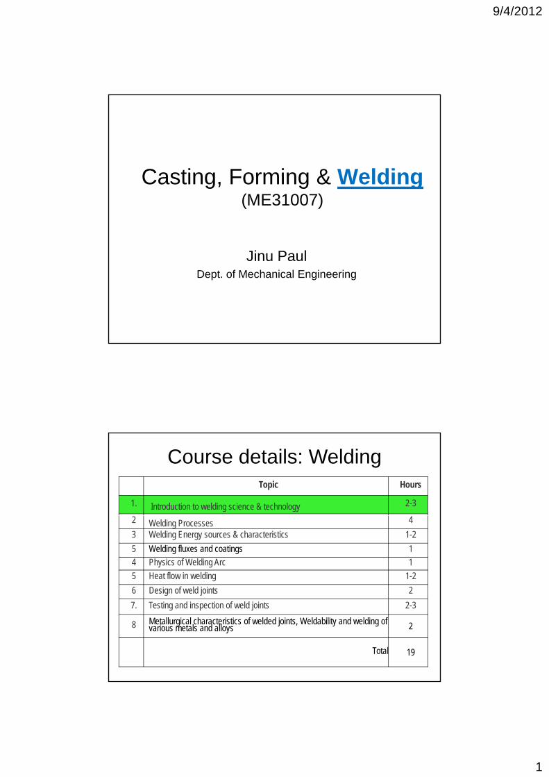
Course details: WeldingTopic Hours
1. Introduction to welding science & technology 2-3
2 Welding Processes 4
3 Welding Energy sources & characteristics 1-2
5 Welding fluxes and coatings 1
4 Physics of Welding Arc 1
5 Heat flow in welding 1-2
6 Design of weld joints 2
7. Testing and inspection of weld joints 2-3
8 Metallurgical characteristics of welded joints, Weldability and welding of various metals and alloys 2
Total 19
9/4/2012
2
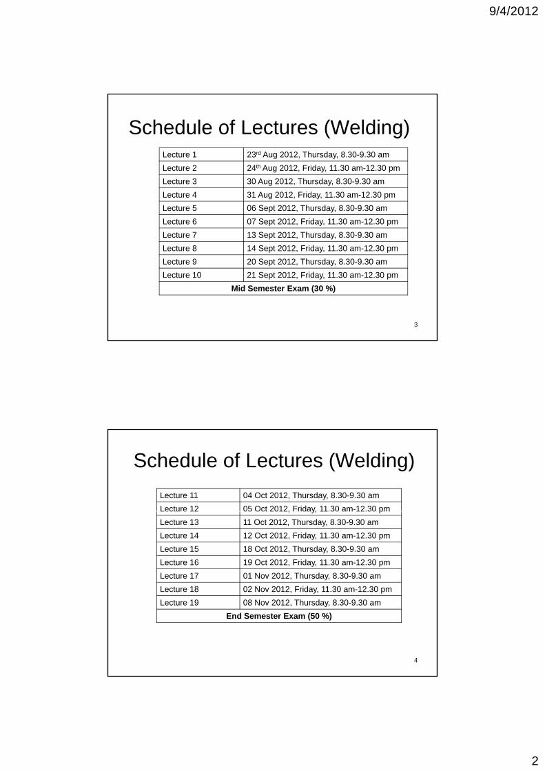
Schedule of Lectures (Welding)Lecture 1 23rd Aug 2012, Thursday, 8.30-9.30 am
Lecture 2 24th Aug 2012, Friday, 11.30 am-12.30 pm
Lecture 3 30 Aug 2012, Thursday, 8.30-9.30 am
Lecture 4 31 Aug 2012, Friday, 11.30 am-12.30 pm
Lecture 5 06 Sept 2012, Thursday, 8.30-9.30 am
Lecture 6 07 Sept 2012, Friday, 11.30 am-12.30 pm
Lecture 7 13 Sept 2012, Thursday, 8.30-9.30 am
Lecture 8 14 Sept 2012, Friday, 11.30 am-12.30 pm
L 9 20 S 2012 Th d 8 30 9 30Lecture 9 20 Sept 2012, Thursday, 8.30-9.30 am
Lecture 10 21 Sept 2012, Friday, 11.30 am-12.30 pm
Mid Semester Exam (30 %)
3
Schedule of Lectures (Welding)
Lecture 11 04 Oct 2012, Thursday, 8.30-9.30 am
Lecture 12 05 Oct 2012, Friday, 11.30 am-12.30 pm, y, p
Lecture 13 11 Oct 2012, Thursday, 8.30-9.30 am
Lecture 14 12 Oct 2012, Friday, 11.30 am-12.30 pm
Lecture 15 18 Oct 2012, Thursday, 8.30-9.30 am
Lecture 16 19 Oct 2012, Friday, 11.30 am-12.30 pm
Lecture 17 01 Nov 2012, Thursday, 8.30-9.30 am
Lecture 18 02 Nov 2012, Friday, 11.30 am-12.30 pm
Lecture 19 08 Nov 2012, Thursday, 8.30-9.30 am
End Semester Exam (50 %)
4

9/4/2012
3
Lecture 1
Introduction to welding
23rd Aug 2012, Thursday, 8.30-9.30 am
5
Overview of Joining processes
Joining processesprocesses
Welding
Mechanical Assembly
BrazingSolderingWelding (e.g., Threaded
fastners, rivets)
SolderingAdhesive bonding
6

9/4/2012
4
Joining processes-overview
Threaded fastnerRiveted Joint
Brazed Joint
Welded Joint
7
Some application areas of welding
Aircraft industryShip building
8Automotive industry
Dell_XPS
Sticky Note
coarse grain because it cools slowly and haz of both metals are different
Dell_XPS
Sticky Note
columnar grain due fast cooling
9/4/2012
5
Welding: Application areas
• Applications in Air, Underwater & SpaceAutomobile industry aircraft industry• Automobile industry, aircraft industry, ships and submarines
• Buildings, bridges, pressure vessels, girders, pipelines, machine tools, offshore structures, nuclear power plants, etc.
9
• House hold products, farm, mining, oil industry, jigs & fixtures, boilers, furnaces, railways etc.
Welding process-Features
• Permanent joining of two materials through l li d l lti flocalized coalescence resulting from a suitable combination of Temperature & Pressure
• Formation of Common metallic crystals at the joints/interface
10
the joints/interface
• With or Without filler material
Dell_XPS
Sticky Note
in haz region
9/4/2012
6
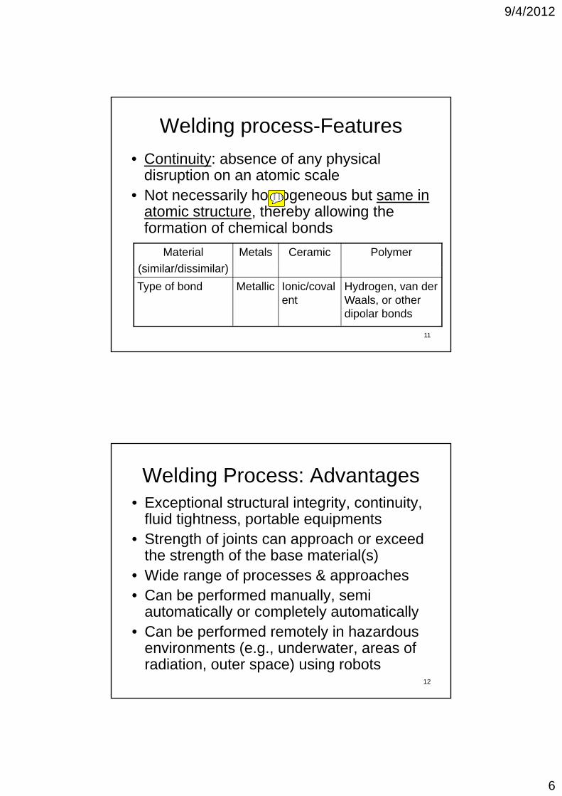
Welding process-Features
• Continuity: absence of any physical disruption on an atomic scalep
• Not necessarily homogeneous but same in atomic structure, thereby allowing the formation of chemical bonds
Material
(similar/dissimilar)
Metals Ceramic Polymer
11
(similar/dissimilar)
Type of bond Metallic Ionic/covalent
Hydrogen, van der Waals, or other dipolar bonds
Welding Process: Advantages• Exceptional structural integrity, continuity,
fluid tightness, portable equipments• Strength of joints can approach or exceed
the strength of the base material(s)• Wide range of processes & approaches • Can be performed manually, semi
automatically or completely automatically
12
automatically or completely automatically• Can be performed remotely in hazardous
environments (e.g., underwater, areas of radiation, outer space) using robots
Dell_XPS
Sticky Note
homogeneous means composition at all points is same
9/4/2012
7
Welding Process: Disadvantages
• Precludes disassembly
• Requirement for heat in producing many welds can disrupt the base material microstructure and degrade properties; may induce residual stresses
• Requires considerable operator skill
13
• Requires considerable operator skill
• Capital equipment can be expensive (e.g., laser beam, vacuum chambers etc.)
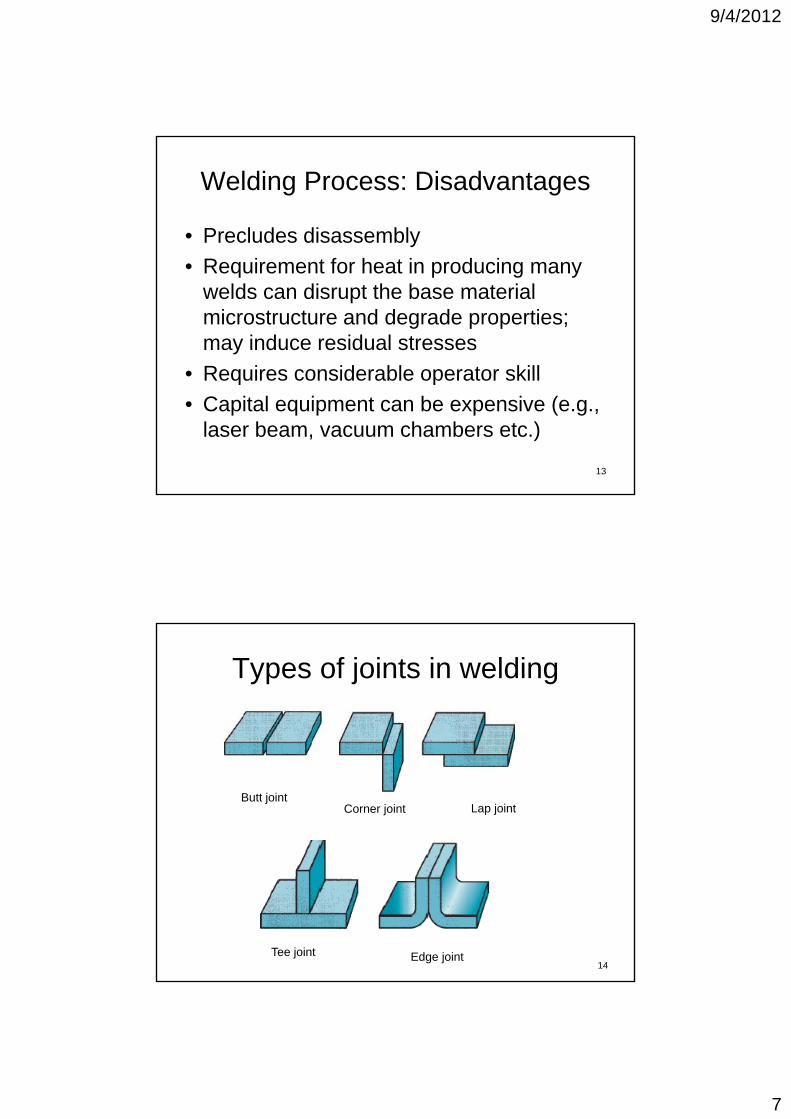
Types of joints in welding
Butt jointCorner joint Lap joint
14Tee joint Edge joint
9/4/2012
8
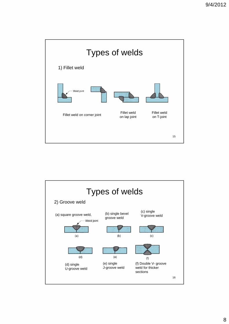
Types of welds
1) Fillet weld
15
Fillet weld on corner jointFillet weld on lap joint
Fillet weld on T-joint
Types of welds2) Groove weld
(a) square groove weld (b) single bevel(c) singleV groove weld(a) square groove weld, ( ) g
groove weldV-groove weld
16
(f) Double V- groove weld for thickersections
(d) singleU-groove weld
(e) singleJ-groove weld
9/4/2012
9
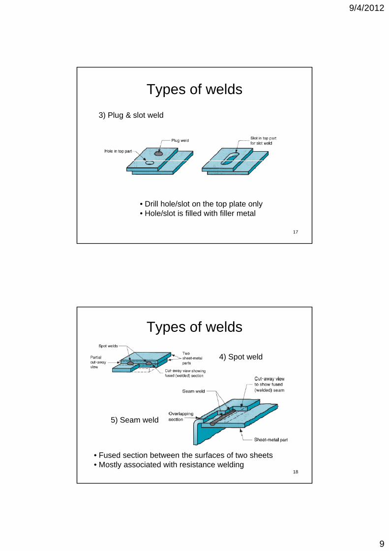
Types of welds
3) Plug & slot weld
17
• Drill hole/slot on the top plate only• Hole/slot is filled with filler metal
Types of welds
4) Spot weld
5) Seam weld
18
• Fused section between the surfaces of two sheets• Mostly associated with resistance welding
9/4/2012
10
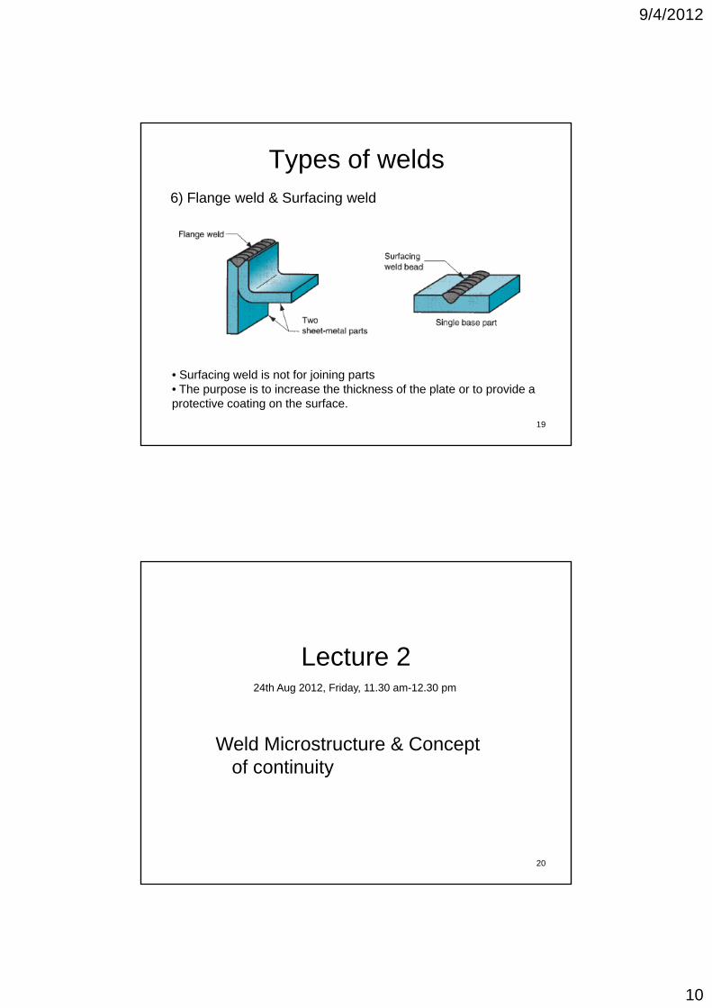
Types of welds6) Flange weld & Surfacing weld
19
• Surfacing weld is not for joining parts• The purpose is to increase the thickness of the plate or to provide a protective coating on the surface.
Lecture 2
Weld Microstructure & Concept of continuity
24th Aug 2012, Friday, 11.30 am-12.30 pm
20
y
9/4/2012
11
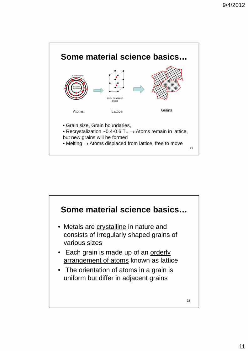
Some material science basics…
Atoms Lattice Grains
21
• Grain size, Grain boundaries, • Recrystalization ~0.4-0.6 Tm Atoms remain in lattice, but new grains will be formed• Melting Atoms displaced from lattice, free to move
Some material science basics…
• Metals are crystalline in nature and i t f i l l h d i fconsists of irregularly shaped grains of
various sizes
• Each grain is made up of an orderly arrangement of atoms known as lattice
• The orientation of atoms in a grain is
22
• The orientation of atoms in a grain is uniform but differ in adjacent grains
22

9/4/2012
12
Basic Classification of welding
(a) Fusion welding (b) solid-state welding
• Uses heat to melt the base metals • A filler metal is mostly added to the molten pool to facilitate the process and provide bulk and strength to the welded joint
a) Fusion Welding
2323
and strength to the welded joint.• e.g., Arc welding, resistance welding, Gas welding, Laser beam welding, Electron beam welding
Micro-structural zones in Fusion welding
2424
1) Fusion zone 2) Weld interface/partially melted zone3) Heat affected zone 4) Unaffected base metal
9/4/2012
13
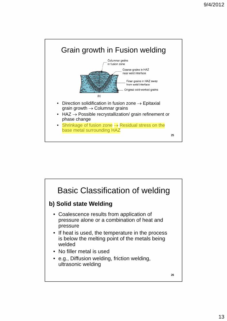
Grain growth in Fusion welding
• Direction solidification in fusion zone Epitaxial grain growth Columnar grains
2525
grain growth Columnar grains• HAZ Possible recrystallization/ grain refinement or
phase change• Shrinkage of fusion zone Residual stress on the
base metal surrounding HAZ
C l lt f li ti f
Basic Classification of welding
b) Solid state Welding
• Coalescence results from application of pressure alone or a combination of heat and pressure
• If heat is used, the temperature in the process is below the melting point of the metals being welded
2626
• No filler metal is used• e.g., Diffusion welding, friction welding,
ultrasonic welding
Dell_XPS
Highlight

9/4/2012
14
Micro-structural zones in Solid state welding
2727
• No Fusion zone• Little or no HAZ• Mechanically upset region• Plastic deformation at the interface
Role of Temperature in Fusion/ solid state welding
• Drives off volatile adsorbed layers of gases, moisture, or organic contaminantsg
• Breaks down the brittle oxide through differential thermal expansion
• Lowers yield/flow strength of base materialshelps plastic deformation
• Promotes dynamic recrystallization during plasticPromotes dynamic recrystallization during plastic deformation (if T > Tr)
• Accelerates the rates of diffusion of atoms
• Melts the substrate materials, so that atoms can rearrange by fluid flow (if T > Tm) 28
Dell_XPS
Highlight
Dell_XPS
Sticky Note
only for fusion welding
9/4/2012
15
Role of Pressure in solid state welding
• Disrupts the adsorbed layers of gases/organic• Disrupts the adsorbed layers of gases/organic compound or moisture by macro- or microscopic deformation
• Fractures brittle oxide or tarnish layers to expose clean base material atoms
• Plastically deform asperities (lattice) to increase
29
• Plastically deform asperities (lattice) to increase the number of atoms that come into intimate contact (at equilibrium spacing)
29
Mechanisms for obtaining material continuity
(1) Solid phase plastic deformation(1) Solid-phase plastic deformation, without or with recrystallization
(2) Diffusion, and
(3) Melting and solidification
303030

9/4/2012
16
Obtaining continuity1) Solid-phase plastic deformation
• Atoms are brought together byAtoms are brought together by plastic deformation
• Sufficiently close to ensure that bonds are established at their equilibrium spacing
• Significant lattice deformation
L tti l ft i th t i d
3131
(a) Cold deformation and lattice strain
• Lattices are left in the strained state (distorted) in cold deformation
Prevailing mechanism in solid state welding with out heat
Obtaining continuity1) Solid-phase plastic deformation (with heat)
• In hot state (0.4-0.5 Tm), the
(b) hot deformation and
strained lattice recover from the distorted state
• Atomic rearrangement & Recrystallization
• Grain growth across original interface
3232
(b) hot deformation and dynamic recrystallization• Eliminates the original physical
interface
Prevailing mechanism in solid state welding with heat

9/4/2012
17
Obtaining continuity2) Diffusion
• Transport of mass through atom
) S lid h diff i
Transport of mass through atom movement
• Can occur entirely in solid phase or with liquid phase
• For dissimilar materials thin layer of alloy at the interface
R t f diff i Diff i
3333
a) Solid-phase diffusion across the original interface (dotted line)
• Rate of diffusion Difference in composition (Fick’s law)
Prevailing mechanism in brazing/soldering
Obtaining continuity3) Melting and solidification
Liquid provided by melting the parent materials without or with additional filler
Establishing a bond upon epitaxial solidification of this liquid
3434
this liquid
• Solidifying crystals take up the grain structure & orientation of substrate/unmelted grains
• Prevailing mechanism in most fusion welding process

9/4/2012
18
Lecture 330th Aug 2012, Thursday, 8.30 am-9.30 am
Elements of welding set up, d i & h f
35
power density & heat transfer
Basic elements of a welding setup
1 Energy source to create union by1. Energy source to create union by pressure/heat
2. Method to remove surface contaminants
3. Protect metal from atmospheric contamination
3636
4. Control of weld metallurgy
9/4/2012
19
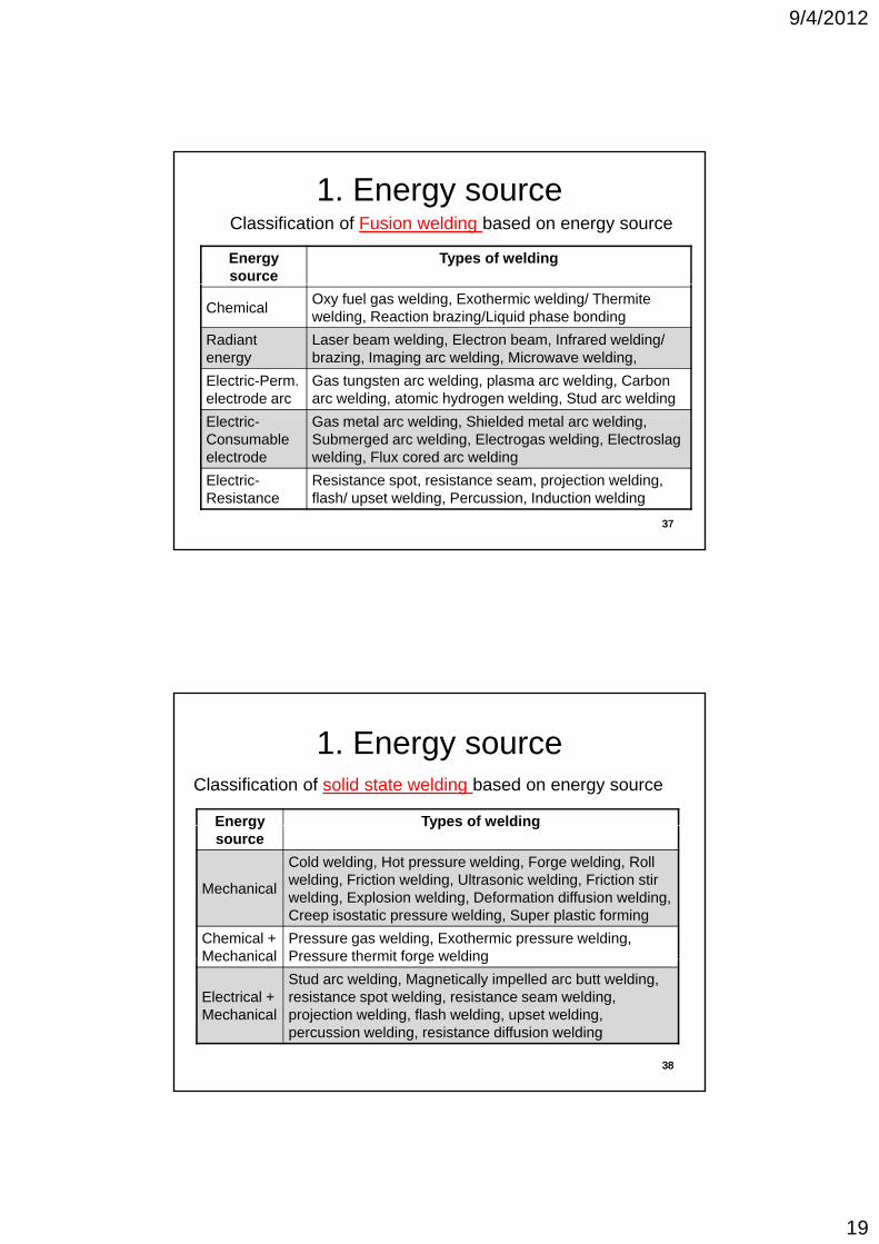
1. Energy sourceClassification of Fusion welding based on energy source
Energy source
Types of welding
ChemicalOxy fuel gas welding, Exothermic welding/ Thermite welding, Reaction brazing/Liquid phase bonding
Radiant energy
Laser beam welding, Electron beam, Infrared welding/ brazing, Imaging arc welding, Microwave welding,
Electric-Perm. electrode arc
Gas tungsten arc welding, plasma arc welding, Carbon arc welding, atomic hydrogen welding, Stud arc welding
El t i G t l ldi Shi ld d t l ldi
3737
Electric-Consumable electrode
Gas metal arc welding, Shielded metal arc welding, Submerged arc welding, Electrogas welding, Electroslag welding, Flux cored arc welding
Electric-Resistance
Resistance spot, resistance seam, projection welding, flash/ upset welding, Percussion, Induction welding
1. Energy sourceClassification of solid state welding based on energy source
Energy Types of weldingEnergy source
Types of welding
Mechanical
Cold welding, Hot pressure welding, Forge welding, Roll welding, Friction welding, Ultrasonic welding, Friction stir welding, Explosion welding, Deformation diffusion welding, Creep isostatic pressure welding, Super plastic forming
Chemical + Mechanical
Pressure gas welding, Exothermic pressure welding, Pressure thermit forge welding
3838
Mechanical Pressure thermit forge welding
Electrical + Mechanical
Stud arc welding, Magnetically impelled arc butt welding, resistance spot welding, resistance seam welding, projection welding, flash welding, upset welding, percussion welding, resistance diffusion welding

9/4/2012
20
2. Removal of Surface contaminants
• Surface contaminants may be organic films, b b d h i l d f thabsorbed gases or chemical compounds of the
base metals (usually oxides)
• Heat when used as source of energy removes organic films and absorbed gases
• Fluxes are used to clean oxide films and other i f l
3939
contaminants to form slag
• Slag floats and solidifies above weld bead protecting the weld from further oxidation
3. Protection from atmospheric contamination
• Shielding gases are used to protect moltenShielding gases are used to protect molten weld pool from atmospheric contaminants like O2 & N2 present in air
• Shielding gases could be Ar, He,CO2
• Alternatively, welding could be carried out in
4040
y gan inert atmosphere.

9/4/2012
21
4. Control of weld metallurgy
• Microstructures formed in the weld and HAZ determines the properties of the weld
• Depends on heating, cooling rates (power, weld travel speed)
• Can be controlled by preheating/ post heat treatment
4141
treatment
• De-oxidants, alloying elements etc. added to control weld metal properties
Power density• Defined as the power transferred to work per
unit surface area (W/mm2)( )
• Time to melt the metal is inversely proportional to power density
Welding Process Approx. Power density
(W/mm2)
4242
Oxy-fuel welding
Arc welding
Resistance welding
Laser beam welding
Electron beam welding
10
50
1000
9000
10,000

9/4/2012
22
Heat transfer mechanisms in Fusion Welding
43
Heat transf. factor f1= Heat transf. to work / Heat gen. by source
Melting Factor f2 = Heat used for melting / Heat tranf. to work
Useful heat or energy = f1.f243
Example 1The power source in a particular welding setup generates
3500 W that can be transferred to the work surface with a heat transfer factor f1 = 0 7 The metal to be welded isa heat transfer factor f1 0.7. The metal to be welded is low carbon steel, whose melting temperature is 1760K. The melting factor in the operation is 0.5. A continuous fillet weld is to be made with a cross-sectional area of 20 mm2. Determine the travel speed at which the welding operation can be accomplished?
H t it f l b t l (C ) 480 J/K K
44
Heat capacity of low carbon steel (Cp)=480 J/Kg.KLatent heat of melting Lm =247 kJ/KgDensity = 7860 kg/m3
Initial sample temperature T0 = 300 K
44

9/4/2012
23
Example 1-Solution
Rate of heat input to the weld bead = 3500 × f1 × f2= 3500 × 0 7 × 0 5 = 1225 J/s= 3500 × 0.7 × 0.5 = 1225 J/s
Heat input = Energy used for heating to Tm + Energy used for melting
1225 = [Cp(Tm-T0) + Lm ] × A × v
1225 [480(1760 300) + 247 103] 7860 20 10 6
45
1225 = [480(1760-300) + 247 ×103] × 7860 × 20 ×10-6 × v
Travel speed v = 0.0082 m/s = 8.2 mm/s
45
Summary: Lectures 1-3• Overview of welding, applications,
advantagesad a tages
• Welded Joint types
• Fusion & Solid state welding
• Elements of weld setup, Heat Balance, Power density
46
y
• N.B: Characteristics, micro-structural zones and concept of lattice continuity in fusion & solid state welding
46

9/4/2012
24
Lecture 4
Welding Processes1) Oxy-Fuel gas welding
31th Aug 2012, Friday, 11.30 am-12.30 pm
47
) y g g
47
Welding Processes-1) Oxy-Fuel gas welding
• Uses oxygen as oxidizerUses oxygen as oxidizer
• Acetylene, H2 or Natural gas, methane, propane, butane or any hydrocarbon as fuel
• Fuel + Oxidizer Energy
48
gy
• Acetylene is preferred (high flame temperature-3500 C)
48

9/4/2012
25
Gases used in Oxy-gas weldingFuel Peak
reactionHeat of
combustion (MJ/ 3)Temp (C) (MJ/m3)
Acetylene 3500 54.8
Methylacetylene-propadiene (C3H4)
2927 91.7
Hydrogen 2660 12.1
49
Propylene 2900 12.1
Propane 2526 93.1
Natural gas 2538 37.3
49
Oxy-acetylene welding (OAW) operation
5050
9/4/2012
26
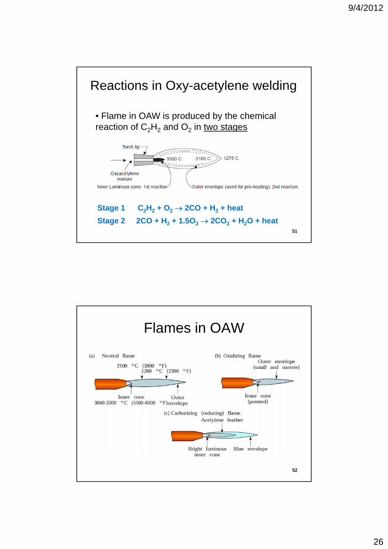
Reactions in Oxy-acetylene welding
• Flame in OAW is produced by the chemical reaction of C H and O in two stagesreaction of C2H2 and O2 in two stages
51
C2H2 + O2 2CO + H2 + heat
2CO + H2 + 1.5O2 2CO2 + H2O + heat
Stage 1
Stage 251
Flames in OAW
5252

9/4/2012
27
Flames in OAW
Neutral flame is used for most applications53
• Reducing flame for removing oxides from metals s ch as al mini m or
Flames in OAW- Reducing flame
from metals, such as aluminium or magnesium• Preventing oxidation reactions during welding• To prevent decarburization (i.e., C to
54
CO,) in steels. • Low carbon, alloy steels, monel metal (Ni+Cu+…), hard surfacing
54

9/4/2012
28
•The oxidizing flame causes the metal being elded to form an o ide
Flames in OAW-Oxy. flame
being welded to form an oxide. • Useful for preventing the loss of high vapor-pressure components, such as zinc out of brass, through the formation of an impermeable “oxide skin” (here, copper oxide)• Brass, bronze, Cu, Zn & Sn alloys
55
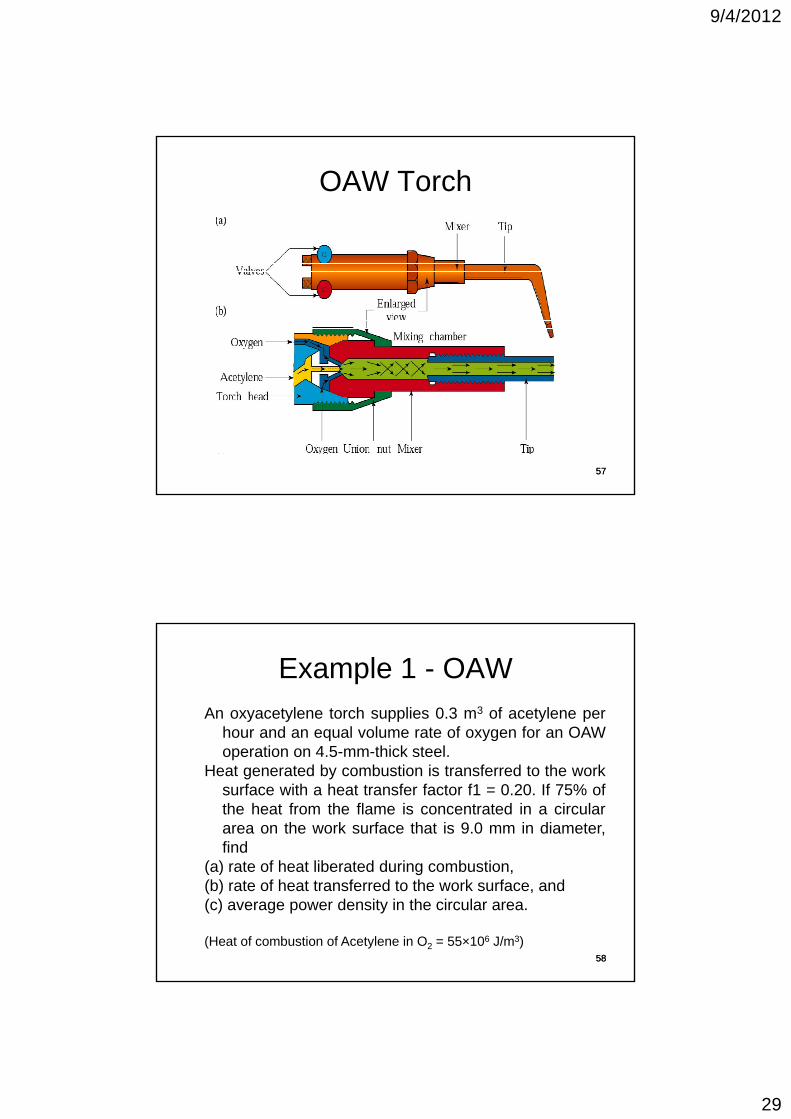
OAW set up
• Pressurized cylinders of O d C HO2 and C2H2
• Gas regulators for controlling pressure and flow rate• A torch for mixing the gases
56
gases• Hoses for delivering the gases from the cylinders to the torch
56
9/4/2012
29
OAW Torch
5757
Example 1 - OAWAn oxyacetylene torch supplies 0.3 m3 of acetylene per
hour and an equal volume rate of oxygen for an OAWoperation on 4.5-mm-thick steel.
Heat generated by combustion is transferred to the worksurface with a heat transfer factor f1 = 0.20. If 75% ofthe heat from the flame is concentrated in a circulararea on the work surface that is 9.0 mm in diameter,find
( ) t f h t lib t d d i b ti
58
(a) rate of heat liberated during combustion,(b) rate of heat transferred to the work surface, and(c) average power density in the circular area.
(Heat of combustion of Acetylene in O2 = 55×106 J/m3)58

9/4/2012
30
Example 1 - OAW(a) The rate of heat generated by the torch is the product of the volume rate of acetylene times the heat of combustion: RH = (0 3 m3/hr) (55×106) J/m3 = 16 5×10⁶combustion: RH (0.3 m /hr) (55×10 ) J/m3 16.5×10J/hr or 4583 J/s
(b) With a heat transfer factor f1 = 0.20, the rate of heat received at the work surface isf1 × RH = 0.20×4583 = 917 J/s
59
(c) The area of the circle in which 75% of the heat of the flame is concentrated is A = Pi. (9)2/4 = 63.6 mm2
The power density in the circle is found by dividing the available heat by the area of the circle: Power density = 0.75 × 917/63.6 = 10.8 W/mm2 59
OAW-Advantages
• The OAW process is simple and highly blportable
• Inexpensive equipment
• Control over temperature
• Can be used for Pre-heating, cutting & ldi
60
welding
60
9/4/2012
31
OAW-Disadvantages
• Limited energy welding is slow • Low protective shielding welding of reactive• Low protective shielding welding of reactive
metals (e.g., titanium) is generally impossible• Low power density, Energy wastage, total heat
input per linear length of weld is high• Unpleasant welding environment• Weld lines are much rougher in appearance
than other kinds of welds Require more
61
than other kinds of welds Require more finishing
• Large heat affected zones
61
OAW-Applications
• Preheating/post heat treatment
C b d f tti i i i• Can be used for cutting, grooving, or piercing (producing holes), as well as for welding
• Oxyfuel gas processes can also be used for flame straightening or shaping
• Oxidizing flame for welding Brass, bronze, Cu-
62
Zn and Tin alloys
• Reducing flame for low carbon & alloy steels

9/4/2012
32
Pressure Gas welding(Special case of OAW)
63
• Oxyfuel gas used for preheating the weld interface
63
References
• Principles of Welding, Robert W Messler
M t ll f W ldi J F L t• Metallurgy of Welding, J.F. Lancaster
• Welding Science and Technology, Md. Ibrahim Khan
• Welding Technology-O.P. Khanna
• Manufacturing Engineering and• Manufacturing Engineering and Technology, S. Kalpakjian
64
Related Documents