Welding Reference Guide

Welcome message from author
This document is posted to help you gain knowledge. Please leave a comment to let me know what you think about it! Share it to your friends and learn new things together.
Transcript

Welding
Reference Guide

4-H Motto‘Learn To Do By Doing’
4-H Pledge
‘I pledgeMy Head to clearer thinking,My Heart to greater loyalty,My Hands to larger service,My Health to better living,For my Club, my community and my country’
4-H Grace(Tune of Auld Lang Syne)
We thank thee, Lord, for blessings greatOn this, our own fair land.Teach us to serve thee joyfully,With head, heart, health and hand
Funding for this project has been provided by Agriculture and Agri-Food Canada through the Canadian Agricultural Adaptation Program (CAAP). In Saskatchewan, this program is delivered by the Agriculture Council of Saskatchewan. No portion of this manual may be reproduced without written permission from the Saskatchewan 4-H Council, phone 306-933-7727, email: [email protected]. Developed December 2013.This material was written by Christine Korol

TABLE OF CONTENTS
UNIT 1 WELDING 101 .............................................................................................................................. 1
CHAPTER 1: WELCOME TO WELDING ............................................................................................................... 2
CHAPTER 2: THE W’S OF WELDING: WHAT? WHY? WHO? ................................................................................. 3
CHAPTER 3: DRESSING THE PART ..................................................................................................................... 6
CHAPTER 4: WELDING SAFETY ...................................................................................................................... 14
CHAPTER 5: TOOLS OF THE TRADE ................................................................................................................. 19
UNIT 1 RESOURCES ....................................................................................................................................... 20
UNIT 2 ALL ABOUT ARC ......................................................................................................................... 22
CHAPTER 1: TALK THE TALK .......................................................................................................................... 23
CHAPTER 2: A VERY BRIEF HISTORY ............................................................................................................... 26
CHAPTER 3: HOW IT WORKS ........................................................................................................................ 27
CHAPTER 4: LET THE SPARKS FLY ................................................................................................................... 32
CHAPTER 5: CLEANING UP ........................................................................................................................... 35
UNIT 2 RESOURCES ....................................................................................................................................... 36
UNIT 3 READY, SET, WELD ..................................................................................................................... 37
CHAPTER 1: RUNNING A STRINGER BEAD ........................................................................................................ 38
CHAPTER 2: ARC LENGTH ............................................................................................................................. 40
CHAPTER 3: ELECTRODE ANGLE ..................................................................................................................... 42
CHAPTER 4: CURRENT SETTING (AMPERAGE) ................................................................................................... 44
CHAPTER 5: TRAVEL SPEED ........................................................................................................................... 46
CHAPTER 6: RE-STARTING, STOPPING AND FINISHING ........................................................................................ 48
CHAPTER 7: TRYING IT ALL TOGETHER ............................................................................................................ 50
UNIT 3 RESOURCES ....................................................................................................................................... 53
UNIT 4 EXAMINING ELECTRODES .......................................................................................................... 54
CHAPTER 1: CHOOSING THE CORRECT ELECTRODE FOR THE JOB ........................................................................... 55
CHAPTER 2: POLARITY ................................................................................................................................. 57
CHAPTER 3: CLASSIFICATION ......................................................................................................................... 60
CHAPTER 4: STORING ELECTRODES ................................................................................................................ 64
CHAPTER 5: PREPPING FOR WELDING JOINTS ................................................................................................... 65
UNIT 4 RESOURCES ....................................................................................................................................... 66
UNIT 5 WORKING WITH WELDS ............................................................................................................ 67
CHAPTER 1: JOINTS ..................................................................................................................................... 68
CHAPTER 2: WELDING DIFFERENT JOINTS ........................................................................................................ 71
CHAPTER 3: MAKING WIDER AND BIGGER WELDS ............................................................................................ 76
CHAPTER 4: DISTORTION.............................................................................................................................. 79
UNIT 5 RESOURCES ....................................................................................................................................... 82

UNIT 6 MASTER NEW SKILLS .................................................................................................................. 83
INSTRUCTIONAL DICTIONARY INDEX ................................................................................................................... 84
UNIT 6 RESOURCES ...................................................................................................................................... 102
UNIT 7 PERFECTING YOUR TECHNIQUE ............................................................................................... 103
CHAPTER 1: MAKING GOOD WELDS ............................................................................................................. 104
CHAPTER 2: TROUBLESHOOTING .................................................................................................................. 106
CHAPTER 3: TIPS N’ TRICKS ......................................................................................................................... 115
UNIT 7 RESOURCES ...................................................................................................................................... 117
UNIT 8 WRAPPING UP ......................................................................................................................... 118
CHAPTER 1: GETTING READY FOR ACHIEVEMENT DAY ...................................................................................... 119
CHAPTER 2: JUDGING ................................................................................................................................. 120
CHAPTER 3: THAT’S A WRAP ....................................................................................................................... 122
UNIT 8 RESOURCES ...................................................................................................................................... 123
APPENDIX ............................................................................................................................................ 124
THE WELL-DRESSED WELDER .................................................................................................................. 125
TABLES .................................................................................................................................................... 126
ACTIVITY WORKSHEETS ........................................................................................................................... 127
PROJECT PICKER ...................................................................................................................................... 137
WELDING TERMS ..................................................................................................................................... 140
RESOURCES ............................................................................................................................................. 150
ACKNOWLEDGMENTS ............................................................................................................................. 153

Unit 1 Welding 101
Bring with you to the meeting:
Pen or pencil
Notepad
In this Unit we will:
Talk about how important welding is to our lives.
Learn what type of clothing and gear we need for welding.
Discuss the dangers of welding and how to protect ourselves from them.
Look at some common welding tools.
Make a list of “Shop Rules” for our club to follow.

2 | Arc Welding Reference Book
CHAPTER 1: Welcome to Welding
This project is an introduction to welding where we will be learning how to arc weld. If you
have no experience welding, this project is the perfect place to start. If you already do have
some experience welding you’ve also come to the
right place because you will have the opportunity
to hone your skills, learn new things and by the
end of the project, you will definitely be better at
welding than you are today.
Since you’re here and enrolled in this 4-H
project you probably have a good idea of what
welding is and a reason for wanting to learn
how to weld. Maybe you want to be able to fix broken farm machinery. Maybe you like
working with your hands and want to try something new. Or maybe you’re creative and
can’t wait to turn that great ideas in your head into reality. You could even be an artist
hoping to make sculptures out of metal or a high school student wondering if you
should consider a career in welding. Perhaps you have an entirely unique reason for
being here or are just curious about welding and want to see what it’s all about.
Whatever your reason, this project will help you work towards your goals by giving you
lots of hands on experience and practical knowledge.
Before we dive into the world of welding, let’s take a moment to get to know each other
and find out why we’re all here.
Spark of Information
Do you want to learn how to
stick weld, electric arc weld
or use SMAW? You’re in
luck! These are all just other
names used for arc welding.
#1. Meet, Greet and Goals
ACTIVITY

Arc Welding Reference Book | 3
CHAPTER 2: The W’s of Welding: What? Why? Who?
Welding is the process of joining pieces of metal together. It is the most common, economical
and efficient way to join metals permanently. There are other ways to connect two pieces of
metal together (like riveting) but welding is the only way to join pieces of metal together so that
they act as a single piece. This is done by melting part of each
piece and adding a filler metal to form a joint.
There are many different ways to weld including using a gas
flame, an electric arc, a laser and even an ultrasound. As
technology continues to advance, new ways to weld are being
developed. Welding can also be done anywhere: inside, outside…
even underwater and in outer space!
weld, the result is a high strength joint (if done correctly, of
course). Because of this, as well as the number of different welding methods that have already
been developed, welding can be used to build massive structures like bridges and skyscrapers,
small objects like pens and door knobs and intricate ones like cars and airplanes.
Have you ever really stopped to think about all of things that we use in our day to day lives that
have been welded together? The list is endless.
Once we’ve stopped to think about how many of the objects we depend on are made of metal
we can start to see why welding is so important and why we need it.
Could you image if suddenly, all at once, all of the welds in the world
came apart? It would be catastrophic! Just picture it. Skyscrapers would
crumble down on themselves. Vehicles would flop into heaps of
parts in the middle of the road. Ships would fall apart and sink.
Airplanes would drop out of the sky in pieces. Farmers wouldn’t have
any of the tools and machinery they need to produce a crop. Even the
way you pass your day and what you do inside of your house would be
Many welders learn
how to arc weld first
before moving on to
other types of welding
like MIG and TIG.
Hot Tip
What is Welding?
#2. Here a Weld, There a Weld, Everywhere a Weld
ACTIVITY
Why Weld?

4 | Arc Welding Reference Book
affected. What would you eat without having a fridge, stove, microwave or toaster? Where
would you sleep since most likely your bed has collapsed? How would you spend your free time
without a computer, TV, radio or telephone?
It’s easy to see how different and much more difficult life would be without all of these metal
things that are held together by welds. But, the scope of how much welding affects our daily
lives goes beyond this. Many of the objects around us that are not made of metal are made
from a machine that is made of metal and welds. This includes things like clothing, dishes,
furniture, building materials and books.
Without metals and the ability to weld them we would have to resort to using materials like
stone and wood for all of our needs. These materials would work to replace some of the
products we know as common necessity, but many, like computers, would be impossible to
replace and most of our ways to manufacture products would disappear.
Would you believe that welding serves another purpose
beyond all of this? It does. Welding is also used to make
things better and stronger. For example, a bridge made of
one single plank is not nearly as strong as a bridge made of
several pieces welded together, like a box girder bridge. Even
if we join these pieces together with a method other than
welding, they wouldn’t be nearly as strong as if they were
held together by welds.
Welding is a great skill to learn so that we can build our own projects and do our own repairs.
Plus, it’s a skill that almost anyone can develop.
In order to work as a welder, you need to have good eyesight and be healthy and fit enough to
be able to bend, stoop and work in awkward positions. And, most importantly, you need to have
patience and be willing to practice and receive training because as you will see in Unit 2, it takes
just a few minutes to learn how to run a weld bead, but a lot of practice and patience before
you can weld something to be structurally sound.
#3. Chocolate Welding
ACTIVITY
Who Welds?

Arc Welding Reference Book | 5
Thankfully, the other skills required to be a good welder can be developed with all of the
practice you’ll be doing. This includes things like good hand-eye coordination, the ability to
concentrate on detailed work for long periods of time and having manual dexterity.
Since we already know that almost everything we use in our daily lives are welded or made by
equipment that is welded we could probably imagine all of the job opportunities available to a welder.
Welders work in construction, shaping the world around us with bridges and buildings. They
work in manufacturing, building machines for agriculture, mining, construction and our everyday
transportation. They work in mining and oil and gas extraction and in smelting and refining
plants. They work in the electric and electronics industries making our household appliances.
And of course they work in repair and maintenance.
In any of these fields, welders can advance to work as supervisors, inspectors, or even
instructors. They can work locally, for a large company, overseas, out in the ocean on oil rigs or
be self-employed.
And, if you’re thinking about farming, welding would be an invaluable skill for you to have.
Knowing how to weld not only saves farmers money by not having to hire a professional but also
saves time… which is always precious when you’re counting on crops and the weather.
#4. Finding Metal for Projects
ACTIVITY

6 | Arc Welding Reference Book
CHAPTER 3: Dressing the Part
When welding, there are a number of potential dangers for you and for others around you.
These dangers include things like electric shock, burns, eye damage, toxic fumes and fire. That’s
a pretty intense list, but the good news is that welding can be a safe activity when measures are
taken to protect ourselves from these potential hazards.
The first thing you can do to protect yourself when welding is to dress appropriately. Just like
firefighters wear clothing to protect from burns and construction workers wear hardhats to
prevent injury, welders dress head to toe in gear that will help them prevent injury and protect
themselves.
Instead of just looking at a list of all the gear we need to wear when welding, let’s find out
exactly what we’re protecting ourselves from in the first place and how we can dress from the
top down to keep ourselves safe.
In arc welding an extremely bright light is created, which gives off ultraviolet (UV) and infrared
radiation. Even just briefly exposing your eyes to this radiation can cause eye burn know as
welder’s flash. This is a condition, whose symptoms can take effect hours after exposure, that
causes extreme discomfort and can even result in swelling, fluid excretion and temporary
blindness. Yikes! Usually welder’s flash is temporary, but repeated or prolonged exposure to the
bright light created when we arc weld can lead to permanent eye damage, like cataracts or
retinal burning.
To protect your eyes from this radiation you could just simply never look at an arc, which is the
source of the bright light. That would be fine if we were just passing by a room where someone
was welding. But, of course, keeping your eyes closed when you’re the one doing the welding isn’t
an option, as doing so would create more hazards… and result in some pretty poor quality welds.
So that’s where welding helmets come in. Welding helmets have
a filter shade in the visor, which protects eyes by blocking out
the harmful radiation. Helmets also protect the face from hot
metal spatter, sparks and other flying debris.
The filter shades in welding helmets come in a range of shades –
from a No.8 (lightest) to a No. 14 (darkest). It may seem to make
the most sense to always use the darkest shade available so you
get the best protection for your eyes. But, unfortunately, this
strategy won’t work. Some welding operations create less light
Check out Table No. 1
in the Appendix – it
will help you to
choose the right filter
shade for the welding
job you’re working on.
Hot Tip
Protecting Your Face and Eyes

Arc Welding Reference Book | 7
than others and a dark filter shade would block out too much light, making it impossible to see
what you’re doing. This means you need to match the filter shade in your helmet with the
welding operation you’re performing.
As a rule of thumb, when you’re trying to choose the shade that is right for you and what you’re
welding, start with a shade that is too dark (you’ll know that it is too dark because you will have
trouble seeing the “weld zone” – the place where you are welding). Then, switch to lighter
shades until you get to one that allows you to sufficiently see the weld zone. If you see white
spots in your vision after you’ve stopped welding, the filter you are using is not dark enough.
There are two different types of welding helmets. Fixed shade helmets and auto-darkening
helmets, each with pros and cons.
With fixed shade helmets, it is very difficult to see much of anything through your visor until you
strike an arc. This is why the signature welding head nod, which flips down a helmet exists. With
their helmet up, welders set up their hand position to start a weld so they can see what they’re
doing and then at the last moment before striking an arc they lower their helmet with a quick
nod. These helmets also require you to manually change the filter to a different shade when you
change welding operations.
Auto-darkening helmets add convenience to a welder because you never have to manually
change a filter. There is a dial right on the helmet that you can turn to adjust the darkness of the
filter, without even taking the helmet off. This is a great feature if you are changing welding
tasks throughout your day or if you’re unsure about which filter you’ll need for the welding task
at hand. But the best feature of these helmets is, of course, that they auto-darken. This means
that while the helmet is down you can see clearly through the lens and that as soon as you strike
an arc the lens darkens to the filter shade selected. This darkening happens fast – in 4/10 of a
millisecond, which is fast enough to protect your eye from any damage.

8 | Arc Welding Reference Book
It’s because of these features that auto-darkening helmets are becoming an industry standard.
Despite this, fixed shade helmets are not going to go extinct any time soon because there are
certain welders, like pipeliners, who will always prefer to use them. For the welding that we will
be doing in this project, either type of helmet will do just fine. However, if you do need to buy a
new helmet, you will most likely prefer the features of an auto-darkening helmet. Fortunately,
some auto-darkening helmets with the standard features discussed here are comparable in
price to fixed-shade helmets (while ones with more features can be quite expensive). When
choosing a helmet, the most important things are that it fits properly so that you can see where
you’re welding and that it is comfortable.
Normally helmets have a clear lens on either side of the filter to protect the filter lens from being
damaged. But if you do scratch, crack or chip the filter it needs to be replaced. Scratches on the
filter allow dangerous UV and infrared light to pass through and so even though you’re wearing
the helmet, you won’t be properly protected. (Even if you don’t think your eyes are bothered by
the light that is passing through the crack or chip, you would still be damaging them.)
When welding, it is important to always clearly see what you’re doing. So, make sure that you
clean your lens often, because it is guaranteed that it will get dirty quickly once sparks and
spatter start flying. If the clear lens on your helmet gets scratched, you’ll want to replace it too,
since the scratch will get in your way of seeing clearly. However, replacing a scratched clear lens
isn’t urgent like replacing a scratched filter lens, because a scratched clear lens won’t injure your
eyes, it will just be a nuisance.
And remember, it is absolutely necessary to protect your eyes from the radiation given off
during arc welding; welder’s flash can occur from just a few seconds of looking directly at a
welding arc. Never look directly at an arc without proper eye protection.
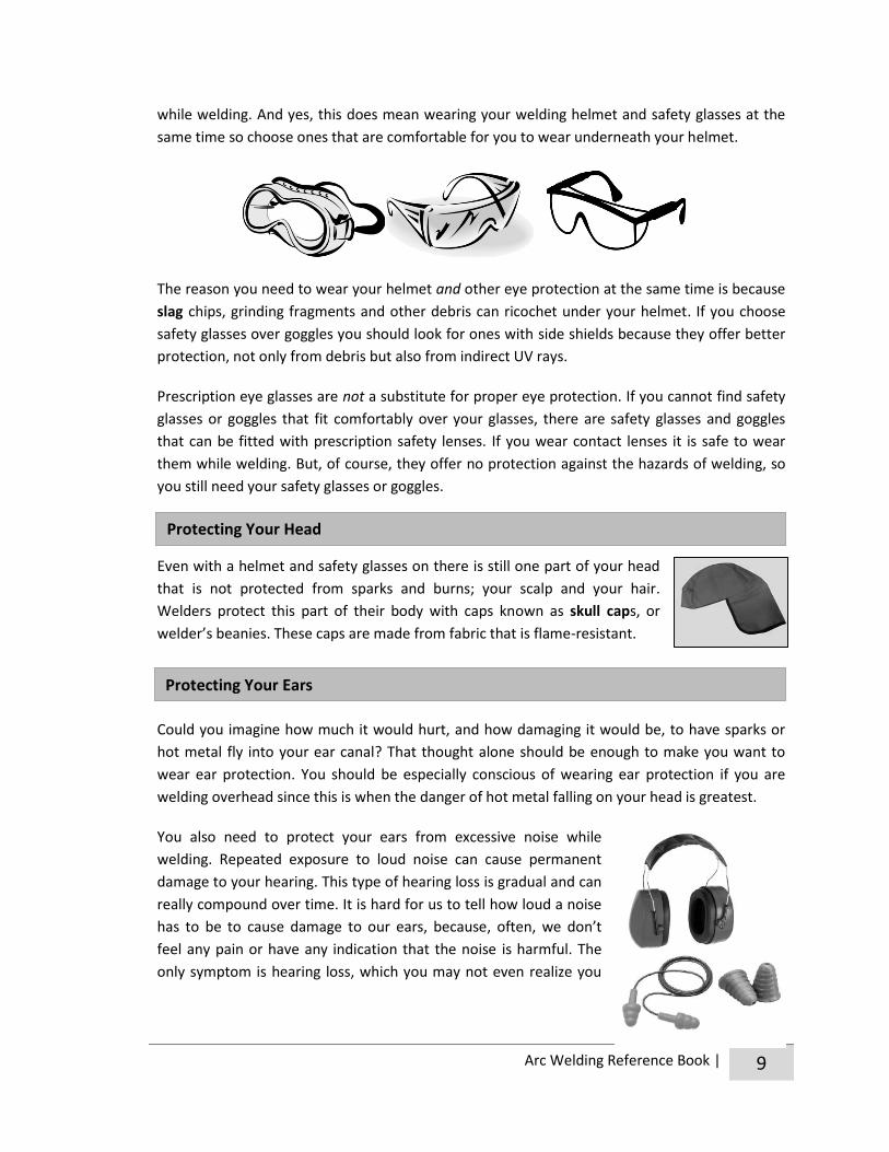
Beyond using a welding helmet, we need to protect our eyes, especially in arc welding, from
flying debris. To properly protect our eyes we need to wear safety glasses or goggles at all times
Helmet Handling
#6. Types of Helmets
#5. Parts of a Helmet
ACTIVITY
Protecting Your Eyes
Arc Welding Reference Book | 9
while welding. And yes, this does mean wearing your welding helmet and safety glasses at the
same time so choose ones that are comfortable for you to wear underneath your helmet.
The reason you need to wear your helmet and other eye protection at the same time is because
slag chips, grinding fragments and other debris can ricochet under your helmet. If you choose
safety glasses over goggles you should look for ones with side shields because they offer better
protection, not only from debris but also from indirect UV rays.
Prescription eye glasses are not a substitute for proper eye protection. If you cannot find safety
glasses or goggles that fit comfortably over your glasses, there are safety glasses and goggles
that can be fitted with prescription safety lenses. If you wear contact lenses it is safe to wear
them while welding. But, of course, they offer no protection against the hazards of welding, so
you still need your safety glasses or goggles.
Even with a helmet and safety glasses on there is still one part of your head
that is not protected from sparks and burns; your scalp and your hair.
Welders protect this part of their body with caps known as skull caps, or
welder’s beanies. These caps are made from fabric that is flame-resistant.
Could you imagine how much it would hurt, and how damaging it would be, to have sparks or
hot metal fly into your ear canal? That thought alone should be enough to make you want to
wear ear protection. You should be especially conscious of wearing ear protection if you are
welding overhead since this is when the danger of hot metal falling on your head is greatest.
You also need to protect your ears from excessive noise while
welding. Repeated exposure to loud noise can cause permanent
damage to your hearing. This type of hearing loss is gradual and can
really compound over time. It is hard for us to tell how loud a noise
has to be to cause damage to our ears, because, often, we don’t
feel any pain or have any indication that the noise is harmful. The
only symptom is hearing loss, which you may not even realize you
Protecting Your Head
Protecting Your Ears

10 | Arc Welding Reference Book
have until you take a hearing test. By the time hearing loss happens, it is way too late.
In arc welding, the noises we are exposed to, especially when using a chipping hammer, are
great enough to cause damage to your ears. To protect our ears from both noise and hot debris
you can use ear muffs or ear plugs. Either will provide adequate protection against hearing loss,
but ear muffs will better protect your entire ear. You should choose the type of ear protection
that you find the most comfortable.
Wearing the correct clothing while welding not only protects welders from burns caused by
sparks and weld spatter but, also from arc radiation. Like the sun, the UV radiation given off
during welding causes skin burns. That means that if all of your skin isn’t covered, you may be
surprised to go home after a day of welding with a severe “sunburn”.
To protect ourselves properly, we need to:
Wear clothing that covers all of our body. You can either choose to wear coveralls or a
long sleeve shirt (no v-necks).
Wear clothing that is free of any frays or
tears.
Wear clothing that fits properly, allowing you
the ability to move freely but not be baggy
and loose.
Eliminate places in your clothing wear hot
metal can get trapped. This means unrolling
any cuffs on your pants and sleeves, tucking
your shirt into your gloves and wearing your
pants over top of your boots.
Wear clothing that is free of grease and oil,
since these substances ignite easily.
Make sure you never carry anything
flammable in any of your pockets like cigarette lighters or matches and avoid carrying
paper in your breast pocket.
Believe it or not, the material that our welding clothing is made
of plays a very important role in protecting us. When welding,
we need to avoid clothing that is made of synthetic materials
because they melt easily. These include things like polyester
and nylon. Instead, we should choose clothing that is made of
Spark of Information
Labels inside of clothing will
specify what materials they
are made from. For
example, a tag in a shirt may
say “65% cotton, 35%
polyester,” making it
unsuitable for welding
because it is not made of
100% natural materials.
Protecting Your Body

Arc Welding Reference Book | 11
natural material like leather, wool, denim or heavy cotton.
Of these natural materials, leather is the most expensive and provide the best protection and
durability. You’ll find professional welders wearing leather aprons, jackets and chaps. Tightly
knit wools give the second best protection, but may be hard to find. Denim is a common, and
good, material to wear while welding and so is heavy cotton. Both of
these options are less expensive and easier to find. Lightweight
clothes, even if made of natural material, should be avoided
because heavy spatter will burn through them quickly. If you are
shopping for new clothes to wear while welding, buying ones that
are special treated to be flame retardant are the most ideal.
Your hands are the closest thing to the hot material when you’re welding and are constantly
splashed with metal and flying sparks. The only thing that will protect your hands against all of
this is leather gauntlet gloves, which are long leather gloves that will cover your wrists and
much of your lower arm.
It is important that your gloves don’t have any holes so sparks can’t get inside
of them. Hole-free gloves will also insulate you better which helps protect
against electric shocks. You should also make sure to keep your gloves dry for
this same reason.
Grabbing hot metal while wearing gloves can still hurt your hand and can cause gloves to shrink,
and become stiff and hard. So even while wearing gloves using pliers to grab hot metal.
Guaranteed if hot metal gets inside of your shoe
you’ll drop everything to get it out. The result
might not only be a bad burn, but in your panic
you may drop something you’re working with that
could cause more serious problems like a fire.
To avoid a problem like this, never wear low cut shoes when
welding. This includes slip on shoes and loafers. Nylon running
shoes are also a bad idea because if exposed to high heat, they
could melt to your foot.
Protecting Your Hands
Protecting Your Feet

12 | Arc Welding Reference Book
The best thing to wear on your feet when welding is some sort of work boot. Ones made with
leather and that have steel toes are best.
Make sure to keep boots laced to avoid tripping and to keep your pants over your boots so that
hot metal and sparks cannot fall into the rim of your boot and cause burns.
Wondering where you can buy all of this safety gear? Welding supplies stores and
stores like Peavey Mart, Princess Auto and Canadian Tire should sell everything that
you need. But, check tags on existing clothing first because you might already own
some clothing that is appropriate to wear while welding.
The Well-Dressed Welder
Welding helmet
Ear plugs or muffs
Gauntlet gloves
Skull cap
Safety glasses
or goggles
Long sleeves shirt or coveralls
made of natural fibers
Pants, chaps or coveralls
made of natural fibers
Work boots
Hot Tip

Arc Welding Reference Book | 13
#7. The Good and the Bad
ACTIVITY
#8. The Right Gear
#9. Gear Guide
#10. At the Store

14 | Arc Welding Reference Book
CHAPTER 4: Welding Safety
Even when dressed properly, we still have to take extra safety measures to protect ourselves
from other things that can cause injuries or even death – things like electric shock, fumes, gases,
fire and explosions. Below is a list of things you can do to insure safety for yourself and for
others while welding:
1. Inspect equipment before beginning to weld. Every day before starting to weld we
need to inspect our welding equipment to make sure that everything is in good
working order and connected properly. We will learn about the arc welding machine
and what to look for in our inspection in the next Unit. If you find something in this
safety check that you think could pose a hazard tell your leader or disconnect the
power source and ask a qualified repair man.
2. Keep your work area clear of clutter and tripping hazards. This is important because
if you, or someone passing by your welding station trips, you could be injured by
shock, hot metal or falling. To avoid accumulation of dangerous clutter clean up at the
end of every day and periodically throughout the day by rolling up cables, organizing
your tools and sweeping the floor.
3. Never weld on containers that hold or have held
flammable materials. Doing so is extremely dangerous
and could result in an explosion.
4. Be aware of fire hazards around you. The heat of a
welding arc can get as hot as 5,500°C and sparks and
molten metal from your work can spray more than 10 metres! So make sure you
distance yourself at least 10 metres from any combustible materials, which includes
things like rags, wood, paper, gasoline and oil.
5. Know where the fire alarms, fire extinguishers and exits are located. If you do have
an emergency the first thing to remember is don’t panic, shut off your welder if
possible and get out. Alert the fire department by pulling an alarm or calling 9-1-1. If
the fire is small enough to safely put out allow your leader to do it.
6. Use fire-resistant screens and curtains when working around
others. If working in close proximity to others, using fire-resistant
screens or curtains will protect them from being hit by sparks and
spatter and protect their eyes from the light given off when welding.
7. Keep your head out of the fume plume. The fume plume is the
visible column of fume that rises from the spot where you’re

Arc Welding Reference Book | 15
welding. It contains solid particles from the
electrode, base metal and base metal coating.
Exposure to these fumes can cause burning eyes
and skin, dizziness, nausea and fever.
8. Be aware of hot metal and know how to handle
it. Metals can get up to 1,000°C and have no
change in colour to indicate that they’re hot. As a
safety precaution, with your gloves on, tap metal
to see if it really is cool enough to touch before grabbing it. If metal is hot, it should
always be handled with metal tongs or pliers. If you leaving hot metal somewhere to
cool, write “HOT” on it with soapstone. If you do receive a burn, make sure you tell
your leader.
9. Have proper ventilation. Proper ventilation can help direct the fume plume away
from your face. It is also needed because some gases produced during arc welding can
be toxic and others displace oxygen, making a shortage of oxygen in the air you
breathe, which could lead to dizziness or even unconsciousness. If you feel dizzy or
nauseous try to improve ventilation in your area. If that doesn’t work, turn off your
welder, get some fresh air immediately and notify your leader.
Depending on where you’re welding natural ventilation may be adequate. This
includes the wind if you’re working outside or the flow of air through open windows
and doors if you’re working inside.
When you need more ventilation than this, because of where you are welding, what
you are welding, and how many welders are being operated in the same area, other
ventilation can come from fans to help move air through the workplace or exhaust
hoods that captures fumes at or near the arc.
10. Avoid possible shock hazard. Shock is one of the most serious risks to a welder.
Contact with metal parts that are electrically hot can cause injury or death because of
the shock. When a welder is in use, and when it is idling, the electrode and all parts in
the welding circuit are electrically hot.
There are two types of electrical shocks an unsafe welder can receive: primary
voltage shock or secondary voltage shock.
Primary voltage shock is very dangerous because of how strong it is (230-460V). While
the welder is plugged in, even if the welder is off, you can receive this type of shock by
touching the inside of a welder and any other grounded metal at the same time,
including the welder frame and casing. To avoid a primary voltage shock you should:
a. Never remove a fixed panel from your welder.
b. Never weld with any of the welder’s covers removed.

16 | Arc Welding Reference Book
c. Make sure that your welder is always properly grounded.
d. Never ignore a blown fuse, which is a warning sign that something is wrong with
your welder.
e. Have the welder installed by an electrician.
f. Before opening your welder disconnect the power by either unplugging the
welder or turning off the power disconnect switch.
Secondary voltage shock (60-100V) happens when a part of the welding circuit, like a
bare spot on the electrode cable, and the grounded piece of metal you are welding are
touched by parts of your body at the same time. To avoid a secondary voltage shock you
should:
a. Wear dry gloves without holes.
b. Avoid touching electrodes and the metal parts of electrode holders with skin or
wet clothing.
c. Keep dry insulation (a.k.a. the proper protective clothing) between your body,
the ground and the metal being welded.
d. Do not work in wet conditions or where spills are present.
e. Check electrode holder and cables for damage and have any damage repaired
before using.
A few other things you can do to avoid electrical shock
are to never weld on live circuits, be sure the ground
clamp is securely fastened to the welding table or metal
being welded and never set the electrode holder on the
welding table or in contact with any grounded metal.
11. Read and obey warning labels. Dangerous materials will
be marked with symbols to let us know of their potential hazards. In Canada, this
labelling system is called WHMIS (Workplace Hazardous Materials Information
System). It is important to be able to identify WHMIS symbols and know what they
mean so that we can safely handle dangerous materials.
The following are standard WHMIS symbols:
Compressed Gas
Compressed gases are materials that are gases at normal room
temperature and pressure, but that are packaged as pressurized gas,
dissolved gas or liquefied gas by compression or refrigeration.
Containers holding compressed gas need to be kept away from heat and
handled carefully. The gases are held under high pressure and the container may
explode if heated or dropped or become a projectile object when ruptured. Examples
Damaged cables
can be repaired
with electrical tape.
Hot Tip

Arc Welding Reference Book | 17
of compressed gases that you may find in a welding shop are acetylene and oxygen
tanks.
Flammable and Combustible Material
Flammable or combustible materials are capable of catching fire easily
when exposed to a flame, spark or other source of ignition (like
friction). The materials may be solids, liquids or gases and in the
welding shop include things like acetylene, grease and paints.
Oxidizing Material
Fires always need three things to start: fuel (a combustible material),
an ignition source (heat, spark, friction, etc.) and oxygen. Oxidizing
materials increase the rise of fire or explosion if they come in contact
with flammable or combustible materials because they release oxygen
or other oxidizing materials. Some examples of oxidizing materials are hydrogen
peroxide and compresses oxygen.
Poisonous and Infections Material – Materials Causing Immediate and Serious Toxic
Effects
These materials can cause death or injury when a person is exposed to
even small amounts, through inhalation or skin contact. Some
examples of these poisonous materials are sodium cyanide and
hydrogen sulphide.
Poisonous and Infections Material – Materials Causing Other Toxic Effects
With repeated or prolonged exposure these materials can cause life-
threatening and serious long-term health problems, like cancer or
reproductive problems. They can also cause less severe but
immediate reactions like eye and skin irritation. Some examples of
these poisonous materials are mercury and acetone.
Poisonous and Infections Material – Biohazardous Infectious Material
These materials contain pathogens (disease causing organisms) that
have been shown to cause serious disease resulting in illness or death.
Some examples of these poisonous materials are a culture containing
salmonella and a blood sample containing Hepatitis B.
Corrosive Material
These materials can eat through metals and permanently damage
human tissue on contact. They may also be harmful to inhale. Some
examples of corrosive materials are ammonia and hydrochloric acid.

18 | Arc Welding Reference Book
Dangerously Reactive Material
These materials are very unstable. They may self-react (explode)
when exposed to things such as an increase in temperature, physical
shock or friction. They may also react with water to release toxic or
flammable gases. Some examples of reactive materials are ozone and
benzoyl peroxide.
You may be thinking that this is a lot of safety information. But when we go out in the shop and
start welding it’s important that we remember to stay safe so that we don’t hurt ourselves or
others. This means constantly being aware of the possible dangers and following the rules. If
your leader has any safety guidelines for the shop beyond the ones listed here, be sure to follow
them as well. Remember, arc welding is a safe activity if we know the dangers, follow safety
rules and use common sense.
#11. WHMIS I.D.
ACTIVITY
#12. Rules of the Shop
ACTIVITY
#13. Safety Video
#14. Team Tent Building

Arc Welding Reference Book | 19
CHAPTER 5: Tools of the Trade
Now that we know all about welding safety, it’s time to get familiar with some of the tools we’ll
use and see around the shop.
Angle grinder – This is a hand-held power tool that can be used to clean metal
before welding and to shape the edges of metal pieces.
Chipping hammer – These hammers are used to chip off slag from the weld
before passing another weld over it. Some of these hammers come as a
brush/hammer combo.
Wire Brush – These stiff wire brushes are used to clean welds once the slag has
been chipped off. They can also be used to remove rust, paint, etc. before
welding.
Soapstone – This is like chalk, except it won’t burn at high temperatures. An area marked with
soapstone is easier to see through a welding helmet. So if you’re having trouble seeing the spot
you need to weld, make it with soapstone. It will really help!
Water bucket – This is used to dip hot metal in so that it cools quickly. You’ll want to do this
with your practice pieces so that you don’t have to wait for the metal to cool down to keep
working. But, quenching metal in cold water like this destroys some of the metals desirable
qualities. So you do not want to do this with any of your actual welding
projects.
Pliers – You’ll need to have a pair of pliers with you to pick up hot pieces of
metal.
Tape measure and framing square – These tools will be
needed when working on your projects to ensure that you
have the correct measurements and that you are welding
your pieces together at the correct angles.
Welding table – This is a metal table where you’ll do all of your welding. Most are made of a
thick steel plate, but if the table is made of copper or cast iron, welding spatter won’t stick to it.
C-clamp – This clamp will come in handy when you need to hold two
objects in place to be welded.

20 | Arc Welding Reference Book
Fixed clamp – Many welders attach these clamps to a vertical pipe that is fixed to their welding
table. The clamp can then hold their work in position.
Can for metal scraps – This is a safe place to put scraps. The can must be made of
metal so that if scraps are still a bit hot, no fire will start.
Most of these tools will already be found in the welding shop. If you need to bring any of your
own tools to the meeting, your leader will let you know.
Unit 1 Resources
http://www.weldinginfocenter.org/basics/ba_02.html
http://www.aws.org/technical/facts/
http://www.weldinginfocenter.org/health/index.html
http://www.lincolnelectric.com/en-us/education-center/welding-safety/Pages/welding
-safety.aspx
http://www.worksafesask.ca/Hazard-symbols-classes
www.health.gc.ca/whmis
http://www2.worksafebc.com/Topics/WHMIS/Introduction.asp
#15. Shop Tour
ACTIVITY
#16. Bottle Toss

Arc Welding Reference Book | 21
#1. Meet, Greet and Goals
COMPLETE LIST OF
UNIT 1 ACTIVITIES
#2. Here a Weld, There a Weld, Everywhere a Weld
#3. Chocolate Welding
#4. Finding Metal for Projects
#5. Parts of a Helmet
#10. At the Store
#9. Gear Guide
#11. WHMIS I.D.
#6. Types of Helmets
#8. The Right Gear
#7. The Good and the Bad
#12. Rules of the Shop
#13. Safety Video
#15. Shop Tour
#14. Team Tent Building
#16. Bottle Toss


Unit 2 All About Arc
Bring with you to the meeting:
Pen or pencil and notebook
Clothes to weld in and safety gear (see appendix for the image of the well-dressed welder)
In this Unit we will:
Look over some common words used by welders.
Take a quick look at the history of welding.
Find out how shielded metal arc welding works.
Learn how to set up the welding circuit and strike an arc.
Make a list of clean-up duties that needs to be done at the end of the day.

Arc Welding Reference Book | 23
CHAPTER 1: Talk the Talk
If you want to be a welder, you not only have to dress and act safely like one, you also need to
talk like one. Most trades and professions have a unique set of words when communicating
about their jobs, and welding is no exception. Becoming familiar with the list of “welding words”
below will help us as we learn about arc welding in the following chapters.
Current – the movement or flow of an electrical charge through a conductor.
Welding circuit – the electrical path in welding where the current flows: from the power source
through the components and connections that make up the circuit and then back to the source.
The welding circuit consists of the welding machine (the power source), the electrode cable, the
electrode holder, the electrode, the arc, the base metal, the ground clamp and the ground cable.
Amperage – the amount of electrical current that flows through a circuit. In welding, when you
adjust the amperage or “amps” you adjust the amount of heat that you are welding with.
Direct current (DC) – an electrical current that flows in one constant direction, either from
positive to negative or from negative to positive.
Alternating current (AC) – an electrical current that constantly reverses its direction between
positive and negative at regular intervals.
Welder or welding machine – the machine (that can confusingly share the same name with the
person that is operating the machine) which provides a power source to carry out welding
operations.
Electrode Cable
Welding
Machine
AC or DC
Power Source
Electrode Holder
Electrode
Arc
Base Metal
Ground Clamp
Ground Cable

24 | Arc Welding Reference Book
Duty cycle – the number of minutes, usually during a 10-minute cycle period, that the welder can
be operated at maximum output without needing to cool down. It is usually given in a percentage.
For example, 30% duty cycle means that the unit has the capability of operating at maximum
output for three minutes of each 10-minute period before the welder needs to cool down.
Base metal – the metal or alloy this is being welded. Also referred to as the workpiece.
Ground clamp – the clamp that must be attached to the metal being welded (the base metal) or
to the welding table in order to arc weld.
Ground cable – a flexible, durable and well insulated cable attached to the ground clamp used
to move current back to the welder. Also called work lead or ground lead.
Electrode – also called welding rods. These are the long metal rods, comprised of a wire core
and a flux covering. When the electrode is part of the welding circuit the arc is created between
its tip and the base metal. The heat of the arc cause the electrode to melt providing the filler
material needed to fuse metals together in arc welding.
Flux – the coating found on the outside of the electrode, covering the core wire of the
electrode. When the flux melts it produces shielding gas to protect the weld and then forms a
hardened protective coating over the weld, called slag.
Electrode holder – the insulated hand clamp used to hold the electrode during welding. The
electrode holder conducts current into the electrode. It is also commonly referred to as the stinger.
Electrode cable – flexible, durable and well insulated cable used to move current from the
welder to the electrode. It is also called electrode lead.
Arc – the physical gap between the end of the electrode and the base metal where heat is
generated. The heat is caused by the flow of electricity through the gap (due to resistance of
current flow and arc rays).
Weld pool – also called weld puddle. This is the area of the base metal which has reached its
melting point and has become a pool of hot liquid metal. It is normally about the size of a dime.
Arc length – the distance from the tip of the electrode to the adjacent surface of the weld pool.
Bead – the metal that has been added in welding. It is this continuous deposit of weld metal
that creates the seam between the two pieces of metal that have been fused together.
Slag – the waste material left on the weld bead that must be chipped off. Is a nonmetallic waste
product created by the flux.

Arc Welding Reference Book | 25
At first, reading through this list of terminology may feel like you’re reading a foreign language,
especially if you’ve never welded before. But, don’t worry. Once we get out in to the shop and
start welding, you’ll begin hearing these words being used in context. And, eventually they will
begin to feel like common place. Soon you’ll be adding more words into your “welding
language” and will be speaking like a welder in no time. Remember that these words, and all
other welding terms that you’ll need to know for the arc welding, are found at the back of this
Reference Manual.
#17. Learn the Lingo - Crossword
ACTIVITY
#19. Learn the Lingo – Word Match
#18. Learn the Lingo - Wordsearch

26 | Arc Welding Reference Book
CHAPTER 2: A Very Brief History
Humans started working with metals a long time ago (more than 6,000 years ago) and have
actually been welding metals together for quite a while as well (for more than 3,000 years.)
However, the method they used to weld for thousands of years was fairly primitive. They used a
forge to heat the metal and then hammered it together until it fused.
It wasn’t until relatively recently (200 years ago) that humans began to discover a more efficient
way to fuse two pieces of metal together. Despite that, would you believe that the first cars
built in the early 1900s were bolted together, not welded? This is because even though electric
arc welding began to be developed more than 200 years ago, it wasn’t used successfully in
industry until about 1910.
In 1782, a professor in Germany made the first known electric arc weld. Then in 1801, in
England, Sir Humphrey Davy made the first sustained arc weld. But, the first time that someone
intentionally joined pieces of metal together with arc welding wasn’t until 1860, by an
Englishman named Wilde. Throughout the rest of the late 1800s and beginning of the 1900s
various advances were made in arc welding to improve the process. It wasn’t until the demands
for products that came with World War I that arc welding became prevalent in industry.
Since then, arc welding has continued to be
developed and is still the most widely used type of
welding. In fact, there are more than 20 different arc
welding processes being used today. In this project,
we are going to work with the arc welding process
that is the most common. It is called SMAW, which
stands for shielded metal arc welding. It is often
referred to as stick welding, electric arc welding or
simply just as arc welding.
SMAW is a great place to start learning how to weld
because the skills that you develop can be transferred to all other types of welding. Plus, SMAW
machines are quite accessible because of how mainstream they are. You’ll find them on farms,
in small welding shops and in various welding industries.
Spark of Information
All of these different arc
welding processes use the
same three principles to fuse
metal. They all use a heat
source, a filler material and
a type of shielding.

Arc Welding Reference Book | 27
CHAPTER 3: How It Works
All types of arc welding require three things to weld metal. They all require a heat source, a filler
material and a type of shielding. And so, of course, shielded metal arc welding is no exception.
In SMAW, heat is generated when the arc is struck. And by heat we’re talking about 3,600°C! As
a welder, you’re responsible for creating this heat by keeping a small amount of space between
the electrode and your workpiece. This creates a gap in the electrical circuit. When electrical
current jumps across this gap, it creates the arc, and thus the heat.
When the arc is struck, the heat that is generated begins to melt the base metal, creating a
molten puddle. The force of the arc also creates a crater in the base metal. You can picture this
crater being formed in the way that the force of water from a garden hose makes ruts in dirt as
you drag it along the ground.
At the same time, the end of the electrode is also melted and the particles of molten metal pass
through the arc stream into the molten puddle. This is the filler material that builds up forming
the weld bead. As the electrode adds material to the weld it is used up, and so becomes smaller
and smaller.
The flux coating on the electrode is also melted by the arc. When this happens, gases are
released which shield the weld puddle from the surrounding atmosphere. (Gases in the
atmosphere can ruin a weld.) Other parts of the flux coating also pass through the arc stream
into the molten puddle. They then float to the top of the weld puddle, creating a protective
covering over the weld bead called slag. As the welder, you create a continuous weld bead by
moving the arc along the workpiece.
The Process

28 | Arc Welding Reference Book
The result of all of this is the fusion of two different pieces of metal into one strong piece.
Of course, for all of this to happen we need a power source to create the heat, as well as all of
the components that create a welding circuit.
When unplugging an electric plug from a wall socket, you sometimes see a spark jump from the
end of the plug into the socket. That spark is the electricity trying to keep its movement going. If
you keep electricity jumping a small gap like this it will produce a
lot of heat.
Shielded metal arc welding is often called electric arc welding
because it produces its heat like this, with electricity. When the
electricity jumps from the small gap between the electrode and
the metal being welded the heat producing arc is created.
The power source that produces this electricity is the welding
machine*. The machines we’re using need to be plugged into an
electrical outlet. And not just into any outlet. The outlet needs
to be on its own circuit, with a power disconnect switch
and specially wired to provide the correct voltage for the
welder being plugged in to it. Most welders found on
farms and in shops are 220V. This is enough voltage to
carry out all of their welding needs. Welders using a
higher voltage exist, but are mainly used in industry.
No matter the type or style of welder, all electric arc
welding machines produce a steady flow of electrical
current with relatively low voltage and high amperage.
They are known as constant current machines. This
means that the current stays at fairly constant amperage,
despite changes in arc length.
These machines either produce an alternating current
(AC) or a direct current (DC). Some SMAW machines are
AC/DC, meaning they have both AC and DC capabilities,
allowing you to switch between the two currents.
You should never
intentionally try to
create a spark like this
at an electrical socket.
It could start a fire.
Hot Tip
*There are many different types of SMAW welders available that produce their electricity in different ways. It’s most
likely that you’ll be using a 220V that plugs into the wall, so that’s what we’ll talk about here.
The Machine

Arc Welding Reference Book | 29
The current in AC welders changes its direction of travel several hundred times per minute.
Whereas, with DC welders, the current always travels in the same direction. With DC machines
you are also able to choose which direction you want the current to travel (either by flipping a
switch or changing around cables). The two different directions of travel are called DC+ or DC-.
When welding, these different types of currents, AC, DC+ and DC-, all behave slightly differently
from each other.
It might make a difference to a professional which of these currents is used. But, for general
welding, and the type of welding that we’ll be doing in this project, any of these will work just
fine. In Unit 4, we’ll learn more about currents, polarity and amperage. You’ll discover then
when you might prefer to use one type of current over the other.
The benefit of having a combination AC/DC machine is that you have the ability to weld with
either alternating or direct current. This can come in handy for special welding jobs. You may
also find out that you prefer to use one current over the other because of how it handles. For
example, because of the current travelling in one constant direction, controlling the arc can be
easier with DC.
What’s really important with SMAW welders is the duty cycle and the amount of amperage a
machine is capable of producing. That’s why every welder is rated according to these two things;
amperage capacity at specified duty capacity. Welders range from 150-1,000 amps and 20-60
per cent duty cycle.
The duty cycle is the number of minutes, during a 10-minute period, that the welder can be
operated at maximum output without needing to cool down. It is usually given in a percentage.
For example, 30% duty cycle means that the welder has the capability of operating at maximum
output for three minutes in a 10 minute period.
A machine that is rated as 150-300 amp at
20-30 duty cycle is more than adequate
enough for farms and home shops.
Regardless of all of this (current used,
amperage produced and duty cycle percent),
all SMAW machines have the same standard
features. They all have a way for you, the
welder, to adjust the amperage and see
what the amperage is set at. They also all
have two terminals, one to attach the
ground cable to and one to attach the electrode cable to. And of course, they all have an on/off
power switch. In addition, if it’s an AC/DC machine it will also have a polarity switch, which
allows you to switch between the currents.

30 | Arc Welding Reference Book
The welding machine is only one of the many parts that make up the welding circuit. If you want
to get out there and start welding, you need to be able to properly put together the circuit that
will enable you to do just that. Your welding set up should look something like this:
To create the welding circuit, first the cables connect to their proper terminals on the welding
machine. These cables carry the current to and from the machine and the metal you’re welding.
They come in different sizes, according to how much current they can carry without
overheating. A No. 4 is sufficient for small shops and farms.
At the end of one of those cables is the ground clamp. This cable is called the work lead or
ground clamp. It attaches to the work terminal on the welder. The ground clamp attaches to
your workpiece or the welding table (which your workpiece is sitting on). This clamp and cable
take the current back to the welder.
The other cable that attaches to the welder is called the electrode lead or electrode cable. It
carries electricity from the welder to the electrode holder that it’s attached to. The electrode
holder is an insulated clamp that is electrically hot. It does exactly what its name implies. It holds
the electrode, which is the next part of the welding circuit.
To complete this circuit you turn the machine on and then hold the electrode far enough away
from the metal you’re working on to sustain an arc. And just like that a weld can be formed!
The Welding Circuit

Arc Welding Reference Book | 31
It’s important to keep all the parts of this circuit in good condition. This means dry and free of oil
and grease. And if any of the parts are damaged in any way, they need to be replaced.
#20. How it All Comes Together
ACTIVITY
#21. Name That Part

32 | Arc Welding Reference Book
CHAPTER 4: Let the Sparks Fly
Now that we have a basic understanding of how arc welding works, it’s time to start welding.
Here are the steps to get yourself set up so that you can begin welding:
1. Prepare the metal you’ll be working on. It must be free of dirt, paint, oil, grease and
rust. You can remove these contaminants with a wire brush or grinder. Place the
metal on the welding table, making sure that the table is clean and that the metal is in
good contact with it.
2. With your welder off, check that your equipment is in good working order, that
everything is properly connected and that your work space is safe. Are the electrode
holder and welding cables in good condition? Are there any dangers in your area that
need to be removed (flammables, etc.)? Is the machine grounded and dry?
3. Set up the welding machine and circuit. Connect the ground clamp securely to the
metal you’re working on or to the welding table. Select the appropriate electrode and
set the machine to the correct amperage. (For now, your leader will tell you which
electrodes and amperage setting to use.)
4. Make sure that you wearing all your appropriate welding safety equipment (see
appendix for the image of the well-dressed welder ) and then turn the welder on.
5. Put the electrode securely into the electrode holder. To do this you squeeze the
electrode holder to open the jaws and then insert the bare end of the electrode into
it. (The bare end is the end without any flux coating on it.) For now, position the
electrode so that it is 90° to the holder. Once the electrode is in the holder, be careful
not to accidentally touch any metal with it. (This can create an accidental arc.)
6. Get yourself in a comfortable position, flip your welding helmet down, strike an arc
and begin welding.
Of course you can only do this last step if you know how to strike an arc! There are actually two
different ways to strike an arc. You can either use the tapping or the scratching technique.
If using the scratching technique, scratch the tip of the electrode across the workpiece. Do this
just like you would strike a match. Immediately lift electrode slightly after it scratches the
surface of the workpiece to start the arc. If the arc goes out, the electrode was lifted too high.
The Welding Circuit

Arc Welding Reference Book | 33
If using the tapping technique, hold
the electrode vertically and bring it
straight down so the tip of the
electrode touches the workpiece. As
soon as the electrode touches, lift it
slightly to start the arc. If the arc goes
out, the electrode was lifted too high.
Whichever technique you choose to
use, the important thing is to bring
the electrode tip into contact with the
base metal and then instantly raise
the rod.
For an arc to form, the distance you’ll
raise the electrode once it contacts
the base metal is about 4-5 mm. Once
you establish an arc by holding it at
this distance for a second or two, you’ll bring the electrode tip closer to the base metal to do
your welding. (About 1.5-3 mm away.) You’ll hold the electrode in place here until a weld
puddle forms (a pool of molten metal) that is about the same diameter as two electrodes wide.
And voila… with sparks flying, you’ll be welding!
If the electrode gets stuck to the base metal don’t panic. This is a common occurrence when
learning how to properly strike an arc. (And can happen to veteran welders on occasion.) It even
has a special name called “freezing” and it’s a quick fix to get it unfrozen.
While the electrode is still in the holder, use a sideways wrist snap, to give it a quick twist to get
it free. (Leave your helmet down because when it comes free it will flash.) If this doesn’t work,
release the electrode from the electrode holder and work free with hands. (You can take your
helmet off to do this since the electrode is no longer part of the welding circuit.) If you need to
use pliers or a chipping hammer to get it free make sure you SHUT YOUR MACHINE OFF first.
Don’t get discouraged if your electrode gets stuck repeatedly to your workpiece. Everyone sticks
the electrode to their workpiece when they’re learning. In fact, that’s how SMAW gets one of its
common nicknames, stick welding. I bet you thought that name came from the electrode
looking like a little stick. But no, that’s not why. It’s because, when learning, the electrode sticks
to the workpiece so much!

34 | Arc Welding Reference Book
If you’re having troubles striking an arc, make sure that the ground clamp is making a good
connection with the welding table or base metal. It may help to move the clamp closer to where
you’re working, or actually attach it to the base metal.
Check that the electrode is clamped in the electrode holder properly. None of the coated part of
the electrode should be touching the holder, only the bare metal part of the electrode should be.
Double check that you’ve set your machine to the correct amperage (the one your leader had
you set it at). If your amperage is too high or two low it could make sustaining an arc tricky.
Try welding with both hands. Using both hands to weld helps to steady the electrode and will
help with fatigue. To use both hands (assuming you’re right-handed) you would rest your left
elbow on the welding table. Then, use the left hand to steady the right hand by holding the right
wrist. And, if you’re left-handed, you would do the opposite.
Try getting yourself in a more comfortable position and relax. If you’re not comfortable, you’re
in for a long day
And most importantly, if you are having difficulty, don’t get frustrated. It is common for
beginners to have trouble getting the arc going, their hands to be shaking the electrode all over
the place, to have the electrode repetitively get stuck to the base metal and to find it difficult to
see what they’re doing through the helmet lens. Your leader is there to help you. Plus, like most
things, welding takes practice. With patience, you will get the hang of it!
Troubleshooting
#22. Striking an Arc
ACTIVITY
#23. Connect the Dots

Arc Welding Reference Book | 35
CHAPTER 5: Cleaning Up
At the end of each welding day it’s important to clean up. Cleaning up properly helps prolong
the life of your equipment and insures safety for you and other using the shop.
The following is a checklist to use when cleaning up at the end of the day. Have your leader add
any clean-up duties that are missing and check this list at the end of each day to make sure you
haven’t forgotten to do anything.
Clean-up Checklist
Remove the electrode from the holder.
Place the electrode holder in a safe spot.
Roll up cables.
Sweep debris off welding table and floor
Disconnect welder from its power source.
Place metal scraps that you welded on in metal bin.
#24. Cleaning-up Duties
ACTIVITY
#25. Question Toss
#26. Cartoon Safety

36 | Arc Welding Reference Book
Unit 2 Resources
http://www.welding.com/history_of_welding.asp
http://deltaschooloftrades.com/stick%20welding.htm http://www.esabna.com/EUWeb/AWTC/Lesson2_4.htm http://www.advantagefabricatedmetals.com/stick-welding.html http://www.mig-welding.co.uk/arc-welder-types.htm http://www.lincolnelectric.com/en-us/support/welding-how-to/Pages/strike-establish-arc -detail.aspx http://www.mig-welding.co.uk/arc-starting.htm - includes video (on right hand side of page) http://www.ehow.com/video_4420307_strike-arc-arc-welding.html - video
#17. Learn the Lingo Crossword
COMPLETE LIST OF
UNIT 2 ACTIVITIES
#18. Learn the Lingo Wordsearch
#19. Learn the Lingo Word Match
#20. How it All Comes Together - Mandatory
#22. Striking an Arc - Mandatory
#21. Name That Part
#23. Connect the Dots
#24. Clean-up Duties - Mandatory
#25. Question Toss
#26. Cartoon Safety


Unit 3 Ready, Set, Weld
Bring with you to the meeting:
A pen or pencil and notebook
Clothes to weld in and safety gear (see appendix for the image of the well-dressed welder)
In this Unit we will:
How to form a weld bead.
Examine the different techniques used to create a well formed bead.
Find out how to restart and finish beads.
Take all of this new information and put it to practice in the shop.

38 | Arc Welding Reference Book
CHAPTER 1: Running a Stringer Bead
In the last Unit, we learned how to strike and maintain an arc. No matter which technique you
choose to use to strike an arc (scratching or tapping), the next step is to create a continuous
weld bead. Arc welding is all about making one good weld bead at a time. Once we know how to
run a bead, we can start welding pieces of metal together. And that means you can start
building those projects you have in mind.
There are several different types of weld beads you can make. For now, we’re going to learn
how to run a stringer bead. This may not leave beads that are as aesthetic as ones done by
using a circular or zigzag motion (which we’ll learn to do in Unit 5), but if done properly they are
just as strong. The basic techniques we learn running a stringer bead can be applied to all of the
other types of welding beads we’ll ever make.
A stringer bead is a narrow bead made by dragging the
electrode across the base metal in the direction you wish to
make the weld. Or, instead of just using a simple dragging
motion, it can also be made by using a stepping motion,
which is done by adding a very tiny back and forth motion
into the drag. Once the slag is chipped off, a good stringer
bead looks a bit like a roll of dimes.
To start running a stringer bead, you’ll strike the arc. Once the arc is established, you’ll tilt the
electrode towards the direction of travel. You’ll hold the arc here, at the starting point, for a
moment or two, letting it form a proper molten puddle. Then, with some fancy handwork, you’ll
move the electrode along, creating the weld bead, one molten puddle after another. This is a
real game of coordination because, as you weld, you need to continuously move the electrode
in two directions at once. Down, as the electrode is consumed by the arc, and across, to lay a
continuous, even bead. Right-handed people usually start a weld bead at the left of the weld
and then work towards the right. Left-handed people usually do the opposite.
In order to weld, we need to carefully watch the molten puddle. The puddle is the key to
producing a good, strong weld. A new puddle is created every time we move the arc a little bit
further along the weld. And every new puddle created is just as important as the last. As you
move the arc along, you need to watch where each new puddle meets the surface of the base
metal to ensure that it is the same width as the puddle before it. You should also be watching
the top of the puddle to see that it’s building up as high as the puddle before it. Doing this
ensures that we end up with a nice bead that is uniform in size the entire way along.
There are other factors that affect how good (or bad) a weld is: amperage, length of arc, travel
speed and electrode angle. These things all affect the final quality and strength of a weld. But,

Arc Welding Reference Book | 39
how can we be sure if we’re doing all of these things properly as we’re welding? The molten
puddle of course! If we know what to look for, by watching the puddle, we will be able to tell
how to adjust all of these things so that our end result is a high-quality, strong weld. Being able
to recognize a good weld bead while you’re making it is a very important skill to learn. So that’s
exactly what we’re going to learn how to do in the rest of this Unit. We have a lot of information
to cover in the next few chapters, but once we finish reading all about proper welding
technique, we’ll get to learn to do by doing by getting out into the shop and putting all of this
knowledge into practice.

40 | Arc Welding Reference Book
CHAPTER 2: Arc Length
Correct arc length is something you discovered when you were striking an arc. You may have
found that if your electrode got too close to the base metal it got stuck. Or, that if your
electrode got too far away, the arc went out. These things happened because of arc length; the
distance between the tip of your electrode and the base metal. The closer your electrode tip
gets to the base metal, the shorter the arc length is. The farther away it gets, the longer arc
length is.
Somewhere in between being too close and being too far away is the sweet spot where the arc
is sustained. A sustained arc isn’t the only indication that you are welding with the correct arc
length. Even with an established arc, you can still have an arc length that is too short or too long.
If the arc length is too short, the tip of the electrode is too close to the
base metal. The arc will not create enough heat to properly melt the base
metal or the electrode, and the electrode will frequently stick to the base
metal. This leads to pour penetration and ill-shaped beads. Beads
produced with short arc length may have irregular shape and ripples, a
high crown and could have slag trapped in them.
If the arc length is too long, the tip of the electrode is too far away from
the base metal. This can cause the arc itself to jump around which leads
to poor penetration and fusion, and you lose control of how the filler
metal is deposited. Metal melts off the electrode in blobs and are blown
around by the arc force. Beads produced with long arc length may be
uneven, wide and flat, and have excessive spatter. The slag may also be
difficult to remove, especially from around the edges of the weld, and
they may have undercut or porosity.
The correct arc length helps control the puddle, so that you can produce
uniform weld beads, with consistent penetration. That means that the
better you control arc length, the better quality your welds will be.
Besides watching the puddle for proper arc length, you can also listen for
it. When the proper arc length is obtained, it produces a sharp, crackling
sound, sort of like bacon frying. If arc length is too long, this turns into
more of a hissing sound, sort of like stream is trying to escape. Most
beginners tend to weld with an arc length that is too long.
It can be tricky to maintain the proper arc length because as the weld puddle is formed the
electrode adds filler material to the puddle. This causes the electrode to become shorter and
shorter, and the tip to be further and further away from the base metal. This means that you

Arc Welding Reference Book | 41
need to continuously move the electrode closer to your work piece to constantly maintain the
correct arc length. All of course, while moving the electrode in the direction you wish to make
the weld bead.
When you strike an arc, in order for it to establish, you need to hold the electrode 4-5 mm away.
This distance is considered an excessively long arc length. (This is why you need to bring the
electrode closer to your workpiece once the arc is established.)
A good rule of thumb, to help you find the correct arc length, is
that the length of arc should be about the same diameter as
the core wire in the electrode you’re using. This means that if
you’re using an electrode with a thicker core wire, the correct
arc length will be longer. And if the core wire is thinner, the
correct arc will be shorter. That being said, the correct arc
length will vary with things like the material being welded, the
welding position and the type of electrode being used.
Sometimes, the correct arc length can even be so short that
the flux coating of the electrode touches the workpiece as you
weld.
#27. Good Weld Cheat Sheet – Part 1
ACTIVITY

42 | Arc Welding Reference Book
CHAPTER 3: Electrode Angle
The next step to making proper welds is to hold the electrode at
the correct angles. Electrode angles greatly affect the shape of
the weld bead. There are two different electrode angles we
need to be aware of: the travel angle and the work angle.
The travel angle is the tilt
of the electrode in the
direction of the weld. To
achieve this angle, hold the electrode at a 90° angle to
the workpiece. Then, tilt it slightly towards the direction
you will be travelling to run your bead. However much
you tilt the electrode from its original 90° position, is
considered the travel angle. For the stringer beads we
will be welding, we want our travel angle to be around
10-30°. (This means that the angle between your
electrode and the workpiece will be 60-80°.)
If you hold your electrode on the weld line and then look
from one end
of your
workpiece to the other along the weld line, the side
to side tilt of the electrode off of this weld line is the
work angle. When we hold the electrode perfectly in
line with the weld like this, the work angle is 0°. For
laying our stringer beads, we want a work angle of
0°, keeping the electrode in line with the weld we’re
running.
Electrode angles matter so much because of the arc
force at the end of the rod. When we learned how
SMAW worked, we found out that the force of the
arc is so strong that it creates a crater in the base
metal. This arc force also has another purpose. It
helps us manipulate the puddle. If we hold the electrode at the proper angle for the job being
done, the arc force can help us get the puddle doing what we want it to do.
When the rod is held straight up and down, all the heat is concentrated right under the rod and
the arc force drives the puddle down. This results in deep penetration and spreads the puddle
out, creating a flatter weld bead and less weld build up. As the rod is angled, the arc force is
A 90° angle is the
same as “square” or
“perpendicular.”
Hot Tip

Arc Welding Reference Book | 43
directed more towards the back of
the puddle, allowing the weld to stack
up and build. If the rod is angled too
low, the arc is directed right where
we’re trying to build up the weld,
making the puddle hard to control.
When we run a stringer bead, we
should think of the arc as pushing the
puddle towards the bead to create the proper weld, rather than as the electrode dragging the
bead where we want it to go. This is why a travel angle of 10-30° works best. You may run into
situations where you do want to flatten out the weld, or when you’ll need to push the puddle
back more. These situations will require using different rod angles than the ones we use to run
stringer beads.
It takes a lot of practice to always be able to maintain the correct angle while welding. Being
comfortable can definitely help with this. If the electrode isn’t sitting in the holder in a way that
is comfortable to weld with, there is an easy fix. While the electrode is in the holder, grab it and
bend it to a new angle until you find one that makes it more comfortable to hold and maintain
the correct angle.
You should try to use an electrode until only
4 cm remains before replacing it with a new
one. Throwing away longer electrode stubs is
wasteful. Stubs shorter than this can cause
damage to the electrode holder.
Hot Tip
#27. Good Weld Cheat Sheet – Part 2
ACTIVITY

44 | Arc Welding Reference Book
CHAPTER 4: Current Setting (Amperage)
In order to do any sort of arc welding, we
need enough heat to melt the base metal and
form a molten puddle. This heat is controlled
by the amount of current, or amperage, we
use. The higher the amperage is set, the
hotter the arc is. Correct amperage setting is
important to ensure a well-shaped bead,
proper penetration and a minimum amount
of spatter.
If the amperage is set too low, the base metal
doesn’t get hot enough for proper
penetration. This means that molten metal
from the electrode lays more on top of the work instead of adequately penetrating the base
metal. This can make the weld bead narrow, irregular shaped and cause it to pile up or overlap.
The puddle may be smaller and can look a bit like it is following the electrode around rather
than the arc pushing the puddle. You can also experience trouble striking the arc and
maintaining the correct arc length.
If the amperage is set too high, the base metal gets too hot, causing the strong arc force to
gouge too deeply into the base metal. This can make the weld bead flat and porous and have
undercutting around its edges. There can also be excessive spatter around the bead and the slag
can be difficult to remove from the edges of the weld. The electrode can also become
overheated if the amperage is set too high. When this happens you might see charring on the
flux coating and the electrode will melt faster. If excessive travel speed is used to compensate
for the faster melting electrode, you could end up with slag in your weld, which would be bad. If
your amperage is much too high, you could even burn through the base metal!
When the amperage is set just right, the puddle will spread out and its outside edges will tie into
the base metal immediately. You should also be able to ease the puddle around, by gently
pushing it with the arc force. The bead will be a consistent rounded shape and the slag will be
easy to remove. The correct amperage also ensures good penetration by allowing the arc force
to form a crater that is the proper depth. This depth is important because it is the distance that
the weld can reach into the metal and directly affects how strong a weld will be. A weld with too
little penetration will be weak and can come apart with light pressure.
The correct amperage setting will change with the welding job at hand and depends on a variety of
things. Thickness of metal being welded, type/size of electrode, welding position and machine
being used all affect what the amperage will need to be set at. If a metal is thick, it will need a

Arc Welding Reference Book | 45
Spark of Information
Every electrode has a range of amperage that it can be used at. (This is given
by the manufacturer and can usually be found on the outside of the electrode
box.) The electrode will work anywhere within this given range. That being
said, when you’re trying to pick the correct amperage for the job, start by
picking one that is in the middle of the manufacturer’s recommended range.
For example, if the suggested range is between 75 and 130, start by setting the
amperage around 100. Then, once you begin welding, depending on what
the puddle is doing, fine tune the amperage, adjusting it up or down.
higher amperage than a thin metal and a small electrode requires less amperage than a large one.
Correct amperage setting is determined by what the molten puddle is doing. You’ll know when
you’ve found the right amperage when the puddle is behaving properly. After you gain some
experience, this process will become easier and easier. Eventually, you’ll develop a good idea of
the amperage that different jobs require. Most welding machines also have charts fixed to them
that aid in choosing the correct amperage for a variety of electrodes and material thicknesses.
#27. Good Weld Cheat Sheet – Part 3
ACTIVITY

46 | Arc Welding Reference Book
CHAPTER 5: Travel Speed
Welding has a lot to do with the temperature of the base metal. This is why travel speed plays
an important factor in forming a good quality
weld bead. Travel speed is the rate at which
you, the welder, move the electrode along
the weld seam. This speed determines how
much the weld bead is built up in height and
width.
When you move too slowly, you put heat into
the base metal for a longer amount of time.
This causes the metal to get extremely hot
which will result in poor penetration; the
puddle will spread out and be hard to control.
The beads produced are too wide and too
high and the weld metal will pile up and be an inconsistent shape because of overlap. This
overlap can also lead to slag inclusions in the bead that cannot be removed. If you move much
too slowly you can also burn a hole right through the base metal.
When you move too fast, you produce welds with poor penetration and which are weak and can
crack easily. This happens because not enough time is allowed for the base metal to heat up
properly, causing the puddle to cool too quickly (which locks in impurities) and makes the weld
bead sit more on top of the base metal. The beads produced do not have enough height, are thin
and stringy, and have a v-shaped ripple. There may also be undercut along the edges of the weld.
When the speed of travel is correct, the puddle spreads out, but is still controllable. The sides of
the puddle tie into the base metal and the ripples in the weld bead are half-moon or crescent
shaped. The beads produced will usually be about as twice as wide as the outer diameter of the
electrode and about as high as the diameter of the core of the electrode. If you are able to
consistently maintain the correct speed, the result will be uniformly shaped beads with rounded
ripples that are evenly spaced.
The correct travel speed will change from job to job depending on a number of things like
penetration required, position of the weld and type of electrode used. Most beginner welders
tend to travel too fast, so while you are learning, concentrate on moving smoothly and
uniformly to create beads that are nicely shaped.
There’s one more thing you need to keep in mind to form a bead that is uniform in size from
start to finish. The temperature of the base metal heats up as welds are made. This means that
the metal is much cooler when we first strike an arc than it is when we get to the end of the

Arc Welding Reference Book | 47
weld. Welding on cooler metal results in weld beads that are smaller than beads formed when
welding on hotter metals. So, if we moved at the exact same speed from the beginning of the
weld to end, the bead would be slightly smaller at the beginning of the weld (since it was
welded on colder metal).
In order to keep our beads the same width from beginning to end despite this temperature
change, try to let the weld get as wide in the beginning as it will end up being when the metal is
hot. This can be tricky to gauge as a beginner, but will become second nature once you’ve spent
more time welding.
#27. Good Weld Cheat Sheet – Part 4
ACTIVITY

48 | Arc Welding Reference Book
CHAPTER 6: Re-starting, Stopping and Finishing
Sometimes a job is interrupted, or your
electrode is completely used up before
you’ve finish the bead you’re working on.
When this happens, a crater is left at the
end of the bead. Any dip below the surface
of the base metal qualifies as a crater. These
hollows are created by the arc force and
they may not be clearly visible until the slag
is chipped off. You never want to leave a
crater anywhere in your weld bead. Craters
left in your work, not only look funny, but
also create a weak point in the weld, so they need to be filled.
You fill this crater properly when restarting the bead. To do this, before restarting the arc, chip
the slag off the end of the bead and out of the crater
and brush clean. Strike the arc ahead of where you left
off (just a touch ahead of the crater). Once the arc is
established back track through the crater to the end of
the interrupted bead. Then, move forward again and
continue welding in your original direction of travel.
This should effectively fill the crater and make it appear
as though you ran one, uninterrupted bead.
If you stop welding quickly at the end of bead, by quickly withdrawing the electrode, an unfilled
crater is also formed. To avoid leaving a crater at the end of your bead you finish it properly by
adding a little extra metal to fill the crater before you withdraw the electrode. You can do this
by pausing for a moment with the rod at the end of the bead (or by making one or two very
tight, tiny circles with the rod at the end of the bead) and then bringing the rod up and back
over the weld about 1 cm, before lifting up to extinguish the arc.
Of course, to really see what your finished weld bead looks like, you’ll have to
chip off the slag with your chipping hammer. Be careful not to look too
closely at a hot weld without your welding helmet down. Bits of slag can ping
off the weld as it cools. (Hot slag flying at your eye is just another reason to
remember to wear your eye protection!)
After you have deposited one weld bead you must properly clean it before you lay another
bead. Otherwise, you are just asking for bits of slag to be included in the weld you’re making.
It’s okay to leave a crater when laying
practice beads, but you never want to
leave them when working on an actual
welding project or repair. However, if
you always fill them on practice beads,
your skills will improve.
Hot Tip

Arc Welding Reference Book | 49
This would cause defects (like porosity) making weak weld joint. To properly clean a weld,
remove the slag with the chipping hammer and then brush it clean with the wire brush. There
are other power tools (such as grinders) and chemical agents (such as nitric acid) that can also
be used to help clean the weld. If these are available for use in the shop your leader will show
you how to use them and what safety precautions need to be taken while using them.

50 | Arc Welding Reference Book
CHAPTER 7: Trying it All Together
Good welds are determined by four things, that you, the operator, can control. These are:
1. Length of Arc 2. Angle of Electrode 3. Speed of Travel 4. Heat (or current/amperage setting)
To help you remember these four things try recalling them by their acronym L.A.S.H.
With practice, and by keeping your eye on the puddle,
you’ll be able to recognize what looks like a good weld
bead, and what doesn’t. A good weld bead is slightly
higher in the centre, tapering smoothing towards its edges
and has evenly spaced ripples all along. It will be
consistent in shape and size and there will be a minimal
amount of spatter.
When you’re learning, and your weld bead doesn’t look like this, it can be tricky to know what
exactly you need to change in order to improve the quality of the bead. With a little detective
work, you can help identify the problem.
1 – bead completed using correct amperage, arc length, travel speed and electrode angles 2 – amperage too low 3 – amperage too high 4 – arc length too short 5 – arc length too long 6 – travel speed too slow
7 – travel speed too fast
No matter what you’re welding the basic steps are all the same. To review, these steps are:
1. Strike the arc.
2. Tilt the electrode in the direction of travel.

Arc Welding Reference Book | 51
3. Wait a moment to allow for a puddle to form and properly penetrate.
4. Begin travelling in the direction you wish to lay the bead.
5. Start the puddle wide enough that it will be uniform with the rest of the weld bead
once the base metal heats up.
6. Ease the puddle around using the force of the arc, making sure you always have a
good view of the puddle.
7. Watch the sides and top of the puddle ensuring they’re the same width and height as
the rest of weld bead.
8. Maintain a uniform arc length and speed.
9. If your amperage setting is too high/low stop and adjust it.
10. Add filler metal to the end of the bead before pulling away so you don’t leave a crater.
In order to become a proficient welder, two things are for certain. You’re going to need to put in a lot
of practice time and you are going to make a lot of mistakes. The goal is to learn from our mistakes
to develop our skills. So don’t be scared of making mistakes, just go for it. The only way you can learn
how to make a good weld is by making some bad ones and examining them to see what made them
bad. If you’re working on a project and you make a bad weld, you can always grind it out and start
again. It will take a lot of practice before you’ll have the proper technique down and for all of the
things we covered in this chapter to become second nature. But it will happen!
#27. Good Weld Cheat Sheet – Part 4
ACTIVITY
#28. See How It’s Done
#30. Tilted This Way or That
#29. Too Long, Too Short
#31. Too Hot, Too Cold
#32. Too Fast, Too Slow
#33. All the Wrong Beads
#34. Start, Stop, Re-start

52 | Arc Welding Reference Book
#35. Straight as Can Be
#36. Pad Practice
#37. Written in Stone Metal
#39. How-to Video
#38. Bead Art

Arc Welding Reference Book | 53
Unit 3 Resources
http://www.mig-welding.co.uk/learning-arc.htm - includes video (on right hand side of page)
http://www.mig-welding.co.uk/arc-welding-faults.htm
http://www.millerwelds.com/resources/articles/index.php?page=articles16.html
http://deltaschooloftrades.com/stick%20essentials.htm
#27. Good Weld Cheat Sheet – Part 1-4
COMPLETE LIST OF
UNIT 3 ACTIVITIES
#28. See How It’s Done
#29. Too Long, Too Short
#30. Tilted This Way or That
#31. Too Hot, Too Cold
#32. Too Fast, Too Slow
#33. All the Wrong Beads
#34. Start, Stop, Re-start
#35. Straight as Can Be
#36. Pad Practice
#37. Written in Stone Metal
#38. Bead Art
#39. How-To Video


Unit 4 Examining Electrodes
Bring with you to the meeting:
Pen or pencil
Notepad
In this Unit we will:
Talk about how to choose the right electrode for each welding project.
Learn more about polarity and how it affects the welds we make.
Find out what electrode numbers stand for.
Take and in-depth look at five common electrodes.
Discuss how to prepare metal that will be welded.

Arc Welding Reference Book | 55
CHAPTER 1: Choosing the Correct Electrode for the Job
Since we’re already running
stringer beads we have a
pretty good idea of how an
electrode works. They contain
a core wire and flux coating.
The core wire adds filler
material to the weld and as the
flux burns it protects the
puddle with a gaseous shield
and deposits slag on top of the
weld bead. But, in order to really be able to call ourselves welders, there is a bit more about
electrodes that we need to know. For starters, we need to know how to pick the right electrode
for the job. There are several factors that go into choosing the right electrode. Things like type
of base metal, metal thickness, current requirements, polarity, welding positions and desired
characteristics of the weld all affect which electrode
we choose to use.
You can quickly narrow down your choice of
electrode options by the type of metal we’ll be
working with. Electrodes are designed to work with
specific types of metals. Since the core wire of the
electrode melts as we weld and adds filler material
to the weld, a basic rule when picking an electrode is
to pick one that contains a metal similar to the one
we’re working with.
Another factor which affects electrode choice is the
thickness of the base metal. Generally, the thicker
the metal is, the larger the electrode needed. The
size of the electrode is determined by the diameter
of its metal core, not by diameter with coating. The
diameter is often given in imperial measurements
instead of metric. Common electrode sizes are 1/8”
(2.5mm), 3/32” (3.2mm), 5/32” (4.0mm) and 3/16”
(5.0mm). The most common size used in a farm
shop is 1/8” and 5/32” to weld metal that is thicker
than 6mm. As a basic rule of thumb, the diameter of
the electrode should not be larger than the
Spark of Information
Not sure what type of metal
you’re working with?
Identifying metals properly
could be an entire project in
and of itself. If you want to
try our hand at identifying
metals check out websites at
the end of this unit under
“Resources.” You’ll find
several websites there with
tips and test to help you
with metal I.D. Most metal
we’ll be working with in this
project will probably be a
carbon-steel alloy. But if
you do work with another
type of metal there is most
likely a specific electrode
for the job.

56 | Arc Welding Reference Book
thickness of the metal to be welded. Try to choose an electrode diameter that is approximately
half of the thickness of the plate to be welded.
That being said, the amperage, diameter of electrode, thickness of workpiece and welding
position all co-depend on each other. So it’s important to take all of these things into
consideration as you set up to weld. For example, higher currents and larger diameter
electrodes are better for welding in the flat position than in vertical or overhead positions. And,
if you’re welding on thinner material you will use a smaller electrode and use less amperage.
Thin metals require less current than thick metals, and a small electrode requires less amperage
than a large one. Most companies that make electrodes can provide you with charts to help you
make these decisions. You can get these charts from your local welding supplier.
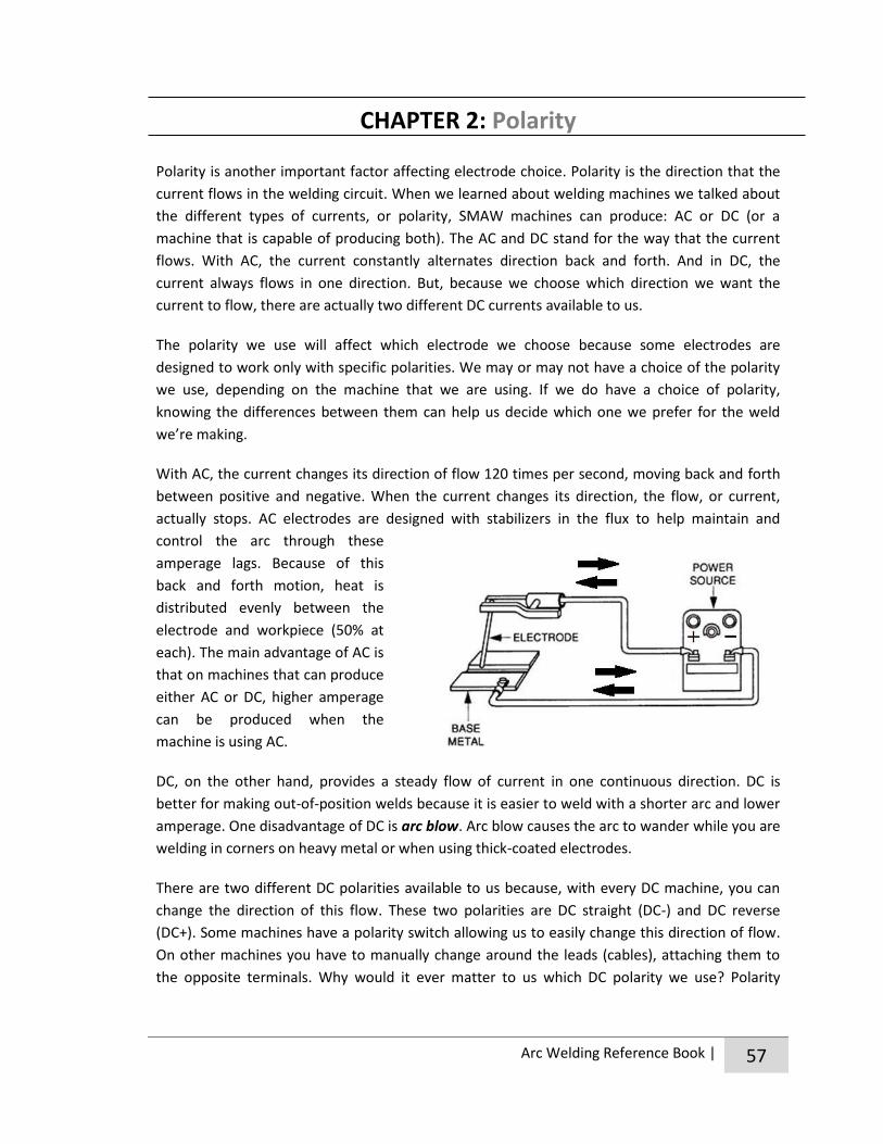
Arc Welding Reference Book | 57
CHAPTER 2: Polarity
Polarity is another important factor affecting electrode choice. Polarity is the direction that the
current flows in the welding circuit. When we learned about welding machines we talked about
the different types of currents, or polarity, SMAW machines can produce: AC or DC (or a
machine that is capable of producing both). The AC and DC stand for the way that the current
flows. With AC, the current constantly alternates direction back and forth. And in DC, the
current always flows in one direction. But, because we choose which direction we want the
current to flow, there are actually two different DC currents available to us.
The polarity we use will affect which electrode we choose because some electrodes are
designed to work only with specific polarities. We may or may not have a choice of the polarity
we use, depending on the machine that we are using. If we do have a choice of polarity,
knowing the differences between them can help us decide which one we prefer for the weld
we’re making.
With AC, the current changes its direction of flow 120 times per second, moving back and forth
between positive and negative. When the current changes its direction, the flow, or current,
actually stops. AC electrodes are designed with stabilizers in the flux to help maintain and
control the arc through these
amperage lags. Because of this
back and forth motion, heat is
distributed evenly between the
electrode and workpiece (50% at
each). The main advantage of AC is
that on machines that can produce
either AC or DC, higher amperage
can be produced when the
machine is using AC.
DC, on the other hand, provides a steady flow of current in one continuous direction. DC is
better for making out-of-position welds because it is easier to weld with a shorter arc and lower
amperage. One disadvantage of DC is arc blow. Arc blow causes the arc to wander while you are
welding in corners on heavy metal or when using thick-coated electrodes.
There are two different DC polarities available to us because, with every DC machine, you can
change the direction of this flow. These two polarities are DC straight (DC-) and DC reverse
(DC+). Some machines have a polarity switch allowing us to easily change this direction of flow.
On other machines you have to manually change around the leads (cables), attaching them to
the opposite terminals. Why would it ever matter to us which DC polarity we use? Polarity

58 | Arc Welding Reference Book
affects the amount of heat going into the base metal. By changing polarity, we direct the heat
where it is needed for specific welding jobs.
When the electrode is connected to
the positive terminal and the ground is
connected to the negative terminal you
have DC+ which is often referred to as
reverse polarity (or DCEP: Direct
Current Electrode Positive). The
current flows from negative to positive.
So, with DC + the arc actually travels
from the base metal up into the
electrode. This causes the tip of the electrode to heat more than the base metal. In fact, two-
thirds of the heat is with the electrode. This gives the operator better control of the arc and often
makes DC+ the preferred polarity to use. When using DC+, you’ll have deeper penetration, a
steadier arc, slower welding speeds and often a narrower weld bead. Because a cooler base metal
allows the filler metal to cool faster (giving it greater holding power to stay where it needs to be),
DC+ is a good choice when doing overhead welding.
When the electrode is connected to
the negative terminal and the ground
is connected to the positive you have
DC- which is often referred to as
straight polarity (or DCEN: Direct
Current Electrode Negative). With DC-
the flow is from the electrode to the
base metal so the electrode stays
cooler and the base metal gets hotter.
Two-thirds of the heat is with the base
metal. When using DC-, you’ll have
shallower penetration, faster welding speeds and often a smoother weld bead. DC- is used with
certain rods for high speed sheet metal welding and in certain situations where it is desirable to
have more heat on the workpiece because of its size. DC- is also a good choice when making
heavy deposits.
When you’re starting out, you most likely won’t have a choice what type of machine you use.
You’ll probably learn to weld with whatever welding machine is put in front of you. So you may
not have a choice as to which polarities you can use. Don’t worry if the machine you’re welding
with doesn’t have different polarity options. If the machine is in proper working condition, you
can weld with it, regardless of polarity, as long as you have the right electrode.

Arc Welding Reference Book | 59
You should be aware that every welding machine welds a little differently. Even two identical
machines may have subtle differences in the way that they perform. So, to make things easier,
try to use the same welding machine as much as possible. And remember, if you do switch
machines, the settings you figured out with one machine may not be exactly the same as ones
you need to use with another machine.

60 | Arc Welding Reference Book
CHAPTER 3: Classification
Thankfully, to help welders identify which electrode is best for the job the American Welding
Society (AWS) developed a classifications system that is used all across North America. When
you understand how this system works, you can tell by just looking at the electrode number
(often called AWS number) a great deal about the electrode. This number is 4-5 digits long and
written right on every single electrode. It tells us the type of electrode, strength of the core wire
once welded, type of coating used, welding positions it can be used in, what polarities it will
work with and other operating characteristics. Now that’s a lot of information passed on from
four little numbers!
The “E” at the beginning of the number indicates that this is an electrode for electric arc welding.
The first two numbers (E60xx) indicate the tensile strength of the filler metal. Tensile strength is
the force that it would take to pull apart the joint. When you multiply these two numbers by
1,000 you get the minimum tensile strength (in pounds per square inch) of the welded filler
metal. For example, if the first two numbers are 60, the strength of the filler metal is 60,000 psi.
Some electrodes have a five digit number written on them instead of four. In those instances,
the first three numbers indicate the tensile strength. For example, E10018 would have a
minimum of 100,000 psi. If you’re wondering how much tensile strength you need for a job,
60,000 is enough for building things like trailers.
The second last digit (Exx1x) corresponds with how fast the weld puddle solidifies and indicates
the welding positions the electrode can be used in. This digit will either be a 1, 2 or 3. The 1
means the electrode can be used in all positions, the 2 means it can only be used in flat and
horizontal fillet positions and 3 means that it can only be used in the flat position.

Arc Welding Reference Book | 61
Welding positions are the position that
the metal is in when we make our
weld. You can weld in flat, horizontal,
horizontal fillet, vertical and overhead
positions. So far, we’ve only welded in
the flat position, which is when we
make a weld down onto a horizontal
surface. This is the most commonly
used welding position because the
molten puddle is not affected by
gravity as it is in other positions. This
makes it easier to deposit a uniform
bead with proper penetration at a fast
speed. The horizontal fillet position
refers to welding a joint, where one
piece of the joint is in the flat position
and the other is perpendicular (vertical)
to that piece. In this position gravity
can cause the molten puddle to sag
slightly. The horizontal position is when
the piece you’re working on is held
vertically, but you run the weld
horizontally along this vertical surface.
The vertical position is one where the
material that we’re welding on is
vertical and the bead we run is laid vertically. And lastly, there is the overhead position, which is
exactly as it sounds. It’s when we make a weld above our head and so, because of gravity, is
probably the most difficult of all the welding positions.
The last digit, in combination with the
second last digit (Exx13), indicates a
variety of things including operating
characteristics, composition of the flux
coating and the polarity the electrode
can be used with. There are too many
combinations and characteristics to get
into here. If you’d like to learn more
#40. Ways to Weld
ACTIVITY

62 | Arc Welding Reference Book
about what the last two digits in combination mean, check out the links under resources at the
end of this Unit. This chart has some information about what the last digit means, so use it as a
reference whenever you need.
Welders use many different kinds of welding electrodes because there isn’t a magical electrode
that does everything. There are so many electrodes that it would be a challenge to try to
become familiar with them all. If you’re purchasing electrodes and not sure which ones to buy
for the job you’re working on you can obtain a list of all available AWS numbers from a supplier.
This list will help you to select the right electrode for the project you’re working on.
As a beginner you don’t need to become familiar with every type of electrode. You just need to
be acquainted with a handful that will work for most of your common welding needs. If you
know a bit about the E6010, E6011, E6013, E7018 and E7024 you’ll be all set for most of the
welding jobs that you’ll come across.
These two rods have very similar characteristics. The difference between them is that E6010 can
only be used on DC+ and E6011 can be used on AC and DC+. These rods are fast-freeze, have a
strong arc force and provide deep penetration. They are a great choice when welding out-of-
position. They are often used as a first pass or to fill gaps and then covered with a filler
electrode. These rods also perform relatively well on dirty, greasy and rusty surfaces. So, if you
are making repairs on farm machinery or joints that are difficult to clean properly, these
electrodes are a good choice.
These are filler electrodes designed for welding in all positions with all polarities. However, they
may be harder to use out of position. They make a great general-purpose electrode and are a
popular choice for many welders because of how easy they are to use and how smooth the
finished weld bead is. They can often be used for applications on the farm, although the metal
has to be cleaned well (unlike 6010/6011). The deposited weld is high quality with low to
medium penetration and was originally designed for use on sheet metal.
#41. Examining Electrodes
ACTIVITY
#42. Electrode Code
E6010 and E6011
E6013
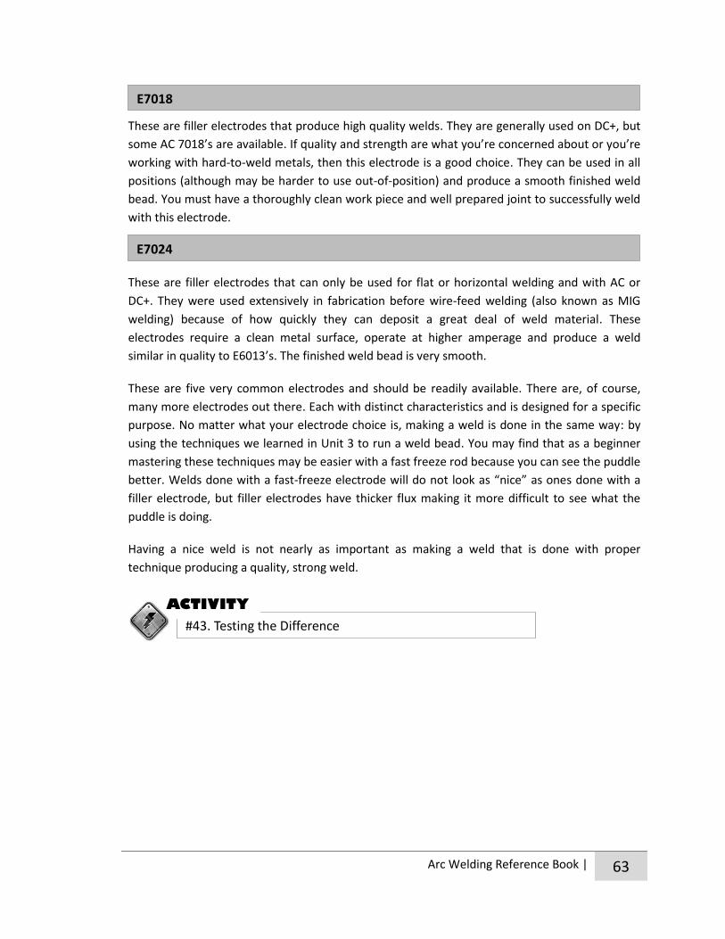
Arc Welding Reference Book | 63
These are filler electrodes that produce high quality welds. They are generally used on DC+, but
some AC 7018’s are available. If quality and strength are what you’re concerned about or you’re
working with hard-to-weld metals, then this electrode is a good choice. They can be used in all
positions (although may be harder to use out-of-position) and produce a smooth finished weld
bead. You must have a thoroughly clean work piece and well prepared joint to successfully weld
with this electrode.
These are filler electrodes that can only be used for flat or horizontal welding and with AC or
DC+. They were used extensively in fabrication before wire-feed welding (also known as MIG
welding) because of how quickly they can deposit a great deal of weld material. These
electrodes require a clean metal surface, operate at higher amperage and produce a weld
similar in quality to E6013’s. The finished weld bead is very smooth.
These are five very common electrodes and should be readily available. There are, of course,
many more electrodes out there. Each with distinct characteristics and is designed for a specific
purpose. No matter what your electrode choice is, making a weld is done in the same way: by
using the techniques we learned in Unit 3 to run a weld bead. You may find that as a beginner
mastering these techniques may be easier with a fast freeze rod because you can see the puddle
better. Welds done with a fast-freeze electrode will do not look as “nice” as ones done with a
filler electrode, but filler electrodes have thicker flux making it more difficult to see what the
puddle is doing.
Having a nice weld is not nearly as important as making a weld that is done with proper
technique producing a quality, strong weld.
E7018
E7024
#43. Testing the Difference
ACTIVITY

64 | Arc Welding Reference Book
CHAPTER 4: Storing Electrodes
As the electrode burns, the gases from the flux protect the puddle so the gases in the air don’t
mix with the molten metal. If air were able to mix with the molten metal it would leave gas
pockets in the weld bead which show up as tiny holes called porosity. These tiny holes decrease
the strength of the weld. Beyond this, the flux helps stabilize the arc, which helps us to achieve
maximum weld penetration and uniformity. It also lifts impurities from the molten metal. When
the flux cools it creates a slag coating on the weld bead, providing even more protection from
the air as it cools.
Basically what all this means, is that without flux the SMAW process wouldn’t be possible. It’s
because of how important the flux is to the welding process that electrodes need to be stored
and handled properly. Do not use electrodes with damaged flux. Beyond making your job
difficult, damaged electrodes can form weak welds with defects. There are a few things we can
do to insure that we don’t damage the flux and keep the electrode in optimal working condition.
The first thing you can do is handle electrodes carefully. Don’t be rough with them by throwing
or dropping the electrode containers or carrying electrodes around in your pocket or tool box.
Be careful that you do not bend electrodes in the stinger too
closely to the coating because this could crack the coating
further down the electrode. If you damage the coating of the
electrode with a chip or a crack you can lose shielding, allowing
contamination and porosity into the weld and lose arc
stabilizers. This can make the arc difficult to maintain and
control resulting in poor bead appearance.
The other thing you can do is to store electrodes in a dry, dirt-
free area and avoid getting them wet/damp. Electrodes are
very susceptible to moisture. Moisture causes the coating to
disintegrate and fall off and a moist flux coating will result in
low quality welds or an unstable arc.
As soon as you open a new package of electrodes, they start
absorbing moisture from your shop. So they need to be stored in
a sealed container. Taping up electrodes in the bag they came in
is an adequate way to store them sealed. You also want to avoid
getting electrodes wet by exposing them to rain, leaving them
out in high humidity or dropping them in water/on a wet floor.
The good news is that
if you do get
electrodes wet you
can reclaim them by
baking them in an
oven. The temperature
and time needed in
the oven will vary from
electrode to electrode
and depend how wet
they are. Usually
baking them at 150-
250°C for three hours
will dry them properly
so that they can be
used again.
Hot Tip

Arc Welding Reference Book | 65
CHAPTER 5: Prepping for Welding Joints
Beginning welders often think that the heat generated by the electrode will burn away dirt, oil,
rust, etc. But that’s not so. As hot and powerful as the arc of an electrode gets, it doesn’t clean
away impurities. If the surfaces you are joining are not cleaned of contaminants before welding
they can be included in the weld and cause defects and weakness. New metals that have mill
scale on them also require joint prep before welding. Mill scale is a film left on some metals
from the milling process and is bluish black in color.
There are a variety of methods you can use to clean the metal properly where it will be joined.
Sandpaper or abrasive cloth are readily available and are a good option. Prepping a joint with
these materials is often a better choice than using power sanders since it’s very easy to remove
more metal than you intend to with a power sander. Wire brushes or chemical cleaning agents
are also a good option. Remember not to store these chemicals anywhere near where you’ll be
welding. For large scale jobs you may also want to consider sand blasting, followed by cleaning
with an air compressor. If you can’t get surfaces completely clean, 6010 and 6011 are suitable
electrodes to use. But, even welds made with these electrodes will fail if the surfaces joined are
too dirty.
Remember, if it is worth your time to weld something, it is worth your time to prepare the weld
area before welding. By doing so, you ensure that the weld you make will be as strong as possible.
#44. How-To Video
ACTIVITY
#45. Question Toss

66 | Arc Welding Reference Book
Unit 4 Resources
http://www.lincolnelectric.com/en-us/support/process-and-theory/pages/understanding
-polarity-detail.aspx
http://www.lincolnelectric.com/en-us/support/welding-solutions/pages/polarity-for-smaw.aspx
http://www.mig-welding.co.uk/wiki/Electrode_Reference_Chart
http://www.sweethaven.com/sweethaven/BldgConst/Welding/lessonmain.asp?lesNum=7
&modNum=3
http://www.parselectrode.com/Welders%20hand%20book.pdf
http://www.metalwebnews.com/howto/weldrod.html
http://www.weldingtipsandtricks.com/shielded-metal-arc-welding-rods.html
http://www.mig-welding.co.uk/electrode-classification.htm
http://www.weldingwire.com/applications/DocumentLibraryManager/upload/METAL%20ID.pdf
http://igor.chudov.com/manuals/Spark_Testing_for_Mystery_Metals.pdf
http://www.esabna.com/EUWeb/oxy_handbook/589oxy24_4.htm (pages 4-6)
http://www.sweethaven.com/sweethaven/BldgConst/Welding/lessonmain.asp?lesNum=1&mo
dNum=4
http://everythingscrapmetal.blogspot.ca/p/metal-test-identification.html
Metal ID Websites
#40. Ways to Weld
COMPLETE LIST OF
UNIT 4 ACTIVITIES
#41. Examining Electrodes
#42. Electrode Code
#43. Testing the Difference
#44. How-To Video
#45. Question Toss


Unit 5 Working with Welds
Bring with you to the meeting:
Pen or pencil and notebook
Clothes to weld in and safety gear (see appendix for the image of the well-dressed welder)
In this Unit we will:
Learn about the different types of joints and weld anatomy.
Find out how to weld butt joints, T-joints and lap joints in the flat position.
Discover how to make large welds with weave beads and multiple pass welds.
Talk about distortion and how to deal with it in our work.

68 | Arc Welding Reference Book
CHAPTER 1: Joints
Now that we know how to pick the right electrode for the job and run good stringer beads by
carefully watching the puddle, the world is ours to weld! The next step is to apply this
knowledge into joining two pieces of metal together.
There are five basic types of joints in welding, each with its own variations.
They are the butt, corner, edge, lap and T-joint.
The butt joint (A) is formed between two pieces of metal that are aligned
on the same plane. To create this joint, the two pieces are brought
together, edge to edge and welded along the seam created between them.
The corner joint (B) is formed by two pieces of metal meeting at right
angles to each other at their corner edges.
The edge joint (C) is formed between the edges of two or more pieces of
metal that lie parallel to one another.
The lap joint (D) is formed by two pieces of metal that overlap each other.
The weld binds the edge of one plate to the face of the other.
The T-joint (E) is formed between two pieces of metal that are at right
angles to each other. The resulting connection forms a T shape.
The two most common types of welds used in arc welding to make these joints are the groove
weld and the fillet weld. Groove welds are used mainly for butt joints and can also be used in
welding edge joints. Basically, with a groove weld, you leave a space between the two pieces of
metal you’re joining and fill it in with weld beads. Fillet welds are used commonly for welding
lap, T and corner joints. To make a fillet weld a layer/layers of weld are deposited to fill in the
corners created by the joints. The weld looks triangularly shaped. In this Unit we learn how to
join butt joints with groove welds and lap joints and T-joints with a fillet weld. Once you know
how to make these three different joints using these two welds, you can really get cracking on
your individual and community projects.
#46. Which Joint is Which
ACTIVITY
#47. Find the Joint

Arc Welding Reference Book | 69
No matter which joint you’re welding, or type of weld you’re using, you’ll have to set up the
joint before you begin. To do this you weld the pieces together with small temporary welds to
hold the two parts in the correct position so that they don’t move out of place when you do
your actual welding. These small welds are called tack welds. They are not structural and should
always be covered by another proper weld. When making a weld pass, you weld right through
them. Position tack welds at each end of the parts you’re welding. If a part is long or has an
unusual shape you may need to use several tack welds along the length of the joint.
As you learn to weld these different joints you’re going to come across a few new terms that
describe the structure of a weld. Let’s define them before we get going so that you aren’t left
scratching your head when they come up.
Root face, groove face and root edge – These terms all describe the surfaces along the groove,
or along the edges that will touch, when
the two pieces are welded together.
The groove face is the surface of the
metal that will be included in the weld.
The root face is the surface of the metal
that will be included in the weld that
has not been prepared with a bevel. To
make things even more confusing, in
butt joints and T-joints, the groove
surface and the root face can refer to
the exact same edges! The root edge is
a root face with zero width, meaning
it’s the tip of a triangle that will be
included in the weld.
Root opening, bevel angle and groove angle –
These words all refer to the space between the
two pieces being joined together. The root
opening is the space left (if any) between the two
pieces at the root of the joint. The bevel angle
describes the angle (other than square) put onto
the edges that will be joined. The groove angle is
the total angle of the groove between the two
pieces being joined. For example, if two plates
were both beveled to 30° angle, when they are put together the groove angle they create is 60°.
Weld root – This refers to the points
where the bottom or back of the weld

70 | Arc Welding Reference Book
intersects with the base metal. In a fillet weld, the root is the point of deepest penetration.
Weld size – With a groove weld, the weld size is indicated by joint penetration. With a fillet
weld, the size of weld is indicated by the leg length of the fillet.
Weld face – This is the exposed surface of a weld on the side from which the welding is done.
Weld toe – This is the junction where
the face of the weld meets the base
metal.
Leg of a fillet weld – This is the
distance from the root of the joint to
the toe of the fillet weld.
#48. What’s in a Weld?
ACTIVITY

Arc Welding Reference Book | 71
CHAPTER 2: Welding Different Joints
The butt joint is made by welding the edges of two pieces together to make one flat piece.
There are several different types of butt joints and different methods to weld each one. The
type of joint and weld we use depends on the thickness of the metal, whether it will be welded
from one or both sides, and how the edges are prepared. For now, we’ll learn how to make a
square butt joint in the flat position which is completed with a square groove weld. This weld is
formed when we join two pieces with square edges together. Usually only materials that are 6
mm or thinner can be welded with a square groove weld.
If we were to butt two plates with square
edges tightly together, and run a weld on
either side of the joint, there would be an
area in the centre of the joint that wouldn’t
be held together by the welds. To avoid this,
we have to leave a space in between the
plates we’re welding. This way, the two
beads can weld to each other in the centre
of the plates, making the two plates become
one solid piece.
To weld a square butt joint, place the two plates flat (horizontally) on the welding table, leaving
a small gap (root opening) between them. Leaving a gap about the size of the electrode core
wire between the two plates is usually adequate. Tack weld the plates together at both ends to
ensure that, as you weld, the root opening stays the same size. Without tack welding, the root
opening can spread apart, or close up, as a result of the heat from the welding process.
Hold the electrode perpendicular to the plates and angled 10-30° in the direction of travel. Run
a straight bead centered down the seam between the two plates.
If you’re welding on material that is thin (3mm or less) you may only need to run a weld bead on
one side of the joint. Normally, for full penetration, you need to turn the plate over and run a
similar weld on the reverse side. Remember to make sure that these two welds are deep
enough that they
meet with each
other near the
centre of the plate.
Butt Joints: How to weld a square butt joint in the flat position

72 | Arc Welding Reference Book
When welding butt joints, the welds need to penetrate deeply enough so that the final weld
deposit is at least as thick as the base metal. This is most easily done by running beads on both
sides of the joint which provides maximum penetration and strength. However, usually only
materials that are 6 mm or thinner can be welded with a square groove weld.
If you need to weld a butt joint between two thicker pieces of metal or on a joint that can only
be reached to be welded from one side (on material that is thicker than 3mm) you’ll have to
prepare the edges with bevels first before welding. In Unit 6 you can learn the proper joint
preparation and the corresponding welding technique for a butt joint with bevels like this.
T-joints are made by welding two pieces of metal together to form a 90° angle. The weld is
made on the inside corner created by the two pieces using a fillet weld. This is the most
commonly used weld in welding fabrication and is often used when doing repair work on
machinery. Most fillet welds are made in the horizontal position.
To make a T-joint in the horizontal fillet position one plate is
placed flat (horizontally) onto the welding table. The second
plate is placed perpendicular to the first plate so that it sits
vertically with its edge resting against the first plate. This results
in the two plates being at right angles to each other, forming an
inverted T. The edge of the vertical plate should be tack-welded
to the surface of the horizontal plate at both ends of the joint so
that it will not move during welding.
Bevels are angles cut into the edge pieces so that the root opening is larger. This
makes it possible for electrodes to reach farther into the joint, which in turn will allow
welders to get adequate weld penetration that would otherwise be impossible.
Hot Tip
#49. Welding a Butt Joint
ACTIVITY
T-Joints: How to weld a T-Joint in the horizontal position

Arc Welding Reference Book | 73
When making T-joints, and any other fillet weld, you need to pay close attention to both
electrode angles. Hold the electrode at a 45° work angle, so that it is pointed towards the
middle of the joint, and at a 15° travel angle.
The work angle determines the position of the
fillet in the joint (centered), and the travel
angle determines the shape of the bead (how
flat or rounded it will be). It’s important when
making fillet welds to hold the electrode in
such a way that the legs of the bead are the
same length along the top as they are on the
bottom. You also need to make sure that the
arc is directed into the corner of the joint, so
that both plates are heated equally. To do this,
it often helps if you hold the electrode so that
its flux lightly touches both plates as you drag
it along. A short arc is also necessary when making a fillet weld to provide good fusion at the
root and along the legs of the weld. Holding the electrode so that it touches both plates also
helps to attain this short arc length. However, if you’re welding two pieces together that are
different thicknesses, you need to direct the arc more towards the thicker piece so both plates
of metal are heated equally.
Move the electrode ahead to create a fillet weld in this manner, joining the plates together.
Carefully observe the puddle as you weld, changing the angle or speed if it sags or if there is
undercut (which tends to happen on the vertical plate). The finished weld should penetrate
equally into each plate. As a beginner, a common problem when welding T-joints is to burn
through the vertical piece, and get insufficient penetration along the horizontal piece. If you
hold the electrode at the correct angle you should be able to avoid this problem.
You may also notice that when finished, the T-joint warps in towards the direction of the weld,
which ends up leaving the joint you’ve made narrower than the original 90° you set out to make.
This happens because metal shrinks as it cools. To prevent this from happening, tack weld the
vertical plate so that it leans back slightly. Then, once welded, as the joint cools/shrinks the
vertical plate will end up being pulled perpendicular to the bottom plate, just like you want! Or,
weld on both sides of the joint, alternating welding passes between one
side of the joint and the other. When you weld on both sides of the joint
like this it is called a double fillet. If you only weld on one side of the joint
it is a single fillet. Whenever possible, weld on both sides of the joint
because double fillet welds make a stronger joint.

74 | Arc Welding Reference Book
No matter which type of joint you’re welding with a fillet weld, you need to make sure that
you’re using enough heat for the arc to penetrate right down into the corner of the joint so that
you end up with a strong joint. With any fillet weld, the finished bead should not only be
uniform and smooth, but also be flat or slightly convex (rounded) because concave beads are
prone to cracking. You should also try to ensure that the leg of the weld is equal to the thickness
of the parts being welded. If you are unable to get the legs of the weld to be equal in thickness
to the material you’re welding try using a larger electrode to make a wider weld. If you’re still
unable to achieve the correct sized weld, you’ll have to make a bigger weld bead by making
more than one pass, which we’ll learn to do in the next chapter.
Lap joints are formed by two plates overlapping each other. When you weld a lap joint, you are
joining the surface of one plate with the edge of the other plate by running a fillet weld along
the inside corner of the joint created by the overlap. Because T-joints and lap joints are both
welded with fillet welds, the technique for welding them is very similar. This biggest difference is
that with a lap joint, you have to be careful to avoid overheating the outside edge of the
overlapping plate.
To weld a lap joint in the horizontal fillet position lay one piece flat (horizontally) on the welding
table and then lay the second piece
(horizontally) on it so that the two pieces
overlap. When this is done, two corners
(joints) are formed, one on the top side of
the plates, and the other on the bottom side
of the plates. Lap joints can be welded on
one or both sides. Whenever possible, you
should weld on both sides of the plates
because it will be stronger. When you weld
both joints created by the two overlapping
plates like this it is called a double fillet weld.
You should fit up the joint so that there is no gap between the
two plates and then tack-weld them in place, so that they will
not move during welding. To reduce the risk of warping, you
should tack each of the four corners (the corners on the top joint
and on the bottom joint). Remember when making tack welds to
#50. Welding a T-Joint
ACTIVITY
Lap Joints: How to weld a Lap Joint in the horizontal and flat position

Arc Welding Reference Book | 75
make the welds small enough so that when you run your actual fillet weld, you can weld
through them, incorporating them into the weld bead.
Just like making a fillet weld with a T-joint, the electrode should be held at angles that allow the
arc to heat both plates equally and form slightly convex beads when making a lap joint. To do
this, hold the electrode at about a 45° work angle and tilted with a 15° travel angle. If you are
welding plates of different thicknesses direct the arc more towards the thicker plate so that
both plates heat evenly.
Move the electrode ahead like this in a straight line along the joint. Watch the bead as it builds
up, changing your angle or speed if it sags or undercuts, which is a common problem along the
horizontal piece. The edge and the top corner of the overlapping piece are going to get hot and
melt faster than the surface of the other piece. So as you weld, watch the top edge of the joint.
As soon as the side of your puddle meets the top edge, move on to your next puddle.
The goal when making a lap joint is to get good penetration right down into the corner of the
joint. The legs of the weld should come up and out at a distance that is equal to the metal being
welded with little or no undercutting. On thicker metal, you might not be able to make fillet
welds that are large enough in one pass. If this is the case, the next chapter will guide you
through a multi-pass welding procedure. Your finished fillet weld should be uniform, smooth,
slightly rounded and penetrate evenly into each plate.
If you want to make fillet welds on lap joints or T-joints in a flat position, instead of in the
horizontal fillet position, it is possible. You simply need to tilt the work so that the corners of the
joint become a trough for the molten puddle. Welding like this can often be faster, but
sometimes, depending on what you are working on, rigging the piece that you’re working on to
sit at this titled angle can be difficult and sometimes impossible.
#51. Welding a Lap Joint
ACTIVITY
#52. Skill Plate

76 | Arc Welding Reference Book
CHAPTER 3: Making Wider and Bigger Welds
So far, all of the weld beads we’ve made have been stringer beads made with little or no
oscillation. But, there are actually several other beads called weave beads, which we can run.
Just as the name suggests, we run these beads by adding a weaving motion into our electrode
movement. Weaving is a small back and forth motion crosswise to the direction of travel.
The point of learning how to run a weave bead isn’t to
make things more complicated. The goal in welding is
that the completed weld to be just as strong, or
stronger, than the base metal. When we start joining
thicker pieces of metal together, a single stringer bead
like the ones we’ve been making, is not able to make
a weld that is large enough or strong enough to
correctly join the pieces together. In these instances,
weaving is a very useful technique to use to make
wider weld beads that will be strong enough to hold
the joint together. Weaving can also help prevent the
bead from running and dropping when you need to
weld out of position. Welding with weave beads will
often cause less distortion than stringer beads.
There are several different ways you can run a weave
bead. “A” is a weave made with a simple zigzag
motion. “B” is probably the most commonly used
weave. It is also made with a zigzag motion, except
that each zig and zag is made crescent shaped instead
of straight. “C” is done with a figure-8 motion and “D”
is done with a small circular mot ion. It’s important to
keep the circles small and tight to end up with a
smooth weld bead. “E” makes a hesitation at each
side of the weave to allow a slight buildup of metal at
the edges of the joint.
You use the same techniques to run a weave bead as you would a stringer bead, watching the
puddle and paying attention to arc length, travel speed and electrode angle. The only difference
is that when running a weave you also need to pay attention to moving the electrode from side
to side as you move it forward. If you move the rod too far to one side or another you give the
molten metal at the opposite side time to harden and for slag to form over it. If this happens,
Making Weave Beads
Spark of Information
Out of position welding =
welding in any other
position other than flat.

Arc Welding Reference Book | 77
when you bring the rod back to that side the slag will get trapped in the weld making it weak. To
avoid this, the weave should not be made wider than three times the diameter of the electrode.
Forming a uniform bead with a weave can be tricky for beginners. But, if you watch the outside
edge of the puddle to make sure it is as wide as the weave before it and watch the top the
puddle as you pass the centre to see that it builds up as high as the pass before it you should
end up with a fairly consistent and uniform bead. It is also a good idea to make a slight pause at
the end of each weave allowing the weld to build up. This ensures good fusion and prevents
undercutting. If done properly, a weaving motion can float out slag, secure good penetration at
the edges of the weld and avoid porosity by allowing gases to escape. Weave beads, however,
usually do not penetrate as deeply into the base metal as stringer beads.
If you ever get the opportunity to visit a welding shop, watch welders at work and see what
techniques they use to run beads. You’ll probably notice that each welder has his/her own
personal style and preferences. Some welders change the type of bead they use when they work
on different types of joints and in different welding positions. And some welders use the same
bead for all of their welds with slight variations in speed and size.
When we join thick pieces of metal together sometimes a weave bead by itself still won’t make
a bead wide enough to properly join the metal we’re working on. When this is the case, we need
to make multiple passes using stringer beads and/or weave beads. The first pass in a multi-pass
bead is called the root pass. Succeeding passes are called fill passes.
The choice of which bead to use and how many
passes to make depends on the thickness of the
metal being joined. Anywhere from two to 20 or
more passes may be used to make a bead large
enough for the parts being welded together. But, it
is best to try to make the weld in as few passes as
possible. Since the goal is to make a weld that is as
thick as the base metal, there is no point in running
more beads once this is achieved. It is important when making multiple passes that each bead
be placed in the proper sequence and relationship to the other beads.
#51. Welding With Weaves
ACTIVITY
#52. Pad Practice With Weaves
Making Multiple Passes with Fillet Welds

78 | Arc Welding Reference Book
It’s likely that the fillet welds you’ll be making when working on
your projects will not require more than three passes.
Normally, when making fillet welds, only plates that are 9mm
or thicker will require multiple passes. A proper three-pass
bead on a fillet weld should be done in this order:
To make a three-pass weld like this, the first pass is laid right
in to the corner of the joint, just as if you were making a fillet
weld that only needed a single pass. Then, the second pass is
laid to cover the seam between the first weld and the bottom
base metal. It should cover about 50-75% of the first weld.
The electrode will need to be at about a 60° angle from the horizontal plate to do this. Lastly,
the third pass is made, covering the seam between the second weld and the first weld, as well
as the seam between the first weld and the vertical plate. It should cover the second weld by 50-
75%. The electrode will need to be at about a 30° angle from the horizontal plate to do this.
Remember to chip off the slag from each bead before running the next one.
If you do have to make a
weld that requires more
than three passes, they are
all completed in the same
way; with each new pass
partially covering the
preceding pass.
Making multiple passes on butt joints usually requires special edge preparation, so it will be
covered in the next unit.
The size of the finished
fillet weld should
correspond with the
size of the metal it’s
joined together, with
the leg lengths of the
weld being equal in
thickness to that of
the metal plate.
Hot Tip
#55. Making Multiple Passes
ACTIVITY

Arc Welding Reference Book | 79
CHAPTER 4: Distortion
In order to set up joints and make a weld there
is one more thing we need to know about.
Distortion! Distortion is the name used to
describe plates that bend or twist out of shape
after they’ve been welded. If when you were
welding T-joints, the vertical piece leaned in
towards the welded side of the joint instead of
standing straight up, you’ve already
encountered distortion! In order to combat
distortion in our work we need to know what
causes it and then take extra measures to
minimize its effects.
When we weld, quite a lot of heat is built up in
the weld and in the parts near the weld.
Whenever metal is heated it expands. And
then as it cools, it contracts. It’s these
expansion and contraction forces that cause
distortion in welding. As the deposited weld
cools, it shrinks, pulling with it whatever metal
it is attached to. And as the metal close to the
weld shrinks, its movement is restricted by the
weld, causing it to bend or twist. There is
absolutely nothing we can do when welding to stop this expansion and contraction since it will
always happen when metal is heated.
We can, however, figure out how these forces will affect our work and prepare for them By
planning our welds in advance we can reduce the amount of heat we use, anticipate how our
pieces may move and work to balance out the distortion forces. Taking the time to prevent
distortion by planning our welding sequence in advance is time well spent. Doing so is much easier
than dealing with a finished weld that is fused together at incorrect angles or warped and twisted.
Here is a list of things you can do to help prevent distortion:
1. Do not over-weld.
In welding, more doesn’t mean better. Excessive
amounts of weld metal results in excessive heat.
More heat equals more expansion and contraction
which can lead to more distortion. You should stop

80 | Arc Welding Reference Book
welding when you have deposited enough metal to create a joint as thick as the base
metal. Making a weld that is larger than required is also a waste of time and money.
2. Prepare joints with correct spacing.
Leaving too much space between joints means making welds that are bigger. Bigger joints
require more weld material and more heat than smaller, well-spaced joints. Be sure to
tack-weld joints so the correct spacing is maintained as you weld. When putting bevels on
edges to be joined, avoid making a bevel with a low angle, as this results in a joint that is
larger than necessary. The joint should also fit together easily without being forced.
3. Use as few passes as possible.
You should limit the number of weld passes to the
amount necessary to properly complete the job by
using larger electrodes. Larger electrodes deposit a
larger weld bead, which means less passes are made,
less heat is built up and welds take less time to
complete.
4. Use back-stepping.
When a continuous bead is laid, joints can spread open as they are welded. Back-
stepping helps prevent this spreading.
To back-step, a short weld is made at
one end of the plate. Then, a space is
left between this first weld and the start
of the second weld. The second weld is
then deposited towards the first weld
until the two are connected. A space is
left between the second weld and the
third, and the third is deposited towards
the second, connecting with it, and so
on.
5. Use intermittent welds (skip welding).
Making intermittent welds, instead of one continuous bead, helps disrupt the shrinkage
forces by avoiding concentrating them all on one area at one time. To intermittent weld,
a short weld is made at the beginning of the joint. Then, a section is skipped, and further
down the seam another short weld is made. This is continued along the length of the
seam. Once you reach the end, you can come back and weld in the skipped spots. Using

Arc Welding Reference Book | 81
this welding method to weld square or round tubing is an especially good idea: weld
top, then bottom, then side, then other side.
6. Weld on both sides of the joint.
Welding on both sides of the joint counterbalances the distortion forces. Whenever
possible, weld on both sides of the joint and use intermittent welding, alternating
passes between one side of joint and the other.
7. Use a weave.
A weaving pass usually has less penetration than a straight pass, but will usually causes
less distortion.
8. Position plates out of alignment.
You can use the shrinkage force of metal to your advantage by positioning plates out of
alignment by tacking them or bending them out of alignment. To do this, position the
pieces so that they are angled slightly in the opposite direction from where the
contraction will take place. You then rely on the weld to pull the pieces into their proper
positions as it cools. It does take some experience to figure out where to properly tack
pieces so that they end up in the position that you want.
9. Use clamps and jigs.
To prevent excessive movement you can use jigs and clamps to hold the parts you’re
welding in a fixed position. This will help counteract some of the distortion forces.
10. Peen the weld.
This is just a fancy way of saying “hit the weld with a hammer.” Stretching the weld
with hammer blows relieves some of the internal stresses that can cause distortion.
#56. Working with Contraction Forces
ACTIVITY
#57. Defeating Distortion
#58. How-To Video

82 | Arc Welding Reference Book
Unit 5 Resources
http://www.millerwelds.com/pdf/guidelines_smaw.pdf
http://www.sweethaven.com/sweethaven/BldgConst/Welding/lessonmain.asp?lesNum=3 &modNum=2
http://www.sweethaven.com/sweethaven/BldgConst/Welding/lessonmain.asp?lesNum=3 &modNum=5
http://www.mig-welding.co.uk/arc-fillet-joints.htm
http://deltaschooloftrades.com/basic_joints.htm
#46. Which Joint is Which
COMPLETE LIST OF
UNIT 5 ACTIVITIES
#47. Find the Joint
#48. What’s in a Weld?
#49. Welding a Butt Joint
#50. Welding a T-Joint
#51. Welding a Lap Joint
#52. Skill Plate
#53. Welding with Weaves
#54. Pad Practice with Weaves
#55. Making Multiple Passes
#56. Working with Contraction Forces
#57. Defeating Distortion
#58. How-To Video

Unit 6 Master New Skills
This Unit is designed as an “instructional dictionary.” In order to use it you don’t need to go
through the whole unit all at once. In fact, since you’re probably itching to spend more time
working on your individual and community projects, you should only read this unit if, and when,
you need to learn how to weld out of position, weld on sheet metal or use a joint that wasn’t
covered in Unit 5.
When you encounter things that we haven’t
already covered while working on your projects,
you can stop, come here and look up how to
properly make the weld. Then do an activity to
practice the skill and once you feel that you’re
able to make a quality weld using your new skill,
go back to your project to complete the weld.
Don’t worry or feel nervous when you have to
learn a new welding skill in order to complete
your project. Because you already know how to
make the three most common joints in the flat
position, you will definitely be able to learn how
to make any other weld in any other position.
Keep in mind, welding in the flat
position is always the easiest and
usually the fastest way to weld. So,
whenever possible, try to position
your work so that it is in the flat
position even if you know how to
weld out of position.
Hot Tip

84 | Arc Welding Reference Book
Instructional Dictionary Index
Multi-Pass Butt Joints ................................................................................................................. 85
V-Groove Butt Joint (Flat Position) ........................................................................................ 86
Corner Joints ............................................................................................................................... 88
Edge Joints .................................................................................................................................. 89
Sheet Metal (Thin-Gauge Metal) welding ................................................................................. 90
Out of Position Welding ............................................................................................................. 91
Whipping Motion .................................................................................................................. 91
Forehand Welding ................................................................................................................. 92
Horizontal Welding ............................................................................................................... 93
Horizontal Stringer Bead ................................................................................................. 93
Horizontal Square Butt Joint ........................................................................................... 93
Horizontal V-Groove Butt Joint ....................................................................................... 94
Vertical Welding .................................................................................................................... 95
Vertical-Down Welding .......................................................................................................... 95
Vertical-Down Fillet Joint ................................................................................................ 95
Vertical-Down Square Butt Joint ..................................................................................... 96
Vertical-Up Welding ............................................................................................................... 97
Vertical-Up Fillet Joint ..................................................................................................... 97
Vertical-Up V-Groove Butt Joint ..................................................................................... 98
Overhead Welding ................................................................................................................ 98
Overhead Fillet Joint ....................................................................................................... 99
Overhead Square Butt Joint ............................................................................................ 100
Overhead V-Groove Butt Joint ........................................................................................ 100

Arc Welding Reference Book | 85
A pass made by an electrode can only penetrate the base metal so deeply. This means that
when we make a butt joint with material that is thicker than 5mm we need to specially prepare
the edges of the plates we’re joining. By doing so, we create a larger groove in the joint. This
allows the electrode to get into the joint far enough to deposit multiple passes of weld metal
that will penetrate through the
entire thickness of the plate.
There are a variety of angles and
shapes called profiles that we can
cut into edges to create these
grooves. The profile you choose to
use will depend on the thickness of
the metal being welded and if the
joint can be reached from one side
or both. The most common profile
used in welding is the bevel to form a
single V- or double V-groove.
V-grooves will allow you to get
proper penetration in plates that are
5-19mm thick. If you’re butt joining
metal thicker than that, the U-groove
is a good option. Thankfully, the
technique for welding grooves made
of these various profiles is very
similar. So, once you learn how to
weld one, you should be able to weld
them all.
The thickness of the material you’re
welding is what determines the bevel
angle, groove angle and root opening of the joint. You want to make a groove that is large
enough for the electrode to fit inside so that you can pass a bead at the root of the joint,
ensuring adequate penetration. You also want to avoid making bevels that are too large. Bevels
that are too large result in an excessively large groove and add no strength to the finished weld.
They also add unnecessary heat into the weld and take more time to complete.
Normally when making V-groove butt joints, a bevel angle on each edge of 30° is suitable.
Together, the two bevels would make a groove angle of 60°. There are a number of different
methods that can be used to put profiles on the edges of plate, such as using a grinder,
Multi-Pass Butt Joints

86 | Arc Welding Reference Book
acetylene torch, plasma cutter, etc. Since the method you’ll use will depend on what is available
in your shop, we won’t cover the different methods in detail. If you do need to put a profile on
plates have your leader help you.
There are a number of different ways you can set up a
V-groove butt joint. You can make a single V-groove or
a double V-groove.
You can choose whether you use a back-up bar, also
called a back-up strip, (single V only), whether or not you leave a root face on the bevel and if
you leave a root opening or not.
The great thing about these choices is that you can design the best V-groove for the joint you’re
working on. No matter what, you need to choose an option that allows you to get 100% penetration.
Some things that will influence this
choice are the strength requirements
of the joint and the thickness of
material being joined. Material that is
5-19mm thick is appropriate to weld
with either a single V- or double V-
groove. Material that is 3-5mm thick
that can only be welded from one side
should be welded with a single V-
groove. And material that is thicker
than 19mm should be welded with a double V-groove.
Besides thickness of material, when trying to figure out which set-up is best for the joint you’re
working on ask yourself questions like these:
Does the joint require maximum strength? If yes, a double V-joint is the best option.
Can the joint only be made from one side? If yes, it has to be done with a single V.
Do I have a tendency to burn through the fine edges of the bevels? If so, preparing bevels
with root faces or using a back-up bar will be a better option.
V-Groove Butt Joint (Flat Position)
Spark of Information
Your personal preference will also play
a part of this choice. You may find that
one method is easier for you. As long as
the method you prefer to use meets
strength requirements, it is fine to use.

Arc Welding Reference Book | 87
Am I able to get penetration through to the other side of the joint on my first pass? If
not, a larger root gap could be used.
Would it be appropriate to place a back-up bar behind my single V-groove? Doing so can
help you have better penetration.
These are just some of the examples of questions you need to ask yourself. Regardless of what
combinations you choose to make the groove weld, the bevels should be about 30° on each
plate, resulting in a 60° groove angle.
V-groove weld instructions:
1. Fit-up the joint so that it is wide enough for your electrode to fit into. Be sure to
maintain a root gap that is appropriate for the thickness of metal being welded. Tack-
weld plates together to form desired joint with even root gap all the way along.
2. Hold the electrode pointing directly into the root of the weld and tilted 20-30°
towards the direction of travel.
3. Strike the arc and lay a root pass at the bottom of the V. If you burn a hole through
the narrow beveled edges, stop and restart the bead ahead of the hole and continue
the weld. Come back when finished to fill the hole.
4. Chip off the slag and check to see that you have attained complete penetration and
even fusion into each plate. The root pass must penetrate through to the other side of
the joint, creating a crown on the underside.
5. Run successive passes to fill the V as shown in
the image, laying each bead so that it
completely covers the last. You may use a
weaving motion to create fill passes that are
wide enough. When the V becomes larger than
three times the electrode diameter, lay stringer
beads side by side to build up the weld. These
side-by-side beads are laid in the same way as the
beads you made when building a pad; with each
bead overlaps the one before it in such a manner
that a smooth surface is created, with no dip between the two beads. Remember to
clean each bead before running another pass.
6. If welding a double V-groove you should alternate passes on either side of the weld as
you build it up.
7. Continue passing beads until the weld is flush with the surface of the plates. The
number of passes required to finish a butt joint depends on the thickness of metal. To

88 | Arc Welding Reference Book
reduce the number of fill passes used, switch to a larger electrode as the weld
progresses and increase the amperage accordingly.
8. Lastly you need to cap the weld off. The cap welds both edges of the plates in with the
last layer of fill passes. The cap only needs to be slightly wider than the bevel and just
above the surface of the base metal. Depending on the size of the weld it can be done
with a weave bead or with multiple stringer beads creating a smooth, even surface.
Corner joints and their corresponding welds are used on a
number of jobs. They can be used on material of any thickness
and no edge preparation is needed because square edged plates
can be tacked together to form a V at the corner.
A full open joint (image 1) can be used for maximum strength. A half open joint (image 2) may
be used where less strength is needed. A closed joint (image 3) can be used when tightness is
the only thing needed.
Corner welds on thin metal tend to spread apart easily so need to be tack-welded at closer
intervals. Back-step welding will minimize distortion.
The procedure for making corner joints is similar to V-butt joints. For maximum strength a fillet
weld is necessary on the inside.
Corner joint instructions:
1. Tack-weld plates together to form desired corner. For maximum penetration you
could leave a small root gap.
#59. Mastering a New Skill
ACTIVITY
#60. How-To Video
Corner Joints

Arc Welding Reference Book | 89
2. Hold the electrode pointing directly into the root of the weld and tilted 15-20°
towards the direction of travel.
3. Strike the arc. Maintaining a short arc length, lay the bead
using a slight weaving motion.
4. If multiple passes are needed, clean the first pass well
and lay a second bead over it using a weaving motion. Be
sure your weave is wide enough to cover the first pass
and penetrates evenly into each plate.
Sometimes called flange welds, edge welds are usually only
done on joints that are not subject to heavy loads. They are
also usually only done on material that is thinner than 6mm.
The procedure for making edge welds is similar to running a
bead on a flat plate, except that you have to be sure to keep
the bead evenly on the narrow edge.
Whenever possible these welds should be made in the flat position. When it is necessary to
weld edge joints vertically, the down welding technique should be used.
Edge joint instructions:
1. Tack-weld plates together leaving no root spacing.
2. Hold the electrode perpendicular to the joint (90°) and tilted 15-20° towards the
direction of travel.
3. Strike the arc. Maintaining a short arc
length, move along quite quickly,
completing the weld in one pass. If
material is too thick for the bead to
#60. How-To Video
#59. Mastering a New Skill
ACTIVITY
#61. Larger Than Life Dice
Edge Joints

90 | Arc Welding Reference Book
penetrate the joint you must prepare the joint with bevels and weld them similarly to
V-groove butt joints.
4. The finished weld should be fused evenly into each place and be a uniform height the
entire way along.
The use of sheet metal around the shop is very common. Technically, sheet metal, also called
thin-gauge metal, is less than 3mm thick. Most sheet metal is mild steel with a coating of zinc or
iron. Tractor and car bodies are made of sheet metal. They are usually mild steel covered by
primer and paint.
The good news is that if you’re wanting to work with sheet
metal you use the same techniques as if you were welding a
thicker plate. However, there are some problems specific to
sheet welding that you should know and take into
consideration before beginning a job with sheet metal. Because
of how thin sheet metal is, using the correct amount of heat is
very important. Too little heat will not maintain the arc and too
much heat will quickly burn through the base metal. Distortion
due to expansion and contraction is also much more
problematic when welding lighter material.
There are several things you can do to make welding with sheet
metal go smoothly.
Joints should have good fit-up and be carefully tack-
welded.
Use electrodes that are designed for welding sheet
metal. These electrodes produce a softer arc. Definitely avoid using electrodes with deep
penetrating characteristics.
Tip the base metal up 10-25° and weld
downwards. This will help you weld faster
and have less penetration; both of which are
desirable when working with sheet metal.
When learning, it’s
likely that your first
attempts at welding
sheet metal won’t be
successful because
of burn-through
problems. But don’t
get discouraged. Keep
trying, adjusting the
current and varying
your travel speed.
Hot Tip
#59. Mastering a New Skill
ACTIVITY
#60. How-To Video
Sheet Metal (thin-gauge metal) Welding

Arc Welding Reference Book | 91
If a gap exists in the joint, use a back-up bar to protect from burn-through. If you don’t
wish for the back-up bar to be part of your final weld use a copper strip because weld
metal will not stick to copper. Back-up bars also help to prevent distortion.
The easiest way to make a quality weld is to have the work lying flat. In the flat position, the
work is less tiring, welding speed is faster, the molten puddle is less likely to run and better
penetration can be achieved. However, when welding in the flat position is not possible you
need not worry, we can make any weld we need to horizontally,
vertically or overhead.
When welding out of position, electrode movement and arc
length become even more important. Because gravity will cause
the molten puddle to sag it’s necessary to keep the puddle
smaller than when welding in the flat position. This is done by
using less amperage and using the force of the arc to help keep
the puddle in place. You should also use an electrode that has
fast-freeze characteristics when welding out of position.
A whipping motion is another technique that can be used to run a weld bead. It is especially
useful when welding out of position or when burn-
through is a problem. It is accomplished by flicking the
wrist to whip the electrode while holding the arm
steady. With the flicking motion, the electrode is
whipped quickly away from the crater and moved
ahead to lengthen the arc, allowing the metal to
solidify. The electrode is then immediately returned to the crater to continue the weld. Every
time the electrode is whipped away, the puddle is given time to solidify. Because of this,
whipping is used when welding out of position to prevent the puddle from running and sagging.
It is a good idea to practice whipping on a flat surface, before trying to master it out of position.
Practice welding in
these new positions
before attempting
to do them on your
own projects.
Hot Tip
#59. Mastering a New Skill
ACTIVITY
#60. How-To Video
Out of Position Welding
Whipping Motion

92 | Arc Welding Reference Book
All this while, we have been doing what is called backhand welding: pointing the electrode back
towards the weld puddle as we move it forward. There is another way to weld called forehand
welding. With forehand welding the electrode is pointed in the direction that we are welding,
with the tip pointed away from the weld bead we’re making.
Backhand welding is used for
most welding operations and
forehand welding is used
almost only when making
vertical-up passes. Although it
is rarely used for anything
other than vertical-up, you can
use forehand welding in other positions to make a deeper penetrating weld. Because it’s always
easiest to master a technique in the flat position it is worth trying your hand at forehand in the
flat position before trying it to make a vertical-up weld.
We’ve already learned how to make horizontal
fillet welds (in Unit 5 when you made your lap
and T-joints). There are other joints that may
also need to be welded horizontally. These are
welds on a plate that is in the vertical position,
but where the joint runs along the plate
horizontally, parallel to the ground. All the
joints you might encounter in horizontal
Spark of Information
A challenge when making
horizontal welds is that gravity can
cause the molten weld metal to sag
before a uniform bead with
sufficient penetration can be
deposited.
#59. Mastering a New Skill
ACTIVITY
#60. How-To Video
Forehand Welding
#59. Mastering a New Skill
ACTIVITY
#60. How-To Video
Horizontal Welding

Arc Welding Reference Book | 93
welding are done similarly to either running a horizontal bead on its own or making a butt joint.
Horizontal bead instructions (same techniques are used to weld a horizontal edge joint):
1. Tack-weld a plate to a piece of scrap metal so that it is positioned vertically or use
clamps to hold it in position.
2. Hold the electrode at about 5° below
perpendicular to the plate and tilted 70-75° in the
direction of travel (which makes it a travel angle of
15-20°).
3. Strike the arc on the vertical plate and draw the
bead along holding a short arc.
4. Make sure you are depositing molten metal along the vertical plate. If the molten
metal is sagging or running down the plate try lowering the amperage and/or using a
whipping motion.
Horizontal square butt joint instructions:
1. Tack-weld two plates together (that are appropriate thickness to be welded with a
square butt joint) to form desired square butt joint, leaving proper root gap.
2. Secure plates in vertical position.
3. Hold the electrode just below perpendicular to the plate (about a 5° angle) and tilted
15-20° towards the direction of travel.
4. Strike the arc and run the bead along the joint using a slight whipping motion.
5. Maintain a short arc while welding and if the puddle is difficult to control or sagging,
reduce amperage. Ensure that weld is penetrating at least halfway through the joint
and that the bead is fusing evenly to each plate.
6. Weld the reverse side of plates in the same manner, ensuring beads meet in middle of
the plate for adequate penetration.
#59. Mastering a New Skill
ACTIVITY
#60. How-To Video

94 | Arc Welding Reference Book
Horizontal V-groove butt joint instructions:
1. Prepare appropriate bevels on plates for:
material less than 10mm thick only prepare one plate with a
30° bevel (image A). Tack-weld the plates together, leaving
proper root spacing, with the beveled piece on top.
material more than 10mm thick prepare both plates with a
30° bevel (image B). Tack-weld the plates together, leaving
proper root spacing.
2. Secure plates in vertical position.
3. Use a slightly smaller electrode for the root
pass than for the fill passes.
4. Hold the electrode with a 15-20° travel angle
and similar to the angles shown here for each
pass.
5. Strike the arc and run the bead along the joint
maintaining a short arc.
6. Usually beads are laid in straight lines without any weaving motion. However, the
cover pass (last pass), may be done with a weave if desired.
7. Whenever possible, make welds from both sides.
#59. Mastering a New Skill
ACTIVITY
#60. How-To Video
#59. Mastering a New Skill
ACTIVITY
#60. How-To Video
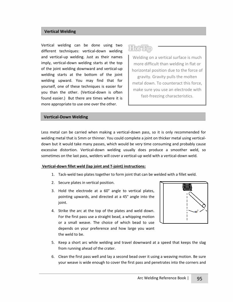
Arc Welding Reference Book | 95
Vertical welding can be done using two
different techniques: vertical-down welding
and vertical-up welding. Just as their names
imply, vertical-down welding starts at the top
of the joint welding downward and vertical-up
welding starts at the bottom of the joint
welding upward. You may find that for
yourself, one of these techniques is easier for
you than the other. (Vertical-down is often
found easier.) But there are times where it is
more appropriate to use one over the other.
Less metal can be carried when making a vertical-down pass, so it is only recommended for
welding metal that is 5mm or thinner. You could complete a joint on thicker metal using vertical-
down but it would take many passes, which would be very time consuming and probably cause
excessive distortion. Vertical-down welding usually does produce a smoother weld, so
sometimes on the last pass, welders will cover a vertical-up weld with a vertical-down weld.
Vertical-down fillet weld (lap joint and T-joint) instructions:
1. Tack-weld two plates together to form joint that can be welded with a fillet weld.
2. Secure plates in vertical position.
3. Hold the electrode at a 60° angle to vertical plates,
pointing upwards, and directed at a 45° angle into the
joint.
4. Strike the arc at the top of the plates and weld down.
For the first pass use a straight bead, a whipping motion
or a small weave. The choice of which bead to use
depends on your preference and how large you want
the weld to be.
5. Keep a short arc while welding and travel downward at a speed that keeps the slag
from running ahead of the crater.
6. Clean the first pass well and lay a second bead over it using a weaving motion. Be sure
your weave is wide enough to cover the first pass and penetrates into the corners and
Welding on a vertical surface is much
more difficult than welding in flat or
horizontal position due to the force of
gravity. Gravity pulls the molten
metal down. To counteract this force,
make sure you use an electrode with
fast-freezing characteristics.
Hot Tip
Vertical Welding
Vertical-Down Welding

96 | Arc Welding Reference Book
evenly into each plate. If making a lap joint take care to overheating the outside edge
of the joint.
Vertical-down square butt joint instructions:
1. Since vertical-down is most suitable for thinner materials, normally only a square butt
joint should be made welding down. Tack-weld two plates together to form desired
square butt joint, leaving proper root gap.
2. Secure plates in vertical position.
3. Hold the electrode at a 60° angle up from
the vertical plates, pointing directly into the
joint.
4. Strike the arc at the top of the plates and
weld downward. You’ll probably have the
most success using a whipping motion.
5. Keep a short arc while welding and travel
downward at a speed that keeps the slag from running ahead of the crater. Ensure
that the weld is penetrating at least half way through the joint and that the bead is
fusing evenly to each plate.
6. Weld the reverse side of the plates in the same manner, ensuring beads meet in the
middle of the plate for adequate penetration.
Since deeper penetration is achieved and more metal can be carried with a vertical-up pass, it is
usually used on plates 6mm or thicker. Because of these qualities, welds made with vertical-up
require fewer passes which results in less distortion.
#59. Mastering a New Skill
ACTIVITY
#60. How-To Video
#59. Mastering a New Skill
ACTIVITY
#60. How-To Video
Vertical-Up Welding

Arc Welding Reference Book | 97
Welding with vertical-up requires a lower amperage
setting than flat or vertical-down welding. The heat
must be high enough to allow the puddle to spread
out and get good penetration, but low enough to
prevent run down and overheating.
Vertical-up fillet weld (lap joint and T-joint)
instructions:
1. Tack-weld two plates together to form a joint that can be welded with a fillet weld.
2. Secure plates in vertical position.
3. Hold the electrode nearly perpendicular to vertical plates, pointing upwards slightly,
and directed at a 45° angle into the joint.
4. Strike the arc at the bottom of the plates and weld upwards. Lay the first pass using a
whipping motion. The whipping motion allows the metal to solidify, preventing it from
running downwards.
5. Clean the first pass well
and lay a second bead
over it using a weaving
motion. Be sure your
weave is wide enough to
cover the first pass and
penetrates into the
corners and evenly into
each plate. If making a lap
joint take care to avoid overheating the outside edge of the joint.
6. If desired, for a smoother finished bead, run your last pass either with a 7018
electrode or using a vertical-down pass.
Vertical-up V-groove butt joint instructions:
1. Prepare the plates identically to the way you would if welding in the flat position with
appropriate bevels according to thickness of metal. Tack-weld two plates together to
form desired V-butt joint, leaving proper root spacing. If desired, to make first pass
easier, also tack on a backing strip.
Spark of Information
Most of the problems that
occur while vertical-up
welding are from improper
amperage settings.
#59. Mastering a New Skill
ACTIVITY
#60. How-To Video

98 | Arc Welding Reference Book
2. Secure plates in vertical position.
3. Hold the electrode nearly perpendicular to vertical plates, pointing upwards slightly
and directed straight into the joint.
4. Strike the arc at the bottom of the plates and weld upward. You’ll probably have the
most success using a whipping motion.
5. Clean the first pass well and lay a
second bead over it using a weaving
motion. Be sure your weave is wide
enough to cover the first pass and
penetrates evenly into each plate.
The number of passes will depend on
thickness of metal. Some joints may
only require one pass to be welded
correctly.
The overhead position is when welds are deposited on the underside of a joint. This welding
position is the most difficult because you have to work against the force of gravity while
depositing a weld bead. Plus, the majority of time you also have to assume an awkward,
tiresome stance and contend with very hot falling debris. For these reasons, if you can avoid
welding in the overhead position, do. It will always be easier to make a weld in any other
position. However, in those instances when you have no other choice other than to weld
overhead, it is definitely doable, especially now that you have practice and experience making
good quality welds in other welding positions.
Even though making a uniform bead with sufficient penetration in the overhead position can be
a tricky task, with practice it is possible to make welds that are equal in quality to those made in
other positions. You can achieve this by holding a short arc and depositing the bead with a
whipping motion which will help to keep the puddle small and avoid sagging.
To combat fatigue and keep a steady hand while welding in the overhead position try draping
the cable over your shoulder if standing, or over your knee if sitting. If you don’t disperse the
#59. Mastering a New Skill
ACTIVITY
#60. How-To Video
Overhead Welding

Arc Welding Reference Book | 99
weight of the cable like this you will definitely tire sooner. Also try using both hands to hold onto
the electrode holder and resting an arm or elbow on your body or a solid object to help you to
steady the electrode.
You also need to take extra measures to protect yourself from falling spatter and sparks while
welding overhead. Try to stand to one side of the bead and hold the electrode in such a way that
the back of your hands are the first thing the spatter hits as opposed to your head, shoulders
and neck. Be sure to button up the collar of your shirt to protect your neck and wear your skull
cap to protect your head.
Overhead fillet weld (lap joint and T-joint) instructions:
1. Tack-weld two plates together to form a joint that can be welded with a fillet weld.
2. Secure plates in overhead position so that the underside is easily reached by the
electrode.
3. Hold the electrode at a 30-45° angle to the
vertical plate and tilted slightly (5-15°)
towards the direction of travel. If the
electrode is angled too far, the molten
filler metal takes the heat instead of the
base metal which causes the puddle to
drip.
4. Strike the arc and establish a puddle evenly
on both pieces. Place a bead in the corner
of the joint using a whipping motion.
5. Keep a short arc while welding and use the speed of your
whipping motion to prevent the bead from sagging.
6. Clean the first pass and, if multiple passes are necessary, lay
multiple stringer beads in the same manner. If needed, these
passes can be made with a slight weaving motion. If the joint
only requires a two-pass weld, lay the second pass with weaving. If making a lap joint
be sure that your last pass ties this outside edge in completely with the weld.
#59. Mastering a New Skill
ACTIVITY
#60. How-To Video

100 | Arc Welding Reference Book
Overhead square butt joint instructions:
1. Tack-weld two plates together to form desired square butt joint, leaving proper root
gap. (Remember, if the joint can only be reached from one side, you may have to weld it
as a V-groove butt joint instead of a square butt joint to get adequate weld
penetration.)
2. Secure plates in overhead position.
3. Hold the electrode pointing directly into the joint and
tilted 15° in the direction of travel. If the electrode is
angled too far, the molten filler metal takes the heat
instead of the base metal causing the puddle to drip.
4. Strike the arc and run a stringer bead along the joint
using a slight whipping motion. Maintain a short arc while welding and use the speed
of your whipping motion to prevent the bead from sagging. Ensure that the weld is
penetrating at least halfway through the joint and that the bead is fusing evenly to
each plate.
5. Weld the reverse side of plates, which will normally be accessible to weld in flat
position, ensuring beads meet in the middle of the plate for adequate penetration.
Overhead V-groove butt joint instructions:
1. Prepare the plates identically to the way you would if welding in the flat position to
create beveled edges. Tack-weld the plates together to form desired V-butt joint,
leaving proper root spacing. If desired, to make first pass easier, also tack on a backing
strip. The backing strip will also help ensure the first pass has proper penetration.
2. Secure plates in overhead
position.
3. Hold the electrode pointing
directly into the joint and tilted
15° in the direction of travel. If
the electrode is angled too far,
the molten filler metal takes the
#59. Mastering a New Skill
ACTIVITY
#60. How-To Video

Arc Welding Reference Book | 101
heat instead of the base metal causing the puddle to drip.
4. Strike the arc and run a stringer bead along the joint with a whipping motion.
Maintain a short arc while welding and use the speed of your whipping motion to
prevent the bead from sagging.
5. Clean the first pass and lay multiple stringer beads in the same manner with a
whipping motion. The way you hold the electrode for multiple passes will depend on
which pass you’re laying. The sequence you lay the passes should look something like
this.

102 | Arc Welding Reference Book
Unit 6 Resources
http://www.sweethaven.com/sweethaven/BldgConst/Welding/lessonmain.asp?lesNum=7&modNum=6
http://www.lincolnelectric.com/assets/global/products/consumable_stickelectrodes -mildandlowalloysteels-excalibur-excalibur10018-d2mr/c2410.pdf
http://www.sweethaven.com/sweethaven/BldgConst/Welding/lessonmain.asp?lesNum=3&modNum=3
http://www.mig-welding.co.uk/arc-flat-joints.htm
#59. Mastering a New Skill
COMPLETE LIST OF
UNIT 6 ACTIVITIES
#60. How-To Video
#61. Larger than Life Dice

Unit 7 Perfecting Your Technique
Bring with you to the meeting:
Pen or pencil and notebook
Clothes to weld in and safety gear (see appendix for the image of the well-dressed welder)
In this Unit we will:
Look at the characteristics that make up a good weld.
Find out how to test and inspect welds for quality.
Learn how to solve our welding problems by looking them up in the “troubleshooting
dictionary” and following the suggestions given.
Talk about tips and tricks that can help us weld successfully every time.

104 | Arc Welding Reference Book
CHAPTER 1: Making Good Welds
As a welder, every time you make a weld you need to ask the question, “Did I just produce a
good quality weld?” The answer to this question should always be yes. If not, you need to figure
out what you did wrong, correct your technique and make the weld again. If you know you’ve
made a poor quality weld when working on your projects there is absolutely no harm in grinding
out the weld you made and trying again. In fact, this is what you should do if you’ve made a
weld that isn’t up to par.
But how do you know if the weld is good quality or not? Well for starters, it should look good
from the outside. A good looking weld is smooth, has evenly spaced ripples and is uniform in
size the entire way along. There is no burn through and the edges of the weld are feathered into
the base metal. When a weld is good looking, it is a sign that care and good welding techniques
were used to make it.
Good Weld Bead Characteristics
Don’t be deceived into thinking that a weld that looks good from the inside is a good weld
through and through. Sometimes, even when our welds look perfect from the outside, they may
have some major problems on the inside. These hidden problems can lead to weak welds that
may break when stress is put on the joint or with wear and tear over time.
What really determines a good quality weld is adequate penetration and fusion. When you get
these two things right, a good weld will be one that is as strong, if not stronger than the base
metal surrounding it. This means that if force is applied to the joint, the base metal will most
Poor Weld Bead Characteristics

Arc Welding Reference Book | 105
#62. Whip It
likely break before the joint does. Even a beginner welder can consistently produce good welds
of high quality by taking care when welding, using the correct techniques and properly preparing
the weld before beginning.
There are a number of different methods that can be used to test welds for proper penetration
and fusion. Some methods like x-rays and ultrasounds will leave a finished weld intact and some
methods, like bend testing or sawing the joint in half, will destroy a welded joint. Most likely,
the method that will be most accessible to you will be “destructive testing.”
Examples of destructive testing
As a beginner, performing tests on welds you’ve made to check for penetration and fusion is a
very good idea. You don’t want to use destructive testing to test the joints of your actual
project. Instead, you should weld practice pieces and then break them apart to inspect for
quality. There is no other way to know if your practice and hard work has paid off!
ACTIVITY
#63. Back and Forth
#64. Strength Testing

106 | Arc Welding Reference Book
CHAPTER 2: Troubleshooting
Sometimes, even when we think we’ve done everything right, welds just don’t turn out the way
they’re supposed to. When this happens you need to troubleshoot to figure out what’s gone
wrong, why it’s happened and what you can do to correct the situation. Since there are so many
different factors that play a role in forming a good weld, troubleshooting can be a bit of a
nightmare. What do you try doing first to fix the problem? Adjust arc length? Switch to a
different electrode? Change the amperage setting? There are so many possibilities!
Thankfully, this chapter is here to help. It is a diagnostic dictionary. That means that when you
are having troubles making quality welds, you should stop what you’re doing, come here, look
up the problem and then follow the suggestions given. You don’t need to go through this entire
dictionary right now. Just come here when you’re looking for some troubleshooting help.
Diagnostic Dictionary
Problem: The arc wanders while you’re welding, refusing to
go where it’s supposed to go, spattering badly, and “blows”
back or forward. If you’ve encountered arc blow while
welding, you know that dealing with an unruly arc makes the
molten puddle nearly impossible to control. Beyond making
welding difficult, welds made when arc blow is present are
poorer in quality because of things like poor fusion, porosity
and slag inclusion.
Causes: Every part of the welding circuit that carries current is surrounded by a magnetic field.
Sometimes when using a DC power source the force of the magnetic field can be distributed
unevenly around the arc causing arc blow. Arc blow is most often encountered when welding
complex joints, in corners, deep grooves and at the beginning and end of joints.
Corrective Actions: There are a number of things you can try to get rid of arc blow.
If you have the option, switch to AC. Arc blow does not happen when using AC.
Change position of the ground clamp, placing it as far from the joint to be welded as possible.
Weld towards a heavy tack or towards a weld that’s already been made.
Weld away from the ground clamp.
Use back-stepping along welds.
Use as short of an arc length as possible.
Rearrange ground cables, coiling them on the ground.
Arc Blow

Arc Welding Reference Book | 107
Burn through
Cracked weld
Wrap ground cable around your welding table or workpiece, perhaps even passing
ground clamp through these coils.
Reduce current.
Problem: Weld metal melts completely through base metal leaving holes where no metal
remains.
Causes: excessive heat
Corrective Actions:
Select lower amperage.
Use a smaller electrode.
Increase and/or maintain steady travel speed.
Problem: Cracks appear in welds (usually after weld has cooled).
Cracks are an indication of weld failure. Although some cracks are
more serious than others, they are always a point of weakness.
Causes: Corrective Actions:
Incorrect electrode Choose proper electrode for metal thickness/joint size.
Ensure electrode is not damp.
Poor fit-up/incorrect gap size Establish proper gap size and good fit-up for pieces
being weld.
Ensure uniform gap all along joint.
Amperage too high Use lowest amperage possible that will still create a
sound weld.
Welds too small for size
of parts being joined
Adjust the size of weld to correspond with size of
parts being welded.
Make sure the weld bead is strong enough for the
stresses on the joint caused by heating and cooling of
welding process.
Try using a weaving instead of a stringer bead to
make a larger weld.

108 | Arc Welding Reference Book
Distortion
Poor Fusion
Craters improperly filled at
ends of beads
Properly fill craters at the end of each bead.
Poor quality base metal Try using a low-hydrogen electrode.
Problem: Pieces that have been welded move as they cool, pulling themselves out of proper
alignment. This is due to metal contracting as it cools down.
Causes: Corrective Actions:
Excessive heat input Use lower amperage.
Increase travel speed.
Weld in small segments and allow cooling in between
welds.
Use minimum number of passes by weaving or using
a larger electrode.
Improper welding sequence Before welding, develop a plan of attack on how you
will complete the weld.
Divide complicated welds into sub-assemblies.
Lack of anticipation
of metal movement
Use clamps to hold base metal in place.
Make several tack welds along joint before welding.
Set up the joint to allow for distortion movement.
Problem: Weld metal fails to fuse completely with base metal or
previous weld bead. Poor fusion is a serious structural defect but
often cannot be seen with the naked eye. It will show up in strength
testing the weld.
Causes: Corrective Actions:
Insufficient heat input
Increase amperage.
Select larger electrode and increase amperage.
Decrease weld speed.
Widen groove to access bottom during welding or use
smaller electrode that can reach into the groove.
Improper welding technique Place beads in proper location along joint.
Adjust work angle and ensure arc is at leading edge

Arc Welding Reference Book | 109
Shallow Penetration
of puddle.
When weaving, pause slightly at the edge of each
weave pass.
Dirty workpiece or failure to
clean beads between passes
Clean all base metal that will be included in the weld
joint well before welding by removing all grease,
paint, dirt, etc.
Clean beads well between each pass, chipping off slag
and brushing with a wire brush.
Arc blow See corrective actions under “arc blow” section.
Poor joint fit-up Ensure gap size isn’t too large.
Problem: Weld metal deposited does not reach deeply enough
into the base metal. Depth of penetration is usually not visible by
looking at the outside of a finished weld. Penetration, or the depth
the weld enters the base metal, is very important in creating a
strong weld.
Problem: Small holes in the weld that are usually not visible from
surface of the weld. Porosity is a result of gas pockets being
trapped in the weld and can lead to cracking.
Causes: Corrective Actions:
Travel speed too fast Decrease to a speed that allows enough weld metal
to be deposited.
Electrode too large
to fit in groove
Use narrower electrode that can reach to the bottom
of the joint.
Amperage too low Increase amperage.
If necessary, switch to an electrode with deeper
penetrating characteristics.
Improper joint preparation Leave the correct sized gap at the bottom of the weld
and, if needed, use a backing strip on the root opening.
When joining thicker material, bevel the edges.
Porosity

110 | Arc Welding Reference Book
Undercut
Causes: Corrective Actions:
Dirty workpiece Clean all base metal that will be included in the weld
joint before welding by removing all grease, rust, oil,
mill scale, paint, dirt, etc.
Defect of electrode Make sure the electrode is dry.
Chose an electrode that easily makes sound welds
(like a low-hydrogen electrode).
Do not use damaged electrodes.
Be sure to be using the correct type of electrode for
the metal you’re joining.
Improper welding
technique used
Puddle the weld long enough to allow trapped gases
to escape.
Try using a weaving pass instead of stringer bead.
Experiment with arc length to see if you need to
make it longer or shorter.
Try not to weld at an excessively fast speed.
Problem: An unfilled groove is left below the surface of the base metal along the edge of the
weld bead.
Causes: Corrective Actions:
Amperage too
high
Lower the amperage.
Arc length too
long
Use a shorter arc length.
Improper
electrode
movement or
position
Avoid excessive weaving.
Try to make weave as uniform as
possible.
Try not to weld too quickly.
Make sure you use an electrode designed
for the position you’re welding in.
Avoid letting an excessively large molten
puddle form.
When making a fillet, hold electrode
further away from vertical plate.
Adjust angle of electrode.

Arc Welding Reference Book | 111
Poor Weld Appearance
Spatter (excessive)
Electrode too
large
Use a smaller diameter electrode.
Arc blow See corrective actions under “arc blow”
section.
Problem: Weld bead has noticeable flaws that are visible by outwardly inspecting the weld.
Flaws may or may not affect the strength of the weld.
Causes: Corrective Actions:
Faulty or incorrect electrode Make sure the electrode is dry.
Do not use damage electrodes.
Be sure to be using the correct type electrode for the
metal you’re joining and position you’re working in.
Improper electrode
manipulation
Use a shorter arc length.
Focus on making a uniform weave bead.
Improper welding technique Travel at a constant speed.
Adjust arc length and/or amperage setting.
Overheating Lower the amperage.
Travel more quickly.
Improper joint preparation Take care when fitting up joints to leave even and
correctly spaced gaps.
Clean base metal well before starting.
Failure to clean beads
properly between passes
Remove all slag, flux and spatter from weld bead and
adjacent base metal before running more passes.
Unsteady hand
(if bead is wavy)
Use two hands to steady yourself, resting one elbow
on your welding table.
Problem: Small pieces of weld material scatter and splash while
welding. Once cooled these scattered pieces form small bumps
on base metal that are not part of the weld. Spattering is not a
structural fault, but can indicate that you are making a weld that
does have some structural weaknesses.

112 | Arc Welding Reference Book
Slag Inclusion
Causes: Corrective Actions:
Amperage too high Lower the amperage.
Using wrong polarity Switch polarity, making sure to use the one your
electrode is designed for.
Arc blow See corrective actions under “arc blow” section.
Wrong electrode Some electrodes spatter more than others, choose
one with less spattering characteristics.
Electrode may be too large, choose one with a
smaller diameter that corresponds with thickness of
material being welded.
Ensure you are using the correct electrode for
polarity being used.
Be sure electrode is dry.
Arc length too short Use a longer arc length.
Incorrect electrode angle Experiment with different angles.
Problem: Pieces of slag become stuck in weld while welding
and cannot be removed. Slag inclusion can either be visible
from the surface or hidden inside of the finished weld
bead.
Causes: Corrective Actions:
Amperage too low Raise the amperage.
Dirty workpiece Clean base metal that will be included in the weld
joint well before welding, removing all grease, rust,
oil, mill scale, paint, dirt, etc.
Lack of care when making
multiple passes
Remove all slag, flux and spatter from weld bead and
adjacent base metal before running more passes.
Plan weld sequence in advance and make passes in
correct order.
Faulty electrode Be sure electrode is dry and free from damage.
Arc length too low Use shorter arc length.

Arc Welding Reference Book | 113
Warping
Sluggish Arc
Improper welding technique Adjust electrode angle.
Travel at a correct and even speed.
Take care when weaving to make sure the puddle doesn’t
solidify before you’ve tied it in with the next weave.
Electrode too large
to fit in groove
Use narrower electrode that can reach to the bottom
of the joint.
Problem: Thin pieces that have been welded bend and twist out of shape.
Causes: Corrective Actions:
Excessive heat input Use a high speed electrode with moderate
penetrating characteristics.
Use lower amperage.
Increase travel speed, welding as quickly as possible
when welding thin material.
Weld in small segments and allow cooling in between
welds.
Use minimum number of passes (by using weaving or
a larger electrode).
Lack of anticipation of
metal movement and
improper fit-up
Use clamps to hold pieces in place.
Do not leave excessive gap between parts being welded.
If necessary, hammer metal around the joint thinner
before welding; this will elongate the metal around
the joint so that when its welded it will contract to
desired size.
Use a back-up bar.
Problem: Arc is not powerful enough to properly weld with.
Causes: Corrective Actions:
Amperage too low Increase amperage.
Poor connection
somewhere in the
circuit
Check all components of welding circuit to make sure they’re
properly connected (electrode holder and cable, ground clamp
and cable, etc.).

114 | Arc Welding Reference Book
Using incorrect size
cable
Check that you are using a cable that is the right size
(diameter) and length for job at hand.
#65. Fault Finding r
ACTIVITY
#66. Good vs. Bad
Arc Welding Reference Book | 115
CHAPTER 3: Tips n’ Tricks
Still having troubles making the perfect weld? Don’t worry. Making a quality weld is often easier
said than done. It can be tricky and time consuming. Sometimes it feels as if it would just be
easier to make a bad weld than take the time to make a good one, but that is never the case.
Doing so will just result in your welds coming apart or breaking in the future. In the long run,
making quality welds are always well worth the effort.
Below is a list of tips that will help you make quality welds. When you feel like your welds aren’t
up to snuff or if your strength testing reveals some flaws that you can’t seem to resolve you can
come here to review this list. Hopefully you’ll find a tip or two that will help you improve the
quality of your welds.
Keep in mind that every welding machine welds a little differently. Even two identical
machines may have slight differences in how they weld. So try to use the same machine as
much as possible and keep in mind that when you do switch machines the settings you
used with one machine may not be the exact ones you need to use with another machine.
Experiment with speed, arc length, travel angle and amperage even after you think you
have found the best to do the job. You may find an even better way!
Avoid building up more weld material than necessary. Building up more weld bead
beyond what you need doesn’t add any strength to the weld, it just takes longer and puts
more heat into the metal.
Allow the weld to cool slowly. Do not quench your workpiece and leave the slag on as
the weld cools.
When making multiple passes make sure that each bead partially covers the one before
it so they are all fused together well.
Take care to properly fit up joints. Use clamps, vise grips, right angle magnets and tack-
welds to properly position the metal. If leaving a gap, make sure it is a uniform size the
entire way along.
Be sure to chip the slag and clean each bead before laying another one over top of it. A
sign that a weld is well-made is when the slag comes off quite easily.
Examine the weld when finished. If it has any defects remove the weld with a grinder and
start again. Or, if you know that you’ve made an error that will leave a hidden defect in
your weld, grind it out and run a new one. Never attempt to weld over a cracked or
porous weld.
Welding is a skill that requires a lot practice to perfect. Practice, practice and more
practice will help you gain experience, which is probably the best thing you can do to
improve your welding.
If the sides of the bead aren’t tied in properly to the base metal you may be moving too
fast, jamming the rod into the puddle or using an amperage that is too low.

116 | Arc Welding Reference Book
Everybody welds a little differently, so if you get the chance, watch other welders at
work. Seeing how different welders complete a weld can help you to develop a
successful style and rhythm of your own.
Try using a different electrode (one with a different number). You may be surprised to
find out that welding with one electrode is easier or more difficult than another.
Make sure you choose an appropriate electrode for the metal type and job at hand.
When welding out of position make sure that you are using fast-freeze electrodes.
Thoroughly clean the base metal before welding removing dirt, grease, paint, etc. If you
don’t clean the plate properly these things can be included in the weld, making it weak. If
needed, you can use a grinder to help you clean off rust and paint.
Whenever possible, weld in the flat position instead of out of position. The easiest way
to make a quality weld is to have the work lying flat because the work is less tiring,
welding speed is faster, the molten puddle is less likely to run and better penetration can
be achieved.
When you are forced to weld out of position, it is helpful to use lower amperage and a
shorter arc length than what you would for welding the same joint in the flat position.
When making multiple passes, try to build the weld up evenly as you go along. If you do
end up with peaks and valleys it’s easier to level them with a grinder than it is to fix with
the next bead.

Arc Welding Reference Book | 117
#62. Whip It
Unit 7 Resources
http://www.sweethaven.com/sweethaven/BldgConst/Welding/lessonmain.asp?lesNum=7&modNum=13
http://www.weldguru.com/weld-troubleshooting.html
http://www.lincolnelectric.com/en-us/support/welding-how-to/Pages/high-quality-stick-welds-detail.aspx
http://deltaschooloftrades.com/stick%20essentials.htm
http://www.thefabricator.com/article/arcwelding/smaw-a-welders-guide
http://www.customclassictrucks.com/techarticles/1307_mig_welding_tricks_tips_and_proper_techniques/photo_15.html
http://commons.wikimedia.org/wiki/File:Welding_cracks.svg
http://www.ndt.net/article/wcndt00/papers/idn403/idn403.htm
http://isadikin.wordpress.com/2006/08/27/weld-defects/`
https://www.ndeed.org/EducationResources/CommunityCollege/Radiography/TechCalibrations/RadiographInterp.htm
#64. Strength Testing
COMPLETE LIST OF
UNIT 7 ACTIVITIES
#65. Fault Finding
#66. Good vs. Bad
#63. Back and Forth

Unit 8 Wrapping Up
Bring with you to the meeting:
Pen or pencil and notebook
Clothes to weld in and safety gear (see appendix for the image of the well-dressed welder)
In this Unit we will:
Talk about Achievement Day and put the finishing touches on our projects.
Learn about judging and explore useful judging techniques.
Reflect on the year and look at our future in welding.

Arc Welding Reference Book | 119
CHAPTER 1: Getting Ready for Achievement Day
Achievement Day is an exciting part of the 4-H year. It is an opportunity for us to show off our
accomplishments and all of the work we’ve done over the year to our fellow
club members, our families, our friends and our community. Beyond
recognizing our own accomplishments, Achievement Day is also about
evaluating our project work, demonstrating to the public what 4-H is
about and giving recognition to sponsors and other who have helped
out the club in a special way.
We’ve actually been getting ready for Achievement Day since our very first meeting by learning
new skills, completing activities and working on our projects. Now is the time to put the finishing
touches on everything so that we are putting our best foot forward on Achievement Day.
If there were any activities that you didn’t complete fully that will be displayed at Achievement
Day, now is the time to go back and finish them. Just as your would never sell an unfinished
project to a client, you should take pride in your work and finish it to the best of your ability
before displaying it.
That being said, if you are working on one of your big individual projects and did not have time
to finish it before Achievement Day, make a sign to be displayed with it that says “work in
progress.” By doing so, you are still allowing the public to appreciate what you’ve been working
on throughout the 4-H year, while at the same time are letting them know that what they are
seeing isn’t the finished product.
To prepare all of your projects and weldments for Achievement Day you will want to smooth
rough edges by filing, sanding and/or grinding. You should eliminate imperfections like spatter in
the same way. Where appropriate, you may also want to paint your projects. Painting not only
makes our projects more aesthetically pleasing, but also prevents them from rusting.
When getting projects ready for Achievement Day think about it as if you were getting all of
your projects ready to be sold. What a consumer would rather purchase: a weldment that has
sharp, unfinished edges and spatter everywhere, or one with a smooth finish that not only looks
great, but feels good to the touch? This type of thinking brings us to another very important
aspect of Achievement Day… judging!

120 | Arc Welding Reference Book
CHAPTER 2: Judging
Judging is an important part of Achievement Day because it is an important part of our lives.
There isn’t a day that goes by that we don’t judge because judging is how we make informed
decisions and how, as consumers, we choose the best products for our needs. Just think about
all of the judgments we make all day long; we make judgments when we decide what we are
going to wear, what we will have for breakfast, how we will style our hair… and that’s only
within the first 30 minutes of being awake! We also use judging when making really important
decisions such as choosing which career path to follow.
Practicing judging in 4-H helps us to:
Appreciate the opinions of others.
Improve our own work.
Recognize good products and choose articles based on their quality.
Become more observant.
Learn how to assess the positives and negatives of a situation.
Make our own decisions.
Communicate our ideas clearly so others can understand.
In 4-H, judging requires members to examine a group of four
items and to rank these items by comparing them to an “ideal”
and to each other. All items that are in this group for
comparison are called a class. Once members have decided on
the ranking, or placement, of the class they must give reasons
to support why the decision was made.
For successful judging, we can use the steps below to compare
and evaluate the articles in each class. These steps can be
applied to any class, from weldments to food to livestock. We can even use these steps in life
after 4-H to help make our decision; only the number of options to consider and how/if we
present our decisions will vary.
1. Picture the ideal item – Picture the ideal item in your mind. What does the perfect
fillet weld look like? What about the perfect pizza? In your mind, or even on a sheet of
paper, list the characteristics that you feel are important in a perfect item. Then rank
these characteristics in order of importance.
2. Think comparatively – Judging determines the advantages of one item over another.
So you need to think comparatively when looking at the items in a class; compare
each item in the class with the other items and with your ideal item. As you examine
the class thing about comparative terms you might use in your reasoning.
A 4-H judging class will
always have four items
to compare. The items
are numbered 1 to 4
from left to right.
Hot Tip

Arc Welding Reference Book | 121
Comparative terms are words ending in “er” and phrases with more in them. For
example, one weldment may have more penetration and straighter weld beads than
another. Or one pizza may have more cheese and a thicker crust than another. Try to
keep your comparative terms positive.
3. Examine – First, examine the class from a distance. Stand back so that you can view all
items in the class at the same time. This makes it easier to view overall appearance,
size and structure and compare them against one another. Next examine the items
closely. Inspect each one individually, continuing to compare them against all of the
others and the ideal. If you are judging small items, feel them, pick them up, turn
them over and look at them from all angles. Look closest at the characteristics you
ranked most important first, as this is what you will base the placing of the class on.
4. Make your decision – Place items in order from most desirable to least desirable. The
item that most resembles the ideal will be placed first, the next closest to the ideal
second and so on for the four placings. Make your easiest placing first. For example,
it’s often easiest to select the top and bottom placings first and then decide on the
middle placings. If you have doubts go back and re-examine the items to confirm your
decision. Remember, your first impression is usually best, so try not to second guess
yourself. Take time to picture each item clearly in your mind so that you will
remember its features when it comes time to back up your decision. If needed take
notes.
5. Tell why – Give reasons to support your decision. Use comparative words in your
reasoning and stay positive, pleasant and precise. Everyone else judging the same
class may not have placed the items in the same order as you did. This is perfectly
okay. Your reasons, and being able to back up your placement, is what’s really
important.

122 | Arc Welding Reference Book
CHAPTER 3: That’s a Wrap
Congratulations, you’ve completed a year of Arc Welding!
Do you remember how, in Unit 1, we learned that welding touches almost every aspect of our
everyday lives? This means that the world of welding is so vast, diverse and interesting that
we’ve only just got our feet wet.
The great part of having learned how to arc weld is that you now have a solid set of welding
skills. You can apply these skills to any other welding process and build upon them with more
training and practice. If you are interested in more training, at the end of this Unit there is a list
of colleges and trade schools in Saskatchewan that offer welding programs.
Are you wondering where welding can take you in life? The opportunities are endless! Welding
students have a unique opportunity to learn a career that can be shaped around their interests.
There is a welding niche for nearly every area of interest: working indoors or outdoors, staying
close to home or travelling, science or art, research or sales, teaching or designing, robotics or
computer programming, engineering or farming.
If you’re considering a career in welding, do some digging around: talk to welders, do internet
searches, subscribe to welding magazines. You may be surprise when you hear more about the
incredible variety of welding jobs out there and how well they can pay. And be sure to check out
the website for the Canadian Welding Association. They have some great videos available (see
resources) that show how rewarding a career in welding can be!

Arc Welding Reference Book | 123
Unit 8 Resources
http://www.4-h.sk.ca/plugins/userData/Info%20Sheets/Planning%20Achievement%Day.pdf
http://www.gov.ns.ca/agri/4h/awareness/planning.shtml
http://www.gov.ns.ca/agri/4h/judging/howtojudge.pdf
http://www.4-hontario.ca/uploads/userfiles/files/judging%20toolkit.pdf
http://www.thejudgingconnection.com/pdfs/Learning_Through_Judging.pdf
http://mason.ext.wvu.edu/r/download/149451
http://www.careersinwelding.com/students.php
http://www.cwa-acs.org/education.html
http://www.livingin-canada.com/salaries-for-welders-canada.html
http://www.cwa-acs.org/video.html
http://www.cwa-acs.org/saskaton.html or http://www.cwa-acs.org/regina.html
http://www.youtube.com/watch?feature=player_embedded&v=N1za61qLcVA
http://www.youtube.com/watch?v=YuKDH4NtKjg&feature=player_embedded
http://www.youtube.com/watch?feature=player_embedded&v=DFbJwtwBLnU&list=UUVbLbc7goDa6FxauaveyUHA#at=127
Carlton Trail Regional College – http://www.ctrc.sk.ca/programs
Great Plains College – http://www.greatplainscollege.ca/
North West Regional College – http://www.nwrc.sk.ca
Northlands College – http://trainnorth.ca/
Parkland College – http://www.parklandcollege.sk.ca
Saskatchewan Indian Institute of Technologies – http://www.siit.sk.ca
Saskatchewan Institute of Applied Science and Technology – http:// gosiast.com/
Southeast Regional College – http://www.southeastcollege.org
Schools That Offer Welding Programs in Saskatchewan

Appendix
The Well-Dressed Welder
Tables
Activity Worksheets
Project Picker
Welding Terms
Resources
Acknowledgements

Arc Welding Reference Book | 125
THE WELL-DRESSED WELDER
Welding Helmet
Ear Plugs
or Muffs
Skull Cap
Safety Glasses
or Goggles
Long Sleeve Shirt
or Coveralls
made of natural
fibers
Gauntlet
Gloves
Pants, Chaps or
Coveralls Made of
Natural Fibers
Work Boots

126 | Arc Welding Reference Book
TABLES
Table 1 - Guide for Filter Shade Selection
Guide for Filter Shade Selection
Operation Electrode Size
(mm) Arc Current (A) Min Shade
Suggested
Shade
Shielded Metal Arc Welding
< 2.5 mm
2.5-4 mm
4-6.4 mm
> 6.4 mmm
< 60
60-160
160-250
250-550
7
8
10
11
*
10
12
14
*As a rule of thumb, start with a shade that is too dark to see the weld zone. Then go to a
lighter shade which gives sufficient view of the weld zone without going below the minimum.
From this chart, you can see that welding operations with a higher arc current or amperage
need a darker filter than ones with lower amperage. This is because the higher amperage, the
more intense and bright the light given off is.
Table 2 – AWS A5.1 Carbon Steel Electrodes for SMAW
E6010 E = Electrode
60 = Min. Tensile (in ksi)
1 = Position
0 = Type of Coating and Current
Key to Type of SMAW Coating and Current
Digit Type of Coating Current
0 High Cellulose Sodium DC+
1 High Cellulose Potassium AC, DC±
2 High Titania Sodium AC, DC-
3 High Titania Potassium AC, DC±
4 Iron Power, Titania AC, DC±
5 Low Hydrogen Sodium DC+
6 Low Hydrogen Potassium AC, DC+
7 High Iron Oxide, Iron Powder AC, DC±
8 Low Hydrogen Potassium, Iron Powder AC, DC±

Arc Welding Reference Book | 127
ACTIVITY WORKSHEETS
1. Meet, Greet and Goals Worksheet
2. WHMIS I.D. Worksheet
3. The Shop Rules
4. Learn the Lingo Crossword
5. Learn the Lingo Word Search
6. Learn the Lingo Word Match
7. Name that Part Fill-in-the-blank
8. Good Weld Cheat Sheet
9. End-of-Year Reflection Worksheet

128 | Arc Welding Reference Book
Meet, Greet and Goals Worksheet
Name: ________________________________________________________________________
Have you ever welded before? ____________________________________________________
If so, what have you done? _______________________________________________________
_____________________________________________________________________________
_____________________________________________________________________________
_____________________________________________________________________________
_____________________________________________________________________________
Why are you interested in welding? ________________________________________________
_____________________________________________________________________________
_____________________________________________________________________________
_____________________________________________________________________________
_____________________________________________________________________________
_____________________________________________________________________________
What are five things you hope to learn by taking this project?
________________________________________________________________________
_____________________________________________________________________________
________________________________________________________________________
_____________________________________________________________________________
________________________________________________________________________
_____________________________________________________________________________
________________________________________________________________________
_____________________________________________________________________________
________________________________________________________________________
_____________________________________________________________________________

Arc Welding Reference Book | 129
WHMIS I.D. Worksheet
Draw lines to connect each image to its correct definition.
a. Compressed gas
b. Flammable and combustible material
c. Materials causing immediate and serious toxic effects
d. Bio hazardous infectious material
e. Materials causing other toxic effects
f. Corrosive material
g. Dangerously reactive material
h. Oxidizing material

130 | Arc Welding Reference Book
The Shop Rules
_______________________________________________________
_______________________________________________________
_______________________________________________________
_______________________________________________________
_______________________________________________________
_______________________________________________________
_______________________________________________________
_______________________________________________________
_______________________________________________________
______________________________________________________
______________________________________________________
______________________________________________________
______________________________________________________
______________________________________________________
______________________________________________________
______________________________________________________
______________________________________________________
______________________________________________________
______________________________________________________
______________________________________________________

Arc Welding Reference Book | 131
Learn the Lingo Crossword
1 2
3 4
5
6
7 8 9
10
11
12
Across
3. The coating found on the outside of the
electrode.
6. The metal rods used in arc welding, made of
wire core and flux coating.
8. This is used to mark areas to be welded so
that they can be seen while helmet is on.
10. Wear this to protect your eyes from
harmful rays while welding.
11. The name for types of materials that can
easily catch on fire.
12. Another name for the electrode holder.
Down
1. The visible column of fume that rises from
the spot being welded. (2 words)
2. DC stands for this. (2 words)
4. The bright spark caused by electricity
jumping between electrode and base metal.
5. Type of long gloves to be worn while
welding.
7. Use these to pick up hot pieces of metal.
9. The amount of electrical current that flows
through a circuit.
12. The waste material left on the weld that
must be chipped off.

132 | Arc Welding Reference Book
Learn the Lingo Word Search
s e f u m e p l u m e e d w
h s g w e l d e r d a e b e
s e l b a c t a e e r e w l
s s l a y y n u d g p l i d
l s t m g c e o e a l g r i
e a t i e y r a l r u g e n
l l t l t t r r r e g t b g
y g s e c u u c e p s a r c
b y p e m d c l g m e h u i
n t l a t e m e s a b a s r
r e m m a h g n i p p i h c
y f l u x h r g e g w c c u
c a c d c e u t e l w e a i
r s y p m l h h a s f e s t
acdc cables electrode safety glasses
amperage chipping hammer flux slag
arc length current fume plume welder
base metal duty cycle helmet welding circuit
bead earplugs metal wire brush

Arc Welding Reference Book | 133
Learn the Lingo Word Match
Match the correct words to their definitions.
_________ Duty cycle A. The shaded lens in a helmet that protects your eyes from
arc rays.
_________ Welding table B. This is used to chip slag off of weld beads.
_________ Ventilation C. The number of minutes a welder can be operated for
without needing to cool down.
_________ Natural D. The movement of air through a workplace to keep harmful
fumes and gases away from welder.
_________ Welder’s flash E. The power source for arc welding.
_________ Filter lens F. The part of the welding circuit that attaches to the base
metal or welding table.
_________ Ground clamp G. The electrical path in welding where the current flows.
_________ Auto-darkening H. You place a workpiece on this metal surface to do all of
your welding.
_________ Chipping hammer I. Condition that occurs when eyes are exposed (even briefly)
to the light emitted by arc.
_________ Base metal J. The metal or alloy being welded. Also called workpiece.
_________ Welding circuit K. The type of helmet that darkens as soon as an arc is struck.
_________ Welding machine L. The type of material that a welder’s clothing must be made
out of.

134 | Arc Welding Reference Book
Name that Part Fill-in-the-Blank
Welding Circuit
Welding Machine

Arc Welding Reference Book | 135
Good Weld Cheat Sheet
If the bead is…. …the arc length is too short
If the bead is… …the arc length is too long.
If I hear a _______________________________________ sound the arc length is correct.
If I hear a _______________________________________ sound the arc length is too short.
If I can see the arc “jumping around” the arc length is _______________________________.
When running a stringer bead you should hold the electrode so that the arc force will push the puddle in a way that the weld will __________________________________________.
The correct travel angle for running a stringer bead is____________________.
If the bead… …the amperage is too low.
If the bead… …the arc length is too long.
If I see charring on electrode’s flux or if I burn through the base metal the amperage is ___________________________.
If it is difficult to strike the arc the amperage is __________________________________.
If the bead… …the travel speed is too slow.
If the bead… …the travel speed is too fast.
If my beads are not uniform I am not travelling at a _______________________ speed.
If I burn through my work I am travelling _________________________.

136 | Arc Welding Reference Book
End-of-year Reflection Worksheet
Name: ________________________________________________________________________
What are five things you learned while taking this project?
________________________________________________________________________
_____________________________________________________________________________
________________________________________________________________________
_____________________________________________________________________________
________________________________________________________________________
_____________________________________________________________________________
________________________________________________________________________
_____________________________________________________________________________
________________________________________________________________________
_____________________________________________________________________________
What part of this project did you find most interesting? _______________________________
_____________________________________________________________________________
_____________________________________________________________________________
_____________________________________________________________________________
_____________________________________________________________________________
_____________________________________________________________________________
If you took this project again, what would you like to do differently? _____________________
_____________________________________________________________________________
_____________________________________________________________________________
_____________________________________________________________________________
_____________________________________________________________________________
_____________________________________________________________________________

Arc Welding Reference Book | 137
PROJECT PICKER
Every member should complete one individual project and assist in one community project as
part of their Achievement Day requirements. This section of the manual provides a list of project
ideas, as well as some project plans (which includes a list of materials needed, shop drawings
and instructions).
All project ideas whose plans are included in the “Project Plans” part of this manual are
indicated by ***. Due to the source of the plans, measurements are given in imperial instead of
metric. To convert inches to millimetres multiply the measurement by 25.4 (The term “Schedule
40” in these plans indicates the nominal wall thickness for standard black iron pipe.)
Some project ideas also have an internet website address underneath them. At the time that
this manual was printed, these website contained useful plans that could be adapted into
welding project plans.
For the project ideas that do not have
plans, library books and the internet can
both be valuable resources for you to
find existing plans or develop your own
plans. You may find it difficult to locate
an actual step-by-step plan with
material lists and shop drawings, like the
ones provided in this section. However,
if you do an internet search of any of
these project ideas you will find many images that you can use as inspiration in your own
designs. If developing your own project plan, before you begin working on the project you
should hand draw a shop drawing, make a list of materials needed and write out the steps that
you will take to complete it.
At the time that this manual was printed, the following websites had a multitude of project
plans and ideas:
http://freeplans.domerama.com/
http://www.millerwelds.com/interests/projects
http://www.wcwelding.com/welding-plans.html
http://www.lincolnelectric.com/en-ca/support/welding-projects/Pages/welding
-projects.aspx
Spark of Information
Having trouble finding images of the
project you’d like to work on? Adding
the word “metal” into your internet
search (i.e. searching for “metal garden
bench” instead of “garden bench”) may
give you better results

138 | Arc Welding Reference Book
Community projects will be completed by the entire club or in small groups. Following is a list of
ideas for projects that you may want to consider as community projects. When picking a
community project try to think of your community and how you could be of best service to the
people who live there. For example, is there a spot where seniors might want to stop for a rest?
If so, a garden bench would be perfect there. Are there community buildings that lack
wheelchair access? Making a building accessible to everyone that uses the buildings would be
greatly appreciated. Are there locations that are frequented by families? Bicycle racks would be
a great addition to these locations.
Community Project Ideas
Bicycle rack
http://hostesswiththemotzes.com/2012/04/29/project-4-diy-bike-rack-made-from
-pvc-pipe/
http://weldingweb.com/showthread.php?t=33211
http://bikeracked.com/triangle-bike-rack-plans/
Picnic table
http://ana-white.com/2010/04/furniture-plans-full-size-picnic-table.html?page=10
http://www.curbly.com/users/rebekah-greiman/posts/13975-how-to-build-an-extra
-large-diy-picnic-table
Pitching screen
http://www.lincolnelectric.com/en-us/support/welding-projects/Documents/build-a
-pitching-screen.pdf
Garden bench
http://www.wcwelding.com/garden-bench-plans.html
Wheelchair ramp
http://www.lincolnelectric.com/en-ca/support/welding-projects/Pages/wheelchair-
ramp-detail.aspx
Do you have any project ideas that are not included in this list that you think would benefit your
community in some way? If so, bring them up at the meeting. Your idea could be just what your
community needs!
Community Projects

Arc Welding Reference Book | 139
Below is a list of ideas for your individual project. Make sure you discuss with your leader which
project you would like to do before making your final choice. It’s better to pick a smaller project
that you and your leader think you will have time to complete rather than pick a large project
that will not be finished in time for Achievement Day. The great thing about picking a smaller
project is that if you finish it you can start working on a second project of your choice! That
being said, if this is your second or third time taking this project, you may have time to complete
a larger more complex project.
Individual Project Ideas:
Fire pit
Welding table
http://www.mylincolnelectric.com.au/knowledge/articles/content/howto_weldingtable.asp
Christmas tree stand***
Post driver***
Shop stool
http://www.millerwelds.com/interests/projects/shop-stool
Bookends
Tomato cage
Ornaments for gardens/outdoors
Boot scraper***
Trailer
http://www.lincolnelectric.com/en-ca/support/welding-projects/Pages/mower-trailer
-detail.aspx
Chipping hammer and welding jig***
Coat rack
Electrode holder***
Pedestal (for grinder)***
Welding table with positioner***
If you are itching to make a project that is not included in the list above, talk it over with your
leader. It may be something that would make an excellent individual project.
Individual Projects

140 | Arc Welding Reference Book
WELDING TERMS
AC welder – A machine that produces an
alternating current for striking the arc and
running a weld bead.
alloy – A metal manufactured by combining
a base metal with other metals or chemical
elements in order to alter or improve its
properties.
alternating current (AC) – An electrical
current that reverses its direction at regular
intervals. In one complete cycle the current
spends 50 percent of the time flowing one
way and the other 50 percent flowing the
other way. The rate of change in direction is
called frequency and is indicated by cycles
per second such as 60 cycles per second or
60 hertz.
amperage – The measurement of the
amount of electricity flowing past a given
point in a conductor per second. Current is
another name for amperage. Often referred
to as “amps.”
arc – The physical gap between the end of
the electrode and the base metal. The
physical gap causes heat due to resistance
of current flow and arc rays.
arc blow - The deflection of an electric arc
from its normal path because of magnetic
forces.
arc length – The distance from the tip of
the electrode to the adjacent surface of the
weld pool.
arc flash – See welder’s flash.
arc radiation – The electromagnetic energy
given off by the arc that can injure eyes and
burn skin. An operator can see the visible
light radiation given off but cannot see the
ultraviolet or infrared radiation. Radiation is
often silent and undetected, yet injury
occurs if operator does not wear protective
gear and clothing.
arc welding – See SMAW.
auto-darkening helmets – These are
welding helmets whose filter lens
automatically darkens to the chosen filter
shade within 4/10 of a second of the arc
being struck. This is fast enough to protect
eye from any damage.
AWS number - This is a 4-5 digit number
that is written on every electrode. The
American Welding Society (AWS)
numbering system can tell a welder quite a
bit about a specific stick electrode including
what application it works best in and how it
should be used to maximize performance.
backhand welding – A welding technique
in which the electrode is pointed back
towards the weld puddle as it is moved
forward along the weld seam.
back-stepping – This is a welding technique
where the general progression of welding
may be left to right, but the bead is
deposited in segments from right to left.
This technique is used to avoid distortion,
especially while welding on thin sheets.

Arc Welding Reference Book | 141
back-up bar – This is a material, usually a
metal strip, that is placed against the back
side of an open joint to support and retain
the molten weld metal. The back-up bar can
be left in place or cut off.
back-up strip – See back-up bar.
base metal – The metal or alloy that is to be
weld. Often referred to as the workpiece.
bead – The deposited filler metal on and in
the workpiece created when the wire core
of electrode is melted and fused into the
base metal. From the exterior it appears as
a series of tight, overlapping ovals. A
stringer bead is a narrow bead made with
only a dragging motion or light oscillation,
while a weave bead is wider and made with
more oscillation.
bevel – These are angles cut or grinded into
the edge of workpieces. The purpose of a
bevel is to make the root opening larger,
allowing for more penetration.
bevel angle – The angle formed between
the prepared edge of one side of the base
metal and a plane perpendicular to the
surface of the other side of the base metal.
butt joint – A joint between two metal parts
that lie in the same plane. Filling the weld
groove formed between the two plates’
edges creates a single piece. This is the
most common type of joint.
carbon steel – A steel that contains a
certain amount of carbon. Low-carbon
steels are some of the most commonly
welded metals.
concave – Curving inward like the inside of
a bowl.
conductor – A substance or material that
readily allows electrical current to pass
continuously along it.
constant current machines – An arc welding
machine (power source) where the voltage
will change with different arc lengths while
only slightly varying the amperage, those
the name constant current.
convex – Curving outward like the exterior
part of a circle.
corner joint – A type of joint created
between the edges of two metal parts and
are situated at right angles to one another
forming an L shape.
crater – A depression at the end of an arc
weld bead caused by the force of the arc as
it is withdrawn.
current – The movement or flow of an
electrical charge through a conductor. In
welding, it is the current that flows through
the welding circuit during the making of a
weld. It is measured in amperes.
DCEN: Direct Current Electrode Negative –
See straight polarity.
DCEP: Direct Current Electrode Positive –
See reverse polarity.
DC welder – A machine that produces a
direct current for striking an arc and
running a weld bead.
defect – A flaw in the weld metal or in the
base metal that can cause a weld to fail.

142 | Arc Welding Reference Book
There is a large variety of different weld
defects such as a crack, slag inclusion,
undercut, etc.
direct current (DC) – An electrical current
that flows in one direction only.
distortion – The permanent shape change
of the weldment due to the non-uniform
expansion and contraction of the weld
metal and adjacent base metal during the
heating and cooling cycle of the welding
process.
double fillet – Is when fillet weld is placed
on both sides of a joint.
duty cycle – The number of minutes out of
a 10-minute time period an arc welding
machine can be operated at maximum
rated output before it needs to cool down.
An example would be 60% duty cycle at 300
amps. This would mean that at 300 amps
the welding machine can be used for 6
minutes and then must be allowed to cool
with the fan motor running for 4 minutes.
edge joint – A joint along the edges of two
or more parallel plates whose faces touch.
electric arc welding – See SMAW.
electrically hot - Is a part of an electrical
circuit that is electrically charged.
electrical circuit – The path taken by an
electrical current flowing through a
conductor from one terminal of the source
to be load and returning to the other
terminal of the source.
electrode – The conductive element
creating the electric arc between itself and
the base metal. In arc welding, the
electrode melts and becomes a part of the
weld. Also referred to as stick or rod.
electrode cable – The electrical
conductor/cable between the source of the
arc current (the welding machine) and the
electrode holder. To prevent injury the
cable must be in good condition and
correctly installed.
electrode holder – An insulated hand clamp
used for holding and conduction current
into an electrode during welding.
electrode lead – See electrode cable.
electrode size – The size of the electrode is
determine by the diameter of tis metal
core, not by the diameter including the flux
coating. The diameter is often given in
imperial measurements such as 1/8” or
5/32”.
fast-freeze electrode – A SMAW electrode
that solidifies quickly. Fast-freeze
electrodes are ideal for overhead welding.
fill passes – A progression of weld passes
with the purpose of filling the joint with
metal.
filler electrode – A SMAW electrode that
fills up a joint quickly. Fast-fill electrodes
are ideal for large workpieces.
filler material – Metal deposited into the
weld that often adds strength and mass to
the welded joint. In SMAW, the metal from

Arc Welding Reference Book | 143
the electrode’s wire core acts as the filler
metal.
fillet weld – A type of weld that is triangular
in shape and joins two surfaces at right
angles to each other in a lap joint, T-joint, or
corner joint. Fillet welds are the most
common types of welds.
filter shade – The shaded protective lens
inside the welder’s helmet that filters out
harmful rays and intense bright light. The
amount of shading required depends on the
welding process, electrode size, and
amount of current used.
fixed-shade helmets – A welding helmet
where the user must manually change the
filter shade.
flange welds – The welds used to fuse edge
joints.
flat-position welding – The welding
position used to weld from the upper side
of the joint. The face of the weld is
horizontal.
flux – A nonmetallic material coating the
wire core of an electrode. Flux is used to
protect the weld puddle and solid metal fro
atmospheric contamination and creates slag
on top of the weld bead.
forehand welding – A welding technique in
which the electrode is pointed in the
direction of welding, with the tip pointed
away from the bead it is forming.
forge – A furnace or hearth where metals
are heated and then hammered into shape.
Forge welding is a process by which a
blacksmith hammers near-molten metals
together to create a weld.
freezing – Is a term used in SMAW to
describe the electrode getting stuck to the
base metal.
fume – Metallic vapor that is emitted during
the weld process.
fume plume – A cloud-like area where
welding fume collects. The fume plume
contains solid particles from the
consumables (electrodes), base metal, base
metal coating and gases formed in the
process, which include oxides of nitrogen
and ozone.
fusion – The melting together of filler metal
and base metal, or of base metal only, to
produce a weld.
gauntlet gloves – Leather gloves used in
welding whose long cuffs cover most of the
forearm.
groove angle – The angle of the groove
between the two workpieces that are
welded together.
groove face – The exposed surface of the
groove weld in between workpieces.
groove weld - A type of weld made in the
groove between workpieces.
ground cable – The electrical
conductor/cable between the arc welding
power source (the welding machine) and
the ground clamp. Also called ground lead
or workpiece lead. To prevent injury, the

144 | Arc Welding Reference Book
cable must be in good condition and
correctly installed.
ground clamp – Part of the welding circuit
that is an adjustable clamp used to fasten
the ground cable (work lead/cable) to the
workpiece. Also referred to as workpiece
connection.
ground lead – See ground cable.
grounded – Grounding refers to a return
path for electric current to the service panel
or a direct physical connection to the Earth.
Having an electrical circuit grounded gives
the electricity a route to go that is away
from the operator, which will help to
prevent electrical shocks.
heat-affected zone (HAZ) – The portion of
the base metal that has not been melted,
but whose mechanical properties have
been altered by the heat of welding.
helmet – See welding helmet.
horizontal –position welding – A common
welding position used for fillet and groove
welds. For fillet welds, welding is performed
on the upper side of a horizontal surface
and against a vertical surface. For groove
welds, the weld axis lies in a horizontal
plane, and the weld face lies in a vertical
plane.
insulation – Material that does not allow
for the easy flow of electricity.
intermittent welds –A weld in which the
continuity is broken by recurring unwelded
spaces.
jig – An apparatus used by welders to align
and hold parts in a fixed position while the
weld is being made.
joint – The junction or edges of material
that are to be joined or have been joined.
There are five basic types of joints: butt,
corner, edge, lap and T.
lap joint – A type of joint between two
overlapping metal parts in parallel planes.
leg of a fillet weld – The distance from the
root to the toe of the fillet weld (from the
intersection of the joint to the end of the
weld). There will be a leg for each plate. The
size of the fillet weld is determined by the
length of its legs.
live circuits – An electrical circuit which is
electrically charged.
low-hydrogen electrode – A covered arc-
welding electrode that provides an
atmosphere around the arc and molten
weld metal which is low in hydrogen. Such
electrodes minimize the possibility of
hydrogen related cracking.
manual dexterity – Skill or agility in using
the hands or body.
mill scale – A black scale of magnetic oxide
of iron formed on iron and steel when
heated for rolling, forging, or other
processing.
multiple pass weld - Successive beads laid
down upon each other until a joint is filled.
Multiple passes are required when welding
tick metal plates or repairing large cracks.

Arc Welding Reference Book | 145
natural material – Materials derived from
plants or animals such as leather, cotton
and wool. For welding, leather covering
provides the welder with the most
protection.
oscillation – A back and forth movement.
out-of-position – Any welding operation in
which the parts are not laid out flat in front
of the operator, such as vertical or
overhead welding.
over-head position – The welding position
in which welding is performed form the
underside of the joint. Overhead-position
welding is the most difficult welding
position.
parent metal – Also called “base metal”,
this is the metal or steel that you are
actually welding on.
peen – To strike with the rounded end of a
hammer in order to bend or shape a sheet
of metal.
penetration – Describes how deeply the
weld metal extends into the joint. The
deeper the penetration, the stronger the
joint.
polarity – The direction of the flow of
electrical current in circuit.
porosity – Tiny holes or bubbles in the weld
bead formed by gas entrapment during
solidification of the weld metal. Porosity
can weaken the weld and lead to cracking
and often cannot be seen from the face of
the weld.
power disconnect switch – A switch used to
make sure that an electrical circuit can be
completely de-energized from service or
maintenance.
primary voltage – The voltage of the power
line or generator from which the welding
source of power is operated. Primary
voltage is the input voltage.
primary voltage shock – An electrical shock
from 120-180 volts that occurs in arc
welding from touching a lead inside a
switched-on welder and then touch the
welder case or other grounded metal at the
same time. Primary voltage shock is strong
enough to be fatal.
profile – a shape cut out of a blank sheet.
puddle – See weld pool.
quench – To cool suddenly by plunging into
a liquid.
reverse polarity – The direction of current
flow through a welding circuit when the
electrode lead/cable is connected to the
positive terminal and the ground lead/cable
is connect to the negative terminal of a DC
welding machine. Also called DCEP.
rod – See electrode.
root edge – A root face of zero width.
root face – The surface of the joint that will
be included in the weld that has not been
prepared with a bevel.
root opening – The gap between base
metal plates at the root of the joint.

146 | Arc Welding Reference Book
root pass – The first weld bead deposited at
the root of a joint in a multiple pass weld.
secondary voltage shock – An electrical
shock from 60-100 volts that occurs in arc
welding from touching the electrode while
another part of the body touches the
workpiece.
sheet metal – Thin metals, general between
12 and 24 gauge, used in auto bodies,
household appliances and HVAC
applications.
shielded metal arc welding – See SMAW.
shielding gas – Inert, non-flammable, non-
reactive gas released, from an electrode’s
flux, around the weld zone protecting the
arc area and weld puddle from reacting
negatively with the atmosphere.
single fillet – A fillet weld made only on one
side of the joint.
skull caps – The beanie worn by welders to
protect their scalp from burns.
slag – A non-metallic waste product formed
from the non-metallic impurities during the
SMAW process. Molten slag floats to the
top of the weld pool and then forms a
hardened protective coating over the weld
bead. This solidified slag also insulates the
weld and slows the cooling rate. Weld
beads must have slag chipped off with a
hammer and brushed clean before
additional weld beads are applied.
slag inclusion – Non-metallic solid material
entrapped in weld metal or between weld
metal and base metal.
SMAW – Stand for shielded metal arc
welding. Is an electric welding process by
which metal workpieces are melted
together with a consumable electrode
creating an arc between itself and the
workpieces. The coating on the electrode
provides shielding during the process and
deposits slag over the weld.
soapstone – A soft rock consisting largely of
talc. Used in welding to draw on base metal
and highlight joints.
spatter – Metal droplets blown by welding
arc that become scattered around the weld
zone. Spatter does not form part of the
completed weld.
square-groove weld – A type of groove
weld with a slight separation at the edges of
the base metal parts. Edges of metal parts
are not prepared with a bevel or profile.
This is the most economical groove weld to
prepare.
stick – See electrode.
stick welding – See SMAW.
stinger – See electrode holder.
straight polarity – The direction of current
flow through a welding circuit when the
electrode lead/cable is connected to the
negative terminal and the ground
lead/cable is connected to the positive
terminal of a DC welding machine. Also
called DCEN.
stringer bead – A type of weld bead formed
by moving the electrode straight across the
joint without using a weaving motion.

Arc Welding Reference Book | 147
synthetic materials – Man-made materials,
such as polyester and rayon, that are
created through chemical processes from
raw materials that are often petroleum
based. These materials are not suitable to
wear while welding.
tack welds – Small weld used to hold the
parts of what you’re welding in place. Final
welds are made right over the tack welds.
T-joint – A type of joint between two metal
plates located at right angles to one
another to form a T.
travel angle – The angle less than 90
degrees between the electrode and the
weld.
travel speed – The speed with which the
welder runs a bead during welding.
tensile strength – A measure of the ability
of material to resist a force that tends to
pull it apart. It is expressed as the minimum
tensile stress (force per unit area) needed
to split the material apart.
ultraviolet (UV) and infrared rays – Intense
electromagnetic rays that in welding are
given off by the arc. These rays can cause
skin and eye burns and even permanent eye
damage.
undercut – A groove melted into the base
metal, by the heat and force of the arc,
adjacent to the weld tow or weld root and
left unfilled by weld material. This is a weld
defect that produces a weak spot in the
weld.
V-groove weld – A groove weld with an
opening in the shape of the letter “V”. V-
groove welds require more joint
preparation but less weld metal.
vertical-position welding – The welding
position in which welding is done on a
vertical surface where the axis of the weld
is also vertical. Vertical-position welding is
more difficult than flat- or horizontal-
position welding.
voltage – The pressure or force that pushes
the electrons through a conductor. Voltage
does not flow, but causes amperage or
current to flow. Voltage is sometimes
termed electromotive force (EMF) or
difference in potential.
weave bead – A type of weld bead made
with transverse oscillation. This type of
bead deposits more weld material than a
stringer bead.
weld – A mix of metals that joins at least
two separate parts . Welds can be produced
by applying heat or pressure, or both heat
and pressure, and they may or may not use
an additional filler metal.
weld bead - See bead.
weld metal – The electrode and base metal
that was melted while welding was taking
place. This forms the weld bead.
weld pass – A single progression of welding
along a joint. The result of a pass is weld
bead or layer.
weld pool – The dime-sized pool of molten
metal that is created by the heat of the arc

148 | Arc Welding Reference Book
as the weld is being made. It can consist of
metal from the parent material alone, from
the parent material combined with the filler
material or mostly just the filler material.
The weld pool is central to the success of
the welding process.
weld puddle – See weld pool.
welder – One who performs manual or
semiautomatic welding.
welder’s eye – See welder’s flash.
welder’s flash – An extremely painful
condition that results from even brief
exposure to ultraviolet and infrared
radiation, that is created during welding
arc, without wearing proper eye protection.
Welder’s flash can feel like sunburn on the
eye or having sand in the eyes and can take
effect hours after exposure; it is usually a
temporary condition. Also called arc flash or
welder’s eye.
weld face – The exposed surface of a weld
on the side from which the welding was
done.
weld root – This refers to the points where
the bottom or back of the weld intersects
with the base metal. In a fillet weld, the
root is the point of deepest penetration. OR
this can also refer to the portion of the joint
to be welded where the members approach
closest to each other. In cross section, the
joint root may be a point, a line, or an area.
weld size – With a groove weld, the weld
size indicated by joint penetration. With a
fillet weld, the weld size is indicated by the
leg length of the fillet.
weld toe – The point at which the weld face
and the base metal meet.
welding – A joining process that uses heat,
pressure, and/or chemicals to fuse two
materials together permanently.
welding circuit – The electrical path in
which the welding current flows. The circuit
consists of the output circuit of the welding
power sources (the welding machine), the
electrode cable, the electrode, the arc, the
base metal, the ground clamp and the
ground cable.
welding helmet – A device, equipped with a
cover plate and a filter plate, designed to be
worn on the head to protect eyes, face, and
neck from arc radiation, radiated heat,
spatter or other harmful matter expelled
during some welding and cutting processes.
welding position – The relationship
between the weld pool, joint, joint
members, and welding heat source during
welding. The positions for plate welding are
flat, horizontal, vertical and overhead.
welding rods – See electrode.
welding sequence – The order in which the
component parts of a structure are welded.
Planning welding sequence is important for
the control of distortion and to achieve
ultimate strength in weldments.
weldment – A welded joint.
WHMIS – Canada’s national system for
hazardous material communication, the
WHMIS, or Workplace Hazardous Materials
Information System, was implemented to

Arc Welding Reference Book | 149
label containers of controlled products,
create material safety data sheet and
educate workers. The eight WHIMS symbols
are circular icons with corresponding
classes.
work angle – The angle less than 90
degrees between a line perpendicular to
the workpiece and a plane determined by
the electrode axis and the weld axis. The
work angle is used to center the weld bead
on a given application.
work lead – See ground cable.
workpiece – See base metal.
workpiece connection – See ground clamp.
workpiece lead – See ground cable.

150 | Arc Welding Reference Book
RESOURCES
There are many resources available if you want to supplement the material supplied in this
manual or to continue honing your welding skills outside of the scope of 4-H. Below is a list of
resources, which have been subdivided into categories to assist in your search.
Recommended Books Used in Production of This Manual
(These books are highly recommended. They were used as a basis for this manual, and contain
additional information and exercises which could easily be adapted for a 4-H club.)
New Lessons in ARC WELDING, The Lincoln Electric Company 1981
Audel Welding Pocket Reference, James E. Brumbaugh and Rex Miller, Wiley Publishing Inc. 2007
Welder’s Handbook, Robert Finch, Penguin Group Inc. 2007
Other Printed Resources Used in Production of This Manual
Arcs & Sparks: Shielded Metal Arc Welding, (Ohio 4-H Welding Project) The Ohio State University 2002
Shielded Metal Arc Welding (S.M.A.W.), (Manitoba 4-H Welding Project) Manitoba 4-H Council 2005
Welding, (Saskatchewan 4-H Welding Project) Saskatchewan 4-H Council 1985
Arc Welding Projects: Volume V, James F. Lincoln Arc Welding Foundation 2009
Online Resources Used in Production of This Manual (Pictures) as of August 25, 2014.
risun.en.supplierlist.com
www.princessauto.com
www.signtorch.com
www.landmarkonline.co.za
www.directindustry.com
www.northernsafety.com
www.tpub.com
canstockphoto.com
www.worksafebc.com
www.safetyoffice.uwaterloo.ca
www.leanordsafety.com
www.lisgar.net
www.toolstation.com
www.lincolnelectric.com
www.weldguru.com
nasdonline.org

Arc Welding Reference Book | 151
stevenling-ilpks.blogspot.com
sarinamkjb.wikispaces.com
www.waybuilder.net
constructionmanuals.tpub.com
shaiksameeruddin.wordpress.com
www.countrysidemag.com
origin.autospeed.com
www.wballoys.co.uk
cimc.alcaweb.org
www.weldingengineer.com
weldinganswers.com
mitcalc.com
www.spartanmechanics.net
www.neow.net
navyaviation.tpub.com
www.meadinto.org
www.metals4u.co.uk
manikamsutera.blogspot.com
www.weldingtipsandtricks.com
www.sweethaven.com
deltaschooloftrades.com
www.thefabricator.com
Recommended Online pdf Files Used in Production of This Manual
http://www.millerwelds.com/pdf/guidelines_smaw.pdf
http://deltaschooloftrades.com/DELTA%20BOOK%202009.pdf
http://www.lincolnelectric.com/en-us/education-center/Documents/SMAWFacilitator Guide.pdf
http://www.globalsecurity.org/military/library/policy/navy/nrtc/14250.htm (Chapter 3 and 7)
http://www.millerwelds.com/pdf/PrinciplesSMAW.pdf
Other Resources
Books: There are many books on welding available through the Saskatchewan Library System. (http://www.sasklibraries.ca/) or through book stores.
Canadian Welding Association (http://www.cwa-acs.org/): This national association has offices in Saskatoon and Regina. They are valuable resource providing many services to those in the welding profession and those interested in welding. Hosting local events and providing access to training and education courses and materials are just a few of the many services they offer.
Lincoln Electric (www.lincolnelectric.com/): This is a company that manufactures and sells welding equipment. Their website contains a great deal of valuable information, including project plans and educational material. In fact, the company has a strong

152 | Arc Welding Reference Book
education mandate and if you contact them directly, they provide education kits for instructors that contain books, DVD and other teaching resources.
ESAB Welding and Cutting Canada (http://www.esab.ca/): This is a company that manufactures welding equipment. Their website contains a lot of useful information for those interested in welding. The portion of their website dedicated to education I s especially helpful. They even offer what they call “ESAB University” that offers several free online course handbooks. The handbook found at http://www.esabna.com/EUWeb /AWTCC/Lesson2_1.htm was used as a resource creating this manual.
Miller Electric (www.millerwelds.com/): This is a company that manufactures and sells welding equipment. The resource section of their website contains a host of educational material, including project plans.
American Welding Society (www.aws.org/): This welding society is a great resources providing a variety of different services for those in the welding profession. Beyond having a section of their website dedicated to education, they also offer online courses and workshops (that you must pay for) that cover many different topics for those wanting to learn more about welding. The AWS does have a Canadian branch (http://www.aws.org/canada/), but, at the time of publishing, the website lacks resources and information.
Local Welding Shops: Many communities have local welding shops that do fabrication and/or repair. Contacting these local businesses may yield skilled people who can assist with the Project, provide other types of support, and perhaps allow the club to visit the shop.
Online Instructional Videos: Websites like YouTube and eHow have a multitude of instructional videos that cover an endless number of welding topics and techniques.
Welding Supply Stores: There are a number of stores throughout Saskatchewan dedicated to supplying welders with what they need. You may find the staff at these stores to be an invaluable source of information and resources.
Schools Offering Welding Programs in Saskatchewan
Carlton Trail Regional College – http://www.ctrc.sk.ca/programs
Great Plains College – http://www.greatplainscollege.ca/
North West Regional College – http://www.nwrc.sk.ca/
Northlands College – http://www.trainnorth.ca/
Parkland College – http://www.parklandcollege.sk.ca/
Saskatchewan Indian Institute of Technologies – http://www.siit.sk.ca/
Saskatchewan Institute of Applied Science and Technology – http://gosiast.com
Southeast Regional College – http://www.southeastcollege.org/

Arc Welding Reference Book | 153
ACKNOWLEDGMENTS
Appreciation is expressed to the following organizations who are among those that supplied
technical information used in the development of this manual and granted permission for use of
their illustrations to appear in this manual.
Manitoba 4-H Council’s “Welding” 4-H Project Manual and “Welding Leader Guide”
Ohio State University “Arcs & Sparks” 4-H Project Activity Guide
Golbalsecurity.org NAVEDTRA course “Steelworker Volume 01” chapters 3 and 7
Miller Electric publications. Please note: The Miller Electric Mfg. Co. information included in this manual are reproduced with the permission of Miller Electric Mfg. Co., © Miller Electric Mfg. Co., All Rights Reserved.
Lincoln Electric publications, including the book “New Lessons in ARC WELDING”.


Saskatchewan 4-H Council3830 Thatcher AvenueSaskatoon SK S7K 2H6
PH: 306-933-7727Fax: 306-933-7730
Website: www.4-h.sk.ca
Related Documents