The Formation of Chevron Cracks in Submerged Arc Weld Metal Chevron crack formation is a multi-stage process, and its morphology is explained in terms of a model of crack nucleation within shear bands intersecting columnar grain boundaries BY D. J. ALLEN, B. CHEW AND P. HARRIS ABSTRACT. The cause of chevron crack- ing in multipass submerged arc weld metal has been investigated by welding trials and fractographic studies. The quenching procedure of Tuliani was used in a series of test welds in which the same flux and wire were used throughout, but the weld metal hydrogen content was varied by baking the flux. Chevron cracking was observed at high hydrogen leveis, but cracking was entirely eliminated at low hydrogen lev- els. Electron fractography demonstrated that both the intercolumnar and transco- lumnar crack components were formed at low temperature. Thermal etching and surface smoothing were observed on some crack surfaces, but these effects were shown to be caused by reheating on deposition of subsequent weld beads and thus did not imply a high crack formation temperature. Ultrasonic and magnetic particle inspection were used to detect chevron cracks and the sensitivity of these tech- niques was determined by comparison with optical microscopy. The morpholo- gy and preferred locations of chevron cracking were investigated by optical metallography. A new model of crack nucleation in shear bands is used to explain the observations. Introduction The occurrence of chevron cracking has only been recognized as a problem for the UK welding industry within the last decade. The cracks appear most commonly in multipass submerged arc mild and low alloy steel weld metals. They are typically 0.25-3 mm (0.01-0.12 in.) long and may be recognized by their characteristic stepped or staircase mor- phology and by their overall 45 deg inclination to the plate surface as seen in longitudinal-vertical sections —Fig. 1. In plain view, the cracks are approximately transverse to the welding direction. Chevron cracks are partly intercolum- nar and partly transcolumnar. Near-verti- cal "intercolumnar" components, run- ning mainly through proeutectoid ferrite and thus approximately following prior austenite grain boundaries, are linked by short horizontal transcolumnar compo- nents. The intercolumnar and transco- lumnar segments tend to alternate and produce a stepped morphology on a microscopic scale, while maintaining the overall average 45 deg inclination to the vertical on a macroscopic scale. Chevron cracking was first recognized in submerged arc welded structural steel fabrications in 1969 (Ref. 1, 2) and occurred in several submerged arc weld- ments within the next two years (Ref. 3, 4). This initial outbreak of chevron crack- ing was associated with the introduction of a particular commercial agglomerated flux of high basicity. This type of flux produced cleaner weld metal and improved notch toughness compared with the previously used fused fluxes, but was susceptible to moisture pick-up. Hamilton (Ref. 3) found two types of crack: short, isolated intercolumnar cracks aligned with the proeutectoid fer- rite, and larger "staircase" cracks com- posed of a series of intercolumnar cracks linked by transcolumnar cracks. He noted that the fractographic features did not correspond with the traditionally ac- cepted picture of hydrogen cracking, but nevertheless found that the problem could be overcome by hydrogen control D. /. ALLEN. B. CHEW, and P. HARRIS are Research Officers, Central Electricity Generat- ing Board, Marchwood Engineering laborato- ries, Southampton, England. measures. Similar observations were made by Chitty and Brown (Ref. 4), who suggested that the tendency to cracking increased with section thickness. The consensus view at the time was that chevron cracking was probably caused by hydrogen, associated with the use of hygroscopic agglomerated fluxes. As a result, the flux manufacturing process was modified in 1971 by raising the flux baking temperature to the region of 800°C (1472°F), which reduced the initial moisture content and also reduced the tendency to moisture reabsorption on exposure. As a result, chevron cracking ceased to be a problem for some years. Unfortunately, in 1974-1975 a new outbreak of chevron cracking occurred in submerged arc welded oil production platform components and heavy section engineering fabrications. According to the flux manufacturer, the cracking coin- cided with a temporary increase in flux moisture content associated with the introduction of new drying equipment. Considerable confusion arose, because there were several instances when hydrogen control measures such as flux drying and raised preheat and interpass temperatures did not overcome the problem (Ref. 5). It is still not clear wheth- er these measures were inadequately controlled or were simply insufficient. These difficulties and uncertainties gave rise to a burst of research activity, which is reviewed below as a background to the present work. Review of Previous Research Tuliani (Ref. 6), in collaboration with Taylor and Farrar of Southampton Uni- versity, was able to reproduce chevron cracking using a relatively simple labora- tory test. Cracking was obtained by intro- 212-s | JULY 1982

Welding Jurnal 1982 07 s212
Oct 24, 2015
welding jurnal
year 1982
year 1982
Welcome message from author
This document is posted to help you gain knowledge. Please leave a comment to let me know what you think about it! Share it to your friends and learn new things together.
Transcript

The Formation of Chevron Cracks in Submerged Arc Weld Metal
Chevron crack formation is a multi-stage process, and its morphology is explained in terms of a model of crack
nucleation within shear bands intersecting columnar grain boundaries
BY D. J. ALLEN, B. CHEW AND P. HARRIS
ABSTRACT. The cause of chevron cracking in multipass submerged arc weld metal has been investigated by welding trials and fractographic studies. The quenching procedure of Tuliani was used in a series of test welds in which the same flux and wire were used throughout, but the weld metal hydrogen content was varied by baking the flux.
Chevron cracking was observed at high hydrogen leveis, but cracking was entirely eliminated at low hydrogen levels. Electron fractography demonstrated that both the intercolumnar and transco-lumnar crack components were formed at low temperature. Thermal etching and surface smoothing were observed on some crack surfaces, but these effects were shown to be caused by reheating on deposition of subsequent weld beads and thus did not imply a high crack formation temperature.
Ultrasonic and magnetic particle inspection were used to detect chevron cracks and the sensitivity of these techniques was determined by comparison with optical microscopy. The morphology and preferred locations of chevron cracking were investigated by optical metallography. A new model of crack nucleation in shear bands is used to explain the observations.
Introduction
The occurrence of chevron cracking has only been recognized as a problem for the UK welding industry within the last decade. The cracks appear most commonly in multipass submerged arc mild and low alloy steel weld metals. They are typically 0.25-3 mm (0.01-0.12 in.) long and may be recognized by their characteristic stepped or staircase morphology and by their overall 45 deg inclination to the plate surface as seen in
longitudinal-vertical sections —Fig. 1. In plain view, the cracks are approximately transverse to the welding direction.
Chevron cracks are partly intercolumnar and partly transcolumnar. Near-vertical "intercolumnar" components, running mainly through proeutectoid ferrite and thus approximately following prior austenite grain boundaries, are linked by short horizontal transcolumnar components. The intercolumnar and transcolumnar segments tend to alternate and produce a stepped morphology on a microscopic scale, while maintaining the overall average 45 deg inclination to the vertical on a macroscopic scale.
Chevron cracking was first recognized in submerged arc welded structural steel fabrications in 1969 (Ref. 1, 2) and occurred in several submerged arc weldments within the next two years (Ref. 3, 4). This initial outbreak of chevron cracking was associated with the introduction of a particular commercial agglomerated flux of high basicity. This type of flux produced cleaner weld metal and improved notch toughness compared with the previously used fused fluxes, but was susceptible to moisture pick-up.
Hamilton (Ref. 3) found two types of crack: short, isolated intercolumnar cracks aligned with the proeutectoid ferrite, and larger "staircase" cracks composed of a series of intercolumnar cracks linked by transcolumnar cracks. He noted that the fractographic features did not correspond with the traditionally accepted picture of hydrogen cracking, but nevertheless found that the problem could be overcome by hydrogen control
D. /. ALLEN. B. CHEW, and P. HARRIS are Research Officers, Central Electricity Generating Board, Marchwood Engineering laboratories, Southampton, England.
measures. Similar observations were made by Chitty and Brown (Ref. 4), who suggested that the tendency to cracking increased with section thickness. The consensus view at the time was that chevron cracking was probably caused by hydrogen, associated with the use of hygroscopic agglomerated fluxes. As a result, the flux manufacturing process was modified in 1971 by raising the flux baking temperature to the region of 800°C (1472°F), which reduced the initial moisture content and also reduced the tendency to moisture reabsorption on exposure. As a result, chevron cracking ceased to be a problem for some years.
Unfortunately, in 1974-1975 a new outbreak of chevron cracking occurred in submerged arc welded oil production platform components and heavy section engineering fabrications. According to the flux manufacturer, the cracking coincided with a temporary increase in flux moisture content associated with the introduction of new drying equipment. Considerable confusion arose, because there were several instances when hydrogen control measures such as flux drying and raised preheat and interpass temperatures did not overcome the problem (Ref. 5). It is still not clear whether these measures were inadequately controlled or were simply insufficient. These difficulties and uncertainties gave rise to a burst of research activity, which is reviewed below as a background to the present work.
Review of Previous Research
Tuliani (Ref. 6), in collaboration with Taylor and Farrar of Southampton University, was able to reproduce chevron cracking using a relatively simple laboratory test. Cracking was obtained by intro-
212-s | JULY 1982

Subsequent room temp, ( d u c t i l e ) -
fracture
Chevron i— crack
surface
Fig. I - Example of chevron cracking: A — cracking in a vertical longitudinal section (weld 7, section A3), X5.6; B -breaking open at room temperature, X26.5 (Reductions as follows on reproduction: A - 12%; B— 14",,)
crack surface observed in SEM after
ducing a nickel-bearing welding wire (i.e., electrode) and quenching the weld after each run. This form of test has been used in much of the subsequent work, including the present research. Tuliani studied laboratory and industrial cracks by optical metallography, scanning electron microscopy (SEM) and transmission electron microscopy (TEM).
Optical metallography showed that intercolumnar crack components were often of appreciable width but that transcolumnar components were always thin. TEM examination of carbon replicas indicated that the intercolumnar fracture surfaces were generally smooth and featureless, but showed evidence of thermal faceting and grain boundary grooving. This was taken to be definitive evidence of crack formation at high temperature. However, the cracks did not coincide with the dendritic solidification structure as revealed by a selective etchant; also, they did not exhibit surface films or precipitates.
Solidification and liquation cracking were, therefore, eliminated, and a "ductility dip" mechanism involving decohesion of the austenite grain boundaries was suggested. The transcolumnar fracture surfaces, however, showed ductile shear dimples with no evidence of thermal faceting. Accordingly, they were considered to be a secondary interlinking phenomenon occurring later at low temperatures. The stepped crack morphology, and the considerable differences in width of intercolumnar and transcolumnar segments, were cited as supporting evidence in favor of this two-stage model of crack formation.
Subsequently, Keville (Ref. 7) argued that the thermal etching effects observed by Tuliani could have been produced by the reheating (on deposition of subsequent weld beads) of cracks which formed at low temperatures. Keville used
the Tuliani test procedure with a molybdenum-bearing instead of a nickel-bearing welding wire. This produced stepped, 45 deg angled cracks. However, unlike the cracks studied by Tuliani, these frequently showed extensive fine branching. Tests in which slices were cut from the weld after each bead was laid indicated that cracks appeared in the lower runs only after several upper runs had been deposited. This was rationalized in terms of the build-up of hydrogen and residual stress during the course of welding, assuming purely cold cracking.
Farrar and Taylor (Ref. 8, 9) attempted to avoid the possible complications of reheating effects by examining crack surfaces taken from the final bead. They found ductile regions and also smooth areas on intercolumnar crack surfaces, with some evidence of solidification structure. Thus, their observations supported the hot component hypothesis.
Hart (Ref. 10) studied examples of chevron cracking from production and laboratory sources, using SEM. He observed features such as quasicleavage and microvoid coalescence fractures. These were taken to indicate a hydrogen cracking mechanism.
Mota, Jubb and Apps (Ref. 11-13) studied chevron cracking in multi-run shielded metal-arc welds, using a water-cooled jig. Basic electrodes produced chevron cracking at intermediate weld metal hydrogen levels. Severe microfissuring occurred at high hydrogen levels, while cracking was generally reduced or eliminated when electrodes were baked to yield low hydrogen levels. It was suggested that chevron cracks form at intermediate hydrogen levels because higher hydrogen levels promote extensive fissure nucleation, and thus reduce the tendency for subsequent crack growth. The cracks maintained an overall 45 deg orientation in medium strength weld met
als, but long vertical cracks with few transcolumnar components were found in higher strength weld metals. The vertical crack components of 45 deg cracks were observed to be not exclusively intercolumnar. Their fracture surface morphologies were commonly quasi-cleavage; some possible indications of thermal faceting were found but were not considered significant as they only appeared in small areas. These regions were apparently "smoothed" by reheating (Ref. 13). In associated work, Crouch (Ref. 14) found that a high heat input promoted chevron cracking.
Wright and Davison (Ref. 5) made a comprehensive study using the Tuliani test with SD3 1Ni wire and 28 commercially available submerged arc fluxes. These included fused and agglomerated types and covered a wide range of basicity. Twelve of these fluxes produced cracked welds. Correlations were sought between cracking and flux particle size, weld bead shape, flux and weld metal compositions, flux moisture content, and weld metal hydrogen content.
Flux moisture content and weld metal hydrogen content were found to be significant; a particularly clear correlation was observed between cracking and hydrogen content. Of the fluxes which initially gave < 10 ml NTP H2/100 g weld metal, all but one produced crack-free welds and the exceptional flux yielded a higher carbon equivalent weld deposit. Cracking was most prevalent with agglomerated fluxes of high basicity. However, it was also observed with fused and/or low basicity fluxes. It was also shown that chevron cracking could be induced by wetting a flux which had previously yielded sound weld metal. However, a trial using the reverse procedure of baking a crack-prone flux down to 8.6 ml H2/100 g did not eliminate cracking.
WELDING RESEARCH SUPPLEMENT I 213-s

Workers outside the UK have also observed cracks which, in the present terminology, may be recognized as chevron cracks. Killing and Orlikowski (Ref. 15) found such cracks in submerged arc welds, observed a variety of cleavage-type fracture surfaces, and attributed the cracking to hydrogen.
Present Work
Summarizing previous work, welding trials have generally indicated that chevron cracking is a form of hydrogen-induced cold cracking in weld metal; metallographic studies, however, have shown several features which do not correspond with the traditional picture of hydrogen cracking. The choice of correct remedial action against chevron cracking during fabrication is made difficult by this conflict of evidence. The present work was aimed at resolving this difficulty by testing the hypothesis that the intercolumnar components of the cracks form at high temperature.
The plan was to make a series of welds with the same flux-wire combination, but to use a flux which had been withdrawn from manufacture before high temperature baking, and to bake this flux at several selected temperatures to provide a range of moisture contents and hence hydrogen levels for the different welds. In this way, a series of test welds could be produced in which weld metal hydrogen content would be the only variable and all other composition and process variables would be held constant.
If the high temperature crack component hypothesis was correct, a progressive reduction in weld hydrogen content
would be expected to eliminate the cold cracking component, but would leave a residue of vertical intercolumnar hot cracking. However, if chevron cracking were purely cold cracking, it would be possible to eliminate both the vertical and horizontal components of cracking and achieve sound welds by means of hydrogen control alone.
Experimental Work
Flux Baking Trials
It was necessary to carry out a preliminary flux baking exercise in order to anticipate the likely weld hydrogen levels associated with the cracking tests. A 200 kg (441 Ib) stock of the agglomerated basic flux OP41TT was obtained from Oerlikon Electrodes Limited, which agreed to withdraw the experimental material from their standard production sequence before the normal final high-temperature bake. It should be noted, therefore, that all observations of hydrogen levels and cracking reported in this work apply to this experimental batch of flux, and not to the regular production grade of OP41TT.
Samples of flux were each baked for 1h at a series of temperatures ranging from 150 to 850°C (302 to 1562°F). Weld metal hydrogen determinations were carried out on single-pass submerged arc deposits using these samples with Oerlikon SD3 1Ni wire according to the method given in BS 639, but with a non-standard copper jig to clamp the base strips on which the deposit was laid. This change was necessary because the BS jig is intended for use in shielded
metal-arc welding where the heat input is lower. The expected trend of decreasing hydrogen level with increasing flux baking temperature is clearly observed in Fig. 2.
Two tests to check for moisture regain in the holding oven were included, since it was realized that because of the time required to make the cracking test welds, the flux would have to be baked on the day before welding. The results show that holding the baked flux at 150°C (302°F) for up to 24 h does not cause any significant increase in weld metal hydrogen content.
Production of Test Welds
Eight welds were produced according to the procedure given by Tuliani (Ref. 6). Two 380 X 150 X 25 mm (15 X 5.9 X 1 in.) mild steel test plates were butt-welded together using a 16 mm (0.63 in.) root gap and 20 deg included angle — Fig. 3. The plates were pre-set so that, after movement during welding, they became flat as required for ultrasonic testing and sectioning. The welding conditions, which were the same as those used in the hydrogen determinations and in Tuliani's work, are given in Fig. 2.
After each run, the assembly was left to stand for specified times (following Tuliani) of 5, 10 and 15 minutes (min) for the bottom, center, and top third of the joint respectively, to assist diffusion of hydrogen out of the deposit. Then, before the next run was laid, the joint was deslagged, quenched in water to 20°C (68°F), and then carefully dried. The exact procedure was as set out by Wright and Davison (Ref. 5), except that
OP41TT "Special batch"
* Baked as indicated plus24h at 150°C
J. Spread of results (3)
O Mean value
Welding conditions -500 A 30 V 6.3 mm/s
3 8 0 x 1 5 0 x 2 5 mm mild steel base plates
SMAW sealing runs
Thermocouple hole 3mm deep
250 350 450 550 650 750 Temperature of lh bake, °C
850
Fig. 2 —Hydrogen potential as a function ol flux baking temperature
1 6mm root gap
450 x 50 x 12 mm mi ld steel backing bar
Fig. 3 - Details of weld test assembly, after Tuliani (Ref. 6)
214-s | JULY 1982

Table 1—Weld
Weld number
2 3 4 5 6 7 8 9
10
Hydrogen
flux baking temp.,
°C
440 530 720 370 550 350 465 350 350
Content and Cracking
Weld hydrogen,
100 g weld metal
11.2 7.6 3.4
16.6 4.3
17.7 7.6
18.5 n.d.'d>
Ultrasonics
49 (c)
0 34« 0
60 27(a) 39(a) 90<a»
CRACKS
MPI All
174 124
0 385
0 2160
155 n.d.<d>
n.d.(d>
Long ( b )
7 2 0
20 0
82 10
n.d.<d'
n.d.<d'
(a) Original ultrasonics data referred to non-standard weld sizes: these numbers have been scaled up accordingly for comparison with the other welds. (b) Appearing as > 2mm length in MPI records, and thus including cracks of true length > 1mm, see text. |c) Ultrasonic inspection incomplete: see "Results" section. (d) n.d. — not determined
Table 2—Chemical Composition of Filler Metal Wire and Weld Metal, %
Mn Ni Cr Mo Cu
Wire SD3 INi Weld 2 Weld 4 Weld 5 Weld 6 Weld 7
0.11 0.10 0.10 0.10 0.10 0.10
1.95 1.51 1.50 1.52 1.50 1.56
0.39 0.35 0.33 0.35 0.38 0.37
1.56 1.37 1.33 1.23 1.37 1.34
0.18 0.12 0.10 0.10 0.12 0.10
0.09 0.06 0.07 0.06 0.06 0.07
0.024 0.014 0.014 0.014 0.016 0.015
0.027 0.027 0.026 0.027 0.027 0.026
0.38 0.23 0.22 0.21 0.23 0.22
those authors used slightly shorter hold times before quenching.
Flux baking temperatures for each cracking test w e l d w e r e selected (using the results of the baking trials) t o give target hydrogen levels. Dur ing the p ro duct ion of each w e l d , fur ther hydrogen determinat ions w e r e carried ou t at the beginning, middle, and end o f we ld ing. These hydrogen values w e r e averaged to give a measure of the hydrogen potent ia l associated w i t h each particular cracking test we ld —Table 1. The actual hydrogen concentrat ions w i th in the multipass we ld can be assumed to be di f ferent f r o m , but propor t iona l to , the hydrogen levels measured in single-pass welds.
The flux was baked in 450 X 450 m m (17.7 X 17.7 in.) trays filled to a dep th not
exceeding 50 m m (2 in.). Eight the rmocouples w e r e placed at various depths and locations to conf i rm that an even distr ibut ion of baking tempera ture was achieved. The flux was sieved be fo re use to r emove particles greater then 2 m m (0.08 in.) in diameter. Af ter baking, the flux was stored overnight at 150°C (302 °F) and used directly f r o m the tray t o make the test w e l d : only sufficient flux for one run was r e m o v e d f r o m the tray at any given t ime. The plate and cool ing wa te r temperatures prior to each we ld run we re recorded , and the plate temperatures immediately be fo re quenching w e r e also no ted .
We lds 9 and 10 d i f fered f r o m the rest in that only six runs (we ld 9) or four runs (we ld 10) w e r e depos i ted along the full
length of the we ld preparat ion. The remaining runs required to fill the g roove (13-14 passes in all) w e r e laid only along half the we ld length. The object was to determine whe the r over lay ing af fected crack fo rmat ion in the lower runs.
Examination of Test Welds
O n comple t ion , welds w e r e left for b e t w e e n one and t w o weeks be fo re ultrasonic inspection was carried out . This invo lved machining of f the backing strip f o l l owed by examinat ion using Wells-Krautkramer U.S.M.B.2 equipment w i th C D 10 /5 compression w a v e probes (5 MHz) and MAP 60 and 70 deg , TMAP 45, 60, and 70 deg shear w a v e probes (4 MHz) . Then, fo l low ing Tuliani, welds w e r e sect ioned vertically along the centers of each o f the t w o t o p beads. This exposed four longitudinal-vertical sections, labelled A 1 , A2 , A3, A4 in succession across the w e l d , wh i ch w e r e g round flat and subjected to magnetic particle inspection (MPI).
T w o MPI techniques w e r e used —one in wh ich A C current was passed th rough the specimen, the second involving a magnetic yoke — to detect transverse and longitudinal defects, respectively. Permanent records w e r e obta ined o n adhesive labels placed on the specimen surfaces be fo re energizing.
Opt ical metal lography was used to check the NDT findings and determine the sensitivity of MPI, to study the crack morpho logy , and to p rov ide quanti t ive data on the occurrence and size distr ibutions of cracks in di f ferent beads and microstructural zones. Electron f ractography , using TEM examinat ion o f carbon replicas and SEM studies, p rov ided further in format ion on the f racture mechanisms. Sample chemical analyses (Table 2) s h o w e d no significant composi t ional differences (other than hydrogen level) b e t w e e n di f ferent welds.
Results
Incidence of Cracking
Cracks w e r e de tec ted by NDT in all welds except numbers 4 and 6. W e l d 3
2 0 0 0
o o o
u-o u
o £
Z
1000
200 -0
M P I
©
- 0 - 0 -8 - -
/ /
/ /
/
/ /
_L J 5 10 ~ T 5 55
[ H ] In w e l d m e t a l , ml N T P / l O O g d e p o s i t e d m e t a l
60
40
o E 3
2
20 -
0
Ul trasonics
/ /
/ cf
/
/ /
S /
/ /
/ /
-o-a^- J 5 10 15 20
[H ] in we ld m e t a l , ml NTP/ lOOg deposi ted metal
Fig. 4 — Cracking as a function of test weld hydrogen content: A - detected by MPI; B — detected by ultrasonics
W E L D I N G RESEARCH SUPPLEMENT I 215-s
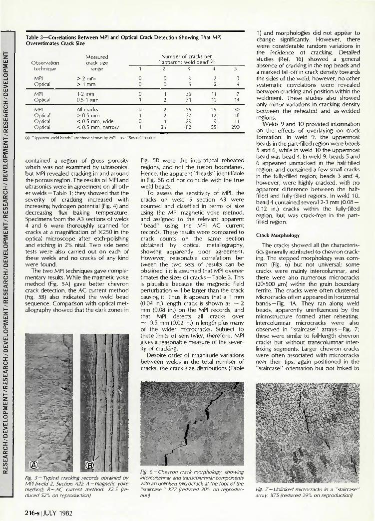
Table 3—Correlations Between MPI and Optical Crack Detection Showing That MPI Overestimates Crack Size
Observation technique
MPI Optical
MPI Optical
MPI Optical Optical Optical
(a) "Apparent weld beads
Measured crack size
range
> 2 mm > 1 mm
1-2 mm 0.5-1 mm
All cracks > 0.5 mm < 0.5 mm, wide < 0.5 mm, narrow
are those shown bv MPI — see
1
0 0
0 1
0 1 0 1
Results" section
Number of cracks per "apparent
2
0 0
1 2
2 2 1
26
weld bead 3
9 6
36 31
56 37 29 82
'(a)
4
2 2
11 10
15 12 9
55
5
3 4
7 14
30 18 11
290
contained a region of gross porosity which was not examined by ultrasonics, but MPI revealed cracking in and around the porous region. The results of MPI and ultrasonics were in agreement on all other welds —Table 1; they showed that the severity of cracking increased with increasing hydrogen potential (Fig. 4) and decreasing flux baking temperature. Specimens from the A3 sections of welds 4 and 6 were thoroughly scanned for cracks at a magnification of X250 in the optical microscope after etch-polishing and etching in 2% nital. Two side bend tests were also carried out on each of these welds and no cracks of any kind were found.
The two MPI techniques gave complementary results. While the magnetic yoke method (Fig. 5A) gave better chevron crack detection, the AC current method (Fig. 5B) also indicated the weld bead sequence. Comparison with optical metallography showed that the dark zones in
I Fig. 5 — Typical cracking records obtained by MPI (weld 2. Section A2): A — magnetic yoke method; B — AC current method. X2.5 (reduced 52",, on reproduction)
Fig. 5B were the intercritical reheated regions, and not the fusion boundaries. Hence, the apparent "beads" identifiable in Fig. 5B did not coincide with the true weld beads.
To assess the sensitivity of MPI, the cracks on weld 5 section A3 were counted and classified in terms of size using the MPI magnetic yoke method, and assigned to the relevant apparent "bead" using the MPI AC current records. These results were compared to crack counts on the same section obtained by optical metallography, showing apparently poor agreement. However, reasonable correlations between the two sets of results can be obtained if it is assumed that MPI overestimates the sizes of cracks —Table 3. This is plausible because the magnetic field perturbation will be larger than the crack causing it. Thus, it appears that a 1 mm (0.04 in.) length crack is shown as ~ 2 mm (0.08 in.) on the MPI records, and that MPI detects all cracks over ~ 0.5 mm (0.02 in.) in length plus many of the wider microcracks. Subject to these limits of sensitivity, therefore, MPI gives a reasonable measure of the severity of cracking.
Despite order of magnitude variations between welds in the total number of cracks, the crack size distributions (Table
~i:..^:^':'-.y
/ . /
.
1
Fig. 6 — Chevron crack morphology, showing intercolumnar and transcolumnar components with an unlinked microcrack at the foot of the "staircase." X77 (reduced 30% on reproduction)
1) and morphologies did not appear to change significantly. However, there were considerable random variations in the incidence of cracking. Detailed studies (Ref. 16) showed a general absence of cracking in the top beads and a marked fall-off in crack density towards the sides of the weld; however, no other systematic correlations were revealed between cracking and position within the weldment. These studies also showed only minor variations in cracking density between the reheated and as-welded regions.
Welds 9 and 10 provided information on the effects of overlaying on crack formation. In weld 9, the uppermost beads in the part-filled region were beads 5 and 6, while in weld 10 the uppermost bead was bead 4. In weld 9, beads 5 and 6 appeared uncracked in the half-filled region, and contained a few small cracks in the fully-filled region; beads 3 and 4, however, were highly cracked, with no apparent difference between the half-filled and fully-filled regions. In weld 10, bead 4 contained several 2-3 mm (0.08 — 0.12 in.) cracks within the fully-filled region, but was crack-free in the part-filled region.
Crack Morphology
The cracks showed all the characteristics generally attributed to chevron cracking. The stepped morphology was common (Fig. 6) but not universal; some cracks were mainly intercolumnar, and there were also numerous microcracks (20-500 /xm) within the grain boundary ferrite. The cracks were often clustered. Microcracks often appeared in horizontal bands —Fig. 1A. They ran along weld beads, apparently uninfluenced by the microstructure formed after reheating. Intercolumnar microcracks were also observed in "staircase" arrays —Fig. 7; these were similar to full-length chevron cracks but without transcolumnar interlinking segments. Larger chevron cracks were often associated with microcracks near their tips, again positioned in the "staircase" orientation but not linked to
I I • Fig. 7 —Unlinked microcracks in a "staircase' array. X75 (reduced 29% on reproduction)
216-s JULY 1982

Fig. 8 —A crack X arrested by the fine-grained reheated region, in line with a microcrack Y in the coarse-grained reheated region, X22 (reduced 30% on reproduction)
Transcolumnar
Fig. 9 —Crack "melted off" at fusion boundary above. X29 (Saspa-Nansa etch)
Transcolumnar
I * " Intercolumnar
Fig. 10 — Fracture morphologies in the as-welded regions (SEM): A — X490; reduced 34 % on reproduction)
-X2720 (A and .
In the as-welded regions, cracks were stepped (Fig. 1B) and intercolumnar and transcolumnar surfaces were readily distinguished. The intercolumnar segments showed cleavage-type fracture surfaces. These, however, differed from the fractures produced at liquid nitrogen temperatures in that they were more broken up into flakes, exhibited holes and protrusions, were more curved and had less clearly developed river patterns— Fig. 10. These features may be evidence of a limited amount of ductility. Flat grain boundary facets were not observed, indicating that intergranular fracture did not occur. The transcolumnar segments exhibited rough ductile shear fracture surfaces —Fig. 10. Some cracks showed temper colors when examined by eye, indicating slight oxidation. These did not appear very different from cracks with non-oxidized surfaces when examined in the SEM.
In the reheated regions (including the intercritical regions), cracks were also stepped and were often slightly oxidized. The oxidized intercolumnar segments were fairly similar to those observed in the as-welded regions, except for some fine-scale roughening on the cleavage facets, which may have been caused by transformation on reheating. By contrast, non-oxidized intercolumnar segments were quite different to those observed in the as-welded regions. Smoothed surfaces appeared in patches of varying size within most of the unoxidized interco-
the main crack —Fig. 6. In the as-welded regions, vertical crack
segments generally followed the columnar grain boundaries, but were not entirely confined to the proeutectoid ferrite. These crack segments were often quite wide —Fig. 6. The overall directions of the cracks appeared to depend on the columnar grain orientation — that is, when the columnar grains pointed forward along the weld, the cracks usually also pointed forward. However, the cracks maintained a constant overall inclination of approximately 45 deg, despite marked variations in columnar grain inclination. The crack step spacing was of the same order as the columnar grain width, ~ 5 0 - 1 0 0 )j.m. Thus, the columnar microstructure clearly exerted a strong influence on crack formation.
In the reheated regions, many cracks exhibited the stepped structure, and thus appeared to have formed prior to reheating. However, they were often wider than cracks in the as-welded regions, probably as a result of widening during the reheating cycle. There were indications that delayed cracks could have been arrested by the ductile finegrained reheated region — Fig. 8. A common feature which is also shown in this figure is the occurrence of a microcrack, marked Y, directly ahead of the line of
the arrested main crack X, in the coarsegrained reheated region.
Cracks tended to be confined within a single bead. Many cracks ended at the fusion boundary of the bead above and had blunted tips —Fig. 9; this indicated that parts of these cracks had been melted off during deposition of subsequent weld beads. However, cracks also often arrested close to the fusion boundary as they approached it from above. A few of the longest cracks did cross the fusion boundary and continue into the coarse-grained reheated region of the bead below, but these cracks were sharply reduced in width as they entered the lower bead —Fig. 8. Thus, the longest cracks observed in welds 2-8 were only slightly longer than the bead depth. A few longer cracks, 10-15 mm (0.39-0.59 in.), did appear in the full-height regions of welds 9 and 10.
Electron Fractography
Several chevron cracks were examined in the SEM after breaking open at room temperature or at liquid nitrogen temperature. In describing these observations, it is necessary to distinguish between cracks in the as-welded and reheated regions, and between oxidized and non-oxidized fracture surfaces.
Fig. 11 — Fracture morphologies in the reheated regions (SEM): A - smoothed area showing grain boundary grooving and indications ot thermal faceting. X2640; b-smoothed (prompt) and unsmoothed (delayed) fracture areas in juxtaposition, X2620 (A and B reduced 38",, on reproduction)
WELDING RESEARCH SUPPLEMENT I 217-s
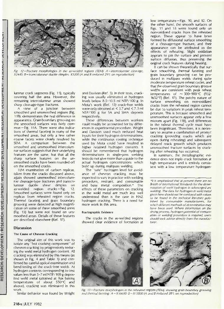
Fig. 12 — Fracture morphologies in the as-welded regions (TEM): A — intercolumnar cleavage. X2440; B - transcolumnar ductile dimples, X3200 (A and B reduced 29% on reproduction)
lumnar crack segments (Fig. 11), typically covering half the area. However, the remaining intercolumnar areas showed sharp cleavage-type fractures.
A view of a junction between smoothed and unsmoothed regions (Fig. 11B), demonstrates the real difference in appearance. Grain boundary grooving on the smoothed surfaces was fairly common—Fig. 11 A. There were also indications of thermal faceting in many of the smoothed areas, but only a few rather coarse facets were clearly resolved by SEM. A comparison between the smoothed and unsmoothed intercolumnar surfaces suggests that their underlying features are the same, but that all the sharp surface features on the unsmoothed cracks have been rounded off on the smoothed cracks.
TEM examination of carbon replicas, taken from the cracks discussed above, again showed unsmoothed intercolumnar cleavage-type fractures and transcolumnar ductile shear dimples on as-welded region cracks —Fig. 12. Smoothed surfaces were found only on replicas from reheated region cracks. Thermal faceting and grain boundary grooving were detected at high magnification on some of these smoothed areas (Fig. 13) but were not found on unsmoothed areas. Details of these features are described elsewhere (Ref. 17).
Discussion
The Cause of Chevron Cracking
The original aim of this work was to isolate any "hot cracking component" of chevron cracking by progressively reducing the weld metal hydrogen content. All cracking was eliminated by this means (as shown in Fig. 4 and Table 1) and confirmed by careful optical examination and bend-testing of the crack-free welds. At hydrogen contents corresponding to test values less than 5-7 ml NTP/100 g deposited weld metal (attained at flux baking temperatures of about 550°C and above), cracking was eliminated in this work.
Similar behavior was found by Wright
and Davison (Ref. 5). In their tests, cracking was usually eliminated at hydrogen levels below 8.5-10.5 ml NTP/100 g. In Mota's work (Ref. 13) crack-free welds were only obtained at < 3.7 and < 7.3 ml NTP/100 g for SA and SMA deposits respectively.
These differences between workers could readily be accounted for by differences in experimental procedure. Wright and Davison used much reduced heat inputs for their hydrogen determinations, while the continuous cooling technique used by Mota could have resulted in higher retained hydrogen contents. It should be remembered that hydrogen determinations in single-pass welding tests do not give more than a guide to the actual hydrogen concentrations which build up during multipass welding.
The "safe" hydrogen level for avoidance of chevron cracking must be expected to vary in practice with welding procedure, restraint, and consumable and base metal composition.* The effects of these parameters on cracking in the weld metal are much less well understood than is the case in HAZ hydrogen cracking. There is a need for more work in this area.
Fractographic Evidence
The cracks in the as-welded regions showed clear evidence of formation at
low temperature —Figs. 10, and 12. On the other hand, the smooth surfaces of Figs. 11 and 13 were found only on non-oxidized cracks from the reheated region. These appear to have been formed by diffusional surface smoothing of a cleavage-type fracture, and their appearance can be attributed to the effects of reheating. Slight oxidation appears to pin the surface and prevent surface diffusion, thus preserving the original crack features during heating.
It can be shown theoretically that surface smoothing, thermal faceting and grain boundary grooving can be produced in multipass welds during quite moderate temperature reheat cycles, and that the observed grain boundary groove widths are consistent with peak reheat temperatures of ~ 500-900°C (932-1652°F) (Ref. 17). The patchy nature of surface smoothing on non-oxidized cracks from the reheated region cannot be due to variations in peak reheat temperature. This is because smoothed and unsmoothed surfaces appear only a few microns apart (Fig. 11B), and differences in the reheat thermal cycle must have been insignificant. Therefore, it is necessary to assume a combination of prompt cracking (providing cracks which are open during reheating) and subsequent delayed crack growth which produces unsmoothed fracture surfaces by cracking after reheating has occurred.
In summary, the metallographic evidence does not imply crack formation at high temperature and is entirely consistent with a low temperature hydrogen-
*lt is emphasized that at present there are no British or International Standards for the determination of weld hydrogen in submerged arc welding. The data for hydrogen in weld metal given here should not be confused with values to be found in the technical literature published by consumable manufacturers, for which different methods of determination may have been used. Where information on the drying process, hydrogen potential of consumables or welding procedure is required, users should seek advice directly from the manufacturer.
Fig. 13 —Fracture morphologies in the reheated regions (TEM), showing grain boundary grooving and thermal faceting: A-X16600; B-X13800 (A and B reduced 28% on reproduction)
218-s | JULY 1982

assisted cracking mechanism.
Crack Detection
The comparison between optical and MPI examination techniques shows that MPI is a reasonable tool for detecting chevron cracks over 0.5 mm (0.02 in.) long on ground surfaces. However, since the surface beads contain few or none of the cracks, MPI would be of little value in the absence of sectioning. Ultrasonic inspection is capable of detecting chevron cracks in all weld locations, but appears to have an identification limit of about 2 mm (0.08 in.) —Table 1. Because of this, it might be feared that ultrasonic inspection could allow a heavily micro-cracked weld to be passed as sound. This did not occur in the present work, since microcracks were generally associated with larger, ultrasonically detectable cracks.
It should be emphasized that chevron cracks will not generally be detected unless an appropriate ultrasonic inspection technique is selected, using 45 deg angled probes to inspect the weld metal.
Crack Formation Sequence
The observations described earlier may be used to relate the times at which crack nucleation and growth occurred to the sequence of welding operations. Little cracking is found in the last bead to be deposited. This is shown most clearly by the observations on welds 9 and 10. It suggests that a critical requirement for crack formation in a given bead is that there should be one or more overlaying beads.
Few cracks are likely to be formed during the initial quench. However, many cracks definitely form prior to the reheating cycle which takes place on deposition of the overlaying bead. This is shown by the observations of cracks with smoothed surfaces within the reheat region and by the common observation of cracks "melted off" at the fusion boundary above the bead containing the crack —Fig. 9.
It is not entirely clear why cracks should be largely absent from a bead which has just been deposited and quenched, yet appear in considerable numbers before the bead experiences a reheating cycle. It may be noted, however, that there is generally one weld run interposed between a given bead (e.g., bead 7) and its overlaying bead (in this case, bead 9). One speculation is that cracks may form in bead 7 ahead of the arc while bead 9 is being deposited, in regions which are then subjected to tensile stresses but are not close enough to the arc to be heated above hydrogen cracking temperatures.
While many cracks form before reheating, considerable subsequent crack
Verfica
Weld direct
Maximum shear stress directions
Preferred shear band direction
Columnar grain
boundaries
astic zone
rack Longitudinal tensile stress
A ) Microcrack nucleation ( g ) Blunting and arrest
Direction of shear
Dislocation pile-up Shear band
•&K-. Nucleation W site of
Crack 3
Crack 1
/ \Cj Crack formation within
the shear band
Fig. 14 — Proposed mechanism of chevron crack formation associated with dislocation shear bands: A—microcrack nucleation; B — blunting and arrest; C—crack formation within the shear band; D — macrocrack formation
D) Macrocrack formation
growth probably also occurs. The observations of smoothed and unsmoothed fracture surfaces in juxtaposition (Fig. 11 B) directly demonstrate crack growth both before and after reheating. Thus, cracking appears to begin early in the welding sequence and continue during and after completion of the weld, with individual cracks experiencing more than one stage of growth.
The way in which this discontinuous form of crack growth takes place may perhaps be inferred from the observations of clustered microcracks —Figs. 6 and 7. These clusters appear to represent intermediate stages in the formation of a macroscopic chevron crack. Thus, a series of intercolumnar microcracks may first form in a staircase array as in Fig. 7, and subsequently link up by transcolumnar shear. Alternatively, a crack may grow by nucleation of a microcrack ahead of the main crack tip as suggested by Fig. 6, followed by transcolumnar linking back to the main crack. In either case, the appearance of the cluster suggests a discontinuous, multi-stage crack growth mechanism in which microcrack nucleation seems to be aided by the presence of nearby cracks.
A Mechanism for Chevron Cracking
The above observations give some indication of the reasons for the stepped crack structure. However, a full explanation of the crack morphology requires a more detailed model.
The restraint provided by the cracking test assembly, and the transverse nature of the cracks, indicate that the highest stress is in the longitudinal direction. On this assumption, Keville (Ref. 7) pointed out that the 45 deg crack orientation coincides with the direction of maximum shear stress. However, she did not advance a specific crack formation mechanism. It will be shown here that a model (adapted from that of Mota-Ref . 13) of crack nucleation in shear bands intersecting the columnar grain boundaries can account for the main morphological features of chevron cracking.
The suggested sequence of events is: 1. Longitudinal tensile stresses build up
as the weld bead cools, and approach or exceed yield point magnitude (Ref. 18). Plastic strain is initially concentrated in the soft intercolumnar proeutectoid ferrite. When enough hydrogen is present, the ductility of the proeutectoid ferrite is
WELDING RESEARCH SUPPLEMENT | 219-s

much reduced, and so an intercolumnar microcrack may nucleate (Ref. 19, 20) — Fig. 14A.
2. As the crack grows, the size of the plastic zone at the crack tip will tend to increase. Hence the crack may be blunted and arrested. The plastic zone may then form the nucleus of a long-range transcolumnar shear band at 45 deg to the longitudinal direction (Ref. 21) —Fig. 14B. (The reason why one particular 45 deg direction is preferred is discussed later.)
3. Plastic flow within the shear band then leads to dislocation pile-ups at the neighboring columnar grain boundaries. The stress concentration at the head of the pile-up nucleates a second, separate intercolumnar crack, either directly by causing decohesion at a weak zone such as an inclusion, or indirectly by promoting further plastic flow in the proeutectoid ferrite. Hydrogen transport to the columnar grain boundary by moving dislocations assists crack formation (Ref. 13, 22).
4. The second intercolumnar crack in turn grows (upwards and downwards) and blunts. In this way, an array of intercolumnar crack segments forms by repeated nucleation on columnar grain boundaries within the shear band. As each segment relaxes the longitudinal tensile stress on either side of it, the base of crack 2 tends to arrest at about the same height as the top of crack 1 — Fig. 14C.
5. The crack array forms a zone of weakness. This promotes further plastic f low between the microcrack tips. Horizontal transcolumnar cracks therefore form by ductile shear, assisted by hydrogen. These cracks link the intercolumnar microcracks together to produce a mac-rocrack —Fig. 14D.
This model successfully accounts for the 45 deg crack orientation and provides a plausible explanation for the disconnected, multi-stage growth behavior observed.
Implications of the Mechanism
Several features of the crack morphology can now be rationalized. The crack orientation is clearly affected by micro-structure as well as stress. There are two directions of maximum shear stress at 45 deg from the vertical (Fig. 14B) and a marginal difference in shear resistance between these two different directions could result in almost all the deformation being concentrated in a single shear band. The proeutectoid ferrite in the present material forms easy shear zones along the columnar grain direction. Shear along these soft zones is, therefore, maximized by formation of shear bands in the 45 deg orientation which is closest to the columnar grain direction. Thus, the cracks also have this orientation.
The tendency of chevron cracks to arrest at the fusion boundary is also
readily explained in terms of the shear nucleation model. Shear bands in one bead are unlikely to coincide with shear bands formed in neighboring beads, owing to differences in columnar grain orientation and in the times at which deformation takes place. Consequently, cracks are often confined within one bead. Larger weld beads would be expected to contain more well-developed shear bands; this may account for the correlation between chevron cracking and high heat input observed by Crouch (Ref. 14).
In Fig. 8, crack X in the as-welded region is in line with a microcrack Y in the coarse-grained reheated region. This can be associated with variations in ductility within the weld bead. The fine-grained reheated region is too ductile to crack, but the 45 deg shear band passes through it to cause microcracking in the coarse-grained reheated region.
Mota and Apps (Ref. 12, 13) found a transition from chevron cracking to "vertical" intercolumnar cracking with increasing weld metal strength. They suggested that, because plasticity is limited in the harder materials, an intercolumnar crack does not blunt and arrest and can, therefore, propagate along the columnar grain boundary without interruption. Mota noted that a decrease in the amount of proeutectoid ferrite occurred together with the increase in strength and transition to vertical cracking. It seems likely that proeutectoid ferrite plays a significant part in suppressing vertical cracking by the blunting mechanism, thus promoting chevron cracking.
The model thus suggests that chevron cracking is a special form of weld metal hydrogen cracking. Chevron cracking involves a significant amount of deformation, while vertical weld metal cracking and heat-affected zone hydrogen cracking do not. This suggests that there may be important differences in hydrogen cracking behavior between weld metals and heat-affected zones. In a multipass weld, the weld metal undergoes much more deformation during welding than does the HAZ. Thus, HAZ hydrogen cracks form by a brittle mechanism in microstructural zones of high hardness, but weld metal hydrogen cracks may be able to form in softer material via the relatively ductile chevron cracking mechanism. Thus, carbon equivalent formulas derived from studies of HAZ cracking are unlikely to be directly applicable to weld metal cracking.
Chevron crack length is often restricted to the size of the weld bead. While it would clearly be unsafe to ignore the possibility of longer cracks, this may be the reason why chevron cracking does not appear to have caused any major failures of components in service.
Conclusions
1. Chevron cracking is a form of weld
metal hydrogen cracking. The present work provided no evidence to indicate that hot cracking is even partially responsible. The thermal etching and surface smoothing effects observed on chevron crack surfaces are attributed to the reheating of cracked regions on deposition of subsequent weld beads.
2. Chevron crack formation is a multistage process. The morphology of cracking can be satisfactorily explained in terms of a model of crack nucleation within shear bands intersecting the columnar grain boundaries.
3. Cracks over 2 mm (0.08 in.) long were detected by ultrasonic inspection. Since optical metallography established that microcracks occurred only when longer cracks were also present, the ultrasonic technique successfully identified crack-free welds in this case.
Acknowledgments
The authors are indebted to Mr. J. Eariss, who developed the MPI techniques used in this work and carried out the welding program. Thanks are also due to Oerlikon Electrodes Limited, which supplied the flux and wire electrodes for this investigation. The authors also acknowledge useful discussions with Dr. J. M. F. Mota and Professor R. L. Apps of the Cranfield Institute of Technology.
References
1. Thomas, S. N. C. 1969. Contribution to discussion: Conference on cracking in welds. Met. Const. I(2s): 142.
2. Cotton, H, C. 1969. Contribution to discussion: Conference on cracking in welds. Met. Const. 1(2s): I44.
3. Hamilton, I. G. 1972. Trends in user requirements for welding consumables. International conference on welding research related to power plant: 285-292. England: Univ. of Southampton.
4. Chitty, A., and Brown, I. M. 1972. Welding consumables for the turbine-generator industry. International Conference on Welding Research Related to Power Plant: 293-309. England: Univ. of Southampton.
5. Wright, V. S„ and Davison, I. T. 1978. Chevron cracking in submerged arc welds. Conference on Trends in Steels and Consumables for Welding: paper 38, London. Also (abridged) in Met. Const. 11(3): 129-133.
6. Tuliani, S. S. 1976 (April). A metallographic study of chevron cracks in submerged arc weld metals. CEGB Report R/M/R234. Also in Welding Res. Int. 6(6): 19-45.
7. Keville, B. R. 1976. An investigation to determine the mechanisms involved in the formation and propagation of chevron cracks in submerged arc weldments. Welding Res. Int. 6(6): 47-66.
8. Farrar. R. A. 1977. The nature of chevron cracking in submerged arc weld metals. Welding Res. Int. 7(2): 85-89.
9. Farrar, R. A., and Taylor, L. G. 1977 (Nov.). A metallographic study of chevron cracking in submerged arc weld metals. Welding and Metal Fab., 45(9): 575-578.
10. Hart, P. H. M. 1978. Weld metal hydrogen cracking, Weld. Inst. Res. Bull. 19(11): 320-324.
11. Mota, |. M. F., |ubb, |. E. M.; and Apps,
220-s | JULY 1982

R. L. 1978 (Nov.). Chevron cracking: initiation and propagation. Welding and Metal Fab. 46(9): 625-627.
12. Mota, I. M. F.; Apps, R. L; and lubb, |. E. M. 1978. Chevron cracking in manual metal-arc welding. Conference on trends in steels and consumables for welding: paper 18. London.
13. Mota, |. M. F. 1979. Chevron cracking in steel weld metals. Ph.D. thesis. England: Cranfield Institute of Technology.
14. Crouch. S. |. 1978. The influence of heat input on weld metal transverse cracking. M.Sc. Thesis. England: Cranfield Institute of Technology.
15. Killing, R., and Orlikowski, P. 1977.
Investigation of damage caused by the presence of hydrogen in submerged arc weld metal. Schweissen u. Schneiden 29(8): 286-288.
16. Allen, D. I., Chew, B„ and Harris, P. 1980. The formation of chevron cracks in submerged arc weld metal. CEGB Report RD/ M/R295.
17. Allen, D. |. 1981. Thermal etching and smoothing of weld fracture surfaces at high temperatures. Metals Technol., 8 (10), 395-404.
18. )ones, W. K. C , and Alberry, P. |. 1977 (lune). The role of phase transformations in the development of residual stresses during the welding of some fast reactor steels. Ferritic
Steels for Fast Reactor Steam Generators, paper 78. London: BNES.
19. Watkinson, F. 1969. Hydrogen cracking in high strength weld metals., Welding journal 48(9): 417-s to 424-s.
20. Konkol, P. )., and Domis, W. F. 1979. Causes of grain-boundary separations in electroslag weld metals. Welding lournal, 58(6): 161-s to 167-s.
2 I. lino, M. 1978. The extension of hydrogen blister-crack array in linepipe steels. Metall. Trans.. 9A(II): 1581-1590.
22. Savage, W. F.; Nippes, E. F.; and Toku-naga, Y. 1978. Hydrogen induced cracking in HY-130 steel weldments. Welding journal, 57(4): 188-s to 126-s.
WRC Bulletin 273 December, 1981
Design Implications of Recent Advances in Elevated Temperature Bounding Techniques by J . S. Porowski , W. J . O'Donnel l and M . Badlani
Recent advances in bounding {i.e., limiting) techniques and simplified methods of analysis for components operated in the creep regime are used herein to obtain some very useful design guides. Damage mechanisms are determined for a wide range of dimensionless design parameters, operating pressure and cyclic thermal conditions, and material properties.
Publication of this report was sponsored by the Subcommittee on Elevated Temperature Design of the Pressure Vessel Research Committee of the Welding Research Council.
The price of WRC Bulletin 273 is $10.00 per copy, plus $3.00 for postage and handling. Orders should be sent with payment to the Welding Research Council, 345 E. 47th St., New York, NY 10017.
WRC Bulletin 274 January, 1982
International Benchmark Project on Simplified Methods for Elevated Temperature Design and Analysis: Problem II—The Saclay Fluctuating Sodium Level Experiment; Comparison of Analytical and Experimental Results; Problem III—The Oak Ridge Nozzle to Sphere Attachment by H. Kraus
Problem II. Recently, experimental results became available on the second benchmark problem on simplified methods for elevated temperature design and analysis: the Saclay fluctuating sodium level experiment. These are compared to previously published numerical and analytical results in WRC Bulletin 258, May 1980.
Problem III. The Oak Ridge Nozzle to Sphere Attachment is analyzed by finite element computer programs and by approximate analytical techniques. The methods are described and the results obtained by each are compared. No experimental data are available.
Publication of these reports was sponsored by the Subcommittee on Elevated Temperature Design of the Pressure Vessel Research Committee of the Welding Research Council.
The price of WRC Bulletin 274 is $10 per copy, plus $3.00 for postage and handling. Orders should be sent with payment to the Welding Research Council, 345 East 47th St., New York, NY 10017.
WELDING RESEARCH SUPPLEMENT I 221-s
Related Documents