Introduction ER410NiMo is a low-carbon 13% Cr–4% Ni soft marten- sitic stainless steel. This filler metal is considered to be the best match to CA6NM base metal, which is the cast version of this steel. For hydraulic turbine runners, which are the application of interest in this paper, several properties are important. These include good fatigue properties, corrosion resistance, cavitation erosion resistance, and weldability, as well as ease of casting. These requirements are satisfactorily met by soft martensitic stainless steels, which is the reason for their growing popularity in the hydropower industry. Weldability and fatigue properties of weldments are espe- cially important for hydraulic turbine runner manufactur- ers, because runners are assembled by welding, and for pow- er plant owners because they often have to carry out on-site repairs of cavitation and fatigue damages through welding. Welded regions, however, have particular features such as undesired residual stresses, welding discontinuities, and in- clusions. Moreover, as demonstrated by Amrei et al. (Ref. 1), martensitic stainless steel weldments are characterized by a complex and heterogeneous microstructure due to the exis- tence of coarse and fine-grain regions in the weld. Currently, arc welding processes are used to assemble hy- draulic turbine runners. The assembly process consists of welding the blades to the crown and belt. Current practices use the flux cored arc welding (FCAW) process with a shield- ing gas of 75% argon (Ar)/25% carbon dioxide (CO 2 ). To test the influence of oxides on mechanical properties, gas metal arc welding (GMAW) was used with two different shielding gas compositions and compared to current FCAW proce- dures. Procedures using shielding gases with more CO 2 trap more oxygen in the molten pool. This is due to the electric arc and the high temperatures involved during the welding operation, which lead to ionization of CO 2 decomposes into C and O, resulting in more oxygen in the weld pool. This oxygen is then free to form oxides through reactions with other alloying elements. Teske and Martins (Ref. 2) conducted a study on the in- fluence of shielding gas composition in GMAW using differ- ent mixtures with either CO 2 or O 2 . When present, CO 2 and WELDING RESEARCH Shielding Gas and Inclusion Content Effects on Impact Toughness and Tensile Properties of 410NiMo Steel Welds The effect of shielding gas on the mechanical and microstructural characteristics of ER410NiMo martensitic stainless steel weldments was investigated BY B. TENNI, S. GODIN, D. THIBAULT, AND M. BROCHU ABSTRACT The effect of shielding gas on the mechanical and microstructural characteristics of ER410NiMo martensitic stainless steel weldments was investigated. Three weldments with various inclusion contents were manufac- tured using different shielding gas compositions and weld- ing processes: gas metal arc welding (GMAW) with 100% argon (Ar), GMAW 85% Ar/15% carbon dioxide (CO 2 ), and flux cored arc welding (FCAW) 75% Ar/25% CO 2 . The inclusions in each weldment were characterized by means of scanning electron microscope observations and energy-dispersive spectroscopy analysis. The weldments underwent postweld heat treatment, after which the chem- ical composition and reformed austenite proportion were measured to account for microstructural effects. Hardness measurements, tensile tests, and impact toughness tests using the Charpy method were performed. The results showed that the Charpy V-notch (CVN) absorbed energy de- creases with increasing inclusion content. The highest CVN absorbed energy, 195 J, was obtained for the GMAW 100% Ar weld, which had the lowest inclusion content. GMAW 85% Ar/15% CO 2 , with four times more inclusions than the former, had a CVN absorbed energy of 63 J. The current manufacturing process, FCAW 75% Ar/25% CO 2 , was found to have an inclusion content three times higher than the GMAW 100% Ar weld but a CVN absorbed energy of 66 J, which is close to the GMAW 85% Ar/15% CO 2 weld. The re- sults showed that using GMAW 100% Ar as a replacement to FCAW 75% Ar/25 % CO 2 would lead to a three-fold improvement in terms of absorbed impact energy. The effect of inclusions on tensile properties, which was not clearly identified as several factors, in addition to inclu- sion content, affects the weld strength and elongation. Overall, the yield and ultimate tensile strengths differed slightly: 724 and 918 MPa for GMAW 100% Ar, 746 and 927 MPa for GMAW 85% Ar/15% CO 2 , and 711 and 864 MPa for FCAW 75% Ar/25% CO 2 , respectively. KEYWORDS • Martensitic Stainless Steel • Inclusions • Welding • Impact Toughness WELDING JOURNAL / FEBRUARY 2021, VOL. 100 52-s https://doi.org/10.29391/2021.100.005

Welcome message from author
This document is posted to help you gain knowledge. Please leave a comment to let me know what you think about it! Share it to your friends and learn new things together.
Transcript
Introduction
ER410NiMo is a low-carbon 13% Cr–4% Ni soft marten-sitic stainless steel. This filler metal is considered to be thebest match to CA6NM base metal, which is the cast versionof this steel. For hydraulic turbine runners, which are the applicationof interest in this paper, several properties are important.These include good fatigue properties, corrosion resistance,cavitation erosion resistance, and weldability, as well as easeof casting. These requirements are satisfactorily metby soft martensitic stainless steels, which is the reason fortheir growing popularity in the hydropower industry. Weldability and fatigue properties of weldments are espe-cially important for hydraulic turbine runner manufactur-ers, because runners are assembled by welding, and for pow-er plant owners because they often have to carry out on-siterepairs of cavitation and fatigue damages through welding. Welded regions, however, have particular features such asundesired residual stresses, welding discontinuities, and in-clusions. Moreover, as demonstrated by Amrei et al. (Ref. 1),martensitic stainless steel weldments are characterized by acomplex and heterogeneous microstructure due to the exis-tence of coarse and fine-grain regions in the weld. Currently, arc welding processes are used to assemble hy-draulic turbine runners. The assembly process consists ofwelding the blades to the crown and belt. Current practicesuse the flux cored arc welding (FCAW) process with a shield-ing gas of 75% argon (Ar)/25% carbon dioxide (CO2). To testthe influence of oxides on mechanical properties, gas metalarc welding (GMAW) was used with two different shieldinggas compositions and compared to current FCAW proce-dures. Procedures using shielding gases with more CO2 trapmore oxygen in the molten pool. This is due to the electricarc and the high temperatures involved during the weldingoperation, which lead to ionization of CO2 decomposes intoC and O, resulting in more oxygen in the weld pool. Thisoxygen is then free to form oxides through reactions withother alloying elements. Teske and Martins (Ref. 2) conducted a study on the in-fluence of shielding gas composition in GMAW using differ-ent mixtures with either CO2 or O2. When present, CO2 and
WELDING RESEARCH
Shielding Gas and Inclusion Content Effects onImpact Toughness and Tensile Properties of
410NiMo Steel Welds
The effect of shielding gas on the mechanical and microstructural characteristics ofER410NiMo martensitic stainless steel weldments was investigated
BY B. TENNI, S. GODIN, D. THIBAULT, AND M. BROCHU
ABSTRACT The effect of shielding gas on the mechanical andmicrostructural characteristics of ER410NiMo martensiticstainless steel weldments was investigated. Threeweldments with various inclusion contents were manufac-tured using different shielding gas compositions and weld-ing processes: gas metal arc welding (GMAW) with 100%argon (Ar), GMAW 85% Ar/15% carbon dioxide (CO2), andflux cored arc welding (FCAW) 75% Ar/25% CO2. The inclusions in each weldment were characterized bymeans of scanning electron microscope observations andenergy-dispersive spectroscopy analysis. The weldmentsunderwent postweld heat treatment, after which the chem-ical composition and reformed austenite proportion weremeasured to account for microstructural effects. Hardnessmeasurements, tensile tests, and impact toughness testsusing the Charpy method were performed. The resultsshowed that the Charpy V-notch (CVN) absorbed energy de-creases with increasing inclusion content. The highest CVNabsorbed energy, 195 J, was obtained for the GMAW 100% Arweld, which had the lowest inclusion content. GMAW 85%Ar/15% CO2, with four times more inclusions than theformer, had a CVN absorbed energy of 63 J. The currentmanufacturing process, FCAW 75% Ar/25% CO2, was foundto have an inclusion content three times higher than theGMAW 100% Ar weld but a CVN absorbed energy of 66 J,which is close to the GMAW 85% Ar/15% CO2 weld. The re-sults showed that using GMAW 100% Ar as a replacementto FCAW 75% Ar/25 % CO2 would lead to a three-foldimprovement in terms of absorbed impact energy. The effect of inclusions on tensile properties, which wasnot clearly identified as several factors, in addition to inclu-sion content, affects the weld strength and elongation.Overall, the yield and ultimate tensile strengths differedslightly: 724 and 918 MPa for GMAW 100% Ar, 746 and 927MPa for GMAW 85% Ar/15% CO2, and 711 and 864 MPa forFCAW 75% Ar/25% CO2, respectively.
KEYWORDS• Martensitic Stainless Steel • Inclusions • Welding• Impact Toughness
WELDING JOURNAL / FEBRUARY 2021, VOL. 10052-s
https://doi.org/10.29391/2021.100.005
Layout_Tenni Supplement 2019117.qxp_Layout 1 1/7/21 7:02 PM Page 52
O2 cause the formation of oxide inclusions due to their oxi-dation potential; note that the oxidation potential is twiceas high for O2 than it is for CO2. The welds with the highestoccurrence of oxides showed the lowest impact toughnessproperties. Foroozmehr et al. (Ref. 3) examined the effect ofinclusions on the impact toughness properties of two 13%Cr–4% Ni martensitic stainless steels, a cast version(CA6NM) and a wrought one (UNS S41500). The resultsshowed that the higher content and the larger mean size ofinclusions in CA6NM explained the lower impact toughnessproperties compared to UNS S41500. This was justified bymicrovoid formation from the inclusions. Other metallurgical factors should also be accounted forwhen studying such steels. Though the microstructure ismostly martensitic, small amounts of delta ferrite and austen-ite are usually present and can affect mechanical properties.Delta ferrite, for example, is oftentimes considered detrimen-tal to mechanical properties, especially in terms of fracturetoughness and impact absorbed energy. Iwabuchi andKobayashi (Ref. 4) attributed the deleterious effect of deltaferrite to the precipitation of carbides along delta-ferrite grainboundaries during heat treatment. To minimize the negativeeffect of delta ferrite, nickel, which is an austenite-stabilizingelement, is added to chromium martensitic stainless steels tokeep a martensitic microstructure, thus preventing carbidesfrom precipitating. However, due to carbide precipitationalong delta-ferrite grain boundaries, it is difficult to isolate theeffect of delta ferrite from that of carbides as Wang et al. (Ref.5) brought to attention.
By successfully isolating both effects, the authors con-cluded that delta-ferrite only influences the transition tem-perature region in terms of impact absorbed energy, and it
does not have a significant effect on the upper- and lower-shelf energies. Aside from delta ferrite, another phase thatcan be present is retained austenite; usually only a verysmall fraction remains present after quenching. However,during tempering heat treatment, a greater amount ofaustenite can be reformed. Bilmes et al. (Ref. 6) studied tem-pering of martensitic stainless steel as well as the austeniteresulting from such a treatment. It was found that the re-formed amount can reach up to 30% in the form of finelyprecipitated at the prior austenite grain boundaries. Thisphase is believed to improve toughness and ductility of thestudied steels. When tempering slightly above Ac1, the re-formed austenite is thermally stable and leads to optimalmechanical properties. Tempering at higher temperaturesleads to the formation of unstable austenite, which trans-forms to fresh martensite upon cooling. However, under ap-plied load, even thermally stable austenite can transformback to martensite, which makes austenite mechanically un-stable. This mechanism is commonly known as the transfor-mation-induced-plasticity (TRIP) effect and is responsiblefor the interesting mechanical properties resulting from re-formed austenite. Thibault et al. (Ref. 7) studied this aspect,concluding that when the TRIP mechanism occurs, more en-ergy is required for the fracture process due to the volumet-ric expansion accompanying the austenite to martensitetransformation, which induces compressive stresses at thecrack tip. In addition to creating reformed austenite, tempering post-weld heat treatment relieves residual stresses in the weld andthe heat-affected zone (HAZ) as well as softens the hard andbrittle as-welded martensite as demonstrated in the work ofTrudel et al. (Ref. 8) performed on welded CA6NM.
WELDING RESEARCH
FEBRUARY 2021 / WELDING JOURNAL 53-s
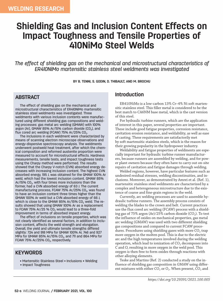
Fig. 1 — Dimensions, in millimeters, of the bare plates: A —Side view; B — view from the top of the weld; C — profileshowing the U-notch.
Fig. 2 — Tensile test specimen geometry (mm). Prior to test-ing, two points were punched 1 in. apart to establish the orig-inal length and calculate the elongation at fracture.
A
BC
Fig. 3 — Schematic drawing showing the Charpy specimenorientation with respect to the weld.
Table 1 — Welding Conditions Used to Prepare the Weldments forImpact Toughness Testing
GMAW GMAW FCAW100% Ar 85% Ar/ 75% Ar/
15% CO2 25% CO2
Voltage (V) 25 28.8 27.5 Current (A) 210 207.5 228 Torch speed (mm/s) 3.8 3.8 4.2 Heat input (J/mm) 1381 1572 1505 Number of weld beads 11 10 12
Layout_Tenni Supplement 2019117.qxp_Layout 1 1/7/21 7:02 PM Page 53
The aim of the research presented in this paper is tostudy the effect of shielding gas composition on the impacttoughness and tensile properties of martensitic stainlesssteel weldments. The weldments made using different weld-ing processes and shielding gas compositions produced vary-ing inclusion contents.
Experimental Methodology
Materials
The welding procedure used FCAW with a shielding gascomposition of 75% Ar/25% CO2. As discussed in the introduction, this relatively high con-tent of CO2 is believed to cause the formation of oxides,shown to negatively affect mechanical properties. SinceGMAW requires less active gas in the shielding mixture, itwas used to produce welds under different shielding gascompositions, which in turn resulted in different oxide con-tents. Hence, three welds were produced under the followingatmospheres:
• FCAW 75% Ar/25% CO2, the current process in use;• GMAW 100% Ar, the process thought to generate the
least oxide content and;• GMAW 85% Ar/15% CO2, an intermediate condition for
research purposes. Figure 1 gives the dimensions of the CA6NM plates thatwere used to produce the welds destined to machine theCharpy specimens. The U-notch preparation presented in Fig.1C has been filled by multipass robotized welding with an
AWS ER410NiMo filler metal wire of 1.6 mm in diameter. Table 1 provides the welding conditions used in eachprocedure. An effort was made to keep the heat input ener-gy constant in the three procedures because it directly af-fects the temperatures and, as a result, the weld mi-crostructure. The objective was to vary the oxide contentwhile keeping all other influencing factors constant. Additional weldments were prepared by depositing weldmetal on the entire surfaces of the plates. This is done to en-sure the tensile test specimens are fully extracted from theweld metal. The same filler metal was used but the base metalwas UNS-S41500, which is the wrought version of CA6NMused previously. Because UNS-S41500 and CA6NM have com-parable chemical compositions, it was expected that the tensileproperties of the second batch of welded plates were also char-acteristic of the first one. Table 2 gives the welding conditionsused for this second batch.
Postweld Heat Treatment
After welding, the plates underwent a tempering post-weld heat treatment at 600ºC for a duration of 20 h. Thefurnace atmosphere was not controlled.
Austenite Measurements
After postweld heat treatment, the proportions ofaustenite were measured by x-ray diffraction from a Rietveldanalysis (Ref. 9). The x-ray diffraction patterns were ob-tained with a Bruker D8 Advance diffractometer equipped
WELDING RESEARCH
WELDING JOURNAL / FEBRUARY 2021, VOL. 10054-s
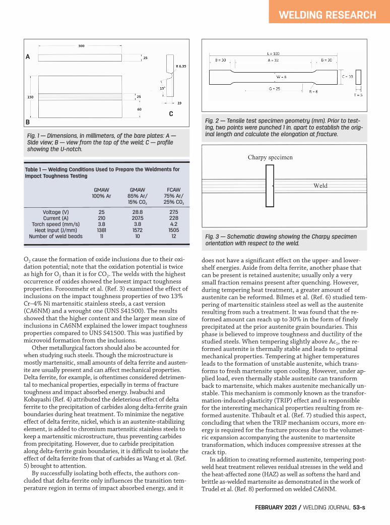
Fig. 4 — Macrographs of the postweld heat treated welds: A —GMAW 100% Ar; B — GMAW 85% Ar/15% CO2; C — FCAW 75%Ar/25% CO2.
Table 2 — Welding Conditions Used to Prepare the WeldmentsDestined for Tensile Testing
GMAW GMAW FCAW100% Ar 85% Ar/15% CO2 75% Ar/
25% CO2
Voltage (V) 24.3 26.5 27.5 Current (A) 212 222 222 Torch speed (mm/s) 3.9 3.9 4.2 Heat input (J/mm) 1320 1508 1453
A B
C
Layout_Tenni Supplement 2019117.qxp_Layout 1 1/7/21 7:02 PM Page 54
WELDING RESEARCH
FEBRUARY 2021 / WELDING JOURNAL 55-s
with a copper x-ray tube and a nickel filter. The measure-ments were done on thin slices cut transverse to the welds.Three samples per weld were prepared.
Chemical Composition Measurements
The chemical composition of both types of filler metals(solid wire and flux-cored wire), as well as the base metaland each of the fusion zones of the welds described above,were measured by inductively coupled plasma-emissionatomic spectrometer in accordance with ASTM E1479 (Ref.10) except for carbon, sulfur, oxygen, and nitrogen contentsmeasured by combustion and inert gas fuel (ASTM E1019).
Hardness Measurements
To evaluate the hardness of the welds, and ensure thethree welds were equivalent in terms of hardness, ten Vickershardness measurements were made in each weld using aZwickRoell ZHU 250 hardness tester in the transverse direc-tion as well as in the as-welded and tempered conditions at 10kgf in accordance with ASTM E92 (Ref. 12).
Quantification of Oxides
Metallographic cross sections cut transverse to the weldwere prepared. Using a scanning electron microscope (SEM)Hitachi S-4700 equipped with an energy dispersive spec-trometer (EDS), the oxides were observed, counted, and an-
alyzed through EDS analysis. In total, 16 images at a 5000xmagnification were used, yielding a total examined surfaceof seven 200 m2 for GMAW 85% Ar/15% CO2 and FCAW75% Ar/25% CO2 welds. As for GMAW 100% Ar, extra im-ages were taken to ensure at least 100 oxides were counted,yielding a total surface of 15 338 m2. For each observed ox-ide, the horizontal and vertical ferrets were measured, andthe mean of both measurements was considered to producesize distribution spectra.
Tensile Testing
Three tensile tests per condition were realized in the weldmetal in the transverse direction with respect to the de-posited weld beads. A MTS Systems tensile tester model Ex-ceed 40 using a 50-kN load cell was used. A MTS extensome-ter model 632.24-50 with a gauge length of 25 mm was usedto monitor the elongation. The displacement rate was 2mm/min, leading to a strain rate of about 0.06/min. Figure 2 shows the geometry and dimensions of the testspecimens, which correspond to an ASTM E8 (Ref. 13) sub-size specimen.
Impact Toughness Properties
To perform impact toughness tests, five Charpy V-notch(CVN) bars of standard dimensions 10 10 55 mm weremachined from each weld. Impact tests were performed at0ºC, with a ZwickRoell RKP450 pendulum impact tester inaccordance with ASTM E23 (Ref. 14). The specimens were
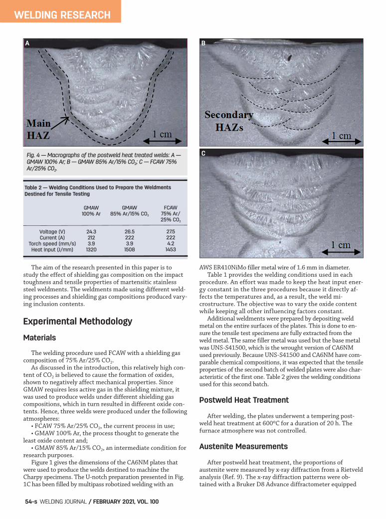
Fig. 5 — Weld microstructure observed in FCAW 75% Ar/25% CO2 postweld heat treated: A — Macrograph of the weld; B — magni-fied view displaying a column-shaped martensite; C — magnified view displaying a HAZ with finer grains. The red arrows show theorientation of martensite columns, corresponding to the heat flow directed toward the top of the weld.
A B
C
Layout_Tenni Supplement 2019117.qxp_Layout 1 1/7/21 7:02 PM Page 55
machined in the transverse direction, in the center of theweld, as shown in Fig. 3.
Results and Discussion
Chemical Composition
Table 3 gives the measured chemical compositions of eachweld and the specified chemical compositions for comparison.The measured chemical compositions are all compliant withthe specifications, except for the manganese content in the410NiMo solid wire and both GMAW welds. The higher-than-specified Mn content in the GMAW weldments is thereforemost probably due to the high Mn content found in the corre-sponding filler metal, which might affect the austenite contentbecause Mn is an austenite-promoting element. Also, GMAW85% Ar/25% CO2 has a slightly lower-than-specified Ni con-tent, which might also affect the austenite content becausenickel is an austenite-promoting element. Note that the car-bon and oxygen contents are significantly higher in GMAW85% Ar/15% CO2 compared to the other welds.
Reformed Austenite Measurements
Table 4 provides the mean percentage of austenite and
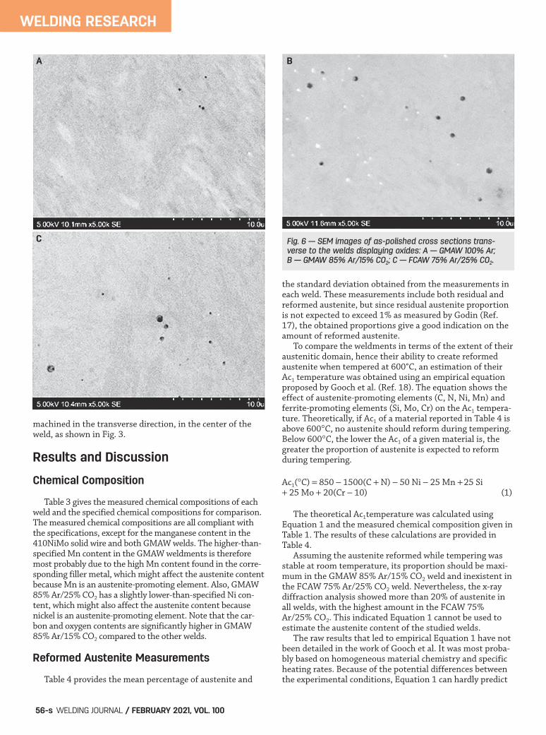
the standard deviation obtained from the measurements ineach weld. These measurements include both residual andreformed austenite, but since residual austenite proportionis not expected to exceed 1% as measured by Godin (Ref.17), the obtained proportions give a good indication on theamount of reformed austenite. To compare the weldments in terms of the extent of theiraustenitic domain, hence their ability to create reformedaustenite when tempered at 600°C, an estimation of theirAc1 temperature was obtained using an empirical equationproposed by Gooch et al. (Ref. 18). The equation shows theeffect of austenite-promoting elements (C, N, Ni, Mn) and ferrite-promoting elements (Si, Mo, Cr) on the Ac1 tempera-ture. Theoretically, if Ac1 of a material reported in Table 4 isabove 600C, no austenite should reform during tempering.Below 600C, the lower the Ac1 of a given material is, thegreater the proportion of austenite is expected to reformduring tempering.
Ac1(C) = 850 - 1500(C N) - 50 Ni - 25 Mn 25 Si 25 Mo 20(Cr - 10) (1)
The theoretical Ac1temperature was calculated usingEquation 1 and the measured chemical composition given inTable 1. The results of these calculations are provided inTable 4. Assuming the austenite reformed while tempering wasstable at room temperature, its proportion should be maxi-mum in the GMAW 85% Ar/15% CO2 weld and inexistent inthe FCAW 75% Ar/25% CO2 weld. Nevertheless, the x-raydiffraction analysis showed more than 20% of austenite inall welds, with the highest amount in the FCAW 75%Ar/25% CO2. This indicated Equation 1 cannot be used toestimate the austenite content of the studied welds. The raw results that led to empirical Equation 1 have notbeen detailed in the work of Gooch et al. It was most proba-bly based on homogeneous material chemistry and specificheating rates. Because of the potential differences betweenthe experimental conditions, Equation 1 can hardly predict
WELDING RESEARCH
WELDING JOURNAL / FEBRUARY 2021, VOL. 10056-s
Fig. 6 — SEM images of as-polished cross sections trans-verse to the welds displaying oxides: A — GMAW 100% Ar;B — GMAW 85% Ar/15% CO2; C — FCAW 75% Ar/25% CO2.
A B
C
Layout_Tenni Supplement 2019117.qxp_Layout 1 1/7/21 7:02 PM Page 56
the austenite content in the studied cases. The amount ofaustenite measured in the FCAW 75% Ar/25% CO2 weld isclose to the maximum amount reported by Bilmes et al.(Ref. 6), who specifically studied the formation and stabilityof reformed austenite 13Cr–NiMo martensitic steel weldmetals.
Microstructure of the Welds
Figures 4 and 5A show macrographic views of the preparedmetallographic cross sections of the the postweld heat treatedwelds, etched with Vilella’s reagent. The main HAZ, as well asthe secondary ones in between weld beads, is visible on the
WELDING RESEARCH
FEBRUARY 2021 / WELDING JOURNAL 57-s
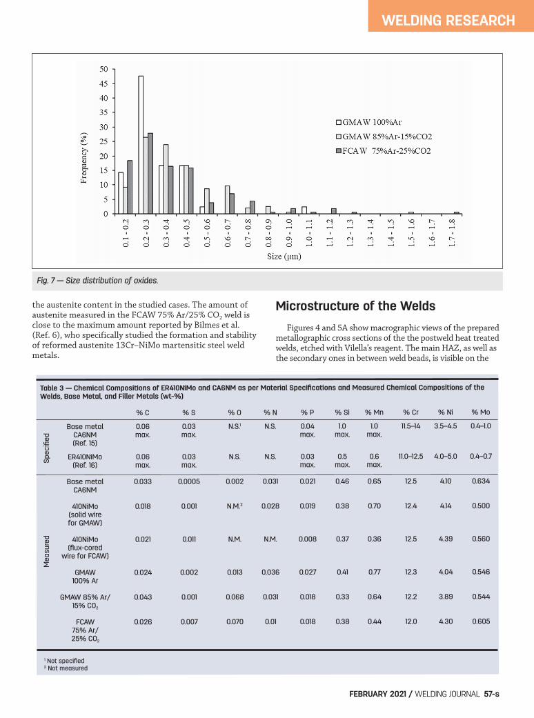
Fig. 7 — Size distribution of oxides.
Table 3 — Chemical Compositions of ER410NiMo and CA6NM as per Material Specifications and Measured Chemical Compositions of the Welds, Base Metal, and Filler Metals (wt-%)
% C % S % O % N % P % Si % Mn % Cr % Ni % Mo
Base metal 0.06 0.03 N.S.1 N.S. 0.04 1.0 1.0 11.5–14 3.5–4.5 0.4–1.0 CA6NM max. max. max. max. max. (Ref. 15) ER410NiMo 0.06 0.03 N.S. N.S. 0.03 0.5 0.6 11.0–12.5 4.0–5.0 0.4–0.7
(Ref. 16) max. max. max. max. max.
Base metal 0.033 0.0005 0.002 0.031 0.021 0.46 0.65 12.5 4.10 0.634CA6NM
410NiMo 0.018 0.001 N.M.2 0.028 0.019 0.38 0.70 12.4 4.14 0.500(solid wirefor GMAW)
410NiMo 0.021 0.011 N.M. N.M. 0.008 0.37 0.36 12.5 4.39 0.560 (flux-cored wire for FCAW)
GMAW 0.024 0.002 0.013 0.036 0.027 0.41 0.77 12.3 4.04 0.546100% Ar
GMAW 85% Ar/ 0.043 0.001 0.068 0.031 0.018 0.33 0.64 12.2 3.89 0.54415% CO2
FCAW 0.026 0.007 0.070 0.01 0.018 0.38 0.44 12.0 4.30 0.60575% Ar/25% CO2
1 Not specified2 Not measured
Spe
cifie
dM
easu
red
Layout_Tenni Supplement 2019117.qxp_Layout 1 1/7/21 7:02 PM Page 57
macrographs due to its darker aspect. As observed, an effortwas made to have similar weld pool and overall weld dimen-sions to create a comparable weld microstructure. Figure 5B and C provides a magnified view of the FCAW75% Ar/25% CO2 postweld heat treated weld macrograph. Re-gions of columnar martensite, consisting of column-shapedpackets, are shown in Fig. 5B separated by fine-grain regionsas in Fig. 5C. A similar grain structure was observed by Amreiet al. (Ref. 19) in ER410NiMo filler metal deposited by FCAWusing 75% Ar/25% CO2. Note that martensite columns appearto be pointing to the top of the weld as depicted by the red ar-rows, which corresponds to the heat flow direction. Reformedaustenite is not visible by optical microscopy because it is fine-ly (60 to 200 nm wide) distributed between the martensitelath, as shown in other work performed on comparable mate-rial (Ref. 22). Although it was not confirmed, the fine white stringers, ob-served in Fig. 5A and C indicated by the smaller yellow arrows,are most likely delta-ferrite stringers because they look similarto what was reported by Thibault et al. (Ref. 20) andForoozmehr et al. (Ref. 3).
Hardness
Table 5 gives the Vickers hardness measurements foreach weld in both the as-welded and tempered conditions. The obtained results show the softening effect of thetempering heat treatment. In each of the three welding con-ditions, the mean hardness decreased by 18%, 23%, and14% after tempering. The standard deviation was reduced as well for all welds, suggesting a more uniform microstruc-ture. Considering the standard deviations, the hardness in-tervals of the welds overlap, which means the welds can beconsidered comparable in terms of hardness.
Oxides Characterization
Figure 6 shows SEM images of as-polished cross sectionscut transverse to the welds displaying oxides, which identifi-cation of was confirmed through detection of oxygen in EDSanalyses. Table 6 gives the quantification results, namely the num-ber of oxides per 100 mm2, the mean size of oxides, as wellas the median size for each weld. To verify if there are any significant differences between thewelds in terms of inclusion size, an analysis of variance (ANO-VA) test was used. This test is used to compare multiple statis-tical groups and determine whether they significantly differ.Setting the P value of the ANOVA test to 5%, we can’t rejectthe hypothesis that all means are equal. This shows that it isnot possible to consider with confidence the mean values ofthe oxides as different. As expected, the GMAW 100% Ar had the lowest oxide con-tent. However, the FCAW 75% Ar/25% CO2 didn’t have thehighest oxide content, despite having the highest CO2 concen-trated shielding gas. This can be explained by the presence of
WELDING RESEARCH
WELDING JOURNAL / FEBRUARY 2021, VOL. 10058-s
Fig. 8 — Charpy absorbed energy results and the oxide den-sity in each weld.
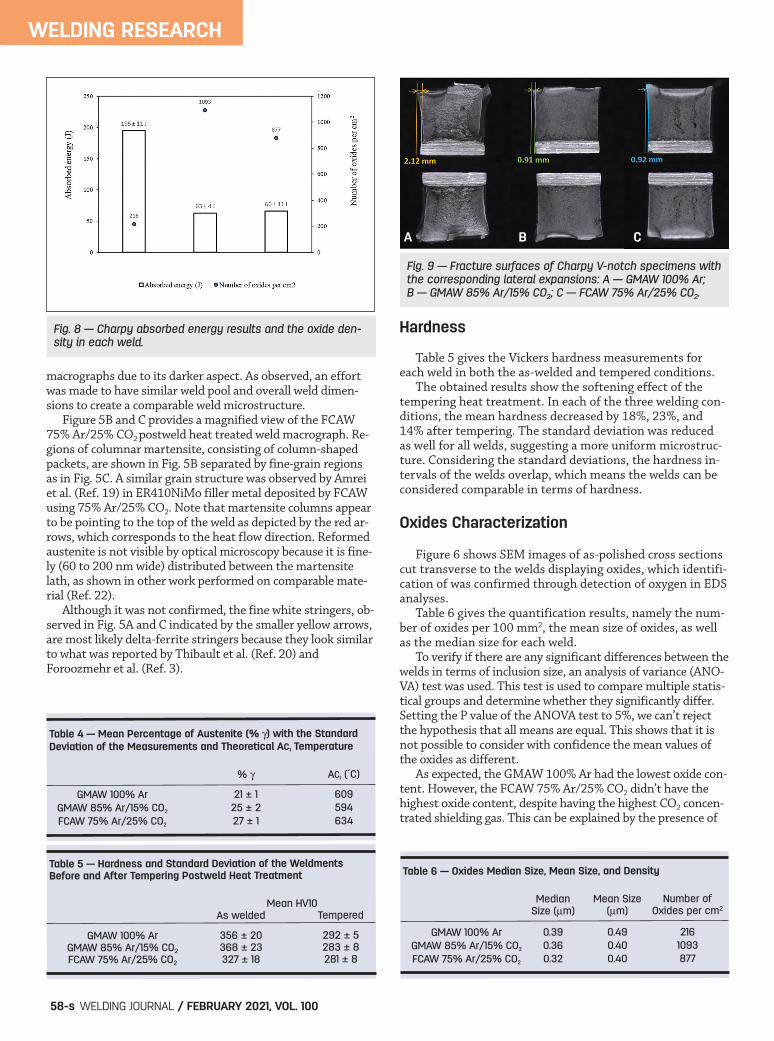
Fig. 9 — Fracture surfaces of Charpy V-notch specimens withthe corresponding lateral expansions: A — GMAW 100% Ar; B — GMAW 85% Ar/15% CO2; C — FCAW 75% Ar/25% CO2.
Table 4 — Mean Percentage of Austenite (% ) with the Standard Deviation of the Measurements and Theoretical AC1 Temperature
% AC1 (C)
GMAW 100% Ar 21 ± 1 609 GMAW 85% Ar/15% CO2 25 ± 2 594 FCAW 75% Ar/25% CO2 27 ± 1 634
Table 5 — Hardness and Standard Deviation of the Weldments Before and After Tempering Postweld Heat Treatment
Mean HV10As welded Tempered
GMAW 100% Ar 356 ± 20 292 ± 5 GMAW 85% Ar/15% CO2 368 ± 23 283 ± 8 FCAW 75% Ar/25% CO2 327 ± 18 281 ± 8
Table 6 — Oxides Median Size, Mean Size, and Density
Median Mean Size Number ofSize (m) (m) Oxides per cm2
GMAW 100% Ar 0.39 0.49 216 GMAW 85% Ar/15% CO2 0.36 0.40 1093 FCAW 75% Ar/25% CO2 0.32 0.40 877
A B C
Layout_Tenni Supplement 2019117.qxp_Layout 1 1/8/21 2:23 PM Page 58
WELDING RESEARCH
FEBRUARY 2021 / WELDING JOURNAL 59-s
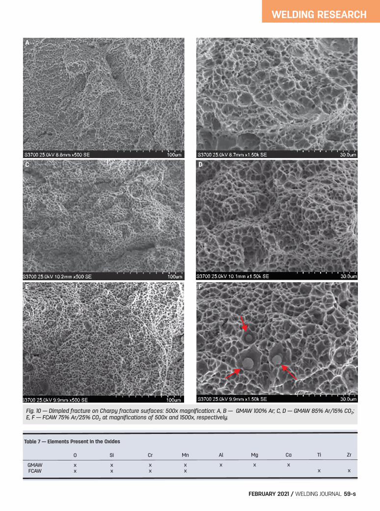
Fig. 10 — Dimpled fracture on Charpy fracture surfaces: 500x magnification: A, B — GMAW 100% Ar; C, D — GMAW 85% Ar/15% CO2;E, F — FCAW 75% Ar/25% CO2 at magnifications of 500x and 1500x, respectively.
Table 7 — Elements Present in the Oxides
O Si Cr Mn Al Mg Ca Ti Zr
GMAW x x x x x x x FCAW x x x x x x
A B
C D
FE
Layout_Tenni Supplement 2019117.qxp_Layout 1 1/7/21 7:02 PM Page 59
the flux, which protects the weld pool from oxidation. Figure 7 displays the size distribution of the measured ox-ides for each welding process. For all three welds, the classwith the highest number of oxides is 0.2–0.3 m. The chemical composition of the oxides was determined us-ing the EDS spectrometer coupled with the SEM. Though thismethod is standardless and semiquantitative, it gives a goodidea about the chemical composition of the oxides. The analy-sis showed both GMAW welds to have oxides with similarcompositions, but the FCAW weld had slightly different ox-ides. Table 7 gives the elements present in the weld oxidesfrom both welding processes. This difference between GMAW and FCAW might becaused by the elements present in the flux. Foroozmehr et al.(Ref. 3) reported that Si/Mn inclusions have a lower resistanceagainst rupture and microvoid formation than Al inclusions(both types seem to be present in the GMAW welds) whereasAl inclusions weren’t detected in FCAW.
Tensile Properties
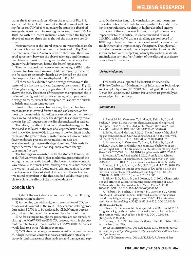
Table 8 gives the means and standard deviations obtainedfrom the tensile properties retrieved from the stress-straincurves following ASTM E8 (Ref. 13) recommendations. Three material characteristics that could influence theweld’s mechanical behavior are presented in Table 8: the inclu-
sion content, the percentage of reformed austenite, and thecarbon content. Indeed, the inclusion content was shown to bedetrimental to the material ductility as reported byForoozmehr et al. (Ref. 3), who compared the mechanical be-havior and microstructure of CA6NM and UNS41500. Re-formed austenite, on the other hand, is believed to increasethe steel yield strength and ductility due to the TRIP mecha-nism. As for the carbon content, Krauss (Ref. 21) showed thatthe yield stress of low-carbon martensite has a square-root de-pendency with the solute carbon content. Despite having thelargest inclusion content, GMAW 85% Ar /15% CO2 shows thehighest yield and tensile strengths without a significant dropof ductility when compared with the GMAW 100% Ar weldcharacterized by the lowest inclusion content. The higher car-bon content within the GMAW 85% Ar/15% CO2 weld,0.043% vs. 0.024% and 0.026% for GMAW 100% Ar andFCAW 75% Ar/25% CO2, could explain its higher strength.Moreover, the percentage of reformed austenite measured inthis weldment was 25%, compared to 21% for GMAW 100%Ar, which could have compensated for a potential ductility losscaused by the presence of inclusions. The FCAW 75% Ar/25% CO2 weld also had a quite largeinclusion content, but it is also characterized by the highestamount of austenite. In this case, as for GMAW 85%Ar/15% CO2, it could explain that no significant decrease inductility was observed.
Impact Toughness Properties
Figure 8 gives the CVN absorbed energy and the oxidedensity, while Fig. 9, the measured lateral expansions, illus-
WELDING RESEARCH
WELDING JOURNAL / FEBRUARY 2021, VOL. 10060-s
Table 8 — Tensile Properties of the Welds
Weld y 0.2% UTS A (%)
GMAW 100% Ar 724 ± 7 918 ± 1 21 ± 1 GMAW 85% Ar/15% CO2 746 ± 11 927 ± 4 19 ± 1 FCAW 75% Ar/25% CO2 711 ± 32 864 ± 1 19 ± 5
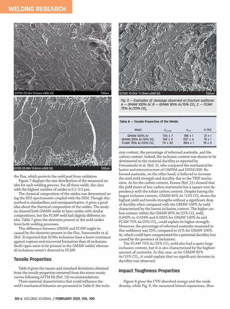
Fig. 11 — Examples of cleavage observed on fracture surfaces:A — GMAW 100% Ar; B — GMAW 85% Ar/15% CO2; C — FCAW75% Ar/25% CO2.
A B
C
Layout_Tenni Supplement 2019117.qxp_Layout 1 1/8/21 10:30 AM Page 60
trates the fracture surfaces. Given the results of Fig. 8, itseems that the inclusion content is the dominant influenc-ing factor on CVN absorbed energy because the absorbedenergy decreased with increasing inclusion content. GMAW100% Ar with the lowest inclusion content had the highestabsorbed energy, three times that of the other two condi-tions. Measurements of the lateral expansion were realized on thefractured Charpy specimens and are illustrated in Fig. 9 withthe fracture surfaces. As can be seen on the image, there is agood agreement between the absorbed energy and the meas-ured lateral expansion: the higher the absorbed energy, thegreater the deformation, hence, the lateral expansion. The fracture surfaces were examined using a SEM to de-termine fracture mechanisms. SEM fractography revealedthe fracture to be mostly ductile as evidenced by the dim-pled rupture. Examples are displayed in Fig. 10. All three welds exhibited some cleavage areas toward thecenter of the fracture surfaces. Examples are shown in Fig. 11.Although cleavage is usually suggestive of brittleness, it is notalways the case. The center of the specimens represents the lo-cation of the highest hydrostatic stresses, which promotescleavage fracture, even if the temperature is above the ductile-to-brittle transition temperature. Based on the previous observations, the main fracturemechanism is microvoid formation and coalescence, as formost ductile materials. All oxides observed on the fracture sur-faces are found sitting inside the dimples (as shown by red ar-rows in Fig. 10), suggesting the dimples nucleated at oxides. Therefore, the effect of oxides on absorbed energy can bediscussed as follows: In the case of a large inclusion content,void nucleation from oxide inclusions is the dominant mecha-nism, and the growth stage is instantaneous. However, whenfewer oxides are present, fewer nucleation sites areavailable, making the growth stage dominant. This leads tohigher deformation, and consequently, a more energy-consuming fracture. The findings are consistent with the study of Foroozmehret al. (Ref. 3), where the higher mechanical properties of thewrought steel were attributed to the lower inclusion content,lower mean size of inclusions, and type of inclusions; those inthe wrought steel were found more resistant against rupturethan the ones in the cast steel. As the size of the inclusionswas found equivalent in the three studied welds, it was possi-ble to isolate the effect of the inclusion density.
Conclusion
In light of the work described in this article, the followingconclusions can be drawn:
1) A shielding gas with a higher concentration of CO2 in-creases oxide content in the weld. If the current welding proce-dure using FCAW is to be replaced by GMAW under pure ar-gon, oxide content could be decreased by a factor of three.
2) As far as impact toughness properties are concerned, re-placing the FCAW 75% Ar/25% CO2 process, which is the cur-rent manufacturing process, with the GMAW 100% Ar processwould lead to a three-fold improvement.
3) CVN absorbed energy decreases as oxide content increas-es. A high inclusion content increases nucleation sites for mi-crovoids, and coalescence then leads to rapid damage and rup-
ture. On the other hand, a low inclusion content means lessnucleation sites, which leads to more plastic deformation dur-ing the growth stage, resulting in higher absorbed energy. In view of these three conclusions, for application whereimpact resistance is critical, it is recommended to weld410NiMo with GMAW using a shielding gas composed of100% argon because it limits the formation of inclusions thatare detrimental to impact energy absorption. Though smallvariations were observed in tensile properties, it seemed thatseveral factors were competing, namely the carbon, austenite,and inclusion content. Verification of the effect of each factoris saved for future work.
This work was supported by Institut de Recherched’Hydro-Québec and Mathematics of Information Technologyand Complex Systems (IT07240). Technologists René Dubois,Alexandre Lapointe, and Manon Provencher are gratefully ac-knowledged for their help.
1. Amrei, M. M., Verreman, Y., Bridier, F., Thibault, D., andBocher, P. 2015. Microstructure characterization of single andmultipass 13Cr4Ni steel welded joints. Metal., Microstruct., andAnal. 4(3): 207–218. DOI: 10.1007/s13632-015-0202-8
2. Teske, M., and Martins, F. 2010. The influence of the shield-ing gas composition on GMA welding of ASTM A 516 steel. Weld.Int. 24(3): 222–230. DOI: 10.1080/09507110902843875
3. Foroozmehr, F., Verreman, Y., Chen, J., Thibault, D., andBocher, P. 2017. Effect of inclusions on fracture behavior of castand wrought 13% Cr-4% Ni martensitic stainless steels. Eng. Fract.Mech. 175: 262–278. DOI: 10.1016/j.engfracmech.2017.02.002
4. Iwabuchi, Y., and Kobayashi, I. 2010. A study of toughnessdegradation in CA6NM stainless steel. Mater. Sci. Forum 654–656:2515–2518. DOI: 10.4028/www.scientific.net/msf.654-656.2515
5. Wang, P., Lu, S. P., Xiao, N. M., Li, D. Z., and Li, Y. Y. 2010. Ef-fect of delta ferrite on impact properties of low carbon 13Cr-4Nimartensitic stainless steel. Mater. Sci. and Eng. A 527(13–14):3210–3216. DOI: 10.1016/j.msea.2010.01.085
6. Bilmes, P. D., Solari, M., and Lorente, C. L. 2001. Characteris-tics and effects of austenite resulting from tempering of 13Cr-NiMo martensitic steel weld metals. Mater. Charact. 46(4):285–296. DOI: 10.1016/S1044-5803(00)00099-1
7. Thibault, D., Bocher, P., Thomas, M., Lanteigne, J., Hoving-ton, P., and Robichaud, P. 2001. Reformed austenite transforma-tion during fatigue crack propagation of 13%Cr-4%Ni stainlesssteel. Mater. Sci. and Eng. A 528(21): 6519–6526. DOI: 10.1016/j.msea.2011.04.089
8. Trudel, A., Sabourin, M., Lévesque, M., and Brochu, M. 2014.Fatigue crack growth in the heat affected zone of a hydraulic tur-bine runner weld. Int. J. of Fat. 66: 39–46. DOI: 10.1016/j.ijfatigue.2014.03.006
9. Young, R. A. 1993. The Rietveld Method. First Ed. Oxford Uni-versity Press Inc. USA.
10. ASTM International. 2016. ASTM E1479. Standard Practicefor Describing and Specifying Inductively Coupled Plasma Atomic Emis-sion Spectrometers.
11. ASTM International. 2011. ASTM E1019. Standard Test
WELDING RESEARCH
FEBRUARY 2021 / WELDING JOURNAL 61-s
References
Acknowledgment
Layout_Tenni Supplement 2019117.qxp_Layout 1 1/7/21 7:02 PM Page 61
Methods for Determination of Carbon, Sulfur, Nitrogen, and Oxygen inSteel, Iron, Nickel, and Cobalt Alloys by Various Combustion and FusionTechniques.
12. ASTM International. 2017. ASTM E92. Standard Test Meth-ods for Vickers Hardness and Knoop Hardness of Metallic Materials.
13. ASTM International. 2016. ASTM E8. Standard Test Methodsfor Tension Testing on Metallic Materials.
14. ASTM International. 2016. ASTM E23. Standard Test Meth-ods for Notched Bar Impact Testing of Metallic Materials. ASTM International.
15. ASTM International. 2015. ASTM A743. Standard Specifica-tion for Castings, Iron-Chromium, Iron-Chromium-Nickel, CorrosionResistant, for General Application.
16. American Welding Society. 2012. AWS A5.9, Specification forBare Stainless Steel Welding Electrodes and Rods. Eighth Ed. Miami,Fla.
17. Godin, S. Effet d’un enrichissement en nickel sur la stabilitémécanique de l’austénite de réversion lorsque soumise à de la fa-tigue oligocyclique. Master Thesis. 2014. École de TechnologieSupérieure, Montréal.
18. Gooch, T. G., Woollin, P., and Haynes, A. G. 1999. S99-22,Welding metallurgy of low carbon 13% chromium martensitic steels, supermartensitic stainless steel 99. Belgian Welding Institute:188–195.
19. Amrei, M. M., Monajati, H., Thibault, D., Verreman, Y., Ger-main, L., and Bocher, P. 2016. Microstructure characterization andhardness distribution of 13Cr4Ni multipass weld metal. Mater.
Charact. 111: 128–136. DOI: 10.1016/j.matchar.2015.11.02220. Thibault, D., Bocher, P., and Thomas, M. 2009. Residual
stress and microstructure in welds of 13% Cr–4%Ni martensiticstainless steel. J. of Mater. Process. Technol. 209(4): 2195–2202.DOI: 10.1016/j.jmatprotec.2008.05.005
21. Krauss, G. 2015. Steels: Processing, Structure, and Perform-ance. Second Ed. ASM International.
22. Godin, S., Hamel-Akré, J., Thibault, D., Serventi, A.-M., andBocher, P. 2020. Ni and Mn enrichment effects on reformed austenite:Thermodynamical and low cycle fatigue stability of 13%Cr–4%Ni and13%Cr–6%Ni stainless steels. Springer Nature, accepted for publica-tion on February 4, 2020.
WELDING RESEARCH
WELDING JOURNAL / FEBRUARY 2021, VOL. 10062-s
BOUCHRA TENNI and MYRIAM BROCHU ([email protected]) are with École Polytechnique de Montréal, Mon-treal, Canada. STÉPHANE GODIN and DENIS THIBAULT are with In-stitut de Recherche d’Hydro-Québec, Quebec, Canada.
The majority of the content in this article was published in themaster's thesis Étude expérimentale de l’effet du contenuinclusionnaire sur les propriétés mécaniques de résilience etde fatigue-propagation au seuil de soudures en acier 410 NIMO,by Bouchra Tenni, École Polytechnique de Montréal.
Publisher/EditorAnnette Alonso, [email protected], ext. 299General Management, Reprint Permission,Copyright Issues, Editorial Content
Managing EditorKristin Campbell, [email protected], ext. 257Feature Articles, Industry News
Sr. EditorCindy Weihl, [email protected], ext. 256Section News, SPRAYTIME®
Associate EditorsAllie Quinones, [email protected], ext. 465Arc-Tist CornerKatie Pacheco, [email protected], ext. 275Society News, New Products
Education EditorRoline Pascal, [email protected], ext. 303Coming Events, Personnel
Production ManagerZaida Chavez, [email protected], ext. 265Design and Production
Managing Editor, Digital and Design; Editor of Inspection Trendsand Welding Journal en Español
Carlos Guzman, [email protected], ext. 348Inspection and Spanish-Language Content,Design and Production
AdvertisingSandra Jorgensen, [email protected], ext. 254Lea Owen, [email protected], ext. 220
SubscriptionsMarandi Gills, [email protected], ext. 353Subscriptions Representative
Welding Journal Dept.8669 NW 36 St., #130Miami, FL 33166
The Welding Journal staff encourages an exchange of ideas with you, our readers. If you’d like to ask a question, share an idea, orvoice an opinion, you can call, write, email, or fax. Staff email addresses are listed below, along with a guide to help you interact with theright person.
Can We Talk?
Layout_Tenni Supplement 2019117.qxp_Layout 1 1/8/21 4:55 PM Page 62
Related Documents


