Weld Strength and Crack Growth Ductility from the Lazy-L Test by Chad Matthew Brooks S.B. Mechanical Engineering Massachusetts Institute of Technology (1994) Submitted to the Department of Mechanical Engineering in Partial Fulfillment of the Requirements for the Degree of MASTER OF SCIENCE IN MECHANICAL ENGINEERING at the MASSACHUSETTS INSTITUTE OF TECHNOLOGY May 1995 C 1995 Massachusetts All right Institute of Technology reserved Signature of Author , 1 Department of Mechanical Engineering May, 1995 Certified by Professor Emeritus Frank A. McClintock Thesis Supervisor ,,- ,··-*.L,~ Accepted by ;JASSACHIJSETTS INSTITUTE OF TECHNOLOGY Professor Ain A. Sonin Chairman, Graduate Committee AUG 31 1995 LIBRARIES Barker En I

Welcome message from author
This document is posted to help you gain knowledge. Please leave a comment to let me know what you think about it! Share it to your friends and learn new things together.
Transcript
Weld Strength and Crack Growth Ductility from the Lazy-L Test
by
Chad Matthew Brooks
S.B. Mechanical EngineeringMassachusetts Institute of Technology
(1994)
Submitted to the Department of Mechanical Engineeringin Partial Fulfillment of the Requirements
for the Degree of
MASTER OF SCIENCEIN MECHANICAL ENGINEERING
at the
MASSACHUSETTS INSTITUTE OF TECHNOLOGY
May 1995
C 1995 MassachusettsAll right
Institute of Technologyreserved
Signature of Author , 1
Department of Mechanical EngineeringMay, 1995
Certified byProfessor Emeritus Frank A. McClintock
Thesis Supervisor
,,- ,··-*.L,~
Accepted by
;JASSACHIJSETTS INSTITUTEOF TECHNOLOGY
Professor Ain A. SoninChairman, Graduate Committee
AUG 31 1995
LIBRARIES
Barker En
I
Weld Strength and Crack Growth Ductility from the Lazy-L Test
by
Chad Matthew Brooks
Submitted to the Department of Mechanical Engineering on May 12, 1995, in partialfulfillment of the requirements for the degree of Master of Science in Mechanical
Engineering.
Abstract
Fully plastic fracture of fillet welded T-joints is characterized by the limit moment,slip line displacement to crack initiation, and crack growth ductility, defined as the slip linedisplacement per unit crack advance. A novel fillet weld fracture experiment, the Lazy-LTest, is developed as a simple, inexpensive method of measuring data used to calculatethese parameters. Fully plastic fracture mechanics provides an extrapolation of Lazy-LTest results to other fillet weld failure modes observed in ship grounding, includingpeeling of the shell plating. The Lazy-L Test is introduced as an alternative to more costlyand difficult experimental and computer methods, and suggested for consideration as astandard test in the design and qualification of fillet welds for service.
The Lazy-L is used to test single fillets in predominant bending (opening from theroot of the weld), single fillets in predominant transverse shear, and double fillets inpredominant bending. The plastic flow field for each configuration is modeled by singlearcs of sliding in the fillet selected to yield a least upper bound to the limit moment. Load-displacement data for each configuration determine an experimental limit moment,displacement to initiation and crack growth per unit slip line displacement. The results aregeneralized for other weld loadings when expressed in terms of the mean normal stressacross the crack tip.
Twelve experiments are presented for 6mm and 9mm weld sizes produced usingGMAW with the combination of LR-EH36 steel plate and E7016 stick electrode. Withthe modeling assumptions of plane strain, homogenous weld metal shear strength andsmall angles of deformation, the experimental limit moments for single fillet shear anddouble fillet bending range from 10-20% above predicted values. Single fillet bendinglimit moments vary more significantly, and lead to the selection of alternate modelsincluding an edge-notched bar of weld metal in bending. Displacements to crack initiationare consistent throughout the data sets and experimental crack growth ductility rates arewithin 10-20% of the predicted values from prior stutudies of overmatched welds.
These results encourage further study of the Lazy-L Test configuration to establishan experimental database over a range of material, geometry, and welding processparameters.
Thesis Supervisor: Frank A. McClintockTitle: Professor Emeritus, Mechanical Engineering
2
Acknowledgments
This research was sponsored by members of the Joint M.I.T - Industry Project for
Tanker Safety, Professor T. Wierzbicki, Principal Investigator. Testing facilities were
provided by the M.I.T. Lab for Manufacturing and Productivity, and the Mechanical
Behavior of Materials Lab, Department of Mechanical Engineering. Welding was
performed by Atomic Ltd., Cambridge, Massachusetts. Machining was provided by the
M.I.T. Lab for Nuclear Science Machine Shop.
I thank Professor Wierzbicki for his enthusiastic leadership of the tanker safety
project and Professor K. Masubuchi for his guidance and support of the welding and
fabrication team. I also thank team members R. Wilcox, J. Atmadja, and R. Middaugh for
their valued contributions and encouragement.
Finally, I gratefully thank Professor F.A. McClintock for his tireless devotion and
patience as a teacher and supervisor. His insight, professionalism, and passion for
engineering have been inspiring.
3
Table of Contents
Abstract ................................................................................................................
Acknowledgments ................................................................................................
Table of Contents .................................................................................................
List of Figures ......................................................................................................
List of Tables .......................................................................................................
List of Symbols ...................................................................................................
Chapter 1
2
3
4
7
9
10
Introduction ............................................... 111.1 Background .............................................. 11
1.2 Objectives .............................................. 12
1.3 Paper Organization ........................................ ...... 13
Chapter 2 User's Guide to the Lazy-L Test .............................................. 14
2.1 Introduction ......... ....................................... 142.2 Lazy-L Test Configurations ................................................ 14
2.3 Specimen and Fixture Design ........................................ 15
2.4 Data Analysis and Interpretation ........................................ 19
2.5 Conclusion ........................................ 20
Chapter 3 Limit Moments from Plastic Slip Lines ........................................... 21
3.1 Introduction ............................................... 21
3.2 Bounds to the Limit Moment from Plastic Slip Line Fields.. 21
3.3 Upper Bounds to the Limit Moment in the Lazy-L Test ...... 23
3.3.1 Bound for Single Fillet in Predominant Bending ................. 23
3.3.2 Bound for Single Fillet in Predominant Transverse Shear .. 25
3.3.3 Bound for Double Fillet in Predominant Bending ............... 28
Chapter 4 Relations for Specimen Design and Data Reduction ....................... 30
4.1 Reaction Forces from Applied Load and Geometry ............ 30
4.2 Weld Moment from Reaction Forces .................................. 31
4.3 Weld Rotation from Measured Displacement ..................... 34
4.4 Test Stability ........................................ 35
4.5 Specimen Compliance ................... ..................... 36
4.6 Specimen Leg Limit M oment .............................................. 37
4
4.7 Magnitude of Weld End Effects .......................................... 39
Chapter 5 Specimen and Fixture Design and Fabrication ............................... 40
5.1 Introduction ......... 40....... ......... .....................40
5.2 Specimen Design ................................................................ 40
5.3 Specimen Fabrication ......................................................... 43
5.4 Fixture Design .................................................................... 44
5.5 Fixture Fabrication ............................................................. 45
Chapter 6 Data Analysis and Interpretation ........ ........... .........46
6.1 Moment-Rotation from Load-Displacement ........................ 46
6.2 Slip Line Displacement ........................................ .. 46
6.3 Crack Growth Ductility Factor .......................................... 47
6.4 Lazy-L Parameters in terms of Mean Normal Stresses ........ 47
Chapter 7 Lazy-L Experiment and Results ................................... 49
7.1 Test Specimens ........................................ .. 49
7.2 Experimental Procedure .......................................... 49
7.3 Experimental Measurements ........................................ .. 50
7.4 Experimental Outputs ........................................ .. 51
Chapter 8 Conclusions and Recommendation for Future Work ...................... 53
8.1 Conclusions .......................................... 53
8.2 Recommendations for Future Work ................................... 54
Figures .................................................................................................................. 55
Tables ................................................................................................................... 73
R eferences ............................................................................................................. 77
Appendix 1 Minimization of Normalized Limit Moments ................................. 79
Al.1 Computer Methods ...................................... 79A1.2 Spreadsheet Codes ......................................... 79
Appendix 2 Measurement of Test Machine Compliance ................................... 84
5
Appendix 3 Web and Fillet ShearStrength from Superficial Hardness .............. 90
Appendix 4 Moment-Rotational Displacement Graphs for Lazy-L Experiment . 94
Appendix 5 Test Machine Calibration and Data Acquisition ............................ 106
A5.1 Machine Setup ....................................... 106
A5.2 Data Acquisition ........................................ 107
6
List of Figures
Figure 1 Lazy-L Test configurations ................................................. 55
Figure 2 American Bureau of Shipping Tack Welder Qualification Test ..... 56
Figure 3 Normalized bending moment for double fillet in predominantbending .......................................................................................... 57
Figure 4 Normalized bending moment for single fillet in predominanttransverse shear ............................................................................. 58
Figure 5 Hardness distribution in a fillet weld ........................................ 59
Figure 6 Geometry of single fillet in predominant bending ........................... 60
Figure 7 Geometry of single fillet in predominant transverse shear .............. 61
Figure 8 Geometry of double fillet in predominant bending .......................... 62
Figure 9 Overall Lazy-L specimen geometry ........................................ 63
Figure 10 Geometry for calculating moment arm of reaction force .................. 64
Figure 11 Diagrams for evaluating moment of single fillet inpredominant transverse shear ................................................... 65
Figure 12 Diagrams for evaluating moment of single fillet inpredominant bending ......................................... 66
Figure 13 Geometry for evaluating weld rotation from measureddisplacement .................................................................................. 67
Figure 14 Model for free surface effect at weld end ....................................... 68
Figure 15 Suggested tack welds for fabrication .............................................. 69
Figure 17 Representative machine drawing of Lazy-L specimen .................... 70
Figure 18 Representative machine drawing of 3/4-round support ................... 71
Figure 19 Observed crack direction in single fillet bending ............................ 72
Figure A2. 1 Machine, Specimen and Measured Displacements .......................... 87
7
Figure
Figure
Figure
A2.2
A2.3
A4.1
Figure A4.2
Figure A4.3
Figure A4.4
Figure A4.5
Figure A4.6
Figure A4.7
Figure A4.8
Figure A4.9
Figure A4. 10
Figure A4.11
Figure A4.12
Load-Displacement Graph for 6061 -T6 Aluminum Cylinder (lst) ..
Load-Displacement Graph for 6061 -T6 Aluminum Cylinder (2nd).
Moment per unit weld length vs. rotational displacement for6mm fillet in predominant bending (st) .........................................
Moment per unit weld length vs. rotational displacement for6mm fillet in predominant bending (2nd) ........................................
Moment per unit weld length vs. rotational displacement for6mm fillet in predominant bending (3rd) ......................................
Moment per unit weld length vs. rotational displacement for9mm fillet in predominant bending (st) .........................................
Moment per unit weld length vs. rotational displacement for9mm fillet in predominant bending (2nd) ........................................
Moment per unit weld length vs. rotational displacement for9mm fillet in predominant bending (3rd) ........................................
Moment per unit weld length vs. rotational displacement for6mm fillet in predominant transverse shear ....................................
Moment per unit weld length vs. rotational displacement for9mm fillet in predominant transverse shear (st) ...........................
Moment per unit weld length vs. rotational displacement for9mm fillet in predominant transverse shear (2nd) ..........................
Moment per unit weld length vs. rotational displacement fordouble 6mm fillet in predominant bending (lst)..............................
Moment per unit weld length vs. rotational displacement fordouble 6mm fillet in predominant bending (2nd).............................
Moment per unit weld length vs. rotational displacement for
88
89
.94
.95
96
97
98
99
100
101
102
103
104
double 9mm fillet in predominant bending (st) .............................. 105
8
List of Tables
Table 1: Slip Line Parameters and Predicted NormalizedBending Moments .......................................... 73
Table 2: Specimen Dimensions, Reaction Forces, and DataConversion Factors ......................................... 74
Table 3: Measured Normalized Moment and Displacement to Initiation ......... 75
Table 4: Measured Crack Growth Ductility ..................................................... 76
Table Al. 1 Minimization of Normalized Bending Moment for SingleFillet in Predominant Bending ........................................ 81
Table A1.2 Minimization of Normalized Bending Moment for SingleFillet in Predominant Transverse Shear .............................................. 82
Table A1.3 Minimization of Normalized Bending Moment for DoubleFillet in Predominant Bending ............................................................ 83
Table A3.1 Wilson Rockwell Hardness Conversion Chart (Excerpt) ................... 92
Table A3.2 Fillet and Web Metal Shear Strength from RockwellSuperficial Hardness ................................................ 93
Table A5. 1 20,000 Pound Load Cell Calibration .............................................. 108
9
List of Symbols
a
8 vert
tA, C'
a0
included angle of Lazy-L specimen Leg A and the test surface
included angle of Lazy-L specimen Leb B and the test surface
vertical displacement due to specimen compliance
coefficient of friction
slip arc angles
mean normal stress across the slip line at the fillet root
yield strength
relative rotational displacement of Lazy-L specimen legs
ab
CdrClmdDDg, dus/da
Eha,I
kfkwLaLbM
(Mnorm)web(Mnorm)weldMtotNa, NbP
ra, rcRa, RbRweldtw
Us(us)initdv/dP
Vmw
crack lengthligament widthdisplacement-rotation conversion factorload-moment conversion factorweld leg lengthdiameter of 3/4-round supportcrack growth ductility factor (inverse of crack growth rate per unitslip line displacement)Young's moduluseffective height rise of specimen leg due to relative rotationmoment of inertiafillet weld shear strengthweb metal shear strengthlength of Lazy-L specimen Leg Alength of Lazy-L specimen Leg Bmoment per unit weld lengthnormalizing moment of web.normalizing moment of bar of fillet weld metaltotal weld momentmoment arm of Lazy-L specimen leg reaction forcesapplied loadslip arc radiiLazy-L specimen leg reaction forcestear resistanceweb metal thicknessslip line displacementslip line displacement to crack initiaitoncompliancemeasured displacement of Lazy-L specimenweld length
10
1 Introduction
Renewed consideration of the crash worthiness of oil tankers has demonstrated the
need for more detailed characterization of hull fillet weld failure due to grounding loads.
(Wierzbicki, et al, 1991) Existing fillet weld design standards have been formulated to
ensure safe performance under normal operating conditions but do not guarantee fillet
weld integrity under extreme loading conditions. The next generation of fillet weld
standards must specify fillet weld parameters of interest for crash worthiness analyses and
provide simple, flexible tests for measuring those parameters over a range fillet weld
design choices.
This paper introduces a simple test, named the "Lazy-L" for its appearance, which
provides data to quantify fillet weld failure parameters which may be extrapolated to the
peeling mechanism observed at the interface of the stiffeners and shell plating. These
parameters are the limit moment of the weld, the displacement to crack initiation, and the
crack growth ductility factor expressed as the inverse of the crack growth rate per unit slip
line displacement. These parameters characterize both the initial plastic sliding and
subsequent ductile fracture observed in the peeling failure mechanism. They also allow
computation of the tearing work per unit weld length for use in structural analyses of hull
grounding. (McDonald, 1994) The Lazy-L configuration is shown as Fig. 1.
1.1 Background
Public awareness of oil tanker crash worthiness was heightened by the 11 million
tons of spillage resulting from the March 1989 grounding of Exxon Valdez in Prince
William Sound, Alaska. Congress responded to the incident with passage of the Oil
Pollution Act of 1990 (OPA90) which mandates that all U.S. and foreign flag vessels
operating in U.S. waters and constructed or overhauled after June 30, 1990 must have a
11
double hull. The Secretary of Transportation, directed to establish the requirements of a
double hull, is authorized to propose to Congress alternative methods which provide the
same level of environmental protection as a double hull. (Federal Register, Vol. 55, No.
234)
In the interest of satisfying the mandate of OPA90 as well as protecting the
environment and valuable cargo, the M.I.T. "Joint Industry Project on Grounding
Protection of Tankers" formed in September 1992 to develop technology for assessing,
designing, and certifying spill resistant tankers. Specifically, the project was directed
towards predicting structural damage in grounding, providing improved design and
fabrication methods to resist grounding, and developing performance standards for
tankers.
1.2 Objectives
In view of these goals, a welding a fabrication team was established within the
M.I.T. Tanker Safety Project to conduct an analytical and experimental study of the
strength of fillet welds. Specific tasks included an experimental study of the tearing
strength of T-joints subjected to bending, peeling, or tension, and an analytical study of
the bending and tensile strengths of fillet welds using simple plastic fracture mechanics.
This study addresses these tasks by providing an application of previously developed fully
plastic fracture mechanics for welded T-joints (McClintock, 1994) in the development of a
novel experimental configuration which provides data to quantify limit moment,
displacement to crack initiation, and the crack growth ductility. This is achieved by using
plastic slip line models to provide equations for design and data analysis, leading to weld
limit moment, slip line displacement to initiation, crack growth ductility, and predictions of
the critical peeling work. Further, such data are provided from a pilot study.
12
The proposed test configuration is intended as a tool for designers and fabricators
of fillet welded T-joints. The test is flexible in that three different experiments are
available from the same general setup. The first is a single fillet in the upper position of
Fig. 1 which experiences predominant bending. The second is a single fillet in the lower
position which experiences predominant transverse shear and fails in a plastic fracture
similar to that for pure tension. The third is a double fillet bending experiment which
simulates web folding. Throughout the development of the test, an effort has been made
to maintain the simplicity of specimen design, experimentation, and data analysis. With
further experimentation and development, it is proposed that the Lazy-L configuration be
adopted as an industry standard for the design and qualification of fillet welds for service.
1.3 Paper Organization
The paper provides an introduction to the Lazy-L test and related analysis at
several levels of detail. Chapter 2 provides an overview of essential specimen design and
data interpretation methods with only the relevant results of the theoretical development.
A more detailed treatment begins with Chapter 3 which elaborates the plastic slip line
theory for fillet welds. Chapter 4 presents complete specimen and fixture design relations
for the range of experiments possible with the Lazy-L test. Chapter 5 outlines specific
steps in the design and fabrication of test specimens and fixtures. Chapter 6 details data
analysis and interpretation methods. Chapter 7 provides the specifications, results and
interpretation of a pilot study of the Lazy-L test configuration. Chapter 8 provides
conclusions and recommendations. The Appendices, referenced from the body of the
report, present computer methods and procedural notes helpful in conducting tests.
Figures and tables referenced in the body of the report are included after Chapter 8.
Figures and tables for the Appendices are provided at the end of the Appendix in which
they are referenced.
13

2 Overview of the Lazy-L Test
2.1 Introduction
Existing fillet weld standards, such as the American Bureau of Shipping tack
welder qualification test No. 3 shown as Fig. 2, test for qualitative weld characteristics
associated with fabrication including porosity, uniformity and undercut.(ABS, 1991) To
predict fillet integrity under grounding loads, more quantifiable measures are needed. In
bending, these parameters include the limit moment, rotation to crack initiation and load
drop per unit bend angle. In tension, these are the tear resistance, limit load, and load
drop per unit extension across the weld. Fracture mechanics for plastic slip lines
demonstrate that these quantities may be expressed as functions of weld hardness, slip line
displacement to initiation as a function of the normal stress across it, and crack growth
rate per unit slip as a function of the mean normal stress across the crack tip.
(McClintock, 1994)
The Lazy-L test is an inexpensive, versatile experiment which provides data to
calculate limit moment, displacement to initiation and crack growth ductility, defined as
slip line displacement per unit crack advance. The plastic flow field is modeled as a single
arc of sliding in the weld chosen to yield the least upper bound to the limit moment. The
results may be applied to designing fillet welds against peeling, tension and combined
loading.
2.2 Lazy-L Test Configurations
The Lazy-L Test specimen is a modified 90° lap joint in which enough overhang
is allowed to accommodate a 45' fillet. The specimen is loaded in compression to
14
produce a bending moment at the weld. Load-displacement data and specimen geometry
are used to calculate the moment-rotational displacement characteristic of the specimen.
As demonstrated in Fig. 1, three joint configurations are available in the Lazy-L
test. The first is a single fillet in the upper position which is subjected to predominant
bending. The second is a single fillet in the lower position which is subjected to
predominant transverse shear. The fracture for this configuration is very similar to that
observed in pure tension and indicates the feasibility of extrapolating strength and crack
initiation results to fillet welds in tension. The third configuration is a double fillet in
bending which simulates web folding.
The plastic flow field for each configuration is represented as an arc of sliding.
The arc is chosen which results in a least upper bound to the limit moment. The limit
moments govern specimen sizing to assure weld failure. Constraints include sufficient
width for plane strain, low machine and specimen compliances for stable fracture, small
plastic deformation of the web, and low friction at contact points between the specimen
and support fixtures.
2.3 Specimen and Fixture Design for Weld Failure
The Lazy-L specimen is designed for a particular combination of web metal, filler
metal, and welding process of interest. These choices fix the weld leg length, d, web metal
shear strength, kw, and fillet metal shear strength, kf. These parameters are assumed
constant throughout the design process. Fow weld failure, the web thickness, tw, may
need to be increased to prevent leg yielding or to reduce complaince. The following
design steps have been simplified by the assumption of negligible friction and specimen
symmetry.
15
Step 1: Weld length. For a given weld configuration, choose weld length, w (equal to
specimen width), of ten times the weld leg to satisfy plane strain. Longer welds require
proportionately larger machine capacity.
Step 2: Web thickness. Taking the moment of a bar of fillet metal as the normalizing
variable for a single fillet in bending, the minimum normalized limit moment is 1.475 for all
combinations of web thickness and weld leg length. The least upper bound to the limit
moment of the weld is:
M =( M )Mnorm = 1.475kfd2 /2 (2.1)norm
Normalized bending moments for single fillet shear and double fillet bending are more
complicated functions of the ratio of web thickness to weld leg length, tw/d, and the ratio
of weld shear strength to web shear strength, kptkw. When the normalizing variable is
taken as the moment of the web, the relationships are as shown in Fig. 3 and Fig. 4. The
least upper bound to the limit moment of the weld, M, is the product of the minimum
normalized bending moment from the appropriate graph and the nominal bending moment
of the base metal:
M =( (M )kwt /2 (2.2)
Choose web thickness so that the moment for specimen leg yielding is greater than the
weld moment.
16
Step 3: Specimen Leg Length. The specimen leg length is chosen for sufficient stiffness
and to achieve the limit moment of the weld, M, for a load safely within machine capacity.
First, reaction forces at contact points are expressed as functions of the applied load, P, by
applying equilibrium conditions to the specimen. Next, the specimen is divided at the weld
into two free bodies for which the equilibrium conditions can be solved for weld moment
in terms of applied load. For a symmetric specimen with negligible friction and small
sliding arc radii compared to specimen leg length, a load-moment relation for the Lazy-L
specimen may be expressed as:
P45M= 4(L - tw ) (2.3)
4
where L is the specimen leg length measured from the joint. Choose L to achieve the weld
moment for the available load capacity.
At this stage of design, the specimen geometry is fully specified. The remaining
steps predict specimen behavior during testing and suggest design changes for improved
performance.
Step 4: Specimen Leg Yielding. The first consideration is plastic deformation of the
specimen leg. With the assumption of small web thickness compared to specimen leg
length, plastic deformation occurs in the base material when:
y < 6M (2.4)wt 2Wfw
where ay is the yield stress of the web metal. Web metal thickness may be increased to
prevent yielding; however, the normalized limit moment and the peak load also increase.
17
Step 5: Specimen Compliance. The final consideration for specimen design is crack
growth stability. Stable crack growth occurs only when the steepest load drop per unit
deflection is larger than the sum of machine and specimen compliances. This displacement
must be estimated for the particular weld, but is in the range of 0.7-1.0 degrees of rotation
from prior work on crack growth ductility factor. (Lyman, 1969) The estimated rotation
is related to measured displacement by specimen geometry. In the symmetric specimen,
this relation is:
V m L 2 (2.5)
where Vm is measured displacement and 9 is rotation at the joint.
Machine compliance is often provided but varies with the test direction. In
displacement machines, it may be measured by compressing an aluminum cylinder and
subtracting the cylinder compliance from the measured data. Specimen compliance is
found by applying beam bending equations to the specimen legs. For the symmetric
specimen, measured displacement is related to the applied load by:
pL3
=Ewtw3 (2.6)
where E is modulus of elasticity of the web metal. Specimen compliance is reduced by
increasing base metal thickness and reducing specimen leg length; however, these changes
increase the peak load. If the test is not stable for a specimen requiring nearly the entire
machine capacity, a larger, more rigid machine must be used for testing.
18
The test fixtures are the same for all Lazy-L specimen configurations. Three steel
3/4-round cylinders of length w reduce friction to negligible levels when well-lubricated
with oil, grease or Teflon spray. The specimen is supported by a hardened steel plate and
is compressed using a flat plate grip. Steel for the 3/4 rounds and plates are chosen to
prevent local yielding at the contact points as predicted in Roark. (see Chapter 5)
Shielding is required during testing to prevent projectiles in the event of unstable fracture.
2.4 Data Analysis and Interpretation
Characteristic load-displacement data for the Lazy-L experiment include an elastic
loading region followed by a region of plastic deformation and subsequent load drop due
to crack initiation and propagation. The similarity of the data reduction relations and
experimental design relations facilitate data processing and suggest the use of spreadsheets
for both operations. First, an experimental normalized bending moment is obtained by
entering the peak measured load into Equation (2.3) and dividing by the moment of the
web metal. The measured displacement at crack initiation, indicated by the beginning of a
steep load drop, is equated to a rotational displacement according to Equation (2.5). This
rotation is related to displacement along the arc of maximum shear in the weld by the
radius of the arc presented for representative specimens in Table 1. Finally, displacement
along the arc of sliding per unit crack advance is computed by relating the moment change
associated with an incremental displacement along the slip line with a reduction of weld
ligament due to crack growth.
Application of these values to other loading conditions is described in Chapter 6.
19
2.5 Conclusion
The Lazy-L test shows promise as a practical, simple and inexpensive means of
measuring critical fillet weld parameters for use in gauging overall joint integrity. These
paramters may be used in comparative studies to measure the effectiveness of changes to
fillet weld design.
20
3 Plasticity for the Lazy-L Test
3.1 Introduction
Fillet welded T-joints are difficult to analyze due to complex geometry. Further,
material properties in the fillet, web metal and heat affected zone, which are a function of
both the original material properties and the welding process parameters, are not
homogeneous. For these reasons, previous analyses of fillet weld performance under
critical loading conditions have utilized equilibrium across a single section such as the fillet
throat or fillet-web interface which, except for longitudinal shear, produce neither exact
solutions nor bounds to it. The following summarizes an application of fully plastic
fracture mechanics for fillet welded T-joints, developed by McClintock, to compute a least
upper bound to the limit moment of the weld.
The steels used in ship hull construction are ductile enough that the plastic
deformation observed in collisions and groundings is large compared to the elastic
deformation. Further, at the limit load, elastic strain increments are zero.(McClintock,
Kim, Parks 1993) Additionally, non-hardening, rate-independent plasticity is presented as
a practical limiting case. Throughout the development, the plane strain approximation is
used.
3.2 Bounds to the Limit Moment from Plastic Slip Line Fields
The moment in a moment-displacement curve of a plastic member rises steeply in
the elastic region and is virtually constant in the plastic region before dropping off due to
thinning or fracture. The nearly constant moment is called the limit moment and is a
measure of the strength of the member for the given loading. An exact solution for the
limit moment or the limit load of a member is difficult to calculate, even without strain
21

hardening, since it must satisfy no less than five conditions of mechanics: (i) the partial
differential equations of equilibrium of stress gradients, (ii) the definitions of components
of strain in terms of displacement gradients, (iii) boundary conditions in terms of
displacements or tractions, (iv) a yield locus which limits the magnitudes of the stress
components, and (v) linear functions relating the increments of strain components to the
current stress components. Exact solutions to the limit moment for plane strain and strain-
hardening are best expressed in terms of possibly curved lines parallel to the two
directions of maximum shear stress at a point. (McClintock, 1994) These lines together
form a slip line field. Constructing complete slip line fields involves discovering a field
that satisfies (a) the Hencky equations for equilibrium and yield condition in the deforming
region, (b) the Geiringer equations for incompressibility in the deforming region, and (c)
equilibrium and the yield inequality in the rigid region.(Kim, McClintock, Parks, 1993)
Although slip line fields have been developed for a number of common geometries (e.g.
Chakrabarty, 1987), developing a slip-line field for a novel geometry is a matter of
experience, insight and possibly experimentation.
Fortunately, an upper bound to the limit moment is found from the plastic work of
incompressible displacement fields which satisfy any displacement boundary conditions.
(e.g. McClintock, 1994) Useful upper bounds to the limit moment can be constructed
from kinematically admissible deformation fields consisting of circular arcs of sliding.
Upper bounds found in this way often provide estimates within 20% of the limit moment.
(McClintock, 1994) Kim, McClintock and Parks demonstrate that if stresses on the arc
which yields the least upper bound, called the LUB arc, are chosen to satisfy one global
equilibrium condition, they satisfy all conditions (a)-(c) above. (Kim, McClintock, Parks,
1993) Lower bounds are rarely practical due to the difficulty of satisfying the equilibrium
equations and yield criterion everywhere, even in the rigid region.
22
3.3 Upper Bounds to the Limit Moment in the Lazy-L Test
As shown in Fig. 5, a hardness survey of a fillet weld has revealed that the
hardness within the weld is roughly uniform and is less than that of the surrounding heat
affected zone.(Middaugh, 1994) As a first estimate, therefore, the plastic flow fields for
the fillet welds and surrounding web metal are modeled as arcs of maximum shear through
the weld metal. The arcs separate the structure into two sections with the lower section
remaining fixed while the upper section rotates about the focus of the arcs. The product
of this rotation and the applied moment is equal to the work done in sliding along the arcs
against the shear strength of the weld metal, kf.
The arc focus is adjusted until the arcs of sliding produce the minimum limit
moment. As will be illustrated, the limit moment of the single fillet in bending is not a
function of the web metal properties and is normalized by the moment of a bar of weld
metal. In the cases of a single fillet in transverse shear and double fillet in bending, the
normalizing variable is the moment of a bar of web metal. Iterative minimization methods,
described in Appendix 1, are performed using Microsoft Excel spreadsheets.
The following analyses utilize the shear strength of the fillet and web, kf and kw,
respectively. Means of estimating these values from Rockwell superficial hardness
readings and corresponding tensile strengths are presented in Appendix 3. Note that the
shear strength of the web metal, kw, is calculated as the tensile strength divided by A3;
however, prior studies conclude that shear strength of the fillet weld metal, kf, is better
approximated as the tensile strength times 0.75. (Krumpen and Jordan, 1984)
3.3.1 Bound for Single Fillet in Predominant Bending
Calculation of an upper bound to the limit moment for the single fillet bending
configuration begins with the selection of an arbitrary arc of sliding through the fillet as
23
shown in Fig. 6. The arc is characterized by a radius of curvature, denoted by rc in the
figure, and angles Xc and VD measured from a tangent to the arc of sliding clockwise to
the face of the weld. Note that angle 0c is a constant 135 . The moment, M, times a
rotation 8 is equal to the work done in sliding along the arc of radius rc against the shear
strength of the fillet weld metal, kf, and may be expressed in term of the angle difference
(t c - D ) in radians:
M = kf [rc c(C - D )rc 8 (3.1)
The angles and the radius of curvature are related to the weld leg, d, by expressing the
weld throat, d I /2i, as the sum of two line segments, shown as solid lines through the
weld in Fig. 6, which may in turn be expressed as functions of rc and the angle 0D by the
following relation:
d= rc sin 45 + rc sin(90° - D ) (3.2)
The angle D is now expressed in terms of the arc of curvature, rc and the weld leg length,
d, by solving (3.2) for D:
d 1sin(/ 2- D)= cos( D)= r - (3.3)
The normalizing moment in the single fillet opening case is the moment of a bar of fillet
weld metal of throat thickness, d / Vi:
24
(Mnorm)weld = 2 k f2 (3.4)4 4
The non-dimensionalized expression of M/Mnorm, per unit weld length, is constructed by
dividing Equation (3.1) by Equation (3.4):
M / Mnorm = 4(R )2 ( D) (3.5)d
For chosen values of weld leg length, d, the value of rc is chosen which, for Xc = r/ 2
and 0D from Equation (3.3), minimizes M/Mnom. Minimization methods are described
in Appendix 1 and summarized in Table 1. Note that the minimum value of M/Mnorm is
the same for all single fillets in predominant bending since it is a function only of weld leg
length with which the arcs of sliding scale.
3.3.2 Bound for Single Fillet in Predominant Transverse Shear
The minimum normalized bending moment for the single fillet in predominant
transverse shear is a function of the web thickness, tw as well as weld leg, d. Also, both
angles are functions of the radius of curvature, ra. Figure (7) illustrates the geometry for
the single fillet in transverse shear. As before, the first step is to assume an arbitrary arc of
sliding through the weld which is now characterized by the radius of curvature, ra. Other
variables include the height of the center of rotation, h, and the point of intersection of the
arc and the free surface of the weld, denoted by (x,y) coordinates with respect to the
reference axes shown in the figure.
25
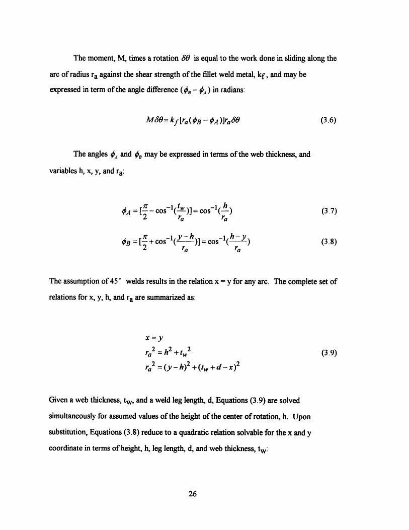
The moment, M, times a rotation 58 is equal to the work done in sliding along the
arc of radius ra against the shear strength of the fillet weld metal, kf, and may be
expressed in term of the angle difference (B - OA) in radians:
M80= kf [ra( B - OA )ra O (3.6)
The angles A and ~B may be expressed in terms of the web thickness, and
variables h, x, y, and ra:
OA = -coslf( tw)]= cosl (3.7)2 ra ra
sB =[ +cos -h )]=cos- l(h ) (3.8)2 ra ra
The assumption of 45 ° welds results in the relation x = y for any arc. The complete set of
relations for x, y, h, and ra are summarized as:
x=yra2 = h2 + t2 (3.9)
ra2 =(y - h)2 +(tw +d-x) 2
Given a web thickness, tw, and a weld leg length, d, Equations (3.9) are solved
simultaneously for assumed values of the height of the center of rotation, h. Upon
substitution, Equations (3.8) reduce to a quadratic relation solvable for the x and y
coordinate in terms of height, h, leg length, d, and web thickness, tw:
26
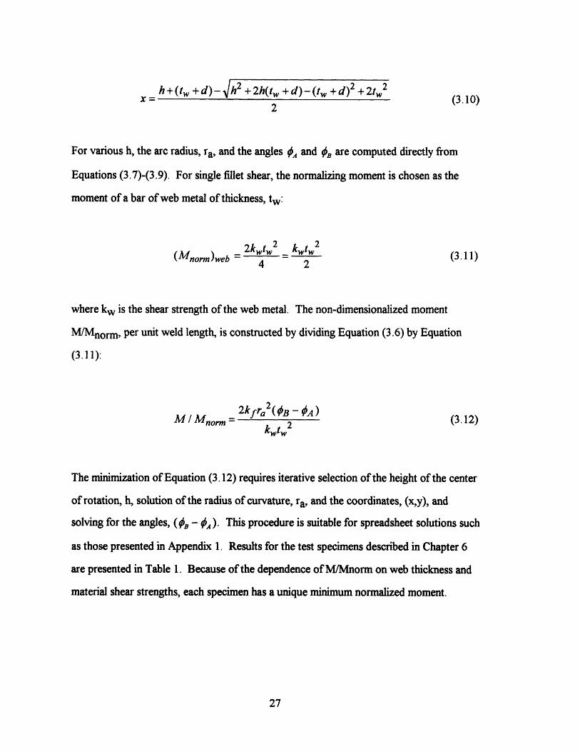
h+(tw +d)- /h2 + 2h(tw +d)-(t +d)2 +2t 2 (3.10)x = (3.10)
2
For various h, the arc radius, ra, and the angles {0 and #B are computed directly from
Equations (3.7)-(3.9). For single fillet shear, the normalizing moment is chosen as the
moment of a bar of web metal of thickness, tw:
(Mnorm)web = 2kwt = kwtw (3.11)4 2
where kw is the shear strength of the web metal. The non-dimensionalized moment
M/Mnorm, per unit weld length, is constructed by dividing Equation (3.6) by Equation
(3.11):
2kfra 2( B - A )
M / Morm a2kfr (BA0A) (3.12)
The minimization of Equation (3.12) requires iterative selection of the height of the center
of rotation, h, solution of the radius of curvature, ra, and the coordinates, (x,y), and
solving for the angles, (B - OA). This procedure is suitable for spreadsheet solutions such
as those presented in Appendix 1. Results for the test specimens described in Chapter 6
are presented in Table 1. Because of the dependence of M/Mnorm on web thickness and
material shear strengths, each specimen has a unique minimum normalized moment.
27
3.3.3 Bound for Double Fillet in Predominant Bending
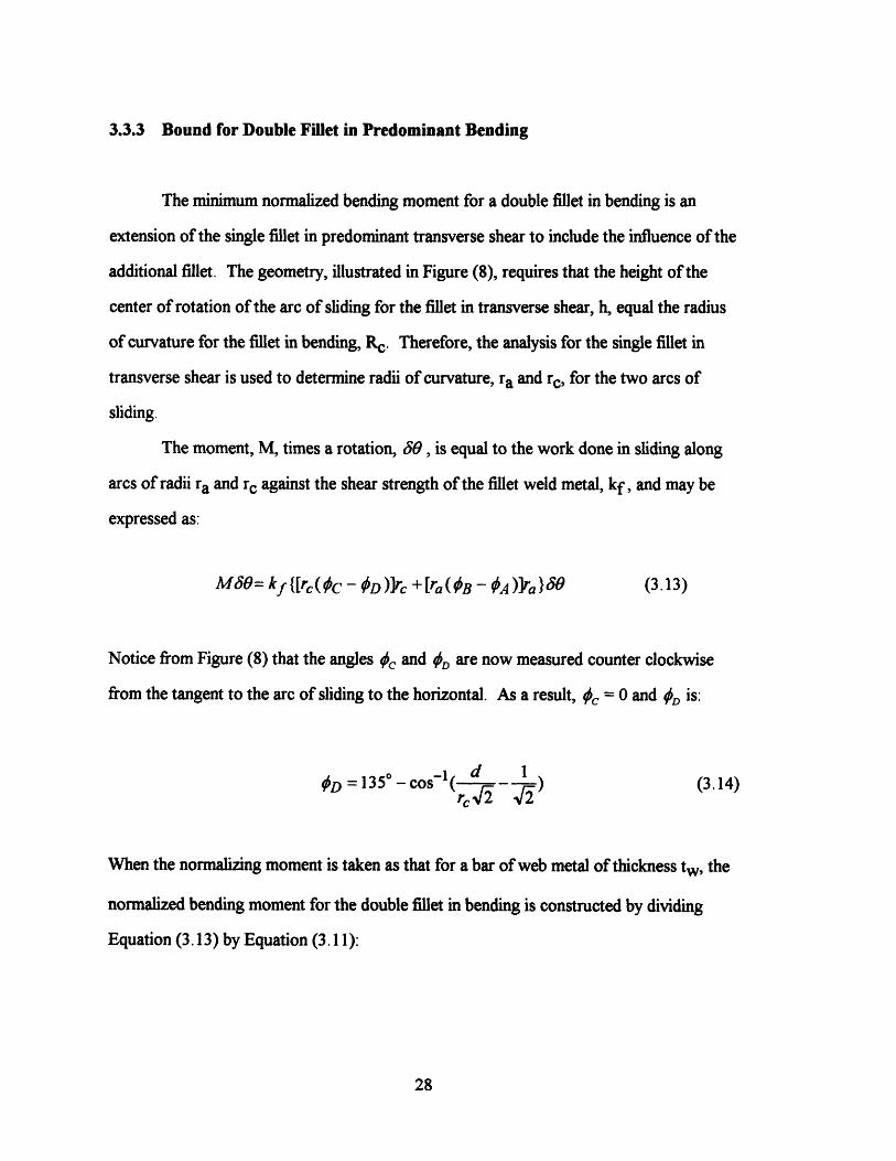
The minimum normalized bending moment for a double fillet in bending is an
extension of the single fillet in predominant transverse shear to include the influence of the
additional fillet. The geometry, illustrated in Figure (8), requires that the height of the
center of rotation of the arc of sliding for the fillet in transverse shear, h, equal the radius
of curvature for the fillet in bending, Rc. Therefore, the analysis for the single fillet in
transverse shear is used to determine radii of curvature, ra and rc, for the two arcs of
sliding.
The moment, M, times a rotation, 80, is equal to the work done in sliding along
arcs of radii ra and rc against the shear strength of the fillet weld metal, kf, and may be
expressed as:
Me0= kf {[rc( C - D )]rc + [ra( OB - A )]ra}c80 (3.13)
Notice from Figure (8) that the angles 0c and D are now measured counter clockwise
from the tangent to the arc of sliding to the horizontal. As a result, Xc = 0 and D is:
D = 135d -os-1 ( d 1 (3.14)rc - a2
When the normalizing moment is taken as that for a bar of web metal of thickness tw, the
normalized bending moment for the double fillet in bending is constructed by dividing
Equation (3.13) by Equation (3.11):
28
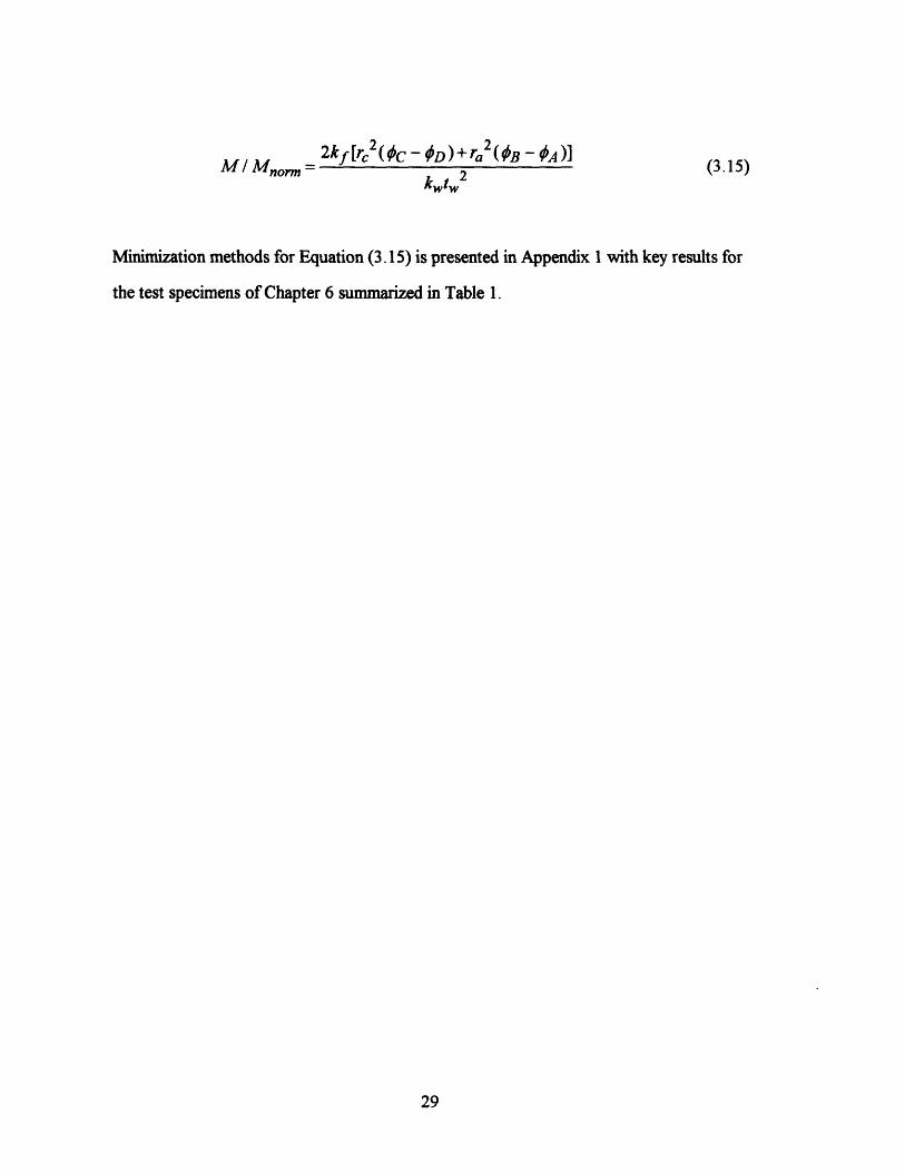
M / Mnorm =2kf[rC2 (C -D)+ ra (B OA)]
kwtw2(3.15)
Minimization methods for Equation (3.15) is presented in Appendix 1 with key results for
the test specimens of Chapter 6 summarized in Table 1.
29
4 Relations for Specimen Design and Data Reduction
4.1 Reaction Forces from Applied Load and Geometry
The Lazy-L configuration is analyzed using simple trigonometric and mechanical
equilibrium relations. In this section, reaction forces on the legs are developed as
functions of geometry and applied load. These forces are later used to calculate the
bending moment at the weld.
The legs of the Lazy-L specimen are assumed to be joined at right angles as shown
in Fig. 9. La and Lb represent the overall dimension of the specimen legs while Lb
represents the length of leg B below the intersection of the two members.
The interior angles of the triangle formed by the Lazy-L specimen, noted as a and
,f in Fig. 9, are:
a = tan-(Lb -2tw (4.1)La
---a (4.2)2
These angles are used to compute moment arms of the reaction forces with respect
to the point at which the load, P, is applied. Since the load, P, and the reaction force, Rb,
are applied to opposite corners of Leg B, the moment arm of Rb must be a function of
both the length, Lb, and thickness, tw, of Leg B. As shown in Fig. 10, this relationship is
developed by imagining an extension of the outside edge of member B, which intersects
the horizontal at angle a. The moment arm of reaction force Rb is equal to the moment
arm of an imagined reaction for the extended leg less the horizontal component, x. The
moment arm of the reaction force Ra is the horizontal span of the Lazy-L specimen less
the moment arm of reaction force Rb:
30
Nb =(Lb + Iw )cos ,- tw (4.3)tanfi sin (4
Na = - Nb (4.4)cos6
A moment balance about the point of load application and a force balance for the
specimen are solved simultaneously for Ra and Rb as functions of the applied load:
P=Ra + Rb (4.5)
RNa =RaNb (4.6)
These relations are entered into spreadsheet to produce output such as Table 2. The
expressions of Ra and Rb as functions of P are now used with appropriate diagrams of the
separated Lazy-L specimens to arrive at an expression of the joint moment as a function of
applied load.
4.2 Weld Moment from Reaction Forces
An experimental, non-dimensionalized limit moment is a useful output of the Lazy-
L Test. The weld moment is expressed in terms of the measured load and specimen
geometry. Such relations are derived for each of the three test configurations using
appropriately selected free body diagrams and equilibrium equations. In each case, the
moment is expressed in terms of a reaction force which is in turn a function of load and
geometry; therefore, the moment may be expressed as the product of the applied load and
a load-moment conversion factor, Clm. Such conversion factors are computed for the
specimens of the pilot study and presented in Table 2.
31
Single Fillet in Predominant Transverse Shear
Fig. 11 depicts the diagrams used to develop a relationship between the measured
load and the weld moment, Mw, for the weld in predominant shear and tension. Body A
is taken as Leg A of the Lazy-L specimen while Body B is taken as Leg B and all of the
weld metal. Globally external forces include the applied load, reaction forces, and friction
forces, xRx, acting at the points of contact between the legs and test bed. Several
internal forces are considered including a friction and contact force, pWand N, acting
between the specimen legs, and a moment, shear, and contact force, Mw, S, and W, acting
between Leg A and the weld metal.
Assuming pure bending of specimen leg (valid for long speimen legs), a
relationship between P and the resultant moment of the internal forces arises from a
solution of the moment equilibrium relations for either of the bodies. The moment
equilibrium relations for Body A is:
ZLVMx = O: Ra(La - rc)cos a - N(Tw )- aRa(La - r)sin a - Mw = 0 (4.7)
This relations reduce to the following expression for the resultant weld moment, Mw:
Mw = Ra (La - rc)cos a- aR (La - rc )sin a- Ratw(sin a + Ha cosa) (4.8)
where La, tw and a are geometrical parameters of the Lazy-L specimen, rc is the radius of
the least upper bound arc, and Pa is the coefficient of friction between Leg A of the
specimen and the test bed. As illustrated in section 4.1, the reaction force, Ra, is
expressed in terms of the applied load, P.
32
Single Fillet in Predominant Bending
Fig. 12 illustrates the free body diagrams used to establish a relation between
applied load, P, and weld moment, Mw, for a single fillet in predominant bending.
The weld is split along the throat into two equal segments. Body A is taken as Leg A of
the specimen along with half of the weld metal while Body B is Leg B along with the
remaining weld metal. External forces include the applied load, reaction forces, and
friction forces acting at the points of contact between the legs and test bed. The moment
at the weld, Mw , becomes external to the bodies. Additional forces required to satisfy
static equilibrium of Body A, a shear and contact force, act at the point of rotation
between the two bodies and do not enter the moment balance. A relationship between
applied load and weld moment can be derived from a single equation:
Ra[(La - rc )cosa- tw sin a]- aRa [(La - rc )sin a+ t cosa]- Mw = O (4.9)
where La, tw and a are geometrical parameters of the Lazy-L specimen, rc is the radius of
the least upper bound arc, and ua is the coefficient of friction between Leg A of the
specimen and the test bed. Rearranging to solve for Mw:
Mw = Ra(La - r)cos a- laRa (La - rc )sin a- Ratw(sin a + ,ua cos a) (4.10)
This result indicates that despite the change of geometry from the single fillet in transverse
shear to the single fillet in predominant bending, the load-moment relation remains
unchanged when the center of rotation is chosen as the focus of the arc of maximum shear.
Double Fillet in Predominant Bending
33
Separation of a double fillet specimen into free bodies requires the introduction of
reaction forces which act at each weld. The result is that each free body is statically
indeterminate; however, when the center of rotation is again chosen as the focus of the arc
of maximum shear, the load-moment relation for double fillet bending is the same as for
single fillet bending, Equation (4.10).
4.3 Weld Rotation from Measured Displacement
In order to interpret displacement data, we must relate the measured displacement,
vm, to the relative rotations, 0, between the two specimen legs. This relative rotation is
later related to displacement along the arc of sliding through the weld, dus. The
displacement-rotation relation is developed for the case in which the Lazy-L specimen legs
remain rigid throughout the test.
Fix Leg B of the specimen and impose a displacement vector perpendicular to Leg
A as shown in Fig. 13. Assuming small angles, the height rise at A, ha, is expressed as:
ha = Lacosa (4.11)
The height rise results in a rigid body rotation, dy, about point B. Again assuming small
angles:
Lad cosa = (AB)d (4.12)
where the segment, AB, is the span of the Lazy-L specimen defined as:
(AB ) = La cos a + mcos,B (4.13)
34
where m is the length of Leg B below the joint. The measured displacement, vm , can now
be expressed in terms of dy as:
vm = Lbdycos3dO (4.14)
Equations (4.12) through (4.13) are combined to express a relation between the measured
displacement, vm , and the relative rotation, dO, in terms of specimen geometry:
80= ELa cosa+ mcosl v (4.15)La cos a Lb cos M
The expression in brackets, a function of specimen geometry only, is called the
displacement-rotation conversion factor, Cdr, and is computed for the specimens of the
pilot study in Table 2.
4.4 Test Stability
Weld fracture must be stabilized in order to collect data measuring the moment
drop per unit crack advance. The test is stable when the measured displacement for
through crack propagation divided by peak load, (dv/dP)meas, is larger than the sum of
machine and specimen compliances. Otherwise, the elastic deformation of machine and
specimen accelerate during crack propagation and no displacement is measured for the
sudden load drop.
The required displacement from crack initiation to through crack propagation is
estimated from experimentation or by Equation (4.15). Measured displacement is
calculated for a web rotation assumed adequate for through crack propagation. In the
35
pilot experiment, for example, web rotation of 0.75 corresponding to 0.25mm
displacement was assumed adequate for crack propagation. This result is divided by the
peak predicted load from Chapter 3 to construct (dv/dP)meas. Specimen compliance is
discussed in the next section. Machine compliance is often provided in literature with the
testing machine but may be measured as described in Appendix 2.
4.5 Specimen Compliance
The sum of specimen and machine compliance is minimized in the design phase to
ensure stable fracture of the welded specimen. Specimen compliance is computed by
determining the vertical displacement due to the elastic deformation of the specimen legs
subjected to the reaction forces calculated in section 4.1.
For Leg A of the Lazy-L specimen, the component of the reaction force, Ra,
perpendicular to the leg is Ra cos a. If the specimen joint is assumed fixed, then this force
results in elastic deformation of the specimen leg. The magnitude of the displacement is
(Crandall, 1992):
RX cosa (4.16)3E/
where E is the Young's Modulus of the web metal and I is the moment of inertia which for
the rectangular specimen leg cross section is expressed as:
wt3
1= 2 (4.17)12
36
The vertical displacement at the end of the specimen leg due to the elastic deformation, 8,
is Scos a. Combining this result with Equations (4.16) and (4.17), the vertical
displacement of the specimen leg to elastic deformation of the leg, 8 ve, , is:
4RaL 3 cos2 a8vert = 3 (4.18)
Ewt 3
An equivalent expression may be developed for Leg B of the specimen by substituting the
reaction force, Rb, free leg length, m, and included angle, A, for the corresponding
variables for Leg A in Equation (4.18). With these relations, the resulting measured
displacement, v m , due to elastic deformation of the specimen legs is computed. For a
symmetric specimen in which La = Lb-2tw, the vertical displacements, 8 vert, are equal,
and vm = ver. For asymmetrical specimens, the measured displacement, vm, is the sum
of the smaller vertical displacement at the leg end, 5 vert, and an additional vertical
displacement computed in the same way as the vertical displacement due to the height rise,
ha, of Equation (4.13). For this calculation, the equivalent height rise is expressed as
(S1vert)a -( vert)b . For simplicity, however, a conservative estimate of specimen
compliance is achieved by equating vm with the larger of the two vertical displacements at
the leg ends.
4.6 Specimen Leg Limit Moment
All relations have been computed on the assumption that the specimen legs resist
plastic deformation prior to weld deformation and fracture. This assumption not only
guarantees weld failure, but validates the right-angle trigonometry used in the analysis.
For the predicted limit moment of the chosen weld, the predicted limit load is computed
37
using the load-moment conversion factor, Clm, developed in Section 4.2. For the
corresponding reaction forces found as in Section 4.1, the predicted reaction force
component perpendicular to Leg A is Ra cos a, while that for Leg B is Rb cos,8. When
these force components are multiplied by their respective moment arms, free leg lengths
La and m, the result is the maximum predicted moment acting on the specimen leg, M1 ,
which occurs close to the weld. The leg yields when the maximum stress resulting from
this moment exceeds the yield stress of the web material, cry.
In the elastic region, the stress distribution in a slender member subjected to
bending is (Crandall, 1992):
x = MMby (4.19)I
where Mb is the bending moment, y is the distance from the neutral surface, and I is the
moment of inertia. The maximum bending moment occurs at the greatest distance from
the neutral surface, or for the specimen leg, where y = tw/2 . Combining this result with
Equations (4.17) and (4.20), the criteria for no leg yielding is:
6RaLa cosawt2
w6&mcosfiW~ ~(4.20)
6RbmcosPwt 2
Specimen leg lengths and weld parameters are chosen to satisfy these criteria for the yield
stress of the chosen web metal.
38
4.7 Magnitude of Weld End Effects
An important modeling assumption is the plane strain approximation; however, the
weld ends of the Lazy-L specimen experience free surface effects which include out of
plane deformation. Plane strain is satisfied when the weld is constrained by enough
adjacent weld metal to prevent out of plane deformation. The required weld length to
ensure the validity of the plane strain approximation may be determined by analyzing the
scale of the free surface effect.
The scale of the free surface effect may be estimated by analyzing the effect of
constraint on the yield strength of two-dimensional weld sections taken at the center and
edge of the weld. As shown in Fig. 14, for stress applied in the x-direction, ao, the
constraint of adjacent weld metal on the center section results in a stress in the y-direction,
ry. In contrast, no stress develops in the y-direction of the end section since it is free to
deform. If the effect of constraint on the resulting yield stress is small, then the free
surface effect is small and the plane strain approximation is satisfied.
The yield stress of each section is expressed as a function of the root mean square
of the differences among the principle stresses by the von Mises yield criterion (eg.
Crandall, et al., 1992):
1
{2[(I x y)2 +(u _ ) + ( c) ]} (4.2 1)2ry(f4-oylfoy ~22 (4.21)
According to Equation (4.23), the end section of the weld, subject only to ax, yields at
ry = ax . In order to satisfy the condition that the center section experiences no strain in
the y-direction, y = 0, andoy = 0.5 ox. For this condition, Equation (4.21) provides the
result that ay = 0.867oax for the center section, which suggests that the free surface effect
is much less than 15% for weld material a few leg lengths from the end.
39
5 Specimen and Fixture Design and Fabrication
5.1 Introduction
Three configurations are available in the Lazy-L test. The first is a single fillet in
predominant bending, the second is a single fillet in predominant transverse shear, and the
third is the double fillet in predominant bending. Despite the differences in the predicted
least upper bounds to the limit moment described in Chapter 3, the specimen design
relations for the three cases are similar. Further, each configuration is tested using the
same test fixtures. Therefore, a single procedure is presented for specimen and fixture
design, respectively, with special note at any step for which there is difference due to the
configuration.
5.2 Specimen Design
The Lazy-L specimen must meet several key requirements to provide the necessary
data for accurately computing the limit moment, rotational displacement to initiation, and
crack growth ductility factor. First, the specimen must be sized properly to produce a
large enough moment to reach the limit moment of the weld within the available load
capacity of the testing machine. Second, the specimen legs must be designed to resist
yielding below the limit moment of the weld. Finally, in order to ensure a stable fracture
for which unloading data may be gathered, the overall compliance must be limited to the
largest slope of the load-displacement curve. The effect of design choices on these
specimen characteristics are discussed below.
The design steps assume that the designer has chosen the combination of web
metal and weld metal of interest. The initial choice of base metal thickness, tw, is
40
suggested by the application, but may need to be increased later in the design process to
stabilize the test or prevent specimen leg yielding.
Step 1: Choose weld length, w. Initial choice of weld length is driven by the plane
strain requirement discussed in Section 4.6. The weld length must be several times the
weld leg length to ensure plane strain and minimize the influence of weld end effects on
the results. The recommended weld length is ten times the weld leg length.
As illustrated in Chapter 3, the total moment of the weld varies proportionately
with weld length. Longer weld length requires either a higher machine capacity or longer,
more compliant specimen legs to achieve the required moment. If the tests are to be
conducted on a large capacity testing machine, then choose the recommended weld length.
For smaller machines, some iteration will be necessary to determine the maximum
allowable weld length. For the chosen weld length, the total required moment, Mtot. is:
Mtot = Mnorm( )w (5.1)Mnorr
where M/Mnorm is the normalized bending moment calculated as in Chapter 3, Mnorm is
the normalizing moment for the particular Lazy-L configuration chosen, and w is the weld
length.
Step 2: Choose specimen leg lengths. L. The leg lengths are chosen to achieve the
required moment, Mtot, at a load within the capacity of the testing machine. For the
selected leg lengths, compute the reaction forces as a function of the applied load, P, using
Equations (4.1)-(4.6). With these reaction forces, express the moment per unit weld
length, M w , as a function of applied load, P, using the appropriate relation from Section
4.2. From this expression, determine if the total moment, Mtot = Mw w, may be
41
achieved within the machine load capacity. In order to minimize specimen compliance and
prevent the onset of leg yielding, select the minimum leg lengths which provide the
required moment.
Step 3. Calculate specimen compliance. (dv/dP)s Specimen compliance is
computed using Equations (4.16)-(4.18). Specimen compliance must be minimized since
the test will be unstable if the sum of specimen and machine compliances is greater than
the anticipated load drop per unit displacement of the weld. Machine compliance is
computed as described in Appendix 3 and weld compliance is estimated from prior
experiments or as the measured displacement for through crack propagation at the peak
test load. From Equation (4.18), specimen compliance is a strong function of specimen
leg length and a strong inverse function of web metal thickness. If the minimum leg
lengths have been chosen for the required Mtot in step 2, then the specimen compliance
may be reduced by increasing the web metal thickness, tw. If web metal thickness may
not be increased, then the weld length must be decreased in order to reduce Mtot and
allow for shorter specimen leg lengths.
Step 4. Check specimen leg yielding. Equation (4.20) provides the criteria for no
yielding in the specimen legs. Stress in the specimen legs is a strong inverse function of
web metal thickness, but a weaker function of specimen leg length. If web metal thickness
can not be increased to satisfy the leg yielding criteria, then leg length must be reduced. If
the leg length is already minimized from step 2, then the weld length must be decreased to
reduced Mto t and allow for shorter specimen leg lengths.
42
5.3 Specimen Fabrication
Fabrication techniques are selected which best represent the application for which
the Lazy-L test is being conducted. The two specimen legs are machined square at the
dimensions, L, w, and tw chosen above. The welding procedure, process parameters and
degree of surface preparation are chosen to match the application. Several important
considerations during welding include weld fit-up, deformation and edge cooling effects.
The theory developed in Chapter 3 does not account for changes in the slip lines
and corresponding bounds to the weld limit moment due to variations in root gap.
Although root gap of up to two millimeters is allowed in shipbuilding applications for
which the leg length is nine millimeters (Middaugh, 1994), the theory assumes a close-fit
weld for which the root gap is negligible.
The development also assumes that the specimen legs are welded at right angles;
however, deformation due to welding causes the specimen legs to fold over toward the
side of the joint which is welded. Deformation is minimized by securely tack welding the
legs in place at right angles before welding the specimen. Tack welds are placed on the
side of the joint opposite the weld and may also be placed at the ends as shown in Fig. 15.
Once the weld is made, the specimen is machined to remove the tack weld material. The
most desirable alternative is to machine the specimen legs two inches wider than the
design width, w, to allow extra surface for tack welds on the side of the joint opposite the
weld. After welding, the entire specimen is machined to width w to remove the extra
material. (Masubuchi, 1994) This method also removes the start and stop of the weld
which cool at a slightly different rate than the remainder of the weld and are usually not of
consistent quality. Fig. 16 illustrates a representative machine drawing of the as-fabricated
Lazy-L specimen.
43

5.4 Fixture Design
A principal advantage of the Lazy-L test is that all configurations use the same
simple test fixtures. As shown in Fig. 1, these are a base plate, load applying plate, and
three 3/4-round supports. Fixtures are designed to reduce friction and resist yielding at
the highest anticipated test loads.
The 3/4-round supports reduce friction and indentation while ensuring that the
reaction force vector remains orthogonal to the base plate for any degree of specimen leg
rotation. They are designed to the length of the longest anticipated weld length, w, and
sized to resist yielding at peak loading. For cylinder length large compared to diameter,
the maximum compressive stress at the point of contact between the 3/4-round and the
plate is (Roark, 1989):
Cmax = 0.591 E (5.2)
given in terms of the load per unit length p, Young's modulus E, diameter D, and a
constant for dimensions in pounds and inches. Since equation (5.2) assumes similar
Young's modulus and Poisson's ratio for the plate and 3/4-round, a hardened steel with
high yield strength, oa, is chosen for all fixtures. For this material, compute the diameter,
D, which satisfies the criterion: ar>ma x. If the required diameter is prohibitively large,
then select are new material for which the criterion is satisfied at a reasonable diameter.
For example, the 3/4-rounds described in Chapter 6 for the pilot experiment were
fabricated using one inch diameter TI steel. Note that fixture compliance is assumed
negligible compared to machine and specimen compliance. Any available plate thickness
in the range of 1/4 to one inch is recommended.
44
5.4 Fixture Fabrication
In order to provide stability and accommodate large specimen deformation, the
base plate is fabricated to a width greater than the longest anticipated weld length, w, and
a length roughly twice the specimen leg length. Since anticipated horizontal displacement
of the top 3/4-round is small, the load applying plate may be machined as a square the
same width as the base plate. All plates are surface ground and polished to reduce friction
with boundary lubrication during the test.
The 3/4-rounds are turned to diameter D and then drilled along the axis using a
1/8-inch diameter bit. A 90° wedge of material is removed using a band saw and milling
machine to complete the fabrication. The drilling procedure creates a rounded notch
which relieves the stress concentration in the event of uneven loading caused by a
specimen leg that is not properly squared. Fig. 17 illustrates a representative machine
drawing for the 3/4-round supports.
45
6 Data Analysis and Interpretation
The parameters of interest in the Lazy-L test are the limit moment, slip line
displacement to crack initiation and the crack growth ductility factor, Dg, defined as the
inverse of crack growth per unit slip line displacement. This section demonstrates how
these are computed from measured Lazy-L load-displacement data and expressed in terms
of universal weld parameters including weld geometry and mean normal stress across the
slip line. In this form, the Lazy-L test results may be applied to other fillet weld failure
modes including pure tension and peeling for which experiments are less practical.
6.1 Moment-Rotation from Load-Displacement
The data conversion factors developed in Chapter 4 are used to convert measured
load-displacement data to moment (per unit weld length)-rotation data. Measured loads
are multiplied by the load-moment factor for the specimen, Clm, and divided by the weld
length, w. Corresponding displacements are multiplied by the displacement-rotation
factor, Cdr. (See Table 2)
6.2 Slip Line Displacement
The rotational displacement above is the rotation of one Lazy-L specimen leg with
respect to the other. For small angles, the displacement along the arc of sliding is the
product of the rotational displacement and the radius of the arc:
us =r5O (6.1)
Slip line displacements for the pilot study are reported in Table 3.
46
6.3 Crack Growth Ductility Factor
The crack growth ductility factor, Dg = dus I da, is a measure of the slip line
displacement per unit crack advance needed for calculating the tear resistance of welds in
tension according to(McDonald, 1994):
Rweld = Dgkfd (6.2)
where Rweld is the tear resistance, or tearing work per unit weld length. For a slip line
displacement from Equation (6.1), the ductility factor is constructed by computing the
crack advance (or reduction of ligament) for the corresponding drop in moment. In the
case of single fillet bending, for example, the moment drop is related to the change in
ligament by the normalized limit moment Equation (3.4). Crack growth ductility is
reported for the stable tests of the pilot study in Table 4.
6.4 Lazy-L Parameters in Terms of Mean Normal Stresses
Lazy-L test results expressed in term of the mean normal stress across the crack tip
are independent of the test configuration and applicable to other loadings. McClintock
(1994) has developed equations for the mean normal stress at the fillet root as functions of
the slip arc angles (eg. Table 1) and the fillet shear strengths for each of the three Lazy-L
configurations. With angles in radians, the mean normal stress at the root of the single
fillet in bending Fig. 6 is:
47
2kf = ( D -1)+(C- D)2k /l2
Similarly, the mean normal stress for the single fillet in transverse shear Fig. 7 is:
aA =( 3 -1)+(A-B)2kf 7r12
(6.3)
(6.4)
where 'B = B + r/ 4 in order to measure from the fillet surface rather than the horizontal
as in Equation (3.7). Finally, the two mean normal stresses for the double fillet in bending
Fig. 8 are:
c =( ~ + )+(C - D)2kf fr/2 2
aA = ( B 1 )+(A A-B)2kf =(,/ 2
Graphs of displacement to initiation or crack growth ductility against corresponding
normal stresses depict the relationships for use in general fillet weld design.
48
(6.5)
7 Lazy-L Experiment and Results
7.1 Test Specimens
An experimental study was conducted to validate the Lazy-L design as a feasible
alternative to more costly and difficult methods such as finite element analysis for
determining limit moment, displacement to initiation, and crack growth ductility. The
combination of 20mm LR-EH36 plate and E7016 stick electrode were selected since prior
research by Tanker Safety Project members (ie. Kirkov, 1994) had shown it to be of
interest to the shipping community. Further, consistent material selection allows
comparison of results from a number of different experiments.
Twelve specimens were fabricated to include at least two of each configuration,
one with 9mm weld leg length and the other with 6mm leg length. Specimen leg length, L,
and weld length, w, were varied in an effort to stabilize the tests and demonstrate the
robustness of the results to changes in specimen geometry. Table 1 lists the measured
dimensions, reaction forces, and data conversion factors for each of the specimens tested.
7.2 Experimental Procedure
The specimens were ruptured in compression on a 20,000 lb. capacity Instron
1125 testing machine equipped with Labtech Notebook data acquisition software. Details
of calibration and data acquisition procedures are provided as Appendix 5. Support
fixtures included three one inch diameter 3/4-round supports machined from T1 steel, and
hardened steel flat-plate grips provided as fixtures with the Instron 1125. Points of
contact between the 3/4-rounds and plates were well lubricated with a combination of
heavy oil and pulverized Teflon in a solvent. During testing, the influence of friction was
tested by reversing the direction of the crosshead to create a hysteresis in the output. For
49
a narrow hysteresis, the effect of friction is shown to negligible. Tests were run until zero
load or until the incremental load drop became very small. Ruptured specimens were
surface polished and tested for hardness both within the weld and base metal.
A peculiarity of the testing machine used is that the crosshead displacement is
computed by Notebook as the product of the crosshead speed and the elapsed test time.
As illustrated by the triangular shapes of load-displacement curves of Appendix 2, the
result is that both tensile and compressive crosshead displacements appear positive in the
output. To create the hysteresis loop, the data sets were processed on Microsoft Excel
spreadsheets to convert positive crosshead displacement increments during unloading to
negative displacements increments in the output.
7.3 Experimental Measurements
A plot of limit moment/unit weld length versus rotational displacement is presented
in Appendix 4 for each of the specimens tested. Limit moments are calculated from the
raw load-displacement data by multiplying the measured load by the load-moment
conversion factor, Clm, and dividing by the weld length, w. Corresponding rotational
displacement data are found by multiplying the measured displacements and the
displacement-rotation conversion factor, Cdr, for each test. (See Table 2) Notice that for
each configuration, the assumption of negligible friction is confirmed by a narrow
hysteresis loop.
The six single fillet bending tests are characterized by a steep load rise in the elastic
region before plastic deformation and load drop due to fracture. The shape of the curve
for the first 6mm fillet in bending appears inconsistent in that there is negligible plastic
deformation before fracture. Although this might normally indicate fracture below the
yield point of the weld, the load data for this test are also inconsistently high. Load data
for the single fillets in transverse shear are more uniform; however, the displacement to
50
crack initiation varied significantly. Also, notice from the steep load drops that the crack
growth was not stabilized. Spikes in the data for the single 6mm fillet in transverse shear
result from the rupture of Teflon shims that were used in an effort to further reduce the
effect of friction. The 6mm double fillet tests are characterized by rupture of the fillet in
shear followed by reloading and subsequent fracture of the remaining fillet in bending.
Notice that the 9mm double fillet specimen did not rupture at the weld due to excessive
specimen leg yielding.
7.4 Experimental Outputs
As described in Chapter 6, the Lazy-L experiment produces the limit moment, slip
line displacement to initiation, and crack growth ductility factor. Experimental normalized
limit moments are listed in Table 3. They are constructed by dividing the peak moment for
each specimen by the appropriate normalizing moment expressed as a function of weld leg
length and fillet or web shear strength. Slip line displacement to initiation, also listed in
Table 3, is computed according to Equation (6.1).
Crack growth ductility may be computed only for those specimens for which crack
propagation was stabilized. In the pilot experiment, this includes all six of the single fillet
bending specimens. Observation of the fracture surfaces in these specimens reveal that the
crack advances nearly along the weld throat. As shown in Figure (20), this may result
from the interaction of two symmetrical arcs of sliding which are alternately active. The
resulting fracture is similar to that of an unequally grooved plate of weld metal in bending
with a halfback-angle of 90° . Neglecting changes in halfback-angle, the least upper
bound arc solution (McClintock, Kim, Parks, 1995) relates the moment to the ligament by:
M = 1.380(kfb 2 / 2) (7.1)
51
where b is the ligament. The change in ligament is computed by Equation (7.1) for
arbitrarily selected changes in moment. The rotational displacement corresponding to this
change in moment is used to compute the slip line displacement from Equation (6.1).
Table 4 illustrates the computation of crack growth ductility for five of the single fillet
bending cases where the reference moments are chosen as the moment at crack initiation,
Minit, and 90% of the moment at crack initiation. Lower values challenge the small angle
approximation for Equation (7.1). Predicted values for crack growth ductility are 0.24 for
evenly matched welds and 0.12 for overmatched welds. (Lyman, 1969)
52
8 Conclusions and Recommendations for Future Work
8.1 Conclusions
1. Limit moment, displacement to initiation, and crack growth ductility are critical
fillet weld parameters in predicting the integrity of fillet welded joints subject to web
folding, pure tension and peeling.
2. The Lazy-L Test is a practical, simple, and inexpensive means of measuring limit
moment, displacement to initiation, and crack growth ductility. Fully plastic fracture
mechanics allows extrapolation of test results to other loading conditions.
3. Experimental results indicate that the least upper bound to the limit moment from a
single arc approximation of the plastic flow field in the fillet under predicts the limit
moment by 10-20% for the single fillet in transverse shear and the double fillet in bending.
The limit moment for single fillet bending is significantly over predicted for 9mm welds,
and 10-20% over predicted for 6mm welds.
4. Experimental crack growth ductility estimates from stabilized single fillet bending
specimens modeled as unequally grooved plates of fillet metal in bending with 900 half
back-angle are within +/-20% of the predicted value of 0.12 for overmatched welds.
5. The Lazy-L Test should be further developed for consideration as a standard test
of limit moment, displacement to initiation and crack growth ductility for use in the design
and qualification of fillet welds for service.
53
8.2 Recommendations for Future Work
1. Further experimentation with the Lazy-L configuration is recommended to develop
an extensive experimental database for a range of materials and geometries. Stabilized
tests of single fillet transverse shear are needed to estimate crack growth ductility from
this configuration. Tests of the effect of penetration and weld metal matching on strength
and ductility parameters are recommended.
2. Develop an experimental method of measuring crack direction during the test or
from analysis of fractured specimens. Model the crack growth vector as a function of
mean normal stress across the crack tip for incremental changes in slip line displacement.
For a crack assumed to propagate along the slip line, consider changes in the slip line
computed to yield the least upper bound to the limit moment for each increment of crack
advance.
3. Consider new models of the slip line field for single fillet bending including a pair
of symmetrical arcs ending in a constant state region at the free surface. Determine limit
moment correlation for new model.
4. Relax small angle assumption by developing specimen geometry as a function of
the measured displacement.
5. Correlate limit moment, displacement to initiation, and ductility factor from Lazy-
L tests with applicable results of finite element analysis, transversely welded beam test,
and tension tests.
54
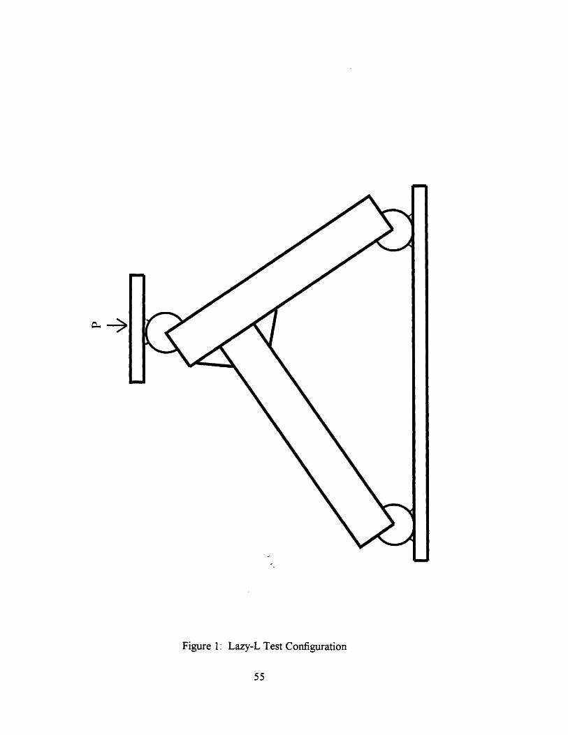
Figure 1: Lazy-L Test Configuration
55
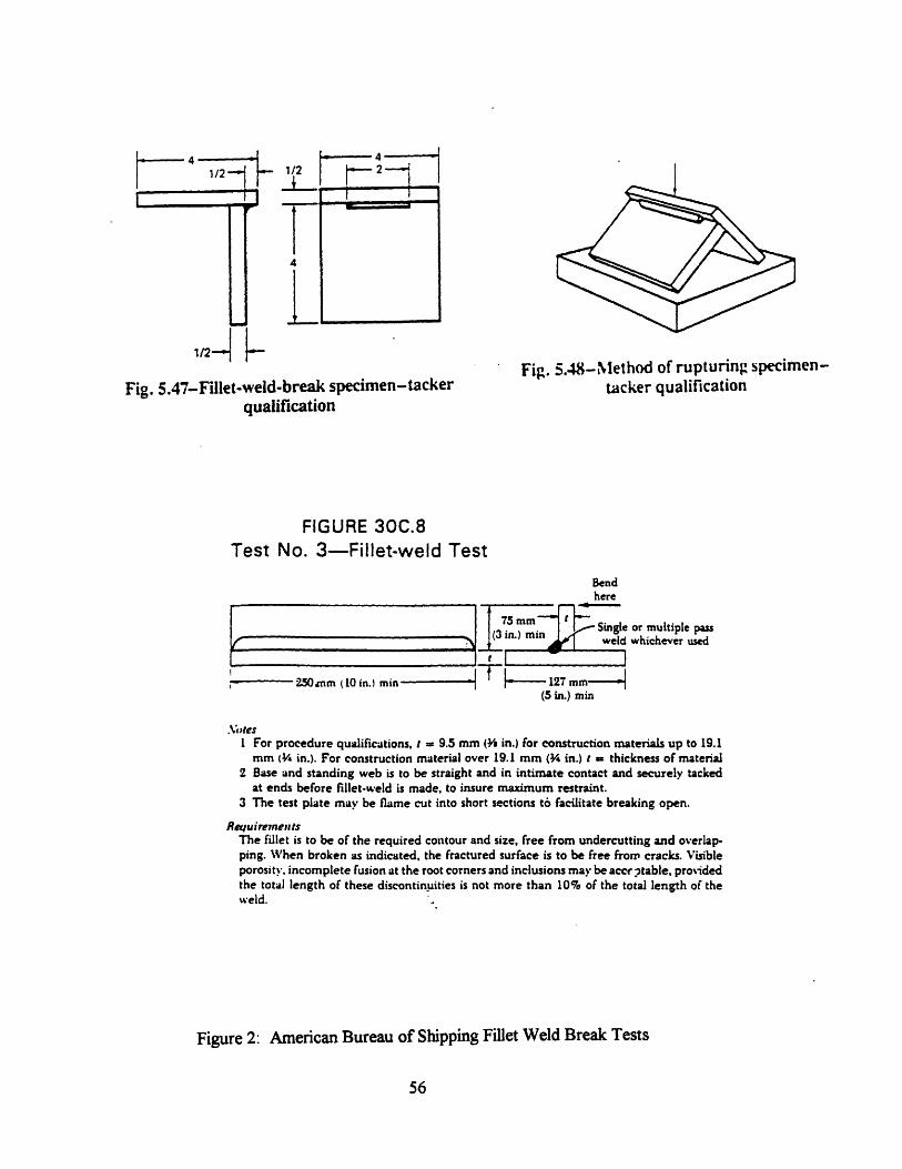
LA- A41/2,I
4
1i~Fig. 5.47-Fillet-weld-break specimen-tacker
qualification
Fig. 5.48-Method of rupturing specimen-tacker qualification
FIGURE 30C.8Test No. 3-Fillet-weld Test
Bendhere
75mm Single or multiple pass(3 in.) m weld whichever used
I-' 250 nm (10 in.I min - - t 127mm -(5 in.) min
.\;,tesI For procedure qualifications, t = 9.5 mm ( in.) for construction materials up to 19.1
mm ( in.). For construction material over 19.1 mm (4 in.) t = thickness of material2 Base and standing web is to be straight and in intimate contact and securely tacked
at ends before fillet-weld is made, to insure maximum restraint.3 The test plate may be flame cut into short sections t6 facilitate breaking open.
RequirementsThe fillet is to be of the required contour and size, free from undercutting and overlap-ping. When broken as indicated, the fractured surface is to be free from cracks. Visibleporosity. incomplete fusion at the root corners and inclusions may be accr )table. providedthe total length of these discontinuities is not more than 10% of the total length of the%weld.
Figure 2: American Bureau of Shipping Fillet Weld Break Tests
56
-t -
6EL
Il
r __ I
i 1� 2 -- 1
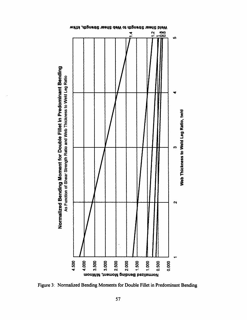
M/pl '4p6utaS JeoLS qaM o uaSt JeatgS PlaM
In
ac
-J
0f)
._
CiFS
A%
0 0 0 0 0 0 0 0 0 00 0 0 0 0 0 0 0 0 0V) t rC) C ) N N _ - 0 0 O
WOUI/W 'WUWOlyW u!puaS paz!leWJoN
Figure 3: Normalized Bending Moments for Double Fillet in Predominant Bending
57
co0'
ECC
_e
0 .2
,mc
.2a c.-
0Z
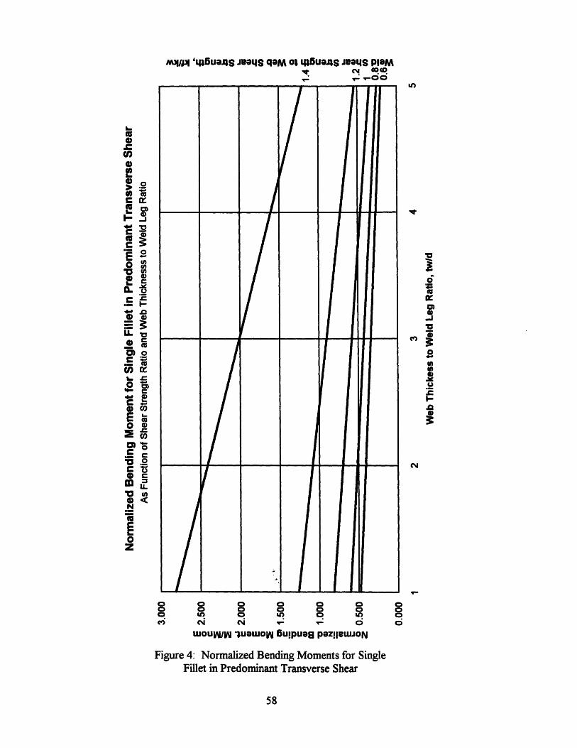
M'ju p 'q46ua.4S JeIaS qaM o: Lua4 S JIeaIS PlaM
V' -o 0ot-~ - oo
o 0 0 0 0 0o o 0 0 0 0o UI 0 In 0 inci N i : :
wouW/I IuawuoW u!puag paz!leLUON
Figure 4: Normalized Bending Moments for SingleFillet in Predominant Transverse Shear
58
co
, or
ca,
.c._ r
02
C
o 0c
0z
U,
,
10A
'U0
I,J0302
.0
0
c3I
000ci
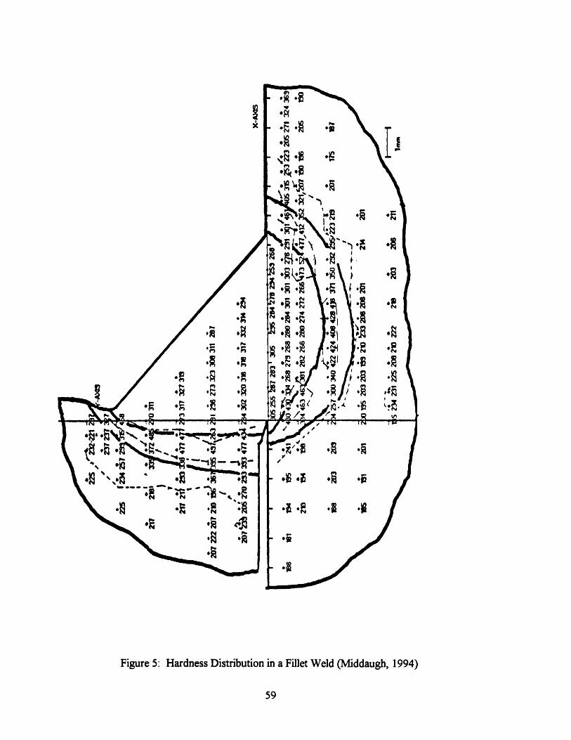
/ Ha ·EA
, * *f
.R ,e .e.e~ ,f~ .1
., :1
. .O -,iA F..:*E Ia
.~ .S.0
4 4 #I
·0 Q *I .0
Figure 5: Hardness Distribution in a Fillet Weld (Middaugh, 1994)
59
I AA OE .A
*A
<Q Ssem O$
·9 -t.t.OR N
oz
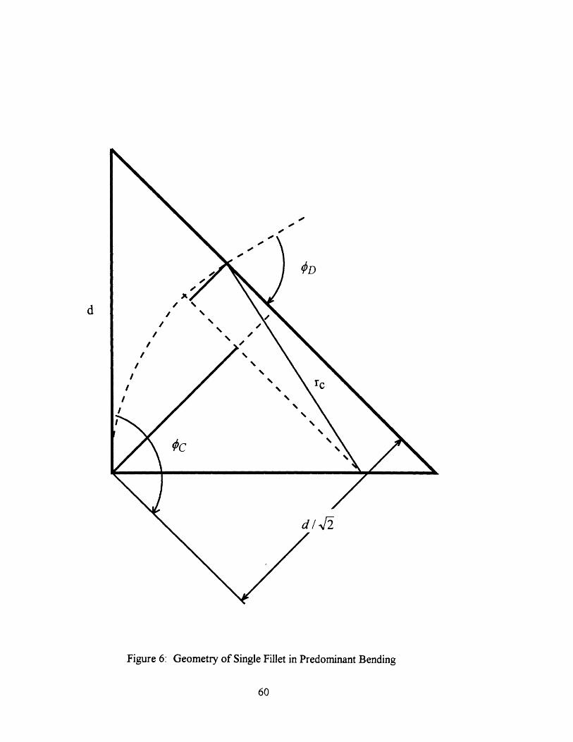
d
Figure 6: Geometry of Single Fillet in Predominant Bending
60
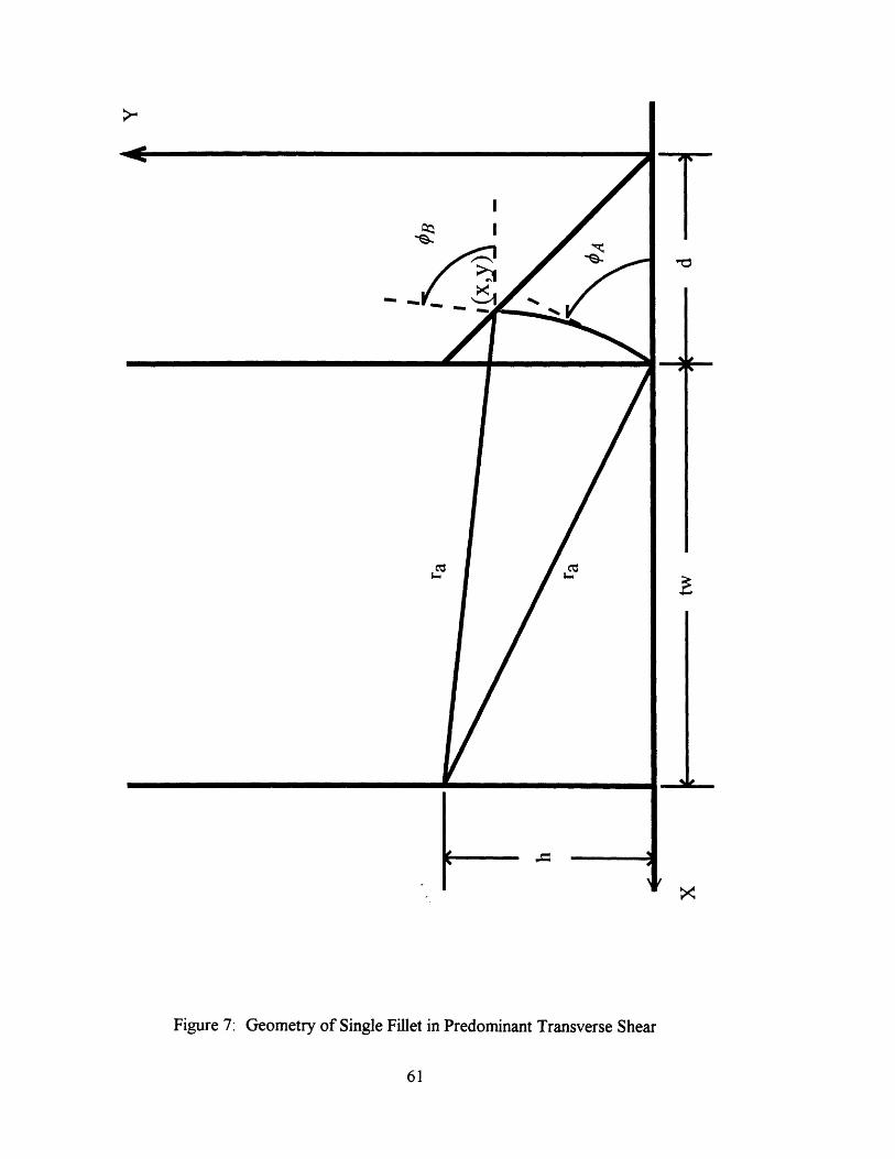
1
Figure 7: Geometry of Single Fillet in Predominant Transverse Shear
61
I
I
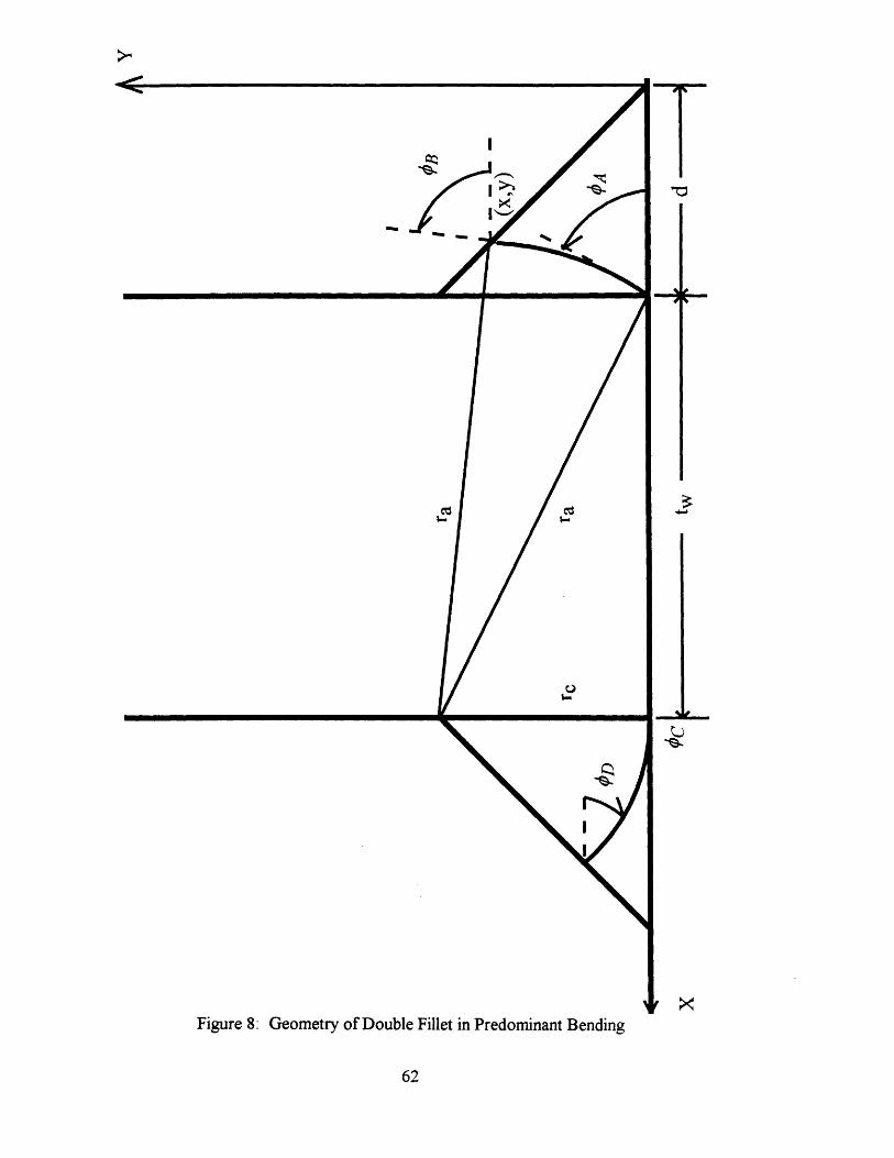
I
62
eM
C$-
Figure 8: Geometry of Double Fillet in Predominant Bending
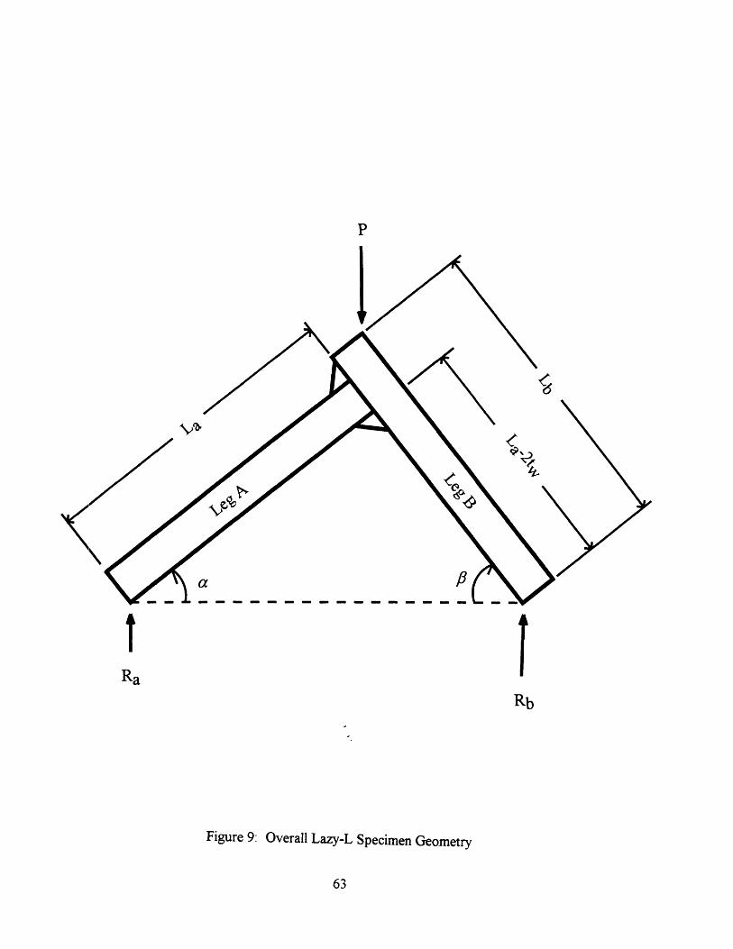
P
a /3
Ra
Rb
Figure 9: Overall Lazy-L Specimen Geometry
63
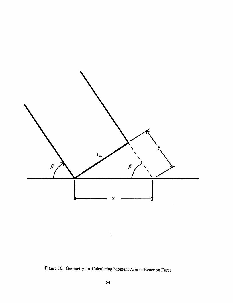
ytw ¶4
¶4
x
\4
Figure 10: Geometry for Calculating Moment Arm of Reaction Force
64
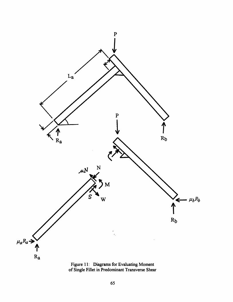
P
I
La
'V
.L N
M
V
., R -'Pa'as
RaFigure 11: Diagrams for Evaluating Moment
of Single Fillet in Predominant Transverse Shear
65
I
c- /iLRL_q -D' U
tRb
T'Ra
C
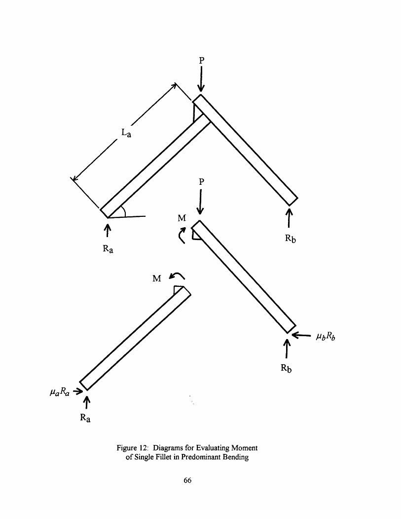
P
C
I
I
RbRa
M
Rb
jorl9a'a 7
Ra
Figure 12: Diagrams for Evaluating Momentof Single Fillet in Predominant Bending
66
,, ? -v
. DL
p
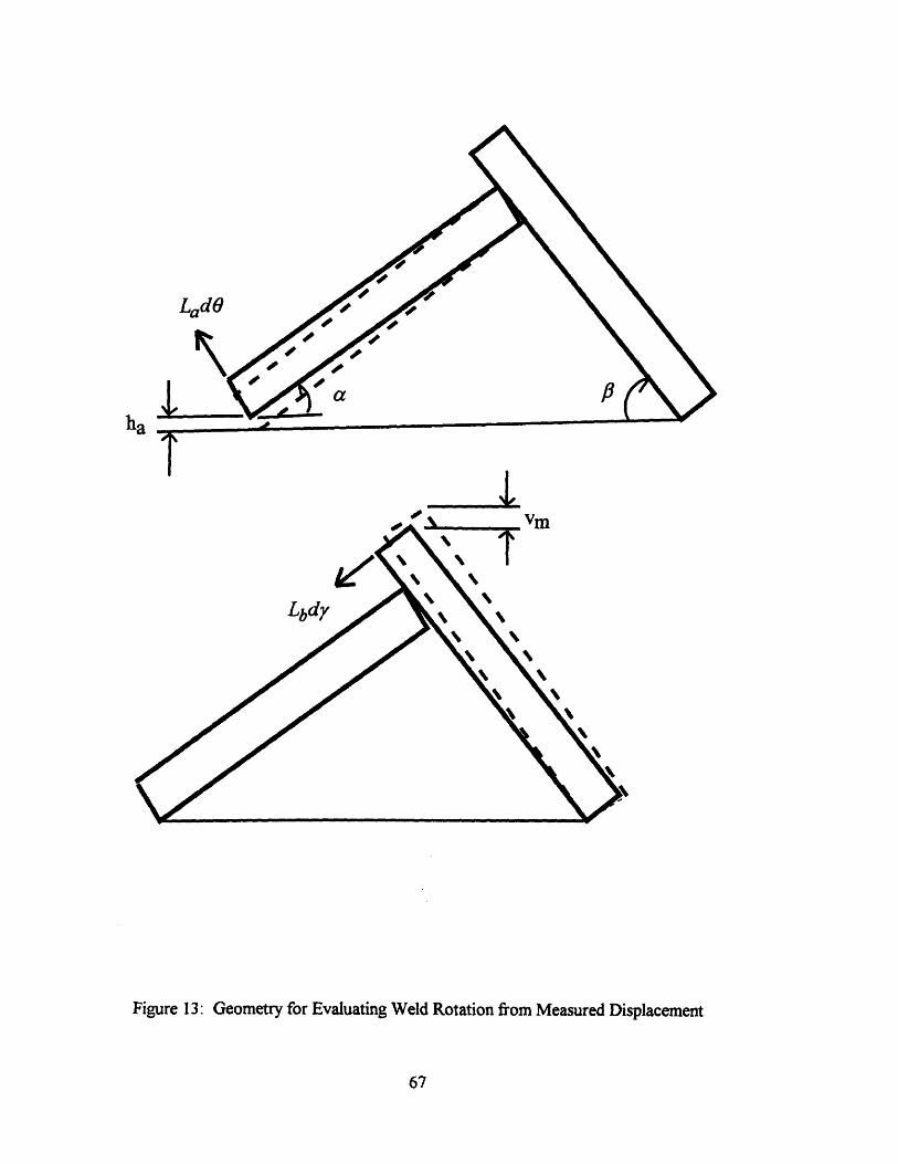
LadO
ha
o , V,
Figure 13: Geometry for Evaluating Weld Rotation from Measured Displacement
67
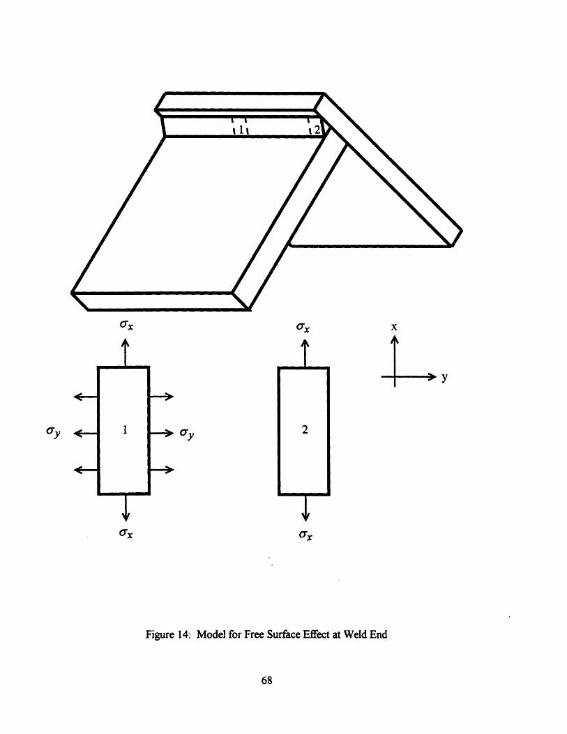
CrX (Tx x
t rI
2
ax ax
Figure 14: Model for Free Surface Effect at Weld End
68
(y . 1
ymmmmmmwk�
a ay
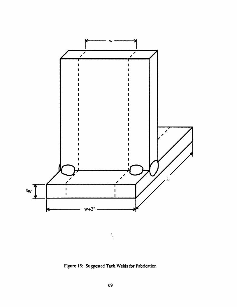
tw
Figure 15: Suggested Tack Welds for Fabrication
69
r~~w
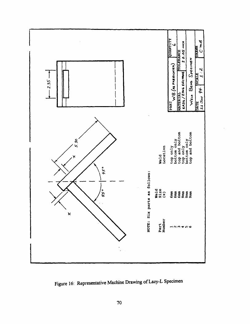
0 00 > 4
-4 0 -4 o
l o o.o 4J
U ac40, Pi)0 000000
~c ~cc
0i'
Ln to
Figure 16: Representative Machine Drawing of Lazy-L Specimen
70
a
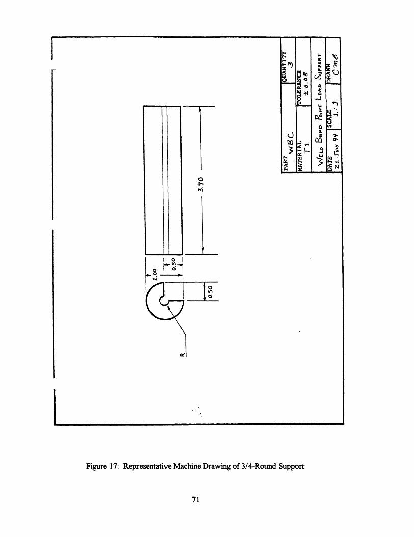
oor
I
Figure 17: Representative Machine Drawing of 3/4-Round Support
71
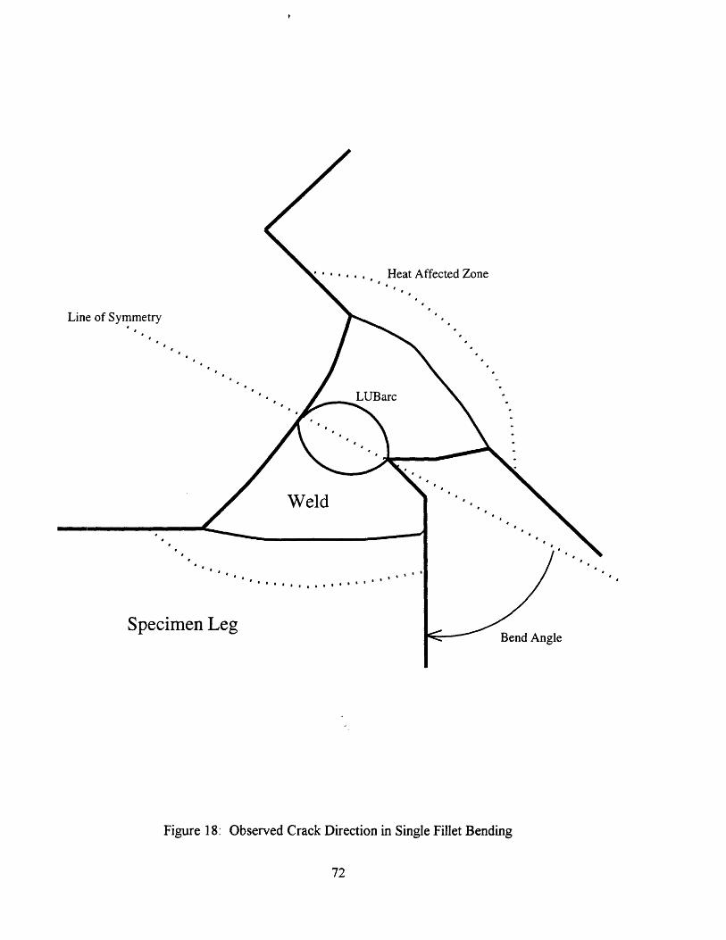
... ., , Heat Affected Zone
Line of Symmetry
I *
a * * * a * * * *
Specimen LegBend Angle
Figure 18: Observed Crack Direction in Single Fillet Bending
72
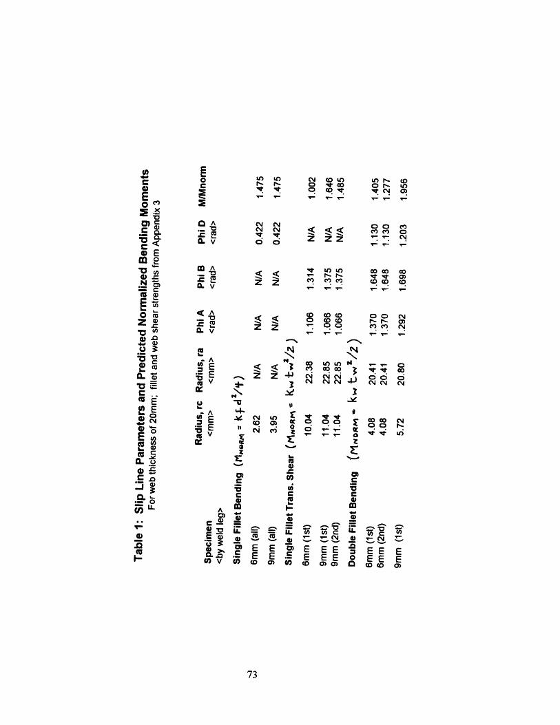
(a EE~~c,~~ ,, c C LO C
X) C /l $ N$ $_ E
· m ""r uz fL V Z Z ° ° C 4
Mg g
o 3 i CoE ' r 0 E N Co C o o z
L.O~ ~ ~ ~ ~ ~~~ Co CO _ -C,.~ od z .- , -- ,,,' n . '
CL c' 3 (3 0 ( C
O ' ^ ZQ]X~~~~~~ .E 00 , Co,
iQ vE u4-^Cr Q)r AV 4) E cj LO ac ~~~~~~~~0 l 'ql' V
:E 0 cq ,,PU3~~~~~~~~~~~~~U
C N 1J~C ._= ,.oou, o S Cr 0 0 Q
I- EE~zcid o EEE r~~
u) O
m o g!,~~~~mEE mEE ca ~~L - EES E0E CoV O Co 0 o Co C C o 0
73
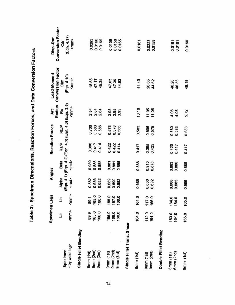
0U
L o- E0 0 . E
0
I.0O. OO- UC O
E c00
o >0 Ca-i
0o A
V
0 AV(U
0 -. X w
C -
o A< v
wQ *
$n ' r
< z si Qc rr6 w
v
001-
0
UE,
Q,
A. E-J Ev
Acu E
Ev
0)C:C0mA
' -a0V 0C v (h
c o U) 00 )0) c0 o u tu oCN - ___000 000000 000
U) V)oo r cUU) Co u
C) 0C) C)0 C 0v IV IV
"it le t IJ) ) )co co o 0) 0 0)Ni Ci N mC6 m
$ 0c ( 0( 000N U) U ) V) U) o o co co co co
o ( (t C- i- CD co co o o, co0 0 0 0 0 00 CN~C C vrci 6 c i c
M LO co V 7 00
co co co co co co
0' co co 0 000 00 0 0 0
) 0 0(0 O (0 00 00 00 00coc6 o co000cU-) (D CC) co CD coci i c ; c;
O O00 O O
0 O O00 CD CO
E D
EEEEEE(0 cD f(
o o oU o 0
(O Do 0
EEEEEE0 0 0)
74
o0 o66 d
d (6D(0(0
0
'l
o1..0
oU.O
oI.
*,"mcC,
e(U
C)
0
(UI.
- c 0co o o0 C00oo o
o o C
t (D D
v o o
O O
o _L_O _00oc U) U)0 o U (
0 C
0 0)O o 0 00
0 00
E EEE EE(O 0 a)
00(0 0N0 0 0
i U
0 0 0
O o o66 60(0 (0
0 00( 0
.u'-'
'
m0
0
c,_._c
C=
IA.
0)C":5c0m
0e.0
0C
" rEEEE(D cD
U=-
EE0)
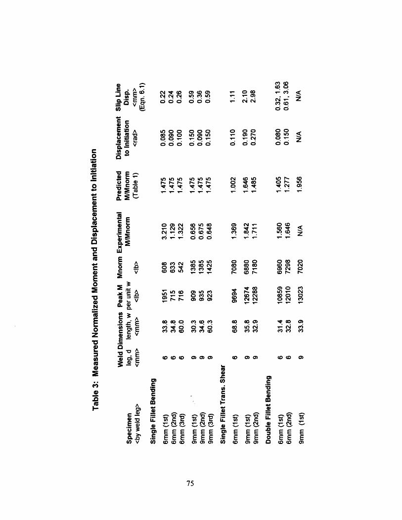
E A C%4 ( i4 0 0 O co C0(A,, E .- C14 C1 c U V) Ur as _
_ V,,,o oo
oo( o
00E 0 , A o ,O 0 000 0 00 0 0
C0 o o o o o- o ro 0 o o
o._
E0 c
0 0 O C O O 0 O 0( co° A co N to n- W- v- CD co 00r- ) CD
C o
C 0 O Vc cs It 0 00 - O C 00 c V C c X I - co- c r-0 C
Z co co vE "o 0 E om Vc ss v~ 0 0 c OjCo O l . -0 ._N 0A0 ) 0mo " ,, > d E i 2, cE c cou zZ~ v V CD coD ) D V) 0C ( m
0 c
C C'00 L. 7 a
E- C
E EEE EEE E S ES E SE E0.n E E E E E E . E E 0 E S Eto v otCO co m 0)0) U) CD 0 0)0 co(c 0
75
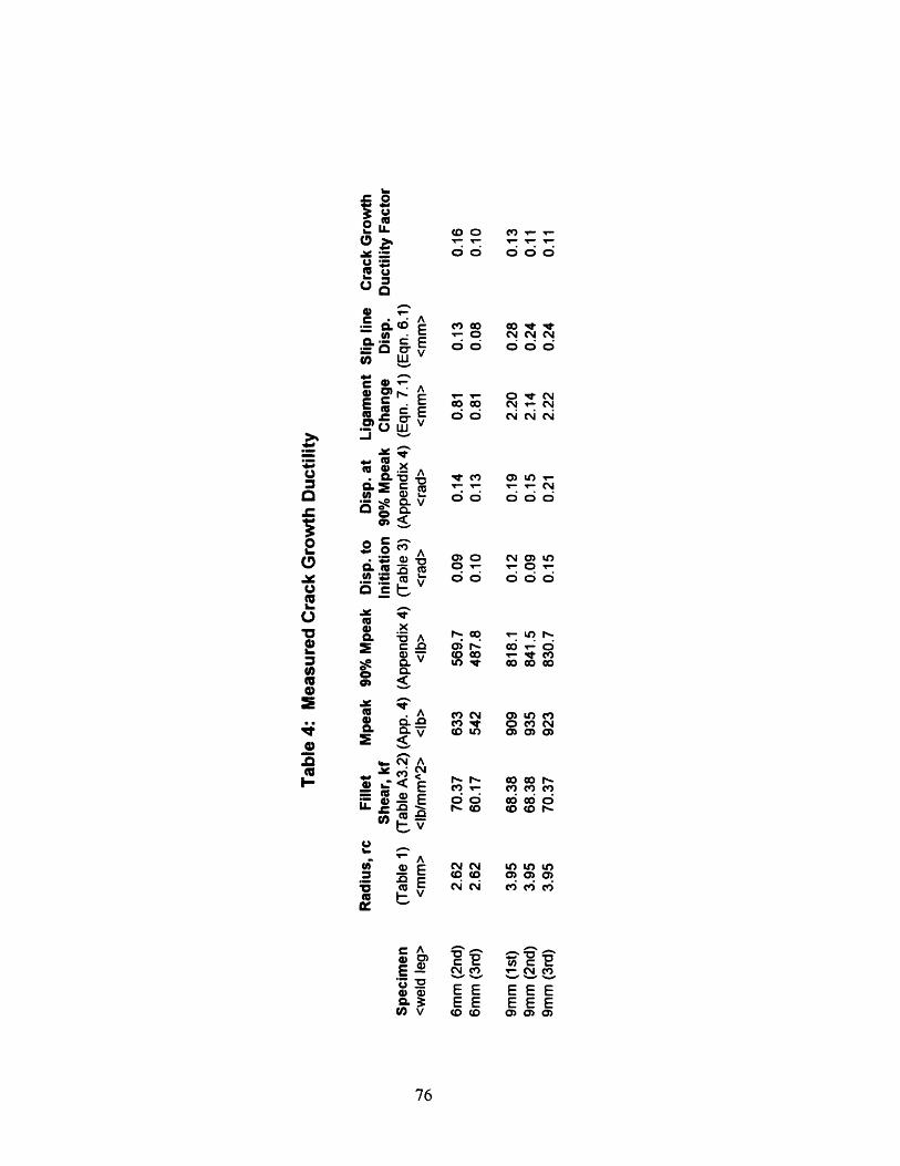
0oLL
. -QC EL L~r E_D A
4) .xo cA
v4) o..
.COCUO
m D G o * le.O C )o1 ooo dc d
O O O
~~-0 C'4~C'
COCO~Cdd ddd_ O d b1
0- 00 cv O O N t~l N~Ct) 0 )0) 0
r - vr -0> O CV Q, uO ICDU)
m cm a) ceQO r OQ (0 cO O cn u, 0
CM 0N LO t LO
00 0 0 0 )C) (N 0j ) i 6e cDt O e CC\ If) aw 0 rO( O 0 0 0
cu c(D axj a c
._E '0-- EEo. EE
cn v co D(
76
EEEEEE0) 0 Q
References
American Bureau of Shipping (ABS), 1991, Rules for Bulding and Classing Steel Vessels,Chapter 30.
Chakrabarty, J. Theory of Plasticity. 1987, McGraw-Hill, New York.
Crandall, S.H., Dahl, N.C., and Lardner, T.J., An Introduction to the Mechanics of Solids,1992, McGraw-Hill Inc.
"Federal Register", Dec. 1990, Vol. 55, No. 234, U.S. Federal Printing Office.
Kim, Y.J., McClintock, F.A., and Parks, D.M., "Global Equilibrium of the Least UpperBound Circular Arcs Applied to Fracture Mechanics", February, 1993, J. Mech.Phys. Solids.
Kirkov, K.D., "Tearing Resistance for Fillet Welds in Ships Exposed to Grounding - AFull Scale Test and Cost Implications", May, 1994, S.M. Thesis, M.I.T.Department of Ocean Engineering.
Krumpen R.P. Jr., and Jordan, C.R., "Updating of fillet weld strength parameters forCommercial Shipbuilding", 1984, Ship Structural Committee Report 323.
Lyman, 1969, Metals Handbook.
Masubuchi, K. M.I.T. Professor of Ocean Engineering, 1994, personal communication.
McClintock, F.A. "Fully Plastic Fracture Mechanics for Fillet Welded T- Joints", 1994,Joint M.I.T.-Industry Consortium on Tanker Safety, Report No. 26.
McClintock, F.A., Kim, Y.J., and Parks, D.M., "Tests and Analyses for Fully PlasticFracture Mechanics of Plane Strain Mode I Crack Growth", 1995, FractureMechanics, 26th Vol., ASTMSTP 1256.
McClintock, F.A., Kim, Y.J, and Parks, D.M, "Criteria for Plane Strain, Fully PlasticQuasi-Steady Crack Growth", 1995, Int. J. Fracture.
McDonald, H.A. "Required Strength and Tear Resistance for Fillet Welds in ShipsExposed to Grounding or Collision Loads", 1993, S.M. Thesis, M.I.T. Departmentof Ocean Engineering.
Middaugh, R.A., 1993, personal communication.
77
Yang, W.C., ed., Roark's Formulas for Stress and Strain. 6th ed. McGraw-Hill, NewYork, 1989.
Wierzbicki, T., Peer, D.B., and Rady, E., "The Anatomy of a Tanker Grounding", MarineTechnology, 1993, Vol. 30, No. 2, pp. 71 -7 8.
78
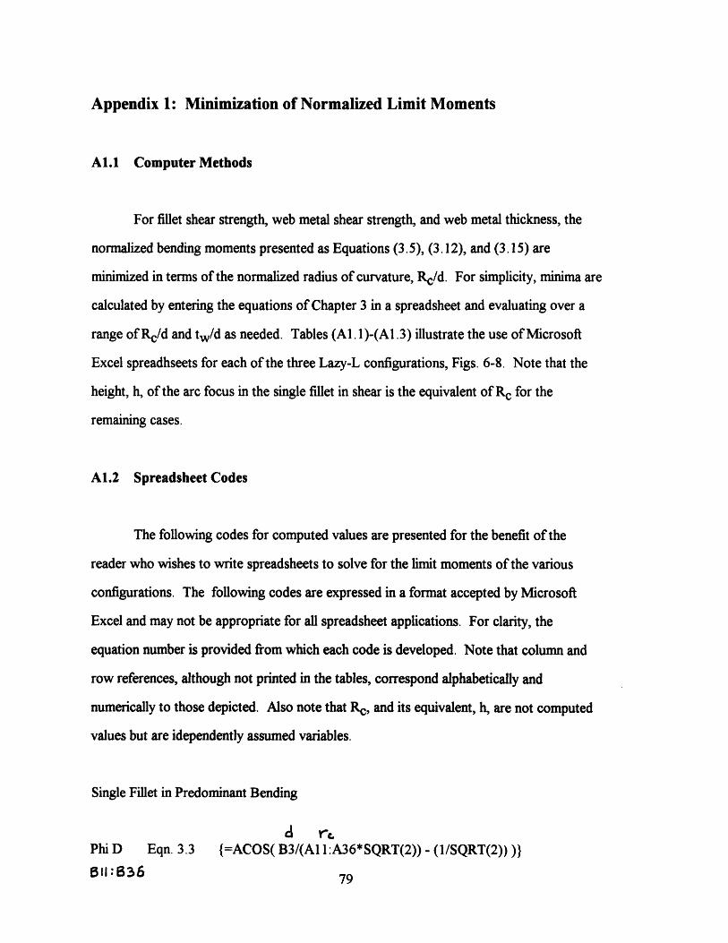
Appendix 1: Minimization of Normalized Limit Moments
Al.1 Computer Methods
For fillet shear strength, web metal shear strength, and web metal thickness, the
normalized bending moments presented as Equations (3.5), (3.12), and (3.15) are
minimized in terms of the normalized radius of curvature, Rc/d. For simplicity, minima are
calculated by entering the equations of Chapter 3 in a spreadsheet and evaluating over a
range of Rc/d and tw/d as needed. Tables (Al. l)-(A1.3) illustrate the use of Microsoft
Excel spreadhseets for each of the three Lazy-L configurations, Figs. 6-8. Note that the
height, h, of the arc focus in the single fillet in shear is the equivalent of Rc for the
remaining cases.
A1.2 Spreadsheet Codes
The following codes for computed values are presented for the benefit of the
reader who wishes to write spreadsheets to solve for the limit moments of the various
configurations. The following codes are expressed in a format accepted by Microsoft
Excel and may not be appropriate for all spreadsheet applications. For clarity, the
equation number is provided from which each code is developed. Note that column and
row references, although not printed in the tables, correspond alphabetically and
numerically to those depicted. Also note that Rc, and its equivalent, h, are not computed
values but are idependently assumed variables.
Single Fillet in Predominant Bending
d reuPhi D Eqn. 3.3 {=ACOS( B3/(A1 1:A36*SQRT(2)) - (1/SQRT(2)) )}
:B36 79
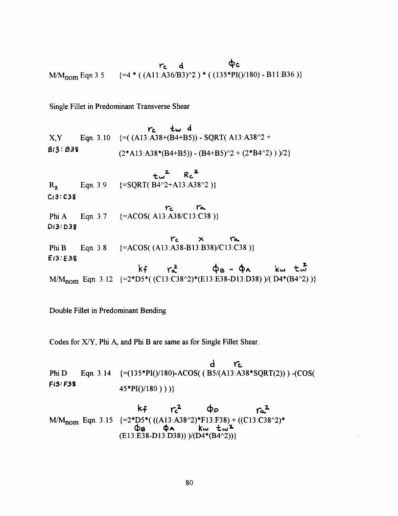
M/Mnom Eqn 3 5
rc. d ({=4 * ((A1:A36/B3)^2) * ((135*PI()/180)-B11:B36)}
Single Fillet in Predominant Transverse Shear
re t+w dX,Y Eqn. 3.10 {=( (A13:A38+(B4+B5))- SQRT( A13:A38A2 +
B31 038 (2*A13:A38*(B4+B5)) - (B4+B5)A2 + (2*B4^2)) )/2}
tw 2' Rc.Ra Eqn. 3.9 {=SQRT( B4^2+A13:A38^2 )}
CI3:C38
Phi A
Dr3: D38
·r c rEqn. 3.7 {=ACOS( A13:A38/C13:C38 )}
rc X ra.Phi B Eqn. 3.8 {=ACOS( (A13:A38-B13:B38)/C13:C38 )}
iE13: E3g
M/Mnom Eqn. 3.12 {=2*D5*( (C13:C38a2)*(E13:E38-D13:D38) )/(k tw
D4*(B4A2) )}
Double Fillet in Predominant Bending
Codes for X/Y, Phi A, and Phi B are same as for Single Fillet Shear.
d 'cr.Phi D Eqn. 3.14 {=(135*PI()/180)-ACOS( (B5/(A13:A38*SQRT(2))) -(COS(
FJ3: F39 45*PI()/180) ) ))}
M/Mnom Eqn. 3.15
kf rc?2 f r;c{=2*D5*( ((A13:A38A2)*F13:F38) + ((C13:C38A2)*
(b 4)^ kw t '(E13:E38-D13:D38)) )/(D4*(B4A2))}
80
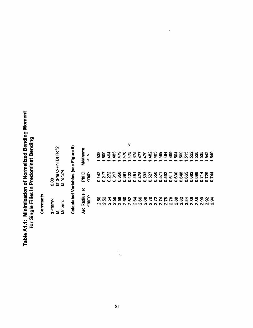
aY 3
.0a
o -I. -C0'I
V
o Av
2
.D u
a n
.. c IrC go 04: o o
O t O O 0 I N a o N 0 u N aNC O mW r r r 0- 0 cn QD O o o C0 C0 Co Mt rL) ) v v v s v v t v t ) U V7 7 U) r U
. . . . . . . . . . . . . . . . . . . . . . .
T- IrI- Il V' - Ir T- It Ir It- T- T -T -T -T - V r
A N- N - T- -N 0 r O V0 t 0 tt _ e C) 2 T) N O M MV V O Ln 0 0 ( 0 0 I- _ -seX v I N df d< df d st d ) u) u^ ) d1 Ed d ) ed ed (d d d dLV OOO°OO°°O°°°°°°°°
CVI.
AEEV
81
.1CI
C
E ;0 ~m o to
., l.
E E
Z C C.
.W 10
iLE I,
.. co
IW
I
U)cU)c0o
EEv
0 Ln 0 0 0 0 0 0 or ( l- I- r O W W 0 W CV -- 1 N N ~ N cq N CN,04' 04' N, 04 N, 04, 04 04,04' 04' 04, 04
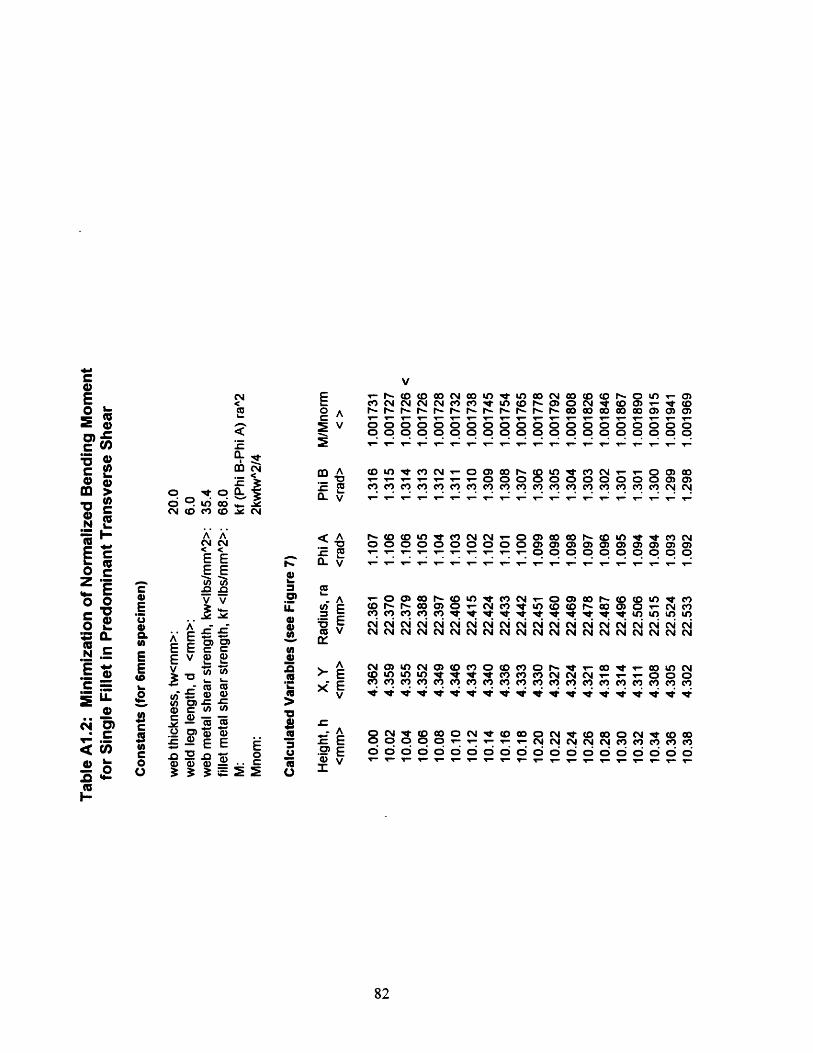
NcoCL
i:~m E
,,omG ~ ~d ° L 0 V (D CO c Y
Eo A2 v:E
A ^
EEEE
_ vA
AD0 EE FE E v
L. (D -ra
.@E Eo a E
V
M N N N CN N e t U) tD I- )v O ID a) N - * <D1s F F 1_ l l_ 1< te 1_ F ~y 0 0 0 0 0O CO 0) 0)r- l I r rl r - - r- r- r- r- r- w w 00000000000000000000 O00000000000000000000 OV r r - _ ____- V ____v -- 1- 1 -- 1 -1 ·_. C I
l A <° uA t r N- 0 1 tD LO V M< N T _ O Q0
0000000:000)0)0)tr)a (L V V ' TC t q 1 l l'- I'- - -T -- _- _ _-
ez E$ D EU-
9 E'W x E4 ).0*.r
(U E
la10
E
0 *I _ .).2I
AEvV
m m m^ m^ m^ v N9 v v v v v^ I v ^v n , N
NV C C C CN CN N N N N C NN N N N ^ N NV
0 u ) CO V V ) V M N N N - O.- O O 0L Ofl f lU c< n e d: v4: e e e e e e e e . . . . . . . . .
a QV 0 C 000000o o o o oo , o o o
o CV cO 0
_l _ .Ir %- - -- 1 1 - 1-
82
0E0
Cemc00mel
eN
Eozo0
N
E
i0w
L.
U)
0Co0120U)
c
E
0la-E00C
LU.0C4)
cn
0L.12
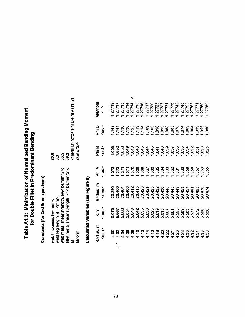
V
E V) ......... M o l 0 N W MC, cr r Ic ~~~~~~c,~~ ~~ Cc ~~f r- f IPc I P r -- P- I- c r y C
'-- ~ 1 V CV CV CV CV CV CV CV CV CV CU CV .... C VC <GE ~~m C ~ ~ ~ m
00 r ICI 0 r D V) 0) ) Vr) GO 0C 00 ) 00 V Q V ) L OQ A ~ ~ ~~ ~ o~5) e ·rrt ~~~~~~~ C' V M ) C 0 0 C 0) 0 00 00 I- I- CD CD LO LO LO
E ~ ~ E =~0. *V ~ o oooooo+ -m,~~~44 a-I.C Q
4) C14 M A MO(N 0 N) 0 cO (0C'(D 0 U C LC) f V- fl 0 '* < LO LO LO v It C* le It v It it m ) v) vV) cnV) i) )
iZ E) .. Z * V r -rr~·-· - -a, EEE
oS ~ EVE .B A c)ci C V co co co c o co (o co o o C co o co o coco ( co oV &O (14 ( I- ~ c u
o~ Sa C ~ WV0E- < A 0 VMN 00WI
8i34 .Y "" a~~~~~~~. (II --E~~~EE coo o r ~ r uC u unC)CC3CCL E EP O · ~ C E 'DS ttl .2 u 0A avW v oN o n ) nP- L 0lo~~~ D000 C nVVVL O( Dr-P
4-~~~~8
Appendix 2: Measurement of Test Machine Compliance
Before testing, machine compliance must be determined. Machine compliance,
expressed as (dv/dP)m, is a measure of the incremental crosshead displacement for a given
load increment. This displacement, due to the elastic behavior of the crosshead and
crosshead supports, is often negligible; however, in experiments such as the Lazy-L test
which are characterized by large loads and small measured displacements, crosshead
displacement becomes significant.
Machine compliance data is often included in literature from the manufacturer, but
varies with the crosshead position and the direction and orientation of the test; therefore,
it should be measured at the time of testing for a particular test configuration.
A common technique for measuring machine compliance in tension is to collect
load-displacement data while the upper and lower grips are rigidly connected. The inverse
slope the resulting curve is the machine compliance. The greatest risk associated with this
method is that the maximum capacity of the load cell may be exceeded if there is any error
in the calibration of the data acquisition system. A much safer technique exists for
measuring machine compliance in compression. Load-displacement data is collected for
the elastic compression of an aluminum cylinder of known properties. As shown in Figure
(A2. 1), the algebraic difference of the measured data and the calculated behavior of the
test cylinder yields the machine compliance according to:
( )meas = ( )m +( d)S (A2. 1)dP dP dP
When the test cylinder is designed to yield plastically at 90% of the load cell capacity, then
there is much less risk of damaging the load cell.
The Lazy-L tests were conducted on an Instron 1125 testing machine with a
20,000 pound capacity load cell. A test cylinder of 6061 -T6 aluminum was designed for
84
use in measuring machine compliance. The diameter of the cylinder was chosen to assure
yielding below the capacity of the load cell using the Von Mises yield criterion:
1
2 [(a-x ry) +(cry _ a- )2 + (o _ )2 ]}-2 (A2.2)
For stress in the x-direction only, equation (A2.2) predicts yielding when -a x is equal to
the yield stress of the material; thus, for yielding at 90% of the maximum load cell
capacity, cylinder sizing is governed by:
R2 = O.9Pax (A2.3)
For load cell capacity, Pmax, of 20,000 pounds and yield stress, Y, of 40,000 psi, equation
(A2.3) requires a radius, R, of 0.378 inches. The test cylinder used was a two inch length
of 0.75 inch diameter stock.
Representative load-displacement data collected for this test specimen is shown in
Figures (A2.2) and (A2.3). Note that the data acquisition system computes displacement
as the product of crosshead speed and time, such that negative displacement increments
during unloading appear as positive displacement increments and result in the triangular
shape of the curve.
The slope of the measured data, (dP/dv)meas, is 7558.5 lbs/0.5 mm or 383,875
lbs/in. For this load increment, test cylinder displacement is calculated using:
LdPdvs = A (A2.4)
where dvs is the change in specimen displacement, L is the specimen length, dP is the
change in measured load, A is the area of the cylinder face and E is the Young's modulus
85
of the material which is 10e+06 psi for 6061-T6 aluminum. From equation (A2.4), dvs
corresponding to a 7558.5 pound load increment is 0.00342 inches; therefore, dvm, equal
to (dvmeas - dvs), is 0.01627 inches and (dv/dP)m is 2.15e-06 in/lb.
86
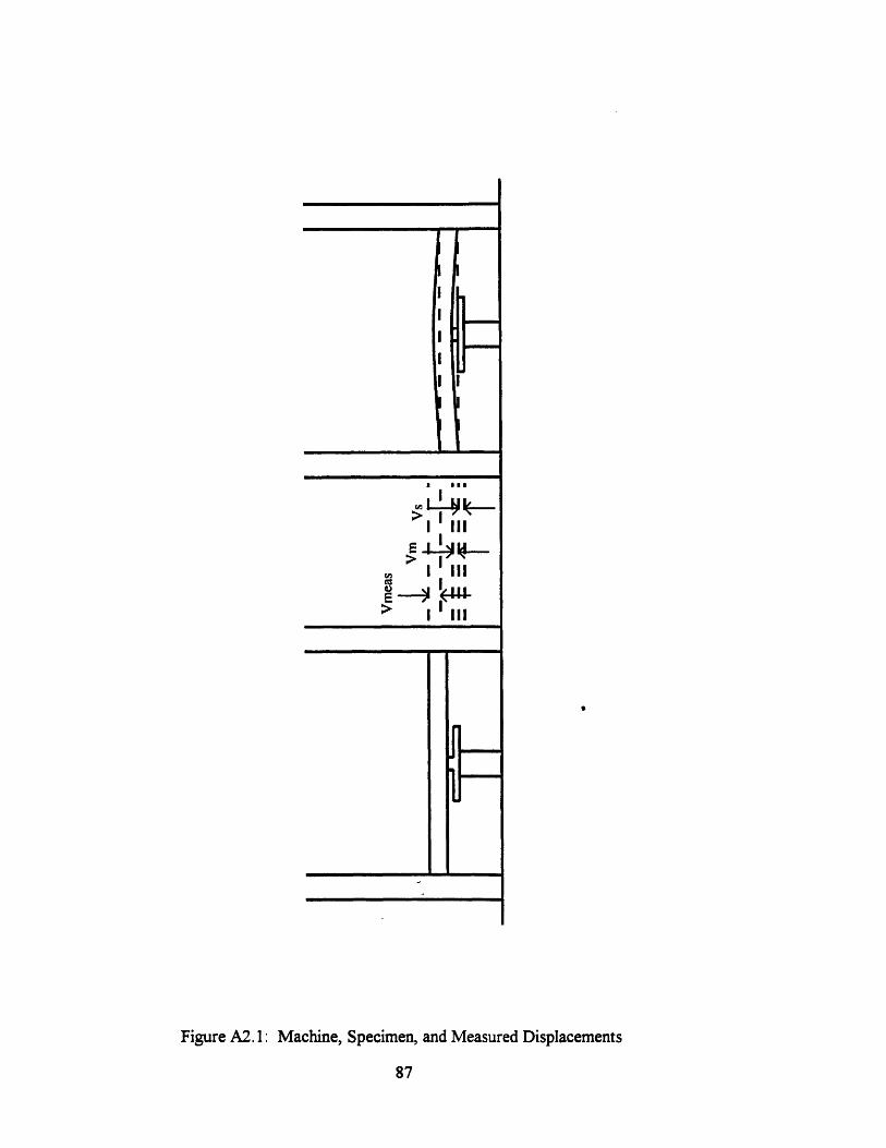
E a IaI
> ,I III
Figure A2. 1: Machine, Specimen, and Measured Displacements
87
- .
- -
I
I I
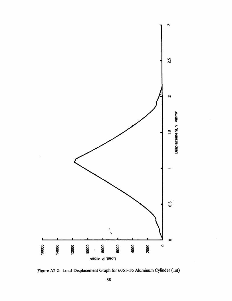
0 0 o o0 0 o oo o 0 0C I 0VI' V' VI
o o 0 0o o 0 00 0 0 0co (0 IV N
<sql> d 'peo-!
Figure A2.2: Load-Displacement Graph for 6061-T6 Aluminum Cylinder (lst)
88
Cis
inN
AEEV
'- SU c
U)
U,Q
O
0

o 0 0 0o o o oo o 0 0o0 C 0 0co0 Iw 0 CD
o o 0 0o o 0 0o o 0 0co co t 0N
<sql> d 'peol
Figure A2 .3: Load-isplacement Graph for 6061-T6 Aluminum Cylinder (2nd)
89
c"
CNcli
AEEV
en_- aECDU(UMCLIn
LO6
00
Appendix 3: Web and Fillet Shear Strength from Superficial Hardness
The shear strengths of the fillet and the web metal, kf and kw , are estimated from
Rockwell superficial hardness readings taken within each region of the specimen.
Although the correlations of hardness to tensile strength and tensile strength to shear
strength are approximate, this method is the most convenient for a reasonable degree of
accuracy. First, the test specimens are surface ground to a smooth finish. Water cooling
is recommended to prevent surface hardening during specimen preparation. Next, the
specimens are measured using the N Brale indenter on a Rockwell superficial hardness
tester with 15 kilogram load.
Readings are taken at several locations within the base metal and weld metal.
Readings are not taken within the heat affected zone for two reasons. First, the fillet shear
strength of interest is that along the slip line. The slip lines for all three Lazy-L
configurations occur in the weld metal. Second, the normalizing variable is a function of
the shear strength of the web metal before welding.
Because the hardness reading is a measure of the plastic deformation of the
material, readings must be spaced by least three diameters of the indenter from each other
and from the edge of the specimen. Note that the first few reading are often inaccurate
since the indenter must be well seated before testing; therefore, a calibration block is used
until the readings are accurate.
Shear strength estimates from hardness data assume roughly uniform material
properties in both the web metal and base metal; therefore, an average hardness reading is
taken from a set of consistent measurements within each region of the specimen. The
readings are converted to tensile strength using a hardness conversion chart. Table (A3. 1)
illustrates relevant portions of the Wilson hardness conversion chart for superficial
hardness. All readings taken in the pilot Lazy-L experiments were below the 15N scale.
Since the 45N scale represents three times the load of the 15N scale at the same
90
indentation, however, the measurements were read on the 45N scale and converted to
one-third the linearly interpolated, corresponding tensile strength. The shear strength of
the web, kw, is taken as the tensile strength times 1 / V3 and the shear strength of the
fillet, kf, is taken as the tensile strength times 0.75 (Krumpen and Jordan, 1984) perhaps
due to increased strain hardening in a confined region.
Table (A3.2) shows the hardness readings and corresponding tensile and shear
strengths for the Lazy-L specimens tested.
91
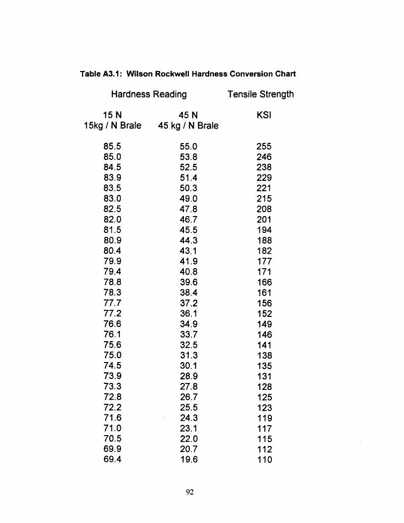
Table A3.1: Wilson Rockwell Hardness Conversion Chart
Hardness Reading
15N15kg / N Brale
85.585.084.583.983.583.082.582.081.580.980.479.979.478.878.377.777.276.676.175.675.074.573.973.372.872.271.671.070.569.969.4
Tensile Strength
45 N45 kg / N Brale
55.053.852.551.450.349.047.846.745.544.343.141.940.839.638.437.236.134.933.732.531.330.128.927.826.725.524.323.122.020.719.6
92
KSI
255246238229221215208201194188182177171
166161156152149146141138135131128125123119117115112110
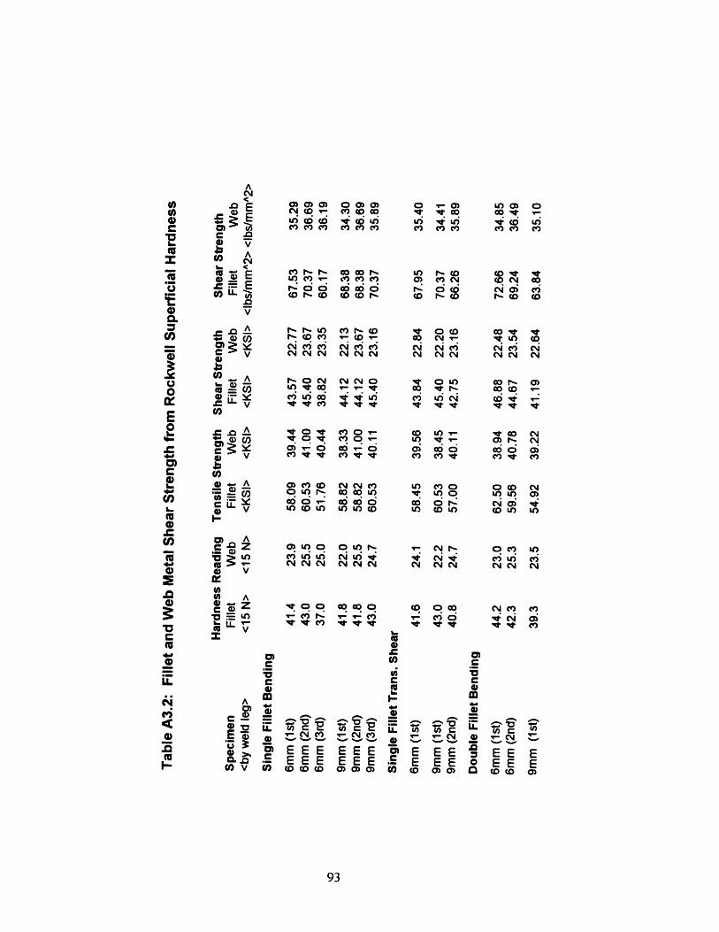
ACYEUV) n' cna MQ OQO a a ) o) Q uOo) N D D ) - <C 0 0 V _
I _ e c~ e c s e~ eq e t e
e V9, ,~ rrdc E ~ v 'f' dv iN u nN ,e C cn C3 CIs wi C6 (6 4 (6 L6 4 6 Cr) ) X 4> Qe E eC a V m c n n
*e,> -E E > o o eo , o I' (o (i 0 Ce-..cV) I- r) C,', W, r-. CD C v
,e . LO(. (, r",. M (c)C0 CY G. (0 E c c i --g Cj o Ci
U= -nI > s S sO S O F O -O CD'IE~~~~~~~~~~~~~c' v
< - n cn t- V) (r) I (. o O N' C. o ·_n ca V) Ne <M A V 0 CD C v e
cu c~ cli ~j ~~ cj you3 co r,.UI - NO N N O O L) 00 f 0)
rOV U) 0 V U) ce) Ul er CO Nv 1* V cn v vs
E V
2~~~~ A * CD to O O CY tX _4 C 1 4L t ° st X o u Z t .: C 1NcC ~~~~~~3 O ~~~~~~~ V)gn ,3 w~'
v 3 ~ ~ Or 14 ~1. O4) CC1 ¢0 cO ~r ur3CD 3: C:d d d oi dd d oC S Y ( I) O Y 0- 0 CO 'L O) _ A n o uA C) N CD 0 Y 0 0 CD W N)-5 CR 04 PI O i 0404 0C0 4 Q o
le E 0 0 0 C o E I
r s Z O C) O O U) C _ CD LO O CD U)
X X > -) e ) LO ) N ) t N U)o r- _ CN N CY N CY CY N N N CY CY CYV
) Qe v Z t o oo o 0 o o o Nm UL) vi tz vi o6
O (P V
C I~~~~~~~4)~~~~~~~~~~~Q
LL r C E
*"i m ; -o L _ e U r 2 r
Q) E -6 vo - E, ct _ ) t-Q 0> v <0 O O OEEE EE E EE E E0 erB~~CL E EE E E E 0 E E
C V)~~C v CO D D 0) <o CD CO CD ) ) 9 CO CO 0
93
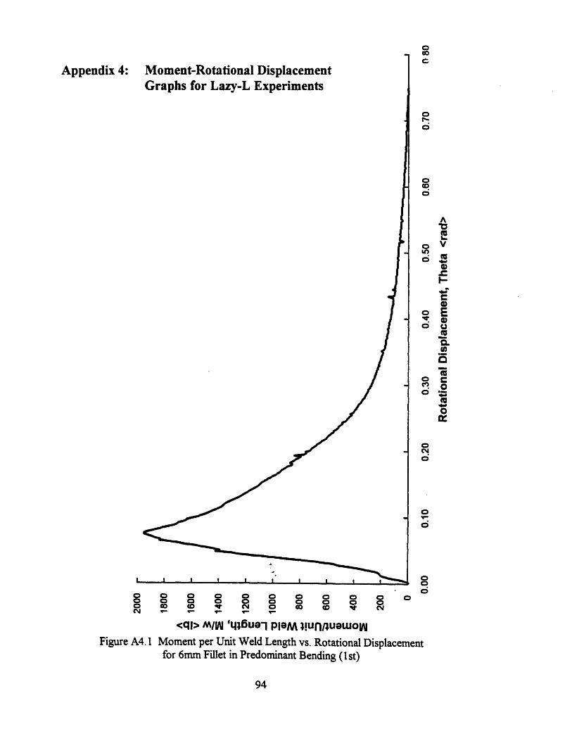
O o 0 0 0 0 0 0 00 0 0 0 0 0 0 0 0 0cm T- T- y-
<ql> M/W 'q46ue'l PlaM !unruwuowow
Figure A4. 1 Moment per Unit Weld Length vs. Rotational Displacementfor 6mm Fillet in Predominant Bending (st)
94
Appendix 4:c0o
o
Ic.U,
oEo VLO
o ECo E
o .
0 r0
o
o
00
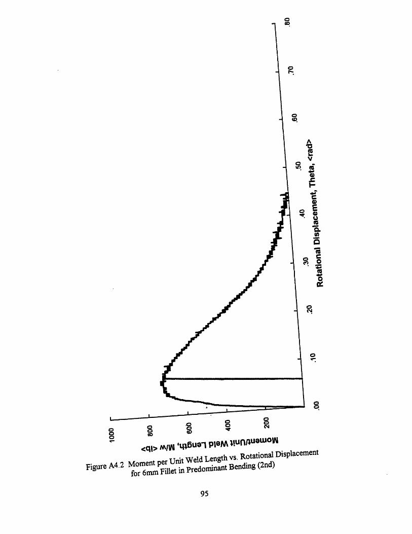
0or-
(D*
A
*l(a
I-C
toI)
0c·. 10
WC
CCM
0
o
0 0
o o0 o
o- -- tre.*A ~iunnua wc
Figure A4.2
c<q> MIW 'Du- IlJUri IV ,_:, ,,- -
Moment per Unit Weld Length vs. Rotational Displacement
for 6mm Fillet in Predominant Bending (2nd)
95
ok
)IN
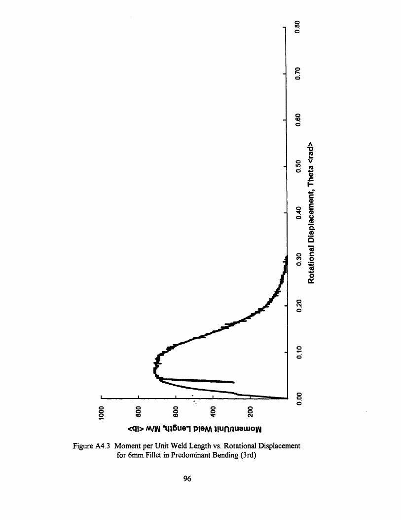
o0
O(o
AO(l
oV* Vo
0
c0o E
Qd:.
o Ce. O
co
o
o0
0
o0
0CD0o o 0 0 0
0 co co no
Fql> m/W 't46ueU n PlaM munnuatuo
Figure A4.3 Moment per Unit Weld Length vs. Rotational Displacementfor 6mm Fillet in Predominant Bending (3rd)
96
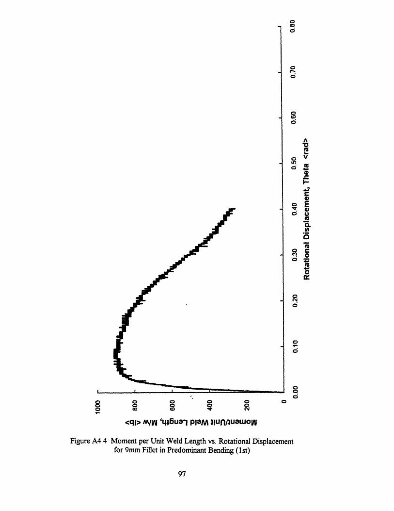
0co
Or-.
0
I-
)
.0
O0O
acS
00
0o 0 i ~
<ql> M1AN ,6Ui p1GM m!unlRu tu° w
Figure A4.4 Moment per Unit Weld Length vs. Rotational Displacementfor 9Fm Fillet in Predominant Bending ( st)for 9mm fi9l
97
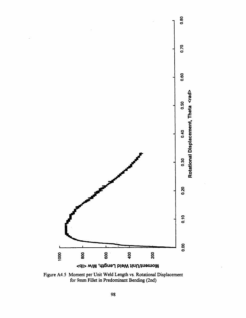
01^
0
0o
0
CI A
Ia
o E
o oaC
00UO0-0
o
o
oo
o00 0 0 o 0 0o 0 0 o o0 co cD N
<ql> M/Wl ',6§uel PleM m!unnuawow
Figure A4.5 Moment per Unit Weld Length vs. Rotational Displacementfor 9mm Fillet in Predominant Bending (2nd)
98
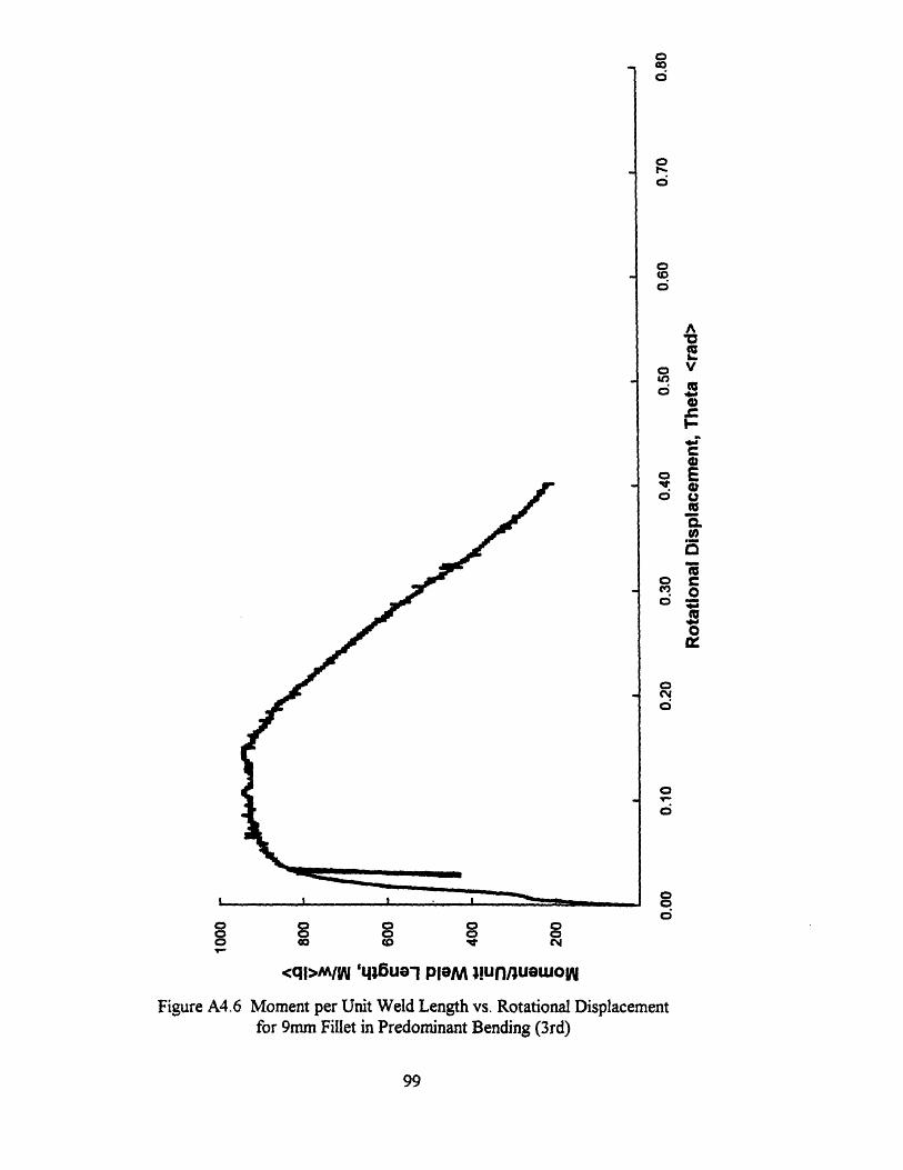
oGo
0
0
0to0
a
Et
r-00
o
o
OS:0
o 0
<ql>MlIWy ,lue pleM !UnlueuWOWFiure A4.6 Moment per Unit Weld Length Vs. Rotational Displacementfor 9mm Fillet inPredominant Bending (3rd)
99
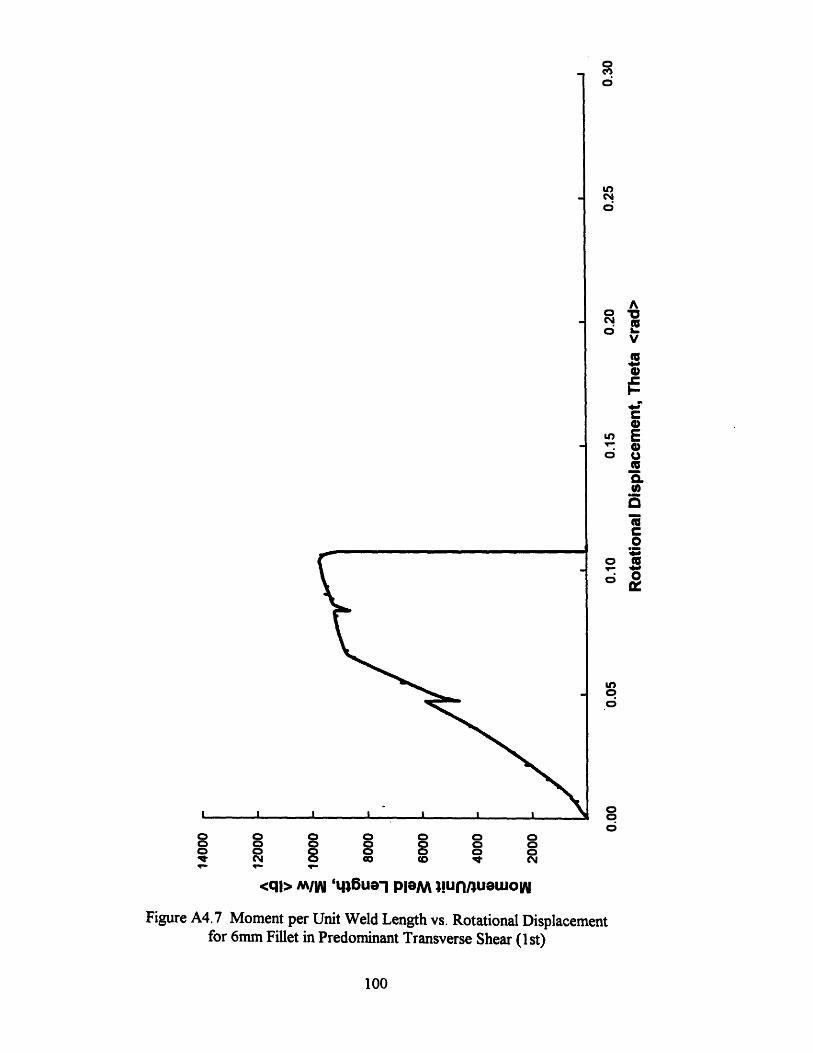
o o 0o 0 oI N 0O
o 0 0 0o o 0 ao c I NCD (0 (C i
<ql> mW '46ua'l PleM !UnRluewow
Figure A4.7 Moment per Unit Weld Length vs. Rotational Displacementfor 6mm Fillet in Predominant Transverse Shear (st)
100
O
d
V
0
I-
(No EEQ.o U(n
00
0
o 0
oo
o
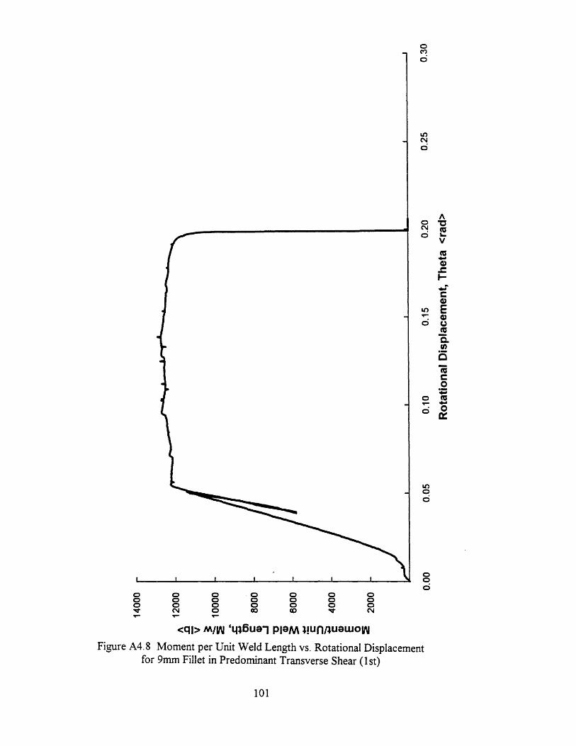
0eno
o
0o 0o M
V
I-
e)
o
C0
o E
u,0o0%U *o.
Lo
o 0 0 -0 0 0 00 0 0 0 a a 0
<ql> M/W '4l6ua- PlaM !iunnuOuwow
Figure A4.8 Moment per Unit Weld Length vs. Rotational Displacementfor 9mm Fillet in Predominant Transverse Shear (lst)
101
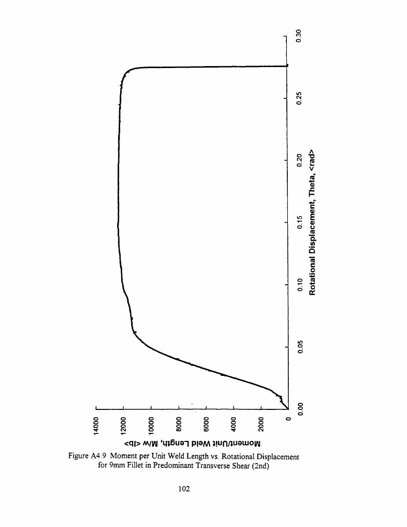
o o oo 0o o o o
114, 0
o o o 0o o o o
c tO CM
O
<ql> M/W ',86ua'l PlaM !unnuauow
Figure A4.9 Moment per Unit Weld Length vs. Rotational Displacementfor 9mm Fillet in Predominant Transverse Shear (2nd)
102
0c
UOC
o 1
V
rl-
I-
*rC-
- E. 0
(U
o
o
oo
o0
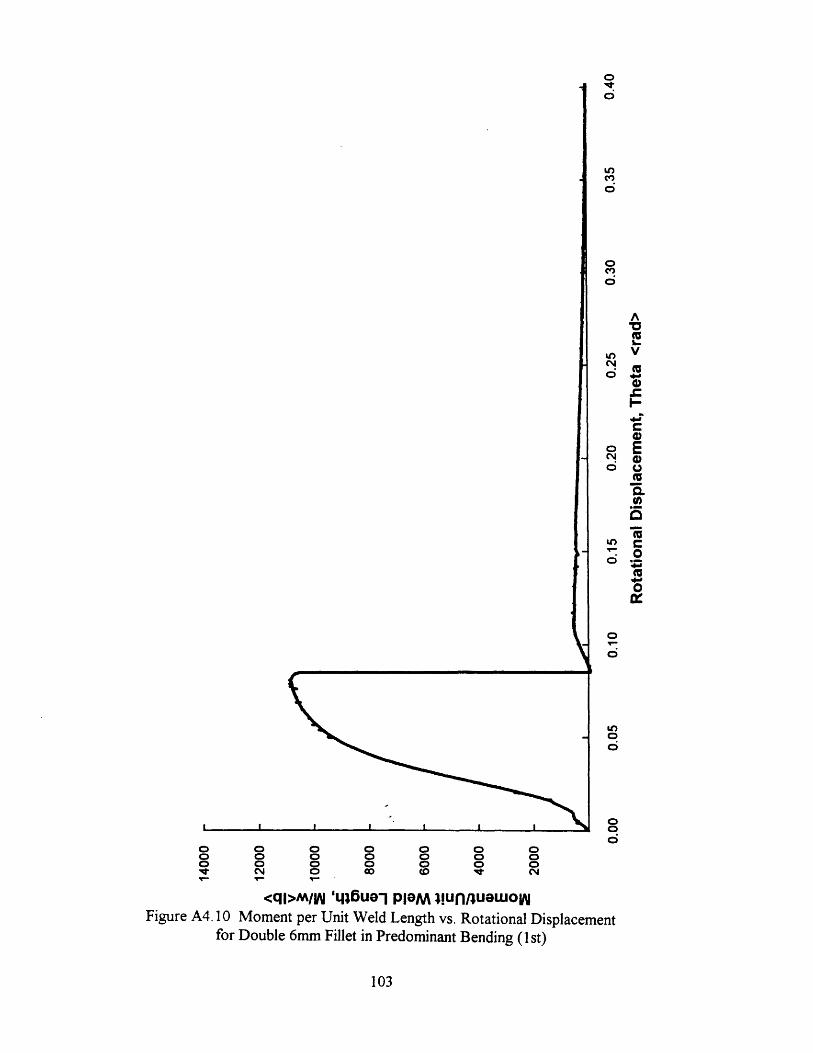
o o oo o oo o ot CN or ro 0 o 0o 0 o oo o C 0co co t N
<ql>m/W 'Ll6fiui PleM !unfluouwowFigure A4. 10 Moment per Unit Weld Length vs. Rotational Displacement
for Double 6mm Fillet in Predominant Bending (1 st)
103
00
u)
,
0
VC 0
I-4)
.Oo EUo
o
00
6O
u,
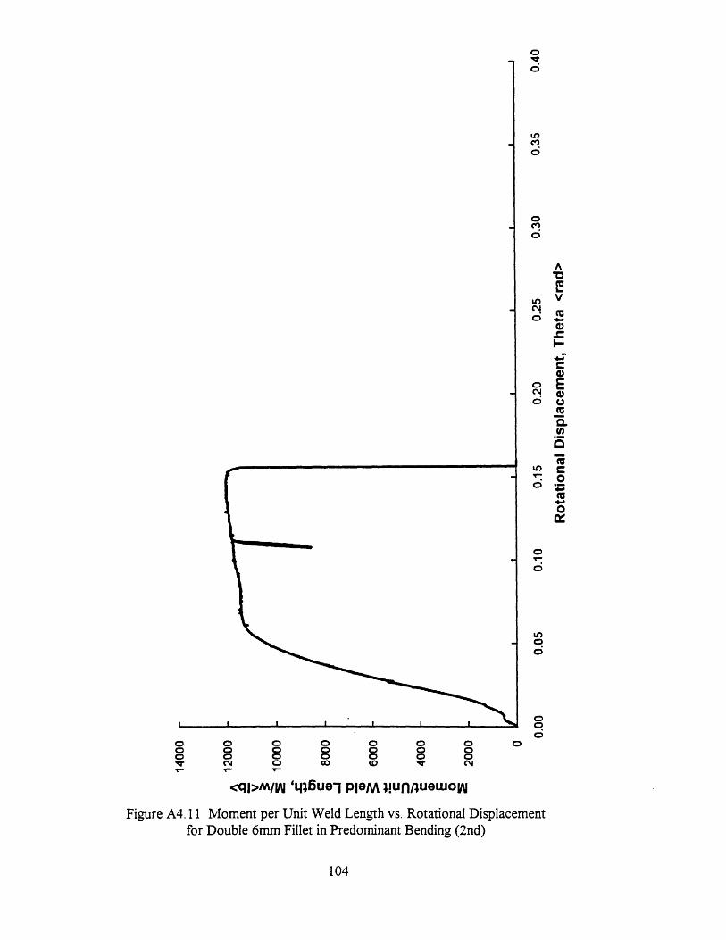
o 0 0 0 0 0 O 00 0 0 0 0 0 00 0 0 0 0 0 0w CY 0 cD CN
<ql>M// 'tluale PaM !unnuuuo
Figure A4. 11 Moment per Unit Weld Length vs. Rotational Displacementfor Double 6mm Fillet in Predominant Bending (2nd)
104
Ou0
LOCIZ
0
o*3
oc 0)A
I=LO V
C4 M
O Q
'a(3
o_
0
060
0
00
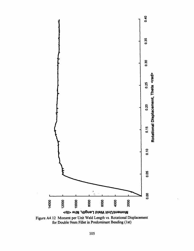
00
00
V(V
I-
O UiO.Q)
C]
0
0n =
0u,
P
0
eO
O
do 0 0 0 0 0 00 0 0 0 0 0 0o0 0 0 0 0 0N ql O 'O u O l No
<qi> M/W '6Ue PM !unnua wou
Figure A4.12 Moment per Unit Weld Length vs. Rotational Displacementfor Double 9mm Fillet in Predominant Bending (lst)
105
Appendix 5: Test Machine Calibration and Data Acquisition
The Lazy-L test experiments were conducted on an Instron 1125 universal testing
machine in Mechanical Behavior of Material Lab at the M.I.T. Department of
Mechanical Engineering. The following is provided as a reference for future tests at this
and similar facilities.
A5.1 Machine Setup
After a fifteen minute warm-up, the Instron 1125 with 20,000 lb. load cell must be
zeroed and balanced. Switch the load shunt resistance to OFF and select polarity on the
load cell amplifier for compression. With the test grips in place, hold the zero button on
the load cell amplifier and adjust the adjacent dial until the voltmeter reads 0.00. Release
the zero button and adjust the load cell amplifier balance dials (coarse, medium, fine) until
the voltmeter again reads 0.00. This procedure sets the reference of the bridge and
compensates for the static load of the test fixtures.
Next, the load must be calibrated. The Instron 1125 is equipped with shunt
resistors which simulate a range of loads. Table (AS. 1) illustrates the equivalent load of
the available shunt resistors for the 20,000 lb. load cell. The voltmeter range is 0-10
Volts; therefore a convenient scale is 1V = 2000 lb. Notice from Table (AS. 1) that the
100,000 Ohms resistor simulates a load of 2916 lb. in compression. The desired voltmeter
reading for this resistor is found as:
29161b. 1.46V (A5. 1)20001b./Volt
106
With the 100K shunt resistor selected, adjust the fill scale load dial to a low setting for
high resolution of the load voltmeter scaling. Adjust the calibration dial until the
voltmeter reads 1.46 but do not press the adjacent calibration button. Return the shunt
resistance to OFF and check the balance. Adjust the balance until the voltmeter reads
0.00. Compute the expected voltmeter reading for adjacent shunt resistors and check that
the scaling is tuned at several different loads. When the scaling is well tuned, the
voltmeter reading does not change when the fill scale load dial is returned to 20,000 lb.
A5.2 Data Acquisition
Details of the data acquisition software are omitted. Note, however, that Labtech
Notebook treats both the load and displacement as calculated variables. Notebook
samples the voltmeter output at a rate selected by the user to provide good resolution at
the selected crosshead speed. The load is computed as the product of the voltmeter
readings and a factor entered by the user. For the example given, this factor is 2000.
Displacement is computed as the product of elapsed time and the crosshead speed entered
by the user. Since the displacement in the Lazy-L tests are small, a convenient
displacement scale is millimeters. For crosshead speed selected as 0.05 inches/minute, the
appropriate factor is 0.2117 mm/s. Test duration is a function of the crosshead speed and
specimen size. Test times for the pilot experiment at the speed indicated averaged roughly
300 seconds.
107
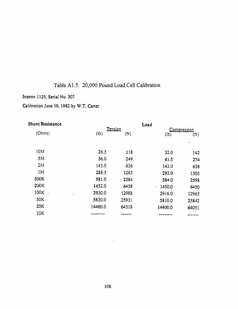
Table A1.5: 20,000 Pound Load Cell Calibration
Inslron 1125, Serial No. 307
Calibration June 19, 1982 by W.T. Carter
Shunt Resistance LoadTension Compression
(Ohms) (lb) (N) (lb) (N)
10M 26.5 118 32.0 1425M 56.0 249 61.5 2742M 143.0 636 143.0 6581M 288.5 1283 293.0 1303
500K 581.0 2584 584.0 2598200K 1452.0 6458 1450.0 6450100K 2930.0 12988 2916.0 1296550K 5830.0 25931 5810.0 2584220K 14460.0 64318 14400.0 6405110K----- .
108
Related Documents