220 WEIGHT INDICATING INSTRUMENT QUICK SETUP GUIDE 8200-M317-O1 Rev B PO BOX 151 • WEBB CITY, MO 64870 Printed in USA 03/02 PH (417) 673-4631 • FAX (417) 673-5001 http://www.cardinalscale.com

Welcome message from author
This document is posted to help you gain knowledge. Please leave a comment to let me know what you think about it! Share it to your friends and learn new things together.
Transcript

220
WEIGHT INDICATING INSTRUMENT
QUICK SETUP GUIDE
8200-M317-O1 Rev B PO BOX 151 • WEBB CITY, MO 64870 Printed in USA 03/02 PH (417) 673-4631 • FAX (417) 673-5001 http://www.cardinalscale.com
1
TABLE OF CONTENTS INTRODUCTION - - - - - - - - - - - - - - - - - - - - - - - - - - - - - - - - - - - - - - - - - - - - - - - - - - Page 2 FCC COMPLIANCE STATEMENT - - - - - - - - - - - - - - - - - - - - - - - - - - - - - - - - - - - - - Page 2 SPECIFICATIONS - - - - - - - - - - - - - - - - - - - - - - - - - - - - - - - - - - - - - - - - - - - - - - - - - Page 3
Certifications - - - - - - - - - - - - - - - - - - - - - - - - - - - - - - - - - - - - - - - - - - - - - - - - - - - Page 3 SITE PREPARATION REQUIREMENTS - - - - - - - - - - - - - - - - - - - - - - - - - - - - - - - - - Page 4 INSTALLATION - - - - - - - - - - - - - - - - - - - - - - - - - - - - - - - - - - - - - - - - - - - - - - - - - - - Page 5
Mounting the 220 - - - - - - - - - - - - - - - - - - - - - - - - - - - - - - - - - - - - - - - - - - - - - - Page 5 Load Cell Connection - - - - - - - - - - - - - - - - - - - - - - - - - - - - - - - - - - - - - - - - - - - Page 5 Load Cell Connections With Over 30 Feet Of Cable - - - - - - - - - - - - - - - - - - - - - Page 6 Load Cell Cable Shield Wire Connection - - - - - - - - - - - - - - - - - - - - - - - - - - - - - Page 6 Serial I/O Cable Installation - - - - - - - - - - - - - - - - - - - - - - - - - - - - - - - - - - - - - - Page 6 Optically Isolated Inputs - - - - - - - - - - - - - - - - - - - - - - - - - - - - - - - - - - - - - - - - - Page 7 AC Input Relay Board(s) - - - - - - - - - - - - - - - - - - - - - - - - - - - - - - - - - - - - - - - - Page 7 Preset Weight Comparator/Checkweigher Logic Level Output - - - - - - - - - - - - - - Page 8 AC Output Relay Board(s) - - - - - - - - - - - - - - - - - - - - - - - - - - - - - - - - - - - - - - - Page 9 Re-Installing The Rear Panel - - - - - - - - - - - - - - - - - - - - - - - - - - - - - - - - - - - - - Page 9 I/O Functions and Relay Box Cable Wire To Relay Number Tables- - - - - - - - - - - Page 10 220 Main PCB (Figure No. 7) - - - - - - - - - - - - - - - - - - - - - - - - - - - - - - - - - - - - - Page 11 Main PCB Jumpers - - - - - - - - - - - - - - - - - - - - - - - - - - - - - - - - - - - - - - - - - - - - Page 12
KEYPAD FUNCTIONS - - - - - - - - - - - - - - - - - - - - - - - - - - - - - - - - - - - - - - - - - - - - - - Page 13 SETUP AND CALIBRATION - - - - - - - - - - - - - - - - - - - - - - - - - - - - - - - - - - - - - - - - - - Page 15 CALIBRATION "C" NUMBERS - - - - - - - - - - - - - - - - - - - - - - - - - - - - - - - - - - - - - - - - Page 22 SETUP REVIEW - - - - - - - - - - - - - - - - - - - - - - - - - - - - - - - - - - - - - - - - - - - - - - - - - - Page 23 TROUBLESHOOTING - - - - - - - - - - - - - - - - - - - - - - - - - - - - - - - - - - - - - - - - - - - - - - Page 25
Error Codes - - - - - - - - - - - - - - - - - - - - - - - - - - - - - - - - - - - - - - - - - - - - - - - - - - Page 25 Before You Call Service - - - - - - - - - - - - - - - - - - - - - - - - - - - - - - - - - - - - - - - - - Page 28
CALIBRATION SEAL INSTALLATION - - - - - - - - - - - - - - - - - - - - - - - - - - - - - - - - - - - Page 28 EUROPEAN DECLARATION OF CONFORMITY - - - - - - - - - - - - - - - - - - - - - - - - - - - Page 29
SERIAL NUMBER _____________________
DATE OF PURCHASE _________________
PURCHASED FROM __________________
____________________________________
____________________________________
____________________________________ RETAIN THIS INFORMATION FOR FUTURE USE
PRECAUTIONS
Before using this instrument, read this manual and pay special attention to all "WARNING" symbols:
IMPORTANT
ELECTRICALWARNING
STATIC SENSITVE

2
INTRODUCTION Thank you for purchasing the Cardinal 220 Weight Indicating Instrument. This instrument was built with quality and reliability at our factory in Webb City, Missouri. The 220 incorporates the latest in digital technology and innovative features for the weighing industry. Configuration and upgrades can easily be performed in the field, while still maintaining the rigid control the most demanding installations require. This flexibility insures the 220 will be able to meet your weight indicating needs for years to come. The purpose of this guide is to provide you with a guide through installation and calibration of your new weight indicating instrument. Please read it thoroughly before attempting to install your 220 Indicator and keep it handy for future reference. For complete details on the features, functions and programming of your 220 Indicator, refer to the 220 Weight Indicating Instrument Technical and Operation Manual, 8200-M502-O1.
FCC COMPLIANCE STATEMENT WARNING! This equipment generates, uses and can radiate radio frequency and if not installed and used in accordance with the instruction manual, may cause interference to radio communications. It has been tested and found to comply with the limits for a Class A computing device pursuant to Subpart J of Part 15 of FCC rules, which are designed to provide reasonable protection against such interference when operated in a commercial environment. Operation of this equipment in a residential area may cause interference in which case the user will be responsible to take whatever measures necessary to correct the interference. You may find the booklet “How to Identify and Resolve Radio TV Interference Problems” prepared by the Federal Communications Commission helpful. It is available from the U.S. Government Printing Office, Washington, D.C. 20402. Stock No. 001-000-00315-4.
All rights reserved. Reproduction or use, without expressed written permission, of editorial or pictorial content, in any manner, is prohibited. No patent liability is assumed with respect to the use of the information contained herein. While every precaution has been taken in the preparation of this manual, the Seller assumes no responsibility for errors or omissions. Neither is any liability assumed for damages resulting from use of the information contained herein. All instructions and diagrams have been checked for accuracy and ease of application; however, success and safety in working with tools depend to a great extent upon the individual accuracy, skill and caution. For this reason the Seller is not able to guarantee the result of any procedure contained herein. Nor can they assume responsibility for any damage to property or injury to persons occasioned from the procedures. Persons engaging the procedures do so entirely at their own risk.
3
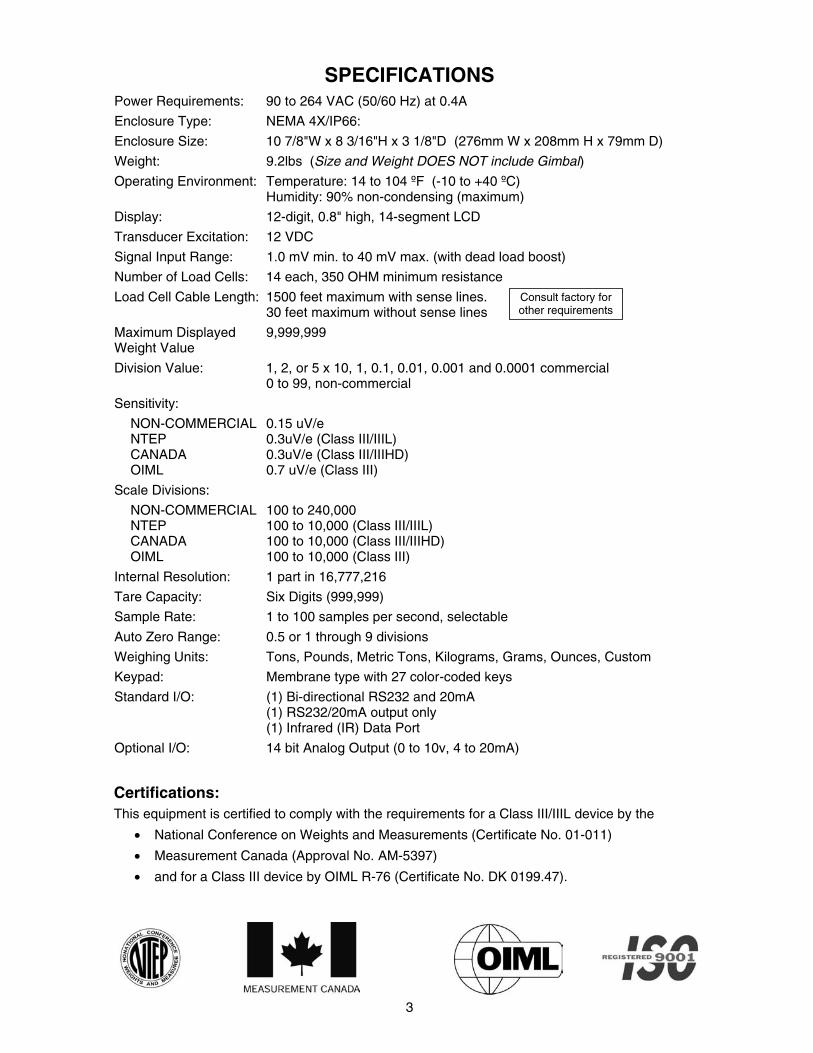
SPECIFICATIONS Power Requirements: 90 to 264 VAC (50/60 Hz) at 0.4A
Enclosure Type: NEMA 4X/IP66:
Enclosure Size: 10 7/8"W x 8 3/16"H x 3 1/8"D (276mm W x 208mm H x 79mm D)
Weight: 9.2lbs (Size and Weight DOES NOT include Gimbal)
Operating Environment: Temperature: 14 to 104 ºF (-10 to +40 ºC) Humidity: 90% non-condensing (maximum)
Display: 12-digit, 0.8" high, 14-segment LCD
Transducer Excitation: 12 VDC
Signal Input Range: 1.0 mV min. to 40 mV max. (with dead load boost)
Number of Load Cells: 14 each, 350 OHM minimum resistance
Load Cell Cable Length: 1500 feet maximum with sense lines. 30 feet maximum without sense lines
Maximum Displayed Weight Value
9,999,999
Division Value: 1, 2, or 5 x 10, 1, 0.1, 0.01, 0.001 and 0.0001 commercial 0 to 99, non-commercial
Sensitivity:
NON-COMMERCIAL NTEP CANADA OIML
0.15 uV/e 0.3uV/e (Class III/IIIL) 0.3uV/e (Class III/IIIHD) 0.7 uV/e (Class III)
Scale Divisions:
NON-COMMERCIAL NTEP CANADA OIML
100 to 240,000 100 to 10,000 (Class III/IIIL) 100 to 10,000 (Class III/IIIHD) 100 to 10,000 (Class III)
Internal Resolution: 1 part in 16,777,216
Tare Capacity: Six Digits (999,999)
Sample Rate: 1 to 100 samples per second, selectable
Auto Zero Range: 0.5 or 1 through 9 divisions
Weighing Units: Tons, Pounds, Metric Tons, Kilograms, Grams, Ounces, Custom
Keypad: Membrane type with 27 color-coded keys
Standard I/O: (1) Bi-directional RS232 and 20mA (1) RS232/20mA output only (1) Infrared (IR) Data Port
Optional I/O: 14 bit Analog Output (0 to 10v, 4 to 20mA)
Certifications: This equipment is certified to comply with the requirements for a Class III/IIIL device by the
• National Conference on Weights and Measurements (Certificate No. 01-011)
• Measurement Canada (Approval No. AM-5397)
• and for a Class III device by OIML R-76 (Certificate No. DK 0199.47).
Consult factory for other requirements

4
SITE PREPARATION REQUIREMENTS The 220 Weight Indicator is a precision weight measuring instrument. As with any precision instrument, it requires an acceptable environment to operate at its peak performance and reliability. This section is provided to assist you in obtaining such an environment. Electrical Power The 220 indicators has been designed to operate from 90 to 264 VAC at 50/60 Hz. Note that a special order is not required for operation at 230 VAC.
CAUTION! - To avoid electrical hazard and possible damage to the indicator, DO NOT, under any circumstance, cut, remove, alter, or in any way bypass the power cord grounding prong.
On models requiring 230 VAC power, it is the responsibility of the customer to have a qualified electrician install the proper power cord plug which conforms to national electrical codes and local codes and ordinances. The power outlet for the indicator should be on a separate circuit from the distribution panel. This circuit should be dedicated to the exclusive use of the indicator. The wiring should conform to national and local electrical codes and ordinances and should be approved by the local inspector to assure compliance. To prevent electrical noise interference, make certain all other wall outlets for use with air conditioning and heating equipment, lighting or other equipment with heavily inductive loads, such as welders, motors and solenoids are on circuits separate from the indicator. Many of these disturbances originate within the building itself and can seriously affect the operation of the instrument. These sources of disturbances must be identified and steps must be taken to prevent possible adverse effects on the instrument. Examples of available alternatives include isolation transformers, power regulators, uninterruptible power supplies, or simple line filters.
Environmental In general, the 220 Indicator will perform well within a temperature range of 14 to 104 °F (-10 to +40 °C ). In order to keep cooling requirements to a minimum, the indicator should be placed out of direct sunlight and to provide adequate air circulation, keep the area around the indicator clear. Make certain the instrument is not directly in front of a heating or cooling vent. Such a location will subject the indicator to sudden temperature changes which may result in unstable weight readings. Insure that the indicator has good, clean AC power and is properly grounded. In areas subject to lightning strikes, additional protection to minimize lightning damage, such as surge suppressors, should be installed.
CAUTION! When in parallel runs, locate Load Cell cables a minimum of 24" away from all AC wiring.
5
CAUTION! Disconnect any external load cell power supply before connecting load cells to the instrument. Failure to do so will result in permanent damage to the instrument.
INSTALLATION Before beginning installation of your Model 220 Weight Indicating Instrument, make certain that the instrument has been received in good condition. Carefully remove the instrument from the shipping carton and inspect it for any evidence of damage (such as exterior dents or scratches) that may have taken place during shipment. Keep the carton and packing material for return shipment if it should become necessary. It is the responsibility of the purchaser to file all claims for any damages or loss incurred during transit.
Mounting the 220
NOTE! Should your 220 indicator come already installed on a scale, the following information describing the installation of the instrument does not apply.
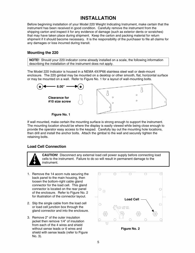
The Model 220 Indicator is housed in a NEMA 4X/IP66 stainless steel wall or desk-mount enclosure. The 220 gimbal may be mounted on a desktop or other smooth, flat, horizontal surface or may be mounted on a wall. Refer to Figure No. 1 for a layout of wall-mounting bolts.
6.00"
Figure No. 1 If wall mounted, make certain the mounting surface is strong enough to support the instrument. The mounting location should be where the display is easily viewed while being close enough to provide the operator easy access to the keypad. Carefully lay out the mounting hole locations, then drill and install the anchor bolts. Attach the gimbal to the wall and securely tighten the retaining bolts.
Load Cell Connection
1. Remove the 14 acorn nuts securing the back panel to the main housing, then loosen the bottom-right cable gland connector for the load cell. This gland connector is located on the rear panel of the enclosure. Refer to Figure No. 2 for illustration of the connector layout.
2. Slip the single cable from the load cell
or load cell junction box through the gland connector and into the enclosure.
3. Remove 2" of the outer insulation
jacket then remove 1/4" of insulation from each of the 4 wires and shield without sense leads or 6 wires and Figure No. 2 shield with sense leads (refer to Figure No. 3).
Clearance for #10 size screw
Load Cell
6
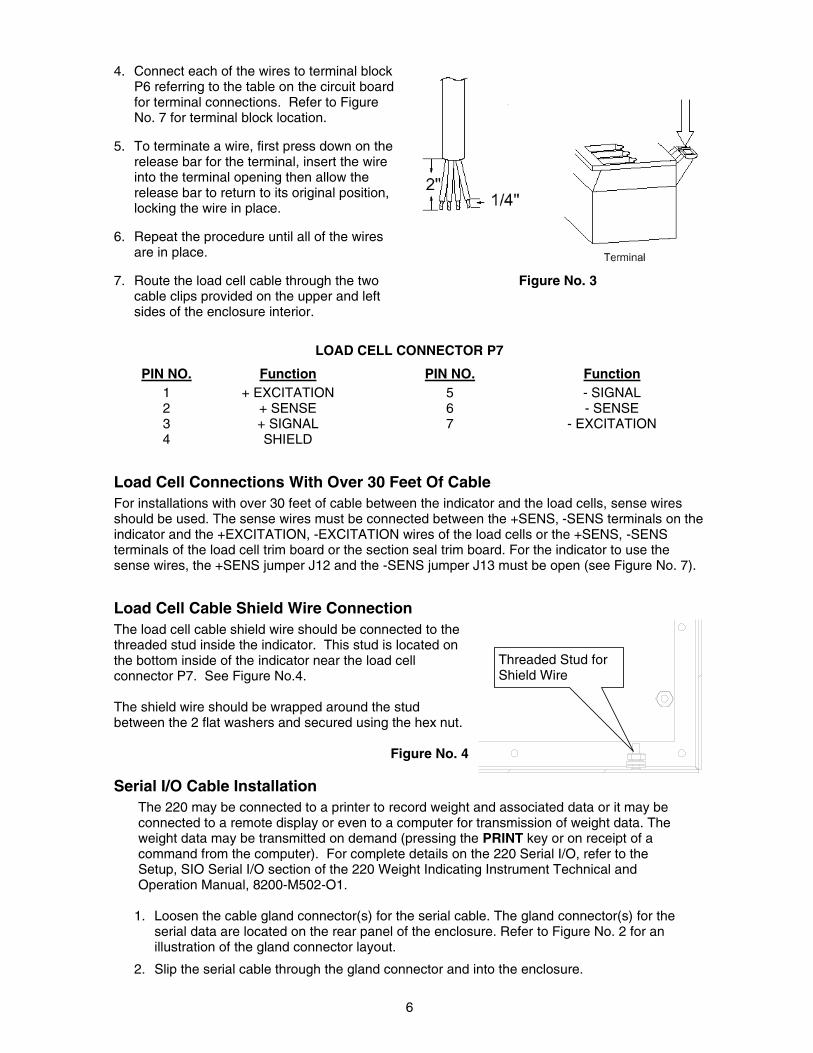
4. Connect each of the wires to terminal block P6 referring to the table on the circuit board for terminal connections. Refer to Figure No. 7 for terminal block location.
5. To terminate a wire, first press down on the
release bar for the terminal, insert the wire into the terminal opening then allow the release bar to return to its original position, locking the wire in place.
6. Repeat the procedure until all of the wires are in place.
7. Route the load cell cable through the two Figure No. 3
cable clips provided on the upper and left sides of the enclosure interior.
LOAD CELL CONNECTOR P7
PIN NO. Function PIN NO. Function 1 + EXCITATION 5 - SIGNAL 2 + SENSE 6 - SENSE 3 + SIGNAL 7 - EXCITATION 4 SHIELD
Load Cell Connections With Over 30 Feet Of Cable For installations with over 30 feet of cable between the indicator and the load cells, sense wires should be used. The sense wires must be connected between the +SENS, -SENS terminals on the indicator and the +EXCITATION, -EXCITATION wires of the load cells or the +SENS, -SENS terminals of the load cell trim board or the section seal trim board. For the indicator to use the sense wires, the +SENS jumper J12 and the -SENS jumper J13 must be open (see Figure No. 7).
Load Cell Cable Shield Wire Connection The load cell cable shield wire should be connected to the threaded stud inside the indicator. This stud is located on the bottom inside of the indicator near the load cell connector P7. See Figure No.4. The shield wire should be wrapped around the stud between the 2 flat washers and secured using the hex nut.
Figure No. 4 Serial I/O Cable Installation
The 220 may be connected to a printer to record weight and associated data or it may be connected to a remote display or even to a computer for transmission of weight data. The weight data may be transmitted on demand (pressing the PRINT key or on receipt of a command from the computer). For complete details on the 220 Serial I/O, refer to the Setup, SIO Serial I/O section of the 220 Weight Indicating Instrument Technical and Operation Manual, 8200-M502-O1.
1. Loosen the cable gland connector(s) for the serial cable. The gland connector(s) for the
serial data are located on the rear panel of the enclosure. Refer to Figure No. 2 for an illustration of the gland connector layout.
2. Slip the serial cable through the gland connector and into the enclosure.
Threaded Stud for Shield Wire
7
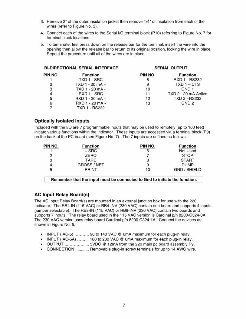
3. Remove 2" of the outer insulation jacket then remove 1/4" of insulation from each of the wires (refer to Figure No. 3).
4. Connect each of the wires to the Serial I/O terminal block (P10) referring to Figure No. 7 for terminal block locations.
5. To terminate, first press down on the release bar for the terminal, insert the wire into the opening then allow the release bar to return to its original position, locking the wire in place. Repeat the procedure until all of the wires are in place.
BI-DIRECTIONAL SERIAL INTERFACE SERIAL OUTPUT
PIN NO. Function PIN NO. Function 1 TXD 1 - SRC 8 RXD 1 - RS232 2 TXD 1 - 20 mA + 9 TXD 1 – CTS 3 TXD 1 - 20 mA - 10 GND 1 4 RXD 1 - SRC 11 TXD 2 - 20 mA Active 5 RXD 1 - 20 mA + 12 TXD 2 - RS232 6 RXD 1 - 20 mA - 13 GND 2 7 TXD 1 - RS232
Optically Isolated Inputs Included with the I/O are 7 programmable inputs that may be used to remotely (up to 100 feet) initiate various functions within the indicator. These inputs are accessed via a terminal block (P9) on the back of the PC board (see Figure No. 7). The 7 inputs are defined as follows:
PIN NO. Function PIN NO. Function 1 + SRC 6 Not Used 2 ZERO 7 STOP 3 TARE 8 START 4 GROSS / NET 9 DUMP 5 PRINT 10 GND / SHIELD
Remember that the input must be connected to Gnd to initiate the function.
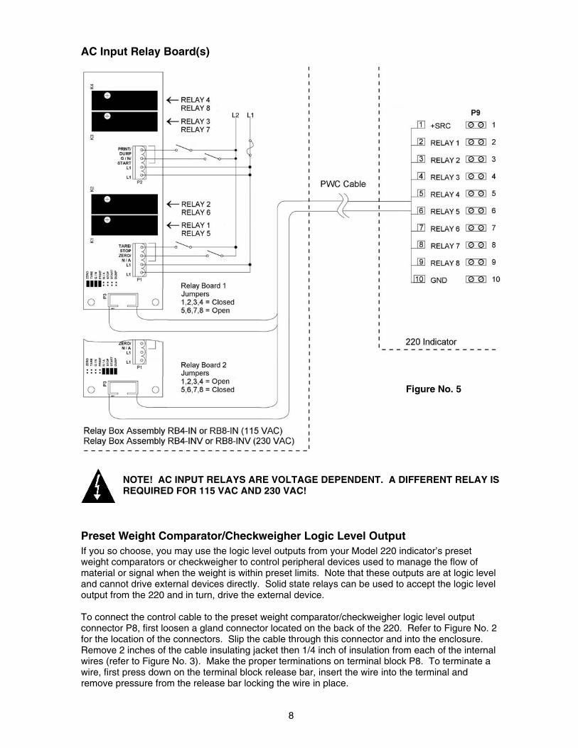
AC Input Relay Board(s) The AC Input Relay Board(s) are mounted in an external junction box for use with the 220 Indicator. The RB4-IN (115 VAC) or RB4-INV (230 VAC) contain one board and supports 4 inputs (jumper selectable). The RB8-IN (115 VAC) or RB8-INV (230 VAC) contain two boards and supports 7 inputs. The relay board used in the 115 VAC version is Cardinal p/n 8200-C324-0A. The 230 VAC version uses relay board Cardinal p/n 8200-C324-1A. Connect the devices as shown in Figure No. 5.
• INPUT (IAC-5) ……….. 90 to 140 VAC @ 6mA maximum for each plug-in relay. • INPUT (IAC-5A) ……... 180 to 280 VAC @ 6mA maximum for each plug-in relay. • OUTPUT ..…………..... 5VDC @ 12mA from the 220 main pc board assembly P9. • CONNECTION ............ Removable plug-in screw terminals for up to 14 AWG wire.
8
AC Input Relay Board(s)
NOTE! AC INPUT RELAYS ARE VOLTAGE DEPENDENT. A DIFFERENT RELAY IS REQUIRED FOR 115 VAC AND 230 VAC!
Preset Weight Comparator/Checkweigher Logic Level Output If you so choose, you may use the logic level outputs from your Model 220 indicator’s preset weight comparators or checkweigher to control peripheral devices used to manage the flow of material or signal when the weight is within preset limits. Note that these outputs are at logic level and cannot drive external devices directly. Solid state relays can be used to accept the logic level output from the 220 and in turn, drive the external device. To connect the control cable to the preset weight comparator/checkweigher logic level output connector P8, first loosen a gland connector located on the back of the 220. Refer to Figure No. 2 for the location of the connectors. Slip the cable through this connector and into the enclosure. Remove 2 inches of the cable insulating jacket then 1/4 inch of insulation from each of the internal wires (refer to Figure No. 3). Make the proper terminations on terminal block P8. To terminate a wire, first press down on the terminal block release bar, insert the wire into the terminal and remove pressure from the release bar locking the wire in place.
Figure No. 5
9
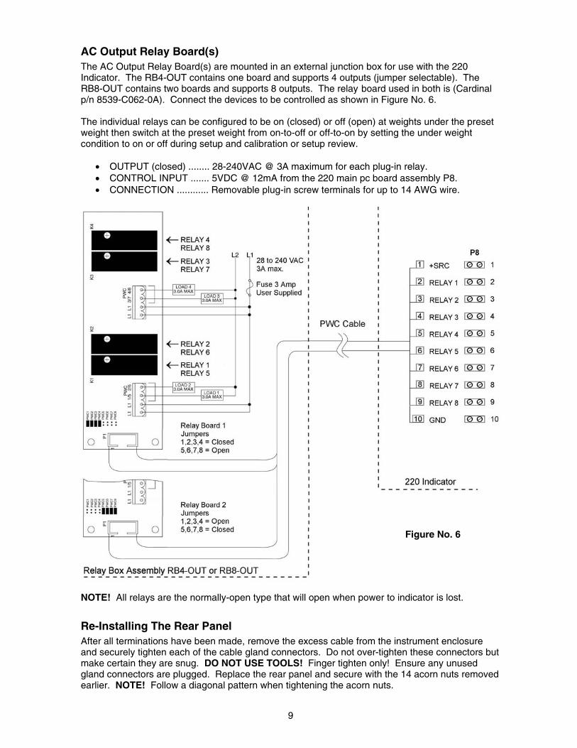
AC Output Relay Board(s) The AC Output Relay Board(s) are mounted in an external junction box for use with the 220 Indicator. The RB4-OUT contains one board and supports 4 outputs (jumper selectable). The RB8-OUT contains two boards and supports 8 outputs. The relay board used in both is (Cardinal p/n 8539-C062-0A). Connect the devices to be controlled as shown in Figure No. 6. The individual relays can be configured to be on (closed) or off (open) at weights under the preset weight then switch at the preset weight from on-to-off or off-to-on by setting the under weight condition to on or off during setup and calibration or setup review.
• OUTPUT (closed) ........ 28-240VAC @ 3A maximum for each plug-in relay. • CONTROL INPUT ....... 5VDC @ 12mA from the 220 main pc board assembly P8. • CONNECTION ............ Removable plug-in screw terminals for up to 14 AWG wire.
NOTE! All relays are the normally-open type that will open when power to indicator is lost.
Re-Installing The Rear Panel After all terminations have been made, remove the excess cable from the instrument enclosure and securely tighten each of the cable gland connectors. Do not over-tighten these connectors but make certain they are snug. DO NOT USE TOOLS! Finger tighten only! Ensure any unused gland connectors are plugged. Replace the rear panel and secure with the 14 acorn nuts removed earlier. NOTE! Follow a diagonal pattern when tightening the acorn nuts.
Figure No. 6
10
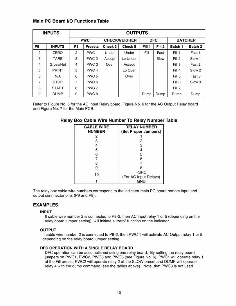
Main PC Board I/O Functions Table
INPUTS OUTPUTS
PWC CHECKWEIGHER DFC BATCHER
P9 INPUTS P8 Presets Check 3 Check 5 Fill 1 Fill 2 Batch 1 Batch 2
2 ZERO 2 PWC 1 Under Under Fill Fast Fill 1 Fast 1
3 TARE 3 PWC 2 Accept Lo Under Slow Fill 2 Slow 1
4 Gross/Net 4 PWC 3 Over Accept Fill 3 Fast 2
5 PRINT 5 PWC 4 Lo Over Fill 4 Slow 2
6 N/A 6 PWC 5 Over Fill 5 Fast 3
7 STOP 7 PWC 6 Fill 6 Slow 3
8 START 8 PWC 7 Fill 7
9 DUMP 9 PWC 8 Dump Dump Dump Dump
Refer to Figure No. 5 for the AC Input Relay board, Figure No. 6 for the AC Output Relay board and Figure No. 7 for the Main PCB.
Relay Box Cable Wire Number To Relay Number Table
CABLE WIRE NUMBER
RELAY NUMBER (Set Proper Jumpers)
2 1 3 2 4 3 5 4 6 5 7 6 8 7 9 8
10 +SRC (For AC Input Relays)
1 GND The relay box cable wire numbers correspond to the indicator main PC board remote input and output connnector pins (P9 and P8). EXAMPLES:
INPUT If cable wire number 2 is connected to P9-2, then AC Input relay 1 or 5 (depending on the relay board jumper setting), will initiate a “zero” function on the indicator.
OUTPUT
If cable wire number 2 is connected to P8-2, then PWC 1 will activate AC Output relay 1 or 5, depending on the relay board jumper setting.
DFC OPERATION WITH A SINGLE RELAY BOARD DFC operation can be accomplished using one relay board. By setting the relay board jumpers on PWC1, PWC2, PWC3 and PWC8 (see Figure No. 6), PWC1 will operate relay 1 at the Fill preset, PWC2 will operate relay 2 at the SLOW preset and DUMP will operate relay 4 with the dump command (see the tables above). Note, that PWC3 is not used.
11
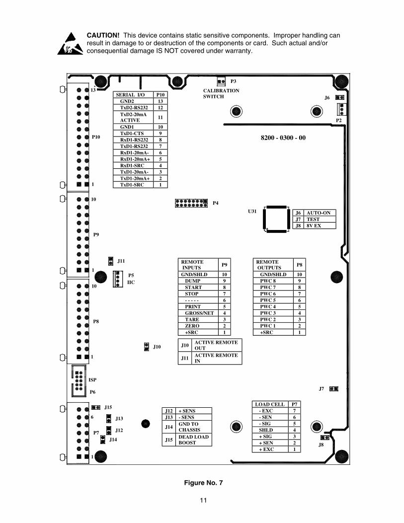
CAUTION! This device contains static sensitive components. Improper handling can result in damage to or destruction of the components or card. Such actual and/or consequential damage IS NOT covered under warranty.
Figure No. 7
SERIAL I/O P10 GND2 13 TxD2-RS232 12 TxD2-20mA ACTIVE 11
GND1 10 TxD1-CTS 9 RxD1-RS232 8 TxD1-RS232 7 RxD1-20mA- 6 RxD1-20mA+ 5 RxD1-SRC 4 TxD1-20mA- 3 TxD1-20mA+ 2 TxD1-SRC 1
J6 AUTO-ON J7 TEST J8 8V EX
CALIBRATION SWITCH J6
P2
P3
13
P10
1
10
P9
1
J11
P5 IIC 10
P8
1
ISP
P6
J15
6 J13
J12 P7 J14
1
J12 + SENS J13 - SENS
J14 GND TO CHASSIS
J15 DEAD LOAD BOOST
LOAD CELL P7 - EXC 7 - SEN 6 - SIG 5 SHLD 4 + SIG 3 + SEN 2 + EXC 1
J7
J10
P4
J8
8200 - 0300 - 00
U31
REMOTE INPUTS P9
GND/SHLD 10 DUMP 9 START 8 STOP 7 - - - - - 6 PRINT 5 GROSS/NET 4 TARE 3 ZERO 2 +SRC 1
REMOTE OUTPUTS P8
GND/SHLD 10 PWC 8 9 PWC 7 8 PWC 6 7 PWC 5 6 PWC 4 5 PWC 3 4 PWC 2 3 PWC 1 2 +SRC 1
J10 ACTIVE REMOTE OUT
J11 ACTIVE REMOTE IN
12
Main PCB Jumpers (See Figure No. 7)
J6 - AUTO-ON JUMPER The AUTO-ON jumper J6, when connected, will cause the indicator to power on automatically whenever power is applied to the power input connector. If power is lost momentarily and then reapplied, the indicator will turn on without pressing the ON key. See Figure No. 7 for jumper location.
J7 - TEST JUMPER
The TEST jumper J7, when connected, will turn the backlight on, disregarding the LIGHT ON= setting (refer to Setup Review for explanation of LIGHT ON). See Figure No. 7 for jumper location.
J8 - 8V EX JUMPER The 8V EX jumper J8, when connected, allows the 220 indicator to supply 8 VDC excitation voltage when a remote (external) 12 VDC battery is used to power the indicator. To operate from the 12 VDC battery, the load cell excitation voltage MUST be set to 8 VDC (J8 closed). Operating with the load cell excitation voltage set to 12 VDC will result in an unstable weight display. See Figure No. 7 for jumper location.
J10 - ACTIVE REMOTE OUT JUMPER The Active Remote Out jumper J10, when connected, allows the 220 indicator to supply (source) 5 VDC to a solid-state relay or other load of 200 ohms or greater. To operate from the 5 VDC source, the positive connection from the relays must be connected to P8 pins 2 through 9 and the negative wire from the relays to P8 pin 10 (GND/SHLD). See Figure No. 7 for jumper and connector P7 location. For completely isolated outputs, J10 must be open (positioned on one plug-in pin only or removed) and the user must provide 5 to 12 VDC to P8 pin 1 (+SRC) and a ground return to the load. The load must still be 200 ohms or greater. Note that P8 pin 10 (GND/SHLD) is not connected.
J11 - ACTIVE REMOTE IN JUMPER The Active Remote In jumper J11, when connected, allows the 220 indicator to supply (source) 5 VDC to a remote input circuit. Connecting P9 pins 1 through 9 to P9 pin 10 (GND) through a switch will cause the selected action. See Figure No. 7 for jumper and connector P9 location. For completely isolated inputs, J11 must be open (positioned on one plug-in pin only or removed) and the user must provide 5 to 12 VDC to P9 pin 1 (+SRC) and a ground return to the switch connected to P9 pin 2 through 9. Note that P9 pin 10 (GND) is not connected.
J12 AND J13 - SENSE JUMPERS If the sense leads are NOT used, you must install plug-in jumpers at J12 and J13 adjacent to the terminal block. These jumpers attach the sense leads to the excitation leads. If sense leads ARE used (as in motor truck scales), these plug-in jumpers should be positioned on one plug-in pin only or removed and stored for later use. Refer to Figure No. 7 for the location of the jumpers.
J14 - GND TO CHASSIS JUMPER This jumper when installed connects the analog circuit ground to the indicator chassis ground. Refer to Figure No. 7 for the location of the jumper.
J15 - DEAD LOAD BOOST JUMPER For very low dead loads (less than 10% of the combined load cell capacity) connect the dead load boost jumper J15 on the printed circuit board. Refer to Figure No. 7 for the location of the jumper.
13
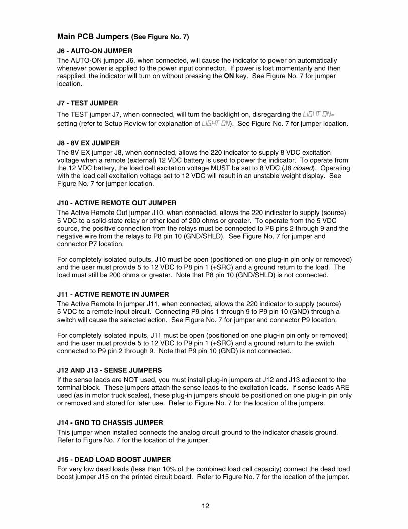
KEYPAD FUNCTIONS
The following describes the keys and their functions as used during setup and calibration. For complete details on the 220 Indicator keypad functions, refer to the 220 Weight Indicating Instrument Technical and Operation Manual, 8200-M502-O1.
ON/OFF (K) KEY This key is used to apply and remove power to the indicator. In the alphanumeric mode, it is used to enter the letter “K”. 0 THROUGH 9 (P THROUGH Y) KEYS These keys are used to enter numeric data during setup and calibration. The 1 and 0 are also used to answer yes (1 = YES) or no (0 = NO) to various prompts. In the alphanumeric mode, they are used to enter the letters “P” through “Y”. ✱ ASTERISK KEY During Setup, when a setup parameter is displayed, pressing this key will "backup" to the previous prompt. Pressing this key during entry of data will toggle the keypad to the “alpha” mode. It is also used in conjunction with the other keys on the keypad to access additional indicator functions. ENTER (Z) KEY The ENTER key is used to signal completion of the entry of data and causes the indicator to process the data entered. When reviewing setup parameters, pressing the ENTER key will display the current setting of the parameter. In the alphanumeric mode, it is used to enter the letter “Z”. ZERO/REVIEW (A) KEY Pressing this key after the ASTERISK key will enter the Review mode of Setup and Calibration. Refer to the Setup Review section of this guide for details. In the alphanumeric mode, this key is used to enter the letter “A”. TARE (B) KEY (WITH DIAMOND "T" SYMBOL) In the alphanumeric mode, this key is used to enter the letter “B”. NET/GROSS (C) KEY In the alphanumeric mode, this key is used to enter the letter “C” TARE (D) KEY (WITH WEIGHT "T"SYMBOL) In the alphanumeric mode, this key is used to enter the letter “D”. UNITS/TEST (E) KEY Pressing this key after the ASTERISK key will enter the Test mode and conduct a test of all display elements. The test consists of 12 cycles, each lasting about one second:
1. The model number and the software version are displayed.
2. All alphanumeric characters and annunciators will turn on. 3. The calibration numbers (C1 to C4) are displayed.
In the alphanumeric mode, this key is used to enter the letter “E”. START/STOP (F) KEY In the alphanumeric mode, this key is used to enter the letter “F”. MEM (G) KEY In the alphanumeric mode, this key is used to enter the letter “G”.
14
ID (H) KEY In the alphanumeric mode, this key is used to enter the letter “H”. ACCUM (I) KEY In the alphanumeric mode, this key is used to enter the letter “I”. DELETE (J) KEY In the alphanumeric mode, this key is used to enter the letter “J”. COUNT/SAMPLE (L, ) KEY Pressing this key during entry of alphanumeric data will backspace and delete the last character entered. In the alphanumeric mode, it is used to enter the letter “L”. TIME/DATE (M, CAPS) KEY This key is used to enter the clock mode to program the time, date and consecutive number. In the alphanumeric mode, it is used to enter the letter “M” and to toggle between lower and upper case alpha characters.
12 Hour Format Selected In Setup (TIME=12) 1. If the time displayed is correct, press the ENTER key and proceed to step 3. 2. If the displayed time is incorrect, enter the correct time and press the ENTER key.
3. The display will show AM=XX, where XX is the current setting. If the time is before noon (12:00 PM), press the 1/YES key (display will show AM=YES), then press the ENTER key.
4. The display will show DATE=XX.XX.XX, where XX.XX.XX is the current date.
5. If the date displayed is correct, press the ENTER key to proceed to the CNC NO= prompt. 6. If the date displayed is incorrect, enter the correct date and press the ENTER key to
proceed to the CNC NO= prompt. Remember to enter the date in the same format (month-day-year or day-month-year) as selected by the USA setup parameter.
24 Hour Format Selected In Setup (TIME=24)
1. If the time displayed is correct, press the ENTER key and proceed to step 3. 2. If the displayed time is incorrect, enter the correct time and press the ENTER key. Note that
with the 24 hour format selected, entering all times after noon (12:00 PM), you must add 12 to the time, i.e. 3 PM would be 1500.
3. The display will show DATE=XX.XX.XX, where XX.XX.XX is the current date.
4. If the date displayed is correct, press the ENTER key to proceed to the CNC NO=.prompt. 5. If the date displayed is incorrect, enter the correct date and press the ENTER key to
proceed to the CNC NO= prompt. Remember to enter the date in the same format (month-day-year or day-month-year) as selected by the USA setup parameter.
Consecutive Number (CNC NO=)
If the consecutive number displayed is correct, press the ENTER key. If the consecutive number displayed is incorrect, enter the correct number (6 digits max.) then press the ENTER key to resume normal operation.
PRESET (N, SPACE) KEY This key is used to enter the weight values for the Preset Weight Comparators (PWC), the Checkweigher feature or the Digital Fill Control feature depending on which function was selected during setup and calibration. In the alphanumeric mode, it is used to enter the letter “N” or to insert a space between characters. PRINT (O) KEY In the alphanumeric mode, this key is used to enter the letter “O”.
15
SETUP AND CALIBRATION
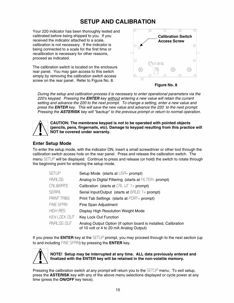
Your 220 indicator has been thoroughly tested and calibrated before being shipped to you. If you received the indicator attached to a scale, calibration is not necessary. If the indicator is being connected to a scale for the first time or recalibration is necessary for other reasons, proceed as indicated. The calibration switch is located on the enclosure rear panel. You may gain access to this switch simply by removing the calibration switch access screw on the rear panel. Refer to Figure No. 8. Figure No. 8
During the setup and calibration process it is necessary to enter operational parameters via the 220's keypad. Pressing the ENTER key without entering a new value will retain the current setting and advance the 220 to the next prompt. To change a setting, enter a new value and press the ENTER key. This will save the new value and advance the 220 to the next prompt. Pressing the ASTERISK key will "backup" to the previous prompt or return to normal operation.
CAUTION: The membrane keypad is not to be operated with pointed objects (pencils, pens, fingernails, etc). Damage to keypad resulting from this practice will NOT be covered under warranty.
Enter Setup Mode To enter the setup mode, with the indicator ON, insert a small screwdriver or other tool through the calibration switch access hole on the rear panel. Press and release the calibration switch. The menu SETUP will be displayed. Continue to press and release (or hold) the switch to rotate through the beginning point for entering the setup mode.
SETUP Setup Mode (starts at USA= prompt)
ANALOG Analog to Digital Filtering (starts at FILTER= prompt)
CALIBRATE Calibration (starts at CAL WT 1= prompt)
SERIAL Serial Input/Output (starts at BAUD 1= prompt)
PRINT TABS Print Tab Settings (starts at PORT= prompt)
FINE SPAN Fine Span Adjustment
HIGH RES Display High Resolution Weight Mode
KEY LOCK OUT Key Lock Out Function
ANALOG OUT Analog Output Option (If option board is installed, Calibration of 10 volt or 4 to 20 mA Analog Output)
If you press the ENTER key at the SETUP prompt, you may proceed through to the next section (up to and including FINE SPAN) by pressing the ENTER key.
NOTE! Setup may be interrupted at any time. ALL data previously entered and finalized with the ENTER key will be retained in the non-volatile memory.
Pressing the calibration switch at any prompt will return you to the SETUP menu. To exit setup, press the ASTERISK key with any of the above menu selections displayed or cycle power at any time (press the ON/OFF key twice).
Calibration Switch Access Screw
16
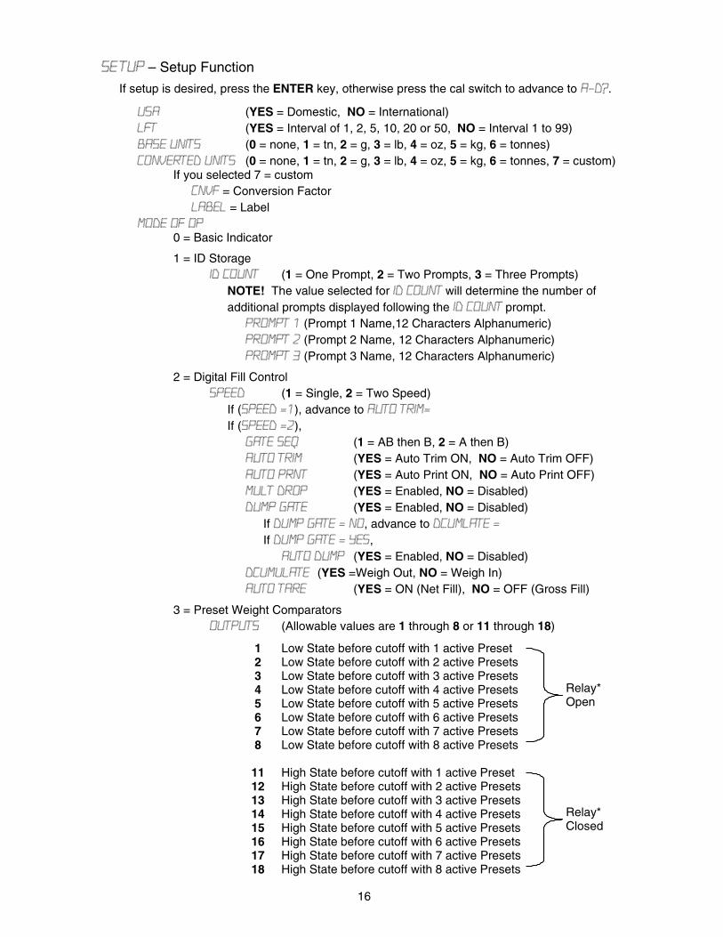
SE TUP – Setup Function If setup is desired, press the ENTER key, otherwise press the cal switch to advance to A-D?.
USA (YES = Domestic, NO = International) LFT (YES = Interval of 1, 2, 5, 10, 20 or 50, NO = Interval 1 to 99) BASE UNITS (0 = none, 1 = tn, 2 = g, 3 = lb, 4 = oz, 5 = kg, 6 = tonnes) CONVERTED UNITS (0 = none, 1 = tn, 2 = g, 3 = lb, 4 = oz, 5 = kg, 6 = tonnes, 7 = custom)
If you selected 7 = custom CNVF = Conversion Factor LABEL = Label
MODE OF OP 0 = Basic Indicator
1 = ID Storage ID COUNT (1 = One Prompt, 2 = Two Prompts, 3 = Three Prompts)
NOTE! The value selected for ID COUNT will determine the number of additional prompts displayed following the ID COUNT prompt.
PROMPT 1 (Prompt 1 Name,12 Characters Alphanumeric) PROMPT 2 (Prompt 2 Name, 12 Characters Alphanumeric) PROMPT 3 (Prompt 3 Name, 12 Characters Alphanumeric)
2 = Digital Fill Control SPEED (1 = Single, 2 = Two Speed)
If (SPEED =1), advance to AUTO TRIM= If (SPEED =2),
GATE SEQ (1 = AB then B, 2 = A then B) AUTO TRIM (YES = Auto Trim ON, NO = Auto Trim OFF) AUTO PRNT (YES = Auto Print ON, NO = Auto Print OFF) MULT DROP (YES = Enabled, NO = Disabled) DUMP GATE (YES = Enabled, NO = Disabled)
If DUMP GATE = NO, advance to DCUMLATE = If DUMP GATE = YES,
AUTO DUMP (YES = Enabled, NO = Disabled) DCUMULATE (YES =Weigh Out, NO = Weigh In) AUTO TARE (YES = ON (Net Fill), NO = OFF (Gross Fill)
3 = Preset Weight Comparators OUTPUTS (Allowable values are 1 through 8 or 11 through 18)
1 Low State before cutoff with 1 active Preset 2 Low State before cutoff with 2 active Presets 3 Low State before cutoff with 3 active Presets 4 Low State before cutoff with 4 active Presets 5 Low State before cutoff with 5 active Presets 6 Low State before cutoff with 6 active Presets 7 Low State before cutoff with 7 active Presets 8 Low State before cutoff with 8 active Presets
11 High State before cutoff with 1 active Preset 12 High State before cutoff with 2 active Presets 13 High State before cutoff with 3 active Presets 14 High State before cutoff with 4 active Presets 15 High State before cutoff with 5 active Presets 16 High State before cutoff with 6 active Presets 17 High State before cutoff with 7 active Presets 18 High State before cutoff with 8 active Presets
Relay* Open
Relay* Closed
17
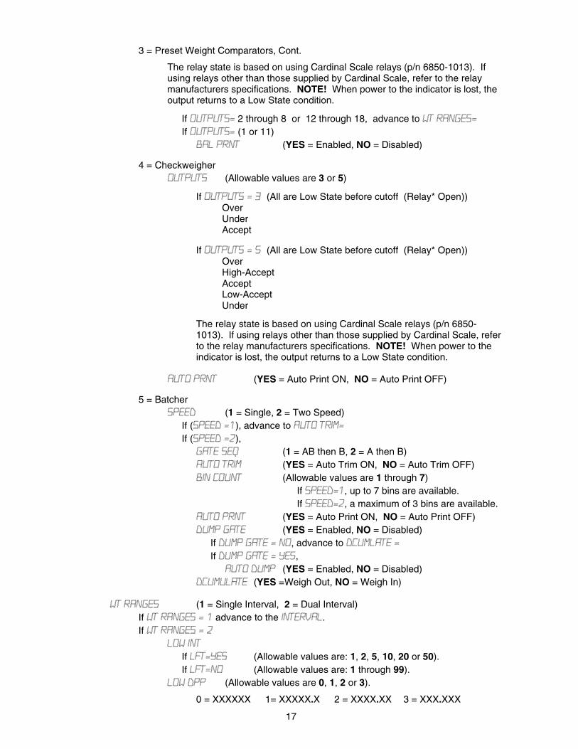
3 = Preset Weight Comparators, Cont.
The relay state is based on using Cardinal Scale relays (p/n 6850-1013). If using relays other than those supplied by Cardinal Scale, refer to the relay manufacturers specifications. NOTE! When power to the indicator is lost, the output returns to a Low State condition.
If OUTPUTS= 2 through 8 or 12 through 18, advance to WT RANGES= If OUTPUTS= (1 or 11)
BAL PRNT (YES = Enabled, NO = Disabled)
4 = Checkweigher OUTPUTS (Allowable values are 3 or 5)
If OUTPUTS = 3 (All are Low State before cutoff (Relay* Open)) Over Under Accept
If OUTPUTS = 5 (All are Low State before cutoff (Relay* Open)) Over High-Accept Accept Low-Accept Under
The relay state is based on using Cardinal Scale relays (p/n 6850-1013). If using relays other than those supplied by Cardinal Scale, refer to the relay manufacturers specifications. NOTE! When power to the indicator is lost, the output returns to a Low State condition.
AUTO PRNT (YES = Auto Print ON, NO = Auto Print OFF)
5 = Batcher SPEED (1 = Single, 2 = Two Speed)
If (SPEED =1), advance to AUTO TRIM= If (SPEED =2),
GATE SEQ (1 = AB then B, 2 = A then B) AUTO TRIM (YES = Auto Trim ON, NO = Auto Trim OFF) BIN COUNT (Allowable values are 1 through 7)
If SPEED=1, up to 7 bins are available. If SPEED=2, a maximum of 3 bins are available.
AUTO PRNT (YES = Auto Print ON, NO = Auto Print OFF) DUMP GATE (YES = Enabled, NO = Disabled)
If DUMP GATE = NO, advance to DCUMLATE = If DUMP GATE = YES,
AUTO DUMP (YES = Enabled, NO = Disabled) DCUMULATE (YES =Weigh Out, NO = Weigh In)
WT RANGES (1 = Single Interval, 2 = Dual Interval) If WT RANGES = 1 advance to the INTERVAL. If WT RANGES = 2
LOW INT If LFT=YES (Allowable values are: 1, 2, 5, 10, 20 or 50). If LFT=NO (Allowable values are: 1 through 99).
LOW DPP (Allowable values are 0, 1, 2 or 3).
0 = XXXXXX 1= XXXXX.X 2 = XXXX.XX 3 = XXX.XXX
18
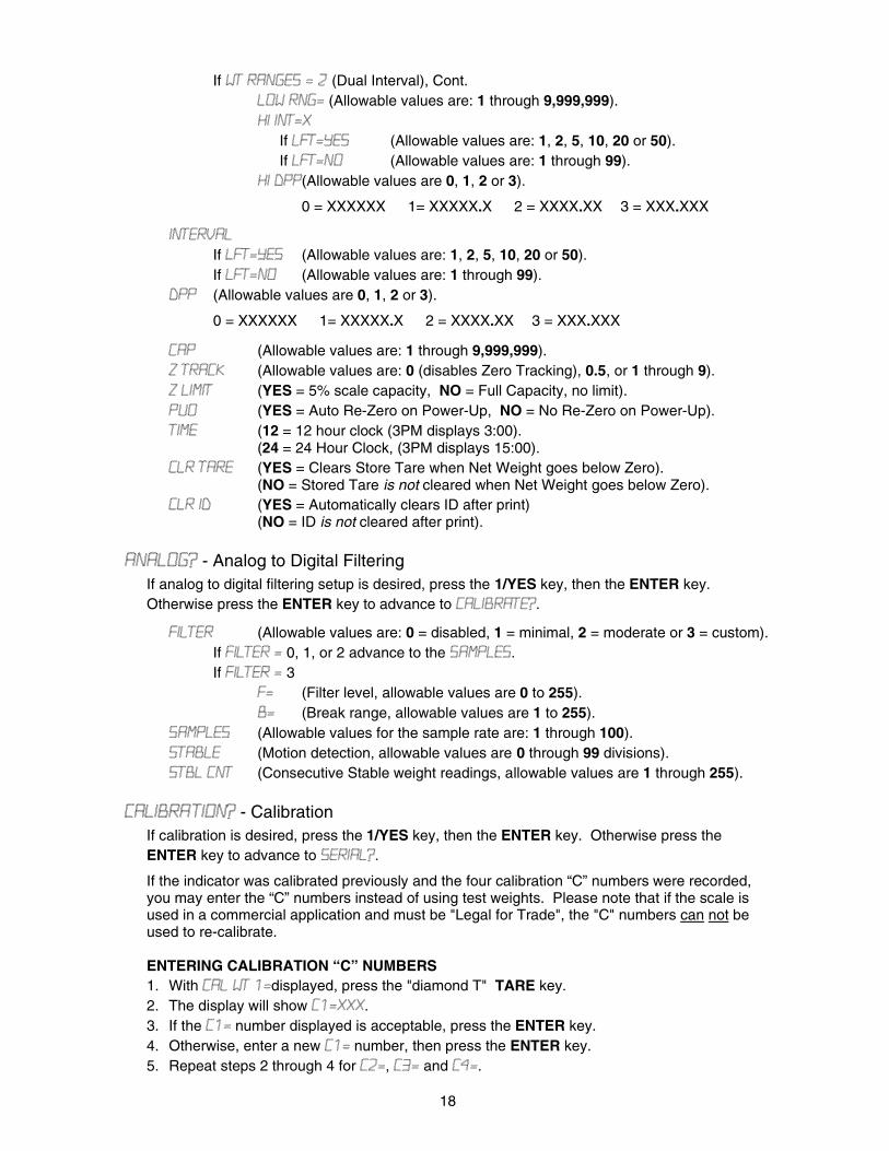
If WT RANGES = 2 (Dual Interval), Cont. LOW RNG= (Allowable values are: 1 through 9,999,999). HI INT=X
If LFT=YES (Allowable values are: 1, 2, 5, 10, 20 or 50). If LFT=NO (Allowable values are: 1 through 99).
HI DPP (Allowable values are 0, 1, 2 or 3).
0 = XXXXXX 1= XXXXX.X 2 = XXXX.XX 3 = XXX.XXX
INTERVAL If LFT=YES (Allowable values are: 1, 2, 5, 10, 20 or 50). If LFT=NO (Allowable values are: 1 through 99).
DPP (Allowable values are 0, 1, 2 or 3).
0 = XXXXXX 1= XXXXX.X 2 = XXXX.XX 3 = XXX.XXX
CAP (Allowable values are: 1 through 9,999,999). Z TRACK (Allowable values are: 0 (disables Zero Tracking), 0.5, or 1 through 9). Z LIMIT (YES = 5% scale capacity, NO = Full Capacity, no limit). PUO (YES = Auto Re-Zero on Power-Up, NO = No Re-Zero on Power-Up). TIME (12 = 12 hour clock (3PM displays 3:00).
(24 = 24 Hour Clock, (3PM displays 15:00). CLR TARE (YES = Clears Store Tare when Net Weight goes below Zero).
(NO = Stored Tare is not cleared when Net Weight goes below Zero). CLR ID (YES = Automatically clears ID after print)
(NO = ID is not cleared after print).
ANALOG? - Analog to Digital Filtering If analog to digital filtering setup is desired, press the 1/YES key, then the ENTER key. Otherwise press the ENTER key to advance to CALIBRATE?.
FILTER (Allowable values are: 0 = disabled, 1 = minimal, 2 = moderate or 3 = custom). If FILTER = 0, 1, or 2 advance to the SAMPLES. If FILTER = 3
F= (Filter level, allowable values are 0 to 255). B= (Break range, allowable values are 1 to 255).
SAMPLES (Allowable values for the sample rate are: 1 through 100). STABLE (Motion detection, allowable values are 0 through 99 divisions). STBL CNT (Consecutive Stable weight readings, allowable values are 1 through 255).
CALIBRATION? - Calibration If calibration is desired, press the 1/YES key, then the ENTER key. Otherwise press the ENTER key to advance to SERIAL?.
If the indicator was calibrated previously and the four calibration “C” numbers were recorded, you may enter the “C” numbers instead of using test weights. Please note that if the scale is used in a commercial application and must be "Legal for Trade", the "C" numbers can not be used to re-calibrate. ENTERING CALIBRATION “C” NUMBERS 1. With CAL WT 1=displayed, press the "diamond T" TARE key. 2. The display will show C1=XXX. 3. If the C1= number displayed is acceptable, press the ENTER key. 4. Otherwise, enter a new C1= number, then press the ENTER key. 5. Repeat steps 2 through 4 for C2=, C3= and C4=.
19
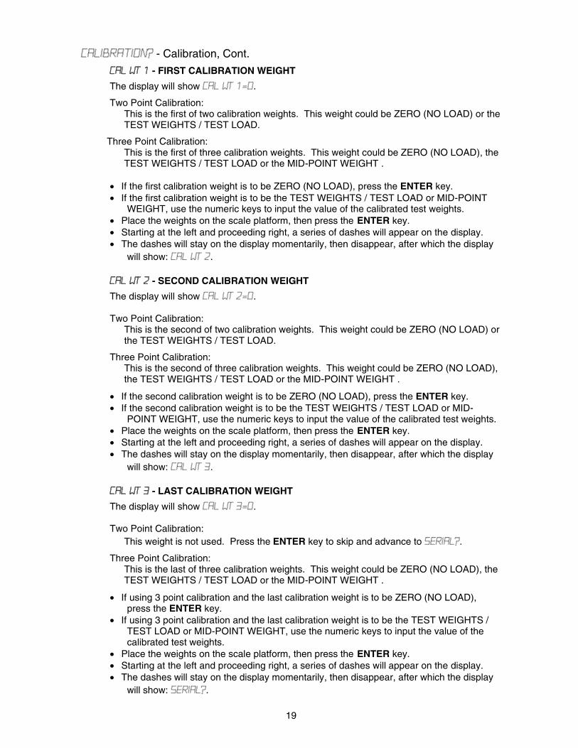
CALIBRATION? - Calibration, Cont.
CAL WT 1 - FIRST CALIBRATION WEIGHT
The display will show CAL WT 1=0.
Two Point Calibration: This is the first of two calibration weights. This weight could be ZERO (NO LOAD) or the TEST WEIGHTS / TEST LOAD.
Three Point Calibration: This is the first of three calibration weights. This weight could be ZERO (NO LOAD), the TEST WEIGHTS / TEST LOAD or the MID-POINT WEIGHT .
• If the first calibration weight is to be ZERO (NO LOAD), press the ENTER key. • If the first calibration weight is to be the TEST WEIGHTS / TEST LOAD or MID-POINT
WEIGHT, use the numeric keys to input the value of the calibrated test weights. • Place the weights on the scale platform, then press the ENTER key. • Starting at the left and proceeding right, a series of dashes will appear on the display. • The dashes will stay on the display momentarily, then disappear, after which the display
will show: CAL WT 2.
CAL WT 2 - SECOND CALIBRATION WEIGHT
The display will show CAL WT 2=0.
Two Point Calibration: This is the second of two calibration weights. This weight could be ZERO (NO LOAD) or the TEST WEIGHTS / TEST LOAD.
Three Point Calibration: This is the second of three calibration weights. This weight could be ZERO (NO LOAD), the TEST WEIGHTS / TEST LOAD or the MID-POINT WEIGHT .
• If the second calibration weight is to be ZERO (NO LOAD), press the ENTER key. • If the second calibration weight is to be the TEST WEIGHTS / TEST LOAD or MID-
POINT WEIGHT, use the numeric keys to input the value of the calibrated test weights. • Place the weights on the scale platform, then press the ENTER key. • Starting at the left and proceeding right, a series of dashes will appear on the display. • The dashes will stay on the display momentarily, then disappear, after which the display
will show: CAL WT 3.
CAL WT 3 - LAST CALIBRATION WEIGHT
The display will show CAL WT 3=0.
Two Point Calibration: This weight is not used. Press the ENTER key to skip and advance to SERIAL?.
Three Point Calibration: This is the last of three calibration weights. This weight could be ZERO (NO LOAD), the TEST WEIGHTS / TEST LOAD or the MID-POINT WEIGHT .
• If using 3 point calibration and the last calibration weight is to be ZERO (NO LOAD), press the ENTER key.
• If using 3 point calibration and the last calibration weight is to be the TEST WEIGHTS / TEST LOAD or MID-POINT WEIGHT, use the numeric keys to input the value of the calibrated test weights.
• Place the weights on the scale platform, then press the ENTER key. • Starting at the left and proceeding right, a series of dashes will appear on the display. • The dashes will stay on the display momentarily, then disappear, after which the display
will show: SERIAL?.
20
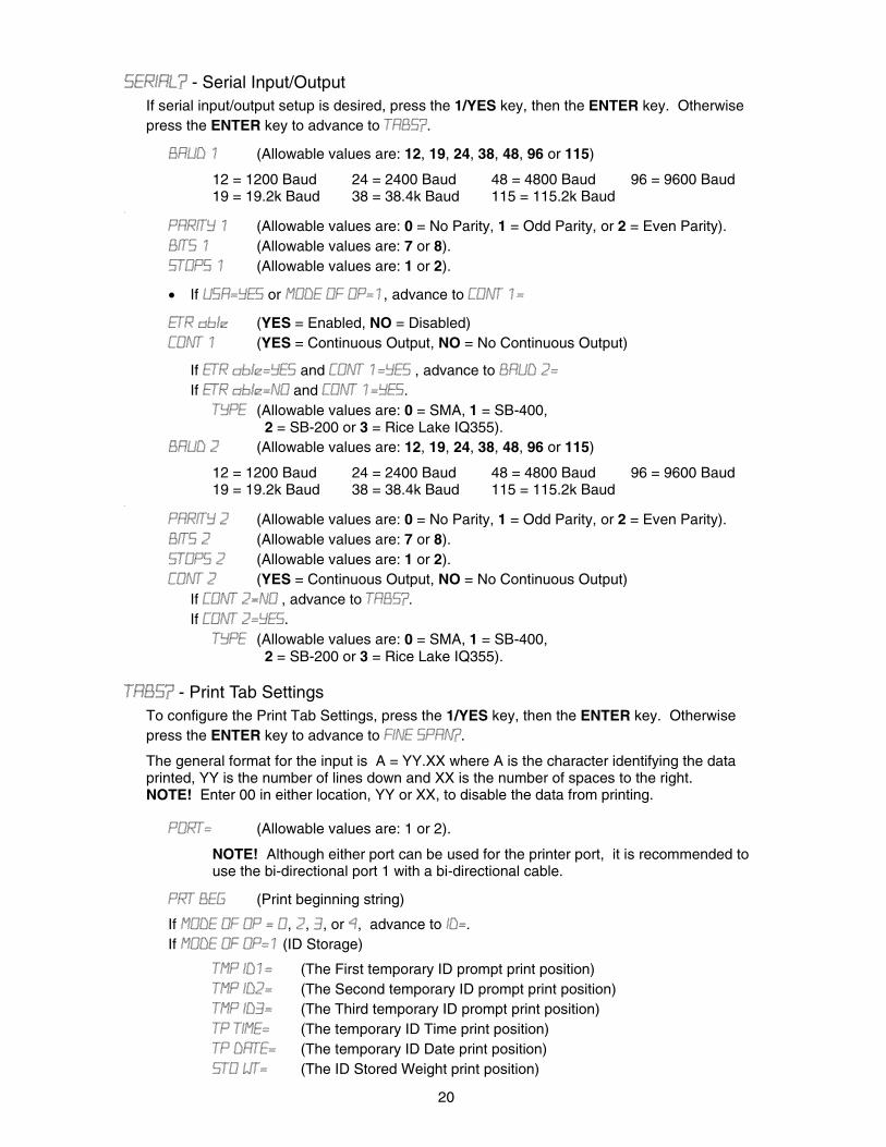
SERIAL? - Serial Input/Output If serial input/output setup is desired, press the 1/YES key, then the ENTER key. Otherwise press the ENTER key to advance to TABS?.
BAUD 1 (Allowable values are: 12, 19, 24, 38, 48, 96 or 115)
12 = 1200 Baud 24 = 2400 Baud 48 = 4800 Baud 96 = 9600 Baud 19 = 19.2k Baud 38 = 38.4k Baud 115 = 115.2k Baud
.
PARITY 1 (Allowable values are: 0 = No Parity, 1 = Odd Parity, or 2 = Even Parity). BITS 1 (Allowable values are: 7 or 8). STOPS 1 (Allowable values are: 1 or 2).
• If USA=YES or MODE OF OP=1, advance to CONT 1=
ETR able (YES = Enabled, NO = Disabled) CONT 1 (YES = Continuous Output, NO = No Continuous Output)
If ETR able=YES and CONT 1=YES , advance to BAUD 2= If ETR able=NO and CONT 1=YES.
TYPE (Allowable values are: 0 = SMA, 1 = SB-400, 2 = SB-200 or 3 = Rice Lake IQ355).
BAUD 2 (Allowable values are: 12, 19, 24, 38, 48, 96 or 115)
12 = 1200 Baud 24 = 2400 Baud 48 = 4800 Baud 96 = 9600 Baud 19 = 19.2k Baud 38 = 38.4k Baud 115 = 115.2k Baud
.
PARITY 2 (Allowable values are: 0 = No Parity, 1 = Odd Parity, or 2 = Even Parity). BITS 2 (Allowable values are: 7 or 8). STOPS 2 (Allowable values are: 1 or 2). CONT 2 (YES = Continuous Output, NO = No Continuous Output)
If CONT 2=NO , advance to TABS?. If CONT 2=YES.
TYPE (Allowable values are: 0 = SMA, 1 = SB-400, 2 = SB-200 or 3 = Rice Lake IQ355).
TABS? - Print Tab Settings To configure the Print Tab Settings, press the 1/YES key, then the ENTER key. Otherwise press the ENTER key to advance to FINE SPAN?.
The general format for the input is A = YY.XX where A is the character identifying the data printed, YY is the number of lines down and XX is the number of spaces to the right. NOTE! Enter 00 in either location, YY or XX, to disable the data from printing.
PORT= (Allowable values are: 1 or 2).
NOTE! Although either port can be used for the printer port, it is recommended to use the bi-directional port 1 with a bi-directional cable.
PRT BEG (Print beginning string)
If MODE OF OP = 0, 2, 3, or 4, advance to ID=. If MODE OF OP=1 (ID Storage)
TMP ID1= (The First temporary ID prompt print position) TMP ID2= (The Second temporary ID prompt print position) TMP ID3= (The Third temporary ID prompt print position) TP TIME= (The temporary ID Time print position) TP DATE= (The temporary ID Date print position) STO WT= (The ID Stored Weight print position)
21
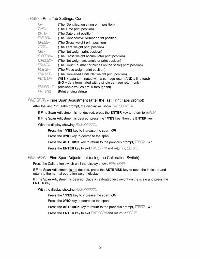
TABS? - Print Tab Settings, Cont.
ID= (The IDentification string print position) TIME= (The Time print position) DATE= (The Date print position) CNC NO= (The Consecutive Number print position) GROSS= (The Gross weight print position) TARE= (The Tare weight print position) NET= (The Net weight print position) G ACCUM= (The Gross weight accumulator print position) N ACCUM= (The Net weight accumulator print position) COUNT= (The Count (number of pieces on the scale) print position) PCS WT= (The Piece weight print position) CNV NET= (The Converted Units Net weight print position) AUTO LF= (YES = data terminated with a carriage return AND a line feed)
(NO = data terminated with a single carriage return only) ENDING LF (Allowable values are: 0 through 99) PRT END (Print ending string)
FINE SPAN - Fine Span Adjustment (after the last Print Tabs prompt)
After the last Print Tabs prompt, the display will show FINE SPAN? N.
If Fine Span Adjustment is not desired, press the ENTER key to return to SETUP.
If Fine Span Adjustment is desired, press the 1/YES key, then the ENTER key.
With the display showing ADJ=XXXXXX,
Press the 1/YES key to increase the span OR
Press the 0/NO key to decrease the span.
Press the ASTERISK key to return to the previous prompt, TABS? OR
Press the ENTER key to exit FINE SPAN and return to SETUP. FINE SPAN - Fine Span Adjustment (using the Calibration Switch)
Press the Calibration switch until the display shows FINE SPAN.
If Fine Span Adjustment is not desired, press the ASTERISK key to reset the indicator and return to the normal operation weight display.
If Fine Span Adjustment is desired, place a calibrated test weight on the scale and press the ENTER key.
With the display showing ADJ=XXXXXX,
Press the 1/YES key to increase the span OR
Press the 0/NO key to decrease the span.
Press the ASTERISK key to return to the previous prompt, TABS? OR
Press the ENTER key to exit FINE SPAN and return to SETUP.

22
NOTE! The menu selections HIGH RES and KEY LOCK OUT can only be selected using the calibration switch.
HIGH RES - Display High Resolution Weight
Press the Calibration switch until the display shows HIGH RES.
If High Resolution Weight adjustment is not desired, press the ASTERISK key to reset the indicator and return to the normal operation weight display.
If High Resolution Weight adjustment is desired, place a calibrated test weight on the scale and press the ENTER key.
With the display showing HI Res=XXXXXX,
Press the 1/YES key to increase the span OR
Press the 0/NO key to decrease the span
Press the ASTERISK key to return to the HIGH RES prompt OR
Press the ENTER key to exit HIGH RES and return to SETUP Press the PRINT key to print the weight.
KEY LOCK OUT - Key Lock Out Function
Press the Calibration switch until the display shows KEY LOCK OUT.
Press the key(s) to be locked out (display will show -LOCKED-) OR
Press the key(s) to be unlocked (display will show –UNLOCKED-)
Press the calibration switch or cycle power to exit the KEY LOCK OUT function. During normal operation, pressing a locked key will results in a 1/2 second display -LOCKED- and the key will be ignored.
CALIBRATION “C” NUMBERS • The “C” numbers are displayed only during the Test mode operation. • Press the ASTERISK key then the UNITS/TEST key. • The "C" numbers are shown at the end of the test operation and each number is
displayed for approximately 4 seconds. • Each number may be up to three (3) digits in length. • Recording these numbers (and entering the numbers when prompted) will allow the
indicator to return to its present calibration settings without using test weights. • Refer to the Setup and Calibration, CALIBRATION? section of this manual for instructions
on using the "C" numbers.
NOTE! If the scale is used in a commercial application and must be "Legal for Trade", "C" numbers can not be used to re-calibrate.
23
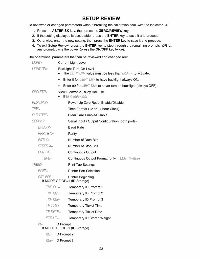
SETUP REVIEW To reviewed or changed parameters without breaking the calibration seal, with the indicator ON:
1. Press the ASTERISK key, then press the ZERO/REVIEW key.
2. If the setting displayed is acceptable, press the ENTER key to save it and proceed.
3. Otherwise, enter the new setting, then press the ENTER key to save it and proceed.
4. To exit Setup Review, press the ENTER key to step through the remaining prompts OR at any prompt, cycle the power (press the ON/OFF key twice).
The operational parameters that can be reviewed and changed are:
LIGHT= Current Light Level
LIGHT ON= Backlight Turn-On Level • The LIGHT ON= value must be less than LIGHT= to activate.
• Enter 0 for LIGHT ON= to have backlight always ON.
• Enter 99 for LIGHT ON= to never turn on backlight (always OFF).
FIND ETR= View Electronic Talley Roll File • If ETR able=YES
PWR UP Z= Power Up Zero Reset Enable/Disable
TIME= Time Format (12 or 24 hour Clock)
CLR TARE= Clear Tare Enable/Disable
SERIAL? Serial Input / Output Configuration (both ports)
BAUD X= Baud Rate
PARITY X= Parity
BITS X= Number of Data Bits
STOPS X= Number of Stop Bits
CONT X= Continuous Output
TYPE= Continuous Output Format (only if, CONT X=YES)
TABS? Print Tab Settings
PORT= Printer Port Selection
PRT BEG Printer Beginning If MODE OF OP=1 (ID Storage)
TMP ID1= Temporary ID Prompt 1
TMP ID2= Temporary ID Prompt 2
TMP ID3= Temporary ID Prompt 3
TP TIME= Temporary Ticket Time
TP DATE= Temporary Ticket Date
STO WT= Temporary ID Stored Weight
ID= ID Prompt If MODE OF OP=1 (ID Storage)
ID2= ID Prompt 2
ID3= ID Prompt 3
24
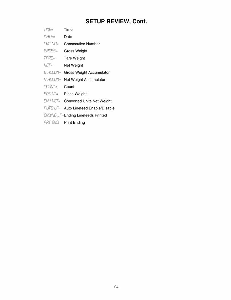
SETUP REVIEW, Cont. TIME= Time
DATE= Date
CNC NO= Consecutive Number
GROSS= Gross Weight
TARE= Tare Weight
NET= Net Weight
G ACCUM= Gross Weight Accumulator
N ACCUM= Net Weight Accumulator
COUNT= Count
PCS WT= Piece Weight
CNV NET= Converted Units Net Weight
AUTO LF= Auto Linefeed Enable/Disable
ENDING LF= Ending Linefeeds Printed
PRT END Print Ending
25
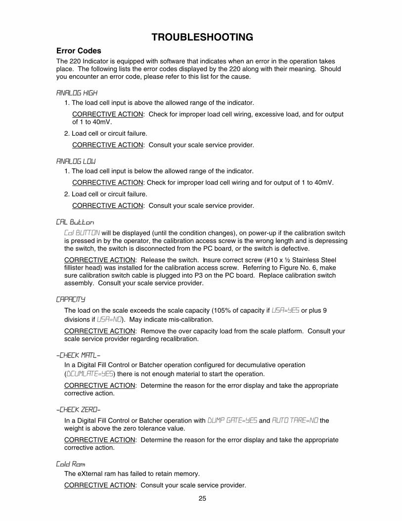
TROUBLESHOOTING Error Codes The 220 Indicator is equipped with software that indicates when an error in the operation takes place. The following lists the error codes displayed by the 220 along with their meaning. Should you encounter an error code, please refer to this list for the cause. ANALOG HIGH
1. The load cell input is above the allowed range of the indicator.
CORRECTIVE ACTION: Check for improper load cell wiring, excessive load, and for output of 1 to 40mV.
2. Load cell or circuit failure.
CORRECTIVE ACTION: Consult your scale service provider. ANALOG LOW
1. The load cell input is below the allowed range of the indicator.
CORRECTIVE ACTION: Check for improper load cell wiring and for output of 1 to 40mV.
2. Load cell or circuit failure.
CORRECTIVE ACTION: Consult your scale service provider. CAL Button
Cal BUTTON will be displayed (until the condition changes), on power-up if the calibration switch is pressed in by the operator, the calibration access screw is the wrong length and is depressing the switch, the switch is disconnected from the PC board, or the switch is defective.
CORRECTIVE ACTION: Release the switch. Insure correct screw (#10 x ½ Stainless Steel fillister head) was installed for the calibration access screw. Referring to Figure No. 6, make sure calibration switch cable is plugged into P3 on the PC board. Replace calibration switch assembly. Consult your scale service provider.
CAPACITY
The load on the scale exceeds the scale capacity (105% of capacity if USA=YES or plus 9 divisions if USA=NO). May indicate mis-calibration.
CORRECTIVE ACTION: Remove the over capacity load from the scale platform. Consult your scale service provider regarding recalibration.
-CHECK MATL-
In a Digital Fill Control or Batcher operation configured for decumulative operation (DCUMLATE=YES) there is not enough material to start the operation.
CORRECTIVE ACTION: Determine the reason for the error display and take the appropriate corrective action.
-CHECK ZERO-
In a Digital Fill Control or Batcher operation with DUMP GATE=YES and AUTO TARE=NO the weight is above the zero tolerance value.
CORRECTIVE ACTION: Determine the reason for the error display and take the appropriate corrective action.
Cold Ram
The eXternal ram has failed to retain memory.
CORRECTIVE ACTION: Consult your scale service provider.
26
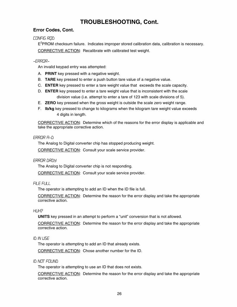
TROUBLESHOOTING, Cont. Error Codes, Cont.
CONFIG RQD E2PROM checksum failure. Indicates improper stored calibration data, calibration is necessary.
CORRECTIVE ACTION: Recalibrate with calibrated test weight.
-ERROR- An invalid keypad entry was attempted:
A. PRINT key pressed with a negative weight.
B. TARE key pressed to enter a push button tare value of a negative value.
C. ENTER key pressed to enter a tare weight value that exceeds the scale capacity.
D. ENTER key pressed to enter a tare weight value that is inconsistent with the scale
division value (i.e. attempt to enter a tare of 123 with scale divisions of 5).
E. ZERO key pressed when the gross weight is outside the scale zero weight range.
F. lb/kg key pressed to change to kilograms when the kilogram tare weight value exceeds
4 digits in length.
CORRECTIVE ACTION: Determine which of the reasons for the error display is applicable and take the appropriate corrective action.
ERROR A-D
The Analog to Digital converter chip has stopped producing weight.
CORRECTIVE ACTION: Consult your scale service provider.
ERROR DRDY The Analog to Digital converter chip is not responding.
CORRECTIVE ACTION: Consult your scale service provider. FILE FULL
The operator is attempting to add an ID when the ID file is full.
CORRECTIVE ACTION: Determine the reason for the error display and take the appropriate corrective action.
HUH?
UNITS key pressed in an attempt to perform a “unit” conversion that is not allowed.
CORRECTIVE ACTION: Determine the reason for the error display and take the appropriate corrective action.
ID IN USE
The operator is attempting to add an ID that already exists.
CORRECTIVE ACTION: Chose another number for the ID.
ID NOT FOUND The operator is attempting to use an ID that does not exists.
CORRECTIVE ACTION: Determine the reason for the error display and take the appropriate corrective action.
27
TROUBLESHOOTING, Cont. Error Codes, Cont.
-LOCKED- The key pressed has been locked out.
CORRECTIVE ACTION: Refer to SETUP AND CALIBRATION, KEY LOCK OUT section of this manual to unlock the key.
-NO TARE-
NET key pressed with no stored tare weight value.
CORRECTIVE ACTION: Determine the reason for the error display and take the appropriate corrective action.
OVERFLOW
The indicator is attempting to display a positive number greater than seven (7) digits in length or a negative number of more than six (6) digits.
CORRECTIVE ACTION: Return to Gross Weight mode and review Tare value. May indicate mis-calibration.
TOO BIG
UNITS key pressed in an attempt to perform a “unit” conversion where the interval would have been greater than 50.
CORRECTIVE ACTION: Determine the reason for the error display and take the appropriate corrective action.
TOO SMALL
UNITS key pressed in an attempt to perform a “unit” conversion where the interval would have been less than .0001.
CORRECTIVE ACTION: Determine the reason for the error display and take the appropriate corrective action.
-UNLOCKED-
This is not an error message. It is shown on the display when a previously locked out key is unlocked.
CORRECTIVE ACTION: None required. Refer to SETUP AND CALIBRATION, KEY LOCK OUT section of this manual for more details.
-UNSTABLE- Motion is present when trying to power up, print, zero or perform a push button tare function.
CORRECTIVE ACTION: Wait for a stable weight display (STABLE annunciator on) before performing any of these operations.
WRONG RAM
During memory access to the eXternal ram, an error has occurred.
CORRECTIVE ACTION: Consult your scale service provider. Xram FAILURE
The power up test of eXternal ram (the big chip in a socket) has failed.
CORRECTIVE ACTION: Consult your scale service provider.
28
TROUBLESHOOTING, Cont.
Before You Call Service
The 220 Indicator has been designed to provide you with years of trouble-free operation. In spite of this, troubles sometimes happen. Before calling for service assistance you should make some initial checks to verify that a problem does exist. The following describes several types of symptoms along with suggested remedies.
PROBLEM
POSSIBLE SOLUTIONS
Display does not turn on Is the AC power cord fully inserted into the wall receptacle? Check wall receptacle for proper AC power. Try another electrical appliance in the same receptacle, does it work? Check the circuit breaker. Has there been power failure?
Incorrect weight displayed Has the instrument been calibrated? Insure that the scale platform isn't touching an adjacent object. Check the load cell connector wiring. If using four (4) wire load cells, insure the sense lead jumpers (J4 & J5) are installed. Have proper operation procedures been followed?
Indicator will not display weight Refer to Error Codes section and make certain that the OVER CAP message is not displayed. If so, and scale is not loaded, perform the calibration sequence.
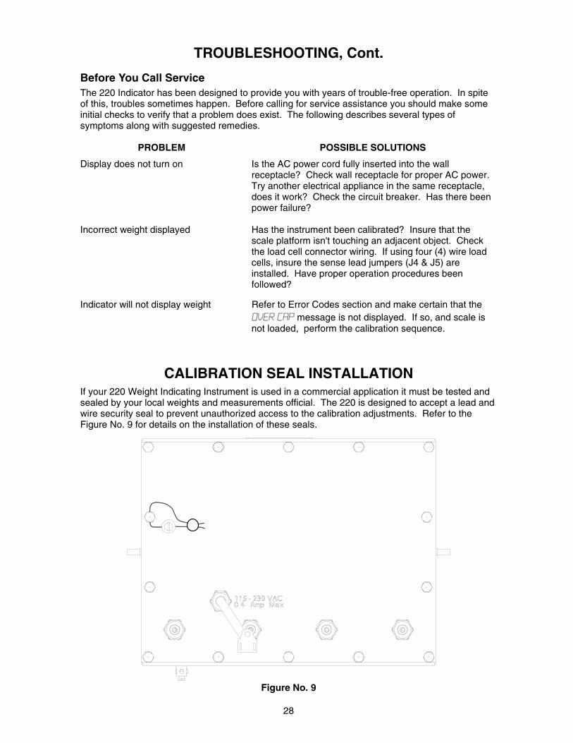
CALIBRATION SEAL INSTALLATION
If your 220 Weight Indicating Instrument is used in a commercial application it must be tested and sealed by your local weights and measurements official. The 220 is designed to accept a lead and wire security seal to prevent unauthorized access to the calibration adjustments. Refer to the Figure No. 9 for details on the installation of these seals.
Figure No. 9

29
EUROPEAN DECLARATION OF CONFORMITY Manufacturer: Cardinal Scale Manufacturing Company PO Box 151 203 East Daugherty Webb City, Missouri 64870 USA Telephone No. 417 673 4631 Fax No. 417 673 5001 Product: Non-automatic Weight Indicating Instrument Model Numbers 200, 205, 210 and 220 Serial Number EXXXYY-ZZZ where XXX = day of year YY = last two digits of year ZZZ = sequential number The undersigned hereby declares, on behalf of Cardinal Scale Manufacturing Company of Webb City, Missouri, that the above-referenced product, to which this declaration relates, is in conformity with the provisions of: European Standard EN 45501: 1992 and equivalent International Recommendation OIML R76, edition 1992 EU Type Approval Certificate Number DK 0199.47 Report No. DANAK-195612 Council Directive 73/23/EEC (19 February, 1993) Low Voltage Directive as amended by Council Directive 93/68/EEC (22 July, 1993) Council Directive 90/384/EEC (20 June, 1990) on the Harmonization Of the Laws of Member States relating to non-automatic weighing Systems as amended by: Council Directive 93/68/EEC (22 July, 1993) Report No. DANAK-195728 European Standard EN50082: 1995 for radiated emissions and European Standard EN50082-2: 1995 Class B for EMC immunity. The Technical Construction File required by this Directive is maintained at the corporate headquarters of Cardinal Scale Manufacturing Company, 203 East Daugherty, Webb City, Missouri. _____________________ Link Yeager Director, Quality Assurance

30

31
Related Documents