Welcome message from author
This document is posted to help you gain knowledge. Please leave a comment to let me know what you think about it! Share it to your friends and learn new things together.
Transcript


Air Heaters Installation instructions
Air Top 3500Air Top 5000Type Air Top 3500 B (Petrol
Type Air Top 3500 D (Diesel)Type Air Top 5000 B (Petrol)
Type Air Top 5000 D (Diesel)
12/1998

Table of ContentsPage
Installation Instructions
Legal Provisions for Installation 1Installation 3Installation Example 5Heating Air System 6Fuel Supply 7Combustion Air Supply 10Exhaust Pipe 10Electrical Connections 12Circuit Diagrams 15Initial Operation 22Shut-Down on Faults 22Technical Data 23Drilling Template 25Webasto Service Phone 27
Air Top 3500/5000
II
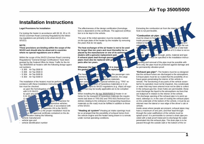
Installation InstructionsLegal Provisions for Installation
For testing the heater in accordance with §§ 19, 20 or 21StVZO (German Road Licensing Regulations) the follow-ing regulations are primarily to be observed (§ 22 aStVZO):
NOTE:These provisions are binding within the scope of theStVZO and should also be obs erved in countrieswhere no special regulations are in effect!
Within the scope of the StVZO (German Road LicensingRegulations) “General Design Certifications” have beengranted by the Federal Office for Motor Traffic for the AirTop 3500/5000 air heaters with the following design appro-val numbers: ~ S 305 Air Top 3500 B ~ S 306 Air Top 3500 D ~ S 304 Air Top 5000 B ~ S 303 Air Top 5000 D
The installation of the heaters must be performed in ac-cordance with these Installation Instructions. The installa-tion must be checked
a) upon the homologation of the vehicles in accordancewith § 20 StVZOb) upon any individual test in accordance with § 21 StVZO, orc) upon any examination in accordance with § 19 StVZO by a registered expert or examiner for motor traffic, an expert for automotive vehicles, or any other authorised official, in accordance with paragraph 7.4 a of Appendix VIII to the StVZO
and in the case of item c) the proper installation must becertified on the approval certificate contained on the de-sign certification stating the following:- vehicle manufacturer- vehicle type and- vehicle identification number
The effectiveness of the design certification (homologa-tion) is dependent on this certificate. The approval certifica-tion is to be kept in the vehicle.
The year of the initial operation must be durably markedon the type plate of the heater by the installer by removingthe years that do not apply.
The heat exchanger of the air heater is not to be usedfor longer than ten years and must thereafter be re-placed by the manufacturer or one of its authoriseddealers with a genuine replacement part.If exhaust pipes lead through passenger areas, thesepipes must also be replaced with genuine replacementparts after ten years.
Whenever the heater is removed it is imperative thatthe gasket located underneath be replaced.
The heaters are approved for heating the passenger com-partment and the driver’s cabin, not however, the cargospace for the transport of hazardous materials.When using the heater in special vehicles (e.g. “TRS” ve-hicles for the transport of hazardous materials) or in ve-hicles not subject to StVZO regulations (e.g. ships) all regu-lations that may be locally applicable are to be compliedwith.When installing the Air top 3500/5000 D heater in ve-hicles for the transport of hazardous materials the require-ments laid down in TRS 002 and TRS 003 (Technical Gui-delines relating to the ordinance of transporting hazardousmaterials on the road) must be fulfilled in addition to thoseof the StVZO.
“Heating air system”: Heating air intake openings mustbe so arranged that the possibility of exhaust fumes fromthe vehicle engine and the heater being drawn in is remoteunder normal operating conditions.
Extracting the combustion air from the interior of the ve-hicle is not permissible.
“Combustion air pipe: The combustion air requiredmust be drawn in from the outside of the vehicle.Inside passenger areas the combustion air lines are per-mitted to have a maximum of four joints and must be pro-vided with a splash-proof opening leading through the out-side wall. These joints must be so sealed that a total leak-age rate of 200 l/h at an overpressure of 0.5 mbar is not ex-ceeded.The pipe including lead-through, joints, material and typeof construction must be specified in the installation instruc-tions.Mounting and removal of the pipe must be possible withtools only, the pipe must be protected against damage andbe permanently vibration-proof.
“Exhaust gas pipe”: The heaters must be so designedthat the exhaust fumes are discharged to the atmosphere.Exhaust pipes must be so routed that the possibility of ex-haust gases penetrating the interior of the vehicle isremote. The functioning of any parts of the vehicle essen-tial for its operation must not be impaired. Any condensateor water that may have entered must not be able to collectin the exhaust gas line. Drain holes are permissible; thesemust discharge the liquid to the atmosphere via lines thatare leakproof in relation to the interior of the vehicle.The discharge opening of the exhaust pipe is to point up-ward, sideways or, in the case of routing the exhaust pipeson the underside of the bottom of the vehicle, it must be po-sitioned near the lateral or rear edge of the driver’s cab orvehicle.Inside areas where people are present, exhaust pipes mayhave a maximum of one joint, and their lead-throughthrough the outer wall/bottom of the vehicle must besplash-proof. It is permissible to connect a drain pipe pro-vided with a leak-proof metal joint to discharge the waterpenetrated into the exhaust pipe. The drain pipe is to bepassed through the outside wall or the bottom of the ve-
Air Top 3500/5000
1

hicle through a sealed bush.The heat exchanger, the connected exhaust pipe as wellas any drain pipe that may be connected must be sosealed that in the event of an overpressure equivalent tothe twofold overpressure of the exhaust gas at maximumpermissible exhaust pipe length – however, at a minimumoverpressure of 0.5 mbar – a leakage rate of a total of 30l/h is not exceeded.The pipe including lead-through, joints, material and typeof construction must be specified in the installation instruc-tions.Mounting and removal of the pipe must be possible withtools only, it must be protected against damage and be per-manently vibration-proof.Only metal pipes may be used. These must not exceed atemperature of 110 °C if the possibility of accidental con-tact in the vehicle’s interior exists. It is permissible to installa protection against accidental contact.
“Combustion Air Inlet” and “Exhaust Gas Outlet”:During installation it must be ensured that the openings ofthe combustion air inlet and exhaust gas outlet pipes areso designed that a spherical object of 16 mm diameter can-not be introduced.
Electric lines, switchgear and controlgear of the heatermust be so arranged in the vehicle that their functioningcannot be impaired under normal operating conditions.
All tubes leading from the heater toward the outside mustbe routed through splashwater-proof openings.
In the case of buses, the heater must be installed neitherin the driver’s compartment nor in the passenger area.
For the routing of fuel lines and the installation of additionalfuel tanks, articles 45 and 46 StVZO are to be adhered to.The most important excerpts therefrom are as follows:Fuel lines are to be designed in such a way that their sta-bility remains unaffected by torsional stresses in the ve-hicle, engine movement and the like. They must be pro-tected against mechanical damage. All parts of the fuel sys-tem must be protected against heat which would impair
their operation, and must be located such that dripping orevaporating fuel can neither collect nor be ignited by hotcomponents or electrical equipment.In the case of buses, fuel lines and fuel tanks may be lo-cated neither in the passenger area nor in the driver’s com-partment. In these vehicles the fuel tanks must be locatedsuch that they do not pose a direct hazard to the exits inthe event of a fire. The fuel must not be supplied by meansof gravity or gauge pressure in the fuel tank.
Mounting instructions for Webasto fuel tanks for fuel sup-ply of heating units in vehicles:In the case of buses, installation must not be performed inthe passenger area or in the driver’s compartment.The fuel filler neck must not be located inside the pas-senger area or the driver’s compartment in any vehicle.Petrol fuel tanks must not be located directly behind thefront panelling of the vehicle.They must be separated from the engine in such a mannerthat the possibility of fuel inflammation is remote even inthe event of an accident. This does not apply to tractor ve-hicles with open cabs.
The operating state of the heater at any given time – i.e. atleast whether it is on or off – must be easily recognizable.
Webasto will not assume any liability if the installation in-structions and the notes contained therein are not ob-served. The same applies to improperly performed repairsor those where others than genuine replacement partshave been used. In those cases, the heater’s General De-sign Certification and thus the vehicle’s General OperatingPermit (homologation) will be invalidated as a conse-quence.
Air Top 3500/5000
2

Scope of Application of the Air Heaters
The Webasto Air Top 3500/5000 air heaters are designedto provide the following features:- for the heating of driver’s cabs, boats, trucks, small
buses, vans and ambulance vehicles- defrosting the vehicle’s windows.
The heaters operate independently of the vehicle engineand are connected to the fuel tank and the electrical sys-tem of the vehicle.
They can be used in vehicles with water-cooled or air-cooled engines.
Installation
CAUTION:The legal provisions 1 and 2 relating to the installation areto be adhered to.It is not permitted to operate the heater without control unitcover (results in overheating of the heater).
Installation Details for Air Top 3500/5000
NOTE:The different vehicle-specific installation conditions shouldbe taken into account.
Installation Location
The heater can be fitted both inside and outside the ve-hicle. When installed on the outside, care must be takenthat the heater is fitted in a location that is protectedagainst splashwater and spray.
1 Heating air inlet2 Heating air outlet3 Combustion air inlet4 Exhaust gas outlet5. Fuel inlet
6 Space required for heating air inlet7 Space required for heating air outlet8 Space required for removal of heater9 Cable outlet (optionally on the right or left)
Fig. 1: Dimensions of the Heater
Air Top 3500/5000
3

If installed in the vehicle’s interior, the lead-through open-ings for combustion air inlet, exhaust gas outlet and fuelpipe must be splash-water protected.
For this purpose, the special gasket supplied with theheater must be used (see Fig. 4). The gasket must berenewed prior to each re-installation.
Mounting the Heater
When mounting the Air Top 3500/5000 heater, the M 6 nutsmust be tightened to a torque of 6 Nm +1 Nm.
The mounting dimensions as well as the space requiredfor the performance of servicing work are shown in the in-stallation drawing (Fig. 1). The specified horizontal andaxial angles of inclination must not be exceeded (Fig. 2).
A gasket (Fig. 4) must be fitted between heater and carbody. The gasket must be renewed prior to each re-installation. The support surface for the heater mountingfoot must be level . A special tool is available from themanufacturer for drilling the holes and levelling the supportsurface, if necessary. Surface irregularities of up to max. 1mm can be compensated for by means of the gasket.
CAUTION:After the installation has been performed, a check must becarried out to verify that no part of the housing is in contactwith any surrounding parts. Non-compliance could result ina blockage of the heater fan.
Name Plate
The type plate must be located at a place where it is pro-tected against damage and be easily accessible once theheater has been installed (or else, a type plate duplicate isto be used).
The years not applicable are to be removed from the typeplate.
0 - 90° 0 - 90° 0 - 90°
0 - 30°0 - 90° 0 - 90°
Diesel-fuelled heaters
petrol-fuelled heaters
Fig. 2: Permissible Installation Positions
Fig. 3: Hole Pattern
Fig. 4: Gasket
Unobstructed installation to be ensured!
Fig. 5: Installation
Air Top 3500/5000
4
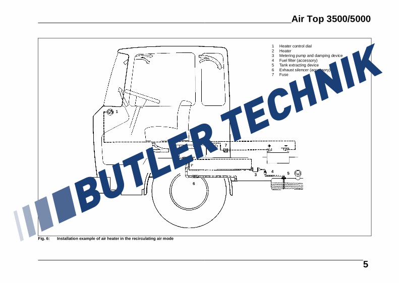
1 Heater control dial2 Heater3 Metering pump and damping device4 Fuel filter (accessory)5 Tank extracting device6 Exhaust silencer (accessory)7 Fuse
1
3
2
4
6
5
7
Fig. 6: Installation example of air heater in the recircul ating air mode
Air Top 3500/5000
5

Heating Air System
NOTE:It is not permissible to integrate the heater into the vehi-cle’s air ducting system.
Both recirculated-air and fresh-air operation is permissible.In the case of fresh-air operation, care must be taken thatthe heating air is extracted from an area that is protectedagainst splashwater and spray.
NOTE:In the case of fresh-air operation, an external temperaturesensor must be mounted within the space to be heated.
A temperature sensor is installed in the heater on the heat-ing air intake side which, in conjunction with the heater con-trol element and dependent upon the intake temperatureand position of the setpoint transmitter, operates theheater within the appropriate heat output range. Heat out-put is so adjusted that after a quick reaching of the presetinterior temperature the same will be maintained at thepreset value.Minimum inside diameter of heating air pipe is90 mm at Air Top 500080 mm at Air Top 3500may be decreased to 75mm subject to prior approval bythe manufacturer.
NOTE:For heating air ducts only materials capable of withstand-ing a temperature of at least 150° may be used.The hot air discharge opening is to be located so that thehot air is not directed onto parts that are not resistant toheat.
CAUTION:In vehicles designed for the transportation of passengers,the air outlet openings must be arranged in such a waythat they cannot be obstructed by passengers.
Maximum air pressure drop between intake and deliveryside of the heating air line:Air Top 3500 2,0 mbar (20 mm WH)Air Top 3500 Volume Plus 3,0 mbar (30 mm WH)Air Top 5000 3,0 mbar (30 mm WH)
The test can also be performed by measuring the tempera-ture directly at the heater:temperature difference between heating air inlet and hotair outlet max. 130 K.If this value is exceeded, the temperature limiter is ex-pected to trip. The heating air hose is to be secured at thejoints.
The hot air stream must be prevented from re-entering theheater, if the heater is operated in the recirculating modewithout any hot air ducting
CAUTION:If the heater is operated without heating air intake hose, itis imperative that the air intake grille supplied with theheater be mounted!
NOTE:The installation must be checked for the following:- “closed circuit” of air between the vehicle heater and the heater air inlet- “closed circuit” of air between heater air inlet and heater air outlet (fig. 7)- adequate space for taking in heating air (heating air to be extracted from the cool space of the cabin, e.g. in the case of installation underneath a bunk)
If an installation housing is used, the area around the airdischarge nozzle must be tightly sealed so that no hot aircan enter the installation box.
External Temperature Sensor
The installation of an external temperature sensor is rec-ommended if the heater is installed in an installation hous-ing or in location with poor ventilation (e.g. under-neathbunks). Extremely short cycle times of the heater can thusbe avoided.
Mounting of External Temperature Sensor
The external temperature sensor must be mounted on sur-faces as vertical as possible, at mid-height in the vehiclecab in the area to be heated.
The temperature sensor must not- be located directly in the hot air stream (vehicle’s orheater’s heating air).
- be mounted in the vicinity of heat sources (e.g. vehicle’s heating system).
- be exposed to direct sun radiation (e.g. on thedashboard).
- be mounted behind curtains or the like.
Fig. 7: Heating air inlet and heating air outlet
Fig. 7a: Heating air inlet with intake grille
Air Top 3500/5000
6
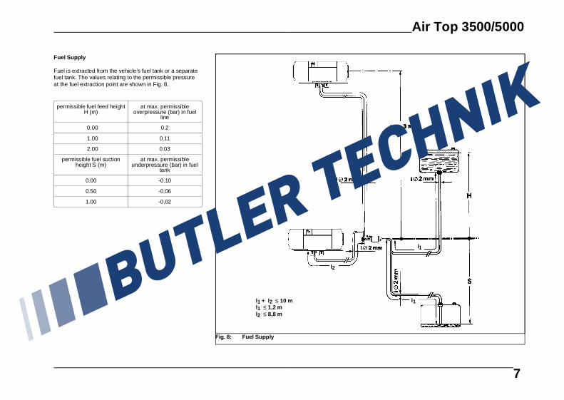
Fuel Supply
Fuel is extracted from the vehicle’s fuel tank or a separatefuel tank. The values relating to the permissible pressureat the fuel extraction point are shown in Fig. 8.
permissible fuel feed heightH (m)
at max. permissibleoverpressure (bar) in fuel
line
0.00 0.2
1.00 0.11
2.00 0.03
permissible fuel suctionheight S (m)
at max. permissibleunderpressure (bar) in fuel
tank
0.00 -0.10
0.50 -0.06
1.00 -0.02
l2
l1
l2
l1 + l2 ≤ 10 ml1 ≤ 1,2 ml2 ≤ 8,8 m
l1
Fig. 8: Fuel Supply
Air Top 3500/5000
7
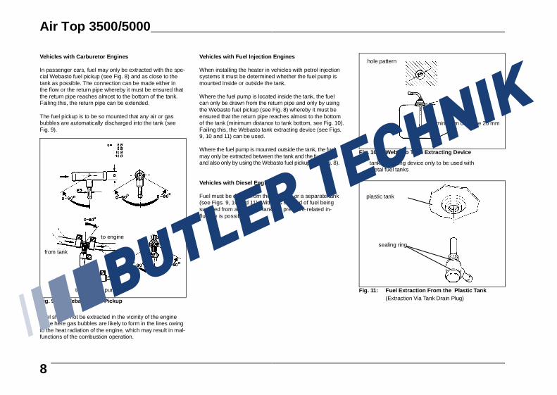
Vehicles with Carburetor Engines
In passenger cars, fuel may only be extracted with the spe-cial Webasto fuel pickup (see Fig. 8) and as close to thetank as possible. The connection can be made either inthe flow or the return pipe whereby it must be ensured thatthe return pipe reaches almost to the bottom of the tank.Failing this, the return pipe can be extended.
The fuel pickup is to be so mounted that any air or gasbubbles are automatically discharged into the tank (seeFig. 9).
Fuel should not be extracted in the vicinity of the enginesince here gas bubbles are likely to form in the lines owingto the heat radiation of the engine, which may result in mal-functions of the combustion operation.
Vehicles with Fuel Injection Engines
When installing the heater in vehicles with petrol injectionsystems it must be determined whether the fuel pump ismounted inside or outside the tank.
Where the fuel pump is located inside the tank, the fuelcan only be drawn from the return pipe and only by usingthe Webasto fuel pickup (see Fig. 8) whereby it must beensured that the return pipe reaches almost to the bottomof the tank (minimum distance to tank bottom, see Fig. 10).Failing this, the Webasto tank extracting device (see Figs.9, 10 and 11) can be used.
Where the fuel pump is mounted outside the tank, the fuelmay only be extracted between the tank and the fuel pumpand also only by using the Webasto fuel pickup (see Fig. 8).
Vehicles with Diesel Engines
Fuel must be drawn from the fuel tank or a separate tank(see Figs. 9, 10 and 11). With this method of fuel beingsupplied from a separate tank, no pressure-related in-fluence is possible.
* tank extracting device only to be used with metal fuel tanks
to metering pump
to engine
from tank
Fig. 9: Webasto Fuel Pickup
hole pattern
minimum distance 25 mm
Fig. 10: Webasto Tank Extracting Device
plastic tank
sealing ring
Fig. 11: Fuel Extraction From the Plastic Tank(Extraction Via Tank Drain Plug)
Air Top 3500/5000
8
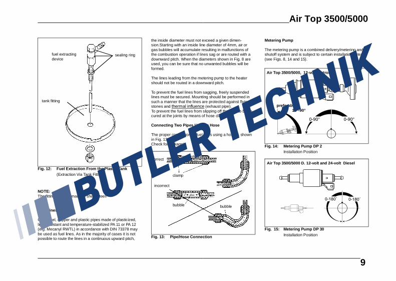
NOTE:The fitting must be made of sheet steel!
Fuel Lines
Only steel, copper and plastic pipes made of plasticized,light-resistant and temperature-stabilized PA 11 or PA 12(e.g. Mecanyl RWTL) in accordance with DIN 73378 maybe used as fuel lines. As in the majority of cases it is notpossible to route the lines in a continuous upward pitch,
the inside diameter must not exceed a given dimen-sion.Starting with an inside line diameter of 4mm, air orgas bubbles will accumulate resulting in malfunctions ofthe combustion operation if lines sag or are routed with adownward pitch. When the diameters shown in Fig. 8 areused, you can be sure that no unwanted bubbles will beformed.
The lines leading from the metering pump to the heatershould not be routed in a downward pitch.
To prevent the fuel lines from sagging, freely suspendedlines must be secured. Mounting should be performed insuch a manner that the lines are protected against flyingstones and thermal influence (exhaust pipe).To prevent the fuel lines from slipping off they are to be se-cured at the joints by means of hose clamps.
Connecting Two Pipes Using a Hose
The proper connection of fuel lines using a hose is shownin Fig. 13.Check for leakage!
Metering Pump
The metering pump is a combined delivery/metering andshutoff system and is subject to certain installation criteria(see Figs. 8, 14 and 15).
fuel extracting device
tank fitting
sealing ring
Fig. 12: Fuel Extraction From the Plastic Tank(Extraction Via Tank Fitting)
correct
incorrect
clamp
bubblebubble
Fig. 13: Pipe/Hose Connection
Air Top 3500/5000, 12-volt Petrol
preferably 15°-90°
Fig. 14: Metering Pump DP 2Installation Position
Air Top 3500/5000 D. 12-volt and 24-volt Diesel
Fig. 15: Metering Pump DP 30Installation Position
Air Top 3500/5000
9
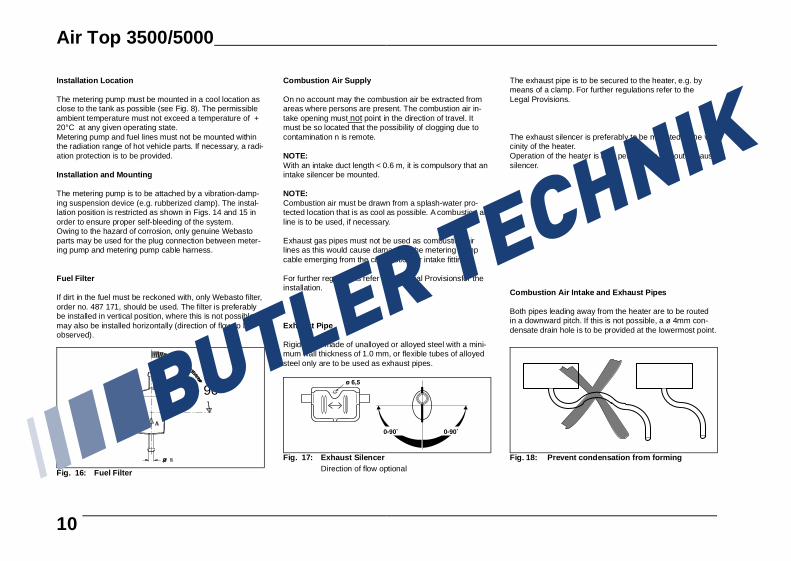
Installation Location
The metering pump must be mounted in a cool location asclose to the tank as possible (see Fig. 8). The permissibleambient temperature must not exceed a temperature of +20°C at any given operating state.Metering pump and fuel lines must not be mounted withinthe radiation range of hot vehicle parts. If necessary, a radi-ation protection is to be provided.
Installation and Mounting
The metering pump is to be attached by a vibration-damp-ing suspension device (e.g. rubberized clamp). The instal-lation position is restricted as shown in Figs. 14 and 15 inorder to ensure proper self-bleeding of the system.Owing to the hazard of corrosion, only genuine Webastoparts may be used for the plug connection between meter-ing pump and metering pump cable harness.
Fuel Filter
If dirt in the fuel must be reckoned with, only Webasto filter,order no. 487 171, should be used. The filter is preferablybe installed in vertical position, where this is not possible, itmay also be installed horizontally (direction of flow to beobserved).
Combustion Air Supply
On no account may the combustion air be extracted fromareas where persons are present. The combustion air in-take opening must not point in the direction of travel. Itmust be so located that the possibility of clogging due tocontamination n is remote.
NOTE:With an intake duct length < 0.6 m, it is compulsory that anintake silencer be mounted.
NOTE:Combustion air must be drawn from a splash-water pro-tected location that is as cool as possible. A combustion airline is to be used, if necessary.
Exhaust gas pipes must not be used as combustion airlines as this would cause damage to the metering pumpcable emerging from the combustion air intake fitting.
For further regulations refer to the Legal Provisionsfor theinstallation.
Exhaust Pipe
Rigid pipes made of unalloyed or alloyed steel with a mini-mum wall thickness of 1.0 mm, or flexible tubes of alloyedsteel only are to be used as exhaust pipes.
The exhaust pipe is to be secured to the heater, e.g. bymeans of a clamp. For further regulations refer to theLegal Provisions.
The exhaust silencer is preferably to be mounted in the vi-cinity of the heater.Operation of the heater is also permissible without exhaustsilencer.
Combustion Air Intake and Exhaust Pipes
Both pipes leading away from the heater are to be routedin a downward pitch. If this is not possible, a ø 4mm con-densate drain hole is to be provided at the lowermost point.
0 - 90°
Fig. 16: Fuel Filter
Fig. 17: Exhaust SilencerDirection of flow optional
Fig. 18: Prevent condensation from forming
Air Top 3500/5000
10

The lines must not point into the direction of travel.
The lines must be so arranged that any clogging due tocontamination is not to be expected.
CAUTION:A fire hazard exists if the installation position of the ex-haust pipe discharge opening differs from that shown inFig. 21.
Length of combustion air intake and exhaust pipes: with exhaust gas silencer: max. 2.6 m without exhaust gas silencer: max. 5.6 m
NOTE:For exhaust pipes lengths of 2 m and more, insulated ex-haust pipes are to be used (dew point not reached)
Inside diameter of pipes:Combustion air pipe: 25 mmExhaust pipe (metal): 24 mm
Smallest bending radius: 50 mm
Total angle of all bends:Combustion air pipe: max. 270°Exhaust pipe: max. 270°
Fig. 19: Pipe discharge openings not in direction oftravel
Fig. 20: Avoid areas exposed to water, mud or snow
To ensure an angle of discharge of 90° ± 10°, it is re-quired that the pipe clamp be attached no more than150 mm, from the exhaust pipe end
direction of discharge approximately vertical 90° ± 10°
Fig. 21: Exhaust Pipe Discharge OpeningInstallation Position
Air Top 3500/5000
11

Electrical Connections
All pipes that are not required must be insulated!
NOTE:When using the combination or standard digital timer aremote-control pushbutton may be provided near the bunkfor added convenience. The connection is to be performedin accordance with wiring diagram 30 and 31.
The electrical connection is to be performed in accordancewith the system circuit (Fig. 29, 30, 31, 32, 33).
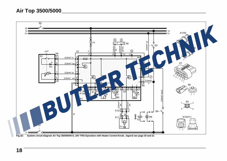
Connection in Vehicles for the Transportation of Dan-gerous Goods (TRS)
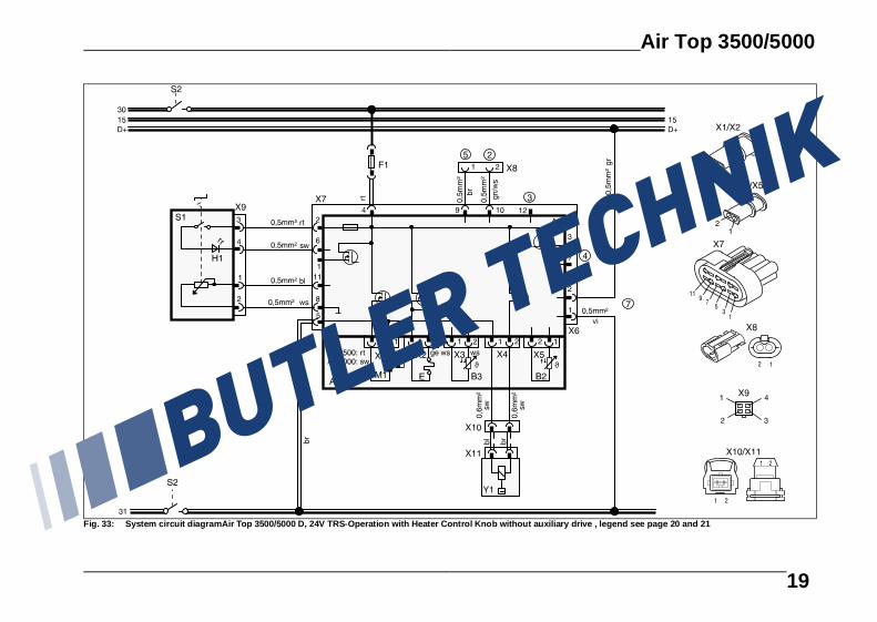
When installing the Air Top 3500/5000 D heaters in ve-hicles for the transport of hazardous materials, the require-ments laid down in TRS 002 and TRS 003 (Technical Gui-delines relating to the ordinance of transporting hazardousmaterials on the road) must be fulfilled in addition to thoseof the StVZO. The electrical connection is to be performedin accordance with wiring diagrams Fig. 32 or 33.On vehicles without auxiliary drives, electrical connectionis to be performed in accordance with the system circuit di-agram Fig. 33.
NOTE:Switch S3 must be so installed that in the event of a pump-ing device being put into operation, a plus potential is ap-plied across the corresponding input of the electronic con-trol unit.
CAUTION:If no voltage to ground is present at the control unit inputX6/1 upon start-up all TRS functions will be inoperative.After the plus potential has been applied across the controlunit input X6/1 (auxiliary drive ON) a short after-run periodof 20 seconds takes place and subsequently the controlunit is in its “fault lock-out” state.
CAUTION:In accordance with the Technical Guidelines relating to theordinance of transporting hazardous materials on the road,heaters may only be switched on by means of a specialswitch installed in the driver’s cabin and are to be actuatedmanually. If the heater is equipped with a combination orstandard digital timer, it must ensured that pin 4 on thecombination or standard digital timer remains unassigned.The heater can therefore only be started up by means ofthe instant heating button.No other digital timers are allowed to be used in TRS ve-hicles.
Connection of the Heater
To connect the cable harness, remove the control unitcover on the heater and connect the cable harness con-nectors with the control unit.
NOTE:Lift off control unit cover applying a blunt edge at its side(see arrows in Fig. 22)Be sure not to touch the printed cond uctors of thecontrol unit.Prior to starting up the heater for the first time, reinstall thecontrol unit cover to prevent any undue escaping of heat-ing air (overheating of heater).Cable lead-through can optionally be located on the left orright.To ensure that the cable lead-through in the control unitcover provides a tight seal, the cable grommet on thecable harness must be displaced accordingly.
Connection to Supply Voltage
Preferably to be supplied from the vehicle central electricalsystem.
To provide the heater with adequate protection, an ad-ditional flat fuse holder is to be installed (suppliedwith the heater). The fuse holder may only be installedin the vehicle interior.
Fig. 22: Removal of Control Unit Cover
Fig. 23: Removal of Mounting Plate of Fuse Holder
F = 15A (24V)F = 20A (12V)
Fig. 24: Fuse Holder, Installation Position
Air Top 3500/5000
12

Connection of Heater Control Element
The cable harness is prepared for connection to the heatercontrol.To withdraw the connector pull at the connector housingonly.If the cable harness is pulled, the connector housing islocked (self-locking).
NOTE:The optical fiber must be in contact with the rotary knob.
NOTE:As an option, an external temperature sensor can be in-stalled in the passenger area (see page 6)
Fig. 25: Heater Control Knob
Correct!Fig. 26: Mounting of Heater Control Knob
Incorrect!Fig. 27: Mounting of Heater Control Knob (incorrect)
Air Top 3500/5000
13
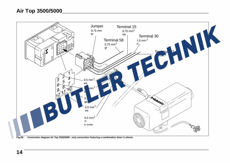
Jumper Terminal 15
Terminal 30
Terminal 31
to isolate
Terminal 58
Fig.28: Connection diagram Air Top 3500/5000 ; only connection featuring a combination timer is shown.
Air Top 3500/5000
14

ϑϑ
Fig.29: System circuit diagram Air Top 3500/5000, 12V/24V with Control Knob, legend see page 20 and 21
Air Top 3500/5000
15
ϑϑ
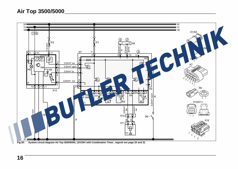
Fig.30: System circuit diagram Air Top 3500/5000, 12V/24V with Combination Timer , legend see page 20 and 21
Air Top 3500/5000
16

ϑϑ
Fig. 31: System circuit diagram Air Top 3500/5000, 12V/24V with Combination Timer and electrical battery disconnecting switch, legend see page 20 and 21
Air Top 3500/5000
17
ϑϑ
Fig.32: System circuit diagram Air Top 3500/5000 D, 24V TRS-Oper ation with Heater Control Knob , legend see page 20 and 21
Air Top 3500/5000
18
ϑϑ
Fig. 33: System circuit diagramAir Top 3500/5000 D, 24V TRS-Operation with Heater Control Knob without aux iliary drive , legend see page 20 and 21
Air Top 3500/5000
19
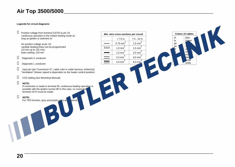
Min. wire cross sections per circuit
< 7.5 m 7.5 - 15 m
0.75 mm2
1.5 mm2
1.0 mm2
1.5 mm2
1.5 mm2
2.5 mm2
2.5 mm2
4.0 mm2
4.0 mm2
6.0 mm2
Colour of cables
blbrgegngrorrtswviws
bluebrownyellowgreengrayorangeredblackvioletwhite
Legende for circuit diagrams:
➀ Positive voltage from terminal (15/75) to pin 10:continuous operation in the instant heating mode aslong as ignition is switched on
No positive voltage at pin 10:variable heating times can be programmed(10 min up to 120 min), basic setting: 120 min
➁ Diagnostic K conductor
➂ Diagnostic L conductor
➃ Input pin (pin 7/connector X7, cable color in cable harness: white/red):“Ventilation” (blower speed is dependent on the heater control position)
➄ CO2 setting (see Workshop Manual)
➅ NOTE:If connection is made to terminal 30, continuous heating operation ispossible with the ignition turned off! In this case, no connection toterminal 15/75 must be made!
➆ NOTE:For TRS function, gray and purple wires are required.
Air Top 3500/5000
20
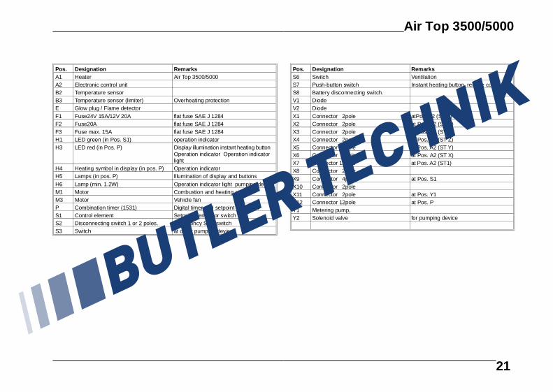
Pos. Designation RemarksA1 Heater Air Top 3500/5000A2 Electronic control unitB2 Temperature sensorB3 Temperature sensor (limiter) Overheating protectionE Glow plug / Flame detectorF1 Fuse24V 15A/12V 20A flat fuse SAE J 1284F2 Fuse20A flat fuse SAE J 1284F3 Fuse max. 15A flat fuse SAE J 1284H1 LED green (in Pos. S1) operation indicator H3 LED red (in Pos. P) Display illumination instant heating button
Operation indicator Operation indicatorlight
H4 Heating symbol in display (in pos. P) Operation indicator H5 Lamps (in pos. P) Illumination of display and buttonsH6 Lamp (min. 1.2W) Operation indicator light pumping deviceM1 Motor Combustion and heating air fanM3 Motor Vehicle fanP Combination timer (1531) Digital timer and setpoint generator S1 Control element Setpoint generator switchS2 Disconnecting switch 1 or 2 poles. Emergency Stop switchS3 Switch at or for pumping device
Pos. Designation RemarksS6 Switch VentilationS7 Push-button switch Instant heating button remote controlS8 Battery disconnecting switch.V1 DiodeV2 DiodeX1 Connector 2pole atPos. A2 (ST B)X2 Connector 2pole at Pos. A2 (ST V)X3 Connector 2pole at Pos. A2 (ST U)X4 Connector 2pole at Pos. A2 (ST Z)X5 Connector 2pole at Pos. A2 (ST Y)X6 Connector 2pole at Pos. A2 (ST X)X7 Connector 12pole at Pos. A2 (ST1)X8 Connector 2poleX9 Connector 4pole at Pos. S1X10 Connector 2poleX11 Connector 2pole at Pos. Y1X12 Connector 12pole at Pos. PY1 Metering pump, Y2 Solenoid valve for pumping device
Air Top 3500/5000
21

Initial Operation
After the heater has been installed, the fuel supply systemis to be bled thoroughly.
NOTE:Owing to the low fuel consumption it is required that theheater be turned on repeatedly to fill the fuel line leading tothe heater.
During a test run of the heater all connections are to bechecked for leakage and security. Should a malfunction ofthe heater occur during operation, fault isolating measuresare to be performed.
Shut-Down on Faults
Faults related to individual heater components and mal-functions during the start-up sequence are detected in thecontrol unit.
The heater is shut down (fault lock-out) in the followingcases: - no or unsuccessful start-up- temperature sensor defective- temperature limiter (interruption or short-circuit)- glow plug defective- insufficient fan speed, short circuit or interruption- fault in the metering pump circuit or overheat protection
circuit (during start-up phase only)- undervoltage of less than 10 volts or overvoltage of
more than 15 volts and for longer than 20 seconds (aplies to 12-volt heaters)
- undervoltage of less than 20 volts or overvoltage ofmore than 32 volts and for longer than 20 seconds(on 24-volt heaters)
- control unit defective- overheating
Fuel supply will be interrupted in the event of overheating.An after-run cycle is performed as is the case when theheater is shut down manually.After the after-run cycle has been terminated, the controlunit is in the fault lock-out state.An overheating condition is indicated by 10 flashing lightsignals of the operation indicator. Eliminate cause of malfunction.To deactivate the fault lock-out, the heater is to be briefly(min. 2 seconds) turned off and then switched back onagain one time.
Fault Code Display
If the heater is equipped with a combination or standarddigital timer, a fault code is indicated on the display of thedigital timer whenever a malfunction has occurred:
F 00 Control unit failure / incorrect parameter set / warm start detection
F 01 No start-up (after 2 start-up attempts) no formation of flamesF 02 Flame extinguished (repeated >5)F 03 Undervoltage or overvoltageF 04 Premature flame detectionF 06 Temperature sensor interruption or temperature sensor short-circuitF 07 Metering pump interruption or metering pump short-circuitF 08 Fan motor interruption or fan motor short-circuit or fan motor incorrect speedF 09 Pencil-type glow plug interruption or pencil-type glow plug short-circuitF 10 OverheatingF 11 Temperature limiter interruption or
temperature limiter short-circuitF 12 Setpoint transmitter (interruption / short-circuit)
Air Top 3500/5000
22

Technical DataUnless tolerances are shown within the technical datatable, a tolerance of ± 10% applies at an ambient tempera-ture of +20°C and at the rated voltage and conditions.
Electrical Components:Control unit, motor, fuel metering pump, light bulb in thedigital timer* and pencil-type glow plug/flame detector aredesigned either for 12-volt or 24-volt operation.
The digital timer*, temperature limiter and temperature sen-sor are voltage-independent components.
* Presetting of heater operating times is not possible forTRS-operation
Fuel for AT 3500/5000 B (Petrol):The fuel specified by the vehicle manufacturer is suitableas fuel for the heater.
Fuel for AT 3500/5000 D (Diesel/Fuel Oil EL):The Diesel fuel specified by the vehicle manufacturer issuitable as fuel for the heater. Also EL class fuel oil – not,however, L type fuel oil – can be used provided it conform-s to the usual quality on the German market in accordancewith DIN 51603.Any negative effect caused by additives is not known.When the fuel for the heater is drawn from the vehicle’s fuel tank, the vehicle manufac-turer’s specifications concerning additives are to be ob-served.
When to changing to cold-resistant fuels, the heater mustbe operated for approx. 15 minutes to ensure that the fuelpump is filled with the new fuel.
Heater Operation Air Top3500 B
Air Top3500 D
Air Top3500 D Volume
Plus
Air Top5000 B
Air Top5000 D
Mark of approval ~S 305 ~S 306 ~S 306 ~S 304 ~S 303
Type air heater with vaporizing type burner
Heat output control range 1,5 – 3,5 kW 1,5 – 3,5 kW 1,5 – 5,0(5,5)* kW*booster setting for max.
30 min.
Fuel petrol Diesel petrol Diesel
Fuel consumption *booster setting for max. 30 min.
control range 0,17 – 0,46l/h
0,17 – 0,42 l/h 0,19 – 0,66l/h
(0,73)* l/h
0,17 – 0,60l/h
(0,66)* l/h
Rated voltage 12 volts 12/24 volts 12 volts 12/24 volts
Operating voltage range 10,5 – 15volts
10,5–15/21–30 volts 10,5 – 15volts
10,5–15/21–30volts
Rated power consumption control range 15 – 36 W 15 – 36 W 15 – 90 W 15 – 90 W 15 – 90 W
Permissible ambient temperature:Heater: - operation
- storageMetering pump- operation
- storageHeater control - operation
- storage
-40°... +40°C-40°... +85°C-40°... +20°C-40°... +85°C-40°... +75°C-40°... +85°C
Perm. combustion air intake temperature
-40°... +20°C
Setting range for interior temperature
+10 ... + 45 °C
Flow rate of heating air against 0.5 mbar
139 m3/h 139 m3/h 218 m3/h 218 m3/h 218 m3/h
CO2 content in exhaust gas(permissible operating range)
1,5 kW:5,0-8,0%3,5 kW:9,0-12,5%
1,5 kW:5,0-8,0% 5 kW:9,0-12,5%
Dimensions of heater length 425 ± 2 mmwidth 148 ± 1 mmheight148 ± 1 mm
Weight of heater 5,9 Kg
Air Top 3500/5000
23

VersionAir Top 3500/5000 B (Petrol)Type Air Top 3500/5000 BAir heaters for petrol fuel(12 volts)
Air Top 3500/5000 D (Diesel)Type Air Top 3500/5000 DAir heaters for “Diesel/EL Fuel Oil EL” (12 or 24 volts)
Air Top 3500 Volume Plus D(Diesel)Type Air Top 3500 DAir heaters for “Diesel/EL Fuel Oil EL” (12 or 24 volts)
Air Top 3500/5000
24

Gasket
NOTE:Max. floor unevenness in thevicinity of the gasket: 1mm
Fig. 34: Drilling template
Air Top 3500/5000
25

Air Top 3500/5000
26

subject of modification Webasto Thermosysteme GmbH82131 Stockdorf . Kraillinger Str. 5 . Telefon (089) 85794-0 Telefax (089) 8 57 94-448 . Telex 5 23 647 webas d

Related Documents