Media access control - Ethernet (802.3) - Wireless LANs – 802.11 – Bluetooth - Switching and bridging – Basic Internetworking (IP, CIDR, ARP, DHCP,ICMP ) UNIT 2 MEDIA ACCESS & INTERNETWORKING MEDIA ACCESS CONTROL ETHERNET 802.3 Developed in the mid-1970s by researchers at the Xerox Palo Alto Research Center (PARC), the Ethernet eventually became the dominant local area networking technology, emerging from a pack of competing technologies. Today, it competes mainly with 802.11 wireless networks but remains extremely popular in campus networks and data centers. The more general name for the technology behind the Ethernet is Carrier Sense,Multiple Access with Collision Detect (CSMA/CD). As indicated by the CSMA name, the Ethernet is a multiple-access network,meaning that a set of nodes sends and receives frames over a shared link. You can, therefore, think of an Ethernet as being like a bus that has multiple stations plugged into it. The “carrier sense” in CSMA/CD means that all the nodes can distinguish between an idle and a busy link, and “collision detect” means that a node listens as it transmits and can therefore detect when a frame it is transmitting has interfered (collided) with a frame transmitted by another node. The Ethernet has its roots in an early packet radio network, called Aloha, developed at the University of Hawaii to support computer communication across the Hawaiian Islands. Like the Aloha network, the fundamental problem faced by the Ethernet is how to mediate access to a shared medium fairly and efficiently (in Aloha, the CS 6551 CN S.GNANAVEL AP (SS)/ CSE REC PAGE 1

Welcome message from author
This document is posted to help you gain knowledge. Please leave a comment to let me know what you think about it! Share it to your friends and learn new things together.
Transcript

Media access control - Ethernet (802.3) - Wireless LANs – 802.11 – Bluetooth - Switching and
bridging – Basic Internetworking (IP, CIDR, ARP, DHCP,ICMP )
UNIT 2 MEDIA ACCESS & INTERNETWORKING
MEDIA ACCESS CONTROL
ETHERNET 802.3
Developed in the mid-1970s by researchers at the Xerox Palo Alto Research Center (PARC), the
Ethernet eventually became the dominant local area networking technology, emerging from a pack of
competing technologies. Today, it competes mainly with 802.11 wireless networks but remains
extremely popular in campus networks and data centers. The more general name for the technology
behind the Ethernet is Carrier Sense,Multiple Access with Collision Detect (CSMA/CD).
As indicated by the CSMA name, the Ethernet is a multiple-access network,meaning that a set of
nodes sends and receives frames over a shared link. You can, therefore, think of an Ethernet as being
like a bus that has multiple stations plugged into it. The “carrier sense” in CSMA/CD means that all
the nodes can distinguish between an idle and a busy link, and “collision detect” means that a node
listens as it transmits and can therefore detect when a frame it is transmitting has interfered (collided)
with a frame transmitted by another node.
The Ethernet has its roots in an early packet radio network, called Aloha, developed at the University
of Hawaii to support computer communication across the Hawaiian Islands. Like the Aloha network,
the fundamental problem faced by the Ethernet is how to mediate access to a shared medium fairly
and efficiently (in Aloha, the medium was the atmosphere, while in the Ethernet the medium is a coax
cable). The core idea in both Aloha and the Ethernet is an algorithm that controls when each node can
transmit. Interestingly, modern Ethernet links are now largely point to point; that is, they connect one
host to an Ethernet switch, or they interconnect switches. Hence, “multiple access” techniques are not
used much in today’s Ethernets. At the same time, wireless networks have become enormously
popular, so the multiple access technologies that started in Aloha are today again mostly used in
wireless networks such as 802.11 (Wi-Fi) networks.
PHYSICAL PROPERTIES:
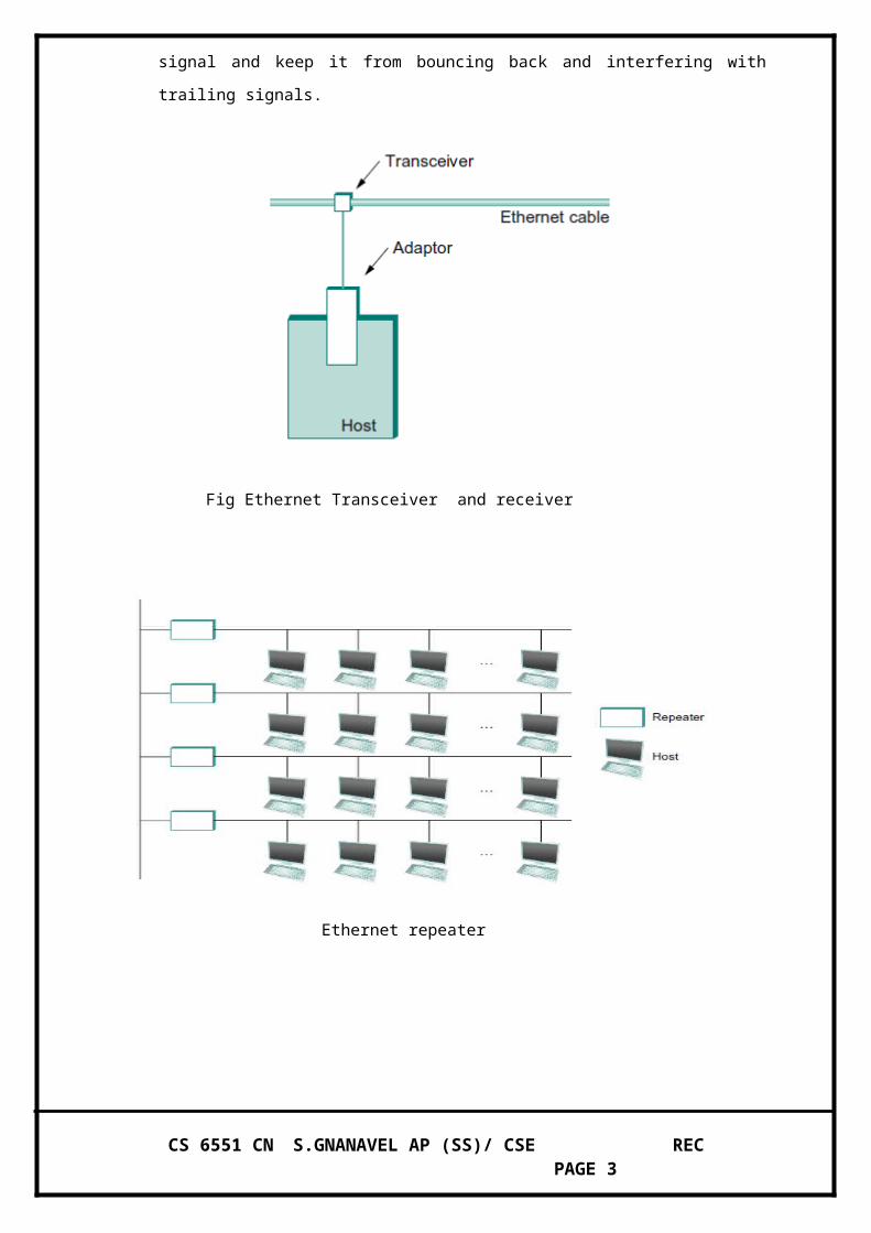
An Ethernet segment is implemented on a coaxial cable of up to 500m. this cable is similar to
the type used for cable TV, except that it typically has an impedance of 50 ohms instead of
cable TV’s 75 ohms. Hosts connect to an Ethernet segment by tapping into it; taps must be at
least 2.5 m apart.
CS 6551 CN S.GNANAVEL AP (SS)/ CSE REC PAGE 1

A transceiver a small device directly attached to the tap detects when the line is idle and
drives the signal when the host is transmitting. It also receives incoming signals. The
transceiver is, in turn, connected to an Ethernet adaptor, which is plugged into the host.
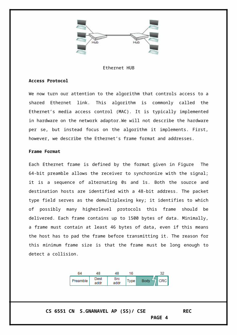
Multiple Ethernet segments can be joined together by repeater. A repeater is a device that
forwards digital signals, much like an amplifier forwards analog signals. However, no more
than four repeaters may be positioned between any pair of hosts, meaning that an Ethernet has
a total reach of only 2,500m.
An Ethernet is limited to supporting a maximum of 1,024 hosts. Terminators attached to the
end of each segment absorb the signal and keep it from bouncing back and interfering with
trailing signals.
Fig Ethernet Transceiver and receiver
CS 6551 CN S.GNANAVEL AP (SS)/ CSE REC PAGE 2
Ethernet repeater
Ethernet HUB
Access Protocol
We now turn our attention to the algorithm that controls access to a shared Ethernet link. This
algorithm is commonly called the Ethernet’s media access control (MAC). It is typically implemented
in hardware on the network adaptor.We will not describe the hardware per se, but instead focus on the
algorithm it implements. First, however, we describe the Ethernet’s frame format and addresses.
Frame Format
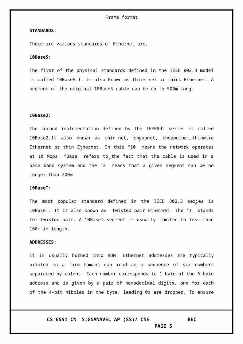
Each Ethernet frame is defined by the format given in Figure The 64-bit preamble allows the receiver
to synchronize with the signal; it is a sequence of alternating 0s and 1s. Both the source and
destination hosts are identified with a 48-bit address. The packet type field serves as the
demultiplexing key; it identifies to which of possibly many higherlevel protocols this frame should be
delivered. Each frame contains up to 1500 bytes of data. Minimally, a frame must contain at least 46
bytes of data, even if this means the host has to pad the frame before transmitting it. The reason for
this minimum frame size is that the frame must be long enough to detect a collision.
Frame format
STANDARDS:
There are various standards of Ethernet are,
10Base5:
The first of the physical standards defined in the IEEE 802.3 model is called 10Base5.It is also known
as thick net or thick Ethernet. A segment of the original 10Base5 cable can be up to 500m long.
CS 6551 CN S.GNANAVEL AP (SS)/ CSE REC PAGE 3
10Base2:
The second implementation defined by the IEEE892 series is called 10Base2.It also known as thin-
net, cheapnet, cheapernet,thinwire Ethernet or thin Ethernet. In this “10” means the network operates
at 10 Mbps, “Base” refers to the fact that the cable is used in a base band system and the “2” means
that a given segment can be no longer than 200m
10BaseT:
The most popular standard defined in the IEEE 802.3 series is 10BaseT. It is also known as twisted
pair Ethernet. The “T” stands for twisted pair. A 10BaseT segment is usually limited to less than
100m in length.
ADDRESSES:
It is usually burned into ROM. Ethernet addresses are typically printed in a form humans can read as a
sequence of six numbers separated by colons. Each number corresponds to 1 byte of the 6-byte
address and is given by a pair of hexadecimal digits, one for each of the 4-bit nibbles in the byte;
leading 0s are dropped. To ensure that every adaptor gets a unique address, each manufacturer of
Ethernet devices is allocated a different prefix that must be prep-ended to the address on every
adaptor they build.
UNICAST : Addresses are used to send messages to specific device.
MULTICAST : Addresses are used to send messages to group of devices.
BROADCAST : address are just used to send messages in the network who are in the need of
messages can use it.
TRANSMITTER ALGORITHM:
The receiver side of the Ethernet protocol is simple; the real smarts are implemented at
the sender’s side. The transmitter algorithm is defined as follows:
When the adaptor has a frame to send and the line is busy, it waits for the line to go
idle and then transmits immediately.
The Ethernet is said to be a 1-persistent protocol because an adaptor with a frame to
send transmits with probability 0<=p<=1 after a line becomes idle, and defers with
probability q=1-p.Because there is no centralized control it is possible for two (or
more) adaptors to begin transmitting at the same time, either because both found the
line to be idle or because both had been waiting for a busy line to become idle.
CS 6551 CN S.GNANAVEL AP (SS)/ CSE REC PAGE 4
When this happens, the two (or more) frames are said to collide on the network. Each
sender, because the Ethernet supports collision detection, is able to determine that a
collision is in progress. At the moment an adaptor detects that is frame is colliding
with another, it first makes sure to transmit a sure to transmit a 32-bit jamming
sequence and then stops the transmission.
Thus, a transmitter will minimally send 96 bits in the case of a collision: 64-bit
preamble plus 32-bit jamming sequence. One way that an adaptor will send only 96-
bits which is sometimes called a runt frame is if the two hosts are close to each other.
Had the two hosts been farther apart, they would have had to transmit longer, and thus
send more bits, before detecting the collision.
In fact, the worst-case scenario happens when the two hosts are at opposite ends of the
Ethernet. To know for sure that the frame it just sent did not collide with another
frame, the transmitter may need to send as many as 512 bits.
Not coincidentally, every Ethernet frame must be at least 512 bits (64 bytes)long: 14
bytes of header plus 46 bytes of data plus 4 bytes of CRC.
Where hosts A and B are at opposite ends of the network. Suppose host A begins
transmitting a frame at time t, as shown in (a). it takes it one link latency (let’s denote
the latency as d) for the frame to reach host B.
Thus, the first bit of A’s frame arrives at B at time t+d, as shown in (b). Suppose an
instant before host A’s frame arrives (i.e., B still sees and idle line), host B begins to
transmit its own frame.
B’s frame will immediately collide with A’s frame, and this collision will be detected
by host B(c). host B will send the 32-bit jamming sequence, as described above.(B’s
frame will be a runt).
Unfortunately, host A will not know that the collision occurred until B’s frame
reaches it, which will happen one link latency later, at time t+2xd, as shown in (d).
Host A must continue to transmit until this time in order to detect the collision. In
other words, host A must transmit for 2xd should be sure that it detects all possible
collisions.
Considering that a maximally configured Ethernet is 2,500 m long, and that there may
be up to four repeaters between any two hosts, the round-trip delay has been
determined to be 51.2 microseconds, which on a 10-Mbps Ethernet corresponds to
512 bits.
The other way to look at this situation is that we need to limit the Ethernet’s
maximum latency to a fairly small value (e.g., 512micro seconds) for the access
CS 6551 CN S.GNANAVEL AP (SS)/ CSE REC PAGE 5

algorithm to work; hence, an Ethernet’s maximum length must be something on the
order of 2,500m.
Once an adaptor has detected a collision and stopped its transmission, it waits certain
amount of time and tries again. Each time it tries to transmit but fails, the adaptor
doubles the amount of time it waits before trying again.
This strategy of doubling the delay interval between each retransmission attempt is a
general technique known as exponential back off. More precisely, the adaptor first
delays either 0 or 51.2 microseconds, selected at random. If this effort fails, it then
waits 0, 51.2, 102.4, or 153.6 microseconds (selected randomly) before trying again;
this is kx51.2 for k=0...2^3-1, again selected at random.
In general, the algorithm randomly selects a k between 0 and 2^n-1 and waits kx51.2
microseconds, where n is the number of collisions experienced so far. The adaptor
gives up after a given number of tries and reports a transmit error to the host. Adaptor
typically retry up to 16 times, although the back off algorithm caps n in the above
formula at 10.
WIRELESS
Wireless technologies differ in variety of dimensions, most notably in how much bandwidth
they provide and how far apart communicating nodes can be. Other important differences
include hich part of the electromagnetic spectrum they use (including whether it requires a
license) and how much power they consume.
Four prominent wireless technologies:
Blue tooth
Wi-Fi(more formally known as 802.11)
WiMAX(802.16)
Third generation or 3Gcellular wireless.
CS 6551 CN S.GNANAVEL AP (SS)/ CSE REC PAGE 6

The most widely used wireless links today are usually asymmetric, that is, the two endpoints
are usually different kinds of nodes. BASE STATION, usually has no mobility, but has a
wired (or at least high bandwidth) connection to the internet or other networks.
Wireless network using base station
A “client node” is often mobile, and relies on its link to the base station for all its
communication with other nodes. Wireless communication naturally supports point to
multipoint communication, because radio waves sent by one device can be simultaneously
received by many devices. However, it is often useful to create a point to point link
abstraction for higher layer protocols.
This topology implies three qualitatively different levels of mobility. The first level is no
mobility, such as when a receiver must be in a fixed location to receive a directional
transmission from the base station, as is the case with the initial version of WiMAX. The
second level is mobility within the range of a base, as is the case with Bluetooth. The third
level is mobility between bases, as is the case with cell phones and Wi-Fi.
Wireless adhoc or mesh network
CS 6551 CN S.GNANAVEL AP (SS)/ CSE REC PAGE 7

WI-FI (802.11):
This section takes a closer look at a specific technology centered on the emerging IEEE
802.11 standard, also known as Wi-Fi. Wi-Fi is technically a trademark, owned by a trade
group called the Wi-Fi alliance that certifies product compliance with 802.11. 802.11 is
designed for use in a limited geographical area (homes, office buildings, campuses) and its
primarily challenge is to mediate access to a shared communication medium in this case,
signals propagating through space.
Physical Properties:
802.11 run over six different physical layer protocols. Five are based on spread spectrum
radio, and one on diffused infrared (and is of historical interest only at this point). The fastest
runs at a maximum of 54 Mbps. he original 802.11 standard defined two radio based
physical layers standards, one using frequency hopping and the other using direct sequence.
Both provide up to 2 Mbps. Then physical layer standard 802.11 b was added. Using a
variant of direct exempt 2.4GHz frequency band of the electromagnetic spectrum. Then came
802.11a, which delivers up to 54 Mbps using a variant of FDM called orthogonal frequency
division multiplexing (OFDM). 802.11 a runs in the license-exempt 5GHz band. The most
recent standard is 802.11g, which is backward compatible with 802.11b.
Overview of Leading Wireless Technologies Bluetooth (802.15.1) Wi-Fi (802.11) 3G
Cellular Typical link length 10 m 100 m Tens of kilometers Typical data rate 2 Mbps
(shared) 54 Mbps (shared) Hundreds of kbps (per connection) Typical use Link a peripheral
Link a computer Link a mobile phone to a computer to a wired base to a wired tower Wired
technology USB Ethernet DSL analogyCollision Avoidance At first glance, it might seem
that a wireless protocol would follow the same algorithm as the Ethernet—wait until the link
becomes idle before transmitting and back off should a collision occur—and, to a first
approximation, this is what 802.11 does. The additional complication for wireless is that,
while a node on an Ethernet receives every other node’s transmissions and can transmit and
receive at the same time, neither of these conditions holds for wireless nodes. This makes
detection of collisions rather more complex. The reason why wireless nodes cannot usually
transmit and receive at the same time (on the sam frequency) is that the power generated by
the transmitter is much higher than any received
CS 6551 CN S.GNANAVEL AP (SS)/ CSE REC PAGE 8

signal is likely to be and so swamps the receiving circuitry. The reason why a node may not
receive transmissions from another node is because that node may be too far away or blocked
by an obstacle. This situation is a bit more complex than it first appears, as the following
discussion will illustrate. Consider the situation depicted in Figure , where A and C are both
within range of B but not each other. Suppose both A and C want to communicate with B and
so they each send it a frame. A and C are unaware of each other since their signals do not
carry that far. These two frames collide with each other at B, but unlike an Ethernet, neither
A nor C is aware of this collision. A and C are said to be hidden nodes with respect to each
other.
The hidden node problem .Although A and C are hidden from each other, their
signals can collied at B . (B's reach is not shown)
A related problem, called the exposed node problem, occurs under the circumstances
illustrated in Figure , where each of the four nodes is able to send and receive signals that
reach just the nodes to its immediate left and right. For example, B can exchange frames with
A and C but it cannot reachD, while C can reach B andDbut not A. Suppose B is sending to
A. Node C is aware of this communication because it hears B’s transmission.
It would be a mistake, however, for C to conclude that it cannot transmit to anyone just
because it can hear B’s transmission. For example, suppose C wants to transmit to node D.
This is not a problem since C’s transmission toDwill not interfere with A’s ability to receive
fromB. (Itwould interfere with A sending to B, but B is transmitting in our example.)
802.11 addresses these problems by using CSMA/CA, where the CA stands for collision
avoidance, in contrast to the collision detection of CSMA/CD used on Ethernets. There are a
few pieces to make this work. The Carrier Sense part seems simple enough: Before sending a
packet, the transmitter checks if it can hear any other transmissions; if not, it sends. However,
because of the hidden terminal problem, just waiting for the absence of signals from other
transmitters does not guarantee that a collision will not occur from the perspective of the
receiver. For this reason, one part of CSMA/CA is an explicit ACK from the receiver to the
sender. If the packet was successfully decoded and passed its CRC at the receiver, the
receiver sends an ACK back to the sender.
CS 6551 CN S.GNANAVEL AP (SS)/ CSE REC PAGE 9

Fig: the exposed node problem. Although B and C are exposed to each other's signals, there
is no interference if B transmits to A while C transmits t o D . (A and D reaches are not
shown)
Note that if a collision does occur, it will render the entire packet useless.10 For this reason,
802.11 adds an optional mechanism called RTS-CTS (Ready to Send-Clear to Send). This
goes some way toward addressing the hidden terminal problem. The sender sends an RTS a
short packet—to the intended receiver, and if that packet is received successfully the receiver
responds with another short packet, the CTS.
Even though the RTS may not have been heard by a hidden terminal, the CTS probably will
be. This effectively tells the nodes within range of the receiver that they should not send
anything for a while—the amount of time of the intended transmission is included in the RTS
and CTS packets. After that time plus a small interval has passed, the carrier can be assumed
to be available again, and another node is free to try to send.
Of course, two nodes might detect an idle link and try to transmit an RTS frame at the same
time, causing their RTS frames to collide with each other. The senders realize the collision
has happened when they do not receive the CTS frame after a period of time, in which case
they each wait a random amount of time before trying againAfter a successful RTS-CTS
exchange, the sender sends its data packet and, if all goes well, receives an ACK for that
packet. In the absence ofa timely ACK, the sender will try again to request usage of the
channel again, using the same process described above. By this time, of course, other nodes
may again be trying to get access to the channel as well.
Distribution System
As described so far, 802.11 would be suitable for a network with a mesh (ad hoc) topology,
and development of an 802.11s standard for mesh networks is nearing completion. At the
current time, however, nearly all 802.11 networks use a base-station-oriented topology.
CS 6551 CN S.GNANAVEL AP (SS)/ CSE REC PAGE 10

Instead of all nodes being created equal, some nodes are allowed to roam (e.g., your laptop)
and some are connected to a wired network infrastructure. 802.11 calls these base stations
access points (APs), and they are connected to each other by a so-called distribution system.
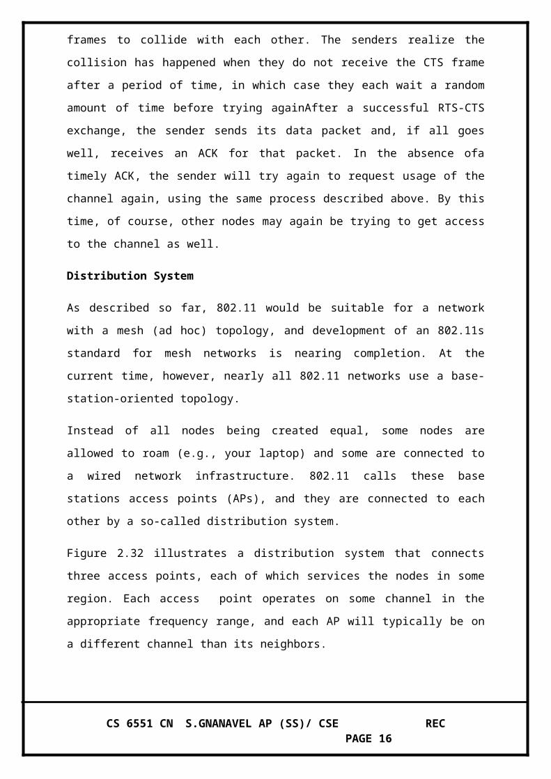
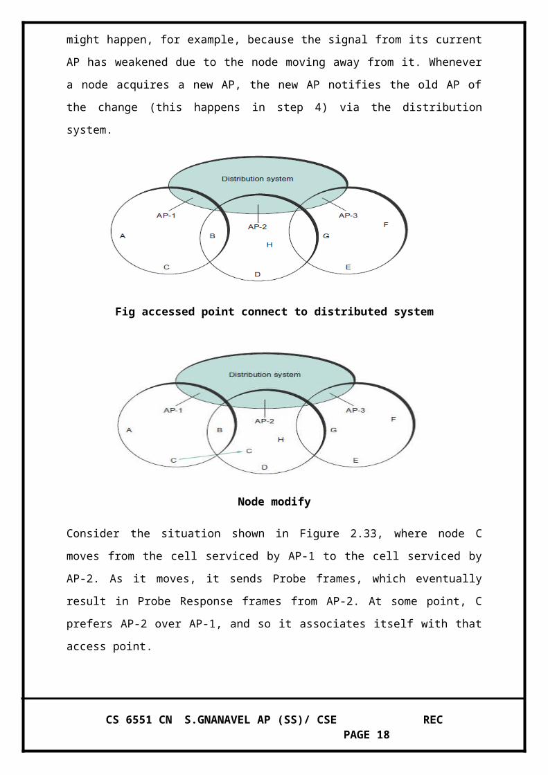
Figure 2.32 illustrates a distribution system that connects three access points, each of which
services the nodes in some region. Each access point operates on some channel in the
appropriate frequency range, and each AP will typically be on a different channel than its
neighbors.
The details of the distribution system are not important to this discussion—it could be an
Ethernet, for example. The only important point is that the distribution network operates at
the link layer, the same protocol layer as the wireless links. In other words, it does not depend
on any higher-level protocols (such as the network layer). Although two nodes can
communicate directly with each other if they are within reach of each other, the idea behind
this configuration is that each node associates itself with one access point. For node A to
communicate with node E, for example, A first sends a frame to its accesspoint (AP-1),
which forwards the frame across the distribution system to AP-3, which finally transmits the
frame to E. How AP-1 knew to forward the message to AP-3 is beyond the scope of 802.11.
What 802.11 does specify is how nodes select their access points and, more interestingly,
how this algorithm works in light of nodes moving from one cell to another.
The technique for selecting an AP is called scanning and involves the following four steps:
1. The node sends a Probe frame.
2. All APs within reach reply with a Probe Response frame.
3. The node selects one of the access points and sends that AP an Association Request frame.
4. The AP replies with an Association Response frame.
A node engages this protocol whenever it joins the network, as well as when it becomes
unhappy with its current AP. This might happen, for example, because the signal from its
current AP has weakened due to the node moving away from it. Whenever a node acquires a
new AP, the new AP notifies the old AP of the change (this happens in step 4) via the
distribution system.
CS 6551 CN S.GNANAVEL AP (SS)/ CSE REC PAGE 11

Fig accessed point connect to distributed system
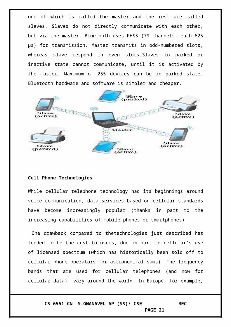
Node modify
Consider the situation shown in Figure 2.33, where node C moves from the cell serviced by
AP-1 to the cell serviced by AP-2. As it moves, it sends Probe frames, which eventually
result in Probe Response frames from AP-2. At some point, C prefers AP-2 over AP-1, and
so it associates itself with that access point.
The mechanism just described is called active scanning since the node is actively searching
for an access point. APs also periodically send a Beacon frame that advertises the capabilities
of the access point; these include the transmission rates supported by the AP. This is called
passive scanning, and a node can change to this AP based on the Beacon frame simply by
sending an Association Request frame back to the access point.
Frame Format
Fig 801.11 Frame format
CS 6551 CN S.GNANAVEL AP (SS)/ CSE REC PAGE 12

Most of the 802.11 frame format, which is depicted in Figure , is exactly what we would
expect. The frame contains the source and destination node addresses, each of which is 48
bits long; up to 2312 bytes of data; and a 32-bit CRC. The Control field contains three
subfields of interest (not shown): a 6-bit Type field that indicates whether the frame carries
data, is an RTS or CTS frame, or is being used by the scanning algorithm, and a pair of 1-bit
fields—called ToDS and FromDS—that are described below. The peculiar thing about the
802.11 frame format is that it contains four, rather than two, addresses. How these addresses
are interpreted depends on the settings of the ToDS and FromDS bits in the frame’s Control
field. This is to account for the possibility that the frame had to be forwarded across the
distribution system, which would mean that the original sender is not necessarily the same as
the most recent transmitting node. Similar reasoning applies to the destination address. In the
simplest case, when one node is sending directly to another, both the DS bits are 0, Addr1
identifies the target node, and Addr2 identifies the source node. In the most complex case,
both DS bits are set to 1, indicating that the message went from a wireless node onto the
distribution system, and then from the distribution system to another wireless node.With both
bits set, Addr1 identifies the ultimate destination, Addr2 identifies the immediate sender (the
one that forwarded the frame from the distribution system to the ultimate destination), Addr3
identifies the intermediate destination (the one that accepted the frame from a wireless node
and forwarded it across the distribution system), and Addr4 identifies the original source.
BLUETOOTH.
Bluetooth technology, standardized as IEEE 802.15.1 is a personal area network (PAN).
It is used for short-range wireless communication (maximum 10 m) between mobile phones,
PDAs, notebook and other peripheral devices. Uses low power transmission, operates in 2.45
GHz band with data rate up to 3 Mbps. Bluetooth Special Interest Group has specified a set of
protocols for a range of application, known as profiles. For instance, a profile synchronizes
PDA and PC.
Bluetooth network configuration is known as piconet. A piconet can have up to eight stations,
one of which is called the master and the rest are called slaves. Slaves do not directly
communicate with each other, but via the master. Bluetooth uses FHSS (79 channels, each
625 μs) for transmission. Master transmits in odd-numbered slots, whereas slave respond in
even slots.Slaves in parked or inactive state cannot communicate, until it is activated by the
master. Maximum of 255 devices can be in parked state. Bluetooth hardware and software is
simpler and cheaper.
CS 6551 CN S.GNANAVEL AP (SS)/ CSE REC PAGE 13

Cell Phone Technologies
While cellular telephone technology had its beginnings around voice communication, data
services based on cellular standards have become increasingly popular (thanks in part to the
increasing capabilities of mobile phones or smartphones).
One drawback compared to thetechnologies just described has tended to be the cost to users,
due in part to cellular’s use of licensed spectrum (which has historically been sold off to
cellular phone operators for astronomical sums). The frequency bands that are used for
cellular telephones (and now for cellular data) vary around the world. In Europe, for
example, the main bands for cellular phones are at 900 MHz and 1800 MHz. In North
America, 850-MHz and 1900-MHz bands are used. This global variation in spectrum usage
creates problems for users who want to travel from one part of the world to another and has
created a market for phones that can operate at multiple frequencies (e.g., a tri-band phone
can operate at three of the four frequency bands mentioned above).
That problem, however, pales in comparison to the proliferation of incompatible standards
that have plagued the cellular communication business. Only recently have some signs of
convergence on a small set of standards appeared. And, finally, there is the problem that,
because most cellular technology was designed for voice communication, high-bandwidth
data communication has been a relatively recent addition to the standards.Like 802.11 and
WiMAX, cellular technology relies on the use of base stations that are part of a wired
network.
The geographic area served by a base station’s antenna is called a cell. A base station could
serve a single cell or use multiple directional antennas to serve multiple cells. Cells don’t
have crisp boundaries, and they overlap. Where they overlap, a mobile phone could
CS 6551 CN S.GNANAVEL AP (SS)/ CSE REC PAGE 14

potentially communicate with multiple base stations. This is somewhat similar to the 802.11
picture shown in Figure . At any time, however, the phone is in communication with, and
under the control of, just one base station.
As the phone begins to leave a cell, it moves into an area of overlap with one or more other
cells. The current base station senses the weakening signal from the phone and gives control
of the phone to whichever base station is receiving the strongest signal from it. If the phone is
involved in a call at the time, the call must be transferred to the new base station in what is
called a handoff.As we noted above, there is not one unique standard for cellular, but rather a
collection of competing technologies that support data traffic in different ways and deliver
different speeds. These technologies are loosely categorized by generation.
The first generation (1G) was analog, and thus of limited interest from a data
communications perspective.
Second-generation standards moved to digital and introduced wirelessdata services, while
third generation (3G) allowed greater bandwidths and simultaneous voice and data
transmission. Most of the widely deployed mobile phone networks today support some sort of
3G, with 4G starting to appear. Because each of the generations encompasses a family of
standards and technologies, it’s often a matter of some debate (and marketing interest) as to
whether a particular network is 3G or some other generation.The concept of a third
generation was established before there was any implementation of 3G technologies, with the
aim of shaping a single international standard that would provide much higher data
bandwidth than 2G. Unfortunately, a single standard did not emerge, and this trend seems
likely to continue with 4G. Interestingly, however,
most of the 3G standards are based on variants of CDMA (Code Division Multiple Access).
CDMA uses a form of spread spectrum to multiplex the traffic from multiple devices into a
common wireless channel. Each transmitter uses a pseudorandom chipping code at a
frequency that is high relative to the data rate and sends the exclusive OR of the data with the
chipping code. Each transmitter’s code follows a sequence that is known to the intended
receiver—for example, a base station in a cellular network assigns a unique code sequence to
each mobile device with which it is currently associated.
When a large number of devices broadcast their signals in the same cell and frequency band,
the sum of all the transmissions looks like random noise. However, a receiver who knows the
code being used by a given transmitter can extract that transmitter’s data from the apparent
CS 6551 CN S.GNANAVEL AP (SS)/ CSE REC PAGE 15
noise. Compared to other multiplexing techniques, CDMA has some good properties for
bursty data. There is no hard limit on how many users can share a piece of spectrum you just
need to make sure they all have unique chipping codes. The bit error rate does however go up
with increasing numbers of concurrent transmitters.
This makes it very well suited for applications where many users exist but at any given
instant many of them are not transmitting which pretty well describes many data applications
such as web surfing. And, in practical systems when it is hard to achieve very tight
synchronization among all the mobile handsets, CDMA achieves better spectral efficiency
(i.e., it gets closer to the theoreticallimits of the Shannon–Hartley theorem) than other
multiplexing schemes Like TDMA.
Switching and Bridging
In the simplest terms, a switch is a mechanism that allows us to interconnect links to forma
larger network. A switch is a multi-input, multi-output device that transfers packets from an
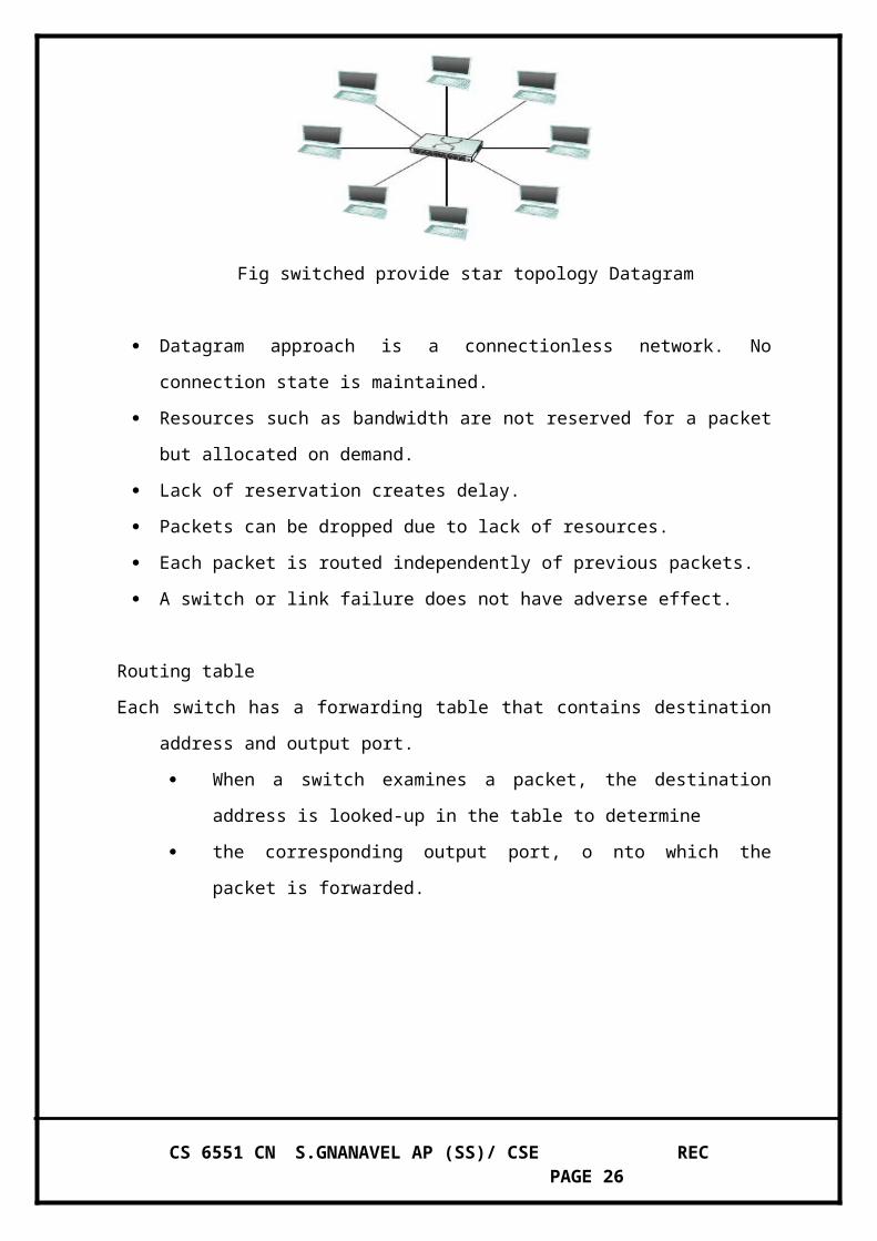
input to one or more outputs. Thus, a switch adds the star topology (see Figure ) to the point-
to-point link, bus (Ethernet), and ring topologies established .
A star topology has several attractive properties:
Even though a switch has a fixed number of inputs and outputs, which limits the
number of hosts that can be connected to a single switch, large networks can be built
by interconnecting a number of switches.
We can connect switches to each other and to hosts using point-to-point links, which
typically means that we can build networks of large geographic scope.
Adding a new host to the network by connecting it to a switch does not necessarily
reduce the performance of the network for other hosts already connected.
Fig switched provide star topology Datagram
CS 6551 CN S.GNANAVEL AP (SS)/ CSE REC PAGE 16

Datagram approach is a connectionless network. No connection state is maintained.
Resources such as bandwidth are not reserved for a packet but allocated on demand.
Lack of reservation creates delay.
Packets can be dropped due to lack of resources.
Each packet is routed independently of previous packets.
A switch or link failure does not have adverse effect.
Routing table
Each switch has a forwarding table that contains destination address and output port.
When a switch examines a packet, the destination address is looked-up in the
table to determine
the corresponding output port, o nto which the packet is forwarded.
Example Network Forwarding table for Switch-2
Datagram networks have the following characteristics:
A host can send a packet anywhere at any time, since any packet that turns up at a
switch can be immediately forwarded (assuming a correctly populated forwarding
table). For this reason, datagram networks are often called connectionless; this
contrasts with the onnection-oriented networks described below, in which some
connection state needs to be established before the first data packet is sent.
When a host sends a packet, it has no way of knowing if the network is capable of
delivering it or if the destination host is even up and running.
CS 6551 CN S.GNANAVEL AP (SS)/ CSE REC PAGE 17
Each packet is forwarded independently of previous packets that might have been sent
to the same destination. Thus, two successive packets from host A to host B may
follow completely different paths (perhaps because of a change in the forwarding
table at some switch in the network).
A switch or link failure might not have any serious effect on communication if it is
possible to find an alternate route around the failure and to update the forwarding
table accordingly.
Virtual Circuit Switching
Virtual-circuit is a connection-oriented model. A virtual connection from source to the
destination is established before any data is sent.
Each switch contains VC table with each entry containing incoming port, incoming
VCI, outgoing port and outgoing VCI.
Virtual Circuit Identifier (VCI) uniquely identifies a connection. It has link local
scope. Incoming and outgoing VCI is always distinct.
VCI and interface on which it was received, uniquely identifies a virtual connection.
Connection state set by the administrator is known as Permanent virtual circuit
(PVC).
Hosts can set virtual circuit through signalling (SVC). It consist of two phases: Setup
Request and Acknowledgement
Setup Request Acknowledgement
CS 6551 CN S.GNANAVEL AP (SS)/ CSE REC PAGE 18

Setup Request
Switch 1 receives connection setup request frame from host A.
It knows that frames for host B should be forwarded on port 3. Creates an entry in its VC
table for the new connection with incoming port=1 and outgoing port=3.
Chooses an unused VCI for frames to host B, say 14 as incoming VCI.
Outgoing VCI is unknown (left blank) and the frame is forwarded to switch 2.
Similarly entries are made at other switches as frame is forwarded to destination.
Destination B accepts the setup request frame. Assigns an unused VCI, say 77, for
frames that come from host A.
Acknowledgment
Host B sends an acknowledgment to switch 3.
The ACK frame carries source & destination addresses and chosen VCI by host B.
Switch 3 uses this VCI, i.e., 77 as outgoing VCI and completes VC table entry.
Similarly other switches fill up outgoing VCI and forward the ACK.
Finally switch 1 sends an acknowledgment to source host A containing VCI as 14.
Source host A uses 14 as its outgoing VCI for data frames to be sent to destination B.
Data transfer starts after connection establishment
Resources are reserved, therefore QoS is guaranteed by the network
In case of switch/link failure, old connection is torn and new one needs to be
established.
All information about network topology required to route a packet to the destination is
provided by the source host.
Header contains ordered list of intermediate hosts, through which packet must
traverse. Hence headers are of variable length.
Headers can be handled either by rotation or stripping or pointer-based approach.
Source routing is classified as either strict or loose.
Strict source route specifies every node along the path
Loose source route specifies set of nodes to be Traversed
When a frame arrives, the bridge performs a look-up on the table.
Outgoing port for the destination is obtained and the frame is sent on that port.
Rotation Stripping Pointer
CS 6551 CN S.GNANAVEL AP (SS)/ CSE REC PAGE 19

BRIDGES AND LAN SWITCHES:
It is a node that forward frames from one Ethernet to the other. This node would be in
promiscuous mode, accepting all frames transmitted on either of the Ethernets, so it could
forward them to the other. A bridge is connected between two LANs with port. By using the
port number the LANs are addressed. Connected LANs are known as extended LAN
LEARNING BRIDGES:
Bridges maintains a forwarding table which contains each host with their port number.
Having a human maintain this table is quite a burden, so a bridge can learn this information
for itself. The idea is for each bridge to inspect the source address in all the frames it receives.
When a bridge first boots, this table is empty; entries are added over time. Also a timeout is
associated with each entry and the bridge is cards the entry after a specified period of time.
Bridged network Forwarding Table
Learning bridges builds forwarding table gradually by learning from frame
movements.
Forwarding table is empty when the bridge boots up.
Bridge uses source address to add entries and destination address to forward frames.
Source address and incoming port is appended to the table, if an entry does not exist.
Forwarding table is looked up for destination address:
If source and destination are from same LAN, then the frame is dropped.
If an entry exists, then frame is forwarded on the corresponding port.
Otherwise, the frame is flooded on all other ports.
Learning process continues as bridge forwards frames and optimizes forwarding decision.
When host A sends a frame to D:
Bridge has no entry for either station D or A
CS 6551 CN S.GNANAVEL AP (SS)/ CSE REC PAGE 20
From source address, the bridge learns that station A is located on the LAN connected
to port 1, i.e., frames destined for A must be sent out through port 1.
oBridge appends entry to the table and floods the frame on all other ports.
When host E sends a frame to A:
p Bridge has an entry for host A, so it forwards the frame only to port 1.
It adds source address of the frame, i.e., E, to the table.
When host B sends a frame to C:
p Bridge has no entry for station C.
It floods the network and adds one more entry to the table.
When does learning bridge fail?
Learning bridge works fine as long as there is no loop.
Loops are formed when redundant bridges are introduced to improve reliability. When loop
exists, multiple copies of the frame exists as they are flooded by bridges.
SPANNING TREE ALGORITHM
CS 6551 CN S.GNANAVEL AP (SS)/ CSE REC PAGE 21

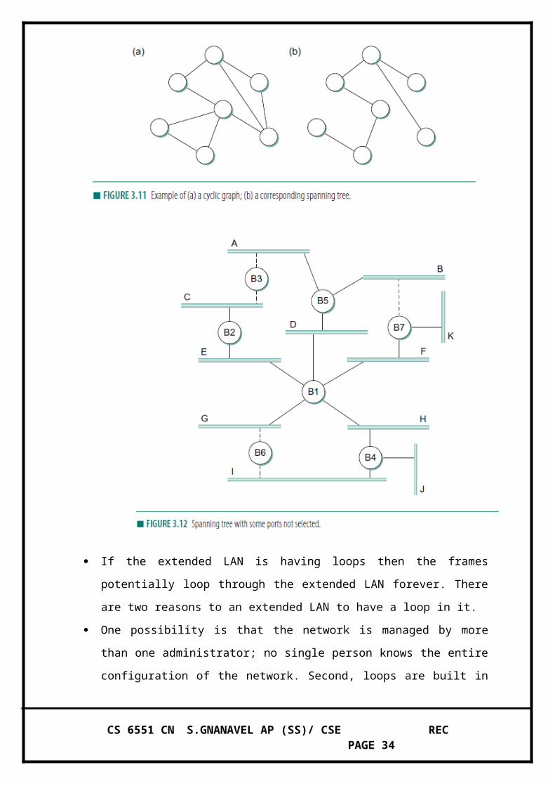
If the extended LAN is having loops then the frames potentially loop through the
extended LAN forever. There are two reasons to an extended LAN to have a loop in
it.
One possibility is that the network is managed by more than one administrator; no
single person knows the entire configuration of the network. Second, loops are built in
to network on purpose to provide redundancy in case of failure. Bridges must be able
to correctly handle loops. This problem is addressed by having the bridges run a
distributed spanning tree algorithm.
CS 6551 CN S.GNANAVEL AP (SS)/ CSE REC PAGE 22
The spanning tree algorithm wad developed by Digital Equipment Corporation. The
main idea is for the bridges to select the ports over which they will forward frames.
The algorithm selects as follows. Each bridge has a unique identifier.
In the above example they are labeled as B1, B2, B3 … the algorithm first elects the
bridge with smallest ID as the root of the spanning tree. The root bridge always
forwards frames out over all of its ports. Then each bridge computes the shortest path
to root and notes which of its ports is on this path. This port is also elected as the
bridge’s preferred path to the root.
Finally, all the bridges connected to a given LAN elect a single designated bridge that
will be responsible for forwarding frames toward the root bridge. Each LANs
designated bridge is the one that is closest to the root, and if two or more bridges are
equally close to the root, then the bridge which having smallest ID wins.
In the above example, B1 is the root bridge since it having the smallest ID. Both B3
and B5 are connected to LAN A, but B5 is the designated bridge since it is closer to
the root. Similarly B5 and B7 are connected to LAN B, but B5 is the designated
bridge even they are equally closer to the root since B5 having smallest ID.
The bridges have to exchange configuration messages with each other and then decide
whether or not they are the root or a designated bridge based on this message.
The configuration contains three pieces of information.
1. The ID for the bridge that is sending the message
2. The ID for what the sending bridge believes to be the root bridge
3. The distance, measured in hops, from the sending bridge to the root bridge.
Initially each bridge thinks it is the root bridge, so the configuration message will contain the
sending and root same ID. By receiving the configuration message from other bridges they
select the root bridge. The selection will be by,
1. It identifies a root with a smaller ID or
2. It identifes a root iwth an equal ID but with a shorter distance or
3. The root ID and distance are equal , but the sending bridge has a smaller ID
CS 6551 CN S.GNANAVEL AP (SS)/ CSE REC PAGE 23

BROADCAST AND MULTICAST
Most LANs support both broadcast and multicast; then bridges must also support these two
features.
Broadcast is simple, each bridge forward a frame with a destination broadcast address out on
each active port other that the one on which the frame was received. In multicasting, each
host deciding for itself whether or not to accept the message.
Spanning tree algorithm creates a sub-graph that has no loops, i.e., each LAN can be reached
from any other LAN through one path only.
Each bridge decides the ports on which it is willing to forward frames
Some ports are removed, reducing the extended LAN to an acyclic graph.
Spanning tree algorithm is dynamic, i.e., bridges reconfigure the spanning tree due to some
failure or additions or deletions.
Algorithm
Each bridge has a unique identifier.
Bridges exchange configuration message (Y, d, X), known as bridge protocol data unit
(BPDU) to decide on root/designated bridge, where:
Y—id of the root bridge according to sending bridge.
d—distance in hops from sending bridge to root bridge.
X—id of the bridge that is sending the message.
System stabilizes with the selection of root bridge and designated bridges. Root Bridge
Initially each bridge considers itself as root and broadcasts BPDU with distance 0.
A bridge accepts another bridge as root, if it receives a BPDU that has:
a root with a smaller id.
a root with an equal id but shorter distance.
root id and distance are equal, but sending bridge has a smaller id.
Once a bridge accepts another bridge as root, it P
Stops generation of its own messages
CS 6551 CN S.GNANAVEL AP (SS)/ CSE REC PAGE 24

Forwards messages after incrementing distance-to-root field
Eventually, bridge with the smallest id is selected as the root bridge.
Root bridge always floods frames on all ports.
Absence of periodical message from root, forces bridges to elect a new root bridge.
Designated Bridge
All bridges connected to a LAN elect a designated bridge.
Each bridge computes shortest path to the root and notes the port on the path.
Each LAN’s designated bridge is the one that is closest to the root.
If two or more bridges are equally close to root, then bridge with smallest id is
chosen.
Designated bridge is responsible for forwarding frames to the root bridge.
A bridge stops sending messages over a port, when it’s not designated bridge for that
port
Example
B3 receives (B2, 0, B2). B3 accepts B2 as root, since B2 is the lower id.
B3 increments the distance advertised by B2 and sends (B2, 1, B3) towards B5.
B2 accepts B1 as root because it has the lower id and sends (B1, 1, B2) to B3.
B5 accepts B1 as root and sends (B1, 1, B5) to B3.
B3 accepts B1 as root, and knows that both B2 and B5 are closer to the root than itself.
B3 stops forwarding messages on both its interfaces.
B2 and B5 are chosen as the designated bridges for LAN A and C respectively.
INTERNETWORKING
CS 6551 CN S.GNANAVEL AP (SS)/ CSE REC PAGE 25
An internetwork is often referred to as a network of networks because it is made up of
lots of smaller networks. The nodes that interconnect the networks are called routers. They
are also sometimes called gateways, but since this term has several other connotations, we
restrict our usage to router. The internet protocol is the key tool used today to build scalable,
heterogeneous internetwork.
Service Model
The main concern in defining a service model for an internetwork is that we can provide a
host-to-host service only if this service can somehow be provided over each of the underlying
physical networks. For Example, it would be no good deciding that our internetwork service
model was going to provide guaranteed delivery of every packet in 1 ms or less if there were
underlying network technologies that could arbitrarily delay packets. The IP service model
can be thought of as having two parts: an addressing scheme, which provides a way to
identify all hosts in the internetwork, and a datagram (connectionless) model of data delivery.
This service model is sometimes called best effort because, although IP makes every effort to
delivery datagram, it makes no guarantees.
Datagram Delivery
A datagram is a type of packet that happens to be sent in a connectionless manner over a
network. Every datagram carries enough information to let network forward the packet to its
correct destination; there is no need for any advance setup mechanism to tell the network
what to do when the packet arrives. The network makes its best effort to get it to the desired
destination. The best-effort part means that if something goes wrong and the packet gets lost,
corrupted, misdelivered,or in any way fails to reach its intended destination, the network does
nothing-it made its best effort, and that is all it had to do. It does not make any attempt to
recover from the failure. This is sometimes called an unreliable service.
Packet Format
The IP datagram, like most packets, consists of a header followed by a number of
bytes of data. The Version field specifies the version of IP. The current version of IP is 4, and
CS 6551 CN S.GNANAVEL AP (SS)/ CSE REC PAGE 26

it is sometimes called IPv4^2.putting this field right at the start of the datagram makes it easy
for everything else in the packet format to be redefined in subsequent versions; the header
processing software starts off by looking at the version and then branches off to process the
rest of the packet according to the appropriate format.
The next field, HLEN, specifies the length of the header in 32-bit words. When there
are no options, which is most of the time, the header is 5 words (20 bytes) long. The 8_bit
type of service (TOS) field has had a number of different definitions over the years, but its
basic function is to allow packets to be treated differently based on application needs. For
example, the TOS value might determine whether or not a packet should be placed in a
special queue that receives low delay. The next 16-bit of the header contain the Length of the
datagram, including the header. Unlike the HLEN field, the Length field counts bytes rather
than words. Thus, the maximum size of an IP datagram is 65,535 bytes.
The physical network, over which IP is running, however, may not support such long
packets. For this reason, IP supports a fragmentation and reassembly process, the second
word of the header contains information about fragmentation. The next byte is the time to live
(TTL) field. The intent of the field is to catch pockets that have been going around in routing
loops and discard them, rather than let them consume resources indefinitely. The Protocol
field is simply a demultiplexing key that identifies the higher-level protocol to which this
packet should be passed. These are values defined for TCP (6), UDP (17), and many other
protocols that may sit above IP in the protocol graph.
CS 6551 CN S.GNANAVEL AP (SS)/ CSE REC PAGE 27

The Checksum is calculated by considering the entire IP header as a sequence of 16-
bit words, adding them up using ones complement arithmetic, and taking the ones
complement of the result. The last two required fields in the header are the SourceAddr and
the DestinationAddr for the packet. The latter is the key to datagram delivery: every packet
contains a full address for its intended destination so that forwarding decisions can be made
at each router.
The source address is required tom allow recipients to decide if they want to accept
the packet and to enable them to reply. Finally, there may be a number of options at the end
of the header. Th e presence or absence of options may be determined by examining the
header length (HLen) field. While options are used fairly rarely, a complete IP
implementation must handle them all.
FRAGMENTATION AND REASSEMBLY
One of the problems of providing a uniform host-to-host service model over a heterogeneous
collection of network is that each network technology tends to have its own idea of how large
a packet can be. For example, an Ethernet can accept packets up to 1,500 bytes long, while
FDDI packets may be 4,500 bytes long.
This leaves two choices for the IP service model: make sure that all IP datagram are small
enough to fit inside one packet on any network technology, or provide a means by which
packets can be fragmented and reassembled when they are too big to go over a given network
technology.
The latter turns out to be a good choice, especially when you consider the fact that new
network technologies are always turning up, and IP needs to run over all of them; this would
make it hard to pick a suitably small bound on datagram size.
This also means that a host will not send needlessly small packets, which wastes bandwidth
and consumes processing resources by acquiring more headers per byte of data sent. For
example, two hosts connected to FDDI networks that are interconnected by a point-to-point
link would not need to send packets small enough to fit on an Ethernet.
CS 6551 CN S.GNANAVEL AP (SS)/ CSE REC PAGE 28

The central idea here is that every network type has a maximum transmission unit
(MTU), which is the largest IP datagram that it can carry in a frame.
The unfragmented packet has 1,400 bytes of data and a 20-byte IP header. When the
packet arrives at the R2, which has an MTU of 532 bytes, it has to be fragmented. A 532-byte
MTU leaves 512 bytes for data after the 20-byte IP header, so the first fragment contains 512
bytes of data. The router sets the M bit in the Flags field, meaning that there are more
fragments to follow, and it sets the offset to 0,since this fragmented contains the first part of
the original datagram.
The data carried in the second fragment starts with the 513th byte of the original data,
so the Offset field in this header is set to 64, which is 512/8. Why the division by 8? Because
the designers of IP decided that fragmentation should always happen on 8-byte boundaries,
which means that the Offset field counts 8-byte chunks, not bytes. The third fragment
contains the last 376 bytes of data, and the offset is now 2*512/8=128. since this is the last
fragment, the M bit is not set.
GLOBAL ADRESSES:
Global uniqueness is the first property that should be provided in an addressing scheme.
Ethernet addresses are globally unique but not sufficient to address entire network. And also
they are flat that is no structure in addressing.
IP addresses are hierarchical. They made up of two parts, they are a network part and a host
part. The network part identifies the network to which the host is connected. All hosts which
are connected to the same network have same network part in their IP address. The host part
then identifies each host on the particular network.
CS 6551 CN S.GNANAVEL AP (SS)/ CSE REC PAGE 29
The routers are host but they are connected with two networks. So they need to have an
address on each network, one for each interface. IP addresses are divided into three different
classes. They are,
1. Class A
2. Class B
3. Class C
The class of an IP address is identified in the most significant few bits. If the first bit is 0, it is
a class A address. If the first bit is 1 and the second bit is 0, it is a class B address. If the first
two bits are 1 and the third bit is 0, t is a class C address.
Class A addresses have 7 bits for network part and 24 bits for host part. The 0 and 127 are
reserved.
Class B addresses have 14 bits for network part and 16 bits for host part.
Class C addresses have 21 bits for network part and 8 bits for host part. The 0 and 127 are
reserved. There are approximately 4 billion possible IP addresses, one half for class A, one
quarter for class B and one-eighth for class C address.
There are also class D and class E are there.
But class D for multicast and class E are currently unused. IP addresses are written as four
decimal integers separated via dots. Each integer represents the decimal value contained in 1
byte of the address, starting at the most significant.
CIDR OR SUPERNETING
1. Subnetting does not prevent an organization opting for Class B. Address efficiency for
Class B can be as low as 0.39% (256 / 65535).
If Class C addresses were given instead of Class B, then routing tables gets larger.
CS 6551 CN S.GNANAVEL AP (SS)/ CSE REC PAGE 30

Classless Interdomain Routing (CIDR) tries to balance between minimize the number of
routing table entries and handling addresses space efficiently.
CIDR aggregates routes, by which an entry in forwarding table is used to reach multiple
networks. It collapses multiple addresses into a single supernet, i.e., supernetting.
Example
Consider an organization with 16 Class C networks. Instead of providing 16 addresses at
random, a block of contiguous Class C address is given.
For example, from 192.4.16 to 192.4.31
Bitwise analysis show 20 MSBs (11000000 00000100 0001) are same. Thus a 20-bit network
number is created, i.e., range between Class B and C network.
Thus higher address efficiency is achieved by providing small chunks of address, smaller
than Class B network. Thus a single network prefix is used in forwarding table.
CIDR uses a new type of notation to represent network numbers or prefixes.
It is represented as /X, where X is the prefix length in bits. For example, 192.4.16/20
Addresses in a block must be contiguous and number of addresses must be powers of 2.
Example
When different customers are connected to a service provider, prefixes can be assigned such
that they share a common, further aggregation can be achieved.
Consider an ISP providing internet connectivity to 8 customers. All customer prefix starts
with the same 21 bits.
Since all customers are reachable through the same provider network, a single route is
advertised by ISP with common 21-bit prefix that all customers share.
CS 6551 CN S.GNANAVEL AP (SS)/ CSE REC PAGE 31

ADDRESS RESOLUTION PROTOCOL (ARP)
IP data grams contain IP addresses, but the physical interface hardware on the host or
router can only understands the addressing scheme of that particular network. So the
IP address should be translated to a link level address.
One simplest way to map an IP address in to a physical network address is to
encode a host’s physical address in the host part of its IP address.
For example, a host with physical address 00100001 01001001 (which has the
decimal value 33 in the upper byte and 81 in the lower byte) might be given the IP
address 128.96.33.81. But in class C only 8 bits for host part. It is not enough for 48
bit Ethernet address.
A more general solution would be for each host to maintain a table of address pairs,
i.e, and the table would map IP addresses into physical address.
While this table could be centrally managed by a system administrator and then be
copied to each host ion the network, a better approach would be for each host to
dynamically learn the contents of the table using the network. This can be
accomplished by Address Resolution Protocol (ARP).
The goal of ARP is to enable each host on a network to build up a table of mappings
between IP address and link level addresses.
Since these mappings may change over time, the entries are timed out periodically
and removed. This happens on the order of every 15 minutes. The set of mappings
currently stored in a host is known as ARP cache or ARP table.
While communicating, a host needs Layer-2 (MAC) address of the destination machine
which belongs to the same broadcast domain or network. A MAC address is physically burnt
into the Network Interface Card (NIC) of a machine and it never changes.
On the other hand, IP address on the public domain is rarely changed. If the NIC is changed
in case of some fault, the MAC address also changes. This way, for Layer-2 communication
to take place, a mapping between the two is required.
CS 6551 CN S.GNANAVEL AP (SS)/ CSE REC PAGE 32

To know the MAC address of remote host on a broadcast domain, a computer
wishing to initiate communication sends out an ARP broadcast message asking, “Who has
this IP address?” Because it is a broadcast, all hosts on the network segment (broadcast
domain) receive this packet and process it. ARP packet contains the IP address of destination
host, the sending host wishes to talk to. When a host receives an ARP packet destined to it, it
replies back with its own MAC address.
Once the host gets destination MAC address, it can communicate with remote host using
Layer-2 link protocol. This MAC to IP mapping is saved into ARP cache of both sending and
receiving hosts. Next time, if they require to communicate, they can directly refer to their
respective ARP cache. Reverse ARP is a mechanism where host knows the MAC address of
remote host but requires to know IP address to communicate.
CS 6551 CN S.GNANAVEL AP (SS)/ CSE REC PAGE 33
The above figure shows the ARP packet format for IP to Ethernet address mappings.
ARP can be used for lots of other kinds of mappings the major difference is their
address size. In addition to the IP and link level addresses of both sender and target,
the packet contains
a HardwareTypefiels, which specifies the type of the physical network (ex., Ethernet)
a ProtocolType field, which specifies the higher layer protocol (ex., IP)
HLen (hardware address length) and PLen (protocol address length) fields, which
specifies the length of the link layer address and higher layer protocol address,
respectively An Operation field, which specifies whether this is a request or a
response
The source and target hardware (Ethernet) and protocol (IP) address. The results of
the ARP process can be added as an extra column in a forwarding table.
DHCP-DYNAMIC HOST CONFIGURATION PROTOCOL
It allows a host to have an IP address automatically and also to learn the additional
information.
The additional information like
Its subnet mask
Address of its first top router
Address of its level DNS server
Generally IP address has
Network part
host part
CS 6551 CN S.GNANAVEL AP (SS)/ CSE REC PAGE 34

Network part should be the same for all hosts on the network.There occur drawbacks in
manual IP configuration.
Drawbacks
1. Two host getting same IP address.
2. Host gets correct n/w number.
To resolve such issues there is a need of automated configuration methods. DHCP protocol is
used. DHCP relies on the existence of a DHCP server that is responsible for providing
configuration information to hosts. It must have at least 1DHCP server for an administrative
domain.
DHCP Server
DHCP Server works as a central respiratory for host configuration information. For every
host , the configuration information is stored in the DHCP server.
So whenever the host is booted it will automatically retrieves the address.
Advantages:
1. It saves the n/w administrator from having to assign address to individual hosts.
2. Maintains the list of address of individual host & minimizes the manual configuration.
Operations of DHCP
Fig :A DHCP relay agent receives a broadcast DHCPDISCOVER message from a
host and sends a Unicast DHCPDISCOVER to the DHCP server
DHCP server maintains list of address which it hands out to hosts on demand.
1. To contact a DHCP server, a newly booted or attached host sends a
DHCPDISCOVER message to a special IP address (255.255.255.255) that is an IP
broadcast address. This means it will be received by all hosts and routers on that
network.
CS 6551 CN S.GNANAVEL AP (SS)/ CSE REC PAGE 35

2. 2.The server would then reply to the host that generated the discovery message(all the
other nodes would ignore it).
3. 3. DHCP Server will reply for the request.
Another approach is
1. DHCP uses the concept of a relay agent. There is at least one relay agent on each network,
and it is configured with just one piece of information: the IP address of the DHCP server.
2. When a relay agent receives a DHCPDISCOVER message, it unicasts it to the DHCP
server and awaits the response, which it will then send back to the requesting client.The
process of relaying a message from a host to a remote DHCP server is shown in Figure
DHCP Protocol Format:
Operation―specifies type of DHCP packet.
Xid―specifies the transaction id.
ciaddr―specifies client IP address in case of DHCPREQUEST
yiaddr― known as your IP address, filled by DHCP server.
siaddr―contains IP address of the DHCP server.
giaddr―contains IP address of the Gateway or relay agent.
chaddr―contains hardware (physical) address of the client.
options―contains information such as lease duration, default route, DNS server, etc.
Dynamic Address Allocation
1. DHCP server is configured with range of addresses to be assigned to hosts on demand. To
contact DHCP server, client broadcasts a DHCPDISCOVER message with IP address
255.255.255.255 and it's physical address placed in chaddr field.
2. DHCP server selects an unassigned IP address for yiaddr field and adds an entry to
dynamic database along with client's physical address.
3. DHCP server sends DHCPOFFER message containing client's IP and physical address,
server IP address and options.
4. Client sends a DHCPREQUEST message, requesting the offered address.
CS 6551 CN S.GNANAVEL AP (SS)/ CSE REC PAGE 36
5. Based on transaction id, the DHCP server acknowledges with a DHCPACK message.
6. When lease period expires, client attempts to renew. It’s up to server to accept or reject it.
Disadvantage:
It introduces some more complexity into network management, since it makes the binding
between physical hosts and IP addresses much more dynamic.
INTERNET CONTROL MESSAGE PROTOCOL (ICMP)
Internet Control Message Protocol (ICMP) is used to report error messages to source host and
diagnose network problems. ICMP message is encapsulated within an IP packet
Error reporting
Destination Unreachable―When a router cannot route a datagram, the datagram is discarded
and sends a destination unreachable message to source host.
Source Quench―When a router or host discards a datagram due to congestion, it sends a
source-quench message to the source host. This message acts as flow control.
Time Exceeded―Router discards a datagram when TTL field becomes 0 and a timeexceeded
message is sent to the source host.
Parameter Problem―If a router discovers ambiguous or missing value in any field of the
datagram, it discards the datagram and sends parameter problem message to source.
Redirection―Redirect messages are sent by the default router to inform the source host to
update its forwarding table when the packet is routed on a wrong path.
Query Messages
Echo Request & Reply―The combination of echo-request and echo-reply messages
determines whether two systems can communicate at the IP level.
Timestamp Request & Reply―Two machines can use the timestamp request and timestamp
reply messages to determine the round-trip time (RTT).
Address Mask Request & Reply―A host to obtain its subnet mask, sends an address mask
request message to the router, which responds with an address mask reply message.
Router Advertisement―A host broadcasts a router solicitation message to know about the
router. Router broadcasts its routing information with router advertisement message.
******ALL THE BEST****
CS 6551 CN S.GNANAVEL AP (SS)/ CSE REC PAGE 37
Related Documents