IQ3xcite Web Enabled Controller Data Sheet TA200505 Issue 1/B 31/3/03 1 IQ3xcite WEB ENABLED CONTROLLER Data Sheet Web Enabled Controller 4 5 6 2 7 8 9 3 10 11 12 4 13 14 15 5 16 17 18 6 19 20 21 7 22 23 24 8 25 26 27 9 28 29 30 10 + 0 + 0 + 0 + 0 + 0 + 0 + 0 + 0 + 0 1 2 3 1 + 0 0 V 24 V 24 V 34 35 36 12 37 38 39 13 40 41 42 14 A 31 32 33 P 11 43 44 45 15 46 47 48 16 100-240 V OK RX P 0 P 0 P 0 P 0 P 0 P 0 Features • Ethernet 10 Mbps main network with TCP/IP protocol • embedded web server • security protected monitor/control via web browser • compatible with existing Trend protocol • basic unit has 10 universal inputs, and 6 analogue outputs • option of 80 additional points via DIN rail I/O modules • I/O bus allows separate placement of modules • flexible number of software strategy modules • RS232 local supervisor port • local display (SDU-xcite) • reliable I/O bus • small footprint with DIN rail mounting Description The IQ3xcite is a Building Management System controller that uses Ethernet and TCP/IP networking technologies. It incorporates a web server which can deliver user-specific web pages to a PC or mobile device running internet browser software. If a system is set up with the correct connections, a user with the appropriate security codes can monitor or adjust the controller from any Internet access point in the world. It is also compatible with the traditional Trend protocol. This DIN rail mounting controller has a basic version with 10 inputs and 6 outputs, and an expandable version which can have up to 96 points by adding DIN rail mounting I/O modules. This flexibility makes it suitable for a broad range of applications. A local PC or display (SDU-xcite) can be connected via the RS232 port. Physical screen earth auxiliary output supply supply to output power bus 263 mm 150 mm 42 mm 46 mm output LEDs input links OK, RX Ethernet LEDs I/O Bus cover Ethernet connector RS232 local supervisor connector 100 to 240 Vac supply output channels input channels input LEDs Under cover Under front panel auxiliary board cover e.g. battery backup option 130 mm LEDs watchdog power I/O bus

Welcome message from author
This document is posted to help you gain knowledge. Please leave a comment to let me know what you think about it! Share it to your friends and learn new things together.
Transcript
IQ3xcite Web Enabled Controller Data Sheet TA200505 Issue 1/B 31/3/03 1
IQ3xcite WEB ENABLED CONTROLLER
Data Sheet
Web Enabled Controller
4 5 6
27 8 9
310 11 12
4
13 14 15
516 17 18
619 20 21
722 23 24
825 26 27
928 29 30
10+ 0+ 0 + 0 + 0 + 0 + 0+ 0+ 0+ 0
1 2 3
1+ 0
0 V24 V
24 V 34 35 36
12
37 38 39
13
40 41 42
14A
31 32 33P
11
43 44 45
15
46 47 48
16100-240 V
OK RXP 0 P 0 P 0P 0 P 0 P 0
Features
• Ethernet 10 Mbps main network with TCP/IP protocol• embedded web server• security protected monitor/control via web browser• compatible with existing Trend protocol• basic unit has 10 universal inputs, and 6 analogue outputs• option of 80 additional points via DIN rail I/O modules• I/O bus allows separate placement of modules• flexible number of software strategy modules• RS232 local supervisor port• local display (SDU-xcite)• reliable I/O bus• small footprint with DIN rail mounting
Description
The IQ3xcite is a Building Management System controller thatuses Ethernet and TCP/IP networking technologies. It incorporatesa web server which can deliver user-specific web pages to a PCor mobile device running internet browser software. If a systemis set up with the correct connections, a user with the appropriatesecurity codes can monitor or adjust the controller from any Internetaccess point in the world. It is also compatible with the traditionalTrend protocol. This DIN rail mounting controller has a basicversion with 10 inputs and 6 outputs, and an expandable versionwhich can have up to 96 points by adding DIN rail mounting I/Omodules. This flexibility makes it suitable for a broad range ofapplications. A local PC or display (SDU-xcite) can be connectedvia the RS232 port.
Physicalscreen earth
auxiliary output supply
supply to output power bus
263 mm
150
mm
42 mm
46 mm
output LEDs
input links
OK, RX Ethernet LEDs
I/O Buscover
Ethernet connectorRS232 local supervisorconnector
100 to 240 Vacsupply
output channels
input channels
input LEDsUnder cover
Under frontpanel
auxiliary board cover e.g. battery backup option
130
mm
LEDs
watchdog
power
I/O bus
IQ3xcite Web Enabled Controller Data Sheet TA200505 Issue 1/B 31/3/03
Data Sheet
2
8+ 07+ 06+ 0
13 14 15
5+ 0
16 17 18 19 20 21 22 23 24
1 2 3
1+ 0
4 5 6
2+ 0
7 8 9
3+ 0
10 11 12
4+ 0
4 5 6
27 8 9
310 11 12
4
13 14 15
516 17 18
619 20 21
722 23 24
825 26 27
928 29 30
10+ 0+ 0 + 0 + 0 + 0 + 0+ 0+ 0+ 0
1 2 3
1+ 0
0 V24 V
24 V 34 35 36
12
37 38 39
13
40 41 42
14A
31 32 33P
11
43 44 45
15
46 47 48
16100-240 V
OK RXP 0 P 0 P 0P 0 P 0 P 0
24 V
P 13 14 15
5P 0
16 17 18
6P 0
19 20 21
7P 0
22 23 24
8P 0
1 2 3
1+ 0
4 5 6
2+ 0
7 8 9
3+ 0
10 11 12
4+ 0
24 V
P 13 14 15
5P 0
16 17 18
6P 0
19 20 21
7P 0
22 23 24
8P 0
1 2 3
1+ 0
4 5 6
2+ 0
7 8 9
3+ 0
10 11 12
4+ 0
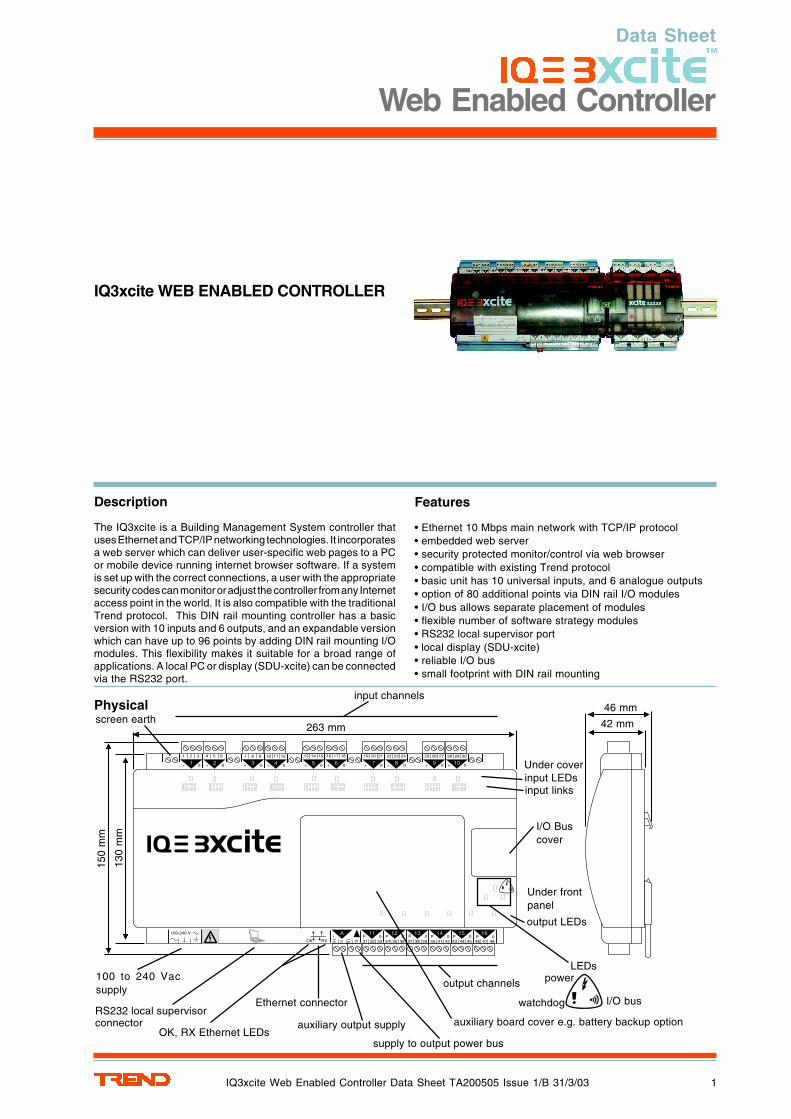
Physical (continued)
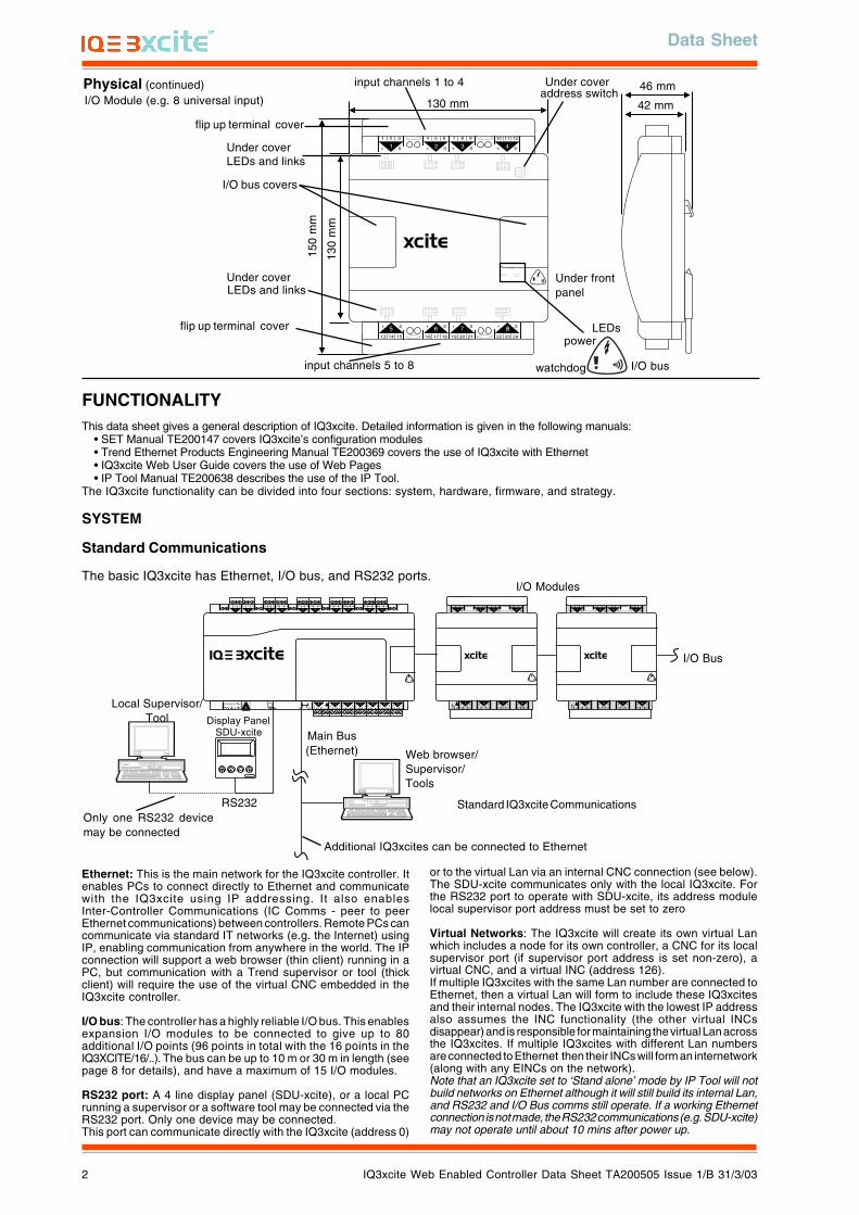
I/O Bus
I/O Modules
Main Bus(Ethernet) Web browser/
Supervisor/Tools
Local Supervisor/Tool
SDU-xciteDisplay Panel
Only one RS232 devicemay be connected
Ethernet: This is the main network for the IQ3xcite controller. Itenables PCs to connect directly to Ethernet and communicatewith the IQ3xcite using IP addressing. It also enablesInter-Controller Communications (IC Comms - peer to peerEthernet communications) between controllers. Remote PCs cancommunicate via standard IT networks (e.g. the Internet) usingIP, enabling communication from anywhere in the world. The IPconnection will support a web browser (thin client) running in aPC, but communication with a Trend supervisor or tool (thickclient) will require the use of the virtual CNC embedded in theIQ3xcite controller.
I/O bus: The controller has a highly reliable I/O bus. This enablesexpansion I/O modules to be connected to give up to 80additional I/O points (96 points in total with the 16 points in theIQ3XCITE/16/..). The bus can be up to 10 m or 30 m in length (seepage 8 for details), and have a maximum of 15 I/O modules.
RS232 port: A 4 line display panel (SDU-xcite), or a local PCrunning a supervisor or a software tool may be connected via theRS232 port. Only one device may be connected.This port can communicate directly with the IQ3xcite (address 0)
Standard IQ3xcite CommunicationsRS232
Additional IQ3xcites can be connected to Ethernet
FUNCTIONALITYThis data sheet gives a general description of IQ3xcite. Detailed information is given in the following manuals:
• SET Manual TE200147 covers IQ3xcite’s configuration modules• Trend Ethernet Products Engineering Manual TE200369 covers the use of IQ3xcite with Ethernet• IQ3xcite Web User Guide covers the use of Web Pages• IP Tool Manual TE200638 describes the use of the IP Tool.
The IQ3xcite functionality can be divided into four sections: system, hardware, firmware, and strategy.
SYSTEM
Standard Communications
The basic IQ3xcite has Ethernet, I/O bus, and RS232 ports.
42 mm
46 mm
130 mm
150
mm
LEDs
Under frontpanel
flip up terminal cover
LEDs and linksUnder cover
Under coveraddress switch
I/O bus covers
input channels 1 to 4
input channels 5 to 8
flip up terminal cover
I/O Module (e.g. 8 universal input)
130
mm
Under coverLEDs and links
or to the virtual Lan via an internal CNC connection (see below).The SDU-xcite communicates only with the local IQ3xcite. Forthe RS232 port to operate with SDU-xcite, its address modulelocal supervisor port address must be set to zero
Virtual Networks: The IQ3xcite will create its own virtual Lanwhich includes a node for its own controller, a CNC for its localsupervisor port (if supervisor port address is set non-zero), avirtual CNC, and a virtual INC (address 126).If multiple IQ3xcites with the same Lan number are connected toEthernet, then a virtual Lan will form to include these IQ3xcitesand their internal nodes. The IQ3xcite with the lowest IP addressalso assumes the INC functionality (the other virtual INCsdisappear) and is responsible for maintaining the virtual Lan acrossthe IQ3xcites. If multiple IQ3xcites with different Lan numbersare connected to Ethernet then their INCs will form an internetwork(along with any EINCs on the network).Note that an IQ3xcite set to ‘Stand alone’ mode by IP Tool will notbuild networks on Ethernet although it will still build its internal Lan,and RS232 and I/O Bus comms still operate. If a working Ethernetconnection is not made, the RS232 communications (e.g. SDU-xcite)may not operate until about 10 mins after power up.
watchdog
power
I/O bus
Data Sheet
IQ3xcite Web Enabled Controller Data Sheet TA200505 Issue 1/B 31/3/03 3
CNC
IQ3
INC
IQ3xcite
CNC CNC
Web Browser
TCP/IP
Local Supervisor/Tool
RS232
TCP/IP
Supervisor/ Tool
A B
C
Web Browser
Local Supervisor/Tool
Supervisor/ ToolEthernet
A
B
C
4 5 6
27 8 9
310 11 12
413 14 15
516 17 18
619 20 21
722 23 24
825 26 27
928 29 30
10+ 0+ 0 + 0 + 0 + 0 + 0+ 0+ 0+ 0
1 2 3
1+ 0
0 V24 V
24 V 34 35 36
12
37 38 39
13
40 41 42
14A
31 32 33P
11
43 44 45
15
46 47 48
16100-240 V
OK RXP 0 P 0 P 0P 0 P 0 P 0
physical system
virtual system
CNC
IQ3
INC
IQ3xcite
CNC CNC
Web Browser
TCP/IP
Local Supervisor/Tool
RS232
TCP/IP
Supervisor/ Tool
A B
C
CNC
IQ3
INC
IQ3xcite
CNC CNC
Lan
Lan
I/N
virtual system
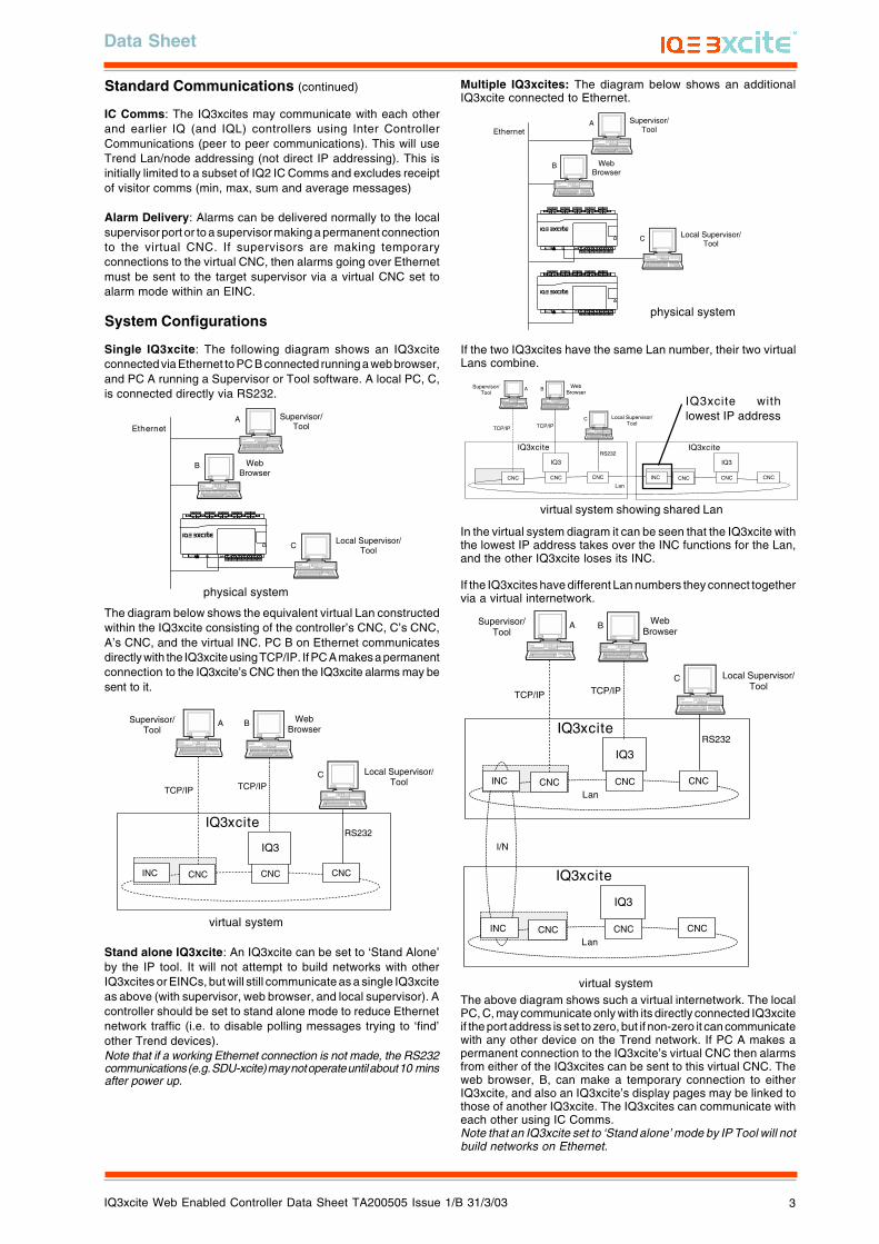
Multiple IQ3xcites: The diagram below shows an additionalIQ3xcite connected to Ethernet.
Web Browser
Local Supervisor/Tool
Supervisor/ ToolEthernet
A
B
C
4 5 6
27 8 9
310 11 12
413 14 15
516 17 18
619 20 21
722 23 24
825 26 27
928 29 30
10+ 0+ 0 + 0 + 0 + 0 + 0+ 0+ 0+ 0
1 2 3
1+ 0
0 V24 V
24 V 34 35 36
12
37 38 39
13
40 41 42
14A
31 32 33P
11
43 44 45
15
46 47 48
16100-240 V
OK RXP 0 P 0 P 0P 0 P 0 P 0
4 5 6
27 8 9
310 11 12
413 14 15
516 17 18
619 20 21
722 23 24
825 26 27
928 29 30
10+ 0+ 0 + 0 + 0 + 0 + 0+ 0+ 0+ 0
1 2 3
1+ 0
0 V24 V
24 V 34 35 36
12
37 38 39
13
40 41 42
14A
31 32 33P
11
43 44 45
15
46 47 48
16100-240 V
OK RXP 0 P 0 P 0P 0 P 0 P 0 physical system
CNC
IQ3
IQ3xcite
CNC CNC
Web Browser
TCP/IP
Local Supervisor/Tool
RS232
TCP/IP
Supervisor/ Tool
A B
C
CNC
IQ3
INC
IQ3xcite
CNC CNC
Lan
virtual system showing shared Lan
IQ3xcite withlowest IP address
Standard Communications (continued)
IC Comms: The IQ3xcites may communicate with each otherand earlier IQ (and IQL) controllers using Inter ControllerCommunications (peer to peer communications). This will useTrend Lan/node addressing (not direct IP addressing). This isinitially limited to a subset of IQ2 IC Comms and excludes receiptof visitor comms (min, max, sum and average messages)
Alarm Delivery: Alarms can be delivered normally to the localsupervisor port or to a supervisor making a permanent connectionto the virtual CNC. If supervisors are making temporaryconnections to the virtual CNC, then alarms going over Ethernetmust be sent to the target supervisor via a virtual CNC set toalarm mode within an EINC.
System Configurations
Single IQ3xcite: The following diagram shows an IQ3xciteconnected via Ethernet to PC B connected running a web browser,and PC A running a Supervisor or Tool software. A local PC, C,is connected directly via RS232.
The diagram below shows the equivalent virtual Lan constructedwithin the IQ3xcite consisting of the controller’s CNC, C’s CNC,A’s CNC, and the virtual INC. PC B on Ethernet communicatesdirectly with the IQ3xcite using TCP/IP. If PC A makes a permanentconnection to the IQ3xcite’s CNC then the IQ3xcite alarms may besent to it.
Stand alone IQ3xcite: An IQ3xcite can be set to ‘Stand Alone’by the IP tool. It will not attempt to build networks with otherIQ3xcites or EINCs, but will still communicate as a single IQ3xciteas above (with supervisor, web browser, and local supervisor). Acontroller should be set to stand alone mode to reduce Ethernetnetwork traffic (i.e. to disable polling messages trying to ‘find’other Trend devices).Note that if a working Ethernet connection is not made, the RS232communications (e.g. SDU-xcite) may not operate until about 10 minsafter power up.
If the two IQ3xcites have the same Lan number, their two virtualLans combine.
In the virtual system diagram it can be seen that the IQ3xcite withthe lowest IP address takes over the INC functions for the Lan,and the other IQ3xcite loses its INC.
If the IQ3xcites have different Lan numbers they connect togethervia a virtual internetwork.
The above diagram shows such a virtual internetwork. The localPC, C, may communicate only with its directly connected IQ3xciteif the port address is set to zero, but if non-zero it can communicatewith any other device on the Trend network. If PC A makes apermanent connection to the IQ3xcite’s virtual CNC then alarmsfrom either of the IQ3xcites can be sent to this virtual CNC. Theweb browser, B, can make a temporary connection to eitherIQ3xcite, and also an IQ3xcite’s display pages may be linked tothose of another IQ3xcite. The IQ3xcites can communicate witheach other using IC Comms.Note that an IQ3xcite set to ‘Stand alone’ mode by IP Tool will notbuild networks on Ethernet.
IQ3xcite Web Enabled Controller Data Sheet TA200505 Issue 1/B 31/3/03
Data Sheet
4
Web Browser
Local Supervisor/Tool
Supervisor/ ToolEthernet
A
B
C
Lan
OK
Tx Rx
230 V1 2 3 4 5 6 83 4 5
7 9 10 1124V 24V
AC24VAC
24VAC
OK
Tx Rx
230 V1 2 3 4 5 6 83 4 5
7 9 10 1124V 24V
AC24VAC
24VAC
OK
Tx Rx
230 V1 2 3 4 5 6 83 4 5
7 9 10 1124V 24V
AC24VAC
24VAC
EINC
Supervisor/ToolD
4 5 6
27 8 9
310 11 12
413 14 15
516 17 18
619 20 21
722 23 24
825 26 27
928 29 30
10+ 0+ 0 + 0 + 0 + 0 + 0+ 0+ 0+ 0
1 2 3
1+ 0
0 V24 V
24 V 34 35 36
12
37 38 39
13
40 41 42
14A
31 32 33P
11
43 44 45
15
46 47 48
16100-240 V
OK RXP 0 P 0 P 0P 0 P 0 P 0
4 5 6
27 8 9
310 11 12
413 14 15
516 17 18
619 20 21
722 23 24
825 26 27
928 29 30
10+ 0+ 0 + 0 + 0 + 0 + 0+ 0+ 0+ 0
1 2 3
1+ 0
0 V24 V
24 V 34 35 36
12
37 38 39
13
40 41 42
14A
31 32 33P
11
43 44 45
15
46 47 48
16100-240 V
OK RXP 0 P 0 P 0P 0 P 0 P 0
physical system
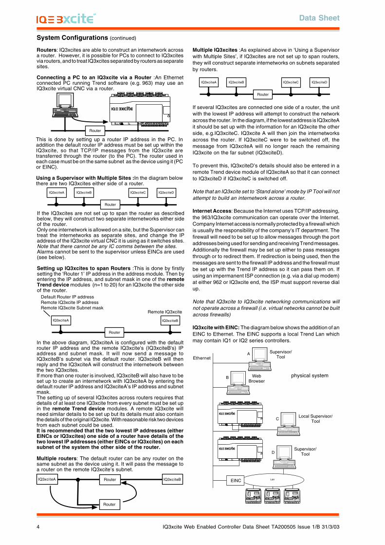
In the above diagram, IQ3xciteA is configured with the defaultrouter IP address and the remote IQ3xcite's (IQ3xciteB's) IPaddress and subnet mask. It will now send a message toIQ3xciteB’s subnet via the default router. IQ3xciteB will thenreply and the IQ3xciteA will construct the internetwork betweenthe two IQ3xcites.If more than one router is involved, IQ3xciteB will also have to beset up to create an internetwork with IQ3xciteA by entering thedefault router IP address and IQ3xciteA’s IP address and subnetmask.The setting up of several IQ3xcites across routers requires thatdetails of at least one IQ3xcite from every subnet must be set upin the remote Trend device modules. A remote IQ3xcite willneed similar details to be set up but its details must also containthe details of the original IQ3xcite. With reasonable risk two devicesfrom each subnet could be used.It is recommended that the two lowest IP addresses (eitherEINCs or IQ3xcites) one side of a router have details of thetwo lowest IP addresses (either EINCs or IQ3xcites) on eachsubnet of the system the other side of the router.
Multiple routers: The default router can be any router on thesame subnet as the device using it. It will pass the message toa router on the remote IQ3xcite’s subnet.
IQ3xciteA
Router
IQ3xciteB
Remote IQ3xcite
Default Router IP addressRemote IQ3xcite IP addressRemote IQ3xcite Subnet mask
Multiple IQ3xcites :As explained above in ‘Using a Supervisorwith Multiple Sites’, if IQ3xcites are not set up to span routers,they will construct separate internetworks on subnets separatedby routers.
RouterIQ3xciteA
Router
IQ3xciteB
IQ3xciteA
Router
IQ3xciteB IQ3xciteC IQ3xciteD
System Configurations (continued)
Routers: IQ3xcites are able to construct an internetwork acrossa router. However, it is possible for PCs to connect to IQ3xcitesvia routers, and to treat IQ3xcites separated by routers as separatesites.
Connecting a PC to an IQ3xcite via a Router :An Ethernetconnected PC running Trend software (e.g. 963) may use anIQ3xcite virtual CNC via a router.
Router
4 5 6
27 8 9
310 11 12
413 14 15
516 17 18
619 20 21
722 23 24
825 26 27
928 29 30
10+ 0+ 0 + 0 + 0 + 0 + 0+ 0+ 0+ 0
1 2 3
1+ 0
0 V24 V
24 V 34 35 36
12
37 38 39
13
40 41 42
14A
31 32 33P
11
43 44 45
15
46 47 48
16100-240 V
OK RXP 0 P 0 P 0P 0 P 0 P 0
This is done by setting up a router IP address in the PC. Inaddition the default router IP address must be set up within theIQ3xcite, so that TCP/IP messages from the IQ3xcite aretransferred through the router (to the PC). The router used ineach case must be on the same subnet as the device using it (PCor EINC).
Using a Supervisor with Multiple Sites :In the diagram belowthere are two IQ3xcites either side of a router.
IQ3xciteA
Router
IQ3xciteB IQ3xciteC IQ3xciteD
If the IQ3xcites are not set up to span the router as describedbelow, they will construct two separate internetworks either sideof the router.Only one internetwork is allowed on a site, but the Supervisor cantreat the internetworks as separate sites, and change the IPaddress of the IQ3xcite virtual CNC it is using as it switches sites.Note that there cannot be any IC comms between the sites.Alarms cannot be sent to the supervisor unless EINCs are used(see below).
Setting up IQ3xcites to span Routers :This is done by firstlysetting the ‘Router 1’ IP address in the address module. Then byentering the IP address, and subnet mask in one of the remoteTrend device modules (n=1 to 20) for an IQ3xcite the other sideof the router.
If several IQ3xcites are connected one side of a router, the unitwith the lowest IP address will attempt to construct the networkacross the router. In the diagram, if the lowest address is IQ3xciteAit should be set up with the information for an IQ3xcite the otherside, e.g.IQ3xciteC. IQ3xcite A will then join the internetworksacross the router. If IQ3xciteC were to be switched off, themessage from IQ3xciteA will no longer reach the remainingIQ3xcite on the far subnet (IQ3xciteD).
To prevent this, IQ3xciteD’s details should also be entered in aremote Trend device module of IQ3xciteA so that it can connectto IQ3xciteD if IQ3xciteC is switched off.
Note that an IQ3xcite set to ‘Stand alone’ mode by IP Tool will notattempt to build an internetwork across a router.
Internet Access: Because the Internet uses TCP/IP addressing,the 963/IQ3xcite communication can operate over the Internet.Company Internet access is normally protected by a firewall whichis usually the responsibility of the company's IT department. Thefirewall will need to be set up to allow messages through the portaddresses being used for sending and receiving Trend messages.Additionally the firewall may be set up either to pass messagesthrough or to redirect them. If redirection is being used, then themessages are sent to the firewall IP address and the firewall mustbe set up with the Trend IP address so it can pass them on. Ifusing an impermanent ISP connection (e.g. via a dial up modem)at either 962 or IQ3xcite end, the ISP must support reverse dialup.
Note that IQ3xcite to IQ3xcite networking communications willnot operate across a firewall (i.e. virtual networks cannot be builtacross firewalls)
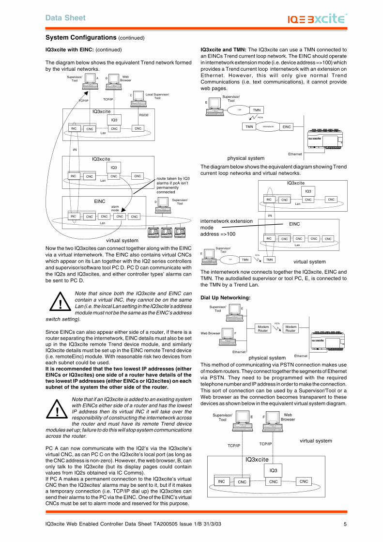
IQ3xcite with EINC: The diagram below shows the addition of anEINC to Ethernet. The EINC supports a local Trend Lan whichmay contain IQ1 or IQ2 series controllers.
Data Sheet
IQ3xcite Web Enabled Controller Data Sheet TA200505 Issue 1/B 31/3/03 5
Supervisor/ Tool
Ethernet
Internetwork EINCTMN
Lan
PSTN
TMN
E
4 5 6
27 8 9
310 11 12
413 14 15
516 17 18
619 20 21
722 23 24
825 26 27
928 29 30
10+ 0+ 0 + 0 + 0 + 0 + 0+ 0+ 0+ 0
1 2 3
1+ 0
0 V24 V
24 V 34 35 36
12
37 38 39
13
40 41 42
14A
31 32 33P
11
43 44 45
15
46 47 48
16100-240 V
OK RXP 0 P 0 P 0P 0 P 0 P 0
CNC
IQ3
INC
IQ3xcite
CNC CNC
Lan
I/N
CNCINC
EINC
CNC
Lan
CNC CNC
Supervisor/ Tool
TMNLan TMN
PSTNE
internetwork extensionmodeaddress =>100
Supervisor/ Tool
Ethernet
PSTN
ModemRouter
E
FWeb Browser
ModemRouter
Ethernet
4 5 6
27 8 9
310 11 12
413 14 15
516 17 18
619 20 21
722 23 24
825 26 27
928 29 30
10+ 0+ 0 + 0 + 0 + 0 + 0+ 0+ 0+ 0
1 2 3
1+ 0
0 V24 V
24 V 34 35 36
12
37 38 39
13
40 41 42
14A
31 32 33P
11
43 44 45
15
46 47 48
16100-240 V
OK RXP 0 P 0 P 0P 0 P 0 P 0
CNC
IQ3
INC
IQ3xcite
CNC CNC
Web Browser
TCP/IPTCP/IP
Supervisor/ Tool
E F
virtual system
physical system
physical system
virtual system
CNC
IQ3
INC
IQ3xcite
CNC CNC
Web Browser
TCP/IP
Local Supervisor/Tool
RS232
TCP/IP
Supervisor/ Tool
A B
C
CNC
IQ3
INC
IQ3xcite
CNC CNC
Lan
Lan
I/N
OK
Tx Rx
230 V1 2 3 4 5 6 83 4 5
7 9 10 1124V 24V
AC24VAC
24VAC
OK
Tx Rx
230 V1 2 3 4 5 6 83 4 5
7 9 10 1124V 24V
AC24VAC
24VAC
OK
Tx Rx
230 V1 2 3 4 5 6 83 4 5
7 9 10 1124V 24V
AC24VAC
24VAC
CNCINC
EINC
CNC
Lan
CNC CNC
alarm mode
Supervisor/ToolD
route taken by IQ3alarms if pcA isn’tpermanentlyconnected
Now the two IQ3xcites can connect together along with the EINCvia a virtual internetwork. The EINC also contains virtual CNCswhich appear on its Lan together with the IQ2 series controllersand supervisor/software tool PC D. PC D can communicate withthe IQ2s and IQ3xcites, and either controller types’ alarms canbe sent to PC D.
Note that since both the IQ3xcite and EINC cancontain a virtual INC, they cannot be on the sameLan (i.e. the local Lan setting in the IQ3xcite’s addressmodule must not be the same as the EINC’s address
switch setting).
Since EINCs can also appear either side of a router, if there is arouter separating the internetwork, EINC details must also be setup in the IQ3xcite remote Trend device module, and similarlyIQ3xcite details must be set up in the EINC remote Trend device(i.e. remoteEinc) module. With reasonable risk two devices fromeach subnet could be used.It is recommended that the two lowest IP addresses (eitherEINCs or IQ3xcites) one side of a router have details of thetwo lowest IP addresses (either EINCs or IQ3xcites) on eachsubnet of the system the other side of the router.
Note that if an IQ3xcite is added to an existing systemwith EINCs either side of a router and has the lowestIP address then its virtual INC it will take over theresponsibility of constructing the internetwork acrossthe router and must have its remote Trend device
modules set up; failure to do this will stop system communicationsacross the router.
PC A can now communicate with the IQ2’s via the IQ3xcite’svirtual CNC, as can PC C on the IQ3xcite’s local port (as long asthe CNC address is non-zero). However, the web browser, B, canonly talk to the IQ3xcite (but its display pages could containvalues from IQ2s obtained via IC Comms).If PC A makes a permanent connection to the IQ3xcite’s virtualCNC then the IQ3xcites’ alarms may be sent to it, but if it makesa temporary connection (i.e. TCP/IP dial up) the IQ3xcites cansend their alarms to the PC via the EINC. One of the EINC’s virtualCNCs must be set to alarm mode and reserved for this purpose.
virtual system
System Configurations (continued)
IQ3xcite with EINC: (continued)
The diagram below shows the equivalent Trend network formedby the virtual networks.
IQ3xcite and TMN: The IQ3xcite can use a TMN connected toan EINCs Trend current loop network. The EINC should operatein internetwork extension mode (i.e. device address =>100) whichprovides a Trend current loop internetwork with an extension onEthernet. However, this wil l only give normal TrendCommunications (i.e. text communications), it cannot provideweb pages.
The diagram below shows the equivalent diagram showing Trendcurrent loop networks and virtual networks.
The internetwork now connects together the IQ3xcite, EINC andTMN. The autodialled supervisor or tool PC, E, is connected tothe TMN by a Trend Lan.
Dial Up Networking:
This method of communicating via PSTN connection makes useof modem routers. They connect together the segments of Ethernetvia PSTN. They need to be programmed with the requiredtelephone number and IP address in order to make the connection.This sort of connection can be used by a Supervisor/Tool or aWeb browser as the connection becomes transparent to thesedevices as shown below in the equivalent virtual system diagram.
!
!

IQ3xcite Web Enabled Controller Data Sheet TA200505 Issue 1/B 31/3/03
Data Sheet
6
A
PSU
0 V24 V
24 V
A
31 32 33P
11P 0
A
0 V24 V
24 V
A
31 32 33P
11P 0
Internal power bus
External power supply (24 Vac/Vdc)
External link
Using internal power supply
Indicators:I/O Channels
Input LEDs: (yellow) All input channels have an LED tomonitor the input state when the input channel isset to a digital input. The LED will illuminate whenthe associated input contact is closed.
Output LEDs: (yellow) Light intensity increases with outputvoltage.
Core functionWatchdog ( ): (red) On if controller has a software fault
(i.e. strategy or firmware).I/O bus error ( ): (red) On if there is an I/O bus fault,
(e.g. check for short circuit between Data Hi orData Lo and either of the power lines).
Power ( ): (green) On when supply is connected. Flashesbriefly at 1 second intervals if power supply fault;return unit to supplier.
EthernetOK : (green) Normally called LINK on Ethernet systems.
ON indicates a good Ethernet connection. If OFFindicates faulty Ethernet connection.
RX: (yellow) Flashes when packet of data is being receivedacross the Ethernet.
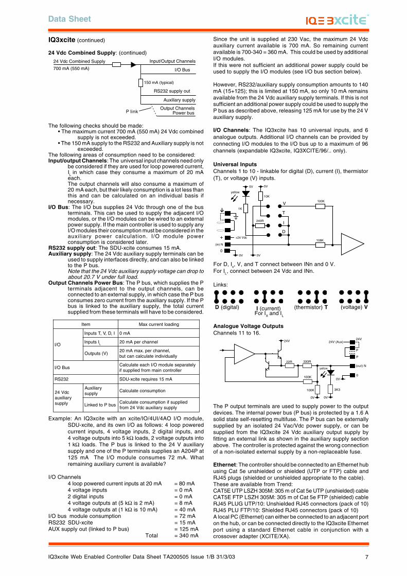
24 Vdc Combined Supply: The 24 Vdc combined supply suppliesthe IQ3xcite’s own input/output channels, the I/O bus, the RS232connector (e.g. to power SDU-xcite), and the 24 Vdc auxiliarysupply output terminals. The total available current is 700 mAreducing to 550 mA for if the mains supply is less than 200 Vac.The PSU has thermal overload protection and the combinedsupply is protected by a self resetting electronic circuit breaker.The input and output channels are current limited at 22 mA each.The part of the combined supply used by the RS232 connectorand the auxiliary supply is current limited to 150 mA (typical). Theauxiliary supply can be linked into the P connector to supplyauxiliary power for use by output devices.
The P output terminals are used to supply the power to outputdevices. The internal power bus (P bus) is protected by a 1.6self-resetting multifuse. The P bus can be externally supplied byan isolated 24 Vac/Vdc power supply, or can be supplied from theIQ3xcite 24 Vdc auxiliary output supply by fitting an external link.The controller is protected against the wrong connection of anon-isolated external supply by a non-replaceable fuse.
HARDWARE
IQ3xcite
Box: The controller box is DIN rail mounting and must be fittedinside a cabinet. The input channel links are accessible via aclear polycarbonate cover which can be unclipped using ascrewdriver. The I/O bus connector has a hinged plastic cover.The auxiliary board cover can be levered off by inserting ascrewdriver between the back of the cover and the main unit. Ithas a rear DIN rail clip.The digital input and output LEDs and the three controller statusLEDs can be viewed through the clear polycarbonate.
I/O Bus: This feature is only available on the expandable IQ3xcite.The IQ3xcite is connected to an adjacent I/O module by a rigidconnector. It can be connected to a remote I/O module by aflexible cable. The connection is made by opening the flap,plugging in the connector, and then closing the flap over thecable. The last module on the I/O bus must be correctly terminated(see I/O Modules section). The IQ3xcite is provided with aterminator, and each I/O module is provided with a rigidinterconnector).
Connectors: Two part connectors are used throughout to facilitateinstallation. The screw terminals are of a rising cage clamp typeto facilitate good connections. Each input channel has a singlepart earthing terminal for cable screen connection. The internalcable screen earthing terminal bus is connected to the controllerearth by a soldered link on the board. If required to segregate thescreen earth from the controller mains earth, it may be connectedto a separate external earth by lifting the cover and cutting thescreen earth link; the internal screen bus terminal should then beconnected to an external earth.
4 5 6
2+ 0
1 2 3
1+ 0
Internal screen bus
Separateearthconnection
Power Supply: The IQ3xcite can be supplied with 100 to 240 Vacat 50 or 60 Hz. Power requirement is 23 VA maximum.Note that a switch or circuit breaker must be included in thesupply to the unit and in close proximity to it, and it must be clearlymarked as the disconnecting device for the unit.
Fusing: The 24 Vdc combined supply to the IQ3xcite’s own I/Ochannels, the I/O bus, the RS232 connector (e.g. to powerSDU-xcite), and the auxiliary supply output is protected by aself-resetting electronic circuit breaker. The part of the 24 Vdccombined supply which supplies the RS232, and the 24 V auxiliarysupply output is limited to 150 mA.The analogue output P bus is protected by a 1.6 A self resettingmultifuse.The power supply is protected against catastrophic failure by anon-replaceable fuse. The analogue output circuitry is protectedagainst the wrong connection of a non-isolated external supplyby a non-replaceable fuse. If either non-replaceable fuse blows,the controller should be sent back for repair.The I/O modules have protection as described in the I/O modulesection.
Battery Backup: The strategy configuration and data (logs,alarms) are stored in the unit in nonvolatile memory (Flash). A‘supercap’ is used to maintain the real time clock (time and date).In the event of power failure this will support the clock for 6 days(typically). Note that the supercap needs about 2 minutes toreach full charge after power is applied.Optionally a battery board (XCITE/BBC) can be fitted into theunit; this will support the clock for several years in the event ofpower failure (e.g. for Timemaster, see Firmware/Timemaster).If the battery hasn’t been discharged, it should be replacedroutinely every 5 years. The battery (type CR2032) can be replacedafter turning the power off and removing the auxiliary board cover(while the battery is not in circuit the supercap will maintain thereal time clock).
earth link cut
Note that if an external 24 Vac/dc power supply is used, its outputmust be isolated from earth, and it must comply with the relevantEMC and safety standards
The external supply can be either 24 Vac or 24 Vdc, but if theoutput devices require a mix of 24 Vac and 24 Vdc a decision willhave to be made over which supply to connect to the P bus; theother supply will need to be provided by external wiring.Note that the installer should note whether the P bus is 24 Vac,or 24 Vdc and only connect the appropriate loads.
A
0 V24 V
24 V 34 35 36
12
37 38 39
13
40 41 42
14A
31 32 33P
11
43 44 45
15
46 47 48
16100-240 V
OK RXP 0 P 0 P 0P 0 P 0 P 0
4 5 6
27 8 9
310 11 12
4
13 14 15
516 17 18
619 20 21
722 23 24
825 26 27
928 29 30
10+ 0+ 0 + 0 + 0 + 0 + 0+ 0+ 0+ 0
1 2 3
1+ 0
PSU 700 mA(550 mA)max.
150 mAmax.
1.6 A max.
22 mAmax
22 mAmax.
input channelsI/O Bus
RS232 auxiliary supplypower bus input
output channels
power bus (P bus)
circuit breaker
Data Sheet
IQ3xcite Web Enabled Controller Data Sheet TA200505 Issue 1/B 31/3/03 7
The P output terminals are used to supply power to the outputdevices. The internal power bus (P bus) is protected by a 1.6 Asolid state self-resetting multifuse. The P bus can be externallysupplied by an isolated 24 Vac/Vdc power supply, or can besupplied from the IQ3xcite 24 Vdc auxiliary output supply byfitting an external link as shown in the auxiliary supply sectionabove. The controller is protected against the wrong connectionof a non-isolated external supply by a non-replaceable fuse.
Ethernet: The controller should be connected to an Ethernet hubusing Cat 5e unshielded or shielded (UTP or FTP) cable andRJ45 plugs (shielded or unshielded appropriate to the cable).These are available from Trend:CAT5E UTP LSZH 305M: 305 m of Cat 5e UTP (unshielded) cableCAT5E FTP LSZH 305M: 305 m of Cat 5e FTP (shielded) cableRJ45 PLUG UTP/10: Unshielded RJ45 connectors (pack of 10)RJ45 PLU FTP/10: Shielded RJ45 connectors (pack of 10)A local PC (Ethernet) can either be connected to an adjacent porton the hub, or can be connected directly to the IQ3xcite Ethernetport using a standard Ethernet cable in conjunction with acrossover adapter (XCITE/XA).
5V5V
yellow
V
0V
(in) N
1K
10K
108K
240R
100K
T
I
D+
0
+24 Vdc
0V
For D, Ix, V, and T connect between INn and 0 V.For IL, connect between 24 Vdc and INn.
Links:
24V
0V
(out) N
0100K
22R 330R
0V
100K
24V (Aux)
P
P
24V
yellow
0V
3K3
Analogue Voltage OutputsChannels 11 to 16.
24 Vdc Combined Supply
I/O Bus
Auxiliary supply
RS232 supply out
Output Channels
150 mA (typical)
700 mA (550 mA)
Input/Output Channels
Power busP link
D (digital) I (current) (thermistor) T (voltage) VFor IX and IL
The following checks should be made:• The maximum current 700 mA (550 mA) 24 Vdc combined
supply is not exceeded.• The 150 mA supply to the RS232 and Auxiliary supply is not
exceeded.The following areas of consumption need to be considered:Input/output Channels: The universal input channels need only
be considered if they are used for loop powered current,IL in which case they consume a maximum of 20 mAeach.The output channels will also consume a maximum of20 mA each, but their likely consumption is a lot less thanthis and can be calculated on an individual basis ifnecessary.
I/O Bus: The I/O bus supplies 24 Vdc through one of the busterminals. This can be used to supply the adjacent I/Omodules, or the I/O modules can be wired to an externalpower supply. If the main controller is used to supply anyI/O modules their consumption must be considered in theauxil iary power calculation. I/O module powerconsumption is considered later.
RS232 supply out: The SDU-xcite consumes 15 mA.Auxiliary supply: The 24 Vdc auxiliary supply terminals can be
used to supply interfaces directly, and can also be linkedto the P bus.Note that the 24 Vdc auxiliary supply voltage can drop toabout 20.7 V under full load.
Output Channels Power Bus: The P bus, which supplies the Pterminals adjacent to the output channels, can beconnected to an external supply, in which case the P busconsumes zero current from the auxiliary supply. If the Pbus is linked to the auxiliary supply, the total currentsupplied from these terminals will have to be considered.
metI gnidaoltnerrucxaM
O/I
I,D,V,TstupnI Am0
IstupnI L lennahcrepAm02
)V(stuptuO,lennahcrep.xamAm02
yllaudividnietaluclacnactub
suBO/IyletarapeseludomO/IhcaeetaluclaC
rellortnocniammorfdeilppusfi
232SR Am51seriuqereticx-UDS
cdV42yrailixua
ylppus
yrailixuAylppus
noitpmusnocetaluclaC
subPotdekniLdeilppusfinoitpmusnocetaluclaC
ylppusyrailixuacdV42morf
Example: An IQ3xcite with an xcite/IO/4UI/4AO I/O module,SDU-xcite, and its own I/O as follows: 4 loop poweredcurrent inputs, 4 voltage inputs, 2 digital inputs, and4 voltage outputs into 5 kΩ loads, 2 voltage outputs into1 kΩ loads. The P bus is linked to the 24 V auxiliarysupply and one of the P terminals supplies an A204P at125 mA The I/O module consumes 72 mA. Whatremaining auxiliary current is available?
I/O Channels4 loop powered current inputs at 20 mA = 80 mA4 voltage inputs = 0 mA2 digital inputs = 0 mA4 voltage outputs at (5 kΩ is 2 mA) = 8 mA4 voltage outputs at (1 kΩ is 10 mA) = 40 mA
I/O bus module consumption = 72 mARS232 SDU-xcite = 15 mAAUX supply out (linked to P bus) = 125 mA
Total = 340 mA
Since the unit is supplied at 230 Vac, the maximum 24 Vdcauxiliary current available is 700 mA. So remaining currentavailable is 700-340 = 360 mA. This could be used by additionalI/O modules.If this were not sufficient an additional power supply could beused to supply the I/O modules (see I/O bus section below).
However, RS232/auxiliary supply consumption amounts to 140mA (15+125); this is limited at 150 mA, so only 10 mA remainsavailable from the 24 Vdc auxiliary supply terminals. If this is notsufficient an additional power supply could be used to supply theP bus as described above, releasing 125 mA for use by the 24 Vauxiliary supply.
I/O Channels: The IQ3xcite has 10 universal inputs, and 6analogue outputs. Additional I/O channels can be provided byconnecting I/O modules to the I/O bus up to a maximum of 96channels (expandable IQ3xcite, IQ3XCITE/96/.. only).
Universal InputsChannels 1 to 10 - linkable for digital (D), current (I), thermistor(T), or voltage (V) inputs.
IQ3xcite (continued)
24 Vdc Combined Supply: (continued)

IQ3xcite Web Enabled Controller Data Sheet TA200505 Issue 1/B 31/3/03
Data Sheet
8
The bus should be terminated at the furthest end from the controllerbetween Data Hi and Data Lo terminals with a 122 Ω resistor. Aterminator is supplied with the controller, and spare terminators(XCITE/TERM/5 - pack of 5) are available from Trend.
+24 Vdc
0 V
Data Hi
Data Lo
+24 Vdc
0 V
Data Hi
Data Lo
Ground Ground
The rigid bus interconnector includes a ground connection.
For modules further apart within a metal enclosure, plug in screwterminals (XCITE/CC/10 - pack of 10) are available, enabling themodules to be wired together. Belden M3084A cable should beused, the ground connector should be earthed locally, and thecable screen should be grounded at the controller end.
+24 Vdc
0 V
Data Hi
Data Lo
+24 Vdc
0 V
Data Hi
Data Lo
Ground Ground
Red
White
Blue
Black
XCITE/CCInterconnecting cable type A
Interconnecting cable type B must be used if the connection isbetween the same side of each controller as one connector isrotated due to polarisation of the connectors. There are 2 types,right to right and left to left as shown below.
+24 Vdc
0 V
Data Hi
Data Lo
+24 Vdc
0 V
Data Hi
Data Lo
Ground Ground
Red
White
Blue
Black
Cable type B (right to right)
cable type A
cable type B(right to right)
terminator
terminator
HARDWARE (continued)
I/O Modules
The expandable version of the IQ3xcite (IQ3XCITE/96/..) has theoption of additional I/O modules connected via the I/O bus.
• A maximum of 15 I/O modules can be connected.• A maximum of 96 points (16 points in the IQ3xcite and 80
expansion points) can be used.• The controller and its I/O modules are to be fitted
inside enclosures.• No spurs are allowed on the I/O bus.• If a single fully earth screened and bonded contiguousmetal enclosure is used, then the total I/O bus cablelength can be up to 30 m (this covers the use of a multiplesection electrical control cabinet e.g. Form 4 enclosures).However, if any other type of enclosure is used, or theI/O bus runs between enclosures, then the total I/O buscable length can be up to 10 m.(For the calculation of cable length, rigid interconnectorscan be ignored.)• Multiple enclosures must be earthed to a commonearth point according to latest IEE regulations.
The current range of modules consists of:8 Universal Inputs (/8UI/)4 Universal Inputs (/4UI/)4 Universal Inputs and 4 Analogue Voltage Outputs (/4UI/4AO)2 Universal Inputs and 2 Analogue Voltage Outputs (2UI/2AO/)8 Relay Outputs (/8DO/)4 Relay Outputs (/4DO/)
I/O Bus: The I/O module has a hinged plastic cover each side forconnection of the I/O bus, enabling the bus to be daisy chainedby the I/O modules. A short rigid interconnector (XCITE/IC) isavailable for adjacent modules.
Use of cable type A to interconnect 2 sections of DIN rail
Note that the cable core colours shown are for the recommendedcable, Belden M3084A.
This type of cable (type A) connects left hand side of one moduleto right hand side of another. It can be used for two sections ofDIN rail in a panel as shown below:
L+L+L-L-
L
N
DC
ADJ.
IN
PSRL+L+L-L-
L
N
DC
ADJ.
IN
PSR
The diagram of cable type B (left to left) below shows the cableentry directions correctly, so the signal direction is reversed.
type Btype A
type B terminator
Multisection panel with single length bus
4 5 6
27 8 9
310 11 12
413 14 15
516 17 18
619 20 21
722 23 24
825 26 27
928 29 30
10+ 0+ 0 + 0 + 0 + 0 + 0+ 0+ 0+ 0
1 2 3
1+ 0
0 V24 V
24 V 34 35 36
12
37 38 39
13
40 41 42
14A
31 32 33P
11
43 44 45
15
46 47 48
16100-240 V
OK RXP 0 P 0 P 0P 0 P 0 P 0
24 V
P 13 14 15
5P 0
16 17 18
6P 0
19 20 21
7P 0
22 23 24
8P 0
1 2 3
1+ 0
4 5 6
2+ 0
7 8 9
3+ 0
10 11 12
4+ 0
IQ3xcite controller I/O module
xcite/Interconnector xcite/Terminator
The IQ3xcite can supply 24 Vdc to the I/O modules via the I/O bus24 Vdc terminal. The available current from the controller’scombined 24 Vdc supply can be calculated as described abovein the IQ3xcite/24 Vdc Combined Supply section.Alternatively an external 24 Vdc supply must be used if:
• There are more than 6 I/O modules• The main controller combined supply would be overloaded.
If an external supply is required, then a connection is not madebetween the 24 Vdc terminals, instead an isolated 24 Vdc supply iswired between the 24 Vdc and 0V terminals.
Note that if an external 24 Vdc power supply is used, its outputmust be isolated from earth, and it must comply with the relevantEMC and safety standards.
+24 Vdc
0 V
Data Hi
Data Lo
+24 Vdc
0 V
Data Hi
Data Lo
Ground Ground
RedWhite
Blue
Black
Signal direction
cable type B(left to left)
No spurs are allowed. For example, in the multisection panelbelow the DIN rail sections are connected in series to form onesingle length of bus with termination at the farthest end from thecontroller.
Cable type B (left to left)
DIN rails mustbe earthed
DIN rails mustbe earthed

Data Sheet
IQ3xcite Web Enabled Controller Data Sheet TA200505 Issue 1/B 31/3/03 9
L+L+L-L-
L
N
DC
ADJ.
IN
Black
Red
Bla
ck
Whi
te
Blu
e
PSR
L+L+L-L-
L
N
DC
ADJ.
IN
Black
Red
Bla
ck
Whi
te
Blu
e
PSR
PSR connection to left side PSR connection to right side
mainssupply
mainssupply
The maximum current consumed by the I/O modules is:
PSU
24 V
P 13 14 15
5P 0
24 V
P 13 14 15
5P 0
Internal power bus
Separate power supply (24 Vac/Vdc)
External link
Core Electronics
Auxiliary Supply Output Channels
150 mA (typical)
Input/Output Channels
Power busP link
I/O Bus terminal 1
24 Vdc
Using internal power supply
Just as for the main controller, on I/O modules with analogueoutputs the P output terminals can be used to supply the powerto output devices. The internal power bus (P bus) is protected bya 1.6 A self-resetting multifuse.The P bus can be externally supplied by an isolated 24 Vac/Vdcpower supply, or can be supplied from the I/O module’s 24 Vdcauxiliary supply by fitting an external link. The I/O module isprotected against the wrong connection of a non-isolated externalsupply by a non-replaceable fuse.
Note that if an external 24 Vac/dc power supply is used, its outputmust be isolated from earth, and it must comply with the relevantEMC and safety standards.
The following checks should be made:• Calculate the maximum current consumed from the I/O bus 24 Vdc
terminal for use in the main controller’s auxiliary calculation.• Check that the 150 mA supply to the Auxiliary Supply is not exceeded.The following areas of consumption need to be considered:Core electronics: 20 mA is required to supply the I/O module’s
electronics.Input/output Channels: The universal input channels need only
be considered if they are used for loop powered current, I.L., inwhich case they consume a maximum of 20 mA each. Eachchannel is individually current limited.The analogue output channels require 3 mA each for theirLED plus the output rated at 20 mA maximum, but their likelyconsumption is a lot less than this and can be calculated on anindividual basis if necessary.Relay outputs consume 10 mA each
Output Channels Power Bus: On I/O modules with analogueoutputs, the P bus which supplies the P terminals adjacent to theoutput channels can be connected to an external supply, inwhich case there is zero consumption from the I/O bus 24 Vdcterminal to any output devices. If not, the total current suppliedfrom these terminals will have to be taken into account.
Example: An xcite/IO/4UI/4AO I/O module has 2 digital inputs,and 2 external powered current inputs, and 4 voltage outputsinto 1kΩ loads. The P bus is linked to the 24 V AuxiliarySupply and one of the P terminals supplies an A204P at 125mA.
I/O Channels2 external powered current inputs = 0 mA2 digital inputs = 0 mA4 voltage outputs at (1 kΩ is 10 mA + 3mA) = 52 mA
Core Electronics = 20 mAAuxiliary Supply out (linked to P bus) = 125 mA
Total = 197 mA
metI gnidaoltnerrucxaM
O/I
I,D,V,TstupnI Am0
IstupnI L lennahcrepAm02
stuptuOeugolanA,lennahcrep.xamAm32
yllaudividnidetaluccaebnactub
stuptuOyaleR lennahcrepAm01
scinortceleeroC Am02
cdV42ylppusyrailixua
subPotdekniLdeilppusfinoitpmusnocetaluclaC
ylppusyrailixuacdV42morf
Trend can supply the PSR range of DIN rail mounted auxiliarypower supplies (e.g. 1.3 A or 2.5 A). They have isolated outputs.
150 mAmax.
1.6 A max.
22 mAmax
22 mAmax.
1 2 3
1+ 0
4 5 6
2+ 0
7 8 9
3+ 0
10 11 12
4+ 0
core electronics
24 V
P 13 14 15
5P 0
16 17 18
6P 0
19 20 21
7P 0
22 23 24
8P 0
input channels
auxiliary supplypower bus input output channels
power bus
I/O Module 24 Vdc Supply: An I/O module can either take itssupply from the main controller or from an external supply asdescribed above.An external supply must be used if more than 6 I/O modules areconnected, or if the main controller combined 24 Vdc supplycurrent were to be overloaded. This second condition dependson the total current consumed by the I/O module, and the currentavailable from the main controller (calculated as described in themain controller auxiliary supply section above).
The I/O bus connector 24 Vdc terminal supplies the I/O module’score electronics, its input/output channels, and the 24 Vdc auxiliarysupply terminal which is limited to 150 mA (typical). The auxiliarysupply is provided so that it can be linked into the P connector tosupply auxiliary power for use by output devices.
24 VdcPSU
+24 Vdc
0 V
Data Hi
Data Lo
+24 Vdc
0 V
Data Hi
Data Lo
Ground Ground
White
Blue
Black
Black Red
Type A connection with external PSU
For non adjacent modules the following connections should beused (type A connection shown). This is facilitated byXCITE/PCON/1000, a 1 metre cable.
XCITE/PCON/1000 (1000 mm cable)
24 VdcPSU
+24 Vdc
0 V
Data Hi
Data Lo
+24 Vdc
0 V
Data Hi
Data Lo
Ground Ground
White
Blue
Black
Black Red
I/O Modules (continued)
I/O Bus: (continued)
XCITE/PCON/50
.doM Am .doM Am .doM Am
OD8 001 IU8 081 OA4/IU4 051xamylppusxuA+081
OD4 06 IU4 001 OA2/IU2 051xamylppusxuA+001
The external supply can be either 24 V ac or 24 Vdc, but if theoutput devices require a mix of 24 Vac and 24 Vdc a decision willhave to be made over which supply to connect to the P bus; theother supply will need to be provided by external wiring.Note that the installer should note whether the P bus is 24 Vac,or 24 Vdc and only connect the appropriate loads.
For adjacent modules theXCITE/PCON/50 cable facilitates theconnection of the external powersupply; it leaves a 10 mm gap betweenthe modules.

IQ3xcite Web Enabled Controller Data Sheet TA200505 Issue 1/B 31/3/03
Data Sheet
10
24 V
P 13 14 15
5P 0
16 17 18
6P 0
1 2 3
1+ 0
4 5 6
2+ 0
1 2 3
1+ 0
4 5 6
2+ 0
7 8 9
3+ 0
10 11 12
4+ 0
8+ 07+ 06+ 0
13 14 15
5+ 0
16 17 18 19 20 21 22 23 24
1 2 3
1+ 0
4 5 6
2+ 0
7 8 9
3+ 0
10 11 12
4+ 0
24 V
P 13 14 15
5P 0
16 17 18
6P 0
19 20 21
7P 0
22 23 24
8P 0
1 2 3
1+ 0
4 5 6
2+ 0
7 8 9
3+ 0
10 11 12
4+ 0 1
1 2 3
NC C 2
4 5 6
NC C 3
7 8 9
NC C 4
10 11 12
NC C
513 14 15
C NC 616 17 18C NC 7
19 20 21C NC 8
22 23 24C NC
8 Universal Inputsxcite/IO/8UI
8 Relay Outputsxcite/IO/8DO
address switch input links
output LEDs
output LEDs
4 Universal Inputsxcite/IO/4UI
1
1 2 3
NC C 2
4 5 6
NC C 3
7 8 9
NC C 4
10 11 12
NC C
4 Universal Inputs, 4 Analogue Outputsxcite/IO/4UI/4AO
2 Universal Inputs, 2 Analogue Outputsxcite/IO/2UI/2AO
4 Relay Outputsxcite/IO/4DO
input LEDs
Power
Watchdog
I/O bus
LEDs
8 Channels
4 Channels flip up cover
flip up cover
I/O Module Range:
screen earthlink
1 2 3
1+ 0
4 5 6
2+ 0
SeparateearthConnection
earth link cut
internal screen bus
I/O Modules (continued)
The total consumption from the 24 Vdc supply terminal is 197 mAwhich should be considered when calculating the load on themain controller’s auxiliary supply. If the main controller cannotsupply this current, an external 24 Vdc supply should be connectedto supply the I/O module.
The Auxiliary Supply consumption amounts to 125 mA; this islimited at 150 mA, so 25 mA remains available from the 24 VdcAuxiliary Supply terminal. If this were to exceed the 150 mA limit,an additional power supply should be used to supply the P busas described above.Note that the 24 Vdc auxiliary out supply is normally about 19.8 Vand will drop to about 18.4 V under full load.
Screen Earthing: On I/O modules with analogue inputs, thescreens for analogue input channels are normally connected tothe module ground, but they may be separately earthed (if requiredto segregate the screen earth from the I/O module ground). Thisis similar to the controller screen earthing, see IQ3xcite, connectorssection. There is a separate link for each group of four channels(i.e. the 8 universal input module has two links).
I/O Module Enclosure: The I/O module enclosure is DIN railmounting and must be installed in a cabinet. It has clearpolycarbonate covers over both the upper and lower terminalsets to enable access to the channel links and the address switch.The strips can be unclipped using a screwdriver and clipped back
in position after use. The I/O terminals are protected by clearpolycarbonate flip up safety covers. It has a rear DIN rail clip.The digital input and output LEDs and the three controller statusLEDs can be viewed through the clear polycarbonate.
I/O Module Address Switch: The address switch consists of ahexadecimal switch, 0 to 9, A, B, C, D, E, F. Selecting addresszero disables the module. If there is an address clash on the I/Obus, the I/O bus fault LEDs on all the modules with the sameaddress will flash; a module’s address can be corrected by settingits address switch to other addresses until its LED stops flashing.When setting up the input and output channels in sensor, digitalinput, and driver software strategy modules, the I/O moduleaddress and the channel number have to be entered; the maincontroller is referred to as module zero.
I/O Module Channels: The universal input and analogue outputchannels have similar connections to the main IQ3xcite. Theanalogue outputs have a similar arrangement to the main controllerwith the 24 Vdc auxiliary output supply (limited at 150 mA) andthe P bus.The relay outputs are single pole changeover, and have a relayoutput status LED (yellow) which is ON when the relay is energised.
Indicators: The I/O modules have similar indicators to thecontroller: Digital input, Analogue output, Relay output (seeabove), Power, and Watchdog.The I/O Bus LED will illuminate continuously for an I/O bus fault(e.g check for short circuit between Data Hi or Data Lo and eitherof the power lines). If the LED flashes at 1 second intervals, theI/O module has not been in receipt of any valid comms for 30secs, and the module will switch off any outputs. If the LEDflashes faster it indicates an address clash as described above(I/O Module Address Switch).
1 2 3 4 1 2 3 4
1 2 3 4
5 6 7 8
1 2 3 4
1 2 3 41 2
5 6 7 8 5 6 7 8
5 6

Data Sheet
IQ3xcite Web Enabled Controller Data Sheet TA200505 Issue 1/B 31/3/03 11
FIRMWARE
The IQ3xcite strategy modules are based on the traditional IQparadigm with minor changes to increase capability and efficiency.The .IQ3 strategy file can be created using SET and downloadedvia Ethernet (FTP). This requires the PC running SET to beconnected to Ethernet, and to communicate with the IQ3xciteusing the IQ3xcite’s IP address (SET will actually obtain the IPaddress from the IQ3xcite using the Trend Lan number and deviceaddresses). The .IQ3 strategy file can be backed up in the sameway.A local PC (Ethernet) can either be connected to an adjacent porton the hub, or can be connected directly to the IQ3xcite Ethernetport using a standard Ethernet cable in conjunction with acrossover adapter (XCITE/XA).The IQ3xcite web server provides pages (HTML) which enablelimited configuration from a web browser; most module parametersmay be viewed and adjusted, but the strategy structure (moduleinterconnections, creation or deletion of a module) cannot bemodified from a web browser.
Addressing
Each IQ3xcite has a unique MAC (Media Access Control) addressallocated to its Ethernet node. The IP Tool (SET auxiliaryapplication) enables the IQ3xcite IP address (and other Ethernetparameters), and the Trend Lan number and device address tobe set up. This requires the PC running SET and the IP Tool tobe connected to Ethernet as described above. The IP Tool canautomatically fetch the details of all the Trend IP devices (EINCsand IQ3xcites) on its own segment of Ethernet; it can also fetchdetails from devices the other side of a router by reading theremote Trend Device modules from an IQ3xcite or EINC if theuser enters the remote device’s IP address (alternatively the usercan enter the details by hand).The IP Tool also enables the Virtual CNCs to be configured, andfor the IQ3xcite to be set stand alone if required. Note that for acontroller in stand-alone mode, if a working Ethernet connection isnot made, the RS232 communications (e.g. SDU-xcite) may notoperate until about 10 mins after power up.
Strategy Modules
The IQ3xcite strategy modules include the following IQ2 modules:
Type (sensor type), Sensor, Digital input, Function, Logic, Loop,Sequence table, Knob, Switch, Time, Zone, OSS, User, Address,IC Comms, Alarm history, Plots, Time zone exceptions (partialimplementation of Calendars), Display and Directory modules,Driver, page , group, route, destination.
Although the analogue and digital arrays are not included, thenew analogue modules and digital byte modules can be used forIC Comms and to support IQ2 strategies. (Also not included are:Schedules, Critical alarms, Autodialling modules, and Calendarsother than time zone exceptions.)
The following features indicate the differences between IQ3xciteand IQ2 modules:
Longer labels: Module labels will now have a maximum of 30characters, although to maintain backwards compatibility, in somecircumstances only 20 may be used (e.g. only 20 charactersretained in the alarm log). If using an SDU-xcite, the label lengthmust be limited to 20 characters; if longer the SDU may fail tooperate.
Plot: The IQ3xcite logs will have 8 digit resolution. However, thefirst release IQ3xcite can only use existing communicationsprotocol which limits the resolution to 5 digits.
Time Zones: The time zone has a normal week (standard week),and exceptions. The exceptions are the IQ3xcite equivalent ofIQ2xx calendars and enable dates to be set up with differentoccupation times (see Web Pages, Time Zones)
User module: The user module is extended to include securityfor web access. There are Name (30 characters) and Password(30 characters) parameters. The module also a Home page (URL)that can be defined for each user.
Flexible module numbers: The number of each type of modulemay be adjusted to match the requirements of the application aslong as the memory capacity of the controller is not exceeded. Asa general guideline the IQ3xcite has at least equal capacity as afully utilised IQ251.
The available capacity is measured in brIQs. The total availablecapacity in the IQ3xcite is 30000 brIQs. Each type of module hasmemory requirement in brIQs as listed below:
yrogetaC eludoM )sQIrb(eziS
seludommralA
puorG 9
etuoR 9
noitanitseD 41
lortnoCseludoM
#noitcnuF 91
*snoitpecxE 31
#smmoCCI 91
#cigoL 91
pooL 55
#edoN 61
SSO 43
epytrosneS 21
#revirD 75
#tupnilatigiD 82
bonK 31
ecneuqeS 601
#rosneS 67
hctiwS 01
eludoMemiT 83
*enoZemiT 665
lareneGseludoM
CNClautriV 9
sserddA 42
O/IerawdraHseludom
41
egaP 4
yalpsiDseludoM
stolP 21
yrotceriD 31
yalpsiD 91
resU 21
In SET, as the modules are created, a tally is kept of the brIQsused and the amount available to be used; an indication of thiscan be viewed. If the limit is exceeded, then SET will prohibit thecreation of further modules.It is possible to create modules which are not numericallysequential so module lists can be non-continuous (e.g. L1, L2,L5, L7...)
Notes:# The actual size in (numbers of brIQs) varies with module type.
The largest size is shown here.* The time zone size includes 20 exceptions. If more are required
they require 13 brIQs each.
IQ3xcite Web Enabled Controller Data Sheet TA200505 Issue 1/B 31/3/03
Data Sheet
12
FIRMWARE (continued)
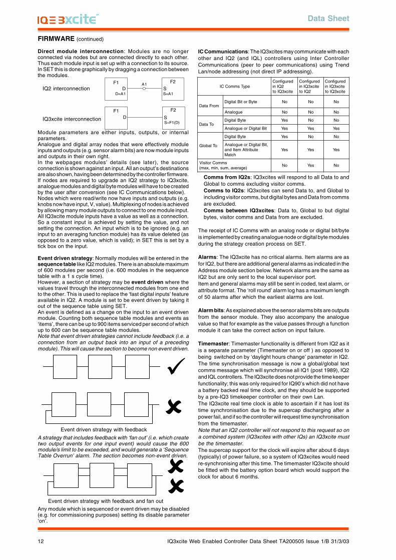
Direct module interconnection: Modules are no longerconnected via nodes but are connected directly to each other.Thus each module input is set up with a connection to its source.In SET this is done graphically by dragging a connection betweenthe modules.
IC Communications: The IQ3xcites may communicate with eachother and IQ2 (and IQL) controllers using Inter ControllerCommunications (peer to peer communications) using TrendLan/node addressing (not direct IP addressing).
D SF1 F2
A1
D=A1 S=A1IQ2 interconnection
D SF1 F2
S=F1(D)IQ3xcite interconnection
Module parameters are either inputs, outputs, or internalparameters.Analogue and digital array nodes that were effectively moduleinputs and outputs (e.g. sensor alarm bits) are now module inputsand outputs in their own right.In the webpages modules’ details (see later), the sourceconnection is shown against an input. All an output’s destinationsare also shown, having been determined by the controller firmware.If nodes are required to upgrade an IQ2 strategy to IQ3xcite,analogue modules and digital byte modules will have to be createdby the user after conversion (see IC Communications below).Nodes which were read/write now have inputs and outputs (e.g.knobs now have input, V, value). Multiplexing of nodes is achievedby allowing many module outputs to connect to one module input.All IQ3xcite module inputs have a value as well as a connection.So a constant input is achieved by setting the value, and notsetting the connection. An input which is to be ignored (e.g. aninput to an averaging function module) has its value deleted (asopposed to a zero value, which is valid); in SET this is set by atick box on the input.
Event driven strategy: Normally modules will be entered in thesequence table like IQ2 modules. There is an absolute maximumof 600 modules per second (i.e. 600 modules in the sequencetable with a 1 s cycle time).However, a section of strategy may be event driven where thevalues travel through the interconnected modules from one endto the other. This is used to replace the ‘fast digital inputs’ featureavailable in IQ2. A module is set to be event driven by taking itout of the sequence table using SET.An event is defined as a change on the input to an event drivenmodule. Counting both sequence table modules and events as‘items’, there can be up to 900 items serviced per second of whichup to 600 can be sequence table modules.Note that event driven strategies cannot include feedback (i.e. aconnection from an output back into an input of a precedingmodule). This will cause the section to become non event driven.
epyTsmmoCCIderugifnoC
2QInieticx3QIot
derugifnoCeticx3QIni
2QIot
derugifnoCeticx3QInieticx3QIot
morFataDetyBrotiBlatigiD oN oN oN
eugolanA oN oN oN
oTataDD latigi etyB seY oN oN
tiBlatigiDroeugolanA seY seY seY
oTlabolG
D latigi etyB seY oN oN
,tiBlatigiDroeugolanAetubirttAmetIdna
hctaMseY seY seY
smmoCrotisiV)egareva,mus,nim,xam(
oN seY oN
Event driven strategy with feedback
A strategy that includes feedback with ‘fan out’ (i.e. which createtwo output events for one input event) would cause the 600module/s limit to be exceeded, and would generate a ‘SequenceTable Overrun’ alarm. The section becomes non-event driven.
Event driven strategy with feedback and fan out
Any module which is sequenced or event driven may be disabled(e.g. for commissioning purposes) setting its disable parameter‘on’.
Comms from IQ2s: IQ3xcites will respond to all Data to andGlobal to comms excluding visitor comms.Comms to IQ2s: IQ3xcites can send Data to, and Global toincluding visitor comms, but digital bytes and Data from commsare excluded.Comms between IQ3xcites: Data to, Global to but digitalbytes, visitor comms and Data from are excluded.
The receipt of IC Comms with an analog node or digital bit/byteis implemented by creating analogue node or digital byte modulesduring the strategy creation process on SET.
Alarms: The IQ3xcite has no critical alarms. Item alarms are asfor IQ2, but there are additional general alarms as indicated in theAddress module section below. Network alarms are the same asIQ2 but are only sent to the local supervisor port.Item and general alarms may still be sent in coded, text alarm, orattribute format. The ‘roll round’ alarm log has a maximum lengthof 50 alarms after which the earliest alarms are lost.
Alarm bits: As explained above the sensor alarms bits are outputsfrom the sensor module. They also accompany the analoguevalue so that for example as the value passes through a functionmodule it can take the correct action on input failure.
Timemaster: Timemaster functionality is different from IQ2 as itis a separate parameter (Timemaster on or off ) as opposed tobeing switched on by ‘daylight hours change’ parameter in IQ2.The time synchronisation message is now a global/global textcomms message which will synchronise all IQ1 (post 1989), IQ2and IQL controllers. The IQ3xcite does not provide the time keeperfunctionality; this was only required for IQ90’s which did not havea battery backed real time clock, and they should be supportedby a pre-IQ3 timekeeper controller on their own Lan.The IQ3xcite real time clock is able to ascertain if it has lost itstime synchronisation due to the supercap discharging after apower fail, and if so the controller will request time synchronisationfrom the timemaster.Note that an IQ2 controller will not respond to this request so ona combined system (IQ3xcites with other IQs) an IQ3xcite mustbe the timemaster.The supercap support for the clock will expire after about 6 days(typically) of power failure, so a system of IQ3xcites would needre-synchronising after this time. The timemaster IQ3xcite shouldbe fitted with the battery option board which would support theclock for about 6 months.
Data Sheet
IQ3xcite Web Enabled Controller Data Sheet TA200505 Issue 1/B 31/3/03 13
FIRMWARE (continued)
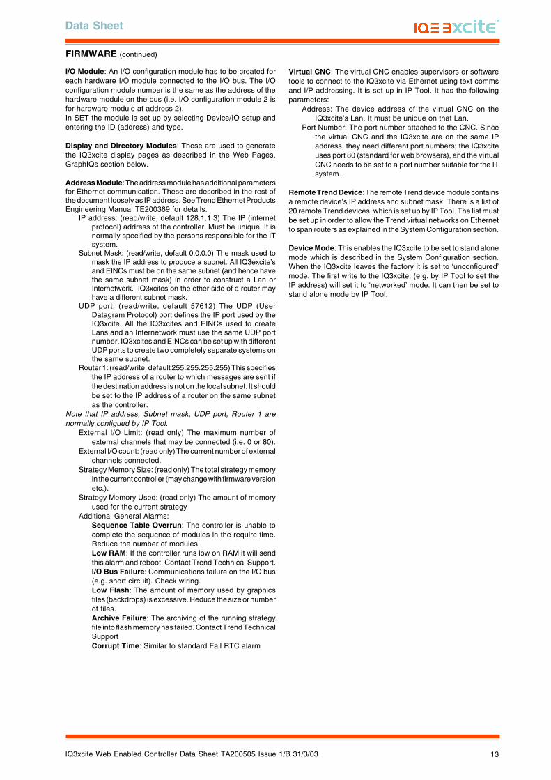
I/O Module: An I/O configuration module has to be created foreach hardware I/O module connected to the I/O bus. The I/Oconfiguration module number is the same as the address of thehardware module on the bus (i.e. I/O configuration module 2 isfor hardware module at address 2).In SET the module is set up by selecting Device/IO setup andentering the ID (address) and type.
Display and Directory Modules: These are used to generatethe IQ3xcite display pages as described in the Web Pages,GraphIQs section below.
Address Module: The address module has additional parametersfor Ethernet communication. These are described in the rest ofthe document loosely as IP address. See Trend Ethernet ProductsEngineering Manual TE200369 for details.
IP address: (read/write, default 128.1.1.3) The IP (internetprotocol) address of the controller. Must be unique. It isnormally specified by the persons responsible for the ITsystem.
Subnet Mask: (read/write, default 0.0.0.0) The mask used tomask the IP address to produce a subnet. All IQ3excite’sand EINCs must be on the same subnet (and hence havethe same subnet mask) in order to construct a Lan orInternetwork. IQ3xcites on the other side of a router mayhave a different subnet mask.
UDP port: (read/write, default 57612) The UDP (UserDatagram Protocol) port defines the IP port used by theIQ3xcite. All the IQ3xcites and EINCs used to createLans and an Internetwork must use the same UDP portnumber. IQ3xcites and EINCs can be set up with differentUDP ports to create two completely separate systems onthe same subnet.
Router 1: (read/write, default 255.255.255.255) This specifiesthe IP address of a router to which messages are sent ifthe destination address is not on the local subnet. It shouldbe set to the IP address of a router on the same subnetas the controller.
Note that IP address, Subnet mask, UDP port, Router 1 arenormally configued by IP Tool.
External I/O Limit: (read only) The maximum number ofexternal channels that may be connected (i.e. 0 or 80).
External I/O count: (read only) The current number of externalchannels connected.
Strategy Memory Size: (read only) The total strategy memoryin the current controller (may change with firmware versionetc.).
Strategy Memory Used: (read only) The amount of memoryused for the current strategy
Additional General Alarms:Sequence Table Overrun: The controller is unable tocomplete the sequence of modules in the require time.Reduce the number of modules.Low RAM: If the controller runs low on RAM it will sendthis alarm and reboot. Contact Trend Technical Support.I/O Bus Failure: Communications failure on the I/O bus(e.g. short circuit). Check wiring.Low Flash: The amount of memory used by graphicsfiles (backdrops) is excessive. Reduce the size or numberof files.Archive Failure: The archiving of the running strategyfile into flash memory has failed. Contact Trend TechnicalSupportCorrupt Time: Similar to standard Fail RTC alarm
Virtual CNC: The virtual CNC enables supervisors or softwaretools to connect to the IQ3xcite via Ethernet using text commsand I/P addressing. It is set up in IP Tool. It has the followingparameters:
Address: The device address of the virtual CNC on theIQ3xcite’s Lan. It must be unique on that Lan.
Port Number: The port number attached to the CNC. Sincethe virtual CNC and the IQ3xcite are on the same IPaddress, they need different port numbers; the IQ3xciteuses port 80 (standard for web browsers), and the virtualCNC needs to be set to a port number suitable for the ITsystem.
Remote Trend Device: The remote Trend device module containsa remote device’s IP address and subnet mask. There is a list of20 remote Trend devices, which is set up by IP Tool. The list mustbe set up in order to allow the Trend virtual networks on Ethernetto span routers as explained in the System Configuration section.
Device Mode: This enables the IQ3xcite to be set to stand alonemode which is described in the System Configuration section.When the IQ3xcite leaves the factory it is set to ‘unconfigured’mode. The first write to the IQ3xcite, (e.g. by IP Tool to set theIP address) will set it to ‘networked’ mode. It can then be set tostand alone mode by IP Tool.
IQ3xcite Web Enabled Controller Data Sheet TA200505 Issue 1/B 31/3/03
Data Sheet
14
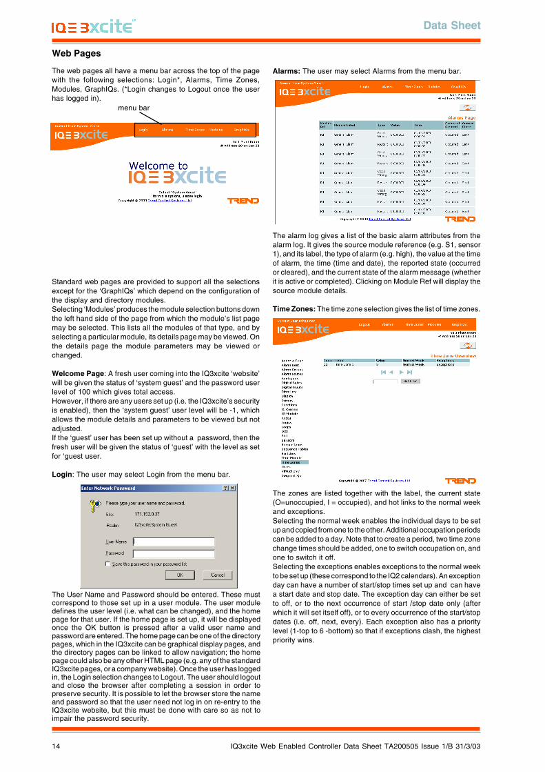
The alarm log gives a list of the basic alarm attributes from thealarm log. It gives the source module reference (e.g. S1, sensor1), and its label, the type of alarm (e.g. high), the value at the timeof alarm, the time (time and date), the reported state (occurredor cleared), and the current state of the alarm message (whetherit is active or completed). Clicking on Module Ref will display thesource module details.
Time Zones: The time zone selection gives the list of time zones.
The zones are listed together with the label, the current state(O=unoccupied, I = occupied), and hot links to the normal weekand exceptions.Selecting the normal week enables the individual days to be setup and copied from one to the other. Additional occupation periodscan be added to a day. Note that to create a period, two time zonechange times should be added, one to switch occupation on, andone to switch it off.Selecting the exceptions enables exceptions to the normal weekto be set up (these correspond to the IQ2 calendars). An exceptionday can have a number of start/stop times set up and can havea start date and stop date. The exception day can either be setto off, or to the next occurrence of start /stop date only (afterwhich it will set itself off), or to every occurrence of the start/stopdates (i.e. off, next, every). Each exception also has a prioritylevel (1-top to 6 -bottom) so that if exceptions clash, the highestpriority wins.
The User Name and Password should be entered. These mustcorrespond to those set up in a user module. The user moduledefines the user level (i.e. what can be changed), and the homepage for that user. If the home page is set up, it will be displayedonce the OK button is pressed after a valid user name andpassword are entered. The home page can be one of the directorypages, which in the IQ3xcite can be graphical display pages, andthe directory pages can be linked to allow navigation; the homepage could also be any other HTML page (e.g. any of the standardIQ3xcite pages, or a company website). Once the user has loggedin, the Login selection changes to Logout. The user should logoutand close the browser after completing a session in order topreserve security. It is possible to let the browser store the nameand password so that the user need not log in on re-entry to theIQ3xcite website, but this must be done with care so as not toimpair the password security.
Alarms: The user may select Alarms from the menu bar.
Web Pages
The web pages all have a menu bar across the top of the pagewith the following selections: Login*, Alarms, Time Zones,Modules, GraphIQs. (*Login changes to Logout once the userhas logged in).
menu bar
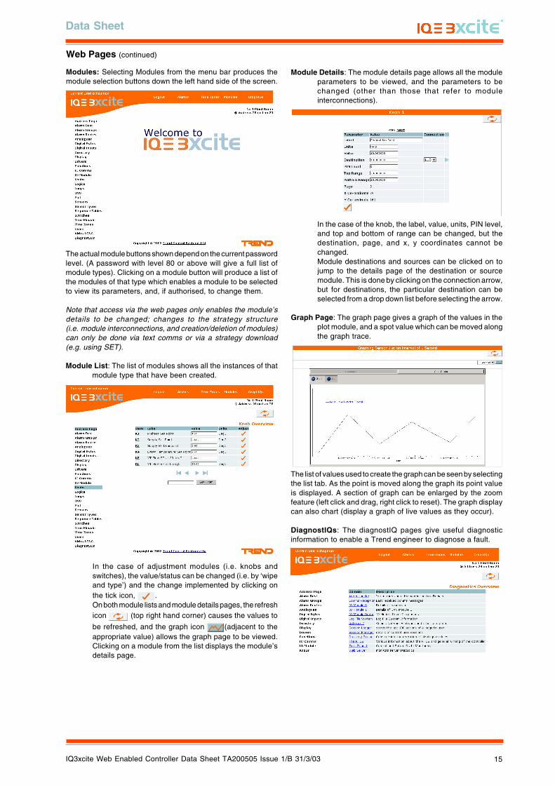
Standard web pages are provided to support all the selectionsexcept for the ‘GraphIQs’ which depend on the configuration ofthe display and directory modules.Selecting ‘Modules’ produces the module selection buttons downthe left hand side of the page from which the module’s list pagemay be selected. This lists all the modules of that type, and byselecting a particular module, its details page may be viewed. Onthe details page the module parameters may be viewed orchanged.
Welcome Page: A fresh user coming into the IQ3xcite ‘website’will be given the status of ‘system guest’ and the password userlevel of 100 which gives total access.However, if there are any users set up (i.e. the IQ3xcite’s securityis enabled), then the ‘system guest’ user level will be -1, whichallows the module details and parameters to be viewed but notadjusted.If the ‘guest’ user has been set up without a password, then thefresh user will be given the status of ‘guest’ with the level as setfor ‘guest user.
Login: The user may select Login from the menu bar.
Data Sheet
IQ3xcite Web Enabled Controller Data Sheet TA200505 Issue 1/B 31/3/03 15
In the case of the knob, the label, value, units, PIN level,and top and bottom of range can be changed, but thedestination, page, and x, y coordinates cannot bechanged.Module destinations and sources can be clicked on tojump to the details page of the destination or sourcemodule. This is done by clicking on the connection arrow,but for destinations, the particular destination can beselected from a drop down list before selecting the arrow.
Graph Page: The graph page gives a graph of the values in theplot module, and a spot value which can be moved alongthe graph trace.
In the case of adjustment modules (i.e. knobs andswitches), the value/status can be changed (i.e. by ‘wipeand type’) and the change implemented by clicking onthe tick icon, .On both module lists and module details pages, the refreshicon (top right hand corner) causes the values to
be refreshed, and the graph icon (adjacent to theappropriate value) allows the graph page to be viewed.Clicking on a module from the list displays the module’sdetails page.
The list of values used to create the graph can be seen by selectingthe list tab. As the point is moved along the graph its point valueis displayed. A section of graph can be enlarged by the zoomfeature (left click and drag, right click to reset). The graph displaycan also chart (display a graph of live values as they occur).
DiagnostIQs: The diagnostIQ pages give useful diagnosticinformation to enable a Trend engineer to diagnose a fault.
The actual module buttons shown depend on the current passwordlevel. (A password with level 80 or above will give a full list ofmodule types). Clicking on a module button will produce a list ofthe modules of that type which enables a module to be selectedto view its parameters, and, if authorised, to change them.
Note that access via the web pages only enables the module’sdetails to be changed; changes to the strategy structure(i.e. module interconnections, and creation/deletion of modules)can only be done via text comms or via a strategy download(e.g. using SET).
Module List: The list of modules shows all the instances of thatmodule type that have been created.
Module Details: The module details page allows all the moduleparameters to be viewed, and the parameters to bechanged (other than those that refer to moduleinterconnections).
Web Pages (continued)
Modules: Selecting Modules from the menu bar produces themodule selection buttons down the left hand side of the screen.
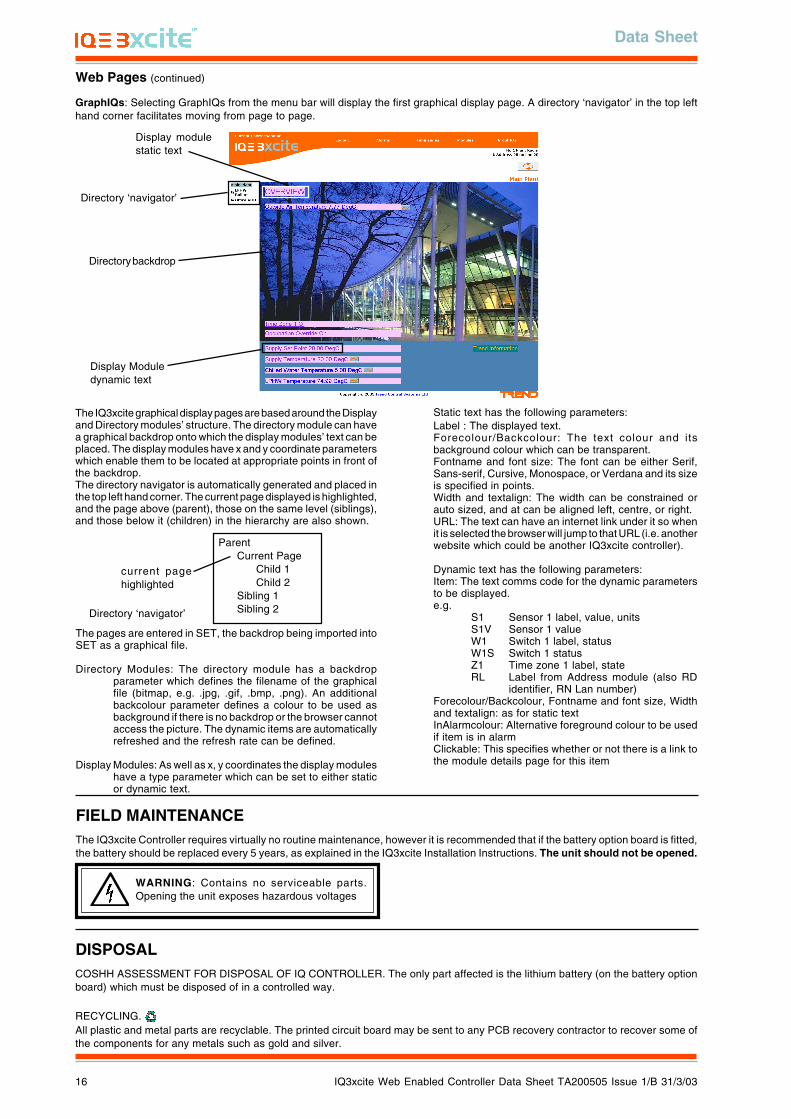
IQ3xcite Web Enabled Controller Data Sheet TA200505 Issue 1/B 31/3/03
Data Sheet
16
Web Pages (continued)
GraphIQs: Selecting GraphIQs from the menu bar will display the first graphical display page. A directory ‘navigator’ in the top lefthand corner facilitates moving from page to page.
The IQ3xcite graphical display pages are based around the Displayand Directory modules’ structure. The directory module can havea graphical backdrop onto which the display modules’ text can beplaced. The display modules have x and y coordinate parameterswhich enable them to be located at appropriate points in front ofthe backdrop.The directory navigator is automatically generated and placed inthe top left hand corner. The current page displayed is highlighted,and the page above (parent), those on the same level (siblings),and those below it (children) in the hierarchy are also shown.
Static text has the following parameters:Label : The displayed text.Forecolour/Backcolour: The text colour and itsbackground colour which can be transparent.Fontname and font size: The font can be either Serif,Sans-serif, Cursive, Monospace, or Verdana and its sizeis specified in points.Width and textalign: The width can be constrained orauto sized, and at can be aligned left, centre, or right.URL: The text can have an internet link under it so whenit is selected the browser will jump to that URL (i.e. anotherwebsite which could be another IQ3xcite controller).
Dynamic text has the following parameters:Item: The text comms code for the dynamic parametersto be displayed.e.g.
S1 Sensor 1 label, value, unitsS1V Sensor 1 valueW1 Switch 1 label, statusW1S Switch 1 statusZ1 Time zone 1 label, stateRL Label from Address module (also RD
identifier, RN Lan number)Forecolour/Backcolour, Fontname and font size, Widthand textalign: as for static textInAlarmcolour: Alternative foreground colour to be usedif item is in alarmClickable: This specifies whether or not there is a link tothe module details page for this item
Directory ‘navigator’
Display modulestatic text
Directory backdrop
The pages are entered in SET, the backdrop being imported intoSET as a graphical file.
Directory Modules: The directory module has a backdropparameter which defines the filename of the graphicalfile (bitmap, e.g. .jpg, .gif, .bmp, .png). An additionalbackcolour parameter defines a colour to be used asbackground if there is no backdrop or the browser cannotaccess the picture. The dynamic items are automaticallyrefreshed and the refresh rate can be defined.
Display Modules: As well as x, y coordinates the display moduleshave a type parameter which can be set to either staticor dynamic text.
ParentCurrent Page
Child 1Child 2
Sibling 1Sibling 2
current pagehighlighted
Directory ‘navigator’
WARNING: Contains no serviceable parts.Opening the unit exposes hazardous voltages
FIELD MAINTENANCEThe IQ3xcite Controller requires virtually no routine maintenance, however it is recommended that if the battery option board is fitted,the battery should be replaced every 5 years, as explained in the IQ3xcite Installation Instructions. The unit should not be opened.
DISPOSALCOSHH ASSESSMENT FOR DISPOSAL OF IQ CONTROLLER. The only part affected is the lithium battery (on the battery optionboard) which must be disposed of in a controlled way.
RECYCLING. All plastic and metal parts are recyclable. The printed circuit board may be sent to any PCB recovery contractor to recover some ofthe components for any metals such as gold and silver.
Display Moduledynamic text
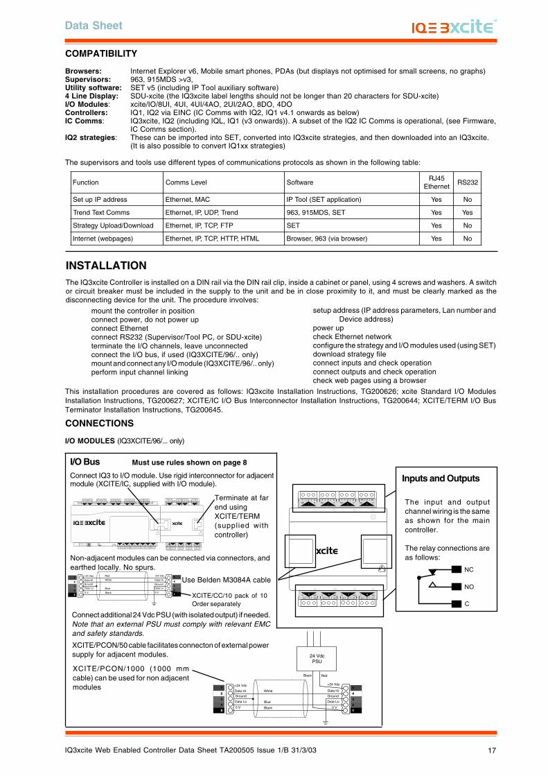
Data Sheet
IQ3xcite Web Enabled Controller Data Sheet TA200505 Issue 1/B 31/3/03 17
COMPATIBILITY
Browsers: Internet Explorer v6, Mobile smart phones, PDAs (but displays not optimised for small screens, no graphs)Supervisors: 963, 915MDS >v3,Utility software: SET v5 (including IP Tool auxiliary software)4 Line Display: SDU-xcite (the IQ3xcite label lengths should not be longer than 20 characters for SDU-xcite)I/O Modules: xcite/IO/8UI, 4UI, 4UI/4AO, 2UI/2AO, 8DO, 4DOControllers: IQ1, IQ2 via EINC (IC Comms with IQ2, IQ1 v4.1 onwards as below)IC Comms: IQ3xcite, IQ2 (including IQL, IQ1 (v3 onwards)). A subset of the IQ2 IC Comms is operational, (see Firmware,
IC Comms section).IQ2 strategies: These can be imported into SET, converted into IQ3xcite strategies, and then downloaded into an IQ3xcite.
(It is also possible to convert IQ1xx strategies)
The supervisors and tools use different types of communications protocols as shown in the following table:
INSTALLATIONThe IQ3xcite Controller is installed on a DIN rail via the DIN rail clip, inside a cabinet or panel, using 4 screws and washers. A switchor circuit breaker must be included in the supply to the unit and be in close proximity to it, and must be clearly marked as thedisconnecting device for the unit. The procedure involves:
mount the controller in positionconnect power, do not power upconnect Ethernetconnect RS232 (Supervisor/Tool PC, or SDU-xcite)terminate the I/O channels, leave unconnectedconnect the I/O bus, if used (IQ3XCITE/96/.. only)mount and connect any I/O module (IQ3XCITE/96/.. only)perform input channel linking
noitcnuF leveLsmmoC erawtfoS54JR
tenrehtE232SR
sserddaPIputeS CAM,tenrehtE )noitacilppaTES(looTPI seY oN
smmoCtxeTdnerT dnerT,PDU,PI,tenrehtE TES,SDM519,369 seY seY
daolnwoD/daolpUygetartS PTF,PCT,PI,tenrehtE TES seY oN
)segapbew(tenretnI LMTH,PTTH,PCT,PI,tenrehtE )resworbaiv(369,resworB seY oN
1
1 2 3
NC C 2
4 5 6
NC C 3
7 8 9
NC C 4
10 11 12
NC C
513 14 15
C NC 616 17 18C NC 7
19 20 21C NC 8
22 23 24C NC
24 VdcPSU
+24 Vdc
0 V
Data Hi
Data Lo
+24 Vdc
0 V
Data Hi
Data Lo
Ground Ground
White
Blue
Black
Black Red
I/O BusConnect IQ3 to I/O module. Use rigid interconnector for adjacentmodule (XCITE/IC, supplied with I/O module).
Connect additional 24 Vdc PSU (with isolated output) if needed.Note that an external PSU must comply with relevant EMCand safety standards.
Inputs and Outputs
The input and outputchannel wiring is the sameas shown for the maincontroller.
The relay connections areas follows:
Non-adjacent modules can be connected via connectors, andearthed locally. No spurs.
+24 Vdc
0 V
Data Hi
Data Lo
+24 Vdc
0 V
Data Hi
Data Lo
Ground Ground
Red
White
Blue
Black
CONNECTIONS
I/O MODULES (IQ3XCITE/96/... only)
setup address (IP address parameters, Lan number andDevice address)
power upcheck Ethernet networkconfigure the strategy and I/O modules used (using SET)download strategy fileconnect inputs and check operationconnect outputs and check operationcheck web pages using a browser
This installation procedures are covered as follows: IQ3xcite Installation Instructions, TG200626; xcite Standard I/O ModulesInstallation Instructions, TG200627; XCITE/IC I/O Bus Interconnector Installation Instructions, TG200644; XCITE/TERM I/O BusTerminator Installation Instructions, TG200645.
4 5 6
27 8 9
310 11 12
413 14 15
516 17 18
619 20 21
722 23 24
825 26 27
928 29 30
10+ 0+ 0 + 0 + 0 + 0 + 0+ 0+ 0+ 0
1 2 3
1+ 0
0 V24 V
24 V 34 35 36
12
37 38 39
13
40 41 42
14A
31 32 33P
11
43 44 45
15
46 47 48
16100-240 V
OK RXP 0 P 0 P 0P 0 P 0 P 0
24 V
P 13 14 15
5P 0
16 17 18
6P 0
19 20 21
7P 0
22 23 24
8P 0
1 2 3
1+ 0
4 5 6
2+ 0
7 8 9
3+ 0
10 11 12
4+ 0
Terminate at farend usingXCITE/TERM(supplied withcontroller)
XCITE/CC/10 pack of 10Order separately
Use Belden M3084A cable
Must use rules shown on page 8
XCITE/PCON/50 cable facilitates connecton of external powersupply for adjacent modules.
XCITE/PCON/1000 (1000 mmcable) can be used for non adjacentmodules

IQ3xcite Web Enabled Controller Data Sheet TA200505 Issue 1/B 31/3/03
Data Sheet
18
ORDER CODESIQ3XCITE/16/UK/100-240: Web enabled controller with 10 Universal Inputs, and 6 Analogue Voltage Outputs, non expandable via
I/O bus. Supplied with I/O bus terminator.IQ3XCITE/96/UK/100-240: Web enabled controller with 10 Universal Inputs, and 6 Analogue Voltage Outputs, expandable up to 96
points (i.e. 80 additional I/O channels) by addition of I/O modules to I/O bus. Supplied with I/O busterminator.
XCITE/IO/8UI: 8 channel universal input I/O module. Supplied with rigid interconnector.XCITE/IO/4UI: 4 channel universal input I/O module. Supplied with rigid interconnector.XCITE/IO/4UI/4AO: 4 channel universal input and 4 channel analogue voltage output I/O module. Supplied with rigid interconnector.
4 5 6
27 8 9
310 11 12
4
13 14 15
516 17 18
619 20 21
722 23 24
825 26 27
928 29 30
10+ 0+ 0 + 0 + 0 + 0 + 0+ 0+ 0+ 0
1 2 3
1+ 0
0 V24 V
24 V 34 35 36
12
37 38 39
13
40 41 42
14A
31 32 33P
11
43 44 45
15
46 47 48
16100-240 V
OK RXP 0 P 0 P 0P 0 P 0 P 0
Inputs
Mains Supply (option)
Outputs
L N E
2 part L N E
Local Supervisor Port
RJ11 to 9way ’D type’female cable
CABLE/EJ101442
Supervisor orSDU-xcite
RJ11(FCC68)
Ethernet Port
CONNECTIONS (continued)
4 5 6
27 8 9
310 11 12
413 14 15
516 17 18
619 20 21
722 23 24
825 26 27
928 29 30
10+ 0+ 0 + 0 + 0 + 0 + 0+ 0+ 0+ 0
1 2 3
1+ 0
34 35 36
12
37 38 39
13
40 41 42
14
31 32 33
11
43 44 45
15
46 47 48
16P 0 P 0 P 0P 0 P 0 P 0
4 5 6
27 8 9
310 11 12
413 14 15
516 17 18
619 20 21
722 23 24
825 26 27
928 29 30
10+ 0+ 0 + 0 + 0 + 0 + 0+ 0+ 0+ 0
1 2 3
1+ 0
0 V24 V
24 V 34 35 36
12
37 38 39
13
40 41 42
14A
31 32 33P
11
43 44 45
15
46 47 48
16100-240 V
OK RXP 0 P 0 P 0P 0 P 0 P 0
24 V
P 13 14 15
5P 0
16 17 18
6P 0
19 20 21
7P 0
22 23 24
8P 0
1 2 3
1+ 0
4 5 6
2+ 0
7 8 9
3+ 0
10 11 12
4+ 0
24 VdcPSU
+24 Vdc
0 V
Data Hi
Data Lo
+24 Vdc
0 V
Data Hi
Data Lo
Ground Ground
White
Blue
Black
Black Red
I/O Bus (IQ3XCITE/96/... only)
Connect IQ3xcite to I/O module. Use rigid interconnector foradjacent module (XCITE/IC, supplied with I/O module).
A
PSU
0 V24 V
24 V
A
31 32 33P
11P 0
A
0 V24 V
24 V
A
31 32 33P
11P 0
Separate 24 Vac/Vdc power supply. Supply outputmust be isolated from earth, and supply mustcomply with relevant EMC and safety standards
External link
Power BusEitherInternal power supply
OrExternal power supply
MAIN CONTROLLER
Terminate at farend usingXCITE/TERM(supplied withcontroller)
A
0 V24 V
24 V
A
P
24 Vdc 0 V
Auxiliary Supply Out24 Vdcat 150 mA maximum
XCITE/CC/10 pack 10(order separately)
Connect additional 24 Vdc PSU (with isolated output) if needed.Note that external power supply must comply with relevantEMC and safety standards
+24 Vdc
0 V
Data Hi
Data Lo
+24 Vdc
0 V
Data Hi
Data Lo
Ground Ground
Red
White
Blue
Black
Use Belden M3084A cable
Non-adjacent modules can be connected via connectors, andearthed locally. No spurs.
Must use rules shown on page 8
100 to 240 Vac50/60 Hz
Cat 5e twisted pair e.g.CAT5E UTP LSZH 305 M (UTP)CAT5E FTP LSZH 305 M (FTP)305 m cable
RJ45 e.g.RJ45 PLUG UTP/10 (UTP)RJ45 PLUG FTP/10 (FTP)(packs of 10)
100 m(max)
Ethernet hub e.g.FL HUB 10BASET
A local supervisor (Ethernet) can be connectedto an adjacent port on the hub or directly viaa standard Ethernet cable and an XCITE/XAadapter
XCITE/PCON/50 cable facilitates connecton of externalpower supply for adjacent modules.
XCITE/PCON/1000 (1000 mmcable) can be used for non adjacentmodules

Data Sheet
IQ3xcite Web Enabled Controller Data Sheet TA200505 Issue 1/B 31/3/03 19
ORDER CODES (continued)
XCITE/IO/2UI/2AO: 2 channel universal input and 2 channel analogue voltage output I/O module. Supplied with rigid interconnector.XCITE/IO/8DO:8 channel relay output I/O module. Supplied with rigid interconnector.XCITE/IO/4DO:4 channel relay output I/O module. Supplied with rigid interconnector.
XCITE/BBC: Battery option board increases protection time of clock (in case of mains failure) to several years (e.g for Timemaster).XCITE/IC/5: Pack of 5 rigid I/O bus interconnectors for adjacent I/O modules (spare)XCITE/TERM/5: Pack of 5 I/O bus terminators (spare)XCITE/CC/10: Pack of 10 I/O bus connectors with screw terminals to facilitate wired connection (one required each end).XCITE/PCON/50: I/O bus interconnector (4 wide) for adjacent I/O modules to facilitate connection of external bus power supplyXCITE/PCON/1000: 1000 mm I/O bus connection cable (4 wide) between I/O modules to facilitate connection of external bus power supplyCABLE/EJ101442: Adapter cable to connect PC to local supervisor portXCITE/XA/5: Pack of 5 Ethernet connecter adapters for direct connection of a PC to the IQ3xcite using a standard Ethernet cablePSR/230/24-1.3: 1.3 A DIN rail mounted 24 Vdc power supply (isolated output) suitable for supplying I/O modulesPSR/230/24-2.5: 2.5 A DIN rail mounted 24 Vdc power supply (isolated output) suitable for supplying I/O modulesSDU-XCITE/UK:Smart Display unit for IQ3xcite within UK label set. Wall mounting unit with 2x40 electroluminescent display allowingviewing and adjustment of plant parameters and timesRD/SDU-IQ2COMMSCABLE/3M: 3 m cable to connect SDU-xcite to IQ3xciteRD/SDU-IQ2COMMSCABLE/10M: 10 m cable to connect SDU-xcite to IQ3xciteSDU DOWNLOAD ADAPTOR: (EJ105174) RJ11 socket to RJ11 plug, download adaptor cable for use with CABLE/EJ10442 forSDU-xcite configuration by PC running SDU Tool (an applet running in SET available from Trend website and protected by licence)FL HUB 10BASET: 4 port Ethernet hub.FL SWITCH 5TX: 5 port Ethernet switchFL HUB AGENT: 4 port Ethernet managed hubCAT5E UTP LSZH 305M: 305 m of Cat 5e UTP (unshielded) cable for wiring Ethernet connections.CAT5E FTP LSZH 305M: 305 m of Cat 5e FTP (shielded) cable for wiring EthernetRJ45 PLUG UTP/10: Unshielded RJ45 connector for wiring Ethernet connections.RJ45 PLUG FTP/10: Shielded RJ45 connector for wiring Ethernet connections.
SPECIFICATIONS
MAIN CONTROLLER
Electrical
CPU :MCF5272CPU speed :66 MHzCycle time :sequence table 1sMemory :16 Mbyte SDRAM, and 8 Mbyte Flash.Supply voltage :100 to 240 Vac ±10% 50/60 HzConsumption :23 VA max24 Vdc combined supply :24 Vdc ±10%, 700 mA maximum (typical)
to supply 24 Vdc auxil iary supplyterminals, I/O bus, RS232, the I/Ochannels (see page 6). Output deratedto 550 mA for mains supply <200 Vac.
24 Vdc auxiliary supply:Part of combined supply, 20 to 24 Vdclimited to 150 mA supplied to RS232,24 V auxiliary, and output power bus.
Fusing :No replaceable fuses required. The24Vdc combined supply is protected bya self resetting solid state circuit breaker.The part of the combined supply toRS232, 24 V auxiliary supply and outputpower bus is protected by 150 mA currentlimit. The output power bus is protectedby a 1.6 A multifuse. The power supply isprotected against catastrophic failure bya non-replaceable fuse. The analogueoutput circuitry is protected against thewrong connection of a non-isolated externalsupply by a non-replaceable fuse.
Mains failure protection :All strategy and data in nonvolatilememory. Supercap maintains real timeclock for up to 6 days (typical). Option tofit a battery board to maintain clock forup to several years in the case of mainssupply failure.
Battery option :XCITE/BBC, battery option boardincludes CR2032 3V lithium button cell
Clock accuracy :30 s per month (typical).2-line display panel :SDU-xcite to local supervisor portEthernet :main bus, 10 BASE-T (IEEE 802.3).
Supports TCP/IP, FTPSupervisor Port
Transmission :RS232, EIA/TIA/232E, V28 supportsTrend comms, PPP
Distance :15 m
Baud rate :9k6.I/O bus :maximum length 30 m, 15 additional nodes
maximum, 96 points maximum. Signallingrate 125 kbits/s. Cable Belden M3084A.
Inputs/Outputs :10 universal inputs, 6 voltage outputsexpandable via I/O bus to 96 pointsmaximum
Universal inputs :Channels 1 to 10, linkable for analoguevoltage (V), analogue current (I),thermistor (T) or digital (D).
Analogue voltage (V) :12 bit resolution. Minimum 60 dB seriesmode rejection at supply frequency. 0 to10 V, input resistance 200 kΩ, accuracy50 mV equivalent to ±0.5% of span.
Analogue current (I) :12 bit resolution (4096 steps - effective).Minimum 60 dB series mode rejection atsupply frequency. 0 to 20 mA, inputresistance 240 Ω, accuracy 0.5% of span(i.e. 100 µA). Loop powered input supplyis 20 to 36 Vdc.
Thermistor (T) :12 bit resolution. Minimum 60 dB seriesmode rejection at supply frequency.Thermistor bridge resistor 10 kΩ 0.1%,accuracy 0.5% of span. Bridge supply 5 V.
Digital (D) :volt free contact. Count rate 30 Hz(minimum pulse width of 20 ms). Wettingcurrent = 3 mA nominal. 5 V supply.Status LED per channel (ON = closedcontact).
Analogue Voltage Outputs :Channels 11 to 16. 11 bitresolution. 0 to 10 V with 20 mA currentlimit, accuracy ±0.5% of span.
IndicatorsInputs :(yellow) Indicates status, only for digital
inputs (ON= contact closed)Analogue Outputs :(yellow) Light intensity increases with
output voltage (power) :(green) ON when supply is connected.
Flashing at 1 second intervals indicatespower supply fault.
(watchdog) :(red) ON if controller has a software fault (I/O bus) :(red) On if there is an I/O bus fault.
OK :(green) Normally called LINK onEthernet systems. ON indicates a goodEthernet connection.
RX :(yellow) Flashes when packet of data isbeing received across the Ethernet.

Data Sheet
20 IQ3xcite Web Enabled Controller Data Sheet TA200505 Issue 1/B 31/3/03
Trend Control Systems Ltd reserves the right to revise this publication from time to time and make changes to the content hereofwithout obligation to notify any person of such revisions or changes.
Trend Control Systems Ltd P.O. Box 34 Horsham Sussex RH12 2YF England Tel:+44 (0)1403 211888 Fax:+44 (0)1403 241608 www.trend-controls.com
SPECIFICATIONS (continued)
MechanicalDimensions
Controller :263 mm x 150 mm (max.) x 46 mmMaterial :PolycarbonateProtection :IP20Weight
Controller :702 gmIO Module :332 gm (approx.)
ConnectorsPower in :2 part connector with 3 rising cage clamp
screw terminals for 0.5 to 2.5 mm2 crosssection area cable.
I/O :2 part connectors with rising cage clampscrew terminals for 0.5 to 2.5 mm2 crosssection area cable.
Screens :single part connector with rising cage clampscrew terminals for 0.5 to 2.5 mm2 crosssection area cable.
Supervisor port :RJ11 (FCC68), for Trend utility software,supervisor or SDU-xcite connected viaadaptor cable CABLE/EJ101442. Can supplysignal and power.
Ethernet :RJ45 connector, unshielded or shieldedtwisted pair (UTP or FTP) cable 10 Mbps,100 m (10 BASE-T). Cable and connectorsavailable from Trend (see product codes).Connect local supervisor (Ethernet) viaadjacent hub or directly using standardEthernet cable and XCITE/XA adapter
I/O bus :5 wide connector. For expandable controlleronly, connect with special rigid interconnector(XCITE/IC) supplied with I/O Module) toadjacent module, or use connector with screwterminals (XCITE/CC/10 - pack of 10) andwire in Belden M3084A or equivalent. Lastconnection requires termination(XCITE/TERM supplied with controller).Special 4 wide cables available to facilitateconnection of additional I/O bus power supply;XCITE/PCON/50 for adjacent I/O module,XCITE/PCON/1000 for cable connection toI/O module up to 1 metre.
EnvironmentalEMC
Emissions :EN50081-1:1992Immunity :EN61000-3-2:1995 + A1:1998 + A2:1998
EN61000-3-3:1995EN61000-6-2:1999
Safety :EN61010:2001(Installation Category III - fixed installations)
Ambient limitsstorage :-10 °C to +50 °Coperating :0 °C to 45 °Chumidity :0 to 90 %RH non-condensing
Version This document covers:Firmware :v1.0Boards
IQ3xcite :Baseboard AM104979 Issue 1CPU board AM104979 Issue 1
I/O bus :XCITE/IC AM105225 Issue 1XCITE/TERM AM105226 Issue 1
I/O MODULES
ElectricalCPU :microprocessor PIC 18F458Supply voltage :24 Vdc ±10%Consumption :Maximum: 8DO=100 mA, 4DO=60 mA,
8UI=180 mA, 4UI=100 mA, 4UI/4VO=180 mA(+Aux supply 150 mA), 2UI/2VO=100 mA (+Auxsupply 150 mA) see page 9 for calculation.
Auxiliary supply :18 to 24 Vdc, limited to 150 mA.Fusing :no replaceable fuses required. The auxiliary
supply is protected by a 150 mA current limit.
The analogue output bus is protected by a1.6 A multifuse. The analogue output circuitryis protected against the wrong connection ofa non-isolated external supply by anon-replaceable fuse.
I/O bus :maximum length 30 m, 15 additional nodesmaximum, 96 points maximum. Signallingrate 125 kbits/s. Cable Belden M3084A (seerules page 8)
Inputs/outputs :selectable from range of 8UI, 4UI, 4UI/4VO,2UI/2VO, 8RO, or 4RO.
Key: UI Universal inputVO Analogue voltage outputRO Relay output
Universal input :as for main controllerAnalogue voltage output :as for main controller except 10 bit
resolutionRelay output :Relay outputs with LED status indication (on
= energised) per channel. Single polechangeover relays. Outputs rated at 5 Amaximum for 240 Vac single phase only (usesame phase throughout) inductive,(cosφ=0.4), or resistive load, 30 Vdc (resistiveload), and 20 Vdc (inductive load). For 24Vdc (inductive load) reduce to 2 A. Arcsuppression recommended, (see RelayOutput Arc Suppression InstallationInstructions TG200208).
IndicatorsInputs :(yellow) Indicates status, only for digital
inputs (ON= contact closed)Analogue Outputs :(yellow) Light intensity increases with output
voltageRelay Outputs :(yellow). Indicates relay status (ON = relay
energised) (power) :(green) ON when supply is connected (watchdog) :(red) ON if module has a software fault
(I/O bus) :(red) On if there is an I/O bus fault. Flashes at1 second intervals if the I/O module has notbeen in receipt of any valid comms for 30 secs(outputs will be switched off). Flashes faster ifan address clash on I/O bus, or the addresshas been set to zero (I/O module disabled)
MechanicalDimensions
I/O Module :130 mm x 150 mm (max.) x 46 mmMaterial :PolycarbonateProtection :IP20Weight
IO Module :332 gm (approx.)Connectors
Power in :2 part connector with 3 rising cage clampscrew terminals for 0.5 to 2.5 mm2 crosssection area cable.
I/O :2 part connectors with rising cage clampscrew terminals for 0.5 to 2.5 mm2 crosssection area cable.
Screens :single part connector with rising cage clampscrew terminals for 0.5 to 2.5 mm2 crosssection area cable.
I/O bus :5 wide connector. For expandable controlleronly, connect with special rigid interconnector(XCITE/IC supplied with I/O Module) toadjacent module, or use connector with screwterminals (XCITE/CC/10 - pack of 10) andwire in Belden M3084A or equivalent. Lastconnection requires termination(XCITE/TERM supplied with controller)
Environmental :as for main controller
Version This document covers:Firmware v1.00Boards 8 relay output AM105145 Issue 1
8 universal input/4 analogue outputAM105146 issue 1
Related Documents