IEEE TRANSACTIONS ON INSTRUMENTATIONAND MEASUREMENT, VOL. 64, NO. 2, FEBRUARY 2015 439 Wireless Wearable T-Shirt for Posture Monitoring During Rehabilitation Exercises Emilio Sardini, Mauro Serpelloni, and Viviane Pasqui Abstract— The monitoring of any human physiological parameters during rehabilitation exercises requires noninvasive sensors for the patient. This paper describes a wireless wearable T-shirt for posture monitoring during rehabilitation or rein- forcement exercises. The subject posture is measured through a sensorized T-shirt using an inductive sensor sewn directly on the fabric. The wireless wearable T-shirt design specifications are the following: independence from the remote unit, easy to use, lightweight and comfort of wearing. This paper reports the conceptual framework, the fabricated device description, and the adopted experimental setup. The instrumented T-shirt’s output data are compared with the data obtained via an optical system, as a gold standard, that measures the marker positions over the patient’s back and chest. The trials performed on four subjects obtained on different days demonstrate that the wireless wearable sensor described in this paper is capable of producing reliable data compared with the data obtained with the optical system. The constitutive sensor simplicity that includes only a copper wire and a separable circuit board allows achieving the objectives of simplicity, ease of use, and noninvasiveness. The sensorized T-shirt, integrated with designed conditioning and transmission electronics for remote communication, could be used as a support tool for postural monitoring during rehabilitation exercises. Index Terms— Impedance analysis, optical measurements, posture monitoring, sensorized T-shirt, smart vest, wearable system, wireless system. I. I NTRODUCTION D IFFERENT spinal disorders may occur through the phases of a person’s life during growth, working, and aging period. In addition to physical spinal deformities, such as scoliosis and osteoporotic vertebral fractures, posture and receptive position dysfunctions are suggested to be the cause of different diseases, which may result in spinal deformity. Possible approaches in the rehabilitation of these spinal disor- ders are surgical, medical, or the application of restraint corsets and muscle strengthening exercises to counteract the postural deviations. For the nonsurgical and nonmedical interventions, a simple physical exercise consisting in the stretching of the body may help increasing the range of motion and improving the spinal mobilization [1], [2] since the muscle increases Manuscript received February 24, 2014; revised July 8, 2014; accepted July 10, 2014. Date of publication August 15, 2014; date of current version December 31, 2014. The Associate Editor coordinating the review process was Dr. Wendy Van Moer. E. Sardini and M. Serpelloni are with the Department of Information Engineering, University of Brescia, Brescia 25123, Italy (e-mail: [email protected]). V. Pasqui is with the Institut des Systèmes Intelligents et de Robotique, Université Pierre et Marie Curie, Paris 75252, France (e-mail: [email protected]). Color versions of one or more of the figures in this paper are available online at http://ieeexplore.ieee.org. Digital Object Identifier 10.1109/TIM.2014.2343411 its capacity and better supports the postural reeducation by lessening muscle hypertonicity [3]. This exercise is typically performed for every type of subject including elderly and/or impaired people. One important effect of this exercise is the awareness improvement of the subject’s upright posture as demonstrated by recent studies where the postural awareness improves the clinical outcomes [4], [5]. The awareness can be supported by a signal, generated by a monitoring system, indicating to the subject his/her postural state. The signal can be activated by an algorithm that implements the suggestions of the physician that has in charge the responsibility of the diagnosis on correct or incorrect posture. This way, the patients are encouraged to assume the correct postural habits that could restore the proper physiological state. A system that monitors the postural state should be wearable if it does not inhibit movements and it makes acceptable to be worn continuously during the exercise throughout the day. Other significant characteristics are that the vest equipped with the measurement system must be easily wearable without the help of other persons, easy to use, and should not compromise the patient’s privacy. Finally, a postural system equipped with the possibility to send data via Internet opens the opportunity of remote medical supervision, since the physician can have objective data relating to the exercise execution. Different solutions for the monitoring of postural activity during postural rehabilitation or reinforcement are reported in the literature, from simple visual observation in clinical practice to more complex motion systems used in medical laboratories. The analysis of posture is usually performed to measure the kinematic variables of anatomic segments using specific inertial devices, [accelerometers [6], [7], inertial measurement unit (IMU) [4], [8], [9]], electromagnetic sensors [10], [11] or cameras integrated in finer equipment as stereo photogrammetric systems [12]–[14], and hybrid systems [15]. Some of the mentioned techniques are not well suited to develop a wearable measuring system due to the weight of the electromagnetic sensor or to the impossibility to put on the patient’s back a camera or optical sensors. Accelerometers and gyroscopes are commonly incorporated in corsets and in IMU. They detect the position change in terms of spinal curvature change in the sagittal plane measuring inclination and angular rates of rotations that are integrated to obtain the positions [16]. However, the position values are affected by drift problems due to the integration method used. The main drawbacks of wearable sensors available on the market are their weight, the rigidity of the structures that support them, and the size and other properties that make them uncomfortable for the patient, and therefore hardly acceptable 0018-9456 © 2014 IEEE. Personal use is permitted, but republication/redistribution requires IEEE permission. See http://www.ieee.org/publications_standards/publications/rights/index.html for more information.

Welcome message from author
This document is posted to help you gain knowledge. Please leave a comment to let me know what you think about it! Share it to your friends and learn new things together.
Transcript
IEEE TRANSACTIONS ON INSTRUMENTATION AND MEASUREMENT, VOL. 64, NO. 2, FEBRUARY 2015 439
Wireless Wearable T-Shirt for Posture MonitoringDuring Rehabilitation Exercises
Emilio Sardini, Mauro Serpelloni, and Viviane Pasqui
Abstract— The monitoring of any human physiologicalparameters during rehabilitation exercises requires noninvasivesensors for the patient. This paper describes a wireless wearableT-shirt for posture monitoring during rehabilitation or rein-forcement exercises. The subject posture is measured througha sensorized T-shirt using an inductive sensor sewn directly onthe fabric. The wireless wearable T-shirt design specificationsare the following: independence from the remote unit, easy touse, lightweight and comfort of wearing. This paper reports theconceptual framework, the fabricated device description, and theadopted experimental setup. The instrumented T-shirt’s outputdata are compared with the data obtained via an optical system,as a gold standard, that measures the marker positions over thepatient’s back and chest. The trials performed on four subjectsobtained on different days demonstrate that the wireless wearablesensor described in this paper is capable of producing reliabledata compared with the data obtained with the optical system.The constitutive sensor simplicity that includes only a copper wireand a separable circuit board allows achieving the objectivesof simplicity, ease of use, and noninvasiveness. The sensorizedT-shirt, integrated with designed conditioning and transmissionelectronics for remote communication, could be used as a supporttool for postural monitoring during rehabilitation exercises.
Index Terms— Impedance analysis, optical measurements,posture monitoring, sensorized T-shirt, smart vest, wearablesystem, wireless system.
I. INTRODUCTION
D IFFERENT spinal disorders may occur through thephases of a person’s life during growth, working, and
aging period. In addition to physical spinal deformities, suchas scoliosis and osteoporotic vertebral fractures, posture andreceptive position dysfunctions are suggested to be the causeof different diseases, which may result in spinal deformity.Possible approaches in the rehabilitation of these spinal disor-ders are surgical, medical, or the application of restraint corsetsand muscle strengthening exercises to counteract the posturaldeviations. For the nonsurgical and nonmedical interventions,a simple physical exercise consisting in the stretching of thebody may help increasing the range of motion and improvingthe spinal mobilization [1], [2] since the muscle increases
Manuscript received February 24, 2014; revised July 8, 2014; acceptedJuly 10, 2014. Date of publication August 15, 2014; date of current versionDecember 31, 2014. The Associate Editor coordinating the review processwas Dr. Wendy Van Moer.
E. Sardini and M. Serpelloni are with the Department of InformationEngineering, University of Brescia, Brescia 25123, Italy (e-mail:[email protected]).
V. Pasqui is with the Institut des Systèmes Intelligents et de Robotique,Université Pierre et Marie Curie, Paris 75252, France (e-mail:[email protected]).
Color versions of one or more of the figures in this paper are availableonline at http://ieeexplore.ieee.org.
Digital Object Identifier 10.1109/TIM.2014.2343411
its capacity and better supports the postural reeducation bylessening muscle hypertonicity [3]. This exercise is typicallyperformed for every type of subject including elderly and/orimpaired people. One important effect of this exercise is theawareness improvement of the subject’s upright posture asdemonstrated by recent studies where the postural awarenessimproves the clinical outcomes [4], [5]. The awareness canbe supported by a signal, generated by a monitoring system,indicating to the subject his/her postural state. The signal canbe activated by an algorithm that implements the suggestionsof the physician that has in charge the responsibility of thediagnosis on correct or incorrect posture. This way, the patientsare encouraged to assume the correct postural habits thatcould restore the proper physiological state. A system thatmonitors the postural state should be wearable if it doesnot inhibit movements and it makes acceptable to be worncontinuously during the exercise throughout the day. Othersignificant characteristics are that the vest equipped with themeasurement system must be easily wearable without the helpof other persons, easy to use, and should not compromisethe patient’s privacy. Finally, a postural system equipped withthe possibility to send data via Internet opens the opportunityof remote medical supervision, since the physician can haveobjective data relating to the exercise execution.
Different solutions for the monitoring of postural activityduring postural rehabilitation or reinforcement are reportedin the literature, from simple visual observation in clinicalpractice to more complex motion systems used in medicallaboratories. The analysis of posture is usually performedto measure the kinematic variables of anatomic segmentsusing specific inertial devices, [accelerometers [6], [7], inertialmeasurement unit (IMU) [4], [8], [9]], electromagnetic sensors[10], [11] or cameras integrated in finer equipment as stereophotogrammetric systems [12]–[14], and hybrid systems [15].Some of the mentioned techniques are not well suited todevelop a wearable measuring system due to the weight ofthe electromagnetic sensor or to the impossibility to put onthe patient’s back a camera or optical sensors. Accelerometersand gyroscopes are commonly incorporated in corsets andin IMU. They detect the position change in terms of spinalcurvature change in the sagittal plane measuring inclinationand angular rates of rotations that are integrated to obtainthe positions [16]. However, the position values are affectedby drift problems due to the integration method used. Themain drawbacks of wearable sensors available on the marketare their weight, the rigidity of the structures that supportthem, and the size and other properties that make themuncomfortable for the patient, and therefore hardly acceptable
0018-9456 © 2014 IEEE. Personal use is permitted, but republication/redistribution requires IEEE permission.See http://www.ieee.org/publications_standards/publications/rights/index.html for more information.
440 IEEE TRANSACTIONS ON INSTRUMENTATION AND MEASUREMENT, VOL. 64, NO. 2, FEBRUARY 2015
if worn continuously throughout the day. Reference [17] man-ages patients with scoliosis monitoring the spinal posture andproviding feedback signals to patients to correct their posture.Even if no cumbersome cables are used, thus facilitating themovement and normal function in a wide range of activities,the device requires sticking, with adhesive tape, the sensorcable directly to the back skin and this operation is difficultwithout expert help. In [5], sensorized busts are used forpatients with lumbar scoliosis, patients with low back painfor the elderly and osteoporotic vertebral fracture. However,the use of these resources is limited by external factors, suchas invasiveness, clutter, physical restraint, and thus low levelof acceptance.
In this paper, a posture monitoring system consisting ofa wireless sensorized T-shirt integrating an inductive sensoris presented. The T-shirt is in stretch fabric (Lycra) as atextile substrate and it integrates a thin copper wire sewnon it resulting in this way lightweight and easily wearable.It meets also the clinical and psychological needs, such aspatient comfort, easiness of use, and noninvasiveness. Thus,the device is designed to be a valuable aid in monitoringpostural exercises during rehabilitation. The wire works asan inductive sensor that measures the deformation appliedon the T-shirt by the lengthening and straightening in thesagittal plane of the body. The experimental results have beencompared with those obtained by an optical measurementsystem (typically used in the experiment for postural analysis[4], [9], [11]–[13], [17]–[19]). This paper is a developmentof [19], where a preliminary sensor was characterized by acommercial impedance analyzer and preliminary experimentalresults have been reported.
II. REINFORCEMENT EXERCISE DESCRIPTION
The adopted reinforcement exercise of the body is schemat-ically shown in Fig. 1 [1], [2]. The subject is seated on abackless chair and performs the exercise stretching the bodyslowly. Fig. 1 shows the patient assuming two extremepostures: 1) (Pslump) has a high degree of spinal curvatureand 2) (Phyper−ext) is characterized by a lengthening andstraightening of the body, then postures Pslump and Phyper−extshow a significant difference due to a lengthening of thebody in the sagittal plane. With the aim to measure thedeformation applied on the subject’s T-shirt by the lengtheningand straightening in the sagittal plane, we designed a newsensor integrated in a common T-shirt. The proposed sensormeasures the lengthening at which the T-shirt is subjected tobecause of the reinforcement exercise.
III. POSTURE MONITORING SYSTEM DESCRIPTION
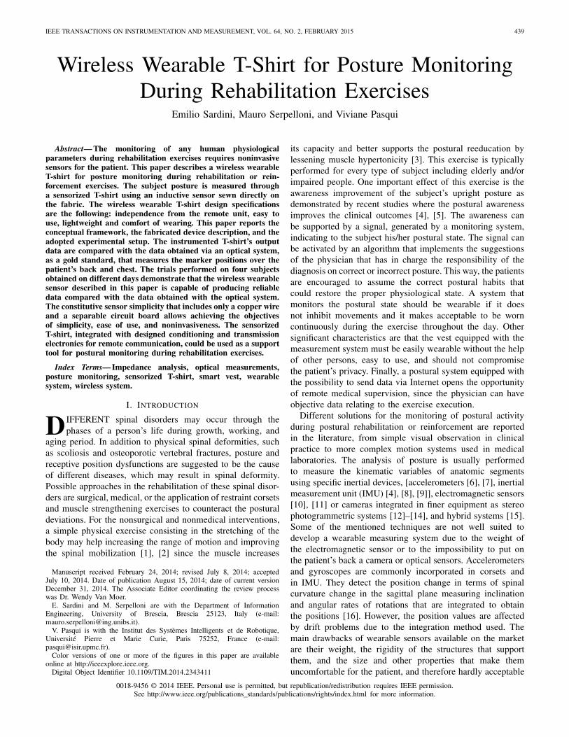
Fig. 2(a) and (b) shows the block diagrams of the posturemonitoring system. The proposed system can be dividedin two parts: a wearable instrumented T-shirt and readoutunit. The sensorized T-shirt is constituted by the induc-tive sensor, a circuit board, and a piezoelectric actuator.It weighs 175 g as a normal T-shirt. The sensor is a wire,appropriately stitched to the T-shirt throughout the patientback and chest. The circuit board, supplied by batteries,
Fig. 1. Image of the postural exercise.
incorporates conditioning and transmitting circuits and it ishoused in a box of about 13 × 7 × 5 mm fastened tothe pants. The two terminals of the sensor on the T-shirtare two metal snaps that are used to connect the sensor tothe circuit board using a snap connector. The actuator is avibration micromotor (Pico Vibe) commercialized by PrecisionMicrodrivers. The read-out unit is constituted by a Bluetoothmodule directly connected to a personal computer (PC) ordirectly to a local area network (LAN) integrated servermodule.
A. Sensor Description
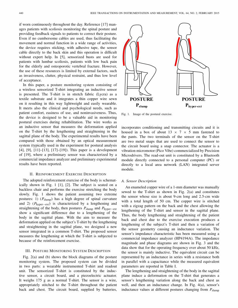
An enameled copper wire of a 1-mm diameter was manuallysewed to the T-shirt as shown in Fig. 2(a) and constitutesthe sensor whose size is about 9-cm long and 2.5-cm widewith a total length of 50 cm. The copper wire is stitchedwith a zigzag pattern on the back and the chest allowing thelengthening of the T-shirt and sensor in the sagittal plane.Thus, the body lengthening and straightening of the patientback and chest due to the exercise execution produces alengthening of the subject’s T-shirt and then a variation ofthe sensor geometry causing an inductance variation. Thesensor’s impedance characteristic has been measured using acommercial impedance analyzer (HP4194A). The impedancemagnitude and phase diagrams are shown in Fig. 3 and thedata show that for the operating frequency over about 50 kHz,the sensor is mainly inductive. The equivalent circuit can berepresented by an inductance in series with a resistance bothin parallel with a capacitance while the measured equivalentparameters are reported in Table I.
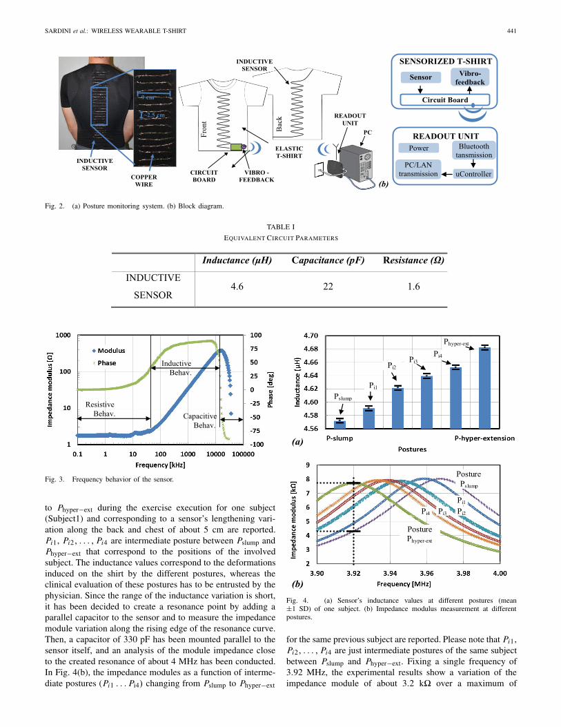
The lengthening and straightening of the body in the sagittalplane induce a deformation on the T-shirt that generates asensor’s lengthening variation along the back and chest aswell, and then an inductance change. In Fig. 4(a), sensor’sinductance values at different postures changing from Pslump
SARDINI et al.: WIRELESS WEARABLE T-SHIRT 441
Fig. 2. (a) Posture monitoring system. (b) Block diagram.
TABLE I
EQUIVALENT CIRCUIT PARAMETERS
Fig. 3. Frequency behavior of the sensor.
to Phyper−ext during the exercise execution for one subject(Subject1) and corresponding to a sensor’s lengthening vari-ation along the back and chest of about 5 cm are reported.Pi1, Pi2, . . . , Pi4 are intermediate posture between Pslump andPhyper−ext that correspond to the positions of the involvedsubject. The inductance values correspond to the deformationsinduced on the shirt by the different postures, whereas theclinical evaluation of these postures has to be entrusted by thephysician. Since the range of the inductance variation is short,it has been decided to create a resonance point by adding aparallel capacitor to the sensor and to measure the impedancemodule variation along the rising edge of the resonance curve.Then, a capacitor of 330 pF has been mounted parallel to thesensor itself, and an analysis of the module impedance closeto the created resonance of about 4 MHz has been conducted.In Fig. 4(b), the impedance modules as a function of interme-diate postures (Pi1 . . . Pi4) changing from Pslump to Phyper−ext
Fig. 4. (a) Sensor’s inductance values at different postures (mean±1 SD) of one subject. (b) Impedance modulus measurement at differentpostures.
for the same previous subject are reported. Please note that Pi1,Pi2, . . . , Pi4 are just intermediate postures of the same subjectbetween Pslump and Phyper−ext. Fixing a single frequency of3.92 MHz, the experimental results show a variation of theimpedance module of about 3.2 k� over a maximum of
442 IEEE TRANSACTIONS ON INSTRUMENTATION AND MEASUREMENT, VOL. 64, NO. 2, FEBRUARY 2015
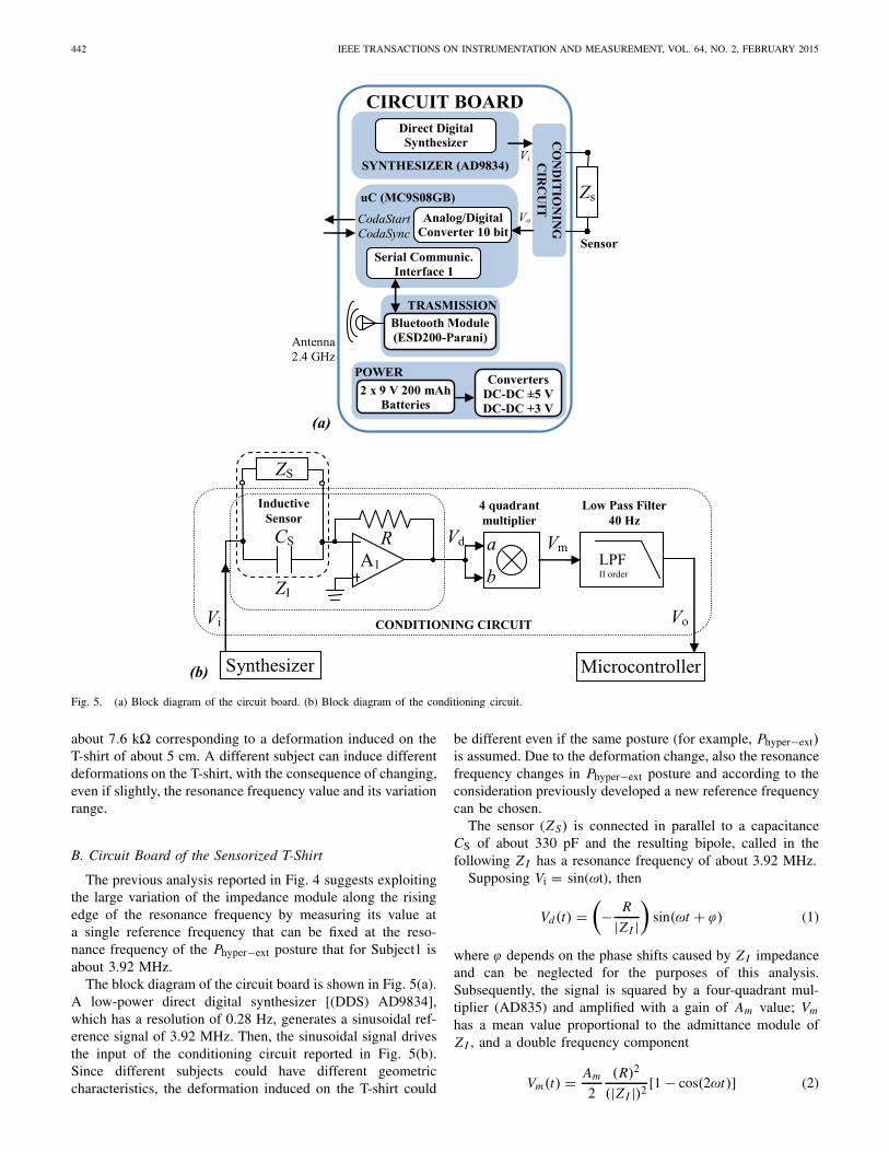
Fig. 5. (a) Block diagram of the circuit board. (b) Block diagram of the conditioning circuit.
about 7.6 k� corresponding to a deformation induced on theT-shirt of about 5 cm. A different subject can induce differentdeformations on the T-shirt, with the consequence of changing,even if slightly, the resonance frequency value and its variationrange.
B. Circuit Board of the Sensorized T-Shirt
The previous analysis reported in Fig. 4 suggests exploitingthe large variation of the impedance module along the risingedge of the resonance frequency by measuring its value ata single reference frequency that can be fixed at the reso-nance frequency of the Phyper−ext posture that for Subject1 isabout 3.92 MHz.
The block diagram of the circuit board is shown in Fig. 5(a).A low-power direct digital synthesizer [(DDS) AD9834],which has a resolution of 0.28 Hz, generates a sinusoidal ref-erence signal of 3.92 MHz. Then, the sinusoidal signal drivesthe input of the conditioning circuit reported in Fig. 5(b).Since different subjects could have different geometriccharacteristics, the deformation induced on the T-shirt could
be different even if the same posture (for example, Phyper−ext)is assumed. Due to the deformation change, also the resonancefrequency changes in Phyper−ext posture and according to theconsideration previously developed a new reference frequencycan be chosen.
The sensor (ZS) is connected in parallel to a capacitanceCS of about 330 pF and the resulting bipole, called in thefollowing Z I has a resonance frequency of about 3.92 MHz.
Supposing Vi = sin(ωt), then
Vd(t) =(
− R
|Z I |)
sin(ωt + ϕ) (1)
where ϕ depends on the phase shifts caused by Z I impedanceand can be neglected for the purposes of this analysis.Subsequently, the signal is squared by a four-quadrant mul-tiplier (AD835) and amplified with a gain of Am value; Vm
has a mean value proportional to the admittance module ofZ I , and a double frequency component
Vm(t) = Am
2
(R)2
(|Z I |)2 [1 − cos(2ωt)] (2)
SARDINI et al.: WIRELESS WEARABLE T-SHIRT 443
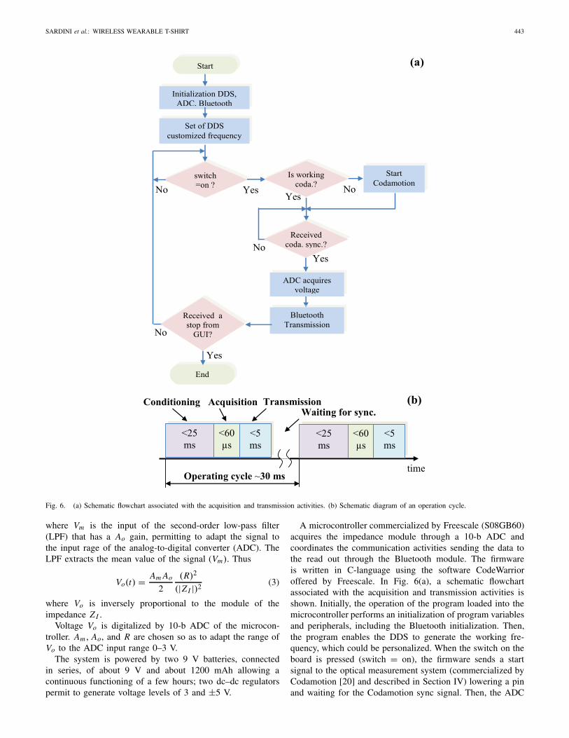
Fig. 6. (a) Schematic flowchart associated with the acquisition and transmission activities. (b) Schematic diagram of an operation cycle.
where Vm is the input of the second-order low-pass filter(LPF) that has a Ao gain, permitting to adapt the signal tothe input rage of the analog-to-digital converter (ADC). TheLPF extracts the mean value of the signal (Vm). Thus
Vo(t) = Am Ao
2
(R)2
(|Z I |)2 (3)
where Vo is inversely proportional to the module of theimpedance Z I .
Voltage Vo is digitalized by 10-b ADC of the microcon-troller. Am, Ao, and R are chosen so as to adapt the range ofVo to the ADC input range 0–3 V.
The system is powered by two 9 V batteries, connectedin series, of about 9 V and about 1200 mAh allowing acontinuous functioning of a few hours; two dc–dc regulatorspermit to generate voltage levels of 3 and ±5 V.
A microcontroller commercialized by Freescale (S08GB60)acquires the impedance module through a 10-b ADC andcoordinates the communication activities sending the data tothe read out through the Bluetooth module. The firmwareis written in C-language using the software CodeWarrioroffered by Freescale. In Fig. 6(a), a schematic flowchartassociated with the acquisition and transmission activities isshown. Initially, the operation of the program loaded into themicrocontroller performs an initialization of program variablesand peripherals, including the Bluetooth initialization. Then,the program enables the DDS to generate the working fre-quency, which could be personalized. When the switch on theboard is pressed (switch = on), the firmware sends a startsignal to the optical measurement system (commercialized byCodamotion [20] and described in Section IV) lowering a pinand waiting for the Codamotion sync signal. Then, the ADC
444 IEEE TRANSACTIONS ON INSTRUMENTATION AND MEASUREMENT, VOL. 64, NO. 2, FEBRUARY 2015
Fig. 7. (a) Block diagram of the read out unit. (b) Image of the realizedGUI.
acquires the voltage (Vo). At this stage, the Bluetooth is notenabled to transmit. When the data have been acquired andis ready to be sent to the Bluetooth, the DDS and ADCare not functioning and then the transmission via Bluetoothis activated. Then, another cycle follows. If requested, thecommunication can be interrupted by the software on the PCor by pressing the switch on the circuit board. The typicalmeasurement cycle, where each sensor value is conditioned,acquired, and transmitted to the readout unit, has a length ofabout 30 ms [Fig. 6(b)].
The Bluetooth (ESD200) is commercialized by Parani andit is connected to an antenna integrated over the printed circuitboard. The Bluetooth establishes a communication serial portprofile channel between the circuit board’s and the readout’sBluetooth. The functioning is simple; first, the firmware resetsthe Bluetooth at every connection. Then, the Bluetooth isconfigured in discoverable mode and waiting for a connectionfrom the readout unit. Finally, when the connection is estab-lished, the data transmission can be initiated by the softwareimplemented on the PC or by a switch on the circuit board.
C. Readout Unit
The readout unit, whose block diagram is reported inFig. 7(a), uses a Bluetooth ESD200, which is connected to amicrocontroller HC9S08AZ commercialized by Freescale bya serial communication interface (SCI). The microcontrollerelaborates the data and sent them to the PC for a localanalysis or by a second SCI to a LAN integrated servermodule (Digi-connect ME9210) commercialized by Digi forremote connectivity. The virtual instrument (VI) softwareimplemented in the PC is designed using LabVIEW marketedby National Instruments. In Fig. 7(b), an image with thedeveloped graphical user interface (GUI) is shown. The VIcan be run on any computer allowing you to manage thecommunication of data and save and display the received data.The program allows managing the Bluetooth communication,saving the data received from the readout unit, and visualizingthe received data in a graph. When the exercise is completed,the program allows stopping the Bluetooth communication.If necessary, all the received data can be saved into a file forfurther processing.
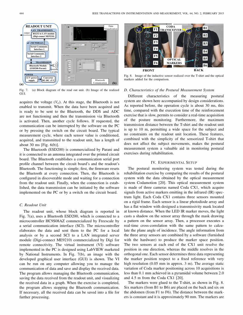
Fig. 8. Image of the inductive sensor realized over the T-shirt and the opticalmarkers added for the comparison.
D. Characteristics of the Postural Measurement System
Different characteristics of the measuring posturalsystem are shown here accompanied by design considerations.As reported before, the operation cycle is about 30 ms, thistime, compared with the execution time of the reinforcementexercise that is slow, permits to consider a real-time acquisitionof the posture monitoring. Furthermore, the maximumtransmission distance between the T-shirt and the readout unitis up to 10 m, permitting a wide space for the subject andno constraints on the readout unit location. These features,combined with the simplicity of the sensorized T-shirt thatdoes not affect the subject movements, makes the posturalmeasurement system a valuable aid in monitoring posturalexercises during rehabilitation.
IV. EXPERIMENTAL SETUP
The postural monitoring system was tested during therehabilitation exercise by comparing the results of the posturalsystem with the data obtained by the optical measurementsystem Codamotion [20]. This optical measurement systemis made of three cameras named Coda CX1, which acquiresignals from active markers emitting in the infrared (IR) spec-trum light. Each Coda CX1 contains three sensors mountedon a rigid frame. Each sensor is a linear photodiode array andhas a flat window with designed a transmissivity mask locatedat known distance. When the LED IR marker moves, the lightcasts a shadow on the sensor array through the mask drawinga pattern on the sensor array. Then, a processor executes areal-time cross-correlation with the same pattern to calcu-late the plane angle of incidence. The angle information fromthe three array sensors are combined by a software (furnishedwith the hardware) to produce the marker space position.The two sensors at each end of the CX1 unit resolve theposition in one direction, whereas the middle resolves in theorthogonal one. Each sensor determines three data representingthe marker position respect to a fixed reference with veryhigh resolution (0.05 mm in approx. 3 m). The average staticvariation of Coda marker positioning across 10 acquisitions isless than 0.1 mm achieved in a pyramidal volume between 2.0and 4.5 m from the Coda CX1 [20].
The markers were glued to the T-shirt, as shown in Fig. 8.Six markers (from B1 to B6) are placed on the back and six onthe abdomen (from F1 to F6). The distance between the mark-ers is constant and it is approximately 90 mm. The markers are
SARDINI et al.: WIRELESS WEARABLE T-SHIRT 445
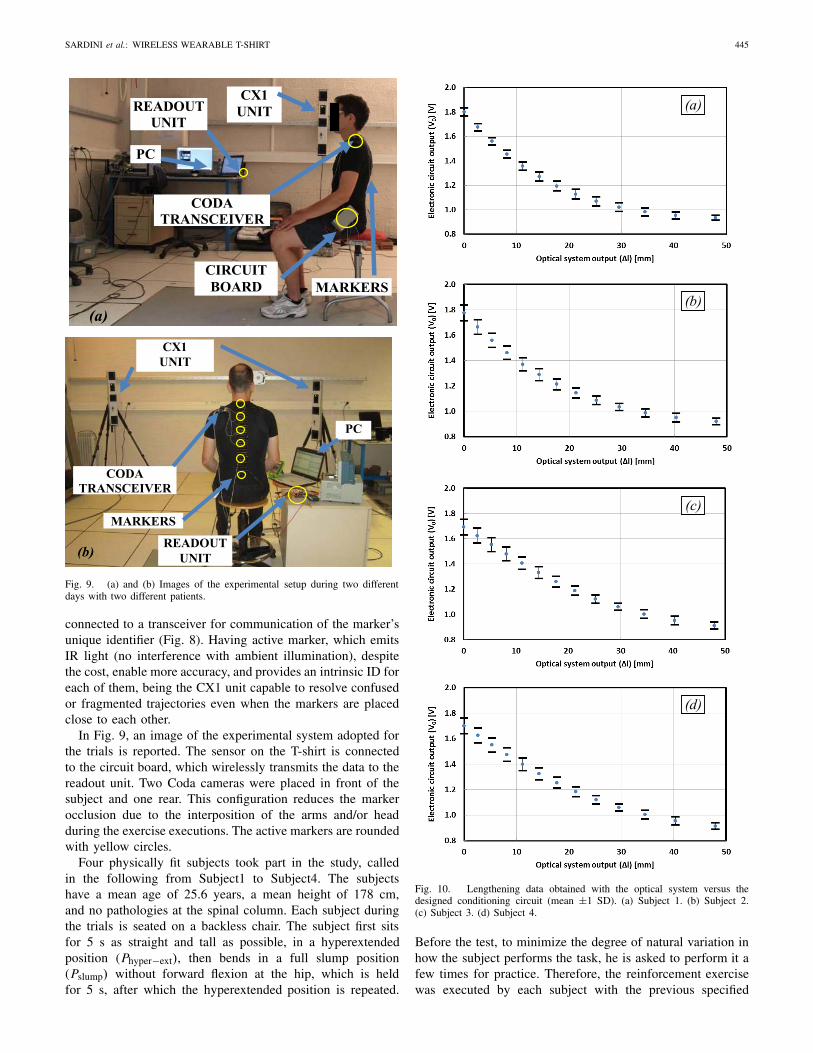
Fig. 9. (a) and (b) Images of the experimental setup during two differentdays with two different patients.
connected to a transceiver for communication of the marker’sunique identifier (Fig. 8). Having active marker, which emitsIR light (no interference with ambient illumination), despitethe cost, enable more accuracy, and provides an intrinsic ID foreach of them, being the CX1 unit capable to resolve confusedor fragmented trajectories even when the markers are placedclose to each other.
In Fig. 9, an image of the experimental system adopted forthe trials is reported. The sensor on the T-shirt is connectedto the circuit board, which wirelessly transmits the data to thereadout unit. Two Coda cameras were placed in front of thesubject and one rear. This configuration reduces the markerocclusion due to the interposition of the arms and/or headduring the exercise executions. The active markers are roundedwith yellow circles.
Four physically fit subjects took part in the study, calledin the following from Subject1 to Subject4. The subjectshave a mean age of 25.6 years, a mean height of 178 cm,and no pathologies at the spinal column. Each subject duringthe trials is seated on a backless chair. The subject first sitsfor 5 s as straight and tall as possible, in a hyperextendedposition (Phyper−ext), then bends in a full slump position(Pslump) without forward flexion at the hip, which is heldfor 5 s, after which the hyperextended position is repeated.
Fig. 10. Lengthening data obtained with the optical system versus thedesigned conditioning circuit (mean ±1 SD). (a) Subject 1. (b) Subject 2.(c) Subject 3. (d) Subject 4.
Before the test, to minimize the degree of natural variation inhow the subject performs the task, he is asked to perform it afew times for practice. Therefore, the reinforcement exercisewas executed by each subject with the previous specified
446 IEEE TRANSACTIONS ON INSTRUMENTATION AND MEASUREMENT, VOL. 64, NO. 2, FEBRUARY 2015
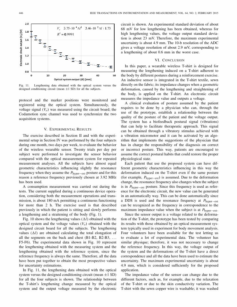
Fig. 11. Lengthening data obtained with the optical system versus thedesigned conditioning circuit (mean ±1 SD) for all the subjects.
protocol and the marker positions were monitored andregistered using the optical system. Simultaneously, thevoltage signal (Vo) was measured using the circuit board; theCodamotion sync channel was used to synchronize the twoacquisition systems.
V. EXPERIMENTAL RESULTS
The exercise described in Section II and with the experi-mental setup in Section IV was performed by the four subjectsduring one month, two days per week, to evaluate the behaviorof the wireless wearable sensor. Twenty trials per day persubject were performed to investigate the sensor behaviorcompared with the optical measurement system for repeatedmeasurement analyses. All the subjects have almost equalgeometric characteristics influencing slightly the resonancefrequency when they assume the Phyper−ext posture and for thisreason a reference frequency previously chosen at 3.92 MHzhas been used.
A consumption measurement was carried out during thetests. The current supplied during a continuous device opera-tion, considering both the measurement operations and trans-mission, is about 180 mA permitting a continuous functioningfor more than 2 h. The exercise used is that describedpreviously in which the patient is sitting and slowly performsa lengthening and a straitening of the body (Fig. 1).
Fig. 10 shows the lengthening values (�l) obtained with theoptical system and the voltage values (Vo) obtained with thedesigned circuit board for all the subjects. The lengtheningvalues (�l) are obtained calculating the total elongation ofall the segments on the back and chest (B1-B2, B2-B3, . . .F5-F6). The experimental data shown in Fig. 10 representthe lengthening obtained with the measuring system and thelengthening obtained with the reference system, since thereference frequency is always the same. Therefore, all the datahave been put together to obtain the most prospective valuesfor uncertainty estimations.
In Fig. 11, the lengthening data obtained with the opticalsystem versus the designed conditioning circuit (mean ±1 SD)for all the four subjects is shown. The relationship betweenthe T-shirt’s lengthening change measured by the opticalsystem and the output voltage measured by the electronic
circuit is shown. An experimental standard deviation of about68 mV for low lengthening has been obtained, whereas forhigh lengthening values, the voltage output standard devia-tion is about 23 mV. Therefore, the maximum experimentaluncertainty is about 4.9 mm. The 10-b resolution of the ADCgives a voltage resolution of about 2.9 mV, corresponding toa lengthening of about 0.6 mm in the worst case.
VI. CONCLUSION
In this paper, a wearable wireless T-shirt is designed formeasuring the lengthening induced on a T-shirt adherent tothe body by different postures during a reinforcement exercise.An inductive sensor is integrated in the T-shirt textile, sewndirectly on the fabric; its impedance changes when a geometricdeformation, caused by the lengthening and straightening ofthe body, is applied on the T-shirt. An electronic circuitmeasures the impedance value and outputs a voltage.
A clinical evaluation of posture assumed by the patientrequires to be done by a physician who can, through theuse of the prototype, establish a relationship between thequality of the posture of the patient and the voltage output.The system has a biofeedback postural signal (vibrations)that can help to facilitate therapeutic approach. This signalcan be obtained through a vibratory stimulus achieved witha vibration micromotor and it can be activated by an algo-rithm that implements the suggestions of the physician thathas in charge the responsibility of the diagnosis on corrector incorrect posture. This way, patients are encouraged toassume the correct postural habits that could restore the properphysiological state.
Each patient that use the proposed system can have dif-ferent geometric characteristics influencing in this way thedeformation induced on the T-shirt even if the same posture(for example, Phyper−ext) is assumed. Due to the deformationchange, the resonance frequency also changes when the subjectis in Phyper−ext posture. Since this frequency is used as refer-ence for the electronic circuit, the new value can be generatedin an automatically way. This can be done automatically sincea DDS is used and the resonance frequency at Phyper−extcan be recognized as the frequency in correspondence to themaximum impedance value when the subject is at Phyper−ext.
Since the sensor output is a voltage related to the deforma-tion of the T-shirt, the prototype has been tested by comparingits results with those obtained by an optical measurement sys-tem typically used in experiment for body movement analysis.Four volunteers have been available for the test letting usto evaluate a lot of experimental data. The volunteer hassimilar physique; therefore, it was not necessary to changethe reference frequency. In this way, the voltage output ofthe system and the deformations of the T-shirt have a directcorrespondence and all the data have been used to estimate theuncertainty. The maximum experimental uncertainty is about4.9 mm, which is considered sufficiently for the proposedapplication.
The impedance value of the sensor can change due to thedifferent factors, such as, for example, due to the relaxationof the T-shirt or due to the skin conductivity variation. TheT-shirt with the sewn copper wire is washable; it was washed
SARDINI et al.: WIRELESS WEARABLE T-SHIRT 447
(expecting a relaxation) because of its use and then no varia-tion of the L parameters reported in Table I was observed.Anyway, in case of fabrication, the synthesizer allows tochange the frequency to obtain the maximum value of theimpedance when the patient is in Phyper−ext. Operatively, thismeans that the T-shirt can be calibrated, when necessary, push-ing a button and recovering thus possible unwanted variations.The skin conductivity variation and the consequently effectshave to be deepen by other studies and research activities evenif, as the reported experimental results conducted over differentdays and places show, it can be concluded that these effectsare secondary.
Since the inductive sensor consists only of a commercialcopper wire, the T-shirt is simple and light. The electroniccircuit board is separated and is placed in a pocket connectedto the T-shirt by two snap buttons. Such electronics can beintegrated in a silicon circuit, powered by battery, constitutinga device of a few grams; then, a small lightweight batterycan be adopted. Therefore, the proposed T-shirt is wireless,lightweight, wearable, and meets the clinical and psycho-logical needs, such as patient comfort, easiness of use, andnoninvasiveness.
Furthermore, other aspects were considered; during reha-bilitation exercises, physical activity is not likely to makethe subject sweats, however, even if this should happen, thesweat in normal condition does not interfere; the variationof the parasitic capacitance of the sensor, which may begenerated, is not influential because negligible with respectto CS. Furthermore, the variations in the conductive pathsof the currents caused by the sweat are avoided because thecopper wire is enameled, preserving it also form the possibleenvironment influence and not in contact with the human body.
Furthermore, since the circuit board processes the datadirectly on the T-shirt, and then the data are available forimmediate presentation and analysis, or sent via Internet usingthe readout unit, it is possible to monitor the rehabilitationexercise in remote with advantages such as:
1) reduction of the environmental impact created byunnecessary patient’s travel;
2) increasing the effectiveness in terms of optimizing theuse of resources and clinical nursing;
3) reduction of the social cost of caregivers.
Further research is underway to further reduce the con-sumption of electronics. The prototype that we have describedhere allows achieving the goal of this paper that aims toassess the behavior of T-shirt for this specific application.The research in progress will maximize the performance of theprototype.
REFERENCES
[1] C. Liebenson, “Advice for the clinician,” J. Bodywork MovementTherapies, vol. 3, no. 3, pp. 147–149, 1999.
[2] C. Liebenson, “Self-treatment of mid-thoracic dysfunction: A key linkin the body axis—Part three: Clinical issues,” J. Bodywork MovementTherapies, vol. 5, no. 4, pp. 264–268, 2001.
[3] C. Lindsey, “Impaired posture,” in Geriatric Physical Therapy, 3rd ed.Amsterdam, The Netherlands: Elsevier, 2012, ch. 16, pp. 292–315.
[4] W. Y. Wong and M. S. Wong, “Smart garment for trunk posturemonitoring: A preliminary study,” Scoliosis, vol. 3, pp. 1–9, Jan. 2008.
[5] A. A. Gopalai and S. M. N. A. Senanayake, “A wearable real-time intelli-gent posture corrective system using vibrotactile feedback,” IEEE/ASMETrans. Mechatronics, vol. 16, no. 5, pp. 827–834, Oct. 2011.
[6] O. A. Postolache, P. M. B. S. Girao, J. Mendes, E. C. Pinheiro,and G. Postolache, “Physiological parameters measurement based onwheelchair embedded sensors and advanced signal processing,” IEEETrans. Instrum. Meas., vol. 59, no. 10, pp. 2564–2574, Oct. 2010.
[7] J. Baek and B.-J. Yun, “Posture monitoring system for context awarenessin mobile computing,” IEEE Trans. Instrum. Meas., vol. 59, no. 6,pp. 1589–1599, Jun. 2010.
[8] N. Mijailovic, A. Peulic, N. Filipovic, and E. Jovanov, “Implementationof wireless sensor system in rehabilitation after back spine surgery,”Serbian J. Elect. Eng., vol. 9, no. 1, pp. 63–70, Feb. 2012.
[9] W.-Y. Wong and M.-S. Wong, “Measurement of postural change in trunkmovements using three sensor modules,” IEEE Trans. Instrum. Meas.,vol. 58, no. 8, pp. 2737–2742, Aug. 2009.
[10] A. Maduri and S. E. Wilson, “Lumbar position sense with extreme lum-bar angle,” J. Electromyography Kinesiol., vol. 19, no. 4, pp. 607–613,2009.
[11] A. P. Claus, J. A. Hides, G. L. Moseley, and P. W. Hodges, “Is‘ideal’ sitting posture real?: Measurement of spinal curves in four sittingpostures,” Manual Therapy, vol. 14, no. 4, pp. 404–408, 2009.
[12] M. G. Benedetti, F. Biagi, A. Merlo, C. Belvedere, and A. Leardini,“A new protocol for multi-segment trunk kinematics,” in Proc. IEEEInt. Workshop Med. Meas. Appl. (MeMeA), May 2011, pp. 442–445.
[13] L. E. Dunne, P. Walsh, B. Smyth, and B. Caulfield, “Design andevaluation of a wearable optical sensor for monitoring seated spinalposture,” in Proc. 10th IEEE Int. Symp. Wearable Comput., Oct. 2006,pp. 65–68.
[14] G. Baroni, C. Rigotti, A. Amir, G. Ferrigno, D. Newman, and A. Pedotti,“Multifactorial movement analysis in weightlessness: A ground-basedfeasibility study,” IEEE Trans. Instrum. Meas., vol. 49, no. 3,pp. 476–482, Jun. 2000.
[15] M. Bazzarelli, N. G. Durdle, E. Lou, and V. J. Raso, “A wearable com-puter for physiotherapeutic scoliosis treatment,” IEEE Trans. Instrum.Meas., vol. 52, no. 1, pp. 126–129, Feb. 2003.
[16] D. Giansanti, V. Macellari, G. Maccioni, and A. Cappozzo, “Is itfeasible to reconstruct body segment 3-D position and orientationusing accelerometric data?” IEEE Trans. Biomed. Eng., vol. 50, no. 4,pp. 476–483, Apr. 2003.
[17] K. O’Sullivan, L. O’Sullivan, A. Campbell, P. O’Sullivan, andW. Dankaerts, “Towards monitoring lumbo-pelvic posture in real-life sit-uations: Concurrent validity of a novel posture monitor and a traditionallaboratory-based motion analysis system,” Manual Therapy, vol. 17,no. 1, pp. 77–83, 2012.
[18] W. S. Marras et al., “The role of dynamic three-dimensional trunkmotion in occupationally-related low back disorders. The effects ofworkplace factors, trunk position, and trunk motion characteristics onrisk of injury,” Spine, vol. 18, no. 5, pp. 617–628, Apr. 1993.
[19] E. Sardini, M. Serpelloni, and M. Ometto, “Smart vest for posturemonitoring in rehabilitation exercises,” in Proc. IEEE Sensors Appl.Symp. (SAS), Feb. 2012, pp. 1–5.
[20] Charnwood Dynamics Ltd. (2006). Codamotion Data Manual.Codamotion cx1 User Guide. Leicester, U.K. [Online]. Available:http://www.codamotion.com/
Emilio Sardini received the Degree in electronicengineering from the Polytechnic of Milan, Milan,Italy, in 1983.
He has been involved in research and teachingactivities with the Department of Electronics forAutomation, University of Brescia, Brescia, Italy,since 1984. Since 2006, he has been a Full Pro-fessor of Electrical and Electronic Measurement, amember of the Integrated Academic Senate and theBoard of Directors of the University of Brescia, andthe Deputy Dean of the Faculty. He is currently a
Coordinator of the Technology for Health Ph.D. program and a memberof the College of Mechatronics with the University of Bergamo, Bergamo,Italy, and the Director of the Department of Information Engineering. Hehas done intensive research in the field of electronic instrumentation, sen-sors, and signal conditioning electronics. He has authored and co-authoredmore than 100 papers published in international journal and proceedings ofinternational conferences. His current research interests include developmentof autonomous sensors for biomedical applications with some specific interesttoward devices implantable inside the human body.
448 IEEE TRANSACTIONS ON INSTRUMENTATION AND MEASUREMENT, VOL. 64, NO. 2, FEBRUARY 2015
Mauro Serpelloni was born in Brescia, Italy, in1979. He received the Laurea (summa cum laude)degree in industrial management engineering and thePh.D. degree in electronic instrumentation from theUniversity of Brescia, Brescia, in 2003 and 2007,respectively.
He has been involved in several projects relatingto the design, modeling, and fabrication of mea-surement systems for industrial applications. He iscurrently an Assistant Professor of Electrical andElectronic Measurements with the Department of
Information Engineering, University of Brescia. His current research interestsinclude biomechatronic systems, contactless transmissions between sensorsand electronics, contactless activation for resonant sensors, and signal process-ing for microelectromechanical systems.
Viviane Pasqui is an Assistant Professor with theDepartment of Mechanical Engineering, UniversitéPierre et Marie Curie, Paris, France. She is involvedin an international master’s program of Mecha-tronic Systems for Rehabilitation, a University Grant(RENOIR), four National Research Projects (MON-IMAD, AILISA, NEUROMAD, and MIRAS teamleader for each), and one European Research Project(DOMEO team leader). She has authored and co-authored more than 40 research papers published inthe international and national journals, and presented
in the international and national conferences. Her current research interestsinclude human motion, even pathological, and designing robots for rehabili-tation of patients suffering from motor problems.
Related Documents