RESEARCH ARTICLE Copyright © 2010 American Scientific Publishers All rights reserved Printed in the United States of America Journal of Nanoscience and Nanotechnology Vol. 10, 1–6, 2010 Wear Resistance and Wear Mechanisms in Polymer + Metal Composites Oscar Olea-Mejia 1 2 ∗ , Witold Brostow 1 , and Eli Buchman 1 3 1 Laboratory of Advanced Polymers and Optimized Materials (LAPOM), Department of Materials Science and Engineering, University of North Texas, 1150 Union Circle # 305310, Denton, TX 76203-5017, USA 2 Centro de Investigación en Química Sustentable, Facultad de Química, Universidad Autónoma del Estado de México, Toluca, México 50120, Mexico 3 Department of Materials Engineering, Technion-Israel Institute of Technology, Technion City, Haifa 32000, Israel We have investigated composites containing metallic micro-size and nano-sized particles as the 10 wt% dispersed phase. Branched low density polyethylene (LDPE) was the matrix. Microsized metals were Al, Ag and Ni; nanosized metals were Al and Ag. Several mechanisms of wear are observed in function of the kind and size of metal used: deformation, delamination, abrasion, adhe- sion and rolls formation. The presence of Ag particles increases the wear rate as compared to neat LDPE. The presence of Al particles lowers the wear of LDPE significantly; nanoparticles are more effective than microparticles. Keywords: Low Density Polyethylene, Polymer + Metal Nanocomposites, Focused Ion Beams, Scratch Resistance, Wear Resistance. 1. INTRODUCTION Polymer composites are used extensively for numerous purposes because of their wide variety of properties and relative ease of tailoring them. 1–4 Mechanical, thermophys- ical, electrical, dielectric and optical properties are the most studied. 5–13 By contrast, much less work has been done on tribology of polymer-based materials (PBMs). It is a difficult area since external lubricants used so widely for metals do not work. Penetration of the lubricant into the polymer occurs, the polymer swells, and increased material size makes the tribological situation worse. A small num- ber of laboratories active in PBM tribology includes the laboratory of Karger-Kocsis (now at Tshwane University, Pretoria), 14 15 the Uadimyr Belyi Institute of Metal and Polymer Mechanics in Homel, 16 a group at the University of Erlangen-Nuremberg, 17 a group at the Leibniz Institute in Dresden 18 as well as our own group 19–22 including col- laborations with Technion in Haifa, 23 with the University of Antioquia in Medellin 24 25 and with the Technical Uni- versity of Cartagena. 26 27 Given inherent poor scratch and wear resistance of polymers, clearly much more work in this field is needed. Let us now focus on PBMs containing a reinforce- ment as a dispersed second phase for improvement ∗ Author to whom correspondence should be addressed. of tribological properties. Most work along these lines involves carbon in various forms 7 10 23 24 or else ceramic fillers. 25–28 As for polymer + metal composites, the sit- uation is similar as with other polymer-based materials (PBMs); they have been mostly studied for thermal, elec- trical and mechanical applications and also as biomateri- als. There has been only little work on using a metallic dispersed phase to improve tribological properties of poly- mers, with the exception of results reported by Yu et al. 29 and our own earlier work. 30 In this situation, the goal of the present project is to investigate wear resistance and wear mechanisms of a polymer filled with metallic particles. Two issues are important here. One is the effect of the size of the dispersed particles, namely comparison of effects of particles with diameters in the microns range with those of particles in the nm range. The other natural factor to investigate is the effect of the nature of the metal. In this work we have created micro- and nanocomposites containing three different metals. 2. EXPERIMENTAL DETAILS 2.1. Materials Branched low density polyethylene (LDPE, from Hunstman) was used as the matrix. Microsized and nano- sized metallic particles were used as the filler dispersed J. Nanosci. Nanotechnol. 2010, Vol. 10, No. xx 1533-4880/2010/10/001/006 doi:10.1166/jnn.2010.3026 1

Welcome message from author
This document is posted to help you gain knowledge. Please leave a comment to let me know what you think about it! Share it to your friends and learn new things together.
Transcript

RE
SE
AR
CH
AR
TIC
LE
Copyright © 2010 American Scientific PublishersAll rights reservedPrinted in the United States of America
Journal ofNanoscience and Nanotechnology
Vol. 10, 1–6, 2010
Wear Resistance and Wear Mechanisms inPolymer+Metal Composites
Oscar Olea-Mejia1�2�∗, Witold Brostow1, and Eli Buchman 1�3
1Laboratory of Advanced Polymers and Optimized Materials (LAPOM), Department of Materials Science and Engineering,University of North Texas, 1150 Union Circle # 305310, Denton, TX 76203-5017, USA
2Centro de Investigación en Química Sustentable, Facultad de Química, Universidad Autónoma del Estado de México,Toluca, México 50120, Mexico
3Department of Materials Engineering, Technion-Israel Institute of Technology, Technion City, Haifa 32000, Israel
We have investigated composites containing metallic micro-size and nano-sized particles as the10 wt% dispersed phase. Branched low density polyethylene (LDPE) was the matrix. Microsizedmetals were Al, Ag and Ni; nanosized metals were Al and Ag. Several mechanisms of wear areobserved in function of the kind and size of metal used: deformation, delamination, abrasion, adhe-sion and rolls formation. The presence of Ag particles increases the wear rate as compared to neatLDPE. The presence of Al particles lowers the wear of LDPE significantly; nanoparticles are moreeffective than microparticles.
Keywords: Low Density Polyethylene, Polymer+Metal Nanocomposites, Focused Ion Beams,Scratch Resistance, Wear Resistance.
1. INTRODUCTION
Polymer composites are used extensively for numerouspurposes because of their wide variety of properties andrelative ease of tailoring them.1–4 Mechanical, thermophys-ical, electrical, dielectric and optical properties are themost studied.5–13 By contrast, much less work has beendone on tribology of polymer-based materials (PBMs). It isa difficult area since external lubricants used so widely formetals do not work. Penetration of the lubricant into thepolymer occurs, the polymer swells, and increased materialsize makes the tribological situation worse. A small num-ber of laboratories active in PBM tribology includes thelaboratory of Karger-Kocsis (now at Tshwane University,Pretoria),14�15 the Uadimyr Belyi Institute of Metal andPolymer Mechanics in Homel,16 a group at the Universityof Erlangen-Nuremberg,17 a group at the Leibniz Institutein Dresden18 as well as our own group19–22 including col-laborations with Technion in Haifa,23 with the Universityof Antioquia in Medellin24�25 and with the Technical Uni-versity of Cartagena.26�27 Given inherent poor scratch andwear resistance of polymers, clearly much more work inthis field is needed.
Let us now focus on PBMs containing a reinforce-ment as a dispersed second phase for improvement
∗Author to whom correspondence should be addressed.
of tribological properties. Most work along these linesinvolves carbon in various forms7�10�23�24 or else ceramicfillers.25–28 As for polymer+metal composites, the sit-uation is similar as with other polymer-based materials(PBMs); they have been mostly studied for thermal, elec-trical and mechanical applications and also as biomateri-als. There has been only little work on using a metallicdispersed phase to improve tribological properties of poly-mers, with the exception of results reported by Yu et al.29
and our own earlier work.30 In this situation, the goal of thepresent project is to investigate wear resistance and wearmechanisms of a polymer filled with metallic particles.
Two issues are important here. One is the effect ofthe size of the dispersed particles, namely comparison ofeffects of particles with diameters in the microns rangewith those of particles in the nm range. The other naturalfactor to investigate is the effect of the nature of the metal.In this work we have created micro- and nanocompositescontaining three different metals.
2. EXPERIMENTAL DETAILS
2.1. Materials
Branched low density polyethylene (LDPE, fromHunstman) was used as the matrix. Microsized and nano-sized metallic particles were used as the filler dispersed
J. Nanosci. Nanotechnol. 2010, Vol. 10, No. xx 1533-4880/2010/10/001/006 doi:10.1166/jnn.2010.3026 1
tcd0033
Typewritten Text
tcd0033
Typewritten Text
8524
tcd0033
Typewritten Text
tcd0033
Typewritten Text
tcd0033
Typewritten Text
tcd0033
Typewritten Text
J. Nanosci. Nanotechnol.10, 8524-8530, 2010
tcd0033
Typewritten Text
tcd0033
Typewritten Text
RE
SE
AR
CH
AR
TIC
LE
Wear Resistance and Wear Mechanisms in Polymer+Metal Composites Olea-Mejia et al.
phase (from NanoAmor, Houston, Texas). The microsizedmetals were Al, Ni (both spherical) and Ag (flakes); theaverage particle sizes were 1.0, 6.4 and 4.2 micrometersrespectively. The nanosized metals were Al and Ag (bothirregular shape flakes); average particle sizes were 127 and69 nm respectively. Particle sizes refers to the diameters inthe case of spherical particles and the longest distance inthe case of the irregular flake particles. The concentrationwas 10.0 wt% in all cases.
2.2. Sample Preparation
A Brabender type 6 mixer was used to blend each poly-mer with the appropriate metallic powder. The blendingtemperature was 150 �C. The mixing time was 5 min andthe blade speed was 80 rpm for all cases. The resultingblends were pelletized and then injection molded at 170 �Cat the pressure of 60 psi in an AB-100 injection moldingmachine (AB Machinery, Montreal, Quebec, Canada) toobtain the final specimens. SEM analysis was performedafter gold coating the samples.
2.3. Composites Characterization
In order to determine the wear mechanisms on each sampleas well as to measure the wear track thickness, secondaryelectrons scanning electron microscopy (SEM) imagingwas performed with a FEI analytical dual focused ionsbeam (FIB) at 20 keV. The SEM-FIB equipment combi-nation was the same as used in earlier work,31 the sourceconsisted of gallium ions.
The wear experiments were carried out in a pin-on-disctribometer (Fig. 1, from Nanovea series of Microphoton-ics), the same as used in earlier work.32 Carbon nitridewas selected as the pin ball because of its exceptionallyhigh hardness (1580 kg/mm2� compared to our compos-ites. In a project involving a PBM containing highly abra-sive thermal-shock resistant ceramic particles, we havefound that steel balls of two kinds are abraded while car-bon nitride balls are not.33 Thus, we can safely assume
Fig. 1. A schematic of the pin-on-disk tribometer.
that there is no deformation of the ball. The experimen-tal conditions were: ball diameter 3.12 mm, track radius2.0 mm, disc rotational speed 200 rpm, total number ofrevolutions 2000, applied normal load = 7�0 N, ambienttemperature (22 �C). Five repetitions of the same experi-ment were performed in all cases to ensure repeatabilityof the results.
3. WEAR MECHANISMS
Since tribological phenomena involve the interactionbetween surfaces, it is important to reveal whether themetal particles are present on the composite surface. Inour previous work we have shown that metallic particlescan be found on the surface of the composite and are welldispersed, with the exception of Ag (micro and nanosized)which tends to form agglomerates as large as 30 micronsin diameter.30�31
In general, the wear mechanisms of materials includeadhesion, abrasion, fatigue, impact, electrical and chemi-cal wear. For polymeric materials adhesion, abrasion andfatigue wear are the dominant mechanisms.34�35 Althoughthere is only little tendency of adhesion between ceramicmaterials and polymers, in many cases a film of trans-ferred material can be formed on the ceramic surface (thehardest material) and thus adhesion can be stronger.36�37
As demonstrated below, we find that for our PBMs thewear mechanisms are similar to those in neat polymericmaterials.
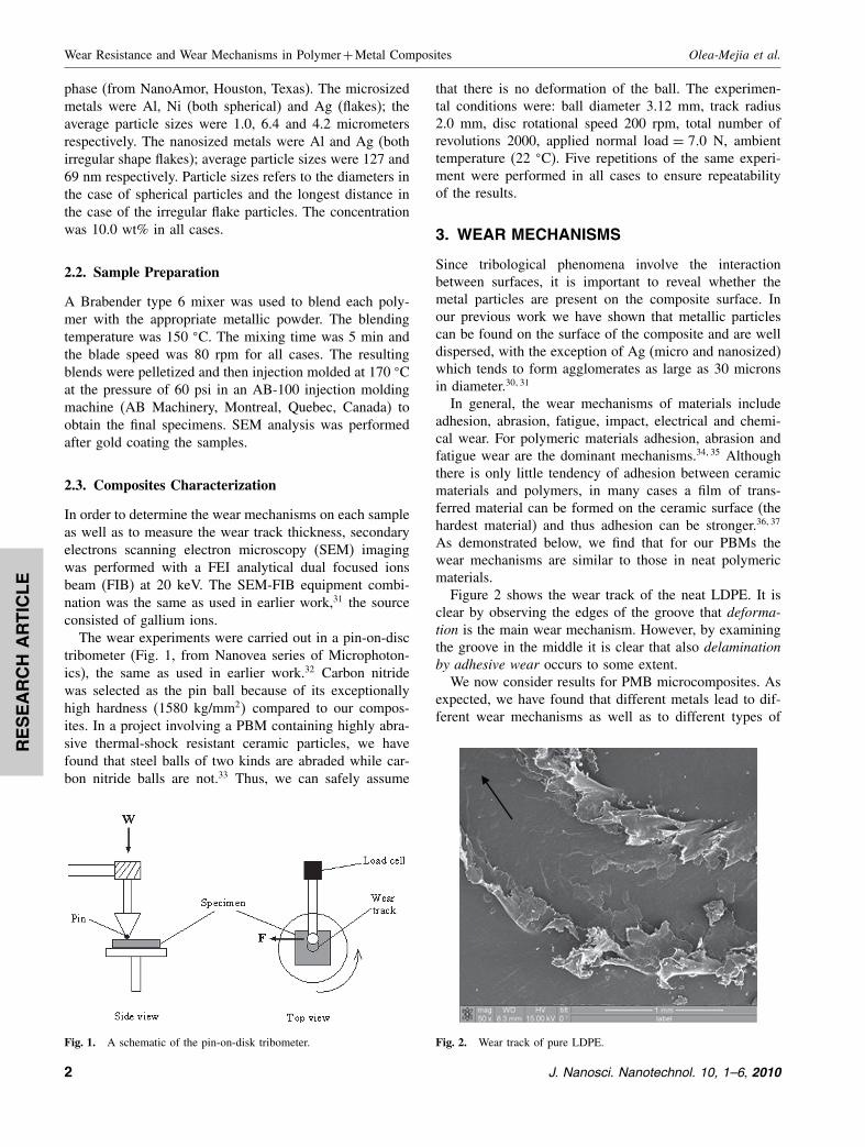
Figure 2 shows the wear track of the neat LDPE. It isclear by observing the edges of the groove that deforma-tion is the main wear mechanism. However, by examiningthe groove in the middle it is clear that also delaminationby adhesive wear occurs to some extent.
We now consider results for PMB microcomposites. Asexpected, we have found that different metals lead to dif-ferent wear mechanisms as well as to different types of
Fig. 2. Wear track of pure LDPE.
2 J. Nanosci. Nanotechnol. 10, 1–6, 2010
tcd0033
Typewritten Text
tcd0033
Typewritten Text
8525
tcd0033
Typewritten Text
RE
SE
AR
CH
AR
TIC
LE
Olea-Mejia et al. Wear Resistance and Wear Mechanisms in Polymer+Metal Composites
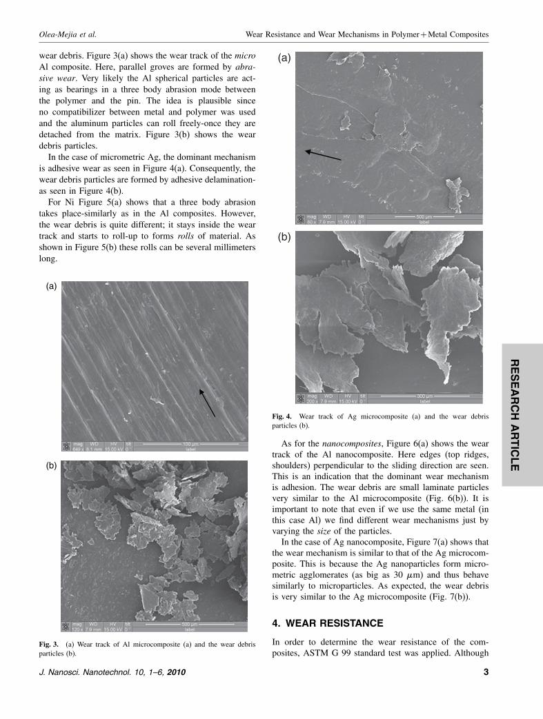
wear debris. Figure 3(a) shows the wear track of the microAl composite. Here, parallel groves are formed by abra-sive wear. Very likely the Al spherical particles are act-ing as bearings in a three body abrasion mode betweenthe polymer and the pin. The idea is plausible sinceno compatibilizer between metal and polymer was usedand the aluminum particles can roll freely-once they aredetached from the matrix. Figure 3(b) shows the weardebris particles.
In the case of micrometric Ag, the dominant mechanismis adhesive wear as seen in Figure 4(a). Consequently, thewear debris particles are formed by adhesive delamination-as seen in Figure 4(b).
For Ni Figure 5(a) shows that a three body abrasiontakes place-similarly as in the Al composites. However,the wear debris is quite different; it stays inside the weartrack and starts to roll-up to forms rolls of material. Asshown in Figure 5(b) these rolls can be several millimeterslong.
(a)
(b)
Fig. 3. (a) Wear track of Al microcomposite (a) and the wear debrisparticles (b).
(a)
(b)
Fig. 4. Wear track of Ag microcomposite (a) and the wear debrisparticles (b).
As for the nanocomposites, Figure 6(a) shows the weartrack of the Al nanocomposite. Here edges (top ridges,shoulders) perpendicular to the sliding direction are seen.This is an indication that the dominant wear mechanismis adhesion. The wear debris are small laminate particlesvery similar to the Al microcomposite (Fig. 6(b)). It isimportant to note that even if we use the same metal (inthis case Al) we find different wear mechanisms just byvarying the size of the particles.
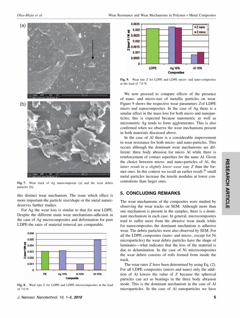
In the case of Ag nanocomposite, Figure 7(a) shows thatthe wear mechanism is similar to that of the Ag microcom-posite. This is because the Ag nanoparticles form micro-metric agglomerates (as big as 30 �m) and thus behavesimilarly to microparticles. As expected, the wear debrisis very similar to the Ag microcomposite (Fig. 7(b)).
4. WEAR RESISTANCE
In order to determine the wear resistance of the com-posites, ASTM G 99 standard test was applied. Although
J. Nanosci. Nanotechnol. 10, 1–6, 2010 3
tcd0033
Typewritten Text
8527
tcd0033
Typewritten Text

RE
SE
AR
CH
AR
TIC
LE
Wear Resistance and Wear Mechanisms in Polymer+Metal Composites Olea-Mejia et al.
(a)
(b)
Fig. 5. Wear track of Ni microcomposite (a) and the wear debrisparticles(b).
this standard procedure was first intended to be usedfor metals, it is possible to use it for plastics as agood approximation.38 Wear volume loss v was calculatedaccording to the same standard:
v = 2�R
[r2 sin−1
(d
2r
)−(d
4
)(4r2 −d2
)1/2]
(1)
Here R = wear track radius, d = wear track width andr = pin end radius.
The wear rate Z represents the volume loss v dividedby the normal load W and the sliding distance d:
Z = v/Wd (2)
Thus, Z is normalized with respect to the load and thesliding distance. A minimum of 20 measurements (for Rand d� were performed in each wear track to calculate asuitable average value for Z. The variation in the valuesmeasured leads to a calculated error of 0.00015 mm3/Nm.
(a)
(b)
Fig. 6. Wear track of Al nanocomposite (a) and the wear debrisparticles (b).
Figure 8 shows the wear rate Z for our LDPE micro-composites. It is clear that the lowest Z is achieved whenAl particles are present. Even though the abrasive wearis more detrimental than adhesion in many cases, in thiscase the opposite is seen. A probable reason is that thedetached spherical aluminum particles from the compositesurface actually roll between the metal and the polymeracting as bearings; thus, the three body abrasion results inreinforcement of wear resistance. Given the objectives ofthe present project, this is a worthwhile result.
When we add Ni particles, the mass loss is the high-est. Once the debris rolls seen in Figure 5 start forming,the material is removed continuously while the rate ofremoval is higher than from the neat polymer by deforma-tion. Interesting is the fact that-even though there can bea three-body abrasion mode as we presume is the case ofAl microparticles-the wear is high because of the forma-tion of these rolls. Since all the experimental parameterswere kept constant and the only variable are the differ-ent Ni particles, we infer that they are responsible for
4 J. Nanosci. Nanotechnol. 10, 1–6, 2010
tcd0033
Typewritten Text
8528
tcd0033
Typewritten Text
RE
SE
AR
CH
AR
TIC
LE
Olea-Mejia et al. Wear Resistance and Wear Mechanisms in Polymer+Metal Composites
(a)
(b)
Fig. 7. Wear track of Ag nanocomposite (a) and the wear debrisparticles (b).
this distinct wear mechanism. The issue which effect ismore important-the particle size/shape or the metal nature-deserves further studies.
For Ag the wear loss is similar to that for neat LDPE.Despite the different main wear mechanisms-adhesion inthe case of Ag microcomposites and deformation for pureLDPE-the rates of material removal are comparable.
Fig. 8. Wear rate Z for LDPE and LDPE microcomposites at the loadof 7.0 N.
Fig. 9. Wear rate Z for LDPE and LDPE micro- and nano-compositesat the load of 7.0 N.
We now proceed to compare effects of the presenceof nano- and micro-size of metallic particles on wear.Figure 9 shows the respective wear parameters Zof LDPEmicro and nanocomposites. In the case of Ag there is asimilar effect in the mass loss for both micro and nanopar-ticles; this is expected because nanometric as well asmicrometric Ag tends to form agglomerates. This is alsoconfirmed when we observe the wear mechanisms presentin both materials discussed above.
In the case of Al there is a considerable improvementin wear resistance for both micro- and nano-particles. Thisoccurs although the dominant wear mechanisms are dif-ferent: three body abrasion for micro Al while there isreinforcement of contact asperities for the nano Al. Giventhe choice between micro- and nano-particles of Al, thelatter result in a slightly lower wear rate Z than the for-mer ones. In this context we recall an earlier result:30 smallmetal particles increase the tensile modulus at lower con-centrations than larger ones.
5. CONCLUDING REMARKS
The wear mechanisms of the composites were studied byobserving the wear tracks on SEM. Although more thanone mechanism is present in the samples, there is a domi-nant mechanism in each case. In general, microcompositestend to suffer more from the abrasive wear mode whilefor nanocomposites the dominant mechanism is adhesivewear. The debris particles were also observed by SEM. Forall the LDPE composites (nano- and micro-, except for Nimicroparticles) the wear debris particles have the shape oflaminates—what indicates that the loss of the material isdue to delamination. In the case of Ni microcompositesthe wear debris consists of rolls formed from inside thetrack.
The wear rates Z have been determined by using Eq. (2).For all LDPE composites (micro and nano) only the addi-tion of Al lowers the value of Z because the sphericalparticles can act as bearings in the three body abrasionmode. This is the dominant mechanism in the case of Almicroparticles. In the case of Al nanoparticles we have
J. Nanosci. Nanotechnol. 10, 1–6, 2010 5
tcd0033
Typewritten Text
tcd0033
Typewritten Text
8529

RE
SE
AR
CH
AR
TIC
LE
Wear Resistance and Wear Mechanisms in Polymer+Metal Composites Olea-Mejia et al.
reinforcement of the polymer that smaller particles providemore effectively than larger ones. Since the concentrationby weight is the same in both cases, the Al nanocompos-ite contains many more wear-resistant particles than therespective microcomposite.
Acknowledgments: A partial financial support hasbeen provided by the Robert A. Welch Foundation,Houston (Grant B-1203).
References and Notes
1. M. Rabello, Aditivação de Polimeros, Artliber, São Paulo (2000),Chap. 10.
2. W. Brostow (ed.), Performance of Plastics, Hanser, Munich-Cincinnati (2000).
3. A. R. Bunsell and J. Renard, Fundamentals of Fibre ReinforcedComposite Materials, Institute of Physics, Bristol and Philadelphia(2005).
4. T. E. Twardowski, Introduction to Nanocomposite Materials,DEStech, Philadelphia (2007).
5. A. Dhanabalan, C. R. Mendonça, D. T. Balogh, L. Misoguti, C. J.L. Constantino, J. A. Giacometti, S. C. Zilio, and O. N. Oliveira, Jr.,Macromolecules 32, 5277 (1999).
6. A. Dhanabalan, D. S. Dos Santos, Jr., C. R. Mendonça, L. Misoguti,D. T. Balogh, J. A. Jacometti, S. C. Zilio, and O. N. Oliveira, Jr.,Langmuir 15, 4560 (1999).
7. I. Mironi-Harpaz and M. Narkis, J. Polymer Sci. Phys. 39, 1415(2001).
8. C. R. Mendonça, D. S. dos Santos, D. T. Balogh, A. Dhanabalan,J. A. Giacometti, S. C. Zillo, and O. N. Oliveira, Jr., Polymer42, 6539 (2001).
9. R. Popielarz, C. K. Chiang, R. Nozaki, and J. Obrzut, Macro-molecules 34, 5910 (2001).
10. Z. Roslaniec, G. Broza, and K. Schulte, Compos. Interfaces 10, 95(2003).
11. T. Hu, J. Juuti, H. Jantunen, and T. Vilkman, J. Eur. Ceram. Soc.27, 3997 (2007).
12. S. Miller, D. Papadopoulos, P. Heimann, L. Inghram, andL. McCorkle, Compos. Sci. Tech. 67, 2183 (2007).
13. J. M. Cavalcante and L. H. de Carvalho, presented at the 9oCongresso Brasileiro de Polimeros, Campina Grande, PB, October(2007).
14. J. D. Xu, J. Karger-Kocsis, and A. K. Schlarb, J. Mater. Sci. 43, 4330(2008).
15. J. Karger-Kocsis, D. Felhös, T. Barany, and T. Czigany, ExpressPolymer Letters 2, 520 (2008).
16. N. K. Myshkin, M. I. Petrokovets, and A. V. Kovalev, Tribol.Internat. 38, 910 (2005).
17. Z. Brocka, E. Schmachtenberg, and G. W. Ehrenstein, Proc. Ann.Tech. Conf. Soc. Plastics Eng. (ANTEC-SPE), 67, 1690 (2007).
18. M. S. Khan, D. Lehmann, G. Heinrich, U. Gohs, and R. Franke,Express Polymer Letters 3, 39 (2009).
19. W. Brostow, J.-L. Deborde, M. Jaklewicz, and P. Olszynski, J. Mater.Ed. 25, 119 (2003).
20. W. Brostow, W. J. A. Hinze, and R. Simões, J. Mater. Res. 19, 851(2004).
21. W. Brostow and R. Simões, J. Mater. Ed. 27, 19 (2005).22. W. Brostow, S. Deshpande, K. Fan, S. Mahendrakar, D. Pietkiewicz,
and S. R. Wisner, Polymer Eng. Sci. 49, 1035 (2009); W. Brostow,W. Chonkaew, K. P. Menard, and T. W. Scharf, Mater. Sci. Eng., A507, 241 (2009).
23. W. Brostow, M. Keselman, I. Mironi-Harpaz, M. Narkis, andR. Peirce, Polymer 46, 5058 (2005); L. F. Giraldo, W. Brostow,E. Devaux, B. L. Lopez, and L. D. Perez, J. Nanosci. Nanotechnol.8, 3176 (2008).
24. W. G. Sawyer, S. S. Perry, S. R. Phillpot, and S. B. Sinnott, J. Phys.Cond. Matter 20, 354012 (2008).
25. W. Brostow, W. Chonkaew, T. Datashvili, and K. P. Menard,J. Nanosci. Nanotechnol. 8, 1916 (2008).
26. F. J. Carrion, A. Arribas, M.-D. Bermúdez, and A. Guillamon, Eur.Polymer J. 44, 968 (2008).
27. A. Arribas, M.-D. Bermudez, W. Brostow, F. J. Carrion-Vilches,and O. Olea-Mejia, Express Polymer Letters 3, 621 (2009); M.-D.Bermudez, W. Brostow, F. J. Carrion-Vilches, and J. Sanes,J. Nanosci. Nanotechnol. 10 (2010), to be published.
28. A. F. Vargas, W. Brostow, H. E. Hagg Lobland, B. L. Lopez, andO. Olea-Mejia, J. Nanosci. Nanotechnol. 9, 6661 (2009).
29. L. G. Yu, S. R. Yang, H. T. Wang, and Q. J. Xue, J. Appl. PolymerSci. 77, 2404 (2000).
30. W. Brostow, A. Buchman, E. Buchman, and O. Olea-Mejia, PolymerEng. Sci. 48, 1977 (2008).
31. W. Brostow, B. P. Gorman, and O. Olea-Mejia, Mater. Lett. 61, 1333(2007).
32. W. Brostow, W. Chonkaew, K. P. Menard, and T. W. Scharf, Mater.Sci. Eng., A 507, 241 (2009).
33. W. Brostow, T. Datashvili, J. Geodakyan, and J. Lou, in preparation.34. M.-D. Bermudez, F. J. Carrion-Vilches, and C. Martinez-Nicolas,
J. Appl. Polymer Sci. 74, 831 (1999).35. M.-D. Bermudez, F. J. Carrion-Vilches, and I. Martinez-Mateo,
J. Appl. Polymer Sci. 81, 2426 (2001).36. M. H. Cho, S. Bahadur, and J. W. Anderegg, Tribol. Internat.
39, 1436 (2006).37. H. Unal, A. Mimaroglu, and V. Serdar, Wear 261, 841 (2006).38. M.-D. Bermudez, F. J. Carrion-Vilches, and P. Iglesias, Tribol.
Internat. 40, 479 (2007).
Received: 14 November 2009. Accepted: 5 February 2010.
6 J. Nanosci. Nanotechnol. 10, 1–6, 2010
tcd0033
Typewritten Text
tcd0033
Typewritten Text
8530
tcd0033
Typewritten Text
tcd0033
Typewritten Text
tcd0033
Typewritten Text
J. Nanosci. Nanotechnol.10, 8524-8530, 2010
tcd0033
Typewritten Text
tcd0033
Typewritten Text
tcd0033
Typewritten Text
tcd0033
Typewritten Text
tcd0033
Typewritten Text
tcd0033
Typewritten Text
tcd0033
Typewritten Text
tcd0033
Typewritten Text
tcd0033
Typewritten Text
Related Documents