ORIGINAL PAPER Wear Behavior of Dual Particle Size (DPS) Zircon Sand Reinforced Aluminum Alloy Suresh Kumar • Vipin Sharma • Ranvir Singh Panwar • O. P. Pandey Received: 1 July 2011 / Accepted: 11 May 2012 / Published online: 26 May 2012 Ó Springer Science+Business Media, LLC 2012 Abstract The present investigation aims to find the combined effect of coarse and fine size particle reinforce- ment of zircon sand in aluminum alloy LM13 on the wear behavior. The composites are fabricated by varying the reinforcement of fine and coarse size zircon sand particles and compared with the single size reinforcement. Coarse and fine particle zircon sand of 106–125 and 20–32-lm size, respectively, are used in this study. The wear test was carried out on pin-on-disc machine. Microhardness mea- surement was done for developed composites. Wear track and debris are analyzed by SEM to study the wear mech- anism. Line profile and EDS analysis is also done to vali- date the microstructural results. Study reveals that a combination of 3 % fine and 12 % coarse particle rein- forced composite exhibits better wear resistance while 3 % coarse and 12 % fine particle reinforcement decreases the wear resistance. It is also observed that zircon sand parti- cles provide effective nucleation site for the eutectic sili- con. Microstructural examination shows globular and finely distributed eutectic silicon in the vicinity of the reinforced particles. Keywords Composite Á Stir casting Á Dual particle size Á AMCs Á Zircon sand 1 Introduction Aluminum–silicon alloys find their application in different engineering components because of their good castability, high corrosion resistance, and low density. Wear resistance of these alloys can be enhanced by incorporation of cera- mic phase in the soft aluminum matrix [1]. Reinforcement of hard ceramic particulates imparts a combination of properties not achievable in either of the constituents individually. In recent years, many processing techniques have been developed to prepare particulate reinforced aluminum matrix composites (AMCs). These techniques are stir casting, liquid metal infiltration, squeeze casting, spray co-deposition, powder metallurgy, etc. Among the variety of processing techniques available for particulate or discontinuous reinforced metal matrix composites, stir casting is one of the methods accepted for the production of large quantity composites. It is attractive because of sim- plicity, flexibility, and is most economical for large size components to be fabricated [1–5]. In recent years, numerous research works have been reported on production of AMCs by stir casting technique, but very limited research work has been done on reinforcement of dual size particles [6, 7]. Moreover, to the best of our knowledge no work is reported on wear behavior of aluminum composites reinforced with dual size zircon sand particles. Prabhakar and co-workers [6] studied tribological behavior of dual particle size (DPS) SiC particles rein- forced composite and compared with single particle size (SPS) reinforced composite. They found that the DPS composite exhibited better wear resistance compared to same volume fraction of SPS composite. Zhang et al. [7] studied thermal conductivity of Al–12Si matrix composite reinforced with 70 vol % SiC particles of two different sizes and analyzed the effect of dual-sized particles on structural and thermal conduction properties. The com- posites fabricated with finer reinforcement particulates exhibit greater strength as compared to coarser with the same quantity of reinforcement. Ahmad et al. [8] studied S. Kumar Á V. Sharma Á R. S. Panwar Á O. P. Pandey (&) School of Physics and Material Science, Thapar University, Patiala 147004, Punjab, India e-mail: [email protected] 123 Tribol Lett (2012) 47:231–251 DOI 10.1007/s11249-012-9983-y

Welcome message from author
This document is posted to help you gain knowledge. Please leave a comment to let me know what you think about it! Share it to your friends and learn new things together.
Transcript
ORIGINAL PAPER
Wear Behavior of Dual Particle Size (DPS) Zircon SandReinforced Aluminum Alloy
Suresh Kumar • Vipin Sharma • Ranvir Singh Panwar •
O. P. Pandey
Received: 1 July 2011 / Accepted: 11 May 2012 / Published online: 26 May 2012
� Springer Science+Business Media, LLC 2012
Abstract The present investigation aims to find the
combined effect of coarse and fine size particle reinforce-
ment of zircon sand in aluminum alloy LM13 on the wear
behavior. The composites are fabricated by varying the
reinforcement of fine and coarse size zircon sand particles
and compared with the single size reinforcement. Coarse
and fine particle zircon sand of 106–125 and 20–32-lm
size, respectively, are used in this study. The wear test was
carried out on pin-on-disc machine. Microhardness mea-
surement was done for developed composites. Wear track
and debris are analyzed by SEM to study the wear mech-
anism. Line profile and EDS analysis is also done to vali-
date the microstructural results. Study reveals that a
combination of 3 % fine and 12 % coarse particle rein-
forced composite exhibits better wear resistance while 3 %
coarse and 12 % fine particle reinforcement decreases the
wear resistance. It is also observed that zircon sand parti-
cles provide effective nucleation site for the eutectic sili-
con. Microstructural examination shows globular and
finely distributed eutectic silicon in the vicinity of the
reinforced particles.
Keywords Composite � Stir casting � Dual particle size �AMCs � Zircon sand
1 Introduction
Aluminum–silicon alloys find their application in different
engineering components because of their good castability,
high corrosion resistance, and low density. Wear resistance
of these alloys can be enhanced by incorporation of cera-
mic phase in the soft aluminum matrix [1]. Reinforcement
of hard ceramic particulates imparts a combination of
properties not achievable in either of the constituents
individually. In recent years, many processing techniques
have been developed to prepare particulate reinforced
aluminum matrix composites (AMCs). These techniques
are stir casting, liquid metal infiltration, squeeze casting,
spray co-deposition, powder metallurgy, etc. Among the
variety of processing techniques available for particulate or
discontinuous reinforced metal matrix composites, stir
casting is one of the methods accepted for the production of
large quantity composites. It is attractive because of sim-
plicity, flexibility, and is most economical for large size
components to be fabricated [1–5]. In recent years,
numerous research works have been reported on production
of AMCs by stir casting technique, but very limited
research work has been done on reinforcement of dual size
particles [6, 7]. Moreover, to the best of our knowledge no
work is reported on wear behavior of aluminum composites
reinforced with dual size zircon sand particles.
Prabhakar and co-workers [6] studied tribological
behavior of dual particle size (DPS) SiC particles rein-
forced composite and compared with single particle size
(SPS) reinforced composite. They found that the DPS
composite exhibited better wear resistance compared to
same volume fraction of SPS composite. Zhang et al. [7]
studied thermal conductivity of Al–12Si matrix composite
reinforced with 70 vol % SiC particles of two different
sizes and analyzed the effect of dual-sized particles on
structural and thermal conduction properties. The com-
posites fabricated with finer reinforcement particulates
exhibit greater strength as compared to coarser with the
same quantity of reinforcement. Ahmad et al. [8] studied
S. Kumar � V. Sharma � R. S. Panwar � O. P. Pandey (&)
School of Physics and Material Science, Thapar University,
Patiala 147004, Punjab, India
e-mail: [email protected]
123
Tribol Lett (2012) 47:231–251
DOI 10.1007/s11249-012-9983-y
the effect of particle size for Al2O3 reinforced AMCs and
reported that the fine particle reinforced composites have
higher hardness as compared to coarse particles. This is
because composites reinforced with the finer particle size
offer higher number of barriers per unit volume compared
with composites reinforced with larger particle size at the
same weight percentage. Small reinforcement particles
permit larger contact area with aluminum alloy matrix.
Ozdemir and Yakuphanoglu [9] have reported that the fine
particles reinforced composites also exhibit better thermal
conductivity as compared to composite reinforced with
larger particles. Das et al. [2] have compared the wear
properties of alumina and zircon sand reinforced AMCs
and reported that decrease in particle size improves wear
resistance. Roy et al. [3] have studied the effect of sub-
micron and micron size reinforcement of Al2O3 particles in
AMCs and concluded that submicron size particle rein-
forced composites offer lowest wear as compared to
Table 1 Composition of the LM13 alloy in wt%
LM13 alloy Si Fe Cu Mn Mg Zn Ti Ni Pb Sn Al
wt% 11.8 0.3 1.2 0.4 0.9 0.2 0.02 0.9 0.02 0.005 Balance
Table 2 Composition of the zircon sand (ZrSiO4)
Elements ZrO2 (?HfO2) SiO2 TiO2 Fe2O3
% in Bulk 65.30 32.80 0.27 0.12
Table 3 List of processing parameters
Melting temperature 750 �C
Total stirring time 22–25 min
Mixing time 8–10 min
Blade angle 45�No. of blades 3
Position of stirrer Up to 2/3 depth in the melt
Table 4 Reinforcement combination of composites
Composites Fine (wt%)
(20–32 lm)
Coarse (wt%)
(106–125 lm)
SPS1 15 0
SPS2 0 15
DPS1 3 12
DPS2 12 3
LM-13 ALLOY (Al-Si alloy)
MOLTEN METAL
Melt at 800ºC
MELT + ZrO2
Stirring (630rpm) + Zircon sand
Held at 750ºC
CASTING
SAMPLE PREPERATION
CHARACTERIZATION TESTING
OPTICAL MICROSCOP
SEM WEAR HARDNESS
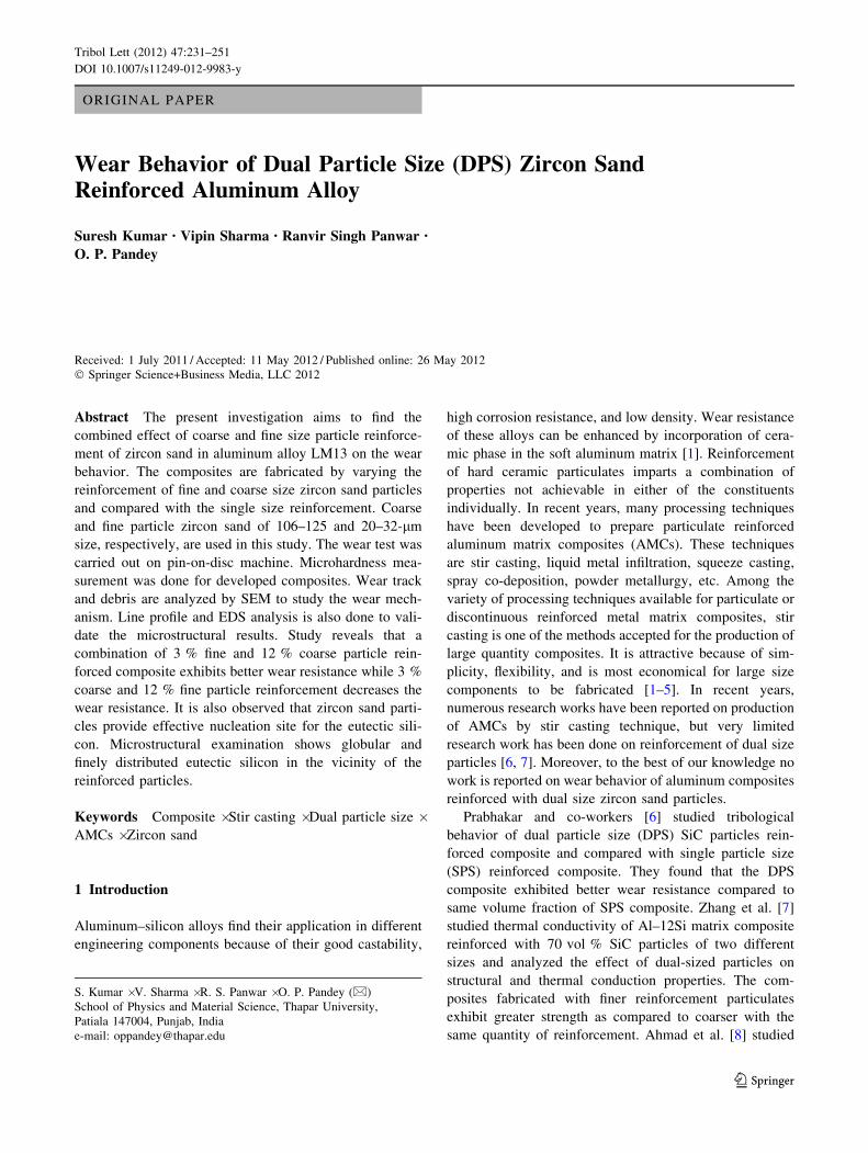
Fig. 1 Schematic diagram of experimental procedure
232 Tribol Lett (2012) 47:231–251
123
micron size reinforcement. On the other hand, it is reported
that coarse particle reinforced composites exhibit better
wear resistance as compared to fine particle reinforced
composites [10, 11]. Yılmaz and Buytoz [10] have reported
that the wear rates decreased with increase in Al2O3 size
for the composites containing the same amount of Al2O3.
They have concluded that aluminum alloy composites
reinforced with larger Al2O3 particles are more effective
against abrasive wear than those reinforced with smaller
Al2O3 particles. Zou et al. [11] in their work depict that the
wear resistance of 38 vol% SiCp of average size 57-lm
reinforced composite is almost 10 times higher than that of
the SiCp of 5.5-lm reinforced composite having same
volume fraction. They also found that the depth of plastic
deformation zone in the subsurface decreases with
increasing volume fraction and average diameter of SiC
particles.
Considering all these parameters, this study is aimed to
analyze the combined effect of both coarse and fine size
particle reinforcement in aluminum alloy composite. Our
study is mainly focused on investigating the microstruc-
tural features and wear properties of DPS zircon sand
reinforced LM13 alloy which has not been studied so far.
The effect of dual size particles on the mechanical prop-
erties, microstructures, and wear resistance of the particu-
late reinforced composite at room temperature is reported
in this work.
2 Experimental
In this study, well-known piston alloy LM13 is used as
matrix material and high-purity zircon sand (ZrSiO4) as
reinforcement. LM13 alloy was obtained in the form of
ingots. The compositional analysis of the LM13 alloy was
done by wet chemical analysis which is given in Table 1.
Table 2 gives the composition of zircon sand used in the
present work.
The composite was made by stir casting route. The
detailed description of the process is similar to described in
other work [12–15]. Required quantity of LM13 alloy was
taken in a graphite crucible and melted in an electric fur-
nace. The temperature of melt was raised to 750 �C. This
molten metal was stirred using a graphite impeller at a
speed 630 rpm to create the vortex. The impeller blades
were designed in such way that it creates vortex. Different
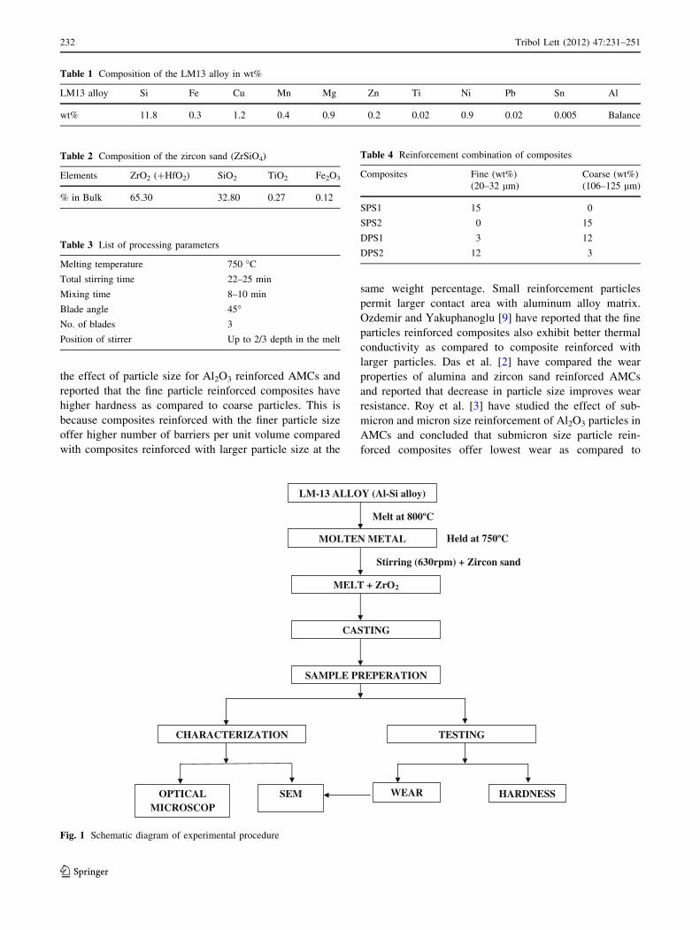
Fig. 2 Optical micrograph of SPS1 composites containing 15 % fine
particles showing a uniform particle distribution, b showing dendritic
and fragmented dendritic growth in particle depleted region,
c eutectic silicon exhibiting globular morphology around particles,
and d SEM micrograph of SPS1 composite showing uniform
distribution of particles
Tribol Lett (2012) 47:231–251 233
123
sizes of zircon sand were taken in defined proportion and
mixed properly and this mixed zircon sand (DPS) was
preheated at 450 �C to drive off the moisture. After the
formation of vortex in the melt, the sand particle was
charged inside the vortex at the rate of 20–25 g/min into
the melt during stirring with the help of funnel kept on top
of vortex. Zircon sand particle of fine grade (20–32 lm)
and coarse grade (106–125 lm) was selected for present
work. The stirring was continued for another 5 min even
after the completion of particle feeding to ensure homo-
geneous distribution of the sand particles. The vortex
method is one of the better known approaches used to
create and maintain a good distribution of the reinforce-
ment material in the matrix alloy. The molten mass was
finely poured into the metal mold and allowed to solidify at
room temperature. During production of composite, the
amount of LM13 alloy, stirring duration, and position of
stirrer in the crucible were kept constant to minimize the
contribution of variables related to stirring on distribution
of second phase particles. The other detail is given in
Table 3.
During fabrication of the DPS composite, zircon sand
particles of two sizes were chosen. In our earlier work on
spray forming, it was observed that 15 % reinforcement of
zircon sand reinforced composite has given better property,
so we have restricted the reinforcement up to 15 % only
[1]. In order to compare and correlate the effect of particle
size on mechanical and tribological properties, four dif-
ferent composites containing a total of 15 wt% reinforce-
ment were fabricated. In the first combination of DPS
(DPS1) there was 12 % coarse (106–125 lm) and 3 % fine
(20–32 lm) zircon sand particles, whereas, in the second
combination (DPS2) there was 3 % coarse and 12 % fine
zircon sand particles. The two composites were synthesized
by incorporation of only single size particle of fine (SPS1)
and coarse particles (SPS2) of 15 wt%. The reinforcement
combinations are also given in Table 4.
Dry sliding wear tests of the reinforced and unreinforced
alloys were performed under the ambient temperatures
between 25 and 30 �C and relative humidity between 22
and 35 %, using a pin-on-disc wear and friction monitor
(Model TR-20, Ducom, Bangalore). The cylindrical-
Fig. 3 Optical micrograph of SPS2 composites containing 15 %
coarse particles showing a uniformly arranged particles in the alloy
matrix, b consistent and better bonding between zircon sand particle
and alloy matrix and morphology of silicon at particle–matrix
interface, c long dendrite in particle depleted region and the presence
of silicon in between dendrite arm spacing, and d SEM micrograph of
SPS2 composite showing uniform distribution of fine particles with
clustering at some places
234 Tribol Lett (2012) 47:231–251
123
shaped samples (30 9 9 mm) of composite were tested
against the hardened EN32 steel disc having chemical
composition (0.14 % C, 0.52 % Mn, 0.18 % Si, 0.13 % Ni,
0.05 % Cr, 0.06 % Mo, 0.019 % P, 0.015 % S, balance Fe)
and hardness 65 HRC. Before testing, each specimen was
ultrasonically cleaned in acetone.
The wear tests of specimen from each set of composite
have been conducted up to 2,880 m of sliding distance at a
constant sliding velocity of 1.6 m/s and under five different
loads 1, 2, 3, 4, and 5 kg. The microstructural analysis has
been done with the help of both optical (Eclipse MA-100,
Nikon) and scanning electron microscope (SEM, JEOL,
JSM-6510LV, Japan) with EDS attachment at various
magnifications. Before optical observation, the sample was
mechanically polished and etched by Keller’s reagent for
obtaining better contrast.
Microhardness of the different phases was measured
using microhardness tester (Mitutoyo, Japan). Microhard-
ness measurement was done on each set of sample by
taking minimum of five indentations per sample at 100 kgf
load. To understand the procedure in a better way, the
schematic diagram of the experimental procedure is shown
in Fig. 1.
3 Results and Discussion
3.1 Microstructural Analysis
The optical micrographs of SPS1 reinforced with 15 % fine
particles (20–32 lm) are shown in Fig. 2. Figure 2a shows
fairly uniform distribution of reinforced particles in alloy
matrix. Uniform distribution of second phase particles is
required for achieving better wear resistance and mechan-
ical properties. Fairly uniform distribution of particles in a
molten alloy is achieved due to the high shear rate during
stirring which also minimized the particle settling tendency
[14, 15]. However, agglomeration of particles is also
observed which is visible at certain places (Fig. 2a, b).
Figure 2b shows the micrograph of the composite where
fragmented dendrites in the alloy matrix can be seen,
though limited dendritic growth in the particle depleted
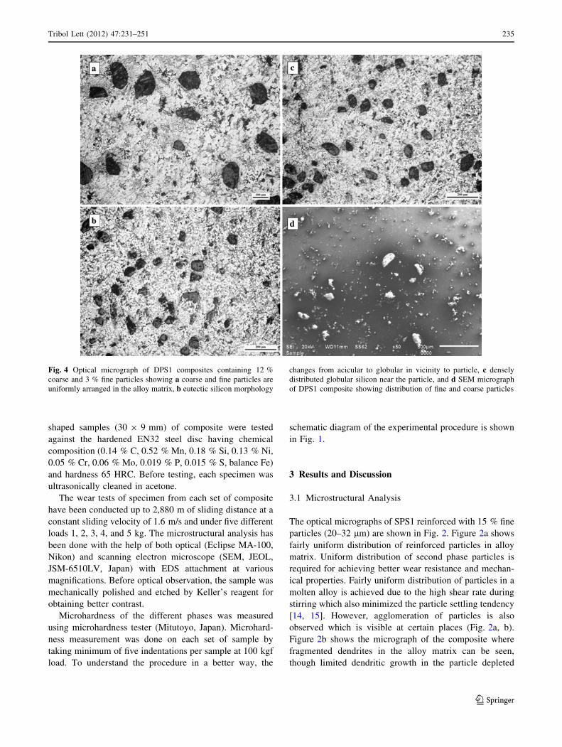
Fig. 4 Optical micrograph of DPS1 composites containing 12 %
coarse and 3 % fine particles showing a coarse and fine particles are
uniformly arranged in the alloy matrix, b eutectic silicon morphology
changes from acicular to globular in vicinity to particle, c densely
distributed globular silicon near the particle, and d SEM micrograph
of DPS1 composite showing distribution of fine and coarse particles
Tribol Lett (2012) 47:231–251 235
123
region is also visible. This growth has occurred because of
clustering of zircon sand. Fine size zircon sand are pushed
or engulfed by advancing solid–liquid interface creating
sufficient space inside the matrix which leads to growth of
dendrite [14]. Dendritic fragmentation can be attributed to
the shearing of initial dendritic arms by the stirring action.
During particle addition, local solidification of the melt
occurs which is induced by the particles as there is a
temperature difference between the particle and the melt. It
was also found that the perturbation in the solute field due
to the presence of particles can change the dendrite tip
radius and the dendrite tip temperature. These effects give
rise to a dendrite–cell transition as the density of particles
is increased. Also the length of the dendrite is reduced in
the presence of the particles [14]. The higher magnification
micrograph (Fig. 2c) exhibits some what rounded mor-
phology of eutectic silicon having fine distribution as col-
onies around the reinforced particles. SEM micrograph of
SPS1 composite also exhibits homogeneous distribution of
particle whereas at some places particle clustering and
porosity due to entrapment of air during pouring are also
observed (Fig. 2d).
The optical micrographs of SPS2 reinforced with 15 %
coarse particles (106–125 lm) are shown in Fig. 3.
Fig. 5 Sequential growth of
solid in the composite showing
fragmentation of dendrite and
growth of rosette dendrite
having cellular morphology
236 Tribol Lett (2012) 47:231–251
123
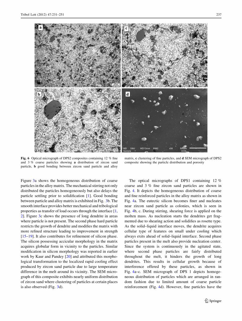
Figure 3a shows the homogeneous distribution of coarse
particles in the alloy matrix. The mechanical stirring not only
distributed the particles homogeneously but also delays the
particle settling prior to solidification [1]. Good bonding
between particle and alloy matrix is exhibited in Fig. 3b. The
smooth interface provides better mechanical and tribological
properties as transfer of load occurs through the interface [1,
2]. Figure 3c shows the presence of long dendrite in areas
where particle is not present. The second phase hard particle
restricts the growth of dendrite and modifies the matrix with
more refined structure leading to improvement in strength
[15–19]. It also contributes for refinement of silicon phase.
The silicon possessing accicular morphology in the matrix
acquires globular form in vicinity to the particles. Similar
modification in silicon morphology was reported in earlier
work by Kaur and Pandey [20] and attributed this morpho-
logical transformation to the localized rapid cooling effect
produced by zircon sand particle due to large temperature
difference in the melt around its vicinity. The SEM micro-
graph of this composite exhibits nearly uniform distribution
of zircon sand where clustering of particles at certain places
is also observed (Fig. 3d).
The optical micrographs of DPS1 containing 12 %
coarse and 3 % fine zircon sand particles are shown in
Fig. 4. It depicts the homogeneous distribution of coarse
and fine reinforced particles in the alloy matrix as shown in
Fig. 4a. The eutectic silicon becomes finer and nucleates
near zircon sand particle as colonies, which is seen in
Fig. 4b, c. During stirring, shearing force is applied on the
molten mass. As nucleation starts the dendrites get frag-
mented due to shearing action and solidifies as rosette type.
As the solid–liquid interface moves, the dendrite acquires
cellular type of features on small under cooling which
always exits ahead of solid–liquid interface. Second phase
particles present in the melt also provide nucleation center.
Since the system is continuously in the agitated state,
where second phase particles are fairly distributed
throughout the melt, it hinders the growth of long
dendrites. This results in cellular growth because of
interference offered by these particles, as shown in
Fig. 4a–c. SEM micrograph of DPS 1 depicts homoge-
neous distribution of particles which are arranged in ran-
dom fashion due to limited amount of coarse particle
reinforcement (Fig. 4d). However, fine particles have the
Fig. 6 Optical micrograph of DPS2 composites containing 12 % fine
and 3 % coarse particles showing a distribution of zircon sand
particle, b good bonding between zircon sand particle and alloy
matrix, c clustering of fine particles, and d SEM micrograph of DPS2
composite showing the particle distribution and porosity
Tribol Lett (2012) 47:231–251 237
123
tendency of clustering though it is not much in this case as
compared to SPS1. This transition is schematically depicted
in Fig. 5 where fragmentation of primary dendrite and
growth of rosette dendrite having cellular structure is shown.
Optical micrograph of DPS2 composite containing 12 %
fine and 3 % coarse zircon sand particles is shown in
Fig. 6. Homogeneous distribution of particles can be seen
(Fig. 6a). Eutectic silicon morphology has changed from
acicular to globular which is uniformly distributed
throughout the matrix as is seen in Fig. 6b. However, the
fine particles and silicon form a network structure because
of pushing interface from different nucleation sites as is
seen in Fig. 6a–c which are taken from different areas. This
is clear in Fig. 6b, c where the network of silicon and fine
particles are observed. Moreover, the clustering of fine
particles at some places is also observed. SEM micro-
graph of DPS2 composite exhibits uniform distribution of
particles (Fig. 6d). However, porosity at certain places is
also observed. Overall analysis of structure indicates that
fine particles have tendency of clustering in the composite
because these are pushed to a greater extent by solidifi-
cation front as compared to coarse particles. Most of the
fine particles are placed at grain boundaries and very
limited particles are engulfed within the grains [16].
Particle pushing and engulfing phenomenon during
solidification is also correlated with the mutual wetting
behavior among the solid, liquid, and particle phases. If
the contact angle at a solid–liquid interface of a particle is
\90�, the particle can be engulfed into the solid, and if
the contact angle is [90�, the particle would be pushed
ahead [17]. Coarse particles have greater tendency to
settle as compared to fine particles. Composite reinforced
with coarse particles in majority exhibit clustering due to
settling of particles and fine particles form cluster by
pushing action of solidification front [16, 17]. Moreover,
most of these adverse phenomena are rectified in our
prepared composites.
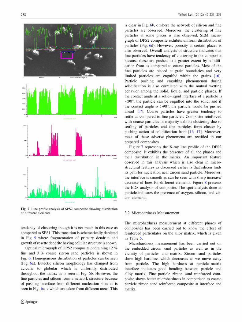
Figure 7 represents the X-ray line profile of the DPS2
composite. It exhibits the presence of all the phases and
their distribution in the matrix. An important feature
observed in this analysis which is also clear in micro-
structural features as discussed earlier is that silicon finds
its path for nucleation near zircon sand particle. Moreover,
the interface is smooth as can be seen with sharp increase/
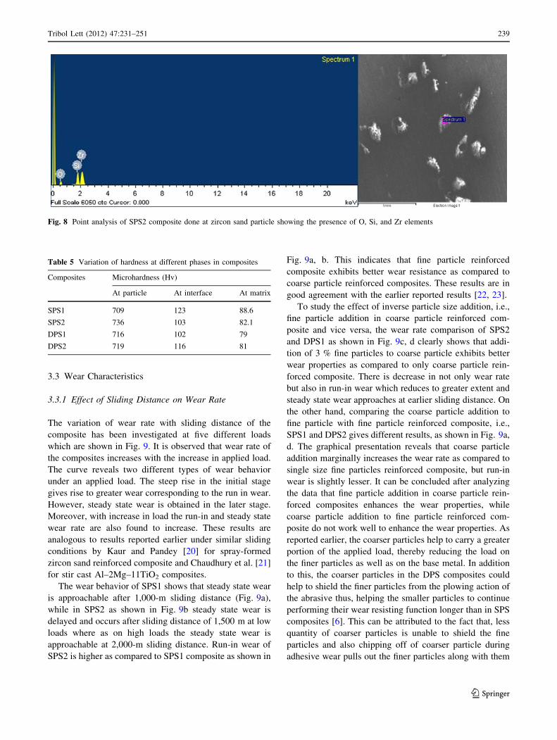
decrease of lines for different elements. Figure 8 presents
the EDS analysis of composite. The spot analysis done at
particle indicates the presence of oxygen, silicon, and zir-
con elements.
3.2 Microhardness Measurement
The microhardness measurement at different phases of
composites has been carried out to know the effect of
reinforced particulates on the alloy matrix, which is given
in Table 5.
Microhardness measurement has been carried out on
the embedded zircon sand particles as well as in the
vicinity of particles and matrix. Zircon sand particles
show high hardness which decreases as we move away
from particle. The high hardness at particle–matrix
interface indicates good bonding between particle and
alloy matrix. Fine particle zircon sand reinforced com-
posite shows better microhardness in comparison to coarse
particle zircon sand reinforced composite at interface and
matrix.
Fig. 7 Line profile analysis of SPS2 composite showing distribution
of different elements
238 Tribol Lett (2012) 47:231–251
123
3.3 Wear Characteristics
3.3.1 Effect of Sliding Distance on Wear Rate
The variation of wear rate with sliding distance of the
composite has been investigated at five different loads
which are shown in Fig. 9. It is observed that wear rate of
the composites increases with the increase in applied load.
The curve reveals two different types of wear behavior
under an applied load. The steep rise in the initial stage
gives rise to greater wear corresponding to the run in wear.
However, steady state wear is obtained in the later stage.
Moreover, with increase in load the run-in and steady state
wear rate are also found to increase. These results are
analogous to results reported earlier under similar sliding
conditions by Kaur and Pandey [20] for spray-formed
zircon sand reinforced composite and Chaudhury et al. [21]
for stir cast Al–2Mg–11TiO2 composites.
The wear behavior of SPS1 shows that steady state wear
is approachable after 1,000-m sliding distance (Fig. 9a),
while in SPS2 as shown in Fig. 9b steady state wear is
delayed and occurs after sliding distance of 1,500 m at low
loads where as on high loads the steady state wear is
approachable at 2,000-m sliding distance. Run-in wear of
SPS2 is higher as compared to SPS1 composite as shown in
Fig. 9a, b. This indicates that fine particle reinforced
composite exhibits better wear resistance as compared to
coarse particle reinforced composites. These results are in
good agreement with the earlier reported results [22, 23].
To study the effect of inverse particle size addition, i.e.,
fine particle addition in coarse particle reinforced com-
posite and vice versa, the wear rate comparison of SPS2
and DPS1 as shown in Fig. 9c, d clearly shows that addi-
tion of 3 % fine particles to coarse particle exhibits better
wear properties as compared to only coarse particle rein-
forced composite. There is decrease in not only wear rate
but also in run-in wear which reduces to greater extent and
steady state wear approaches at earlier sliding distance. On
the other hand, comparing the coarse particle addition to
fine particle with fine particle reinforced composite, i.e.,
SPS1 and DPS2 gives different results, as shown in Fig. 9a,
d. The graphical presentation reveals that coarse particle
addition marginally increases the wear rate as compared to
single size fine particles reinforced composite, but run-in
wear is slightly lesser. It can be concluded after analyzing
the data that fine particle addition in coarse particle rein-
forced composites enhances the wear properties, while
coarse particle addition to fine particle reinforced com-
posite do not work well to enhance the wear properties. As
reported earlier, the coarser particles help to carry a greater
portion of the applied load, thereby reducing the load on
the finer particles as well as on the base metal. In addition
to this, the coarser particles in the DPS composites could
help to shield the finer particles from the plowing action of
the abrasive thus, helping the smaller particles to continue
performing their wear resisting function longer than in SPS
composites [6]. This can be attributed to the fact that, less
quantity of coarser particles is unable to shield the fine
particles and also chipping off of coarser particle during
adhesive wear pulls out the finer particles along with them
Fig. 8 Point analysis of SPS2 composite done at zircon sand particle showing the presence of O, Si, and Zr elements
Table 5 Variation of hardness at different phases in composites
Composites Microhardness (Hv)
At particle At interface At matrix
SPS1 709 123 88.6
SPS2 736 103 82.1
DPS1 716 102 79
DPS2 719 116 81
Tribol Lett (2012) 47:231–251 239
123
at higher load. It is confirmed by the result as mentioned
earlier, in which 12 % coarse zircon sand particles with
3 % fine zircon sand particles gives better wear resistance.
3.3.2 Effect of Load on Wear Rate
The bar graph of wear rate comparison of composites with
different loads is presented in Fig. 10. In Fig. 10a, the
graphical representation clearly shows the wear rate of
coarse particle reinforced composite, i.e., SPS1 is higher as
compared to fine particles reinforced composite, i.e., SPS2
at all investigated loads. Further at low and high loads the
wear rate of SPS1 is nearly double as compared to SPS2
whereas wear rate difference is less between the compos-
ites at load range of 3–4 kg. This representation concludes
that fine particle reinforced composite exhibits better wear
resistance in comparison to coarse particles. Similar results
are reported earlier by other researchers [22, 23].
Figure 10b shows that the wear rate of DPS2 is higher
than SPS1 composite at all investigated loads. Graphical
study clearly depicts that the addition of coarse particle in
fine particle reinforced composites is not effective in
enhancing the wear resistance of the composite. It is not
the case in the composite with fine particle addition to the
coarse particle reinforced composite as presented in the
Fig. 10c. SPS2 containing 15 % coarse particle shows
higher wear rate in comparison to DPS1 reinforced with
12 % coarse and 3 % fine zircon sand particles. The fine
particle addition enhances the wear resistance of the coarse
particle composite at all the investigated loads. It is con-
cluded from Fig. 10b, c that the fine particle addition in
coarse particle reinforced enhances the wear resistance of
the composite, but the coarse particle addition to fine
particle reinforced composite increases the wear rate.
The graphical comparison of composites SPS1, SPS2,
DPS1, and DPS2 depicts that the composite reinforced with
15 % coarse particle, i.e., SPS2 exhibits higher wear rate at
all the investigated loads. At higher load, the difference
between wear rate of SPS2 as compared to other com-
posites is greater, which is lesser at low load.
0
2
4
6
8
10
12
14
16
18
20
22w
ear
rate
x 1
0-3 (
mm
3/m
)
Sliding Distance (m)
1 Kg 2 Kg 3 Kg 4 Kg 5 Kg
a
0
2
4
6
8
10
12
14
16
18
20
22
24
26
wea
r ra
te x
10-3
(m
m3
/m)
Sliding distance (m)
1 Kg 2 Kg 3 Kg 4 Kg 5 Kg
b
0
2
4
6
8
10
12
14
16
18
20
22
24
26
wea
r ra
te x
10-3
(m
m3
/m)
Sliding distance (m)
1 kg 2 Kg 3 Kg 4 Kg 5 Kg
c
500 1000 1500 2000 2500 3000
500 1000 1500 2000 2500 3000
500 1000 1500 2000 2500 3000
500 1000 1500 2000 2500 30000
2
4
6
8
10
12
14
16
18
20
22
24
26
wea
r ra
te x
10-3
(m
m3
/m)
Sliding distance (m)
1 kg 2 kg 3 kg 4 kg 5 kg
d
24
26
Fig. 9 Wear rate of composites against sliding distance at different
loads. a Wear rate of SPS1 LM13/15 % zircon sand fine particles
(20–32 lm), b wear rate of SPS2 LM13/15 % zircon sand coarse
particles (106–125 lm), c wear rate of DPS1 LM13/15 % zircon sand
(12 %C ? 3 %F), and d wear rate of DPS2 LM13/15 % zircon sand
(12 %F ? 3 %C)
240 Tribol Lett (2012) 47:231–251
123

The wear rate of all the composites on different loads is
shown in Fig. 11 for comparison. It shows the wear rate of
SPS1, SPS2, DPS1, and DPS2 at different loads. The wear
follows a linear relationship with respect to increasing load
which portrays Archard’s law of adhesive wear for metals.
It clearly shows that SPS1 exhibits better wear resistance as
compared to all the composites under investigation.
The wear rate results of SPS1 show a change in slope of
wear curve from 2- to 3-kg load. This change in slope
corresponds to the change in wear behavior from mild to
severe behavior. On the other hand, the transition from
mild to severe behavior in SPS2 occurs from 3 to 4-kg load.
The severe wear manifested itself by massive surface
damage and large-scale matrix material transfer to the
counterface accompanied by the generation of coarse
debris particles, typically in the shape of plates with a shiny
metallic appearance. Kaur and Pandey [20] have also
reported similar behavior for spray-formed zircon sand
0
1
2
3
4
5
6
7
8
9
10
11
12
13
wea
r ra
te
Load (Kg)
SPS 1 SPS 2
a
0
1
2
3
4
5
6
7
8
9
10
11
12
13
wea
r ra
te
Load (Kg)
SPS 1 DPS 2
b
0
1
2
3
4
5
6
7
8
9
10
11
12
13
wea
r ra
te
Load (Kg)
SPS 2 DPS1
c
1 2 3 4 5
1 2 3 4 5
1 2 3 4 5
1 2 3 4 50
1
2
3
4
5
6
7
8
9
10
11
12
13
wea
r ra
te
Load (Kg)
SPS 1 SPS 2 DPS 1 DPS 2
d
Fig. 10 Bar graph of wear rate at different loads. Wear rate comparison of a SPS1 and SPS2, b SPS1 and DPS2, c SPS2 and DPS1, and d SPS1,
SPS2, DPS1, and DPS2
1 2 3 4 51
2
3
4
5
6
7
8
9
10
11
12
13
wea
r ra
te x
10-3
(mm
3/m
)
Load (Kg)
SPS 1 SPS 2 DPS 1 DPS 2
Fig. 11 Wear rate of composites at different loads
Tribol Lett (2012) 47:231–251 241
123
reinforced LM13 composite, i.e., same alloy and size of
reinforcement as used in this study.
To compare the effect of dual size particle on wear rate
against load, the graph shows that DPS1 exhibits better
wear resistance by only addition of 3 % fine particles as
compared to SPS2 composite, which contain only coarse
particle of single size. The fine particles work effectively
to resist wear and their shielding is done by the coarse
particles [6]. On comparing the results of SPS1 and DPS2
it is observed that addition of the coarse particle to fine
particles adversely affect the wear properties, as shown in
Fig. 11.
The wear mechanism can be further explained well by
analyzing the microstructural features of the worn surface
of pin and the wear debris.
3.3.3 Morphological Analysis of Worn Surface and Debris
The morphologies of worn out surface of pins and debris
offer clues to the wear mechanisms involved in sliding the
Fig. 12 SEM micrograph of worn out surface of SPS1 composite at different loads. a 1 kg, b 2 kg, c higher magnification at 2 kg, d 3 kg,
e 4 kg, and f 5 kg
242 Tribol Lett (2012) 47:231–251
123
sample against load. The SEM micrographs of the single and
dual size zircon sand reinforced composites tested at loads of
1–5 kg at a speed of 1.6 m/s are presented in Fig. 12, which
show the wear track morphology of the specimens tested.
One of the common features observed in both lower and
higher loads is the formation of grooves and ridges running
parallel to the sliding direction in composites. On further
analyzing, it has been found that wear grooves are fine in
worn pin surface of composite subjected to low load as
compared to higher load. The depth of microplowing is
increased on increasing load to 5 kg where contact asper-
ities change the shape. Consequently, the size and the depth
of the grooves become greater at this stage. However, at
high loads the worn surfaces in some places reveal patches
from where the material was removed from the surface
during the course of wear [20, 24].
Figure 12a shows the SEM micrograph of worn pin
SPS1 composite reinforced with fine size zircon sand
particles at a load of 1 kg. The worn surfaces are smooth
and plowing strips are very shallow on the surface. At 2-kg
load, the plowing marks got deeper as shown in Fig. 12b
and damaged spots in the form of craters can be seen,
which grow further in size on increasing load. Particle
cracking and microcrack are observed at higher magnifi-
cation, as shown in Fig. 12c. These factor increases the
wear rate significantly. This behavior is characterized as
severe wear behavior, in which material removal is
accelerated.
Fig. 13 SEM micrograph of wear debris generated from SPS1 at different loads. a 3 kg, b 4 kg, and c 5 kg
Tribol Lett (2012) 47:231–251 243
123
The material of the pin adheres along the flat running
surfaces causing adhesive sliding wear as shown in
Fig. 12d at 3-kg load. This wear behavior causes the
damage to parent material and wear rate increases signifi-
cantly. The crack running from the removed material is
also visible in the matrix and loosely held debris flakes,
which may detach further on higher load.
At 4 kg, the material removal increases significantly and
the cross section of the craters increases, as shown in
Fig. 12e. At 5-kg load material removal rate is significantly
higher. Adhesive wear is dominating at this stage. Micro-
cracks result in delamination, which in turn damage the
parent material by excessive material loss. The loose wear
debris and crushed zircon sand particles are seen on the
wear track, as shown in Fig. 12f.
Wear debris generated at higher load of SPS1 is pre-
sented in Fig. 13. Figure 13a shows wear debris obtained at
3-kg load in which plate-like debris of matrix alloy
and debonded zircon sand particles are observed. Wear
is governed by delamination which gives plate-like
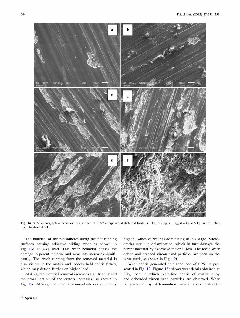
Fig. 14 SEM micrograph of worn out pin surface of SPS2 composite at different loads. a 1 kg, b 2 kg, c 3 kg, d 4 kg, e 5 kg, and f higher
magnification at 5 kg
244 Tribol Lett (2012) 47:231–251
123
morphology of debris with microcracks. The pull-out of
ductile aluminum having thread-type morphology is also
seen. Wear debris at 4-kg load as shown in Fig. 13b shows
the plate or flakes of alloy matrix and debonded zircon sand
particles which get spheroidized as they are trapped in the
track during sliding action. The debris particles are likely
to act as the third-body abrasive particles and could be
responsible for the higher wear rate. Loose debris particles
trapped between the specimen and the counterface causes a
microplowing on the contact surface of the composite.
Majority of flakes have number of cracks due to repetitive
stress occurred in sliding under high load. When the load is
increased, the dominant wear mechanism delaminates and
severe plastic deformation occurs. Wear debris generated at
5-kg load as shown in Fig. 13c is having long flakes gen-
erated by delamination along with small flakes. Small
flakes are generated by the crushing of the flakes at high
load. Debris having long flakes as compared to debris
generated at low load depicts the severe wear behavior.
Worn out pin surface micrographs of SPS2 are presented
in Fig. 14. Figure 14a shows worn surface at 1-kg load in
which grooves and ridges running parallel to the sliding
direction can be seen. Microplowing dominates the wear
mechanism although local damaged spots are also observed
on the surface. At 2-kg load, the grooves are distinct and
deeper, crater grow in size which exposes the reinforced
particles, as shown in Fig. 14b. As load increases the
adhesive wear mechanism operates and removes the ductile
matrix material. The particles are protruding in the matrix
depicting good bonding between particle and alloy matrix
as observed in Fig. 14c. At higher load, the material
removal is governed by adhesive wear and crack propa-
gation resulting in delamination of matrix material. The
protective layer of the reinforcing particles can no longer
remain stable under the plowing action at high load. The
material removal is enhanced by adhesive wear mechanism
and number of craters is increased between deep plowing
marks, as shown in Fig. 14d, e. Material removal during
the process is in the form of small pieces resulting in the
formation of flake-type debris. As shown in Fig. 14f, the
craters are so large and distinct that the surface underneath
is visible. The higher magnification SEM examination at
5-kg load of the subsurface clearly reveals cracks indicat-
ing delamination wear.
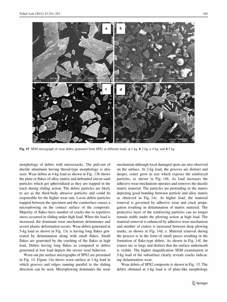
Wear debris of SPS2 composite is shown in Fig. 15. The
debris obtained at 1-kg load is of plate-like morphology
Fig. 15 SEM micrograph of wear debris generated from SPS2 at different loads. a 1 kg, b 3 kg, c 4 kg, and d 5 kg
Tribol Lett (2012) 47:231–251 245
123
and zircon sand particle is not observed, which indicates
that the reinforced particles are bearing the load and plate-
like debris as shown in Fig. 15a is generated. As load
increases the debonding of zircon sand particles occurs and
long flakes of debris having different morphologies as
shown in Fig. 15b are observed. In the collected wear
debris, zircon is present in the form of mechanically mixed
layer. The particle itself has cracked into further smaller
fragments and after long run it makes an oxide-rich layer
on the worn surface by picking iron oxide from the coun-
terface which was confirmed by EDS analysis (discussed
later). Several microcracks are visible in debris indicating
delamination while zircon sand particle takes spherical
shape by trapping in during course of sliding. Twisted and
layered debris revealing the repetitive nature of stress
occurred at high load sliding condition. At 4-kg load, as
shown in Fig. 15c the debris having long flakes apart from
this small metallic debris is also observed, which get
Fig. 16 SEM micrograph of worn out pin surface of DPS 1 composite at different loads. a 1 kg, b 2 kg, c 3 kg, d 4 kg, e 5 kg, and f lower
magnification at 5 kg
246 Tribol Lett (2012) 47:231–251
123
fragmented during sliding action. Debris at 5-kg load
shows mixed morphology with long flakes, small frag-
mented flakes, and layered flakes. Crack propagation leads
to delamination although some flakes depicting microcut-
ting behavior as shown in Fig. 15d can be seen.
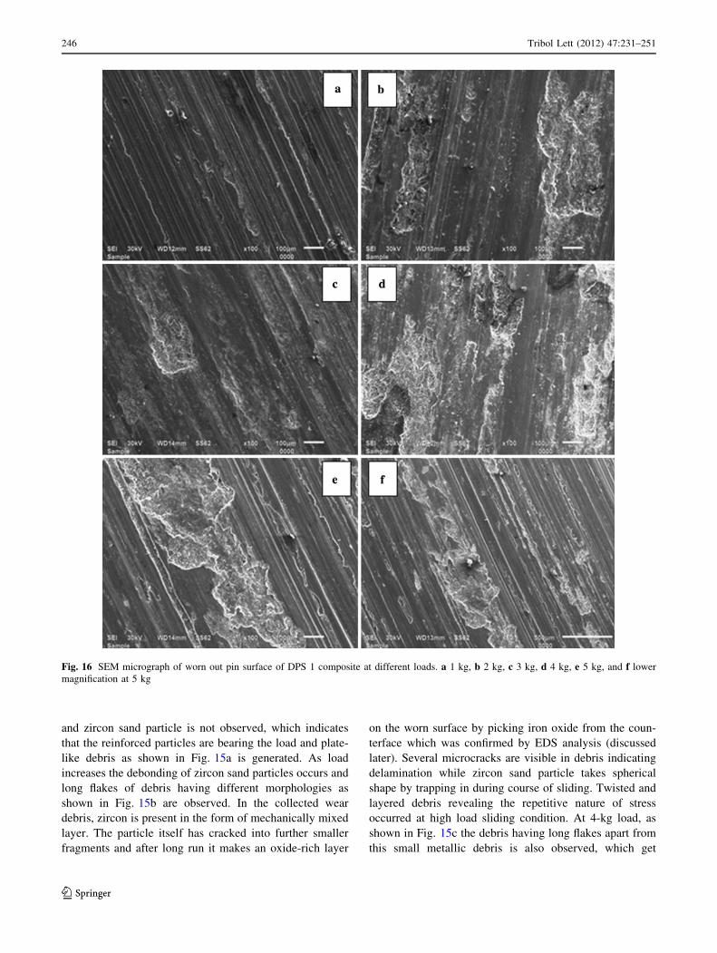
Figure 16 shows the pin surface morphology of DPS1
composite. At 1-kg load, the grooves running all over the
pin surface along sliding direction are shown in Fig. 16a.
Load increment initiates the formation of cater and crack,
as shown in Fig. 16b. At 2-kg load, the crater formation
starts by the loss of parent material. The rupture of
mechanically mixed layer initiates the adhesive wear
mechanism and crater grows in size at 3 kg (Fig. 16c). At
4-kg load, the material removal shows the dimple-like
morphology as void nucleates around the particle in the
ductile matrix, as observed in Fig. 16d. At higher load, i.e.,
at 5 kg the cracks propagates and removal of material
occurs by delamination, as shown in Fig. 16e. A lower
magnification micrograph shows the dimple morphology
around the particle (Fig. 16f).
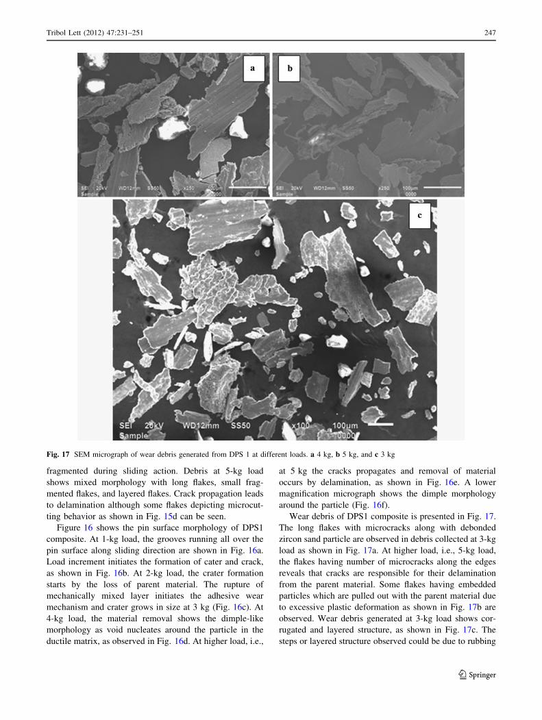
Wear debris of DPS1 composite is presented in Fig. 17.
The long flakes with microcracks along with debonded
zircon sand particle are observed in debris collected at 3-kg
load as shown in Fig. 17a. At higher load, i.e., 5-kg load,
the flakes having number of microcracks along the edges
reveals that cracks are responsible for their delamination
from the parent material. Some flakes having embedded
particles which are pulled out with the parent material due
to excessive plastic deformation as shown in Fig. 17b are
observed. Wear debris generated at 3-kg load shows cor-
rugated and layered structure, as shown in Fig. 17c. The
steps or layered structure observed could be due to rubbing
Fig. 17 SEM micrograph of wear debris generated from DPS 1 at different loads. a 4 kg, b 5 kg, and c 3 kg
Tribol Lett (2012) 47:231–251 247
123
caused by constant sliding between the pin material and the
counterface. Each of the steps could then be caused by the
deforming force subjected in one rotation. Similar mor-
phology of wear debris is earlier reported by Bakshi et al.
[25] for aluminum–silicon composite coatings prepared by
cold spraying.
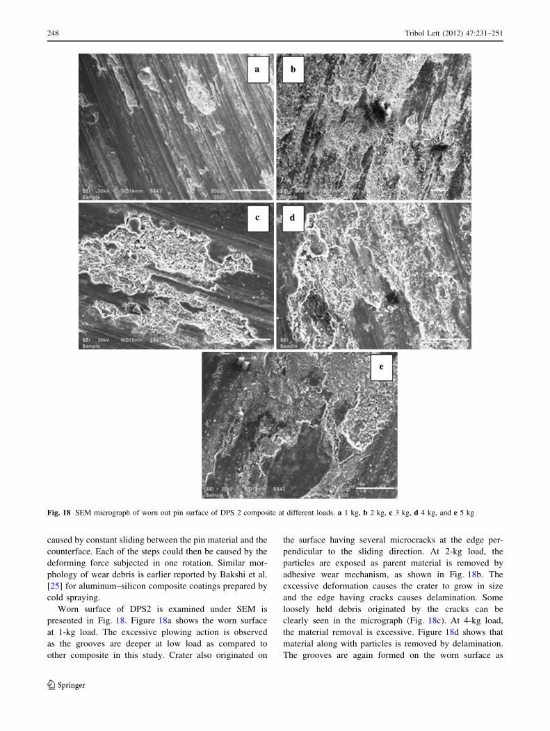
Worn surface of DPS2 is examined under SEM is
presented in Fig. 18. Figure 18a shows the worn surface
at 1-kg load. The excessive plowing action is observed
as the grooves are deeper at low load as compared to
other composite in this study. Crater also originated on
the surface having several microcracks at the edge per-
pendicular to the sliding direction. At 2-kg load, the
particles are exposed as parent material is removed by
adhesive wear mechanism, as shown in Fig. 18b. The
excessive deformation causes the crater to grow in size
and the edge having cracks causes delamination. Some
loosely held debris originated by the cracks can be
clearly seen in the micrograph (Fig. 18c). At 4-kg load,
the material removal is excessive. Figure 18d shows that
material along with particles is removed by delamination.
The grooves are again formed on the worn surface as
Fig. 18 SEM micrograph of worn out pin surface of DPS 2 composite at different loads. a 1 kg, b 2 kg, c 3 kg, d 4 kg, and e 5 kg
248 Tribol Lett (2012) 47:231–251
123
seen in the micrograph. At 5-kg load, the crack propa-
gation lead to excessive removal of parent material
although some island-type parent material remains there,
as they bypass the crack growth, as shown in Fig. 18e.
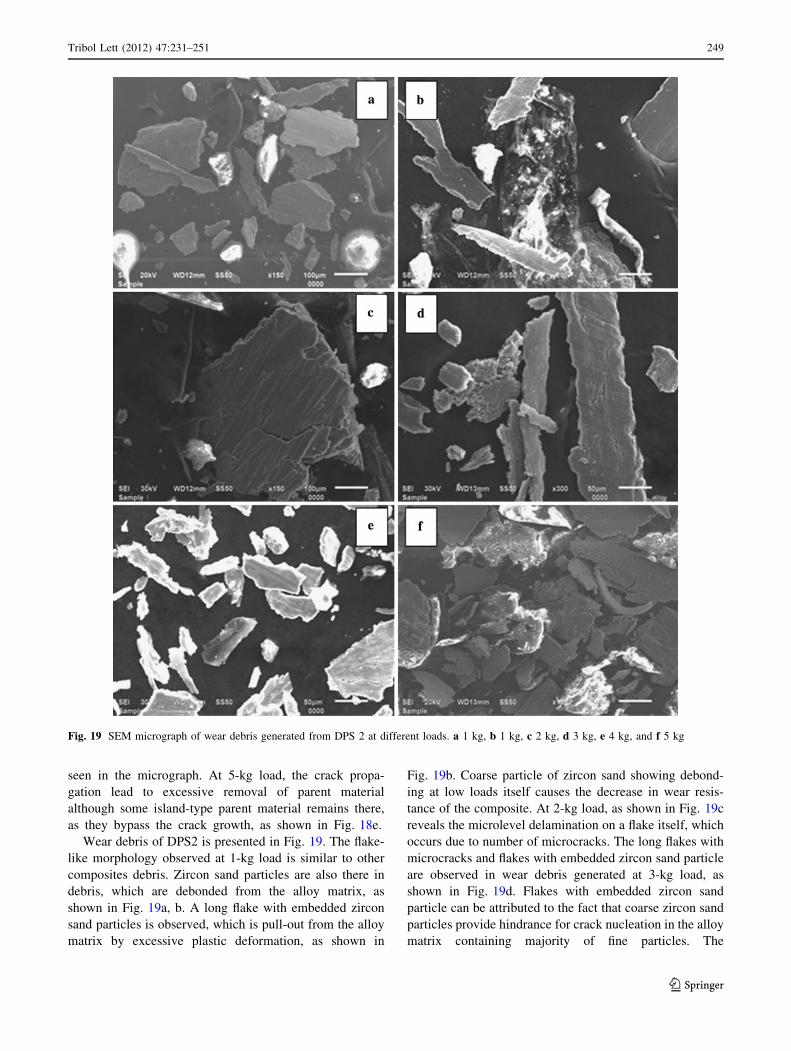
Wear debris of DPS2 is presented in Fig. 19. The flake-
like morphology observed at 1-kg load is similar to other
composites debris. Zircon sand particles are also there in
debris, which are debonded from the alloy matrix, as
shown in Fig. 19a, b. A long flake with embedded zircon
sand particles is observed, which is pull-out from the alloy
matrix by excessive plastic deformation, as shown in
Fig. 19b. Coarse particle of zircon sand showing debond-
ing at low loads itself causes the decrease in wear resis-
tance of the composite. At 2-kg load, as shown in Fig. 19c
reveals the microlevel delamination on a flake itself, which
occurs due to number of microcracks. The long flakes with
microcracks and flakes with embedded zircon sand particle
are observed in wear debris generated at 3-kg load, as
shown in Fig. 19d. Flakes with embedded zircon sand
particle can be attributed to the fact that coarse zircon sand
particles provide hindrance for crack nucleation in the alloy
matrix containing majority of fine particles. The
Fig. 19 SEM micrograph of wear debris generated from DPS 2 at different loads. a 1 kg, b 1 kg, c 2 kg, d 3 kg, e 4 kg, and f 5 kg
Tribol Lett (2012) 47:231–251 249
123
deformation observed is also not homogeneous due to the
presence of coarse particles in fine particle reinforced alloy
matrix. At 4-kg load, the wear debris having flakes along
with fragmented flakes as shown in Fig. 19e are seen. On
higher load, i.e., at 5 kg, flakes showing extensive micro-
cracks and small thin debris show microcutting behavior,
as shown in Fig. 19f.
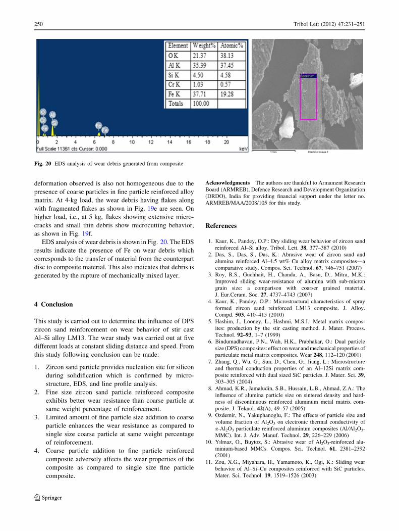
EDS analysis of wear debris is shown in Fig. 20. The EDS
results indicate the presence of Fe on wear debris which
corresponds to the transfer of material from the counterpart
disc to composite material. This also indicates that debris is
generated by the rupture of mechanically mixed layer.
4 Conclusion
This study is carried out to determine the influence of DPS
zircon sand reinforcement on wear behavior of stir cast
Al–Si alloy LM13. The wear study was carried out at five
different loads at constant sliding distance and speed. From
this study following conclusion can be made:
1. Zircon sand particle provides nucleation site for silicon
during solidification which is confirmed by micro-
structure, EDS, and line profile analysis.
2. Fine size zircon sand particle reinforced composite
exhibits better wear resistance than coarse particle at
same weight percentage of reinforcement.
3. Limited amount of fine particle size addition to coarse
particle enhances the wear resistance as compared to
single size coarse particle at same weight percentage
of reinforcement.
4. Coarse particle addition to fine particle reinforced
composite adversely affects the wear properties of the
composite as compared to single size fine particle
composite.
Acknowledgments The authors are thankful to Armament Research
Board (ARMREB), Defence Research and Development Organization
(DRDO), India for providing financial support under the letter no.
ARMREB/MAA/2008/105 for this study.
References
1. Kaur, K., Pandey, O.P.: Dry sliding wear behavior of zircon sand
reinforced Al–Si alloy. Tribol. Lett. 38, 377–387 (2010)
2. Das, S., Das, S., Das, K.: Abrasive wear of zircon sand and
alumina reinforced Al–4.5 wt% Cu alloy matrix composites—a
comparative study. Compos. Sci. Technol. 67, 746–751 (2007)
3. Roy, R.S., Guchhait, H., Chanda, A., Basu, D., Mitra, M.K.:
Improved sliding wear-resistance of alumina with sub-micron
grain size: a comparison with coarser grained material.
J. Eur.Ceram. Soc. 27, 4737–4743 (2007)
4. Kaur, K., Pandey, O.P.: Microstructural characteristics of spray
formed zircon sand reinforced LM13 composite. J. Alloy.
Compd. 503, 410–415 (2010)
5. Hashim, J., Looney, L., Hashmi, M.S.J.: Metal matrix compos-
ites: production by the stir casting method. J. Mater. Process.
Technol. 92–93, 1–7 (1999)
6. Bindumadhavan, P.N., Wah, H.K., Prabhakar, O.: Dual particle
size (DPS) composites: effect on wear and mechanical properties of
particulate metal matrix composites. Wear 248, 112–120 (2001)
7. Zhang, Q., Wu, G., Sun, D., Chen, G., Jiang, L.: Microstructure
and thermal conduction properties of an Al–12Si matrix com-
posite reinforced with dual sized SiC particles. J. Mater. Sci. 39,
303–305 (2004)
8. Ahmad, K.R., Jamaludin, S.B., Hussain, L.B., Ahmad, Z.A.: The
influence of alumina particle size on sintered density and hard-
ness of discontinuous reinforced aluminum metal matrix com-
posite. J. Teknol. 42(A), 49–57 (2005)
9. Ozdemir, N., Yakuphanoglu, F.: The effects of particle size and
volume fraction of Al2O3 on electronic thermal conductivity of
a-Al2O3 particulate reinforced aluminum composites (Al/Al2O3-
MMC). Int. J. Adv. Manuf. Technol. 29, 226–229 (2006)
10. Yılmaz, O., Buytoz, S.: Abrasive wear of Al2O3-reinforced alu-
minium-based MMCs. Compos. Sci. Technol. 61, 2381–2392
(2001)
11. Zou, X.G., Miyahara, H., Yamamoto, K., Ogi, K.: Sliding wear
behavior of Al–Si–Cu composites reinforced with SiC particles.
Mater. Sci. Technol. 19, 1519–1526 (2003)
Fig. 20 EDS analysis of wear debris generated from composite
250 Tribol Lett (2012) 47:231–251
123
12. Surappa, M.K.: Aluminium matrix composites: challenges and
opportunities. Sadhana 28, 319–334 (2003)
13. Amirkhanlou, S., Niroumand, B.: Synthesis and characterization
of 356-SiCp composites by stir casting and compocasting meth-
ods. Trans. Nonferrous Met. Soc. China 20, 788–793 (2010)
14. Hashim, J., Looney, L., Hashmi, M.S.J.: Particle distribution in
cast metal matrix composites—part I. J. Mater. Process. Technol.
123, 251–257 (2002)
15. Hashim, J., Looney, L., Hashmi, M.S.J.: Particle distribution in
cast metal matrix composites—part II. J. Mater. Process. Tech-
nol. 12, 258–263 (2002)
16. Youssef, Y.M., Dashwood, R.J., Lee, P.D.: Effect of clustering on
particle pushing and solidification behavior in TiB2 reinforced
aluminium PMMCs. Compos. A 36, 747–763 (2005)
17. Nakae, H., Wu, S.: Engulfment of Al2O3 particles during solid-
ification of aluminum matrix composites. Mater. Sci. Eng., A
252, 232–238 (1998)
18. Segurado, J., Gonzalez, C., Lorca, J.L.: A numerical investigation
of the effect of particle clustering on the mechanical properties of
composites. Acta Mater. 51, 2355–2369 (2003)
19. Cruz, K.S., Meza, E.S., Fernandes, F.A.P., Quaresma, J.M.V.,
Casteletti, L.C., Garcia, A.: Dendritic arm spacing affecting
mechanical properties and wear behavior of Al–Sn and Al–Si
alloys directionally solidified under unsteady–state conditions.
Metall. Mater. Trans. A 41, 973 (2010)
20. Kaur, K.O., Pandey, P.: Wear and microstructural characteristics
of spray atomized zircon sand reinforced LM13 alloy. Mat. Wiss.
Werkst. 41(7), 21 (2010)
21. Chaudhury, S.K., Singh, A.K., Sivaramakrishnan, C.S., Panigrahi,
S.C.: Wear and friction behavior of spray formed and stir cast
Al–2Mg–11TiO2 composites. Wear 258, 759–767 (2005)
22. Das, S., Mondal, D.P., Dixit, G.: Correlation of abrasive wear
with microstructure and mechanical properties of pressure die-
cast aluminum hard-particle composite. Metall. Mater. Trans. A
32, 633–642 (2001)
23. Das, S., Udhayabanu, V., Das, S., Das, K.: Synthesis and char-
acterization of zircon sand/Al-4.5 wt% Cu composite produced
by stir casting route. J. Mater. Sci. 41, 4668–4677 (2006)
24. Sharma, S.C., Girish, B.M., Somashekar, D.R., Satish, B.M.,
Kamath, Rathnakar.: Sliding wear behaviour of zircon particles
reinforced ZA-27 alloy composite materials. Wear 224, 89–94
(1999)
25. Bakshi, S.R., Wang, D., Price, T., Zhang, D., Keshri, A.K., Chen,
Y., McCartney, P., Graham, D., Shipway, H., Agarwal, A.:
Microstructure and wear properties of aluminum/aluminum-sili-
con composite coatings prepared by cold spraying. Surf. Coat.
Technol. 204, 503–551 (2009)
26. Zhang, J., Alpas, A.T.: Transition between mild and severe wear
in aluminium alloys. Acta Mater. 45, 513–528 (1997)
Tribol Lett (2012) 47:231–251 251
123
Related Documents