Science & Global Security, 1991, Volume 2,pp.301-324 Photocopying pennitWd bylicense only Reprints available directly from thepublisher @ 1991 Gordon and Breach Science Publishers S.A. PrinWd in theUniWd States ofAmerica .An Atmospheric Limit on N uclear- powered Microwave Weapons Dan L. Fenstermachera and Frank von Hippelb We present a simple model that predicts a limit to the microwave energy fluence (energy per unit area) that can propagate through the atmosphere and show that this limit falls within levels that can be shielded against. Within the relevant range of parameters, this model simplifies and extends results reported by Yee et aI.1 to show explicitly the dependence of the breakdown time on microwave field strength and alti- tude above sea level. W ith continued nuclear-weapon testing, the possibility that the US and USSR could develop nuclear-explosion-powered microwave weapons capable of paralyzing mobile missiles or command systems has complicated arguments about comprehensive or low-yield-threshold test ban treaties.2 In this note, we explore one physical effect that would limit the capabilities of such weapons-the rapid (subnanosecond) dielectric breakdown of air under the high electric fields present in intense microwavepulses. This limit on the energy fluence deliverable in a microwavepulse, along with the difficulties of generating and focusing such a beam, leads us to con- clude that nuclear-poweredmicrowave weapons, like existing counterforce weapons,would not fundamentally alter the US-Soviet mutual nuclear-hos- tage relationship. Neither desire for a bloodlessly paralyzing "use able" weapon nor fear of a possible "gap" in progress toward the developmentof a. CongressionalOffice of Technology Assessment. WashingtonDC 20510 b. Center for Energy and Environmental Studies. Princeton University. Princeton NJ 08544

Welcome message from author
This document is posted to help you gain knowledge. Please leave a comment to let me know what you think about it! Share it to your friends and learn new things together.
Transcript

Science & Global Security, 1991, Volume 2, pp.301-324Photocopying pennitWd by license onlyReprints available directly from the publisher@ 1991 Gordon and Breach Science Publishers S.A.PrinWd in the UniWd States of America
.An Atmospheric Limit onN uclear- powered Microwave
Weapons
Dan L. Fenstermachera and Frank von Hippelb
We present a simple model that predicts a limit to the microwave energy fluence(energy per unit area) that can propagate through the atmosphere and show that thislimit falls within levels that can be shielded against. Within the relevant range ofparameters, this model simplifies and extends results reported by Yee et aI.1 to showexplicitly the dependence of the breakdown time on microwave field strength and alti-tude above sea level.
W ith continued nuclear-weapon testing, the possibility that the US andUSSR could develop nuclear-explosion-powered microwave weapons
capable of paralyzing mobile missiles or command systems has complicatedarguments about comprehensive or low-yield-threshold test ban treaties.2 Inthis note, we explore one physical effect that would limit the capabilities ofsuch weapons-the rapid (subnanosecond) dielectric breakdown of air underthe high electric fields present in intense microwave pulses.
This limit on the energy fluence deliverable in a microwave pulse, alongwith the difficulties of generating and focusing such a beam, leads us to con-clude that nuclear-powered microwave weapons, like existing counterforceweapons, would not fundamentally alter the US-Soviet mutual nuclear-hos-tage relationship. Neither desire for a bloodlessly paralyzing "use able"weapon nor fear of a possible "gap" in progress toward the development of
a. Congressional Office of Technology Assessment. Washington DC 20510b. Center for Energy and Environmental Studies. Princeton University.Princeton NJ 08544

1.,!f1\
302 Fenstermacher and Van Hippe!
such a weapon should therefore be used to slow progress toward a nucleartest-ban treaty.3
ATMOSPHERIC SHIELDING OF INTENSE MICROWAVE PULSES
The physical effect to be described has the result that very powerful electro-magnetic pulses in the atmosphere are "cut off" in the time required for theelectric field in the leading edge of the pulse to break down the air into a denseplasma. In effect, the plasma created by the leading edge of the pulse buildsup into a conductor that can block the passage of the remainder of the pulse ifthe plasma is thick enough. The required thickness is characterized relative toa local "skin depth" 0, the exponential attenuation length of an electromag-netic wave in such a plasma. Since 0 varies inversely with the plasma electrondensity, it rapidly decreases as the electron plasma builds up. When theplasma becomes dense enough so that the local skin depth is short comparedto the thickness of the ionized plasma, the transmission of the remaining por-tion of the pulse is blocked (see figure 1). Because the build-up of the ioniza-tion density is exponential with time, the cut-off time tco occurs effectively assoon as the local plasma density at a distance ctco behind the leading edge of amicrowave pulse has built up to the point where the skin depth there equals.the length of pulse that has already passed:
0 (z = -ctco) = ctco (1)
Here c = 3.108 m s-l is the speed of light in vacuum, and the distance z is mea-
.Complete cut-off would occur after just a few more doublings in electron density in additionto the 40-50 that are typically required to satisfy equation 1. One could also consider "erosion" ofthe pulse closer to its leading edge, where the plasma would not be dense enough to cut off thepulse but where microwave energy would still be transferred to the electrons and dissipated bycollisions. For instance, if 60 ionization doublings occurred prior to too' then the local skin depth inthe middle of the pulse would be about 215 times longer than that at the rear, i.e., 215.ctoo (the skindepth varies as the inverse square root of the electron density), or about 10 kilometers for too = 1nanosecond. Since we have neglected this erosion effect, pulses propagating horizontally over dis-tances of tens of kilometers would be somewhat shorter than our model predicts. For verticalpropagation, however, the number of generations in the electron avalanche required to achievethe cut-off condition is only slightly more than that needed to produce a significant erosion effectover the narrow range of altitudes in which cut-off occurs, and the erosion effect therefore doesnot significantly shorten vertically propagating pulses.
\I

An Atmospheric Umit on Nuclear-powered Microwave Weapons 303
sured back from the leading edge of the pulse.In appendix A, we use the simple model expressed by equation 1 to calcu-
late the cut-off time as a function of both pulse electric-field strength and alti-tude, for cases in which the microwave frequency of the pulse is low comparedto the collision frequencies causing the ionization. In the regimes where themodel is well-justified, the results are found to be in remarkably good agree-ment with numerous experimental results as well as the more detailednumerical model ofYee et al., which does not make this low-frequency approx-imation.
We find that, for a field strength E of 1 MV m-l, the onset of breakdownoccurs just below 50 kilometers in altitude and ultimately results in a pulse nolonger than 1-2 nanoseconds (see figure 2). Using the relationship for the elec-tromagnetic energy flux or intensity I
E2I = -(2)211
(where 11 = 377 for E in V m-l and I in W m-2) this corresponds to a microwavepower flux of about 109 W m-2 and a nanosecond fluence of 1 to 2 J m-2.* Intheory, stronger pulses can deliver somewhat more energy, but this can onlyoccur if the rise-time of the electric field at the leading edge of the pulse is con-siderably shorter than 1 nanosecond. Such fast time-scales would be exceed-ingly difficult to achieve with a nuclear explosive-powered device, because itsradiation release and hydrodynamic time-scales are on the order of 10 nano-seconds or more. Furthermore, since stronger pulses are cut off more rapidly(tco at the altitude of maximum cut-off scales roughly as the inverse of theelectric field), maximum energy fluences through the atmosphere would scaleapproximately only as the first power of the electric field rather than as thesquare. Thus no matter how powerful or directional the microwave generator,the energy in the pulse that can be propagated to the lower atmosphere isquite limited.
* The fluence is the energy flux integrated over its duration. In our low-frequency model. E istaken to be the maximum electric field of a sinusoidal wave. 11 E (CEo)-I, where Eo = 8.85.10-12 F m-lis the permittivity of free space.
-

304 Fenstermacher and Van Hippe'
logorithmic scale skin depth 6(z)
6(z)
(c)
partially reflected pulse

An Atmospheric Umit on Nuclear-powered Microwave Weapons 305---~ --
70 .'.,\ '.',',oo/vc = 1 ', 60 " .
, " /\,SO tco= 1/001 ' t-i?:]MVm-1
I .~ i 0.14 J rrr2 '\,
~~ 40 eEl.; = 1,00) ev~ ~ 0.1 A-1vm-1:J<I> " .~00- E ' ,.-E 0 30 ' ~ 0.3 MV m-' " \
<"" " ,~ , !
I;
20 \;
OOtd= 1 \10 !
;;ia '
0.1 1 10 100
Cut-off timenanoseconds
Figure 2: Cut-off time tco plotted agoinst altitude tor microwave pulses with various maximumelectric-field strengths E. The amount of energy fluence remaining in the pulse is given at sev-eral of the "knees' of the curves. The boundaries of validity imposed by the model's assump-tions are indicated for a microwave frequency ro/21t = 0.1 gigahertz. (The curves for 3gigahertz would be only about a line's width to the right of those plotted, but the low-fre-quency approximation would then be justified only for cut-off times less than about 3 nano-seconds or, equivalently, for electric fields E greater than 1 MV m-l.) The dashed boundariesof reliability are explained in the text.
Figure 1: Schematic diagram illustrating the mechanism of plasma build-up and cut-off as anidealized intense electromagnetic pulse moves into a fresh region of only very weakly ionizedair. (The vertical scale for skin depth and electron-density is logarithmic.) (a) A pulse of lengthL and field strength E approaches the new region of air, whose ambient electron density is no'(b) As a result of dielectric breakdown by the high electric field, a plasma with electron den-sity n builds up behind the leading edge of the pulse and the local skin depth 5 decreases.(c) The front portion of the pulse continues to propagates while the rear portion is partiallyabsorbed and partially reflected. The cut-off occurs almost immediately after the local skindepth (at a distance L' = ctco behind the leading edge of the pulse) becomes short enoughto equal the length of pulse L' that got through before the ionization had a chance to buildup.

306 Fenstermacher and Von Hippel
DAMAGE THRESHOLDS FROM MICROWAVE PULSES
As is well known, electronic components are many orders of magnitude more
susceptible to EMP damage than electrical machinery or ordinary materials.
In general, electronics can be damaged by submicrosecond pulses of micro-
waves with component-absorbed energy in the range of only 10-6 joules (sensi-
tive microwave diodes), to 10-3 joules (high-power transistors and rectifier
diodes).4 Computer chips fall somewhere in the middle of this range (see table
1)5For a microwave pulse with a characteristic wavelength Ap' components
might be expected to absorb on the order of A,2/47t times the energy fluence.6p
Table 1: Microwave damage thresholds for electronicsa
E.J. Lernerb Ricketts et al.c Antlnoned
kilo joulesMotors and Transformers 10 -4,cx:X:J --
mil/ijoulesVacuum tubes 1 -10,cx:X:J --Relays 2 -1,cx:X:J 2 -100 -Resistors 1 -1,cx:X:J -10 -Rectifier and Zener diodes 0.5 -300 -0.5 -1 0.3 -100Medium and high-power transistors 0.1 -100 -1 0.1 -10Ge and low-power transistors 0.003- 10 0.02- 1 0.003- 1
microjoulesSwitching diodes -70 -100 -Integrated circuits 0.1 -1,cx:X:J -10 3 -l,OOOeMicrowave (mixer) diodes 0.1 -100 0.7 -12 0.2- 20
a. Columns 2 and 3 are specific threshold energies for 1-mlcrosecond pulses, which would be expectedto be only slightly higher than thresholds for much shorter pulses.
b. Eric J. Lerner, "Electromagnetic Pulses: Potential Crippler: IEEE Spectrum. May 1981. p.43.
c. L. W. Ricketts. J.E. Bridges, and J. Miletta, EMP Radiation and Protective Techniques, (New York: Wiley,1976), pp.28-29, 76.
d. Robert J. Antlnone, "How to Prevent Circuit Zapping: IEEE Spectrum, April 1987, p.38.
e. TTL Integrated circuits are believed to have a damage threshold from 3-100 microjoules, CMOS from10-1.000 microjoules. and "linear" integrated circuits from 30-1.000 microjoules.
An Atmospheric Limit on Nuclear-powered Microwave Weapons 307
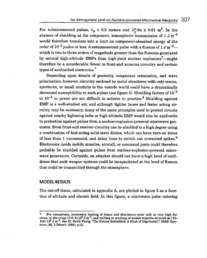
For subnanosecond pulses, Ap ~ 0.3 meters and J..~ /4n ~ 0.01 m2. In the
absence of shielding at the component, atmospheric transmission of 1 J m-2
would therefore translate into a limit on component-absorbed energy of the
order of 10-2 joules or less. A subnanosecond pulse with a fluence of 1 J m-2-
which is two to three orders of magnitude greater than the fluences generated
by normal high-altitude EMPs from high-yield nuclear explosions 7-might
therefore be a considerable threat to front-end antenna circuitry and certain
types of un shielded electronics..
Depending upon details of geometry, component orientation, and wave
polarization, however, circuitry enclosed by metal structures with only seams,
apertures, or small conduits to the outside world could have a dramatically
decreased susceptibility to such pulses (see figure 3). Shielding factors of 10-3
to 10-5 in power are not difficult to achieve in practice.8 Shielding against
EMP is a well-studied art, and although tighter boxes and faster acting cir-
cuitry may be necessary, many of the same principles used to protect circuits
against nearby lightning bolts or high-altitude EMP would also be applicableto protection against pulses from a nuclear-explosion-powered microwave gen-
erator. Even front-end receiver circuitry can be shielded to a high degree using
a combination of fast-acting solid-state diodes, which can have turn-on times
of less than 1 nanosecond, and delay lines to switch out unwanted spikes.9
Electronics inside mobile missiles, aircraft, or command posts could therefore
probably be shielded against pulses from nuclear-explosion-powered micro-
wave generators. Certainly, an attacker should not have a high level of confi-
dence that such weapon systems could be incapacitated at the level of fluence
that could be transmitted through the atmosphere.
MODEL RESULTS
The cut-off times, calculated in appendix A, are plotted in figure 2 as a func-
tion of altitude and electric field. In this figure, a microwave pulse entering
.For comparison, microwave heating of tissue and skin-burns occur only at very high fiu-ences, in the range (0.2-1).106 J m-2, and melting or cracking of metals requires as much as (10-100).106 J m-2. See H. Keith Florig, "The Future Battlefield: A Blast of Gigawatts?," IEEE Spec-trum, 25, 3 (March 1988), p.53.

,c". ~-'1" , "'-' ..C c"
308 Fenstermacher and Van Hippe'
~~ -Filter, limiter, or-~ delay-line switching Receiver diode
Antenna
FRONT-DOOR COUPLING
Aperture ~
~ Conducting penetration!\"""""""'h"","" ,- -""""""""", ",'","",-" "'"'""
II ~ I;: .vV\/\1 Jointi Cable shield leakage E .« Connector cavity
~ leakage Bcavity
I IIII Shielding i
; ~"""""""""""","""", 'h"""""""""",""""""""""""""""",
BACK-DOOR COUPLING
Figure 3: Schematic diagram illustrating the mechanisms of "front- and back-door coupling"of electromagnetic pulses to electronic circuits. "Front-door" coupling involves the pulsebeing picked up by an exposed element of receiving circuitry (the "antenna" here). Circuitprotection is provided by a filter or by switching out such pulses using a delay line. "Back-door" coupling involves the pulse leaking through protective shielding that otten surroundsthe circuitry. (Adapted from Florig, "High-Power Microwave Coupling," p.1OS.)

An Atmospheric LImit on Nuclear-powered Microwave Weapons 309~~- ""~,~..~.",, .."'"',..,""",,
the atmosphere from space-if it were long enough-would first cause break-
down somewhat above and to the right of the top of the angular curve corre-
sponding to its electric field.. It would then become progressively shorter, as
described by the curve, until it encountered the knee of the curve. t Below that
altitude, it would be shortened little if at all during the remainder of its
descent to the earth's surface.
Above and below the indicated domain of validity, the curves for tco would
eventually bend to the right, and cut-off would take longer than what would
be predicted by simply extending the angular curves in figure 2. Far below the
bottom boundary, cut-off would eventually fail to take place at all, because the
electrons would undergo so many elastic and ultimately inelastic collisions
that they would not be accelerated to ionizing energies, and the true curves
would become horizontal.:!:
As figure 2 indicates, a pulse with a power of 1013 W m-2 ( = 100 MY m-l)
would cut itself off near the earth in about 0.02 nanoseconds, transmitting up
to 200 J m-2 at centimeter wavelengths. However, this fluence would only get
through if the initial rise-time of the pulse was of the order of 0.02 nanosec-
onds or less-an implausibly short time-constant for a nuclear-powered
device. Therefore, it is more likely that the pulse would be cut off at lower val-
ues of its electric field and transmit much less overall energy.
In figure 4, we compare the predictions of our breakdown model with a
.The angular curves resulting from the model in figure 2 are, of course, approximations forwhat in reality would look more like parabolas opening to the right. For a downward-propagatingpulse, one would therefore expect the most rapid decrease in pulse-length (per kilometer of alti-tude) to occur over a very narrow range of altitudes near the top of each angular curve-wherethey meet the boundary eE,-; = 1,000 eV: This, in fact, is exactly what is seen in numerical simula-tions of such propagation. Cf. Yee et al., "Theory of Intense Electromagnetic Pulse Propagation,"p.1242 (figure 5).
t This knee occurs at the altitude where the mean free path for electrons initially at rest in theatmosphere is such that they gain just the right amount of kinetic energy from a given electricfield between each collision (about 20 electron volts) so as to cause ionizations most quickly. Seeappendix A, equationsA-12a andA-12b.:!: In the low-field low-frequency regime, experiments have shown that cut-off does not takeplace at all (the cut-off time goes to infinity) when the electric field is so weak that electrons gainonly about 1 eV of energy between elastic collisions, i.e., eE.'-e = 1 eV. (See Yee et al., figure 5.)
For verI high field strengths of around 30,000 MY m-1 (corresponding to a pulse energy fluxof about 101 W m-2), far to the left of the curves shown in figure 2, electrons would begin to tun-nel out of air molecules and the ionization would occur much faster than even this model predicts,thus providing another constraint on the total electromagnetic energy flux that can be propagatedthrough air.
-

,~",'
31 0 Fenstermacher and Van Hippe'
109 eE>.; = 1 ,(xx) eV
-Our (low-frequency) model.Uvermore data
-0- Felsenthal & Proud-0- Tetenbaum
1108 -6,- Gould & Roberts
Q,O~- =20eVE~ #
( "ti' " .. eE>.e = 5 eV107 0, ""', ..." D.. ..."0.", .
"""':c ~." 0" .." '.,--., 'Q ~""-..6
10610-12 10-11 10-10 1Q-9 10-& 10-7 1Q-6 10-5
p-tcoalms
Figure 4: Universal plot of the electric field of a microwave pulse (normalized by the pressure)vs. the product of pressure and cut-off time-for our model and various experimental results.The indicated values of electron energy (5, 20, and 1 ,(xx) eV) at points along the curves cor-respond to three points along each constant-electric-field curve plotted in figure 2: 5 and1 ,(xx) eV correspond to the electron energies achieved in one elastic or ionizing mean freepath, respectively, at the lowest and highest altitudes justified by the model's assumptions; 20eV is the energy gained in one elastic mean free path at the knee of the curves. For one-mean free path electron energies below 5 eV, the cut-off times are longer than would be pre-dicted by simply extending the lower straight line predicted by our model. The differencebetween the lower (0.03 MV m-l; 0.1 gigahertz) and upper (30 MV m-l; 3 gigahertz) curves isprimarily due to the large variation in the ambient "seed" electron density at the altitudeswhere these curves apply and, to a lesser extent, the difference in microwave frequency.(References for experimental data points: P. Felsenthal and J.M. Proud, Phys. Rev., 139,p.A 1796 (1965); S.F. Tetenbaum, A.D. MacDonald, and H.W. Bandel, J. Appl. Phys., 42, p.5861(1971); and L. Gould and L.W. Roberts, "Breakdown of Air at Microwave Frequencies," J. Appl.Phys., 28, p.1167 (1956). Uvermore data Is from Yee et al., p.1243 (figure 9). All experimentaldata were obtained at 2.8 gigahertz.)

An Atmospheric Limit on Nuclear-powered Microwave Weapons 311
number of experimental results, which fall near a "universal curve" when plot-
ted using the composite variables Elp and ptco' where p is the atmosphericpressure. The agreement is quite good over a wide range of electric fields and
pressures. Indeed, we find that our model predicts the correct behavior of the
cut-off time even somewhat into the regimes where the low-frequency approx-imation or the sufficient-energy assumption (eEAe ~ 5 eV) are not strictly satis-
*fied.
CONCLUSIONS
The predictions of our model can be used to arrive at bounds on the potential
fluences of pulses produced by microwave generators exploding both within
and above the atmosphere.
Explosion of a Microwave Generator in the AtmosphereEven if a pulse with a strength of 200 J m-2 were short enough to be able to
survive atmospheric breakdown at 10 meters from a detonation-and we have
not been able to come up with any mechanism that would produce a micro-
wave pulse short enough to have such a fluence-the r-2 fall-off of the energyflux would result in that pulse having a strength of only 0.02 J m-2 by the time
it had propagated 1 kilometer, where other nuclear effects would still be
extremely lethal, and 0.0002 J m-2 by 10 kilometers. Therefore, nuclear-pow-
ered microwave generators of potential military significance would require
that their microwave flux be generated in space and directed downward, so
that the energy could spread out over a large area before it entered the atmo-
sphere.
Exo-atmospheric Directed-microwave WeaponsAn exo-atmospheric nuclear-explosive-powered EMP weapon might be able to
produce a directed microwave pulse by sending a beam of neutrons or gamma
* For instance, the low-frequency approximation (O)td < 1) would not apply to the curve corre-sponding to an electric field E = 0.03 MY m-l at a frequency of 3 gigahertz. But the predictions ofour model-if plotted-would fall between the two (angular) curves from the model that are plot-ted in figure 4, and would thus still fit the experimental results shown there. One can also seefrom the figure that extending the curves below the point where eEAe = 5 eV would also fit thedata fairly well down to a value of about 2-3 eV.

31 2 Fenstermacher and Van Hippe!
rays into the atmosphere using a nuclear shaped-charge, generating an EMPat altitudes between 20 and 40 kilometers that would then propagate down tothe ground,10 or it might generate and focus a microwave beam using thedevice itself. 11
If 0.1-radian directivity and 10-5 to 10-3 efficiency are assumed, then a 1-kiloton device exploded at an altitude of 200 kilometers could illuminate a 20-kilometer diameter circle on the ground with an average fiuence of 0.1-10J m-2 in the absence of atmospheric breakdown or attenuation.12 One mightguess that, with a more efficient design, a higher-yield device, or by explodingthe device at lower altitude, higher fiuences might be delivered to the earth'ssurface. However, according to our model, unless the energy could be com-pressed into a pulse much shorter than 1 nanosecond-which is implausiblesince the radiation release and hydrodynamic expansion from fission andfusion explosive processes occur over time-scales of about 10 nanoseconds-airbreakdown occurring within 1 nanosecond at electric fields around 1-3 MY m-1 would limit the fiuence of any such electromagnetic pulse propagating down
through the atmosphere to considerably less than 10 J m-2. If the rise-timewere several nanoseconds, the fiuence that passed through the atmospherewould be less than 1 J m-2 (see figure 2). Thus, 1-10 J m-2 is a rough upperlimit on the microwave fiuence that can propagate through the atmospherefrom any plausible nuclear device, independent of the altitude of burst, effi-ciency, yield, frequency, or directivity.*
Since such a fiuence could require precautionary measures or additionalexpense for shielding beyond that already incorporated for protection againstordinary EMP effects and conventionally-produced microwaves,13 nuclearmicrowave devices aimed at achieving these levels might remain of at leastmarginal interest for some strategic planners and weapon designers and couldcontribute to the continuation of the nuclear arms race. However, their usewould bring the same risk of escalation to all-out nuclear war as any other
* To produce higher fluences one would have to create very long pulses with much lower (non-ionizing) electric fields, whose accumulated fluence over microseconds or milliseconds could thenexceed these limits. However, such long pulses would be much easier to shield against-especiallyif they were low-frequency (long-wavelength) as well-and would be less lethal to electronics evenif they penetrated the shielding because of heat dissipation over these time-scales.

An Atmospheric Umit on Nuclear-powered Microwave Weapons 31 3
nuclear weapon, without having a decisive effect. For all practical purposes,they should therefore be considered no more useable nor any less dangerousthan other nuclear weapons.
ACKNOWLEDGEMENTSThe authors would like to acknowledge the support of grants from the Carn-egie Corporation, the John D. and Catherine T. MacArthur Foundation, andthe Rockefeller Brothers Fund.
APPENDIX A: THE ATMOSPHERIC BREAKDOWN MECHANISM AND 'co
We describe here a model of atmospheric dielectric breakdown by electromagneticpulses in which the microwave frequencies are assumed to be small in comparison toelectron collision frequencies. This low-frequency model sufficiently covers the regimeof interest for our purposes.
Because of the effects of cosmic rays, natural radioactivity, and (at higher alti-tudes) ultraviolet rays, the atmosphere contains an ambient densitr of free electronsna that increases very rapidly in the lower region of the ionosphere:1
na ~ 100 m-3 below 36 kilometersna ~ 106(h/60 km)18 m-3, for h = 36 to 100 kilometers. (A-I)
If the electric field of a microwave pulse accelerates one of these electrons to an energyUi sufficient to ionize an air molecule (Ui ~ 10 eY. on average for air), then it can colli-sionally eject another electron. If the colliding electron's energy is high enough (above40 eV), then such an ionizing collision is more probable than an elastic collision. In thiscase, both the initial and ejected electrons can quickly cause additional ionizations,leading to an exponential avalanche that creates a plasma of conducting (free) elec-trons.
Such an exponential electron avalanche can be characterized by a doubling timetd:
n = na 2'ft. (A-2)
The doubling time depends upon the strength of the accelerating electric field and the"mean free path" of the electrons between collisions with air molecules.
* The electron volt (eV) is a unit of energy equal to 1.6.10-19 joules. An electron would gain 1e V of kinetic energy if accelerated in a vacuum over a distance of 1 meter by a constant electricfield of 1 V m-1.

314 Fenstermacher and Van Hippe'
Electron AccelerationThe mean free path A is given by
1A = -(A-3)NO"
where 0" is the (energy-dependent) total equivalent "cross section" or target area repre-sented by an average air molecule, and N is the number density of air molecules. Ndecreases exponentially with height h and can be approximated up to about 100 kilo-meters above sea level by;l5
N~2.7 .10 25 exp (~) m-3 (A-4)
Non-ionizing or elastic scattering dominates in air at electron energies U below about10 eV and has an associated cross sectionl6
0" ~ 10-19 m 2 (U ~ 10 eV) (A-5)e
Ionizing collisions dominate above an electron energy of about 40 ev* with arough11 constant cross section thereafter up to an energy of about 1,000 eV having avaluel
cr. ~ 0.3.10-19 m2(40 ~ U~ I, 000 eV) (A-6)1
The elastic and ionization mean free paths in these regimes are therefore
Ae ~0.4 .10-6 exp (-rk- ) meters, (U~ 10 eV) (A-7a)
Ai ~ 1.2 .10-6exp ( -rk- ) meters, (40 ~ U ~ I, 000 eV) (A-7b)
If the electric field strength E in the microwave pulse is high enough so that anelectron will be accelerated to at least 20 eV in an elastic mean free path, i.e.,
* a!ae = (1/30, 1/3, 1,3) at U = (10, 20, 40, 80) eV, respectively. OJ decreases by a factor of about3 between 80 eVand 1,000 eV. The value we use for the wider range (40 eV to 1,000 eV) is anintermediate one.

An Atmospheric Limit on Nuclear-powered Microwave Weapons 315
Ei..e ~ 20 V or E ~ 50 exp ( ~ ) MY m -1 (A-B)
then collisions in an electron avalanche are likely to be ionizing rather than elastic.. Ifthe time between collisions is short compared to microwave frequency-i.e., ClYtd < 1,the low-frequency approximation-then the time between electron doublings for thishigh-field case 't~o) (in which electrons undergo no elastic collisions) may be approxi-mated by the time required for an accelerating electron, starting at rest, to travel anionization mean free path Aj:t
~m.i... 3 7 .10-9 ( h )'t~o) = ~ = _.:~ exP km seconds (Ei.. ~ 20 V) (A-9)eE ",E 14 e
where we have used equation A- 7b and E is in V m-l.* At very high electric fields (EAj >1,000 V), the ionization cross section decreases appreciably and doubling times wouldbe longer than that given by the right-hand side of equation A-9. Thus equation A-9applies only up to EAj = 1,000 V.
At lower field strengths (EAe < 20 V), the doubling time between ionizations will belengthened not only because of slower electron acceleration but also because elastic col-lisions interrupt the acceleration process and randomize the electron velocity direction.In a constant electric field E, the average time needed for an electron initially at rest togain an energy U by a collisional random walk in velocity-space is
~m.i.. ( 4[ U J3/2 1 )'trend = --.!.-. (for U ~ eEi.. ) (A-I0)u eE 3 eEi.. 3 e
e
* Although an electron accelerating from rest is more likely to be scattered elastically thancause an ionization while its energy is less than 20 eV, most electrons in an ionizing cascade willbegin with energies of 10 eV or more, since most ionizations will occur at energies above 20 eVand lose only about 10 eV of energy to the ionization. Therefore, the condition in equation A-8 issufficient for the avalanche to be dominated by ionizing collisions.
t Since most electrons created by ionizing collisions do not start at rest, this estimate of ioniza-tion time is an upper bound.:j: For electric fields just satisfying the condition EAe = 20 V in equation A-9, the doubling timeis given by 't~o) = 5.10-4 exp(hl1:7 km]} nanoseconds. (This condition is satisfied at the knees of thecurves in figure 2.) This means that the low-frequency approximation CJYtd < 1 would hold at thesepoints for microwave frequencies up to about 15 gigahertz at an altitude of 20 kilometers, and upto 50 megahertz at 60 kilometers. For higher electric fields at any given altitude, the low-fre-quency approximation would be satisfied for even higher frequencies.

An Atmospheric Limit on Nuclear-powered Microwave Weapons 31 7.
3 7 .10-9 ( h )'td ='t~O) == -=-"jE-exp 14 kIn seconds (A-12a)
For 5 VIAe ~ E ~ 20 V/A~ ionization occurs after a series of elastic collisions (from 56 to2.6 such collisions), and
rand 1.56 .103 ( -h ) 1 ~ d (A 12b)'td= 'td == --~exp ~ -3~~ secon s -
The knees in the curves in figures 2 and 4 correspond to electron energies of eEAe = 20eV, where the models of electron acceleration expressed by equations A-12a and A-12bare joined.
Number of Electron DoublingsWe must now compute the number of electron doublings required to raise the plasmafrequency and thereby reduce the skin depth to the cut-off length given by equation 1.
At any particular local electron density n, the associated "plasma frequency"19 is
(I) = f2 = 56.4Fn S-1 (where n is in m-3) (A-13)p ~~
It is shown in appendix B that, when the plasma becomes dense enough to satisfy thecondition
(1)2 ~ (l)V (A-14)p c
where v c is the collision frequency, the local skin depth S can be approximated interms of ~ using the simple formula
c f!jVcS == --(A-15)(I) (I)
p
Here (I) is the characteristic frequency of the microwave pulse, c is the speed of light,and
* Note that we have set U = 26.8 eV in equation A-IO to obtain equation A-12b. Within thegiven range of E, the second tenD in equation A-12b is always small compared to the first.

I
31 8 Fenstermacher and Von Hippel
- ( -h ) mv2 v =Nv(cr +cr.)~5.l012exp -s-lforleVoSU=-oSl,OOOeV (A-16)c e I 7km 2
is the approximate average collision frequencir. for electron collisions with air mole-cules over the entire energy range of interest.2
If we require from equation 1 that 0 oS ctoo for cut-off, and substitute 0 from equa-tion A-15, we can express the cut-off condition in terms of the plasma frequency:
2vc0>2 ~ -(A-17)P o>t2co
When 0> < 1/too' according to the Heisenberg uncertainty principle the pulse thatsneaks through the ionized region will be dominated by higher frequencies, making itappropriate to substitute 0> ~ l/too as a typical frequency of the pulse. Since this substi-tution is then conservative when 0> > 1/too (leading to an overestimate of O>p in that caseand hence of the cut-offtime), we will therefore use 0> = 1/too in equationA-17. In thisapproximation, equation A-17 becomes
2vc 20>2 ~ -(subject to 0> ~ o>v ) (A-18)P t P cco
'Ib obtain an expression for the cut-off time itself, we must express the exponen-tially increasing O>p in terms of t and solve equation A-18 for t = too' Using equation A-13 for O>p and equation A-2 for n, we obtain
0>2 = 5642 n 2,ft. (A-19)P .a
Using equation A-18 with this expression and taking the natural log results in
[ [2V c - J)max -; (o>v )
t = ~ In tco c (A-20)co In (2) 56.42na
where the max function has been used for notational convenience in order to incorpo-rate both conditions from equation A-18. We then use equations A-12a and A-12b to
..v is, of course, dominated by elastic collisions below 10 eV and by ionizing collisions above40 eV. "Note that, although the approximation for the collision frequency v in equation A-16 isdifferent from the more exact approximation used previously of constant aj "and ae within certainlimited energy ranges, the approximation here is adequate for the purposes of equation A-I5 andis therefore chosen as a matter of computational convenience.
i
~
An Atmospheric Umit on Nuclear-powered Microwave Weapons 319.~,- -~
express the doubling time td in terms of E and h, equation A-16 for the collision fre-quency Yc' and equation A-I to express the ambient electron density na(h), and solveequation A-20 for too as a function of E and h,.
Dependence on Microwave FrequencyEquation A-20 holds in the low-frequency approximation Cl)td < I and for electric fieldssatisfying the conditions in equations A-12a and A-12b, For electric fields outside thisrange (i.e., E < 5 VIAe and E > 1,000 V~), breakdown is inhibited by nonionizinginelastic collisions and by the decreasing ionization cross section, respectively, and toowould be correspondingly greater than the value that would be predicted by our formu-las. For very low fields (EAe « 5 volts), too would increase dramatically and the cut-offprocess would eventually be squelched completely.
Values of too that satisfy equation A-20, along with the domain of validity of themodel's assumptions, are shown in figure 2, as a function of altitude and the electricfield strength of the pulse, for a microwave frequency of 0.1 gigahertz. At 3 gigahertz,the low-frequency approximation causes the Cl)td < I boundary to move left by a factorof 30 along the too-axis and the wy c < I boundary to move down by 7.ln(30) = 24 kilo-meters, Cut-off times were computed for this frequency as well and, where different,
, were found to be only about a line's width larger at each electric field than those plot-
ted for 0.1 gigahertz, (This is due to the relative insensitivity of the model to frequencyas long as the low-frequency approximation is satisfied and to the natural-log factor inequation A-20.) Thus, the curves on figure 2 for too ~ 3 nanoseconds (E ~ I MY m-l) arealso justified and very nearly correct for 3-gigahertz microwave frequencies as well.
APPENDIX B: DERIVATION OF THE ELECTROMAGNETIC "SKIN DEPTH"
In order to understand the features of intense electromagnetic wave propagationthrough an ionizing gas or plasma, we employ a one-dimensional plasma-fluid modelcombined with Maxwell's equations to describe plane-wave propagation in the z-direc-tion:
-dBV xE = -(B-1)
Z dt
-2 dEV xB = J.l J +c -(B-2)
Z 0 at
dn-+V .(nu) = v.n (B-3)at Z I
d(nu) -en --= -(E +u xB) -nv u (B-4)dt m c.
.When the first term in square brackets is the maximum, the solution for too is actuallyimplicit, However, because of the insensitivity of the natural-log factor, a few numerical iterationsquickly converge on a self-consistent value for too.
320 Fenstermacher and Van Hippe'
where -e, me' and n are respectively the electron charge, mass, and number density, uis the electron fluid velocity, ~o = 1J(£oc2) = 41t.10-7 H m-l in MKSA units, J = -neu isthe current density, V z = z dlaz, vi is the electron ionization frequency (implicitlydependent on air density), and v c is the momentum-transfer collision frequency aver-aged over the electron energies of interest.21 Frequencies (although low compared tothe rate of electron collisions) can be assumed to be high enough so that ions contributeonly as an immobile charge-neutralizing background. The energy equation-whichwould include the u.E term as well as terms for the air-molecule-exciting inelastic col-lisions and the energy transfer associated with the ionization rate vi-is omitted here,because it decouples from the transverse waves in the linearized approximation to fol-low.. Without loss of generality, we may also assume that the electric and magneticfields of the transverse waves are polarized in the x and Sr directions, respectively.
We now linearize equations B-1 to B-4, ignoring products of the first-order quanti-ties Ex, Ez, BY' UX' Uz, and n, while taking the zeroth-order electron density from equa-tion B-3 to be:
no(t) = naexp(Vjt)t (B-5)
where na is the ambient ("seed") electron density. Assuming plane waves with fre-quency ro propagating in the z -direction, the space and time variation can be repre-sented by exp(i[kz -cot]), where i is the square root of -1. Equations B-1 to B-4 then
become
ikEx = iroBy
-ikBy = -elJ.onoUx -(iro/c2)Ex
0 = -e~onoUz -(iro/c2)Ez
-iron + iknoUz = vin
-ironoUx = (-enJm)Ex -no v c Ux
-ironoUz = (-enJm)Ez -no v c Uz
in which the BY' Ex, and Ux components (in the first, second, and fifth of these six equa-tions) decouple from the others to give the dispersion relation k(ro) for the transverse(electromagnetic) waves. This can be written in the form of a complex dielectric func-tion £(ro) as:
* See, for example, Yee et al., pp.1238-1240. The pressure term, Vz(nU) is also omitted fromthe momentum equation, equation B-4, for the same reason; it affects only the longitudinal
plasma waves.t Comparing this with the notation in equation A-2, we see that the ionization frequency issimply vi = In(2)/td' where td is the "doubling time" in our model.
An Atmospheric Urnit on Nuclear-powered Microwave Weapons 321.
2( k (o»c ) 0>: £(0»= =1- .-(B-6)0> 0>2+W 0>
c
The imaginary part of the wavenumber k incorporates the loss of energy due toelectron collisions with air molecules, causing the electromagnetic fields of the wave todecay exponentially in a characteristic plasma length 5, called the "skin depth~:
1 c5=- = (B-7)~ (k) ~Ji(C;))
The wave's power, which is proportional to the square of the field strength, thus decaysby a factor of e2.. 7 in each skin depth along the direction of propagation.
Using the relation
IJa~-a~(j;;:;ib)=~'- '2- -
along with the low-frequency approximations y c »0> and 0>: » O>Y c ' we obtain.
c J2JYc 5= --(B-8)0> 0>
p
Since O>p grows exponentially with time, other multiplicative factors involving 0> andy that come out of the exact expression for 5 have only an extremely small effect ont6e cut-off time and need not be included here. For the same reason, the condition 0>2» O>Y c is guaranteed to occur, if not before, then almost simultaneously with the cut-off time. (See discussion at equationA-18.)
* These approximations also satisfy the definition of a good conductor, 3(£[00]) » 19t(£[oo]) I.
Alternatively, but with less insight into the plasma dynamics, equation B-8 can be derived fromequation 7.49 (with the electron binding frequency set to zero), and equations 7.58, 7.68, and 7.77of J.D. Jackson, Classical Electrodynamics, (New York: Wiley & Sons, 1975), pp.284-298.
Note that since there cannot be fewer overall collisions than ionizing collisions (v ?; 1/td),the low-frequency condition 1/td ?; 00 also implies that v ~ (Il If we were to examine the otherregime-the collisionless regime where v /00« 1, then tfie plasma skin depth would simply be 0= c/~, under the conditions 002 > 002 andc9t(£) « -1. However, in this high-frequency regime ourmodel is not appropriate. P

322 Fenstermacher and Van Hippe!
NOTES AND REFERENCES1. Jick H. Yee, R.A. Alvarez, D.J. Mayhall, D.P. Byrne, and J. DeGroot, "Theory ofIntense Electromagnetic Pulse Propagation Through the Atmosphere," Physics of Flu-ids 29, 4 (April 1986), pp.1238-1244; presents theory, numerical simulations, andexperimental data.
2. See for example Theodore B. Taylor, "Third Generation Nuclear Weapons," Scien-tific American 256, 4 (April 1987), p.30; Michael D. Lemonick, "A Third Generation ofNukes," llme, 25 May 1987, p.36; and Dan L. Fenstermacher, "The Effects of NuclearTest Ban Regimes on Third-generation-weapon Innovation," Science & Global Security1,3-4 (Spring 1990), pp.209-220.3. For a detailed discussion of the technical issues involved in a test ban on nuclearweapons, see Toward a Comprehensive Nuclear Warhead Test Ban (Washington DCand Moscow: The International Foundation, January 1991).
4. The one-dimensional model for electrically stressed semiconductor junctions firstproposed by Wunsch predicts that, for pulses shorter than about 100 nanoseconds,junction failure in integrated circuits will occur for a certain amount of energy in thepulse, not power, because the heat cannot be dissipated in such a short time. (D.C.Wunsch and R.R. Bell, "Determination of Failure Levels of Semiconductor Diodes andTransistors Due to Pulse Voltages," IEEE 7rans. Nuclear Science, NS-15, 6 [December1968], pp.244-259; see also Robert J. Antinone, "How to Prevent Circuit Zapping,"IEEE Spectrum, April 1987 , p.37.)
5. It is interesting to compare these damage-threshold energies with experimentalresults of continuous-wave illumination of integrated circuits. Tests have shown thatone or two out of three unhardened commercially-available microprocessor boardswere upset by 2.5 or 25 W m-2 of continuous I-gigahertz microwaves, respectively.(W.W. Everett III, and W.W. Everett, Jr., "Microprocessor Susceptibility to RF Sig-nals-Experimental Results," in IEEE Southeastcon '84 Conference Proceedings, IEEECatalog No. 84CH1984-4 [1984], pp.512-516.) If we assume thermal equilibrium isreached in about 1 millisecond, as would be suggested by the Wunsch model, then thiswould roughly correspond to an absorbed energy from a single short pulse (with 0.01m2 absorption cross section, see below) of 25-250 micro joules-which does, in fact, fallin the middle of the range of estimates given for integrated circuits (see table 1).6. A 2 /47t is the maximum absorption cross section of a monopole (omnidirectional)antenha. For antenna-like components whose characteristic dimensions are much lessthan Ap' however, the inevitable mismatch to the component's internal impedance willcause a substantial portion of the incoming energy fluence to be reflected; thus theeffective absorption cross section for absorbers much smaller than a wavelength wouldbe considerably smaller than that given by this formula. [E.C. Jordan and KG. Bal-main, Electromagnetic Waves and Radiating Systems, 2nd Edition, (Englewood Cliffs,New Jersey: Prentice-Hall, Inc., 1968], p.377.) Similarly, a directional antenna will col-lect incoherent power only over an area on the order of one wavelength squared, andsuch a signal will not propagate down a solid lead for many wavelengths. (CompareSamuel Glasstone and Philip J. Dolan, The Effects of Nuclear Weapons, 3rd edition,[Washington DC: US Government Printing Office, 1977], p.524.)
7. See Conrad L. Longmire, "On the Electromagnetic Pulse Produced by NuclearExplosions," IEEE 1ransactions on Antennas and Propagation AP-26, 1 (January1978), pA.8. For instance, the effective area of a circular aperture for transmitting electromag-
" I

An Atmospheric Umit on Nuclear-powered Microwave Weapons 323
netic energy is about (2D~)4 times its actual area when its diameter D ~ An, i.e., 10-4when D = 'A.,/20. (J .E. Casper, et al., "Performance of Standard Aperture Shie[ding Tech-niques at Microwave Frequencies," in IEEE 1988 International Symposium on Electro-magnetic Compatibility, IEEE Catalog No. 88CH2623- 7 [1988], pp.218-222.) A 3 x 0.3-centimeter slit in a 100 x 20-centimeter cylinder provides more than a factor of 100shielding (for example, to an internal 22-centimeter wire) even at the slit's resonant fre-quency of 4 gigahertz-where the length of the slit is roughly a half-wavelength-and103 to 105 shielding at both higher and lower frequencies. (R.J. King, et al., "Phenome-nology of Electromagnetic Coupling-Part II," Technical Report NTIS DE86000838,Lawrence Livermore National Laboratory Report UCID20215 part II, 1985.)
9. Such diodes are often used in combination with gas-filled waveguides (plasma lim-iters) which, as would be expected, have turn-on times of about 10 nanoseconds, as wellas ferrite devices to absorb large surges. (See H. Keith Florig, "High Power MicrowaveCoupling and Effects on Electronics," Annales de Physique, Colloque no. 2 14, 6, sup-plement, (December 1989), p.114, and references therein.]
10. We are grateful to Stanislav Rodionov of the Soviet Space Research Institute forbringing this possibility to our attention.
11. Microwave directed-energy weapons of the latter type might, for example, bebased on the principles of virtual -cathode oscillators ("vircators") or magnetic-flux com-pression. (See Fenstermacher, "The Effects of Nuclear Test Ban Regimes on Third-gen-eration-weapon Innovation.") In the vircator-like concept, gamma rays from a nucleardetonation would generate an electron beam within the device sufficiently intense soas to create a self-repelling virtual cathode that would oscillate-depending on its elec-tron density and plasma frequency-at up to tens of gigahertz. Such a device might beable to generate a several-nanosecond pulse with a directivity of 0.1 to 0.01 radians ornarrower. (Diffraction spreads electromagnetic beams to angular widths of at least1.2VD, where D is the diameter of the focusing optics and An is the pulse wavelength.)
A second possibility involves magnetic flux compression 'between a cylindrical con-ducting armature containing a nuclear explosive and a rigid current-carrying coil thatwould surround it. A directed EMP might be generated from the resulting currentpulse using some kind of antenna. Here, pulse lengths might be made short enough tolie in the gigahertz range, with directivities for 3-meter antennas, say, of around 0.1radian. For discussions of (conventional-explosive-powered) magnetic-flux compressiondevices, see A.D. Sakharov, "Magneto-implosive Generators," Soviet Physics (Uspekhi)9, 2 (September-October 1966), pp. 294-299; and E.C. Cnare, R.J. Kaye, and M.Cowan, "A 2 MJ Staged Explosive Generator," in M.F. Rose and T.H. Martin, eds., Pro-ceedings of the 4th IEEE Pulse Power Conference, Albuquerque, New Mexico, 6-8 June1983, pp.l02-104.
Although it will not be discussed further here, an additional problem with anydevice attempting to focus its own microwave beam is electron emission at its metalsurfaces or antenna, which occurs at field strengths of around 30-100 MY m-l and canshort-circuit a beam.
12. See Fenstermacher, "The Effects of Nuclear Test Ban Regimes on Third-genera-tion-weapon Innovation," for the basis for these assumptions. Recall that 1 kiloton =4.2.1012 joules. At higher frequencies, attenuation due to resonant absorption by mole-cules in the atmosphere will reduce the maximum fluence. For example, water vaporand oxygen have resonances at 22 and 60 gigahertz, which cause attenuations in thelower atmosphere of 0.1 and 10 dB km-1, respectively, within several gigahertz of thesefrequencies. See Florig, "High Power Microwave Coupling and Effects on Electronics."

324 Fenstermacher and Van Hippel
13. Conventionally powered microwave generators such as gyrotrons, magnetrons, vir-cators, and explosive flux-generators continue to be of great interest to the military,but applications are generally short-range and quite distinct from the potential strate-gic missions of nuclear-powered counterparts. See, for example, V.L. Granatstein,"High Power and High Peak Power Gyrotrons: Present and Future Prospects,. IntI.Journal of Electronics 57, 6 (June 1986), pp.787-799; and M.D. Pacha, "High-PowerMicrowave Generation,. Energy and Technology Review, July-August 1990, p.72.14. For the value ofna near the earth's surface, see O.H. Gish, "Atmospheric Electric-ity,. in JA. Fleming, ed., Physics of the Earth, Vol. 8: Terrestrial Magnetism and Elec-tricity, (McGraw-Hill, 1939), pp.166 fr. ~Gish assumes an ionization rate from cosmicrays and other natural radiation of 10 m-3 s-1 and an electron lifetime of 10-5 sec-onds.) Above 36 kilometers, the daytime and nighttime profiles of the "D-region.(approximately 60-90 kilometers altitude) can be modeled more exactly in equationA-I 's power law by using 53 and 68 kilometers, respectively, in place of 60 kilometers.Compare J.K Hargreaves, The Upper Atmosphere and Solar-Terrestrial Relations(New York: Van Nostrand, 1979), p.60 (figure 4.5).15. Hargreaves, pp.53-54. Up to an altitude of 100 kilometers, the exponential scale-height varies with altitude by only about :t20 percent, primaril1 due to temperaturevariations, and is given by kBT/mg, where kB == 1.38.10-23 J K- is Boltzmann's con-stant, andg == 9.8 m s-2 is the acceleration at sea level due to gravity. Up to 100 kilome-ters, the average mass of air molecules is m == 29 atomic mass units == 4.8.10-26kilograms, and the average temperature is about 240 K (-28 OF). This gives a scale-height of about 7 kilometers.16. See for example Yee et al., figures 1 and 2.
17. Ibid.18. See for example Gerhard Herzberg, Molecular Spectra and Molecular Structure I:Spectra of Diatomic Molecules, second edition, (New York: Van Nostrand, 1950).pp.444-450; D.C. Cartwright, W.J. Hunt, W. Williams, S. Trajmar, and W.A. GoddardIII, "Theoretical and Experimental (Electron-Impact) Studies of the Low-Lying Ryd-berg States in °2'. Physical Review A, 8 (1973), pp.2436-2448.19. See for example J.D. Jackson, Classical Electrodynamics, 2nd edition (New York:John Wiley & Sons, 1975), p.321.20. Derived from Yee et al., figures 1 and 2, pven the density of air molecules in theatmosphere. The value v /p == 5.1012 s-1 atm- over a wide range of E/p (p is the atmo-spheric pressure) can als~ be derived from Sanford Brown, Basic Data of Plasma Phys-ics, 2nd Edition (Cambridge, Massachusetts: MIT Press, 1966), p.84 (figure 4.9).
21. Yee, et al., p.1239. See especially equation 14 of that reference.
Related Documents