PRODUCT CATALOUGE We Know Your Well Very Well..

Welcome message from author
This document is posted to help you gain knowledge. Please leave a comment to let me know what you think about it! Share it to your friends and learn new things together.
Transcript

PRODUCT CATALOUGE
We Know Your Well Very Well..

Tabl
e of
CONTENTS h Tubing Retrievable/Conventional Gas Lift Valve
(Injection Pressure Operated) ................................................................................................7 h Conventional Check Valve (Spring Loaded) ..........................................................................8 h Conventional Gas Lift Mandrel ..............................................................................................9 h Wireline Retrieveable Gas Lift Valve
(Injection Pressure Operated) .............................................................................................10 h Wireline Retrieveable Dummy Valve .................................................................................11 h Wireline Retrievable Orifice Valve........................................................................................12 h Wireline Retrieveable Latches ..............................................................................................13 h Side Pocket Mandrel..............................................................................................................14 h Chemical Injection Valve ......................................................................................................15 h Running Tools .......................................................................................................................16 h JD Pulling Tool ........................................................................................................................17
h Type - “CF” Top No Go Nipple ...............................................................................................21 h Type - “CR” Bottom No Go Nipple ....................................................................................... 22 h Otis Type- “CX” Selective Nipple ..........................................................................................23 h Otis Type- “CXN” Bottom No Go Nipple .............................................................................24 h Otis Type- “CR” Selective Nipple ..........................................................................................25 h Otis Type- “CRN” Non-Selective Nipple ...............................................................................26 h CX”, CXN, CR & CRN Lock Mandrels (Blanking Plugs) .......................................................27 h CX”, CXN, CR & CRN Standing Valves ..................................................................................28 h CPS “CF-2 & CR-2” Equalizing Check Valves .......................................................................29 h CPS-NE Non Elastomeric Sliding Sleeve ..............................................................................30 h CPS-CL Elastomeric Sliding Sleeve .......................................................................................31 h Sliding Sleeve Packoff ............................................................................................................32 h CPS-X Running Tool ...............................................................................................................33 h CPS-GS Pulling Tool ...............................................................................................................34 h CPS-JD and JU Pulling Tool ...................................................................................................35
h CPS-D & DA Permanent Seal Bore Packer ..........................................................................39 h CPS-F-1 & FA-1 Permanent Seal Bore Packer .....................................................................41 h CPS-SB & SAB Hydraulic Set Permanent Seal Bore Packer ...............................................43 h CPS-FH Hydraulic Set Retrivable Packer .............................................................................45 h CPS-HS Hydraulic Set Double Grip Retrievable Packer ....................................................47 h CPS-HP Hydraulic Set Retrievable Production Packer ......................................................49 h CPS-TS Tension Set Packer ...................................................................................................51 h CPS-CS Compression Set Packer ..........................................................................................52 h CPS-”CR-3”Mechanical Set Retrievable Packer ...................................................................53 h CPS-”IX” Mechanical Set Retrievable Packer . .....................................................................55 h CPS-”RSB” Retrievable Seal Bore Packer .............................................................................57 h CPS-”PBR” Hydraulic Set Retrievable Packer ......................................................................59 h CPS-Isolation Packer ............................................................................................................61 h CPS- “H” Hydraulic Setting Tool ............................................................................................62 h CPS- “BT” Wireline Pressure Setting Tool ............................................................................63 h CPS-Pump Out Plug ...............................................................................................................64 h CPS- “T-2” On - Off Tool .........................................................................................................65 h CPS-K Shear Out Safety Joint ................................................................................................66 h CPS-RS Rotational Safety Joint ..............................................................................................67
ART
IFIC
IAL
LIFT
SYS
TEM
FLO
W C
ON
TRO
L EQ
UIP
MEN
TCO
MPL
ETIO
N E
QU
IPM
ENT,
BR
IDG
E PL
UG
& C
EMEN
T RE
TAIN
ERS

LIN
ER H
AN
GER
EQ
UIP
MEN
TCE
MEN
TIN
G
EQU
IPM
ENT
COM
PLET
ION
EQ
UIP
MEN
T,
BRID
GE
PLU
G &
CEM
ENT
RETA
INER
S h CPS-NR Expansion Joint ........................................................................................................68 h CPS-E Rotational Expansion Joint .........................................................................................69 h CPS-Polished Bore Receptacle .............................................................................................70 h CPS-Tubing Swivel ..................................................................................................................71 h CPS-Anchor Latch Seal Assembly.........................................................................................72 h CPS-Locator Tubing Seal Assembly .....................................................................................73 h CPS-Auto Orienting Bottom Sub with Half Mule Shoe ......................................................74 h CPS-Seal Bore Extension .......................................................................................................75 h Mill Out Extension .................................................................................................................75 h CPS-Ball Actuating Circulating Valve ....................................................................................76 h Presure Actuated Circulating Valve .....................................................................................76 h CPS-E Hydrotrip Pressure Sub .............................................................................................77 h CPS-Blast Joint ........................................................................................................................78 h CPS-Perforated / Non - Perforated Spacer Tube ...............................................................78 h CPSC-1 Tubing Anchor Catcher ............................................................................................79 h CPS-Bridge Plug .....................................................................................................................80 h CPS-Midget Bridge Plug ........................................................................................................81 h CPS-Wireline Set Retrievable Bridge Plug ...........................................................................82 h CPS-Cement Retainer ............................................................................................................84
h CPS Dovetail Hydraulic Set Liner Hanger ............................................................................87 h CPS-”HS”Single / Double Core Hydraulic Set Liner Hanger ...............................................89 h CPS-MS Mechanical Set Liner Hanger ................................................................................91 h CPS Liner Top Packer ............................................................................................................93 h CPS-HS Hydraulic Release Running Tool ............................................................................95 h CPS-Mechanical Release Running Tool ...............................................................................96 h CPS-Landing Collar ................................................................................................................97 h CPS-Retrievable Pack off Bushing ........................................................................................98 h Swab Cup Assembly ..............................................................................................................99 h CPS Pump Down Plug (PDP) .............................................................................................. 100 h CPS Liner Wiper Plug (LWP) ............................................................................................... 100 h CPS-Polished Bore Receptacle .......................................................................................... 101 h CPS-Handling Nipple .......................................................................................................... 101 h CPS - Junk Screen ................................................................................................................ 102 h CPS - Seal Stinger ................................................................................................................ 102 h CPS-Tieback Seal Nipple..................................................................................................... 103 h CPS - Float Collar ................................................................................................................. 104 h CPS-Float Shoe .................................................................................................................... 104 h Liner Hanger Hook – Up Drawing ..................................................................................... 105
h Cementing Plug .................................................................................................................. 109 h Float Shoe ............................................................................................................................ 110 h Float Collar ........................................................................................................................... 112 h Guide Shoe .......................................................................................................................... 114 h Reamer Shoe ....................................................................................................................... 115 h Cross Coupling Protector ................................................................................................... 116

www.cpsog.com4
CPS has designed it’s product lines for Well Completion Equipment, Artificial Lift, Flow Control Equipment, Liner Hangers and Cementing & Casing Accessories on the basis of the five principles of “Trust, Righteousness, Propriety, Wisdom, and Courtesy”.
CPS aims to become a leader in manufacturing Well Completion Equipment, Artificial Lift, Flow Control Equipment, Liner Hangers and Cementing & Casing Accessories in the Oil and Gas Industry. We at CPS aim to manufacture high quality Tools & continue to prove our products in the field.
Having a highly experienced team of engineering background engineers, and with a immensely talented management team, CPS is looking forward to establish a name in the Oil and Gas Industry.
In a span of 5 years, CPS has achieved ISO & API certification to manufacture Completion Equipment,
Conventional Gas Lift Valves, Conventional Mandrels, Wireline Gas Lift Valves, Dummy Valves, Latches, Orifice Valves, Liner Hangers, Landing Nipples, Flow Control Equipment, Cementing & Casing Accessories to meet the demands of the Industry.
CPS has a invested in a well-established testing facility which includes Pressure testing, Validation of Completion equipment to V0 Levels, testing of flow control equipment, TRO testing, Aging, hydro and shelf test to validate our products to meet the stringent API requirements. Further testing of Float Equipment is carried through a uniquely designed Scada System with flow loop facility. The system is equipped to test the Float under High Temperature and High Pressure providing real well environment.
h Quality of Products • Customer Satisfaction • Continuous product improvement and development
h Company- Customer Relationship h Proactive Response to Customers
• Focus On Time Product Delivery • On time Customer Support
h QUALITY TO Manufacture quality products compliant to international oil and gas standards
h HEALTH A healthy lifestyle to all our employees by providing them with best facilities
h SAFETY Trainings to our employees so that we work in a safe and accident free Environment
h ENVIRONMENT Take necessary actions in order to reduce environmental impact
WE ARE FOCUSED ON
WE AT CPS ENSURE
ABOUT US

We Know Your Well Very Well..
ARTIFICIAL LIFT SYSTEM


7www.cpsog.com
ARTIFICIAL LIFT SYSTEM
Features
TUBING RETRIEVABLE/CONVENTIONAL GAS LIFT VALVE (INJECTION PRESSURE OPERATED)
CPS 06 is a conventional (tub-ing retrievable) injection pressure operated gas lift valve that CPS manufactures in 1.0” and 1-1/2” O.D. This valve is basically controlled by injection gas pressure (casing pressure). The valve is installed on a conventional mandrel. The valve has a bellows assembly that
h Body material in stainless steel SS304/SS 316L, 17-4PH and Monel.
h Three-ply Monel bellows.
h Mechanical stop prevents bellows over stoke.
h Viscous fluid shear dampening prevents bellow fatigue and stem Chattering.
h Tungsten carbide ball and ball stem assembly.
h Replaceable floating Monel seat (also available in tungsten carbide material)
h Silver brazed bellows connections
Valve Type &
Size
Effective Bellow
Area(IN2)
Port Size (IN)
Port Area (IN2)
Ap/Ab 1-Ap/Ab*Rtef-
(Ap/Ab)/ (1-Ap/Ab)
IPO; 1.0" 0.313/16 0.029 0.094 0.906 0.1031/4 0.051 0.165 0.835 0.197
5/16 0.079 0.255 0.745 0.342
IPO; 1.5" 0.773/16 0.029 0.038 0.962 0.0391/4 0.051 0.066 0.934 0.071
5/16 0.079 0.103 0.897 0.114
*- Tubing Effective Factor
contains a nitrogen charge over damping fluid. The dome charge provides the closing force of the valve. When injection gas pressure exceeds the closing force, the bellows compress, lifting the valve stem off of the seat, allowing gas to be injected through the valve and into the tubing.

8 www.cpsog.com
ARTIFICIAL LIFT SYSTEM
Features
CONVENTIONAL CHECK VALVE(SPRING LOADED)
CPS 62 is a conventional check Valve that CPS manufactures in 1.0” and 1-1/2” O.D. The check valve is installed externally on conventional mandrels. Check dart prevent gas and fluid flow from the tubing back into the casing annulus.
An elastomer check pad is contacted first by the check dart and as differential pressure increases
h Body material in stainless steel SS304/SS 316L, 17-4PH and Monel.
h Check valve back pressure rating 5,000 PSI.
h Spring material Inconel X 750.
h Compatible with other industry standard conventional (tubing retrievable) mandrels
h Available Elastomer material Viton, Aflas and MFT.
Check Valve Type & Size
Check Valve OD
Effective Port Diameter(IN)
Top & Bottom Connection Flow Direction
Spring Loaded; 1.0" 1.0" 5/16 1/2" NPT
Annulus to TubingSpring
Loaded; 1.5" 1.5" 1/2 1/2" NPT
a metal-to-metal contact acts as a secondary seal.
The check valve is manufactured of premium material for corrosion resistance in wells with high concentrations of H2S and/or CO2.

9www.cpsog.com
ARTIFICIAL LIFT SYSTEM
Mandrel Tubing
SizePPF Valve
Size Connection Mandrel OD
Mandrel ID
Drift ID
Mandrel Length
2-3/8" 4.71.0"
API EU*
3.783"1.995” 1.901”
4 feet1.5" 4.283"
2-7/8” 6.51.0” 4.335”
2.441” 2.347”1.5 4.835”
*- Premium connection is also available upon request.
CPS 03 is a conventional mandrel.It is designed to receive 1.0” and 1-1/2” conventional gas lift valves and conventional check valve. These valves are mounted externally on the mandrel . Our conventional mandrels feature external side guards to protect
the gas lift valve and check. Mandrels are available in standard sizes 2-3/8” and 2-7/8” in J-55, N-80, L-80 and P110 materials. We can also accommodate 3-1/2” and 4- 1/2” sizes along with 13-CR material by special order.
CONVENTIONAL GAS LIFT MANDREL

10 www.cpsog.com
ARTIFICIAL LIFT SYSTEM
Valve Type &
Size
Latch Type
Effective Bellow Area (IN2)
Port Size (IN)
Port Area (IN2)
Ap/Ab 1-Ap/Ab
*Rtef-(Ap/Ab)/
(1-Ap/Ab)
IPO; 1.0” BK-2 0.313/16 0.029 0.094 0.906 0.1031/4 0.051 0.165 0.835 0.197
5/16 0.079 0.255 0.745 0.342
IPO; 1.5” RK 0.773/16 0.029 0.038 0.962 0.0391/4 0.051 0.066 0.934 0.071
5/16 0.079 0.103 0.897 0.114
CPS 05 IPO is a wirline retrievable injection pressure opeated gas lift valve that manufactures in 1.0”or 1-1/2” O.D. This valve is basically controlled by injection gas pressure (casing pres-sure). The valve is installed in side pocket mandrels with the help of wireline tools.
The valve has a bellows assembly that contains a nitrogen charge over damping fluid. The dome charge
Features
h Body material in stainless steel SS304/SS 316L, 17-4PH and Monel.
h Standard packing material Neoprene others are also available.
h Three-ply Monel bellows.
h Mechanical stop prevents bellows over stoke.
h Viscous fluid shear dampening prevents bellow fatigue and stem Chattering.
h Tungsten carbide ball and ball stem assembly.
h Replaceable floating Monel seat (also available in tungsten carbide material)
h Silver brazed bellows connections
h Compatible with CPS as well as other manufacturer’s side pocket mandrels
provides the closing force of the valve. When injection gas pressure exceeds the closing force, the bellows compress, lifting the valve stem off of the seat, allowing gas to be injected through the valve and into the tubing.
The valve has an integral back check device which prevent gas and fluid flow from the tubing back into the casing annulus.
WIRELINE RETRIEVABLE GAS LIFT VALVE (INJECTION PRESSURE OPERATED)
*- Tubing Effective Factor

11www.cpsog.com
ARTIFICIAL LIFT SYSTEM
WIRELINE RETRIEVABLE DUMMY VALVE
CPS 11 1.5” and 1.0” Wireline Dunmy Valves are Wireline Retriev-able non-equalizing isolationtools designed to install in a side pocket mandrel.
The CPS Dummy is a multi-purpose tool used to blank off the pocket of side pocket mandrels. This allows production operations to be carried out prior to the need for gas lift valves, allow pressurizing of the tubing or
Features
h Body material in stainless steel SS304/SS 316L, 17-4PH and Monel.
h Standard packing material Neoprene others are also available.
h Compatible with standard 1.0”(BK-2) and 1.5”(RK) latches.
h Compatible with CPS as well as other manufacturer’s side pocket mandrels.
Valve Type & Size Latch Type
Dummy; 1.0" BK-2
Dummy; 1.5" RK
casing for setting packers, testing and treatment procedures.
The simple design of the dummy valve allows for easy replacement of the valve packing and for rapid low-cost repair of valve components. The rugged, solid construction and premium materials assure a long service life.

12 www.cpsog.com
ARTIFICIAL LIFT SYSTEM
WIRELINE RETRIEVABLE ORIFICE VALVE
CPS 12 1.5” and 1.0” Wireline Retrievable Orifice Valve is used to control the flow of gas from the casing annulus into the tubing. The valve is installed in side pocket mandrels.
The valve is designed with a square edged orifice which, when properly sized, allows volume control when the casing and tubing pressures are known. An integral reverse flow check prevents gas and or fluid from flowing from the tubing back into the casing annulus. The CPS valve consists of a flow barrel, seat housing and floating square edged orifice, lower
Features
h Replaceable square edged orifice (Tungsten Carbide available)
h Flow capacity determined by orifice sizing.
h Integral reverse flow check valve.
h Compatible with standard 1.0”(BK-2) and 1.5”(RK) latches.
h Compatible with other manufacturers’ side pocket mandrels.
h Standard packing material Neoprene others are also available.
Valve Type & Size Latch Type Port Size (IN)
Orifice; 1.0" BK-23/161/4
5/16
Orifice; 1.5" RK3/161/4
5/16
packing retainer, and check nose with a reverse flow check drop.
In operation, gas and/or fluids that are injected into the casing annulus enter through the ports in the side pocket mandrel. This gas and/or fluid then enter through the ports in the valve that is located in the flow barrel between the two sets of packing. The gas and/or fluid then flows through the seat housing and square edged orifice, past the reverse flow check drop, through the check nose and into the tubing.

13www.cpsog.com
ARTIFICIAL LIFT SYSTEM
WIRELINE RETRIEVABLE LATCHES
CPS 07 Wireline RetrievablLatches are designed to secure Retrievable Gas Lift Valves and any other flow control devices, such as chemical injection valves and water flood valves, into the appropriate side pocket mandrels equipped with 1” or 1-1/2” outside
Features
h Available in SS316/SS316L, SS304 and Monel.
h Latch design allows valves to be pulled and serviced or replaced without pulling the whole tubing, reducing the pulling and servicing costs.
h 1 1/2-in. OD latch type include two O-rings that provide a barrier against fine sands and debris, protecting the latch from becoming stuck and hindering retrieval.
h Compatible with pulling tools, gas lift devices and side pocket mandrels.
h Springs are available with Inconel Alloy to prevent scale buildup and enhance erosion resistance.
diameter receiver pockets. All the running post and bodies for the BK-2 and RK model latches are drilled and pinned.
Pocket Size
Lug Profile Model Locking
Profile
Pulling Neck
OD(IN)
Running Neck
OD(IN)
Running Tool
Pulling Tool
1.0" 180° BK-2 Ring Type 0.875 0.750 JK 1-1/4" JDC
1.5" 180° RK Ring Type 1.185 0.937 RK-1 1-5/8" JDS
BK - 2
RK

14 www.cpsog.com
ARTIFICIAL LIFT SYSTEM
SIDE POCKET MANDREL
The CPS26 1.5” and 1.0” Wireline Retrievable Orifice Valve is used to control the flow of gas from the casing annulus into the tubing. The valve is installed in side pocket mandrels.
The valve is designed with a square edged orifice which, when properly sized, CPS26 Side Pocket mandrel is used tohouse gas-lift valves and similar devices that require communication with the annu-lus. The design of a side-pocket mandrel is such that the installed components do not obstruct the production flow path, enabling
Features
h Offset design eliminates the need to pull or rerun the tubing string to install or replace gas-lift valves.
h Pocket is offset from tubing ID, Which allows the maximum flow from tubing.
h Orienting sleeve having mule profile which allows precise installation and retrieval of gas-lift equipment in straight and deviated wellbores.
h Deflectors protects gas-lift equipment from damage.
h Mandrel is available in 4140/4130 and 13CR material.
h Mandrel can be furnished in either API threads or Premium connection.
h Round body design is available for high pressure applications.
access to the wellbore and completion components below.
CPS ’s Oval/Round Body Mandrel configuration is designed to provide a full opening tubing drift while receiving any manufactures 1.0” or 1-1/2” O.D. CPS or other manufacturer’s Gas Lift Valves. These mandrel feature an orienting sleeve and deflector above the pocket. The orienting sleeve allows you an option to use a positive orienting kickover tool to run or retrieve valves. Deflectors are in place to deflect and protect the valve latch.
Tubing Size
Mandrel Type Pocket Pocket
TypePocket Latch Configuration
Orientation Sleeve
Major O.D.
Major I.D. Drift
2-7/8" Oval1.0" Forged
180° Yes4.75" 4.00"
2.347”1.5" Machined 5.40" 4.62"
2-7/8" Round1.0" Forged
180° Yes5.00" -
1.5" Machined 5.44" -
3-1/2" Oval1.0" Forged
180° Yes5.31" 4.12"
2.867”1.5" Machined 5.96" 5.00"
3-1/2" Round1.0" Forged
180° Yes5.75" -
1.5" Machined 6.00" -

15www.cpsog.com
ARTIFICIAL LIFT SYSTEM
CONVENTIONAL CHEMICAL INJECTION VALVE
The CPS50 1.0” Conventional Chemical Injection Valve is used for injection of corrosion inhibitors and chemical to treat corrosion in the tubing or around the downhole tools.
CPS50 is a spring loaded valve is
installed on a conventional mandrel. Injection rate of the valve is adjusted by the port size and tension of the power spring. The preset power spring keeps the valve in closed position.
Features
h INCONEL power spring and check-valve spring withstand corrosive and high temperature conditions.
h Spring Loaded integral reverse-flow check valve prevents tubing-to-casing annulus communication during operation.
h Simple design increases the flow efficiency.
h Tungsten-carbide ball and insert seat (standard) offer the highest abrasion and impact resistance available, providing a robust and stable injection system.
h Valve is available in SS316 and Monel material. Inconel is also available upon request.
Valve Type & Size Top Connection Port Size (IN)
Chemical Injection; 1.0” 1/4” NPT
3/16
1/4
5/16

16 www.cpsog.com
ARTIFICIAL LIFT SYSTEM
RUNNING TOOL
CPS running tools are wireline application tools used to run and install 1.0”. and 1.5” outside diameter (OD) devices inside pocket mandrels.
These running tools consist of a fishing
neck, a pin thread connection on the top end, and a skirt on the lower end, which attaches to the gas lift device with shear pins.
Running Tool Type
Top Connection
Fishing neck Maximum OD Device Size
JK Running ToolØ15/16-10
UNS 2A
1.187" 1.25" 1.0"
RK-1 Running Tool 1.187" 1.45" 1.5"

17www.cpsog.com
ARTIFICIAL LIFT SYSTEM
JD PULLING TOOL
CPS08 JD pulling tools are wireline application tools designed to pullout the retrievable devices from a well with outside fishing necks. These tools are available with three different core lengths, which enable the tools to retrieve subsurface devices with fishing necks of different lengths of reach.
The JD series pulling tools use the D sub, which is made up to the core of the tool. The dogs, which are mount-ed on the skirt, are inserted into the vertical openings in the skirt. The dogs are spring-loaded and have pawls located in the windows on the skirt.
The pulling tool can be released in the event that the subsurface device cannot be freed by continuous downward jarring.
Three types of JD series tools are used and differ only by their core length, which is selected according to the reach required:
y JDC long core/short reach
y JDS intermediate core/intermediate reach
y JDL short core/long reach
All other parts of each tool are identical and entirely interchangeable.
Pulling Tool Size
Top Connection
Pulling Tool Fishing
neck
Maximum OD
To Pull Finish Neck OD
Core Connection
1-1/4" Ø15/1 6-10 UNS 2A
1.187" 1.30" 0.875" Ø1/4-20
1-5/8" 1.187" 1.625" 1.187" Ø1/2-13


We Know Your Well Very Well..
FLOW CONTROL EQUIPMENTS


21www.cpsog.com
FLOW CONTROL EQUIPMENTS
TYPE- “CF” TOP NO GO NIPPLE
CPS model “CF” Landing Nipple is a tubing nipple for use with Top No-Go locking devices only. It has a Polished Sealbore, Top No-Go shoulder, and a locking groove.
CF Nipple locates seals and retains flow control accessories that have a top no go locking device accesso-ries which are run and retrieved on slickline.
The CPS “CF” Landing Nipple is a full bore, selective nipple that allows for the location of many wireline-run and retrieved Flow Control devices, such as:
y Blanking Plugs
y Check Valves (Standing Valves)
y Instrument Hangers
y Bottom Hole Chokes
Applications
h Inserting blanking plugs for shutting in or testing
h Setting a packer or testing tubing
h Installing instrument hangers for temperature and pressure recorders
h Velocity-type safety valves for shutting off flow
Features and Benefits
h Internal locking groove fits various other Flow Control tools
h Selective locking devices allow more than 1 CF Landing Nipple of the same sealbore diameter to be used in the same tubing string
h Seal bore area packs off various Flow Control devices
h Available in all metallurgical and Elastomers conforming to NACE MR 0175 or H2S, and suitable for standard normal/H2S, CO2 well services requirements.
h Available in All API & Premium thread connections
CPS- “CF” Top No Go Landing Nipple specification guide
Tubing size Seal bore (In.) Min. OD (In.) Length (In.) *
2-3/8”1.781
2.560 12-171.8121.875
2-7/8”
2.062
3.109 13-182.1252.1882.2502.312
3-1/2”2.562
3.687 13-182.7502.812
4-1/2”3.688
5.200 15-203.7503.812
* Length may vary depending on thread size and type.

22 www.cpsog.com
FLOW CONTROL EQUIPMENTS
TYPE- “CR” BOTTOM NO GO NIPPLE
CPS model “CR” Landing Nipple is a tubing nipple for use with Bottom No-Go locking devices only. It has a Polished Sealbore, Bottom No-Go shoulder, and a locking groove.
CR Nipple locates seals and retains flow control accessories that have a bottom no go locking device accessories are run and retrieved on slickline.
The CPS “CR” Landing Nipple is a full bore, non-selective nipple that allows for the location of many wireline-run and retrieved Flow Control devices, such as:
y Blanking Plugs
y Check Valves (Standing Valves)
y Instrument Hangers
y Bottom Hole Chokes
Applications
h Inserting blanking plugs for shutting in or testing
h Setting a packer or testing tubing
h Installing instrument hangers for temperature and pressure recorders
h Velocity-type safety valves for shutting off flow
Features and Benefits
h Internal locking groove fits various other Flow Control tools
h Seal bore area packs off various Flow Control devices
h Available in all metallurgical and Elastomers conforming to NACE MR 0175 or H2S, and suitable for standard normal/H2S, CO2 well services requirements.
h Available in All API & Premium thread connections
CPS- “CR” Bottom No Go Landing Nipple specification guide
Tubing size Seal bore (In.) Min. OD (In.) No Go ID(In.) Length (In.) *
2-3/8”1.781
2.5601.728
12-171.812 1.7601.875 1.822
2-7/8”
2.062
3.109
1.978
13-182.125 2.0752.250 2.1972.312 2.259
3-1/2”2.562
3.687 13-182.7502.812
4-1/2”3.688
5.2003.625
15-203.750 3.7003.812 3.759
* Length may vary depending on thread size and type. Available in All API & Premium thread connections on request

23www.cpsog.com
FLOW CONTROL EQUIPMENTS
OTIS TYPE- “CX” SELECTIVE NIPPLE
“CX” Landing Nipples are fully selective nipples, used to land, lock and seal X-type locking mandrels with attached flow control devise in the production tubing string.
The internal profile of CX Landing Nipples includes a selective profile a locking recess and a polished sealbore. When installed, the locking dogs in the
X-type lock move out into the recess of the nipple, anchoring the lock and positioning the lock packing in the polished sealbore section of the nipple.
y Blanking Plugs
y Standing Valves
y Instrument Hangers
y Bottom Hole Chokes
Applications
h Inserting Blanking Plugs for shutting in or testing
h Setting a packer or testing tubing
h Installing instrument hangers for temperature and pressure recorders
h Velocity-type safety valves for shutting off flow
Features and Benefits
h Internal locking groove fits various other Flow Control tools
h Selective locking devices allow more than 1 CX Landing Nipple of the same sealbore diameter to be used in the same tubing string
h Seal bore area packs off various Flow Control devices
h Available in all metallurgical and Elastomers conforming to NACE MR 0175 or H2S, and suitable for stand ard normal/H2S, CO2 well services requirements
h Available in All API & Premium thread connections
CPS- “CX” Landing Nipple specification guide
Tubing size Seal bore (In.) Min. OD (In.) Length (In.) *
2-3/8” 1.875 3.063 12-172-7/8” 2.312 3.668 13-18
3-1/2”2.750
4.500 15-202.812
4-1/2” 3.812 5.563 15-20

24 www.cpsog.com
FLOW CONTROL EQUIPMENTS
OTIS TYPE- “CXN” BOTTOM NO GO NIPPLE
CPS model “CXN” Landing Nipple is a tubing nipple for use with “XN” Bottom No-Go locking devices only. It has a Polished Sealbore, Bottom No-Go shoulder, and a locking groove.
CXN Nipple locates seals and retains flow control accessories that have a bottom no go locking device accessories are run and retrieved on slickline.
The CPS “CXN” Landing Nipple is a full bore, non-selective nipple that allows for the location of many wireline-run and retrieved Flow Control devices, such as:
y Blanking Plugs
y Check Valves(Standing Valves)
y Instrument Hangers
y Bottom Hole Chokes
Applications
h Inserting blanking plugs for shutting in or testing
h Setting a packer or testing tubing
h Installing instrument hangers for temperature and pressure recorders
h Velocity-type safety valves for shutting off flow
Features and Benefits
h Internal locking groove fits various other Flow Control tools
h Seal bore area packs off various Flow Control devices
h Available in all metallurgical and Elastomers conforming to NACE MR 0175 or H2S, and suitable for standard normal/H2S, CO2 well services requirements.
h Available in All API & Premium thread connections
CPS- “CX” Landing Nipple specification guide
Tubing size Seal bore (In.) Min. OD (In.) No-Go ID(In.) Length (In.) *
2-3/8” 1.875 3.063 1.791 12-172-7/8” 2.312 3.668 2.205 13-18
3-1/2”2.750
4.5002.635
15-202.812 2.666
4-1/2” 3.812 5.563 3.725 15-20

25www.cpsog.com
FLOW CONTROL EQUIPMENTS
OTIS TYPE- “CR” SELECTIVE NIPPLE
“CR” Landing Nipples are fully selective nipples, used to land, lock and seal R-type locking mandrels with attached flow control devise in the production tubing string.
The ”CR” Nipple is designed to be used in the heaviest weight, higher rated pressure tubing. It has a Polished Sealbore and a locking groove.
The internal profile of “CR” Landing Nipples includes a Non-selective pro-
file a locking recess and a polished sealbore. When installed, the locking dogs in the RN-type lock move out into the recess of the nipple, anchoring the lock and positioning the lock packing in the polished sealbore section of the nipple.
y Blanking Plugs y Standing Valves y Instrument Hangers y Bottom Hole Chokes
Applications
h Inserting blanking plugs for shutting in or testing
h Setting a packer or testing tubing
h Installing instrument hangers for temperature and pressure recorders
h Velocity-type safety valves for shutting off flow
Features and Benefits
h Internal locking groove fits various other Flow Control tools
h Selective locking devices allow more than 1 CR Landing Nipple of the same sealbore diameter to be used in the same tubing string
h Seal bore area packs off various Flow Control devices
h Available in all metallurgical and Elastomers conforming to NACE MR 0175 or H2S, and suitable for standard normal/H2S, CO2 well services requirements
h Available in All API & Premium thread connections
CPS- “CR” Landing Nipple specification guide
Tubing size Seal bore (In.) Min. OD (In.) Length (In.) *
2-3/8”1.500
3.063 15-181.7101.781
2-7/8”
1.875
3.668 15-182.0002.1252.188
3-1/2”2.188
4.500 13-182.3132.562
4-1/2”
3.437
5.563 15-203.6883.7503.813
* Length may vary depending on thread size and type. Available in All API & Premium thread connections on request
26 www.cpsog.com
FLOW CONTROL EQUIPMENTS
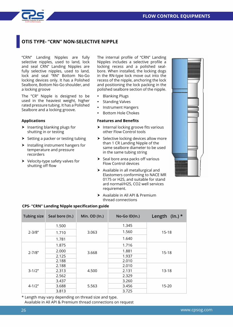
OTIS TYPE- “CRN” NON-SELECTIVE NIPPLE
Applications
h Inserting blanking plugs for shutting in or testing
h Setting a packer or testing tubing
h Installing instrument hangers for temperature and pressure recorders
h Velocity-type safety valves for shutting off flow
Features and Benefits
h Internal locking groove fits various other Flow Control tools
h Selective locking devices allow more than 1 CR Landing Nipple of the same sealbore diameter to be used in the same tubing string
h Seal bore area packs off various Flow Control devices
h Available in all metallurgical and Elastomers conforming to NACE MR 0175 or H2S, and suitable for stand ard normal/H2S, CO2 well services requirement.
h Available in All API & Premium thread connections
CPS- “CRN” Landing Nipple specification guide
Tubing size Seal bore (In.) Min. OD (In.) No-Go ID(In.) Length (In.) *
2-3/8”
1.500
3.063
1.345
15-181.5601.7101.6401.781
2-7/8”
1.875
3.668
1.716
15-182.000 1.8812.125 1.9372.188 2.010
3-1/2”2.188
4.5002.010
13-182.313 2.1312.562 2.329
4-1/2”3.437
5.5633.260
15-203.688 3.4563.813 3.725
* Length may vary depending on thread size and type. Available in All API & Premium thread connections on request
“CRN” Landing Nipples are fully selective nipples, used to land, lock and seal CRN” Landing Nipples are fully selective nipples, used to land, lock and seal “RN” Bottom No-Go locking devices only. It has a Polished Sealbore, Bottom No-Go shoulder, and a locking groove
The ”CR” Nipple is designed to be used in the heaviest weight, higher rated pressure tubing. It has a Polished Sealbore and a locking groove.
The internal profile of “CRN” Landing Nipples includes a selective profile a locking recess and a polished seal-bore. When installed, the locking dogs in the RN-type lock move out into the recess of the nipple, anchoring the lock and positioning the lock packing in the polished sealbore section of the nipple.
y Blanking Plugs y Standing Valves y Instrument Hangers y Bottom Hole Chokes

27www.cpsog.com
FLOW CONTROL EQUIPMENTS
“CX”, “CXN”, “CR” & “CRN” LOCK MANDRELS (BLANKING PLUGS)
The CPS Locking Mandrels are selective and Non Selective set lock mandrels designed to be landed down hole in a respective CX, CXN, CR, CRN Landing Nipple profile. The “CX” Lock is available with various sub surface plug assemblies and flow control accessories.
These Lock mandrels are runs with respective size model “CX” and “CR” Running Tools and can be retrieve by using model “GS” pulling Tool.
Applications
h Selected zones can be produced or shut in.
h To pressure test tubing.
h To isolate tubing for wellhead repair or removal
h To set hydraulic actuated Packers.
h Gauge hangers for bottomhole pressure/temperature surveys
h Positive locator for straddle systems
h Plugging under pressure
h Almost unlimited locations for setting and locking
h subsurface flow controls
Features and Benefits
h Retractable locking keys
h Locks designed to hold pressure from above or
h below or from sudden reversals
h Extra large ID for higher flow volumes Available in All API material grade.
h Available in material conforming to NACE MR 0175 or H2S, CO2 well environment services requirements.
CPS- “Lock Mandrel specification guide
Tubing size Seal bore (In.) Min. OD (In.) Lock Mandrel ID(In) (CX and CXN type)
Lock Mandrel ID(In) (CR and CRN type)
2-3/8”1.500
3.063 1.000.62
1.710 0.751.781 0.88
2-7/8”
1.875
3.668 1.380.882.000
2.1252.188 1.12
3-1/2”2.188
4.500 1.751.12
2.3132.562 1.38
4-1/2”
3.437
5.563 2.62
1.943.688 2.383.750 NA3.813 2.12

28 www.cpsog.com
FLOW CONTROL EQUIPMENTS
“CX”, “CXN”, “CR” & “CRN” STANDING VALVES
The CPS Standing Valves are selective and Non Selective set lock mandrels designed to be landed down hole in a respective CX, CXN, CR, CRN Landing Nipple prfile. CPS standing Valve allows the flow from tubing string during run in after landing over respective landing nipple a
ball drops to seat over the Seat Housing of standing Valve it allows the string to pressurize to set the packer inject the necessary chemicals.
These Lock mandrels are runs with respective size model “CX” and “CR” Running Tools and can be retrieve by using model “GS” pulling Tool.
Applications
h To pressure test tubing.
h To set hydraulic actuated Packers
h Positive locator for straddle systems
h Almost unlimited locations for setting and locking
h subsurface flow controls
Features and Benefits
h Retractable locking keys
h Locks designed to hold pressure from above or
h below or from sudden reversals
h Extra large ID for higher flow volumes Available in All API material grade.
h Available in material conforming to NACE MR 0175 or H2S, CO2 well environment services requirements.
CPS- “Lock Mandrel specification guide
Tubing size Seal bore (In.) Min. OD (In.) Lock Mandrel ID(In) (CX and CXN type)
Lock Mandrel ID(In) (CR and CRN type)
2-3/8”1.500
3.063 1.000.62
1.710 0.751.781 0.88
2-7/8”
1.875
3.668 1.380.882.000
2.1252.188 1.12
3-1/2”2.188
4.500 1.751.12
2.3132.562 1.38
4-1/2”
3.437
5.563 2.62
1.943.688 2.383.750 NA3.813 2.12
29www.cpsog.com
FLOW CONTROL EQUIPMENTS
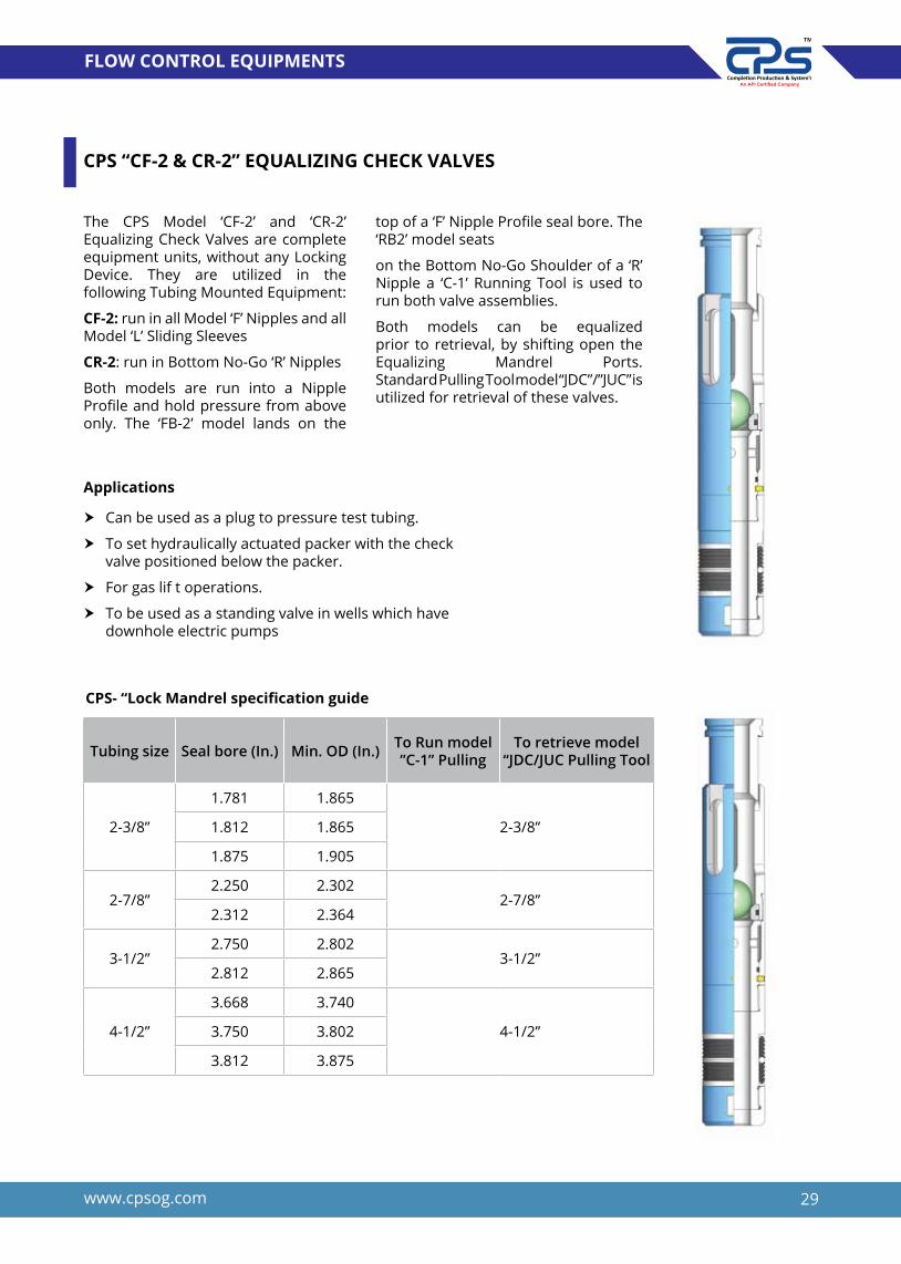
CPS “CF-2 & CR-2” EQUALIZING CHECK VALVES
The CPS Model ‘CF-2’ and ‘CR-2’ Equalizing Check Valves are complete equipment units, without any Locking Device. They are utilized in the following Tubing Mounted Equipment:
CF-2: run in all Model ‘F’ Nipples and all Model ‘L’ Sliding Sleeves
CR-2: run in Bottom No-Go ‘R’ Nipples
Both models are run into a Nipple Profile and hold pressure from above only. The ‘FB-2’ model lands on the
top of a ‘F’ Nipple Profile seal bore. The ‘RB2’ model seats
on the Bottom No-Go Shoulder of a ‘R’ Nipple a ‘C-1’ Running Tool is used to run both valve assemblies.
Both models can be equalized prior to retrieval, by shifting open the Equalizing Mandrel Ports. Standard Pulling Tool model “JDC”/”JUC” is utilized for retrieval of these valves.
Applications
h Can be used as a plug to pressure test tubing.
h To set hydraulically actuated packer with the check valve positioned below the packer.
h For gas lif t operations.
h To be used as a standing valve in wells which have downhole electric pumps
CPS- “Lock Mandrel specification guide
Tubing size Seal bore (In.) Min. OD (In.) To Run model ”C-1” Pulling
To retrieve model “JDC/JUC Pulling Tool
2-3/8”
1.781 1.865
2-3/8”1.812 1.865
1.875 1.905
2-7/8”2.250 2.302
2-7/8”2.312 2.364
3-1/2”2.750 2.802
3-1/2”2.812 2.865
4-1/2”
3.668 3.740
4-1/2” 3.750 3.802
3.812 3.875

30 www.cpsog.com
FLOW CONTROL EQUIPMENTS
CPS-NE NON ELASTOMERIC SLIDING SLEEVE
The Sliding Sleeve is a Downhole Tool normally screwed into the production tubing, allowing for communication between the tubing and the casing.
It is used to selectively produce zones in a multi-zone completion, stimulate and test zones, displace tubing or casing once the wellhead is installed, kill the well by circulation and allows for the circulation of treatment chemicals or agents.
The closing sleeve has replaceable, vee type upper and lower seals to ensure maximum sealing integrity for extended periods of time downhole. The upper sub is available in
selective/Non Selective and Otis (X, XN, R, RN)/Baker (F&R) type Nipple profile machined into it. This feature provides a profile to locate and lock into place various flow control devices which may be required from time to time.
The Sliding Sleeve is shift down to open and closes with the B Shifting Tool. The Shifting Tool can be dressed to either release automatically or to shear a pin to release.
Downward jarring opens the sleeve and upward jarring closes it. The Sliding Sleeve is designed so that normal wireline operations will not open or close it inadvertently.
Applications
h A specially designed diffuser ring made of high-strength thermoplas tic is critically spaced between the flow ports and the upper packing unit. This prevents damage to the upper packing unit during shifting by controlling the rush of fluid or gas, and lessens the likelihood of tool string damage by providing for slow equalization of high differentials.
h Mill slots replace drill holes as flow ports on both the housing and the insert to allow more flow area, reduce erosion and allow higher torque and tensile strengt through the sleeve
h The threat of galling is further reduced by coating critical metallic components with proprietary surface treatments.
h Available in All API material grades h Available in material conforming to
NACE MR 0175 or H2S, CO2 well envi ronment services requirements.
h Available in All API & premium thread connections and Elastomers type
h High chamfered smooth Equalizing Port does not damage the seals during the shifting of Inner Sleeve
h Top and Bottom Sub having High Finish seal Bore ID to accommodate isolation sleeve and other sealing devices
CPS Non Elastomeric Sliding Sleeve Technical specification guide
Seal bore(Inch)
Flow area (Ports) Sq. In
Flow Area (Min ID) Sq. In
Max OD (Inch)
Thread connection
Shifting Tool
Pressure Rating (Psi)
1.625 0.919 2.073 2.625 2-3/8” 1.625 “B” 9,0001.875 2.355 2.762 3.063 2-3/8” 1.875 “B”
9,0002.313 2.974 4.199 3.668 2-7/8” 2.313 “B”2.750
7.2125.940 4.281
3-1/2”2.750 “B”
80002.812 6.211 4.281 2.812 “B”3.312
11.4268.611 5.680
4-1/2”3.250“B”
7,5003.813 11.413 5.680 3.813 “B”4.312 10.598 14.596 6.400 5-1/2” 4.312 “B” 6,5004.562 16.337 7.500 4.562 “B”

31www.cpsog.com
FLOW CONTROL EQUIPMENTS
CPS-CL ELASTOMERIC SLIDING SLEEVE
The “CL” Sliding Sleeve is a Downhole Tool normally screwed into the production tubing, allowing for communication between the tubing and the casing. It is used to selectively produce zones in a multi-zone completion, stimulate and test zones, displace tubing or casing once the wellhead is installed, kill the well by circulation and allows for the circulation of treatment chemicals or agents. The closing sleeve has replacea-ble, Bonded seal type upper and lower seals to ensure maximum sealing integrity for extended periods of time
downhole. The upper sub is available in selective/Non Selective and Otis (X, XN, R, RN)/Baker (F&R) type Nipple profile machined into it. This feature provides a profile to locate and lock into place various flow control devices which may be required from time to time. The Sliding Sleeve is shift down to open and closes with the D-2 Shifting Tool. The Shifting Tool can be dressed to either release automatically or to shear a pin to release. Downward jarring opens the sleeve and upward jarring closes it. The Sliding Sleeve is designed so that normal wireline operations will not open or close it inadvertently.
Features & Benefits
CPS model “L” Elastomeric Sliding Sleeve Technical specification guide
h Mill slots replace drill holes as flow ports on both the housing and the insert to allow more flow area, reduce erosion and allow higher torque and tensile strength through the sleeve
h The threat of galling is further reduced by coating critical metallic components with proprietary sur face treatments.
h Available in All API material grades
h Available in material con forming to NACE MR 0175 or H2S, CO2 well environ ment services requirements.
h Available in All API & premium thread connections and Elastomers type
h Top and Bottom Sub having High Finish seal Bore ID to accommo date isolation sleeve and other sealing devices
h Ports can be closed without leaving any obstructions in the tubing once the shifting operation is completed
h The circulation ports can be carburised to prevent the damage during flow.
Seal bore(Inch)
Flow area (Ports) Sq. In
Flow Area (Min ID) Sq. In
Max OD (Inch)
Thread connection
Shifting Tool
Pressure Rating (Psi)
1.625 0.919 2.073 2.625 2-3/8 1.625” “D-2” 9,000
1.812 2.355 2.762 3.063 2-3/8 1.812” “D-2” 9,0001.875 2.355 2.762 3.063 2-3/8 1.875 “D-2”
9,0002.313 2.974 4.199 3.668 2-7/8 2.313 “D-2”2.750
7.2125.940 4.281
3-1/22.750 “D-2”
80002.812 6.211 4.281 2.812 “D-2”3.312 11.426 8.611 5.680 4-1/2 3.250 “D-2” 7,5003.813 11.413 5.680 3.813 “D-2”4.312 10.598 14.596 6.400 5-1/2 4.312 “D-2” 6,5004.562 16.337 7.500 4.562 “D-2”

32 www.cpsog.com
FLOW CONTROL EQUIPMENTS
SLIDING SLEEVE PACKOFF
Features & Benefits
The CPS Sliding Sleeve Packoff is designed to be attached to a lock type that matches the integral landing in the sliding sleeve. When sliding Sleeve malfunctioning, leaks fluid between casing annulus and tubing when closed, a Packoff used to isolates this zone without pulling up the entire tubing string.
Packoff assemblies are used to Sliding Sleeve ports and prevent migration fluids between tubing and casing annulus, as well as provide the path for flow production fluids to the surface.
CPS Sliding Sleeve Packoff consist of a subassembly called Lock mandrel having Baker/Otis type lock which sets inside the matching Landing Nipple lock profile of Upper Sub. This also
consists of two seal stack unit suitable to well bore environment, the Upper seal unit seal inside the Upper sub of and Lower seal set inside the Bottom Sub of Sliding Sleeve.
Since the Sliding sleeve is hollow it, it will still allow flow up the tubing and provide the uniform path for the other Wireline job.
CPS Sliding Sleeve Packoff consist of a Equalizing Plug/ Knockout plug which break by Equalizing Prong during pulling to equalize the pressure across the Sleeve at the begin.
Downward jarring set the lock mandrel by using “CPSX” Running Tool run by Wireline/Slickline. The tool ids retrieved by “CPSGS” Pulling Tool.
h Blanking off the ports in a Sliding Sleeve.
h Shutting off flow from casing zone. h Allowing flow from lower Zone. h Straddles and Packs off above
and below flow ports h Pressure is equalized by a
Equalizing Plug before pulling out the tool.
h Adaptable to most of Manufacturers lock.
h Adaptable to most of Manufacturers Sliding Sleeves type.
h Available in All API material grades h Available in material conforming to
NACE MR 0175 or H2S, CO2 well environment services requirements.
h Available in All Elastomers type. h Validated to withstand 7,500 psi
differential pressure and 300° F Temperature
h High chamfered smooth Equalizing Port does not damage the seals during the shifting of Inner Sleeve
CPS Sliding Sleeve Pack Off Technical specification guide
SSD size
Lock mandrel size
Max. Tool OD
Min. Tool
Running/Pulling Tool
Pressure Rating (Psi) Temperature
2-3/8”1.625 1.625 0.75 1.625 9,000
300°F
1.875 1.875 1.00 1.875 9,000
2-7/8” 2.313 2.313 1.38 2.313
3-1/2”2.750 2.750
1.752.750
8,0002.812 2.812 2.812
4-1/2”3.312 3.312 2.12 3.250
7,5003.813 3.813 2.62 3.813
5-1/2” 4.312 4.312 4.312 7,5004.562 4.562 3.12 4.562

33www.cpsog.com
FLOW CONTROL EQUIPMENTS
CPS-X RUNNING TOOL
The X-Line Selective Running Tool is designed to install subsurface controls using a type X Locking Mandrel. The selective features of the X Running Tool allow the operator to install the downhole device in a pre-determined CX Landing Nipple by adjusting the tool into the selective position. If the subsurface control is to be installed in the upper most landing nipple, the locking
mandrel may be run with the keys in the control or location position.
In addition to setting the X Locking Mandrel, the Running Tool may be used to locate WX Landing Nipples.
The R Selective Running Tool, similar in design, is available in a wide range of sizes to install Type R Locking Mandrels in heavy weight tubings.
Sizes 1.710 1.781 1.875 2.125
Fishing neck OD 1.188 1.375 1.375 1.375
Connection 15/16-10 15/16-10 15/16-10 15/16-10
Bottom thread 3/8-16 1/2-13 1/2-13 1/2-13
Length 30.063 29.313 29.313 29.313
Shear Pin 3/16 x 1-1/8” 1/4x 1-1/2” 1/4x 1-1/2” 1/4x 1-1/2”
OD Dogs retracted 1.640 1.750 1.750 2.063
OD Dogs Expanded 1.760 1.828 1.937 2.165
Fishing Neck Engages 1-1/16 1-3/4 1-3/4 1-3/4
Sizes 2.188 2.313 2.562
Fishing neck OD 1-3/4 1-3/4 1-3/4
Connection 15/16-10 15/16-10 15/16-10
Bottom thread 5/8-11 5/8-11 5/8-11
Length 29.313 29.313 30.250
Shear Pin 1/4” x 1-7/8” 1/4” x 1-7/8” 1/4” x 1-7/8”
OD Dogs retracted 2.175 2.175 2.500
OD Dogs Expanded 2.297 2.359 2.671
Fishing Neck Engages 1.812 1.812 1.812

34 www.cpsog.com
FLOW CONTROL EQUIPMENTS
CPS-GS PULLING TOOL
The “GS” Pulling Tool is a wireline service tool designed to retrieve flow control devices from well bore. The “GS” Pulling Tool is designed to engage an internal type fishing neck. The tool is available in a wide range of sizes, for standard or H2S service.
The “GS” Pulling Tool is designed to be released from the downhole device by downward jarring.
CPS GS Pulling Tool Technical Specification Guide
‘GS’ PULLING TOOL
NominalSize (in)
ProngConn. Fishing Neck Max. O.D.
(in)F/N O.D.
(in)Top
Conn.Reach
(in)
Box I.D. Guide (in)
1-1/4 3/8 -16 0.880 1.160 1.000 5/8-11 UNC 1.08
1-1/2-1-3/4 1/2-13 1.060 1.470 1.187 15/16-10 UN 1.62
2 1/2-13 1.380 1.750 1.375 15/16-10 UN 1.62
2 1/2-13 1.380 1.810 1.375 15/16-10 UN 1.62
2-1/2 5/8-11 1.810 2.160 1.750 15/16-10 UN 1.62
2-1/2 5/8-11 1.810 2.160 1.750 15/16-10 UN 1.62
3 5/8-11 2.310 2.720 2.313 1-1/16-10 UN 1.62
3-1/2 1-3/8-12 2.620 3.110 2.313 1-1/16-10 UN 1.62
4 2-1/8-12 3.120 3.620 2.313 1-1/16-10 UN 1.62
5 2-1/2-10 4.000 4.500 3.125 1-1/16-10 UN 1.82
6 2-3/4-10 4.750 5.560 3.125 1-1/16-10 UN 1.86
7 3-5/8-10 5.250 5.830 3.125 1-1/16-10 UN 1.86
7 3-5/8-10 5.250 5.880 3.125 1-1/16-10 UN 1.86
35www.cpsog.com
FLOW CONTROL EQUIPMENTS
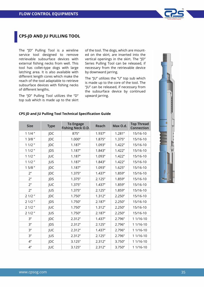
CPS-JD AND JU PULLING TOOL
The “JD” Pulling Tool is a wireline service tool designed to remove retrievable subsurface devices with external fishing necks from well. This tool has collet-type dogs with large latching area. It is also available with different length cores which make the reach of the tool adaptable to retrieve subsurface devices with fishing necks of different lengths.
The “JD” Pulling Tool utilizes the “D” top sub which is made up to the skirt
of the tool. The dogs, which are mount-ed on the skirt, are inserted into the vertical openings in the skirt. The “JD” Series Pulling Tool can be released, if necessary from the retrievable device by downward jarring.
The “JU” utilizes the “U” top sub which is made up to the core of the tool. The “JU” can be released, if necessary from the subsurface device by continued upward jarring.
CPS JD and JU Pulling Tool Technical Specification Guide
Size Type To Engage Fishing Neck O.D. Reach Max O.d. Top Thread
Connection
1 1/4 ’’ JDC 875’’ 1.937’’ 1.281’’ 15/16-10
1 3/8 ’’ JDC 1.000’’ 1.875’’ 1.375’’ 15/16-10
1 1/2 ’’ JDC 1.187’’ 1.093’’ 1.422’’ 15/16-10
1 1/2 ’’ JDS 1.187’’ 1.843’’ 1.422’’ 15/16-10
1 1/2 ’’ JUC 1.187’’ 1.093’’ 1.422’’ 15/16-10
1 1/2 ’’ JUS 1.187’’ 1.843’’ 1.422’’ 15/16-10
1 5/8 ’’ JDC 1.187’’ 1.093’’ 1.625’’ 15/16-10
2’’ JDC 1.375’’ 1.437’’ 1.859’’ 15/16-10
2’’ JDS 1.375’’ 2.125’’ 1.859’’ 15/16-10
2’’ JUC 1.375’’ 1.437’’ 1.859’’ 15/16-10
2’’ JUS 1.375’’ 2.125’’ 1.859’’ 15/16-10
2 1/2 ’’ JDC 1.750’’ 1.312’’ 2.250’’ 15/16-10
2 1/2 ’’ JDS 1.750’’ 2.187’’ 2.250’’ 15/16-10
2 1/2 ’’ JUC 1.750’’ 1.312’’ 2.250’’ 15/16-10
2 1/2 ’’ JUS 1.750’’ 2.187’’ 2.250’’ 15/16-10
3’’ JDC 2.312’’ 1.437’’ 2.796’’ 1 1/16-10
3’’ JDS 2.312’’ 2.125’’ 2.796’’ 1 1/16-10
3’’ JUC 2.312’’ 1.437’’ 2.796’’ 1 1/16-10
3’’ JUS 2.312’’ 2.125’’ 2.796’’ 1 1/16-10
4’’ JDC 3.125’’ 2.312’’ 3.750’’ 1 1/16-10
4’’ JUC 3.125’’ 2.312’’ 3.750’’ 1 1/16-10


We Know Your Well Very Well..
COMPLETIONEQUIPMENT
-BRIDGE PLUG
- CEMENT RETAINER


39www.cpsog.com
COMPLETION EQUIPMENT
CPS-D & DA PERMANENT SEAL BORE PACKER
The CPS-D Permanent Seal Bore Production Packer is a versatile tool that can be used for single or multiple zone completions. The CPS-D is ideally suited for wells where high pressure, temperatures and corrosive fluids are anticipated. The packer is available in a variety of elastomers and seal bore materials to meet the most hostile downhole environments. The CPS-D is recommended for injection, stimulation, testing
The Model “D” provides with Blank Bottom Guide and model DB bottom guide provides with threaded (Box or pin) distinguishes it from the Signature D. The Model PB guide can be threaded to accept a mill-out extension, seal-bore extension, or tubing.
Applications
CPS-DA
Features and Benefits
h Permanent Gravel-Pack Packing
h Vertical, Deviated and Horizontal wellbores
h Permanent sealbore production or isolation packing
h Designed for ease of milling
h Components keyed for milling.
h Wireline or Hydraulic set
h Unique interlocking expandable metal backup rings contact casing, creating a positive barrier to pack ing element extrusion
h Smooth, continuous ID sealing bore
h Two opposed sets of full-circle, full-strength slips ensure packer will remain properly set
h Packing element resists swab-off and packs off securely when packer is set
h Available in all metallurgical and Elastomers conforming to NACE MR 0175 or H2S, and suitable for standard normal/H2S, CO2 well services requirements.
h Available in All API & Premium thread connections
CPS-D

40 www.cpsog.com
COMPLETION EQUIPMENT
CPS -D Permanent Production Packer Specification Guide
CasingRecommended
casing ID size (In.)
Packer max
OD (In.)
Min Sealbore ID of
Packer (in.)
Min IDthru SealsAssy. (In.)
Baker E-4Setting
Tool
Model “H”Hyd. Setting
Tool SizeSize(In.)
Weight(lbs/ft)
4-1/29.5-13.5 3.920-4.090 3.812 2.687 1.938
Size 10 2.37511.6-15.1 3.826-4.000 3.593 1.968 0.984
511.5-13 4.494-4.560 4.250 2.687
1.938Size 20
2.37515-20.8 4.156-4.408 3.960 2.687 Size 20
5-1/2
13-17 4.892-5.044 4.560 2.687
1.938 Size 20
2.375
20-23 4.670-4.778 4.430 2.6872.875
23-26 4.548-4.670 4.330 2.687
6-5/820-32 5.675-6.049 5.468
2.687 1.938 Size 20 2.87524-32 5.675-5.921 5.350
7
17-20 6.456-6.538 6.1873.250 and
2.687
2.375 and
1.938 Size 20 2.875
20-29 6.184-6.456 5.875
23-32 6.094-6.366 5.687
32-42.7 5.750-6.094 5.468
38-46.4 5.626-5.920 5.350
7 5/8
24-33.7 6.765-7.025 6.375 3.250 and
2.687
2.375 and
1.938 Size 20 2.87533.7-39 6.625-6.765 6.187
45.3-51.2 6.251-6.435 5.875
8-5/824-36 7.825-8.097 7.500
3.875 and 4
2.468 and
2.985Size 20 2.875
36-49 7.511-7.825 7.125
9-5/8 36-53.5 8.535-8.921 8.125 4.750 and 4
3.875 and2.985
Size 20 2.875
Model CPS-DA Permanent Production Packer specification guide
**Packer for these casing sizes also available with other seal bore and Seal assembly bore on order.
Casing Size
Upper Seal Bore (In.)
Min ID Through seal assy.(In)
Lower Seal Bore(in)** Min ID Through seal assy. (In.)
4-1/2” 2.500 1.875 1.968 1.3125-1/2” 3.250 2.500 2.688 1.9686-5/8” 4.000 3.250 3.250 2.406
7” 4.000 3.250 3.250 2.4067-5/8” 4.000 3.250 3.250 2.4069-5/8” 6.000 4.875 4.750 3.875

41www.cpsog.com
COMPLETION EQUIPMENT
CPS-F-1 & FA-1 PERMANENT SEAL BORE PACKER
CPS-F-1 and production packers are the big-bore versions of the high-per-forming D retainer production packer. They feature the largest bore through any drillable packer.
CPS “FA-1” production packer provides all the versatility and high-per-formance characteristics of the CPS-D but with a larger sealing bore at the upper end. It’s frequently used in complex multiple-string completions or when large tubing is run and it is necessary to maintain clearance
through the packer. The “FA-1” is also used when the seal nipple is required to be compatible with the tubing ID.
The Model CPS-F-1 and CPS “FA-1” provides with Blank Bottom Guide and model CPS-FB-1 and “FAB-1” bottom guide provides with threaded (Box or pin) distinguishes it from the Signature CPS-F-1 and FA-1. The Model B-1 guide can be threaded to accept a mill-out extension, seal-bore extension, or tubing.
Applications
h Permanent Gravel-Pack Packing
h Vertical, Deviated and Horizontal wellbores
h Permanent sealbore production or isolation packing
Features and Benefits
h Designed for ease of milling
h Components keyed for milling.
h Wireline or Hydraulic set
h CPS “FA-1” have larger diameter upper seal bore accepts an anchor seal assembly to maximize thru bore
h Unique interlocking expandable metal backup rings contact casing, creating a positive barrier to packing element extrusion
h Smooth, continuous ID sealing bore
h Two opposed sets of full-circle, full-strength slips ensure packer will remain properly set
h Packing element resists swab-off and packs off securely when packer is set
h Available in all metallurgical and Elastomers conforming to NACE MR 0175 or H2S, and suitable for standard normal/H2S, CO2 well services requirements.
h Available in All API & Premium thread connections
CPS-FA-1
CPS-F-1

42 www.cpsog.com
COMPLETION EQUIPMENT
CPS-F-1 Permanent Production Packer specification guide
CasingRecommended casing ID
size (In.)
Packer max
OD (In.)
Min Sealbore ID of
Packer (in.)
Min IDthru SealsAssy. (In.)
Baker E-4Setting
Tool
Model “H”Hyd. Setting
Tool SizeSize(In.)
Weight(lbs/ft)
4-1/29.5-13.5 3.920-4.090 3.812 2.687 1.938
Size 10 2.37511.6-15.1 3.826-4.000 3.593 1.968 0.984
511.5-13 4.494-4.560 4.250 2.687
1.938Size 20
2.37515-20.8 4.156-4.408 3.960 2.687 Size 20
5-1/2
13-17 4.892-5.044 4.560 2.687
1.938 Size 20
2.375
20-23 4.670-4.778 4.430 2.6872.875
23-26 4.548-4.670 4.330 2.687
6-5/820-32 5.675-6.049 5.468
2.687 1.938 Size 20 2.87524-32 5.675-5.921 5.350
7
17-20 6.456-6.538 6.1873.250 and
2.687
2.375 and
1.938 Size 20 2.875
20-29 6.184-6.456 5.875
23-32 6.094-6.366 5.687
32-42.7 5.750-6.094 5.468
38-46.4 5.626-5.920 5.350
7 5/8
24-33.7 6.765-7.025 6.375 3.250 and
2.687
2.375 and
1.938 Size 20 2.87533.7-39 6.625-6.765 6.187
45.3-51.2 6.251-6.435 5.875
8-5/824-36 7.825-8.097 7.500
3.875 and 4
2.468 and
2.985Size 20 2.875
36-49 7.511-7.825 7.125
9-5/8 36-53.5 8.535-8.921 8.125 4.750 and 4
3.875 and2.985
Size 20 2.875
Model CPS-FA-1 Permanent Production Packer specification guide
**Packer for these casing sizes also available with other seal bore and Seal assembly bore on order.
Casing Size
Upper Seal Bore (In.)
Min ID Through seal assy.(In)
Lower Seal Bore(in)**
Min ID Through seal assy. (In.)
4-1/2” 2.500 1.875 1.968 1.3125-1/2” 3.250 2.500 2.688 1.9686-5/8” 4.000 3.250 3.250 2.406
7” 4.000 3.250 3.250 2.4067-5/8” 4.000 3.250 3.250 2.4069-5/8” 6.000 4.875 4.750 3.875

43www.cpsog.com
COMPLETION EQUIPMENT
CPS-SB & SAB HYDRAULIC SET PERMANENT SEAL BORE PACKER
The CPS-SB is a hydraulic-set is permanent packer set by applied hydraulic pressure against a temporary plugging device set below the packer.
The “CPS-SAB” has a large upper seal bore allowing the use of an anchor latch to create the largest possible I.D. through the packer and seals for
completions requiring large tubing sizes.
It is ideal for highly deviated and/or single-trip production and injection applications. This packer includes a one-piece mandrel, which eliminates a potential leak path. It has a low profile for greater running clearance to help reduce problems that may occur when running in highly deviated and horizontal wells
Applications
h Permanent Gravel-Pack Packing
h Vertical, Deviated and Horizontal wellbores
h Permanent sealbore production or isolation packing
Features and Benefits
h Designed for ease of milling
h Components keyed for milling.
h Hydraulic set
h Solid construction enables faster run-in without fear of impact damage or premature setting, making significant rig-time savings possible
h Unique interlocking expandable metal backup rings contact casing, creating a positive barrier to packing element extrusion
h Smooth, continuous ID sealing bore
h Two opposed sets of full-circle, full-strength slips ensure packer will remain properly set
h Packing element resists swab-off and packs off securely when packer is set
h Available in all metallurgical and Elastomers conforming to NACE MR 0175 or H2S, and suitable for standard normal/H2S, CO2 well services requirements.
h Available in All API & Premium thread connections

44 www.cpsog.com
COMPLETION EQUIPMENT
CPS-SB Permanent Production Packer specification guide
CasingRecommended casing ID
size (In.)
Gauge OD of Packer (Inch)
Min. Sealbore ID of Packer
(Inch)Min ID thru Seals (Inch)Size Weight
(lbs/ft)
5“ 15-21 4.126-4.408 3.968 1.968 1.312
5-1/2” 13-17 4.892-5.125 4.500 2.500 1.865
6-5/8”17-20 6.049-6.175 5.687 3.250 2.406
17-32 5.675-6.175 5.468 3.250 2.406
7”
17-20 6.456-6.538 6.187 3.250
2.40620-32 6.094 – 6.456 5.687 3.250
32-38 5.920 – 6.094 5.468 3.250
7-5/8”24-33.7 6.765-7.025 6.375 3.250
2.40633.7-39 6.625-6.765 6.187 3.250
8-5/8” 24-36 7.825-8.097 7.500 4.000 3.000
9-5/8” 32.3-53.0 8.535-9.001 8.125 4.750 3.000
Model CPS-SAB Permanent Production Packer specification guide
**Packer for these casing sizes also available with other seal bore and Seal assembly bore on order.
Casing Size
Upper Seal Bore (In.)
Min ID Through seal assy.(In)
Lower Seal Bore(in)**
Min ID Through seal assy. (In.)
4-1/2” 2.500 1.875 1.968 1.3125-1/2” 3.250 2.500 2.688 1.9686-5/8” 4.000 3.250 3.250 2.406
7” 4.000 3.250 3.250 2.4067-5/8” 4.000 3.250 3.250 2.4069-5/8” 6.000 4.875 4.750 3.875
45www.cpsog.com
COMPLETION EQUIPMENT
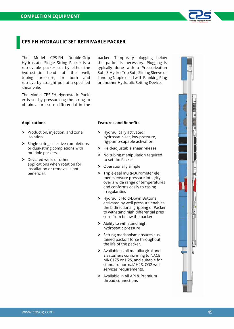
CPS-FH HYDRAULIC SET RETRIVABLE PACKER
The Model CPS-FH Double-Grip Hydrostatic Single String Packer is a retrievable packer set by either the hydrostatic head of the well, tubing pressure, or both and retrieve by straight pull at a specified shear vale.
The Model CPS-FH Hydrostatic Pack-er is set by pressurizing the string to obtain a pressure differential in the
packer. Temporary plugging below the packer is necessary. Plugging is typically done with a Pressurization Sub, E-Hydro-Trip Sub, Sliding Sleeve or Landing Nipple used with Blanking Plug or another Hydraulic Setting Device.
Applications
h Production, injection, and zonal isolation
h Single-string selective completions or dual-string completions with multiple packers.
h Deviated wells or other applications when rotation for installation or removal is not beneficial.
Features and Benefits
h Hydraulically activated, hydrostatic-set, low-pressure, rig-pump-capable activation
h Field-adjustable shear release
h No tubing manipulation required to set the Packer
h Operationally simple
h Triple-seal multi-Durometer ele ments ensure pressure integrity over a wide range of temperatures and conforms easily to casing irregularities
h Hydraulic Hold-Down Buttons activated by well pressure enables the bidirectional gripping of Packer to withstand high differential pres sure from below the packer.
h Ability to withstand high hydrostatic pressure
h Setting mechanism ensures sus tained packoff force throughout the life of the packer.
h Available in all metallurgical and Elastomers conforming to NACE MR 0175 or H2S, and suitable for standard normal/ H2S, CO2 well services requirements.
h Available in All API & Premium thread connections

46 www.cpsog.com
COMPLETION EQUIPMENT
CPS-FH Hydraulic set retrievable Packer specification guide
CasingRecommended casing ID size
Gauge OD of Packer (In)
Min. ID of Packer (Inch)
**Thread connectionSize Weight(lbs/ft)
4-1/2” 9.5-13.5 3.910 - 4.090 3.800 1.9
2-3/8” EU5”
15-18 4.250 - 4.408 4.125 1.9
11.5-15 4.408 – 4.560 4.250 1.9
5-1/2”
13.0-15.5 4.950 - 5.190 4.781
2 2-3/8” EU15.5-20.0 4.778- 4.950 4.641
20.0-23.0 4.625- 4.778 4.500
26 4.500 4.250
6-5/8”
20 - 24 5.921- 6.049 5.6612 or
2.42
2-3/8” & 2-7/8” EU24 - 28 5.791- 5.921 5.625
28 - 32 5.675 - 5.791 5.484
7”
17.0-23.0 6.366- 6.538 6.154
2.42or
3.00
2-7/8” & 3-1/2” EU
23.0-26.0 6.276- 6.366 6.078
26.0-29.0 6.184- 6.276 5.968
26.0-32.0 6.094- 6.276 5.891
32.0-35.0 6.004- 6.094 5.817
7 5/8”
20-24 7.025- 7.125 6.8102.42or
3.00
2-7/8” & 3-1/2” EU24-29.7 6.800-7.030 6.670
33.7-39 6.625- 6.765 6.453
9-5/8”40-47 8.681 – 8.835 8.463 3.00
or3.95
3-1/2”& 4-1/2” EU47-53.5 8.535 - 8.681 8.354
47www.cpsog.com
COMPLETION EQUIPMENT
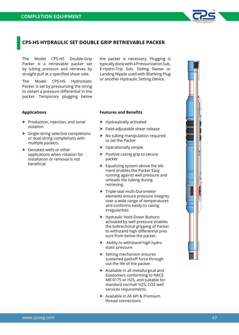
CPS-HS HYDRAULIC SET DOUBLE GRIP RETRIEVABLE PACKER
The Model CPS-HS Double-Grip Packer is a retrievable packer set by tubing pressure and retrieves by straight pull at a specified shear vale.
The Model CPS-HS Hydrostatic Packer is set by pressurizing the string to obtain a pressure differential in the packer. Temporary plugging below
the packer is necessary. Plugging is typically done with a Pressurization Sub, E-Hydro-Trip Sub, Sliding Sleeve or Landing Nipple used with Blanking Plug or another Hydraulic Setting Device.
Applications
h Production, injection, and zonal isolation
h Single-string selective completions or dual-string completions with multiple packers.
h Deviated wells or other applications when rotation for installation or removal is not beneficial.
Features and Benefits
h Hydraulically activated
h Field-adjustable shear release
h No tubing manipulation required to set the Packer
h Operationally simple
h Positive casing grip to secure packer
h Equalizing system above the ele ment enables the Packer Easy running against well pressure and unloads the tubing during retrieving.
h Triple-seal multi-Durometer elements ensure pressure integrity over a wide range of temperatures and conforms easily to casing irregularities
h Hydraulic Hold-Down Buttons activated by well pressure enables the bidirectional gripping of Packer to withstand high differential pres sure from below the packer.
h Ability to withstand high hydro static pressure
h Setting mechanism ensures sustained packoff force through out the life of the packer.
h Available in all metallurgical and Elastomers conforming to NACE MR 0175 or H2S, and suitable for standard normal/ H2S, CO2 well services requirements.
h Available in All API & Premium thread connections

48 www.cpsog.com
COMPLETION EQUIPMENT
CPS-HS Hydraulic set retrievable Packer specification guide
CasingRecommended casing ID size
Gauge OD of Packer (In)
Min. ID of Packer (Inch)
**Thread connectionSize Weight(lbs/ft)
4-1/2” 9.5-13.5 3.910 - 4.090 3.800 1.9
2-3/8” EU5”
15-18 4.250 - 4.408 4.125 1.9
11.5-15 4.408 – 4.560 4.250 1.9
5-1/2”
13.0-15.5 4.950 - 5.190 4.781
2 2-3/8” EU15.5-20.0 4.778- 4.950 4.641
20.0-23.0 4.625- 4.778 4.500
26 4.500 4.250
6-5/8”
20 - 24 5.921- 6.049 5.6612 or
2.42
2-3/8” & 2-7/8” EU24 - 28 5.791- 5.921 5.625
28 - 32 5.675 - 5.791 5.484
7”
17.0-23.0 6.366- 6.538 6.154
2.42or
3.00
2-7/8” & 3-1/2” EU
23.0-26.0 6.276- 6.366 6.078
26.0-29.0 6.184- 6.276 5.968
26.0-32.0 6.094- 6.276 5.891
32.0-35.0 6.004- 6.094 5.817
7 5/8”
20-24 7.025- 7.125 6.8102.42or
3.00
2-7/8” & 3-1/2” EU24-29.7 6.800-7.030 6.670
33.7-39 6.625- 6.765 6.453
9-5/8”40-47 8.681 – 8.835 8.463 3.00
or3.95
3-1/2”& 4-1/2” EU47-53.5 8.535 - 8.681 8.354

49www.cpsog.com
COMPLETION EQUIPMENT
CPS-HP HYDRAULIC SET RETRIEVABLE PRODUCTION PACKER
The CPS-HP hydraulics set retrievable production Packer is set by hydraulic pressure on the tubing string and retrieved by straight pull. The packer features no downward mandrel movement during setting so it can be run in stacked applica-tions. This feature also eliminates the need for staggering the setting pressures between packers, since all packers in the well can be reliably set
simultaneously. The CPS-HP packer is ideally suited for running below dual string packers as well, and may be set after the well has been flanged up.
With the CPS-HP packer, the tubing may be landed in tension, compression or neutral, in deviated and horizontal holes. It may also be run in applications using gas lift mandrels and safety valves where tubing rotation is not desirable.
Applications
h Production
h Injection
h Offshore completions with safety valves, gas lift mandrels
h Horizontal and deviated wells
h Stacked and dual string applications
h Zonal Isolation
h Coil tubing completions
Features and Benefits
h Adjustable straight pull release
h Can be landed in tension, neutral or compression
h No downward mandrel movement for stacked applications
h Elastomer and metallurgical options available for hostile
h environments
h Compensating piston counteracts pressure from below
h Works with tubing disconnect tools and expansion joints
h Can be run with a T-2 On-Off Tool and wireline plug to act as a bridge plug Ideal for use with fiber glass tubing, or coil tubing.
h Available in all metallurgical and Elastomers conforming to NACE MR 0175 or H2S, and suitable for standard normal/ H2S, CO2 well services requirements.
h Available in All API & Premium thread connections
50 www.cpsog.com
COMPLETION EQUIPMENT
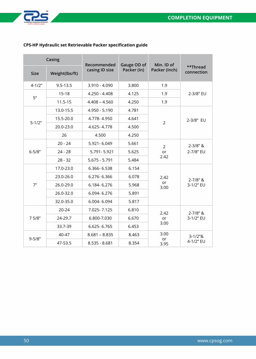
CPS-HP Hydraulic set Retrievable Packer specification guide
CasingRecommended casing ID size
Gauge OD of Packer (In)
Min. ID of Packer (Inch)
**Thread connectionSize Weight(lbs/ft)
4-1/2” 9.5-13.5 3.910 - 4.090 3.800 1.9
2-3/8” EU5”
15-18 4.250 - 4.408 4.125 1.9
11.5-15 4.408 – 4.560 4.250 1.9
5-1/2”
13.0-15.5 4.950 - 5.190 4.781
2 2-3/8” EU15.5-20.0 4.778- 4.950 4.641
20.0-23.0 4.625- 4.778 4.500
26 4.500 4.250
6-5/8”
20 - 24 5.921- 6.049 5.6612 or
2.42
2-3/8” & 2-7/8” EU24 - 28 5.791- 5.921 5.625
28 - 32 5.675 - 5.791 5.484
7”
17.0-23.0 6.366- 6.538 6.154
2.42or
3.00
2-7/8” & 3-1/2” EU
23.0-26.0 6.276- 6.366 6.078
26.0-29.0 6.184- 6.276 5.968
26.0-32.0 6.094- 6.276 5.891
32.0-35.0 6.004- 6.094 5.817
7 5/8”
20-24 7.025- 7.125 6.8102.42or
3.00
2-7/8” & 3-1/2” EU24-29.7 6.800-7.030 6.670
33.7-39 6.625- 6.765 6.453
9-5/8”40-47 8.681 – 8.835 8.463 3.00
or3.95
3-1/2”& 4-1/2” EU47-53.5 8.535 - 8.681 8.354

51www.cpsog.com
COMPLETION EQUIPMENT
CPS-TS TENSION SET PACKER
The CPS-TS tension packer is a compact, economical, retrievable packer. Primarily used in waterflood applications, it can also be used for production, treating operations, and when a set-down packer is impractical. And because the CPS-TS is tension-set, it is ideally suited for shallow wells where set-down weight is not available.
The packer can be set by applying right hand torque to the tubing. While the right hand torque applied, the tubing is picked up and appropriate amount of tension is applied to set the Packer. Packer can be released by simply picking up the tubing. The shear release mechanism uses slotted brass shear screws which can be easily accessed for adjustment in the field.
Applications
h Production
h Injection
h Completion, Well servicing and treating operation
Features and Benefits
h Case Hardened Drag blocks make for extended life.
h Fullbore Mandrel.
h Automatic J-slot provides for easy release.
h Incorporates both a rotational and a field adjustable shear safety release.
h Uses proven one-piece packing element.
h Available in all metallurgical and Elastomers conforming to NACE
h MR 0175 or H2S, and suitable for standard normal/ H2S, CO2 well
h Services requirements.
h Available in All API & Premium thread connections
CasingRecommended casing ID size
Gauge OD of Packer (In)
Min. ID of Packer (Inch)
**Thread connectionSize Weight(lbs/ft)
5-1/2”
13.0-14.0 5.012 4.813 2.40 2-3/8” &
2-7/8” EUE14.0-20.0 4.778- 5.012 4.625 2.4020.0-23.0 4.670- 4.778 4.500 2.4023.0-26.0 4.548- 4.670 4.406 2.40
2-7/8” & 3-1/2” EUE7”
17.0-20.0 6.456-6.538 6.250 3.0017.0-26.0 6.276 - 6.538 6.000 3.0026.0-32.0 6.094 - 6.276 5.875 3.0029.0-35.0 6.004 - 6.184 5.812 3.00
35.0 6.004 5.812 3.00
9-5/8”32.3-43.5 8.755 - 9.001 8.500 4.00
4-1/2” EUE43.5-53.5 8.535- 8.755 8.250 4.00

52 www.cpsog.com
COMPLETION EQUIPMENT
CasingRecommended casing ID size
Gauge OD of Packer (In)
Min. ID of Packer (Inch)
**Thread connectionSize Weight(lbs/ft)
5-1/2”
13.0-14.0 5.012 4.813 2.40 2-3/8” &
2-7/8” EUE14.0-20.0 4.778- 5.012 4.625 2.40
20.0-23.0 4.670- 4.778 4.500 2.40
23.0-26.0 4.548- 4.670 4.406 2.40
2-7/8” & 3-1/2” EUE
7”
17.0-20.0 6.456-6.538 6.250 3.00
17.0-26.0 6.276 - 6.538 6.000 3.00
26.0-32.0 6.094 - 6.276 5.875 3.00
29.0-35.0 6.004 - 6.184 5.812 3.00
35.0 6.004 5.812 3.00
9-5/8”32.3-43.5 8.755 - 9.001 8.500 4.00
4-1/2” EUE43.5-53.5 8.535- 8.755 8.250 4.00
The packer can be set by applying right hand torque to the tubing. While the right hand torque applied, the tubing is lowered and appropriate amount of set down weight is applied to set the Packer. Packer can be released by simply picking up the tubing. The shear release mechanism uses slotted brass shear screws which can be easily accessed for adjustment in the field.
Features and Benefits
CPS-CS COMPRESSION SET PACKER
The CPS-CS compression pack-er is a compact, economical, retrievable packer. Primarily used in waterflood applications, it can also be used for production, treating operations, and when a set-down packer is impractical. And because the CPS-TS is compression-set, it is ideally suited for shallow wells where set-down weight is not available.
Applications
h Production
h Injection
h Completion, Well servicing and treating operation
h Case Hardened Drag blocks make for extended life.
h Fullbore Mandrel
h Automatic J-slot provides for easy release.
h Incorporates both a rotational and a field adjustable shear safety release.
h Uses proven one-piece packing element.
h Available in all metallurgical and Elastomers conforming to NACE MR 0175 or H2S, and suitable for standard normal/ H2S, CO2 well services requirements.
h Available in All API & Premium thread connections

53www.cpsog.com
COMPLETION EQUIPMENT
CPS-”CR-3”MECHANICAL SET RETRIEVABLE PACKER
The CR-3 Packer is a Mechanical compression-set production packer intended for a broad range of production applications. It is a compression-set packer, suitable for stimulation and treating applications in a single/double-grip configuration. Applications in which excessive bottomhole pressures have been depleted, a single-grip
version can be used as an economical production packer.
It is set by applying a quarter turn to the right at the packer followed by set down weight. The packer is released by straight pick up to open the large by-pass allowing equalization. After equalization, the packing elements release reducing tendency of swabbing when pulling out of wellbore.
Applications
h Squeeze Cementing
h Acidizing
h Formation fracturing
h Well Testing & Servicing
Features and Benefits
h Holds high pressure differentials from above or below.
h The J-slot design allows easy setting and releasing; 1/4 turn right-hand set, and straight pull release.
h Reliable Three-piece, dual-durometer sealing elements provide better pack off Bypass valve is below upper slips so the debris is washed from slips when the valve is opened Benefits.
h Bypass valve opens before upper slips are released
h Available in material conforming to NACE MR 0175 or H2S, CO2 well environment services requirements.
h Available in All API & premium thread connections and Elastomers type

54 www.cpsog.com
COMPLETION EQUIPMENT
CR-3 PACKER Technical information
CasingRecommended casing ID size
Max Gauge OD of Packer
(In.)
Min. ID of Packer (Inch)
Thread connectionSize Weight(lbs/ft)
4-1/29.5-13.5 3.920-4.090 3.786 1.938
2-3/8” EUE15.1 3.826 3.620 1.500
5-1/2
14-15.5 4.950-5.012 4.796 1.995
*2-3/8” & 2-7/8” EUE
15.5-20 4.778-4.950 4.656 1.995
20-23 4.670”- 4.778 4.515 1.995
26.8 4.375 4.406” 1.995
6-5/8
20 6.049 5.827 2.4062-3/8” &
2-7/8” EUE24-28 5.791-5.921 5.603 2.406
28-32 5.675-5.791 5.490 2.406
7
17-20 6.456-6.538 6.281 2.441
**2-7/8” & 3-1/2” EUE
20-26 6.276 - 6.456 6.093 2.441
26-29 6.184- 6.276 5.939 2.441
32-35 6.004 - 6.094 5.827 2.441
7-5/824 7.025 6.827 2.441
**2-7/8” & 3-1/2” EUE
24-29.7 6.875 -7.025 6.687 3.000
9-5/840-47 8.681 - 8.835 8.453 3.958
47-53.5 8.535 - 8.681 8.233 3.958
* For casing Size 5-1/2” the packer can also be supply with 2-7/8” Tubing with 2.365” ID** For casing Size 7” the packer can also be supply with 3-1/2” Tubing with 3” ID• Packer can be supplied with any API and premium threads on request.
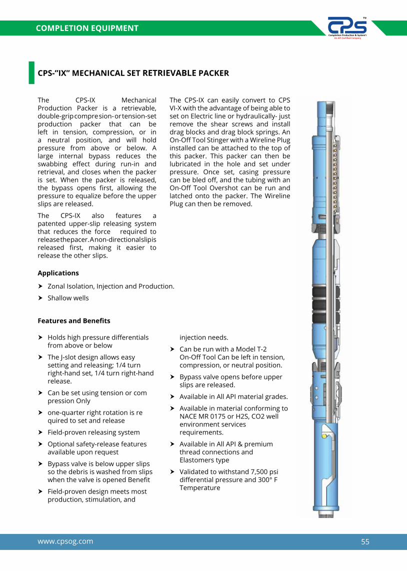
55www.cpsog.com
COMPLETION EQUIPMENT
CPS-”IX” MECHANICAL SET RETRIEVABLE PACKER
The CPS-IX Mechanical Production Packer is a retrievable, double-grip compre sion- or tension-set production packer that can be left in tension, compression, or in a neutral position, and will hold pressure from above or below. A large internal bypass reduces the swabbing effect during run-in and retrieval, and closes when the packer is set. When the packer is released, the bypass opens first, allowing the pressure to equalize before the upper slips are released.
The CPS-IX also features a patented upper-slip releasing system that reduces the force required to release the pacer. A non-directional slip is released first, making it easier to release the other slips.
The CPS-IX can easily convert to CPS VI-X with the advantage of being able to set on Electric line or hydraulically- just remove the shear screws and install drag blocks and drag block springs. An On-Off Tool Stinger with a Wireline Plug installed can be attached to the top of this packer. This packer can then be lubricated in the hole and set under pressure. Once set, casing pressure can be bled off, and the tubing with an On-Off Tool Overshot can be run and latched onto the packer. The Wireline Plug can then be removed.
Applications
h Zonal Isolation, Injection and Production.
h Shallow wells
Features and Benefits
h Holds high pressure differentials from above or below
h The J-slot design allows easy setting and releasing; 1/4 turn right-hand set, 1/4 turn right-hand release.
h Can be set using tension or com pression Only
h one-quarter right rotation is re quired to set and release
h Field-proven releasing system
h Optional safety-release features available upon request
h Bypass valve is below upper slips so the debris is washed from slips when the valve is opened Benefit
h Field-proven design meets most production, stimulation, and
injection needs.
h Can be run with a Model T-2 On-Off Tool Can be left in tension, compression, or neutral position.
h Bypass valve opens before upper slips are released.
h Available in All API material grades.
h Available in material conforming to NACE MR 0175 or H2S, CO2 well environment services requirements.
h Available in All API & premium thread connections and Elastomers type
h Validated to withstand 7,500 psi differential pressure and 300° F Temperature
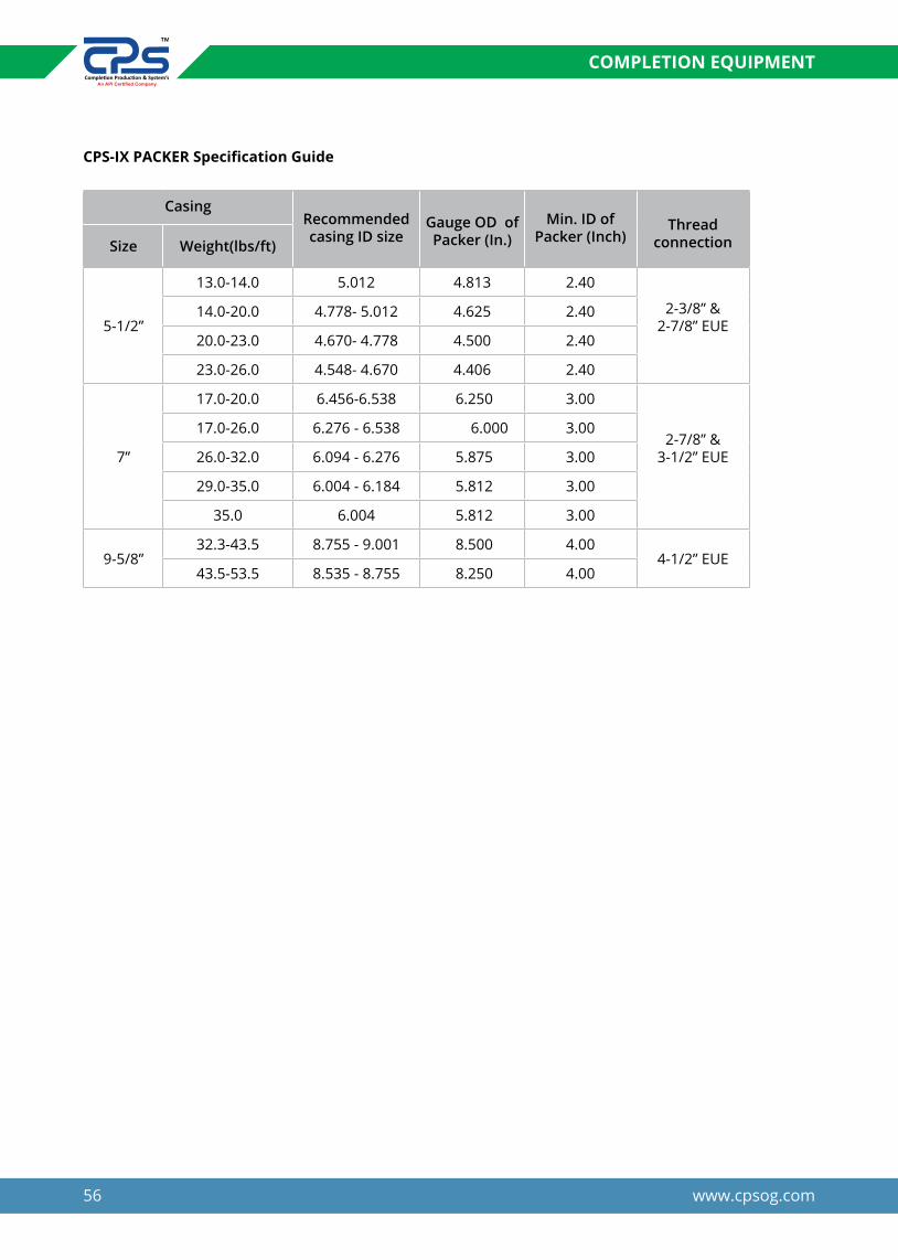
56 www.cpsog.com
COMPLETION EQUIPMENT
CPS-IX PACKER Specification Guide
CasingRecommended casing ID size
Gauge OD of Packer (In.)
Min. ID of Packer (Inch)
Thread connectionSize Weight(lbs/ft)
5-1/2”
13.0-14.0 5.012 4.813 2.40
2-3/8” & 2-7/8” EUE
14.0-20.0 4.778- 5.012 4.625 2.40
20.0-23.0 4.670- 4.778 4.500 2.40
23.0-26.0 4.548- 4.670 4.406 2.40
7”
17.0-20.0 6.456-6.538 6.250 3.00
2-7/8” & 3-1/2” EUE
17.0-26.0 6.276 - 6.538 6.000 3.00
26.0-32.0 6.094 - 6.276 5.875 3.00
29.0-35.0 6.004 - 6.184 5.812 3.00
35.0 6.004 5.812 3.00
9-5/8”32.3-43.5 8.755 - 9.001 8.500 4.00
4-1/2” EUE43.5-53.5 8.535 - 8.755 8.250 4.00

57www.cpsog.com
COMPLETION EQUIPMENT
CPS-”RSB” RETRIEVABLE SEAL BORE PACKER
The CPS-RSB Packer is a retrievable seal bore packer run on electric line with a wireline adapter kit and setting tool or on tubing using a hydraulic setting tool. All the load bearing parts are designed to withstand high
tensile loads and the bi-directional slips prevent any movement after set-ting. It is retrieved by a straight pull release mechanism using a CPS-R Retrieving Tool.
Applications
h High pressure production or injection
h Suitable for ERD wells
h Anchored or floating seal completions
h Vertical, Deviated and Horizontal wellbores
h Sealbore production or isolation packing
h Liner Top installation and straddle packer installation.
Features and Benefits
h Designed for use in vertical, deviated or horizontal well completion applications.
h Bi-directional slips prevent any movement after setting.
h An internal locking device maintains pack off.
h Retrieved by a straight pull shear release using a retrieving tool.
h Retrieving tool has an emergency shear release feature in the event that the packer does not release.
h Wireline or Hydraulic set
h Smooth, continuous ID sealing bore
h Available in all metallurgical and Elastomers conforming to NACE MR 0175 or H2S, and suitable for standard normal/H2S, CO2 well services requirements.
h Available in All API & Premium thread connections

58 www.cpsog.com
COMPLETION EQUIPMENT
CPS-RSB packer specification guide
CasingRecommended casing ID size
Gauge OD of Packer (In.)
Min. Sealbore ID of Packer (Inch)
Min ID thru Seals (In.)Size Weight(lbs/ft)
5” 11.5-15 4.408-4.560 4.250 2.688 1.968
5-1/2”
14-15.5 4.950-5.012 4.765 2.688
1.96817-20 4.778-4.892 4.593 2.688
20-23 4.670- 4. 778 4.485 2.688
7”
17-20 6.456-6.538 6.250 3.250
1.995or 2.406
23-29 6.184 - 6.366 6.000 3.250
29-32 6.094 - 6.184 5.820 3.250
35-38 5.920 - 6.004 5.735 3.250
7-5/8”24-29.7 6.875-7.025 6.690 4.000
2.406 or 329.7-33.7 6.765-6.875 6.580 4.000
9-5/8”
36-40 8.835-8.921 8.619 4.750
3 or 3.87540-47 8.681- 8.835 8.465 4.750
47-53.5 8.535- 8.681 8.319 4.750
# Bottom thread connection types, sizes, are available on request

59www.cpsog.com
COMPLETION EQUIPMENT
CPS-”PBR” HYDRAULIC SET RETRIEVABLE PACKER
The CPS-PBR Packer is a hydraulic set retrievable seal bore packer. It is run on tubing using an Anchor Seal Nipple and set by applying tubing pressure. It includes Large Upper bore of the Packer allows maximum flow through the completion string for high volume applications.
All the load bearing parts are designed to withstand high tensile loads and the bi-directional slips prevent any movement after setting. It is retrieved by a straight pull release mechanism using a CPS-R Retrieving Tool.
Applications
h High pressure production or injection
h Anchored or floating seal completions
h Vertical, Deviated and Horizontal wellbores
h Sealbore production or isolation packing
h Liner Top installation and straddle packer installation.
Features and Benefits
h Designed for use in vertical, deviated or horizontal well completion applications.
h Bi-directional slips prevent any movement after setting.
h An internal locking device maintains pack off.
h Retrieved by a straight pull shear release using a retrieving tool.
h Retrieving tool has an emergency shear release feature in the event that the packer does not release.
h Wireline or Hydraulic set
h Smooth, continuous ID sealing bore
h Available in all metallurgical and Elastomers conforming to NACE MR 0175 or H2S, and suitable for standard normal/H2S, CO2 well services requirements.
h Available in All API & Premium thread connections

60 www.cpsog.com
COMPLETION EQUIPMENT
CPS-PBR Packer specification guide
CasingRecommended casing ID size
Gauge OD of
Packer (In.)
Upper Bore (Inch)
Min. Sealbore ID of Packer
(Inch)
Min ID thru Seals
(In.)Size Weight(lbs/ft)
5” 11.5-15 4.408-4.560 4.250 3.000 2.688 1.968
5-1/2”
14-15.5 4.950-5.012 4.765 3.000 2.688
1.96817-20 4.778-4.892 4.593 3.000 2.688
20-23 4.670- 4. 778 4.485 3.000 2.688
7”
17-20 6.456-6.538 6.250 4.000 3.250
1.995or 2.406
23-29 6.184 - 6.366 6.000 4.000 3.250
29-32 6.094 - 6.184 5.820 4.000 3.250
35-38 5.920 - 6.004 5.735 4.000 3.250
7-5/8”24-29.7 6.875-7.025 6.690 4.750 4.000
2.406 or 329.7-33.7 6.765-6.875 6.580 4.750 4.000
9-5/8”
36-40 8.835-8.921 8.619 4.750 4.750
3 or 3.87540-47 8.681- 8.835 8.465 4.750 4.750
47-53.5 8.535- 8.681 8.319 4.750 4.750
# Bottom thread connection types, sizes, are available on request

61www.cpsog.com
COMPLETION EQUIPMENT
CPS-ISOLATION PACKER
The CPS Isolation Packer is a hydraulic set, single string tandem packer used in multiple zone well completions.
The Packer is set by applying hydraulic pressure to the tubing against a temporary plug located below to shear the setting screws and pack off the elements. It is released by straight
pull which shears the releasing screws allowing the packing elements to relax and equalizing pressure from tubing to annulus.
It can be used as the upper packer in a dual zone application or in multiple quantities when more than two zones are to be completed.
Features and Benefits
h Easily adjustable set and release shear screws, both field adjustable.
h Compact length makes it ideal for use in highly deviated wells.
h Economical design.
h Standard three piece nitrile packing elements, premium elements available on request.
h Available in all metallurgical and Elastomers conforming to NACE MR 0175 or H2S, and suitable for standard normal/H2S, CO2 well services requirements.
h Available in All API & Premium thread connections.
CPS-Isolation Packer specification guide
Casing Recommended casing ID size
Gauge OD of Packer (In.)
Min. Sealbore ID of Packer (Inch)
Thread connectionSize Weight(lbs/ft)
4-1/2” 9.5-13.5 3.910 - 4.090 3.800 1.9
2-3/8” EU5”
15-18 4.250 - 4.408 4.125 1.9
11.5-15 4.408 – 4.560 4.250 1.9
5-1/2”
13.0-15.5 4.950 - 5.190 4.781
2 2-3/8” EU15.5-20.0 4.778- 4.950 4.641
20.0-23.0 4.625- 4.778 4.500
26 4.500 4.250
7”
17.0-23.0 6.366- 6.538 6.1542.42 or
3.00
2-7/8” & 3-1/2” EU
23.0-26.0 6.276- 6.366 6.078
26.0-29.0 6.184- 6.276 5.968
26.0-32.0 6.094- 6.276 5.891

62 www.cpsog.com
COMPLETION EQUIPMENT
CPS - “H” HYDRAULIC SETTING TOOL
The CPS Model “H” Hydraulic Setting Tools are used to run and set packers, bridge plugs and cement retainers on tubing or drill pipe. After dropping a Ball, the setting tool converts hydraulic pressure applied to the tubing into a mechanical force that is transmitted through the adapter kit to the tool. It allows setting in high an-gle or deviated wells where it is often difficult to use wireline equipment.
Auto flow sub is optional can be supply on the request of customer. The auto flow sub connect with the Top thread of Setting tool. The Auto flow sub allow the Tubing/Drill string pressure by shearing the Ball seat to activate the Piston cylinder arrangement of setting Tool. The shearing force of the ball seat can be varying at surface by increasing or decreasing the no. of shear pins.
Features and Benefits
h Simple Operation
h Uses the same adapter kits for running as are used with a Baker 10# or 20# setting tool
h Automatically fills and drains tubing
h Hydraulically balanced while running in the hole to prevent premature setting
h Number of Pistons can be increased as per customer requirement
h Can withstand high tensile loads
h No rotation required to set or release the tool
h Available in material conforming to NACE MR 0175 or H2S, CO2 well environment services requirements.
CPS-“H” Setting Tool specification guide
Casing Size
Tool
OD (In.)Thread connection Min. Sealbore ID
of Packer (Inch)Max-
Setting Force(Lbs)Top Bottom
4-4-1/2” 3.5 2-3/8” EUE BAKER #10 7,500 75,000
≥ 5” 3.88 2-7/8” EUEBAKER #20 6,000 1,00000
≥ 6-5/8” 5 3-1/2” EUE

63www.cpsog.com
COMPLETION EQUIPMENT
CPS - “BT” WIRELINE PRESSURE SETTING TOOL
The CPS Model “BT” Wireline Setting Tools are used to run and set packers, bridge plugs and cement retainers on tubing or drill pipe.
The combustion are used to provide the gradual development of force through pressure. The force in the setting tool creates the various parts which allow the successful setting of bridge Plugs, Cement retainers and packers etc.
The pressure that powers this tool is built up throughout of a Power charge. The pressure is confined to the correct portion of the tool through the use of O-ring seals.
The BT Wireline Pressure Setting Tool incorporates a manual bleeder valve to provide a safe and easy way of bleeding trapped pressure prior to disassembly after the tool has made a run in the well.
CPS-BT Wireline pressure setting Tool specification guide
Casing Size
Tool OD (In.)Thread connection
Max Setting Force(Lbs)Top Bottom
4-4-1/2” 3.5 2-3/8” EUE BAKER #10 75,000
≥ 5” 3.88 2-7/8” EUEBAKER #20 1,00000
≥ 6-5/8” 5 3-1/2” EUE

64 www.cpsog.com
COMPLETION EQUIPMENT
PUMP OUT PLUG
The Pump-Out Plug is installed to the bottom of the tubing string below the Packer to isolate the tubing from the annulus. To remove the plug, drop the Ball and apply pressure the Pump-Out Plug is removed to allow full opening. Also available with blank seat sub.The
plug is available with the half Mule Full mule and bevelled lower end to aid the re-entry of Slick line/Wireline Entry Tools.
Features and Benefits
h Field Adjustable shear screws to achieve desired pressure rating
h Available in All API material grades
h Available in material conforming to NACE MR 0175 or H2S, CO2 well environment services requirements.
h Available in All API & premium thread connections and O-Ring type
h High chamfered Lower End aid the re-entry of Slickline/Wireline Entry Tools
CPS-Pump Out Plug specification guide
Tubing Size
Tool
OD (In.)Tool Id after shear
the Ball Seat Ball Size ID of Ball Seat
2-3/8” 3.062” 1.937” 1 ¼” 1.000”
2-7/8” 3.668” 2.375” 1 ½” 1.250”
3-1/2” 4.500” 2.937” 2 ½” 2.250”
4-1/2” 5.563” 3.937” 3 ½” 3.250”
5-1/2” 6.050” 4.500” 3 ½” 3.250”

65www.cpsog.com
COMPLETION EQUIPMENT
CPS - “T-2” ON - OFF TOOL
The CPST-2 On-Off Tool is tubing disconnect device that has an internal blanking plug locking profile with seal bore for utilizing flow control equipment. The Overshot has a box looking up which connects to tubing string and a pin looking down off the Stinger which connects to the packer. The WT has two basic components that comprise the Overshot. The Top Sub which contains two Bonded
rubber steel seals and the Jay Latch which has a J Slot configuration to locate and latch the On-Off Tool Stinger. The Jay Latch also has a wash over shoe configuration which allows cutting through debris. The Overshot automatically Jays up on Stinger when lowered into well.
Applications
h Mechanical, hydraulic or Wire line-set packer completions
h Zonal isolation above the packer
h Temporary abandonment of lower zones
h Tubing retrieval without disturbing the packer
Features and Benefits
h The tool enables the packer to be used as a bridge plug for zonal iso lation or the temporary abandonment of lower zones, saving rig costs.
h The tool can be full-pressure tested at the surface to save rig time.
h Available in All API material grades
h Available in material conforming to NACE MR 0175 or H2S, CO2 well environment services requirements.
h Available in All API & premium thread connections
CPST-2 On-Off Tool specification guide
Casing Size
Washover
Shoe OD (In.)Thread
connectionStinger or Slick joint
Locking profile
4-1/2” 3.750 2-3/8” 1.812, 1.875, X, XN, R, RN, F, R
5-1/2” 4.516 2-3/8” & 2-7/8” EUE 1.812, 1.875, 2.125 X, XN, R, RN, F, R
7” 5.875 2-3/8” 2-7/8” & 3-1/2” EUE 2.313, 2.250, 2.750, 2.813 X, XN, R, RN, F, R
9-5/8” 8.255 3-1/2” & 4-1/2 EUE 2.750, 2.813, 3.312 X, XN, R, RN, F, R

66 www.cpsog.com
COMPLETION EQUIPMENT
CPS-K SHEAR OUT SAFETY JOINT
Model CPS-K Shear out Safety Joint provides a means of releasing the tubing string from the rest of the completion in an emergency. A straight pull separates the tool at a
predetermined shear value. The Model K Shear Safety Joint allows torque to be transmitted through the tool without affecting the shear screws.
Features and Benefits
h The shear value is field adjustable.
h Allows the application of torque without affecting the shear screws.
h Field proven design.
h Additional sizes available on request.
h Available in All API material grades.
h Available in material conforming to NACE MR 0175 or H2S, CO2 well environment services requirements.
h Available in All API & premium thread connections
CPS- Shear out safety Joint specification guide
Tubing Size
Tool OD (In.) Tool Id Max Shear (Lbs.)
2-3/8” 3.062 1.985 54,000
2-7/8” 3.640 2.485 54,000
3-1/2” 4.500 2.985 60,000
4-1/2” 5.563 3.985 108,750

67www.cpsog.com
COMPLETION EQUIPMENT
CPS-RS ROTATIONAL SAFETY JOINT
The model CPS-RS Rotational Safety Joint provides for emergency release of the tubing string. The RH Rotational Safety Joint uses larger square left-hand threads to
separate the upper and lower subs with right-hand rotation abandoning any production equipment below.
Features and Benefits
h The shear value is field adjustable.
h Field proven deign.
h Additional sizes available on request.
h Available in All API material grades.
h Available in material conforming to NACE MR 0175 or H2S, CO2 well environment services requirements.
h Available in All API & premium thread connections
CPS-RS Rotational Safety Joint specification guide
Tubing size Tool OD(In.) Tool Id (In.)
2-3/8” 3.062 1.985
2-7/8” 3.640 2.485
3-1/2” 4.500 2.985
4-1/2” 5.563 3.985

68 www.cpsog.com
COMPLETION EQUIPMENT
The CPS-NR Expansion Joint is designed to allow expansion or contraction of the tubing during injection, treating and production operations. The Expansion Joint is designed to transmit torque
throughout the stroke of the tool. Pressure is contained with a bonded seal system as standard equipment. Premium seals are available upon request.
Features and Benefits
h Tool locks in fully extended, fully collapsed or mid-stroke position with shear screws.
h Full-length keys provide transmission of torque through full length of travel.
h Torque transmitted through tool throughout stroke of tool.
h Shear values are field adjustable.
h Bonded HNBR seals standard equipment.
h Available in 4, 6, 10, 15, 20 feet
stroke length standard other lengths available upon request.
h Temperature rating up to 325° F [ 162,78° C] standard Higher temperature rating determined by seals used.
h Available in All API material grades.
h Available in material conforming to NACE MR 0175 or H2S, CO2 well environment services requirements
h Available in All API & premium thread connections
CPS-NR Rotational Safety Joint specification guide
Tubing size Tool OD(In.) Tool Id (In.)
2-3/8” 3.260 1.990
2-7/8” 4.000 2.409
3-1/2” 5.010 2.990
4-1/2” 6.375 3.938
CPS-NR EXPANSION JOINT

69www.cpsog.com
COMPLETION EQUIPMENT
CPS-E ROTATIONAL EXPANSION JOINT
The CPS-E Expansion Joint is designed to allow expansion or contraction of the tubing during injection, treating and production operations. The E joint is also a swivel joint, unless extended to its full stroke when a clutch
engages and allows torque to be transmitted through the joint. Pressure is contained with a bonded seal system as standard equipment. Premium seals are available upon request.
Features and Benefits
h Torque transmitted at full opening of tool.
h Bonded HNBR seals standard equipment.
h Available in4, 6, 10, 15, 20 feet stroke length standard. other lengths available upon request.
h Temperature rating up to 325° F [ 162,78° C] standard.
h Higher temperature rating determined by seals used.
h Available in All API material grades.
h Available in material conforming to NACE MR 0175 or H2S, CO2 well environment services requirements.
h Available in All API & premium thread connections
CPS-E Rotational Safety Joint specification guide
Tubing size Tool OD(In.) Tool Id (In.)
2-3/8” 3.260 1.990
2-7/8” 4.000 2.409
3-1/2” 5.010 2.990
4-1/2” 6.375 3.938

70 www.cpsog.com
COMPLETION EQUIPMENT
The CPS PBR Polished Bore Receptacle is used in a well completion to provide a means of sealing the tubing to the top of the production packer while maintaining maximum ID. It can accept either a latching type or locator seal assembly. It is made up
to the top of the packer and provides an upper seal bore to allow tubing retrieval without releasing the packer. The PBR is run with the seal assembly in place. Following tubing retrieval, the PBR can be released from the packer using the pulling tool and right-hand rotation.
CPS-POLISHED BORE RECEPTACLE
Features and Benefits
h Equipped with standard nitrile seals.
h Upper Right-hand box thread to allow right-hand rotation to release PBR from the packer.
h After packer setting and testing the locator seal assembly is
h released by straight pull on the tubing to shear the screws and allow space out.
h Can accommodate locator seal assemblies.
h Available in 5, 10, 15 and 20 foot lengths.
h Allows tubing retrieval while leaving the packer and PBR in place.
h Allows subsequent PBR retrieval with right-hand rotation pulling tool.
h Available in All API material grades.
h Available in material conforming to NACE MR 0175 or H2S, CO2 well environment services requirements.
h Available in All API & premium thread connections.
PBR
size Inches Max O.D inches
Min I.D Inches
PBR LengthFeet (m)
Max StrokeLength Feet (M)
3.00 3.660 2.370 5.500 3.0
3.00 3.660 2.370 6.050 4.0
3.00 3.660 2.370 7.718 6.0
3.00 3.660 2.370 12.052 10.0
4.750 5.750 3.875 5.000 3.500
4.750 5.750 3.875 10.000 8.500
4.750 5.750 3.875 15.000 13.500
4.750 5.750 3.875 20.000 18.500

71www.cpsog.com
COMPLETION EQUIPMENT
CPS-TUBING SWIVEL
The CPS Tubing Swivel is designed for use in multi string packer completions to facilitate their assembly. The Downhole Tubing Swivel allows easy makeup of the tubing by allowing rotation of the tubing below the dual string packer.
The tubing below the packer may be made-up to the lower end of the long string or short string of the packer without having to rotate the packer or the tubing below the packer simply by turning the swivel joint.
Features and Benefits
h Field proven design.
h Temperature rating up to 325° F [ 162,78° C] standard.
h Higher temperature rating deter mined by seals used.
h Available in All API material grades.
h Available in material conforming to NACE MR 0175 or H2S, CO2 well environment services requirements.
h Available in All API & premium thread connections.
CPS-Tubing Swivel specification guide
Tubing size Tool OD(In.) Tool Id (In.)
2-3/8” 3.062 1.985
2-7/8” 3.640 2.485
3-1/2” 4.500 2.985
4-1/2” 5.563 3.985
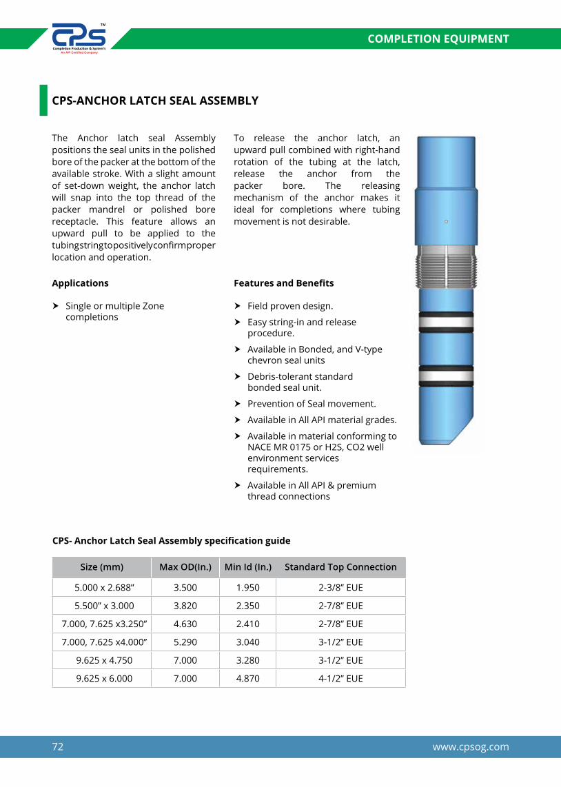
72 www.cpsog.com
COMPLETION EQUIPMENT
CPS- Anchor Latch Seal Assembly specification guide
Size (mm) Max OD(In.) Min Id (In.) Standard Top Connection
5.000 x 2.688” 3.500 1.950 2-3/8” EUE
5.500” x 3.000 3.820 2.350 2-7/8” EUE
7.000, 7.625 x3.250” 4.630 2.410 2-7/8” EUE
7.000, 7.625 x4.000” 5.290 3.040 3-1/2” EUE
9.625 x 4.750 7.000 3.280 3-1/2” EUE
9.625 x 6.000 7.000 4.870 4-1/2” EUE
The Anchor latch seal Assembly positions the seal units in the polished bore of the packer at the bottom of the available stroke. With a slight amount of set-down weight, the anchor latch will snap into the top thread of the packer mandrel or polished bore receptacle. This feature allows an upward pull to be applied to the tubing string to positively confirm proper location and operation.
To release the anchor latch, an upward pull combined with right-hand rotation of the tubing at the latch, release the anchor from the packer bore. The releasing mechanism of the anchor makes it ideal for completions where tubing movement is not desirable.
CPS-ANCHOR LATCH SEAL ASSEMBLY
Applications Features and Benefits
h Single or multiple Zone completions
h Field proven design.
h Easy string-in and release procedure.
h Available in Bonded, and V-type chevron seal units
h Debris-tolerant standard bonded seal unit.
h Prevention of Seal movement.
h Available in All API material grades.
h Available in material conforming to NACE MR 0175 or H2S, CO2 well environment services requirements.
h Available in All API & premium thread connections

73www.cpsog.com
COMPLETION EQUIPMENT
CPS-LOCATOR TUBING SEAL ASSEMBLY
The CPS Locator Tubing Seal assemblies are used with Seal Bore packer to provide leak-proof seal
between the Packer Bore and production tubing string.
Seal Type
The Bonded Seal is tolerant to damage from debris, tubing movement and unloading of seals under pressure. Standard Seal material is nitrile which is recommended for non H2S environments. For H2S
environment Viton, HNBR and Aflas sealingsystem can be supply on request
LTSA have No Go locator Sub which allow the LTSA to land over the top of the packer. The LTSA supplied standard length 6, 10, 15 feet can be vary on request.
Features and Benefits
h Seal are debris-and movement-tolerant
h Bonded seals can be unloaded under differential pressure.
h Seal unit used with anchors and Locators optimize seal placement in polished bores.
h Provides with Concentric coupling and Bottom Sub to connect with Bottom tail pipe.
h Provides with one feet seal length.
h Provides necessary ID for other Wireline Tool.
h Available in All API and premium Top connection.
h Can be supply with the Blank, Half Mule, Locater latch type, and Threaded type Bottom Sub.
h Available in all metallurgical and Elastomers conforming to
h NACE MR 0175 or H2S, and suitable for standard normal/H2S,
h CO2 well services requirement.
h Have same pressure and temperature rating with tubing.
Recommended Min Seal bore ID of Packer (in.)
OD (In.) of seal unit
Min ID thru Seals Assy. (In.)
Pressure Rating (Psi)
Tubing Thread Connection
1.968 1.875 1 9,000 2-3/8” EU
2.687 2.673 1.963 9,000 2-3/8” EU
3 2.985 2.250 12,000 2-7/8” EU
3.250 3.234 2.375 10,000 2-7/8” EU
3.875 3.859 2.875 10,000 2-7/8” EU
4 3.984 3.030 10,000 3-1/2”EU
4.750 4.734 3.875 9,500 3-1/2”EU
6 5.984 4.875 9,200 4-1/2”EU

74 www.cpsog.com
COMPLETION EQUIPMENT
The bottom sub of LTSA is provided with double-start helical groove and two Guide Pins. Half Mule Shoe as shown in the accompanying illustration. The double start helix provides for uniform self-orienting action of the Half Mule Shoe to permit easy entry in the Packer bore.
Muleshoe guides provide a means to guide the end of the tubing away from the casing wall, and then enter liner tops or the packer bores. The
length of the muleshoe varies with the application, from centralization, to seal guide and protection, to flow isolation sleeve.
Self-aligning muleshoe guides allow the end of the guide to rotate and orient with the liner top without rotation of the tubing. This tool is especially useful in dual wellbore or horizontal completions where control of tubing rotation downhole is difficult.
CPS-AUTO ORIENTING BOTTOM SUB WITH HALF MULE SHOE
Features & Benefits
h Can be supply with the Blank, Half Mule, Locater latch type, and Threaded type Bottom Sub.
h Available in all metallurgical and Elastomers conforming to
h NACE MR 0175 or H2S, and suitable for standard normal/H2S,
h CO2 well services requirement.
h Have same pressure and temperature rating with tubing.
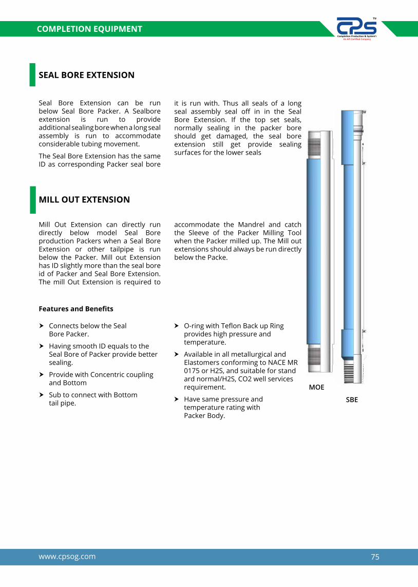
75www.cpsog.com
COMPLETION EQUIPMENT
MILL OUT EXTENSION
MOE
SBE
Mill Out Extension can directly run directly below model Seal Bore production Packers when a Seal Bore Extension or other tailpipe is run below the Packer. Mill out Extension has ID slightly more than the seal bore id of Packer and Seal Bore Extension. The mill Out Extension is required to
accommodate the Mandrel and catch the Sleeve of the Packer Milling Tool when the Packer milled up. The Mill out extensions should always be run directly below the Packe.
SEAL BORE EXTENSION
Seal Bore Extension can be run below Seal Bore Packer. A Sealbore extension is run to provide additional sealing bore when a long seal assembly is run to accommodate considerable tubing movement.
The Seal Bore Extension has the same ID as corresponding Packer seal bore
it is run with. Thus all seals of a long seal assembly seal off in in the Seal Bore Extension. If the top set seals, normally sealing in the packer bore should get damaged, the seal bore extension still get provide sealing surfaces for the lower seals
Features and Benefits
h Connects below the Seal Bore Packer.
h Having smooth ID equals to the Seal Bore of Packer provide better sealing.
h Provide with Concentric coupling and Bottom
h Sub to connect with Bottom tail pipe.
h O-ring with Teflon Back up Ring provides high pressure and temperature.
h Available in all metallurgical and Elastomers conforming to NACE MR 0175 or H2S, and suitable for stand ard normal/H2S, CO2 well services requirement.
h Have same pressure and temperature rating with Packer Body.

76 www.cpsog.com
COMPLETION EQUIPMENT
PRESURE ACTUATED CIRCULATING VALVE
The pressure-actuated circulating sleeve is used as a means of opening the tubing to the annulus. The shear pinned outer sleeve is displaced once
the predetermined opening pressure is applied. The sleeve does not require the aid of a wireline sinker bar or ball such as the B bar/ball sleeve does.
CPS-BALL ACTUATING CIRCULATING VALVE
The circulating valve was designed as a means of opening the tubing above a packer to permit reversing, equalizing, circulating, and spotting of acids or other fluids. The Shear
pins prevent premature opening while running in the hole.The CPS Ball actuated circulating sleeve is used as a means of opening the tubing to the annulus.
Features and Benefits
h Rugged heavy duty collet allows repeated use.
h Large by-pass area.
h Full bore I.D. matching the packer bore.
h Remains open when running or retrieving thus minimizing swabbing tendencies.
h Available in all metallurgical and Elastomers conforming to
h NACE MR 0175 or H2S, and suitable for standard
h Normal / H2S, CO2 well services requirement.
h Have same pressure and temperature rating with Packer Body.
h Available in all metallurgical and Elastomers conforming to NACE MR 0175 or H2S, and suitable for stand ard normal/H2S, CO2 well services requirement.
h Have same pressure and temperature rating with Packer Body.
CPS-Circulating Valve specification guide
Tubing size Tool OD(In.) Tool Id (In.)
2-3/8” 3.750 1.985
2-7/8” 4.515 2.485
3-1/2” 4.500 2.985
4-1/2” 5.563 3.985

77www.cpsog.com
COMPLETION EQUIPMENT
CPS-E HYDROTRIP PRESSURE SUB
The CPS Model E Hydro-Trip Sub is used to hydraulically set tools, such as hydraulic packers with the application of tubing pressure. Setting is achieved by circulating a ball to a seat in the sub, and applying sufficient pressure to activate the setting mechanism in the tool below.
When further pressure is applied to the ball, the mechanism shears, allowing the ball to pass down the tubing string. After the Hydro-Trip Sub has been set, the tool provides an open bore for passage of drop balls or wireline equipment.
Operation To set a hydraulic packer, drop or circulate a ball down the tubing to the seat in the HydroTrip Sub. Apply sufficient tubing pressure to activate the setting mechanism in the packer. After the packer is set, a pressure increase shears the shear screws in the shear ring, to allow the ball seat to move down until the fingers snap back into a groove. The sub is then fully open with no restrictions to productions, and the ball passes on down the tubing.
Applications
Features & Benefits
h Temporary plug in tubing for setting hydraulically actuated packers.
h Works in single and dual completions.
h Can be run in any location in the tubing string.
h Single body joint with anti-torque lock screws full tubing ID post shear.
h Shear value can be adjusted Circulation available prior to ball drop.
h Available in All API material grades.
h Available in material conforming to NACE MR 0175 or H2S, CO2 well environment services requirements.
h Available in All API & premium thread connections.
h Have same pressure and temperature rating with Packer Body.
CPS-E Hydrotrip Pressure Sub specification guide
Tubing size Tool OD(In.) Tool Id (In.)
2-3/8” 3.750 1.985
2-7/8” 4.515 2.485
3-1/2” 4.500 2.985
4-1/2” 5.563 3.985

78 www.cpsog.com
COMPLETION EQUIPMENT
CPS-BLAST JOINT
* Blast joint are available in all apigrade material and api threads other theard & meterial is available up on request
* Perforated / Non Perforated spacer tube are available in all API Grade Material& API threads. Other Material & threads are also available upon request.
CPS-PERFORATED / NON - PERFORATED SPACER TUBE
Flow couplings / Blast joints are installed in the tubing opposite perforations in wells with two or more zones. These are heavy walled and are sized to help prevent tubing damage from the jetting action of the zone perforations. It should be installed above and below landing nipples or other restrictions that may cause turbulent flow. Help to extend the life of the well completion.
The Perforated Spacer Tube is used at the end of a tubing string to provide an alternate flow path in cases where wire line measuring devices are used. The Perforated Spacer Tube is made of low grade material and its assembly consists of a perforated nipple with standard tubing thread, a crossover coupling up, and a crossover sub down. Perforated Spacer Tube are
Basic applications are to help inhibit erosion caused by jetting action near perforations, installed opposite perforations in one or more zones. Furnished in various grades of materials with requiredend connections and different lengths to meet our customer’s as well as API standard requirements.
available with special box thread up and pin thread down, upon request.
The Non-Perforated Production Tube is made-up at the bottom of the production string. Its basic purpose is to act as a stinger (or extension) to keep the packer flapper valve open when producing or when working below the packer.

79www.cpsog.com
COMPLETION EQUIPMENT
CPSC-1 TUBING ANCHOR CATCHER
The CPS MODEL C-1 Tubing Anchor Catcher is a retrievable Double Grip Tubing Anchor designed to anchor the tubing string in tension or compression. When installed with the proper amount of tubing tension, this anchor prevents movement of the tubing string during rod pumping operations. This result in more oil production per pump stroke and in turn extends the life of the pump, rods and tubing decreases pumping costs.
The CPSC-1 Anchor Catcher incorporates an emergen-cy shear release which is easily adjustable in the field. Unless otherwise specified, anchors are furnished with a total of 50,000 lbs secondary release shears.
The SC-1 Anchor utilizes drag block backed up by Inconel leaf springs which results in more positive drag, thus reducing repair costs by at least 50% of the cost for repairing older drag spring designs.
Features & Benefits
h Increase Pump efficiency.
h Left hand rotation to set and right hand to release.
h Straight pull emergency release mechanism.
h Field adjustable shear release value.
h Improve operating costs by reducing maintenance and down time cost by tubing or sucker rod wear
h Case hardened double grip Slips having 50-56 HRc Hardness are suitable to set inside all API casing grade
h Drag Blocks are for setting and releasing control.
h When the anchor catcher has been sheared the slips are completely retracted, permitting the slips to move up or down thus eliminating the potential damage on anchor catcher, tubing or casing.
Model CPSC-1 Tubing Anchor Catcher Technical information
Casing Recommended casing ID size
Gauge OD of Packer (In.)
Min. ID of Packer
**Thread connectionSize Weight(lbs/ft)
4-1/2” 9.5-13.5 3.910” - 4.090” 3.75” 1.92-3/8” EU
5” 11.5-18 4.276” – 4.560” 4.12” 1.9
5-1/2”13.0-15.5 4.950” - 5.190” 4.62” 2” or 2.42”
2-3/8” or 2-7/8” EU
20.0-26.0 4.548”- 4.778” 4.50”
6-5/8” 20.0 – 32.0 5.675”- 6.049” 5.50” 2” or 2.42” 2-3/8” or 2-7/8” EU
7”17.0-20.0 6.456”- 6.538” 6.25”
2.42” or 3.00” 2-7/8” or 3-1/2” EU20.0-38.0 5.920”- 6.456” 5.55”
7-5/8” 24.0-39.0 6.625”- 7.025” 6.25”
8-5/8” 24.0-49.0 7.511”- 8.079” 7.00”3.00” 3-1/2” EU
9-5/8” 32.3-47 8.681” – 9.001” 8.25”

80 www.cpsog.com
BRIDGE PLUG
BRIDGE PLUG
A downhole tool that is located and set to isolate the lower part of the wellbore. Bridge plugs may be permanent or retrievable, enabling the lower wellbore to be permanently sealed from production or temporarily isolated from a treatment conducted on an upper zone.
We deal in Wireline/Hydraulic type bridge plug which we supply in two designs:
y Big Boy bridge plug
y Midget bridge plug
CPS- BIG BOY BRIDGE PLUG
Features & Benefits
The Big Boy Bridge Plug has proven to be a product that can be depended on. It has excellent running characteristics and secure sets. The plug can be set on different types of wireline pressure
h Electric wireline set
h Drillable
h Cast iron construction
h One piece slips - hardened to depth of wicker only
h Sets in any grade casing including P-110
h Form-fitting metal back-ups prevent rubber extrusion
h For temporary or permanent service
h Ratcheting lock ring holds setting force
setting tools. The Big Boy is designed for rapid drill-out while maintaining sufficient strength during the set. This plug sustains high pressures and temperatures.

81www.cpsog.com
BRIDGE PLUG
CPS- MIDGET BRIDGE PLUG
The Midget Bridge Plug Series provides an economical means of zone isolation for fracturing or other treatments. The plugs are compact and require less drilling time when being removed. The
plug can be set on different types of wireline pressure setting tools. This plug sustains moderate pressures and temperatures.
Features & Benefits
h Electric wireline set
h Drillable
h Cast iron construction
h One piece slips - hardened to depth of wicker only
h Sets in any grade casing including P-110
h For temporary or permanent service
h Ratcheting lock ring holds setting force
h Small O.D.’s for speed and safety when running
h For temporary or permanent service
h Ratcheting lock ring holds setting force
h Small O.D.’s for speed and safety when running
Casing Plug Setting Range
Setting Tool
ElastomerO.D. PPF O.D.
2-3/8 3.3-5.9 1.71 1.867-2.107 B05
NITRILE/HNBR/VITON/AFLAS
3-1/2 5.7-10.2 2.75 2.867-3.258 B10
4-1/2 9.5-15.1 3.50 3.826-4.090 B10
5-1/2 13.0-25.0 4.24 4.580-5.047 B20
7.0 17.0-35.0 5.61 5.989-6.655 B20
9-5/8 29.3-53.5 7.71 8.435-9.063 B20
13-3/8 48.0-72.0 12.0 12.347-12.715 B20

82 www.cpsog.com
BRIDGE PLUG
CPS-WIRELINE SET RETRIEVABLE BRIDGE PLUG
The CPS WR Retrievable Bridge Plug is a premium quality high performance WR style bridge plug. The WR Retrievable Bridge Plug is a product designed to isolate the wellbore when performing treatments such as fracturing, acidizing, surface equipment maintenance or temporary suspen-sion of a producing formation. The WR is generally set using electric line wireline. This allows the plug to be logged on depth and accurately placed in the well. With the use of the CPS “H” Hydraulic Setting Tool the WR can also be conveyed into the well by Jointed or Coiled Tubing. This method allows
the operator to place the plug in a deviated well where wireline is not an option. The WR can be retrieved using Tubing, Coiled Tubing or in some cases Wireline by using the WR Retriev-ing Head. To retrieve the WR simply requires a set down force then pull tension to release there is not rotation required to pull the plug. Our WR Bridge Plugs are pressure tested by top quality third party consultants to the most exacting standards of the industry to ensure reliability for your operation.
Features and Benefits
h Can be set by hydraulic setting Tool/Wireline set
h Bidirectional Slip
h Three element sealing system to provide superior pressure containment
h Built in differential pressure equalizing system
h WR will not release unless equalizing sleeve has been shifted
h Ability to hang pressure recorders
h One piece double acting slips to prevent movement in the casing Multiple retrieving option

83www.cpsog.com
BRIDGE PLUG
CPS-WR Bridge Plug technical specification
CasingSetting Range
Plug O.d.(Inch)
Setting Tool
ElastomerO.D. PPF
3-1/2 7.7 - 10.2 2.922 - 3.068 2.700 B05
NITRILE/HNBR/VITON/AFLAS
49.5 - 11.0 3.476 - 3.548
B10
10.46 - 12.95 3.340 - 3.476 3.187
s4-1/2
9.5 - 13.5 3.920 - 4.090 3.750
13.5 - 15.1 3.826 - 3.920 3.650
15.1 - 16.6 3.754 - 3.826 3.625
511.5 - 15.0 4.408 - 4.560 4.125
B20
18.0 - 21.0 4.154 - 4.276 3.969
5-1/2
13.0 - 20.0 4.778 - 5.156 4.625
20.0 - 23.0 4.670 - 4.778 4.500
23.0 - 26.0 4.548 - 4.670 4.406
717.0 - 26.0 6.276 - 6.538 5.969
26.0 - 32.0 6.094 - 6.276 5.875

84 www.cpsog.com
CEMENT RETAINERS
CPS - CEMENT RETAINER
Wireline/Hydraulic set cement retainer is a high quality tool for squeeze cementing. The sleeve valve is controlled from the surface by simply picking up to close and setting d o w n to open. The valve is automatically closed when the stinger is removed
from the retainer. This retainer plug sustains high pressure and temper-ature. It may be set on a Wireline/Hydraulic setting tool or mechanically by changing the top slips. It can also converts to a bridge plug by replacing the sliding sleeve by solid plug.
Features
h Electric Wireline/Hydraulic set / Mechanical set.
h Drillable.
h Cast iron construction.
h One piece slips - hardened to depth of wicker only.
h Sets in any grade casing including P-110.
h Metal back-up rings prevent rubber extrusion
h For temporary or permanent service
h Ratcheting lock ring holds setting force.
h Temperature rating 325°F.
h Differential pressure 10000 psi
Casing Plug / Retainer Setting
RangeSetting
ToolElastomer
O.D. PPF O.D.
4-1/2 9.5-15.1 3.593 3.826-4.090 B10
NITRILE/HNBR/VITON/AFLAS
5-1/2 13.0-23.0 4.312 4.670-5.118 B20
6-5/8 17.0-34.0 5.375 5.959-6.135 B20
7.0 32.0-38.0 5.375 5.959-6.135 B20
7.0 17.0-35.0 5.687 6.004-6.538 B20
9-5/8 29.3-53.3 8.125 8.435-9.063 B20
10-3/4 32.7-51.0 9.437 9.660-10.192 B20
13-3/8 48.0-72.0 12.000 12.175-12.715 B20
LINER HANGER EQUIPMENT
We Know Your Well Very Well..


87www.cpsog.com
LINER HANGER EQUIPMENT
CPS DOVETAIL SLIP TYPE HYDRAULIC SET LINER HANGER
Hydraulic Liner Hanger is used to hang a liner in the well. It is set hydrauli-cally by applied pressure through the run-in string, and is designed to support medium to heavy liner loads. The hanger is widely used in deep and high angle wells, where actuation of mechanical-set hangers may not be preferred. A setting ball is dropped and/or circulated to a ball seat in the landing collar or running string. Differential pressure acts on the hydraulic cylinder, moving slips up to the set position.
This LH has two types Multicone pocket slip type or Dovetail type with rotating or non-Rotating mechanism. Multi cone design provides excellent fluid bypass for proper cementing. Hydraulic liner hanger is couple with running tools, pack off bushing, hydraulic landing collar, float collar (if required), and float shoe and other tools.
In this document we include dimensional details of liner hanger, parts of liner hanger and operation of liner hanger.
Applications
Features & Benefits
h Offshore and Deviated Wells with tight turns.
h High pressure and High temperature wells.
h No tubing manipulation required during setting.
h Large multi slot design provides excellent bypass area for proper cementing.
h Available in Single Cone, Double Cone, and multi cone Dovetail type.
h Available in Rotating Non Rotating type design.
h High performance Roller bearing enables rotation during running and Cementing for proper cementing operation.
h Faster Running speed with Dovetail design.
h Dovetail Slip cone Design delivers lower and more uniform stresses on Casing and mandrel enhance hanging capacity.
h Well application requiring hanging heavy liners.
h Drill down applications.
h Vertical and horizontal wells.
h Manufactured from a heavy walled integral Tube which eliminates the no. of internal connections and provide maximum differential pressure rating and liner hanging capacity.
h Case hardened Slips having 50-56 HRc hardness are suitable to set inside all API casing grade.
h Protected type Slips are suitable for highly deviated well operations.
h Available in all metallurgical con forming to NACE MR 0175 or H2S, and suitable for standard normal/ H2S, CO2 well services requirements.
h Available in All API & Premium thread connections and type.
h High Burst and Collapse pressure ratings.
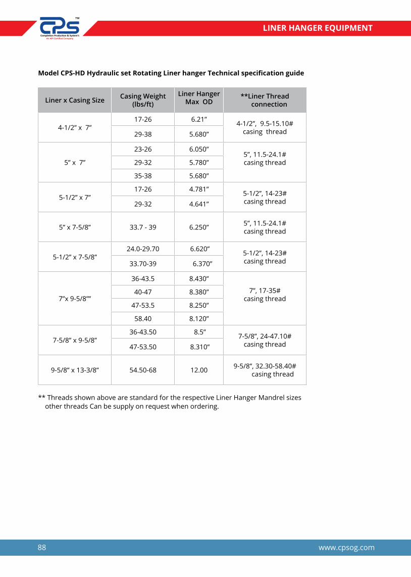
88 www.cpsog.com
LINER HANGER EQUIPMENT
Model CPS-HD Hydraulic set Rotating Liner hanger Technical specification guide
** Threads shown above are standard for the respective Liner Hanger Mandrel sizes other threads Can be supply on request when ordering.
Liner x Casing Size Casing Weight (lbs/ft)
Liner Hanger Max OD
**Liner Thread connection
4-1/2” x 7”17-26 6.21”
4-1/2”, 9.5-15.10# casing thread29-38 5.680”
5” x 7”
23-26 6.050”5”, 11.5-24.1# casing thread29-32 5.780”
35-38 5.680”
5-1/2” x 7”17-26 4.781” 5-1/2”, 14-23#
casing thread29-32 4.641”
5” x 7-5/8” 33.7 - 39 6.250” 5”, 11.5-24.1# casing thread
5-1/2” x 7-5/8”24.0-29.70 6.620” 5-1/2”, 14-23#
casing thread33.70-39 6.370”
7”x 9-5/8””
36-43.5 8.430”
7”, 17-35#casing thread
40-47 8.380”
47-53.5 8.250”
58.40 8.120”
7-5/8” x 9-5/8”36-43.50 8.5” 7-5/8”, 24-47.10#
casing thread47-53.50 8.310”
9-5/8” x 13-3/8” 54.50-68 12.00 9-5/8”, 32.30-58.40# casing thread

89www.cpsog.com
LINER HANGER EQUIPMENT
CPS-”HS”SINGLE / DOUBLE CORE HYDRAULIC SET LINER HANGER
Hydraulic Liner Hanger is used to hang a liner in the well. It is set hydrauli-cally by applied pressure through the run-in string, and is designed to support medium to heavy liner loads. The hanger is widely used in deep and high angle wells, where actuation of mechanical-set hangers may not be preferred. A setting ball is dropped and/or circulated to a ball seat in the landing collar or running string. Differential pressure acts on the hydraulic cylinder, moving slips up to the set position.
This LH has two types single cone / double cone type with rotating or non-Rotating mechanism. Hydraulic liner hanger is couple with running tools, pack off bushing, hydraulic landing collar, float collar (if required), and float shoe and other tools.
In this document we include dimensional details of liner hanger, parts of liner hanger and operation of liner hanger.
Applications
Features & Benefits
h Offshore and Deviated Wells with tight turns.
h High pressure and High temperature wells.
h No tubing manipulation required during setting.
h Large bypass area for proper cementing.
h Available in Single Cone, Double Cone.
h Available in Rotating Non Rotating type design.
h High performance Roller bearing enables rotation during running and Cementing for proper cementing operation.
h Manufactured from a heavy walled integral Tube which eliminates the no. of internal connections and provide maximum differential
h Well application requiring hanging heavy liners.
h Drill down applications.
h Vertical and horizontal wells.
pressure rating and liner hanging capacity.
h Case hardened Slips having 50-56 HRc hardness are suitable to set inside all API casing grade.
h Slips are protected with Split rings suitable for highly deviated well operations.
h Available in all metallurgical con forming to NACE MR 0175 or H2S, and suitable for standard normal/ H2S, CO2 well services requirements.
h Available in All API & Premium thread connections and type.
h High Burst and Collapse pressure ratings.

90 www.cpsog.com
LINER HANGER EQUIPMENT
Model CPS-HD Hydraulic set Liner hanger Technical specification guide
** Threads shown above are standard for the respective Liner Hanger Mandrel sizes other threads can be supply on request when ordering.
Liner x Casing Size Casing Weight (lbs/ft)
Liner Hanger Max OD **Liner Thread
connection
4-1/2” x 7”17-26 6.21”
4-1/2”, 9.5-15.10#
casing thread29-38 5.680”
5” x 7”
23-26 6.050”5”, 11.5-24.1# casing thread29-32 5.780”
35-38 5.680”
5-1/2” x 7”17-26 4.781” 5-1/2”, 14-23#
casing thread29-32 4.641”
5” x 7-5/8” 33.7 - 39 6.250” 5”, 11.5-24.1# casing thread
5-1/2” x 7-5/8”24.0-29.70 6.620” 5-1/2”, 14-23#
casing thread33.70-39 6.370”
7”x 9-5/8””
36-43.5 8.430”
7”, 17-35#casing thread
40-47 8.380”
47-53.5 8.250”
58.40 8.120”
7-5/8” x 9-5/8”36-43.50 8.5” 7-5/8”, 24-47.10#
casing thread47-53.50 8.310”
9-5/8” x 13-3/8” 54.50-68 12.00 9-5/8”, 32.30-58.40# casing thread

91www.cpsog.com
LINER HANGER EQUIPMENT
CPS-MS MECHANICAL SET LINER HANGER
CPS-MS Liner Hanger is set mechan-ically with either right or left- hand rotation, depending on the type of setting tool or design. Staggered cone design gives maximum bypass area to ease running in and circulation. Automatic J- cage allows hanger to re-turn to the run-in position, should the hanger set prematurely while running in the well. The slip cage contains a “J” slot and high strength drag springs to manage the movement of the slips into contact with the cones. Mechan-ical Set Liner Hanger are set through
manipulation of the work string (pick-up & 1/4 right hand turn) line up the cones and the slips, and a further slack off sets the slips onto the casing wall.
This LH has two types Single cone / Double cone type with rotating or non-Rotating mechanism. Hydraulic liner hanger is couple with running tools, pack off bushing, float collar (if required), and float shoe and other tools.
Features & Benefits
h Automatic J-cage, allows hanger to return to run-in position constrain ing hanger preset while running in.
h Open-bottom J-cage, available in right or left-hand set.
h Large bypass area in run-in and set position.
h Slips profile provide more biting area to increase hanging capacity and reduce the possibility of dam age while running in.
h Single or multiple cone designs available to match hanging ca pacity with liner strength, minimizing stress in supporting casing.
h Complete wells with less weight landed on wellheads.
h Give rise to improved cementing jobs.
h Prevent lost circulation.
h Provide good well control while
drilling and completing.
h Impart more completion flexibility.
h Afford low-cost liner on appraisal wells.
h Liner Hangers are available with all API and premium thread connections.
h Case hardened Slips having 50- 56 HRc hardness are suitable to set inside all API casing grade.
h Slips are protected with Split rings suitable for highly deviated well operations.
h Available in all metallurgical con forming to NACE MR 0175 or H2S, and suitable for standard normal/ H2S, CO2 well services requirements.
h Available in All API & Premium thread connections and type.
h High Burst and Collapse pressure ratings.

92 www.cpsog.com
LINER HANGER EQUIPMENT
Model CPS-MS Mechanical set Liner Hanger Technical specification guide
** Threads shown above are standard for the respective Liner Hanger Mandrel sizes other threads can be supply on request when ordering.
Liner x Casing Size Casing Weight (lbs/ft)
Liner Hanger Max OD **Liner Thread
connection
4-1/2” x 7”17-26 6.21”
4-1/2”, 9.5-15.10#
casing thread29-38 5.680”
5” x 7”
23-26 6.050”5”, 11.5-24.1# casing thread29-32 5.780”
35-38 5.680”
5-1/2” x 7”17-26 4.781” 5-1/2”, 14-23#
casing thread29-32 4.641”
5” x 7-5/8” 33.7 - 39 6.250” 5”, 11.5-24.1# casing thread
5-1/2” x 7-5/8”24.0-29.70 6.620” 5-1/2”, 14-23#
casing thread33.70-39 6.370”
7”x 9-5/8””
36-43.5 8.430”
7”, 17-35#casing thread
40-47 8.380”
47-53.5 8.250”
58.40 8.120”
7-5/8” x 9-5/8”36-43.50 8.5” 7-5/8”, 24-47.10#
casing thread47-53.50 8.310”
9-5/8” x 13-3/8” 54.50-68 12.00 9-5/8”, 32.30-58.40# casing thread

93www.cpsog.com
LINER HANGER EQUIPMENT
CPS LINER TOP PACKER
The CPS Liner top Packer is used to prevent gas migration through the cement as it begins to set stopping any micro-annulus that may form without the packer in the well bore. It is run as an integral part of the original liner string. Designed to be set after the liner is cemented, the packer is set by picking up the running string, placing the setting dogs in the setting
tool assembly above the liner top/TBR and slacking off weight. Excess cement above the liner top packer can be circulated out after the packer is set.
CPS LTP is available with or without hold down slips and with or without clutch profile on the top of the packer used with Rotating or Non rotating Liner Hanger
Features & Benefits
h Can be rotated during run-in and cementing operation.
h Available with or without hold down slips and can be pulled if needed in heavy oil applications.
h Optimizes chemical resistance to completion and production fluids with a variety of elastomer options for packer element and seal assemblies.
h Maintains element setting with mandrel lock ring.
h Facilitates high circulating rates with enhanced packer element de-sign without risk of element washout.
h Anti-swab while running or re ciprocating allows to achieve high running speeds.
h Eliminates extra components and connections with integral retrieva ble cementing bushing profile.
h Available in Rotating Non Rotating Clutch type design features.
h Manufactured from a heavy walled integral Tube which eliminates the no. of internal connections and provide maximum differential pressure rating and liner hanging capacity.
h Case hardened Slips having 50- 56 HRc hardness are suitable to set inside all API casing grade.
h Hold down Slips prevents upward movement against differential pressure.
h Available in all metallurgical and Elastomers conforming to NACE MR 0175 or H2S, and suitable for standard normal/H2S, CO2 well services requirements.
h Available in All API & Premium thread connections and type.
h High Burst and Collapse pressure ratings.
Applications
h Offshore and Deviated Wells with tight turns.
h High pressure and High temperature wells.
h Well application requiring hanging heavy liners.
h Liner Hanger application requiring Drill down Capabilities.
h Vertical and horizontal wells.
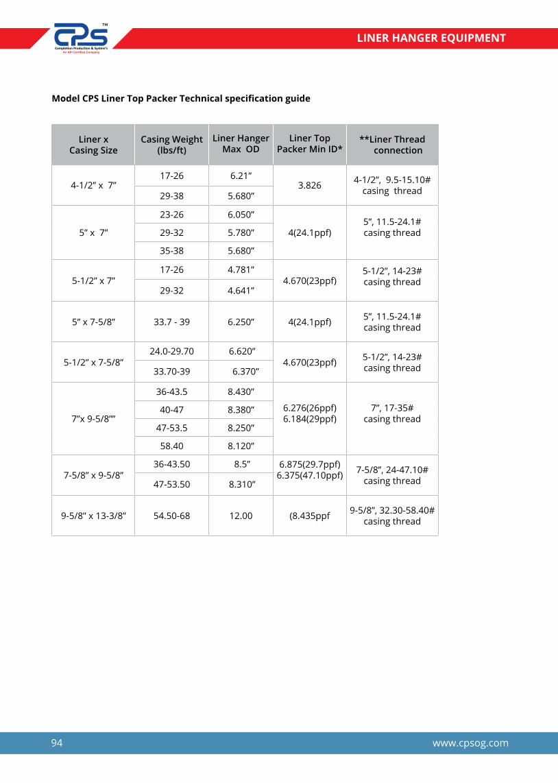
94 www.cpsog.com
LINER HANGER EQUIPMENT
Model CPS Liner Top Packer Technical specification guide
Liner x Casing Size
Casing Weight (lbs/ft)
Liner Hanger Max OD
Liner Top Packer Min ID*
**Liner Thread connection
4-1/2” x 7”17-26 6.21”
3.826
4-1/2”, 9.5-15.10#
casing thread29-38 5.680”
5” x 7”
23-26 6.050”
4(24.1ppf)5”, 11.5-24.1# casing thread29-32 5.780”
35-38 5.680”
5-1/2” x 7”17-26 4.781”
4.670(23ppf)5-1/2”, 14-23# casing thread
29-32 4.641”
5” x 7-5/8” 33.7 - 39 6.250” 4(24.1ppf) 5”, 11.5-24.1# casing thread
5-1/2” x 7-5/8”24.0-29.70 6.620”
4.670(23ppf) 5-1/2”, 14-23# casing thread33.70-39 6.370”
7”x 9-5/8””
36-43.5 8.430”
6.276(26ppf)6.184(29ppf)
7”, 17-35#casing thread
40-47 8.380”
47-53.5 8.250”
58.40 8.120”
7-5/8” x 9-5/8”36-43.50 8.5” 6.875(29.7ppf)
6.375(47.10ppf) 7-5/8”, 24-47.10# casing thread47-53.50 8.310”
9-5/8” x 13-3/8” 54.50-68 12.00 (8.435ppf 9-5/8”, 32.30-58.40# casing thread

95www.cpsog.com
LINER HANGER EQUIPMENT
CPS-HS HYDRAULIC RELEASE RUNNING TOOL
CPS-HR Running Tool connects with the HR Liner Setting sleeve and provides a means to carry a Liner Down hole, set a Liner Hanger and release from the liner prior to or, if desired after cementing. The primary releasing mechanism is hydraulic with an emergency mechanical back-up release system.
This tool carries the weight of the liner on a fully supported collet assembly with no threads that could back off and drop the liner while running in the hole.
Applications
h Offshore and Deviated Wells with tight turns.
h High pressure and High temperature wells.
h Well application requiring hanging heavy liners.
h Vertical and horizontal wells.
Features & Benefits
h Push Pull and rotate while running the liner down hole. The design of this tool allows right hand rotation of the work string and liner with the tool in tension, compression or neutral.
h Rotation after release when running a rotating liner hanger. Multiple torque fingers permit rotation of the liner during ce menting after the hanger is set and the running tool released from the liner.
h Easy stub-up to load the HR setting tool into the HR liner Setting sleeve. Simply push straight in and setting tool automatically latches
into the profile. Maximum 1/3 turn engages the torque fingers.
h No Rotation to release after actuating the hydraulic cylider, the tool is retrieved by straight pick-up. The collet is retained in the released position by an internal body lock ring to prevent re-engagement into the setting sleeve profile.
h Emergency mechanical release in the event the primary hydraulic releasing mechanism fails to operate, the setting tool may be released mechanically by ¼ turn to left.
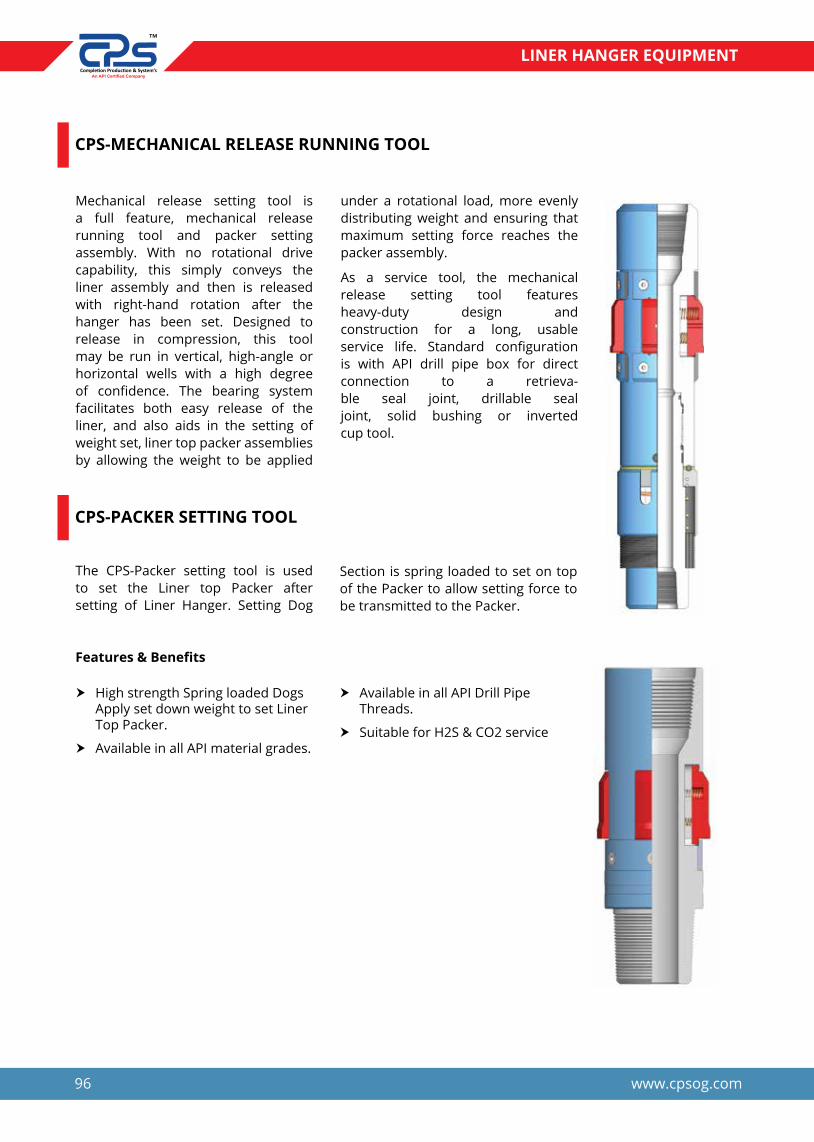
96 www.cpsog.com
LINER HANGER EQUIPMENT
CPS-MECHANICAL RELEASE RUNNING TOOL
CPS-PACKER SETTING TOOL
Mechanical release setting tool is a full feature, mechanical release running tool and packer setting assembly. With no rotational drive capability, this simply conveys the liner assembly and then is released with right-hand rotation after the hanger has been set. Designed to release in compression, this tool may be run in vertical, high-angle or horizontal wells with a high degree of confidence. The bearing system facilitates both easy release of the liner, and also aids in the setting of weight set, liner top packer assemblies by allowing the weight to be applied
The CPS-Packer setting tool is used to set the Liner top Packer after setting of Liner Hanger. Setting Dog
under a rotational load, more evenly distributing weight and ensuring that maximum setting force reaches the packer assembly.
As a service tool, the mechanical release setting tool features heavy-duty design and construction for a long, usable service life. Standard configuration is with API drill pipe box for direct connection to a retrieva-ble seal joint, drillable seal joint, solid bushing or inverted cup tool.
Section is spring loaded to set on top of the Packer to allow setting force to be transmitted to the Packer.
Features & Benefits
h High strength Spring loaded Dogs Apply set down weight to set Liner Top Packer.
h Available in all API material grades.
h Available in all API Drill Pipe Threads.
h Suitable for H2S & CO2 service

97www.cpsog.com
LINER HANGER EQUIPMENT
CPS - LANDING COLLAR
CPS - LINER SWIVEL SUB
Landing Collar is used when setting liner hanger prior to cementing. A setting ball seat in the shear seat allowing pressure to be applied to the hanger to set the slips. Increasing the pressure after setting the hanger shears the ball seat allowing full circulation for cementing operations. The shear rating of the ball seat is adjustable to meet the requirements of the hanger. It incorporates a latch with Non- rotational Mechanism to accept, lock and seal the Liner Wiper Plug upon completion of cementing.
The liner Swivel Sub is normally used when running mechanical set liners in highly deviated wells in which rotating to set the liner may be a problem. The swivel allows rotation of the hanger without rotating the total liner. A clutch system in the swivel (feature may be detected if required) allows easy re-lease of running nut from the liner, if the liner has to be set on bottom.
y The Liner Swivel allows rotation of the anger without having to rotate the total Liner.
Internal components are manufacture from PDC drillable Material and are compatible for drill out. We retained ball seat design prevents the sheared out cage and ball assembly from interfering with float equipment run below the landing collar. Large, milled slots provide an unrestricted flow area while cementing. Shears/setting balls are available in bronze, aluminum or phenolic materials of varying specific gravity for use in vertical, high angle or horizontal wells or for specific cement weights. All seals are of standard
y A clutch system in the swivel allows easy release of the running nut from the liner, if the liner has to be set on bottom.
y Available in all metallurgical con forming to NACE MR 0175 or H2S, and suitable for standard normal/ H2S, CO2 well services requirements.
y Available in All API & Premium thread connections and type.
y High Burst and Collapse pressure ratings.
Features & Benefits
h Anti-rotation feature for wiper plugs.
h Available in thread connection per ordered.
h Available in all API material grades.
h PDC drillable material use for drill out items.
h Brass shear pins loaded Ball seat.
h Suitable for H2S & CO2 service.
h High Burst and collapse pressure
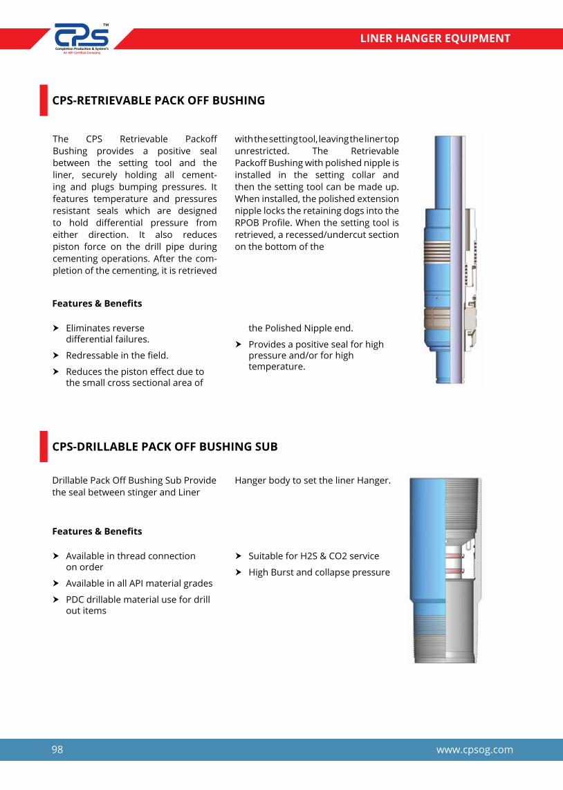
98 www.cpsog.com
LINER HANGER EQUIPMENT
CPS-RETRIEVABLE PACK OFF BUSHING
CPS-DRILLABLE PACK OFF BUSHING SUB
The CPS Retrievable Packoff Bushing provides a positive seal between the setting tool and the liner, securely holding all cement-ing and plugs bumping pressures. It features temperature and pressures resistant seals which are designed to hold differential pressure from either direction. It also reduces piston force on the drill pipe during cementing operations. After the com-pletion of the cementing, it is retrieved
Drillable Pack Off Bushing Sub Provide the seal between stinger and Liner
with the setting tool, leaving the liner top unrestricted. The Retrievable Packoff Bushing with polished nipple is installed in the setting collar and then the setting tool can be made up. When installed, the polished extension nipple locks the retaining dogs into the RPOB Profile. When the setting tool is retrieved, a recessed/undercut section on the bottom of the
Hanger body to set the liner Hanger.
Features & Benefits
Features & Benefits
h Eliminates reverse differential failures.
h Redressable in the field.
h Reduces the piston effect due to the small cross sectional area of
h Available in thread connection on order
h Available in all API material grades
h PDC drillable material use for drill out items
the Polished Nipple end.
h Provides a positive seal for high pressure and/or for high temperature.
h Suitable for H2S & CO2 service
h High Burst and collapse pressure

99www.cpsog.com
LINER HANGER EQUIPMENT
SWAB CUP ASSEMBLY
CPS Swab Cup Assembly Run together with a hanger setting ball seat, the swab cup packoff assembly allows for a hanger to be set and Release Running Tool without increasing the risk of formation damage which occurs when pressuring the entire liner for setting the hanger and expending the setting ball. The ball seat in the running tool string, in concert with the swab cup packoff assembly, allows for pressure to be maintained only in the work-string, therefore decreasing surge on
the formation when the setting ball is expended
The Ball Seat assembly consist of Ball seat which is supported by Shear Pins. The shear value of Seat sub is always keep higher than the Setting pressure of Liner hanger and releasing pressure of Running Tool by changing the No. of shear pins. After shearing of Ball seat the Flo rate can be establish for cementing or wash over operation.
Features & Benefits
h Available in NBR, HNBR, Viton elastomers
h All Rubber cup designed for maximum lifting capacity and extra-long life.
h Abrasion resistant
h High swabbing speeds, Deep wells, rough tubing.
h Ball seat catcher hold the Ball seat and Ball no need to left in well
h Setting Ball is available in Steel and Brass material.
h Available in all metallurgical con forming to NACE MR 0175 or H2S, and suitable for standard normal/ H2S, CO2 well services requirements.
h Available in All API thread connections and type.
h High Burst and Collapse pressure ratings.

100 www.cpsog.com
LINER HANGER EQUIPMENT
CPS PUMP DOWN PLUG (PDP)
CPS LINER WIPER PLUG (LWP)
CPS inner-string Pump Down Plug is pumped behind cement and wipes the inside of drill pipe or tubing strings, providing a mechanical barrier between cement and spacer fluids or between mud and cement.
It wipes cement from the drill pipe and lands in Liner Wiper Plug. When this happen the pressure increases and shears the LWP. Allowing both plug to
The Liner Wiper Plug, commonly shear pinned to the Liner setting Tool, has a hollow internal diameter that allows fluids and cement to pass through the plug until the PDP latches into the Upper part of the LWP.
be displaced as an unit to the Landing Collar.
The “PDP” is designed for use with CPS inner-string stab-in float equipment to cement large-diame-ter casing strings. The stinger dart is launched from cementing head, displacing fluids through the drillpipe or tubing string while preventing cement contamination.
The PDP is then mechanically and hydraulically sealed to the LWP, and the two plugs are sheared from the Liner setting Tool. After wiping the liner, the LWP is latched and sealed to the landing collar preventing the back flow of cement.
Applications
Features and Benefits
h Wiping drillpipe or tubing in conjunction with CPS inner-string float equipment.
h Composed entirely of PDC- (polycrystalline diamond composite) drillable materials, the stinger dart enables trouble-free drillout, conserving rig time.
h Seal ring provides a positive bidirectional seal when latched into float quipment with the corre sponding aluminum snap ring, enabling the device to withstand exceptionally high backpressures.
h PDP acts as a mechanical barrier between displacement fluids to prevent cement contamination, resulting in a clean pipe ID.
h Angled, aluminum nose prevents the dart from hanging up in the drillpipe or tubing string, ensuring proper functionality of the device.
h Polyurethane fins offer superior abrasion resistance and excellent wiping action, resulting in a clean casing ID after passage.
h Fin design enables versatility, sta bility, and superior wiping action for drillpipe and tubing strings, providing operational flexibility.
h Large-diameter casing strings requiring inner-string cementing Features

101www.cpsog.com
LINER HANGER EQUIPMENT
CPS-POLISHED BORE RECEPTACLE
CPS-HANDLING NIPPLE
The Polished Bore Receptacle (PBR) is run as a part of the liner. This PBR comes as a means to tie-back to and existing liner with either a seal assemble or tie-back packer for remedial work.
The Handling Nipple is a heavy weight Drill Pipe Pup Joint for handling the Liner Hanger assembly and for using the Slips and elevator once the assembly below table. It is located above Packer Setting Tool usually the Handling Nipple is equipped with Junk Bonnet
This PBR is a means to Tie-Back to the liner system should it be needed. This can be accomplished with a seal nipple or with a Tie-Back packer
y Available in all API drill pipe thread connections
y Available in different lengths from 10 feet to 20 feet
y Suitable for H2S & CO2 service
y Better Cementing wiping

102 www.cpsog.com
LINER HANGER EQUIPMENT
CPS - JUNK SCREEN
CPS - SEAL STINGER
The Junk Bonnet Sub consists of two metal cups installed around Lifting Sub with two bolts.
The Liner Hanger junk screen should be run as part of the setting tool
Seal stinger with grounded ODs is to provide a sealing surface for the retrievable/drillable Pack-off Bushing. These are manufactured from higher group of API 5CT standard materials as well as furnished with end connections in compliance to API standard and CRA materials suited for H2S or CO2 ser-vice are available on request.
assembly to prevent debris from damaging the polished bore of Tieback Receptacle.
A groove is provided at the bottom end to attach the Liner Wiper Plug. Our seal joint manufactured from high grade alloy material and surface would be chrome platted so as to possess resistance for corrosive environments.
Features and Benefits
h Available in all API thread connections
h Available in different lengths from 10 feet to 20 feet
h Polished Bore high finished OD for better sealing with Pack Of Bushing Seals
h Suitable for H2S & CO2 service
h Better Cementing wiping
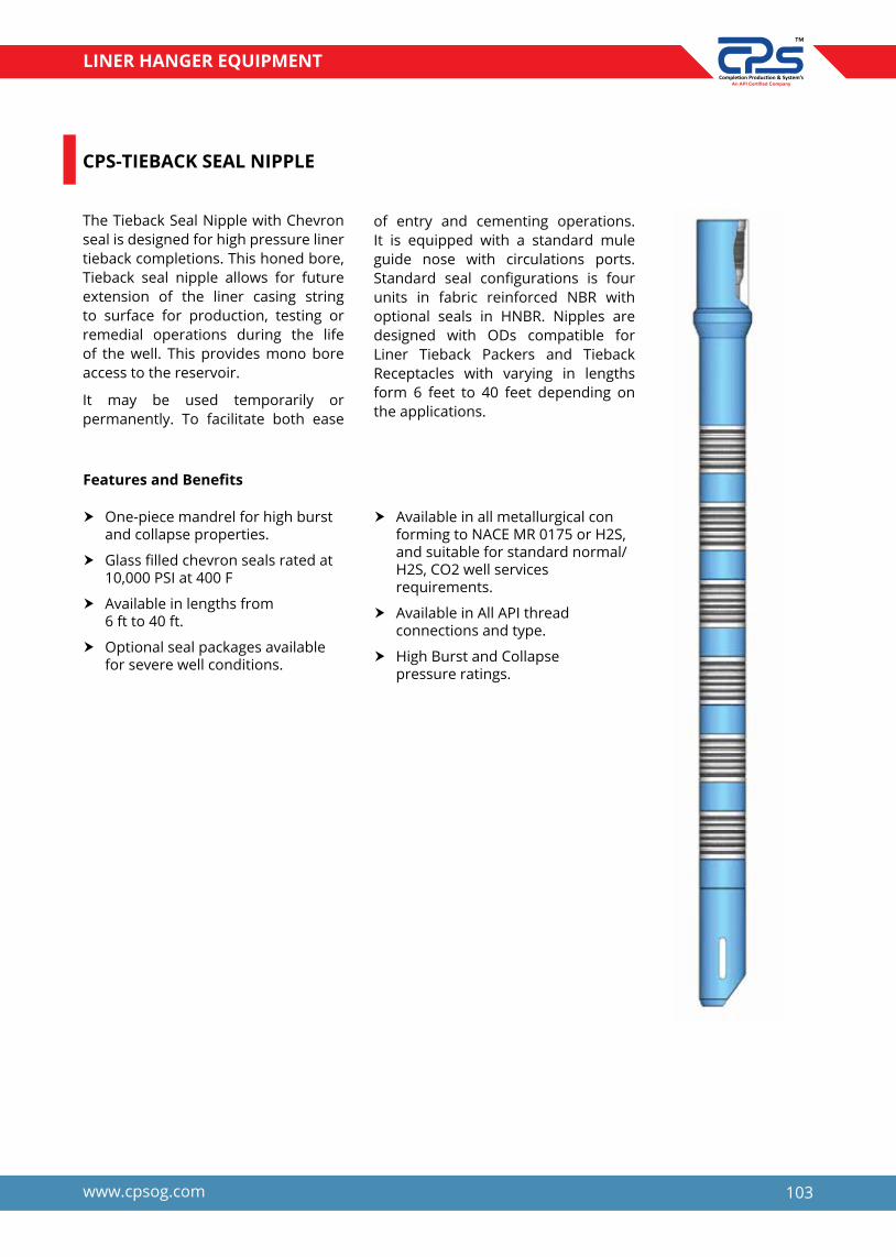
103www.cpsog.com
LINER HANGER EQUIPMENT
CPS-TIEBACK SEAL NIPPLE
The Tieback Seal Nipple with Chevron seal is designed for high pressure liner tieback completions. This honed bore, Tieback seal nipple allows for future extension of the liner casing string to surface for production, testing or remedial operations during the life of the well. This provides mono bore access to the reservoir.
It may be used temporarily or permanently. To facilitate both ease
of entry and cementing operations. It is equipped with a standard mule guide nose with circulations ports. Standard seal configurations is four units in fabric reinforced NBR with optional seals in HNBR. Nipples are designed with ODs compatible for Liner Tieback Packers and Tieback Receptacles with varying in lengths form 6 feet to 40 feet depending on the applications.
Features and Benefits
h One-piece mandrel for high burst and collapse properties.
h Glass filled chevron seals rated at 10,000 PSI at 400 F
h Available in lengths from 6 ft to 40 ft.
h Optional seal packages available for severe well conditions.
h Available in all metallurgical con forming to NACE MR 0175 or H2S, and suitable for standard normal/ H2S, CO2 well services requirements.
h Available in All API thread connections and type.
h High Burst and Collapse pressure ratings.

104 www.cpsog.com
LINER HANGER EQUIPMENT
CPS - FLOAT COLLAR
CPS-FLOAT SHOE
The optional Float Collar acts as an extra back pressure valve sealing against pressure from below when floating in a liner or casing. The positive action, back pressure ball and seat valve constructed of thermal plastic ensures
The Poppet Valve Float Shoe features back pressure valves and a spaded nose with circulating side ports.
The side ports are used when liners are
a secure seal. The Float Collar has no internal connections and is highly resistant to abrasive fluids, corrosion, and temperature.
set on bottom and improve cementing operations, The Double Valve Float Shoe, Poppet valve is PDC drillable.
Features and Benefits
Features and Benefits
h Available in all thread connection as per ordered from 4-1/2” to 20”
h Available in all API material grades
h PDC drillable material use for drill out items
h Jet swirl features for better cementing.
h Available in all thread connection as per ordered from 4-1/2” to 20”
h Available in Slip on and Butt weld type
h Suitable for H2S & CO2 service
h High Burst and collapse pressure
h Available in all API material grades
h PDC drillable material use for drill out items
h Suitable for H2S & CO2 service
h High Burst and collapse pressure

105www.cpsog.com
LINER HANGER EQUIPMENT
LINER HANGER HOOK - UP
PBR
PUMP DOWN PLUG
PUP JOINT
PACKER SETTINGTOOL
HYD. RELEASERUNNING TOOL
SLICK JOINT
PUMP LINER WIPER PLUG
LINER TOP PACKER
DRILLABLE PACK OFBUSHING
HYD. SET DOUBLECONE LINER HANGER
LINER CASING
LANDING COLLAR
FLOAT COTTAR
PLUNGER VALVES
FLOAT SHOE


CEMENTING EQUIPMENT
We Know Your Well Very Well..


109www.cpsog.com
CEMENTING EQUIPMENT
CEMENTING PLUG
Cementing plug is used to separate the cement slurry from other fluids, reducing contamination and maintaining expected slurry performance. CPS provides two types of cementing plug which are generally used on a cementing operation.
y Conventional(Rotating)Type Cementing Plug (Product Code: CPS17)
y Non-Rotating Type Cementing Plug (Product Code: CPS18)
The bottom plug(In Red) is launched ahead of the cement slurry to minimize contamination by fluids inside the cas-ing prior to cementing. A rupture disk in the plug body ruptures to allow the cement slurry to pass through after the plug reaches the Float Collar.
The Top Plug(In Black) has a solid body that provides positive indication of contact with the Float Collar and Bottom Plug through an increase in pump pressure.
Features and Benefits
h Five fins design.
h Internal core is available in Phenolic as well as aluminimum.
h Oil Resistant.
h Five Fins provides greater wiping area.
h Plugs are available in Nitrile, Viton, Aflas and other elastomers.
h Plugs are available in conventional
and Non Rotating Design.
h One plug can be used in range of PPF for same size of casing.
h Plugs are PDC drillable.
h Maximum temperature rating 400°F.
h Non Rotating profile reduces the drilling time.
Specification Table
Cementing Plug Specification Conventional Plug Product
Number
Non Rotating Plug Product
NumberSize PPF OD Bottom Plug Rating
Top Plug Bump Rating
4 1/2" 9.5-13.5 4.33" 300-400 PSI 4000 PSI CPS17-0412 CPS18-0412
5 1/2" 14.0-23.0 5.31" 300-400 PSI 4000 PSI CPS17-0512 CPS18-0512
6 5/8" 20.0-32.0 6.46" 300-400 PSI 4000 PSI CPS17-0658 CPS18-0658
7.0" 17.0-38.0 6.69" 300-400 PSI 5000 PSI CPS17-0700 CPS18-0700
7 5/8 24.0-39.0 7.28" 300-400 PSI 5000 PSI CPS17-0758 CPS18-0758
8 5/8 24.0-39.0 8.27" 300-400 PSI 7000 PSI CPS17-0858 CPS18-0858
9 5/8 36.0-53.5 9.25" 300-400 PSI 7000 PSI CPS17-0958 CPS18-0958
13-3/8 48.0-72.0 13.11" 300-400 PSI 6000 PSI CPS17-1338 CPS18-1338

110 www.cpsog.com
CEMENTING EQUIPMENT
FLOAT SHOE
Float Shoe is a cylindrical steel section with a rounded nose which guides the casing toward the that is attached to the bottom of the casing
string towards the centre of the hole. It contains a check valve to permit fluid to pass downward but not upward through the casing.
Features
h Fast Drill Out.
h Internal Parts are PDC drillable.
h Float Shoe is available in all API grade material.
h Float shoe can be furnished in API threads as well as in Premium threads.
h Jet port/Nose configuration is available upon request. CPS offers Side Jet Ports, Down Jet Ports and Up Jet Ports.
h Valve is tested as per API RP 10F Category III C.
h Float Shoe is available in Single and Double valve Configuration.
h Maximum Back Pressure rating: 5000 psi @400°F.
h Tubing Float Shoe for high pressure up to 10000 PSI.
h Float Shoe is available in different type of nose as per the application.
h Chip breaker features are in all type of aluminimum nose as well as Phenolic nose.
Float Shoe
Bullet Nose Spade Nose Eccentric Nose Phenolic Nose

111www.cpsog.com
CEMENTING EQUIPMENT
Down Jet Float Shoe
Side Jet Float Shoe
Up JetFloat Shoe
TubingFloat Shoe
Stab in Float Shoe
4 1/2" 12.6 3.958" 5.563" CPS15-0412API/Premium
Threads3-1/2" 9.2 2.992" 4.500" CPS15-0312
2-7/8" 6.4 2.441" 3.688" CPS15-0278
Tubing Float Shoe Specification ProductNumber ConnectionOD PPF ID Coupling OD
Cementing Plug Specification ProductNumber
ConnectionOD PPF ID Coupling OD
4 1/2" 12.6 3.958" 5.000" CPS15-0412
API/Premium Threads
5.0" 11.5 4.560" 5.563" CPS15-0500
5 1/2" 14.0 5.012" 6.050" CPS15-0512
6 5/8" 20.0 6.049" 7.390" CPS15-0658
7.0" 17.0 6.538" 7.656" CPS15-0700
7 5/8" 24.0 7.025" 8.500" CPS15-0758
8 5/8" 24.0 8.097" 9.625" CPS15-0858
9 5/8" 36.0 8.921" 10.625" CPS15-0958
10-3/4" 40.5 9.950" 11.750" CPS15-1034
11 3/4" 42.0 11.084" 12.750" CPS15-1134
API/Premium Threads
13 3/8" 48.0 12.715" 14.375" CPS15-1338
16.0" 65.0 15.250" 17.000" CPS15-1600
18-5/8" 87.5 17.755" 20.000" CPS15-1858
20.0" 94.0 19.124" 21.000" CPS15-2000
Specification Table

112 www.cpsog.com
CEMENTING EQUIPMENT
FLOAT COLLAR
Float Collar is a cylindrical steel section with box and pin threads. Float Collar generally uses one string above the Float Shoe. It contains a check valve
to permit fluid to pass downward but not upward through the casing and provides a flat landing surface for cementing plugs.
Features
h Fast Drill Out.
h Internal Parts are PDC drillable.
h Float Collar is available in all API grade material.
h Float Collar can be furnished in API threads as well as in Premium threads.
h Float Collar can be furnished with non rotating feature.
h Valve is tested as per API RP 10F Category III C.
h Float Collar is available in Single and Double valve Configuration.
h Maximum Back Pressure rating:
5000 psi @400°F.
h Tubing Float Collar for high pres sure up to 10000 PSI.
h Orifice float collar for Tie-back application.
h Ball Catcher/Ball Deflector is avail able upon request.
h Flat surface provides platform to bump the bottom plug.
h Baffle plate float collar is available upon request.
h Inner String float collar is available for larger size casing.
Float Collar

113www.cpsog.com
CEMENTING EQUIPMENT
Non Rotating DV Float Collar
Stab in Float Collar
Non Rotating SV Float Collar
Specification Table
Cementing Plug Specification ProductNumber
Connection
OD PPF ID Coupling OD
4 1/2" 12.6 3.958" 5.000" CPS16-0412
API/Premium Threads
5.0" 11.5 4.560" 5.563" CPS16-0500
5 1/2" 14.0 5.012" 6.050" CPS16-0512
6 5/8" 20.0 6.049" 7.390" CPS16-0658
7.0" 17.0 6.538" 7.656" CPS16-0700
7 5/8" 24.0 7.025" 8.500" CPS16-0758
8 5/8" 24.0 8.097" 9.625" CPS16-0858
9 5/8" 36.0 8.921" 10.625" CPS16-0958
10-3/4" 40.5 9.950" 11.750" CPS16-1034
11 3/4" 42.0 11.084" 12.750" CPS16-1134
API/Premium Threads
13 3/8" 48.0 12.715" 14.375" CPS16-1338
16.0" 65.0 15.250" 17.000" CPS16-1600
18-5/8" 87.5 17.755" 20.000" CPS16-1858
20.0" 94.0 19.124" 21.000" CPS16-2000
4 1/2" 12.6 3.958" 5.563" CPS16-0412API/Premium
Threads3-1/2" 9.2 2.992" 4.500" CPS16-0312
2-7/8" 6.4 2.441" 3.688" CPS16-0278
Tubing Float Shoe Specification ProductNumber
ConnectionOD PPF ID Coupling OD

114 www.cpsog.com
CEMENTING EQUIPMENT
GUIDE SHOE
Guide Shoe is a cylindrical steel section with a rounded nose which guides the casing toward the that is
attached to the bottom of the casing string towards the centre of the hole.
h Guide Shoe is available in all API grade material.
h Guide shoe can be furnished in API threads as well as in Premium threads.
h Jet port configuration is available upon request. CPS offers Side Jet Ports, Down Jet Ports and Up Jet Ports.
Specification Table
4 1/2" 12.6 3.958" 5.563" CPS51-0412 API/Premium Threads3-1/2" 9.2 2.992" 4.500" CPS51-0312
2-7/8" 6.4 2.441" 3.688" CPS51-0278
Tubing Float Shoe Specification ProductNumber ConnectionOD PPF ID Coupling OD
Guide Shoe
Down Jet Float Shoe
Side Jet Float Shoe
Up Jet Float Shoe
Cementing Plug Specification ProductNumber Connection
OD PPF ID Coupling OD
4 1/2" 12.6 3.958" 5.000" CPS51-0412
API/Premium Threads
5.0" 11.5 4.560" 5.563" CPS51-05005 1/2" 14.0 5.012" 6.050" CPS51-05126 5/8" 20.0 6.049" 7.390" CPS51-06587.0" 17.0 6.538" 7.656" CPS51-0700
7 5/8" 24.0 7.025" 8.500" CPS51-07588 5/8" 24.0 8.097" 9.625" CPS51-08589 5/8" 36.0 8.921" 10.625" CPS51-0958
10-3/4" 40.5 9.950" 11.750" CPS51-103411 3/4" 42.0 11.084" 12.750" CPS51-1134
API/Premium Threads
13 3/8" 48.0 12.715" 14.375" CPS51-133816.0" 65.0 15.250" 17.000" CPS51-1600
18-5/8" 87.5 17.755" 20.000" CPS51-185820.0" 94.0 19.124" 21.000" CPS51-2000

115www.cpsog.com
CEMENTING EQUIPMENT
REAMER SHOE
Reamer Shoe is a cylindrical steel section with an eccentric nose which guides the casing toward the that is attached to the bottom of the casing
string towards the centre of the hole. It contains a check valve to permit fluid to pass downward but not upward through the casing.
h Carbide spiral vanes and diamond shapes structure provides full-bore coverage in rotating and recipro cating applications, which provides easy passage to total depth.
h The eccentric nose can climb ledges and negotiate other well bore obstructions while the cutting structure reams out tight spots.
h Reamer shoe enables both rotating and reciprocating reaming action while running casing and liners.
h Flow ports provide full-bore coverage while rotating and reaming, and they prevent channeling while cement is pumped.
h All internal parts and standard aluminum alloy nose are PDC drillable.
h Reamer Shoe is available in all API grade material.
h Reamer shoe can be furnished in API threads as well as in Premium threads.
h Reamer Shoe is available in Single and Double valve Configuration.
h Maximum Back Pressure rating: 5000 psi @400°F.
h Reamer shoe is available in welded design as well as single piece design.
Reamer Shoe
Specification Table
Cementing Plug Specification ProductNumber
Hole Size
Reamer OD
ConnectionOD PPF ID Coupling OD
4 1/2" 12.6 3.958" 5.000" CPS46-0412 6.0" 5.875"
API/ Premium Threads
5.0" 11.5 4.560" 5.563" CPS46-0500 6 1/2" 6.375"5 1/2" 14.0 5.012" 6.050" CPS46-0512 7 7/8" 7.75"6 5/8" 20.0 6.049" 7.390" CPS46-0658 8 1/2" 8.375"7.0" 17.0 6.538" 7.656" CPS46-0700 8 1/2" 8.375"
7 5/8" 24.0 7.025" 8.500" CPS46-0758 9 7/8" 9.75"8 5/8" 24.0 8.097" 9.625" CPS46-0858 11.0" 10.875"9 5/8" 36.0 8.921" 10.625" CPS46-0958 12 1/4" 12.125"
10-3/4" 40.5 9.950" 11.750" CPS46-1034 12 1/4" 12.125"11 3/4" 42.0 11.084" 12.750" CPS46-1134 15 1/2" 15.375"
API/ Premium Threads
13 3/8" 48.0 12.715" 14.375" CPS46-1338 17 1/2" 17.375"16.0" 65.0 15.250" 17.000" CPS46-1600 20.0" 19.875"
18-5/8" 87.5 17.755" 20.000" CPS46-1858 22.0" 21.875"20.0" 94.0 19.124" 21.000" CPS46-2000 24.0" 23.875"

116 www.cpsog.com
CEMENTING EQUIPMENT
CROSS COUPLING PROTECTOR
CPS manufactures the Cross Coupling Cable Protectors(Casted) to protect and support ESP cable, control lines
and injection lines in the well bore for wells completed with artificial lift.
h The protector is designed and tested to support a minimum of 100 ft. of ESP cable and control/ injection line across the coupling without cable slippage and crimping.
h The protector is designed to effectively withstand high axial and rotational forces experienced while performing completion operations.
h The protector is designed to withstand axial load of 30 tons and lateral load of 20 tons without slipping on the production tubing.
h The protector is of one-piece design/assembly with captivated cap screw and pre-engaged bolts to eliminate potential for detachment of bolts from the main protector body.
h No loose parts to fall out during or after installation.
h The protector comes with an interlock feature as a standard which protects the bolts from shear stress.
h The protector is designed to have a low profile collar that gives increased clearance within casing and thus allows more standoff protection over cable.
h The protector is designed to have contoured profiles to deflect away impacts encountered while running the production string down-hole.
h All components used in the con struction of the cable protector conform to NACE specifications MR-01-75 (latest edition) for sour service applications.
h All protectors are fully retrievable and reusable after minor refur bishment and replacement of few parts
Features
SIZE ESP Cable Type Control Line Size Thread Connection
2-7/8" Flat or Round 1/4", 3/8" API/Premium
3-1/2" Flat or Round 1/4", 3/8" API/Premium
4-1/2" Flat or Round 1/4", 3/8" API/Premium

117www.cpsog.com
Note

118 www.cpsog.com
Note

119www.cpsog.com
Note

For any further query please contact us on
CPS Oil and Gas Equipments Pvt. Ltd.28, Phase V, Parmar Techno Centre, Vasai East, Western Express Highway,
Thane Dist, Maharashtra - 401208, India.Email : [email protected] | Tel.: +91 7028971169 | Mob.: +91 9819433435
Related Documents