Waves and Patterns in Chemical Reactions Steve Scott Nonlinear Kinetics Group School of Chemistry University of Leeds [email protected]

Waves and Patterns in Chemical Reactions Steve Scott Nonlinear Kinetics Group School of Chemistry University of Leeds [email protected].
Dec 18, 2015
Welcome message from author
This document is posted to help you gain knowledge. Please leave a comment to let me know what you think about it! Share it to your friends and learn new things together.
Transcript
Waves and Patterns in Chemical Reactions
Steve Scott
Nonlinear Kinetics Group
School of Chemistry
University of Leeds
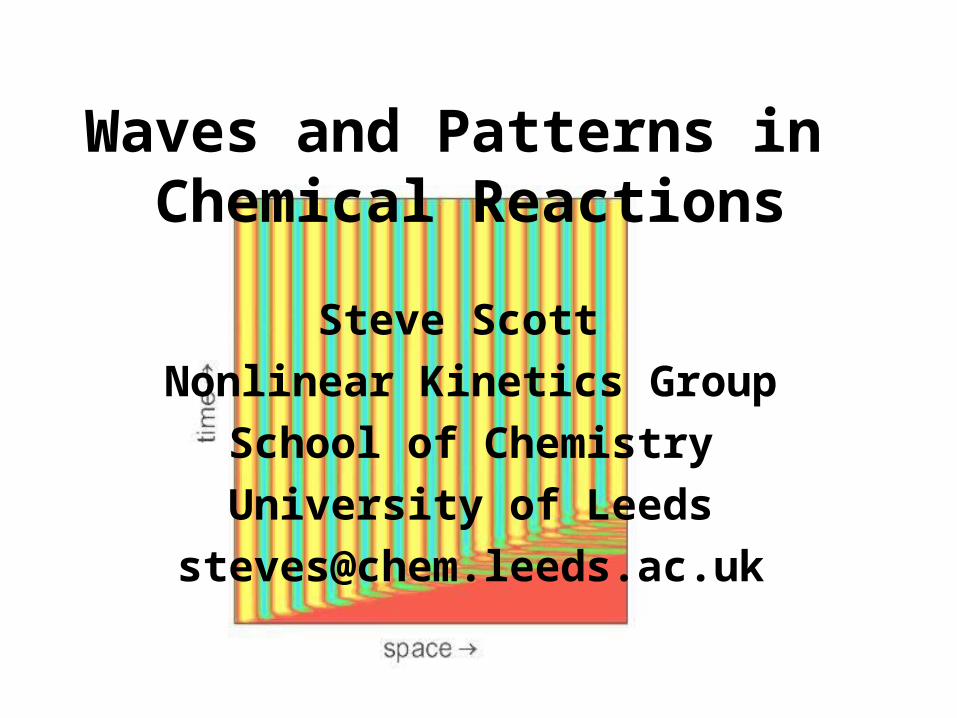
Outline
• Background
• PatternsDIFICIFDO
• Wavesexcitable mediawave block

Feedback
non-elementary processes
intermediate species influence rate of own production and, hence, overall reaction rate.
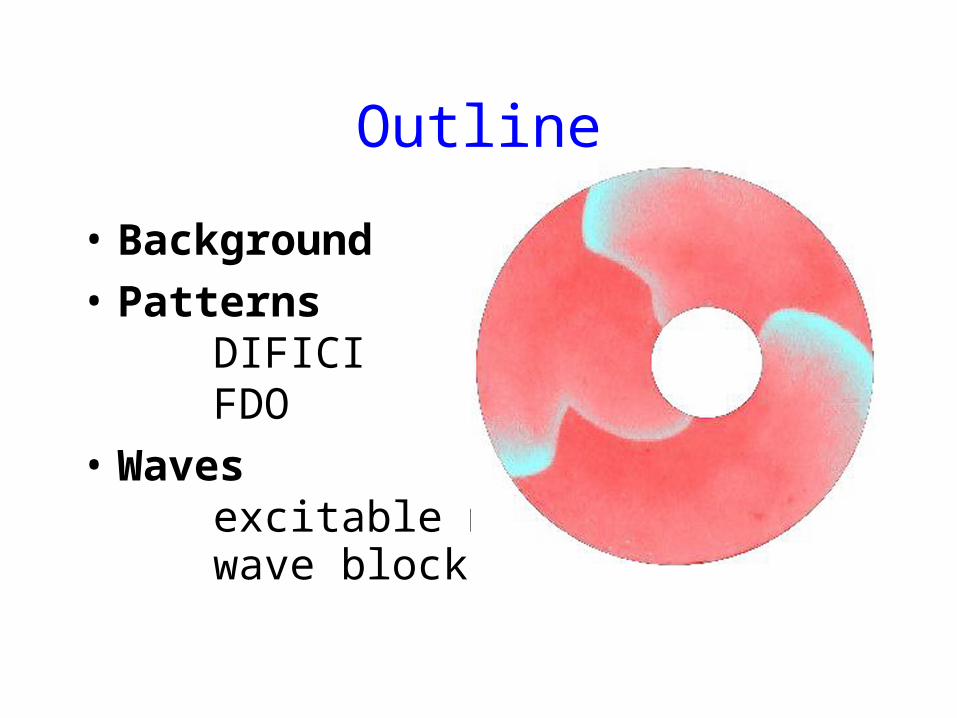
Waves & PatternsWaves
uniform steady state
localised disturbance
leads to propagating “front”
repeated initiation leads to successive waves
precise structure depends on location of initiation
sites
Patterns
uniform state is unstable
spatial structure develops spontaneously
(maybe through waves)
pattern robust to disturbance
wavelength determined by kinetics/diffusion
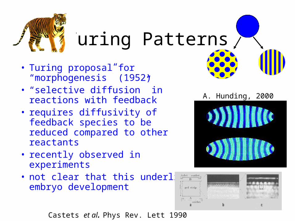
Turing Patterns
• Turing proposal for “morphogenesis” (1952)
• “selective diffusion” in reactions with feedback
• requires diffusivity of feedback species to be reduced compared to other reactants
• recently observed in experiments• not clear that this underlies
embryo development
Castets et al. Phys Rev. Lett 1990
A. Hunding, 2000
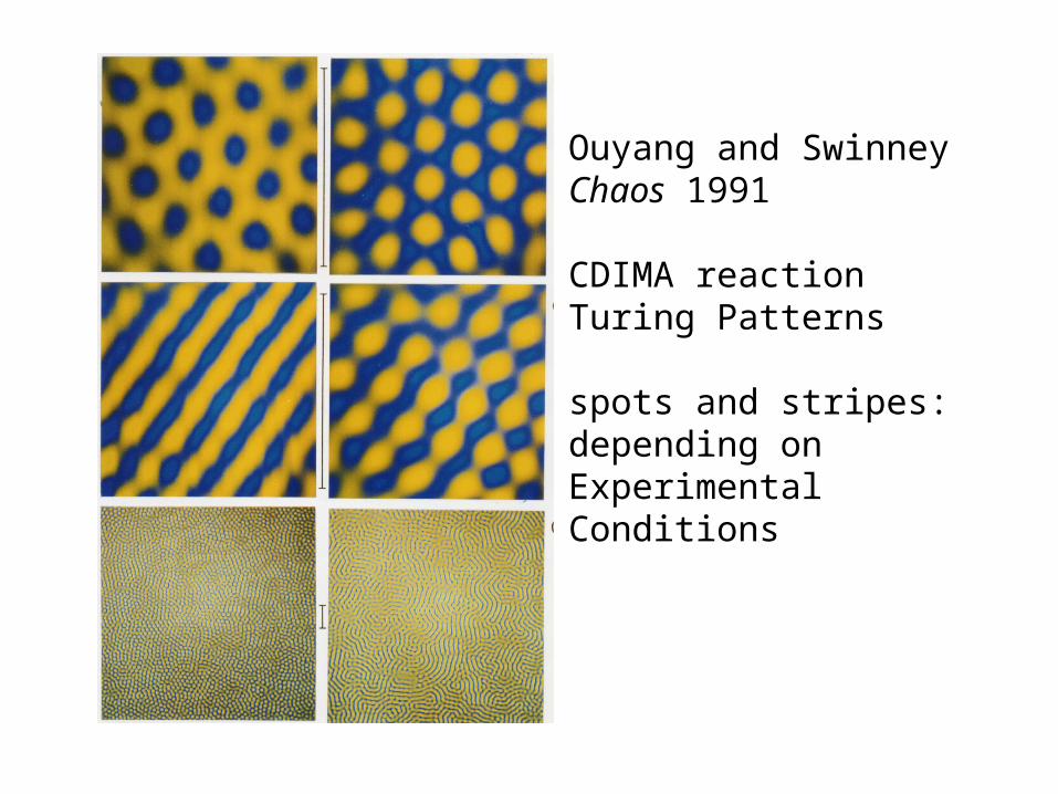
Ouyang and SwinneyChaos 1991
CDIMA reactionTuring Patterns
spots and stripes: depending onExperimentalConditions
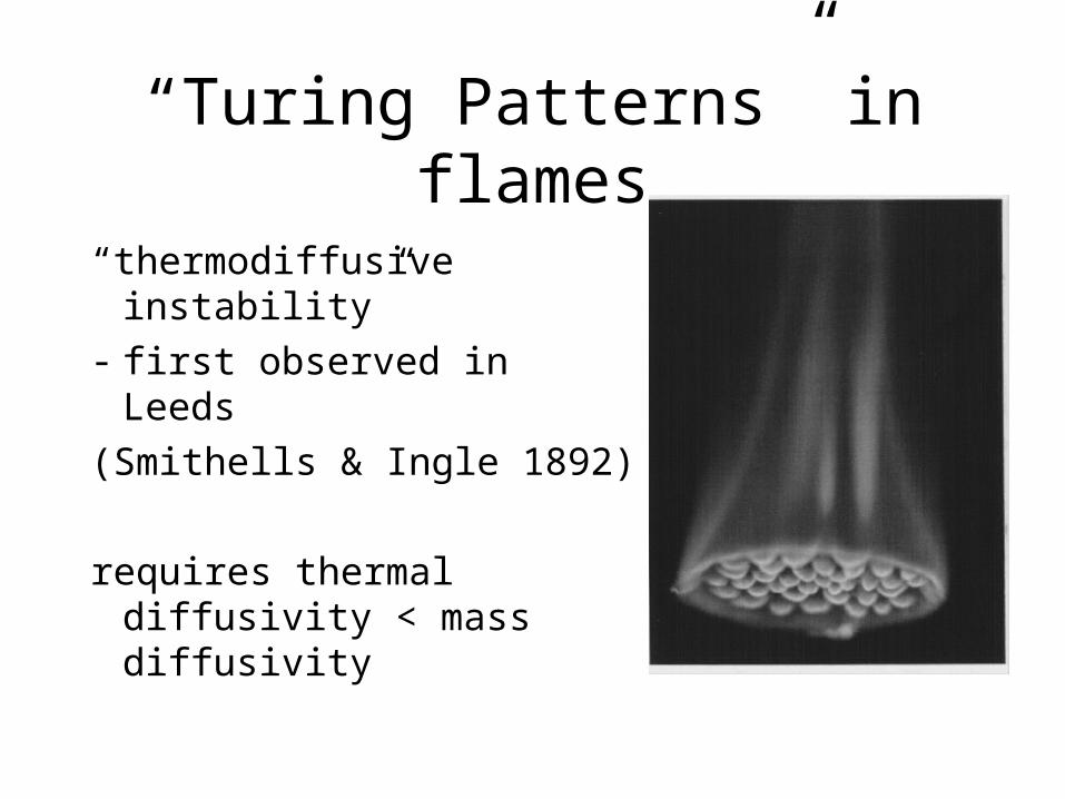
“Turing Patterns” in flames
“thermodiffusive instability”
- first observed in Leeds
(Smithells & Ingle 1892)
requires thermal diffusivity < mass diffusivity
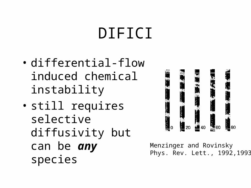
DIFICI
• differential-flow induced chemical instability
• still requires selective diffusivity but can be any species
Menzinger and RovinskyPhys. Rev. Lett., 1992,1993
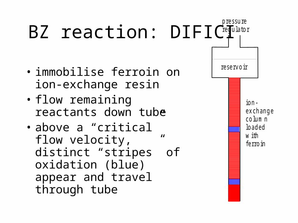
BZ reaction: DIFICI
• immobilise ferroin on ion-exchange resin
• flow remaining reactants down tube
• above a “critical” flow velocity, distinct “stripes” of oxidation (blue) appear and travel through tube
p re ssu rereg u la to r
rese rv o ir
io n -ex ch an g eco lu m nlo a d edw ithfe rro in
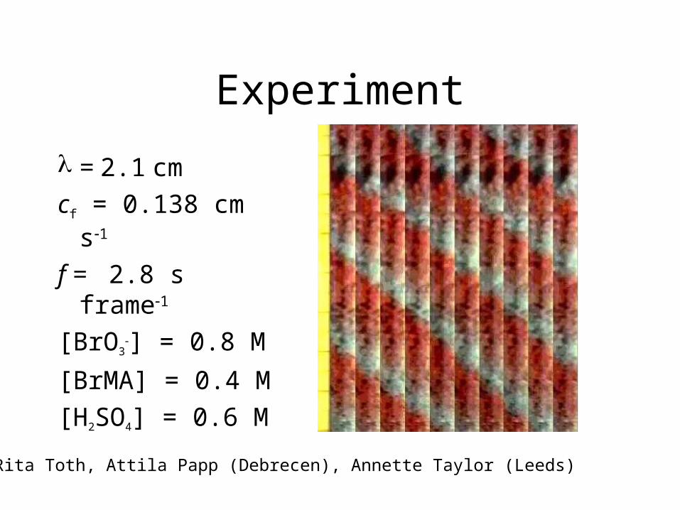
Experiment
= 2.1 cm
cf = 0.138 cm s1
f = 2.8 s frame1
[BrO3] = 0.8 M
[BrMA] = 0.4 M
[H2SO4] = 0.6 M
Rita Toth, Attila Papp (Debrecen), Annette Taylor (Leeds)
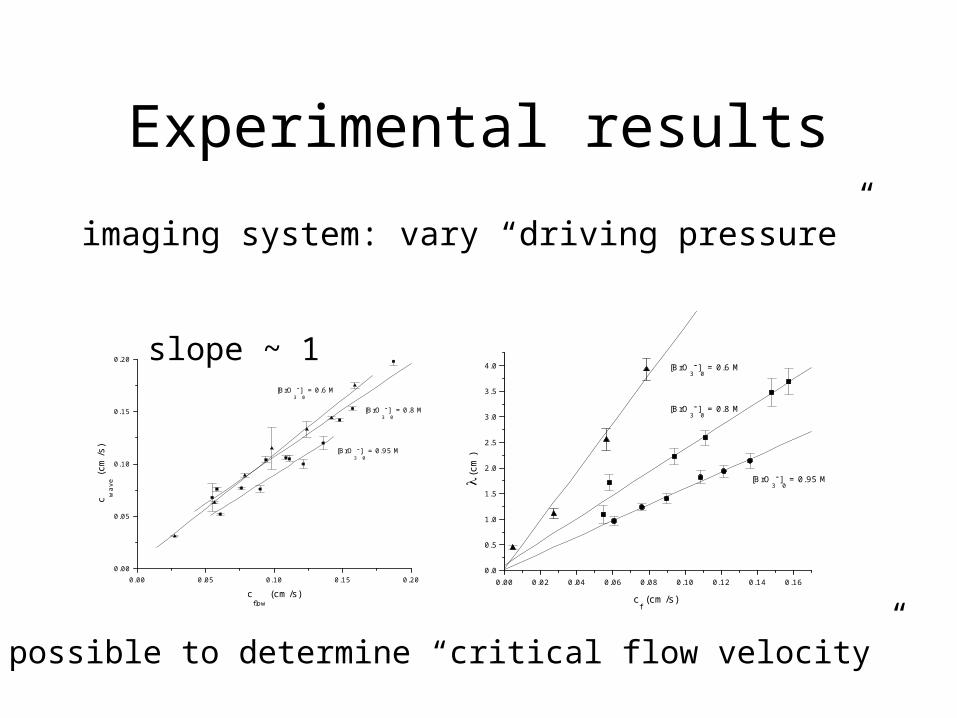
Experimental results
imaging system: vary “driving pressure”
0.00 0.05 0.10 0.15 0.200.00
0.05
0.10
0.15
0.20
[BrO3
]0 = 0.95 M
[BrO3
]0 = 0.8 M
[BrO3
]0 = 0.6 M
c wa
ve (
cm/s
)
cflow
(cm/s)0.00 0.02 0.04 0.06 0.08 0.10 0.12 0.14 0.16
0.0
0.5
1.0
1.5
2.0
2.5
3.0
3.5
4.0
[BrO3]
0 = 0.95 M
[BrO3]
0 = 0.8 M
[BrO3]
0 = 0.6 M
(c
m)
cf (cm/s)
slope ~ 1
Not possible to determine “critical flow velocity”
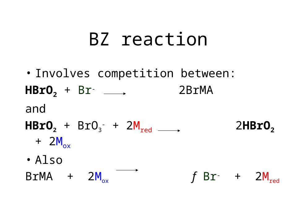
BZ reaction
• Involves competition between:
HBrO2 + Br- 2BrMA
and
HBrO2 + BrO3- + 2Mred 2HBrO2 + 2Mox
• Also
BrMA + 2Mox f Br- + 2Mred
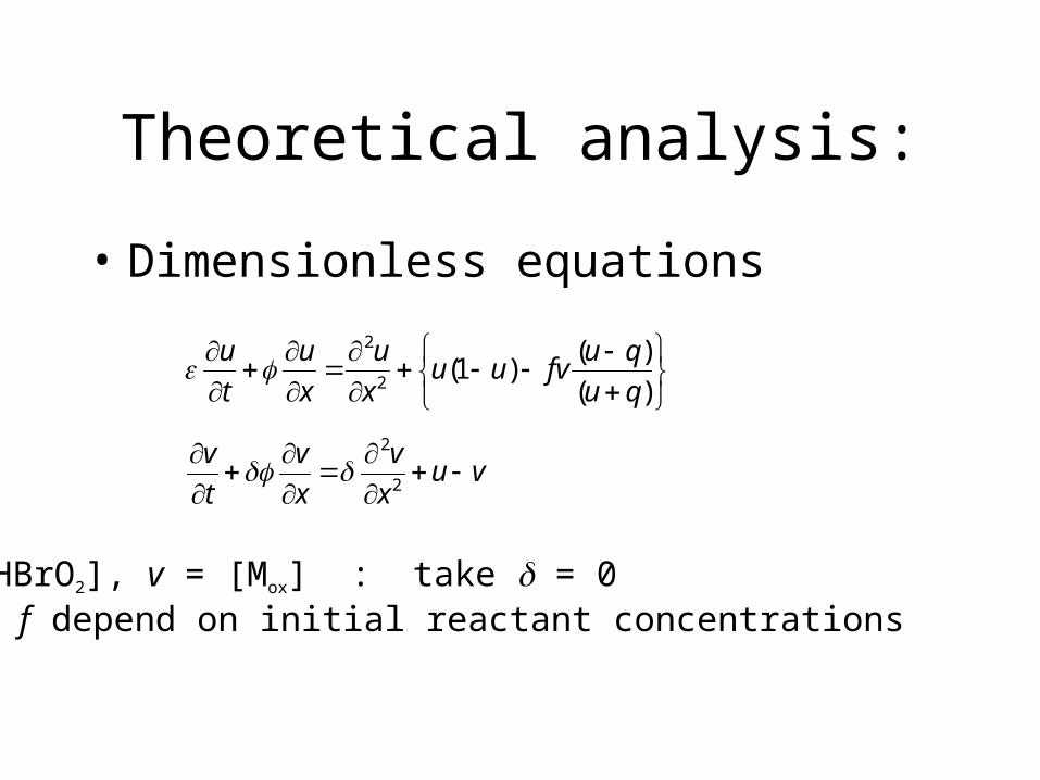
Theoretical analysis:
• Dimensionless equations
)(
)()1(
2
2
qu
qufvuu
x
u
x
u
t
u
u = [HBrO2], v = [Mox] : take = 0 and f depend on initial reactant concentrations
vux
v
x
v
t
v
2
2
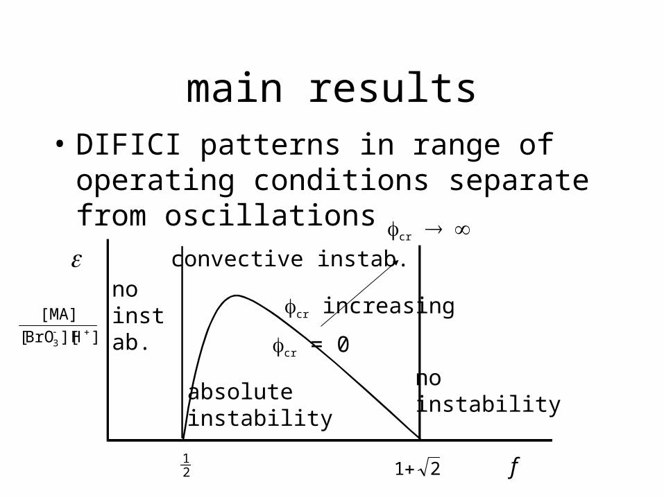
main results• DIFICI patterns in range of operating
conditions separate from oscillations
f
absoluteinstability
convective instab.
noinstability
no instab.
21
21
]H][BrO[
[MA]
3
cr = 0
cr
cr increasing
5 0
01 0 0 0
x
t
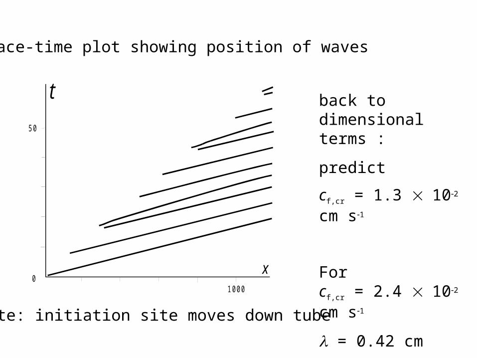
Space-time plot showing position of waves
note: initiation site moves down tube
back to dimensional terms :
predict
cf,cr = 1.3 102 cm s1
Forcf,cr = 2.4 102 cm s1
= 0.42 cm
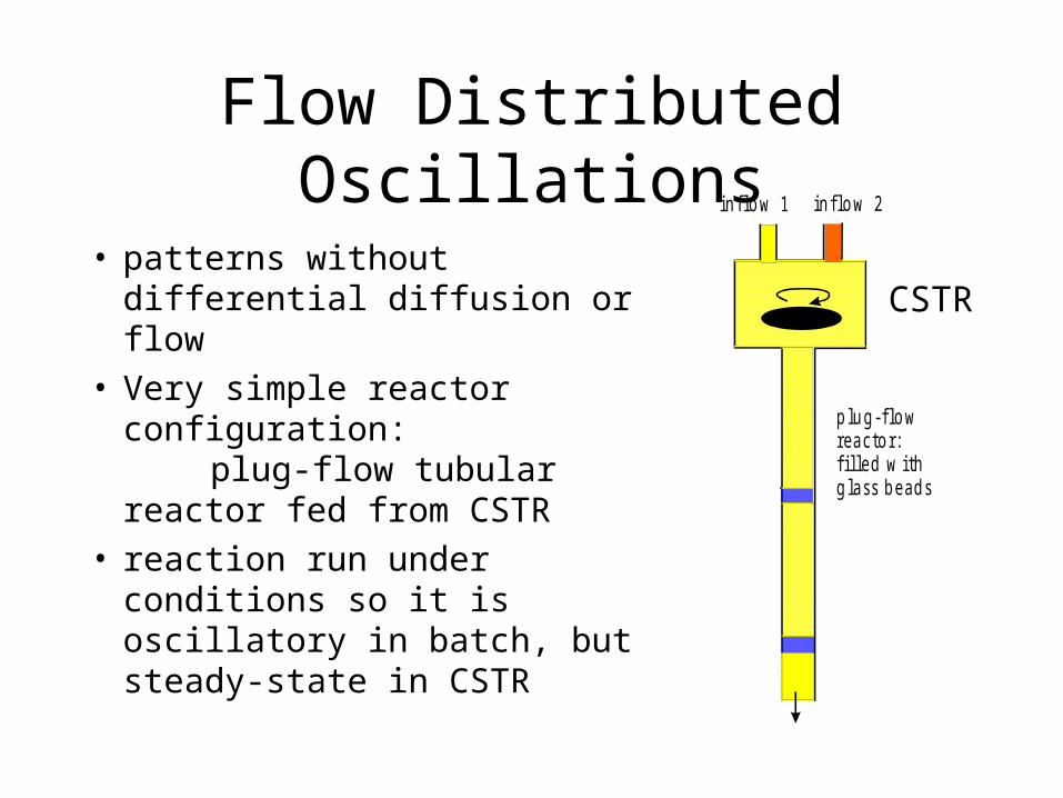
Flow Distributed Oscillations
• patterns without differential diffusion or flow
• Very simple reactor configuration:
plug-flow tubular reactor fed from CSTR
• reaction run under conditions so it is oscillatory in batch, but steady-state in CSTR
p lu g -flo wrea c to r: f ille d w ithg la ss b e ad s
in flo w 1 in flo w 2
CSTR
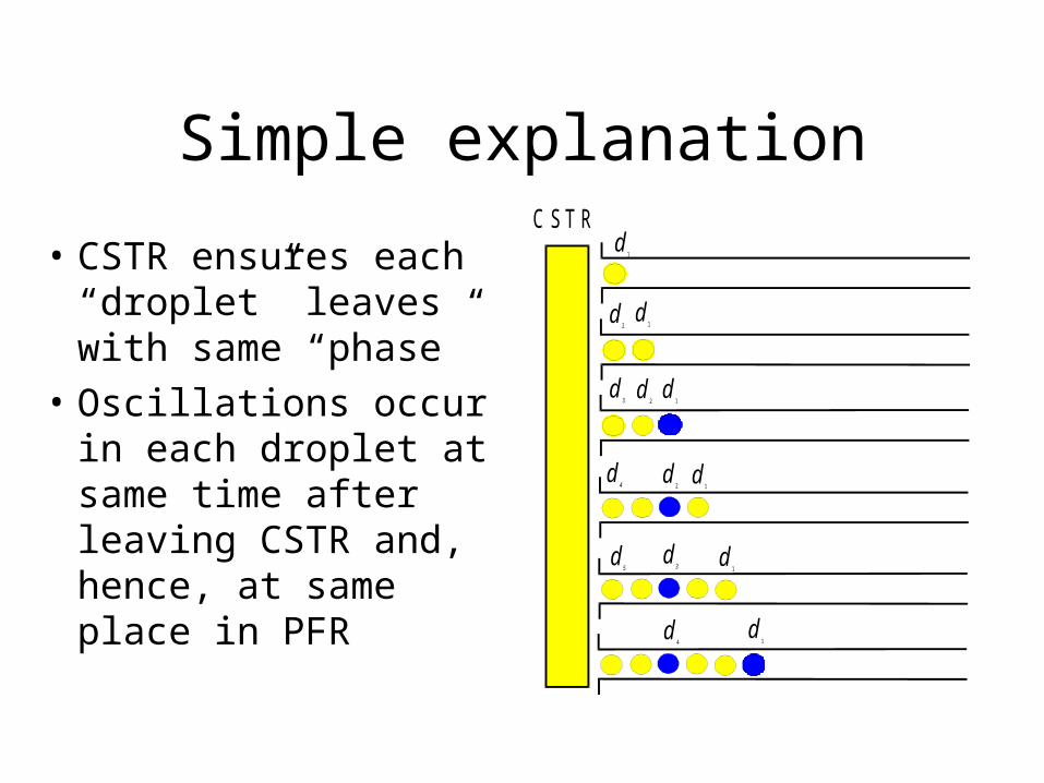
Simple explanation
• CSTR ensures each “droplet” leaves with same “phase”
• Oscillations occur in each droplet at same time after leaving CSTR and, hence, at same place in PFR
C S T Rd
1
d1
d1
d1
d1
d1
d2
d2
d2
d4
d3
d4
d5
d3
• Explains:
need for “oscillatory batch” reaction
stationary pattern
wavelength = velocity oscill period
• Doesn’t explain
critical flow velocity
other responses observed
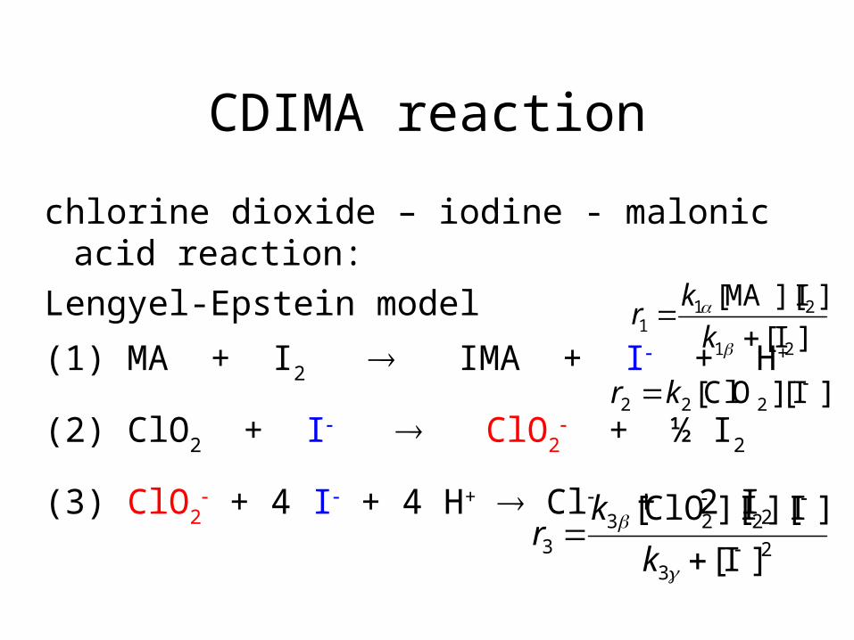
CDIMA reaction
chlorine dioxide – iodine - malonic acid reaction:
Lengyel-Epstein model
(1) MA + I2 IMA + I + H+
(2) ClO2 + I ClO2 + ½ I2
(3) ClO2 + 4 I + 4 H+ Cl + 2 I2
]I[
]I][MA[
21
211
k
kr
r k2 2 2 [ ][ ]ClO I
23
2233 ]I[
]I][I][ClO[
k
kr
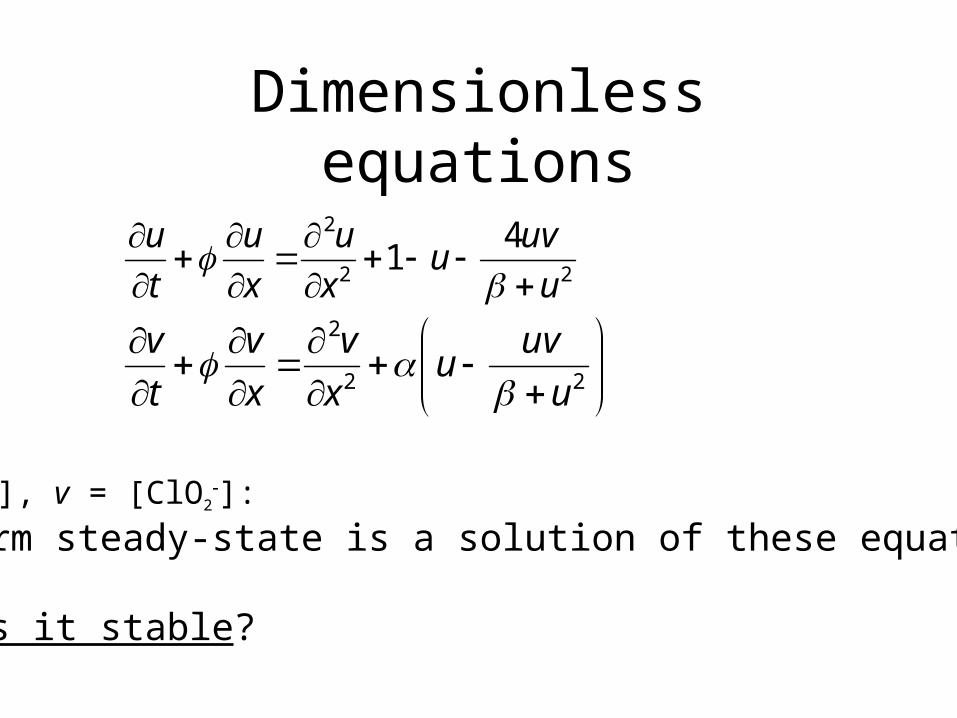
Dimensionless equations
22
2 41
u
uvu
x
u
x
u
t
u
22
2
u
uvu
x
v
x
v
t
v
u = [I], v = [ClO2]:
uniform steady-state is a solution of these equations,
but is it stable?
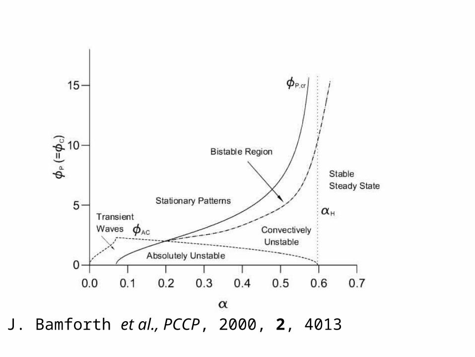
J. Bamforth et al., PCCP, 2000, 2, 4013
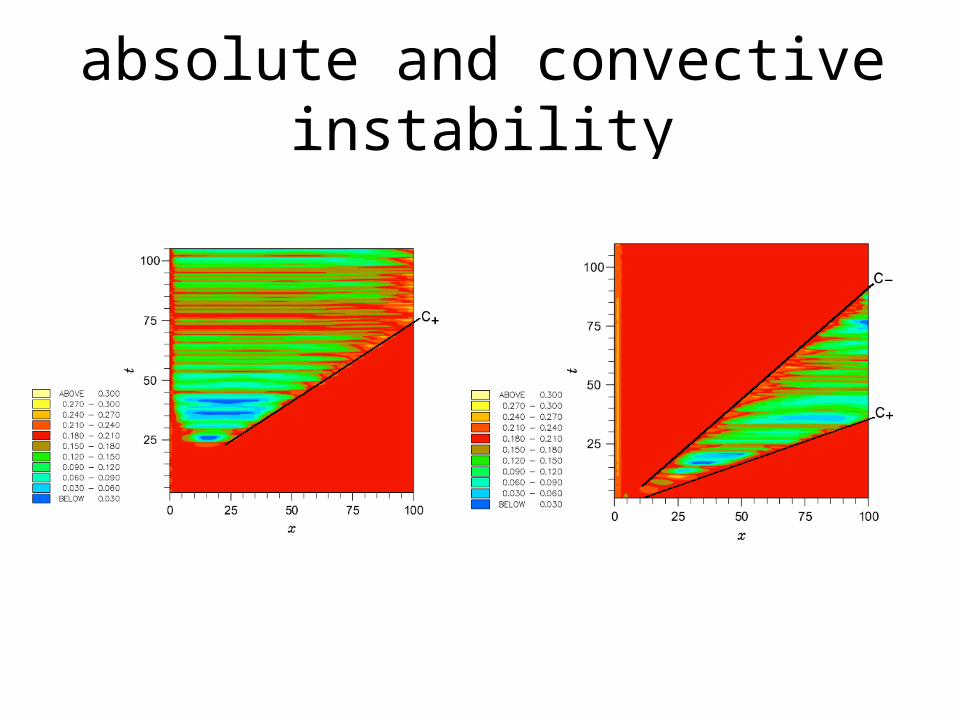
absolute and convective instability
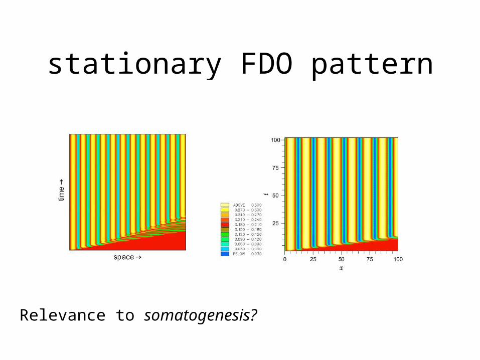
stationary FDO pattern
Relevance to somatogenesis?
Waves in Excitable Media
• What is an “excitable medium?
• Where do they occur?
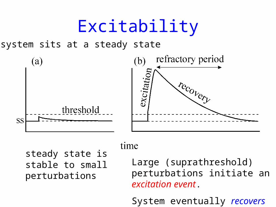
Excitability
steady state is stable to small perturbations
system sits at a steady state
Large (suprathreshold) perturbations initiate an excitation event.
System eventually recovers but is refractory for some period
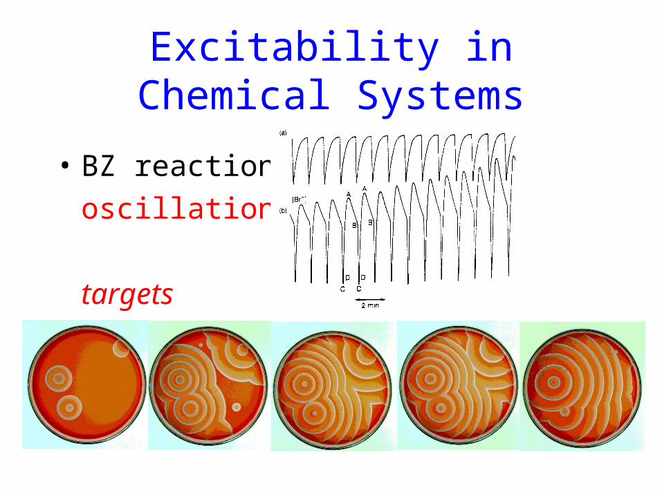
Excitability in Chemical Systems
• BZ reaction:
oscillations
targets
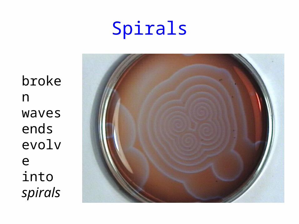
Spirals
broken waves ends evolve into spirals
O2-effects on BZ waves
propagate BZ waves in thin films of solution under different atmospheres:
main point is that O2 decreases wave speed and makes propagation harder:
this effect is more important in thin layers of solution
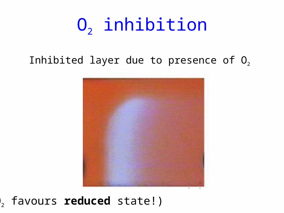
O2 inhibition
Inhibited layer due to presence of O2
(O2 favours reduced state!)
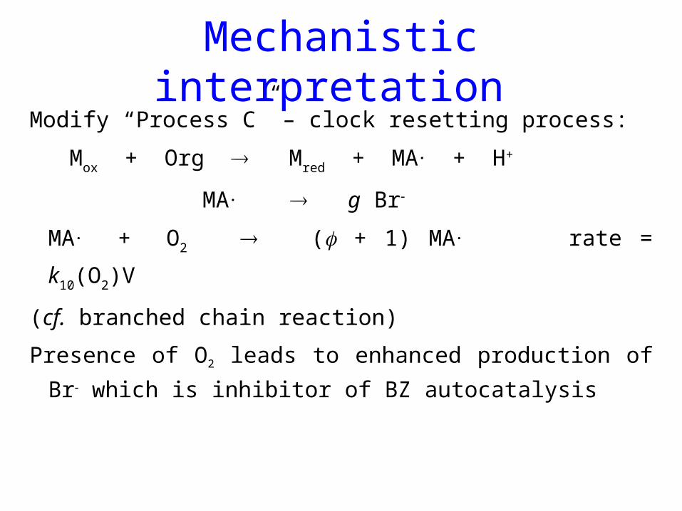
Mechanistic interpretation
Modify “Process C” – clock resetting process:
Mox + Org Mred + MA. + H+
MA. g Br
MA. + O2 ( + 1) MA. rate = k10(O2)V
(cf. branched chain reaction)
Presence of O2 leads to enhanced production of Br
which is inhibitor of BZ autocatalysis
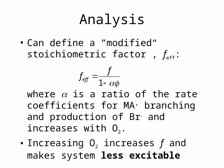
Analysis
• Can define a “modified stoichiometric factor”, feff:
where is a ratio of the rate coefficients for MA. branching and production of Br and increases with O2.
• Increasing O2 increases f and makes system less excitable
1
ffeff
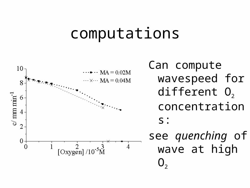
computations
Can compute wavespeed for different O2 concentrations:
see quenching of wave at high O2
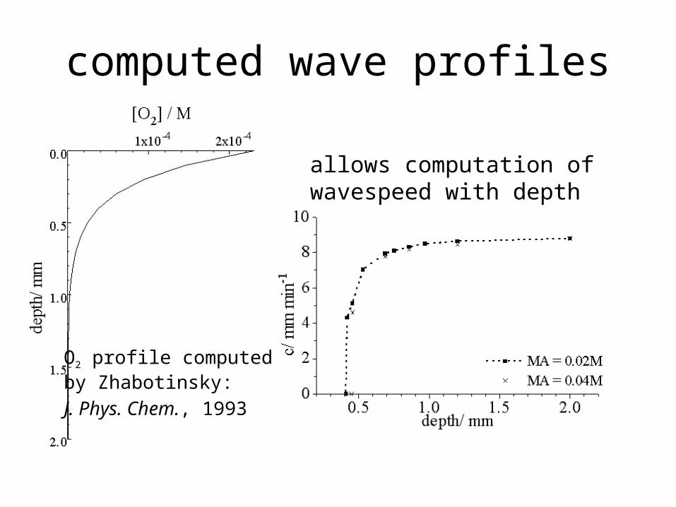
computed wave profiles
O2 profile computedby Zhabotinsky:
J. Phys. Chem., 1993
allows computation of wavespeed with depth
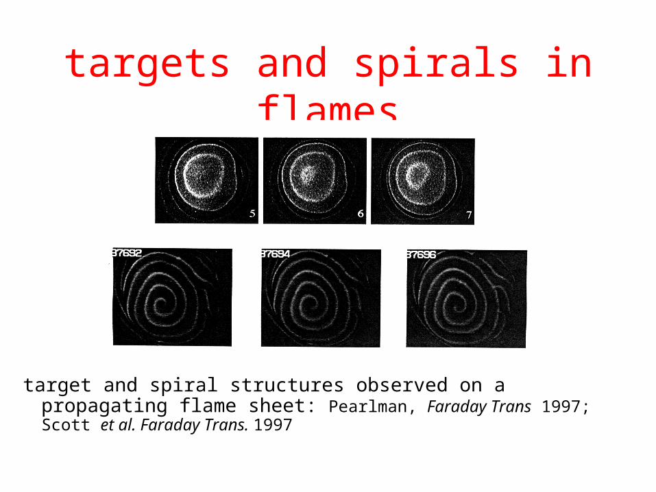
targets and spirals in flames
target and spiral structures observed on a propagating flame sheet: Pearlman, Faraday Trans 1997; Scott et al. Faraday Trans. 1997
Biological systems
• wave propagation widespread:
signalling
sequencing of events
co-ordination of multiple cellular responses
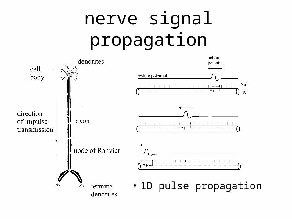
• 1D pulse propagation
nerve signal propagation
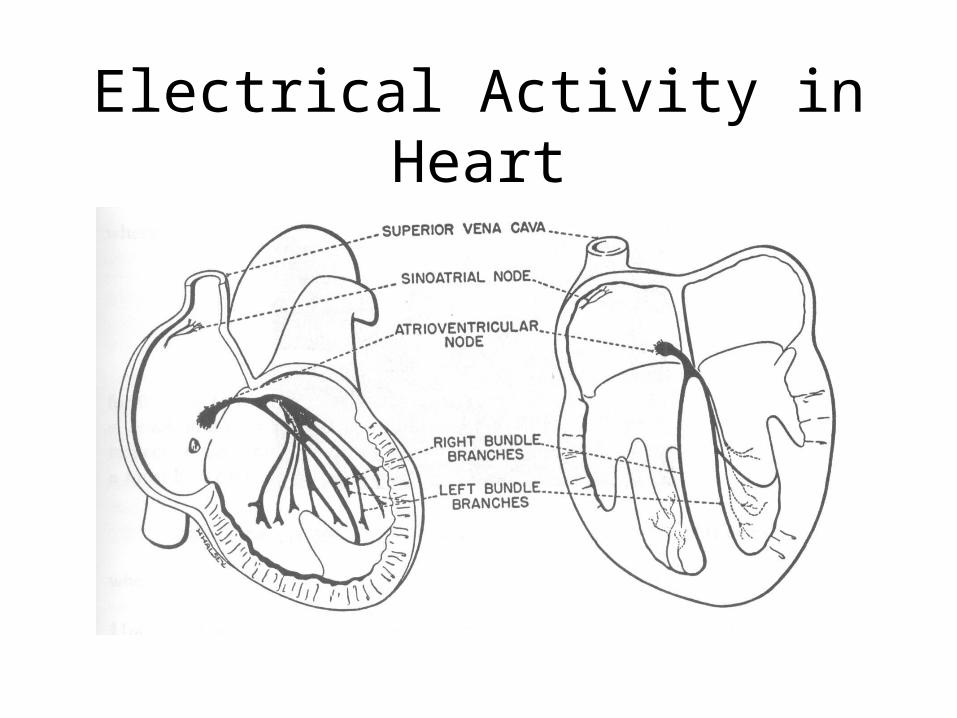
Electrical Activity in Heart
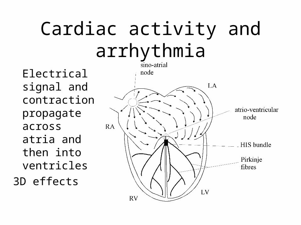
Cardiac activity and arrhythmia
Electrical signal and contraction propagate across atria and then into ventricles
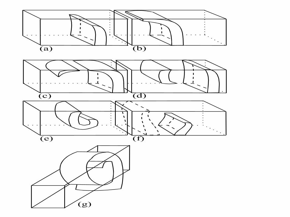
3D effects
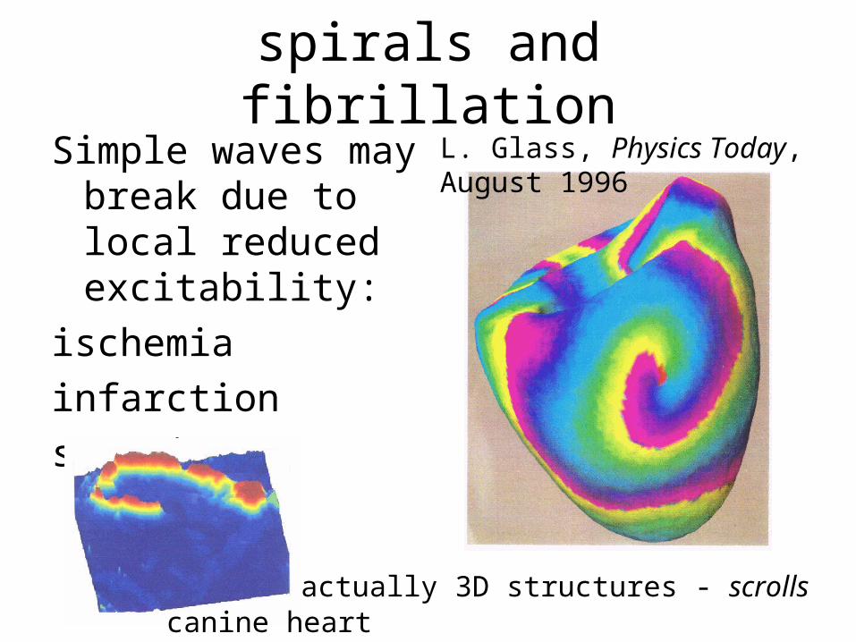
spirals and fibrillationSimple waves may
break due to local reduced excitability:
ischemia
infarction
scarring
actually 3D structures - scrollscanine heart
L. Glass, Physics Today, August 1996
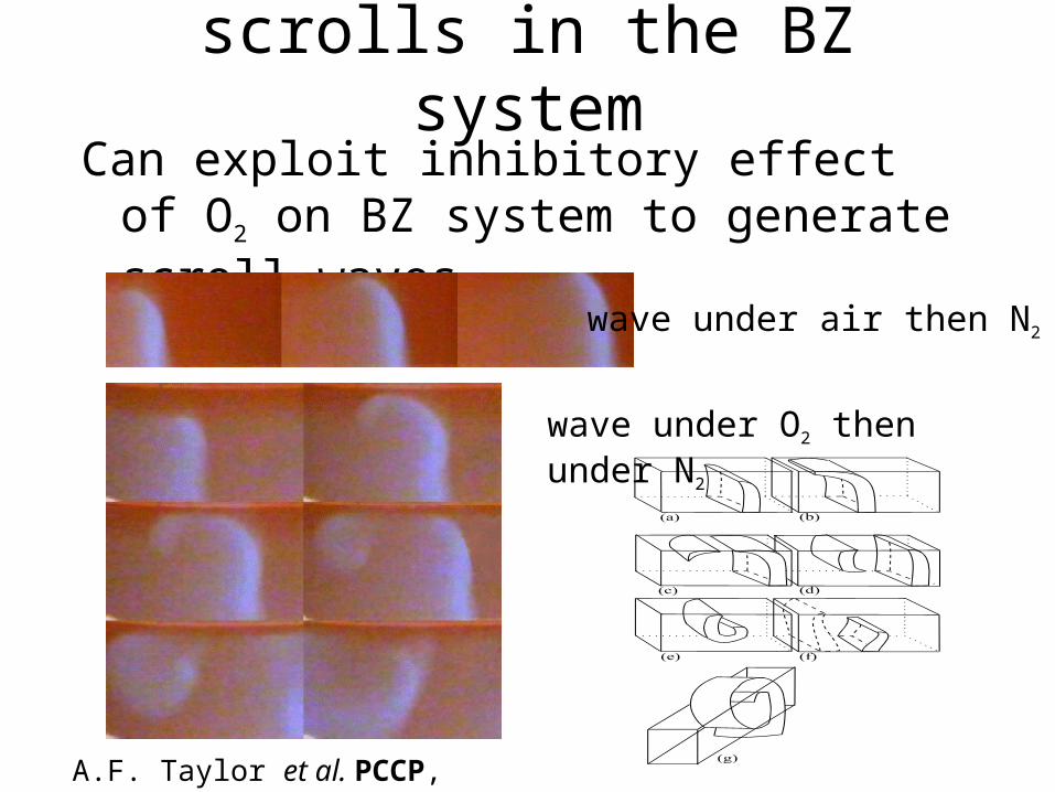
scrolls in the BZ systemCan exploit inhibitory effect of O2 on BZ
system to generate scroll waves
wave under air then N2
wave under O2 then under N2
A.F. Taylor et al. PCCP, 1999
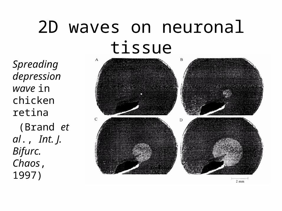
2D waves on neuronal tissue
Spreading depression wave in chicken retina
(Brand et al., Int. J. Bifurc. Chaos, 1997)
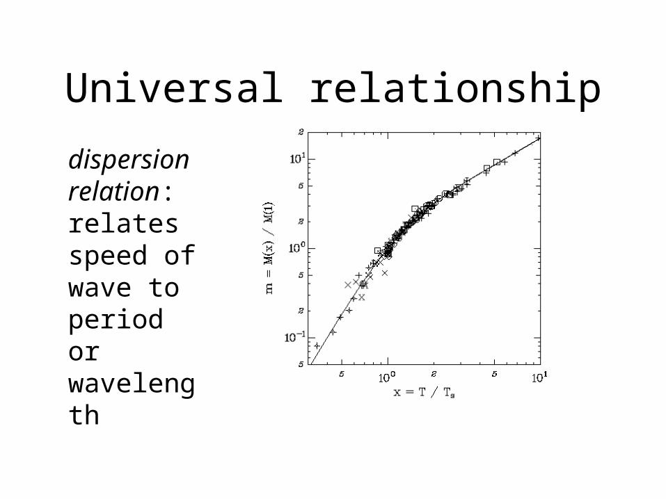
Universal relationship
dispersion relation: relates speed of wave to period or wavelength
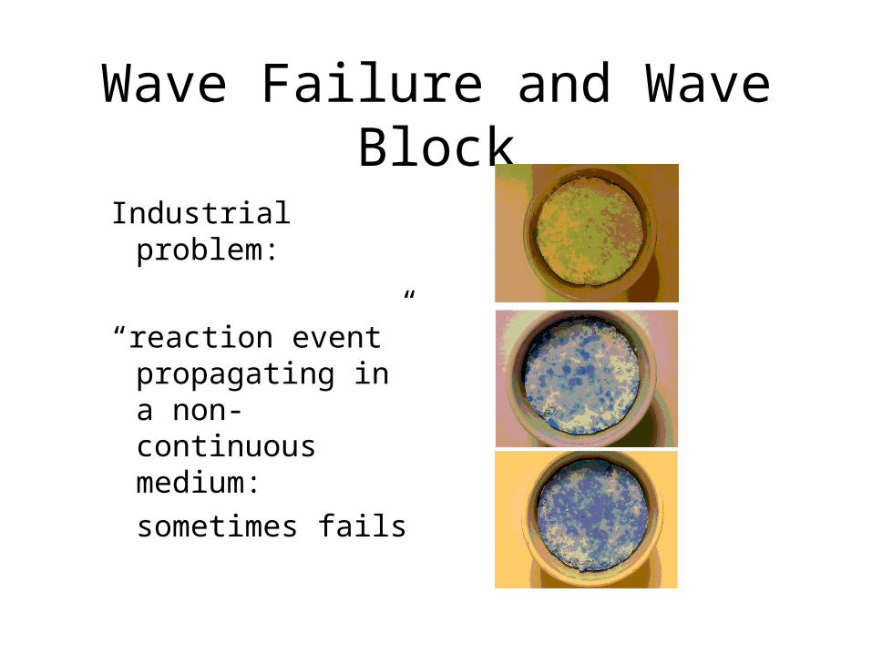
Wave Failure and Wave Block
Industrial problem:
“reaction event” propagating in a non-continuous medium:
sometimes fails
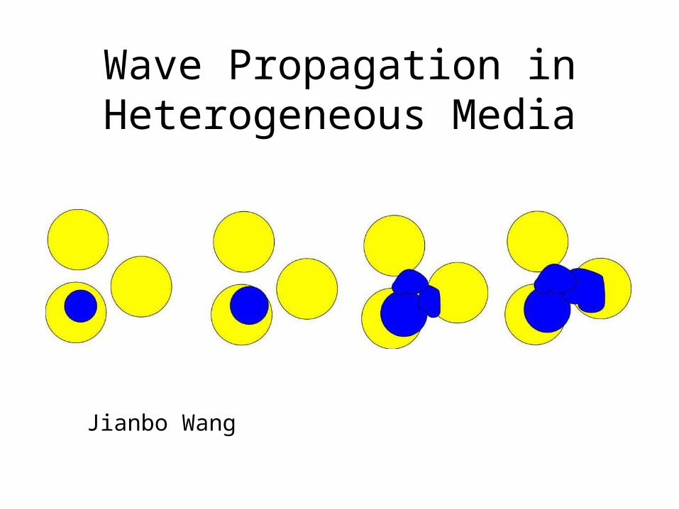
Wave Propagation in Heterogeneous Media
Jianbo Wang
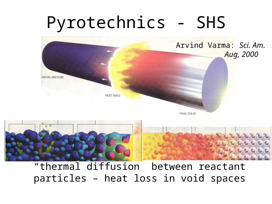
Pyrotechnics - SHS
“thermal diffusion” between reactant particles – heat loss in void spaces
Arvind Varma: Sci. Am. Aug, 2000
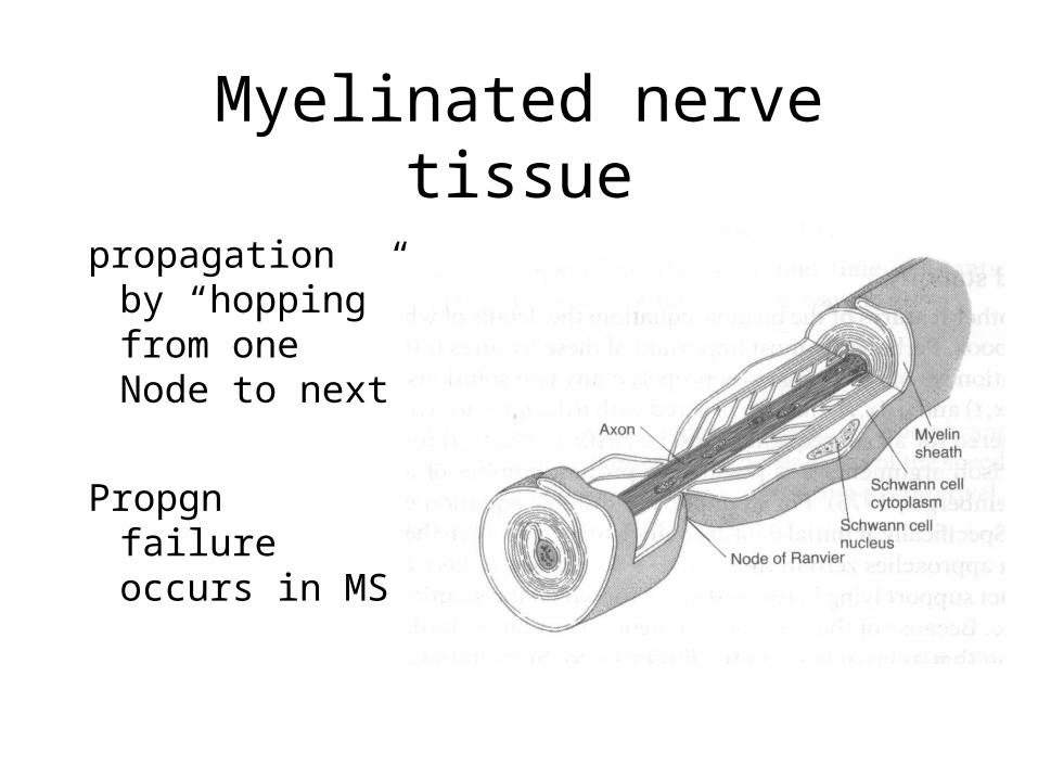
Myelinated nerve tissue
propagation by “hopping” from one Node to next
Propgn failure occurs in MS
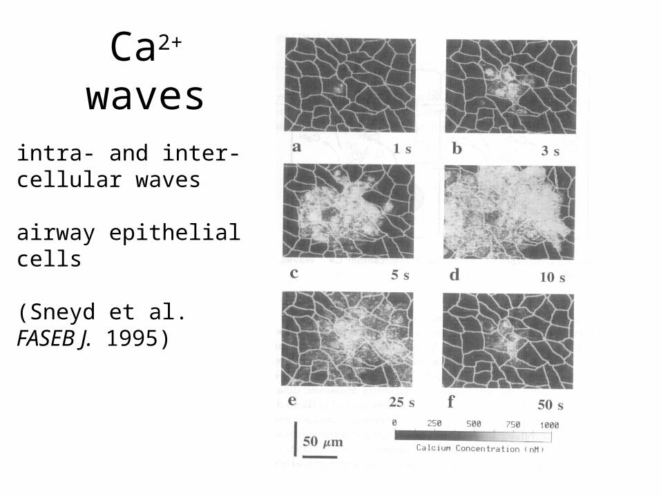
Ca2+ waves
intra- and inter-cellular waves
airway epithelialcells
(Sneyd et al. FASEB J. 1995)
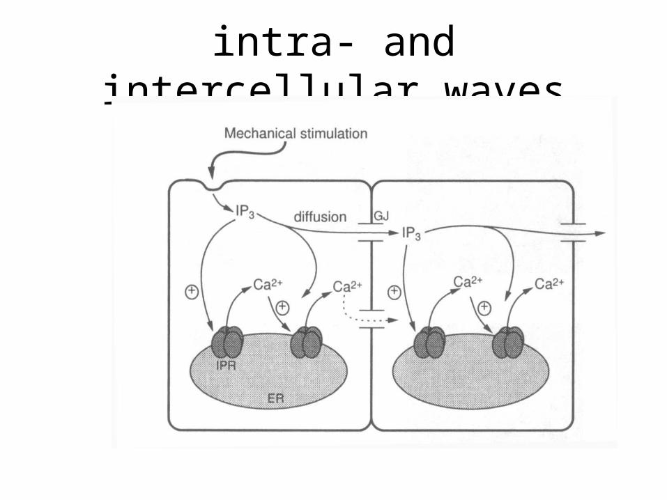
intra- and intercellular waves
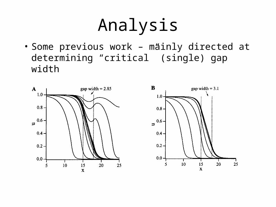
Analysis• Some previous work – mainly directed at
determining “critical” (single) gap width
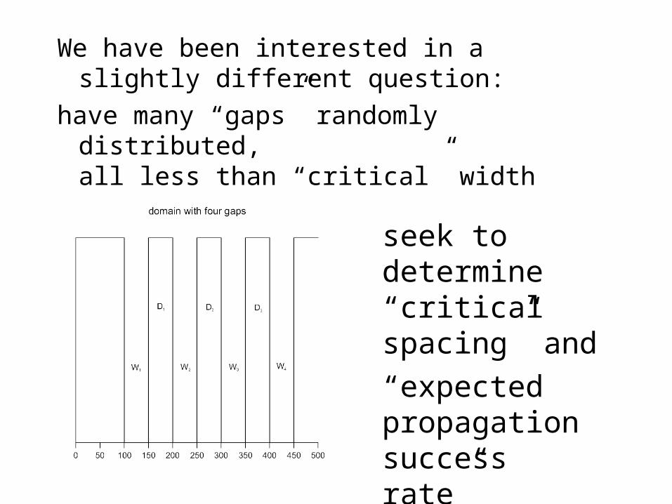
We have been interested in a slightly different question:
have many “gaps” randomly distributed, all less than “critical” width
seek to determine “critical spacing” and
“expected propagation success rate”
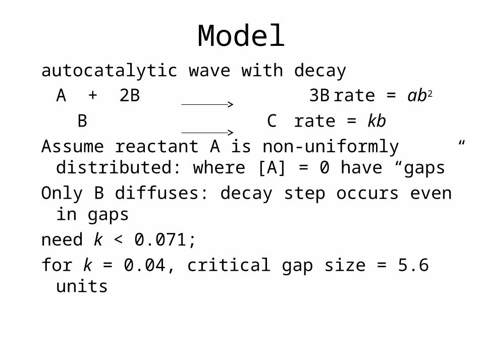
Modelautocatalytic wave with decay
A + 2B 3B rate = ab2
B C rate = kb
Assume reactant A is non-uniformly distributed: where [A] = 0 have “gaps”
Only B diffuses: decay step occurs even in gaps
need k < 0.071;
for k = 0.04, critical gap size = 5.6 units
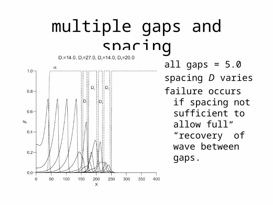
multiple gaps and spacing
all gaps = 5.0
spacing D varies
failure occurs if spacing not sufficient to allow full “recovery” of wave between gaps.
• Have developed a set of “rules” which allow us to judge whether a wave is likely to propagate throughout whole of domain on the basis of sequence of gap spacings.
• Generate 1000 (say) random gap spacings to satisfy some overall “void fraction”
• Inspect each set to determine whether it passes or fails the rules.
• Calculate fraction of “passes”
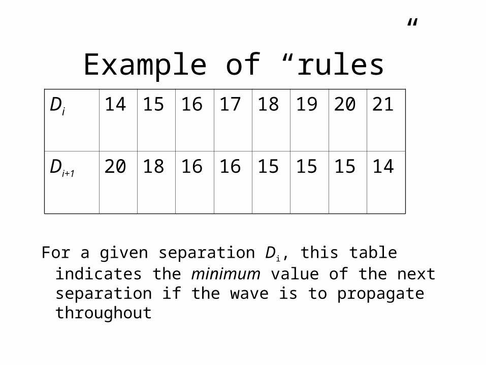
Example of “rules”
For a given separation Di, this table indicates the minimum value of the next separation if the wave is to propagate throughout
Di 14 15 16 17 18 19 20 21
Di+1 20 18 16 16 15 15 15 14
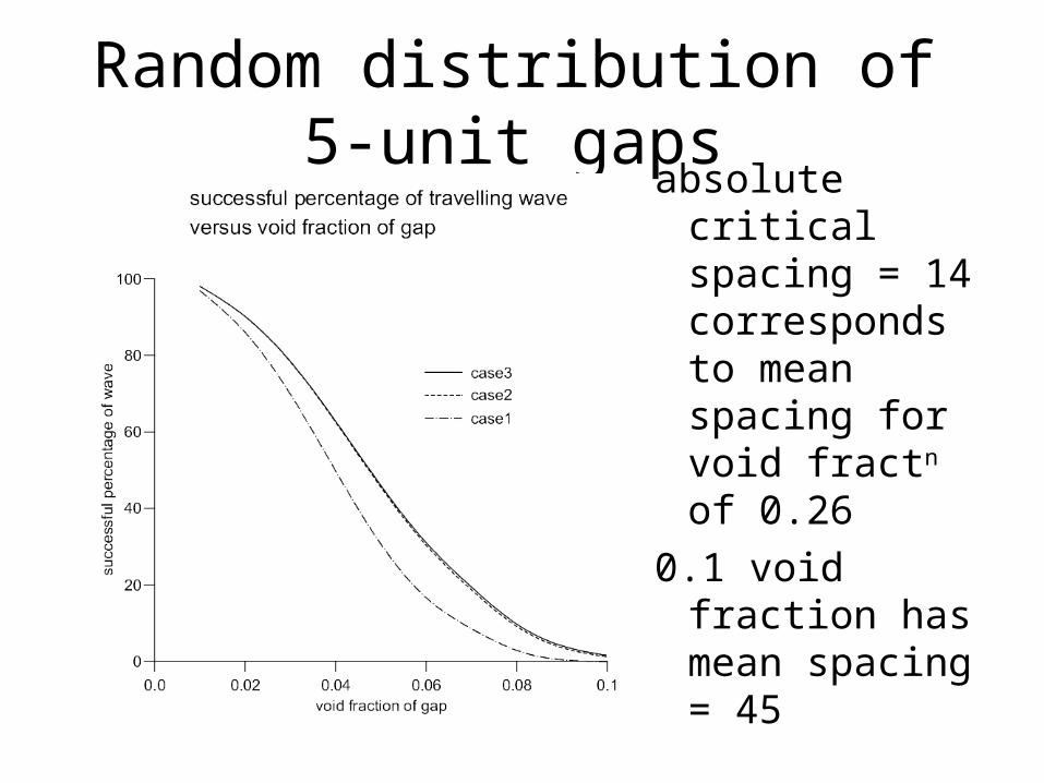
Random distribution of 5-unit gapsabsolute critical
spacing = 14 corresponds to mean spacing for void fractn of 0.26
0.1 void fraction has mean spacing = 45
• Can choose different “gap distributions” – same rules, so just need to generate distribution sets.
• Could consider random gap widths – need to develop new rules
• Extend to “bistable wave” or “excitable wave dynamics” for biological systems
Acknowledgements
Matt Davies, Jonnie Bamforth, Jianbo Yang , Alice Lazarovici, Phil Trevelyan, Annette Taylor, Barry Johnson : Leeds
Rita Toth, Vilmos Gaspar : Debrecen
John Merkin, Serafim Kalliadasis
British Council – Hungarian Academy
ESF Scientific Programme REACTOR
EPSRC
Related Documents