International Journal of Fuzzy Logic Systems (IJFLS) Vol.6, No.3, July 2016 DOI : 10.5121/ijfls.2016.6301 1 WAVELET- FUZZY BASED MULTI TERMINAL TRANSMISSION SYSTEM PROTECTION SCHEME IN THE PRESENCE OF STATCOM CONTROLLER J.Uday Bhaskar 1 and S.S Tulasi Ram 2 1 Department of Electrical & Electronics Engineering, D.M.S S.V.H College Of Engineeing, Machilipatnam, India 2 Department of Electrical & Electronics Engineering, University College Of Engineeing- Jntuh, Hyderabad, India ABSTRACT In This Paper, A New Protection Scheme In The Areas Of Accurate Fault Detection, Classification And Location Estimation For Multi Terminal Transmission System Compensated With Statcom Is Proposed. The Fault Indices Of All The Phases At All The Terminals Are Obtained By Analyzing The Detail Coefficients Of Current Signals Through Bior 1.5 Mother Wavelet. The Complete Digital Simulation Of A Transmission System With Statcom Is Performed Using Matlab /Simulink For Fault Detection, Classification, And Faulty Terminal Identification With Variations In Fault Distance And Fault Inception Angle For All Types Of Faults And Fuzzy Inference System Is Used To Estimate The Fault Location. The Protection Scheme Yielded Accurate Results Within Half Cycle And Show That The Above Scheme Is Suitable For Multi Terminal Transmission System With And Without Statcom Compensation. KEYWORDS Multi Terminal Transmission System, Wavelet Transform, Threshold Value, Statcom, Fault Inception Angle, Fault Indices, Fuzzy Logic 1. INTRODUCTION The Difficulties In Obtaining The Right-Of-Way And The Increase In The Capital Expenditure Have Led To The Development Of Multi Terminal Transmission Lines Where More Than Two Terminals Are Interconnected. The Protection Of Such Systems Is Difficult As Compared With Two-Terminal Systems. The Multi Terminal Lines Experience Problems Generated By The Intermediate In Feed Of The Currents From The Other Terminals Or An Out Feed To The Terminals, Variations In Section Lengths And Source Impedances And Superimposing Of Currents Which Require The System To Be Protected Under Fault Conditions. The Multi Terminal Transmission Lines Are Usually Compensated With Facts Devices Like Svc, Tcsc, Upfc, Statcom Etc., For Transmission Efficiency And To Make Necessary Corrections Of Transmission Functionality. Power Flow Along The Transmission Lines Needs To Be Controlled And Facts Devices Received Some Attention As They Can Alter Power System Parameters In Order To Control Power Flow. The Accurate Fault Detection And Classification Are Vitally Important For Efficient Transmission As The Faults Cause Interruption Of Power Flow. Quick Detection Of Faults Helps In Faster Maintenance And Restoration Of Supply Which Results In Improved Economy And Power Supply Reliability. The Statcom Is An Important Member Of Facts Family And Is Capable Of Enhancing The Power Transfer Capability With Apparent Impedance Being Influenced By The Absorption Or Injection Of The Reactive Power Causing

Welcome message from author
This document is posted to help you gain knowledge. Please leave a comment to let me know what you think about it! Share it to your friends and learn new things together.
Transcript
International Journal of Fuzzy Logic Systems (IJFLS) Vol.6, No.3, July 2016
DOI : 10.5121/ijfls.2016.6301 1
WAVELET- FUZZY BASED MULTI TERMINAL
TRANSMISSION SYSTEM PROTECTION SCHEME IN
THE PRESENCE OF STATCOM CONTROLLER
J.Uday Bhaskar1 and S.S Tulasi Ram
2
1Department of Electrical & Electronics Engineering, D.M.S S.V.H College Of
Engineeing, Machilipatnam, India
2Department of Electrical & Electronics Engineering, University College Of Engineeing-
Jntuh, Hyderabad, India
ABSTRACT
In This Paper, A New Protection Scheme In The Areas Of Accurate Fault Detection, Classification And
Location Estimation For Multi Terminal Transmission System Compensated With Statcom Is Proposed.
The Fault Indices Of All The Phases At All The Terminals Are Obtained By Analyzing The Detail
Coefficients Of Current Signals Through Bior 1.5 Mother Wavelet. The Complete Digital Simulation Of A
Transmission System With Statcom Is Performed Using Matlab /Simulink For Fault Detection,
Classification, And Faulty Terminal Identification With Variations In Fault Distance And Fault Inception
Angle For All Types Of Faults And Fuzzy Inference System Is Used To Estimate The Fault Location. The
Protection Scheme Yielded Accurate Results Within Half Cycle And Show That The Above Scheme Is
Suitable For Multi Terminal Transmission System With And Without Statcom Compensation.
KEYWORDS
Multi Terminal Transmission System, Wavelet Transform, Threshold Value, Statcom, Fault Inception
Angle, Fault Indices, Fuzzy Logic
1. INTRODUCTION
The Difficulties In Obtaining The Right-Of-Way And The Increase In The Capital Expenditure
Have Led To The Development Of Multi Terminal Transmission Lines Where More Than Two
Terminals Are Interconnected. The Protection Of Such Systems Is Difficult As Compared With
Two-Terminal Systems. The Multi Terminal Lines Experience Problems Generated By The
Intermediate In Feed Of The Currents From The Other Terminals Or An Out Feed To The
Terminals, Variations In Section Lengths And Source Impedances And Superimposing Of
Currents Which Require The System To Be Protected Under Fault Conditions. The Multi
Terminal Transmission Lines Are Usually Compensated With Facts Devices Like Svc, Tcsc,
Upfc, Statcom Etc., For Transmission Efficiency And To Make Necessary Corrections Of
Transmission Functionality. Power Flow Along The Transmission Lines Needs To Be Controlled
And Facts Devices Received Some Attention As They Can Alter Power System Parameters In
Order To Control Power Flow. The Accurate Fault Detection And Classification Are Vitally
Important For Efficient Transmission As The Faults Cause Interruption Of Power Flow. Quick
Detection Of Faults Helps In Faster Maintenance And Restoration Of Supply Which Results In
Improved Economy And Power Supply Reliability. The Statcom Is An Important Member Of
Facts Family And Is Capable Of Enhancing The Power Transfer Capability With Apparent
Impedance Being Influenced By The Absorption Or Injection Of The Reactive Power Causing

International Journal of Fuzzy Logic Systems (IJFLS) Vol.6, No.3, July 2016
2
Under Reaching Or Over Reaching Of Distance Relay Wavelet Transform Is An Effective Tool
In Analyzing Transient Current Signals Associated With Faults Both In Frequency And Time
Domain. Amany Et Al Have Done The Work Related With Dwt And Wavelet Entropy To
Analyse Fault Current Signals When Facts Device Placed In The Mid Point Of The Two
Terminal Transmission Line [1].Gorakhnath Abande Et Al Have Given The Impact Analysis Of
Statcom On Distance Relay When Statcom Is Placed At Different Locations During Phase To
Ground Fault[2]. R.Illango Et Al Proposed That Statcom Has Great Impact On The Measured
Impedance At The Relaying Point Which In Turn Effects The Performance Of The Relay. With
Usage Of Synchronized Data Sampling Of Statcom Current At The Relay Location[3].Sriteja Et
Al Have Emphasized The Effect Of Statcom On Distance Relay Performance In A Transmission
Line[4]. A.Y.Abdelaziz Et Al Have Done Work By Extracting The Modal Information From The
Measured Signals To Classify The Faults In A Facts Compensated Transmission Line[5].Qazi
Waqar Ali Et Al Have Applied Facts Devices To Power System And Found That Satisfactory
Regulation Of System Voltage And Increased Loading Ability[6].Sham M.V Et Al Proposed The
Distance Relay Performance In The Presence Of Statcom[7].E.Kazeni Abharian Et Al
Emphasized The Effective Power Flow Control With Statcom Controller Than With Pi, Pid
Controllers[8].R.P.Hasabe Et Al Applied Neural Networks To Locate Faults Along The
Transmission Line[9.]Majid Jamil Et Al Proposed The Fault Location Estimation Using Wavelet
And Ffnn Methods For Two Terminal Transmission System[10].
E.Latha Mercy Et Al Applied Dwt And Anfis Techniques For Fault Detection And Classification
In Transmission Lines With High Fault Resistance[11] Bo,Z.Q Proposed A Protection Scheme
For Multi-Terminal Transmission Circuits Such As Unit And Non-Unit Schemes. The Unit
Schemes Require Extensive Communication Channels Between The Line Ends[12]. Bhalija,B Et
Al Proposed A Distance Relaying Scheme To Detect High Resistance Faults On Two Terminal
Transmission Lines[13]. Brahma And Girgis Proposed A Fault Location Scheme For A Multi-
Terminal Transmission Line Using Synchronized Voltage Measurements At All Terminals[14].
Lyonette,D.R.M Et Al Proposed A Different Directional Comparison Techniques For Multi-
Terminal Lines, Which Compare The Polarity Of Fault Generated Transient Current
Signals[15]. B.Bhalija Et Al Proposed A Differential Protection Scheme For Tapped
Transmission Lines Where Outfeed Current In Case Of Internal And External Faults Was
Considered[16] .Al-Fakhri Proposed Differential Protection Scheme For Multi-Terminal Lines
Using Incremental Currents [17]. Yugant A Parate Et Al Investigated The Enhancement Of
Power System Stability Using Facts Devices[18].Joe –Air Jiang Et Al Proposed A Protection
Scheme For Fault Detection, Direction Discrimination, Classification And Location In
Transmission Lines[19]. Ching-Shan Chen Et Al Considered Double And Three Terminal Lines
For Accurate Fault Detection Using Phasor Measurement Units[20]. Semwal Et Al Used Fuzzy
Inference System With Two Crispy Values As Inputs And Reduced Number Of Fuzzy Rules
Where The Approach Is Fast And Effective [21]. There Must Be Some Innovative Methods To
Be Developed For Multi Terminal Transmission Line Protection. In This Paper, Wavelet Multi-
Resolution Analysis Is Used For Detection And Classification Of Faults And Faulty Terminal
Identification On Four Terminal Transmission System. Fuzzy Inference System Has Been
Applied For Fault Location Estimation. Detail D1 Coefficients Of Current Signals At All The
Four Ends Are Used To Detect And Classify The Faults. The Current Signals Are Analyzed
Taking Into Consideration That Sum Of The Current Coefficients At All The Four Terminals.
The Major Contribution Of This Paper Is The Fast Detection Of Faults And Faulty Terminal
Identification Which Is Very Important In Present Day’s Power System Protection. The Faulty
Terminal Identification Is Done By Considering The Fault Indices Of The Faulty Phase At All
The Terminals And The Fault Index Of The Faulty Terminal Is Maximum As Compared With
The Fault Indices Of The Same Phase At The Remaining Terminals Which Is Very Novel Feature
In Terminal Identification.

International Journal of Fuzzy Logic Systems (IJFLS) Vol.6, No.3, July 2016
3
2. WAVELET ANALYSIS
Wavelet Transform (Wt) Is An Efficient Means Of Analyzing Transient Currents And Voltages.
Unlike Discrete Fourier Transform, Wt Not Only Analyses The Signal In Frequency Bands But
Also Provides Non-Uniform Division Of Frequency Domain I.E. Wt Uses Short Window At High
Frequencies And Long Window At Low Frequencies. This Helps To Analyze The Signal In Both
Frequency And Time Domains Effectively. A Set Of Basis Functions Called Wavelets, Are Used
To Decompose The Signal In Various Frequency Bands, Which Are Obtained From A Mother
Wavelet By Dilation And Translation Hence The Amplitude And Incidence Of Each Frequency
Can Be Found Precisely. Wavelet Transform Is Defined As A Sequence Of A Function
{H(N)}(Low Pass Filter) And {G(N)} (High Pass Filter). The Scaling Function ⱷ(T) And
Wavelet Ψ(T) Are Defined By The Following Equations.
( ) ( ) ( )
( ) ( ) ( )∑
∑
−=
−=
ntngt
ntnht
22
,22
ϕψ
ϕϕ
(1)
Where G(N)=(-1)N H(1-N). A Sequence Of {H(N)} Defines A Wavelet Transform. This Method,
Like The Fourier Transform, Provides Information Related To The Frequency Composition Of A
Waveform, Thus It Is More Appropriate Than The Familiar Fourier Methods For The Non-
Periodic, Wide-Band Signals Associated With Electromagnetic Transients. Wavelet Transform
Provides A New Tool For Signal Processing In Contrast To The Traditional Fourier Analysis
That Averages Frequency Features Both In Time And Frequency. Wavelets Allow The
Decomposition Of A Signal Into Different Levels Of Resolution Which Gives A Much Better
Signal Characterization And A More Reliable Discrimination. The Multi Resolution Analysis Of
Wavelet Can Be Utilized Effectively In Analyzing The Power System Transients. The Feature
Extraction Property Of Wavelets Transforms Is Exploited In The Area Of Protection Of
Transmission Line To Detect And Classify The Faults On Various Components. There Are Many
Types Of Wavelets Such As Haar, Daubachies, Symlet, Bior Etc. The Selection Of Mother
Wavelet Is Based On The Type Of Application And After Extensive Work With All Wavelets,
Bior-1.5 Was Found To Be Effective And Has Been Selected As Mother Wavelet.
3. FAULT DETECTION AND CLASSIFICATION
Fig.1.Single Line Diagram of the Proposed Four Terminal Transmission System.

International Journal of Fuzzy Logic Systems (IJFLS) Vol.6, No.3, July 2016
4
Figure 1 Shows The Single Line Diagram Of The Multi Terminal Transmission System
Considered For The Proposed Scheme. Four 110-Km 400 Kv Transmission Lines Compensated
With 100mva Static Synchronous Compensator (Statcom) At The Middle Of The Second
Terminal Are Interconnected. The Scheme Is Evaluated Using 400kv, 50hz Four Terminal
Transmission System Whose Line Parameters Are R0=0.1888ω/Km,
R1=0.02ω/Km,L0=3.5mh/Km, L1=0.94mh/Km,C0=0.0083µf/Km., C1=0.012µf/Km.A Sampling
Frequency Of 16khz Is Chosen To Capture The High Frequency Content Of Current Signals.The
System Is Modeled In Matlab Simulink Environment. The Network Is Simulated For Various
Fault Situations. Exhaustive Simulations Were Carried Out For L-G, L-L-G, L-L-L Faults
Occurring At Different Locations Along The Paths Of Terminal 1 To Terminal 2, Terminal 2 To
Terminal 3, Terminal 3 To Terminal 1, And Terminal 4 To Terminal 1. For Each Type Of Fault
At A Particular Location, The Fault Inception Angle Was Varied To Evaluate The Performance
Of The Proposed Scheme. Influence Of Fault Resistance Also Being Considered With Value Of 5
Ohms. Synchronized Sampling Of Three Phase Currents At All Terminals Was Carried Out And
The Detail D1 Coefficients Were Used For Detection And Classification Of The Type Of Fault.
The Three Phase Currents Of The Local Terminal Are Analyzed With Bior1.5 Mother Wavelet
To Obtain The Detailed Coefficients (D11) At Terminal 1 Over A Moving Window Of Half Cycle
Length. These D11 Coefficients Are Then Transmitted To The Remote End. The Detailed
Coefficients Received From The Remote End At Bus2 (D12) Are Subtracted From The Local
Detail Coefficients (D11) To Obtain Effective D1 Coefficients (D1e). The Fault Index (If1) Of
Each Phase Is Then Calculated As If1 =Σ׀D1e׀
Fig. 2a.Three Phase Currents Ia,Ib,Ic at All Terminals for A-G Fault at Terminal-1
Fig. 2b.Three Phase Currents Ia,Ib,Ic at All Terminals for A-G Fault at Terminal-2
International Journal of Fuzzy Logic Systems (IJFLS) Vol.6, No.3, July 2016
5
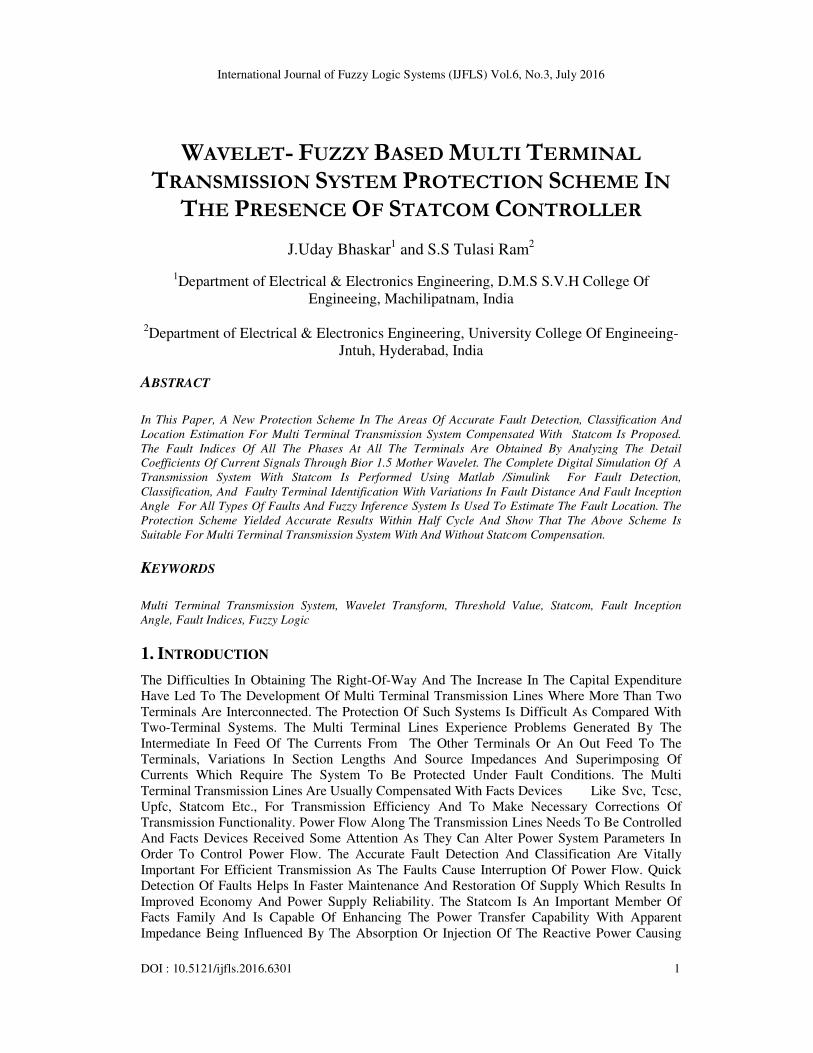
Fig. 2c.Three Phase Currents Ia,Ib,Ic at All Terminals for A-G Fault at Terminal-3
Fig. 2d.Three Phase Currents Ia,Ib,Ic at All Terminals for A-G Fault At Terminal-4
The Performance Of The Scheme In Detecting And Classifying The Faults I.E. Line-To-Ground,
Line-To-Line, Line-Line-To- Ground, Triple-Line-To- Ground Is Evaluated. In All The Cases
Studied, The Scheme Is Able To Detect The Faults. The Fault Inception Angle Is Varied From
200
To 1800 For All Types Of Faults. The Simulations Show That The Fault Inception Angle Has
A Considerable Effect On The Phase Current Samples And Therefore On Wavelet Transform
Output Of Post-Fault Signals.
Digital Protection Scheme Involves The Analysis Of Current Signals Of All The Three Phases At
All The Terminals. The Impedance Measurement Involves Both The Voltage And Current
Signals To Be Analyzed And Takes More Time To Measure Faulty Section Impedance Thereby
The Relay Operation. The Faulty Phases Will Be Identified With The Analysis Of Only Current
Signals And Fault Clearing Time Will Be Less Than Half Cycle. The Digital Protection Scheme
Involved The Comparison Of All Phases With Threshold Value, Where The Faulty Phase(S)
Indices Have Higher Value Compared With The Threshold Value And The Healthy Phase Indices
Are Less Than The Threshold Value And Therefore The Digital Values Of The Fault Indices Play
A Significant Role In The Protection Of Multi Terminal Transmission System.

International Journal of Fuzzy Logic Systems (IJFLS) Vol.6, No.3, July 2016
6
Distance,
Km Ia Ib Ic Ia Ib Ic
10 1033.331 286.459 149.4982 1024.458 339.8103 165.9121
20 998.2832 285.2209 151.271 990.3503 344.1673 144.6448
30 973.8581 312.6837 162.4574 953.7788 329.2317 155.1531
40 953.4877 294.3952 168.2564 922.266 343.1482 147.2432
50 949.1886 281.5716 153.9101 920.6146 366.1937 122.6623
60 917.093 285.6333 199.9271 855.2354 358.5313 162.3399
70 888.4642 302.1282 148.8825 857.9772 327.5753 160.4146
80 859.9076 298.6013 146.1221 828.838 327.076 149.7437
90 853.2456 284.426 153.5551 831.3929 364.1094 131.7178
100 818.1098 279.9247 187.2792 767.9162 301.783 168.2288
Table. 1. Variation of Fault Indices with Distance at A Fault Inception Angle of 100 and 40 Degrees
for A-G Fault from Terminal-1
Distance,
Km Ia Ib Ic Ia Ib Ic
10 1057.573 961.7888 189.5009 807.4977 731.0871 210.9502
20 1040.357 942.6548 189.4051 795.1843 718.3432 206.0904
30 1022.145 924.1152 192.1158 780.1028 702.838 203.8661
40 1004.8 908.4013 193.4396 766.5435 690.4211 208.1875
50 987.0542 890.6561 186.3663 749.2409 672.203 205.3493
60 982.7881 882.8934 192.9558 768.3603 687.8382 207.9141
70 949.5369 848.9852 190.7618 706.7732 623.8897 207.8097
80 947.7505 852.5902 190.9937 730.7641 658.3374 207.2141
90 931.273 833.8187 187.6191 724.2885 649.0083 206.7211
100 911.6705 814.6469 190.852 702.303 621.637 206.8226
Table. 2. Variation of Fault Indices with Distance at A Fault Inception Angle Of 100 and 40degrees
for A-B Fault from Terminal-1
Distance,
Km Ia Ib Ic Ia Ib Ic
10 1042.393 1094.961 183.2439 1023.031 853.5925 192.1528
20 1020.911 1073.287 174.6212 991.3387 831.1754 213.6953
30 1011.031 1052.098 184.06 971.3961 796.029 191.8168
40 990.0857 1044.688 140.3366 943.7259 764.4818 161.3464
50 956.8631 1020.847 222.2276 879.2248 768.6352 250.2213
60 951.8511 1013.83 132.2794 907.0141 761.2414 166.1711
70 938.4284 960.0935 187.0728 854.9817 715.6742 215.5146
80 938.6608 961.6798 170.9948 879.7436 686.7476 229.2
90 912.7606 952.331 168.2597 848.7681 715.9616 227.6593
100 929.5522 919.3 190.617 840.1008 688.9574 231.0944
Table. 3. Variation of Fault Indices with Distance at A Fault Inception Angle Of 100 and 40
Degrees for A-B-C Fault from Terminal-1

International Journal of Fuzzy Logic Systems (IJFLS) Vol.6, No.3, July 2016
7
Distance,
Km Ia Ib Ic Ia Ib Ic
10 1052.235 1089.278 846.3662 1040.996 861.8766 1258.423
20 1034.719 1069.696 826.4491 1026.869 844.7463 1240.881
30 1016.948 1052.47 817.214 1004.081 829.7035 1212.627
40 1000.253 1033.229 808.98 985.9953 814.1834 1198.16
50 988.0762 1017.45 793.5142 981.739 796.0876 1160.313
60 977.2336 988.448 664.2236 998.7082 741.3593 1148.663
70 942.6669 1006.265 892.3341 877.5124 827.4979 1097.725
80 947.7684 952.5956 786.6413 930.9151 796.9225 1042.324
90 918.8919 946.2872 741.5403 957.866 734.4872 1112.003
100 963.9481 942.8445 800.5099 950.4385 748.3551 1101.025
Table. 4. Variation of Fault Indices with Distance at A Fault Inception Angle of 100 and 40
Degrees for A-B-G Fault from Terminal-1
Fia Ia Ib Ic Ia Ib Ic
20 1219.143 365.2023 169.4123 1035.732 406.9321 171.5462
40 953.7788 329.2317 155.1531 831.3929 364.1094 131.7178
60 800.7785 334.6379 183.6582 692.6818 355.6985 177.251
80 807.5176 314.6352 179.618 690.6542 326.9855 169.9186
100 973.8581 312.6837 162.4574 853.2456 284.426 153.5551
120 1139.447 297.8991 200.5526 959.0316 275.3462 189.089
140 964.7391 305.8995 171.2995 849.1141 276.384 177.962
160 797.9094 236.4523 187.8835 700.0159 255.7934 161.936
180 785.6498 257.8884 205.616 683.0886 278.4598 190.0645
Table. 5. Variation Of Fault Indices With Fault Inception Angle For A-G Fault At A Distance Of 30
and 90 Km From Terminal-1
Fia Ia Ib Ic Ia Ib Ic
20 937.8798 885.7476 228.9844 840.0977 792.0436 233.931
40 780.1028 702.838 203.8661 724.2885 649.0083 206.7211
60 718.5739 734.2625 191.0719 646.7307 665.3005 188.3375
80 862.6578 849.658 219.7925 794.6285 786.462 215.1059
100 1022.145 1024.115 192.1158 931.273 933.8187 187.6191
120 890.1368 876.3922 176.7765 811.7434 798.9336 172.2426
140 714.4459 735.1727 211.2695 653.692 674.9876 206.3764
160 655.2473 751.1015 164.0773 598.2009 692.8947 163.8941
180 808.4303 850.9312 188.5316 735.2762 777.4878 187.9613
Table. 6. Variation Of Fault Indices With Fault Inception Angle For A-B Fault At A Distance Of 30
and 90 Km From Terminal-1
International Journal of Fuzzy Logic Systems (IJFLS) Vol.6, No.3, July 2016
8
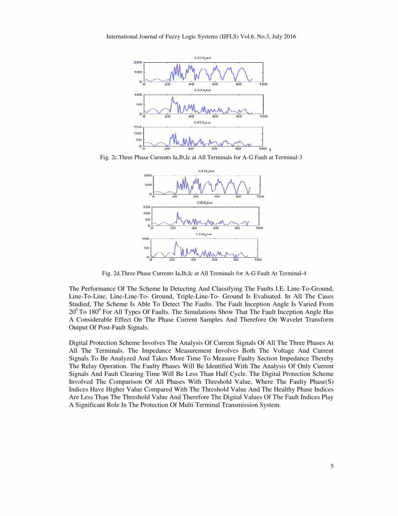
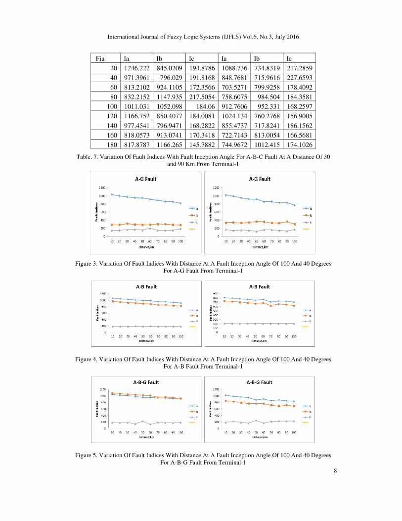
Fia Ia Ib Ic Ia Ib Ic
20 1246.222 845.0209 194.8786 1088.736 734.8319 217.2859
40 971.3961 796.029 191.8168 848.7681 715.9616 227.6593
60 813.2102 924.1105 172.3566 703.5271 799.9258 178.4092
80 832.2152 1147.935 217.5054 758.6075 984.504 184.3581
100 1011.031 1052.098 184.06 912.7606 952.331 168.2597
120 1166.752 850.4077 184.0081 1024.134 760.2768 156.9005
140 977.4541 796.9471 168.2822 855.4737 717.8241 186.1562
160 818.0573 913.0741 170.3418 722.7143 813.0054 166.5681
180 817.8787 1166.265 145.7882 744.9672 1012.415 174.1026
Table. 7. Variation Of Fault Indices With Fault Inception Angle For A-B-C Fault At A Distance Of 30
and 90 Km From Terminal-1
Figure 3. Variation Of Fault Indices With Distance At A Fault Inception Angle Of 100 And 40 Degrees
For A-G Fault From Terminal-1
Figure 4. Variation Of Fault Indices With Distance At A Fault Inception Angle Of 100 And 40 Degrees
For A-B Fault From Terminal-1
Figure 5. Variation Of Fault Indices With Distance At A Fault Inception Angle Of 100 And 40 Degrees
For A-B-G Fault From Terminal-1
International Journal of Fuzzy Logic Systems (IJFLS) Vol.6, No.3, July 2016
9
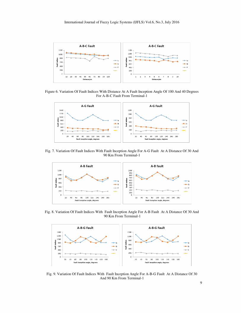
Figure 6. Variation Of Fault Indices With Distance At A Fault Inception Angle Of 100 And 40 Degrees
For A-B-C Fault From Terminal-1
Fig. 7. Variation Of Fault Indices With Fault Inception Angle For A-G Fault At A Distance Of 30 And
90 Km From Terminal-1
Fig. 8. Variation Of Fault Indices With Fault Inception Angle For A-B Fault At A Distance Of 30 And
90 Km From Terminal-1
Fig. 9. Variation Of Fault Indices With Fault Inception Angle For A-B-G Fault At A Distance Of 30
And 90 Km From Terminal-1
International Journal of Fuzzy Logic Systems (IJFLS) Vol.6, No.3, July 2016
10
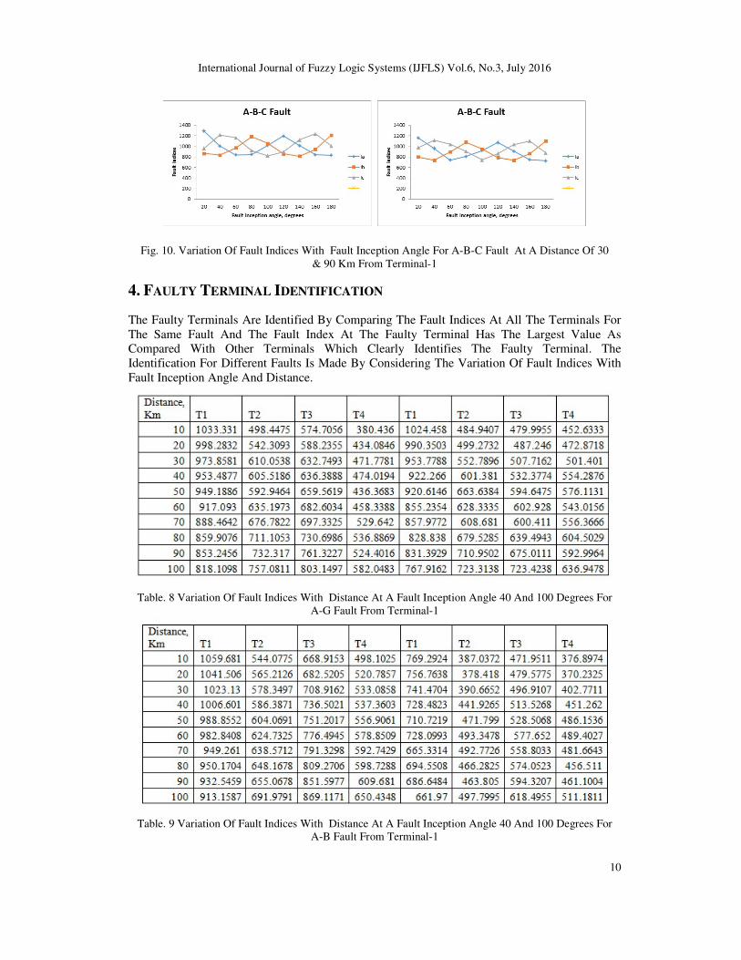
Fig. 10. Variation Of Fault Indices With Fault Inception Angle For A-B-C Fault At A Distance Of 30
& 90 Km From Terminal-1
4. FAULTY TERMINAL IDENTIFICATION
The Faulty Terminals Are Identified By Comparing The Fault Indices At All The Terminals For
The Same Fault And The Fault Index At The Faulty Terminal Has The Largest Value As
Compared With Other Terminals Which Clearly Identifies The Faulty Terminal. The
Identification For Different Faults Is Made By Considering The Variation Of Fault Indices With
Fault Inception Angle And Distance.
Table. 8 Variation Of Fault Indices With Distance At A Fault Inception Angle 40 And 100 Degrees For
A-G Fault From Terminal-1
Table. 9 Variation Of Fault Indices With Distance At A Fault Inception Angle 40 And 100 Degrees For
A-B Fault From Terminal-1

International Journal of Fuzzy Logic Systems (IJFLS) Vol.6, No.3, July 2016
11
Table. 10 Variation Of Fault Indices With Distance At A Fault Inception Angle 40 And 100 Degrees
For A-B-G Fault From Terminal-1
Table. 11 Variation Of Fault Indices With Distance At A Fault Inception Angle 40 And 100 Degrees
For A-B-C Fault From Terminal-1
Table. 12. Variation Of Fault Indices With Fault Inception Angle For A-G Fault At A Distance Of 30
And 90 Km From Terminal-1

International Journal of Fuzzy Logic Systems (IJFLS) Vol.6, No.3, July 2016
12
Table. 13. Variation Of Fault Indices With Fault Inception Angle For A-B Fault At A Distance Of 30
And 90 Km From Terminal-1
Table. 14. Variation Of Fault Indices With Fault Inception Angle For A-B-G Fault At A Distance Of
30 And 90 Km From Terminal-1
Table. 15. Variation Of Fault Indices With Fault Inception Angle For A-B-C Fault At A Distance Of
30 And 90 Km From Terminal-1
Fig. 11.Variation Of Fault Indices With Distance At A Fault Inception Angle Of 40 And 100 Degrees
For A-G Fault From Terminal-1

International Journal of Fuzzy Logic Systems (IJFLS) Vol.6, No.3, July 2016
13
Fig. 12.Variation Of Fault Indices With Distance At A Fault Inception Angle Of 40 And 100 Degrees
For A-B Fault From Terminal-1
Fig. 13.Variation Of Fault Indices With Distance At A Fault Inception Angle Of 40 And 100 Degrees
For A-B-G Fault From Terminal-1
Fig. 14.Variation Of Fault Indices With Distance At A Fault Inception Angle Of 40 And 100 Degrees
For A-B-C Fault From Terminal-1
Fig. 15. Variation Of Fault Indices With Fault Inception Angle For A-G Fault At A Distance Of 30 And
90 Km From Terminal-1

International Journal of Fuzzy Logic Systems (IJFLS) Vol.6, No.3, July 2016
14
Fig. 16. Variation Of Fault Indices With Fault Inception Angle For A-B Fault At A Distance Of 30 And
90 Km From Terminal-1
Fig. 17. Variation Of Fault Indices With Fault Inception Angle For A-B-G Fault At A Distance Of 30
And 90 Km From Terminal-1
Fig. 18. Variation Of Fault Indices With Fault Inception Angle For A-B-C Fault At A Distance Of 30
And 90 Km From Terminal-1
Figures 4-7 Illustrate The Variation Of Fault Indices Of Three Phase Currents With Fault
Inception Angle At A Distance Of 30 Km And 90 Km From Terminal-1 Towards The Path Of
Terminal-1 To Terminal-2 For A-G, A-B, A-B-G, A-B-C Faults Respectively. Figures 8-11
Illustrate The Variation Of Fault Indices With Distance At A Fault Inception Angle 400 And 1000
From Terminal-1 Towards The Path Of Terminal-1 To Terminal-2 For The Same Type Of Faults.
In Both The Cases, It Is Observed That The Fault Indices Of Faulty Phase Is Large As Compared
With That Of Healthy Phase. Thus The Number Of Faulty Phases Is Determined By Comparing
The Fault Index With A Threshold Value (Th) Which Is Taken As 400. Once The Faulty Phase Is
Identified, Then The Faulty Terminal Is Identified By Considering The Fault Indices Of That
Particular Phase At All The Terminals And Comparing The Index Values At All The Terminals
And The Index Value Of That Particular Phase At The Faulty Terminal Is Higher Than The Index
Value Of The Same Phase At The Remaining Terminals. Figures 12-15 Illustrate The Variation
Of Fault Index Of Current Of Phase ‘A’ At All The Terminals For A-G Fault, Fault Indices Of
Phases A And B For A-B And A-B-G Faults, Fault Indices Of Phases Of A,B,C For A-B-C
Fault At A Fault Inception Angle Of 400 And 100
0 With Variation In Distance From Terminal-1

International Journal of Fuzzy Logic Systems (IJFLS) Vol.6, No.3, July 2016
15
Towards The Path Of Terminal-1 To Terminal-2, It Is Observed That The Fault Indices Of That
Particular Phase(S) At Faulty Terminal Is(Are) Higher As Compared With That Of Other
Terminals. Figures 16-19 Illustrate The Variation Of Fault Index Of Current Of Phase ‘A’ At All
The Terminals For A-G Fault, Fault Indices Of Phases A And B For A-B And A-B-G Faults,
Fault Indices Of Phases Of A,B, C For A-B-C Fault At A Distance Of 30km And 90km From
Terminal-1 Towards The Path Of Terminal-1 To Terminal-2, It Is Observed That The Fault
Indices Of That Particular Phase(S) At Faulty Terminal Is(Are) Higher As Compared With That
Of Other Terminals. Thus The Number Of Faulty Phases Are Determined By Comparing The
Fault Index With A Threshold Value (Th) And The Faulty Terminal Is Identified By Comparing
The Fault Index Of The Same Phase(S) At All The Terminals And The Faulty Terminal Fault
Index Will Be Higher Than The Other Terminals For The Same Phase Which Identifies The
Faulty Terminal.
5. FAULT LOCATION ESTIMATION
After The Fault Detection, Classification And Faulty Terminal Identification, The Fault Location
Has Been Estimated With Fuzzy Logic. For This Purpose, The Three Phase Current Signals At
The Corresponding Terminal Have Been Decomposed With Bior 1.5 Mother Wavelet And The
Fault Indices Obtained Were The Inputs To The Fuzzy Inference System. The Standard Fuzzy
Membership Function Taken Was Triangular And The Output Function Taken Was Distance(D).
Each Input Variable Is Quantized Into The Linguistic Variables Such As Very Low(Vl), Low(L),
High(H), Very High(Vh) For The Universe Of Discourse Spanning From 0 To 1 And For The
Output Variable, It Is The Length Of The Transmission System Divided Into Four Zones
D1,D2,D3,D4.The Inputs Are Combined Together Based On The Expert Opinion And The
Possible Rules Are Framed And The Output Is Defuzzified To Get The Crisp Value Of D.
Simulations Were Carried Out Considering Variations In Fault Location And Fault Inception
Angle For Different Types Of Faults.
Figure 19: Fuzzy Inference System For Fault Location Estimation.
Figure 20: Input Variable (Fault Indices) For Fault Location From Terminal-1

International Journal of Fuzzy Logic Systems (IJFLS) Vol.6, No.3, July 2016
16
Figure 21: Output Variable For Location Of Distance
Table16: Fuzzy Based Fault Location Analysis From Terminal -1 Of The Transmission System
6. CONCLUSIONS
The Conventional Distance Relay Is Likely To Over Reach Or Under Reach Depending Upon
The Mode, Type Of Facts Devices Incorporated In The Transmission System And Can Be
Rectified By Wavelet Based Multi-Resolution Analysis Approach That Is Applied For Effective
Fault Detection, Classification And Faulty Terminal Identification In Multi-Terminal
Transmission Lines. The Above Algorithm Has Been Implemented For All Types Of Faults With
Variations In Fault Inception Angle And Fault Distance And Location Of Statcom At All
Terminals. The Results Indicate The Accuracy In Fault Detection, Classification And Faulty
Terminal Identification, And Fault Location Estimation. This Scheme Is Proved To Be
Unaffected By The Presence Of Statcom By Testing The Protection Scheme On Same
Transmission System Without Statcom. The Proposed Protection Scheme Is Found To Be Fast,
Reliable And Accurate For Various Types Of Faults On Transmission Lines With And Without
Flexible Ac Transmission Control Device Such As Statcom At Different Locations And With
Various Inception Angles.

International Journal of Fuzzy Logic Systems (IJFLS) Vol.6, No.3, July 2016
17
REFERENCES
[1] Amany M.El Zonkoly, Hussein Desouki, “ Wavelet Entropy Based Algorithm For Fault Detection
And Classification In Facts Compensated Transmission Line.” Energy And Power Engineering,
Scientific Research,2011,Vol.3,Pp.34-42.
[2] Gorakshanath Abande, Mfar Satarkar,Mohan Thakre,V.S.Kale,Ganesh Patil “Impact Analysis Of
Statcom On Distance Relay.” International Journal Of Innovative Research In Science, Engineering,
Technology, Vol.3, Special Issue 3, March 2014.
[3] R.Illango, T.S.Rangeraja “Accurate Distance Protection Scheme For Transmission Line Fault
Location Considering The Impact Of Shunt Connected Statcom”, Middle-East Journal Of Scientific
Research, 21(11): 2123-2129,2014.
[4] Sriteja Alapati, B.Durga Prasad, “Effect Of Statcom On Distance Relay Performance In A
Transmission Line”, International Journal Of Computer And Electrical Engineering, Vol.4
[5] A.Y.Abdelaziz, Amr.M.Ibrahim “ A Hybrid Wavelet-Ann Based Protection Scheme For Facts
Compensated Transmission Lines” International Journal Of Intelligent Sytems And
Applications,2013,07,23-31
[6] Qazi Waqar Ali, Azzam Ul Asar, “ Smart Power Transmission System Using Facts Device”,
International Journal Of Applied Power Engineering, Vol.2, No.2, August-2013, Pp.61-70.
[7] Sham M.V, Panduranga Vittal K “ Simulation Studies On The Distance Relay Performance In The
Presence Of Statcom”, Journal Of Electrical Engineering.
[8] E.Kazeni Abharian, M.Karimi, P.Farhadi “ Statcom Controller Design Based On Mlp For Power Flow
Control”, International Journal Of Modeling And Optimization, Vol.1, No.4, October 2011, Pp.327-
333.
[9] R.Kameswara Rao, G.Ravikumar, Sheik Abdul Gafoor, S.S.Tulasiram “Fault Analysis Of Double
Line Transmission System With Statcom Controller Using Neuro-Wavelet Based Techniques”,
International Journal Of Engineering Technology, Vol.2, No.6, June-2012
[10] Majid Jamil, Md.Abdul Kalam, A.Q.Ansari, M.Rizwan “Wavelet Ffnn Based Fault Location
Estimation Of A Transmission Line” Electrical Engineering Research, Issue 3, July-2013.
[11] E.Latha Mercy, G.Jyosthna “Fault Detection And Classification In Transmission Lines Using Dwt
And Anfis Techniques” Advanced Research In Electrical Engineering, Vol.2, No.2, October-
December 2014, Pp.123-129.
[12] Bo, Z.Q.,“A New Non-Communication Protection Technique For Transmission Lines’’ Ieee Trans.
Power Delivery,1998,13,(4), Pp. 1073-1078\
[13] Bhalija, B., And Maheswari, R.P,; “High Resistance Faults On Two Terminal Parallel Transmission
Line; Analysis, Simulation Studies, And An Adaptive Distance Relaying Scheme”, Ieee Trans. Power
Delivery, 2007, 22, (2), Pp. 801-812
[14] Brahma,S.M And Girgis,A..A. “Fault Location On A Transmission Line Using Synchronized Voltage
Measurements’’, Ieee Transactions On Power Delivery, 2004,9(4),Pp. 1619-1622.
[15] Lyonette,D.R.M.,Bo,Z.Q, Weller G. And Jiang,G, “A New Directional Comparison Technique For
The Protection Of Teed Transmission Circuits”. Power Engineering. Society, Winter Meeting, Ieee.,
January 2000, Vol.3, Pp. 1979-1984
[16] Bhalija,B.,And Maheswari, R.P; “New Differential Protection Scheme For Tapped Transmission
Line’’. Iet Generation.Transmission,Distribution,2008,2,(2),Pp. 271-279
[17] Al-Fakhri,B, “The Theory And Application Of Differential Protection Of Multi-Terminal Lines
Without Synchronization Using Vector Difference As Restraint Quantity-Simulation Study.’’8th Iee
International Conference On Dpsp, April 2004, Vol.2, Pp. 404-409
[18] Yugant A.Parate, Ankita Y.Pai “ Power System Stability Improvement Using Facts Devices”,
International Journal Of Engineering Research And General Science, Vol.3, Issue-5, Sep-Oct.2015
[19] Joe-Air Jiang, Ching-Shan Chen, Chih-Wenliu “A New Protection Scheme For Fault Detection,
Direction Discrimination, Classification And Location In Transmission Lines”. Ieee Transactions On
Power Delivery, Vol.18, No.1, January-2003.
[20] Ching –Shan Chen, Chih-Wenliu “Fast And Accurate Fault Detection/Location Algorithm For Double
Circuit/ Three Terminal Lines Using Pmus”. Journal Of The Chinese Institute Of Engineering,
Vol.26,No.3, 2003, Pp.289-299.
[21] Semwal, Vijay Bhaskar, Pavan Chakraborty, And Gora Chand Nandi. "Less Computationally
Intensive Fuzzy Logic (Type-1)-Based Controller For Humanoid Push Recovery." Robotics And
Autonomous Systems 63 (2015): 122-135.

International Journal of Fuzzy Logic Systems (IJFLS) Vol.6, No.3, July 2016
18
AUTHORS
J.Uday Bhaskar Received B.E From Gitam, Andhra University, Visakhapatnam.
M.Tech From Jntu Kakinada.Presently Pursuing Ph.D From Jntu Kakinada. Research
Areas Include Multiterminal Transmission Line Protection, Facts Devices.
S.S Tulasi Ram Received B.Tech, M.Tech And Ph.D From Jntu College Of
Engineering, Kakinada. Presently Working As Professor In The Department Of
Electrical And Electronics Engineering In College Of Engineering, Jntuh, Hyderabad.
His Areas Of Interest Include High Voltage Engineering, Power System Analysis And
Control.
Related Documents