Vincenzo Di Lorenzo HAP Workshop: Advanced Technologies | Mainz | 2016-02-02 Wavelength-shifting Optical Module (WOM)

Welcome message from author
This document is posted to help you gain knowledge. Please leave a comment to let me know what you think about it! Share it to your friends and learn new things together.
Transcript
Vincenzo Di Lorenzo
HAP Workshop: Advanced Technologies | Mainz | 2016-02-02
Wavelength-shiftingOptical Module (WOM)

WOM —
Cherenkov light
1
Increase the energy resolution decreasing the energy threshold
Cherenkov light is ∝ 1/𝜆2
More photon in the UV region𝑑2𝑁
𝑑𝑥𝑑𝜆=
2𝜋𝑧2
𝜆2𝛼 sin2 𝜃
absorption coefficient: Low in the wavelength range of 250 – 400 nm
maximize the collection area minimizing the dark count rate

WOM —
Wavelength-shifting Optical Module concept
Setup: Pressure vessel (∅ 114 mm ×1,3 m)
Coaxial WLS tube (∅ 90 𝑚𝑚 ×90 𝑐𝑚)
Main advantages of the WOM: High efficiency in the UV range Large sensitive area Passive components as collectors
and concentrators only Reduce the noise to ≈ 10 𝐻𝑧
(Icecube DOMs ≈ 500 𝐻𝑧)
2

WOM —
Paint plot
Dip coater speed control
0-10 cm/min
dipping speed
faster dipping
less time for paint to run off
thick layer
empirical law ℎ =𝑎𝑣𝑥
𝑣+1𝑐𝑚
𝑚𝑖𝑛
layer thickness determination
weigh WLS layer
well reproducible
3

WOM —
WOM efficiency
Measured capture and transport efficiency
𝜀𝑐𝑡 =# 𝑑𝑒𝑡𝑒𝑐𝑡𝑎𝑏𝑙𝑒 𝑝ℎ𝑜𝑡𝑜𝑛𝑠
# 𝑝ℎ𝑜𝑡𝑜𝑛𝑠 𝑖𝑛𝑗𝑒𝑐𝑡𝑒𝑑 𝑎𝑡 𝑜𝑢𝑡𝑒𝑟 𝑠𝑢𝑟𝑓𝑎𝑐𝑒
Optimize paint for: Capture and transport efficiency Adhesiveness Surface quality
Best paint mix: 77,31% Toluene, 22,29% Paraloid B72,
0,13% Bis-MSB and 0,27% P-Terphenyl Projected sensitivity ≳ 2 × IceCube optical
module
Dustin Hebecker(DESY/HUB)
4

WOM —
PD and PMT efficiencyDustin Hebecker
(DESY/HUB)
5

WOM —
Simulation of the WOM:• PMMA refrective index 1,503• length 90 cm• inner radius 8,65 cm• outer radius 9 cm
Geant4 simulation of the WOM
Simulation of the WLS• PMP in PMMA• refrective index 1,503• thickness 0,02 mm
Implemented Rayleigh scattering
6

WOM —
angular acceptance of the photodiode (Bachelor student Sandra Gerlach at Humboldt)
exit angle distribution of the photons respect to the tube axis
Exit angle distribution
𝟏
𝟎, 𝟑𝟔= 𝟐, 𝟕𝟖
7

WOM —
Attenuation
Theoretical efficiency
𝜀𝑊𝐿𝑆 = 80 − 100 %
𝜀𝑇𝐼𝑅 = 74,6 % 𝜀𝑊𝐿𝑆 ⋅ 𝜀𝑇𝐼𝑅 > 60 %
Sources of losses?
Q.E. in plastic
absorption Rayleigh or Mie
scattering
8
WOM —
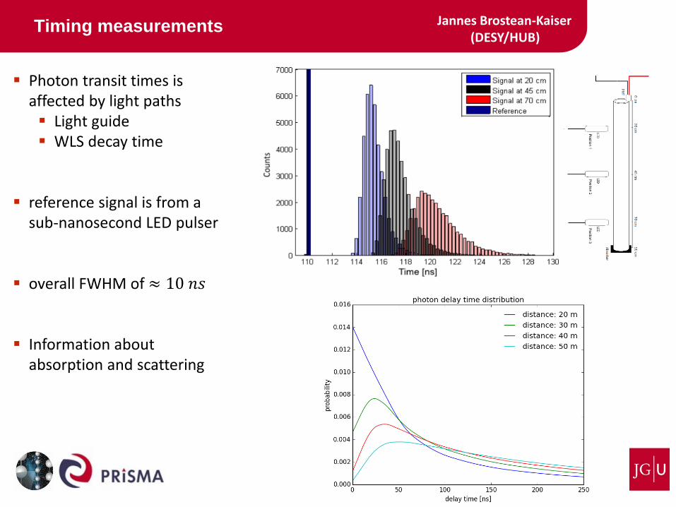
Timing measurements
9
Jannes Brostean-Kaiser(DESY/HUB)
Photon transit times isaffected by light paths Light guide WLS decay time
reference signal is from a sub-nanosecond LED pulser
overall FWHM of ≈ 10 𝑛𝑠
Information aboutabsorption and scattering

WOM —
Dark count rateKrystina Julia Sand
(JGU Mainz)
Hamamatsu R11920-100 PMT Disigned for the CTA experiment 1.5 inch in diameter High Q.E. (32-35% at 350 nm) Low dark noise rate 8 dynodes (low gain)
Low dark count rates for the PMT ∼ 10 𝐻𝑍
High dark count rates for PMT and WOM glass end-caps (borosilicate)?
NEW MEASUREMENTS!!!
10

WOM —
Read-out
IceCube Gen-2 readout
Continuous digitizer (DDC2) 250 MS/s @ 14 bit
firmware trigger in FPGA
Performance
low noise (1.7 counts RMS) good linearity PMT pulse width ~ 5 𝑛𝑠
Carl-Christian Fösig(JGU Mainz)
11

WOM —
Read-out challenge
Result Low PMT gain Short pulses
Requirements High bandwidth High sensitivity
Carl-Christian Fösig(JGU Mainz)
12
3 different PMTs will be characterized soon!

WOM —
WOM status
13

WOM —
Summary
14
Wavewlength shifting Optical Module high effective area at low noise
Photon collection efficiency very good results angular acceptance for the PD measurements (simulation) absorption or scattering sources of losses new measurements with casted PMMA tubes (better optical properties)
PMT & Electronics 10 𝐻𝑧 noise level reachable read-out tests for different PMTs
Prototype assembly will be completed soon!

WOM —
Backup
Backup slides from here on out
15

WOM —
IceCube & PINGU
PINGU – Precision IceCube Next Generation Upgrade
40 strings, 22 m apart
96 optical modules per strings, 3 m apart
Dense instrumentation Measure neutrinos with energiesof a few GeV
16

WOM —
Total internal reflaction
17
Ω = 4𝜋 sin2𝜔
4
𝜖 = 1 − 2 sin2arcsin
11,5
2= 74,6%

WOM —
(Re-)absorption test
18
Shifted light is reabsorbed
re-emission likely lost
Emission spectrum indicates
small effect

WOM — 19
Timing measurements Jannes Brostean-Kaiser(DESY/HUB)

WOM —
Maximizing Liouville
20
Entendue (aperture × solid angle) is constant
(only) detect photons that enter the WOM

WOM —
Maximizing Liouville
21
Semi-spherical surface grid(lenticular arrays) maximizes acceptance gain 37% w.r.t. flat
Related Documents