VOLUME 22, 1960/61, No. 6 _pp. 181-216 Published 14th March 1961 Philips Technical Review DEALING WITH TECHNICAL PROBLEMS RELATING TO THE PRODUCTS, PROCESSES AND INVESTIGATIONS OF THE PHILIPS INDUSTRIES WAVEGUIDE EQUIPMENT FOR 2 mm MICROWAVES n. MEASURING SET-UPS 621.372:8 :621.317.3 by C. W. van ES, M. GEVERS and F. C. de RONDE. In Part I of this article, a review was given of the equipment developed by Phllips for 2 mm microwaves. Part 11 below contains a description of some measur.ing set-ups in which the use of the components discussed are considered in more detail; in addition, some components which were not considered in Part I are also described. The first two set-ups discussed arefor the measurement of the losses and the impedances of microwave components. The third set-up is a microwave gas spectrometer by means of which the absorption lines in gases can be experimentally determined. When designing components for a new frequency range, the mierowave technician requires good meas- uring equipment in order to investigate the prop~ erties ofthe developed components. In this context, his preference will be for measuring instruments which do not need to be calibrated, i.e. instruments which are "absolute" _The rotary attenuator is one such instrument. This latter ean be used for the measurement of attenuations such as the dissipative loss in microwave components, which will later be discussed. The rotary attenuator itself was treated in Part I of this article 1); likewise, the variable impedance with which reflection coefficients can be measured. This instrument is also absolute as far as the modulus of the reflection coefficient is concerned, It is used in the second measuring set-up discussed below for measuring the reflection coefficient of an unknown impedance in a bridge circuit (with a hybrid T as the bridge element]. Here, the variable impedance serves as a reference impedance. The third measuring set-up to be discussed is for the investigation of absorption spectra in gases. An example is carbonyl-sulphide gas (COS), which exhibits absorption at about 146 Gc/s. If the gas is irradiated at the correct frequency, the energy sup- plied allows the COS molecules to move to a higher 1) C. W. van Es, M. Gevers and F_ C. de Ronde, Wave- guide equipment for 2 mm microwaves, 1. Components, Philips tech. Rev. 22, 113-125, 1960/61 (No. 4). rotational level. This transition is accompanied by absorption. The frequency at which absorption occurs can be determined with the set-up to be de- scribed. Measurement of the dissipative loss in microwave components When a microwave component is inserted in a waveguide set-up which has been matched to both the load and generator sides, the losses will in general increase. This increase, which is called "insertion loss", is caused partly by reflections and partly by dissipation in the four-terminal network constituted by the inserted component, Reflection and dissipa- tion are both characteristic properties of a four- terminal network. The dissipative loss can be meas- ured in the manner now to be described; the reflec- tive loss is derived from an impedance measurement using a second set-up which will be dealt with presently. It is almost always desired to keep the dissipative loss as small as possible, and for that reason an effort has been made to keep the length of our corn- ponents to a minimum. The need for short compo- nents becomes more evident as the frequency in- creases, since the loss per unit length increases as the t power of the frequency. As mentioned in Part I, the claw flange with its associated lock ring is one of the devices used to achieve short constructions

Welcome message from author
This document is posted to help you gain knowledge. Please leave a comment to let me know what you think about it! Share it to your friends and learn new things together.
Transcript

VOLUME 22, 1960/61, No. 6 _pp. 181-216 Published 14th March 1961
Philips Technical ReviewDEALING WITH TECHNICAL PROBLEMS
RELATING TO THE PRODUCTS, PROCESSES AND INVESTIGATIONS OF
THE PHILIPS INDUSTRIES
WAVEGUIDE EQUIPMENT FOR 2 mm MICROWAVES
n. MEASURING SET-UPS 621.372:8 :621.317.3
by C. W. van ES, M. GEVERS and F. C. de RONDE.
In Part I of this article, a review was given of the equipment developed by Phllips for 2mmmicrowaves. Part 11below contains a description of some measur.ing set-ups in which the useof the components discussed are considered in more detail; in addition, some componentswhich were not considered in Part I are also described.
The first two set-ups discussed are for the measurement of the losses and the impedances ofmicrowave components. The third set-up is a microwave gas spectrometer by means of whichthe absorption lines in gases can be experimentally determined.
When designing components for a new frequencyrange, the mierowave technician requires good meas-uring equipment in order to investigate the prop~erties ofthe developed components. In this context,his preference will be for measuring instrumentswhich do not need to be calibrated, i.e. instrumentswhich are "absolute" _The rotary attenuator is onesuch instrument. This latter ean be used for themeasurement of attenuations such as the dissipativeloss in microwave components, which will later bediscussed. The rotary attenuator itself was treatedin Part I of this article 1); likewise, the variableimpedance with which reflection coefficients can bemeasured. This instrument is also absolute as far asthe modulus of the reflection coefficient is concerned,It is used in the second measuring set-up discussedbelow for measuring the reflection coefficient of anunknown impedance in a bridge circuit (with ahybrid T as the bridge element]. Here, the variableimpedance serves as a reference impedance.
The third measuring set-up to be discussed is forthe investigation of absorption spectra in gases. Anexample is carbonyl-sulphide gas (COS), whichexhibits absorption at about 146 Gc/s. If the gas isirradiated at the correct frequency, the energy sup-plied allows the COS molecules to move to a higher
1) C. W. van Es, M. Gevers and F_ C. de Ronde, Wave-guide equipment for 2 mm microwaves, 1. Components,Philips tech. Rev. 22, 113-125, 1960/61 (No. 4).
rotational level. This transition is accompanied byabsorption. The frequency at which absorptionoccurs can be determined with the set-up to be de-scribed.
Measurement of the dissipative loss in microwavecomponents
When a microwave component is inserted in awaveguide set-up which has been matched to boththe load and generator sides, the losses will in generalincrease. This increase, which is called "insertionloss", is caused partly by reflections and partly bydissipation in the four-terminal network constitutedby the inserted component, Reflection and dissipa-tion are both characteristic properties of a four-terminal network. The dissipative loss can be meas-ured in the manner now to be described; the reflec-tive loss is derived from an impedance measurementusing a second set-up which will be dealt withpresently.
It is almost always desired to keep the dissipativeloss as small as possible, and for that reason aneffort has been made to keep the length of our corn-ponents to a minimum. The need for short compo-nents becomes more evident as the frequency in-creases, since the loss per unit length increases asthe t power of the frequency. As mentioned in PartI, the claw flange with its associated lock ring isone of the devices used to achieve short constructions
182 PHILIPS TECHNICAL REVIEW VOLUME 22
with correspondingly low dissipative losses. More-over, at high frequencies the surface roughness hasa considerable influence: the higher the frequency,and therefore the smaller the depth of penetration,the greater the resistance which irregularities andimpurities will offer to the current.
The dissipative loss can be determined by twopower measurements, one with the component beinginvestigated in the set-up and one without it. Thepower can be measured by a water calorimeter; thisis an absolute instrument but is cumbersome to use.In its place, use can be made of a thermistor, i.e. athermal detector, which has been calibrated by awater calorimeter or (somewhat less accurately) byDC 2). Also, a crystal detector (fig. I) with a DCmetercan be used as a power indicator. The crystal is amore or less square-law detector, so that the deflec-tion of the meter is approximately proportional tothe microwave power. The dissipation loss can befound from the ratio of the readings given by the twopower measurements. Use of the rotary attenuator
Fig. 1. Crystal detector for 2 mm waves. Left, claw flange,right, shorting plunger. The differential screw wbich is used tobring the silicon crystaL into contact with the catswhisker issituated beneath the black cap; the displacement can be mo-nitored tbrough the window. Below: the coaxial connection forthe millivoltmeter. The sensitivity is better than 10 mV permW.
2) See Pbilips tech. Rev. 21, 228 (Note 7», 1959/60 (No. 8).
has the advantage that the two measurements canbe made at the samo crystal power, the measure-ments then being completely independent of thedetection characteristic. The difference in position
1 '
3297
2
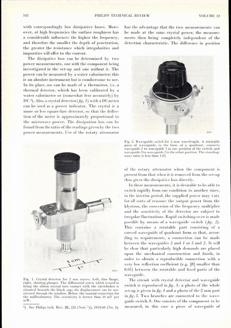
Fig. 2. Waveguide switch for 2 mm wavelength. A rotatablepiece of waveguide, in the form of a quadrant, connectswaveguide 3 to waveguide 1 in one position of the switch, andwaveguide 3 to waveguidc 2 i.11the other position. The standing-wave ratio is less than 1.02.
3295
of the rotary attenuator when thc componcnt isprcsent from that when it is removed from the set-upthus gives the dissipative loss directly.
In these measurements, it is desirable to be able toswitch rapidly from one condition to another since,in the interim period, the supplied power may varyfor all sorts of reasons: the output power from theklystron, the conversion of the frequency multiplierand the sensitivity of the detector are subject toirregular fluctuations. Rapid switching-over is madepossible by means of a waveguide switch (fig. 2).This contains a rotatable part consisting of acurved waveguide of quadrant form so that, accor-ding to requirements, a connection can be madebetween the waveguides 3 and I or 3 and 2. It willbe clear that particularly high demands are placedupon the mechanical construction and finish, inorder to obtain a reproducible connection with avery low reflection coefficient (e.g. IRI smaller than0.01) between the rotatable and fixed parts of thewaveguide.
The circuit with crystal detector and waveguideswitch is reproduced in fig. 3; a photo of the wholeset-up is given infig. 4 and a photo of the 2 mm partin fig. 5. Two branches are connected to the wave-guide switch S. One consists of the component to bemeasured, in this case a piece of waveguide of

1960/61, No. 6 2 mm WAVEGUlDE EQUIPMENT, II 183
Fig. 3. Block diagram of tbe circuit for measuring tbe dissipa-tive loss in a microwave component at a wavelengtb of 2 mm.4. mm part: Cl generator (reflex klystron DX 151), 11 isolator,AUl vane attenuator, W wavemeter, Tl sliding screw tuner,1\ sborting plunger.2 mm part: M frequency multiplier, P, shorting plunger, T2pivoting screw tuner, 12 isolator (see fig. 6), Att2 rotaryattenuator, C rotary directional coupler, S waveguide switch(see fig. 2). Branch 1 consists of tbe component being investi-gated (length L) combined witha line of length I adjustablewith plunger PI' Branch 2consists of a similar length Iadjustable with plunger P2• T3
pivoting screw tuner. D detec-tor (see fig. I).Other equipment: C generator(8 kc/s) for synchronous detec-tion, A selective amplifier,V millivoltmeter.The sign a means "rectangularwaveg~!de" .an~ t,~e sign bmeans coaxial line .
.---------- 4 mm
length L terminated at a distance Z from the flangeby a shorting plunger Pl' The other branch isterminated directly by a plunger P 2' this latterbeing adjustcd to the same distance Z. By meansof the waveguide switch, either the branch L + Z orthe branch Z can thus be connected to the rest of thecircuit. The circuit contains, in addition to a rotaryattenuator, a rotary directional coupler C - a com-ponent described in Part I. The rotary directional
t
-t [2..... --r- 5PI,
2mm l3527
coupler is used to measure the reflected wave whichcomes back from the branch switched in by S.The measurement of the dissipative loss is carried
out as follows. With the waveguide switch in posi-tion 1, adjustments are made until the meter Vshows full-scale deflection, and the rotary attenua-tor is set to zero. This done, S is switched to position2, i.e. to the opposite branch from that carrying thecomponent to be measured. The attenuation will
Fig. 4. Set-up for measuring the dissipative loss in components at a wavelength of 2 mm(refer to the diagram in fig. 3). V cooling fan for the reflex klystron. Notation otherwise asin fig. 3.

1S4 PHILIPS TECHNICAL REVIEW VOLUME 22
Fig. 5. The 2 mm part of the set-up reproduced in fig. 4-, Notation as in fig. 3.
thcn bc less, hence the reflected wave stronger andthe meter will tend to deflect further. Now, using therotary attenuator, the signal is attenuated sufficient-ly to restore the meter to its original deflection. Wethen read off from the rotary attenuator the indi-cated attenuation. Half this attenuation gives thedissipation in the component (half, since the wavetraverses the length L of the component twice).In order to make the measurement as accurate as
possible, a few precautions must be taken, one ofwhich is to include a directional isolator.
Looking towards the generator, the transmission line will notgenerally he reflection-free. For this reason, on displacing theplunger P, or 1'2' the deflection of the meter will vary. Inorder to keep this effect as small as possible, an isolator isconnected between the aLlenuator and the multiplier (12 infig. 3). This device, whose operation depends on the Faradayeffect "), is depicted in fig. 6. However, even with these precau-tions some reflection will remain so that, in order to adjust themeter to the maximum or minimum deflection, the plungersPI and P2 must both be adjustable.
At the beginning of the measurement, and before the compo-nent of length L has been inserted in one of the hranches, itmust be ascertained that the two branches (length I) are iden-tical, i.e. that, for both positions of the waveguide switch, themeter deflections are the same. When the component L is subse-quently fitted into the branch 1, a small phase change willgenerally appear (unless the length L is precisely a whole multi-ple of V.g, where }'g is the wavelength in the guide). This phasechange can be corrected by adjusting the plunger P" In itsturn, this adjustment causes some change in the dissipa tiveloss, but only to a negligibly small degree.
3) H. G. Beljers, The appl ication of ferroxcube in unidirec-tional waveguides and its bearing on the principle of reci-procity, Phil ips tech. Rev. IS, 158-166,1956/57.
Since the use of a directional coupler means that reflectionsfrom the component are also measured, it must first be ascer-tained that these are indeed negligibly small. If this is not thecase, the reflection must first he compensated.
The measures taken make a very accurate meas-urement possible. The circuit described is particular-ly suited to the measurement of losses in sectionsof waveguide and residual losses in components,e.g. the losses in a vane attenuator (see Part I) inthe zero position. With this method, losses of theordcr of 0.1 dB can easily be measured.The dissipative loss in the components discussed
in Part I was measured with the circuit of fig. 3.This does not, of course, mean that the method isonly suitable for measurements on rmcrowavecomponents; it can be used equally well for meas-uring attenuations caused by any sort of physical
329(5
Fig. 6. Isolator for 2 mm wavelength, based on the Faradayeffect 3). The black rings are ferroxdure magnets. Attenuationin the forward direction (in the direction of the arrow): 2 dB;in the reverse direction: 15 dB.

1960/61, No. 6 2 mm WAVEGUIDE EQUIPMENT, II 185
phenomena. It is, for example, very useful for meas-uring the absorption in superconductors 4).
Impedance measurements using the bridge method
In general, an impedance reflects some of the ap- •plied microwave energy when the impedance differsfrom the characteristic impedance of the line. Ameasure of this "mismatch" is either the standing-wave ratio or the reflection coefficient 5). In order todetermine the impedance by means of the standing-wave ratio, a standing-wave detector is necessary.However, it is extremely difficult to make astanding-wave detector for millimetre waves withreasonable accuracy. A more direct measurement ofthe impedance is possible by inserting it in a bridgecircuit and comparing it with a standard impedance.The variable impedance discussed in Part I canserve this latter purpose. This instrument is absoluteand the value of the reflection coefficient of the un-known impedance can be read off directly.
The circuit is reproduced infig. 7. It consists of a4 mm and a 2 mm part, the latter containing ahybrid T (seePart I), HT, as the bridge element. Theinput arm 1 of the T is connected to the frequencymultiplier M via a pivoting screw tuner Tl' On thearm 4, via another pivoting screw tuner T3, a crystaldetector D is connected, and on the arms 2 and 3 thevariable impedance Zv and the unknown impedanceZ3' respectively. Thelatter consists of apivoting screw tunerT2 in conjunction witha matched load. Usingthis assembly, anyrequired impedancecan be made up.
The energy comingfrom the multiplierdivides in the hybridT into two equalparts, which travel
4) M. A. Biondi and M. P.Garfunkel, Millimeterwave absorption insuperconducting alumi-num, I and II, Phys.Rev. 116, 853-867, 1959(No.4).
5) For the relationshipsbetween the quantitiesimpedance, reflectioneoefficientand standing-wave ratio, seee.g, A. E.Pannenborg, A meas-uring arrangement forwaveguides, Philipstech. Rev. 12, 15-24.,1950/51.
+
along the arms 2 and 3. Z3will cause a certain amountof reflection in arm 3; the reflected wave returns tothe branching point of the hybrid T and distributesitself over the arms 1 and 4. If the reflection from Z.,.is now made equal in phase and amplitude to thereflection from Z3' then a reflected wave of equalmagnitude willlikewise be split into two equal partsat the branching point and travel along the arms 1and 4. As explained in Part I, the geometric configu-ration is such that the waves issuing from the arms2 and 3 cancel each other in arm 4; therefore, thedetector D receives no signal and the meter does notdeflect. This is thus an indication that Zv= Z3' andthe modulus of the reflection coefficient can bedirectly read off on the variable impedance, whilstits argument can be rapidly determined (see Part I,page 121).
> A detail photo of the 2 mm part of this set-up isshown infig. 8.
The sensitivity of this method is very high. Anotherproperty of the bridge circuit is that the sensi-tivity is considerably greater if the measurement ismade after the bridge has been slightly unbalanced.This property is useful in the measurement of veryweak reflections, such as those which occur atflanges, when values of IRlless than 0.01 can still befairly reliably measured. For this purpose, one armof the hybrid T is terminated by a matched load and
G
+ Zv
M
-f 2 HT -F -1 4H E f1
3~
2mm3528
-...---------4mm----------
Fig. 7. Block diagram of the circuit for measuring the reflection coefficient of impedancesat a wavelength of 2 mm.4. mm part; from left to right: generator, sliding screw tuner, isolator, wavemeter, vaneattenuator, sliding screw tuner; shorting plunger.2 mm part: M frequency multiplier, Pi shorting plunger, Tl pivoting screw tuner, HT hy-brid T, Zv variable impedance, T2 pivoting screw tuner (with matched load), Ta pivotingscrew tuner, P2 shorting plunger, D detector.Other equipment: Ggenerator (8 kc/s), A seleetive amplifier (tuned to the frequency of G).V millivoltmeter.

186 PHILIPS TECHNICAL REVIEW VOLUME 22
a small reflection is introduced in the arm con-taining the variable impedance, so that the bridge isslightly out of balance. By altering the IRI of thevariable impedance by a certain amount with re-spect to the adjusted value (readable upon the scale"mod R", see fig. 16 of Part I), a specific variationin the deflection of the meter is obtained. The intro-duetion of a flange coupling between the hybrid T
shown in Part I, as far as the hybrid T is concernedthe accuracy is determined solely by the mechanicalconstruction and the finish. In the variable impe-dance, still other factors play a part. The detrimen-tal influence of all these factors upon the accuracyare particularly noticeable in the two extreme posi-tions, mod R = 1 and mod R = O. In the latterposition, there is always some residual reflection,
Fig. 8. The 2 mm part of the set-up shown in the diagram of fig. 7. Notation as in the latter.At the extreme left, a few 4 mm components: isolator, vane attcnuator and sliding screwtuner.
and the matched loadlikewise causes a change in thedeflection. The reflection coefficient can be foundfrom the two changes in deflection. The fact thatthere are still other reflections of the same order ofmagnitude as those which are being measured, ac-tually makes the measurement somewhat more corn-plicated than is here described. It is necessary, forexample, to compensate as well as possible for thereflections at other flange connections in the armsand for reflections at the transition, and the reflec-tion at the matched load can no longer be neglected.When reasonably accurate measurements are re-quired of very small reflection coefficients such asoccur at claw-flange couplings, all this must betaken into account.
The accuracy with which the reflection coefficientof an impedance can be determined is dependentupon the quality oftwo components: a) the hybrid Tand b) the variable impedance. As has already been
namely at the transition from the rectangular wave-guide to the circular waveguide. If extremely accu-rate measurement is required, this residual reflec-tion must be neutralized by means of a tuner.In the maximum reflection position, IRI is not
quite 1 because of the losses in the waveguide. Here,again, is an advantage of the bridge circuit, in thatthese losses can be compensated by insertingbetween the impedance Z3 and the hybrid T a sectionof waveguide which causes identicallosses. For thispurpose, the variable impedance is set to the positionmod R = 1 and, in the other arm of the hybrid T,Z3 is replaced by a short-circuited piece of wave-guide of such length that, by adjustment ofthe phase, equilibrium can be established. Havingbalanced the bridge in this way for mod R = 1, wecan then determine the dissipative loss a in compo-nents having low reflection. For this purpose thecomponent is connected between the short-circuit

1960/61, No. 6 2 mm WAVEGUIDE EQUIPMENT, 11
and the added piece of waveguide. If balance issubsequently re-established, then:
a = -10 log IRI dB.
Thus, the dissipative loss in microwave compo-nents can be determined by the method just de-·scribed as well as by the circuit of fig. 3. The meas-urement of large losses is, in both cases, limited byreflections.
Measmement of an absorption line of COSat 2 mm.
The binding forces existing between particleswhich together form a "system" (such as betweenthe atoms in a molecule, between the nucleus andthe electrons in an atom, between the protons andthe neutrons in an atomic nucleus) give rise to aseries of energy states which the system can occupy.On absorbing electromagnetic energy of certain fre-quencies, such a system can change from a givenenergy state to one of higher energy. A transitionfrom the nth to the (n + l)th energy level is madepossible by absorption of radiation whose frequencyv is proportional to the energy difference En+1-Enbetween the two levels:
Here, h is Planck's constant (= 6.6 X 10⁻³⁴joule seconds). The energylevels En are determinedhy the nature of the forcesand the kinds of particles.Thus, absorption in thegamma ray region iscaused by changes of statewithin the atomic nucleus;absorption in the opticalregion is predominantlyconcerned with the bind-ing forces between nucleiand electrons, and absorp-tion in the infra-red andmicrowave regions arerelated to the force whichthe atoms of the moleculeexert upon one another.Thus, microwave spec-
troscopy can provide in-formation 'concerning thechemical bonds in mole-cules (vibrational androtational states). Here,infra-red spectroscopy isalso important, but spec-
v=
._ ~ _D_ ...Hor. Vert.
G
t
+ --r-.~
0,- -GC ..JL
P, C d ~4mm
2mm
h
troscopy in the microwave region has the advantagesthat the radiation is purely monochromatic and thatthe sensitivity, the accuracy of determination of theabsorption frequencies and the resolving power aregreater. The latter is such that fine and hyperfinestructures can be observed, enabling conclusions tobe drawn concerning the behaviour of the nucleiof individual atoms. For further particulars thereader is referred to the literature 6).The third set-up, now to he discussed, is a micro-
wave gas spectrometer used for determining therotational spectra of gas molecules. The diagram ofthe circuit is reproduced in fig. 9. The main compo-nents in th~ 2 mm part - shown separately infig. la - are a gas cellGC and a 2 mm crystal detec-tor Dl' The gas cell consists of a piece of 8 mmwaveguide (this being used since it has a greatervolume and smaller wall-losses per unit length)with at each end a transition to 2 mm guide. The
G) See, for example: W. Gordy, W. V. Smith and R. F.Trambarulo, Microwave spectroscopy, Wiley, New York1957. .D. J. E. Ingram, Spectroscopy at radio and microwavefrequencies, Btitterworth's Scientific Puhlications, London1955.C. A. Burrus, Stark effect from 1.1 to 2:6 millimeterswavelength: PHa, PDa, DI, and CO, J. chem. Phys. 28,427-429, 1958.M. Cowan and W. Gordy, Precision measurements ofmillimeter and submillimeter wave spectra: DCI, DBr, andDI, Phys. Rev. 111, 209-211, 1958. .
3529Fig. 9. Block diagram of the circuit for measuring the absorption line of carbonyl sulphideat about 146 Gc/s.4 mm part, from left to right: generator, sliding screw tuner, isolator, wavemeter. vaneattenuator, sliding screw tuner, shorting plunger.2 mm part: M frequency multiplier, Pl shorting plunger, Tl pivoting screw tuner, GC gascell (with mica windows c and d), T2 pivoting screw tuner, P2 shorting plunger, Dl detector.Other equipment: G generator (45 kc/s) which amplitude-modulates the 2 mm wave, Aselective amplifier tuned to the frequency of G, D2 detector, 0 oscilloscope. The sawtoothtime-base voltage of 0 frequency-modulates the 4 mm generator. The form of the detectedmicrowave is indicated at the-input of A; the form of the signal after low-frequency detec-tion by P2 is shown at the input of O.
187

188 PHILIPS TECHNICAL REVIEW
p
GC
Fig. ID. The 2 mm part of the set-up, the diagram of which is reproduced infig. 9. p is the pump connection to the gas cell GC (8 mm waveguide). Nota-tion otherwise as in fig. 9. For the purpose of monitoring a wavemeter (W)(TE",,, mode) is included in thc 2 mm part.
cell is made gas-tight by providing the transitions with micawindows (c and d in fig.9). In fig. 10 the pump connection pis visible, this being used to evacuate the gas cell beforethc admission of the gas sample.
One gas that exhibits an absorption line in the neighbour-hood of 2 mm wavelength is carbonyl sulphide (COS). TheCOS molecule is a linear rotator, i.e. the three constituent atomslie on a straight line (S = C= 0), and the molecule rotatesabout an axis perpendicular to this line. The transitions be-tween the rotational levels lie within the microwave region.Thus, for COS, the following transitions in the 2 mm
VOLUME 22
region have been calculated:
transition from level 9 to levellOat 121.625 Ge!«,
transition from level 11 to level 12at 145.947 Gc]«,
transition from level 13 to level 14at 170.267 Gc/s.
The method of measuring theseabsorption frequencies will nowbe described 7). For this purpose,we choose the line in the neigh-bourhood of 146 Gc/s. The repellervoltage of the klystron ismodulatedby the sawtooth voltage which isused for the time-base of theoscilloscope O. The klystron os-cillates only when the instantan-eous value VI" of the repellervoltage lies between the limitsVq and Vr2, and in this region thefrequency f varies more or lesslinearly with Vr (.fig.11). In thisway, a certain frequency region
f
t--~
4360
Fig. 11. The repeller voltage v r of the klys-tron in fig. 9 has a sawtooth waveform.The klystron oscillates between the limitsVq and V'2' The output power Po andfrequency fvary as shown. At Po = PO'lHIXthe value of f must be approximately73 Gc/s.
') C. G. Montgomery, Technique ofmicrowave measurements, M.I.T.Radiation Lab. Ser., Vol. 11, McGraw-Hill, New York 1947, p. 24-33.

1960/61, No. 6 2 mm WAVEGUIDE EQUIPMENT, II
is covered 8). The frequency sweep has a valueof, for example, 0.1 Gcls and the sweep musttake place about the value 73 Gcls approximately;this frequency must occur in the neighbourhoodof the maximum output power Po max-
A check on whether the latter conditions are fulfilled can bemade by switching off the generator G and connecting the os-cilloscope to the frequency multiplier M, which now acts tem-porarily as a 4 mm detector. This will give an oscillogram ofthe type shown in fig. 12, which represents the power charac-teristic of the klystron - Po as a function of v, (and thereforeoff) - wi th a superimposed dip caused by the absorption in the4 mm waverneter. The latter is tuned to 73 Gc/s. If the klystronis properly tuned, then the peak of the curve occurs at the samefrequency as the dip. If this is not so, then the klystron mustbe mechanically adjusted until the maximum does coincidewith the dip.
Using the circuit of fig. 9, when no gas is presentin the cell, an oscillogram of the type shown in jig.13a is obtained. When the cell contains COS gas,the picture obtained is as shown in fig. 13b, wherethe absorption line is visible. The sharper this line is,the more accurately the frequency can bc deter-mined. Ata given cell volume, the line width increasesas the gas pressure rises; this is the result of theinteraction between the molecules. An excessivemicrowave power has a similar detrimental effectbecause of the saturation which then occurs at thehigher level.
The determination of the frequency is achievedin the first instance with the aid of a 4 mm or 2 mmwavemeter. With, for example, a carefully calibrated
Fig. 12. Oscillogram of the detected output power Po from theklystron; the abscissa represents both time and frequency. Thedip marks the frequency to which the wavemeter is tuned (73Gc/s), the klystron being mechanically adjusted so that thepeak of Po occurs at this frequency.
B) Use is thus made of the "electronic tuning range" of thereflex klystron; see Philips tech. Rev. 21, 224 (fig. 6, Note 4)),1959/60 (No. 8).
Fig. 13. Oscillograms obtained from the oscilloscope 0 of fig. 9,a) evacuated gas cell, b) gas cell filled with COS gas. The ab-sorption line in (h) occurs at a frequency of approximately146 Gc/s.
TEOln wavemeter of good construction, the measure-ment can be made with an accuracy of up to 0_01%.For greater accuracy, more elaborate equipment isnecessary 9), including a frequency standard whichis regularly checked. However, the discussion ofthis does not fall within the scope of this article.
9) O. R. Gilliam, Ch. M. J ohnson and W. Gordy, Microwavespectroscopy in the region from two to three millimeters,Phys. Rev. 78, 140-144, 1950.
Summary. In continuation of Part I of this article, in whichwaveguide components for 2 mm wavelength were discussed,Part 11 describes three measuring set-ups. The first of these isfor measuring dissipative losses of the order of 0.1 to 3 dB inmicrowave components. In the second set-up, the reflectioncoefficients of unknown impedances are determined hy meansof a bridge circuit using a hybrid T. With certain precautions,voltage reflection coefficients lower than 0.01 can he measuredwith reasonable accuracy. The third set-up is used for the ex-perimental determination of absorption lines in gases. The gascarbonyl sulphide (COS), which exhibits an ahsorption line atabout 146 Gc]«, is chosen as an example. Some 2 mm compo-nents are also discussed which were not treated in Part I: acrystal detector, a waveguide switch and an isolator.
189
a
b
Related Documents