Wave Energy Converter Seminar 2011 1. INTRODUCTION Today more than 80 per cent of the world’s electric power production comes from fossil- fuelled plants. As the demand for electricity is forecasted to increase, there is an urgent need to find new methods to extract electric energy from renewable sources. Renewable electric energy supply is today one of the highest priorities in many parts of the world. The Kyoto declaration 1997 and the last agreement at Marrakech 2002 are significant proof of this. Both the EU and the US have set their targets on future greenhouse emissions. Ocean waves represent a vast unexplored source of renewable energy. The wave energy potential in the EU has been estimated conservati vely as 120– 190 TWh/yea r offsh ore and an additional 34–46 TWh/year at near shore locations. However, these estimations depend on assumptions of technology and energy cost. The actual resource could be a magnitude larger. In any case, it will be a challenging task to convert the vast energies in the ocean waves into electric energy. When approaching sustainable electric power production for the future, attention must be paid to the economical constraints. The social, ecological and environmental impacts also need to be addressed. The need for research and investigations in this area must not be underestimated. Today, several countries have national efforts within wave energy. The dominating countries in the development of wave power have so far been Denmark, India, Ireland, Japan, Norway, Portugal, The Netherlands, Australia, UK and USA. The Swedish waters have been estimated to contain too little wave energy and the general opinion has been that it could not be motivated to do research on small 5–50 kW conversion devices. From the mid eighties the area has been considered difficult and uneconomical. Despite this, one of the more tested technologies has been developed in Sweden, the so-called IPS OWEC Buoy with a power of 100 kW or more. It is now further developed in the USA and UK. The device is pumping water up and down, thereby driving a traditional generator. The ocean wave’s behaviors have been the objectives for many investigations. However, apart from some tests, mechanical solutions with a traditional rotating generator VVIT EEE Dept 1

Welcome message from author
This document is posted to help you gain knowledge. Please leave a comment to let me know what you think about it! Share it to your friends and learn new things together.
Transcript
8/3/2019 Wave Energy Convertor Edit
http://slidepdf.com/reader/full/wave-energy-convertor-edit 1/22
Wave Energy Converter Seminar 2011
1. INTRODUCTION
Today more than 80 per cent of the world’s electric power production comes from fossil-
fuelled plants. As the demand for electricity is forecasted to increase, there is an urgent need
to find new methods to extract electric energy from renewable sources. Renewable electric
energy supply is today one of the highest priorities in many parts of the world.
The Kyoto declaration 1997 and the last agreement at Marrakech 2002 are significant proof
of this. Both the EU and the US have set their targets on future greenhouse emissions. Ocean
waves represent a vast unexplored source of renewable energy. The wave energy potential inthe EU has been estimated conservatively as 120–190 TWh/year offshore and an additional
34–46 TWh/year at near shore locations.
However, these estimations depend on assumptions of technology and energy cost. The actual
resource could be a magnitude larger. In any case, it will be a challenging task to convert the
vast energies in the ocean waves into electric energy. When approaching sustainable electric
power production for the future, attention must be paid to the economical constraints.
The social, ecological and environmental impacts also need to be addressed. The need for
research and investigations in this area must not be underestimated.
Today, several countries have national efforts within wave energy. The dominating countries
in the development of wave power have so far been Denmark, India, Ireland, Japan, Norway,
Portugal, The Netherlands, Australia, UK and USA.
The Swedish waters have been estimated to contain too little wave energy and the general
opinion has been that it could not be motivated to do research on small 5–50 kW conversion
devices. From the mid eighties the area has been considered difficult and uneconomical.
Despite this, one of the more tested technologies has been developed in Sweden, the so-called
IPS OWEC Buoy with a power of 100 kW or more. It is now further developed in the USA
and UK. The device is pumping water up and down, thereby driving a traditional generator.
The ocean wave’s behaviors have been the objectives for many investigations. However,
apart from some tests, mechanical solutions with a traditional rotating generator
VVIT EEE Dept 1
8/3/2019 Wave Energy Convertor Edit
http://slidepdf.com/reader/full/wave-energy-convertor-edit 2/22
Wave Energy Converter Seminar 2011
(1,500 r.p.m.) have been predominant for the conversion. Most of the projects remain in the
research stage, but a substantial number of plants have been deployed in the sea as
demonstration schemes.
Several ways of classifying wave energy devices have been proposed, based on the energy
extraction method, the size of the device and so on. A group of devices, classified as “Point
Absorbers”, appears to have the approach a performance where commercial exploitation is
possible.
Available Energy from the ocean
Potential Energy: PE = mh
Kinetic Energy: KE = ½ mv2 or ½ mu2
Wave energy is proportional to wave length times wave height squared per wave length per
unit of crest length
A four-foot (1.2 m), ten-second wave striking a coast expends more than 35, 000 HP per mile
of coast.
VVIT EEE Dept 2
8/3/2019 Wave Energy Convertor Edit
http://slidepdf.com/reader/full/wave-energy-convertor-edit 3/22
Wave Energy Converter Seminar 2011
2 TWO TYPES OF WAVE ENERGY CONVERTERS
2.1. Point absorber driven linear generator
2.2. Floating wave energy extractor
2.1. POINT ABSORBER DRIVEN LINEAR GENERATOR
Linear generators for wave power conversion have previously been considered but where
concluded as impossible, since low velocities were believed to give too slow flux changes
and thereby large and expensive electromagnetic converters. However, renewed activities
have been reported from England and the Netherlands. Furthermore, recent electromagnetic
simulations revile a neglected opportunity.
We work with a concept that combines Faraday’s law of induction, Newton’s laws of motion,
and the even older principle of Archimedes with relative recent advancement in materials
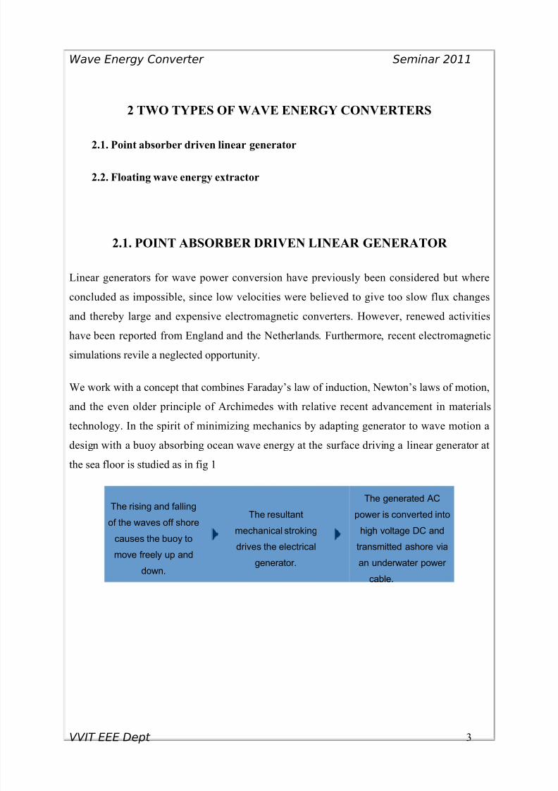
technology. In the spirit of minimizing mechanics by adapting generator to wave motion a
design with a buoy absorbing ocean wave energy at the surface driving a linear generator at
the sea floor is studied as in fig 1
The rising and falling
of the waves off shore
causes the buoy to
move freely up and
down.
The resultant
mechanical stroking
drives the electrical
generator.
The generated AC
power is converted into
high voltage DC and
transmitted ashore via
an underwater power
cable.
VVIT EEE Dept 3
8/3/2019 Wave Energy Convertor Edit
http://slidepdf.com/reader/full/wave-energy-convertor-edit 4/22
Wave Energy Converter Seminar 2011
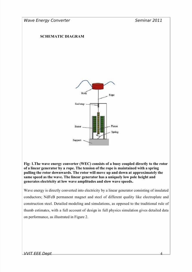
SCHEMATIC DIAGRAM
Fig: 1.The wave energy converter (WEC) consists of a buoy coupled directly to the rotor
of a linear generator by a rope. The tension of the rope is maintained with a spring
pulling the rotor downwards. The rotor will move up and down at approximately the
same speed as the wave. The linear generator has a uniquely low pole height and
generates electricity at low wave amplitudes and slow wave speeds.
Wave energy is directly converted into electricity by a linear generator consisting of insulated
conductors; NdFeB permanent magnet and steel of different quality like electroplate and
construction steel. Detailed modeling and simulations, as opposed to the traditional rule of
thumb estimates, with a full account of design in full physics simulation gives detailed data
on performance, as illustrated in Figure 2.
VVIT EEE Dept 4
8/3/2019 Wave Energy Convertor Edit
http://slidepdf.com/reader/full/wave-energy-convertor-edit 5/22
Wave Energy Converter Seminar 2011
The buoy, which drives the linear generator, can be built from different materials having good
resistance to corrosion and which can withstand high stress caused by the ocean waves and in
different forms.
However, a cylindrical shape is preferred as a uni-directional point absorber is desired. Buoy
dynamics and its behaviors during ocean wave exposure have been described elsewhere. A
buoy connected with a stiff rope will drive the generator piston as the wave is rising. When
the wave subsides a spring that has stored energy mechanically will drive the generator. Thus
allowing for generation of electricity during both up and down travel.
When the flux from the piston circumvents its coils induction will occur in the generators
stator, as the piston ideally moves up and down. Dependent on several parameters, generator
design, wave shape, buoy size, weight, load and springs etc., different voltages with varying
frequencies will be induced in the stator windings.
For open circuit conditions, the generator AC-voltage starts at zero, when the buoy is
momentarily at rest in its lowest position, increases as the buoy accelerates towards the top of
the wave, where it again reaches zero as the buoy stops.
For a relatively small wave energy converter (WEC) in the regime of 10–20 kW the buoy will
have a diameter of three to five meters depending on wave climate and power rating. The
buoy will have a weight in the regime of a few hundred kg to one metric ton depending on
size and material. The buoy is connected to the generator with modern synthetic rope
(possible of stretched polyethylene) trade names such as Dyneema and Spectra, with an
optional cover for handling of fouling. Housing encloses the generator, as indicted in Figure
1. This could be made of concrete or steel with and integrated bottom concrete slab.
The total weight of the generator is in the range of a few tons whereas the bottom slab must
have a weight surpassing the floatation of the buoy, in the range of 10 to 30 metric tons. The
slab can be positioned directly at the bottom and kept in place by gravity.
VVIT EEE Dept 5
8/3/2019 Wave Energy Convertor Edit
http://slidepdf.com/reader/full/wave-energy-convertor-edit 6/22
Wave Energy Converter Seminar 2011
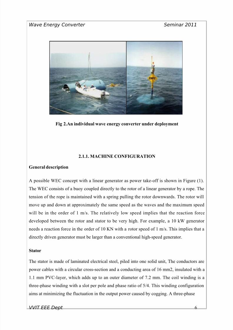
Fig 2.An individual wave energy converter under deployment
2.1.1. MACHINE CONFIGURATION
General description
A possible WEC concept with a linear generator as power take-off is shown in Figure (1).
The WEC consists of a buoy coupled directly to the rotor of a linear generator by a rope. The
tension of the rope is maintained with a spring pulling the rotor downwards. The rotor will
move up and down at approximately the same speed as the waves and the maximum speed
will be in the order of 1 m/s. The relatively low speed implies that the reaction force
developed between the rotor and stator to be very high. For example, a 10 kW generator
needs a reaction force in the order of 10 KN with a rotor speed of 1 m/s. This implies that adirectly driven generator must be larger than a conventional high-speed generator.
Stator
The stator is made of laminated electrical steel, piled into one solid unit, The conductors are
power cables with a circular cross-section and a conducting area of 16 mm2, insulated with a
1.1 mm PVC-layer, which adds up to an outer diameter of 7.2 mm. The coil winding is a
three-phase winding with a slot per pole and phase ratio of 5/4. This winding configuration
aims at minimizing the fluctuation in the output power caused by cogging. A three-phase
VVIT EEE Dept 6
8/3/2019 Wave Energy Convertor Edit
http://slidepdf.com/reader/full/wave-energy-convertor-edit 7/22
Wave Energy Converter Seminar 2011
LFM with a slot per pole and phase ratio equal to one is proposed as generator in the
Archimedes Wave Swing.
Rotor
Two types of magnet fixation methods, surface mounting and burying magnets between pole
efficiency and low material usage is desired. The electromagnetic efficiency includes
hysteresis losses, eddy current losses and resistive losses. Furthermore, a low load angle is
desired. A machine with inherently low load angle has better performance at both normal and
transient conditions and is less affected by changing loads and varying frequencies. The four
rotor concepts are simulated for different magnet dimensions and various pole widths. Output
power, voltage and stator width are held constant in the simulation and the vertical length of
the rotor is iterated to fulfill these conditions. Usage such as total magnet volume, stator steel.
Magnet dimensions
Different heights to width relations of the magnets have been investigated in order to seeif
there is an optimum. The magnet volume of single magnet is kept constant and the
electromagnetic efficiency and total magnet weight is plotted for different height to width
relations of the magnets. As can be seen the electromagnetic efficiency is steadily increasing
and the total magnet weight is decreasing with increasing magnet width for the surface
mounted magnets. The pole width limits the magnet width and no optimum is reach for the
surface mounted magnets.
Only active power is converted
From an analytical point of view, introduction of a load necessary to extract energy, poses a
new challenge. The load considerably complicates the dynamics of the motion. An electrical
current, from the induced voltage in the stator windings, exerts a retarding force on the piston
proportional to its speed relative the stator.
Using rectifier with an externally applied DC voltage makes the dynamics even harder.
Current passes the diodes when the induced voltages have higher potential than the externally
applied voltage.
VVIT EEE Dept 7
8/3/2019 Wave Energy Convertor Edit
http://slidepdf.com/reader/full/wave-energy-convertor-edit 8/22
Wave Energy Converter Seminar 2011
The retarding force is zero when the current is zero in the windings. Moreover, as induced
and rectified voltage excides the applied DC voltage, a retarding force will abruptly be
introduced, momentarily reducing the acceleration.
However, only active power transmitted is converted in the rectifier. Hence, the design has to
be render the generator insensitive to wave and load variations. This can be accomplished by
designing for a load angle close to unity. In practice, the current has to be relatively low at
full load securing small variations in load angle versus open circuit.
This strategy has advantages of and widens the range of components used for conversion
from stator windings to the grid connection. Simulations show that a working efficiency of
around 85 per cent can be obtained.
3.1.2. GRID CONNECTION
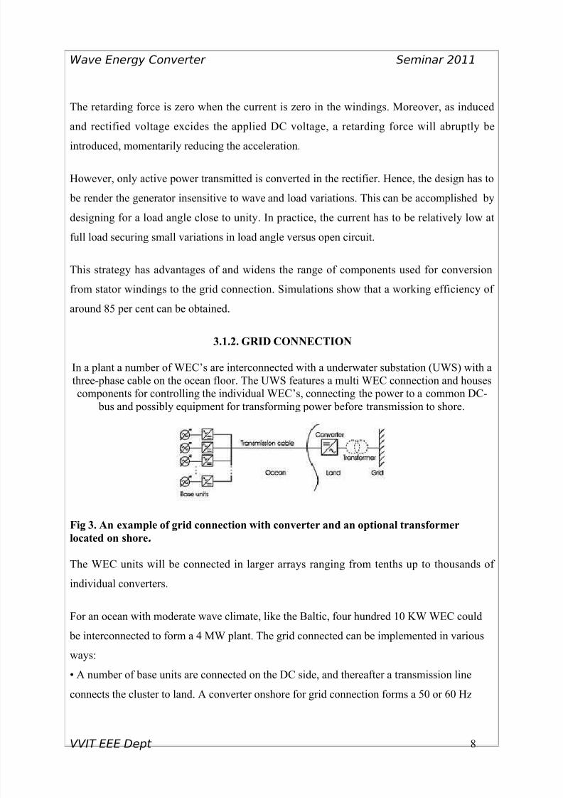
In a plant a number of WEC’s are interconnected with a underwater substation (UWS) with a
three-phase cable on the ocean floor. The UWS features a multi WEC connection and houses
components for controlling the individual WEC’s, connecting the power to a common DC-
bus and possibly equipment for transforming power before transmission to shore.
Fig 3. An example of grid connection with converter and an optional transformer
located on shore.
The WEC units will be connected in larger arrays ranging from tenths up to thousands of
individual converters.
For an ocean with moderate wave climate, like the Baltic, four hundred 10 KW WEC could
be interconnected to form a 4 MW plant. The grid connected can be implemented in various
ways:
• A number of base units are connected on the DC side, and thereafter a transmission line
connects the cluster to land. A converter onshore for grid connection forms a 50 or 60 Hz
VVIT EEE Dept 8
8/3/2019 Wave Energy Convertor Edit
http://slidepdf.com/reader/full/wave-energy-convertor-edit 9/22
Wave Energy Converter Seminar 2011
AC. An optional shore transformer could also include a tap changer in order to compensate
voltage variations,
• Another option, similar to the first, is to move the converter offshore which limits land use.
However, this increases the complexity and may decrease the availability as maintenance will
be more weather dependent. The converter can be placed on a platform or enclosed in a
watertight container on the seabed.
• A further development would be to also install a transformer offshore. This would increase
power transmission possibilities since power is proportional to the square of the voltage, i.e.
for the same power rating the current is lower with higher transmission voltage.• A fourth option includes a high voltage DC “HVDC” transmission link. This implies a
higher degree of complexity, but transmission losses are kept at a minimum. However, the
power components losses will be added. A platform or watertight enclosure is also required
for the electrical power components.
2.1.3. POINT ABSORBER ARRAYS
Shadowing effects
Theoretically, up to 50% of the incoming wave energy can be absorbed by a system of
oscillating point absorbers, i.e. an array of buoys [8]. For
Individual buoys absorption of 20% of the incoming energy has been observed [5]. In a
simplified model, neglecting three-dimensional scattering of waves, buoys at the back of an
array will receive less energy than those at the front for a wave field with a predominant
direction. If the absorption over the width of the buoy is assumed to be 20%, and the spacing
is ten times the buoy diameter, only 2% of the incoming energy will be
Absorbed by each row. For the n: th row in an array subjected to unidirectional waves the
available power flux will be attenuated by 0.98n-1. In this way, for an ideal wave climate
with sinusoidal waves from one direction a 20-row-array will receive at least 83% of the
incoming power flux. For a rectangular shape of the array, the effects of
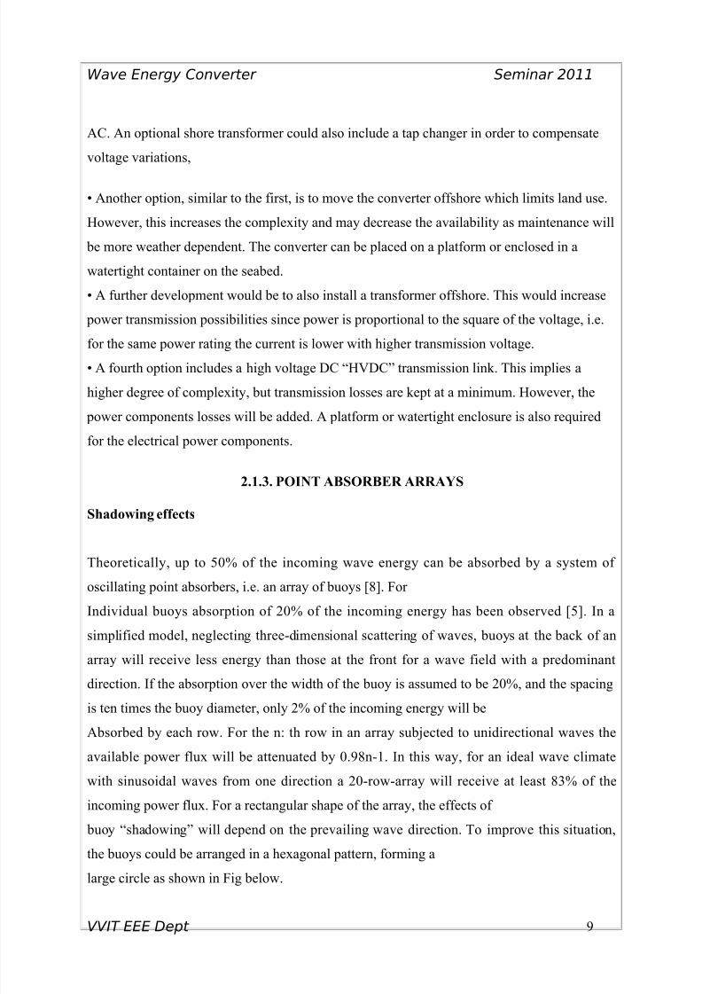
buoy “shadowing” will depend on the prevailing wave direction. To improve this situation,
the buoys could be arranged in a hexagonal pattern, forming a
large circle as shown in Fig below.
VVIT EEE Dept 9
8/3/2019 Wave Energy Convertor Edit
http://slidepdf.com/reader/full/wave-energy-convertor-edit 10/22
Wave Energy Converter Seminar 2011
2.1.4. WAVE REGENERATION
In a system where a number of WEC-arrays are deployed over an ocean surface the “up
wave” arrays will shadow the ones behind them, when there is a predominant wave direction
in the same sense as the buoys instead the individual array as discussed,. However, this
additional shadowing effect can be avoided through an ample distance between arrays, for
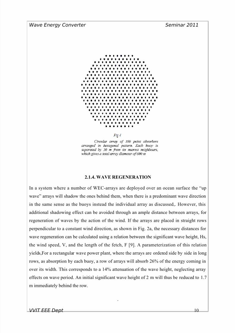
regeneration of waves by the action of the wind. If the arrays are placed in straight rows
perpendicular to a constant wind direction, as shown in Fig. 2a, the necessary distances for
wave regeneration can be calculated using a relation between the significant wave height, Hs,
the wind speed, V, and the length of the fetch, F [9]. A parameterization of this relation
yields,For a rectangular wave power plant, where the arrays are ordered side by side in long
rows, as absorption by each buoy, a row of arrays will absorb 26% of the energy coming in
over its width. This corresponds to a 14% attenuation of the wave height, neglecting array
effects on wave period. An initial significant wave height of 2 m will thus be reduced to 1.7
m immediately behind the row.
.
VVIT EEE Dept 10
8/3/2019 Wave Energy Convertor Edit
http://slidepdf.com/reader/full/wave-energy-convertor-edit 11/22
8/3/2019 Wave Energy Convertor Edit
http://slidepdf.com/reader/full/wave-energy-convertor-edit 12/22
Wave Energy Converter Seminar 2011
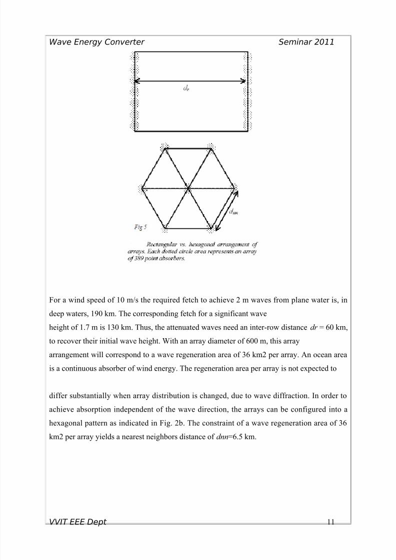
Fig 6.power station showing multiple buoys and underwater transmission cable. Inset
shows individual WEC. A 10-Megawatt power station would occupy only approximately
4 acres of ocean space.
2.2. FLOATING WAVE ENERGY EXTRACTER
Another variation of a wave energy converter, which uses the vertically exerted force of a
wave, is a Floating wave energy extractor
About the technology: The floating wave energy extractor is also a method for the maximum
exploitation of the wave energy and it is designed for distant offshore with very
unstable sea surface. The system is consists of a rectangular shaped huge mass floating body
supported by a large number of floating air columns. The air column’s extensions are
connected to pistons. The pistons are placed its own cylinders and it can move up and down
through the cylinders when the floating air columns moves with the up-down movements of
the waves. The upper side of the cylinders has two valves. One to a high-pressure fluid pipe
VVIT EEE Dept 12

8/3/2019 Wave Energy Convertor Edit
http://slidepdf.com/reader/full/wave-energy-convertor-edit 13/22
Wave Energy Converter Seminar 2011
and it will open when the floating air column on crest. One valve is to the low-pressure fluid
pipe and it will open when the floating air column on the trough. The whole system is
anchored to the sea bottom.
2.2.1. COMPONENTS
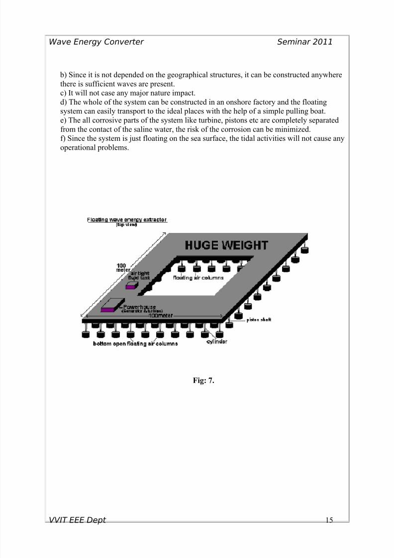
a). The huge mass floating body: - It can be made of iron or concrete (or water or sand
can be used for the huge mass).
b) The pipe systems for the hydraulic fluid: The pipe system is wired through inside of the
floating body.
c) Piston shafts, Pistons and cylinders: - Made of cast iron.
d). Bottom side open floating air columns: - Can be made of anticorrosive- long lastingmaterial like PVC etc. [The floating air columns made of a number of small units of
floating systems will be more secure instead of a large single floating column].
e) Air tight fluid tank: - This tank is partially filled with fluid and air. This tank takes an
important role as the fluid collector when overflow from the cylinders and supplier in the
shortage of the fluid in the cylinders.
f). The anchors: - The anchor is used to keep the floating system on position.
g). Power transmission: - The power can be transmitted to the grid through the under
ground (under water) cables.
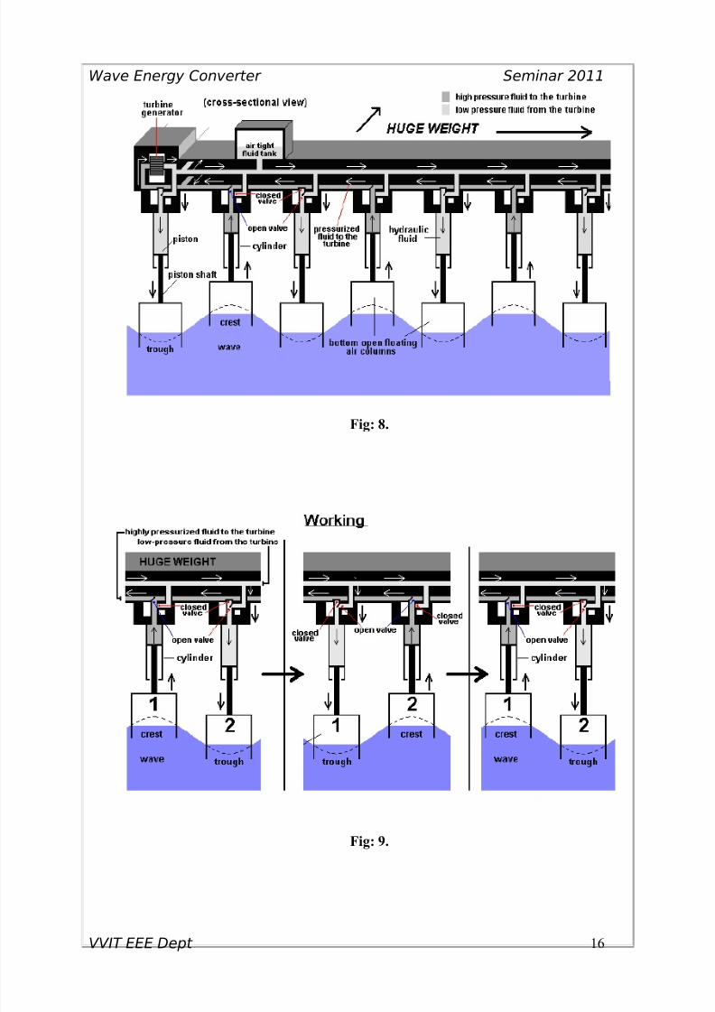
2.2.2. WORKING
When the wave moves through the floating air columns, it to oscillate the floating air
columns. When some of the air columns (air columns that on the crest) move upward, the
whole weight of the floating system will be supported through that air columns. Also,
now some floating air columns (the air columns that on the trough) will move downward.
As some of the air columns move upward, the pistons of those air columns to pressurize
its corresponding cylinders and the hydraulic fluid inside of the cylinders rush to the high-
pressure fluid pipe with high pressure (now the valves to the low-pressure fluid pipe will
be closed). Since the whole of the high-pressure fluid pipes are interconnected, the net
VVIT EEE Dept 13
8/3/2019 Wave Energy Convertor Edit
http://slidepdf.com/reader/full/wave-energy-convertor-edit 14/22
Wave Energy Converter Seminar 2011
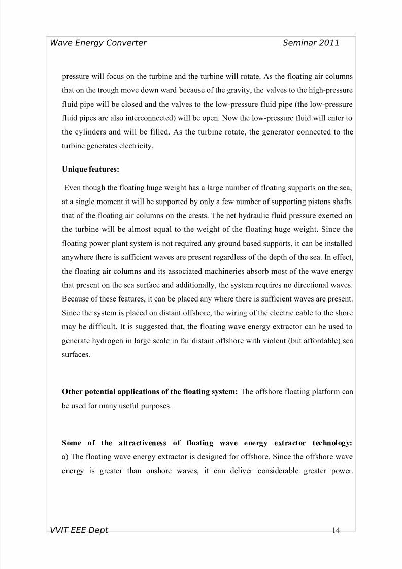
pressure will focus on the turbine and the turbine will rotate. As the floating air columns
that on the trough move down ward because of the gravity, the valves to the high-pressure
fluid pipe will be closed and the valves to the low-pressure fluid pipe (the low-pressure
fluid pipes are also interconnected) will be open. Now the low-pressure fluid will enter to
the cylinders and will be filled. As the turbine rotate, the generator connected to the
turbine generates electricity.
Unique features:
Even though the floating huge weight has a large number of floating supports on the sea,
at a single moment it will be supported by only a few number of supporting pistons shafts
that of the floating air columns on the crests. The net hydraulic fluid pressure exerted on
the turbine will be almost equal to the weight of the floating huge weight. Since the
floating power plant system is not required any ground based supports, it can be installed
anywhere there is sufficient waves are present regardless of the depth of the sea. In effect,
the floating air columns and its associated machineries absorb most of the wave energy
that present on the sea surface and additionally, the system requires no directional waves.
Because of these features, it can be placed any where there is sufficient waves are present.
Since the system is placed on distant offshore, the wiring of the electric cable to the shore
may be difficult. It is suggested that, the floating wave energy extractor can be used to
generate hydrogen in large scale in far distant offshore with violent (but affordable) sea
surfaces.
Other potential applications of the floating system: The offshore floating platform can
be used for many useful purposes.
Some of the attractiveness of floating wave energy extractor technology:
a) The floating wave energy extractor is designed for offshore. Since the offshore wave
energy is greater than onshore waves, it can deliver considerable greater power.
VVIT EEE Dept 14
8/3/2019 Wave Energy Convertor Edit
http://slidepdf.com/reader/full/wave-energy-convertor-edit 15/22
Wave Energy Converter Seminar 2011
b) Since it is not depended on the geographical structures, it can be constructed anywhere
there is sufficient waves are present.
c) It will not case any major nature impact.
d) The whole of the system can be constructed in an onshore factory and the floating
system can easily transport to the ideal places with the help of a simple pulling boat.
e) The all corrosive parts of the system like turbine, pistons etc are completely separated
from the contact of the saline water, the risk of the corrosion can be minimized.
f) Since the system is just floating on the sea surface, the tidal activities will not cause any
operational problems.
Fig: 7.
VVIT EEE Dept 15
8/3/2019 Wave Energy Convertor Edit
http://slidepdf.com/reader/full/wave-energy-convertor-edit 16/22
Wave Energy Converter Seminar 2011
Fig: 8.
Fig: 9.
VVIT EEE Dept 16
8/3/2019 Wave Energy Convertor Edit
http://slidepdf.com/reader/full/wave-energy-convertor-edit 17/22
Wave Energy Converter Seminar 2011
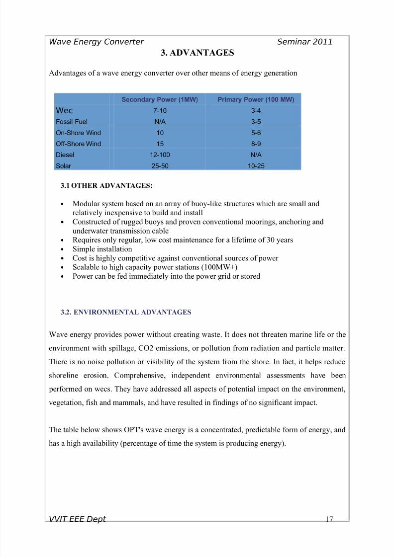
3. ADVANTAGES
Advantages of a wave energy converter over other means of energy generation
Secondary Power (1MW) Primary Power (100 MW)
Wec 7-10 3-4
Fossil Fuel N/A 3-5
On-Shore Wind 10 5-6
Off-Shore Wind 15 8-9
Diesel 12-100 N/A
Solar 25-50 10-25
3.1 OTHER ADVANTAGES:
• Modular system based on an array of buoy-like structures which are small and
relatively inexpensive to build and install
• Constructed of rugged buoys and proven conventional moorings, anchoring and
underwater transmission cable
• Requires only regular, low cost maintenance for a lifetime of 30 years
• Simple installation
• Cost is highly competitive against conventional sources of power
• Scalable to high capacity power stations (100MW+)
• Power can be fed immediately into the power grid or stored
3.2. ENVIRONMENTAL ADVANTAGES
Wave energy provides power without creating waste. It does not threaten marine life or the
environment with spillage, CO2 emissions, or pollution from radiation and particle matter.
There is no noise pollution or visibility of the system from the shore. In fact, it helps reduce
shoreline erosion. Comprehensive, independent environmental assessments have been
performed on wecs. They have addressed all aspects of potential impact on the environment,
vegetation, fish and mammals, and have resulted in findings of no significant impact.
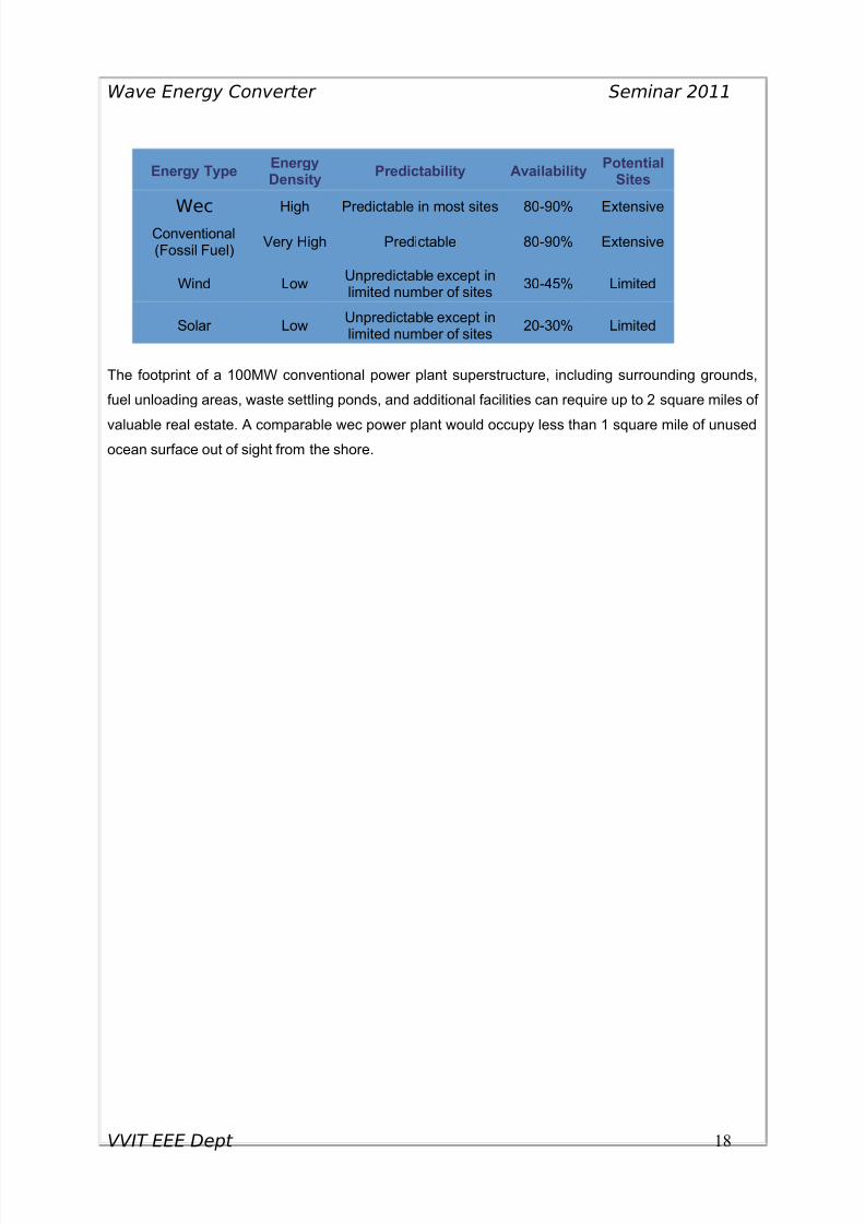
The table below shows OPT's wave energy is a concentrated, predictable form of energy, and
has a high availability (percentage of time the system is producing energy).
VVIT EEE Dept 17
8/3/2019 Wave Energy Convertor Edit
http://slidepdf.com/reader/full/wave-energy-convertor-edit 18/22
Wave Energy Converter Seminar 2011
Energy TypeEnergyDensity
Predictability AvailabilityPotential
Sites
WecHigh Predictable in most sites 80-90% Extensive
Conventional(Fossil Fuel)
Very High Predictable 80-90% Extensive
Wind LowUnpredictable except inlimited number of sites
30-45% Limited
Solar LowUnpredictable except inlimited number of sites
20-30% Limited
The footprint of a 100MW conventional power plant superstructure, including surrounding grounds,
fuel unloading areas, waste settling ponds, and additional facilities can require up to 2 square miles of
valuable real estate. A comparable wec power plant would occupy less than 1 square mile of unusedocean surface out of sight from the shore.
VVIT EEE Dept 18

8/3/2019 Wave Energy Convertor Edit
http://slidepdf.com/reader/full/wave-energy-convertor-edit 19/22
Wave Energy Converter Seminar 2011
4. DRAW BACKS
The main challenges have been high investment cost associated with large structures and
survivability of the parts exposed to the large powers of the ocean. Mechanical overloads are
difficult to handle without excessive over-dimensioning with associated increased costs.
DIFFICULTIES
At a more detailed level, there are a large number of topics to be tackled; a few of them are
given here for illustrative purposes:
• moorings – long-term fatigue of lines and connections;
• standard couplings for quick-release and re-attachment of moorings and cables;
• reduced-cost production of cables, construction and laying offshore;
• modeling of arrays of multiple wave energy devices;
• real-time wave behavior forecasting;
• direct-drive power generators;
• power-smoothing systems;
VVIT EEE Dept 19
8/3/2019 Wave Energy Convertor Edit
http://slidepdf.com/reader/full/wave-energy-convertor-edit 20/22
Wave Energy Converter Seminar 2011
5. CONCLUSION
Waves represent one of the most densely powered natural fluxes which can be directly used
for renewable energy generation.
Furthermore, it can have a relatively large utilization time as the power flux variations are
attenuated when the waves are induced by winds which in turn originates from solar power.
In this present scenario of injudicious use of natural resources wave energy will definitely
play an important role in accounting for the future energy needs.
VVIT EEE Dept 20

8/3/2019 Wave Energy Convertor Edit
http://slidepdf.com/reader/full/wave-energy-convertor-edit 21/22
Wave Energy Converter Seminar 2011
6. REFERENCES
1. http://www.telegraph.co.uk/news.html
2. http://ocsenergy.anl.gov/guide/wave/index.cfm
3. http://en.wikipedia.org/wiki/Pelamis_Wave_Energy_Converter
4. http://www.wavegen.com/about_wave_energy_info_schools_prep_model.htmhttp://w
ww.opt.com
5. Fluid mechanics and hydraulic machines- Dr R K Bansal
VVIT EEE Dept 21

8/3/2019 Wave Energy Convertor Edit
http://slidepdf.com/reader/full/wave-energy-convertor-edit 22/22
Wave Energy Converter Seminar 2011
VVIT EEE D t 22
Related Documents