WATER UTILITIES DEPARTMENT SPECIFICATIONS 2021 Water Utilities Department (479) 271-3140 Wastewater Treatment (479) 271-3160 Fire Department (479) 271-3151 Council Approved - June 22, 2021 | Ordinance - 2021-135 Approved by Arkansas Department of Health - April 1, 2021 www.bentonvillear.com

Welcome message from author
This document is posted to help you gain knowledge. Please leave a comment to let me know what you think about it! Share it to your friends and learn new things together.
Transcript

WATER UTILITIES DEPARTMENT
SPECIFICATIONS
2021
Water Utilities Department
(479) 271-3140
Wastewater Treatment
(479) 271-3160
Fire Department
(479) 271-3151
Council Approved - June 22, 2021 | Ordinance - 2021-135
Approved by Arkansas Department of Health - April 1, 2021
www.bentonvillear.com

2021 WATER UTILITIES DEPARTMENT SPECIFICATIONS
City of Bentonville
Water Utilities Department
(479) 271-3140
Wastewater Treatment
(479) 271-3160
www.bentonvillear.com
Fire Department
(479) 271-3151

Table of ContentsSECTION 1 General Information 9
1.1 All Materials Shall Be Domestically Made 9
SECTION 2 Definitions And Abbreviations 10
SECTION 3 Laws, Regulations And Ordinances 12
SECTION 4 Permits And Licenses 12
SECTION 5 Plans And Specifications 125.1 Record Drawing Standards 12
5.2 CAD Files 13
5.3 Shape Files 14
5.4 Data Files 14
5.5 Water Features 14
5.6 Sewer Features 17
5.7 Required data folder file format: 19
SECTION 6 Inspection 19
SECTION 7 Construction Layout 20
SECTION 8 Final Inspection Procedures 21
SECTION 9 General Regulations For Construction Purposes 239.2 Underground Utility Notification 23
9.3 Water Outages 23
9.4 Trench Dewatering 24
9.5 Location, Alignment and Grade 24
9.6 Public Travel 24
9.7 Surface & Subsurface Structures Location And Protection 25
9.8 Protection of Vegetation 25
9.9 Excavation and Preparation of Trench 26
9.10 Work Performed by Department 27
9.11 Confined Spaces 28
9.12 Public Employees Right to Know Act 28
9.13 Clean-Up of Job Sites 28
SECTION 10 General Installation Information And Procedures 2810.1 Handling Pipeline Materials 28
10.2 Pipe Embedment 29
10.3 Compaction 30
10.4 Jointing PVC & Ductile Iron Pipe and Fittings 30
10.5 Jointing Flanged Pipe & Fittings 30
10.6 Jointing Mechanical Joint Pipe & Fittings 31
10.7 Pipe Deflection 31
10.8 Pipe Material 31

SECTION 11 Water Distribution System General Information 32
SECTION 12 Water Distribution System Materials 3412.2 Pipe 34
12.3 Polyvinyl Chloride (PVC) Water Pipe (4" – 12") (14" - 48") 34
12.4 Ductile Iron Pipe (DI) 35
12.5 Ductile Iron Pipe 4” - 54” 35
12.6 Polyetheylene Pipe (PE) 35
12.7 Copper Pipe 35
12.8 Encasement Pipe 36
12.9 Fittings 36
12.10 Tapping Sleeves (4” Tap & Larger) 38
12.11 Sleeves Or Couplings 39
12.12 Tapping Saddles or Sleeves (Female Iron Pipe or AWWA CC Outlet) 40
12.13 Service Fittings 42
12.14 Gate Valves 44
12.14.1 Gate Valves - 4” Through 18” with Resilient Seat 44
12.15 Butterfly Valves 44
12.16 Air Release Valves 45
12.17 Valve Boxes, Lids And Extensions 45
12.18 Meter Boxes, Vaults And Lids 45
12.19 Fire Hydrants 46
12.20 Polyethylene Tubing Material for Pipe Encasement 47
12.21 Locator Wire 47
12.22 Concrete Material Specifications 48
12.23 Percent Retained by Weight 48
12.24 Concrete Proportions and Consistency 48
12.25 Concrete Testing 49
SECTION 13 Installation Criteria for Water Mains and Appurtenances 5013.1 Connections to Water Distribution System 50
13.2 Installation of Valves 50
13.3 Installation of Tapping Sleeves & Tapping Saddles 51
13.4 Fire Hydrant Installation 51
13.5 Concrete Placement & Finishing 52
13.6 Concrete Reinforcement 53
13.7 Concrete Cold-Weather Requirements 54
13.8 Concrete Hot-Weather Requirements 54
13.9 Concrete Thrust Blocks & Anchor Collars 55
13.10 Pressure Table 57
13.11 Installation of Polyethylene Protection Material 57
13.12 Meter Connections 58
13.13 Filling Water Lines 58
13.14 Hydrostatic Pressure and Leakage Tests 59

13.15 Disinfecting Water Lines and Appurtenances 60
13.16 Cleaning Large Pipelines 61
SECTION 14 Wastewater Collection System General Information 6214.2 Encasement Pipe 63
14.3 Minimum Slope for Sewer Line Installation Table 64
SECTION 15 Wastewater Collection System Materials 6515.2 Polyvinyl Chloride (PVC) 65
15.3 Ductile Iron Pipe 65
15.4 Pipe Accessories 66
15.5 Fittings 66
15.6 Cleanouts 66
15.7 Force Mains 66
15.8 Tracer Wire Ports for Force Mains 66
SECTION 16 Sewer Manhole Information And Materials 6716.2 Concrete Curing and Compounds 67
16.3 Cast-In-Place-Manholes 67
16.4 Drop Type Manholes 67
16.5 Sanitary Sewer Manhole Abandonment 67
16.6 Manhole Rings And Lids 67
16.7 Private Manhole 68
16.8 Watertight Manhole Rings and Lids 68
16.9 Manhole Steps 68
16.10 Water Stops 68
16.11 Manhole Configurations and Construction 68
16.12 Manhole Shape and Inside Dimensions 69
16.13 Manhole Design Depth, Height and Placement 69
16.14 Main And Service Pipes 69
16.15 Connections to Manholes 69
16.16 Inverts 69
SECTION 17 Sewer System General Installation Information 7017.2 Field Quality Control 70
17.3 Air Testing of Gravity Sewer Lines 70
17.4 Gravity Sewer Air Testing Time Requirements 71
17.5 Hydrostatic Pressure and Leakage Test of Force Mains 71
17.6 Testing Safety Precautions 72
17.7 Ground Water Elevation 72
17.8 Test Equipment 73
17.9 Mandrel Test 73
17.10 Manhole Vacuum Testing 73
17.11 Close Circuit Television Inspection – (CCTV) 74
17.12 Acceptance Of Installation 75

17.13 Warranty 75
SECTION 18 Sewer Lift Stations 7518.2 Final Acceptance 75
18.3 Basic Control Panel Specifications 75
18.4 Level Controls 77
18.5 Access Road 77
18.6 Lift Station And Site 77
18.7 Pump Requirements 78
18.8 Lift Station Plumbing 78
18.9 Valve Vaults and Wet Wells for Lift Stations 78
18.10 Valves 79
SECTION 19 Sewer Lift Stations – Private 8019.2 Lift Station Site 80
19.3 Basic Control Panel Specifications 80
19.4 Pump Requirements 80
SECTION 20 Cross-Connection Control Program Manual 8120.1 General 81
20.2 Introduction 81
20.3 Purpose 81
20.4 Definitions 81
Section 21 Administration 8421.1 Authority Of Approving Authority 84
21.2 Powers And Authorities Of Inspectors 85
21.3 Cross-Connection Surveys 86
21.4 Scheduling Surveys, Priorities 86
21.5 Other Surveys 86
21.6 Follow-Up Surveys 86
21.7 Enforcement Action 86
Section 22 Public Water Systems 8722.1 Auxiliary Public Water Systems 87
Section 23 Domestic Water Service Lines 8723.1 General 87
23.2 Costs 87
23.3 RPZA Containment 87
23.4 Containment Not Required 90
23.5 Retrofit 90
Section 24 Fire Protection Service Lines 9124.1 Classes of Fire Protection Systems 91
24.2 Backflow Prevention On Fire Protection Systems 91
24.3 Retrofit of Existing Systems 92

24.4 Assembly Installation 93
24.5 Plan Approval 93
24.6 Definitions 94
24.7 Flow/Pressure Loss Table 94
Section 25 Consumer Responsibilities 9525.1 General 95
Section 26 Assembly Specifications 9626.1 General 96
26.2 Backflow Prevention Assemblies 96
Section 27 Assembly Installation, Records and Reports 9727.1 General 97
27.2 Authorized Installers & Testers 97
27.3 Permits 97
27.4 Installation Detail 98
Pictures - Hot Box 99
Pictures - Assemblies 99
27.5 RPZA & DRPZA Installation 100
27.6 DDCVA & DCVA Installation 101
27.7 Temporary Use Assemblies 101
27.8 Reporting Requirements 101
27.9 Records 102
27.10 Protection Of Assemblies 102
27.11 Penalties 102
APPENDIX A Detailed Drawings 104

CITY OF BENTONVILLE // WATER UTILITIES DEPARTMENT SPECIFICATIONS // 2021 8CITY OF BENTONVILLE // WATER UTILITIES DEPARTMENT SPECIFICATIONS // 2021 8
2021 Bentonville Water Utilities Construction Specifications

CITY OF BENTONVILLE // WATER UTILITIES DEPARTMENT SPECIFICATIONS // 2021 9CITY OF BENTONVILLE // WATER UTILITIES DEPARTMENT SPECIFICATIONS // 2021 9
SECTION 1 General Information
1.1 All Materials Shall Be Domestically Made
Any deviation to require DEPARTMENT approval, and certificate(s) of materials origin shall be provided at the pre-construction meeting.
1.2 The intent of this publication is to simplify and expedite the process of water and sewer construction within the jurisdiction of the City of Bentonville. This publication specifically applies, but is not limited to “Subdivision” and “Large Scale Development”. All rules and regulations set forth by the ADH - Division of Engineering, shall be the minimum standard of all construction and development practices to be approved by the Bentonville Water Utilities. In such case as the standard specifications herein set forth exceeds the Arkansas Department of Heath specifications, this document as approved by the City Council of Bentonville, Arkansas shall govern.
1.3 These general and detailed specifications shall govern the handling and installation of pipe and appurtenances for the City of Bentonville Water Utilities. Specifications stipulate general requirements for the preparation of reports, plans, specifications, methods of construction, inspection, testing, and final approval of any proposed water and/or sanitary sewer lines, appurtenances, or other structures that are within the jurisdiction of Bentonville Water Utilities. Any requested deviation from the specifications herein set forth, shall be reviewed on a case-by-case basis by the DEPARTMENT and approved or denied by written authorization of the MANAGER.
1.4 Special conditions may arise on projects that are not covered in these specifications or that may require special handling. In case of such special conditions, complete detail as to materials, method of construction or other procedures shall be submitted to the Bentonville Water Utilities for review and approval. Standard construction details are incorporated and made a part of the specifications and shall become a part of the standard requirements for water line, sewer line and lift station construction. The standard details are included in these appendices at the back of these specifications. Where reference is made to a particular industry specification (ASTM, etc) it is hereby understood that reference is made to the latest specification revision in effect.
1.5 These specifications are intended to set forth minimum standards of quality for the construction of water and sewer facilities which are to be accepted by the Bentonville Water Utilities. These specifications do not replace the ENGINEERS specifications and contract documents; however, construction of all water and sewer facilities must meet these standards of quality as a minimum. The Bentonville Water Utilities shall not be responsible nor shall it bear any liability for CONTRACTOR’S means, methods, techniques, sequences or procedures of construction, or the safety precautions and programs incident thereto, nor shall the Bentonville Water Utilities be responsible for any actions resulting from direction of the project by a City of Bentonville ENGINEER/INSPECTOR. The Bentonville Water Utilities shall not be responsible for the acts or omissions of the CONTRACTOR, Sub-Contractor, supplier, or of any other person or organization performing or furnishing any of the work. Nothing contained in these specifications shall be construed as an endorsement or warranty by the Bentonville Water Utilities of any product, material, or workmanship. The Bentonville Water Utilities shall not be responsible nor shall it bear any liability for the durability of any material or method of construction. Material used on any project shall be warranted against defects and workmanship by responsible CONTRACTOR for one calendar year from date of acceptance.

CITY OF BENTONVILLE // WATER UTILITIES DEPARTMENT SPECIFICATIONS // 2021 10CITY OF BENTONVILLE // WATER UTILITIES DEPARTMENT SPECIFICATIONS // 2021 10
SECTION 2 Definitions And Abbreviations
2.1 DEPARTMENT: Refers to the Bentonville Water Utilities, under the jurisdiction of the Bentonville City Council, hereinafter referred to as “DEPARTMENT”; having full and complete authority to manage, operate, improve, extend and maintain the City water distribution system and sewer collection system.
2.2 ENGINEERING DEPARTMENT: City of Bentonville Engineer.
2.3 MANAGER: Bentonville Water Utilities Manager.
2.4 DEVELOPER: Industrial partnership, corporation, or other legal entity such as an improvement district, desiring to construct water and/or sanitary sewer facilities for immediate or contemplated future inclusion in the city system.
2.5 ENGINEER: Individual registered to practice Engineering in the State of Arkansas who is responsible for the preparation of reports, plans, specifications and inspection of the work herein approved.
2.6 CONTRACTOR: The person, firm or corporation with whom the DEVELOPER has entered into an agreement to construct the water and/or sewer improvements.
2.7 CITY INSPECTOR: City of Bentonville Engineering Department Inspector responsible for inspection, and notification of proposed reconstruction or alterations and inspections involving the City of Bentonville’s water and sewer system.
2.8 RESIDENT INSPECTOR: An authorized representative of the ENGINEER responsible for the inspection of construction for compliance with approved plans, specifications and other contract documents.
2.9 NORMAL WORK SCHEDULE: The City of Bentonville’s normal work schedule is Monday through Friday 7:30 AM to 4:00 PM except HOLIDAYS.
2.10 HOLIDAYS: New Year’s Day, Martin Luther King Day, President’s Day, Memorial Day, Independence Day, Labor Day, Veteran’s Day, Thanksgiving Day, Friday following Thanksgiving Day, Christmas Eve and Christmas Day.
2.11 TERMS: “As specified” shall mean as specified by the DEPARTMENT in plans, proposals, specifications, and other written instructions.
2.11.1 The term “or equal” shall mean that the proposed material or item shall perform adequately the duties imposed by the general design and is of the same or equal design, substance and junction to that specified by using the name of a product, manufacturer, or vendor. Use of the term “equal” shall mean any party proposing to substitute an “equal” shall obtain an approval from the DEPARTMENT. The DEPARTMENT shall make final approval of such items or materials judged to be “equal”.
2.11.2 The term “these specifications” shall refer to the “Design Materials and Construction Specification of Water and Sewer Facilities”, latest revision, written by the DEPARTMENT. It is the responsibility of the CONTRACTOR, ENGINEER, DEVELOPER or OWNER, etc. to obtain copies and to comply with the latest revision of these specifications.

CITY OF BENTONVILLE // WATER UTILITIES DEPARTMENT SPECIFICATIONS // 2021 11CITY OF BENTONVILLE // WATER UTILITIES DEPARTMENT SPECIFICATIONS // 2021 11
2.12 Abbreviations used throughout these specifications have meanings as follows:
ASTM American Society for Testing and Materials
AASHTO American Association State Highway & Transportation Officials
ARDOT Arkansas Highway Transportation Department
DEQ Arkansas Department of Energy Environment, Division of Environmental Quality
ADH Arkansas Department of Health
ADL Arkansas Department of Labor
ANSI American National Standards Institute
AWWA American Water Works Association (Latest Revision)
CTS Copper Tubing Size
CI Gray Cast Iron
CS or CC AWWA (Mueller Corp Stop Thread)
DI Ductile Iron
DFT Film Thickness
FCCCHR Foundation for Cross Connection Control & Hydraulic Research
FIP Female Iron Pipe
HDPE High Density Polyethylene
ID Inside Diameter
IP Iron Pipe
MIP Male Iron Pipe
NFPA National Fire Protection Association
OD Outside Diameter
OSHA Occupational Safety and Health Administration
PE Polyethylene
PSI/PSIG Pounds per Square Inch (gauge)
PVC Polyvinyl Chloride
SSPC Steel Structures Painting Council
USACE U.S. Army Corps of Engineers

CITY OF BENTONVILLE // WATER UTILITIES DEPARTMENT SPECIFICATIONS // 2021 12CITY OF BENTONVILLE // WATER UTILITIES DEPARTMENT SPECIFICATIONS // 2021 12
SECTION 3 Laws, Regulations And Ordinances
3.1 This section covers such rules and regulations as required by statute for the completion of plans, specifications and construction work on any and all proposed water and/or sanitary sewage facilities.
3.2 All Federal, State, County and City Laws, Regulations or Ordinances shall be complied with on all projects. This shall include, but not be limited to the obtaining of approval from ADH, DEQ, and USACE. Submission to and approval by ADH, DEQ, and USACE shall be the ENGINEERS responsibility, including payment of any applicable fees. Approved plans and specifications shall be returned to the City of Bentonville for file and inspection prior to the pre-construction meeting.
SECTION 4 Permits And Licenses
4.1 All permits and licenses required by a Federal, State, County or City shall be obtained in strict accordance with requirements of the governing agency. When required by the licensing agency, the DEPARTMENT will assist in application for permits and licenses, but the cost of any permit, fee or bond required will be borne by the DEVELOPER. The DEPARTMENT shall charge 10% of the bond fee as a handling charge. Permits for all street bores within the City of Bentonville’s corporate limits shall be permitted by the Bentonville Street Department. Permits for boring of state highways will be permitted via the DEPARTMENT as to obtaining permission from ARDOT. The project ENGINEER shall provide footage’s, profiles, and any other documented information necessary to the DEPARTMENT for State boring permits. Project ENGINEER may obtain permit and obtain ARDOT permit without going through the DEPARTMENT. ARDOT will require a check for the full amount of bond to ARDOT. Project ENGINEER to submit copy of approved permit to DEPARTMENT when received.
SECTION 5 Plans And Specifications
5.1 Record Drawing Standards
5.1.1 Prior to final inspection of the project, one (1) complete set of “As-Built” drawings shall be PDF and furnished or emailed to the DEPARTMENT for record purposes by the same ENGINEER who prepared and submitted the construction plans and specifications. Change of ENGINEERING firm shall warrant re-submittal both to CITY ENGINEERING and ADH. CITY ENGINEERING shall be notified in writing of change in Engineering Firm, additional requirements considered on a case-by-case basis. Record Drawing Standards shall be as outlined below:
CITY OF BENTONVILLE // WATER UTILITIES DEPARTMENT SPECIFICATIONS // 2021 13CITY OF BENTONVILLE // WATER UTILITIES DEPARTMENT SPECIFICATIONS // 2021 13
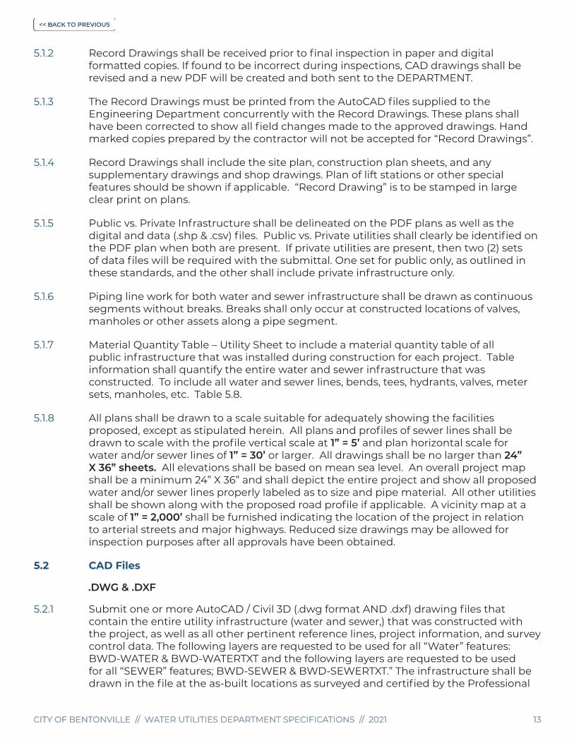
5.1.2 Record Drawings shall be received prior to final inspection in paper and digital formatted copies. If found to be incorrect during inspections, CAD drawings shall be revised and a new PDF will be created and both sent to the DEPARTMENT.
5.1.3 The Record Drawings must be printed from the AutoCAD files supplied to the Engineering Department concurrently with the Record Drawings. These plans shall have been corrected to show all field changes made to the approved drawings. Hand marked copies prepared by the contractor will not be accepted for “Record Drawings”.
5.1.4 Record Drawings shall include the site plan, construction plan sheets, and any supplementary drawings and shop drawings. Plan of lift stations or other special features should be shown if applicable. “Record Drawing” is to be stamped in large clear print on plans.
5.1.5 Public vs. Private Infrastructure shall be delineated on the PDF plans as well as the digital and data (.shp & .csv) files. Public vs. Private utilities shall clearly be identified on the PDF plan when both are present. If private utilities are present, then two (2) sets of data files will be required with the submittal. One set for public only, as outlined in these standards, and the other shall include private infrastructure only.
5.1.6 Piping line work for both water and sewer infrastructure shall be drawn as continuous segments without breaks. Breaks shall only occur at constructed locations of valves, manholes or other assets along a pipe segment.
5.1.7 Material Quantity Table – Utility Sheet to include a material quantity table of all public infrastructure that was installed during construction for each project. Table information shall quantify the entire water and sewer infrastructure that was constructed. To include all water and sewer lines, bends, tees, hydrants, valves, meter sets, manholes, etc. Table 5.8.
5.1.8 All plans shall be drawn to a scale suitable for adequately showing the facilities proposed, except as stipulated herein. All plans and profiles of sewer lines shall be drawn to scale with the profile vertical scale at 1” = 5’ and plan horizontal scale for water and/or sewer lines of 1” = 30’ or larger. All drawings shall be no larger than 24” X 36” sheets. All elevations shall be based on mean sea level. An overall project map shall be a minimum 24” X 36” and shall depict the entire project and show all proposed water and/or sewer lines properly labeled as to size and pipe material. All other utilities shall be shown along with the proposed road profile if applicable. A vicinity map at a scale of 1” = 2,000’ shall be furnished indicating the location of the project in relation to arterial streets and major highways. Reduced size drawings may be allowed for inspection purposes after all approvals have been obtained.
5.2 CAD Files
.DWG & .DXF
5.2.1 Submit one or more AutoCAD / Civil 3D (.dwg format AND .dxf) drawing files that contain the entire utility infrastructure (water and sewer,) that was constructed with the project, as well as all other pertinent reference lines, project information, and survey control data. The following layers are requested to be used for all “Water” features: BWD-WATER & BWD-WATERTXT and the following layers are requested to be used for all “SEWER” features; BWD-SEWER & BWD-SEWERTXT.” The infrastructure shall be drawn in the file at the as-built locations as surveyed and certified by the Professional

CITY OF BENTONVILLE // WATER UTILITIES DEPARTMENT SPECIFICATIONS // 2021 14CITY OF BENTONVILLE // WATER UTILITIES DEPARTMENT SPECIFICATIONS // 2021 14
Land Surveyor. The AutoCAD file(s) shall be placed into a folder named “CAD” on the submitted media. Please note: the delivered CAD files should not be of the Plan/Profile sheets, but should be the overall working drawing in “model space” that is registered to AR North State Plane, NAD 1983.
5.3 Shape Files
.shp
5.3.1 Submit as-built data for direct import into the City’s Geographic Information System (GIS). Submit four (4) shape (.shp) files; One (1) shape file (points), named “WTR_F” that contains all of the water infrastructure features that was constructed with the project; One (1) shape file (lines), named “WTR_L” that contains all of the water infrastructure lines that was constructed with the project; One (1) shape file (points), named “SWR_F” that contains all of the sanitary sewer infrastructure features that was constructed during the project; One (1) shape file (lines), named “SWR_P” that contains all of the sanitary sewer infrastructure lines that was constructed during the project. Each shape file shall include all features and line work that was constructed with the project only. Correctly name the files as outlined above. The shape files shall match the data files (.csv)
5.4 Data Files
.CSV
5.4.1 Data shall consist of files in an ASCII Comma Separated Value (CSV) file format. The preferred horizontal coordinate system for the digitally submitted data as described below shall be AR NORTH State Plane (NAD83), U.S. Survey Feet. The preferred vertical coordinate system for the digitally submitted data as described below shall be North American Vertical Datum, 1988 (NAVD 1988), U.S. Survey Feet. All of these file(s) shall be placed into a folder named “DATA” on the submitted media.
5.5 Water Features
5.5.1 The file shall be named “Water_Features” and contains various elements that connect and control the distribution of water within and among various water lines. These features include both buried fittings (bends, crosses, end caps, reducers, and tees) and features that are accessible and/or visible at the surface (meters, valves, and hydrants). Buried features should be located similar to the method our utility locators use: (a paint dot is placed on the pavement at the approximate location of the feature and then surveyed location is taken at the paint mark.)
Water line locations are required only if the water line curves. These locations shall be surveyed at 25 foot stations along the length of the water line.
Each line of the file shall contain the following information:
ID, Type, Northing, Easting, Elevation, Description (all on first line of the file)
Where:
ID - A unique ID number assigned to each feature noted on the as-built plan and profile sheets (e.g. GV1, HYD1, etc.)
Type - The type of feature. Provide the following codes as indicated in the table below:

CITY OF BENTONVILLE // WATER UTILITIES DEPARTMENT SPECIFICATIONS // 2021 15CITY OF BENTONVILLE // WATER UTILITIES DEPARTMENT SPECIFICATIONS // 2021 15
5.5.2 Water Features Descriptions
Feature Description Type
Air Release Valve ARV
Backflow Preventer BFP, RPZ, RPA, etc.
Bend BEND
Blow Off BLOWOFF
Cross CROSS
Demarcation Valve DMV
Encasement ENCASE
End Cap CAP
Feature Description Type
Fire Department Connection FDC
Fire Hydrant HYDRANT
Post Indicator Valve PIV
Reducer/Increaser REDUCER
Tee/Tapping Sleeve TEE
Water Valve VALVE
Water Line WATERLINE
Water Meter METER
Northing – North coordinate value (+/- 2.0’ if buried, +/- 0.1’ otherwise)
Easting – East coordinate value (+/- 2.0’ if buried, +/- 0.1’ otherwise)
Elevation – Elevation, collected as follows: (+/- 2.0’ if buried, +/- 0.1’ otherwise)
5.5.3 Water Feature Elevation Locations
Feature Type Elevation Location
BEND/BLOWOFF/CROSS/END CAP/REDUCER/TEE
Surface, at the mark that indicates the approximate location of the buried feature.
HYDRANT Top of the fire hydrant.
METER/VALVE Center of the access structure.
WATERLINE Surface, at the mark that indicates the approximate location of the buried line, at 25 foot stations. Only required if a water line is curved.
Description - The description of the item for the feature; encoded as follows:

CITY OF BENTONVILLE // WATER UTILITIES DEPARTMENT SPECIFICATIONS // 2021 16CITY OF BENTONVILLE // WATER UTILITIES DEPARTMENT SPECIFICATIONS // 2021 16
5.5.4 Water Feature Descriptions
Feature Type Description
BEND Degree of bend (e.g. 11.25/22.5/45/90).
BLOWOFF Size (in inches) of the blow off.
CROSS Size (in inches) of each water line that connects to the cross (e.g. “12x12x8x8”).
ENDCAP Size (in inches) of the water line.
HYDRANT Manufacturer and year of manufacture. This information will be on the hydrant (e.g. “CLOW- 2004”).
METER The size (in inches).
REDUCER The size (in inches) of the lines on either side of the reducer (e.g. “8x4”).
TEE The sizes (in inches) of each water line that connects to the tee (e.g. “12x12x8”).
VALVE The size (in inches) and type of the valve (e.g. 6 GV, 12 BFV)
WATERLINE No description required.
Example file format:
ID Type Northing Easting Elevation Description
GVI VALVE 749862.3433 653776.6033 1215.05 8 GV
BEND1 BEND 749818.6838 653805.9192 1214.15 22.5 BEND
5.5.6 Water Lines
The file shall be named “Water_Lines” and shall contain the following data. There is one line of data for each water line that connects two water features.
ID, Size, Material, FeatureID1, FeatureID2 (all on first line of the file)
Where:
ID – A unique number assigned to each section of water line noted on the as-built plan and profile sheets (e.g. “WL1”)
Material – Water line material
Size – The size (in inches) of the water line
FeatureID1 - The ID of the feature on the near end of the water line as shown on the as- built plans (e.g. “GV1”)
FeatureID2 - The ID of the feature on the far end of the water line as shown on the as- built plans (e.g. “HYD1”)Example file format:
ID Material Size Feature ID 1 Feature ID 2
WL1 PVC 8 GV1 GV2
WL2 PVC 8 GV10 GV1
CITY OF BENTONVILLE // WATER UTILITIES DEPARTMENT SPECIFICATIONS // 2021 17CITY OF BENTONVILLE // WATER UTILITIES DEPARTMENT SPECIFICATIONS // 2021 17
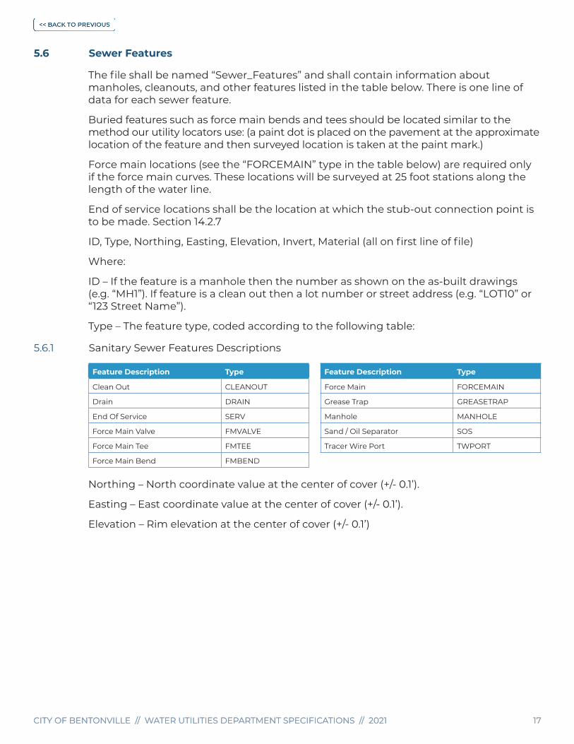
5.6 Sewer Features
The file shall be named “Sewer_Features” and shall contain information about manholes, cleanouts, and other features listed in the table below. There is one line of data for each sewer feature.
Buried features such as force main bends and tees should be located similar to the method our utility locators use: (a paint dot is placed on the pavement at the approximate location of the feature and then surveyed location is taken at the paint mark.)
Force main locations (see the “FORCEMAIN” type in the table below) are required only if the force main curves. These locations will be surveyed at 25 foot stations along the length of the water line.
End of service locations shall be the location at which the stub-out connection point is to be made. Section 14.2.7
ID, Type, Northing, Easting, Elevation, Invert, Material (all on first line of file)
Where:
ID – If the feature is a manhole then the number as shown on the as-built drawings (e.g. “MH1”). If feature is a clean out then a lot number or street address (e.g. “LOT10” or “123 Street Name”).
Type – The feature type, coded according to the following table:
5.6.1 Sanitary Sewer Features Descriptions
Feature Description Type
Clean Out CLEANOUT
Drain DRAIN
End Of Service SERV
Force Main Valve FMVALVE
Force Main Tee FMTEE
Force Main Bend FMBEND
Feature Description Type
Force Main FORCEMAIN
Grease Trap GREASETRAP
Manhole MANHOLE
Sand / Oil Separator SOS
Tracer Wire Port TWPORT
Northing – North coordinate value at the center of cover (+/- 0.1’).
Easting – East coordinate value at the center of cover (+/- 0.1’).
Elevation – Rim elevation at the center of cover (+/- 0.1’)

CITY OF BENTONVILLE // WATER UTILITIES DEPARTMENT SPECIFICATIONS // 2021 18CITY OF BENTONVILLE // WATER UTILITIES DEPARTMENT SPECIFICATIONS // 2021 18
5.6.2 Sanitary Sewer Features Elevation Locations
Feature Type Elevation Location
CLEANOUT Surface adjacent to the cleanout.
DRAIN Center of the drain grate.
FMVALVE Center of the access structure.
FMTEE/FMBENDSurface, at the mark that indicates the approximate location of the buried feature.
Feature Type Elevation Location
FORCEMAINSurface, at the mark that indicates the approximate location of the buried main, at 25 foot stations. Only required if a force main curves.
GREASETRAP/OWS Center of the structure
MANHOLE Center of Rim
Invert Elevation– Invert elevation (+/- 0.1’, bottom of manholes)
Material – Construction materialExample file format:
ID Type Northing Easting Elevation Invert Material
MH1 Manhole 751915.787 662437.91 1282.86 1277.71 CIP
CLEANOUT1 CLEANOUT 751927.504 662217.212 1285.37 1280.13 PVC
5.6.3 Sewer Pipes
The file shall be named “Sewer_Pipes” and shall contain the following data. There is one line of data for each sewer pipe.
If the pipe is a force main, values for Size, Material, USId, and DSId only need to be provided.
ID, Size, Material, USId, DSId, USInv, DSInv, Slope, Length (all on first line of the file)
Where:
ID – A sequential pipe number as noted on the as-built drawings (e.g. “SSP1”).
Size – Inside pipe diameter (inches).
Material – Pipe material
USId – Upstream manhole number as shown on the as-built drawings (e.g. “MH1”).
DSId - Downstream manhole number as shown on the as-built drawings (e.g. “MH2”).
USInv – Invert elevation at the upstream end.
DSInv – Invert elevation at the downstream end. If downstream end is a drop connection, provide both elevations separated by a slash (e.g. 1100.05 / 1100.15).
Slope – The as-built grade of the pipe, expressed as a percentage and carried out to two decimal places.
Length – The length (in linear feet) of the pipe as indicated on the as-built carried out two decimal places.Example file format:
ID Size Material USID DSID USINV DSINV Slope Length
SSPI1 8” PVC MH1 MH2 1233.15 1228.15 6.02% 78.76

CITY OF BENTONVILLE // WATER UTILITIES DEPARTMENT SPECIFICATIONS // 2021 19CITY OF BENTONVILLE // WATER UTILITIES DEPARTMENT SPECIFICATIONS // 2021 19
5.7 Required data folder file format:
Example file format:
5.8 Material Quantity Table
WATER SYSTEM IMPROVEMENTS
TYPE QUANTITY
16” ENCASEMENT LF 20
8” PVC WATER LINE LF 1200
GATE VALVES (8”) EA 16
TAPPING SLEEVE & VALVE EA 2
FIRE HYDRANTS EA 8
45° BEND EA 4
METER SETS EA 36
SEWER SYSTEM IMPROVEMENTS
TYPE QUANTITY
8” PVC LF 880
8” DIP LF 40
CIP SMH EA 10
CLEANOUT EA 2
4” FM LF 180
SECTION 6 Inspection
6.1 This section covers the requirements of inspection for the construction of water and sewer facilities.
6.2 The responsible ENGINEER who prepared and submitted the construction plans and specifications shall be responsible for construction layout, general direction, resident inspection and final inspection as described in more detail in the following sections. Continuous project responsibility shall be an express condition of plan approval. The ENGINEERS responsibility shall extend through final inspection approval and submittal of “As-Built” drawings for acceptance of the project by the DEPARTMENT for maintenance.

CITY OF BENTONVILLE // WATER UTILITIES DEPARTMENT SPECIFICATIONS // 2021 20CITY OF BENTONVILLE // WATER UTILITIES DEPARTMENT SPECIFICATIONS // 2021 20
6.3 All water and sewer facilities proposed shall be constructed by a licensed utility CONTRACTOR with the correct classification and inspected by the responsible ENGINEER as defined under definitions. Inspection shall consist of, but not be limited to, periodic visits to the construction site to observe the progress and quality of the executed work to determine if the work is proceeding in accordance with the approved plans and specifications and with the standards set forth by the DEPARTMENT. Any defects, deficiencies or irregularities in the work found by the ENGINEER or reported by the RESIDENT INSPECTOR shall be reported to the CITY INSPECTOR. Such action, as deemed appropriate, and as approved by the DEPARTMENT, shall be taken to correct such deficiencies. All work performed, shall at all times be subject to general inspection by the MANAGER or representative.
6.4 If deemed necessary by the DEPARTMENT to insure conformance with the approved plans and specifications, full time resident inspection may be required during all or part of the project and shall be performed by qualified personnel under the direct supervision of the ENGINEER. The name(s) of the RESIDENT INSPECTOR shall be furnished to the DEPARTMENT, any changes shall be notified to the DEPARTMENT in writing with all contact information included. It shall be the responsibility of the RESIDENT INSPECTOR to safeguard the DEPARTMENT’S interest by checking the construction work for compliance with the approved plans, specifications and other standards. The responsible ENGINEER shall provide an inspector for each location within a project that would use more than one pipe laying crew (e.g. two pipe laying crews on two different sites, two inspectors, one for each site). The CITY INSPECTOR or DEPARTMENT representative and the RESIDENT INSPECTOR shall witness all test procedures. The RESIDENT INSPECTOR shall provide a documented report of results, conditions, and time of test to the DEPARTMENT for its use and approval. If the CONTRACTOR intends to work outside of the normal work schedule or on a holiday, the RESIDENT INSPECTOR shall be required to be on the job site at all times and shall notify the DEPARTMENT. Refer to Section 2.
6.5 Any defects, deficiencies or irregularities shall be reported to the ENGINEER. A job diary shall be kept, outlining all aspects of the construction project and shall be made available to the DEPARTMENT upon request.
SECTION 7 Construction Layout
7.1 The layout and staking of the construction work shall be completed by trained and qualified survey personnel under the supervision of the ENGINEER. Construction layout shall consist of staking (physical monuments) necessary to determine alignment and elevations to properly construct the proposed facilities. All depths shall be approved by the DEPARMENT during plan review.

CITY OF BENTONVILLE // WATER UTILITIES DEPARTMENT SPECIFICATIONS // 2021 21CITY OF BENTONVILLE // WATER UTILITIES DEPARTMENT SPECIFICATIONS // 2021 21
SECTION 8 Final Inspection Procedures
8.1 Before acceptance of new construction involving water lines or sewer main extensions, a physical site inspection will be scheduled by the ENGINEERING DEPARTMENT referred to as a “Final Inspection”.
8.2 All lot corners shall be in place and witnessed by a survey marker. Said marker shall bear the number of the respective lot it represents. If lot lines do not coordinate with newly constructed utilities, it shall be the DEVELOPER’S responsibility to make the appropriate adjustments. If said situation exists at time of final inspection, approval shall be withheld until lot lines and utility locations coordinate. If these requirements have not been met, then final inspection shall be cancelled.
8.3 Water valve boxes will be to final ground elevation or paving grade centered directly over operator nut. Water valves and valve boxes shall be positioned in a manner to allow operability at all times. A continuous locator wire shall be present and operable in all valve boxes.
8.4 All water valve locations shall be verified by two reference measurements previously recorded by “As-Built” drawings. Water valve boxes shall be surrounded by a ground-level circular pre-fabricated concrete valve pad. Pre-fabricated circular valve pads shall be installed and grouted around valve box top section. All auxiliary fire hydrant valve boxes and valve pads shall have an 18” to 24” clearance from the top of the valve box to the fire hydrant cap and not interfere with cap removal when using a standard fire hydrant wrench.
8.5 Fire hydrants shall be set at bury line at finished grade. Hydrants shall be positioned 3’ to 9’ from back of curb or edge of any driving surface (measured from the steamer cap nut) or as directed by the DEPARTMENT during plan review.
8.5.1 All public fire hydrants shall be painted Industrial Safety Yellow. All private fire hydrants not maintained by the DEPARTMENT shall be painted Industrial Safety Red. Fire hydrants shall be painted prior to inspection unless otherwise instructed by the DEPARTMENT.
8.5.2 All fire hydrant assemblies shall have an auxiliary gate valve installed at the point of connection serving the hydrant. Hydrant lead lines in excess of 50’ shall have an additional auxiliary gate valve installed at the fire hydrant or as designated by the DEPARTMENT during plan review.
8.6 Fire Department Connection (FDC) for each sprinkler or standpipe system shall be located not more than 100’ from the nearest public fire hydrant connected to an approved public water supply. The FDC height shall be between 36” and 48” from the finished grade with a 30° bend and a 5” Storz connection. There shall be #10 tracer wire taped every 10 feet on the top of FDC line. Additional fire hydrants may need to be installed as required by the Fire Chief or his designated representative. With respect to hydrants, driveways, buildings and landscaping, fire department connections shall be so located that the fire apparatus and hose connected to supply the system will not obstruct access to the buildings for other fire apparatus. The location of the fire department connections and/or fire hydrants shall be approved by the Fire Chief or

CITY OF BENTONVILLE // WATER UTILITIES DEPARTMENT SPECIFICATIONS // 2021 22CITY OF BENTONVILLE // WATER UTILITIES DEPARTMENT SPECIFICATIONS // 2021 22
his designated representative. This fire hydrant will be solely used for the FDC. (Or per newest Fire Department Ordinance).
8.6.1 FDC’s shall be located on address side of building and shall be approved by the Fire Department’s Inspection Division prior to installation.
8.6.2 Butterfly valves are not approved for use in fire suppression systems. Only approved Post Indicator gate valves (P.I.V.) or wall indicator valves shall be utilized and approved. P.I.V. needs to be 30” to 36” above final grade to the sight glass. There shall be #10 tracer wire taped at 10’ intervals on top of the fire line. PIV shall to be shown on construction plans.
8.7 Residential Meter boxes shall be set at 3” above proposed final grade or as directed by the DEPARTMENT during plan review. All meter setters inside the box shall not touch the sides of the box and shall be located where the turn-on and turn-off valves are easily accessible and operable by meter personnel. All meter sets shall have a minimum 3’ stub-out service line for each service placed in such a manner to minimize disturbing meter box in the process of plumbing connection from pigtail to the customer’s service line. All damage to meter boxes shall be the responsibility of the owner or builder after final acceptance has been completed. Meter personnel reserve the right to refuse placement of meters if setters or boxes are damaged, misaligned, or if finished grades have changed. All meter box lids shall have one or two pre-drilled holes, depending on the number of meter setters installed within the meter box. The holes are for use with the DEPARTMENT’S meter reading system. Failure to install predrilled lids will lead to acceptance failure.
8.8 All meter vault plans and installations shall be approved by the DEPARTMENT during plan review. All meter vaults are to be installed by designated CONTRACTOR of the project. Section 12.18.4
8.9 All pipe and fittings shall meet the DEPARTMENT’S specifications. All DI pipe shall be cement lined and tar coated, all fittings shall be epoxy coated. Meter by-pass material shall be rigid copper or DI pipe. Valves shall meet specifications herein. Vault depth shall not exceed 5’ unless approved by the DEPARTMENT.
8.10 The vault cover shall be removable to allow full access to the vault. Four recessed lifting points shall be provided. An access door shall be installed in the center of the vault. The lid shall have pre-drilled holes for meter capability. Approved doors shall be similar or equal to Bilco or Halladay and shall be a minimum of 36” x 36”.
8.11 Water meters shall not be installed within buildings without prior approval by the DEPARTMENT. If approved, meters inside buildings shall meet the following criteria, Section 8.12, which shall be furnished and guaranteed by owner of future development prior to approval.
8.12 Meters must have capability via outside of building and accessible to meter personnel, (no obstructions). Meters 4” and larger are to be purchased by OWNER with direction of the DEPARTMENT.
8.13 Sewer stub-outs installed for a domestic sewer connection shall be marked and made visible by installing a metal tee post painted green at the precise location above said sewer line end, at a height of 3’ exposed above ground and buried a minimum of 3’ below ground.

CITY OF BENTONVILLE // WATER UTILITIES DEPARTMENT SPECIFICATIONS // 2021 23CITY OF BENTONVILLE // WATER UTILITIES DEPARTMENT SPECIFICATIONS // 2021 23
8.14 All trees planted in large scale projects and subdivisions shall be planted at a minimum of 5’ from any water or sewer mains.
8.15 ENGINEER shall contact the DEPARTMENT by email to schedule televising of sewer mains and tracer wire inspections before roadways have been completed and before 1st full inspection is requested. Full CCTV inspection shall be completed and 1st tracer wire inspection shall be completed before final inspection. ENGINEER shall provide revised “as-built” drawing of utility sheet with sewer profile before testing will be scheduled.
8.16 The Owner/Contractor/DEVELOPER shall pay any outstanding (3 or more months) invoice issued by the Water Utilities Office prior to final acceptance of the current project. This includes previous projects, water/sewer line repairs, fire hydrant contracts, discontinue services, replace meter tiles, re-inspection fees, survey fees, etc. – Does not include Utility Bills.
8.17 The DEPARTMENT shall charge for each re-inspection. Refer to current fee ordinance.
SECTION 9 General Regulations For Construction Purposes
9.1 Refer also to current Transportation Department Specifications.
9.1.1 This section outlines minimum construction procedures and standards for the installation of water and sewer extensions.
9.1.2 Any Contractor/developer/CUSTOMER/RESIDENT that requests the use of a hydrant meter will be required to fill out a Contract and pay for a Fire Hydrant Meter at the Water Utilities Office. The Contractor/developer/CUSTOMER/RESIDENT of the City of Bentonville will determine the location for the hydrant meter with the DEPARTMENTS approval. The current contract may also be found online on the City of Bentonville Water Utilities Department website.
9.2 Underground Utility Notification
9.2.1 It is the CONTRACTOR’S responsibility to notify “Arkansas One-Call” (1-800-482-8998 or 811) two days in advance of any excavation. Location of utility requests for surveying purposes will be charged to the requesting party. A notice of at least 2 working days (normal work schedule) should be expected before locates are performed by the DEPARTMENT. Refer to current fee ordinance.
9.3 Water Outages
9.3.1 In the event that the CONTRACTOR must have a water main out of service in order to connect to the water system, the CONTRACTOR shall notify the DEPARTMENT of impending loss of service at least 5 days in advance. All shutdowns shall be coordinated and scheduled by the DEPARTMENT. Notifying customers will be accomplished by means of approved door hanger notices supplied by the DEPARTMENT, however it is the CONTRACTOR’S responsibility to notify the customers a minimum of 24 hours ahead of time. Section 13.1.2

CITY OF BENTONVILLE // WATER UTILITIES DEPARTMENT SPECIFICATIONS // 2021 24CITY OF BENTONVILLE // WATER UTILITIES DEPARTMENT SPECIFICATIONS // 2021 24
9.4 Trench Dewatering
9.4.1 The CONTRACTOR shall install dewatering systems as necessary that will be required to construct the proposed utilities in a manner that will prevent groundwater contamination. Must meet current City of Bentonville Storm Water Regulations. For 12” and larger pipe sizes, ground water encountered shall be prevented from migrating along the trench with either clay or flowable fill mitigation dams and wrapping pipe bedding with filter fabric as approved by the DEPARTMENT, in accordance with geotechnical recommendations.
9.5 Location, Alignment and Grade
9.5.1 The pipe, fittings, valves, fire hydrants, meter boxes, manholes, and other appurtenances shall be constructed to conform to the location, line size and material, and grades specified or as shown on the Plans.
9.5.2 Valves and fire hydrants shall be set with operating stem and nut plumb.
9.5.3 Horizontal and vertical control points will be established along or adjacent to the construction area. It shall be the responsibility of the CONTRACTOR to make necessary measurements from these control points in order to maintain the proper alignment and grade of the structures. The CONTRACTOR shall preserve all stakes and markers established by the ENGINEER.
9.5.4 In a residential or commercial subdivision, the water and sewer mains will be placed at 12’ back of curb or 2’ behind master plan street right-of-way. The manholes and fire hydrants will be placed on the lot line and water and sewer services will be placed 3’ off the lot line. Water services that are on the same side as the water main will be placed at 14’ back of curb and the water services across the road from the water main will be placed in the green space centered between the curb and proposed sidewalk. The 1” tubing going to the meter set will be installed without excess tubing wrapping around the meter tile. The sewer services are to extend to the building setback or the back edge of the utility easement. The fire hydrants that are placed on the lot line need to meet the back of curb measurement that is shown on the fire hydrant installation Details W04 and W05. The manholes that are street side need to have a final rim elevation that is 4” to 6” above final grade and any manholes that are at the back of lots or along drainage areas need to be 12” above final grade. Please keep in mind that the maximum vertical extension above the cone is 24”. If the vertical extension is greater than 24” it will be necessary to take the cone off, extend the walls, re-pour the cone and do a vacuum test on the manhole. Any variation from the above described layout needs to be submitted to the DEPARTMENT for approval during the plan review process.
9.6 Public Travel
9.6.1 Traffic control shall be in accordance with the City of Bentonville Minimum Standard Specification for Streets.

CITY OF BENTONVILLE // WATER UTILITIES DEPARTMENT SPECIFICATIONS // 2021 25CITY OF BENTONVILLE // WATER UTILITIES DEPARTMENT SPECIFICATIONS // 2021 25
9.7 Surface & Subsurface Structures Location And Protection
9.7.1 The DEPARTMENT does not guarantee the accuracy or correctness of locations of subsurface structures. It shall be the responsibility of the CONTRACTOR to satisfy himself as to the actual location and nature of subsurface structures.
9.7.2 The CONTRACTOR shall make necessary exploratory excavations to determine the location of underground structures such as pipes, drains, conduits, and other structures. The CONTRACTOR shall be responsible for contacting the respective utility of such structures before excavating in the vicinity of these structures and shall be guided by their instructions.
9.7.3 The CONTRACTOR shall provide adequate protection and support for all surfaces and subsurface structures or other facilities encountered during the progress of the work. Whenever such structures or facilities are in the same location as the proposed pipeline or appurtenances thereto, the CONTRACTOR shall relocate or reconstruct or cause to be relocated or reconstructed, the structure or facility to the satisfaction of the DEPARTMENT and utility facility owner. Whenever requested by the DEPARTMENT or utility owner, the CONTRACTOR shall provide drawings and other plans for supporting or otherwise safeguarding surface and subsurface structures or other facilities which, in the opinion of the DEPARTMENT, or utility or facility owner, may be damaged as a result of the CONTRACTOR’S work.
9.7.4 The CONTRACTOR shall not stop or impede the flow in any pipe, sewer, surface or subsurface drain without making provisions for diverting the flow to the satisfaction of the DEPARTMENT.
9.7.5 If any utility facility or structure is damaged during the progress of the work, the CONTRACTOR shall immediately notify the appropriate owner. Repairs shall not be made by the CONTRACTOR without the prior approval of the utility facility or structure owner. The CONTRACTOR shall pay utility owners for the cost of repairing, relocating or replacing any facilities damaged by the CONTRACTOR. In addition, the CONTRACTOR shall provide all assistance available to the utility involved in making repairs under emergency conditions.
9.7.6 The CONTRACTOR shall not operate any control valve or fire hydrant in the existing water distribution system without the approval of the DEPARTMENT.
9.7.7 All existing water mains, services, appurtenances and bends shall be properly restrained in such manner so as to prevent displacement before excavating behind these appurtenances.
9.8 Protection of Vegetation
9.8.1 The CONTRACTOR shall not remove or disturb any vegetation except that required for the execution of the work.
9.8.2 Unless otherwise specified in these specifications or in the plans, the CONTRACTOR shall replace all sod, shrubs, bushes, trees, and flowers disturbed or removed, that are located upon improved or landscaped public and private property. The CONTRACTOR shall replant vegetation and re-landscape or cause such to be performed throughout the work area as soon as possible after the water lines and appurtenances have been installed. All vegetation damaged during or after removal shall be replaced

CITY OF BENTONVILLE // WATER UTILITIES DEPARTMENT SPECIFICATIONS // 2021 26CITY OF BENTONVILLE // WATER UTILITIES DEPARTMENT SPECIFICATIONS // 2021 26
with healthy vegetation of the same kind or type. All plants shall be replanted in the original location. The CONTRACTOR shall maintain all such replanted vegetation by the application of water, fertilizers and topsoil. The vegetation shall be cultivated to prohibit the growth of foreign vegetation until a “well developed” root system has been established and transplanted vegetation has overcome the “shock” resulting from transplanting. If any vegetation dies or becomes unhealthy, it shall be replaced by the CONTRACTOR. The contour of the ground shall be left as near the original contour as possible.
9.8.3 The CONTRACTOR shall stabilize all areas where ground surface has been disturbed by water and sewer construction activities to as good or better condition.
9.9 Excavation and Preparation of Trench
9.9.1 The CITY INSPECTOR and “Arkansas One-Call System” shall be contacted before excavation shall begin. Also, excavations shall be in accordance with the Arkansas Department of Labor requirements.
9.9.2 All trench excavation side walls greater than 5’ in depth shall be sloped, shored, sheeted, braced or otherwise supported by means of sufficient strength to protect the workmen within them in accordance with the applicable rules and regulations established for construction by OSHA and ADL.
9.9.3 Before installation of pipe and appurtenances, the trench bottom shall be graded so uniform support of the pipe and appurtenances are provided. Shallow depressions shall be made in the trench bottom to accommodate bell ends. It is a requirement for bell or coupling holes to be excavated where no part of the load is supported by bells, couplings, or fittings.
9.9.4 All trenches shall be backfilled immediately after proper installation of the pipeline, tracer wire, embedment, and appurtenances. It may be necessary to backfill only a portion of the trench in order to allow adequate curing of concrete thrust blocking.
9.9.5 The trench width may vary and depend upon the depth and the nature of the excavated material encountered. The trench shall be of ample width to permit the pipe to be laid and jointed properly and the backfill to be placed and compacted properly. The minimum width of non-sheeted trench shall be at least 1’ greater than the nominal diameter of the pipe. Ledge rock, boulders, large stones, and other rock formation shall be removed to provide a clearance of at least 6” on each side of pipeline and appurtenances up to and including 24” in diameter.
9.9.6 The bottom of the trench shall be prepared so as to provide a uniform and continuous bearing and support for the pipe on solid undisturbed or compacted soil. The trench shall be excavated to at least the depth specified as follows beyond the specified grade when the following described conditions exist:
9.9.7 When the bottom of the trench is at sub-grade and is found to be unstable or includes ashes, cinders, refuse, other organic material, or large pieces of inorganic material, that, in the judgment of the ENGINEERING DEPARTMENT, should be removed, the CONTRACTOR shall remove all such material to the extent required by the ENGINEERING DEPARTMENT

CITY OF BENTONVILLE // WATER UTILITIES DEPARTMENT SPECIFICATIONS // 2021 27CITY OF BENTONVILLE // WATER UTILITIES DEPARTMENT SPECIFICATIONS // 2021 27
9.9.8 When the excavation is carried below or beyond that specified or required due to conditions described in Section 9.9.7, the CONTRACTOR shall backfill the trench to the proper grade with approved backfill material specified by the DEPARTMENT, unless permitted by the DEPARTMENT to install the lines and appurtenances at the undercut grade. The backfill shall be accomplished in accordance with that specified by the DEPARTMENT or elsewhere herein.
9.9.9 The use of trench-digging machinery will be permitted except in places where operations of same will cause damage to trees, buildings, or other existing structures above or below the ground; in which case hand methods shall be employed.
9.9.10 Blasting for excavation will be permitted only after the CONTRACTOR secures the approval of the Fire Department and DEPARTMENT and only when proper precautions are taken for the protection of persons and property. The Fire Department will approve the hours of blasting. Any damage caused by blasting shall be repaired by the CONTRACTOR at their expense. The method of transporting, handling, and storage of explosives and blasting procedure shall conform to Federal Regulations, local and state laws, municipal ordinances and be approved by the Fire Department in advance.
9.9.11 The CONTRACTOR shall comply with all federal, state and local laws or ordinances with respect to obtaining permits, the deposit of bonds and all other provisions of such laws and ordinances.
9.9.12 In order to prevent caving when excavating in sand, gravel, sandy soil, or other unstable material shall be adequately sheeted and braced. Where sheeting and bracing is used, the trench width may be increased accordingly. Trench sheeting shall remain in place until the pipe has been laid and jointed. Where slides or cave-ins occur, the CONTRACTOR shall, at his expense, provide proper bedding and support for the pipe to maintain line and grade.
9.9.13 All excavated material stored on the job site shall be stockpiled in a manner to avoid blocking driveways, streets or sidewalks and will not endanger workers, pedestrians or travelers. Gutters shall be kept clear or other satisfactory provisions shall be made for street drainage. If local conditions permit their re-use, all surface materials suitable for re-use in restoring the surface shall be kept separate from the general excavation material. Excess material and debris shall be removed promptly.
9.9.14 The CONTRACTOR shall maintain all temporary surfaces in good condition until permanent repairs are complete.
9.10 Work Performed by Department
9.10.1 The intent of these specifications is for the CONTRACTOR to do all installation of new water and sewer infrastructure. All water and sewer taps to the existing Water Distribution or Wastewater Collection Systems shall be made by the DEPARTMENT as outlined in Section 11.10.
9.10.2 If damage occurs to the water or wastewater collection systems during construction, the DEPARTMENT, with its labor forces, will make all repairs to these systems. The CONTRACTOR may be requested to assist in the repairs to reduce charges for damages occurred.

CITY OF BENTONVILLE // WATER UTILITIES DEPARTMENT SPECIFICATIONS // 2021 28CITY OF BENTONVILLE // WATER UTILITIES DEPARTMENT SPECIFICATIONS // 2021 28
9.10.3 If the DEPARTMENT assists the CONTRACTOR for any reason, the CONTRACTOR shall pay for the cost of this assistance, based on the cost of labor, equipment, materials and overhead.
9.11 Confined Spaces
9.11.1 The CONTRACTOR’S attention is called to the requirements for entry into confined spaces as defined by the Current Edition of the OSHA Standard for Permit Required Confined Spaces which is specifically incorporated herein by reference.
9.11.2 CONTRACTOR’S responsibilities for entry into any Permit Required Confined Space are:
a. CONTRACTOR shall obtain from DEPARTMENT any available information regarding any hazards of entry operations for a Permit Required Confined Space.
b. When both DEPARTMENT and CONTRACTOR’S personnel are to work in or near a Permit Required Confined Space, CONTRACTOR shall coordinate such work with DEPARTMENT.
c. CONTRACTOR shall inform DEPARTMENT of type of Permit Required Confined Space Program used by his employees.
d. CONTRACTOR shall inform DEPARTMENT of any hazards confronted or created in a Permit Required Confined Space.
e. CONTRACTOR is responsible for having knowledge of and complying with all requirements of OSHA’s Standard for Permit Required Confined Spaces.
9.12 Public Employees Right to Know Act
9.12.1 The CONTRACTOR’S attention is called to the requirements of the Hazard Communication Standard adopted by OSHA and State of Arkansas Act 556 of 1991: Public Employees Chemical Right to Know Act.
9.12.2 The CONTRACTOR is reminded that other obligations are imposed upon employers by the above Standard and Act.
9.13 Clean-Up of Job Sites
9.13.1 The CONTRACTOR shall remove all materials, equipment, tools, temporary structures, barricades, trees and other vegetation that have been cut or have died as a result of the work from both public and private property along the job site.
SECTION 10 General Installation Information And Procedures
10.1 Handling Pipeline Materials
10.1.1 The CONTRACTOR shall handle the material with the utmost care and in a manner to prevent damage to the materials, material coating and lining during loading, hauling, unloading, and installation operations. Hooks, chains, or cables shall not

CITY OF BENTONVILLE // WATER UTILITIES DEPARTMENT SPECIFICATIONS // 2021 29CITY OF BENTONVILLE // WATER UTILITIES DEPARTMENT SPECIFICATIONS // 2021 29
come in contact with the exterior/interior of pipeline materials. It is recommended to use approved nylon straps or approved clamps to handle pipeline material. Material damaged shall be replaced at the CONTRACTOR’S expense.
10.1.2 Hooks shall not be in contact with the pipe interior and to the extent possible the interior of the pipeline materials shall be kept free from dirt and foreign matter.
10.1.3 Pipeline materials, especially valves, hydrants and fittings shall be drained and stored in a manner to protect them from damage by freezing. Under no circumstances shall pipe or accessories be dropped or dumped into the trench.
10.1.4 Proper implements, tools and facilities shall be provided and used by the CONTRACTOR for the safe and convenient execution of work.
10.1.5 All foreign matter or dirt shall be removed from the inside of the pipe and appurtenances before lowering into the trench and the pipe interior shall be kept clean during and after laying. A swab shall be kept in the water line as long as the pipe is being laid. Care shall be taken to prevent dirt from entering the joint space. When pipe laying is not in progress, the open ends of the pipe shall be closed by installing a plug or cap of sufficient design to prevent trench water, foreign matter, and dirt from entering the pipeline.
10.1.6 Cutting of the pipe for inserting valves, fittings or closure pieces shall be done in a neat and workmanlike manner without damage to the pipe or pipe lining. Torch cutting is not permitted. All pipes shall be cut at an angle of 90° to the pipe centerline. Cutting at other angles to provide greater deflections at the joints shall not be permitted. Field welding or welding except by the pipe manufacturer shall not be permitted.
10.1.7 Unless otherwise approved or directed by the DEPARTMENT, all pipe shall be laid with bell ends facing the direction of laying; and for lines on an appreciable slope, bells shall face upgrade. Steep slope protection shall be provided in accordance with 10 States Standards.
10.1.8 No pipe shall be laid in water, or when the trench condition or the weather is unsuitable for such work, except by permission of the DEPARTMENT.
10.2 Pipe Embedment
10.2.1 This section covers materials used for embedment of water and sewer mains. Unless otherwise specified herein or shown on the plans, embedment materials shall be restricted to Class #67 type bedding as modified and described below with a maximum aggregate size of ¾”. Installation of bedding shall be 6” under pipe and 6” over pipe. CONTRACTOR’S must provide proof of material to match required specifications.
• Crushed aggregate conforming to the ASTM C33, gradation 67 and as follows:
• Crushed aggregate sized from maximum ¾” to No. 8 sieves:
• 100% passing the ¾” sieve (maximum aggregate size ¾”)
• 20 to 55% passing the 3/8” sieve
• 0 to 10% passing the No. 4 sieve
• 0 to 5% passing the No. 8 sieve

CITY OF BENTONVILLE // WATER UTILITIES DEPARTMENT SPECIFICATIONS // 2021 30CITY OF BENTONVILLE // WATER UTILITIES DEPARTMENT SPECIFICATIONS // 2021 30
The required modification of the ASTM C33, gradation 67 is the clarification and potential additional requirement of 100% passing the ¾” sieve.
10.3 Compaction
10.3.1 All pipeline backfill shall be placed in layers of appropriate thickness and compacted using a mechanical, hydraulically-powered vibratory trench compactor or other equivalent equipment. All trench backfill (except under paved areas) shall be compacted to 95% (minimum) standard proctor density of that of the adjacent undisturbed soil Trench backfill is subject to density test as deemed necessary. In areas where the trench crosses a street, parking lot or driveway, the material shall be compacted as specified in Section 10.3.2 to a minimum of 95% of that of the adjacent soils.
10.3.2 SB-2 crushed stone trench backfill where required shall be compacted to 95% modified proctor density (ASTM D1557). A minimum of one compaction test per crossing is required.
10.3.3 Ditch line compaction shall follow immediately after trench backfill. Topsoil shall be placed and shaped leaving the ditch line slightly rounded above existing grade.
10.4 Jointing PVC & Ductile Iron Pipe and Fittings
10.4.1 Prior to jointing the pipe and/or fittings, the plain ends of the pipe and the bells of the pipe and fittings shall be thoroughly cleaned using a soapy water and cloth, removing all foreign materials from the bells, especially the gasket seats. Any burrs or imperfections in that part of the plain end or bell, which will be in contact with the gasket, shall be removed.
10.4.2 The clean rubber gasket shall be inserted in the bell and a thin film of lubricant shall be applied to the inside surface of the gasket. The cleaned plain end shall initially be entered in the bell straight.
10.4.3 The plain end shall be pushed inside the gasket and bell until it strikes the end of the interior of the bell, after which the end of the pipe shall be moved sideways or as specified by the manufacturer’s requirements to move it slightly away from home to allow for expansion and to provide flexibility to the completed line.
10.4.4 Pipe lubricants specified by the pipe manufacturer shall be used. No substitutes shall be made.
10.4.5 When connecting the pipe or fittings according to manufacturer’s requirements, care shall be exercised to avoid damage to where the pushing device or machine part contacts the pipe. A wood block or suitable pad shall be placed between the pipe and that part of the pushing device which contacts the pipe and/or fittings.
10.4.6 All plain ends that enter a push-on bell shall be beveled as specified by manufacturer requirements. All cut pieces or ends of pipe of other classifications shall be so beveled.
10.5 Jointing Flanged Pipe & Fittings
10.5.1 The faces of all flanges shall be thoroughly cleaned and all burrs or imperfections removed and brushed with a steel brush.
10.5.2 Gaskets between flanges shall be AWWA approved of 1/16” minimum thickness.

CITY OF BENTONVILLE // WATER UTILITIES DEPARTMENT SPECIFICATIONS // 2021 31CITY OF BENTONVILLE // WATER UTILITIES DEPARTMENT SPECIFICATIONS // 2021 31
10.5.3 Care shall be taken to prevent strain of the flanges. All bolts and nuts shall be cleaned and lubricated prior to tightening. Bolts on opposite sides shall be tightened alternately to the torque listed in paragraph 10.6.4 herein.
10.6 Jointing Mechanical Joint Pipe & Fittings
10.6.1 Prior to jointing the pipe and/or fittings, the plain ends of the pipe and the bells of the pipe and fittings shall be thoroughly cleaned using a soapy water and cloth, removing all foreign materials from the bells, especially the gasket seats. When a pipe is being installed in a fitting, the factory bevels shall be removed.
10.6.2 The DI retainer glands shall be placed on the plain end of the pipe or fittings, followed by the rubber gasket, which has been thoroughly cleansed and lubricated with the soapy water.
10.6.3 The plain end of the pipe shall be placed in the bell, to which connection is to be made, and shouldered in back of the bell. The rubber gasket shall be advanced into the bell and seated in the gasket seat; the follower ring shall next be brought into contact with the rubber ring, and all bolts entered and nuts started.
10.6.4 Joints shall be made tight by advancing the nuts with a wrench 180° apart until a tight joint is made. The CONTRACTOR shall provide a “torque wrench” suitable for measuring tension on bolts for at least such a time as the workmen making the joints have gotten the “feel” of the required tension. At no time should handles longer than those supplied by the wrench manufacturer be permitted. The torque range shall be as follows or as directed by the manufacturer:
5/8” bolts 45 - 60 ft. lbs.
3/4” bolts 75 - 90 ft. lbs.
1” bolts 85 -100 ft. lbs.
11/4” bolts 105 -120 ft. lbs.
10.6.5 The rubber gasket and joint bolts of mechanical joint retainer glands shall be installed in accordance with above section. Set screws shall be tightened evenly to approximately 75-foot pounds or as directed by the manufacturer.
10.6.6 The entire follower, retainer gland and all bolts shall be encased in polyethylene material in accordance with Section 13.11.
10.7 Pipe Deflection
10.7.1 During the pipe laying operation, deflections at joints shall not exceed the amounts indicated by the manufacturer’s recommendations.
10.8 Pipe Material
10.8.1 For 12” and larger water and sewer pipes with pipe cover exceeding 14’, the DEPARTMENT reserves the right to request geotechnical and design calculations, in accordance with AWWA design manuals. The DEPARTMENT shall be immediately notified if field conditions differ from the design and geotechnical.
CITY OF BENTONVILLE // WATER UTILITIES DEPARTMENT SPECIFICATIONS // 2021 32CITY OF BENTONVILLE // WATER UTILITIES DEPARTMENT SPECIFICATIONS // 2021 32
SECTION 11 Water Distribution System General Information
11.1 No water main shall be less than 8” in diameter unless prior approval is obtained in writing from the DEPARTMENT. Variances will be considered, on a case-by-case basis for the reduction of water main sizes.
11.2 The minimum cover over water mains 8” and less shall be 4’ minimum. Mains larger than 8” shall have a minimum cover of 5’ or as approved by the DEPARTMENT. The minimum cover over water services shall be 24” or as approved by the DEPARTMENT. Sewer mains shall have a minimum cover of 3’. Minimum cover shall be measured from the ground surface or the surface of the permanent improvement to the top of the barrel of the pipe, whichever is greater. All depths of water and sewer mains shall be approved in advance by the DEPARTMENT.
11.3 In any case of signs, fencing or structures installed near a water line, at least 5’ of separation between the water line and structure must be maintained. In any case of a permanent building installed near a water line, at least 10’ of separation must be maintained. Any deviation in separation minimums must get the approval of the DEPARTMENT prior to installation.
11.4 Each component within a project, i.e. water valves, fire hydrants, pipe, etc. shall be homogenous throughout the project and by a single manufacturer. All materials shall be domestically made. All utility mains shall be extended to property lines on all stubbed out streets. Any water main within a project that is stubbed out shall terminate at a fire hydrant assembly with a restrained gate valve connected to the downstream side of the tee. The purpose for the stub-out is to allow for connection to the utility without disturbing the existing development.
11.5 Water easements will be a minimum 20’ in width or as directed by the DEPARTMENT. Easements shall be dedicated as utility easements unless required to dedicate for the exclusive use of the water mains. Water lines must be located within the center of the easement or as directed by the DEPARTMENT.
11.6 Fire hydrants shall be installed so that no distance shall be greater than 500’ apart within residential areas and 300’ apart in commercial or mixed developments or as directed by the Fire Department during plan review. Placement of fire hydrants in rural areas shall be installed so that no distance shall be greater than 1000’ apart or as directed by the DEPARTMENT. Densely constructed or industrial sites may need to meet criteria set forth by Fire Department requirements. All considerations involving the physical locations of FDC connections shall be regulated by the Fire Department. New construction of buildings must have a working fire hydrant before structure construction begins. Subject to approval from the Fire Department. Fire hydrants placed in subdivisions need to be installed at the lot line to avoid conflicts with driveways. In a situation where a fire hydrant lead is over 50’ an auxiliary gate valve shall be installed at the fire hydrant.
11.7 End of main fire hydrant locations for main extensions shall be approved by the DEPARTMENT during plan review.
11.8 The hydraulic analysis, design flows, residual pressures and static pressure of the proposed mains shall be provided as requested by the DEPARTMENT. Additional design

CITY OF BENTONVILLE // WATER UTILITIES DEPARTMENT SPECIFICATIONS // 2021 33CITY OF BENTONVILLE // WATER UTILITIES DEPARTMENT SPECIFICATIONS // 2021 33
data may be required if, in the opinion of the DEPARTMENT, it is necessary for review prior to approval of the plans.
11.9 Valves should be located not more than 500’ intervals within residential areas and 300’ intervals within commercial areas or as required by the DEPARTMENT. Valves shall be provided at each quadrant of intersecting mains so as to enable two directions of flow throughout the designed system during times of maintenance or emergencies. Valves shall be installed in a manner that connects them to all fittings with an anchor coupling.
11.10 All taps on existing mains shall be performed by the DEPARTMENT. Request for taps to be performed by the DEPARTMENT shall be made at least 24 hours in advance. CONTRACTOR shall provide material for all water taps greater than 2”. CONTRACTOR shall be responsible for excavation, installation of valve and tapping sleeves, and shall provide 2 pressure tests prior to the DEPARTMENT’S execution of tap. 2 Pressure Tests, as defined herein, at 200 psig with no loss for 15 minutes or in areas of higher pressure test to 1 ½ times the operating pressure with no loss for 15 minutes and shall be witnessed and recorded by the CITY INSPECTOR or DEPARTMENT representative. The first pressure test shall be with the valve closed and without a test plug, and the second pressure test shall be with the valve open and a test plug. Testing equipment shall be inspected by CITY INSPECTOR and shall be in proper working order at time of test. Tap locations on pipe sizes 6” to 12” will be no closer than 24” to the back end of the bell or collar of the pipeline and no closer than 24” from the insertion line on the spigot end of the pipeline. Water lines larger than 12” tap locations will be no closer than 36”.
11.11 In no case shall a structure that is independently owned be allowed to connect to the same water service of another independently owned structure. Plumbing systems of two independently owned structures or properties shall not be served by the same water meter. Each individually owned plumbing system will have its own water meter to serve water for its domestic or commercial use. Each independently owned property or structure shall have a direct connection to public water and sewer. A private easement is not an acceptable means to access public water or sewer for new structures or lots. Only when approved as part of the zoning for a planned development shall two properties be served from the same 1” service line suppling water to a double meter set installed on the property line of the adjoining properties. These double meter set installations will only be allowed in these approved developments in cases where no lawns exist and/or a community irrigation system is being provided. All water and sewer service lines shall be inspected by the Bentonville Building Inspection Department.
11.12 All water meter boxes and services shall terminate as indicated on the approved plans or as directed by the DEPARTMENT. The DEVELOPER will provide 1” water service piping to each lot with a minimum single meter set and box. All service lines shall be a minimum size of 1”. All 1” service lines shall include 10 gauge solid strand copper tracer wire. All service lines installed shall be backfilled with class 67 bedding as outline in Detail W02. Service tap locations on pipe sizes 6” to 12” will be no closer than 24” to the back end of the bell or collar of the pipeline. Water lines larger than 12” service line taps will be no closer than 36”.
11.13 All water services shall include a meter yoke, meter box, and lid. All meter sets shall have a minimum 3’ service “pig-tail” on the customer’s side of the meter connection for each water service. The “pig-tail” shall be placed in such a manner to minimize disturbing meter box in the process of plumber connection. Ensure fiber washers are

CITY OF BENTONVILLE // WATER UTILITIES DEPARTMENT SPECIFICATIONS // 2021 34CITY OF BENTONVILLE // WATER UTILITIES DEPARTMENT SPECIFICATIONS // 2021 34
installed in all meter yokes. All 1” tubing installed for new water services will be one piece installation, no couplings or joining appurtenances permitted unless approved by the DEPARTMENT. In such cases that new 1” water services are to be installed across future streets, 2” conduit shall be installed from 1’ back of curb to 1’ back of curb on the opposite side of the street. The 1” tubing and 10 gauge tracer wire shall be installed within the conduit. Only one service shall be installed in each conduit. Disclaimer: “pig-tail” belongs to property owner and is not the responsibility of the CITY. Any residential lots in new developments that are 6500 square feet or larger will be required to install a double meter set for the lot and provide a 2 hole lid for the meter box.
11.14 For information related to cross-connection control and backflow prevention rules and regulations. Refer to Cross Connection Control Manual – Sections 20 - 27.
11.15 The utility main that is stubbed out shall terminate at a manhole for a sewer main or a fire hydrant assembly with a restrained gate valve connected to the downstream side of the tee for a water main. The purpose for the stub-out is to allow for connection to the utility without disturbing the existing development.
SECTION 12 Water Distribution System Materials
12.1 ALL MATERIALS SHALL BE DOMESTICALLY MADE
12.1.1 These material specifications are intended to set a standard of quality and design for all materials used in the construction of water mains and appurtenances. Materials shall be of types listed in these specifications. Materials not specifically authorized in these specifications are forbidden for use in the system unless prior approval is obtained in writing from the DEPARTMENT prior to construction.
12.1.2 The DEPARTMENT must approve all material prior to installation. All materials shall meet AWWA specifications.
12.2 Pipe
12.2.1 All pipe furnished shall be designed for the distribution of potable water. Lubricant furnished for lubricating joints shall be non-toxic, shall not support the growth of bacteria, shall have no deteriorating effects on the gasket or pipe material, and shall not impart taste or odor to water. The lubricant container shall be labeled with the manufacturer’s name. The DEPARTMENT will determine type and size of pipe to be installed within the water distribution system during plan review.
12.2.2 In areas where the static operating water pressure is 150psi or greater or installation of water mains are within 10’ of any permanent structure the DEPARTMENT reserves the right to require ductile iron water piping be installed. Request and approval will be made in the plan review process.
12.3 Polyvinyl Chloride (PVC) Water Pipe (4" – 12") (14" - 48")
12.3.1 PVC pipe in sizes 4” – 12” shall meet the requirements of AWWA C-900 DR-14 and

CITY OF BENTONVILLE // WATER UTILITIES DEPARTMENT SPECIFICATIONS // 2021 35CITY OF BENTONVILLE // WATER UTILITIES DEPARTMENT SPECIFICATIONS // 2021 35
comply with ASTM D1784 pressure classification rated class 305. Pipe joints shall be integrally molded bell ends in accordance with ASTM 3034 with factory supplied elastomeric gaskets and lubricant. Pipe to bear NFS-61 seal of approval for potable water. The pipe shall be approved by the Underwriter’s Laboratories (UL) for use in underground fire protection service. The pipe shall be extruded from PVC meeting the requirements of cell classification 12454-B as defined in ASTM-D-1784, PVC compounds. The pipe shall be manufactured to cast iron size (C.I.) outside dimensions. Pipe shall bear identification markings that will remain legible during normal handling, storage and installation. Marking on pipe shall include the following and shall be applied at intervals of not more than 5’:
a. Nominal size and OD (DR-14)
b. PVC
c. Dimension ratio (DR-14)
d. AWWA pressure class (for example PVC1120 or PC200)
e. AWWA designation numbers (AWWA C-900)
f. Manufacturer’s name or trademark and production code
g. Seal (mark) of the testing agency that verified the suitability of the pipe
h. Material for potable water service. (for example NSF-61 or ULFM)
12.3.2 PVC pipe in sizes 14” – 60” shall meet the requirements of AWWA C-900 DR-21 and comply with ASTM D 1784 pressure classification rated class 200.
12.4 Ductile Iron Pipe (DI)
12.4.1 The pipe shall have a cement mortar lining and seal coat in accordance with ANSI/AWWA C104 A21. The pipe and flanges shall conform to ANSI/AWWA C111/A21, Class 50 rated at 350 psi unless otherwise specified. Tapping DI pipe shall conform to ANSI/AWWA C600.
12.5 Ductile Iron Pipe 4” - 54”
12.5.1 DI pipe shall conform to ANSI/AWWA C104/A21 and shall have a cement mortar lining and seal coat conforming to ANSI/AWWA C104/A21. Joints shall conform to ANSI/AWWA C111/A21 and may be mechanical joint or push-on joint unless otherwise specified. The minimum thickness class shall be Class 50 rated at 350 psi unless otherwise specified.
12.6 Polyetheylene Pipe (PE)
12.6.1 All Polyethylene pipe shall conform to ANSI/AWWA C901-17 with a MINIMUM pressure class rating of 200 psi and a DR rating of 9. All service line pipes will be 1” unless otherwise specified by the DEPARTMENT.
12.6.2 In no case shall stainless steel inserts be used with the installation of poly tubing service lines. If inserts are needed, the use of a plastic insert will be acceptable and approved at product submittal. In no case shall the insert extend passed the compression cap of the corporation stop when fully tightened.
12.7 Copper Pipe

CITY OF BENTONVILLE // WATER UTILITIES DEPARTMENT SPECIFICATIONS // 2021 36CITY OF BENTONVILLE // WATER UTILITIES DEPARTMENT SPECIFICATIONS // 2021 36
12.7.1 Copper service pipe shall be 1” Type “K”, soft tempered, seamless, for underground installation, in accordance with ASTM B88 and Federal Specifications WW-T-799.
12.8 Encasement Pipe
12.8.1 Smooth Wall Steel Encasement Pipe - Pipe shall conform to ASTM A-139, ASTM A-21.11 or AWWA C200. The metal thickness shall be as shown in the Proposal or Plans.
12.8.2 Casing spacer systems shall be manufactured in two pieces, made from heavy gauge T-304 stainless steel with Polymer Plastic Runners (Teflon). Spacers shall be a Cascade Casing Spacer manufactured by Cascade Waterworks Manufacturing Company or equal conforming to ASTM ratings, approved by AWWA and the DEPARTMENT. Casing and utility pipes shall be sealed with synthetic rubber end seals. Detail GWS01.
12.8.3 Any bell located within an encasement pipe shall be restrained by an approved method.
12.9 Fittings
12.9.1 DI fittings shall be designed for working pressure of at least 350 psi, shall be DI and shall conform to ANSI/AWWA C153 A21. Joints shall be mechanical joint conforming to ANSI A21.11. All fittings shall be furnished with gaskets and mechanical joint fittings shall be furnished with bolts, nuts and retainer glands. All fittings shall be ANSI/AWWA C550 AND C116 6-8 mil Nominal Thickness Fusion Bonded Epoxy Coated inside and out. Fittings shall be manufactured by U.S. Pipe “TRIM TYTE”, Tyler, Star Pipe Products, or approved equal. Any alternate manufacturer shall require DEPARTMENT approval prior to installation.

CITY OF BENTONVILLE // WATER UTILITIES DEPARTMENT SPECIFICATIONS // 2021 37CITY OF BENTONVILLE // WATER UTILITIES DEPARTMENT SPECIFICATIONS // 2021 37
12.9.2 Mechanical Joint Retainer Glands shall be installed on all water line valves bends and couplings. Mechanical Joint Retainer Glands for DI shall be made from DI and shall be designed for a working pressure of at least 200 psig. The set screws shall be extended through the outer most part of the gland. Glands shall be designed to standard mechanical joint fittings (AWWA C111). The minimum number and minimum size set screws shall be as follows, or approved equal. Any alternate manufacturer shall require Department approval prior to installation:
Size Gland Size Set Screw Number of Set Screws
4” 1/2” 4
6” 5/8” 6
8” 5/8” 9
10” 5/8” 16
12” 5/8” 16
16” 5/8” 24
20” 5/8” 28
24” 5/8” 32
DESCRIPTION SIZE CATALOG NUMBER MANUFACTURER
Gland Retainer (Series 1400) 18” UFR1400-D18 Ford
Gland Retainer (Series 1100) 18” 1118 EBBA
Gland Retainer (Series 1400) 12” UFR1400-D12 Ford
Gland Retainer (Series 1100) 12” 1112 EBBA
Gland Retainer (Series 1400) 8” UFR1400-D8 Ford
Gland Retainer (Series 1100) 8” 1108 EBBA
Gland Retainer (Series 1400) 6” UFR1400-D6 Ford
Gland Retainer (Series 1100) 6” 1106 EBBA
Gland Retainer (Series 1400) 4” UFR1400-D4 Ford
Gland Retainer (Series 1100) 4” 1104 EBBA

CITY OF BENTONVILLE // WATER UTILITIES DEPARTMENT SPECIFICATIONS // 2021 38CITY OF BENTONVILLE // WATER UTILITIES DEPARTMENT SPECIFICATIONS // 2021 38
12.9.3 Mechanical Joint Retainer Glands for PVC shall be made from DI and shall be designed for a working pressure of at least 200 psi. The set screws shall be extended through the outer most part of the gland. Glands shall be designed to standard mechanical joint fittings (AWWA C111).
DESCRIPTION SIZE CATALOG NUMBER MANUFACTURER
Gland Rtnr.C900 Circle-Lock 18” UFR1500-C-18 Ford
Gland Retainer (Series 2000 PV) 18” 2018 EBBA
Gland Retainer C900 Circle-Lock 16” UFR1500-C-15 Ford
Gland Retainer (Series 2000 PV) 16” 2016 EBBA
Gland Retainer C900 Circle-Lock 12” UFR1500-C-12 Ford
Gland Retainer (Series 2000 PV) 12” 2012 EBBA
Gland Retainer C900 Circle-Lock 8” UFR1500-C-8 Ford
Gland Retainer (Series 2000 PV) 8” 2008 EBBA
Gland Retainer C900 Circle-Lock 6” UFR1500-C-6 Ford
Gland Retainer (Series 2000 PV) 6” 2006 EBBA
Gland Retainer C900 Circle-Lock 4” UFR1500-C-4 Ford
Gland Retainer (Series 2000 PV) 4” 2004 EBBA
12.9.4 Swivel hydrant adapters, anchor couplings, and Tees shall be designed for a working pressure of at least 250 psig and to fit standard mechanical joint fittings (ANSI/AWWA C111 A21). One end of the straight anchor coupling and the branch of the tee shall be provided with a gland that may be rotated 360° on the fitting. Lengths of swivel adapter shall be as specified on plans and conform to standard manufactured lengths.
12.10 Tapping Sleeves (4” Tap & Larger)
12.10.1 Tapping Sleeves shall be stainless steel. They shall be designed for a working pressure of at least 200 psig. Steel sleeves shall be stainless steel or coated with high build, Thermo-Set Epoxy. A test plug shall be furnished through the body for hydrostatic pressure testing. The outlets shall conform to ANSI B16.1, Class 125 flanges designed to accept tapping valves described herein. All bolts shall be of corrosion resistant alloy. Sleeves may be designed for a water tight seal by the use of mechanical followers or by the use of a gasket placed in a recess between the sleeve body and the pipe barrel. Only sleeves with mechanical followers or full circle gaskets may be used. If the known working pressure of the pipe to be tapped is greater than 200 psig the DEPARTMENT may require a MUELLER H-615 Series Tapping Sleeve.

CITY OF BENTONVILLE // WATER UTILITIES DEPARTMENT SPECIFICATIONS // 2021 39CITY OF BENTONVILLE // WATER UTILITIES DEPARTMENT SPECIFICATIONS // 2021 39
DESCRIPTION SIZE CATALOG NUMBER MANUFACTURER
Tapping Sleeves: Stainless Steel w/Carbon Steel Flange for AC
Sleeve 16 x 6 Fast-1900-6A18.60-1900 OD Rough Barrel AC Ford Meter
Sleeve 16 x 8 Fast-1900-8A18.60-1900 OD Rough Barrel AC Ford Meter
Sleeve 16 x 12 Fast-1900-12A18.60-1900 OD Rough Barrel AC Ford Meter
Sleeve 12 x 12 FAST-1440-12A Ford Meter
Sleeve 12 x 8 FAST-1440-8A Ford Meter
Sleeve 12 x 6 FAST-1440-6A Ford Meter
Sleeve 8 x 8 FAST-945-8A Ford Meter
Sleeve 8 x 6 FAST-945-6A Ford Meter
Sleeve 6 x 6 FAST-750-6A Ford Meter
Tapping Sleeves: Stainless Steel w/Carbon Steel Flange for CI/C900
Sleeve 24 x 4 Fast-2600-4A Ford Meter
Sleeve 24 x 6 Fast-2600-6A Ford Meter
Sleeve 24 x 8 Fast-2600-8A Ford Meter
Sleeve 24 x 12 Fast-2600-12A Ford Meter
Sleeve 18 x 6 Fast-1992-6A Ford Meter
Sleeve 18 x 8 Fast-1992-8A Ford Meter
Sleeve 18 x 12 Fast-1992-12A Ford Meter
Sleeve 16 x 8 FAST-1780-8A Ford Meter
Sleeve 16 x 6 FAST-1780-6A Ford Meter
Sleeve 12 x 12 FAST-1350-12A Ford Meter
Sleeve 12 x 8 FAST-1350-8A Ford Meter
Sleeve 12 x 6 FAST-1350-6A Ford Meter
Sleeve 8 x 8 FAST-945-8A Ford Meter
Sleeve 8 x 6 FAST-945-6A Ford Meter
Sleeve 6 x 6 FAST-730-6A Ford Meter
Sleeve 4 x 4 FAST-620-44A Ford Meter
Tapping Sleeves: Stainless Steel
Sleeve 4” SST OR SSTIII Romac
Sleeve 6” SST OR SSTIII Romac
Sleeve 8” SST OR SSTIII Romac
Sleeve 10” SST OR SSTIII Romac
Sleeve 12” SST OR SSTIII Romac
Sleeve 16” SST OR SSTIII Romac
Sleeve 18” SST OR SSTIII Romac
Sleeve 24” SST OR SSTIII Romac
12.11 Sleeves Or Couplings
12.11.1 Sleeves shall be iron with mechanical joint followers. Couplings shall be steel or iron with gasketed ends. They shall be designed for a working pressure of at least 200 psig and sized to properly fit the type and class of pipe specified. All bolts shall be of

CITY OF BENTONVILLE // WATER UTILITIES DEPARTMENT SPECIFICATIONS // 2021 40CITY OF BENTONVILLE // WATER UTILITIES DEPARTMENT SPECIFICATIONS // 2021 40
corrosion resistance alloy. Steel couplings shall be coated internally and externally with high build, high strength, Thermo-Set epoxy coating. The Thermo-Set epoxy coating shall be 8 - 10 mils DFT and free of voids. Or approved equal, prior to construction.
DESCRIPTION SIZE CATALOG NUMBER MANUFACTURER
Transition Couplings:
Comp Coup AC/CI 16 x 12 442-19201780-400 Smith-Blair
Comp Coup AC/CI 12 x 12 442-14401350-400 Smith-Blair
Comp Coup AC/CI 8 x 12 442-09850945-400 Smith-Blair
Comp Coup AC/CI 6 x 12 442-07650722-400 Smith-Blair
12.12 Tapping Saddles or Sleeves (Female Iron Pipe or AWWA CC Outlet)
12.12.1 Tapping Saddles/Sleeves shall be made from iron, bronze, steel or stainless steel and designed for a working pressure of at least 200 psig. Outlets shall be ANSI B16.1, Class 125 flanged tapping outlets, or as specified. Watertight seal shall be accompanied by the use of a gasket placed in a recess between the sleeve body and pipe barrel. The use of these Strap Saddle/Sleeves is restricted to taps where the branch is at least one size smaller than the run. Coatings on steel sleeves/saddles shall be as specified in Paragraph 12.10 above.

CITY OF BENTONVILLE // WATER UTILITIES DEPARTMENT SPECIFICATIONS // 2021 41CITY OF BENTONVILLE // WATER UTILITIES DEPARTMENT SPECIFICATIONS // 2021 41
DESCRIPTION SIZE CATALOG NUMBER MANUFACTURER
Service Saddle, C.I., D.I., A.C.
Saddle 24 x 2 IP Double Strap FC202-2650xIP7 Ford Meter
Saddle 18 x 2 IP Double Strap FC202-2050xIP7 Ford Meter
Saddle 16 x 2 IP Double Strap (CI) FC202-1840xIP7 Ford Meter
Saddle 16 x 2 IP Double Strap (AC) FC202-1925xIP7 Ford Meter
Saddle 12 x 2 IP Double Strap FC202-1438xIP7 Ford Meter
Saddle 12 x 2 PVC Only FC202-1320-IP7 FOR C900 Ford Meter
Saddle 8 x 2 IP Double Strap FC202-979xIP7 Ford Meter
Saddle 8 x 2 PVC Only FC202-905-IP7 FOR C900 Ford Meter
Saddle 6 x 2 IP Double Strap FC202-760xIP7 Ford Meter
Saddle 6 x 2 PVC Only FC202-690-IP7 FOR C900 Ford Meter
Saddle 4 x 2 IP Double Strap FC202-526xIP7 Ford Meter
Saddle 24 x 1 CC Double Strap FC202-2650xCC4 Ford Meter
Saddle 18 x 1 CC Double Strap FC202-2050xCC4 Ford Meter
Saddle 6 x 1 CC Double Strap (CI) FC202-1840xCC4 Ford Meter
Saddle 16 x 1 CC Double Strap (AC) FC202-1925xCC4 Ford Meter
Saddle 12 x 1 CC Double Strap FC202-1438xCC4 Ford Meter
Saddle 12 x 1 PVC Only FC202-1320-CC4 FOR C900 Ford Meter
Saddle 8 x 1 CC Double Strap FC202-979xCC4 Ford Meter
Saddle 8 x 1 PVC Only FC202-905-CC4 FOR C900 Ford Meter
Saddle 6 x 1 CC Double Strap FC202-760xCC4 Ford Meter
Saddle 6 x 1 PVC Only FC202-690-CC4 FOR C900 Ford Meter
Saddle 4 x 1 CC Double Strap FC202-526xCC4 Ford Meter
Saddle 3 x 1 CC Double Strap FC202-425xCC4 Ford Meter
Saddle 2 x 1 CC Double Strap FC202-250xCC4 Ford Meter
Service Saddle with nylon coating:
Saddle 4 x 2 CC Double Strap 202NS Romac
Saddle 6 x 2 CC Double Strap 202NS Romac
Saddle 8 x 2 CC Double Strap 202NS Romac
Saddle 10 x 2 CC Double Strap 202NS Romac
Saddle 12 x 2 CC Double Strap 202NS Romac
Saddle 16 x 2 CC Double Strap 202NS Romac
Saddle 18 x 2 CC Double Strap 202NS Romac
Saddle 24 x 2 CC Double Strap 202NS Romac
Saddle 4 x1 CC Double Strap 202NS Romac
Saddle 6 x1 CC Double Strap 202NS Romac
Saddle 8 x1 CC Double Strap 202NS Romac
Saddle 10 x1 CC Double Strap 202NS Romac
Saddle 12 x1 CC Double Strap 202NS Romac
Saddle 16 x1 CC Double Strap 202NS Romac
Saddle 18 x1 CC Double Strap 202NS Romac
Saddle 24 x1 CC Double Strap 202NS Romac
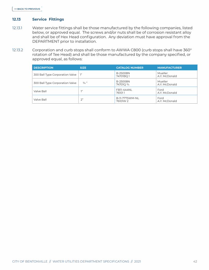
CITY OF BENTONVILLE // WATER UTILITIES DEPARTMENT SPECIFICATIONS // 2021 42CITY OF BENTONVILLE // WATER UTILITIES DEPARTMENT SPECIFICATIONS // 2021 42
12.13 Service Fittings
12.13.1 Water service fittings shall be those manufactured by the following companies, listed below, or approved equal. The screws and/or nuts shall be of corrosion resistant alloy and shall be of Hex Head configuration. Any deviation must have approval from the DEPARTMENT prior to installation.
12.13.2 Corporation and curb stops shall conform to AWWA C800 (curb stops shall have 360° rotation of Tee Head) and shall be those manufactured by the company specified, or approved equal, as follows:
DESCRIPTION SIZE CATALOG NUMBER MANUFACTURER
300 Ball Type Corporation Valve 1” B-25008N74701BQ 1
MuellerA.Y. McDonald
300 Ball Type Corporation Valve ¾ ” B-25008N74701Q ¾
MuellerA.Y. McDonald
Valve Ball 1” FB11-444NL76101 1
FordA.Y. McDonald
Valve Ball 2” B-11-777SWM-NL76101W 2
FordA.Y. McDonald

CITY OF BENTONVILLE // WATER UTILITIES DEPARTMENT SPECIFICATIONS // 2021 43CITY OF BENTONVILLE // WATER UTILITIES DEPARTMENT SPECIFICATIONS // 2021 43
12.13.3 PE and Copper pipe fittings shall conform to AWWA C800 and shall be those manufactured by the Mueller Company, or approved equal, as follows:
DESCRIPTION SIZE CATALOG NUMBER MANUFACTURERS
Adapter, Female ¾” C-14-33-NL74754Q ¾
FordA.Y. McDonald
Adapter, Female ¾” x 1” C-14-43-NL74754Q ¾ X1
FordA.Y. McDonald
Adapter, Female 1” H-15451N74754Q 1
MuellerA.Y. McDonald
Adapter, Female 1” x ¾” C-14-34-NL74754Q 1 X ¾
FordA.Y. McDonald
Adapter, Male ¾” H-15428N74753Q ¾
MuellerA.Y. McDonald
Adapter, Male 1” H-15428N74753Q 1
MuellerA.Y. McDonald
Adapter, Male 1” x ¾” H-15428N74753Q 1 X ¾
MuellerA.Y. McDonald
Coupling, Straight ¾” x 1” C-44-34-NL74758Q ¾ X 1
FordA.Y. McDonald
Coupling, GALV/PVC ¾” x 1” C-45-43NL74758Q-55 1 X ¾
FordA.Y. McDonald
Coupling, GALV/PVC ¾” C-45-33-NL74758Q-55 ¾
FordA.Y. McDonald
Coupling, GALV/PVC 1” C-45-44NL74758Q-55 1
FordA.Y. McDonald
Coupling, 110 Comp ¾” H-15403N74758Q ¾
MuellerA.Y. McDonald
Coupling, 110 Comp 1” H-15403N74758Q 1
MuellerA.Y. McDonald
Ell Brass, 110 Comp ¾” H-15526N74761Q ¾
MuellerA,Y. McDonald
Ell Brass, 110 Comp 1” H-15526N74761Q 1
MuellerA.Y. McDonald
Tee Pack Joint 1” T444-444NL74760Q 1
FordA.Y. McDonald
Tee, 110 Comp ¾”x¾”x1” H-15381N74760Q ¾ X 1
MuellerA.Y. McDonald
Tee, 110 Comp ¾” H-15381N74760Q ¾
MuellerA.Y. McDonald
U-Branch 1”x¾”x7-½” H-15363N7084QM
MuellerA.Y. McDonald
*Brass Nipples, Tees, Bell Reducers, Ells, Collars, etc. will be 150# SCH-40 Red Brass Domestic Fittings with Iron Pipe Threads.
12.13.4 The following meter setters and meter connection fittings shall conform to AWWA C800 and be those manufactured by the following companies, or approved equal:
DESCRIPTION SIZE CATALOG NUMBER MANUFACTURER
Meter Set w/o Dual Check 5/8”x¾”x7” B-2404FN20-207WXLL 33
MuellerA.Y. McDonald
Meter Set w/o Dual Check 1” x 10” B-2404FN20-410WXDD 44
MuellerA.Y. McDonald
*All meter sets will be installed with Mueller End Connection # H-14222N and Mueller End Connection # H-14227N or A.Y. McDonald equal. A Fiber Washer Mueller # H-48234 or A.Y. McDonald equal shall be set in each end connection of the meter set.

CITY OF BENTONVILLE // WATER UTILITIES DEPARTMENT SPECIFICATIONS // 2021 44CITY OF BENTONVILLE // WATER UTILITIES DEPARTMENT SPECIFICATIONS // 2021 44
12.14 Gate Valves
12.14.1 Gate Valves - 4” Through 18” with Resilient Seat
12.14.2 Resilient seat gate valves 4” through 18” shall be designed for a working pressure of 250 psig. Valves shall conform to AWWA C515 (Thin Wall or Lightweight Ductile Spec) with non-rising stem, O-ring stem seals and 2” square operating nut. Valves shall open when the operating nut is turned to the left (counterclockwise). Valve ends shall be as specified. The resilient seat may be bonded or mechanically attached to the gate. All interior metal surfaces shall be coated with a two-part thermosetting epoxy. Gate valves larger than 18” need to be submitted to the DEPARTMENT for approval prior to installation.
12.14.3 Epoxy Coating shall be 8-mils DFT and free of voids.
12.14.4 Tapping valves shall have full size flow way accepting standard size shell cutter.
12.14.5 Valves conforming to these specifications will be accepted from the following manufacturers:
• American Flow Control Model # 2500
• Clow Valve Company, Model 2638
• Mueller Company, Model A2361
12.15 Butterfly Valves
12.15.1 Butterfly valves shall conform to AWWA C504, having the following features and be approved by the DEPARTMENT prior to installation:
12.15.2 Class 150B
12.15.3 Suitable for complete buried service. Exterior of valve shall be epoxy coated.
12.15.4 Disc may be made from any of the materials as specified in AWWA C504. However, discs made from material other than bronze or stainless steel shall be coated with epoxy material in accordance with Section 12.15.9. All other interior surfaces which are not stainless steel or bronze shall also be coated with epoxy material.
12.15.5 Valve resilient seats shall be BUNA-N bonded into a self-retaining recess in the body or a natural rubber molded to an 18-8, Type 304 stainless steel retaining ring secured to the disc by self-setting screws. If the set is attached to the disc, the mating surface to the resilient seat shall be 304 or 316 stainless steel.
12.15.6 Stainless steel shafting. “O-Ring” or split-V shaft seals. Bronze, nylon or Teflon bearings and a “Manual Operator” totally enclosed for buried service shall include the following:
12.15.7
a. 2” x 2” operating nut
b. Open counter-clockwise
c. Operators of the traveling nut type shall not have u-joints on the rods.

CITY OF BENTONVILLE // WATER UTILITIES DEPARTMENT SPECIFICATIONS // 2021 45CITY OF BENTONVILLE // WATER UTILITIES DEPARTMENT SPECIFICATIONS // 2021 45
d. On operators composed of worm gears; worm gears may be either bronze or DI and the worms shall be composed of hardened steel.
e. The operator shall satisfy the valve operating torque requirements for Class 150B valves and the operator input requirements of AWWA C504.
12.15.8 Valve ends shall be as specified. If flange ends are specified, they shall conform to Class 125, ANSI B16.1.
12.15.9 Epoxy Coating for Valve Disc. Before application of coating material, all surfaces of the disc shall be thoroughly cleaned to remove dirt, grease, oil and any other substances; all sharp angles, protrusions or irregularities which would interfere with proper coating coverage shall be removed; and the entire surface grit blasted to white metal in accordance with SSPC Specification SP5 resulting in an anchor pattern of at least 1 mil. Thermo-set epoxy material shall be applied to the sand-blasted surfaces before the white metal begins to oxidize (darken in color). The thermoset epoxy shall be approved for exposure to fluids for human consumption by the Federal Food and Drug Administration. The final DFT shall be at least 8 mils DFT and free of voids. The disc shall be post-cured for a sufficient period of time to assure full polymerization. Polymerization shall be checked by a direct impact test at 60-inch-lb. with no cracking or chipping of the coating. The DFT shall be checked using an accurate magnetic DFT gauge. The entire coated surface shall be checked for voids using a wet sponge type holiday detector. Any area where the DFT is found to be less than 8 mils or where voids were detected shall be re-coated and re-checked. Valves shall be packed for shipment in such manner that the disc coating is protected from damage.
12.16 Air Release Valves
12.16.1 Air Release Valves shall be APCO No. 200-A, or approved equal, or as specified.
12.17 Valve Boxes, Lids And Extensions
12.17.1 Valve boxes shall be Tyler 6850 series or equal with 5 ¼” shafts. Length variable 10 ¼” OD bottom flange, 8” ID Bottom, 7 3/16” OD top, 6 ¾” ID top of 2 section valve box.
12.17.2 Valve box lids shall have a 7 5/16” outside diameter with 6 ½” inside diameter for 5 ¼” valve boxes. The lids shall be marked with “WATER” unless located at the tap for a fire line where a post indicator may not be installed. In this case the lid shall be marked “FIRE” and be painted safety red. The “FIRE” lid shall be locking and require only a wrench to open.
12.17.3 Extension shaft shall be required on any valve that exceeds 4’ in depth. Valve stem extensions shall be adequate to transmit full torque required to open valve, and shall be secured to the valve operating nut by set screws not clips. The top of the extension shaft shall be a 2” square AWWA nut. Extensions shall be provided to bring the operating nut to within 4’ of grade and have disc attached to hold operating nut in the center of valve box and shall be firmly attached to the valve.
12.18 Meter Boxes, Vaults And Lids
12.18.1 Water meters 5/8” and 1” shall be installed in 18” Brook’s type 22HFX1802KS round plastic meter boxes that are domestically manufactured or as approved by the DEPARTMENT.

CITY OF BENTONVILLE // WATER UTILITIES DEPARTMENT SPECIFICATIONS // 2021 46CITY OF BENTONVILLE // WATER UTILITIES DEPARTMENT SPECIFICATIONS // 2021 46
12.18.2 Water meters 5/8” and 1” that are installed in non-deliberate and incidental traffic shall be installed with a load bearing meter tile. Water meter installations that fit this criteria will use the DFW Plastics #DFW1800F-18-1ET load rated meter tile. Prior approval for water meters installed in potential traffic loaded areas shall be obtained from the DEPARTMENT during the plan review process.
12.18.3 2” meters are to be installed by City of Bentonville at OWNER/DEVELOPER’S expense. 2” meters shall be installed in 30”x 36” diameter Mid-States MSP 30”X36” meter boxes.
12.18.4 All meter vault plans and installations shall be approved by the DEPARTMENT prior to the start of construction. Meter vaults shall not be subject to flooding and shall be water tight to prevent intrusion of water and dirt. The walls of the vault shall extend above the finished grade a minimum of 3” to prevent intrusion of water or dirt. Vault to be installed by CONTRACTOR at OWNER’S expense. Detail W12.
12.19 Fire Hydrants
12.19.1 All fire hydrants furnished shall be dry barrel hydrants in conformance with AWWA C502, latest revision, for “Dry Barrel Fire Hydrants”, and shall be designed for a 250 psig maximum working pressure. All fire hydrants shall be equipped with a safety stem coupling and flange, which are intended to fail upon vehicle impact without damage to the stem or main valve. All fire hydrants shall conform to AWWA C502, the following specifications, and shall be the Traffic Model Fire Hydrant:
Maximum Working Pressure 250 psig
Size of Valve Opening Minimum 5”
Diameter of Inlet Connection 6”
Type of Inlet Connection Mechanical Joint
Number & Size of Hose Connections 2 - 2 1/2”, 1 - 4 1/2”
Nozzle Arrangement All in same place
Nozzle Thread ASA Standard
Nozzle Cap Chains Three
Nozzle Cap Washers Rubber
Barrel Ductile Iron Pipe
Operating Threads Oil or Grease Lubricated Seals
Lubrication Chamber Oil or Grease
Seat Rings Bronze to Bronze
Direction to Turn to Open Left (Counter-Clockwise)
Shape & Size of Operating & Nozzle Cap Nut 5-Sided, 1 1/2” from flat to point
Operating Nut Bronze
Hydrant Shoe Epoxy Coated
Color above ground - barrel and dome Industrial Safety Yellow
Color, Nozzle Caps & Top Nut, including shield Industrial Safety Yellow
12.19.2 Seat must be removable, using a short, lightweight wrench which will fit all depths of bury.
12.19.3 The hydrant shall have a 6” mechanical joint inlet in conformance to the dimensions shown in ANSI/AWWA C110 A21, latest revision. The lead pipe from the valve to the fire hydrant shall be an approved Mechanical Joint Swivel Anchor Coupling 6” x 13” Tyler

CITY OF BENTONVILLE // WATER UTILITIES DEPARTMENT SPECIFICATIONS // 2021 47CITY OF BENTONVILLE // WATER UTILITIES DEPARTMENT SPECIFICATIONS // 2021 47
084150A CL 153 or approved equal for direct connections, or retainer glands as specified by type throughout these specifications. A fire hydrant anchor tee will be required for new main installation as indicated by the DEPARTMENT.
12.19.4 All fire hydrants shall be equipped with a two-piece barrel having a flange at the required elevation to meet the height requirement (18” to 24” from final grade) designated in Detail WO4.
12.19.5 All fire hydrant installations shall have 6” gate valve with tracer wire, valve boxes and valve box pads meeting all provisions specified elsewhere in these specifications. Auxiliary gate valves are necessary for fire hydrant leads longer than 50’.
12.19.6 All concrete used for fire hydrant blocking shall be in conformance with the concrete Section 12.24 of these specifications.
12.19.7 Fire hydrants conforming to these specifications will be accepted from the following manufacturers:
• Mueller Super Centurion 250
• Clow Medallion.
12.19.8 If a fire hydrant needs to be raised only 1 extension will be approved and all parts shall be manufactured by the same company as the fire hydrant. Generic extension parts shall not be used.
12.20 Polyethylene Tubing Material for Pipe Encasement
12.20.1 Polyethylene material for the encasement of cast IP (gray or ductile) shall conform to ANSI A21.5 (AWWA C105).
12.20.2 Tape for field application shall be Polyken #900, or Scotchrap #50, or equal, at least 2” wide.
12.21 Locator Wire
12.21.1 All water mains and sewer force mains, including DI pipe, PE water services or other appurtenances installed shall have single #10 gauge type TW (single strand) insulated copper locator wire, on top of pipe and fastened securely with tape every 10’ and buried with it. This locator wire shall be installed in conjunction with the main at the same depth as the water main or service.
12.21.2 Locator wire shall not be connected in any way to main or any other underground metal (except other tracer wires). Installation of locator wire shall be tested 1 time before the 1st acceptance inspection. Tracer wire shall be tested after curbs are installed and prior to asphalt. Section 8
12.21.3 Wire shall be accessible at all valve boxes and meter boxes and shall extend a minimum of 6” above the valve or meter box, at the main or service, connect all locator wires together so that a continuous electrical path is ensured. Tracer wire shall be installed through the outside of the valve box bottom section then inserted through the inside of the top section of the valve box. A minimum of 6” to maximum of 12” of tracer wire is required to be extended beyond the top of the valve box. Detail W07.

CITY OF BENTONVILLE // WATER UTILITIES DEPARTMENT SPECIFICATIONS // 2021 48CITY OF BENTONVILLE // WATER UTILITIES DEPARTMENT SPECIFICATIONS // 2021 48
12.21.4 To connect locator wires, the wires shall be spliced using a split bolt connector (Blackburn 9H or Kearney KS90) or equal, then covered with electrical plastic tape (Type 3M Scotch 33) so that a waterproof joint is made.
12.22 Concrete Material Specifications
12.22.1 Concrete shall have a 28-day compressive strength of at least 4,000-psi and shall contain not more than six (6) gallons of water per sack of cement, including the water in the aggregates, and not less than six (6) sacks of cement per cubic yard of concrete. A copy of all tickets from concrete company shall be presented to the DEPARTMENT.
12.22.2 Portland cement conforming to ASTM C150, Type 1, shall be used unless the DEPARTMENT approves the use of other types.
12.22.3 Water used shall be clean and free from injurious amounts of oil, acids, alkalis, salt, organic matter, or other deleterious substances.
12.22.4 Fine aggregate shall consist of clean, sound, properly graded sand conforming to ASTM Standard C33 uniformly graded from 100% passing the 3/8” sieve to not more than 8% passing the Number 100 sieve.
12.22.5 Coarse aggregate shall consist of crushed stone, gravel, or other inert material of similar characteristics, having clean, hard, strong, durable, uncoated particles with not more than 5% by weight of soft fragments, ¼ % by weight of clay lumps, and 1% by weight of material removed by decantation, except that when the material removed by decantation consists essentially of crushed dirt the maximum amount permitted may be increased to 1 ½ % by weight. Aggregate shall conform to ASTM Standard D289. Coarse aggregate may be either of two sizes, 1 ½” and smaller or ¾” and smaller, and shall be graded within the following requirements.
12.23 Percent Retained by Weight
Maximum size mesh screen (sq. mesh) 0 - 3
Half-Maximum size mesh screen (sq. mesh) 30 - 65
No. 4 Sieve 94 - 100
12.23.1 In no case shall the maximum size aggregate exceed 1/3 of the design thickness of any part of a structure. Coarse aggregate for exposed aggregate surfaces shall be as follows:
Total Retained on 1 1/2” Sieve - 0 %
Total Retained on 3/4” Sieve 25 - 60%
Total Retained on 3/8” Sieve 70 - 90%
Total Retained on #4 Sieve 95 - 100%
12.24 Concrete Proportions and Consistency
12.24.1 The proportions of the concrete shall produce a mixture that will work readily, with the placement method most used, into the corners and angles of the forms and around reinforcement. Segregation of materials in the mixture shall not be permitted nor the collection of excess free water on the surface.

CITY OF BENTONVILLE // WATER UTILITIES DEPARTMENT SPECIFICATIONS // 2021 49CITY OF BENTONVILLE // WATER UTILITIES DEPARTMENT SPECIFICATIONS // 2021 49
12.24.2 The slump of the concrete shall be the minimum that is practicable. When vibrators are used to consolidate the concrete, the slump shall not exceed 4”; otherwise, the slump shall not exceed 6”.
12.24.3 The methods of measuring concrete materials shall be such that the proportions can be accurately controlled and easily checked. Measurement of materials for ready-mixed concrete shall conform to Specifications for Ready-Mixed Concrete (ASTM C94).
12.24.4 Ready-mix concrete shall be required and shall conform to ASTM Standard C94 and to applicable portions of these specifications for on-site mixing. The concrete shall be delivered and placed within 1-hour after all materials, including mixing water, shall have been placed in the mixing drum. The CONTRACTOR shall obtain from the supplier of the ready-mixed concrete, the supplier’s agreement to inspection by the DEPARTMENT, to the full extent deemed necessary by the DEPARTMENT.
12.25 Concrete Testing
12.25.1 As the placement of concrete progresses, the DEPARTMENT may take samples of the concrete for testing. The CONTRACTOR shall provide whatever assistance required by the DEPARTMENT in collecting and preparing samples for testing. Sampling shall be in accordance with ASTM Standard C172.
12.25.2 An independent laboratory in accordance with ASTM Standard C143 shall conduct slump tests.
12.25.3 Compression test specimen shall be prepared and cured in accordance with ASTM Standard C31. Specimens shall be tested in accordance with ASTM Standard C39.
12.25.4 All reinforcing bars shall be “Billet-Steel Concrete Reinforcement Bars” conforming to ASTM Designation A15 or “Rail-Steel Concrete Reinforcement Bars” conforming to ASTM Designation A16. Billet-Steel bars shall be intermediate grade with minimum yield point of 60,000 psi.
12.25.5 All reinforcing bars shall be deformed bars. Deformation shall comply with “Minimum Requirements of the Deformation of Deformed Steel Bars for Concrete Reinforcement - ASTM Designation A305”.
12.25.6 When the volume of concrete required at the work site is less than 1/3 cubic yard, mixing may be accomplished by hand tool methods. The concrete shall be mixed in a clean, watertight vessel to the extent necessary to assure that the cement; aggregate and water are thoroughly integrated. The mix shall be at least 1 part Portland cement to 2 parts coarse aggregate, as specified in Section 12.22.5 and 2 parts sand, as specified in Section 12.22.4. Only that amount of water required to provide a stiff, workable mix shall be used. The strength requirements specified in Section 12.22.1 herein, apply.

CITY OF BENTONVILLE // WATER UTILITIES DEPARTMENT SPECIFICATIONS // 2021 50CITY OF BENTONVILLE // WATER UTILITIES DEPARTMENT SPECIFICATIONS // 2021 50
SECTION 13 Installation Criteria for Water Mains and Appurtenances
13.1 Connections to Water Distribution System
13.1.1 All connections to or any operations of appurtenances to the existing distribution system must be accomplished in the presence of the CITY INSPECTOR or DEPARTMENT representative.
13.1.2 In cases where completing the connection will disrupt service to customers, the CONTRACTOR shall notify the DEPARTMENT at least 5 days in advance of the work. The customers whose service will be disrupted shall be notified by the CONTRACTOR a minimum of 24 hrs prior to disruption of services. The CONTRACTOR shall plan the work so that disruption of service is held to a minimum. The schedule shall be approved by the DEPARTMENT. Section 9.3.1
13.1.3 After connections have been completed, the valves shall be tightly closed. All valve operation shall be performed by the CITY INSPECTOR or DEPARTMENT personnel. At no time shall the CONTRACTOR operate valves or fire hydrants within the water distribution system.
13.1.4 A minimum horizontal distance of 10’ should be maintained between water lines, and sewer lines, including edges of manholes or other sources of contamination. Water lines and sewer lines shall not be laid in the same trench except on the written approval of the ADH. Water mains necessarily in close proximity to sewers must be placed so that the bottom of the water line will be at least 18” above the top of the sewer line at its highest point. If this distance must unavoidably be reduced, the water line or the sewer line must be encased in watertight pipe with sealed watertight ends extending at least 10’ either side of the crossing Where a water line must unavoidably pass beneath the sewer line, at least 18” of separation must be maintained between the outside of the two pipes in addition to the preceding encasement requirement. Exceptions to this must be approved in writing by the ADH.
13.2 Installation of Valves
13.2.1 Valves shall be joined in accordance with the methods of jointing pipe as specified elsewhere herein. Valve stems shall be plumb and there shall not be any obstructions which will prohibit the installation of valve boxes directly over the stem. For dead-end lines, concrete anchor collars shall be provided around an adjoining length of pipe for all valves. Mechanical joint retainer glands shall be installed on all valves with mechanical joint ends. Valves shall be installed and anchored on all sides of any Cross or Tee application. All valves shall be firmly supported on well compacted approved bedding and completely wrapped in polyethylene tubing material as specified in Section 13.11.
13.2.2 Valve boxes shall be installed over the operating nut of each valve and be of adequate length to reach the finished grade. The box cover shall be flush with the final grade. Tracer wire shall be installed through the outside of the valve box bottom section then inserted through the inside of the top section of the valve box. A minimum of 6” to maximum of 12” of tracer wire is required to be extended beyond the top of the valve box. Detail W07.

CITY OF BENTONVILLE // WATER UTILITIES DEPARTMENT SPECIFICATIONS // 2021 51CITY OF BENTONVILLE // WATER UTILITIES DEPARTMENT SPECIFICATIONS // 2021 51
13.2.3 When the distance between the valve operating nut and the finished surface exceeds 4’, a valve stem extension shall be provided. The stem shall be round steel bar stock or steel pipe with a 2” square bar steel operating nut (except 2” valve) attached to the upper end. The stem extension shall be of adequate length to reach from the valve operating nut to a point within 4’ of the final grade. A box wrench, 2 1/8” ID square, made from high grade
steel 3/16“ thick shall be welded * to the lower end of the stem extension which will fit over the valve operating nut. A round center guide made from 3/16” or 1/4” steel plate shall be placed on the valve stem extension approximately 6” from the upper end. The diameter of the guide shall be slightly less than the ID of the valve box. The guide shall be affixed to the stem extension in such a way that it can rotate freely on the stem. A bituminous coating shall be applied to all stem extension pieces.
13.2.3.1 *NOTE: Welds on stem extensions (top and bottom nut) shall be 1/8” - 3/16” fillet weld around full circumference, small - large valve stem extension.
13.2.4 Valve stem extensions shall be manufactured by Clow, or equal. Shop drawings shall be submitted to the DEPARTMENT for approval prior to installing the stem extension pieces.
13.3 Installation of Tapping Sleeves & Tapping Saddles
13.3.1 The pipe shall be free of dirt and other debris before attaching tapping sleeve or tapping saddle. That part of the pipe barrel, which will be in contact with the gasket of tapping saddles, shall be smooth.
13.3.2 Tapping saddles or sleeves shall be bolted securely to the pipe. The face of the outlet shall be plumb. Mechanical joint glands for tapping sleeves shall be installed in accordance with Section 12.9.3 herein. The strap bolts for tapping saddles shall be alternately tightened “snug” and then alternately tightened to a torque as required by manufacturer’s requirements.
13.3.3 The tapping valve shall be bolted securely to the tapping sleeve or tapping saddle outlet flange. The tapping valve shall be supported by concrete cap blocks to remove weight from the valve and sleeve or saddle.
13.3.4 After installation of the tapping sleeve or saddle and the tapping valve, the assembly shall be hydrostatically tested at 200 psi for 15 minutes by introducing water through the sleeve or saddle test tap.
13.3.5 All tapping sleeves shall have poured-in-place concrete thrust blocking installed after pressure testing prior to tapping. Detail GWS02.
13.3.6 Polyethylene material shall be placed in accordance with Section 13.11 herein.
13.4 Fire Hydrant Installation
13.4.1 All fire hydrants must have placement approval from the DEPARTMENT.
13.4.2 Hydrants shall be thoroughly cleaned before setting, removing all dirt and foreign matter from the barrel and bottom section up to the main valve. The main valve shall be in the “closed” position and the waste outlet shall be free of any obstructions.
13.4.3 Hydrants shall be located a safe distance from driveways, roadways and sidewalks and in a manner to provide complete accessibility. They shall stand plumb with nozzles at

CITY OF BENTONVILLE // WATER UTILITIES DEPARTMENT SPECIFICATIONS // 2021 52CITY OF BENTONVILLE // WATER UTILITIES DEPARTMENT SPECIFICATIONS // 2021 52
proper elevation and the steamer/pumper nozzle pointed perpendicular to traffic when hydrant is adjacent to a street, roadway or parking lot drive or toward the protected building unless otherwise directed by the DEPARTMENT. Detail W04.
13.4.4 The large diameter nozzle shall be at right angles to the street or fire lane, with the nozzle cap at a minimum of 3’ to maximum of 9’ from back of curb or edge of any driving surface (measured from the steamer cap nut) or as directed by the DEPARTMENT. Under no conditions will fire hydrants be allowed in the sidewalk or radius, unless otherwise directed by the DEPARTMENT. Fire hydrants placed in subdivisions need to be installed at the lot line to avoid conflicts with driveways.
13.4.5 The CONTRACTOR shall, if necessary, rotate the hydrant barrel or nozzle section at the flanged joint to obtain the desired nozzle position as specified by the DEPARTMENT.
13.4.6 The fire hydrant shoe shall be supported firmly on the bottom and shall be well braced against unexcavated earth with formed and poured concrete blocking on the backside. If considered necessary by the DEPARTMENT, the fire hydrant shall be tied to the branch pipe with suitable rods or clamps. Rods or clamps are to be furnished by the CONTRACTOR without additional compensation.
13.4.7 All mechanical joint fittings shall be properly protected by polyethylene tubing as described in Section 13.11.
13.4.8 A drainage bed shall be provided under and around the base of the hydrant of at least 6 cubic feet in volume and extending at least 6” above the weep hole drain outlet and shall consist of Class #67 gravel. As defined in Section 10.2.1. Under no circumstances shall the waste outlet on the hydrant or the drainage bed be connected to sewer or storm drainage.
13.4.9 Backfilling and tamping around hydrant barrels shall be continuous in operation.
13.4.10 After installation, it is required that all fire hydrants shall be covered with a water resistant sack to indicate out-of-service. These may be removed after the CITY INSPECTOR or DEPARTMENT has placed the line in service.
13.5 Concrete Placement & Finishing
13.5.1 All placement of concrete must be in the presence of the DEPARTMENT or representative. The CONTRACTOR is cautioned that he may be required to remove, without compensation, any concrete placed in the absence of the DEPARTMENT or representative.
13.5.2 Equipment for chuting, pumping and pneumatically conveying concrete shall be of such size and design as to ensure a practically continuous flow of concrete at the delivery end without separation of materials. All concrete in reinforced walls and columns shall be poured through tremies unless otherwise permitted by the DEPARTMENT. The free fall of concrete shall be 5’ maximum.
13.5.3 Concrete shall be deposited as nearly as practicable in its final position to avoid segregation due to re-handling or flowing. The placing of concrete shall be carried on at such a rate that concrete is at all times plastic and flows readily into the spaces between the bars. Concrete that has been contaminated by foreign material shall not be used, nor shall re-tempered concrete be used.

CITY OF BENTONVILLE // WATER UTILITIES DEPARTMENT SPECIFICATIONS // 2021 53CITY OF BENTONVILLE // WATER UTILITIES DEPARTMENT SPECIFICATIONS // 2021 53
13.5.4 When placing is once started, it shall be carried on as a continuous operation until placement of the panel or section is complete.
13.5.5 In placing concrete, care shall be taken that the freshly placed mass is so placed and vibrated that there is no tendency for the coarse aggregate to segregate from the mortar, that no rock pockets are left, that the concrete flows readily around the steel and into the extremities of the forms, and the whole freshly-placed mass becomes a plastic jelly-like mass but without free water in appreciable quantity on its surface. No concrete shall be poured without vibration with mechanical or magnetic internal vibrators.
13.5.6 Water shall be removed from place of deposit before concrete is placed unless otherwise permitted by the DEPARTMENT.
13.5.7 Concrete placed directly on the ground shall be placed in the forms on a compacted moist sub-grade and shall be vibrated until mortar covers the entire surface. Vibrating shall be given special attention in order to prevent voids in the concrete.
13.5.8 Concrete after placement and finishing shall be protected from damage while curing. Provisions shall be made for maintaining concrete in moist condition for a period of at least 72 hours after placement.
13.5.9 After removal of forms and finishing, as specified elsewhere herein, backfill shall be placed around the structure and thoroughly compacted.
13.5.10 Forms shall be constructed before placement of any concrete* unless otherwise authorized by the DEPARTMENT.
13.5.10.1 *NOTE: Concrete Utilized For Thrust Blocking To Be Poured Against Undisturbed Earth.
13.5.11 Forms shall conform to shapes, lines, and dimensions of the members as specified on the Plans, or as required to conform to the original shape and dimensions in the case of replacement structures, and shall be sufficiently tight to prevent leakage of mortar. They shall be properly braced or joined together so as to maintain position and shape. They may be constructed of any material with sufficient strength, which will provide the finished work a satisfactory surface and alignment.
13.5.12 Forms shall be removed in such a manner as to insure the complete safety of the structure. When the structure is supported on shores, the removable floor forms, beams and girder sides, and column and similar vertical forms may be removed after 72 hours, providing the concrete will not be injured. In no case shall supporting forms or shoring be removed until members have acquired sufficient strength to support their weight and imposed loads safely.
13.5.13 Forms shall be coated with a form oil before placement of reinforcing steel or concrete. Excessive coating material shall not be allowed to form or stand in puddles in the forms nor allowed to come in contact with concrete against which fresh concrete or reinforcing bars will be placed.
13.6 Concrete Reinforcement
13.6.1 At the time concrete is placed, metal reinforcement shall be free from rust scale or other coatings that will destroy or reduce the bond. All bars shall be shop bent, unless

CITY OF BENTONVILLE // WATER UTILITIES DEPARTMENT SPECIFICATIONS // 2021 54CITY OF BENTONVILLE // WATER UTILITIES DEPARTMENT SPECIFICATIONS // 2021 54
otherwise permitted by the DEPARTMENT. No bars partially embedded in concrete shall be field bent except as shown on Plans or as specifically permitted by the DEPARTMENT. Field bonding of rail steel bars will not be permitted.
13.6.2 Metal reinforcement shall be accurately placed according to the Plans or as specified herein and adequately secured in position by concrete, metal, or other approved chairs, spacers or ties.
13.6.3 No splices of reinforcement shall be made except as shown on the Plans, or as specified, or as authorized by the DEPARTMENT. All welding shall conform to the American Welding Society’s Recommended Practices for Welding Reinforcing Steel, Metal Inserts and Connections in Reinforced Concrete Construction (AWS D12.1), unless otherwise authorized by the DEPARTMENT. All laps and splices shall be in accordance with ACI 318, using f’c = 3,000 psig and fy = 60,000 psig unless otherwise shown on the Plans.
13.6.4 The reinforcement shall be protected by the thickness of concrete indicated in the Plans. Where not otherwise shown, the thickness of concrete over the reinforcement shall be as follows:
a. Where concrete is deposited against the ground without the use of forms not less than 3”, except wire mesh reinforcement for concrete slabs which may be within 1 ½” of the ground.
b. Where concrete is to be exposed to the weather or to the ground but placed in forms not less than 2” for bars larger than No. 5 and 1 ½” for No. 5 bars or smaller.
c. In slabs and walls not exposed to the ground or to the weather - not less than ¾”.
d. In all cases - at least equal to the diameter of the bars.
13.7 Concrete Cold-Weather Requirements
13.7.1 Concrete shall not be placed when the ambient temperature is 40°F and falling, but can be placed if the temperature is 35°F and rising, or when the concrete is likely to be subjected to freezing temperatures before final set has occurred. Concrete footings or slabs shall not be placed over frozen ground. The temperatures of the concrete when placed shall not be less than 45°F. Heated materials shall be free of ice, snow and frozen lumps before entering the mixer. Methods and equipment for the heating of materials shall be subject to the DEPARTMENT’S approval. Suitable means shall be provided for maintaining the concrete at a temperature of at least 45°F for not less than 96 hours after placing.
13.7.2 Any and all concrete damaged by freezing shall be removed to the satisfaction of the DEPARTMENT, and replaced, all at the expense of the CONTRACTOR.
13.8 Concrete Hot-Weather Requirements
13.8.1 In hot weather, suitable precautions shall be taken to avoid drying of the concrete prior to finishing operations. Use of windbreaks, sunshades, fog sprays, or other devices shall be provided as directed by the DEPARTMENT.
13.8.2 Concrete deposited in hot weather shall not have a placing temperature that will cause difficulty from loss of slump, flash set, or cold joints. Concrete temperatures shall be less than 90°F unless higher temperatures are permitted by the DEPARTMENT.
CITY OF BENTONVILLE // WATER UTILITIES DEPARTMENT SPECIFICATIONS // 2021 55CITY OF BENTONVILLE // WATER UTILITIES DEPARTMENT SPECIFICATIONS // 2021 55
13.8.3 The use of additives shall be prohibited unless written approval of its use has been secured, in advance, from the DEPARTMENT.
13.9 Concrete Thrust Blocks & Anchor Collars
13.9.1 Concrete thrust blocks and anchors shall be provided along the pipeline in accordance with the construction details, plan sheets, or as directed by the DEPARTMENT. The concrete shall have a 28 day compressive strength of 4,000-psi.
13.9.2 Concrete for thrust blocks shall be placed against undisturbed soil. The excavation shall be hand shaped and free of loose material. Forms shall be used to confine the concrete in areas other than that part that is in contact with undisturbed soil in the direction of the thrust.
13.9.3 No concrete shall be placed around any part of a joint or placed so that it interferes with the removal of any joint accessories such as bolts, followers, threads, collars, couplings, etc. Fire hydrant weep hole drain outlets shall not be restricted.
13.9.4 The top of the concrete thrust block or anchor collar shall be struck off with a wood straight edge or float.
13.9.5 Admixtures are not to be used without the approval of the DEPARTMENT.
13.9.6 All placement of concrete must be in the presence of the CITY INSPECTOR or DEPARTMENT representative. The CONTRACTOR is cautioned that he may be required to remove, without compensation, any concrete placed in the absence of the CITY INSPECTOR or DEPARTMENT representative.
13.9.7 Backfill over concrete thrust blocks or anchor collars shall not be placed before the concrete has attained initial set.
13.9.8 No thrust blocks shall be less than 12” thick between the pipeline or appurtenances and undisturbed soil in the direction of thrust.
13.9.9 The excavation shall be free of water before concrete is placed. Steel reinforcement, as specified on the plans, shall be placed in accordance with Section 13.6 herein.
13.9.10 The pipe or appurtenances shall be cleaned before placing concrete when the concrete is to be in direct contact with the pipe or appurtenance. Polyethylene plastic shall cover all pipes or appurtenances subject to direct contact with concrete.

CITY OF BENTONVILLE // WATER UTILITIES DEPARTMENT SPECIFICATIONS // 2021 56CITY OF BENTONVILLE // WATER UTILITIES DEPARTMENT SPECIFICATIONS // 2021 56
13.9.11 The area of contact of the thrust blocks and anchor collars shall be sufficient to resist the thrust. This area will vary depending on the safe bearing value of the soil. Suggested safe soil bearing values are as follows:
TYPE OF SOIL SUGGESTED SAFE BEARING VALUES (TONS\SQ.FT.)
Solid Rock 25
Hard Slate 6
Medium Shale 4
Soft Shale 2
Dry Clay Gravel 4
Soft Clay 1.5
Dry Sand or Loam 2.5
Wet Clay 0.75
13.9.12 The above values are approximate and will vary considerably and are intended to be used only as a reference. The CONTRACTOR is responsible for determining the soil bearing value or taking other action to assure that the bearing area is adequate to restrain the pipe or appurtenances.
13.9.13 Where the soil is unstable or in the case of recent fill areas, the following procedures shall apply either individually or in a combination:
a. Thrust blocks shall be of adequate size to restrain pipe or appurtenances by mass alone without depending on horizontal bearing of the soil.
b. The excavation shall extend deep enough to contact firm soil and the block brought up to the pipe or appurtenances and constructed so that the block acts as a beam and will provide restraint required. Such block shall be reinforced with steel reinforcing bars. Detail GWS04.
c. Anchor blocks shall be constructed in a firm soil and tie rods extended to the pipe or appurtenances. Detail GWS04.
13.9.14 Thrust blocks for vertical bends shall be adequate to resist the thrust by mass alone when the thrust is upward.
13.9.15 Thrust blocks and anchor collars shall be adequate to restrain the pipeline and appurtenances at the specified test pressure. The following table lists the resultant thrust at certain fittings at a pressure of 100 psi. In order to determine the thrust at the test pressure these values are to be multiplied by a factor equal to the test pressure divided by 100.
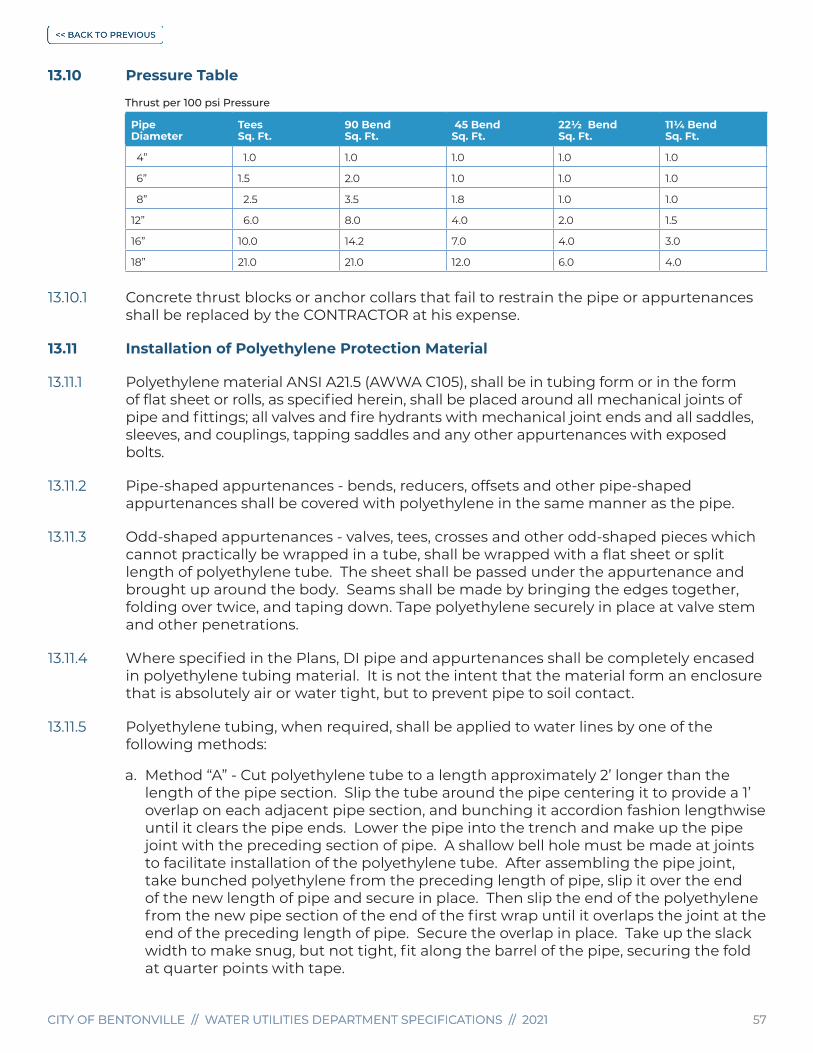
CITY OF BENTONVILLE // WATER UTILITIES DEPARTMENT SPECIFICATIONS // 2021 57CITY OF BENTONVILLE // WATER UTILITIES DEPARTMENT SPECIFICATIONS // 2021 57
13.10 Pressure Table
Thrust per 100 psi Pressure
PipeDiameter
TeesSq. Ft.
90 BendSq. Ft.
45 BendSq. Ft.
22½ Bend Sq. Ft.
11¼ BendSq. Ft.
4” 1.0 1.0 1.0 1.0 1.0
6” 1.5 2.0 1.0 1.0 1.0
8” 2.5 3.5 1.8 1.0 1.0
12” 6.0 8.0 4.0 2.0 1.5
16” 10.0 14.2 7.0 4.0 3.0
18” 21.0 21.0 12.0 6.0 4.0
13.10.1 Concrete thrust blocks or anchor collars that fail to restrain the pipe or appurtenances shall be replaced by the CONTRACTOR at his expense.
13.11 Installation of Polyethylene Protection Material
13.11.1 Polyethylene material ANSI A21.5 (AWWA C105), shall be in tubing form or in the form of flat sheet or rolls, as specified herein, shall be placed around all mechanical joints of pipe and fittings; all valves and fire hydrants with mechanical joint ends and all saddles, sleeves, and couplings, tapping saddles and any other appurtenances with exposed bolts.
13.11.2 Pipe-shaped appurtenances - bends, reducers, offsets and other pipe-shaped appurtenances shall be covered with polyethylene in the same manner as the pipe.
13.11.3 Odd-shaped appurtenances - valves, tees, crosses and other odd-shaped pieces which cannot practically be wrapped in a tube, shall be wrapped with a flat sheet or split length of polyethylene tube. The sheet shall be passed under the appurtenance and brought up around the body. Seams shall be made by bringing the edges together, folding over twice, and taping down. Tape polyethylene securely in place at valve stem and other penetrations.
13.11.4 Where specified in the Plans, DI pipe and appurtenances shall be completely encased in polyethylene tubing material. It is not the intent that the material form an enclosure that is absolutely air or water tight, but to prevent pipe to soil contact.
13.11.5 Polyethylene tubing, when required, shall be applied to water lines by one of the following methods:
a. Method “A” - Cut polyethylene tube to a length approximately 2’ longer than the length of the pipe section. Slip the tube around the pipe centering it to provide a 1’ overlap on each adjacent pipe section, and bunching it accordion fashion lengthwise until it clears the pipe ends. Lower the pipe into the trench and make up the pipe joint with the preceding section of pipe. A shallow bell hole must be made at joints to facilitate installation of the polyethylene tube. After assembling the pipe joint, take bunched polyethylene from the preceding length of pipe, slip it over the end of the new length of pipe and secure in place. Then slip the end of the polyethylene from the new pipe section of the end of the first wrap until it overlaps the joint at the end of the preceding length of pipe. Secure the overlap in place. Take up the slack width to make snug, but not tight, fit along the barrel of the pipe, securing the fold at quarter points with tape.

CITY OF BENTONVILLE // WATER UTILITIES DEPARTMENT SPECIFICATIONS // 2021 58CITY OF BENTONVILLE // WATER UTILITIES DEPARTMENT SPECIFICATIONS // 2021 58
b. Method “B” - Cut polyethylene tube to a length approximately 1’ shorter than the length of the pipe section. Slip the tube around the pipe, centering it to provide 6” of bare pipe at each end. Make polyethylene snug, but not tight; secure ends. Before making up a joint, slip a 3’ length of polyethylene tube over the end of the preceding pipe section, bunching it accordion fashion lengthwise. After completing the joint, pull the 3’ length of polyethylene over the joint, overlapping the polyethylene previously installed on each adjacent section of pipe by at least 1’; make snug and secure each end.
13.11.6 Openings in Tubing Material - openings for branches, service taps, blow-offs, air valves, and similar appurtenances shall be made by making a x-shaped cut in the polyethylene and temporarily folding the film back. After the appurtenance is installed, tape the slack securely to the appurtenance and repair the cut, as well as any other damaged areas in the polyethylene with tape.
13.11.7 Junctions between Wrapped and Unwrapped Pipe - Where polyethylene wrapped pipe joins a pipe, which is not wrapped, extend the polyethylene tube to cover the unwrapped pipe a distance of at least 2’ and secure the end.
13.11.8 The polyethylene material shall be secured around the pipe and appurtenances by at least 3 circular wraps of tape. Tape for field application shall be Polyken #900, or Scotchrap #50, or equal, at least 2” wide.
13.11.9 All tongs, cables or chains that are used for lifting pipe and appurtenances that have been encased in polyethylene material shall be adequately padded to prevent damage to the material.
13.11.10 Repair any rips, punctures, or other damage to the polyethylene with tape or with a short length of polyethylene tube cut open, wrapped around the pipe and secured in place.
13.11.11 Polyethylene material shall be stored on the job site in such a manner that it is not exposed to direct sunlight. Exposure during installation shall not exceed 48 hours.
13.11.12 Backfill material shall be the same as specified for pipe without polyethylene wrapping. Special care shall be taken to prevent damage to the polyethylene wrapping when placing backfill. Backfill material shall be free from cinders, refuse, boulders, rocks, stones and/or other material that could damage polyethylene.
13.12 Meter Connections
13.12.1 All meter sets shall be provided with approved washers at both ground union connections.
13.12.2 All fittings shall be sealed using approved pipe sealant or Teflon tape.
13.13 Filling Water Lines
13.13.1 After the water lines and appurtenances have been installed, all concrete thrust blocking has cured adequately and upon approval of the CITY INSPECTOR or DEPARTMENT, the water lines shall be filled with water.

CITY OF BENTONVILLE // WATER UTILITIES DEPARTMENT SPECIFICATIONS // 2021 59CITY OF BENTONVILLE // WATER UTILITIES DEPARTMENT SPECIFICATIONS // 2021 59
13.13.2 In order to prevent circulation of water through the new water lines back into the distribution system, only one valve shall be opened to allow water to flow into the new water lines. This valve will be tightly closed after the filling operation has been completed.
13.13.3 The valve operated to fill the water lines shall be operated slowly and shall not be fully opened. All water valve and fire hydrant operation shall be performed by the CITY INSPECTOR or DEPARTMENT representative.
13.13.4 All air shall be expelled from the pipeline by opening fire hydrants and/or other openings installed at the pipeline crests by the CONTRACTOR. The location and number of such openings shall be as shown on the Plans or as directed by the DEPARTMENT.
13.14 Hydrostatic Pressure and Leakage Tests
13.14.1 All water lines and appurtenances shall be tested by a hydrostatic pressure test conducted at a minimum of 150 psig, or static pressure plus 50% whichever is greater after all trenching or boring has been completed in area of water main or water services, this includes the installation of electric conduit.
13.14.2 After the water lines or isolated sections of the pipeline have been filled with water, the pressure shall be increased to the test pressure by means of a pump. The leakage test shall be in accordance with the AWWA Manual of Water Supply Practice. The manual shall be chosen based on pipe material being tested. Concrete Pressure Pipe (M9), Steel Pipe (M11), PVC Pipe (M23), Ductile-Iron Pipe (M41), and PE Pipe (M55).
13.14.3 The CONTRACTOR shall furnish a pump with meter on discharge side of pump and a 4” gauge in 2 lb. increments, and all labor for conducting the tests.
13.14.4 The duration of the hydrostatic leakage test shall be 2 hours or as specified by the CITY INSPECTOR or DEPARTMENT representative.
13.14.5 The source of water for the pump suction shall be potable water from the DEPARTMENT’S distribution system. The vessel used must be approved by the CITY INSPECTOR or DEPARTMENT representative.
13.14.6 All interior valves including valves on fire hydrants and other appurtenances shall be open during all tests.
13.14.7 The maximum leakage per hour for DI and PVC shall be as calculated from the following formula (All rubber gasket or 0-ring joints):
L = SD (P)
148,000
L = allowable leakage, (gallons per hour)
S = Length of pipe tested, in feet
D = nominal diameter of pipe, (inches)
P = average test pressure during leakage test, (psig)
13.14.8 After the specified test pressure has been applied the entire pipeline shall be checked in the presence of the CITY INSPECTOR or DEPARTMENT representative. After the CONTRACTOR has taken the necessary action to repair or replace any part of the

CITY OF BENTONVILLE // WATER UTILITIES DEPARTMENT SPECIFICATIONS // 2021 60CITY OF BENTONVILLE // WATER UTILITIES DEPARTMENT SPECIFICATIONS // 2021 60
pipeline or appurtenances where leaks were apparent or if no leaks were apparent, the water lines shall be subjected to a leakage test at the pressure specified with a meter inserted in the test pump discharge line.
13.14.9 If any test of pipe laid discloses leakage greater than the allowable leakage as calculated from above formula or table, the CONTRACTOR shall, at his expense, locate the leak or leaks and perform whatever work and/or replace whatever material that is required in order to remedy the defect and stop the leak. After corrective work has been completed, the section of line replaced or repaired shall be re-tested. All corrective work must be approved by the DEPARTMENT.
13.14.10 Prior to the pressure test, the ENGINEER shall present an allowable leakage report to the CITY INSPECTOR.
13.15 Disinfecting Water Lines and Appurtenances
13.15.1 Disinfection of water lines shall be performed in accordance with AWWA C651.
13.15.2 The CONTRACTOR shall construct blow-offs and sample points, as shown on the Plans or as directed by the CITY INSPECTOR or DEPARTMENT. Temporary blow-offs shall be utilized as sample points. Openings for sample points shall be 1” with polyethylene riser pipe that extends well above the surface, Detail W01. The lines shall not be considered acceptable until 2 consecutive samples are negative of bacteria. Water samples are only taken on Monday’s, Tuesday’s, Wednesday’s and Thursday’s.
13.15.3 The continuous feed method is the only acceptable method for disinfection and sterilization. The DEPARTMENT shall approve any method other than the continuous feed method. The continuous feed method using liquid chlorine or granulated minimum of 60% available chlorine calcium hypochlorite. Liquid chlorine shall be used only when the CONTRACTOR has suitable equipment available and employees who are familiar with the physiological, chemical and physical properties and who are properly trained and equipped to handle any emergency that may arise. If, in the opinion of the CITY INSPECTOR or DEPARTMENT, the equipment is inadequate or the personnel are not qualified, this method shall not be used.
13.15.4 When the continuous feed method is to be used, the pipelines and appurtenances shall be thoroughly flushed prior to disinfecting. The flushing plan shall be approved by the CITY INSPECTOR or DEPARTMENT. The DEPARTMENT may halt or reduce flushing when required.
13.15.5 The operation of valves or fire hydrants for this method shall be performed by the CITY INSPECTOR or DEPARTMENT Representative.
13.15.6 The CONTRACTOR is reminded that chlorine is a powerful oxidant and reacts readily with foreign substances. All chlorine compounds shall be handled and stored in accordance with manufacturer’s recommendations. Breathing of chlorine gas can be fatal. Hypochlorite solutions should not come into contact with skin or clothing. Containers used for mixing hypochlorite solution shall be clean and dry.
13.15.7 When the continuous flow method is used, the final concentration of chlorine inside the main shall be 50 parts per million and remain at this strength for a period not less than 24 hours. Calcium hypochlorite shall contain minimum 60% available chlorine by weight in granular form.
CITY OF BENTONVILLE // WATER UTILITIES DEPARTMENT SPECIFICATIONS // 2021 61CITY OF BENTONVILLE // WATER UTILITIES DEPARTMENT SPECIFICATIONS // 2021 61
13.15.8 During application of any chlorine solution, The CITY INSPECTOR or DEPARTMENT Representative shall be present to operate valves to ensure that the solution does not flow back into the distribution system.
13.15.9 The procedure for disinfecting by the continuous flow method shall be as follows:
a. The flow through the pipeline and the solution flow shall be regulated so that the required concentration of chlorine is attained. The flow through the main shall be measured by using a pitot gauge or meter.
b. The introduction of the solution shall be continuous until the desired concentration is attained throughout the pipeline system. The concentration shall be checked by the Drop Dilution Method.
c. After the required concentration has been attained all internal valves shall be operated in order to assure that the solution comes in contact with all appurtenances.
d. The solution shall remain in the pipeline system for 24 hours after which the pipelines shall be thoroughly flushed. The chlorine concentration shall be checked before flushing. If the concentration is less than 25 parts per million, the disinfecting procedure shall be repeated if directed by the CITY INSPECTOR or DEPARTMENT representative. Extreme caution shall be taken to ensure solution does not run into a stream or pond.
13.15.10 If any of the samples collected are positive of bacteria, the disinfecting procedures shall be repeated as directed by the DEPARTMENT until negative samples are collected and approved by the ADH.
13.15.11 The cost of continuous sampling and flushing of water may be charged to the CONTRACTOR.
13.16 Cleaning Large Pipelines
13.16.1 Before disinfection, hydrostatic pressure and leakage testing - Sections 13.14 & 13.15, water lines 16” in diameter and larger or any other water line required by the DEPARTMENT shall be cleaned by forcing a resilient high density Polyurethane foam “cleaning pig” through each segment of the pipeline by water pressure to remove any dirt or other foreign matter from the pipeline. The “pig” shall be Style III, Type C (blue, plain criss-cross), manufactured by Knapp, Inc., Houston, Texas, or equal, in good condition and shall be at least 2% larger in diameter than the ID of the pipeline being cleaned.
13.16.2 The “pig” shall be inserted in the first length of pipe installed in each segment of pipeline. After installation of the pipeline segment to be cleaned, the pipeline shall be filled at a point downstream of the “pig”. The “pig” shall be forced through the pipeline by applying water pressure to the rear of the “pig” and opening blow-off valves or fire hydrants downstream of the “pig”. Valve at blow-off points shall be closed immediately prior to the “pig” passing.
13.16.3 Based on past experience, the “pig” will negotiate bends and tees in the pipeline and may also be forced through the pipeline backward after a pass forward. Openings in the pipeline, as shown on the Plans for removing the “pig”, are based on this assumption. If the CONTRACTOR is unable to clean the pipeline, utilizing the openings

CITY OF BENTONVILLE // WATER UTILITIES DEPARTMENT SPECIFICATIONS // 2021 62CITY OF BENTONVILLE // WATER UTILITIES DEPARTMENT SPECIFICATIONS // 2021 62
provided, additional openings shall be provided by the CONTRACTOR, upon approval of the DEPARTMENT, at the expense of the CONTRACTOR.
13.16.4 If the need for more than one pass of the “pig” through the pipeline is indicated, the CONTRACTOR shall make additional passes as directed by the DEPARTMENT.
13.16.5 Drainage at blow-off points shall be provided so as not to create a nuisance and to avoid property damage.
SECTION 14 Wastewater Collection System General Information
14.1 No gravity sewer main conveying raw sewage shall be less than 8” in diameter unless prior approval is obtained from the DEPARTMENT and the ADH.
14.1.1 There shall be a 5’ minimum separation between the outside edge of a public sewer main to the outside edge of all other utilities within the utility easement. There shall be a 3’ minimum separation from the outside edge of a manhole barrel to the outside edge of any other utility within the utility easement. Any deviation must have approval from the DEPARTMENT prior to installation. Sewer STEP systems are prohibited in the City of Bentonville. There shall be no case that a property has an active septic tank directly or indirectly tied to the public sewer system.
14.1.2 Where the difference in invert elevation between two pipes entering a manhole is 2’ or more, and no alternative exists, a drop connection shall be utilized as shown on the standard detail sheets. Internal drop connections may be utilized if top to invert elevation is greater than 15’ with the DEPARTMENTS approval. For new manholes and pipes 8” and larger, drop manholes shall have a larger inside dimension than specified as directed by the DEPARTMENT. External drop connections are not permitted for manholes greater than 13’ deep.
14.1.3 The minimum earth cover for sanitary sewer mains shall not be less than 36” from final grade unless there is prior approval from the DEPARTMENT.
14.1.4 In any case of signs, fencing or structures installed near a public sewer main, at least 5’ of separation must be maintained. In any case of a permanent building built near a public sewer main at least a 10’ separation must be maintained. Any deviation in separation minimums must get approval from the DEPARTMENT prior to installation or construction.
14.1.5 Sewer pipe material shall be of the types listed in these specifications. Materials not specifically authorized in these specifications are forbidden for use in the system unless otherwise approved by the DEPARTMENT in writing.
14.1.6 For maintenance purposes, an access road shall be provided for all off-site sanitary sewer manholes. For the purpose of this section, off-site manhole refers to manholes which are not located within 25’ of a public street.

CITY OF BENTONVILLE // WATER UTILITIES DEPARTMENT SPECIFICATIONS // 2021 63CITY OF BENTONVILLE // WATER UTILITIES DEPARTMENT SPECIFICATIONS // 2021 63
14.1.7 Access roads shall be a minimum of 12’ wide and located within a minimum 20’ wide utility and/or access easement. Street curb sections shall be modified to allow access for large vehicles including adequate turning radii. Turning radii shall also be provided to accommodate Department vehicles at any change of direction. Turn-arounds shall be provided at dead-end access roads which change direction and at any point where the slope of the road increases to 10% or steeper. Access roads with slopes up to 10% shall be minimum 6” of ARDOT Class 7 granular base compacted to 95% of standard proctor maximum dry density. Access roads steeper than 10% shall include a minimum 2” thick asphalt surface course in addition to the 6” of granular base mentioned above. Asphalt surface course shall meet the requirements of the current City of Bentonville’s Minimum Standards for Streets. A rigid pavement section with equivalent structural number will be allowed on sections steeper than 10%. Erosion and storm water controls shall be installed to prevent erosion and other road impairment.
14.1.8 The utility main that is stubbed out shall terminate at a manhole for a sewer main or a fire hydrant assembly with a restrained gate valve connected to the downstream side of the tee for a water main. The purpose for the stub-out is to allow for connection to the utility without disturbing the existing development.
14.2 Encasement Pipe
14.2.1 Smooth Wall Steel Encasement Pipe - Pipe shall conform to ASTM A-139, ASTM A-21.11. The metal thickness shall be as shown in the Proposal or Plans.
14.2.2 Casing spacer systems shall be manufactured in two pieces, made from heavy gauge T-304 stainless steel with Polymer Plastic Runners (Teflon). Spacers shall be a Cascade Casing Spacer manufactured by Cascade Waterworks Manufacturing Company or equal conforming to ASTM ratings, approved by AWWA and the DEPARTMENT. Encasement spacers shall be sized to eliminate the potential for the sewer main inside the encasement pipe to float. Casing and utility pipes shall be sealed with synthetic rubber end seals. Detail GWS01.
14.2.3 Location of main extensions to service parcels of property shall be planned so as to minimize the length of building sewer, which must be maintained by the property owner. If sewer stub-outs are provided for each lot in a new development, said stub-out shall be placed on the lowest elevation corner of property.
14.2.4 In no case shall a residential building be allowed to connect to the same sewer service or building sewer of another private residential building. Each building structure shall have a separate sewer line service from the point of the utility source and in no case be interconnected with the plumbing system of another privately owned property.
14.2.5 All gravity sewer main extensions without regard to length shall terminate in a standard manhole. Manholes are to be spaced no greater than 400’ and shall occur at all changes in direction or grade.
14.2.6 Sewer easements will be a minimum 20’ in width. Easements shall be dedicated as utility easements unless required to dedicate for the exclusive use of the sewer lines. Sewer lines must be located within the center of the easement or as directed by the DEPARTMENT. Recorded utility easement shall be provided to the DEPARTMENT. There shall be a 5’ minimum separation between the outside edge of a public sewer main to the outside edge of all other utilities within the utility easement. Any deviation
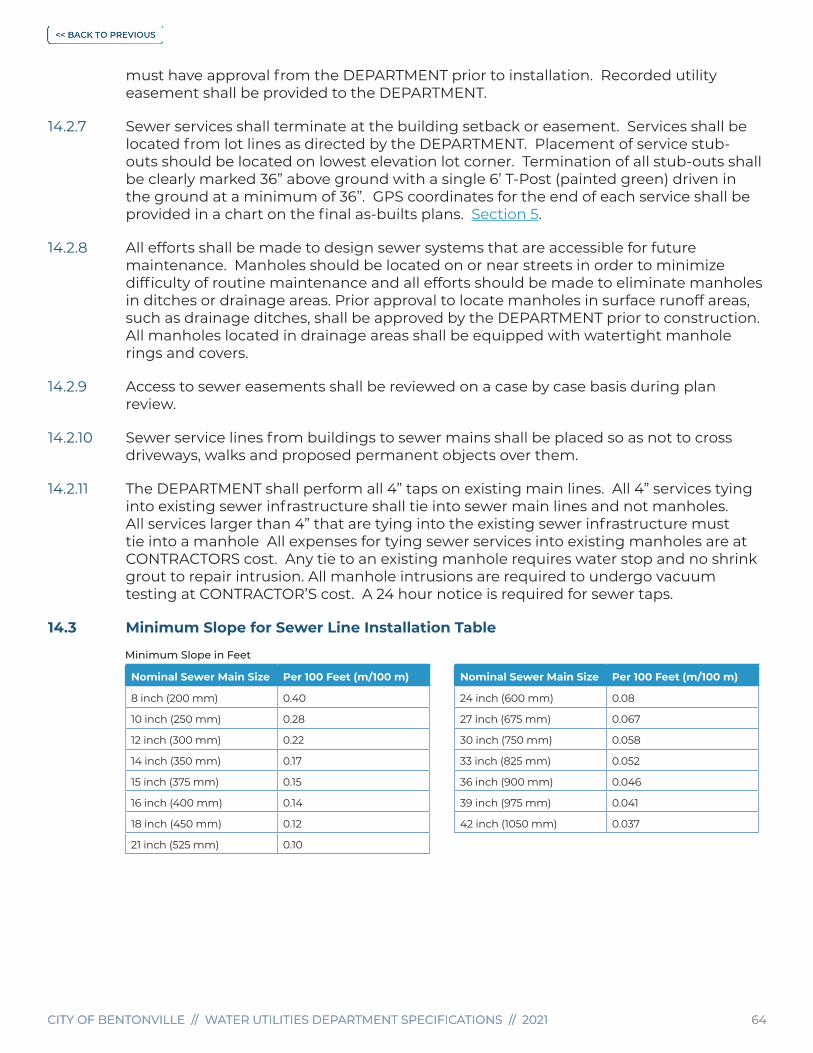
CITY OF BENTONVILLE // WATER UTILITIES DEPARTMENT SPECIFICATIONS // 2021 64CITY OF BENTONVILLE // WATER UTILITIES DEPARTMENT SPECIFICATIONS // 2021 64
must have approval from the DEPARTMENT prior to installation. Recorded utility easement shall be provided to the DEPARTMENT.
14.2.7 Sewer services shall terminate at the building setback or easement. Services shall be located from lot lines as directed by the DEPARTMENT. Placement of service stub-outs should be located on lowest elevation lot corner. Termination of all stub-outs shall be clearly marked 36” above ground with a single 6’ T-Post (painted green) driven in the ground at a minimum of 36”. GPS coordinates for the end of each service shall be provided in a chart on the final as-builts plans. Section 5.
14.2.8 All efforts shall be made to design sewer systems that are accessible for future maintenance. Manholes should be located on or near streets in order to minimize difficulty of routine maintenance and all efforts should be made to eliminate manholes in ditches or drainage areas. Prior approval to locate manholes in surface runoff areas, such as drainage ditches, shall be approved by the DEPARTMENT prior to construction. All manholes located in drainage areas shall be equipped with watertight manhole rings and covers.
14.2.9 Access to sewer easements shall be reviewed on a case by case basis during plan review.
14.2.10 Sewer service lines from buildings to sewer mains shall be placed so as not to cross driveways, walks and proposed permanent objects over them.
14.2.11 The DEPARTMENT shall perform all 4” taps on existing main lines. All 4” services tying into existing sewer infrastructure shall tie into sewer main lines and not manholes. All services larger than 4” that are tying into the existing sewer infrastructure must tie into a manhole All expenses for tying sewer services into existing manholes are at CONTRACTORS cost. Any tie to an existing manhole requires water stop and no shrink grout to repair intrusion. All manhole intrusions are required to undergo vacuum testing at CONTRACTOR’S cost. A 24 hour notice is required for sewer taps.
14.3 Minimum Slope for Sewer Line Installation Table
Minimum Slope in Feet
Nominal Sewer Main Size Per 100 Feet (m/100 m)
8 inch (200 mm) 0.40
10 inch (250 mm) 0.28
12 inch (300 mm) 0.22
14 inch (350 mm) 0.17
15 inch (375 mm) 0.15
16 inch (400 mm) 0.14
18 inch (450 mm) 0.12
21 inch (525 mm) 0.10
Nominal Sewer Main Size Per 100 Feet (m/100 m)
24 inch (600 mm) 0.08
27 inch (675 mm) 0.067
30 inch (750 mm) 0.058
33 inch (825 mm) 0.052
36 inch (900 mm) 0.046
39 inch (975 mm) 0.041
42 inch (1050 mm) 0.037

CITY OF BENTONVILLE // WATER UTILITIES DEPARTMENT SPECIFICATIONS // 2021 65CITY OF BENTONVILLE // WATER UTILITIES DEPARTMENT SPECIFICATIONS // 2021 65
SECTION 15 Wastewater Collection System Materials
15.1 ALL MATERIALS TO BE DOMESTICALLY MADE.
15.1.1 All gravity or force sanitary sewer pipe shall be PVC. If it is deemed necessary to install DI pipe, the use of DI pipe shall be subject to approval by the DEPARTMENT prior to installation. The minimum acceptable size of all gravity sewer mains is 8” diameter, unless prior approval is obtained from the DEPARTMENT and the ADH. All pipe installed shall be of the type, size, class and thickness as indicated in these specifications and on the design plans. The design strength of pipe used shall be based on standard Engineering design principles and manufacturer or trade association recommendations. Only pipe materials listed in this section shall be used for sanitary sewer mains and service lines unless specifically authorized by the DEPARTMENT.
15.2 Polyvinyl Chloride (PVC)
15.2.1 Pipe shall meet the requirement of SDR-26 Heavy Wall Sewer Pipe and comply with ASTM-3034 and Cell Classification 12454-B. Pipe joints shall be integrally molded bell ends per ASTM D-3034 Type PSM with factory supplied elastomeric gaskets and lubricant. Pipe shall be continually marked with the following:
a. Nominal OD
b. Dimension Ratio (SDR-26)
c. Notation “Heavy Wall Sewer Pipe”
d. Cell Classification: 12454-B
e. SDR Rating ASTM-D3034
f. Manufacturer’s name or trademark and production code
g. Seal (mark) of the testing agency that verified the suitability of the pipe. (such as: “PSP”)
15.2.2 The DEPARTMENT prohibits all A2000 type or any “profile pipe” use.
15.2.3 Pipe joints shall be integrally molded bell ends per ASTM D 3034, Table 2, with factory supplied elastomeric gaskets and lubricant.
15.3 Ductile Iron Pipe
15.3.1 Installation of DI pipe shall be installed under the direction of the DEPARTMENT. DI pipe that meets ASTM 4746, extra heavy type, inside nominal diameter as specified on plans, bell and spigot end shall be used. Jointing devices ASNI A21.11, rubber gasket joint devices.
15.3.2 All DI pipe and fittings for sewer service shall have an interior epoxy lining. The lining system shall be either Protecto 401 Ceramic Epoxy as manufactured by Vulcan Painters, Inc or Perma-Shield Series 431 manufactured by Tnemec. The lining applicator shall have a successful history of applying linings to the interior of DI pipe.

CITY OF BENTONVILLE // WATER UTILITIES DEPARTMENT SPECIFICATIONS // 2021 66CITY OF BENTONVILLE // WATER UTILITIES DEPARTMENT SPECIFICATIONS // 2021 66
15.4 Pipe Accessories
15.4.1 If any pipe accessories are necessary the material being used shall be submitted to the DEPARTMENT for approval prior to installation. If approval has not been obtained in writing, the contractor is at risk of removing any accessory at the DEPARTMENTS discretion.
15.5 Fittings
15.5.1 All fittings shall be made of the same material as the sewer main whether it is Ductile Iron or Heavy Wall SDR-26. Fittings shall have a push-on gasket seal that will allow for a passing air test. All fittings shall be submitted to the DEPARTMENT for approval prior to installation.
15.6 Cleanouts
15.6.1 Cleanouts are strictly prohibited as a point of entry or maintenance for use in the municipal sewer system. Clean-outs shall be installed on private plumbing only. Entry into the sewer main shall be facilitated by the use of manholes only or as directed by the DEPARTMENT.
15.7 Force Mains
15.7.1 All force mains will have a 3’ minimum cover of bedding material installed according to Detail LS09. The installation of the force main will include a 10 gauge solid strand copper tracer wire with locator ports. The pipe material that is to be used will need to withstand a 150 pound hydrostatic test preferably C-900 DR-18. Warning tape will need to be installed approximately 6” above the pipe. The warning tape will have “Force Main” written on in order to identify the pipe. Pipe size shall be a minimum of 4”.
15.7.2 Where force mains enter manholes the manholes shall be epoxy lined to a thickness of 125 mils after the installation of a ½” of cementitious lining has been applied. Manholes within 1000’ downstream shall also be epoxy lined to prevent degradation of the manhole. In addition, any manhole upstream of the lift station wet well within 500’ shall be epoxy lined.
15.8 Tracer Wire Ports for Force Mains
15.8.1 Tracer wire ports will be located no further apart than 500’ and placed at every change in direction. The ports are to be laid out so that they are located by a manhole whenever possible for ease of locating in the event that they get buried. The tracer wire ports will consist of a 4” pipe resting on the bedding material and extending to the final grade elevation. The tracer wire port will include a cast iron lid and an 18” pre-cast or cast in place concrete pad. The tracer wire will be brought up through the 4” pipe and extend a minimum of 12” out of the top of the pipe. The tracer wire will be installed in a manner that will allow the force main to be located in both directions from the tracer wire port.
15.8.2 Valve boxes shall be Tyler 6850 series or equal with 5 ¼” shafts. screw type, 5 ¼” drop lid with “SEWER” on lid. All valve box material shall be domestically made.

CITY OF BENTONVILLE // WATER UTILITIES DEPARTMENT SPECIFICATIONS // 2021 67CITY OF BENTONVILLE // WATER UTILITIES DEPARTMENT SPECIFICATIONS // 2021 67
SECTION 16 Sewer Manhole Information And Materials
16.1 This section covers materials to be used in the construction of standard manholes, drop manholes and watertight manholes.
16.2 Concrete Curing and Compounds
16.2.1 Concrete used in the construction of manholes shall conform to the requirements in Section 12.22. Curing compounds or covers must be approved by the DEPARTMENT. It is the responsibility of the CONTRACTOR to protect the concrete to prevent cracking during the curing process and to protect the manhole during freezing temperatures. The CITY INSPECTOR shall, at their discretion, prohibit pouring concrete during periods of extreme cold or inclement weather.
16.3 Cast-In-Place-Manholes
16.3.1 Cast-in-place manholes shall be constructed of 4,000 psi concrete with the concrete base a minimum thickness of 8” below the invert and shall be poured on undisturbed earth. The base shall extend a minimum of 24” in all directions from the exterior of the manhole barrel. Detail SS01.
16.3.2 Concrete shall be deposited evenly distributed in a continuous pour in maximum layers of 18”, with each layer vibrated to bond it to the preceding layer.
16.4 Drop Type Manholes
16.4.1 Drop type manholes installations shall be approved during plan review. Detail SS02 for interior drop type manholes and Detail SS03 for exterior drop type manholes.
16.4.2 Internal drops may be constructed in existing manholes if top to invert elevation is 15’ or greater. All requests for internal drop construction shall be approved by the DEPARTMENT. Point of intrusion shall be re-sealed with an approved water stop and grouted in place, the top section fitting shall be an all Hub SDR 26 double sanitary tee with direction of flow pointing downward. Vertical piping will be attached to concrete with 1 ¾” stainless steel bands by 5/8” X 3” stainless steel bolts with expansion anchors. Piping will terminate with a 90º long sweep bend resting on original invert base, fitting will be grouted in place on both sides to support assembly while forming new invert trough. Minimum pipe size for internal drop shall be 6”.
16.5 Sanitary Sewer Manhole Abandonment
The DEPARTMENT requires the entire removal of the manhole if 5’ deep or less. Upon removal of the manhole, all lines going into the manhole are to be cut and filled with 4,000 psi concrete until pipe is full, to not allow any infiltration.
Any manhole that is deeper than 5’ is to be abandoned according to Detail SS07.
16.6 Manhole Rings And Lids
16.6.1 All castings for manhole rings and lids must be of the best quality gray cast iron, free from cracks, holes, scale, shrinkage, distortion and other defects which might make them unfit for their intended use. They shall have a workmanlike finish, shall be non-

CITY OF BENTONVILLE // WATER UTILITIES DEPARTMENT SPECIFICATIONS // 2021 68CITY OF BENTONVILLE // WATER UTILITIES DEPARTMENT SPECIFICATIONS // 2021 68
rocking, shall have all bearing surfaces machined smooth and shall be of such quality that a blow from a hammer will produce an indentation on a rectangular edge of casting without flaking the metal. Manhole rings and lids shall have a minimum access diameter of 24”. The manhole lids shall be of solid construction without any openings other than 2 concealed pick holes which shall be located on direct opposite sides of the manhole lid. The concealed pick holes shall be of such design as not to allow infiltration into the manhole. Manhole lids shall have “SANITARY SEWER” or “CITY OF BENTONVILLE SANITARY SEWER” cast on the lid. Standard manhole rings and lids shall be East Jordan Iron Works 1348-1 266# total weight or approved equal determined by Bentonville Water Utilities, either model shall have a combined weight of ring and lid equaling 250 pounds or greater. All rings and lids shall be domestically made. Detail SS04.
16.7 Private Manhole
16.7.1 The manholes along private sewer lines shall require the private manhole lids. Model #00134853. Detail SS08
16.8 Watertight Manhole Rings and Lids
16.8.1 Watertight manhole rings and lids where required on the plans by DEPARTMENT, shall be East Jordan Iron Works, (260# or greater), or approved equal determined by Bentonville Water Utilities and be domestically made. Detail SS05.
16.9 Manhole Steps
16.9.1 Manhole steps are strictly prohibited within the Bentonville Wastewater Collection System.
16.10 Water Stops
16.10.1 Water stops for pipe connections to manholes shall be Fernco Concrete Manhole Adapters, or approved equal determined by Bentonville Water Utilities, furnished in the appropriate size for the type and class pipe used. Water stops are required for all sewer pipes entering manhole walls or bases.
16.11 Manhole Configurations and Construction
16.11.1 Manholes shall be of such construction so that the finished manhole will have an ID of 4’ 0” plus or minus ½”. Concrete used to pour the manhole shall be 4,000 psi with a slump of approximately 3”. Wall thickness shall be a minimum of 6”. Detail SS01
16.11.2 Before the forms are set in place, any water that may have accumulated in the excavated area shall be pumped out.
16.11.3 All manholes shall be a monolithic pour. Pouring the base and walls with one continuous pour. The manhole shall not be backfilled less than 24 hours after the forms have been removed. Extra care shall be taken to compact all backfill to the top of the highest pipe entering the manhole. After these pipes have been put in place, the barrel shall be repaired using a grout mixture. If honeycombing of the barrel is found to be present after removal of the forms, they shall be repaired as directed by the ENGINEER, DEPARTMENT or CITY INSPECTOR. If it is necessary due to the depth of the sewer main to pour the manhole in two sections, the joint shall have #4 rebar

CITY OF BENTONVILLE // WATER UTILITIES DEPARTMENT SPECIFICATIONS // 2021 69CITY OF BENTONVILLE // WATER UTILITIES DEPARTMENT SPECIFICATIONS // 2021 69
on 12” centers with a 3” X 3” construction joint. Manhole is to be inspected by CITY INSPECTORS before additional pour is done.
16.12 Manhole Shape and Inside Dimensions
16.12.1 Manhole shapes shall be cylindrical and 48” diameter for sewer mains 12” and less and 60” diameter for sewer mains larger than 12”.
16.13 Manhole Design Depth, Height and Placement
16.13.1 Manhole depth shall be as indicated on plans. The DEPARTMENT requires accessibility to all manholes, the responsible ENGINEER shall design the sanitary sewer system in a manner so as to eliminate backyard placements between buildings, behind permanent structures, or other locations not accessible for normal street side maintenance.
16.13.2 Street side manhole rim elevations shall be 4” above the proposed final grade and offsite or non-street side manhole top rim elevations shall be 12” above proposed final grade. Manhole risers used in vertical adjustment must have ram-nek installed with the new riser. It must be heated in a manner that allows workability so it can be pressed into the receiving ring or inset of additional risers used to achieve proper rim elevation. Any risers added must be seated fully, “squeeze out” is proof of a water tight joint and a proper installation. All manhole rim elevations shall be shown as such on the sewer profile sheet and noted in the general construction notes. The DEPARTMENT, during final inspection, will address finished manhole elevations and may require additional height elevations. All manholes constructed in ravines, drainage or runoff areas will require the installation of a watertight ring and lid or rim shall be 12” above 100 year flood.
16.13.3 After sewer construction is complete, the vertical adjustment shall be no more than 24” plus the lid. Adjustments greater than 24” require the reconstruction of the manhole cone. A maximum of (2) risers may be utilized to achieve the 24” of adjustment.
16.14 Main And Service Pipes
16.14.1 All main and service pipes shall be neatly cut flush with inside of manhole or inlet where they enter structure walls, and correct irregularities and rough edges with non-shrinking grout.
16.15 Connections to Manholes
16.15.1 To ensure that pipe will not sag or break immediately adjacent to the manhole, care shall be taken that excavation for the manhole bottom is limited to the area to be filled with concrete. The CONTRACTOR shall support pipe entering the manhole all the way to solid bedding by placing approved backfill under the pipe and up to the mid spring-line with Class B concrete.
16.16 Inverts
16.16.1 The invert of the manhole shall be hand-placed and shaped using the same 4,000-psi concrete mixture used to pour the base and walls of the manhole. The invert shall be shaped and smoothed so that the manhole will be self-cleaning and free of areas where solids may be deposited as sewage flows through the manhole and from service lines that enter the manhole base. Inverts shall be shaped, formed and brushed

CITY OF BENTONVILLE // WATER UTILITIES DEPARTMENT SPECIFICATIONS // 2021 70CITY OF BENTONVILLE // WATER UTILITIES DEPARTMENT SPECIFICATIONS // 2021 70
smooth from the concrete poured for the base prior to the initial set of the base. In all cases the diameter of each pipe entering the manhole barrel shall be cut smooth with the inside edge of the manhole barrel and the invert shaped throughout from all inlet pipes to the outside pipe. Shape inverts for smooth flow across structure floor as shown on drawings.
SECTION 17 Sewer System General Installation Information
17.1 All Materials Shall Be Domestically Made
17.2 Field Quality Control
17.2.1 Compaction testing will be performed in accordance with ANSI/ASTM D698, ASTM D2922, ASTM D3017 or ASTM D1557.
17.2.2 Test sanitary sewer pipe system installed below grade and outside building in accordance with the following procedures:
a. The CONTRACTOR shall perform the testing of manhole construction, pipe materials and/or other materials incorporated into the construction of the sanitary sewer system to determine leakage and water tightness. Testing to be supervised by design ENGINEER and inspected by the CITY INSPECTOR.
17.3 Air Testing of Gravity Sewer Lines
17.3.1 All gravity sewer lines shall be tested in accordance with the following procedures after all trenching and boring in area of sewer mains and sewer services:
a. Plug all pipe outlets with suitable test plugs. Brace each plug securely.
b. Pipe air supply to the pipeline to be tested in such a manner that the air supply may be shut off, pressure observed and air pressure released from the pipe without workmen entering the manhole.
c. Add air slowly to the portion of pipe under test until the internal pressure of the line is raised to approximately 4 psig but less than 5 psig.
d. Shut the air supply off and allow at least 2 minutes for the air pressure to stabilize.
e. When the pressure has been bled down to 3 1/2 psig and stabilized, start the test.
f. If the pipe section does not decrease from 3.5 psi to 2.5 psi in less time than is allotted the section passes the test.
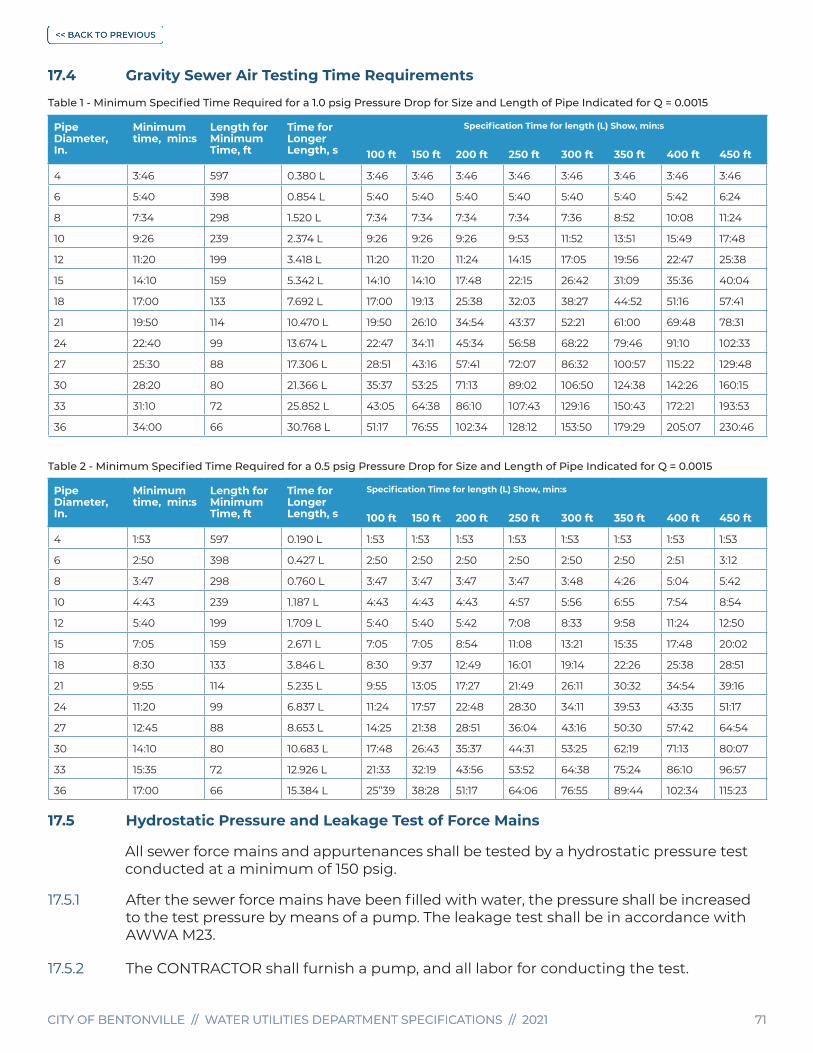
CITY OF BENTONVILLE // WATER UTILITIES DEPARTMENT SPECIFICATIONS // 2021 71CITY OF BENTONVILLE // WATER UTILITIES DEPARTMENT SPECIFICATIONS // 2021 71
17.4 Gravity Sewer Air Testing Time Requirements
Table 1 - Minimum Specified Time Required for a 1.0 psig Pressure Drop for Size and Length of Pipe Indicated for Q = 0.0015
Pipe Diameter, In.
Minimum time, min:s
Length for Minimum Time, ft
Time for Longer Length, s
Specification Time for length (L) Show, min:s
100 ft 150 ft 200 ft 250 ft 300 ft 350 ft 400 ft 450 ft
4 3:46 597 0.380 L 3:46 3:46 3:46 3:46 3:46 3:46 3:46 3:46
6 5:40 398 0.854 L 5:40 5:40 5:40 5:40 5:40 5:40 5:42 6:24
8 7:34 298 1.520 L 7:34 7:34 7:34 7:34 7:36 8:52 10:08 11:24
10 9:26 239 2.374 L 9:26 9:26 9:26 9:53 11:52 13:51 15:49 17:48
12 11:20 199 3.418 L 11:20 11:20 11:24 14:15 17:05 19:56 22:47 25:38
15 14:10 159 5.342 L 14:10 14:10 17:48 22:15 26:42 31:09 35:36 40:04
18 17:00 133 7.692 L 17:00 19:13 25:38 32:03 38:27 44:52 51:16 57:41
21 19:50 114 10.470 L 19:50 26:10 34:54 43:37 52:21 61:00 69:48 78:31
24 22:40 99 13.674 L 22:47 34:11 45:34 56:58 68:22 79:46 91:10 102:33
27 25:30 88 17.306 L 28:51 43:16 57:41 72:07 86:32 100:57 115:22 129:48
30 28:20 80 21.366 L 35:37 53:25 71:13 89:02 106:50 124:38 142:26 160:15
33 31:10 72 25.852 L 43:05 64:38 86:10 107:43 129:16 150:43 172:21 193:53
36 34:00 66 30.768 L 51:17 76:55 102:34 128:12 153:50 179:29 205:07 230:46
Table 2 - Minimum Specified Time Required for a 0.5 psig Pressure Drop for Size and Length of Pipe Indicated for Q = 0.0015
Pipe Diameter, In.
Minimum time, min:s
Length for Minimum Time, ft
Time for Longer Length, s
Specification Time for length (L) Show, min:s
100 ft 150 ft 200 ft 250 ft 300 ft 350 ft 400 ft 450 ft
4 1:53 597 0.190 L 1:53 1:53 1:53 1:53 1:53 1:53 1:53 1:53
6 2:50 398 0.427 L 2:50 2:50 2:50 2:50 2:50 2:50 2:51 3:12
8 3:47 298 0.760 L 3:47 3:47 3:47 3:47 3:48 4:26 5:04 5:42
10 4:43 239 1.187 L 4:43 4:43 4:43 4:57 5:56 6:55 7:54 8:54
12 5:40 199 1.709 L 5:40 5:40 5:42 7:08 8:33 9:58 11:24 12:50
15 7:05 159 2.671 L 7:05 7:05 8:54 11:08 13:21 15:35 17:48 20:02
18 8:30 133 3.846 L 8:30 9:37 12:49 16:01 19:14 22:26 25:38 28:51
21 9:55 114 5.235 L 9:55 13:05 17:27 21:49 26:11 30:32 34:54 39:16
24 11:20 99 6.837 L 11:24 17:57 22:48 28:30 34:11 39:53 43:35 51:17
27 12:45 88 8.653 L 14:25 21:38 28:51 36:04 43:16 50:30 57:42 64:54
30 14:10 80 10.683 L 17:48 26:43 35:37 44:31 53:25 62:19 71:13 80:07
33 15:35 72 12.926 L 21:33 32:19 43:56 53:52 64:38 75:24 86:10 96:57
36 17:00 66 15.384 L 25”39 38:28 51:17 64:06 76:55 89:44 102:34 115:23
17.5 Hydrostatic Pressure and Leakage Test of Force Mains
All sewer force mains and appurtenances shall be tested by a hydrostatic pressure test conducted at a minimum of 150 psig.
17.5.1 After the sewer force mains have been filled with water, the pressure shall be increased to the test pressure by means of a pump. The leakage test shall be in accordance with AWWA M23.
17.5.2 The CONTRACTOR shall furnish a pump, and all labor for conducting the test.

CITY OF BENTONVILLE // WATER UTILITIES DEPARTMENT SPECIFICATIONS // 2021 72CITY OF BENTONVILLE // WATER UTILITIES DEPARTMENT SPECIFICATIONS // 2021 72
17.5.3 The duration of the hydrostatic leakage test shall be 2 hours or as specified by the CITY INSPECTOR or DEPARTMENT representative.
17.5.4 The source of water for the pump suction shall be potable water from the DEPARTMENT’S distribution system. The vessel used must be approved by the CITY INSPECTOR or DEPARTMENT representative.
17.5.5 The maximum leakage per hour for DI and PVC shall be as calculated from the following formula (All rubber gasket or 0-ring joints):
L = SD (P)
148,000
L = allowable leakage, (gallons per hour)
S = Length of pipe tested, in feet
D = nominal diameter of pipe, (inches)
P = average test pressure during leakage test, (psig)
17.5.6 After the specified test pressure has been applied the entire pipeline shall be checked in the presence of the CITY INSPECTOR representative giving particular attention to that part of the pipeline and those appurtenances that are exposed. After the CONTRACTOR has taken the necessary action to repair or replace any part of the pipeline or appurtenances where leaks were apparent or if no leaks were apparent, the sewer force mains shall be subjected to a leakage test at the pressure specified with a meter inserted in the test pump discharge line.
17.5.7 If any test of pipe laid discloses leakage greater than the allowable leakage as calculated from above formula or table, the CONTRACTOR shall, at his expense, locate the leak or leaks and perform whatever work and/or replace whatever material that is required in order to remedy the defect and stop the leak and re-test the line. All corrective work must be approved by the DEPARTMENT.
17.5.8 Prior to the pressure test, the ENGINEER shall present an allowable leakage report to the CITY INSPECTOR.
17.6 Testing Safety Precautions
17.6.1 The low-pressure air test may be dangerous to personnel if, through lack of understanding or carelessness, a line is over pressurized or plugs are installed improperly. It is extremely important that the various plugs be installed so as to prevent the sudden expulsion of a poorly inflated plug. As an example of the hazard, a force of 250 pounds is exerted on an 8” plug by an internal pressure of 5 psi. Observe the following safety precautions:
a. No person shall be allowed in the manholes during the test or when a plugged pipe is under pressure.
b. Gauges, air piping manifolds and valves shall be located at the top of the ground. Install and brace all plugs securely.
17.7 Ground Water Elevation
17.7.1 If the pipeline to be tested is below the ground water level, the starting test pressure shall be increased by 0.433 psi for each foot the groundwater level is above the invert of the sewer pipe. In no case shall the starting test pressure exceed 9.0 psig.

CITY OF BENTONVILLE // WATER UTILITIES DEPARTMENT SPECIFICATIONS // 2021 73CITY OF BENTONVILLE // WATER UTILITIES DEPARTMENT SPECIFICATIONS // 2021 73
17.8 Test Equipment
17.8.1 All necessary equipment to perform the air test in accordance with this specification shall be provided by the CONTRACTOR. The test gauge shall be 4” and have incremental division of 0.10 psig and have an accuracy of at least + 0.04 psig. In no case shall a test gauge be used which has incremental divisions of greater than 0.25 psig. The gauge shall be of sufficient size in order to determine this accuracy.
17.8.2 The ENGINEER shall furnish one copy of gravity sewer and manhole test results to the DEPARTMENT upon completion of gravity sewer system approval by the CITY INSPECTOR.
17.9 Mandrel Test
17.9.1 The mandrel (go/no-go) device shall be cylindrical in shape and constructed with either 9 or 16 evenly spaced arms or prongs. Mandrels with fewer arms will be rejected as not sufficiently accurate. The contact length of the mandrel’s arms shall equal or exceed the nominal ID of the sewer to be inspected. Critical mandrel dimensions shall carry a tolerance of + 0.01”. The mandrel and all necessary equipment for the mandrel test shall be provided by the CONTRACTOR. No handmade mandrel devices shall be used for testing unless prior permission is given by the DEPARTMENT or the CITY INSPECTOR.
17.9.2 The mandrel shall be hand-pulled by the CONTRACTOR through all flexible pipe sewer lines no earlier than 30 days after the trench has been completely backfilled. Any sections of the sewer not passing the mandrel shall be uncovered and the CONTRACTOR shall re-bed, re-round or replace the sewer to the satisfaction of the DEPARTMENT. Any repaired section shall be re-tested.
17.9.3 The OD of the mandrel shall be set according to the following table:
NOMINAL DIAMETER (IN) MANDREL OD (IN)
8” 7.11”
10” 8.87”
12” 10.55”
15” 12.90”
18” 15.76”
NOMINAL DIAMETER (IN) MANDREL OD (IN)
21” 18.57”
24” 21.36”
27” 23.51”
30” 27.32”
17.10 Manhole Vacuum Testing
17.10.1 The manhole vacuum test shall be performed with suitable apparatus made for such purpose and shall draw a vacuum of 10” of mercury (Hg). The test shall pass if the vacuum remains at 10” of mercury (Hg) or drops to not less than 9” of mercury (Hg) in one minute. Vacuum test will be performed by construction CONTRACTOR. Test shall be witnessed and documented by CITY INSPECTOR. Responsible ENGINEER shall furnish test result information to the DEPARTMENT. If, after 2 attempts to perform a satisfactory vacuum test have failed, the DEPARTMENT may require that the manhole be removed and re-poured. All sewer services entering the manhole shall be vacuum tested with the manhole.
17.10.2 If existing manhole is to be adjusted – either lowered or raised – and cone is removed – manhole will require a passing vacuum test.

CITY OF BENTONVILLE // WATER UTILITIES DEPARTMENT SPECIFICATIONS // 2021 74CITY OF BENTONVILLE // WATER UTILITIES DEPARTMENT SPECIFICATIONS // 2021 74
17.10.3 Pre-vacuum testing is recommended on existing manholes. If manhole is cored, a post vacuum test shall be required except for the below circumstances:
• If pre-vacuum test passes – a post vacuum test shall pass.
• If pre-vacuum test fails – a post vacuum test will not be required.
17.11 Close Circuit Television Inspection – (CCTV)
17.11.1 All sewer mains that are installed as part of a new subdivision or large scale development and for the purpose of becoming part of a public sewer system, maintained by the City of Bentonville will require a Close Circuit Television Inspection (CCTV). The inspection will be performed by City personnel after all other required sewer main line testing has been completed. The inspection consists of hydro-jet cleaning the sewer main line and allowing it to drain for a period of not less than one hour. After the sewer main line has been allowed to drain the CCTV inspection will begin. Defects that will be documented are: Pipe bell ends facing downstream, narrow or rough manhole inverts, misaligned or backward service wyes, loose or missing pipe joint gaskets, pipe joints not fully seated, crushed, or out-of-round pipe and the pooling of water in the pipe and at service wyes, joints and manhole inverts. The camera has been fitted with a measuring device that can determine the depth of the water in the event of any pooling. Any pooling of water that is deeper than ¾” will require the sewer main line to be adjusted to eliminate the problem. The only personnel allowed in the CCTV vehicle during the inspection are City of Bentonville employees.
17.11.2 A pass or fail decision is not made in the field. The camera inspection is recorded on video recording software and then reviewed at the DEPARTMENT. After review of the recording, the comments will be made available to the responsible ENGINEER for the project indicating approval of the sanitary sewer mains or a list of defects that require repair.
17.11.3 All CCTV inspections or re-inspections that are necessary are to be requested in written form by email to the DEPARTMENT by the responsible ENGINEER for the development project. The responsible ENGINEER shall provide accurate record drawing of sewer system, with profiles, at time of CCTV request.
17.11.4 One attempt will be made by City staff to adequately clean new sewer mains for proper CCTV inspection. If during construction sufficient care is not taken to keep rocks, dirt or debris from entering new sewer mains and extra cleaning is necessary, CCTV staff will not complete the inspection. Department personnel will then advise the ENGINEER of record of the condition of the pipe. The contractor shall be responsible for the additional cleaning needs. It will be the ENGINEER of record’s responsibility to communicate to the contractor why the inspection was stopped and why they are now responsible for cleaning and removing obstructions in the sewer main. After the contractor has completed the necessary cleanings, the ENGINEER of record will contact the DEPARTMENT and request continuation of the CCTV inspection.
17.11.5 After the completion of the required repairs by the CONTRACTOR, a re-inspection must be performed using the same procedures as for the initial inspection. All re-inspections will be billed to the OWNER/DEVELOPER according to current fee ordinance.
17.11.6 Full CCTV inspection shall be completed and 1st tracer wire inspection shall be completed before final inspection.

CITY OF BENTONVILLE // WATER UTILITIES DEPARTMENT SPECIFICATIONS // 2021 75CITY OF BENTONVILLE // WATER UTILITIES DEPARTMENT SPECIFICATIONS // 2021 75
17.12 Acceptance Of Installation
17.12.1 No gravity sewer or manhole will be accepted that does not comply with the minimum requirements of tests described within these specifications.
17.13 Warranty
17.13.1 The DEPARTMENT reserves the right to inspect by mandrel test or camera inspection any sewer line before acceptance, and also prior to expiration of the first year of operation. If a previously accepted line fails an inspection during the first year of operation, the defects must be corrected at the CONTRACTOR/DEVELOPER’S expense.
SECTION 18 Sewer Lift Stations
18.1 The Wastewater Department must approve all plans.
18.1.1 The Wastewater Department lift station details contained in this specifications book are to be used as a guide only. These details are not to be used as construction plans.
18.2 Final Acceptance
18.2.1 The Wastewater Department, at the DEVELOPER’S expense, will purchase an alarm system at current market price. This fee is required and must be paid prior to the final inspection and acceptance of the lift station.
18.2.2 A spare pump must be furnished with each sewer lift station and delivered to the Wastewater Department prior to lift station final inspection and acceptance.
18.2.3 The electric and water meters shall be installed before a final inspection is requested.
18.2.4 A final lift station inspection shall be conducted at the DEVELOPER’S request once lift station construction has been completed, a pump startup has been performed and the alarm fee has been paid. Wastewater Department maintenance personnel must be present at the pump start up session. The lift station final inspection and development final inspections are separate inspections and will take place at separate appointments.
18.2.5 The DEVEOPER/CONTRACTOR shall be responsible for supplying alternate means of power for the pump start-up during final inspection.
18.2.6 Before final acceptance, 1 paper and 1 pdf copy of as-built drawing must be supplied to the Wastewater Department.
18.3 Basic Control Panel Specifications
18.3.1 All electrical services shall meet City and State Codes.

CITY OF BENTONVILLE // WATER UTILITIES DEPARTMENT SPECIFICATIONS // 2021 76CITY OF BENTONVILLE // WATER UTILITIES DEPARTMENT SPECIFICATIONS // 2021 76
18.3.2 A portable generator connector is required on lift station control panels. It must be an Appleton 200 Amp 4-W, 4-P style -1 type connector Cat # ADR20044 for 3Ø stations only
18.3.3 Control panel shall be NEMA 4X stainless steel mounted on a 6” X 6” stainless steel pedestal on the wet well and shall be sealed to prevent fumes from rising into control panel. Control panel and pedestal door shall open away from wet well hatch.
18.3.4 One combination circuit breaker/overload disconnect unit with magnetic trip elements sized for individual protection shall be provided for each pump. Detail LS01 and LS02.
18.3.5 One across the line magnetic contactor shall be provided per pump and sized in accordance with the maximum NEMA horsepower standards.
18.3.6 Control panels shall incorporate the following features as a minimum:
a. Alternator shall be provided for duplex controls.
b. Individual selector switches to provide “hand-off-auto” control of each pump.
c. HAND POSITION - In this position, the pump controlled by the switch will run regardless of the wet well level. The pump will continue to run until the switch is turned to “off” or “auto” position.
d. AUTO POSITION - In this position, the operation of the pumps is controlled automatically by the level sensors in the wet well. The control center will be designed to provide automatic operation, while maintaining motor protection.
e. 24 or 120 volt AC control transformer protected on both the primary and secondary control circuit.
f. Terminals shall be provided for connection of the level sensors.
g. A hinged, removable dead-front panel is required.
h. Pump running pilot lights (green) mounted on operator’s control panel.
i. Totalizer for each pump must be mounted on operator’s control panel.
18.3.7 All operator controls, toggle switches, circuit breakers, etc., shall be accessible without removing the dead-front panel.
18.3.8 NEMA 4X stainless steel enclosures with draw pull catch, provisions for padlocking and suitable for indoor or outdoor mounting.
18.3.9 Electrical connections in the wet well are not allowed.
18.3.10 Coordinate with Bentonville Electric Department prior to project start to determine type of electrical service. Three-phase 480 VAC power must be used when available.
18.3.11 An approved lightning arrester must be installed.
18.3.12 3-phase power monitor must be installed to protect pump from low voltage, single phasing and phase reversal.
18.3.13 The level control system sensors must be submersible transducer, floats or equivalent. If a transducer control is installed the system shall have a float backup.

CITY OF BENTONVILLE // WATER UTILITIES DEPARTMENT SPECIFICATIONS // 2021 77CITY OF BENTONVILLE // WATER UTILITIES DEPARTMENT SPECIFICATIONS // 2021 77
18.3.14 Electrical terminal strip must be a minimum of 4” above the bottom of the control panel.
18.4 Level Controls
18.4.1 Provide a switch control system incorporating a hermetically sealed liquid level indictor as a level sensing and signal control device for automatic control of lift station. The system shall monitor and control wet well level at each station as follows:
SWITCH 1 – All Stop
SWITCH 2 – Energize Lead Pump
SWITCH 3 – Energize Lag Pump
SWITCH 4 – High Level Alarm
18.4.2 High level alarms are required. A red warning light with flasher and audible alarm shall be installed on the control panel.
18.4.3 Contingent upon wet well level, float system shall cause indicator/controller to energize appropriate control contacts.
18.5 Access Road
18.5.1 A paved access road shall be provided from the curb to the lift station.
18.5.2 The road leading to the lift station shall be asphalt, a minimum of 12’ wide and no greater than a 10% slope. A minimum of 6” of compacted base material is required. Base material and compaction shall be in accordance with the latest edition of ARDOT Standard Specifications (Division 300). A minimum of 4” of asphalt is required. Paving materials and construction methods shall be in accordance with the latest edition of the ARDOT Standard Specifications (Division 400).
18.6 Lift Station And Site
18.6.1 Lift station site and access road shall be deeded to the City of Bentonville.
18.6.2 Minimum lot size shall be 50’ X 50’.
18.6.3 Lift station lot shall be 2’ above surrounding project area. Wet wells shall be 8” above the asphalt.
18.6.4 Lift station lot shall be asphalt. A minimum of 6” of compacted base material is required. Base material and compaction shall be in accordance with the latest edition of the ARDOT Standard Specification (Division 300). A minimum of 4” of asphalt is required. Paving materials and construction methods shall be in accordance with the latest edition of the ARDOT Standard Specifications (Division 400).
18.6.5 Based on the location of the lift station, the City of Bentonville Wastewater Department will determine the type of 8’ fence requested to be installed. All fence poles or columns will be set 1’ inside the asphalt with 14’ roll back or swing type gates.
18.6.6 A pole mounted LED photocell light that conforms to the Subdivision Code for outdoor lighting shall be provided to adequately illuminate the control panel and site.

CITY OF BENTONVILLE // WATER UTILITIES DEPARTMENT SPECIFICATIONS // 2021 78CITY OF BENTONVILLE // WATER UTILITIES DEPARTMENT SPECIFICATIONS // 2021 78
18.6.7 There shall be a frost free, 2’ min bury water hydrant, at each lift station. The hydrant shall be protected by a reduced pressure zone backflow prevention device. The device must be protected from freezing by an approved enclosure. See Cross Connection Control Program Specifications. Detail W14
18.7 Pump Requirements
18.7.1 All lift stations require rail mounted submersible pumps as manufactured by Flygt or Hydromatic, or HCP and interchangeable without alteration to the piping or electrical system. Details LS04 and LS05.
18.7.2 Lift stations requiring less than 5-HP pumps must be grinder pumps. Larger pumps should have shredder type impellers when possible. Detail LS05.
18.7.3 All pumps will meet or exceed the requirements to pump the anticipated flow for the known number of houses, units, or number of persons. The pumps will meet or exceed required head values based on ENGINEERS design. At a minimum, all lift stations shall be duplex, two pumps of the same size that alternate pumping.
18.7.4 Any time it is determined through an analysis that a development or subdivision impacts or exceeds the capacity or the flow of an existing lift station, the existing lift station shall be upgraded. The existing lift station shall be upgraded with equipment including pumps, piping and control panel components that are consistent with the existing equipment.
18.8 Lift Station Plumbing
18.8.1 Plumbing shall be constructed in such a manner that the force main velocity is never below 2’ per second and never above 8’ per second. All lift station mounting rails, cables, chains and hardware shall be 316 stainless steel. All lift station piping shall be Type 316L stainless steel (in accordance with ASTM A312 and 150 psi minimum), and stainless steel piping shall extend from the pump to three feet outside the valve vault.
18.8.2 All lift station wet wells and valve vaults shall be concrete with aluminum hatches to allow access to pumps and valves. Wet well hatch shall open toward the control panel.
18.8.3 The lift station will be constructed of concrete with reinforcement material. All plumbing entering or leaving the wet well shall be grouted to prevent infiltration.
18.8.4 Piping shall be sized to meet flow needs.
18.8.5 Gate Valves and Check Valves are required on both discharging lines.
18.8.6 A stainless steel chain shall be hooked to each pump for removal.
18.8.7 All lift station wet wells shall be vented by a 4” stainless steel pipe with bird screen.
18.9 Valve Vaults and Wet Wells for Lift Stations
18.9.1 Wet wells shall be a minimum of 8’ in diameter and a minimum of 10’ in depth. Alternate Storage (i.e. equalization basin) may be required at certain locations, which will be determined by the Wastewater Department. EQ shall be the same size as the wet well.

CITY OF BENTONVILLE // WATER UTILITIES DEPARTMENT SPECIFICATIONS // 2021 79CITY OF BENTONVILLE // WATER UTILITIES DEPARTMENT SPECIFICATIONS // 2021 79
18.9.2 Wet wells shall be 8” above the asphalt.
18.9.3 Wet well walls shall be a minimum of 8” thick with #4 rebar on 12” centers. The base of the wet well shall be designed to resist the buoyance/floating with the wet well empty.
18.9.4 Wet well bottom rebar spacing - #4 bar on 6” centers.
18.9.5 Wet well top shall be a minimum of 6” thick with # 4 rebar on 6” centers.
18.9.6 Wet well access shall be cast-in-place, grout will not be accepted.
18.9.7 All interior concrete walls of new lift station wet wells will be epoxy coated prior to lift station approval and being brought into service. Epoxy coating will be 100% epoxy at a minimum application thickness of 125 mils after the installation of a ½” of cementitious lining has been applied . Epoxy is added to extend the service life of the concrete wet well walls.
18.9.8 Valve vault walls shall be a minimum of 6” thick.
18.9.9 Valve vault base shall be a minimum of 6” thick.
18.9.10 Valve vault top shall be a minimum of 6” thick with # 4 rebar on 6” centers.
18.9.11 Vaults and wet wells shall be of all concrete construction incorporating a double aluminum access lid. Door shall open to 90º, lock automatically in position; have closed position lock hasp and retractable grip for opening and closing with one hand. Lid shall support a minimum live load of 150 pounds per square foot. Details LS06 and LS07.
18.9.12 Vaults and wet wells shall be constructed on a minimum of 6” of SB2 base material. Steps shall not be incorporated. Maximum vault depth shall be 5’ from access hatch to base.
18.10 Valves
18.10.1 Check valves shall be swing type with iron body and flanged ends mounted in the horizontal position only and shall be located in a valve vault not exposed to wastewater. 2” check valves may be IPT.
18.10.2 Gate valves 4” and larger shall be of the resilient seat type and meet the requirements of AWWA C515 latest revision. Valves shall have non-rising stems and close right (clockwise). Valves shall have flanged ends and have a 2” operating nut or hand wheel. Valves smaller than 2” shall meet AWWA C500. Acceptable manufacturers for all sizes include; American Darling, Clow, Kennedy, Mueller or equal. Gate valves shall be mounted horizontally in valve vault with no exposure to wastewater.
18.10.3 Plug valves are an acceptable means for isolation and shall be flanged Dezurik or Pratt equal.

CITY OF BENTONVILLE // WATER UTILITIES DEPARTMENT SPECIFICATIONS // 2021 80CITY OF BENTONVILLE // WATER UTILITIES DEPARTMENT SPECIFICATIONS // 2021 80
SECTION 19 Sewer Lift Stations – Private
19.1 Plans shall be provided to the DEPARTMENT for approval before construction begins.
19.2 Lift Station Site
19.2.1 An unobstructed access to the lift station shall be provided and maintained.
19.2.2 The lift station shall have a minimum wet well diameter of 2’ and a minimum depth of 6’.
19.3 Basic Control Panel Specifications
19.3.1 The lift station shall have a control center to provide automatic and manual operation. A Hand – Off – Automatic switch shall be included for each pump.
19.3.2 Station shall operate on a minimum of 220 V AC.
19.3.3 One “across the line magnetic contactor” per pump sized to HP and NEMA standards shall be provided and installed.
19.3.4 Control center shall have a locking hasp.
19.3.5 Alternator shall be provided for duplex units.
19.3.6 A lighting arrester shall be installed for pump protection.
19.3.7 High level alarms are required. A red warning light with flasher and audible alarm shall be installed on the control panel for easy monitoring.
19.3.8 An identification plate listing contact information, name, address and phone number of responsible party will be attached to the control panel and a copy issued to the Wastewater Department.
19.4 Pump Requirements
19.4.1 Pumps shall be Flygt, Hydromatic, or HCP and must be approved in writing by the Wastewater Department.
19.4.2 Pumps shall be mounted on stainless steel slide rails and use Campbell type pump connector or equivalent.
19.4.3 Pumps shall have stainless steel lifting chains or stainless steel lifting cables for pump removal and installation.
19.4.4 All pumps shall meet or exceed the minimum requirements to pump the anticipated flow for the known number of units or number of persons. The pumps shall meet or exceed required head values based on ENGINEER’s design.
19.4.5 Pump impellers shall be grinder type impellers.
19.4.6 Before final acceptance, 1 paper and 1 pdf copy of as-built drawing with contact information must be supplied to the Wastewater Department.

CITY OF BENTONVILLE // WATER UTILITIES DEPARTMENT SPECIFICATIONS // 2021 81CITY OF BENTONVILLE // WATER UTILITIES DEPARTMENT SPECIFICATIONS // 2021 81
SECTION 20 Cross-Connection Control Program Manual
20.1 General
This document sets forth the Bentonville Water Utilities Cross-Connection Control Program, and is adopted within the water and sewer specifications for the purpose of regulating cross-connection hazards by the operating staff and management of the DEPARTMENT.
20.2 Introduction
This program prohibits uncontrolled cross-connections within the water distribution system of the Bentonville Water Utilities, authorizes the DEPARTMENT to conduct inspections of the consumers’ property, requires that cross-connection hazards be corrected or controlled and provides for enforcement.
20.3 Purpose
The purpose of this program is to:
20.3.1 Protect the public potable water supply of the City of Bentonville from the possibility of contamination or pollution from backflow into the Water System.
20.3.2 Promote the elimination or control of existing cross-connections, actual or potential, between the customer’s potable water system(s) and nonpotable water systems, plumbing fixtures, and industrial piping systems.
20.3.3 Provide for a continuing program of cross-connection control that will systematically and effectively prevent the contamination or pollution of potable water systems.
20.4 Definitions
The following terms shall have the stated meanings:
20.4.1 APPROVING AUTHORITY: the DEPARTMENT or its designated agent(s).
20.4.2 AUXILIARY WATER SUPPLY: any water supply, on or available to the property other than the Water System.
20.4.3 BACKFLOW: flow of water or other liquids, mixtures or substances, under positive or reduced pressure in the distribution pipes of a potable water supply from any source other than its intended source.
20.4.4 BACKFLOW PREVENTION ASSEMBLY (“BACKFLOW PREVENTION ASSEMBLY” OR “ASSEMBLY”): a mechanical backflow preventer assembly constructed with shut-off valves, and provided as a complete assembly by a single manufacturer, used to prevent the flow of contaminants or pollutants into the Water System. The assembly must have the approval of the FCCCHR, ADH, and the DEPARTMENT.
20.4.5 BACKFLOW PREVENTION DEVICE: a mechanical back-flow preventer without shut-off valves on any side of the backflow prevention mechanism.

CITY OF BENTONVILLE // WATER UTILITIES DEPARTMENT SPECIFICATIONS // 2021 82CITY OF BENTONVILLE // WATER UTILITIES DEPARTMENT SPECIFICATIONS // 2021 82
20.4.6 BYPASS: any arrangement of pipes, plumbing, or hoses designed to divert the flow around an installed device or assembly through which the flow normally passes.
20.4.7 CERTIFIED ASSEMBLY TESTING TECHNICIAN: a person certified by the Arkansas Department of Health as an Assembly Testing Technician.
20.4.8 CERTIFIED ASSEMBLY REPAIR TECHNICIAN: a person certified by the ADH as an Assembly Repair Technician.
20.4.9 CITY: the City of Bentonville, Arkansas.
20.4.10 CONSUMER: a “person” or facility receiving service from a potable water system.
20.4.11 CONTAMINANT: a biological agent or chemical compound, which can cause disease or threat to health.
20.4.12 CROSS CONNECTION: any actual or potential connection between the Water System and a source of contamination or pollution.
20.4.13 CROSS CONNECTION CONTROL: the use of backflow prevention assemblies, methods and procedures to prevent contamination or pollution of a potable water supply through cross connections.
20.4.14 DIRECT CROSS-CONNECTION: a cross-connection which is subject to both backsiphonage and backpressure.
20.4.15 DOMESTIC WATER SERVICE: refers to plumbing as defined by the State of Arkansas Plumbing Code that is not associated with designated fire protection water service lines and systems.
20.4.16 DOUBLE CHECK VALVE ASSEMBLY (DCVA): a backflow prevention assembly consisting of two (2) independently operating check valves, four (4) test cocks, and two (2) shut-off valves. DCVA’s are only appropriate for use against non-health hazards.
20.4.17 DETECTOR DOUBLE CHECK VALVE ASSEMBLY (DDCVA): a DCVA with an additional smaller DCVA with a flow detector meter in parallel, used to detect system leaks and unauthorized use.
20.4.18 DETECTOR REDUCED PRESSURE ZONE ASSEMBLY (DRPZA): an RPZA with an additional smaller RPZA with a flow detector meter in parallel, used to detect system leaks and unauthorized use.
20.4.19 FIRE PROTECTION SYSTEM: a fire protection system consisting of one or more of the following: pipes, sprinklers, valves, fixtures, fittings, ponds, tanks, water storage vessels and fire hydrants that are intended and used exclusively for fire protection.
20.4.20 HAZARD: any contaminant or pollutant which if it enters the potable water system causes a risk to public health or has an adverse effect on the public potable water system.
20.4.21 INDIRECT CROSS-CONNECTION: a cross-connection which is subject to backsiphonage only.
CITY OF BENTONVILLE // WATER UTILITIES DEPARTMENT SPECIFICATIONS // 2021 83CITY OF BENTONVILLE // WATER UTILITIES DEPARTMENT SPECIFICATIONS // 2021 83
20.4.22 INSPECTOR: a person authorized by the APPROVING AUTHORITY to perform inspections of consumer’s facilities to determine compliance with the Program.
20.4.23 MULTIPLE SERVICES: two or more water service connections. When two or more water suppliers are involved, the multiple service connections constitute an “auxiliary source” of water on the property.
20.4.24 NEW CONSTRUCTION: construction of a new facility, alteration of or addition to an existing facility, or modification of or addition to existing plumbing and fire protection systems.
20.4.25 PERMIT: a document issued by DEPARTMENT that allows the use of a backflow prevention assembly at the Consumer’s service connection.
20.4.26 PERSON: any individual, partnership, company, public or private corporation, political subdivision or agency of the United States or any other legal entity.
20.4.27 POLLUTANT: a biological or chemical substance which do not pose a health hazard, but reduces the aesthetic quality of water.
20.4.28 POTABLE WATER: any water which, according to recognized standards, is safe for human consumption.
20.4.29 PROGRAM: the Bentonville Water Utilities Cross-Connection Control Program.
20.4.30 RESPONSIBLE MANAGING EMPLOYEE (RME): an individual or individuals who shall be designated by each company that plans, sells, installs, maintains, or services a fire protection sprinkler system on a full time basis to assure that each fire protection sprinkler system as installed, maintained, or serviced, meets the standards as provided by state law.
20.4.31 REDUCED PRESSURE ZONE ASSEMBLY (RPZA): a backflow prevention assembly consisting of four (4) test cocks, two (2) shutoff valves, two (2) independently operating, spring-loaded check valves with a reduced pressure zone between the checks valves. The zone contains a relief port, which will open to atmosphere if the pressure in the zone falls within two (2) psi of the supply pressure. The assembly provides protection against both backpressure and back-siphonage.
20.4.32 RETROFIT: replacement of an existing device or backflow prevention assembly when the specifications or condition of the device or assembly are not adequate for the degree of hazard found on the property as defined by this program.
20.4.33 SERVICE CONNECTION: a piping connection between the water main of the Water Utilities and a consumer’s system.

CITY OF BENTONVILLE // WATER UTILITIES DEPARTMENT SPECIFICATIONS // 2021 84CITY OF BENTONVILLE // WATER UTILITIES DEPARTMENT SPECIFICATIONS // 2021 84
Section 21 Administration
21.1 Authority Of Approving Authority
21.1.1 APPROVING AUTHORITY is hereby authorized to:
21.1.2 Protect the public water distribution system from contamination or pollution due to the backflow or backsiphonage through the water service connection.
21.1.3 Conduct a program, which includes routine survey of commercial, institutional and industrial establishments for possible contamination or pollution.
21.1.4 Review construction plans and determine requirements for backflow prevention assemblies. This shall apply to new construction, alteration or additions, as well as, modification of existing fire protection systems.
21.1.5 Provide installation criteria for backflow prevention assemblies and issuance of permits prior to construction.
21.1.6 Conduct a final inspection of backflow prevention assembly installations to verify conformance with approved installation plans.
21.1.7 Ensure that RPZA’s used for fire hydrants are performance tested and have a backflow prevention assembly permit.
21.1.8 Maintain RPZA’s and meters for issue to water users needing temporary water service from fire hydrants.
21.1.9 Ensure RPZA’s used by customers are tested annually and before issue/use. (Within ten (10) days of installation)
21.1.10 Verify collection of fees for permits.
21.1.11 Verify fire hydrant RPZA’s and meters are set and removed by DEPARTMENT Personnel.
21.1.12 Submit all required reports, maintain a database, coordinate with other agencies to accomplish the goals of the Program and maintain the following records:
a. Master files on customer Cross-Connection Tests.
b. Master files on Cross-Connection Permits.
c. Copies of permits and permit applications.
d. Copies of lists and summaries supplied to the ADH.
e. Number of annual tests conducted on backflow prevention assemblies.
f. Number of cross-connection control surveys performed.
g. Total number of each type of backflow prevention assemblies installed.
h. The following information is required per assembly: DDCVA and DRPZA are made up of two (2) assemblies, each requiring record data.

CITY OF BENTONVILLE // WATER UTILITIES DEPARTMENT SPECIFICATIONS // 2021 85CITY OF BENTONVILLE // WATER UTILITIES DEPARTMENT SPECIFICATIONS // 2021 85
1. Organization or Customer’s name, mailing address, phone #, contact name, assembly address, permit # and account number.
2. Type installation, problem history, location on property, installed by, phone # and type of service.
3. Name of the manufacturer, model number and serial number of assembly.
4. Type of assembly, date of installation and installation specifications.
5. Number of the DEPARTMENT meter, if any.
6. Date of initial cross-connection survey, survey results and type of actual or potential hazard.
7. Date of initial permit and current permit number.
8. Test results before and after repair or maintenance and date of latest retest.
9. Maintenance performed, repairs made, replacement parts, part numbers and date repairs were made.
10. Information on backflow through the assembly.
21.1.13 Maintain an inventory of all commercial, institutional and industrial locations with complete information on cross connection devices or assemblies installed.
21.1.14 Ensure meters on fire protection assemblies are read and consumer advised of water usage.
21.1.15 Coordinate repairs on any damage resulting from vandalism or flooding of backflow prevention assemblies.
21.1.16 Ensure a Certified Assembly Repair Technician is responsible for all repairs performed on an assembly. A Journeyman or Master Plumber’s License shall be required when installing backflow prevention assemblies within the scope of the plumbing system.
21.1.17 Verify only Certified Assembly Testing Technicians perform testing on backflow prevention assemblies.
21.2 Powers And Authorities Of Inspectors
21.2.1 The APPROVING AUTHORITY or duly authorized employees of the DEPARTMENT or the City bearing proper credentials and identification shall be permitted to enter all properties for the purposes of inspection, observation and testing to verify adherence to the provisions of this program. Authorized personnel shall have authority to inspect and copy records pertaining to the threat of a hazard to the Water System.
21.2.2 The consumer’s property shall be available for inspection at all reasonable times to authorized representatives of the APPROVING AUTHORITY to determine whether cross connections or other structural or sanitary hazards, including violations of the Program, exist.
21.2.3 On request by the APPROVING AUTHORITY, the consumer shall furnish information on water use practices within the consumer’s premises.

CITY OF BENTONVILLE // WATER UTILITIES DEPARTMENT SPECIFICATIONS // 2021 86CITY OF BENTONVILLE // WATER UTILITIES DEPARTMENT SPECIFICATIONS // 2021 86
21.3 Cross-Connection Surveys
21.3.1 Personnel authorized by the APPROVING AUTHORITY will survey the property of consumers considered likely to have cross-connections to determine if backflow can occur. Routine surveys will be made periodically to determine if backflow prevention measures are maintained, are functioning properly and new cross-connections have not been created.
21.4 Scheduling Surveys, Priorities
21.4.1 The selection of existing property for cross-connection surveys will be made on the basis of suspected hazard. Those customers suspected of having the most hazardous cross-connections will be surveyed first. Surveys shall continue until all property considered likely to have cross-connection problems have been surveyed. Information for the review process will be obtained from questionnaires sent to industrial, commercial and institutional establishments.
21.5 Other Surveys
21.5.1 Cross-connection surveys will continue with the aim being to survey all industrial, commercial or institutional type customers and agricultural operations that may pose a hazard. Prompt attention will be given to identifying residential type customers that may have significant cross-connection problems.
21.6 Follow-Up Surveys
21.6.1 Follow up surveys shall be made on a frequency established by the Minimum Standards for a Cross-Connection Control Program from the ADH – Division of Engineering.
21.7 Enforcement Action
21.7.1 Where backflow prevention is required, the APPROVING AUTHORITY shall require the problem to be eliminated or controlled by a properly installed, approved backflow prevention assembly. Such protective measures may include but not be limited to a backflow prevention assembly on the consumer’s water service line. Every effort will be made to secure the voluntary cooperation in correcting cross-connection hazards. If voluntary corrective action cannot be obtained within a reasonable period of time, the water service shall be terminated.
CITY OF BENTONVILLE // WATER UTILITIES DEPARTMENT SPECIFICATIONS // 2021 87CITY OF BENTONVILLE // WATER UTILITIES DEPARTMENT SPECIFICATIONS // 2021 87
Section 22 Public Water Systems
22.1 Auxiliary Public Water Systems
22.1.1 The Water System shall be protected as outlined in the Arkansas Department of Health publication, “Policies and Procedures for Backflow Prevention Devices Location and Installation” by an approved method of backflow prevention at the point of connection to the Water System if a public water supply other than the Water System is available to the premises. Backflow prevention is required regardless of actual development or cross-connection between the Water System and the other public water system.
22.1.2 RPZA Containment is required if the auxiliary water supply is not operating under the authority of the ADH.
22.1.3 Backflow prevention is not required if the auxiliary water supply is being operated under the authority of the ADH, and has properly conducted sanitary control and cross-connection control programs, and provides potable water to the Water System.
Section 23 Domestic Water Service Lines
23.1 General
23.1.1 The information on backflow preventers described in this section is extracted from the ADH publication, “Policies and Procedures for Backflow Prevention Devices Location and Installation”.
23.2 Costs
23.2.1 The consumer of a property shall bear the expense and burden of protecting the Water System from the potential hazard through approved backflow prevention methods and procedures.
23.3 RPZA Containment
23.3.1 Any building strictly consisting of commercial use or mixed-use shall be protected from cross-connection backflow by an approved RPZA containment assembly.
23.3.2 Any multi-story building, hotel, apartment house or private structure when a booster pump is used that furnishes water to all or part of the property, or where there is the potential for a cross-connection; it shall be protected from cross-connection backflow by an approved RPZA containment assembly.
23.3.3 Any Establishment’s use such as, but not limited to the following that contain a risk to cross-connection on the premises:

CITY OF BENTONVILLE // WATER UTILITIES DEPARTMENT SPECIFICATIONS // 2021 88CITY OF BENTONVILLE // WATER UTILITIES DEPARTMENT SPECIFICATIONS // 2021 88
• Aircraft Plants (with industrial water)
• Asphalt Plants
• Automotive Plants
• Autopsy Facilities
• Baking Facility
• Battery Manufacturer
• Breweries
• Beverage Bottling Plants
• Blood Banks
• Bottled Water Manufacturing
• Broiler Houses
• Canneries (except small plants without industrial fluids)
• Car Wash Facilities
• Chemical Plants
• Cleaners (processing plant)
• Cold Storage Plants
• Colleges (with laboratories)
• Compressed Gas Handling Facilities
• Concrete Mixing Plants
• Crime Laboratories
• Dairies and Milk Distributors
• Dental Facilities
• Dye Works
• Film Laboratories
• Food Processing Plants
• Funeral Homes
• Golf Courses
• Gravel Processing Plants
• Hazardous Waste Processing
• Health Clinics
• Health Clubs and Fitness Centers
• Hospitals
• Laboratories
• Landfills
• Laundries (excluding Laundromats)
• Liquid Gas Handling Facilities
• Livestock Operations (excluding small non-commercial operations without industrial fluids)
• Lumber Processing Plants
• Medical Facilities, Health, Chiropractic, Veterinary
• Metal Plating, Etching, Passivation or Pickling Plants
• Mines and Quarries
• Missile Plants (with industrial water)
• Morgues
• Mortuaries
• Motion Picture Studios (with industrial water)
• Natural Gas Handling Facilities
• Nursery, Shrubbery or Garden Centers
• Nursing Homes or convalescent homes
• Oil Handling Facilities
• Packing Houses (except small plants without industrial fluids)
• Pesticide Processors or Applicators
• Paper and Paper Product Plants (with industrial fluids)
• Poultry Operations (excluding small non-commercial operations without industrial fluids)
• Power Plants (excluding small heating or compressing systems)
CITY OF BENTONVILLE // WATER UTILITIES DEPARTMENT SPECIFICATIONS // 2021 89CITY OF BENTONVILLE // WATER UTILITIES DEPARTMENT SPECIFICATIONS // 2021 89
• Pressure Vessel Repair, Testing and Maintenance Facilities
• Propane or Butane Gas Handling Facilities
• Radioactive Material Plants and Handling Facilities
• Railroads
• Recycling Facilities
• Reduction Plants
• Restricted, Classified or Other Closed Facilities
• Rubber Manufacturing Plants (excluding small plants)
• Sand Processing Plants
• Sanitariums
• Schools (with laboratories)
• Sod Farms
• Steel Manufacturers (using Industrial Fluids)
• Swimming Pools
• Tank Repair, Cleaning, Testing and Maintenance Facilities
• Taxidermist
• Wastewater Plants and Pump Stations
• Water Front Facilities and Industries, excluding:
• (premises without docks-cafes, comfort stations, concessions, office buildings, or private residences)
• Water Treatment Plants and Pump Stations
• Zoos
23.3.4 Multiple Water Services: If there is a potential for two or more water service lines being interconnected; and there is a potential high hazard on the premises, or the water is used for other than domestic purposes.
23.3.5 Private Water System: If there is an auxiliary water supply on or available to the premises that is a potential high hazard, including a fire protection system.
23.3.6 Used Water and Industrial Fluids: If there is a used water or industrial fluid system on the premises that is a potential high hazard.
23.3.7 Solar Heating Systems: If there is a solar heating system on the premises, and chemicals are added to the solar heating system or the solar heating system is not used exclusively for once through heating (i.e. domestic hot water.)
23.3.8 Chemically Contaminated Water Systems: If chemicals are used as an additive to the water, or the water is subjected to additional treatment, or water is used on the premises to transport chemicals or chemicals are used with water on the premises in compounding or processing.
23.3.9 Sewers and Storm Drains: Any premises used for handling sewage or storm water (e.g. treatment and processing facilities, pumping plants, gauging stations, lift stations, ejector plants.)
23.3.10 Public Fire Hydrants as Temporary Water Services: The Water System shall be protected by an approved RPZA on the outlet of any fire hydrant when it is used as a water supply, except when used to extinguish a fire.
23.3.11 Irrigation System: If there is an irrigation system on the premises.

CITY OF BENTONVILLE // WATER UTILITIES DEPARTMENT SPECIFICATIONS // 2021 90CITY OF BENTONVILLE // WATER UTILITIES DEPARTMENT SPECIFICATIONS // 2021 90
23.3.12 All RPZ backflow devices used for domestic water service will need to be a low lead device to meet the current Safe Water Drinking Act section 1417.
23.3.13 All new structures in a mixed use zoning based on the City of Bentonville zoning map that allows for a mix of uses including but not limited to commercial and industrial uses accompanied with a residential use, shall be required to have a backflow permit and an RPZ backflow assembly.
23.3.14 At the time of construction all structures within the mixed use zone may utilize a spool or like method and floor drain in lieu of installation of the backflow device if all current uses are strictly residential. In the event of a shared meter the spool or like method must be removed and an appropriate backflow assembly be installed at the first change of use within the structure.
23.3.15 All new structures shall depict the location and type of backflow assembly on the construction plans. In the event of a spool or like method, the construction plans shall depict the location. The construction plans shall be reviewed and approved by the City of Bentonville Water Utilities Department prior to construction.
23.3.16 All current buildings that change their use and are allowed commercial uses doing a remodel or renovation that requires a building or plumbing permit that does not have a current RPZ will be required to bring the existing building (or suite if metered separately) up to meet current specifications.
23.3.17 All Code Compliance applications for a current commercial building or suite not currently protected by an RPZ will be required to have a permit and bring the existing building (or suite if metered separately) up to meet current specifications.
23.4 Containment Not Required
23.4.1 Residential Systems: Used exclusively for domestic purposes (without irrigation).
23.4.2 Solar Heating Systems: Used exclusively for once through heating (i.e. domestic hot water), and no chemical additives are used in the system.
23.5 Retrofit
23.5.1 All presently installed backflow prevention assemblies and devices that do not meet the requirements of this program but were approved assemblies for the purposes described herein at the time of installation and have been properly maintained, shall, except for the inspection, testing and maintenance requirements, be excluded from the requirements of these rules so long as the APPROVING AUTHORITY is assured that they will satisfactorily protect the Water System.
23.5.2 If the existing assembly is moved or requires more than the minimum maintenance or, the APPROVING AUTHORITY determines that the operation or maintenance of this assembly constitutes a hazard, the assembly shall be replaced by an approved backflow prevention assembly.

CITY OF BENTONVILLE // WATER UTILITIES DEPARTMENT SPECIFICATIONS // 2021 91CITY OF BENTONVILLE // WATER UTILITIES DEPARTMENT SPECIFICATIONS // 2021 91
Section 24 Fire Protection Service Lines
24.1 Classes of Fire Protection Systems
24.1.1 Class 1 - A fire protection system directly connected to the Water System as the only water supply - no pumps, tanks or reservoirs; no physical connection to auxiliary water supplies; no antifreeze or other additives of any kind; all fire protection system drains discharging to atmosphere, dry wells or other safe outlets.
24.1.2 Class 2 - A fire protection system that is the same as a Class 1 system; except that a booster pump is installed in the fire protection system, and no outlet is located between the booster pump and the Water System. (Note - Booster pumps alone do not affect the potability of the system. In Class 2 fire protection system, it is necessary to avoid low or negative pressures that can occur by excessive flow through the booster pump. A minimum pressure of 20 psig on the inlet side of the booster pump shall be maintained through proper design, construction, operation and maintenance in addition to the use of a low pressure cutoff switch, pump modulating valve, or other automatic device.)
24.1.3 Class 3 – Direct connection from public water supply mains, plus one or more of the following: elevated storage tank, fire pump taking suction from above ground covered reservoir, tank, or pressure tank. Such storage facilities are filled or connected to public water only and the water in the tank is to be maintained in a potable condition. (Note: Unless the storage tank is owned and operated by the public water system, the assumption will be made that the water in the tank is non-potable, making it a Class 4 installation).
24.1.4 Class 4 - A fire protection system that is the same as a Class 1 or Class 2 system; except that an auxiliary water supply is on or available to the properties, or there is an auxiliary water supply designated by the DEPARTMENT within a radius of 1,700-feet from a pumper connection to the fire protection system. (Note - Connection to an auxiliary water supply cannot exist in a Class 4 fire protection system.)
24.1.5 Class 5 - A fire protection system that is connected to an auxiliary water supply which could be exposed to a high hazard (e.g. non-potable reservoirs, rivers, ponds, wells, industrial water), or that uses additives (e.g. antifreeze, wetting agents, “Foamite”), or that does not maintain a minimum pressure of 20 psig on the inlet side of a booster pump as defined for a Class 2 fire protection system.
24.1.6 Class 6 - A fire protection system that is connected to a water service line from the Water System if the water service line is not used exclusively for fire protection.
24.2 Backflow Prevention On Fire Protection Systems
24.2.1 The Water System shall be protected by an approved method of backflow prevention in water service lines to fire protection systems, regardless of backflow prevention requirements in other water services on the premises.
24.2.2 Classes 1, 2 & 3: An approved DDCVA is required as the minimum backflow prevention in the water service line to a Class 1, 2 or 3 fire protection system. An approved DRPZA shall be required on any system with hose drops or standpipe outlet.

CITY OF BENTONVILLE // WATER UTILITIES DEPARTMENT SPECIFICATIONS // 2021 92CITY OF BENTONVILLE // WATER UTILITIES DEPARTMENT SPECIFICATIONS // 2021 92
24.2.3 Classes 4, 5 & 6: An approved DRPZA is required in the water service line to a Class 4, 5 or 6 fire protection system.
24.2.4 Strainers are not required to be installed on fire protection systems.
24.3 Retrofit of Existing Systems
24.3.1 This applies to an existing fire protection system, which is modified, extended, or enlarged. Such systems include a modification or extension to an existing network (distribution piping, sprinkler heads control valves, etc. are added to or replaced in an existing system), or where an additional fire protection system (new feed line, riser, control valve, distribution piping, sprinkler heads, etc.) will connect to a fire main which has an existing cross-connection control device.
24.3.2 If the existing assembly is moved, or requires more than the minimum maintenance or the APPROVING AUTHORITY determines that the operation or maintenance of this assembly constitutes a hazard, the assembly shall be replaced by an approved backflow prevention assembly.
24.3.3 The minimum protection for cross-connection control for existing systems is the same as listed for new systems, except as noted for Class 1 and 2 systems only.
24.3.4 The installation of a properly sized assembly may cause an excessive pressure loss in some altered Class 1 and 2 systems. Such loss could make the system non-compliant with NFPA Pamphlets 13 and 14 as adopted.
24.3.5 The RME shall document to the APPROVING AUTHORITY that reasonable modifications will not compensate for the additional loss.
24.3.6 The documentation shall contain a listing of the minimum flow and pressure, headloss summary, desired and calculated sprinkler head output and a summary of the options examined to reduce headloss.
24.3.7 For these installations, if not already installed, the existing cross-connection control device will be replaced with two check valves in series (one of which can be the alarm valve), each valve meeting AWWA C510, UL 312-88, or UL 193-88, or the latest versions thereof, and equipped with a resilient seating surface. Valves on assemblies for fire protection services shall meet the appropriate recognized standard of UL and FM Global listed or approved for use in Fire Protection Systems. The valves or adjacent piping shall be equipped with a sufficient number of resilient seated test cocks (minimum diameter of one quarter to one-half inch) to determine the effectiveness of each valve (there shall be no leakage past any check valve). Sufficient isolation valves-one valve upstream of the valves and one valve downstream of the valves - shall be present or added to the system to permit this testing.
24.3.8 Existing fire protection systems which are not being modified, enlarged, or expanded are not required to upgrade to comply with this policy unless a hazard is found within the fire protection system.
24.3.9 For Class 1 and 2 systems, if the hydraulic analysis for the modified, extended, or enlarged system demonstrates that the installation of a properly sized cross-connection control device will increase the pressure loss so as to make the system noncompliant with the Rules and Regulations for Sprinkler Systems of the Arkansas

CITY OF BENTONVILLE // WATER UTILITIES DEPARTMENT SPECIFICATIONS // 2021 93CITY OF BENTONVILLE // WATER UTILITIES DEPARTMENT SPECIFICATIONS // 2021 93
Fire Protection Licensing Board (less than the minimum flow required by state fire sprinkler regulations), and that reasonable modifications to the system cannot compensate for the additional losses, the Responsible Managing Employee (RME) of the fire protection firm will document 1 that as part of the submittal to the ADH. (1 Refer to Section 24.7.2)
24.4 Assembly Installation
24.4.1 The following conditions apply to Class I through Class 6 systems:
24.4.2 Backflow preventers must be tested within 10 days of placing the fire sprinkler system “on stream” and annually thereafter by a state certified Assembly Test Technician. A copy of the test report must be sent to the local water utility.
24.4.3 Reduced pressure type backflow prevention assemblies shall not be installed in pits or vaults. Double check valve assemblies must be installed above ground, if possible. However, if review and approval by the ADH permits below grade installation of a double check valve assembly because of unique conditions at the job site then the below grade unit must be placed in a vault which is located in a well drained area.
24.4.4 Installers of fire protection equipment must be licensed by the Fire Protection Licensing Board.
24.5 Plan Approval
24.5.1 All plans submitted to the ADH for approval shall indicate the name and license number of the RME. Section 5
24.5.2 There shall be no deviation from backflow prevention assembly installation plans and specifications once approved by the ADH and the DEPARTMENT unless revised plans and specifications have been first re-submitted for review and re-approval and written consent given by said authorities.
24.5.3 Plans for connection to fire protection systems must be submitted to the ADH and the local water utility for review and approval prior to beginning installation work. Submittals must include the following elements (include the elements appropriate to the project):
a. A utility plan showing location of the fire main, property lines, and easements.
b. Material of construction of the fire main.
c. Pressure class of the fire main.
d. Fire sprinkler connection details; including the following:
e. Test flow information at the job site; including flow rate, static and residual pressures.
f. Location of the backflow preventer.
g. Make, model number, size, and type DC, RP, DCDA, or RPDA.
h. Show where the FDC line takes off from the riser or verbally describe the location.
i. Show flow calculations or certify that the flow through the backflow preventer will not exceed the maximum rated flow for the unit as indicated in the table show below.

CITY OF BENTONVILLE // WATER UTILITIES DEPARTMENT SPECIFICATIONS // 2021 94CITY OF BENTONVILLE // WATER UTILITIES DEPARTMENT SPECIFICATIONS // 2021 94
24.5.4 Reduced pressure type backflow prevention assemblies shall not be installed in the vertical position unless approved by the Foundation for Cross-Connection Control and Hydraulic Research (FCCCHR), University of Southern California, Los Angeles, CA.
24.6 Definitions
24.6.1 Double check valve assembly (DCVA): a complete assembly meeting University of Southern California and ADH standards and approval or the latest version thereof consisting of two (2) internally loaded, independently operating check valves between two (2) tightly closing resilient-seated shutoff valves, with four (4) properly placed resilient seated test cocks.
24.6.2 Reduced-pressure principle backflow-prevention assembly (RP): a complete assembly meeting University of Southern California and ADH standards and approval or the latest version thereof consisting of a mechanical, independently operating, hydraulically dependent relief valve located between two (2) independently operating, internally loaded check valves that are located between two (2) tightly closing resilient seated shutoff valves with four (4) properly placed resilient-seated test cocks.
24.7 Flow/Pressure Loss Table
24.7.1 DCVA’s and RP’s are to be sized according to the following table:
Maximum Flow Rate - gpm
Minimum DCA/RPBP Size - inches
Maximum DCA Pressure Loss – psi
Maximum RPBP Pressure Loss - psi
50 1 10 18
75 1 ¼ 10 18
100 1 ½ 10 16
160 2 10 16
225 2 ½ 10 15
320 3 10 14
500 4 10 14
1000 6 10 14
1600 8 10 14
2300 10 10 14
3000 12 10 14
24.7.2 NOTE: 1 The sprinkler flow and pressure on which the calculation is based is to be the minimum required by NFPA as defined in the latest regulation of the Arkansas Fire Protection Licensing Board. Documentation to the ADH is to include a listing of that minimum flow and pressure, a headloss summary, the desired and calculated sprinkler head output, and a summary of the options examined to reduce headloss. As required per Section 24.3.9

CITY OF BENTONVILLE // WATER UTILITIES DEPARTMENT SPECIFICATIONS // 2021 95CITY OF BENTONVILLE // WATER UTILITIES DEPARTMENT SPECIFICATIONS // 2021 95
Section 25 Consumer Responsibilities
25.1 General
The consumer shall:
25.1.1 Eliminate all cross connections or install an approved backflow prevention assembly on the water service line.
25.1.2 Immediately correct any malfunction of the backflow prevention assembly.
25.1.3 Inform the APPROVING AUTHORITY of any proposed or modified cross connections and of any existing cross connections of which the consumer is aware.
25.1.4 Prior to start of construction have plans approved and permit obtained for any domestic plumbing or fire service installation requiring an approved backflow prevention assembly. Failure, refusal, or inability on the part of the customer to install, maintain, and have tested, any backflow prevention assembly on the consumer’s property shall constitute grounds for discontinuing water service until such requirements have been satisfactorily met.
25.1.5 Have the type of backflow prevention assembly and manner of installation approved by the APPROVING AUTHORITY.
25.1.6 Install a backflow prevention assembly if a private water source is operational even if it is not cross-connected to the Water System.
25.1.7 Install two (2) backflow prevention assemblies in parallel if uninterrupted water service is desired during testing or repair.
25.1.8 Not install a by-pass around any backflow prevention assembly unless there is a backflow prevention assembly of the same type in the bypass.
25.1.9 Have a certified operational test within ten (10) days of installation and at intervals not to exceed one year thereafter. In those instances where the APPROVING AUTHORITY deems the degree of hazard to be great, an operational test may be required at more frequent intervals.
25.1.10 Have only personnel authorized by the ADH perform repairs, installation, maintenance and testing of domestic backflow prevention assemblies.
25.1.11 Have only personnel authorized by the ADH perform repairs, maintenance, and testing of designated fire protection service line backflow prevention assemblies.
25.1.12 Make repairs immediately upon notification by the tester that repairs are needed. Overhaul shall be performed at intervals not to exceed five (5) years.

CITY OF BENTONVILLE // WATER UTILITIES DEPARTMENT SPECIFICATIONS // 2021 96CITY OF BENTONVILLE // WATER UTILITIES DEPARTMENT SPECIFICATIONS // 2021 96
Section 26 Assembly Specifications
26.1 General
26.1.1 Specifications for backflow prevention assemblies are essential, since no two assemblies are always reliable under every condition.
26.2 Backflow Prevention Assemblies
26.2.1 NOTE: Only those assemblies that are approved by the DEPARTMENT shall be used for backflow prevention in water service lines:
26.2.2 Approved Assembly: Assemblies that have been tested and approved by the FCCCHR and certified by the ADH are approved by the DEPARTMENT.
26.2.3 Double check valve assembly (DCVA): a complete assembly meeting FCCCHR and the ADH standards and approval or the latest version thereof consisting of two (2) internally loaded, independently operating check valves between two (2) tightly closing resilient-seated shutoff valves, with four (4) properly placed resilient seated test cocks.
26.2.4 Reduced-pressure principle backflow-prevention assembly (RP): a complete assembly meeting FCCCHR and the ADH standards and approval or the latest version thereof consisting of a mechanical, independently operating, hydraulically dependent relief valve located between two (2) independently operating, internally loaded check valves that are located between two (2) tightly closing resilient seated shutoff valves with four (4) properly placed resilient-seated test cocks.
26.2.5 The following information shall be distinctly marked on every RPZA, DCVA, DDCVA and DRPZA by cast in the metal, stamped in the metal, or stamped on a brass or stainless steel nameplate permanently affixed to the assembly:
a. Name or trademark
b. Type (RPZA, DCVA, etc.)
c. Size
d. Model number
e. Direction of flow (indicated by an arrow)
f. Serial number
g. Maximum working water pressure
h. Maximum water temperature for which designed (designate degree F or degree C).
26.2.6 Every RPZA, DCVA, DDCVA and DRPZA shall be shipped completely assembled.
26.2.7 All frost free bury hydrants shall have the minimum of a hose bib atmospheric vacuum breaker with set screw installed prior to meter being installed. A hose bib freeze proof atmospheric vacuum breaker with set screw is also recommended for the customers protection. All parts must be American Made.

CITY OF BENTONVILLE // WATER UTILITIES DEPARTMENT SPECIFICATIONS // 2021 97CITY OF BENTONVILLE // WATER UTILITIES DEPARTMENT SPECIFICATIONS // 2021 97
26.2.8 HOSE BIB ASTMOSPHERIC VACUUM BREAKER with set screw
26.2.9 HOSE BIB FREEZE PROOF ATMOSPHERIC VACUUM BREAKER with set screw
Section 27 Assembly Installation, Records and Reports
27.1 General
27.1.1 Proper installation of backflow prevention assemblies is necessary to adequately protect the Water System from backflow.
27.2 Authorized Installers & Testers
27.2.1 Installation of backflow prevention assemblies on domestic water service lines shall be provided by personnel licensed or certified by the ADH.
27.2.2 Installation of backflow prevention assemblies on fire protection services shall be provided by personnel licensed or certified by the Arkansas Fire Protection Licensing Board.
27.2.3 Testing of backflow prevention assemblies on domestic and fire protection services shall be provided by personnel licensed or certified by the ADH.
27.3 Permits
27.3.1 Consumers shall possess a permit from the APPROVING AUTHORITY prior to beginning installation of an assembly. All permits shall be obtained by Licensed Plumber installing the device.

CITY OF BENTONVILLE // WATER UTILITIES DEPARTMENT SPECIFICATIONS // 2021 98CITY OF BENTONVILLE // WATER UTILITIES DEPARTMENT SPECIFICATIONS // 2021 98
27.3.2 A permit authorizes the use of the backflow prevention assembly and is necessary for continuing water service. Permits are non-transferable and may be revoked if the consumer fails to adhere to the conditions of the permit. Adequate records and documentation are required for continued permit usage. Consumer shall secure and hold one backflow prevention assembly “use” permit per address. Water meter shall not be set until permit is purchased and recorded at the Bentonville Water Utilities Office and the inspection completed.
27.4 Installation Detail
27.4.1 Assembly Installation
27.4.1.1 A backflow prevention assembly shall be installed in accordance with the manufacturer’s instructions.
27.4.2 An assembly shall be installed on the owner’s side of the water meter prior to first outlet.
27.4.3 Piping connected to the assembly shall not be used for electrical grounding.
27.4.4 Piping for risers on irrigation BFP assemblies shall be hard copper (per plumbing code) with two ground unions, one on the upstream riser and one on the downstream riser, for repair and replacement. No plastic allowed.
27.4.5 Piping connected to the assembly shall be thoroughly flushed before installing the assembly.
27.4.6 An adequate and permanent method of test water disposal shall be provided.
27.4.7 A pressure relief valve and a thermal expansion tank shall be properly installed and maintained on all water heating apparatus served by the assembly.

CITY OF BENTONVILLE // WATER UTILITIES DEPARTMENT SPECIFICATIONS // 2021 99CITY OF BENTONVILLE // WATER UTILITIES DEPARTMENT SPECIFICATIONS // 2021 99
27.4.8 Examples of approved enclosures:
Pictures - Hot Box
Pictures - Assemblies
With Regulator Standard
27.4.8.1 IMPORTANT! Thermal Expansion Notice-
Water expands as it heats up and is ordinarily not a problem in an open water system. However, the installation of a backflow preventer into the water system creates a closed system. This can create a potentially dangerous and/or costly situation in the water system if a provision is not allowed for the safe expansion of the heated water.
27.4.8.2 The installation of Thermal Expansion Tanks or other approved methods or devices are recommended in domestic water systems requiring backflow prevention assemblies.
27.4.8.3 Please refer to current Arkansas State Plumbing Codes or call the Bentonville Water Utilities office at 271-3140 if you have any questions.
27.4.9 The assembly installation shall be protected from vandalism and freezing. Heating and electrical wiring shall meet ASSE 1060 Standards.
27.4.10 Backflow prevention assemblies installed outdoors and subject to freezing shall be protected by an ‘enclosure’ which complies with the standards and specifications set forth by the American Society of Sanitary Engineering (ASSE), Code 1060.
27.4.11 Adequate support, excluding water lines, shall be provided for assemblies that are 3” or larger.

CITY OF BENTONVILLE // WATER UTILITIES DEPARTMENT SPECIFICATIONS // 2021 100CITY OF BENTONVILLE // WATER UTILITIES DEPARTMENT SPECIFICATIONS // 2021 100
27.4.12 If not part of the approved assembly, an approved strainer shall be installed on the inlet side of the assembly prior to the assembly isolation valve, so that all water must pass through the strainer immediately before entering the assembly.
27.4.12.1 NOTE: On backflow prevention assemblies 2” and smaller, utilizing outdoor enclosures, width of enclosure and location of Y-strainer must be taken into account to allow for proper fit of enclosure. Strainers are not required on Fire Protection Systems.
27.4.13 An approved blow-off shall be installed in the water line immediately after the assembly, to allow for flushing the assembly and to allow for usage of water that is not charged a sewer fee.
27.4.13.1 NOTE: On backflow prevention assemblies 2” and smaller utilizing outdoor enclosures, the Blow-off shall be installed on the downstream riser, keeping width of assembly to a minimum to allow for proper fit of enclosure. 2” through 10” assemblies shall have a blow-off not less than 2” in diameter. Assemblies larger than 10” shall have a minimum 4” blow-off. Blow-offs installed in vaults shall have piping into the existing vault drain to prevent splashing.
27.4.14 Blow-offs in vaults may also be routed above grade and away from the vault, however, a self draining feature must be incorporated to prevent freezing damage to the blow-off piping.
27.4.15 If the assembly cannot be installed in the prescribed manner for any reason, the proposed deviations shall be submitted to the DEPARTMENT for review and approval before installation.
27.4.16 No backflow preventer assembly shall be installed above or inside a ceiling or over head in any manner, between a ceiling and sub floor or within a wall structure (between wall boards), without the express authorization of the Cross-Connection Control Program manager/agent.
27.5 RPZA & DRPZA Installation
27.5.1 The assembly shall not be buried or shall not be installed in a vertical position unless the assembly is approved for use in that position by the FCCCHR.
27.5.2 The assembly may be contained in an approved enclosure. If a shelter is desirable, plans will be reviewed on a case by case basis.
27.5.3 An adequate and permanent method of handling relief vent discharge and test water discharge shall be provided.
27.5.4 Clear unobstructed space for the relief vent shall be provided to prevent the vent from becoming blocked or flooded.
27.5.5 This discharge and drainage method shall meet all applicable codes and regulations per the ADH and the Bentonville Cross-Connection Control Program.

CITY OF BENTONVILLE // WATER UTILITIES DEPARTMENT SPECIFICATIONS // 2021 101CITY OF BENTONVILLE // WATER UTILITIES DEPARTMENT SPECIFICATIONS // 2021 101
27.6 DDCVA & DCVA Installation
27.6.1 The assembly shall not be installed below grade, unless the following criteria can be met and accepted by the APPROVING AUTHORITY:
a. The vault and its installation shall be approved by the DEPARTMENT before the start of construction.
b. The vault shall not be subject to flooding.
c. The walls of the vault shall extend above the finished grade a minimum of 3” to prevent intrusion of water or dirt.
d. The vault shall be water-tight to prevent intrusion of water or dirt.
e. The vault shall drain to daylight through an adequate and permanent gravity drain with a slope of at least 1º. Installation plans shall show the elevation of the vault floor and the area the water will drain to. Plans shall show drainage pipe depth and location. Drainage pipe size shall be 2” larger than the blow-off. Protection on the drainage outlet shall be provided to prevent undesirable creatures from entering.
f. The vault cover shall be removable to allow full access to the vault. A minimum of two lifting points shall be provided.
g. An access door will be installed in the vault cover on the testable side of the assembly. Approved doors shall be similar or equal to Bilco or Halladay and shall be a minimum of 24” x 24”.
h. Directly below the access door, steps shall be provided in the vault wall similar or equal to ICM Plastic Manhole Steps. Steps are ½” steel reinforced rod encapsulated in special polypropylene plastic.
i. Minimum installation clearance dimensions shall be 30” between the assembly and corresponding wall and 12” on the opposite side, 8” on each end, 6” above the highest point and 12” under the assembly. Top of assembly shall not exceed 72” above finished grade.
j. Manufactured enclosures shall be equal to or the equivalent of a “Hot Box”. Enclosures shall be placed on a wire reinforced concrete pad a minimum of 4” thick and shall be removable.
27.7 Temporary Use Assemblies
27.7.1 A public fire hydrant used as a temporary water source shall be protected by a check valve or air gap and metered by a flow meter which shall be obtained from and installed by the APPROVING AUTHORITY. Refer to current fire hydrant meter contract.
27.8 Reporting Requirements
27.8.1 The consumer shall be responsible for properly filing reports with the APPROVING AUTHORITY for each required backflow prevention assembly. DDCVA’s and DRPZA’s are composed of two (2) unique assemblies, each requiring report submission. In addition to the administrative reports, any failure, removal, modification or replacement of an assembly or suspected backflow shall be reported immediately to the APPROVING AUTHORITY. Performance tests, replacement, repair and maintenance reports shall be filed within 14 calendar days.
CITY OF BENTONVILLE // WATER UTILITIES DEPARTMENT SPECIFICATIONS // 2021 102CITY OF BENTONVILLE // WATER UTILITIES DEPARTMENT SPECIFICATIONS // 2021 102
27.9 Records
27.9.1 The consumer shall keep records for each assembly. Installation drawings, installer, test reports, manufacturer, model, serial number, date installed, copy of current permit, schedule of preventive maintenance, test reports and technical data are the minimum record requirements. These records shall be maintained for a period not less than five years.
27.10 Protection Of Assemblies
27.10.1 No person shall maliciously, willfully, or negligently break, damage, destroy, deface or tamper with any structure, appurtenance or equipment which is a part of the backflow prevention assembly.
27.10.2 No person shall cover a backflow prevention assembly vault with earth or pavement, or otherwise render it inaccessible.
27.11 Penalties
27.11.1 The DEPARTMENT shall, within an approximate period of forty five (45) days prior to the annual test date, mail a notification letter to customers operating a backflow prevention assembly (BFP) on that customer’s premises, informing them of the annual test due date of said assembly. Included in the notification letter shall be identifying information connected with the BFP assembly, i.e.; brand, model, serial number and approximate location of the BFP assembly(s). The City may also include with the notification a test form and a list of Licensed Assembly Tester Technicians that the customer may use to have the BFP assembly tested. The Licensed Assembly Tester Technician list is also available on the City of Bentonville website. The period of approximately forty five (45) days allows adequate time to secure a satisfactory test report of the BFP assembly(s) and to have a copy of the report sent to the DEPARTMENT.
27.11.2 In the event the DEPARTMENT has not received a copy of a satisfactory test report approximately fifteen (15) days prior to the due date, a second notice letter will be mailed to the customer. This letter is a reminder to the customer of the approaching due date.
27.11.3 The second notice shall also contain the same BFP assembly information.
27.11.4 If the DEPARTMENT has not received a satisfactory test result within five (5) days after the due date, the customer shall be notified by mail, hand delivery or in some cases certified mail that they are in violation of current ordinance and have 15 days to complete a satisfactory test and deliver a copy of the test report to the DEPARTMENT, or water service to this address shall be discontinued until such time a copy of said test report shall be delivered to the DEPARTMENT office.
27.11.5 Any consumer found in violation of any of the provisions of the Program, shall be served by the APPROVING AUTHORITY with written notice stating the nature of the violation, describing the penalty applicable to the violation and providing a reasonable time limit for the satisfactory correction thereof. The offender shall, within the period of time stated in such notice, permanently cease all violations. The consumer may deliver by certified mail to the APPROVING AUTHORITY, within 5 days of receipt of such notice a written request for a “just cause” meeting with the APPROVING AUTHORITY. At this

CITY OF BENTONVILLE // WATER UTILITIES DEPARTMENT SPECIFICATIONS // 2021 103CITY OF BENTONVILLE // WATER UTILITIES DEPARTMENT SPECIFICATIONS // 2021 103
meeting the consumer shall be given the opportunity to show “just cause” for the notice to be rescinded or modified.
27.11.6 Any notice issued pursuant to this sub-section may provide one or more of the following penalties:
a. A compliance directive mandating procedures to bring the consumer into compliance with the Program within the designated time; failure to comply with the compliance directive shall result in termination of water service.
b. A withdrawal of the Consumers backflow prevention assembly permit and termination of water service to the consumer.
27.11.7 No action to withdraw a consumer’s permit shall be final until the APPROVING AUTHORITY has given notice described herein held a “just cause” meeting, if requested.
27.11.8 However, if the APPROVING AUTHORITY determines that to continue to provide water service will endanger the public health, due to possible contamination of the Water System, water service to the property shall be immediately terminated.
27.11.9 Any person violating the provisions of this Program shall become liable to the DEPARTMENT for any expense, loss or damage occurred to the DEPARTMENT by reason of such violation.
27.11.10 The listing of penalties in this Section shall not preclude other appropriate judicial remedies available to the DEPARTMENT for any violation of the Program. The DEPARTMENT may petition any Court of competent jurisdiction to grant injunctive or other legal or equitable relief by reason of a violation.
Approved by City Council 22 February 2000

CITY OF BENTONVILLE // WATER UTILITIES DEPARTMENT SPECIFICATIONS // 2021 104CITY OF BENTONVILLE // WATER UTILITIES DEPARTMENT SPECIFICATIONS // 2021 104
APPENDIX A Detailed Drawings
General Water/Sewer DetailsGWS01 Encasement Detail
GWS02 Thrust Blocking
GWS03 Reaction Backing Table
GWS04 Anchor Collar Specifications
GWS05 Encasement Crossing
GWS06 Subdivision Utility Placement – Black/White and Color
GWS07 Typical Bedding Detail – Per Street Department Specs
Water DetailsW01 1” Temporary Blow-off Assembly/
Sample Point
W02 1” Water Service
W03 5/8” Water Service
W04 Fire Hydrant with Retainer Glands
W05 Fire Hydrant with Swivel Anchor Coupling
W06 Deep Bury Fire Hydrants
W07 Valve Box Valve Stem and Tracer Wire Installation
W08 Restrained Gate Valve
W09 2” Combination Air/Vacuum Valve
W10 1” Combination Air/Vacuum Valve
W11 Swing Connection - New Main to Existing Main
W12 Meter Vault 4” – 8” Meters (Typical)
W13 Cut and Cap Detail
W14 Frost Free Hose Bibb with Vacuum Breaker
W15 Reduced Pressure (RP) Backflow Device – Irrigation Only
W16 Reduced Pressure (RP) Backflow Device – Domestic Only
Sanitary Sewer DetailsSS01 Sanitary Sewer Manhole - Cast-In-
Place
SS02 Sanitary Sewer Manhole - Interior Drop
SS03 Sanitary Sewer Manhole - Exterior Drop
SS04 Heavy Duty Manhole Lid and Frame
SS05 Water Tight Bolted Lid and Frame
SS06 Sanitary Sewer Service Wye
SS07 Existing Manhole Abandonment – 5’ or deeper
SS08 Private Sewer Manhole – Ring and Lid
SS09 Manhole Adjust to Grade
Lift Station DetailsLS01 Duplex Pump Control Panel 480V
3-Phase
LS02 Duplex Pump Control Panel 230V Single Phase
LS03 Lift Station Site
LS04 Lift Station Non-Clog Pumps above 5-HP
LS05 Lift Station Grinder Pumps 5-HP and Less
LS06 Lift Station Wet Well
LS07 Lift Station Valve Vault
LS08 Air Vacuum /Release Manhole for Force Main
LS09 Typical Bedding Detail for Force Main
LS10 Tracer Wire Port

CITY OF BENTONVILLE // WATER UTILITIES DEPARTMENT SPECIFICATIONS // 2021 105CITY OF BENTONVILLE // WATER UTILITIES DEPARTMENT SPECIFICATIONS // 2021 105
DRAWN BY: JIGEN WATER/SEWER DETAIL: GWS01
CHECKED BY: PN
APPROVED: LAST REVISION DATE: 01/27/2020
06/22/2021

CITY OF BENTONVILLE // WATER UTILITIES DEPARTMENT SPECIFICATIONS // 2021 106CITY OF BENTONVILLE // WATER UTILITIES DEPARTMENT SPECIFICATIONS // 2021 106
6"
C
4"
GEN WATER/SEWER DETAIL: GWS02CHECKED BY: PN
LAST REVISION DATE: 01/27/2020
DRAWN BY: JI
APPROVED: 06/22/2021

CITY OF BENTONVILLE // WATER UTILITIES DEPARTMENT SPECIFICATIONS // 2021 107CITY OF BENTONVILLE // WATER UTILITIES DEPARTMENT SPECIFICATIONS // 2021 107
GEN WATER/SEWER DETAIL: GWS03CHECKED BY: PN
LAST REVISION DATE: 01/27/2020
DRAWN BY: JI
APPROVED: 06/22/2021

CITY OF BENTONVILLE // WATER UTILITIES DEPARTMENT SPECIFICATIONS // 2021 108CITY OF BENTONVILLE // WATER UTILITIES DEPARTMENT SPECIFICATIONS // 2021 108
GEN WATER/SEWER DETAIL: GWS04CHECKED BY: PN
LAST REVISION DATE: 01/27/2020
DRAWN BY: JI
APPROVED: 06/22/2021

CITY OF BENTONVILLE // WATER UTILITIES DEPARTMENT SPECIFICATIONS // 2021 109CITY OF BENTONVILLE // WATER UTILITIES DEPARTMENT SPECIFICATIONS // 2021 109
GEN WATER/SEWER DETAIL: GWS05CHECKED BY: PN
LAST REVISION DATE: 01/27/2020
DRAWN BY: JI
APPROVED: 06/22/2021

CITY OF BENTONVILLE // WATER UTILITIES DEPARTMENT SPECIFICATIONS // 2021 110CITY OF BENTONVILLE // WATER UTILITIES DEPARTMENT SPECIFICATIONS // 2021 110
SS
SANIT
ARY S
EW
ER M
AIN
WATER L
INE
SANITARY SEWER CROSSING
SANITARY SEWER CROSSING
WATER CROSSING
WATER CROSSING
SS
SANIT
ARY S
EW
ER M
AIN
WATER L
INE
WATER CROSSING
WATER CROSSING
PROPERTY LINE
3'
3'
2'-6"
PROPERTY LINE
PROPERTY LINE
PROPERTY LINE
PROPERTY LINE
PROPERTY
SANITARY SEWER STUB
12' 12'
CL
52' ROW
30' BOC-BOC3'
3'
BUIL
DIN
G S
ETBACK/U
TIL
ITY E
ASEMENT
BUIL
DIN
G S
ETBACK/U
TIL
ITY E
ASEMENT
BUIL
DIN
G S
ETBACK/U
TIL
ITY E
ASEMENT
BUIL
DIN
G S
ETBACK/U
TIL
ITY E
ASEMENT
LINE SANITARY SEWER STUB
SANITARY SEWER STUBSANITARY SEWER CROSSING
5'5'
1'
5' 5'
1'
20'
20'
r.o.
w.
r.o.
w.
12' 12'
GREENSPACE
GREENSPACE
SID
EW
ALK
SID
EW
ALK
GEN WATER/SEWER DETAIL: GWS06CHECKED BY: PN
UTILITY SEPARATIONS:
10' HORZ. BETWEEN WATER & SEWER18" VERT. BETWEEN WATER & SEWER
5' HORZ. BETWEEN ELECTRIC & WATER OR SEWER(MAINS)18" MIN. VERT. BETWEEN ELEC. & WATER OR SEWER12" MIN. HORZ. BETWEEN ELEC. & FRANCHISE UTIL.
12" MIN. VERT. BETWEEN SECONDARY CONDUIT AND WATER & SEWER LAST REVISION DATE: 01/27/2020
DRAWN BY: JI
APPROVED: 06/22/2021

CITY OF BENTONVILLE // WATER UTILITIES DEPARTMENT SPECIFICATIONS // 2021 111CITY OF BENTONVILLE // WATER UTILITIES DEPARTMENT SPECIFICATIONS // 2021 111
GEN WATER/SEWER DETAIL: GWS07CHECKED BY: PN
LAST REVISION DATE: 01/27/2020
DRAWN BY: JI
APPROVED: 06/22/2021

CITY OF BENTONVILLE // WATER UTILITIES DEPARTMENT SPECIFICATIONS // 2021CITY OF BENTONVILLE // WATER UTILITIES DEPARTMENT SPECIFICATIONS // 2021 112
DRAWN BY: JI
LAST REVISION DATE: 01/27/2020WATER DETAIL: W01
06/22/2021
CHECKED BY: PN
APPROVED:
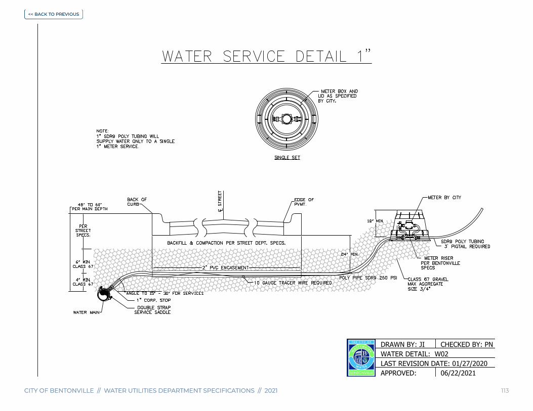
CITY OF BENTONVILLE // WATER UTILITIES DEPARTMENT SPECIFICATIONS // 2021CITY OF BENTONVILLE // WATER UTILITIES DEPARTMENT SPECIFICATIONS // 2021 113
DRAWN BY: JI
LAST REVISION DATE: 01/27/2020WATER DETAIL: W02
CHECKED BY: PN
06/22/2021APPROVED:

CITY OF BENTONVILLE // WATER UTILITIES DEPARTMENT SPECIFICATIONS // 2021CITY OF BENTONVILLE // WATER UTILITIES DEPARTMENT SPECIFICATIONS // 2021 114
DRAWN BY: JIWATER DETAIL: W03
CHECKED BY: PN
LAST REVISION DATE: 01/27/202006/22/2021APPROVED:

CITY OF BENTONVILLE // WATER UTILITIES DEPARTMENT SPECIFICATIONS // 2021CITY OF BENTONVILLE // WATER UTILITIES DEPARTMENT SPECIFICATIONS // 2021 115
DRAWN BY: JIWATER DETAIL: W04
CHECKED BY: PN
LAST REVISION DATE: 03/16/202106/22/2021APPROVED:

CITY OF BENTONVILLE // WATER UTILITIES DEPARTMENT SPECIFICATIONS // 2021CITY OF BENTONVILLE // WATER UTILITIES DEPARTMENT SPECIFICATIONS // 2021 116
BURY
DRAWN BY: JIWATER DETAIL: W05
CHECKED BY: PN
LAST REVISION DATE: 03/16/202106/22/2021APPROVED:

CITY OF BENTONVILLE // WATER UTILITIES DEPARTMENT SPECIFICATIONS // 2021CITY OF BENTONVILLE // WATER UTILITIES DEPARTMENT SPECIFICATIONS // 2021 117
BURY
DRAWN BY: JIWATER DETAIL: W06
CHECKED BY: PN
LAST REVISION DATE: 03/16/202106/22/2021APPROVED:

CITY OF BENTONVILLE // WATER UTILITIES DEPARTMENT SPECIFICATIONS // 2021CITY OF BENTONVILLE // WATER UTILITIES DEPARTMENT SPECIFICATIONS // 2021 118
DRAWN BY: JIWATER DETAIL: W07
CHECKED BY: PN
LAST REVISION DATE: 01/27/202006/22/2021APPROVED:
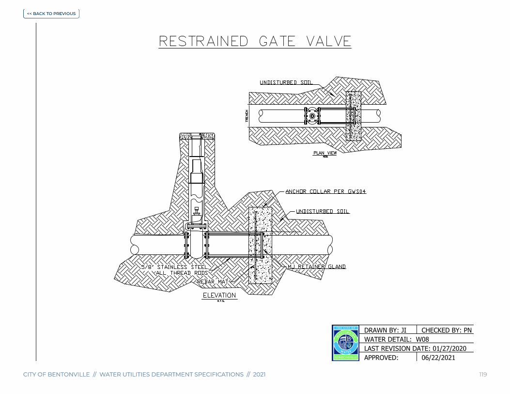
CITY OF BENTONVILLE // WATER UTILITIES DEPARTMENT SPECIFICATIONS // 2021CITY OF BENTONVILLE // WATER UTILITIES DEPARTMENT SPECIFICATIONS // 2021 119
DRAWN BY: JIWATER DETAIL: W08
CHECKED BY: PN
LAST REVISION DATE: 01/27/202006/22/2021APPROVED:

CITY OF BENTONVILLE // WATER UTILITIES DEPARTMENT SPECIFICATIONS // 2021CITY OF BENTONVILLE // WATER UTILITIES DEPARTMENT SPECIFICATIONS // 2021 120
DRAWN BY: JIWATER DETAIL: W09
CHECKED BY: PN
LAST REVISION DATE: 01/27/202006/22/2021APPROVED:

CITY OF BENTONVILLE // WATER UTILITIES DEPARTMENT SPECIFICATIONS // 2021CITY OF BENTONVILLE // WATER UTILITIES DEPARTMENT SPECIFICATIONS // 2021 121
DRAWN BY: JIWATER DETAIL: W10
CHECKED BY: PN
LAST REVISION DATE: 01/27/202006/22/2021APPROVED:

CITY OF BENTONVILLE // WATER UTILITIES DEPARTMENT SPECIFICATIONS // 2021CITY OF BENTONVILLE // WATER UTILITIES DEPARTMENT SPECIFICATIONS // 2021 122
WATER DETAIL: W11CHECKED BY: PN
LAST REVISION DATE: 01/27/2020
DRAWN BY: JI
06/22/2021APPROVED:

CITY OF BENTONVILLE // WATER UTILITIES DEPARTMENT SPECIFICATIONS // 2021CITY OF BENTONVILLE // WATER UTILITIES DEPARTMENT SPECIFICATIONS // 2021 123
WATER DETAIL: W12CHECKED BY: PN
LAST REVISION DATE: 01/27/2020
DRAWN BY: JI
06/22/2021APPROVED:
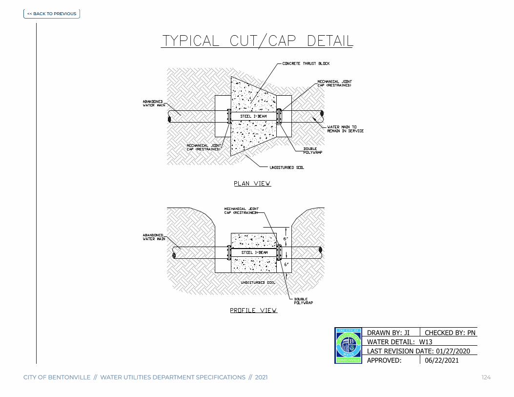
CITY OF BENTONVILLE // WATER UTILITIES DEPARTMENT SPECIFICATIONS // 2021CITY OF BENTONVILLE // WATER UTILITIES DEPARTMENT SPECIFICATIONS // 2021 124
WATER DETAIL: W13CHECKED BY: PN
LAST REVISION DATE: 01/27/2020
DRAWN BY: JI
06/22/2021APPROVED:

CITY OF BENTONVILLE // WATER UTILITIES DEPARTMENT SPECIFICATIONS // 2021CITY OF BENTONVILLE // WATER UTILITIES DEPARTMENT SPECIFICATIONS // 2021 125
WATER DETAIL: W14CHECKED BY: PN
LAST REVISION DATE: 03/16/2021
DRAWN BY: JI
06/22/2021APPROVED:
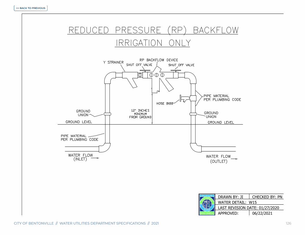
CITY OF BENTONVILLE // WATER UTILITIES DEPARTMENT SPECIFICATIONS // 2021CITY OF BENTONVILLE // WATER UTILITIES DEPARTMENT SPECIFICATIONS // 2021 126
WATER DETAIL: W15CHECKED BY: PN
LAST REVISION DATE: 01/27/2020
DRAWN BY: JI
06/22/2021APPROVED:
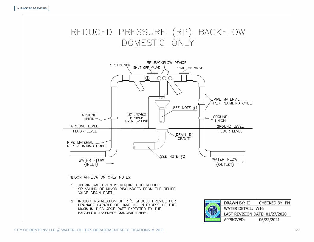
CITY OF BENTONVILLE // WATER UTILITIES DEPARTMENT SPECIFICATIONS // 2021CITY OF BENTONVILLE // WATER UTILITIES DEPARTMENT SPECIFICATIONS // 2021 127
WATER DETAIL: W16CHECKED BY: PN
LAST REVISION DATE: 01/27/2020
DRAWN BY: JI
06/22/2021APPROVED:

CITY OF BENTONVILLE // WATER UTILITIES DEPARTMENT SPECIFICATIONS // 2021 128CITY OF BENTONVILLE // WATER UTILITIES DEPARTMENT SPECIFICATIONS // 2021 128
CENTERLINES OFPIPES ENTERINGAND EXITINGMANHOLES AREREQUIRED TO PASSTHROUGH THECENTER OF THEMANHOLE.
PROVIDE AS LARGE ACURVE AS POSSIBLE IN
THE FLOW CHANNEL.
MANHOLEFLOW CHANNEL
· CAST IN PLACE MANHOLE REQUIRES A CONCRETE MH
ADAPTER (CMA) OR APPROVED EQUAL WHERE
PIPES PASS THROUGH MANHOLE WALLS.
(REQUIRED)· INSTALL PERMANUFACTURERS
INSTRUCTIONS.
CONCRETEMANHOLEADAPTER(CMA) ISREQUIRED.
FL
CAST INPLACECONCRETEMANHOLEWALL.
CONCRETE MANHOLEADAPTER (CMA)
DETAIL
SEWER PIPE
FLOW CHANNEL.
24" VERTICALMAX.
DIFFERENCEFL IN & FL OUT
FRAME TO BE EMBEDDED IN CONCRETEAT THE TIME OF CONSTRUCTION
6" MIN. WALL THICKNESS(4,000 PSI CONCRETE)
CONCRETE MHADAPTER(REQUIRED).
STANDARD MH RING& COVER (REQUIRED).
Varies
FRAME SHALL BE INSTALLED ATTHE TIME THE MANHOLEIS CONSTRUCTED (TYP).
4' DIA
5' DIA
6' DIA
6"
8"
8"
24"(< or Equal to 24" Pipes)
36"(> 24" Pipes)
8"
10"
12"
InsideDiameter
of Manhole
MinimumWall
Thickness
MinimumRing & Cover
SizeBase
Thickness
MANHOLE INFORMATION TABLE
SELECTBACKFILL
UNYIELDING SUBGRADE(REPLACE WITH STONE
AS REQUIRED)
12" MAX.
24" MIN.30" MAX.
VARIES
6" MIN.
BENCH
NOTE:
BENCH SHALL SLOPE FROMSPRINGLINE OF PIPE TO MANHOLEWALL. OUTLET CHANNEL SHALLBE FULL DEPTH "U" FROM CENTEROF MANHOLE TO WALL.
MH BASE(TABLE ABOVE)
SEWER PIPE
SEWER PIPE
BRUSH FINISH SURFACES TOREMOVE ALL SHARP EDGES
NO STEPS ALLOWED
SANITARY SEWER DETAIL: SS01CHECKED BY: PN
LAST REVISION DATE: 01/27/2020
DRAWN BY: JI
APPROVED: 06/22/2021

CITY OF BENTONVILLE // WATER UTILITIES DEPARTMENT SPECIFICATIONS // 2021 129CITY OF BENTONVILLE // WATER UTILITIES DEPARTMENT SPECIFICATIONS // 2021 129
SANITARY SEWER DETAIL: SS02CHECKED BY: PN
LAST REVISION DATE: 01/27/2020
DRAWN BY: JI
APPROVED: 06/22/2021

CITY OF BENTONVILLE // WATER UTILITIES DEPARTMENT SPECIFICATIONS // 2021 130CITY OF BENTONVILLE // WATER UTILITIES DEPARTMENT SPECIFICATIONS // 2021 130
WYE(45°)
CONCRETE MANHOLEADAPTER (REQUIRED)
GRADE
STANDARD MH RING & COVER.
GREATERTHAN 24"
UNDISTURBED EARTH
THE CONNECTIONS TO EXISTING MANHOLES ARE TO BE CORE-DRILLED WITH THE USE OF A WATER-STOP AND NON-SHRINK GROUT.
45° BEND
4" MIN. ABOVEFINISHED GRADE
4" MIN.6" MAX.
CUT PIPE @ SPRINGLINE COMPACTEDCLASS 67 BACKFILLMAX AGGREGATESIZE 3/4"
CONCRETE MANHOLE ADAPTER (REQUIRED)
SANITARY SEWER DETAIL: SS03CHECKED BY: PN
LAST REVISION DATE: 01/27/2020
DRAWN BY: JI
APPROVED: 06/22/2021
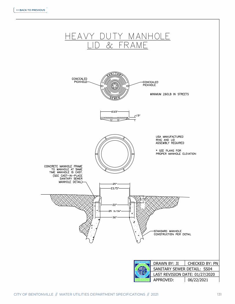
CITY OF BENTONVILLE // WATER UTILITIES DEPARTMENT SPECIFICATIONS // 2021 131CITY OF BENTONVILLE // WATER UTILITIES DEPARTMENT SPECIFICATIONS // 2021 131
SANITARY SEWER DETAIL: SS04CHECKED BY: PN
LAST REVISION DATE: 01/27/2020
DRAWN BY: JI
APPROVED: 06/22/2021

CITY OF BENTONVILLE // WATER UTILITIES DEPARTMENT SPECIFICATIONS // 2021 132CITY OF BENTONVILLE // WATER UTILITIES DEPARTMENT SPECIFICATIONS // 2021 132
SANITARY SEWER DETAIL: SS05CHECKED BY: PN
LAST REVISION DATE: 01/27/2020
DRAWN BY: JI
APPROVED: 06/22/2021

CITY OF BENTONVILLE // WATER UTILITIES DEPARTMENT SPECIFICATIONS // 2021CITY OF BENTONVILLE // WATER UTILITIES DEPARTMENT SPECIFICATIONS // 2021 133
SANITARY SEWER DETAIL: SS06CHECKED BY: PN
LAST REVISION DATE: 01/27/2020
DRAWN BY: JI
APPROVED: 06/22/2021

CITY OF BENTONVILLE // WATER UTILITIES DEPARTMENT SPECIFICATIONS // 2021 134CITY OF BENTONVILLE // WATER UTILITIES DEPARTMENT SPECIFICATIONS // 2021 134
REMOVE MH RING & COVER,CONE AND/OR BARREL TO AMIN. OF 2'-0" BELOW EXISTINGGRADE ELEVATION.
CLASS 67 GRAVEL ONLYMAX AGGREGATE SIZE 3/4"(NO SAND)
GRADE
PLUG LINESCONSTRUCT CONCRETE PLUG FROMINSIDE OF THE EXISTING MANHOLE.FILL BOTTOM OF MANHOLE WITH 4,000 PSICONCRETE TO 6" ABOVE THE CROWNOF ALL PIPES.NO EXCAVATION IS REQUIRED.
ABANDONEDSS
ABANDONEDSS
ABANDONEDSS
CLASS 67 GRAVEL ONLY.MAX AGGREGATE SIZE 3/4"(NO SAND)
ABANDONEDSS
GRADE GRADE
SANITARY SEWER DETAIL: SS07CHECKED BY: PN
LAST REVISION DATE: 01/27/2020
DRAWN BY: JI
APPROVED: 06/22/2021
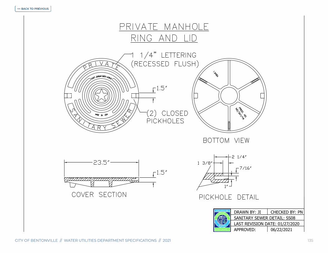
CITY OF BENTONVILLE // WATER UTILITIES DEPARTMENT SPECIFICATIONS // 2021CITY OF BENTONVILLE // WATER UTILITIES DEPARTMENT SPECIFICATIONS // 2021 135
SANITARY SEWER DETAIL: SS08CHECKED BY: PN
LAST REVISION DATE: 01/27/2020
DRAWN BY: JI
APPROVED: 06/22/2021

CITY OF BENTONVILLE // WATER UTILITIES DEPARTMENT SPECIFICATIONS // 2021 136CITY OF BENTONVILLE // WATER UTILITIES DEPARTMENT SPECIFICATIONS // 2021 136
BACKFILL NOTES:
IN STREET:· PER STREET STD. FOR BACKFILLIN OTHER AREAS:· USE SELECT NATIVE BACKFILL
REMOVEEXISTING
CONE
ADJUST BARREL WITHNEW CONE:
TO FINISH GRADEELEVATION
NEWGROUNDELEVATION
EXISTINGGRADE
EXISTINGMANHOLE
VARIES WITH MANHOLE ADJUSTMENT DEPTH
3" X 3" CONSTRUCTIONJOINT / KEYHOLE WITH
24" #4 REBAR ON 12" CENTER
STANDARD MHRING & COVER(REQUIRED).
SANITARY SEWER DETAIL: SS09CHECKED BY: PN
LAST REVISION DATE: 01/27/2020
DRAWN BY: JI
APPROVED: 06/22/2021

CITY OF BENTONVILLE // WATER UTILITIES DEPARTMENT SPECIFICATIONS // 2021 137CITY OF BENTONVILLE // WATER UTILITIES DEPARTMENT SPECIFICATIONS // 2021 137
LIFT STATION DETAIL: LS01CHECKED BY: PN
LAST REVISION DATE: 01/27/2020
DRAWN BY: JI
APPROVED: 06/22/2021

CITY OF BENTONVILLE // WATER UTILITIES DEPARTMENT SPECIFICATIONS // 2021 138CITY OF BENTONVILLE // WATER UTILITIES DEPARTMENT SPECIFICATIONS // 2021 138
LIFT STATION DETAIL: LS02CHECKED BY: PN
LAST REVISION DATE: 01/27/2020
DRAWN BY: JI
APPROVED: 06/22/2021

CITY OF BENTONVILLE // WATER UTILITIES DEPARTMENT SPECIFICATIONS // 2021 139CITY OF BENTONVILLE // WATER UTILITIES DEPARTMENT SPECIFICATIONS // 2021 139
LIFT STATION DETAIL: LS03CHECKED BY: PN
LAST REVISION DATE: 01/27/2020
DRAWN BY: JI
APPROVED: 06/22/2021

CITY OF BENTONVILLE // WATER UTILITIES DEPARTMENT SPECIFICATIONS // 2021CITY OF BENTONVILLE // WATER UTILITIES DEPARTMENT SPECIFICATIONS // 2021 140
LIFT STATION DETAIL: LS04CHECKED BY: PN
LAST REVISION DATE: 01/27/2020
DRAWN BY: JI
APPROVED: 06/22/2021

CITY OF BENTONVILLE // WATER UTILITIES DEPARTMENT SPECIFICATIONS // 2021CITY OF BENTONVILLE // WATER UTILITIES DEPARTMENT SPECIFICATIONS // 2021 141
LIFT STATION DETAIL: LS05CHECKED BY: PN
LAST REVISION DATE: 01/27/2020
DRAWN BY: JI
APPROVED: 06/22/2021
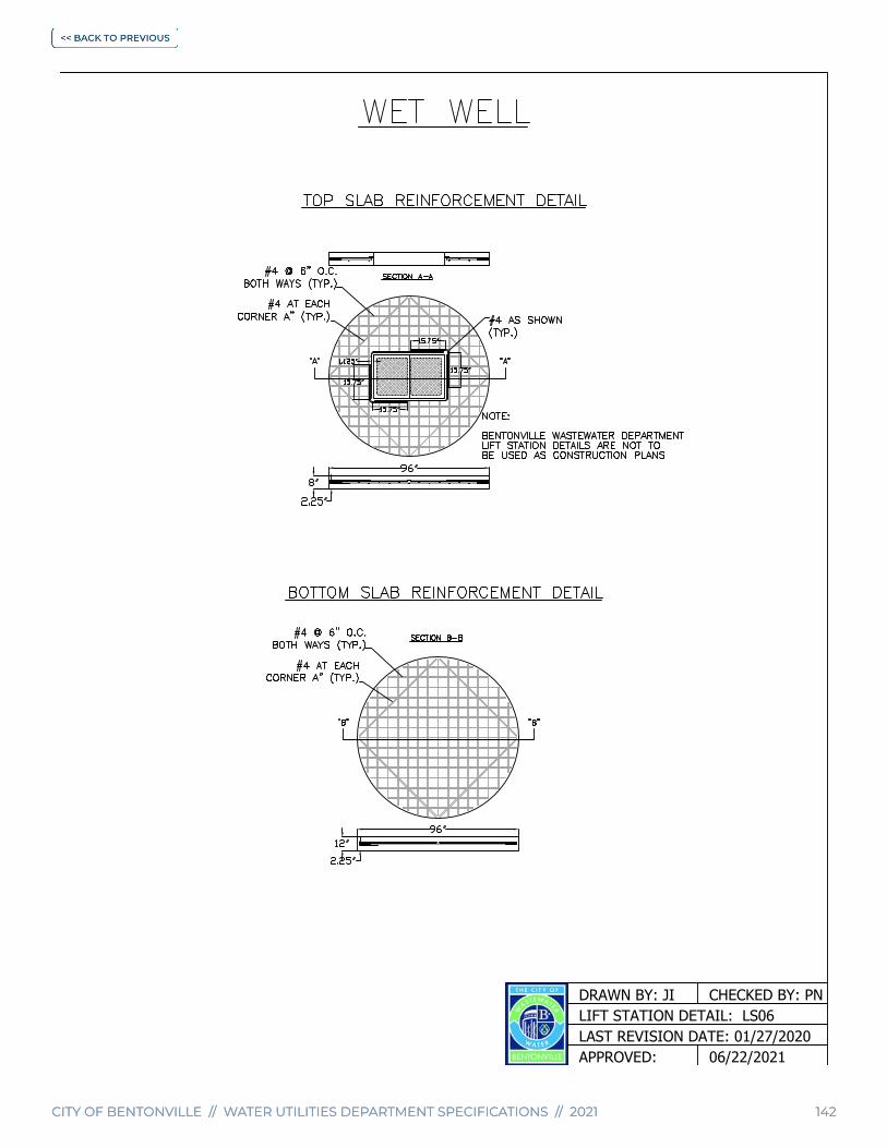
CITY OF BENTONVILLE // WATER UTILITIES DEPARTMENT SPECIFICATIONS // 2021 142CITY OF BENTONVILLE // WATER UTILITIES DEPARTMENT SPECIFICATIONS // 2021 142
LIFT STATION DETAIL: LS06CHECKED BY: PN
LAST REVISION DATE: 01/27/2020
DRAWN BY: JI
APPROVED: 06/22/2021

CITY OF BENTONVILLE // WATER UTILITIES DEPARTMENT SPECIFICATIONS // 2021CITY OF BENTONVILLE // WATER UTILITIES DEPARTMENT SPECIFICATIONS // 2021 143
LIFT STATION DETAIL: LS07CHECKED BY: PN
LAST REVISION DATE: 01/27/2020
DRAWN BY: JI
APPROVED: 06/22/2021

CITY OF BENTONVILLE // WATER UTILITIES DEPARTMENT SPECIFICATIONS // 2021 144CITY OF BENTONVILLE // WATER UTILITIES DEPARTMENT SPECIFICATIONS // 2021 144
LIFT STATION DETAIL: LS08CHECKED BY: PN
LAST REVISION DATE: 01/27/2020
DRAWN BY: JI
APPROVED: 06/22/2021

CITY OF BENTONVILLE // WATER UTILITIES DEPARTMENT SPECIFICATIONS // 2021 145CITY OF BENTONVILLE // WATER UTILITIES DEPARTMENT SPECIFICATIONS // 2021 145
LIFT STATION DETAIL: LS09CHECKED BY: PN
LAST REVISION DATE: 01/27/2020
DRAWN BY: JI
APPROVED: 06/22/2021

CITY OF BENTONVILLE // WATER UTILITIES DEPARTMENT SPECIFICATIONS // 2021CITY OF BENTONVILLE // WATER UTILITIES DEPARTMENT SPECIFICATIONS // 2021 146
LIFT STATION DETAIL: LS10CHECKED BY: PN
LAST REVISION DATE: 01/27/2020
DRAWN BY: JI
APPROVED: 06/22/2021
2021 WATER UTILITIES DEPARTMENT SPECIFICATIONS
City of Bentonville
Water Utilities Department (479) 271-3140
Wastewater Treatment (479) 271-3160
Fire Department (479) 271-3151
Council Approved - June 22, 2021 | Ordinance - 2021-135
Approved by Arkansas Department of Health - April 1, 2021
www.bentonvillear.com
Related Documents


