City of Grass Valley Section 4 Construction Standards Water Supply System REV CST 02/14 W 1 OF 16 SECTION 4 WATER SUPPLY SYSTEM (W) 4-1. GENERAL - All potable water pipe, fittings, valves, fire hydrants, blow-offs and other appurtenances shall be installed in accordance with the approved improvement plans, these Construction Standards, the American Water Works Association (AWWA), the latest edition of Caltrans Standard Specifications and Standard Plans, as recommended by the manufacturer and as specified by the City Engineer. These Construction Standards and the manufacturer's guidelines shall be present at the construction site at all times. 4-2. CONNECTION TO EXISTING FACILITIES - Connection to existing City water facilities may be made with approval of the Public Works Department and in conformance with the following: A. System Tap - The Public Works Department shall make all systems tap up to 2” in diameter, as required on the plans unless otherwise approved by the City Engineer. The Contractor shall pay for such work on a time and materials reimbursement basis. The Contractor shall be responsible for the following tasks associated with the tap as determined by the Public Works Department: 1. Coordinating the work requested with the Public Works Inspector. This shall include discussions on provisions for materials and equipment required to complete the work. 2. Providing traffic control per the City's Public Works Department requirements. 3. Excavating the work area, as agreed upon by the Public Works Inspector. 4. Providing sheeting, shoring, and bracing as required. 5. Provide lighting as required if the tap is to be performed at night. 6. Backfilling, compacting, and pavement restoration of the excavation(s) upon tap completion. B. System Tie-In - The Contractor shall tie-in the new system to an existing stub under the following conditions: 1. With specific approval of the Public Works Inspector. 2. Care shall be taken to provide a clean, sanitary tie-in site. 3. Dewatering of both the new and existing water mains shall take place in a way as to prevent contamination by trench water. 4. All material used in the tie-in shall be clean and swabbed with chlorine to the satisfaction of the Public Works Inspector. 5. All tie-ins shall take place in the presence of the Public Works Inspector. 6. Tie-ins may take place only after the newly constructed water system has successfully passed all required testing procedures as established in these Construction Standards and as determined by the Public Works Inspector.

Welcome message from author
This document is posted to help you gain knowledge. Please leave a comment to let me know what you think about it! Share it to your friends and learn new things together.
Transcript
City of Grass Valley Section 4
Construction Standards Water Supply System
REV CST
02/14 W 1 OF 16
SECTION 4
WATER SUPPLY SYSTEM (W) 4-1. GENERAL - All potable water pipe, fittings, valves, fire hydrants, blow-offs and other appurtenances
shall be installed in accordance with the approved improvement plans, these Construction Standards, the
American Water Works Association (AWWA), the latest edition of Caltrans Standard Specifications and
Standard Plans, as recommended by the manufacturer and as specified by the City Engineer. These
Construction Standards and the manufacturer's guidelines shall be present at the construction site at all
times.
4-2. CONNECTION TO EXISTING FACILITIES - Connection to existing City water facilities may be
made with approval of the Public Works Department and in conformance with the following:
A. System Tap - The Public Works Department shall make all systems tap up to 2” in diameter, as
required on the plans unless otherwise approved by the City Engineer. The Contractor shall pay for
such work on a time and materials reimbursement basis. The Contractor shall be responsible for the
following tasks associated with the tap as determined by the Public Works Department:
1. Coordinating the work requested with the Public Works Inspector. This shall include discussions
on provisions for materials and equipment required to complete the work.
2. Providing traffic control per the City's Public Works Department requirements.
3. Excavating the work area, as agreed upon by the Public Works Inspector.
4. Providing sheeting, shoring, and bracing as required.
5. Provide lighting as required if the tap is to be performed at night.
6. Backfilling, compacting, and pavement restoration of the excavation(s) upon tap completion.
B. System Tie-In - The Contractor shall tie-in the new system to an existing stub under the following
conditions:
1. With specific approval of the Public Works Inspector.
2. Care shall be taken to provide a clean, sanitary tie-in site.
3. Dewatering of both the new and existing water mains shall take place in a way as to prevent
contamination by trench water.
4. All material used in the tie-in shall be clean and swabbed with chlorine to the satisfaction of the
Public Works Inspector.
5. All tie-ins shall take place in the presence of the Public Works Inspector.
6. Tie-ins may take place only after the newly constructed water system has successfully passed all
required testing procedures as established in these Construction Standards and as determined by
the Public Works Inspector.
City of Grass Valley Section 4
Construction Standards Water Supply System
REV CST
02/14 W 2 OF 16
7. Under no circumstances shall anyone other than a representative of the Public Works Department
open or close valves in a City-operated system.
4-3. CONSTRUCTION STAKING - The water main shall be staked prior to excavation. Staking shall
provide the station and the offset to the water main, as well as the cut to the nearest one-tenth foot (0.1’).
Stakes shall be provided at a minimum of every fifty (50) feet in tangent sections, every twenty-five (25)
feet in curved sections, and every ten (10) feet in approved vertical curve sections.
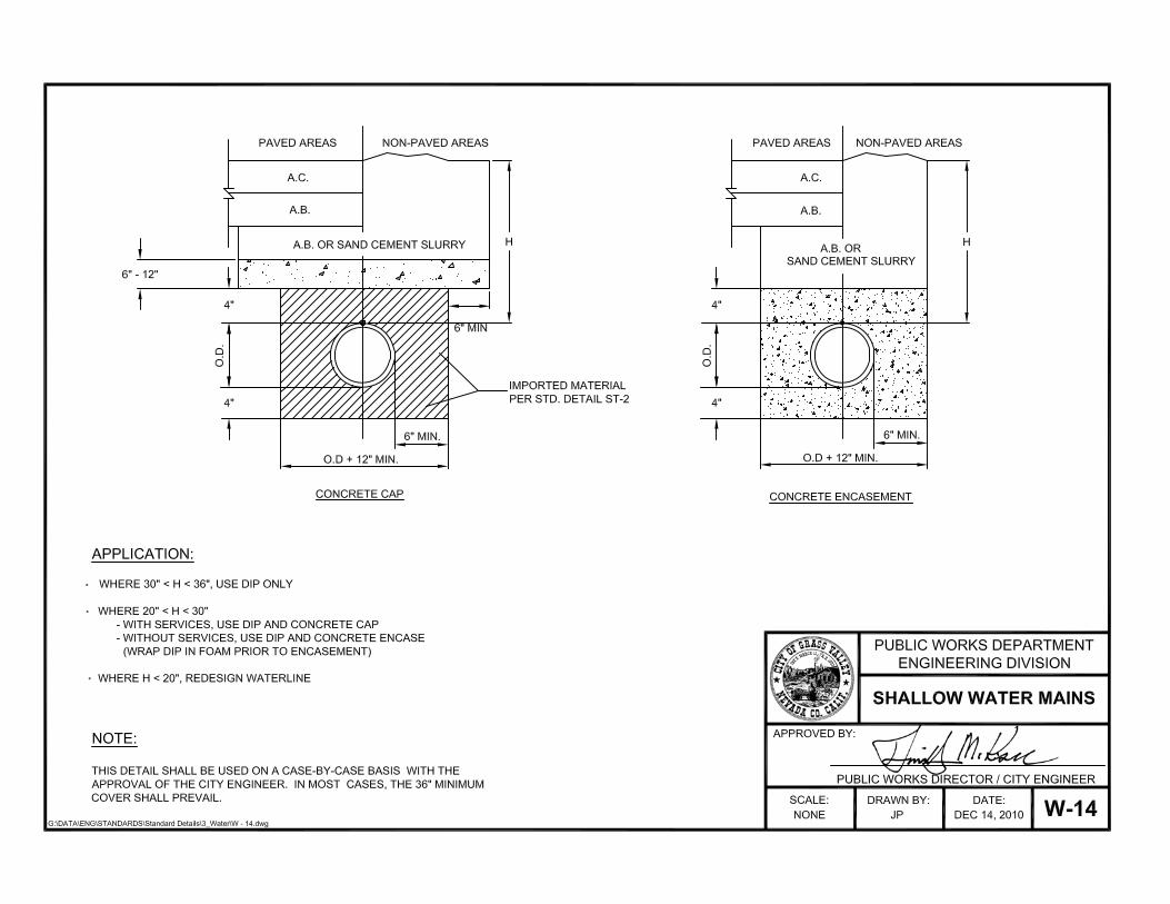
4-4. CONCRETE CRADLES, ARCHES & ENCASEMENTS - Concrete cradles, arches and encasements
shall conform to the “Shallow Water Mains” and “Special Concrete Encasement” details and the
following:
A. Placement - The pipe shall be placed in proper position on temporary cradles or arches consisting of
concrete block or bricks. When necessary, the pipe shall be rigidly anchored or weighted to prevent
flotation when the concrete is placed.
B. Installation - Cradles and arches shall be constructed with an ability to adjust the pipe to proper
grade in order to avoid vertical joint pull. Cradles and arches shall be placed at the one-third and half-
way points along each pipe segment where specified. Concrete placed beneath the pipe shall be
sufficiently workable to fill the voids without excessive vibration. The concrete shall be allowed to
cure and remain undisturbed for a minimum of 24 hours prior to backfill and compaction of the
trench. Water shall not be permitted to enter, seep or run onto the concrete while curing.
4-5. TRENCHING AND BACKFILL - Construction of water pipes and appurtenances shall be performed to
the lines and grades shown on the approved project plans, as specified in the “Streets” section of these
Construction Standards and in conformance with the following requirements:
A. Excavations - Pipeline excavations shall be open-cut trenches, unless otherwise specified on the
approved improvement plans, with vertical sides to the pipe crown as specified on the “Utility Trench
Bedding, Backfill and Paving” detail. Excavations shall conform to all applicable Federal and State
safety requirements. All work shall be conducted in such a manner as to prevent damage to new and
existing facilities or adjoining property.
B. Bell Holes - Bell holes shall be excavated per manufacturer's recommendations. The minimum depth
of bedding material shall be provided under the bell. Care shall be taken to ensure that the bell hole is
no larger than necessary to accomplish proper joint assembly.
C. Pipe Support - Pipes shall be placed on a firm bed of imported granular material conforming to the
“Utility Trench Bedding, Backfill and Paving” detail. Bedding shall provide uniform and continuous
support along the barrel of the pipe. The minimum depth of bedding material shall be provided under
the bell. Blocking of the pipe is not permitted. Loose material shall be removed from the trench
bottom and replaced with imported material.
D. Trench Backfill and Compaction - Initial backfill material shall be placed immediately after pipe
joints have been completed, inspected and passed by the Public Works Inspector. The material shall
be carefully placed, consolidated around the pipe zone and shall be brought up evenly on both sides.
Sufficient care shall be taken to prevent movement or damage to the pipe during shovel slicing.
Shovel slicing shall be witnessed by the Public Works Inspector prior to shading the pipe.
Trench backfill shall be placed and compacted in accordance with the “Streets” section of these
Construction Standards. Slurry or concrete caps shall only be used if deemed necessary by the City
Engineer. Compaction equipment shall not make direct contact with the pipe.
City of Grass Valley Section 4
Construction Standards Water Supply System
REV CST
05/16 W 3 OF 16
4-6. PIPE INSTALLATION - Water pipe shall be installed in accordance with the following provisions:
A. Storage of Pipe - The Contractor shall keep the pipe interior free from foreign materials and in a
clean and sanitary condition until acceptance by the City. At times when pipe-laying is not in
progress, the open pipe end shall be sealed with a tight cap or plug to prevent foreign matter from
entering the pipe. Provisions shall apply to the noon-hour as well as overnight.
B. Pipe Placement - Care shall be taken when lowering pipe into the trench to protect the pipe from
damage. Chains are not permitted. The pipe shall be laid carefully to the lines and grades shown
without grade breaks, unless designed with such, or to minimum depths shown on the approved plans.
If field conditions exist such that the pipe may not be laid to the specified grade, the approved plans
will require revisions prior to proceeding with construction.
C. Joints - Pipe sections shall be closely jointed to form a smooth flowline. Care shall be taken in
placing the pipe and making field joints.
D. Manufacturer's Recommendations - All installations shall follow manufacturer's recommendations
unless otherwise noted on the approved plans. The manufacturer’s installation guide shall be on the
job site at all times.
E. Mechanical Restraint - Pipes shall be mechanically restrained to the length specified in the approved
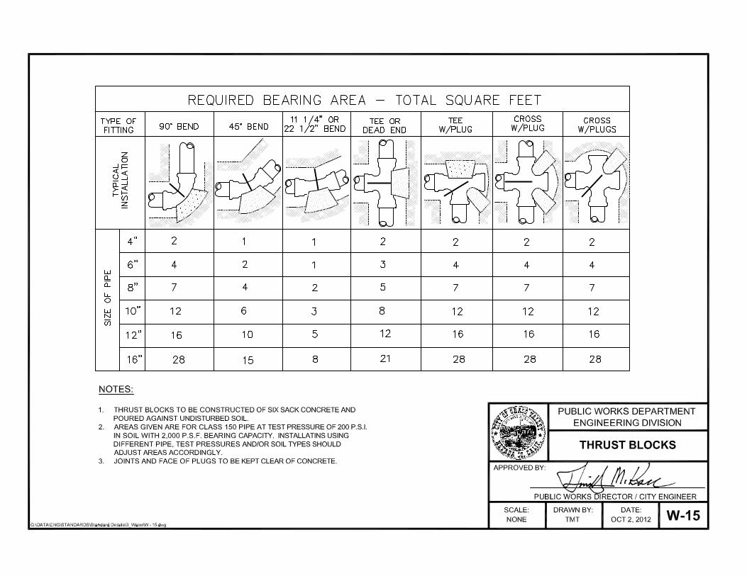
plans, using materials specified herein. Thrust Blocks - Thrust blocks shall only be used where
specifically shown on the plan/profile sheets and as required by AWWA standards. All fittings and
appurtenances shall maintain a minimum of 18 feet of restrained pipe into the fitting from all
directions.
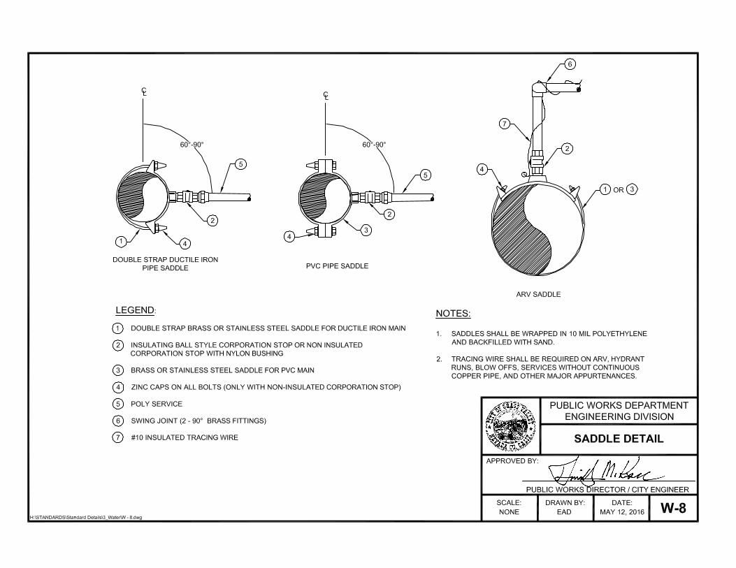
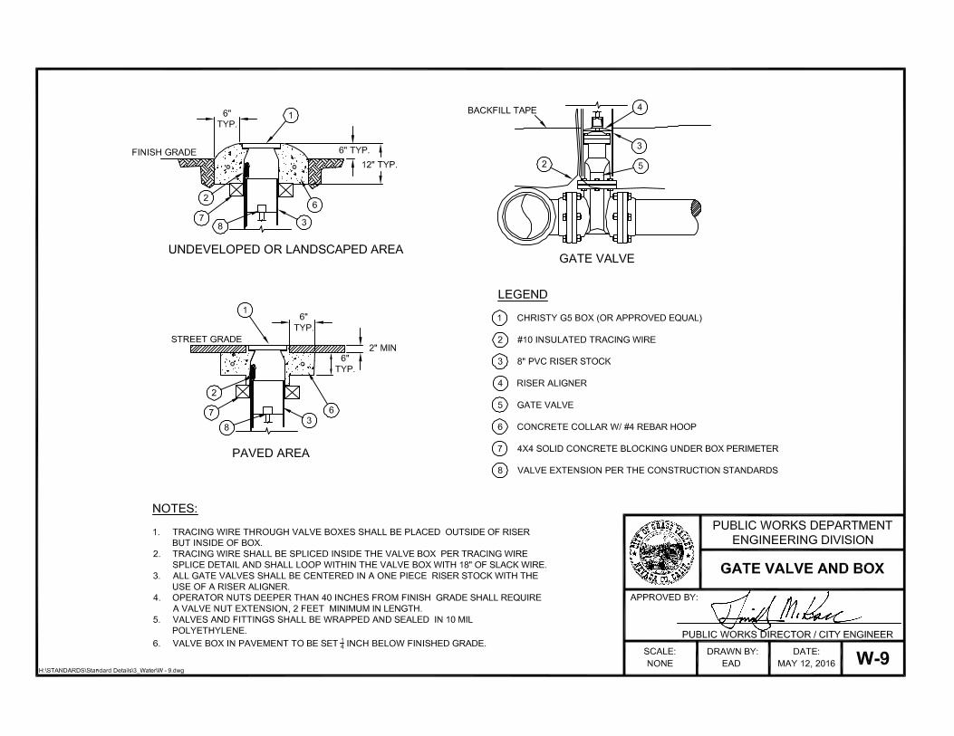
F. Tracing Wire - A continuous 10 gauge solid insulated tracing wire shall be attached to mains, service
lines and appurtenances per the Construction Standard Details and the following:
1. Tracing wire shall be continuous between mainline valve boxes and fire hydrants. It shall be
attached to the top of the pipe with 10-mil vinyl tape every 5 feet.
2. Tracing wires through valve boxes shall be placed outside of riser, but inside the box.
3. Tracing wire in manholes and vaults shall be attached inside the facility within one foot of the
rim.
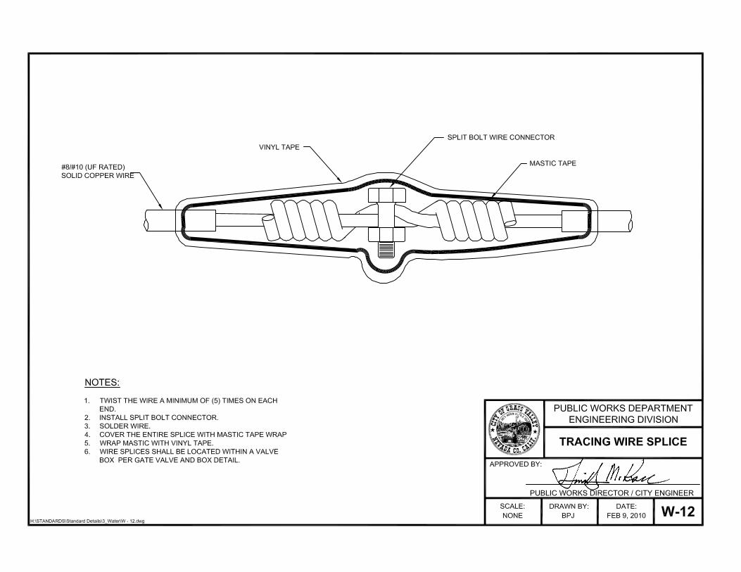
4. Wire splices shall be located above ground, when possible, and inside of valve boxes and
completed per the Standard Details and as follows:
a. Twist the wire together with a minimum of 5 twists.
b. Install a copper split bolt connector on the splice.
c. Solder all connections.
d. Cover the splice with mastic tape and wrap with vinyl tape.
G. Marking Tape - A 4.0 to 5.0 mil, 3 to 4 inch wide, blue plastic non-detectable water pipe marking
tape, marked "Caution Buried Water Line Below" or equivalent shall be placed in all main line
trenches, 12 to 24 inches from the surface.
City of Grass Valley Section 4
Construction Standards Water Supply System
REV CST
02/14 W 4 OF 16
H. Marking Pipe in Unpaved Areas - Mains in unpaved areas shall be marked every 150 lineal feet
with a blue composite utility marker having a decal stating: "Caution Water Pipeline." Appurtenances
(valves, ARV's, test stations, etc.) and angle points shall also be marked. Mains in landscaped areas
shall be delineated with a brass marker set in an 8-inch concrete cylinder 4 inches above finished
grade. The brass marker shall state “City of Grass Valley Water Main.”
I. Protection of Underground Metal - All underground metal (ductile iron, valves, fittings, copper,
brass, etc.) shall be wrapped in 8-mils minimum thickness polyethylene encasement, per AWWA
standards, with ends taped off with vinyl pipe wrap tape.
J. Polyvinyl Chloride (PVC) Pressure Pipe Installation - PVC shall be installed in accordance with
the AWWA Manual M23 and the manufacturer's recommendations, except as otherwise provided
herein:
1. PVC Pipe shall have been manufactured within the 18-month period prior to installation.
2. Pipe and gaskets shall be kept clean and protected against sunlight and heat damage.
3. Pipe showing signs of physical damage or excessive ultraviolet exposure will be rejected and
shall be immediately removed from the job site.
4. The pipe shall be installed with the manufacturing label showing on the top.
5. The reference mark or stab line on the spigot end must be flush with the bell end and visible for
inspection.
6. The beveled end of the pipe shall be cut off before placement into a mechanical joint.
7. Minimum length of pipe for installation shall be five (5) feet.
K. Ductile Iron Pipe (DIP) - DIP shall be installed in accordance with the standards for "Installation of
Ductile Iron Water Mains and Their Appurtenances" (ANSI/AWWA C-600) and the manufacturer's
recommendations, and as provided herein:
1. DIP shall be polyethylene-encased in accordance with these Construction Standards and the
standard for "Polyethylene Encasement for Ductile-Iron Piping for Water and Other Liquids"
(ANSI/AWWA C-105/A21.5).
2. At the direction of the Public Works Inspector, the Contractor shall repair damages to the
polyethylene encasement as described within ANSI/AWWA C-105/A21.5 or shall replace all
damaged polyethylene film sections.
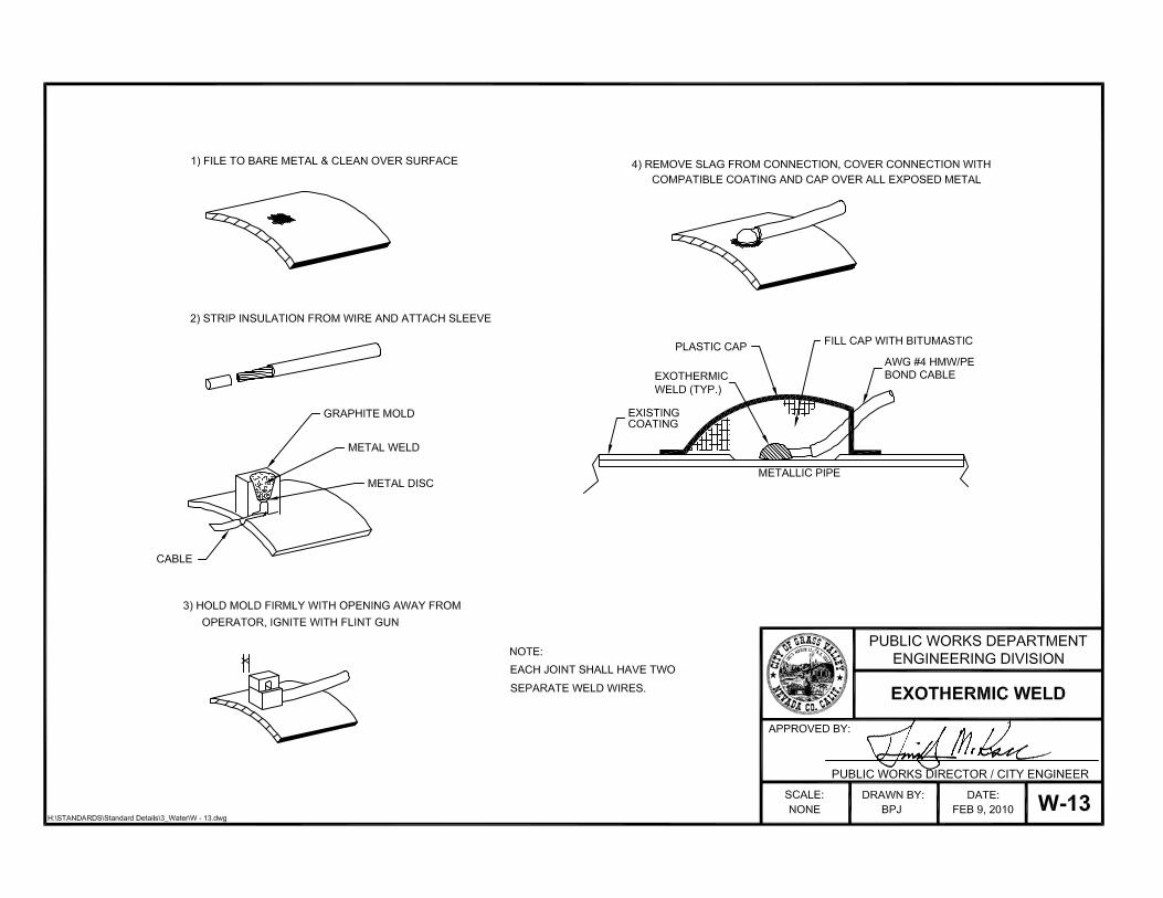
3. Metallic lines shall be exothermically welded and electrically continuous on DIP runs exceeding
100 feet or as approved by the City Engineer. Exothermic welds shall be installed per the
Construction Standard Detail for “Exothermic Weld”, and as follows:
a. Weld only against bare metal on both the bell and spigot ends of pipe.
b. Care must be taken not to remove excess metal when removing the pipe coating.
City of Grass Valley Section 4
Construction Standards Water Supply System
REV CST
02/14 W 5 OF 16
c. After a solid weld is made, coat the bare metal with an acceptable bituminous coating
material and cover with a plastic protective cap or approved equal.
d. DO NOT weld onto valves.
4. Corrosion test stations shall be installed on metallic lines at intervals not to exceed 1,000 lineal
feet or as specified on the approved plans.
5. DIP cuts shall be coated with an approved bituminous material.
6. Minimum length of pipe for installation shall be two (2) feet.
L. Ductile Iron Pipe Fittings - In addition to requirements set by these standards, fittings shall be
constructed per the following requirements. Mechanical joint fitting bolt threads and nut shall be
coated with an approved bituminous material. Flanged bolt heads and threads shall be coated with an
approved material.
M. Transitions Between DIP and PVC - Transitions between DIP and PVC shall be made as follows:
1. A PVC pipe spigot may be inserted into a DIP bell by cutting off the PVC bevel on the spigot,
and leaving no more than a ½-inch taper. A Public Works Inspector shall be present to witness
this process.
2. Transitions may be made by the use of a DIP repair sleeve.
N. Boring of Water Lines - Borings for installation of water lines shall be made as follows:
1. The equipment, method and sequence of operation and conductor pipe grades shall be approved
by the Public Works Inspector. A minimum of 48 hours notice shall be given prior to the start of
work.
2. Excavation for the boring operation shall be the minimum necessary to satisfactorily complete the
work. Bracing, sheeting, and shoring shall be adequate to protect workers and any adjacent
structure or roadbed.
3. When, in the opinion of the Public Works Inspector, the nature of the soil indicates the likelihood
of ground loss, the Contractor shall take steps to prevent boring holes that are substantially
oversized.
4. Utilizing the City’s drainage system for residual discharge from boring operations is prohibited.
This discharge is a violation of the City’s Stormwater Ordinance and the Clean Water Act.
Discharge fluid shall be recovered, contained and discharged at an appropriate location, or if the
situation allows, fluid may be discharged into an open area with the pre-written approval of the
property owner and approval from the Regional Water Quality Control Board, provided it does
not impact sensitive areas such as wetlands, creeks, or other natural water conveyances.
All street boring shall include adequate measures to mitigate sediment laden water discharge. An
acceptable measure is pumping the discharge fluid into a tanker and hauling it away. Other
measures suggested by the Contractor will be considered by the City.
O. Vertical Elevation Change - Mains designed with a vertical elevation change using angle fittings
shall use ductile iron pipe with an approved restraint system between the two angle fittings.
City of Grass Valley Section 4
Construction Standards Water Supply System
REV CST
05/16 W 6 OF 16
P. Bridges and Casings - Pipe within bridges and casings shall be fully restrained and fully extended
prior to closure.
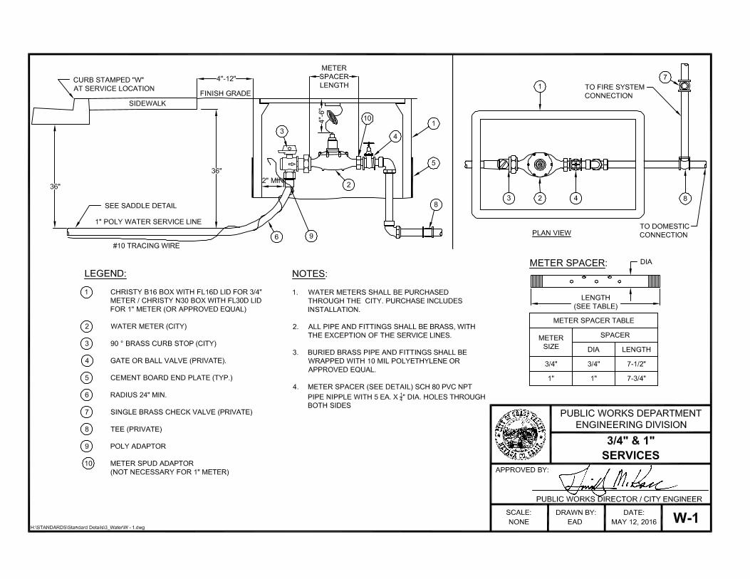
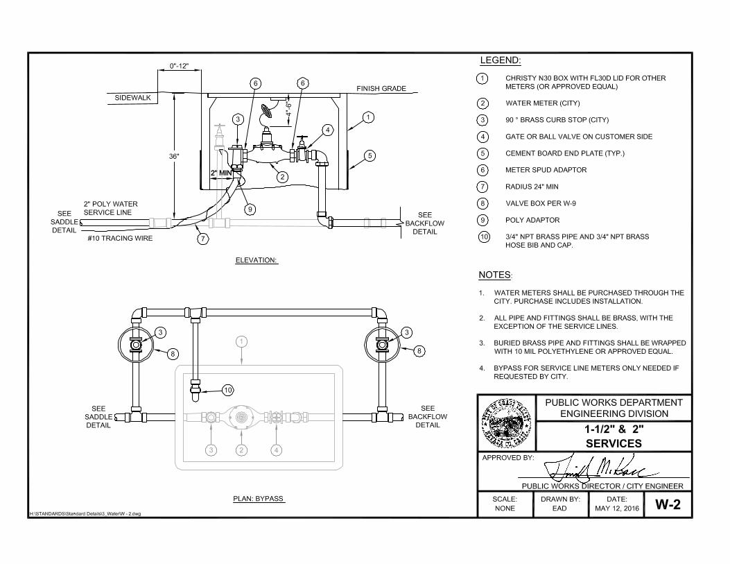
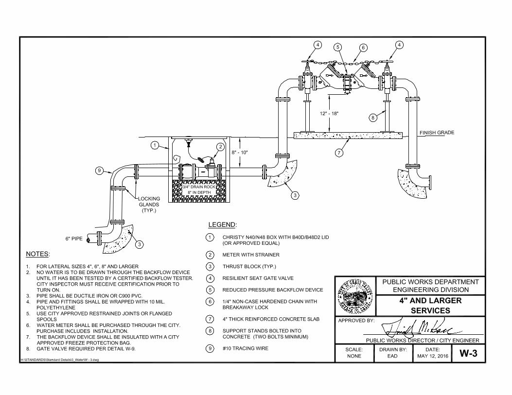
4-7. SERVICE INSTALLATION - Water services shall be installed in accordance with manufacturer's
recommendations, the Standard Details and the following provisions.
A. Continuity of Installation - Services shall be continuous from the main line to the service box.
B. Separation of Taps, Service Saddles and Fittings - Taps, service saddles and fittings attached to
mains shall be separated from each other by a minimum of 24 inches.
C. Wrapping Service Saddles - Service saddles shall be wrapped and sealed in 8-mil minimum
thickness polyethylene and backfilled with sand. Use pipe wrap tape to secure and seal the
polyethylene wrap.
D. Service Manifolds - Service manifolds shall be constructed per the following criteria:
1. Where a service line is extended a distance greater than 40 feet, a construction jumper shall be
installed per the Construction Standard Detail for “Backflow Manifold Schematic”. The new
service line and manifold shall be tested in accordance with these Construction Standards.
Where a service line is extended a distance less than 40 feet, the extension shall be cleaned,
swabbed with chlorine and flushed in the presence of the Public Works Inspector. The new
service line and manifold shall be pressure tested in accordance with these Construction
Standards.
In both cases, the installation shall be fully restrained by an approved restraint system, starting at
the main and as required by the approved Improvement plans.
2. No water shall be drawn through a service prior to installation of the water meter and testing of
the backflow assembly.
E. Temporary Backflow Assemblies - A backflow assembly shall be required for construction and
sales trailers having a landscape irrigation system or a septic holding tank.
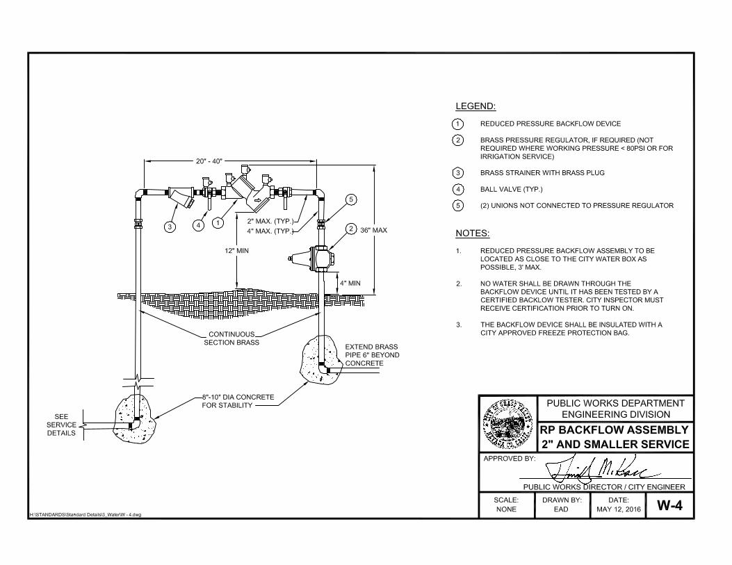
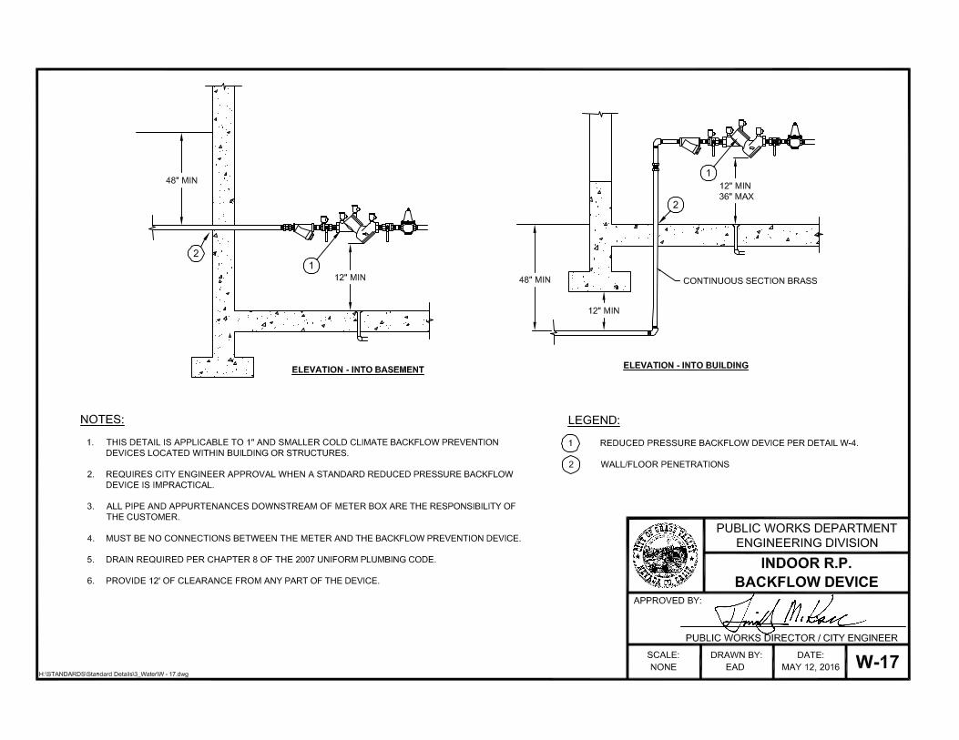
F. Permanent Backflow Assemblies - Backflow assemblies shall be installed per Standard Detail. A
Hotbox or freeze bag may be used for above ground installations.
G. Marking Residential Water Services - The curb in front of residential water services shall be
stamped with a "W.”
H. Caps on Service Saddles - Service saddles shall be installed with zinc caps on all bolts, per these
Construction Standards.
4-8 ABANDONMENT OF SERVICES AND MAINS - All water services requiring abandonment shall be
disconnected from the main line at the corporation stop and plugged unless otherwise approved by the
Public Works Department. Mainline stubs shall have the valve removed and replaced with a blind flange
or as approved by the Public Works Inspector. The abandoned piping shall be removed or left in place as
approved by the Public Works Inspector.
City of Grass Valley Section 4
Construction Standards Water Supply System
REV CST
05/16 W 7 OF 16
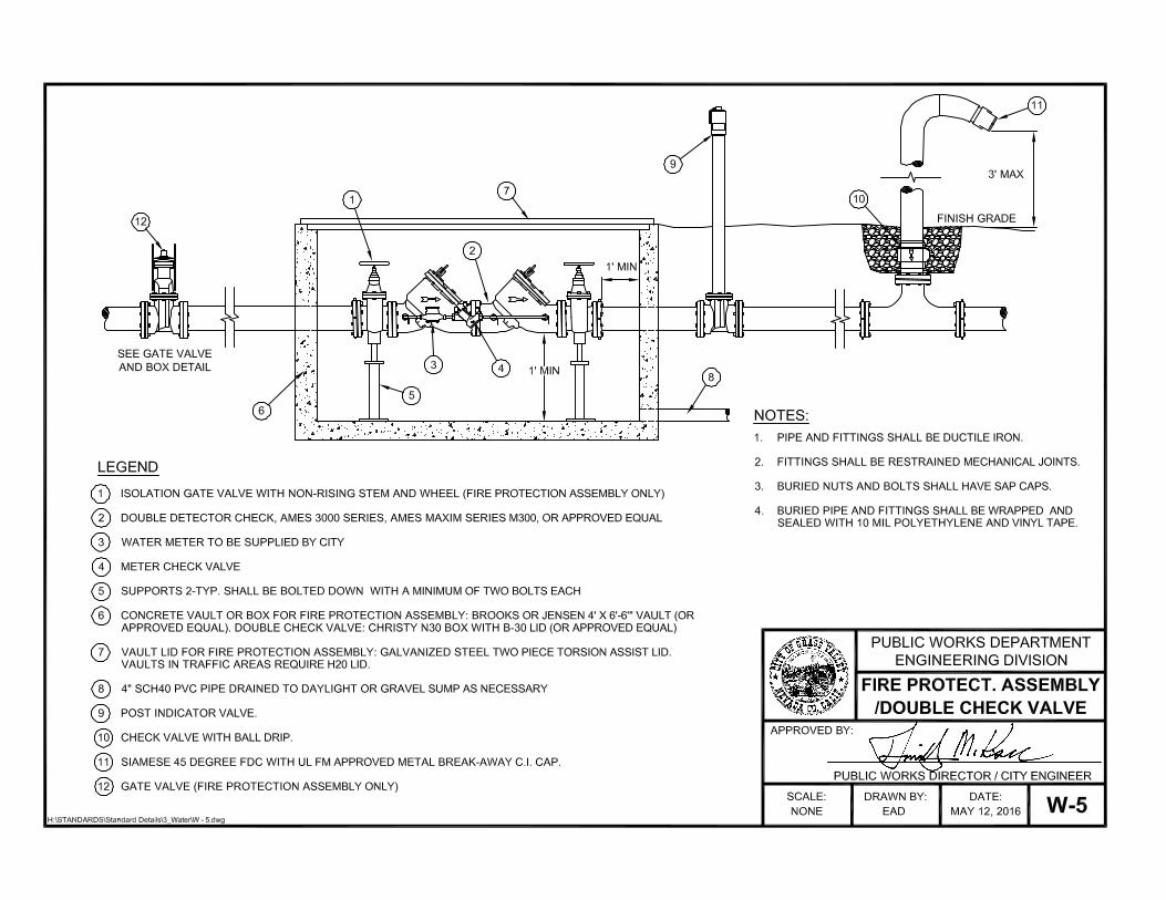
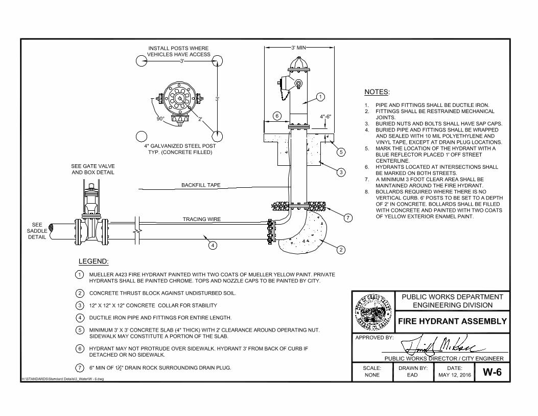
4-9 APPURTENANCES INSTALLATION - All appurtenances, including fire protection, blow-offs,
sample stations, air release valves and fire hydrants shall be installed in accordance with manufacturer's
recommendations, these Construction Standards and the following provisions:
A. Encasement - All valves, fittings, DIP, copper and underground brass shall be wrapped and sealed in
an 10-mil minimum thickness polyethylene encasement. Use pipe wrap tape to secure and seal to the
polyethylene encasement. Damaged or scratched surfaces on epoxy coated valves and appurtenances
may be repaired with an epoxy kit per manufacturer’s recommendations and to the satisfaction of the
Public Works Inspector prior to wrapping. Otherwise, the damaged valve shall be replaced with a new
valve.
B. Gate Valves and Extensions - Gate valves shall be centered in a one-piece riser stock. An operator
nut extension shall be installed on valves where the operating nut exceeds 40 inches in depth from
final grade. Valve extensions shall be continuous and within 24 inches of finished grade.
C. Coating Buried Nuts and Bolts - Buried nuts and bolts shall have “Sap” caps or shall be coated with
a bituminous material. This includes exposed bolts found on a manufactured appurtenance (i.e., valve
bonnets, etc.). “T” bolt heads do not require coating.
D. Fire Hydrant Markers - Fire hydrants shall be marked with a blue recessed reflector placed 1 foot
off of street centerline on the fire hydrant side of the street. Fire hydrants located at intersections shall
be marked on both streets.
E. Paint for Fire Hydrants - Fire hydrant barrels shall be painted with Sherwin Williams Polane SP
Polyurethane Mueller Yellow (Part Number 172-6918). Private hydrants shall be painted chrome. The
tops and nozzle caps shall be painted by the City with the following capacity indicating scheme, per
NFPA standard color code:
1. Class AA - Flow capacity of 1,500 gpm or greater = OSHA Safety Light Blue
2. Class A - Flow capacity of 1,000 gpm to 1499 gpm = OSHA Safety Green
3. Class A - Flow capacity of 500 gpm to 999 gpm = OSHA Safety Orange
4. Class A - Flow capacity less than 500 gpm = OSHA Safety Red
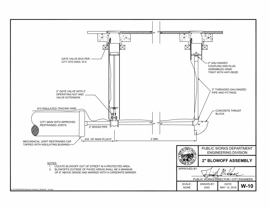
F. Blow-Off Assemblies for Dead-End Lines - Dead-end lines, low points and pressure zone
boundaries, permanent and temporary, shall have a blow-off constructed per the “2” Blowoff Hydrant
Assembly” Standard Detail and marked with a Carsonite marker
G. Insulating kits - Insulating kits shall be installed at transitions between dissimilar metal pipe per the
Construction Details and as required by the Public Works Department.
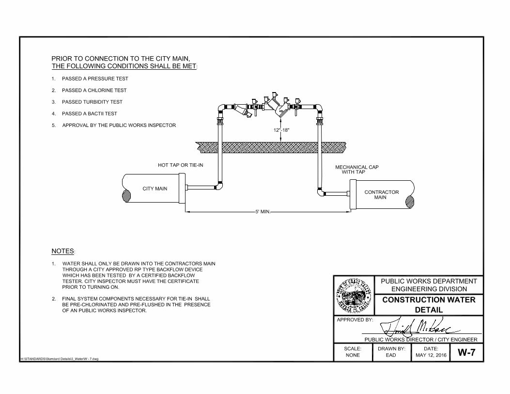
4-10 TESTING PROCEDURES - Testing of the water system may proceed only after joint utility crossings
are completed, the sewer mains and services have passed pressure test and TV inspection and subgrade
elevations have been met. Road bases to be lime-treated shall be pressure tested before and after the lime
treatment process. Testing prior to subgrade placement may be subject to additional pressure tests at the
discretion of the Public Works Inspector. The new system shall be filled with potable water through an
approved backflow device.
A. Pressure Test:
1. The Public Works Inspector will be present during the duration of the test.
City of Grass Valley Section 4
Construction Standards Water Supply System
REV CST
02/14 W 8 OF 16
2. Contractor shall verify with the Public Works Inspector that all system valves are open prior to
testing. Air shall be completely expelled from the pipe, valves and hydrants.
3. Pressure testing shall be conducted for a minimum of two hours at 150 pounds per square inch or
at one-and-one-half times the operating pressure for water mains and 200 pounds per square inch
for fire hydrant and fire protection assemblies, whichever is higher, as measured from the system
high point. The test gauge shall be liquid-filled and capable of testing up to 300 psi.
4. Loss of pressure shall not exceed 5psi during the two hour test period.
B. Chlorine Disinfection - Chlorine disinfection shall comply with the American Water Works
Association Standard for Disinfection Water Mains (C651-92) and as specified below:
1. Disinfection inspections shall begin only after passing the pressure test.
2. Prior to chlorination, pre-flush water mains and services. Pre-flushing is not permitted if using the
Tablet Method for chlorination.
3. Chlorine shall be drawn through all mains, hydrant runs and services. The Public Works Inspector
shall verify that a minimum chlorine residual of 50 parts per million (ppm) has been achieved.
4. After a 24-hour holding period, the Public Works Inspector will verify that a minimum chlorine
content of 25 ppm remains in the system.
5. Upon approval by the Public Works Inspector, the water system shall be flushed to remove
concentrated chlorine. Flushing shall be continued until the remaining water has a chlorine
residual below 1 ppm and a turbidity equal to or less than 1 NTU. Chlorinated water shall be
neutralized to 0.1 ppm chlorine residual or less prior to discharge. Discharge location and
neutralization methods shall be documented in the SWPPP and coordinated with, and approved
by, the Public Works Inspector.
6. Chlorinated water resulting from flushing newly installed water lines may be discharged into the
City's sewer system only with the specific permission of the City Engineer.
Prior to discharging into the sewer system, the Contractor shall sign a form authorizing the Public
Works Department to bill for the amount of water discharged into the system. At the end of each
flushing exercise, and prior to tying into the City water system, the Public Works Inspector(s)
shall prepare a bill for water usage based on the meter reading. This bill must be paid before the
project is signed off by the City Engineer.
The Public Works Department shall determine the volume of discharge. Chlorinated water shall
not be disposed of into environmentally-sensitive areas (i.e., under oak trees, vernal pools, man-
made or natural streams, drainage systems, etc.) during any time of the year.
All discharges into the sewer system shall be governed by the following conditions:
a. Water used for the purpose of flushing shall be metered.
b. Discharge into the sewer system shall be done in such a manner as to avoid surcharging the
sewer system.
c. No discharge into the sewer system shall be permitted on rainy days.
City of Grass Valley Section 4
Construction Standards Water Supply System
REV CST
05/16 W 9 OF 16
d. No discharge shall be permitted upstream of a small lift station.
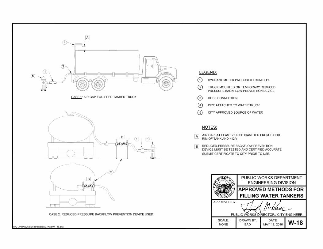
e. An approved air gap shall be maintained at all times. Air gap distances shall be calculated as
2.5 times the pipe diameter. In no case shall the air gap be less than 12 inches.
C. Water Quality Testing - Water quality samples shall be taken per the following procedure:
1. Once flushing has lowered the chlorine residual below 1 ppm and the turbidity is equal to or less
than 1 NTU, the water system shall observe a minimum 24 hour detention time. Water may not
be drawn during this time period.
2. After the 24-hour holding period has elapsed, water quality samples shall be collected for testing.
If the sample lot does not meet the minimum chlorine residual and turbidity criteria, additional
flushing and added 24-hour holding period shall be required. The procedure shall be repeated
until the criteria are met.
3. If the minimum criteria are met a final Presence/Absence test for coliform shall be performed
prior to connection to the City water system. The flushing and chlorinating procedure shall be
repeated until no coliform are detected.
D. Tying Into The City System - A tie-in procedure shall be submitted and approved by the Public
Works Department prior to the proposed work. The Contractor shall allow up to seven days for
review of the procedures by the Public Works Department. The water system shall be tied into the
City system within ten (10) working days upon completing and passing all the testing procedures.
Tie-ins shall be conducted as specified in Section 4-2 of these Construction Standards. After the tie-in
has been made, the Contractor shall flush the segment tied-in to the approval of the Public Works
Inspector.
1. If the new water system cannot be tied into the City system within ten (10) working days, the new
system shall maintain a chlorine residual of 0.5 to 1.0 ppm or be subject to water quality testing
and re-chlorination. This shall be discussed with the Public Works Inspector.
2. On-site private systems may connect onto the City System upon passing all testing procedures,
backflow tests, and meters have been paid for and installed. A tie-in procedure shall be required
per this section.
E. Continuity Testing - The Public Works Department will test continuity of the tracing wire with City
standard locating equipment upon request for testing by the Contractor. Discontinuity in the tracing
wire shall be repaired. It is recommended that the Contractor request continuity testing after subgrade
is made, but before asphalt is placed. Final continuity testing will take place after asphalt is placed
and all valve boxes are raised. Costs for said inspection shall be borne by the Contractor. Preliminary
inspections may be performed by outside Contractors, but shall not be accepted by the Public Works
Department as an official record.
F. Corrosion Protection System Testing - At the completion of the pipe installation and prior to curb
and gutter, the Corrosion Engineer shall conduct a test of the corrosion monitoring system in the
presence of the Public Works Inspector. A report showing the test results shall be submitted to the
Public Works Department for review and approval. The report shall include test station locations as
called out on the approved plans, appurtenance tested, test result, and recommendations for future
monitoring and maintenance.
City of Grass Valley Section 4
Construction Standards Water Supply System
REV CST
05/16 W 10 OF 16
4-11 REPAIRING INSTALLED IMPROVEMENTS - All PVC and DIP water mains shall be repaired per
the following procedures:
A. Damaged or Failed Pipe Sections - Damaged or failed pipe sections shall be removed and replaced
with new pipe in the presence of the Public Works Inspector. Replacement can be accomplished by
the use of City approved ductile iron mechanical joint repair sleeves. Pipe restraints will be required.
B. Backfill - After the repair has been completed, the excavation shall be backfilled and compacted to
grade as specified in the Utility Trench Bedding, Backfill and Paving detail. The repairs shall then be
re-tested per these Construction Standards.
C. Encasement Repair - At the direction of the City, the Contractor shall repair damage to the
polyethylene encasement as described within ANSI/AWWA C-105/A21.5 or shall replace all
damaged polyethylene film sections.
4-12 PUNCHLIST PROCESS - When the Contractor is satisfied that all improvements are substantially
complete, a punchlist of final outstanding items may be requested. With the assistance and presence of the
Contractor, the punchlist shall be generated by the Public Works Inspector.
4-13 MATERIALS
A. Water Main - Unless noted on the approved plans, all water mains shall be sizes 6, 8 ,10, 12-inch,
and either Polyvinyl Chloride Pressure Pipe (PVC) or Ductile Iron Pipe (DIP).
1. PVC Pressure Pipe - PVC Pressure Pipe shall be manufactured to a minimum Class 150 rating
and shall conform to the "Standard for Polyvinyl Chloride (PVC) Pressure Pipe, 6 inches through
12 inches, for Water" (AWWA C-900), and shall also include the following:
a. PVC Pressure Pipe shall be blue in color and shall have been manufactured within 18 months
of installation. The pipe shall be manufacturer date coded and the City provided the
manufacturer's coding for translation. Sun damaged pipe may be rejected at the Public Works
Inspector’s discretion.
b. Rubber rings shall conform to the "Standard Specifications for Elastomeric Seals (Gaskets)
for Joining Plastic Pipe" (ASTM F-477).
c. Approved PVC Pressure Pipe manufacturers include: Certain Teed Certa Lock, Diamond
Plastics Corporation, J-M Manufacturing, Pacific Western Pipe, Vinyl Tech-White Knight,
Pressure - Flex Pipe, or approved equals.
2. Ductile Iron Pipe - DIP shall be manufactured to conform to the standards ANSI/AWWA C-
150/21.50 thickness design of ductile iron pipe and to "Ductile Iron Pipe Centrifugally Cast in
Metal Molds or Sand-Lined Molds for Water and Other Liquids" (ANSI/AWWA C-151/A21.51)
and shall also include the following:
a. DIP shall be cement-mortar lined in accordance with the standard for "Cement-Mortar Lining
for Ductile Iron Pipe and Fittings for Water" (ANSI/AWWA C-104/A21.4).
b. Approved DIP manufacturers include: Pacific States, Tyler, US Pipes, Griffin, or approved
equals.
City of Grass Valley Section 4
Construction Standards Water Supply System
REV CST
05/16 W 11 OF 16
B. Services
1. Polyethylene Pressure Pipe - Service laterals shall be sizes 1, 2, 4, and 6-inch iron pipe size (IPS)
polyethylene pipe conforming to ASTM D2239 and shall be rated for use at a pressure class of
200 psi.
2. Brass Material
a. Brass pipe - Brass pipe shall conform to ASTM B-43 standards. A listing of approved pipe
include: Hallstead 3/4" through 2" Red Brass, Cambridge-Lee, Federal WW-351, Wolverine,
or approved equal.
b. Brass fittings - Brass fittings shall conform to ANSI Standard B16.15, B16.24, B2.1, T-94-1
and be a minimum of Class 125. A listing of approved manufacturers include: Lee Brass,
Merritt Brass, New England Union Co., or approved equal.
3. Corporation Stops
a. Corporation stops shall be male, iron pipe thread by iron pipe thread and full throat ball valve
design. A corporation stop shall be installed at the water main for all service laterals smaller
than 2 inches. Approved manufacturers of corporation stops include: Jones, Mueller, or Ford.
Part reference numbers are as shown below:
i. Jones: Part #J-1943 (3/4-inch to 2 inches)
ii. Mueller: Part#B-2969-N (Compression 1 1/2-inch to 2 inches)
Part#B-20013-N (Compression 3/4-inch to1 inch)
iii. Ford: Part #FB500-NL (3/4-inch to 2 inches)
4. 90° Curb Stops
a. All curb stops must have lock/padlock wings. Approved curb stop manufacturers include:
Jones, Mueller, or Ford. Part reference numbers are shown below:
i. Jones: Part #E-1966W (3/4-inch to 1 inch)
Part #E-1974W (1½ inches to 2 inches)
ii. Mueller: Part #B-24265N (3/4-inch to 1 inch)
Part #B-24286N (1½ inches to 2 inches)
iii. Ford: Part #BA13-332W-NL (3/4-inch)
Part #BA13-444W-NL (1 inch)
Part #BFA13-666W-NL (1½ inches)
Part #BFA13-777-NL (2 inches)
5. Dielectric Tape - Approved manufacturers for dielectric tape include Polyken #932 Hi-Tack joint
wrap tape or approved equivalent flexible dielectric tape.
6. Service Saddles
City of Grass Valley Section 4
Construction Standards Water Supply System
REV CST
05/16 W 12 OF 16
a. PVC Pressure Pipe Service Saddles manufacturers include: Jones or Mueller. Part reference
numbers are as indicated below:
i. Jones: 4-inch through 12-inch saddles with ¾-inch through 2-inch tap, Part #J-996
ii. Mueller:
Saddle Size Part #
4-inch H-13490
6-inch H-13491
8-inch H-13492
10-inch H-13493
12-inch H-13494
b. DIP Service Saddles manufacturers include: Jones, Mueller, or approved equal. Part reference
numbers are as indicated below:
i. Jones: 4-inch through 12-inch saddles with ¾-inch through 2-inch taps: Part #J-979
ii. Mueller: ¾-inch through 2-inch taps:
Saddle Size Part #
4-inch BR2B0474IP *
6-inch BR2B0684IP *
8-inch BR2B0899IP *
10-inch BR2B1104IP *
12-inch BR2B1314IP *
16-inch BR2B1732IP *
C. Appurtenances
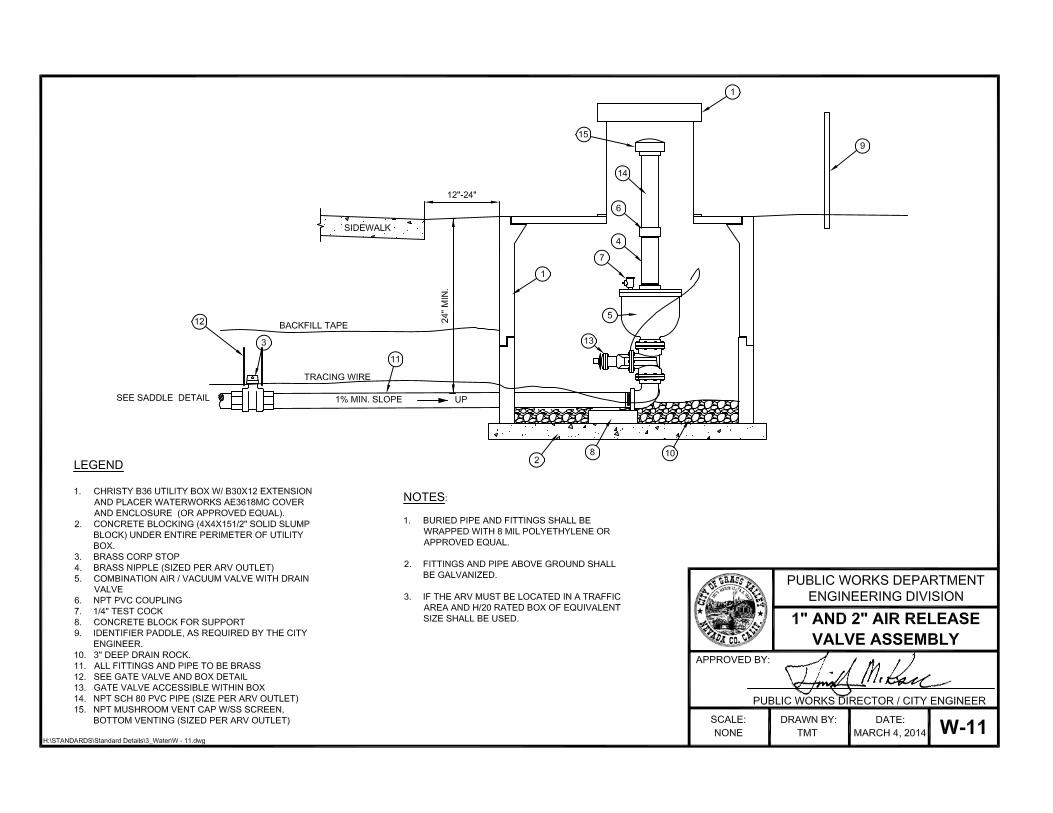
1. Air Release Valves - Air release valves shall be epoxy coated vacuum break type and include a
drain valve. A listing of approved manufacturers includes: Crispin, Valmatic, or approved equal.
Part reference numbers are as shown below:
Crispin Part # Valmatic Part #
1" UL10 1" 201C
2" UL20 2" 202C
3" UL31 3" 203C
4" UL41 4" 204C
6" UL61 6" 206C
8" UL81 8" 208C
2. Backflow Assembly - Refer to the current “List of Approved Backflow Prevention Assemblies”
from the University of Southern California Foundation for Cross-Connection Control and
Hydraulic Research. Where there is a conflict between these standards, the University of
California Testing Laboratory approved list and Title 17 of the State of California Administrative
Code, the more restrictive requirement shall apply.
3. Blocking for Boxes - Slump Block - 4”x4”x15-1/2”, or approved equal.
4. Blow-Off Assemblies - Kupferle, Eclipse #78 (2-inch) or approved equal.
City of Grass Valley Section 4
Construction Standards Water Supply System
REV CST
05/16 W 13 OF 16
5. Cadwelds - A listing of approved materials includes:
a. #4 jumper cable, CP cable, 18" long with 1" bare end
b. #4 cadweld copper sleeve
c. #4 cadweld shot with thermite mastic weld cap-t-cap
6. Fittings -
a. PVC - All fittings to be used with PVC Pressure Pipe shall conform to AWWA C-900 and C-
905 standards.
b. Ductile Iron Pipe - Unless otherwise specified or shown on the approved plans, all fittings to
be used with DIP shall employ either mechanical joints or restrained joints conforming to the
standard for "Ductile Iron Compact Fittings for Water and Other Liquids" (ANSI/AWWA C-
153/A21.53). Approved fitting manufacturers include Tyler, Union, and US Pipe.
i. All ductile iron fittings shall be mortar lined in accordance with the standard for "Cement
Mortar Lining for Ductile Iron Pipe and Fittings for Water" (ANSI/AWWA C-
104/A21.4).
ii. All fittings shall be wrapped and sealed in clear polyethylene encasement in accordance
with these Construction Standards.
7. Gaskets - Gaskets shall conform to the following specifications:
a. Flange Gaskets - Flange gaskets shall be neoprene rubber, red rubber, US Pipe, Flange Tyte,
or approved equal.
b. Insulating Flange Gaskets - Insulating flange gaskets shall be USSO Standard B.16.21
insulation flange kits, Type E Full Face Gasket with two-side insulation as manufactured by
Calpico, or approved equal.
8. Hydrants - Hydrants shall be dry barrel type with bronze operating nut, hydrant seat and drain
ring lining. Caps shall be cast iron. Approved hydrants include: Meuller #A-423 yellow or
approved equal.
9. Meters - All meters shall be provided by the City of Grass Valley Public Works Department.
10. Meter Spud Couplers -
a. Ford Part #
3/4" x 2 ½” C38-23-2.5NL
1” x 2 ½” C38-44-2.625NL
1 1/2” x 2 ½” CF31-66NL
2" x 2 ½” CF31-77NL
b. Jones Part #
¾” x 2 ½” JE130
1” x 2 5/8” JE130
City of Grass Valley Section 4
Construction Standards Water Supply System
REV CST
05/16 W 14 OF 16
11/2" x 2" JE129
c. Mueller Part #
¾ " H-10890N
1" H-10890N
1 ½” H-10129JN
2” H-10129JN
11. Nuts and Bolts
a. Flange Bolts and Nuts - Flange bolts and nuts shall conform to a minimum ASTM #A307.
Bolts less than ¾ inches in diameter shall be a minimum Grade B (heavy hex). Bolts ¾ inches
and larger in diameter shall be a minimum Grade A (standard hex).
b. Meter Bolts - Meter bolts are to be stainless steel, Grade 316 with brass nuts
c. Tee Bolt - Steel bolts are to be 3/4" high strength, low alloy steel with a heavy nut,
conforming to AWWA Standard C-111-90
12. Nylon Bushings - Nylon bushings shall be 76-76R, 2 1/2" NST x 2" Pipe.
13. Patching Material - Cop-Coat Carboline Company (Bitumastic No. 50, Coal Tar), Coppers Coat
50, or approved equal.
14. Pipe Wrap Tape - 10-mil vinyl tape manufactured by Calpico Inc. (Calpico VI-10) or approved
equal.
15. Polyethylene Encasement - “Clear” non-colored polyethylene film shall be used. The
polyethylene film shall have a minimum thickness of 8-mils. The thickness shall not be less than
10 percent of the nominal thickness. The polyethylene shall be in either tubular or in sheet form.
Polyethylene film shall be manufactured from a Type 1, Class C raw polyethylene material
conforming to "Polyethylene Encasement for Ductile-Iron Piping for Water and Other Liquids"
(ANSI/AWWA C-105/A21.5). Approved manufacturers include: Fee Spec's-LP378D Northtown,
Fulton Enterprise Inc., Global Polymer Tech, Unisource, or approved equal.
16. Pressure Regulators - Watts (3/4" through 2", UB5-series), Wilkens (3/4" through 2"-600 series,
2.5" through 3"-500YSBR), or approved equal.
17. Restraints
a. PVC – Megalug 2000PV Series, Sigma One-Lok Series, or approved equal.
b. DIP - Field Lock Gaskets (3 inches through 12 inches diameter only), Mega Lug 1100 Series,
Sigma One-Lok Series, or approved equal.
18. Riser Aligners - Davis & Associates Riser Aligners (8"), or approved equal.
19. Riser Stock For Main Line Valves - Riser stock shall be 8-inch diameter PVC C-900 or SDR 35
for all main line valves.
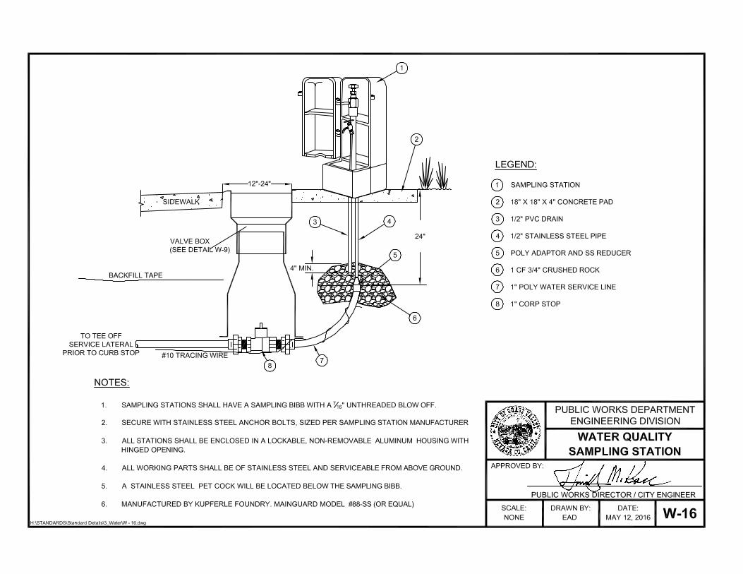
20. Sampling Stations - The Kupferle Foundry Company Eclipse #88 or approved equal.
City of Grass Valley Section 4
Construction Standards Water Supply System
REV CST
05/16 W 15 OF 16
21. Silicone - Silicone shall be clear, 100% silicone with a 25-year life.
22. Tracing Wire Connectors - Tracing wire connectors shall be copper split-bolt type connectors. A
listing of approved products include: Perminate Seal-Wire Connectors- Part #97811, Christy’s (S-
X), or approved equal.
23. Tracing Wire Mastic Tape Seal - 3M Mastic Tape #2229 or approved equal.
24. Utility Boxes and Lids - All box lids are to be permanently marked with the appropriate label
(i.e., Water, ARV, CPT, etc.). In commercial projects, meter lids shall be stenciled with the
number address it serves. The numbers shall be painted using white enamel paint and 2-inch
stenciling. Traffic rated boxes are required in all streets. When located in a traffic area, boxes
shall be rated for H20 loading. A list of approved box manufacturers include: Christy
(Oldcastle), BES, or approved equal. Part reference numbers for Christy boxes and Christy or
Nicor Inc. lids are shown below:
Non-Traffic Traffic
Christy Part # Part#
¾” service B16BOX
FL16D Lid
B16X12 Extension
B1324BOX
B1324-51JH
B1324X12 Extension
1" to 2" services
N30BOX
FL30D Lid
B30X12 Extension
B1324BOX
B1324-51JH
B1324X12 Extension
3" meter box
N36BOX
FL36D Lid
B36X12 Extension
B1730BOX
B1730-51JH
B1730X12 Extension
4” meter box N40BOX
B40D Lid
N40X10 Extension
B2436BOX
B2436-52JH
B2436X12 Extension
Valve box G05TBOX G05TBOX
G05CT Lid G05CT Lid
G08X12 Extension G08X12 Extension
25. Valves
a. Butterfly Valves - Butterfly valves to be used on diameters ranging from 12" to 72",shall be
Mueller Lineseal III (Holiday free epoxy, interior lining and standard black asphalt varnish
exterior) or approved equal. Certification shall be provided by the valve manufacturer stating
the epoxy lining is holiday free. The epoxy coating shall be spark tested and approved for
installation by the Public Works Inspector.
b. Gate Valves - Gate valves for 2" - 2 1/2" services shall be A2360 Thread or approved equal.
Gate valves to be used on diameters ranging from 3" to 12" shall be grey cast iron or
approved equal. All in-line gate valves shall have integral flat face flanges on both ends. A
list of approved valves includes: Mueller-A-2360 RS Gate Valve, AFC 2500, US Pipe-Metro
Seal 250, Clow 604, or approved equal.
City of Grass Valley Section 4
Construction Standards Water Supply System
REV CST
05/16 W 16 OF 16
c. Provide additional o-rings for each purchased valve.
26. Poly Adaptors –
a. Ford Part #
2” male C86-77NL
2” female C16-77NL
b. Jones Part #
2” male JE-15429N
2” female JE-15454N
2” MIP x IPS JE-2640
2” female JE-2608
c. Mueller Part #
1" MIP x IPS H-15426
1" FIP x IPS H-15456
27. Zinc Caps - Zinc caps shall be Mars or approved equal. Mars part numbers are listed below:
a. 7/16" to 1/2"-2.5 ounce weight
b. 5/8" to 1"- 6.0 ounce weight
Related Documents