Irrigation Engineering, 2016 Dr. Alaa El-Hazek Faculty Of Engineering at Shobra 3 rd Year Civil – Structure - 2016 1 Chapter 3 Water Structures 3-1 Introduction: Water structures are the constructions used for irrigation and drainage projects. Figure (3-1) shows a general layout for different water structures for an irrigation and drainage project. Figure (3-1): A General Layout for different Water Structures for Irrigation and Drainage Projects.

Welcome message from author
This document is posted to help you gain knowledge. Please leave a comment to let me know what you think about it! Share it to your friends and learn new things together.
Transcript
Irrigation Engineering, 2016 Dr. Alaa El-Hazek
Faculty Of Engineering at Shobra 3rd Year Civil – Structure - 2016
1
Chapter 3
Water Structures
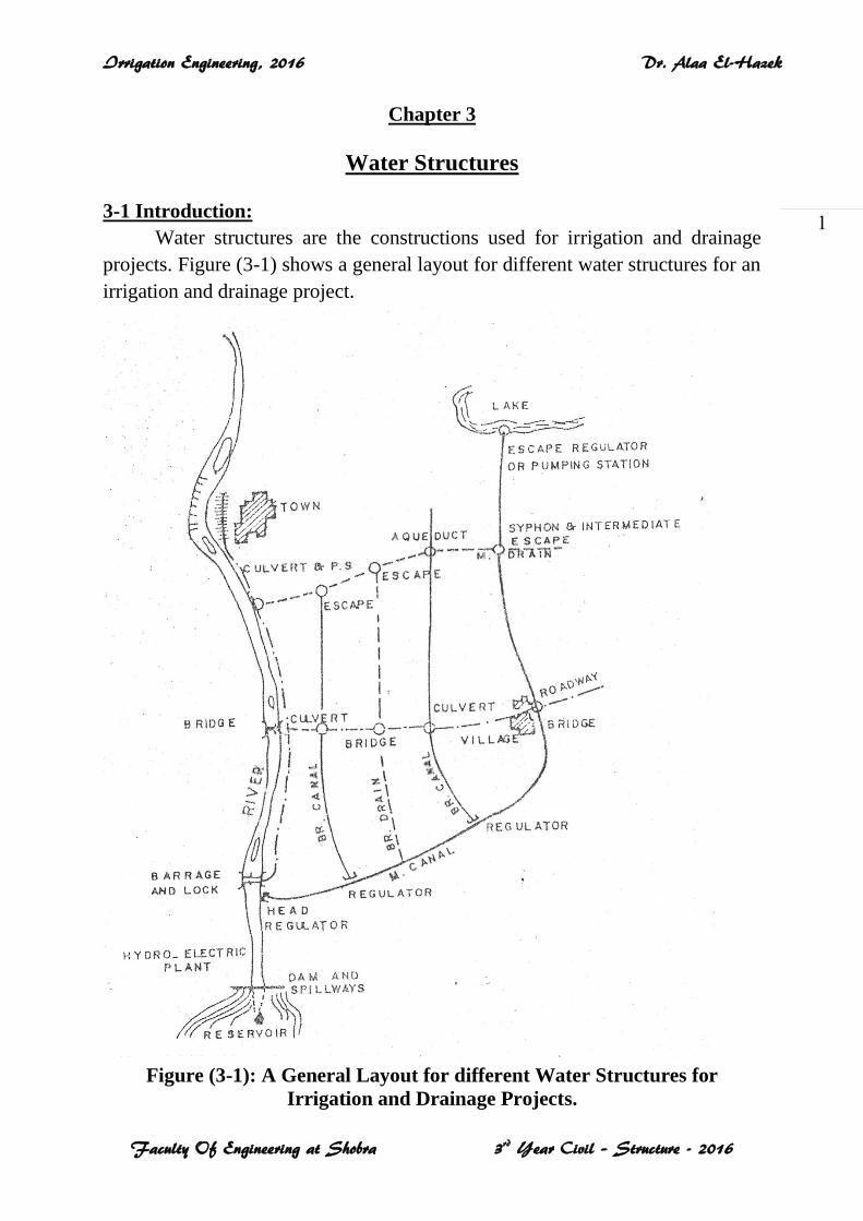
3-1 Introduction:
Water structures are the constructions used for irrigation and drainage
projects. Figure (3-1) shows a general layout for different water structures for an
irrigation and drainage project.
Figure (3-1): A General Layout for different Water Structures for
Irrigation and Drainage Projects.
Irrigation Engineering, 2016 Dr. Alaa El-Hazek
Faculty Of Engineering at Shobra 3rd Year Civil – Structure - 2016
2
Water structures are divided into crossing structures and heading-up
(control) structures.
1- Crossing Structures:
A- Intersection of a water channel with a road:
(1) Bridge.
(2) Culvert. (بربخ) B- Intersection of two water channels:
(1) Syphon. (سحارة)
(2) Aqueduct. (بدالة) 2- Heading-up (Control) Structures:
A- Diversion Structures:
(1) Weir. (هدار)
(2) Barrage and Regulator.
(3) Escape.
B- Navigation Structures:
Lock. (هويس)
C- Storage Structures:
Dam.
3-2 Elements of a Water Structure:
Any water structure consists of three main parts:
1- Superstructure: It includes reinforced concrete (R.C.) slabs and
girders, masonry arches, rolled steel joists with timber flooring.
2- Substructure: It includes the supports(mainly abutments and piers)
and the retaining walls.
3- Foundations.
3-3 Retaining Walls:
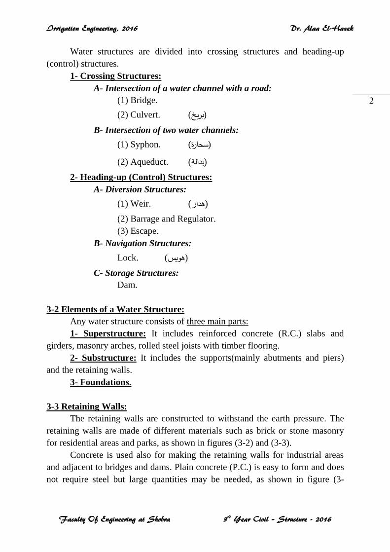
The retaining walls are constructed to withstand the earth pressure. The
retaining walls are made of different materials such as brick or stone masonry
for residential areas and parks, as shown in figures (3-2) and (3-3).
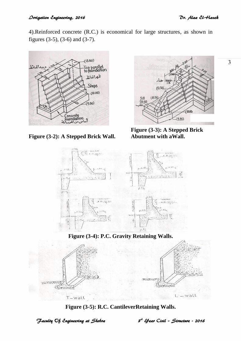
Concrete is used also for making the retaining walls for industrial areas
and adjacent to bridges and dams. Plain concrete (P.C.) is easy to form and does
not require steel but large quantities may be needed, as shown in figure (3-
Irrigation Engineering, 2016 Dr. Alaa El-Hazek
Faculty Of Engineering at Shobra 3rd Year Civil – Structure - 2016
3
4).Reinforced concrete (R.C.) is economical for large structures, as shown in
figures (3-5), (3-6) and (3-7).
Figure (3-3): A Stepped Brick
Figure (3-2): A Stepped Brick Wall. Abutment with aWall.
Figure (3-4): P.C. Gravity Retaining Walls.
Figure (3-5): R.C. CantileverRetaining Walls.
Irrigation Engineering, 2016 Dr. Alaa El-Hazek
Faculty Of Engineering at Shobra 3rd Year Civil – Structure - 2016
4
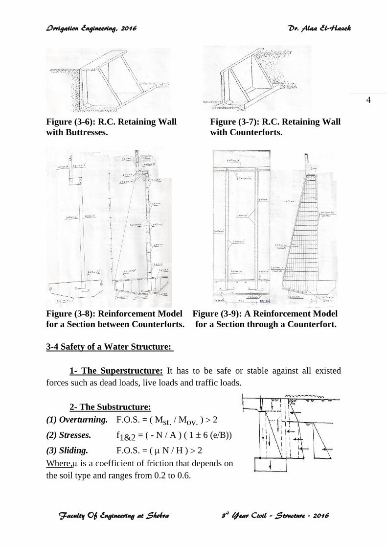
Figure (3-6): R.C. Retaining Wall Figure (3-7): R.C. Retaining Wall
with Buttresses. with Counterforts.
Figure (3-8): Reinforcement Model Figure (3-9): A Reinforcement Model for a Section between Counterforts. for a Section through a Counterfort.
3-4 Safety of a Water Structure:
1- The Superstructure: It has to be safe or stable against all existed
forces such as dead loads, live loads and traffic loads.
2- The Substructure:
(1) Overturning. F.O.S. = ( Mst. / Mov. ) 2
(2) Stresses. f1&2 = ( - N / A ) ( 1 6 (e/B))
(3) Sliding. F.O.S. = ( N / H ) 2
Where, is a coefficient of friction that depends on
the soil type and ranges from 0.2 to 0.6.
Irrigation Engineering, 2016 Dr. Alaa El-Hazek
Faculty Of Engineering at Shobra 3rd Year Civil – Structure - 2016
5
3- The Foundation:
(1) Percolation:
Percolation occurs in the underlying permeable soil due to the head of
water between both the upstream (US) and the downstream (DS). It causes
undermining for the pervious soil which may lead to the collapse of the whole
structure.
The length of the foundation floor (or apron) has to be enough to be stable
against the percolation.
(2) Uplift Pressure:
The floor of the water structure is forced upwards due to the uplift
pressure of the water filtering through the pervious soil under the foundation.
A net uplift diagram has to be established to check the stability against the
uplift pressure.
(3) Downstream Erosion:
The soil downstream the water structure has to be protected against the
erosive (scour) action of the falling water (such as the water falling over the sill
of a weir).
End sill and/or stone pitching may be used.
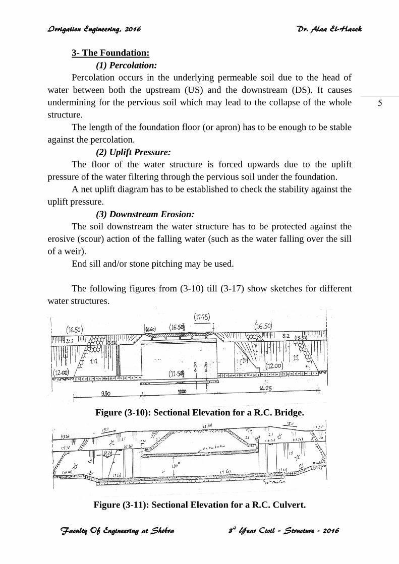
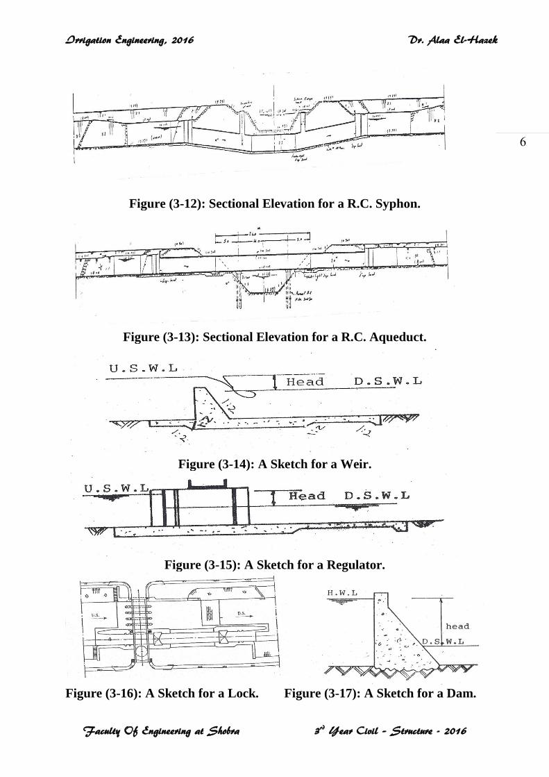
The following figures from (3-10) till (3-17) show sketches for different
water structures.
Figure (3-10): Sectional Elevation for a R.C. Bridge.
Figure (3-11): Sectional Elevation for a R.C. Culvert.
Irrigation Engineering, 2016 Dr. Alaa El-Hazek
Faculty Of Engineering at Shobra 3rd Year Civil – Structure - 2016
6
Figure (3-12): Sectional Elevation for a R.C. Syphon.
Figure (3-13): Sectional Elevation for a R.C. Aqueduct.
Figure (3-14): A Sketch for a Weir.
Figure (3-15): A Sketch for a Regulator.
Figure (3-16): A Sketch for a Lock. Figure (3-17): A Sketch for a Dam.
Irrigation Engineering, 2016 Dr. Alaa El-Hazek
Faculty Of Engineering at Shobra 3rd Year Civil – Structure - 2016
7
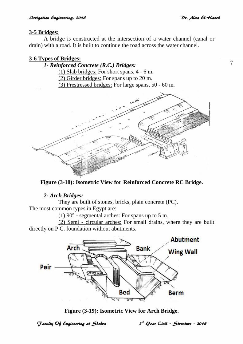
3-5 Bridges: A bridge is constructed at the intersection of a water channel (canal or
drain) with a road. It is built to continue the road across the water channel.
3-6 Types of Bridges:
1- Reinforced Concrete (R.C.) Bridges: (1) Slab bridges: For short spans, 4 - 6 m.
(2) Girder bridges: For spans up to 20 m.
(3) Prestressed bridges: For large spans, 50 - 60 m.
Figure (3-18): Isometric View for Reinforced Concrete RC Bridge.
2- Arch Bridges:
They are built of stones, bricks, plain concrete (PC).
The most common types in Egypt are:
(1) 90 - segmental arches: For spans up to 5 m.
(2) Semi - circular arches: For small drains, where they are built
directly on P.C. foundation without abutments.
Figure (3-19): Isometric View for Arch Bridge.
Irrigation Engineering, 2016 Dr. Alaa El-Hazek
Faculty Of Engineering at Shobra 3rd Year Civil – Structure - 2016
8
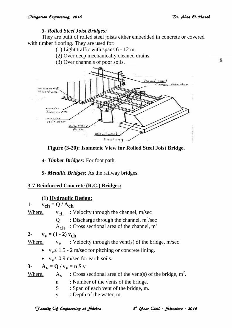
3- Rolled Steel Joist Bridges:
They are built of rolled steel joists either embedded in concrete or covered
with timber flooring. They are used for:
(1) Light traffic with spans 6 - 12 m.
(2) Over deep mechanically cleaned drains.
(3) Over channels of poor soils.
Figure (3-20): Isometric View for Rolled Steel Joist Bridge.
4- Timber Bridges: For foot path.
5- Metallic Bridges: As the railway bridges.
3-7 Reinforced Concrete (R.C.) Bridges:
(1) Hydraulic Design:
1- vch = Q / Ach
Where, vch : Velocity through the channel, m/sec
Q : Discharge through the channel, m3/sec
Ach : Cross sectional area of the channel, m2
2- vv = (1 - 2) vch
Where, vv : Velocity through the vent(s) of the bridge, m/sec
vv 1.5 - 2 m/sec for pitching or concrete lining.
vv 0.9 m/sec for earth soils.
3- Av = Q / vv = n S y
Where, Av : Cross sectional area of the vent(s) of the bridge, m2.
n : Number of the vents of the bridge.
S : Span of each vent of the bridge, m.
y : Depth of the water, m.
Irrigation Engineering, 2016 Dr. Alaa El-Hazek
Faculty Of Engineering at Shobra 3rd Year Civil – Structure - 2016
9
Check: Av 0.6 Ach
The design is --- vents, each vent has a span of --- m.
4- vv(act) = Q / Av(act)
Where, vv(act): Actual velocity through the vent(s) of the bridge, m/sec
Av(act)(= n Sact y): Actual cross sectional area of the vent(s) of the bridge, m2.
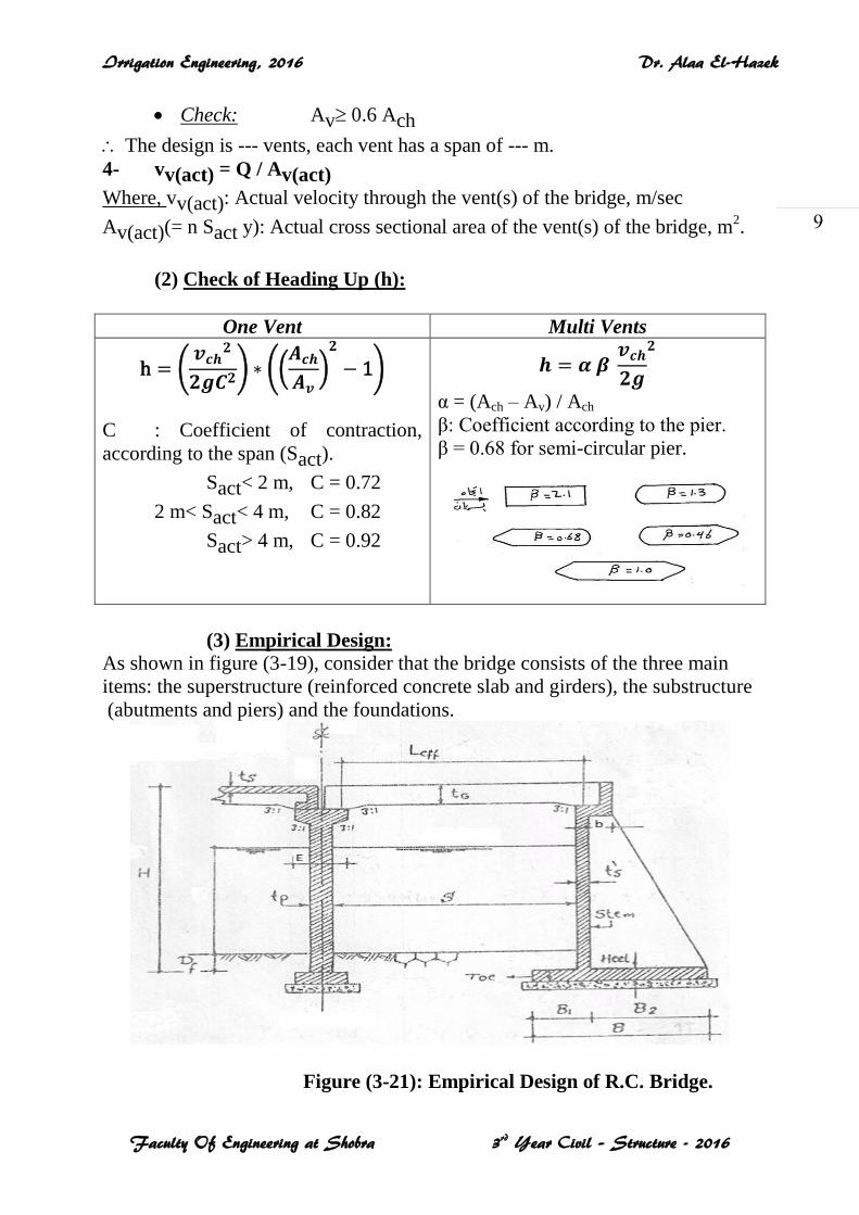
(2) Check of Heading Up (h):
One Vent Multi Vents
C : Coefficient of contraction,
according to the span (Sact).
Sact< 2 m, C = 0.72
2 m< Sact< 4 m, C = 0.82
Sact> 4 m, C = 0.92
α = (Ach – Av) / Ach
β: Coefficient according to the pier.
β = 0.68 for semi-circular pier.
(3) Empirical Design: As shown in figure (3-19), consider that the bridge consists of the three main
items: the superstructure (reinforced concrete slab and girders), the substructure
(abutments and piers) and the foundations.
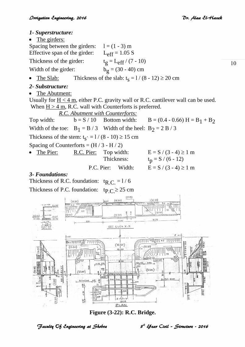
Figure (3-21): Empirical Design of R.C. Bridge.
Irrigation Engineering, 2016 Dr. Alaa El-Hazek
Faculty Of Engineering at Shobra 3rd Year Civil – Structure - 2016
11
1- Superstructure:
The girders:
Spacing between the girders: l = (1 - 3) m
Effective span of the girder: Leff = 1.05 S
Thickness of the girder: tg = Leff / (7 - 10)
Width of the girder: bg = (30 - 40) cm
The Slab: Thickness of the slab: ts = l / (8 - 12) 20 cm
2- Substructure:
The Abutment:
Usually for H < 4 m, either P.C. gravity wall or R.C. cantilever wall can be used.
When H > 4 m, R.C. wall with Counterforts is preferred.
R.C. Abutment with Counterforts:
Top width: b = S / 10 Bottom width: B = (0.4 - 0.66) H = B1 + B2
Width of the toe: B1 = B / 3 Width of the heel: B2 = 2 B / 3
Thickness of the stem: tsˋ = l / (8 - 10) 15 cm
Spacing of Counterforts = (H / 3 - H / 2)
The Pier: R.C. Pier: Top width: E = S / (3 - 4) 1 m
Thickness: tp = S / (6 - 12)
P.C. Pier: Width: E = S / (3 - 4) 1 m
3- Foundations: Thickness of R.C. foundation: tR.C. = l / 6
Thickness of P.C. foundation: tP.C. 25 cm
Figure (3-22): R.C. Bridge.
Irrigation Engineering, 2016 Dr. Alaa El-Hazek
Faculty Of Engineering at Shobra 3rd Year Civil – Structure - 2016
11
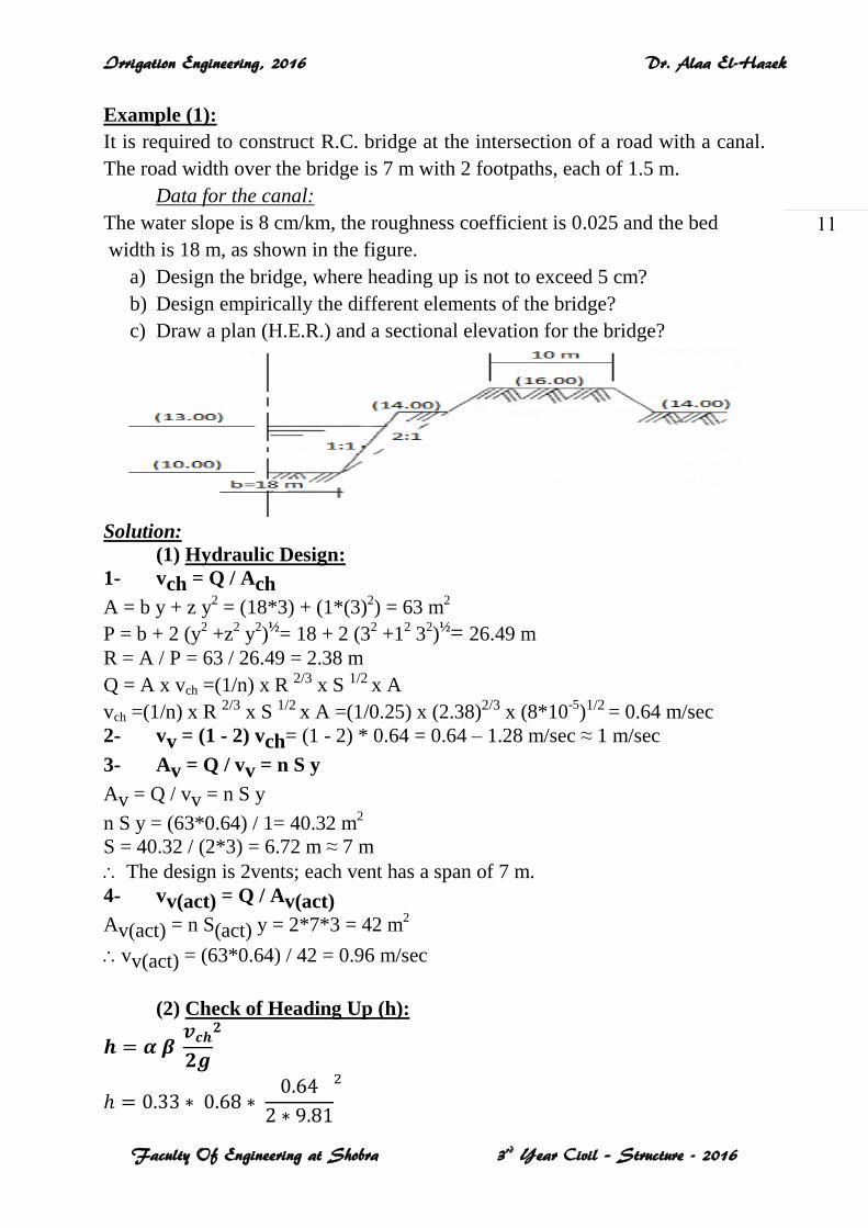
Example (1):
It is required to construct R.C. bridge at the intersection of a road with a canal.
The road width over the bridge is 7 m with 2 footpaths, each of 1.5 m.
Data for the canal:
The water slope is 8 cm/km, the roughness coefficient is 0.025 and the bed
width is 18 m, as shown in the figure.
a) Design the bridge, where heading up is not to exceed 5 cm?
b) Design empirically the different elements of the bridge?
c) Draw a plan (H.E.R.) and a sectional elevation for the bridge?
Solution:
(1) Hydraulic Design:
1- vch = Q / Ach
A = b y + z y2 = (18*3) + (1*(3)
2) = 63 m
2
P = b + 2 (y2 +z
2 y
2)½= 18 + 2 (3
2 +1
2 3
2)½= 26.49 m
R = A / P = 63 / 26.49 = 2.38 m
Q = A x vch =(1/n) x R 2/3 x S 1/2 x A
vch =(1/n) x R 2/3 x S 1/2 x A =(1/0.25) x (2.38)2/3 x (8*10-5
)1/2 = 0.64 m/sec
2- vv = (1 - 2) vch= (1 - 2) * 0.64 = 0.64 – 1.28 m/sec ≈ 1 m/sec
3- Av = Q / vv = n S y
Av = Q / vv = n S y
n S y = (63*0.64) / 1= 40.32 m2
S = 40.32 / (2*3) = 6.72 m ≈ 7 m
The design is 2vents; each vent has a span of 7 m.
4- vv(act) = Q / Av(act)
Av(act) = n S(act) y = 2*7*3 = 42 m2
vv(act) = (63*0.64) / 42 = 0.96 m/sec
(2) Check of Heading Up (h):
Irrigation Engineering, 2016 Dr. Alaa El-Hazek
Faculty Of Engineering at Shobra 3rd Year Civil – Structure - 2016
12
α = (Ach – Av) / Ach= (63 - 42) / 63 = 0.33 h = 0.0047 m = 0.5 cm ˂ 5 cm
Av 0.6 Ach (2*7*3=42)(0.6*63=37.8)
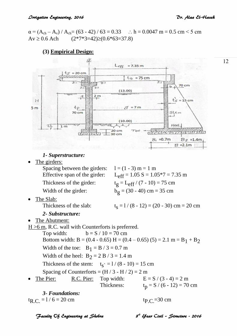
(3) Empirical Design:
1- Superstructure:
The girders:
Spacing between the girders: l = (1 - 3) m = 1 m
Effective span of the girder: Leff = 1.05 S = 1.05*7 = 7.35 m
Thickness of the girder: tg = Leff / (7 - 10) = 75 cm
Width of the girder: bg = (30 - 40) cm = 35 cm
The Slab:
Thickness of the slab: ts = l / (8 - 12) = (20 - 30) cm = 20 cm
2- Substructure:
The Abutment:
H >6 m, R.C. wall with Counterforts is preferred.
Top width: b = S / 10 = 70 cm
Bottom width: B = (0.4 - 0.65) H = (0.4 – 0.65) (5) = 2.1 m = B1 + B2
Width of the toe: B1 = B / 3 = 0.7 m
Width of the heel: B2 = 2 B / 3 = 1.4 m
Thickness of the stem: tsˋ = l / (8 - 10) = 15 cm
Spacing of Counterforts = (H / 3 - H / 2) = 2 m
The Pier: R.C. Pier: Top width: E = S / (3 - 4) = 2 m
Thickness: tp = S / (6 - 12) = 70 cm
3- Foundations: tR.C. = l / 6 = 20 cm tP.C.=30 cm
Irrigation Engineering, 2016 Dr. Alaa El-Hazek
Faculty Of Engineering at Shobra 3rd Year Civil – Structure - 2016
13
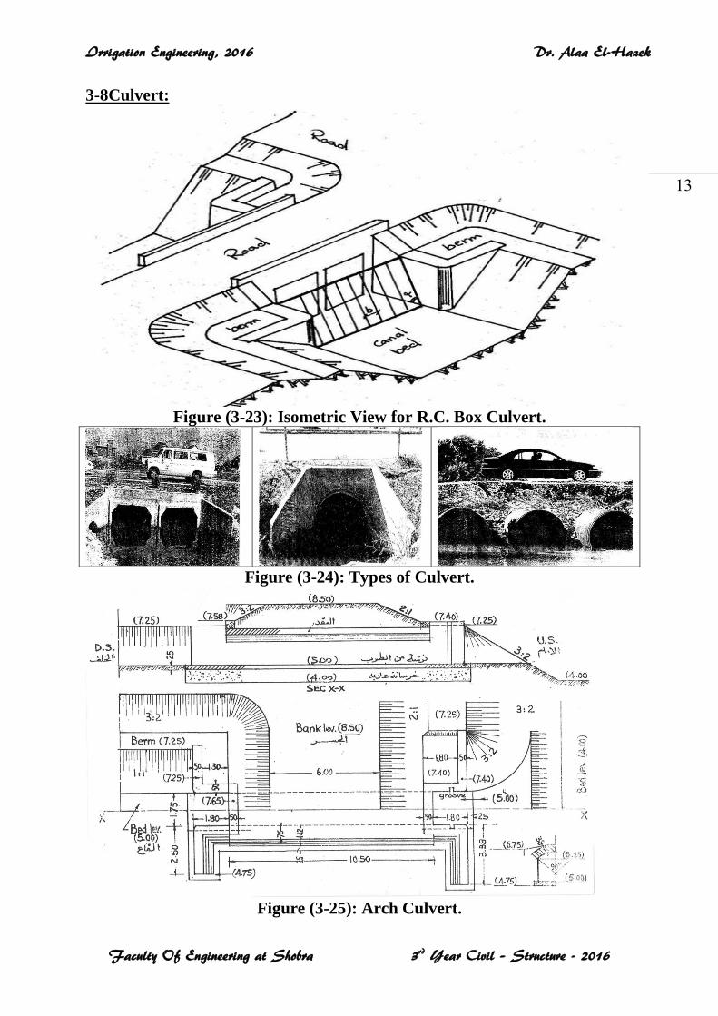
3-8Culvert:
Figure (3-23): Isometric View for R.C. Box Culvert.
Figure (3-24): Types of Culvert.
Figure (3-25): Arch Culvert.
Irrigation Engineering, 2016 Dr. Alaa El-Hazek
Faculty Of Engineering at Shobra 3rd Year Civil – Structure - 2016
14
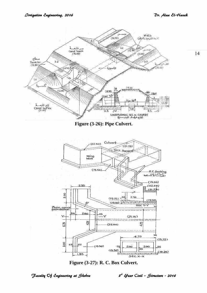
Figure (3-26): Pipe Culvert.
Figure (3-27): R. C. Box Culvert.
Irrigation Engineering, 2016 Dr. Alaa El-Hazek
Faculty Of Engineering at Shobra 3rd Year Civil – Structure - 2016
15
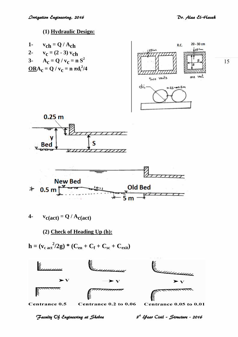
(1) Hydraulic Design:
1- vch = Q / Ach
2- vc = (2 - 3) vch
3- Ac = Q / vc = n S2
ORAc = Q / vc = n πdi2/4
4- vc(act) = Q / Ac(act)
(2) Check of Heading Up (h):
h = (vc act2/2g) * (Cen + Cf + Csc + Cexit)
Irrigation Engineering, 2016 Dr. Alaa El-Hazek
Faculty Of Engineering at Shobra 3rd Year Civil – Structure - 2016
16
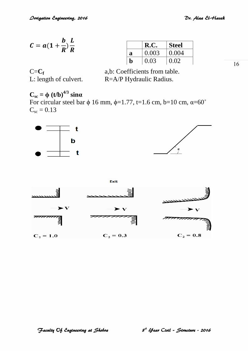
C=Cf a,b: Coefficients from table.
L: length of culvert. R=A/P Hydraulic Radius.
Csc = ϕ (t/b)4/3
sinα
For circular steel bar ϕ 16 mm, ϕ=1.77, t=1.6 cm, b=10 cm, α=60˚
Csc = 0.13
R.C. Steel
a 0.003 0.004
b 0.03 0.02
Irrigation Engineering, 2016 Dr. Alaa El-Hazek
Faculty Of Engineering at Shobra 3rd Year Civil – Structure - 2016
17
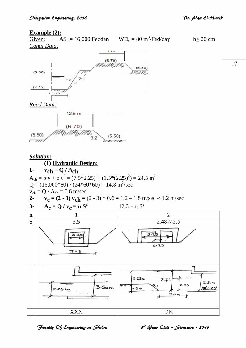
Example (2):
Given: ASc = 16,000 Feddan WDc = 80 m3/Fed/day h≤ 20 cm
Canal Data:
Road Data:
Solution:
(1) Hydraulic Design:
1- vch = Q / Ach
Ach = b y + z y2 = (7.5*2.25) + (1.5*(2.25)
2) = 24.5 m
2
Q = (16,000*80) / (24*60*60) = 14.8 m3/sec
vch = Q / Ach = 0.6 m/sec
2- vc = (2 - 3) vch = (2 - 3) * 0.6 = 1.2 – 1.8 m/sec ≈ 1.2 m/sec
3- Ac = Q / vc = n S2 12.3 = n S
2
n 1 2
S 3.5 2.48 ≈ 2.5
XXX OK
Irrigation Engineering, 2016 Dr. Alaa El-Hazek
Faculty Of Engineering at Shobra 3rd Year Civil – Structure - 2016
18
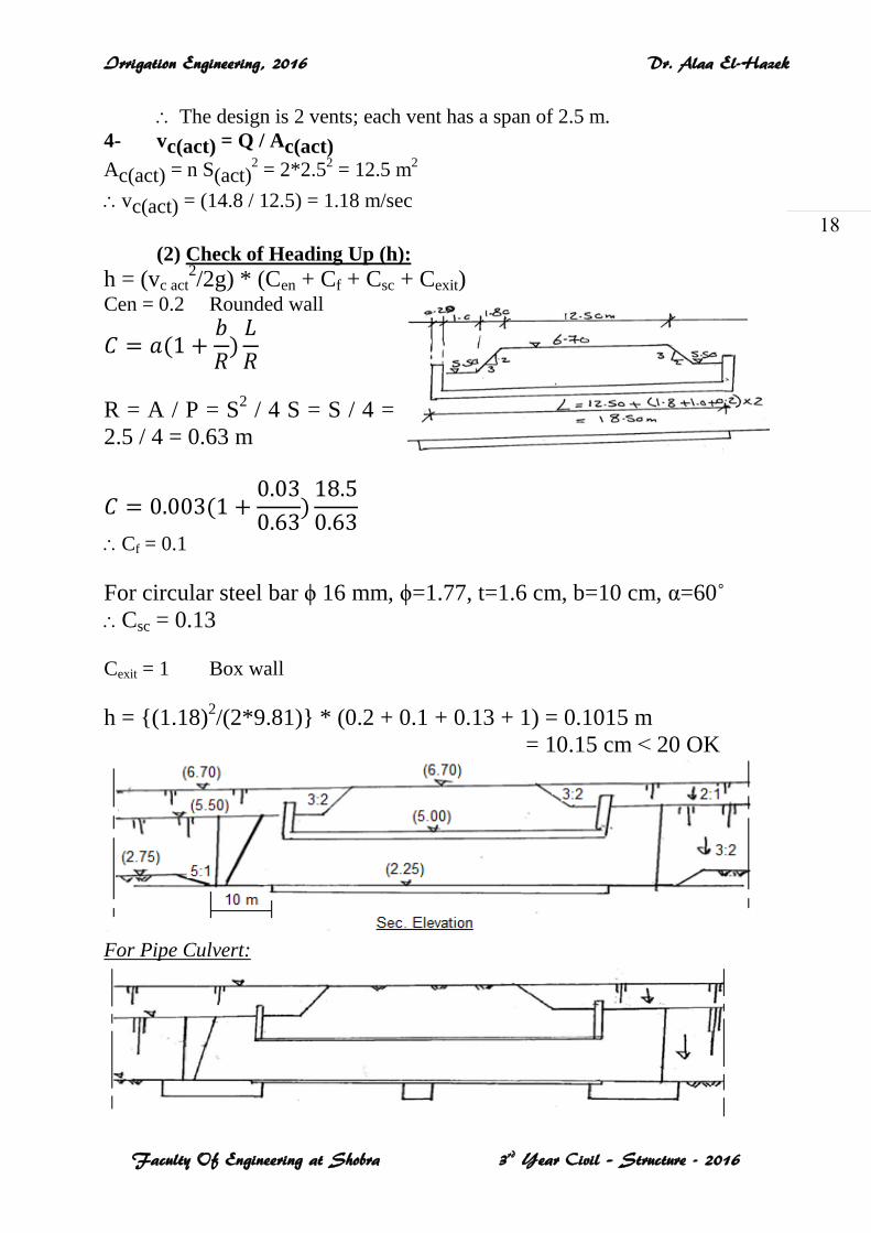
The design is 2 vents; each vent has a span of 2.5 m.
4- vc(act) = Q / Ac(act)
Ac(act) = n S(act)2 = 2*2.5
2 = 12.5 m
2
vc(act) = (14.8 / 12.5) = 1.18 m/sec
(2) Check of Heading Up (h):
h = (vc act2/2g) * (Cen + Cf + Csc + Cexit)
Cen = 0.2 Rounded wall
R = A / P = S2 / 4 S = S / 4 =
2.5 / 4 = 0.63 m
Cf = 0.1
For circular steel bar ϕ 16 mm, ϕ=1.77, t=1.6 cm, b=10 cm, α=60˚
Csc = 0.13
Cexit = 1 Box wall
h = {(1.18)2/(2*9.81)} * (0.2 + 0.1 + 0.13 + 1) = 0.1015 m
= 10.15 cm ˂ 20 OK
For Pipe Culvert:
Irrigation Engineering, 2016 Dr. Alaa El-Hazek
Faculty Of Engineering at Shobra 3rd Year Civil – Structure - 2016
19
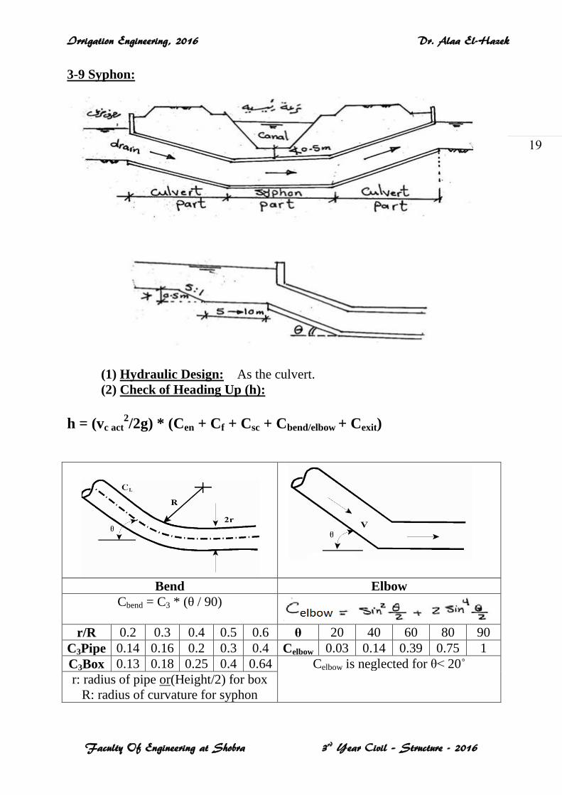
3-9 Syphon:
(1) Hydraulic Design: As the culvert.
(2) Check of Heading Up (h):
h = (vc act2/2g) * (Cen + Cf + Csc + Cbend/elbow + Cexit)
Bend Elbow
Cbend = C3 * (θ / 90)
r/R 0.2 0.3 0.4 0.5 0.6 θ 20 40 60 80 90
C3Pipe 0.14 0.16 0.2 0.3 0.4 Celbow 0.03 0.14 0.39 0.75 1
C3Box 0.13 0.18 0.25 0.4 0.64 Celbow is neglected for θ˂ 20˚
r: radius of pipe or(Height/2) for box
R: radius of curvature for syphon
Irrigation Engineering, 2016 Dr. Alaa El-Hazek
Faculty Of Engineering at Shobra 3rd Year Civil – Structure - 2016
21
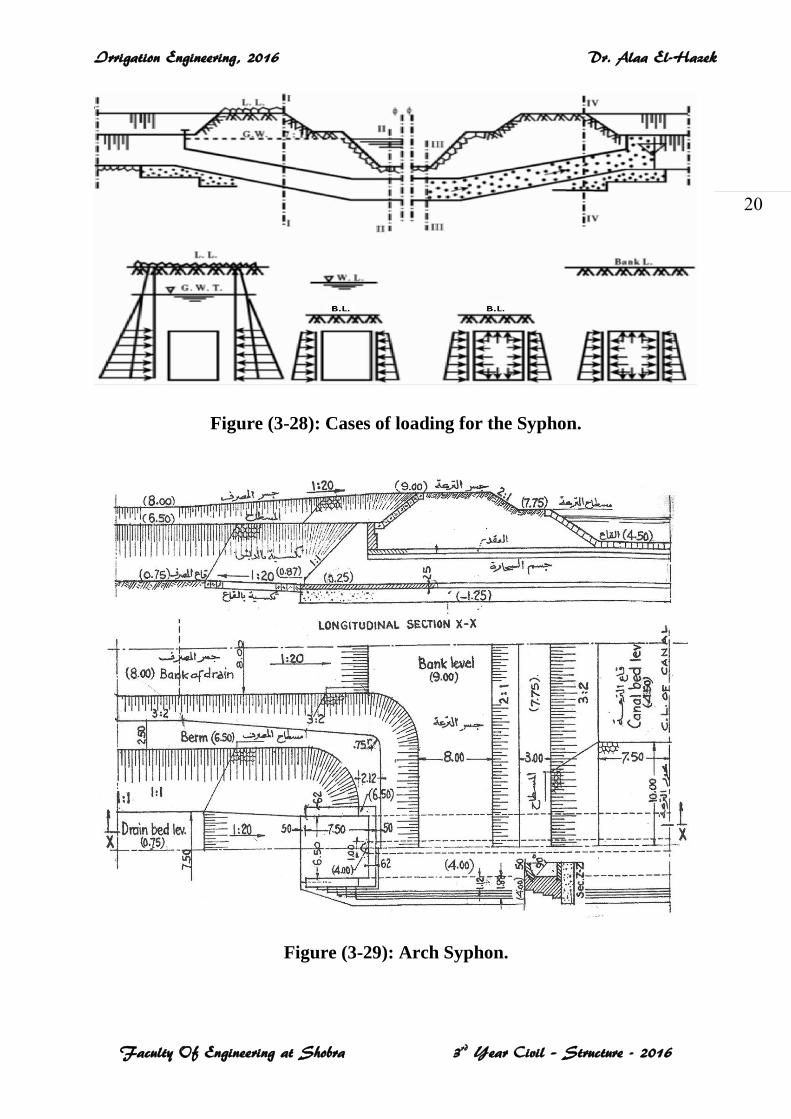
Figure (3-28): Cases of loading for the Syphon.
Figure (3-29): Arch Syphon.
Irrigation Engineering, 2016 Dr. Alaa El-Hazek
Faculty Of Engineering at Shobra 3rd Year Civil – Structure - 2016
21
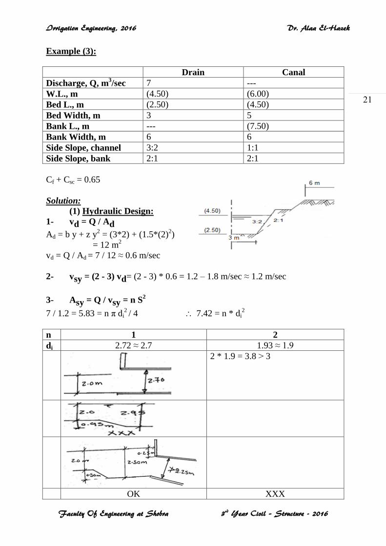
Example (3):
Drain Canal
Discharge, Q, m3/sec 7 ---
W.L., m (4.50) (6.00)
Bed L., m (2.50) (4.50)
Bed Width, m 3 5
Bank L., m --- (7.50)
Bank Width, m 6 6
Side Slope, channel 3:2 1:1
Side Slope, bank 2:1 2:1
Cf + Csc = 0.65
Solution:
(1) Hydraulic Design:
1- vd = Q / Ad
Ad = b y + z y2 = (3*2) + (1.5*(2)
2)
= 12 m2
vd = Q / Ad = 7 / 12 ≈ 0.6 m/sec
2- vsy = (2 - 3) vd= (2 - 3) * 0.6 = 1.2 – 1.8 m/sec ≈ 1.2 m/sec
3- Asy = Q / vsy = n S2
7 / 1.2 = 5.83 = n π di2 / 4 7.42 = n * di
2
n 1 2
di 2.72 ≈ 2.7 1.93 ≈ 1.9
2 * 1.9 = 3.8 ˃ 3
OK XXX
Irrigation Engineering, 2016 Dr. Alaa El-Hazek
Faculty Of Engineering at Shobra 3rd Year Civil – Structure - 2016
22
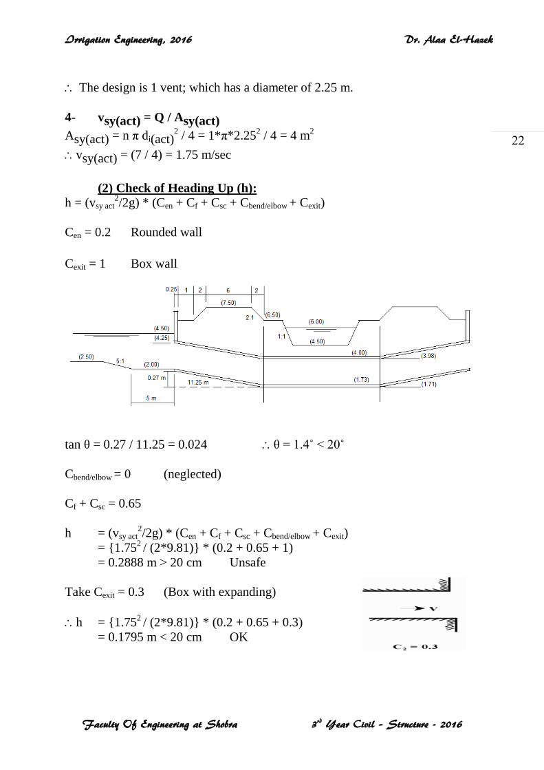
The design is 1 vent; which has a diameter of 2.25 m.
4- vsy(act) = Q / Asy(act)
Asy(act) = n π di(act)2 / 4 = 1*π*2.25
2 / 4 = 4 m
2
vsy(act) = (7 / 4) = 1.75 m/sec
(2) Check of Heading Up (h): h = (vsy act
2/2g) * (Cen + Cf + Csc + Cbend/elbow + Cexit)
Cen = 0.2 Rounded wall
Cexit = 1 Box wall
tan θ = 0.27 / 11.25 = 0.024 θ = 1.4˚ < 20˚
Cbend/elbow = 0 (neglected)
Cf + Csc = 0.65
h = (vsy act2/2g) * (Cen + Cf + Csc + Cbend/elbow + Cexit)
= {1.752 / (2*9.81)} * (0.2 + 0.65 + 1)
= 0.2888 m ˃ 20 cm Unsafe
Take Cexit = 0.3 (Box with expanding)
h = {1.752 / (2*9.81)} * (0.2 + 0.65 + 0.3)
= 0.1795 m < 20 cm OK
Related Documents