THE UNITED REPUBLIC OF TANZANIA MINISTRY OF WATER AND IRRIGATION WATER PIPELINES SPECIFICATIONS FIRST EDITION MAY 2007

Welcome message from author
This document is posted to help you gain knowledge. Please leave a comment to let me know what you think about it! Share it to your friends and learn new things together.
Transcript

THE UNITED REPUBLIC OF TANZANIA
MINISTRY OF WATER AND IRRIGATION
WATER PIPELINES
SPECIFICATIONS
FIRST EDITION MAY 2007
MAJI PIPE SPECIFICATIONS – ISSUE 1 (May 2007)
CONTENTS Clause Description Page
PREFACE. WATER PIPELINES: DESIGN, MATERIALS AND CONSTRUCTION --------------------------------- 1
PART I – ALL PIPES, VALVES & FITTINGS DURING DESIGN, MANUFACTURE, WORKS TESTING AND SUPPLY -------------------------------------------------------------------------------------------------------------------- 2
4.1 GENERAL ---------------------------------------------------------------------------------------------------------------- 2 4.2 CERTIFICATE AND SAMPLES FROM PIPE MANUFACTURERS ---------------------------------------- 5 4.3 INSPECTION AND TESTING DURING MANUFACTURE, SUPERVISION BY PROJECT
MANAGER’S AND EMPLOYER’S REPRESENTATIVES ----------------------------------------------------- 5 4.4 THIRD PARTY INSPECTION DURING MANUFACTURER OF FIRMS WITH OR WITHOUT ISO
QUALITY ASSURANCE ACCREDITATION ---------------------------------------------------------------------- 6 4.5 ACCEPTANCE OF PIPES, VALVES AND FITTINGS ---------------------------------------------------------- 6
PART II –FERROUS PIPES DURING MANUFACTURE, SUPPLY, INSTALLATION COMMISSIONING & TESTING ------------------------------------------------------------------------------------------------------------------- 7
4.6 DUCTILE IRON PIPES AND FITTINGS - MATERIALS AND STANDARDS, ----------------------------- 7 4.7 BARRIER COATED STEEL PIPES AND FITTINGS - MATERIALS AND STANDARDS ------------ 10 4.8 HOT DIPPED ZINC (GALVANISED) COATED STEEL PIPES AND FITTINGS (GS / GI)-
MATERIALS AND STANDARDS ---------------------------------------------------------------------------------- 13 4.9 JOINING TO STEEL PIPES WITH BARE STEEL ENDS, ABOVE GROUND PIPELINES AND
FITTINGS AND PIPELINES IN BACKFILLED TRENCHES BOLTED BY FLEXIBLE COUPLINGS (MOULDING METHOD) --------------------------------------------------------------------------------------------- 14
4.10 PACKING FOR TRANSPORT BY SHIP – FERROUS PIPES ---------------------------------------------- 14 4.11 IN-COUNTRY STORAGE, HANDLING AND TRANSPORTATION OF FERROUS PIPES --------- 15 4.12 DISTRIBUTION OF FERROUS PIPES FROM STORAGE ------------------------------------------------- 16 4.13 FLANGED JOINTS FOR FERROUS PIPES AND FITTINGS ---------------------------------------------- 16 4.14 FLEXIBLE JOINTS --------------------------------------------------------------------------------------------------- 16 4.15 COMPLETION OF EXTERNAL PROTECTION AT FLEXIBLE JOINTS ON FERROUS PIPELINES
17 4.16 TRENCH EXCAVATION AND EARTHWORKS FOR FERROUS PIPES -------------------------------- 18 4.17 PIPE LAYING FOR FERROUS PIPES--------------------------------------------------------------------------- 20 4.18 BACKFILLING OF PIPE TRENCHES- FERROUS PIPES -------------------------------------------------- 22 4.19 MAKING GOOD SUBSIDENCE AFTER REFILLING -------------------------------------------------------- 25 4.20 REINSTATEMENT OF SURFACES ------------------------------------------------------------------------------ 25
PART III – THERMOPLASTIC PIPES DURING MANUFACTURE, SUPPLY, INSTALLATION, COMMISSIONING & TESTING ------------------------------------------------------------------------------------ 26
4.21 MATERIALS AND STANDARDS, UNPLASTICISED PVC PIPES AND JOINTS ---------------------- 26 4.22 MATERIALS & STANDARDS, HIGH DENSITY POLYETHYLENE PIPES AND FITTINGS --------- 32 4.23 TRENCH EXCAVATION AND EARTHWORKS FOR THERMOPLASTIC PIPES --------------------- 35 4.24 PIPE LAYING FOR THERMOPLASTIC PIPES ---------------------------------------------------------------- 37 4.25 BACKFILLING OF PIPE TRENCHES FOR THERMOPLASTIC PIPES---------------------------------- 39 4.26 MAKING GOOD SUBSIDENCE AFTER REFILLING -------------------------------------------------------- 42 4.27 REINSTATEMENT OF SURFACES ------------------------------------------------------------------------------ 42
PART IV - ALL PIPELINES DURING DELIVERY, INSTALLATION, TESTING AND COMMISSIONING --- 43 4.28 ON-SITE INSPECTION ---------------------------------------------------------------------------------------------- 43 4.29 HANDLING FROM STORAGE TO TRENCH ------------------------------------------------------------------- 43 4.30 MEASUREMENT FOR PIPE LAYING --------------------------------------------------------------------------- 43 4.31 WORKING WIDTH --------------------------------------------------------------------------------------------------- 44
1
2
4.32 LOCATION OF UNDERGROUND SERVICES ETC. --------------------------------------------------------- 44 4.33 CONCRETE PROTECTION ---------------------------------------------------------------------------------------- 44 4.34 ANCHOR BLOCKS --------------------------------------------------------------------------------------------------- 44 4.35 ADDITIONAL PROTECTION TO FLEXIBLE COUPLINGS AND FLANGE ADAPTORS IN
CHAMBERS AND/OR ABOVE GROUND ----------------------------------------------------------------------- 45 4.36 PROTECTION TO FLEXIBLE COUPLINGS AND FLANGED ADAPTORS FITTED TO EPOXY
COATED PIPE SPIGOTS. ------------------------------------------------------------------------------------------ 45 4.37 IN-SITU WELDING OF STEEL FITTINGS AND FLANGES ------------------------------------------------- 45 4.38 PIPE SUPPORTS ----------------------------------------------------------------------------------------------------- 45 4.39 SERVICE PIPE CONNECTIONS --------------------------------------------------------------------------------- 45 4.40 HYDROSTATIC TESTING OF PIPELINES --------------------------------------------------------------------- 46 4.41 FLUSHING AND STERILISATION ------------------------------------------------------------------------------- 47 4.42 MARKER POSTS ----------------------------------------------------------------------------------------------------- 47 4.43 HORIZONTAL DIRECTIONAL DRILLING (HDD) FOR ROAD AND RAILWAY CROSSINGS ----- 47 4.44 TIE-IN WORKS BETWEEN EXISTING AND NEW PIPELINES ------------------------------------------- 52
PART V - VALVES, FITTINGS , AND OTHER RELATED ITEMS ------------------------------------------------- 56 4.45 VALVES - GENERAL ------------------------------------------------------------------------------------------------ 56 4.46 GATE VALVES -------------------------------------------------------------------------------------------------------- 56 4.47 BUTTERFLY VALVES ----------------------------------------------------------------------------------------------- 57 4.48 HANDWHEELS AND VALVE CAPS AND VALVES --------------------------------------------------------- 58 4.49 VALVE KEYS ---------------------------------------------------------------------------------------------------------- 58 4.50 NON-RETURN VALVES -------------------------------------------------------------------------------------------- 58 4.51 AIR RELEASE AND VACUUM BREAK VALVES ------------------------------------------------------------- 58 4.52 SURFACE BOXES --------------------------------------------------------------------------------------------------- 59 4.53 VALVE CHAMBERS ------------------------------------------------------------------------------------------------- 59 4.54 VALVE CHAMBER COVERS -------------------------------------------------------------------------------------- 60 4.55 RESERVOIR INLET VALVES ------------------------------------------------------------------------------------- 60 4.56 TWO-POINT TIME-MODULATED PRESSURE REDUCING VALVES ---------------------------------- 60 4.57 THREE-WAY T-PORT PLUG OR BALL CONTROL VALVE ----------------------------------------------- 61 4.58 WATER METERS ----------------------------------------------------------------------------------------------------- 61 4.59 BURSTING DISCS AND BURSTING DISCS DEVICES ----------------------------------------------------- 62 4.60 INDICATOR PLATES ------------------------------------------------------------------------------------------------ 62
APPENDIX
APPENDIX A: SPECIFICATION CROSS REFERENCE NUMBERS (SCSRN) NUMBERS, AS AT APRIL 2007

PREFACE: WATER PIPELINES: DESIGN, MATERIALS AND CONSTRUCTION The Ministry of Water has adopted the following pipe materials policy in an effort to balance the capital investment cost, the operation and maintenance cost, the social implications and the environmental health implications in the supply and installation of water pipelines. The Ministry has therefore endeavoured to ensure that adherence to these pipe specifications meets the following criteria: • Unless specifically prohibited, or constrained by socio-environmental consequences as
hereinafter indicated, manufacturers and contractors are free to bid for any of the four pipe material against all pipeline diameters and the market price at the time of bidding shall be allowed to determine what material is used;
• The specifications should be performance based with guidance given to design requirements, acceptable grade, trenching conditions, etc. for each material likely to be bid;
• There should be one general approach to specifying pipeline materials and this should only be varied for specific design situations such as a major transmission main, unusually high working pressures, etc.;
• Specifications should not unduly prejudice local manufacturers but neither should they ignore international best practice in regards to the standards of design and construction
• Unless specifically indicated or allowed otherwise, e.g. hot dipped zinc (galvanised) steel pipes of diameter less than DN 80, the minimum design working life shall be 40 years and pipe manufacturers shall provide a written guarantee to this effect which shall nevertheless be conditional upon the installation requirements of this specification being complied with.
As far as it has been possible, these specifications balance the rigorous requirements across the board for all pipe materials in conformance to their international standard and best practice. This also takes account of the issue of equivalent pressure rating for thermoplastic pipes to meet both hydraulic and area specific conditions such as temperature, loading, impact fatigue and the like and the issue of durable and long lasting coating and lining for ferrous pipes. For this reason, it is preferable to refer to the Standard Dimension Ratio (SDR) (i.e. outside diameter/wall thickness) rather than to a pressure class when specifying thermoplastic pipes. In case of any doubts, respective international standards shall apply, strengthened where indicated by National Standards.
The specifications on pipe materials presented in this section shall therefore have precedence over other clauses that discuss same issues elsewhere in this Specification Volume. The preferred standard specification is clearly indicated in every case. However, possible alternatives known to be available in certified English translation are acceptable. For these Specification Cross Reference Numbers, (SCRNs), please refer to Appendix A. However, and where an ISO reference is indicated in Appendix A as not be equal or not equivalent, it shall be strengthened by one of the corresponding SCRNs. Whilst every effort has been made to quote the latest available version of the Standard Specifications mentioned herein as at the date of this edition (May 2007), due to continuous research and development on enhancing asset useful life, these standards are frequently being updated, revised or replaced, and in all cases, the editions current at the time of bidding shall be applicable. In particular, it should be noted that EuroNorms (ENs) are replacing National European Standard Specifications.
Design, whether it be prior to bidding or for variations or additions during construction shall meet the requirements of the design standards as indicated herein and be in general accord with Chapter 4 of the MAJI Water Design Manual, 2009, 3rd edition.
1

PART I – ALL PIPES, VALVES & FITTINGS DURING DESIGN, MANUFACTURE, WORKS TESTING AND SUPPLY
4.1 GENERAL
This specification applies in particular to water supply pipework. Pipes, valves and fittings shall comply with the relevant International and/ or National Specifications as stated hereinafter.
In general the recommendations contained in EN 1295 pt 1:B.1.1.2 with regards to pipe design), and BS 8010, EN 1610 and BSCP 2010 or their equal (with regards to general pipe work and its installation) shall be followed in so far as they are relevant to the prevailing conditions. For design recommendations not covered by EN 1295, reference should be made to EN 545 for ductile iron pipes; BS 534, EN 10224, EN 10311 and AWWA M11 for steel pipes; BS 2782, BS 3505, BSCP 312, EN 921 and for PVCu; and BS 3284 and EN 12201 for HDPE (PE100) pipes. Other related standards listed in Appendix A are also relevant and pipe materials and their installation shall conform to them as well. At all times latest editions and updated standards and procedures for design and installation shall be used and adopted. This will ensure that the employer benefits from superior materials with enhanced useful life. In the same context the Contractor may provide, with the approval of the Project Manager, superior materials using other standards not listed here provided they can demonstrate this to be the case through tests, examples and guarantee certifications.
Except where otherwise specifically indicated, all ferrous pipes of DN 80 and above shall be barrier coated.
The Contractor shall be wary of the worst case scenarios making their pipes unsuitable and these can be caused by such things as unsuitable soils, shallow depths, bedding types and extraordinary traffic loads among other things and the Contractor shall inform the Project Manager when they occur. Such incidences shall be remedied by using a higher class of pipe (wall thickness and/or yield stress) and / or bedding as shall be directed.
As a general guidance, the pipes proposed for the Contract shall conform to the following international and national standards unless a superior quality is demonstrated.
Standards for Pipes and Pipelines Pipeline general EN 1295 Section 1.B1.12 – Structural Design of Buried Pipelines, saving
that where the Specification is silent on any pertinent matter, then the alternative relevant part of the SCRN (e.g. AWWA) indicated shall be complied with
BS 8010 British Standard Code of Practice for Pipelines Part 2 Pipeline on land : Design, construction and installation
Section 2.1 1987 – Ductile Iron Part 3 1993 – Pipelines subsea – design, construction and installation
BSCP 2010 – 2 – Design and Construction of Steel Pipeline Inland
Steel pipes & fittings Pipes EN 10224
Standard steel grades, ISO 559 (higher grades may be specified or allowed only with the written authorisation of the Project Manager.
Wall thickness ISO 559 as a minimum, unless otherwise indicated or specifically authorised following a design certified by the manufacturer
Flanges EN 1092 Coating and Lining DIN 30675 Part I for Type III soils (unless detailed field
tests have proven Type I and II soils to be exclusively present).
Ductile Iron pipes Pipes and joints EN 545
2

and Fittings Flanges EN 1092 Coating and Lining DIN 30675 Part 2 for Type III soil (unless detailed field
tests have proven Type I and II soils to be exclusively present), and DIN 30674 Part 1
PVC pipes ISO 4422 and EN 1452 Fittings shall in general be steel or ductile iron. Injection moulded PVCu
bends and tees shall be allowed.
HDPE pipes & fittings ISO 4427 and EN 12201 Fittings shall in general be steel or ductile iron whilst electro-fusion jointed bends and tees shall be allowed providing these are not formed by bending straight pipe below the minimum radius specified.
These and other specific standard specifications are listed in Appendix A – SCRNs.
Design Criteria for All Pipelines
Ductile iron pipes are classified as semi-rigid pipes whilst steel and thermoplastic pipes are classified as flexible and any design must take the different requirements between the two into account.
Materials data for all pipes is required to enable structural design to proceed. Common to all is the internal diameter, excluding lining (if any) and where applicable including lining as well as the wall thickness being considered. All flexible pipes also require the stiffness, [S=E × I/D3] to be taken into account.
In addition, steel requires knowledge of the maximum allowable working pressure, the maximum allowable surge pressure, the allowable stress and the allowable deflection, whilst PVCu and pipes comprising PE require knowledge of long term ring bending modulus of elasticity, the allowable deflection, cyclic fatigue and the allowable long term combined stress.
In all cases, hydraulic design shall be based on the actual internal diameter and NOT the Nominal Diameter (DN) as well as the appropriate roughness (k) in mm.
Except where otherwise indicated, pipes have been designed to allow for the conditions listed in the Table below . Where in the opinion of the Project Manager, actual site conditions result in loads and stresses greater than allowed for, the Project Manager may require the pipe design to be modified to account for such changes in design assumptions. Unless authorised otherwise in writing by the Project Manager, these criteria shall also be used for any design undertaken during the construction stage.
Criteria Units Value Specific Design Necessary Minimum Pipe Cover Thermoplastic pipes Ferrous Pipes Transmission Mains (all)
mm mm mm
900 600 900
May be increased for road crossings
Minimum Trench Width DN < 125 DN 125 to < 300 DN 300 to < 600 Diameter > 600
mm mm mm mm mm
600
General minimum trench widths OD + 450 OD + 600 OD + 900 OD + 1200
Soil Type Expected Native Soil Modulus E’3
MPa
2.5
Clayey silty sand, loose condition
Cont’d
3
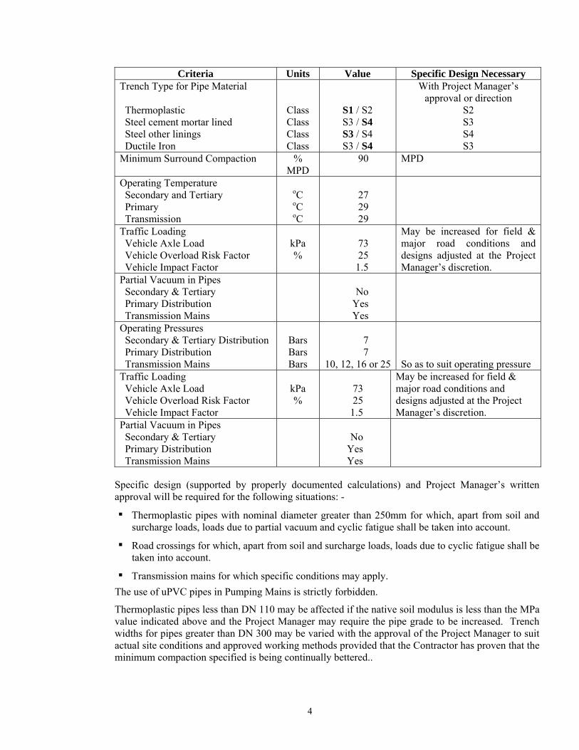
Criteria Units Value Specific Design Necessary Trench Type for Pipe Material Thermoplastic Steel cement mortar lined Steel other linings Ductile Iron
Class Class Class Class
S1 / S2 S3 / S4 S3 / S4 S3 / S4
With Project Manager’s approval or direction
S2 S3 S4 S3
Minimum Surround Compaction % MPD
90 MPD
Operating Temperature Secondary and Tertiary Primary Transmission
oC oC oC
27 29 29
Traffic Loading Vehicle Axle Load Vehicle Overload Risk Factor Vehicle Impact Factor
kPa %
73 25
1.5
May be increased for field & major road conditions and designs adjusted at the Project Manager’s discretion.
Partial Vacuum in Pipes Secondary & Tertiary Primary Distribution Transmission Mains
No
Yes Yes
Operating Pressures Secondary & Tertiary Distribution Primary Distribution Transmission Mains
Bars Bars Bars
7 7
10, 12, 16 or 25
So as to suit operating pressure
Traffic Loading Vehicle Axle Load Vehicle Overload Risk Factor Vehicle Impact Factor
kPa %
73 25
1.5
May be increased for field & major road conditions and designs adjusted at the Project Manager’s discretion.
Partial Vacuum in Pipes Secondary & Tertiary Primary Distribution Transmission Mains
No
Yes Yes
Specific design (supported by properly documented calculations) and Project Manager’s written approval will be required for the following situations: -
▪ Thermoplastic pipes with nominal diameter greater than 250mm for which, apart from soil and surcharge loads, loads due to partial vacuum and cyclic fatigue shall be taken into account.
▪ Road crossings for which, apart from soil and surcharge loads, loads due to cyclic fatigue shall be taken into account.
▪ Transmission mains for which specific conditions may apply. The use of uPVC pipes in Pumping Mains is strictly forbidden.
Thermoplastic pipes less than DN 110 may be affected if the native soil modulus is less than the MPa value indicated above and the Project Manager may require the pipe grade to be increased. Trench widths for pipes greater than DN 300 may be varied with the approval of the Project Manager to suit actual site conditions and approved working methods provided that the Contractor has proven that the minimum compaction specified is being continually bettered..
4
For ferrous pipes of diameter less than DN 80 mm and where a non-barrier, (that is a metallic type coating) such as zinc has been specified or approved as part of the protection system, additional on-site protection as indicated herein for buried screwed joints and joints incorporating bolts must be strictly complied with and no exceptions whatsoever will be allowed.
4.2 CERTIFICATE AND SAMPLES FROM PIPE MANUFACTURERS
Where specifically required by the Bidding Document, samples shall have been provided by the Contractor at the time of Bidding and these, if accepted, shall be used for the purpose of comparison with all components of a similar nature delivered subsequently. Any subsequent goods supplied that do not meet the standards of the sample shall be liable to rejection with all consequences to the cost of the Contractor.
The Contractor shall within 42 days of award, supply to the Project Manager a signed certificate from the pipe manufacturer(s) stating that the pipes and fittings comply in all respects with the provisions of these Specification and the indicated National or International Standards, and that they shall conform to the required standards for all raw materials, processes, quality control, manufacturing, and for fully manufactured products including where appropriate, the handling to shipment. The pipe and fittings manufacturer’s key personnel shall have at least three (3) years relevant manufacturing experience especially in regards to plant management, quality control / quality assurance, application of the coating and lining systems offered in the bid, and selection / batching / mixing of raw materials, and in the case of thermoplastic pipes, the manufacturer (or licensor in the case of local manufacture under license) shall certify that the requirements of SABS 966-1:06 Table B.1 have been complied with. The Contractor shall have submitted reasonable documentary evidence with its bid to support statements made in the bid documents in this regard. The manufacturer shall also state that they have the ability to carry out the necessary tests during the manufacturing process and tests on the finished products as required by the respective standards.
If the manufacturer of any pipe, valve or fitting supplied under this Contract has a Quality Assurance (QA) System complying with ISO 9000/9001/9002, he shall submit a notarised copy of a fully independent 3rd Party certification to that effect together with sufficient information from his Quality Assurance Plan (in English) to enable the Project Manager and the Employer to understand the levels of performance he has undertaken to honour. Where a manufacturer is not ISO QA certified, then a full copy of his Quality Assurance Plan (in English), shall be submitted.
The Contractor shall furnish the Project Manager with a manufacturer’s certificate in respect of every consignment of the pipeline materials, confirming that all the items of the consignment comply in all respects with the requirement of the specified standards and of this specification. The original and one copy of such manufacturer’s certificate shall be delivered to the Project Manager prior to shipment in the case of imported pipes and prior to despatch from the factory in the case of local manufacture.
4.3 INSPECTION AND TESTING DURING MANUFACTURE, SUPERVISION BY PROJECT MANAGER’S AND EMPLOYER’S REPRESENTATIVES
In addition to Clause 4.2, during manufacture and before despatch of pipes and fittings from the place of manufacture the Contractor shall allow for inspection by the Project Manager or his representative and the Employer of all the manufacturing processes and tests on raw materials and finished products. The inspection may include attendance at all pressure and material tests, execution of dimensional checks and inspection of the workmanship and standard of manufacture with scrutiny of evidence of the materials used in the fabrication of the Pipeline Materials.
5
The Project Manager and the Employer’s representative shall be allowed full access to all areas at the place of manufacture or elsewhere where testing, furnishing or preparation of materials for the performance and testing of work under this Specification is taking place.
The Contractor shall furnish the Project Manager with reasonable facilities and space (without charge) for the inspection, testing and obtaining of such information as he desires respecting the character of material in use and the progress and manner of the work.
The Contractor shall arrange for such testing at his cost as may be required to be carried out at the place of manufacture according to this Specification. If there are no facilities at the place of manufacture for making the prescribed tests the Contractor shall bear the cost of carrying out the tests elsewhere or avail an acceptable third party institution to carry out such tests.
The Contractor shall supply test certificates and shall furnish and prepare the necessary test pieces and samples and shall supply and provide all test rigs, equipment appliances, labour and any other facility required for inspection and testing.
During the duration of the Contract, the Contractor shall propose a schedule and meet all costs for two inspection visits to the each manufacturer’s yard by a total of three representatives of the Employer and the Project Manager during the manufacturing and pre-shipment stages.
4.4 THIRD PARTY INSPECTION DURING MANUFACTURER OF FIRMS WITH OR WITHOUT ISO QUALITY ASSURANCE ACCREDITATION
As quality assurance is considered to be of the utmost importance to ensure the required asset lives, all manufacturers of pipes and fittings shall have facilities that conform to international standards and also carry out tests related to manufacturing process, finished products and handling to shipment.
Where Third Party inspection is specified or in the Project Manager or Employer’s view becomes necessary, this shall be provided by an independent, non-governmental body acceptable to the Employer.
In the event, during inspections and tests carried out in the presence of the Employer and Project Manager’s representatives as stated in Clause 4.3 if any inadequacies in the manufacturing process are shown resulting in non-conformance in finished products to an level considered unacceptable to the Employer, solely at his own discretion, the Employer will deploy his agent or third party inspector to carry out independent third party inspection. Where such inspections or tests show that there is conformance, the costs shall then be borne by the Employer, but otherwise by the Contractor. In the event of non-conformance, the supply and incorporation of materials from such a source shall be stopped immediately until further notice and the Contractor shall instead provide materials from another approved source. The Contractor shall be required to replace at his cost all the rejected non-conforming materials including the cost of this inspection in the event such third party inspection reveal non-conformance in manufacturing and quality standards. The inspectors from the independent inspectorate shall be provided with full access to carry out third party inspection including the use of the in-house testing processes, failing which all manufacturing at the specific manufacturers premises will be rejected forthwith and all costs of whatsoever a nature, both direct and indirect shall be borne by the contractor.
Contractors are advised to take out the necessary insurances to cover such a possible eventuality, or to have covered these risks in the contract with their manufacturer(s).
4.5 ACCEPTANCE OF PIPES, VALVES AND FITTINGS
Only pipes, valves and fittings that are manufactured using acceptable materials, tested and delivered by firms which had been proven at the time of tender to be listed under the ISO standards hereinabove provided for, or alternatively, pipes, valves and fittings, which have been certified as
6
acceptable subsequent to Third Party Inspection as herein provided for, shall be accepted as conforming to the Contract. Any other pipes, valves and fittings, shall be liable for rejection at the Contractor's risk, cost and responsibility.
Compliance with the provision of this Clause shall be separate and additional to the Contractor's compliance with the requirements of Tanzanian customs authorities for pre- or post- shipment inspection of imports into Tanzania. The costs for such inspection shall also be fully borne by the Contractor.
PART II –FERROUS PIPES DURING MANUFACTURE, SUPPLY, INSTALLATION COMMISSIONING & TESTING
For ferrous pipes, emphasis is laid on corrosion protection and therefore no compromise will be accepted in pipe wall thickness, lining and coating, such that as far as possible the asset life is at least 40 years. Unlike thermoplastic pipes, ferrous pipes can withstand higher external pressure and therefore the bedding class requirements are less stringent provided they do not negatively affect the coating. It is pertinently important therefore for the Contractor to ensure that their ferrous pipe manufacturers are able to supply pipes and fittings with the specified lining and coating materials in compliance with the required recognised international standards. The manufacturer shall also be able to demonstrate that the lining and coating materials and application provided withstand all the necessary tests as detailed in this specification.
In lieu of this emphasis, it is important that all international and latest updated standards are applicable for ferrous pipes so that the asset useful lives are enhanced by providing more robustness and superior lining and coating materials. Standards that provide superior materials shall therefore apply.
4.6 DUCTILE IRON PIPES AND FITTINGS - MATERIALS AND STANDARDS,
Ductile iron pipes and fittings shall generally comply with EN 545:2000, ISO 2531 and other international standards that specify superior pipe thickness and lining / coating materials.
a) Socketed Pipes
Ductile Iron Socketed pipes shall be centrifugally cast in accordance with BS 8010 section 2.1 and EN 545. The minimum tensile strength shall be 420 N/mm2 and the minimum 0.2% proof stress shall be 300 N/mm2. The minimum elongation after fracture shall be 10% for nominal diameters DN 60 to 1,000 and 7% for nominal diameters DN 1,200 to 2,000.
Centrifugally cast ductile iron pipes shall be individually subjected to a works hydrostatic test of not less than 10 seconds duration.
All pipes supplied shall conform to class K9 and fittings shall conform to K12 unless specifically indicated otherwise on drawings, bills of quantities or design criteria. The thickness of Class K9 pipes shall conform to SRN 202.
If specifically called for elsewhere in this Bid Document, for pipe sizes DN 300 and above, the Contractor shall excavate trial pits along the proposed pipe alignment at not more than 500 metre intervals to a depth of not less than 2.0 metres and describe in detail or determine the appropriate native soil modulus for each section of pipe, and manufacturers/ contractors will have been required to submit, detailed calculations for the design of the pipe based on these findings. For pipe sizes DN 300 and greater, the Contractor shall (if required) determine the native soil corrosion characteristics in accordance with DIN 50929 to confirm whether the specified pipe coatings provide adequate protection in keeping with an expected life of 40 years.
7
b) Socketed Joints
Socketed joints shall be of the push-on type to EN 545 unless otherwise specified on drawings or in bills of quantities. The material used for the rubber gaskets shall be either natural rubber or synthetic elastomer to EN 681 and EN 682, and they shall be stored in accordance with EN 2230.
c) Flanged Pipes
Ductile Iron Flanged Pipes shall be centrifugally cast to EN 545.
They shall be joined using a rubber gasket of minimum thickness of 3 mm which shall be reinforced unless otherwise indicated on drawings or in bills of quantities. The material used shall be either natural rubber or synthetic elastomer in accordance with EN 681 and EN 682, which shall be stored in accordance with EN 2230. Pipe thickness shall conform to EN 545 class K9 unless otherwise indicated on drawings or in the bills of quantities.
d) Internal and External Works Protection
PIPES
COATINGS:
All coating for ductile iron pipes shall be barrier coatings and conform to DIN 30675 Part 2 for Type III soil or equal unless specifically indicated otherwise in the Bills of Quantities.
The coating for urban environments and coastal areas for Ductile Iron Pipes shall be a factory applied heat fused Polyethylene Coating to DIN 30674 pt 1 either by extrusion or sintering, or by any other similar material of superior coating. However, and where the alternative coating indicated for steel pipes is neither finished in a factory applied polyethylene or polypropylene then an alternative barrier coating may be supplied save that a zinc plus bitumen wash may not be offered.
For rural environments and non-coastal areas, Ductile Iron Pipes, as a minimum requirement, shall be externally protected by a metallic zinc spray coating to DIN 30674 pt3 applied directly to the warm film after annealing and covered by a layer of bituminous varnish to ISO 8179-2 but shall only be used with an anodic embedment backfill material. The mass of sprayed zinc metal shall be not less than 130 g/m2 and the thickness of the bituminous varnish not less than 70 microns. Such a coating shall not be offered for urban environments and coastal areas, or for soils with a pH value under 6, nor for peaty, boggy, silty or marshy soils.
Where the coating offered comprises zinc and bituminous varnish, a final coat of whitewash shall be applied generally in accordance to BS 7873 to reduce heat absorption. The pipe manufacturer shall also provide a polythene sleeve for site protection purposes. The sleeve shall conform to EN 14628 EN 14628and be of minimum thickness of 200 microns.
In the event that corrosive soils are encountered in rural areas, then the pipes shall be externally protected by a factory heat applied fused polythene coating by extrusion or sintering, to DIN 30674 Part 1 or equal.
In the case of Ductile Iron pipes supplied with a zinc coating and bituminous layer together with polyethylene sleeving in accordance with DIN 30675 Part 2 or equal, the Contractor shall also supply and install anodic embedment material in accordance with DIN 30675 Part 2 for Type III soils to the approval of the Project Manager and his price will be deemed to have included for the cost of this.
For pipe sizes less than DN 300, if in the opinion of the Project Manager native soil corrosion characteristics are worse than allowed for, the Project Manager may require additional protection in addition to anodic backfill materials, pipe sleeving, or pipe wrapping. For pipe sizes DN 300 or greater, the Contractor shall (if called for) determine the native soil corrosion characteristics in accordance to DIN 50929 to confirm whether the specified pipe coatings provide adequate protection in keeping with an expected life of 40 years.
8
The Contractor shall test along the alignment of the pipeline at intervals not exceeding 500m and to a depth not less than the depth of the required trench. Where in the opinion of the Project Manager, native soil corrosion characteristics are worse than the expected, the Project Manager may require additional protection to be provided involving measures such as anodic backfill material, increased standard of pipe coatings, pipe sleeving, pipe wrapping or cathodic protection. The Contractor shall be compensated for additional protection against corrosion required by the Project Manager.
LININGS:
Ductile Iron Pipes shall be internally lined with a cement mortar, centrifugally applied and conforming to EN 545 and DIN 2880.
Where the water being carried is specified as being aggressive, the internal face of the cement mortar shall be further protected by a factory applied epoxy coating.
COATING AND LINING TESTS
• Tests indicating the durability and robustness of the lining and coating shall be carried as specified in DIN 30670, DIN 30675, and DIN 30678 or equal, and in accordance with the coating and lining specifications.
The supplier shall certify that their lining and coating materials conform to these tests and shall provide the Contractor testing instruments and train technician to operate the instruments for carrying out these tests in Dar es Salaam.
e) Fittings
Ductile Iron Fittings shall be sand cast in accordance with EN 545. The minimum tensile strength shall be 400 N/mm2 and the minimum 0.2% proof stress shall be 300 N/mm2. The minimum elongation after fracture shall be 5%. All fittings shall be subjected to a works leak-tightness test using water to a pressure as given in EN 545.
Fittings shall be to thickness class K12 except for tees that shall be to thickness class K14 unless otherwise indicated in drawings or in bills of quantities. They shall be protected with a fusion-bonded epoxy, thickness range 305 minimum to 406 micron maximum.
f) Joints to Fittings
Socketed fittings, except for collars, shall be supplied with push-on joints unless otherwise called for on drawings or in bills of quantities. Collars shall be supplied with mechanical joint. Flange fittings shall be fixed by rubber gaskets as indicated above for flanged pipes.
g) Assistance by Pipe Manufacturer
The Contractor shall utilise the technical services of the pipe manufacturer, unless he already has in his proposed site team a person or persons of appropriate competence with proven experience in the laying of pipes of the type and magnitude to be provided.
The Contractor shall therefore either have clearly stated in his Tender that he has such a person or persons who shall be named and their CV.'s provided or he shall indicate the extent, nature and duration of the technical assistance he proposes to obtain from the pipe supplier. This shall include details of the personnel to be provided, and the time when such shall be available during the laying and jointing, external pipe protection work, trench backfilling and testing periods and the cost of the above shall be deemed to have been included by the Contractor in his Tender..
h) Provision of Laying Tools
The Contractor will be deemed to have allowed in his Tender for tools and equipment for use in the laying and jointing of the pipes and specials. The Contractor will also be required to provide a number of cutting devices and spare cutting discs.
9
i) Marking
Each pipe, fitting or accessory shall bear the mark of the manufacturer, and indication of its casting and be marked with its nominal diameter. As appropriate, each fitting shall bear an indication of its main characteristics. Pipes, fittings and accessories with a nominal diameter of 300 mm or more shall also bear the year of manufacture. In addition, a referencing system shall be employed by the manufacturer denoting where pipes and fittings are to be stored and located along the route of the pipeline.
j) Flexible joints for Ductile Iron Pipes
Ductile Iron pipes and fittings between sizes 65 mm diameter and 600 mm diameter shall have sockets suitable for joints to EN 545 and DIN 28603 except that from DN 300 to DN 600 mm they may have, as an alternative, sockets suitable for bolted gland joints to EN 545. Rubber rings for flexible joints to Ductile Iron pipes shall comply with EN 681 and EN 682.
4.7 BARRIER COATED STEEL PIPES AND FITTINGS - MATERIALS AND STANDARDS
Steel pipes and fittings shall generally comply with EN 10224: 2002, ISO 559, AWWA C200, and other international standards that specify superior pipe thickness and lining / coating materials. All latest and updated international standards pertaining to steel pipes and fittings shall apply.
(a) Standard Pipes and Fittings
Specifically steel pipes shall dimensionally conform to BS 534 and EN 10224, and in terms of materials, properties and tests to BS 3600 and BS 3601 and EN 10220, EN 10216 and EN 10217, and where appropriate EN 10255. Fittings shall in general conform dimensionally to BS 534, AWWA C208-01 and AWWA M11, however where specifically required the lengths of straight barrel sections may exceed or be less than standard dimensions. They shall be manufactured from pipes that have been manufactured to BS 534, EN 10224, BS 3660, EN 10220, EN 10216-1, or EN 10217-1, and successfully passed all mechanical, dimensional visual, pressure and non-destructive testing. All new welds made during the fabrication of the fitting shall be subject to non-destructive testing using either radiological, ultrasonic or dye penetrants dependant upon the geometry of the weld. Where necessary fittings shall be reinforced in accordance with AWWA C208-1 and AWWA M11.
Flanges will be to EN 1092-1. Flexible joints shall be by the use of bolted sleeve couplings to BS 534 and EN 10311 or flexible grooved joints, with a tapping boss to BSCP 2010-2 or AWWA C606-where specified in the Bills of Quantities, and of approved pattern. Alternatively, socket and spigot joints may be offered subject to BSCP 2010-2, and EN 10224 in which case saddle clamps in accordance with clause 4.39 and in number and size equivalent to that indicated in the Bills of Quantities for tapping bosses shall be provided at no extra charge.
Fitting ends for use with flexible couplings shall be true ended with the ends appropriately prepared for the type of coupling required.
Joints for site welding shall comprise a socket and special spigot (bell joint with air chamber) to BS 534 or EN 10311 such that the lining of the spigot shall be undamaged during the welding.
All bolts shall be hot dipped zinc coated and those for bolted sleeve couplings further protected with a topcoat of aluminium pigmented organic epoxy to their respective standards, unless otherwise indicated on the drawings or in the Bills of Quantities.
The Contractor shall demonstrate that the thickness and steel grade provided in accordance with ISO 559 gives a thickness adequate for the pressure calculated in accordance with EN 1295. The thickness calculation shall take into consideration the following: the operating pressure, test pressures, pressure transients or surges if applicable, external pressures, steel pipe strength characteristics, temperature, soil condition, trench width and depth and appropriate traffic loads.
10
If specifically called for elsewhere in this Bid Document, for pipe sizes DN 300 and above, the Contractor shall excavate trial pits along the proposed pipe alignment at not more than 500 metre intervals to a depth of not less than 2.0 metres and describe in detail or determine the appropriate native soil modulus for each section of pipe, and manufacturers/ contractors will have been required to submit, detailed calculations for the design of the pipe based on these findings.
(b) Manufacture of Steel Pipes
The manufacturer shall operate a quality system relating to the manufacture of pipes, and integral joints to the required specification that shall be no less rigorous than that of EN ISO 9002 to ensure that products consistently meet the required level of quality.
(c) Internal and External Works Protection
PIPES
COATINGS:
All coatings shall conform to DIN 30675 Part I for Type III soil or equal and coating thickness shall conform to DIN 30670 or equal unless a less rigorous type soil is indicated..
All coatings for DN 80 and above shall be of the factory applied barrier type.
The preferred coating for buried steel pipes shall be factory applied external protection with triple layer polythene coating (3LPE) to EN 10288 and DIN 30675 Part I for Type III soil comprising triple wrap system of fusion bonded or sprayed epoxy primer, an intermediate polymer adhesive layer and an extruded polyethylene coating providing an overall total film thickness shall not be less than that specified in EN 10288 or its equal unless single layer fusion bonded epoxy to EN 10289 is indicated in the Bill of Quantities. The epoxy thickness should be sufficient to provide a holiday free surface.
For above ground steel pipes a triple layer polypropylene coating (3LPP) with polypropylene to pr EN 10286, AWWA-C215 or DIN 30678 shall be used unless single layer fusion bonded epoxy is indicated in the Bills of Quantities.
Where a 3LPE or 3LPP coating is specified, the manufacturer shall demonstrate that the adhesion of the coating to the substrate does not lessen to extent that the PE coating could be easily cut or removed with time underground. The manufacturer shall carry out abrasive blast cleaning immediately before applying epoxy primer during the same work shift. In the case where steel plate or bare steel pipe is transported by sea to the place where coatings are applied, the steel or bare steel pipe as the case may be shall be subject to abrasive blast cleaning as well as phosphoric acid washing or chromate treatment immediately before applying epoxy primer during the same work shift.
The polyethylene offered shall be HDPE.
For the pipe sizes less than DN 300, if in the opinion of the Project Manager the soils encountered are excessively corrosive, the pipe shall be provided with additional protection such as sleeving, wrapping or cathodic protection as instructed by the Project Manager. The Contractor shall be compensated for such additional protection against corrosion.
For pipe sizes DN 300 and greater, the Contractor shall (if required) determine the native soil corrosion characteristics in accordance with DIN 50929 to confirm whether the specified pipe coatings provide adequate protection in keeping with an expected life of 40 years. The Contractor shall test along the alignment of the pipeline at intervals not exceeding 500m and to a depth not less than a depth of the required trench. Where in the opinion of the Project Manager, native soil corrosion characteristics are worse than expected, the Project Manager may require additional protection to be provided involving such measures as increased standard pipe coatings, pipe sleeving, pipe wrapping, or cathodic protection. The Contractor shall be compensated for additional protection against corrosion required by the Project Manager.
11
Protection to site welded joints shall be by a solvent free epoxy coating to AWWA C210-97 or a tape wrap to AWWA M11 as indicated in the Bills of Quantities or offered by the manufacturer.
LININGS:
For sizes less than DN 80, pipes may be protected by hot dipped zinc (galvanised) coating to EN 10240, and all buried pipes shall in addition be protected by an organic coatings such or a factory applied extruded polyethylene or by bituminous or epoxy paint in at least two coats, or alternatively in rural areas only if the risk of subsequent damage is regarded as very low by a tight fitting and strapped polythene wrap. In addition all threaded joints and any exposed threads as well as joints incorporating bolts shall be further protected after jointing, and should first be thoroughly cleaned, prepared and then wrapped in a suitable adhesive tape.
For sizes DN 80 up to and including DN 300, pipes shall either be protected internally in cement mortar or epoxy at the manufacturers stated option. Cement mortar lining shall conform to BS 534, DIN 2880-1 or AWWA C205. Where the water being carried is specified as being aggressive, the internal face of the cement mortar shall be further protected by a factory applied epoxy coating.
If specifically called for elsewhere in this Bid Document, for pipe sizes DN 300 and above, the Contractor shall excavate trial pits along the proposed pipe alignment at not more than 500 metre intervals to a depth of not less than 2.0 metres and describe in detail or determine the appropriate native soil modulus for each section of pipe, and manufacturers/ contractors will have been required to submit, detailed calculations for the design of the pipe based on these findings. For sizes above DN 300 pipes and fittings shall be lined in fusion-bonded epoxy conforming to EN 10339 unless otherwise indicated in the Bills of Quantities or directed by the Project Manager.
FITTINGS
COATINGS AND LININGS
Fittings shall be protected externally and internally by fusion-bonded epoxy to EN 10289, or AWWA C213 as specified by the manufacturer or required in the Bills of Quantities.
Flexible couplings and self-sealing (grooved) couplings shall be protected externally and internally by fusion-bonded epoxy to EN 10289.
Self-sealing (grooved) coupling shall, where specified or otherwise allowed, conform to AWWA or BSCP 2010-2. Bolts and nuts for such couplings shall be hot dipped zinc coated and capped nuts shall be provided. Bolts shall be an exact pre-determined length so that no bolt thread is exposed but so that the capped nut fully tightens without bearing down on the top of the bolt.
If specifically called for, a polythene sleeve to ISO 8180 protruding not less than 50 cm on each side of the joint shall be provided around all flexible couplings outside chambers during underground laying so as to further enhance joint protection, and shall be of minimum thickness of 200 microns. Such sleeves shall be tightly double-strapped at either end using a non-metallic strap.
COATING AND LINING TESTS
Tests indicating the durability and robustness of the lining and coating shall be carried out as specified in DIN 30670, 30675, 30678 or equal and where relevant to the coating or lining in accordance with the requirements of the coating and lining specifications.
The supplier shall certify that their lining and coating materials conform to these tests and shall provide the Contractor testing instruments and train technicians to operate the instruments for carrying out these tests in Tanzania , or if agreed at the manufacturer’s premises elsewhere.
All coating and lining shall be on site tested for holiday free surfaces using the holiday testers. No pipe shall be laid having failed the holiday tests.
12
The Contractor shall be compensated for additional protection against corrosion required by the Project Manager.
(d) Flexible joints for Steel Pipes
Steel pipes from DN 65 to DN 500, outside chambers, may be plain ended suitable for jointing with flexible couplings and flange adapters or grooved for thrust-transmitting self-sealing joints, or with socket and spigot with rubber gaskets as described herein and as indicated in the Bills of Quantities. Steel pipes from DN 550 upwards shall be plain ended suitable for jointing with flexible couplings and flange adaptors or with socket and spigot with rubber gaskets where the joint is specifically approved in advance. Steel pipes within chambers shall be suitable for jointing as shown on Tender Drawings.
Where a manufacturer opts for steel pipes with socket and spigot joints, or such joints are specifically called for, such joints shall in general conform to BSCP 2010-2, AWWA C200-97 or EN 10224, and the manufacturer shall submit calculations that the natural sag under 1.5 m of soil load with 90% compaction and a parked vehicle (wheel load and overload as defined above) will not exceed 2.0% on the spigot end of the pipe with the coating and lining as specified. The socket and spigot assembly shall be capable of withstanding a works test pressure of not less than 1.5 times the nominal pressure of the pipeline unless indicated otherwise on the Tender Drawings or in the Bills of Quantities. Sockets shall be produced integral with the pipe and be hot formed. Rubber gaskets shall conform to EN 681. Unless a high pressure seal, they shall have a front lip for dirt removal and a back lip for pressure sealing. Unless otherwise indicated on Tender Drawings or Bills of Quantities, the internal faces of the sockets shall be coated in fusion bonded or liquid epoxy. A tight clearance shall be maintained between socket and spigot and should be in the range 1.6 mm +/- 0.8 mm.
(e) Assistance by Pipe Manufacturer
The Contractor shall utilise the technical services of the pipe manufacturer, unless he already has in his proposed site team a person or persons of appropriate competence with proven experience in the laying of pipes of the type and magnitude to be provided.
The Contractor shall therefore either have clearly stated in his Tender that he has such a person or persons who shall be named and their CV.'s provided or he shall indicate the extent, nature and duration of the technical assistance he proposes to obtain from the pipe supplier. This shall include details of the personnel to be provided, and the time when such shall be available during the laying and jointing, external pipe protection work, trench backfilling and testing periods.
The cost of the above shall be deemed to have been included by the Contractor in his Tender.
4.8 HOT DIPPED ZINC (GALVANISED) COATED STEEL PIPES AND FITTINGS (GS / GI)- MATERIALS AND STANDARDS
Hot dipped zinc (galvanised) steel pipes shall only be provided where specifically allowed for in the Bills of Quantities and then only in diameters less than DN 80. An acceptable alternative to GS pipes in the diameter range DN15 mm to DN65 mm is to replace the zinc coating by either a coating of FBE or PE (if necessary after grit blasting off the zinc), with jointing then made using either similarly protected flexible couplings or flexible grooved joints.
Only heavy or medium duty pipes that as a minimum meet the requirements of the now withdrawn standard BS 1387:1985 shall be supplied and all buried pipes shall be wrapped in a polyethylene sleeve. Where treaded joints are included, the maximum working pressures for GS pipes as given in BS 1387 shall be reduced by 40%. Because threaded joints are also the weakest point of such pipes both in terms of pressure and corrosion risk, especial care shall be taken after laying at all such joints.
EN 12502-3:2004, entitled “Protection of metallic materials against corrosion” shall be consulted during design and if necessary, the minimum thickness of galvanising increased accordingly.
13
In addition joints, and any exposed threads, should be cleaned, prepared and wrapped in a suitable approved adhesive tape in accordance with the tape manufacturer’s instructions. In preparing the joint for wrapping and after cleaning this shall include the application of proprietary mastic adjacent to each side of the socket, tapered up from the pipe to the socket so as to present a smooth transition between diameters of pipe and socket and facilitate the application of the wrapping.
4.9 JOINING TO STEEL PIPES WITH BARE STEEL ENDS, ABOVE GROUND PIPELINES AND FITTINGS AND PIPELINES IN BACKFILLED TRENCHES BOLTED BY FLEXIBLE COUPLINGS (MOULDING METHOD)
Where exposed ends of existing sheathed steel pipes have not been factory coated with epoxy as indicated in Clause 4.7 (c) then the external protection to sheathed pipes and fittings jointed by mechanical couplings shall be completed by moulding the couplings with an enamel composition compatible with the enamel used for the pipe sheathing, i.e. a bituminous composition shall be used on pipes and fittings sheathed with bitumen (asphalt) enamel, and a coal tar composition shall be used on pipes and fittings sheathed with coal tar enamel.
The exposed end of the pipe or fitting shall be thoroughly cleaned (including removing whitewash from that portion of the sheathing adjacent to the joint) and dried together with that portion of the pipe that will come within the moulding box and the whole shall be painted with the quick drying primer supplied.
The inside of the moulding box and externally around the pouring gate shall be coated with a thick wash of lime of similar material to prevent any possibility of the moulding box sticking, and shall be dried thoroughly.
The moulding box shall be fitted around the coupling so that the pouring gate is at the top and the flanges and bolts of the coupling sit centrally in the recesses provided for them in the moulding box. The clip or bolts of the box shall be fitted and tightened and all joints sealed, including the joints between the box and pipes, with clay or similar material to prevent the hot composition running out.
The enamel composition shall be heated in an approved boiler (to be provided by the Contractor complete with an accurate thermometer) to the temperature recommended by the supplier, and stirred during melting to prevent overheating and the filler settling to the bottom.
The fluid enamel composition shall be slowly poured (at the temperature recommended by the supplier), taking care to prevent air- locks, until the gate is filled. The gate shall be kept filled by toppling up as necessary to allow for cooling shrinkage.
The moulding box shall be removed as soon as it is cool enough to handle by which time the enamel will have set. The moulding may be cooled with water to make the enamel set more quickly.
Any defective part of the moulding shall be immediately repaired by applying hot enamel composition with a trowel.
It may be necessary to support the moulding box on larger diameter sheathing pipes to avoid the box from sinking into the pipe sheathing which may have become softened by the hot enamel in the box. The moulding box must be re-coated with lime wash before being re-used.
The Contractor shall provide all other materials required for completion of external protection by the moulding method, and if the pipes or fittings were supplied under this contract, then the full costs of meeting these requirements shall be at the cost of the Contractor.
4.10 PACKING FOR TRANSPORT BY SHIP – FERROUS PIPES
Pipes up to DN 300 may be bundled; with larger sizes packed loose. Containerised packing and transportation is also acceptable and if proposed shall be so indicated by the Tenderer.
14
Notwithstanding any intention to utilise containers, all nuts, bolts, rubber gaskets etc., shall be packed in wooden boxes and protected against the elements. Nesting of pipes is not permitted. Fittings up to and including DN 200 mm and flanged pipe pieces up to DN 200 mm and length not exceeding 1 metre shall also be packed and supplied in wooden boxes. All other fittings and flanged pipes may be packed loose. All flanges shall be protected with discs of wood, wool, fibre or timber. Bolted gland joints and flexible couplings shall be bundled if not containerised. Pipe sockets, spigots, plain ends shall be protected by suitable wrapping prior to transportation.
The Contractor shall further have described in his Tender in full detail the method(s) of offloading for imported items or on- loading for locally manufactured ex-works items, the methods of road/rail transportation and of site off-loading including the lifting methods intended. He shall further have described in his Tender in full detail the method(s) of stacking and storage. His Tender shall also be deemed to have included for the transportation as described and for the provision of all the necessary facilities for off- loading at the storage sites, and for proper stacking and storage.
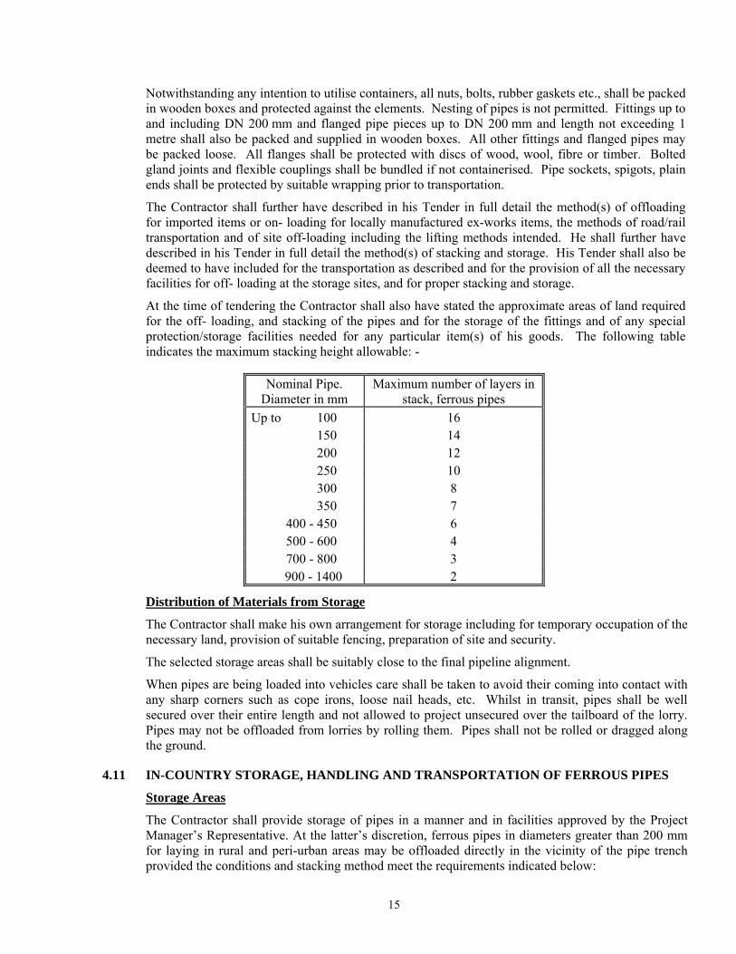
At the time of tendering the Contractor shall also have stated the approximate areas of land required for the off- loading, and stacking of the pipes and for the storage of the fittings and of any special protection/storage facilities needed for any particular item(s) of his goods. The following table indicates the maximum stacking height allowable: -
Nominal Pipe. Diameter in mm
Maximum number of layers in stack, ferrous pipes
Up to 100 16 150 14 200 12 250 10 300 8 350 7 400 - 450 6 500 - 600 4 700 - 800 3 900 - 1400 2
Distribution of Materials from Storage
The Contractor shall make his own arrangement for storage including for temporary occupation of the necessary land, provision of suitable fencing, preparation of site and security.
The selected storage areas shall be suitably close to the final pipeline alignment.
When pipes are being loaded into vehicles care shall be taken to avoid their coming into contact with any sharp corners such as cope irons, loose nail heads, etc. Whilst in transit, pipes shall be well secured over their entire length and not allowed to project unsecured over the tailboard of the lorry. Pipes may not be offloaded from lorries by rolling them. Pipes shall not be rolled or dragged along the ground.
4.11 IN-COUNTRY STORAGE, HANDLING AND TRANSPORTATION OF FERROUS PIPES
Storage Areas
The Contractor shall provide storage of pipes in a manner and in facilities approved by the Project Manager’s Representative. At the latter’s discretion, ferrous pipes in diameters greater than 200 mm for laying in rural and peri-urban areas may be offloaded directly in the vicinity of the pipe trench provided the conditions and stacking method meet the requirements indicated below:
15
Pipe Stacking and Storage
Pipes shall be stacked at the pipe storage areas using one or all of the following methods. - square stacking for small diameter pipes - parallel stacking using wooden roller boards - pyramidal stacking
All pipes shall be stacked on raised wooden battens at least 100 mm thick and 225 mm wide. A minimum of three battens per pipe for ferrous pipe lengths not exceeding 6 metres should be used with the outer battens laid 600 mm in from both pipe end and the middle batten placed equidistant between them. For ferrous pipe lengths greater than 6 metres, four battens shall be used. Pipe stacks shall be suitably wedged and the Contractor shall be deemed to have included for an adequate number of timber, wedges, etc., in his Tender.
Where socket and spigot pipes are stacked, the sockets should be placed at alternate ends of the stack with the sockets protruding.
4.12 DISTRIBUTION OF FERROUS PIPES FROM STORAGE
Ferrous pipes of DN 200 mm and less may be distributed from storage to the trench side no more than 7 days prior to laying whilst ferrous pipes above DN 200 mm may be strung out up to 15 days prior to laying.
In all instances when along trench sides, ferrous pipes shall be supported within 1 metre of either end on sand filled bags such that no part of the wall of the pipe touches the ground, and in the case of pipes over 6 metres long with additional central sand bags.
When pipes are being loaded into vehicles care shall be taken to avoid their coming into contact with any sharp corners such as cope irons, loose nail heads, etc. Whilst in transit, pipes shall be well secured over their entire length and not allowed to project unsecured over the tailboard of the lorry.
Pipes may not be offloaded from lorries by rolling them. Pipes shall not be rolled or dragged along the ground.
4.13 FLANGED JOINTS FOR FERROUS PIPES AND FITTINGS
Where specifically called for or deemed appropriate, flanged joints shall be utilised. They shall conform to EN 1092, drilled to NP 10 except where otherwise indicated on drawings or bills of quantities, with gaskets made of reinforced elastomer rubber to EN 1514 and of minimum thickness of 3 mm. They shall be stored in accordance with EN 2230.
Bolts for flanged joints shall conform to ISO 4014-1 threaded to BS 3643, nuts to EN 24032 or ISO 4032 and washers to BS 4320. Bolts, nuts and washers shall be protected to ISO 4032 or EN 24032 for above ground installation and to BS 3382-7 for below ground installation and in chambers. Nuts for use with self-sealing joints for steel pipes shall be as described under the section for service connections. Exposed threads of all bolts shall be fitted with a tight plastic cap after flange assembly.
4.14 FLEXIBLE JOINTS
Where specifically called for or deemed appropriate flexible couplings shall be used and shall be coated with fusion bonded epoxy layer 350 microns thick. Flexible couplings shall be of a mechanical type coupling consisting of a centre sleeve, two end ring flanges, two wedge shaped sealing rings of Nitrile rubber, and with galvanised nuts and bolts. The main components shall be made from hot rolled steel for larger diameters and malleable cast iron to EN 1562 or ductile iron for smaller diameters. If specifically called for, couplings shall be provided with a suitably sized screw plugged hole in the sleeve to allow for the introduction of molten bitumen for additional internal protection. The manufacturer shall then include the necessary removable internal backing-up rings of
16
rubber composition and shall further include for all materials for in-situ jointing and protecting both for remedial works and for internal and external protection at such joints. After jointing, the exposed part of the bolt shall be provided with a tight fitting polythene protection cap unless capped nuts are used.
4.15 COMPLETION OF EXTERNAL PROTECTION AT FLEXIBLE JOINTS ON FERROUS PIPELINES
The completion of the external protection at flexible joints on ferrous pipes and fittings (other than hot dipped zinc steel pipes) shall be carried out as detailed below as appropriate and shall be to the satisfaction of the Project Manager’s Representative. The costs thereof shall be deemed to be allowed for within the Tender.
(a) Above ground pipelines and fitting and in backfilled trenches Bolted by Flexible Joints
In all cases where the pipe joint has involved the use of nuts and bolts, the exposed threads of every bolt shall first be thoroughly cleaned and then coated with an approved zinc-rich paint allowed to dry for not less than 24 hours before proceeding with further protection as indicated below.
(i) Above ground pipelines and fitting and in backfilled trenches Bolted by Flexible Couplings for Coal Tar or Bitumen coated Pipes and fittings supplied without epoxy coating (Moulding Method)
Where for whatever reason, any such flexible couplings have not been factory epoxy coated then the external protection to such mechanical couplings shall be completed by moulding the couplings with an enamel composition compatible with the enamel used for the pipe sheathing; i.e. a bituminous composition shall be used on pipes and fittings sheathed with bitumen (asphalt) enamel, and a coal tar composition shall be used on pipes and fittings sheathed with coal tar enamel.
The assembled coupling shall be thoroughly cleaned (including removing whitewash from that portion of the sheathing adjacent to the joint) and dried together with that portion of the pipe that will come within the moulding box and the whole shall be painted with the quick drying primer supplied.
The inside of the moulding box and externally around the pouring gate shall be coated with a thick wash of lime of similar material to prevent any possibility of the moulding box sticking, and shall be dried thoroughly.
The moulding box shall be fitted around the coupling so that the pouring gate is at the top and the flanges and bolts of the coupling sit centrally in the recesses provided for them in the moulding box. The clip or bolts of the box shall be fitted and tightened and all joints sealed, including the joints between the box and pipes, with clay or similar material to prevent the hot composition from running out.
The enamel composition shall be heated in an approved boiler (to be provided by the Contractor complete with an accurate thermometer) to the temperature recommended by the supplier, and stirred during melting to prevent overheating and the filler settling to the bottom.
The fluid enamel composition shall be slowly poured (at the temperature recommended by the supplier), taking care to prevent air- locks, until the gate is filled. The gate shall be kept filled by toppling up as necessary to allow for cooling shrinkage.
The moulding box shall be removed as soon as it is cool enough to handle by which time the enamel will have set. The moulding may be cooled with water to make the enamel set more quickly.
17
Any defective part of the moulding shall be immediately repaired by applying hot enamel composition with a trowel.
It may be necessary to support the moulding box on larger diameter sheathing pipes to avoid the box from sinking into the pipe sheathing which may have become softened by the hot enamel in the box. The moulding box must be re-coated with lime wash before being re-used.
The Contractor shall provide all other materials required for completion of external protection by the moulding method.
(ii) Where pipes and fittings are to be concreted in (Wrapping Method)
The external protection to pipes and fittings jointed by mechanical couplings, flanged joints, "Tyton", type or Bolted Gland joint, or similar shall be completed by wrapping the joint with approved petrolatum tape prior to which the area shall have been cleaned by an approved proprietary paste and the area protected by an approved proprietary mastic. It shall then be wrapped in PVC 'outerwrap' or similar material.
The whole joint shall be thoroughly cleaned removing all loose rust and extraneous matter and the approved paste rubbed well over the whole of the joint and for a few centimetres either side of the joint over the pipe sheathing. A liberal amount of paste shall be left around all bolt heads, narrow cavities, etc.
The approved mastic shall be applied to cover all bolt heads and nuts, forced into the annular gap between the spigot and socket in the case of 'Tyton' type or bolted gland joints, formed as a triangular fillet against the face of socket or flanges and filled in all gaps and abrupt change in contour to provide an even contour for wrapping.
The approved tape shall be applied circumferentially, starting and finishing at the top of the joint care being taken to smooth and eliminate any air pockets and to form the tape well into all angles and changes in contour. The tape should extend on to the pipe sheathing on either side of the joint by at least 50 mm and the tape should be applied with a minimum overlap of 25 mm.
An outer wrapping of 'PVC Outerwrap' shall be finally applied over the approved tape'. This wrapping should extend at least 50 cm on to the pipe sheathing and should be applied with a minimum lap of 50 mm.
All the above mentioned materials shall be provided by the Contractor and deemed covered in his rates.
4.16 TRENCH EXCAVATION AND EARTHWORKS FOR FERROUS PIPES
This clause for excavation shall apply except for thrust boring as specified in Clause 4.43 below.
(i) All trench excavation will as a minimum precaution be taped off to alert members of the public to its existence.
(ii) The excavation shall be made in open cutting unless tunnelling or heading is specified by the Project Manager’s Representative or it is specified in the Bills of Quantities.
(iii) Trenches for pipes shall be excavated to the lines and depths shown on the Drawings, or as directed by the Project Manager’s Representative, and shall be of sufficient width to give an equal clearance on both sides of the barrel of the pipe or pipes such that in general the total trench width is 3/2 'D' where 'D' is the outside diameter of the pipe or the average outside diameter of the group of pipes or will be equal to the outside diameter or the pipe plus 30 cm on each side whichever is greater. For pipes bedded in concrete sections, the breadth of
18

(iv) If in the opinion of the Project Manager’s Representative delays in laying are due to the fault of the Contractor and the ground becomes weathered prior to the laying of the pipes, the Contractor shall remove the weathered soil and replace it with suitable compacted material to the original formation level at his own expense.
(v) Where pipes are not laid on concrete, the bottoms of the trenches as excavated, shall be smooth and shall be free from stones or other projections. Holes cut out at the joints in the lower bedding shall be of as small a size as possible throughout their entire length. The trench shall be dug to within 15 cm of its formation and proper grade pegs shall then be set in the bottom of the trench by the Contractor for the accurate taking out of the rest of the excavation. Grooves about 5 cm deep shall be cut across the trench in the lower bedding at the required positions to enable the easy removal of pipe slings.
(vi) Where an imported lower bedding layer is not included and if instructed to do so by the Project Manager’s Representative, the pipe trench shall be excavated to a depth of 10 cm below the invert of the pipe and be refilled with suitable ‘as-dug’ material free from stones greater than 20 mm dia. and foreign matter and compacted to a minimum 90% MPD in order to provide a smooth bed for the pipes.
(vii) The materials excavated from trenches shall be laid completely and neatly on the sides of the trench except where in the opinion of the Project Manager’s Representative's Representative this would so obstruct a road or footpath as to prevent the passage of traffic or pedestrians. In such cases the Contractor must dig out the pipe trench in such lengths as directed and keep his excavated material at such a distance as may seem advisable, and the rates shall be deemed to cover for this.
(viii) During excavation, the Contractor shall ensure that all material suitable for re-use and which he intends for re-use are kept separate and set aside and protected as necessary to prevent loss or deterioration. Materials forming the surface and foundations of roads shall when excavated and if required for further use, be carefully separated. Paving slabs, bricks and similar surfaces shall be carefully removed and stacked for re-use, or as otherwise instructed by the Project Manager’s Representative.
(ix) No pipes shall be laid nor lower bedding introduced and no excavation filled in or covered with concrete until the formation has been inspected and permission to proceed with the Work obtained. The Contractor shall provide to the Project Manager, a weekly schedule in advance indicating the dates and approximate times he expects to request such inspections.
(x) Where pipes are to be laid under a road formation or in open country, or in cutting, trenches shall generally be excavated after the earthwork is completed. The Project Manager’s Representative may permit these pipe trenches to be excavated before the earthwork is complete, but payment for the excavation of the trench will only be made upon the volume excavated below the road formation.
(xi) The unit of measurement for the excavation of trenches shall be per linear metre or per cubic metre of void calculated from the deemed width of the trench, and the average depth of excavation as mentioned in the Bills of Quantities. Unless otherwise indicated, for valve chambers and other water works structures, the unit of excavation will be per number or per cubic metre of excavated material calculated to the exact outer dimensions and depths of the Permanent Works. In neither case will allowance be made for bulking.
19

(xii) The rates for excavation of trenches in "normal" material shall include removal of all material except "rock", selecting and segregating material to be backfilled in special layers, supporting or sheeting, shoring and strutting, any additional working space or room for timbering or sheeting required, dealing with water, maintenance of the trench, and all labour, tools, materials, plants, supervision, overheads and profit.
(xiii) The provisions of the above Clause shall apply to the rates of excavation in "rock" and in addition the Contractor shall also allow in his rates for back-filling the invert with Class 15 concrete or other materials as directed by the Project Manager’s Representative and removing to a spoil dump all "rock" excavated.
(xiv) Where rock is encountered and should the Contractor wish to excavate the rock in advance and temporarily to refill the excavated trench with the excavated material until he is ready to proceed with the laying of the pipe, he shall be permitted to do so, which permission must be given in writing by the Project Manager. Such work shall normally be included in the Contractors rates unless he can show that the amount of rock is in excess of the amount billed to an extent that his work programme will be unduly delayed if he does not do so. In such a case he may seek to be paid both the E.O. item rate for the rock and twice the rate quoted for excavation in class III material.
4.17 PIPE LAYING FOR FERROUS PIPES
(a) Pipes shall only be laid in the presence of a Project Managers representative unless written authority from the Project Manager has been granted.
(b) Pipes generally shall be laid and jointed in accordance with the manufacturer's instructions. Extra excavation must not be carried out so as to avoid backfill, excessive deviation in joints and other irregularities. Otherwise, the pipe grade will follow the Drawings, with a continuous (but not necessarily uniform) fall towards washout-valves and rise towards air-valves.
(c) Prior to laying, damage to linings or coatings shall be repaired in accordance with the manufacturer's instructions and this will be the Contractor's liability. Where, in the opinion of the Project Manager’s Representative or his representative, the damage to a pipe coating is significant and notwithstanding the repairs made in accordance with the manufacturer’s instructions, the complete pipe shall be further protected by a polythene sleeve. The sleeve shall conform to ISO 8180 for steel pipes and EN 14628 for DI pipes and be of minimum thickness of 200 microns. It shall be strapped beyond the joints of adjoining pipes using a non-metallic strap around the pipe. All costs of supply and installation of such additional protection shall be to the Contractors account.
(d) Every pipe shall be laid separately and shall bear evenly upon the lower bedding or concrete for its full length, holes to receive sockets, couplings or flanges being cut in the bottom of the trench of such size and depth as to allow the joints to be properly made. The pipes shall be laid to true inverts, straight lines and falls, each pipe being separately boned between sight rails. Before lowering into the trench or placing in position each ductile iron pipe or casting shall be slung and sounded with a mallet to test for hair cracks. Pipes that do not ring true will be discarded. For ferrous pipes with barrier coatings, the coating, and where appropriate the lining of every pipe shall be inspected by use of holiday detectors in accordance with NACE RP 0490. Unless otherwise authorised in writing by the Project Manager to carry out such inspections in a nearby storage yard, such inspections shall be carried out at the trench side immediately prior to lowering into the trench. Each pipes shall be thoroughly brushed inside and outside prior to laying and no foreign matter shall be allowed to enter the pipe during or after laying.
20
At the end of each working day the exposed pipe end shall be stoppered up with a stopper plug of appropriate diameter and not merely covered in polythene sheet tied around the end.
(e) Trenches shall be bottomed up only immediately in advance of pipe laying, although at least 15 metres shall be prepared in advance of any given pipe. Trenches and joint holes shall be kept free from water, until the pipes are laid and the joints completed and no ground water shall be allowed to enter the new pipes.
(f) Prior to laying in trench the lower bedding in the trench must provide support throughout the entire length of the pipe. The pipe shall never be laid directly on cohesive, rocky or stony material. Where the natural trench bottom meets the bedding class required, this shall initially be loosened to a depth of 10 cm and then re-compacted to at least 90% MPD and then the surface loosened on the day of and prior to laying
(g) In rock excavation, the pipes shall be bedded on concrete or selected granular fill, e.g. sand, to a minimum thickness of 150 mm and the exclusion of rocks and other hard material to at least 300 mm around the pipe, leaving proper joint holes and subsequently making good with selected materials to the Project Manager’s Representative’s approval.
(h) All flanged joints shall be made with jointing rings, which shall be carefully inserted concentric to the bore of the pipe, so that undue stresses shall not be caused in any of the bolts or on the flanges when bolting up. The joint ring shall be compressed gradually and evenly by taking a few turns on each diagonal bolt in succession. Over-tightening shall be avoided. If the Project Manager is dissatisfied with the degree of care being taken, the Contractor shall provide and use torque-wrenches for this purpose at no extra cost.
(i) Mechanical joints shall be made in accordance with the manufacture's instructions. After successful testing of pipelines, the joints will receive external protection as specified or to the Project Manager’s Representative's approval.
(j) The threads of any screw connections shall be coated with red lead before the joint is made. (k) Concrete anchor blocks shall be provided at bends, tees, stopped ends, etc as shown on the
drawings or as directed by the Project Manager’s Representative. (l) Where a pipeline crosses under roads or railway lines, and if required by the relevant
authority, the pipe shall be sleeved or surrounded with concrete or protected by reinforced concrete slabs as instructed by the Project Manager’s Representative, and Contractors shall have been deemed to have made allowance in their rates at the time of tender for compliance with the requirements of the relevant authority.
(m) For the insertion of valves and other fittings into existing pipelines, pipes may need to be cut. Approved tools and machines specially made for the purpose, shall be provided and used by the Contractor.
(n) The Contractor shall provide and fix wooden drumheads to the open ends of the mains, and similar drumheads shall be used to close the ends of any pipes to exclude dirt and stones, etc., when the pipe laying is not actually in progress. Wooden markers properly inscribed, shall be left projecting out of the ground to indicate the ends of all pipes, where these are buried in the ground in open country. In public highways, a danger sign or other suitable means as approved by the Project Manager’s Representative shall be adopted.
(o) At every point of loading or unloading, pipes must be handled by approved lifting tackle. (Unloading by rolling them down planks of any form or including ramp will not be allowed except with the special consent of the Project Manager’s Representative).
(p) The stacking of pipes shall be used such as to prevent damage during storage. Timber runners shall be laid to keep the upper row separated from the lower and the bottom row shall be staked to prevent any rolling. The whole arrangement shall be subject to the approval of the Project Manager’s Representative.
21

(q) Care should be taken to minimise the risk of bush fires damaging any pipes, their coatings and linings laid out along the line of the mains.
(r) Refilling of pipe trenches shall conform to the specifications provided in Clause 4.18. (s) The requirements for making good any ground subsidence after refilling are provided for in
Clause 4.19. (t) Reinstatement of surfaces shall conform to the specifications provided for in Clause 4.20. (u) For Ferrous Pipes Laid in Trenches the soil cover shall be a minimum of 600 mm. and the
embedment material required is S3 (sand and coarse grained soil with less than 12% fines) for epoxy lined steel pipes and class S4 and for ferrous cement mortar lined pipes in all cases with a minimum of 90% compaction. For details of the trench specifications, and backfill material sizes refer to Clause 4.28. Contractors shall be deemed to have made full allowance in their Tender for the price of such trenching and importation of necessary backfill material and compaction as part of the pipe installation price.
4.18 BACKFILLING OF PIPE TRENCHES- FERROUS PIPES All excavation of pipe trenches shall be of such form and to dimension as shown on the drawings or as the Project Manger’s Representative may direct, and in all respects provide with embedment configurations and minimum covers as detailed here below. As a general rule trench width shall be not less than 1 ½ times the OD of the pipe but subject to the following figure and tables.
Typical Trench for Ferrous Pipes
OD
trench width
'x' 'x'
14
11
13
12
ab
c
1 2 3
5
6
7
8
9
10
1 Surface2 Bottom of road or railway
3 Trench walls4 Top soil5 Main backfill6 Initial backfill7 Sidefill8 Upper bedding9 Lower bedding10 Trench bottom11 Depth of cover12 Depth of bedding13 Depth of embedment14 Trench deptha Depth of lower beddingb Depth of upper beddingc Depth of initial backfill
construction (if any)4
Note 2: the embedment is the arrangement and type(s) of material(s)around a buried pipeline which contribute to its structuralperformance. Attaining cited minimum compaction requirements ismandatory for embedment.
Note 1: compaction is the deliberatedensification of soil during the construct-ion process, whereas consolidation is thesubsequent time-dependant densificationafter construction. Attaining citedminimum compaction requirements is atthe supervisors disgression.
Figure: Trench Installation
B
'x' =OD/4 subject tominimum of 30 cm
* Minimum cover 600mm, except for Transmission mains, where minimum cover shall be 900mm.
(600 mm minimum *)
22
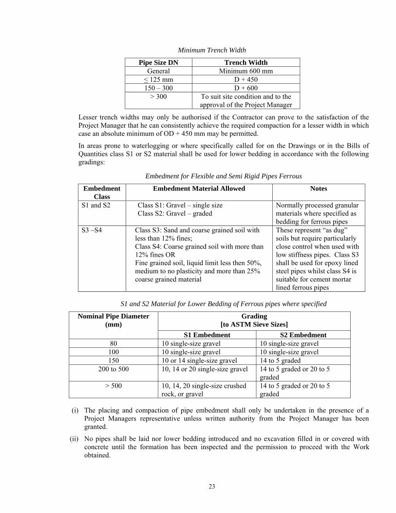
Minimum Trench Width
Pipe Size DN Trench Width General Minimum 600 mm
< 125 mm D + 450 150 – 300 D + 600
> 300 To suit site condition and to the approval of the Project Manager
Lesser trench widths may only be authorised if the Contractor can prove to the satisfaction of the Project Manager that he can consistently achieve the required compaction for a lesser width in which case an absolute minimum of OD + 450 mm may be permitted.
In areas prone to waterlogging or where specifically called for on the Drawings or in the Bills of Quantities class S1 or S2 material shall be used for lower bedding in accordance with the following gradings:
Embedment for Flexible and Semi Rigid Pipes Ferrous
Embedment Class
Embedment Material Allowed Notes
S1 and S2 Class S1: Gravel – single size Class S2: Gravel – graded
Normally processed granular materials where specified as bedding for ferrous pipes
S3 –S4 Class S3: Sand and coarse grained soil with less than 12% fines; Class S4: Coarse grained soil with more than 12% fines OR Fine grained soil, liquid limit less then 50%, medium to no plasticity and more than 25% coarse grained material
These represent “as dug” soils but require particularly close control when used with low stiffness pipes. Class S3 shall be used for epoxy lined steel pipes whilst class S4 is suitable for cement mortar lined ferrous pipes
S1 and S2 Material for Lower Bedding of Ferrous pipes where specified
Nominal Pipe Diameter (mm)
Grading [to ASTM Sieve Sizes]
S1 Embedment S2 Embedment 80 10 single-size gravel 10 single-size gravel
100 10 single-size gravel 10 single-size gravel 150 10 or 14 single-size gravel 14 to 5 graded
200 to 500 10, 14 or 20 single-size gravel 14 to 5 graded or 20 to 5 graded
> 500 10, 14, 20 single-size crushed rock, or gravel
14 to 5 graded or 20 to 5 graded
(i) The placing and compaction of pipe embedment shall only be undertaken in the presence of a Project Managers representative unless written authority from the Project Manager has been granted.
(ii) No pipes shall be laid nor lower bedding introduced and no excavation filled in or covered with concrete until the formation has been inspected and the permission to proceed with the Work obtained.
23
(iii) In every instance, embedment material (consisting of bedding, side fill and initial backfill) filled around the pipe and for 300 mm over the top of the pipes shall be free from stones, tree roots or similar objects which through impact or by concentrating imposed loads might damage the pipes, and shall not include black cotton type soil. The filling shall be carried out with utmost care, special attention being paid to tamping of material around the pipes and to joint holes so as to obtain the greatest possible compactness and solidity. The material shall if necessary, be screened to exclude material which would damage the pipes. The material shall be in accordance with the relevant pipe bedding drawing but no worse than a class S3 material for epoxy lined steel pipes (sand and coarse grained soil with not more than 12% fines) or an S4 material for cement-mortar lined ferrous pipes and the source and material shall be approved by the Project Manager’s Representative before excavation commences. Any delays as a result of not seeking this approval in good time shall be entirely to the Contractor’s account.
(iv) Where the ‘as-dug’ trench material contains material which meets the bedding class requirements as specified and providing that this is carefully screened to the sizes indicated above, and segregated from material that does not, the Contractor may, at his discretion, use it as such or incorporate such material into the imported embedment material being used.
(v) The lower bedding for the pipes shall have a minimum thickness of 75 mm in normal trenches, and 125 mm where rock/stones are present and at designated road crossings. In trenches where there is a continuous accumulation of groundwater, the trench shall after obtaining the approval of the Project Manager’s Representative, be over-excavated by 150 mm and shall be backfilled using compacted granular material. Bedding material shall be compacted in layers not exceeding 50 mm thickness. Compaction of fill around the pipe shall be in layer thickness not exceeding half the pipe diameter or 75 mm whichever is the lesser. Layer thickness is however subject to consistently achieving 90% MPD (Modified Proctor Density) or better, failing which layers shall be reduced in depth as necessary to achieve the % compaction.
(vi) The upper bedding shall be introduced as carefully and thoroughly as practicable to the underside or haunch of the pipe such that no large spaces remain before it is compacted.
(vii) The sidefill and backfill material within the embedment shall be placed in layers of not more than 150 mm thickness when compacted and where hand ramming is employed the number of men filling shall not be more than half the number of men ramming. Sidefill shall be placed simultaneously on both sides of the pipe. Where mechanical-ramming of the remaining backfill is employed, the machines shall be to the approval of the Project Manager’s Representative and soil shall be replaced and well rammed down by hand for a depth of not less than 50 cm to give sufficient cover to the pipes and obviate risk of damage to them before the mechanical rammer is brought into operation. The rammer shall not cease to be used on any length of trench until thorough compaction has been obtained. All backfill soil shall be free from clay lumps, boulders stones and rock fragments greater than 20 mm and 90 % MPD shall be attained in all instances. All backfill soil above the embedment shall be free from clay lumps, boulders and rock fragments greater than 50 mm and as far as practicable 90 % MPD shall be attained, but this may be relaxed (e.g. in fields and open areas) by the Project Manager’s Representative.
(viii) The Contractor in excavating shall ensure that materials from strata containing no stones and suitable for filling around the pipes as described above, shall be kept separately and used for this purpose. The Contractor shall not be entitled to claim for any extra costs (as provided for below) for screening if this requirement is not complied with. If no such strata occur in the excavation, the excavated material shall either be screened or suitable material transported to the Site from other excavations as the Project Manager’s Representative shall direct. The cost of such work shall be paid for according to the rates in the Bills of Quantities.
(ix) Before commencing the placing of embedment in the trenches, the Contractor shall obtain approval from the Project Manager’s Representative as to the methods he proposes to use and he shall
24
demonstrate by means of tests that the specified compaction can be achieved (according to BS 1377 or ISO 22476 using the “sand replacement” method). The method of compaction and the testing thereof shall be at all times to the approval of the Project Manager’s Representative and in general at a frequency of once every 30 metres unless this is specifically relaxed based on continuously good in-situ test results.
(x) Where pipes are joined by rigid joist (flanges or welded), the pipe trench shall be backfilled entirely without leaving out areas around and at pipe joints uncovered, for subsequent filling. To facilitate the subsequent location of any suspected leaking joints during pipe testing, should this become necessary, the Contractor shall provide marker pegs at regular intervals and/or use a handheld GPS to be able to relocate joint positions.
(xi) Where for pipes a minimum cover of 600 mm (or 900 mm for transmission lines) cannot be maintained, including highways and trafficked areas then the pipe must either be laid in a protective ferrous sleeve or be protected by a 150 mm thick reinforced concrete slab above the pipe. A minimum of a 150 mm layer of appropriate grade bedding material must first be placed and lightly compacted as a cushion above the crown of the pipe before the slab is laid, and the slab must extend at least 150 mm out beyond either side of the trench.
4.19 MAKING GOOD SUBSIDENCE AFTER REFILLING
Should any but very localised subsidence occur of the pipe trench after refilling and before the expiry of the maintenance period, the Contractor shall first demonstrate that such subsidence is only to the backfilling above the pipe and not to the pipe, embedment, bedding or sub-soil itself.
Should this not be so demonstrated then the Contractor at his own expense shall, excavate and remove the pipe or pipes affected and return the bottom of the trench to grade through a process of over-excavation, re-compaction or use of a lean concrete mix as determined by the Project Manager’s Representative, who shall also determine whether or not the affected pipes may be re-used or replaced.
The affected section or sections will in any event be liable for a further twelve months maintenance period.
All refilling necessary due to subsidence in pipe trench backfill shall be thoroughly compacted by ramming. Any subsidence due to consolidation shall be made up by the Contractor at his own expense with extra compacted material. Should subsidence occur after any topsoil has been replaced, the topsoil shall first be removed before any hollows are made up before being replaced.
4.20 REINSTATEMENT OF SURFACES
(i) All surfaces of roads, fields, paths, gardens, verges, etc. whether public or private which are affected by the operations of the Contractor shall be temporarily restored by him in the first instance and permanently reinstated in the second instance when the ground has consolidated fully. Separate payment for reinstatement shall be made only for surfaced roads (e.g. tarmac, concrete, paving bricks or similar material), and for official designated dirt roads of at least 6m width, grassland, cultivated lands and sports fields. Any other reinstatements are deemed to be covered by the pipe installation rates.
(ii) The Contractor shall be responsible for the temporary reinstatement and permanent reinstatement of all surfaces whether or not the area requiring restoration is within the limits of his excavations if the necessity for the restoration arises from causes due to the operations of the Contractor. The Contractor's prices shall include for restoring all surfaces so damaged to their original condition, as no extra payment will be made for any such work. The Contractor shall take all necessary measures to ensure that no toxic materials that may cause damage to vegetation or livestock or
25
pollute streams or water-courses are used in any temporary restoration or permanent reinstatement and shall indemnify the Employer against any claims arising out of the use of such materials.
(iii) Temporary restoration shall be carried out immediately after the excavations have been refilled by returning the excavated material to the position from which it was removed and adding such suitable materials as may be required and consolidating the various materials as the Work proceeds in order to provide a surface that is adequate for the purpose that the original surface fulfilled. Temporary surfaces shall be maintained in a condition satisfactory to the Project Manager’s Representative and/or responsible Authority until the permanent reinstatement is made. In the case of roads and streets the surface shall be necessary to consolidate the filling and keep the surface fit for traffic, suitable material being added to all placed which have sunk or become rough.
(iv) Permanent reinstatement shall not be made until the ground has consolidated permanently and until sanction to do so is received from the Project Manager’s Representative. It shall be carried out with materials similar to those that were used in the original Work to the entire satisfaction of the Project Manager’s Representative and/or responsible Authority.
(v) In verges and other grass surfaces the topsoil shall be removed, stored and replaced after consolidation of the filling and planted or seeded with approved grass. Should subsidence occur, it shall be made good with additional topsoil and be replanted with grass or re- seeded. New grass shall be planted if for any reason the grass fails to grow or is destroyed.
(vi) The trenches, channels, gutters and kerbs shall be reinstated to the condition in which they were before excavation was commenced. The final surface of the trench shall be flush with the surrounding ground.
(vii) If the work of restoration or reinstatement as carried out by the Contractor is not to the satisfaction of the Project Manager’s Representative and/or the responsible Authority and should the Contractor not remedy the defect forthwith, any remedial work considered necessary may be undertaken by the Project Manager’s Representative and/or the responsible Authority and the cost thereof shall be borne by the Contractor.
(viii) If at any time any trench becomes dangerous, the Project Manager’s Representative shall be at liberty to call upon the Contractor to restore it to a proper condition at three hours' notice and should the Contractor fail to carry out the work, have it done at the Contractor's expense.
PART III – THERMOPLASTIC PIPES DURING MANUFACTURE, SUPPLY, INSTALLATION, COMMISSIONING & TESTING
4.21 MATERIALS AND STANDARDS, UNPLASTICISED PVC PIPES AND JOINTS
PVC pipes and fittings shall be manufactured and installed in accordance to ISO 4422 and EN 1452. Preference shall be given to PVCu pipes that are not stabilised by lead, tin or other heavy metals. However, where they are then tests in accordance with DIN 8061, and EN 8063 must produce acceptable results.
Other related standards for pipes and joints of PVCu are given in BS 3505, EN 1452 and BS 4346. For laying, jointing and pressure testing they shall conform to the relevant sections of BSCP 312-2, and for quality control to DIN 8061 and EN 921. They shall be transported, laid, jointed and backfilled in accordance with the manufacturers written instructions except where this specification is more rigorous in which case this shall be followed.
To ensure that the Employer benefits from superior materials with enhanced useful life, at all times, latest and updated standards and procedures for design and installation shall be used and adopted but governed by cost effectiveness. In the same context the Contractor may provide, with the approval of the Project Manager, superior materials using other standards not listed here provided that they do
26
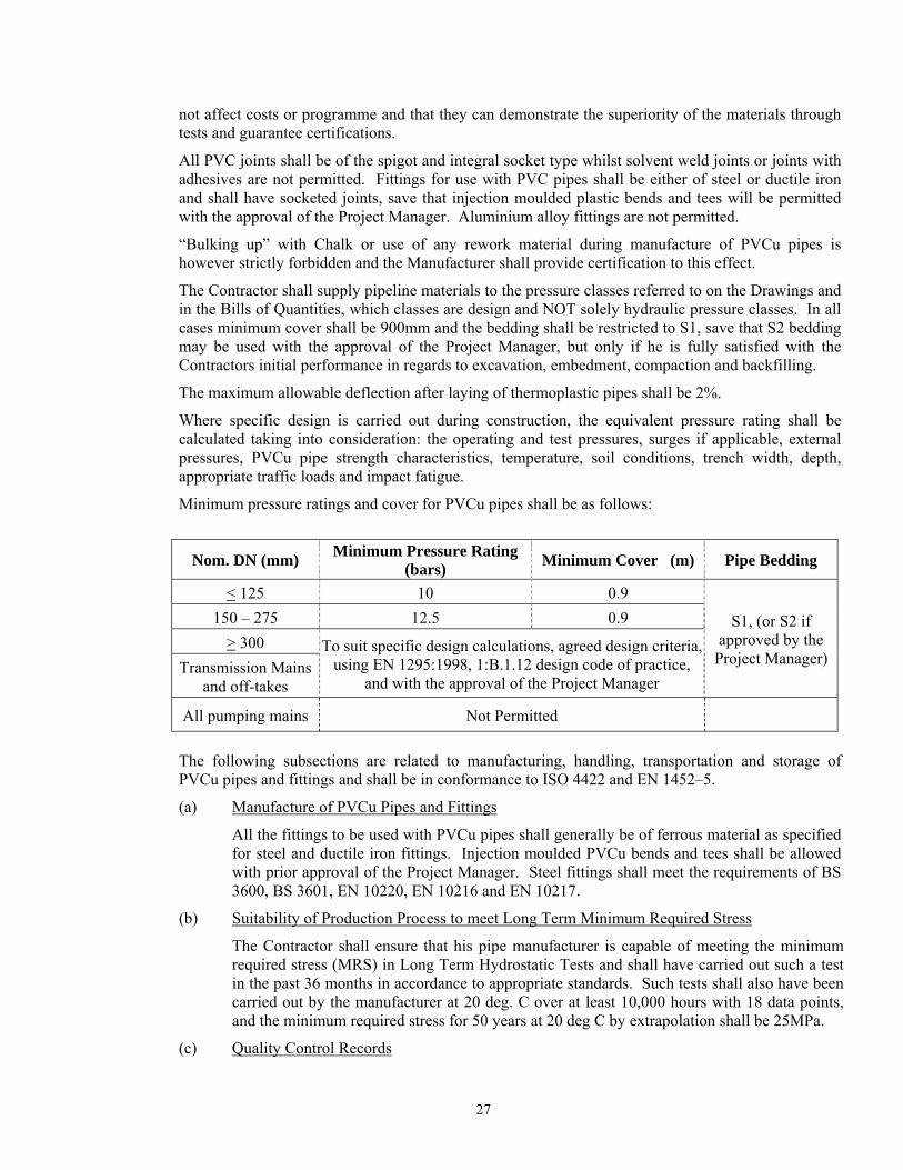
not affect costs or programme and that they can demonstrate the superiority of the materials through tests and guarantee certifications.
All PVC joints shall be of the spigot and integral socket type whilst solvent weld joints or joints with adhesives are not permitted. Fittings for use with PVC pipes shall be either of steel or ductile iron and shall have socketed joints, save that injection moulded plastic bends and tees will be permitted with the approval of the Project Manager. Aluminium alloy fittings are not permitted.
“Bulking up” with Chalk or use of any rework material during manufacture of PVCu pipes is however strictly forbidden and the Manufacturer shall provide certification to this effect.
The Contractor shall supply pipeline materials to the pressure classes referred to on the Drawings and in the Bills of Quantities, which classes are design and NOT solely hydraulic pressure classes. In all cases minimum cover shall be 900mm and the bedding shall be restricted to S1, save that S2 bedding may be used with the approval of the Project Manager, but only if he is fully satisfied with the Contractors initial performance in regards to excavation, embedment, compaction and backfilling.
The maximum allowable deflection after laying of thermoplastic pipes shall be 2%.
Where specific design is carried out during construction, the equivalent pressure rating shall be calculated taking into consideration: the operating and test pressures, surges if applicable, external pressures, PVCu pipe strength characteristics, temperature, soil conditions, trench width, depth, appropriate traffic loads and impact fatigue.
Minimum pressure ratings and cover for PVCu pipes shall be as follows:
Nom. DN (mm) Minimum Pressure Rating (bars) Minimum Cover (m) Pipe Bedding
< 125 10 0.9
S1, (or S2 if approved by the
Project Manager)
150 – 275 12.5 0.9 > 300 To suit specific design calculations, agreed design criteria,
using EN 1295:1998, 1:B.1.12 design code of practice, and with the approval of the Project Manager
Transmission Mains and off-takes
All pumping mains Not Permitted
The following subsections are related to manufacturing, handling, transportation and storage of PVCu pipes and fittings and shall be in conformance to ISO 4422 and EN 1452–5.
(a) Manufacture of PVCu Pipes and Fittings
All the fittings to be used with PVCu pipes shall generally be of ferrous material as specified for steel and ductile iron fittings. Injection moulded PVCu bends and tees shall be allowed with prior approval of the Project Manager. Steel fittings shall meet the requirements of BS 3600, BS 3601, EN 10220, EN 10216 and EN 10217.
(b) Suitability of Production Process to meet Long Term Minimum Required Stress
The Contractor shall ensure that his pipe manufacturer is capable of meeting the minimum required stress (MRS) in Long Term Hydrostatic Tests and shall have carried out such a test in the past 36 months in accordance to appropriate standards. Such tests shall also have been carried out by the manufacturer at 20 deg. C over at least 10,000 hours with 18 data points, and the minimum required stress for 50 years at 20 deg C by extrapolation shall be 25MPa.
(c) Quality Control Records
27
The Contractor shall ensure that the manufacturer keeps accurate records of all types of component raw materials such as polymer powder, additives, stabilizers, lubricants, etc. used in the manufacture of PVCu pipes, together with detailed manufacturer’s test reports carried out on the raw materials, date produced and date received, and batch or lot numbers.
During production, records shall be kept for mixing ratios of all the components used in the PVCu blend and these mixing ratios shall not be changed without the prior approval of the Project Manager.
PVC material silos shall be equipped with appropriate sized sieves.
Pipes shall each be identified individually by a unique number. Such numbers shall be recorded along with the Blend and Lot number they were manufactured from.
The pipe lot shall be the pipes manufactured during a work shift. The Contractor shall state in its bid the length of shift the manufacturer intends to use. The number of pipes in a lot shall be the number of pipes manufactured during the specified shift period.
(d) Polymer Certification
The manufacturer shall state for each batch and lot of pipes and fittings manufactured the K value of the polymer which shall have certifications from the polymer supplier. If required by the Project Manager, tests will be carried out to determine the K value is in accordance with the relevant standards.
(e) Inspection and Testing during Production
The manufacturer shall be carrying out the necessary inspections and tests during production in accordance to the relevant ISO standards and such tests shall include all tests relevant for PVCu pipes and fittings as required by BS 2782; and EN 921.
The number of pipes to be tested and the frequency of testing shall be in accordance with SABS 966-1.
(f) Inspection of pipes and pipe fittings
The inspection will consists of visual examining the external surfaces of the pipe that must smooth and free of the following defects: • grooving • blistering • scoring (scratches) • cavities • impurities • other surface defects which will be deleterious defects
In addition the pipes will be inspected for correct chamfering at 15 degrees to the half the wall thickness on the spigot end and squareness of both ends to the pipe longitudinal axis.
The numbers of samples that do not comply with the above requirements during inspection shall not exceed the quantities given in the relevant standards.
(g) Testing of Pipes and Fittings
For each lot, the pipes and fittings shall be tested at the factory before shipment in accordance to the relevant ISO standards such as ISO 11922, ISO 2507, ISO 3126 / 3127, ISO 9852, ISO 1167 among others for softening temperature, resistance to creep, pipe dimensions, ovality, thermal reversion, resistance to dichloromethane, freedom from toxicity, hydrostatic pressures, vacuum, fracture toughness and resistance to impact etc. The whole
28

Lot will be rejected if the quantity of non-compliant pipes exceed the acceptable level.
(h) Marking of Pipes and Fittings
Each Pipe or Fitting shall be marked clearly with indelible ink with the following data: • the manufacturers trade name or trade mark • the designation PVC-U • the pressure class and/or SDR ratio of the pipe • the nominal diameter of the pipe • the individual pipe number or fitting number • the week number of manufacture • the Lot Number the pipe belongs to • the Blend Number the pipe belongs to
(i) Release from manufacturers works
No PVCu pipes and fittings shall be released from the manufacturer’s works until all tests results on the particular Blend and Lot it belongs are in conformance with requirements. No pipe shall also be delivered before a full lapse of 6 weeks from its production to allow for positive results of accelerated resistance hydrostatic test pressure testing.
(j) Determination of pipe and socket wall thickness
All pipes shall be manufactured in accordance to ISO 4422 and EN 1425 and the pressure rating design stated or based on specific design using the internationally acceptable design code of practice for PVCu pipes.
The Contractor shall demonstrate and obtain approval from the Project Manager that the pipe thickness proposed achieve the necessary operating and test pressures, and can withstand the external pressures and that they are in conformance with the acceptable international standards for the purpose of its use in this project
(k) Pipe Lengths
Pipes shall be in effective lengths (i.e. overall length minus the depth of engagement in the socket) of not exceeding 6.0 m length.
(l) Pressure Classification
All PVCu Pipes supplied shall be classified by their PN operating pressure rating and their SDR ratio as required under this contract.
(m) Protection of Fittings used with PVCu Pipes
All types of fittings shall be protected in conformance to their respective required standards. i. Protection of extruded PVCu fittings - Protection shall be in conformance to ISO 2035,
2034-5 and 2048 and their other respective standards. ii. Protection of Steel Fittings: - Steel fittings shall be coated and lined with fusion bonded
epoxy to EN 10289 with a thickness of between 305 to 406 microns. In addition, for transport, fittings shall be shrink wrapped in 0.2 mm polythene packing to reduce the risk of transport damage.
iii. Protection of DI fittings: - DI fittings shall be coated and lined with fusion bonded epoxy to a thickness as for the steel fittings above and shall similarly be shrink wrapped in 0.2 mm polythene packing for transport.
29
(n) Packing for Shipment – PVCu Pipes
Pipes up to DN 300 may be bundled; with larger sizes packed loose. Containerised packing and transportation is also acceptable and if proposed shall be so indicated by the Tenderer. Notwithstanding any intention to utilise containers, all nuts, bolts, rubber gaskets etc. shall be packed in wooden boxes and protected against the elements. Nesting of pipes is not permitted. Fittings up to and including DN 200 mm and flanged pipe pieces up to DN 200 mm and length not exceeding 1 metre shall also be packed and supplied in wooden boxes. All other fittings, protected for shipment as described above may be packed loose. All flanges shall be protected with discs of wood, wool, fibre or timber. Flexible couplings shall be bundled if not containerised. Pipe sockets, spigots, and plain ends shall be protected by suitable wrapping prior to transportation.
The Contractor shall further have described in his Tender in full detail the method(s) of offloading for imported items or on-loading for locally manufactured ex-works items, the methods of road/rail transportation and of site off-loading including the lifting methods intended.
He shall further have described in his Tender in full detail the method(s) of stacking and storage. His Tender rates shall also be deemed to have included for the transportation as described and for the provision of all the necessary facilities for off- loading at the storage sites, and for proper stacking and storage.
At the time of tendering the Contractor shall also have stated the approximate areas of land required for the off- loading, and stacking of the pipes and for the storage of the fittings and of any special protection/storage facilities needed for any particular item(s) of his goods
(o) In-country Storage, Handling and Transportation of PVCu Pipes
(i) Storage Areas
The Contractor shall provide storage for PVCu pipes in a manner and in facilities approved by the Project Manager’s Representative. For pipes of local manufacture, this may include a temporary fenced-off area at the manufacturers premises, provided a Contractor in his Tender has so indicated his intention in this and the area to be fenced off is shown to be sufficient for the purpose.
(ii) Pipe Stacking and Storage
Upon arrival at the pipe storage area, all pipes delivered in containers shall be immediately removed therefrom and stacked in properly protected pipe storage sheds.
Pipes shall be stacked at the pipe storage areas using one or all of the following methods. - square stacking for small diameter pipes - parallel stacking using wooden roller boards - pyramidal stacking
All pipes shall be stacked on raised wooden battens at least 100 mm thick and 225 mm wide. The PVCu pipes should be uniformly supported throughout their length or at not more than 1 m centres. Pipe stacks shall be suitably wedged and the Contractor shall be deemed to have included for an adequate number of timber, wedges, etc., in his Tender.
Where socket and spigot pipes are stacked, the sockets should be placed at alternate ends of the stack with the sockets protruding.
The Contractor shall further have described in his Tender in full detail the method(s) of offloading for imported items or on- loading for locally manufactured ex-works items, the methods of road/rail transportation and of site off-loading including the lifting
30
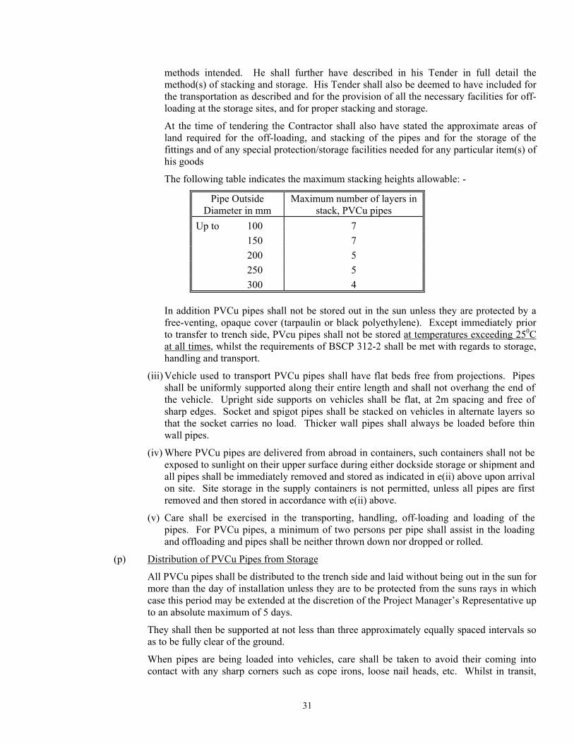
methods intended. He shall further have described in his Tender in full detail the method(s) of stacking and storage. His Tender shall also be deemed to have included for the transportation as described and for the provision of all the necessary facilities for off- loading at the storage sites, and for proper stacking and storage.
At the time of tendering the Contractor shall also have stated the approximate areas of land required for the off-loading, and stacking of the pipes and for the storage of the fittings and of any special protection/storage facilities needed for any particular item(s) of his goods
The following table indicates the maximum stacking heights allowable: -
Pipe Outside Diameter in mm
Maximum number of layers in stack, PVCu pipes
Up to 100 7 150 7 200 5 250 5 300 4
In addition PVCu pipes shall not be stored out in the sun unless they are protected by a free-venting, opaque cover (tarpaulin or black polyethylene). Except immediately prior to transfer to trench side, PVcu pipes shall not be stored at temperatures exceeding 250C at all times, whilst the requirements of BSCP 312-2 shall be met with regards to storage, handling and transport.
(iii) Vehicle used to transport PVCu pipes shall have flat beds free from projections. Pipes shall be uniformly supported along their entire length and shall not overhang the end of the vehicle. Upright side supports on vehicles shall be flat, at 2m spacing and free of sharp edges. Socket and spigot pipes shall be stacked on vehicles in alternate layers so that the socket carries no load. Thicker wall pipes shall always be loaded before thin wall pipes.
(iv) Where PVCu pipes are delivered from abroad in containers, such containers shall not be exposed to sunlight on their upper surface during either dockside storage or shipment and all pipes shall be immediately removed and stored as indicated in e(ii) above upon arrival on site. Site storage in the supply containers is not permitted, unless all pipes are first removed and then stored in accordance with e(ii) above.
(v) Care shall be exercised in the transporting, handling, off-loading and loading of the pipes. For PVCu pipes, a minimum of two persons per pipe shall assist in the loading and offloading and pipes shall be neither thrown down nor dropped or rolled.
(p) Distribution of PVCu Pipes from Storage
All PVCu pipes shall be distributed to the trench side and laid without being out in the sun for more than the day of installation unless they are to be protected from the suns rays in which case this period may be extended at the discretion of the Project Manager’s Representative up to an absolute maximum of 5 days.
They shall then be supported at not less than three approximately equally spaced intervals so as to be fully clear of the ground.
When pipes are being loaded into vehicles, care shall be taken to avoid their coming into contact with any sharp corners such as cope irons, loose nail heads, etc. Whilst in transit,
31

pipes shall be well secured over their entire length and not allowed to project unsecured over the tailboard of the lorry.
Pipes may not be offloaded from lorries by rolling them, nor shall pipes be rolled or dragged along the ground.
4.22 MATERIALS & STANDARDS, HIGH DENSITY POLYETHYLENE PIPES AND FITTINGS
HDPE (PE100 and PE100 layer) pipes and fittings shall meet the requirements of BS 3284, BS 5114, EN 12201 Parts 1,2, and 5, ASTM D2565 All manufacturing shall be in accordance to ISO 4427 and materials used shall be in conformance to ASTM D2122.
HDPE pipes shall be transported, laid, jointed and backfilled in accordance with the manufacturers written instructions except where this specification is more rigorous in which case this shall be followed.
At all time, latest and updated confirmed standards and procedures for design and installation shall be used and adopted. This will help ensure that the Employer benefits from superior materials with enhanced useful life. In the same context the Contractor may provide with the approval of the Project Manager superior materials using other standards not listed here provided they can demonstrate so through tests and guarantee certifications.
The polyethylene used shall be of a high molecular type with average to high density. Not less than Third Generation polyethylene known as PE 100 shall be used for the manufacture of the pipes. Second Generation polyethylene (PE 80) shall not be offered. The polyethylene shall be stabilised against the effects of ultraviolet radiation by the addition of carbon black.
The Contractor shall provide pipeline materials to the pressure classes and SDR ratios referred to on the Drawings and in the Bills of Quantities. Unless otherwise indicated on Tender Drawings or in the Bills of Quantities, HDPE pipes shall not be used in any pumping mains or in outside diameters exceeding DN 300 mm and the pressure ratings shall not be lower than PN 10.
In all cases minimum cover shall be 900mm and the bedding shall be restricted to S1 or S2 if specified by the Project Manager. Where S2 material is permitted, it may comprise or include screened ‘as-dug’ materials that meet this requirement.
Where specific design is carried out, the pressure rating shall be calculated taking into consideration : the operating and test pressures, surges if applicable, external pressures, HDPE pipe strength characteristics, temperature, soil condition, trench width and depth, appropriate traffic loads and impact fatigue.
The maximum allowable deflection of HDPE pipes shall be as follows:
Maximum Allowable Deflection of HDPE (PE100) Thermoplastic Pipes
PE pipes with electrofusion joints PE pipes with mechanical joints
5% 2%
Minimum pressure ratings and cover for HDPE pipes shall be as follows:
32
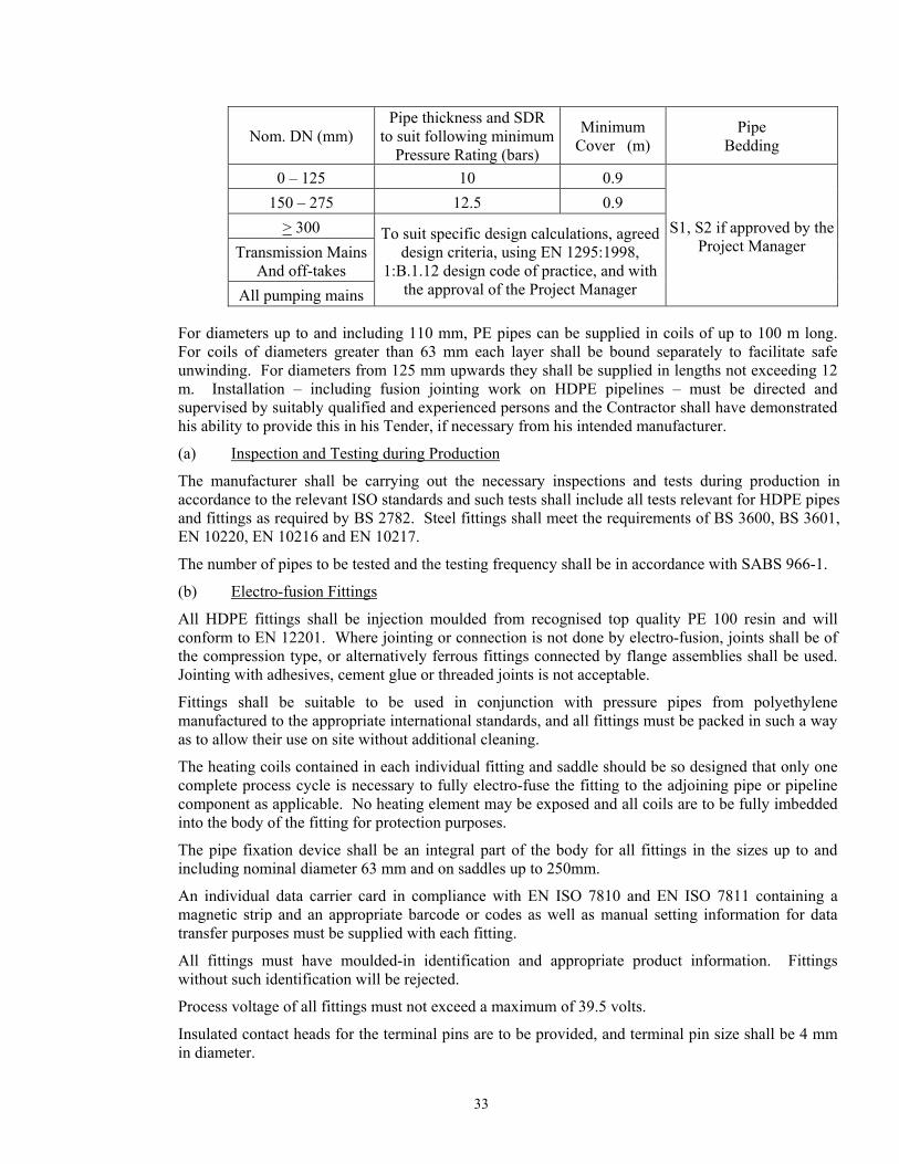
Nom. DN (mm)
Pipe thickness and SDR to suit following minimum
Pressure Rating (bars)
Minimum Cover (m)
Pipe Bedding
0 – 125 10 0.9
S1, S2 if approved by the Project Manager
150 – 275 12.5 0.9 > 300 To suit specific design calculations, agreed
design criteria, using EN 1295:1998, 1:B.1.12 design code of practice, and with
the approval of the Project Manager
Transmission MainsAnd off-takes
All pumping mains
For diameters up to and including 110 mm, PE pipes can be supplied in coils of up to 100 m long. For coils of diameters greater than 63 mm each layer shall be bound separately to facilitate safe unwinding. For diameters from 125 mm upwards they shall be supplied in lengths not exceeding 12 m. Installation – including fusion jointing work on HDPE pipelines – must be directed and supervised by suitably qualified and experienced persons and the Contractor shall have demonstrated his ability to provide this in his Tender, if necessary from his intended manufacturer.
(a) Inspection and Testing during Production
The manufacturer shall be carrying out the necessary inspections and tests during production in accordance to the relevant ISO standards and such tests shall include all tests relevant for HDPE pipes and fittings as required by BS 2782. Steel fittings shall meet the requirements of BS 3600, BS 3601, EN 10220, EN 10216 and EN 10217.
The number of pipes to be tested and the testing frequency shall be in accordance with SABS 966-1.
(b) Electro-fusion Fittings
All HDPE fittings shall be injection moulded from recognised top quality PE 100 resin and will conform to EN 12201. Where jointing or connection is not done by electro-fusion, joints shall be of the compression type, or alternatively ferrous fittings connected by flange assemblies shall be used. Jointing with adhesives, cement glue or threaded joints is not acceptable.
Fittings shall be suitable to be used in conjunction with pressure pipes from polyethylene manufactured to the appropriate international standards, and all fittings must be packed in such a way as to allow their use on site without additional cleaning.
The heating coils contained in each individual fitting and saddle should be so designed that only one complete process cycle is necessary to fully electro-fuse the fitting to the adjoining pipe or pipeline component as applicable. No heating element may be exposed and all coils are to be fully imbedded into the body of the fitting for protection purposes.
The pipe fixation device shall be an integral part of the body for all fittings in the sizes up to and including nominal diameter 63 mm and on saddles up to 250mm.
An individual data carrier card in compliance with EN ISO 7810 and EN ISO 7811 containing a magnetic strip and an appropriate barcode or codes as well as manual setting information for data transfer purposes must be supplied with each fitting.
All fittings must have moulded-in identification and appropriate product information. Fittings without such identification will be rejected.
Process voltage of all fittings must not exceed a maximum of 39.5 volts.
Insulated contact heads for the terminal pins are to be provided, and terminal pin size shall be 4 mm in diameter.
33
A limited path style fusion indicator acting for each fusion zone as visual recognition of completed fusion cycle should be incorporated into the body of the fitting or saddle near or adjacent to the terminal.
The design of the fusion indicators must prevent the escape of fusion melt.
All couplers in the sizes up to and including nominal diameter 160 mm must have an easily removable centre stop not requiring tools for removal.
All internal or externally threaded transition adaptors in the nominal sizes up to and including DN 63 must be designed with an integrated polyethylene collar from PE 100 for jointing purposes not relying on rubber or synthetic seals for leak prevention.
Threaded adapter bodies may be from brass or stainless steel and should be of the modular principle, not being supplied moulded into an electrofusion fitting socket.
(b) Product training and Technical Information
The manufacturer or the material supplier shall provide a specialised theoretical and active practical product training given by qualified instructors to enable installers of the above mentioned products to be able to understand and use the products correctly and efficiently under site conditions. The courses are to be held on the purchaser’s own premises upon demand.
The manufacturer is to provide accurate and easy-to-understand assembly instructions in English which can be used at any subsequent time for reference purposes.
(c) Manufacturing, Testing, Handling, Transport and Storage
The quality control procedure in manufacturing, transporting, handling and storage of HDPE pipes and fittings shall be in accordance Clause 4.22 (a) to (o) where appropriate and in conformance to their respective standards if not covered in this section.
(d) In-country Storage, Handling and Transportation of HDPE Pipes
(i) Before transporting HDPE pressure pipes, the loading surface of the vehicle must be cleaned and free from projecting nails, screws or other sharp objects. The bottom layer of all pipes must as far as possible be in contact with the loading surface throughout their entire length and not project beyond it. The pipes must be secured from slipping and shall not be pulled over sharp edges when loading and offloading. Pipes shall not be dragged along the ground.
(ii) Pipes, fittings and coils of HDPE pipes shall be stored in such a way that they are completely protected from direct sunlight. When covered they must be well ventilated to avoid accumulation of heat and resultant deformation. Transparent coverings shall not be used. The storage location shall be flat and shall, for pipes, support the pipes throughout their length. Stones and sharp objects shall not be present. Pipes shall not be stacked to a height exceeding 1 m. The pipes must be secured at the sides to prevent them from rolling. Contact with harmful materials shall be avoided. As far as possible, coils shall be stored in a horizontal position. The area shall be free of stones and sharp objects. If stored upright they must be secured to avoid tilting.
(iii) HDPE Pipes supplied in coils of up to 63 mm diameter may be unrolled with the coil in the vertical position. For larger diameters an unwinding device shall be used. A turnstile can be used with the coil laid in a horizontal position on it or with the coil mounted vertically on a slow moving lorry. The pipe shall never be removed from a coil in a spiral manner as this may cause kinking. Should kinking nevertheless occur the Contractor shall cut the pipe on either side of the kink, prepare the ends, and then
34
use an approved joint after laying. All costs of dealing with kinking shall be to the Contractors expense. A minimum bending radii of 35 x the diameter shall be observed.
(e) Distribution of Materials from Storage
The Contractor shall make his own arrangement for storage including for temporary occupation of the necessary land, provision of suitable fencing, preparation of site and security, and the selected storage areas shall be suitably close to the final pipeline alignment to allow for speedy transfer to the installation location.
HDPE pipes shall be distributed to the trench side and laid without being out in the sun for more than the day of installation unless they are to be protected from the suns rays in which case this period may be extended at the discretion of the Project Manager’s Representative up to an absolute maximum of 5 days. Pipes not in coils shall then be supported at not less than three approximately equally spaced intervals so as to be fully clear of the ground.
When pipes are being loaded into vehicles care shall be taken to avoid their coming into contact with any sharp corners such as cope irons, loose nail heads, etc. Whilst in transit, pipes shall be well secured over their entire length and not allowed to project unsecured over the tailboard of the lorry.
Pipes may not be offloaded from lorries by rolling them. Pipes shall not be rolled or dragged along the ground.
4.23 TRENCH EXCAVATION AND EARTHWORKS FOR THERMOPLASTIC PIPES
This clause for excavation shall apply except for thrust boring as specified in Clause 4.25 below.
(i) All trench excavation will as a minimum precaution be taped off to alert members of the public to its existence.
(ii) The excavation shall be made in open cutting unless tunnelling or heading is specified by the Project Manager’s Representative or it is specified in the Bills of Quantities.
(iii) Trenches for pipes shall be excavated to the lines and depths shown on the Drawings, or as directed by the Project Manager’s Representative, and shall be of sufficient width to give an equal clearance on both sides of the barrel of the pipe or pipes such that in general the total trench width is 3/2 'D' where 'D' is the outside diameter of the pipe or the average outside diameter of the group of pipes or will be equal to the outside diameter or the pipe plus 30 cm whichever is greater. For pipes bedded in concrete sections, the breadth of concrete bedding for the pipes will be equal to the width of the trench. Excavation for fire hydrants, valve chambers or any other water works structures shall be carried out to the levels and outlines of such structures, and the rates shall include for any additional excavation or other temporary Works required.
(iv) If in the opinion of the Project Manager’s Representative due to delays in laying which are the fault of the Contractor the ground becomes weathered prior to the laying of the pipes, the Contractor shall remove the weathered soil and replace it with suitable compacted material to the original formation level at his own expense.
(v) Where pipes are not laid on concrete, the bottoms of the trenches as excavated shall be smooth and shall be free from stones or other projections. Holes cut out for joints in the lower bedding shall be of as small a size as possible throughout their entire length. The trench shall be dug to within 15 cm of its formation and proper grade pegs shall then be set in the bottom of the trench by the Contractor for the accurate taking out of the rest of the excavation. Grooves about 5 cm deep shall be cut across the trench in the lower bedding at the required positions to enable the easy removal of pipe slings.
35
(vi) The materials excavated from trenches shall be laid completely and neatly on the sides of the trench except where in the opinion of the Project Manager’s Representative's Representative this would so obstruct a road or footpath as to prevent the passage of traffic or pedestrians. In such cases the Contractor must dig out the pipe trench in such lengths as directed and keep his excavated material at such a distance as may seem advisable, and the rates shall be deemed to cover for this.
(vii) During excavation, the Contractor shall ensure that all material suitable for re-use and which he intends for re-use are kept separate and set aside and protected as necessary to prevent loss or deterioration. Materials forming the surface and foundations of roads shall when excavated and if required for further use, be carefully separated. Paving slabs, bricks and similar surfaces shall be carefully removed and stacked for re-use, or as otherwise instructed by the Project Manager’s Representative.
(viii) No pipes shall be laid nor lower bedding introduced and no excavation filled in or covered with concrete until the formation has been inspected and the permission to proceed with the Work obtained. The Contractor shall provide to the Project Manager, a weekly schedule in advance indicating the dates and approximate times he expects to request such inspections.
(ix) Where pipes are to be laid under a road formation or in open country, or in cutting, trenches shall generally be excavated after the earthwork is completed. The Project Manager’s Representative may permit these pipe trenches to be excavated before the earthwork is complete, but payment for the excavation of the trench will only be made upon the volume excavated below the road formation.
(x) The unit of measurement for the excavation of trenches shall be per linear metre or per cubic metre of void calculated from the deemed width of the trench, and the average depth of excavation as mentioned in the Bills of Quantities. Unless otherwise indicated, for valve chambers and other water works structures, the unit of excavation will be per number or per cubic metre of excavated material calculated to the exact outer dimensions and depths of the Permanent Works. In neither case will allowance will be made for bulking.
(xi) The rates for excavation of trenches in "normal" material shall include removal of all material except "rock", selecting and segregating material to be backfilled in special layers, supporting or sheeting, shoring and strutting, any additional working space or room for timbering or sheeting required, dealing with water, maintenance of the trench, and all labour, tools, materials, plants, supervision, overheads and profit.
(xii) The provisions of the above Clause shall also apply to the rates of excavation in "rock" and in addition the Contractor shall allow in his rates for back-filling the invert with Class 15 concrete or other materials as directed by the Project Manager’s Representative and removing to a spoil dump all "rock" excavated.
(xiii) Where rock is encountered and should the Contractor wish to excavate the rock in advance and temporarily to refill the excavated trench with the excavated material until he is ready to proceed with the laying of the pipe, he shall be permitted to do so, which permission must be given in writing by the Project Manager. Such work shall normally be included in the Contractors rates unless he can show that the amount of rock is in excess of the amount billed to an extent that his work programme will be unduly delayed if he does not do so in which case he may seek to be paid both the E.O. item rate for the rock and twice the rate quoted for excavation in class III material.
36
4.24 PIPE LAYING FOR THERMOPLASTIC PIPES
4.24.1 Individual Pipes not supplied in Coils
(a) Pipes shall only be laid in the presence of a Project Managers representative unless written authority from the Project Manager has been granted.
(b) Pipes generally shall be laid and jointed in accordance with the manufacturer's or his licensor’s instructions. Extra excavation must not be carried out so as to avoid backfill, excessive deviation in joints and other irregularities. Otherwise, the pipe grade will follow the Drawings, with a continuous (but not necessarily uniform) fall towards washout-valves and rise towards air-valves.
(c) Every pipe shall be laid separately and shall bear evenly upon the lower bedding or concrete for its full length, holes to receive sockets, couplings or flanges being cut in the bottom of the trench of such size and depth as to allow the joints to be properly made. The pipes shall be laid to true inverts, straight lines and falls, each pipe being separately boned between sight rails. The pipes shall be thoroughly brushed inside insofar as is practicable and outside prior to laying, and no foreign matter shall be allowed to enter the pipe during or after laying. At the end of each working day the exposed pipe end shall be stoppered up with a stopper plug of appropriate diameter and not merely covered in polythene sheet tied around the end.
(d) Trenches shall be bottomed up only immediately in advance of pipe laying, although at least 15 metres shall be prepared in advance of any given pipe. Trenches and joint holes shall be kept free from water, until the pipes are laid and the joints completed and no ground water shall be allowed to enter the new pipes.
(e) Prior to laying in trench the lower bedding in the trench must provide support throughout the entire length of the pipe. The pipe shall never be laid directly on cohesive, rocky or stony material. Where the natural trench bottom meets the bedding class required, this shall initially be loosened to a depth of 10 cm and then re-compacted to at least 90% MPD and then the surface loosened on the day of and prior to laying
(f) In rock excavation, the pipes shall be bedded on concrete or selected granular fill, e.g. gravel, to a minimum thickness of 150 mm and the exclusion of rocks and other hard material to at least 300 mm around the pipe, leaving proper joint holes and subsequently making good with selected materials to the Project Manager’s Representative’s approval.
(g) All flanged joints shall be made with jointing rings, which shall be carefully inserted concentric to the bore of the pipe, so that undue stresses shall not be caused in any of the bolts or on the flanges when bolting up. The joint ring shall be compressed gradually and evenly by taking a few turns on each diagonal bolt in succession. Manufacturers’ recommendations on the maximum tightening torque shall be followed, and over-tightening shall be avoided. Where one or both of the flanges is itself of plastic, torque-wrenches shall always be used, and the bolts shall first be hand tightened and then diagonally tightened progressively to achieve 5%, 20%, 50%, 75% and finally 100% torque. For metal to metal flanges and if the Project Manager is dissatisfied with the degree of care being taken, the Contractor shall provide and use torque-wrenches for this purpose at no extra cost.
(h) Mechanical joints shall be made in accordance with the manufacture's instructions. After successful testing of pipelines, the joints will receive external protection as specified or to the Project Manager’s Representative's approval.
(i) The threads of any screw connections shall be coated with red lead before the joint is made.
(j) Concrete anchor blocks shall be provided at bends, tees, stopped ends, etc as shown on the drawings or as directed by the Project Manager’s Representative.
37

(k) Where a pipeline crosses under roads or railway lines, the pipe shall be sleeved or surrounded with concrete or protected by reinforced concrete slabs as instructed by the Project Manager’s Representative, and Tenderers shall have been deemed to have made allowance in their rates for compliance with the requirements of the relevant authority. Where roadside verges are liable to receive traffic, this protection shall be extended under the areas concerned and Tenderers shall have been deemed to have made allowance in their rates for compliance with this requirement.
(l) For the insertion of valves and other fittings into existing pipelines, pipes may need to be cut. Approved tools and machines specially made for the purpose, shall be provided and used by the Contractor.
(m) The Contractor shall provide and fix wooden drumheads to the open ends of the mains, and similar drumheads shall be used to close the ends of any pipes to exclude dirt and stones, etc. when the pipe laying is not actually in progress. Wooden markers properly inscribed, shall be left projecting out of the ground to indicate the ends of all pipes, where these are buried in the ground in open country. In public highways, a danger sign or other suitable means as approved by the Project Manager’s Representative shall be adopted.
(n) At every point of loading or unloading, pipes must be handled by approved lifting tackle. (Unloading by rolling them down planks of any form or including ramp will not be allowed except with the special consent of the Project Manager’s Representative).
(o) The stacking of pipes shall be used such as to prevent damage during storage. Timber runners shall be laid to keep the upper row separated from the lower and the bottom row shall be staked to prevent any rolling. The whole arrangement shall be subject to the approval of the Project Manager’s Representative.
(p) Care should be taken to minimise the risk of bush fires damaging any pipes laid out along the line of the mains.
(q) Refilling of pipe trenches shall conform to the specifications provided in Clause 4.25.
(r) The requirements for making good subsidence after refilling are provided for in Clause 4.26.
(s) Reinstatement of surfaces shall conform to the specifications provided for in Clause 4.27.
(t) For Thermoplastic Pipes Laid in Trenches: (i) The soil cover shall be a minimum of 900 mm. and the embedment material shall be S1
or S2 (single size or graded gravel). For details of the trench specifications, and backfill material sizes and grading refer to Clause 4.25. Tenderers shall allow for the price of such trenching and importation of necessary backfill material and compaction as part of the pipe installation price.
(ii) For all bedding classes, compaction shall be 90% MPD minimum. (iii) Marker tapes made of a pigmented low density polyethylene and aluminium foil in a
bright colour or other approved material not less than 100 mm wide and 0.15 mm thick shall be placed in the ground above the PVCu and HDPE pipelines laid underground as a measure to detect the pipe and at the same time to reduce the risk of accidental damage which may be caused by future excavations. The tape shall be laid about 300 mm above the crown of the pipe. The tape shall be continuously labelled with black printing “DANGER-PLASTIC PIPE alternately in English and Kiswahili. The price tape shall be deemed included in the price for the supply and installation of the pipe.
38

4.24.2 Pipes supplied in Coils
(a) All sub-clauses of clause 4.24.1 that are appropriate to pipe coils shall also apply and in case of any dispute, the Project Managers ruling shall be final.
(b) Pipe coils generally shall be laid and jointed in accordance with the manufacturer's written instructions. A re-rounding and straightening tool shall be used prior to making each joint. Extra excavation must not be carried out so as to avoid backfill, excessive deviation in joints and other irregularities. Otherwise, the pipe grade will follow the Drawings, with a continuous (but not necessarily uniform) fall towards washout-valves and rise towards air-valves. Horizontal alignment shall be as straight and central to the trench as is practicable, and if necessary, wooden pegs shall be used initially to ensure this until the upper bedding has been compacted at which juncture they shall be carefully withdrawn.
(c) Electrofusion Control Units for HDPE Pipes
The Contractor shall provide electrofusion control units as recommended by the HDPE pipe manufacturer and confirming to EN 60335, EN 5008, EN 55014 and EN 61000. The workmanship shall be in accordance to the manufacturer’s recommended procedure and quality.
4.25 BACKFILLING OF PIPE TRENCHES FOR THERMOPLASTIC PIPES All excavation of pipe trenches shall be of such form and to dimension as shown on the drawings or as the Project Manager’s Representative may direct, and in all respects provide with embedment configurations and minimum covers as detailed here below. As a general rule trench width shall be not less than 1 ½ times the OD of the pipe but subject to the following figure and tables.
Typical Trench for Thermoplastic Pipes
OD
trench width
'x' 'x'
14
11
13
12
ab
c
1 2 3
5
6
7
8
9
10
1 Surface2 Bottom of road or railway
3 Trench walls4 Top soil5 Main backfill6 Initial backfill7 Sidefill8 Upper bedding9 Lower bedding10 Trench bottom11 Depth of cover12 Depth of bedding13 Depth of embedment14 Trench deptha Depth of lower beddingb Depth of upper beddingc Depth of initial backfill
construction (if any)4
Note 2: the embedment is the arrangement and type(s) of material(s)around a buried pipeline which contribute to its structuralperformance. Attaining cited minimum compaction requirements ismandatory for embedment.
Note 1: compaction is the deliberatedensification of soil during the construct-ion process, whereas consolidation is thesubsequent time-dependant densificationafter construction. Attaining citedminimum compaction requirements is atthe supervisors disgression.
Figure: Trench Installation
B
'x' =OD/4 subject tominimum of 30 cm
(900 mm minimum)
39
Lesser trench widths may only be authorised if the Contractor can prove to the satisfaction of the Project Manager that he can consistently achieve the required compaction for a lesser width in which case an absolute minimum of OD + 450 mm may be permitted.
Minimum Trench Width
Pipe Size DN Trench Width General OD + minimum 600 mm
< 125 mm D + 450 150 – 300 D + 600
> 300 To suit site condition and to the approval of the Project Manager
If called for in the Bills of Quantities or if in the Project Manager’s opinion, the risk of vandalism in a particular area is higher than anticipated at the time of design, cover shall be increased to a minimum of 1.2m and the Contractor shall be paid for the removal and replacement of the additional materials at the same rates as quoted in the Bills of Quantities for the depth range indicated.
Embedment for PVCu and HDPE (PE100) Thermoplastic Pipes
Embedment Class
Bedding, Sidefill & Initial Backfill Material Allowed
Notes
S1 and S2 Class S1: Gravel – single size Class S2: Gravel – graded
processed granular materials required for all plastic pipes
S1 and S2 Embedment Material for Thermoplastic Pipes
Nominal Pipe Grading [to ASTM Sieve Sizes] Diameter (mm) S1 Embedment S2 Embedment
80 10 single-size gravel 10 single-size gravel 100 10 single-size gravel 10 single-size gravel 150 10 or 14 single-size gravel 14 to 5 graded
200 to 500 10, 14 or 20 14 to 5 graded or 20 to 5 graded single-size gravel > 500 le-size crushed graded or 20 to 5 graded 10, 14, 20 sing
or rock, 14 to 5
gravel
(i) The placing and co pipe embedment be undertaken in the presence of a Project Managers r e unles oject Manager has been granted.
(ii) No pipes shall be laid nor lower bedding introduced and no excavation filled in or covered with
(iii)
fragments, t trating imposed loads ed out
are, o tamping of material around the pipes and to joint ho as to o mpactness and solidity al shall if
ich would mbedment be vant pipe em be no less
stringent than a class S2 material for thermoplastic pipes and the source and any material brought to the site from elsewhere shall be approved in writing by the Project Manager’s
mpaction oepr tiv
f shall onlyesenta s written authority from the Pr
concrete until the formation has been inspected and the permission to proceed with the Work obtained.
In every instance, embedment material (consisting of bedding, side fill and initial backfill) filled around the pipe and for 300 mm over the top of the pipes shall be totally free from stones, rock
ree roots or similar objects which through impact or by concen the pipes cotton type soil. The filling shall be carrimight damage
with utmost cles so
and shall not include black special attention being paid tbtain the greatest possible coeened to exclude material whin accordance with the rele
. The materi damage the pipes. The ebedment drawing but shall
necessary, be scrmaterial shall
40

Representative before excavation commences. Any delays as a result of not seeking this approval all be entirely to the Co
(iv) ug’ trench m aterial which meets s requirements as specified and carefully screened to the sizes indicated above, and segregated from m the Contractor , use it as such or incorporate such m ment m
(v) The lower bedding mum t enches, and m wher g s where there is a continuou ation of groundwater, the trench shall after obtaining the approval of the Project Manager’s Representative, be over-excavated by 150 mm and shall be backfilled using
eter or 75 mm whichever is the lesser. Layer thickness is however subject to consistently
edding shall be introduced as carefully and thoroughly as practicable to the underside
free from clay lumps, boulders and rock fragments
ents and suitable for
compaction can be achieved (according to BS
relaxed based on
in good time sh
Where the ‘as-d
ntractor’s account.
aterial contains m the bedding clasproviding that this isaterial that does not, may, at his discretion
d. aterial into the imported embed aterial being use
for the pipes shall have a mini hickness of 100 mm in normal tr 150 m e rock/stones are present and at desi
s accumulnated road crossings. In trenche
compacted granular material. Bedding material shall be compacted in layers not exceeding 50 mm thickness. Compaction of fill around the pipe shall be in layer thickness not exceeding half the pipe diamachieving 90% MPD (Modified Proctor Density) or better, failing which layers shall be reduced in depth as necessary to achieve the % compaction.
(vi) The upper bor haunch of the pipe such that no large spaces remain before it is compacted.
(vii) The sidefill and backfill material within the embedment shall be placed in layers of not more than 150 mm thickness when compacted and where hand ramming is employed the number of men filling shall not be more than half the number of men ramming. Sidefill shall be placed simultaneously on both sides of the pipe. Where mechanical-ramming of the remaining backfill is employed, the machines shall be to the approval of the Project Manager’s Representative and soil shall be replaced and well rammed down by hand for a depth of not less than 60 cm to give sufficient cover to the pipes and obviate risk of damage to them before the mechanical rammer is brought into operation. The rammer shall not cease to be used on any length of trench until thorough compaction has been obtained. All backfill soil shall be free from clay lumps, boulders stones and rock fragments greater than 20 mm and 90 % MPD shall be attained in all instances. All backfill soil above the embedment shall be greater than 50 mm and as far as practicable 90 % MPD shall be attained, but this may be relaxed (e.g. in fields and open areas) by the Project Manager’s Representative.
(viii) The Contractor in excavating the trench from which he wishes to use ‘as-dug’ material for bedding shall ensure that materials from strata containing no stones or rock-fragmfilling around the pipes as described above, shall be kept separately and used for this purpose. The Contractor shall not be entitled to claim for any extra costs (as provided for below) for screening if this requirement is not complied with. If no such strata occur in the excavation, the excavated material shall either be screened or suitable material transported to the Site from other excavations as the Project Manager’s Representative shall direct. The cost of such work shall be paid for according to the rates in the Bills of Quantities.
(ix) Before commencing the placing of embedment in the trenches, the Contractor shall obtain approval from the Project Manager’s Representative as to the methods he proposes to use and he shall demonstrate by means of tests that the specified1377 and ISO 22476 using the “sand replacement” method). The method of compaction and the testing thereof shall be at all times to the approval of the Project Manager’s Representative and in general at a frequency of once every 30 metres unless this is specificallycontinuously good in-situ test results.
(x) The pipe trench shall be backfilled entirely without leaving out areas around and at pipe joints uncovered, for subsequent filling. To facilitate the subsequent location of any suspected leaking
41
joints during pipe testing, should this become necessary, the Contractor shall provide marker pegs at regular intervals and/or use a handheld GPS to be able to relocate joint positions.
(xi) Where for pipes other than those used for service connections a minimum cover of 900 mm cannot be maintained, including highways and trafficked areas then the pipe must either be laid in a protective ferrous sleeve or be protected by a 150 mm thick reinforced concrete slab above the pipe. A minimum of a 150 mm layer of appropriate grade granular bedding material must first be placed and lightly compacted as a cushion above the crown of the pipe before the slab is laid, and the slab must extend at least 150 mm out beyond either side of the trench.
4.26
ench to grade through a process of
ation shall be made up by the Contractor at his own expense
s of at least 6m width, grassland, cultivated lands and sports fields. All other reinstatements both temporary and
n rates.
(ii)
ontractor. The
(iii)
le materials as may be required and consolidating the various materials as the Work proceeds
MAKING GOOD SUBSIDENCE AFTER REFILLING
Should any but very localised subsidence occur of the pipe trench after refilling and before the expiry of the maintenance period, the Contractor shall first demonstrate that such subsidence is only to the backfilling above the pipe and not to the pipe, embedment, bedding or sub-soil itself.
Should this not be so demonstrated then the Contractor at his own expense shall, excavate and remove the pipe or pipes affected and return the bottom of the trover-excavation, re-compaction or use of a lean concrete mix as determined by the Project Manager’s Representative, who shall also determine whether or not the affected pipes may be re-used or replaced.
The affected section or sections will in any event be liable for a further twelve months maintenance period.
All subsequent refilling shall be thoroughly compacted by ramming as with a newly completed trench. Any subsidence due to consolidwith extra compacted material. Should subsidence occur after any topsoil has been replaced, the topsoil shall first be removed before any hollows in the backfilling are made up before being replaced.
4.27 REINSTATEMENT OF SURFACES
(i) All surfaces of roads, fields, paths, gardens, verges, etc. whether public or private which are affected by the operations of the Contractor shall be temporarily restored by him in the first instance and permanently reinstated in the second instance when the ground has consolidated fully. Separate payment for reinstatement shall be made only for surfaced roads (e.g. tarmac, concrete, paving bricks or similar material), and for officially designated dirt road
permanent are deemed to be covered by the pipe installatio
The Contractor shall be responsible for the temporary reinstatement and permanent reinstatement of all surfaces whether or not the area requiring restoration is within the limits of his excavations if the necessity for the restoration arises from causes due to the operations of the CContractor's prices shall include for restoring all surfaces so damaged to their original condition, as no extra payment will be made for any such work. The Contractor shall take all necessary measures to ensure that no toxic materials that may cause damage to vegetation or livestock or pollute streams or water-courses are used in any temporary restoration or permanent reinstatement and shall indemnify the Employer against any claims arising out of the use of such materials.
Temporary restoration shall be carried out immediately after the excavations have been refilled by returning the excavated material to the position from which it was removed and adding such suitabin order to provide a surface that is adequate for the purpose that the original surface fulfilled. Temporary surfaces shall be maintained in a condition satisfactory to the Project Manager’s Representative and/or responsible Authority until the permanent reinstatement is made. In the case
42
of roads and streets the surface shall be necessary to consolidate the filling and keep the surface fit for traffic, suitable material being added to all placed which have sunk or become rough.
ade until the ground has consolidated permanently and until Project Manager’s Representative. It shall be carried out
4.28
age to:
such remedial works or
4.29
s Representative on Site.
cavation, backfilling, and temporary reinstatement, all as described in the Bills of Quantities. Measurement of
(iv) Permanent reinstatement shall not be msanction to do so is received from thewith materials similar to those that were used in the original Work to the entire satisfaction of the Project Manager’s Representative and/or responsible Authority.
(v) In all verges and other, grassed surfaces, the topsoil shall be removed, stored and replaced after consolidation of the filling and planted or seeded with approved grass. Should subsidence occur, it shall be made good with additional topsoil and be replanted with grass or re- seeded. New grass shall be planted if for any reason the grass fails to grow or is destroyed.
(vi) The trenches, channels, gutters and kerbs shall be reinstated to the condition in which they were before excavation was commenced. The final surface of the trench shall be flush with the surrounding ground.
(vii) If the work of restoration or reinstatement as carried out by the Contractor is not to the satisfaction of the Project Manager’s Representative and/or the responsible Authority and should the Contractor not remedy the defect forthwith, any remedial work considered necessary may be undertaken by the Project Manager’s Representative and/or the responsible Authority and the cost thereof shall be borne by the Contractor.
(viii) If at any time any trench becomes dangerous, the Project Manager’s Representative shall be at liberty to call upon the Contractor to restore it to a proper condition at three hours' notice and should the Contractor fail to carry out the work, have it done at the Contractor's expense.
PART IV - ALL PIPELINES DURING DELIVERY, INSTALLATION, TESTING AND COMMISSIONING
ON-SITE INSPECTION
All pipes, valves and fittings shall be inspected upon arrival at the pipe storage areas for dam
- the pipe or fitting itself - external coatings (if any) - internal linings (if any) - jointing surfaces (incl. sockets if any)
The Contractor shall be responsible for and shall undertake any work required by the Third Party Inspector or by the Project Manager or his Representative as appropriate or where deemed necessary, replace defective pipes and fittings. All expenses in connection with replacements shall be deemed covered by the Tender.
HANDLING FROM STORAGE TO TRENCH
All pipes shall be handled from storage to trench in accordance with the manufacturer’s recommendations.
The Contractor shall obtain and keep on Site copies of all the manufacturer's literature relating to the proper handling, storage, laying, installation and testing of their products and shall make them or copies thereof available to the Project Manager’
4.30 MEASUREMENT FOR PIPE LAYING
Pipe laying and jointing where in trench is included in the Bill of Quantities with ex
43

the work done will be along the centre-line of junctions in the pipe network, and branches, unless otherwise indicated in the Bills of Quantities.
inal bore of pipe will be allowed. Where pipelines are a wayleave clearance of five metres plus nominal bore of pipe
te Clearance will be based upon this width except that the Project s the right to restrict this width due to the presence of obstructions,
be according to the actual area cleared. No claims for
g, to locate and avoid the damaging of any , electricity or telephone. Notwithstanding this Contractors further obligation at his own cost to
amaged article to the entire satisfaction of the Utility concerned.
4.33 antities or directed by the
Project Manager’s Representative, a concrete surround of not less than 0.15 m shall be provided to -
Drawings or directed by the Project Manager’s
ing and formwork, protection and curing and all labour, tools, plant, supervision overheads and profit.
4.34
or blocks shall be allowed to cure for at least 7 days and soil around anchor blocks shall be compacted thoroughly
he pipeline. Payment for anchor blocks will be per unit volume of
st at least ys d section
4.31 WORKING WIDTH
Where pipelines are within 20 metres of a motorable track, or through light bush or thicket a wayleave clearance of 3 metres plus nomthrough dense bush, thicket or forest will be allowed. Payment for SiManager’s Representative reserveroads, houses and the like. Payments will then additional space nor for inconvenience and the like caused by obstructions will be allowed.
4.32 LOCATION OF UNDERGROUND SERVICES ETC.
It shall be the Contractors obligation when trenchinexisting services, be they water, drainage, sewageobligation and should damage occur, it will be theurgently liase with the utility organisation concerned and to bear the full cost of the repair or replacement of the d
CONCRETE PROTECTION
Unless otherwise provided in the Special Specification or Bills of Qu
water mains in the following circumstances:
(a) Water mains with less than 0.6 m or more than 6.0 m of soil cover over the pipes.
(b) Water mains under carriageways if depth of soil cover is less than 1.30 m
(c) In the places where shown on the Representative.
All concrete for beds and surrounds shall be class 15 concrete.
Alternatively under carriageways and where indicated on the drawings, the pipeline shall be laid in a stepped trench with the immediate surround backfilled with approved granular material and then across the step shall be laid precast reinforced concrete slabs of class 25 concrete, 150 mm thick.
The unit of measurement shall be cubic metre or linear metre as indicated in the Bills of Quantities.
The rate shall include for the provision, transporting and placing of concrete, all strutt
ANCHOR BLOCKS
Pipelines with mechanical (or flexible) joints shall be adequately anchored at bends, tees, sluice or butterfly valves, tapers, blank ends, etc. Anchor blocks shall be constructed from Class 20 concrete to the dimensions indicated on Drawings unless otherwise directed by the Project Manager’s Representative. Support blocks shall be constructed from Class 15 concrete. All anch
before the hydraulic testing of tconcrete in the blocks and shall include for all of the earthwork, formwork and other operations required for their construction. No separable payment shall be made for any temporary or permanent anchor blocks constructed by the Contractor specifically for the testing of the pipeline.
Anchor and thrust blocks at proposed tie-in points between old and new pipework will be ca7 da prior to the proposed tie-in works and post tie-in pipeline testing for the affecte
44

except that where this is impracticable then a thrust wall shall be constructed similarly in advance
and fitte ve rubber insert. Immediately after re-commissioning, the space between the s 20 concrete, thereby permanently
4.35 IN
ntities shall after installation be cleansed by brushing away soil and then shall have an approved mastic
them so as to provide a contour suitable for wrapping the component with an
4.36
ped using a
4.37
Prior to deployment of any welder he shall within the preceding 3 months have satisfactorily
ager’s Representative. Each welder deployed shall at
4.38 S 3974-1, PNFS 0001 and MSS SP 58.
t of the tapping clamp shall be of robust ductile iron or stainless steel with a fusion bonded epoxy coating of not less than 300
first instead and the final connecting fitting propped initially from this thrust wall by means of a horizontal steel joist with the contact face with the fitting curved to the outside diameter of the fitting
d with a protectithrust wall and the propped fitting shall be filled with clasencapsulating the steel joist. The proposed tie-in works described in Clause 4.44 will therefore be preceded by the required anchor/thrust block or thrust wall casting.
ADDITIONAL PROTECTION TO FLEXIBLE COUPLINGS AND FLANGE ADAPTORSCHAMBERS AND/OR ABOVE GROUND
Such mechanical joints e.g. flexible couplings, flange adaptors, etc. in chambers and/or above ground shall have been factory epoxy coated and where indicated on drawings or in the Bill of Qua
blanket moulded aroundapproved petrolatum anti-corrosion tape suitable for tropical climates which shall then be done so as to achieve a clean and neat good tape finish.
PROTECTION TO FLEXIBLE COUPLINGS AND FLANGED ADAPTORS FITTED TO EPOXY COATED PIPE SPIGOTS.
Where factory coated flexible couplings have been used on pipes whose exposed surfaces beyond other protection materials have been factory protected using epoxy, then such joints shall be site protected by a polythene outer wrap sheathing of minimum thickness 200 microns that shall extend beyond the pipe epoxy coating by at least 50 cm. This outer wrap shall be double strapnon-metallic strap to each pipe end beyond and not to the epoxy coating.
IN-SITU WELDING OF STEEL FITTINGS AND FLANGES
Wherever it is necessary to undertake in-situ welding of steel fittings and flanges the work shall be undertaken under cover, temporary or otherwise. Outside of buildings, the cost of providing such cover shall be deemed included in the Contractors rates. Only suitably qualified welders shall be employed.
Welding procedures used shall comply with ISO 15607 and EN 288-9.
undergone an ‘approved testing’ in accordance with EN 287-1 and certification thereof shall be provided to the satisfaction of the Project Manintervals of not more than 6 months undergo similar approved retesting and only those who pass such retesting will be allowed to continue to undertake the in-situ welding works.
All testing and retesting will be deemed to be covered in the Contractors rates.
PIPE SUPPORTS
Pipe supports shall meet the requirements of B
4.39 SERVICE PIPE CONNECTIONS
All tapping shall be carried out using tapping saddle clamps (sleeves or collars type – surrounding the pipe). Self tapping directly on pipes shall not be permitted. Ferrules alone shall not be permitted
The form of the customer connection tapping clamp shall be two equal halves held together by threaded ends, washers and bolts. The tapping clamp for flexible pipes shall be double band with a minimum thickness of 1.5 mm if made from stainless steel. The body par
45
microns dry firm thickness. The seal shall be of elastomer or nitrile rubber material and shall
er connection tapping clamp shall have following features :
th the pipe body for
his Tender offers service pipe connections that are not fully in compliance with rements of this
4.40 be
fy at what stage testing is required.
such shorter lengths as the erstanding that no extra cost will be
hall not
test in accordance with the
connecting pipework, feeding tank, blank flanges, temporary stop-
ng to the Project Manager’s Representative for approval.
stop-ends and gauges fitted to the Project
surround the pipe circumference completely and shall be suitable for use with potable water. The tapping clamp shall be supplied complete with removable and lockable ferrule. They shall be of approved manufacture which shall not be unreasonably withheld.
The custom▪ They shall be impressed with the logo of the Employer. ▪ All stainless steel parts shall conform to high corrosion protection grade (AISI 316 L). ▪ The rubber lining shall eliminate metal to metal contact or metal to plastic contact and insulate
against galvanic corrosion between two different types of metals. ▪ They should be able to fit range of pipe diameters and also be able to adapt to pipe
irregularities and ovality ▪ Double band or wide bodies to allow large surface area contact wi
supporting the pipe.
Any Tenderer who inthese requirements will be required to confirm in writing that he will meet the requiclause in full without any price adjustment to his offer if his Tender is to be considered for possible award.
HYDROSTATIC TESTING OF PIPELINES
After laying, new pipelines shall be tested under pressure and where in trench, such tests shallmade before it is reinstated. Unless otherwise approved, during the test, all joints shall be clear of earth, timber, etc to allow visual inspection. Testing shall commence when not more than 20% or 10 km of all pipework has been laid whichever is the lesser and at no time may there be more than that amount remain untested. If, in the view of the Project Manager, the level of failure is unsatisfactory, then the maximum length remaining untested at any one time shall be reduced at his discretion.
Where old pipelines that are yet to be taken back into service are involved they shall be similarly tested, except that the Project Manager’s Representative may speci
The pipeline shall be tested in lengths between valve locations or inProject Manager’s Representative may approve on the undincurred to the Employer but the maximum length of main to be tested at any one time snormally exceed 1km.
The Contractor shall supply all necessary materials to carry out the requirements including force pumps, water pressure gauges, as well as tools for the use of the Project Manager’s Representative, interends, struts and water for the test. The test section shall be capped or flanged off at each end and all branches. Testing shall not take place against closed valves.
For a pipeline incorporating flexible joints, testing shall not commence until after all the permanent anchor blocks along the pipeline have been constructed, cured, and soil around them backfilled and compacted. Capped or flanged ends along the pipeline shall also be anchored adequately to withstand the force due to test pressure. The Contractor shall submit his proposals for temporary anchori
After the main has been clear of debris, and all necessaryManager’s Representative's approval, the Contractor shall fill up the pipe with water free from silt, sand and grit and bring steadily up to the nominal pressure of the pipe or incorporated fittings, whichever is the lesser, (except for old pipelines where a lower value may be specified by the Project Manager’s Representative), and this shall be maintained it with a force pump for 24 hours.
46

The pressure shall then be increased steadily in increments of 1.0 kg/cm2 with a pause of one minute between each increment to the specified test pressure for the section. Unless otherwise specifically mentioned, the applied test pressure shall be measured at the lowest point along the section being
our for a total period of 3 hours, or longer, if the Project Manager’s
d faulty pipes, fittings, and specials,
4.41
4.42
long the pipelines installed in open country or as directed by the Project Manager’s
4.43
ns specified in the
r HDD:
ling (HDD), the Contractor shall ensure that the following decision process and tasks are completed and approved by the Project Manager :
the planned installation
tested.
Where the test pressure has not been specified, it shall be assumed to be 50% in excess of the nominal pressure at the lowest point of the section being tested.
After a period of half an hour, the fall in test pressure shall be recorded and sufficient water again pumped into the line under test to bring the pressure back to the test pressure. The procedure shall be repeated every half-an-hRepresentative so directs, and the amount of water pumped in shall be recorded.
The rate of leakage shall be calculated from the amount of water pumped in during testing and if it is less than 1 litre of water per 10 mm diameter of pipe per km of length of pipeline, for each 24 hours and for every 30 m head, the pipe line will be considered to have passed the test.
Leaks exceeding permissible amounts shall be made good. Anshall be replaced by the Contractor at his own expense and the section tested again before approval is given for backfilling. Payment for the section will not be certified, until the test has been passed and any remaining backfilling completed.
FLUSHING AND STERILISATION
This shall be done in accordance with the recommendations set out in BS 6700.
All tested pipework shall be flushed and cleaned and all treated water pipework shall additionally be sterilised. The rates inserted are to be for the flushing and sterilising, and where appropriate for cleaning shall be inclusive for, sampling, testing and inclusive of the reports on the bacteriological quality of water.
MARKER POSTS
Pre-cast reinforced marker posts to the dimensions indicated on Drawings shall be installed at 100 m spacing aRepresentative. Marker posts shall be painted with at least two coats of all weather plastic emulsion paint of approved colour.
HORIZONTAL DIRECTIONAL DRILLING (HDD) FOR ROAD AND RAILWAYCROSSINGS
The Contractor shall install pipes using horizontal directional drillings at the locatiodrawings and the Bills of Quantities. The locations are normally across heavily trafficked roads and railway crossings where bypass or diversions cannot be readily made. The Contractor shall be responsible for all the design, permit acquisition from TANROADS or the City or Urban Council and for implementation and restoration. The following procedure shall be applicable fo
A. Design Guidelines
Prior to submitting an application for a Right-of-Way Permit to TANROADS or the City Council that will involve horizontal directional dril
a) Prepare or obtain scaled mapping for- including all exiting surface facilities and improvements. - and including any indication of underground facilities or improvements.
b) Collect existing underground utility information
47
- including the horizontal location of all known substructures (expected). - and including the depth of all known substructures (whenever possible).
ay information from TANROADS or City Council.
uding the location of all planned improvements,
d vertical clearance requirements when determining the HDD
ter requirements;
3m radius per 1 cm pipe ls and
and including drill operation and final product staging.
pplication Requirements
s, type
c) Obtain Right-of-W
d) Obtain general and/or specific geotechnical information as required or deemed necessary - including soil data for the project area. - and possibly including site-specific geotechnical sampling and analysis to confirm the
soil data.
e) Prepare Design Drawings using the information noted above - incl- including existing underground utility information, and - including right-of-way limits and property ownership information (as required).
In addition to the design requirements listed above, the Contractor shall take into consideration the following:
f) the minimum horizontal analignment
- including road setbacks and existing surface features, - and including exiting underground utilities and other underground facilities;
g) pipe sizes to be installed and their corresponding reamer diame
Pipe Diameter Reamer Diameter < 200mm Diameter + 100 200 – 600mm Diameter + 150
60> 0mm Diameter + 300
h) the bore geometry for the given ground profile - including bore length(s) and depth requirements, and
including bending radii for the final product pipe (Typically 1- diameter, with 200m to 330 m radius minimums depending on subsurface materiaequipment requirements);
i) drilling equipment requirements for the given geotechnical conditions, geometry and final product diameter
- including thrust and pullback ratings - including mud motors vs jetting heads and - including wireline vs walkover tracking systems;
j) equipment and material handling requirements - including drilling fluid and drilling fluid containment -
k) material strengths, capacities, and coupling methods.
B. TANROADS and City Council Right-of-Way Permit A
The Contractor shall submit the following information with the application :
a) Provide proposed HDD Location Information - Pipe diameter , pressures etc.,
48
- Locatio en d depths, covers,ns, l gth an clearances.
b) Pro ings on g and shall include : posed alignment (dimensioned),
of the proposed crossing), and
d) itions based on local knowledge or based on
start date(s), completion date(s), and
it, the Contractor shall consider f the Project Manager:
nel are
ication) is implemented
ion measures (required with the permit application)
lity coordination requirements have been met;
cted to be ed vertical alignment,
ested by TANROADS or City Council;
2m of the proposed alignment, d alignment,
shall have a planned response in the event of a utility strike including utility
The HDD Contractor shall contain, handle, and dispose of drilling fluids in accordance with the
vide Design Draw scalable mappin- the pro- existing utility information (within 10m- the road right-of-way information
c) Provide specific installation requirements or typical installation parameters indicating the design bending radii and diameter(s).
Provide assumed subsurface geotechnical condspecific site soil tests.
e) Pro evid a Traffic Control Plan
f) Provide a Storm Water Pollution Prevention Plan
g) Provide a Construction Schedule indicating the proposedrestoration schedule.
C. Construction Safety Guidelines
Prior to performing work involving HDD under a Right-of-Way Permthe following safety guidelines and shall obtain approval o
a) Perform all operations in compliance with OSHA guidelines and insure that all personproperly trained and equipped to work in the public right-of-way;
b) Insure that the approved traffic control plan (required with the permit appland followed at all times;
c) Insure that all storm water pollution preventare implemented and followed at all times;
d) Insure all setbacks, offsets, and clearances are maintained;
e) Insure that utility One-Calls and City or other uti
f) Positively identify from records or by potholing all crossed utilities that are expe- above and within 2m of the propos- below and within 1m of the proposed vertical alignment, - and additionally as requ
g) Positively identify from record or by potholing all parallel utilities at the beginning and ending of all bores and
- every 70m if it is within- every 15m if it is within 1m of the propose- and additionally as requested by the City Project Manager.
h) The HDD Contractor owner notification and
- avoiding electrocution in the event of an electric strike, - avoiding combustion in the event of a gas line strike, - avoiding contamination in the case of a sewer strike.
D. Drilling Fluid Containment and Disposal Requirements
49
following requirements:
a) All drilling fluid and fluid additives shall be disclosed to the Project Manager.
does not enter roadways, streams,
rom the site and disposed at an
ll be environmentally safe and
l Council, and as outlined below. For all work involving horizontal l perform the following:
b) Excess drilling fluid shall be confined in a containment pit at the entry and exit locations until recycled or removed from the site.
c) Precautions shall be taken to insure that drilling fluidmunicipal storm or sanitary sewer lines, and/or any other drainage system or body of water.
d) Unintended surfacing of drilling fluid shall be contained at the point of discharge and recycled orremoved from the site.
e) Drilling fluids that are not recycled and reused shall be removed fapproved disposal site.
f) Drilling fluids shall be completely removed from the construction site prior to back filling or restoring the site.
g) Collection, transportation, and disposal of drilling fluids shacomply with local ordinances and government regulations.
E. Construction Requirements
All construction work shall be performed in accordance to the following unless stated otherwise by TANROADS or the Locadirectional drilling under a Right-of-Way Permit, the Contractor shal
Prior to Construction:
a) The HDD Contractor shall familiarize itself with the work area and the technical requirements of
ry and exit locations, and
the plans;
b) The Contractor shall establish construction marking/staking, prior to construction, to indicate - HDD ent- proposed HDD alignment at 10m (max) intervals;
c) Provide the Project Manager with a contact list of all crew foremen;
During Construction:
a) The HDD Contractor shall calibrate its tracking and locating equipment at the beginning of each work day;
b) The HDD Contractor shall monitor and record the alignment and depth readings provided by the tracking system
- every 10m for normal conditions, - every 2m where precise alignment control is necessary;
ertically unless otherwise authorized by the Project Manager;
nstallation, and
c) The HDD Contractor shall complete the HDD installation as designed and permitted both horizontally and v
d) The HDD Contractor shall attempt to maintain drilling fluid circulation throughout the HDD process
- during the initial pilot hole i- during the reaming and back pull process(es)
e) The HDD Contractor shall not expand the bore hole by more than 150mm using only compaction reamer(s).
50

f) The HDD Contractor shall plan its reaming and back pulling operations carefully to insure that,
to
insure that no construction-s occurred
including drilling fluid fractures or releases
HDD operations;
Fo
once started, all reaming and back pulling operations can be completed without stopping and within the permitted work hours;
g) The HDD Contractor shall at all times and for the entire length of the HDD alignment be abledemonstrate
- the horizontal and vertical position of the alignment, - the fluid volume used, return rates, and pressures;
h) The HDD Contractor shall inspect the work and surrounding area torelated damage ha
- including heaving or humping of paved surfaces, and -
i) At all times the Contractor shall provide access to the Project Manager’s representative for inspection of the
llowing Construction:
a) completion of the authorized
r shall notify the
, the Contractor will schedule a closeout inspection.
c) estoration is in compliance with the .
ompleted and inspected to the Project Manager’s satisfaction.
plied for all Storm Water Pollution Prevention planning:
a)
d)
e) .
restoration as soon as possible.
cific Best Management Practices:
ization are to follow;
The Contractor shall notify the Project Manager as appropriate upon work;
b) Prior to the start of backfilling excavations under paved surfaces, the ContractoProject Manager to schedule an inspection. Upon completion of all right-of-way restoration activities
The Contractor shall insure that all cleanup and rrequirements for restoration, reinstatement and cleaning up
d) The Contractor’s 1 year maintenance period will not begin until any corrective actions required have been c
F. Storm Water Pollution Prevention
All construction activities shall be performed in accordance with the acceptable international standards and Best Management Practice, to insure that storm water runoff is not contaminated by sediment caused by land disturbances associated with construction activities. The following seven main objectives shall be ap
Insure that sediment controls are in place prior to disturbance.
b) Maintain sediment controls throughout the construction and restoration processes.
c) Minimize the overall disturbance whenever possible.
Protect disturbed areas throughout the construction process.
Prevent storm water runoff from entering disturbed areas
f) Never intentionally discharge construction contaminants directly into creeks, rivers, ditches, or storm systems.
g) Complete permanent
In addition to those overall goals stated previously, the contractor shall, at a minimum, implement the following spe
h) Provide temporary erosion protection whenever possible: - Mulch, seed, or gravel may be applied even if a disturbed area may and/or will be
disturbed again or other permanent measures of stabil
51

- Cover spoil piles with a tarp or contain with a sediment barrier.
i) Contain disturbed sediment on site: - Use sediment barriers such as silt fence, sand bags, straw bails, rock checks and/or
sediment traps to contain sediment on the construction site; - Existing vegetation may be used as a sediment filter where minimal grades and sheet
d filters after all storm events.
ecords of all activities associated with the ermittee shall provide the city of
ys of project but may be submitted in paper form.
ata and operator logs shall be maintained daily and shall be made available upon cords and operator notes shall specify:
tallation, ng adjustments and other equipment
b) inimum, the
4.44
flow runoff will occur; - Insure that all sediment barriers are installed and functioning properly.
j) Avoid causing flooding in roadways and adjacent right-of-way: - Do not block existing culverts and storm inlets except as a last resort; - Insure that sediment is removed from sediment traps an
G. Construction Records and As Built Plan Requirements
The HDD Contractor shall keep detailed and accurate rHDD process. Upon completion of HDD installations, the POverland Park with As Built plans and any supporting documents within 60 dacompletion. As Built plans are preferred in AutoCAD formatHDD construction records and As Built plans shall include the following:
a) HDD tracking drequest from the City Project Manager. These field re
- the type of tracking equipment used, - the length and depth of the HDD ins- additional information that may include steeri
performance parameters;
As Built plans shall be derived from the tracking data and operator logs. At a mdrawings shall indicate:
- horizontal and vertical HDD alignment, - existing utility horizontal locations and depths at all exposed or potholed locations, and - existing utility horizontal locations where indicated with field locates.
TIE-IN WORKS BETWEEN EXISTING AND NEW PIPELINES
a) General
This specification clause shall apply to any tie-in works betweepipelines which involve closing down of any main which is in servic
n existing operational and new either Raw or
ting that has to be
xcept under circumstances where
e supplying water, Treated, within the existing supply system. It shall further apply to any new fitinserted into an existing operational pipeline.
The Contractor shall be responsible for the execution of the works ethe execution of the tie- in operation is assumed by Project Manager’s Representative as mentioned under (f) below, from the date of the Project Manager’s Representative's instruction to perform described under (g) below. The Project Manager’s Representative's instruction to perform the tie-in will be given at least 14 days before the date on which the tie in is to be executed.
b) Fittings
The Contractor shall take delivery of any fittings required at the Works not less than 96 hours before the commencement of the tie in operations. He shall provide all the necessary watching to ensure that
he Contractor shall, check the suitability of such such fittings do not get misplaced or stolen. T
52

fittings including checking of all dimensions, particularly the external diameter of the pipe into which
o
including those on existing pipes that are to be
n
not less than 24 hours before anager’s Representative who
e materials against the schedule as approved where he deems this necessary
the connection is being made and the internal diameter(s) of couplings which are to be used for such c nnection. This shall be done by measuring the circumference of the two joining surfaces to a tolerance of 0.25 mm. The Contractor shall certify the suitability of such materials to the Project Manager’s Representative not less than 48 hours before the commencement of tie-in operations.
The Contractor shall prepare a schedule of fittings used for such tie-in or redeployed elsewhere as instructed on the drawings and shall obtain approval of the Project Manager’s Representative not less than 48 hours before the commencement of tie ioperations of such schedule.
The Contractor shall ensure that all materials are at the site of the worksthe commencement of the tie-in operation and shall inform the Project Mshall check th
Any non standard fittings which are required for the execution of the tie-in works shall be fabricated under the Project Manager’s Representative's supervision and shall be hydro statically tested to at least one and a half times the maximum working pressure.
c) Personnel
The Contractor shall ensure that at least one senior member of his field supervisory staff who has proven experience of such operations and fluent in English and the language of his labourers is on site throughout the whole duration of the tie in operation.
The Contractor shall also ensure that all necessary skilled artisans for the operation of all his plant are e whole duration of the tie-in operation.
site
on site for th
The Contractor shall furnish the Project Manager’s Representative's Representative a list of the key personnel to be involved in the tie in exercise at least 48 hours before the commencement of the exercise and shall get the Project Manager’s Representative's approval at least 24 hours before the commencement in respect of such personnel. To gain this approval the Project Manager’s Representative may require that operative is tested in the performance of his duties in the operation of the plant for which he is in attendance. In particular this requirement shall apply to all welders, pipe cutters using either mechanical or flame cutting equipment and lifting plant operators.
The Contractor shall ensure that an adequate number of labourers are in attendance upon theduring the period of the tie in operation.
d) Pre Tie-in Works
The Contractor shall execute all works possible before the commencement of the operations which
the Project
g of the floor of any chamber which is to be constructed around such tie-in works. of any thrust blocks or thrust walls or any other works necessary for effective
the Project Manager’s Representative upon
shall include:- • Excavation and supports to the excavation. • Blinding with concrete the bottom of the excavation and (where instructed by
Manager’s Representative) immediate working areas. • Provision of any required drains a sump of adequate size from which any accumulating water
is to be pumped out. • Castin• Casting
execution of the tie-in works as may be required by the Project Manager’s Representative.
The Contractor shall complete these works at least 96 hours before the commencement of the tie-in operation or within a period that may be otherwise set by issue of the Project Manager’s Representative's instruction to perform the tie-in works, and obtain the
53

Project Manager’s Representative's approval not less than 24 hours before commencement of the tie-in operations.
e) Plant
The Contractor shall prepare a schedule of the plant which he proposes to have on site either to use, or on standby, or for emergency use and shall obtain the approval of the Project Manager’s Representative not less than 48 hours before the commencement of the tie-in operations.
pment
ing equipment (unless a drain is provided)
approved where he deems this necessary.
Such Plant shall include: • Excavation plant • Cutting equi• Lifting equipment • Pump• Concrete Mixer • All tools necessary for the erection and assembly of the plant.
The Contractor shall also ensure that all plant is on site not less than 24 hours before the commencement of the tie-in operation and shall inform the Project Manager’s Representative who shall check the plant against the schedule as
f) Actual Tie-in Works
The Contractor shall prepare a programme giving details of the proposed scheduling and sequencing
, shall first empty the section of the main on which the tie-in is to be made and shall ensure that the nearest air valves and washouts immediately upstream and downstream are all open
shout dry.
r’s Representative is also satisfied that the main is empty of water he shall commence the works from which time the Contractor shall be solely
nd completion of the tie-in works unless relieved of such responsibility
at the required tie-in works be carried out uch tie-in on the Municipality consumer
shall make all required preparation for provision of lighting (including Representative may direct.
ect Manager’s
r’s Representative is satisfied that the tie-in works are completed he shall
of tie-in works necessary for minimising the interruption to the existing water supply. Approval of such programme by the Project Manager’s Representative shall be obtained not less than 72 hours before commencement of the tie-in operation.
The Contractor, unless relieved of the responsibility by the Client or the Project Manager’s Representative
and the wa
Where the Contractor is relieved of this operation, which shall be notified to him by the Project Manager’s Representative not less than 96 hours before the tie-in operation is due to commence, he shall check that air-valves and washouts mentioned above are in the state described.
When the Project Manageverbally give the order to responsible for the execution aby the Project Manager’s Representative.
In event that the Project Manager’s Representative directs thduri g the night for purposes of minimising the effect of sn community, the Contractorstandby and emergency) and any other measures as the Project Manager’s
The Contractor shall provide all the insurance normally required by the Project Manager’s Representative and the operating FIDIC. Condition of Contract and shall obtain an endorsement if necessary to ensure that the insurances remain valid in the event that the ProjRepresentative takes over the direction of the works.
When the Project Managegive notice for the main to be re- commissioned, when this has been satisfactorily accomplished the Contractor shall re-deploy his staff on the Project Manager’s Representative's verbal instructions of completion of the tie-in.
54
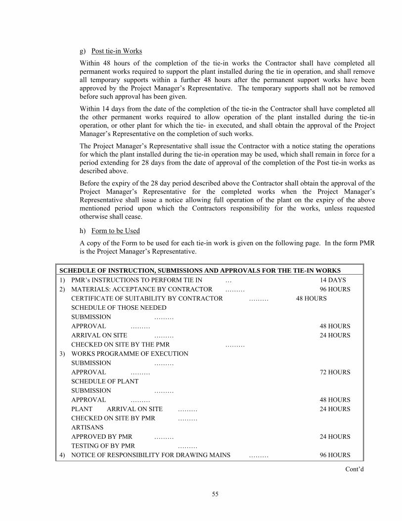
g) Post tie-in Works
Within 48 hours of the completion of the tie-in works the Contractor shall have completed all permanent works required to support the plant installed during the tie in operation, and shall remove all temporary supports within a further 48 hours after the permanent support works have been approved by the Project Manager’s Representative. The temporary supports shall not be removed
uring the tie-in
in operation may be used, which shall remain in force for a
before such approval has been given.
Within 14 days from the date of the completion of the tie-in the Contractor shall have completed all the other permanent works required to allow operation of the plant installed doperation, or other plant for which the tie- in executed, and shall obtain the approval of the Project Manager’s Representative on the completion of such works.
The Project Manager’s Representative shall issue the Contractor with a notice stating the operations for which the plant installed during the tie-period extending for 28 days from the date of approval of the completion of the Post tie-in works as described above.
Before the expiry of the 28 day period described above the Contractor shall obtain the approval of the Project Manager’s Representative for the completed works when the Project Manager’s Representative shall issue a notice allowing full operation of the plant on the expiry of the above mentioned period upon which the Contractors responsibility for the works, unless requested otherwise shall cease.
h) Form to be Used
A copy of the Form to be used for each tie-in work is given on the following page. In the form PMR is the Project Manager’s Representative.
ULE OF INSTRUCTION,
SCHED SUBMISSIONS AND APPROVALS FOR THE TIE-IN WORKS 1) PMR’s INSTRUCTIONS TO PERFORM TIE IN … 14 DAYS
48 HOURS ARCH
3) WOSUAPSCSUAP …… 48 HOURS PLCHARAPTE ………
ITY FOR DRAWING MAINS ……… 96 HOURS
2) MATERIALS: ACCEPTANCE BY CONTRACTOR ……… 96 HOURS CERTIFICATE OF SUITABILITY BY CONTRACTOR ……… 48 HOURS SCHEDULE OF THOSE NEEDED SUBMISSION ……… APPROVAL ………
RIVAL ON SITE ……… 24 HOURS ECKED ON SITE BY THE PMR ……… RKS PROGRAMME OF EXECUTION
BMISSION ……… PROVAL ……… 72 HOURS HEDULE OF PLANT BMISSION ……… PROVAL …ANT ARRIVAL ON SITE ……… 24 HOURS ECKED ON SITE BY PMR ……… TISANS PROVED BY PMR ……… 24 HOURS STING OF BY PMR
4) NOTICE OF RESPONSIBIL
Cont’d
55
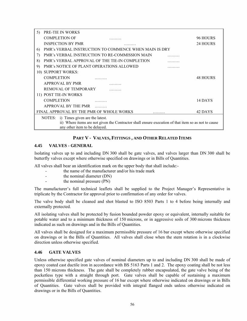
5) PRE-TIE IN WORKS COMPLETION OF ……… 96 HOURS
S
8) TION …… 9) T NS ALLOWED ……… 10)
……
14 DAYS
FIN PMR OF WHOLE WORKS ……… 42 DAYS
INSPECTION BY PMR ……… 24 HOUR6) PMR’s VERBAL INSTRUCTION TO COMMENCE WHEN MAIN IS DRY 7) PMR’s VERBAL INSTRUCTION TO RE-COMMISSION MAIN ………
PMR’s VERBAL APPROVAL OF THE TIE-IN COMPLE … PMR’s NOTICE OF PLANT OPERA IOSUPPORT WORKS: COMPLETION ……… 48 HOURS APPROVAL BY PMR ……… REMOVAL OF TEMPORARY …
11) POST TIE-IN WORKS COMPLETION ……… APPROVAL BY THE PMR ……… AL APPROVAL BY THE
NOTES: i) Times given are the latest. ii) Where items are not given the Contractor shall ensure execution of that item so as not to cause any other item to be delayed.
P V - V , FART ALVES ITTINGS , AND OTHER RELATED ITEMS 4.45 Isolating valves up to and including DN ll be gate valves, and valves larger than DN 300 shall be
a
All valves shall bear an identification mark on the upper body that shall include:- e nufacturer and/or his trade mark
t Manager’s Representative in s.
fore being internally and
potabindic gs and in the Bills of Quantities.
a permissible pressure of 16 bar except where otherwise specified e
direc
4
Unl de of epoxy coated cast ductile iron in accordance with BS 5163 Pa less than 150 microns thickness. The gate mpletely rubber encapsulated, the gate valve being of the pocketless type with a straight through port. Gate valves shall be capable of sustaining a maximum permissible differential working pressure of 16 bar except where otherwise indicated on drawings or in Bills of Quantities. Gate valves shall be provided with integral flanged ends unless otherwise indicated on drawings or in the Bills of Quantities.
VALVES - GENERAL
300 shabutterfly valves except where otherwise specified on drawings or in Bills of Qu ntities.
- the name of th ma- the nominal diameter (DN) - the nominal pressure (PN)
The manufacturer’s full technical leaflets shall be supplied to the Projectriplicate by the Contractor for approval prior to confirmation of any order for valve
The valve body shall be cleaned and shot blasted to ISO 8503 Parts 1 to 4 beexternally protected.
All isolating valves shall be protected by fusion bounded powder epoxy or equivalent, internally suitable for le water and to a minimum thickness of 150 microns, or in aggressive soils of 300 microns thickness ated as such on drawin
All valves shall be designed for a m ximumon drawings or in the Bills of Quantities. All valves shall close when the stem rotation is in a clockwis
tion unless otherwise specified.
.46 GATE VALVES
ess otherwise specified gate valves of nominal diameters up to and including DN 300 shall be marts 1 and 2. The epoxy coating shall be not
shall be co
56
Unless otherwise spe ged ends shall be in 12627 basic series 14 (short) or basic series 15(long) as indicated on the ies.
558 and EN 12627
cally indicated otherwise. The stem seal least two such seals. Seals shall be capable of being
n the fully open position.
iding features shall be
ll be of elastomer (suitable for potable water). The bonnet studs or allen screws shall be
eing encapsulated with elastomer EPDM, nitrile or equivalent.
e made of stainless steel at least equivalent to ISO 10088 Part 1.4021, except in ere this shall be to ISO 10088 Part 1.44404, indicated as such on drawings and in
l to ISO 10088 Part 1.4301 or as detailed on drawings.
shall comply with BS 5155 and EN 593 and shall be double flanged,
capable of sustaining a maximum permissible differential working pressure of 16 bar
EPDM rubber and shall be attached at
ll be permanently lubricated, not in contact with the water and tilted with an OPENED/CLOSED proportional position indicator in order to indicate the disk angular position. The mechanism shall be sized in order to minimise torque for ease of manual operation under maximum
cified the face to face dimensions of gate valves with integral flanaccordance with EN 558 and ENdrawings or in the Bills of Quantit
Where specified, valves for replacement washouts shall have valve bodies of epoxy coated ductile iron and the flanges shall be undrilled. Face to face dimensions for these valves shall be to ENbasic series 14 (short).
Gate valves shall be of the non-rising stem type except where specifishall be of toroidal sealing rings (O-rings) with at replaced with the valve under pressure and i
The gate shall be of ductile iron fully rubber encapsulated, the gate sealing in the body being ensured by compressing of the rubber. Wedge/gate guides of wear resistant plastic with high glprovided in the body, optimally placed to guarantee low wear and tear of the gate and low closing torques.
The bonnet gasket shacorrosion-protected. In addition the studs/allen screws shall be placed in countersunk holes in the bonnet and completely sealed with wax or a suitable material, which can be removed by low-temperature melting in case they have to be disassembled.
The gate valve bodies shall be works cleaned and shot-blasted in accordance with ISO 8503 Parts 1 to 4 before being coated internally and externally. The body, the bonnet and the gate of the valve shall be made of ductile iron to EN 1564, the gate b
The operating stem shall bareas of aggressive soils whthe Bills of Quantities.
The stem nut shall normally be made of high tensile brass to BS 1981, except in areas of aggressive soils where this shall be aluminium bronze to EN 12167, indicated as such on drawings and in the Bills of Quantities.
Furthermore and in aggressive soils indicated are such on drawings and in bills of quantities, outside bolts and nuts shall be made of stainless stee
4.47 BUTTERFLY VALVES
Butterfly valves for manual operation resilient and metal seated tight shut-off design and of the eccentric disc type supported from two shafts placed in self lubricating bearing bushes.
Butterfly valves shall beexcept where otherwise indicated on drawings or in bills of quantities.
They shall operate with a clockwise closing direction. The valve disk shall rotate though an angle between 0 degrees and 90 degrees inclusive. The sealing ring shall be made ofthe disk edge circumference by a retaining ring without adjustment to form a resilient and durable seal.
The valve disc seal shall be replaceable without dismantling the operating mechanism, disk or shafts, and without removing the valve from the pipeline.
The butterfly valve shall be equipped with an irreversible and proportional worm gear operator. This shall be either with or without an additional primary reduction gear placed within a waterproof housing dependant upon nominal valve diameter and maximum working conditions as stated in the bills of quantities.
The operating mechanism sha
57
differential pressure and shall be with high class enclosure IP67 to ISO 60529. Valve body, disk and disk retaining ring shall be in ductile "SG" iron casting to EN 1563 or EN 1564. Disk shafts shall be in stainless steel to EN 10088:1.4021.
Each butterfly valve shall be works pressure tested in accordance with BS 6755 and EN 12266 Parts 1 and 2. - body test at a minimum pressure of 1.5 times the maximum permissible pressure - seal test at a minimum pressure of 1.1 times the maximum permissible pressure.
wheels are specified, they shall have cast into them the words 'open' or 'closed', together with an
tender/contract drawing.
with valve caps, dimensioned to the appropriate Tender Drawing.
PN 16 rating and shall achieve a movement from fully open to
upply and
nti-shock anti-surge
ired to confirm that they will meet these
ninterrupted high volume air discharge through the large orifice.
or Column Separation
4.48 HANDWHEELS AND VALVE CAPS AND VALVES
Where handarrow indicating the direction for such opening or closing.
Valves for tee-key operation shall be provided with valve caps conforming to the appropriate
4.49 VALVE KEYS
These shall be of mild steel with ends to suit either valves to BS 5163 Parts 1 and 2, valves to EN 593 or valves to EN 12360 or 12288 fitted
4.50 NON-RETURN VALVES
These shall have bodies made from bronze for DN not greater than 40 mm and they shall be of the swing pattern type and shall be rated for at least PN 10 or greater as specified. The ends shall be either screwed to EN 10228-1 or flanged to EN 1092-1, PN 10 or as the installation demands.
For DN greater than 40 mm they shall be either of a profiled poppet type with non-slam characteristics (surge suppressing type) or of the venture type and shall be of approved manufacture. The proposed valve shall be of low pressure loss and maintenance free with fully closed on pump stoppage in 0.1 to 0.3 seconds. The valve housing shall as a minimum be of epoxy coated cast iron and flanged with the closing system of stainless steel.
With his tender, a Tenderer shall have supplied full technical details of the valves he proposes to sinstall. If the Project Manager deems the valve proposed to be appropriate he will accept the offer. If however the Project Manager considers the offer to be inappropriate he will reject the offer from the Tenderer and instruct him instead as to the acceptable manufacturer(s) of these items. Should a financial offer from a Tenderer in this regard be obviously under-priced then the cost of supplying an appropriate valve shall be fully to the account of the Contractor.
4.51 AIR RELEASE AND VACUUM BREAK VALVES
Automatic air relief and vacuum break valves (air valves) shall be of the triple function atype and shall be from an approved manufacturer.
Bids which apparently contain non-compliant offers will be requspecifications in their totality at the rates quoted in their offer.
Such valves will be designed to meet and provide all of the functions described below:
i) Pipeline filling
U
ii) Pipeline draining
Uninterrupted high volume air intake through the large orifice.
58
iii) Pipeline full and operating
Discharge of disentrained pressurised air through the small orifice.
iv) Rapid Filling / Column Separation
The valve must incorporate an integral surge alleviation mechanism that will automatically dampen surge pressures due to rapid air discharge or the subsequent rejoining of separated water columns.
The air release and vacuum break valve shall be of a compact single chamber design with solid cylindrical High Density Polyethylene control floats. These shall be housed in a tubular stainless steel or corrosion protected body with epoxy powder coated cast iron, or stainless steel ends secured by means of stainless steel
required and are therefore unacceptable.
trol float seating against a nitrile rubber ‘Ó’ the large orifice. Discharge of pressurised air
aracteristics, so that defo amage of any kind does not occur by submission to twice the designed working pres
The val ll fail without an explosive effect, such ssed air is released suddenly. This feature shall consist of easily re
The air valve shall be provided with a separate isolating gate valve or if so specified with a separate isolating but
Unless ntegral flanged inlet with studs app nstallation demands and complying with the appropriate nominal pressure
All air v ot
URFACE BOXES
tie rods.
The valve shall have an integral surge alleviation mechanism which shall operate automatically to limit transient pressure rise or shock induced by closure due to high velocity air discharge or the subsequent rejoining of separated water columns. The limitation of pressure rise must be achieved by deceleration of approaching water prior to valve closure. Relief mechanisms that act subsequent to valve closure cannot react in the low millisecond time span
Large orifice sealing shall be effect by the flat face of the conRing housed in a dovetail groove circumferentially surrounding shall be controlled by the seating and unseating of a small orifice on a natural rubber seal affixed to the control float.
The intake/discharge area shall be equal to the nominal size of the valve, i.e. a 150 mm valve shall have a 150 mm intake/discharge orifice.
The valve construction shall be proportioned with regard to material strength chrmation, leaking or dsure.
ve design shall incorporate an over pressure safety feature that wi as is normally the case when highly compre
placeable components such as gaskets, seals or the like.
terfly valve.
otherwise specified all air valves shall be provided with an iropriate to EN 1092-1 NP 10 or as the i
.
alves at new installations shall be fitted to an air accumulator tee with the branch of a diameter nless then 0,6 times the diameter of the main. Where necessary, a concentric taper either integral with or as a separate fitting shall be inserted between the branch and the isolating valve immediately beneath the air valve and an abrupt diameter change between branch and isolating valve shall be avoided.
4.52 S
These shall be of cast iron, (hinged and locked) and from an approved manufacturer to BS 5834. They shall be sized to suit the purpose required and as otherwise shown on the relevant drawings.
The number of keys required (if any) is indicated in the Bills of Quantities.
4.53 VALVE CHAMBERS
New chambers shall be constructed in accordance with the drawings, and where indicated shall incorporate thrust walls.
59

Rehabilitated chambers shall be constructed or rebuilt or repaired in accordance with the original drawings or as directed by the Project Manager’s Representative using materials approved by the Project Manager’s
s indicated on the drawings are provided within the chamber and that where chambers have pre-
eight of minimum 50 kg per piece and provided with an embedded steel device for lifting at
ber cover shall in all cases allow for this. It will be the Contractor's responsibility to ensure that
ied:
type wherein operation is effected automatically by change of displacement of nate actuating forces provided by weight and buoyancy being transmitted by
by ensuring sensitive be drop tight and the valves shall
discharge vertically downwards. The valve shall act from fully open to fully closed with a ater level of the order of magnitude indicated below.
(Nominal) (valve open to close)
Representative.
Notwithstanding the size and shape of the valve to be supplied the Contractor shall ensure that the minimum clearance acast roofs, the manhole cover provided shall be of a size sufficient to allow for the removal and replacement of the valve without disassembly..
4.54 VALVE CHAMBER COVERS
Unless otherwise indicated in the Bills of Quantities, valve chamber manhole covers shall be reinforced concrete with a weach end. They shall be supplied complete with lifting keys. Except where a chamber is provided with pre-cast roof slabs to facilitate placing and removal of the valve or valves within the chamber, the clear opening in the chamthe covers provided are of a sufficient clear opening size.
4.55 RESERVOIR INLET VALVES
All reservoir inlet float operated valves shall be of one of the following types as specif
(a) Of the streamline the float, the alterlever mechanism to the valve element.
The float action shall operate the pilot valve housed within the plunger thereresponse to the small mechanical forces applied. Closure shall
change in reservoir w
Inlet Diameter Reservoir Level Change
(mm) Approx. (mm) 80 130
150
400
230
850
200 250 300
260 320 380
Where controlled closing and opening of the float valve is required the valve will be provided
e of approved manufacture.
To itatemodulated p
with a stilling basin to ensure gentle transition on valve closure so as to avoid sudden pressure rise in the incoming main as a result of closure.
(b) Of a type that has been specifically designed to overcome problems of influence in operation by water surface turbulence and of the risk of causing surge pressures in the upstream pipeline as a result of the closing mechanism deployed. They should further be simple to service without the need for special tools or lifting equipment.
In either case, the valves shall b
4.56 TWO-POINT TIME-MODULATED PRESSURE REDUCING VALVES
facil pressure management, the Tender may call for the supply and installation of two-point time-ressure reducing valves as indicated on the drawings and in the Bills of Quantities.
60
The time m l comprise a main valve and a pilot control system. The valve gate downward oaccessible fconnection restrictions
The throttling control shall be capable of being adjusted automat valve at a minimum of two outlet pressures through a time based modulator e-set time of adjustment of outlet pressures and the outlet pressures themselves can be ch ances require it. The time modulating device shall be an encapsulated, self contained, water-tight device inclusive of a power pack. The power pack shall have a m um guaranteed usable life of two years. Means of replacing battery pack, and adjusting time and pressures shall be straight forward.
If included, Tenderers shall be speci y required with his Tender to have supp full technical details of the valves and PRV controllers he proposes to supply and install. If the Project Manager’s Representative deems the valves and controllers proposed to be appropriate he will accept the offer. If however the Project Manager’s Representative considers the offer to be and instruct Tenderer incontroller sh
4.57 TH
To facilitateon the draw e shall in general conform to the requirements of BS 5158 and E quired and will have supplied full technical details of the valve he proposes to supply and install. If the Project Manager’s Representative
he Project Manager’s
fully to the
odulated Pressure Reducing Valves shalshall comprise a horizontally mounted resilient disc moving upward to open the valve and nto a seat so as to close the valve. It shall be held in place by a diaphragm assembly and spring,
rom above via a removable cover. Opening, closing and throttling shall be achieved through the of upstream, cover chamber and downstream compartments of the valve through appropriate and throttling controls.
ically from outside of thesuch that both the pr
anged if circumst
inim
ficall lied
inappropriate he will reject the offer from the Tenderer him instead as to the acceptable manufacturer(s) of these items. Should a financial offer from a this regard be obviously under-priced then the cost of supplying an appropriate valve and all be fully to the account of the Contractor.
REE-WAY T-PORT PLUG OR BALL CONTROL VALVE
the control of flow, a three-way T-port plug or ball control valve may be called for as indicated ings and in the Bills of Quantities. The valvN 60534. If included, Tenderers shall be specifically re
deems the valve proposed to be appropriate he will accept the offer. If however tRepresentative considers the offer to be inappropriate he will reject the offer from the Tenderer and instructhim instead as to the acceptable manufacturer(s) of these items. Should a financial offer from a Tenderer in this regard be obviously under-priced then the cost of supplying an appropriate valve shall beaccount of the Contractor.
4.58 WATER METERS
(i) Bulk flow meters for diameters greater than 150 mm, shall be inclined in-line turbine type meters to BS 5728, EN 14184-3 and EN 14154 suitable for installation in horizontal or vertical mains unless otherwise indicated on Drawings or in the Bills of Quantities. Each meter shall have a
as otherwise called for on the drawings and
register calibrated in cubic metres, with straight reading counters. The meters shall be capable of measuring accurately +/- 2.5%. For diameters of 150 mm and less, and if so specified, then a combination water meter shall be provided so as to give an accuracy of +/- 2.0%. All meters shall be supplied complete with a removable strainer, and if so indicated on the Drawings with extended registers of the nearest but shorter standard length to that indicated.
End flanges shall be drilled to EN 1092-1, NP 16 or shall be supplied complete with flange gaskets, bolts, nuts and washers.
(ii) Domestic (consumer) meters will be of the single jet inferential type, with metal body and unless otherwise called for shall be with a dry dial register capable of measuring to the nearest 0.001 m3, and having an accuracy of +/- 2% unless otherwise indicated in the Bill of Quantities. The meters shall be manufactured to BS 5728, EN 14184-3 and EN 14154, and shall be subject to the Project Manager’s Representative's approval prior to ordering. They shall be suitable for both horizontal and vertical location and shall be supplied complete with removable strainer and non return valve.
61
62
n the indicator plate. The plates shall either incorporate an approved colour in least two coats of all-weather plastic emulsion paint of the approved colour.
4.59 BURSTING DISCS AND BURSTING DISCS DEVICES
Bursting discs and bursting disc devices shall be included in pipe branches shortly after a pumping station as a final surge protection device and shall be in general accordance with ISO 4126 Parts 2, 6 and 7 and of an approved design. A minimum pack of 5 such bursting discs shall be provided with each bursting disc device.
4.60 INDICATOR PLATES
Pre-cast reinforced concrete indicator plates to the dimensions indicated on the Drawing shall be installed at all sluice valves, air valves, fire hydrants and washouts, with letters SV, AV, FH, WO, respectively, indented in them. The diameter of the valve in mm and the distance to the valve in metres from the indicator plate shall be clearly indicated otheir mix or be painted with at

APPENDIX A
SPECIFICATION CROSS REFERENCE NUMBERS (SCRNs)
(last updated April 2007)
1
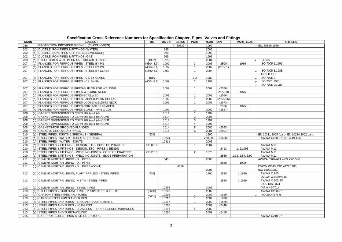
SUBJECT BS BS EN BS ISO PART YEAR DIN PART/YEAR038 PROTECTION PROVIDED BY ENCL. (CLASS 'N'-DEG) 60529 1992202 (a) DUCTILE IRON PIPES & FITTINGS (WATER) 545 2006202 (b) DUCTILE IRON PIPES & FITTINGS (SEWERAGE) 598 1995202 (c) DUCTILE IRON PIPES & FITTINGS (GAS) 969 1996203 (a) STEEL TUBES WITH PLAIN OR THREADED ENDS (1387) 10255 2004207 (a) FLANGES FOR FERROUS PIPES - STEEL BY PN (4504-3.3) 1092 3 2003 [2500] :1966207 (a) FLANGES FOR FERROUS PIPES - STEEL BY PN (4504-3.1) 1092 1 2002 (2519:1)207 (b) FLANGES FOR FERROUS PIPES - STEEL BY CLASS (1560-3.1) 1759 1 2004
207 (c) FLANGES FOR FERROUS PIPES - C.I. BY CLASS 1560 3.2 1989207 (d) FLANGES FOR FERROUS PIPES - C.I. BY PN (4504-3.2) 1092 2 1997
207 (e) FLANGES FOR FERROUS PIPES-SLIP ON FOR WELDING 1092 1 2002 (2576)207 (f) FLANGES FOR FERROUS PIPES-WELDING NECK 2627-38 :1975207 (g) FLANGES FOR FERROUS PIPES-SCREWED 1092 1 2002 (2566)207 (h) FLANGES FOR FERROUS PIPES-LAPPED-PLAIN COLLAR 1092 1 2002 (2655-56)207 (I) FLANGES FOR FERROUS PIPES-LOOSE-WELDING NECK 1092 1 2002 (2673)207 (j) FLANGES FOR FERROUS PIPES-CONTACT SURFACES 2526 :1975207 (k) FLANGES FOR FERROUS PIPES-BLANK - NP 6 to 100 1092 1 2002 (2527)208 (a) GASKET DIMENSIONS TO CSRN 207 (a) & (d) 1514 1 1997208 (b) GASKET DIMENSIONS TO CSRN 207 (a) & (d) (CONT) 1514 2 2005208 (c) GASKET DIMENSIONS TO CSRN 207 (a) & (d) (CONT) 1514 3 1997208 (d) GASKET DIMENSIONS TO CSRN 207 (a) & (d) (CONT) 1514 4 1997208 (e) GASKETS-FOR GROOVED FLANGES 1514 8 2005 (2693)208 (f) GASKETS-GROOVED O-RINGS 1514 6 2004 (2697)210 (a) STEEL PIPES, JOINTS & SPECIALS - GENERAL [534] 1990210 (a) STEEL PIPES - WATER - TUBES & FITTINGS 10224 2003,05 (2460)210 (b) STEEL PIPES - WATER - JOINTS 10311 2005210 (c) STEEL PIPES & FITTINGS - DESIGN, ETC - CODE OF PRACTICE PD 8010 1 2004210 (c) STEEL PIPES & FITTINGS - DESIGN, ETC - PIPES & BENDS 2413 1, 2:1993210 (d) STEEL PIPES & FITTINGS - WELDING JOINTS - CODE OF PRACTICE CP 2010 2 1970210 (d) STEEL PIPES & FITTINGS - WELDING JOINTS - EDGE PREPARATION 2559 1:73, 2:84, 3:90211 (a) CEMENT MORTAR LINING - D.I. PIPES 545 2006211 (b) CEMENT MORTAR LINING - D.I. PIPES 2880 :1999211 (c) CEMENT MORTAR LINING - D.I. PIPES (CONT) 4179
2005212 (a) CEMENT MORTAR LINING, PLANT APPLIED - STEEL PIPES [534] 1990 2880 1:1999
212 (b) CEMENT MORTAR LINING, IN SITU - STEEL PIPES 2880 1:1999
212 (c) CEMENT MORTAR LINING - STEEL PIPES 10298 2005213 (a) STEEL PIPES & TUBES-MATERIAL, PROPERTIES & TESTS (3600) 10220 2002213 (b) CARBON STEEL PIPES AND TUBES 10216 1 2002 [1629]213 (b) CARBON STEEL PIPES AND TUBES 10217 1 2002 [1630]213 (c) STEEL PIPES AND TUBES - SPECIAL REQUIREMENTS 10217 1 2002 (1626)213 (d) STEEL PIPES AND TUBES - SEAMLESS 10220 2002 (2448)213 (d) STEEL PIPES AND TUBES - SEAMLESS - FOR PRESSURE PURPOSES 10216 4 2002213 (e) STEEL PIPES AND TUBES-WELDED 10220 2002 (2458)215 EXT. PROTECTION - IRON & STEEL-EPOXY C.
SCRN
(3601)
Specification Cross Reference Numbers for Specification Chapter, Pipes, Valves and FittingsOTHERS
= IEC 60529:1989
= ISO 65ISO 7005-1:1992
≠ ISO 7005-3:1988; ANSI B 16.5
≠ ISO 7005-2 ≠≠
ISO 2531:1991; ISO 7005-2:1988
≡ EN 10311:2005 (part), EN 10224:2002 part)AWWA C200-97, (NF A 49-150)
AWWA M11AWWA M11AWWA M11AWWA M11
AWWA C104/A21.4-03, C602-06
DVGW W343, ISO 4179:1985, ISO 6600:1980,
AWWA C 205, DVGW-W343/W346AWWA C 602-95ISO / DIS 8324(NF A 49-701)AWWA C200-97
≠ ISO 2604/2 /3 /6
AWWA C210-97
2
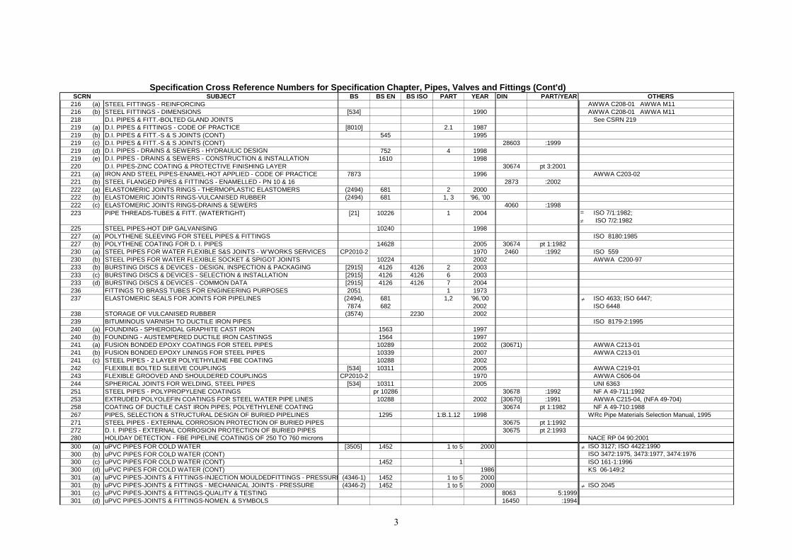
SUBJECT BS BS EN BS ISO PART YEAR DIN PART/YEAR216 (a) STEEL FITTINGS - REINFORCING216 (b) STEEL FITTINGS - DIMENSIONS [534] 1990218 D.I. PIPES & FITT.-BOLTED GLAND JOINTS219 (a) D.I. PIPES & FITTINGS - CODE OF PRACTICE [8010] 2.1 1987219 (b) D.I. PIPES & FITT.-S & S JOINTS (CONT) 545 1995219 (c) D.I. PIPES & FITT.-S & S JOINTS (CONT) 28603 :1999219 (d) D.I. PIPES - DRAINS & SEWERS - HYDRAULIC DESIGN 752 4 1998219 (e) D.I. PIPES - DRAINS & SEWERS - CONSTRUCTION & INSTALLATION 1610 1998220 D.I. PIPES-ZINC COATING & PROTECTIVE FINISHING LAYER 30674 pt 3:2001221 (a) IRON AND STEEL PIPES-ENAMEL-HOT APPLIED - CODE OF PRACTICE 7873 1996221 (b) STEEL FLANGED PIPES & FITTINGS - ENAMELLED - PN 10 & 16 2873 :2002222 (a) ELASTOMERIC JOINTS RINGS - THERMOPLASTIC ELASTOMERS (2494) 681 2 2000222 (b) ELASTOMERIC JOINTS RINGS-VULCANISED RUBBER (2494) 681 1, 3 '96, '00222 (c) ELASTOMERIC JOINTS RINGS-DRAINS & SEWERS 4060 :1998223 PIPE THREADS-TUBES & FITT. (WATERTIGHT) [21] 10226 1 2004
225 STEEL PIPES-HOT DIP GALVANISING 10240 1998227 (a) POLYTHENE SLEEVING FOR STEEL PIPES & FITTINGS227 (b) POLYTHENE COATING FOR D. I. PIPES 14628 2005 30674 pt 1:1982230 (a) STEEL PIPES FOR WATER FLEXIBLE S&S JOINTS - W'WORKS SERVICES CP2010-2 1970 2460 :1992230 (b) STEEL PIPES FOR WATER FLEXIBLE SOCKET & SPIGOT JOINTS 10224 2002233 (b) BURSTING DISCS & DEVICES - DESIGN, INSPECTION & PACKAGING [2915] 4126 4126 2 2003233 (c) BURSTING DISCS & DEVICES - SELECTION & INSTALLATION [2915] 4126 4126 6 2003233 (d) BURSTING DISCS & DEVICES - COMMON DATA [2915] 4126 4126 7 2004236 FITTINGS TO BRASS TUBES FOR ENGINEERING PURPOSES 2051 1 1973237 ELASTOMERIC SEALS FOR JOINTS FOR PIPELINES (2494),
7874681682
1,2 '96,'002002
238 STORAGE OF VULCANISED RUBBER (3574) 2230 2002239 BITUMINOUS VARNISH TO DUCTILE IRON PIPES240 (a) FOUNDING - SPHEROIDAL GRAPHITE CAST IRON 1563 1997240 (b) FOUNDING - AUSTEMPERED DUCTILE IRON CASTINGS 1564 1997241 (a) FUSION BONDED EPOXY COATINGS FOR STEEL PIPES 10289 2002 (30671)241 (b) FUSION BONDED EPOXY LININGS FOR STEEL PIPES 10339 2007241 (c) STEEL PIPES - 2 LAYER POLYETHYLENE FBE COATING 10288 2002242 FLEXIBLE BOLTED SLEEVE COUPLINGS [534] 10311 2005243 FLEXIBLE GROOVED AND SHOULDERED COUPLINGS CP2010-2 1970244 SPHERICAL JOINTS FOR WELDING, STEEL PIPES [534] 10311 2005251 STEEL PIPES - POLYPROPYLENE COATINGS pr 10286 30678 :1992253 EXTRUDED POLYOLEFIN COATINGS FOR STEEL WATER PIPE LINES 10288 2002 [30670] :1991258 COATING OF DUCTILE CAST IRON PIPES; POLYETHYLENE COATING 30674 pt 1:1982267 PIPES, SELECTION & STRUCTURAL DESIGN OF BURIED PIPELINES 1295 1:B.1.12 1998271 STEEL PIPES - EXTERNAL CORROSION PROTECTION OF BURIED PIPES 30675 pt 1:1992272 D. I. PIPES - EXTERNAL CORROSION PROTECTION OF BURIED PIPES 30675 pt 2:1993280 HOLIDAY DETECTION - FBE PIPELINE COATINGS OF 250 TO 760 microns300 (a) uPVC PIPES FOR COLD WATER [3505] 1452 1 to 5 2000300 (b) uPVC PIPES FOR COLD WATER (CONT)300 (c) uPVC PIPES FOR COLD WATER (CONT) 1452 1300 (d) uPVC PIPES FOR COLD WATER (CONT) 1986301 (a) uPVC PIPES-JOINTS & FITTINGS-INJECTION MOULDEDFITTINGS - PRESSURE (4346-1) 1452 1 to 5 2000301 (b) uPVC PIPES-JOINTS & FITTINGS - MECHANICAL JOINTS - PRESSURE (4346-2) 1452 1 to 5 2000301 (c) uPVC PIPES-JOINTS & FITTINGS-QUALITY & TESTING 8063 5:1999301 (d) uPVC PIPES-JOINTS & FITTINGS-NOMEN. & SYMBOLS 16450 :1994
SCRNSpecification Cross Reference Numbers for Specification Chapter, Pipes, Valves and Fittings (Cont'd)
OTHERSAWWA C208-01 AWWA M11AWWA C208-01 AWWA M11
See CSRN 219
AWWA C203-02
=≠
ISO 7/1:1982; ISO 7/2:1982
ISO 8180:1985
ISO 559AWWA C200-97
≠ ISO 4633; ISO 6447; ISO 6448
ISO 8179-2:1995
AWWA C213-01AWWA C213-01
AWWA C219-01AWWA C606-04UNI 6363NF A 49-711:1992AWWA C215-04, (NFA 49-704)NF A 49-710:1988
WRc Pipe Materials Selection Manual, 1995
NACE RP 04 90:2001≠ ISO 3127; ISO 4422:1990
ISO 3472:1975, 3473:1977, 3474:1976 ISO 161-1:1996KS 06-149:2
≠ ISO 2045
3
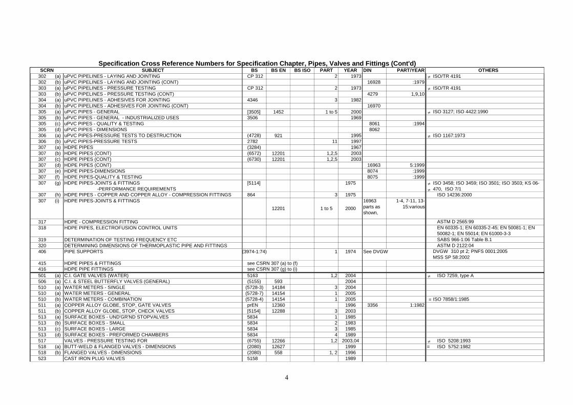
SUBJECT BS BS EN BS ISO PART YEAR DIN PART/YEAR302 (a) uPVC PIPELINES - LAYING AND JOINTING CP 312 2 1973302 (b) uPVC PIPELINES - LAYING AND JOINTING (CONT) 16928 :1979303 (a) uPVC PIPELINES - PRESSURE TESTING CP 312 2 1973303 (b) uPVC PIPELINES - PRESSURE TESTING (CONT) 4279 1,9,10304 (a) uPVC PIPELINES - ADHESIVES FOR JOINTING 4346 3 1982304 (b) uPVC PIPELINES - ADHESIVES FOR JOINTING (CONT) 16970305 (a) uPVC PIPES - GENERAL [3505] 1452 1 to 5 2000305 (b) uPVC PIPES - GENERAL - INDUSTRIALIZED USES 3506 1969305 (c) uPVC PIPES - QUALITY & TESTING 8061 :1994305 (d) uPVC PIPES - DIMENSIONS 8062306 (a) uPVC PIPES-PRESSURE TESTS TO DESTRUCTION (4728) 921 1995306 (b) uPVC PIPES-PRESSURE TESTS 2782 11 1997307 (a) HDPE PIPES (3284) 1967307 (b) HDPE PIPES (CONT) (6572) 12201 1,2,5 2003307 (c) HDPE PIPES (CONT) (6730) 12201 1,2,5 2003307 (d) HDPE PIPES (CONT) 16963 5:1999307 (e) HDPE PIPES-DIMENSIONS 8074 :1999307 (f) HDPE PIPES-QUALITY & TESTING 8075 :1999307 (g) HDPE PIPES-JOINTS & FITTINGS
-PERFORMANCE REQUIREMENTS[5114] 1975
307 (h) HDPE PIPES - COPPER AND COPPER ALLOY - COMPRESSION FITTINGS 864 3 1975307 (i) HDPE PIPES-JOINTS & FITTINGS
12201 1 to 5 200016963parts as shown,
1-4, 7-11, 13-15:various
317 HDPE - COMPRESSION FITTING318 HDPE PIPES, ELECTROFUSION CONTROL UNITS
319 DETERMINATION OF TESTING FREQUENCY ETC 320 DETERMINING DIMENSIONS OF THERMOPLASTIC PIPE AND FITTINGS 406 PIPE SUPPORTS (3974-1:74) 1 1974 See DVGW
415 HDPE PIPES & FITTINGS see CSRN 307 (a) to (f)416 HDPE PIPE FITTINGS see CSRN 307 (g) to (i)501 (a) C.I. GATE VALVES (WATER) 5163 1,2 2004506 (a) C.I. & STEEL BUTTERFLY VALVES (GENERAL) (5155) 593 2004510 (a) WATER METERS - SINGLE (5728-3) 14184 3 2004510 (a) WATER METERS - GENERAL (5728-7) 14154 1 2005510 (b) WATER METERS - COMBINATION (5728-4) 14154 1 2005511 (a) COPPER ALLOY GLOBE, STOP, GATE VALVES prEN 12360 1996 3356 1:1982511 (b) COPPER ALLOY GLOBE, STOP, CHECK VALVES [5154] 12288 3 2003513 (a) SURFACE BOXES - UND'GR'ND STOPVALVES 5834 1 1985513 (b) SURFACE BOXES - SMALL 5834 2 1983513 (c) SURFACE BOXES - LARGE 5834 3 1985513 (d) SURFACE BOXES - PREFORMED CHAMBERS 5834 4 1989517 VALVES - PRESSURE TESTING FOR (6755) 12266 1,2 2003,04518 (a) BUTT-WELD & FLANGED VALVES - DIMENSIONS (2080) 12627 1999518 (b) FLANGED VALVES - DIMENSIONS (2080) 558 1, 2 1996523 CAST IRON PLUG VALVES 5158 1989
SCRNSpecification Cross Reference Numbers for Specification Chapter, Pipes, Valves and Fittings (Cont'd)
OTHERS≠ ISO/TR 4191
≠ ISO/TR 4191
≠ ISO 3127; ISO 4422:1990
≠ ISO 1167:1973
≠≠
ISO 3458; ISO 3459; ISO 3501; ISO 3503; KS 06-470, ISO 7/1
ISO 14236:2000
ASTM D 2565:99EN 60335-1; EN 60335-2-45; EN 50081-1; EN 50082-1; EN 55014; EN 61000-3-3SABS 966-1:06 Table B.1ASTM D 2122:04
DVGW 310 pt 2; PNFS 0001:2005MSS SP 58:2002
≠ ISO 7259, type A
≡ ISO 7858/1:1985
≠ ISO 5208:1993= ISO 5752:1982
4
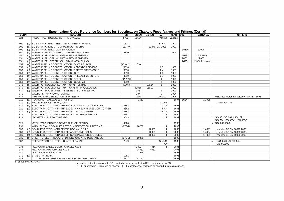
SUBJECT BS BS EN BS ISO PART YEAR DIN PART/YEAR524 INDUSTRIAL-PROCESS CONTROL VALVES [5793] 60534 various various
601 (a) SOILS FOR C. ENG.- TEST METH.-AFTER SAMPLING 1377 1 to 8 1990601 (b) SOILS FOR C. ENG .- TEST METHOD - IN SITU [1377-9] 22476 2,3:2005 1990601 (c) SOILS FOR C. ENG.- CLASSIFICATION 18196 :2006651 (a) WATER SUPPLY - DOMESTIC - WITHIN BUILDINGS 6700 2006651 (b) WATER SUPPLY-PRINCIPLES & REQUIREMENTS 1998 1,2,3:1988651 (b)] WATER SUPPLY-PRINCIPLES & REQUIREMENTS 2000 :2000651 (c) WATER SUPPLY-TECHNICAL DRAWINGS - PLANS 2425 1,2,3,5,8:various653 (a) WATER PIPELINE CONSTRUCTION - DUCTILE IRON [8010-2.1] 1610653 (b) WATER PIPELINE CONSTRUCTION - ASBESTOS CEMENT (8010) 2.3 1988653 (c) WATER PIPELINE CONSTRUCTION - PRESTRESSED CONC. (8010) 2.4 1988653 (d) WATER PIPELINE CONSTRUCTION - GRP 8010 2.5 1989653 (e) WATER PIPELINE CONSTRUCTION - PRECAST CONCRETE (8010) 2.7 1989653 (f) WATER PIPELINE CONSTRUCTION - STEEL CP 2010 2 1970653 (g) WATER PIPELINE CONSTRUCTION - GENERAL 8010 1 1989670 (a) WELDING PROCEDURES - APPROVAL TESTING (4870-3) 15614 8 2002670 (b) WELDING PROCEDURES - APPROVAL OF PROCEDURES (288) 15607 2003670 (c) WELDING PROCEDURES - PIPELINES - BUTT WELDING 288 9 1999671 WELDERS - APPROVAL TESTING 287 1 2004679 PIPE MATERIAL SELECTION AND DESIGN 1295 1:B.1.12 1998911 (a) FOUNDING. MALLEABLE CAST IRON 1562 1997 1684 1:1998911 (b) MALLEABLE CAST IRON (CONT) 01-Apr921 (a) ELECTROP. COATINGS - THREADS - CADMIUM/ZINC ON STEEL 3382 1 & 2 1961921 (b) ELECTROP. COATINGS - THREADS - NICKEL ON STEEL OR COPPER 3382 3 & 4 1965921 (c) ELECTROP. COATINGS - THREADS - TIN ON COPPER 3382 5 & 6 1967922 ELECTROP. COATINGS - THREADS - THICKER PLATINGS 3382 7 1966923 ISO METRIC SCREW THREADS 3643 1, 2 1981
925 METAL WASHERS FOR GENERAL ENGINEERING 4320 1968936 WROUGHT AND STAINLESS STEE L- INSPECTION & TESTING (970-1) 10250 1 2000936 (a) STAINLESS STEEL - GRADE FOR NORMAL SOILS 10088 1 2005 :1.4021936 (b) STAINLESS STEEL - GRADE FOR AGRESSIVE SOILS 10088 1 2005 :1.4404936 (c) STAINLESS STEEL - GRADE FOR NUTS IN AGRESSIVE SOILS 10088 1 2005 :1.4301936 (d) BRIGHT STEEL PRODUCTS - DIMENSIONS AND TOLERANCES (970-3) 10278 1999937 PREPARATION OF STEEL - BLAST CLEANING 7079 C-C1 to
C41989
938 HEXAGON HEADED BOLTS- GRADES A & B (24014) 4014 1 2001939 HEXAGON NUTS- GRADES A & B 24032 4032 2001940 DUCTILE IRON CASTINGS 1564 1997941 (a) BRASS FOR NUTS 1981 1991942 ALUMINIUM BRONZE FOR GENERAL PURPOSES - NUTS (2874) 12167 1998
Last updated April 2007
SCRNSpecification Cross Reference Numbers for Specification Chapter, Pipes, Valves and Fittings (Cont'd)
≠: related but not equivalent to BS =: technically equivalent to BS ≡: identical to BS( ) superceded & replaced as shown [ ] obsolecent or replaced as shown but remains current
OTHERS
WRc Pipe Materials Selection Manual, 1995
ASTM A 47-77
= ISO 68; ISO 261; ISO 262; ISO 724; ISO 965/1; ISO 965/3
= ISO 887:1983
see also BS EN 10020:2000see also BS EN 10020:2000see also BS EN 10020:2000
≡ ISO 8503-1 to 4:1995, SIS 055900
5
Related Documents