WIRLESS WATER LEVEL MONITORING SYSTEM Presented By:-

Welcome message from author
This document is posted to help you gain knowledge. Please leave a comment to let me know what you think about it! Share it to your friends and learn new things together.
Transcript

WIRLESS WATER LEVEL MONITORING SYSTEM
Presented By:-

Project overview Block diagram Power supply Microcontroller Sensor RF module Software requirements Schematic & Working of the project Advantages Applications Future scope Conclusion
contents
Introduction
•This paper presents the design and testing of a wireless sensor system developed using an ATMEGA 16 based WATER LEVEL SENSOR
•In response to the complexity of time and technology , the occurrence of saving time and completing the need without wasting water in home and industrial field, a WWLMS which was combined with water level measuring sensor .
• wireless-networking communication technicalness and data acquisition technicalness is designed to reduce cable connection with enhanced data rate. The specific absorption rate distribution can also be studied by finite-difference time-domain method.

Block diagram

The four diodes labeled D1 to D4 are arranged in "series pairs" with only two diodes conducting current during each half cycle. During the positive half cycle of the supply, diodes D1 and D2 conduct in series while diodes D3 and D4 are reverse biased and the current flows through the load as shown below.
Power supply

It is a smaller computer Has on-chip RAM, ROM, I/O ports...
Microcontroller
RAM ROM
I/O Port
TimerSerial COM Port
Microcontroller
CPU
A single chip

CPU
On-chip RAM
On-chip ROM for program code
4 I/O Ports
Timer 0
Serial Port
OSC
Interrupt Control
External interrupts
Timer 1
Timer/Counter
Bus Control
TxD RxD
P0 P1 P2 P3
Address/Data
Counter Inputs
Block diagram of mc

The high-performance, low-power Atmel 8-bit AVR RISC-
based microcontroller combines 16KB of programmable
flash memory, 1KB SRAM, 512B EEPROM, an 8-channel
10-bit A/D converter, and a JTAG interface for on-chip
debugging.
By executing instructions in a single clock cycle, the
device achieves throughputs approaching 1 MIPS per MHz,
balancing power consumption and processing speed.
ATMEGA 16

Features of MC

Pin description

IR or any kind of sensor can be used which show the level of water through variation of light or water.
The sensor circuitry is sealed and therefore it is not subjected to oxidation and other processes.
It also possess low self heating and does not cause more than 1.2 v in still air.
The operating temperature range is from 0 to 5 v. The output voltage varies by 10mV in response to every 0 to 5 v .
SENSOR
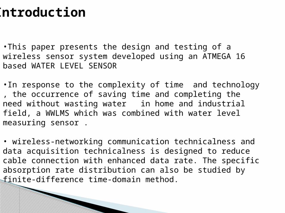
Most common LCDs connected to the microcontrollers are
16x2 and 20x2 displays.
This means 16 characters per line by 2 lines and 20
characters per line by 2 lines, respectively.
The standard is referred to as HD44780U, which refers to
the controller chip which receives data from an external
source (and communicates directly with the LCD.
Liquid crystal display (lcd)

If an 8-bit data bus is used the LCD will require 11 data lines(3 control lines plus the 8 lines for the data bus)
The three control lines are referred to as EN, RS, and RW
EN=Enable (used to tell the LCD that you are sending it data)
RS=Register Select. When RS=0; data is treated as a command & When RS=1; data being sent is text data.
R/W=Read/Write . When RW=0; the data written to the LCD & When RW=0; the data reading to the LCD.
Contd..

There are several ways that you can write, compile,
and download a program to the ATmega16
microcontroller. There are many different text editors,
compilers, and utilities available for many different
languages (C, BASIC, assembly language, etc.).
In this work, we have used a freeware package of
software tools named WinAVR (pronounced,
“whenever”).
Software requirements
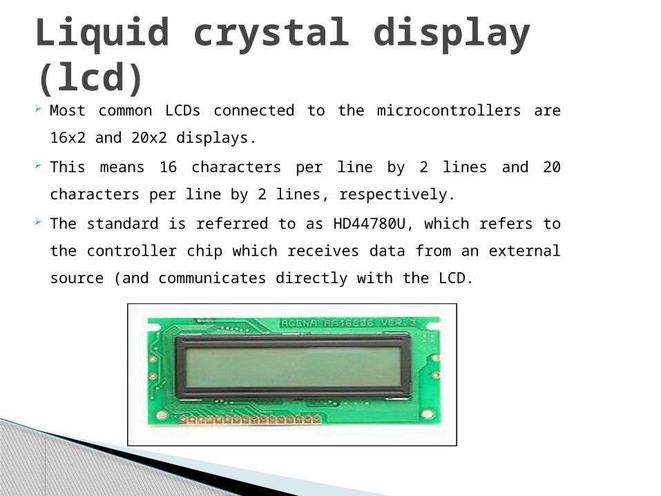
CodeVisionAVR (CVAVR) is the C-program language compiler that shall be used to program the MCU. CVAVR is a highly versatile software which offers “High Performance ANSI C Compiler, Integrated Development Environment, Automatic Program Generator and In-System Programmer for the Atmel AVR family of microcontrollers.” After installing and setting up CVAVR, a typical screen with a program open looks like this:
Contd..
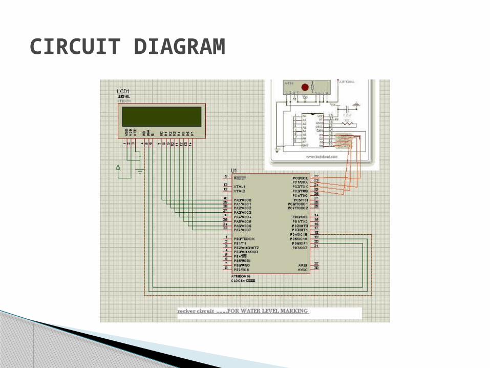
CIRCUIT DIAGRAM

Contd..
The transmitter output is up to 8mW at 433.92MHz with a range of approximately 400 foot (open area) outdoors. Indoors, the range is approximately 200 foot, and will go through most walls.
The TWS-434 transmitter accepts both linear and digital inputs, can operate from 1.5 to 12 Volts-DC, and makes building a miniature hand-held RF transmitter very easy.
RF working Transmitter
The receiver also operates at 433.92MHz, and has a sensitivity of 3uV. The RWS-434 receiver operates from 4.5 to 5.5 volts-DC, and has both linear and digital outputs.
The example above shows the receiver section using the HT-12D decoder IC for a 4-bit RF remote control system. The transmitter and receiver can also use the Holtek 8-bit HT-640/HT-648L remote control encoder/decoder combination for an 8-bit RF remote control system. Here are the schematics for an 8-bit RF remote control system.
RF working Receiver

Level sensorWide spectrum of sensors is available in the market and commonly, they are classified based on the specific application of the sensor. Sensor used for measuring humidity is termed as humidity sensor, the one used for measurement of pressure is called pressure sensor, sensor used for measurement of displacement is called position sensor and so on though all of them may be using the similar sensing principle. In a similar fashion, the sensor used for measurement of fluid levels is called a level sensor.
The water level sensors are placed in the water tank. It reads the level of the water tank. The signal of the sensors are given to the encoder then it is
transmitted through RF transmitter. The receiver side is connected to the decoder. Then it is connected to the controller. The output of the controller is given to the LCD.
WORKING PRINCIPLE

Conclusion and Future scope
The project is implemented in real time and will provide many benefits for the communication links using RF over AVR Board.
For the improvement of the system, increased bandwidth, and much greater transmission distance (range) of RF can be used, all resulting in superior consumer end products achieving much higher end-user satisfaction.

References

QUERIES ?

THANKYOU
Related Documents