Water Harvesting ~ ~ ~ ©~ ~ ~ ~ ~ ~ M.T. Hai 213.0 16409

Welcome message from author
This document is posted to help you gain knowledge. Please leave a comment to let me know what you think about it! Share it to your friends and learn new things together.
Transcript

Water Harvesting~ ~ ~ ©~
~ ~
~ ~ ~
M.T. Hai
213.0 16409

LL8RARY ~RCP0 ~ox 93190,2509 AD THE HAGUE
Tei:+31 703068980Fax: +31 703589964
RCODE: séL1q31.0

WATER HARVESTING
An IllustrativeManualfor Developmentof MicrocatchmentTechniques
for CropProductionin DryAreas
RELMA TechnicalHandbookNo. 16
The TechnicalHandbook Seriesof the RegionalLand ManagementUnit:
1. Curriculumfor In-ServiceTraining in Agroforestry& RelatedSubjectsin Kenya.Editedby StachysN. Muturi, 1992ISBN 9966-896-03-1
2. AgroforestryManualforExtensionWorkerswithEmphasisonSmall-ScaleFarmersin EasternProvince,Zambia. By SamuelSimute,1992ISBN 9966-896-07-4
3. Guidelineson AgroforestryExtensionPlanningin Kenya. By Bo Tengnas,1993ISBN 9966-896-11-2
4. AgroforestryManualfor ExtensionWorkersin SouthernProvince,Zambia.By JerichoMulofwa with SamuelSimuteandBo Tengnas,1994ISBN 9966-896-14-7
5. UsefulTreesandShrubsforEthiopia.Ident~fIcation,PropagationandManagementforAgriculturalandPastoralCommunities.ByAzeneBekele-TessemawithAnn Birnie andBo Tengnas,1993ISBN 9966-896-15-5
6. UsefulTreesandShrubsfor Tanzania.Identification,PropagationandManagementforAgricultural andPastoralCommunities.By L. P. Mbuya,H. P. Msanga,C. K. Ruffo, Ann Birnie andBo Tengnas,1994ISBN 9966-896-16-3
7. Soil Conservationin ArushaRegion,Tanzania.Manualfor ExtensionWorkerswith Emphasison Small-ScaleFarmers. By PerAssmowithArne Eriksson,1994ISBN 9966-896-19-8
8. Curriculumfor Training in Soil and WaterConservationin Kenya.Editedby StachysN. Muturi andFabianS. Muya, 1994ISBN 9966-896-20-1
9. TheSoilsofEthiopia.AnnotatedBibliography.1100works. By BerhanuDebele,1994ISBN 9966-896-21-X
10. UsefulTreesandShrubsfor Uganda:Ident~fIcation,PropagationandManagementfor Agricultural andPastoral Communities.ByA. B. Katende,AnnBirnie andBo Tengnãs,1996
11. AgroforestryExtensionManualforNorthernZambia. By Henry Chilufya andBo Tengnas,1996
12. UsefulTreesand Shrubsin Eritrea: Identification, PropagationandManagementforAgricultural andPastoralCommunities.By E. Bein, B. Habte,A. Jaber,Ann Birnie andBo Tengnäs.
13. Facilitators‘Manualfor CommunicationSkillsWorkshop. By PamelaBaxter.
14. AgroforestryManualforExtensionWorkersin CentralandLusakaProvinces,Zambia.By JosephBanda,PeniasBandaandBo Tengnäs.
15. IntegratedSoil Fertility Managementon Small-ScaleFarmsin EasternProvinceofZambia.Editedby ThomasRaussen.ISBN 9966-896-32-5

© RegionalLandManagementUnit, SwedishInternationalDevelopmentCooperationAgency, 1998.
Contentsmay be reprintedwithout specialpermission. However, mentionof sourceis requested.The photographerconcernedmustbe contactedfor reproductionof photographs.
Views expressedin the RELMA publicationsseriesare thoseof theauthorsanddo not necessarilyreflect theviews ofRELMA/Sida.
Cover Photo: by Mwangi HaiTop: Admiring a farmer-improvedinfiltration ditch usedforbananaproductionin AEZ 4, Machakos;Left: A 3-year-oldguavaplantedusinga negarim;Right: Newpossibilitiesareopenedup usingwaterharvesting—avineyardin Mwingi district.
Publishedby:the RegionalLandManagementUnit (RELMA/Sida),ICRAF House,United NationsAvenue,Gigiri.P.O. Box 63403,Nairobi, Kenya.
Editing,design,layoutandproduction:DevelopmentCommunicationsLtd., (DevCom)P.O.Box 39486,Nairobi, Kenya
Editor of RELMA seriesof publications:Alex Oduor/RELMA
Printedby:SignalPressLtd.P.O. Box 12714,Nairobi
Cataloguing-in-PublicationData:WaterHarvesting:An IllustrativeManualfor theDevelopmentofMicrocatchmentTechniquesfor CropProductionin DryAreas/MwangiHai.Nairobi, Kenya:RegionalLandManagementUnit (RELMA), SwedishInternationalDevelopmentCooperationAgency(Sida), 1998(RegionalLandManagementUnit (RELMA) HandbookSeries;16)
Bibliography: p:
ISBN 9966-896-33-3
Tech.HandbookNo. 16.

WATER HARVESTING
An IllustrativeManualfor Developmentof MicrocatchmentTechniquesfor CropProductionin Dry Areas
Mwangi T. Hai
Soil andWater Conservation Branch,Department of Agriculture
RegionalLandManagementUnit, RELMA
SwedishInternationalDevelopmentAuthorityNairobi
1998
*1~
TABLE OF CONTENTS
List of figures and plates iii
List of tables iv
Acronyms V
Foreword vi
Preface Vii
Acknowledgements viii
Section 1 Introduction 1
1.1 Waterharvesting- a definition 21.2 Classificationof waterharvestingsystems 21.3 Theroleof waterharvestingin agriculture 3
1.4 Technologylimitation 31.5 Socio-economicconsiderationsin Water Harvesting 4
Section2 TechnicalRequirementsfor Water Harvesting 5
2.1 Cropwaterrequirements 52.1.1 Methodsof estimatingcropwaterrequirements 52.1.1.1 Panevaporationmethod 52.1.1.2 Estimationmethod 52.2 Soil requirements 62.3 Rainfall dataanalysis 7
2.3.1 Computingprobabilityrainfall 82.4 Rainfall-runoffrelationships 102.4.1 The SCScurvenumbermethod 102.4.2 Runoffcoefficientmethod 10
Section3 Water HarvestingDesign 12
3.1 Designingfor the requiredcatchmentarea 12Estimatingthe RunoffCoefficientFactor 12Selectingdesignrainfall level 12EstimatingtheEfficiency Factor 14
3.2 Designfor runoff controlandretainingembankments 14

Tableof Contents
Section4 Water HarvestingTechniques is4.1 Negarims 154.2 Semi-circularbunds 194.3 Contourridges 224.4 TrapezoidalBunds 244.5 Contourstonebunds 284.6 Contourbunds 294.7 OtherImportantTechniques 314.7.1 Broadbedandfurrow system 314.7.2 Ridgingandtiedridging 324.7.3 Conservationbench 324.7.4 Zay pits 334.7.5 Runoff harvestingfrom theroad 354.7.5.1 Rootstoragebasins 354.7.5.2 Bananachannel 36
Section5 DesignFor SimpleRunoff Storage Structures 38
5.1 Sizing the reservoir capacity 385.2 Designof simpleundergroundstoragestructures 41
References 45
AppendicesAppendixA: Applicationof the SCScurvenumbermethod. 47AppendixB: Detailsof the designof semi-circularbunds 49AppendixC: Detailsofthe designoftrapezoidalbunds 50AppendixD: Log-probabilitypapersfor rainfall analysis 51
11

LIST OF FIGURES AND PLATES
Fig. 1: Distributionofdry areasin RSCUmandateregion. 1Fig. 2. The waterharvestingmodel. 2Fig. 3. Typical rainfall andgrowing seasonsinASAL areas. 8Fig. 4: Probabilityplot for annualrainfall, Mutomo,Kitui. 10Fig. 5: Fieldlayoutof negarimmicrocatchments. 15Fig. 6: Minimum heightof soilbundsfor negarims. 16Fig. 7: Negarimfield layoutprocedure. 17Fig. 8: Field layoutof semi-circularbunds. 19Fig. 9: Generalnomographfor sizing thediameterof semi-circularbundsfor
commonfruit trees. 20Fig. 10: Semi-circularbundsfield layoutprocedure. 21Fig. 11: Minimum heightfor semi-circularbunds. 22Fig. 12: Field layoutof contourridges. 23Fig. 13: Minimum heightfor contourridgebunds. 24Fig. 14: Field layoutof trapezoidalbundsanddetailsof a singlebund. 24Fig. 15: Trapezoidalbundsfield layoutprocedure. 27Fig. 16: Minimumheightfor trapezoidalbunds. 28Fig. 17: Field layoutfor contourstonebunds. 28Fig. 18: Field layout of contourbunds. 30Fig. 19: Alternativecrop androw arrangementson broadbeds. 31Fig. 20: Field layout andgeometryof tiedridges. 32Fig. 21: Detailsof the layoutof aconservationbench. 33Fig. 22: Field layoutanddimensionsof Zaypits commonlytried in Kenya. 34Fig. 23: Roadrunoffharvestinganddistributioninto basins. 35Fig. 24: Improvedroadrunoffharvestinganddistributiontechnique. 36Fig. 25: Runoffbenefittinga line of bananasandacroppedfield. 37Fig. 26: Runoffdiversioninto simpleundergroundreservoirs. 38Fig. 27: Planandsectionof aparabolicundergroundreservoir. 41Fig. 28: Planandsectionof atrapezoidalreservoir. 43Fig. 29: Relationshipbetweendiameterandcapacityof undergroundreservoirs. 44
Plate 1: A healthypawpawplantgrown inAEZ 5 usinga negarim. 18Plate2: An above-averagemaizecropafterlowApril rains, 1997,Mwingi, on FanyaJuu
with externalrunoff. 33Plate3: Comparisonbetweenmaizeplantedwith andwithoutpits. 34
111

LIST OF TABLES
Table 1: Rainfallassociatedwith agroecologicalzonesin drylandKenya. 3Table2: Estimatedcropwaterrequirementsfor local conditions. 6Table3: Waterholdingcapacityby differentsoiltextures. 7Table4: Probabilityrainfall andreturnperiod levels,Mutomo,Kitui. 9Table5: Valuesofrunoff coefficient,C. 11Table6: GuidelineCCAR valuesfor cultivatedclayandsilt loam soilsatdifferentlandslopes. 13Table7: Variationofreturnperiodandcatchmentareawith selectedprobabilityrainfall levels1. 14Table 8: Minimum heightof soil bundsfor negarims. 18Table9: Minimum heightfor semi-circularbunds. 21Table 10: Minimumridge heightfor contourridgebunds. 23Table 11: Minimum heightfor trapezoidalbunds. 25Table 12: Minimum heightof contourstonebunds. 29Table 13: Minimum heightfor contourbundsfor trees. 30Table 14: Valuesof CCAR for differentdiametersandspacingofZay pits. 35Table 15: Guidelinesfor estimationof domesticwaterdemand. 39Table 16: Calculationof requiredtankusingtotal roofarea. 40Table 17: Summaryofreservoircapacityby differentroofareas. 40Table 18: Runoffstoragevolume for aparaboliccross-sectionreservoir. 42Table 19: Dimensionsandstoragevolume for acircularplan, trapezoidalcross-sectionreservoir. 43TableAl: Runoffcurvenumbersfor arid andsemi-aridrangelands. 48
iv

ACRONYM S
AEZ Agro-EcologicalZoneASAL Arid andSemi-AridLandsDAREP DrylandAppliedResearchandExtensionProjectDPT DivisionPlanningTeamFAO FoodandAgricultural OrganizationGTZ GermanAgency for TechnicalCooperationKARl KenyaAgriculturalResearchInstituteMOA Ministry ofAgricultureNDFRS NationalDrylandFarmingResearchStationRSCU RegionalSoil ConservationUnitSIDA SwedishInternationalDevelopmentAuthoritySCS UnitedStatesSoil ConservationServiceUNEP UnitedNationsEnvironmentalProgrammeUM4 UpperMidland4, meanannualtemp. 18-21o~
LM3 LowerMidland 3, meanannualtemperature21-24°CLM4 LowerMidland 4 (temperatureas above)LM5 LowerMidland 5 (temperatureasabove)1L5 InnerLowland5, meanannualtemp >24°C
v

FOREWORD
Thismanualwas preparedin responseto a generalfeeling that we do not yethaveadequateinformationonvarioustechnologiesfor usein the developmentof sustainableagriculturein dry areas.Largeportionsof thecountriesunderthe RSCUmandatearearid to semi-arid.As the mostlimiting factor in drylandagricultureissoil moisture,and in the new thinking of SIDA, we neededa publication that shifts focus from resourceconservationtoproductivityof farmlandswithin theEasternAfrica region.Thustheobjectiveofthismanualis:
To compiletechnicaldataon commonandpopularwaterharvestingstructuresfor agriculturalproductionto guide extensionworkersfor improvementon the currentwaterharvestingpracticesin dry areas.
Mostagriculturalcurricula in Kenyaremainsilenton waterharvestingtechnology.This manualprovidesusefulfirst handinformationneverbeforewidelyavailableinKenyain this form anddetail.It shouldbeusefulto thoseinterestedindrylandagricultureandwaterresources,andtocollegestudentsinsoilandwatermanagementat diploma level andabove.Besidesathoroughcoverageof the mostcommontechniques,theauthorhasalsodevelopedasimplemethodologyfor sizing rainwater/runoffstoragestructures.
The primary target groupfor thismanualare the Division PlanningTeams(DPTs)which areheadedbydiploma holders; this is why further simplification of the manualis not advisableat this stage.However,possibilitiesofa scaleddown“pocket” versionof themanualfor otherextensionworkerscanbe exploredinfuture.
We highly commendMr. MwangiHai for devotingmuchtimeandeffort towardsproducingthismanual.Itrust that it will stimulateinterestamongthe users(in Kenyaandwithin theregion)to do furtherexplorationandfield testingof theseandothertechniques.
Eric SkoglundDirector, RegionalSoil ConservationUnit
Nairobi, May 1997
vi

PREFACE
Waterharvestingdevelopmentfor cropproductionis the simplestway inwhichfood securitycanbeimprovedin dry areas.It hasbeentried in variouspartsof KenyasuchasTurkana,Baringo,Kitui andTaita Taveta.Mostof thework doneso far hasbeenfinancedby donors.In somecasesheavymachineryhavealsobeenused.Itseemsthatin mostoftheseprojects,the objectwas to choosetechniquesof interestanddemonstratethattheywork, ratherthan extensionto farmers.Althoughthe resultshavebeenencouraging,little adoptionhasbeenachievedexceptinTaitaTavetawhereclearlythe objectivehasbeendifferent.From1993/94,waterharvestingtargetshavebeenset everyyearby the Ministry of Agriculture, Livestock DevelopmentandMarketing inASAL districts.The reportedachievementshavebeenvery low. The main reasonsfor poor adoptioncan besummarizedas follows:
1) thefield staffaretechnicallyill-prepared.Nosinglepublicuniversity,collegeor institutehasto dateadoptedwaterharvestingtraining.This issinglythebiggestdrawbackto progressin waterharvestingdevelopment.
2) thereareno instructionmaterialsexplaininghowto implementthe techniqueson the ground.3) useof unavailableandunaffordableheavymachinery.4) inappropriateobjectivesandapproaches.
With the frequentcycles of droughtandsubsequentcrop failures,thereis an urgentneedfor aconsciousdevelopmentof thistechnologyfor extensionandadoptionby farmers.This manualthereforeaimsatbridgingthesedeficiencies.It doesthisbyprovidingfirst-handinformationtothosechargedwithagriculturaldevelopmentindryareas.Henceit hasbeensimplifiedasmuchasispracticalforeffectivetechnologydissemination.Secondly,therearevery few sourcebooks for this technology.For this reason,themanual is intendedto be usefultocertificate,diplomaandundergraduatestudentsof naturalresourcemanagementandagriculture.
Themanualdealswith designandimplementationofwithin-fieldtechniquesfor cropandfodderproduction,rehabilitation,andfor establishmentofforestandfruit trees.Specifically,it coverstwelvedistinctwaterharvestingtechniquesfor crop development.The designof simplerunoffstoragestructureshasalsobeenincluded;suchwatercanbeusedfor bucketirrigation, livestockor humanuse.Themanualconsistsof five chapters:Introduction;Technicalrequirementsforwaterharvesting;Waterharvestingdesign;Waterharvestingtechniques;Designof runoff storagestructures
Thematerial includesimportantsocio-economicconsiderations,basicdesigncriteria andconsiderations,requireddesigndataandfinally design,layoutandconstructionprocedures.The techniquesareexplainedin asimple languageandwith diagrams,designnomographsandtables.To makethe manualmorepractical,thetechniquesareexplainedusing29 diagramsand 19 tables;moreover,8 exampleshavebeendonefor varioustechniquesto showthe userhow to proceed.The designsaresizescommonlyusedin Kenya,but the givenproceduresalsoshowtheuserhowtomakeadesignsite-specific.Manyofthecurrentwaterharvestingdesignsarebasedon trial anderror. For thatreason,empiricaldesigncriteriahasbeendevelopedin this manual.Thisshouldbeusedwith flexibility to fit individualfarmconditionsandfarmerneeds.Someappendicesareprovidedto expoundon themethodsusedto developthe designprocedures.
This manualis mostlybasedon local experiences,engineeringprinciplesandbasicagriculturalsciences.Modificationscanbemadeasmoreinformationcomesin from research.Otherrelatedbooksandmanualsarerecommendedas supplementarymaterials.
M. T. HaiJuly 1997
vii

ACKNOWLEDGEMENT S
I wishto thanktheRegionalSoil ConservationUnit/SIDA throughtheDirectorof theUnitMr. Eric Skoglundfor thekind offer ofthis fellowship. I believethatthisis a signof theUnit’s deepappreciationoftheproblemsof agriculturaldevelopmentin dry areas.I am sincerelygrateful to Mr. H.G. Kimaru who deeplysharedtheoriginal ideasaboutthiswork. Henot only helpeddefine its scopeandobjectives,buthasmaderegularfollow-up on its progress.
My gratitudealsogoesto theSoilandWaterConservationBranchoftheMinistry ofAgriculture,LivestockDevelopmentandMarketingfor financingtransport.I thankMr. F.W.Mbote(Head,Soil andWaterConservationBranch)and Mr. GideonShoneof RSCUfor their moral supportandusefulreviewsof severaldrafts of themanual.I alsothankthe Provincial Director of Agriculture Mr. P.T. Ibeerefor providing transportfacilitiesduringthedatacollectionphase.
I am grateful to the following for their variety of contributionsto this work: Dr. OkwachandDr. Itabari(NDFRS,Katumani) for sharingwith me, respectively,theirrainfall-runoffandwaterharvestingexperiencesandmoral support; Mr. R.K. Muni (University of Nairobi) for his timeandusefuldiscussions;andMr. E.K.Biamah (University of Nairobi) for runoff dataandinvaluablediscussionson the preparationand use ofnomographs;Mr. Kithinji Mutungafor athoroughtechnicalreviewofthe manual.Onproduction,my thanksgo to Miss PaulineMuragefor diligently typing the original draft, andto Mr. FrancisN. Nthukuri of DAO’sOffice, Embu, forpreparingthe sketchesusedin themanual.
The manualhasbenefitedimmenselyfrom excellentinputsby thesededicatedpeople.I hopethatI havebeenable to put togethersomeof their wonderfulcontributions.
MwangiT. HaiJuly 1997
viii
SECTION 1
INTRODUCTION
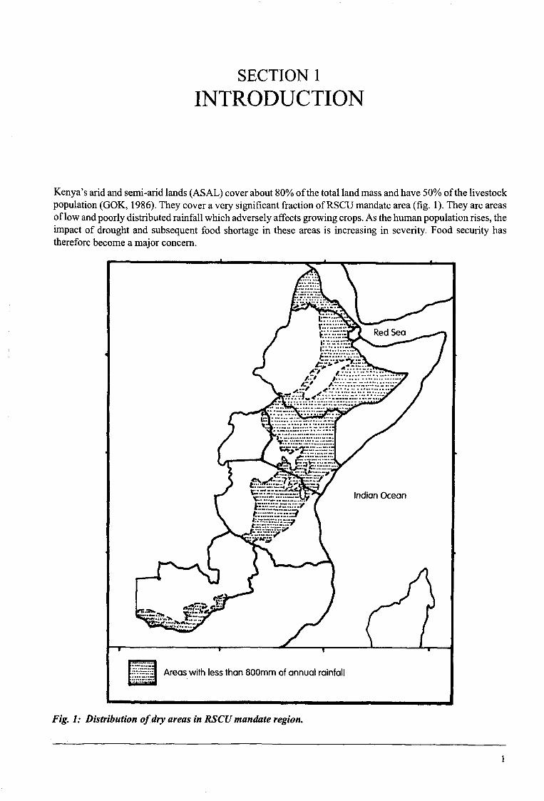
Kenya’saridandsemi-aridlands(ASAL) coverabout80%ofthetotallandmassandhave50%ofthelivestockpopulation(GOK, 1986).Theycoveraverysignificantfractionof RSCUmandatearea(fig. 1). Theyareareasoflowandpoorlydistributedrainfall whichadverselyaffectsgrowingcrops.As thehumanpopulationrises,theimpactof droughtand subsequentfood shortagein theseareasis increasingin severity.Food securityhasthereforebecomeamajor concern.
______________ -_____ -
Fig. 1: Distribution ofdry areasin RSCUmandateregion.
/.. I
,.., ~~: #.~::.:::~
-
~.. ~. :: .~
Indian Ocean
C..-.
.ii?T~~:
“I,
Areas with Ie:s than 800mm of annual rainfall -
1

Introduction
1.5 Socio-economicconsideratiOns in Water Harvesting
It is alwaysusefulto considerimportantsocio-economicissueswhichcan hinderor enhancewaterharvestingdevelopment.Theseinclude:
1) LandtenureissuesPeopledo not wantto investon landwhichmayin future go to someoneelse.Thereforeownershipandrightof useof landis a very importantfactorto consider.
2) Returnto investmentThe costof developingatechniqueshouldbe recoverablein the short term - say,seasonallyor annually.Treestakelongfor thebenefitstoberealized.Growingthemwith quickermaturingcropsmaybebeneficialespeciallyduringtreeestablishment.Alternatively,onecanusefruit trees.
3) Local prioritiesLocal prioritiesshouldbe considered.If thepriority is subsistence,thenawaterharvestingsystemshouldtry to fit in andassistto meetthis objective.
4) SustainabilityFora technologyto besustainable,it oughtto be simplein design,layout, implementation,maintenance,managementanduseof locally availableresources,e.g.family labour,animalpowerandmaterials.
5) Main economicactivityGrowingofcropsmaybeof no immediaterelevanceto apastoralcommunity;developmentof smallwaterstoragestructuresmaybe moreurgentto them. Thetechnologyfor cropproductionis moreapplicabletosettledcommunitiesalreadyengagedin farmingactivities.
6) SocialorganizationsWheretheyexist, thesecanbe a verygoodbasefor labour supply,encouragementandhencewidespreadadoption.An exampleis theMyethya groupsin Ukambaniareaof Kenya.
7) CommunityinvolvementThe community should be involved in all stages,i.e. needidentification, design, implementation,management,monitoring,evaluation,maintenanceandsystemmodificationwherenecessary.
8) GenderissuesIt is importantto considerthe role ofbothmenandwomenandtheirbenefitsfrom suchactivities.
9) MotivationWherepossible,it is goodto motivatepeoplein anypossibleway, suchas creatingawarenesson variousoptionsandthe possibleimmediatebenefits.Trainingandtoursto similarprojectscan servethispurpose.
The extensionworker shouldtry to strengthenthoseissuesthat are likely to speedup waterharvestingdevelopment.Issueslikely to haveanegativeeffectcanbedealtwithby
a) solvingthem,b) collaboratingwith thosewho couldsolvethem,orc) changingthe approachor the technique,includingimprovisingwith farmers.
4

SECTION2
TECHNICAL REQUIREMENTS FORWATER HARVESTING
Theharshcropping environmentof dry areasmustbe clearlyunderstoodfor efficient utilization of soil andwaterresources.The mostimportantenvironmentalvariablesarecropwaterrequirementandthesoil in whichcropsaresown.
2.1 Crop water requirement
This is the amountof waterrequiredby a crop to grow from planting to maturity. Different cropsrequiredifferentamountsof waterdependingon the crop type, the lengthof the growing seasonandthe particularseason.Dry areashavehightemperaturesandlow humidity,two factorswhichraisetheevaporativedemandofthe environment.Other factorswhich influencecrop wateruseincludea) wind,b) hoursof sunshineanditsintensity.Whenaseasonis wet, a crop tendsto usemorewateras the supply is not limited.
2.1.1 Methods ofestimating crop water requirements
Thecropwaterrequirementis estimatedby thereferencecropevapotranspiration,ET.Therearemanymethodsof estimatingcropwaterrequirements.TheseincludePenman,Blaney-Criddle,PanEvaporationetc. The firstmethodis widelyusedbut it iscomplicatedandrequiresalotof informationwhichmaynotalwaysbeavailable.The othersarestraightforward.Here thethird methodis discussedbecauseit is simpleandeasyto apply.
2.1.1.1 Panevaporationmethod
Referencecrop evapotranspirationcanbeestimatedfrom daily waterevaporationratesfromastandardclassAevaporationpan. Evaporationfiguresareobtainedevery24 hoursby noting how muchwater(mm depth) isusedto top up to the20cmmark. This figure can becorrectedwith apanfactor(K,,~)of 0.7:
ET0 = EpanxKpanmm (1)
This givesagoodestimatefor theevaporativedemandoftheenvironment.To get thecropwaterrequirement,theabovefigure ismultiplied withacropcoefficient(I(~).A valueof 0.9is quitesufficientfor waterharvestingdesign.
2.1.1.2 Estimationmethod
This methodcanbeusedwhenothermethodsarenot possible.Informationon waterrequirementsfor variouscropshasbeendevelopedin variousparts of the world. It can be adjustedto suit localconditions.The bestknowndatais thatgivenbyDoorenbosandPruitt(1977)andcoversmostcommoncrops.Dry areasgrowmanydifferentcropsanddatafor theseis often lacking. Jaetzoldand Schmidt(1982)havepublishedthe rangeofrequiredwell distributedrainfall for variouscrops.The figuresgivenby both sourcesarequiteclose(table 2),implying thatthe muchwider crop rangegivenby the latter is quite reasonablefor applicationin dry areasofKenya.
5

TechnicalRequirementsof WaterHarvesting
Table 2: Estimatedcrop water requirementsfor local conditions.
Crop Daysto Requiredwell distributedmaturity/harvest rainfall (mm)
Maize: (400-750)’‘)AA ,1~g~2Dryland compite 75 -
Katumani 85 260-450Coast 105 550-700
Wheat 110 350-530 (300-450)Barley 55 180-350 (300-450)MilletFoxtail 50 160-320Bulrush 70 250-450Finger 75 230-500
Sorghum 75 200-500 (300-650)Groundnuts 50 180-550Teparybeans 60 180-320Cowpeas 60 190-400Greengrams 75 190-400Beans 70 230-450 (250-500)Dolichos 100 200-700Pigeonpeas 110 370-650
“(bimodal) 180 500-800Soyabeans 80 350-680 (450-825)Sunflower 75 180-550Simsim 90 300-600Sweetpotato 60 3 50-900 (400-675)Cassava 180 500-1000Cotton 170 5 50-950 (550-950)Banana 365 900-1700 (700-1700)Mango 800-1000Passion fruit 9002000Pawpaw 1000-1500Citrus 800-1400 (650-950)Coffee(Arabica) 900-1500 (800-1200)
(Robusta) 1100-2000Macadamia 750-1200Sugarcane 1250-1800 (1000-1500)Tobacco 150 400-700 (300-900)
Source:adaptedfromJaetzoldandSchmidt(1982).1) Figuresin bracketsfromDoorenbosandPruitt (1977).2) compiledfor veryshortto mediumASALgrowthperiods.
2.2 Soil requirements
Soil is an importantfactorin design.Fourpropertiesof agriculturalsoils areparticularlyimportant:1) Fertility - oncesoil moistureis enough,nutrientsbecomethenextmostlimiting factorin cropyields.Low
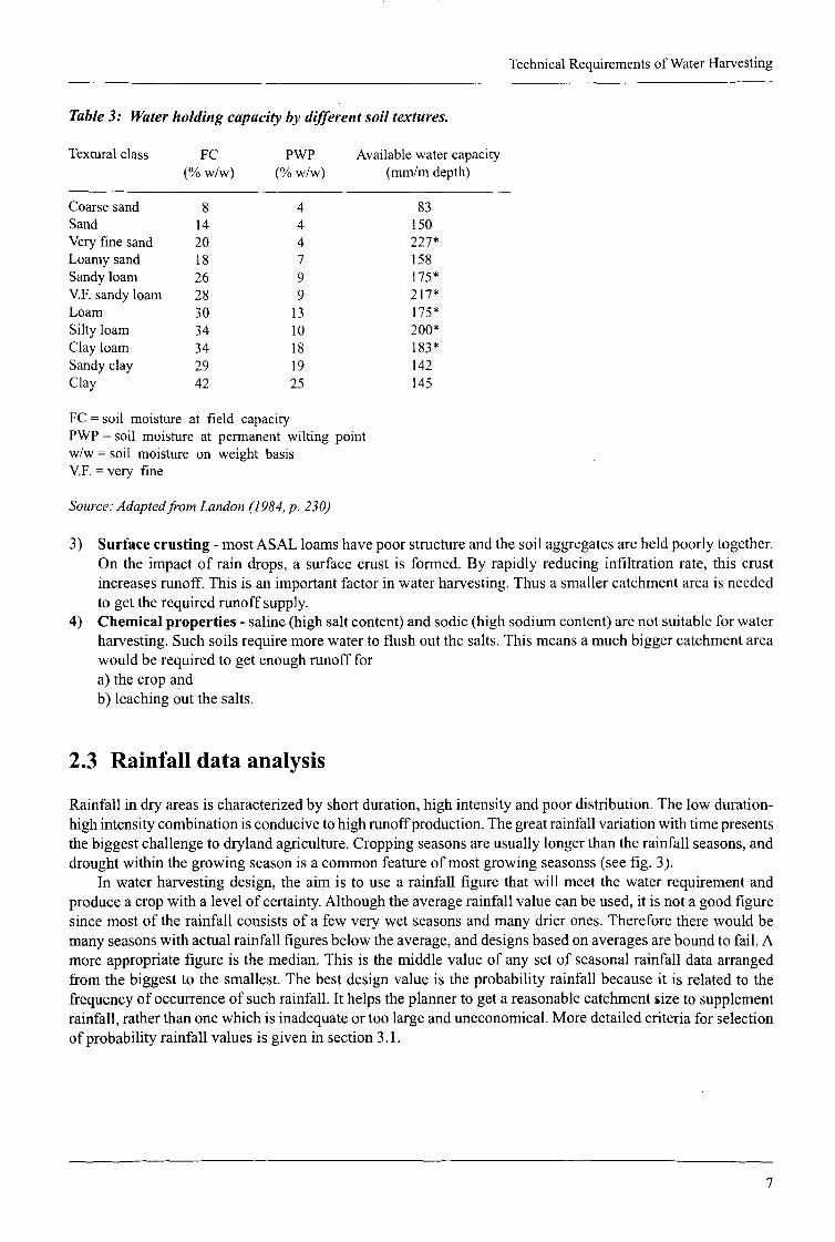
soil fertility canbeimprovedby usingfertilizersandmanures.2) Storage - soil forms the cheapeststoragefor soilmoisture.Thereforethe soil in theplantingareashould
a)be deepfor maximumstorage,andb) havegood waterholdingandreleasingproperties.Sandsaregenerallynot recommendedbecausethey
holdvery little water.Onthe otherhand,claysstorealot of waterbut do not releaseit easily.The bestsoils for waterharvestingare loams(soilsmarkedwith “*“, table3).
6
Technical Requirements of Water Harvesting
Table3: Waterholdingcapacitybydifferent soiltextures.
Texturalclass FC PWP Availablewatercapacity
(% w/w) (% w/w) (mm/rn depth)
Coarse sand 8 4 83Sand 14 4 150Veryfinesand 20 4 227*Loamy sand 18 7 158Sandy loam 26 9 175*V.F. sandy loam 28 9 217*Loam 30 13 175*Silty loam 34 10 200*Clay loam 34 18 183*Sandy clay 29 19 142Clay 42 25 145
FC = soil moisture at field capacityPWP= soil moisture at permanent wilting pointw/w = soil moisture on weight basisV.F. = very fine
Source:AdaptedfromLandon(1984,p. 230)
3) Surfacecrusting- mostASAL barnshavepoorstructureandthe soil aggregatesareheldpoorlytogether.On the impactof rain drops, a surfacecrust is formed. By rapidly reducing infiltration rate, this crustincreasesrunoff. This is an importantfactorin waterharvesting.Thus asmallercatchmentareais neededto get the requiredrunoffsupply.
4) Chemicalproperties - saline(high saltcontent)andsodic(high sodiumcontent)arenot suitablefor waterharvesting.Suchsoilsrequiremorewaterto flush out the salts.This meansa muchbiggercatchmentareawould be required to get enoughrunoff fora) the crop andb) leachingout the salts.
2.3 Rainfall data analysis
Rainfall in dry areasis characterizedby shortduration,high intensityandpoordistribution.The low duration-highintensitycombinationis conduciveto highrunoffproduction.Thegreatrainfall variationwith timepresentsthe biggestchallengeto drylandagriculture.Croppingseasonsareusuallylongerthantherainfall seasons,anddroughtwithin thegrowingseasonis a commonfeatureof mostgrowing seasonss(seefig. 3).
In waterharvestingdesign,the aim is to usea rainfall figure that will meet the waterrequirementandproduceacrop with alevel of certainty.Althoughtheaveragerainfall valuecanbeused,it is nota goodfiguresince most of the rainfall consists of a few very wet seasons and many drier ones. Therefore therewouldbemany seasons with actual rainfall figures belowtheaverage,anddesignsbasedon averages are bound to fail. A
more appropriate figure is themedian.This is the middle valueof any setof seasonal rainfall data arrangedfrom thebiggestto the smallest.The bestdesignvalueis the probabilityrainfall becauseit is relatedto thefrequencyof occurrenceof suchrainfall. It helpsthe plannerto get areasonablecatchmentsize to supplementrainfall, ratherthanonewhich is inadequateor too largeanduneconomical.Moredetailedcriteriafor selectionof probabilityrainfall valuesis givenin section3.1.
7

TechnicalRequirementsofWaterHarvesting
100
Fig. 3: Typicalrainfall and growingseasonsin ASAL areas:1990Novemberrains,Mutomo, Kitui(Hai, 1993).
2.3.1 Computing probability rainfall
The following procedureshouldbe followed to arrive atthe requiredprobability rainfall value.
1) identify the growing seasonfor theparticularcrop, i.e. whetherseveralmonths(for annualcrops)orwholeyear(for perennialcropssuchas trees);
2) obtainreliableseasonalrainfall datafor atleast10 years.Themorethe datathe better.Overtwentyyearsispreferred;
3) arrange the data in descending order, starting with the highestandendingwith thelowest;4) calculate seasonal probabilities using the following equation(Chowet. al 1988):
~m—0.375 (2)
N +0.25
where P = probabilityofthis amountof rainfall beingexceeded;m = rankof rainfall value(highest= 1; lowest= N)N = totalnumberof data(months, seasons or years);
5) plot the rainfall values against their probability valueson alog-probability graph(see Appendix D);6). drawalineofbestfit between these points.Fromthisline, anydesiredrainfallvalueataselectedprobability
level can bereaddirectlyandusedfor design;7) computethe returnperiod for the given rainfall values:
1T=— (3)
whereT = returnperiod in years of that rainfall event.
Daily rainfall (mm)
200 -
150 - Total length of the growing season
Length of the rainy season Dry end of season* critical *
— Daily raintall lmml
HarvestingPlanting I
50
0j~0
Il~l~20 40 60 80 100
sequential days of cropping season
120
8

TechnicalRequirementsof WaterHarvesting
Example 1:Table4 (below) gives24 yearannualrainfall for Mutomo,Kitui, Kenya.A farmerin theareawishesto plantamangoorchardin his farm.
Question:1) Whatis themean,medianand50%probability rainfall level?2) Selectanappropriatedesignlevel rainfall for the farmer.
Solution:1) Steps1 and2: Mangois aperennialcrop,hencetheseasonhas12months.Rainfall valuesaregivenin table4; the annualmeanis calculatedas 680mmwith themedianbeingthe averageof 621 and594(table 4), i.e.608mm.
Step3-7:Therainfall datais arrangedindescendingorderandranked.Probabilityvaluesandcorrespondingreturnperiodsarecomputedfor eachrankusingequation2 and3 (above).The datais summarizedin table4.The rainfall andprobability valuesareplottedon alog-probabilitypaper(fig. 4). The 50%probabilityrainfallis readfromthe graphas 620mm.
Table4: Probability rainfall andreturn periodlevels,Mutomo,Kitut.
Year Rainfall,(mm)
Rank Probability Rettirn period(T)(years)
(1) (2) (3) (4) (5)
1989 1309 1 0.03 38.801967 1175 2 0.07 14.921984 1146 3 0.11 9.241968 1086 4 0.15 6.691988 1047 5 0.19 5.241986 1026 6 0.23 4.311966 960 7 0.27 3.661978 882 8 0.31 3.181979 806 9 0.36 2.811977 713 10 0.40 2.521971 647 11 0.44 2,281985 621 12 0.48 2.091972 594 13 0.52 1.921981 576 14 0.56 1.781969 576 15 0.60 1.661973 467 16 0.64 1.551982 465 17 0.69 1.461974 455 18 0.73 1.381970 422 19 0.77 1.301980 361 20 0.81 1.241976 341 21 0.85 1.181975 287 22 0.89 1.121983 216 23 0.93 1.071987 147 24 0.97 1.03
Source:Rawdataadaptedfrom Hai (1993).
2) A 67%probabilityrainfall isselected.Thisamountis likely to beachievedin2 ofevery3 years.Thedesignlevel is therefore480mm.
Becausetheyare largelyunavailable,probability graph papersare providedat the endof the manual.It issuggestedthatthe usermakescopiesbeforeexhaustingwhathasbeenprovided.
9

TechnicalRequirementsofWaterHarvesting
2.4 Rainfall-runoff relationships
Waterharvestingdependson how muchrunoff canbecollectedfrom a surface.Consequently,this subjectisvery important.A numberof rainfall-runoffrelationshavebeenusedin manystudies.One suchrelationis thethresholdrainfall. This is the minimumstormrainfall observedbeforerunofftakesplace.A figure of 7.8mmwas observedfrom crustingsoils (Critchley, 1986).
2.4.1 The SCScurve number method
The secondimportantmethodisthe SCScurvenumbermethod.In thismethod,daily runoffdepthisestimatedusingcurvenumbersfor anygivencatchmentcondition. The possibleseasonalrunofftotal is got by addingdaily valuesfor thewholeseason.Themethodworkswell with acomputeror ahand-heldcalculator.For moredetails,the readeris referredtoAppendixA.
3000
2000
Probability (%)Fig. 4: Probabilityplotfor annualrainfall, Mutomo,Kitui.
2.4.2 Runoff coefficientmethod
This is arelationshipbetweentotal rainfall andtotal runoff. Becauseof its simplicity, it is themost importantmethod.Runoffcoefficientdefinesthepercentageofrainfall thatbecomesrunoff. Thereis limited informationon coefficientsfor the varioussoils,surfaceconditionsandslopes.However,somestudieshavebeendoneoncrustingsoils of tropicalregions.
Studiesin WestAfrica, IndiaandKenyahaveindicatedseasonalrunoffratesof crustingsoils of 26.5%to45.4% (Lal, 1976; Sharmaet al., 1982; Biama etal., 1993; Okwach,1994). However, someof the findingsconflict on the effectof slopeon runoff.
Hudson(1981)hasgivenrunoffcoefficientsforusewith theRationalmethodtoestimatepeakrunoffrates.Thesevaluesarebasedon soil type, landuseanddegreeof slope.The coefficientscan be extendedto theestimationofrunoffdepth.Theremaybesmallerrors,but thisis themostcomprehensiveinformationavailableyet. It is summarizedin table5.
EEaaaCC
1000 —
100
:i~=—~F~
~P~~~âl’:II:
‘mTh1!i~~
~~~ ~Itk~wItI~IIt;WHl
~
~ ~ ~ H1~ik~I I~1~III~~
j~liIIIli~I1~iI~!j~j~:ii J~II
~ -
lEEWI J I I 1 I
99 98 95 ~0 80 70 60 50 40 30 20 10 5 2 1
10

TechnicalRequirementsofWaterHarvesting
Table 5: Values of runoff coefficient, C.Topographyand
Vegetation
Woodland
SandyLoam
0.100.250.30
0.10.160.22
0.30.40.52
Soil texture:Clayandsilt loam
0.300.350.50
0.30.360.42
0.50.60.72
Clay
0.40.50.6
0.40.550.6
0.60.70.82
UrbanFlatRolling
30%impervious0.40.5
50% impervious0.550.65
70%impervious0.650.8
Source.’Hudson(1981)
Flat (0-5%)Rolling (5-10%)Hilly (10-30%)
PastureFlatRollingHilly
CultivatedFlatRollingHilly
11

SECTION3
WATER HARVESTING DESIGN
3.1 Designingfor therequiredcatchmentarea
A waterharvestingsystemconsistsof two areas- a croppedanda catchmentarea(fig. 2). A croppedareaiswhereacrop is plantedandgetsits moistureandnutrients.A catchmentareais usedto provideadditionalsoilmoisturein formofrunoff. Foranyparticularcrop,thisrunoffplustherainfall fallingdirectonthecroppedareashouldbeequalto cropwaterrequirement:
Water requirements= rainfall + runoff
Theaim ofa waterharvestingdesignis thereforeto estimatethecatchmentarearequiredfor agivencrop areasothata crop getssufficientmoisturetoproducethe neededgrain orfruit.
Rainfall is normally not enoughto meetcrop waterrequirement.The amountof waterharvestedshouldbeequalto the extrawaterrequiredby a crop. This is influencedby the runoff coefficientandthe amountofrainfallreceived.Becausesomewaterenteringthesoil is inevitablylostthroughdeeppercolation,anefficiencyfactoris considered.The catchmentandthe croppedareasarerelatedby the catchmentto croppedarearatio(CCAR):
CCAR=~RI? (4)
where RCECWR = crop waterrequirement,mm;
R = designrainfall, mm;C = runoffcoefficient,0<C<zl;E = efficiencyfactor, 0<E<1.
All within-field techniquesaredesignedbased’on thisequation.In somecases,thedesignmaybemodifiedtotakecareof farmimplementsizeandrecommendedcropspacing.Table 6givessomeguidelineCCARfiguresfor commoncrops,agroecologicalzonesandslopesfor clay andsilt loam soils.
Estimating the runoff coefficient factor
Experienceindicatesthatrunoffcouldbeup to 70%for barecrustingsoilsunderintensestorms.Morework isneededin this area.Table 5 shouldbeuseduntil thereis betterinformation.
Selectingdesignrainfall level
Theselectionof designrainfall is avery importantdecision.The objectiveis to selectaseasonalrainfall valuethatbestsuitsadesign.Thepreferredmethodofrainfall analysisisgivenin detailsundersection2.3.1.Whatisimportantis to understandtheimplicationof a selectedlevel ofrainfall with respectto1) the frequencyofthe systemperformingas desired,and2) the size of catchmentarearequired.
12

WaterHarvestingDesign
‘Basedon 60%probability rainfall in LM4, LM5 andL5 asgivenbyJaetzoldandSchmidt(1983),p202. Thelowerofthetwo seasonalrainfall is usedfor design.2For cottonand otherperennialcrops,rainfall valuesfor bothseasonsareadded.
A short returnperiodstorm is themost frequent,henceit hasahighprobability. Technically,the selectionofsucha rainfall level enablesadesignwhich shouldwork at all longer returnperiods.However,suchrainfalllevelsresultinvery largecatchmentsandarethereforeimpracticalastheywasteland.Ontheotherhand,averylongreturnperiod isnot useful.The amountof rainfall is veryhigh, which is arareoccurrence.Thedesignedcatch~mentis thereforetoo smalland fails to raisea crop in most of the years.A balancebetweenthe two
Table6: GuidelineCCARvaluesfor cultivatedclayandsilt loamsoilsat different land slopes.’
AEZLM4, E=60%
Rain Crop MeanCWR 2 4
Slopeof land(%)6 8 10
LM5, (E=50%)
148
L5, (E=40%)
350
210 Maize(Kat) 355 2.3 2.3 1.9 1.9 1.6F. Millet 365 2.5 2.5 2.1 2.1 1.7B. Millet 350 2.2 2.2 1.9 1.9 1.5Wheat 375 2.6 2.6 2.2 2.2 1.8Sorghum 475 4.2 4.2 3.5 3.5 2.9C. Peas 295 1.3 1.3 1.1 1.1 0.9G.Grams 295 1.3 1.3 1.1 1.1 0.9Soya 638 6.8 6.8 5.7 5.7 4.7Sunflower 365 2.5 2.5 2.1 2.1 1.7
5602 Cotton 750 1.1 1.1 0.9 0.9 0.8Citrus 800 1.4 1.4 1.2 1.2 1.0Mango 900 2.0 2.0 1.7 1.7 1.4Pawpaw 1250 4.1 4.1 3.4 3.4 2.9
Maize(Kat) 355 5.6 4.7 3.9 3.9 3.2F. Millet 365 5.9 5.9 4.1 4.1 3.4B. Millet 350 5.5 5.5 3.8 3.8 3.2Wheat 375 6.1 6.1 4.3 4.3 3.6Sorghum 475 8.8 8.8 6.1 6.1 5.1C. Peas 295 4.0 4.0 2.8 2.8 2.3G. Grams 295 4.0 4.0 2.8 2.8 2.3Soya 638 13.2 13.2 9.2 9.2 7.7Sunflower 365 5.9 5.9 4.1 4.1 3.4Cotton 750 4.6 4.6 3.2 3.2 2.6Citrus 800 5.1 5.1 3.6 3.6 3.0Mango 900 6.3 6.3 4.4 4.4 3.6Pawpaw 1250 10.3 10.3 7.1 7.1 6.0
123 Maize(Kat) 355 9.4 9.4 7.9 7.9 6.5F. Millet 365 9.8 9.8 8.2 8.2 6.8B. Millet 350 9.2 9.2 7.7 7.7 6.4Wheat 375 10.2 10.2 8.5 8.5 7.1Sorghum 475 14.3 14.3 11.9 11.9 9.9C. Peas 295 7.0 7.0 5.8 5.8 4.9G. Grams 295 7.0 7.0 5.8 5.8 4.9Soya 638 20.9 20.9 17.4 17.4 14.5Sunflower 365 9.8 9.8 8.2 8.2 6.8
328 Cotton 750 6.4 6.4 5.4 5.4 4.5Citrus 800 7.2 7.2 6.0 6.0 5.0Mango 900 8.7 8.7 7.3 7.3 6.1Pawpaw 1250 14.1 14.1 11.7 11.7 9.8
13

WaterHarvestingDesign
extremesis clearly desired.The selectedrainfall level dependson bettertechnicalinformationregardingthecropandadiscussionwith thefarmer.Noticethenegativecatchmentareain thelast column(table7), implyingthat drainage,ratherthanwaterharvesting,is desiredinstead.
Table 7: Variation of returnperiodand catchmentareawith selectedprobabilityrainfall levels’.
Selected Probability Return CCAR Catchmentannual ofrainfall rainfall Period Area(mm) (%) (years) (m2)
1300 5 20.0 -0.5 -5.11070 10 10.0 0.1 0.9870 20 5.0 0.9 8.8740 30 3.3 1.6 16.2650 40 2.5 2.3 23.1575 50 2.0 3.0 30.4500 60 1.7 4.0 40.0440 70 1.4 5.0 50.0380 80 1.3 6.3 63.2300 90 1.1 8.9 88.9250 95 1.1 11.3 113.3
‘Table basedon citrus(CWR=1100),silt loam soil, 5% slope,C 0.5, E= 0.6grown inLM4.
Estimating the Efficiency Factor
This factoris usedbecausenotall waterput in theroot zoneis usedby theplant.The factorvariesgreatlyfromseasonto season.Low rainfall seasonshavehigh efficiencyvaluesbecausetheremaybe very limited deeppercolation.In the designof surfaceirrigation systems,an efficiency factorof 0.4-0.85is commonlyused.Becauseof poorrainfall distribution,a figure of O.4-0~6is suggested,with the lower figure for drierareas.
3.2 Designfor runoff controlandretainingembankments
Two typesof embankmentsareusedinwaterharvestingi.e. stoneandearthbunds.Stonebundsareporousandcanallow someovertopping.Therefore,theymaynot requireafreeboard.Theyalsosilt quicklyandmaylosetheir effectivenessinholdingrunoffunlesstheyareincreasedsubsequentto silting. Whenloosestoneisavailable,it shouldbe preferredto earthbunds.Stonescan be usedtogetherwith grasses;this helpsto slow runoff anddepositsuspendedsoil while allowingthe waterto slowly flow downthe landslope.
Soil is the most abundantconstructionmaterial. Soil bundsare madeby spreadingthe soil in uniformlayersandcompactingatoptimummoistureuntil therequiredheightis achieved.For field conditions,themostpracticalconstructionperiodis whenthe soil is moist, suchas:1) immediatelyafterharvestingthecrop;2) after afew showersatthebeginningof themain season;3) makingbundsduringtheminorseason;thatis, for areaswhereNovemberisthe mainrainfall, bundscanbe
madein theApril rains.This removescompetitionfor labour in themainseason.
Becauseoftherelativelylow pondingtime in waterharvestingsystems,thedesignconsiderationsfor thebundsarequitesimple.Theminimumrecommendedsideslopesare1:1 onbothsidesto ensurestabilityofthestructure.
14

SECTION4
WATER HARVESTING TECHNIQUES
4.1 Negarims
DescriptionNegarimsare regularsquaresmadeof soilbundsturnedby 450 from the contourto concentraterunoffwateratthelowestcornerof thesquare.At thiscorner,aninfiltration basinis made.At thecentreof thisbasinaplantingpit ismade.Thewholesquareconsistsofacatchmentareaandacroppedarea.Runoffcollectsfromthecatchmentareaandflows into the croppedareawhereit ponds,infiltratesandis storedin the soil. The techniquerequiresdeepsoils up to 2m to storethe harvestedrunoff. The techniqueis mainly usedfor treeestablishmentin dryareaswith seasonalrainfall as low as 150mm. Whenusedfor fruit trees, it is designedto provide sufficientmoistureto aproducingtree.Whenusedin uneventopography,it is recommendedthattheblocksof negarimsshouldbesubdividedto smallerunits.
Thebundsshouldbe atleast25cmhighto avoidovertopping.Thetop width is atleast20cmwide andthesideslopes1:1.On steeperlandslopes,thebundheightshouldbeincreasedespeciallyneartheinfiltration pit. Thepit shouldbe60cmx 60cm~x60cmwith the subsoilbeingusedfor bundconstruction.The infiltration basinismostly round,but theplantingpit canbeeitherroundor square.
i Details.. Upper contour
Infiltration basin
Fig. 5: Field layout ofnegarimmicrocatchments.
Lower contour
15

WaterHarvestingTechniques
Design,layout and construction details
Requirements:line level,measuringtape,cottonstring,pegs1) designthedimensionsof thenegarim- lengthofthesidesandtheheightof thesoil bunds(seeexample2);2) wherenecessary,protect the field from externalrunoff with a cut-offdrain at a maximumgradientof
0.25%;
70
60
50
40
30
20
Blind height (cm)
1 3 5 7 9 11 13 15 17Length of a riegarim aide (m)
Fig. 6: Minimum heightofsoil bundsfor negarims.
3) cleardensevegetationfrom theareato leaveacatchmentcoveras specifiedby thedesign;4) stakeout acontourline belowthecut-offdrainandsmoothit out to roughlya straightline;5) makepegswith heightmarksfor indicating bundheightduringsoil placement;6) usingthepegs,markbundtips alongthe contourby spacingthemat adistanceequalto thediagonalofthe
negarim;7) measureastringtwicethelengthofasideofthenegarim.Markthecentreof thestring.Hold thetipsof the
string on the contourat the pegsandpull the mid-pointtight downslope.This marksthe lower cornerofthatnegarim.It becomesthe contourofthenext row of negarims;
8) completethe row anddo theotherrows as in (6) above;9) mark the infiltration basinandplanting pit at its centreaccordingto the recommendedsize about50cm
from thebund.Replacethefertile top soil into the planting pit andusethe subsoilformaking thebunds;10) makethebundsby placingsoil in 10cmlayersoneatatimeandcompactwith astick. Repeatthisuntil the
desiredbundheightis achieved;11) planta suitablegrasson thebundsto avoiderosion.
~.
~
~
5—8%S—7%
S6%:
~. . 3—5%
L—--—~—-—~—~------ ..-~----~
H -~
~---------
- -- ~--- -
I I 1.
16

f~#-~__D~ ~
7¼, \
, ‘.‘.
S
.‘S
(.
~
T
Water Harvesting Techniques
2
43
5
7
9
6
8
Fig. 7: Negarimfield layoutprocedure.
17

WaterHarvestingTechniques
Table8: Minimum heightofsoil bundsfor negarims.
MicrocatchmentSize Groundslope(%)1 2 3 4 5 6 7 8 9 10
2x23x34x45x56x67x7
8x89x9lOx 10lix 1112 x 1213 x 1314x 1415 x 15
25 30 3528 33 3931 37 43
40 47
44 5247 5651 6055 6458
28 31
3743505662
2633
40475562
Example2:A farmerin anAEZ LM4 haslandslopingat 2%on onesideand5% on theother.The soil is aclay loam. Hewishesto plant acitrus orchardto financeschool fees.As the extensionagentof the area,yourecommendtohim negarimmicrocatchments.
Question:1) what is the requiredspacingof negarims?2) whatis theheightof the soil bunds?3) howmanytreesfit in ahectare?Canthisbejustified?
Plate1:A healthypawpawplantgrownin AEZ 5 using a negarim.Noticetheyoungmangotreesin thebackground.
Usea bundheightof25cm
26 30 3326 31 35 39
40 4545 5050 56
26 33 55 6228 36 59 67
31 39 6433 42
25 35 4526 37 47
Not recommended
18

WaterHarvestingTechniques
Solution:1) The rainfall is similar to that given in fig. 4. The selected67% probability annualrainfall is 460mm.
Orangesrequire 1100mmannually(table2). Fromtable5, C=0.5.AssumingE0.5,
CCAR= 1100—460 —5.6 (5)460x0.5x0.5
A matureorangetreecanopyis roughly4mwide. Thetreerootsprimarilyextractmoisturefrom arootareaof 12.6 m2. Thetotal area(catchmentandcroppedarea)for a single tree is givenby
Total area— 12.6 (1 + CCAR) = 83.2 m2 (6)
Thesidesof eachnegarimarethereforethe squarerootof the totalarea,or 9.lm.
2) The heightofthe bundcanbereadfrom fig. 6 or table 8 for 5% slope.Half the diagonalof the negarimis6.4m. Usingthis figure, thebundheightis about28cm(5% slope)and25cm(2% slope).
3) There would be a maximum of 120 orange plants in a hectarecomparedto 156 for thenormalspacingof8mx 8m. This canbejustified by the designfor a bettermoisturesupplyandan economicallyproductiveorchard.
4.2 Semi-circular bunds
Description
This is anetworkof earthbundsshapedashalf-circleswith thetips facingupsiopeandon thecontour.Theycanbeusedfor trees,fodderandimprovementofrangeproductivity.Theyvarydependingon thecroptype,soilandtherainfall amount.
Semi-circularbundsareusedin areasof200-750mmrainfall, deepsoilsandlow slopes.Theyrequireeventopography.Thespacebetweentips ofconsecutivebundsis usedfor dischargeof excessrunoff. Thetop widthofthe bundsis usually 10cmandthe heightmaybe uniform wherethe topographyis flat. The sideslopesare1:1 althoughflatter sideshavealsobeenused.As theslopeincreases,the heighL is increasedaccordinglyfromthe tip to the lowestpoint. The minimumheightatthe tip is 0. lm.
section A—A
~oHsH
~erfi~ ~
Fig. 8: Field layoutofsemi-circular bunds.
19

WaterHarvestingTechniques
Two distinctdesignsareuseddependingon whetherthe cropis atreeor a row crop. While thegeometryof thebundsis the same,the shapeandsize of croppedandcatchmentareasdiffer. The readeris referredto AppendixB for designdetails.
Bund diameter (m)
17
15
13
11
9
7
5
3
...~Bai
at
Ma
aaa~-
ru
ago
._ ~.
50 150 250 350 450 550 650 750 850Deeign annual rainfall (mm)
Fig. 9: Generalnomographfor sizingthe diameterof semi-circularbundsfor commonfruit treesforC—O.5, E=O.6and canopydiameterof 2-4m.
Design,layout and constructiondetails
Requirements:line level, measuringtape,cotton twine,pegs.1) designthediameter,spacingandheightof the bunds(seeExample3);2) wherenecessary,stakeout acutoff drainabovethebundsto protectthemfrom excessrunofffromoutside
the field;3) stakeout a contourline atthe top ofthe field justbelowthecut-offdrain;4) cutastring equalto adiameterandahalf, markinginto threeequalparts.With it, markthe tipsof abund,
its centre and the spacing on the contour; —
5) with a pegtied at two endsof the halfdiameterportion, inscribethe bund belowthe contour.Similarly,complete the row of bunds on the contour;
6) measurethe positionof the next row from thebottomof the row aboveusingthe calculatedspacing.Thecentresofbundsin thisrow shouldvertically line with the mid-pointofthespacebetweenthebundsin thefirst row. Repeatuntil all rows aredone;
7) dig a small trench outside the bund to get soil. Make the bunds in layers of up to 10cm and compact eachuntil the required height is achieved;
8) protectbund tips with stonesto avoid erosion. If stonesare not available, plant a suitabledensegrassinstead.
Example3:A farmerintendsto usethesemi-circularbundsfor orangeproductionin hisfarmwhichis in anareawith a60%probabilityrainfall of 500mm.The landslopesat 6%.a) what is thediameterof the bunds,andb) what is theheightof the bunds?
20
WaterHarvestingTechniques
3
5
7
9
2
4
6
8
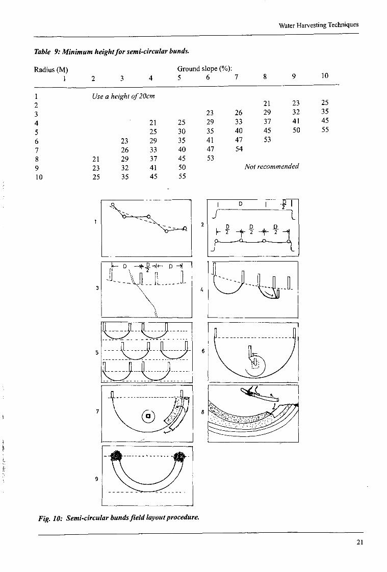
Table 9: Minimum heightfor semi-circularbunds.
Radius(M) Groundslope(%):1 2 3 4 5 6 7 8 9 10
1 Usea heightof20cm2 21 23 253 23 26 29 32 354 21 25 29 33 37 41 455 25 30 35 40 45 50 556 23 29 35 41 47 537 26 33 40 47 548 21 29 37 45 539 23 32 41 50 Not recommended10 25 35 45 55
z~N~
I~D
J
~ 1~-1~-~~-1
k—D ~D~_ D—~f
Fig. 10: Semi-circularbundsfield layoutprocedure.
21

Water Harvesting Techniques
Solution:a) Oranges require an average of 1100mmper year (table 2). Going to fig. 9, for 500mmrainfall we readthe
bunddiameteras 8.6m.A morespecific designcan alsobe done.b) readbund heightfrom fig. 11 or interpolatedbetweenh=29andh=35 in table9 for 4.3m(halfof 8.6) as
32cm.
70
60
50
40
30
20
10
Fig. 11: Minimum heightfor semi-circular bunds.
4.3 Contour ridges
DescriptionThe technique is used for row crops in areas of 350-700mm of annualrainfall andrequireseventopography.Furrows are dug on a contour and ridges formed immediately on the lower side. The ridges are spaced at 1-2mand are usually 15-20cm or higher. This forms a catchment which producesrunoffthatcollectsatthefurrow.Acereal is planted on the lowef side of the furrow and a pulse on the upper side. The furrows are tied every Smtoensurethat incaseofadefectivespirit level, runoffdoesnotflow laterally andconcentrateon onesidecausingerosion.Contourridgescanbemadewith oxen.Thetechniqueis thereforesuitableinareaswithawelldevelopeduseof draughtpower.
The designfollows thestandardprocedure.Assumingthatthecropisplantedin a50cmstrip, thecatchmentareacanb~calculatedfor the crop, soil typeandrainfall. Fordrierareas,the distancebetweenridgesandtheridgeheigh~’increase.Design,layout andconstructiondetailsRequirements:line level, measuringtape,cottontwine, pegs.
1) designridge spacingandheight(seeExample4);2) wherenecessary,protectthe field usinga diversionditch at the top of the field at a maximum0.25%
gradient;3) stakeout contoursandsmooththemout;4) stakeout contourkeylinesatadistancewhich is amultiple of the ridge spacing.Mark theridgepositions
betweenandalongthe keylines;5) excavatethefurrowsleaving30cmearthties every5 metres.Placethe soil downslopeimmediatelybelowit.
Bund height (cm)
0 1 2 3 4 5 6 7 8 9 10 11 12Diameter of S-C bund (m)
22

WaterHarvestingTechniques
slopeI Section A-A
crop cutchment
~rea~ area ~ridge
Fig. 12: Field layout of contourridges.
Example4:A farmerwants to plant a mixed maize-greengramcrop in an areawith a 60% reliable seasonalrainfall of150mm. The field slopes at 4%. Field examination and discussion with the farmer leads to the selectionofcontour ridges as the most suitable method. If the soil is a sandy loam, determine a) the ridge spacingandb) therequired height of contourridges.
Solutiona) from table 1, the mean seasonal water requirement for a diyland compositemaize/greengramsare
extrapolated to 430 and 200 mm,respectively; the mean for bothis 315mm.Fromtable5, C=0.3;assumingE=0.5, the CCARis:
CCAR= 315—150 = 7.3:1 (7)150x0.3x0.5
Taking the crop areaas 0.5mwide, thecatchmentis 0.5 x 7.3 = 3.6mwide andthe total area is 3.6 + 0.5 = 4. im wide.
b) the height of the ridge is read from fig. 13 or table 10. For a slope of 4%, the ridge height should be at least21cm high.
Table 10: Minimum ridge height(cm)for contourridge bunds.
RidgeSpacing Groundslope,%1 2 3 4 5 6 7 8 9 10
0.5 Useaheightof2ocm
1.52 21 23 252.5 23 25 28 303 23 26 29 32 353.5 23 26 30 33 37 404 21 25 29 33 37 41 454.5 23 28 32 37 41 46 505 25 30 35 40 45 505.5 22 27 33 38 44 49 Not6 23 29 35 41 47 recommended
23

WaterHarvestingTechniquesRidge height (cm)
70
60
50
40
30
20
10
Fig. 13: Minimum heightfor contourridge bunds.
4.4 Trapezoidal Bunds
DescriptionThis techniqueis suitablefor areawith 250-500mmof annualrainfall. It consistsoflargestructuresenclosingup to 1 haandimpoundinglargeamountsofrunofffrom anexternalarea.Cropsareplantedin thecroppingareaenclosed by soil bunds. The impounding bunds are laid on the contour but staggered downtheslopeto allow forreleaseof excessrunoff. Excessrunoff is dischargedaroundthe tipsof the bunds.
The mostsuitableslopesare0.25-1.5%on eventopographyandon non-crackingsoilssuchasblackcottonsoil. Themaximumbundheightis 0.6mdecreasingto 0.2mat thetips. Thetechniquecanbeusedfor treesandgrassbut is bestsuited for row cropswhere manualwork is the modeof cultivation. The standarddesignmethodis usedto size therequiredcatchmentarea.
Runoff inflow
N I IIN~~tchme~
NN/21 N~/
Details. . . __
N> /“\Wing wall
‘~-3asebund
Fig. 14: Field layoutof trapezoidalbundsand detailsof a singlebund~
0 1 2 3 4 5 6 7 8Ridge epacing (m)
It
24

WaterHarvestingTechniques
The needfor variationThis techniquewas initially developedin TurkanaDistrict wheremachinerywas usedfor constructionof thelargestructures.Theuseofmachineryis not sustainableduetotheirunavailabilityandhighcost.Thereforethestructureneedsto bemodified1) for manualimplementation,2) to enableimplementationon slopesexceeding1.5%,and3) to reducewasteon landespeciallyin moreintenselycultivatedsemi-aridareas.
The suggestedchangesare:1) reductionof the sideslopefrom 4:1 to 1:1;2) takinga standard0.2mtop width, and3) amethodof sizingthebasebundandthewing walls.
It is suggestedthatthe basebund be equalin lengthto the wing wall. The heightof the walls dependon landslope.Thereaderis referredto AppendixC for designdetails.
Design,layout and construction detailsRequirements:line level, measuringtape,cottontwine, pegs.1) determinethedimensionsof thebund - theheight, thelengthofthebasebundandthe wing walls, spacing
alongcontouranddown the slope(seeExample5);2) wherenecessary,protectthefield withadiversionditch placedjustabovethe field at amaximumgradient
of 0.25%;
Table11: Minimum heightfor trapezoidalbunds.
VL AWL(M) (M)
1
Ground slope (%)
1.5 2 2.5 3 4 5 6 7
8 11.39 12.710 14.111 15.612 17.013 18.414 19.815 21.216 22.617 24.018 25.5
2323 26
21 25 2923 28 3225 30 35
22 27 33 3823 29 35 4125 31 38 4426 33 40 4728 35 43 50
21 29 37 45 5322 31 39 48 5623 32 41 50 59
23 2621 25 29 3325 30 35 4029 41 4733 47 5437 53 6141 594549535761
VL vertical (normal)lengthofthewing wall (m) upslopeAWL = actualwingwall lengthalongthe135oangle.
3) stakeout othercontoursdownslopeaccordingto design;4) makestringA. Its total lengthis madeup of
a)basebundlength,b)2 timestheactualwingwall length(AWL), andhasanallowanceof 30cmfor tying. Folding it into two,measurehalf thebasebundlengthon eachside from the centreandmark thesetwo points.Tie aloop oneachendof the stringusing15cmstring length;
34567
4.25.7 Usea heightof2Ocm7.18.59.9
354045505560
NotRecommended
25

WaterHarvestingTechniques
5) makestring B. Its total lengthis madeup ofa)basebund length,b) spacinglength(onthecontour),c) 2.82 timestheverticallength(VL). Mark the stringas follows:
- half the spacinglength atextremeendsof the string- halfbasebundlengthon eachsidefrom the centre
6) startingfromthe leftboundaryofthe field, markwith apegpointsP1, P2,P3 andP4usingstringA. P1 isthe edgeof the fieldlmid-pointbetweenbunds.P2 andP3 arethe tips of the bund.P4is like P1;
7) hookoneloop at P2 andthe otheratP3. Pull the stringtightdownslopeatthetwo marks.Pegthe endsofthebasebundsatthetwo marks;
8) repeat steps 6 and 7 to complete the row of bunds. Repeat downslope to complete all the rows of bunds.The centre of the base bund is madeto correspondto themid-point of the spacingbetween bunds on thecontourimmediatelyabove;
9) make and compact each bund in 10cm layers. For any additional fill material,excavateoutsidethebund;10) protectbundtips with stonesandgrass.
Example5:A farmerhasa gently sloping land(3%) of deepsilt loam soil anduniformtopography.As awaterharvestingexpert,you haveproposedtrapezoidalbundsto the farmerfor sorghum(CWR=350mm)to improveon cropyields. The 67% reliableseasonalrainfall for the areais 185mm.
a) whatis theCCAR andbund dimensions?(useC=0.4,E0.4)b) howmanybundsfit in ahectare?
Solutiona) For thegiveninformation,theCCARis 5.6:1. Sorghumisplantedat60cmbetweenrows.Thenormalwing
wall would be a multiple of this interrow spacing.We canchooseanyconvenientlength of wing wall.Selectinganormalwingwall length(VL) of 6m (table 11) for 11 croprows,theactuallengthis 8.5mandthebundheight23cm.Thebasebundis also8.5mlong.Fora0.2mtop width, themaximumbottomwidthof thebundis 0.2m+2 x 0.23m 0.66m.
b) AppendixC is usedto completethedesign.The trapezoidalcroppedareais givenby A, andA2.Fora normalwing wall of 6m,A, = 62 = 36m
2andA
2 = 1.41 x 62 = 50.76m2for atotal croppedareaof 86.76m2.
Catchmentarea= cropareax CCAR= 86.76x 5.6= 485.86m2.This includesareaA
3, which isA3= 485.86-86.76= 399.lm2.
Sincethe distancebetweenbundtips(T) is known,bund spacingdownslopeis:
399.1 =19.5m (8)
T 3.41x6
Therewouldbe 18 bundsof 1 562m2croppedareaperhectare.
26

5
WaterHarvestingTechniques
— — — — — — — — — —
- .-
———————————--—.
—— —— — ——----. --..-
2
I~B B ~~AL —1k---- AL 1
1
3
~—BB-4~4--S-914--2~82VLJo.
p1( ~ ~
S B8 BBI1 ~S
Jo-o--o--~o---o--c~
4
.o
P3
-i6
pull
7 8
Fig. 15: Trapezoidalbundsfield layoutprocedure.
27

WaterHarvestingTechniques
Buod het~ht(cm)
Fig. 16: Minimum heightfor trapezoidalbunds.
4.5 Contour stonebunds
DescriptionThesearemadeof stoneslaid on the contouron up to 2% slope in areasof 200-750mmrainfall. They aresuitableon stonyland.Theyareusedto1) slow downrunoffandfilter out the soil, and2) increaseinfiltration of runoffwater.
They can be used without spillways and have low construction andmaintenancerequirements.The spacingbetweenstonebundsisnormally 15-30m but should be decreasedas theslopeincreases.Theminimumheightof25cmandabasewidth of35-40cmsetintoa5-10cmdeeptrenchwhichactsasakey.On slopeslessthan1%,bundsare spacedat 20m andon 1-2%, 15m. Bundsare madewith a good mix of largeandsmall stonestoensurethat runoffis allowedto passthroughslowly. The smallstonesarenormallyplacedupstreamandthelargeonesdownstream.
The standarddesignis usedfor sizingthecatchmentarea.The initial cultivatedareamaybe smallbut isadjustedupwardsin subsequentseasonsas moreexperienceis gained.Thebundswill allowrunoff throughinthe first few seasons.However,soil and vegetativematerialswill subsequentlyplug the spacesbetweenthestonesto makethe structureto holdrunoffaboveit.
Wherestonesareinadequate,theycanbeusedin combinationwithothermaterials.Grassandothervegetativematerialsareplantedbehindstonebundsfor morestreng.Earthbundscanalsobe used,with stonesmakingspillwaysstaggeredalongthe bund.
k— 35 - 4OCM—~
~tiofl A - A
Fig. 17: Field layoutfor contourstonebuMs.
2 4 6 8 10 12 14 16 18 20Normal wing wall leogtb (m)
28
WaterHarvestingTechniques
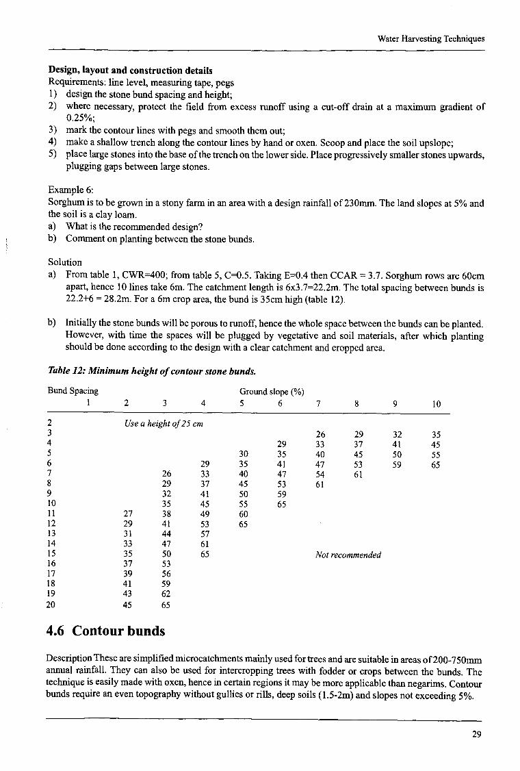
Design,layout and construction detailsRequirements:line level,measuringtape,pegs1) designthe stonebundspacingandheight;2) wherenecessary,protectthe field from excessrunoff usinga cut-off drain at a maximumgradientof
0.25%;3) markthecontourlineswith pegsandsmooththemout;4) makea shallowtrenchalongthe contourlinesby handoroxen.Scoopandplacethe soilupsiope;5) placelargestonesinto thebaseofthetrenchon thelowerside.Placeprogressivelysmallerstonesupwards,
plugginggapsbetweenlargestones.
Example6:Sorghumis to begrown in astonyfarmin anareawith adesignrainfall of 230mm.The landslopesat 5% andthe soil is aclay loam.a) Whatis therecommendeddesign?b) Commenton planting betweenthe stonebunds.
Solutiona) Fromtable 1, CWR=400;from table5, C=0.5. Taking E0.4 thenCCAR= 3.7. Sorghumrows are60cm
apart,hence10 lines take 6m. The catchmentlengthis 6x3.7=22.2m.The total spacingbetweenbundsis22.2+6= 28.2m.Fora6m croparea,thebundis 35cmhigh(table 12).
b) Initially thestonebundswill beporousto runoff, hencethewholespacebetweenthebundscanbeplanted.However, with time the spaceswill be pluggedby vegetativeand soil materials,after which plantingshouldbe doneaccordingto thedesignwith a clearcatchmentandcroppedarea.
Table12: Minimum heightofcontourstonebunds.
BundSpacing Groundslope(%)1 2 3 4 5 6 7 8 9 10
2 Usea heightof25cm3 26 29 32 354 29 33 37 41 455 30 35 40 45 50 556 29 35 41 47 53 59 657 26 33 40 47 54 618 29 37 45 53 619 32 41 50 5910 35 45 55 6511 27 38 49 6012 29 41 53 6513 31 44 5714 33 47 6115 35 50 65 Not recommended16 37 5317 39 5618 41 5919 43 6220 45 65
4.6 Contour bunds
DescriptionThesearesimplifiedmicrocatchmentsmainlyusedfor treesandaresuitablein areasof200-750mmannualrainfall. They canalsobe usedfor intercroppingtreeswith fodderor cropsbetweenthe bunds.Thetechniqueis easilymadewith oxen,hencein certainregionsit maybemoreapplicablethanneganms.Contourbundsrequirean eventopographywithoutgullies or rills, deepsoils (1 .5-2m)andslopesnot exceeding5%.
29

WaterHarvestingTechniques
Bundsaremadeon the contourat spacingsdictatedby thedesign.They areformedwith soil excavatedfrom afurrow on thecontouranddepositeddownslope.Perpendicularearthties aremadeat closespacingonthe upsiopefor betterrunoffcontrol. Eachmicrocatchmentcan be plantedwith oneor severaltrees.Plantingpitsaremadebetweentheties andthebunds.
Themicrocatchmentsizeis designedin thenormalway. Theyvary from 1 0-50m2for eachtree.Thebundsareatleast25cmhigh, theheightincreasingwith theslopeoftheland.Theties are2mor longerandarespacedat2-1Omdependingontherequiredsizeofmicrocatchment.Thespacingof ties increaseswith increasingslopeas thespacingof thebundsdecreases.
Table13: Minimum heightfor contourbundsfor trees.
Section A—A
Ridge Spacing Groundslope,%
Notrecommended
Fig. 18: Field layoutofcontourbunds.
2 Use a bundheightof3 20cm 23 264 21 25 29 335 25 30 35 406 23 29 35 41 477 26 33 40 47 548 21 29 37 45 53 619 23 32 41 50 59 6810 25 35 45 55 65 7511 27 38 49 60 71 8212 29 41 53 65 77 8913 31 44 57 70 83 9614 33 47 61 75 8915 35 50 65 80 95
21 23 2529 32 3537 41 4545 50 5553 59 6561 68 7569 77 8577 86 9585 9593
1 2 3 4 5 6 7 8 9 10
Design,layoutand constructiondetailsRequirements:line level,measuringtape,pegs1) designthe spacing,microcatchmentsize andheightof thebunds;2) wherenecessary,provideadiversionditch at0.25%abovethefield to protectit from largeexternalrunoff;3) stakecontourlinesandalignthem.Dig soilfromthefurrowandplaceit in layersofupto 10cmcompacting
alayeratatimeuntil thedesiredheightis achieved;4) makeearthtiestomarkthemicrocatchments.Betweenthetiesmakeplantingpitsof 80cmX 80cmX 40cm
deepjustabovethebund;
30

WaterHarvestingTechniques
5) on eachsideofthe field, makea 25-30cmbundto preventrunoff loss from the system.Excavatethe soilfrom within the system,with the contourbundjoining the lateralbund;
Example7:A forestisto beestablishedusingcontourbundsin anareawith a60%reliableannualrainfall of480mm.Theland is apasturesloping at 3%. The estimatedwaterrequirementof the treesis 900mm. If the soil is asiltyloam,determinebundspacingandheight.Assumea2m canopyfor 4-yearold trees.
SolutionFromtable5, C=0.3. TakingE=0.7 (sincetreestakeadvantageof deeppercolatedwater),CCAR= 4.2. Eachtreewill havean effective root zoneof 3.14 m2 andrequiresa total areaof 3.14x(1 + 4.2) = l6.3m2. Themaximumbundspacingwill be 8m for whichthe minimumbundheightis 47cm(table 13). The ties can be at16.33/8= 2m. Theremaybeverymanytiesalongthebunds,hencetie spacingmaybechangedto anyconvenientspacingsuchas 8m (4 trees between ties) or lOm (5 treesbetweenties).
4.7 Other Important Techniques
Thereareotherlessknowntechniquesbut whichhavepotentialfor applicationin thevariedsoil, topographicandclimatic conditions.A farmercan beassistedto choosethe moat suitabletechnique.basedon the existimzconditions.
4.7.1 Broad bed and furrow system
This istherecommendedICRISATsystem.It is madeof im broadbedsseparatedby 0.5mfurrows.The furrowslope is usually0.4-0.8% on vertisols (black cotton).On eachbroadbed width, 2-4 rows of cropscan beplanted. The crop geometryis variedto suit the cultivation and planting equipment.The objectivesof thetechniqueare to:1) encouragemoisturestoragein thesoil profile;2) disposesafelyanysurplussurfacerunoff,3) providebetterdrainedandmoreeasilycultivatedsoil in thebed.
This techniquehasbeensuccessfullyusedin Taita Taveta,Kenya,wheretheyarecalledcamberedbeds.
45
sorghum or millet crop
L75 -J ~—150 —~maIze crop
p/pee sorghumlmaize intercrop
Fig. 19: Alternativecrop and row arrangementson broadbeds.
3’

WaterHarvestingTechniques
4.7.2 Ridging and tied ridging
Thepurposeofusingtiedridgesisto increasesurfacestorageofrainwater.Furrowson thecontouraredammedwith smallties downthe slopeto preventrunoffflow from oneendof the field to another.It is ahighlabourrequirementtechniqueunlessthefarmercanfirst useoxento maketheridges.Thetechniquegivesgoodyieldsgenerallybut canalsogive lowyields duetowaterlogginginverywetseasons.Theymaynotgive goodyieldsafterdry seasonsdueto their limited runoffharvestingpotential.
The techniquerequireshigh moisturestoragesoils of high infiltration rate. The following safetyconsiderationsshouldbe observed:a) the furrowsshouldbeat agentlegradientin casethe ties fail;b) theties shouldbelower in heightthantheridges.
Section A-A
ridgetie
4.7.3 Conservationbench
This is a rainfall multiplier techniqueusing an adjacentcatchmentto provide additional runoff onto levelterracesgrown with crops.Thetechniqueis usefulin increasingyield andits reliability in areasof 300-600mmannualrainfall. It requiresagentleslopeof 0.5-1.5%butcanbeusedup to 6%slope.A deepsoil isrecommendedfor goodmoisturestorageand to reducethe effect of decreasedsoil fertility dueto excessivelevelling andexposureof subsoil in thecrop area.Thereshouldbe outlets andawaterwayat the endof terracesin caseofexcessrunoff.
Themaindesignconsistsofthewidth ofterraceandthecatchmentarea.Typical terracewidthsarelOm (on5-6%slope)andup to 30m(2% slope)and50mor more(1%slope).Mini terraces9m widearemadewith 1:1CCAR. Thebenchcanbemadeeitherlevel alongits length,or gradedat 1:400 (0.25%).
TypicalCCARare1:1 or 2:1.Thecatchmentareaincreasesasrainfalldecreases.Arotationcanbeconsideredto alternatecroppingin thecatchmentin wetterseasonsandfallow in thedrierone~s1nKenya,this techniquecaneasilybe adaptedin terracedfieldswheretheupperpartoftheterraceis left asacatchmentwhile theloweroneis plantedwith acrop. The designfollows theprocedurediscussedundersection4.5.
Fig. 20: Field layout andgeometryof tiedridges.
32

WaterHarvestingTechniques
,1. slope
r~I~I’:::~-~---~-.~
Fig. 21: Detailsof the layoutof a conservationbench.
section A—A
I catchment I croparea : ~
I tI I
4.7.4 Zay pits
DescriptionThis is atechniquecommonlyusedin theSahelianregionof WestAfrica for growingsorghumandmillet. Zaypits increasecrop yield by a cOmbinationof moistureconservationandharvestingof runoff from the spacebetweentheplantingpits.
Plate2: An above-averagemaizecrop after lowApril rains, 1997,Mwingi, on FanyaJuu with externalrunoff
3~3

WaterHarvestingTechniques
Fig. 22: Field layoutanddimensionsof Zaypitscommonlytriedin Kenya.
Local experienceIn Kenya,the techniqueis alsoreferredto as planting pits. It hasbeentried by the DrylandAppliedResearchandExtensionProject(DAREP) in Embuandby the NationalDrylandFarmingResearchStation(NDFRS)Katumani.Thepreferredsoil is sandyloamas pitpreparationis easier.However,pits canbeusedon awider rangeofslopesdueto their small size.Manureis spreadon thewholepit to improveon soilfertility. Seedsareplantedaroundtheedgeof thepit halfwayup the sideto avoidwaterloggingand“burning”bymanure.
Thesizerefersto the diameterofthepitsandvariesfrom oneplaceto another.TheresearchersatKatumaniusedadiameterof30cm,aninterrowspacingof 60cmandadepthof 15cm.On theotherhand,DAREPusedan80cmdiameter,with 100cmand 150cmbetweencentresofpits and15cmdepth.With thesepit spacings,themaizeplantsperpit are4 and8, giving populationsof 40000and28800plantsperhectare,respectively.Withregardto cow peas,theplantsperpit.are6 and 12,giving 60000and43200plantsperha. The spacingaroundthe pits dependson the recommendedspacing.However, farmersparticipatingin DAREP modified thesedimensionsto 80cmdiameterpits and20cmspacingbetweenpitsto reduce“wasteon land”.
ThemajordisadvantageofZaypitsis high labourrequirements;theycannotbe doneusinganimaldraughtpower.Butwherefarmershaveseentheir benefits,theyarewilling to implementthem.
IPlate3: Comparisonbetweenmaizeplantedwith and withoutpitsbarely5m apartin the samefield, lowerEmbu. Notethe deepgreencolour and large cobswherepitshavebeenused.
0000Section A-A
00 O~100-150 cmo ~oo
30-80cm
L~
34

WaterHarvestingTechniques
Table 14: Valuesof CCARfor different diametersand spacingof Zaypits.
Pit Pit Crop Seeds Pit Total Catch.Size Spacing per Area Area Area(m) (m) pit (m2) (m2) (m2)
0.3 0.6 maize 3 0.07 0.81 0.74 10.5 37037’maize 5 0.07 0.81 0.74 10.5 61728
C/Peas 3 0.07 0.81 0.74 10.5 37037C/Peas 4 0.07 0.81 0.74 10.5 49383
0.8 0.2 maizemaize
46
0.500.50
11
0.500.50
1.01.0
4000060000
0.7 C/PeasC/Peas
812
0.500.50
2.252.25
1.751.75
3.53.5
3555653333
‘Theseedsperpit, henceplantpopulation,wereestimatedforthesedimensionsusedbyKatumani.
4.7.5 Runoff harvesting from the road
A numberof local techniqueshavebeendevisedby farmersfor reducingseriouserosionhazardscausedbyroadrunoff. This runoffis subsequentlyputinto somegooduse.Thesetechniqueshavebeendevelopedwithoutanytechnicalinput from extensionbut seemto be working. Although theyhaveresultedin improvedcropyields, theywouldbenefitfrom someresearch,engineeringandextensioninput. Someof theseare discussedbelow.
4.7.5.1 Root storage basins
Theseare structureswhichhold runoffon the cultivatedsurfaceallowing it to infiltrate. The sourceof runoffcanbearoad,grazingfield, shoppingcentre,hill etc. Thebasinsaremadeof earthbunds20-40cmhighandaremostusefulon low slopesof 0.5-5%.Thebundsareprovidedwith spillwayswhich allow dischargeofexcessrunoffwithoutcausingerosion.
l-~6 direction ofrunoff flow
— diversion
— waterway or road
CCAR PlantPop.
ROW 1
ROW 2
OR
ROW 1
ROW 2
distribUtion can at
.-1- ~
-v--out
Fig. 23: Roadrunoff harvestingand distribution into basins.
35

WaterHarvestingTechniques
nd2 row of
b a sins
1st row
of basins
Two variationshavebeenusedin TaitaTaveta.In the first method,runofffills thefirst basinin therow beforeextrarunoffflows into thenextbasinlaterallyuntil theentirerow is covered.Runoffflow changesdirectionandina similarmannercoversthe nextrow ofbasins.Excessrunoffleavesthe systematthe endof thelast row ofbasins.The othermethoddivertsrunoffandallows a uniformdistributionandinfiltration in the first row ofbasins.Whenwaterpondsbeyondapre-determineddepth,it flows into the lower row of basinsrow afterrowuntil all basinsarecovered(fig. 23).
Bothmethodsresultin poordistributionof runoff. Thefirst row ofbasinsgetmorewaterandis subjecttowaterlogging.The last rowsmaynot get enoughwater.An improvementwouldbe to haveeachrow fed by aseparatediversion.Subjectto adequaterunoffflow, equaldiversionsarepossibleif channelsaremadeof equalside slopes,gradientanddimensions(fig. 24).
______________ LI_________________________ ~w aterway
or road
I~—
— ~1 -____
4.7.5.2 Banana channel
I
-~ —1~ I J
spiliways
Fig. 24: Improvedroadrunoff harvestinganddistribution technique.
This is a commontechniquein Ukambaniin areasof 500-800mmofannualrainfall. Similar to a cut-offdrain,it is mostlyusedfor bananaproduction.In dry areas,retentionditchesarepreferredto cut-offdrains.Theseholdalot of runoff. Bananasareplantedinto the channelandbenefit from the additionalrunoff. Thetechniquecanbe improvedin at leasttwo ways:
1) Reductionof “dead”storage:Mostof theditchesusedtodayaresimilarto alevelcut-off drain.The standardsize of acut-offdrainis 1 .52m(top), 0.92m(bottom)and0.61mdepthfor a cross-sectionareaof 0.74m
2.It would store7.4m3of runoff forevery lOm whenfull. If thedepthis reducedto say0.2m, thestoredvolumeof thestructurewouldbereducedby 74%to I .9m3, saving5.5m3 ofrunoff. Thisadditionalrunoffcanbe spreadin thefield to benefitothercropsratherthanbe lost as deeppercolation.The currentditch depthis thereforewastefulon runoff. It wouldbe amoreefficientwaterharvestingstructureif the depthis reducedto makeit a conveyanceratherthana storagestructure.
Two variationsof runoffspreadingobservedin the field are:
a) havinga shallow channelwhich conveysrunoff to the end of the field. Once full, it allows runoff tooverflow the channelandspreadinto thefield below;
b) diggingazigzagchannelto circulaterunoffwaterfrom the top to thebottombananarow.
36

WaterHarvestingTechniques
2) Increasingthe size of plantingholes:Currentlysomefarmersdig justasmallhole in thechannelornoneatall. A largehole isdesirabletopermit
for manureapplicationfor improvementof organicmatter,hencebettermoisturestorageandsoil fertility.
banana channel
Hn
0 0 0 0~1 I
I _-__Q__--
L~:;:~0~
Section 4- A
~t~eI
Fig. 25: Runoffbenefittinga line ofbananasanda croppedfield (a) andzigzagvariationfor bananasalone (b).
37
~c~çridge
.: ______________
,.....“y~
A B~bananas
____ p~iI~ ~
Section B —B
L~~~-- ~outL. banana hole

SECTION5DESIGN FOR SIMPLE RUNOFF
STORAGE STRUCTURES
IntroductionWhenit rains, largeamountsof runoffwatercollectfrom roads,grazingareasandhomesteads.Thisrunoffmaynot all infiltrate whendiverted into cultivatedfields; if it does,most is lost as deeppercolation.Crops sufferfromwaterstressjustdaysafter rainfall ceases.Simplestoragestructuresduginto thegroundcantemporarilystorethisrunoff. A farmercan subsequentlyapply thiswateron acrop.
Besidesrunoffwaterfor cropproduction,thereare seriouswatersupplyproblemsin dry areas.Someoftheseproblemscan be solvedrathereasily if peoplehad the technology.In this section,a simpledesignmethodologyis presentedfor waterharvestingfrom aknownsizeof surfacearea.Thismethodcanbeappliedto developwatersupplyforhomesandinstitutionssuchas schoolsandhospitals.A differentmethodwouldberequiredif the catchmentareawasunlimited.
or road catcbment
Fig. 26: Runoffdiversioninto simpleundergroundreservoirs. Watercouldalsobeharnessedfrom a roofrather than a watercourse.
5.1 Sizing the reservoircapacity
The size of storagereservoiris very importantbecauseof1) thecostimplication,and2) its ability to meetwaterneeds.
Becauseof lack of designprocedures,mostreservoirsare madeeither too largeor too small. Althoughmorerigorousmethodsmaybe possible,the following simpleprocedurecan beappliedto determinethemosteconomicalreservoirto meetthewaterneeds:
1) selectthe wettestmonthof theyear asthe startingmonth.This ensuresthat thereis large storagespaceavailable;
silt trap
div ersionchannel
38

Design for Simple Runoff StorageStructures
2) computethe watersupply(litres) for eachmonth.This is doneby multiplying the monthly rainfall (R) bythetotal surfacearea(A) andacoefficient (C), andconvertedto m3 by dividing by 1000;
Volume= O.OOlRxAxCm3 (9)
3) list all thewaterdemandcomponents(cooking,drinking, washing,livestock,kitchengardenetc) andthedaily demandfor each(table 15);
4) computethedemandfor eachmonth includingallowancefor evaporationandseepagelosses(all in litres).Seepageloss canbe estimatedfrom the soil type if thereservoiris not cemented,but is otherwisezero.Convertall thefiguresto m3 by dividing thetotalmonthlydemandby 1000;
Table15: Guidelinesfor estimationofdomesticwaterdemand
Usercategory Daily consumption(litres) in thefollowing rainfall regimes:high medium low unclassified
Sanitationandablution 75’Cookingandlaundry 45’Hospital, school 25’Human 20 15 102 l5-35~Dairy cattle 50 50 502
Local cattle 17 17 172
Sheep/goats 4 4 42
‘Barnesetal (1983)2Ministiyof WaterDevelopment(1992)
3Argawalet a! (1980)
5) from the startingmonth,accumulateboththe supplyandthe demandmonth aftermonth;6) computethe monthly differencesbetweenthe accumulatedsupplyanddemand.If the annualsupply is
muchlargerthanthe demand,thenthereservoirsize is controlledby surfacearearatherthandemandandthis criteria shouldbe used.Forexample,atrial anderror of surfaceareacan bedoneuntil the monthlydifferencesof all the monthsarepositivewith oneof thedifferencesjustabovezero;
7) the largestmonthlydifferencebetweentotalsupplyandtotaldemandis themosteconomicalreservoirthatcanmeetthewaterneeds.Thisprocedurewill beusedin anexampleto showhowthemethodworks.Thisis a real-life exampleof Obuolo PrimarySchool. The school is about8km north eastof Kisumutowncentreandcurrentlyhasapopulationof 900students.
Example8During a normalschoolday,ObuoloPrimary Schooluses400 litres of waterdaily for drinking andcleaning.Because of a broken down water supply, the school spends KSh. 400 every school day to buy water. Forsustainability,a morereliableandcheaperalternativewatersupplywasdeemednecessary.a) designa roofwaterharvestingsystemfor the school.b) in your opinion, is this projectjustifiable?
Solutiona) Theschoolconsistsof 3 blocksofbuildings- tuition (320and288m2) andtheoffice/staffroom(80m2) for
atotalof 688m2.Thefirst computationinvolvestotal roofareaoftheschoolandis summarizedin table14.Computationswerealsodonefor the otherroofs, i.e. 320, 288 and80 m2 to seeif anyofthemwould beadequate.Theseresultsaresummarizedin table 16.
39

Designfor Simple RunoffStorageStructures
Table16: Calculation of requiredtank using total roofarea.
Month Rain Total area Supply SumSup Demand SumDem Difference
(1)(mm)(2)
(m2)(3)
(mi)(4)
(mi)(5)
(ms)(6)
(ms)(7)
(5-7)(ms)(8)
3 168.8 688.0 104.5 104.5 37.9 37.9 66.64 171.8 688.0 106.4 210.9 7.9 45.8 165.15 163.8 688.0 101.4 312.3 37.9 83.7 228.66 91.7 688.0 56.8 369.1 36.7 120.4 248.77 48.9 688.0 30.3 399.4 37.9 158.3 241.08 53.3 688.0 33.0 432.4 10.5 168.8 263.59 70.3 688.0 43.5 475.9 36.7 205.5 270.4
10 88.5 688.0 54.8 530.7 37.9 243.5 287.2Il 83.9 688.0 52.0 582.6 18.4 261.8 320.812 74.3 688.0 46.0 628.7 0.0 261.8 366.8
1 78.3 688.0 48.5 677.1 37.9 299.8 377.42 80.1 688.0 49.6 726.7 35.5 335.3 391.4
Notes:1) Demandfiguresasobtainedbygroupsduring thepracticals2) Al = blockI area (320);A2 = officearea (80); A3 = block2 area (288);A4 = areafor optimaldesign(317.5)3) 20%was addedto thedemandfor lossesandincreaseddemand
Interpretation of thedesign(tables16 and 17)1) By tappingwaterfrom thewholeschoolroof, the storagecontinuesincreasingunboundedeverymonthto
amaximumof 391.4m3(table 17 col.)2) If this sizeof tankwasmade,anequivalentvolume of waterwouldhaveto bepouredout attheendof the
wateryear.As thelargestcapacity,thisstorageis clearlyuneconomicalto make.
Table17: Summaryofreservoircapacitybydifferentroofareas.
Month Roof areasof differentbuildingblocks,in2
688 320 317.5 288 80(1) (2) (3) (4) (5) (6)
Total Al Optimal A3 A2
3 66.6 10.7 10.3 5.9 -25.74 165.1 52.3 51.5 42.6 -21.25 228.6 61.5 60.4 47.1 -47.36 248.7 51.3 49.9 34.1 -77.47 241.0 27.4 25.9 8.9 -111.98 263.5 32.3 30.7 12.2 -118.59 270.4 15.8 14.1 -6.3 -150.2
1011
287.2320.8
3.39.2
1.47.0
-21.3-17.9
-181.7-194.0
12 366.8 30.6 28.3 1.4 -188.71 377.4 15.2 12.7 -16.3 -221.02 391.4 2.7 0.0 -31.0 -250.8
2) If theoffice areawasused,therewouldbeawaterdeficit everymonthincreasingto amaximumof 251m3by theendoftheyear(table 17 col. 6). Hencethistankwouldnot solvetheproblem.Fromthiscolumn,itis not possibleto determinethereservoircapacity.
3) If the288m2blockwasused,themaximumstoragerequiredwouldbe47.1m3. However,the schoolwouldhaveto buywaterin 5 of 12 months,namelyJanuary,February,September,OctoberandNovember(table17 col. 5).
4) Thewaterdemandforthe schoolcanhoweverbemetby usingthe 320m2 roofalone.We maybetemptedtomakeatankof 338.2m3 (to collectall thewater)or 335.3m3 (to meetthetotaldemand).Thiswouldbewrong becausetotal supplyanddemanddo not comesimultaneously.The mosteconomicaltankfor the
40

Designfor SimpleRunoffStorageStructures
schoolis, however,61.5m3, leaving2.7 in3 attheendofthewateryear,whichisusedfor cleaningthetank.This procedurereducestankcapacityby 82%.
Noticethatattheoptimalroofareaof 317.5m2, thefinal storageattheendofthewateryearwouldbe0 m3andthereservoircapacityslightly lessat 60.4 in3. However,thereshouldbesomewater left for cleaning.
b) The school already has a largeroof; the only costto be incurredare labour andmaterials.Roof waterharvestingwould be the mostreliablesourceof water.Moreover,it wouldsavethe schoolaboutKSh. 80000annually.Thisjustifies the option.
5.2 Designof simple underground storagestructures
Having establishedthe reservoirsize,the next stepis to design its shape and dimensions. There are variousshapesof undergroundreservoirsused,buttheyareof unknowncapacities.Othertankssuchas abovegroundandothervariationsof undergroundreservoirscanalsobeused.Here,two typesof circularplanreservoirsareconsideredbecauseoftheir simplicity:a) aparaboliccross-section;andb) atrapezoidalcrosssectionof 1:1 sideslopes.
Thefirst reservoiris flatter andmorestable.Thestoragevolumecanbeestimatedfor variousdiametersasoutlinedin table11.Forbothreservoirs,thequotedcapacityis reducedwhenthereservoiris linedasrecommendedto reduceseepage.
Layout and construction procedure1) selecta suitablesite nearthe watercourse,leavingsufficientdistancefor atleastonesilt basin;2) usingtwo pegs and a string, stake out theedgeofthecircle fromthecentreandmarkit with asmalltrench;
Distance from centre of reservoir (ml
~1A
41
Reservoir surface
Section A - A
2345
10 8 6 h 2 2 4 6 8 10
Fig. 27: Plan andsectionof aparabolicundergroundreservoir.

Designfor SimpleRunoff StorageStructures
3) mark the short distancesindicated(in bold italics, table 18) startingwith the shortestdistancefrom thecentre;
4) dig to the requireddepthstartingatthe centre.Continuedigginguntil theedge(brim) is reached.Diggingseveraltrenchesradiatingoutwardwouldhelpgetthe depthright.
The secondreservoiris simplertolay out butmaybelessstable.Thebottomofthereservoirshouldbedugto a level ratherthan slopingsurface.The dimensionscan be estimatedusingtable 19 for the designvolumecomputedin section5.1.
Layout and construction procedure1) selectasuitablesite nearthe watercourse,leavingsufficientdistancefor atleastonesilt basin;2) usingtwo pegsanda string, layout the bottomandtop circles from thesamecentre,marking eachcircle;
Table18: Runoffstoragevolumefor aparaboliccross-sectionreservoir.
A = depthofreservoiratvarious distancesB = distanceofvariouspointsfromcentreto thebrimC= volumeofreservoir incubic metres.
3) firstdig insidethemiddlecircleto the requireddepth;placethesoil downslopeatleastim belowtheoutercircle, startingfarthestfrom the edgeof the circle;
4) finish by slopingthe sidesfromthebottomofthe innercircleto thetop ofthe outercircle.
Forbothtypesofreservoirs,fig. 29 is providedto givethevolumefor varioustankdiameterssincenot allpossiblevolumesarelistedin tables18 and19. Thefollowing considerationsshouldalsobemade:
1) Diversion - this is a raisedearthdyke which divertsrunoff from the mainwater courseinto an intakechannel.It shouldbeusedwhenthecatchmentareaisknownandaspillway ofadequatecapacitydesigned.
2) Intake channel - this isa furrowintakeof sufficientsizewhich conveysdivertedrunoffinto thereservoir.It shouldbeshallowandwide to reducethekinetic energyofmovingwater.Thechannelshouldbeplanted
Radius (m) Depth (m) for indicateddistancefrom centre:Centre Brim Volume
0 20 40 60 80 100 (cu.m)
1 0.05 0.048 0.042 0.032 0.018 OA0 0.2 0.4 0.6 0.8 1.0’s O.lc
2 • 0.20
0.1920.4
0.1680.8
0.1281.2
0.0721.6
02.0 1.3
3 0.450
0.4320.6
0.3781.2
0.2881.8
0.1622.4
03.0 6.4
4 0.80
0.7680.8
0.6721.6
0.5122.4
0.2883.2
04.0 20.1
5 1.250
1.21
1.052
0.83
0.454
05.0 49.1
6 1.80
1.7281.2
1.5122.4
1.1523.6
0.6484.8
06.0 101.8
7 2.450
2.3521.4
2.0582.8
1.5684.2
0.8825.6
07.0 188.6
8 3.20
3.0721.6
2.6883.2
2.0484.8
1.1526.4
08.0 321.7
9 4.05050
3.8881.84.82
3.4023.64.24
2.5925.43.26
1.4587.21.88
09.00
10.0
515.3
785.410
42

Designfor SimpleRunoffStorageStructures
with asuitableshort grassandalsohavecheckstructuresif theslopeishigh. The channelgradientshouldbe lessthan0.25%(sandyandsilty soils)and0.5%(clay soils).
Table19: Dimensionsandstoragevolumefor a circular plan, trapezoidalcross-sectionground reservoir.
Top Bottom Depth VolumeDiameter Diameter
(m) (in) (m) (ms)
2 0.86 0.57 1.13 1.29 0.86 3.64 1.71 1.14 8.55 2.14 1.43 16.66 2.57 1.71 28.77 3.00 2.00 45.68 3.43 2.29 68.09 3.86 2.57 96.8
10 4.29 2.86 132.811 4.71 3.14 176.812 5.14 3.43 229.513 5.57 3.71 291.814 6.00 4.00 364.415 6.43 4.29 448.216 6.86 4.57 544.017 7.29 4.86 652.518 7.71 5.14 774.519 8.14 5.43 910.920 8.57 5.71 1062.5
I i
\
‘I
3) Silt trap - this is arectangularholedugbeforethe reservoirandusedfor holdingheavy soilmaterials.Itensuresalongerreservoirlife by reducingsiltationrate.A convenientstrainerjustbelowthesilt trap helpskeepawaywoodplanksanddeadvegetativematerials.
/
/ V
/ V/
/
H—i
/
/
Fig. 28: Plan and sectionofa trapezoidalreservoir.
43

Design for Simple Runoff Storage Structures
Reservoirradius Cm)
Fig. 29: Relationshipbetweendiameterand capacityof undergroundreservoirs.
4) Lining - wherepossible,lining shouldbeconsideredto reduceseepagelossesespeciallyin sandysoils. Itcan be doneusinga clay “blanket” of about15cmplacedandcompacteda little at a time startingatthecentre.Whereaffordable,thissoil layermaybeprecededby alayerof plasticsheetlaid inward from theedgeof the reservoir.For domesticwatersupply,concretelining could be consideredto improvewaterquality.
5) Covering - evaporationlossesareveryhighin dry areas.It is oftennecessaryto reducedirect sunlightonthewater. Sisalpolescanbeusedformakingacoveringstructure.Gunnybagscanbepatchedtogethertomakeamosaicwhichcanbetiedwith ropesto hangabovethewatersurface.A thingrassthatchmaybethemostsustainable.
6) Maintenance- silt trapsdo notremoveall soil materials.Largersilt andsandparticlessettleatthebottomofthereservoir.Thisshouldberemovedperiodicallybetweenrainfall seasonswhenthereservoiris emptyanddry.
--..-.-- -----.-.----~----.~
---~
~— ~
EwE0>
02:a)(I)a)
1000
100
10
1
0.1
0.01
- E.~E~T ~± .- -
~i~—
~:i ~iii/ IIi~Ii1IIIIIIJLIIIIILI ~I I~iii7 ~‘___ I.
~T~5E~EiE ~~-!!i~ . .
~ — Parabolic section -—
~--~---~ -----~ Trapezoidal section --
0 2 4 6 8 10 12
44
REFERENCES
Argawal,A., Kimondo, J., Moreno, G., Tinker, J., 1980. Water, sanitation,Health - for All? EarthscanPublications,lIED, p36.
Barnes,D., Bliss, P.J., Gould, B.W., Vallentine, H.R., 1983. Water andwastewaterengineeringsystems,Pitman,London.
Biamah, E.K., Nagaya,L.M., Gichangi,E.M., Cherogony,R.K.K., 1994.Microscaleeffectsoftillage andorganicmanureon infiltration anderosionof acrustingsoil. In: Jensen,H.E., Schjonning,P., Mikkelsen,S.A., MadsenK.B. (ed). Soiltillagefor cropproductionandprotectionofthe environment.Proceedingsofthe 13thinternationalsoil andtillageresearchconference,Aalborg, Denmark.
Chow, V.T., Maidment, D.R., Mays, L.W., 1988.Applied hydrology,McGraw-Hill Internationaledition,Singapore.
Critchley,W.R.S, 1986. Runoffharvestingfor crop production:Experiencesin Kitui District, 1984-1986.In:Thomas,etal. (ed)Soil andwaterconservationin Kenya.DepartmentofAgriculturalEngineering,Universityof Nairobi/SIDA, pp39O-4O6.
Critchley,W.,K. Siegert1991.Waterharvesting:A manualfor thedesignandconstructionofwaterharvestingschemesfor plantproduction,FAO.
Critchley W, Reij C., SeznecA., 1992. Waterharvestingfor plantproduction:Casestudiesandconclusionsfor sub-saharanAfrica, The World Bank,Tech.paper157,Vol. II, Washington,D.C.
Doorenbos,J., Pruitt, W.O., 1977.Guidelinesforpredictingcrop waterrequirements.Irrigationanddrainagepaper#24, FAO, Rome.
GOK, 1986. SessionalpaperNo. 1: Economicmanagementforrenewedgrowth,GovernmentPrinter,Nairobi.
GOK, 1989.Farmmanagementhandbookof Kenya:Horticulturalproductionguidelines.Vol. V, Nairobi.
GOK, 1992.Guidelinesfor thedesign,constructionandrehabilitationofsmalldamsandpansinKenya.Ministryof WaterDevelopment.
Hai, M.T., 1993. Runoffharvestingpotentialfor cropproductioninKitui, Kenya.MSc thesis,DepartmentofAgricultural Engineering,Universityof Nairobi.
Hai, M.T., 1997.A rationalapproachto the designof semi-circularbundsfor treeandcrop establishmentinsemi-aridareasof Kenya.Unpublished.
Hromadka,T.V., R.J.Whitley, 1989.Stochasticintegralequationsandrainfall-runoffmodels.Springer-Verlag,pp384.
45

References
Hudson,N.W., 1981. Soil conservation.Batsford.
Hudson,N.W., 1987. Soil andwaterconservationin semi-aridareas.SoilsBulletin #57,FAO, Rome.
Jaetzold,R., Schmidt, H., 1983.Agroclimatologicalcroplist of Kenya.In: FarmManagementHandbookofKenya - Natural conditionsand farm managementinformation,Vol. 2A, WesternKenya, MOAIGTZ,pp34-40.
Jaetzold,R., Schmidt, H., 1983. Farm ManagementHandbookof Kenya.- Naturalconditionsand farmmanagementinformation,Vol. 2C, EastKenya,MOA/GTZ, p202.
Lal, R., 1976.Soil andwaterlossesfordifferentslopesandsoilmanagementpractices.In: Soil erosionproblemson anAlfisol inWesternNigeriaandtheir control, IITA Monograph#1, p25-38.
Landon, J.R., (ed.)., 1984. Booker tropical soil manual:A handbookfor soil survey andagricultural landevaluationin the tropicsandsub-tropics.BookerAgricultural InternationalLimited, pS8-l04.
Mellis, D., Matsaert,II., Micheni,A.N., 1996.Demand-ledresearch:Integratingfarmers’andresearchers’experimentsin surfacewatermanagementin a semiarid areaof Kenya.KARl ScientificConference,30/lOto 1/11/1996.
Mwarasomba,L.I., K. Mutunga, 1995. Soil and waterconservationtechnologydevelopmentin ASAL - Asurveyof positiveexperiences.MALDM.
Okwach, G.E, 1994. Evaluationof managementeffectson surfacehydrologyon the Luvisols of semi-aridEasternKenya.PhDThesis,Facultyof EnvironmentalSciences,Griffith University, Brisbane,Australia.
Sharma, K.D., Pareek,O.P.,Singh,H.P., 1982.Effectsof runoffconservationon growth andyieldofjujube.Agric. WaterManagement5(1): 73-84.
46

APPENDIXA
APPLICATION OF THE SCSCURVENUMBER METHOD
The amountof runoffproducedby agiven storm depthis givenby the following relation:
(P—0.2S)(AP.1)
P+0.8Swhere
Q = daily runoffdepth,mmP = daily rainfall, mmS = maximumdifferencebetweenrainfall andrunoff, mm
andS is givenby:
s = 25400—254 (AP.2)CN
whereCN curvenumberfor soil, coverand moisturecondition
Curvenumbersrangefrom 0 to 100.Thesevaluesreflect thesoil type,the vegetationandthe antecedentsoil moisturestatus.For the ASAL, recommendedvaluesaregiven in tableAl. The mostreasonablerunoffestimatesare thosebasedon acurvenumberthatis dynamicthroughoutthe season.By assumingdependencebetweenCN in consecutivedays,it canbe shownthatthecurvenumberfor eachday is (Hai, 1993):
CN. = (AP.3)1+
3~0—R~÷ET,+Q~
whereCNfJ = curvenumber,mm-iEl’
1 = evapotranspirationfrom thecatchment,mmR. = daily rainfall, mmQ. = daily runoff, mm
This methodrequiresthefollowing informationfor it to work:daily rainfall datadaily evapotranspirationestimatessoilmoistureestimatesespeciallyatthebeginningactualrunoff(measured)initial curvenumberatthebeginningof rainfall
Whencalibrated,themethodhasgoodpotentialas arapidwaterharvestingdesigntool.
47

Appendices
TableAl: Runoffcurvenumbersfor arid and semi-aridrangelands.
Curvenumberfor hydrologicsoil group
Coverdescription Condition A B C D
Grass+ weedsandlow growingbush
Mountainbrushmixture
Sagebrushwith grassunderstory
Desertshrub
PoorFair
Good
PoorFair
Good
PoorFair
Good
PoorFair
Good
80 87 9371 81 8962 74 85
66 74 7948 57 6330 41 48
67 80 8551 63 7035 47 55
63 77 85 8855 72 81 8649 68 79 84
Conditions:Poor: 30%cover Fair: 30-70%cover Good: 70%cover
SoilgroupAB
DescriptionLowestrunoffpotential.High infiltration ratesin deepsandswith little silt andclay.Moderatelylow runoffpotential.Aboveaverageinfiltration afterthoroughwetting.Mostly sandysoilsshallowerthanA.
C Moderatelyhighrunoffpotential.Belowaverageinfiltration. Shallowandclayeysoils.D Highestrunoffpotential.Mostly swellingclays,shallowsoilwith nearlyimpermeablesub-horizon.
Source:HromadkaandWhitley0989)
48

APPENDIX B
DETAILS OF THE DESIGN OFSEMI-CIRCULAR BUNDS
1. Designfor trees
The designspresentedherehavebeenproposedby Hai (1997)as amoresystematicandefficient approachcomparedto theexistingone.The diameterof asemi-circularbundfor a fruit or foresttreeis foundusingthefollowing equation:
D_~0.898B3’~(1+.~~)m (AP.4)
whereA = required catchment area, m2B = croppedarea,m2.
The ratio AJB is the catchmentto croppedarearatio (CCAR)which dependson the type, rainfall, soil,slopeandlanduse.The croppedareafor atreeis the areawherea treegetssoilmoisturesupply.This canbeestimatedusingthecanopydiameterfor amatureproducing tree in the caseof fruit trees. The designfor atreecrop is rather straight forwardandis outlined as follows:
1) determinethe CCARfor the~articuIartreecrop;2) determinethe crop(or canopy)area,and3) computethebunddiameter.
2. Designfor field crops
In the row crop, the cropped area is determined by the area covered by roots. It may be estimated by therecommendedspacingof the specific crop.The correspondingbunddiameter for a row crop is given by:
D1.087B~”21~1÷L~.)m (AP.5)
with A andB as definedabove.Forarow crop,the croppedareais ahalfcirclewhichis completelycropped.The designprocedureis as follows:
1) assumethe sizeof the croppedarea;2) calculatethevalueof CCAR,and3) calculatethe bunddiameter.
In bothdesigns,notethatthediameterdependson theslopeoftheland- thehigherthe slopethe smallerthediameter. The radius ofthe bundshouldalwaysbecheckedagainstthebundheight given in (fig. 11).
Both oftheseequationsarebasedon diameterto bundspacingratioof 2:1 andare therefore unique. Otherratioswouldgive differentequations.
49

APPENDIX C
DETAILS OF THE DESIGN OFTRAPEZOIDAL BUNDS
This designconsiderswithin field smallcatchmentswith thedesignbundsin themiddleof afield. Thebundsatthe top, right andleft boundariesmayrequire additionalcatchment-areas.The basicassumptionis that thelengthof thewing wall is equalto that ofthebasebund (fig. Cl).
N__,//
~~Wlng wall
H— 1.41 H —i
Fig. Cl:
Let the lengthof the wing wall be L andits vertical lengthH. Becausethe wing wall is slopingat 135°,L isapproximately1.41H. Thusthedistancebetweenthetipsof the wing wallsof abund(X to X) is T = L + 2H =
3.41H.The layoutshouldbe simplifiedas muchas possible.The selectedlayoutis with the tips of alowerbund
vertically correspondingto the endsofthe basebundof theupperrow of bunds.Now let the spacebetweenthe tipsof two consecutivebundsbe S.Let the distancefrom themid-pointof
S to the lowestpoint of the wing wall beM. Let the distancebetweenthe lower endpointsof wing walls ofcorrespondingbundsbeN, i.e. N=2M. Forthedesignto besimplest,thenN = 3.4lH. Calculationsfor M andNaredonein termsofH until this is achieved.It canbeshownthatthisrequirementis metwhenbundspacingonthe contouris S1.41Hfor whichN3.4lH.
Sofar we havedealtwith thegeometryof thebunds.To completethe design,thisgeometryis relatedtothewaterharvestingdesign,thatis the croparea,the catchmentareaandthe CCAR. Notethatthecroppedareaismadeup of areasAl andA2. AreasAl andA2 aregivenby
A1r~H2 and A
2= 1.4JHxH= 1.41H2 (AP.6)
To getthecatchmentarea,we alsohaveareaA3, whichis givenby
A3= VT (AP.7)
whereV theverticalspacingof thebunds,mI = spacingbetweentips of bundsm
andworksout to 3.41V.Whenall threeareas(Al, A2 andA3) are added,the valueof V can be computed.Itdependson theselectedvalueof H andthe CCAR. Detailsof this are givenin example5.
50

APPENDIXD
LOG-PROBABILITY PAPERS FORRAINFALL ANALYSIS
Noteson theuseof log-probabilitygraphpaper
Becausesomeusersof thismanualmaynotbeusedto log-probabilitygraphs,the following notesareprovidedasa guide.
1. A log-probability graphpaperhasaprobability scaleon thehorizontalaxis andalogarithmicscaleon theverticalaxis. Thesearenot normalscales.
2. Probabilityis givenin percentagee.g.98%,60%,10%etc. On theprividedgraphpapers,therangeis 1%-99%. When calculating,the probability values will be in decimal,e.g. 0.15, 0.82, 0.45 etc. To get theprobability valueson thegraphpaper,multiply thesefiguresby 100%as follows:
0.l5xlOO% 15%0.82x100% 82%0.45xl00%=45%
3. The verticalscaleis whererainfall figures are read.This is a three-cyclescale.The figures usedon theverticalscaledependson the rangeof the rainfall values.Note thatno zeroescanbe put in alogarithmicgraph; instead,positivefiguresareusedfrom 1 increasingby a factorof 10 accordingto the cycles.Forsimplicity, the graphshavebeenmadein threecategoriesasfollows:
Period Cycles Range(mm)
Monthly 3 1-1000Seasonal 3 10-2000Annual 3 100-3000
Whendrawingthe graph,markall the rainfall valuesaccordingto thecorrespondingprobabilities.Thenmarktwo pointsat approximateprobabilityvaluesof 16% and84%.Drawastraightline throughthesetwo points.Any rainfall cannowbe readfrom this line accordingto the desiredprobabilitylevel.
51

Appendices
EE
C
2
CC
I I I I,
80 70 60 50 40 3D 20 10 5
Probability(%)
lOW
100 -~i~II
~11 Itti ~t~1~t1-#11PttPt141~111?11 1~t1IN1?1t~P1I
— .1. — F-4-
~__1’ITi
11 ]I~I F I-
10 ~ III 1 tIllr— :j: r t-t’~ ~ ~ ~L.Ii1~1 ~ r’ t~.i. ~ ~ ~.‘ :~:-~ =
—4-. - 4—
rriI:i:
1999
I ~ ~‘
‘~ ~~--~-~rr ~90 2
52

Appendices
1000
EE
CD-~ 100
CC
2000—
= : : 4- ~
—. - - ~1 - ~.::E
t_~. ~-~~ t~--~1l~i~~
10 —
Probability (%)
99 98 95 .90 80 70 60 50 40 30 20 10 5 2 1
53

Appendices
H
3000-S
2000.
1000-
100
3000
2000
1000
100
EE
C
2
0
C
C
EE
0C0
oCC
1~~ I10 5 2
I I I ~
90 98 80 70 60 50 40
Probability (%)
Ifl-~
dP~idJ+J__1IIII—~I~ -—Ii: ‘i
~ ~ -, ‘— ~ ~~ L~
~~titii~ ~ ~L~___~~II’(~I -1_~_4JJ r ~ ~ 1:
~t L- -~
::i::41AiLlL ~1L~ lrj ~99 98 95 90 80 70 60 50
Probability (%)
40 30 20 10 5
54

About this publicationThe semi-aridregionsoccupyavery largepercentageof landfor mostofthe countriesin the tropics.The foregoingis thatwaterbecomesthemajor limiting factorfor cropproduction,hencetheneedforharvestingandutilizationof greenwaterbecominginevitable.
This manualis mainly targetedto soil cohservationand extensionstaff. The author,Mwangi Hai,presentedconceptsand somecasestudieson waterharvestingin simplified language.The recentdecadeshavewitnessedmassivemigrationtothearid andsemi-aridareas.Hai’s effortscouldthereforenot havecomeatabettertime.
~ SidaRegionalLandManagementUnit
RELMA/Sida, ICRAF Building, GigiriP 0 Box 63403,Nairobi,KenyaTel (+2542)52 0025,5201 03
Fax(+254 2) 52 07 62
TheSwedishInternationalDevelopmentCooperationAgency,Sida,hassupportedrural developmentprogrammesincountriesinEasternAfrica sincethe 1 960s.It hasbeenrecognizedthatconservationofsoil,waterandvegetationmustform thebasisfor sustainableutilizationof land,andincreasedproductionof food, fuel andwood.
In January1998, Sida launchedthe RegionalLand ManagementUnit, RELMA, basedin Nairobi.RELMA arisesfrom the Regional Soil ConservationUnit, RSCU, that hasbeenfacilitating soilconservationandagroforestrysince1982.RELMA’s objectiveis to increasethe qualityof technicalandinstitutionalcompetencethroughimprovedcontentsof both Sida-supportedactivitiesas well asotherprogrammes,projectsandins~titutionsof the landmanagementsectorin theregion.RELMA’smandatereads:“To contribute towards improved livelihoodsand enhancedfood security amongsmall scaleland users in the region.”
RELMA organizestrainingcourses,workshopsandstudytours,preparesanddistributesmanualsandtextbooks,givestechnicaladvice,facilitatesexchangeofexpertiseandinitiatespilot activitiesfor thedevelopmentofnewknowledge,techniquesandapproaches.Thegeographicalfocal arearemainsthesameas previouslyfor RSCUandcoversEritrea,Ethiopia,Kenya,Tanzania,UgandaandZambia.
In order to publicize the experiencesfrom practical landmanagementactivities, RELMA issuesaseriesof publicationsconsistingof reports,technicalhandbooksandtraining materialsproducedintheregion.
ISBN 9966-896-33-3
Related Documents