This journal is © The Royal Society of Chemistry 2022 Chem. Soc. Rev., 2022, 51, 4583–4762 | 4583 Cite this: Chem. Soc. Rev., 2022, 51, 4583 Water electrolysis: from textbook knowledge to the latest scientific strategies and industrial developments† Marian Chatenet, a Bruno G. Pollet, bc Dario R. Dekel, de Fabio Dionigi, f Jonathan Deseure, a Pierre Millet, gh Richard D. Braatz, i Martin Z. Bazant, ij Michael Eikerling, kl Iain Staffell, m Paul Balcombe, n Yang Shao-Horn o and Helmut Scha ¨ fer * p Replacing fossil fuels with energy sources and carriers that are sustainable, environmentally benign, and affordable is amongst the most pressing challenges for future socio-economic development. To that goal, hydrogen is presumed to be the most promising energy carrier. Electrocatalytic water splitting, if driven by green electricity, would provide hydrogen with minimal CO 2 footprint. The viability of water electrolysis still hinges on the availability of durable earth-abundant electrocatalyst materials and the overall process efficiency. This review spans from the fundamentals of electrocatalytically initiated water splitting to the very latest scientific findings from university and institutional research, also covering specifications and special features of the current industrial processes and those processes currently being tested in large-scale applications. Recently developed strategies are described for the optimisation and discovery of active and durable materials for electrodes that ever-increasingly harness first- principles calculations and machine learning. In addition, a technoeconomic analysis of water electrolysis is included that allows an assessment of the extent to which a large-scale implementation of water splitting can help to combat climate change. This review article is intended to cross-pollinate and strengthen efforts from fundamental understanding to technical implementation and to improve the ‘junctions’ between the field’s physical chemists, materials scientists and engineers, as well as stimulate much-needed exchange among these groups on challenges encountered in the different domains. a University Grenoble Alpes, University Savoie Mont Blanc, CNRS, Grenoble INP (Institute of Engineering and Management University Grenoble Alpes), LEPMI, 38000 Grenoble, France b Hydrogen Energy and Sonochemistry Research group, Department of Energy and Process Engineering, Faculty of Engineering, Norwegian University of Science and Technology (NTNU) NO-7491, Trondheim, Norway c Green Hydrogen Lab, Institute for Hydrogen Research (IHR), Universite ´ du Que ´bec a ` Trois-Rivie `res (UQTR), 3351 Boulevard des Forges, Trois-Rivie `res, Que ´bec G9A 5H7, Canada d The Wolfson Department of Chemical Engineering, Technion – Israel Institute of Technology, Haifa, 3200003, Israel e The Nancy & Stephen Grand Technion Energy Program (GTEP), Technion – Israel Institute of Technology, Haifa 3200003, Israel f Department of Chemistry, Chemical Engineering Division, Technical University Berlin, 10623, Berlin, Germany g Paris-Saclay University, ICMMO (UMR 8182), 91400 Orsay, France h Elogen, 8 avenue du Parana, 91940 Les Ulis, France i Department of Chemical Engineering, Massachusetts Institute of Technology, Cambridge, Massachusetts 02139, USA j Department of Mathematics, Massachusetts Institute of Technology, 77 Massachusetts Avenue, Cambridge, Massachusetts 02139, USA k Chair of Theory and Computation of Energy Materials, Division of Materials Science and Engineering, RWTH Aachen University, Intzestraße 5, 52072 Aachen, Germany l Institute of Energy and Climate Research, IEK-13: Modelling and Simulation of Materials in Energy Technology, Forschungszentrum Ju ¨lich GmbH, 52425 Ju ¨lich, Germany m Centre for Environmental Policy, Imperial College London, London, UK n Division of Chemical Engineering and Renewable Energy, School of Engineering and Material Science, Queen Mary University of London, London, UK o Research Laboratory of Electronics and Department of Mechanical Engineering, Massachusetts Institute of Technology, Cambridge, Massachusetts 02139, USA p Institute of Chemistry of New Materials, The Electrochemical Energy and Catalysis Group, University of Osnabru ¨ck, Barbarastrasse 7, 49076 Osnabru ¨ck, Germany. E-mail: [email protected] † Electronic supplementary information (ESI) available. See DOI: https://doi.org/10.1039/d0cs01079k Received 11th February 2022 DOI: 10.1039/d0cs01079k rsc.li/chem-soc-rev Chem Soc Rev REVIEW ARTICLE Published on 16 May 2022. Downloaded by MIT Library on 7/19/2022 10:23:58 PM. View Article Online View Journal | View Issue

Welcome message from author
This document is posted to help you gain knowledge. Please leave a comment to let me know what you think about it! Share it to your friends and learn new things together.
Transcript

This journal is © The Royal Society of Chemistry 2022 Chem. Soc. Rev., 2022, 51, 4583–4762 | 4583
Cite this: Chem. Soc. Rev., 2022,
51, 4583
Water electrolysis: from textbook knowledge tothe latest scientific strategies and industrialdevelopments†
Marian Chatenet, a Bruno G. Pollet, bc Dario R. Dekel, de Fabio Dionigi, f
Jonathan Deseure, a Pierre Millet, gh Richard D. Braatz, i Martin Z. Bazant, ij
Michael Eikerling, kl Iain Staffell, m Paul Balcombe, n Yang Shao-Horn o
and Helmut Schafer *p
Replacing fossil fuels with energy sources and carriers that are sustainable, environmentally benign, and
affordable is amongst the most pressing challenges for future socio-economic development. To that
goal, hydrogen is presumed to be the most promising energy carrier. Electrocatalytic water splitting, if
driven by green electricity, would provide hydrogen with minimal CO2 footprint. The viability of water
electrolysis still hinges on the availability of durable earth-abundant electrocatalyst materials and the
overall process efficiency. This review spans from the fundamentals of electrocatalytically initiated water
splitting to the very latest scientific findings from university and institutional research, also covering
specifications and special features of the current industrial processes and those processes currently
being tested in large-scale applications. Recently developed strategies are described for the optimisation
and discovery of active and durable materials for electrodes that ever-increasingly harness first-
principles calculations and machine learning. In addition, a technoeconomic analysis of water
electrolysis is included that allows an assessment of the extent to which a large-scale implementation of
water splitting can help to combat climate change. This review article is intended to cross-pollinate and
strengthen efforts from fundamental understanding to technical implementation and to improve the
‘junctions’ between the field’s physical chemists, materials scientists and engineers, as well as stimulate
much-needed exchange among these groups on challenges encountered in the different domains.
a University Grenoble Alpes, University Savoie Mont Blanc, CNRS, Grenoble INP (Institute of Engineering and Management University Grenoble Alpes), LEPMI, 38000
Grenoble, Franceb Hydrogen Energy and Sonochemistry Research group, Department of Energy and Process Engineering, Faculty of Engineering, Norwegian University of Science and
Technology (NTNU) NO-7491, Trondheim, Norwayc Green Hydrogen Lab, Institute for Hydrogen Research (IHR), Universite du Quebec a Trois-Rivieres (UQTR), 3351 Boulevard des Forges, Trois-Rivieres, Quebec G9A 5H7,
Canadad The Wolfson Department of Chemical Engineering, Technion – Israel Institute of Technology, Haifa, 3200003, Israele The Nancy & Stephen Grand Technion Energy Program (GTEP), Technion – Israel Institute of Technology, Haifa 3200003, Israelf Department of Chemistry, Chemical Engineering Division, Technical University Berlin, 10623, Berlin, Germanyg Paris-Saclay University, ICMMO (UMR 8182), 91400 Orsay, Franceh Elogen, 8 avenue du Parana, 91940 Les Ulis, Francei Department of Chemical Engineering, Massachusetts Institute of Technology, Cambridge, Massachusetts 02139, USAj Department of Mathematics, Massachusetts Institute of Technology, 77 Massachusetts Avenue, Cambridge, Massachusetts 02139, USAk Chair of Theory and Computation of Energy Materials, Division of Materials Science and Engineering, RWTH Aachen University, Intzestraße 5, 52072 Aachen, Germanyl Institute of Energy and Climate Research, IEK-13: Modelling and Simulation of Materials in Energy Technology, Forschungszentrum Julich GmbH, 52425 Julich, Germanym Centre for Environmental Policy, Imperial College London, London, UKn Division of Chemical Engineering and Renewable Energy, School of Engineering and Material Science, Queen Mary University of London, London, UKo Research Laboratory of Electronics and Department of Mechanical Engineering, Massachusetts Institute of Technology, Cambridge, Massachusetts 02139, USAp Institute of Chemistry of New Materials, The Electrochemical Energy and Catalysis Group, University of Osnabruck, Barbarastrasse 7, 49076 Osnabruck, Germany.
E-mail: [email protected]
† Electronic supplementary information (ESI) available. See DOI: https://doi.org/10.1039/d0cs01079k
Received 11th February 2022
DOI: 10.1039/d0cs01079k
rsc.li/chem-soc-rev
Chem Soc Rev
REVIEW ARTICLE
Publ
ishe
d on
16
May
202
2. D
ownl
oade
d by
MIT
Lib
rary
on
7/19
/202
2 10
:23:
58 P
M.
View Article OnlineView Journal | View Issue

4584 | Chem. Soc. Rev., 2022, 51, 4583–4762 This journal is © The Royal Society of Chemistry 2022
1 Introduction
All our environmental problems are compounded with a growingpopulation.1,2 Population increases the greenhouse gas produc-tion due to increasing livestock husbandry and the gigantichunger of the population for electrical energy, the productionof which releases carbon dioxide (Fig. 1a).3 The world energydemand is predicted to double by 2050 and triple by the end ofthe 21st century.4 The accelerated depletion of fossil fuels andecological consequences associated with their use are a majorconcern of both policy makers and the public. Thus, the globalenergy consumption by energy source will have to change dras-tically in the next decades (Fig. 1b) and scientists and engineersare forced to search for green energy carriers, i.e., produced usingzero-carbon renewable energy resources like wind, solar, hydro-power or geothermal.5,6 Solar energy however suffers from inter-mittent availability due to regional or seasonal factors – adrawback that makes it difficult to adapt to the demands of amodern society.7,8 Energy conversion, and in particular energystorage, will therefore be an essential pillar in allowing energy tobe harvested where and when needed. Compared to electro-chemical storage (e.g., in Li-ion batteries), storing energy inthe bonds of molecules such as hydrogen does not suffer from
self-discharge (energy loss) during the storage period. Hydrogen(H2) has future potential as an energy carrier due to its high energycontent and harmless burning products. The energy can besubsequently regenerated by fuel cells. In addition, H2 could beeasily integrated to existing distribution systems for gas and oil.9
However, hydrogen can only be seen as a green energycarrier when its generation is not fraught with the release ofgreenhouse gases. Hydrogen is currently produced almostentirely from fossil fuels, with 6% of global natural gas and2% of global coal being used for hydrogen, and therefore it isresponsible for CO2 emissions of around 830 million tonnes ofcarbon dioxide per year.10
A sustainable energy industry based on hydrogen is cur-rently only being implemented slowly by society. National andinternational efforts are necessary and are already ongoing topave the way for hydrogen as the main energy carrier of thefuture.10 Several countries and regions now have ambitioustargets for the share of electricity coming from low-carbonsources, with South Australia aiming for 100% by 2025, Fukush-ima Prefecture by 2040, Sweden by 2040, California by 2045,and Denmark by 2050.10
Splitting of water into hydrogen and oxygen by exploitingsolar energy transforms water into an inexhaustible and
Marian Chatenet
Marian Chatenet graduated as anengineer in materials-sciences anda master in electrochemistry in1997 from Grenoble Institute ofTechnology (Grenoble INP). Hedefended his PhD in Electro-chemistry in 2000 (Grenoble INP)and moved to the Universityof Minnesota as a post-doc.Appointed associate professor inelectrochemistry (2002), he isprofessor in Grenoble INP since2011. He studies electrocatalysisof complex reactions and activity/
durability of electrocatalysts for low-temperature fuel cell/electrolyzerapplications. Best young scientist in Electrochemistry of the FrenchChemical Society (SCF, 2009), he received the Oronzio and NiccoloDe Nora Foundation Prize of the International Society ofElectrochemistry on Applied Electrochemistry (ISE, 2010). Hepresently co-chairs the ‘‘Mobility Applications’’ axis of theHydrogen Federation of CNRS (FRH2, CNRS 2044) and is Editorfor the Journal of Power Sources. So far, he published 180+ papers inpeer-reviewed journals, took 9 patents and gave 250+ (inter)nationalconferences.
Dario R. Dekel
After receiving his PhD fromTechnion – Israel Institute ofTechnology, Dr Dekel managed50 researchers to develop high-temperature batteries in RafaelLtd. In 2007 Dr Dekel co-founded CellEra Inc. (laterPOCellTech, today HydroLite), ayoung startup company where, asVP R&D, he led 15 researchers topioneer and develop the Anion-Exchange Membrane Fuel Cell(AEMFC) technology. In 2015 hejoined the Technion. Today he is
a Professor in the Wolfson Department of Chemical engineering,where he currently leads one of the largest worldwide researchgroups entirely devoted to developing the AEMFC technology. Prof.Dekel’s group of 20 graduate students and researchers study anddevelop materials, components, and processes for AEMFCs, AEMWater Electrolyzers (AEMWEs), including anion-exchangemembranes (AEMs), PGM and PGM-free electrocatalysts forhydrogen (and other fuels) oxidation and oxygen reductionreactions, ionomeric materials, electrodes, and cells. Prof. Dekel’spublications span from fundamental studies on the mainphenomena and challenges in the AEMFC and AEMWE fieldsthrough experimental and theoretical studies, all the way toapplied work that sets new directions for the future of thesetechnologies. Prof. Dekel holds more than 100 patents andpapers on battery and fuel cell technologies and manages ca.$4M company and government research grants from Israel,Europe, and the USA.
Review Article Chem Soc Rev
Publ
ishe
d on
16
May
202
2. D
ownl
oade
d by
MIT
Lib
rary
on
7/19
/202
2 10
:23:
58 P
M.
View Article Online

This journal is © The Royal Society of Chemistry 2022 Chem. Soc. Rev., 2022, 51, 4583–4762 | 4585
environmentally friendly fuel source.11–16 Among the knownstrategies, water electrolysis is the easiest technology to betransferred to large-scale industry.17,18
Electricity-driven water splitting comprises two half-cellreactions, the hydrogen evolution reaction (HER) and theoxygen (O2) evolution reaction (OER). Oxygen-evolving electro-des contribute mainly to the surplus of cell voltage which must
be applied in addition to the theoretical decomposition voltage(1.229 V in standard conditions) of water electrolysis. Fig. 2shows the Pourbaix diagram of water (potential pH diagram atstandard conditions). HER and OER fundamentals are dis-cussed in Section 2 of this review.
Besides alkaline water electrolyser (AWE),17 proton-exchangemembrane (PEM) water electrolysers20 (PEMWE) and mostrecently anion-exchange membrane (AEM) water electrolysers21
(AEMWE) are currently well-developed and commercially avail-able. Section 3 gives an overview of the water electrolyser tech-nologies. Unlike AWE, PEMWE is compatible with frequentchanges of the current load, a crucial characteristic when con-verting energy from a renewable source of electricity. All thesetechnologies have their advantages and disadvantages, and thechallenges for reducing the costs of produced hydrogen really aretechnology-depending. The membrane material represents anenormous cost driver for PEM technology;however, for PEMWEdeveloping earth-abundant, durable electrode materials capableof replacing noble electrodes is currently the most effective way toreduce capital costs (capital expenditure, CAPEX). For AEMWEelectrolysers, the maintenance costs caused by the poor stabilityof the membranes are the main cost factor. To bring clarity here,the different approaches are compared based on a (in-depth)techno-economic and SWOT (Strengths, Weakness Opportunities,and Threats) analysis (Sections 4 and 14), while Section 5 focuseson the materials of these water electrolysers’ technologies.
The usefulness of electrocatalytically-driven H2/O2 produc-tion stands and falls with complementary properties that mustbe met by the electrolyzer system. The efficiency, the rate andthe stability of the system and its core materials are pivotal toits practical implementation. From an engineering standpoint,a system operated at a low overpotential (and low rate) wouldexhibit a high efficiency (low operating cost), combined with alow productivity (little hydrogen production in comparisonto the total cost of the construction: high capital cost), main-tenance and operation of the system, so that it will not alwaysbe economically competitive. On the contrary, a system running
Pierre Millet
P. Millet is an electrochemicalengineer and university professorof material science and physical-chemistry. He graduated in 1986from the French ‘‘Ecole NationaleSuperieure d’Electrochimie etd’Electrometallurgie de Grenoble’’(ENSEEG) at the ‘‘Institut NationalPolytechnique de Grenoble’’ (INPG).He completed his PhD thesis onwater electrolysis in 1989, at theFrench ‘‘Centre d’Etudes Nucleairesde Grenoble’’ (CEA-CENG). Heworked at Electricite de France and
then spent most of his career as Professor of physical-chemistry at theFrench Paris-Saclay University where he was heading the ‘‘Laboratory ofResearch and Innovation in Electrochemistry for Energyapplications’’, at the ‘‘Institute of Molecular Chemistry andMaterial Science’’. He is currently seconded to the industry andworks as innovation director at Elogen, the French manufacturer ofPEM water electrolysers. His research activities focus on thedevelopment of innovative materials, nanostructures andelectrochemical reactors, mainly for water electrolysis, waterphoto-dissociation, carbon dioxide electro- and photo-reduction.He is also active in the field of hydrogen storage using hydride-forming materials, hydrogen compression and hydrogenpermeation across metallic membranes. Email: [email protected], [email protected].
Iain Staffell
Iain Staffell is an AssociateProfessor of Sustainable Energyat Imperial College London. Hestudied at the University ofBirmingham, obtaining degreesin Physics (2004, 2005) and aPhD in Chemical Engineering(2009) under the supervision ofProfessor Kevin Kendall FRS andProfessor Richard Green. Afterpostdoctoral research at theBirmingham Centre for Fuel Celland Hydrogen Research and atImperial College Business
School, Iain joined the Centre for Environmental Policy atImperial College London in 2015. He is a co-founder ofRenewables.ninja and EnergyStorage.ninja.
Helmut Schafer
Helmut Schafer received hisPhD in 2001 at the University ofOldenburg, Germany. After postdocstays at IWT Bremen, GermanAerospace Centre in Cologne, andFreie Universitat Berlin, he becamea faculty member at the Universityof Osnabruck, Germany in 2017. In2018 he set up his own workinggroup dealing with the synthesisand characterization of novelinorganic (functional) materialsfor any kind of heterogeneouscatalysis for the most part,
however, limited to energy applications covering energyconversion and storage.
Chem Soc Rev Review Article
Publ
ishe
d on
16
May
202
2. D
ownl
oade
d by
MIT
Lib
rary
on
7/19
/202
2 10
:23:
58 P
M.
View Article Online

4586 | Chem. Soc. Rev., 2022, 51, 4583–4762 This journal is © The Royal Society of Chemistry 2022
at higher rate (and a lower efficiency), could be moreeconomically-viable per produced kg of hydrogen. In addition,the system stability must be considered, as long-lasting electro-des would enable to lower the maintainence/replacement costs.So, it is not only the electrodes/electrocatalysts’ efficiency whichdrive the electrolyser’s practicability. However, one can admitthat more efficient electrodes/electrocatalysts are still desperatelyneeded; the electrocatalytic efficiency is directly determined by
the overpotentials (Z) occurring on both half-cell sides.22,23 It istherefore not surprising that optimisation of hydrogen-evolvingand oxygen-evolving electrodes remains a hard-fought battlefieldon which scientists and engineers currently cavort.
Especially of interest is the development of OER electrodesthat consist of cheap, non-noble earth-abundant elementscapable of replacing the noble, rarely occurring componentssuch as iridium (Ir), platinum (Pt), or ruthenium (Ru) known tobe highly active oxygen evolving electrodes. We would like topoint out here that the periphery of the as-prepared electrode,i.e., the as prepared catalyst, is usually not identical withthe active catalytic surface that is formed under operation.Today’s materials discovery strategies based on first-principlescalculations (e.g., DFT), machine learning, and optimisationapproaches (aka the materials-by-design approach) for reducingthe overpotential for metal-based and metal-free OER and HERelectrocatalysts are evaluated in Sections 6–8.
For a general assessment of the quality of water electrolysiselectrodes, it is not enough to consider only the pure electro-catalytic performance of the materials from which the electro-des are made. The number of active sites and the activity of theactive site (the latter being defined as the intrinsic catalystactivity24) of the exploited materials play a major role in termsof the overall catalyst’s performance and are influenced byparticle size,25 by engineering catalyst morphology,26 and by
Fig. 2 Water electrolysis electrode potentials with pH at standard condi-tions. Reproduced with permission from ref. 86. Wiley 2020.
Fig. 1 (a) Global carbon dioxide emissions; (b) global primary energy consumption by energy source. Source: ref. 19.
Review Article Chem Soc Rev
Publ
ishe
d on
16
May
202
2. D
ownl
oade
d by
MIT
Lib
rary
on
7/19
/202
2 10
:23:
58 P
M.
View Article Online

This journal is © The Royal Society of Chemistry 2022 Chem. Soc. Rev., 2022, 51, 4583–4762 | 4587
surface reconstruction into more active site species.27–31 Fortailored electrocatalytic properties and advantageous mass-transfer behaviour, optimised electrode preparation techniquesand options for post-treatment of electrode materials andready-to-use electrodes are essential (Section 9).
Water-splitting approaches that can be classified as beingheterogenous catalysis are the most promising. Molecularcatalysts originally intended to support photocatalytic water-splitting are also gradually implemented in water electro-catalysis (heterogenisation of molecular catalysts). Metal com-plexes can help not only in the understanding of the sequentialsteps of water oxidation but also have promise for their putativeintegration in functional devices, particularly for the hydrogenproduction reaction32 (Section 10).
A knowledge-based optimisation of electrodes would havebeen impossible without the development of ever finer char-acterisation methods, some of which being applied underpotential control (i.e. in situ or even operando). X-ray photo-electron spectroscopy (XPS), Extended X-Ray Absorption FineStructure (EXAFS), and X-ray Absorption Near Edge Structure(XANES) analysis helped to understand the characteristics thataffect OER activity and are therefore vital for determining theOER mechanism and developing OER electrocatalysts. Oftencatalysts that appeared to be initially promising have failedwhen used at conditions approaching normal industrial opera-tion. To evaluate the value of electrode materials or completewater-splitting devices in terms of practical application, inten-sive ex situ/in situ testing and durability (long-term) testingunder conditions ranging from classical laboratory operatingsettings (current density loads, temperature, load change beha-viour) to industrial settings are an indispensable prerequisite.It is widely agreed that dynamic conditions (e.g., cycling theelectrode potential or current density) accelerate the degrada-tion relative to galvanostatic testing which led to the so-calledaccelerated durability tests (ADT).33,34 In terms of the durabilityof fuel cells, steady progress has been made towards the Depart-ment of Energy (DOE) MYRD&D 2020 target of 5000 hours withless than 10% loss of performance (with an ultimate target of8000 hours at 10% loss of performance).35 The challenge today isto have PEMFCs (proton exchange membrane fuel cells) forheavy-duty vehicles with 40 000–50 000 hours of service.36 PEM(proton exchange membrane) electrolyser components alsodegrade upon usage, but this is less of a concern as B60 000hours lifetime has been reported in commercial stacks withoutany detected voltage decay.37 To provide evidence-based scientificsupport to the European policymaking process, EU harmonisedtest protocols have been developed.38,39 The characterisationmethods of water electrolysers and their constitutive materialsare addressed in Section 11.
Thinking outside the box can be worthwhile if the problemsof classical approaches that have existed for years cannot becompletely or not satisfactorily solved. Non-classical water-splitting approaches such as ultrasound and magnetic field-assisted water electrolysis29 are reviewed in Section 12.
In order to avoid expensive pre-treatment of the water(depending on country specifications), the electrolyser technology
must be adaptable to the water that is directly available in nature.The savings originating from not using a purification step couldhowever be counterbalanced by the depreciated performances ofthe water electrolyzer when fed with impure water. Problematicingredients of water from the sea, lakes, and rivers as well aswastewater pose major challenges for electrodes and membranes.This research field is addressed in Section 13, while market andcost issues are focused on in Section 14.
Water splitting is a research field of activity that is develop-ing at breath-taking speed. Consequently, the number ofpapers that can be assigned to water splitting published pertime has increased dramatically. This area of research must notlose sight of a critical review of the research approaches. Theauthors try at every point in the article to identify opportunitiesin approaches – including around basic research such aselectrode development, approaches to developing theoreticalexplanations, and the technical implementation of newerresearch approaches – and perhaps even to uncover possiblewrong turns.
2 Basic concepts in OER andHER electrocatalysis
A typical water electrolyser comprises three (main) compo-nents: an electrolyte, a cathode, and an anode. Energy suppliedwith an externally generated voltage that must exceed theequilibrium voltage of water splitting, decomposes water mole-cules into hydrogen gas in the hydrogen evolution reaction(HER) at the cathode and oxygen gas in the oxygen evolutionreaction (OER) at the anode. The net reaction of water electro-lysis is 2H2O - 2H2 + O2. The standard equilibrium voltage ofthe water electrolysis cell is U0 = 1.229 V (at T = 298 K, P = 1 atmand pH 0). It is related to the standard reaction Gibbs energy bythe well-known relation DG0
R = �nFU0, with the Faraday con-stant F = 96 485 C mol�1 and the number of electrons convertedper H2 molecule, n = 2. Here, U0 = E0,OER � E0,HER is thedifference between standard electrode potentials at anode,E0,OER, and cathode, E0,HER, that would be measured understandard conditions, if the net reaction rate and the corres-ponding cell current density were exactly equal to zero. Whenconditions deviate from the standard conditions, the equili-brium voltage, Ueq is determined by U0 and an additional termthat generally depends on the temperature as well concentra-tions, activities or partial pressures of reactant and productspecies, as described by the Nernst equation. In order toachieve a certain decomposition rate (current density) the cellvoltage U should exceed the equilibrium voltage (U 4 Ueq).Because of the sluggishness of the OER, a significant departure(U � Ueq 4 0.5 V) is required in order to attain technicallyrelevant current densities on the order of 0.3 to 10 A cm�2,depending on the water electrolysis technology employed.
The electrode potential values required to achieve a certainnet rate or current density of the water decomposition reactiondepends strongly on the pH value. Oxygen-evolving electrodes,in particular, incur a significantly higher overpotential
Chem Soc Rev Review Article
Publ
ishe
d on
16
May
202
2. D
ownl
oade
d by
MIT
Lib
rary
on
7/19
/202
2 10
:23:
58 P
M.
View Article Online

4588 | Chem. Soc. Rev., 2022, 51, 4583–4762 This journal is © The Royal Society of Chemistry 2022
(ZOER = EOER � Eeq,OER) under neutral or acidic conditions thanunder alkaline conditions.40,41 The overpotential at hydrogen-evolving electrodes (ZHER = EHER � Eeq,HER) is higher in neutraland alkaline environments.42 The overall water decompositionreaction is the reverse process of the water production reactionin a hydrogen fuel cell, in which H2 flows around the anode tobe oxidised in the hydrogen oxidation reaction (HOR) and O2
flows around the cathode to be reduced in the oxygen reductionreaction (ORR). The maximal terminal voltage Ut (under equili-brium condition at zero current) or equilibrium voltage of anoxyhydrogen fuel cell is identical to the minimal decompositionvoltage of water electrolysis (Ut = U0 = 1.229 V under standardconditions). Depending upon the solution pH, different OERand HER water electrolysis half-cell reactions and differentHOR and ORR fuel-cell half-cell reactions can be defined.43
Under acidic conditions for the OER, two water moleculesare converted into four protons (H+) and one oxygen molecule.In neutral and alkaline media, the OER involves the oxidationof four hydroxide ions to water. The direct oxidation of hydro-xide anions on the electrode might be favoured over that ofneutral water molecules, due to attractive interactions betweenanions and the positive anode – an effect that depends on thesurface charging relation of the (supported) electrocatalystmaterial and the corresponding local reaction environmentestablished.44–46
The HER takes place at the negatively-charged cathode.When hydrated extra protons (hydronium ions) are availablein significant concentrations in acidic electrolytes, they are thepreferred reactant and are reduced, eventually leading to theformation of a hydrogen molecule from two protons and twoelectrons. However, in neutral and alkaline media, the concen-tration of protons is negligible compared to that of water, andthe reduction of H2O molecules prevails. The HER requires two-electron transfer steps, whereas the OER comprises at least foursteps, typically proton-coupled electron transfer (PCET) steps,and three reaction intermediates. The more complex reactionpathway of the OER causes a higher overall activation energy,thus resulting in the more sluggish reaction kinetics. Rationa-lising the complex reaction behaviour of the OER requiresdetailed mechanistic models and analytical concepts that willbe discussed below.47,48
The energy efficiency of the water splitting reaction isdefined as the ratio of the thermodynamic equilibrium cellvoltage, Ueq = 1.229 V in standard conditions, to the real cellvoltage, Ucell, measured at T,P,j operating conditions. Ucell is thesum of the thermodynamic equilibrium cell voltage, the over-potentials that stem from charge transfer reactions on anodeand cathode sides, and ohmic losses due to ion migration inthe electrolyte phase, and from other parasitic losses, e.g., viaconvection or diffusion or other metallic cell components, i.e.,overall U ¼ Ueq þ
Pi
Zib c.49 For example, when Ucell = 1.8 V, this
yield an efficiency e = 1.229 V/1.8 V � 100 = 68.3% at theoperating conditions of interest (assuming that the effect ofoperating temperature and pressure on Ueq can be neglected).Note: The specific energy consumption at U0 (under standard
equilibrium conditions) is equal to 2.94 kW h m�3 H20, and theone at Ucell = 1.8 V (a usual PEMWE cell voltage at beginning oflife; j = 1 A cm�2, 60 1C)), is equal to 4.31 kW h m�3 H2. Theefficiency can also be defined as e = 2.94/4.31 � 100 =68.3%.23,50 Although the assessment of energy consumptionand efficiency of an electrolyser cell can be quite easily deter-mined by the overvoltage beyond the theoretical equilibriumvoltage (assuming 100% faradaic efficiency), knowing the over-potential losses from different cell components (anode, cath-ode, electrolyte) and energy loss processes (HER, OER, ionmigration, diffusion) is a more precise methodology, thatwould enable to isolate/mitigate the cell limitations.
In the following, we will briefly discuss basic concepts andimportant parameters that determine the response functionsbetween the electrode potentials, EOER (anode) or EHER
(cathode) or total electrode overpotential, ZOER/HER = EOER/HER �Eeq,OER/HER, and the cell current density, j. This response function,also referred to as polarisation curve, is the characteristic functionof an electrochemical cell.
The condition of electrochemical equilibrium for individualelectrode configurations or electrochemical cells can be devel-oped from the very basic concepts of electrochemical thermo-dynamics that are well-covered in numerous textbooks.43,51,52
The interested reader could find a concise treatment of theequilibrium thermodynamics of electrochemical cells in thechapter ‘‘Basic Concepts’’ of ref. 53 and recent extensions fornonequilibrium thermodynamics at high currents in ref. 54.
The flow of electric current influences the electrode poten-tials at anode and cathode for three reasons. Firstly, thekinetics of charge transfer at electrochemical interfaces iskinetically hindered and thus proceeds at a finite rate. Asufficient overvoltage must be applied to accelerate the chargetransfer rate to the value required for achieving the targetcurrent density. Secondly, in order to supply electroactivespecies to the interface at the rate, at which they are beingconsumed, mass-transport limitations or resistances must beovercome. In water electrolysis, relevant transport processesinvolve charged ionic species, i.e., hydronium ions or hydroxideanions, and the voltage loss incurred by their transport require-ments in liquid electrolyte, or polymer electrolyte membranes(AEM or PEM) and ionomer-impregnated electrodes, isdescribed by Ohm’s law that implies a linear relation betweenvoltage loss and current density. Thirdly, the electronic con-ductors present on both sides of the interface cause furtherohmic potential losses.
Depending on the value of the electrode potential relative tothe equilibrium electrode potential, either the forward reactionor the reverse reaction of each electrode reaction is sloweddown or accelerated. In this way, at the anode, the oxidationhalf-reaction will be accelerated by an electrode potential thatexceeds the equilibrium potential of the OER, ZOER = EOER �Eeq,OER 4 0, and at the cathode the reduction half-reaction willbe accelerated by an electrode potential that is smaller than theequilibrium electrode potential of the HER, ZHER = EHER �Eeq,HER o 0. For an electrolysis cell, the terminal cell voltage isincreased relative to the equilibrium cell voltage, Ut(I) 4 Ueq,
Review Article Chem Soc Rev
Publ
ishe
d on
16
May
202
2. D
ownl
oade
d by
MIT
Lib
rary
on
7/19
/202
2 10
:23:
58 P
M.
View Article Online

This journal is © The Royal Society of Chemistry 2022 Chem. Soc. Rev., 2022, 51, 4583–4762 | 4589
by a sum that includes the absolute values of the electrodeoverpotentials, terms due to ohmic transport of ions andelectrons, and other transport losses.
At practically-relevant current densities of water electrolysis,the evolution of oxygen and hydrogen involve the nucleation,growth, detachment and transport of gas bubbles. These pro-cesses cause further increases in the voltage losses associatedwith the reaction kinetics and ion transport. Bubbles that areattached to the catalyst surface diminish the effective activityand bubbles present in the electrolyte increase the ohmic lossesassociated with ionic transport in the electrolyte.
As stated above, the overpotential is connected to both thekinetics of charge-transfer and mass-transport. In the mostrudimentary form, overvoltage’s associated with the electrodekinetics can be related to the current density at an electrode bythe Butler–Volmer equation,
j ¼ j0 expaFRT
Z� �
� exp�ð1� aÞF
RTZ
� �� �: (1)
This equation, even though hugely oversimplified, serves tointroduce the two crucial parameters that, at a level of pheno-menological theory, define the electrochemical properties of anelectrocatalyst material: the intrinsic exchange current density, j0,and the electron transfer coefficient a. Here, R = 8.31 J (K mol)�1 isthe ideal gas constant.
It should be noted, that albeit being well-known and widelyused, the form of the BV equation provided above, is valid onlyfor single outer-sphere electron transfer processes with com-plete elimination of any mass-transport effects – conditionsthat are hardly ever encountered in any technogically relevantelectrochemical cell. In the more general case that applies tocomplex multistep reactions and to conditions with significantmass transport effects, which come into play when the absolutevalue of the overpotential Z is large (Zc RT/F), the form of the BVequation could be – in principle – retained, but only the termwith positive argument of the exponential function needs to beconsidered at the particular electrode considered (correspondingto the so-called Tafel behaviour). Moreover, due to mass transporteffects, local concentrations of reactants (electroactive species) atthe electrode surface must be accounted for, which departsignificantly from the bulk values or the concentrations providedin external reservoirs. The relations between current density andoverpotential in these general cases are:
j ¼ ja0;effRð0ÞR�
expaaeffFRT
Z� �
anodeð Þ and
j ¼ �jc0;effOð0ÞO�
exp �aceffF
RTZ
� �cathodeð Þ;
(2)
where R(0) is the local (meaning: at the electrode surface)concentration of the reduced electroactive species and O(0) thelocal concentration of the oxidised electroactive species, with R*and O* being the corresponding bulk or reference values. Whilethe form of these equations resembles that of the BV equation,they will be the results of detailed derivations based on themicrokinetic modelling of reaction mechanisms that accounts
for the full complexity of relevant reaction mechanisms andpathways.
Looking deceptively simple in the form of eqn (2), themultistep character of reactions of interest in water electrolysis,especially the OER, will be hidden in two effective parameters(only considering the anode side here): the effective exchangecurrent density, ja
0,eff, and the effective transfer coefficient, aaeff.
For the latter parameter, we may also introduce the Tafel slope,
b ¼ RT
aaeffF. A microkinetic model of the ORR was solved in ref. 48
and the solution was cast into the form of eqn (2). Theformalism was generalised in ref. 47, where the concept of arate-determining term was presented and applied to the case ofthe OER. The detailed analyses provided in these recent worksunravel the impact of the multistep character of ORR and OERand they reveal the price paid by casting the relation betweencurrent density and overpotential into the form of an ‘‘effective
BV’’ equation: the two effective parameters ja/c0,eff and b ¼ RT
aa=ceff F
exhibit strong dependencies on electrode potential (or over-potential), cf. Fig. 6 in ref. 48. In the case of jc0,eff for the ORR,this dependence amounts to a variation by 10 orders of magni-tude over the potential range relevant for the ORR. The Tafelslopes needed in eqn (2) vary in the range between 24 mV dec�1
at small overpotential and 120 mV dec�1 at large overpotential,as revealed by the analyses based on microkinetic modellingand also found in good agreement with experimental observa-tions for ORR48 and OER.47 Any student or scholar who isbeginning to scrutinise the vast experimental literature on theORR (or OER) is likely to make a confusing experience: reportedvalues for the exchange current density for this reaction seem tobe inconsistent and varying by large factors across the literaturescreened. Ultimately, the multistep nature of the reaction andthe oversimplification involved in forcing the complex kineticsof such a process into the form of eqn (2) is responsible for thisfrustrating experience. Given the strong dependence on thepotential of the effective exchange current density and Tafelslope, it is expected that the values found from a Tafel-analysiswill be highly sensitive to the range of electrode potentialsconsidered for the fitting of experimental data.
To summarise, the HER and, to a very certain degree, OERare defined by charge transfer kinetics more than by thermo-dynamic restrictions and contribute mainly to the surplus ofcell voltage which must be supplied by an external power sourcein addition to the theoretical decomposition voltage.55 Thereactions are not severely mass-transport limited in a well-designed cell, except if bubbles are poorly managed, in parti-cular in AWE.56,57 Besides compensation of activation barriersat the anode and cathode side caused by charge-transferlimitations, the overall overpotential results from solutionand contact resistances. Activation barriers can be reduced byexploiting improved electrocatalysts suitable for OER and HER,whereas a clever cell design can substantially reduce Ohmicand mass-transport resistances.
Several reviews are discussing mechanisms of OER andHER.58–61 Different preparation methods for the generation of
Chem Soc Rev Review Article
Publ
ishe
d on
16
May
202
2. D
ownl
oade
d by
MIT
Lib
rary
on
7/19
/202
2 10
:23:
58 P
M.
View Article Online

4590 | Chem. Soc. Rev., 2022, 51, 4583–4762 This journal is © The Royal Society of Chemistry 2022
the same metal oxide may lead to different metal oxide struc-tures, leading to other pathways for the OER and HER. Thefollowing section discusses reaction pathways and mechanisticdetails of OER and HER for heterogeneous water electro-catalysis. They are not easily transferable to homogeneous catalysts(molecular systems)62 or atomically-dispersed catalysts.63
2.1 Basic mechanisms of the oxygen evolution reaction
Pioneering studies by the groups of Hoare, Bard, Bockris,Conway, and several others64–68 showed that the voltage neces-sary to produce oxygen on a metal surface is related to the redoxpotential of the metal/metal oxide couple. In other words, evenin the case of noble metals, no oxygen can be released from thesurface if the corresponding metal oxide is not formed. As wasconfirmed by recent studies, the OER generally occurs on thehydroxide, oxyhydoxide or oxide layer formed in situ on thesurface of the electrocatalyst.69
The two generally accepted pathways for the OER in acidicconditions are the Eley–Rideal (ER)-type and the Langmuir–Hinshelwood (LH)-type adsorbate evolution reaction (AEM)mechanisms, illustrated in Scheme 1(a). The differencebetween the former (aka acid–base OER) and the latter (akadirect coupling OER) is in the O–O bond formation step.70,71
The OER reaction sequence is in all aqueous media initiated by
the formation of metal hydroxide intermediates (MOH) subse-quently converted to metal oxide species (MO). The formationof dioxygen starting from MO can occur through two differentpathways. Either two MO centers are involved, directly splittingoff dioxygen, or one MO intermediate reacts with water (acidiccondition) or with OH� (alkaline or neutral condition) to givea hydroperoxide species that decompose under release ofdioxygen.72 The nature of the OER mechanism strongly dependson the nature and structure of the catalyst at stake and any ‘‘easygeneralisation’’ appears awkward, the same holding (if not moreso) for the kinetics of the reaction. Both ER- and LH-type OERmechanisms involve four steps starting from the transformationof adsorbed OH (OH*) to O*, which results in the oxidation ofthe metal site.
The ER-type AEM mechanism assumes single metal cationactive sites; thus, in the second step, O* undergoes the nucleo-philic attack of the active first water molecule, resulting in theformation of OOH*. In the third step, OOH* further oxidises toOO*, which is released in the last step in the form of O2,providing the free surface site for the next cycle, starting withthe adsorption of another water molecule. The LH-type AEMmechanism, on the other hand, assumes two adjacent metalcation active sites. Therefore, in the second step, OO* is formedbetween two O* species via the direct coupling of two
Scheme 1 (a) The acid–base and direct coupling adsorbate evolution reaction mechanisms of OER in the acidic (blue) or alkaline (red) medium. (b) Thelattice oxygen mechanism of OER in alkaline medium. (c) The Volmer–Tafel HER mechanism on the electrode surface in acidic (blue) or alkaline (red)conditions. (d) Volmer–Heyrovsky mechanism of the HER.
Review Article Chem Soc Rev
Publ
ishe
d on
16
May
202
2. D
ownl
oade
d by
MIT
Lib
rary
on
7/19
/202
2 10
:23:
58 P
M.
View Article Online

This journal is © The Royal Society of Chemistry 2022 Chem. Soc. Rev., 2022, 51, 4583–4762 | 4591
neighbouring oxidised surface metal sites. Likewise, in alkalineconditions, the ER-type AEM involves the evolution fromOH� reactant to OH*, O*, OOH*, OO* intermediates to O2
product on a single active metal site, while the LH-type AEMassumes that two adjacent metal sites are involved.73 Asreviewed in ref. 71 the ER-type mechanism is reported forRu-based catalysts,71,74 while there have been reports onLH-type mechanisms for Co-based catalysts,71,75
Pathways in AEM assume proton-coupled electron transfer(PCET) for all steps. For catalysts favouring these routes, theOER overpotential becomes pH-independent in the RHE scale,the case reported for Ir oxide catalysts.76 In contrast, the latticeoxygen mechanism (LOM) proceeds via non-concerted proton–electron transfer steps involving both the metal cation activesite and the lattice oxygen. One proposed path for LOM involvesfive intermediates, viz. M–OH, M–O, M–OOH, M–OO, and M–U(O represents the lattice oxygen), as illustrated in Scheme 1(b).In this picture, LOM is like LH-type AEM because both bypassthe OOH* formation step. However, it differs from AEM ingenerating a vacant oxygen site upon the desorption of molecularoxygen from the surface. The non-concerted proton–electrontransfer in LOM gives rise to pH-dependent OER kinetics, thephenomena observed in certain perovskite electrocatalysts77 aswell as Ni oxyhydroxides.78,79 On the other hand, for RuO2 (110),the lattice oxygen is not involved in the OER.80
2.2 Basic mechanisms of the hydrogen evolution reaction
The HER is one of the most extensively studied electrochemicalreactions due to its relative simplicity and its direct industrialrelevance, not only in water electrolysis but also in chlor-alkalioperations. In contrast to the sluggish kinetics of the OER andORR,81,82 the kinetics of the HER on noble metal (platinumgroup metals, PGM) electrodes are much faster so that practicalcurrent densities (41 A cm�2) are possible at a few tens ofmillivolts overpotential.83–85 The only exception is HER in analkaline media (even on PGM surfaces42,86). The first investiga-tions that aimed to clarify the mechanism of the HER on metal-based surfaces focused on nickel and date back to the early1950s.87 The reaction sequence of the HER begins with theadsorption of a proton in case of acidic conditions (M–H+) or awater molecule in neutral or alkaline environment (M–HOH),followed by reduction of adsorbed water molecule/proton toform M–H* (and release OH� in case of the reduction ofchemisorbed water). From this point onwards, two possiblefollow-up steps can be distinguished:88 (1) the combination ofthe chemisorbed Had with another chemisorbed H*, referred toas the Tafel step, which leads to the chemical desorption ofH2,ad, or (2) electrochemical reaction of the chemisorbed protonwith another proton or water molecule from solution, referredto as the Heyrovsky step, followed by further electrochemicaldischarge and desorption of H2. The former sequence of stepscorresponds to the Volmer–Tafel mechanism89 whereas thelatter is known as the Volmer–Heyrovsky mechanism.90,91
Scheme 1(c) and (d) illustrates the two pathways for the HERunder acidic and alkaline conditions, i.e., the Volmer–Tafel and theVolmer–Heyrovsky mechanisms, respectively.92,93 Both pathways
start with the Volmer step, in which an electron transfer fromthe electrode is coupled with proton adsorption on the catalystsite to form an adsorbed H atom,
H+ + e� - H* (in acidic electrolyte) (3)
H2O + e� - OH� + H* (in alkaline electrolyte) (4)
Hydronium ions (H3O+) and water molecules are the sourceof protons in acidic and alkaline electrolytes, respectively. Next,in the Volmer–Tafel mechanism, the Tafel step combines twoH* on adjacent sites to form H2, i.e.,
H* + H* - H2 (in acidic and alkaline electrolytes) (5)
In the Heyrovsky step of the Volmer–Heyrovsky mechanism,H2 is formed via direct interaction of the H* atoms with protons(in acidic) and water molecules (in an alkaline environment),
H* + H+ + e� - H2 (in acidic electrolyte) (6)
H2O + e� - H2 + OH� (in alkaline electrolyte) (7)
Scheme 2 displays the reaction steps according to bothmechanisms for the hydrogen evolution carried out in theacidic regime. The occurrence of one or the other HER mechanismdepends on operating parameters, including the pH, the electrodepotential, and the nature and structure of the electrodeconsidered.94 To date, nickel remains the most popular base metalfor HER (and HOR) in an alkaline environment and is underextensive focus by the research community.95–97
Based on Scheme 2, one can easily understand that theM–H* bond strength will influence the catalytic activity of metaltowards the HER. On the one hand, a substantial strength isrequired to support the formation of the M–H* bond, the firststep that initiates the reaction sequence (Volmer). On the otherhand, too strong M–H bonding is counterproductive, as che-misorbed intermediates or product species will not be easilyreleased from the surface, thereby causing a surface blockingeffect. This is the case for reduced Ni surfaces, which bind Had
too strongly,91 whereas oxidised Ni surfaces present an inter-mediate and thus more ‘‘optimised’’ Ni–H bond strength that isbeneficial for fast HER/HOR. Investigations confirmed that thecatalytic activity toward the HER is correlated with the strengthof the interaction between the catalyst surface and adsorbedhydrogen. At low overpotentials (at which HER usually occurs),the slope of the current–voltage curve is proportional to theexchange current density j0. Exchange current densities for the
Scheme 2 The mechanism of the hydrogen evolution reaction in anacidic medium.
Chem Soc Rev Review Article
Publ
ishe
d on
16
May
202
2. D
ownl
oade
d by
MIT
Lib
rary
on
7/19
/202
2 10
:23:
58 P
M.
View Article Online

4592 | Chem. Soc. Rev., 2022, 51, 4583–4762 This journal is © The Royal Society of Chemistry 2022
HER on pure metals in acidic media have been reported in aplethora of experimental studies, as collected and famouslyreported by Trasatti in ref. 98. Plotting these values against themetal-hydrogen bond strength revealed a characteristic beha-viour that is known as the ‘‘volcano’’ curve (Fig. 3) and expectedbased on the Sabatier principle:99,100 the HER activity increasesto a peak value obtained at medium bond strengths (Pt, Rh, Ir)then decreases again towards higher bond strengths. It shouldbe mentioned at this point that the Trasatti volcano is onlyapplicable to acidic media and requires an exchange currentdensity correction for Pt.101
Pt group metals (PGM) are the most effective materials tocatalyse the HER in acidic and alkaline conditions. Among thenon-PGM class, sulphides, phosphides, carbides, and borideshave shown promising HER activity, and these will be reviewedin the forthcoming sections.
In alkaline electrolysers, non-precious-transition metal oxi-des such as Co-, Ni-, and Fe-based materials are stable andactive towards the OER (see Section 7), with Ni-based oxyhydr-oxides (NiOxHy) being among the best-performing OER cata-lysts under alkaline conditions. In situ surface spectroscopystudy by Diaz-Morales et al. suggests a pH-dependency of theOER at NiOxHy materials, based upon which a mechanismwas proposed that involves a non-concerted proton–electrontransfer step. pH-Dependence at RHE scale is linked to surfacedeprotonation and formation of negatively-charged surfaceoxygen species, NiOO–, that are involved in the OER. DFT
studies of the OER mechanism on b-NiOOH(0001) revealedthe involvement of lattice oxygen in the mechanism; however,despite the experimental observation, PCET was assumed forall steps. A more recent experimental investigation by Koperet al. reported the effect of electrolyte alkali metal cations onthe OER activity of these materials:79 the interaction of cations withnegatively-charged surface oxygen species (NiOO�) stabilises cationson the surface. A thorough modelling investigation by Huang et al.explains the decrease in OER activity with the increasing effectivesize of electrolyte cations by a cation overcrowding-effect near thenegatively-charged electrode surface.102
Incorporating Fe into NiOxHy materials, either intentionallyvia doping or incidentally due to iron ions formed duringfabrication or operation of the electrochemical cell and enter-ing the catalyst layer as impurities, significantly increase theirOER activity.103,104 Controversial explanations were proposed tounderstand the role of Fe. From the simulation point of view,the controversy can originate at different levels. As an example,the well-known experimental-theoretical investigation by Frie-bel et al. observed the OER dependence on the Fe content andproposed Fe3+ as an active site in g-FeNiOOH(01%12).105 First,the choice of surface termination for the DFT study wasexplained based on its high activity; however, the (0001) facetis known to be the thermodynamically most stable facet; unlikeon the high index facet, the mechanism of OER on the (0001)facet involves lattice oxygen.106 The calculations were per-formed in the gas phase; it is, however, known from studiesusing the DFT+U approach that water strongly interacts withNiOOH surfaces.107,108 The calculations in ref. 106, were per-formed at the PBE+U level, although it was shown that thePBE+U does not correctly describe the electronic structure ofNiOOH and significantly underestimates the bandgap of thematerial.109 The g-phase of FeNiOOH under OER conditionsinvolves intercalated water and ionic species; Friebel et al.approximated the g-phase with 50% dehydrogenated b-phaseto obtain an average oxidation state of +3.5 consistent withg-phase. Most importantly, the computational hydrogen electrodescheme was used to generate the OER energy diagram assumingthat all steps involve PCET. However, there is experimentalevidence against this assumption for this material. For example,similar to the conclusion by Koper et al.,78 Gorlin et al. proposed adecoupled proton transfer–electron transfer scheme involvingnegatively-charged oxygenate ligands generated at Fe centers.110
In another study, Trotochaud et al. explored the activity-dependence of FeNiOOH on the film thickness. They proposedthat Fe induces a partial charge on Ni activating it for the OER.104
At variance, Xiao et al. presented that O–O coupling at Ni-sites isinvolved, which requires the synergy from the mixed Ni–Fe site.111
Mossbauer spectroscopy study indicated the formation of Fe4+,but its role on OER is not clear.112 Finally, Qiu et al. suggested thatFe in NiFe LDHs acts as an agent that creates higher valence Ni inthe created oxyhydroxides under OER conditions, resulting inenhanced OER properties.113 These studies suggest that thephenomenon driving the enhancement of the activity of FeNiOOHare probably linked to the interplay between Fe and Ni moieties,even though complete understanding is not fully reached yet.
Fig. 3 A common phenomenon in chemical catalysis is the volcanorelationship between the catalytic activity of a particular reaction on theordinate (on a log scale) and an activity descriptor on the abscissa. It isfound that for a given reaction carried out on a variety of catalysts, therates on each catalyst can be plotted so that they pass through amaximum. What is plotted on the abscissa varies, but it is always a functionthat includes a property of the catalyst (e.g., heat of sublimation, bondingstrength of a reaction intermediate to the catalyst material). The volcanobehaviour of the exchange current density of the hydrogen oxidationreaction vs. M–H bonding strength is generally valid for pure metals inacidic solution and was first determined by Trasatti 97. The noble metals Ptand Pd demonstrate exceptionally high activity, with Ni as the most activenon-precious metal. Reproduced with permission from ref. 98 Copyright1972 Elsevier.
Review Article Chem Soc Rev
Publ
ishe
d on
16
May
202
2. D
ownl
oade
d by
MIT
Lib
rary
on
7/19
/202
2 10
:23:
58 P
M.
View Article Online

This journal is © The Royal Society of Chemistry 2022 Chem. Soc. Rev., 2022, 51, 4583–4762 | 4593
In addition to NiOx-based electrocatalysts, bimetallic cobaltiteoxy-/thio-spinels114,115 as well as perovskite oxides with tuneableelectronic structure properties, have recently attracted interestdue to their promising OER activities.27 For the latter class, theOER proceeds via the LOM, and the structural changes underOER conditions lead to the formation of an oxy(hydroxide) sur-face layer that is highly OER-active.77 In contrast to the conven-tional explanations of OER activity based on the correlations inadsorption energies of intermediates, understanding the LOMmechanism on perovskites requires identifying correlations withsurface reconstruction phenomena.
2.3 Challenges for theory and computation
In the context of PEMWE technology, the key practical questionbeing asked is: how can the precious metal loading, concerningmainly Ir as a key component, and the corresponding cost ofthis scarce material in anodes for the OER be drasticallyreduced while meeting or exceeding performance, durabilityand lifetime targets?116–119 This specific problem, entails twogeneral, closely-intertwined challenges: (i) to find a catalystmaterial with an ideal combination of high intrinsic electro-catalytic activity and chemical stability that is also inexpensive andenvironmentally-benign,20 and (ii) to optimise the design of theporous composite electrode that accommodates the catalyst120 tomaximise the statistical utilisation (on a per-atom basis) of thecatalyst and ensure uniform reaction conditions over the entirecatalyst surface dispersed inside of this medium. Using experi-mental and modelling-based analyses of electrocatalytic perfor-mance and stability, candidate materials to be used aselectrocatalyst and support can be identified. These pre-selected materials can be passed on for in-device testing andfabrication scale-up.
There is thus an intricate interplay of intrinsic catalyticactivity and multicomponent transport that is controlled bythe selection and specifically tuned properties of catalyst andsupport materials and the electrode design. Theory and com-putation are needed to contribute fundamental understandingas well as modelling-based analytical tools to deconvolute andquantify different voltage loss contributions caused by ohmictransport of ions (hydronium or hydroxide ions), electrocatalyticactivation, and gas removal from active catalyst surface sites.Complicating matters, all of these processes and associated voltagelosses are affected by the dynamics of gas bubble nucleation,growth, coalescence, detachment, and transport.121,122 In particu-lar, the latter aspect calls for game-changing progress in therational design of gas-evolving electrodes with rapid gas bubbledetachment and removal, as emphasised by Zeradjanin123,124 andBernt et al.20
This section of the review article is not intended as adetailed review of the field of theory and computation inelectrolysis research. Recent reviews and perspectives with astrong emphasis on atomic-scale simulations exist.125–133 TheSabatier principle and the volcano-type relationships that resultfrom it, are concepts borrowed from the field of heterogeneouscatalysis (i.e., dealing with solid-gas interfaces). Early atomisticsimulations in the field of electrocatalysis (i.e., dealing with
solid-liquid electrolyte interfaces) have essentially transferred theseconcepts over from heterogeneous catalysis. Such approaches havebeen remarkably successful126,127,129,134 considering the fact thatthey neglected essential physics of electrochemical interfaces.Aspects of surface morphology, i.e., addressing differencesbetween idealized flat surfaces and those that have terraces andkinks are similar for heterogeneous catalysis and electrocatalysis.However, in the latter field a detailed theoretical understanding ofthe (sub-)nanoscale structure and properties of the electrochemicalinterface is needed.45,46,148 To evaluate, compare and select elec-trocatalyst materials for the OER (or the HER), it is of utmostimportance to understand the local reaction environment thatprevails at the interface (reaction plane) when the electrolysis cellis operated at a certain voltage. This local reaction environment isaffected by the atomic-scale surface configuration of the catalyst,by the potential and pH-dependent formation of surface oxides (asrationalized in the form of Pourbaix diagrams),108 by the surfacecharging relation46 and by specific ionic effects.102,108
This section provides a perspective on what this field currentlycan or cannot contribute and along which directions it is advan-cing. It will survey efforts to devise a theoretical-computationalframework that comprehensively rationalises potential-inducedsurface charging phenomena, local reaction conditions, andmicrokinetic mechanisms at heterogeneous electrochemicalinterfaces and links such efforts with the modelling of transportand reaction in porous composite electrodes.
2.4 What to expect from theory and computation in the fieldof water electrolysis
Theory and computation can support the development ofhighly-performing and durable electrocatalyst materials andelectrode media for water electrolysis in the following threeareas: (i) devise a set of theory-based activity and stabilitydescriptors to steer efforts in materials discovery and inversedesign,134–137 (ii) employ efficient computational tools basedon artificial intelligence to rapidly search the complex para-meter space138–144 in conjunction with advances in autono-mous or self-driving laboratories144–146 and (iii) implementsmart approaches in electrode design and fabrication basedon knowledge of reaction mechanisms, pathways and localreaction conditions.147,148
The local reaction environment (LRE) that prevails at thecatalyst’s surface under real operating conditions plays a cen-tral role in this endeavour. On the one hand, it is crucial tounderstand how the LRE depends on the operating regime, i.e.,cell current density or cell voltage, and the externally-controlledparameters such as pressure and temperature – this is thechallenge that porous electrode theory and modelling mustaddress. On the other hand, the impact of the LRE on electro-catalytic reaction mechanism and pathways as well as kineticrate constants must be rationalised – this task calls for con-certed efforts in interface theory, microkinetic modelling, andquantum-mechanical (DFT-based) calculations of energy andinteractions parameters that control surface adsorption statesas well as reactive transformations between them.
Chem Soc Rev Review Article
Publ
ishe
d on
16
May
202
2. D
ownl
oade
d by
MIT
Lib
rary
on
7/19
/202
2 10
:23:
58 P
M.
View Article Online

4594 | Chem. Soc. Rev., 2022, 51, 4583–4762 This journal is © The Royal Society of Chemistry 2022
Once the optimal LRE has been determined by connectingthese aspects, electrode design and fabrication will aim toprovide these conditions uniformly over all available catalystsurface sites dispersed in a porous composite electrode. Thedeparture from optimally-uniform conditions can be quantifiedby calculating the effectiveness factor of catalyst utilisation, asdemonstrated for cathode catalyst layers (CCLs) in PEM fuelcells.149–153 For CCLs in PEM fuel cells, well-established hier-archical models describe the interplay of transport and reactionat different structural levels, viz. (i) single pore, (ii) mesoscopicagglomerate of Pt nanoparticles, carbon-based support anddispersed ionomer aggregates, and (iii) macroscopic porouscomposite layer. This interplay determines distributions ofreaction conditions and rates and the net activity of the CCLfor the ORR.53,154 Using these approaches, the effectivenessfactor of catalyst utilisation was found to lie in the range of 5 to10%; it decreases with increasing current density of operation,corresponding to higher non-uniformity of reaction conditionsand rate distributions.
An overall effectiveness factor of Pt utilisation in PEM fuelcells that accounts for statistical utilisation effects was deter-mined to be even smaller, lying in the range of 1 to 4%.153 ForPEMWE, a similar model-based calculation and assessment ofeffectiveness factors in Ir-based anodes have not been made, aselectrode models that account for a hierarchy of transportand electrokinetic effects in porous electrodes have not beendeveloped to a sufficient level of sophistication. However, it canbe expected that the overall effectiveness factor of Ir-utilisationwill be about as small, most likely even smaller, due to the lessextensive efforts in CL design for PEMWE and to the fact that(at least present) IrO2 OER catalysts are unsupported and oflarger particle size than present PtM/C-based ORR catalysts inPEMFCs.
The OER activity in the PEMWE anode is highly dependenton electronic interactions between the electrode material andreaction intermediates. Binding energies of reaction inter-mediates can thus be employed as viable descriptors for thecomparative assessment or ‘‘screening’’ of electrocatalystmaterials in terms of their activity for the OER. These energiescan be calculated with quantum-mechanical simulations basedon density functional theory (DFT).155–158
However, other effects related to the electrolyte composition,i.e., the type of solvent and the types and concentrations ofions, must be factored in when attempting to rationalise orpredict catalytic activities computationally. These effects deter-mine the local surface state and the near-surface conditionsin the electrolyte and thereby exert crucial impacts on electro-catalytic activities of OER and HER.79,159–165 DFT-based studiesrationalised the importance of cation effects on the HERactivity of transition metal electrodes,166 and more recentlyfor the OER activity of oxide electrodes.102,108
2.5 Understanding of the local reaction environment
In electrochemistry, theory and simulation of the structure anddynamics at electrified interfaces between a solid electrode andan electrolyte are of central importance.167 The main challenges
are concerned with understanding how the metal-based electrodematerial, the water-based electrolyte, and the complex boundaryregion in-between these two media impact the energetics anddynamics of adsorption and charge-transfer processes, as con-sidered in a recent review.195 Specific questions in this contextfocus on the following aspects: (i) how do adsorbed intermediatesdetermine or affect pathways of multistep reactions andreactivity125 (ii) How do solvent species and ions in the near-surface region modulate interfacial properties and local reactionenvironment?148
The theory of electrified interfaces168–170 is closely interwovenwith theoretical electrocatalysis and charge-transfer theory.171–173
It draws upon large inventories of condensed matter physics,surface science, heterogeneous catalysis, and chemical kinetics.
First-principles computational methods in electrochemistry,with density functional theory (DFT) at their core, strive todecipher the complex relations among the atomic structure andcomposition of an electrocatalyst material, the energetics, andthe reaction kinetics of electrochemical processes. Importantsteps reveal how surface impurities and chemisorbed species,including reaction intermediates, affect the pathways of multi-step reactions and how solvent molecules and ions modulateinterfacial properties and the LRE. Theoretical and computa-tional approaches are required to provide distributions of theelectric potential, ion concentrations, and solvent orientation oralignment in the near-surface region of the electrolyte that istermed the electrochemical double layer. The key responsefunction or fingerprint of a particular interface configurationis the surface-charging relation, i.e., the relation between theexcess surface charge density at the metal denoted sM, and themetal phase potential, fM, as explored in ref. 44–46.
Various innovative catalyst designs have helped improveIr-based catalysts, the most important element for PEMWEs.Ir–Ir oxide core–shell concepts,174 alloys/bimetallic mixedoxides175 and inexpensive support materials176,177,1428 that pro-long the lifetime178 have been explored. The crucial idea is toenhance the IrOx nanoparticle dispersion and the ratio of theactive surface to the total mass of catalyst.179
For supported catalysts, the mechanism and strength ofbond formation between nanoparticle and support material mustbe investigated. The bond strength between these subsystems canbe tuned by support doping. Electrochemical conditions at theinterface are modulated by the size, shape, and density ofnanoparticles on the support. For systems of IrO2 nanoparticlesdeposited on antimony-doped tin oxide (ATO), a significantincrease in OER activity has been observed.176,178,1428 This gainin OER activity cannot simply be explained as a geometric surfacearea enhancement effect achieved with the nanoparticle disper-sion of the catalyst.179–181,1420 Understanding the impact of theoxide support’s physical properties on the nanoparticles’ electro-catalytic activity is of crucial importance in this context. Explana-tions found in the literature often invoke a so-called metalsupport ‘‘interaction’’.178,182–185 Charge transfer properties at thejunction between active catalyst particle and electronic supportmay also be affected by a Schottky-type barrier. This resistive effectcould exert a significant impact on the electrocatalytic activity.186
Review Article Chem Soc Rev
Publ
ishe
d on
16
May
202
2. D
ownl
oade
d by
MIT
Lib
rary
on
7/19
/202
2 10
:23:
58 P
M.
View Article Online

This journal is © The Royal Society of Chemistry 2022 Chem. Soc. Rev., 2022, 51, 4583–4762 | 4595
The origin of this MSI effect has remained poorly under-stood and thus controversial.178,183 Electronic equilibration inthe catalyst-support system is supposed to play an importantrole.183–185 However, a consistent explanation should alsoaccount for simultaneous electrochemical equilibria at interfacesbetween metal, support material, and electrolyte.187 To date, thecomplex problem of the coupled electronic and electrochemicalequilibria at the heterogeneous particle-support surface has notbeen solved.
2.6 Theoretical-computational workflow to decipher the OER
Over the last two decades, the DFT-based method, known as theComputational Hydrogen Electrode (CHE),82 has found wideapplication in the electrocatalysis community as a convenienttool to identify activity trends within a certain class of catalystmaterials, including those for transition metals, alloys, or oxidesfor the OER,135,189,421 and the HER.190–192 Despite its assump-tions and drastic simplifications to the real electrocatalyticsystem, this scheme has also been the standard approach todetermine the stable interface structure under varying electro-chemical environments, i.e., for generating surface Pourbaixdiagrams under the OER/HER conditions,108,193,194 as well forthe identification of active sites105 and the mechanistic under-standing of reaction mechanisms.125
However, the main challenge in theoretical and computationalelectrocatalysis is to move beyond commonly-made simplifyingassumptions of the interface problem, such as those made in theCHE scheme. A systematic workflow to proceed in studying OER/HER is illustrated and described in Fig. 4.195 The approachcombines DFT calculations with microkinetic modelling and theelectric double layer theory to address the major complexities atthe interface, including the nonlinear solvent polarisation and ionsize effects, chemisorption and induced surface dipole effect andsurface charging relation.46,48,102 The microkinetic modeling expli-citly treats all elementary steps of the reaction and it rationalizesthe effects of reaction intermediates and their surface coverages onthe effective kinetic rate of the overall reaction, as worked out indetail in ref. 47 and 48.
Pinpointing the most stable interface structure under relevantreaction conditions is an essential prerequisite to unraveling thelocal reaction environment for OER or HER and a requirementin connection with the studies on the kinetic processesinvolved in surface reactions. Therefore, the first step of theworkflow combines the surface slab calculations in periodicDFT with thermodynamics to generate surface Pourbaixdiagrams.193 Here, the Gibbs energy change associated withthe formation of a specific surface configuration is given by,
Dg ¼ 1
ADGad �
Pi
ni~mi
� �; where, DGad is the change in the
Gibbs free energy due to adsorption, ~mi is the electrochemicalpotential of ions in the electrolyte, and ni is the number ofadsorbed species of type, i. In this picture, the change inthe adsorption Gibbs free energy is approximated by, DGad EDEad + DZPE � TDS. Here, DEad is the adsorbate binding energycalculated from DFT; DZPE, and TDS are the zero-point energy
entropy correction terms. ZPE is calculated from the harmonicoscillator approximation of adsorbates, and the total entropiesfor solvent are typically adopted from standard thermodynamictables, while only the vibrational entropy contributions areaccounted for the adsorbates.196
The grand-canonical variant of the CHE assumes that theelectrode and the electrolyte are thermodynamic reservoirs forelectrons and ions, respectively, whereas the reference systemtypically corresponds to the standard hydrogen electrode (SHE).At standard conditions, molecular hydrogen in the gas phase isin equilibrium with the solvated proton and the electron,1
2H
gas2 Ð Hþ þ e�.
Therefore, for a proton-coupled electron transfer (PCET)step in thermodynamic equilibrium, the correspondingchemical potential of hydrogen in the gas phase is equal tothat of a proton–electron pair.82 This way, one could refer thepotential to the SHE or RHE scale and use the calculated gas-phase energy of molecular hydrogen to avoid the calculation ofthe proton solvation energy in water,
mHþ þ me ¼1
2m0H2� eUSHE � kBT ln 10ð ÞpH ¼ 1
2m0H2� eURHE:
Therefore, the electrode potential, U, and pH enter the equili-brium expression of Dg to account for deviations from thestandard conditions. In thermal equilibrium, the most stableadsorbate structure is determined from the lowest Dg at a givenpotential and pH; hence the Pourbaix diagram is constructed asshown in the first step in Fig. 4. Besides applying the CHE inthe PCET processes, it can be applied to any solvated ionicspecies for which the standard potential exists.197
The second step of the above scheme entails calculating theGibbs free energy change of each elementary step of the OER/HER and constructing the most favourable reaction pathwayunder standard conditions. The reference surface structure forthis step should be obtained from the output of the first step.For quasi-equilibrium conditions at zero overpotential, allreaction intermediates forming under electrochemical condi-tions should have higher energy than the reference surface.198
The theoretical overpotential is then obtained from the stepwith the highest value of the reaction Gibbs energy,
Zth ¼max DG1;DG2;DG3;DG4ð Þ
e� 1:229ðVÞ:
So-called Volcano-type plots, based on the Sabatier principle,can be obtained by plotting Zth as a function of a simple descriptorlike the adsorption energy of the critical intermediate132,410 For theOER, the adsorption energy of OOH* and OH* intermediates arelinearly correlated, known as the scaling relation. Due to thisuniversal correlation, the binding energy of these intermediatescannot be varied independently on the catalyst surface.199
The computational approaches described so far have beenemployed to rationalise the impact of materials modificationstrategies that aim to break the scaling relation at the interfaceand thereby reduce the overpotential. Surface alloying or dopingthe oxide material with a second metal provide different active
Chem Soc Rev Review Article
Publ
ishe
d on
16
May
202
2. D
ownl
oade
d by
MIT
Lib
rary
on
7/19
/202
2 10
:23:
58 P
M.
View Article Online

4596 | Chem. Soc. Rev., 2022, 51, 4583–4762 This journal is © The Royal Society of Chemistry 2022
sites for optimal binding of key intermediates and thus breaksthe scaling relation for an increased catalyst activity. In a recenttheory-experiment investigation, the cationic substitution ofIrO2(100) with Ni was reported to enhance the OER activity of thecatalyst.135 Rossmeisl and co-workers have shown this effect on Ruby incorporating Ni or Co into the surface.126 Buvat et al. reportedan activity-dependence caused by the orthorhombic distortion ofthe tetragonal IrO2 due to the mismatch between the substrate andthe catalyst thin-film at different temperatures.200 Other strategiesinclude altering the electrolyte by adding promoters like cations,79
engineering the active site by designing novel catalysts like nano-frames,201 or applying interfacial nanoconfinement.202
The fundamental challenge for first principles studies ofelectrocatalytically active interfaces is to exert control over theelectrode potential, as the crucial parameter controlling struc-ture and dynamics at the interface region between electrodeand electrolyte. The electrode potential is not an explicit vari-able in DFT calculations within the CHE scheme.82,155 The
electrode potential determines not only the electronic proper-ties of the electrode but also the surface adsorption state andsurface charging effects, the orientation of interfacial water (or,generally, solvent) molecules, the local pH, and ion concen-tration distributions.46 The activation energy of elementarysteps typically depends on the electrode potential. However,the CHE scheme and its variants do not account for thedependences of the interface properties mentioned above onelectrode potential.203 Moreover, the adsorbate-induced dipolefield interaction, which is neglected in the CHE, is critical foridentifying the rate-determining step of reactions that involveintermediates with adsorption energies sensitive to the inter-facial electric field.204 Additionally, statistical averaging overmany electrolyte configurations should also be considered, asproper accounting for the interaction of the adsorbate withsolvent is critical in specific reactions.205
Other recently presented first-principles schemes to simu-late the local reaction condition at electrified interfaces include
Fig. 4 A theoretical-computational workflow to decipher the OER. Step 1. A DFT-based grand-canonical approach is developed to identify the surfaceadsorption state under relevant electrochemical conditions, i.e., through computing the surface Pourbaix diagram.108 Step 2. The OER reactionmechanism is identified and the Gibbs free energy diagram is generated using periodic DFT calculations.102 Step 3. A microkinetic model is formulated toobtain an expression for the net reaction rate.102 Step 4. The electrochemical interface model is solved to obtain the metal charging relation.46 The fullyparameterised approach provides as output mechanistic insights as in Step 5 and 6, e.g., the rate-determining term in the net reaction rate;47 adescriptor-based activity assessment for materials screening; and effective parameters like Tafel-slope or exchange current density to use in porouselectrode models.188
Review Article Chem Soc Rev
Publ
ishe
d on
16
May
202
2. D
ownl
oade
d by
MIT
Lib
rary
on
7/19
/202
2 10
:23:
58 P
M.
View Article Online

This journal is © The Royal Society of Chemistry 2022 Chem. Soc. Rev., 2022, 51, 4583–4762 | 4597
extrapolation of the unit-cell in periodic slab-type calculations toinfinite size to eliminate finite-size effects on activation andreaction energies of charge-transfer reactions,206,207 compensat-ing charge and explicit consideration of a reference electrode tosimulate the applied potential,208 an explicit treatment of elec-trified interface with ab initio molecular dynamics simulations,205
effective screening medium combining electronic DFT withmean-field theories and continuum solvation for the electrolyteregion,209–211 and grand-canonical density functional theory(GC-DFT) that combines electronic and classical DFT for differentregions.212,213
However, these methods do not account for polarisationeffects induced by chemisorbed partially charged adsorbates andcharge delocalisation. At potentials that depart significantly fromthe nominal potential of zero charge, the electrostatic chargingand polarisation properties of the boundary region may respondin a non-linear and, possibly, non-monotonic fashion to changesin electrode potential, invalidating approaches based on linearpotential extrapolation. The non-linear charging effects modifysurface electronic states, short-range electronic interactions withnear-surface species, adsorption strength or orientational order-ing of polar solvent molecules.214 For ionic and molecular speciesin the near-surface region of the interface, ensemble averagingand the choice of the water model are critical aspects to consider,which may require using ab initio molecular dynamics for thisspecific region.107,205
In the past few years, a concerted theoretical-computationalframework for modelling interface properties and electrocata-lytic reactions has been developed. It combines DFT-based first-principles calculations, a mean-field type model of the doublelayer, and a microkinetic model for the multistep kinetics of theparticular reaction under investigation. DFT calculations areused by this framework to calculate adsorption energies ofintermediates or reaction energies of proton-coupled electrontransfer steps in the reaction sequence; moreover, DFT studiesyield chemisorption-induced surface dipole moments.215 Themean-field model of the double layer considers dipolar effectsdue to chemisorption of oxygen species, solvent orientationalpolarisation, and ionic effects in the electrolyte.46 A more recent,extended theoretical approach explicitly couples the mean-fieldtreatment of electrolyte effects (including solvent, ionic andelectronic degrees of freedom) with electronic degrees of free-dom in the metal, which are treated at the level of Thomas–Fermi–Dirac–Wigner theory of inhomogeneous electron gas,and it treats the impact of specific ion adsorption at the levelof the Anderson–Newns theory.44
The mean-field double layer model yields the local reactionenvironment (LRE) required for the microkinetic model. In themicrokinetic model, the reaction rate of each elementary reac-tion step is formulated using the Frumkin-Butler–Volmer the-ory. The microkinetic model is parameterised with conditionsthat define the LRE, viz. reactant and ion concentrations, pH,and electrolyte-phase potential. The reaction free energy ofeach elementary reaction step is obtained from DFT calcula-tions, with proper modifications such as considering lateralinteractions between reaction intermediates.
The coupled approach described in the preceding paragraphsolves in a self-consistent manner for (i) the coverage variables forthe reaction intermediates, which are obtained from the solutionof the microkinetic model under the steady-state condition;(ii) the chemisorption-induced surface dipole moment, usingcoverages of reaction intermediates obtained in the previous stepand the value of the elementary dipole properties to be obtainedfrom specific DFT calculations; and (iii) the electrolyte properties(LRE) in the interface region (ion density and potential distribu-tion, solvent density and alignment) using the mean-field doublelayer model. Closing the self-consistency loop, (iv) the LREobtained as the output of the double-layer model is used asinput for the microkinetic model, which in turn defines theboundary condition for the double-layer model. The resultingsurface charge density calculated from the double layer modelimpacts the binding energies of reaction intermediates, defininganother coupling effect that the approach solves self-consistently.Solving the coupled model at a series of electrode potentials, onecan build a closed system of relations between the microscopicparameter space of catalyst composition and interfacial proper-ties and the macroscopic parameter space of the effective electro-catalytic activity for the reaction of interest.
The capabilities of the concerted approach that self-consistently integrates DFT-based first-principles calculationsfor parameterisation of microscopic mechanistic parameters, amean-field type model of the double layer, and a microkineticmodel for the multistep kinetics were demonstrated in ref. 48for the oxygen reduction reaction (ORR) at Pt(111). In ref. 47and 102, the approach was applied to the OER.
The approach rationalises contributions of terms consistingof different sequences of elementary steps to the net rate of thereaction. This analysis led to the identification of a rate-determining term (RDT) as a new mechanistic concept to assessand compare the activity of electrocatalyst materials.
The RDT concept incorporates detailed microscopic infor-mation about the kinetics and thermodynamics of multistepelectrochemical reactions. It represents a generalisation overmore widely-known albeit simplified reactivity concepts suchas the rate-determining step (RDS),216,217 a well-established con-cept in chemical kinetics, or the potential-determining step(PDS),82,158,218,219 specifically developed for the field of electro-catalysis. Both the RDS and PDS concepts, which have beenemployed in the past to guide comparative materials assessmentand screening, start from a premise that a single elementary stepcould be identified that determines the net rate of the overallreaction. This premise is, however, usually overly reductionist,and it fails to capture vital details of multistep reactions. UsingRDS and PDS concepts could, therefore, mislead searches for themost active electrocatalyst material for a particular reaction, asdemonstrated in the volcano plots in Fig. 4 and 6 of ref. 47.
The detailed deconvolution of contributions of microscopicelementary steps and reactions pathways to the overall rate ofthe multistep reaction allows effective kinetic electrode para-meters, such as the Tafel slope and the exchange currentdensity, to be calculated as functions of electrode potential.Predictions for potential dependences of the Tafel slope were
Chem Soc Rev Review Article
Publ
ishe
d on
16
May
202
2. D
ownl
oade
d by
MIT
Lib
rary
on
7/19
/202
2 10
:23:
58 P
M.
View Article Online

4598 | Chem. Soc. Rev., 2022, 51, 4583–4762 This journal is © The Royal Society of Chemistry 2022
found to be in agreement with experimental data for the ORR48
and the OER.47 Exchange current densities calculated from thefully parameterised model in ref. 48 exhibit a variation by morethan ten orders of magnitude over the potential range relevantfor the ORR.
Lastly, knowledge of the LRE obtained as the self-consistentloop that solves the theoretical-computational frameworkmodel should be the basis for comparative assessment orscreening of electrocatalysts in terms of their activity for thereaction of interest, e.g., OER or HER. This means that a singledescriptor based on the chemisorption energy of a reactionintermediate or the d-band center of the metal, as employed incomputational approaches based on the CHE, is not sufficientfor catalyst screening. Clearly, the LRE that is related to thecharging or capacitive response of the interface must beaccounted for. Moreover, it should be noted that knowing theLRE is also an essential prerequisite for assessing catalyststability, i.e., predicting rates of catalyst degradation.
3 Overview of electrolyser technologies
Water electrolysis – literally the decomposition of water underthe action of electricity – was first performed by using staticelectricity by Deiman and van Troostwijk 1789220 and then in a‘‘more actual manner’’ by Nicholson and Carlisle, using a Voltapile, in the early 19th century.221 Since then, many electrolysisprocesses have been discovered, optimised and industriallyimplemented; for example, the Hall-Heroult process to producealuminium in molten-salt-based cells222,223 or the Castner–Kellner process of alkaline salt electrolysis to produce alkali-
hydroxides (e.g., NaOH and KOH).224 In this section, theprincipal water electrolysis technologies are reviewed, coveringtheir main advantages and drawbacks. Special emphasis isgiven to their critical core materials, which would benefit fromfurther research to make these technologies an industrialreality, or to enhance their present performance (for already-industrialised systems).
Water electrolysis is the most significant primary electro-chemical method for molecular hydrogen, and its importance willincrease rapidly with renewable energy production. Depending onthe electrolytes, separators, working temperatures and pressuresemployed, five main types of water electrolysers (summarised inScheme 3 and Table 1) are encountered, namely:
(1) Alkaline water electrolyser (AWE)(2) Proton exchange membrane water electrolyser (PEMWE)(3) Anion exchange membrane water electrolyser (AEMWE)(4) Solid oxide electrolysis cell (SOEC)(5) Proton conducting ceramic electrolyser (PCCEL)
3.1 Near ambient temperature electrolysers
3.1.1 Alkaline-type electrolysers3.1.1.1 Alkaline water electrolyser (AWE). Alkaline water elec-
trolysis is the most mature hydrogen production technology viaelectrochemical water splitting. It is implemented for industrialhydrogen production since several decades226 (as a matter offact, that there were over 400 industrial water electrolyzers inuse already in 1902227), notably with hydrogen production unitscoupled to hydroelectric power (dam), e.g. in Trail (Canada),Nangaı (India), Aswan (Egypt – it is part of the Aswan Damproject), Norsk (Norway),228 and many other plants. In these
Scheme 3 Schematic presentation of the five main types of water electrolysers.
Review Article Chem Soc Rev
Publ
ishe
d on
16
May
202
2. D
ownl
oade
d by
MIT
Lib
rary
on
7/19
/202
2 10
:23:
58 P
M.
View Article Online

This journal is © The Royal Society of Chemistry 2022 Chem. Soc. Rev., 2022, 51, 4583–4762 | 4599
facilities, the hydrogen produced has a renewable origin (hydro-electric power) and is, therefore, a ‘green’ endeavour for (alkaline)water electrolysis. Hydrogen production uses electricity producedin off-peak (low-demand) times, or at times of large river flows inthe spring, enabling electricity storage in the form of chemicalbonds (power-to-hydrogen). When the peak electricity generationis needed, hydrogen can be converted back to electricity via fuelcells,229 although hydrogen is typically used locally as a chemical,notably in plants producing fertilisers (Aswan, Nangaı, Trail), butalso in metallurgy and for the production of heavy water. Atpresent, another technology of alkaline electrolysis produces awealth of pure hydrogen: the brine electrolysis process. In thiscase, the reaction at the positive electrode is not the evolution ofoxygen, but the evolution of chlorine, the hydrogen rarely beenutilised as a fuel for fuel cells, but instead as a chemical (e.g., toproduce hydrogen peroxide)230 or for heat generation. Thistechnology will not be further addressed herein.
The basic architecture of an alkaline water electrolyser is assimple as one can expect for an electrochemical system: 2electrodes separated by a porous separator impregnated withan alkali electrolyte, usually KOH). It is this inherent simplicitythat has enabled the early and consequent deployment ofindustrial AWE cells worldwide. Alkaline water electrolyser cellsconsist of two metallic electrodes that are immersed inan aqueous liquid electrolyte (generally 25–40 wt% aqueoussolutions of KOH or NaOH); the working temperature range is70–90 1C in order to provide maximum electrical conductivity:KOH has a specific conductivity of 0.184 S cm�1 at 25 1C.231 Thereduction of water in an AWE (at pH 14) takes place at thecathode (eqn (8)):
2H2Oþ 2e� ¼ H2 þ 2OH� EoC ¼ �0:828 V vs: SHE
� �(8)
while the hydroxyl ion oxidation occurs at the anode (eqn (9)):
2OH� ¼ 1
2O2 þH2Oþ 2e� Eo
A ¼ þ 0:401V vs: SHE� �
(9)
The AWE technology presents several advantages, mostlyrelated to the alkali metal hydroxide aqueous electrolyte, whichenables using non-PGM catalysts without compromising theperformance and durability in operation.232 Electrode materialsbased on nickel (RANEYs at the negative electrode or oxyhydr-oxides at the positive electrode),226,233–235 cobalt or simplystainless steels233,234 are conventionally used in AWE cells.226
Some important and recent advances regarding the develop-ment of such PGM-free catalysts for AWE will be addressed inSection 7, while Section 6 will detail more classical (and some-times used in AWE) PGM-based catalysts.
Several designs/constructions are used for industrial alka-line water electrolysers.236 Either the individual cells are con-nected in parallel (monopolar assembly), or in series (bipolarassembly). In the former case, all anodes (resp. cathodes) areconnected in parallel, usually on copper (or aluminium) con-duction bars to lower Ohmic drop and ensure homogeneouscurrent feeding/collection. In the latter case, the current iscollected via endplates at the two extremities of the assembly,the cathode and anode of neighbouring unit cells beingelectrically connected. The monopolar and bipolar assemblieshave their own advantages and drawbacks (Table 2), the bipolarconfiguration being more efficient from an energetic viewpoint.
Whatever the configuration, the main drawback of AWEcells is linked to the generation of H2 and O2 bubbles at thecathode and anode, respectively17 Firstly, bubbles in the liquidelectrolyte alter its ionic conductivity, hence heightening thecell Ohmic-drop and the operating cost of AWE. Secondly,because the separator is porous, intermixing between H2
and O2 bubbles is possible if the mass-transport is not well-balanced, which has adverse consequences in terms of safety ofoperation, but also of gas purity.237,238 In practice, AWE cellsneed several hours to reach their steady-state, in terms ofelectrolyte flow, temperature and current density (hence ofbubbles generated),57,239 which means that AWE can usuallynot be operated in transient regime, making their coupling to
Table 1 Short description of the five types of water electrolysers. Modified from IRENA225
AWE PEMWE AEMWE SOEC PCCEL
Operatingtemperature
70–90 1C 50–80 1C 40–60 1C 700–850 1C 300–600 1C
Operating pressure 1–30 bar o70 bar o35 bar 1 bar 1 barElectrolyte Potassium hydroxide
(KOH) 5–7 mol L�1PFSA membranes DVB polymer support with
KOH or NaHCO3 1 mol L�1Yttria-stabilisedzirconia (YSZ)
(Y,Yb)-Doped-Ba(Ce,Zr)O3�d
Separator ZrO2 stabilised with PPSmesh
Solid electrolyte (above) Solid electrolyte (above) Solid electrolyte(above)
Solid electrolyte(above)
Electrode/catalyst(oxygen side)
Nickel coated perforatedstainless steel
Iridium oxide High surface area nickel orNiFeCo alloys
Perovskite-type(e.g., LSCF, LSM)
Perovskite-type(e.g., LSCF, LSM
Electrode/catalyst(hydrogen side)
Nickel coated perforatedstainless steel
Platinum nanoparticles oncarbon black
High surface area nickel Ni/YSZ Ni/YSZ, Ni-BZY/LSC, BCFYZ
Porous transportlayer anode
Nickel mesh (not alwayspresent)
Platinum coated sinteredporous titanium
Nickel foam Coarse nickel-mesh or foam
Coarse nickel-mesh or foam
Porous transportlayer cathode
Nickel mesh Sintered porous titaniumor carbon cloth
Nickel foam or carboncloth
None None
Bipolar plate anode Nickel-coated stainlesssteel
Platinum-coated titanium Nickel-coated stainlesssteel
None None
Bipolar platecathode
Nickel-coated stainlesssteel
Gold-coated titanium Nickel-coated stainlesssteel
Cobalt-coatedstainless steel
Cobalt-coatedstainless steel
Frames and sealing PSU, PTFE, EPDM PTFE, PSU, ETFE PTFE, silicon Ceramic glass Ceramic glass
Chem Soc Rev Review Article
Publ
ishe
d on
16
May
202
2. D
ownl
oade
d by
MIT
Lib
rary
on
7/19
/202
2 10
:23:
58 P
M.
View Article Online

4600 | Chem. Soc. Rev., 2022, 51, 4583–4762 This journal is © The Royal Society of Chemistry 2022
renewable sources of solar/wind electricity awkward (althoughthis coupling is being studied).240 For the same reasons, operationunder pressure is awkward. These drawbacks are not encounteredwith water electrolysis cells using a dense separator, like a PEM oran AEMs.
3.1.1.2 Alkaline membrane-based water electrolysis. To furtherdecrease the internal resistance of the electrolysers and tooperate the cells at high pressure, the possibility of using a non-porous membrane with high anionic conductivity has also beenstudied. Porous catalyst layers are deposited on each side of thepolymeric membrane to form a membrane electrode assembly(MEA) very similar to what is currently used in PEMWE. The mainrequirements of OH�-conducting membranes are as follows:
(1) excellent mechanical and thermal stability in contactwith water and during operations;
(2) insulator regarding electronic conductivity;(3) efficient transfer of OH� ions from one electrode to the
other (high ionic conductivity);(4) very low permeability to gases to minimise or even eliminate
gas crossover between the anodic and cathodic compartments;(5) low cost.AEM are described in detail in Section 5.2. In AEMWE, the
alkaline environment allows a great variety of catalyst materialselection, which could permit the use of non-precious metalsfor the HER and OER. The ability to use cheaper non-platinumor non-precious metal-based catalysts in AEMWEs is the reasonwhy research is actively addressing the issues hindering AEMcommercialising for AEMWE.
3.1.2 Proton exchange membrane water electrolyser (PEMWE).PEMWEs are the most effective water electrolysis technology. Theircritical component is the ion-exchange membrane. Anode andcathode form a sandwich against a proton-conducting polymerelectrolyte (e.g., Nafions), the so-called membrane-electrode assem-bly (MEA). This MEA is then immersed in pure water, and a cellvoltage (Vcell) is applied to trigger the O2 evolution at the anode(eqn (10)):
H2O ¼1
2O2 þ 2e� þ 2Hþ Eo
A ¼ þ1:229 V vs: SHE at 25 �C� �
(10)
and the H2 evolution at the cathode (eqn (11)):
2Hþ þ 2e� ¼ H2 EoC ¼ 0:000 V vs: SHE at 25 �C
� �(11)
The overall reaction in a PEMWE (as in all WE cells) being(eqn (12)):
H2O! H2 þ1
2O2 Uo ¼ þ1:229 V at 25 �Cð Þ (12)
Importantly, there is no net consumption of the electrolyteand only water is consumed. Provided that water is suppliedat the rate at which it is consumed, the concentration of theions remains constant. During the electrolysis, mobile protonspecies remain confined with the highly-acidic polymer membrane.Due to this, noble metal catalysts that are resistant to such acidityare required at both the cathode and the anode.
Modern PEMWEs contain perfluorinated sulphonic acidcopolymer membranes because of their relatively high ionicconductivity (as compared to other membrane materials), highmechanical strength, and fairly strong chemical stability. Themost widely used membrane material is Nafions by DuPont deNemours Co. (USA). Nafions membranes are thin, elastic andtransparent. However, swelling and dissociation of the ion-exchange groups of the membrane can occur when in contactwith water, resulting in the free movement of protons from oneelectrode to another. The resistivity of perfluorinated sulphonicacid membranes is significantly larger than that of alkali solu-tions (i.e., 11–12 O cm at 20 1C and 5–6 O cm at 80–90 1C). Thinmembranes having a thickness in the 100–300 mm range are usedto reduce ohmic losses. However, using thin membranes increasethe permeability of gases through the membrane, reducingthe efficiency of the system. Since liquid electrolytes are notused in PEMWEs, the electrodes are pressed tightly against themembrane in a zero-gap configuration. The catalysts used inPEMWEs are deposited on the surface of the ion-conductingmembrane (to form a CCM – catalyst coated membrane) toachieve high surface contact between the catalyst and theelectrolyte. Porous current collectors are then pressed againstthese CCMs, adjacent electrolysis cells being stacked togetherand separated by metallic bipolar plates. The intimate contactbetween the porous transport layer (PTL) is critical to reachhigh performance PEMWE. The HER electrode morphology canessentially be kept similar to that of PEMFC anodes (where H2
oxidation occurs). Pt-based catalysts supported on high surfacearea carbon in contact with a conventional gas diffusion layer(GDL) encompassing a microporous layer (mixture of highsurface area carbon and PTFE binder) is appropriate,241,242
Table 2 Advantages and drawbacks of the monopolar and bipolar configurations of assembly for AWE cells
Configuration Monopolar assembly Bipolar assembly
Advantages � Smaller electrolysis voltage due to the parallel stacking,resulting in larger electrical safety of operation
� More homogeneous current feeding
� Absence of current leaks � Gain in voltage due to minored Ohmic drop in connectors/wires� Impossibility of electrical shorts between anodes andcathodes
� Smaller current intensity, resulting in less expensive electricaltransformer/rectifier
Drawbacks � Less homogeneous current feeding � Larger installation voltage, inducing electrical safety issues� Larger number of electrical contacts/wires � Possible current leaks between the inlets/outlets of electrolyte,
feeding the cells in parallel (high potential differences applied to thesame channel)
� Larger current intensity, resulting in more expensiveelectrical transformer/rectifier
� Risk of contact failure between two neighbouring anodes/cathodes
Review Article Chem Soc Rev
Publ
ishe
d on
16
May
202
2. D
ownl
oade
d by
MIT
Lib
rary
on
7/19
/202
2 10
:23:
58 P
M.
View Article Online

This journal is © The Royal Society of Chemistry 2022 Chem. Soc. Rev., 2022, 51, 4583–4762 | 4601
and further refinements are possible (fluorinated carbonsimprove the performance243). On the OER side, the issue is morecomplex, because carbon is not stable; hence, titanium-based PTLare usually employed as the porous current collector. Because theyare complex to nanostructure, Ti-based PTL usually display coarserstructures than carbon-based ones, enabling poorer distribution ofthe electrical contact points to the OER catalyst layer. As a result,the OER preferentially occurs at the regions of the catalyst layernear to good conducting paths (contact points) of the PTL,resulting in very heterogeneous OER within the catalystlayer119,244 especially with alteration of the PTL/catalyst layerconductivity, owing to unavoidable increase of the interfacialcontact resistance of the Ti PTL upon gradual passivation in OERregime.245 PTL with finer structures improve the situation, result-ing in more numerous electrical contact points between the PTLand the catalyst layer246 opening the way to more tailored designedGDSs for the OER in PEMWE.247,248 The catalysts used in PEMWEsare generally platinum group metals (PGMs). Ruthenium (Ru) isone such PGM that has high catalytic activity in the O2 evolutionreaction when in oxide form. However, it must be noted that Ru-based electrodes can have poor stability in acidic conditions. Themost commonly used anode catalyst is iridium (Ir) with loadingsof around 1.0–2.0 mg cm�2, whereas platinum (Pt) or palladium(Pd) are the main catalysts used at the cathode, with the anodecurrent collectors being constructed of a porous titanium (Ti)material and the cathode current collectors being constructed ofcarbon material.
When compared to other water electrolysers, the mainadvantages of a PEMWEs are as follows (see also Table 1):
(1) Possibility of operating at high current densities (highpower);
(2) High energy efficiency;(3) High purity of generated gases; and(4) A high dynamic range (ideal for use with intermittent
renewable energy).The main drawbacks are:(1) High initial capital investment; and(2) Requirement for high-temperature electrolysers
3.2 High-temperature electrolysers
3.2.1 Solid oxide electrolyser cell (SOEC). In solid oxideelectrolyser cells (SOEC),249–252 oxide-ion conducting ceramicsare used both as the solid electrolyte and the cell separator. Theoperating temperatures for the SOECs are usually in the 800–1000 1C range. The electrolyte used in SOECs is generallyzirconia that has been stabilised with yttrium and scandiumoxides (‘‘YSZ’’), with the main components consisting ofstainless-steel bipolar plates and manganite-coated stabilisedzirconia as the solid electrolyte. In a SOEC, water vapour isreduced at the cathode (eqn (13)):
H2OðgÞ þ 2e� ! H2ðgÞ þO2� (13)
The resulting oxygen ions migrate to the anode, where O2
evolves (eqn (14)):
2O2� ! O2 þ 4e� (14)
The oxide ions are transported from the cathode to the anode acrossthe zirconia electrolyte by an ionic diffusion process, very thin (ca.30–150 mm thick) ceramic membranes being used to reduce theohmic losses. The steam cathode is typically composed porousnickel, while the air anode is typically composed of porous per-ovskite materials, such as lanthanum strontium manganite(‘‘LSM’’), with various catalyst blends under development, such aslanthanum strontium cobalt ferrite (LSCF) and samarium-dopedceria253 and rare-earth nickelates.254 Detailed modelling of hetero-geneous electrocatalysis in these systems, supported by impedanceand imaging data, has shown that oxygen surface diffusion andde-sorption on the LSM surface from the YSZ triple-phase boundarycan be the rate-limiting step, which can be optimised by tailoringthe microstructure of the porous composite functional layer at thecathode-electrolyte interface.255 Despite the high temperature,multi-component gas diffusion in the porous electrodes can alsobe rate-limiting, especially at the steam electrode.256
SOEC technologies have been driven by the possibility tooperate at high current densities (e.g., 3.6 A cm�2 at 1.48 V and950 1C) and efficiencies. In addition, the electrochemicalprocesses are highly efficient and reversible, because SOECsare run at high operating temperatures, which allows a singleSOEC unit to operate as either a fuel cell or electrolysis cell.Challenges for current research include understanding and con-trolling electrochemical degradation and thermo-mechanicalstability,257 in order to meet the demands of producing H2 from(intermittent) renewable electricity.
3.2.2 Proton conducting ceramic electrolyser (PCCEL). In aproton-conducting ceramic electrolyser (PCCEL) water vapouris supplied to the oxygen electrode side (anode), and pure H2 isgenerated at the cathode (no dilution by water vapour). Thecathode in both a SOEC and a PCCEL is typically a Ni-in-oxide-electrolyte composite (cermet). Since the water vapour is sup-plied to the anode, it is expected to avoid Ni oxidation andirreversible agglomeration at the cathode. In addition, theintermediate operating temperatures of a PCCEL (around500 1C) brings economic advantages: (i) the required electricalenergy for water electrolysis decreases as the operating tem-perature increases, since a significant portion of the energysupplied is in the form of thermal energy; (ii) the sluggishkinetic issues at low temperatures are offset by the elevatedoperating temperatures. Therefore, PCCELs enable water electro-lysis with higher efficiency than low-temperature electrolysers.Although the first demonstration of PCCEL technology wasreported in 1981, its development has been slow due to thetechnical difficulty associated with the fabrication of the bilayerstructure in the configuration of thin and dense electrolyte/porous electrode support. They also suffer from the same poorthermos-mechanical properties as SOEC.
4. Key performance indicators (KPI)and technology targets
According to the International Energy Agency’s Net Zero by2050 report,258 achieving global net-zero emissions by 2050
Chem Soc Rev Review Article
Publ
ishe
d on
16
May
202
2. D
ownl
oade
d by
MIT
Lib
rary
on
7/19
/202
2 10
:23:
58 P
M.
View Article Online

4602 | Chem. Soc. Rev., 2022, 51, 4583–4762 This journal is © The Royal Society of Chemistry 2022
would require to produce around 306 million tonnes of greenhydrogen from renewable energy sources each year. This wouldalso require a global electrolyser capacity of ca. 3600 GW, upfrom about 300 MW today, and ca. 14 500 TW h of electricity—about 20% of the world’s electricity supply (B71 000 TW h). TheIEA predicts that blue hydrogen from natural gas will cost aroundUS$1–2 per kg, with green hydrogen at U$1–2.50 kg�1 by 2050. Inthe same report, the IEA estimates a substantial increase inrenewable and other energy sources of installed capacities(Table 3).
On 8th July 2020, the European Union (EU) launched ‘‘Ahydrogen strategy for a climate-neutral Europe’’259 as part of itsGreen Deal but also announced two other important initiatives –the Energy System Integration plan and the European CleanHydrogen Alliance (E2CH2A). The overall objective is to establisha European hydrogen economy and to make of euro the cur-rency of choice on the global market. The industry led E2CH2Aintends to promote investments in hydrogen production andapplication.259
All three initiatives offer a unique opportunity for usingwind- and PV-sourced renewable hydrogen (RH2) to supply fueland chemical feedstock throughout Europe and to store energyin salt caverns. Clean hydrogen production capacity is projectedto grow to 1 million tonnes by 2024 and 10 million by 2030 –meaning 6 and 40 GW by 2024 and 2030, respectively. Adding in40 GW produced in neighbouring countries, 2030 capacity willreduce CO2 emissions by 100 million tonnes.
The total cost of kick-starting a European hydrogen economyis estimated at h430 billion, with initial EU investments comingto h96 billion. The funding will be split between electrolysers(13%), offshore (47%) and onshore wind (25%) and solar PV(15%). The aim is to produce 4.4 million tonnes of RH2 inthe EU. An additional h91.5 billion will be spent producing4 million tonnes in Ukraine and North Africa.
The European electrolyser industry will create an estimated170 000 jobs. As for the hydrogen infrastructure, h120 billionwill need to be invested in the EU and North Africa to supplyRH2 for fuel and materials production, e.g., for producing
kerosene and steel, and to fund hydrogen manufacture in thetransportation, heat and power markets. Natural gas pipelinesand storage systems are expected to serve an important elec-tricity interconnector function across Europe, while hydrogencould provide more grid flexibility.
The European Commission’s strategy for rapid marketgrowth involves three stages:259
– Stage 1 (2020 to 2024): produce 1 million tonnes of RH2
and kick-start electricity generation.– Stage 2 (2025 to 2030): increase energy production capa-
city, produce 10 million tonnes, and decarbonise most ofEurope’s energy markets and industry.
– Stage 3 (2030 to 2050): modernise and transform hard-to-abate sectors, e.g., shipping and aviation.
Overall, an EU-wide market for hydrogen promises significantvalue-adds within a multi-billion-euro high-tech environment.Hydrogen production, storage and distribution will drive innova-tion, growth, jobs, trade and transportation throughout the EU.The technology’s competitiveness will hinge on the swift deliveryof new, innovative and sustainable solutions promising efficient,on-demand power. These solutions will be vital to meet societaldemand for reliable, clean and efficient energy generation throughsmart, green and integrated networks. By 2050, a continent-widehydrogen market could generate h820 billion in revenues, provide5.4 million jobs, and avoid 560 million tonnes of CO2 a year.Supporting innovative production techniques is thus crucial tofacilitate the establishment of a hydrogen economy.
In order to achieve these ambitious economic and produc-tion targets, stringent technology targets and key performanceindicators (KPIs) have been implemented. Table 4 lists KPIs forthe four-electrolysis technologies considered, both for the state-of-the-art in 2020 and as targets for 2050.
5 Materials: focus, challenges, andsolutions
It is clear that green hydrogen production (coupling renewableenergy systems with electrolysers) is witnessing an exponentialincrease. According to the Hydrogen Council, hydrogen couldhelp meet almost a quarter of the global energy demand by2050, creating a US$10 trillion addressable market. Theseprojections are supported by the recent strong hydrogen-focused national hydrogen strategies, for example in Germany,France, Spain, Portugal, the EU, Japan, South Korea, Australia,New Zealand, Canada, Chile and the USA. Moreover, AuroraEnergy Research predicts that a 1000-fold increase in electro-lyser units is expected by 2040.260,261
Overall, most green hydrogen projects involve the installationof PEMWEs and AWEs as they are well-established technologies,although AEMWE (e.g., Enapter) and SOEC (e.g., Haldor Topsoe)technologies are currently being chosen as potential candidatesfor large-scale hydrogen production. Water electrolysis is themost significant primary electrochemical method for hydrogenproduction, and its importance will increase rapidly with renew-able energy production.
Table 3 Power capacity to be installed in 2050 for reaching net-zeroemissions. Modified from the IEA258
Energy sources2020 installedcapacity/GW
2050 projectedinstalledcapacity/GW
Solar PV 737 14 458Wind 737 8265Hydro 1327 2599Hydrogen power plants 0 1867Nuclear 415 812Bioenergy 171 640Coal-fire with carbon capturesequestration (CCS)
1 222
Gas-fire with carbon capturesequestration (CCS)
0 171
Concentrating solar power (CSP) 6 426Geothermal 15 126Marine (wave and tidal) 1 55Total 3410 29 641
Review Article Chem Soc Rev
Publ
ishe
d on
16
May
202
2. D
ownl
oade
d by
MIT
Lib
rary
on
7/19
/202
2 10
:23:
58 P
M.
View Article Online

This journal is © The Royal Society of Chemistry 2022 Chem. Soc. Rev., 2022, 51, 4583–4762 | 4603
However, water electrolysis technologies strongly dependupon the materials used i.e., catalysts, electrolytes, separators,working temperatures and pressures. Currently, hydrogen
production via electrolysis is more expensive than via othermethods due to the capital costs and dependence on electricitycosts. Although the CAPEX and OPEX of electrolysers have been
Table 4 State-of-the-art and future key performance indicators (KPIs) for all electrolyser technologies. Adapted from IRENA225
2022 Target 2050 R&D focus
PEM electrolysersNominal current density 1–3 A cm�2 4–6 A cm�2 Design, membraneVoltage range (limits) 1.4–2.3 V o1.7 V Catalyst, membraneOperating temperature 50–80 1C 80 1C Effect on durabilityCell pressure r50 bar 470 bar Membrane, rec. catalystsLoad range 5–130% 5–300% MembraneH2 purity 99.9–99.9999% Same MembraneVoltage efficiency (LHV) 50–68% 480% CatalystsElectrical efficiency (stack) 47–66 kW h kgH2
�1 o42 kW h kgH2�1 Catalysts/membrane
Electrical efficiency (system) 50–83 kW h kgH2�1 o45 kW h kgH2
�1 Balance of plantLifetime (stack) 50 000–80 000 h 100 000–120 000 h Membrane, catalysts, PTLsStack unit size 1–2 MW 10 MW MEA, PTLElectrode area r3000 cm2 410 000 cm2 MEA, PTLCold start (to nom. load) o20 min o5 min Insulation (design)Capital costs (stack) min 1 MW 400 USD kW�1 o100 USD kW�1 MEA, PTLs, BPsCapital costs (system) min 10 MW 700–1400 USD kW�1 o200 USD kW�1 Rectifier, water purification
Alkaline electrolysersNominal current density 0.2–0.8 A cm�2 42 A cm�2 DiaphragmVoltage range (limits) 1.4–3 V o1.7 V CatalystsOperating temperature 70–90 1C 490 1C Diaphragm, frames, BoP componentsCell pressure o30 bar 470 bar Diaphragm, cell, framesLoad range 15–100% 5–300% DiaphragmH2 purity 99.9–99.9998% 499.9999% DiaphragmVoltage efficiency (LHV) 50–68% 470% Catalysts, temp.Electrical efficiency (stack) 47–66 kW h kgH2
�1 o42 kW h kgH2�1 Diaphragm, catalysts
Electrical efficiency (system) 50–78 kW h kgH2�1 o45 kW h kgH2
�1 Balance of plantLifetime (stack) 60 000 h 100 000 h ElectrodesStack unit size 1 MW 10 MW ElectrodesElectrode area 10 000–30 000 cm2 30 000 cm2 ElectrodesCold start (to nom. Load) o50 min o30 min Insulation (design)Capital costs (stack) min 1 MW 270 USD kW�1 o100 USD kW�1 ElectrodesCapital costs (system) min 10 MW 500–1000 USD kW�1 o200 USD kW�1 Balance of plant
AEM electrolysersNominal current density 0.2–2 A cm�2 42 A cm�2 Membrane, rec., catalystVoltage range (limits) 1.4–2.0 V o2 V CatalystOperating temperature 40–60 1C 80 1C Effect on durabilityCell pressure o35 bar 470 bar MembraneLoad range 5–100% 5–200% MembraneH2 purity 99.9–99.999% 499.9999% MembraneVoltage efficiency (LHV) 52–67% 475% CatalystsElectrical efficiency (stack) 51.5–66 kW h kgH2
�1 o42 kW h kgH2�1 Catalysts/membrane
Electrical efficiency (system) 57–69 kW h kgH2�1 o45 kW h kgH2
�1 Balance of plantLifetime (stack) 45000 h 100 000 h Membrane, electrodesStack unit size 2.5 kW 2 MW MEAElectrode area o300 cm2 1000 cm2 MEACold start (to nom. Load) o20 min o5 min Insulation (design)Capital costs (stack) min 1 MW Unknown o100 USD kW�1 MEACapital costs (system) min 1 MW Unknown o200 USD kW�1 Rectifier
Solid oxide electrolysersNominal current density 0.3–1 A cm�2 42 A cm�2 Electrolyte, electrodesVoltage range (limits) 1.0–1.5 V o1.48 V CatalystsOperating temperature 700–850 1C o600 1C ElectrolyteCell pressure 1 bar 420 bar Electrolyte, electrodesLoad range 30–125% 0–200% Electrolyte, electrodesH2 purity 99.9% 499.9999% Electrolyte, electrodesVoltage efficiency (LHV) 75–85% 485% CatalystsElectrical efficiency (stack) 35–50 kW h kgH2
�1 o35 kW h kgH2�1 Electrolyte, electrodes
Electrical efficiency (system) 40–50 kW h kgH2�1 o40 kW h kgH2
�1 Balance of plantLifetime (stack) o20 000 h 80 000 h AllStack unit size 5 kW 200 kW AllElectrode area 200 cm2 500 cm2 AllCold start (to nom. Load) 4600 min o300 min Insulation (design)Capital costs (stack) min 1 MW 42000 USD kW�1 o200 USD kW�1 Electrolyte, electrodesCapital costs (system) min 1 MW Unknown o300 USD kW�1 All
Chem Soc Rev Review Article
Publ
ishe
d on
16
May
202
2. D
ownl
oade
d by
MIT
Lib
rary
on
7/19
/202
2 10
:23:
58 P
M.
View Article Online

4604 | Chem. Soc. Rev., 2022, 51, 4583–4762 This journal is © The Royal Society of Chemistry 2022
reduced noticeably since 2012, further improvements arerequired, especially when operated solely on renewable energysources; limited utilisation increases the impact of the CAPEXand OPEX on commercial viability. A second objective is toimprove the electrolyser system’s efficiency to reduce cost andthe electricity consumed.
As a ‘‘rule of thumb’’ for all electrolysers, new materials whichare low-cost, highly performing, and durable with a particularfocus on thinner membranes (electrolytes), more active anddurable catalysts and less critical raw materials, are required.
5.1 Alkaline water electrolyser
AWE is a mature and commercial technology which uses mainlynickel based material although some systems contain platinum(and cobalt). IRENA (the International Renewable Energy Agency)highlights that further R&D in AWE materials is required todrastically improve performance and durability.225 Table 5 high-lights the degree of challenges in material properties develop-ment and makes clear that new development in OER and HERcatalyst is required.
5.2 Anion exchange membrane water electrolysers
5.2.1 AEM main properties. AEMWE can use the samecatalysts than their liquid electrolyte counterpart. Those willbe described in great details in the forthcoming sections. Thereal challenge of AEMWE is their AEM, as described below.
The concept of AEM water electrolysis has been the subjectof numerous reports in recent years in the scientific literature.A search of the academic literature (Web of Science) in the fieldin the past decade shows a remarkable increasing number ofpublications in AEMs as well as AEMs for water electrolysers(Fig. 5) clearly underpinning a growing interest in the researchcommunity, caused by the many advantages of the AEMWEover the PEMWE technology.
AEM electrolysers work with an alkaline environment at themembrane interface provided by an anion-conducting polymericmembrane, called Hydroxide-Exchange Membrane (HEM), orgenerically, Anion-Exchange Membrane (AEM). Generally, AEMsare formed by a polymer backbone with anchored cationic groupsthat confer anion conductivity and selectivity (Fig. 6). The mostcommon relevant backbones cited in the literature used for AEMs
are: polysulphone type262–266 poly(ether ketone) type,267–270
poly(ether imide) type,271–273 poly(ether oxadiazole) type,275–277 andpoly(phenylene oxide) type,274,278–282 polyphenylene type,283–285
fluorinated type,286–291 polybenzimidazole type,292–298 polyethylenetype,299–306 and polystyrene type.264,307–313
A few cationic functional group chemistries have been studied(Fig. 7), most of which involve N-based groups296,315–322 wherebypiperidinium323 and spirocyclic280 are currently state-of-the-art.
Table 5 Degree of challenges in AWE material properties development. Modified from ref. 225. Abbreviations: E: easy; M: moderate; D: difficult L: low;M: moderate; H: high
AWE component: AWE material propertiesDegree ofchallenges
Degree ofimprovement
Catalyst: high catalyst surface area 4 50 m2 g�1 E MCatalyst: high catalyst utilisation 4 80% M MCatalyst: improved kinetics for both OER and HER with novel nickel-based alloys M HCatalyst: mitigate catalyst poisoning/deactivation by foreign elements from electrolyte, and componentspresent in the system
M M
Catalyst: design, create, and integrate forms of recombination catalysts for gas permeation (crossover) M MCatalyst: mitigate critical degradation of catalysts on the anode side to avoid loss of surface area D HCatalyst: mitigate nickel hydride (NiH) formation on the cathode side D LCatalyst layer: eliminate mechanical degradation of catalyst layers (delamination, dissolution) D HCatalyst layer/porous transport layer: identify and reduce interface resistances from catalyst layer to PTLs D HDiaphragm: identify stable polymer chemistry that can be used as ionomer (OH� transport) to be used tofabricate electrodes for alkaline electrolysers
D H
Fig. 5 The annual number of publications in the field of AEMs (from Webof Science (access 29.07.2021)). Search terms: ‘‘Anion exchangemembrane’’, ‘‘water’’ and ‘‘electrolysis’’.
Fig. 6 Scheme of hydroxide ion transport through an AEM. Reproducedwith permission from ref. 314 Copyright Springer 2014.
Review Article Chem Soc Rev
Publ
ishe
d on
16
May
202
2. D
ownl
oade
d by
MIT
Lib
rary
on
7/19
/202
2 10
:23:
58 P
M.
View Article Online

This journal is © The Royal Society of Chemistry 2022 Chem. Soc. Rev., 2022, 51, 4583–4762 | 4605
Besides non-N-based cationic groups like phosphonium,269,324–327
phosphatranium,328 S-based functional groups such assulphonium329–331 and metal-containing anion-conducting groups,such as complexes of ruthenium(II),332,333 Cobaltocenium,334–338
ferrocenium,339 copper(II),340 Nickel(II)341,342 and gold(II)343 havebeen described (Fig. 7). Alternative anion-conducting groups werealso exploited, such as guanidinium.265,328,344–347
These cationic functional groups can be an integral part ofthe backbone (e.g., polybenzimidazolium-based polymers) orattached to the polymer backbone in different ways (Fig. 8).348
The cationic moieties can also consist of mono-cations ormulti-cations.341,349–351 Besides hyper-branched cations (andpendant groups),313,352,353 can also be found.
There are two main synthetic approaches to incorporate thecation functional groups into AEMs for AEMWE (and otherelectrochemical applications) – the direct polymerisation ofcationic monomers and the post-polymerisation functionalisa-tion of the cationic functional groups onto pre-formed polymerbackbones.354,355 The most important performance character-istics of AEMs for water electrolysis applications are hydroxide
Fig. 7 Scheme of representative cationic functional groups used in AEMs.
Chem Soc Rev Review Article
Publ
ishe
d on
16
May
202
2. D
ownl
oade
d by
MIT
Lib
rary
on
7/19
/202
2 10
:23:
58 P
M.
View Article Online

4606 | Chem. Soc. Rev., 2022, 51, 4583–4762 This journal is © The Royal Society of Chemistry 2022
conductivity (ideally, 4100 mS cm�1) and water mobility, bothof which are directly linked to each other. Zheng et al.297 havesummarised conductivity and water uptake (WU) data that havebeen collected on AEMs submerged in liquid water (e.g., not incontact with water vapor) (Fig. 9).
The conductivity, mechanical properties, and the physicaldimensions of an AEM are functions of such water content,making this an important parameter for AEM design for waterelectrolysers.356 Fig. 10a and b summarise hydroxide conduc-tivity and water uptake of highly conducting AEMs reported inthe past few years.
Alkaline AEMs (AAEMs) with hydroxide conductivity exceed-ing 200 mS cm�1 (e.g.,357,358) and as high as B300 mS cm�1
working durably at measured at temperatures close, or evenabove 100 1C were reported,302,303 values which only a few yearsago seemed far from possible. These recent data show not onlythe potential of AEMs to be used in AEMWEs, but also suggestthat they can be used in high-temperature AEM fuel cells(HT-AEMFC).303,359,360
High hydroxide conductivity is primarily enabled by a highdensity of cationic functional groups, e.g., high ion exchangecapacity (IEC). Fig. 10c and d show that most of the lately developedAEMs exhibit a mid-range of IEC of 1.4–2.2 mmol g�1, with relatively
low water uptake (o60%) making them suitable for their use forAEMWE application.
Similar to what has been observed for the case ofAEMFCs,361 the progress achieved in the AEMWE performanceis also remarkable; thus the AEMWE cell performance (mostlyachieved with PGM-free catalysts) increased from 0.4 (2012) to5 A cm�2 at 1.8 V reached in 2020 (Fig. 11).
Liquid electrolyte (in addition to polymer electrolytes) notonly reduces the ohmic resistance of the AEM and the catalystlayer, but also improves the reaction kinetics, increasing inturn, the AEMWE performance369 (Fig. 12).
Several commercially available AEMs have appeared inrecent years.370 Fig. 13 compares the performance and perfor-mance stability of AEMWEs based on AEMs from both researchand industrial groups.
Very good performance has been reported with bothresearch and industrial AEMs. Worth noting the outstandingperformance of the HTMA-DAPP AEM46 and Sustainions
AEM.371
Despite the numerous reports presenting AEMWE perfor-mance data, studies on cell performance stability remain rare:most of the performance stability tests for AEMWE at constantcurrent density showed a substantial reduction in performancein the first 200 h of operation (Fig. 13d), probably owing tochemical degradation of the anion conducting polymers usedboth as AEMs (and ionomers) at high pH value. Only a fewAEMs relatively withstand performance above 1000 h such asSustainion.368,372 Besides ionomer-catalyst detachment, iono-mer poisoning, and catalyst degradation are further issues.373
5.2.2 Remaining challenges of AEMs for their use inAEMWE applications. A peculiar characteristic of AEMWE, thehigh operating pressure, creates a unique operational challengethat requires special attention for the design of AEMs. Mechan-ical properties of the membrane and other components arealmost the same for both PEM and AEM electrolysers, hence-nodesign modifications of cell components are required whenhydrogen pressure at the cathode is limited to less than 10bars.374 However, when hydrogen is pressurised in the cathodecompartment, the increase in hydrogen cross-permeationthrough the membrane needs to be carefully considered. Thehydrogen permeability of an AEM (hydrocarbon-based) is usually
Fig. 8 Schematic representation for (a) main chain type, (b) comb-shaped, (c) side chain type with multi-cationic head groups, and (d) hyper-branchedAEMs.
Fig. 9 Conductivity as a function of water uptake (WU) from liquid waterof AEMs at room temperature (RT, 20–30 1C), 60 1C, and 80 1C. Reproducedwith permission from ref. 297. Copyright American Chemical Society 2018.
Review Article Chem Soc Rev
Publ
ishe
d on
16
May
202
2. D
ownl
oade
d by
MIT
Lib
rary
on
7/19
/202
2 10
:23:
58 P
M.
View Article Online

This journal is © The Royal Society of Chemistry 2022 Chem. Soc. Rev., 2022, 51, 4583–4762 | 4607
around one order of magnitude less than that of its counterpartPEM; so, the hydrogen barrier ability of an AEM of B28 mmthickness corresponds to that of a B175 mm-thick PEM,375 andsubstantially thinner membrane can be used in AEMWEs than inPEMWEs, one of the many advantages of AEMs for electrolysis.
Mechanical failure of the membrane can contribute to thefailure of the entire device; thus, membrane durability iscritical to overall system design. Fig. 14 gives an overview ofthe mechanical properties of selected AEMs. In general, forAEMs to be used in AEMWEs, high Young’s modulus, a high
tensile strength, and high elongation at break are desired.These properties are usually reported for AEM in their dryhalide form at room temperature, which is, unfortunately, notrelevant for AEMWE. Higher tensile strength of the catalyst
Fig. 10 (a) AEM hydroxide conductivity vs. temperature, and (b) hydroxide conductivity and water uptake of selected AEMs (with conductivities Z150 mS cm�1).(c) Fraction of AEMs at different levels of (c) IEC range and (d) water uptake range. Water uptake values are given in different temperatures. Represented data andthe underlying sources are given in Table S1 (ESI†).
Fig. 11 Selected high performance (polarisation curves) of AEMWEsreported in the literature. KOH solutions are fed to the AEMWEs. PGM-catalysts were used in these studies.307,362–368
Fig. 12 Performance summary of AEMWEs: comparison of current den-sities achieved at cell voltages in the 1.5–2.4 V range, extracted fromdifferent polarisation curves with different feed types. Yellow and orangeareas represent AEMWE performance data with (KOH addition) and with-out liquid electrolyte (pure water). Operating temperature ranges from 22to 90 1C. Main design parameters, operating conditions and underlyingsources are provided in Tables S3 and S4 (ESI†).
Chem Soc Rev Review Article
Publ
ishe
d on
16
May
202
2. D
ownl
oade
d by
MIT
Lib
rary
on
7/19
/202
2 10
:23:
58 P
M.
View Article Online

4608 | Chem. Soc. Rev., 2022, 51, 4583–4762 This journal is © The Royal Society of Chemistry 2022
ionomer improves the electrode-membrane adhesion andreduces electrode crack formation, which positively influencesthe device performance.376 For AEMs, benchmark values of410 MPa stress at break, 4100% elongation at break, and aYoung’s modulus between 75–400 MPa are proposed as beingessential to obtain robust membranes.377
Overcoming degradation caused by the alkaline electrolyte isstill challenging. The molecular structure of the anion-conducting
polymers (both for AEMs and ionomers in the electrodes) breaksdown due to the strong reactivity of the hydroxide ions with thequaternary ammonium (QA) cation leading to a detrimentalreduction of the membrane IEC, which, in turn, reduces theanion conductivity (increases cell resistance), causing a rapiddecay in the AEMWE performance. Among the differentmechanisms of degradation, Hofmann elimination (E2), SN2,N-Ylide formation, ring-opening, deprotonation, SET, andbenzyne mechanisms were identified for the ammonium,378
imidazolium,296,320 piperidinium,317,379 carbazolium,321,322
and phosphonium378 groups (Fig. 15).AEM degradation rate was found to be affected by the concen-
tration of the alkali hydroxide as well as the temperature (Fig. 16). Itcan be seen that (i) most of the available data is in the 0–2000 hrange, significantly lower than the targeted lifetime of the desiredAEMWEs; (ii) the degradation rate increases when the temperatureincreases from 60 to 80 1C or above (Fig. 16). Unfortunately, thereare very scarce data published on stability tests longer than 5000 h.Table S1 (ESI†) summarises all details of the stability tests of AEMs.
Despite recent improvements in ex situ alkaline stabi-lity,296,320,339,380–382 AEM in situ alkaline stability in operandoAEMWE is still a major concern, suggesting that maybe morethan one single factor should be taken into account.
Ex situ long-term tests do not adequately simulate the liquid-electrolyte-free environment of AEMWEs, yielding false or
Fig. 13 Selected AEMs and their operando performance stability data reported in the literature. AEMs under development (research in universities) aremarked in red, and commercially available AEMs are marked in blue, for (a) pure water fed (no liquid electrolyte) and (b) liquid electrolyte. AEMs and theiroperando performance stability of selected AEMWE cells showing the long-term tests (c) and a zoom in into the 0–600 h range (d). Main designparameters, operating conditions and underlying sources are provided in Tables S3–S5 (ESI†).
Fig. 14 Elongation [%] vs. tensile strength [MPa]. In case there is a range ofvalues, the lower value was considered. Represented data and underlyingsources are given in Table S1 (ESI†).
Review Article Chem Soc Rev
Publ
ishe
d on
16
May
202
2. D
ownl
oade
d by
MIT
Lib
rary
on
7/19
/202
2 10
:23:
58 P
M.
View Article Online

This journal is © The Royal Society of Chemistry 2022 Chem. Soc. Rev., 2022, 51, 4583–4762 | 4609
misleading indications of degradation rates. The combinationof two effects explains how an anion-conducting ionomer canbe ‘stable’ in alkaline solution ex situ stability tests, but rapidlydegrades during operation.383 A new ex situ technique tomeasure AEM degradation in conditions that mimic an operandocell environment384 as well as new stable cationic groups wererecently proposed.296,321,342
Concerning the durability of the backbone, Mohanty et al.showed that aryl ether bonds in the repeating unit have poorchemical stability in alkaline solutions; backbones without arylether bonds [e.g., poly(biphenyl alkylene)s and polystyreneblock copolymers] remained stable.385 AEM backbone degrada-tion could be triggered by the type of cation functional group,while the cation functional group can be destabilised by thetype of backbone used in the AEM.385–389 Muller et al. recentlyreported a practical and reproducible ex situ method tomeasure the true alkaline stability of AEMs (interactionbetween backbone and functional groups)384 that simulatesthe most severe environment inside an operando AEM-based
device (with combined alkaline, temperature, and controlledhydration environment).
AEMs need to be stable towards dissolved oxygen (DO). DO mayindeed promote (through ORR in AEMFCs and OER in AEMWEs,respectively) the reactive oxygen species (ROS) formation,390 whichin turn, may degrade the AEM polymer.391,392 However currentmethods cannot reasonably mimic operating AEMWE environ-ment, and new methods need to be developed.
5.3 Proton exchange membrane water electrolyser
As stated earlier PEMWE uses expensive and scarce materialssuch as iridium (Ir) and platinum (Pt) at the anode and at thecathode respectively, as well as titanium-based materials in theporous transport layer (PTL). The current PGM loading is2–5 mgIrO2
cm�2 and 1–2 mgPt cm�2 at the anode and cathoderespectively, and 100 MW PEMWE would require ca. 50 kg of Ir(assuming a typical Ir loading of 2 mgIr cm�2 active area andoperation @ 4 W cm�2). At today’s Ir price of US$203 g�1 393
this would correspond to a staggering US$10.15 million for a
Fig. 15 Different degradation mechanisms reported for cationic functional groups in AEMs.
Chem Soc Rev Review Article
Publ
ishe
d on
16
May
202
2. D
ownl
oade
d by
MIT
Lib
rary
on
7/19
/202
2 10
:23:
58 P
M.
View Article Online

4610 | Chem. Soc. Rev., 2022, 51, 4583–4762 This journal is © The Royal Society of Chemistry 2022
100 MW PEMWE, not to speak from the scarcity of Ir and Pt inthe Earth’s crust.394
According to a study from Minke et al.395 current iridiumand platinum production rates are estimated at 7–8 and200 tonnes per annum respectively,37 mined mainly in Canada,Russia, South Africa, United States of America and Zimbabwe,South Africa being the leading producer (70% of the globalreserve396).
According to Minke et al.,395 if iridium loading is not signifi-cantly reduced and the PGM is not fully recycled (at least 90%),
a possible bottleneck in iridium supply is expected as PEMWEinstallation rates ramp up over a 50 year project (at a lineargrowth of 2 GW year�1 of installed capacity). As an example, if itis assumed that the 2030 EU target of 40 GW of electrolysersare mainly PEMWE with a current loading of 0.50 gIr kW�1
(0.5 kgIr MW�1 or 500 kgIr GW�1), then 20 tonnes of iridiumwould be required. Table 6 shows Ir and Pt loading, current andpower density and electrode area targets for PEMWE.
Due to price volatility and scarcity of PGM’s, one majorobjective is to drastically reduce their loading by a factor of atleast 40, in the case of Ir, and in the long-term to replace themwith PGM-free catalysts. The former can be achieved by devel-oping (i) non-carbonaceous high surface area (HSA) supportedcatalyst, (ii) alloy PGMs with other abundant materials (e.g.,other transition metals), or increasing the (iii) catalyst surfacearea by using better manufacturing methods, and the(iii) catalyst utilisation in membrane electrode assemblies byusing better dispersion and deposition techniques.1424
Fig. 17 shows the evolution of platinum and iridium cost(US$ g�1) in the period of 2000–2020. Historically Pt has beenmore expensive than iridium. However, since 2017, Ir pricesurpassed that of Pt (since 2015 the price of Ir has increased byca. 500%; in May 2021, the price of Ir had increased by 20-foldsince 2013).
5.4 Solid oxide electrolysis cell
SOEC commonly requires high operating temperatures (Z700 1C),because the yttria-stabilised zirconia (YSZ) electrolyte only dis-plays excellent ionic conductivity at these temperatures. However,during long-term operations, YSZ suffers from thermomechani-cal and thermochemical issues, particularly under shutdown andtemperature ramping conditions, which lead to increased degra-dation rates and shorter stack and system lifetimes. Thereare also other issues related to SOEC stack degradation e.g.,sealing failure at higher differential pressure, electrode contam-ination originating from external components (e.g., piping),interconnects and sealing. SOECs are today only deployedat the o1 MW scale, although some current demonstrationprojects have already reached 1 MW. Deploying SOEC at largescale would require larger SOEC cells than currently used e.g.,up from 300 cm2 to over 1000 cm2, which makes them moresusceptible to failure.
SOEC is mainly made of abundant and low-cost minerals(e.g., Y, Zr, Sr, La, Mn, Ni) and ceramic materials (no rare
Fig. 16 Ex situ alkaline stability data of AEMs. The stability is reported as % QAcation remaining vs. time of stability test, performed in various base concen-trations at constant temperatures of (a) 60 1C, (b) 80 1C, and (c) Z85 1C.Represented data and underlying sources are given in Table S2 (ESI†).
Table 6 Ir and Pt loading, current and power density and electrode areatargets for PEMWE. Modified from ref. 225 and 395
Parameter 2020 status2020target
2035target Future
Ir (mg cm�2) 2–5 1 0.2–0.40 0.05–0.2Ir (g kW�1) o2.5 (0.33/0.5/0.67) 0.40 0.05–0.4 0.01–0.4Pt (mg cm�2) 1–2 1 0.5 0.05Pt (g kW�1) 0.5–1 0.5 0.25 0.1Current density (A cm�2) 2 2 3 5Power density (W cm�2) 3 3 8 10Electrode area (m2) 0.12 — — 0.50
Review Article Chem Soc Rev
Publ
ishe
d on
16
May
202
2. D
ownl
oade
d by
MIT
Lib
rary
on
7/19
/202
2 10
:23:
58 P
M.
View Article Online

This journal is © The Royal Society of Chemistry 2022 Chem. Soc. Rev., 2022, 51, 4583–4762 | 4611
metals/critical raw minerals are employed). However, SOECcould experience supply risk, as roughly 95% of the supplyfor all their materials currently originates from China.225 Exactminerals amount per 1 MW cannot be found in the literaturebut as an example, 1 TW of SOEC would require 1 months and21 months’ worth of global ZrO2 and Y2O3 production,respectively.
Therefore, the R&D focuses on improving the electrolyteconductivity matching the thermal expansion coefficient ofboth electrodes, ensuring minimal reactant crossover andoptimising chemical and mechanical stability. Decreasing theoperating temperatures (r600 1C) is also an option, openingthe way to proton-conducting ceramic electrolysers.
5.5 Proton conducting ceramic electrolyser
Proton conducting ceramic electrolysers (PCCEL) exhibit sig-nificant proton conductivity at intermediate temperatures inthe range of 300–600 1C397 which was firstly demonstrated in1981, by Iwahara et al.398 Recently, some research groups399,400
proved that the technology could be scaled up. Like in SOEC,the electrolyte material is crucial. ABO3 perovskites (e.g. Y,Yb-doped-Ba(Ce,Zr)O3�d) are the most widely-used electrolytes,because they are chemically stable and exhibit high protonconductivity. Examples of perovskites developed include Y andYb-doped barium zirconate (BZY and BZYb), Y and Yb-dopedbarium cerate (BCY and BCYb), Y and Yb-doped zirconate-cerate solid solution (BCZY and BCZYb), (iv) Y andYb-codoped zirconate-cerate solid solution (BCZYYb).401,402
In general, PCCELs have similar issues to that of SOECs i.e.,problems in cell fabrication and material integrity. As anexample, the electrode support structural and compositionalhomogeneities are critical for large-size cell fabrication; devel-oping novel materials possessing (i) high proton and electronicconductivities, (ii) chemical compatibility and stability with the
electrolyte, and (iii) similar thermal expansion coefficients withthe electrolyte is the current challenge.397
The overall strategy is to decrease both the ohmic andpolarisation resistance component, so as to improve (i) theelectrolyte conductivity, (ii) the chemical and mechanicalstability, (iii) the understanding of material properties at basiclevels (in order to achieve ‘‘ideal’’ microstructures), (iv) themanufacturability (at low-cost), (v) match the thermal expansioncoefficient of both electrodes, and (vi) optimise the operatingconditions.
In summary for this section, key success factors for waterelectrolysers are as follows: (i) lower costs, (ii) higher perfor-mance, (iii) higher efficiency, (iv) higher durability and (v) lowerOPEX. High volumes will definitely decrease the cost of electro-lysers and governmental support for R&D in supporting thedevelopment of new low-cost highly performing and durablematerials is key.
6. Status of PGM-based HER and OERelectrocatalysts and their alloys
Due to the importance of water electrolysis and related electro-catalysis, many in-depth and excellent reviews on PGM-based HERand OER electrocatalysts have been recently published.133,403–405
This section will attempt to capture general findings in recentadvances in developing strategies to improve HER and OER noblemetal-based electrocatalysts.
Generally, one of the most critical barriers for electrochemi-cal water splitting is to use high-performance and durableelectrocatalytic material that allow both fast HER and OERreaction kinetics and low overpotentials. The choice of HERand OER catalysts in acidic, neutral and alkaline electrolytes isimportant as the HER and OER reaction kinetics and over-potential will differ. For example, the HER activity in acidic
Fig. 17 The evolution of platinum and iridium price (US$ g�1) in the period of 2000–2020.
Chem Soc Rev Review Article
Publ
ishe
d on
16
May
202
2. D
ownl
oade
d by
MIT
Lib
rary
on
7/19
/202
2 10
:23:
58 P
M.
View Article Online

4612 | Chem. Soc. Rev., 2022, 51, 4583–4762 This journal is © The Royal Society of Chemistry 2022
electrolytes is usually 2 to 3 orders of magnitude higher than inalkaline ones, because the water dissociation step is unneces-sary in an acidic environment and the high concentration of H+
ions results in faster H–H coupling than at high pH.
6.1 PGM-based HER and their alloys
HER activity is related to hydrogen adsorption (Had) in acidicmedia, which is composed of either Volmer/Heyrovsky (eqn (6))or Volmer/Tafel (eqn (5)) steps. In alkaline electrolytes, theHeyrovsky (eqn (4)) and Volmer (eqn (7)) steps occur involvinghydroxyl adsorption (OHad), and water dissociation, breakingthe strong covalent H–O–H bond. In acidic electrolytes, H3O+
adsorption is much stronger than water adsorption for alkalineconditions. The HER kinetics are highly dependent on variousparameters such as the electrode material, the nature of theelectrolyte and the crystalline nature and orientation of theelectrode (i.e., single-crystal, polycrystalline or amorphous).406
Hydrogen adsorption and desorption on the electrode surfaceare two successive steps in HER electrocatalysis. However, thesetwo steps compete in nature: a catalyst surface with insufficientbonding strength to hydrogen atoms cannot efficiently adsorbthe reactant to initiate the HER; whereas a catalyst surfacehaving too high bonding strength would have difficulty inreleasing the product toward the completion of the HER.Therefore, the ideal HER electrocatalysts should have well-balanced hydrogen adsorption and desorption properties.407
This is entirely in line with the Sabatier principle, which statesthat to have high catalytic activity, the interaction betweenreactants and catalysts should neither be too strong nor tooweak.408 If the interaction is too weak, the catalyst surface willhardly bind the M–H intermediate species, resulting in slowreaction kinetics. If the interaction is too strong, the catalystactive sites will be blocked by intermediate species, leaving noactive sites available for new reactant molecules that wouldcontinue the reaction.407,409 The Sabatier principle usuallyyields a ‘‘volcano’’ curve when plotting the activity versus theM–H bonding energy for different metals.98 Fig. 3 (Section 2.2)illustrates the relationship between the logarithm of the
exchange current density (log( jo)) and the energy of hydrideformation (EM–H), which was observed by Trasatti98 in the formof a ‘‘volcano’’ curve:409,410 the HER exchange current densitychanges by the electrode material, with Pt-group materials onthe top of the volcano plot. For alkaline electrolytes, theobjective is to increase the M–H2O bond energies to help wateradsorption and water dissociation, leading to effective HERkinetics. In alkaline electrolytes, the HER kinetics are sluggishwhen compared to acidic solutions, and four parameters needto be considered when designing the HER catalysts: (a) wateradsorption, (b) water dissociation capability, (c) M–H bindingenergy, and (d) aqueous OH� on the active sites.
6.1.1 HER on Pt. PGM-based catalysts have usually acted asthe benchmark for HER, as they exhibit relatively high HERactivity. Since the highest |jo| is exhibited by Pt, atomic-scalestudies of the HER rate dependence on the Pt single-crystalsurfaces’ atomic-scale morphology have been in the researchfocus for many years. Markovic et al.411 first illustrated the HERin acid solutions as a surface-sensitive process, suggesting itsrate depends on the Pt crystal orientation, as shown inFig. 18.409,411 This might seem intuitively obvious today whenEads(H) is commonly used in HER activity studies. This energydepends on the atomic-scale structure of the surface, itsorientation, the coordination number of the surface atomsand its reconstruction;409 however, early HER studies on Ptdid not reveal HER’s rate dependence on surface orientation.409
Markovic et al.411 observed that the catalytic activity both inacidic and alkaline solutions decreases in the order Pt(110) 4Pt(100) 4 Pt(111). The order is the same for both media;however, the absolute rates are quite different.
The dependency of the HER rate on the crystallographicorientation of Pt in acidic media is also shown in Table 7.409 Forplatinum polycrystalline, experiments in acid solutions showthat at low overpotentials the recombination reaction, or Tafelstep, is rate-determining following the fast-initial discharge reac-tion or Volmer step. A Tafel slope b B30 mV dec�1 is measured atthis potential range. As the overpotential is increased, the cover-age of absorbed hydrogen atoms approaches saturation.
Fig. 18 Polarisation curves for hydrogen evolution/oxidation on Pt(hkl), with scan rate of 20 mV s�1, in (a) acid and (b) alkaline media. Reproduced withpermission from ref. 409 (copyright MDPI 2020), 410 (copyright American Chemical Society 1997),412 (copyright RSC 1996).
Review Article Chem Soc Rev
Publ
ishe
d on
16
May
202
2. D
ownl
oade
d by
MIT
Lib
rary
on
7/19
/202
2 10
:23:
58 P
M.
View Article Online

This journal is © The Royal Society of Chemistry 2022 Chem. Soc. Rev., 2022, 51, 4583–4762 | 4613
This leads to accelerated atom–atom recombination. As a result,the discharge reaction or Volmer step becomes rate-determiningwith a measured Tafel slope b B 120 mV dec�1.407 HER is alsosurface-sensitive on Pt in alkaline solutions. This feature hasbeen shown in Fig. 18. According to Markovic et al.,412 Pt(100)exhibits a two-step Tafel slope, starting from 55 mV dec�1
shifting to 150 mV dec�1, Pt(110) exhibits a slope of 75 mV dec�1
that shifts to 140 mV dec�1, and Pt(111) is reported to exhibit aTafel slope of 140–150 mV dec�1 with no transition in a 0.1 MKOH solution.413
Conway et al.414 illustrated that the Tafel slopes andmechanisms of the HER at Pt in acid and alkaline solutionsare rationalised in terms of the observed overpotential-deposited (OPD) H coverage behaviour in relation to a parallelpathway of electrochemical and recombination-controlleddesorption steps. The best electrocatalytic activity of Pt electro-des for the HER arises in acid solutions where the nominalextent of measured OPD H coverage is found to correspond tothe apparent formation of 8 equivalent monolayers; one possi-ble interpretation of that result is in terms of hydride formationin the near-surface region of Pt. As a result, the OPD M–Hadsorption bond can be weakened so that the recombinationstep with low Tafel slope becomes the favoured desorption stepand characterises the kinetics at active Pt electrodes. Based onConway et al.,414 Tafel slopes of 36–68 mV dec�1 at low over-potentials (Z r 0.05) followed by 125 mV dec�1 at high over-potentials BZ4 0.075 V in a 0.5 M H2SO4 electrolyte for bulk Ptdisc electrode have been reported. This indicates the Tafel slopeis indeed potential-dependent and, in turn, coverage dependent.Conway et al.414 also showed that the Pt electrode becomes apoorer electrocatalyst for the HER as the cathodic polarisationtime increases. In the same paper, the Tafel plot for the same Ptelectrode after 30 min cathodic polarisation at BZ = 0.050 V in0.5 NaOH is a straight line with a slope of 125 mV dec�1
throughout the potential range measured. According to Conwayet al.,414 the decrease of activity of the Pt electrode with time inalkaline solution is appreciably more rapid than in acid solution.Shinagawa et al.413 confirmed that the Tafel slope measured forPt electrodes in alkaline solutions is around 120 mV dec�1,indicating that the Volmer or the Heyrovsky step is the RDS.
6.1.2 HER on PGM and their alloys. Various strategies havebeen adopted to reduce the loading of platinum and otherPGMs such as Pd, Ru, Ir and Rh as they are expensive and
scarce. Examples include alloying them or producing core–shellstructures with low cost and abundant metals such as transitionmetals (TM e.g., Ni, Ti, Zr etc.) without compromising on theperformance and catalyst utilisation. To boost the HER activity,especially in alkaline solutions, alloying PGMs like Pt with TMs cangreatly improve catalyst utilisation by modifying the alloy electro-nic structure, in turn favouring efficient HER. For example, it wasfound that the downshift d-band centre of Pt weakens the adsorp-tion energy of hydroxyl species (OH*) on the surface Pt atom.415
For alkaline electrolytes, several researchers have worked onimproving the M–H2O by developing new structures such asPGM nanoparticles on nitrogenated carbon (PGM@C2N).416
To improve the slow HER kinetics, dual-active electrocatalyticsites i.e., bifunctional HER catalysts need to be engineeredallowing better water adsorption/dissociation, hydrogen adsorp-tion/desorption, and OH� desorption. This is often achieved bydeveloping hybrid structures, such as PGM (Pt/Ir/Ru) on Ni(OH)2
surface, PGM (Pt)-decorated Ni3/N nanosheets, NiOx/Pt3Ni inter-faces, PGM (Ru)@C2N, Co-decorated PGM (Ru) nanosheets, andPGM (Pd)–CNx composites.
Strncnik et al.417 found that Li+–Ni(OH)2–Pt interface exhib-ited excellent HER activity in alkaline conditions. It was observedthat (i) the edges of the Ni(OH)2 cluster promote water dissocia-tion and the Pt surface adsorbs the hydrogen intermediates forrecombining into molecular hydrogen, and (ii) the introductionof Li+ further strengthens the water dissociation ability becauseof the distributed HO–H bond. The same research group alsofound that 3D transition metals (Ni, Ti and V) exhibited similarHER activity in both alkaline and acidic electrolytes due tosurface oxides aiding water dissociation.418
Another strategy is to dope PGM-based alloy catalyst with N,such as PtNi(N). Xie et al.420 showed that PtNi(N) exhibitedsuperior kinetics when compared to Pt–Ni and Pt/C with Tafelslopes of ca. 29 mV dec�1, BZ = 0.013 V (@ 10 mA cm�2) andwith no potential changes at j = 40 mA cm�2 for 10 hours in1.0 M KOH. They attributed the excellent water dissociationkinetics to N decreasing the electron density around Ni site,yielding strong interaction between N and Ni.
6.2 PGM-Based OER and their alloys
The OER is the key process that controls the overall efficiency ofelectrochemical water splitting. This is because the OER ismore kinetically sluggish as this reaction is a four-electron
Table 7 Hydrogen evolution reaction (HER) on Pt single-crystal surfaces, in acid solutions, and the corresponding available data: Tafel slope (b),exchange current density ( jo) at given temperatures (T), activation energy (Ea), number of electrons transferred (z) and identified mechanism and rate-determining step (rds).409 Modified from ref. 263. Copyright MDPI 2020
Single crystal b (mV dec�1) z jo (mA cm�2) (T) Ea (kJ mol�1) Mechanism and RDS
Pt(100)2 2:303
RT
zF
� �1 0.36 (274 K) 12 Heyrovsky–Volmer
0.60 (303 K)0.76 (333 K)
Pt(110)2:303
RT
zF
2 0.65 (274 K) 9.5 Tafel–Volmer0.98 (303 K)1.35 (333 K)
Pt(111)B2:303
RT
zF
1 0.21 (274 K) 18 Tafel–Volmer, Heyrovsky–Volmer0.45 (303 K)0.83 (333 K)
Chem Soc Rev Review Article
Publ
ishe
d on
16
May
202
2. D
ownl
oade
d by
MIT
Lib
rary
on
7/19
/202
2 10
:23:
58 P
M.
View Article Online

4614 | Chem. Soc. Rev., 2022, 51, 4583–4762 This journal is © The Royal Society of Chemistry 2022
transfer process, while the HER needs only two electrons.Binding energy (M–O, M–OH, and M–OOH) is mainly therudimentary benchmark for OER performance that is usuallytuned by electronic and geometric structural ‘‘engineering’’.Overall, PGM play crucial roles because of their high activitiesand good selectivity.419 Under acidic environments, the PGMcatalytic activities decrease in the order of Ru 4 Ir 4 Rh 4Pd 4 Pt 4 Au, while the structural durability follows the orderof Pd 4 Pt 4 Rh 4 Ir 4 Au 4 Ru. The most efficient OERcatalysts are so far combined Ir and Ru electrocatalysts as itpossesses excellent dissolution resistance in acidic conditions.Their oxides such as RuO2 and IrO2, are considered as state-of-the-art electrocatalysts for the OER. To date, many Ir andRu-based metals, alloys, and oxides have been developed forthe OER under acidic environments.419
6.2.1 OER on Pt. While Pt is the best oxygen reductionreaction (ORR) catalyst, it does not have good catalytic activitytowards the OER, due to the formation of Pt oxides on itssurface at high overpotentials.420,421 According to the observa-tions from Willsau et al.422 only two-dimensional Pt surfaceoxide (OQO), which is a thin oxide layer, participates in theOER, while Pt(II) and/or Pt(IV) oxide layer does neither take partin the acidic nor alkaline OER. In 1991, Damjanovic et al.423
proved that the OER activity of Pt strongly depends on the Ptoxide film thickness. They also confirmed the OER Tafel slopesare always greater than 120 mV dec�1 in acidic solutions at allthicknesses and potentials. Reier et al.424 investigated the OERactivity of Pt bulk and Pt nanoparticles in 0.10 M HClO4 andobtained Tafel slopes of 145 mV dec�1 and 210 mV dec�1 for Ptbulk and Pt nanoparticles, respectively, results in excellentagreement with Damjanovic et al.’s findings. The experimentallyobserved high Tafel-slope illustrates additional contributionsfrom processes with exponential current–potential dependency,probably related to the formation of Pt oxide layers.423,424
In 1992, Damjanovic et al.425 reported that the OER at Pt inalkaline solutions follows two E–log( j) relationships (Tafelbehaviour). At low current densities, the Tafel slope of Ptis close to 60 mV dec�1, and at high current density to120 mV dec�1. In the high current density region where theTafel slope is 120 mV dec�1, the reaction rates are stronglyaffected by the thickness of the anodically formed oxide filmduring electrode pre-treatment at high current density or athigh electrode potentials.424 In contrast, in the low currentdensity region where the slope is 60 mV dec�1, the rates are notaffected by the film thickness. In alkaline and acid solutions,an 8–15 Å thick anodic oxide or hydroxide film was found tocover the Pt electrode in the potential region of the OER.424
These oxide films are electronic insulators424–426 and electronsrequired for the OER are transferred through the films byelectron tunnelling process.424 They also observed a decreasewith the thickness of the oxide film in the rates in alkalinesolutions at high current densities.424 Experimental parametersat high and low current densities based on Damjanovic et al.’sobservations are summarised in Table 8.425
Bizzotto et al.427 investigated the OER structure sensitivityon Pt(111) and Pt(100) in 0.10 M HClO4 solution. According to
their findings, Pt is structure-sensitive and Pt(100) is significantlymore active than Pt(111) towards OER. In their study, the OERactivity was evaluated based upon a series of polarisation curveexperiments, and the current density values were monitored at apotential of +1.65 V vs. RHE, i.e., j+1.65V. They considered twodifferent potential regions (Fig. 19). In the first potential regionranging from +0.80 V to +1.30 V vs. RHE, j+1.65V was found to be4 to 5 times larger on Pt(100) than on Pt(111). They estimatedthe onset potentials of +1.4 V vs. RHE and +1.5 V vs. RHE forPt(100) and Pt(111), respectively. Tafel slopes of 116 mV dec�1
for Pt(100) and 132 mV dec�1 for Pt(111) were calculated in thepotential range of +1.40 to +1.60 V vs. RHE; the higher slope forPt(111) was related to additional (overlapping) processes to theOER, possibly due to surface oxidation.423–427 They concludedthat a potential region exists where the OER is structuresensitive, and no insulating oxide layer is growing. In thispotential region, the Pt(100) surface is significantly more activethan the Pt(111) surface, although at very high oxidative poten-tials, i.e. +1.70 V vs. RHE, the structure sensitivity disappears,and the activity of the two single crystals becomes the same(Fig. 19).427
Table 8 Summary of kinetic parameters for the OER at Pt.425 Reproducedwith permission from ref. 278. Copyright Elsevier 1992
Electrolyte type b (mV dec�1) z
Acidic2:303
2RT
zF
� �1
Alkaline (at low current densities)2:303
RT
zF
� �1
Alkaline (at high current densities)2:303
2RT
zF
� �1
Fig. 19 LSV curves of (a) Pt(111), (b) Pt(100) in 0.1 M HClO4 with scan rateof 50 mV s�1. (c) Plot of the current density at +1.65 V vs. RHE ( j+1.65V) inthe LSV as a function of the applied potential. Reproduced with permissionfrom ref. 427. Copyright Wiley 2019.
Review Article Chem Soc Rev
Publ
ishe
d on
16
May
202
2. D
ownl
oade
d by
MIT
Lib
rary
on
7/19
/202
2 10
:23:
58 P
M.
View Article Online

This journal is © The Royal Society of Chemistry 2022 Chem. Soc. Rev., 2022, 51, 4583–4762 | 4615
In another study by Lopes et al.,428 the relationships betweenatomic level structure and stability/activity of Pt surface atoms inboth acidic (0.1 M HClO4) and alkaline media (0.1 M KOH) wasinvestigated. They found that the degree of stability of Pt(hkl)surfaces (Pt(110) { Pt(100) o Pt(111)) at early stages of oxideformation is proportional to the coordination of surface atoms, asexpected from oxophilicity trends. They also investigated func-tional links between the activity of the OER and the stability ofPt(hkl) surface atoms. According to their studies, the amount ofdissolution was directly proportional to the OER activity i.e. theOER activity increased in the order of Pt(100) 4 Pt(110) 4 Pt(111)which is the same order of instability.428 These findings were inexcellent agreement with those from Bizzotto et al.,427 as the leaststable surface is the most active towards the OER.
6.2.2 OER on PGM and their alloys. As stated earlier, RuO2
is the most active OER electrocatalyst, but the dissolution rateof Ru is faster than Ir in acidic environments. IrO2 exhibits ahigher stability than RuO2 and good activity in acidic media,but its cost is 10–15 times higher than that of RuO2. Therefore,several strategies have been adopted to enhance the activity andstability of the Ru- and Ir-based catalysts under acidic condi-tions by either engineering their size, shape, elemental compo-sition or employing stable substrate materials.
For example, for acidic media, well-developed structurescontaining Ir and Ru such as nanosheets, nanotubes andnanoparticles, as well as alloys (containing non-PGMs) andoxides (e.g., as amorphous, perovskite, pyrochlore and hollan-dite) on carbonaceous/non-carbonaceous substrates haveexhibited excellent catalytic activity, catalyst utilisation anddurability towards the OER.419,429–440 In general, the catalyticactivity towards the OER in acidic electrolytes strongly dependon the electrocatalyst size, surface area, porosity, and the crystaland electronic structure arrangements with other elements tocreate heterostructures. Chen et al.419 reviewed the currentstate-of-the art OER catalysts in acidic environments (Fig. 20).
As a matter of fact, the very harsh environment of the OERanode in a PEMWE leaves very little hope to discover catalysts
alternative to IrO2 that would be durable and active. Implement-ing iridium oxide (IrOx) nanoparticles at PEMWE anodesrequires developing electron-conductive supports, that arestable in OER conditions, and exhibit high specific surface areaand porous structure adapted to gas–liquid flows. Of course, inthis seek, carbon can play no role as it will be irremediablyoxidised into CO2. That’s why, metal oxides are under intensefocus since a decade, more specifically substoechiometric (e.g.,Magnely-phases: Ti4O7, Ti5O9) or doped metal oxides (e.g., Sb-doped SnO2 or Nb-doped TiO2). Previously used in PEMFC forORR applications441–444 these metal oxides (e.g., TiO2 and SnO2)have shown some robustness versus oxidation/metal leaching/dissolution. Their Hachille heel however laid in their propensityto passivate at their surface (becoming less electron conductive)and to dissolve/degrade upon incursions to reducing potential.In particular, the doping element was found fairly unstable inoperation.
For OER applications, incursions to reducing potentials areavoided, which leaves hope to obtain more stable (doped) metaloxide structures. For example, Claudel et al. evaluated severaldoped SnO2 aerogels (IrOx/doped SnO2), and assessed theirelectrocatalytic activity and electrochemical stability towardsthe OER.34,445 Using a flow cell connected to an inductively-coupled mass spectrometer (FC-ICP-MS), they revealed that thecorrosion-resistance of the doping element controls the long-term OER activity of the material. In addition, the dopingelement concentration in the host SnO2 matrix controls theelectron conductivity of the material, hence its propensity to bepractically active. The study further demonstrated that Sb-dopedSnO2 type supports continuously dissolve in OER operation. Onthe contrary, Ta-doped or Nb-doped SnO2 supports are morestable under acidic OER conditions, provided their dopingconcentration is appropriate. Although these studies open a doorto nanostructured IrOx OER catalysts (hence to large depreciationof the materials’ cost of a PEMWE MEA), there is still large roomfor practical improvements. Developing active and durablenanostructured IrOx catalysts for OER in acidic media is therefore
Fig. 20 Comparison of OER overpotentials at 10 mA cm�2 for the ten most promising catalysts in each category (Ir-, Ru- and PGM-free based catalysts)in acidic media. (a: the overpotential @ 20 mA cm�2). Reproduced with permission from ref. 419. Copyright Elsevier 2020.
Chem Soc Rev Review Article
Publ
ishe
d on
16
May
202
2. D
ownl
oade
d by
MIT
Lib
rary
on
7/19
/202
2 10
:23:
58 P
M.
View Article Online

4616 | Chem. Soc. Rev., 2022, 51, 4583–4762 This journal is © The Royal Society of Chemistry 2022
still a mandatory research topic if one wants to deploy PEMWE atlarge scale.
The previous paragraphs showed that PGM-based catalystsare still the norm in PEMWE (and the (almost) only ones thatare active and durable in practical acidic operation). In thesearch for alternative catalyst materials, the present review willfocus specifically on catalysts for alkaline systems, for whichthe available chemistries are far richer (see following sections).Of course, some of these chemistries can find applications inPEMWE cells, as will be specified as well.
7 Status of PGM-free based HER andOER electrocatalysts and their alloys
Due to the low cost and (in most cases) large presence of non-PGM’s in the earth’s crust, non-PGM-based water-splittingelectrocatalysts are of particular interest.71,446–451 The essentialgroups of non-precious metal-based compound classes (transi-tion metal dioxides, spinels, perovskites, transition metallayered double hydroxide, metal-non-metal-based compoundswith the main group elements of groups 3, 4, 5 and 6) arediscussed in the following subsections. Water splitting pro-moted on steel surfaces is considered separately (subsection7.6). Tables 9–11 summarise the OER key data of some recently-developed PGM-free OER electrocatalysts, HER electrocatalystsrespectively.
A detailed discussion of possible reaction pathways throughwhich OER occurs when in particular non-PGM-based electro-catalysts are involved would go beyond the scope of this work
and we refer instead to the common articles that have beenpublished on the subject.133,452–456,880
A significant technological advance in the development ofoxygen evolving electrodes came with H. Beer’s 1965 patent onthe dimensionally stable anode (DSA), which usually consists ofan active metal oxide such as RuO2, thermally decomposed onan inert carrier such as Ti. These electrodes are highly active insupporting electrocatalytic oxidation reactions and are alsoresistant to chemical and electrochemical degradation.457
7.1 Metal dioxides as OER and HER electrode materials
PbO2, MnO2, MoO2, TiO2 (with restrictions) and SnO2 wereinvestigated as potential water-splitting electrocatalysts. Tosomehow keep the amount of literature within manageablelimits, we will concentrate on MeO2 material in this subsectionand hardly consider composite materials containing MeO2
458
species.7.1.1 PbO2 as electrode material for oxygen evolution. The
technical application of lead dioxide is not restricted to leadacid batteries. PbO2 is inexpensive and combines high con-ductivity and high corrosion resistance in acids. It is thereforebroadly used as an active coating material for applications withan electrochemical background.459 PbO2 exists in two poly-morphic structures, a-PbO2 and b-PbO2, exhibiting conductivitiesbetween 103 S cm�1 and 104 S cm�1.460
The usual method of forming a lead dioxide containingelectrode is to oxidise lead first to PbSO4 and then to PbO2.Oxygen evolution in the lead acid battery occurs as a sidereaction on the anode side during charging and as a partial
Table 9 OER activity of recently reported and highly active NiFe- and CoFe-based LDH and oxyhydroxide catalysts, including trimetallic andmultimetallic variants
Catalyst Substrate Catalyst loading (mg cm�2) Electrolyte Z (mV) @ Jgeo = 10 mA cm�2 Ref. (year)
CoFe LDH GC 0.21 1 M KOH 331 (�3) 823 (2016)Gelled-FeCoW oxyhydroxide GC 0.21 1 M KOH 223 (�2) 823 (2016)Co5Fe3Cr2 (oxy)hydroxide GC 0.2 1 M KOH 232 895 (2021)CoCuFeMo (oxy)hydroxides Cu foil 1 1 M KOH 199 896 (2021)Ni6Fe2Cr1 LDH GC 0.2 1 M KOH 280 897 (2018)Ni3Fe0.5V0.5 CFP (0.2 cm2) — 1 M KOH 200 899 (2018)Ni–Fe–Mo (oxy)hydroxides NF 1.6 1 M KOH 238 900 (2018)NiFeCe-LDH/CNT GC 0.2 1 M KOH 227 901 (2018)NiFeMn-LDH CFP 0.2 1 M KOH 310 902 (2016)NiFe CFP 1.67 1 M KOH 248 906 (2020)NiFeMo CFP 1.67 1 M KOH 201 906 (2020)NiFeMoW CFP 1.67 1 M KOH 205 906 (2020)FeCo CFP 1.67 1 M KOH 266 906 (2020)FeCoMo CFP 1.67 1 M KOH 233 906 (2020)FeCoMoW CFP 1.67 1 M KOH 212 906 (2020)Pororus monolayer NiFe LDH GP 0.35 1 M KOH 230 846 (2019)NiFe LDH GC 0.1 1 M KOH 270 894 (2019)NixFe1�xSe2 derived NF (0.2 cm2) — 1 M KOH 195 861 (2016)Ni3FeN GC 0.35 1 M KOH 280 866 (2016)Fe–Ni–F GC 0.714 1 M KOH 225 859 (2019)NiFe LDH GC 0.1 0.1 M KOH 348 1775 (2020)CoFe LDH GC 0.1 0.1 M KOH 404 1775 (2020)Ni2.5Co0.5Fe LDH NF 0.3 0.1 M KOH 275 905 (2016)NiFeS GC 0.25 0.1 M KOH 286 858 (2017)NiFe LDH (pristine) NF — 1 M KOH 182 113 (2019)Aged–NiFe LDH NF — 1 M KOH 184 113 (2019)
GC: glassy carbon; CFP: carbon fiber paper; NF: nickel foam; CNT: carbon nanotube; GP: graphite paper.
Review Article Chem Soc Rev
Publ
ishe
d on
16
May
202
2. D
ownl
oade
d by
MIT
Lib
rary
on
7/19
/202
2 10
:23:
58 P
M.
View Article Online

This journal is © The Royal Society of Chemistry 2022 Chem. Soc. Rev., 2022, 51, 4583–4762 | 4617
anodic reaction during self-discharge of the positive plate. Thisis certainly the main reason why the OER properties of PbO2
have been intensively studied for decades.461–465 In one of thefirst publications dealing with OER on PbO2-based electrodesin sulphuric acid, the OER overpotential to current densityrelationship was investigated.461 A more detailed investigationof the composition and crystallographic phase of the productsformed upon electrochemical oxidation of lead metal in 3.5 MH2SO4 was for the first time reported in 1978 by Pavlov andRogachev.463 Lead oxidation takes place at the lead|oxide inter-face yielding tetragonal PbO and then either a-PbO2 or b-PbO2,while the evolution of oxygen (and as we know today not limitedto lead metal) takes place at the oxide|solution interface.463,466,467
Oxygen (O2) evolution on PbO2 surfaces follows Tafel behaviourup to current densities of j = 50 mA cm�2 in sulphuric acid withslope values between 90 and 140 mV dec�1,463–465 whereasat higher current densities ozone evolves with a Tafeldependence.464,468–471 First works that report on a reduction
of the OER overpotentials determined for PbO2 in H2SO4 werecarried out in the late 1980s:466 Sb doped PbO2 significantlyreduces the oxygen overvoltage.466 Investigations related toPbO2 concern e.g. detailed kinetic experiments,472,473 elucida-tion of the electrochemical reactions occurring whilst OER orozone evolution reaction,474 the influence of ion doping on theratio of O3/O2 produced,469–471,475 its suitability for wastewatertreatment476,477 or the properties as an electrode in the lead-acid battery.478,479 With respect to lead-acid batteries, oxygenevolution is a parasitic reaction that needs to be suppressedrather than accelerated and reducing the OER overpotential iscounterproductive.480 Therefore, much effort has been made toincrease the overpotential of oxygen evolution of PbO2, whichacts as an anode in sulphuric acid.481,482
In addition, experiments on PbO2-based electrode materialsaimed rather on lowering the onset potential for ozone formationthan for dioxygen formation.475 Deviations from the stoichio-metry 1 : 2 in the Pb–O system significantly influence its
Table 10 Electrochemical characteristics of recently developed steel-based OER electrocatalysts
OER catalyst Type of activationAverage overpotential atcurrent density (mA cm�2) Tafel slope (pH)
Faraday efficiency atcurrent density (mA cm�2) Ref.
Mild steel Ex situ inco type 123 paint 200 mV (100) in 30 wt%KOH at 80 1C
35–40 mV dec�1 (414) — 1274
AISI 316L In situ 500 mV (20) in 5 M LiOH 40 mV dec�1 (414) — 1277AISI 316L Unmodified 370 mV (10) at pH 14 30 mV dec�1 (14) 96% (10) at pH 14 1238S235 steel Ex situ 347 mV (2) at pH 13 58.5 mV dec�1 (13) 67% (2) at pH 13 1288
Chem. Oxidation with air/chlorine 462 mV (1) at pH 7 68.7 mV dec�1 82% (10) at pH 13 1304Phosporisation 326 mV (10) at pH 13
AISI 302 steel Unmodified 400 mV (6.3) at pH 14 33 mV dec�1 (14) — 1275AISI 304 steel Ex situ 500 mV (0.65) at pH 7 — — 1281
Chem. Oxidation with air/chlorine 260 mV (1.5) at pH 13AISI 304 steel Ex situ 260 mV (10) at pH 14 41 mV dec�1 (14) 366
Chem. Oxidation with KOH/OCl� 288 mV (50) at pH 14AISI 304 steel Ex situ 269 mV (10) at pH 13 49 mV dec�1 (13) 75,5% (10) at pH 13 1286
Electro-oxidation 212 mV (12) at pH 14AISI 304 steel Ex situ 504 mV (10) at pH 6.7–7.3 138 mV dec�1 97% (10) at pH 1287
Electro-oxidation 7AISI 304 steel Ex situ 360 mV (100) at pH 14 46 mV dec�1 (14) — 1298
Etching + electro-oxidation in KRuO4
AISI 316L Ex situ 330 mV (100) at pH 414 35 mV dec�1 — 1454Electro-oxidation
AISI 316L Ex situ 270 mV (100) at pH 414 40 mV dec�1 (414) — 1289Electro-oxidation
AISI 316L Ex situ 290 mV (10) at pH 14 35 mV dec�1 (14) 100% (10) 1295Electro/chem-oxidation
AISI 302 Ex situ 300 mV (10) at pH 14 35 mV dec�1 1222Chem-oxidation
AISI 304 Ex situ 293 mV (500) at pH 14 36 mV dec�1 98.5% 1229Thermoselenisation
AISI 304 mesh Ex situ 230 mV (20) at pH 14 36 mV dec�1 — 1228Hydrothermal treatment 173 mV (100) at pH 14 65.7 mV dec�1 1308Electro-oxidation
AISI 316 mesh Ex situ 319 mV (100) at pH 14 70 mV dec�1 at pH 13 — 1307Electrochem.
X20CoCrWMo10-9 Electro-oxidation 298 mV (10) at pH 7 141 mV dec�1 (7) 75,6% (10) at pH 7 40Electro-oxidation 230 mV (10) at pH 13 47 mV dec�1 (13) 83% (5) at pH 7 1324Oxidation + Li+ inter-calation 574 mV (10) at pH 1 36 mV dec�1 95,2% (10) at pH 1
40 mV (10) at pH 7 88.7% (10) at pH 7Ni42 steel Electro-oxidation 491 mV (4) at pH 7 151 mV dec�1 (7) 99,4% (2) at pH 7 1239
254 mV (10) at pH 13 72 mV dec�1 (13) 79% (10) at pH 1 1327215 mV (10) at pH 14 127 mV dec�1 (1)445 mV (10) at pH 0
Ni42 steel Modified in hematite/H2SO4 suspension
31 mV (30) at pH 0 188.7 mV dec�1 (0) 93% (30) at pH 0 1328
Chem Soc Rev Review Article
Publ
ishe
d on
16
May
202
2. D
ownl
oade
d by
MIT
Lib
rary
on
7/19
/202
2 10
:23:
58 P
M.
View Article Online

4618 | Chem. Soc. Rev., 2022, 51, 4583–4762 This journal is © The Royal Society of Chemistry 2022
conductivity and thus also its OER activity. The first publication,which reports specifically on overpotential values at a definedcurrent density for the electrocatalytically initiated OER on PbO2,appeared in 2000.483 Anodes comprise PbO2 doped with Coexhibit an overpotential Z of 535 mV for the OER in 1 M NaOHat a current density of j = 100 mA cm�2; the tafel slope amountedto 59 mV dec�1.483 Unfortunately, the study lacks long termpolarisation experiments. An enhancement of the OER activityof PbO2 electrodes upon Co doping was later on confirmed byVelichenko et al.475 To the best of the authors’ knowledge, thefirst studies specifically aimed at lowering the OER potential ofPbO2-based electrode materials in order to make them a moreactive oxygen evolving electrode for water electrolysis was notpublished until 2007.458,484,486,487
Abaci et al. and Cao et al. found that the OER activity of PbO2 isenhanced considerably for sub-stoichiometric oxides.485,486
Besides doping with cobalt, doping with Ce or P enables to obtainPbO2 electrodes with increased OER activity.484,487 Phosphorous-doped PbO2 synthesised by co-deposition was investigated by Liet al. The OER activity (Z = 615 mV at j = 0.174 mA cm�2) isimproved when compared to pure PbO2 generated via a similarapproach but, remains substantially lower compared with PbO2
classically-generated via Pb metal electrooxidation.473
A composite material based on titanium used as conductivesubstrate modified with TiO2 NT/PbO2 exhibited a reasonable
low overpotential (Z = 630 mV at j = 50 mA cm�2 in 1.53 MH2SO4).488
Since TiO2-NT was created by simple anodisation, the overallprocess seems straightforward (Fig. 21).
Thus, all in all, one can say that the overpotentials requiredto result in reasonable OER-based current densities for lead-based electrode materials are in the range of a few hundredmillivolts, which is not on benchmark level.
7.1.2 MnO2 as electrode material for oxygen evolution.Efforts to investigate manganese oxides as potential water oxidationelectrocatalysts have most likely spurred by the presence of manga-nese in water oxidation cluster in nature’s photosystem II. ThePourbaix diagram of Mn reveals that it is stable in the form of MnO2
at broad pH range (0–14) between 1.3 to 1.7 V vs. RHE.489 There aredozens of MnO2 polymorphs that crystallise in different crystalstructures. The most important ones in terms of electrochemicalapplications are orthorhombic (cryptomelane), tetragonal b-MnO2
(pyrolusite) and layered d-MnO2 (birnesite). The activity of MnO2
compounds is highly influenced by the presence of defects and suchcompounds have been under intense focus for their alkaline ORRproperties for two decades (see e.g., the carbon-supported anddivalent metal-doped MnOx/C nanostructures Chatenet et al. pre-pared by a mild hydrothermal procedure490–493).
Alpha MnO2 is regarded as one of the most promisingbifunctional catalysts for use in secondary metal–air batteries
Table 11 Electrochemical HER characteristics of recently developed electrocatalysts
HER catalystOverpotential (Z) in mV HER( j in mA cm�2; pH) Tafel slope (pH)
Faraday efficiencyHER (pH) Ref.
Pt on glassy carbon 65 (20; 0) — 92 (0) 1257Commercial Pt/C 40 (20; 14) — — 910
50 (100; 14)100 (15; 9,5)
NiO/Ni CNT on Ni foam 100 (100; 14) 51 mV dec�1 (14) — 910NiO/Ni core shell NP on CNT 100 (10; 14) 82 mV dec�1 (14) — 910
100 (2.5; 9.5)Ni2P 100 (10; 0) 81 mV dec�1 (0) 100 (0) 1259Fe 360 (10; 13) 105.2 (13) 911NiSe 185 (50; 14) 64 mV dec�1 (14) 100 (14) 912CoP 110 (10; 0) 64 mV dec�1 (14) 1260
41 mV dec�1 (0)Co2P 110 (10; 0) 52 mV dec�1 (14) 100 (14) 1260
45 mV dec�1 (0)Pt–MoS2 35 (10; 0) 54 mV dec�1 (0) 913NiCo2S2 305 (100; 14) 89 mV dec�1 (14) 914
141 mV dec�1 (14)Modified steel Ni42 189 (10; 0) 198 mV dec�1 (7) 101.8 (13) 1237
268.4 (10; 1) 72 mV dec�1 (13)333 (10; 13) 118 mV dec�1 (0)299 (10; 14) 81 mV dec�1 (1)275 (10; 14.6) (at 343.15 K)
Steel Ni42 anode in hematite/H2SO4 suspension 370 (30; 0) — 83.1 (0) 1328Steel AISI 434 315 (10; 14) 121 mV dec�1 (14) — 1266Sulphurised steel AISI 316 136 (10; 14) 147 mV dec�1 (14) 100 (14) 1262
280 (50; 14)Steel 316L 340 (1.3; 4) — 91.4 (4) 1249N,P-Doped AISI 304 steel mesh 230 (12; 14) 36 mV dec�1 (14) 1263N-Doped anodised AISI 304 steel mesh 146 (10; 14) 60.1 mV dec�1 (14) 1264Fe3C modified AISI 304 290 (10; 14) 38 mV dec�1 (14) 98 (14) 1267Chem.- + electrochem oxidation 550 (200; 14) 90. mV dec�1 (14) 1271AISI 304 484 (100; 14)NiFe LDH (pristine) on NF 204 (10; 14) 78.39 mV dec�1 (14) 113Aged–NiFe LDH on NF 59 (10; 14) 62.30 mV dec�1 (14) 113
Review Article Chem Soc Rev
Publ
ishe
d on
16
May
202
2. D
ownl
oade
d by
MIT
Lib
rary
on
7/19
/202
2 10
:23:
58 P
M.
View Article Online

This journal is © The Royal Society of Chemistry 2022 Chem. Soc. Rev., 2022, 51, 4583–4762 | 4619
due to the advantageous OER494,495 and ORR496,497 activity. Theunique feature of a-MnO2 is the large cavities (2V2 tunnel)surrounded by edge and corner-linked MnO6 octahedra. Thefirst studies that are dealing with MnO2 anodes for applicationin aqueous solutions were carried out by Kokhanov and Shem-bel et al.498,499
Studies that particularly focused on OER on MnO2-coatedelectrodes were carried out in Japan starting in the middle ofthe 1970s.500–502 In their first contribution, Morita et al. reporton MnO2 electrodes evaluated as oxygen-evolving electrode in0.5 M H2SO4 and 1 M KOH.500 An active zone comprising amixture of b-MnO2 and a-MnO2 was achieved on Pt or Tisubstrate via thermal decomposition of Mn(NO3)2. ThePt–MnO2 samples turned out to be more active than theTi-MnO2 ones (Z = 650 mV, j = 1 mA cm�2, 0.5 M H2SO4;Z = 480 mV, j = 1 mA cm�2, 1 M KOH). Manganese oxide-coatedelectrodes or electrodes which are coated with mixed oxidescontaining manganese oxide have found particular interest forseawater electrolysis, since it is known that they somewhatsuppress the formation of chlorine.503,504,1853
An active bifunctional electrocatalyst for ORR and OERcomprising Mn oxide electrodeposited on glassy carbon wasintroduced by Gorlin et al.:505 its OER activity (Z = 520 mV atj = 10 mA cm�2) in 0.1 M KOH is almost on par with that of Ir orRu (Fig. 22). XPS results did neither 100% confirm the existenceof a-Mn2O3 nor did they unequivocally rule-out the existence ofMnO2, though it must be stated that the extreme surface andcore of the crystallites may consist of different oxides, especiallyupon OER.
Fekete et al.506 deposited upstream-prepared manganeseoxide catalysts using screen-printing, a widely used techniquefor e.g., circuit boards. The screen-printed films althoughconsisting mostly of the less active pyrolusite phase (b-MnO2)
exhibited promising overall OER efficiency (Z = 500 mV at j =10 mA cm�2 in 1.0 M NaOH), suggesting that even materialstraditionally considered less active can be activated by thechoice of an appropriate deposition method and/or by anappropriate electrochemical activation. In that regard, the workof Moureaux et al. (for the ORR) demonstrated that the activity ofnanostructured MnOx/C compounds can be significantly modu-lated by the nature of the counter cation of the hydroxide-basedelectrolyte;493 this likely also proceeds for the OER.
a-MnO2 exhibits better OER + ORR properties than b-MnO2
does.495 Selvakumar et al., by hydrothermal procedures, synthe-sised nano-scaled (wires, tubes, particles) phase-pure a-MnO2.;495
their OER activity based on CV scans is mediocre (Z = 570 mV atj = 1 mA cm�2 in 0.1 M KOH) which might be caused byinsufficient catalyst loading (0.14 mg cm�2).
Fig. 22 OER activities of the Mn-oxide electrode compared with the onesfrom Pt, Ir and Ru. Reproduced with permission from ref. 505 CopyrightAmerican Chemical Society 2010.
Fig. 21 Schematic representation of the generation of Ti/TiO2-NTs/PbO2. Reproduced with permission from ref. 488. Copyright Royal Society ofChemistry 2021.
Chem Soc Rev Review Article
Publ
ishe
d on
16
May
202
2. D
ownl
oade
d by
MIT
Lib
rary
on
7/19
/202
2 10
:23:
58 P
M.
View Article Online

4620 | Chem. Soc. Rev., 2022, 51, 4583–4762 This journal is © The Royal Society of Chemistry 2022
MnO2, although in general electrochemically stable, dis-solves at high OER overpotentials in acidic media and at lowpotential values (MnIII is non-negligibly soluble, including inbase). Frydendal stabilised MnO2 upon modification with TiO2
or GeO2.507 By DFT, the authors demonstrated that the termi-nation of undercoordinated sites on MnO2 is favourable forguest oxides with lower surface formation energies than MnO2.The calculations exhibit that GeO2 and TiO2 should indeedimprove the stability of MnO2.
As mentioned, b-MnO2 shows lower OER activity owing toinaccessibility to the inner Mn centers, in sharp contrast toalpha MnO2. This disadvantage can be overcome via a specificsynthesis strategy allowing to achieve highly porous b-MnO2
nanoplates with surface-bound catalytic Mn sites508 (Z = 450 mVat j = 10 mA cm�2 in 1.0 M KOH). Zheng et al. investigated theinfluence of the morphology on the electrocatalytic activity ofa-MnO2.509 Two different types of 3D radial a-MnO2 (dandelion-and urchin-like) have been synthesised through a hydrothermal
route starting from MnSO4 upon exploitation of two differentoxidants (K2S2O8 - dandelion-like; KClO3 - urchin-like)509
(Fig. 23).The MnO2 based OER electrocatalysts listed so far required
an overpotential in the 500 mV range to promote anodic waterelectrolysis with a current density of 10 mA cm�2 in 1 Malkaline. Ye et al. studied transition metal-ion doped MnO2
ultrathin nanosheets electrodeposited on carbon fiber in2017.510 Transition metal ion doping into MnO2 is capable toincrease the conductivity of the MnOx structures511 but also tostabilise the MnIII/MnIV redox shuttle, at least for the ORR.490,512
Anodic co-deposition was exploited to prepare a compositeelectrode comprising multi (Fe, V, Co, Ni) doped MnO2
nanosheet/carbon fiber paper (Fig. 24): Z = 500 mV measuredfrom galvostatic measurements in 1.0 M KOH electrolyte atj = 20 mA cm�2.
Tripkovic et al. carried out an in-depth evaluation of (single)doped a-MnO2 in terms of structural stability, catalytic activityand electronic conductivity using DFT calculations.513 To theauthor’s knowledge, the best OER performance determined forMnO2-based electrocatalysts was recently presented by Fanget al.514 Ni doped d-MnO2 nanosheet array hydrothermallygrown on Ni foam (Ni–MnO2/NF) and modified with amor-phous mixed-metal (oxy)hydroxide overlayers exhibited a large(active) surface area and high electron conductivity. Short-timetreatment of Ni–MnO2/NF with aqueous FeSO4 solution led tothe deposition of the mixed metal(oxy)hydroxide layers viagalvanic replacement leading to ammo@MnO2 (Fig. 25).The modified OER catalyst reached j = 10 mA cm�2 at onlyZ = 232 mV overpotential in 1 M KOH. However, it is uncertainwhether these properties can be maintained in the long-term.
Recent theoretical studies provide detailed insights into therequirements that must be met for high OER efficiency ofMnO2-based catalysts. The increased OER activity of MnO2
polymorphic OER catalysts is known to be caused by thepresence of Mn3+ ions whereby the suppression of the Mn3+
oxidation to Mn4+ by structural constraints was suggested as animportant step to enable the accumulation of oxygen holes and
Fig. 23 SEM images of dandelion-like- (a and b) and urchin-like a-MnO2
(c and d). Reproduced with permission from ref. 509. Copyright Elsevier2017.
Fig. 24 Schematic representation for the preparation of the metal-ion (Fe, V, Co, Ni)-doped MnO2 ultrathin nanosheet/CFP composite. Reproducedwith permission from ref. 510, Copyright Wiley 2017.
Review Article Chem Soc Rev
Publ
ishe
d on
16
May
202
2. D
ownl
oade
d by
MIT
Lib
rary
on
7/19
/202
2 10
:23:
58 P
M.
View Article Online

This journal is © The Royal Society of Chemistry 2022 Chem. Soc. Rev., 2022, 51, 4583–4762 | 4621
the reductive elimination of O2.515 In situ electrochemical andX-ray absorption spectroscopic studies revealed that that (i)Mn3+ is kinetically stabilised in tetrahedral centers and (ii) itspresence strains the oxide lattice, which leads to a favourablearrangement of oxide-based versus metal-based energy levels,favoring improved OER.516 In general, the overall OER activity(OER-based current per projected area) of MnO2-based materialdepends on many individual factors like crystal structure,517
Mn517,518 oxidation state, lattice strain,516 the existence of struc-tural fragments (m-oxo-bridges,815,819 pseudo-cubane fragments519),coordinatively-unsaturated metal cations,520 oxygen vacancies,521
specific surface area,522,523 crystallinity or the electric conductivityof the oxide phase, explaining the richness of the literature aboutelectrochemical properties of MnO2 compounds.
In a sense brought into conversation by nature itself MnO2 isstill a promising water splitting electrocatalyst even if it is notone of the current favorites due to the limited performance anddurability.
7.1.3 MoO2 as electrode material for oxygen and hydrogenevolution. Molybdenum dioxide exhibits metal-like electricalconductivity and has received considerable attention for exploi-tation as heterogeneous catalyst524 and for water electrolysis,525
both for OER526 and HER527,528 purposes. Pure, binder-free,porous MoO2 synthesised on nickel foam was checked for itsfull water splitting capabilities by Jin et al.529 Via a hydrother-mal process starting from ammonium molybdate solution,nickel foam activated into a full-water splitting electrocatalyst(1.52 V cell voltage; j = 10 mA cm�2 in 1.0 M KOH) (Fig. 26).
Oxygen vacancies created in MoO2 by post-treatment usingN2H4 solution resulted in good HER (Z = 200 mV; j = 10 mA cm�2)and OER (Z = 371 mV; j = 85 mA cm�2) properties in 1.0 M KOH.530
Guha et al. synthesised MoO2 via reduction of MoO3 uponannealing in hydrogen atmosphere.531 The post-grown MoO2
has OH� occupancy after 7 h annealing in hydrogen (MoO2+OH�)and after 9 h of heat-treatment oxygen vacancies have beencreated (MoO2�x+OH�). With these defects, MoO2 was durable
Fig. 25 Process of the surface-guided formation of ammo@MnO2 via the galvanic replacement reaction. Reproduced with permission from ref. 514Copyright Wiley 2017.
Fig. 26 Steady-state polarisation curves for overall water splitting of Ni foam, commercial Pt/C, compact MoO2, and porous MoO2 in a two-electrodeconfiguration. (b) Demonstration of water-splitting device. (c) Chronopotentiometric curve of water electrolysis for porous MoO2. Reproduced withpermission from ref. 529 Copyright Wiley 2016.
Chem Soc Rev Review Article
Publ
ishe
d on
16
May
202
2. D
ownl
oade
d by
MIT
Lib
rary
on
7/19
/202
2 10
:23:
58 P
M.
View Article Online

4622 | Chem. Soc. Rev., 2022, 51, 4583–4762 This journal is © The Royal Society of Chemistry 2022
and active (h = 300 mV; j = 20 mA cm�2; 1.0 M KOH) for OER(Fig. 27).
7.1.4 TiO2 as electrode material for oxygen evolution. TiO2
has long been recognised as a promising photocatalyst for watersplitting and wastewater treatment.532,533 However, the low elec-tron conductivity of pure TiO2 prevents its direct use for electro-catalytic water splitting.534 Anatase-structured TiO2 can bereduced at high temperatures via hydrogen to sub stoichiometricTiO2�x which exhibit larger electronic conductivity (the bestbeing reached by magneli phases, TinO2n�1:Ti4O7 and Ti5O9)and showed electrocatalytic water oxidation capabilities.535,536
In the meantime, conductive stoichiometric TiO2 nanotubes thatare either blue or black in appearance, have been produced.537
The electronic conductivity and OER activity achieved with pureTiO2 without addition of suitable dopants remains insatisfactoryfor implementation in water electrolysis. TiO2 doping is a reason-able strategy to increase its conductivity:538 doping trace amountsof cobalt onto black TiO2 nanotube array resulted in a substan-tially lower OER overpotential and increased electrode stability.539
The best sample (Co-Black) showed at least a reasonable OERactivity in a 0.1 M KPi buffer at pH 7.2: j = 10 mA cm�2 was
measured at Z = 770 mV539 (Fig. 28). TiO2 based materials areespecially investigated as inert and conductive supports for OERcatalysts, as detailed in other sections of the review and illustratedin ref. 248 and 540–542.
7.1.5 SnO2 as electrode material for oxygen evolution.Transparent and conductive tin oxide (TCO) thin films areinteresting for solar energy conversion, sensors and other variouselectrode applications.543 SnO2 is insulating in its bulk form, but,due to deviations in stoichiometry, it becomes semiconductingwhen manufactured in thin layers. Not only thin films of SnO2
but also SnO2 nanoparticles exhibit in comparison with theirbulk counterparts advantageous electrical-, catalytic- and opticalproperties.544–549 An increase in conductivity can also be reachedby increasing the number of free charge carriers realised throughdoping.34,550 The best-known material produced in this way areantimony-doped tin oxide (ATO) and fluorine-doped tin oxide(FTO); both received tremendous attention for their use asconductive and X-ray transparent carriers for electrochemically-or photochemically active compounds.550–554
The OER onset potential on pure SnO2 electrodes in aqueoussolutions is shifted positive compared to PbO2-based electrodes480
Fig. 27 Polarisation curves toward the OER for as-grown MoO2+OH� (7 h case), MoO2–x+OH� (9 h case), commercially available MoO2, and IrO2/Celectrocatalysts on GCE in 1 M KOH electrolyte. Reproduced with permission from ref. 531. Copyright American Chemical Society 2020.
Review Article Chem Soc Rev
Publ
ishe
d on
16
May
202
2. D
ownl
oade
d by
MIT
Lib
rary
on
7/19
/202
2 10
:23:
58 P
M.
View Article Online
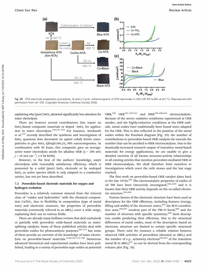
This journal is © The Royal Society of Chemistry 2022 Chem. Soc. Rev., 2022, 51, 4583–4762 | 4623
explaining why (pure) SnO2 attracted significantly less attention forwater electrolysis.
There are however several contributions that report onSnO2-based composite materials or doped –SnO2 for applica-tion in water electrolysis.550,555–559 For instance, Sreekanthet al.559 recently described the synthesis and investigation ofSnO2 quantum dots decorated on spinel cobalt ferrite nano-particles to give SnO2 QDs@CoFe2O4 NPs nanocomposites. Incombination with Ni foam, this composite gave an average-active water electrolysis anode for alkaline OER (Z = 290 mV;j = 10 mA cm�2; 1.0 M KOH).
However, to the best of the authors’ knowledge, waterelectrolysis with reasonably satisfactory efficiency, which ispromoted by a solid (pure) SnO2 electrode or by undopedSnO2 as active species which is only adapted to a conductivecarrier, has not yet been described.
7.2 Perovskite-based electrode materials for oxygen andhydrogen evolution
Perovskite is a relatively common mineral from the mineralclass of ‘‘oxides and hydroxides’’ with the chemical composi-tion CaTiO3. Due to flexibility in composition (type of metalions) and electronic structure, the properties of perovskitematerials (commonly referred to as ABO3) cover a wide range,explaining their use in various fields.
There are already many brilliant reviews that deal exclusivelyor partially with perovskite oxide-based materials as water-splitting catalysts. Some of these published articles deal withperovskite oxides for photocatalysis purposes560–571 but someof them provide an overview of the knowledge of water electro-lysis on perovskite-based materials.24,86,451,572–589 Numerousadvanced theoretical and experimental studies have been pub-lished, leading to a variety of perovskite-type oxides as potential
ORR,590 OER591–597,611 and HER598–600,619 electrocatalysts.Because of the severe oxidative conditions experienced at OERanodes, and the highly-reductive conditions at the HER cath-ode, metal oxides have traditionally been found more adaptedfor the OER. This is also reflected in the position of the metaloxides within the Pourbaix diagram (Fig. 29): the number ofcontributions to perovskite-based OER catalysts far exceeds thenumber that can be ascribed to HER electrocatalysis. Due to thedrastically-increased research output of transition metal-basedmaterials for energy applications, we are unable to give adetailed overview of all known structure-activity relationshipsor all existing articles that mention perovskite-mediated OER orHER electrocatalysis. We shall therefore limit ourselves toinvestigations which cover the mile stones and the last stagereached.
The first work on perovskite-based OER catalyst dates backto the late 1970s.601 The electrocatalytic properties of oxides of3d TM have been intensively investigated,602,1309 and it isknown that their OER activity depends on the so-called electro-nic structure.603,604
Various factors of the electronic structure have been used asdescriptors for the OER efficiency, including features (energy,filling and width) of the electronic states,605 the M-O coordina-tion state,606,607 covalent part of the TM–O bond,608 and thenumber of electrons with specific symmetry.609 Such descrip-tors enable predicting their efficiency. Due to the structuraldifferences of metal oxides, most of the descriptors based onelectronic structure are limited to certain specific structuralgroups. There exist for instance a reliable relation betweenobserved OER activities of perovskites (denoted as ABO3) andthe number of e.g., symmetry electrons610,665 of the transitionmetal (B in ABO3)611 as can be derived from the correspondingvolcano plot (Fig. 30).
Fig. 28 NTA electrode preparation procedures. (b and c) Cyclic voltammograms of NTA electrodes in 100 mM KPi buffer at pH 7.2. Reproduced withpermission from ref. 539. Copyright American Chemical Society 2018.
Chem Soc Rev Review Article
Publ
ishe
d on
16
May
202
2. D
ownl
oade
d by
MIT
Lib
rary
on
7/19
/202
2 10
:23:
58 P
M.
View Article Online

4624 | Chem. Soc. Rev., 2022, 51, 4583–4762 This journal is © The Royal Society of Chemistry 2022
On both sides of the volcano according to perovskites withtoo little/too much e.g., orbital occupancy, the too strong/weakinteraction with oxygen species is responsible for a lower OERactivity. At the top of the volcano, perovskites with eg fillingclose to unity plot exhibit appropriate binding with reactionintermediates and high OER performance.
Moreover, it was shown that the perovskite family with itschemical tunability of various substituting metals can exhibitexcellent catalytic performance.611
In perovskite oxides (ABO3; Fig. 31), the B site is occupiedwith smaller transition metal ions octahedral (corner shared)surrounded by oxygen (BO6 octaeders). The A position issuitable for larger ions (alkali metal or rare-earth) with 12-fold coordination. On the surface the exposed B sites have BO5
coordination with the vertical oxygen removed, i.e., this geo-metry would bring the orbital splitting of eg and t2g states todistinct energy levels and this surface can be considered as theactive site.612 Synchronised eg electron filling can be disturbedby strong on-site coulomb repulsive interaction between
neighbouring eg orbitals which can be up to some extentcontrolled by introducing high-valence transition metal- or rareearth ions.613 Especially for double perovskite (AA0)B2O6 orA(BB0)O6 the eg orbital filling and thus also the OER propertiescan be changed in a targeted manner by substitution at certainpositions.591,614
Up to now a high number of reasonable- and highlyactive perovskite-based OER electrocatalysts have beendeveloped.613,615–619
Typically, perovskites are accessible via conventional synth-esis methods like for instance high temperature solid statereactions with stoichiometric amounts of solid starting materialssynthesis, sol–gel process and high-pressure synthesis. Perovs-kites synthesised this way are usually characterised by largeparticle sizes, small surface area (typically below 4 m2 g�1)combined with good intrinsic OER activity.620–625 Suntivic andShao-Horn611 described a strategy for rationally-designingperovskite-based materials for OER: Ba0.5Sr0.5Co0.8Fe0.2O3�d(BSCF) catalyses the OER with intrinsic activity that is at leastan order of magnitude higher than that of the state-of-the-artiridium oxide catalyst in alkaline media.611 The intrinsic OER
Fig. 30 Relation between observed OER activities of perovskites (ABO3)and the number of eg symmetry electrons of the transition metal (B inABO3). Reproduced with permission from ref. 611. Copyright AAAS 2011.
Fig. 31 Schematic structure of CaTiO3 perovskite. Reproduced withpermission from ref. 580. Copyright Wiley 2019.
Fig. 29 Pourbaix diagrams (potential-pH) calculated for the nickel/water and cobalt/water system. Reproduced with permission from ref. 577. CopyrightWiley 2018.
Review Article Chem Soc Rev
Publ
ishe
d on
16
May
202
2. D
ownl
oade
d by
MIT
Lib
rary
on
7/19
/202
2 10
:23:
58 P
M.
View Article Online

This journal is © The Royal Society of Chemistry 2022 Chem. Soc. Rev., 2022, 51, 4583–4762 | 4625
activity of the investigated binary-, ternary-, quaternary- andpentanary oxides strictly depends on the occupancy of the 3delectron with an eg symmetry of surface transition metal cationsin an oxide leading to a volcano-shaped (electronic) structure-activity relationship.611 In an update Shao-Horn et al. examinedthe performance of 14 descriptors of the metal-oxygen bondstrength using statistical approaches;626 they divided thesedescriptors into five groups and identified electron occupancyand metal-oxygen covalency as the dominant influences on theOER activity. Durability and performance of perovskites uponOER electrocatalysis have been studied in detail: some of theperovskites are leached by either A or B metal cations andsurface amorphisation subject to OER conditions.627,1773,1781
A strategy that aims in improving the overall OER activity isbased on increasing the specific surface area and the surface-to-volume ratio by reducing the particle size (down to nm dimension)without compromising the morphology (porosity).628 Nano-scaledperovskites have been accessible by fine adjustment of synthesisconditions of wet chemical routes (sol–gel processes,629–632 hydro-thermal procedures.628 Nano-scaled perovskites have been accessibleby fine adjustment of synthesis conditions of wet chemical routes(sol–gel processes,629–632 hydrothermal procedures633–641) depositionapproaches (chemical precipitation642–652 physical-,653–657 orchemical vapor deposition,658–660 electrodeposition617,661–663),electrospinning,664–667 and template-based approaches.668–679
Nanorods comprising SNCF are also accessible upon a facileelectrospinning method (Fig. 32) and showed very good bifunc-tionality (HER + OER) with respect to water electrolysis(1.68 V cell voltage; j = 10 mA cm�2; 0.1 M KOH).619
In addition to controlling the particle size of the synthesisproduct while the synthesis is actually being carried out, top-down approaches to generate small particles using mechanical
grinding of bulk materials represent an alternative route tosmall particles.618,680
Notably; reducing size dimensions to nm scale does notsimply increase the surface to volume ratio but can lead tonovel physical properties and make nano-sized perovskitedifferent from their bulk counterparts.665,681
Many composite materials developed as potential water-splitting electrocatalysts bear perovskite as the active electro-catalytic phase. Park et al. reported on the synthesis and propertiesof an electrospun graphene oxide-based composite, baringLa0.5Sr0.5Co0.8Fe0.2O3 perovskite nanorods as a catalytically-activephase and exhibiting bifunctional properties for oxygen evolution(Z = 570 mV at j = 15 mA cm�2) and oxygen reduction667 (Fig. 33).
Non-noble element-containing perovskites need not shyaway from a comparison with highly established and highly-activePGM-containing water splitting electrocatalysts like e.g., IrO2. Chenet al. synthesised nano-scaled oxygen-deficient BaTiO3�x perovskitesby sol–gel-based chemistry630 and obtained a reasonable activebifunctional (OER + ORR) electrocatalyst: at relatively low over-potentials (Z o 370 mV), it proved more efficient than IrO2 forOER in 0.1 M NaOH.630
In recent years the OER performance of perovskite-based elec-trode materials was enormously improved.596,682–684 A heterostruc-tured catalyst comprising La0.5Sr0.5CoO3�d (LSC) perovskite as theOER active part and K+ bonded molybdenum diselenide (K-MoSe2)as the active HER part was very recently shown by Oh et al.684
The LSC/K-MoSe2 system characterises the multidirectionalcharge transfer phenomenon, with a two-way charge transferfrom K to MoSe2 and from LSC to MoSe2 (Fig. 34a and b), whichis claimed to be responsible for the good (full-) water electro-lysis performance (1.75 V cell voltage; j = 50 mA cm�2;1 M KOH).
Fig. 32 (a) ABO3 perovskite structure. (b) Schematic illustration of the preparation process of SNCF-NR by electrospinning. (c) Scanning electronmicroscopy (SEM) image of as-spun precursory polymer nanofibers before calcination. (d and e) Low/high-magnification SEM images of SNCF-NR. (f)Refined XRD pattern of SNCF-NR. Observed (purple circles), calculated (red solid line), and differences (orange line, bottom) are presented. Reproducedwith permission from ref. 619. Copyright Wiley 2017.
Chem Soc Rev Review Article
Publ
ishe
d on
16
May
202
2. D
ownl
oade
d by
MIT
Lib
rary
on
7/19
/202
2 10
:23:
58 P
M.
View Article Online
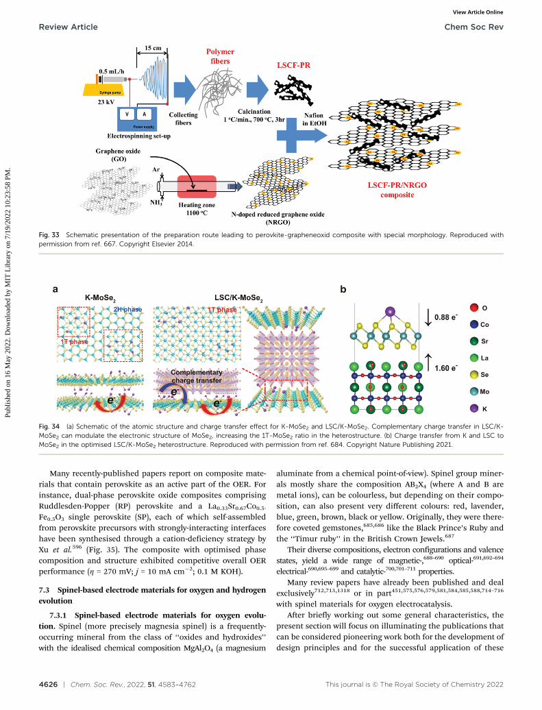
4626 | Chem. Soc. Rev., 2022, 51, 4583–4762 This journal is © The Royal Society of Chemistry 2022
Many recently-published papers report on composite mate-rials that contain perovskite as an active part of the OER. Forinstance, dual-phase perovskite oxide composites comprisingRuddlesden-Popper (RP) perovskite and a La0.33Sr0.67Co0.5-
Fe0.5O3 single perovskite (SP), each of which self-assembledfrom perovskite precursors with strongly-interacting interfaceshave been synthesised through a cation-deficiency strategy byXu et al.596 (Fig. 35). The composite with optimised phasecomposition and structure exhibited competitive overall OERperformance (Z = 270 mV; j = 10 mA cm�2; 0.1 M KOH).
7.3 Spinel-based electrode materials for oxygen and hydrogenevolution
7.3.1 Spinel-based electrode materials for oxygen evolu-tion. Spinel (more precisely magnesia spinel) is a frequently-occurring mineral from the class of ‘‘oxides and hydroxides’’with the idealised chemical composition MgAl2O4 (a magnesium
aluminate from a chemical point-of-view). Spinel group miner-als mostly share the composition AB2X4 (where A and B aremetal ions), can be colourless, but depending on their compo-sition, can also present very different colours: red, lavender,blue, green, brown, black or yellow. Originally, they were there-fore coveted gemstones,685,686 like the Black Prince’s Ruby andthe ‘‘Timur ruby’’ in the British Crown Jewels.687
Their diverse compositions, electron configurations and valencestates, yield a wide range of magnetic-,688–690 optical-691,692–694
electrical-690,695–699 and catalytic-700,701–711 properties.Many review papers have already been published and deal
exclusively712,713,1318 or in part451,575,576,579,581,584,585,588,714–716
with spinel materials for oxygen electrocatalysis.After briefly working out some general characteristics, the
present section will focus on illuminating the publications thatcan be considered pioneering work both for the development ofdesign principles and for the successful application of these
Fig. 33 Schematic presentation of the preparation route leading to perovkite-grapheneoxid composite with special morphology. Reproduced withpermission from ref. 667. Copyright Elsevier 2014.
Fig. 34 (a) Schematic of the atomic structure and charge transfer effect for K-MoSe2 and LSC/K-MoSe2. Complementary charge transfer in LSC/K-MoSe2 can modulate the electronic structure of MoSe2, increasing the 1T-MoSe2 ratio in the heterostructure. (b) Charge transfer from K and LSC toMoSe2 in the optimised LSC/K-MoSe2 heterostructure. Reproduced with permission from ref. 684. Copyright Nature Publishing 2021.
Review Article Chem Soc Rev
Publ
ishe
d on
16
May
202
2. D
ownl
oade
d by
MIT
Lib
rary
on
7/19
/202
2 10
:23:
58 P
M.
View Article Online

This journal is © The Royal Society of Chemistry 2022 Chem. Soc. Rev., 2022, 51, 4583–4762 | 4627
design principles to water oxidation, i.e., work that deals withfascinatingly-active and stable OER electrocatalysts. In addi-tion, very current, promising results will be highlighted.
In an AB2X4 spinel metal A ions (in +2 or +4 oxidation state)occupy the centers of tetrahedral-coordinated positions, metalB ions (in +3 or +2 oxidation state) occupy the centers ofoctahedral coordinated positions, and the anion (e.g., O2�) islocated at the polyhedral vertexes (for normal spinels seeFig. 36a). The tetrahedral spaces are usually smaller than theoctahedral ones. Cations with smaller radii preferentiallyoccupy the A sites, while larger cations preferentially occupythe B sites.
One type of cation may occupy different positions, i.e.,tetrahedral and octahedral interstices. Depending on theirdistribution, spinels are therefore distinguished into threeclasses: normal, inverse (Fig. 36a and b)717 and complex spinelsIn normal spinels AB2X4, cations A solely occupy octahedralcenters and B tetrahedral centers. This is valid for the ‘‘originaltype of spinel’’ MgAl2O4. For inverse spinels (B(AB)X4), half ofthe B cations occupy tetrahedral positions and the remaininghalf, the octahedral-coordinated centers: MgGa2O4 or NiFe2O4
are typical representatives’ inverse spinels (Fig. 36b). Incomplex spinels, both sort of metal ions partially occupies boththe tetrahedral and octahedral interstices: CuAl2O4 is an exam-ple of complex spinel.
Defects are crucial to the spinel’s properties, and in parti-cular can significantly increase their catalytic activity.709,718–721
Like perovskites, spinels are an important class of widelyavailable,722 thermodynamically stable,723 relatively cost- and
environmental-friendly724 OER electrocatalysts with a well-knowngood efficiency.709 Spinels are accessible via a number of methods:high-temperature solid-phase synthesis starting from metals,metal oxides, -halides, hydroxides or other salts;725 spraypyrolysis;706 vapor phase methods at lower temperature;726,727
low-temperature methods are also feasible, like solution phase(sol–gel, hydrothermal- or solvothermal-) approaches721,728–732
or wet-deposition-based techniques like e.g. electrodeposition,733
electrospinning,702,734,735 or dip-coating.736
Landon et al.736 reported on the synthesis of spinel-phasebased Fe–Ni Oxides with different Ni to Fe ratio by using threedifferent synthesis strategies: evaporation-induced self-assembly, hard templating and dip-coating (sample names =EISA, hard template and Ni mesh, respectively). Regardless ofthe selected synthesis method, the Ni–Fe oxide catalysts com-prising a mixed NiO/NiFe2O4 phase exhibited substantially
Fig. 36 Normal and inverse spinel structures. (a) MgAl2O4 normal and (b)MgGa2O4 inverse ground state atomic configurations. In each case theunit cell is shown by solid black lines. Octahedral and tetrahedral atomiccoordination environments are also identified by the coordination poly-hedra in each case. Reproduced with permission from ref. 717. CopyrightNature Publishing 2020.
Fig. 37 (a) Electrochemical oxygen evolution activity at a fixed over-potential of 360 mV for the varying synthesis methods and compositionsof mixed metal oxide electrocatalysts. (b) Geometric area-normalisedpolarisation (scan rate = 1 mV s�1) data of mixed Ni–Fe oxide catalysts(synthesised by the EISA method) showing the highest activity for 10 mol %Fe oxide. Reproduced with permission from ref. 736 Copyright AmericanChemical Society 2012.
Fig. 35 Design of RP/SP composites. Schematic for the RP/SP compo-sites showing RP and SP phase crystal structures. The unit cell of the SPstructure is duplicated along the c-axis, to suggest a difference in thematerial’s dimensionality, that is, 2D for RP versus 3D for SP. Reproducedwith permission from ref. 596. Copyright Wiley 2021.
Chem Soc Rev Review Article
Publ
ishe
d on
16
May
202
2. D
ownl
oade
d by
MIT
Lib
rary
on
7/19
/202
2 10
:23:
58 P
M.
View Article Online

4628 | Chem. Soc. Rev., 2022, 51, 4583–4762 This journal is © The Royal Society of Chemistry 2022
higher activity than pure oxides, the activity peaking near 10mol% Fe (Fig. 37a). Reasonable OER activities, although notcompetitive to recently-developed OER electrocatalysts wereshown (Z = 440 mV; j = 2 mA cm�2; 1 M KOH; Fig. 37b).
Crystalline and amorphous films of Co3O4 are accessible viaa low-temperature route comprising electrodeposition, e.g., onstainless steel. Koza et al.733 demonstrated convincing overallOER properties of such steel-supported spinel films (Z = 400 mVat j = 10 mA cm�2; pH = 13; Fig. 38).
The high-temperature solid-state method is useful for large-scale applications, but requires long reaction times.737 In general,all synthesis strategies allow creating defects in spinel structuresusing specific settings for the respective synthesis method.738–740
All processes discussed so far are also suitable to produce spinel-based nanoparticles,721,730,731,741 whereas vapor-phase processesare particularly suited to synthesise 2d-structured materials.726 Inview of their practical application in real water electrolysers, thevast majority of recently published papers in the field of spinel-based water electrocatalysis rely on nanocrystalline systems,727 e.g.generated via sol–gel-based methods742–746 as demonstrated byChakrapani et al. who synthesised uniform and highly dispersedCoV2�xFexO4 (x = 0–2) spinel nanoparticles703 (Fig. 39).
However, it was found that well-dispersed spinel-structurednanoparticles are also accessible by hydrothermal synthesisusing additional surfactants such as ethylenediamine,731 poly-vinylpyrrolidone and polyethylene glycol,747 cetyltrimethylam-monium bromide or ethanol748 or upon solvothermal routes749
based on e.g. dimethylforamide (DMF),749,750 alcohols102,751 orpolyethylenglycole.752 Although even highly faceted nano-particles can be elaborated via template-free hydrothermalapproaches753 the exploitation of hard-672 or soft templates754
still represents the method of choice, when regularly-shapednanoparticles are desired.
In addition, spinel-based nano-scaled materials are accessibleby precipitation- based strategies755–757 or upon an oxidation-precipitation routes.707 The precipitation route might beexpanded by templates: transition metal (e.g. Fe) hydroxidescan be precipitated in alkaline solution; if Al3+ is simultaneouslypresent in solution Al(OH)3 is precipitated as well, which inprinciple allows the generation of mesoporous spinel oxides viathis hard template-based strategy.758 In general, porous struc-tures are available via the usage of templates754,759 or areaccessible by carbonate and oxalate-based precipitants, whichwill form CO2 upon thermal decomposition.760,761 Small (20 oparticle size o 30 nm) but agglomerated cobalt manganese(CoMnO) spinels have been synthesised via a solution-oxidation-precipitation route.707 The tailored generation of cubicand tetragonal-phase material was achieved by simply reorderingthe addition of Co2+ and Mn2+-containing metal salts in theoxidation/precipitation step (Fig. 40). A hybrid material compris-ing carbon-supported CoMnO spinel particles synthesised thisway exhibied reasonable alkaline OER activity (Z = 500 mV; j =10 mA cm�2, pH 13), though the use of carbon as a conductiveadditive presents issue in terms of long-term durability (it willirremediably corrode upon OER) and may bias the OER activitymeasurement as shown by Poux et al. for perovskite oxidesduring ORR-OER.762
Cheng et al. introduced a particular synthesis route whichtakes advantage of oxidation and precipitation to generate aMn-based spinel precursor, followed by reduction and renewedprecipitation (reduction-recrystallisation route).763 Dependingon the type of reducer (NaH2PO4 or NaBH4) cubic-phase-(CoMnO-P) or tetragonal-phase CoxMn3�xO4 (CoMnO-B) wasobtained (Fig. 41). The OER activity of electrodes prepared with
Fig. 38 Plot of the overpotential as a function of time at current densitiesof 10 mA cm�2 (black) and 100 mA cm�2 (red) measured in 1 M KOH forfilms deposited at 50 1C (dashed lines) and 103 1C (full lines). Reproducedwith permission from ref. 733. Copyright American Chemical Society 2020.
Fig. 39 High-resolution images of spinel-type CoV2–xFexO4 (x = 0–2) nanoparticles: (A) CoFe2O4, (B) CoFeVO4, and (C) CoV2O4. Reproduced withpermission from ref. 703. Copyright American Chemical Society 2018.
Review Article Chem Soc Rev
Publ
ishe
d on
16
May
202
2. D
ownl
oade
d by
MIT
Lib
rary
on
7/19
/202
2 10
:23:
58 P
M.
View Article Online

This journal is © The Royal Society of Chemistry 2022 Chem. Soc. Rev., 2022, 51, 4583–4762 | 4629
the CoMnO-B-based spinels exhibited reasonable catalytic activity(Z = 635 mV at j = 2.5 mA cm�2; pH = 13). DFT calculations providedinsight into the capability of the material towards oxygen adsorption,a usual descriptor of ORR activity. OER being the reverse process of
the ORR, one predicts that the tetragonal material should providehigher OER activity, in agreement with experimental finding.
Bajdich et al. performed an in-depth evaluation of theactivity of spinel-phase cobalt oxides which covers (i) the
Fig. 40 Schematic synthesis of cubic (a) and tetragonal (b) spinel phases, involving two steps of oxidation precipitation and crystallisation. Reproducedwith permission from ref. 707. Copyright Nature Publishing 2015.
Fig. 41 Structural analysis of the synthesised nanocrystalline spinels. (a and b) Rietveld- refined XRD patterns of CoMnO-B (a) and CoMnO-P (b) withexperimental data (red dots), calculated profiles (black line), allowed Bragg diffraction positions (vertical bars) and difference curve (blue line). (c and d)Schematic representation of tetragonal (c) and cubic (d) spinels. Reproduced with permission from ref. 763. Copyright Nature Publishing 2015.
Chem Soc Rev Review Article
Publ
ishe
d on
16
May
202
2. D
ownl
oade
d by
MIT
Lib
rary
on
7/19
/202
2 10
:23:
58 P
M.
View Article Online

4630 | Chem. Soc. Rev., 2022, 51, 4583–4762 This journal is © The Royal Society of Chemistry 2022
determination of the stability (under anodic electrode conditions) –and (ii) of the OER activity of selected surfaces in bulk material.711
The investigations resulted in a calculated Pourbaix diagram clearlyunmasking b-CoOOH as the OER catalytic active phase for alkalinewater electrolysis; its OER activity can be enhanced by surfacesubstitution of Co by Ni (Fig. 42), as experimentally confirmed bythe well-known highly-active NiyCo1�yOx.
As with perovskites,611 descriptors for oxygen electrocatalysis(ORR + OER) have also been developed for spinels.704 ForMnCo2O4 species with different electronic structures, the Mnin octahedral centers is identified as the active site. Plotting theORR/OER activity against the Mn valence state in octahedralsite, results in a volcano curve, whose summit locates at the Mnvalency of B+3. This finding was transferred to other transition-metal-spinels and the active cation eg occupancy in octahedral
sites was found the dominating descriptor for spinels ORR/OERactivity as well (Fig. 43).
Several strategies to improve the electrocatalytic propertiesof spinel electrocatalysts have been considered, including fine-tuning the phase and composition (doping of well-known spinelswith metal ions or the combination of spinels with other com-pounds in a hybrid material strategy)764–771,1324), the introductionof core–shell architectures or general crystal engineering on thenano- or micron-scale.772–778 In one of these exciting works, Bellet al.771 showed how metals like Au, Pt, Pd, Cu, Co can be used toenhance the OER activity of metal oxides (Co3O4 in this study). Theelectrochemical activity is influenced by the increase in the Co(IV)proportion following the increased oxidation of cobalt oxide bygold (Au has greater electronegativity than Pt or Pd).
Latest efforts aimed in further incrementing the activity ofspinel-based OER electrocatalysts.779–785 A nano-scaled oxidehybrid material comprising CoFe2O4 spinel modified by CeO2
(CeO2@CoFe2O4) displayed outstanding OER activity in 1 MKOH: a very low overpotential (Z = 213 mV) was enough to reachj = 100 mA cm�2.780 A strategy to increase the number ofoctahedral OER active sites on the surface of spinel oxideswas recently shown by Yue et al.:784 a solid solution comprisingMoFe2O4 and CoFe2O4 nanosheets supported on iron foam wassynthesised through a hydrothermal route + annealing step(Fig. 44a–c). Additional cation vacancies induced by oxidationof Mo led to cations filling into unoccupied octahedral inter-stices (cationic misalignment) and to high occupation of octa-hedral sites, hence to an increased number of OER activesites. The OER activity of the material is convincing, with j =250 mA cm�2 at E = 1.49 V vs. RHE in 1 M KOH (Fig. 44d).
7.3.2 Spinel-based electrode materials for hydrogen evolution.As Section 7.2 mentions, metal oxides are traditionally moreresistant in OER than in HER condition. Pure binary spinel-based oxides (not specifically treated) either lack of sufficientactivity or durability for HER electrocatalysis.786,787 It is there-fore understandable that in early studies spinel-based oxideswere clearly assigned the role of the oxygen-evolving electrode inwater electrolysis experiments.788
Fig. 42 (a) 2D map of theoretical overpotentials Z for the doped 10%14 surface of b-CoOOH as function of DGO � DGOH and DGOH. The individual valuesof Z are indicated in brackets. Improvement in activity relative to undoped surface is obtained in the case of Ni with Z = 0.36 V and Fe with 0.43 V.Reproduced with permission from ref. 711. Copyright American Chemical Society 2013.
Fig. 43 OER activity on various spinels as a function of eg occupancy ofthe active element at octahedral site. Reproduced with permission fromref. 704. Copyright Wiley 2017.
Review Article Chem Soc Rev
Publ
ishe
d on
16
May
202
2. D
ownl
oade
d by
MIT
Lib
rary
on
7/19
/202
2 10
:23:
58 P
M.
View Article Online

This journal is © The Royal Society of Chemistry 2022 Chem. Soc. Rev., 2022, 51, 4583–4762 | 4631
10–20 years ago, spinel-based materials were investigated fortheir photocatalytic properties to promote hydrogen evolution.789,790
Thus, for years, the trend was to use complex spinels for HERelectrodes.
Ternary Copper-cobalt-oxide spinels (CuxCo3�xO4) weretested for OER and HER under close-to-real industrial waterelectrolysis conditions ( j = 1 A cm�2; 1.0 M NaOH):787 (i) dopingof Co3O4 with copper significantly increased the coating con-ductivity (maximum at x = 0.3), (ii) accelerated life test showedlarger durability of electrodes with x = 0.3 (cathode life = ca.518 h, versus 190 h for Co3O4).
Zhu et al. reported astonishing HER activity (Z = 400 mV; j =400 mA cm�2) for Co3O4 microtube arrays (Co3O4-MTA) thateven outperformed the HER activity of Pt/C.791 However, neverbefore and never again afterwards could Co3O4 be attested tosuch a high level of activity. One notices that the electrocatalyticHER testing was carried out with a Pt counter-electrode.Obviously, during the HER experiments (continuous cyclic vol-tammetry scanning for 2000 cycles in aggressive medium:1 M KOH) Pt from the counter-electrode could have beentransferred to the working electrode.1269 So, these experiments
should ;be reproduced/verified, with the nature of the counter-electrode and cell geometry more compatible to bestpractices.792,1744
All spinel-based materials (M3O4) that proved efficient andstable HER electrodes are altered by doping,789,793–799 or areotherwise modified spinels e.g., hybrid materials that containpure spinel M3O4 (binary metal oxides)800 besides another e.g.,inorganic compound or contain or represent more complexspinels e.g. AB2X4.801–806
Peng et al. studied a spinel-based nanowire electrode systemfor full water electrolysis.796 NiCo2O4 nanowires, subjected tosulphuration to yield Ni0.33Co0.67S2 nanowires (Fig. 45), showedgood alkaline HER performance (Z = 100 mV, j = 10 mA cm�2,pH 14). However, upon sulphuration, NiCo2O4 loses its spinelstructure and the pyrite structure can be assigned to Ni0.33Co0.67S2.
In 2018, complex spinel transition metal oxides (TMO’s suchas NiCo2O4, CoMn2O4 or NiMn2O4) with a multi–shell hollowstructure (necklace-like) were introduced, which were reducedwith NaBH4 in aqueous solution (Fig. 46).797 The reductiontreatment contributed to their bifunctionality and resulted inreasonable OER alkaline activity (Z = 250 mV; j = 10 mA cm�2)
Fig. 44 (a) Scheme of synthesis route for MCFO NS/IF. (b and c) XRD patterns of MCFO NS/IF, MFO NS/IF and CFO NP/IF. (d) The chronoamperometricplot of OER on MCFO NS/IF at 1.49 V versus RHE in 1.0 M KOH for 1000 h (25 1C). Reproduced with permission from ref. 784. Copyright Wiley 2021.
Chem Soc Rev Review Article
Publ
ishe
d on
16
May
202
2. D
ownl
oade
d by
MIT
Lib
rary
on
7/19
/202
2 10
:23:
58 P
M.
View Article Online

4632 | Chem. Soc. Rev., 2022, 51, 4583–4762 This journal is © The Royal Society of Chemistry 2022
and good HER activity (Z = 300 mV; j = 200 mA cm�2) combinedwith good durability in 1 M KOH.
Insertion of non-metals like S, P into transition metal-basedspinels has become an established strategy to improve theirHER electrocatalytic properties.799,800,807–809 Wang et al.799 alsodemonstrated that P-doping of Co3O4 spinel leads to improvedOER activity (Z = 260 mV; j = 20 mA cm�2) paired with good HERactivity (Z = 140 mV; j = 100 mA cm�2) in 1 M KOH.
Muthurasu et al. recently presented a hybrid material com-prising Co3O4/MoS2 heterostructure capable to act as anodeand cathode in alkaline water electrolysis.800 An OER current
density of j = 20 mA cm�2 was obtained at Z = 230 mV (HER: Z =205 mV, j = 10 mA cm�2) in 1 M KOH. Williamson et al. recentlyreported the synthesis of small thiospinel CoNi2S4 nanocrystalswith an average size of 4.8–10.7 nm.810
Among spinel-structured NiCo2O4, NiCo2S4 and NiCo2Se4,NiCo2Se4 was found to demonstrate higher oxygen and hydro-gen evolution reaction activities (245 mV and 122 mV for j =10 mA cm2) respectively) compared to those of NiCo2O4 andNiCo2S4.809
Oxygen-defect density is a useful control tool to adjust theelectrocatalytic properties that are relevant for water splitting.811
The work covers multi pH water-splitting (alkaline-, neutral andacidic pH) and in addition seawater electrolysis. CoFe2O4 NPshave been generated by precipitation and the as-preparedmaterial (AP-CoFe2O4) was calcinated at 350 1C, 550 1C and650 1C (samples CoF-1, CoF-2 and CoF-3), which resulted in anincrease of the particle size from 8 nm (AP-CoFe2O4), 10 nm,20 nm and 55 nm (samples CoF-1, CoF-2 and CoF-3; Fig. 47).Sample CoF-2 showed the best intrinsic HER activity (Z =218 mV, j = 10 mA cm�2) for water electrolysis carried out atpH 14 (Fig. 48).
In summary, spinel-based materials are more predestined toact as oxygen-evolving electrodes than as hydrogen-evolvingelectrodes (a large number of papers are dedicated to spinel-structured materials for the OER), which stems from theintrinsically-larger oxide materials stability in oxidising (OER)than in reducing (HER) conditions. However, recent effortsclearly show that, upon suitable design strategy based on e.g.,oxygen vacancy engineering to increase the density of catalyticactive sites or doping that may end in better electrical con-ductivity, highly active and durable spinel structured HERelectrocatalysts can also be achieved.
Fig. 45 Schematic illustration of the synthesis of NiCo2O4 andNi0.33Co0.67S2 nanowires, and the utilisation of these homologous Ni–Cobased nanowires as OER and HER catalysts for water splitting. Reproducedwith permission from ref. 796. Copyright Wiley 2015.
Fig. 46 (a) Schematic illustration of the formation process of R-TMO with a necklace-like multishelled hollow structure for water splitting. (I) Theabsorption of metal ions on the carbon, (II) calcination of the absorbed carbon, and (III) reduction of the TMO to obtain R-TMO with a necklacelikemultishelled hollow structure. (b) Schematic illustration of creating oxygen vacancy defects on the surface of NCO after reduction. Reproduced withpermission from ref. 797. Copyright American Chemical Society 2018.
Review Article Chem Soc Rev
Publ
ishe
d on
16
May
202
2. D
ownl
oade
d by
MIT
Lib
rary
on
7/19
/202
2 10
:23:
58 P
M.
View Article Online

This journal is © The Royal Society of Chemistry 2022 Chem. Soc. Rev., 2022, 51, 4583–4762 | 4633
7.4 Transition metal layered double hydroxide OER catalystsfor alkaline electrolytes
Late 3d transition metal-based (Ni, Fe, Co, Mn) hydroxides andoxyhydroxides (generally indicated in the following as (oxy)-hydroxides) comprise highly active catalysts for the OER in
alkaline and neutral pH electrolytes.812 Besides their directsynthesis, surface reconstruction of metal or metal oxide nano-particles and electrodes in alkaline electrolyte might also resultin formation of surface metal oxyhydroxides acting as the OERcatalysts (see for example the section related to OER on steels,
Fig. 47 (a) Schematic illustration of the formation of AP-CoFe2O4 through the coprecipitation method followed by thermal treatment under N2 toobtain CoF-1, CoF-2, and CoF-3. (b) Field-emission (FE) SEM image of AP-CoFe2O4. (c) XRD patterns of CoF-1, CoF-2, and CoF-3 NPs. Reproduced withpermission from ref. 811. Copyright Wiley 2020.
Fig. 48 (a) LSV polarisation curves for the HER. (b) Overpotential values reach a current density of 10 mA cm�2. (c) Tafel and (d) Nyquist plots of CoFe2O4
NPs for the HER recorded at 0.4 V versus RHE. (e) Chronoamperometric stability test for CoF-2 performed at 0.35 V versus RHE. Inset shows the LSVpolarisation curves before and after stability tests. (f) Experimental and theoretical gas evolution at 0.764 V versus RHE for the HER of CoF-2. Reproducedwith permission from ref. 811. Copyright Wiley 2020.
Chem Soc Rev Review Article
Publ
ishe
d on
16
May
202
2. D
ownl
oade
d by
MIT
Lib
rary
on
7/19
/202
2 10
:23:
58 P
M.
View Article Online

4634 | Chem. Soc. Rev., 2022, 51, 4583–4762 This journal is © The Royal Society of Chemistry 2022
the surface of which can be close to (oxy)hydroxides). For thisreason and the very high activity reported for some of thesecatalysts (Table 9), they represent an interesting area ofresearch for both fundamental insights into the OER mecha-nism and practical application as anode catalysts in waterelectrolysers.
7.4.1 Crystal structure of single-metal based (oxy)hydroxideOER catalysts. Single-metal based (oxy)hydroxides, while notbeing among the most active OER catalysts within this materialfamily, provide the basis on which more complex and activemultinary (oxy)hydroxides can be designed. Therefore, their studyis important to provide fundamental insights and guide therational design of improved catalysts. Among them, Ni hydro-xides can be prepared in the crystalline brucite-like b-phase, b-Ni(OH)2, which is characterised by layers of edge-sharing octahe-dra, where the metal atoms occupy the center of the octahedraand OH groups the corners. Co hydroxides can also be synthe-sised in this structure (b-Co(OH)2). In addition, other phases havebeen reported, i.e., water intercalated Ni(OH)2 (a-phase) andothers characterised by various types of defects and turbostraticdisorder. Ni oxyhydroxide phases, i.e., anhydrous b-NiOOH andwater and cation intercalated g-NiOOH, form under appliedanodic potentials. Co hydroxides also transform to the oxyhydr-oxide phase (b-CoOOH) under applied anodic potentials. There-fore, for these two families of catalysts the as-prepared hydroxidephases are not the catalytically-active phases for OER, whichtypically occurs at higher potentials than the oxidation of themetal centres from 2+ to higher oxidation states (i.e. B1.4 Vand B1.1 V vs. RHE for Ni(OH)2 and Co(OH)2, respectively). Fecenters with 2+ oxidation state being unstable in oxygenenvironment, Fe oxyhydroxides are typically obtained insteadof Fe hydroxides (Fe2+Fe3+ layered double hydroxide, alsoknown as ‘‘green rust’’, can be synthesised but is unstable inair). Atomic structures for Fe oxyhydroxides range widely fromdiaspore-type a-FeOOH,813 boehmite-type g-FeOOH and otherg-polymorphs,813 to b-FeOOH.814 Crystalline and amorphousmanganese oxides and oxyhydroxides (structural depictions ofwhich are displayed in Fig. 49) have been investigated foracidic, neutral, and alkaline water oxidation.815–819 Amongthe oxyhydroxide phases, manganite g-MnOOH showed bettercatalytic performance than other MnOx materials and consistsof corner-linked octahedra.820 Feitknechtite b-MnOOH has alsobeen observed as one of the components of an active multi-phase Mn-based electrocatalyst.821 g-MnOOH is the most stablepolymorph of MnOOH, however it was also observed duringOER to convert into MnO2 and deactivate, revealing a generalinstability issue for Mn oxyhydroxides.820
7.4.2 Crystal structure of binary and multiple transitionmetal (oxy)hydroxide OER catalysts. Introducing metal withoxidation states 3+ into a metal hydroxide host where the hostmetals are in oxidation states 2+, leads to the intercalation ofcharge-compensating anions and water in the region betweenthe brucite-like metal hydroxide layers. This structure, typical ofthe mineral hydrotalcite, is known as layered double hydroxide(LDH) crystal structure.812 Fig. 50 shows a comparison of thecrystal structure of b-Ni(OH)2 (Brucite) and of NiFe LDH.
Similarly, to Ni(OH)2, it was confirmed for NiFe and CoFeLDH that the prepared crystal structure (a-LDH) deprotonateunder potential control, transforming into a g-LDH phase,which is the catalytically active phase under OER822 and ischaracterised by contracted interlayer and intralayer atomicdistances and switching of intercalated anions to cations.
Ternary and multiple metal-based (oxy)hydroxides have alsobeen investigated, where the additional metals have beenintroduced as dopants into the synthesis of the binary metalLDHs,823 and by systematic compositional studies, for example,by high through-put methods.824,825 Selected examples arediscussed in the following section.
7.4.3 OER activity and stability trends among transitionmetal (oxy)hydroxides. The OER activity trend among the Ni,Fe, Co, Mn monometallic (oxy)hydroxides in alkaline electro-lytes that have been purified from Fe impurities reveals thatwhen Fe oxyhydroxides are deposited as ultrathin film or smallclusters on a conductive electrode, they show the highestactivity.826,827 Due to the poor electrical conduction of Feoxyhydroxides, the performance of these materials is severelyhindered with thicker electrodes.826 Co (oxy)hydroxides followin the activity trend, while pure Ni (oxy)hydrixides and Mn(oxy)hydroxides show the lowest activity. However, due todifferent metal dissolution rates, the stability trend was foundto be the opposite: NiOxHy 4 CoOxHy c FeOxHy.827
Fig. 49 Typical structures of selected Mn-oxides and oxyhydroxides.Reproduced with permission from ref. 820. Copyright ACS 2016.
Review Article Chem Soc Rev
Publ
ishe
d on
16
May
202
2. D
ownl
oade
d by
MIT
Lib
rary
on
7/19
/202
2 10
:23:
58 P
M.
View Article Online

This journal is © The Royal Society of Chemistry 2022 Chem. Soc. Rev., 2022, 51, 4583–4762 | 4635
A thorough purification of the alkaline electrolyte is impor-tant when benchmarking these catalysts, since trace amountsof Fe impurities in the electrolyte significantly enhances the activityof Ni-based and Co-based (oxy)hydroxides significantly.104,828 Con-sequently, Fe-activated Ni hydroxide catalysts and, in general,NiFe (oxy)hydroxides are among the most active OER electro-catalysts at alkaline pH (Fig. 51a). CoFe oxyhydroxides are alsomore active than Co oxyhydroxides.103 To evaluate the catalyticactivity of transition metal (oxy)hydroxides the OER overpoten-tials are typically compared at a fixed geometric current density,i.e., j = 10 mA cm�2 (different types of intrinsic activity metricswere proposed in the literature (see Section 7.2). However,determining the intrinsic activity for these catalysts is challenging,since the nature of the active sites is often unknown, and theirsurface concentration is also difficult to estimate due to roughsurface morphologies. This affects the calculation of turn overfrequencies (TOF). Also, the evaluation of the electrochemicalsurface area (ECSA) to calculate surface specific activities mustbe performed with care, since the electrical conductivity ofLDHs changes with the applied potentials829 resulting in anarrow or non-existing potential window that is free of faradaiccurrent in the conductive regime. This limits the range ofpotentials where certain electrochemical techniques can beapplied, such as the ones based on cyclic voltammetry orelectrochemical impedance spectroscopy (EIS). Furthermore,metal oxidation peaks in cyclic voltammograms often overlapwith the OER faradaic current and model catalysts with smoothplanar surfaces for the conversion of the calculated values, i.e.,capacitances, in the unit of an area are not always available.830
Recently, a method to calculate the ECSA based on the capaci-tance of the adsorbed OER intermediates (Ca), instead of themore commonly used double layer capacitance, was proposedfor a series of transition metal based LDH catalysts.831 Ca wascalculated by EIS at 1.6 VRHE, and normalised by the specificunit area capacitance that was obtained from a smooth Ni(OH)2
surface from ref. 832. This method surpasses most of thementioned limitations, providing surface-based intrinsic activitiesand calls for new experiments that provide specific unit areacapacitances for the different LDHs. The general intrinsic activitytrend was NiFe LDH 4 CoFe LDH 4 Fe-free Co-containingcatalysts 4 Fe-Co-free Ni-based catalysts (Fig. 51b).
In contrast to the activity, these catalysts stability has beenless systematically investigated. The most commonly per-formed stability tests range from short term stability tests (2hours) at low current densities of ( j = 10 mA cm�2)833 mostlyused for preliminary screening, to galvanostatic stability testsover longer time, for example hundreds of hours,834,835 as wellas at higher current densities (4100 mA cm�2).835,836 Chrono-amperometry measurements, for example at the applied cellpotential of 1.6 V,835 have been also used as well as protocolssimulating the natural day-night light cycle,835 and stabilitytests at higher temperatures (480 1C)837 and high KOH concen-tration (41 M).835,836 Most of these studies were performed onNiFe (oxy)hydroxide catalysts. At room temperature, stabilitytests of NiFe (oxy)hydroxide catalysts generally show very pro-mising results with the stability of dozens of hours, and insome cases even more. However, stability tests must be ran alsoat operation-relevant temperatures for alkaline electrolysers,i.e., B80 1C.838 Recently, Chung et al. extended to late 3dtransition metal (oxy)hydroxide catalysts a previously proposedmetrics called activity-stability factor (ASF)839 that takes intoaccount both activity and stability (Fig. 51c).827 This wasobtained by the evaluation of both the OER activity, in termsof current densities at 1.7 V vs. RHE, and the stability, as therates of metal dissolution. Finally, the ASF was calculated asactivity/stability ratio and expressed the amount of O2 that isproduced per dissolved active site. Ni-based and Co-based(oxy)hydroxide clusters that incorporated Fe, which were pre-pared by adding Fe nitrate to the electrolytes, showed higherASF than their Fe-free analogues. In these Fe-containing
Fig. 50 Typical structure of Brucite type Ni(OH)2 and hydrotalcite-like NiFe LDH. Reproduced with permission from ref. 812. Copyright Wiley 2016.
Chem Soc Rev Review Article
Publ
ishe
d on
16
May
202
2. D
ownl
oade
d by
MIT
Lib
rary
on
7/19
/202
2 10
:23:
58 P
M.
View Article Online

4636 | Chem. Soc. Rev., 2022, 51, 4583–4762 This journal is © The Royal Society of Chemistry 2022
catalysts the authors found higher Fe dissolution thanthe metal host dissolution, suggesting that the poor activityretention in Fe-free electrolytes was related to the dissolution of
Fe active sites. Finally, they suggested that Fe dissolution andelectrochemical re-deposition yields dynamically stable Feactive sites, providing a strategy for designing better catalysts.
In the following sections, we will focus mostly on Ni-based(NiFe) LDH and (oxy)hydroxide catalysts, which have been themost investigated in alkaline electrolytes, and on their activity(for their stability we refer to the discussion in this section).Later, selected results obtained with the other transition metalLDH and (oxy)hydroxide catalysts will be summarised.
7.4.4 OER activity of NiFe (oxy)hydroxide catalysts. NiFeLDHs, and more generally NiFe oxyhydroxides, are among themost active OER catalysts in alkaline electrolyte.812,840,841 Themost common methods to synthesise NiFe (oxy)hydroxidesconsist of electrodeposition,104,829,1279 co-precipitation at con-stant pH842 homogeneous precipitation methods involvingsolvothermal or hydrothermal treatments,112,843–848,1864 phasetransformation by soft chemistry (chimie douce),849 or electro-chemical conditioning in alkaline electrolyte (without or in thepresence of Fe impurities in the case of uptake using a Ni oxide/hydroxide electrode)128,850,851,1792 pulsed-LASER ablation inliquid852 and photochemical metal-organic deposition.853,854
In particular, the electrochemical conditioning in alkalineelectrolyte that leads to activation of an NiFe oxyhydroxidesurface allowed the investigations of NiFe-based pre-catalystswith different electrical conductivity and structural properties,such as metal alloys,850,1752 phosphides,855 sulphides,856–858
(oxy)fluoride859,860 and selenides.861,862 A detailed review ofthese materials can be found in ref. 863. In addition, NiFe-based nitrides have also been investigated.864–866 Furthermore,composite and hybrid catalyst materials employing NiFe (oxy)-hydroxide and nanocarbon materials were also prepared toachieve better active sites utilisation and improve the electricalconductivity.844,867–871 Besides carbon, different supports havealso been investigated, and gold has been found to affect theintrinsic activity of NiFe (oxy)hydroxide thin films.104,851,872–875
However, the authors note that carbon cannot be considered astable support for OER operation, according to its unavoidablecorrosion in such alkaline oxidising conditions, in particular inpresence of metal (-oxide) catalysts.876,877,1361,1363–1365,1367
The OER activity of NiFe (oxy)hydroxides was found todepend on many parameters, including Fe content, electrolytepH, cations, and structural disorder, among others. Fe incor-poration in Ni-based (oxy)hydroxides catalysts821,878,879,1244,1771
decreases in the overpotentials by 200–300 mV with respect toFe-free Ni(OH)2 and generally a maximum in activity is reachedfor 10–50% Fe metal content.812 Fe metal sites at the high indexsurfaces of Fe doped g-NiOOH have been suggested as the OERactive sites by a combination of operando X-ray absorptionspectroscopy (XAS) and DFT+U calculations (Fig. 52a).878 Theclassical OER mechanism where the adsorbed OH*, O*, OOH*,intermediates form on top of the active site was considered.127,880
Several works and results supported this hypothesis,842,851 whileothers considered alternative mechanisms and sites.881–883 Forexample, the electronic effect of Fe atoms on Ni sites, which actedas superior Lewis acid and promoted the formation of tetravalentNi, was discussed by Li et al.884 In their proposed mechanism, the
Fig. 51 Transition metal (oxy)hydroxides and LDHs OER performance trends.(a) Activity trend as effective turnover frequencies (TOF) at overpotential Z =350 mV and based on the total mass of the electrodeposited catalyst filmscalculated from quartz crystal microbalance measurements and orderedbased on the atomic number of the host/primary metal cation. Electrolyte:1 M KOH. Reproduced from ref. 826. Copyright American Chemical Society2015. (b) Intrinsic activity trend as OER overpotentials at ECSA-normalisedcurrent densities of 0.1 mA cm�2
ECSA for crystalline transition metal LDHs.Electrolyte: 0.1 M KOH. Reproduced from ref. 831. Copyright Wiley 2021. (c)Activity stability factor (ASF) trend for Fe containing (red bars) and Fe-free (bluebars) transition metal hydroxy oxide clusters. The Fe containing catalysts wereobtained by adding Fe nitrate to the 0.1 M KOH electrolyte. Reproduced withpermission from ref. 827. Nature Publishing 2020.
Review Article Chem Soc Rev
Publ
ishe
d on
16
May
202
2. D
ownl
oade
d by
MIT
Lib
rary
on
7/19
/202
2 10
:23:
58 P
M.
View Article Online

This journal is © The Royal Society of Chemistry 2022 Chem. Soc. Rev., 2022, 51, 4583–4762 | 4637
increased population of Ni4+ leads to greater Ni–O covalency, andthus greater oxyl character by Ni(III)–O� resonant contribution,with the oxyl radical finally promoting O–O formation. Drevonet al. performed in situ XAS at the oxygen K-edge and their resultsare consistent with the presence of an electron deficient oxygensite prior to O–O formation.885 This observation might be relatedto the superoxo species (NiOO�) or ‘‘negatively charged oxygen’’ligands that were previously proposed to participate to the OERmechanism on NiFe and Ni (oxy)hydroxide catalysts.78,110,886
Recently, DFT calculations by Dionigi and Zeng et al. confirmedthat Fe sites are more active than Ni sites, but revealed that O-bridged Fe–Ni reaction centers and the synergy between the twometals stabilise OER intermediates that are unfavourable onsingle Fe sites or on O-bridged metal-metal sites of the samemetal (Fig. 52b).1775 Therefore, they proposed that the bridgingoxygen between Ni and Fe atoms in the g-phase of NiFe LDHis the active sites. The OER mechanism starts from the
deprotonation of that bridging O site, which is saturated by Hunder OER conditions according to the calculated surface phasediagrams and follows a Mars-van-Krevelen mechanism involvingthe surface lattice oxygen. With the O2 release, a vacancy isformed that will be refilled in the next cycle by OH� from theelectrolyte.
The hypothesis of lattice oxygen involvement into the OERmechanism (LOER) was also investigated by isotope labellingexperiments.847,850,887 Roy et al. investigated electrochemicallyactivated NiFe alloy nanoparticles using isotope-labellingexperiments with an electrochemical mass spectrometry setupand concluded that the OER is only limited to the near-surfaceregion and does not proceed via lattice oxygen exchange.850
Following a different experimental approach, Lee et al. per-formed 18O-labeling experiments in combination with in situRaman spectroscopy:847 lattice oxygen participation in the OERfor Fe-free NiOOH was proposed, probably via formation of
Fig. 52 NiFe (oxy)hydroxide active site and OER mechanism by DFT calculations. (a) Proposed OER pathway involving the HO*, O* and HOO*intermediates and with a Fe atom site that was substituted in the (01%12) surface of g-NiOOH as the active site. Reproduced with permission from ref. 878.American Chemical Society. (b) A second proposed OER mechanism and intermediates on the H-saturated O-bridged Ni–Fe site as active site at the (01–10) surface of g-NiFe LDH. The reaction centers are highlighted by large dotted white circles, the vacancy by a small pink dashed circle. The magneticmoments of Ni and Fe during OER are also given. Reproduced with permission from ref. 1775. Copyright Nature Publishing 2020. (c) A third example ofproposed mechanism for OER on Ni1�xFexOOH catalyst. Blue ovals highlight the synergistic role of Ni and Fe sites in forming key reaction intermediates.Reproduced with permission from ref. 888. Copyright American Chemical Society 2018.
Chem Soc Rev Review Article
Publ
ishe
d on
16
May
202
2. D
ownl
oade
d by
MIT
Lib
rary
on
7/19
/202
2 10
:23:
58 P
M.
View Article Online

4638 | Chem. Soc. Rev., 2022, 51, 4583–4762 This journal is © The Royal Society of Chemistry 2022
NiOO� intermediates. However, while oxygen exchange wasobserved in ultrathin NiFe LDH if the catalyst was in thereduced state (Ni atoms in Ni2+ state), the experiments withoxidised ultrathin NiFe LDH catalyst agreed with Roy et al.850
Recently, LOER was directly confirmed for Fe-free Ni(OH)2/NiOOH by Ferreira et al. by using a novel differential electro-chemical mass spectrometry (DEMS) cell interface and isotopelabelling experiments.887 Furthermore, the authors observed evi-dences of LOER also for NiFe LDH, supporting previous hypothesisof a Mars-Van-Krevelen mechanism.850,1775 Differences in theliterature regarding the detection of LOER on NiFe oxyhydroxidecatalysts may be caused by rapid ligand exchange prior to LOERdetection, different pre-treatment protocols or arising from struc-tural differences among the investigated catalysts.
The synergy between Ni and Fe as the origin of the enhancedactivity was also proposed by Goddard and co-workers.111,888
Their proposed mechanism involved multiple sites and theirDFT calculations revealed that the formation of a key O�
intermediate is stabilised on the high spin d4 Fe4+ site, whilethe subsequent O–O coupling is catalysed on low spin d6 Ni4+
site (Fig. 52c). The deprotonation of the OOH adsorbed on Ni4+
forms O2� on the Ni4+ site, in agreement with previous experi-
mental findings that suggested a NiOO� species78 before thefinal release of O2. Despite no universally accepted mechanismis agreed on, these works highlight the importance of Fe andespecially its interaction and synergy with Ni, as the origin of theenhanced (and stabilised) OER activity of NiFe (oxy)hydroxides.
Another important factor affecting the activity of NiFeoxyhydroxides is the pH of the electrolyte, as revealed by thesuper-Nernstian behaviour on the NHE scale.844,889,1864
Electrolyte alkaline cations have also been observed to havean effect on the activity of NiFe oxyhydroxide catalysts, followinggenerally the trends of increasing activity from smaller to largercations, i.e. Cs+ 4 Na+ E K+ 4 Li+,79,889 and K+ E Mg2+
Z Na+c
Ca2+.890 Such a trend was suggested to result from intrinsiceffects due to modification of the adsorption energies of OERintermediates (*OH, *O, *OOH) on Ni(Fe)OOH,890 and to betterstabilisation by larger cations of the superoxo OER intermediate(NiOO�) in Fe-free NiOOH.79 Recently, it has been highlightedthat intrinsic cation effects should be carefully decoupled fromindirect pH effects:889 at parity of cation concentration, theelectrolyte pH increases from small to large alkali metal cationsin the order LiOH o NaOH o KOHo RbOH o CsOH. Aftertaking into account pH differences, the intrinsic promotingeffect of alkaline cations on the activity was found to be minor,when compared to Fe substitution and pH differences,889 butstill revealed that a lower activity is obtained with Li+ in respect,for example, to K+, as also previously observed with 316Lactivated steel, which presents a near similar surface structureas NiFe LDHs and (oxy)hydroxides.1277
Besides cations, anions have also been the subject of experi-mental and theoretical studies. Many intercalated anions havebeen shown to quickly exchange to carbonate when the electro-lyte is in equilibrium with ambient conditions.891 However, bycarefully employing carbonate-free electrolyte, Hunter et al.found that the activity correlates with the pKa of the conjugate
acid of the interlayer anions.891 Zhou et al. showed by DFTcalculations that the intercalated anions affect the electronicstructure of surface metal atoms, which may lead to higheractivity.892
The impact of structural disorder on the activity was alsoinvestigated. Fe incorporation in NiOOH was found to lead tohigher structural disorder.893,1279 From XAS observation, Smithet al. reported structural distortions on the oxidised form of aseries of NiFe oxyhydroxide catalysts that were induced by Feincorporation854 and proposed the introduction of localisedstructural distortions as strategy to improve the Ni-based(oxy)hydroxide activity. Lattice distortion and introduction oftensile strain into NiFe-LDH was also obtained by Zhou et al. byball milling and correlated with improved performance.894
Recently, Lee et al. found a volcano-type correlation with thestructural disorder and the TOF of Fe sites as a function of Fecontent.893 Therefore, they suggested that structural disordershould be optimised to improve NiFe LDH activity.
7.4.5 Trimetallic and multimetallic LDH and oxyhydroxidecatalysts. The investigation of ternary and multinary transitionmetal (oxy)hydroxides aims to overcome the catalytic perfor-mance of the most active binary NiFe and CoFe (oxy)hydroxides.
For CoFe (oxy)hydroxides, Zhang et al. reported a CoFeWoxyhydroxide catalyst in which tungsten modulated the electronicstructure of the catalyst, resulting in enhanced activity.823 Cr wasalso reported to enhance the activity of CoFe (oxy)hydroxides, andChen et al. found an optimal composition of Co5Fe3Cr2 (oxy)hydr-oxide, with Cr affecting the Co electronic structure, resulting inhigher TOF.895 Among Co-based quaternary metal oxyhydroxides,Zhang et al. reported ultrathin CoCuFeMo (oxy)hydroxidesnanosheets with enhanced OER performance.896
Cr addition was also investigated for NiFe (oxy)hydrox-ides:897,898 electrodeposited NiFeCr (oxy)hydroxide thin filmcatalyst where Cr was found to dissolve and re-deposit on thesurface898 showed higher activity than the bimetallic NiFe oxyhydr-oxide catalyst and the authors suggested Cr6+ sites as the activesites, which was supported by DFT calculations. Iron andvanadium co-doped nickel (oxy)hydroxide was reported by Jianget al.:899 the metal composition of Ni3Fe0.5V0.5 resulting inhighest activity and the authors suggested combining DFTand XAS that the V site with neighbouring Fe atoms is theactive site. Other investigated metal additions to NiFe oxyhydr-oxides include Mo,900 Ce,901 and Mn.902 Chung et al. proposedFe–NiCu oxyhydroxide as a new promising catalyst, showinghigher activity than the Cu-free Fe–Ni catalyst and a remarkablestability, leading to the highest ASF among the investigatedcatalysts.827
Many researchers also studied the possible synergies arisingfrom Ni–Co–Fe compositions, and the results generally pointedto a small enhancement versus binary NiFe (oxy)hydroxidecatalysts, which suggested a minor but positive synergisticeffect.903–905,1752,1794 High-throughput mapping methods screeninggenerally metal oxides, highlighted metal combinations such asNi–Fe–Co–Ce,824 Ni–Fe–Al, Ni–Fe–Ga, and Ni–Fe–Cr,825 which, onthe basis of possible surface reconstruction, are also promising formetal (oxy)hydroxides.
Review Article Chem Soc Rev
Publ
ishe
d on
16
May
202
2. D
ownl
oade
d by
MIT
Lib
rary
on
7/19
/202
2 10
:23:
58 P
M.
View Article Online

This journal is © The Royal Society of Chemistry 2022 Chem. Soc. Rev., 2022, 51, 4583–4762 | 4639
Zhang et al. performed DFT calculations on both NiFeX andNiCoX series, where X (X = W, Mo, Nb, Ta, Re and MoW)consisted in a high-valence transition-metal dopant and actedas modulator of the electronic structure:906 for both NiFeX andCoFeX oxyhydroxides, the presence of Mo and W significantlyenhances the activity. Furthermore, the quaternary CoFeMoWoxyhydroxide is expected to be slightly more active than theternary CoFeW and CoFeMo based catalysts, while the same isnot expected for the NiFe-based series. Experiments in 1.0 MKOH agreed with the calculation results. The stability was high:the NiFeMo oxyhydroxide catalyst was stable in an electrolyseranode that delivered 300 mA cm�2 at B1.7 V consistently over120 h in 30% KOH electrolyte at 85 1C.
Finally, it is worth to mention that NiFe LDH whenemployed as HER/OER bifunctional catalyst is able to reachvery low overpotentials.113,907 For this catalyst a dynamical self-optimization mechanism was reported, which involved anincreased crystallinity at the cathode during HER, resulting in asignificantly lower HER overpotential than the pristinecatalyst.113 Further bifunctional electrocatalysts will be discussedin Section 8.3. Fig. 53 displays a comparison of the OER activitydetermined in 1 M KOH of commercially available OER materi-als, i.e., currently used in electrolyzers (RuO2, IrO2, stainlesssteels) together with the corresponding data of the materialsdiscussed in Section 7.4.
To summarise this section, typical metals introduced toboost the catalytic performance of binary NiFe and CoFe
(oxy)hydroxides, consist mainly in non-3d high-valencetransition-metal cations, such as Mo6+, and W6+, the Co–Ni–Fecombination and other 3d transition-metals such as Cr, V andCu, while Ce, Ga, and Al are also considered promising dopants.
Other examples incorporating non-metallic elements suchas P, N, S, Se and F, as well as composite catalysts involvingnanocarbon materials, have been briefly discussed in the caseof NiFe (oxy)hydroxide in the corresponding section. For thesecatalysts, often a surface reconstruction to oxyhydroxides isexpected. Nonetheless, improvements in electrical conductivityand catalyst site accessibility have been observed.827,1752
7.5 Compounds of metals and group 3, 4, 5, 6 non-metals asHER electrocatalysts
To avoid a broad content-related overlap with other sections,Section 7.5 is exclusively devoted to compounds that consist ofmetal elements and non-metal elements, whereby the non-metallic elements should be limited to elements of maingroups 3, 4, 5 and 6 with the exception of oxygen. The readerwill find a solid number of review articles dealing inwhole915–919 or in part920–927 with the subject of Section 7.5,and is directed to these articles and additional information onthese subjects. The compounds discussed in this subsectionare divided into five classes (i) metal borides (Section 7.5.1), (ii)metal carbides (Section 7.5.2), (iii) metal pnictides (Section7.5.3), (iv) metal chalcogenides (7.5.4) and (v) metal-nonmetalcompounds bearing different nonmetal elements (Section7.5.5). Section 7.5 is in principle restricted to compounds thatare noble elements-free, except for Rh2C and RuB2 which fitbetter here than in Section 6.
The HER intermediate being the H-adsorbed active site afterelectrochemical discharge of a proton, an efficient HER electro-catalyst is characterised by neither too high nor too low M–Hads
bond strengths. The HER efficiencies of a series of catalysts canbe estimated by calculating the standard free energies of Hadsorption, e.g., by DFT calculations. These enable to constructvolcano-shape relations e.g., between DGH* and the exchangecurrent density, the compounds present at or near the top of thediagram being considered HER active: typical representatives ofcompounds assigned to Section 7.5 are arranged relatively highin such plots (Fig. 54).928 This theoretical-analytical approachclarifies why e.g., binary metal-non-metal species are promisingHER electrocatalysts. When comparing binary metal oxides withbinary metal-sulphur or metal-phosphorus compounds, oneexpects oxides to be more sensitive to reductive potentials thanmetal-sulphur or metal-phosphorus compounds, since the nega-tive charge density (localised at the central metal ion in the metal-S or metal-P species) is higher than for the metal oxides (oxygen ismore electronegative than S or P). As mentioned in Sections 7.2and 7.3, metal oxides are (due to reductive conditions that occuron the HER side) less durable upon HER operation. This quali-tative reasoning explains why metal chalcogenides with theheavier elements from main group 6 are better-suited than metaloxides for HER electrocatalysis. This agrees very well with theobservation that phosphide-, sulfide- and selenide- based sur-faces in many cases are transformed into their corresponding
Fig. 53 A comparison of the OER activity of commercially available OERelectrode materials like RuO2, IrO2 (highlighted in red), steel based OERmaterials (highlighted in blue), transition metal layered double hydroxides(pink), oxyhydroxides (black) and other state of the art OER electrocatalysts(green). The displayed OER materials are unmodified AISI 316 steel (1),1238
unmodified AISI 302 steel (2),1275 ex situ modified steel 304 (3),1286 ex situmodified steel 304 (4),370 ex situ modified steel 316 (5),1295 ex situ modifiedsteel 302 (6),1222 RuO2 (7),908 RuO2 (8),908 RuO2 nanoparticles (9),26 IrO2
908
(10), NiCeO on gold (11),909 CoFe LDH (12),823 gelled FeCoW oxyhydroxide(13),823 Co5Fe3Cr2 (oxy)hydroxide (14),895 CoCuFeMo(oxy)hydroxide (15),896
Ni6Fe2Cr LDH (16),897 NiFeCe LDH (17),901 ex situ modified steel 304 mesh(18),1228 NiFeMo (19),906 Porous monolayer NiFe LDH (20),846 NiFe LDH(21),894 CoFe LDH (22),1775 ex situ modified steel S235 (23),1288 PrBaCoO3
(24),591 FeCoW oxyhydroxide (25).823
Chem Soc Rev Review Article
Publ
ishe
d on
16
May
202
2. D
ownl
oade
d by
MIT
Lib
rary
on
7/19
/202
2 10
:23:
58 P
M.
View Article Online

4640 | Chem. Soc. Rev., 2022, 51, 4583–4762 This journal is © The Royal Society of Chemistry 2022
oxides during catalysis, with only their core intact with the pre-catalyst (at least under oxidative conditions).
7.5.1 Metal-borides used as electrocatalysts for supportingthe hydrogen evolution reaction. In their pioneering work Paulet al.929 discovered that nickel boride (Ni2B) doped with smallamounts of Mo, W, Cr is more HER active than RANEYs Nickel.Nickel boride was further investigated for its cathodic watersplitting ability in the 1970s.930
Amorphous nickel boride (Ni2B) as well as heterogeneousmixtures of nickel boride and nickel were checked for theirelectrocatalytic HER properties in 1 M NaOH solution at 70 1Cby Los et al.931 At only 113 mV overpotential a current density of250 mA cm�2 was reached, which is a fantastic performance,assuming the simplicity of the electrode preparation procedure.
Nickel boride, with which the development of HER electro-des based on metal boride was started, is still being discussedand further developed.932–937 Thus, electroless plated NiB0.54
film exhibited high activity for electrocatalytic H2 evolution( j = 10 mA cm�2 at overpotentials (Z) of 45 mV in 0.5 M H2SO4,54 mV in 1.0 M pH 7 phosphate buffer solution (PBS), and135 mV in 1.0 M KOH).933
MoB, purchased from commercial sources, was used as aworking electrode supporting hydrogen evolution upon using aPt counter electrode in alkaline (pH 14) and acidic regime(pH 0) by Vrubel et al.938 MoB was found reasonably-active
(Z = 195 mV, j = 10 mA cm�2, pH 0; Z = 200 mV, j = 10 mA cm�2,pH 14) and very stable for the HER. In addition, the HERactivity of MoB derived from repeated CV measurements,improves as the number of repeated scans increases. Moreover,the activity determined at pH 0 and pH 14 is almost equal,which seldom happens (Pt is one such catalyst939). The authorsexplain the increasing HER efficiency of MoB electrodes byprogressive reductive removal of surface oxides from the sur-face upon HER. The increase in efficiency could, however, alsobe caused by the Pt transfer from the counter to the workingelectrode, as already discussed above. The experiments con-ducted by Vrubel et al.938 should therefore be reproduced/verified and all electrochemical experiments should be carriedout in accordance with established protocols of best electro-chemical practice.1744
Commercially available powders of TiB2, WB and ZrB2 asprospective hydrogen evolution electrocatalysts in 0.1 M sul-phuric acid have been evaluated by Wirth et al.940 The HERactivity (derived from Tafel measurements) was rather mediocrewith overpotentials of 800 mV required for j = 20 mA cm�2.
Powder consisting of amorphous CoB nanoparticles gener-ated through a precipitation route was pressed to obtain pelletsthat have directly been used as HER electrodes.941 Highly activeCo sites are, created by electronic transfer from B to Coobviously responsible for the very good HER activity and the
Fig. 54 (a–c) HER activity of TMPs. (A) Linear sweep voltammograms (LVSs) per geometric area of representative TMP electrodes. The HER activity of Ptnanoparticles (NPs) is displayed for comparison. (d) Activity volcano for the HER showing the geometric current density from (A) at an overpotential of Z =100 mV as a function of hydrogen adsorption free energy (DGH). (e) Activity volcano for the HER showing the ECSA normalised current density from (B) atZ = 100 mV as a function of DGH. (f) Activity volcano for the HER showing the average TOF from (C) at Z = 100 mV as a function of DGH. Reproducedwith permission from ref. 928. Copyright RSC 2015.
Review Article Chem Soc Rev
Publ
ishe
d on
16
May
202
2. D
ownl
oade
d by
MIT
Lib
rary
on
7/19
/202
2 10
:23:
58 P
M.
View Article Online

This journal is © The Royal Society of Chemistry 2022 Chem. Soc. Rev., 2022, 51, 4583–4762 | 4641
robustness of the electrode at pH 1, 4.4 and 9.2 (Fig. 55). Thecatalyst performed best at pH 9.2 resulting in j = 20 mA cm�2
current density at an overpotential of Z = 170 mV.Amorphous cobalt boride with a stoichiometry close to 1.9 : 1
(Co1.9B) was synthesised via reduction of CoCl2 with NaBH4 inaqueous solution by Masa et al.942 The heat-treated materialexhibited reasonable activity for HER activity: j = 30 mA cm�2 atZ = 300 mV in 1 M KOH.
Three different categories of boride-based materials havebeen investigated in the last 4 years as highly active compoundsfor electrocatalysis of hydrogen evolution: (i) hybrid materialswith binary metal borides;943,944 (ii) ternary945-, quaternary946,947
metal borides; (iii) noble metal borides.948,949
From the point-of-view of HER efficiency (determined inacidic regime) the most convincing results were achieved withPd2B.948 Pd2B nanosheets supported on carbon were synthe-sised via a two-step sol–gel/solvothermal approach using Pd(II)acetylacetonate as Pd precursor (Fig. 56). Pd–B forms a stablealloy; hcp phase is the thermodynamically most favored structurewith B in the octahedral sites of the Pd lattice (Fig. 56a and b) andis reached at 120 1C (Fig. 56f); with only 15.3 mV overpotentialat j = 10 mA cm�2 Pd2B even surpassed Pt/C (Z = 30.1 mV; j =10 mA cm�2; 0.5 M H2SO4).
Rutheniumboride (RuB2) was proven a good HER electro-catalyst at pH 0, too (Z = 100 mV; j = 50 mA cm�2) and itsbifunctionality (Fig. 57) allows full water splitting at a low cellvoltage of 1.525 V ( j = 10 mA cm�2).949
If high HER current densities (4100 mA cm�2) are sought, aternary metal boride was shown advantageous over competitors(Fig. 58a):945 the HER activity of Cr1�xMoxB2 (x = 0, 0.25, 0.4,0.5, 0.6, 0.75) follows the same canonic-like behaviour as the clattice parameter (Fig. 58b), i.e. the ternary representatives ofthe sample series showed higher HER activity (Fig. 58a), themaximum being achieved with Cr0.4 Mo0.6B2 (Fig. 58a, c and d).Remarkably, Cr0.4 Mo0.6B2 even outperformed Pt/C at high HERcurrent densities (4500 mA cm�2, Fig. 58c).
Very recently quaternary borides (e.g., nickel-cobalt-molybdenum-boride: Ni-CMB) were considered;946 nickel incorporation onCo sites being claimed to significantly increase the conductiv-ity. Convincing alkaline HER catalytic activity was shown fromlong-term chronopotentiometry (Z = 130 mV; j = 100 mA cm�2;1.0 M KOH).
The results shown above clearly demonstrate that boridescan be amongst the best HER electrocatalysts in terms of bothactivity and durability.
7.5.2 Metal-carbides used as electrocatalysts for support-ing the hydrogen evolution reaction. The anodic oxidation ofhydrogen (HOR) on tungsten carbide in acidic solution wasobserved by Bohm et al. already more than 50 years ago.950 Theelectronic density-of-states of tungsten carbide near the Fermilevel is closer to that of platinum than of tungsten:951 carbideswere said to have a platinum-like behaviour.952–954 Numerouspublications have appeared confirming the ability of varioustransition metal carbides to act as catalysts for the
Fig. 55 Linear polarisation curves with iR correction for CoB catalyst compared with Co metal in (a) pH 1 (0.1 M HClO4), (b) pH 4.4 (0.5 M KH2PO4) and(c) pH 9.2 (0.4 M K2HPO4) obtained with scan rate of 10 mV s�1. (d) Plot of overpotential (at 2 mA cm�2) and exchange current density values as a functionof pH values of the solution used to test the CoB catalyst. Reproduced with permission from ref. 941. Copyright Wiley 2019.
Chem Soc Rev Review Article
Publ
ishe
d on
16
May
202
2. D
ownl
oade
d by
MIT
Lib
rary
on
7/19
/202
2 10
:23:
58 P
M.
View Article Online

4642 | Chem. Soc. Rev., 2022, 51, 4583–4762 This journal is © The Royal Society of Chemistry 2022
heterogeneous catalysis of a wide variety of reactions.955–960 Tothe authors’ knowledge, HER electrocatalysis on carbides was firstinvestigated in 1975 by Sokolsky et al.955 who carried out polarisa-tion measurements in 1.0 N acids (H3PO4, HCl, H2SO4): a HER
overpotential of 250 mV was measured for j = 1.8 mA cm�2. Overworks followed for tungsten carbide electrodes961–965 but eitherthey lack a detailed examination of the electrode composition oran identification of the catalytically-active phase961 or the basicresults were later not reproduced by others.966 In addition, someinvestigated materials (SiC, TiC, B4C, Mo2C, NbC, TaC, VC,Ni3C, Co3C) show a HER activity that is not competitive withprecious metals940,963,967–971 or carbides are used in compositesand do not present the catalytic active phase.964,965,972–975
The present literature shows that the research now concen-trates somewhat on tungsten—966,976,977 and molybdenumcarbide.978–980,1348
The HER electrocatalysis via carbides was later on taken upby Harnisch et al.966 A mixture of different tungsten carbidespecies WC and W2C together with W and WO2 has beensynthesised via reductive carburisation.981 It turned out thatWC was the part of the mixture with the highest HER activity(Z = 400 mV; j = 30 mA cm�2; pH 7). In addition to MoB,
In addition to MoB, Vrubel’s report also includes the corres-ponding carbide (Mo2C).938 Whereas in acidic (pH 0) MoB andMo2C exhibited the same HER activity (Fig. 59a) with an over-potential of 195 mV for j = 10 mA cm�2 (Fig. 59b), in base (pH 14),
Fig. 56 (a and b) DFT results for Pd–B alloy formation energy convex hull and hcp Pd2B crystal.22 (c) Schematic representation of the synthetic route forPd2B NS/C. (d) HRTEM image of Pd2B NS. The inset is the magnified image of the rectangular region in (d). (e) STEM image and STEM-EDS elementmapping Pd2B. (f) XRD patterns illustrating the phase transformation from Pd (fcc) to Pd2B (hcp) at different reaction temperatures. Reproduced withpermission from ref. 948. Copyright RSC 2019.
Fig. 57 Schematic representation of the use of RuB2 as an anode andcathode in a water electrolysis approach. Reproduced with permissionfrom ref. 949. Copyright American Chemical Society 2020.
Review Article Chem Soc Rev
Publ
ishe
d on
16
May
202
2. D
ownl
oade
d by
MIT
Lib
rary
on
7/19
/202
2 10
:23:
58 P
M.
View Article Online

This journal is © The Royal Society of Chemistry 2022 Chem. Soc. Rev., 2022, 51, 4583–4762 | 4643
Mo2C was significantly more efficient than MoB (Z = 160 mV; j =27 mA cm�2; pH 14).
Adzic et al. investigated molybdenum carbide (b-Mo2C)nanoparticles supported either by carbon nanotubes (CNT) orcarbon black (XC-72).1348 Mo2C/CNT performs best in theHER in 0.1 M HClO4 within the sample series (Z = 63 mV; j =1 mA cm�2), followed by Mo2C/XC-72 and Mo2C and Mo metal(Fig. 60).
Mo2C nanoparticles stabilised by a carbon layer on reducedgraphene oxide (RGO) sheets turned out to be a durable HERelectrocatalyst (Z = 140 mV; 13.8 mA cm�2; 0.5 M H2SO4).982 A
comparable HER activity determined in 0.5 M sulphuric acidwas obtained by Girault et al. for Mo2C nanowires.983 Nano-sised Mo2C is also accessible via a reactive template route basedon C3N4 however pure carbides (nitrogen free) require highdecomposition temperatures (41500 K).984
Youn et al. investigated Mo2C, MoS2 and Mo2N nano-particles anchored on carbon nanotube (CNT)-graphene hybridsupport and found that the carbide-type hybrid is the best HERcatalyst (Fig. 61a and b).985
Besides beta phase Mo2C (Fe2N structure) the synthesis andcatalytic testing of three other phases (a-MoC1�x, Z-MoC and
Fig. 58 Linear sweep polarisation curves of different materials recorded in 0.5 M H2SO4 (current density normalised with the electrode’s geometricsurface area). (b) Plots of the lattice parameter c and the overpotential (at 150 mA cm�2 current density) as a function of molybdenum content. (c) Linearsweep polarisation curves showing the high current density behaviours of Cr0.4Mo0.6B2 and 20% Pt/C. (d) Tafel plots of Cr0.4Mo0.6B2 and 20% Pt/C.Reproduced with permission from ref. 945. Copyright Wiley 2020.
Fig. 59 (a) Polarisation curves (10th) of MoB and Mo2C at pH 0 and 14. Scan rate = 1 mV s�1. MoB, pH 0, 2.5 mg cm�2 (- - - -); MoB, pH 14, 2.3 mg cm�2
(—K—); Mo2C, pH 0, 1.4 mg cm�2 (—); Mo2C, pH 14, 0.8 mg cm�2 (—m—). The iR drop was corrected. (b) Time dependence of catalytic currents duringelectrolysis over 48 h for MoB and Mo2C at pH 0 and 14. The iR drop was corrected. MoB, pH 0, �195 mV (- - - -); MoB, pH 14, �200 mV (—K—); Mo2C,pH 0, �195 mV (—); Mo2C, pH 14, 0.8 mg cm�2 (—m—). Reproduced with permission from ref. 938. Copyright Wiley 2012.
Chem Soc Rev Review Article
Publ
ishe
d on
16
May
202
2. D
ownl
oade
d by
MIT
Lib
rary
on
7/19
/202
2 10
:23:
58 P
M.
View Article Online

4644 | Chem. Soc. Rev., 2022, 51, 4583–4762 This journal is © The Royal Society of Chemistry 2022
g-MoC) was shown by Leonard et al.986 g-MoC was the moststable for acidic HER. However, as confirmed by other research-ers, b-Mo2C has the highest HER activity Fig. 61b.
In order to further improve the overall HER properties, metalion doping of metal carbides was attempted, producing, forexample, ternary metal carbides. Hybrid materials with a morecomplex architecture, which include (binary) metal carbides,were also generated as potential HER electrocatalysts.987–1001
Due to the large number of publications in this area, we haveselected three recently-published articles which, regardless ofthe number of citations they received, guarantee a certain
variety in terms of novelty, catalytic activity, synthesis strategy,design criteria and the type of material examined.
A catalyst made from renewable raw materials fulfill sustain-ability criteria in a perfect way. Humagain et al. recentlyreported on porous Mo2C HER electrocatalyst, synthesisedusing forestry residue biochar as a carbon source1002 (Fig. 62).
Reduction of a Mo/biochar composite by Mg at 650 1Cfollowed by purification steps resulted in b-Mo2C (Fig. 63). Thiscatalyst material designed from regrowable resources turnedout to highly actively and stably supporting HER in 0.5 M H2SO4
(Z = 35 and 60 mV, j = 10 mA cm�2, 100 mA cm�2 respectively).Precious metal carbides do not appear in the precious metal-
carbon phase diagrams and a sensible synthetic method togenerate precious metal carbides has not been established untilrecently. Two years ago, rhodium carbide (Rh2C) was synthe-sised through a sol–gel synthesis route at high temperaturesusing Rh(III) acetylacetonate as metal precursor and tetracya-noethylene (TCNE)1003 (Fig. 64 and 65). Fig. 65b shows the freeenergy diagram of H* on OH*pre-covered surfaces. The catalyst-H adduct shows a free energy close to zero and such species areregarded as highly active towards promoting the HER. Indeed,Rh2C exhibits a comparable HER activity to Pt (Fig. 65a).
Although nano-scaled transition metal carbides have becomean emerging class of HER active materials,1004 conventionalphase diagrams fail to precisely describe the phase stability ofnanocrystalline materials. DFT calculations were used to deter-mine the volume and surface energies for known Mo and Wcarbide phases, and the results of all efforts were combined by
Fig. 60 The polarisation curves of nanostructured Mo2C/CNT, Mo2C/XC,bulk Mo2C, Mo metal, Pt/C and CNT in 0.1 M HClO4. Reproduced withpermission from ref. 1348. Copyright RSC 2013.
Fig. 61 (a) Schematic illustration of Mo2C-, Mo2N-, and MoS2-nanoparticles anchored on carbon nanotubes (in turn) attached to graphene and thecorresponding discharging of H+ ions leading to HER. (b) Polarisation curves derived from the nanoparticle-CNT-graphene hybrid electrocatalyst.Measurements were performed in 0.5 M H2SO4. Reproduced with permission from ref. 985. Copyright American Chemical Society 2014.
Fig. 62 Schematic representation of biochar formation. Reproduced with permission from ref. 1002. Copyright Wiley 2018.
Review Article Chem Soc Rev
Publ
ishe
d on
16
May
202
2. D
ownl
oade
d by
MIT
Lib
rary
on
7/19
/202
2 10
:23:
58 P
M.
View Article Online

This journal is © The Royal Society of Chemistry 2022 Chem. Soc. Rev., 2022, 51, 4583–4762 | 4645
creating particle size-dependent phase diagrams1005 (Fig. 66a):bigger particles are more likely to end up in b-Mo2C and g-MoC.Fig. 66b presents the inverse average particle size vs. (synthesis)temperature diagram derived from experimental reports.
Generally high synthesis temperature will lead to bigger particles;bulk material is very often achieved through high-temperaturesolid-state reactions and if (T 4 600 K) more frequently led tobeta phased Mo2C or reports dedicated to bigger particles are
Fig. 63 (A) Schematic representation of synthesis of Mo2C nanostructures. (B) TEM image (inset: scale bar = 25 nm) and (C) the powder XRD pattern ofMo2C derived from biochar. Reproduced with permission from ref. 1002. Copyright Wiley 2018.
Fig. 64 Schematic presentation of the synthesis of Rh2C. Reproduced with permission from ref. 1003. Copyright American Chemical Society 2020.
Fig. 65 (a) The HER polarisation curves of 20 wt% Rh2C/C (red), Pt/C (black), and Rh/C (blue). The data were recorded in a 1.0 M KOH electrolyte with ascan rate of 50 mV s�1. (b) The 3-state free energy diagram for HER. The structural models show the OH* pre-covered surfaces used for calculations. Theblue spheres are hydrogen atoms, and the gray spheres are oxygen atoms. Reproduced with permission from ref. 1003. Copyright American ChemicalSociety 2020.
Chem Soc Rev Review Article
Publ
ishe
d on
16
May
202
2. D
ownl
oade
d by
MIT
Lib
rary
on
7/19
/202
2 10
:23:
58 P
M.
View Article Online

4646 | Chem. Soc. Rev., 2022, 51, 4583–4762 This journal is © The Royal Society of Chemistry 2022
more frequently based on beta-phased material. The theoreticalpredictions (Fig. 66a) are confirmed by the experimental findings(Fig. 66b and c).
A huge number of scientific papers are dedicated to studiesthat deal with HER on metal-carbide-based compounds: morethan 2000 articles can be assigned to this content (ISI-Thomson-Reuters). The content of this work can be aptlysummarised with the statement that the catalytic activity ofmetals can be increased by alloying with C and is on par withthat of the reference material Pt or platinum on carbon (Pt/C).
7.5.3 Metal pnictides used as electrocatalysts to supportthe hydrogen evolution reaction. To the best of the authors’knowledge, there is only one report dealing with the potentialuse of metal arsenides as cathodes for water electrolysis.1006
However, neither the activity nor the durability towards HERelectrocatalysis in 0.5 M sulphuric acid was convincing withoverpotentials exceeding Z = 300 mV for j = 20 mA cm�2. Amongthe metal pnictides only nitrides and phosphides have receivedmuch attention as cathode materials in water electrolysis experi-ments and we will therefore focus on discussing metal nitrides(Section 7.5.3.1) and metal phosphides (Section 7.5.3.2).
7.5.3.1 Metal nitrides as electro catalysts to support the hydrogenevolution reaction. All readers of this article have certainly seen atleast one representative of the transition metal nitride, less in alaboratory than in a hardware store: the gold-coloured TiN coatedtwist drills. Transition metal nitrides are accessible by high-temperature metals nitriding with N2,940 by nitriding metal pre-cursors with ammonia1007,1008 (less often) by high-frequencyplasma treatment in N2,1009 via high vacuum-supportedapproaches like chemical vapor deposition,1009 via high vacuumsupported approaches like chemical vapor deposition1010,1011 orvia physical vapor deposition directly from the metal in nitrogenatmosphere upon reactive sputtering.1012,1013 The high-temperature approaches to some extent suffer from O and Ccontaminations, which may affect the catalytic properties.
Similar to carbides, formatting early transition-metalnitrides modifies the nature of the d-band of the base metals
and leads to different catalytic properties than for the parentmetals (that more closely resemble those of Group VIII noblemetals).918,1014 In addition, the electric conductivity of transitionmetal nitrides is in the metallic range. In general, early transitionmetal nitrides exhibit excellent activities for catalysing diversereactions:1015,1016 for example, molybdenum nitride acts near-similarly to platinum for hydrocarbons hydrogenolysis. Althoughalready used 15 years ago for the photocatalytically-initiatedhydrogen evolution,11,1017,1018 metal nitrides were only used forthe electrocatalytical HER since 2011.1347 We already tried toreasonably explain why metal oxides are more sensitive tonegative electrode potentials than sulphides, with the conse-quence that oxides are used more as OER electrode materialsthan as HER electrode materials. This could also explain whysome metal nitrides (CoN,1026 Co4N,1019 Fe3N/Fe4N1020) haveamazing activity for the OER rather than for the HER (N iselectronegative). Recently, several reviews have been publishedthat deal with transition metal nitrides as potential electrodematerial for water electrolysis purposes.1021–1025
Among the binary metal nitrides molybdenumnitride standsout in some ways as this type of material has been more intensivelyinvestigated as a potential HER electrocatalyst.1026–1029
The HER activity of carbon-supported Nickel-Molybdenumnitride (NiMo4.7Nx/C) was determined in 0.1 M HClO4 andfound adequate (Z = 200 mV; j = 3.5 mA cm�2) but notcompetitive with current HER electrocatalysts, e.g., of thecarbide family.1347 Wirth et al. investigated besides borides,carbides, sulphides and carbonitrides a series of transitionmetal nitrides (AlN, Ta3N5, TiN) derived from industrial man-ufacturing routes as potential HER electrodes in 0.1 M sulphu-ric acid;940 the nitrides did not prove show active (Z = 763 mV(Ta3N5)–973 mV (AlN); j = 20 mA cm�2.
Khlaifah and co-workers achieved a breakthrough withrespect to the development of transition metal-based nitrideswith at least reasonable HER catalytic activity.1030 Cobaltmolybdenum nitride (Co0.6Mo1.4N2) exhibited, as revealed fromneutron powder diffraction data, a layered structure with alter-nating layers of trigonal prismatic and octahedral coordination
Fig. 66 (a) Lowest energy 2-D phase diagram by projecting 3-D diagram onto DmC � 1/d axis. (b) Inverse average particle size vs. temperature forexperimental reports. For clarity, plasma-based syntheses were omitted from Fig. 66b. (c) Stacked bar graph for percentage of experimental reports atgiven average particle sizes. Reproduced with permission from ref. 1005. Copyright American Chemical Society 2020.
Review Article Chem Soc Rev
Publ
ishe
d on
16
May
202
2. D
ownl
oade
d by
MIT
Lib
rary
on
7/19
/202
2 10
:23:
58 P
M.
View Article Online

This journal is © The Royal Society of Chemistry 2022 Chem. Soc. Rev., 2022, 51, 4583–4762 | 4647
for the Mo and Co (Fig. 67) and was found to reasonablycatalyse the HER (Z = 250 mV; j = 10 mA cm�2; 0.1 M HClO4).
Co-Mo5N6, at first sight a similar-composed material, turnedout to be a composite with coexisting metallic cobalt and a nitrogen-rich molybdenum nitride phase.1031 It’s HER performance is amongthe best ever published (Z = 19 mV; j = 10 mA cm�2; Tafel slope =29.0 mV dec�1; 1.0 M KOH, Fig. 68).
In general, there is no deep evidence that nitrogen atoms actas the HER active sites; one rather assumes that N centers innitrides are simple spectators.1014 To more easily study HERmechanism, some scientists rather did a U-turn and investi-gated (again) binary metal nitrides.1032
The first work that reports on molybdenum nitride that hasproven good characteristics for HER catalysis appeared in2014.1032 Atomically thin molybdenum nitride (MoN) nanosheetsprepared by liquid exfoliation of the bulk material in N-methyl-pyrrolidone (NMP) via ultrasonication. Apical Mo atoms on thesurface of the nanosheets present the catalytic active sites whichfeeds the assumption that through nitriding Mo behaves likeprecious metals. However, from a performance standpoint, MoN(Z = 300 mV; j = 37 mA cm�2; 0.5 M H2SO4) is still a long way fromplatinum. Youn et al.985 and Ma et al.1033 confirmed that in directcomparison with carbides, nitrides of the same family (Mo2C,Mo2N) cannot keep up in terms of efficiency.
Substantially better HER performance was shown by Shalomet al. for Ni3N grown on Ni foam1034 (Z = 500 mV; j =100 mA cm�2; 1 M KOH). The capability of Ni3N to efficientlypromote HER was later confirmed by different groups.1035–1037
Bimetallic nickel-based nitrides, i.e., ternary metal nitridescomprising nickel were found slightly more efficient compared tobinary nickel nitride species:866,1038–1043 Ni3FeN nanoparticles866
are on par with Pt/C, in particular at high current densities(Z = 300 mV, j = 100 mA cm�2), and similar for Ni2Mo3Nnanoparticles grown on nickel foam (Fig. 69).1042
A very consistent implementation of the strategy to usebimetallic nitrides was recently shown by Yu et al.1044 NiFeNcore NiMoN shell-architectured nanoparticles (NiMoN@NiFeN)as well as NiMoN core only particles (Fig. 70) were described asbeing even more efficient than Pt/C in HER experiments in 1 MKOH: Z = 127 mV for j = 500 mA cm�2.
Another way that appears promising for the production ofhighly active transition metal nitrides for HER electrocatalysisis to choose those that contain noble elements to a certainextent.1045
We do not want to close this subsection until we have intro-duced another compound. Hexagonal boron nitride efficientlysupports ORR1046 and has considerable hydrogen adsorptioncapability.1047 In fact, it was demonstrated by Uosaki et al.1048 thatHER proceeds very efficiently on a nanosheet of hexagonal boronnitride (BNNS) on gold substrate.
As a summary the HER performance of most of the nitride-based electrocatalysts discussed so far is slightly below thatof typical representatives of the boride or carbide type.
Fig. 67 (a) Lab X-ray powder diffraction patterns of Co3Mo3N,CoMoN2, and d-MoN. Asterisk marks the impurity peak of cobalt metal.(b) Four-layered crystal structure of CoMoN2. (c) Rietveld refinementsof neutron diffraction for CoMoN2 showing observed data (blackline), calculated pattern (red line) and difference curve (bottom line).Lab X-ray diffraction data (blue line) in same Q (= 2p/d) range between 2and 7 �1 do not clearly show superstructure peaks such as the 013and 015 reflections which are intense in neutron diffraction data.Reproduced with permission from ref. 1030. Copyright AmericanChemical Society 2013.
Fig. 68 Electrochemical measurements. (a) HER polarisation curves of the samples in 1.0 M KOH. (b) Corresponding Tafel plots. Reproduced withpermission from ref. 1031. Copyright Wiley 2020.
Chem Soc Rev Review Article
Publ
ishe
d on
16
May
202
2. D
ownl
oade
d by
MIT
Lib
rary
on
7/19
/202
2 10
:23:
58 P
M.
View Article Online

4648 | Chem. Soc. Rev., 2022, 51, 4583–4762 This journal is © The Royal Society of Chemistry 2022
However, some of the bimetallic nitrides and intelligentlystructured composites, including transition metal nitrides, inparticular, have HER activities that are definitely among thebest performances ever identified. Some publications claimthat the metal centers act as catalytically active centers; how-ever, solid confirmation of this hypothesis has not yet beenpublished, making further optimisation difficult.
7.5.3.2 Metal phosphides as electro catalysts to support thehydrogen evolution reaction. Due to the enormous number ofarticles published on this topic, concision is awkward and canonly be achieved by focusing on the pioneering work, and ongroundbreaking results (heavily cited) results. Additional litera-ture is also accessible, which summarises the collected resultsvery well in the form of review articles,.58,1049–1053
Several decades ago, metal phosphides, at that time basicallysynthesised starting from highly reactive elemental phosphorus,were used in the field of metallurgy, hydrodesulphurisation, pesti-cides and for photocatalytic degradation.1054,1055 Photocatalytically-
initiated hydrogen evolution on the phosphide-solution interfacehas been the topic of several papers published in the 1970 s.1056,1057
Pioneering work by Paseka and Burchardt showed thatamorphous phosphides are able to promote HER in alkalinemedium at low overpotentials.1058,1059
Rodriguez and co-workers proposed that the (001) surface ofNi2P combines the favourable H-bonding of the hydrogenasesystems with the thermal stability of a heterogeneous catalyst.1060
Other researchers noticed the potential mechanistic analogybetween hydrodesulphurisation (HDS), the catalytic process bywhich sulphur impurities are removed from hydrocarbon fuels,and HER. Ni2P, one of the most active HDS catalysts,1061 shouldtherefore be a promising HER electrocatalyst which was experi-mentally confirmed by the groups of Lewis and Schaak.1259 Ni2Pnanoparticles (Fig. 71) highly actively and durably supportsHER in 0.5 M H2SO4 (Fig. 72): Z = 130 mV for j = 20 mA cm�2.Shortly after, Hu’s group confirmed the ability of Ni2P for HERcatalysis.1062
The field of metal phosphide HER catalysts has expandedsince then rapidly. A variety of binary, ternary and higher order
Fig. 69 Electrochemical characterisation for the prepared catalysts. (a) Polarisation curves. (b) Stability measurement. Reproduced with permission fromref. 1042. Copyright RSC 2021.
Fig. 70 Synthesis and microscopic characterisation of the as-prepared NiMoN@NiFeN catalyst. (a) Schematic illustration of the synthesis procedures forthe self-supported 3D core–shell NiMoN@NiFeN catalyst. (b–d) SEM images of (b) NiMoN and (c and d) NiMoN@NiFeN at different magnifications.Reproduced with permission from ref. 1044 Copyright Nature Publishing 2019.
Review Article Chem Soc Rev
Publ
ishe
d on
16
May
202
2. D
ownl
oade
d by
MIT
Lib
rary
on
7/19
/202
2 10
:23:
58 P
M.
View Article Online

This journal is © The Royal Society of Chemistry 2022 Chem. Soc. Rev., 2022, 51, 4583–4762 | 4649
metal phosphides with e.g., high-symmetry ionic crystal struc-tures like NaCl type or more complex structures have beensynthesised and checked for their electrocatalytic properties.The electrical conductivity differs depending on the composi-tion and M-P bond (ionic, metallic or covalent) and ranges fromsemiconducting to metallic to superconducting.
Depending on the composition, the chemical properties alsovary, which, for example, leads to an inertia in relation to thedissolution in acids/bases or which makes them easily soluble(Cd- or Zn phosphide) thereby affecting its suitability to act as
an HER electrocatalyst. Basically Fe, Ni, Co, Cu, W and Mophosphides were found promising cathode materials for waterelectrolysis. Based on DFT approaches, the P atom plays amajor role for the catalytic activity of metal phosphide in metalphosphides. The ability of metal phosphides to act as proton-reducing species (to initiate HER) stands and falls with thetrend of the negatively-charged P atom to donate electrons.Thus, for the same metal phosphide, increasing the percentageof P in the total number of atoms is known to enhance the HERactivity (Ni5P4 4 Ni2P)1063 and an increased P content leads tobetter corrosion resistance.1064 On the other hand, if P iscontinuously doped in metals, the conductivity decreases.926
Metal phosphides have been prepared in various forms(bulk, single crystals, films, nanoscaled solids) and, dependingwhich form is intended, are accessible via various synthesisroutes comprising solid state reaction of the elements and redphosphorous at high temperature,1065 solid state reaction ofreactive metal phosphides with transition metals,1066 phosphi-dation of metal oxides,-hydroxides or reduction of metalphosphates,1067 solvothermal approaches,1068 organometallicprecursor-based routes performed in high boiling solvents1069
and high vacuum CVD or PVD-based techniques.1070–1072
Originally the HER properties of Ni2P were checked inalkaline-1062 and in acidic regime.1259 Meanwhile transition metalphosphides have also been shown to be active HER supportingcatalysts under neutral pH conditions.1073 Several strategies havebeen exploited to further enhance the electrocatalytic activity ofphosphide-based HER electrocatalysts. Among them (i) developingHER active compounds with hydrophilic and aerophobic surfaces;(ii) increasing the conductivity of the electrocatalyst by firmlyattaching the HER active (phosphide-based compound) phase toe.g., CNTs, graphite, graphene;1074–1076 (iii) doping metal phos-phides with other metals to bimetallic phosphides;1077 (iiii) dopingof metal phosphides with other nonmetals.1078 The mostwidely studied materials in relation to phosphide-based-electrodematerials for water electrolysis include nickel phosphides(Ni2P;1062,1079,1253 Ni5P4;1080,1081 Ni12P5,1082,1083 cobalt phosphides(CoP,1084–1088 Co2P,1064,1079,1089 CoP2
1090,1091), molybdenum phos-phides (MoP,1092,1093 Mo3P,1093 MoP2
1094), tungsten phosphides(WP,1095,1096 WP2
1097,1098), iron phosphides (FeP,1099–1104
Fe2P,1079,1105 FeP21100,1106). The best results collected up to2016 for binary nickelphosphides for HER electrocatalysis in0.5 M H2SO4 were achieved with Ni5P4 (Z = 23 mV; j =10 mA cm�2),1080 (Z = 62 mV; j = 20 mA cm�2).1081 CoP showedthe best HER efficiencies that were achieved with the help ofbinary cobalt phosphides (Z = 48 mV; 10 mA cm�2),1087 (Z = 59 mV;20 mA cm�2) in the same electrolyte. Among the binary ironphosphides FeP turned out to be superior to Fe2P or FeP2 basedHER electrocatalysts (Z = 34 mV; j = 10 mA cm�2 and Z = 43 mV; j =20 mA cm�2).1104 A much lower HER efficiency was obtained whenacidic HER was catalysed by binary molybdenum, tungsten- orcopper1107 phosphides. Among this type of electrocatalysts,MoP exhibited the best results in 0.5 M H2SO4 (Z = 90 mV;j = 10 mA cm�2 and Z = 105 mV; j = 20 mA cm�2).1092
It can generally be said that binary transition metal phos-phides perform worse for alkaline HER than in acids: at pH 14,
Fig. 71 (A) TEM image and (B) EDX spectrum of Ni2P nanoparticles. (C)HRTEM image of a representative Ni2P nanoparticle, highlighting theexposed Ni2P(001) facet and the 5.2 Å lattice fringes that correspond tothe (010) planes. (D) Proposed structural model of the Ni2P nanoparticles.Reproduced with permission from ref. 1259 Copyright 2013 AmericanChemical Society.
Fig. 72 (A) Polarisation data for three individual Ni2P electrodes in 0.5 MH2SO4, along with glassy carbon, Ti foil, and Pt in 0.5 M H2SO4, forcomparison. (B) Corresponding Tafel plots for the Ni2P and Pt electrodes.Reproduced with permission from ref. 1259 Copyright 2013 AmericanChemical Society.
Chem Soc Rev Review Article
Publ
ishe
d on
16
May
202
2. D
ownl
oade
d by
MIT
Lib
rary
on
7/19
/202
2 10
:23:
58 P
M.
View Article Online

4650 | Chem. Soc. Rev., 2022, 51, 4583–4762 This journal is © The Royal Society of Chemistry 2022
FeP1108 and CoP1073 required overpotentials in the 200 mVrange for j = 10 mA cm�2. Metal doping, i.e., conversion ofbinary metal phosphides to ternary- or quaternary metal phos-phides, was found efficient to increase the metal phosphideefficiency for alkaline HER electrocatalysis: (Ni0.33Fe 0.67)2Pleads to Z = 214 mV at j = 50 mA cm�2 in 1 M KOH.1109
HER electrocatalysis at pH 14 upon the ternary phosphideMoCoP was actively and durably promoted as well (Z =40 mV; j = 10 mA cm�2).1110 One of the best HER performancesdetermined for HER electrocatalysis in alkaline mediumupon phosphides was achieved with WniCoP: Z = 30 mV forj = 10 mA cm�2.1111
Composites with coexisting phases that differ in terms oftheir chemical nature and that are in close contact presentunique interfacial interactions.1112
In 2018 Zhang et al. reported on Ni5P4 nested on NiCo2O4
(Ni5P4@NiCo2O4, Fig. 73) as a heterogeneous structured HER electro-catalyst generated by phosphating of NiO firmly attached to NiCo2O4:Ni5P4@NiCo2O4 exhibited very good HER activity (Z = 27 mV forj = 10 mA cm�2; 1.0 M KOH).
In 2020 and 2021, more than 1000 articles were found withthe search terms ‘‘phosphide hydrogen evolution’’ (ISI web ofknowledge). Extremely active phosphide-based-HER electroca-talysts were very recently developed for acidic1113–1116 andalkaline HER electrocatalysis.1117–1119
Duan et al. investigated the special role of phosphorousvacancies in nickel phosphide to boost the HER efficiency inalkaline solution by two orders of magnitude1119 (Fig. 74).Possible P-defective sites are obtained using high resolutionTEM (Fig. 74g). Ni12P5 with vacancies (v-Ni12P5) outperformednon-defective Ni12P5 (p-Ni12P5) as well as Pt/C with respect toHER efficiency in polarisation measurements carried out in 1 MKOH (Fig. 75).
As a summary of Section 7.5.3.2, it can be said that the latestfindings impressively confirm the outstanding efficiency ofphosphide based HER electrocatalysts.
7.5.4 Metal chalcogenides as electrocatalysts to supportthe hydrogen evolution reaction. Many review articles summar-ise results on chalcogenides as promising water electrolysiselectrode materials,926,1120–1126,1330 Many transition metal chal-cogenides naturally occur in Earth’s crust, MoS2 exists as themineral molybdenite.1127 Many properties are certainly worthmentioning, but with a potential use as a catalyst in particular,a specialty of the metal chalcogenides seems superficiallyinteresting: The properties of the transition metal chalcogen-ides in their bulk states can significantly differ from theirnanoscale counterparts, which spurred the efforts of scientiststo synthesise e.g. two-dimensionally layered transition metaldichalcogenides (2D TMC), which up to some extent freezes theunique properties of the nanoscale material on a macroscopic
Fig. 73 (a) SEM image showing the uniformly distributed Ni5P4@NiCo2O4 nanoflakes on graphene/Ni foam. (b) High-magnification SEM image ofNi5P4@NiCo2O4 nanoflakes. (c) Low-magnification TEM image and (d) corresponding energy dispersive spectroscopy (EDS) elemental mapping imagesof Ni5P4@NiCo2O4 nanoflakes. (e) High-resolution TEM image showing that nanometric Ni5P4 clusters are nested on the nanoflakes. (f) HRTEM image ofone single Ni5P4 nanocluster. (g) HRTEM image and corresponding elemental mapping images of Ni5P4@NiCo2O4. Reproduced with permission from ref.1112 Copyright Wiley 2018.
Review Article Chem Soc Rev
Publ
ishe
d on
16
May
202
2. D
ownl
oade
d by
MIT
Lib
rary
on
7/19
/202
2 10
:23:
58 P
M.
View Article Online

This journal is © The Royal Society of Chemistry 2022 Chem. Soc. Rev., 2022, 51, 4583–4762 | 4651
scale.1128 The present section will focus on the pioneeringworks plus some groundbreaking (and heavily cited) resultson the theme.
Transition metal chalcogenides are accessible through sol-vothermal aproaches,1155 electrodeposition,1783 high-vacuum-supported deposition methods (PVD and CVD1129), exfoliations(top-down approaches), e.g. realised through sonication1130 andintercalation1131,1132 as well as upon bottom-up strategies (e.g.injection of a precursor solution to a (hot) metal precursorsolution (hot injection method)).1133
From the late 1970s onwards, transition metal chalcogen-ides began to be considered as HER electrode material in waterelectrolysis,1134 while use for photocatalytic water splittingbegan about 4 years later.1135
Vandenborre et al. published the first journal report dealingwith electrocatalytic HER on pure metal chalcogenides appearedin 1984: NiS2 led to j = 30 mA cm�2 at around Z = 100 mV in 1 MNaOH, which is a respectable efficiency value.1136
Little research has been undertaken in the following yearson this field. This research received a kind of initial spark with
Fig. 74 Synthesis and characterisation of catalysts. (A) Synthesis procedure. (B) XRD patterns. (C) SEM image. (D) TEM image. (E and F) TEM EDSelemental mapping images of Ni and P; inset: EDS spectrum. (G) High-resolution TEM image; white circles mark the possible Pv areas. (H) SAED of thewhite circle area in panel (D). (I) AFM image; insets: height distribution curves; note that (C–I) all show images/data for v-Ni12P5. Reproduced withpermission from ref. 1119 Copyright Wiley 2020.
Fig. 75 Electrochemical measurements. (A) Polarisation curves. (B) Tafel plots. Reproduced with permission from ref. 1119 Copyright Wiley 2020.
Chem Soc Rev Review Article
Publ
ishe
d on
16
May
202
2. D
ownl
oade
d by
MIT
Lib
rary
on
7/19
/202
2 10
:23:
58 P
M.
View Article Online

4652 | Chem. Soc. Rev., 2022, 51, 4583–4762 This journal is © The Royal Society of Chemistry 2022
the in-depth investigation of MoS2 material, widely used inindustry for the hydrodesulphurisation of petroleum, whichwas identified as an efficient HER catalyst in acidic mediabased on the theoretical and experimental results of Nørskovand co-workers1137 and Chorkendorff and co-workers.1703 Thecomputational results predicted that graphite-supported MoS2
should be a good HER electrocatalyst.1137 This was experimen-tally confirmed upon using MoS2 nanoparticles supported oncarbon (ZB200 mV; j = 50 mA cm�2; Fig. 76).1137 MoS2 remainedin the focus of interest of numerous researchers.1140
Li et al. showed that S-vacancies in MoS2 create gap statesthat allow favourable hydrogen adsorption.1139 Strained MoS2
with S vacancies proved to be a competitive HER electrodematerial Z = 200 mV; j = 20 mA cm�2; pH 0.2). Long beforeappearance of this work lattice strain engineering proved to bea powerful tool to tune the electronic structure hence theelectrocatalytic properties.1152
To date many transition sulphides, selenides and sometellurides exhibited competitive HER: MoS2,1138–1140 MoS3,1141
MoSe2,1142 CoS,1143 Co9S81144 CoSe2,1145 Co7Se8,1146 NiMo3S4,1147
CoSe2-SnSe2,1148 NiS2,1149 Ni3S2,1149 Ni3Se2,1150 NiS, NiSe,1151
NiS0.5Se0.5,1152 Ni3 S2-CdS,1153 MoS2 in Cu2S matrix,1154 FeS,1155
FeS2,1156,1157 FeSe,1158 Co doped FeSe21159 Ni3Bi2S2,1160 Bi2Te3,1161
MX2 (M = V, Nb, and Ta; X = S, Se, and Te),1162 TaS2,1163 CoTe2,1164
NiTe2,1164 MoTe2,1165 WS2,1166 WSe21167–1170 NiCo2S4,1455 MoS2-
CuS,1171 CuS,1172 Cu2Se,1173 CoTe2-CdTe.1174
This list shows that sulphides and selenides are the mostfrequently investigated metal chalcogenides for water electro-lysis (only some tellurides (MoTe2
1165) have been included inthis investigation so far).
That is rather surprising because, from a theoretical point-of-view tellurides (in general) should not be less active than thelighter homologues of the sixth main group. Huang et al.1138
compared the reaction energy (DGH2) for the rate-determining
Volmer step [MX2]H to [MoX2]H2 (for X = S–Te and M = Mo, W)and calculated the voltage required to obtain DGH2
= 0 (Voltageto balance [MX2]H and [MoX2]H2; Fig. 77): the voltage mini-mum of approximately 90 mV is reached for X = Te (MoTe2).
Different approaches are currently employed to increase thenumber of active sites and to improve the electrocatalytic
properties of metal chalcogenides. For instance, the optimisa-tion of the chemical composition leads to an increase in theintrinsic electrocatalytic activity, which in turn is based on areduction in the free hydrogen adsorption energy DGH
(intrinsic).1139 The optimisation of the structure leads to anincrease in the number of catalytic active sites, hence anincrease in the extrinsic catalytic activity.1152
A special realisation of the structure optimisation resultsfrom the creation of heterostructured systems, in which e.g.,identically composed compounds are in close contact with eachother such as nanorods and sheets (of the same material); ordifferent crystalline phases of materials with identical stoichio-metry form a nanostructured composite. In addition, latticestrain engineering (see above) is a powerful tool for structureoptimisation.
A series of lattice-strained homogeneous NiSxSe1�x nanor-od@nanosheet hybrid (homogeneous composed but hetero-structured NiSxSe1�x) firmly attached to Ni foam have beensynthesised upon a hydrothermal route (Fig. 78):1152 theNiS0.5Se0.5 representative with 2.7% lattice strain is ideallyable to support HER + OER at overvoltages of 70 mV (HER) or257 mV (OER) ( j = 10 mA) cm�2; 1 M KOH).
A common feature of the papers published on this topic over thepast two years is the significant increase in HER activity.1175–1180
Metallic vanadium sulphide (VSn) embedded in a MoS2 film(to result in a V-MoS2 film) are highly active HER catalysts, as
Fig. 76 Polarisation curve for hydrogen evolution on Pt, daihope C-support, and MoS2 cathodes. The potentials are measured with respect to a carbon-supported Pt anode in a proton exchange membrane electrode assembly. (Right) STM images of MoS2 nanoparticles on modified graphite. Reproducedwith permission from ref. 1137 Copyright 2005 American Chemical Society.
Fig. 77 Required applied potential to obtain a zero-reaction energy forthe rate determining Volmer step from [MX2]H to [MX2]H2. Reproducedwith permission from ref. 1138 Copyright 2018 American ChemicalSociety.
Review Article Chem Soc Rev
Publ
ishe
d on
16
May
202
2. D
ownl
oade
d by
MIT
Lib
rary
on
7/19
/202
2 10
:23:
58 P
M.
View Article Online

This journal is © The Royal Society of Chemistry 2022 Chem. Soc. Rev., 2022, 51, 4583–4762 | 4653
shown by Kim’s group:1178 VSn units are formed in the basalplane of MoS2 (Fig. 79), leading to an impressive HER currentdensity of 1000 mA cm�2 at 600 mV overpotential during waterelectrolysis experiments.
A Mo–Ni–Co tri-metallic selenide nanorod arrays-based HERelectrode turned out to be able to achieve high current densities(0.3 A cm�2) at acceptable overpotentials (Z = 350 mV) aswell1175 (Fig. 80).
To summarise, metal chalcogenides are without a doubtsome of the most promising electrodes to promote the HER.However, most of them are not yet at the absolute benchmarklevel and need to be (further) modified. For example, materialsthat contain metal chalcogenide as part of a composite, e.g., incombination with metal phosphides or nitrides, achieve theefficiency of Pt/C or the best species discussed so far in Section 7.
7.5.5 Metal-nonmetal compounds bearing different non-metal elements as potential HER electrocatalysts. This subsectiondiscusses metal-non-metal based multicomponent materials,such as composite materials that include e.g., mixed metalboride, carbide, nitride, phosphide, oxide sulphide, selenideand telluride phases. It is not limited to heterostructured materi-als, but also includes homogeneously structured multi-elementcompounds, for example homogeneously structured sulphoni-tride phases. These multielement compounds have also beenincluded in several review articles577,916,924,1120 and we focus onwhat has been reported recently and describe only extremelyefficient HER electrocatalysts.
WCN-based electrodes were found to highly actively andstably catalyse HER as shown by Zhao et al.1181 or by Chenet al.1182 A series of binary NiP2, NiSe2 and ternary NiPxSey
compounds have been synthesised and checked for their HERcatalytic capabilities:1183 NiP1.93Se0.07 exhibited the best HERperformance (Z = 84 mV; j = 10 mA cm�2; 0.5 M H2SO4). HERefficiency experienced a real boost from work that was pub-lished very recently.1179,1184–1189
Phosphorisation of NiSe2 nanoplate arrays delivered a self-supported electrocatalyst comprising a nickel chalcogenide(NiSe2) and a nickel pnictide (Ni2P) phase1188 (Fig. 81) andturned out to highly efficiently and stably support HER electro-catalysis in 1 M KOH (Z = 66 mV; j = 10 mA cm�2).
A very recently-published work aimed at improving the interfacebetween a transition metal chalcogenide-based- and a transitionmetal phosphide-based phase.1185 Materials comprising MoS2/NiS2
phases (Fig. 82) were found to support HER electrocatalysis effi-ciently and stably with the MoS2/NiS2 material performing slightlybetter. In particular in alkaline media, these two-phase multi-element species significantly outperform Pt/C (Fig. 83).
Even slightly better HER activity (h = 280 mV; j = 400 mV, 1 MKOH) was recently measured for phosphorous doped CoNi2S4
1179
particles with yolk–shell architecture (P-CoNi2S4 YSS, 570 nm indiameter); a spherical interior solid CoNi2S4 core is surroundedby a porous shell made of the same material and separated fromthe core by a void space, Fig. 84).
This selected literature search confirms that metal-nonmetal compounds bearing different nonmetal elementsbelong to the most promising hydrogen evolution catalysts.
7.6 Steel-based HER and OER electrocatalysts
According to the EN 10020 standard established by the Eur-opean Committee for Standardisation, steel is a material in
Fig. 78 Synthesis and structural characterisations. (a) Schematic illustration of the synthetic procedures of NiSxSe1�x nanocomposites. The scale bars forSEM images are 2 mm. (b) TEM and HRTEM images of NiS0.5Se0.5. (c) Atomic-resolution HAADF-STEM image (inset shows the corresponding schematicatom arrangement). (d) HAADF-STEM and EDS mapping images of NiS0.5Se0.5 from the cross-section view. Reproduced with permission from ref. 1152.Copyright Wiley 2020.
Chem Soc Rev Review Article
Publ
ishe
d on
16
May
202
2. D
ownl
oade
d by
MIT
Lib
rary
on
7/19
/202
2 10
:23:
58 P
M.
View Article Online

4654 | Chem. Soc. Rev., 2022, 51, 4583–4762 This journal is © The Royal Society of Chemistry 2022
which the mass fraction of iron is greater than that of any otherelement present in the material and the carbon content is gen-erally less than 2%. Mild steel is the most common form of steeldue to its low price. Corrosion-resistant steel can be achieved bycoating procedures, e.g., applied to mild steel,1190,1191 or by thechosen ingredients leading to so-called stainless steels.
Maurer and Strauss from the Krupp company registered twopatents on stainless steel in autumn 1912, which were issued in1918.1192,1193 In the Strauss-Maurer phase diagram, three mainfamilies of nickel-chromium based steels are isolated: marten-sitic (low nickel and low chromium content), austenitic (highernickel content), and ferritic (high chromium content) steels.
The first reports of electrocatalytically initiated water split-ting on steel surfaces were rather fundamental research studies,
concerning the kinetic study (particularly) of HER1194–1202 andOER revealing that, 40–50 years ago, water splitting was notseriously taken into consideration as a technique suitable forthe production of alternative fuels. Later steel has been inten-sively investigated as a conductive support for OER or HERactive species1203–1235,1238 as well as for OER or HER catalyticactive alloys.1236 In one of the latest published articles dedicated tothe exploitation of steel as a conductive substrate for HER activeelectrocatalysts, Jothi et al.1213 describes a very interesting approachthat uses scrap stainless steel wires to construct very activehydrogen-evolving electrodes under industrial conditions.1213
However, this subsection focuses on the use of steel as a realelectrocatalyst, thus presenting the catalytic active speciesitself. It is very difficult to distinguish between approaches that
Fig. 79 Atomic structure of monolayer V-MoS2. (a) Schematic of V–MoS2 with VS2 and VSn units and hydrogen evolution on V–MoS2 via basal-planeactivation. (b) ADF-STEM image at 9.3% V concentration, indicating a d-spacing of 0.27 nm for 2H–MoS2 and the corresponding electron-diffraction-patternof (101–0) plane in the inset. (c) STEM image of white square region in (b) and simulated image and (d) the corresponding intensity profile. (e) False-colouredADF-STEM image of monolayer V-MoS2 with Mo-substituted V atom (VMo), sulphur-vacancy next to V atom (V-vacs), Mo atom (MoMo), two S atoms (2S), andsulphur-vacancy next to Mo atom (Mo-vacs). (f) Atomic % distribution of VMo, V-vacs, and Mo-vacs as a function of molar ratio of V to Mo precursor. Statisticalanalysis data were obtained from false-coloured ADF-STEM images. Reproduced with permission from ref. 1178 Copyright Wiley 2021.
Review Article Chem Soc Rev
Publ
ishe
d on
16
May
202
2. D
ownl
oade
d by
MIT
Lib
rary
on
7/19
/202
2 10
:23:
58 P
M.
View Article Online

This journal is © The Royal Society of Chemistry 2022 Chem. Soc. Rev., 2022, 51, 4583–4762 | 4655
take advantage of steel just as a conductive substrate (classicalsubstrate-layer architecture) and approaches that are based ondoping the outer sphere of the steel without completely orpartly destroying the role of steel to act as the active catalystitself, i.e., ingredients of steel as well as embedded atoms orions are both active for catalytic promotion. This topic is thesubject of a recent review article.22
7.6.1 HER electrocatalysis on steel. Various groups are stillresearching the mechanism of hydrogen evolution on steel sur-faces and it is suggested that the active site for water reduction isthe protonated Fe-OH2
+ group and, therefore, hydrogen evolutionon steel surfaces should be discussed following the Volmer–Tafel–Heyrovsky scheme, generally valid for metal surfaces.1221,1237
It is a common knowledge that untreated steels basically showreasonable OER activity1238 but quite poor HER activity1239–1241
for electrocatalytically initiated water splitting in aqueous solu-tions. Advanced tools were developed to unmask activity compo-sition relationships that allow a knowledge-based tailoring of thecomposition and structure of the catalytically active outersphere.1240
Studies that use steel-based materials to promote light-driven or photoelectrocatalytic hydrogen evolution are stillrare.1242–1247 The electrocatalytically driven HER on (mild) steelsurfaces in aqueous solution was first examined by Leach andSaunders in 19651194 and the first time that stainless steel wasreported as a hydrogen-evolving electrode in an alkaline med-ium dates back to 1970,1195 or to 19761196 (acid) and 19771197
(neutral). These early studies lacked any kind of investigation ofthe HER efficiency as, for instance, determination of the long-term current–voltage behaviour or the Faraday efficiency.
Decades later Olivares-Ramirez et al.1248 compared the HERbehaviour of three different steel types: 304, 316, and 430 : 316steel was the best, owing to its highest Ni content. A moredetailed investigation of efficiency aspects of the HER on 316steel surfaces was presented in 2010 by De Silva Munozet al.:1249 equal performance was reached in phosphate solution(1 M KH2PO4) and in 25 wt% KOH solution, with the advantageof working at milder pH 4. However, the overall efficiency ofuntreated stainless steels for HER is rather low (Z = 340 mV; j =1.3 mA cm�2; pH 4).1249 Steel 316 samples, mechanically orchemically surface-modified, were checked for their full water-splitting capabilities in 30 wt% KOH in 2016.1250 The sum of theoverpotentials for full water splitting at j = 175 mA cm�2 occurringon both sides amounted to 1270 mV for mechanically-treated steelelectrodes.1250
Some of the authors evaluated Ni42 steel as a potentialHER electrode material for water electrolysis at pH between 0and 14.6.1239 Electro-oxidised samples obtained after hard
Fig. 80 The schematic fabricating processes of MoSe2–NiSe2–CoSe2 nanorods on the PNCF surface. Reproduced with permission from ref. 1175Copyright Elsevier 2020.
Fig. 81 Schematic illustration of synthesis of Ni2P–NiSe2/CC hetero-structure catalyst. Reproduced with permission from ref. 1188 CopyrightElsevier 2020.
Chem Soc Rev Review Article
Publ
ishe
d on
16
May
202
2. D
ownl
oade
d by
MIT
Lib
rary
on
7/19
/202
2 10
:23:
58 P
M.
View Article Online

4656 | Chem. Soc. Rev., 2022, 51, 4583–4762 This journal is © The Royal Society of Chemistry 2022
anodisation in 7.2 M NaOH showed superior HER properties(Z = 333 mV at j = 10 mA cm�2; pH 13). However, theperformance did not even come close to that of state-of-the-art, noble HER electrocatalysts.1239 In addition, a Pt counter-electrode was used, which can falsify the results, since positivepotentials applied to the Pt counter-electrode (oxygen develop-ment takes place) can lead to the dissolution of Pt and conse-quently to its deposition on the working electrode.1251–1255 Ithas been shown that this is a serious problem at least for long-term polarisation experiments in strong acids.1744 As shownlater in the manuscript, the drawing of OER active components
from the inside of the material to the surface of the material byelectrochemical measures that goes along with corrosion-engineering applied to the steel, represents one essentialstrategy to increase the OER activity of steels. However,the transition-metal hydroxides obtained through corrosionengineering exhibit weak surface hydrogen adsorption atalkaline conditions leading to sluggish HER kinetics1256 versusnoble metals electrocatalysts.1257 It is therefore reasonable toassume that the apparently naturally low activity of steel topromote HER at negative electrode potentials has its origin inthe absence of adequate noble ingredients.
Fig. 82 Schematics of the 1T0.72-MoS2@NiS2 and 1T0.81-MoS2@Ni2P synthesis steps. Reproduced with permission from ref. 1185 Copyright NaturePublishing 2021.
Fig. 83 The electrocatalytic HER performance of 1T0.72-MoS2@NiS2 and 1T0.81-MoS2@Ni2P hybrid materials in comparison with MoS2, carbon cloth andPt/C. (a) LSV curves in 1 M KOH. (b) LSV curves in 0.5 M H2SO4. Reproduced with permission from ref. 1185 Copyright Nature Publishing 2021.
Review Article Chem Soc Rev
Publ
ishe
d on
16
May
202
2. D
ownl
oade
d by
MIT
Lib
rary
on
7/19
/202
2 10
:23:
58 P
M.
View Article Online

This journal is © The Royal Society of Chemistry 2022 Chem. Soc. Rev., 2022, 51, 4583–4762 | 4657
Therefore, without doping with known HER active ingredi-ents, steel-based HER electrocatalysts, whose HER performanceis comparable to that of the current state-of-the-art HER electro-catalysts, such as carbon-supported platinum (Pt/C),906,1258 ortransition metal phosphides,1259,1260 can hardly be synthesised.Doping might be realised through addition of noble metals or, incase non-metal doping is intended, through reaction of themetal-surface with nonmetals or nonmetal-containing com-pounds e.g., at higher temperature.
Non-metal doping of steel, for example, nitriding, is highlyestablished to improve mechanical properties.1261 EnhancedHER activity of 316 steel was obtained by surface modificationof 316 steel upon a sulphurisation, phosphorisation, andnitridation procedures in early 2017.1262 Sulphurisation turnedout to be the most effective modification procedure (Z =136 mV; j = 10 mA cm�1; 1.0 M KOH).1262 Shortly thereafter,simultaneous nitridation and phosphorisation were applied to304-type steel mesh, leading to self-supported HER catalystsstably and efficiently supporting alkaline HER (Z = 230 mV;j = 12 mA cm�1; 1 M KOH).1263 Later, mono (nitrogen)-dopedanodised stainless-steel mesh exhibited slightly better activityand high stability towards HER in 1 M KOH (Z = 146 mV;j = 10 mA cm�1; 1 M KOH).1264 Besides wet electrochemicalapproaches, a nitrogen glow discharge plasma has been foundto be capable for nitrogen-doping into the surface of steel 316and resulted in a substantial enhancement of the HER activityof 316 steel (Z = 220 mV at j = 10 mA cm�2, 20 wt% KOH).1265
Also in 2017, Anantharaj1266 reported on stainless steelscrubber (AISI 434 steel) used as working electrodes directlyfor OER and HER electrocatalysis.
The creation of metal carbides on the surface of steelessentially serves the purpose of increasing the surface hard-ness. The first example of carbide-modified steel as a potentialHER electrocatalyst was published in early 2019:1267 Graphene-encapsulated Fe3C nanoparticles obtained on the surface ofstainless steel 316L samples (Fig. 85) exhibited substantiallyimproved HER activity in 1.0 M KOH.
Austenitic stainless steel 304, wet-chemically treated inboiling NaNO3/NiCl2 solution followed by phosphorisation(Ni-P doped) exhibited an increased HER activity ( j = 10 mA cm�2
at Z = 149 mV; 1 M KOH) and were found to be stable towards HERfor 25 h.1268
We mentioned the borderline cases that do not just takeadvantage of steel as a conductive support based on classicalcoating strategies (like electrodeposition, physical vapor deposi-tion, . . .) and steel ingredients still take actively part in thecatalysed chemical reaction but in interaction with substancesapplied to the steel from the outside. This latter procedure canbe realised through fine doping at a low level. Ring et al.1269
found that the HER activity of a Ni42 steel electrode drasticallyincreases when using a Pt counter electrode. Simultaneously tohydrogen evolution occurring on the Ni42 working electrode, aplatinum transfer from the counter electrode to the Ni42 elec-trode takes place, thereby substantially improving the HERactivity of the Ni42 alloy (Z = 140 mV at j = 10 mA cm�2; pH 1).Upon repetitive cycling of the potential of a steel 316 electrodebetween �0.2 V vs. RHE and +1.4 V vs. RHE in 6.0 M NaOH,Fe/Ni-oxide species are formed on the steel electrode.1270
Decoration of the conditioned surface with low level of goldcompleted the surface modification procedure and resulted inan enhancement of the HER activity.
Surface engineering consisting of chemical oxidation(KOH + NaClO) and electrochemical potentiostatic resurfacingapplied to AISI 304 steel resulted in enhanced HER activity(Z = 550 mV; j = 200 mA cm�2; 1.0 M KOH); (Fig. 86)1271 due toNi(OH)2 formation.
In a three-step procedure comprising chemical etching inHCl, electrochemical anodisation followed by thermal treatmentthe HER properties of steel 304 were substantially improved.1272
The etching step creates a rough surface and remove ofchromium oxide. The anodisation leads to tubular ironoxide-based nanostructures and thermal annealing reducesthe oxide layer.
Fig. 84 Schematic presentation of the synthesis steps leading toP-CoNi2S4 YSS particles and TEM images of these particles. Reproducedwith permission from ref. 1179 Copyright Wiley 2021.
Fig. 85 Schematic illustration of the fabrication procedure of SS-based electrodes. Reproduced with permission from ref. 1267. Copyright Elsevier 2019.
Chem Soc Rev Review Article
Publ
ishe
d on
16
May
202
2. D
ownl
oade
d by
MIT
Lib
rary
on
7/19
/202
2 10
:23:
58 P
M.
View Article Online

4658 | Chem. Soc. Rev., 2022, 51, 4583–4762 This journal is © The Royal Society of Chemistry 2022
Based on the results described above, the steel based HERelectrocatalysts produced by various surface modification pro-cesses have a bright future, particularly when taking intoconsideration the low investment costs due to the low priceand cheap mass-production.
7.6.2 OER electrocatalysis upon steel. The electrocatalytically-initiated water oxidation reaction contributes to most of the cellovervoltage, owing to the sluggish OER kinetics.1273 Here, are notaddressed approaches that are based on using steel as a conduc-tive substrate only.
7.6.2.1 Oxygen evolution on untreated or in situ treatedNi-Cr-based stainless steels. Around 40 years ago mild steelwas pre-treated with Inco Type 123 nickel powder containingpaint and afterwards sintered for 10 min in NH3 atmosphere at870 1C:1274 substantial interdiffusion of nickel and iron occursupon heat-treatment, leading to an OER electrocatalyst withconvincing activity and durability (41000 h) for water electro-lysis in 30 wt% KOH at 80 1C (Z = 200 mV at j = 100 mA cm�2).No data from electrolysis tests under normal laboratory condi-tions were shown, making it difficult to compare these earlyresults with more recent ones. AISI 302 steel turned out to be anefficient and durable oxygen-evolving electrode in strong alka-line environment (Z E 400 mV at j = 6.3 mA cm�2; pH 14).1275
However, changes of the morphology whilst long-term usageand characterisation of the catalytic active species/determina-tion of the faradaic efficiency were not shown. A study that israther dedicated to unmask the mechanism of the layer for-mation on steel 430, 304 and 316 than with determining theability to split water was presented by Abreu et al. in 2006.1276
The use of AISI 316L stainless steel as a simple, stable andcompetitive oxygen-evolution electrode in alkaline media foraqueous lithium–air batteries has been reported by Moureauxet al.1277 Long term (43000 h) polarisation was performed in5 M LiOH (Z E 500 mV) at an averaged current density of j E20 mA cm�2. The changes of the catalyst regarding, for exam-ple, crack formation and composition of the surface in opera-tion were investigated in detail. After 500 h of activation viapolarisation the steel electrode outperforms many non-PGM(and even noble) OER electrocatalysts in alkaline environments.
Remarkably, the electrode shows self-healing capabilities as the‘‘active layer’’ is formed in situ from the components of the bulkstainless steel. Would this layer detaches or degrades, it wouldreform in situ using the bulk components of the stainless steelaccording to the same mechanisms as for the first layer.
Three years later Sun et al. investigated the same materialexploited for OER electrocatalysis in more diluted alkalinemedium.1238 Without any pre-treatment, steel 316 showedsatisfying OER electrocatalytic capability (at eye level with pureNickel):1278,1279 Z = 370 mV at j = 10 mA cm�2 and sufficientdurability (20 h of chronopotentiometry-CP. This presents the firststudy in which the charge-to-oxygen-conversion rate whilst OERelectrocatalysis was quantified for 316 steel-based catalysts. Het-erolayered Ni–Fe hydroxide/oxide nanostructures created on 316steel upon constant current density electrolysis through dealloyingplus surface oxidation.1280 Thickness, morphologies and composi-tions of the nanostructures did strongly depend on the electrolysistime. Under optimised preparation conditions, the anode provedactive and stable under near-industrial electrolysis conditions(Z = 380 mV; j = 400 mA cm�2; T = 348 K; 1.0 M KOH).
7.6.2.2 Oxygen evolution on ex situ treated Cr–Ni-based stain-less steels. This subsection covers materials treated (activated)in a different medium from their medium of usage.
The first example of a series of studies in which steel was forthe first time intentionally surface modified (without bringingheteroelements) prior to electrocatalysis in order to improve theelectrocatalytic water-splitting properties was shown in 2015.1281
AISI 304 stainless steel was, upon a very straightforwardsurface oxidation in an air/chlorine mixture at room tempera-ture, converted into a durable OER electrocatalyst with accep-table OER activity at pH 13 (ZE 260 mV at j = 1.5 mA cm�2) andpH 7 (Z E 500 mV at j = 0.65 mA cm�2).
X-ray photoelectron spectroscopy (XPS) analyses showed thata thin film of FeCr oxide was formed on the stainless steeltreated with chlorine/air. The use of iron chromium oxide-basedcatalysts is not limited to water electrolysis but has receivedgeneral attention for catalysis (reforming of ethylene glycol inaqueous phase,1282 pyrolysis of diesel fuel,1283 H2 formationfrom biomass1284). Anantharaj et al. used a combination of KOHand hypochlorite as the corroding agent and promoted the OER,enhancing NiO incorporated Fe2O3 nanocrystals whilst remov-ing Cr on the surface.1285 This strategy substantially enhancedthe OER activity of stainless steel AISI 304 (Fig. 87).
The best OER performance (Z = 212 mV, j = 12 mA cm�2,1.0 M KOH) determined for flat AISI 304 electrodes wereachieved when the steel was pre-electrooxidised under harshelectrochemical conditions ( j = 1.8 A cm�2 in 7.2 M NaOH).1286
The aim of this study was to mimic the composition (67 at %Ni, 33-at % Fe) of recently developed advanced- and highlyactive Fe–Ni-based OER electrocatalysts (Ni(2/3)Fe(1/3)) made bythe Bell and Boettcher groups.104,1279
Anodic water-splitting in neutral medial is considered to bemore challenging than in alkaline regime and the overpoten-tials obtained at pH 7 required for comparable OER currentdensities are substantially higher.1281 Lee et al. reported in 2017
Fig. 86 The HER activity of stainless steel 304 was enhanced in a two-step activation process comprising chemical oxidation (KOH + NaClO).Reproduced with permission from ref. 1271. Copyright American ChemicalSociety 2020.
Review Article Chem Soc Rev
Publ
ishe
d on
16
May
202
2. D
ownl
oade
d by
MIT
Lib
rary
on
7/19
/202
2 10
:23:
58 P
M.
View Article Online

This journal is © The Royal Society of Chemistry 2022 Chem. Soc. Rev., 2022, 51, 4583–4762 | 4659
about a 304-steel-based electrode that sufficiently supportsoxygen evolution at pH 6.7–7.3;1287 after electrochemical oxida-tion in strong alkaline medium, the samples exhibited goodperformances (Z = 504 mV at j = 10 mA cm�2) in a CO2-saturatedbicarbonate electrolyte. Spectroscopic analyses unmaskedNiOOH as the active species.
As mentioned, mild steel was investigated as potential HERelectrode in the late 1960s.1194 Schafer et al. found that pre-oxidation with Cl2/air treatment of S235 steel before performingOER electrocatalysis at pH 13 and pH 7 can significantlyimprove its electrocatalytic activity.1288 The OER kinetics atpH 13 were moderate (Z = 347 mV at j = 2 mA cm�2); however,the one determined at pH 7 (Z = 462 mV at j = 1 mA cm�2) iscomparable to that of the CoPi catalyst introduced by Noceraand Kanan in 2008.1309
In an update of their initial work1277 the group aroundChatenet intended to extend the developed concepts to morewidely used electrolytes and reported in 2019 on ex situ (in5.0 M LiOH or in 5 M KOH) activated steel of the sameaustenitic steel type 316L for use in KOH electrolyte.1454 Thesteel-based anodes generated this way were compared to in situ(in 5 M KOH or in 5 M LiOH) activated steel 316 L with respectto OER: (i) ex situ-activated electrodes perform comparable toin situ-activated ones (the latter being a much more time-consuming procedure), the resulting OER activities in KOHelectrolytes being high compared to other non-precious metalelectrocatalysts; (ii) KOH(aq) is a better electrolyte for activationthan LiOH(aq), whatever the final alkaline electrolyte used.(iii) 316 L electrodes did not show significant degradation inperformance and surface over a few 100 h of OER operation,which should be highlighted given the very large currentdensities experienced (a few 100s of mA cm�2).
Very often electro-activation of austenitic stainless steel wascarried out in strong alkaline media upon applying relativelyhigh current densities whereas the OER properties have beenchecked thereafter in more diluted alkalines.1286 Very recently agroup from Japan has taken a different path;1289 using 1.0 MKOH for the anodisation-based electroactivation of 316 stain-less steel carried out at j = 30 mA cm�2 followed by theevaluation of the OER properties in 7 M KOH, basically done
at j = 100 mA cm�2. This soft electroactivation resulted in theformation of a 50 nm thick nanofiber layer comprising Ni–Fehydroxide (catalyst layer). However, through applying 20 000potential scans the outer sphere (catalyst layer) was found to beunchanged whereas an NiFe-hydroxide interlayer was formed inbetween substrate and catalyst layer. The overall OER efficiencywas comparable to the ones usually achieved with activatedaustenitic stainless steels.
Austenitic stainless steels like AISI 316 or 304 show afterlong tern usage as OER electrode in alkaline media exhibitcracks on their surface1277,1287,1867 which, were more a sign ofself-healing power than of limited stability.
As a catalytic active material, binary Fe–Ni systems are ofgreat general importance (they are known Fischer-Tropschcatalysts1290); they catalyse the selective conversion of furfuralto methylfuran,1291 of m-cresol to toluene1292 and have beenused for the catalysis of the steam reforming reaction (tar -
syngas)1293 or the partial oxidation of methane to syngas.1294
Both chemical- and electrochemical activation have beenapplied to a stainless steel plate.1295 The stainless steel wascorroded in ammonium solution at 200 1C under pressure,resulting in reasonable activity (Z = 290 mV at j = 10 mA cm�2;1.0 M KOH) and durability. A different austenitic stainless steel,namely AISI 302 was chemically activated using peroxydisul-phates leading to a uniform brown film comprising Fe(Ni)OOHwith rippled sheet structure:1222 this material outperforms purenickel (Z = 300 mV at j = 10 mA cm�2; Tafel slope = 34 mV dec�1).
Selenisation was found to be a very good method to increasethe OER activity of stainless steels.1229,1296,1297 When high-temperature is applied to austenitic steels, a ternary phaseNiFeSe forms, i.e., Se in the nickel iron selenide directly bondsto iron through a covalent bonding, hence steel does not simplyact as a conductive substrate. Recently, Xiao et al.1229 reportedon 304 stainless steel with a modified surface by thermo-selenisation and subsequent acid etching (enlargement of thesurface): SexNi0.75Fe0.25OOH is claimed to be the catalytic activephase showing sufficient activity (Z = 293 mV; j = 500 mA cm�2;1.0 M KOH). The number of papers dealing with noble-metal-doped steel surfaces,1269 or noble metal doped surface mod-ified steels1298 is still rather limited. Very recently Kim et al.1298
reported on a straightforward surface modification strategyapplied to stainless steel AISI 304 (Fig. 88) comprising anetching procedure followed by anodisation. A Ni–Fe oxidecontaining periphery with trace amounts of Ru was createdthat converts the steel into an effective full water splittingelectrocatalyst (RuNiFe-O@SS; cell voltage of 1.83 V in 1.0 MKOH, j = 100 mA cm�2).
7.6.2.3 3D-Steel-based OER electrocatalysts. To increase thecatalytic active surface per projected area, 3D steel-based elec-trode materials have been developed. Huang et al.1299 havechosen a quite time consuming, unusual approach; a 3D stain-less steel electrode designed via CAD technique was generatedvia selective LASER melting of stainless steel powder (Fig. 89).The authors think that the high current densities (Z = 332 mV atj = 40 mA cm�2 at pH 14) are basically due to the electrode
Fig. 87 Fe2O3//NiO nanocrystals were formed on the surface ofcorroded AISI 304 steel and significantly improved the capability of thematerial to act as an OER electrode. Reproduced with permission from ref.1285 Copyright American Chemical Society 2017.
Chem Soc Rev Review Article
Publ
ishe
d on
16
May
202
2. D
ownl
oade
d by
MIT
Lib
rary
on
7/19
/202
2 10
:23:
58 P
M.
View Article Online

4660 | Chem. Soc. Rev., 2022, 51, 4583–4762 This journal is © The Royal Society of Chemistry 2022
geometry and are not solely based on the electrode materialitself.
Assuming that 3D structures based on steel like stainlesssteel sponges,1300 felts,1301 mats,1296 tantangles, scrubbers1266
and different sorts of meshes1223,1228,1302 are omnipresent andare already exploited as electrodes for water electrolysis, theusefulness of a time-consuming generation is at least worthy ofdiscussion.
Transforming rusty stainless-steel mesh into stable cathodesfor batteries applications was shown.1303 Generally, surfacemodified steel meshes have become popular as 3D electrodesfor water splitting purposes exhibiting a high current density andrelatively low electrode potential (Z = 230 mV at j = 20 mA cm�2)1228
outperforming Ni metal-based catalysts like Ni foam.Fast removal of gas bubbles is a prerequisite for an efficient
splitting of water into its gaseous cleavage products. It wasfound that Nonwoven stainless-steel fabrics are suitable forincreased gas bubble escape rate during the water electrolysisprocess.1210
In an update of their initial work Schafer et al. applied aphosporisation procedure to S235 steel1304 capable to convertthe starting material into a quite active and stable OER electro-catalyst (Z = 326 mV at j = 10 mA cm�2; 1 M KOH). Recently-published studies focused either on increasing the OER effi-ciency or on further increasing the long-term stability of thesteel-based anode with respect to oxygen evolution:1296,1305
modified stainless steel (316L) fiber felt1306 through anelectrooxidation-based approach ended up in Fe/Ni/Cr hydro-xides/oxides exhibiting good long-term durability (550 h ofchronopotentiometry at j = 100 mA cm�2; E = 1.54 V vs. RHE).
The most commonly-used strategy to activate austeniticstainless steel for better OER properties involves polarisationat positive potentials, which yields Ni-based species enrich-ment on the surface.1277,1286,1295 Etzold’s group reported on acathodisation-activation process carried out at potentials downto �0.6 V vs. RHE applied to stainless steel (316L) mesh in0.1 M KOH (Fig. 90).1307 Obviously, Ni diffusion occurs throughHER mediated adsorption induced surface segregation. Thereduced Ni-species are then oxidised to NiOOH/Ni(OH)2 duringOER, converting stainless steel mesh into an active OERelectrocatalyst (Z = 319 mV at j = 100 mA cm�2; 1.0 M KOH).
Commercial 304 stainless steel mesh has recently beenconverted into a highly active and stable OER electrocatalyst (formore than 2 months of operation in 1.0 M KOH electrolyte).1308
The strategy comprises oxygen gas bubble formation that actstogether with the release of Cr as a co-template. Conductivity andactive site density are then increased by a co-sulphuration/phos-phorisation step (Fig. 91).
7.6.2.4 Oxygen evolution on ex situ-treated co-based steels.Cobalt-based electrode materials that actively support anodicwater splitting, particularly under neutral conditions, have beenknown for more than ten years when Nocera and Kanan reportedon the Co-Pi OER electrocatalyst.1309 Among them are Co-basedcobalt borate/graphene,1310 nano-scaled cobalt oxide-based cata-lysts like Co3O4 nanowire arrays,1311 and graphene Co3O4
nanocomposites.1519 Some steels contain a considerable amountof cobalt.1312 Schafer et al. reported in 2016 on the possible useof a cobalt-containing hot-work steel as an electrode forwater electrolysis.40 The cobalt content on the surface ofX20CoCrWMo10-9 was substantially enhanced following chromiumand iron depletion whilst electro-oxidation in alkaline media. Anintrinsically-grown, Co3O4-based ceramic–alloy composite withabsolute benchmark OER activity at pH 7 was generated thisway (Z = 298 mV at j = 10 mA cm�2), significantly outperformingIrO2–RuO2,40 Co–Pi,1309 or graphene Co3O4 nanocomposites1518 inneutral electrolyte. Co3O4 is one of the most favoured compoundsin inorganic materials science with advanced functionality (sensorapplications,1313–1315 lithium storage,1316 supercapacitor1317).It has been investigated in depth for various applications inthe broader context of heterogeneous catalysis (OER-1512 andORR1318–1320 photocatalysis1321). It sufficiently catalyses theoxidation of CO,1322 which plays a major role in cleaning airand car emissions1323 and represents one of the most extensivelyinvestigated material in heterogeneous catalysis.
Fig. 88 Schematic of the formation mechanism of RuNiFe-O@SS electrocatalyst. Reproduced with permission from ref. 1298 Copyright RSC 2021.
Fig. 89 Schematic representation of the fabrication process of the CESS.Reproduced with permission from ref. 1299. Copyright RSC 2017.
Review Article Chem Soc Rev
Publ
ishe
d on
16
May
202
2. D
ownl
oade
d by
MIT
Lib
rary
on
7/19
/202
2 10
:23:
58 P
M.
View Article Online

This journal is © The Royal Society of Chemistry 2022 Chem. Soc. Rev., 2022, 51, 4583–4762 | 4661
In an update, Schafer et al. applied lithium ion doping to theCo3O4 comprising the outer sphere of the electro-oxidised toolsteel X20CoCrWMo10-9.1324 XPS investigation carried out for thenonlithiated (Co-300) and lithiated samples (Co-300/Li)revealed an energy gap between the oxidation-state of theweakest and strongest oxidised cobalt ion that becomes signifi-cantly more pronounced upon lithiation. This suggests Liintercalation into the cobalt-containing layers, resulting in avalence mixture of Co(IV) and Co(II). Two distinct Li+ siteslocated at fixed positions within the Co-containing steel–cera-mic framework can be unmasked via solid state NMR spectro-scopy due to their different interaction with the paramagneticCo(II) or Co(IV) centers (Fig. 92a). The lithiated steel exhibitedsubstantial oxygen evolution at pH-neutral conditions close tothe thermodynamic limit (Fig. 92b) and therefore outperforms
all other materials compared to what is published in earliercontributions with respect to the voltage–current behaviour.
However, the unique OER properties only last about 2 h( j = 10 mA cm�2) or 5 h ( j = 5 mA cm�2) in 0.1 M KH2PO4/K2HPO4 mixtures.
7.6.2.5 Oxygen evolution on ex situ-treated steels at low pHValues. A few papers report on steel-based oxygen evolvingelectrodes used for water electrolysis at low pH value. As ironis the main compound of steel, it is fully understandable thatcreation of corrosion-resistant (protecting) layers on steel sub-strate is a prerequisite to successfully design reasonably-stablesteel-based anodes working in acidic regimes. The first reporton anodic water splitting realised by steel-based electrodesappeared in 2017:41 cobalt-based tool steel X20CoCrWMo10-9
Fig. 90 Digital photos (a and d) and SEM images (b, c, e and f) of SSM-Pristine (a–c) and SSM-Cathodisation (d–f). Reproduced with permission from ref.1307. Copyright Elsevier 2020.
Fig. 91 An OER-based current density of j = 100 mA cm�2 was achieved at an overpotential of Z = 173 mV in 1 M KOH. Reproduced with permissionfrom ref. 1308. Copyright Elsevier 2020.
Chem Soc Rev Review Article
Publ
ishe
d on
16
May
202
2. D
ownl
oade
d by
MIT
Lib
rary
on
7/19
/202
2 10
:23:
58 P
M.
View Article Online

4662 | Chem. Soc. Rev., 2022, 51, 4583–4762 This journal is © The Royal Society of Chemistry 2022
was converted though electrooxidation in LiOH electrolyte intoa reasonably active and stable OER electrode (39 mg mm�2 weightloss after 50 000 s of chronopotentiometry at j = 10 mA cm�2 in0.05 M H2SO4; Z = 574 mV at j = 10 mA cm�2). The OERmechanism is believed significantly impact the material removalassociated with the release of oxygen from or near the surface.
The so-called ‘‘oxide route’’ is used for materials that releaseoxygen out of the metal oxide-containing surface1325,1326 whereasfor a different group of materials, adsorbed water moleculesrepresent the oxygen source responsible for the OER (solutionroute).422
Typically, the oxide route leads to dominating dissolutionprocess upon disruption of the surface, i.e., yields instability.Electrochemical oxidation of Ni42 steel in LiOH (sampleNi42Li205) is believed to result in the formation of a metaloxide-containing outer zone that supports solution route-based OER in acidic regime accompanied by good stability:1327
stable overpotentials down to 445 mV are required for j =10 mA cm�2 in 0.5 M sulphuric acid.
The first example of water electrolysis of a suspension wasreported in 2020;1328 the basic idea of this approach was beingto completely relocate the oxygen-evolving centers from theelectrode to the bulk electrolyte, which should ideally beaccompanied by a substantial reduction in the weight loss ofthe electrode during operation. An electrolysis set up, thatconsisted of a Ni42 stainless steel anode and of Fe2O3 (hematite)which is suspended in high concentration in sulphuric acidand acted as the electrolyte, exhibited oxygen evolution electro-catalysis at extremely low potential (1.26 V vs. RHE; 0.5 MH2SO4, j = 30 mA cm;2 Fig. 92b and 93a).
The anode mass loss was negligible, and consisted exclu-sively of metals from the non-PGM during 100 h of operation.Experiments to clarify the mechanism suggest that Fe2O3 isconverted to an Fe(II)/Fe(III) oxide species at the cathode, whichis then converted back to Fe2O3, releasing molecular oxygenupon contact with the anode (Scheme 4).
An almost quantitative charge to oxygen conversion (492%) wasconfirmed by faradaic efficiency measurements (Fig. 93b and c).
A potential around 1.26 V vs. RHE (corresponding to Z =30 mV) for j = 30 mA cm2 determined in 0.5 M sulphuric acid iscurrently unparalleled is still unparalleled in water electrolysis.The already mentioned steel-based approaches for acidic watersplitting require overpotentials that are least 25 timeshigher41,1327 than the ones derived from suspension-basedapproaches. Thus, for instance ternary iridium-based systemsare known to be a potential candidate as an anode material that
Fig. 92 (a).7Li MAS NMR spectrum of (as-prepared) Co-300/Li recorded at 11.7 T and a MAS frequency of 25.0 kHz, showing a broad, asymmetricspinning sideband pattern characteristic of a strong electron-Li dipolar interaction. (b). Averaged chronopotentiometry curve based on 53 samples of thesample series Co-300/Li (blacksquares) with standard error bars (magenta). Reproduced with permission from ref. 1324. Copyright American ChemicalSociety 2018.
Fig. 93 Faradaic efficiency measurements of the OER on Ni42 (sample 22)in a sulphuric acid/Fe2O3 suspension during chronopotentiometric mea-surements at 30 mA cm�2. Electrode area: 2 cm2. The areas where the FEmeasurements begin and end are highlighted. (b) Correlation of oxygenevolution (black dotted curve: measurement 1; blue dotted curve:measurement 2) with the charge passed through the electrode system(the red line corresponds to 100% faradaic efficiency). Reproduced withpermission from ref. 1328. Copyright Royal Society of Chemistry 2020.
Review Article Chem Soc Rev
Publ
ishe
d on
16
May
202
2. D
ownl
oade
d by
MIT
Lib
rary
on
7/19
/202
2 10
:23:
58 P
M.
View Article Online

This journal is © The Royal Society of Chemistry 2022 Chem. Soc. Rev., 2022, 51, 4583–4762 | 4663
ensures reasonable activity and stability for the splitting ofacids.1329 However, the overpotentials derived from thesemixed oxides are 15 times higher than the one derived fromthe sulphuric acid/hematite electrolyte system.
To clarify why the water splitting reaction mediated bymeans of an electrocatalytically driven cycle with suspendediron oxide species is advantageous in comparison to classicelectrolysis (clear electrolyte), the energy balances for theassumed electrochemical half-cell reactions must be drawnup. Under the assumption that HER and reduction of Fe(II) toFe(III) simultaneously occurs the cathodic half-cell reaction canbe defined as:
Fe3+ + 3e� + 2H+ - Fe2+ + H2 (15)
with a standard reaction Gibbs energy DG0R of �74.2 kJ mol�1
which corresponds to a standard half-cell potential of +0.256 Vvs. RHE. Given the overall reaction (gross):
Fe3O4 + 2H+ - Fe2O3 + Fe2+ + 0.5O2 + H2 (16)
with a standard reaction Gibbs energy of 194.3 kJ mol�1 and.Based on this difference of standard half-cell potentials (DE =0.67 V), the thermodynamic half-cell potential of the OERamounts to +0.926 V vs. RHE, significantly below the thermo-dynamic half-cell potential of the water oxidation reaction(1.229 V vs. RHE).
8 Research into carbon-based HERand OER electrocatalysts
This section is dedicated to carbon-based OER and HERelectrocatalysts, preferably working in aqueous media, that donot contain any ‘‘bulk’’ metal at all, and thus go beyond theclassifications of noble-metal-free or precious-metal-free.1330
Metal-free catalysts that promote water- splitting upon radia-tion (photocatalytic water splitting)1331 will not be discussedhere. Some reviews are entirely devoted to metal-free OER andHER catalysts.1332 Generally, metal-free electrocatalysts can beseen as cost-effective and environmental-friendly.1333 Someapproaches even convert natural substances like cellulose1334
or clay1381 into water-splitting catalysts. Carbon, the maincomponent of almost all metal-free catalysts, is the mostabundant element in the world and can be produced with lowmanufacturing costs on a large scale. Few papers describemetal-free water-splitting catalysts which are not based oncarbon or in which carbon is not the main component:semiconductor-based materials can be seen as a metal-freeand carbon-free catalysts, for example antimonene nanosheets,which were identified as a potential catalyst for waterelectrocatalysis.1335 When used as water-splitting electrodes,non-metallic electrocatalysts are often chemically modified, atleast on the surface. In particular, when used as oxygen-evolving electrodes, they are converted e.g., to hydroxides oroxyhydroxides.
8.1 Catalysts with a carbon skeletal structure
The development of (non-metal-containing) conducting poly-mers goes back to 1977, when Heeger and MacDiarmid dis-covered that oxidation with chlorine, bromine, or iodineincreases the conductivity of vapour-made polyacetylene by afactor of 109 in the groups of.1336 The low stability andconductivity remained fundamental disadvantages of earlyforms of so-called inherently conducting polymers.1337,1338
The development of organic materials that are reasonablyresistant, particularly towards oxidative potentials poses aspecial hurdle. For understandable reasons, organic materialsare more suitable to act as reductive electrodes. Winther-Jensenet al.1339 reported a polymer composite composed of poly 3,4-ethylenedioxy-thio-phene (PEDOT) and a nonconductive poly-mer of the polyethylene glycol (PEG) family that was found toelectrocatalyse proton reduction. The PEDOT-PEG based elec-trocatalyst coated on porous Goretexs membrane (Fig. 94 leftside) was stable towards long-term HER in 1 M H2SO4, withdecent HER properties: j = 2.5 mA cm�2 at Z = 60 mV (Fig. 94right side). However, rather weak HER efficiency was found inneutral media.1340
Recent studies showed that nitrogen-doped or nitrogen andB or S or P-codoped carbon nanomaterials (nanotubes, graphene)can be alternative to PGM materials for ORR1341–1345 and HER1346
exhibiting an activity at least comparable to that of some tradi-tional metal-based catalysts like Mo- or Ni-based systems.1347,1348
These results are in stark contrast to the ones reported sofar: ORR and OER electrocatalysts were based on metal oxides,and the conductive substrate consisted of carbon-based mate-rials at best.1349
The work based on (N(5)-ethlyflavinium ion Et-Fl+) pub-lished by Mirzakulova et al.1350 presents the first example ofwater oxidation electrocatalysis on a metal-free catalyst.Although the OER activity shown is weak, the work has openeda new category of water oxidation electrocatalysts.
Carbon cloth,1351 a cheap textile characterised by highmechanical strength, low weight, flexibility and high electricconductivity, has been intensively investigated as a conductivesubstrate to support various electrocatalysts for HER,1352
OER-1353,1354 or alcohol oxidation.1355 The relatively low surfacearea of carbon cloth made its direct exploitation as wateroxidation electrodes a bit more demanding. Acidic oxidation
Scheme 4 A cyclic process ensures electrocatalytically initiated splittingof water mediated through two different oxide species. Reproduced withpermission from ref. 1328. Copyright Royal Society of Chemistry 2020.
Chem Soc Rev Review Article
Publ
ishe
d on
16
May
202
2. D
ownl
oade
d by
MIT
Lib
rary
on
7/19
/202
2 10
:23:
58 P
M.
View Article Online

4664 | Chem. Soc. Rev., 2022, 51, 4583–4762 This journal is © The Royal Society of Chemistry 2022
represents one possible approach to substantially increase theoverall OER activity of carbon cloth. Cheng et al. performed achemical oxidation (pretreatment) in alkaline electrolyte yield-ing groups like COO� upon applying positive potentials:1356 Z =477 mV was required for an OER current density of 10 mAcm�2. The OER activity of undoped carbon-based materialsdeveloped thereafter (in most cases) remained rather lowdespite new efforts1357 and it has been found that substantialimprovement in the electrocatalytic properties of carbon-basedmaterials is very difficult to achieve without substantial repla-cement of carbon atoms with heteroatoms. However, at leasttwo recently published papers clearly demonstrate that intelli-gently structured materials that additionally contain oxygen-based functional groups can exhibit respectable electrocatalyticOER properties (Z = 300 mV at j = 10 mA cm�2 in 1 M KOH)1358
(Z = 334 mV at j = 10 mA cm�2; 0.5 M H2SO4).1359
However, irreversible carbon oxidation upon OER is thermo-dynamically favourable, hence unavoidable, and kinetically-accelerated for functionalised carbon surfaces1360 (e.g. graphitewhich is more resistant, but not corrosion-proof),1361,1362 evenmoreso in presence of metal-based catalysts, whatever the pHof operation.1363–1368 This issue is already extremely serious infuel cells (both acidic and alkaline),1369 and is worse in waterelectrolysers as the OER electrode operates at least ca. 0.5 Vhigher in potential than the ORR electrode in a fuel cell. Havinghigh-surface area (disorganised and/or functionalised) carbons
will have dual consequences: larger area and possibly activityfor the desired reaction (OER), but also for the parasitic one(carbon corrosion), leaving little hope to obtain a stable carbon-based OER catalyst, which explains why carbon is essentiallyignored by several groups for OER electrodes, both as a catalystsupport and active material.
8.2 Heteroatom doping of carbon-based OER electrocatalysts
Heteroatom doping improves the electrical conductivity andcatalytic properties, in particular the OER activity of carbons.Paraknowitsch and Sakaushi review how doping with nitrogen,boron, sulphur and phosphorus influences carbons withrespect to the suitability for energy applications.1370,1371
While boron changes the electronic structures of carbon materi-als in the opposite way, but just as beneficially as nitrogen does,synergistic effects result when both dopants are used concomitantlyat the same time.1370 Especially nitrogen doped carbons turned outto be astonishingly stable towards oxygen, i.e., are able to chemi-cally activate oxygen while not reacting themselves.1372,1373
In professional circles even the designation noble carbons madethe rounds for nitrogen doped carbon-based materials.1374
Nakanishi et al.1375 synthesised and investigated nitrogen-doped graphite nanomaterials (N/C) by pyrolysis of a mela-mine/formaldehyde polymer and nickel nitrate (Fig. 95).1375 AnOER-based current density of 10 mA cm�2 was achieved at1.61 V vs. RHE in 0.1 M KOH.
Fig. 94 Schematic of PEDOT-based HER electrode (left side). Long-term performance of PEDOT–PEG on Goretex/Au in 1 M H2SO4 under N2 at�0.35 V vs. SCE. Reproduced with permission from ref. 1339. Copyright 2010 Wiley.
Fig. 95 Steps: (1) synthesis of melamine formaldehyde (MF) polymer with nickel nitrate and carbon particles; (2) pyrolysing metal-salt/MF-polymerprecursor; and (3) acid leaching of the pyrolysed samples. Materials: (a) carbon particles (black dot); (b) carbon particles covered with MF polymer (yellowsphere) and nickel nitrate (green dot); a sample of pyrolysed N/C material that was not subjected to acid leaching was also prepared for a reference andwas termed N/C–NiOx (c) N/C–NiOx catalyst (grey dot, NiOx); and (d) N/C catalyst. Reproduced with permission from ref. 1375. Copyright NaturePublishing.
Review Article Chem Soc Rev
Publ
ishe
d on
16
May
202
2. D
ownl
oade
d by
MIT
Lib
rary
on
7/19
/202
2 10
:23:
58 P
M.
View Article Online

This journal is © The Royal Society of Chemistry 2022 Chem. Soc. Rev., 2022, 51, 4583–4762 | 4665
The location of the dopant (e.g., N) within the crystal (edge,corner) influences the catalytic properties for singly-dopedcarbon-based nanomaterials.1375 Edge-selectively phosphorus-doped graphene (G-P) showed reasonable OER activity(Z = 230 mV at j = 10 mA cm�2; 1.0 M KOH); however, thestudy lacks long term OER stability measurements.1376
Instead of exclusively using non-metal-containing startingmaterials, metal-free catalysts can also be produced from ametal-containing precursor material or on a metal-containingtemplate if the metal component is completely removed by anetching process,.1377–1383 Balogun et al. infiltrated carbon clothwith a Ni precursor, then removed the metal content, leading tothe porous carbon cloth doped with N-heteroatom (NiD-PCC)without traces of Ni (Fig. 96).1377 The NiD-PCC turned out to bea reasonably active anode (Z = 360 mV; j = 10 mA cm�2;1.0 M KOH).
In the past three years various groups studied heteroatom-doped organic frameworks as potential electrocatalysts forOER.1384–1388 Among the investigated materials are nitrogendoped ones1384–1387 as well as S,N-doped ones.1388 OER catalysisin acid is still demanding for non-noble metal (Fe, Mn, Co, Ni)containing anodes due to the combination of oxidative poten-tials and aggressive media which causes dissolving of theelectrode material. Thus, particularly when OER at low pHvalue is intended, metal-free electrocatalysts could be a wel-come alternative to transition metal based OER catalysts. Tworecently reported metal-free OER electrocatalysts were investi-gated in acidic regime.1385,1386 Amino-rich carbon framework(amino-HNC), synthesised from polyaniline nanofibers, elec-trochemically grown on carbon paper, showed both good OERactivity (Z = 281 mV; j = 10 mA cm�2; 0.5 M H2SO4) but also highstability.1386 Core–shell architecture is winning strategy toimprove properties of materials of different functionality anddimensionality. Carbon black//nitrogen-doped graphite core–shell structured material exhibited substantially-improved OERproperties (Z = 472 mV; j = 10 mA cm�2; 0.5 M H2SO4) relative toa nanocarbon-based electrode.1385
8.3 Bifunctional catalysts
To the best of the authors knowledge, the first metal-freebifunctional ORR and OER electrocatalysts were published in2015.1389 Mesoporous carbon foam co-doped with nitrogen andphosphorous (Fig. 97) exhibits a surface area of 1.66 m2 g�1
with good ORR and OER (Z = 270 mV at 5 mA cm�2 currentdensity in 6 M KOH) performance. The most active site wasidentified to be N-dopant.1390,1391 Calculations revealed thatbesides N,P co-doping, graphene edges are crucial for theirbifunctionality. Sakaushi et al. showed that a mesoporousnitrogen-doped noble carbon based on an ionic liquid canefficiently support OER and ORR in tetraethylene glycol dimethylether (TEGDE).1374
Template -based methods for the generation of bifunctional(OER/ORR) catalysts have been developed as well1380,1383 e.g. byWang et al. to generate nitrogen-doped mesoporous grapheneframework (NMGF).1380 The template synthesis strategy wasexploited to prepare a defective nanocarbon with B and Ndoped nanocarbon):1383 reasonable OER activity (Z E 250 mVat j = 10 mA cm�2; 1 M KOH) was achieved and its use in an aircathode resulted in low charge/discharge roundtrip efficiencyand reasonable lifetime in a homemade rechargeable Zn–airbattery.
Metal-free catalysts which are particularly suitable for cata-lysing reduction reactions, i.e. HER or ORR have been in thefocus lastly.1334,1378,1379,1381,1392 A bifunctional ORR/HER elec-trocatalyst based on porous graphitic carbons co-doped withnitrogen and phosphorus1392 was developed, presenting thefirst example of a metal-free electrocatalyst suitable to promoteORR plus HER (Fig. 98), the latter with good activity (Z = 210 mVat j = 30 mA cm�2).1392
Inexpensive and naturally-abundant cellulose nanofibrilshave been converted in a catalyst with reasonable (ORR/HER)bifunctionality comprising an N,S-doped carbon nanofiber net-work coated with N, P-doped carbon nanoparticles.1334 Withoptimised composition the catalyst exhibited onset of HER atoverpotentials in the 200 mV region and demonstrated goodactivity: j = 10 mA cm�2 at Z = 331 mV (0.5 M H2SO4).
Ws,N-Doped carbon nano tubes were checked for their ORR/HER properties in the same year (2016).1378 MnOx nanorodshave been used as a reactive template for generation of thecarbon tubes via a wet-chemical route.1378 The annealed mate-rial delivered a bifunctional ORR/HER electrocatalyst whichexhibited onset of HER (here defined as the overpotential forj = 0.2 mA cm�2) of 95 mV in 0.5 M H2SO4. The development ofmetal-free ORR/HER electrocatalysts continues to enjoy greatpopularity.1379,1381,1393 However, there is still a pronouncedperformance gap between the Pt-C benchmark and some of
Fig. 96 Schematic illustration of the synthesis of the monolith 3D NiDPCC. Reproduced with permission from ref. 1377. Copyright 2010 Royal Society ofChemistry (RSC).
Chem Soc Rev Review Article
Publ
ishe
d on
16
May
202
2. D
ownl
oade
d by
MIT
Lib
rary
on
7/19
/202
2 10
:23:
58 P
M.
View Article Online

4666 | Chem. Soc. Rev., 2022, 51, 4583–4762 This journal is © The Royal Society of Chemistry 2022
the recently developed materials.1381 Notably, the very recentlydeveloped ORR/HER material showed slightly better activityand stability towards HER.1379,1393 An interesting approach thattakes (partly) usage of generally available starting material wasshown by Cai et al.1393 Cigarette butts, which are mainlycomposed of cellulose acetate, were found to easily absorbdicyandiamide dissolved in methanol. After infiltration fol-lowed by calcination in nitrogen, porous N-doped carbon with
high pyridinic N content was achieved (pyridinic N favoringhydrogen desorption). An optimised material exhibited a catho-dic current density of 10 mA cm�2 at around 143 mV over-potential in 0.5 M sulphuric acid.1393 Bifunctional ORR/HERelectrocatalysts that exhibit quite good HER performance inalkaline regime are rarely found. Very recently, Huang et al.evaluated N, O and P-doped hollow carbons synthesised usingCo2P nanoparticles as both P source and sacrificial template;
Fig. 97 (a) Schematic illustration of the preparation process for the NPMC foams. An aniline (i)–phytic acid (ii) complex (iii) is formed (for clarity, only oneof the complexed anilines is shown for an individual phytic acid), followed by oxidative polymerisation into a three-dimensional PANi hydrogelcrosslinked with phytic acids. For clarity, only a piece of the two-dimensional network building block is shown in the enlarged view under the three-dimensional PANi hydrogel and only a piece of the two-dimensional NPMC network building block is shown in the enlarged view under the three-dimensional NPMC). Reproduced with permission from ref. 1389 Copyright Nature Publishing 2015.
Fig. 98 Preparation process of N,P-doped 3D porous graphitic carbon. Reproduced with permission from ref. 1392. Copyright Wiley 2016.
Review Article Chem Soc Rev
Publ
ishe
d on
16
May
202
2. D
ownl
oade
d by
MIT
Lib
rary
on
7/19
/202
2 10
:23:
58 P
M.
View Article Online

This journal is © The Royal Society of Chemistry 2022 Chem. Soc. Rev., 2022, 51, 4583–4762 | 4667
the HER activity was reasonable: j = 10 mA cm�2 at Z = 290 mVin 1 M KOH.
Metal-free Bifunctional catalysts bifunctional HER/OERproperties have also been targetted.1335,1394–1399 The relevanceof using the same catalyst in such different conditions (stronglyreductive at the negative HER electrode and strongly oxidant atthe positive OER electrode) remains an open question: whywould an optimised HER catalyst in terms of activity/durabilitywould also be optimised for the OER? However, such materialswill be briefly discussed below.
O,N,P-doped porous graphite carbon/oxidised carbon cloth(ONPPGC/OCC) has been recently synthesised starting fromaniline, phytic acid and oxidised carbon cloth.1399 Full watersplitting upon applying ONPPGC/OCC at both anode andcathode resulted in a cell voltage of Ucell = 1.66 V for j =10 mA cm�2 in 1 M KOH. In addition, ONPPGC/OCC exhibitedacceptable activity towards full water splitting in 0.5 M H2SO4:Ucell = 1.75 V at j = 10 mA cm�2.1399
Yue et al.1394 synthesised N,F-doped graphene nanosheets(NFPGNS) starting from D301 anion exchange resin, uponabsorption of Na3Co(NO2)6 and KF. Acceptable HER activity(Z = 330 mV; j = 10 mA cm�2; 1 M KOH) combined withacceptable OER activity was measured from steady state polar-isation measurements. N-enriched polydopamine analogue wasused as a carbon precursor for the generation of another OER/HER bifunctional electrocatalyst by using a spherical SiO2
template;1395 the catalyst had high pyridinic N content, andwas reasonably active: j = 10 mA cm�2 at Ucell = 1.74 V; pH 14.
Pyrolysing metal-organic framework (zeolitic imidazoleframework-8 ZIF-8) enables to prepare metal-free bifunctionalcatalysts as well. A highly N-doped (8.4 at%) carbon materialwith a high specific surface area was prepared that way. Aftercathodic polarisation treatment (CPT), N and O-containingfunctional groups were formed at the surface, likely explainingthe satisfying electrochemical water splitting capabilities ( j =10 mA cm�2; Ucell = 1.82 V; 0.1 M KOH).1396
Commercial graphite powder exfoliated into graphenenanosheets and solvothermally treated in a steel autoclavefollowed by low temperature annealing exhibited astonishingelectrochemical capabilities in 1.0 M KOH1398 (HER: Z = 194 mVat j = 10 mA cm�2; OER: Z = 304 mV at j = 10 mA cm�2).1398
However, the long-term performance and material’s durabilitywere not explored.
Recently, in a nucleophilic substitution reaction, 1,4 phenyle-nediamine and phlogoglucinol were reacted with cyanuricchlor-ide in the presence of a base the resulting hybrid porous organicpolymer (POP)1397 carbonised at 700 1C showed reasonable OERactivity in 1.0 M KOH ( j = 10 mA cm�2 at Z = 430 mV) andsamples calcinated at 900 1C exhibited reasonable HER activity(Z = 190 mV at j = 10 mA cm�2) in 1 M sulphuric acid, obviously aresult of pyridinic and pyrrolic N existing in the polymer.
As already mentioned above most of the metal-free catalystsare carbon-based ones. Exceptions are very seldom. However,profound electrochemical properties have been demonstratedfor exfoliated Sb for applications in terms of energy conversionand CO2 fixation.1400–1404
Recently Ren et al. investigated antimonene nanosheets aspotential bifunctional water (full water) splitting catalyst.1335
Their HER and OER performances are not satisfying: in 0.5 MKOH, Z = 280 mV for jHER = 1 mA cm�2:
It would be advantageous if one and the same electrodematerial could support different (desired) electrode reaction likeOER, ORR and HER, possibly after conversion into differentoptimised catalytic active species. Recently, triple functionalmetal-free electrocatalysts, which enable both reduction reactionsin aqueous solution (HER and ORR) and oxidation reaction (OER),have been evaluated.1382,1405,1406 N,P,F-Doped graphene capable tosupport OER, HER and ORR were accessible by pyrolysis ofpolyaniline-coated graphene oxide in the presence of ammoniumhexafluorophosphate.1406 Whereas single wall carbon nanotubes(SWCNT) and C60 fullerene, viewed in isolation do not show anysignificant catalytic activity, the combination of both compounds,i.e. a connection implemented in a suitable manner, does.1405
Buckminsterfullerene adsorbed onto SWCNT acts as anelectron acceptor, ensuring an intermolecular charge transfer;this results in the formation of a triple functional (HER, OERand ORR), solely carbon-based material (Fig. 99) with reason-able activity for OER (Z = 460 mV; j = 10 mA cm�2; pH 0) andHER (Z = 380 mV; j = 10 mA cm�2; pH 13).
8.4 Carbon-nitrogen based catalysts with high N content
Graphitic carbon nitride (g-C3N4) is one of the oldest reportedartificial polymers in the scientific literature. The use of g-C3N4
in heterogeneous catalysis began about 15 years ago in2006.1407 It combines high nitrogen content with high chemicaland thermal stability. However, g-C3N4 is known to haveextremely low conductivity1408 and bulk samples show a ratherlow density of catalytic active sites. It was, however demon-strated that g-C3N4 nanosheets/graphene composites or g-C3N4
nanosheets/carbon nanotube composites (Fig. 100) can be OERactive1409,1410 (Z = 400 mV at j = 20 mA cm�2 in 0.1 M KOH),1410
(Z E 800 mV at j = 35 mA cm�2; 0.1 M KOH),1409 respectively.Unfortunately, long-term stability towards OER over a significantperiod (410 h duration) has not been proven, and the intrinsicsusceptibility for carbon to corrode in OER regime makes theauthors suspicious that the catalyst is durable in operation (seeabove). A more complex hybrid material (S-doped carbon nitride/carbon nanotube/carbon fibre1411) was recently shown1411 with
Fig. 99 Illustration of charge-transfer process and ORR/OER/HER onC60-SWCNTs. Reproduced with permission from ref. 1405. CopyrightAmerican Chemical Society 2019.
Chem Soc Rev Review Article
Publ
ishe
d on
16
May
202
2. D
ownl
oade
d by
MIT
Lib
rary
on
7/19
/202
2 10
:23:
58 P
M.
View Article Online

4668 | Chem. Soc. Rev., 2022, 51, 4583–4762 This journal is © The Royal Society of Chemistry 2022
reasonable OER/HER activity in 1.0 M KOH (Ucell = 1.8 V atj = 10 mA cm�2).
Poor contact between graphitic carbon nitride fragmentsand carbon and the resulting inhomogeneity may be overcomeby choosing alternative routes to C3N4 based polymers, forinstance based on a single carbon-nitrogen sources such asguanidine hydrochloride.1412
Doping of graphitic carbon nitride matrix with P or S or Pand S was indeed found to be an effective way to manipulateelectronic structure and electrochemical properties.1413,1414 Intheir report Lee et al. describe a theoretical structure-activityrelationship in g-C3N4 for OER and ORR electrocatalysis basedon an understanding of the effects of dopants consideringthe possible reaction pathways based on the Eley–Ridealmechanism.1415 For XY-C3N4 (where X and Y indicate thedopant and doping site on C3N4, respectively), PCSC–C3N4
(C3N4 with P and S codoped at the carbon site) shows betterbifunctional performance of OER/ORR with competitive over-potentials at 0.42 and 0.27 V, respectively, compared to con-ventional Pt and RuO2 catalysts.
9 Concepts for electrode preparation
In water electrolysis, as in any electrochemical processes,electrocatalysts are used to increase the charge-transfer kineticsand to maximise the energy efficiency of the redox processestaking place at the interfaces. The electrochemical performanceof the catalytic layers essentially depends on three factors: thecatalysts’ intrinsic electrochemical activity, deployed electro-chemical surface area (ESCA) and accessibility to reactants andproducts, the latter depending more on active layer engineeringthan on electrocatalyst engineering. Research into materialswith optimised electrocatalytic properties therefore requires,on the one hand, to measure the intrinsic electrochemicalactivity of each half-cell reactions of interest and, on the otherhand, nano-structuring so to maximise the surface area of theelectrocatalytic particles|electrolytes interface (and the materialtexture to make it compatible with fast mass-transport in theactive layer). Nano-structuring can be obtained using differentmanufacturing processes. This section describes methods andtechniques to manufacture electrocatalysts and electrodes usedin water electrolysis applications: electrodeposition, chemicalprecipitation, self-assembly, atomic layer deposition, physicalvapour deposition, spray pyrolysis, ultrasonic spraying etc., allenable to tailor the materials electrocatalytic and mass-transferproperties.
9.1 PEM water electrolysis
9.1.1 Preparation of OER catalysts9.1.1.1 Conventional OER oxides. Noble metal oxides have
been used in electrochemistry since the 1960’s. Iridium oxide(IrO2) and ruthenium oxide (RuO2) have been widely employedin the chlor-alkali and chlorine industry, in the so-calleddimensionally stable anodes (DSAs). They are also used aselectrocatalysts at the anode of PEMWE in the form of unsup-ported oxide particles (IrO2, RuO2 or their solid solutions1416).They have metal-like electronic conductivity (6� 10�5–5� 10�5O cm),a feature resulting from their electronic structure.1417 However,the risks associated with the possible formation of higherruthenium oxides (volatility and toxicity) as well as the poorerstability of Ru and RuO2 versus Ir and IrO2
1796 have so far
Fig. 100 Fabrication of the 3D g-C3N4 NS-CNT porous composite.Reproduced with permission from ref. 1410. Copyright Wiley 2014.
Fig. 101 (left) SEM micrographs of unsupported IrO2 nanoparticles used at the anode of PEM water electrolysis cells. (right) In situ cyclicvoltammograms recorded on IrO2 at the anode of a PEM water electrolysis cell, at different scan rates. Reproduced with permission from ref. 116.Copyright Elsevier 2016.
Review Article Chem Soc Rev
Publ
ishe
d on
16
May
202
2. D
ownl
oade
d by
MIT
Lib
rary
on
7/19
/202
2 10
:23:
58 P
M.
View Article Online

This journal is © The Royal Society of Chemistry 2022 Chem. Soc. Rev., 2022, 51, 4583–4762 | 4669
led to a preference for the use of IrO2 alone in PEMWE.These oxides are synthesised by calcination of precursor salts.The synthesis of PtOx by fusion of chloroplatinic acid andsodium nitrate (300–600 1C) has been first described by R.Adams.1418 The same method can be used to synthesise IrO2
and RuO2 or their solid solutions.1419,1420 In a preferred man-ner, IrO2 can be synthesised from H2IrCl6�H2O mixed withNaNO3 in aqueous solution, dried, grinded, and preheated at350 1C for 1 h. The optimum condition for IrO2 synthesis is acalcination temperature of B550 1C, using a mass ratio ofH2IrCl6�H2O to NaNO3 of 1 : 20. The resulting IrO2 electrocata-lyst has a high OER activity (90 mA cm�2 at +1.5 V vs. RHE),a high crystallinity (90%) and a large specific surface area(126 m2 g�1).1421 Unsupported IrO2 shows high electroactivityand stability (practical applications require operation in theupper range of the 50–80 kh interval). Scanning electronmicroscopy (SEM) images of nano structured IrO2 are shownin Fig. 101 (left). Fig. 101 (right) shows typical cyclic voltammo-grams (CVs) measured in situ, using the cathode of the cellas reference and counter electrode simultaneously (see Sec-tion 11). The underpotential deposition and desorption ofhydrogen ad-atoms takes place at potentials lower than+0.4 V vs. RHE. At potentials above, the peaks are attributedto the Ir(III)/Ir(IV) and the Ir(IV)/Ir(V) redox couples.1422
Other synthesis methods have also been reported in theliterature. IrO2 nanoparticles (NPs) can be synthesised usingwet-chemical processes. For example, the nanoparticles can beprepared by reducing metal chlorides in ethylene glycol usingPVP as a capping agent, then annealed in air at 400 1C. In thatcase,1423 a specific activity of up to 3.5 mA cm�2 of oxide wasreported at +1.53 V vs. RHE. Rutile–IrO2 NPs were also preparedby first synthesising metallic Ir NPs in an organic solutionfollowed by air oxidation. An intrinsic OER mass activity (thecurrent per gram of catalyst) of 10 A goxide
�1 was reported at+1.48 V vs. RHE.25
9.1.1.2 Supporting oxides. The price of iridium and thesignificant fluctuations in its price on the raw materials marketchallenges the development of the PEMWE. Efforts have beenmade among the scientific community to find OER alternatives toIrO2, but the task is very challenging and, to date, no realsolutions to this problem have been proposed. Most researchefforts focus on the reduction or Ir loadings (a factor of ten istargeted compared to 2.0 mg cm�2 loadings commonly used; B1.0 mg cm�2 is already common good practice at the industrialscale). Different approaches have been investigated and reportedin the literature. Conventional OER electrocatalysts are made ofmicrometre sized IrO2 particles. Since 90% of the atoms of a1 nanometre-sized cuboctahedral Ir particle are exposed at thesurface, the cost issue could be alleviated by decreasing the sizeof the anodic electrocatalyst, assuming that the increased adsorp-tion strength of oxygenated species on the smallest nanocrystal-lites does not significantly lower their intrinsic OER activity andstability. Decreasing the IrO2 crystallite size to ca. 5–15 nm isrequired to improve both OER mass activity and stability, while
leading to a drastic reduction of the Ir content at the anode of aPEM water electrolyser.
The synthesis and use of self-standing nanometric IrO2
particles cause several problems. Their implementation at theanode of PEM water electrolysis cell can be achieved by usingappropriate electron-conducting supports having (i) a large specificsurface area to maximise the distribution of the nanoparticles(NPs) while preventing their agglomeration/aggregation, (ii) anoptimal pore size distribution to allow easy access of reactants tothe electrode and products removal from the electrode. Thecatalyst support should also withstand high electrochemical poten-tials (+1.8 to +2.1 V vs. SHE), highly acidic environment andmoderate operating temperature (o80–90 1C). Carbon blacks,the usual catalyst support in PEMFCs,1424 and any types ofcarbonaceous structures are strongly unstable in PEMWE anodes(carbon is oxidised at potentials above +0.207 V vs. SHE) andcannot be used for that purpose. On the contrary, antimony-dopedtin dioxide (ATO) substrates (aerogels or nanotubes) have morechances to meet these requirements.444,1420,1425,1426 They offer alarge specific surface area and allow fast mass transport at highcurrent density, a field in which PEM electrolysers outperformtheir alkaline counterparts. Moreover, their morphology is amen-able to the specifications of PEM water electrolysis and theirelectronic conductivity can be tuned depending on the natureand concentration of dopant. This field of research is still veryactive, and works are in progress to improve the electrochemicalstability of such materials, e.g., by tailoring their doping: while Sb-doped SnO2 type supports were shown to non-negligibly dissolve,Ta-doped or Nb-doped SnO2 supports with appropriate dopantconcentrations were found more stable under acidic OERconditions.34 Scott et al. showed that the Nb2O5 addition toRuO2 was found to increase the stability of RuO2 and in somecases performance was improved. In this work, a bimetallic RuOx-Nb1�xO2 catalyst was prepared as an anode catalyst for the OERusing Adams and hydrolysis methods.1427
Recently, a one-step organometallic chemical deposition(OMCD) method was reported to prepare a crystalline iridiumoxide nanoparticle of 2.3 nm on antimony-doped tin oxide. Incomparison to a commercial IrO2–TiO2 benchmark, the crystal-line IrO2 showed a 7-fold increase in Ir mass-specific activity, aswell as excellent stability.1428
The development of core@shell structures composed of ahighly active and durable metal oxide (IrO2) shell, covering acheaper and more abundant transition metal (such as cobalt,nickel, copper), is another option for reducing Ir loadings butstability problems and risks of corrosion and dissolution inPEMWE conditions have led to limited progress so far. Anexample is described in Fig. 102.1429
In this example, IrOx core–shell nanocatalysts were preparedusing a two-step procedure:(i) synthesis of supported IrNix bime-tallic nanoparticles (a previously-documented polyol process, invol-ving 1,2-tetradecadiol as a reducing agent and oleylamine andoleic acid as capping ligands, was used to make Ni rich Ir–Nibimetallic NPs); (ii) preparation of IrNi@IrOx hybrid core–shellcatalysts. To make dealloyed metallic core–shell NPs (‘‘D-IrNix’’),the IrNix NP precursor alloys (PA-IrNix) were first electrochemically
Chem Soc Rev Review Article
Publ
ishe
d on
16
May
202
2. D
ownl
oade
d by
MIT
Lib
rary
on
7/19
/202
2 10
:23:
58 P
M.
View Article Online

4670 | Chem. Soc. Rev., 2022, 51, 4583–4762 This journal is © The Royal Society of Chemistry 2022
dealloyed. Selective surface-oxidation led to stepwise-oxidised (SO)metal oxide core–shell NPs ‘‘SO-IrNi@IrOx’’ of high mass activity(Fig. 103a). Alternatively (Fig. 103b), DO-IrNi@IrOx NPs were directly
obtained by coupling dealloying/oxidation steps (‘‘DO-IrNix’’). TheSO-IrNix or DO-IrNix nomenclatures emphasise the parent precursoralloy’s stoichiometry, while the SO-IrNi@IrOx and DO-IrNi@IrOx
nomenclatures emphasise the chemical core–shell structure. Theparticles thus obtained have an almost pure and nanometre-thicksurface layer of IrOx. The inner central zones are more metallic andenriched in Ni. Interestingly (Fig. 103c and d), the OER activity ofthese core–shell particles is 3 times greater than that measured onthe reference catalysts (IrO2 and RuO2). The turnover frequency(TOF) of the most active IrNi@IrOx catalysts is greatly increased.This concept of core–shell nanoparticles is quite general andcan potentially be applied to the synthesis of other noble metalnanoparticles, paving the way for nanostructured PEMWE elec-trodes with significantly-reduced noble metal contents.
9.1.2 Preparation of HER catalysts. Due to its very highcharge-transfer kinetics and reversibility, the HER reaction inaqueous acid media is probably the most studied and docu-mented electrochemical reaction. The selection of HER electro-catalysts is facilitated by considering volcano plots of theexchange current density j0 as a function of the energy of themetal-H (M–H) bond (Fig. 104a). The binding energy of inter-mediate hydrogen ad-atoms plays a critical role in the HERkinetics and platinum is the most efficient catalyst, at least inacids. In the early days of PEMWE (the 1980s), unsupported Ptnanoparticles were used at the cathode of PEMWE cells. ThesePt nanoparticles were either synthesised separately and thencoated onto the polymer membrane, or synthesised directlyonto the polymer, usually by chemical reduction of precursorplatinum salts such as hexachloroplatinic acid, using softchemical reducers (NaBH4, H2).1430 For cost and environmentalreasons, efforts have been made to reduce Pt loadings.1269 Overthe past decades, progress made in PEMFC technologies led tothe development of quite efficient Pt/C catalysts which can alsobe used for the HER in PEMWE cells (Fig. 104b). Cyclicvoltammograms (CVs) recorded in situ (such measurementsrequire the implementation of a reference electrode, see Sec-tion 11) are a bit distorted but similar in shape to thoserecorded in liquid acid electrolytes1431 (Fig. 104c).
9.1.2.1 Preparation of Pt/C cathode catalyst. There are severalmethods to prepare Pt/C catalysts and can be categorised as
Fig. 102 Overview of the protocol used for the synthesis of SO-IrNi@IrOx
and DO-IrNi@IrOx hybrid core–shell nanoparticle catalysts. Reproducedwith permission from ref. 1429. Copyright. RSC 2014.
Fig. 103 (a and b) sweep voltammetry and catalytic oxygen evolutionreaction (OER) activities of stepwise oxidised (SO) IrNix and directlyoxidised (DO) IrNix core–shell nanoparticles, compared to pure Ir nano-particles. (c) Ir mass-based activities and (d) specific activities at 0.25 Voverpotential. Reproduced with permission from ref. 1429. Copyright RSC2014.
Fig. 104 (a) Volcano plots of j0 vs. M–H bond energy. (b) SEM micrographs of nano-Pt/C electrocatalysts for the HER. (c) Cyclic voltammogramsmeasured (a) on metallic Pt in 1 M H2SO4; (b) in situ at the cathode of a PEM water electrolysis cell. Reproduced with permission from ref. 1431 CopyrightElsevier 2014.
Review Article Chem Soc Rev
Publ
ishe
d on
16
May
202
2. D
ownl
oade
d by
MIT
Lib
rary
on
7/19
/202
2 10
:23:
58 P
M.
View Article Online

This journal is © The Royal Society of Chemistry 2022 Chem. Soc. Rev., 2022, 51, 4583–4762 | 4671
chemical and physical routes (Fig. 105). The chemical routesusually involve the reduction of Pt(II) or Pt(IV) salts on highsurface area carbon substrates (250–1270 m2 g�1, Cabot, AkzoNobel etc.) by the polyol, borohydride, alcohol, and citratereduction and metal evaporation, metal condensation, LASERablation methods as well as electrodeposition and galvanicdisplacement, whilst the physical methods entails atomic layerdeposition, photolytic, radiolytic, sonolytic and sonoelectrolyticreduction.1432
Different carbon substrates, different platinum precursorsand different techniques can be used for the synthesis of appro-priate Pt/C HER electrocatalysts, which are now commerciallyavailable (Johnson Matthey Fuel Cells, Tanaka, Umicore, HySA,etc.). Impregnation/reduction techniques are commonly used.For example, carbon particles can be soaked in Pt(NH3)2(NO3)2
solutions, evaporated to dryness and then decomposed in air(typically at 260 1C for a few hours). Colloidal suspensions ofplatinum can also be adsorbed on carbon,1433 and there are manytechniques to perform the so: Bonnemann,1434 polyol,1435 water-in-oil1436 are typical colloidal methods that are widely employedto elaborate of low-temperature fuel cells and electrolysers cata-lysts (they are not specific to PEMWE catalysts). Impregnation-reduction, an also widely employed technique to prepare Pt/C forPEMFC applications1437 (in this case with an electrochemicalreduction), was used to coat Pt nanoparticles onto multi-wallcarbon nanotubes (MWCNT). This was achieved by using hexa-chloroplatinic acid (H2PtCl6) as precursor Pt salt and formalde-hyde as reducing agent. After 20 minutes of impregnation, themixture was heated to 80 1C and stirred for 3 h. Because of the
lower corrosion rate of highly graphitised MWCNT and theimproved contact between metal nanoparticles and carbon sup-port, the resulting catalyst exhibited higher electrochemicalstability.1438
Atomic layer deposition (ALD) of platinum has also beenreported to improve the HER performance of Pt-based catalystsimmobilised on functionalised Vulcan carbon. Compared tothe industrial 20 wt% Pt/C catalyst, the 7.1 wt% Pt-basedcomposite catalyst exhibited significantly-increased HER activ-ity and stability.1439 Improvements are usually driven byresearch on PEMFC. Interesting results were obtained by insert-ing platinum nanoparticles (PtNPs) into shortened hollowgraphitised carbon nanofibers (PtNP@SGNF): they achieveunprecedented electrochemical stabilisation for oxygenreduction reactions in fuel cells. Unlike commercial Pt/C elec-trocatalysts, the basic activity and electrochemical surface areaof PtNP@SGNF remains unchanged after 50 000 potentialcycles during durability tests.1440 The stability of highly-graphitised carbon nanotubes supports (heat treatment at2800 1C) improves the durability of platinum catalysts.
Another approach reported in the literature is to depositreduced amounts of platinum on cheap (e.g., stainless steel)substrates. The easy contamination of working electrodes withtrace amounts of platinum, when Pt counter electrodes areused in three electrode cells, is well-established. This canhappen quite easily, during the evaluation of the HER electro-chemical activity of non-PGM based materials. However, suchexperimental setup’s flaw can be turned into a beneficial effectto develop highly active and stable HER electrocatalysts. Thiscan be achieved by electrochemical etching of platinum using aplatinum anode:1269 electrodeposition of platinum occurred atthe surface of Ni42 steel (106a) during repeated HER CV scans insulphuric acid (Fig. 106), Pt coming from the (desired) progres-sive dissolution of the Pt counter-electrode (on which OER isthe dominant reaction). The HER which forms hydrogen bub-bles interferes with the electro-crystallisation of platinum onNi42 steel and this leads to porous Pt layers of large specificarea. The process can be assisted by ultrasonication, which isbeneficial in terms of activity and stability.
Apart from the chemical approach, it has been shownrecently that Pt/C can be produced by using ultrasound in thepresence and absence of electrochemistry.1432 Ultrasound pro-duces H� (and OH�) radicals in situ acting as reducing agentsfor the production of Pt NPs1441 and Pt/C in Nafions.1442
9.1.2.2 Non-conventional HER catalysts. The Pt content usedat PEMWE cathodes is low (o0.1–0.2 mgPt cm�2) but never-theless contributes to the higher cost of PEMWEs compared toA(EM)WEs. In addition, platinum is extremely sensitive to thepresence of impurities (organic or inorganic), which imposessevere constraints on the management of the water purity usedin PEMWEs. So, the search for alternatives to platinum remainsa subject of interest for the scientific community and theindustry. The idea is to replace platinum with transition metals(Ni, Co, Fe), the same as those used in alkaline water electro-lysis. In alkaline media, passivation of these metals prevents
Fig. 105 Various routes for preparing PEMFC, and PEMWE Pt/C catalystand catalyst ‘inks’.
Chem Soc Rev Review Article
Publ
ishe
d on
16
May
202
2. D
ownl
oade
d by
MIT
Lib
rary
on
7/19
/202
2 10
:23:
58 P
M.
View Article Online

4672 | Chem. Soc. Rev., 2022, 51, 4583–4762 This journal is © The Royal Society of Chemistry 2022
their dissolution. Hence, they cannot be used directly in acidmedia, where these metal oxides are not sufficient durable.Molecular chemistry offers some interesting solutions to suchproblem. Cobalt, nickel, and iron ions can be introduced ininorganic cage-like organic structures such as the clathroche-lates shown on Fig. 107a.1443 In homogeneous solution, thesecomplexes are chemically stable, and the redox properties ofthe central metallic center can be tuned by selecting appro-priate peripherical radicals of various electro-attractive effects.With cobalt as active center, two redox waves (corresponding toCoIII/CoII and CoII/CoI redox couples) are observed (Fig. 107b).The position of the current peaks along the potential axis canbe significantly shifted towards more positive potentials (tofavour the HER) when peripheral radicals of increasing electro-attractive strengths are used as substituents.
Such complexes and other molecular-type catalysts havebeen widely studied on the fundamental side (see Sections 10and 11). They can be implemented at the cathode of PEM waterelectrolysis cells after adsorption at the surface of appropriatesubstrates such as carbonaceous compounds, commonly used tosupport Pt nanoparticles. The main difficulty remains despiteeverything the functionalisation of these catalysts on thesesubstrates to form practical electrodes. At the laboratory scale,in order to evaluate the electroactivity of these molecular materi-als, simple functionalisation techniques (e.g. physisorption byimpregnation,1444,1445 or by ultrasonics1446) can be used. Theygenerally yield thin layers, which give satisfactory results but donot guarantee lifespans compatible with the targeted applica-tions. More sophisticated functionalisation techniques areneeded to produce highly active and stable monolayers. Electro-grafting is an interesting technique to use for that purpose. A two-step procedure consisting of (i) the electro-grafting of a mono-layer of a diazonium derivative onto a carbonaceous substrate ofinterest and (ii) the chemical grafting of the compounds ofinterest onto the surface by simple chemical reaction, is com-monly used. The technique has been used for electro-grafting of acobalt clathrochelate containing carboxylic end-groups:1447 amonolayer-thick deposit is obtained, corresponding to very lowmetal loadings (in the pg cm�2 range).
9.1.2.3 Thiomolybdate compounds. In the quest for HERelectrocatalysts sufficiently active and stable in acid electrolytesin PEMWE, encouraging results have been obtained withthiomolybdate compounds (molybdenum is a hundred timesmore abundant in the Earth crust than Pt).1448 MoS2 nanocrys-tallites were found active towards the hydrogen dissociationreaction in the 1980s (in the field of Hydrodesulphurisation inthe oil & gas industry). Molybdenum sulphur-based catalystswere also found active for the reverse hydrogen oxidationreaction (HOR) and over the last years, for hydrogen formationin electro- or photo-catalysis HER processes. Sulphur-enrichedclusters (e.g, [Mo3S13]2�), are highly stable in acidic media andhave been reported to exhibit a HER activity comparable tothose of PGMs such as Pt.1449 Tests and results obtained underreal PEMWE conditions are scarce, but the preliminary onesreported in the literature show that replacing platinum inducesa cell voltage increase by approximately 250 mV in the activa-tion area: Ucell = 2.0 V is reached at only j = 500 mA cm�2
compared to 1.5 A.cm�2 with Pt. The compounds are chemi-cally stable and reasonably HER electroactive (this is encoura-ging) but the level of performance obtained with such catalyticsystems based on {MoS} is too low to consider them as goodcandidates to replace Pt for the HER in industrial PEMWEs.
9.1.3 Manufacturing of membrane electrode assemblies.Generally, the catalyst ink (Pt/C or other catalyst-supportedcatalyst + IPA + water + ionomer) may be either deposited tothe gas diffusion layer (GDL) to yield a gas diffusion electrode(GDE), also known as catalyst-coated substrate (CCS) or thepolymeric proton exchange membrane (e.g., PFSA, n-PBI etc.) toform a catalyst-coated membrane (CCM). CCSs are usuallyprepared by screen-printing, hand-painting, ink-jetting, spread-ing, spraying (air and ultrasonic), (electro)deposition, ionomerimpregnation, and sputtering. CCMs are produced by decaling,screen-printing, hand-painting, spraying (air and ultrasonic),impregnation/reduction, evaporation/deposition, sputtering,and dry spraying.
The electrodes used in PEMWEs have the particularity ofbeing very thin (a few microns) and porous (they must allow thegases produced to pass and allow water to access the catalytic
Fig. 106 (a) SEM photograph showing the cross-section of the Ni42/Pt interface (Pt thickness B800–900 nm); the Pt loading is 1.8 mg cm�2. (b)comparison of the HER performances of Pt and Ni42SoPt at pH = 0. Reproduced with permission from ref. 1269. Copyright Wiley 2019.
Review Article Chem Soc Rev
Publ
ishe
d on
16
May
202
2. D
ownl
oade
d by
MIT
Lib
rary
on
7/19
/202
2 10
:23:
58 P
M.
View Article Online

This journal is © The Royal Society of Chemistry 2022 Chem. Soc. Rev., 2022, 51, 4583–4762 | 4673
sites). In the literature, they are rather designated by the terms‘‘catalytic layers’’ or sometimes ‘‘thin-film electrodes’’. This is aporous mixture essentially containing the catalyst particles andthe ionomer ensuring their ionic contact with the membrane.The composition and microstructure of these CLs are criticalsince they dictate the overall cell efficiency, and, to a largeextent, its durability. The catalytic ink can be deposited eitheron both sides of the membrane to form a self-standing CCM, oronto an external substrate (CCS) which is then pressed againstthe membrane. The term membrane electrode assembly (MEA)is also commonly used.
A large number of processes have been reported in theliterature to form or coat catalyst particles directly onto (PFSA)
membranes, mainly to perform laboratory tests. Electrolessplating has been very popular for a long period of time. Forexample, hexachloroplatinic acid can be chemically reducedonto the membrane by cross-permeation of a chemical reducersuch as sodium borohydride.1450 Alternatively, the membranecan be first soaked into a solution of the chemical reducer forimpregnation and then into a solution of the platinum precursorsalt or be soaked in an aqueous solution containing a cationicspecies of platinum precursor before chemical reduction. Byadjusting operating conditions, thin Pt layers deeply anchoredonto the membrane are obtained.1430 Such processes are lessinteresting for the coating of iridium-containing anodes, thoughelectrochemical coating has also been reported in that case.1451
CCS manufacturing is widely used in fuel cell technology(Fig. 108).
In early PEMFC applications, the platinum nanoparticles(used at the hydrogen anode and the oxygen cathode) weredeposited on carbon GDLs to form GDEs, which are thenpressed against the membrane. The need for large volumemanufacturing and quality-monitoring has led to the narrow-ing down of available technologies for the development ofautomated coating processes, and particularly in the elabora-tion of CCMs;1452 this even more applies to PEMWE materials.In the latter case, catalyst particles (Pt/C for the cathode andIrO2 for the anode) are usually synthesised ex situ and thencoated onto the membrane to form a CCM. There are basicallytwo main options. The catalytic inks (a mixture of catalystparticles and ionomer in a solvent) are sprayed either directlyonto the membrane, or onto a PTFE substrate and thentransferred onto the membrane by hot pressing (so-called decalor electrode transfer method). This is performed using a
Fig. 107 (a) General chemical formulae of cobalt clathrochelates. (b)Cyclic voltammograms recorded on three different cobalt clathrochelatesin acetonitrile (10 mV s�1). Complex 1: X = n-butane and R = cyclohexane;complex 2: X = F and R = methyl group; complex 3: X = n-butane and R =phenyl group; complex 4: X = F and R = phenyl group. Reproduced withpermission from ref. 1443 Copyright Wiley 2008.
Fig. 108 Overview of multi-steps processes used for CLs, CCMs, and MEAs manufacturing for PEM fuel cells.
Chem Soc Rev Review Article
Publ
ishe
d on
16
May
202
2. D
ownl
oade
d by
MIT
Lib
rary
on
7/19
/202
2 10
:23:
58 P
M.
View Article Online

4674 | Chem. Soc. Rev., 2022, 51, 4583–4762 This journal is © The Royal Society of Chemistry 2022
catalytic ink printer, usually equipped with an ultrasonicationnozzle to maintain the particle of catalyst in suspension, suchas the one shown in Fig. 108. Direct spray onto the membraneis simpler (Fig. 109) but care must be taken to avoid solventimpregnation into the membrane and its detrimental swelling,favouring expansion/contraction upon the CCM elaborationprocess, hence possible destabilisation of the active layer
(cracks, delamination). In that context, the decal method isinteresting because solvent can be evaporated before transfer-ring the electrodes to the membranes. Alternatively, magnetron-sputtering can also be used to form the particles onto asubstrate.1453 Automated and continuous roll-to-roll manufac-turing processes now commonly-used in PEMFC technologiesare also becoming available for PEMWEs (Fig. 110).
9.2 Alkaline water electrolysis
Most of the previous techniques and materials can also be usedin alkaline water electrolysis,40,1454,1455 (see Sections 3.1.1 and5.1). However, the alkaline medium renders possible the use ofnon-PGM catalysts in AWE, for which the preparation methodscan sharply differ. The present section highlights some of thesedifferences, being admitted that the huge diversity of A(EM)WEcatalyst/electrode materials does not enable isolating standar-dised strategies for their preparation/assembly.
9.2.1 Preparation of OER catalysts. Bulk (standalone) electro-des are possible in A(EM)WE, thanks to the use of non-PGMcatalysts. Steels are example, provided they are properly activated.The electro-activation of a Co tool steel, X20CoCrWMo10-9,resulted in a new composite material (X20CoCrWMo10-9/Co3O4
half-cell reaction of water electrolysis) with previously
Fig. 109 Photograph of a catalytic ink printer used to spray catalytic inksonto PFSA membranes (batch process, lab-scale). Reproduced with per-mission from Paris-Saclay University.
Fig. 110 (a) Sono-Tek Ultrasonic Spray system—‘ExactaCoat’; (b) representation of the vibrating nozzle cross-section; (c) mist formation of the liquidschematic; (d) CCMs for PEMFC, DMFC, and PEMWE manufactured by the Sono-Tek system; (e) representation of nanoparticle de-agglomeration via theultrasonic-spray method vs. the air spray method. Reproduced with permission from ref. 1432. Copyright MDPI 2019.
Review Article Chem Soc Rev
Publ
ishe
d on
16
May
202
2. D
ownl
oade
d by
MIT
Lib
rary
on
7/19
/202
2 10
:23:
58 P
M.
View Article Online

This journal is © The Royal Society of Chemistry 2022 Chem. Soc. Rev., 2022, 51, 4583–4762 | 4675
unmatched effectiveness40 (Fig. 111). Electrocatalytic proper-ties, observed not only at pH 7 corrected with 0.1 M phosphatebuffer, but also at pH 13, were far superior to those of single-phase IrO2–RuO2, Co3O4, or Fe/Ni-based catalysts (Fig. 111a andb). Co3O4 was identified as the dominant compound on thesurface of the X20CoCrWMo10-9/Co3O4 by XPS and FTIR experi-ments. The composite does not correspond to the traditionalsubstrate intrinsic formation of the Co-enriched outer layer. Forcomparison purposes, the author prepared electrodepositedCo3O4 on stainless steel (sample Depos-30) by a two-stepelectrochemical approach has been used to coat the substrate,consisting of (I) electrodeposition of Co(OH)2 and (II) electro-chemical oxidation of Co(OH)2 to Co3O4 (Fig. 111c). Thus,although the surface composition of Depos-30 and Co-300 iscomparable, the OER efficiency is not (Fig. 111a and b), and thehigh catalytic activity of sample Co-300 cannot be explained solelyby the fact that its ‘‘outer sphere’’ is primarily made up of Co3O4.Since the base material in both samples is the same(X20CoCrWMo10-9), it is likely that the conditions and the distancebetween the substrate and the surface significantly impact thematerial’s ability to act as a good OER electrocatalyst.1324
Without the addition of hetero-elements or the inclusion ofdeposits at their surface, 316L stainless steel (SS) electrodescan be activated for the oxygen evolution reaction (OER).1277
This activation can be either in situ (surface modificationduring OER operation, a process that is slow and takes time)or accelerated (ex situ: alternating low/high potential steps).Both techniques allow the creation of a catalytic surface fromSS bulk components under experimental conditions that aresimilar to those encountered in real-world applications, ensur-ing long-term stability and high activity of the surfaces.ex situ-Activated electrodes work similarly to in situ-activatedelectrodes, with higher OER activities in KOH electrolytes thanother noble-metal-free electrodes. In long-term OER activity(4300 h), activated 316L electrodes are remarkably stable1454
(Fig. 112). As a result, activated SS, which is inexpensive andreadily available, may be a very competitive OER material forA(EM)WEs, the materials being also compatible with operationas recharge (oxygen) electrode in metal-air batteries.1454
Octahedral coordinated trivalent cobalt cations (CoOh3+) inmetal oxyhydroxides are highly active catalytic sites for theOER; however, previous synthetic methods have limited controlover these sites. Octahedral-coordinated trivalent cobalt cations(CoOH3+) in metal oxyhydroxides are highly-active catalytic sitesfor the OER; however, previous synthetic methods have limitedcontrol over these sites. A scalable electrodeposition methodwas developed in conjunction with in situ oxidation to generateamorphous Co–Fe–W trimetallic oxyhydroxides enriched in
Fig. 111 (a) Comparison of the electrochemical OER properties of sample Co-300 with sample Ir/Ru and sample Depos-30 in pH 13 (b) and pH 7. (c)SEM micrograph of a FIB machined cross section of sample Co-300. (d) A diagram represents difference between sample Co-300 (electro oxidation) andsample Depos-30 (electrodeposition) as a function of OER properties. Reproduced with permission from ref. 40. Copyright RSC 2016.
Chem Soc Rev Review Article
Publ
ishe
d on
16
May
202
2. D
ownl
oade
d by
MIT
Lib
rary
on
7/19
/202
2 10
:23:
58 P
M.
View Article Online

4676 | Chem. Soc. Rev., 2022, 51, 4583–4762 This journal is © The Royal Society of Chemistry 2022
Co3+ (Fig. 113a and b). Co3+ sites comprise 72% of the Coatoms, according to X-ray absorption and computational stu-dies. The electronic structure of Co is influenced by Fe and W ina synergistic manner, resulting in a favourable coordinationenvironment. With an impressive TOF of 1.96 s�1 at Z = 300 mV,a low Tafel slope of 32 mV dec�1, and a small activation energyof 53 kJ mol�1 in alkaline electrolyte, the Co–Fe–W oxyhydr-oxide exhibits high OER activity. In two-electrode water electro-lysers, the catalyst directly deposited on Ni foams acts as arobust alkaline OER electrode: j = 100 mA cm�2 at Z = 234 mV,120 h durability at j = 100 mA cm�2 (Fig. 113b and c), which isideal for practical water splitting applications.1456
In situ-Grown 1D NiCo2S4 nanowire arrays on 3D Ni foamsare effective bifunctional electrocatalysts in strongly alkalineelectrolytes: binder-free self-made NiCo2S4 NW/NF electrodedelivered j = 10 mA cm�2 at ZOER = 260 mV and ZHER =210 mV in 1.0 M KOH. These good performances are explainedby the material’s high surface area, well-separated nanowirestructure and uniform length, that was supposed to enhancemass-transport. When used in AWE, the NiCo2S4 NW/NFcatalyst maintained continuous evolution of H2 and O2 atj = 10 mA cm�2 and Ucell = 1.63 V (Fig. 114), showing thatoverall water splitting is possible with a bifunctional electro-catalyst.1455
Fig. 112 Comparison of the 316L SS electrodes OER (test conducted at E = +1.75 V vs. RHE) after accelerated activation and the in situ activated 316L SSelectrodes OER in 5.0 M LiOH at T = 25 1C (A). SEM of the surface of the 316L SS electrode activated (B). Reproduced with permission from ref. 1454.Copyright Elsevier 2019.
Fig. 113 A schematic illustration of the electrodeposition of CoFeWOx on NFs (a), In 1.0 M KOH aqueous electrolyte, catalytic output of catalystsdeposited on glassy carbon electrodes (GCEs) for OER in three-electron configuration (b). The electrolyser was tested for stability at 100 mA cm�2 in1.0 M KOH electrolyte. During electrolysis, the elemental preservation of Co, Fe, and W in FeCoWOx/NiF (c). Reproduced with permission from ref. 1456.Copyright Wiley 2020.
Review Article Chem Soc Rev
Publ
ishe
d on
16
May
202
2. D
ownl
oade
d by
MIT
Lib
rary
on
7/19
/202
2 10
:23:
58 P
M.
View Article Online

This journal is © The Royal Society of Chemistry 2022 Chem. Soc. Rev., 2022, 51, 4583–4762 | 4677
9.2.2 Preparation of HER catalysts. N-Doped NiMoO4/Ni3Nheterostructure was investigated as a HER electrocatalyst. Itslow band gap and high conductivity allows for good carriertransport and transition. The N doping increases the number ofactive sites on the surface of NiMoO4, an advantage for theHER reactivity. Construction of a heterostructure with extendedheterogeneous interface enabled to speed up water decom-position, which the authors related to improved hydrogenintermediate adsorption/desorption and increased sitesreactivity. Compared to NiMoO4, the N-doped NiMoO4/Ni3N
heterostructure achieved efficient HER: Z = 51 mV at j =10 mA cm�2 (Fig. 115a) and a lower Tafel slope value of45 mV dec�1. Coupled with an excellent OER catalyst (NiFe-LDH) in a two-electrode electrolyser, the N-doped NiMoO4/Ni3Nheterostructure needed 1.506 and 1.559 V at j = 10 and20 mA cm�2, respectively, with excellent reliability;1457 thesecell voltage values being lower than for Pt/C//RuO2 (Fig. 115b)(1.573 and 1.634 V, respectively), though this not only dependson the intrinsic materials, but also their implementation inefficient GDEs.1457
Fig. 114 The formation of NiCo2S4 nanowire arrays on Ni foam and their morphology are depicted schematically. (a) Ni foam substrate, (b) in situ growthof NiCo2(Co3)1.5(OH)3 nanowire arrays on Ni foam (1st step), (c) hydrothermal anion exchange reaction with full growth of hierarchical NiCo2S4 nanowirearrays on Ni foam (2nd step) (a). OER polarisation curves (iR-corrected) of NiCo2S4 NW/NF, Ni3S2/NF, NiCo2O4/NF, NiCo2S4, bare Ni foam, and IrO2 with ascan rate of 10 mV s�1 (b). HER polarisation curves (iR-corrected) of NiCo2S4 NW/NF, Ni3S2/NF, NiCo2O4/NF, NiCo2S4, bare Ni foam, and Pt/C (40%) witha scan rate of 10 mV s�1. (c). Reproduced with permission from ref. 1455. Copyright Wiley 2016.
Fig. 115 Polarisation curves of Ni foam, NiMoO4, N-doped NiMoO4, Ni3N and N-doped NiMoO4/Ni3N heterostructure (a). LSV curves of N-dopedNiMoO4/Ni3N//NiFe-LDH and commercial Pt/C//RuO2 systems in 1.0 M KOH solution without iR correction (b). Reproduced with permission from ref.1457. Copyright American Chemical Society 2020.
Chem Soc Rev Review Article
Publ
ishe
d on
16
May
202
2. D
ownl
oade
d by
MIT
Lib
rary
on
7/19
/202
2 10
:23:
58 P
M.
View Article Online

4678 | Chem. Soc. Rev., 2022, 51, 4583–4762 This journal is © The Royal Society of Chemistry 2022
Mo2N–Ni heterostructure on Ni foam was created by redu-cing NiMoO4 as a precursor during nitridation at differenttemperatures and for different durations. Such heterostructurebetween the Mo2N phase and metal Ni was shown to improveH-OH dissociation for hydrogen production and thus greatlyaccelerated the HER (Fig. 116). In alkaline electrolytes, thecatalyst showed activity close to that of Pt surfaces, but furtherresearch is required to enhance its efficiency in acidic electro-des for large-scale applications. To account for these impressivecatalytic performances, the authors put forth the vicinitybetween Mo2N and Ni moieties, that improves the adsorptionfree energy of H* at active sites, according to DFT calculations(Fig. 116d). This article showcases that simple methods can beused to develop composite electrocatalysts with transitionmetal and transition metal nitrides-based heterostructures,with large HER activity.1458
10 Molecular compounds for waterelectrocatalysis10.1 Molecular compounds for homogeneous- andheterogeneous water oxidation electrocatalysis
The development of molecular OER catalysts is fundamentallyjustified, as these are molecular species that enable water to be
split via photosynthesis in nature and therefore serve as idealmodels to develop artificial OER catalysts.1459–1461 The mostefficient molecular water oxidation catalyst is the naturally-occurring Water Oxidising Complex (also known as the OxygenEvolving Centre) of Photosystem II (PSII-WOC), which is com-pleted by a collector of light energy. The CaMn4Ox core1462 isthe active site of Photosystem II1463,1464 (Fig. 117). Besides thisgenius water oxidation core, the efficient removal of electrons(transferred to the complex through the oxidation step) via aconductive tyrosine residue coupled to the light absorbingoxidative P680 0/+ complex represents the secret of the smartoxidation process. Being inspired from Nature, the water oxida-tion complex of PSII has led to a couple of model catalysts forphotocatalytic water splitting, referred to as bio-inspired mole-cular catalysts leading to so called artificial photosynthesis.
Molecular systems have the advantage of being easier tostudy and in addition are considered to be more active permetal center.1466 This advantage is however practically attenu-ated by the imperfect accessibility and low density per unitvolume of the active sites, thereby usually resulting into poorsurface/volumetric activities versus inorganic metal-based cata-lysts, not to speak from the (often poor) durability of suchcatalytic moieties. The detailed knowledge of the composition,structure and mechanism of action of the oxygen evolvingcentre of photosystem II substantially helped to understand
Fig. 116 SEM image of Mo2N–Ni/NF(a). LSV curves with iR correction in 1 M KOH (b). LSV curves of Mo2N–Ni/NF before and after a 100 h aging test, andthe SEM image of Mo2N–Ni/NF after a 100 h aging test (c). Volcano plot of i0 as a function of DGH* for Mo2N–Ni and some typical reportedelectrocatalysts (d). Reproduced with permission from ref. 1458. Copyright American Chemical Society 2020.
Review Article Chem Soc Rev
Publ
ishe
d on
16
May
202
2. D
ownl
oade
d by
MIT
Lib
rary
on
7/19
/202
2 10
:23:
58 P
M.
View Article Online

This journal is © The Royal Society of Chemistry 2022 Chem. Soc. Rev., 2022, 51, 4583–4762 | 4679
the sequential steps of water oxidation occurring throughcatalytically-active (inorganic) species on macroscopic electrodesand stimulated researchers in developing more efficient potentialheterogeneous (solid state) water oxidation electrocatalysts.In addition, it helped improving water splitting photocatalysts, astreated extensively in review articles.1460–1470 Photocatalyst materialsmade up e.g., of molecular assemblies can contain additionalcatalytic components, often called cocatalysts, that catalyse electro-chemical redox reactions (also called electrocatalyst).1471
This section deals with molecular OER and HER electro-catalysts (preferably working without sacrificial oxidant) thatcatalyse water splitting electrochemically, are in the dissolvedstate or are fixed to macroscopic electrodes (heterogenised) anddo not represent a co-catalyst in photocatalyst materials. Watersplitting mediated through metal organic framework (MOFs),nanoparticles (not being dissolved in the electrolyte) are at theboundary between molecular and solid-state catalysts and willnot be discussed here. Water splitting supported by molecular
electrocatalysts can, in principle, be assigned to both hetero-geneous catalysis and homogeneous catalysis. When the catalyticactive molecular species have been immobilised (heterogenised)by embedding them into a porous macroscopic electrode or byloading them onto a flat metal-oxide or semiconductor oxide-based macroscopic electrode (ITO, FTO), heterogeneous waterelectrocatalysis is carried out. When the molecular species cap-able to work as water oxidation electrocatalyst are in the dissolvedstate in the electrolyte and a macroscopic electrode is used forcharge-transfer (namely the regeneration of the reduced form ofthe molecular species, which was reduced upon oxidising watermolecules), homogeneous water electrolysis is performed becausecatalyst and substrate are in the same phase. The classification ofthis procedure does not change in case an additional sacrificialoxidant (e.g., Ce(IV) salts) are added. If regeneration of the mole-cular catalyst is ensured solely chemically by a sacrificial oxidant(see explanation below) homogeneously-catalysed water oxidation,i.e., chemical water oxidation, is carried out. When skimming apaper, it is indeed sometimes not an easy task to decide whethergroups have carried out heterogeneous water catalysis or homo-geneous water catalysis.1472,1473,1631
It is evident from all investigations that whenever molecularcatalysts are immobilised (transition from homogeneous cata-lysis to heterogeneous catalysis), the electrochemical results,e.g., the OER current density to potential relationship, becomesignificantly better.
Design rules have been postulated to develop effective,molecular-based catalysts.1474 Ligands of a successful wateroxidation complex should be able to withstand strong oxidativepotentials; finally, high oxidation states of the central metalneed to be accessible at moderate potentials.1475
Meyer’s blue dimer1476 presents the first reported homogeneous(artificial) water oxidising complex (WOC) which functions upon theexploitation of a sacrificial oxidant (Ce(IV)).
Hydrolysis of (bpy)2RuCl2 (bpy is 2,20 bipyridine) deliversdeep blue solution of (bpy)2Ru(H2O)Cl+ which upon reactionwith AgNO3 is converted to the oxo-bridged Ru(III)–Ru(III)dimeric anion 1 (Fig. 118).
Electrochemically initiated oxidation of 1 via a glassy carbonelectrode may lead to the Ru(IV)–Ru(III) dimeric anion species 2
Fig. 117 Side view of the structure of Photosystem II, the water splittingenzyme of photosynthesis. This structure was determined by X-ray crystal-lography. With permission from ref. 1465. Copyright AAAS 2004.
Fig. 118 Molecular structure of cis,cis-[(bpy)2Ru(H2O)RuIIIORuIII(OH2)-(bpy)2]4+ (1).1477 Reprinted with permission from ref. 1477 Copyright 1985.American Chemical Society.
Chem Soc Rev Review Article
Publ
ishe
d on
16
May
202
2. D
ownl
oade
d by
MIT
Lib
rary
on
7/19
/202
2 10
:23:
58 P
M.
View Article Online

4680 | Chem. Soc. Rev., 2022, 51, 4583–4762 This journal is © The Royal Society of Chemistry 2022
through proton-coupled electron transfer (PCET) and uponadditional single electron transfer steps may end in the oxobridged Ru(V)–Ru(V) dimeric anion 3 (i.e. a total of a four-electron oxidation process) which is considered to be able tooxidise water into oxygen (OER) as shown in eqn (17). In theabsence of dimer, electrolysis upon usage of a glassy carbonelectrode did not lead to oxygen evolution.
Interestingly intensive oxygen evolution was obtained onlyin case Ce(IV) which has a standard reduction potential of1.72 V,1478 has been added.
Cerium(IV) turned out to be a powerful one electron oxidantwhich in the role of the sacrificial oxidant regenerates thecatalyst (reconversion of the Ru(III)–Ru(III) system to the Ru(V)–Ru(V) system) via stepwise transfer of 4 electrons each of whichtaken by one Ce(IV) ion.1479 Thus, it was suggested that Ru(V)–Ru(V) dimeric anion 3 act as the active part of the wateroxidation catalyst (WOC), i.e., is capable to oxidise water intooxygen. The blue dimer and species derived from blue dimerare still the subject of current investigations and the elucida-tion of the catalysis mechanism by the blue dimer is stillincomplete yet.1480–1486
The mechanism of water oxidation upon a single siteruthenium polypyridine complex carried out with sacrificialoxidising Ce(IV) was elucidated in 20081487,1488 (Fig. 119).
The catalytic cycle is based on Ce(IV) as sacrificial oxidant(Ox+), which are used in many of the subsequently developedsystems in most of which they replace an electrode (as mentioned3 in eqn (17) can be generated through conversion of 1 chemicallyby adding Ce(IV) instead of using an electrode) or photoelectrode.
Thus, they function as a kind of helping agent for the molecularWOC (homogeneous photocatalyst)1489 (eqn (18). To ensurereasonable practicability sacrificial oxidants are not wanted andthe exploitation of an electrocatalyst (indirect) or photocatalyst(direct) is preferred for solar to fuel conversion.
4Oxþ þ 2H2O ���!WOCO2 þ 4Hþ þ 4Ox (18)
10.1.1 Ruthenium/osmium polypyridine-based molecularOER catalysts. The blue dimer catalyst has limitations andmore active single-site polypyridyl Ru aqua complexes havebeen developed.1487,1490–1493
Ru(tpy)(bpm) (OH2)2+ and Ru(tpy)(bpz) (OH2)2+ (tpy is2,20:60200-terydine, bpm is 2,20-bipyrimidine and bpz is 2,20-bipyrazine) have proven to undergo hundreds of turnoverswithout decomposition.1487 The potential -pH diagram of bothspecies is shown in Fig. 120.
A strategy to enhance (blue dimer based) water oxidationcatalysed by Ce(IV) system is to add redox mediators ([Ru (bpy)2LL]2+
(LL = bpy, bpm, bpz), exhibiting substantially faster electron-transfer kinetics when compared to Ce(IV) system.1494
Combining phosphonate surface-binding and mediator-catalyst assembly (electron-transfer mediator and catalyst func-tion in the same molecule firmly attached to FTO or ITOelectrode) ensured sustained electrolysis of 1.0 M HClO4 formore than 20 hours (Fig. 1211495).
However, the current density was rather low and the overallOER efficiency based on voltage–current behaviour and uponsimilar materials anchored to TiO2, is not close to be compe-titive versus conventional alloy-based OER electrodes (not tospeak from their durability).40,1454,1496 Some very recently-developed ruthenium polypyridine-based OER electrocatalystsfor modification of electrodes were found to be somewhat more
(17)
Fig. 119 Catalytic cycle for water oxidation by single-site ruthenium-based complexes via water nucleophilic attack (WNA), in 0.1 mol L�1 deHNO3. At pH 0 beyond the steps shown an extra pathway occurs, the[RuIV–OO]2+ is further oxidised to [RuV–OO]3+, the O2 release yields[RuIII–OH]3+ starting another cycle. Reprinted with permission from ref.1487. Copyright 2008 American Chemical Society.
Fig. 120 Plots of E1/2 (V vs. NHE) vs. pH for the Ru(V/IV) and Ru(IV/II) redoxcouples of [Ru(tpy)(bpm)(OH2)]2+ and for the Ru(IV/III) and Ru(III/II) redoxcouples of [Ru(tpy)(bpy)(OH2)]2+ in aqueous solution (I) 0.1 M; T) 298 K;glassy carbon working electrode). Reprinted with permission from ref.1479 Copyright 2008. American Chemical Society.
Review Article Chem Soc Rev
Publ
ishe
d on
16
May
202
2. D
ownl
oade
d by
MIT
Lib
rary
on
7/19
/202
2 10
:23:
58 P
M.
View Article Online

This journal is © The Royal Society of Chemistry 2022 Chem. Soc. Rev., 2022, 51, 4583–4762 | 4681
active and stable towards OER:1497 OER faradaic efficiency valuesin acid with ruthenium-polypyridine-based materials loaded onFTO or glassy carbon are in between 131498 and 50%.1499 Veryrarely values around 90% have been obtained1500,1515 (Table 12),when faradaic efficiencies of e.g., alloy-based OER electrocatalystsare (determined in acids) often 480%.833,1501–1503 The catalystperformance can, in addition, be evaluated in terms of turnovernumbers (TONs, defined as moles of produced product per moleof catalyst) and turnover frequencies (TOFs, defined as moles ofproduced product per mole of catalyst per unit of time). Ruthe-nium complexes are known to reach TOFs of up to 50 000 s�1.1500
Improvement of the activity of polypyridine-based molecularOER catalysts has occurred mainly by chosing redox-active metalmatching with compatible ligands (first coordination sphere).Coordination of functional groups (weak interaction) of theligands to the central ruthenium referred to as second coordina-tion spheres was exploited later on to improve the catalytic
activity.1505–1507 The oxidation potentials of metal complexescan be reduced by negatively charged ligands.1500,1508,1509
A binuclear ruthenium complex bearing a negatively-charged carboxylate ligand function as the WOC was generatedand investigated in Sun’s group1510 (Fig. 122). The same groupchecked ligands with different s-donor proprieties, i.e., phosphate-and sulphonate-based bipyridine ligands for Ruthenium coordina-tion as well:1511 j = 0.7 mA cm�2 at ZE 500 mV was reached in bulkelectrolysis experiments at in pH 1. Although this consists of poorOER activity when compared to state-of-the-art catalysts, this is anexample of true homogeneous water electrocatalysis as the catalystis dissolved in the electrolyte. Viewed in this light, activity can beconsidered high. Generally, it seems to be characteristic of many ofthese studies that great emphasis has been placed on possiblereaction mechanisms.1512 However, a throughout electrochemicalcharacterisation underpinning the OER activity in detail (inclusivelong-term behaviour at reasonable current density) confirming highactivity, stability and practicability is very often missing.
The development and in-depth evaluation of rutheniumpolypyridine complexes1513,1514 above all with tda based s-donorshas continued1515–1517(Fig. 123 and Table 13). However, theactivity e.g., of complex 6 at pH 7 ( j = 0.8 mA cm�2 at Z =600 mV) is still very weak when compared to metal (alloy)-basedsystems.40
Fig. 121 Electrolysis of [(4,40-((HO)2P(O)CH2)2bpy)2RuII(bpm)–RuII(tpy)(OH2)]4+ on FTO at 1.8 V in 1.0 M HClO4: turnovers 4 8900; rate)0.3 s�1; current density E 6.7 mA cm�2; G E 7 � 10�11 mol cm�2;(A) 1.95 cm2. For [(4,40-((HO)2P(O)CH2)2bpy)2RuII(bpm)RuII-(Mebim-py)(OH2)]4+ on FTO at 1.8 V in 1.0 M HClO4: turnovers 428 000;rate) 0.6 s�1; current density E 14 mA cm�2; G E 7 � 10�11 mol cm�2;(A) 1.95 cm2. Reprinted with permission from ref. 1495 Copyright Wiley2009. American Chemical Society.
Table 12 Faradaic efficiency of the electrochemically promoted wateroxidation reaction using Ru complexes. Abbreviations: tpy = 2,20:60,200-terpyridine, H2bda = 2,20-bipyridine-6,60-dicarboxylic acid, PO(OH)2)2-bpy =4,40-bismethlylenephosphonato-2,2 0-bipyridine, bpy = 2,20-bipyridine,4-Mebpy-4 0-bimpy = 4-(methylbipyridin-4 0-yl)-N-(benzimidazole)-N0-pyridine), (PO3OH2)2-bpy) = 2,20-bipyridine-4,40-diyldiphosphonic acid.Tda = [2,20:6 0,20 0-terpyridine]-6,60 0-dicarboxylate
CompoundFaradaicefficiency (%) Ref.
Poly[{Ru(H2O)(phen)}2(tpy2ph)] 39 1496[Ru(H2O)(tpy)(PO(OH)2)2-bpy]]2+ 27 1499poly-[Ru(bda)(4-vinylpyridine)2] 13 1498[(bpy)2Ru(4-Mebpy-40-bimpy)Ru(H2O) (tpy)]4+ 28 1504[Ru(H2O)(Mebimpy)(PO3OH2)2-bpy]]2+ 50 1499[RuIV(OH)(tda-k-N3O)(pyridine)2] 92 1500[RuIII(tPaO-k-N2OPOC)(py)2]2� 93 1515
Fig. 122 Left side. Structure of a dinuclear ruthenium complex with anegatively charged dicarboxylate ligand. Right side ORTEP view of thecation of the complex with thermal ellipsoids at the 50% probability level.H atoms are omitted for clarity. Reprinted with permission from ref. 1510.Copyright ACS 2009.
Chem Soc Rev Review Article
Publ
ishe
d on
16
May
202
2. D
ownl
oade
d by
MIT
Lib
rary
on
7/19
/202
2 10
:23:
58 P
M.
View Article Online

4682 | Chem. Soc. Rev., 2022, 51, 4583–4762 This journal is © The Royal Society of Chemistry 2022
Upon anchoring to multiwalled CNTs, the electrocatalyticproperties of tda complexes were substantially improved(Z = 630 mV; j = 30 mA cm�2, pH 7).1518 However, graphene,1519
graphene oxide,1520 carbon nanotubes1521,1522 or graphene/carbonnanotubes1523 loaded with non- noble transition metal-oxides orwith ruthenium directly are, to the best of authors knowledge, notas costly and known to be very active water splitting catalystsas well.
10.1.2 Other ruthenium- or osmium-containing non-solid-state catalysts. The solution chemistry and electrochemicalbehaviour of ruthenium ammine complexes have been intensivelystudied.1525–1528 Mononuclear ruthenium ammine complexes areknown to catalyse water oxidation in the presence of Ce(IV).1529 Inaddition, water oxidation electrocatalysis was performed with[Ru(NH3)5Cl]2+ complex incorporated in Nafion without Ce(IV)support (Z = 700 mV; j = 0.12 mA cm�2; pH 5.4).1530 Substantiallybetter voltage–current behaviour (Z = 700 mV; j = 3.8 mA cm�2;
pH 6.8) was found when [Ru(NH3)5Cl]2+ was incorporated inPt black.1531 More detailed catalytic performance measurementshave been carried out with trinuclear [(NH3)5Ru(m-O)Ru(NH3)4-(m-O)Ru(NH3)5]6+ incorporated in Nafion:1532–1534 reasonable OERefficiencies were only achieved if the OER electrocatalyst wasincorporated in Pt black ( j = 8 mA cm�2 and Z = 670 mv; pH6.8).1535 The intrinsic catalytic activity of ruthenium amminecomplexes turned out to be as follows [(NH3)5Ru(m-O)Ru(NH3)4-(m-O)Ru(NH3)5]6+ 4 [(NH3)5Ru–O–Ru(NH3)5]4+ 4 [Ru(NH3)5Cl]2+:1536
the multinuclear complexes are more active because they arecapable for a one-step-4-electron transfer, while the mononuclearcomplex needs two molecule for O2 evolution.1536
The vast majority of the papers dealing with water splittingmediated through Ru-containing molecular systems are basedon Ru-pyridine/polypyridine or Ru-ammine complexes. How-ever, some other non-solid-state-based Ru-containing catalystshave been designed and used for water electrocatalysis.1537–1543
Fig. 123 Computed Reaction Pathway at pH 7.0 for the Generation of the Catalytically Active Species [RuIII(tPaO-k-N2OPOC)(py)2]2�, 62�, from thePrecursor Complex [RuII(H2tPa-k-N3O)(py)2], 2. Redox potentials (E) in units of volts (V) vs. NHE, and DGs and DG‡ in units of kcal mol�1. Axial pyridylligands are omitted for clarity. Reprinted with permission from ref. 1516. Copyright 2020 American Chemical Society.
Table 13 The electrochemical performance of molecular water oxidation catalysts mentioned in Section 10.1. Abbreviations: tda2�: [2,20:60,200-terpyridine]-6,600-dicarboxylate
Compound Z [mV]/j [mA cm�2] pH Type Ref.
[RuIV(OH)(tda-K-N3O)(py2)]+ 680/0.3 7 Homogeneous 1500[RuIII(tPaO-k-N2OPOC)(py)2]2� 600/0.8 7 Homogeneous 1515[Ru(tda)(4,40-bipy]n (4,40-bpy) 630/30 7 Heterogeneous 1518[Ru(NH3)5Cl]2+ in Nafion 700/0.12 5.4 Heterogeneous 1530[Ru(NH3)5Cl]2+ in Pt black 700/3.8 6.8 Heterogeneous 1531[(NH3)5Ru(m-O)Ru(NH3)4(m-O)Ru(NH3)5]6+ 670/8 6.8 Heterogeneous 1535Ir-N-Heterocyclic carbene (Ir-NHC) on graphene 250/2.5 7 Heterogeneous 1551Ir-N-Heterocyclic carbene (Ir-NHC) on carbon nanotubes 800/60 7 Heterogeneous 1551Fe(tpfc)Cl) on FTO 630/0.75 10 Heterogeneous 1577Cabalt-b-octafluoro-hangman corrole 700/0.10 7 Homogeneous 1586[NiL](ClO4)2; L = 5,5,7,12,12,14 hexamethyl-1,4,8,11 tetraazacyclotetradecane 730/0.9 7 Homogeneous 1601NiL; L = 2,20-((1E,10E)-((4-chloro-5-methyl-1,2-phenylene) bis(azanylylidene))bis(methanylylidene))diphenolate
305/5.5 11 Heterogeneous 1616
(bpy)Cu(OH)2; bpy = bipyridine 860/6 13 Homogeneous 1620CuSO4; boron-doped diamond as WE 1000/30 11 Homogeneous 1623[(TGG4�)CuII–OH2]2�; TGG = triglycylglycine 700/0.5 11 Homogeneous 1524
Review Article Chem Soc Rev
Publ
ishe
d on
16
May
202
2. D
ownl
oade
d by
MIT
Lib
rary
on
7/19
/202
2 10
:23:
58 P
M.
View Article Online

This journal is © The Royal Society of Chemistry 2022 Chem. Soc. Rev., 2022, 51, 4583–4762 | 4683
However, no breakthrough in terms of an acceptably highcatalytic activity has yet been achieved with ruthenium-containing non solid state electrocatalysts for truly homoge-neous electrocatalysis.
Os polypyridyl complexes such as Os(tpy)(bpy)(OH2)2+ arepromising as the redox potentials for Os(III/II) couples andcouples with higher oxidation states were found to be lowerby 0.3–0.4 V relative to their Ru analogs enabling access to e.g.MVQO3+ at relatively low potentials.1544,1545
10.1.3 Iridium-based molecular water oxidation catalysts.Pyridine-iridium complexes like cyclometalated bis-phenylpyridinediaquo iridium(III) complexes have been introduced by Bernardet al.1546 The materials have been throughout electrochemically-investigated for homogeneous water electrocatalysis using CANwhen evaluating the OER properties: the OER activity, i.e., the(OER-based) current density to potential ratio is rather weak. Threedifferent cyclopentadienyl iridium complexes (Fig. 124) weresynthesised and characterised by Brudvig and Crabtree.1547
In view of the considerable material costs (Ir metal, expensesfor the organic ligands) the overall electrochemical activity withcurrent densities j o 1 mA cm�2 over a wide potential range isvery poor. Iridium complexes with differently stabilisedtriazole-derived carbene ligands for water oxidation catalysishave been evaluated upon using different sacrificial oxidants byMazloomi et al.1548 Several other works based on homogeneouswater electrocatalysis mediated through molecular iridiumcontaining species have appeared.1549,1550 Generally, rather
time-consuming approaches and considerable material costslead to a rather low, achieved catalytic activity.1549,1550
As expected, much higher OER efficiency can be achieved ifheterogeneous electrocatalysis is sought. As for instance Iridium,N-heterocyclic carbenes (NHC) immobilised via graphene, exhibitedsubstantially better current voltage behaviour: j = 2.5 mA cm�2 atZ = 250 mV1551 in neutral medium.
Carbon nanotube supported Ir-NHC complexes as wateroxidation catalysts have been shown recently by Nieto et al.1552
(Fig. 125) up to j = 60 mA cm�2 at Z E 800 mV was reached withthe best catalyst (CNT-2-Ir, investigated pH 7 (steady-statemeasurements).
The authors believe that the publishing activity on iridium-or ruthenium-containing molecular species for electrocatalysispurposes has recently slowed, most likely due to the scarcity ofthe element and the recently significantly improved catalyticactivity obtained with Fe, Co, or Ni-based molecules.
10.1.4 Earth-abundant molecular catalysts for OER. Firstraw transition metal containing complexes have been specifi-cally investigated as potential water splitting catalysts.1553
10.1.4.1 Manganese containing complexes. Inspired in largepart by the structure of the oxygen evolving complex in Photo-system II, inorganic clusters, e.g., tetramanganese ones havebeen considered for water oxidation mediated by molecularsystems. Due to the absence of organic ligands, they areintrinsically more stable than the ones discussed so far.
Brudvig and Crabtree reported on a dinuclear manganesecomplex [(OH2)Mn(tpy)(O)2Mn(tpy)(OH2)] with considerable activ-ity for OER upon using OCl� or HSO5
�.1554 However, OER can onlypartly be assigned to water oxidation and, in addition thermo-dynamically- favoured formation of MnO4
� which is known to beinactive to support OER, is a serious obstacle.1468,1555
A manganese complex capable of oxidising water to oxygenin homogeneous solution when using a single-electron oxidant([Ru(bpy)3]3+) in neutral phosphate buffer was introduced byKarlsson et al.1556
Tetramanganese (Mn4 fragment containing) clusters have pre-ferably been exploited to drive OER under light illumination,1557
Fig. 124 Iridium catalysts for water oxidation. Reprinted with permissionfrom ref. 1547 Copyright 2009. American Chemical Society.
Fig. 125 General Procedure for the Synthesis of Hybrid Carbon Nanotubes-Based IrI-NHC Catalysts. Reprinted with permission from ref. 1552.Copyright 2019. American Chemical Society.
Chem Soc Rev Review Article
Publ
ishe
d on
16
May
202
2. D
ownl
oade
d by
MIT
Lib
rary
on
7/19
/202
2 10
:23:
58 P
M.
View Article Online

4684 | Chem. Soc. Rev., 2022, 51, 4583–4762 This journal is © The Royal Society of Chemistry 2022
under both light illumination plus an applied potential (photo-electrocatalytic water splitting)1558 or were even found to be unableto catalyse water oxidation.1559,1560
10.1.4.2 Iron containing complexes. Iron-containing com-plexes have been designed and investigated as potential oxygen
evolution centers as well.1561–1570 However, very often, thesecomplexes decompose under the strongly oxidising test condi-tions and the formed iron ions create iron-oxide, which is thereal active species promoting water oxidation with release ofoxygen.1571,1572
In 2010, a series of FeIII complexes containing tetraamidomacrocyclic ligands (FeIII-TAMLs) were reported as the firstexample of molecular iron WOCs by Bernhard and Collins.1573
A pentanuclear iron complex ([FeII4 FeIII(m3-O)(m-L)6]3+; LH =
3,5-bis(2-pyridyl)pyrazole; Fig. 126) was designed by Okamuraet al.1574 and, dissolved in an acetonitrile/water mixture,checked for its water oxidation capabilities (homogeneouswater electroctatalysis).
However, only mA cm�2 were reached at a certain potential,far from solid-state-based electrodes. This group later devel-oped a pentanuclear iron electrocatalyst with electron donatingand withdrawing new ligands.1575 However, in practice reason-able current densities were not achieved.
Karim et al. investigated the electrocatalytic activity of anewly synthesised dinuclear oxo-bridged iron complex [(FeL-Cl)2O](FeCl4)2] (L = (2-(pyrridin-2-yl)oxazolidi-ne-4,4-diyl.1576
During bulk electrolysis in organic solvent/aqueous NaOH mix-tures the catalyst showed a TON of 408 in 1 h and TOF of 0.11s�1.
A current study addressed the water-oxidising ability ofmononuclear and two types of binuclear iron corroles: m-oxobridged and linked through b-pyrrole C atoms (Fig. 127).1577
The electrocatalysts were heterogenised (loaded on Nafionfilms on FTO) and electrochemically fully characterised in pH10 buffer solution (Fig. 128). Generally, the bimetallic specieswere not as efficient as their monometallic counterparts. Theelectrode-adsorbed iron corrole Fe(tpfc)Cl exhibited a faradaicefficiency of 495%; j E 0.75 mA cm�2 at Z E 630 mV.
10.1.4.3 Cobalt containing complexes. Cobalt salts or simplecobalt complexes have been investigated as potential wateroxidation catalysts.1578–1582 Water oxidation was observed on[Co4(H2O)2(PW9O34)2]10� upon adding a stable stoichiometric(sacrificial) oxidant (Fig. 129).1583
A complex with a tetravalent Co centre stabilised by PCETwas unknown until 2011.1584 Wasylenko et al. exploited theoxidatively stable pentadentate ligand environment of 2,6-(bis(bis-2-pyridyl)methoxy-methane)-pyridine (Py5) to form the
Fig. 126 Ball-and-stick representations of the molecular structure (left)and the Fe5O core structure (right) of [FeII
4FeIII(m3-O)(m-L)6]3+. Threepenta-coordinated iron centres are bridged by an oxygen atom in m3-fashion to form a triangle structure, and two hexa-coordinated ironcentres are connected to the triangle structure by six Ls. Reprinted withpermission from ref. 1574. Copyright 2016. Nature Publishing.
Fig. 127 Iron and Cobalt Metallocorroles tested and compared as WOCsin the study presented by Sinha et al.1577 Reprinted with permission fromref. 1577 Copyright 2020. American Chemical Society.
Fig. 128 Cyclic voltammograms (V vs. Ag/AgCl) of Nafion films, loaded (blue trace) and not loaded (black trace) with Fe(tpfc)Cl, on FTO electrodes in pH10 phosphate–KOH buffer (scan rate of 100 mV s�1; catalyst loading 1.6 nmol cm�2). (b) Evolution of oxygen before (red) and after (blue) application of apotential of 1.5 V. Reprinted with permission from ref. 1577 Copyright 2020.American Chemical Society.
Review Article Chem Soc Rev
Publ
ishe
d on
16
May
202
2. D
ownl
oade
d by
MIT
Lib
rary
on
7/19
/202
2 10
:23:
58 P
M.
View Article Online

This journal is © The Royal Society of Chemistry 2022 Chem. Soc. Rev., 2022, 51, 4583–4762 | 4685
stable coordination compound, [Co(Py5)(OH2)](ClO4)2 (Fig. 130).1585
This compound when converted to a Co(IV) species is capable tofunction as a (homogeneous) water oxidation catalyst in thepresence of a base (Fig. 130).1585
Kinetic and electrochemical studies suggests that thecomplex acts as a molecular catalyst. The OER current densityreached at certain overpotential was very low (o1 mA cm�2),limiting the practical interest of such compound.
Cobalt corroles are known to be capable to support wateroxidation catalysis1577,1586–1588 (Fig. 131). Faradaic efficiencydeterminations confirmed in many cases quantitative chargeto oxygen conversion. However, the electrochemical OER currentdensity achieved upon applying a certain overpotential wasrather weak.
Among the cobalt complexes, Co(tpfc)Py2 exhibited the bestOER efficiency (FE E 95%) and current-potential ratio (Fig. 132).However, parallel investigations on the corresponding iron ana-logues uncovered that the iron corroles are better OER catalystsnot only in terms of efficiency but also in stability.
Molecular species containing cobalt, which can supportwater oxidation, have not lost any of their attractiveness as a
research topic.1589–1599 Just the contrary- when inserting e.g.,‘‘cobalt-water-oxidation’’ into Thomson Reuters ISI Web ofknowledge (Advanced search; field tag: TI = cobalt water oxida-tion) around 20% of the results can be assigned to cobaltcontaining molecules as either heterogeneous or homogeneouswater oxidation catalysts.
10.1.4.4 Nickel containing complexes. Whereas solid-stateNi-based catalysts have been studied intensively in scienceand technology and are state of the art in many industrialsystems, molecular Ni complexes did not receive that muchattention for water oxidation, at least until recently.1553
The first Ni-based non-solid-state water oxidation catalyst,sandwich-type tetra nickel polyoxometalate K11Na1[Ni4(H2O)2-(SiW9O34)2]�nH2O which is based on a Keggin-type buildingblock (Fig. 133) shows the anion) was reported by Car et al.1600
Zhang et al. reported in 2014 about a Ni-containing complexwith a cyclam-like meso ligand [Ni(meso-L](ClO4)2 with L =5,5,7,12,12,14 hexamethyl-1,4,8,11 tetraazacyclotetradecane(Fig. 134)1601 suitable for water oxidation electrocatalysis(Z = 730 mV; j = 0.9 mA cm�2).
Fig. 129 X-Ray structure of Na10[Co4(H2O)2(PW9O34)2] in combinedpolyhedral ([PW9O34] ligands) and ball-and-stick (Co4O16 core) notation.Co atoms are purple; O/OH2(terminal), red; PO4, orange tetrahedra; andWO6, gray octahedra. Hydrogen atoms, water molecules, and sodiumcations are omitted for clarity. Reprinted with permission from ref. 1583Copyright 2010. AAAS.
Fig. 130 A structural representation of [CoII(Py5)(OH2)](ClO4)2] (left image). Pourbaix diagram for [CoII(Py5)(OH2)](ClO4)2]. Reprinted with permissionfrom ref. 1585 Copyright 2011 RSC.
Fig. 131 Water oxidation in the presence of Co(tpc)Py2 (red), Co(tdfc)Py2
(blue) and Co(tpfc)Py2 (green) in acetonitrile on adding 4.8% water.Reprinted with permission from ref. 1577 Copyright 2020. AmericanChemical Society.
Chem Soc Rev Review Article
Publ
ishe
d on
16
May
202
2. D
ownl
oade
d by
MIT
Lib
rary
on
7/19
/202
2 10
:23:
58 P
M.
View Article Online

4686 | Chem. Soc. Rev., 2022, 51, 4583–4762 This journal is © The Royal Society of Chemistry 2022
The faradaic efficiency amounted to 97.5%. When the bulki-ness of the ligands (number of methyl groups of the macrocyclicligand) is varied, it majorly influences catalyst activity.1602–1604
Many other groups reported about nickel complexes capable towork as water oxidation catalysts upon using porphyrin-, cyclam,oxamidate-, and pyridine-based ligand frameworks.1605–1612 How-ever, one needs to distinguish between the OER activity thatoriginates from nickel oxide particles or nickel salts that havebeen formed from the nickel complex (follow-up reaction) underwater electrolysis condition and the true OER activity of thecorresponding nickel complex.1613
Up to now, the investigations of nickel complexes as potentialelectrocatalysts for water oxidation are extremely popular andmany other examples were introduced throughout the lastyears.1614–1619 It is not a surprise that better catalytic activity(up to j = 5.5 mA cm�2; Z = 305 mV; pH 11)1616 was revealed whenthe molecular species is immobilised on a macroscopic electrode,
thus heterogenic catalysis has been performed,1614–1616 althoughin some case respectable efficient homogeneous electrocatalysiswas shown.1619
10.1.4.5 Copper containing complexes. Elizarova et al. werethe first to evaluate the OER properties of copper salts and coppercontaining complexes1579 (CuCl2, [Cu(bpy)2Cl2], [Cu(bpy)3Cl2]) inhomogenous water catalysis at pH 10. Faradaic efficiencies inbetween 32% and 43% were determined, but detailed electro-chemical data were not provided.
More than 30 years later three Copper Bipyridinium com-plexes [(bpy)Cu(m-OH)]2X2 (X = CH3COO�, CF3SO3
�, and SO42�)
were checked for their water splitting capabilities by Barnettet al.1620 (Fig. 135).
A more detailed investigation unmasked (bpy)Cu(OH)2 asthe major species present under electrocatalytic conditions atpH 13, which is consistent with earlier findings.1621,1622 Thecatalyst exhibited a rather moderate activity (Z = 860 mV at j =6 mA cm�2) derived from amperometry measurements.
Meyer et al. reported on simple Cu(II) salts as potential wateroxidation catalysts.1623 CuSO4 dissolved in 1 M Na2CO3 iscapable to reasonably promote the OER: j = 30 mA cm�2 atZ = 1000 mV when boron-doped diamond is the workingelectrode, a decent activity for real homogenous electrocatalysis,even if the catalyst is not even close to solid-state based electro-catalysts at pH 11. A complete review of Cu-containing molecularcomplexes is not wanted here, but it is wise to say that substantialless research activity can be assigned to copper-based molecular
Fig. 132 The charge vs. time and current vs. time plots obtained from chronoamperometric measurements at an applied potential of 1.5 V for two hoursto the Co(tpfc)Py2 -loaded Nafion film. Reprinted with permission from ref. 1577 Copyright 2020 American Chemical Society.
Fig. 133 Structural model of [Ni4(H2O)2(SiW9O34)2]12� (M = Ni; W: blue, O:red; S: yellow; H: white; M: dark blue). Reprinted with permission from ref.1600. Copyright 2012 RSC.
Fig. 134 The structure of [Ni(meso-L)]2+. Reprinted with permission fromref. 1601. Copyright 2014 Wiley.
Review Article Chem Soc Rev
Publ
ishe
d on
16
May
202
2. D
ownl
oade
d by
MIT
Lib
rary
on
7/19
/202
2 10
:23:
58 P
M.
View Article Online

This journal is © The Royal Society of Chemistry 2022 Chem. Soc. Rev., 2022, 51, 4583–4762 | 4687
OER catalysts in direct comparison1624 with their cobalt-, iron- ornickel analogues.1625–1629 Recently there have been reports aboutactivities that are getting somewhat better.1629 However, even inthe more recent publications, the activity indicated for hetero-geneous catalysis remains significantly higher than that inferred(with identical species) from homogeneous catalysis.1629
10.2 Molecular compounds for homogeneous- andheterogeneous water reduction electrocatalysis
In this section, we will focus on molecular compounds basedon metals abundant in the Earth’s crust that supports hydrogenevolution via heterogeneous or homogeneous electrocatalysispreferably in aqueous systems. The molecular species catalysingHER may either be attached to an electrode surface to realiseheterogeneous catalysis or freely diffusing in the electrolyte(homogeneous catalysis). In the latter case, the electrode solelyprovides electrons to the molecular catalyst. Many reviews dedi-cated to HER electrocatalysts have been published16,62,1630–1637
and we will concentrate on the most recent results, limitingourselves to examples reporting efficient electrocatalysis uponmolecular catalysts (Table 14).
A detailed discussion of possible mechanistic ways toreduce protons, in the area of which either experiment-ally1638–1640,1662,1665,1666 or theoretically1641–1644 significant researchactivities have been carried out, is dispensed at this point.
Nature provides exquisite examples of catalysts in the formof hydrogenase enzymes which are based on cheaper, abundantmetals like iron and nickel for proton to hydrogen catalysis andachieve considerable efficiency.1645,1646
Dinuclear iron1646 or nickel-iron complexes1646,1650–1652 repre-sent the actives sites of the enzymes (Fig. 136). Both classes ofhydrogenases can catalyse both proton reduction or hydrogenoxidation, but it is common claims that [Fe] only hydrogenaseshave a greater activity for the HER, while [NiFe] hydrogenases aremore efficient for the conversion of hydrogen to protons (HOR).Thus, inspired by nature functional Fe-Fe hydrogenase weredeliberately imitated.1653–1657 Although cobalt has no biologicalrelevance and is significantly less abundant in the Earth crust(B30 ppm) than Fe (6.3%) or Ni (90 ppm) it is a promising metalcentre for molecular and solid state electrocatalysts. Startingmore than 40 years ago proton reduction was reported for aseries of NiII and Co II tetraazamacrocycles.1658–1660 Fisher andEisenberg reported on such a cobalt-based species that catalyseshydrogen production from pure water with up to 80% faradaicyield at potentials as low as �1,36 V vs. RHE on a mercury poolelectrode.1658 Cyclopentadienyl cobalt complexes were alsoamong the earliest proton reduction catalysts examined inaqueous solutions: Gratzel et al. reported on [Co(Cp-COOH)2]+
to serve as water reduction electrocatalysts at �0.66 V vs. RHE inpH 6.5 phosphate buffer solution.1661 Cobalt complexes withglyoxime-based macrocycles have proven their ability to chemi-cally-1662 or (decades later) electrocatalytically1663–1670 reduceprotons in terms of homogeneous catalysis above all in non-aqueous solvents. Cobalt cage complexes were checked for suit-ability to act as HER electrocatalysts as well by groups of Gratzeland Sargeson.1661,1671 As expected, catalysis experiments resultedeither in quite modest current to potential ratios in case
Fig. 135 The aqueous speciation of a 1 : 1 copper(II):bpy solution,observed by EPR. Reprinted with permission from ref. 1620. Copyright2012 Nature Publishing.
Table 14 The electrochemical performance of molecular water reduction catalysts mentioned in Section 10.2
Compound Z [mV]/j [mA cm�2] pH Type Ref.
Nickel diphosphine complex on multiwalled carbon nanotubes (MWCNTs) 300/4.5 0 Heterogeneous 1677[(PY5Me2)MoO(PF6)2)]; PY5Me2 = 2,6-bis(1,1-bis(2-pyridyl)ethyl)pyridine 600/2 7 Homogeneous 1679Cu polyoxometalate complex embedded into carbon cloth 95.4/10 13 Heterogeneous 1687[Co3(C24S12)]n (Co-PTC complex; PTC = perthiolated coronene) on carbon film 227/10 0 Heterogeneous 1688[Co(Py3Me-Bpy)OH2] (PF6)2 1000/10 7 Homogeneous 1689Bpy = N,N-bis(2-pyridinylmethyl)-2,20-bipyridine-6-methanamineLong chain Zr-porhyrine complex 60/10 0 Heterogeneous 1700Ru-tannic acid complex (Ru-TA) on activated carbon cloth 29/10 14 Heterogeneous 1701N,N,N0,N0-Tetramethyl-p-phenylenediamine intercalated between 1T0 phase MoS2 nanosheets 150/10 0 Heterogeneous 1708Ni-Quinazoline-2(1H)-thione on glassy carbon 250/1.4 0 Heterogeneous 1647Co(II)bis(diselenoimidodiphosphinato) 630/10 14 Heterogeneous 1648[Co{(SePiPr2)2N}2] on AuCo(bpbH2)Cl2] (bpbH2: N,N0-bis(20-pyridinecarboxamide)-1,2-benzene) 1350/1.5 7 Homogeneous 1649
1260/1.4 8.6
Fig. 136 A proposed structure of the active site of the [FeFe] hydrogenaseenzyme. Reprinted with permission from ref. 1646 Copyright 2007. Amer-ican Chemical Society.
Chem Soc Rev Review Article
Publ
ishe
d on
16
May
202
2. D
ownl
oade
d by
MIT
Lib
rary
on
7/19
/202
2 10
:23:
58 P
M.
View Article Online

4688 | Chem. Soc. Rev., 2022, 51, 4583–4762 This journal is © The Royal Society of Chemistry 2022
homogeneous catalysis was performed1672 or, in case the catalyticactive species have been immobilised substantial higher currentdensity was reached at certain overpotential values.1669,1673
Ni bis(phosphine) complexes known to facilitate H2 oxidation1636
have also been deeply investigated for water reduction purposes,above all in the group of Dubois.1636,1674–1676 Nickel diphosphinecomplexes were later on covalently attached onto multiwalledcarbon nanotubes (MWCNTs) and used for heterogeneous HERelectrocatalysis in 0.5 M H2SO4: they exhibited onset of hydrogenevolution at Zo 50 mV and j = 4.5 mA cm�2 at Z = 300 mV, derivedfrom long-term bulk electrolysis (Fig. 137).1677 This represents anoutstanding HER efficiency compared to other molecular basedHER electrocatalysts. However, a commercial electrode comprisingplatinum loaded on a membrane still exhibited roughly two ordersof magnitude higher HER-based current density at a givenpotential1677 (not speaking for the consequent durability of Ptelectrodes for the HER).
Organometallic oxo derivates that show activity as a catalystfor the water reduction reaction were introduced by Parkin andBercaw.1678 High valency metal oxo species, namely [(PY5Me2)-MoO(PF6)2)] (Fig. 138), right side shows the structure of thecation) with the pentadentate ligand 2,6-bis(1,1-bis(2-pyridyl)-ethyl)pyridine (PY5Me2) have been exploited as a robust HERcatalyst for real homogeneous water electrocatalysis by Karunadasaet al.1679
Since the metal cores in hydrogenases are in a sulphur-richenvironment, the development of complexes using macrocyclicsulphur containing ligands was considered a promising bio-inspired design principle mainly pioneered by Sellmannet al.1680–1683
Moreover, the usefulness of using S-containing ligands,which can be guessed from the catalysts found in nature, wassupported by theoretical considerations: synergy betweenmetal- and ligand-based redox activities influences catalystsperformance.1684 Especially the redox activity of a dithiolatoligand and a metal centre enables a complex redox behaviourconsisting of multi-step electron transfer processes between
delocalised p electrons and metal d-electrons.1685 The p backdonating (electron rich-) sulphur is ideal to stabilise of low-oxidation-states in the central metal, allowing the existence ofdifferent metal hydride intermediates.
However, despite considerable success in the structuremodelling of hydrogenases, the new biomimics show only alow level of activity in connection with high overvoltages, soimmediate optimisation prospects appear to be quite limited.In addition, the low stability of some molecular species underelectrolysis condition naturally questions whether it is purpo-seful to develop complexes with smartly designed organicligands if at the end degradation and metal deposition occursin a variety of aqueous media.1686 Unless it is known exactlywhether the newly designed molecular catalyst is the catalyti-cally active species or just the precursor for the active species, itis practically impossible to assign a specific catalytic activity tothe metal complex. At the end of this section, the authors wouldlike to go into the research results that have been developedover the last 5–6 years.
Polyoxometallate of the Keggin type has proven ability towork as OER electrocatalysts.1600 Very recently a series ofKeggin type polyoxometalate (POM) based Cu containingmetal-organic complexes have been synthesised, immobilisedupon embedding into carbon cloth and checked as molecularHER electrocatalysts for heterogeneous water catalysis.1687 Theorganic was varied to evaluate a possible structure-activityrelationship and the highest HER performance can be observedin 0.1 M KOH: Z = 95 mV at j = 10 mA cm�2. Perthiolatedcoronene (PTC) ligand for complexation of Co was used leadingto a catalyst with the formula [Co3(C24S12)]n exhibiting unusualhigh conductivity (45 S cm�1). The Co-PTC catalyst depositedon carbon films showed a Tafel slope of 189 mV dec�1: Z =227 mV at j = 10 mA cm�2; pH 0.1688
As mentioned above, many metal organic complexes areprone to substantial degradation under electrocatalysis conditions.Webster et al. suggested to use soft pyridine groups to improve thestability of a low-valent CoI complex during catalysis, therebyleading to higher HER activity.1689 Real homogenously catalysedHER was shown upon [Co(Py3Me-Bpy)OH2] (PF6)2 with Bpy = N,N-bis(2-pyridinylmethyl)-2,20-bipyridine-6-methanamine (Fig. 139)in neutral phosphate buffered medium (pH 7): j = 10 mA cm�2
Fig. 137 Long-run electrolysis experiments for both hydrogen evolutionand oxidation carried out respectively at �0.3 and +0.3 V vs. NHE in H2SO4
(0.5 mol L�1) on a membrane electrode on which MWCNTs have beendeposited and further Ni-functionalised. Reprinted with permission fromref. 1677 Copyright 2009 AAAS.
Fig. 138 Reaction of [(PY5Me2)Mo(CF3SO3)]1+ with water to form[(PY5Me2)MoO]2+ and release H2. Reprinted with permission from ref.1679. Copyright 2010. Nature publishing.
Review Article Chem Soc Rev
Publ
ishe
d on
16
May
202
2. D
ownl
oade
d by
MIT
Lib
rary
on
7/19
/202
2 10
:23:
58 P
M.
View Article Online

This journal is © The Royal Society of Chemistry 2022 Chem. Soc. Rev., 2022, 51, 4583–4762 | 4689
at Z = 1000 mV was obtained with near-quantitative charge-tohydrogen-conversion rate.
In several recently published articles1690–1699 brilliant theoreticalor experimental investigation of catalytic pathways and char-acterisation of intermediates, as well as highly-advancedstructure-property relationships have been shown, which mightguide future catalyst design of metal organic complexes. How-ever, convincing activity and stability at least compatible withpractical application, constitutes the vast exception.
Long-chain-like zirconium porphyrin-based coordinationcomplexes were recently successfully fabricated via a two-stepstrategy.:1700 promising HER properties were measured (Z = 60 mVat j = 10 mA cm�2; Tafel slope of 87 mV dec�1; 0.5 Msulphuric acid).
Immobilising a Ru-tannic acid (Ru-TA) coordination complexon activated carbon cloth (ACC) was recently reported;1701 dueto the tight coordination between RuIII and tannic acidin alkaline medium, the immobilised molecular Ru-TA/ACCelectrocatalyst exhibits quite good HER efficiency (Z = 29 mV;j = 10 mA cm2; 1.0 M KOH) which can be seen as a highly-competitive performance. Solid-state transition metal-chalcogenideslike e.g. MoS2 are well known to actively support HER.1702,1703 Recentinvestigations show that metastable, semi-metallic 1T0 (distorted 1T)molybdenum disulphide present a particularly HER activephase.1704–1707 Kwak et al.1708 report on the hydrothermal synthesisof 1T0 phase MoS2 nanosheets that was intercalated with a series ofalkylated p-phenylenediamine molecules (p-phenylenediamine(PPD), N,N-dimethyl-p-phenylenediamine (DMPD), and N,N,N0,N0-tetramethyl-p-phenylenediamine (TMPD) see Fig. 140.: intercalationgoes hand-in-hand with substantial charge-transfer (0.40e,0.73e, and 0.84e per molecule for PPD, DMPD, and TMPD),suggesting that the TMPD complex has the best HER activity.
Indeed, for tetramethyl PD, one obtains Z = 0.15 V at j =10 mA cm�2 with a Tafel slope of 35 mV dec�1, underpinningthe very good HER performance.
The coordinated metal centre does not present the catalyticactive spot. The most active site is the nitrogen atom next to Svacancies as was shown by first principal calculations. Metalcomplexes in a way build a scientific bridge between the areasof homogeneous biological and heterogeneous solid-state cat-alysts. Challenges that scientist had to deal with include the lowdensity of metal active sites compared to the overall size of themacromolecules and limited stability under electrolysis condi-tions. On the plus side we can mention the easiness regardingfine tuning and studying catalytic mechanism at a molecularlevel. Particularly when it comes to practical applicability, theyfail in most of the relevant aspects. Classical heterogeneouscatalysts lead to better apparent activity and durability, hencethey are to date the only materials that can cope with practicalwater electrolysis.
11 Characterisation methods
Water electrolysis reactions are electrochemical reactions, andas such, any electrochemical technique has its own interest toevaluate catalyst materials, electrodes (usually in 3-electrodecell) or full electrolysis cells (2-electrode cell). However, waterelectrolysis reactions also convey a double specificity. Firstly,the reactions at stake, the HER at the cathode – negativeelectrode in a water electrolysis cell, and OER at the anode –positive electrode in a water electrolysis cell, are multiple stepreactions; hence, reaction intermediates are produced/con-sumed, which one will need to measure/quantify, to unveilthe reaction mechanisms (see Section 2), a prerequisite to thediscovery of more active (and durable) electrocatalysts. Hence, avariety of physicochemical methods coupled to electrochemis-try are used by the research community to assist mechanismand kinetics understanding. The most relevant, in the authors’opinion, will be addressed hereafter. Secondly, both the HERand OER do generate gases (molecular hydrogen and molecularoxygen, respectively), which, if the rate of the reaction issufficiently fast (a target for industrial systems), will not bepurely dissolved (oversaturated) in the liquid electrolyte (water)but instead will generated bubbles.822 These bubbles will likelyinduce considerable difficulties in the electrochemical (andphysicochemical) experiments and must therefore be consid-ered, so that the techniques at stake are not biases by them.The present section aims at covering these aspects. Methodsthat are relevant to evaluate the performance of full electrolysiscells (2-electrode cells) will be addressed in Section 11.1;methods to evaluate individual electrodes (in 3-electrode cells)will be covered in Section 11.2 and finally, more advancedtechniques to characterise the constitutive materials of theelectrolyser (with special emphasis of the electrocatalysts, butalso minorly on the membranes) will be addressed in Section11.3. This Section 11 will introduce short-term performancecharacterisations and accelerated degradation tests (ADT) or
Fig. 139 [Co(Py3Me-Bpy)OH2] (PF6)2. Reprinted with permission from ref.1689. Copyright Wiley VCH.
Fig. 140 One-step procedure of hydrothermal reaction for the synthesisof MoS2 nanosheets that were intercalated with PPD, DMPD, and TMPD.Reprinted with permission from ref. 1708. Copyright Royal Society ofChemistry.
Chem Soc Rev Review Article
Publ
ishe
d on
16
May
202
2. D
ownl
oade
d by
MIT
Lib
rary
on
7/19
/202
2 10
:23:
58 P
M.
View Article Online

4690 | Chem. Soc. Rev., 2022, 51, 4583–4762 This journal is © The Royal Society of Chemistry 2022
accelerated stress tests (AST), whereas Section 12 will revisitmost of the techniques for long-term durability assessment.
11.1 Two-electrode cell characterisations of the fullelectrolysis cell
The most common and easiest mean to characterise a waterelectrolysis cell (in a non-destructive manner) is to performmeasurements in the actual cell without intruding any externalprobe (without inserting any device in the cell for the measure-ment, i.e., no reference electrode for 3-electrode cell measure-ments). In that case, acquiring polarisation plots, i.e., the[current–cell voltage] characteristics in quasi-stationary conditions,is a widely-used methodology1709,1710 that is readily practicable forindustrial cells (Fig. 141a, full symbols). The quasi-stationaryconditions correspond to very slow solicitation of the system andenable to avoid any disturbance of the measured currents fromcapacitive effects that could be overwhelming for large-surface areaelectrodes (which is often the case in practical systems). The best
manner to record a polarisation plot is to impose the current to thecell and measure its stable voltage (which may take a while), or toimpose the cell voltage and measure the current drawn by the cellafter its stabilisation. This is likely done by successive chronopo-tentiometric (resp. chronoamperometric) steps, whose durationshould be long enough to enable the measured signal stabilisationprior any new jump to another quasi-stationary operating point.Then, longer-term chronopotentiometry (Fig. 141b) or potentio-metry, enable to evaluate whether the cell performance canmaintain versus time (Fig. 141b),1710 and these durabilityaspects will be more thoroughly addressed in Section 11.3.Polarisation plots are at the basis of any performance character-isation for studies dealing with water electrolysis, but are notalways performed in a correct manner, i.e., at sufficiently slowrate to avoid capacitive effects. There are indeed numbers ofstudies, where authors apply the measurement by using (cyclic)linear sweep voltammetry (CV/LSV) experiments at too highpotential sweep rate, thereby resulting in pronounced capacitive
Fig. 141 (A) Polarisation analyses of the three 100 kA Generation alkaline water electrolysers (AWE) of the Varennes experimental plant. A current of100 kA corresponds to a current density of 0.25 A cm�2. (B) Long-term performance of the 100 kA cells of the Varennes experimental plant, monitored ata constant current of 100 kA (0.25 A cm�2). The electrolyte consists of 25% KOH at 70 1C. Reproduced from ref. with permission from Elsevier. (C) TypicalPEMWE polarisation plots and corresponding individual voltage terms in the low current density range (0–1 A cm�2), for a temperature T = 90 1C and anoverall pressure P = 1 bar. Reproduced from1711 with permission from Wiley-Verlag. (D) Device enabling local current density and temperaturemeasurement during PEMWE operation. Reproduced from ref. 1712 with permission from Elsevier.
Review Article Chem Soc Rev
Publ
ishe
d on
16
May
202
2. D
ownl
oade
d by
MIT
Lib
rary
on
7/19
/202
2 10
:23:
58 P
M.
View Article Online

This journal is © The Royal Society of Chemistry 2022 Chem. Soc. Rev., 2022, 51, 4583–4762 | 4691
currents. In such conditions, it is not unusual that some authorsconclude that water electrolysis is possible below the thermo-neutral voltage, which makes no sense, because some of theenergy is provided to the water splitting in the form of heat, thatis not quantified by the simple electrochemical signals (but thatwould definitely be consumed in real operation, at a cost).When the polarisation plot is properly acquired, it providesinformation regarding the various faradaic contributions to thecell characteristics. However, this information is not directlyavailable without extra-analyses. For example, the raw polarisa-tion plot depends on the whole cell (the contributions from thetwo electrodes cannot be separated) and is non-negligiblyaffected by the high-frequency resistance of the cell.
High-frequency resistance (HFR) measurement is a usualcomplement to polarisation plots1713,1714 the best manner tomeasure the cell HFR is electrochemical impedance spectro-scopy (EIS), though other techniques like the current interruptare also performed on occasion, this latter technique leading tolarge error if the time-constant of the measuring device is notsufficiently small. The methodology of HFR measurement in awater electrolyser is no different to that regularly applied forfuel cells,242 which has been practically democratised by theteam of General Motors:1715 the cell high-frequency resistancecan be measured as a function of operating parameters and ofcore (electrode and electrolyte) materials parameters (Fig. 142a).The intercept of the high-frequency loop with the real axis isthe high-frequency resistance (on Fig. 142a), its value is ca.0.09 O cm2, whatever the current density applied in the rangesurveyed). It is thanks to the measurement of the HFR that the(so called IR-free) polarisation plot can be corrected from the IR-drop, as performed in Fig. 142a (open symbols). The HFRoriginates from the conductivity and thickness of the electrolyte,the potential presence of bubbles (that not only lower the conduc-tivity of the electrolyte, but also can mask the electrodes,17,1716,1717
not speaking from the fact they can mechanically destabilise theelectrodes822), the internal resistance of the electrodes and currentcollectors and the interfacial contact resistance between thesevarious materials.822 Many authors have attempted to unveil thesedifferent contributions,17 like for example the interfacial resistancebetween the membrane and active layers, and the membrane andelectrodes’ contribution to the HFR.1718 Going deeper in theanalysis of EIS data, one can evaluate the proton resistance inPEMWE (or PEMFC) electrodes, associated to the hindrance ofproton transport within the composite electrodes as a function ofelectrode parameters and/or of the cell operating parameters. Thishowever requires that the impedance analysis is made in condi-tions where the electrode that is targeted is the limiting one in theassembly. One manner to do this is to have one electrode main-tained under H2 (it will thus play the role of counter electrode andreference electrode, as the HER/HOR are fast reactions) and theother in N2-purged water1714,1719 (it will play the role of the workingelectrode). In that case, the EIS of the working electrode will giveinsight into its own limitations, e.g., by the proton-resistance(Fig. 142b). These methodologies, although exemplified forPEMFCs in Fig. 142 (and widely used in these systems1715,1720)can be applied to water electrolysis cells and start to be.1714,1719,1721
In Fig. 142c, the various contributions of the polarisationplot are separated for a classical PEMWE unit cell. One natu-rally sees the effect of the IR-drop, both brought by the solidpolymer electrolyte (RI-SPE), the other components of the cell,i.e., the electrodes, porous transport layers and interfacesbetween these components and the membrane (RI-cell). As theHER and OER are complex reactions, important contributionsto the cell voltage depend on the overpotential associated tothese reactions, noted ZH2
and ZO2in Fig. 142c. These are
connected to the activation (charge-transfer) overpotentialvalues, i.e., the intrinsic kinetics of the reactions on the con-sidered electrocatalysts weighted by the developed electroche-mical surface area (ECSA) of the active layers, and also to themass-transfer overpotential values, that reflect the mass-transferhindrance to/from the catalytic sites. These individual over-potential values can hardly be directly measured in 2-electrodecell (except by electrochemical impedance spectroscopy,1722
where the authors particularly evaluate how varying the poroustransport layer at the OER electrode affects the mass-transportlimitation in their cell) and will be addressed in Section 11.2related to 3-electrode cell measurements.
Chronometric measurements like those of Fig. 141b enableto evaluate the coulometry of the reactions versus time, and, bycombining measurement of the gas flows, one can evaluate thefaradaic efficiency (FE) of the gas production.1723 Directmeasurement of the H2 content in the O2 flow exiting theanode using a proper sensor (or on-line mass spectrometry20)also enables asserting the FE.242,1724 Usually, this efficiency isclose to 100% when pure water is split, a dense separator(membrane) is used, and high current densities applied (likein industrial water electrolysis). Deviation from 100% FE islikely when impure water is electrolysed (see the example of seawater electrolysis in Section 131725), when significant gas cross-over is experienced (likely in membraneless cells17,822,1723 – andthis also has consequences in terms of safety of operation) andwhen the catalysts materials experience major degradationissues (see Section 5), but this is, again, usually not the casein practical state-of-the-art water electrolysis cells.
In conditions where one electrode of the cell plays the role ofcounter-electrode and reference electrode (which means it isoperated under hydrated H2, see above), one can typically evalu-ate the response of the other electrode (which will play the role ofthe working electrode), e.g. by cyclic voltammetry1714,1721 Thismethodology, widely employed in fuel cells,83,1728 also findsapplications in water electrolysers. Fig. 142c and d show typicalcharacterisations of PEMWE electrodes,1721 where the active areacan be followed in a non-destructive manner before/after PEMWEoperation. The active area can simply be derived from thevoltametric features of the working electrode in supportingelectrolyte, i.e., in absence of faradaic reaction (which is assertedwhen the working electrode is maintained in inert atmosphere,like N2 or Ar-saturated water). The technique is particularly suitedfor PGM-based electrodes (Pt/C or IrO2-based), as PGMs havewell-defined signatures in supporting electrolytes. Besides, thecyclic voltammetry in such conditions can be employed (in H2/N2
or Ar) to evaluate the hydrogen crossover through the electrolyte
Chem Soc Rev Review Article
Publ
ishe
d on
16
May
202
2. D
ownl
oade
d by
MIT
Lib
rary
on
7/19
/202
2 10
:23:
58 P
M.
View Article Online

4692 | Chem. Soc. Rev., 2022, 51, 4583–4762 This journal is © The Royal Society of Chemistry 2022
Fig. 142 (A) Example of Nyquist plots of electrochemical impedance spectroscopy (EIS) measured on an operating unit proton exchange membranefuel cell (PEMFC) in H2/O2 operation at several constant current densities. The membrane electrode assembly (MEA) is based on Nafion 112 CatalystCoated Membrane with anode/cathode loading of 0.4/0.4 mgPt cm�2 and Nafion/carbon weight ratio of approximately 0.8; frequency range of100 kHz–0.01 Hz; peak-to-peak perturbation of�0.02 A cm�2. (B) Corresponding, complex-plane impedance for MEAs with Nafion/Carbon weight ratioof 0.8 and 0.4, respectively. Data corrected for pure resistance and inductance calculated from model. The 451 region enables to evaluate the protonresistance using a transmission line model. Reproduced from ref. 1715 with permission from the Electrochemical Society. Cyclic voltammetry of a (C) Pt/C-based cathode of PEMWE and (D) an IrO2-based anode before and after operation. Reproduced from ref. 1720 with permission from CRC press.(E) Example of H2 crossover measurement through the membrane in a PEMFC, as a function of the temperature. Reproduced from ref. 1726 withpermission from Elsevier. (F) (a) Schematic view of the high-pressure water electrolyser test cell, (b) applied current profile and (c) resulting pressureprofile during the experiment, with y the characteristic time constant of the system, defined by the fraction of its permeance and its capacity. Reproducedfrom ref. 1727 with permission from Elsevier.
Review Article Chem Soc Rev
Publ
ishe
d on
16
May
202
2. D
ownl
oade
d by
MIT
Lib
rary
on
7/19
/202
2 10
:23:
58 P
M.
View Article Online

This journal is © The Royal Society of Chemistry 2022 Chem. Soc. Rev., 2022, 51, 4583–4762 | 4693
(usually the membrane, and specifically performed inPEMFCs)1726 (Fig. 142e); in that case, though, the potential sweeprate must be very slow, so that the capacitive current of theworking electrode is decreased (it scales with the potential sweeprate) sufficiently to let the faradaic contribution (e.g. H2 oxidationat the working electrode, following H2 crossover from the counter-reference electrode compartment) overwhelm the capacitive con-tribution; the working electrode then gives a plateau-like currentcorresponding to the mass-transfer-limited HOR current, thecurrent at the plateau depending on the amount of H2 crossingover from the counter-reference electrode compartment. It must benoted, though, that IrO2 OER electrocatalysts are not the bestsuited for such H2-pump measurements.1724,1729,1730 Bensmanet al. reviewed techniques that can be used to measure the H2
crossover in operating water electrolysers,1727 and they proposed arefined method (the so-called current compensation technique) tomeasure the H2 crossover in pressurised electrolysers (Fig. 142f).The permeate flux is compensated by an electrochemical gasevolution reaction at the electrode of the high-pressure side tomaintain steady-state conditions, and the required current ismeasured, leading to a direct quantification of the H2 crossover.Their procedure allows in situ quantification of hydrogen crossoverin assembled PEMWE cells under electrolysis conditions, with-out the need for inert gases or external sensors. One must notethat such crossover of H2 plays a non-negligible role on thedurability of the water electrolyser catalysts, and in particular ofits OER anode.20
When relevantly performed, 2-electrode cell operationenables measuring in a very precise manner the kinetics ofwater electrolysis (and fuel cell) reactions. In that case, the oneelectrode (counter and reference, fed with hydrated H2) shall bereasonably loaded in catalyst, not to be limiting versus the otherelectrode (working), which shall on the contrary be madelimiting on purpose, i.e., by having ‘‘minimal’’ loading ofcatalyst. This mode of operation is valid to evaluate OER/ORRand HER/HOR catalysts, as relevantly performed by Gasteigeret al.42,84 For HER/HOR evaluation, the hydrogen pump modewas used, which enabled to measure the HER/HOR kineticswith minimal limitations from mass-transport hindrance, ausual issue in the characterisations of very fast reactions, asis the HER/HOR.
Whereas these methodologies have mostly been employedto characterise PEMFCs, there is no real limitation for theirapplication to water electrolysis cells. Besides, although theyrequire that the electrolyser is not in normal operation for themeasurement, they are fully applicable without dismantling thecell, a great advantage in terms of non-destructive (hence fast,possibly on-site) diagnostics of the electrolysis cell.
In complement, authors recently proposed home-madedesigned and built segmented unit cells that enable suchmeasurements at the local scale within a MEA.1731,1732 Segmentedsensor plates equipped for local current density and temperaturemeasurements (Fig. 141d) are also available for such measure-ments and have been applied to unit PEMWE.1712 These techni-ques were firstly proposed for fuel cell characterisations1733–1739 asrecently reviewed.1740
Additional measurements are also possible at the scale of aunit water electrolysis cell (or even the stack). For example (andwithout being exhaustive), compression of the water electro-lyser MEA can be evaluated using a pressure-sensitive film,which gives indications on whether the compression is homo-geneous (or not) on the whole MEA surface,1712,1741 which hasan impact on the cell operation. Using a precision Ohmmeteralso enables to quantify the contact resistance between some ofthe cell components (e.g., the bipolar plate and the poroustransport layer) as a function of the stack assembly (compaction)pressure.1741
Whatever their interest and ease of application, two-electrodecell measurement in real electrolyser cells are insufficient if onewants to access the intrinsic activity of the electrocatalysts, so asto properly evaluate the reaction overvoltage values. In that case,one needs to perform 3-electrode cell measurements.
11.2 Three-electrode cell characterisations of individualelectrodes
In complement to 2-electrode cell measurements (which arepossible at industrial facilities), laboratory researchers usuallyperform 3-electrode cell measurements, in which they indepen-dently control the potential of the working electrode (WE) andcounter-electrode (CE) versus a properly chosen reference-electrode (RE). The nature and position of the RE should beoptimal to enable noiseless measurements, and not bias theoperation of the WE (it shall not mask the surface of the WE toavoid disturbance of the current lines, be sufficiently close ofthe WE to limit the Ohmic drop, and not lead to the pollution ofthe electrolyte, which is possible e.g., with Cl� containing refer-ences, Cl� being a poison to many electrocatalysts encountered inwater electrolysis, e.g., Pt1742). By using a RE, the electrochemicalsignal of the WE can be isolated from that of the CE, and Ohmic-drop correction can be performed in a dynamic manner (althoughthis can yield difficulties under bubbles evolution regime, wherethe conductivity of the electrolyte may non-negligibly change inoperation, hence rendering awkward precise and direct Ohmic-drop correction). Three-electrode cell measurements are alsocompatible with experiments in which the CE compartment isseparated from the working electrode (by a membrane or a glassfrit), thereby limiting the influence of the CE (because it producesby-products in operation) on the behaviour of the working elec-trode. Nevertheless, it is always required to adopt the ‘‘proper’’ CE,both in terms of nature of its constitutive material, and in terms ofsurface area (so that the potential difference between the WE andCE is not limited by the compliance of the potentiate, which canbecome critical if large currents are experienced and/or if theOhmic drop is non-negligible). The nature of the CE should bechosen to sustain the WE current (not to be counter-electrodelimited) and does not pollute the electrolyte by products of itsmajor or side reactions.1743 In that prospect, metallic CE maydissolve, hence favouring deposits at the WE surface, thisphenomenon being likely when the working electrode is inreduction (e.g., under HER) and the counter electrode inoxidation (e.g., OER in competition with metal dissolution).This effect is well-known by the community and recalled in
Chem Soc Rev Review Article
Publ
ishe
d on
16
May
202
2. D
ownl
oade
d by
MIT
Lib
rary
on
7/19
/202
2 10
:23:
58 P
M.
View Article Online

4694 | Chem. Soc. Rev., 2022, 51, 4583–4762 This journal is © The Royal Society of Chemistry 2022
several ‘‘good practice papers’’.1744,1745 It can nevertheless beused as an advantage to ‘‘activate’’ an electrode at minimalmaterials’ cost1269 (in that case using the dissolution of a Pt CEto provoke subtle deposition of Pt at the WE surface), eventhough plenty examples of the literature suffer such effect in anuncontrolled manner (not even evoked by their authors).
Polarisation plots can be easily measured in 3-electrodecells, usually in the rotating disk electrode (RDE) configuration,that enables to control the mass-transport rate, hence operatein quasi-stationary conditions. However, for water electrolysisreactions, bubbles of H2 or O2 cannot be avoided, leading toissues in the measurements, especially at high current density;for that reason, modified RDE setup have been proposed in theliterature, that enable more reliable measurements at highcurrent density.244 Polarisation plots obtained in RDE or modifiedRDE configuration may be used to isolate ‘‘Tafel slopes’’, a widely-used marker of the catalytic activity of a given material towards thereaction at stake (Fig. 143a and b). From these, additional activitymarkers’ can be determined, like onset potential and overvoltageat a given current density,1746 possibly after Ohmic-drop and mass-transport corrections (the latter being usually non-necessary forwater electrolysis reactions, owing to the fact that the reactant iswater, i.e. the solvent, at least if the generated bubbles are‘‘properly’’ expelled from the electrode surface, this is normally
the case in RDE, except when porous active layers are used-inthese, bubbles might be trapped inside the pores of the activelayer-see below).20
3-Electrode cell measurement are ideal for ECSA character-isations because they enable to really isolate the behaviour ofthe working electrode. These measurements are possible forPGM-based catalysts, either by hydrogen underpotentialdeposition (Pt, Pd), CO-stripping (Pt, Ru), metal oxide reduction(all PGM and alloys, as exemplified in1747–1750). When theelectrocatalyst is non-PGM, only the latter technique makessense,1286 but is not necessarily very practical. For Ni-basedcatalysts, integrating the peaks relative to the NiII/Ni transitionenables to assess the developed area of metallic nickel, while thatof the NiIII/NiII transition enables to evaluate the active area ofoxidised nickel,96,1751,1752 similar measurements being also pos-sible with Co-oxide based catalysts.1753 For materials like MoS2,transition metal oxides, (including noble ones1754) etc., one cansimply measure the double layer capacitance of the catalystmaterial in a potential region where the electrode does not leadto quantitative change of oxidation state (by cyclic voltammetry833
or by EIS,1755 Fig. 143c and d), or in a region where a char-acteristic redox is witnessed by cyclic voltammetry,244,1755 thesevalues possibly being calibrated via sorption isothermmeasurements.1756
Fig. 143 Basics of water electrolysis kinetic markers’ determination, for the example of the HER. (a) HER onset potential and overpotential at a currentdensity of 10 mA cm�2 and (b) corresponding Tafel slopes. The blue electrocatalyst would be better for operation at low current density, while the redone would be better at high current density (i.e., in an industrial water electrolyser). Reproduced from with permission from ref. 1746 with permissionfrom the American Chemical Society. (c) Example of electrochemical impedance spectroscopy measurements (EIS) enabling double layer capacitancemeasurements and (d) similar determination of the double layer capacitance from cyclic voltammetry measurements. Reproduced from ref. 1755, withpermission from Elsevier.
Review Article Chem Soc Rev
Publ
ishe
d on
16
May
202
2. D
ownl
oade
d by
MIT
Lib
rary
on
7/19
/202
2 10
:23:
58 P
M.
View Article Online

This journal is © The Royal Society of Chemistry 2022 Chem. Soc. Rev., 2022, 51, 4583–4762 | 4695
A very important aspect of electrochemical characterisationsof water electrolysis catalysts is to find experimental markers toquantify the initial catalytic activity for the desired reaction(HER or OER), or (better) at the same time the activity andshort-term stability of this activity. Indeed, as stated in openingof this section, the operating conditions of water electrolysis arevery harsh (highly reducing conditions at the cathode, andhighly oxidising conditions at the anode, not speaking from thehindrances connected to the evolution of gas bubbles and therather high temperature and operating current density ofindustrial cells). To that goal, authors regularly proposemetrics, and some relevant ones are listed hereafter.
An example of figure-of-merit is the electrocatalyst ability toexhibit the lowest overvoltage when delivering a small (not to belimited by mass-transport) but non-negligible (not to be biased bycapacitive currents) current (e.g., 10 mA cm�2 in absolute value)of HER or OER (Fig. 144a). Other authors propose to compare themass or specific activities of the catalyst materials,244,1752,1757
usually evaluated at a relevant electrode potential value. Used incombination with the proper ECSA characterisation of thecatalyst, these markers enable to assess the turnover frequency(TOF) or turnover number (TON) of the catalytic sites at stake.1757
A refinement is to evaluate the overpotential value measured at arelevant current density (e.g., +/� 10 mA cm�2) versus the sameafter 2 h of operation.833,1758 Another metric is the so-called‘‘stability number’’ which was recently proposed to benchmarkelectrocatalyst stability from 3-electrode cell measurements; ithas been set for Ir-containing catalysts and is defined as the ratiobetween the amounts of evolved oxygen and dissolved iridium,thereby linking the activity to the stability of the OERmaterials.1759 Thanks to this methodology, Cherevko et al.proposed that for many OER catalysts, the activity scales inverselyto the durability (evaluated in the short-term), which would meanthat active catalysts would not be durable in operation.1759 Thisvision is however not unanimous, others claiming that acceler-ated degradation tests performed in 3-electrode cell measure-ments at the lab scale do not necessarily match real waterelectrolysis data, and that real electrolyser cell experiments only
should be used to evaluate the catalysts’ durability.20 One illus-tration of this drawback of 3-electrode cell measurements wasrecently provided by the group of Gasteiger: chronopotentimetricmeasurements performed in the RDE setup, fail to provideinformation on the long-term stability of nanostructured OERcatalysts, as a result of the bubbles build-up in the volume of thethin layer of catalyst immobilised at the RDE tip (Fig. 144), themass-transport in RDE being incapable to effectively evacuatesthese trapped bubbles in long-term RDE operation.20,1760,1761
They however remark that (short-term) catalytic activity of HERand OER can be relevantly assessed in RDE configuration.20
This short literature review shows that bridging the shorttime scale fundamental experiments to the long-time scale inreal operation is therefore still very needed, and indeed, theresearch community actively addresses the issue nowadays.More insights into this topic will be provided in Section 12.
11.3 Physicochemical techniques coupled to electrochemistryto unveil how water electrolysers and their core materialsoperate
Several ex situ materials characterisation techniques (electronmicroscopies, X-ray diffraction, Raman and infra-red spectro-scopies, chemical or elemental analyses, etc.) find their interestto determine the (initial or post-test) composition and micro-structure of water electrolysis catalysts and evaluate whetherthese properties are positive or negative with respect theircatalytic activity for the HER and OER and/or their durabilityin operation. When used ex situ, these techniques are commonfor scientists of the field of fuel cells/electrolysers and are by nomeans specific to water electrolysis. In that context, they willnot be addressed here in more details. Other advanced ex situtechniques enable to probe the surface composition and/orelectronic states of catalysts; atomic probe tomography,1762
X-ray emission spectroscopy (XES) and X-ray photoelectronspectroscopy (XPS)1763 are for example encountered in the recentOER literature to explore the fine composition and electronicproperties of OER catalysts. Ex situ (and non-necessarilyassociated with electrochemistry) methods are also used to
Fig. 144 Evaluation of the OER (a) activity and (b) stability versus time at a given representative OER current in MEA (blue) and RDE (black) configurationfor a state-of-the-art commercial IrO2 catalyst. Reproduced from ref. 20 with permission from Wiley.
Chem Soc Rev Review Article
Publ
ishe
d on
16
May
202
2. D
ownl
oade
d by
MIT
Lib
rary
on
7/19
/202
2 10
:23:
58 P
M.
View Article Online

4696 | Chem. Soc. Rev., 2022, 51, 4583–4762 This journal is © The Royal Society of Chemistry 2022
characterise non-catalytic material of the water electrolysis cell. Afew examples are provided hereafter in a non-exhaustive manner.Porosimetry (i.e., mercury intrusion porosimetry1732) enables toassess the gas transport properties of electrodes and poroustransport layers (PTL).1711 The wetting properties of the PTLare also of importance since these drive the nucleation andevacuation of the bubbles from the PTL surface in liquidwater.1764 Basic corrosion and interfacial contact resistance mea-surements enable to test potential bipolar (or separator) platematerials.241
Now, the real endeavour in characterising water electrolysismaterials processes is to perform such characterisations undercurrent load, i.e., in situ or operando. Such methodologies havereally been democratised for two decades, from the fast andremarkable development of numerous physicochemical char-acterisation tools, that are available at synchrotron beamline,or even at the laboratory scale. The most striking of them arelisted hereafter, in a non-exhaustive manner, recent reviewsproviding more depth on this matter.1765,1766
One technique of choice when it comes to water electrolysisis to detect the gas bubbles, using tailored cells with windowsand fast video-cameras, when then help to model the hindranceof the bubbles on the cell performances.1717,1767 This is parti-cularly important for membraneless systems (e.g., alkalinewater electrolysers) in which bubbles compromise the ionicconduction in the electrolyte, can favour products intermixing,hence decrease of the FE safety issues.240 Operando dynamicspecific resistance measurement was also proposed to evaluatehow gas bubbles do detach during the OER on vanadate-modified surfaces.1768 Such observations are often at the basisof modelling of the electrolyser operation,1769
On-line gas chromatography238 or mass-spectrometry1770 areuseful when it comes to analyse the purity of the H2 or O2 gasesthat exit the cell (two-electrode operation, in real water electro-lyser cell); they can also be used in more model conditions (3-electrode cell), to evaluate the capabilities of one materialtowards the desired reaction and to probe possible (gas-evolving) parasitic reactions (e.g. Cl2 evolution in sea-waterelectrolysis, CO2 formation from carbon oxidation). Differentialelectrochemical mass spectrometry (DEMS) enables such mea-surements and can quantify gaseous or volatile species,110,1771
particularly in transient (non-stationary) conditions, e.g., dur-ing accelerated degradation tests. DEMS or on-line EMS can beused with isotopic materials and water, to further shed light onthe activity or degradation mechanisms, for example to illus-trate whether lattice oxygen from metal oxides is evolved or notduring OER.1772
X-ray are unique probes when it comes to in situ or operandocharacterisation of catalytic materials. X-ray Absorption Spectro-scopy (XAS) enables the analysis of the chemical state, oxidationstate of water electrolysis catalysts in operation (under potentialcontrol), and can enable to reconstruct the surface structure ofoperating active sites, an endeavour into the elucidation of thecomplex OER or HER mechanisms.110,1752,1753,1771–1774 XAS hasfor example been coupled with operando X-ray scattering anddensity functional theory (DFT) calculations, to unveil the
catalytically active phase, reaction center and the OER mecha-nism of NiFe and CoFe (MFe) layered double hydroxides (LDHs)catalysts for the alkaline OER.1775 High-energy X-ray diffractioncan also be performed operando, leading to the fine structure ofthe nanostructured catalysts upon water electrolysis; performedon IrNi@IrOx core–shell nanoparticles and combined with XASand DFT calculations, it enabled to assert that lattice vacanciesare generated following nickel leaching during the catalyst’sactivation, thereby producing shortened Ir–O metal ligandbonds and larger number of d-band holes in the iridium oxideshell, which overall increases the materials OER activity.1776
Operando wide angle X-ray scattering (WAXS) complements thepicture, enabling to access very fine geometric parameters of thecatalyst materials’ lattice upon operation1775 (Fig. 145).
Near-ambient pressure X-ray photoelectron spectroscopy(nap-XPS) cannot be considered a real operando technique forwater electrolysis; however, it enables to evaluate the state ofsurface of catalysts materials when in contact with ca. 20 mbar ofgaseous species (e.g., H2, O2, H2O), which can provide insightsinto the behaviour of the materials in real operation.1765,1777–1781
Like for other operando spectroscopies, these measurements areonly possible provided the in situ cell and operating conditionsare optimised both for the electrochemical and spectrometricinsights, a difficult task at electrified solid|liquid interfaces onwhich gas bubbles are permanently released.1780,1781
Raman spectroscopy is a powerful tool to characterise oxidesand was historically used prior/after electrochemistry to unveilhow catalysts changed upon OER operation.1782 Until recently,operando Raman was not conducted to characterise waterelectrolysis reactions, because of obvious experimental issuesinduced by the unavoidable bubbles’ evolution. The picturechanged starting in 2011 when Yeo and Bell performed in situRaman spectroscopy to evaluate cobalt oxide OER catalysts.771
Then in 2015, Kornienko et al. combined operando Ramanspectroscopy and XAS to characterise CoS2 catalysts underHER regime;1783 their results enabled to build a molecularmodel in which the cobalt atom is in an octahedral CoS2-likestate and is surrounded by a first shell of sulphur atoms, thelatter being preferentially exposed to electrolyte relative to bulkCoS2. They proposed that such CoS2-like clusters are generatedin cathodic polarisation, thereby exposing a high density ofcatalytically active sulphur sites for enhanced HER. Otherstudies using Raman spectroscopy soon followed,1768,1784–1790
demonstrating its clear interest to unveil catalysts’ structuralchanges upon operation, elucidate their possible active sitesand the intermediates formed during (water) electrolysis.
Electrochemical quartz crystal micro/-nanobalance is also areported technique to survey water electrolysis catalysts.1785
Firstly, demonstrated for very model Pd surfaces,1791 it hassince them been used for more practical nanostructuredcatalysts.1792–1794
Inductively coupled plasma mass spectrometry (ICP-MS), aclassical technique for trace analyses, was recently coupled on-line to electrochemistry by the group of Mayrhofer. Initiallydemonstrated for corrosion applications and then fuel cellcatalysis, the technique has been employed with great success
Review Article Chem Soc Rev
Publ
ishe
d on
16
May
202
2. D
ownl
oade
d by
MIT
Lib
rary
on
7/19
/202
2 10
:23:
58 P
M.
View Article Online

This journal is © The Royal Society of Chemistry 2022 Chem. Soc. Rev., 2022, 51, 4583–4762 | 4697
Fig. 145 Evolution of the interlayer spacing and intralayer metal–metal distances of NiFe and CoFe LDHs from WAXS measurement. (a and b)Normalized and background-subtracted (003) peak obtained during in situ WAXS in 0.1 M KOH and potential steps for NiFe LDH (a) and CoFe LDH (b).(c and d) Interlayer distances for NiFe LDH (c) and CoFe LDH (d) obtained by Rietveld refinement. (e and f) In situ WAXS patterns for d-values close to the(110) peak of NiFe LDH (e) and CoFe LDH (f). For NiFe LDH, the WAXS patterns at the reported potentials were obtained by the collapsed film technique. Ine, the dashed arrows highlight the feature associated to the g-phase. (g and h) Lattice parameter a, corresponding to the intralayer metal–metal distancein NiFe LDH (g) and CoFe LDH (h) obtained by Rietveld refinement. Full and open symbols are used for different phases. Error bars represent SD providedby Topas for the refined parameters. Reproduced with permission from ref. 1775 Copyright Springer-Nature 2020.
Chem Soc Rev Review Article
Publ
ishe
d on
16
May
202
2. D
ownl
oade
d by
MIT
Lib
rary
on
7/19
/202
2 10
:23:
58 P
M.
View Article Online

4698 | Chem. Soc. Rev., 2022, 51, 4583–4762 This journal is © The Royal Society of Chemistry 2022
to probe the short-time stability of water electrolysis catalysts,upon fast-potential variation experiments.1795–1799 However, thistool is employed, so far, with liquid electrolytes and in operatingconditions that may non-negligibly differ from the real application,and therefore it has yet to be demonstrated that the conclusionsderiving from such measurements fully apply to the same catalystmaterials when operated in real water electrolysers.20
Because the management of bubbles and liquid water iscritical in low-temperature water electrolysers, and because thislargely depends on the porosity and porous structure of thecatalyst layers and porous transport layers, X-ray tomographicmicroscopy imaging is popular to study PEMWE electrodes andunveil their porous structure/morphology1800,1801(Fig. 146). Bymeasuring the influence of the PTL structure on the masstransport overpotential versus the current density, operatingpressure and temperature, the authors1192 demonstrated thatthe interface properties between the catalyst layer and the PTLhad a major influence on the cell performance.
Water management in a water electrolyser is a critical issue,as is in PEMFECs or in AEMFCs. It can be surveyed by SmallAngle Neutron Scattering (SANS) in operating cells, as initiallydemonstrated by Morin et al. in operating PEMFC1802 and latelyapplied to evaluate water electrolysis membranes.1803 Neutronimaging methodologies now start to be used for two-phase flowinvestigations in the porous structure of PEMWE electrodesand PTL,1804 which enables unveiling the mass-transportmechanisms.1805
This selected literature review demonstrates that theresearch community is very active and inventive to findsmanner to elucidate complex problems. The techniques listedhere have all great interest to improve water electrolyser mate-rials and cells. However, long-term operation and durability inthese conditions can only be relevantly assessed by testsperformed in real electrolysers, which is the topic of Section 5.
12 Enhanced water splitting withexternally applied fields
In general, in electrochemistry, the overpotential (Z) of agalvanic and electrolytic cell is made of three important
components: the activation overpotential (Zactivation), the Ohmicoverpotential (ZOhmic) and the concentration overpotential(Zconcentration), each term having an impact on the cell efficiency.Low-temperature water electrolysers have many assets, althoughthey suffer from molecular hydrogen and oxygen bubble accu-mulation at the electrode surfaces and in the electrolyte, leadingto a high Ohmic voltage drop (IR) and a large reaction over-potential in turns yielding high operational energy consumptionand costs.1806,1807
H2 and O2 gas bubble evolutions during electrochemicalwater splitting lead to electrochemical losses, owing to the factthat the electrochemical reaction rates for both reactions arepurely controlled by the interfacial phenomenon in the three-phase zone (TPZ) where H2 and O2 gas bubbles, electrolyte andelectrode surface are in contact with each other.1808 In firstapproximation, the practical cell voltage (Vcell) for electrochemicalwater splitting technologies obeys eqn (19).1806–1808
Vcell = |Ec� Ea| + I�P
R = Erev + |Za| + |Zc| + I� (Rc + Rm + Rb + Re)(19)
where Ec (or EHER) is the HER cathode potential, Ea (or EOER) isthe OER anode potential, I is the applied current,
PR is total
Ohmic resistance, Erev is the reversible potential (Nernst), Za isthe anode overpotential, Zc is the cathode overpotential, Rc is thecircuit resistance, Rm is the membrane/separator resistance, Rb
is the bubble resistance, and Re is the electrolyte resistance.1809
Eqn (19) shows that Vcell depends greatly upon the over-potential and Ohmic voltage drop and therefore, reducing theanodic and cathodic overpotentials (Za, Zc) and the total Ohmicresistance (
PR) is paramount to reducing energy consumption.
During water electrolysis, Rc and Rm are usually constant andcan be reduced by better wiring and membrane/separatoroptimisation. However, it is not the situation for Rb as manyevolved gas bubbles generated on the electrode surfaces act asan insulating layer (similar to ‘‘passivation’’), which signifi-cantly reduces the effective electrode surface area (Aeff). In thiscase, the bubble coverage (y) on the electrode surface yieldsincreased bubble resistance, Rb. This fraction of the electrodesurface covered with ‘‘sticking’’ i.e., adhering gas bubbles iswell-known to affect substantially: (i) the mass (m) and heat (h)
Fig. 146 Example of tomographic elucidation of a PTL porous structure. Reproduced with permission from ref. 1801. Copyright Elsevier 2017.
Review Article Chem Soc Rev
Publ
ishe
d on
16
May
202
2. D
ownl
oade
d by
MIT
Lib
rary
on
7/19
/202
2 10
:23:
58 P
M.
View Article Online

This journal is © The Royal Society of Chemistry 2022 Chem. Soc. Rev., 2022, 51, 4583–4762 | 4699
transfer, (ii) the limiting current density ( jlim), (iii) the over-potential and (iv) the Ohmic resistance (
PR). In other words,
when the evolved gas bubbles cover the electrode surface, theycause electrolyte access blockage and lead to reactant starvationresulting to an exponential increase of the cell voltage with thecurrent density ( j). Since the Ohmic resistance and the overallcell overpotential depend on bubble surface coverage, y, effec-tive gas-bubbles removal at the electrode surface should intheory reduce the cell voltage.1808 Additionally, the dispersionof the bubbles in the electrolyte decreases its conductivity andin turns increases Re and thus, the current distribution on theelectrode surface increases yielding high cell voltages.1810–1812
In general, hydrogen and oxygen gas bubbles evolving on theelectrolyser electrode surfaces and in an electrolyte affect: (i)Zactivation as the adhering bubbles decrease Aeff, (ii) ZOhmic due toa blockage of ionic pathways available for electronic transport,and (iii) Zconcentration due to the dissolved gas products and thedecrease in supersaturation levels within the electrolyte. Thereare several methods for reducing the total overpotential and totalOhmic resistance in water electrolysis, for example, by eitherincreasing the electrolyte movement i.e., mass-transfer, by usinggravity,1810,1811 by centrifugal acceleration field,1812 by mechan-ical stirring,1813,1814 by using a magnetic field,1809,1812–1820 or byemploying ultrasound,1821–1836 at the gas-evolving electrodes andelectrolyte.
12.1 Mechanical stirring
Many studies have shown that stirring the electrolyte awayfrom/at the electrode surface affects gas-bubble evolution andhence bubble coverage.1813,1814 Eigeldinger and Vogt1813
demonstrated that electrolyte flow past the electrode surfacestrongly affects the fractional bubble coverage and increasingthe flow rate lowers the bubble coverage, increases efficient gasbubble removal at the electrode surface, and in turns reducesthe Ohmic resistance, electrode overpotential and the limitingcurrent density. However, as stated in Section 9, mechanicalstirring only affects the ‘‘surface’’ of the electrode and not itsinner porosity, in which bubbles might remain trapped. This iseven the case in small-scaled porous rotating disk electrodelayers, as put forth by the group of Gasteiger.1760,1761
12.2 Magnetic field
Magneto-electrochemistry is a niche area of electrochemistrythat has been around for over 40 years, in which magnetic fieldsare applied to electrochemical systems. It was found thatmagnetic fields affect mass-transfer, limiting current densityand charge-transfer due to Lorentz and Kelvin forces, magneto-hydrodynamics (MHD), chiral-induced spin selectivity, andhyperthermia (local heating of the electrode materials).1815 Arecent contribution of some of the authors reviews magneticeffects in electrochemistry.1815
In the literature, there are several studies that focus on applyingmagnetic fields to water electrolysis. Overall, magnetic forces(Lorentz and Kelvin) improve bubbles’ removal at the electrodesurface, enhance mass-transfer, reduce cell voltage and electrolyte/electrode Ohmic resistance. Employing ferromagnetic catalysts can
yield improved efficiencies than those using paramagnetic anddiamagnetic catalytic materials.1809,1816
For example, Iida et al.1817 reported improved water electro-lysis efficiencies by reducing the electrode overpotential in amagnetic field under alkaline (4.46 and 0.36 M KOH) and acidic(0.05 M H2SO4) conditions. The OER overpotential was furtherreduced than the HER overpotential under the presence of amagnetic field, due to the different gas bubble sizes from bothprocesses. They associated the findings to MHD convection, thataffects bubbles’ detachment at the electrode surface, leading to asignificant reduction of the void fraction and surface coverage bythe gas bubbles: MHD convection plays an important role forbubbles’ nucleation, growth and detachment.1818
Using a specially-designed electrode (transparent glass) forAWE, Matsushima et al.1819 showed that the magnetic field(1.0 T) affects gas bubble removal remarkably due to MHDconvection. Lin et al.1820 applied simultaneously pulse poten-tials (up to 4 V) and magnetic fields (up to 4.5 T) to Nielectrodes immersed in KOH. By applying this strategy, theymanaged to reduce power consumption by 88% with a 38%increase in current compared to conventional DC electrolysis.Kaya et al.1837 showed that by using cost-effective graphite(anode) and high carbon steel (cathode) electrodes immersedin low KOH concentrations (5–15 wt%) and in the presence of amagnetic field, higher hydrogen production rates (up to 17%)when compared to conventional conditions were achieved.They attributed the findings to efficient hydrogen and oxygengas bubbles removal at the electrode surfaces caused by MHDconvection. The same group1838 demonstrated that by applyinga magnetic field (0.5 T) on a single PEMWE cell could improveperformances up to 56% (@ 2.5 V), particularly at lower flowrates, where Lorenz and buoyancy forces are predominanttowards gas bubbles’ removal.
The use of magnetic field to improve water electrolysis iscurrently seen as a promising method to reduce the so-called‘‘bubble overpotential’’, to minimise power consumption andthus to increase electrolyser efficiencies. As an example, in2021, the European Commission granted a 4 year project (June2021–May 2025) under the EU Horizon 2020 programmeentitled ‘‘Spin-polarised Catalysts for Energy-Efficient AEMWater Electrolysis – SpinCat’’.1839 SpinCat develops a series ofnovel magnetic earth-abundant catalysts that can enhance OERcatalytic activity by a factor of three via the use of magneticfields (spin polarisation) as compared to state-of-the-art OERcatalysts.
In an alternative approach, some of the authors of thecontribution used alternative magnetic field and magnetic@catalytic (FeC@Ni core–shell) nanoparticles to heat the latter totheir Currie temperature and promote enhanced HER andOER.29 It is possible that other magnetic effects as those listedabove and recalled in ref. 1815 are also at stake in theirexperiments.
12.3 Ultrasound in water splitting
Another method is to apply power ultrasound,1840 sonochemistry1841
(ultrasound in chemistry) and sonoelectrochemistry1841,1842
Chem Soc Rev Review Article
Publ
ishe
d on
16
May
202
2. D
ownl
oade
d by
MIT
Lib
rary
on
7/19
/202
2 10
:23:
58 P
M.
View Article Online

4700 | Chem. Soc. Rev., 2022, 51, 4583–4762 This journal is © The Royal Society of Chemistry 2022
(ultrasound in electrochemistry) in the solution and at the gas-evolving electrode. The use and application of ultrasound inchemical, physical and biological sciences can be divided intotwo distinct groups: (a) low frequency ultrasound or powerultrasound (20 kHz–2 MHz) and (b) high frequency ultrasoundor diagnostic ultrasound (2–10 MHz). Power ultrasound (PUS), aprocess intensification technology, is regarded as the propaga-tion and the effect of an ultrasonic wave when transmittedthrough a liquid, leading to (i) the creation of cavities (or voids)and cavitation bubbles (acoustic cavitation bubbles) as well as(ii) acoustic streaming.
12.3.1 Sonochemistry in water splitting. Sonochemistry isa relatively new concept that received attention in the late1970’s and has been defined as the application of ultrasoundin chemistry. In the late 1980’s and early 1990’s, the area wasrevived by Mason1843 and Suslick.1844 The significant effectscaused by acoustic cavitation in a liquid is the ‘‘Sonochemistryand Sonoluminesence’’.1843–1845
Acoustic cavitation of an ultrasonicated liquid can bedefined as the activation of pre-existing nuclei to form stableor transient bubbles in the liquid. These cavitation bubblesusually contain gas molecules such as N2, O2 and other gases aswell as vapour from the liquid. When these bubbles grow insize, they become unstable and then violently collapse creatinglocalised transient high temperatures and pressures at STP.The collapsing of these acoustic bubbles on a solid surface alsoleads to the formation of microjets being directed towards thesurface of the solid material at speeds of up to 200 m s�1. It iswell-accepted in the field that the cavitation bubble collapseleads to near adiabatic heating of the vapour that is inside thebubble, creating the so-called ‘‘hotspot’’ in the liquid, where:(1) high temperatures (ca. 5000 K) and high pressures (ca. 2000atms) are generated with a collision density of 1.5 kg cm�2 andpressure gradients of 2 TPa cm�1, with lifetimes shorter than0.1 ms and cooling rates above 109–10 K s�1 during the collap-sing of cavitation bubbles. At the high temperature and
pressure generated by bubble collapse, the liquid vapour andgas molecules generate various highly reactive radicals andother species1845 (Fig. 147).1846
In the case of ultrasonicated water, water vapour is ‘pyro-lysed’ into these ‘microreactors’ and dissociates to lead to theformation of extremely reactive species such as hydroxyl radi-cals (�OH), hydrogen radicals (H�), and hydroperoxyl radicals(�OOH) as well as hydrogen peroxide (H2O2) – a process knownas water sonolysis.
H� + H� - H2 (x)
H� + �OOH - O2 + H2 (x)
H� + H2O - �OH + H2 (x)
H� + H2O2 - H2 + HO2� (x)
During water sonolysis, molecular hydrogen is produced andthe sonolyic species diffuse out from the interior of the bubbleinto the surroundings and react with solutes present in theaqueous solution.1843–1845
To this day, there are a few reports focusing solely on theapplication of ultrasound for the production of hydrogen. Forexample, Sasikala et al.1846 showed that hydrogen produced bywater sonolysis can be improved by adding suspended metaloxide microparticles (g-Al2O3, TiO2 and SiO2) during ultrasoni-cation, due to the increased number of cavitation bubblescaused by the presence of these particles. They also demon-strated that hydrogen production rates significantly increasedby adding methanol to water during ultrasonication, as it wasfound that the alcohol was efficiently scavenging �OH radicalsand thus thwarting �OH and H� recombination.
However, since 2015, it has been an upsurge of interest inthe area, for example, Merouani and Hamdaoui1847 by usingmodelling tools, reported in great detail the mechanisms of thesonochemical production of hydrogen. In 2019, Islam et al.1821
Fig. 147 Production of sonolysis species by acoustic cavitation.1846
Review Article Chem Soc Rev
Publ
ishe
d on
16
May
202
2. D
ownl
oade
d by
MIT
Lib
rary
on
7/19
/202
2 10
:23:
58 P
M.
View Article Online

This journal is © The Royal Society of Chemistry 2022 Chem. Soc. Rev., 2022, 51, 4583–4762 | 4701
reviewed the area followed by Dincer et al.1822,1823 who inves-tigated the challenges and opportunities of the use of ultra-sound in hydrogen production.
12.3.2 Sonoelectrochemistry in water splitting. There areonly a few reports in the literature dealing with the effects ofPUS on the HER and OER. For example, in 1992, Cataldo1824 studiedthe effects of ultrasound (30 kHz) on the HER and ClER (chlorineevolution reaction) on Pt and carbon electrodes immersed in NaCl(6.0 M), HCl (6.0 M) and acidified NaCl (5.0 M NaCl/1.1 M HCl). Hefound that effective removal of hydrogen and chlorine gas bubblesat the electrode surface leads to better gas yields. Walton et al.1825
showed that PUS (38 kHz) slightly affected the HER, OER and ClERat a platinised Pt electrode immersed in 1.0 M H2SO4 and 2.5 MNaCl/0.1 M HCl due to efficient removal of adhering product specieson the electrode surface. McMurray et al.1826 showed PUS (20 kHz)affected the HER and OER on a titanium sonotrode when thevibrating ultrasonic horn was acting as the working electrodeimmersed in a neutral aqueous 0.7 M Na2SO4/0.1 M NaOH electro-lyte; he concluded that these observations were mainly due toenhanced mass transport and increased metallic corrosion ratesinduced by intense agitation and cavitation at the electrode surface.
Moriguchi1841 and Pollet et al.1827 showed that ultrasounddecreases the electrode overpotential for the OER and HER onAg, Pt and SS (stainless steel) electrodes immersed in aqueoussolutions. Pollet et al.1827 also showed that the onset potentialsfor hydrogen and oxygen were both reduced with increasingultrasonic power; no appreciable change in the Tafel slopeswere observed, although the exchange current density ( jo)values were different in the absence and presence of ultra-sound. They postulated that this decrease in overpotentialscould be due to either changes in electrode surface, changes inelectrode surface temperature, degassing at the electrode sur-face or a combination of all.
Budischak et al.1828 also studied the effects of ultrasound onHER in 2.0 M KOH using Pt as a working electrode and foundthat ultrasound can greatly improve water electrolysis effi-ciency, especially at intermediate current densities. Liet al.1829 demonstrated that the HER was affected by ultrasoundin a pseudo-water electrolyser comprising of two dimensionallystable anodes (DSA, RuO2 and IrO2 plated Ti electrodes) used asworking and counter electrodes immersed in weak alkalinesolutions (0.1 M, 0.5 M and 1.0 M NaOH). PUS aided inremoving the thin layer of bubbles at the electrode surface,especially at lower concentrations, thus yielding energy savingfor hydrogen production of up to 25%. In their conditions, noevident effects of ultrasound on the OER were observed. Liet al.1830 investigated the effects of ultrasound (25.3 kHz and33.3 kHz) on a pure graphite electrode immersed in 0.40 MNaOH electrolytes; the cell voltage was much lower underultrasonic conditions at the two frequencies employed thanunder silent conditions (cell voltage reductions at a currentdensity of 200 mA cm�2 for 0.1 M, 0.5 M and 1.0 M NaOH was+320 mV, +100 mV and +75 mV respectively.
Pollet and co-researchers1831–1834 found that ultrasoundcould practically remove H2 and O2 gas bubbles efficiently fromthe electrode surfaces and electrolyte in turns improving
electrochemical hydrogen and oxygen production rates. Theyinvestigated the effects of ultrasound (20 kHz) on hydrogenproduction from acidic and base electrolytes on several elec-trode materials used both as anodes and cathodes (316 stain-less steel, carbon graphite, POCO carbon, Morganite carbon,nickel, and titanium);1831–1834 PUS increased the hydrogen andoxygen production rates due to the efficient electrode cleaning,electrode surface/solution degassing and enhanced mass-transfer of electroactive species to the electrode surface.Zadeh1833,1834 used ultrasound (20 and 40 kHz) to generatehydrogen from carbon and nickel alloy electrodes immersed inNaOH and KOH electrolytes (up to 15 M): the sonoelectrochem-ical hydrogen production is enhanced by 14% and 25% forNaOH and KOH respectively, the electrolyte conductivity play-ing an important role in the hydrogen yield.
Lin and Hourng1835 demonstrated by EIS that PUS (133 kHz@ transmitted powers of 225, 450, 675, and 900 W) enhancedthe activity and concentration impedances and greatlyimproved the removal of hydrogen bubbles at Ni electrodesurfaces immersed in a series of concentrations of 10, 20, 30and 40 wt% KOH electrolytes: (i) at 30 wt% KOH and at lowpotentials, PUS improved the activation polarisation, and(ii) concentration polarisations were improved under ultrasonicconditions due to efficient degasification at the electrode sur-face. Under optimum conditions (+4 V, 40 wt% KOH, 2 mmelectrode gap, 225 W), the difference in current density wasfound to be 240 mA cm�2 yielding a power saving of 3.25 kWand a gain in power efficiency of up to 15%.
In 2019, Islam et al.1841 reviewed the area showed that PUScan be a used as a powerful tool to overcome the limitations ofelectrochemical water splitting technologies for hydrogen pro-duction via: (i) electrode surface cleaning and activation, (ii)increased mass-transfer in the bulk electrolyte and near theelectrode surface, and (iii) efficient degassing at the electrodesurface and electrolyte. They also showed that ultrasound canimprove the electrolytic efficiency (up to 15–20%) caused byincreased ion concentration and bubble removal at the elec-trode surface (Fig. 148).
Very recently, it was observed by Pollet et al.1836 that ultra-sound (26 kHz, up to B75 W cm�2, up to 100% acousticamplitude, ultrasonic horn) significantly affects the HER cur-rents with an B250% increase in current density achieved atmaximum ultrasonic power on a Pt polycrystalline electrodeimmersed in a weak acidic electrolyte (0.5 M H2SO4; Fig. 149).At j = �10 mA cm�2, a DEHER shift of B+20 mV was observed, at26 kHz and at 100% acoustic amplitude. At the same ultrasonicfrequency and acoustic power, a nearly 100% increase in theexchange current density and a 30% decrease in the Tafel slopewas observed in the low overpotential region, although in thehigh overpotential region, the Tafel slopes were not signifi-cantly affected when compared to silent conditions. Overall,ultrasound did not dramatically change the HER mechanismbut instead, increased currents at the Pt surface area througheffective hydrogen bubble removal).1836
Overall, the effects of ultrasound on the HER and OERprocesses are due possibly due to the following combination
Chem Soc Rev Review Article
Publ
ishe
d on
16
May
202
2. D
ownl
oade
d by
MIT
Lib
rary
on
7/19
/202
2 10
:23:
58 P
M.
View Article Online

4702 | Chem. Soc. Rev., 2022, 51, 4583–4762 This journal is © The Royal Society of Chemistry 2022
of effects: (i) depolarisation mainly due to highly efficientelectrolyte stirring, in turns reducing and even eliminatingthe contribution of concentration gradients to the overpoten-tial, (ii) effective electrode surface activation caused by acoustic
cavitation, and (iii) gas bubble removal from the bulk electro-lyte and the electrode surface due to efficient degasificationinduced by intense agitation, acoustic cavitation and acousticstreaming. However, literature indicates that no studies have
Fig. 148 Effect of ultrasound on (a) cell voltage (Ecell), (b) efficiency (e) and (c) specific energy (e) for hydrogen production (*UsA = ultrasound-assisted).1841
Fig. 149 Hydrogen evolution on a Pt wire in the absence (top left corner) and presence of ultrasound (26 kHz, 100% ultrasonic amplitude). The appliedpotential was set at �1.30 V vs. RHE – (a) 0 ms, (b) 100 ms, (c) 200 ms, (d) 300 ms, (e) 400 ms, (f) 500 ms, (g) 600 ms. The time between each image is 10�4 s(100 ms) filmed at 10 000 frames per second. Reproduced with permission from ref. 1836. Copyright Elsevier 2020.
Review Article Chem Soc Rev
Publ
ishe
d on
16
May
202
2. D
ownl
oade
d by
MIT
Lib
rary
on
7/19
/202
2 10
:23:
58 P
M.
View Article Online

This journal is © The Royal Society of Chemistry 2022 Chem. Soc. Rev., 2022, 51, 4583–4762 | 4703
been undertaken to shed some light on whether power ultra-sound affects the HER and OER mechanisms. Table 15 shows asummary of the experimental conditions employed for thesonoelectrochemical production of hydrogen.
As a conclusion to this section, it must be mentioned that,although many different physic-assisted water electrolysis con-cepts have been successfully demonstrated, the net gain inefficiency has not be precisely quantified, i.e., the cost ofgeneration of the physical signal has not been optimised (andin some case evaluated) versus the gain in electrochemicaloutput. In essence, doing so is not easy, especially at thelaboratory scale, and only well-dimensioned setups (productionplants) will enable really assessing where the game is worth tobe played. So, there is a wealth of technological and industrialstudies that need to be achieved prior these physics-assistedwater electrolysis processes become an industrial reality.
13 Water splitting from seawater,wastewater and other non-pure sources
The electrochemical splitting of pure water requires substantialelectrical input energy, since the resistance of pure water is18 MO cm. In contrast, the resistance of tap water and seawaterare up to six orders of magnitude lower (RSeawater = 20 O cm)which, viewed from the perspective of conductivity, in principleallows energy efficient splitting of water. Sea water covers nearly70% of the earth’s surface and presents the most abundantaqueous feedstock on earth (B97% of the total water1848).
In areas where fresh water is scarce, the direct use of seawateris advantageous to avoid the costs of water treatment. However,seawater is highly corrosive and contains Cl� 1849 (3.5% averageglobal salinity) and microorganisms1850 that can impact metalcorrosion. Especially the chloride anions (B0.5 M in seawater)poses serious challenges for the OER electrode that is set tooxidative hence positive potentials. Parasitic electrochemicalreactions can occur on the anode and may lead to side productslike chlorine or binary Cl–O compounds. Perhaps these reasonsare basically responsible that the number of reports dedicated toelectrocatalysis of seawater remains till to date within a manage-able range.503,1851–1861,1864,1868 Oxygen evolution and chlorineevolution will in general always compete with each other, andsince chlorine is a valuable intermediate in industry, it dependson perspective to decide whether OER or CER is the undesirableparasitic reaction.1862,1863 It is therefore understandable thatelectrocatalysts that are able to selectively support or suppressone or the other reaction are of great interest.1862
The authors dare to say that, whenever hydrogen is intendedto be produced electrochemically, the OER will be (compared toCER) the preferred other water-splitting half-cell reactionbecause transportation of chlorine is difficult and the projectedhydrogen demand is enormous and hard to bring in line withthe local chlorine demand.
The water oxidation reaction obeys the Nernst equation andconsequently shows strong pH dependence. Unlike OER, theequilibrium potential of the chorine evolution reaction (CER):
2Cl� - Cl2 + 2e� (20)
Table 15 Summary of sonoelectrochemical hydrogen production. Modified from ref. 1841
Ultrasonicfrequency(kHz)
Ultrasonicpower orintensity Reactions Electrode material Electrolyte and concentration
Cellvoltage (V) Current density Ref.
30 1–2 W cm�2 HER Carbon rod 6.0 M NaCl, 6.0 M HCl,5.0 M NaCl + 1.1 M HCl
8, 10,12, 20
2.7, 6.5, 7.6 A dm�2 1824ClER
38 — HER Platinised platinum 1.0 M H2SO4, 2.5 M NaCl/0.1 M HCl — 50 mA cm�2 1825OERClER
20 26 W cm�2 HER Titanium alloy sonotrode 0.7 M Na2SO4 (maintainedpH at 7 by using 0.1 M NaOH)
— — 1826OER
20 43 W cm�2 HER Ag, stainless steel,carbon, platinum
Na2S2O3/NaHSO3 — — 1827500 OER42 300 W HER Platinum 2.0 M KOH — — 182860 50 W cm�2 OER DSA–RuO2 and IrO2
plated on titanium0.1, 0.5 M, 1.0 M NaOH — 20–400 mA cm�2 1829
25.3 — OER Pure graphite 0.40 M NaOH — 20–200 mA cm�2 183033.320 139.72, 1186.6,
2349.8 WHER Carbon graphite, POCO
carbon, platinumNaOH (0.1, 0.2, 0.3, 0.4, 0.5, 1.0 M) — o200 mA cm�2 1831
33 OER NaCl (0.1, 0.2, 0.3, 0.4, 0.5, 1.0 M)ClER H2SO4 (0.1, 0.2, 0.3, 0.4, 0.5, 1.0 M)
20 20.7 W cm�2 HER Carbon (Morganite) NaOH (0.1, 0.2, 0.4, 0.5, 1.0 M) o3 o200 mA cm�2 183240 OER NaCl (0.1, 0.2, 0.4, 0.5, 1.0 M)
ClER H2SO4 (0.1, 0.2, 0.4, 0.5, 1.0 M)20 — HER Carbon, nickel alloy
(Rolls-Royce)0.1 M NaOH o3 o200 mA cm�2 1833
40 OER 0.1 M, 1.0 M, 10 M, 15 M KOH20 — HER Nickel 0.1 M NaOH o3 o200 mA cm�2 1834
OER 0.1 M KOH133 225, 450, 675,
900 WHER Pure nickel 10, 20, 30, 40 wt% KOH o4 o2 A cm�2 1835OER
26 75 W cm�2 HER Pt 0.5 M H2SO4 — — 1836
Chem Soc Rev Review Article
Publ
ishe
d on
16
May
202
2. D
ownl
oade
d by
MIT
Lib
rary
on
7/19
/202
2 10
:23:
58 P
M.
View Article Online

4704 | Chem. Soc. Rev., 2022, 51, 4583–4762 This journal is © The Royal Society of Chemistry 2022
does not depend on pH with the consequence that, underacidic conditions, the OER equilibrium potential vs. the normalhydrogen electrode (NHE) is only 130 mV1864 lower than that ofchlorine evolution at pH 0 and 298 K. Therefore, in acidicsolutions, the CER can in principle occur and can compete withthe OER which is nevertheless thermodynamically favouredover CER as can be taken from the Pourbaix diagram1865
(Fig. 150).In contrast to the four-electron oxidation reaction OER, CER
is a two-electron reaction with only a single intermediate. Dueto the faster kinetics, the parasitic CER can become thedominant anodic reaction in acidic electrolytes on severalmetal oxide-based electrocatalysts.1862,1866,1867 A more substan-tial broader gap between onset of OER and CER obtained atpH 0 can be expected at somewhat higher pH (up to pH 3). Ateven higher pH values, a second parasitic, electron-consumingreaction must be considered, namely the hypochlorite for-mation reaction (HFR):
Cl� + 2OH� - ClO� + H2O + 2e� E0 = +0.89 VNHE,pH 14
(21)
In contrast to CER, the equilibrium potential of the HFR slowsdown with increasing pH and the potential difference to OER isfixed 480 mV. Even when taking into consideration the fasterkinetics of the HFR relative to the OER (HFR represents a two-electron transfer reaction), the ‘‘safety distance’’ of almost500 mV will be sufficient to suppress HFR in the case of notso large overvoltage values for the OER.
All of these considerations inevitably show that water split-ting of chloride ion containing media is more advantageous inalkaline media than in the neutral or acidic regime. To the bestof the authors knowledge, Bennett et al.503 was the first toreport on the direct electrolysis of seawater. Current densitiesof 155 mA cm�2 in conventional seawater electrolysersequipped with standard electrodes, i.e., TiO2/RuO2-based DSA,
PbO2, and graphite electrodes, exhibited a faradaic efficiencyfor chlorine evolution up to 92% upon exploitation of neutral,unbuffered seawater. OER and CER taking place on the anodeled to a substantial drop of the pH of the electrolyte in theimmediate vicinity of the electrode based on the equations,
2H2O - O2 + 4H+ + 4e� (22)
Cl2 + H2O - HClO + Cl� + H+ (23)
which minimises the difference between equilibrium potentialsfor OER and CER (the thermodynamic voltage of OER becomesmore anodic) and therefore increases the compatibility of CER.Furthermore, high practical current densities lead to high OERoverpotentials, which disadvantages the OER (at practical cur-rent density) compared with the CER even more than underequilibrium conditions. Upon adding Mn2+ solution and acid-ification with HCl, chlorine gas formation stopped after a whileand a MnO2 coating was formed on the TiO2/RuO2 DSA anode.An electrode prepared this way was found to efficiently produceoxygen from seawater (Z = 720 mV; j = 1000 mA cm�2) withfaradaic efficiency (FE) exceeding 99%. Obviously, this unusualperformance was either caused by an increment of theexchange current density for the OER or by a decrease of theexchange current density for the CER.
A Japanese group took advantage of this material andmodified MnO2 (deposited on IrO2-coated titanium substrate)for water electrolysis of seawater, showing high selectivitytowards oxygen evolution by doping with molybdenum ortungsten,1851–1853 or by simultaneous addition of both transi-tion metals.1854 This group reported later on more temperature-stable (up to 90 1C) triple oxide-based anodes.1855
Thin films of Nocera’s Co–Pi system were also found to besuitable electrocatalysts for selective water oxidation in Pielectrolyte in the presence of 0.5 M NaCl at neutral pH.1868
The buffer solution used by the authors suppresses an acid-ification of the electrolyte. However, the current density(around 1 mA cm�2) was too low to be of practical importanceand most likely chlorine formation was simply not obtaineddue to the weak oxidative potential applied to the anode (1.30 Vvs. NHE).
Taking into consideration both thermodynamics andkinetics, Dionigi et al. defined design criteria for reasonableseawater splitting and chose 480 mV as the upper limit for theOER overpotential (at j = 10 mA cm�2) and 7.5 as the lower pHvalue of the electrolyte based on the fact that, below pH 7.5, thegap between E0 (HFR) and E0 (OER) becomes smaller than480 mV (Fig. 150).1864 The authors synthesised NiFe-layereddouble hydroxide (NiFe LDH) by a solvothermal method.1864
Glassy carbon (GC) with 0.1 mg cm�2 NiFe-LDH loading used asan OER electrode in borate buffer (pH 9.2) and 0.1 M KOH(pH 13), with or without additional NaCl (0.5 M) exhibited100% oxygen/hydrogen selectivity. Chloride ions did notadversely affect the OER activity of the NiFe LDH catalysts atcurrent densities up to 10 mA cm�2 and, in case of pH 9.2,chloride ions even boost the OER activity (Fig. 151).
Fig. 150 Pourbaix diagram for electrolysis of 0.5 M NaCl. The electrodepotential for OER is included as well, assuming oxygen partial pressure of0.021 MPa. The red square points show the operating potentials (vs. SHE)after 1 h constant current density of 10 mA cm�2 with NiFe LDH catalyst in0.1 M KOH + 0.5 M NaCl (pH 13) and 0.3 M borate buffer + 0.5 M NaCl (pH9.2) electrolyte. Reproduced with permission from ref. 1864 CopyrightWiley 2016.
Review Article Chem Soc Rev
Publ
ishe
d on
16
May
202
2. D
ownl
oade
d by
MIT
Lib
rary
on
7/19
/202
2 10
:23:
58 P
M.
View Article Online

This journal is © The Royal Society of Chemistry 2022 Chem. Soc. Rev., 2022, 51, 4583–4762 | 4705
Industrially required current densities (0.4 o j o 1 A cm�2)that can be realised in long-term experiments without substan-tial degradation of the catalytically active compounds are formost of the common electrode materials still very challenging.Kuang et al.1857 recently reported a multilayer (hierarchical)anode consisting of NiFe hydroxide coated on a nickel sulphide
(NiSx) layer formed on porous Ni foam (NiFe/NiSx–Ni). Theystated that, during anodic activation of NiFe/NiSx–Ni succes-sively in 1 M KOH and in 1 M KOH/0.5 M NaCl, sulphate ionsand carbonate ions are formed and intercalated in the NiFe-layered double hydroxide which increased the OER activity(Fig. 152).
Obviously polyanion-rich passivating layers are in situ-generated in the anode and lead to a repelling of chlorideanions and thus suppress parasitic reactions with chlorinecontaining reactants.
Full water splitting upon exploitation of an anode designedin this way and a Ni–NiO–Cr2O3 hydrogen evolution reactioncathode was shown at a cell voltage of 1.7 V as delivering j =400 mA cm�2 current density in 6 M KOH/1.5 M NaCl at80 1C1857 (Fig. 153).
In a more recent work, commercial Ni foam was convertedvia a one-step surface modification route into a porous,S-doped Ni/Fe (oxy)hydroxide electrocatalyst capable for wateroxidation performed in 1 : 1 mixtures of 1 M NaOH and 1 MNaCl at pH 14 reaching a current density of 100 mA cm�2 ataround 300 mV overpotential.1859
The approaches that scientists developed for splitting saltyelectrolytes are not solely restricted to metal-based substrates.Song et al.1858 recently developed carbon-coated sodium cobalt-ironpyrophosphate (Na2Co1�xFexP2O7/C; 0 r x r 1) nanoparticlesloaded on carbon cloth (NCFPO/C@CC) as a promising OERelectrocatalyst for alkaline seawater electrolysis. The catalyst exhib-ited competitive current density to overpotential relationship(Z = 270 mV at j = 10 mA cm�2) in 0.1 M KOH/0.5 M NaCl solutionmixtures as well as long term durability. Even at j = 50 mA cm�2,this material showed an OER FE of close to 100% (Fig. 154).
As already mentioned, it is particularly difficult to selectivelyform O2 gas in the acidic range at the anode in the presence ofchloride ions. This is certainly the reason why studies reportingsaltwater electrolysis at low pH levels can rarely be found. Koet al.1860 chose a not very widely used method for the generationof OER electrodes. A series of catalysts have been produced bypyrolysing Ir organometallics in the presence of a Norits
activated carbon as conductive substrate. Tailored heteroatomdoping is possible through specific choice of the Ir organome-tallic compound (Fig. 155). Due to low Ir doping (2–6 wt%), the
Fig. 151 (a) Electrocatalytic OER activities of NiFe LDH nanoplates sup-ported on carbon, measured using LSV in four different electrolytes afterCV ‘‘break-in’’ (50 cycles). A potential of approximately 480 mV, corres-ponding to the design criteria limit, is marked by a dashed vertical line.(b) Corresponding Tafel plot for low current density j. Measurementconditions: room temperature, 1600 rpm, and scan rate of 1 mV s�1.Reproduced with permission from ref. 1864. Copyright Wiley 2016.
Fig. 152 Cation-selective layer generation during anodic activation (A) chronopotentiometry plot whilst second activation step in salty electrolyte. (B)The associated OER relative faradaic efficiency plots for O2 production. Reproduced with permission from ref. 1857 Copyright PNAS 2019.
Chem Soc Rev Review Article
Publ
ishe
d on
16
May
202
2. D
ownl
oade
d by
MIT
Lib
rary
on
7/19
/202
2 10
:23:
58 P
M.
View Article Online

4706 | Chem. Soc. Rev., 2022, 51, 4583–4762 This journal is © The Royal Society of Chemistry 2022
overall costs can be kept within limits. A respectably lowoverpotential (Z = 283 mV) was required for j = 10 mA cm�2
OER-based current density in 0.1 M HClO4 + 5 wt% NaCl.Also molecular-based approaches have been taken into
consideration: Karunadasa et al. checked their molybdenum-oxo catalyst also for suitability to support hydrogen evolutionwhen dissolved in natural salt water and obtained onset ofhydrogen evolution at about �0.81 V vs. RHE.1679 On the onehand, this underlines the feasibility in principle, but it alsoshows the long way to go in order to achieve the practicalapplicability of homogeneous water catalysis.
Several groups are investigating microbial electrolysis ofwastewater for purification1869 or hydrogen gas productionpurposes.1870,1871 Bio-catalysed electrolysis (microbial electro-lysis) for hydrogen production was independently discovered bytwo research groups.1872,1873 Bacteria can be exploited to gen-erate hydrogen gas upon an electrolysis with electrode reactionssimilar to the ones occurring in a microbial fuel cell (MFC). Theworking principle of an MFC is based on oxidation of organiccompounds by bacteria under formation of CO2, protons pluselectrons.1874 Molecular oxygen present at the cathode willundergo an ORR, resulting in a potential difference betweenanode and cathode which in turn can lead to the flow ofelectricity. If the flow of current is forced by applying voltagebetween anode and cathode, hydrogen gas is produced at thecathode though reduction of protons.
Usually, when using electrochemical approaches for the treat-ment of salt-containing wastewater, chlorine is generated as theactive waste-degrading compound1875,1876 (while also being apollutant).1877–1880 A non-microbial electrolysis-based approachfor purification of organic-polluted wastewaters with high saltloads (mostly NaCl) without chlorine formation has been recentlydemonstrated,1881 in which real diaminodiphenylmethane-production wastewater (10 wt% NaCl) was electrochemicallypurified upon using a boron-doped diamond anode and anoxygen-depolarised cathode (ODC). The anodically producedoxidants, which are either hydroxyl radical or ozone, areobviously responsible for the effective degradation of wastematerials.
A very recently published report1882 deals with an analysis ofseawater electrolysis technologies for the production of greenhydrogen based on economic, ecological, and social criteriaupon using a multicriteria decision-making (MCDM) approach.Five different MCDM techniques have been used in this study
Fig. 153 Durability tests (1000 h) recorded at a constant current of 400 mA cm�2 of the seawater-splitting electrolyser under 1 M KOH + real seawater atroom temperature and 6 M KOH electrolyte at 80 1C, respectively. (h) Reproduced with permission from ref. 1857. Copyright PNAS 2019.
Fig. 154 Theoretically calculated and experimentally measured O2
amounts for NCFPO/C@CC as a function of time in the NaCl + KOHelectrolyte. Reproduced with permission from ref. 1858. Copyright ACS2020.
Fig. 155 Survey of Ir-based organometallics subject to pyrolysis withactivated carbon. Ir1, Ir2, Ir3, Ir4, Ir5, and Ir6 correspond to the followingorganometallics, respectively: chlorodihydrido[bis(2-diisopropylphosphino)-ethylamine]iridium(III), (1,5-yclooctadiene)(pyridine)(tricyclohexylphosphine)-iridium(I) hexafluorophosphate,chloro(5-methoxy-2-{1-[(4-methoxyphenyl)-imino-N]ethyl}phenyl-C)(1,2,3,4,5 pentamethylcyclopentadienyl)iridium(III),bis(pyridine)(1,5-cyclooctadiene) iridium(I)hexafluorophosphate, (1,5-cyclo-octadiene)bis(methyldiphenylphosphine)iridium(I) hexafluorophosphate, andiridium chloride. Reproduced with permission from ref. 1860 Copyright Wiley2020.
Review Article Chem Soc Rev
Publ
ishe
d on
16
May
202
2. D
ownl
oade
d by
MIT
Lib
rary
on
7/19
/202
2 10
:23:
58 P
M.
View Article Online

This journal is © The Royal Society of Chemistry 2022 Chem. Soc. Rev., 2022, 51, 4583–4762 | 4707
to ensure a consistent ranking (Analytic Hierarchy Process(AHP), Choosing By Advantages (CBA), Simple Additive Weight-ing (SAW), Complex Proportional Assessment (COPRAS), andTechnique for Order of Preference by Similarity to IdealSolution (TOPSIS). These different MCDM approaches havebeen applied to a set of different electrolyser technologies.
Direct electrolysis of seawater (DES) was compared withalkaline water electrolysis (AWE), proton exchange membrane(PEM) water electrolysis, and solid oxide electrolysis (SOE)which are used after the demineralisation of seawater. The besteconomic approach will produce hydrogen at lowest levelisedcosts, which requires an estimation of investment costs, opera-tion and maintenance costs (O&M), nominal lifetime, costsbased on impurities in feed water, and costs caused by powerchanges. The criteria related to the environmental factor mustfocus on aspects that could affect the environment in some wayand criteria belonging to the social factor assess the risk ofharm that could arise for workers and are specific to eachtechnology. With regard to almost all criteria, direct electrolysisof salty water is outperformed by a combination of up-to-datede-ionisation technology plus alkaline water electrolysis (AWE)and proton exchange membrane (PEM) water electrolysis,respectively.
Only in terms of resilience can DES be considered on parwith PEM. All the MCDM methods agree on the ranking, with thebest option being PEM followed by AWE. As such, there is goodreason that, even if salt water is ubiquitous, it is not used as anelectrolyte for water electrolysis purposes. Thus, solely deminer-alised water is used as an electrolyte on board nuclear submarineswhere water electrolysis technologies are frequently found as lifesupport systems for oxygen production.1883 The authors thereforethink that further investing resources in exploration of the directelectrolysis of seawater is at least worthy of discussion.
14 Markets and costs for hydrogenelectrolysis
Hydrogen is undergoing a renaissance. Major financial insti-tutes are positioning themselves to advise on hydrogen1884–1886
in anticipation of a growing commercial market. The EuropeanUnion’s 2020 hydrogen strategy signalled a step-change incommitment to the technology, establishing a target for40 GW of electrolysers installed over the coming decade.259
The industry has responded with manufacturing scale-up andthe advent of ‘‘gigafactories’’1887,1888 – mirroring the GW-scaleproduction plants for lithium-ion batteries.
For these plans to materialise and embed hydrogen as amainstream part of the global energy system, it is critical thathydrogen achieves cost competitiveness against incumbenttechnologies. The two most important drivers of hydrogen costare the capital cost (capex) of the electrolyser and the input fuelcost of electricity (opex). Both costs vary widely across regions,between technologies and over time.
This section reviews the markets for hydrogen and antici-pated scale-up of the industry. The focus is on current capital
costs of electrolysis devices and the influence of components andmanufacturing stages. Projected developments in capital costsover time and surveys the drivers for potential cost reduction arereviewed. Finally, the levelised cost of hydrogen production ispresented, which factors in all capital and operating costs.
14.1 Commercial status of hydrogen electrolysis
Electrolysis only provides around 1 to 2% of global hydrogenproduction, or around 7 Mt per year.1889 This share is set toincrease though; Fig. 156 shows the global installed hydrogenelectrolyser capacity over time, and near-term projections fromvarious sources. Global capacity has grown rapidly over the lastdecade, by an average of 32% per year since 2010. AWE was themost mature technology, forming over 90% of global capacityas recently as 2010. However, growth since then has only been19% per year, whereas PEMWE capacity has grown at 80% peryear, overtaking the installed capacity of AWE in 2019. Auroraidentifies over 200 GW of new electrolysis projects planned fordelivery by 2040,1890 of which 85% is located within Europe.This suggests that the market will accelerate over the comingdecade with 75% annual growth.
14.1.1 Markets for hydrogen. Widespread optimism aboutthe prospects for hydrogen is not a new phenomenon.229,1893,1894
Hydrogen technologies have been a faithful adherent to theGartner-Hype Cycle model,1895 experiencing cycles of excessiveexpectations followed by disillusion and bankruptcies.229,1896
The potential markets for hydrogen are changing, as com-petition from other low-carbon technologies intensifies. Inprevious decades, passenger vehicles36 and home-heatingsystems1897 were thought of as the leading sectors to be servedby hydrogen. Their prospects are now seen as waning, as batteryelectric vehicles1898 and electric heat pumps1899 have gainedearly ground in the transition away from fossil fuels.
Fig. 157 shows two examples of analysts’ expectations forwhere hydrogen will be competitive. The role of hydrogen is lesscontested for decarbonising specific industrial sectors (e.g.,fertiliser and refining), heavy duty transport (shipping, aviation,
Fig. 156 The cumulative installed capacity of modern hydrogen electro-lysers, split by technology; with analysts’ projections for future market size.Historical data from Buttler and IEA,18,1891 and future trajectories fromAurora and the ETC.1890,1892
Chem Soc Rev Review Article
Publ
ishe
d on
16
May
202
2. D
ownl
oade
d by
MIT
Lib
rary
on
7/19
/202
2 10
:23:
58 P
M.
View Article Online

4708 | Chem. Soc. Rev., 2022, 51, 4583–4762 This journal is © The Royal Society of Chemistry 2022
Fig. 157 The perceived competitiveness of hydrogen across different market sectors. (a) The ‘hydrogen ladder’ popularised by LiebreichAssociates,1900 which ranks applications from uncompetitive to unavoidable. (b) The competitiveness of hydrogen applications versus low-carbonand conventional alternatives, from the Hydrogen Council.1901 (c) The assessment of multiple potential uses of hydrogen performed by SYSTEMIQ for theETC.1892
Review Article Chem Soc Rev
Publ
ishe
d on
16
May
202
2. D
ownl
oade
d by
MIT
Lib
rary
on
7/19
/202
2 10
:23:
58 P
M.
View Article Online

This journal is © The Royal Society of Chemistry 2022 Chem. Soc. Rev., 2022, 51, 4583–4762 | 4709
trucks and buses) and especially for long-duration electricitystorage.
14.1.2 Major manufacturers of electrolysers. The globalelectrolyser market is relatively concentrated. Buttler & Splieth-off surveyed the market in 2018, finding only 33 medium tolarge suppliers in total: 20 AWE, 12 PEMWE, and 1 SOECsuppliers.18 This situation may change as the market isdynamic with acquisitions being common (for example Hydro-genics being purchased by Cummins and Air Liquide).1902
IRENA1903 and the ETC1892 and various market researchfirms discuss the main technology manufacturers. Some pro-minent examples are listed by technology in Table 16.
14.2 Current capital cost of electrolysers
As with many areas in the energy sector, capex plays a definingrole in the overall economic viability of hydrogen electrolysis.The cost of electrolytes will be critically important to theirsuccess, and competitiveness against other routes to producinghydrogen and other low-carbon fuels. The cost of electrolysersis relatively difficult to quantify for four reasons:
(1) The technology is still at an early stage of commercialdevelopment (so data are not readily available);
(2) Costs differ substantially by technology due to design andmaterials requirements, as well as the maturity and scale ofproduction;
(3) Prices vary strongly based on country of manufacture,with a prominent disparity between China and the rest ofthe world;
(4) Prices are changing rapidly as manufacturers increasetheir scale of production.
14.2.1 Survey of current electrolyser costs. Current estimatesof electrolyser costs vary by an order of magnitude from h170 to2.300 per kW of capacity (Fig. 158). Values are differentiated bytechnology type, with estimates for AWE at h170–1000 kW�1,PEMWE at h700–2000 kW�1, and SOEC at Bh2000 kW�1.The minimum cost for alkaline electrolysers of h170 kW�1
($200 kW�1) is noteworthy, a value cited in several organisationsrelating to claims of cost from recent Chinese manufacturingplants (see Section 14.3 and 0).
It is evident from Fig. 158 that costs have been rapidly fallingin recent years. BNEF estimate that the capex of large-scaleelectrolysers fell by 40–50% in the five years to 2019.1907
Specifically, AWEs fell from $2000 to $1200 kW�1 over theperiod, while PEMWEs fell from $2800 to $1400 kW�1.
14.2.2 Influence of materials and components. AWE andPEMWE electrolysers are relatively mature technologies, withseveral products commercially available at known prices. SOEConly surpassed 1 MW of capacity installed in 2019, so greatervariation and uncertainty surrounds their costs. For the morenovel technologies considered in this paper (AEMWEs, PCCELs),costs can only be speculated upon as large 100 + kW systems havenot yet been built.
Electrolysis systems consist of more than just the electro-lyser stack (Fig. 159). Ancillary equipment, known as thebalance-of-plant (BoP) include the power conditioning (trans-former and rectifier to condition the DC supply), water treat-ment (purification and heating), and hydrogen conditioning(separation, drying and pressurisation). All these componentsare mature technologies and used in a wide array of otherindustries and settings.
The cost contribution of the electrolyser stack itself varieswidely across literature, from 27% to 64%. Fig. 160 shows arange of study estimates of the contribution to capex fromdifferent electrolyser components.
For example, IRENA calculates the stack contributes 45%of total system cost.1903 The remainder comes from the balance-of-plant components: power supply (28%), water circulation
Table 16 A non-exhaustive selection of major manufacturers of electrolysers
AWE PEMWE SOEC AEMWE
Asahi Kesei (Japan) Cummins (US)* Ceres (UK) Enapter (Italy)John Cockerill (France/Belgium) Elogen (Germany) Haldor Tøpsoe (Denmark)McPhy (France) ITM Power (UK) Sunfire (Germany)Teledyne (US) NEL (Norway)* Toshiba (Japan)Thyssenkrupp (Germany) Siemens (Germany)Tianjin Mainland (China)Yangzhou Chungdean (China)
*Also manufacture alkaline electrolysers.
Fig. 158 Capex costs of electrolysers, both historical and projections foralkaline, PEM and SOEC technologies. Data compiled from ref. 1903–1906.
Chem Soc Rev Review Article
Publ
ishe
d on
16
May
202
2. D
ownl
oade
d by
MIT
Lib
rary
on
7/19
/202
2 10
:23:
58 P
M.
View Article Online

4710 | Chem. Soc. Rev., 2022, 51, 4583–4762 This journal is © The Royal Society of Chemistry 2022
(12%), hydrogen processing (11%) and cooling (4%).1903 Mayyasand Mann similarly model the stack as contributing 40% of thetotal system cost,1909 with the BOP share mostly coming fromthe power supply. The share from balance-of-plant grows withscale of production, from 60% at 10 MW per year to 70% at
1 GW per year due to declining stack production costs.1909
IRENA1903 and ETC1892 also present breakdowns of AWE cost,giving 45% and 55% share respectively to the electrolyser stack.The majority of this cost is from manufacturing the diaphragm/electrode package, and the breakdown of BOP costs is similar tothat for PEMWE.
Broadly as the capacity or production levels increase, thecontribution from the stack increases. Lower cost estimates areassociated with larger capacity installations: Fig. 161 shows abreakdown of system costs for different capacities. Whilst thereare some cost reductions associated with the stack cost, theirlargely modular design lends less favourably to economies ofscale. However, substantial cost reductions are achieved with thebalance-of-plant, including hydrogen and water conditioning.
Fig. 159 Typcial schematic of a PEMWE system. Source ref. 1908:
Fig. 160 Comparison of the cost contribution of different electrolysercomponents. Data from ref. 1892, 1903, 1904 and 1909–1911.
Fig. 161 Component contribution to PEMWE electrolysis system cost atdifferent capacities. Data from ref. 1904.
Review Article Chem Soc Rev
Publ
ishe
d on
16
May
202
2. D
ownl
oade
d by
MIT
Lib
rary
on
7/19
/202
2 10
:23:
58 P
M.
View Article Online

This journal is © The Royal Society of Chemistry 2022 Chem. Soc. Rev., 2022, 51, 4583–4762 | 4711
There are very few publicly-available inventories for electro-lysis stacks to understand the contributing components of thecosts and it is likely that there is a large variation acrossmanufacturers and scales of production. NREL suggest thatAWE stacks cost 100 USD kW�1 (1 MW capacity, producing10 to 20 units per year).
There are differences in the literature on the cost contributionfrom different stack elements see Fig. 162 for PEMWE. Thecatalyst-coated membrane is typically the largest cost (23 to47% of total) due to use of iridium and platinum, whereas bipolarplates represent a high cost (9 to 51%) depending on the materialused: higher costs associated with titanium plates, whereas lowercosts may be from gold-coated steel manufacture.1908
14.3 Future capital cost of electrolysers
Another complication in assessing the economics of hydrogenelectrolysis is that costs are rapidly changing over time. Newhydrogen production technologies are being developed andestablished technologies are undergoing continual refinement.Combined with the rapid scale-up of manufacturing, there iswidespread expectation that current prices will continue to fall.This has been observed widely across the energy sector, withprominent examples being solar PV panels,1912 offshore windfarms,1913 electricity storage systems1914 and hydrogen fuelscells.1915
14.3.1 Experience curve analysis. Experience curves are anempirical approach used to track the development of a pro-duct’s price as a function of its cumulative installed capacity.For each doubling of installed capacity, historical prices areoften observed to fall by a fixed percentage – known as theexperience rate (ER). Product price has been observed to relateto the experience by:
Pn ¼ PbaseXn
Xbase
� ��band ER ¼ 1� 2�b (7.1)
where Pn is the price of a specific unit, Pbase is the price of areference unit, Xn is the experience, Xbase is the cumulativeexperience gained before the construction of the product, and bis an exponent. Experience can be represented by number ofunits, or more commonly by the production capacity (e.g., MWof electrolyser).
Experience curves are well established within the energysector for modelling future product prices,1916,1917 and can betraced back to Wright’s Law1918 from the 1930s. Solar photo-voltaic panels are a prime example, with module prices fallingby 23% for each doubling of capacity between 1976 and2019.1919 Experience rates for energy technologies typically liein the region of 5 to 30%.1914,1915,1920
Neij argues that modular technologies such as electrolysersshould experience higher learning rates than monolithic productssuch as turbines.1921 Malhotra and Schmidt1922 show empiricallythat simple and standardised products such as solar panels or LEDlights have higher learning rates (18–22%) than complex orcustomised/bespoke technologies such as conventional powerplants or building insulation (3–5%). With electrolyser stacksbeing modular assemblies of standard repeated units, electro-lysis would appear to fit the ‘simple and standardised’ group oftechnologies, which ought to experience the highest of theselearning rates.
IRENA1903 and Saba et al.1923 survey previous studies oflearning rates for electrolysers (Table 17). As there are relatively
Fig. 162 Estimates of cost contribution of different PEM electrolyser stack elements from three studies. Data from ref. 1909–1911.
Table 17 Estimates for the learning rate for hydrogen electrolysers
Technology NotesLearningrate (%) Ref.
AWE Hypothetical, 1977–1994 10 Thomas1928
AWE Observed, 1972–2004 18 � 13 Schoots1929
AWE Observed, 1956–2014 18 � 6 Schmidt1914
AWE Projection for 2020–30 9 Hydrogen Council1901
PEMWE Projection for 2020–30 13 Hydrogen Council1901
Chem Soc Rev Review Article
Publ
ishe
d on
16
May
202
2. D
ownl
oade
d by
MIT
Lib
rary
on
7/19
/202
2 10
:23:
58 P
M.
View Article Online

4712 | Chem. Soc. Rev., 2022, 51, 4583–4762 This journal is © The Royal Society of Chemistry 2022
few studies to date, these learning rates are compared to esti-mates for hydrogen fuel cell systems, which ‘‘can be adapted alsoto electrolysers’’.1923 Various studies have suggested that fuel
cells have comparable learning rate in the region of 15 to21%.1915,1924–1927
Bohm et al.1910 anticipate that the experience rate forelectrolysers will decline over time as cumulative productionincreases (Fig. 163). This would occur because the core compo-nents of the electrolyser (catalyst layers, bipolar plates) areexpected to have the higher learning rates than the genericcomponents (flanges and pumps) and, as these core compo-nents become cheaper, their impact on the overall system’s rateof cost decline will weaken.
These estimated learning rates can be combined with aforecast for the future market size (in terms of GW of capacityinstalled) to create future cost projections. Schmidt et al.1914
provides an example of this, projecting the price of alkalineelectrolysers up to a cumulative capacity of 100 GW. Whencombined with a market projection, which is conservativein today’s terms, this gives prices of $1300 kW�1 in 2030 and$970 kW�1 in 2040.
ETC1892 provides another example yielding much lowercosts: attaining $160 kW�1 in 2030 and $80 kW�1 in 2040 intheir ‘optimistic scenario’ (Fig. 164). This prediction uses an18% learning rate, the same as in Schmidt et al., but yieldsmuch lower prices due to a lower reference price for electrolysis($825 kW�1 in 2020 compared to $1340 kW�1 in ref. 1914) andmore optimistic scenario for market growth (3300 GW installedby 2040 versus 270 GW in ref. 1914). This comparison highlightsthe sensitivity of experience curve analyses to their specificassumptions.
14.3.2 Expert elicitation analysis. Due to the scarcity ofempirical data, studies have compiled expert estimatesof future costs. Saba et al.1923 compile a list of estimates forAWE and PEMWE electrolyser costs spanning back to the 1990s(Fig. 165). For both technologies they see cost estimates fallingand converging to below $1000 kW�1 after 2020.
Bertuccioli et al.1906 provided trajectories for AWE andPEMWE costs out to 2030, using expert elicitation with 22 peoplefrom industry and academia. The expert estimates for AWEsystems cost fell from $1100 kW�1 ($900–1300 range) in 2015to $700 ($450–950 range) in 2030. For PEMWE, the estimateswere $1.900 kW�1 ($1.450–2.350 range) in 2015 falling to $900($300–1.500 range) in 2030.
Fig. 163 The development of experience rates for electrolysis stack modulesas a function of cumulative production. Reproduced from Bohm et al.1910
Fig. 164 Cost projections from ETC based on optimistic and conservativelearning rates for electrolysers (technology-neutral); compared to theBNEF scenario for costs outside of China. Data from ref. 1892.
Fig. 165 Cost projections for alkaline and PEM electrolysers surveyed from the literature. Reproduced from Saba et al.1923
Review Article Chem Soc Rev
Publ
ishe
d on
16
May
202
2. D
ownl
oade
d by
MIT
Lib
rary
on
7/19
/202
2 10
:23:
58 P
M.
View Article Online

This journal is © The Royal Society of Chemistry 2022 Chem. Soc. Rev., 2022, 51, 4583–4762 | 4713
Similarly, Schmidt et al.1930 conducted an expert elicitationwith ten people from industry and academia to gauge opinionon future cost reductions with both increased R&D fundingand production scale-up (Fig. 166). These elicitations yieldedsimilar ranges to those from Bertuccioli et al. albeit withnarrower ranges in 2030. The experts estimated that increasedR&D funding for water electrolysis could lower capital costs by7–24% by 2030, with the weakest effect seen for AWE due to itsmaturity. Production scale-up was consistently thought toreduce costs by a further 22–29% across all technologies(Fig. 166).
14.4 Drivers of cost reduction
Cost reductions are likely to be driven by a quickly maturingand growing market, namely: manufacturing scale-up, plantsize increases, design improvements, and shifting productionto cheaper world regions.
14.4.1 Electrolyser plant size. Whilst electrolysers spentseveral decades at the kW scale, the size of individual electro-lyser projects has increased markedly over the last decade asmanufacturing supply-chains mature. Between 2010 and 2017,AWE systems increased in size from 120 kW to 2 MW onaverage, and PEMWE increased from 10 kW to 2.9 MW.1891
Projects are expected to increase by three orders of magnitudeover the coming decade, with rapid scale-up from 1–5 MW in2020 to 30–300 MW by 20251890,1891 (Fig. 167).
The impact of increasing plant size reduces system cost viaeconomies of scale. As the capacity of the system increases thematerial and energy requirement typically reduces per unit ofproduction (Fig. 168).
14.4.2 Manufacturing scale-up. Manufacturing scale-upalso gives substantial potential for cost reduction. As withincreasing plant size, increasing economies of scale in manu-facturing can significantly reduce specific costs such as energyand material requirements and labour via increased automa-tion and increased learning rates. For electrolysers, a moveaway from manual stacking and connecting, towards highvolume manufacturing methods such as LASER-cutting, plasticinjection moulding and 3D-printing could contribute to costreductions.
Increased learning from manufacturing experience will helpto de-risk system design and utilise finer margins (e.g., lowermaterial requirements) to optimise cost, efficiency and life-times. Costs of capital and building were identified by Mayyasas being large contributors to low-volume-production of stackelements such as the catalyst-coated membrane, bipolar platesand porous transport layer (for PEMWE) and could be all buteliminated at large manufacturing volumes (of over 2000 unitsper year).1909
Fig. 166 Estimated capital costs for water electrolysis in 2030 fromexpert elicitations conducted by Schmidt et al.1930 The median cost fromall experts is given by technology (top to bottom). Each panel shows therelative impact of increased R&D funding (1x, 2x, 10x) by bars labelled R&D.This impact combined with production scale-up due to increased deploy-ment is shown by bars labelled RD&D. Reproduced from ref. 1930.
Fig. 167 The size of individual electrolysis plants commissioned over thelast two decades, and announced by companies for construction duringthe next decade. Compiled using data from IEA1891 and Aurora.1890
Chem Soc Rev Review Article
Publ
ishe
d on
16
May
202
2. D
ownl
oade
d by
MIT
Lib
rary
on
7/19
/202
2 10
:23:
58 P
M.
View Article Online

4714 | Chem. Soc. Rev., 2022, 51, 4583–4762 This journal is © The Royal Society of Chemistry 2022
14.4.3 Design improvements. There are several technicalimprovements that may increase efficiency or reduce cost forelectrolyser stacks and are specific to each electrolyser technol-ogy type. For AWEs, increasing current density from 0.2–0.4 upto 0.6 A cm�2 via better mixed metal oxide catalysts may beachievable.1931 A higher temperature operation would enableincreased efficiency with more stable electrodes and electro-lytes, and zero-gap designs which remove the distance betweenelectrodes would decrease the resistance associated with elec-trolyte and bubble formation.1931,1932
For PEMWEs, higher current densities can be achieved,from 0.6–2 up to 43 A cm�2 via improved electrode design,catalyst coating and thinner membranes. Reducing the use ofiridium and platinum with thinner coatings may reduce cost, aswell as a replacement of titanium in bipolar plates and porous
transport layers with a high-conductivity/stable coatings onlow-cost materials such as steel. The rectifier, which convertsAC current to DC, represents a large proportion of capex whichcould be reduced if a DC supply was used and required only aDC/DC converter.
For SOEC, capex reductions are achievable via reducingoperating temperatures to B450 1C from reducing electrodepolarisation resistance. This would help to avoid the require-ment for high-temperature exotic materials and enable the useof lower cost materials such as stainless steel. So far, SOECs arestill at an early stage of development and there is a need toprove lifetimes and improve cell and stack designs.
To illustrate the combined potential cost reductions associatedwith design improvements, increased plant size and manufacturingscale up, Fig. 169 shows an example cost reduction for a
Fig. 168 Estimate of cost reduction associated with plant size increases for AWEs and PEMWEs. Reproduced from the IEA.1889
Fig. 169 Future cost reductions for PEMWE systems across different production scales. Reproduced from Mayyas and Mann.1909
Review Article Chem Soc Rev
Publ
ishe
d on
16
May
202
2. D
ownl
oade
d by
MIT
Lib
rary
on
7/19
/202
2 10
:23:
58 P
M.
View Article Online

This journal is © The Royal Society of Chemistry 2022 Chem. Soc. Rev., 2022, 51, 4583–4762 | 4715
PEMWE system. The largest improvements are made frommanufacturing economies of scale increasing productionfrom 10 to 100 units per year, but total costs may be reducedfrom B$560 to 270 kW�1.
14.4.4 Shifting production centres. Another source ofanticipated cost reductions is the shift of production fromthe west (primarily Europe and America) to China. This mirrorsthe experience seen with other low-carbon technologies; forexample, the price of solar PV panels fell rapidly when productionshifted from Germany and the US to China.1933
BNEF cite three reasons for lower costs in China: lower costsfor raw materials and labour, higher utilisation rates for factories,and lower spending on R&D and marketing.1934 Others suggestthat production quality is a factor, in particular lower durabilityand reliability.1935 BNEF announced that Chinese-made AWEssold for $200 kW�1 in 2019, 83% less than Western-made
systems at the time.1934 In addition, the lessons from COVID19 could also spark a re-industrialising of Europe.
This was more bullish than other sources, as according tothe IEA AWEs cost $500 kW�1. BNEF assumes that costs fromWestern manufacturers could converge with those from Chinesemanufacturers over the coming decade.1934 Failing to becomemore competitive on cost could result in a declining market sharefor these manufacturers, and ultimately bankruptcy. Agora pro-pose that EU-wide innovation support is key to the success ofelectrolysis manufacturing in Europe.1935
14.5 Levelised cost of hydrogen production
While capital costs are important, they are only one componentof the overall lifetime cost. The total cost of construction andoperation – and thus the cost of hydrogen produced – alsodepends primarily on the cost of electricity purchased, and ontechnical parameters such as the cell efficiency and lifetime.
Just as renewable and conventional power stations can besummarised by their levelised cost of energy (LCOE), the totalcost of electrolysis can be summarised by the levelised cost ofhydrogen (LCOH), also known as the levelised cost of gas(LCOG). This quantifies the total cost of production discountedover the system’s lifetime, per unit of hydrogen generated (e.g.,$ kg�1 or $ MW�1)
The LCOH provides a fair comparison by factoring in alltechnical and economic parameters: capital cost, operating costs,production efficiency, system lifetime, performance degradationand the cost of energy used. This concept can be used to exploreimportant trade-offs, for example the use of better materials toincrease the durability or efficiency of the system. This will likelyincrease the capital cost but reduce operating costs due to lessmaintenance required or less electricity needing to be purchased.
14.5.1 Calculation of LCOH. The levelised cost of hydrogencan be described as the total lifetime cost of the investment in ahydrogen production technology divided by its cumulativedelivered hydrogen. Its value reveals the average price thathydrogen must be sold for to make the system break-evenfinancially.19 Both costs and hydrogen production are dis-counted according to the investment’s cost of capital (alsoknown as the discount rate), to reflect the time-value of money.Costs incurred many years into the future, or the value ofhydrogen that is sold far into the future will have less impor-tance to the viability of the investment decision made today.
As with the levelised cost of storage (LCOS), there are variousdefinitions employed which may include or exclude relevantparameters such as end-of-life disposal of the system, electrolyserstack replacement or capacity degradation over the lifetime.1936
The levelised cost of hydrogen1936 is given by:
summing up all cost categories in each year (n) up to thesystem’s lifetime (N), and discounting each by the project’sdiscount rate (r).
14.5.2 The importance of electricity costs. The total cost ofhydrogen production from electricity chiefly comprises theelectrolyser capex and the cost of electricity used as input tothe electrolyser. The IEA notes that with increasing utilisation,capex has a decreasing impact on hydrogen costs, whereaselectricity purchase becomes the main cost component forwater electrolysis.1889
The latter is governed by the producing technology and theregional environment. A key distinction is whether electricityis purchased from a region’s power grid or directly from a low-carbon or renewable generation source. Wholesale powermarket prices vary around the world due to differences ingeneration mix and the fuels used, emissions prices andtaxation; but a primary driver in most markets is the globalor regional price of fossil fuels.1937,1938 Electricity prices alsosee substantial short-term and long-term volatility, varyingdiurnally with demand and availability of renewable energy,and seasonally with fluctuating fossil-fuel prices.1939,1940
Many studies1889,1892,1903,1936 consider power prices in therange of $40–60 MW�1 h�1, as this broadly reflects the long-term average seen across Europe and North America, or$20 MW�1 h�1 as a sensitivity to reflect the trend of powerprices falling as the share of renewable energy increases.1941
Fig. 170 shows the impact of power price on the cost ofdelivered hydrogen.
Given the role of water electrolysis in decarbonising energysystems, there is a key focus on ‘green hydrogen’ producedsolely from renewable electricity. The cost of electricity genera-tion from solar PV has fallen by a factor of 7 between 2010and 2020, and for wind it has halved over the same period.1912
LCOH ¼Investment costþ
PNn
O&M cost
1þ rð Þn þPNn
Energy cost
1þ rð Þn þ End of life cost
1þ rð ÞNþ1PNn
Hydrogen produced
1þ rð Þn(7.2)
Chem Soc Rev Review Article
Publ
ishe
d on
16
May
202
2. D
ownl
oade
d by
MIT
Lib
rary
on
7/19
/202
2 10
:23:
58 P
M.
View Article Online

4716 | Chem. Soc. Rev., 2022, 51, 4583–4762 This journal is © The Royal Society of Chemistry 2022
This is primarily due to falling capital costs which are experi-enced worldwide, but there are also strong regional variationsdue to the underlying productivity of wind and solarfarms.1942,1943
Every region has different solar and wind generation char-acteristics which would affect hydrogen production and costs ifinstalled (Fig. 171). For regions with high-capacity factors, thecost of electricity generation is cheap, reducing the cost ofhydrogen production.
If green hydrogen is produced from hard-linking wind orsolar PV with an electrolyser, the lowest cost hydrogen produc-tion requires consideration of the trade-off between installedsolar/wind capacity and installed electrolysis capacity: thisgoverns the average utilisation rate of the electrolyser.
For a 1 MW electrolyser system, 1 MW of installed windcapacity would supply an average of 400 kW (with an averagecapacity factor of 40%). The utilisation rate of the electrolyserwould be the same as the capacity factor of the wind. To achievehigher electrolyser utilisation and to decrease the levelisedelectrolyser capex, higher quantities of wind must be installed.The increase in utilisation will be governed by the wind outputcurve and installing extra capacity will yield an oversupply of
electricity at some points during the year. This oversupply couldbe exported if there is an available connection or used on-site,otherwise it would have to be curtailed. Consequently, theremay be a trade-off between lowering cost from increasedelectrolyser utilisation and increasing cost from curtailed windcapacity.
14.5.3 Hydrogen production cost estimates. Studies have con-verged around a cost of around $5 per kg for electrolytic hydrogenproduced today. This can be converted to $150 MW�1 h�1 via theenergy content of hydrogen (33.3 kW h per kg at lower heatingvalue)1944 to give easier comparison with electricity prices.
IRENA projects that the levelised cost of gas could fall fromaround $5 kg�1 today ($2.70–6 kg�1 range depending on con-ditions) to $1 kg�1 in the future.1903 Most of this saving comesfrom two key interventions: an 80% reduction in electrolysercapex (from $750 to $150 kW�1) which saves $1.80 kg�1; and ahalving of electricity input cost (from $53 to $20 MW�1 h�1)which saves $1.40 kg�1.1903 Similarly, ETC models hydrogencosts in Europe at being h5.10 kg�1 today (assuming $780 kW�1
capital costs).1892 This could fall to h3.60 kg�1 in future with500 TW h (10 Mt) annual demand for hydrogen, and further toh1.70 kg�1 with 1,100 TW h (22 Mt) annual demand. Again, the
Fig. 170 Hypothetical future levelised cost of hydrogen production from electrolysers as a function of capital cost (left) and electricity cost (right).Calculations assume a discount rate of 8% and efficiency of 69% (LHV). Reproduced from IEA.1889
Fig. 171 Modelled cost of hydrogen production using solar PV or wind as electricity source. Reproduced from IEA.1889
Review Article Chem Soc Rev
Publ
ishe
d on
16
May
202
2. D
ownl
oade
d by
MIT
Lib
rary
on
7/19
/202
2 10
:23:
58 P
M.
View Article Online

This journal is © The Royal Society of Chemistry 2022 Chem. Soc. Rev., 2022, 51, 4583–4762 | 4717
main savings come from reducing capital costs ($1.30 kg�1) andabundant cheap renewable electricity ($1.10 kg�1).1892
Agora is more optimistic, suggesting hydrogen could cost$2.60 kg�1 today when using PV in North Africa as the elec-tricity source.1935 This cost could fall to $1.90–2.20 kg�1 in2025, and further to $1.30 in 2030 if there is convergencetowards Chinese manufacturing costs ($115 kW�1), or to$1.90 kW�1 with IEA’s assumption for minimum capex.1935
The influence of the key drivers is summarised in Fig. 172.Academic studies similarly estimate hydrogen production
costs of $4.50 kg�1 1945 when using offshore wind, and $5.00–6.10 kg�1 when using renewable energy;1946 in niche applica-tions, although not yet for industrial-scale $3.48 kg�1.1905
Provided that recent market trends continue the hydrogenproduction costs are assumed to reduce to $2.7 kg�1. Thesescenarios also agree with current industry announcements.Areva H2Gen report a cost of $3.90 kg�1 from a fully-utilised1 MW PEMWE system (8000 operating hours per year) at apower price of $55 MW�1 h�1.1947 Enapter whises to reduce thecost of hydrogen from their household-scale (2.4 kW) AEMWEsfrom $7.60 in 2020 to $1.60 kg�1 in 2030, plus around $3 kg�1
for electricity consumed.1947
14.5.4 Comparison to other technologies. Producinghydrogen from electrolysis has been the highest cost yet lowestemission form of hydrogen generation. As shown in Fig. 173,production of hydrogen from fossil fuels is the cheapest option,following by fossil fuel production with carbon capture andstorage and biomass gasification. Electrolysis has been seen asapproximately twice the cost of the alternative methods but thismay change in the future as the cost of electrolysis and lowcarbon electricity generation becomes ever cheaper and man-ufacturing scale-up is realised.
However, the cost of electrolysing hydrogen and thenconverting it back to electricity is favourable compared toother energy storage technologies. Schmidt et al.1936 cal-culated the levelised cost of storage for several technologies
(including electrochemical, mechanical, pumped hydro) acrossall major power systems applications, and projected these intothe future based on experience rates and market growthscenarios. The most cost-effective storage technology for thefull spectrum of applications is shown in Fig. 174.
Hydrogen storage (comprising electrolysis and a fuel cell)was found to be especially effective for long-duration seasonalstorage due to its technical characteristics. At present, hydro-gen is the lowest-cost technology with more than one month(7000 h) of discharge time; and in regions of the world whichcannot use pumped hydro or underground compressed airstorage, hydrogen is the lowest-cost solution for dischargedurations beyond one day. The operating window in whichhydrogen is cost competitive is expected to broaden over timeas its costs should fall more rapidly than those for maturepumped hydro.
Fig. 172 Cost projections for green hydrogen production over time, as a function electrolyser capital cost and electricity price. Reproduced fromIRENA.1903
Fig. 173 Levelised cost of hydrogen production from different produc-tion technologies. Reproduced from ref. 1948 and 1949.
Chem Soc Rev Review Article
Publ
ishe
d on
16
May
202
2. D
ownl
oade
d by
MIT
Lib
rary
on
7/19
/202
2 10
:23:
58 P
M.
View Article Online

4718 | Chem. Soc. Rev., 2022, 51, 4583–4762 This journal is © The Royal Society of Chemistry 2022
Fig. 174 The most cost-effective storage technology, in terms of lowest levelised cost of storage, as a function of the application requirement. Eachpanel shows the technology with the lowest levelised cost for all possible combinations discharge duration and annual cycle requirements. Left panelsconsider all modelled technologies, and right panels exclude pumped hydro and underground compressed air (as these have geological pre-requirements). Circled numbers represent the requirements of 12 common power-systems applications which are monetised. Colours representtechnologies with lowest LCOS. Shading indicates the difference in levelised cost between the best and second-best technologies, so darker areasindicate a strong cost advantage of the prevalent technology.
Review Article Chem Soc Rev
Publ
ishe
d on
16
May
202
2. D
ownl
oade
d by
MIT
Lib
rary
on
7/19
/202
2 10
:23:
58 P
M.
View Article Online

This journal is © The Royal Society of Chemistry 2022 Chem. Soc. Rev., 2022, 51, 4583–4762 | 4719
15 Summary and outlook
In the present contribution, water electrolysis is addressed in acomprehensive manner, with insights spanning from textbookknowledge to the latest scientific strategies and industrialdevelopments. The contribution bases its argumentation onthorough and relevant literature on the topic, and details keyaspects of water electrolysis in 14 sections.
Firstly, Section 2 gave insight into the fundamentals of thetwo reactions that take place in water electrolysers: the HER atthe negative electrode (where H2 is produced) and the OER atthe positive electrode (where O2 is produced). The basicmechanisms of these reactions are given, with special insightsinto their limiting steps, which enables to pave the way tooptimised electrocatalysts discovery and better electrodeengineering.
Section 3 overviewed the various water electrolyser technol-ogies; while high-temperature systems (solid oxide electrolysercell (SOEC), proton conducting ceramic electrolyser cell(PCCEC)) are in-principle more efficient, they are also sub-mitted to harsh materials constraints, which requires a wealthof engineering optimisation and until now prevented theircommercialisation. Molten carbonate electrolyser cell (MCEC),although less studied from a scientific perspective (the materi-als issues seem handleable), received increasing attention onthe industrial side recently, and could become commercial in aclose future. Low-temperature water electrolysers are now com-mercial. Alkaline water electrolyser (AWE) are commercialisedsince decades and AWE systems are robust and do not dependon platinum group metals, but are also less intensive andefficient, incompatible with intermittent operation and H2
compression, unlike their proton exchange membrane counter-parts (PEMWE). The latter enable better performances, but arelimited by the costs of their constitutive materials. Last, anionexchange membrane water electrolysers (AEMWE), althoughstill at their infancy, could combine the interests of AWE (noPGM catalysts) and of PEMWE (thin membrane for good gasseparation, compatibility with intermittency and H2 compres-sion); intense research efforts are presently devoted to PEMWEsand AEMWEs.
Section 4 listed key performance indicators (KPI) and tech-nology targets for these systems, with special emphasis to low-temperature water electrolysers, which have more chance tomeet wide-scale commercialisation in the next decade.
Section 5 emphasised the need of research in terms ofmaterials science and electrochemistry for the various technol-ogies evaluated in this review. Then, Sections 6–8 focused onpractical research efforts for the various families of electrodematerials that are (or could be) employed in low-temperaturewater electrolysers.
Section 6 starts by a short review of state-of-the-art PGM-based catalysts for the HER and OER. It emphasises the factthat, if their today’s performances are acceptable, the target isto keep these performances at smaller PGM-loading, which canbe achieved by downsizing the particles/crystallites size, and/oralloying the active material (Pt, Ir) with less costly elements,
and/or supporting them on stable conductive substrates (twostrategies which may influence the activity and stability of theobtained composite, in good or in bad). The poor abundance ofPGM in the Earth’s crust motivates the search for alternative(non-PGM-based) catalysts.
Section 7 reported about the very comprehensive literaturedealing with PGM-free based HER and OER electrocatalysts;obviously, many of the references are related to materials forAWEs (and AEMWEs), but some of it also addresses PEMWEs.Among this rich literature, some concerns metal dioxides asOER and HER electrocatalysts (PbO2 and MnO2 as electrodematerial for oxygen evolution). Metal oxides in the perovskite orspinel structure as OER and HER electrocatalysts are alsosurveyed, as well as transition metal layered double hydroxideOER catalysts for alkaline electrolytes. Finally, a rather recently-investigated class of non-PGM materials will be evaluated aswell: steel-based electrodes for both HER and OER electrocata-lysis. All these materials (and in particular the transition metallayered double hydroxides and steels) will have a chance to beemployed in future A(EM)WE systems. As far as PEMWEs areconcerned, durability issues when using non-PGM are a bitharder to handle, and these materials should not be used insuch systems in the next decade.
Because metals in general may experience scarcity if used atthe large scale (even for the non-PGM) mentioned in Section 7,Section 8 addressed the intense research efforts of the scientificcommunity into metal-free (or with ultra-small metal content)HER and OER electrocatalysts. Catalysts with a carbon skeletalstructure are dealt with first, and then heteroatom-dopedcarbons for OER, bifunctional catalysts and catalysts with acarbon-nitrogen skeletal structure, such as carbon nitride-graphene composites-based catalysts with high N content.Although not deployed industrially, these materials may bepart of the solution in the long-term.
Since the performance of a given catalyst in a real waterelectrolysis cell depends not only on its intrinsic activity butalso (and very importantly) on the way it is used in gasgenerating electrodes, Section 9 provides detailed basic con-cepts of 2D and 3D-electrode preparation. The section high-lighted manners to elaborate HER and OER catalysts, but alsohow to prepare electrodes and membrane electrode assembliesto be used in practical systems.
Molecular compounds for HER and OER is a topic where theresearch community is very productive. Inspired by nature,these materials have some assets (selectivity, turnover fre-quency), but the poor accessibility of their active site and lowdurability are two real challenges to their practical usage. Theywere surveyed in Section 10.
Section 11 reviewed methods to characterise both electro-catalysts materials and electrodes. These span from two-electrode cell characterisations of the full electrolysis cell(possible in real system), three-electrode cell characterisationsof individual electrodes (usually performed at the laboratoryscale in more model conditions); importantly, physicochemicaltechniques coupled to electrochemistry are also addressed, theliterature being extremely rich on the subject, because these are
Chem Soc Rev Review Article
Publ
ishe
d on
16
May
202
2. D
ownl
oade
d by
MIT
Lib
rary
on
7/19
/202
2 10
:23:
58 P
M.
View Article Online

4720 | Chem. Soc. Rev., 2022, 51, 4583–4762 This journal is © The Royal Society of Chemistry 2022
mandatory characterisations to unveil how water electrolysersand their core materials operate, a prerequisite to mechanismsdetermination and materials/structures optimisation.
Section 12 then evaluated how externally-applied fields likemechanical stirring, magnetic field and ultrasound couldenhance water splitting, these strategies usually being appliedfor low-temperature cells.
Finally, because purified-water is by far not the most abun-dant and easily-available on the planet, Section 13 focused onwater splitting from non-pure water (saline water, seawater,neutral water pH, wastewater), while Section 14 provided a solidcost-analysis.
The wealth of information contained in this review showshow dynamic research is on the topic of water electrolysis. Itmakes clear that materials science and electrochemistry are atthe basis of new discoveries of more efficient electrode/electro-lyte materials, but one must not lose sight that engineering ofthese materials is also mandatory to turn them into long-lastingefficient electrodes for water splitting.
Outlook
The recent abnormal climatic episodes experienced in summer2021 in Germany/Belgium (extreme flooding) and USA/Canada(severe droughts and subsequent gigantic forest fires) madeeven clearer the sad reality of major climate disturbance on ourplanet. It makes no doubt it is caused by global warming, itselfrelated to major release of greenhouse gases in the atmospheresince the industrial revolution. The strategy to mitigate thisissue is clear: the greenhouse gases emissions must be (very)significantly cut. One manner to do so is to rely more onrenewable energies, which implies that renewable electricityis efficiently stored at the large scale and the long-term. Power-to-hydrogen (and then conversion of hydrogen into electricity infuel cells) is an obvious strategy to that goal.
Water electrolysis when driven by renewable electricityrepresents a green, i.e., a CO2 footprint free power-to-hydrogenroute. To effectively counteract global temperature rise, green-house gas reducing techniques must be enforced internation-ally or, in other words, water electrolysis will only make asubstantial contribution to the reduction of greenhouse gasesemissions if it is widely deployed. The cross-border applicationof water electrolysis technologies however presupposes that itcan be adapted to the different circumstances of the countries(costs for electricity, global solar radiation, availability of wind-active centers, availability of water). A technology always has thebest chance of asserting itself if it is cheaper than competingprocesses, i.e., in this case water electrolysis needs to becomemore economical than processes that are based on the exploi-tation of oil, coal and natural gas, this being completelyindependent on the fact that the last-mentioned methodscounteract the goal of reducing the emission of greenhousegases. The economy of water electrolysis is not only determinedby the physical-chemical efficiency based on the cell voltagenecessary to end up in a certain current density in combinationwith the charge to gas conversion rate. In addition to thedurability of the electrode material in particular and the overall
maintenance costs, the acquisition costs due to the electrodematerials and the device design also play a role. Nevertheless,optimization of water electrolysis electrodes, i.e., the improve-ment of OER and HER electrocatalysts and the intensificationof the electrocatalyst-conductive support interaction is andremains amongst the most important adjustment screw thatneeds to be turned in order to make a significant leap towardshighly efficient electrocatalytic water splitting.
Some of the authors have worked extensively on perovskite-based OER electrode materials. Many recently published arti-cles report on composite materials containing perovskite as theactive component for the OER. Although much research efforthas been devoted to the development of OER-active perovskites,we believe that the development of composites that supportperovskites as the OER electrocatalyst and ensures an intense,synergistic interaction between the electrocatalyst and theconductive support or at the electrocatalyst/interlayer interface,is a sensible strategy worth pursuing. This certainly also appliesto spinel-based water-splitting electrodes. More complex spinel-containing hybrid materials have recently emerged as highlyefficient supported OER catalysts. Further strategies to increasethe number of OER active sites as e.g., cations filling ofunoccupied interstices leading to cationic misalignment needto be implemented into a broader spectrum of spinel for OERelectrocatalysis. In addition, spinel-type materials are promis-ing HER supporting materials giving them bifunctionality.
A more thorough investigation of effects that occur whennonmetals such as S, P are incorporated into transition-metalbased spinels could lead to a more informed knowledge-baseddevelopment of useful material design strategies and shouldresult in more HER-active spinel’s. However, currently metalpnictides, metal carbides, metal borides, metal chalcogenidesare more competitive HER-promoting electrocatalysts; binaryborides and carbides are among the best binary HER electro-catalysts in terms of both activity and durability. Among thematerials that consist of metal elements and non-metal ele-ments (main groups 3, 4, 5 and 6), hybrid composed phaseswith coexisting metallic and a non-metal rich phase belong tothe absolute bench mark species. This has been shown, forexample, for molybdenum nitride-based electrode materials.This concept should be extended and successfully transferredto other metal/nonmetal compounds. Besides the furtherunderstanding and improvement of well-established metal/non-metal based HER active compounds we recommend themore intensive investigation of up to now less investigatedelectrocatalytic active metal/non-metal composed compoundsas for instance transition metal tellurides. From a theoreticalpoint-of-view tellurides (in general) should not be less activethan the lighter homologues of the sixth main group.
Steels have proven to be outstandingly efficient and out-standingly durable as electrode materials for water electrocata-lysis. Recently, suspension-based approaches have emerged;e.g., it has been found that transition metal oxides are reason-able additions to sulfuric acid-based electrolytes. Currently,however, the amount of solid material that needs to be addedto the clear electrolyte to have the desired effect, i.e., to
Review Article Chem Soc Rev
Publ
ishe
d on
16
May
202
2. D
ownl
oade
d by
MIT
Lib
rary
on
7/19
/202
2 10
:23:
58 P
M.
View Article Online

This journal is © The Royal Society of Chemistry 2022 Chem. Soc. Rev., 2022, 51, 4583–4762 | 4721
significantly reduce the overpotential required to achieve agiven current density is high and is about 30 g per 100 mL ofelectrolyte. This means that adapting to current electrolyzertechnologies is almost impossible. Therefore, scientists shouldaim to significantly reduce the required amount of added oxidicsolid compound.
Generally, non-metal based electrocatalysts can still notcompete with metal-based ones with respect to efficiency forOER or HER electrocatalysis. The improvement of the contactbetween conductive support and the periphery composed of thereal catalytic active phase seems to be a promising route toincrease the catalytic activity. Besides doping of the conductivehost lattice, e.g., graphitic carbon nitride matrix with P or S or Pand S was already found to be an effective way to manipulateelectronic structure and electrochemical properties whichmeans not only the increased catalytic efficiency but also thereduction of the intrinsic susceptibility for carbon to corrode inOER regime.
The authors think that the embedding of molecular com-pounds into conductive support might indeed become a pro-mising strategy to result in effective (heterogeneous) waterelectrocatalysis. Thus, whenever molecular species are used insolid-state electrocatalysis, at least reasonable catalytic effi-ciency can be achieved. However, to date, molecular com-pounds that enable homogeneous water catalysis have notbeen able to represent a viable strategy to achieve competitivecurrent densities at moderate overpotentials.
Besides the optimisation of the electrode materials there areseveral methods for reducing the total overpotential and totalOhmic resistance in water electrolysis, for example, by increasingthe electrolyte movement (by using gravity, centrifugal accelera-tion field, mechanical stirring, magnetic field; employing ultra-sound at the gas-evolving electrodes and electrolyte). These arepromising strategies to further increase the efficiency of waterelectrolysis and in particular the combination of externallyapplied fields with newly developed state-of-the-art electrodematerials and cell designs should be further investigated.
Among electrolyser technologies, in particular AEMWE isvery promising in terms of total cost of ownership. Althoughthis technique has been intensively investigated lately, studieson cell performance stability remain rare. The existing studiesthat comprise performance stability tests for AEMWE at con-stant current density showed a substantial reduction in alreadyabout 100 hours after commissioning, probably owing tochemical degradation of the anion conducting polymers athigh pH value. Thus, on the one hand, further tests examiningthe durability of the membrane in long-term use are urgentlyneeded, and further improvement of the membrane againstbase-related degradation must be tackled. Also, the interfacialcontact between the anion-exchange membrane (AEM) and thecatalytic layers need to be further optimized, as it can simplynot be prepared by coupling conventional AWE electrodes withan AEM. These materials and chemical-engineering aspectsshould without any doubt be seriously handled by the researchcommunity in the future, if one wants to have AEMWEs at largefor the storage of renewable electricity. The same applies as well
for PEMWEs, the goal of engineering being in that case to lowerthe amount of PGM used in the electrodes and to reach longerservice-life in real (renewable electricity storage) operation.
Finally, and although this has not been amongst the primarypoints of focus of this review, working on system aspects,balance-of-plant and control and command of the water electro-lyzer (regardless of the technology used) is not less important.
We encourage the scientists involved in this striking field ofresearch to avoid taking wrong turns. To give an example, waterpurification techniques have been very well established and withregard to economic criteria, direct saltwater electrolysis is almostalways surpassed by a combination of the latest deionizationtechnology plus alkaline water electrolysis (AWE) or protonexchange membrane (PEM) water electrolysis. The authors there-fore think that further investing resources in exploration of thedirect electrolysis of seawater is at least worthy of discussion.
This shows that, in the present times where hydrogen iscalled to become a major energy vector in our societies, the researchcommunity as a whole as multiple challenges to handle, whichshould find their solutions be a clever coupling between comple-mentary multidisciplinary approaches spanning from basic materi-als sciences (electrocatalysis, polymer chemistry and physics),chemical and materials engineering all the way to mechanicaland electrical engineering. This is the only solution by which thecomplex systems that are water electrolyzers will become sufficientlytechnologically-advanced and economically-viable to be deployed atlarge (and coupled to fuel cells or other hydrogen-using devices), anendeavor to lower our greenhouse gases emissions.
Author contributions
MC (particularly) wrote Section 2 + Section 6 (partly) as well asSections 11 and 15. He edited the manuscript as a whole indetail. BGP wrote Section 12 as well as Section 6. MZB wroteSection 3.2.1 and particularly edited Section 2. DD wrote Section5.2 and edited the manuscript as a whole in detail. FD wroteSection 7.4. JD evaluated Sections 2 and 6 as well as Sections 11and 15. PM wrote Sections 3, 9 and 5.3 and edited the manu-script as a whole in detail. RDB partly wrote Section 1 and editedthe manuscript as a whole in detail. ME wrote Section 2. ISwrote Section 14 and he edited the manuscript as a whole indetail. He was, in addition responsible for finalizing the maintext and SI files prior submission. PB wrote/edited Section 14.YSH wrote Section 1 and basically edited sections dedicated tothe materials parts. HS wrote Sections 7.1, 7.2, 7.3, 7.5, 7.6, 8, 10,13 and partly contributed to Section 2.
Conflicts of interest
There are no conflicts to declare.
Acknowledgements
D. R. D. time in this work was funded by the MauerbergerFoundation Fund (MFF); by the Nancy & Stephen Grand
Chem Soc Rev Review Article
Publ
ishe
d on
16
May
202
2. D
ownl
oade
d by
MIT
Lib
rary
on
7/19
/202
2 10
:23:
58 P
M.
View Article Online

4722 | Chem. Soc. Rev., 2022, 51, 4583–4762 This journal is © The Royal Society of Chemistry 2022
Technion Energy Program (GTEP); and by the Planning &Budgeting Committee/ISRAEL Council for Higher Education(CHE) and Fuel Choice Initiative (Prime Minister Office ofISRAEL), within the framework of ‘‘Israel National ResearchCenter for Electrochemical Propulsion (INREP)’’. M. C. and J. D.acknowledge funding from the National Research Agency, inthe frame of the Hy-WalHy project (ANR-1-CE05-0017). I. S. wasfunded by the European Union’s Horizon 2020 research andinnovation programme under grant agreement No. 837089.
References
1 ‘‘Sir David Attenborough: We Must Act on Population’’. Popu-lation Matters. 5 October 2018. Retrieved 1 December 2019.
2 J. Gregus and J. Guillebaud, Eur. J. Contracept. Reprod.Health Care, 2020, 25, 409–416.
3 J. Bongaarts and B. C. O’Neill, Science, 2018, 361(6403),650–652.
4 M. Dinca, Y. Surendranath and D. G. Nocera, Proc. Natl.Acad. Sci. U. S. A., 2010, 107, 10337–10341.
5 P. Poizot and F. Dolhelm, Energy Environ. Sci., 2011, 4,2003–2019.
6 R. J. Deetz, J. N.-H. Reek and B. C.-C. van der Zwaan,Energy Environ. Sci., 2018, 11, 1653–1669.
7 M. Beaudin, H. Zareipour, A. Schellenberglabe andW. Rosehart, Energy Sustain. Dev., 2010, 14, 302.
8 I. Staffell and S. Pfenninger, Energy, 2018, 145, 65–78.9 A. Hauer, J. Quinnell and E. Lavemann, Energy Storage
Technologies – Characteristics, Comparison, and Syner-gies, in Transfer to Renewable Energy Systems, ed.D. Stolten and V. Scherer, Wiley-VCH Verlag GmbH &Co., Weinheim, Germany, 2013, ch. 27, pp. 555–577.
10 The Future of Hydrogen: Seizing Today’s Opportunities,International Energy Agency, Paris, France, June 2019.https://www.iea.org/reports/the-future-of-hydrogen.
11 A. Kudo and Y. Miseki, Chem. Soc. Rev., 2009, 38, 253.12 M. G. Walter, E. L. Warren, J. R. McKone, S. W. Boettcher,
Q. Mi, E. A. Santori and N. S. Lewis, Chem. Rev., 2010,110, 6446.
13 A. J. Bard and M. A. Fox, Acc. Chem. Res., 1995, 28, 141.14 T. R. Cook, D. K. Dogutan, S. Y. Reece, Y. Surendranath,
T. S. Teets and D. G. Nocera, Chem. Rev., 2010, 110, 6474–6502.15 M. W. Kanan, Y. Surendranath and D. G. Nocera, Chem.
Soc. Rev., 2009, 38, 109–114.16 V. Artero, M. Chavarot-Kerlidou and M. Fontecave, Angew.
Chem., Int. Ed., 2011, 50, 7238–7266.17 K. Zeng and D. Zhang, Prog. Energy Combust. Sci., 2010,
36, 307–326.18 A. Buttler and H. Spliethoff, Renewable Sustainable Energy
Rev., 2018, 82, 2440–2454.19 U.S. Energy Information Administration, International
Energy Outlook 2019.20 M. Bernt, A. Hartig-Weiß, M. F. Tovini, H. A. El-Sayed,
C. Schramm, J. Schroter, C. Gebauer and H. A. Gasteiger,Chem. Ing. Tech., 2020, 92, 31.
21 J. R. Varcoe, P. Atanassov, D. R. Dekel, A. M. Herring,M. A. Hickner, P. A. Kohl, A. R. Kucernak, W. E. Mustain,K. Nijmeijer, K. Scott, T. Xu and L. Zhuang, EnergyEnviron. Sci., 2014, 7, 3135–3191.
22 H. Schafer and M. Chatenet, ACS Energy Lett., 2018, 3,574–591.
23 C. Lamy and P. Millet, J. Power Sources, 2020, 447, 227350.24 C. Wei, R. R. Rao, J. Peng, B. Huang, I. E.-L. Stephens,
M. Risch, Z. J. Xu and Y. Shao-Horn, Adv. Mater., 2019,31, e1806296.
25 Y. Lee, J. Suntivich, K. J. May, E. E. Perry and Y. Shao-Horn, J. Phys. Chem. Lett., 2012, 3, 399–404.
26 B. M. Tackett, W. Sheng and J. G. Chen, Joule, 2017, 1,253–263.
27 E. Fabbri, M. Nachtegaal, T. Binninger, X. Cheng,B. J. Kim, J. Durst, F. Bozza, T. Graule, R. Schaublin,L. Wiles, M. Pertoso, N. Danilovic, K. E. Ayers andT. J. Schmidt, Nat. Mater., 2017, 16, 925–931.
28 B. Han, K. A. Stoerzinger, V. Tileli, A. D. Gamalski, E. A.Stach and Y. Shao-Horn, Nat. Mater., 2017, 16, 121–126.
29 C. Niether, S. Faure, A. Bordet, J. Deseure, M. Chatenet,J. Carrey, B. Chaudret and A. Rouet, Nat. Energy, 2018, 3,476–483.
30 Y. Zhu, G. Chen, Y. Zhong, Y. Chen, N. Ma, W. Zhou andZ. Shao, Nat. Commun., 2018, 9, 2326.
31 V. Gatard, D. De Masi, R. Chattot, I. M. Marin, J. M. A.Revert, P. F. Fazzini, T. Encinas, V. Martin, S. Faure,J. Deseure, J. Carrey, B. Chaudret and M. Chatenet, Elec-trocatalysis, 2021, 11, 567–577.
32 M.-T. Dinh Nguyen, A. Ranjbari, L. Catala, F. Brisset,P. Millet and A. Aukauloo, Coord. Chem. Rev., 2012, 256,2435–2444.
33 E. Pizzutilo, S. Geiger, J. P. Grote, A. Mingers, K. J.-J.Mayrhofer, M. Arenz and S. Cherevko, J. Electrochem. Soc.,2016, 163, F1510–F1514.
34 S. Abbou, R. Chattot, V. Martin, F. Claudel, L. Sola-Hernandez, C. Beauger, L. Dubau and F. Maillard, ACSCatal., 2020, 10, 7283–7294.
35 J. Kurtz, S. Sprik, G. Saur and S. Onorato, Fuel Cell ElectricVehicle Durability and Fuel Cell Performance, NationalRenewable Energy Laboratory (NREL), Denver, ColoradoTechnical Report NREL/TP-5400-73011, March 2019.https://www.nrel.gov/docs/fy19osti/73011.pdf.
36 B. G. Pollet, S. S. Kocha and I. Staffell, Curr. Opin.Electrochem, 2019, 16, 90–95.
37 E. Price, Johnson Matthey Technol. Rev., 2017, 61, 47–51.38 EUR 29267 EN, JRC107053, in EU Harmonised Test Proce-
dure: Electrochemical Impedance Spectroscopy for WaterElectrolysis Cells, ed. T. Malkow, A. Pilenga andG. Tsotridis, Publications Office of the European Union,Luxembourg, 2018, DOI: 10.2760/67321.
39 EUR 29300 EN, JRC112082, in EU Harmonised Terminologyfor Low Temperature Water Electrolysis for Energy StorageApplications, ed. G. Tsotridis and A. Pilenga, PublicationsOffice of the European Union, Luxembourg, 2018, DOI:10.2760/014448.
Review Article Chem Soc Rev
Publ
ishe
d on
16
May
202
2. D
ownl
oade
d by
MIT
Lib
rary
on
7/19
/202
2 10
:23:
58 P
M.
View Article Online

This journal is © The Royal Society of Chemistry 2022 Chem. Soc. Rev., 2022, 51, 4583–4762 | 4723
40 H. Schafer, D. M. Chevrier, K. Kuepper, P. Zhang,J. Wollschlager, D. Daum, M. Steinhart, C. Hess, U. Kruppand K. Muller-Buschbaum, Energy Environ. Sci., 2016, 9,2609–2622.
41 H. Schafer, K. Kupper, K. M. Muller-Buschbaum, D. Daum,M. Steinhart, J. Wollschlager, U. Krupp, M. Schmidt,W. Han and J. Stangl, Nanoscale, 2017, 9, 17829–17838.
42 J. Durst, A. Siebel, C. Simon, F. Hasche, J. Herranz andH. A. Gasteiger, Energy Environ. Sci., 2014, 7, 2255–2260.
43 C. H. Hamann and W. Vielstich, Elektrochemie, Wiley-VCH Verlag GmbH & Co., Weinheim, Germany, 4th edn,2015.
44 J. Huang, S. Chen and M. Eikerling, J. Chem. TheoryComput., 2021, 17, 2417–2430.
45 R. Tesch, P. M. Kowalski and M. H. Eikerling, J. Phys:Condens. Matter, 2021, 33, 444004.
46 H. Jun, A. Malek, J. Zhang and M. H. Eikerling, J. Phys.Chem. C, 2016, 120, 13587–13595.
47 J. Huang, X. Zhu and M. Eikerling, Electrochim. Acta, 2021,393, 139019.
48 H. Jun, J. Zhang and M. Eikerling, Phys. Chem. Chem.Phys., 2018, 20, 11776–11786.
49 D. M.-F. Santos, A. C. Cesar, J. L. Sequeira andJ. L. Figueiredo, Quim. Nova, 2013, 36, 1176–1193.
50 C. Mittelsteadt, T. Norman, M. Rich and J. W. Giner, PEMElectrolyzers and PEM Regenerative Fuel Cells IndustrialView, in Electrochemical Energy Storage for RenewableSources and Grid Balancing, Elsevier, Waltham, MA,2015, ch. 11, pp. 159–181.
51 J. O.’M. Bockris and A. K.-N. Reddy, Modern Electrochem-istry 1, Plenum Publishing Corporation, New York, 1977,ch. 1–4, vol. 1, pp. 1–460.
52 J. O.’M. Bockris, A. K.-N. Reddy and M. Gamboa-Aldeco, Modern Electrochemistry 2A, Kluwer Academic/Plenum Publishers, New York, 2nd edn, 2018, ch. 6–7,pp. 771–1216.
53 M. Eikerling and A. A. Kulikovsky, Polymer Electrolyte FuelCells – Physical Principles of Materials and Operation, CRCPress, 2014.
54 M. Z. Bazant, Acc. Chem. Res., 2013, 46, 1144–1160.55 H. A. Bandal, A. R. Jadhav and H. Kim, J. Alloy Comp.,
2017, 726, 875–884.56 R. Phillips, W. J. F. Gannon and C. W. Dunnill, Alkaline
Electrolysers, Electrochemical Methods for Hydrogen Production,The Royal Society of Chemistry, 2020, ch. 2, pp. 28–58.
57 J. Schillings, O. Doche, M. Tano Retamales, F. Bauer,J. Deseure and S. Tardu, Int. J. Multiph. Flow, 2017, 89,92–107.
58 A. Lasia, Int. J. Hydrogen Energy, 2019, 44, 19484–19518.59 S. Anantharaj, S. R. Ede, K. Karthick, S. S. Sankar,
K. Sangeetha, P. E. Karthik and S. Kundu, Energy Environ.Sci., 2018, 11, 744–771.
60 Y. Shi and B. Zhang, Chem. Soc. Rev., 2016, 45, 1529–1541.61 E. Fabbri, A. Habereder, K. Waltar, R. Kotz, T. J. Schmidt,
R. Kotz, T. J. Schmidt, R. Kotz, T. J. Schmidt, R. Kotz andT. J. Schmidt, Catal. Sci. Technol, 2014, 4, 3800–3821.
62 J. R. McKone, S. C. Marinescu, B. S. Brunschwig, J. R.Winkler and H. B. Gray, Chem. Sci., 2014, 5, 865–878.
63 Q. Zhang and J. Guan, J. Power Sources, 2020, 471, 228446.64 B. E. Conway, M. A. Sattar and D. Gilroy, Electrochim Acta,
1969, 14, 677–694.65 B. E. Conway and T. C. Liu, J. Chem. Soc. Faraday Transact,
1987, 83, 1063–1079.66 J. P. Hoare, in Advances in Electrochemistry and Electro-
chemical Engineering, ed. P. Delahay and C. W. Tobias,Interscience, New York, 1966, vol. 6, pp. 201–288.
67 C. C. Tseung and S. Jasem, Electrochim. Acta, 1977, 22, 31–34.68 M. Pourbaix, Atlas d‘Equilibres Electrochemiques a 25 1C,
Gauthiers-Villars, Paris, 1963.69 R. L. Doyle, I. L. Godwin, M. P. Brandon and M. E.-C.
Lyons, Phys. Chem. Chem. Phys., 2013, 15, 13737–13783.70 M. G. Mavros, T. Tsuchimochi, T. Kowalczyk, A. McIsaac,
L.-P. Wang and T. Van Voorhis, Inorg. Chem., 2014, 53(13),6386–6397.
71 T. Reier, H. N. Nong, D. Teschner, R. Schlogl andP. Strasser, Adv. Energy Mater., 2017, 7, 1601275.
72 R. L. Doyle and M. E.-C. Lyons, Phys. Chem. Chem. Phys.,2013, 15, 5224.
73 X. Li, Z. Cheng and X. Wang, Electrochem. Energy Rev.,2021, 4, 136–145.
74 D. E. Polyansky, J. T. Muckerman, J. Rochford, R. Zong,R. P. Thummel and E. Fujita, J. Am. Chem. Soc., 2011, 133,14649–14665.
75 M. Giuseppe, P. Giannozzi, A. A. Bonapasta and L. Guidoni,J. Am. Chem. Soc., 2013, 135, 15353–15363.
76 T. Nakagawa, C. A. Beasley and R. W. Murray, J. Phys.Chem. C, 2009, 113, 12958–12961.
77 Y. Pan, X. Xu, Y. Zhong, L. Ge, Y. Chen, J.-P. M. Veder andD. Guan, Nat. Commun., 2020, 11, 1–10.
78 O. Diaz-Morales, D. Ferrus-Suspedra and M. T.-M. Koper,Chem. Sci., 2016, 7, 2639.
79 A. C. Garcia, T. Touzalin, C. Nieuwland, N. Perini and M.T.-M. Koper, Angew. Chem., Int. Ed., 2019, 58, 12999.
80 K. A. Stoerzinger, O. Diaz-Morales, M. Kolb, R. R. Rao,R. Frydendal, L. Qiao and X. R. Wang, ACS Energy Lett.,2017, 4, 876–881.
81 E. M. Fernandez, P. G. Moses, A. Toftelund, H. A. Hansen,J. I. Martinez, F. Abild-Pedersen, J. Kleis, B. Hinnemann,J. Rossmeisl, T. Bligaard and J. K. Norskov, Angew. Chem.,2008, 47, 4683–4686.
82 J. K. Norskov, J. Rossmeisl, A. Logadottir, L. Lindqvist,J. R. Kitchin, T. Bligaard and H. Jonsson, J. Phys. Chem. B,2004, 108, 17886–17892.
83 H. A. Gasteiger, S. S. Kocha, B. Sompalli and F. T. Wagner,Appl. Catal., B, 2005, 56, 9–35.
84 K. C. Neyerlin, W. Gu, J. Jorne and H. A. Gasteiger,J. Electrochem. Soc., 2007, 154, B631–B635.
85 C. M. Zalitis, D. Kramer and A. R. Kucernak, Phys. Chem.Chem. Phys., 2013, 15, 4329–4340.
86 S. Anantharaj and S. Noda, Small, 2020, 16, 1905779.87 J. O. ’M. Bockris and E. C. Potter, J. Chem. Phys., 1952, 20,
614–628.
Chem Soc Rev Review Article
Publ
ishe
d on
16
May
202
2. D
ownl
oade
d by
MIT
Lib
rary
on
7/19
/202
2 10
:23:
58 P
M.
View Article Online

4724 | Chem. Soc. Rev., 2022, 51, 4583–4762 This journal is © The Royal Society of Chemistry 2022
88 B. E. Conway and M. Salomon, Electrochim. Acta, 1964, 9,1599–1615.
89 B. V. Tilak and C. P. Chen, J. Appl. Electrochem., 1993, 23,631–640.
90 L. Chen, J. Electrochem. Soc., 1996, 143, 3576–3584.91 J. Jaksic, M. Vojnovic and N. Krstajic, Electrochim. Acta,
2000, 45, 4151–4158.92 N. Mahmood, Y. Yao, J. W. Zhang, L. Pan, X. Zhang and
J. J. Zou, Adv. Sci., 2018, 5, 1700464.93 Z. Yao, J. Yan, V. Anthony and S. Z. Qiao, Angew. Chem.,
Int. Ed., 2018, 57, 7568–7579.94 A. G. Oshchepkov, A. Bonnefont, V. N. Parmon and
E. R. Savinova, Electrochim. Acta, 2018, 269, 111–118.95 A. G. Oshchepkov, A. Bonnefont, V. A. Saveleva,
V. Papaefthimiou, S. Zafeiratos, S. N. Pronkin, V. N. Parmonand E. R. Savinova, Top. Catal., 2016, 59, 1319–1331.
96 A. G. Oshchepkov, G. Braesch, A. Bonnefont, E. R. Savinovaand M. Chatenet, ACS Catal., 2020, 10, 7043–7068.
97 A. G. Oshchepkov, A. Bonnefont and E. R. Savinova,Electrocatalysis., 2020, 11, 133–142.
98 S. Trasatti, J. Electroanal. Chem. Interfacial Electrochem.,1972, 39, 163–184.
99 P. Sabatier, Ber. Deut. Chem. Ges., 1911, 44, 1984–2001.100 A. A. Balandin, Zh. Obshei Khimii, 1946, 16, 793–804.101 J. N. Hansen, H. Prats, K. K. Toudahl, N. M. Secher,
K. Chan, J. Kibsgaard and I. Chorkendorff, ACS EnergyLett., 2021, 6(4), 1175–1180.
102 H. Jun, M. Li, M. J. Eslamibidgoli, M. Eikerling andA. Groß, J. Am. Chem. Soc., 2021, (1), 1752–1765.
103 M. S. Burke, M. G. Kast, L. Trotochaud, A. M. Smith andS. W. Boettcher, J. Am. Chem. Soc., 2015, 137, 3638.
104 L. Trotochaud, S. L. Young, J. K. Ranney andS. W. Boettcher, J. Am. Chem. Soc., 2014, 136, 6744.
105 D. Friebel, M. W. Louie, M. Bajdich, K. E. Sanwald, Y. Cai,A. M. Wise, M.-J. Cheng, D. Sokaras, T.-C. Weng,R. Alonso-Mori, R. C. Davis, J. R. Bargar, J. K. Nørskov,A. Nilsson and A. T. Bell, J. Am. Chem. Soc., 2015, 137,1305–1313.
106 A. J. Tkalych, L. Houlong and E. A. Carter, ACS Catal.,2017, 7, 5329–5339.
107 M. J. Eslamibidgoli, A. Groß and M. Eikerling, Phys.Chem. Chem. Phys., 2017, 19(34), 22659–22669.
108 M. J. Mohammad, J. Huang, P. M. Kowalski, M. H.Eikerling and A. Groß, Electrochim. Acta, 2021, 398,139253.
109 G. R. Ananth, J. M.-P. Martirez and E. A. Carter, J. Am.Chem. Soc., 2020, 142(7), 3600–3612.
110 M. Gorlin, J. F. De Araujo, H. Schmies, D. Bernsmeier,S. Dresp, M. Gliech, Z. Jusys, P. Chernev, R. Kraehnert,H. Dau and P. Strasser, J. Am. Chem. Soc., 2017, 139, 2070.
111 H. Xiao, H. Shin and W. A. Goddard, PNAS, 2018, 115,5872–5877.
112 Z. Lu, W. Xu, W. Zhu, Q. Yang, X. Lei, J. Liu, Y. Li, X. Sunand X. Duan, Chem. Commun., 2014, 50, 6479–6482.
113 Z. Qiu, C.-W. Tai, G. A. Niklasson and T. Edvinsson,Energy Environ. Sci., 2019, 12, 572–581.
114 Z. Liu, G. Wang, X. Zhu, Y. Wang, Y. Zou, S. Zang andS. Wang, Angew. Chem., 2020, 132(12), 4766–4772.
115 H.-W. Lee, P. Muralidharan, R. Ruffo, C. M. Mari, Y. Cuiand D. K. Kim, Nano Lett., 2010, 10, 3852–3856.
116 C. Rozain, C. Rozain, E. Mayousse, N. Guillet andP. Millet, Appl. Catal., B, 2016, 182, 153–160.
117 C. Rozain, C. Rozain, E. Mayousse, N. Guillet andP. Millet, Appl. Catal., B, 2016, 182, 123–131.
118 F. Hegge, F. Lombeck, E. Cruz Ortiz, L. Bohn, M. vonHolst, M. Kroschel, J. Hubner, M. Breitwieser, P. Strasserand S. Vierrath, ACS Appl. Energy Mater., 2020, 3,8276–8284.
119 J. Mo, Z. Kang, G. Yang, S. T. Retterer, D. A. Cullen,T. J. Toops, J. B. Green and F.-Y. Zhang, Appl. Energy,2016, 177, 817–822.
120 J. Schroder, V. A. Mints, A. Bornet, E. Berner, M. FathiTovini, J. Quinson, G. K.-H. Wiberg, F. Bizzotto, H. A. El-Sayed and M. Arenz, J. Am. Chem. Soc., 2021, 1, 247–251.
121 T. Kadyk, D. Bruce and M. Eikerling, Sci. Rep., 2016,6, 38780.
122 A. R. Zeradjanin, P. Narangoda, I. Spanos, J. Masa andR. Schlogl, Curr. Opin. Electrochem., 2021, 30, 100797.
123 A. R. Zeradjanin, A. A. Topalov, Q. Van Overmeere,S. Cherevko, X. X. Chen, E. Ventosa, W. Schuhmannand K. J.-J. Mayrhofer, RSC Adv., 2014, 4, 9579–9587.
124 A. R. Zeradjanin, Curr. Opin. Electrochem., 2018, 9,214–223.
125 M. J. Eslamibidgoli and M. H. Eikerling, ACS Catal., 2015,5, 6090–6098.
126 N. B. Halck, V. Petrykin, P. Krtil and J. Rossmeisl, Phys.Chem. Chem. Phys., 2014, 16, 13682–13688.
127 I. C. Man, H.-Y. Su, F. Calle-Vallejo, H. A. Hansen,J. I. Martınez, N. G. Inoglu, J. Kitchin, T. F. Jaramillo,J. K. Nørskov and J. Rossmeisl, Chem. Cat. Chem., 2011, 3,1159–1165.
128 M. J. Craig, G. Coulter, E. Dolan, J. Soriano-Lopez,E. Mates-Torres, W. Schmitt and M. Garcıa-Melchor,Nat. Commun., 2019, 10, 4993.
129 S. Divanis, T. Kutlusoy, I. M.-I. Boye, I. C. Man andJ. Rossmeisl, Chem. Sci., 2020, 11, 2943–2950.
130 Axel Groß and Sung Sakong, Curr. Opin. Electrochem.,2019, 14, 1–6.
131 H. Ooka, J. Huang and K. S. Exner, Front. Energy Res.,2021, 9, 654460.
132 Z.-F. Huang, J. Song, S. Dou, X. Li, J. Wang and X. Wang,Matter, 2019, 1, 1494–1518.
133 J. Song, C. Wei, Z.-F. Huang, C. Liu, L. Zeng, X. Wang andZ. J. Xu, Chem. Soc. Rev., 2020, 49, 2196–2214.
134 F. Calle-Vallejo, M. T.-M. Koper and A. S. Bandarenka,Chem. Soc. Rev., 2013, 42, 5210–5230.
135 G. Buvat, M. J. Eslamibidgoli, S. Garbarino, M. Eikerlingand D. Guay, ACS Appl. Energy Mater., 2020, 3, 5229–5237.
136 G. T. Kasun Kalhara Gunasooriya and J. K. Nørskov, ACSEnergy Lett., 2020, 5, 3778–3787.
137 D. Yeon Kim, M. Ha and K. S. Kim, J. Mater. Chem. A,2021, 9, 3511–3519.
Review Article Chem Soc Rev
Publ
ishe
d on
16
May
202
2. D
ownl
oade
d by
MIT
Lib
rary
on
7/19
/202
2 10
:23:
58 P
M.
View Article Online

This journal is © The Royal Society of Chemistry 2022 Chem. Soc. Rev., 2022, 51, 4583–4762 | 4725
138 S. Back, K. Tran and Z. W. Ulissi, ACS Appl. Mater.Interfaces, 2020, 12, 38256–38265.
139 K. Tran and Z. W. Ulissi, Nat. Catal., 2018, 1, 696–703.140 K. Alberi, M. B. Nardelli, A. Zakutayev, L. Mitas, S. Curtarolo,
A. Jain, M. Fornari, N. Marzari, I. Takeuchi, M. L. Green andM. Kanatzidis, J. Phys. D: Appl. Phys., 2018, 52, 013001.
141 P. De Luna, J. Wei, Y. Bengio, A. Aspuru-Guzik andE. Sargent, Nature, 2017, 552, 23–27.
142 T. Zhou, Z. Song and K. Sundmacher, Engineering, 2019, 5,1017–1026.
143 J. G. Freeze, H. R. Kelly and V. S. Batista, Chem. Rev., 2019,119, 6595–6612.
144 A. Malek, Q. Wang, S. Baumann, O. Guillon, M. Eikerlingand K. Malek, Front. Energ. Res., 2021, 9, 52.
145 D. P. Tabor, L. M. Roch, S. K. Saikin, C. Kreisbeck,D. Sheberla, J. H. Montoya, S. Dwaraknath, M. Aykol,C. Ortiz, H. Tribukait and C. Amador-Bedolla, Nat. Rev.Mater., 2018, 3, 5–20.
146 F. Hase, L. M. Roch and A. Aspuru-Guzik, Trends Chem.,2019, 1, 282–291.
147 M. K. Debe, Nature, 2012, 486, 43–51.148 M. J. Eslamibidgoli, J. Huang, T. Kadyk, A. Malek and
M. Eikerling, Nano Energy, 2016, 29, 334–361.149 F. Gloaguen, F. Andolfatto, R. Durand and P. Ozil, J. Appl.
Electrochem., 1994, 24, 863–869.150 F. Gloaguen and R. Durand, J. Appl. Electrochem., 1997,
27, 1029–1035.151 Y. Bultel, L. Genies, O. Antoine, P. Ozil and R. Durand,
J. Electroanal. Chem., 2002, 527, 143–155.152 K. Chan and M. Eikerling, J. Electrochem. Soc., 2012, 159,
B155–B164.153 E. Sadeghi, A. Putz and M. Eikerling, J. Electrochem. Soc.,
2013, 160, F1159–F1169.154 Y. Bultel, P. Ozil and R. Durand, J. Appl. Electrochem.,
1998, 28, 269–276.155 J. K. Nørskov, T. Bligaard, A. Logadottir, J. R. Kitchin,
J. G. Chen, S. Pandelov and U. Stimming, J. Electrochem.Soc., 2005, 152, J23–J26.
156 K. S. Exner, Electrochim. Acta, 2021, 375, 137975.157 A. S. Bandarenka and M. T.-M. Koper, J. Catal., 2013, 308,
11–24.158 J. K. Nørskov, T. Bligaard, J. Rossmeisl and C. H.
Christensen, Nat. Chem., 2009, 1, 37–46.159 D. Strmcnik, K. Kodama, D. van der Vliet, J. Greeley,
V. R. Stamenkovic and N. M. Markovic, Nat. Chem.,2009, 1, 466–472.
160 S. Xue, B. Garlyyev, S. Watzele, Y. Liang, J. Fichtner,M. D. Pohl and A. S. Bandarenka, ChemElectroChem,2018, 5, 2326–2329.
161 E. Liu, J. Li, L. Jiao, H. T.-T. Doan, Z. Liu, Z. Zhao,Y. Huang, K. M. Abraham, S. Mukerjee and Q. Jia,J. Am. Chem. Soc., 2019, 141, 3232–3239.
162 M. M. Waegele, C. M. Gunathunge, J. Li and X. Li, J. Chem.Phys., 2019, 151(16), 160902.
163 J. Suntivich, E. E. Perry, H. A. Gasteiger and Y. Shao-Horn,Electrocatal, 2013, 4, 49–55.
164 J. Tymoczko, V. Colic, A. Ganassin, W. Schuhmann andA. S. Bandarenka, Catal. Today, 2015, 244, 96–102.
165 S. Zhu, X. Hu, L. Zhang and M. Shao, J. Phys. Chem. C,2016, 120, 27452–27461.
166 J. N. Mills, I. T. McCrum and M. J. Janik, Phys. Chem.Chem. Phys., 2014, 16, 13699–13707.
167 O. M. Magnussen and A. Groß, J. Am. Chem. Soc., 2019,141(12), 4777–4790.
168 A. A. Kornyshev, J. Phys. Chem. B, 2007, 111, 5545–5557.169 M. Bazant, B. D. Storey and A. A. Kornyshev, Phys. Rev.
Lett., 2011, 106, 046102.170 B. B. Damaskin and O. A. Petrii, J. Solid State Electrochem,
2011, 15, 1317–1334.171 A. M. Kuznetsov, Charge Transfer in Physics, Chemistry and
Biology: Physical Mechanisms of Elementary Processes andan Introduction to the Theory, Gordon and Breach, Amster-dam, 1995.
172 A. M. Kuznetsov and J. Ulstrup, Electrochim. Acta, 2000,45, 2339–2361.
173 M. C. Henstridge, E. Laborda, N. V. Rees andR. G. Compton, Electrochim. Acta, 2012, 84, 12–20.
174 Y.-T. Kim, P. P. Lopes, S.-A. Park, A. Y. Lee, J. Lim, S. Back,Y. Jung, N. Danilovic, V. Stamenkovic, J. Erlebacher,J. Snyder and N. M. Markovic, Nat. Commun., 2017,8, 1449.
175 V. A. Saveleva, L. Wang, W. Luo, S. Zafeiratos, C. Ulhaq-Bouillet, A. S. Gago, K. A. Friedrich and E. R. Savinova,J. Phys. Chem. Lett., 2016, 7, 3240–3245.
176 A. Hartig-Weiss, M. Miller, H. Beyer, A. Schmitt, A. Siebel,A. T.-S. Freiberg, H. A. Gasteiger and H. A. El-Sayed, ACSAppl. Nano Mater., 2020, 3, 2185–2196.
177 L. Sol.-Hernandez, F. Claudel, F. Maillard and C. Beauger,Int. J. Hydrogen Energy, 2019, 44, 24331–24341.
178 V. A. Saveleva, L. Wang, O. Kasian, M. Batuk,J. Hadermann, J.-J. Gallet, F. Bournel, N. Alonso-Vante,G. Ozouf, C. Beauger, K. J.-J. Mayrhofer, S. Cherevko,A. S. Gago, K. A. Friedrich, S. Zafeiratos and E. R. Savinova,ACS Catal., 2020, 10, 2508–2516.
179 D. Bohm, M. Beetz, M. Schuster, K. Peters, A. G. Hufnagel,M. Doblinger, B. Boller, T. Bein and D. Fattakhova-Rohlfing, Adv. Funct. Mater., 2020, 30, 1906670.
180 D. F. Abbott, D. Lebedev, K. Waltar, M. Povia,M. Nachtegaal, E. Fabbri, C. Coperet and T. J. Schmidt,Chem. Mater., 2016, 28, 6591–6604.
181 H. S. Oh, H. N. Nong, T. Reier, M. Gliech and P. Strasser,Chem. Sci., 2015, 6, 3321–3328.
182 H.-S. Oh, H. N. Nong, H. N. T. Reier, T. A. Bergmann,A. M. Gliech, J. Ferreira de Araujo, E. Willinger,R. Schlogl, D. Teschner and P. Strasser, J. Am. Chem.Soc., 2016, 138, 12552–12563.
183 T. Binninger, T. J. Schmidt and D. Kramer, Phys. Rev. B,2017, 96, 165405.
184 G. Pacchioni, Phys. Chem. Chem. Phys., 2013, 15,1737–1757.
185 G. Pacchioni and H. J. Freund, Chem. Soc. Rev., 2018, 47,8474–8502.
Chem Soc Rev Review Article
Publ
ishe
d on
16
May
202
2. D
ownl
oade
d by
MIT
Lib
rary
on
7/19
/202
2 10
:23:
58 P
M.
View Article Online

4726 | Chem. Soc. Rev., 2022, 51, 4583–4762 This journal is © The Royal Society of Chemistry 2022
186 I. Bayrak Pehlivan, M. A. Arvizu, Z. Qiu, G. A. Niklasson andT. Edvinsson, J. Phys. Chem. C, 2019, 123(39), 23890–23897.
187 J. Huang, J. Zhang and M. Eikerling, J. Phys. Chem. C,2017, 121, 4804–4815.
188 Y. Zhang, J. H. Yufan, J. Huang and M. Eikerling, Electro-chim. Acta, 2021, 400, 139413.
189 J. Greeley, I. E.-L. Stephens, A. S. Bondarenko, T. P.Johansson, H. A. Hansen, T. F. Jaramillo, J. Rossmeisl,I. Chorkendorff and J. K. Nørskov, Nat. Chem., 2009, 1,552–556.
190 J. Greeley, T. F. Jaramillo, J. Bonde, I. B. Chorkendorff andJ. K. Norskov, Nat. Mater., 2006, 5, 909–913.
191 Y. Ma, Z. He, Z. Wu, B. Zhang, Y. Zhang, S. Ding andC. Xiao, J. Mater. Chem. A, 2017, 5, 24850–24858.
192 Z. D. He, J. Wei, Y.-X. Chen, E. Santos and W. Schmickler,Electrochim. Acta, 2017, 255, 391–395.
193 H. A. Hansen, J. Rossmeisl and J. K. Nørskov, Phys. Chem.Chem. Phys., 2008, 10, 3722–3730.
194 F. Gossenberger, F. Juarez and A. Groß, Front. Chem.,2020, 8, 634.
195 M. J. Eslamibidgoli and M. H. Eikerling, Curr. Opin.Electrochem., 2018, 9, 189–197.
196 F. Calle-Vallejo and M. T.-M. Koper, Electrochim. Acta,2012, 84, 3–11.
197 A. Groß, Curr. Opin. Electrochem., 2021, 27, 100684.198 H. Over, ACS Catal., 2021, 11, 8848–8871.199 B. You, M. T. Tang, C. Tsai, F. Abild-Pedersen, X. Zheng
and H. Li, Adv. Mater., 2019, 31, 1807001.200 G. Buvat, J. M. Eslamibidgoli, A. H. Youssef, S. Garbarino,
A. Ruediger, M. Eikerling and D. Guay, ACS Catal., 2019,10, 806–817.
201 J. Park, Y. J. Sa, H. Baik, T. Kwon, S. H. Joo and K. Lee, ACSNano, 2017, 11, 5500–5509.
202 N. Abidi, K. R.-G. Lim, Z. W. Seh and S. N. Steinmann,WIREs Comput Mol Sci., 2021, 11, e1499.
203 Q. Li, Y. Ouyang, S. Lu, X. Bai, Y. Zhang, L. Shi, C. Lingand J. Wang, Chem. Commun., 2020, 56, 9937–9949.
204 S. Ringe, E. L. Clark, J. Resasco, A. Walton, B. Seger,A. T. Bell and K. Chan, Energy Environ. Sci., 2019, 12,3001–3014.
205 S. Sung, K. Forster-Tonigold and A. Groß, J. Chem. Phys.,2016, 144, 194701.
206 J. Rossmeisl, E. Skulason, M. E. Bjorketun, V. Tripkovicand J. K. Nørskov, Chem. Phys. Lett., 2008, 466, 68–71.
207 K. Chan and J. K. Nørskov, J. Phys. Chem. Lett., 2015, 6,2663–2668.
208 A. Y. Lozovoi, A. Alavi, J. Kohanoff and R. M. Lynden-Bell,J. Chem. Phys., 2001, 115, 1661–1669.
209 M. Otani and O. Sugino, Phys. Rev. B, 2006, 73, 115407.210 M. Otani, I. Hamada, O. Sugino, Y. Morikawa, Y. Okamoto
and T. Ikeshoji, Phys. Chem. Chem. Phys., 2008, 10, 3609–3612.211 R. Jinnouchi and A. B. Anderson, Phys. Rev. B, 2008,
77, 245417.212 R. Sundararaman, K. Letchworth-Weaver, K. A. Schwarz,
D. Gunceler, Y. Ozhabes and T. A. Arias, SoftwareX, 2017,6, 278–284.
213 K. Letchworth-Weaver and T. A. Arias, Phys. Rev. B, 2012,86, 075140.
214 S. Schnur and A. Groß, New J. Phys., 2009, 11, 125003.215 A. Malek and M. H. Eikerling, Electrocatalysis, 2018, 9,
370–379.216 J. Laidler, Pure Appl. Chem., 1996, 68, 149–192.217 K. S. Kozuch and J. M.-L. Martin, ChemPhysChem, 2011,
12, 1413–1418.218 J. K. Nørskov, T. Bligaard, B. Hvolbæk, F. Abild-Pedersen,
I. Chorkendorff and C. H. Christensen, Chem. Soc. Rev.,2008, 37, 2163–2171.
219 M. T. M. Koper, J. Solid State Electrochem, 2013, 17,339–344.
220 J. R. Deiman, A. P. van Troostwijk and Lettre a M. de laMetherie, J. Phys. Chim. L’hist. Nat., 1789, 35, 369–378.
221 S. Lilley, Ann. Sci., 1948, 6, 78.222 C. M. Hall, Process of reducing aluminium from its fluoride
salts by electrolysis, patent, US400664A, 1886.223 P. L.-T. Heroult, Procede electrolytique pour la preparation
de l’aluminium, patent, FR175711, 1886.224 H. Y. Castner, Process of and experimental apparatus for
electrolytic decomposition of alkaline salts, patent,FR528322, 1894.
225 IRENA, Green Hydrogen Cost Reduction: Scaling up Electro-lysers to Meet the 1.5 1C Climate Goal, InternationalRenewable Energy Agency, Abu Dhabi, 2020, https://www.irena.org/publications/2020/Dec/Green-hydrogen-cost-reduction.
226 C. T. Bowen, H. J. Davis, B. F. Henshaw, R. Lachance,R. L. LeRoy and R. Renaud, Int. J. Hydrogen Energy, 1984,9, 59–66.
227 W. Kreuter and H. Hofmann, Int. J. Hydrog. Energy, 1998,23, 661.
228 D. S. Tarnay, Int. J. Hydrogen Energy, 1985, 10, 577–584.229 I. Staffell, D. Scamman, A. Velazquez Abad, P. Balcombe,
P. E. Dodds, P. Ekins, N. Shah and K. R. Ward, EnergyEnviron. Sci., 2019, 12, 463–491.
230 J.-C. Millet, Cellules d’electrolyse chlore-soude, in Techni-que de l’ingenieur, Technique de l’ingenieur, Paris, 2008,vol. J 4 804, pp. 1–16.
231 P. Millet and S. Grigoriev, in Renewable Hydrogen Tech-nologies: Production, Purification, Storage, Applications andSafety, ed. L. M. Gandıa, G. Arzamendi and P. M. Dieguez,Elsevier Science, Netherlands, 2013, ch. 2, pp. 19–41.
232 S. Marini, P. Salvi, P. Nelli, R. Pesenti, M. Villa,M. Berrettoni, G. Zangari and Y. Kiros, Electrochim. Acta,2012, 82, 384–391.
233 D. E. Hall, J. Electrochem. Soc., 1981, 128, 740–746.234 D. E. Hall, J. Electrochem. Soc., 1982, 129, 310–315.235 D. E. Hall, J. Electrochem. Soc., 1983, 130, 317–321.236 A. Damien, Hydrogene par electrolyse de l’eau, in Techni-
que de l’ingenieur, Technique de l’ingenieur, Paris, 1992,vol. J 6 366, pp. 1–9.
237 J. Brauns, J. Schonebeck, M. R. Kraglund, D. Aili, J. Hnat,J. Zitka, W. Mues, J. O. Jensen, K. Bouzek and T. Turek,J. Electrochem. Soc., 2021, 168, 014510.
Review Article Chem Soc Rev
Publ
ishe
d on
16
May
202
2. D
ownl
oade
d by
MIT
Lib
rary
on
7/19
/202
2 10
:23:
58 P
M.
View Article Online

This journal is © The Royal Society of Chemistry 2022 Chem. Soc. Rev., 2022, 51, 4583–4762 | 4727
238 P. Haug, M. Koj and T. Turek, Int. J. Hydrogen Energy,2017, 42, 9406–9418.
239 J. Schillings, O. Doche and J. Deseure, Int. J. Heat MassTransfer, 2015, 85, 292–299.
240 J. Brauns and T. Turek, Processes, 2020, 8, 248.241 M. Carmo, D. L. Fritz, J. Mergel and D. Stolten, Int.
J. Hydrogen Energy, 2013, 38, 4901–4934.242 M. Stahler, A. Stahler, F. Scheepers, M. Carmo,
W. Lehnert and D. Stolten, Int. J. Hydrogen Energy, 2020,45, 4008–4014.
243 X. Xie, S. Chen, Y. Zhou and X. Hu, Int. J. Electrochem. Sci.,2020, 15, 2191–2204.
244 M. Kroschel, A. Bonakdarpour, J. T.-H. Kwan, P. Strasserand D. P. Wilkinson, Electrochim. Acta, 2019, 317,722–736.
245 C. Liu, M. Shviro, A. S. Gago, S. F. Zaccarine, G. Bender,P. Gazdzicki, T. Morawietz, I. Biswas, M. Rasinski,A. Everwand, R. Schierholz, J. Pfeilsticker, M. Muller,P. P. Lopes, R.-A. Eichel, B. Pivovar, S. Pylypenko,K. A. Friedrich, W. Lehnert and M. Carmo, Adv. EnergyMater., 2021, 11, 2170031.
246 T. Schuler, J. M. Ciccone, B. Krentscher, F. Marone,C. Peter, T. J. Schmidt and F. N. Buchi, Adv. Energy Mater.,2020, 10, 2070009.
247 M. Buhler, P. Holzapfel, D. McLaughlin and S. Thiele,J. Electrochem. Soc., 2019, 166, F1070–F1078.
248 M. Yasutake, D. Kawachino, Z. Noda, J. Matsuda, S. M.Lyth, K. Ito, A. Hayashi and K. Sasaki, J. Electrochem. Soc.,2020, 167, 124523.
249 M. A. Laguna-Bercero, J. Power Sources, 2012, 203, 4–16.250 Y. Bo, Z. Wenqiang, X. Jingming and C. Jing, Int.
J. Hydrogen Energy, 2010, 35, 2829–2835.251 Q. Cai, A. W.-V. Haw, C. S. Adjiman and N. P. Brandon,
Comput. Aided Chem. Eng., 2012, 30, 257–261.252 P. Arunkumar, A. Uthayakumar, R. Subrayan, S. W. Cha
and S. B.-K. Moorthy, Nanomater. Energy, 2019, 8, 2–22.253 R. Wang, E. Dogdibegovic, G. Y. Lau and M. C. Tucker,
Energy Technol., 2019, 7, 1801154.254 J. Banner, A. Akter, R. Wang, J. Pietras, S. Sulekar,
O. A. Marina and S. Gopalan, J. Power Sources, 2021,507, 230248.
255 Y. S. Fu, S. Poizeau, A. Bertei, C. Qi, A. Mohanram,J. D. Pietras and M. Z. Bazant, Electrochim. Acta, 2015,159, 71–80.
256 Y. Fu, Y. Jiang, S. Poizeau, A. Dutta, A. Mohanram,J. D. Pietras and M. Z. Bazant, J. Electrochem. Soc., 2015,162, F613–F621.
257 Y. Wang, W. Li, L. Ma, W. Li and X. Liu, J. Mater. Sci. &Technol., 2020, 55, 35–55.
258 IEA, 2021, ‘‘Net Zero by 2050: A Roadmap for the GlobalEnergy Sector’’. International Energy Agency.
259 European Commission, 2020. ‘‘A hydrogen strategy fora climate-neutral Europe’’ https://ec.europa.eu/energy/sites/ener/files/hydrogen_strategy.pdf.
260 D. Snieckus, Hydrogen electrolyser market booms with’1,000-fold’ growth in frame by 2040: Aurora, 2021,
https://www.rechargenews.com/energy-transition/hydrogen-electrolyser-market-booms-with-1-000-fold-growth-in-frame-by-2040-aurora/2-1-1009199.
261 E. Woodward, O. Han and C. Forbes, Enabling the Eur-opean hydrogen economy, Aurora Energy Research, 2021.
262 T. Huang, G. He, J. Xue, O. Otoo, X. He, H. Jiang, J. Zhang,Y. Yin, Z. Jiang, J. C. Douglin, D. R. Dekel and M. D.Guiver, J. Membr. Sci., 2020, 597, 117769.
263 J. Zhou, M. Unlu, J. A. Vega and P. A. Kohl, J. PowerSources, 2009, 190, 285–292.
264 A. Amel, N. Gavish, L. Zhu, D. R. Dekel, M. A. Hickner andY. Ein-Eli, J. Membr. Sci., 2016, 514, 125–134.
265 Y. Liu, J. Dai, K. Zhang, L. Ma, N. A. Qaisrani, F. Zhangand G. He, Ionics, 2017, 23, 3085–3096.
266 X. Li, Y. Yu and Y. Meng, ACS Appl. Mater. Interfaces, 2013,5, 1414–1422.
267 X. Yan, S. Gu, G. He, X. Wu and J. Benziger, J. PowerSources, 2014, 250, 90–97.
268 J. Han, H. Peng, J. Pan, L. Wei, G. Li, C. Chen, L. Xiao,J. Lu and L. Zhuang, ACS Appl. Mater. Interfaces, 2013, 5,13405–13411.
269 M. Kumari, J. C. Douglin and D. R. Dekel, J. Membr. Sci.,2021, 626, 119167.
270 X. Lin, Y. Liu, S. D. Poynton, A. L. Ong, J. R. Varcoe, L. Wu,Y. Li, X. Liang, Q. Li and T. Xu, J. Power Sources, 2013, 233,259–268.
271 B. H. Oh, A. R. Kim and D. J. Yoo, Int. J. Hydrogen Energy,2019, 44, 4281–4292.
272 G. Wang, Y. Weng, D. Chu, D. Xie and R. Chen, J. Membr.Sci., 2009, 326, 4–8.
273 G. Wang, Y. Weng, J. Zhao, D. Chu, D. Xie and R. Chen,Polym. Adv. Technol., 2010, 21, 554–560.
274 V. Yadav, A. Rajput, P. P. Sharma, P. K. Jha andV. Kulshrestha, Colloids Surf., A, 2020, 588, 124348.
275 W. Wang, S. Wang, W. Li, X. Xie and Y. Lu, Int. J. HydrogenEnergy, 2013, 38, 11045–11052.
276 Q. Hu, Y. Shang, Y. Wang, M. Xu, S. Wang, X. Xie, Y. Liu,H. Zhang, J. Wang and Z. Mao, Int. J. Hydrogen Energy,2012, 37, 12659–12665.
277 G. Liu, Y. Shang, X. Xie, S. Wang, J. Wang, Y. Wang andZ. Mao, Int. J. Hydrogen Energy, 2012, 37, 848–853.
278 S. Willdorf-Cohen, A. N. Mondal, D. R. Dekel and C. E.Diesendruck, J. Mater. Chem. A, 2018, 6, 22234–22239.
279 B. Lin, F. Xu, F. Chu, Y. Ren, J. Ding and F. Yan, J. Mater.Chem. A, 2019, 7, 13275–13283.
280 J. Xue, X. Liu, J. Zhang, Y. Yin and M. D. Guiver, J. Membr.Sci., 2020, 595, 117507.
281 J. Pan, J. Han, L. Zhu and M. A. Hickner, Chem. Mater.,2017, 29, 5321–5330.
282 A. Zhegur, N. Gjineci, S. Willdorf-Cohen, A. N. Mondal,C. E. Diesendruck, N. Gavish and D. R. Dekel, ACS Appl.Polym. Mater., 2020, 2, 360–367.
283 G. Das, B. J. Park, J. Kim, D. Kang and H. H. Yoon, Sci.Rep., 2019, 9, 9572.
284 R. Janarthanan, J. L. Horan, B. R. Caire, Z. C. Ziegler,Y. Yang, X. Zuo, M. W. Liberatore, M. R. Hibbs and
Chem Soc Rev Review Article
Publ
ishe
d on
16
May
202
2. D
ownl
oade
d by
MIT
Lib
rary
on
7/19
/202
2 10
:23:
58 P
M.
View Article Online

4728 | Chem. Soc. Rev., 2022, 51, 4583–4762 This journal is © The Royal Society of Chemistry 2022
A. M. Herring, J. Polym. Sci., Part B: Polym. Phys., 2013, 51,1743–1750.
285 C. Fujimoto, D. S. Kim, M. Hibbs, D. Wrobleski andY. S. Kim, J. Membr. Sci., 2012, 423–424, 438–449.
286 X. Liu, D. Wu, X. Liu, X. Luo, Y. Liu, Q. Zhao, J. Li andD. Dong, Electrochim. Acta, 2020, 336, 135757.
287 P. J. McHugh, A. K. Das, A. G. Wallace, V. Kulshrestha,V. K. Shahi and M. D. Symes, Membranes, 2021, 11, 425.
288 J. Y. Chu, K. H. Lee, A. R. Kim and D. J. Yoo, Polymers,2018, 10, 1400.
289 M. A. Vandiver, J. L. Horan, Y. Yang, E. T. Tansey,S. Seifert, M. W. Liberatore and A. M. Herring, J. Polym.Sci., Part B: Polym. Phys., 2013, 51, 1761–1769.
290 A. Bosnjakovic, M. Danilczuk, S. Schlick, P. N. Xiong,G. M. Haugen and S. J. Hamrock, J. Membr. Sci., 2014, 467,136–141.
291 A. L.-G. Biancolli, S. Bsoul-Haj, J. C. Douglin, A. S.Barbosa, R. R. de Sousa, O. Rodrigues, A. J.-C. Lanfredi,D. R. Dekel and E. I. Santiago, J. Membr. Sci., 2022,641, 119879.
292 D. Henkensmeier, H. Cho, M. Brela, A. Michalak, A. Dyck,W. Germer, N. M.-H. Duong, J. H. Jang, H. J. Kim,N. S. Woo and T. H. Lim, Int. J. Hydrogen Energy, 2014,39, 2842–2853.
293 H. J. Lee, J. Choi, J. Y. Han, H. J. Kim, Y. E. Sung, H. Kim,D. Henkensmeier, E. Ae Cho, J. H. Jang and S. J. Yoo,Polym. Bull., 2013, 70, 2619–2631.
294 O. D. Thomas, K. J.-W. Y. Soo, T. J. Peckham, M. P.Kulkarni and S. Holdcroft, J. Am. Chem. Soc., 2012,134(26), 10753–10756.
295 O. D. Thomas, K. J.-W. Y. Soo, T. J. Peckham, M. P.Kulkarni and S. Holdcroft, Polym. Chem., 2011, 2,1641–1643.
296 J. Fan, S. Willdorf-Cohen, E. M. Schibli, Z. Paula, W. Li, T.J.-G. Skalski, A. T. Sergeenko, A. Hohenadel, B. J. Frisken,E. Magliocca, W. E. Mustain, C. E. Diesendruck, D. R.Dekel and S. Holdcroft, Nat. Commun., 2019, 10, 2306,DOI: 10.1038/s41467-019-10292-z.
297 Y. Zheng, U. Ash, R. P. Pandey, A. G. Ozioko, J. Ponce-Gonzalez, M. Handl, T. Weissbach, J. R. Varcoe,S. Holdcroft, M. W. Liberatore, R. Hiesgen and D. R.Dekel, Macromolecules, 2018, 51, 3264–3278.
298 B. Lee, D. Yun, J. S. Lee, C. H. Park and T. H. Kim, J. Phys.Chem. C, 2019, 123, 13508–13518.
299 M. Zhang, H. K. Kim, E. Chalkova, F. Mark, S. N. Lvov andT. C.-M. Chung, Macromolecules, 2011, 44, 5937–5946.
300 H. A. Kostalic, T. J. Clark, N. J. Robertson, P. F. Mutolo,J. M. Longo, H. D. Abruna and G. W. Coates, Macromole-cules, 2010, 43, 7147–7150.
301 N. J. Robertson, H. A. Kostalik, T. J. Clark, P. F. Mutolo,H. D. Abruna and G. W. Coates, J. Am. Chem. Soc., 2010,132, 3400–3404.
302 A. Zhegur-Khais, F. Kubannek, U. Krewer and D. R. Dekel,J. Membr. Sci., 2020, 612, 118461.
303 J. C. Douglin, J. R. Varcoe and D. R. Dekel, J. Power SourcesAdv., 2020, 5, 100023.
304 N. C. Buggy, Y. F. Du, M. C. Kuo, K. A. Ahrens, J. S.Wilkinson, S. Seifert, E. B. Coughlin and A. M. Herring,ACS Appl. Polym. Mater., 2020, 2, 1294–1303.
305 G. Gupta, K. Scott and M. Mamlouk, J. Power Sources,2018, 375, 387–396.
306 A. L.-G. Biancolli, A. S. Barbosa, Y. Kodama, R. R. deSousa, A. J.-C. Lanfredi, F. C. Fonseca, J. F.-Q. Rey andE. I. Santiago, J. Power Sources, 2021, 512, 230484.
307 D. Li, E. J. Park, W. Zhu, Q. Shi, Y. Zhou, H. Tian, Y. Lin,A. Serov, B. Zulevi, E. D. Baca, C. Fujimoto, H. T. Chungand Y. S. Kim, Nat. Energy, 2020, 5, 378–385.
308 T. H. Tsai, A. M. Maes, M. A. Vandiver, C. Versek,S. Seifert, M. Tuominen, M. W. Liberatore, A. M.Herring and E. B. Coughlin, J. Polym. Sci., Part B: Polym.Phys., 2013, 51, 1751–1760.
309 J. Zhou, J. Guo, D. Chu and R. Chen, J. Power Sources,2012, 219, 272–279.
310 R. Vinodh, A. Ilakkiya, S. Elamathi and D. Sangeetha,Mater. Sci. Eng., B, 2010, 167, 43–50.
311 D. R. Dekel, ECS Trans., 2013, 50, 2051–2052.312 A. Amel, S. B. Smedley, D. R. Dekel, M. A. Hickner and
Y. Ein-Eli, J. Electrochem. Soc., 2015, 162, F1047–F1055.313 Y. Liu, J. Zhou, J. Hou, Z. Yang and T. Xu, ACS Appl. Polym.
Mater., 2019, 1, 76–82.314 D. R. Dekel, Alkaline Membrane Fuel Cells, Encyclopedia of
Applied Electrochemistry, Springer New York, NY, 2014,DOI: 10.1007/978-1-4419-6996-5.
315 E. Agel, J. Bouet and J. F. Fauvarque, J. Power Sources,2001, 101, 267–274.
316 A. D. Mohanty and C. Bae, J. Mater. Chem. A, 2014, 2,17314–17320.
317 M. G. Marino and K. D. Kreuer, ChemSusChem, 2015, 8,513–523.
318 A. Katzfuß, V. Gogel, L. Jorissen and J. Kerres, J. Membr.Sci., 2013, 425–426, 131–140.
319 B. S. Ko, J. Y. Sohn and J. Shin, Polymer, 2012, 53, 4652–4661.320 K. M. Hugar, H. A. Kostalik and G. W. Coates, J. Am.
Chem. Soc., 2015, 137, 8730–8737.321 N. Gjineci, S. Aharonovich, D. R. Dekel and C. E.
Diesendruck, ACS Appl. Mater. Interfaces, 2020, 12,49617–49625.
322 N. Gjineci, S. Aharonovich, S. Willdorf-Cohen, D. R. Dekeland C. E. Diesendruck, Eur. J. Org. Chem., 2020, 3161–3168.
323 J. Wang, Y. Zhao, B. P. Setzler, S. Rojas-Carbonell, C. BenYehuda, A. Amel, M. Page, L. Wang, K. Hu, L. Shi,S. Gottesfeld, B. Xu and Y. Yan, Nat. Energy, 2019, 4, 392–398.
324 Y. Liu, J. Wang, Y. Yang, T. M. Brenner, S. Seifert, Y. Yan,M. W. Liberatore and A. M. Herring, J. Phys. Chem. C,2014, 118, 15136–15145.
325 X. Yan, S. Gu, G. He, X. Wu, W. Zheng and X. Ruan,J. Membr. Sci., 2014, 466, 220–228.
326 S. Gu, J. Skovgard and Y. S. Yan, ChemSusChem, 2012, 5,843–848.
327 K. J.-T. Noonan, K. M. Hugar, H. A. Kostalik, E. B.Lobkovsky, H. D. Abruna and G. W. Coates, J. Am. Chem.Soc., 2012, 134, 18161–18164.
Review Article Chem Soc Rev
Publ
ishe
d on
16
May
202
2. D
ownl
oade
d by
MIT
Lib
rary
on
7/19
/202
2 10
:23:
58 P
M.
View Article Online

This journal is © The Royal Society of Chemistry 2022 Chem. Soc. Rev., 2022, 51, 4583–4762 | 4729
328 X. Kong, K. Wadhwa, J. G. Verkade and K. Schmidt-Rohr,Macromolecules., 2009, 42, 1659–1664.
329 H. Jang, M. A. Hossain, S. C. Sutradhar, F. Ahmed,K. Choi, T. Ryu, K. Kim and W. Kim, Int. J. HydrogenEnergy, 2017, 42, 12759–12767.
330 B. Zhang, S. Gu, J. Wang, Y. Liu, A. M. Herring and Y. Yan,RSC Adv., 2012, 2, 12683–12685.
331 M. A. Hossain, H. Jang, S. C. Sutradhar, J. Ha, J. Yoo,C. Lee, S. Lee and W. Kim, Int. J. Hydrogen Energy, 2016,41, 10458–10465.
332 M. L. Disabb-Miller, Y. Zha, A. J. DeCarlo, M. Pawar,G. N. Tew and M. A. Hickner, Macromolecules, 2013, 46,9279–9287.
333 Y. Zha, M. L. Disabb-Miller, Z. D. Johnson, M. A. Hicknerand G. N. Tew, J. Am. Chem. Soc., 2012, 134, 4493–4496.
334 N. Chen, H. Zhu, Y. Chu, R. Li, Y. Liu and F. Wang, Polym.Chem., 2017, 8, 1381–1392.
335 T. Zhu, S. Xu, A. Rahman, E. Dogdibegovic, P. Yang,P. Pageni, M. P. Kabir, X. D. Zhou and C. Tang, Angew.Chem., Int. Ed., 2018, 57, 2388–2392.
336 Y. Wang, A. Rapakousiou and D. Astruc, Macromolecules,2014, 47, 3767–3774.
337 T. Zhu, Y. Sha, H. A. Firouzjaie, X. Peng, Y. Cha,D. Dissanayake, M. D. Smith, A. K. Vannucci, W. E.Mustain and C. Tang, J. Am. Chem. Soc., 2020, 142, 1083–1089.
338 S. Gu, J. Wang, R. B. Kaspar, Q. Fang, B. Zhang,E. B. Coughlin and Y. Yan, Sci. Rep., 2015, 5, 11668.
339 X. Liu, N. Xie, J. Xue, M. Li, C. Zheng, J. Zhang, Y. Qin,Y. Yin, D. R. Dekel and M. D. Guiver, Nat. Energy, 2022, 7,329–339.
340 Y. Xu, C. H. Zhao and Q. L. Liu, J. Appl. Polym. Sci., 2013,130, 1172–1178.
341 M. T. Kwasny, L. Zhu, M. A. Hickner and G. N. Tew,J. Polym. Sci., Part A: Polym. Chem., 2018, 56, 328–339.
342 K. Aggarwal, S. Bsoul, S. Li, D. R. Dekel and C. E.Diesendruck, Macromol. Rapid Commun., 2021, 42, 1–6.
343 K. Aggarwal, S. Bsoul, J. C. Douglin, D. R. Dekel andC. E. Diesendruck, Chem. – Eur. J., 2022, 28, e2021037.
344 X. Lin, L. Wu, Y. Liu, A. L. Ong, S. D. Poynton, J. R. Varcoeand T. Xu, J. Power Sources, 2012, 217, 373–380.
345 Q. Zhang, S. Li and S. Zhang, Chem. Commun., 2010, 46,7495–7497.
346 B. Xue, X. Dong, Y. Li, J. Zheng, S. Li and S. Zhang,J. Membr. Sci., 2017, 537, 151–159.
347 D. S. Kim, C. H. Fujimoto, M. R. Hibbs, A. Labouriau,Y. K. Choe and Y. S. Kim, Macromolecules, 2013, 46,7826–7833.
348 Y. Zhu, L. Ding, X. Liang, M. A. Shehzad, L. Wang, X. Ge,Y. He, L. Wu, J. R. Varcoe and T. Xu, Energy Environ. Sci.,2018, 11, 3472–3479.
349 M. Hu, L. Ding, M. A. Shehzad, Q. Ge, Y. Liu, Z. Yang,L. Wu and T. Xu, J. Membr. Sci., 2019, 585, 150–156.
350 L. Zhu, X. Yu and M. A. Hickner, J. Power Sources, 2018,375, 433–441.
351 M. T. Kwasny and G. N. Tew, J. Mater. Chem. A, 2017, 5,1400–1405.
352 Q. Yang, L. Li, C. X. Lin, X. L. Gao, C. H. Zhao,Q. G. Zhang, A. M. Zhu and Q. L. Liu, J. Membr. Sci.,2018, 560, 77–86.
353 Q. Ge, Y. Liu, Z. Yang, B. Wu, M. Hu, X. Liu, J. Hou andT. Xu, Chem. Commun., 2016, 52, 10141–10143.
354 G. Merle, M. Wessling and K. Nijmeijer, J. Membr. Sci.,2011, 377, 1–35.
355 W. You, K. J.-T. Noonan and G. W. Coates, Prog. Polym.Sci., 2020, 100, 101177.
356 Q. Duan, S. Ge and C. Y. Wang, J. Power Sources, 2013,243, 773–778.
357 L. Wang, X. Peng, W. E. Mustain and J. R. Varcoe, EnergyEnviron. Sci., 2019, 12, 1575–1579.
358 C. Shang, Z. Wang, L. Wang and J. Wang, Int. J. HydrogenEnergy, 2020, 45, 16738–16750.
359 J. C. Douglin, R. K. Singh, S. Haj, S. Li, J. Biemolt, N. Yan,J. R. Varcoe, G. Rothenberg and D. Dekel, Chem. Eng.J. Adv., 2021, 8, 100153.
360 K. Yassin, I. G. Rasin, S. Willdorf-Cohen, C. E.Diesendruck, S. Brandon and D. R. Dekel, J. Power SourcesAdv., 2021, 11, 100066.
361 D. R. Dekel, J. Power Sources, 2018, 375, 158–169.362 Y. Leng, G. Chen, A. J. Mendoza, T. B. Tighe, M. A. Hickner
and C. Y. Wang, J. Am. Chem. Soc., 2012, 134, 9054–9057.363 D. Aili, M. K. Hansen, R. F. Renzaho, Q. F. Li,
E. Christensen, J. O. Jensen and N. J. Bjerrum, J. Membr.Sci., 2013, 447, 424–432.
364 C. C. Pavel, F. Cecconi, C. Emiliani, S. Santiccioli,A. Scaffidi, S. Catanorchi and M. Comotti, Angew. Chem.,Int. Ed., 2014, 53, 1378–1381.
365 J. E. Park, M. J. Kim, M. S. Lim, S. Y. Kang, J. K. Kim,S. H. Oh, M. Her, Y. H. Cho and Y. E. Sung, Appl. Catal., B,2018, 237, 140–148.
366 M. R. Kraglund, M. Carmo, G. Schiller, S. A. Ansar, D. Aili,E. Christensen and J. O. Jensen, Energy Environ. Sci., 2019,12, 3313–3318.
367 M. S. Cha, J. E. Park, S. Kim, S.-H. Han, S.-H. Shin,S. H. Yang, T.-H. Kim, D. M. Yu, S. So and Y. T. Hong,et al., Energy Environ. Sci., 2020, 13, 3633–3645.
368 Z. Liu, S. D. Sajjad, Y. Gao, H. Yang, J. J. Kaczur andR. I. Masel, Int. J. Hydrogen Energy, 2017, 42, 29661–29665.
369 J. Liu, Z. Kang, D. Li, M. Pak, S. M. Alia, C. Fujimoto,G. Bender, Y. S. Kim and A. Z. Weber, J. Electrochem. Soc.,2021, 168, 054522.
370 D. Henkensmeier, M. Najibah, C. Harms, J. Zitka, J. Hnatand K. Bouzek, J. Electrochem. Energy Convers. Storage,2021, 18, 024001.
371 Dioxide Materials, Anion Exchange Membranes, 2021.https://dioxidematerials.com/products/anion-exchange-membranes.
372 B. Motealleh, Z. Liu, R. I. Masel, J. P. Sculley, Z. RichardNi and L. Meroueh, Int. J. Hydrogen Energy, 2021, 46,3379–3386.
373 D. Li, A. R. Motz, C. Bae, C. Fujimoto, G. Yang,F. Y. Zhang, K. E. Ayers and Y. S. Kim, Energy Environ.Sci., 2021, 14, 3393–3419.
Chem Soc Rev Review Article
Publ
ishe
d on
16
May
202
2. D
ownl
oade
d by
MIT
Lib
rary
on
7/19
/202
2 10
:23:
58 P
M.
View Article Online

4730 | Chem. Soc. Rev., 2022, 51, 4583–4762 This journal is © The Royal Society of Chemistry 2022
374 H. Ito, N. Miyazaki, M. Ishida and A. Nakano, Int.J. Microgravity Sci. Appl., 2016, 33, 330305.
375 H. Ito, N. Kawaguchi, S. Someya and T. Munakata, Elec-trochim. Acta, 2019, 297, 188–196.
376 H. J. Park, X. Chu, S. P. Kim, D. Choi, J. W. Jung, J. Woo,S. Y. Baek, S. J. Yoo, Y. C. Chung, J. G. Seong, S. Y. Lee,N. Li and Y. M. Lee, J. Membr. Sci., 2020, 608, 118183.
377 K. C. Smith, R. Dmello, J. E. Soc, M. J.-E. Soc, K. C. Smithand R. Dmello, Porous-Electrode, 2016, 530.
378 S. Gottesfeld, D. R. Dekel, M. Page, C. Bae, Y. Yan,P. Zelenay and Y. S. Kim, J. Power Sources, 2018, 375,170–184.
379 C. G. Arges and L. Zhang, ACS Appl. Energy Mater., 2018, 1,2991–3012.
380 T. Weissbach, A. G. Wright, T. J. Peckham, A. SadeghiAlavijeh, V. Pan, E. Kjeang and S. Holdcroft, Chem. Mater.,2016, 28, 8060–8070.
381 J. Zhang, W. Zhu, T. Huang, C. Zheng, Y. Pei, G. Shen,Z. Nie, D. Xiao, Y. Yin and M. D. Guiver, Sci. Adv., 2021,8, 2100284.
382 W. You, E. Padgett, S. N. MacMillan, D. A. Muller andG. W. Coates, PNAS, 2019, 116, 9729–9734.
383 D. R. Dekel, M. Amar, S. Willdorf, M. Kosa, S. Dhara andC. E. Diesendruck, Chem. Mater., 2017, 29, 4425–4431.
384 J. Muller, A. Zhegur, U. Krewer, J. R. Varcoe andD. R. Dekel, ACS Mater. Lett., 2020, 2, 168–173.
385 Y. K. Choe, C. Fujimoto, K. S. Lee, L. T. Dalton, K. Ayers,N. J. Henson and Y. S. Kim, Chem. Mater., 2014, 26, 5675–5682.
386 C. G. Arges, L. Wang, J. Parrondo and V. Ramani,J. Electrochem. Soc., 2013, 160, F1258–F1274.
387 T. H. Pham, J. S. Olsson and P. Jannasch, J. Mater. Chem.A, 2018, 6, 16537–16547.
388 C. G. Arges and V. Ramani, PNAS, 2012, 110, 2490–2495.389 S. Miyanishi and T. Yamaguchi, Phys. Chem. Chem. Phys.,
2016, 18, 12009–12023.390 S. Wierzbicki, J. C. Douglin, A. Kostuch, D. R. Dekel and
K. Kruczała, J. Phys. Chem. Lett., 2020, 11, 7630–7636.391 J. Parrondo, Z. Wang, M. S.-J. Jung and V. Ramani, Phys.
Chem. Chem. Phys., 2016, 18, 19705–19712.392 R. Espiritu, M. Mamlouk and K. Scott, Int. J. Hydrogen
Energy, 2016, 41, 1120–1133.393 https://www.platinum.matthey.com/prices/price-charts.394 P. C.-K. Vesborg and T. F. Jaramillo, RSC Adv., 2020,
2, 7933.395 C. Minke, M. Suermann, B. Bensmann and R. Hanke-
Rauschebach, Int. J. Hydrogen Energy, 2021, 46, 23581–23590.396 B. G. Pollet, I. Staffell and K. A. Adamson, Int. J. Hydrogen
Energy, 2015, 40, 16685.397 H.-I. Ji, J.-H. Lee, J.-W. Son, K. J. Yoon, S. Yang and B.-
K. Kim, J. Korean Ceram. Soc., 2020, 57, 480–494.398 H. Iwahara, T. Esaka, H. Uchida and N. Maeda, Solid State
Ionics, 1981, 3, 359–363.399 S. Choi, T. C. Davenport and S. M. Haile, Energy Environ.
Sci., 2019, 12, 206–215.400 C. Duan, R. Kee, H. Zhu, N. Sullivan, L. Zhu, L. Bian,
D. Jennings and R. O’Hayre, Nat. Energy, 2019, 4, 230–240.
401 D. Medvedev, Int. J. Hydrogen Energy, 2019, 44,26711–26740.
402 H. Ghezel-Ayagh, N. Sullivan and R. O’Hayre, Proton-Conducting Ceramic Electrolyzers for High-TemperatureWater Splitting, 2019. https://www.hydrogen.energy.gov/pdfs/review19/p177_ghezel-ayagh_2019_p.pdf.
403 M. Huynh, T. Ozel, C. Liu, E. C. Lau and D. G. Nocera,Chem. Sci., 2017, 8, 4779–4794.
404 C. Hu, L. Zhang and J. Gong, Energy Environ. Sci., 2019,12, 2620–2645.
405 S. Wang, A. Lu and C.-J. Zhong, Nano Convergence, 2021,8, 4.
406 N. Dubouis and A. Grimaud, Chemical Sci., 2019, 10,9165–9181.
407 M. Zeng and Y. Li, J. Mater. Chem. A, 2015, 3,14942–14962.
408 A. J. Medford, A. Vojvodic, J. S. Hummelshøj, J. Voss,F. Abild-Pedersen, F. Studt, T. Bligaard, A. Nilsson andJ. K. Nørskov, J. Catal., 2015, 328, 36–42.
409 S. J. Gutic, A. S. Dobrota, E. Fako, N. V. Skorodumova,N. Lopez and I. A. Pasti, Catalysts, 2020, 10, 290.
410 P. Quaino, F. Juarez, E. Santos and W. Schmickler, Beil-stein J. Nanotechnol., 2014, 5, 846–854.
411 N. Markovic, B. Grgur and P. N. Ross, J. Phys. Chem. B,1997, 101, 5405–5413.
412 N. M. Markovic, S. T. Sarraf, H. A. Gasteiger andP. N. Ross, Faraday Trans., 1996, 92, 3719–3725.
413 T. Shinagawa, A. T. Garcia-Esparza and K. Takanabe, SciRep., 2015, 5, 13801.
414 B. Conway and L. Bai, J. Electroanal. Chem. InterfacialElectrochem., 1986, 198, 149–175.
415 L. Xie, Q. Liu, X. Shi, A. M. Asiri, Y. Luo and X. Sun, Inorg.Chem. Front., 2018, 5, 1365–1369.
416 J. Mahmood, F. Li, S. M. Jung, M. S. Okyay, I. Ahmad,S. J. Kim, N. Park, H. Y. Jeong and J. B. Baek, Nat.Nanotechnol., 2017, 12, 441–446.
417 D. Strmcnik, M. Uchimura, C. Wang, R. Subbaraman,N. Danilovic, D. van der Vliet, A. P. Paulikas, V. R.Stamenkovic and N. M. Markovic, Nat. Chem., 2013, 5,300–306.
418 N. Danilovic, R. Subbaraman, D. Strmcnik, K. C. Chang,A. P. Paulikas, V. R. Stamenkovic and N. M. Markovic,Angew. Chem., Int. Ed., 2012, 51, 12495–12498.
419 Z. Chen, X. Duan, W. Wei, S. Wang and B.-J. Ni, NanoEnergy, 2020, 78, 105392.
420 Y. Xie, J. Cai, Y. Wu, Y. Zang, X. Zheng, J. Ye, P. Cui,S. Niu, Y. Liu, J. Zhu, X. Liu, G. Wang and Y. Qian, Adv.Mater., 2019, 31, 1807780.
421 Z.-F. Huang, J. Wang, Y. Peng, C.-Y. Jung, A. Fisher andX. Wang, Adv. Energy Mater., 2017, 7, 1700544.
422 J. Willsau, O. Wolter and J. Heitbaum, J. Electroanal.Chem. Interfacial Electrochem., 1985, 195, 299–306.
423 A. Damjanovic, V. Birss and D. Boudreaux, J. Electrochem.Soc., 1991, 138(9), 2549–2555.
424 T. Reier, M. Oezaslan and P. Strasser, ACS Catal., 2012, 2,1765–1772.
Review Article Chem Soc Rev
Publ
ishe
d on
16
May
202
2. D
ownl
oade
d by
MIT
Lib
rary
on
7/19
/202
2 10
:23:
58 P
M.
View Article Online

This journal is © The Royal Society of Chemistry 2022 Chem. Soc. Rev., 2022, 51, 4583–4762 | 4731
425 A. Damjanovic, Electrochim. Acta, 1992, 37(13), 2533–2539.426 K. Vetter and J. Schultze, J. Electroanal. Chem. Interfacial
Electrochem., 1972, 34, 141–158.427 F. Bizzotto, H. Ouhbi, Y. Fu, G. K.-H. Wiberg, U. Aschauer
and M. Arenz, ChemPhysChem, 2019, 20, 3154–3162.428 P. P. Lopes, D. Strmcnik, D. Tripkovic, J. G. Connell,
V. Stamenkovic and N. M. Markovic, ACS Catal., 2016,6, 2536–2544.
429 G. Wu, X. Zheng, P. Cui, H. Jiang, X. Wang, Y. Qu,W. Chen, Y. Lin, H. Li, X. Han, Y. Hu, P. Liu, Q. Zhang,J. Ge, Y. Yao, R. Sun, Y. Wu, L. Gu, X. Hong and Y. Li, Nat.Commun., 2019, 10, 4855.
430 J. Zhu, Q. Xue, Y. Y. Xue, Y. Ding, F. M. Li, P. J. Jin,P. Chen and Y. Chen, ACS Appl. Mater. Interfaces, 2020, 12,14064–14070.
431 L. Fu, X. Zeng, C. Huang, P. Cai, G. Cheng and W. Luo,Inorg. Chem. Front., 2018, 5, 1121–1125.
432 J. A. Arminio-Ravelo, J. Quinson, M. A. Pedersen, J. J.-K.Kirkensgaard, M. Arenz and M. Escudero-Escribano,ChemCatChem, 2020, 12, 1282–1287.
433 B. Jiang, T. Wang, Y. Cheng, F. Liao, K. Wu and M. Shao,ACS Appl. Mater. Interfaces, 2018, 10, 39161–39167.
434 S. B. Roy, K. Akbar, J. H. Jeon, S.-K. Jerng, L. Truong,K. Kim, Y. Yi and S.-H. Chun, J. Mater. Chem. A, 2019, 7,20590–20596.
435 J. Zhang, G. Wang, Z. Liao, P. Zhang, F. Wang,X. Zhuang, E. Zschech and X. Feng, Nano Energy, 2017,40, 27.
436 Q. Xue, W. Gao, J. Zhu, R. Peng, Q. Xu, P. Chen andY. Chen, J. Colloid Interface Sci., 2018, 529, 325–331.
437 I. Boshnakova, E. Lefterova and E. Slavcheva, Int.J. Hydrogen Energy, 2018, 43, 16897–16904.
438 L. A.-D. Faria, J. F.-C. Boodts and S. Trasatti, J. Appl.Electrochem., 1996, 26, 1195–1199.
439 L. A.-D. Silva, V. A. Alves, S. Trasatti and J. F.-C. Boodts,J. Electroanal. Chem., 1997, 427, 97–104.
440 W. Sun, Z. Wang, Z. Zhou, Y. Wu, W. Q. Zaman, M. Tariq,L.-M. Cao, X.-Q. Gong and J. Yang, Chem. Commun., 2019,55, 5801–5804.
441 G. Ozouf, G. Cognard, F. Maillard, M. Chatenet,L. Guetaz, M. Heitzmann, P. A. Jacques and C. Beauger,J. Electrochem. Soc., 2018, 165, F3036–F3044.
442 G. Cognard, G. Ozouf, C. Beauger, G. Berthome,D. Riassetto, L. Dubau, R. Chattot, M. Chatenet andF. Maillard, Appl. Catal., B, 2017, 201, 381–390.
443 G. Cognard, G. Ozouf, C. Beauger, L. Dubau, M. Lopez-Haro, M. Chatenet and F. Maillard, Electrochim. Acta,2017, 245, 993–1004.
444 G. Cognard, G. Ozouf, C. Beauger, I. Jimenez-Morales,S. Cavaliere, D. Jones, J. Roziere, M. Chatenet andF. Maillard, Electrocatalysis, 2017, 8, 51–58.
445 F. Claudel, L. Dubau, G. Berthome, L. Sola-Hernandez,C. Beauger, L. Piccolo and F. Maillard, ACS Catal., 2019, 9,4688–4698.
446 N. T. Suen, S. F. Hung, Q. Quan, N. Zhang, Y. J. Xu andH. M. Chen, Chem. Soc. Rev., 2017, 46, 337–365.
447 D. Chen, C. Chen, Z. M. Baiyee, Z. Shao and F. Ciucci,Chem. Rev., 2015, 115, 9869–9921.
448 I. Roger, M. Shipman and M. Symes, Nat. Rev. Chem.,2017, 1, 0003.
449 B. M. Hunter, H. B. Gray and A. M. Muller, Chem. Rev.,2016, 116, 14120–14136.
450 J. D. Blakemore, R. H. Crabtree and G. W. Brudvig, Chem.Rev., 2015, 115, 12974–13005.
451 J. Gao, H. Tao and B. Liu, Adv. Mater., 2021, 33, 2003786.452 B. E. Conway and B. V. Tilak, in Advances in Catalysis, ed.
D. D. Eley, H. Pines and P. B. Weisz, Academic Press, NewYork, 1992, vol. 38, p. 18.
453 J. O. ’M. Bockris and T. Otagawa, J. Phys. Chem., 1983, 87,2960–2971.
454 J. O. ’M. Bockris and T. Otagawa, J. Electrochem. Soc.,1984, 131, 290–302.
455 X. Rong, J. Parolin and A. M. Kolpak, ACS Catal., 2016,6(2), 1153–1158.
456 L. Bai, S. Lee and X. Hu, Angew. Chem., Int. Ed., 2021, 133,3132–3140.
457 H. B. Beer, Pat. Engl., 1965, Vol. 1, 147–442.458 S. Cattarin and M. Musiani, Electrochim. Acta, 2007, 52,
2796–2805.459 N. Mohammadi, M. Yari and S. R. Allahkaram, Surf. Coat.
Technol., 2013, 236, 341–346.460 X. Li, D. Pletcher and F. C. Walsh, Chem. Soc. Rev., 2011,
40, 3879–3894.461 P. Jones, R. Lind and W. F.-K. Wynne-Jones, Trans. Fara-
day Soc., 1954, 50, 972–979.462 D. F.-A. Koch, Aust. J. Chem., 1959, 12, 127–137.463 D. Pavlov and T. Rogachev, Electrochim. Acta, 1978, 23,
1237–1242.464 E. R. Kotz and S. Stucki, J. Electroanal. Chem., 1987, 228,
407–415.465 M. K. Dimitrov, J. Power Sources, 1990, 31, 121–124.466 T. Rogachev, J. Power Sources, 1988, 23, 331–340.467 I. I. Astachov, E. S. Weisberg and B. N. Kabanov, Dokl.
Acad. Nauk., 1964, 154, 1414–1416.468 P. C. Foller and M. L. Goodwin, Ozone: Sci. Eng., 1984, 6,
29–36.469 A. B. Velichenko, D. V. Girenko, S. V. Kovalyov, A. N.
Gnatenko, R. Amadelli and F. I. Danilov, J. Electroanal.Chem., 1998, 454, 203–208.
470 A. A. Babak, R. Amadelli, A. De Battisti and V. N. Fateev,Electrochim. Acta, 1994, 39, 1597–1602.
471 R. Amadelli, L. Armelao, A. B. Velichenko, N. V.Nikolenko, D. V. Girenko, S. V. Kovalyov and F. I.Danilov, Electrochim. Acta, 1999, 45, 713–720.
472 J. C.-K. Ho, G. Tremiliosi Filho, R. Simpraga and B. E.Conway, J. Electroanal. Chem., 1994, 366, 147–162.
473 D. Pavlov and B. Monahov, J. Electrochem. Soc., 1998,145(1), 70–77.
474 D. Pavlov and B. Monahov, J. Electrochem. Soc., 1996, 143,3616–3629.
475 A. B. Velichenko, R. Amadelli, E. A. Baranova, D. V. Girenkoand F. I. Danilov, J. Electroanal. Chem., 2002, 527, 56–64.
Chem Soc Rev Review Article
Publ
ishe
d on
16
May
202
2. D
ownl
oade
d by
MIT
Lib
rary
on
7/19
/202
2 10
:23:
58 P
M.
View Article Online

4732 | Chem. Soc. Rev., 2022, 51, 4583–4762 This journal is © The Royal Society of Chemistry 2022
476 A. M. Polcaro, S. Palmas, F. Renoldi and M. Mascia,J. Appl. Electrochem., 1999, 29, 147–151.
477 M. H. Zhou, Q. Z. Dai, L. C. Lei, C. Ma and D. H. Wang,Environ. Sci. Technol., 2005, 39, 363–370.
478 G.-L. Wei and J.-R. Wang, J. Power Sources, 1994, 52, 25–29.479 B. Monashov, D. Pavlov, A. Kirchev and S. Vasilev, J. Power
Sources, 2003, 113, 281–292.480 X. Y. Duan, J. R. Li, L. M. Chang and C. W. Yang, J. Water
Reuse Desalin., 2016, 6, 392–398.481 G. Zhao, Y. Zhang, Y. Lei, B. Lv, J. Gao, Y. Zhang and D. Li,
Environ. Sci. Technol., 2010, 44, 1754–1759.482 O. Shmychkova, T. Luk’yanenko, A. Velichenko, L. Meda
and R. Amadelli, Electrochim. Acta, 2013, 111, 332–338.483 S. Cattarin, I. Frateur, P. Guerriero and M. Musiani,
Electrochim. Acta, 2000, 45, 2279–2288.484 Y. Li, L. Jiang, F. Liu, J. Li and Y. Liu, RSC Adv., 2014, 4,
24020–24028.485 S. Abaci, K. Pekmez and A. Yildiz, Electrochem. Commun.,
2005, 7, 328–332.486 J. Cao, H. Zhao, F. Cao and J. Zhang, Electrochim. Acta,
2007, 52, 7870–7876.487 O. Shmychkova, T. Luk’yanenko, R. Amadelli and
A. Velichenko, J. Electroanal. Chem., 2013, 706, 86–92.488 C. Chen, X. Wang, R. Xu, Y. Zhang, S. Fang, A. Ju and
W. Jiang, RSC Adv., 2021, 11, 6146–6158.489 M. Pourbaix, Atlas of electrochemical Equilibria in Aqueous
Solutions, Pergamon Press, Bristol, 1966.490 I. Roche, E. Chainet, M. Chatenet and J. Vondrak, J. Phys.
Chem. C, 2007, 111, 1434–1443.491 A. C. Garcia, A. D. Herrera, E. A. Ticianelli, M. Chatenet
and C. Poinsignon, J. Electrochem. Soc., 2011, 158,B290–B296.
492 A. C. Garcia, F. H. B. Lima, E. A. Ticianelli and M. Chatenet,J. Power Sources, 2013, 222, 305–312.
493 F. Moureaux, P. Stevens and M. Chatenet, Electrocatalysis,2013, 4, 123–133.
494 Y. Meng, W. Song, H. Huang, Z. Ren, S.-Y. Chen andS. L. Suib, J. Am. Chem. Soc., 2014, 136, 11452–11464.
495 K. Selvakumar, S. M. Senthil Kumar, R. Thangamuthu,G. Kruthika and P. Murugan, Int. J. Hydrogen Energy, 2014,39, 21024–21036.
496 Y. L. Cao, H. X. Yang, X. P. Ai and L. F. Xiao, J. Electroanal.Chem., 2003, 557, 127–134.
497 E. M. Benbow, S. P. Kelly, L. Zhao, J. W. Reutenauer andS. L. Suib, J. Phys. Chem. C, 2011, 115, 22009–22017.
498 G. N. Kokhanov, R. A. Anganova and N. G. Milova, Elek-trokhimiya, 1972, 8, 862–874.
499 E. M. Shembel, E. A. Kalinovskii, V. L. Moskalevich,O. M. Mazur and V. G. Artamonov, Elektrokhimiya, 1972,8, 1351–1361.
500 M. Morita, C. Iwakura and H. Tamura, Electrochim. Acta,1977, 22, 325–328.
501 M. Morita, C. Iwakura and H. Tamura, Electrochim. Acta,1978, 23, 331–335.
502 M. Morita, C. Iwakura and H. Tamura, Electrochim. Acta,1979, 24, 357–362.
503 J. E. Bennett, Int. J. Hydrog. Energy, 1980, 5, 401–408.504 F. Jiao and H. Frei, Chem. Commun., 2010, 46, 2920–2922.505 Y. Gorlin and T. F. Jaramillo, J. Am. Chem. Soc., 2010, 132,
13612–13614.506 M. Fekete, R. K. Hocking, S. L.-Y. Chang, C. Italiano,
A. F. Patti, F. Arena and L. Spiccia, Energy Environ. Sci.,2013, 6, 2222–2232.
507 R. Frydendal, E. A. Paoli, I. Chorkendorff, J. Rossmeisl andI. E.-L. Stephens, Adv. Energy. Mater., 2015, 5, 1500991.
508 J. Kim, J. S. Kim, H. Baik, K. Kang and K. Lee, RSC Adv.,2016, 6, 26535–26539.
509 X. Zheng, L. Yu, B. Lan, G. Cheng, T. Lin, B. He, W. Ye,M. Sun and F. Ye, J. Power Sources, 2017, 362, 332–341.
510 Z. Ye, T. Li, G. Ma, Y. Dong and X. Zhou, Adv. Funct.Mater., 2017, 27, 1704083.
511 M. Nakayama, A. Tanaka, Y. Sato, T. Tonosaki andK. Ogura, Langmuir, 2005, 21, 5907–5913.
512 J. Vondrak, B. Klapste, J. Velicka, M. Sedlarikova, J. Reiter,I. Roche, E. Chainet, J. F. Fauvarque and M. Chatenet,J. New Mater. Electrochem. Syst., 2005, 8, 209.
513 V. Tripkovic, H. A. Hansen and T. Vegge, ChemSusChem,2018, 11, 629–637.
514 M. Fang, D. Han, W.-B. Xu, Y. Shen, Y. Lu, P. Cao, S. Han,W. Xu, D. Zhu, W. Liu and J. C. Ho, Adv. Energy Mater.,2020, 10, 2001059.
515 J. P. Perdew, K. Burke and M. Ernzerhof, Phys. Rev. Lett.,1996, 77, 3865–3868.
516 Z. M. Chan, D. A. Kitchaev, J. N. Weker, C. Schnedermann,K. Lim, G. Ceder, W. Tumas, M. F. Toney andD. G. Nocera, PNAS, 2018, 115, E5261–E5268.
517 P. K. Gupta, A. Bhandari, S. Saha, J. Bhattacharya and R.G.-S. Pala, J. Phys. Chem. C, 2019, 123, 22345–22357.
518 T. Takashima, K. Hashimoto and R. Nakamura, J. Am.Chem. Soc., 2012, 134, 1519–1527.
519 Y.-F. Li and Z.-P. Liu, J. Am. Chem. Soc., 2018, 140,1783–1792.
520 H. B. Tao, L. Fang, J. Chen, H. B. Yang, J. Gao, J. Miao,S. Chen and B. Liu, J. Am. Chem. Soc., 2016, 138, 9978–9985.
521 D. A. Tompsett, S. C. Parker and M. S. Islam, J. Mater.Chem. A, 2014, 2, 15509–15518.
522 V. B.-R. Boppana and F. Jiao, Chem. Commun., 2011, 47,8973–8975.
523 J. Heese-Gartlein, D. M. Morales, A. Rabe, T. Bredow,W. Schuhmann and M. Behrens, Chem. – Eur. J., 2020, 26,12256–12267.
524 A. Katrib, P. Leflaive and L. Hilaire, Catal. Lett., 1996, 38,95–103.
525 Y. Jin and P. K. Shen, J. Mater. Chem. A, 2015, 3, 20080–20085.526 B. B. Li, Y. Q. Liang, X. J. Yang, Z. D. Cui, S. Z. Qiao, S. L.
Zhu, Z. Y. Li and K. Yin, Nanoscale, 2015, 7, 16704–16714.527 Y. Tang, M. Gao, C. Liu, S. Li, H. Jiang, Y. Lan, M. Han
and S. Yu, Angew. Chem., Int. Ed., 2015, 54, 12928–12932.528 X. Li, J. Yu, J. Jia, A. Wang, L. Zhao, T. Xiong, H. Liu and
W. Zhou, Nano Energy, 2019, 62, 127–135.529 Y. Jin, H. Wang, J. Li, X. Yue, Y. Han, P. K. Shen and
Y. Cui, Adv. Mater., 2016, 28, 3785–3790.
Review Article Chem Soc Rev
Publ
ishe
d on
16
May
202
2. D
ownl
oade
d by
MIT
Lib
rary
on
7/19
/202
2 10
:23:
58 P
M.
View Article Online

This journal is © The Royal Society of Chemistry 2022 Chem. Soc. Rev., 2022, 51, 4583–4762 | 4733
530 B. Wang, Z. Zhang, S. Zhang, Y. Cao, Y. Su, S. Liu,W. Tang, J. Yu, Y. Ou, S. Xie, J. Li and M. Ma, Electrochim.Acta, 2020, 359, 136929.
531 P. Guha, B. Mohanty, R. Thapa, R. M. Kadam, P. V.Satyam and B. K. Jena, ACS Appl. Energy Mater., 2020, 3,5208–5218.
532 O. Carp, C. L. Huisman and A. Reller, Prog. Solid StateChem., 2004, 32(1-2), 33–177.
533 M. R. Hoffmann, S. T. Martin, W. Choi and D. W.Bahnemann, Chem. Rev., 1995, 95, 69–96.
534 Y. Song, P. Roy, I. Paramasivamm and P. Schmucki,Angew. Chem., Int. Ed., 2010, 49, 351–354.
535 K. Kolbrecka and J. Przyluski, Electrochim. Acta, 1994, 39,1591–1595.
536 F. C. Walsh and R. G.-A. Wills, Electrochim. Acta, 2010, 55,6342–6351.
537 C. Kim, S. Kim, J. Choi, J. Lee, J. S. Kang, Y.-E. Sung,J. Lee, W. Choi and J. Yoon, Electrochim. Acta, 2014, 141,113–119.
538 L. Cai, I. S. Cho, M. Logar, A. Mehta, J. He, C. H. Lee,P. M. Rao, Y. Feng, J. Wilcox, F. B. Prinz and X. Zheng,Phys. Chem. Chem. Phys., 2014, 16, 12299–12306.
539 Y. Ang, L. C. Kao, Y. Liu, K. Sun, H. Yu, J. Guo,S. Y.-H. Liou and M. R. Hoffmamm, ACS Catal., 2018, 8,4278–4287.
540 M. H. Miles, Y. H. Huang and S. Srinivasan, J. Electrochem.Soc., 1978, 125, 1931–1934.
541 V. A. Alves, L. A. Da Silva and J. F.-C. Boodts, Electrochim.Acta, 1998, 44, 1525–1534.
542 N. Li, W. Y. Xia, J. Wang, Z. L. Liu, Q. Y. Li, S. Z. Chen,C. W. Xu and X. H. Lu, J. Mater. Chem. A, 2015, 3,21308–21313.
543 E. Elangovan and K. Ramamurthi, Appl. Surf. Sci., 2005,249, 183–196.
544 H.-X. Zhang, C. Feng, Y.-C. Zhai, K.-L. Jiang, Q.-Q. Li andS.-S. Fan, Adv. Mater., 2009, 21, 2299–2304.
545 D. D. Spasov, N. A. Ivanova, A. S. Pushkarev, I. V.Pushkareva, N. N. Presnyakova and R. G. Chumakov,Catalysts, 2019, 9, 803.
546 L. Jiang, G. Sun, Z. Zhou, S. Sun, Q. Wang and S. Yan,J. Phys. Chem. B, 2005, 109, 8774–8778.
547 M. Salavati-Niasari and M. Ghiyasiyan-Arani, Inorg. Chem.Front., 2021, 8, 2735–2748.
548 H. Bi, X. Zuo, B. Liu, D. He, L. Bai, W. Wang, X. Li, Z. Xiao,K. Sun, Q. Song, Z. Zang and J. Chen, J. Mater. Chem. A,2021, 9, 3940–3951.
549 M.-Y. Lee, S. Han, H. Lim, Y. Kwon and S. Kang, ACSSustainable Chem. Eng., 2020, 8, 2117–2121.
550 W. R. Sinclair, F. G. Peters, D. W. Stilling andS. E. Koonce, J. Electrochem. Soc., 1965, 112, 1096–1100.
551 E. Shanthi, V. Dutta, A. Banerjee and K. L. Chopra, J. Appl.Phys., 1980, 51, 6243–6251.
552 J. Kane, H. P. Schweizer and W. Kern, J. Electrochem. Soc.,1976, 123, 270–277.
553 R. Pommier, C. Gril and J. Marucchi, Thin Solid Films,1981, 77, 91–98.
554 G. K. Mor, K. Shankar, M. Paulose, O. K. Varghese andC. A. Grimes, Nano Lett., 2006, 6, 215–218.
555 Y. Xie, Y. Deng, C. Yang, Z. Zeng, Y. Li and G. Chen,J. Alloys Comp., 2017, 696, 257–265.
556 J. Y. Xu, G. Y. Liu, J. L. Li and X. D. Wang, Electrochim.Acta, 2012, 59, 105–112.
557 X. Wang and M. Z. Gao, Nanoscale, 2018, 10, 12045–12053.558 Y. Song, H. Liu, W. Dong and M. Li, Int. J. Hydrogen
Energy, 2020, 45, 4501–4510.559 T. V.-M. Sreekanth, N. D. Nam, J. Kim and K. Yoo,
J. Electroanal. Chem., 2020, 873, 114363.560 P. Kanhere and Z. Chen, Molecules, 2014, 19, 19995–20022.561 W. Wang, M. O. Tade and Z. Shao, Chem. Soc. Rev., 2015,
44, 5371–5408.562 J.-W. Lee, H.-S. Kim and N.-G. Park, Acc. Chem. Res., 2016,
49, 311–319.563 I. A. Rodionov and I. A. Zvereva, Russ. Chem. Rev., 2016,
85, 248–279.564 M. Moniruddin, B. Ilyassov, X. Zhao, E. Smith, T. Serikov,
N. Ibrayev, R. Asmatulu and N. Nuraje, Mater. TodayEnergy, 2018, 7, 246–259.
565 S. Yun, N. Vlachopoulos, A. Qurashi, S. Ahmad andA. Hagfeldt, Chem. Soc. Rev., 2019, 48, 3705–3722.
566 M. S. Nasir, G. Yang, I. Ayub, S. Wang, L. Wang, X. Wang,W. Yan, S. Peng and S. Ramakarishna, Appl. Catal., B,2019, 257, 117855.
567 J. Chen, C. Dong, H. Idriss, O. F. Mohammed andO. M. Bakr, Adv. Energy Mater., 2020, 10, 1902433.
568 H. Huang, B. Pradhan, J. Hofkens, M. B.-J. Roeffaers andJ. A. Steele, ACS Energy Lett., 2020, 5, 1107–1123.
569 H. Bian, D. Li, J. Yan and S. Liu, J. Energy Chem., 2021, 57,325–340.
570 W. Wang, M. Xu, X. Xu, W. Zhou and Z. Shao, Angew.Chem., Int. Ed., 2020, 59, 136–152.
571 A. Kumar, Ajay Kumar and V. Krishnan, ACS Catal., 2020,10, 10253–10315.
572 S. Gupta, W. Kellogg, H. Xu, X. Liu, J. Cho and G. Wu,Chem. – Asian J., 2016, 11, 10–21.
573 J. T.-S. Irvine, D. Neagu, M. C. Verbraeken,C. Chatzichristodoulou, C. Graves and M. B. Mogensen,Nat. Energy, 2016, 1, 15014.
574 Y. Zhu, W. Zhou and Z. Shao, Small, 2017, 13, 1603793.575 M.-I. Jamesh and X. Sun, J. Power Sources, 2018, 400,
31–68.576 S. Ghosh and R. N. Basu, Nanoscale, 2018, 10, 11241–11280.577 A. Li, Y. Sun, T. Yao and H. Han, Chem. – Eur. J, 2018, 24,
18334–18355.578 X. Xu, W. Wang, W. Zhou and Z. Shao, Small Methods,
2018, 2, 1800071.579 M. Rana, S. Mondal, L. Sahoo, K. Chatterjee, P. E. Karthik
and U. K. Gautam, ACS Appl. Mater. Interfaces, 2018, 10,33737–33767.
580 X. Bo, K. Dastafkan and C. Zhao, ChemPhysChem, 2019,20, 2936–2945.
581 C. Feng, B. Faheem, J. Fu, Y. Xiao, C. Li and Y. Li, ACSCatal., 2020, 10, 4019–4047.
Chem Soc Rev Review Article
Publ
ishe
d on
16
May
202
2. D
ownl
oade
d by
MIT
Lib
rary
on
7/19
/202
2 10
:23:
58 P
M.
View Article Online

4734 | Chem. Soc. Rev., 2022, 51, 4583–4762 This journal is © The Royal Society of Chemistry 2022
582 R. Khan, M. T. Mehran, S. R. Naqvi, A. H. Khoja,K. Mahmood, F. Shahzad and S. Hussain, Int. J. EnergyRes., 2020, 44, 9714–9747.
583 J. Wang, S. Choi, J. Kim, S. W. Cha and J. Lim, Catalysts,2020, 10, 770.
584 Z.-P. Wu, X. F. Lu, S.-Q. Zang and X. W. Lou, Adv. Funct.Mater., 2020, 30, 1910274.
585 Y. Zhu, Q. Lin, Y. Zhong, H. A. Tahini, Z. Shao andH. Wang, Energy Environ. Sci., 2020, 13, 3361–3392.
586 J.-W. Zhao, Z.-X. Shi, C.-F. Li, Q. Ren and G.-R. Li, ACSMater. Lett., 2021, 3, 721–737.
587 C. Sun, J. A. Alonso and J. Bian, Adv. Energy Mater., 2021,11, 2000459.
588 A. Badreldin, A. E. Abusrafa and A. Abdel-Wahab, Chem-SusChem, 2021, 14, 10–32.
589 Y. Wei, Z. Weng, L. Guo, L. An, J. Yin, S. Sun, P. Da,R. Wang, P. Xi and C.-H. Yan, Small Methods, 2021,5, 2100012.
590 J. Suntivich, H. A. Gasteiger, N. Yabuuchi, H. Nakanishi,J. B. Goodenough and Y. Shao-Horn, Nat. Chem., 2011, 3,546–550.
591 A. Grimaud, K. J. May, C. E. Carlton, Y.-L. Lee, M. Risch,W. T. Hong, J. Zhou and Y. Shao-Horn, Nat. Commun.,2013, 4, 2439.
592 J. I. Jung, H. Y. Jeong, J. S. Lee, M. G. Kim and J. Cho,Angew. Chem., Int. Ed., 2014, 53, 4582–4586.
593 J. Edgington, N. Schweitzer, S. Alayoglu and L. C. Seitz,J. Am. Chem. Soc., 2021, 143, 9961–9971.
594 T. X. Nguyen, Y.-C. Liao, C.-C. Lin, Y.-H. Su and J.-M. Ting,Adv. Funct. Mater., 2021, 31, 2101632.
595 J. Kim, X. Yin, K.-C. Tsao, S. Fang and H. Yang, J. Am.Chem. Soc., 2014, 136, 14646–14649.
596 X. Xu, Y. Pan, L. Ge, Y. Chen, X. Mao, D. Guan, M. Li,Y. Zhong, Z. Hu, V. K. Peterson, M. Saunders, C.-T. Chen,H. Zhang, R. Ran, A. Du, H. Wang, S. P. Jiang, W. Zhouand Z. Shao, Small, 2021, 17, 2101573.
597 Y. Zhao, L. Xu, L. Mai, C. Han, Q. An, X. Xu, X. Liu andQ. Zhang, PNAS, 2012, 109(48), 19569–19574.
598 X. Xu, Y. Chen, W. Zhou, Z. Zhu, C. Su, M. Liu andZ. Shao, Adv. Mater., 2016, 28, 6442–6448.
599 B. Hua, M. Li, Y.-Q. Zhang, Y.-F. Sun and J.-L. Luo, Adv.Energy Mater., 2017, 7, 1700666.
600 Q. Sun, Z. Dai, Z. Zhang, Z. Chen, H. Lin, Y. Gao andD. Chen, J. Power Sources, 2019, 427, 194–200.
601 Y. Matsumoto, J. Kurimoto and E. Sato, J. Electron. Chem.Interfacial Electrochem., 1979, 102, 77–83.
602 J. S. Kim, I. Park, E. S. Jeong, K. Jin, W. M. Seong, G. Yoon,H. Kim, B. Kim, K. T. Nam and K. Kang, Adv. Mater., 2017,29, 1606893.
603 E. Marelli, J. Gazquez, E. Poghosyan, E. Mgller, D. J.Gawryluk, E. Pomjakushina, D. Sheptyakov, C. Piamonteze,D. Aegerter, T. J. Schmidt, M. Medarde and E. Fabbri, Angew.Chem., Int. Ed., 2021, 60, 14609–14619.
604 H. Liu, J. Lei, S. Yang, F. Qin, L. Cui, Y. Kong, X. Zheng,T. Duan, W. Zhu and R. He, Appl. Catal., B, 2021,286, 119894.
605 Y.-L. Lee, J. Kleis, J. Rossmeisl, Y. Shao-Horn andD. Morgan, Energy Environ. Sci., 2011, 4, 3966–3970.
606 J. T. Mefford, X. Rong, A. M. Abakumov, W. G. Hardin,S. Dai, A. M. Kolpak, K. P. Johnston and K. J. Stevenson,Nat. Commun., 2016, 7, 11053.
607 S. V. Porokhin, V. A. Nikitina, D. A. Aksyonov, D. S.Filimonov, E. M. Pazhetnov, I. V. Mikheev andA. M. Abakumov, ACS Catal., 2021, 11, 8338–8348.
608 D. N. Mueller, M. L. Machala, H. Bluhm and W. C. Chueh,Nat. Commun., 2015, 6, 6097.
609 F. Calle-Vallejo, N. G. Inoglu, H.-Y. Su, J. I. Martınez,I. C. Man, M. T. Koper, J. R. Kitchin and J. Rossmeisl,Chem. Sci., 2013, 4, 1245–1249.
610 F. Yang, J. Xie, D. Rao, X. Liu, J. Jiang and X. Lu, NanoEnergy, 2021, 85, 106020.
611 J. Suntivich, K. J. May, H. A. Gasteiger, J. B. Goodenoughand Y. Shao-Horn, Science, 2011, 334, 1383–1385.
612 J. Hwang, R. R. Rao, L. Giordano, Y. Katayama, Y. Yu andY. Shao-Horn, Science, 2017, 358, 751–756.
613 Y. Guo, Y. Tong, P. Chen, K. Xu, J. Zhao, Y. Lin, W. Chu,Z. Peng, C. Wu and Y. Xie, Adv. Mater., 2015, 27, 5989–5994.
614 O. Diaz-Morales, S. Raaijman, R. Kortlever, P. J. Kooyman,T. Wezendonk, J. Gascon, W. T. Fu and M. T. Koper, Nat.Commun., 2016, 7, 12363.
615 J. G. Lee, J. Hwang, H. J. Hwang, O. S. Jeon, J. Jang,O. Kwon, Y. Lee, B. Han and Y.-G. Shul, J. Am. Chem. Soc.,2016, 138, 3541–3547.
616 J. R. Petrie, V. R. Cooper, J. W. Freeland, T. L. Meyer,Z. Zhang, D. A. Lutterman and H. N. Lee, J. Am. Chem.Soc., 2016, 138, 2488–2491.
617 B.-Q. Li, C. Tang, H.-F. Wang, X.-L. Zhu and Q. Zhang, Sci.Adv., 2016, 2, e1600495.
618 Y. Zhu, W. Zhou, Z. G. Chen, Y. Chen, C. Su, M. O.Tade and Z. Shao, Angew. Chem., Int. Ed., 2015, 54,3897–3901.
619 Y. Zhu, W. Zhou, Y. Zhong, Y. Bu, X. Chen,Q. Zhong, M. Liu and Z. Shao, Adv. Energy Mater., 2017,7, 1602122.
620 D. Zhang, Y. Song, Z. Du, L. Wang, Y. Li andJ. B. Goodenough, J. Mater. Chem. A, 2015, 3, 9421–9426.
621 F. Dong, Y. Chen, D. Chen and Z. Shao, J. Mater. Chem. A,2014, 6, 11180–11189.
622 S. Yagi, I. Yamada, H. Tsukasaki, A. Seno, M. Murakami,H. Fujii, H. Chen, N. Umezawa, H. Abe, N. Nishiyama andS. Mori, Nat. Commun., 2015, 6, 8249.
623 X. Xu, C. Su, W. Zhou, Y. Zhu, Y. Chen and Z. Shao, Adv.Sci., 2016, 3, 1500187.
624 S. Sengodan, S. Choi, A. Jun, T. H. Shin, Y.-W. Ju,H. Y. Jeong, J. Shin, J. T.-S. Irvine and G. Kim, Nat. Mater.,2014, 14, 205–209.
625 H. Sun, G. Chen, Y. Zhu, B. Liu, W. Zhou and Z. Shao,Chem. – Eur. J., 2017, 23, 5722–5728.
626 W. T. Hong, R. E. Welsch and Y. Shao-Horn, J. Phys. Chem.C, 2016, 120, 78–86.
627 B. Han, M. Risch, Y.-L. Lee, C. Ling, H. Jia and Y. Shao-Horn, Phys. Chem. Chem. Phys., 2015, 17, 22576–22580.
Review Article Chem Soc Rev
Publ
ishe
d on
16
May
202
2. D
ownl
oade
d by
MIT
Lib
rary
on
7/19
/202
2 10
:23:
58 P
M.
View Article Online

This journal is © The Royal Society of Chemistry 2022 Chem. Soc. Rev., 2022, 51, 4583–4762 | 4735
628 J.-I. Jung, M. Risch, S. Park, M. G. Kim, G. Nam, H.-Y. Jeong, Y. Shao-Horn and J. Cho, Energy Environ. Sci.,2016, 9, 176–183.
629 M. Niederberger, G. Garnweitner, N. Pinna andM. Antonietti, J. Am. Chem. Soc., 2004, 126, 9120–9126.
630 C. F. Chen, G. King, R. M. Dickerson, P. A. Papin,S. Gupta, W. R. Kellogg and G. Wu, Nano Energy, 2015,13, 423–432.
631 X. Han, Y. Hu, J. Yang, F. Cheng and J. Chen, Chem.Commun., 2014, 50, 1497–1499.
632 S. Zhuang, C. Huang, K. Huang, X. Hu, F. Tu andH. Huang, Electrochem. Commun., 2011, 13, 321–324.
633 D. U. Lee, H. W. Park, M. G. Park, V. Ismayilov andZ. Chen, ACS Appl. Mater. Interfaces, 2015, 7, 902–910.
634 J. Zhang, Y. B. Zhao, X. Zhao, Z. L. Liu and W. Chen, Sci.Rep., 2014, 4, 6005.
635 X. Ge, F. W.-T. Goh, B. Li, T. S.-A. Hor, J. Zhang, P. Xiao,X. Wang, Y. Zong and Z. Liu, Nanoscale, 2015, 7,9046–9054.
636 J. Kim, X. Chen, P.-C. Shih and H. Yang, ACS SustainableChem. Eng., 2017, 5, 10910–10917.
637 S. Bie, Y. Zhu, J. Su, C. Jin, S. Liu, R. Yang and J. Wu,J. Mater. Chem. A, 2015, 3, 22448–22453.
638 T. D. Thanh, N. D. Chuong, J. Balamurugan, H. V. Hien,N. H. Kim and J. H. Lee, Small, 2017, 13, 1701884.
639 T. V. Pham, H. P. Guo, W. B. Luo, S. L. Chou, J. Z. Wangand H. K. Liu, J. Mater. Chem. A, 2017, 5, 5283–5289.
640 D. Ji, C. Liu, Y. Yao, L. Luo, W. Wang and Z. Chen,Nanoscale, 2021, 13, 9952–9959.
641 T. Wang, H. Chen, Z. Yang, J. Liang and S. Dai, J. Am.Chem. Soc., 2020, 142, 4550–4554.
642 C. Jin, X. Cao, L. Zhang, C. Zhang and R. Yang, J. PowerSources, 2013, 241, 225–230.
643 Q. Xu, X. Han, F. Ding, L. Zhang, L. Sang, X. Liu andQ. Xu, J. Alloys Compd., 2016, 664, 750–755.
644 W. G. Hardin, D. A. Slanac, X. Wang, S. Dai,K. P. Johnston and K. J. Stevenson, J. Phys. Chem. Lett.,2013, 4, 1254–1259.
645 W. G. Hardin, J. T. Mefford, D. A. Slanac, B. B. Patel,X. Wang, S. Dai, X. Zhao, R. S. Ruoff, K. P. Johnston andK. J. Stevenson, Chem. Mater., 2014, 26, 3368–3376.
646 A. Testino, M. T. Buscaglia, V. Buscaglia, M. Viviani,C. Bottino and P. Nanni, Chem. Mater., 2004, 16, 1536–1543.
647 J. Ng, S. Xu, X. Zhang, H. Y. Yang and D. D. Sun, Adv.Funct. Mater., 2010, 20, 4287–4294.
648 T. Zhu, H. E. Troiani, L. V. Mogni, M. Han andS. A. Barnett, Joule, 2018, 2, 478–496.
649 D. J. Donn Matienzo, T. Kutlusoy, S. Divanis, C. Di Bariand E. Instuli, Catalysts, 2020, 10, 1387.
650 N. N. Tham, X. Ge, A. Yu, B. Li, Y. Zong and Z. Liu, Inorg.Chem. Front., 2021, 8, 2052–2060.
651 C. B. Gozzo, M. R.-S. Soares, J. C. Sczancoski,I. C. Nogueira and E. R. Leite, Int. J. Hydrogen, 2019, 44,21659–21672.
652 C. Hwang, O. Gwon, H. Jo, K. M. Ok and G. Kim, Chem-ElectroChem, 2017, 4, 468–471.
653 G. Chen, W. Zhou, D. Guan, J. Sunarso, Y. Zhu, X. Hu,W. Zhang and Z. Shao, Sci. Adv., 2017, 3, e1603206.
654 D. Pergolesi, E. Fabbri, A. D’Epifanio, E. Di Bartolomeo,A. Tebano, S. Sanna, S. Licoccia, G. Balestrino andE. Traversa, Nat. Mater., 2010, 9, 846–852.
655 S. Wang, J. Yoon, G. Kim, D. Huang, H. Wang andA. J. Jacobson, Chem. Mater., 2010, 22, 776–782.
656 K. A. Stoerzinger, W. S. Choi, H. Jeen, H. N. Lee andY. Shao-Horn, Phys. Chem. Lett., 2015, 6, 487–492.
657 M. Risch, K. A. Stoerzinger, S. Maruyama, W. T. Hong,I. Takeuchi and Y. Shao-Horn, J. Am. Chem. Soc., 2014,136, 5229–5232.
658 P. D. Hoat, H.-H. Ha, P. T. Hung, V. X. Hien, S. Lee andY.-W. Heo, Thin Solid Films, 2021, 732, 138799.
659 T. Fang, H. Huang, J. Feng, Y. Hu, Q. Qian, S. Yan, Z. Yu,Z. Li and Z. Zou, Research, 2019, 9, 9282674, DOI:10.34133/2019/9282674.
660 H. W. Park, D. U. Lee, M. G. Park, R. Ahmed, M. H. Seo,F. Nazar and Z. W. Chen, ChemSusChem, 2015, 8, 1058–1065.
661 G. H.-A. Therese, M. Dinamani and P. Vishnu Kamath,J. Appl. Electrochem., 2005, 35, 459–465.
662 B.-K. Park, R.-H. Song, S.-B. Lee, T.-H. Lim, S.-J. Park,W. C. Jung and J.-W. Lee, J. Power Sources, 2017, 348, 40–47.
663 G. Liu, S. K. Karuturi, H. Chen, D. Wang, J. W. Ager,A. N. Simonov and A. Tricoli, Solar Energy, 2020, 202,198–203.
664 A. Vignesh, M. Prabu and S. Shanmugam, ACS Appl.Mater. Interfaces, 2016, 8, 6019–6031.
665 B. Zhao, L. Zhang, D. Zhen, S. Yoo, Y. Ding, D. Chen,Y. Chen, Q. Zhang, B. Doyle, X. Xiong and M. Liu, Nat.Commun., 2017, 8, 14586.
666 D. Zhen, B. Zhao, H. Shin, Y. Bu, Y. Ding, G. He andM. Liu, Adv. Mater. Interfaces, 2017, 4, 1700146.
667 H. W. Park, D. U. Lee, P. Zamani, M. H. Seo, L. F. Zazarand Z. W. Chen, Nano Energy, 2014, 10, 192–200.
668 Y. Wang, J. Ren, Y. Wang, F. Zhang, X. Liu, Y. Guo andG. Lu, J. Phys. Chem. C, 2008, 112, 15293–15298.
669 F. Lu, Y. Wang, C. Jin, F. Li, R. Yang and F. Chen, J. PowerSources, 2015, 293, 726–733.
670 Y. C. Lee, P. Y. Peng, W. S. Chang and C. M. Huang,J. Taiwan Inst. Chem. Eng., 2014, 45, 2334–2339.
671 Y. Wang, X. Cui, Y. Li, L. Chen, Z. Shu, H. Chen and J. Shi,Dalton Trans., 2013, 42, 9448–9452.
672 J. Wang, T. Qiu, X. Chen, Y. Lu and W. Yang, J. PowerSources, 2014, 268, 341–348.
673 J. Wang, Y. Fu, Y. Xu, J. Wu, J.-H. Tian and R. Yang, Int.J. Hydrogen Energy, 2016, 41, 8847–8854.
674 D. G. Shchukin, A. A. Yaremchenko, M. G.-S. Ferreira andV. V. Kharton, Chem. Mater., 2005, 17, 5124–5129.
675 Y.-F. Sun, Y.-Q. Zhang, Y.-L. Yang, J. Chen, B. Hua,Y.-X. Shi, C.-A. Wang and J.-L. Luo, Appl. Catal., B, 2017,219, 640–644.
676 J.-J. Xu, Z.-L. Wang, D. Xu, F.-Z. Meng and X.-B. Zhang,Energy Environ. Sci., 2014, 7, 2213–2219.
677 P. Sennu, V. Aravindan, K. S. Nahm and Y. S. Lee, J. Mater.Chem. A, 2017, 5, 18029–18037.
Chem Soc Rev Review Article
Publ
ishe
d on
16
May
202
2. D
ownl
oade
d by
MIT
Lib
rary
on
7/19
/202
2 10
:23:
58 P
M.
View Article Online

4736 | Chem. Soc. Rev., 2022, 51, 4583–4762 This journal is © The Royal Society of Chemistry 2022
678 F. Deganello, D. N. Oko, M. L. Testa, V. La Parola,M. L. Tummino, C. O. Soares, J. G. Rivera, G. Orozco,D. Guay and A. C. Tavares, ACS Appl. Energy Mater., 2018,1, 2565–2575.
679 C. L. McBean, H. Liu, M. E. Scofield, L. Li, L. Wang,A. Bernstein and S. S. Wong, ACS Appl. Mater. Interfaces,2017, 9, 24634–24648.
680 H. Schafer, C. Hess, H. Tobergte, A. Volf, S. Ichlmann,H. Eickmeier, B. Voss, N. Kashaev, J. Nordmann,W. Akram, B. Hartmann-Azanza and M. Steinhart, Small,2015, 11, 931–935.
681 S. Zhou, X. Miao, X. Zhao, C. Ma, Y. Qiu, Z. Hu, J. Zhao,L. Shi and J. Zeng, Nat. Commun., 2016, 7, 11510.
682 P. F. Wang, Q. Cheng, C. Mao, W. Su, L. Yang, G. Wang,L. Zou, Y. Shi, C. Yan, Z. Zou and H. Yang, J. PowerSources, 2021, 502, 229903.
683 P. B. Selvadurai, T. Xiong, P. Huang, Q. Tan, Y. Huang,H. Yang and M.-S. Balogun, J. Mater. Chem. A, 2021, 9,16906–16916.
684 N. K. Oh, J. Seo, S. Lee, H.-J. Kim, U. Kim, J. Lee, Y.-K. Hanand H. Park, Nat. Commun., 2021, 12, 4606.
685 F. L. Sutherland, K. Zaw, S. Meffre, G. Giuliani,A. E. Fallick, I. T. Graham and G. B. Webb, Aust. J. EarthSci., 2009, 56, 1003–1022.
686 D. Federman, Consumer Guide To Colored Gemstones,Modern Jeweler Magazine, New York, 1990, p. 214.
687 Sir Thomas Butler (1989). The Crown Jewels and CoronationCeremony. Pitkin. p. 6. ISBN 978-0-85372-467-4.
688 J. F. Marco, J. R. Gancedo, M. Gracia, J. L. Gautier,E. I. Rios, H. M. Palmer, C. Greaves and F. J. Berry,J. Mater. Chem., 2001, 11, 3087–3093.
689 D. Hun Kim, N. M. Aimon, X. Sun and C. A. Ross, Adv.Funct. Mater., 2014, 24, 2334–2342.
690 R. S. Yadav, I. Kuritka, J. Vilcakova, J. Havlica, J. Masilko,L. Kalina, J. Tkacz, V. Enev and M. Hajduchova, J. Phys.Chem. Solid, 2017, 107, 150–161.
691 M. Allix, S. Chenu, E. Veron, T. Poumeyrol, E. A. Kouadri-Boudjelthia, S. Alahrache, F. Porcher, D. Massiot andF. Fayon, Chem. Mater., 2013, 25, 1600–1606.
692 S. K. Sampath and J. F. Cordaro, J. Am. Ceram. Soc., 1998,81, 649–654.
693 E. M.-M. Ewais, D. H.-A. Besisa, A. A.-M. El-Amir, S. M. El-Sheikh and D. E. Rayan, J. Alloys Comp., 2015, 649, 159–166.
694 N. Sonoyama, K. Kawamura, A. Yamada and R. Kanno,J. Electrochem. Soc., 2006, 153, H45–H50.
695 J. Hemberger, P. Lunkenheimer, R. Fichtl, H.-A. Krug vonNidda, V. Tsurkan and A. Loidl, Nature, 2005, 434,364–367.
696 O. Padmaraj, M. Venkateswarlu and N. Satyanarayana,Ceram. Int., 2015, 41, 3178–3185.
697 S. Scharner, W. Weppner and P. Schmid-Beurmann,J. Electrochem. Soc., 1999, 146, 857–861.
698 D. Un Lee, B. J. Kim and Z. Chen, J. Mater. Chem. A, 2013,1, 4754–4762.
699 Z. Wu, Y. Zhu and X. Ji, J. Mater. Chem. A, 2014, 2,14759–14772.
700 T. Kessler, A. Visintin, M. R. de Chialvo, W. E. Triaca andA. J. Arvia, J. Electroanal. Chem., 1989, 261, 315–329.
701 A. Restovic, G. Poillerat, J. F. Koenig and P. Chartier, ThinSolid Films, 1991, 199, 139–151.
702 M. Li, Y. Xiong, X. Liu, X. Bo, Y. Zhang, C. Han andL. Guo, Nanoscale, 2015, 7, 8920–8930.
703 K. Chakrapani, G. Bendt, H. Hajiyani, T. Lunkenbein,M. T. Greiner, L. Masliuk, S. Salamon, J. Landers,R. Schlogl, H. Wende, R. Pentcheva, S. Schulz andM. Behrens, ACS Catal., 2018, 8, 1259–1267.
704 C. Wei, Z. Feng, G. G. Scherer, J. Barber, Y. Shao-Horn andZ. J. Xu, Adv. Mater., 2017, 29, 1606800.
705 M. J. Kang, H. Park, J. Jegal, S. Y. Hwang, Y. S. Kang andH. G. Cha, Appl. Catal., B, 2019, 242, 85–91.
706 W. Wang, L. Kuai, W. Cao, M. Huttula, S. Ollikkala,T. Ahopelto, A.-P. Honkanen, S. Huotari, M. Yu andB. Geng, Angew. Chem., Int. Ed., 2017, 56, 14977–14981.
707 C. Li, X. Han, F. Cheng, Y. Hu, C. Chen and J. Chen, Nat.Commun., 2015, 6, 7345.
708 Y. Zhou, S. Sun, J. Song, S. Xi, B. Chen, Y. Du, A. C. Fisher,F. Cheng, X. Wang, H. Zhang and Z. J. Xu, Adv. Mater.,2018, 30, 1802912.
709 J. Bao, X. Zhang, B. Fan, J. Zhang, M. Zhou, W. Yang,X. Hu, H. Wang, B. Pan and Y. Xie, Angew. Chem., Int. Ed.,2015, 54, 7399–7404.
710 H. Zhu, S. Zhang, Y.-X. Huang, L. Wu and S. Sun, NanoLett., 2013, 13, 2947–2951.
711 M. Bajdich, M. Garcıa-Mota, A. Vojvodic, J. K. Nørskovand A. T. Bell, J. Am. Chem. Soc., 2013, 135, 13521–13530.
712 Q. Zhao, Z. Yan, C. Chen and J. Chen, Chem. Rev., 2017,117, 10121–10211.
713 X.-M. Liu, X. Cui, K. Dastafkan, H.-F. Wang, C. Tang,C. Zhao, A. Chen, C. He, M. Han and Q. Zhang, J. EnergyChem., 2021, 53, 290–302.
714 Z. W. She, J. Kibsgaard, C. F. Dickens, I. Chorkendorff,J. K. Norskov and T. F. Jaramillo, Science, 2017, 146, 355.
715 J. M. Gonçalves, M. N.-T. Silva, K. K. Naik, P. R. Martins,D. P. Rocha, E. Nossol, R. A.-A. Munoz, L. Angnes andC. S. Rout, J. Mater. Chem. A, 2021, 9, 3095–3124.
716 A. G. Rajan, J. M.-P. Martirez and E. A. Carter, ACS Catal.,2020, 10, 11177–11234.
717 G. Pilania, V. Kocevski, J. A. Valdez, C. R. Kreller andB. P. Uberuaga, Commun. Mater., 2020, 1, 84.
718 E. Uchaker and G. Z. Cao, Chem. – Asian J., 2015, 10,1608–1617.
719 A. R. Armstrong, D. W. Tee, F. La Mantia, P. Nova andP. G. Bruce, J. Am. Chem. Soc., 2008, 130, 3554–3559.
720 D. Lim, H. Kong, C. Lim, N. Kim, S. E. Shim andS.-H. Baeck, Int. J. Hydrogen Energy, 2019, 44,23775–23783.
721 J. Sun, N. Guo, Z. Shao, K. Huang, Y. Li, F. He andQ. Wang, Adv. Energy. Mater., 2018, 8, 1800980.
722 L. Esposito, A. Piancastelli, P. Miceli and S. Martelli,J. Eur. Ceram. Soc., 2015, 35, 651–661.
723 C. Lai, J. Chen, J. C. Knight, A. Manthiram andA. Navrotsky, ChemPhysChem, 2016, 17, 1973–1978.
Review Article Chem Soc Rev
Publ
ishe
d on
16
May
202
2. D
ownl
oade
d by
MIT
Lib
rary
on
7/19
/202
2 10
:23:
58 P
M.
View Article Online

This journal is © The Royal Society of Chemistry 2022 Chem. Soc. Rev., 2022, 51, 4583–4762 | 4737
724 Y. Huang, Y. Dong, S. Li, J. Lee, C. Wang, Z. Zhu, W. Xue,Y. Li and J. Li, Adv. Energy Mater., 2021, 11, 2000997.
725 P. G. Radaelli, Y. Horibe, M. J. Gutmann, H. Ishibashi,C. Chen, R. M. Ibberson, Y. Koyama, Y. S. Hor,V. Kiryukhin and S. Cheong, Nature, 2002, 416, 155–158.
726 C. Araujo, B. G. Almeida, M. Aguiar and J. A. Mendes,Vacuum, 2008, 82, 1437–1440.
727 P. Silwal, L. Miao, I. Stern, X. Zhou, J. Hu and D. H. Kim,Appl. Phys. Lett., 2012, 100, 032102.
728 H. Schroder, Z. Phys. Chem., 1967, 236, 3–4.729 V. K. Singh and R. K. Sinha, Mater. Lett., 1997, 31, 281–285.730 Z. Chen, C. X. Kronawitter and B. E. Koel, Phys. Chem.
Chem. Phys., 2015, 17, 29387–29393.731 C. X. Guo, S. Chen and X. Lu, Nanoscale, 2014, 6,
10896–10901.732 L. Reith, K. Lienau, D. S. Cook, R. More, R. I. Walton and
G. R. Patzke, Chem. – Eur. J., 2018, 24, 18424–18435.733 J. A. Koza, Z. He, A. S. Miller and J. A. Switzer, Chem.
Mater., 2012, 24, 3567–3573.734 M. Prabu, K. Ketpang and S. Shanmugam, Nanoscale,
2014, 6, 3173–3181.735 S. Peng, L. Li, Y. Hu, M. Srinivasan, F. Cheng, J. Chen and
S. Ramakrishna, ACS Nano, 2015, 9, 1945–1954.736 J. Landon, E. Demeter, N.
:Inoglu, C. Keturakis, I. E.
Wachs, R. Vasic, A. I. Frenkel and J. R. Kitchin, ACSCatal., 2012, 2, 1793–1801.
737 S. Bid, P. Sahu and S. K. Pradhan, Analysis Phys. E, 2007,39, 175–184.
738 D. Aymes, N. Millot, V. Nivoix, P. Perriat and B. Gillot,Solid State Ion, 1997, 101, 261–264.
739 Y. Nie, L. Li and Z. D. Wei, Chem. Soc. Rev., 2015, 44,2168–2201.
740 R. Dziembaj and M. Molenda, J. Power Sources, 2003, 119,121–124.
741 P. W. Menezes, A. Indra, A. Bergmann, P. Chernev,C. Walter, H. Dau, P. Strasser and M. Driess, J. Mater.Chem. A, 2016, 4, 10014–10022.
742 H. T. Cui, M. Zayat and D. Levy, J. Sol-Gel Sci. Technol.,2005, 35, 175–181.
743 R. Thirunakaran, A. Sivashanmugam, S. Gopukumar,C. W. Dunnill and D. H. Gregory, Mater. Res. Bull., 2008,43, 2119–2129.
744 J. Park, J. Joo, S. G. Kwon, Y. Jang and T. Hyeon, Angew.Chem., Int. Ed., 2007, 46, 4630–4660.
745 S. Zhang, M. Ying, J. Yu, W. Zhan, L. Wang, Y. Guo andY. Guo, Appl. Catal., B, 2021, 291, 120074.
746 J. Massoudi, M. Smari, K. Nouri, E. Dhahri, K. Khirouni,S. Bertaina, L. Bessais and E. K. Hlil, RSC Adv., 2020, 10,34556–34580.
747 N. Rani and B. S. Dehiya, Ceram. Int., 2020, 46, 23516–23525.748 S. S. Acharyya, S. Ghosh, N. Siddiqui, L. N.-S. Konathala
and R. Bal, RSC Adv., 2015, 5, 4838.749 J. Han, X. Liu, H. Wan, D. Wu, G. Chen, J. Li, Y. Cao and
R. Ma, ACS Sustainable Chem. Eng., 2020, 8, 5534–5543.750 J. Yang, G. Zhu, Y. Liu, J. Xia, Z. Ji, X. Shen and S. Wu, Adv.
Funct. Mater., 2016, 6, 4712–4721.
751 A. Indra, P. W. Menezes, N. R. Sahraie, A. Bergmann,C. Das, M. Tallarida, D. Schmeisser, P. Strasser andM. Driess, J. Am. Chem. Soc., 2014, 136, 17530–17536.
752 X. Gao, H. Zhang, Q. Li, X. Yu, Z. Hong, X. Zhang, C. Liangand Z. Lin, Angew. Chem., Int. Ed., 2016, 55, 6290–6294.
753 X. Han, G. He, Y. He, J. Zhang, X. Zheng, L. Li, C. Zhong,W. Hu, Y. Deng and T.-Y. Ma, Adv. Energy Mater., 2018,8, 1702222.
754 S. V. Devaguptapu, S. Hwang, S. Karakalos, S. Zhao,S. Gupta, D. Su, H. Xu and G. Wu, ACS Appl. Mater.Interfaces, 2017, 9, 44567–44578.
755 C. Jin, F. Lu, X. Cao, Z. Yang and R. Yang, J. Mater. Chem.A, 2013, 1, 12170–12177.
756 J. Zhao, Y. He, Z. Chen, X. Zheng, X. Han, D. Rao,C. Zhong, W. Hu and Y. Deng, ACS Appl. Mater. Interfaces,2019, 11, 4915–4921.
757 F. Q. Kong, Electrochim. Acta, 2012, 68, 198–201.758 R. Ding, L. L. Lv, L. Qi, M. J. Jia and H. Y. Wang, RSC Adv.,
2014, 4, 1754–1760.759 T. Y. Ma, S. Dai, M. Jaroniec and S. Z. Qiao, Chem. – Eur. J.,
2014, 20, 12669–12676.760 R. Ding, L. Qi, J. M. Jia and H. Y. Wang, Nanoscale, 2014,
6, 1369–1376.761 X. P. Han, T. R. Zhang, J. Du, F. Y. Cheng and J. Chen,
Chem. Sci., 2013, 4, 368–376.762 T. Poux, F. S. Napolskiy, T. Dintzer, G. Kerangueven,
S. Y. Istomin, G. A. Tsirlina, E. V. Antipov andE. R. Savinova, Catal. Today, 2012, 189, 83–92.
763 F. Cheng, J. Shen, B. Peng, Y. Pan, Z. Tao and J. Chen, Nat.Chem., 2011, 3, 79–84.
764 J. Rosen, G. S. Hutchings and F. Jiao, J. Catal., 2014, 310,2–9.
765 L. M. Da Silva, J. F.-C. Boodts and L. A. De Faria, Electro-chim. Acta, 2001, 46, 1369–1375.
766 H. M.-A. Amin, H. Baltruschat, D. Wittmaier and K. A.-A.Friedrich, Electrochim. Acta, 2015, 151, 332–339.
767 D. Pletcher, X. H. Li, S. W.-T. Price, A. E. Russell,T. Sonmez and S. J. Thompson, Electrochim. Acta, 2016,188, 286–293.
768 F. Svegl, B. Orel, I. Grabec-Svegl and V. Kaucic, Electro-chim Acta, 2000, 45, 4359–4371.
769 Y. Li, P. Hasin and Y. Wu, Adv. Mater., 2010, 22,1926–1929.
770 S. K. Bikkarolla and P. Papakonstantinou, J. PowerSources, 2015, 281, 243–251.
771 B. S. Yeo and A. T. Bell, J. Am. Chem. Soc., 2011, 133,5587–5593.
772 Y. Cho, S. Lee, Y. Lee, T. Hong and J. Cho, Adv. EnergyMater., 2011, 1, 821–828.
773 Z. Zhuang, W. Sheng and Y. Yan, Adv. Mater., 2014, 26,3950–3955.
774 S. Sirisomboonchai, X. Li, N. Kitiphatpiboon, R. Channoo,S. Li, Y. Ma, S. Kongparakul, C. Samart, A. Abudula andG. Guan, J. Mater. Chem. A, 2020, 8, 16463–16476.
775 R. Appiah-Ntiamoah, A. F. Baye and H. Kim, ChemElec-troChem, 2020, 7, 3478–3486.
Chem Soc Rev Review Article
Publ
ishe
d on
16
May
202
2. D
ownl
oade
d by
MIT
Lib
rary
on
7/19
/202
2 10
:23:
58 P
M.
View Article Online

4738 | Chem. Soc. Rev., 2022, 51, 4583–4762 This journal is © The Royal Society of Chemistry 2022
776 R. Jiang, D. R. Baker, D. T. Tran, J. Li, A. C. Leff andS. S. Zhang, ACS Appl. Nano Mater, 2020, 3, 7119–7129.
777 B. Rivas-Murias, M. Testa-Anta, P. Torruella, S. Estrade,F. Peiro, B. Rodrıguez-Gonzalez, M. Comesana-Hermoand V. Salgueirino, Chem. Mater., 2020, 32, 10435–10446.
778 S. Kwon and J. H. Lee, Dalton Trans., 2020, 49, 1652–1659.779 J. X. Yang, B.-H. Dai, C.-Y. Chiang, I.-C. Chiu, C.-W. Pao,
S.-Y. Lu, I.-Y. Tsao, S.-T. Lin, C.-T. Chiu, J.-W. Yeh,P.-C. Chang and W.-H. Hung, ACS Nano, 2021, 15,12324–12333.
780 Z. Dai, X. Du, Y. Wang, X. Han and X. Zhang, DaltonsTrans., 2021, 50, 12301–12307.
781 Y. Konno, T. Yamamoto and T. Nagayama, Nanoscale,2021, 13, 12738–12749.
782 A. A. Wani, M. M. Bhat, F. A. Sofi, S. A. Bhat, P. P. Ingole,N. Rashid and M. A. Bhat, New J. Chem., 2021, 45,15544–15554.
783 A. K. Shah, S. Bhowmick, D. Gogoi, N. R. Peela andM. Qureshi, Chem. Commun., 2021, 57, 8027–8030.
784 X. Yue, X. Qin, Y. Chen, Y. Peng, C. Liang, M. Feng, X. Qiu,M. Shao and S. Huang, Adv. Sci., 2021, 8, 2101653.
785 D. Doppelbauer, A. Aljabour, H. Coskun, H. Sun,M. Gusenbauer, J. Lumetzberger, D. Primetzhofer,B. Faina, J. Duchoslav, M. Kehrer, D. Stifter, H. Groiss,V. Ney, A. Ney and P. Stadler, Mater. Adv., 2021, 2, 5494–5500.
786 K. Guo, Y. Wang, J. Huang, M. Lu, H. Li, Y. Peng, P. Xi,H. Zhang, J. Huang, S. Lu and C. Xu, ACS Catal., 2021, 11,8174–8182.
787 J. Jia, X. Li and G. Chen, Electrochim. Acta, 2010, 55,8197–8206.
788 H. B. Sufredini, J. L. Cerne, F. C. Crnkovic, S. A.-S.Machado and L. A. Avaca, Int. J. Hydrogen Energy, 2000,5, 415–423.
789 B. B. Kale, J.-O. Baeg, S. M. Lee, H. Chang, S.-J. Moon andC. W. Lee, Adv. Funct. Mater., 2006, 16, 1349–1354.
790 S. Saadi, A. Bouguelia and M. Trari, Renew. Energy, 2006,31, 2245–2256.
791 Y. P. Zhu, T. Y. Ma, M. Jaroniec and S. Z. Qiao, Angew.Chem., Int. Ed., 2017, 56, 1324–1328.
792 M. Chatenet, J. Benziger, M. Inaba, S. Kjelstrup,T. Zawodzinski and R. Raccichini, J. Power Sources,2020, 451, 227635.
793 N. Kristajic and S. Trasatti, J. Electrochem. Soc., 1995, 142,2675–2681.
794 N. Kristajic and S. Trasatti, J. Appl. Electrochem., 1998, 28,1291–1297.
795 L. Huang, D. Chen, G. Luo, Y.-R. Lu, C. Chen, Y. Zou,C.-L. Dong, Y. Li and S. Wang, Adv. Mater., 2019,31, 1901439.
796 Z. Peng, D. Jia, A. M. Al-Enizi, A. A. Elzatahry andG. Zheng, Adv. Energy Mater., 2015, 5, 1402031.
797 S. Peng, F. Gong, L. Li, D. Yu, D. Ji, T. Zhang, Z. Hu,Z. Zhang, S. Chou, Y. Du and S. Ramakrishna, J. Am.Chem. Soc., 2018, 140, 13644–13653.
798 J. Zhang, X. Shang, H. Ren, J. Chi, H. Fu, B. Dong, C. Liuand Y. Chai, Adv. Mater., 2019, 31, 1905107.
799 Z. Wang, H. Liu, R. Ge, X. Ren, J. Ren, D. Yang, L. Zhangand X. Sun, ACS Catal., 2018, 8, 2236–2241.
800 A. Muthurasu, V. Maruthapandian and H. Y. Kim, Appl.Catal., B, 2019, 248, 202–210.
801 B. Senthilkumar, R. K. Selvan, P. Vonothbabu,I. Perelshtein and A. Gedanken, Mat. Chem. Phys., 2011,130, 285–292.
802 J. X. Flores-Lasluisa, J. Quilez-Bermejo, A. C. Ramirez-Perez, F. Huerta, D. Cazorla-Amoros and E. Morallon,Materials, 2019, 12, 1302.
803 J. Tan, S. Xu, H. Zhang, H. Cao and G. Zheng, Electrochim.Acta, 2021, 381, 138199.
804 J. Lee, N. Son, N.-K. Park, H.-J. Ryu, J.-I. Baek, Y. Sohn,J. Y. Do and M. Kang, Electrochim Acta, 2021, 379, 138168.
805 A. Zareie-Darmian, H. Farsi, A. Farrokhi, R. Sarhaddi andZ. Li, Phys. Chem. Chem. Phys., 2021, 23, 9539–9552.
806 J. Ge, W. Zhang, J. Tu, T. Xia, S. Chen and G. Xie, Small,2020, 16, 2001856.
807 C. Ren, Y. Chen, L. Du, Q. Wang, L. Li and G. Tian,ChemElectroChem, 2021, 8, 1134–1140.
808 W. Song, M. Xu, X. Teng, Y. Niu, S. Gong, X. Liu, X. Heand Z. Chen, Nanoscale, 2021, 13, 1680–1688.
809 G. Janani, S. Yuvaraj, S. Surendran, Y. Chae, Y. sim, S.-J.Song, W. Park, M.-J. Kim and U. Sim, J. Alloys Compd.,2020, 846, 156389.
810 E. M. Wiliamson, B. A. Tappan, L. Mora-Tamez, G. Barimand R. L. Brutchey, ACS Nano, 2021, 15, 9422–9433.
811 B. Debnath, S. Parvin, H. Dixit and S. Bhattacharyya,ChemSusChem, 2020, 13, 3875–3886.
812 F. Dionigi and P. Strasser, Adv. Energy Mater., 2016,6, 1600621.
813 J. A. Kurzman, K. E. Dettelbach, A. J. Martinolich,C. P. Berlinguette and J. R. Neilson, Chem. Mater., 2015,27, 3462–3470.
814 S. H. Zou, M. S. Burke, M. G. Kast, J. Fan, N. Danilovic andS. W. Boettcher, Chem. Mater., 2015, 27, 8011–8020.
815 A. Bergmann, I. Zaharieva, H. Dau and P. Strasser, EnergyEnviron. Sci., 2013, 6, 2745–2755.
816 A. Ramirez, P. Hillebrand, D. Stellmach, M. M. May,P. Bogdanoff and S. Fiechter, J. Phys. Chem. C, 2014,118, 14073–14081.
817 J. Melder, P. Bogdanoff, I. Zaharieva, S. Fiechter, H. Dauand P. Kurz, J. Phys. Chem., 2020, 234, 925–978.
818 M. F. Tesch, S. A. Bonke, T. E. Jones, M. N. Shaker, J. Xiao,K. Skorupska, R. Mom, J. Melder, P. Kurz, A. Knop-Gericke, R. Schlogl, R. K. Hocking and A. N. Simonov,Angew. Chem., Int. Ed., 2019, 58, 3426–3432.
819 I. Zaharieva, P. Chernev, M. Risch, K. Klingan,M. Kohlhoff, A. Fischer and H. Dau, Energy Environ. Sci.,2012, 5, 7081–7089.
820 P. F. Smith, B. J. Deibert, S. Kaushik, G. Gardner,S. J. Hwang, H. Wang, J. F. Al-Sharab, E. Garfunkel,L. Fabris, J. Li and G. C. Dismukes, ACS Catal., 2016, 6,2089–2099.
821 P. W. Menezes, C. Walter, J. N. Hausmann, R. Beltran-Suito, C. Schlesiger, S. Praetz, V. Y. Verchenko,
Review Article Chem Soc Rev
Publ
ishe
d on
16
May
202
2. D
ownl
oade
d by
MIT
Lib
rary
on
7/19
/202
2 10
:23:
58 P
M.
View Article Online

This journal is © The Royal Society of Chemistry 2022 Chem. Soc. Rev., 2022, 51, 4583–4762 | 4739
A. V. Shevelkov and M. Driess, Angew. Chem., Int. Ed.,2019, 58, 16569–16574.
822 Y. Xu, C. Wang, Y. Huang and J. Fu, Nano Energy, 2021,80, 105545.
823 B. Zhang, X. Zheng, O. Voznyy, R. Comin, M. Bajdich,M. Garcıa-Melchor, L. Han, J. Xu, M. Liu, L. Zheng,F. P. Garcıa de Arquer, C. T. Dinh, F. Fan, M. Yuan,E. Yassitepe, N. Chen, T. Regier, P. Liu, Y. Li, P. De Luna,A. Janmohamed, H. L. Xin, H. Yang, A. Vojvodic andE. H. Sarge, Science, 2016, 352, 333–337.
824 J. A. Haber, C. X. Xiang, D. Guevarra, S. H. Jung, J. Jin andJ. M. Gregoire, Chemelectrochem, 2014, 1, 524–528.
825 J. B. Gerken, S. E. Shaner, R. C. Masse, N. J. Porubsky andS. S. Stahl, Energy Environ. Sci., 2014, 7, 2376–2382.
826 M. S. Burke, S. H. Zou, L. J. Enman, J. E. Kellon,C. A. Gabor, E. Pledger and S. W. Boettcher, J. Phys. Chem.Lett., 2015, 6, 3737–3742.
827 D. Y. Chung, P. P. Lopes, P. F.-B. D. Martins, H. Y. He,T. Kawaguchi, P. Zapol, H. You, D. Tripkovic, D. Strmcnik,Y. S. Zhu, S. Seifert, S. Lee, V. R. Stamenkovic andN. M. Markovic, Nat. Energy, 2020, 5, 550, DOI: 10.1038/s41560-020-0638-1.
828 D. A. Corrigan, J. Electrochem. Soc., 1987, 134, 377–384.829 A. S. Batchellor and S. W. Boettcher, ACS Catal., 2015, 5,
6680–6689.830 S. Watzele, P. Hauenstein, Y. C. Liang, S. Xue, J. Fichtner,
B. Garlyyev, D. Scieszka, F. Claude, F. Maillard andA. S. Bandarenka, ACS Catal., 2019, 9, 9222–9230.
831 F. Dionigi, J. Zhu, Z. Zeng, T. Merzdorf, H. Sarodnik,M. Gliech, L. Pan, W.-X. Li, J. Greeley and P. Strasser,Angew. Chem., Int. Ed., 2021, 60, 14446–14457.
832 S. Watzele and A. S. Bandarenka, Electroanalysis, 2016, 28,2394–2399.
833 C. C.-L. McCrory, S. Jung, J. C. Peters and T. F. Jaramillo,J. Am. Chem. Soc., 2013, 135, 16977–16987.
834 S. Dresp, F. Dionigi, S. Loos, J. Ferreira de Araujo,C. Spori, M. Gliech, H. Dau and P. Strasser, Adv. EnergyMater., 2018, 8, 1800338.
835 C. Andronescu, S. Barwe, E. Ventosa, J. Masa, E. Vasile,B. Konkena, S. Moller and W. Schuhmann, Angew. Chem.,Int. Ed., 2017, 56, 11258–11262.
836 X. Y. Lu and C. A. Zhao, Nat. Commun., 2015, 6, 6616, DOI:10.1038/ncomms7616.
837 C. Andronescu, S. Seisel, P. Wilde, S. Barwe, J. Masa,Y. T. Chen, E. Ventosa and W. Schuhmann, Chem. – Eur.J., 2018, 24, 13773–13777.
838 R. Chen, S.-F. Hung, D. Zhou, J. Gao, C. Yang, H. Tao,H. B. Yang, L. Zhang, L. Zhang, Q. Xiong, H. M. Chen andB. Liu, Adv. Mater., 2019, 31, 1903909.
839 Y. T. Kim, P. P. Lopes, S. A. Park, A. Y. Lee, J. Lim, H. Lee,S. Back, Y. Jung, N. Danilovic, V. Stamenkovic,J. Erlebacher, J. Snyder and N. M. Markovic, Nat. Com-mun., 2017, 8, 1449, DOI: 10.1038/s41467-017-01734-7.
840 S. Barwe, C. Andronescu, J. Masa and W. Schuhmann,Curr. Opin. Electrochem., 2017, 4, 4–10.
841 M. Gong and H. J. Dai, Nano Res., 2015, 8, 23–39.
842 O. Diaz-Morales, I. Ledezma-Yanez, M. T.-M. Koper andF. Calle-Vallejo, ACS Catal., 2015, 5, 5380–5387.
843 J. Y.-C. Chen, L. N. Dang, H. F. Liang, W. L. Bi,J. B. Gerken, S. Jin, E. E. Alp and S. S. Stahl, J. Am. Chem.Soc., 2015, 137, 15090.
844 M. Gong, Y. Li, H. Wang, Y. Liang, J. Z. Wu, J. Zhou,J. Wang, T. Regier, F. Wei and H. Dai, J. Am. Chem. Soc.,2013, 135, 8452–8455.
845 X. Liu, X. Wang, X. Yuan, W. Dong and F. Huang, J. Mater.Chem. A, 2016, 4, 167–172.
846 X. Zhang, Y. Zhao, Y. Zhao, R. Shi, G. I.-N. Waterhouseand T. Zhang, Adv. Energy Mater., 2019, 9, 1900881.
847 S. Lee, K. Banjac, M. Lingenfelder and X. Hu, Angew.Chem., Int. Ed., 2019, 58, 10295–10299.
848 L. Yu, J. F. Yang, B. Y. Guan, Y. Lu and X. W. Lou, Angew.Chem., Int. Ed., 2018, 57, 172–176.
849 L. Demourguesguerlou, J. J. Braconnier and C. Delmas,J. Solid State Chem., 1993, 104, 359–367.
850 C. Roy, B. Sebok, S. B. Scott, E. M. Fiordaliso, J. E.Sorensen, A. Bodin, D. B. Trimarco, C. D. Damsgaard, P.C.-K. Vesborg, O. Hansen, I. E.-L. Stephens, J. Kibsgaardand I. Chorkendorff, Nat. Catal., 2018, 1, 820–829.
851 S. Klaus, Y. Cai, M. W. Louie, L. Trotochaud and A. T. Bell,J. Phys. Chem. C, 2015, 119, 7243–7254.
852 B. M. Hunter, J. D. Blakemore, M. Deimund, H. B. Gray,J. R. Winkler and A. M. Muller, J. Am. Chem. Soc., 2014,136, 13118–13121.
853 R. D.-L. Smith, M. S. Prevot, R. D. Fagan, Z. Zhang, P. A.Sedach, M. K.-J. Siu, S. Trudel and C. P. Berlinguette,Science, 2013, 340, 60–63.
854 R. D.-L. Smith, C. Pasquini, S. Loos, P. Chernev, K. Klingan,P. Kubella, M. R. Mohammadi, D. Gonzalez-Flores andH. Dau, Energy Environ. Sci., 2018, 11, 2476–2485.
855 B. Zhang, Y. H. Lui, L. Zhou, X. Tang and S. Hu, J. Mater.Chem. A, 2017, 5, 13329–13335.
856 G. Zhang, Y.-S. Feng, W.-T. Lu, D. He, C.-Y. Wang, Y.-K. Li,X.-Y. Wang and F.-F. Cao, ACS Catal., 2018, 8, 5431–5441.
857 P. Xu, J. Li, J. Luo, L. Wei, D. Zhang, D. Zhou, W. Xu andD. Yuan, Sci. Rep., 2018, 8, 9425, DOI: 10.1038/s41598-018-27477-z.
858 B.-Q. Li, S.-Y. Zhang, C. Tang, X. Cui and Q. Zhang, Small,2017, 13, 1700610.
859 C. Pei, Y. Gu, Z. Liu, X. Yu and L. Feng, ChemSusChem,2019, 12, 3849–3855.
860 L. Guo, K. Marcus, S. Zhang, Z. Yang, D. E. Perea, L. Zhou,Y. Du and Y. Yang, ACS Catal., 2017, 7, 8406–8412.
861 X. Xu, F. Song and X. Hu, Nat. Commun., 2016, 7, 12324,DOI: 10.1038/ncomms12324.
862 J. Nai, Y. Lu, L. Yu, X. Wang and X. W. Lou, Adv. Mater.,2017, 29, 1703870.
863 D. Li, H. Liu and L. Feng, Energy Fuels, 2020, 34,13491–13522.
864 J. Zhao, J.-J. Zhang, Z.-Y. Li and X.-H. Bu, Small, 2020,16, 2003916.
865 G. Fu, Z. Cui, Y. Chen, L. Xu, Y. Tang and J. B.Goodenough, Nano Energy, 2017, 39, 77–85.
Chem Soc Rev Review Article
Publ
ishe
d on
16
May
202
2. D
ownl
oade
d by
MIT
Lib
rary
on
7/19
/202
2 10
:23:
58 P
M.
View Article Online

4740 | Chem. Soc. Rev., 2022, 51, 4583–4762 This journal is © The Royal Society of Chemistry 2022
866 X. Jia, Y. Zhao, G. Chen, L. Shang, R. Shi, X. Kang,G. I.-N. Waterhouse, L.-Z. Wu, C.-H. Tung and T. Zhang,Adv. Energy Mater., 2016, 6, 1502585.
867 P. Xiong, X. Zhang, H. Wan, S. Wang, Y. Zhao, J. Zhang,D. Zhou, W. Gao, R. Ma, T. Sasaki and G. Wang, NanoLett., 2019, 19, 4518–4526.
868 C. Tang, H.-S. Wang, H.-F. Wang, Q. Zhang, G.-L. Tian,J.-Q. Nie and F. Wei, Adv. Mater., 2015, 27, 4516–4522.
869 W. Ma, R. Ma, C. Wang, J. Liang, X. Liu, K. Zhou andT. Sasaki, ACS Nano, 2015, 9, 1977–1984.
870 W. Wang, Y. Liu, J. Li, J. Luo, L. Fu and S. Chen, J. Mater.Chem. A, 2018, 6, 14299–14306.
871 X. Yu, M. Zhang, W. Yuan and G. Shi, J. Mater. Chem. A,2015, 3, 6921–6928.
872 H. Ali-Loytty, M. W. Louie, M. R. Singh, L. Li,H. G. Sanchez Casalongue, H. Ogasawara, E. J. Crumlin,Z. Liu, A. T. Bell, A. Nilsson and D. Friebel, J. Phys. Chem.C, 2016, 120, 2247–2253.
873 P. Chakthranont, J. Kibsgaard, A. Gallo, J. Park, M. Mitani,D. Sokaras, T. Kroll, R. Sinclair, M. B. Mogensen andT. F. Jaramillo, ACS Catal., 2017, 7, 5399–5409.
874 X. Deng, D. C. Sorescu, I. Waluyo, A. Hunt andD. R. Kauffman, ACS Catal., 2020, 10, 11768–11778.
875 H. Gu, G. Shi, H.-C. Chen, S. Xie, Y. Li, H. Tong, C. Yang,C. Zhu, J. T. Mefford, H. Xia, W. C. Chueh, H. M. Chenand L. Zhang, ACS Energy Lett., 2020, 5, 3185–3194.
876 A. Zadick, L. Dubau, N. Sergent, G. Berthome andM. Chatenet, ACS Catal., 2015, 5, 4819–4824.
877 C. Lafforgue, M. Chatenet, L. Dubau and D. R. Dekel, ACSCatal., 2018, 8, 1278–1286.
878 D. Friebel, M. W. Louie, M. Bajdich, K. E. Sanwald, Y. Cai,A. M. Wise, M. J. Cheng, D. Sokaras, T. C. Weng, R. Alonso-Mori, R. C. Davis, J. R. Bargar, J. K. Norskov, A. Nilssonand A. T. Bell, J. Am. Chem. Soc., 2015, 137, 1305–1313.
879 X. Li, F. C. Walsh and D. Pletcher, Phys. Chem. Chem.Phys., 2011, 13, 1162–1167.
880 J. Rossmeisl, A. Logadottir and J. K. Nørskov, Chem. Phys.,2005, 319, 178–184.
881 Y. F. Li and A. Selloni, ACS Catal., 2014, 4, 1148–1153.882 J. Zaffran and M. C. Toroker, ChemistrySelect, 2016, 1,
911–916.883 Z. Cai, D. Zhou, M. Wang, S.-M. Bak, Y. Wu, Z. Wu,
Y. Tian, X. Xiong, Y. Li, W. Liu, S. Siahrostami,Y. Kuang, X.-Q. Yang, H. Duan, Z. Feng, H. Wang andX. Sun, Angew. Chem., Int. Ed., 2018, 57, 9392–9396.
884 N. Li, D. K. Bediako, R. G. Hadt, D. Hayes, T. J. Kempa,F. von Cube, D. C. Bell, L. X. Chen and D. G. Nocera, Proc.Natl. Acad. Sci. U. S. A., 2017, 114, 1486–1491.
885 D. Drevon, M. Gorlin, P. Chernev, L. F. Xi, H. Dau andK. M. Lange, Sci. Rep., 2019, 9, 1532, DOI: 10.1038/s41598-018-37307-x.
886 B. J. Trzesniewski, O. Diaz-Morales, D. A. Vermaas,A. Longo, W. Bras, M. T.-M. Koper and W. A. Smith,J. Am. Chem. Soc., 2015, 137, 15112–15121.
887 J. F. de Araujo, F. Dionigi, T. Merzdorf, H. S. Oh andP. Strasser, Angew. Chem., Int. Ed., 2021, 60, 14981–14988.
888 H. Shin, H. Xiao and W. A. Goddard, J. Am. Chem. Soc.,2018, 140, 6745–6748.
889 M. Gorlin, J. Halldin Stenlid, S. Koroidov, H.-Y. Wang,M. Borner, M. Shipilin, A. Kalinko, V. Murzin,O. V. Safonova, M. Nachtegaal, A. Uheida, J. Dutta,M. Bauer, A. Nilsson and O. Diaz-Morales, Nat. Commun.,2020, 11, 6181, DOI: 10.1038/s41467-020-19729-2.
890 J. Zaffran, M. B. Stevens, C. D.-M. Trang, M. Nagli,M. Shehadeh, S. W. Boettcher and M. CaspaCry Toroker,Chem. Mater., 2017, 29, 4761–4767.
891 B. M. Hunter, W. Hieringer, J. R. Winkler, H. B. Gray andA. M. Muller, Energy Environ. Sci., 2016, 9, 1734–1743.
892 D. Zhou, Z. Cai, Y. Bi, W. Tian, M. Luo, Q. Zhang,Q. Zhang, Q. Xie, J. Wang, Y. Li, Y. Kuang, X. Duan,M. Bajdich, S. Siahrostami and X. Sun, Nano Res., 2018,11, 1358–1368.
893 S. Lee, L. C. Bai and X. L. Hu, Angew. Chem., Int. Ed., 2020,59, 8072–8077.
894 D. Zhou, S. Wang, Y. Jia, X. Xiong, H. Yang, S. Liu, J. Tang,J. Zhang, D. Liu, L. Zheng, Y. Kuang, X. Sun and B. Liu,Angew. Chem., Int. Ed., 2019, 58, 736–740.
895 J. Chen, H. Li, S. Chen, J. Fei, C. Liu, Z. Yu, K. Shin, Z. Liu,L. Song, G. Henkelman, L. Wei and Y. Chen, Adv. EnergyMater., 2021, 11, 2003412.
896 L. Zhang, W. Cai and N. Bao, Adv. Mater., 2021, 33, 2100745.897 Y. Yang, L. Dang, M. J. Shearer, H. Sheng, W. Li, J. Chen,
P. Xiao, Y. Zhang, R. J. Hamers and S. Jin, Adv. EnergyMater., 2018, 8, 1703189.
898 X. Bo, R. K. Hocking, S. Zhou, Y. Li, X. Chen, J. Zhuang, Y. Duand C. Zhao, Energy Environ. Sci., 2020, 13, 4225–4237.
899 J. Jiang, F. Sun, S. Zhou, W. Hu, H. Zhang, J. Dong,Z. Jiang, J. Zhao, J. Li, W. Yan and M. Wang, Nat.Commun., 2018, 9, 2885, DOI: 10.1038/s41467-018-05341-y.
900 F. Qin, Z. Zhao, M. K. Alam, Y. Ni, F. Robles-Hernandez,L. Yu, S. Chen, Z. Ren, Z. Wang and J. Bao, ACS EnergyLett., 2018, 3, 546–554.
901 H. Xu, B. Wang, C. Shan, P. Xi, W. Liu and Y. Tang, ACSAppl. Mater. Interfaces, 2018, 10, 6336–6345.
902 Z. Lu, L. Qian, Y. Tian, Y. Li, X. Sun and X. Duan, Chem.Commun., 2016, 52, 908–911.
903 M. B. Stevens, L. J. Enman, E. H. Korkus, J. Zaffran, C. D.-M. Trang, J. Asbury, M. G. Kast, M. C. Toroker andS. W. Boettcher, Nano Res., 2019, 12, 2288–2295.
904 R. D. Smith, M. S. Prevot, R. D. Fagan, S. Trudel andC. P. Berlinguette, J. Am. Chem. Soc., 2013, 135,11580–11586.
905 X. Zhu, C. Tang, H.-F. Wang, B.-Q. Li, Q. Zhang, C. Li,C. Yang and F. Wei, J. Mater. Chem. A, 2016, 4, 7245–7250.
906 B. Zhang, L. Wang, Z. Cao, S. M. Kozlov, F. P. Garcıa deArquer, C. T. Dinh, J. Li, Z. Wang, X. Zheng and L. Zhang,et al., Nat. Catal., 2020, 3, 985–992.
907 J. S. Luo, J. H. Im, M. T. Mayer, M. Schreier,M. K. Nazeeruddin, N. G. Park, S. D. Tilley, H. J. Fanand M. Gratzel, Science, 2014, 345, 1593–1596.
908 K. A. Stoerzinger, L. Qiao, M. D. Biegalski and Y. Shao-Horn, J. Phys. Chem. Lett., 2014, 5(10), 1636–1641.
Review Article Chem Soc Rev
Publ
ishe
d on
16
May
202
2. D
ownl
oade
d by
MIT
Lib
rary
on
7/19
/202
2 10
:23:
58 P
M.
View Article Online

This journal is © The Royal Society of Chemistry 2022 Chem. Soc. Rev., 2022, 51, 4583–4762 | 4741
909 J. W.-D. Ng, M. Garca-Melchor, M. Bajdich, P. Chakthranont,C. Kirk, A. Vojvodic and T. F. Jaramillo, Nat. Energy, 2016,1, 16053, DOI: 10.1038/nenergy.2016.53.
910 M. Gong, W. Zhou, M.-C. Tsai, J. Zhou, M. Guan, M.-C. Lin, B. Zhang, Y. Hu, D.-Y. Wang and J. Yang, Nat.Commun., 2014, 5, 4695, DOI: 10.1038/ncomms5695.
911 B. C.-M. Martindale and E. Reisner, Adv. Energy Mater.,2016, 6, 1502095.
912 C. Tang, N. Cheng, Z. Pu, W. Xing and X. Sun, Angew.Chem., Int. Ed., 2015, 54, 9351–9355.
913 D. Hou, W. Zhou, X. Liu, K. Zhou, J. Xie and G. Li,Electrochim. Acta, 2015, 166, 26–31.
914 D. Liu, Q. Lu, X. Sun and A. M. Asiri, Nanoscale, 2015, 7,15122–15126.
915 B. You and Y. Sun, ChemPlusChem, 2016, 81, 1045–1055.916 S. Anantharaj, S. R. Ede, K. Sakthikumar, K. Karthick,
S. Mishra and S. Kundu, ACS Catal., 2016, 6, 8069–8097.917 A. P. Tiwari, T. G. novak, X. Bu, J. C. Ho and S. Jeon,
Catalysts, 2018, 8, 551.918 W.-F. Chen, J. T. Muckerman and E. Fujita, Chem. Com-
mun., 2013, 49, 8896–8909.919 R. Michalsky, Y.-J. Zhang and A. A. Peterson, ACS Catal.,
2014, 4, 1274–1278.920 X. Li, X. Hao, A. Abdula and G. Guan, J. Mater. Chem. A,
2016, 4, 11973–12000.921 Y. V. Kaneti, J. Tang, R. R. Salunkhe, X. Jiang, A. Yu, K. C.-W.
Wu and Y. Yamauchi, Adv. Mater., 2017, 29, 1604898.922 Y. Zhang, Q. Zhou, J. Zhu, Q. Yan, S. X. Dou and W. Sun,
Adv. Funct. Mater., 2017, 27, 1702317.923 A. Indra, T. Song and U. Paik, Adv. Mater., 2018,
30, 1705146.924 J. Huang, Y. Jiang, T. An and M. Cao, J. Mater. Chem. A,
2020, 8, 25465–25498.925 Z.-Y. Yu, Y. Duan, X.-Y. Feng, X. Yu, M.-R. Gao and
S.-H. Yu, Adv. Mater., 2021, 33, 2007100.926 C. G. Morales-Guio, L.-A. Stern and X. Hu, Chem. Soc. Rev.,
2014, 43, 6555–6569.927 M. S. Faber and S. Jin, Energy Environ. Sci., 2014, 7,
3519–3542.928 J. Kibsgaard, C. Tsai, K. Chan, J. D. Benck, J. K. Nørskov,
F. Abild-Pedersen and T. F. Jaramillo, Energy Environ. Sci.,2015, 8, 3022–3029.
929 R. Paul, P. Buisson and N. Joseph, Ind. Eng. Chem., 1952,44, 1006–1010.
930 S. Srinivasan, P. W. T. Lu, G. Kissel, F. Kulesa andJ. Orehotsky, Report, Brookhaven Natl. Lab., Upton, NY,USA, BNL-25211 (1978) 4.
931 P. Los and A. Lasia, J. Electroanal. Chem., 1992, 333,115–125.
932 M. Zeng, H. Wang, C. Zhao, J. Wei, K. Qi, W. Wang andX. Bai, ChemCatChem, 2016, 8, 708–712.
933 P. Zhang, M. Wang, Y. Yang, T. Yao, H. Han and L. Sun,Nano Energy, 2016, 19, 98–107.
934 X. Chen, Z. Yu, L. Wei, Z. Zhou, S. Zhai, J. Chen, Y. Wang,Q. Huang, H. E. Karahan, X. Liao and Y. Chen, J. Mater.Chem A, 2019, 7, 764–774.
935 X. Xu, Y. Deng, M. Gu, B. Sun, Z. Liang, Y. Xue, Y. Guo,J. Tian and H. Cui, Appl. Surf. Sci., 2019, 470, 591–595.
936 J. Lao, D. Li, C. Jiang, R. Luo, H. Peng, R. Qi, H. Lin,R. Huang, G. I.-N. Waterhouse and C. Luo, Int. J. HydrogenEnergy, 2020, 45, 28616–28625.
937 C. Han, W. Li, J. Wang and Z. Huang, Nano Res., 2022, 15,1868–1873.
938 H. Vrubel and X. Hu, Angew. Chem., Int. Ed., 2012, 51,12703–12706.
939 R. Subbaraman, D. Tripkovic, D. Strmcnik, K. C. Chang,M. Uchimura, A. P. Paulikas, V. Stamenkovic andN. M. Markovic, Science, 2011, 334, 1256–1260.
940 S. Wirth, F. Harnisch, M. Weinmann and U. Schroder,Appl. Catal., B, 2012, 126, 225–230.
941 S. Gupta, N. Patel, A. Miotello and D. C. Kothari, J. PowerSources, 2015, 279, 620–625.
942 J. Masa, P. Weide, D. Peeters, I. Sinev, Z. Sun, C. Somsen,M. Muhler and W. Schuhmann, Adv. Energy. Mater., 2016,6, 1502313.
943 W. Lu, T. Liu, L. Xie, C. Tang, D. Liu, S. Hao, F. Qu, G. Du,Y. Ma, A. M. Asiri and X. Sun, Small, 2017, 13, 1700805.
944 Z. Zhuang, Y. Li, Z. Li, F. Lv, Z. Lang, K. Zhao, L. Zhou,L. Moskaleva, S. Guo and L. Mai, Angew. Chem., Int. Ed.,2018, 57, 496–509.
945 H. Park, E. Lee, M. Lei, H. Joo, S. Coh and B. P.-T. Fokwa,Adv. Mater., 2020, 32, 2000855.
946 S. Dutta, H. Han, M. Je, H. Choi, J. Kwon, K. Park,A. Indra, K. M. Kim, U. Paik and T. Song, Nano Energy,2020, 67, 104245.
947 S. Gupta, N. Patel, R. Fernandes, R. Kadrekar, A. Dashora,A. K. Yadav, D. Bhattacharyya, S. N. Jha, A. Miotello andD. C. Kothari, Appl. Catal., B, 2016, 192, 126–133.
948 L. Chen, L.-R. Zhang, L.-Y. Yao, Y.-H. Fang, L. He,G.-F. Wei and Z.-P. Liu, Energy Environ. Sci., 2019, 12,3099–3105.
949 D. Chen, T. Liu, P. Wang, J. Zhao, C. Zhang, R. Cheng,W. Li, P. Ji, Z. Pu and S. Mu, ACS Energy Lett., 2020, 5,2909–2915.
950 H. Bohm and F. A. Pohl, Wiss. Ber. AEG-Telefunken, 1968,41, 46.
951 L. H. Bennet, J. R. Cuthill, A. J. McAlister, N. E. Ericksonand R. E. Watson, Science, 1974, 184, 563–565.
952 H. Bohm, Electrochim. Acta, 1970, 15, 1273–1280.953 R. B. Levy and M. Boudart, Science, 1973, 181, 547–549.954 M. D. Scanlon, X. Bian, H. Vrubel, V. Amstutz, K. Schenk,
X. Hu, B. H. Liu and H. H. Girault, Phys. Chem. Chem.Phys., 2013, 15, 2847–2857.
955 D. V. Sokolsky, V. S. Palanker and E. N. Baybatyrov,Electrochim. Acta, 1975, 20, 71–77.
956 P. N. Ross and P. Stoneheart, J. Catal., 1975, 39, 298–301.957 V. S. Palanker, D. V. Sokolsky, E. A. Mazulevsky and
E. N. Baybatyrov, J. Power Sources, 1976, 1, 169–177.958 P. N. Ross and P. Stoneheart, J. Catal., 1977, 48(1-3),
42–59.959 V. S. Palanker, R. A. Gajyev and D. V. Sokolsky, Electro-
chim. Acta, 1977, 22, 133–136.
Chem Soc Rev Review Article
Publ
ishe
d on
16
May
202
2. D
ownl
oade
d by
MIT
Lib
rary
on
7/19
/202
2 10
:23:
58 P
M.
View Article Online

4742 | Chem. Soc. Rev., 2022, 51, 4583–4762 This journal is © The Royal Society of Chemistry 2022
960 S. T. Oyama, Catal. Today, 1992, 15, 179–200.961 I. Nikolov, T. Vitanov and V. Nikolova, J. Power Sources,
1980, 5, 197–206.962 C. A. Ma, W. K. Zhang, D. H. Chen and B. X. Zhou, Trans.
Nonferrous Met. Soc. China, 2002, 12, 1015.963 N. R. Mathews, E. L. Miller, P. J. Sebastian, M. M.
Hernandez, X. Mathew and S. A. Gambo, Int.J. Hydrogen Energy, 2004, 29, 941–944.
964 M. Wu, P. K. Shen, Z. Wie, S. Song and M. Nie, J. PowerSources, 2007, 166, 310–316.
965 C. Ma, J. Sheng, N. Brandon, C. Zhang and G. Li, Int.J. Hydrogen Energy, 2007, 32, 2824–2829.
966 F. Harnisch, G. Sievers and U. Schroder, Appl. Catal., B,2009, 89, 455–458.
967 T. Ferri, D. Gozzi and A. Latini, Int. J. Hydrogen Energy,2007, 32, 4692–4701.
968 S. Meyer, A. V. Nikiforov, I. M. Petrushina, K. Kohler,E. Christensen, J. O. Jensen and N. J. Bjerrum, Int.J. Hydrogen Energy, 2015, 40, 2905–2911.
969 X. Fan, Z. Peng, R. Ye, H. Zhou and X. Guo, ACS Nano,2015, 9, 7407–7418.
970 A. V. Syugaev, N. V. Lyalina, S. F. Lomayeva and A. N.Maratkanova, J. Solid State Electrochem., 2016, 20, 775–784.
971 L. K. Brar, A. Gupta and O. P. Pandey, Catal. Today, 2019,325, 98–108.
972 D. V. Esposito, S. T. Hunt, A. L. Stottlemyer, K. D. Dobson,B. E. McCandless, R. W. Birkmire and J. G. Chen, Angew.Chem., Int. Ed., 2010, 49, 9859–9862.
973 D. V. Esposito and J. G. Chen, Energy Environ. Sci., 2011, 4,3900–3912.
974 D. V. Esposito, S. T. Hunt, Y. C. Kimmel and J. G. Chen,J. Am. Chem. Soc., 2012, 134, 3025–3033.
975 Y. Yan, B. Xia, X. Qi, H. Wang, R. Xu, J.-Y. Wang, H. Zhangand X. Wang, Chem. Commun., 2013, 49, 4884–4886.
976 S. T. Hunt, T. Nimmanwudipong and Y. Roman-Leshkov,Angew. Chem., Int. Ed., 2014, 53, 5131–5136.
977 X. Fan, H. Zhou and X. Guo, ACS Nano, 2015, 9,5125–5134.
978 B. Sljukic, M. Vujkovic, L. Amaral, D. M.-F. Santos,R. P. Rocha, C. A.-C. Sequeira and J. L. Figueiredo,J. Mater. Chem. A, 2015, 3, 15505–15512.
979 H. B. Wu, B. Y. Xia, L. Yu, X.-Y. Yu and X. W. Lou, Nat.Commun., 2015, 6, 6512, DOI: 10.1038/ncomms7512.
980 J. Xiong, J. Li, J. Shi, X. Zhang, N.-T. Suen, Z. Liu,Y. Huang, G. Xu, W. Cai, X. Lei, L. Feng, Z. Yang,L. Huang and H. Cheng, ACS Energy Lett., 2018, 3,341–348.
981 F. Harnisch, U. Schroder, M. Quaas and F. Scholz, Appl.Catal., B, 2009, 87, 63–69.
982 L. F. Pan, Y. H. Li, S. Yang, P. F. Liu, M. Q. Yu andH. G. Yang, Chem. Commun., 2014, 50, 13135–13137.
983 L. Liao, S. Wang, J. Xiao, X. Bian, Y. Zhang, M. D. Scanlon,X. Hu, Y. Tang, B. Liu and H. H. Girault, Energy Environ.Sci., 2014, 7, 387–392.
984 N. S. Alhajri, D. H. Anjum and K. Takanabe, J. Mater.Chem. A, 2014, 2, 10548–10556.
985 D. H. Youn, S. Han, J. Y. Kim, J. Y. Kim, H. Park,S. H. Choi and J. S. Lee, ACS Nano, 2014, 8, 5164–5173.
986 C. Wan, Y. N. Regmi and B. M. Leonard, Angew. Chem.,Int. Ed., 2014, 53, 6407–6410.
987 X. Xu, F. Nosheen and X. Wang, Chem. Mater., 2016, 28,6313–6320.
988 Y. Liu, G. Yu, G.-D. Li, Y. Sun, T. Asefa, W. Chen andX. Zou, Angew. Chem., Int. Ed., 2015, 54, 10752–10757.
989 H. Lin, N. Liu, Z. Shi, Y. Guo, Y. Tang and Q. Gao, Adv.Funct. Mater., 2016, 26, 5590–5598.
990 Z.-Y. Wu, B.-C. Hu, P. Wu, H.-W. Liang, Z.-L. Yu, Y. Lin,Y.-R. Zheng, Z. Li and S.-H. Yu, NPG Asia Mater., 2016,8, e288, DOI: 10.1038/am.2016.87.
991 Z.-Y. Yu, Y. Duan, M.-R. Gao, C.-C. Lang, Y.-R. Zheng andS.-H. Yu, Chem. Sci., 2017, 8, 968–973.
992 C. Lu, D. Tranca, J. Zhang, F. R. Hernandez, Y. Su,X. Zhuang, F. Zhang, G. Seifert and X. Feng, ACS Nano,2017, 11, 3933–3942.
993 M. Y. Zu, P. F. Liu, C. Wang, Y. Wang, L. R. Zheng,B. Zhang, H. Zhao and H. G. Yang, ACS Energy Lett., 2018,3, 78–84.
994 H. Yan, Y. Xie, Y. Jiao, A. Wu, C. Tian, X. Zhang, L. Wangand H. Fu, Adv. Mater., 2018, 30, 1704156.
995 F. Yu, Y. Gao, Z. Lang, Y. Ma, L. Yin, J. Du, H. Tan,Y. Wang and Y. Li, Nanoscale, 2018, 10, 6080–6087.
996 H. Jin, J. Chen, S. Mao and Y. Wang, ACS Appl. Mater.Interfaces, 2018, 10, 22094–22101.
997 T. Cui, J. Dong, X. Pan, T. Yu, Q. Fu and X. Bao, J. EnergyChem., 2019, 28, 123–127.
998 L. Najafi, S. Bellani, R. Oropesa-Nunez, M. Prato,B. Martın-Garcıa, R. Brescia and F. Bonaccorso, ACS Nano,2019, 13, 3162–3176.
999 X. F. Lu, L. Yu, J. Zhang and X. W. Lou, Adv. Mater., 2019,31, 190069.
1000 Y. Ma, M. Chen, H. Geng, H. Dong, P. Wu, X. Li, G. Guanand T. Wang, Adv. Funct. Mater., 2020, 30, 2000561.
1001 D. Vikraman, S. Hussain, K. Karuppasamy, A. Feroze,A. Kathalingam, A. Sanmugam, S.-H. Chun, J. Jung andH.-S. Kim, Appl. Catal., B, 2020, 264, 118531.
1002 G. Humagain, K. MacDougal, J. MacInnis, J. M. Lowe,R. H. Coridan, S. MacQuarrie and M. Dasog, Adv. EnergyMater., 2018, 8, 1801461.
1003 T. Wakisaka, K. Kusada, D. Wu, T. Yamamoto,T. Toriyama, S. Matsumura, H. Akiba, O. Yamamuro,K. Ikeda and T. Otomo, et al., J. Am. Chem. Soc., 2020,142, 1247–1253.
1004 J. S. Kang, J. Kim, M. J. Lee, Y. J. Son, D. Y. Chung, S. Park,J. Jeong, J. M. Yoo, H. Shin, H. Choe, H. S. Park and Y.-E. Sung, Adv. Sci., 2018, 5, 1700601.
1005 A. Shrestha, X. Gao, J. C. Hicks and C. Paoluci, Chem.Mater., 2021, 33, 4606–4620.
1006 J. A. Gauthier, L. A. King, F. T. Stults, R. A. Flores,J. Kibsgaard, Y. N. Regmi, K. Chan and T. F. Jaramillo,J. Phys. Chem C, 2019, 123, 24007–24012.
1007 V. Chakrapani, J. Thangala and M. K. Sunkara, Int.J. Hydrogen Energy, 2009, 34, 9050–9059.
Review Article Chem Soc Rev
Publ
ishe
d on
16
May
202
2. D
ownl
oade
d by
MIT
Lib
rary
on
7/19
/202
2 10
:23:
58 P
M.
View Article Online

This journal is © The Royal Society of Chemistry 2022 Chem. Soc. Rev., 2022, 51, 4583–4762 | 4743
1008 J. Shi, Z. Pu, Q. Liu, A. M. Asiri, J. Hu and X. Sun,Electrochim. Acta, 2015, 154, 345–351.
1009 Y. Zhang, B. Ouyang, J. Xu, G. Jia, S. Chen, R. S. Rawat andH. J. Fan, Angew. Chem., Int. Ed., 2016, 55, 8670–8674.
1010 E. L. Crane, H.-T. Chiu and R. G. Nuzzo, Phys. Chem. B,2001, 105, 3549–3556.
1011 Y. Han, X. Yue, Y. Jin, X. Huang and P. K. Shen, J. Mater.Chem. A, 2016, 4, 3673–3677.
1012 Y.-S. Kang, Y.-J. Yong, P. S. Lee and J.-Y. Lee,J. Electrochem. Soc., 2001, 149, G51–G54.
1013 D. Rosetolato, G. Battaglin and S. Ferro, Electrochem.Commun., 2014, 49, 9–13.
1014 J. G. Chen, Chem. Rev., 1996, 96, 1477–1498.1015 J. C. Schlatter, S. T. Oyama, J. E. Metcalfe and
J. M. Lambert, Ind. Eng. Chem. Res., 1988, 27, 1648–1653.1016 J.-G. Choi, J. R. Brenner, C. W. Colling, B. G. Demczyk,
J. L. Dunning and L. T. Thompson, Catal. Today, 1992, 15,201–222.
1017 T. Kida, Y. Minami, G. Guan, N. Nagano, M. Akiyama andA. Yoshida, J. Mater. Sci., 2006, 41, 3527–3534.
1018 S. S.-K. Ma, T. Hisatomi, K. Maeda, Y. Moriya andK. Domen, J. Am. Chem. Soc., 2012, 134, 19993–19996.
1019 P. Chen, K. Xu, Z. Fang, Y. Tong, J. Wu, X. Lu, X. Peng,H. Ding, C. Wu and Y. Xie, Angew. Chem., Int. Ed., 2015,54, 14710–14714.
1020 F. Yu, H. Zhou, Z. Zhu, J. Sun, R. He, J. Bao, S. Chen andZ. Ren, ACS Catal., 2017, 7, 2052–2057.
1021 J. Xie and Y. Xie, Chem. – Eur. J., 2016, 22, 3588–3598.1022 Y. Zhong, X. Xia, F. Shi, J. Zhan, J. Tu and H. J. Fan, Adv.
Sci., 2016, 3, 1500286.1023 M.-S. Balogun, Y. Huang, W. Qiu, H. Yang, H. Ji and
Y. Tong, Mater. Today, 2017, 20, 425–451.1024 N. Han, P. Liu, J. Jiang, L. Ai, Z. Shao and S. Liu, J. Mater.
Chem. A, 2018, 6, 19912–19933.1025 J. Theerthagiri, S. J. Lee, A. P. Murthy, J. Madhavan and
M. Y. Choi, Curr. Opin. Solid State Mater. Sci., 2020,24, 100805.
1026 H. Jin, X. Liu, A. Vasileff, Y. Jiao, Y. Zhao, Y. Zheng and S.-Z. Qiao, ACS Nano, 2018, 12, 12761–12769.
1027 R. Ramesh, D. K. Nandi, T. H. Kim, T. Cheon, J. Oh andS.-H. Kim, ACS Appl. Mater. Interfaces, 2019, 11,17321–17332.
1028 M. Kozejova, V. Latyshev, V. Kavecansky, H. You,S. Vorobiov, A. Kovalcikova and V. Komanicky, Electro-chim. Acta, 2019, 315, 9–16.
1029 R. Ramesh, S. Y. Sawant, D. K. Nandi, T. Hyun Kim,D. H. Kim, S.-M. Han, Y. Jang, M. G. Ha, M. H. Cho,T. Yoon and S.-H. Kim, ChemSusChem, 2020, 3, 4159–4268.
1030 B. Cao, G. M. Veith, J. C. Neuefeind, R. R. Adzic andP. G. Khalifah, J. Am. Chem. Soc., 2013, 135, 19186–19192.
1031 F. Lin, Z. Dong, Y. Yao, L. Yang, F. Fang and L. Jiao, Adv.Energy Mater., 2020, 10, 2002176.
1032 J. Xie, S. Li, X. Zhang, J. Zhang, R. Wang, H. Zhang, B. Panand Y. Xie, Chem. Sci., 2014, 5, 4615–4620.
1033 L. Ma, L. R.-L. Ting, V. Molinari, C. Giordano and B. SiangYeo, J. Mater. Chem. A, 2015, 3, 8361–8368.
1034 M. Shalom, D. Ressnig, X. Yang, G. Clavel, T. P. Fellingerand M. Antonietti, J. Mater. Chem. A, 2015, 3, 8171–8177.
1035 D. Gao, J. Zhang, T. Wang, W. Xiao, K. Tao, D. Xue andJ. Ding, J. Mater. Chem. A, 2016, 4, 17363–17369.
1036 Q. Zhang, Y. Wang, Y. Wang, A. M. Al-Enizi, A. A. Elzatahryand G. Zheng, J. Mater. Chem. A, 2016, 4, 5713–5718.
1037 Z. Xing, Q. Li, D. Wang, X. Yang and X. Sun, Electrochim.Acta, 2016, 191, 841–845.
1038 Y. Zhang, B. Ouyang, J. Xu, S. Chen, R. S. Rawat andH. J. Fan, Adv. Energy Mater., 2016, 6, 1600221.
1039 Y. Y. Wang, C. Xie, D. D. Liu, X. B. Huang, J. Huo andS. Y. Wang, ACS Appl. Mater. Interfaces, 2016, 8, 18652–18657.
1040 J. Lai, B. Huang, Y. Chao, X. Chen and S. Guo, Adv. Mater.,2019, 31, 1805541.
1041 P. Zhou, D. Xing, Y. Liu, Z. Wang, P. Wang, Z. Zheng,X. Qin, X. Zhang, Y. Dai and B. Huang, J. Mater. Chem. A,2019, 7, 5513–5521.
1042 S. H. Park, T. H. Jo, M. H. Lee, K. Kawashima, C. BuddieMullins, H.-K. Lim and D. H. Youn, J. Mater. Chem. A,2021, 9, 4945–4951.
1043 J. Xiang, W. Zou and H. Tang, Catal. Sci. Technol., 2021,11, 6455–6461.
1044 L. Yu, Q. Zhu, S. Song, B. McElhenny, D. Wang, C. Wu,Z. Qin, J. Bao, Y. Yu, S. Chen and Z. Ren, Nat. Commun.,2019, 10, 5106, DOI: 10.1038/s41467-019-13092-7.
1045 K. A. Kuttiyiel, K. Sasaki, W.-F. chen, D. Su andR. R. Adzic, J. Mater. Chem. A, 2014, 2, 591–594.
1046 K. Uosaki, G. Elumalai, H. Noguchi, T. Masuda, A. Lyalin,A. Nakayama and T. Taketsugu, J. Am. Chem. Soc., 2014,136, 6542–6545.
1047 R. Ma, Y. Bando, H. Zhu, T. Sato, C. Xu and D. Wu, J. Am.Chem. Soc., 2002, 124, 7672–7673.
1048 K. Uosaki, G. Elumalai, H. C. Dinh, A. Lyalin,T. Taketsugu and H. Noguchi, Sci. Rep., 2016, 6, 32217,DOI: 10.1038/srep32217.
1049 J. F. Callejas, C. G. Read, C. W. Roske, N. S. Lewis andR. E. Schaak, Chem. Mater., 2016, 28, 6017–6044.
1050 H. Du, R.-M. Kong, X. Guo, F. Qu and J. Li, Nanoscale,2018, 10, 21617–21624.
1051 B. Owens-Baird, Y. V. Kolenko and K. Kovnir, Chem. – Eur.J., 2018, 24, 7298–7311.
1052 C.-C. Weng, J.-T. Ren and Z.-Y. Yuan, ChemSusChem,2020, 13, 3357–3375.
1053 S. M. El-Refaei, P. A. Russo and N. Pinna, ACS Appl. Mater.Interfaces, 2021, 13, 22077–22097.
1054 T. Wearden, Electron. Power, 1974, 20, 211–214.1055 M. K. Krishnakumari, K. Muktha Bai and S. K. Majumder,
Bull. Environ. Contam. Toxicol., 1980, 25, 153.1056 Y. Nakato, T. Ohnishi and H. Tsubomura, Chem. Lett.,
1975, 883–886.1057 Y. Nakato, S. Tonomura and H. Tsubomura, Ber. Bun-
senges. Phys. Chem., 1976, 80, 1289–1293.1058 I. Paseka, Electrochim. Acta, 1995, 40, 1633–1640.1059 T. Burchardt, Int. J. Hydrogen Energy, 2000, 25, 627–634.1060 P. Liu and J. A. Rodriguez, J. Am. Chem. Soc., 2005, 127,
14871–14878.
Chem Soc Rev Review Article
Publ
ishe
d on
16
May
202
2. D
ownl
oade
d by
MIT
Lib
rary
on
7/19
/202
2 10
:23:
58 P
M.
View Article Online

4744 | Chem. Soc. Rev., 2022, 51, 4583–4762 This journal is © The Royal Society of Chemistry 2022
1061 K. Senevirathne, A. W. Burns, M. E. Bussell andS. L. Brock, Adv. Funct. Mater., 2007, 17, 3933–3939.
1062 L. Feng, H. Vrubel, M. Bensimon and X. Hu, Phys. Chem.Chem. Phys., 2014, 16, 5917–5921.
1063 Y. Pan, Y. Liu, J. Zhao, K. Yang, J. Liang, D. Liu, W. Hu,D. Liu, Y. Liu and C. Liu, J. Mater. Chem. A, 2015, 3,1656–1665.
1064 J. F. Callejas, C. G. Read, E. J. Popczun, J. M. McEnaneyand R. E. Schaak, Chem. Mater., 2015, 27, 3769–3774.
1065 B. F. Stein and R. H. Walmsley, Phys. Rev., 1966, 148,933–939.
1066 R. L. Ripley, J. Less-Common Met., 1962, 4, 496–503.1067 S. T. Oyama, J. Catal., 2003, 216, 343–352.1068 K. A. Kovnira, Y. V. Kolen’ko, S. Ray, J. Lib, T. Watanabe,
M. Itoh, M. Yoshimura and A. V. Shevelkov, Solid StateChem., 2006, 79, 3756–3762.
1069 S. C. Perera, G. Tsoi, L. E. Wenger and S. L. Brock, J. Am.Chem. Soc., 2003, 125, 13960–13961.
1070 S. Motojima, K. Haguri, Y. Takahashi and K. Sugiyama,J. Less-Common Met., 1979, 64, 101–106.
1071 R. M. Biefeld, J. Cryst. Growth, 1982, 56, 382–388.1072 F. Schrey, T. Boone, S. Nakahara, M. Robbins and
A. Appelbaum, Thin Solid Films, 1987, 149, 303–311.1073 J. Tian, Q. Liu, A. M. Asiri and X. Sun, J. Am. Chem. Soc.,
2014, 136, 7587–7590.1074 Q. Liu, J. Tian, W. Cui, P. Jiang, N. Cheng, A. M. Asiri and
X. Sun, Angew. Chem., Int. Ed., 2014, 53, 6710–6714.1075 J. Deng, P. Ren, D. Deng and X. Bao, Angew. Chem., Int.
Ed., 2015, 54, 2100–2104.1076 D. Das and K. K. Nanda, Nano Energy, 2016, 30, 303–311.1077 H. Liang, A. N. Gandi, D. H. Anjum, X. Wang,
U. Schwingenschlogl and H. N. Alshareef, Nano Lett.,2016, 16, 7718–7725.
1078 J. Kibsgaard and T. F. Jaramillo, Angew. Chem., Int. Ed.,2014, 53, 14433–14437.
1079 C. G. Read, J. F. Callejas, C. F. Holder and R. E. Schaak,ACS Appl. Mater. Interfaces, 2016, 8, 12798–12803.
1080 A. B. Laursen, K. R. Patraju, M. J. Whitaker, M. Retuerto,T. Sarkar, N. Yao, K. V. Ramanujachary, M. Greenblattand G. C. Dismukes, Energy Environ. Sci., 2015, 8,1027–1034.
1081 J. Li, J. Li, X. Zhou, Z. Xia, W. Gao, Y. Ma and Y. Qu, ACSAppl. Mater. Interfaces, 2016, 8, 10826–10834.
1082 C. Wang, T. Ding, Y. Sun, X. Zhou, Y. Liu and Q. Yang,Nanoscale, 2015, 7, 19241–19249.
1083 A. R.-J. Kucernak and V. N. Naranammalpuram Sun-daram, J. Mater. Chem. A, 2014, 2, 17435–17445.
1084 E. J. Popczun, C. G. Read, C. W. Roske, N. S. Lewis andR. E. Schaak, Angew. Chem., Int. Ed., 2014, 53, 5427–5430.
1085 E. J. Popczun, C. W. Roske, C. G. Read, J. C. Crompton,J. M. McEnaney, J. F. Callejas, N. S. Lewis andR. E. Schaak, J. Mater. Chem. A, 2015, 3, 5420–5425.
1086 J. Ryu, N. Jung, J. H. Jang, H. J. Kim and S. J. Yoo, ACSCatal., 2015, 5, 4066–4074.
1087 Q. Li, Z. Xing, A. M. Asiri, P. Jiang and X. Sun, Int.J. Hydrogen Energy, 2014, 39, 16806–16811.
1088 X. Yang, A. Y. Lu, Y. Zhu, M. N. Hedhili, S. Min, K. Huang,Y. Han and L. Li, Nano Energy, 2015, 15, 634–641.
1089 Y. Pan, Y. Lin, Y. Chen, Y. Liu and C. Liu, J. Mater. Chem.A, 2016, 4, 4745–4754.
1090 J. Wang, W. Yang and J. Liu, J. Mater. Chem. A, 2016, 4,4686–4690.
1091 Z. Huang, Z. Chen, Z. Chen, C. Lv, M. G. Humphrey andC. Zhang, Nano Energy, 2014, 9, 373–382.
1092 J. M. McEnaney, J. C. Crompton, J. F. Callejas, E. J.Popczun, A. J. Biacchi, N. S. Lewis and R. E. Schaak,Chem. Mater., 2014, 26, 4826–4831.
1093 P. Xiao, M. A. Sk, L. Thia, X. Ge, R. J. Lim and J. Y. Wang,Energy Environ. Sci., 2014, 7, 2624–2629.
1094 Z. Pu, I. Saana Amiinu, M. Wang, Y. Yang and S. Mu,Nanoscale, 2016, 8, 8500–8504.
1095 J. M. McEnaney, J. Chance Crompton, J. F. Callejas,E. J. Popczun, C. G. Read, N. S. Lewis and R. E. Schaak,Chem. Commun., 2014, 50, 11026–11028.
1096 Z. Pu, Q. Liu, A. M. Asiri and X. Sun, ACS Appl. Mater.Interfaces, 2014, 6, 21874–21879.
1097 Z. Xing, Q. Liu, A. M. Asiri and X. Sun, ACS Catal., 2015, 5,145–149.
1098 H. Du, S. Gu, R. Liu and C. M. Li, J. Power Sources, 2015,278, 540–545.
1099 J. F. Callejas, J. M. McEnaney, C. G. Read, J. C. Crompton,A. J. Biacchi, E. J. Popczun, T. R. Gordon, N. S. Lewis andR. E. Schaak, ACS Nano, 2014, 8, 11101–11107.
1100 C. Y. Son, I. H. Kwak, Y. R. Lim and J. Park, Chem.Commun., 2016, 52, 2819–2822.
1101 R. Liu, S. Gu, H. Du and C. M. Li, J. Mater. Chem. A, 2014,2, 17263–17267.
1102 J. Tian, Q. Liu, Y. Liang, Z. Xing, A. M. Asiri and X. Sun,ACS Appl. Mater. Interfaces, 2014, 6, 20579–20584.
1103 Z. Zhang, J. Hao, W. Yang, B. Lu and J. Tang, Nanoscale,2015, 7, 4400–4405.
1104 X. Yang, A. Y. Lu, Y. Zhu, S. Min, M. N. Hedhili, Y. Han,K. W. Huang and L. Li, Nanoscale, 2015, 7, 10974–10981.
1105 Y. Zhang, H. Zhang, Y. Feng, L. Liu and Y. Wang, ACSAppl. Mater. Interfaces, 2015, 7, 26684–26690.
1106 J. Jiang, C. Wang, J. Zhang, W. Wang, X. Zhou, B. Pan, K. Tang,J. Zuo and Q. Yang, J. Mater. Chem. A, 2015, 3, 499–503.
1107 J. Tian, Q. Liu, N. Cheng, A. M. Asiri and X. Sun, Angew.Chem., Int. Ed., 2014, 53, 9577–9581.
1108 Y. Liang, Q. Liu, A. M. Asiri, X. Sun and Y. Luo, ACS Catal.,2014, 4, 4065–4069.
1109 Y. Li, H. Zhang, M. Jiang, Q. Zhang, P. He and X. M. Sun,Adv. Funct. Mater., 2017, 27, 1702513.
1110 C. Guan, W. Xiao, H. J. Wu, X. M. Liu, W. J. Zhang,H. Zhang, J. Ding, Y. P. Feng, S. J. Pennycook and J. Wang,Nano Energy, 2018, 48, 73–80.
1111 S. S. Lu, L. M. Zhang, Y. M. Dong, J. Q. Zhang, X. T. Yan,D. F. Sun, X. Shang, J. Q. Chi, Y. M. Chai and B. Dong,J. Mater. Chem. A, 2019, 7, 16859–16866.
1112 T. Zhang, K. Yang, C. Wang, S. Y. Li, Q. Q. Zhang,X. J. Chang, J. T. Li, S. M. Li, S. F. JiaJ., B. Wang andL. Fu, Adv. Energy Mater., 2018, 8, 1801690.
Review Article Chem Soc Rev
Publ
ishe
d on
16
May
202
2. D
ownl
oade
d by
MIT
Lib
rary
on
7/19
/202
2 10
:23:
58 P
M.
View Article Online

This journal is © The Royal Society of Chemistry 2022 Chem. Soc. Rev., 2022, 51, 4583–4762 | 4745
1113 L. A. King, A. H. McKenzie, C. Capuano, J. Manco,N. Danilovic, E. Valle, T. R. Hellstern, K. Ayers andT. F. Jaramillo, Nat. Nanotechnol., 2019, 14, 1071–1074.
1114 H. Xin, Z. Dai, Y. Zhao, S. Guo, J. Sun, Q. Luo, P. Zhang,L. Sun, N. Ogiwara, H. Kitagawa, B. Huang and F. Ma,Appl. Catal., B, 2021, 297, 120457.
1115 S. Riyajuddin, K. Azmi, M. Pahuja, S. Kumar, T. Maruyama,C. Bera and K. Ghosh, ACS Nano, 2021, 15, 5586–5599.
1116 E. Cao, Z. Chen, H. Wu, P. Yu, Y. Wang, F. Xiao, S. Chen,S. Du, Y. Xie, Y. Wu and Z. Ren, Angew. Chem., Int. Ed.,2020, 59, 4154–4160.
1117 Y. Zhang, N. Li, Z. Zhang, S. Li, M. Cui, L. Ma, H. Zhou,D. Su and S. Zhang, J. Am. Chem. Soc., 2020, 142,8490–8497.
1118 L. Wu, L. Yu, F. Zhang, B. McElhenny, D. Luo, A. Karim,S. Chen and Z. Ren, Adv. Funct. Mater., 2021, 31, 2006484.
1119 J. Duan, S. Chen, C. A. Ortiz-Ledon, M. Jaroniec and S.-Z. Qiao, Angew. Chem., Int. Ed., 2020, 59, 8181–8186.
1120 J. H. Han, M. Kwak, Y. Kim and J. Cheon, Chem. Rev.,2018, 118, 6151–6188.
1121 M. Pumera, Z. Sofer and A. Ambrosi, J. Mater. Chem. A,2014, 2, 8981–8987.
1122 G. Zhang, H. Liu, J. Qu and J. Li, Energy Environ. Sci.,2016, 9, 1190–1209.
1123 S. Anatharaj, S. Kundu and S. Noda, J. Mater. Chem. A,2020, 8, 4174–4192.
1124 A. Giri, G. Park, H. Yang, M. Pal, J. Kwak and U. Jeong,Adv. Mater., 2018, 30, 1707577.
1125 O. Maurya, S. Khaladkar, M. R. Horn, B. Sinha,R. Deshmukh, H. Wang, T. Y. Kim, D. P. Dubal andA. Kalekar, Small, 2021, 17, 2100361.
1126 Y. Guo, T. Park, J. W. Yi, J. Henzie, J. Kim, Z. Wang,B. Jiang, Y. Bando, Y. Sugahara, J. Tang and Y. Yamauchi,Adv. Mater., 2019, 31, 1807134.
1127 D. Lembke, S. Bertolazzi and A. Kis, Acc. Chem. Res., 2015,48, 100–110.
1128 J. N. Coleman, M. Lotya, A. O’Neill, S. D. Bergin, P. J. King,U. Khan, K. Young, A. Gaucher, S. D. Ronan and J. Smith,et al., Science, 2011, 331, 568–571.
1129 T. A. Shifa, F. Wang, K. Liu, K. Xu, Z. Wang, X. Zhan,C. Jiang and J. He, Small, 2016, 12, 3802–3809.
1130 K. G. Zhou, N. N. Mao, H. X. Wang, Y. Peng and H. L.-A. Zhang, Angew. Chem., Int. Ed., 2011, 50, 10839–10842.
1131 J. Feng, X. Sun, C. Z. Wu, L. L. Peng, C. W. Lin, S. L. Hu,J. L. Yang and Y. Xie, J. Am. Chem. Soc., 2011, 133,17832–17838.
1132 C. Wang, Q. He, U. Halim, Y. Liu, E. Zhu, Z. Lin, H. Xiao,X. Duan, Z. Feng and R. Cheng, Nature, 2018, 555,231–236.
1133 S. Jeong, D. Yoo, J. T. Jang, M. Kim and J. Cheon, J. Am.Chem. Soc., 2012, 134, 18233–18236.
1134 H. Harang et al., Electrolyte Cell Active Cathode with LovOvervoltage, Belgian Patent, No. 864275; Norsk Hydro,Oslo, Nederlands Patent, No 7801955, 1978.
1135 S. Yanagida, T. Azuma and H. Sakurai, Chem. Lett., 1982,1069–1070.
1136 H. Vandenborre, P. Vermehren and R. Leysen, Electro-chim. Acta, 1984, 29, 297–301.
1137 B. Hinnemann, P. G. Moses, J. Bonde, K. P. Jørgensen,J. H. Nielsen, S. Horch, I. Chorkendorff and J. K. Nørskov,J. Am. Chem. Soc., 2005, 127, 5308–5309.
1138 Y. Huang, R. J. Nielsen and W. A. Goddard, J. Am. Chem.Soc., 2018, 140, 16773–16782.
1139 H. Li, C. Tsai, A. L. Koh, L. Cai, A. W. Contryman,A. H. Fragapane, J. Zhao, H. S. Han, H. C. Manoharan,F. Abild-Pedersen, J. K. Norskov and X. Zheng, Nat.Mater., 2016, 15, 48–53.
1140 D. Merki, S. Fierro, H. Vrubel and X. Hu, Chem. Sci., 2011,2, 1262–1267.
1141 H. Vrubel, D. Merki and X. Hu, Energy Environ. Sci., 2012,5, 6136–6144.
1142 Z. Gholamvand, D. McAteer, C. Backes, N. McEvoy,A. Harvey, N. C. Berner, D. Hanlon, C. Bradley,I. Godwin, A. Rovetta, M. E.-G. Lyons, G. S. Duesbergand J. N. Coleman, Nanoscale, 2016, 8, 5737–5749.
1143 B. You, N. Jiang and Y. Sun, Inorg. Chem. Front., 2016, 3,279–285.
1144 L.-L. Feng, G.-D. Li, Y. Liu, Y. Wu, H. Chen, Y. Wang, Y.-C. Zou, D. Wang and X. Zou, ACS Appl. Mater. Interfaces,2015, 7, 980–988.
1145 Q. Liu, J. Shi, J. Hu, A. M. Asiri, Y. Luo and X. Sun, ACSAppl. Mater. Interfaces, 2015, 7, 3877–3881.
1146 J. Masud, A. T. Swesi, W. P.-R. Liyanage and M. Nath, ACSAppl. Mater. Interfaces, 2016, 8, 17292–17302.
1147 J. Jiang, M. Gao, W. Sheng and Y. Yan, Angew. Chem., Int.Ed., 2016, 55, 15240–15245.
1148 B. Yu, F. Qi, B. Zheng, W. Hou, W. Zhang, Y. Li andY. Chen, J. Mater. Chem. A, 2018, 6, 1655–1662.
1149 X. Zheng, X. Han, Y. Zhang, J. Wang, C. Zhong, Y. Dengand W. Hu, Nanoscale, 2019, 11, 5646–5654.
1150 A. T. Swesi, J. Masud and M. Nath, Energy Environ. Sci.,2016, 9, 1771–1782.
1151 P. F. Liu, L. Zhang, L. R. Zheng and H. G. Yang, Mater.Chem. Front., 2018, 2, 1725–1731.
1152 Y. Wang, X. Li, M. Zhang, Y. Zhou, D. Rao, C. Zhong,J. Zhang, X. Han, W. Hu, Y. Zhang, K. Zaghib, Y. Wangand Y. Deng, Adv. Mater., 2020, 32, 2000231.
1153 S. Qu, J. Huang, J. Yu, G. Chen, W. Hu, M. Yin, R. Zhang,S. Chu and C. Li, ACS Appl. Mater. Interfaces, 2017, 9,29660–29668.
1154 C. Bae, T. A. Ho, H. Kim, S. Lee, S. Lim, M. Kim, H. Yoo,J. M. Montero-Moreno, J. H. Park and H. Shin, Sci. Adv.,2017, 3, e1602215.
1155 C. Di Giovanni, W.-A. Wang, S. Nowak, J.-M. Greneche,H. Lecoq, L. Mouton, M. Giraud and C. Tard, ACS Catal.,2014, 4, 681–687.
1156 C. D. Giovanni, A. Reyes-Carmona, A. Coursier, S. Nowak,J. M. Greneche, H. Lecoq, L. Mouton, J. Roziere, D. Jones,J. Peron, M. Giraud and C. Tard, ACS Catal., 2016, 6,2626–2631.
1157 M. S. Faber, M. A. Lukowski, Q. Ding, N. S. Kaiser andS. Jin, J. Phys. Chem. C, 2014, 118, 21347–21356.
Chem Soc Rev Review Article
Publ
ishe
d on
16
May
202
2. D
ownl
oade
d by
MIT
Lib
rary
on
7/19
/202
2 10
:23:
58 P
M.
View Article Online

4746 | Chem. Soc. Rev., 2022, 51, 4583–4762 This journal is © The Royal Society of Chemistry 2022
1158 D. Chanda, R. A. Tufa, Y. Y. Birdja, S. Basu and S. Liu, Int.J. Hydrogen Energy, 2020, 45, 27182–27192.
1159 X. Xu, Y. Ge, M. Wang, Z. Zhang, P. Dong, R. Baines,M. Ye and J. Shen, ACS Appl. Mater. Interfaces, 2016, 8,18036–18042.
1160 S. Sarkar, A. Rawat, T. Das, M. Gaboardi, S. Chakraborty,C. P. Vinod and S. C. Peter, ChemSusChem, 2021, 14,3074–3083.
1161 K. Yin, Z. D. Cui, X. R. Zheng, X. J. Yang, S. L. Zhu, Z. Y. Liand Y. Q. Liang, J. Mater. Chem. A, 2015, 3, 22770.
1162 X. Chia, A. Ambrosi, P. Lazar, Z. Sofer and M. Pumera,J. Mater. Chem. A, 2016, 4, 14241–14253.
1163 Q. Yu, Z. Zhang, S. Qiu, Y. Luo, Z. Liu, F. Yang, H. Liu,S. Ge, X. Zou, B. Ding, W. Ren, H.-M. Cheng, C. Sun andB. Liu, Nat. Commun., 2021, 12, 6051, DOI: 10.1038/s41467-021-26315-7.
1164 X. Chia, Z. Sofer, J. Luxa and M. Pumera, Chem. – Eur. J.,2017, 23, 11719–11726.
1165 J. C. McGlynn, T. Dankwort, L. Kienle, N. A. G. Bandeira,J. P. Fraser, E. K. Gibson, I. Cascallana-Matıas, K. Kamaras,M. D. Symes, H. N. Miras and A. Y. Ganin, Nat. Commun.,2019, 10, 4916, DOI: 10.1038/s41467-019-12831-0.
1166 D. Merki and X. Hu, Energy Environ. Sci., 2011, 4,3878–3888.
1167 X. Wang, Y. Chen, F. Qi, B. Zheng, J. He, Q. Li, P. Li,W. Zhang and Y. Li, Electrochem. Commun., 2016, 72,74–78.
1168 Y. Sun, X. Zhang, B. Mao and M. Cao, Chem. Commun.,2016, 52, 14266–14269.
1169 M. Zou, J. Chen, L. Xiao, H. Zhu, T. Yang, M. Zhang andM. Du, J. Mater. Chem. A, 2015, 3, 18090–18097.
1170 M. Zou, J. Zhang, H. Zhu, M. Du, Q. Wang, M. Zhang andX. Zhang, J. Mater. Chem. A, 2015, 3, 12149–12155.
1171 L. Zhang, Y. Guo, A. Iqbal, B. Li, D. Gong, W. Liu, K. Iqbal,W. Liu and W. Qin, Int. J. Hydrogen Energy, 2018, 43,1251–1260.
1172 L. Ji, L. Zhu, J. Wang and Z. Chen, Electrochim. Acta, 2017,252, 516–522.
1173 Y. Zhu, L. Peng, W. Zhu, D. Akinwande and G. Yu, Chem.Mater., 2016, 28(12), 4307–4314.
1174 K. C. Majhi, P. Karfa and R. Madhuri, Electrochim. Acta,2019, 318, 901–912.
1175 G. Wang, W. Chen, G. Chen, J. Huang, C. Song, D. Chen,Y. Du, C. Li and K. K. Ostrikov, Nano Energy, 2020,71, 104637.
1176 H. Kwon, D. Bae, D. Won, H. Kim, G. Kim, J. Cho,H. J. Park, H. Baik, A. R. Jeong, C.-H. Lin, C.-Y. Chiang,C.-S. Ku, H. Yang and S. Cho, ACS Nano, 2021, 15,6540–6550.
1177 S. Zhang, Q. Zhou, Z. Shen, X. Jin, Y. Zhang, M. Shi,J. Zhou, J. Liu, Z. Lu, Y.-N. Zhou and H. Zhang, Adv. Funct.Mater., 2021, 31, 2101922.
1178 F. Osei-Tutu Agyapong-Fordjour, S. J. Yun, H.-J. Kim,W. Choi, B. Kirubasankar, S. H. Choim, L. A. Adofo,S. Boandoh, Y. I. Kim, S. M. Kim, Y.-M. Kim, Y. H. Lee,Y.-K. Han and K. K. Kim, Adv. Sci., 2021, 8, 2003709.
1179 Y. Tong, D. Feng and P. Chen, ACS Sustainable Chem.Eng., 2021, 9, 10601–10610.
1180 L. Zhai, T. W.-B. Lo, Z.-L. Xu, J. Potter, J. Mo, X. Guo,C. C. Tang, S. C.-E. Tsang and S. P. Lau, ACS Energy Lett.,2020, 5, 2483–2491.
1181 Y. Zaho, K. Kamiya, K. Hashimoto and S. Nakanishi,Angew. Chem., Int. Ed., 2013, 52, 13638–13641.
1182 W.-F. Chen, J. M. Schneider, K. Sasaki, C.-H. Wang,J. Scheider, S. Lyer, S. Iyer, Y. Zhu, J. T. Muckerman andE. Fujita, ChemSusChem, 2014, 7, 2414–2418.
1183 J. Zhuo, M. Caban-Acevedo, H. Liang, L. Samad, Q. Ding,Y. Fu, M. Li and S. Jin, ACS Catal., 2015, 5, 6355–6361.
1184 X. F. Lu, S. L. Zhang, W. L. Sim, S. Gao and X. Wen, Angew.Chem., Int. Ed., 2021, 60, 22885–22891.
1185 M. Liu, J.-A. Wang, W. Klysubun, G.-G. Wang,S. Sattayaporn, F. Li, Y.-W. Cai, F. Zhang, J. Yu andY. Yang, Nat. Commun., 2021, 12, 5260.
1186 D. C. Nguyen, D. T. Tran, T. L.-L. Doan, D. H. Kim, N. H.Kim and J. H. Lee, Adv. Energy Mater., 2020, 10, 1903289.
1187 C. Liu, Y. Hu, F. Liu, H. Liu, X. Xu, Y. Xue, J. Zhang, Y. Liand C. Tang, Int. J. Hydrogen Energy, 2021, 46, 17133–17142.
1188 C. Liu, T. Gong, J. Zhang, X. Zheng, J. Mao, H. Liu, Y. Liand Q. Hao, Appl. Catal., B, 2020, 262, 118245.
1189 P. Asen and A. Esfandiar, Electrochim Acta, 2021,391, 138948.
1190 G. X. Shen, Y. C. Chen and C. J. Lin, Thin Solid Films,2005, 489, 130–136.
1191 W. K. Lu, R. L. Elsenbaumer and B. Wessling, Synth. Met.,1995, 71, 2163–2166.
1192 German Patent and Trademark Office: Patent of the Ger-man Empire Nr. 304126, issued on October 18, 1912.
1193 German Patent and Trademark Office: Patent of the Ger-man Empire Nr. 304159, issued on December 21, 1912.
1194 J. S.-L. Leach and S. R.-J. Saunders, J. Electrochem. Soc.,1966, 113, 681–687.
1195 R. N. O’Brien and P. Seto, J. Electrochem. Soc., 1970, 117,32–34.
1196 L. P. Bicelli, C. Romagnani and M. T. Rosania, J. Chim.Phys. Phys.-Chim. Biol., 1976, 73, 783–786.
1197 P. Radhakrishnamurthy, S. Sathyanarayana andK. N. Reddy, J. Appl. Electrochem., 1977, 7, 51–55.
1198 B. G. Ateya and F. M.-A. Elnizamy, Corros. Sci., 1980, 20,461–464.
1199 A. P. Brown, M. Krumpelt, R. O. Loufty and N. P. Yao,Electrochim. Acta, 1982, 27, 557–560.
1200 E. R. Gonzalez, L. A. Avaca, A. Carubelli, A. A. Tanaka andG. Tremiliosi-Filho, Int. J. Hydrogen Energy, 1984, 9,689–693.
1201 R. P. Frankenthal and P. C. Milner, Corrosion, 1986, 42,51–53.
1202 G. E. Badea, I. Maior, A. Cojocaru, I. Pantea and T. Badea,Rev. Roum. Chim., 2009, 54, 55.
1203 R. N. Singh, J. P. Pandey and K. L. Anitha, Int. J. HydrogenEnergy, 1993, 18, 467–473.
1204 M. Dinamini and P. V. Kamath, J. Appl. Electrochem.,2000, 30, 1157–1161.
Review Article Chem Soc Rev
Publ
ishe
d on
16
May
202
2. D
ownl
oade
d by
MIT
Lib
rary
on
7/19
/202
2 10
:23:
58 P
M.
View Article Online

This journal is © The Royal Society of Chemistry 2022 Chem. Soc. Rev., 2022, 51, 4583–4762 | 4747
1205 H. Varela, G. A. Camara, H. S. Junior and E. R. Gonzalez,Quım. Nova, 2000, 23, 721.
1206 N. R. Elezovic, V. D. Jovic and N. V. Krstajic, Electrochim.Acta, 2005, 50, 5594–5601.
1207 J. Panek and B. Antoni, Surf. Coatings Technol., 2007,164, 792.
1208 I. Herraiz-Cardona, E. Ortega and V. Perez-Herranz, Elec-trochim. Acta, 2011, 56, 1308–1315.
1209 K. C. Leonard, M. I. Tejedor-Anderson and M. A. Anderson,Int. J. Hydrogen, 2012, 37, 18654–18660.
1210 L. Wang, X. Huang, S. Jiang, M. Li, K. Zhang, Y. Yan,H. Zhang and J. M. Xue, Appl. Mater. Interfaces, 2017, 9,40281–40289.
1211 H. Zhang, J. M. de Souza e Silva, X. Lu, C. Santos deOliveira, B. Cui, X. Li, C. Lin, S. L. Schweizer,A. W. Maijenburg, M. Bron and R. B. Wehrspohn, Adv.Mater. Interfaces, 2019, 6, 1900774.
1212 H. Zhang, J. M. de Souza e Silva, C. S. de Oliveira, X. Lu,S. L. Schweizer, A. W. Maijenburg, M. Bron andR. B. Wehrspohn, MRS Adv., 2020, 5, 363–368.
1213 V. R. Jothi, K. Karuppasamy, T. Maiyalagan, H. Rajan, C.-Y. Jung and S. C. Yi, Adv. Energy. Mater., 2020, 10, 1904020.
1214 M. J. Gomez, L. A. Diaz, E. A. Franceschini, G. I. Lacconiand G. C. Abuin, J. Appl. Electrochem., 2019, 49, 1227–1238.
1215 A. Amrouche, F. Messaoud, N. Boutarek-Zaourar,P. David, E. Mossang, S. Mansour, M. Slimane andM. Trari, J. Solid State Electrochem., 2019, 23, 2961–2968.
1216 M. J. Gomez, E. A. Franceschini and G. I. Lacconi, Elec-trocatalysis, 2018, 9, 459–470.
1217 H. Li, Y. He, T. He, H. Shi, X. Ma, C. Zhang, H. Yu, Y. Bai,J. Chen and P. Luo, Appl. Surf. Sci., 2021, 549, 149227.
1218 L. Zeng, T. S. Zhao, R. H. Zhang and J. B. Xu, Electrochem.Commun., 2018, 87, 66–70.
1219 S. Zhu, G. Duan, C. Chang, Y. Chen, Y. sun, Y. Tang, P. Wanand J. Pan, ACS Sustainable Chem. Eng., 2020, 8, 9885–9895.
1220 J.-S. Youn, S. Jeong, I. Oh, S. Park, H. D. Mai and K.-J. Jeon, Catalysts, 2020, 10, 1274.
1221 K. Zhang, Y. Liu, B. Wang, F. Yu, Y. Yang, L. Xing, J. Hao,J. Zeng, B. Mao, W. Shi and S. Yuan, Int. J. HydrogenEnergy, 2019, 44, 1555–1564.
1222 D. Tang, O. Mabayoje, Y. Lai, Y. Liu and C. B. Mullins,ChemistrySelect, 2017, 2, 2230–2234.
1223 A. R. Jadhav, J. M.-C. Puguan and H. Kim, ACS SustainableChem. Eng., 2017, 5, 11069–11079.
1224 A. Balram, H. Zhang and S. Santhanagopalan, Mater.Chem. Front., 2017, 1, 2376–2382.
1225 C.-C. Hu and Y.-R. Wu, Mater. Chem. Phys., 2003, 82,588–596.
1226 L. Qian, W. Chen, R. Huang and D. Xiao, RSC Adv., 2015,5, 4092–4098.
1227 Y. Gu, I. Kim and Y. S. Nam, ChemCatChem, 2017, 9,3814–3820.
1228 Q. Zhang, H. Zhong, F. Meng, D. Bao, X. Zhang andX. Wei, Nano Res., 2018, 11, 1294–1300.
1229 Y. Xiao, T. Hu, X. Zhao, F. X. Hu, H. B. Yang and C. M. Li,Nano Energy, 2020, 75, 104949.
1230 I. Barauskiene and E. Valatka, Electrocatalysis, 2019, 10,63–71.
1231 V. Maruthapandian, A. Muthurasu, A. Dekshinamoorthi,R. Aswathy, S. Vijayaraghavan, S. Muralidharan andV. Saraswathy, ChemElectroChem, 2019, 6, 4391–4401.
1232 C. Peng, R. Huang, G. Pan, W. Liu and L. Wang, Ionics,2020, 26, 301–309.
1233 S. A. Gaward, A. Nasr, A. M. Fekry and L. O. Filippov, Int.J. Hydrogen Energy, 2021, 46, 18233–18241.
1234 T. N.-J. I. Edison, R. Atchudan, N. Karthik, S. Chandrasekaran,S. Perumal, P. B. Raja, V. Perumal and Y. R. Lee, Fuels, 2021,297, 120786.
1235 H.-B. Wang, H. Zhu, Y. S. Sun, F. Ma, Y.-Z. Chen,D. J. Zeng, L. Zhou and D.-Y. Ma, J. Alloys Comp., 2021,876, 160163.
1236 Q. Tan, T. Xiong, F. Yang, P. Huang, D. Adekoya, Y. Huangand M.-S. Balogun, J. Alloys Comp., 2021, 858, 157729.
1237 K. Hedenstedt, N. Simic, M. Wildlock and E. Ahlberg,J. Electroanal. Chem., 2016, 783, 1–7.
1238 F. Yu, F. Li and L. Sun, Int. J. Hydrogen Energy, 2016,41(10), 5230–5233.
1239 H. Schafer, D. M. Chevrier, P. Zhang, J. Stangl, K. Muller-Buschbaum, J. D. Hardege, K. Kuepper, J. Wollschlager,U. Krupp, S. Duhnen, M. Steinhart, L. Walder, S. Sadafand M. Schmidt, Adv. Funct. Mater., 2016, 26, 6402–6417.
1240 X. Hu, X. Tian, Y.-W. Lin and Z. Wang, RSC Adv., 2019, 9,31563–31571.
1241 L. C. Yule, V. Shkirskiy, J. Aarons, G. West, C. L. Bentley,B. A. Shollock and P. R. Unwin, J. Phys. Chem. C, 2019,123, 24146–24155.
1242 H. Li, S. Xiao, J. Zhou, J. Zhao, F. Liu, G. Li and D. Zhang,Chem. Commun., 2019, 55, 2741–2744.
1243 C.-J. Chang, Z. Lee and C.-F. Wang, Int. J. Hydrogen, 2014,39(25), 20754–20763.
1244 M. H. Hsu and C. J. Chang, Int. J. Hydrogen, 2014, 39(29),16524–16533.
1245 H. H. Farrag, S. Youssef Sayed, N. K. Allam andA. M. Mohammad, J. Cleaner Prod., 2020, 274, 122826.
1246 H. H. Farrag, A. A. Abbas, S. Y. Sayed, H. H. Alalawy,B. E. El-Anadouli, A. M. Mohammad and N. K. Allam, ACSSustainable Chem. Eng., 2018, 6, 17352–17358.
1247 T. Dlugosch, A. Chnani, P. Muralidhar, A. Schirmer,J. Biskupek and S. Strehle, Semicond. Sci. Technol., 2017,32, 084001.
1248 J. M. Olivares-Ramirez, M. L. Campos-Cornelio, J. UribeGodinez, E. Borja-Arco and R. H. Castellanos, Int.J. Hydrogen Energy, 2007, 32, 3170–3173.
1249 L. De Silva Munoz, A. Bergel, D. Feron and R. Basseguy,Int. J. Hydrogen, 2010, 35, 8561–8568.
1250 M. J. Lavorante and J. I. Franco, Int. J. Hydrogen Energy,2016, 41, 9731–9737.
1251 S. Cherevko, A. A. Topalov, A. Zeradjanin, G. Keeley and K.J.-J. Mayrhofer, Electrocatalysis, 2014, 5, 235–240.
1252 S. Cherevko, A. R. Zeradjanin, G. P. Keeley andK. J.-J. Mayrhofer, J. Electrochem. Soc., 2014, 161,H822–H830.
Chem Soc Rev Review Article
Publ
ishe
d on
16
May
202
2. D
ownl
oade
d by
MIT
Lib
rary
on
7/19
/202
2 10
:23:
58 P
M.
View Article Online

4748 | Chem. Soc. Rev., 2022, 51, 4583–4762 This journal is © The Royal Society of Chemistry 2022
1253 A. A. Topalov, S. Cherevko, A. R. Zeradjanin, J. C. Meier,I. Katsounaros and K. J.-J. Mayrhofer, Chem. Sci., 2014, 5,631–638.
1254 A. A. Topalov, A. R. Zeradjanin, S. Cherevko andK. J.-J. Mayrhofer, Electrochem. Commun., 2014, 40, 49–53.
1255 S. Cherevko, G. P. Keeley, S. Geiger, A. R. Zeradjanin,N. Hodnik, N. Kulyk and K. J.-J. Mayrhofer, ChemElec-troChem, 2015, 2, 1471–1478.
1256 X. Liu, M. Gong, S. Deng, T. Zhao, T. Shen, J. Zhang andD. Wang, Adv. Funct. Mater., 2021, 31, 2009032.
1257 C. Zhang, Y. Hong, R. Dai, X. Lin, L.-S. Long, C. Wang andW. Lin, ACS Appl. Mater. Interfaces, 2015, 7, 11648–11653.
1258 H. E. Van Dam and H. Van Bekkum, J. Catal., 1991, 131,335–349.
1259 E. J. Popczun, J. R. McKone, C. G. Read, A. J. Biacchi,A. M. Wiltrout, N. S. Lewis and R. E. Schaak, J. Am. Chem.Soc., 2013, 135, 9267–9270.
1260 Z. Jin, P. Li and D. Xiao, Green Chem., 2016, 18, 1459–1464.1261 E. Menthe, A. Bulak, J. Olfe, A. Zimmermann and K.-T.
Rie, Surf. Coat. Technol., 2000, 133–134, 259–263.1262 X. Liu, B. You and Y. Sun, ACS Sustainable Chem. Eng.,
2017, 5, 4778–4784.1263 M.-S. Balogun, W. Qiu, Y. Huang, H. Yang, R. Xu,
W. Zhao, G.-R. Li, H. Ji and Y. Tong, Adv. Mater., 2017,29, 1702095.
1264 M. Yao, B. Sun, N. Wang, W. Hu and S. Komarneni, Appl.Surf. Sci., 2019, 480, 655–664.
1265 S. Allami and N. M. Jalal, Surf. Eng. Appl. Electrochem.,2019, 55(1), 77–83.
1266 S. Anantharaj, S. Chatterjee, K. C. Swaathini, S. Amarnath,E. Subhashini, D. K. Pattanayak and S. Kundu, ACSSustainable Chem. Eng., 2018, 6, 2498–2509.
1267 Y. Lyu, R. Wang, L. Tao, Y. Zou, H. Zhou, T. Liu, Y. Zhou,J. Huo, S. P. Jiang, J. Zheng and S. Wang, Appl. Catal., B,2019, 248, 277–285.
1268 Y. Gao, T. Xiong, Y. Li, Y. Huang, Y. Li and M.-S. Balogun,ACS Omega, 2019, 4, 16130–16138.
1269 L. Ring, B. G. Pollet, M. Chatenet, S. Abbou, K. Kupper,M. Schmidt, M. Huck, A. Gries, M. Steinhart andH. Schafer, Angew. Chem., Int. Ed., 2019, 58, 17383–17392.
1270 U. K. Sultana, J. F.-S. Fernando and A. P. O’Mullane, Sust.Mater. Technol., 2020, 25, e00177.
1271 S. Anantharaj, H. Sugime and S. Noda, ACS Appl. EnergyMater., 2020, 3, 12596–12606.
1272 M. Kim, J. Ha, N. Shin, Y.-T. Kim and J. Choi, Electrochim.Acta, 2020, 364, 137315.
1273 M. Koper, J. Electroanal. Chem., 2011, 660, 254–260.1274 D. E. Hall, J. Electrochem. Soc.: Electrochem. Sci. Technol.,
1982, 129, 310–315.1275 S. K. Tiwari, A. K.-L. Singh and R. N. Singh, J. Electroanal.
Chem. Interfacial Electrochem., 1991, 319, 263–274.1276 C. M. Abreu, M. J. Cristobal, R. Losada, X. R. Novoa,
G. Pena and M. C. Perez, Electrochim. Acta, 2006, 51,2991–3000.
1277 F. Moureaux, P. Stevens, G. Toussaint and M. Chatenet,J. Power Sources, 2013, 229, 123–132.
1278 M. E.-G. Lyons and M. P. Brandon, J. Electroanal. Chem.,2010, 641, 119–130.
1279 M. W. Louie and A. T. Bell, J. Am. Chem. Soc., 2013,135, 12329.
1280 N. Todoroki and T. Wadayama, ACS Appl. Mater. Inter-faces, 2019, 11, 44161–44169.
1281 H. Schafer, S. M. Beladi-Mousavi, L. Walder, J. Wollschlager,O. Kuschel, S. Ichilmann, S. Sadaf, M. Steinhart andK. Kupper, ACS Catal., 2015, 5, 2671–2680.
1282 X. Liu, K. Shen, Y. Wang, Y. Guo, Z. Yong and G. Lu, Catal.Commun., 2008, 9, 2316–2318.
1283 G. Xanthopoulou, Appl. Catal., A, 1999, 187, 79–88.1284 M. Marono, J. M. Sanchez and E. Ruiz, Int. J. Hydrogen
Energy, 2010, 35, 37–45.1285 S. Anantharaj, M. Venkatesh, A. S. Salunke, T. V.-S.
H. Simha, V. Prabu and S. Kundu, ACS Sustainable Chem.Eng., 2017, 5, 10072–10083.
1286 H. Schafer, S. Sadaf, L. Walder, K. Kuepper, S. Dinklage,J. Wollschlager, L. Schneider, M. Steinhart, J. Hardegeand D. Daum, Energy Environ. Sci., 2015, 8, 2685–2697.
1287 M. Lee, H. S. Jeon, S. Y. Lee, H. Kim, S. J. Sim, Y. J. Hwangand J. Min, J. Mater. Chem. A, 2017, 5, 19210–19219.
1288 H. Schafer, K. Kupper, J. Wollschlager, N. Kashaev,J. Hardege, L. Walder, S. M. Beladi-Mousavi, B. Hartmann-Azanza, M. Steinhart, S. Sadaf and F. Dorn, ChemSusChem,2015, 8, 3099–3110.
1289 N. Todoroki and T. Wadayama, Electrochem. Commun.,2021, 122, 106902.
1290 E. E. Unmuth, L. H. Schwartz and J. B. Butt, J. Catal.,1980, 61, 242–255.
1291 S. Sitthisa, W. An and D. E. Resasco, J. Catal., 2011, 284,90–101.
1292 L. Nie, P. M. De Souza, F. B. Noronha, W. An, T. Sooknoiand D. E. Resasco, J. Mol. Catal. A: Chem., 2014, 388, 47–55.
1293 L. Wang, D. L. Li, M. Koike, S. Koso, Y. Nakagawa, Y. Xuand K. Tomishige, Appl. Catal., A, 2011, 392, 248–255.
1294 J. G. Wang, C. J. Liu, Y. P. Zhang, K. L. Yu, X. L. Zhu andF. He, Catal. Today, 2004, 89, 183–191.
1295 H. Zhong, J. Wang, F. Meng and X. Zhang, Angew. Chem.,Int. Ed., 2016, 55, 9937–9941.
1296 S. Song, L. Yu, X. Xiao, Z. Qin, W. Zhang, D. Wang, J. Bao,H. Zhou, Q. Zhang, S. Chen and Z. Ren, Mater. TodayPhys., 2020, 13, 100216.
1297 Z. Tian, L. Yang, Z. Wang, C. Xu and D. Li, Res. Chem.Intermed., 2021, 47, 4779.
1298 M. Kim, J. Ha, Y.-T. Kim and J. Choi, J. Mater. Chem. A,2021, 9, 12041–12050.
1299 X. Huang, S. Chang, W. S.-V. Lee, J. Ding and J. M. Xue,J. Mater. Chem. A, 2017, 5, 18176–18182.
1300 S. Rodrıguez Couto, M. A. Sanroman, D. Hofer andG. M. Gubitz, Bioresour. Technol., 2004, 95, 67–72.
1301 D. Liu, T. Zheng, C. Buisman and A. Ter Heijne, ACSSustainable Chem. Eng., 2017, 5, 11346–11353.
1302 J. S. Chen, J. Ren, M. Shalom, T. Fellinger andM. Antonietti, ACS Appl. Mater. Interfaces, 2016, 8,5509–5516.
Review Article Chem Soc Rev
Publ
ishe
d on
16
May
202
2. D
ownl
oade
d by
MIT
Lib
rary
on
7/19
/202
2 10
:23:
58 P
M.
View Article Online

This journal is © The Royal Society of Chemistry 2022 Chem. Soc. Rev., 2022, 51, 4583–4762 | 4749
1303 Y.-H. Zhu, Y.-B. Yin, X. Yang, T. Sun, S. Wang, Y.-S. Jiang,J.-M. Yan and X. Zhang, Angew. Chem., Int. Ed., 2017, 56,7881–7885.
1304 W. Han, K. Kuepper, P. Hou, W. Akram, H. Eickmeier,J. Hardege, M. Steinhart and H. Schafer, ChemSusChem,2018, 11, 3661–3671.
1305 D. Zhang, X. Kong, M. Jiang, D. Lei and X. Lei, ACSSustainable Chem. Eng., 2019, 7, 4420–4428.
1306 S. Zhu, C. Chang, Y. Sun, G. Duan, Y. Chen, J. Pan,Y. Tang and P. Wan, Int. J. Hydrogen Energy, 2020, 45,1810–1821.
1307 G.-R. Zhang, L.-L. Shen, P. Schmatz, K. Krois andB. J.-M. Etzold, J. Energy Chem., 2020, 49, 153–160.
1308 M. Yao, H. Hu, N. Wang, W. Hu and S. Komarneni,J. Colloids Interface Sci., 2020, 561, 576–584.
1309 M. W. Kanan and D. G. Nocera, Science, 2008, 321,1072–1075.
1310 P. Chen, K. Xu, T. Zhou, Y. Tong, J. Wu, H. Cheng, X. Lu,H. Ding, C. Wu and Y. Xie, Angew. Chem., Int. Ed., 2016,55, 2488–2492.
1311 J. He, Y. Peng, Z. Sun, W. Cheng, Q. Liu, Y. Feng, Y. Jiang,F. Hu, Z. Pan and Q. Bian, Electrochim. Acta, 2014, 119, 64–71.
1312 S. Li, K. Zhao, K. Wang and M. Yang, Mater. Charact.,2017, 124, 154–164.
1313 A.-M. Cao, J.-S. Hu, H.-P. Liang, W.-G. Song, L.-J. Wan,X.-L. He, X.-G. Gao and S.-H. Xia, J. Phys. Chem. B, 2006,110, 15858–15863.
1314 W. Li, L. N. Xu and J. Chen, Adv. Funct. Mater., 2005, 15,851–857.
1315 C. W. Na, H. S. Woo, I. D. Kim and J. H. Lee, Chem.Commun., 2011, 47, 5148–5150.
1316 X. W. Lou, D. Deng, J. Y. Lee, J. Feng and L. A. Archer, Adv.Mater., 2008, 20, 258–262.
1317 S. Xiong, C. Yuan, X. Zhang, B. Xi and Y. Qian, Chem. –Eur. J., 2009, 15, 5320–5326.
1318 M. Hamdani, R. N. Singh and P. Chartier, Int.J. Electrochem. Sci., 2010, 5, 556–577.
1319 J. Xu, P. Gao and T. S. Zhao, Energy Environ. Sci., 2012, 5,5333–5339.
1320 Y. Liang, Y. Li, H. Wang, J. Zhou, J. Wang, T. Regier andH. Dai, Nat. Mater., 2011, 10, 780–786.
1321 M. Long, W. M. Cai, J. Cai, B. X. Zhou, X. Y. Chai andY. H. Wu, J. Phys. Chem. B, 2006, 110, 20211–20216.
1322 X. Xie, Y. Li, Z.-Q. Liu, M. Haruta and W. Shen, Nature,2009, 458, 746–749.
1323 A. S. Arico, P. Bruce, B. Scrosati, J.-M. Tarascon andW. van Schalkwijk, Nat. Mater., 2005, 4, 366–377.
1324 H. Schafer, K. Kuepper, J. Koppe, P. Selter, M. Steinhart,M. R. Hansen and D. Daum, ACS Catal., 2018, 8,10914–10925.
1325 M. Wohlfahrt-Mehrens and J. Heitbaum, J. Electroanal.Chem., 1987, 237, 251–260.
1326 O. Diaz-Morales, F. Calle-Vallejo, C. de Munck andM. T.-M. Koper, Chem. Sci., 2013, 4, 2334–2343.
1327 H. Schafer, K. Kupper, M. Schmidt, K. Muller-Buschbaum,J. Stangl, D. Daum, M. Steinhart, C. Schulz-Kolbel,
W. Han, J. Wollschlager, U. Krupp, P. Hou and X. Liu,Catal. Sci. Technol., 2018, 8, 2104–2116.
1328 M. Huck, L. Ring, K. Kupper, J. Klare, D. Daum andH. Schafer, J. Mater. Chem. A, 2020, 8, 9896–9910.
1329 L. C. Seitz, C. F. Dickens, K. Nishio, Y. Hikita, J. Montoya,A. Doyle, C. Kirk, A. Vojvodic, H. Y. Hwang, J. K. Norskovand T. F. Jaramillo, Science, 2016, 353, 1011–1014.
1330 X. Zou and Y. Zhang, Chem. Soc. Rev., 2015, 44, 5148–5180.1331 S. Kundu, K. Bramhaiah and S. Bhattacharyya, Nanoscale
Adv., 2020, 2(11), 5130–5151.1332 Y. Xu, M. Kraft and R. Xu, Chem. Soc. Rev., 2016, 45,
3039–3052.1333 P. Zhang, F. Sun, Z. Xiang, Z. Shen, J. Yun and D. Cao,
Energy Environ. Sci., 2014, 7, 442–450.1334 A. Mulyadi, Z. Zhang, M. Dutzner, W. Liu and Y. Deng,
Nano Energy, 2017, 32, 336–346.1335 X. Ren, Z. Li, H. Qiao, W. Liang, H. Liu, F. Zhang, X. Qi,
Y. Liu, Z. Huang, D. Zhang, J. Li, J. Zhong and H. Zhang,ACS Appl. Energy Mater., 2019, 2, 4774–4781.
1336 C. K. Chiang, C. R. Fincher, Y. W. Park, A. J. Heeger,H. Shirakawa, E. J. Louis, S. C. Gau and A. G.MacDiarmid, Phys. Rev. Lett., 1977, 39, 1098–1101.
1337 M. Somasundrum and J. V. Bannister, J. Chem. Soc.,Chem. Commun., 1993, 21, 1629–1631.
1338 R. C.-M. Jacobs, L. J.-J. Janssen and E. Barendrecht,Electrochim. Acta, 1985, 30, 1313–1321.
1339 B. Winther-Jensen, K. Fraser, C. Ong, M. Forsyth andD. R. MacFarlane, Adv. Mater., 2010, 22, 1727.
1340 B. Winther-Jensen and D. R. MacFarlane, Energy Environ.Sci., 2011, 4, 2790–2798.
1341 K. Gong, F. Du, Z. Xia, M. Durstock and L. Dai, Science,2009, 323, 760–764.
1342 R. Liu, D. Wu, X. Feng and K. Mullen, Angew. Chem., Int.Ed., 2010, 49, 2565–2569.
1343 Y. Zheng, Y. Jiao, L. Ge, M. Jaroniec and S. Z. Qiao, Angew.Chem., Int. Ed., 2013, 52, 3110–3116.
1344 J. Liang, Y. Jiao, M. Jaroniec and S. Z. Qiao, Angew. Chem.,Int. Ed., 2012, 51, 11496.
1345 Y. Jiao, Y. Zheng, M. Jaroniec and S. Z. Qiao, J. Am. Chem.Soc., 2014, 136, 4394–4403.
1346 Y. Zheng, Y. Jiao, L. H. Li, T. Xing, Y. Chen, M. Jaroniecand S. Z. Qiao, ACS Nano, 2014, 8(5), 5290–5296.
1347 W.-F. Chen, K. Sasaki, C. Ma, A. I. Frenkel, N. Marinkovic,J. T. Muckerman, Y. Zhu and R. R. Adzic, Angew. Chem.,Int. Ed., 2012, 51, 6131–6135.
1348 W.-F. Chen, C.-H. Wang, K. Sasaki, N. Marinkovic, W. Xu,J. T. Muckerman, Y. Zhu and R. R. Adzic, Energy Environ.Sci., 2013, 6, 943–951.
1349 J. W.-D. Ng, M. Tang and T. F. Jaramillo, Energy Environ.Sci., 2014, 7, 2017–2024.
1350 E. Mirzakulova, R. Khatmullin, J. Walpita, T. Corrigan,N. M. Vargas-Barbosa, S. Vyas, S. Oottikkal, S. F. Manzer,C. M. Hadad and K. D. Glusac, Nat. Chem., 2012, 4,794–801.
1351 R. Hand, R. F. Nelson, C. J. Obrien and A. K. Carpenter,J. Electrochem. Soc., 1972, 119, 74.
Chem Soc Rev Review Article
Publ
ishe
d on
16
May
202
2. D
ownl
oade
d by
MIT
Lib
rary
on
7/19
/202
2 10
:23:
58 P
M.
View Article Online
4750 | Chem. Soc. Rev., 2022, 51, 4583–4762 This journal is © The Royal Society of Chemistry 2022
1352 X.-D. Wang, Y.-F. Xu, H.-S. Rao, W.-J. Xu, H.-Y. Chen,W.-X. Zhang, D.-B. Kuang and C.-Y. Su, Energy Environ.Sci., 2016, 9, 1468–1475.
1353 M. Nakayama, K. Fujimoto, T. Kobayakawa and T. Okada,Electrochem. Commun., 2017, 84, 24–27.
1354 Q. Liu, A. M. Asiri and X. P. Sun, Electrochem. Commun.,2014, 49, 21–24.
1355 A.-L. Wang, X.-J. He, X.-F. Lu, H. Xu, Y.-X. Tong andG.-R. Li, Angew. Chem., Int. Ed., 2015, 54, 3669–3673.
1356 N. Cheng, Q. Liu, J. Tian, Y. Xue, A. M. Asiri, H. Jiang,Y. He and X. Sun, Chem. Commun., 2015, 51, 1616–1619.
1357 A. Ali, D. Akyuz, M. A. Asghar, A. Koca and B. Keskin, Int.J. Hydrogen Energy, 2018, 43, 1123–1128.
1358 Y. Zhang, X. Fan, J. Jian, D. Yu, Z. Zhang and L. Dai,Energy Environ. Sci., 2017, 10, 2312–2317.
1359 C. Lei, Q. Zheng, F. Cheng, Y. Hou, B. Yang, Z. Li, Z. Wen,L. Lei, G. Chai and X. Feng, Adv. Funct. Mater., 2020,30, 2003000.
1360 K. Kinoshita, Carbon: electrochemical and physicochemicalproperties, John Wiley & Sons, New York, 1988.
1361 P. N. Ross and M. Sattler, J. Electrochem. Soc., 1988, 135,1464–1469.
1362 L. Castanheira, W. O. Silva, F. H. B. Lima, A. Crisci,L. Dubau and F. Maillard, ACS Catal., 2015, 5, 2184–2194.
1363 P. N. Ross and H. Sokol, J. Electrochem. Soc., 1984, 131,1742–1750.
1364 N. Staud and P. N. Ross, J. Electrochem. Soc., 1986, 133,1079–1084.
1365 N. Staud, H. Sokol and P. N. Ross, J. Electrochem. Soc.,1989, 136, 3570–3576.
1366 L. Castanheira, L. Dubau, M. Mermoux, G. Berthome,N. Caque, E. Rossinot, M. Chatenet and F. Maillard, ACSCatal., 2014, 4, 2258–2267.
1367 C. Lafforgue, F. Maillard, V. Martin, L. Dubau andM. Chatenet, ACS Catal., 2019, 9, 5613–5622.
1368 S. Moller, S. Barwe, J. Masa, D. Wintrich, S. Seisel,H. Baltruschat and W. Schuhmann, Angew. Chem., Int.Ed., 2020, 59, 1585–1589.
1369 I. Staffell, PhD thesis, University of Birmingham, 2010.1370 J. P. Paraknowitsch and A. Thomas, Energy Environ. Sci.,
2013, 6, 2839–2855.1371 K. Sakaushi and M. Antonietti, Bull. Chem. Soc. Jpn., 2015,
88, 386–398.1372 T.-P. Fellinger, F. Hasche, P. Strasser and M. Antonietti,
J. Am. Chem. Soc., 2012, 134, 4072–4075.1373 Y. Men, M. Siebenburger, X. Qiu and M. Antonietti,
J. Mater. Chem. A, 2013, 1, 11887–11893.1374 K. Sakaushi, T.-P. Fellinger and M. Antonietti, Chem-
SusChem, 2015, 8, 1156–1160.1375 Y. Zhao, R. Nakamura, K. Kamiya, S. Nakanishi and
K. Hashimoto, Nat. Commun., 2013, 4, 2390.1376 Z. Zhao, X. Huang, L. Xu, D. Yan, J. Huo and S. Wang,
Chem. Commun., 2016, 52, 13008–13011.1377 M.-S. Balogun, W. Qiu, H. Yang, W. Fan, Y. Huang,
P. Fang, G. Li, H. Ji and Y. Tong, Energy Environ. Sci.,2016, 9, 3411–3416.
1378 T. Sun, Q. Wu, Y. Jiang, Z. Zhang, L. Du, L. Yang, X. Wangand Z. Hu, Chem. – Eur. J., 2016, 22, 10326–10329.
1379 S. Huang, Y. Meng, Y. Cao, S. He, X. Li, S. Tong andM. Wu, Appl. Catal., B, 2019, 248, 239.
1380 H.-F. Wang, C. Tang and Q. Zhang, Catal. Today, 2018,301, 25.
1381 D. K. Singh, R. N. Jenjeti, S. Sampath and M. Eswaramoorthy,J. Mater. Chem. A, 2017, 5, 6025–6031.
1382 C. Hu and L. Dai, Adv. Mater., 2017, 29, 1604942.1383 T. Sun, J. Wang, C. Qiu, X. Ling, B. Tian, W. Chen and
C. Su, Adv. Sci., 2018, 5, 1800036.1384 Y.-X. Lin, W.-J. Feng, J.-J. Zhang, Z.-H. Xue, T.-J. Zhao,
H. Su, S. I. Hirano, X.-H. Li and J.-S. Chen, Angew. Chem.,Int. Ed., 2018, 57, 12563–12566.
1385 Y. Zhu, T. Zhang and J. Y. Lee, ChemElectroChem, 2018, 5,583–588.
1386 X. Zhao, H. Su, W. Cheng, H. Zhang, W. Che, F. Tang andQ. Liu, ACS Appl. Mater. Interfaces, 2019, 11, 34854–34861.
1387 M. Zhao, T. Li, L. Jia, H. Li, W. Yuan and C. M. Li,ChemSusChem, 2019, 12, 5041–5050.
1388 S. Mondal, B. Mohanty, M. Nurhuda, S. Dalapati, R. Jana,M. Addicoat, A. Datta, B. K. Jena and A. Bhaumik, ACSCatal., 2020, 10, 5623–5630.
1389 J. Zhang, Z. Zhao, Z. Xia and L. Dai, Nat. Nanotechnol.,2015, 10, 444–452.
1390 M. Li, L. Zhang, Q. Xu, J. Niu and Z. Xia, J. Catal., 2014,314, 66–72.
1391 L. Zhang and Z. Xia, J. Phys. Chem. C, 2011, 115,11170–11176.
1392 J. Zhang, L. Qu, G. Shi, J. Liu, J. Chen and L. Dai, Angew.Chem., Int. Ed., 2016, 55, 2230–2234.
1393 Q. Zhang, F. Luo, Y. Ling, L. Guo, K. Qu, H. Hu, Z. Yang,W. Cai and H. Cheng, ChemCatChem, 2018, 10,5194–5200.
1394 X. Yue, S. Huang, J. Cai, Y. Jin and P. K. Shen, J. Mater.Chem. A, 2017, 5, 7784–7790.
1395 Z. Zhang, Z. Yi, J. Wang, X. Tian, P. Xu, G. Shi andS. Wang, J. Mater. Chem. A, 2017, 5, 17064–17072.
1396 Y. Lei, L. Wang, S. Zhai, Y. Wang, H. E. Karahan, X. Xhen,Z. Zhou, C. Wang, X. Sui and Y. Chen, Mater. Chem.Front., 2018, 2, 102–111.
1397 V. Rajagopal, M. Kathiresan, P. Manivel, V. Suryanarayanan,D. Velayutham and K.-C. Ho, J. Taiwan Inst. Chem. Eng., 2020,106, 183–192.
1398 M. Zhao, J. Zhang, H. Xiao, T. Hu, J. Jia and H. Wu, Chem.Commun., 2019, 55, 1635–1638.
1399 J. Lai, S. Li, F. Wu, M. Saqib, R. Luque and G. Xu, EnergyEnviron. Sci., 2016, 9, 1210–1214.
1400 R. Gusmao, Z. Sofer, D. Bousa and M. Pumera, Angew.Chem., Int. Ed., 2017, 56, 14417–14422.
1401 F. Li, M. Xue, J. Li, X. Ma, L. Chen, X. Zhang,D. R. MacFarlane and J. Zhang, Angew. Chem., Int. Ed.,2017, 56, 14718–14722.
1402 Y. Gao, W. Tian, C. Huo, K. Zhang, S. Guo, S. Zhang,X. Song, L. Jiang, K. Huo and H. Zeng, J. Mater. Chem. A,2019, 7, 3238–3243.
Review Article Chem Soc Rev
Publ
ishe
d on
16
May
202
2. D
ownl
oade
d by
MIT
Lib
rary
on
7/19
/202
2 10
:23:
58 P
M.
View Article Online

This journal is © The Royal Society of Chemistry 2022 Chem. Soc. Rev., 2022, 51, 4583–4762 | 4751
1403 S. Guo, X. Hu, W. Zhou, X. Liu, Y. Gao, S. Zhang,K. Zhang, Z. Zhu and H. Zeng, J. Phys. Chem. C, 2018,122, 29559–29566.
1404 E. Martınez-Perinan, M. P. Down, C. Gibaja, E. Lorenzo,F. Zamora and C. E. Banks, Adv. Energy Mater., 2018,8, 1702606.
1405 R. Gao, Q. Dai, F. Du, D. Yan and L. Dai, J. Am. Chem. Soc.,2019, 141, 11658–11666.
1406 J. Zhang and L. Dai, Angew. Chem., Int. Ed., 2016, 55(42),13296–13300.
1407 F. Goettmann, A. Fischer, M. Antonietti and A. Thomas,Chem. Commun., 2006, 4530–4532.
1408 S. M. Lyth, Y. Nabae, S. Morya, S. Kuroki, M. Kakimoto,J. Ozaki and S. Miyata, J. Phys. Chem. C, 2009, 113,20148–20151.
1409 J. Tian, Q. Liu, A. M. Asiri, K. A. Alamry and X. Sun,ChemSusChem, 2014, 7, 2125–2130.
1410 T. Ma, J. Ran, S. Dai, M. Jaroniec and S. Qiao, Angew.Chem., Int. Ed., 2014, 53, 7281–7285.
1411 Z. Peng, S. Yang, D. Jia, P. Da, P. He, A. M. Al-Enizi,G. Ding, X. Xie and G. Zheng, J. Mater. Chem. A, 2016, 4,12878–12883.
1412 M. A. Wahab, J. Joseph, L. Atanda, U. K. Sultana,J. N. Beltramini, K. Ostrikov, G. Will, A. P. O’Mullane andA. Abdala, ACS Appl. Energy Mater., 2020, 3, 1439–1447.
1413 L. Song, Z. Liu, A. L.-M. Reddy, N. T. Narayanan, J. TahaTijerina, J. Peng, G. H. Gao, J. Lou, R. Vajtai andP. M. Ajayan, Adv. Mater., 2012, 24, 4878–4895.
1414 X. W. Wang, G. Z. Sun, P. Routh, D. H. Kim, W. Huangand P. Chen, Chem. Soc. Rev., 2014, 43, 7067–7098.
1415 C. H. Lee, B. Jun and S. U. Lee, ACS Sustainable Chem.Eng., 2018, 6, 4973–4980.
1416 R. Kotz and S. Stucki, Electrochim. Acta, 1986, 31, 1311–1316.1417 J. M. Honing, in Electrodes of metallic conductive oxides,
ed. S. Trasatti, Elsevier Scientific, Amserdam, 1980.1418 R. Adams and L. L. Shriner, J. Am. Chem. Soc., 1923, 45,
2171–2179.1419 V. K. Puthiyapura, S. Pasupathi, H. Su, X. Liu, B. Pollet
and K. Scott, Int. J. Hydrogen Energy, 2014, 39, 1905–1913.1420 M. Mamlouk, S. Pasupathi, B. G. Pollet and K. Scott,
J. Power Sources, 2014, 269, 451–460.1421 Y. Liua, C. Wanga, Y. Leia, F. Liub, B. Tian and J. Wang,
Int. J. Hydrogen Energy, 2018, 43, 19460–19467.1422 D. Mitchel, D. A.-J. Rand and R. Woods, J. Electroanal.
Chem., 1978, 89, 11–27.1423 T. D. Nguyen, G. G. Scherer and Z. J. Xu, Electrocatalysis,
2016, 7, 420–427.1424 S. Sharma and B. G. Pollet, J. Power Sources, 2012, 208,
96–119.1425 H. N. Nong, H. S. Oh, T. Reier, E. Willinger, M. G.
Willinger, V. Petkov and D. Teschner, Angew. Chem., Int.Ed., 2015, 54, 2975–2979.
1426 G. Ozouf and C. Beauger, J. Mater. Sci., 2016, 51, 5305–5320.1427 V. K. Puthiyapura, S. Pasupathi, S. Basu, X. Wu, H. Su,
N. Varagunapandiyan, B. Pollet and K. Scott, Int.J. Hydrogen Energy, 2013, 38, 8605–8616.
1428 Z. S.-H. S. Rajan, T. Binninger, P. J. Kooyman, D. Susac andR. Mohamed, Catal. Sci. Technol., 2020, 10, 3938–3948.
1429 H. N. Nong, L. Gan, E. Willinger, D. Teschner andP. Strasser, Chem. Sci., 2014, 5, 2955–2963.
1430 P. Millet, R. Durand and M. Pineri, J. Appl. Electrochem.,1989, 19, 162–166.
1431 C. Rozain and P. Millet, Electrochim. Acta, 2014, 131,160–167.
1432 B. G. Pollet, Catalysts, 2019, 9, 246.1433 J. A. Bett, K. Kinoshita and P. Stoneheart, J. Catal., 1974,
35, 307–316.1434 C. Grolleau, C. Coutanceau, F. Pierre and J. M. Leger,
Electrochim. Acta, 2008, 53, 7157–7165.1435 E. Lebegue, S. Baranton and C. Coutanceau, J. Power
Sources, 2011, 196, 920–927.1436 J. Solla-Gullon, V. Montiel, A. Aldaz and J. Clavilier,
J. Electroanal. Chem., 2000, 491, 69–77.1437 S. Adora, Y. Soldo-Olivier, R. Faure, R. Durand, E. Dartyge
and F. Baudelet, J. Phys. Chem. B, 2001, 105, 10489–10495.1438 J. Wang, G. Yin, Y. Shao, Z. Wang and Y. Gao, J. Phys.
Chem. C, 2008, 112, 5784–5789.1439 W. Luo, J. Gan, Z. Huang, W. Chen, G. Qian, X. Zhou and
X. Duan, Front. Mater., 2019, 6, 251.1440 M. del Carmen Gimenez-Lopez, A. Kurtoglu, D. A. Walsh
and A. N. Khlobystov, Adv. Mater., 2016, 28, 9103–9108.1441 H. E. Hansen, F. Seland, S. Sunde, O. S. Burheim and
B. G. Pollet, Mater. Adv., 2021, 2, 1962–1971.1442 D. S. Karousos, K. I. Desdenakis, P. M. Sakkas,
G. Sourkouni, B. G. Pollet and C. Argirusis, Ultrason.Sonochem., 2017, 35, 591–597.
1443 O. Pantani, S. Naskar, R. Guillot, P. Millet,E. Anxolabehere and A. Aukauloo, Angew. Chem., 2008,47, 9948–9950.
1444 O. A. Varzatsky, N. V. Chornenka, A. S. Belov, S. A.Grigoriev, A. S. Pushkarev, P. Millet, V. N. Kalinichenko,Y. Z. Voloshin, I. G. Belaya, M. G. Bugaenko andA. G. Dedov, Electrochim. Acta, 2018, 269, 590–609.
1445 P. Millet, ECS Trans., 2016, 75, 1073–1079.1446 B. G. Pollet and S. S. Kocha, Johnson Matthey Technol. Rev.,
2021, 66, 61–76.1447 J. Al Cheikh, A. Villagra, A. Ranjbari, A. Pradon,
M. Antuch, D. Dragoe, P. Millet and L. Assaud, Appl.Catal., B, 2019, 250, 292–300.
1448 J. Al Cheikh, R. Zakari, A. Bhosale, A. Villagra, N. Leclerc,S. Floquet, P. C. Ghosh, A. Ranjbari, E. Cadot, P. Milletand L. Assaud, Mater. Adv., 2020, 1, 430–440.
1449 D. Yue, T. Zhang, M. Kan, X. Qian and Y. Zhao, Appl.Catal., B, 2016, 183, 1–7.
1450 H. Takenaka and E. Torikai, Production of Ion-ExchangeMembrane-Catalytic Electrode Bonded Material for Electro-lytic Cells, Jap. Pat., 55-38934, 1980.
1451 H. Nagel and S. Stucki, Method for electrolytic deposition ofmetals, US patent no 4326930, 1982.
1452 S. S. Kocha, Principle of MEA preparation, in Handbook ofFuel Cells, ed. W. Vielstich, A. Lamm and H. A. Gasteiger,Wiley, Chichester, 2003, vol. 3, pp. 538–565.
Chem Soc Rev Review Article
Publ
ishe
d on
16
May
202
2. D
ownl
oade
d by
MIT
Lib
rary
on
7/19
/202
2 10
:23:
58 P
M.
View Article Online

4752 | Chem. Soc. Rev., 2022, 51, 4583–4762 This journal is © The Royal Society of Chemistry 2022
1453 A. A. Fedotov, S. A. Grigoriev, E. K. Lyutikova, P. Millet andV. N. Fateev, Int. J. Hydrogen Energy, 2013, 38, 426–430.
1454 F. Moureaux, P. Stevens, G. Toussaint and M. Chatenet,Appl. Catal., B, 2019, 258, 117963.
1455 A. Sivanantham, P. Ganesan and S. Shanmugam, Adv.Funct. Mater., 2016, 26, 4661.
1456 J. Chen, H. Li, Z. Yu, C. Liu and Z. Yuan, Adv. EnergyMater, 2020, 10, 2002593.
1457 X. Liu, Y. Guo, P. Wang, Q. Wu, Q. Zhang, E. A. Rozhkova,Z. Wang, Y. Liu, Z. Zheng, Y. Dai and B. Huang, ACS Appl.Energy Mater., 2020, 3, 2440.
1458 X. Liu, L. Zhang, L. Li, X. Ye, H. Chen and Z. Wie, Inorg.Chem., 2020, 59, 16514–16521.
1459 J. Barber, Chem. Soc. Rev., 2009, 38, 185–196.1460 J. P. McEvoy and G. W. Brudvig, Chem. Rev., 2006, 106,
4455–4483.1461 P. E.-M. Siegbahn, J. Am. Chem. Soc., 2009, 131, 18238–18239.1462 G. C. Dismukes, Science, 2001, 292, 447–448.1463 B. Loll, J. Kern, W. Saenger, A. Zouni and J. Biesiadka,
Nature, 2005, 438, 1040–1044.1464 J. Murray and J. Barber, J. Struct. Biol., 2007, 159, 228–237.1465 K. N. Ferreira, T. M. Iverson, K. Maghlaoui, J. Barber and
S. Iwata, Science, 2004, 303, 1831–1838.1466 P. W.-N. M. van Leeuwen, Homogenous Catalysis, Kluver
Acedemic Publishers, 2004.1467 T. Hisatomi, J. Kubota and K. Domen, Chem. Soc. Rev.,
2014, 43, 7520–7535.1468 M. Yagi and M. Kaneko, Chem. Rev., 2001, 101, 21–36.1469 F. E. Osterloh, Chem. Soc. Rev., 2013, 42, 2294–2320.1470 J. R. Ran, J. Zhang, J. G. Yu, M. Jaroniec and S. Z. Qiao,
Chem. Soc. Rev., 2014, 43, 7787–7812.1471 K. Takanabe, ACS Catal., 2017, 7, 8006–8022.1472 S. J. Folkman, J. Soriano-Lopez, J. Ramon Galan-Mascaros
and R. G. Finke, J. Am. Chem. Soc., 2018, 140, 12040–12055.1473 D. J. Sconyers and J. D. Blakemore, Chem. Commun., 2017,
53, 7286–7289.1474 P. Garrido-Barros, C. Gimbert-Surinach, R. Matheu, X. Sala
and A. LIobet, Chem. Soc. Rev., 2017, 46, 6088–6098.1475 M. L. Helm, M. P. Stewart, R. M. Bullock, M. R. DuBois
and D. L. DuBois, Science, 2011, 333, 863–866.1476 S. W. Gersten, G. J. Samuels and T. J. Meyer, J. Am. Chem.
Soc., 1982, 104, 4029–4030.1477 J. A. Gilbert, D. S. Eggleston, W. R. Murphy, G. A. Geselowitz,
S. W. Gersten, D. J. Hodgson and T. J. Meyer, J. Am. Chem.Soc., 1985, 107, 3855–3864.
1478 In CRC Handbook of Chemistry and Physics, ed. D. R. Lide,CRC Publishing, Boca Raton, FL, 86th edn, 2005, p. 8.
1479 J. J. Concepcion, J. W. Jurss, M. K. Brennaman, P. G.Hoertz, A. O.-T. Patrocinio, N. Y.-M. Iha, J. L. Templetonand T. J. Meyer, Acc. Chem. Res., 2009, 42, 1954–1965.
1480 J. K. Hurst, J. Zhou and Y. Lei, Inorg. Chem., 1992, 31,1010–1017.
1481 C. W. Chronister, R. A. Binstead, J. Ni and T. J. Meyer,Inorg. Chem., 1997, 36, 3814–3815.
1482 H. Yamada and J. K. Hurst, J. Am. Chem. Soc., 2000, 122,5303–5311.
1483 J. L. Cape and J. K. Hurst, J. Am. Chem. Soc., 2008, 130,827–829.
1484 F. Liu, J. J. Concepcion, J. W. Jurss, T. Cardolaccia, J. L.Templeton and T. J. Meyer, Inorg. Chem., 2008, 47, 1727–1752.
1485 J. K. Hurst, M. D. Roemeling and S. V. Lymar, J. Phys.Chem. B, 2015, 119, 7749–7760.
1486 A. Volpe, C. Tubaro, M. Natali, A. Sartorel, G. W. Brundvigand M. Bonchio, Inorg. Chem., 2019, 58, 16573.
1487 J. J. Concepcion, J. W. Jurss, J. L. Templeton andT. J. Meyer, J. Am. Chem. Soc., 2008, 130, 16462–16463.
1488 J. J. Concepcion, M.-K. Tsai, J. T. Muckerman andT. J. Meyer, J. Am. Chem. Soc., 2010, 132, 1545–1557.
1489 A. R. Parent, R. H. Crabtree and G. W. Brudvig, Chem. Soc.Rev., 2013, 42, 2247–2252.
1490 H.-W. Tseng, R. Zong, J. T. Muckerman and R. Thummel,Inorg. Chem., 2008, 47, 11763–11773.
1491 S. Masaoka and K. Sakai, Chem. Lett., 2009, 38, 182–183.1492 A. Dovletoglou, S. A. Adeyemi and T. J. Meyer, Inorg.
Chem., 1996, 35, 4120–4127.1493 E. Masllorens, M. Rodrıguez, I. Romero, A. Roglans,
T. Parella, J. Benet-Buchholz, M. Poyatos and A. Llobet,J. Am. Chem. Soc., 2006, 128, 5306–5307.
1494 J. J. Conception, J. W. Jurss, J. L. Templeton and T. J. Meyer,Proc. Natl. Acad. Sci. U. S. A., 2008, 105, 17632–17635.
1495 J. J. Conception, J. W. Jurss, P. G. Hoertz and T. J. Meyer,Angew. Chem., Int. Ed., 2009, 48, 9473–9476.
1496 Y. Tsubonouchi, T. Eo, J. Honta, T. Sato, E. A. Mohamed,Z. N. Zahran, K. Saito, T. Yui and M. Yagi, J. Photochem.Photobiol., A, 2020, 400, 112696.
1497 T. A. Matias, A. L.-A. Parassulo, P. S. Benavides, R. R.Guimaraes, A. H.-B. Dourado, M. Nakamura, S. I. Cordobade Torres, M. Bertotti and K. Araki, Electrochim. Acta, 2018,283, 18–26.
1498 D. L. Ashford, B. D. Sherman, R. A. Binstead, J. L.Templeton and T. J. Meyer, Angew. Chem., Int. Ed., 2015,54, 4778–4781.
1499 J. J. Concepcion, R. A. Binstead, L. Alibabaei andT. J. Meyer, Inorg. Chem., 2013, 52, 10744–10746.
1500 R. Matheu, M. Z. Ertem, J. Benet-Buchholz, E. Coronado,V. S. Batista, X. Sala and A. Llobet, J. Am. Chem. Soc., 2015,137, 10786–10795.
1501 M. Huynh, D. K. Bediako and D. G. Nocera, J. Am. Chem.Soc., 2014, 136, 6002–6010.
1502 H. Schafer, K. Kupper, K. Muller-Buschbaum, D. Daum,M. Steinhart, J. Wollschlager, U. Krupp, M. Schmidt,W. Han and J. Stangl, Nanoscale, 2017, 9, 17829–17838.
1503 P. P. Patel, M. K. Datta, O. I. Velikokhatnyi, R. Kuruba,K. Damodaran, P. Jampani, B. Gattu, P. M. Shanti,S. S. Damle and P. N. Kumta, Sci. Rep., 2016, 6, 28367.
1504 M. R. Norris, J. J. Concepcion, Z. Fang, J. L. Templetonand T. J. Meyer, Angew. Chem., Int. Ed., 2013, 52,13580–13583.
1505 M. Yoshida, M. Kondo, S. Torii, K. Sakai and S. Masaoka,Angew. Chem., Int. Ed., 2015, 54, 7981–7984.
1506 T. A. Matias, A. Kepper and F. Heering Bartoloni, DaltonTrans., 2020, 49, 16034–16046.
Review Article Chem Soc Rev
Publ
ishe
d on
16
May
202
2. D
ownl
oade
d by
MIT
Lib
rary
on
7/19
/202
2 10
:23:
58 P
M.
View Article Online

This journal is © The Royal Society of Chemistry 2022 Chem. Soc. Rev., 2022, 51, 4583–4762 | 4753
1507 B. Das, L. Ezzedinloo, M. Bhadbhade, M. P. Bucknallbandand S. B. Colbran, Chem. Commun., 2017, 53, 10006–10009.
1508 R. Lomoth, P. Huang, J. Zheng, L. Sun, L. Hammarstrom,B. Akermark and S. Styring, Eur. J. Inorg. Chem., 2002,2965–2974.
1509 R. Matheu, A. Ghaderian, L. Francas, P. Chernev, M. Z.Ertem, J. Benet-Buchholz, V. S. Batista, M. Haumann,C. Gimbert-Surinach, X. Sala and A. Llobet, Chem. – Eur.J., 2018, 24, 12838–12847.
1510 Y. Xu, T. Akermark, V. Gyollai, D. Zou, L. Eriksson,L. Duan, R. Zhang, B. Akermark and L. Sun, Inorg. Chem.,2009, 48, 2717–2719.
1511 J. Yang, L. Wang, S. Zhang, H. Zou, H. Chen, M. S.-G.Ahlquist, L. Duan and L. Sun, Nat Commun, 2021, 12, 373,DOI: 10.1038/s41467-020-20637-8.
1512 L. Duan, A. Fischer, Y. Xu and L. Sun, J. Am. Chem. Soc.,2009, 131, 10397–10399.
1513 S. Watabe, Y. Tanahashi, M. Hirahara, H. Yamazaki,K. Takahashi, E. A. Mohamed, Y. Tsubonouchi, Z. N.Zahran, K. Saito, T. Yui and M. Yagi, Inorg. Chem., 2019,58, 12716–12723.
1514 R. Dhiman and C. M. Nagaraja, Eur. J. Inorg. Chem., 2018,2826–2834.
1515 N. Govindarajan, A. Tiwari, B. Ensing and E. Jan Meijer,Inorg. Chem., 2018, 57, 13063–13066.
1516 N. Vereshchuk, R. Matheu, J. Benet-Buchholz, M. Pipelier,J. Lebreton, D. Dubreuil, A. Tessier, C. Gimbert-Surinach,M. Z. Ertem and A. Llobet, J. Am. Chem. Soc., 2020, 142,5068–5077.
1517 R. Matheu, M. Z. Ertem, C. Gimbert-Surinach, X. Sala andA. LIobet, Chem. Rev., 2019, 119, 3453–3471.
1518 M. A. Hoque, M. Gil-Sepulcre, A. de Aguirre, J. A.-A.W. Elemans, D. Moonshiram, R. Matheu, Y. Shi,J. Benet-Buchholz, X. Sala and M. Malfois, et al., Nat.Chem., 2020, 12, 1060–1066.
1519 Y. Zhao, S. Chen, B. Sun, D. Su, X. Huang, H. Liu, Y. Yan,K. Sun and G. Wang, Sci. Rep., 2014, 5, 7629.
1520 H. M. Fuehwald, R. B. Moghaddam, O. V. Zenkina andE. Bradley Easton, Catal. Sci. Technol., 2019, 9, 6547–6551.
1521 X. Y. Lu and C. Zhao, J. Mater. Chem. A, 2013, 1,12053–12059.
1522 J. Wu, Y. Xue, X. Yan, W. Yan, Q. Cheng and Y. Xie, Nano.Res., 2012, 5, 521–530.
1523 M. Peng, D. Shi, Y. Sun, J. Cheng, B. Zhao, Y. Xie,J. Zhang, W. Guo, Z. Jia, Z. Liang and L. Jiang, Adv. Mater.,2020, 32, 1908201.
1524 M.-T. Zhang, Z. Chen, P. Kang and T. J. Meyer, J. Am.Chem. Soc., 2013, 135, 2048–2051.
1525 P. C. Ford, Coord. Chem. Rev., 1970, 5, 75–99.1526 H. Lim, D. J. Barclay and F. C. Anson, Inorg. Chem., 1972,
11, 1460–1466.1527 I. Ando, H. Katae and M. Okamura, Inorganica Chimica
Acta, 2014, 411, 56–60.1528 G. Metzker, I. de Aguiar, S. C. Martins, M. S. Schultz,
L. C. G. Vasconcellos and D. W. Franco, InorganicaChimica Acta, 2014, 416, 142–146.
1529 M. Kaneko, R. Ramaraj and A. Kira, Bull. Chem. Soc. Jpn.,1988, 61, 417–421.
1530 K. Kinoshita, M. Yagi and M. Kaneko, J. Mol Catal. A:Chem., 1999, 142, 1–5.
1531 M. Yagi, T. Yamaguchi and M. Kaneko, J. Mol. Catal. A:Chem., 1999, 149, 289–295.
1532 M. Yagi, K. Kinoshita and M. Kaneko, J. Phys. Chem.,1996, 100, 11098–11100.
1533 K. Kinoshita, M. Yagi and M. Kaneko, Macromolecules,1998, 31, 6042–6045.
1534 M. Yagi, K. Kinoshita and M. Kaneko, J. Phys. Chem. B,1997, 101, 3957–3960.
1535 O. Ogino, K. Nagoshi, M. Yagi and M. Kaneko, J. Chem.Soc., Faraday Trans., 1996, 92, 3431–3434.
1536 K. Nagoshi, M. Yagi and M. Kaneko, Bull. Chem. Soc. Jpn.,2000, 73, 2193–2197.
1537 A. R. Howells, A. Sankarraj and C. Shannon, J. Am. Chem.Soc., 2004, 126, 12258–12259.
1538 A. Sartorel, P. Miro, E. Salvaodori, S. Romain, M. Carraro,G. Scorrano, M. Di Valentin, A. Llobet, C. Bo andM. Bonchio, J. Am. Chem. Soc., 2009, 131, 16051–16053.
1539 Y. V. Geletii, B. Botar, P. Kogerler, D. A. Hillesheim,D. G. Musaev and C. L. Hill, Angew. Chem., Int. Ed.,2008, 47, 3896–3899.
1540 Y. V. Geletii, C. Besson, Y. Hou, Q. Yin, D. G. Musaev,D. Quinonero, R. Cao, K. I. Hardcastle, A. Proust, P. Kogerlerand C. L. Hill, J. Am. Chem. Soc., 2009, 131, 17360–17370.
1541 Z. M. Dzhabieva, O. P. Avdienko, Y. I. Antonova, V. Yu.Tkachenko and T. S. Dzhabiev, Rus. J. Phys. Chem. A, 2015,89, 1776–1780.
1542 Z. M. Dzhabievaa, G. V. Shilov, V. Yu. Tkachenko,L. V. Avdeeva and T. S. Dzhabiev, Russ. J. Inorg. Chem.,2016, 61, 688–694.
1543 Y. Y. Tkachenko, Z. M. Dzhabieva, L. I. Tkachenko, L. V.Avdeeva and T. S. Dzhabiev, Russ. J. Electrochem., 2020,56, 605.
1544 D. W. Pipes and T. J. Meyer, Inorg. Chem., 1986, 25, 4042–4050.1545 T. J. Meyer and M. V.-H. Huynh, Inorg. Chem., 2003, 42,
8140–8160.1546 N. D. McDaniel, F. J. Coughhlin, L. L. Tinker and
S. Bernhard, J. Am. Chem. Soc., 2008, 130, 210.1547 J. F. Hull, D. Balcells, J. D. Blakemore, C. D. Incarvito,
O. Eisenstein, G. W. Brudvig and R. H. Crabtree, J. Am.Chem. Soc., 2009, 131, 8730.
1548 Z. Mazloomi, J. Margalef, M. Gil-Sepulcre, N. Romero,M. Albrecht, A. Llobet, X. Sala, O. Pamies and M. Dieguez,Inorg. Chem., 2020, 59, 12337–12347.
1549 B. van Dijk, G. Menendez Rodriguez, L. Wu,J. P. Hofmann, A. Macchioni and D. G.-H. Hetterscheid,ACS Catal., 2020, 10, 4398–4410.
1550 A. Volpe, A. Sartorel, C. Graiff, M. Bonchio, A. Biffis, M. Baronand C. Tubaro, J. Organomet. Chem., 2020, 917, 121260.
1551 B. Sanchez-Page, A. M. Perez-Mas, M. Gonzalez-Ingelmo,L. Gonzalez, Z. Gonzalez, M. Victoria Jimenez, J. J. Perez-Torrente, J. Blasco, G. Subıas, P. Alvarez, M. Granda andR. Menendez, J. Organomet. Chem., 2020, 919, 121334.
Chem Soc Rev Review Article
Publ
ishe
d on
16
May
202
2. D
ownl
oade
d by
MIT
Lib
rary
on
7/19
/202
2 10
:23:
58 P
M.
View Article Online

4754 | Chem. Soc. Rev., 2022, 51, 4583–4762 This journal is © The Royal Society of Chemistry 2022
1552 J. Nieto, M. Victoria Jimenez, P. Alvarez, A. M. Perez-Mas,Z. Gonzalez, R. Pereira, B. Sanchez-Page, J. J. Perez-Torrente, J. Blasco and R. Menendez, ACS Appl. EnergyMater., 2019, 2, 3283–3296.
1553 A. Singh and L. Spiccia, Coord. Chem. Rev., 2013, 257, 2607.1554 J. Limburg, J. S. Vrettos, H. Chen, J. C. de Paula, R. H.
Crabtree and G. W. Brudvig, J. Am. Chem. Soc., 2001, 123,423–430.
1555 J. Limburg, G. W. Brudvig and R. H. Crabtree, J. Am.Chem. Soc., 1997, 119, 2761.
1556 E. A. Karlsson, B.-L. Lee, T. Åkermark, E. V. Johnston,M. D. Karkas, J. Sun, O. Hansson, J.-E. Backvall andB. Åkermark, Angew. Chem., Int. Ed., 2011, 50, 11715.
1557 W. Ruettinger, M. Yagi, K. Wolf, S. Bernasek andG. C. Dismukes, J. Am. Chem. Soc., 2000, 122, 10353.
1558 R. Brimblecombe, G. F. Swiegers, G. C. Dismukes andL. Spiccia, Angew. Chem., Int. Ed., 2008, 47, 7335.
1559 M. N.-C. Dunand-Sauthier, A. Deronzier, A. Piron, X. Pradonand S. Menage, J. Am. Chem. Soc., 1998, 120, 3704.
1560 S. M. Gorun, R. T. Stibrany and A. Lillo, Inorg. Chem.,1998, 37, 836.
1561 Z. Codola, I. Garcia-Bosch, F. Acuna-Pares, I. Prat,J. M. Luis, M. Costas and J. Lloret-Fillol, Chem. – Eur. J.,2013, 19, 8042–8047.
1562 B. Das, A. Orthaber, S. Ott and A. Thappe, ChemSusChem,2016, 9, 1178.
1563 K. G. Kottrup and D. G.-H. Hetterscheid, Chem. Commun.,2016, 52, 2643.
1564 Z.-Q. Wang, Z.-C. Wang, S. Zhan and J.-S. Ye, Appl. Catal.,A, 2014, 490, 128.
1565 L. D. Wickramasinghe, R. Zhou, R. Zong, P. Vo, K. J.Gagnon and R. P. Thummel, J. Am. Chem. Soc., 2015,137, 13260.
1566 T. Liu, B. Zhang and L. Sun, Chem. – Asian J., 2019, 14,31–43.
1567 D. Hong, S. Mandal, Y. Yamada, Y.-M. Lee, W. Nam,A. Llobet and S. Fukuzumi, Inorg. Chem., 2013, 52, 9522.
1568 J. L. Fillol, Z. Codola, I. Garcia-Bosch, L. Gomez, J. J. Plaand M. Costas, Nat. Chem., 2011, 3, 807–813.
1569 M. Zheng, Y. Ding, X. Cao, T. Tian and J. Lin, Appl. Catal.,B, 2018, 237, 1091.
1570 B. Zhang, F. Li, F. Yu, H. Cui, X. Zhou, H. Li, Y. Wang andL. Sun, Chem. – Asian J., 2014, 9, 1515–1518.
1571 G. Chen, L. Chen, S.-M. Ng, W.-L. Man and T.-C. Lau,Angew. Chem., Int. Ed., 2013, 52, 1789.
1572 M. M. Najafpour, R. Safdari, F. Ebrahimi, P. Rafighi andR. Bagheri, Dalton Trans., 2016, 45, 2618.
1573 W. C. Ellis, N. D. McDaniel, S. Bernhard and T. J. Collins,J. Am. Chem. Soc., 2010, 132, 10990–10991.
1574 M. Okamura, M. Kondo, R. Kuga, Y. Kurashige, T. Yanai,S. Hayami, V. K.-K. Praneeth, M. Yoshida, K. Yoneda,S. Kawata and S. Masaoka, Nature, 2016, 530, 465.
1575 V. K.-K. Praneeth, M. Kondo, M. Okamura, T. Akai, H. Izuand S. Masaoka, Chem. Sci., 2019, 10, 4628.
1576 S. Karim, A. Chakraborty, D. Samanta, E. Zangrando,T. Ghosh and D. Das, Catal. Sci. Technol., 2020, 10, 2830.
1577 W. Sinha, A. Mahammed, N. Fridman and Z. Gross, ACSCatal., 2020, 10, 3764.
1578 V. Y. Shafirovich, N. K. Khannanov and V. V. Strelets,Nouv. J. Chim., 1980, 4, 81–84.
1579 G. L. Elizarova, L. G. Matvienko, N. V. Lozhkina,V. N. Parmon and K. I. Zamaraev, React. Kinet. Catal.Lett., 1981, 16, 191–194.
1580 B. S. Brunschwig, M. H. Chou, C. Creutz, P. Ghosh andN. Sutin, J. Am. Chem. Soc., 1983, 105, 4832–4833.
1581 O. V. Gerasimov, G. L. Elizarova and V. N. Parmon,J. Photochem. Photobiol., B, 1992, 13, 335–338.
1582 G. L. Elizarova, G. M. Zhidomirov and V. N. Parmon,Catal. Today, 2000, 58, 71–88.
1583 Q. Yin, J. Miles Tan, C. Besson, Y. V. Geletii, D. G. Musaev,A. E. Kuznetsov, Z. Luo, K. I. Hardcastle and C. L. Hill,Science, 2010, 328, 342.
1584 D. J. Wasylenko, C. Ganesamoorthy, B. D. Koivisto,M. A. Henderson and C. P. Berlinguette, Inorg. Chem.,2010, 49, 2202–2209.
1585 D. J. Wasylenko, C. Ganesamoorthy, J. Borau-Garcia andC. P. Berlinguette, Chem. Commun., 2011, 47, 4249–4251.
1586 D. K. Dogutan, R. McGuire and D. G. Nocera, J. Am. Chem.Soc., 2011, 133, 9178–9180.
1587 H. Lei, A. Han, F. Li, M. Zhang, Y. Han, P. Du, W. Lai andR. Cao, Phys. Chem. Chem. Phys., 2014, 16, 1883–1893.
1588 L. Xu, H. Lei, Z. Zhang, Z. Yao, J. Li, Z. Yu and R. Cao,Phys. Chem. Chem. Phys., 2017, 19, 9755–9761.
1589 I. Barraza Alvarez, Y. Wu, J. Sanchez, Y. Ge, M. V. Ramos-Garces, T. Chu, T. F. Jaramillo, J. L. Colon andD. Villagran, Sustainable Energy Fuels, 2021, 5, 430–437.
1590 B. Mondal, S. Chattopadhyay, S. Dey, A. Mahammed,K. Mittra, A. Rana, Z. Gross and A. Dey, J. Am. Chem.Soc., 2020, 142, 21040–21049.
1591 N. I. Neuman, U. Albold, E. Ferretti, S. Chandra,S. Steinhauer, P. Roßner, F. Meyer, F. Doctorovich,S. E. Vaillard and B. Sarkar, Inorg. Chem., 2020, 59, 16622.
1592 J. Lv, X. Guan, M. Yu, X. Li, Y. Yu and D. Chen, Phys.Chem. Chem. Phys., 2020, 22, 14255–14260.
1593 S. Biswas, S. Bose, J. Debgupta, P. Das and A. N. Biswas,Dalton Trans., 2020, 49, 7155–7165.
1594 A. Dey, V. Kumar, S. Pal, A. Guha, S. Bawari,T. N. Narayanan and V. Chandrasekhar, Dalton Trans.,2020, 49, 4878–4886.
1595 P. Su, S. Ma, W. Huang, Y. Boyjoo, S. Bai and J. Liu,J. Mater. Chem. A, 2019, 7, 19415–19422.
1596 A. Haider, B. S. Bassil, J. Soriano-Lopez, H. M. Qasim,C. Saenz de Pipaon, M. Ibrahim, D. Dutta, Y.-S. Koo,J. J. Carbo, J. M. Poblet, J. Ramon Galan-Mascaros andU. Kortz, Inorg. Chem., 2019, 58, 11308–11316.
1597 B. M. Pires, P. L. dos Santos, V. Katic, S. Strohauer,R. Landers, A. L.-B. Formiga and J. A. Bonacin, DaltonTrans., 2019, 48, 4811.
1598 J. Lin, X. Meng, M. Zheng, B. Ma and Y. Ding, Appl. Catal.,B, 2019, 241, 351–358.
1599 Z. Luo, M. Zhou and X. Wang, Appl. Catal., B, 2018, 238,664–671.
Review Article Chem Soc Rev
Publ
ishe
d on
16
May
202
2. D
ownl
oade
d by
MIT
Lib
rary
on
7/19
/202
2 10
:23:
58 P
M.
View Article Online

This journal is © The Royal Society of Chemistry 2022 Chem. Soc. Rev., 2022, 51, 4583–4762 | 4755
1600 P.-E. Car, M. Guttentag, K. K. Baldridge, R. Alberto andG. R. Patzke, Green Chem., 2012, 14, 1680.
1601 M. Zhang, M.-T. Zhang, C. Hou, Z.-F. Ke and T.-B. Lu,Angew. Chem., Int. Ed., 2014, 53, 13042.
1602 G.-Y. Luo, H.-H. Huang, J.-W. Wang and T.-B. Lu, Chem-SusChem, 2016, 9, 485–491.
1603 J.-W. Wang, X.-Q. Zhang, H.-H. Huang and T.-B. Lu,ChemCatChem, 2016, 8, 3287–3293.
1604 J.-W. Wang, C. Hou, H.-H. Huang, W.-J. Liu, Z.-F. Ke andT.-B. Lu, Catal. Sci. Technol., 2017, 7, 5585–5593.
1605 Y. Han, Y. Wu, W. Lai and R. Cao, Inorg. Chem., 2015, 54,5604–5613.
1606 L. Wang, L. Duan, R. B. Ambre, Q. Daniel, H. Chen, J. Sun,B. Das, A. Thapper, J. Uhlig, P. Diner and L. Sun, J. Catal.,2016, 335, 72–78.
1607 J. Lin, P. Kang, X. Liang, B. Ma and Y. Ding, Electrochim.Acta, 2017, 258, 353–359.
1608 D. Wang and C. O. Bruner, Inorg. Chem., 2017, 56,13638–13641.
1609 J. Shen, M. Wang, T. He, J. Jiang and M. Hu, Chem.Commun., 2018, 54, 9019–9022.
1610 L.-H. Zhang, F. Yu, Y. Shi, F. Li and H. Li, Chem. Com-mun., 2019, 55, 6122–6125.
1611 G. Azadi, Z. Zand, Y. Mousazade, R. Bagheri, J. Cui,Z. Song, R. Bikas, K. Wozniak, S. I. Allakhverdiev andM. M. Najafpour, Int. J. Hydrogen Energy, 2019, 44, 2857–2867.
1612 P. Garrido-Barros, S. Grau, S. Drouet, J. Benet-Buchholz,C. Gimbert-Surinach and A. Llobet, ACS Catal., 2019, 9,3936–3945.
1613 J. Hessels, E. Masferrer-Rius, F. Yu, R. J. Detz, R. J.-M.Klein Gebbink and J. N.-H. Reek, ChemSusChem, 2020,13, 6629.
1614 M. Yoshida, S. Onishi, Y. Mitsutomi, F. Yamamoto,M. Nagasaka, H. Yuzawa, N. Kosugi and H. Kondoh,J. Phys. Chem. C, 2017, 121, 255.
1615 C. Singh, S. Mukhopadhyay and S. K. Das, Inorg. Chem.,2018, 57, 6479.
1616 M. Aligholivand, Z. Shaghaghi, R. Bikas andA. Kozakiewicz, RSC Adv., 2019, 9, 40424.
1617 H. M. Shahadat, H. A. Younus, N. Ahmad, M. AbdurRahaman, Z. A.-K. Khattak, S. Zhuiykov and F. Verpoort,Catal. Sci. Technol., 2019, 9, 5651.
1618 Q.-J. Li, Y.-J. Ren, Q. Xie, M. Wu, H.-X. Feng, L.-M. Zheng,H.-X. Zhang, J.-Q. Long and T.-S. Wang, Appl. Organomet.Chem., 2020, 34, e5813.
1619 S. Kalantarifard, S. I. Allakhverdiev and M. M. Najafpour,Int. J. Hydrogen Energy, 2020, 45, 33563.
1620 S. M. Barnett, K. I. Goldberg and J. M. Mayer, Nat. Chem.,2012, 4, 498.
1621 E. Garribba, G. Micera, D. Sanna and L. Strinna-Erre,Inorg. Chim. Acta., 2000, 299, 253.
1622 I. Fabian, Inorg. Chem., 1989, 28, 3805.1623 Z. Chen and T. J. Meyer, Angew. Chem., Int. Ed., 2013,
52, 700.1624 X. J. Su, C. Zheng, Q. Q. Hu, H. Y. Du, R. Z. Liao and
M. T. Zhang, Dalton Trans., 2018, 47, 8670.
1625 M. K. Coggins, M. T. Zhang, Z. Chen, N. Song andT. J. Meyer, Angew. Chem., Int. Ed., 2014, 53, 12226.
1626 X. J. Su, M. Gao, L. Jiao, R. Z. Liao, P. E. Siegbahn,J. P. Cheng and M. T. Zhang, Angew. Chem., Int. Ed.,2015, 54, 4909.
1627 F. Chen, N. Wang, H. Lei, D. Guo, H. Liu, Z. Zhang,W. Zhang, W. Lai and R. Cao, Inorg. Chem., 2017,56, 13368.
1628 Y. Liu, Y. Han, Z. Zhang, W. Zhang, W. Lai, Y. Wang andR. Cao, Chem. Sci., 2019, 10, 2613–2622.
1629 Z. Shaghaghi, P. Sallakh Kouhsangini and R. Mohammad-Rezaei, Appl. Organomet. Chem., 2021, 35, e6103.
1630 U. Kolle, New. J. Chem., 1992, 16, 157.1631 V. Artero and M. Fontecave, Chem. Soc. Rev., 2013,
42, 2338.1632 V. Artero and M. Fontecave, Coord. Chem. Rev., 2005,
249, 1518.1633 P. Du and R. Eisenberg, Energy Environ. Sci., 2012, 5, 6012.1634 S. Losse, J. G. Voss and S. Rau, Coord. Chem. Rev., 2010,
254, 2492.1635 V. S. Thoi, Y. Sun, J. R. Long and C. J. Chang, Chem. Soc.
Rev., 2013, 42, 2388.1636 M. Rakowski Dubois and D. L. Dubois, Acc. Chem. Res.,
2009, 42, 1974.1637 M. Drosou, F. Kamatsos and C. A. Mitsopoulou, Inorg.
Chem. Front., 2020, 7, 37.1638 T. H. Chao and J. H. Espenson, J. Am. Chem. Soc., 1978,
100, 129–133.1639 J. L. Dempsey, J. R. Winkler and H. B. Gray, J. Am. Chem.
Soc., 2010, 132, 1060–1065.1640 G. N. Schrauzer and R. J. Holland, J. Am. Chem. Soc., 1971,
93, 1505–1506.1641 B. H. Solis and S. Hammes-Schiffer, J. Am. Chem. Soc.,
2011, 133, 19036–19039.1642 B. H. Solis and S. Hammes-Schiffer, Inorg. Chem., 2011,
50, 11252–11262.1643 J. T. Muckerman and E. Fujita, Chem. Commun., 2011, 47,
12456–12458.1644 B. H. Solis, Y. Yu and S. Hammes-Schiffer, Inorg. Chem.,
2013, 52, 6994.1645 M. Frey, ChemBioChem, 2002, 3, 153.1646 J. C. Fontecilla-Camps, A. Volbeda, C. Cavazza and
Y. Nicolet, Chem. Rev., 2007, 107, 4273–4303.1647 M. Rajakumar, M. Manickam, N. N. Gandhi and
K. Muthukumar, Int. J. Hydrogen, 2020, 45, 3905.1648 I. M. Abdullahi, J. Masud, P.-C. Ioannou, E. Ferentinos,
P. Kyritsis and M. Nath, Molecules, 2021, 26, 945.1649 Z.-Q. Wang, L.-Z. Tang, Y.-X. Zhang, S.-Z. Zhan and
J.-S. Ye, J. Power Sources, 2015, 287, 50.1650 A. Volbeda, M. H. Charon, C. Piras, E. C. Hatchikian,
M. Frey and J. C. Fontecilla-Camps, Nature, 1995, 373,580–587.
1651 Y. Higuchi, T. Yagi and N. Yasuoka, Structure, 1997, 5,1671–1680.
1652 Y. Higuchi, H. Ogata, K. Miki, N. Yasuoka and T. Yagi,Structure, 1999, 7, 549–556.
Chem Soc Rev Review Article
Publ
ishe
d on
16
May
202
2. D
ownl
oade
d by
MIT
Lib
rary
on
7/19
/202
2 10
:23:
58 P
M.
View Article Online

4756 | Chem. Soc. Rev., 2022, 51, 4583–4762 This journal is © The Royal Society of Chemistry 2022
1653 F. D.-R. Gloaguen, J. D. Lawrence and T. B. Rauchfuss,J. Am. Chem. Soc., 2001, 123, 9476–9477.
1654 M. Y. Darensbourg, E. J. Lyon, X. Zhao and I. P.Georgakaki, Proc. Natl. Acad. Sci. U. S. A., 2003, 100,3683–3688.
1655 L. Sun, B. Åkermark and S. Ott, Coord. Chem. Rev., 2005,249, 1653.
1656 C. Tard, X. Liu, S. K. Ibrahim, M. Bruschi, L. D. Gioia,S. C. Davies, X. Yang, L.-S. Wang, G. Sawers and C. J.Pickett, Nature, 2005, 433, 610–613.
1657 F. Gloaguen and T. B. Rauchfuss, Chem. Soc. Rev., 2009,38, 100–108.
1658 B. F. Fisher and R. Eisenberg, J. Am. Chem. Soc., 1980,102, 7361.
1659 J.-P. Collin, J. Abdelaziz and J.-P. Sauvage, Inorg. Chem.,1988, 27, 1986.
1660 P. V. Bernhardt and L. A. Jones, Inorg. Chem., 1999,38, 5086.
1661 V. Houlding, T. Geiger, U. Kolle and M. Gratzel, J. Chem.Soc., Chem. Commun., 1982, 681–683.
1662 P. Connolly and J. H. Espenson, Inorg. Chem., 1986,25, 2684.
1663 M. Razavet, V. Artero and M. Fontecave, Inorg. Chem.,2005, 44, 4786.
1664 X. Hu, B. M. Cossairt, B. S. Brunschwig, N. S. Lewis andJ. C. Peters, Chem. Commun., 2005, 4723–4725.
1665 X. Hu, B. S. Brunschwig and J. C. Peters, J. Am. Chem. Soc.,2007, 129, 8988.
1666 C. Baffert, V. Artero and M. Fontecave, Inorg. Chem., 2007,46, 1817.
1667 O. Pantini, S. Naskar, R. Guillot, P. Millet, E. Anxolabehere-Mallart and A. Aukauloo, Angew. Chem., Int. Ed., 2008,47, 9948.
1668 P.-A. Jacques, V. Artero, J. Pecaut and M. Fontecave, Proc.Natl. Acad. Sci. U. S. A., 2009, 106, 20627.
1669 E. Anxolabehere-Mallart, C. Costentin, M. Fournier,S. Nowak, M. Robert and J.-M. Saveant, J. Am. Chem.Soc., 2012, 134, 6104.
1670 C. C.-L. McCrogy, C. Uyeda and J. C. Peters, J. Am. Chem.Soc., 2012, 134, 3164.
1671 P. A. Lay, A. Mau, W. H.-F. Sasse, I. I. Creaser, L. R. Gahanand A. M. Sargeson, Inorg. Chem., 1983, 22, 2347.
1672 R. M. Kellet and T. G. Spiro, Inorg. Chem., 1985, 24, 2373.1673 R. M. Kellet and T. G. Spiro, Inorg. Chem., 1985, 24, 2378.1674 A. D. Wilson, R. H. Newell, M. J. McNevin, J. T.
Muckerman, M. Rakowski DuBois and D. L. DuBois,J. Am. Chem. Soc., 2005, 128, 358–366.
1675 D. H. Pool and D. L. DuBois, J. Organomet. Chem., 2009,694, 2858–2865.
1676 M. Rakowski DuBois and D. L. DuBois, Chem. Soc. Rev.,2009, 38, 62–72.
1677 A. Le Goff, V. Artero, B. Jousselme, P. D. Tran, N. Guillet,R. Metaye, A. Fihri, S. Palacin and M. Fontecave, Science,2009, 326, 1384.
1678 G. Parkin and J. E. Bercaw, J. Am. Chem. Soc., 1989, 111,391–393.
1679 H. I. Karunadasa, C. J. Chang and J. R. Long, Nature,2010, 464, 1329.
1680 D. Sellmann, M. Geck and M. Moll, J. Am. Chem. Soc.,1991, 113, 5259.
1681 D. Sellmann and A. Fursattel, Angew. Chem., Int. Ed., 1999,38, 2023.
1682 D. Sellmann, F. Geipel and M. Moll, Angew. Chem., Int.Ed., 2000, 39, 561.
1683 D. Sellmann, F. Geipel, F. Lauderbach and F. W. Heinemann,Angew. Chem., Int. Ed., 2000, 114, 654.
1684 V. Lyaskovskyy and B. de Bruin, ACS Catal., 2012, 2, 170.1685 J. A. Denny and M. Y. Darensbourg, Chem. Rev., 2015,
115, 5248.1686 N. Kaeffer, A. Morozan, J. Fize, E. Martinez, L. Guetaz and
V. Artero, ACS Catal., 2016, 6, 3727.1687 X.-L. Wang, Y. Tian, Z.-H. Chang and H. Lin, ACS Sustain-
able Chem. Eng., 2020, 8, 15696.1688 Z. Chen, Y. Cui, C. Ye, L. Liu, X. Wu, Y. Sun, W. Xu and
D. Zhu, Chem. – Eur. J., 2020, 26, 12868.1689 P. Wang, G. Liang, N. Smith, K. Hill, B. Donnadieu,
C. E. Webster and X. Zhao, Angew. Chem., Int. Ed., 2020,59, 12694.
1690 A. V. Dolganov, B. S. Tanaseichuk, V. Y. Yurova, O. Y.Chernyaeva, E. V. Okina, A. V. Balandina, E. A. Portnova,A. S. Kozlov, E. O. Solovyova, A. D. Yudina, A. A.Akhmatova and Y. I. Lyukshina, Int. J. Hydrogen., 2019,44, 21495.
1691 N. Queyriaux, D. Sun, J. Fize, J. Pecaut, M. J. Field,M. Chavarot-Kerlidou and V. Artero, J. Am. Chem. Soc.,2020, 142, 274.
1692 H. Tang, E. N. Brothers, C. A. Grapperhaus andM. B. Hall, ACS Catal., 2020, 10, 3778–3789.
1693 C. V. Popescu, S. Ding, P. Ghosh, M. B. Hall andM. Cohara, Inorg. Chem., 2019, 58, 7069.
1694 C. Tsay, B. M. Ceballos and J. Y. Yang, Organometallics,2019, 38, 1286.
1695 X. L. Ho, S. P. Das, L. Kia-Sheun Ng, A. Yun Ru Ng, R. Gangulyand H. Sen Soo, Organometallics, 2019, 38, 1397.
1696 Y.-Q. Zhang and R. Z. Liao, Phys. Chem. Chem. Phys., 2017,19, 32589.
1697 P. Ghosh, S. Ding, R. B. Chupik, M. Quiroz, C.-H. Hsieh,N. Bhuvanesh, M. B. Hall and M. Y. Darensbourg, Chem.Sci., 2017, 8, 8291–8300.
1698 A. Z. Haddad, S. P. Cronin, M. S. Mashuta, R. M.Buchanan and C. A. Grapperhaus, Inorg. Chem., 2017,56, 11254.
1699 A. K. Harshan, B. H. Solis, J. R. Winkler, H. B. Gray andS. Hammes-Schiffer, Inorg. Chem., 2016, 55, 2934.
1700 X. Li, Y. Zhang, W. Wang, J. Meng, K. Li, W. Lin, Z. Peng,J. Wan and Z. Hu, Int. J. Hydrogen Energy, 2019, 44, 18072.
1701 J. Chen, H. Wang, Y. Gong and Y. Wang, J. Mater. Chem. A,2019, 7, 11038.
1702 Z. Sun, M. Yang, Y. Wang and Y. Hang Hu, ACS Appl.Energy Mater., 2019, 2, 1102.
1703 T. F. Jaramillo, K. P. Jorgensen, J. Bonde, J. H. Nielsen,S. Horch and I. Chorkendorff, Science, 2007, 317, 100.
Review Article Chem Soc Rev
Publ
ishe
d on
16
May
202
2. D
ownl
oade
d by
MIT
Lib
rary
on
7/19
/202
2 10
:23:
58 P
M.
View Article Online

This journal is © The Royal Society of Chemistry 2022 Chem. Soc. Rev., 2022, 51, 4583–4762 | 4757
1704 D. Voiry, H. Yamaguchi, J. Li, R. Silva, D. C.-B. Alves,T. Fujita, M. Chen, T. Asefa, V. B. Shenoy, G. Eda andM. Chhowalla, Nat. Mater., 2013, 12, 850–855.
1705 I. H. Kwak, I. S. Kwon, H. G. Abbas, G. Jung, Y. Lee,T. T. Debela, S. J. Yoo, J. G. Kim, J. Park and H. S. Kang,Nanoscale, 2018, 10, 14726–14735.
1706 U. Maitra, U. Gupta, M. De, R. Datta, A. Govindaraj and C.N.-R. Rao, Angew. Chem., Int. Ed., 2013, 52, 13057–13061.
1707 S. Presolski, L. Wang, A. H. Loo, A. Ambrosi, P. Lazar,V. Ranc, M. Otyepka, R. Zboril, O. Tomanec, J. Ugolotti,Z. Sofer and M. Pumera, Chem. Mater., 2017, 29,2066–2073.
1708 I. H. Kwak, I. S. Kwon, H. G. Abbas, J. Seo, G. Jung, Y. Lee,D. Kim, J.-P. Ahn, J. Park and H. S. Kang, J. Mater Chem. A,2019, 7, 2334.
1709 I. Vincent and D. Bessarabov, Renewable SustainableEnergy Rev., 2018, 81, 1690.
1710 R. L. LeRoy, J. Electrochem. Soc., 1983, 130, 2158.1711 P. Millet and P. E. M. Water Electrolysis, Hydrogen Prod.,
2015, 63–116.1712 B. Verdin, F. Fouda-Onana, S. Germe, G. Serre, P. A. Jacques
and P. Millet, Int. J. Hydrogen Energy, 2017, 42, 25848.1713 U. Babic, M. Suermann, F. N. Buchi, L. Gubler and
T. J. Schmidt, J. Electrochem. Soc., 2017, 164, F387.1714 M. Bernt, A. Siebel and H. A. Gasteiger, J. Electrochem.
Soc., 2018, 165, F305.1715 R. Makharia, M. F. Mathias and D. R. Baker, J. Electrochem.
Soc., 2005, 152, A970.1716 X. Pang, J. T. Davis, A. D. Harvey and D. V. Esposito,
Energy Environ. Sci., 2020, 13, 3663.1717 M. Wang, Z. Wang, X. Gong and Z. Guo, Renewable
Sustainable Energy Rev., 2014, 29, 573.1718 B. S. Pivovar and Y. S. Kim, J. Electrochem. Soc., 2007,
154, B739.1719 S. Zhao, H. Yu, R. Maric, N. Danilovic, C. B. Capuano,
K. E. Ayers and W. E. Mustaina, J. Electrochem. Soc., 2015,162, F1292.
1720 K. C. Neyerlin, W. Gu, J. Jorne, A. Clark andH. A. Gasteiger, J. Electrochem. Soc., 2007, 154, B279.
1721 P. Millet, in PEM Electrolysis for Hydrogen Production:Principles and Applications, ed. D. Bessarabov, H. Wang,H. Li and N. Zhao, CRC press, Boca Raton, London, 2016,pp. 401.
1722 J. Lopata, Z. Kang, J. Young, G. Bender, J. W. Weidner andS. Shimpalee, J. Electrochem. Soc., 2020, 167, 064507.
1723 M. David, C. Ocampo-Martınez and R. Sanchez-Pena,J. Energy Storage, 2019, 23, 392.
1724 P. Trinke, B. Bensmann and R. Hanke-Rauschenbach, Int.J. Hydrogen Energy, 2017, 42, 14355.
1725 W. Tong, M. Forster, F. Dionigi, S. Dresp, R. SadeghiErami, P. Strasser, A. J. Cowan and P. Farras, Nat. Energy,2020, 5, 367–377.
1726 M. Inaba, T. Kinumoto, M. Kiriake, R. Umebayashi,A. Tasaka and Z. Ogumi, Electrochim. Acta, 2006, 51, 5746.
1727 B. Bensmann, R. Hanke-Rauschenbach and K. Sundmacher,Int. J. Hydrogen Energy, 2014, 39, 49.
1728 H. A. Gasteiger, J. E. Panels and S. G. Yan, J. PowerSources, 2004, 127, 162.
1729 M. Schalenbach, Int. J. Hydrogen Energy, 2016, 41, 729.1730 M. Schalenbach, M. Carmo, D. L. Fritz, J. Mergel and
D. Stolten, Int. J. Hydrogen Energy, 2013, 38, 14921.1731 C. Immerz, B. Bensmann, P. Trinke, M. Suermann and
R. Hanke-Rauschenbach, J. Electrochem. Soc., 2018,165, F1292.
1732 J. Parra-Restrepo, R. Bligny, J. Dillet, S. Didierjean,D. Stemmelen, C. Moyne, A. Degiovanni and G. Maranzana,Int. J. Hydrogen Energy, 2020, 45, 8094.
1733 G. Maranzana, C. Moyne, J. Dillet, S. Didierjean andO. Lottin, J. Power Sources, 2010, 195, 5990.
1734 J. Durst, A. Lamibrac, F. Charlot, J. Dillet, L. F. Castanheira,G. Maranzana, L. Dubau, F. Maillard, M. Chatenet andO. Lottin, Appl. Catal., B, 2013, 138-139, 416.
1735 L. Dubau, L. Castanheira, M. Chatenet, F. Maillard,J. Dillet, G. Maranzana, S. Abbou, O. Lottin, G. De Moor,A. El Kaddouri, C. Bas, L. Flandin, E. Rossinot andN. Caque, Int. J. Hydrogen Energy, 2014, 39, 21902.
1736 L. Dubau, L. Castanheira, F. Maillard, M. Chatenet,O. Lottin, G. Maranzana, J. Dillet, A. Lamibrac, J.-C.Perrin, E. Moukheiber, A. ElKaddouri, G. De Moor,C. Bas, L. Flandin and N. Caque, WIRES Energy Environ.,2014, 3, 540.
1737 S. Abbou, J. Dillet, G. Maranzana, S. Didierjean andO. Lottin, J. Power Sources, 2017, 340, 337.
1738 F. Nandjou, J. P. Poirot-Crouvezier, M. Chandesris,J. F. Blachot, C. Bonnaud and Y. Bultel, J. Power Sources,2016, 326, 182.
1739 F. Nandjou, J. P. Poirot-Crouvezier, M. Chandesris,S. Rosini, D. S. Hussey, D. L. Jacobson, J. M. LaManna,A. Morin and Y. Bultel, Int. J. Hydrogen Energy, 2016,41, 15573.
1740 I. Biswas, D. G. Sanchez, M. Schulze, J. Mitzel, B. Kimmel,A. S. Gago, P. Gazdzicki and K. A. Friedrich, Energies,2020, 13, 2301, DOI: 10.3390/en13092301.
1741 S. H. Frensch, A. C. Olesen, S. S. Araya and S. K. Kær,Electrochim. Acta, 2018, 263, 228.
1742 N. Job, M. Chatenet, S. Berthon-Fabry, S. Hermans andF. Maillard, J. Power Sources, 2013, 240, 294.
1743 M. Tian, C. Cousins, D. Beauchemin, Y. Furuya, A. Ohmaand G. Jerkiewicz, ACS Catal., 2016, 6, 5108.
1744 J. G. Chen, C. W. Jones, S. Linic and V. R. Stamenkovic,ACS Catal., 2017, 7, 6392.
1745 M. Chatenet, J. Benziger, M. Inaba, S. Kjelstrup,T. Zawodzinski and R. Raccichini, J. Power Sources,2020, 451, 227635.
1746 J. D. Benck, T. R. Hellstern, J. Kibsgaard, P. Chakthranontand T. F. Jaramillo, ACS Catal., 2014, 4, 3957.
1747 T. J. Schmidt, H. A. Gasteiger, G. D. Stab, P. M. Urban,D. M. Kolb and R. J. Behm, J. Electrochem. Soc., 1998,145, 2354.
1748 C. L. Green and A. Kucernak, J. Phys. Chem. B, 2002, 106, 1036.1749 C. L. Green and A. Kucernak, J. Phys. Chem. B, 2002,
106, 11446.
Chem Soc Rev Review Article
Publ
ishe
d on
16
May
202
2. D
ownl
oade
d by
MIT
Lib
rary
on
7/19
/202
2 10
:23:
58 P
M.
View Article Online

4758 | Chem. Soc. Rev., 2022, 51, 4583–4762 This journal is © The Royal Society of Chemistry 2022
1750 H. Schulenburg, J. Durst, E. Muller, A. Wokaun andG. G. Scherer, J. Electroanal. Chem., 2010, 642, 52.
1751 M. Grden, M. Alsabet and G. Jerkiewicz, ACS Appl. Mater.Interfaces, 2012, 4, 3012.
1752 M. K. Bates, Q. Jia, H. Doan, W. Liang and S. Mukerjee,ACS Catal., 2016, 6, 155.
1753 A. Bergmann, T. E. Jones, E. Martinez Moreno,D. Teschner, P. Chernev, M. Gliech, T. Reier, H. Dauand P. Strasser, Nat. Catal., 2018, 1, 711.
1754 T. Audichon, E. Mayousse, S. Morisset, C. Morais,C. Comminges, T. W. Napporn and K. B. Kokoh, Int.J. Hydrogen Energy, 2014, 39, 16785.
1755 X. Shang, W. H. Hu, X. Li, B. Dong, Y. R. Liu, G. Q. Han,Y. M. Chai and C. G. Liu, Electrochim. Acta, 2017, 224, 25.
1756 N. Dubouis, C. Yang, R. Beer, L. Ries, D. Voiry andA. Grimaud, ACS Catal., 2018, 8, 828.
1757 W. T. Hong, M. Risch, K. A. Stoerzinger, A. Grimaud,J. Suntivich and Y. Shao-Horn, Energy Environ. Sci., 2015,8, 1404.
1758 C. C.-L. McCrory, S. Jung, I. M. Ferrer, S. M. Chatman,J. C. Peters and T. F. Jaramillo, J. Am. Chem. Soc., 2015,137, 4347.
1759 S. Geiger, O. Kasian, M. Ledendecker, E. Pizzutilo,A. M. Mingers, W. T. Fu, O. Diaz-Morales, Z. Li,T. Oellers, L. Fruchter, A. Ludwig, K. J.-J. Mayrhofer, M.T.-M. Koper and S. Cherevko, Nat. Catal., 2018, 1, 508.
1760 H. A. El-Sayed, A. Weiß, L. F. Olbrich, G. P. Putro andH. A. Gasteiger, J. Electrochem. Soc., 2019, 166, F458.
1761 A. Hartig-Weiss, M. F. Tovini, H. A. Gasteiger and H. A. El-Sayed, ACS Appl. Energy Mater., 2020, 3, 10323.
1762 T. Li, O. Kasian, S. Cherevko, S. Zhang, S. Geiger,C. Scheu, P. Felfer, D. Raabe, B. Gault and K. J.-J.Mayrhofer, Nat. Catal., 2018, 1, 300.
1763 W. T. Hong, K. A. Stoerzinger, Y. L. Lee, L. Giordano,A. Grimaud, A. M. Johnson, J. Hwang, E. J. Crumlin,W. Yang and Y. Shao-Horn, Energy Environ. Sci., 2017,10, 2190.
1764 S. A. Grigoriev, P. Millet, S. A. Volobuev and V. N. Fateev,Int. J. Hydrogen Energy, 2009, 34, 4968.
1765 J. Wang, Y. Gao, H. Kong, J. Kim, S. Choi, F. Ciucci,Y. Hao, S. Yang, Z. Shao and J. Lim, Chem. Soc. Rev., 2020,49, 9154.
1766 Y. Yang, Y. Xiong, R. Zeng, X. Lu, M. Krumov, X. Huang,W. Xu, H. Wang, F. J. Disalvo, J. D. Brock, D. A. Mullerand H. D. Abruna, ACS Catal., 2021, 11, 1136.
1767 G. D. O’Neil, C. D. Christian, D. E. Brown andD. V. Esposito, J. Electrochem. Soc., 2016, 163, F3012.
1768 K. Dastafkan, Q. Meyer, X. Chen and C. Zhao, Small, 2020,16, 2002412.
1769 J. Schillings, O. Doche and J. Deseure, Proc. 21st Interna-tional Congress of Chemical and Process Engineering,CHISA 2014 and 17th Conference on Process Integration,Modelling and Optimisation for Energy Saving and Pollu-tion Reduction, PRES 2014, 2014.
1770 M. Bernt, J. Schroter, M. Mockl and H. A. Gasteiger,J. Electrochem. Soc., 2020, 167, 124502.
1771 M. Gorlin, P. Chernev, J. F. De Araujo, T. Reier, S. Dresp,B. Paul, R. Krahnert, H. Dau and P. Strasser, J. Am. Chem.Soc., 2016, 138, 5603.
1772 B. Han, A. Grimaud, L. Giordano, W. T. Hong, O. Diaz-Morales, L. Yueh-Lin, J. Hwang, N. Charles,K. A. Stoerzinger, W. Yang, M. T. M. Koper and Y. Shao-Horn, J. Phys. Chem. C, 2018, 122, 8445.
1773 R. Frydendal, L. C. Seitz, D. Sokaras, T. C. Weng,D. Nordlund, I. Chorkendorff, I. E. L. Stephens andT. F. Jaramillo, Electrochim. Acta, 2017, 230, 22.
1774 M. Risch, A. Grimaud, K. J. May, K. A. Stoerzinger,T. J. Chen, A. N. Mansour and Y. Shao-Horn, J. Phys.Chem. C, 2013, 117, 8628.
1775 F. Dionigi, Z. Zeng, I. Sinev, T. Merzdorf, S. Deshpande,M. B. Lopez, S. Kunze, I. Zegkinoglou, H. Sarodnik andD. Fan, et al., Nat. Commun., 2020, 11, 2522.
1776 H. N. Nong, T. Reier, H. S. Oh, M. Gliech, P. Paciok,T. H. T. Vu, D. Teschner, M. Heggen, V. Petkov, R. Schlogl,T. Jones and P. Strasser, Nat. Catal., 2018, 1, 841–851.
1777 R. Arrigo, M. Havecker, M. E. Schuster, C. Ranjan,E. Stotz, A. Knop-Gericke and R. Schlogl, Angew. Chem.,Int. Ed., 2013, 52, 11660.
1778 A. K. Opitz, A. Nenning, C. Rameshan, R. Rameshan,R. Blume, M. Havecker, A. Knop-Gericke, G. Rupprechter,J. Fleig and B. Klotzer, Angew. Chem., Int. Ed., 2015,54, 2628.
1779 A. K. Opitz, A. Nenning, C. Rameshan, M. Kubicek,T. Gotsch, R. Blume, M. Havecker, A. Knop-Gericke,G. Rupprechter, B. Klotzer and J. Fleig, ACS Appl. Mater.Interfaces, 2017, 9, 35847.
1780 K. A. Stoerzinger, M. Favaro, P. N. Ross, Z. Hussain,Z. Liu, J. Yano and E. J. Crumlin, Top. Catal., 2018,61, 2152.
1781 V. Streibel, M. Havecker, Y. Yi, J. J. Velasco Velez,K. Skorupska, E. Stotz, A. Knop-Gericke, R. Schlogl andR. Arrigo, Top. Catal., 2018, 61, 2064.
1782 K. J. May, C. E. Carlton, K. A. Stoerzinger, M. Risch,J. Suntivich, Y. L. Lee, A. Grimaud and Y. Shao-Horn,J. Phys. Chem. Lett., 2012, 3, 3264.
1783 N. Kornienko, J. Resasco, N. Becknell, C. M. Jiang,Y. S. Liu, K. Nie, X. Sun, J. Guo, S. R. Leone andP. Yang, J. Am. Chem. Soc., 2015, 137, 7448.
1784 Y. Deng and B. S. Yeo, ACS Catal., 2017, 7, 7873.1785 N. Kornienko, N. Heidary, G. Cibin and E. Reisner, Chem.
Sci., 2018, 9, 5322.1786 W. Elliott, R. Salemmilani, S. Mubeen, C. D. Meinhart,
G. D. Stucky and M. Moskovits, J. Catal., 2019, 371, 287.1787 X. Bo, Y. Li, X. Chen and C. Zhao, Chem. Mater., 2020,
32, 4303.1788 M. Wang, C. L. Dong, Y. C. Huang and S. Shen, ACS
Catal., 2020, 10, 1855.1789 Z. Kuang, S. Liu, X. Li, M. Wang, X. Ren, J. Ding, R. Ge,
W. Zhou, A. I. Rykov, M. T. Sougrati, P. E. Lippens,Y. Huang and J. Wang, J. Energy Chemistry, 2021, 57, 212.
1790 Q. Xu, H. Jiang, X. Duan, Z. Jiang, Y. Hu, S. W. Boettcher,W. Zhang, S. Guo and C. Li, Nano Lett., 2021, 21, 492.
Review Article Chem Soc Rev
Publ
ishe
d on
16
May
202
2. D
ownl
oade
d by
MIT
Lib
rary
on
7/19
/202
2 10
:23:
58 P
M.
View Article Online

This journal is © The Royal Society of Chemistry 2022 Chem. Soc. Rev., 2022, 51, 4583–4762 | 4759
1791 N. Yamamoto, T. Ohsaka, T. Terashima and N. Oyama,J. Electroanal. Chem., 1990, 296, 463.
1792 L. Trotochaud, J. K. Ranney, K. N. Williams andS. W. Boettcher, J. Am. Chem. Soc., 2012, 134, 17253.
1793 L. J. Enman, M. S. Burke, A. S. Batchellor andS. W. Boettcher, ACS Catal., 2016, 6, 2416.
1794 C. G. Morales-Guio, L. Liardet and X. Hu, J. Am. Chem.Soc., 2016, 138, 8946.
1795 S. Cherevko, T. Reier, A. R. Zeradjanin, Z. Pawolek,P. Strasser and K. J. J. Mayrhofer, Electrochem. Commun.,2014, 48, 81.
1796 S. Cherevko, S. Geiger, O. Kasian, N. Kulyk, J. P. Grote,A. Savan, B. R. Shrestha, S. Merzlikin, B. Breitbach,A. Ludwig and K. J. J. Mayrhofer, Catal. Today, 2016, 262, 170.
1797 S. Geiger, O. Kasian, A. M. Mingers, K. J. J. Mayrhofer andS. Cherevko, Sci. Rep., 2017, 7, 4595.
1798 S. Cherevko, Curr. Opin. Electrochem., 2018, 8, 118.1799 O. Kasian, S. Geiger, T. Li, J. P. Grote, K. Schweinar,
S. Zhang, C. Scheu, D. Raabe, S. Cherevko, B. Gault andK. J. J. Mayrhofer, Energy Environ. Sci., 2019, 12, 3548.
1800 J. K. Lee, C. Lee, K. F. Fahy, P. J. Kim, J. M. LaManna,E. Baltic, D. L. Jacobson, D. S. Hussey, S. Stiber, A. S. Gago,K. A. Friedrich and A. Bazylak, Energy Conv. Manag., 2020,226, 113545.
1801 M. Suermann, K. Takanohashi, A. Lamibrac, T. J. Schmidtand F. N. Buchi, J. Electrochem. Soc., 2017, 164, F973.
1802 A. Morin, Z. Peng, J. Jestin, M. Detrez and G. Gebel, SolidState ion, 2013, 252, 56.
1803 E. Babcock, N. Szekely, A. Konovalova, Y. Lin, M. S. Appavou,G. Mangiapia, Z. Revay, C. Stieghorst, O. Holderer,D. Henkensmeier, W. Lehnert and M. Carmo, J. Membr.Sci., 2019, 577, 12.
1804 J. Seweryn, J. Biesdorf, T. J. Schmidt and P. Boillat,J. Electrochem. Soc., 2016, 163, F3009.
1805 O. Panchenko, E. Borgardt, W. Zwaygardt, F. J. Hackemuller,M. Bram, N. Kardjilov, T. Arlt, I. Manke, M. Muller, D. Stoltenand W. Lehnert, J. Power Sources, 2018, 390, 108.
1806 D. Bessarabov and P. Millet, in PEM Water Electrolysis, ed.B. G. Pollet, Hydrogen Energy and Fuel Cells Primers, Else-vier Academic Press, ISBN: 9780128111451, 2018, vol. 1.
1807 D. Bessarabov and P. Millet, PEM Water Electrolysis, ed.B. G. Pollet, Hydrogen Energy and Fuel Cells Primers, Else-vier Academic Press, ISBN: 9780081028308, 2018, vol. 2.
1808 A. Angulo, P. van der Linde, H. Gardeniers, M. Modestinoand D. F. Rivas, Joule, 2020, 4, 555–579.
1809 M. Y. Lin, L. W. Hourng and C. W. Kuo, Int. J. HydrogenEnergy, 2012, 37, 1311–1320.
1810 H. Vogt, J. Appl. Electrochem., 1983, 13, 87–88.1811 H. Vogt and R. J. Balzer, Electrochim. Acta, 2005, 50,
2073–2079.1812 L. Lao, C. Ramshaw and H. Yeung, J. Appl. Electrochem.,
2011, 41, 645.1813 J. Eigeldinger and H. Vogt, Electrochim. Acta, 2000, 45,
4449–4456.1814 K. Scott, Renewable Sustainable Energy Rev., 2018, 81,
1406–1426.
1815 V. Gatard, J. Deseure and M. Chatenet, Curr. Opin. Elec-trochem., 2020, 23, 96–105.
1816 F. A. Garces-Pineda, M. Blasco-Ahicart, D. Nieto-Castro,N. Lopez and J. R. Galan-Mascaros, Nat. Energy, 2019, 4,519–525.
1817 T. Iida, H. Matsushima and Y. Fukunaka, J. Electrochem.Soc., 2007, 154, E112.
1818 H. Matsushima, T. Iida and Y. Fukunaka, J. Solid StateElectrochem., 2012, 16, 617.
1819 H. Matsushima, T. Iida and Y. Fukunaka, ElectrochimActa, 2013, 100, 261–264.
1820 M. Y. Lin and L. W. Hourng, Int. J. Energy Res., 2014, 38,106–116.
1821 M. H. Islam, O. S. Burheim and B. G. Pollet, Ultrason.Sonochem., 2019, 51, 533–555.
1822 S. S. Rashwan, I. Dincer, A. Mohany and B. G. Pollet, Int.J. Hydrogen Energy, 2019, 44, 14500.
1823 S. S. Rashwan, I. Dincer and A. Mohany, Int. J. Energy Res.,2019, 43, 1045–1048.
1824 F. Cataldo, J. Electroanal. Chem., 1992, 332, 325–331.1825 D. J. Walton, L. D. Burke and M. M. Murphy, Electrochim.
Acta, 1996, 41, 2747–2751.1826 H. N. McMurray, D. A. Worsley and B. P. Wilson, Chem.
Commun., 1998, 887–888.1827 B. Pollet, J. P. Lorimer, S. S. Phull, T. J. Mason,
D. J. Walton, J.-Y. Hihn, V. Ligier and M. Wery, J. Appl.Electrochem., 1999, 29, 1359–1366.
1828 C. Budischak, C. Honsberg and R. L. Opila, Electro-analytic effects of ultrasound on a hydrogen evolutionreaction in KOH, Conf. Rec. IEEE Photovolt. Spec. Conf.,2008.
1829 S.-D. Li, C. C. Wang and C. Y. Chen, Electrochim. Acta,2009, 54, 3877–3883.
1830 J. Li, J. Xue, Z. Tan, Y. Zheng, L. Zhang and T. Beijing,Ultrasound-Assisted Electrolysis in NaOH Solution, EPDCongress, 2011, pp. 919–926.
1831 M. Lepesant, Sonoelectrochemical production of hydro-gen for PEM fuel cell applications, Internship report,ENSICAEN: Caen, France, 2011.
1832 D. Symes, Sonoelectrochemical (20 kHz) Production ofhydrogen from aqueous solutions, MSc thesis, Universityof Birmingham, Birmingham, UK, 2011. https://core.ac.uk/download/pdf/75322.pdf.
1833 S. H. Zadeh, Sonoelectrochemical production of hydrogenvia alkaline water electrolysis, MSc thesis, University ofBirmingham, Birmingham, UK, 2012. https://etheses.bham.ac.uk/id/eprint/4014/1/Zadeh13MRes.pdf.
1834 S. H. Zadeh, J. Autom. Control. Eng., 2014, 2, 103–109.1835 M.-Y. Lin and L.-W. Hourng, J. Chinese Inst. Eng., 2014, 37,
1080–1089.1836 B. G. Pollet, F. Foroughi, A. Y. Faid, D. R. Emberson and
M. H. Islam, Ultrason. Sonochem., 2020, 69, 105238.1837 M. F. Kaya, N. Demir, M. S. Albawabiji and M. Tas-, Int.
J. Hydrogen Energy, 2017, 42, 17583–17592.1838 M. F. Kaya, N. Demira, N. V. Rees and A. El-Kharouf,
Applied Energy, 2020, 264, 114721.
Chem Soc Rev Review Article
Publ
ishe
d on
16
May
202
2. D
ownl
oade
d by
MIT
Lib
rary
on
7/19
/202
2 10
:23:
58 P
M.
View Article Online
4760 | Chem. Soc. Rev., 2022, 51, 4583–4762 This journal is © The Royal Society of Chemistry 2022
1839 Spin-polarized Catalysts for Energy-Efficient AEM WaterElectrolysis – SpinCat, https://cordis.europa.eu/project/id/964972, website visited on 22.03.21.
1840 B. G. Pollet and M. Ashokkumar, Introduction to Ultra-sound, Sonochemistry and Sonoelectrochemistry, SpringerNature Switzerland AG: Cham, Switzerland, 2019.
1841 N. Moriguchi, J. Chem. Soc. Jpn., 1934, 55, 749–750.1842 B. G. Pollet, Power Ultrasound in Electrochemistry: From
Versatile Laboratory Tool to Engineering Solution, Wiley,2012.
1843 T. J. Mason, Sonochemistry: The uses of ultrasound inchemistry, in Ultrasound Angioplasty, Royal Society ofChemistry, Cambridge, 1990, pp. 25–54.
1844 K. S. Suslick, Science, 1990, 247, 1439–1445.1845 K. Yasui, Acoustic Cavitation and Bubble Dynamics, in
SpringerBriefs in Molecular Science: Ultrasound and Sono-chemistry, ed. B. G. Pollet and M. Ashokkumar, Springer,2018.
1846 R. Sasikala, O. D. Jayakumar and S. K. Kulshreshtha,Ultrason. Sonochem., 2007, 14, 153.
1847 S. Merouani, O. Hamdaoui, Y. Rezgui and M. Guemini,Int. J. Hydrogen Energy, 2015, 40, 4056–4064.
1848 I. Shiklomanov, Water in crisis: A guide to the world’s freshwater resources, Oxford University Press, 1993, ch. 2.
1849 B. Da, H. Yu, H. Ma and Z. Wu, Anti-Corros. MethodsMater., 2018, 65, 458–470.
1850 P. Cristiani, G. Perboni and A. Debenedetti, Electrochim.Acta, 2008, 54, 100–107.
1851 K. Izumiya, E. Akiyama, H. Habazaki, N. Kumagai,A. Kawashima and K. Hashimoto, Electrochim. Acta,1998, 43, 3303.
1852 F. Fujimura, K. Izumiya, A. Kawashima, H. Habazaki,E. Akiyama, N. Kumagai and K. Hashimoto, J. Appl.Electrochem., 1999, 29, 769.
1853 F. Fujimura, T. Matsui, K. Izumiya, N. Kumagai,E. Akiyama, H. Habazaki, A. Kawashima, K. Asami andK. Hashimoto, Mater. Sci. Eng., 1999, A267, 254.
1854 H. Habazaki, T. Matsui, A. Kawashima, K. Asami,N. Kumagai and K. Hashimoto, Scr. Mater., 2001,44, 1659.
1855 N. A.-A. Ghany, N. Kumagai, S. Meguro, K. Asami andK. Hashimoto, Electrochim. Acta, 2002, 48, 21.
1856 Z. Kato, M. Sato, Y. Sasaki and K. Izumiya, Electrochim.Acta, 2014, 116, 152.
1857 Y. Kuang, M. J. Kenney, Y. Meng, W.-H. Hung, Y. Liu,J. E. Haung, R. Prasanna, P. Li, Y. Li, L. Wang, M.-C. Lin,M. D. McGehee, X. Sun and H. Dai, PNAS, 2019, 116, 6624.
1858 H. J. Song, H. Yoon, B. Ju, D.-Y. Lee and D.-W. Kim, ACSCatal., 2020, 10, 702.
1859 L. Yu, L. Wu, B. McElhenny, S. Song, D. Luo, F. Zhang,Y. Yu, S. Chen and Z. Ren, Energy Environ. Sci., 2020, 13,3439–3446.
1860 J. S. Ko, J. K. Johnson, P. I. Johnson and Z. Xia, Chem-CatChem, 2020, 12, 4526–4532.
1861 W.-H. Huang and C.-Y. Lin, Faraday Discuss., 2019,215, 205.
1862 K. S. Exner, J. Anton, T. Jacob and H. Over, Angew. Chem.,Int. Ed., 2014, 53, 11032.
1863 A. Mills, Chem. Soc. Rev., 1989, 18, 285.1864 F. Dionigi, T. Reier, Z. Pawolek, M. Gliech and P. Strasser,
ChemSusChem, 2016, 9, 962.1865 J. C. Crittenden, R. Rhodes Trussell, D. W. Hand,
K. J. Howe and G. Tchobanoglous, MWH’s Water Treat-ment: Principles and Design, 3rd edn, 2012.
1866 S. Trasatti, Electrochim. Acta, 1984, 29, 1503–1512.1867 H. A. Hansen, I. C. Man, F. Studt, F. Abild-Pedersen,
T. Bligaard and J. Rossmeisl, Phys. Chem. Chem. Phys.,2010, 12, 283–290.
1868 Y. Surendranath, M. Dinca and D. G. Nocera, J. Am. Chem.Soc., 2009, 131, 2615.
1869 B. De Gusseme, T. Hennebel, L. Vanhaecke, M. Soetaert,J. Desloover, K. Wille, K. Verbeken, W. Verstraete andN. Boon, Environ. Sci. Technol., 2011, 45, 5737–5745.
1870 D. Call and B. E. Logan, Environ. Sci. Technol., 2008,42, 3401.
1871 B. E. Logen, D. Call, S. Cheng, H. V.-M. Hamelers, T. H.-J.A. Sleutels, A. W. Jeremiasse and R. A. Rozendal, Environ.Sci. Technol., 2008, 42, 8630–8640.
1872 H. Liu, S. Grot and B. E. Logan, Environ. Sci. Technol.,2005, 39, 4317–4320.
1873 R. A. Rozendal, H. V.-M. Hamelers, G. J.-W. Euverink,S. J. Metz and C. J.-N. Buisman, Int. J. Hydrogen Energy,2006, 31, 1632–1640.
1874 B. E. Logan, P. Aelterman, B. Hamelers, R. Rozendal,U. Schroder, J. Keller, S. Freguiac, W. Verstraete andK. Rabaey, Environ. Sci. Technol., 2006, 40, 5181–5192.
1875 A. H. Degaki, G. F. Pereira, R. C. Rocha-Filho, N. Bocchiand S. R. Biaggio, Electrocatalysis, 2014, 5, 8.
1876 I. Sires, J. A. Garrido and E. Brillas, J. Electrochem., 2013,19, 300.
1877 H. T. Madsen, E. G. Søgaard and J. Muff, Chemosphere,2015, 120, 756.
1878 M. Wu, G. Zhao, M. Li, L. Liu and D. Li, J. hazardousmaterials, 2009, 163, 26.
1879 E. Lacasa, E. Tsolaki, Z. Sbokou, M. A. Rodrigo,D. Mantzavinos and E. Diamadopoulos, Chem. Eng. J.,2013, 223, 516.
1880 M. Panizza, E. Brillas and C. Comninellis, J. Environ. Eng.Manage., 2008, 18, 139.
1881 T. Meddemann, A. Bulan, M. Sivers and U. Kunz,J. Electrochem. Soc., 2018, 165, J3281.
1882 R. d’Amore-Domenech, O. Santiago and T. J. Leo, Renew-able Sustainable Energy Rev., 2020, 133, 110166.
1883 T. Shadle and T. Daley. ‘‘U.S. Navy Submarine Life Sup-port Systems’’. 1991. 10.4271/911329.
1884 M. Cembalest, ‘‘J.P. Morgan Tenth Annual Energy Paper’’,2020. https://tinyurl.com/jpmorgan-10aep.
1885 Deloitte, ‘‘Investing in hydrogen: Ready, set, net-zero’’,2020. https://tinyurl.com/deloitte-investing-in-hydrogen.
1886 HSBC Centre of Sustainable Finance, ‘‘Hydrogen for thefuture: Delivering zero-carbon in heavy industry’’, 2020.https://tinyurl.com/hsbc-hydrogen-for-the-future.
Review Article Chem Soc Rev
Publ
ishe
d on
16
May
202
2. D
ownl
oade
d by
MIT
Lib
rary
on
7/19
/202
2 10
:23:
58 P
M.
View Article Online

This journal is © The Royal Society of Chemistry 2022 Chem. Soc. Rev., 2022, 51, 4583–4762 | 4761
1887 L. Collins, ‘‘Green Hydrogen: ITM Power’s New Gigafactorywill Cut Costs of Electrolysers by Almost 40%’’, 2021. World-Energy. https://www.world-energy.org/article/15430.html.
1888 N. Bullard, ‘‘A Gigafactory for Hydrogen Could Be a Game-Changer’’, 2021. Bloomberg. https://www.bloomberg.com/news/articles/2021-07-01/a-gigafactory-for-hydrogen-could-be-a-game-changer.
1889 IEA, ‘‘The Future of Hydrogen: Seizing today’s opportu-nities’’. 2019, International Energy Agency.
1890 Aurora Energy Research, ‘‘Hydrogen Market Attractive-ness Report (HyMAR)’’, 2021.
1891 IEA, ‘‘Hydrogen Projects Database’’, 2020.1892 ETC, ‘‘Making the Hydrogen Economy Possible: Acceler-
ating Clean Hydrogen in an Electrified Economy’’, 2021.Energy Transitions Commission.
1893 D. P. Gregory, D. Y.-C. Ng and G. M. Long, The HydrogenEconomy, in Electrochemistry of Cleaner Environments, ed.J. O. Bockris, Springer, 1972.
1894 M. Momirlan and T. N. Veziroglu, Renewable SustainableEnergy Rev., 2002, 6, 141–179.
1895 H. Sanderson, 2020. Fuel-cell producers jump on newhydrogen ‘hype cycle’. Financial Times.
1896 S. Bakker, Energy Policy, 2010, 38, 6540–6544.1897 P. E. Dodds, I. Staffell, A. D. Hawkes, F. Li, P. Grunewald,
W. McDowall and P. Ekins, Int. J. Hydrogen Energy, 2014,40, 2065–2083.
1898 IEA, ‘‘Global EV Outlook’’, 2021.1899 I. Staffell, D. Brett, N. Brandon and A. Hawkes, Energy
Environ. Sci., 2012, 5, 9291–9306.1900 M. Liebreich, ‘‘Hydrogen: The Use Case Ladder’’, 2021.
https://twitter.com/MLiebreich/status/1397210398252732433.1901 Hydrogen Council, ‘‘Path to hydrogen competitiveness: A
cost perspective’’, 2020.1902 Fuel Cells Bulletin, 2019, 10, 10, DOI: 10.1016/S1464-
2859(19)30425-0.1903 IRENA, ‘‘Green hydrogen cost reduction: Scaling up
electrolysers to meet the 1.5 1C climate goal’’, 2020,International Renewable Energy Agency.
1904 T. Smolinka, N. Wiebe and M. Thomassen. ‘‘Cost BreakDown and Cost Reduction Strategies for PEM WaterElectrolysis Systems’’, 2017, 6th EUROPEAN PEFC &Electrolyser Forum.
1905 G. Glenk and S. Reichelstein, Nat. Energy, 2019, 4,216–222.
1906 L. Bertuccioli et al. Fuel cells and hydrogen Joint under-taking Development of Water Electrolysis in the EuropeanUnion. (E4Tech/ Element Energy, 2014).
1907 BNEF, ‘‘Hydrogen Economy Outlook’’, 2020.1908 A. Mayyas and M. Mann, Manufacturing Competitiveness
Analysis for Hydrogen Refueling Stations and Electrolyzers2018, NREL: DOE Hydrogen and Fuel Cells Program 2018Annual Merit Review and Peer Evaluation Meeting.
1909 A. Mayyas and M. Mann, Procedia Manuf., 2019,33, 508515.
1910 H. Bohm, S. Goers and A. Zauner, Int. J. Hydrogen Energy,2019, 44, 30789–30805.
1911 J. James, Towards sustainable ammonia production, 2019,TNO.
1912 IRENA, ‘‘Renewable Power Generation Costs in 2020’’,2021, International Renewable Energy Agency.
1913 M. Jansen, I. Staffell, L. Kitzing, S. Quoilin,E. Wiggelinkhuizen, B. Bulder, I. Riepin and F. Musgens,Nat. Energy, 2020, 5, 614–622.
1914 O. Schmidt, A. Hawkes, A. Gambhir and I. Staffell, Nat.Energy, 2017, 2, 17110.
1915 I. Staffell and R. Green, Int. J. Hydrogen Energy, 2013, 38,1088–1102.
1916 BCG, ‘‘Perspectives on experience’’, 1970, Boston Con-sulting Group.
1917 M. Junginger, W. van Sark and A. Faaij. Technologicallearning in the energy sector: Lessons for policy, industry andscience, Edward Elgar Publishing, 2010.
1918 T. P. Wright, J. Aeronaut. Sci., 1936, 3, 122–128.1919 ITRPV. ‘‘Maturity report, 11th edition’’, 2021.1920 A. McDonald and L. Schrattenholzer, Energy Policy, 2001,
29, 255–261.1921 L. Neij, Energy Policy, 2008, 36, 2200–2211.1922 A. Malhotra and T. S. Schmidt, Joule, 2020, 4, 2259–2267.1923 S. M. Saba, M. Muller, M. Robinius and D. Stolten, Int.
J. Hydrogen Energy, 2018, 43, 1209–1223.1924 I. Staffell and R. Green, Int. J. Hydrogen Energy, 2009, 34,
5617–5628.1925 K. Schoots, G. J. Kramer and B. C.-C. van der Zwaan,
Energy Policy, 2010, 38, 2887–2897.1926 M. Wei, S. J. Smith and M. D. Sohn, Appl. Energy, 2017,
191, 346357.1927 W. McDowall, ‘‘Endogenous technology learning for
hydrogen and fuel cell technology’’ in ‘‘UKSHEC II:Literature review, research questions and data’’, 2012.
1928 C. E. Thomas and I. F. Kuhn Jr. ‘‘Electrolytic hydrogenproduction infrastructure options evaluation’’. NREL,1995. 10.2172/125028.
1929 K. Schoots, Int. J. Hydrogen Energy, 2008, 33, 2630–2645.1930 O. Schmidt, A. Gambhir, I. Staffell, A. Hawkes,
J. Nelson and S. Few, Int. J. Hydrogen Energy, 2017, 42,30470–30492.
1931 S. A. Grigoriev, V. N. Fateev, D. G. Bessarabov andP. Millet, Int. J. Hydrogen Energy, 2020, 45, 26036–26058.
1932 R. Phillips and C. W. Dunnill, RSC Adv., 2016, 6,100643–100651.
1933 I. Staffell, D. J.-L. Brett, N. P. Brandon and A. D. Hawkes,Domestic Microgeneration: Renewable and DistributedEnergy Technologies, Policies and Economics, Routledge,London, 2015.
1934 BloombergNEF, ‘‘Hydrogen Economy Outlook’’, 2020.1935 M. Deutsch and A. Graf, ‘‘EU-wide innovation support is
key to the success of electrolysis manufacturing in Eur-ope’’, 2019, Agora Energiewende.
1936 O. Schmidt, S. Melchior, A. Hawkes and I. Staffell, Joule,2019, 3, 81–100.
1937 G. P. Girish and S. Vijayalakshmi, Int. J. Bus. Manage.,2013, 8, 70–75.
Chem Soc Rev Review Article
Publ
ishe
d on
16
May
202
2. D
ownl
oade
d by
MIT
Lib
rary
on
7/19
/202
2 10
:23:
58 P
M.
View Article Online

4762 | Chem. Soc. Rev., 2022, 51, 4583–4762 This journal is © The Royal Society of Chemistry 2022
1938 G. C. Gissey, M. Grubb, I. Staffell, P. Agnolucci andP. Ekins. ‘‘Wholesale cost reflectivity of GB and Europeanelectricity prices’’, 2018, Ofgem.
1939 I. Staffell, Energy Policy, 2017, 102, 463–475.1940 K. R. Ward, R. Green and I. Staffell, Energy Policy, 2019,
129, 1190–1206.1941 J. C. Ketterer, Energy Economics, 2014, 44, 270–280.1942 I. Staffell and S. Pfenninger, Energy, 2016, 114, 1224–1239.1943 S. Pfenninger and I. Staffell, Energy, 2016, 114, 1251–1265.1944 I. Staffell, 2011. The Energy and Fuel Data Sheet. https://
tinyurl.com/energy-fuel-data-sheet.
1945 S. McDonagh, S. Ahmed, C. Desmond and J. D. Murphy,Appl. Energy, 2020, 265, 114732.
1946 X. Guo, X. Li, Z. Xu, G. He and P. Miao, Energy Storage Sci.Technol., 2020, 9, 688–695.
1947 C. Lichner, ‘‘Electrolyzer overview: Lowering the cost ofhydrogen and distributing its production’’, 2020. PVMagazine.
1948 J. Speirs, P. Balcombe, E. Johnson, J. Martin, N. Brandonand A. Hawkes, Energy Policy, 2018, 118, 291–297.
1949 B. Parkinson, P. Balcombe, J. F. Speirs, A. D. Hawkes andK. Hellgardt, Energy Environ. Sci., 2019, 12, 19–40.
Review Article Chem Soc Rev
Publ
ishe
d on
16
May
202
2. D
ownl
oade
d by
MIT
Lib
rary
on
7/19
/202
2 10
:23:
58 P
M.
View Article Online
Related Documents