MArrrtN Mantem WASTE MANAGEMENT PROGRAM ^ MANAGED BY MARTIN MARIETTA ENERGY SYSTEMS, INC. FOR THE UNITED STATES DEPARTMENT OF ENERGY UCN -3916 ;1235 69?) ES/WM-47 Facility Design, Construction, and Operation

Welcome message from author
This document is posted to help you gain knowledge. Please leave a comment to let me know what you think about it! Share it to your friends and learn new things together.
Transcript

MArrrtN M a n t e m
WASTE MANAGEMENT PROGRAM
^ MANAGED BY MARTIN MARIETTA ENERGY SYSTEMS, INC. FOR THE UNITED STATES DEPARTMENT OF ENERGY UCN -3916 ;1235 69?)
ES/WM-47
Facility Design, Construction, and Operation

Numatec, Inc., of Befhesda, MD; SGN of France; and ANDRA of France
contributed to the preparation of this document and should not be considered eligible contractors for its review.
DISCLAIMER
This report was prepared as an account of work sponsored by an agency of the United States Government. Neither the United States Government nor any agency thereof, nor any of their employees, makes any warranty, express or implied, or assumes any legal liability or responsibility for the accuracy, completeness, or usefulness of any information, apparatus, product, or process disclosed, or represents that its use would not infringe privately owned rights. Reference herein to any specific commercial product, process, or service by trade name, trademark, manufacturer, or otherwise, does not necessarily constitute or imply its endorsement, recommendation, or favoring by the United States Government or any agency thereof. The views and opinions of authors expressed herein do not necessarily state or reflect those of the United States Government or any agency thereof.

DISCLAIMER
Portions of this document may be illegible in electronic image products. Images are produced from the best available original document.

ES/WM-47 ES/WM/Sub/93-EGJ68/l
Energy Systems Waste Management Organization
Facility Design, Construction, and Operation
Date Issued—April 1995
Prepared by
SGN ANDRA 1 rue des H6rons Route du Panorama Robert Schuman
Montigny le Bretonneaux B.P. 38 78182 Saint Quentin-en-Yvelines Cedex 92266 Fontenay-aux-Roses
France France Under subcontract to Numatec, Inc.
Submitted by Numatec, Inc.
7401 Wisconsin Avenue Bethesda, Maryland 20814-3416
Under Contract No. 1AK-EGJ68V
Submitted to Energy Systems Waste Management Organization
Oak Ridge, TN 37831-7357
Prepared for U.S. Department of Energy
Office of Environmental Management under budget and reporting code EW 20
Oak Ridge K-25 Site Oak Ridge Y-12 Plant
Oak Ridge National Laboratory managed by
MARTIN MARIETTA ENERGY SYSTEMS, INC. for the
U.S. DEPARTMENT OF ENERGY under contract DE-AC05-84OR21400
DISTRIBUTION OF THIS DOCUMENT IS U N U M I T H ^

TABLE OF CONTENTS
1. INTRODUCTION 1-1 1.1 EXECUTIVE SUMMARY FOR TASK 1.1 1-1 1.2 INSTITUTIONAL MILESTONES FOR THE CENTRE DE STOCKAGE
DE LA MANCHE 1-2 1.2.1 Creation of Infratome 1-2 1.2.2 Creation of ANDRA 1-3 1.2.3 Planning for the Institutional Control Period 1-4
1.3 CHANGES IN SITE BOUNDARIES 1-5 1.4 CHANGES IN FRENCH REGULATIONS 1-6
1.4.1 Centre de la Manche License 1-6 1.4.2 French Regulations 1-6 1.4.3 Application to CSM 1-8
1.5 CHANGES IN REFERENCE SITE CHARACTERISTICS 1-10 1.5.1 Reference Elevations 1-10 1.5.2 Reference Ground Water Level 1-10
1.6 CHANGES IN WASTE PACKAGES . 1-11 1.6.1 Overall Changes 1-11 1.6.2 Stored Waste Packages 1-12
1.7 CHANGES IN TECHNICAL CONCEPTS 1-14 1.7.1 Early Disposal Units 1-14 1.7.2 Host Structures Since 1983 1-15 1.7.3 Disposal Structures Since 1983 1-17 1.7.4 Water Collection 1-18
1.8 PLANNING FOR THE INSTITUTIONAL CONTROL PERIOD 1-21
>. THE CENTRE DE STOCKAGE DE LA MANCHE 2-1 2.1 CHANGES IN THE DISPOSAL CONCEPT 2-1
2.1.1 General Description of CSM Facilities 2-1 2.2 DISPOSAL CAP DESIGN AND CONSTRUCTION 2-15
2.2.1 Design Criteria 2-15 2.2.2 Design Concept 2-15 2.2.3 Safety Analysis of Cap Performance 2-21
Contract 1AK-EGJ68V, Task 1.1 i

2.3 WATER DRAINAGE AND COLLECTION SYSTEMS 2-29 2.3.1 Rainwater Drainage System 2-29 2.3.2 Separative Water Collection System 2-29 2.3.3 Drainage System for Final Disposal Cap 2-31
2.4 OPERATION AND DISMANTLING OF THE COMPACTION FACILITY 2-32 2.4.1 Compaction Facility Operations 2-32 2.4.2 Compaction Facility Dismantling 2-44 2.4.3 Discussion of Dismantling Difficulties 2-53
2.5 OPERATION AND DISMANTLING OF THE GROUTING FACILITY . . 2-58 2.5.1 Grouting Facility Description 2-58 2.5.2 Grouting Facility Dismantling 2-63 2.5.3 Discussion of Dismantling Difficulties 2-67
3. THE CENTRE DE STOCKAGE DE L'AUBE 3-1 3.1 FACILITY DESCRIPTION 3-1
3.1.1 Principal Functions 3-1 3.1.2 Site Layout 3-1 3.1.3 Site Capacity 3-5 3.1.4 General Design Bases 3-5
3.2 DISPOSAL VAULTS 3-6 3.2.1 Design Basis 3-6 3.2.2 Disposal Vaults, Movable Buildings
and Handling Equipment Descriptions 3-12 3.3 WATER COLLECTION SYSTEMS 3-24
3.3.1 Separative Water Collection System 3-24 3.3.2 Conceptual and Detailed Design Considerations 3-24 3.3.3 Operating Procedures 3-31
3.4 DISPOSAL CAP 3-35 3.4.1 Design Criteria 3-35 3.4.2 Design Concept 3-36 3.4.3 Design Description 3-37 3.4.4 Cap Tests 3-40
3.5 COMPACTION FACILITY 3-42 3.5.1 Functional Description 3-42 3.5.2 Compaction System 3-45 3.5.3 Facility Performance 3-53 3.5.4 Operating Procedures and Facility Control Systems 3-54 3.5.5 400-1 Container Conveyors 3-56
Contract 1AK-EGJ68V, Task 1.1 ii

3.6 DRUM STORAGE AND HANDLING EQUIPMENT 3-60 3.6.1 Functions 3_60 3.6.2 Description 3-60 3.6.3 Principal Features 3-63 3.6.4 Operating and Control Systems 3-64
3.7 GROUT INJECTION FACILITY 3-65 3.7.1 Functions 3-65 3.7.2 Detailed Facility Description 3-65
4. IMPACT OF CSM OPERATING EXPERIENCE ON CSA DESIGN 4-1 4.1 CHANGES IN DISPOSAL CONCEPTS 4-1
4.1.1 Changes in Centre de la Manche Technology 4-1 4.1.2 Technology Selection for the Centre de l'Aube 4-6
4.2 CHANGES IN WASTE HANDLING METHODS 4-10 4.2.1 Drum Handling 4-10 4.2.2 Overpack Handling 4-11 4.2.3 Metal Box Handling 4-12 4.2.4 Handling of Non-standard Waste Packages 4-12 4.2.5 CSM Vehicles 4-12 4.2.6 Summary: Impact on CSA 4-13
4.3 ENVIRONMENTAL PROTECTION CRITERIA 4-14 4.3.1 Site Selection Criteria 4-14 4.3.2 Radiological Monitoring 4-16 4.3.3 Public Information: Impact on CSA 4-21
4.4 COMPUTERIZED WASTE TRACKING SYSTEM 4-22 4.5 CHANGES IN WASTE ACCEPTANCE CRITERIA 4-26
4.5.1 Centre de la Manche Operations 4-26 4.5.2 Centre de l'Aube Operations 4-27
5. TECHNOLOGY SELECTION AND ASSESSMENT 5-1 5.1 DISPOSAL PLATFORMS 5-2 5.2 DISPOSAL VAULTS 5-3
APPENDIX 1 Centre de Stockage de l'Aube: 1992 Summary
APPENDIX 2 Centre de l'Aube Environmental Monitoring: Measurement Results (7 t h Edition, 3 r d Trimester 1993)
Contract 1AK-EGJ68V, Task 1.1 iii

LIST OF TABLES
Table 3.2-1. Crane travel speeds 3-18 Table 3.3-1 Water collection detection types 3-33
Contract 1AK-EGJ68V, Task 1.1 iv

LIST OF FIGURES
Figure 2.1-1. Centre de Stockage de la Manche buildings 2-3 Figure 2.1-2. Earthquake design basis load for the Centre de la Manche (A) 2-8 Figure 2.1-3. Earthquake design basis load for the Centre de la Manche (B) 2-9 Figure 2.2-1. Computer rendition of the Centre de Stockage
de la Manche disposal cap 2-22 Figure 2.4-1. Layout of the CSM compaction facility 2-36 Figure 2.4-2. Flow diagram of CSM compaction and overpacking operations . . . . 2-41 Figure 3.1-1. Site boundaries and layout 3-2 Figure 3.2-1. Engineered gravel barrier 3-8 Figure 3.2-2. Engineered concrete barrier 3-9 Figure 3.2-3. Cross-section of design basis disposal vault 3-14 Figure 3.2-4. Design basis disposal vault detail 3-15 Figure 3.2-5. Disposal vault during loading 3-23 Figure 3.3-1. Separative water collection system concept 3-25 Figure 3.3-2. Cross-section of SWCS impoundment basins 3-26 Figure 3.4-1. Design concept for CSA disposal cap 3-38 Figure 3.5-1. Layout of compaction facility 3-43 Figure 3.5-2. Cross-section of compactor 3-47 Figure 3.7-1. Layout of grout injection facility 3-67 Figure 4.1-1. Changes in CSM disposal structures 4-2 Figure 4.4-1. Computerized waste tracking system 4-24
Contract 1AK-EGJ68V, Task 1.1 v

1. INTRODUCTION
1.1 EXECUTIVE SUMMARY FOR TASK 1.1 France has been disposing of low-level radioactive waste (LLW) at the Centre de
Stockage de la Manche (CSM) since 1969 and now at the Centre de Stockage de 1'Aube (CSA) since 1992. In France, several agencies and companies are involved in the development and implementation of LLW technology. The Commissariat a l'Energie Atomic (CEA), or French Atomic Energy Commission, is responsible for research and development of new technologies. The Agence National pour la Gestion des Dechets Radioactifs (ANDRA) is the agency responsible for the construction and operation of disposal facilities and for wastes acceptance for these facilities. Compagnie Generale des Matieres Nucleaires (COGEMA) is the company which provides fuel services, including uranium enrichment, fuel fabrication, and fuel reprocessing, and is thus one generator of LLW. Societe Generale pour les Techniques Nouvelles (SGN) is an engineering company responsible for commercializing CEA waste management technology and for engineering and design support for the facilities. Numatec, Inc. is a U.S. company representing these French companies and agencies in die U.S.
In Task 1.1 of Numatec's contract with Martin Marietta Energy Systems, Numatec provides details on the design, construction and operation of the LLW disposal facilities at CSM and CSA. Lessons learned from operation of CSM and incorporated into the design, construction and operating procedures at CSA are identified and discussed. The process used by the French for identification, selection, and evaluation of disposal technologies will be provided. Specifically, the decisionmaking process resulting in the change in disposal facility design for the CSA versus the CSM is discussed. This report provides all of the basic information in these areas and shall reflect actual experience to date.
Contract 1AK-EGJ68V, Task 1.1 1-1

1.2 INSTITUTIONAL MILESTONES FOR THE CENTRE DE STOCKAGE DE LA MANCHE (CSM)
1.2.1 Creation of Infratome
In early 1965, a decision was made to create a special waste disposal site independent of the research centers of the French Atomic Energy Commission (CEA). Infratome was created immediately following this decision for die sole purpose of determining technical and institutional requirements for a proposed disposal site. In early 1966, Infratome began investigating several potential sites in the northern region of the Cotentin Peninsula, including several that were rather far away from the La Hague plant.
Infratome was officially incorporated by CEA and PEC, CEA's commercial mining and chemical subsidiary, on April 10, 1967. The CEA/Infratome Technical Liaison Committee was created at the same time and authorized to make technical, financial and safety-related decisions pertaining to the future disposal facility.
The CEA provided the results of a geological and hydrogeological site suitability assessment of the "east extension" of the La Hague site on July 13, 1967; this CEA-owned site was selected as the future disposal site in September 1967.
Elected representatives from the community favored commercial expansion of the La Hague site and lobbied against the creation of a disposal facility in the area. The issue was resolved during two meetings held at La Hague on March 27 and April 12, 1968 in which the CEA agreed 1) to retain ownership of the site and assume nuclear liability for the site and its environment no matter who was the operator, and 2) to maintain the boundaries of the proposed 12-hectare- (or 29.7-acre) disposal site for a period of 20 years, without expropriating new land. These commitments were reaffirmed by die Minister of Scientific Research and Space.
On July 18, 1968, the Minister of Territorial Development granted a permit for construction of the Centre de la Manche at the CEA site, and the proposed site was approved by the Joint Committee on Licensed Nuclear Facilities (CJJNB) on January 7, 1969. Oh June 19, 1969, the Prime Minister of France signed the decree "authorizing the Atomic Energy Commission to modify Centre de la Hague facilities through the creation of a facility for the
Contract 1AK-EGJ68V, Task 1.1 1-2

disposal of solid radioactive waste." The decree was published in the Journal officiel on June 22, 1969.
Infratome first performed disposal operations on October 1 and 4, 1969 in the TB concrete-lined trench and on November 20, 1969 in the TO-1 earthen trench. Platform disposal operations did not begin until early March 1970.
The Centre de Stockage de la Manche (CSM) was officially separated from the La Hague site by decree dated March 27, 1973, and was henceforth designated Licensed Nuclear Facility N°66.
1.2.2 Creation of ANDRA
The regulatory authorities granted CEA permission to take direct responsibility for operation of the CSM in order to gain greater scientific and technical assurances. The Technical Liaison Committee was superseded by the Office of Waste Management (OGD) through an internal CEA order dated May 12, 1978 (OGD); the Committee held its last meeting on June 6, 1978.
ANDRA, the National Radioactive Waste Management Agency, was created by executive order of the French government on November 7, 1979; the order was published in the Journal officiel on November 10, 1979. Infratome officially turned over management control of CSM to ANDRA on December 1, 1979, and ANDRA subcontracted for site operations and construction.
ANDRA's status was changed to that of a public service company by an act of Parliament pertaining to research on radioactive waste disposal dated December 30, 1991; ANDRA will continue to be regulated by the Ministry of Industry.
Contract 1AK-EGJ68V, Task 1.1 1-3

1.2.3 Planning for the Institutional Control Period
All of the major notices to CSM by the nuclear regulators relate to planning for the transition to the institutional control period. The license application for site closure is being handled with the greatest of attention because there is no administrative precedent for this event. The Division of Nuclear Facility Safety (DSIN) informed ANDRA by letter dated October 9, 1992 that this new phase in the life of the CSM will necessitate a new license and compliance with related requirements.
Contract 1AK-EGJ68V, Task 1.1 1-4

1.3 CHANGES IN SITE BOUNDARIES
In 1991, ANDRA land ownership corresponded to a surface area of 14 hectares, 19 ares, and 52 centiares (or 35.08 acres), not including the area leased on the south side of the site for the life of the facility. However, the boundaries of the licensed site continue to correspond to the surface area owned by Infratome in 1969 described in the drawing attached to the March 17, 1978 letter of the Central Service for Nuclear Facility Safety [SCSIN, the predecessor to DSIN, the French nuclear regulatory authority] (SIN reference N° 579). All waste disposal units are located inside the licensed boundaries; land currently needed to conduct site operations to the end of the operating period are located outside the boundaries but within the area owned or leased by ANDRA.
Contract 1AK-EGJ68V, Task 1.1 1-5

•1.4 CHANGES IN FRENCH REGULATIONS
1.4.1 Centre de la Manche License
The June 19, 1969 license decree for the Centre de la Manche is the first official document in which special management requirements for radioactive waste disposal sites are specified. In particular, the decree specifies die use of different types of disposal metfiods for different categories of waste package. As a practical matter, the CEA continued to be directly responsible for technical supervision and safety-related decisions.
1.4.2 French Regulations
French regulations on radioactive waste management have evolved over time, as mey have in all other areas of the nuclear industry. All so-called "basic" nuclear facilities (INB) must be licensed by me government according to the decree issued by the latter on December 11, 1963. Near-surface waste disposal facilities are classified as basic nuclear facilities. This decree was amended by a March 27, 1973 decree creating a centralized technical administration organization, particularly the Central Service for Nuclear Facility Safety (SCSIN), which became the Division of Nuclear Facility Safety (DSIN) on May 13, 1991.
The DSIN is responsible for developing technical regulations and implementing procedures as well as for operational oversight of licensed nuclear facilities; it also establishes and updates general technical requirements. The Division calls on the Institution for Nuclear Protection and Safety (EPSN) of me CEA Group and on Standing Committees of experts appointed by me government, particularly me Standing Committee on Radioactive Waste Disposal. Several means are available to the Division to fulfill its mandate, as discussed below.
1.4.2.1 Fundamental Safety Rules
Fundamental Safety Rules are recommendations which establish safety objectives and identify suitable methods for meeting the objectives in various fields. The Rules are mandatory,
Contract 1AK-EGJ68V, Task 1.1 1-6

but allow for technical developments m the form of license amendments granted by the DSIN. Two Fundamental Safety Rules directly relate to near-surface waste disposal:
FSR 1.2, issued November 8, 1982 and revised June 19, 1984, specifying "safety objectives and design bases for near-surface facilities for the disposal of solid radioactive waste with short and medium half-lives and low- and medium-level specific activity levels;" and
FSR III.2.e, issued October 31, 1986, specifying "requirements for acceptance of packages of solid immobilized waste for near-surface disposal."
The Rules are not retroactive, and therefore do not require modification of old disposal units unless they are considered to represent a hazard to operating personnel or to the environment. However, old facilities may be required to comply with the Rules based on a case-by-case review of the regulators. This is the situation for the CSM, where both FSR's are being applied with a minimum of exceptions as the site nears the end of its operating period.
1.4.2.2 Safety Analysis Reports
The Safety Analysis Report (SAR) of a nuclear facility is an important document insofar as it is committing for the facility operator. SAR's, which analyze the foreseeable impacts of a facility in detail, have been required by decree since 1973. There are minimal explicit requirements for the form and content of SAR's, given the wide range of laboratories and commercial facilities with varying sizes and activities (research, production, waste management, etc.) subject to such requirements. The facility operator is responsible for preparing an SAR which demonstrates the safety of the facility to allow regulators to rule that the facility will be safe under all foreseeable operating conditions, whether normal or accidental.
1.4.2.3 Regulatory oversight • Technical requirements
It is up to the nuclear facility operator to establish the operating modes for the various units that make up the facility. The regulators review these documents and, once they are approved,
Contract 1AK-EGJ68V, Task 1.1 1-7
use them as the basis of technical requirements which are officially transmitted to those in charge of the facility. Once formalized in this manner, the technical requirements must be complied with under all identified operating conditions.
• General operating procedures General operating procedures for the facility are compiled in a document which references
the SAR and the technical requirements.
• Inspections Regulators conduct inspections and audits of facilities, the contractor and sub-contractors
to determine operating conditions. It is relatively common for inspections to result in modifications or additions to technical requirements.
1.4.3 Application to CSM
1.4.3.1 Fundamental Safety Rules
The CSM was designed under very different conditions than those called for in the FSR's, but operating experience was an important factor in its design. ANDRA worked closely with the SCSIN and IPSN on studies begun in 1978 to improve waste disposal methods used at the CSM and to identify suitable sites for a new near-surface disposal facility. Well before FSR 1.2, the disposal-related rule, was officially promulgated, it was applied at the CSM in several areas, including disposal structure drainage, collection of separative water and the fabrication of waste packages.
1.4.3.2 Revisions to Safety Analysis Reports
There was no standard review plan for the Safety Analysis Report when the CSM was created. The first such report for the CSM, prepared in 1970, provided only a brief description of the facilities and its general operating requirements. Regulatory review of the report did not elicit any requests for modifications.
Contract 1AK-EGJ68V, Task 1.1 1-8

Nuclear regulations promulgated as a result of the March 27, 1973 decree required that Infratome prepare a new SAR that complied with the new directives. The new SAR was submitted to CEA in August 1975 and reviewed by in-house technical committees in January and March 1976. On November 4, 1976, after making revisions and additions to the report pursuant to CEA review, it was submitted to the SCSIN.
The Standing Committee on Nuclear Facilities met to review technical requirements for operation of the CSM proposed by the CEA on February 3, 1977, approving them after requested revisions were made. SCSIN sent final technical requirements to the Administrator General of the CEA on September 21, 1979; these had been significantly modified compared to the earlier document. Even so, although these requirements were more comprehensive, they were still not as stringent as requirements to appear later in FSR 1.2.
After internal reviews of the new technical requirements and discussions between the CEA Group (ANDRA, IPSN, the Corps of Inspectors, the Commissions, etc.) and SCSIN, a new SAR with numerous appendices was prepared and submitted to SCSIN on June 15, 1982. The Standing Committee reviewed the new SAR during a November 3, 1982 meeting and, after receipt of additional requested information, completed its review on November 16, 1983. After the Standing Committee's verdict on the SAR was issued on February 6, 1985, SCSIN informed the Administrator General of the CEA of new technical requirements for the CSM which take actual operating conditions at the site into account, together with the various requirements applicable at the time and the future closure of the site.
Since improvements had been made to the site and actual operating conditions had evolved significantly, ANDRA undertook the preparation of an updated SAR incorporating the appendices which was submitted to SCSIN on December 31, 1988. An updated version of the General Operating Rules was sent to SCSIN on June 13, 1989.
Studies and reviews conducted by ANDRA to plan for the closure of the CSM were assembled in a document entitled "Report on the Construction of the First Section of the Final Disposal Cap" sent to SCSIN on January 29, 1990.
Contract 1AK-EGJ68V, Task 1.1 1-9

1.5 CHANGES IN REFERENCE SITE CHARACTERISTICS
1.5.1 Reference Elevations
The new national topographical reference system, second edition, October 1973, raises the elevation of the CSM by 31 cm (or 1 ft). This fact was not taken into account at the Centre de la Manche until late 1982, and all of the old documents must therefore be recalculated using the current figure.
1.5.2 Reference Ground Water Level
In February 1970, the CEA reviewed hydrogeologic studies performed in 1967 to assess its accuracy in terms of potential changes in the water table of the site; no significant changes in the reference ground water level were made as a result of this review. However, to comply with new regulations contained in FSR 1.2 of November 1982 pertaining to near-surface waste disposal sites, the BRGM [French Geological Survey] was asked to reinterpret these documents. Their work was summarized in June 1984 in a piezometric map of the site attached to SCSIN's letter of February 6, 1985 (SIN reference A 693/85) identifying the maximum reference level of the water table at all points and concluding that the bottoms of certain disposal units or sections of old disposal structures are below these reference levels.
Work performed since that time, particularly construction of the galleries of the separative water collection system SWCS) well below these reference levels, provides a certain amount of protection for the oldest disposal structures. A drainage system was added to disposal structures built from 1982 to 1985, which are below the reference water levels, to lower the water table during construction or when new disposal structures were built around them. It should be noted that the water table never had to be pumped or lowered to allow construction of these disposal structures.
Contract IAK-EGJ68V, Task 1.1 1-10

1.6 CHANGES IN WASTE PACKAGES
1.6.1 Overall Changes
Before the CSM opened, the Technical Liaison Committee issued general guidelines to all radioactive waste generators for the fabrication of waste packages for disposal. The activity thresholds were still relatively vague, but one must consider die state-of-die-art of fabrication and monitoring equipment at that time. The thresholds were based on the internationally-accepted principle of the non-release of contamination to the surrounding environment. In a certain number of cases, waste was neither compacted nor stabilized witia grout. The license decree discussed earlier contained an identification of the categories of waste packages acceptable for disposal in me facility.
Since CSM does not have shielding for on-site transport, transportation regulations pertaining to allowable dose rates for waste packages became the de facto limit for site operations. In reality, not many irradiating waste packages were snipped to the CSM during the first years of operation. This general requirement is still applicable today, but mobile shielding is now used for on-site transfers and operations, affording greater operating flexibility and allowing significantly higher activity levels as long as the waste has short or medium half-lives and low- or medium-level specific activity levels.
In 1973, the limit for cement-immobilized "alpha" waste was 1 Ci/m3 (or 1.05 GBq/ft3); the limit for waste immobilized in bitumen continued to be 10 Ci/m3 (or 10.05 GBq/ft3) until 1975.
The waste activity limits appearing in me technical requirements recommended by the CEA in 1975 were the first attempt at a consistent rule to be followed by all waste generators, and the first time that the notion of a maximum radiological capacity for the disposal site appeared. The limits are the result of several assessments, begun in 1973 and lasting through 1977, of supplier needs, ongoing test programs and resources available at waste generator sites, and take into account information from international sources which began to appear at the time. The limits were useful in defining the safety objectives to be taken into consideration.
The only activity limits given in the decree is 1,000 CMA, (corresponding to 10,000 CMAp) for outside storage. The CEA added other activity limits for trench disposal. Those limits are:
Contract 1AK-EGJ68V, Task 1.1 1-11

100 Ci/m3 (105 GBq/ft3) for strontium; 1,000 Ci/m3 (1,050 GBq/ft3) for other 0 emitters; 1 Ci/m3 (1 GBq/ft3) for nonstabilized a wastes; 10 Ci/m3 (10 GBq/ft3) for stabilized a wastes and for Pu-238.
The 1979 update of technical requirements contained more stringent activity limits and placed responsibility for compliance clearly on the shoulders of the waste generators.
Beginning in 1975, when it was observed that a certain number of the early platforms had subsided, all waste generators were required to stabilize the waste or to have it stabilized at the CSM.
Subsidence was measured by targets placed on the cover. These targets were aimed from a plane. The elevation is shown on maps, and the subsidence is calculated from these maps. The final clay layers will be placed when the soil is stabilized. New specification were required for future platforms.
When ANDRA assumed direct responsibility for disposal operations and planning was begun for the creation of a second disposal site, the need to fully specify waste package requirements became apparent. FSR 1.2 pertaining to near-surface disposal of radioactive waste, issued in 1982, imposed a maximum activity limit for individual waste packages disposed of at the CSM of 1 Ci/MT (or 37 GBq/MT) and an average activity of 0.1 Ci/t (or 3.7 GBq/MT); the 1984 revision of the FSR lowered these limits by a factor of 10.
With FSR III.2.e, waste certification became mandatory. ANDRA, charged with implementing a certification program, simultaneously established a full-fledged quality assurance program for waste acceptance.
1.6.2 Stored Waste Packages
To alleviate crowding at the research centers, in 1974 the Technical Liaison Committee allowed the CSM to store waste packages for which a final waste disposal site had not been identified at die time. This solution had the advantage of consolidating storage for all CEA research centers into a single building. Infratome built a dry well storage building in 1975, which was extended in 1979-1980 to accommodate the Elan II B and the alpha waste storage
Contract 1AK-EGJ68V, Task l.l 1-12

units. Subsequently, and to comply with current regulations on near-surface disposal of radioactive waste, waste packages not acceptable for disposal at the CSM were transferred to new storage facilities built by the CEA in accordance with safety regulations. The CSM storage facilities were converted, in compliance with current disposal regulations, or neutralized and kept empty.
Contract 1AK-EGJ68V, Task 1.1

1.7 CHANGES IN TECHNICAL CONCEPTS
When the CSM was opened, the term "disposal structure" referred to an entire disposal unit. As technical methods evolved, the distinction was made between "host structure", which was the area where the various waste packages were disposed of, and "disposal structure", which consists solely of waste packages disposed of under well-identified conditions within this host structure.
1.7.1 Early Disposal Units
1.7.1.1 Earthen trenches
Disposal operations in the first earthen trench occurred from November to December 1969. The trench was dismantled in 1981 to make room for a new host structure.
The second earthen trench, which was to be located near the first trench, could not be used due to unstable soil and winter weather conditions.
The third earthen trench was opened in early 1970. Difficult operating conditions caused by flooding by rainwater (183.4 days of rain per year and 39 3/8 inches of rain per year) led to trucks and other vehicles getting lodged in the mud and the subsequent decision to discontinue this type of disposal method. The trench was covered over with another host structure.
1.7.1.2 Platforms
CSM operating conditions were such that it was decided to abandon the "direct earth" method of waste disposal in favor of "platforms". In reality, from the teginning, disposal areas were excavated, leveled with quarry waste and compacted to a slight slope (0.5 cm/m, or 0.06 in/ft) to facilitate access to vehicles and handling equipment; they were then covered with a several centimeter layer of fine gravel and sprayed with a bitumen emulsion. The first platform was opened in March 1970.
Contract 1AK-EGJ68V, Task 1.1 1-14

Atmospheric water was routed via a drainage ditch at the bottom of the slope to a gutter of the rainwater ditch. When the disposal structure was finished and covered with a temporary cap, the ditch was turned into a drain by lining it with a pipe.
Compartments were fashioned on the platforms with "walls" of overpacks or cement-solidified drums of waste, and waste which was to have been disposed of in the trenches was placed in the compartments. From the beginning, the platform was capped with a plastic liner between two layers of compacted earth.
From 1970 to 1980, all platforms were constructed in this manner. Starting in 1975, the plastic liner was no longer used because it proved to have no real utility. Prompted by information coming in from other countries, alternative solutions were examined for the disposal cap (bitumen, clay, sludge, etc.), but without any changes being made.
1.7.1.3 Concrete-lined Trenches
From 1970 to 1974, "non low-level waste" was disposed of in concrete-lined trenches made with prefabricated concrete panels assembled in situ, sealed with a bitumen-coated kraft paper and ultimately covered with a bitumen cap. The compartments were filled with waste and backfilled with grout.
Beginning in 1974, to improve operating conditions and reduce surface area requirements, concrete-lined trenches were constructed with the idea that they would become "monoliths." They were built using movable concrete molds on areas that had been leveled and concreted, but with no internal rebar. This approach was also used for the central concrete-lined trenches operated from 1978 to 1982.
1.7.2 Host Structures Since 1983
There have been several modifications to the design of the host structures, some of which are described elsewhere in this report. The host structures described below have been in use since the 1982/1983 time frame.
Contract 1AK-EGJ68V, Task 1.1 1-15

1.7.2.1 Design concept
Ever since the CEA assumed control of CSM operations, and as the result of changing requirements and experience gained from operations, mechanical load and water-tightness criteria have been applied to the design of the host structures, as has the selective collection of water which may have entered into contact with waste packages at the disposal facility. The design concept for title host structures is described below.
The design had to take into account mechanical loads applied to the host structure by operating equipment, waste packages and the design basis earthquake. This resulted into the selection of concrete slabs incorporating two layers of rebar and designed to withstand punctures and bending. The slab thickness, and therefore its strength, is a function of the type of structures that support it, that is, earth or waste packages. The host structure measures less than 100 m (or 109 yd) to better withstand the design basis earthquake, with the slab itself divided into individual slabs measuring 100 to 200 m 2 (or 1,076 to 2,152 ft2) with PVC construction joints.
The thick reinforced concrete slab, made with water-proof construction seals and built at a slope to drain water by gravity towards border channels, also protects the host structure from water. The water in the channels is routed by gravity to sumps or receiving tanks connected to the main drain in the SWCS gallery, facilitating sampling operations and making it possible to determine the source of water in each sector.
1.7.2.2 Reference design
Since 1983, host structures consist of, from bottom to top, beginning with the excavation pit: • a drainage system beneath the structures designed to keep the water away from the land
beneath the structure during construction;
• a "geotextile"; • a base layer of cement-bound sand and gravel which acts as a stable foundation for the slab
of the platform; • a polyane film covering the upper surface of the base layer;
Contract 1AK-EGJ68V, Task 1.1 1-16

• a concrete slab with two layers of rebar incorporating border channels to collect infiltration water from the disposal units and route it to the separative water collection system (SWCS) located outside each structure; and
• joints dividing the main slab into individual slab units.
1.7.3 Disposal Structures Since 1983
CSM disposal structures built since 1970 were defined as follows: below grade: concrete-lined trenches; above grade: platform disposal.
The first category of disposal structures originally consisted of monoliths; the second category was the tumulus. The design of these disposal structures evolved over time, particularly die concrete-lined trenches, which were constructed as monoliths in me 1974 to 1982 time frame.
1.7.3.1 Monoliths
Monoliths are rectangular disposal structures built on top of the host structures described earlier and designed to receive waste packages immobilized in concrete. More rapid methods of monolith construction have been used since 1984: 50-m3 or 80-m3 (or 1,765-ft3 or 2,825-m3) compartments are built on the host structure with vertical walls of prefabricated reinforced concrete that are anchored to the ground with poured-in-place posts at each corner to add to the mechanical strength of the disposal structure. The monolith is reinforced with two layers of rebar on all six sides. Also since 1984, monoliflis have been made for disposal of metal boxes with lost coffering consisting of walls formed by concrete overpacks lined with a double layer of rebar on all six sides.
Contract 1AK-EGJ68V, Task 1.1 1-17

1.7.3.2 Tumuli
Tumuli disposal structures consist of stacks of waste packages with backfill between the interstices. The skeleton of the disposal structure was created with waste-filled concrete overpacks arranged in tiers along the site boundary and in vertical stacks inside the site, creating compartments with good mechanical strengtii for waste package disposal by category and facilitating disposal operations. There are two types of tumuli: below-grade tumuli and above-grade tumuli.
• Below-grade tumuli
This type of tumulus is built on top of below-grade host structures. The perimeter of me disposal structure is defined by a border made either of monoliths or of concrete overpacks arranged in quincunx and touching each ouier. The border must be created before waste packages can be placed inside the disposal structure.
Within the disposal structure, rectangular compartments are created with "walls" made of concrete overpacks. The size of the compartment is determined based on the estimated volume of waste packages to be disposed of for each category so that all compartments can be filled at the same rate. The number of void spaces to be backfilled is kept to a minimum.
A surface layer is placed on the top of the disposal structure to bring it to the same height as the border. The host structure for an above-grade disposal structure is built on top of this layer.
• Above-grade tumuli The border of the above-grade tumulus is created with concrete overpacks in square or
quincunx arrangement and touching each other. Inside die disposal structure, the methods are the same as those used for the below-grade tumuli.
1.7.4 Water Collection
The 1969 license decree requires that liquid effluent be collected and monitored prior to release or transfer to the effluent treatment facility at the La Hague site, and that groundwater
Contract 1AK-EGJ68V, Task 1.1 1-18

be collected in a network of ditches, including a retention ditch at the site boundary. In addition, each disposal unit must be provided with its own sump so that it can be monitored independently of other units. The decree specifies that water collected in the retention ditches may be released to facilities at the La Hague site.
Since site operations began, rain water from areas in operation was collected in ditches that run along the eastern and northern site boundaries and along the central service road, emptying into a 50 m 3 (or 1,765 ft3) basin which can be closed off with a valve. The latter basin empties into the Saint Helene stream via a ditch that runs along the boundary of the CEA property. Water collected from each disposal unit during operations or after closure is still routed to this system via individual gutters.
Water from below-grade disposal units (earthen trenches or concrete-lined trenches) is collected in small rectangular ditches at the bottom and at either end of the disposal unit; the water can be monitored and pumped out via a pipe at the upper end of each ditch. Depending on monitored activity levels, the water is either released directly into the rainwater system or routed to the La Hague site in a tank truck. The same is true for effluents collected in the site buildings or from the decontamination station.
From 1973 to 1975, rainwater sampling detected contamination by sludges containing cesium, strontium and radium, giving rise to the concept of a special collection system. However, there were fears that an uncontrolled accidental release could occur with such a system, and CEA resources available on short notice had proven their effectiveness during such incidents; the Technical Liaison Committee therefore declined to examine this solution, opting instead to monitor the area immediately adjacent to each disposal structure.
This position was reversed when ground water was contaminated by an accidental release of tritium in October 1976, and several solutions were examined. The OGD decided on the so-called "separative system" solution when it was created in 1978, and ANDRA implemented the decision in 1979. The separative system is a surface water collection system, sometimes consisting of rainwater ditches, connected to a network of small-volume decanting and retention basins just south of the rainwater retention basin. Unfortunately, the separative system quickly proved to be difficult to operate (pumping incidents, gutter clogging, ruptured piping, etc.), and, in late 1981, it was decided to construct a below-grade collection system which functioned solely by gravity: the Separative Water Collection System (SWCS). Construction of the SWCS
Contract 1AK-EGJ68V, Task 1.1 1-19

interfered with operations and lasted for several years, such that the old separative system could not be completely abandoned until 1987.
Since 1983, each individual concrete pad incorporates special piping, a monitoring sump and a selective sampling tank upstream from the SWCS to better identify the source of any contaminated water. In 1982, a drainage system was built beneath the SWCS and the basin building to protect against an unforeseen rise in the water table. The drainage system was also used to collect water from disposal structures under construction at the CSM, and was often left intact at the bottom of the excavation pit after construction was finished to provide additional protection against the water table in the entire southern section of the site. The partially inaccessible system operates entirely by gravity, except for the three pumps which empty the collection sumps beneath the basin building. This system has emptied into the retention basin of the separative system since 1987.
The overall design of the rainwater system has not been altered in recent years, but the system was extended to the southern section of the site and has been modified to accommodate placement of the final disposal cap.
Contract 1AK-EGJ68V, Task 1.1 1-20

1.8 PLANNING FOR THE INSTITUTIONAL CONTROL PERIOD
Planning for the institutional control period began at a relatively early date, having been discussed in the 1975 SAR as well as in the 1979 technical requirements. However, it took some time to finalize the standard format for the preliminary license application for closure corresponding to this new phase in the life of the CSM.
Since 1988, the Ministry of Industry's requests for information in support of the closure license application have been more specific. ANDRA prepared detailed reports on numerous environmental safety issues, identifying short- and long-term objectives for closure, in response to questions raised by the Standing Committee following its review of the most recent version of the SAR for the CSM.
The DSIN granted ANDRA permission to build the first section of the final disposal cap on July 9, 1991, and the second section was authorized on February 18, 1993. Since that time, the DSIN began reviewing the entire report entitled "Preliminary Report on the Transition to the Institutional Control Period" issued by ANDRA in August 1993, indicating that certain previously approved design criteria could be altered if not in compliance with final criteria selected by the Standing Committee and the DSIN. Authorization to start the third and last cap section will thus be decided at a later date.
Contract 1AK-EGJ68V, Task 1.1 1-21

2. THE CENTRE DE STOCKAGE DE LA MANCHE (CSM)
2.1 CHANGES IN DISPOSAL CONCEPTS
2.1.1 General Description of CSM Facilities
2.1.1.1 Role of the Centre de la Manche
• Waste disposal The principal role of the CSM is to dispose of properly solidified radioactive waste in
disposal units complying with French regulations. The technical and administrative organization of disposal operations reflects this role.
• Production of certified waste packages From the beginning, the CSM provided the additional service of converting unfinished
waste packages into waste packages acceptable for disposal in specialized facilities. There are essentially two such facilities, described elsewhere in this report: the compaction facility for certain types of waste, and the grouting facility for waste-containing metal boxes.
2.1.1.2 CSM facilities
The fixed facilities of the CSM, except for the host structures and the various water collection systems, presented elsewhere in this report, are described below.
• Buildings Building construction at the CSM began as soon as a construction permit was granted in
1968, even before the official publication of the license decree. Figure 2.1-1 shows the location of these buildings, which are described below.
Contract 1AK-EGJ68V, Task 1.1 2-1

Administration Building This building was constructed in 1968 to house the site management team. The building
was extended in 1981 to accommodate additional management needs created by a reorganization. This building was removed in 1988 to free up space for a new host structure for waste disposal. The building was an ordinary fixed structure; it was replaced with a temporary building in the southern section of the site for the life of the site.
Change Rooms/Operations Building This building underwent the same changes, at the same time, as the administration
building. The building provides operational support, including change rooms, health physics services and operating personnel administration. The building complies with requirements for radioactive operations. At its current location, the "controlled zone" of the building is inside the site boundaries for the life of the site.
Decontamination Building This building was also constructed when the site was created, and was in fact required
by the construction permit. The building facilities provide for the decontamination of vehicles and certain equipment, and more particularly for the treatment and disposal of the various radioactive effluents generated on site. Based on the outcome of treatment, the contents of the tanks were released by pumping into the rainwater system or, beginning in 1980, into the separative system, or else were transferred by tanker truck to treatment facilities at the La Hague site.
This building was removed in 1986, but it had not been constructed for the life of the site. After considerable improvements to waste package quality criteria, operating experience relative to effluent generation at the CSM proved that the latter was low-level enough that special treatment before release to the separative system was unnecessary. The effluent can also be removed by tanker truck until final closure of the site.
Contract 1AK-EGJ68V, Task 1.1 2-2

Figure 2.1-1. Centre de Stockage de la Mancbe buildings •
Construction Construction Removal or or Modification Status
1 Administration Building 1968 • 1988 V Administrative Building Annex - 1981 1988 2 Change Rooms/Operations Building 1968 - 1988 2' Change Rooms/Operations Building Annex - 1981 1988 3 Decontamination Building 1968 ' - 1988 4 Sorting and Staging Building 1968 1984 5 EOF Transformer 1968 1988 6 Rainwater Decanting Basin 1968 - 1988 6' Separative Water Decanting Basin - 1979 1984 6" New Basin Facility - 1984 -7 Compaction Building 1969 1992 T Compaction Building Annex - 1985 1992 8 Concrete Plant - 1st Location 1969 - 1974 8' Concrete Plant - 2nd Location - 1974 1981 8" Concrete Plant - 1981 1987 9 Oil Incinerator 1973 1976 10 Dry Well Storage Building 1975 -10' Storage Building - Elan II B Annex • 1980 10" Storage Building - Pit Annex 1981 -11 Monitoring Station 1978 - -12 Tritium Intervention Building 1977 - 1981 12' Supply Building (Former Tritium Building) - , 1982 1986 13 Guard Post 1975 1988 14 Electric Generator 1981 • 1988 15 Low Voltage Station 1981 - 1988 16 TO-1 Intervention Building 1981 - 1982 16' Metal Box Grouting Facility
(Former TO-1 Building) 1984 1990
16" New Metal Box Grouting Facility 1990 1992
Buildings dismantled in 1988 were moved to the "Life-of-Facility Base", where the Public Information Building built in 1981 (171 and the Kennel built in 1988 (18) are located.
Contract 1AK-EGJ68V, Task 1.1
10
J,. 9<0 r
1 en 2-3

Waste Sorting and Staging Building This building, also constructed in 1968, provides temporary storage of drummed waste
shipped to the site and as a staging area to create homogeneous groups of drums for disposal. Operating conditions at the CSM allowed for removal of the building in 1984 so that the area could be used to construct more disposal structures. This building was not replaced.
Compaction Building The official decision to install a 400-MT waste compaction unit on site was made only
in 1969, after the site had been licensed for disposal. Therefore, no special request was made for a construction permit for this building as part of the license application.
Grouting Building The original plans for the CSM included a grouting unit; the subsequent strengthening
of regulatory requirements for stabilization of all waste packages disposed of at the site made it necessary to construct a grouting facility to replaced the rather rustic solutions first used at the site.
The grouting building consisted of a Butler-type building originally used as shelter for waste retrieval operations at one of the trenches during the 1981 to 1983 time frame.
The building was taken apart in 1990 to free up the area for a new disposal structure and was relocated near the site boundary, where it functioned through the end of 1992.
Basins When the CSM was opened, the site rainwater collection system terminated in the
northwest section of the site in a 50-m3- (or 1,765-ft3-) basin equipped with a shut-off valve. The basin was used until 1984-1985, when a new basin facility was built at the same location.
The first separative water collection system, created in 1979, terminated in a set of two basins (30 and 50 m3, or 1,059 and 1,765 ft3) built south of and abutting the rainwater basin. These basins were used by the SWCS until 1985.
Contract 1AK-EGJ68V, Task 1.1 2-4

Storage Building In 1975, the Technical Liaison Committee decided upon the construction of a "storage"
building for waste packaged in 60-1 drums. This dry well storage facility was built in 1976 and entered service at the end of that year. It was extended twice: - in 1978-1979, a monitoring cell was built in front; and - in 1981-1982, the "Elan IIB storage unit" was built on the north side for specially packaged
waste generated by dismantling of the Elan II B facility at the La Hague site.
Before the transition to the institutional control period, all stored waste not complying with waste acceptance criteria for disposal at the CSM will be transferred to another site. Accordingly, none of these facilities will be kept in their present form, but will be converted or removed.
• Auxiliary Facilities and Systems
Concrete Plant As soon at the CSM opened, a concrete plant was built for operating requirements. The
plant has occupied three different locations at the site, in 1969, 1974 and 1981, and delivered high-quality concrete for disposal unit construction by mixer truck. The plant was removed in 1986.
Transformer and Generator Set The CSM has a transformer, an electric generator set and, since 1981, a back-up generator.
These facilities were located near the site buildings, and, like them, were moved in 1988.
Guard Station The site has been guarded during working hours beginning 1975 and 24 hours a day since
1981. Surveillance is provided from a specially-equipped building located near the entrance gate to the site. Like other site buildings, the guard station was moved in 1988.
Contract 1AK-EGJ68V, Task 1.1 2-5

Kennel The CSM has had guard dogs since 1988; the kennel is located near the guard station.
Public Information Building A visitor center was built on site and outfitted in 1981, but outside the licensed boundaries.
The building, of lightweight construction, is scheduled to remain for at least the first phase of the institutional control period.
2.1.1.3 Host structures
The disposal units are built on host structures which serve the following functions: - support and facilitate the arrangement of waste packages to create individual disposal units; - collect water by gravity at the edge of the host structure, including atmospheric water falling
on the disposal unit during construction or water seeping through the disposal cap after construction, and route it to an outlet connected to the main drainpipe;
- collect and channel water from all host structures towards a separative retention basin for monitoring and ultimate release to an outlet.
The reference host structure for the CSM incorporates the following elements, from the excavation pit at the bottom to the earth at the top:
- a drainage system beneath the few host structures that were built at a level lower than that of the reference water table;
- a "geotextile" fabric designed to keep the earth and the base layer separate; - a base layer made of compacted cement-bound sand and gravel (to enhance mechanical
performance) whose thickness is suited to the mechanical properties of the soil to provide a sound and stable platform capable of supporting the body of the slab;
- a polyane film to finish the surface of the base layer and separate the latter from the upper concrete slab, thereby preventing stresses and possibly shrinkage of the concrete in the slab; and
Contract 1AK-EGJ68V, Task 1.1 2-6

- a reinforced concrete slab with two layers of rebar (for structures built after 1979) and integral border channels to collect and monitor any infiltration water present during the institutional control period and to collect rainwater during disposal unit operations.
During the operating and institutional control periods, the host structure must provide the following functions: - contain water entering the disposal unit and drain it away by gravity; - support rolling and/or puncture loads from:
. operations,
. the disposal unit and final cap,
. the design basis earthquake; and - withstand earthquakes.
The host structure is limited to no more than 100 m (or 109 yd) on its longest side to facilitate construction and operations. However, because there is currently no method available to calculate the resistance of a large slab to the horizontal wave of an earthquake, the host structure slab is divided into individual slabs measuring 20 or 33 m (or 22 or 33 yd).
With respect to other accelerations and displacements, the slab is not affected by the design basis earthquake because the host strucmre rests directly on the ground, which by definition transmits such movements homogeneously for the dimensions involved.
The disposal structure itself, in the case of a tumulus, is flexible enough to absorb accelerations. Monoliths are separated by a flexible material to absorb impacts if they should knock together due to an earthquake. The monoliths are designed for a relative displacement that is compatible with their degree of freedom.
Contract 1AK-EGJ68V, Task 1.1 2-7

Figure 2.1-2. Earthquake design basis load for the Centre de la Manche (quadrilogarithmic diagram)
2-8 Contract IAK-EGJ68V, Task 1.1

Figure 2.1-3. Earthquake design basis load for the Centre de la Manche (bilogarithmic diagram)
Contract 1AK-EGJ68V, Task 1.1 2-9

2.1.1.4 Disposal structures •
This section provides information on the different types of host structures and the disposal structures that replaced them at different times during the operating period, for there have been a number of changes in operating conditions at the CSM since it opened. For a better understanding of each disposal structure, CSM operations are divided into three internally consistent operating periods:
• early operations, which go from the opening of the site in 1969 to late 1979, when ANDRA was created;
• interim operations, which started before the end of the first period and continued to around 1983; and
• current operations, which began around 1980.
Due to the amount of time needed to implement technical decisions while continuing commercial operations, there are no precise boundaries between these periods.
• Early Operations
Earthen trenches Earthen trenches were to be excavated above the water table, based on knowledge available
at that time. The trenches were drained by sand beds laid in the excavation pit and at either end outside the trench, with a single sump to monitor water table levels. These below-grade, rectangular sumps had a pipe on top to monitor and empty any water which had been collected. When the trench was finished and filled in with sand and earth, it was covered with a plastic liner and coated with bitumen.
Platforms Disposal on platforms is the industrial version of "direct earth" disposal for cement-solidified
waste, as defined by the license decree; the only earthmoving done is to facilitate operations, regardless of weather conditions. Platforms were constructed as follows: ^ ^
Contract 1AK-EGJ68V, Task 1.1 2-10

- the platform area, usually 60- to 100-m long by 25- to 40-m wide (or 65- to 110-yd long by 27- to 44-yd-wide, is traced perpendicular to the central service road;
- the surface layer of earth is removed and the area is leveled with compacted quarry waste; - a layer of fine gravel is spread on top of the earth, compacted, and coated with bitumen; - a 0.5-cm/m (or 0.06-in/ft) slope running in a northerly or southerly direction is created; and - a ditch sloping to the eastern or western site boundary is dug around the lower edge of the
platform, lined with ungrouted cement pipes and filled with gravel, and drains towards a sump at the end of the disposal structure or towards the rainwater drainage ditch surrounding the site.
This approach provides adequate drainage for the platforms during disposal operations and allows for removal of sludge which may have made its way into the drainpipe. The ditch is incorporated into the roll nip of the temporary cap of each platform so that it can continue to perform its function after closure. The sumps, some of which were moved over the course of operations, are well-identified and still constitute the upstream limit of the SWCS collection system.
Since waste that wasn't solidified in cement could not be disposed of in trenches, it was decided to dispose of this type of waste on platforms inside compartments created with concrete overpacks.
A decision was made in 1975 to backfill the void spaces in the disposal structure with fine gravel. The decision to eliminate the void spaces in the disposal structure and decrease potential subsidence was implemented in 1977.
The height of each disposal unit is determined by the number of 1.3-m-high (or 4-ft, 3-in-high) overpacks stacked around the compartments. Once a disposal structure was filled, the entire structure had a more or less umform height. However, the outlying borders of the disposal structures were frequently created with rows of overpacks stacked only one, two or three high to give a more gradual slope to the perimeter of the disposal site.
Contract 1AK-EGJ68V, Task 1.1 2-11

Concrete-lined trenches East concrete-lined trenches: Long trenches with walls of prefabricated concrete panels assembled in situ were built to dispose of medium-level waste in accordance with the requirements set forth in the license decree. The bottom of the trench was leveled with a layer of sand to provide drainage for the entire trench, and the spaces between the concrete panels and the earth were filled with compacted sand. The bottom and sides of the trench were then sealed with a bituminous joint.
The first four concrete-lined trenches were built in the northeastern section of the site. Measuring 100-m-long by 3-m-deep by 5-m-wide (or 109-yd-long by 10-ft-deep by 16-ft, 5-in-wide), each trench has 2-m-long- (or 6 ft, 6-in-long-) compartments separated by prefabricated concrete panels. In the first two trenches, the compartments were further divided into two sections width-wise with concrete panels. The four concrete-lined trenches are 3 m (or 9 ft, 10 in) apart.
For experimental reasons and at the request of the SCPRI, certain compartments in the first three trenches were backfilled with sand with no cement in it. All the other compartments were backfilled with a cement grout. The compartments were then covered with a slab of reinforced concrete that was cemented to the overall structure to seal it.
When a concrete-lined trench was finished, it was covered with a thick layer of bitumen such as used for road construction, preventing accidental rainwater infiltration. Channels in the area between trenches emptied into the rainwater system running along the central service road.
West concrete-lined trenches: Later, the TB West trenches were built in the southwestern section of the site. These trenches had a different design, and in fact may be considered to be the first monoliths of the CSM, despite their name. However, the prefabricated concrete panels were not reinforced with metal rebar and all compartments were interconnected in nine rows.
The compartments were constructed as disposal operations progressed using movable coffering for the inside walls. Waste packages were placed in layers in the first compartments in a row and grout was injected a layer at a time. Once the compartment was full, the structure was covered and sealed with a layer of road bitumen.
Contract 1AK-EGJ68V, Task 1.1 2-12

• Interim operations The interim operating period encompasses the disposal units constructed from the end of the
first period (1979) to the first phase of the current period of CSM operations (1983). Several considerations led to revisions to the design bases of the CSM, including: - the need for better disposal efficiency in terms of waste volume per unit of surface area; - the creation of a system to collect infiltration water from the disposal structures and the later
renovation of this system; - improved waste disposal conditions created by lining the host structures with a lightly
reinforced concrete and sampling and monitoring all collected water, which evolved towards the current water-proof and mechanically stable host structures; and
- the disposal of non alpha-emitting waste packages in disposal structures built towards the end of this period below the new reference level of the water table.
The concepts of "host structure", "collection of separative water", "tumulus" and "monolith" were defined towards the end of the first period. However, these concepts were to evolve considerably throughout the interim operating period while drainage system concepts became more specific, culminating in the current definition of these concepts today. Each disposal structure built during the interim operating period responded to a specific need and partially benefitted from the operating experience acquired with previous structures, which explains the noticeable differences among disposal structures built in this period.
• Current operations
Beginning in 1983, host structures designed and constructed at the CSM comply with the design and construction criteria presented elsewhere in this report. In particular, the host structures must meet the following requirements: - construction above the reference water table and, if close to it, incorporation of a below-slab
drainage system; - inclusion of a reinforced concrete slab capable of bearing the load of disposal machinery,
waste packages and the disposal cap, and designed to withstand the design basis earthquake for the site; and
Contract 1AK-EGJ68V, Task 1.1 2-13

- protection from water and provisions for collection of any water passing through the interior of the disposal structures as well as for selective monitoring of its source.
The design and construction of these structures depends on many other operating conditions, such as the characteristics of batches of waste packages shipped to the site, the duration of host structure construction and loading, and access to disposal structures under construction or in operation for vehicles and handling equipment. These varying requirements explain the complex configuration of the disposal structures in the southern section of the site, although none of them diverge from the design bases described elsewhere in this report.
Disposal structures built on top of the host structures comply with the design bases established during the interim operating period for tumuli and monoliths; however, waste packages with high dose rates are placed in the lower levels of the structures.
Contract 1AK-EGJ68V, Task 1.1 2-14

2.2 DISPOSAL CAP DESIGN AND CONSTRUCTION
2.2.1 Design Criteria
The final disposal cap must provide long-term integrity to the disposal site during the 300-year institutional control period. The cap contributes to the effectiveness of the second waste containment barrier, minimizes the potential for rainwater coming into contact with the waste, and protects the disposal units from uncontrolled human intrusion.
The design goal for the cap is to limit the amount of water reaching the disposal structures to a few liters per square meter per year. The achievement of this goal relies primarily on the features of the "geomembrane", or liner. The most important criteria to be taken into consideration are as follows:
impermeability to a water height of a maximum of a few meters (assuming that the earth covering it is saturated with water);
long-term integrity, with the liner remaining impermeable even when subjected to oxidation or expansion in the presence of mineral salts, organic acids and micro-organisms; ductility, such that the liner adjusts to deformations in the host formation caused by settling of the disposal structures or of the base layer without breaking; and workability, recognizing that most losses of integrity usually occur near joints, seals, folds and welds.
2.2.2 Design Concept
2.2.2.1 Disposal cap
• Site-specific constraints
The CSM cap must be constructed in three phases from 1990 to 1995. CSM site materials may not leave the site. The CSM site is very small. ANDRA wants to construct a cap which fits in with the surrounding environment as much as possible while satisfying technical requirements.
Contract 1AK-EGJ68V, Task 1.1 2-15

• Multi-layer system The final disposal cap consists of permeable layers of drainage sand around an impermeable
bitumen layer called a "membrane," or liner. From bottom to top, the multi-layer system consists of the following:
a 0.5- to 7-m- (or 1-ft-, 8-in- 23-ft-) thick base layer of ungraded material designed to provide the base slope for the cap while forming a semi-impermeable buffer between the disposal units and the cap; a 0.20-m (or 8-in-) thick drainage layer of fine sand designed to prevent puncturing of the bitumen liner and to collect infiltration water in the event of a failure of the disposal cap; a 0.005-m- (or 1/5-in-) thick bitumen liner (or geomembrane); a 0.30-m- (or 1-ft-) thick drainage layer of fine sand separating the bitumen liner from the biological barrier materials, designed to prevent constant hydraulic pressure on the bitumen liner and to collect infiltration water from the biological barrier; and a biological barrier consisting of the following:
a semi-impermeable layer of ungraded compacted material designed to regulate the flow of infiltration water over the liner and particularly to provide protection against root systems and burrowing animals (0.75-m-, or 2 ft, 6-in-minimum thickness at the highest point and 1.25-m-, or 4 ft, 1-in-thickness at the lowest point); a 0.20-m- (or 8-in-) thick layer of ungraded material with added sand to facilitate evapo-transpiration; and a 0.20-m- (or 8-in-) thick layer of topsoil.
2.2.2.2 Bitumen liner
• Liner properties The design goal for the disposal cap is to limit the amount of water reaching the disposal
units to 1.5 1 per m3/yr (or 0.037 gal/ffVyr). The achievement of this goal depends to a large extent on the characteristics of the "geomembrane", or liner.
Contract 1AK-EGJ68V, Task 1.1 2-16

• Liner selection The impermeable liner has two main components: a textile body and a waterproof coating.
The textile body prevents tears and provides a certain amount of stretch. Of the four possible backing materials ~ high density polyethylene, polyvinyl chloride, polyester and polypropylene -- polyester seems to have the greatest tear-resistance, low ambient temperature flow, abrasion-resistance and resistance to chemical agents.
The textile is waterproofed by coating it with a binder, with the most common products being rubber and organic latex, bitumen from oil refining, elastomers, plastomers, thermoplastics, thermosetting resins, and various combinations thereof (bitumen/elastomer, bitumen/plastomer), each of which provides good waterproofing when new. ANDRA looked at natural, direct-distillation bitumen and blown bitumen without added plastifiers or fluidizers, which hold up particularly well over time. These products have been used for a long time and there is significant experience with their use.
• Liner qualification The liner was experimentally aged, usually under accelerated aging conditions, to determine
its performance over time in terms of permeability and mechanical properties when subjected to chemical and biochemical attack.
Permeability and/or diffusion Diffusion rather than permeability, in the Darcy sense, controls water infiltration through
the liner.
Liner compression The volume of water passing through a new bitumen liner declines as compression of the
liner goes up.
Mechanical properties The liner is highly ductile, tiiat is, it can accommodate significant deformation before
breaking.
Contract 1AK-EGJ68V, Task 1.1 2-17

Permeability of stretched material The water diffusion coefficient of the liner increases when it is stretched, although there is
significant leeway compared to the design criteria for permeability.
Natural aging The water diffusion coefficient in the liner increases when the latter is aged in air, whereas
aging in water does not appear to have any influence. Oxidation is therefore the determining factor for aging.
Resistance to humic acids A new liner and a liner which had been naturally aged for 8 years at the bottom of a
simulated disposal unit under conditions similar to those to be expected at the CSM were placed in a solution containing Aldricht-brand humic acids (200 mg/L concentrates). The presence of humic acids had no influence on the pH levels of water in contact with the liner and did not affect the water diffusion coefficient through the liner, nor did it affect the release of organic products or the weight or thickness of the liner.
Resistance of aged liners to micro-organisms New liners previously oxidized in air for 7 years were exposed to micro-organisms (fungus
and bacteria). Deterioration was low throughout the experiment, that is, less than 2% for a new liner and as much as 6% on a liner oxidized in air.
Accelerated aging The liner was aged under accelerated conditions in an enclosure maintained at 60°C (or
140°F) and was intermittently sprayed with hydrogen peroxide to evaluate oxidation and mechanical stresses. Before the oxidation test, liner samples were stretched 5 to 10% to simulate initial laying and early settling conditions. The samples were kept under mild pressure in the enclosure to keep any fissures from closing. After oxidation, the samples were stretched by 5%.
Qualification tests were performed to select an appropriate liner. When new, the liner provides excellent water protection with a wide margin of safety, and it is sufficiently ductile
Contract 1AK-EGJ68V, Task 1.1 2-18

to withstand significant settling. After 7 to 8 years of service, the liners are still in very good condition, and accelerated aging tests will assess the performance of the liners over time. These considerations tend to indicate that it is primarily construction defects, such as seal-welding, which might compromise the achievement of the design goal of a few liters per square meter per year during the first few decades. Experience acquired in the use of this type of liner and 100% x-ray verification of the seal welds provide the best guarantee. In addition, the identification and repair of potential leaks during the institutional control period provide guarantees for the safety of the disposal cap.
2.2.2.3 Perimeter embankments
The embankments constituting the edges of the disposal cap are located outside the disposal area. They are 22 m- (or 72 ft-) high and consist of two sections separated by the surveillance road surrounding the CSM. The upper embankments make up the so-called covered zone; tiiey have a 2.3 horizontal to 1 vertical slope. The lower embankments are uncovered and will be constructed out of conventional ungraded gravel fill material with a slope of 3 horizontal to 2 vertical.
2.2.2.4 Disposal cap drainage system
• Run-off water Run-off water is collected in a reinforced concrete sluice at the bottom of the "roof" over
the tumulus disposal area. The water is routed to the foot of the upper embankments by trapezoidal canals, which dissipate part of their energy. On arriving at road level, the water flows through sluices into gullies (one gully per catchment basin) and into the main rainwater drain, which collects all of the run-off water and releases it at the northwest of the site.
• Infiltration water Infiltration water is collected in two drainage systems on either side of the bitumen liner:
the upper drainage system, located above the liner, and the lower drainage system, located below the liner.
Contract 1AK-EGJ68V, Task 1.1 2-19

Upper drainage system At the "roof" of the tumulus, the upper drainage system consists of a 0.30-m-thick layer of
sand, a 0.7 m2 diameter gravel cord, and a drainpipe with an inside diameter of 200 mm. Water is collected by the gravel and then by the drainpipe. On the embankments, drainage to the bottom of the embankments is provided by the sand layer, with the gravel cord and the drainpipe acting only as outlets to the roof drainage system.
Lower drainage system The lower drainage system consists of a 0.20-m- (or 8-in-) thick layer of sand and two
drainpipes with an inside diameter of 0.15 m (or 6 in). As in the upper drainage system, strainer pipes are replaced with solid pipes on the embankments.
Drainage system at the covered zone boundary At the boundary of the covered zone, the waterproof bitumen liner in the disposal cap is
curved upwards to create a small watertight ditch in which a 0.20-m- (or 8-in-) [inside diameter] drainpipe is laid. A second ditch with a 0.15-m (or 6-in) [inside diameter] drainpipe at the bottom is created beneath the first ditch in the sand layer beneath the liner. The ditch is waterproofed by the bitumen liner. These ditches collect water from the sand layers in the embankments on either side of the main liner and drain the water from the bottom of the embankments at right angles to even-numbered cap panels. The water is then released to monitoring chambers located along the side of the perimeter road. The chambers are interconnected by a 0.70-m- (or 2 ft, 3-in-) diameter drainpipe, which drains infiltration water to the northwest of the site.
2.2.2.5 Cap monitoring
The disposal cap monitoring system was designed for: rapid detection of any failure in the cap, resulting primarily from settling or subsidence, over the short term (0-20 years); and determination of the amount of water infiltrating the disposal cap and comparison with the design goal of a few liters per m2 per year.
Contract 1AK-EGJ68V, Task 1.1 2-20

Three types of monitoring and measurement activities are planned: visual surveillance, involving observation of the condition of the cap and of the accessible walls of the disposal structures and observation of the inside of the water collection and drainage systems using a small video camera; topographical surveillance of the entire tumulus and of its access roads by ground and photographic surveys using markers on the top of the cap; and hydraulic surveillance, to be performed by taking measurements of run-off water, drainage water and of the separative water collection system (SWCS) in specific areas as well as of the site as a whole, using tensimeters in certain areas to understand the hydraulic behavior of the cap panels and to quantify run-off, infiltration and evaporation in the overall site hydraulic profile.
The Centre de la Manche disposal cap is illustrated in Figure 2.2-1.
2.2.3 Safety Analysis of Cap Performance
2.2.3.1 Purpose of safety analysis
The purpose of safety analysis, which consists of an assessment of the radiological impacts of the disposal facility, is to ensure that, given the design concept of the Centre de la Manche, the radiological impacts to members of the public, expressed in terms of individual exposures, from the radionuclides disposed of at the site since the beginning or that will be disposed of in the future are acceptable under all foreseeable circumstances, as defined in Fundamental Safety Rule 1.2.
The first performance objective is the short- and long-term protection of members of the public and of the environment from hazards associated with the spread of radioactive substances, and this for as long as necessary and under all foreseeable circumstances. Short-term protection is required for all nuclear facilities. Conversely, long-term protection is specific to waste disposal.
Contract 1AK-EGJ68V, Task 1.1 2-21

Figure 2.2-1. Computer rendition of the Centre de la Manche disposal cap
Contract 1AK-EGJ68V, Task 1A 2-22

Long-term protection is provided by isolating waste from the environment by solidifying the waste and providing a system of engineered barriers.
The second performance objective is to limit the amount of time required for institutional control. Unrestricted site access must be possible no later than 300 years after the beginning of the institutional control period.
2.2.3.2 Safety Analysis Methodology
Safety analysis is based on a deterministic method consisting in calculating individual exposures resulting from a given situation. In general, a situation is termed "normal" when each barrier fulfills its role; a situation is termed "accidental" when one or more barrier(s) loses all or part of its effectiveness.
The first step in safety analysis therefore consists in identifying plausible scenarios for the transport of radioactivity to members of the public for each phase in the life of the disposal facility under normal operating conditions - the most probable — and under accidental operating conditions.
Under normal operating conditions, a very low fraction of rainwater may percolate through the disposal cap during the institutional control period or through the host formation after the end of the institutional control period, at which time access to the site is unrestricted. This water may leach sections of ruptured waste packages at a given point in time. During the institutional control period, normal operating conditions may consist of one of two scenarios:
• leachate is recovered in the water collection system; or
• leachate percolates through the pad of the disposal unit and through the geosphere to an outlet, resulting in ingestion and inhalation of me radionuclides by the "most exposed member of the public."
Normal operating conditions during the unrestricted site access period involve an increased amount leachate and transport in the host formation, since the first two barriers no longer perform their function of radioactive containment.
Contract 1AK-EGJ68V, Task 1.1 2-23

Accidental operating conditions are highly dependent on when they occur during the life of the disposal facility: • during the institutional control period, the most serious consequence taken into consideration
is the loss of integrity of a section of the disposal cap following an earthquake, for example; • during the unrestricted site access period, the most serious accidental situations are
intrusions which stir up radioactive dust, resulting in inhalation (road construction scenario) or exposure to radiation (housing construction).
Radionuclide transfer mechanisms to members of the public must be analyzed to quantitatively assess me radiological impacts of the disposal facility for the various scenarios. Three transfer mechanisms are recognized: water transport, air transport and external exposure.
2.2.3.3 Water pathways analysis
Under accidental operating conditions resulting in the total or partial loss of disposal cap integrity, which might occur to a much lesser extent under normal operating conditions, waste packages may be exposed to infiltration water, resulting in leaching of a certain amount of radionuclides. To characterize this leaching, a quantity called a Fraction of Activity Leached annually (FAL) is used. The FAL is defined as the ratio of activity leached annually for a given radionuclide to the residual activity of the waste package at the time of leaching. FAL's are therefore expressed in year1.
The collection system is designed to retrieve infiltration water from the disposal units. However, complete reliability of the system cannot be guaranteed over a 300-year time frame. Consequently, it is assumed that there may be transfers of radioactive substances in the host formation and subsequently in the biosphere and up to a member of the public.
Radionuclide transport in fractured rock, such as the schist and sandstone of the CSM, is the result of water flows in me fractures and of the interaction between the rock matrix and the radionuclides.
The metfiod used to study transport consists of characterizing water flow in the host formation using a velocity field Vp, then of studying radionuclide migration in the host formation, taking into account retention and dispersal phenomena characteristic of this migration.
Contract 1AK-EGJ68V, Task 1.1 2-24

2.2.3.4 Air pathways analysis
The risk of stirring up radioactive dust in the disposal facility could occur after the end of the institutional control period. This would affect workers involved in excavation and construction and members of the public living on site or nearby, who are likely to inhale dust stirred up by the wind.
2.2.3.5 External exposure
During the unrestricted site access period, the site is not expected to have barriers to human intrusion. It is assumed that major construction fundamentally modifies the area; waste is mixed with structural materials from deteriorated disposal units and with site soil. At the surface, die soil is said to have a waste content T. External exposure results primarily from gamma radiation emitted by the contaminated soil which, given its depth, may be compared to a semi-infinite medium.
2.2.3.6 Scenario selection
The radiological impact assessment of the CSM involves the assessment of foreseeable exposures to individual workers and members of the public during normal and accidental operating conditions. In the context of this assessment, processes and events contributing to changes in containment systems are taken into account, as are those which could cause upset operating conditions and technical and administrative dispositions taken to maintain normal operating conditions and to prevent upset operating conditions and minimize their effects.
• Normal operating conditions
Institutional control period Under normal operating conditions during the institutional control period, the only possible
pathway for radioactivity transfer from the disposal facility to members of the public is the water pathway. After die end of the operating period, the disposal units are covered with a cap
Contract 1AK-EGJ68V, Task 1.1 2-25

designed to limit water infiltration into the units to a few liters per m2 per year. It is assumed that the entire volume of water leaches waste packages and flows to the bottom of the disposal units. Every measure has been taken to ensure that the water is retrieved in the separative water collection system (SWCS), but since the integrity of the disposal pads cannot be guaranteed for 300 years, two extremes were used for safety analysis for the institutional control period, that is:
all of the infiltration water is recovered in the SWCS and released to the sea; or all leach water percolates through the pads into the host formation.
Unrestricted site access For the unrestricted site access period, Fundamental Safety Rule 1.2 requires a conservative
approach using the following assumptions:
the disposal cap has been reduced to the composition and permeability of the original soil, and 30% of all rainwater, or 300 l/m2/yr (or 7.4-gal/ft2/yr), based on annual rainfall of 1,000 mm (or 3 ft, 3 in), percolates through the host formation; the water collection system is no longer functional, the waste packages have completely failed, and it is assumed that the annual FAL's are at their peak, with radionuclides being split equally between the water and the concrete of the failed disposal structures (assumed to have been reduced to powder); and the existence of the disposal site has been totally forgotten and members of the public may live full-time on and near the site.
In this scenario, using the most conservative assumptions for normal operating conditions, it is assumed that all leached activity is released to the host formation and that the most exposed member of the public lives self-sufficiently near the site.
• Accidental operating conditions
Institutional control period After analysis of all plausible scenarios, the only accidental scenario selected for the
institutional control period is the reference accident, that is, rupture of the disposal cap over a
Contract 1AK-EGJ68V, Task 1.1 2-26

100 m2 (or 1,076 ft2) area for a period of one year, together with rupture of the main drainpipe of the SWCS.
Unrestricted site access Two accident scenarios were selected: construction of a road on site; and housing construction on site, with children's playgrounds as a variant.
It should be noted that these scenarios relate to air pathways and radiation exposure.
2.2.3.7 Radiological impact assessment of the disposal site
• Normal operating conditions
Radiological impacts from sea releases If the situation currently existing at the CSM is selected for the institutional control period,
that is, water collected in the SWCS is released to the sea via Cogema's neighboring facility, the radiological impacts associated with such activity releases is negligible.
Radiological Impacts from Releases to Host Formation Most of the peak activity released annually at the outlet, measured at the beginning of the
institutional control period, is from tritium, primarily from unstabilized waste in perishable containers (with residual activity from the 1976 tritium incident taken into account). This situation can be explained by the predominance of this type of waste package in the inventory of tritium waste disposed at the site.
• Accidental operating conditions
Institutional control period The only accident scenario selected for the institutional control period is the reference
accident, in which the maximum dose equivalent is as follows:
Contract 1AK-EGJ68V, Task 1.1 2-27

actual case: 8.7 x 10"2 mSv/yr; maximum case: 14 mSv/yr.
Unrestricted site access
Road construction: The committed dose for a single exposure, as in the road construction
scenario involving inhalation of 20 mg of waste, is 0.99 mSv, which is rounded to 1 mSv.
Housing: 1) The committed dose over 50 years for inhalation of 4.6 mg of waste per year may be put at 0.23 mSv/yr; 2) the annual dose equivalent for radiation exposure is assessed at 0.7 mSv; and 3) the maximum effective dose equivalent for radon exposure to an individual living on a disposal structure with radium waste is 0.06 mSv/yr.
Playground: 1) the effective dose equivalent for inhalation alone for the playground scenario is 0.09 mSv/yr, which must be added to the dose resulting from dust inhalation due to the presence of a residence on site, giving a total dose equivalent of 0.23 mSv/yr; and 2) radiation exposure from recreation gives an annual dose equivalent (Dl) to be added to the radiation exposure resulting from the residential scenario (D2), giving a total dose equivalent of 0.39 mSv/yr.
Contract 1AK-EGJ68V, Task 1.1 2-28

2.3 WATER DRAINAGE AND COLLECTION SYSTEMS
In a near-surface disposal facility for radioactive waste such as the Centre de la Manche, the principal path for radionuclide migration to the environment is rainwater, which flows on the surface of the disposal facility or seeps through the engineered barriers separating the waste from the environment. Waste is protected from groundwater by building below-grade engineered disposal structures above the highest level of the water table.
Two water drainage and collection systems are used during the operating period at CSM. The first system is the "Rainwater Drainage System", which drains rainwater from the disposal cap but will no longer be used once the final cap is in place. The second system is the "Separative Water Collection System", or SWCS, which is located beneath the disposal facility, where it collects water that has seeped through the disposal structures. This second system must allow infiltration water to be monitored for activity and must enable identification of the source of infiltration in the event of abnormally high activity levels.
Two other drainage systems come into play upon closure of the site at the end of the operating period and are used to monitor water flows on the disposal cap.
2.3.1 Rainwater Drainage System
The Rainwater Drainage System (RDS) was designed to collect and drain away rainwater from the surface of the CSM. The RDS is located below the service road surrounding the site and consists of two sections, one for the northern and eastern boundaries of the site and the other for the western boundary, all of which converge towards a drainage chamber. After activity measurements have been taken, the water is drained by gravity towards Cogema's water collection system. The RDS will no longer be used after placement of the final disposal cap.
2.3.2 Separative Water Collection System
The Separative Water Collection System (SWCS) is independent of the RDS; it collects water that has seeped through the disposal cap and engineered structures and drains it by gravity to an impoundment and monitoring basin called the Separative Basin. The SWCS is located
Contract 1AK-EGJ68V, Task 1.1 2-29

inside a below grade gallery at a lower level than the drainpipes emptying into it; it completely replaced the first separative system constructed at the CSM in 1979, while incorporating some of the latter's sumps.
2.3.2.1 General description
The Separative Water Collection System has two main components: 1) the main drainpipe of the separative system, which is in a below grade gallery made of reinforced concrete designed to allow access to monitoring and maintenance personnel, and 2) connecting structures between the drains of the disposal structures and the separative system, including sampling and measurement tanks (separative system tanks) to monitor the volume and activity of effluent and to allow for visual inspection of the conduits with a video camera.
2.3.2.2 Separative basin
The waters of the SWCS converge towards the separative basin. From upstream to downstream, they pass through the mixing tank of the North and West SWCS, the decanting basin and the impoundment basin before release to the Cogema site.
2.3.2.3 SWCS operations
Operation of the SWCS consists of two main activities: 1) a general inspection of the system at least once a week to observe the flowrate of each drain, to examine die condition of the facilities and to detect any anomalies; and 2) sampling of water in the decanting tanks to monitor SWCS water in accordance with a sampling schedule specific to the CSM; the tanks are emptied after each sampling operation.
In addition, the engineered structures are regularly maintained; detailed data from operational instrumentation, routine maintenance operations, major anomalies and repair work are reported in the operating log.
Contract 1AK-EGJ68V, Task 1.1 2-30

2.3.3 Drainage System for Final Disposal Cap
See section 2.2 for descriptions of the drainage system for run-off and infiltration water from the final disposal cap.
Contract 1AK-EGJ68V, Task 1.1 2-31

2.4 OPERATION AND DISMANTLING OF THE COMPACTION FACILITY
2.4.1 Compaction Facility Operations
2.4.1.1 Background
The Centre de la Manche compactor came from the Saclay nuclear research center, where it had been installed in the 1960's to compact radioactive waste generated by the site. It was the first compactor use by the French Atomic Energy Commission, and therefore was more of an experimental unit. Infratome bought the compactor when Saclay renovated its facilities, although there was nothing wrong with it.
The compactor building was licensed and constructed after the CSM entered service in 1969. The compactor itself was delivered in November of that year, before the building structure was up. Installation and testing were conducted throughout the first half of 1970, and the first active waste was compacted on August 17, 1970.
The facility underwent several modifications needed for operating reasons or to comply with new regulatory requirements. In particular, sand backfilling of void spaces inside the overpacks of compacted drums was replaced with grouting in 1975, although the grouting method was rather rustic. Major facility modifications were undertaken in 1985 to improve operating safety, automate operations and increase throughput.
The compaction facility was the last building at the CSM to be completely dismantled so that new disposal structures could be built in its place. The facility was permanently shut down in February 1991.
2.4.1.2 Building description
• Location The compactor building was in the southern section of the site near the other site buildings.
There was initially a significant amount of space surrounding the building, but this changed over time. The building was operated almost to the end of site operations because of its location
Contract 1AK-EGJ68V, Task 1.1 2-32

close to the southern boundary of the site, whereas other buildings had to be eliminated much earlier.
• Building The building and its annex were made of a metallic structure covered with fibro-cement
panels. The building floor was a reinforced concrete slab covering the TB West trench area. The building occupied a square surface area measuring approximately 33 m (or 36 yd) per side; the western annex was about one third the size of the building. The grout hopper, mixer and injection pump were installed on the north side of the building close to the compactor. The door for the cart that brings in empty overpacks and removes full overpacks was on die east side of the building. Overpacks, whether empty or full, were stored outside the building on the eastern side, where they were handled by a gantry crane . The south side of the building had two doors for supply delivery trucks. The far western side of the annex had a sliding door for truck deliveries of drums to be compacted.
Operating personnel were shielded by a 2-m- (or 6-ft, 6-in-) high, 8-in- (or 20-cm-) thick cement wall at the bottom of the western, northern and southern sides of die annex. The shield wall along the partition between the annex and the first building was 4-m- (or 13-ft-) high; the last few meters of the partition were left open at the northern end for the drum turntable-conveyor system to transfer drums to the compactor.
Rainwater was routed to the site rainwater collection system. The compaction building did not release suspect or active water directly to the site.
2.4.1.3 Compactor description
• Operations The vertical press compresses drums horizontally, one at a time, one on top of the other,
in an open-ended movable mold. The compaction cycle begins when the bottom of the mold is plugged with a convex metal bottom before me first drum is introduced. The compaction cycle ends when the full mold is lifted up, an empty overpack takes its place and the compacted drums are ejected into the overpack by the compactor. The compacted drums are secured inside the overpack with a crossbar, and grout is poured into the overpack to stabilize the waste. The
Contract 1AK-EGJ68V, Task 1.1 2-33

overpack is labeled in accordance with ANDRA requirements (applicable to all waste generators), and data on the compacted waste contents are entered into the site data management system. After the grout has set, the overpack is disposed of on-site.
• Functional units
The compactor may be described in terms of its individual functional units, presented in the following paragraphs.
Drum storage, conveying and labeling This is the only unit installed in the building annex; one end of it was located in the old
building. Unit components are listed and described below (see also Figure 2.4-1).
Drum Receiving Area (A): Trucks of drums which were identified and approved for compaction in advance through the database management system of the compactor were received in this area. The drums were unloaded from the trucks with handling equipment, and each drum was monitored for radiation and contamination before final acceptance of the drum. The drums were men transferred to a staging area. Any nonconformances were immediately recorded.
Drum Staging Area (B): This unit consisted of 10 side-by-side rows of roller conveyors capable of receiving 30 200-1 drums or 42 100-1 drums. The conveyors were slightly inclined to move the drums to the selection system.
Drum Selection System (O: The drums were loaded onto carts on the conveyor-turntable semi-automatically by a system of remotely-controlled cams. Each row of conveyors had drum detectors as well as detectors for conveyor carts.
Conveyor-Turntable (D): Drums were picked up from each row and routed to the compactor in the northern section of the old building by the oval conveyor-turntable. The conveyor-turntable had 40 carts with 4 free-moving wheels conveyed by a drive chain. As drums were inserted in the compactor, more drums were picked up by the conveyor-turntable.
Contract 1AK-EGJ68V, Task 1.1 2-34

Drum Conveyor to the Identification Station (E): Motor-driven roller conveyors laid out in a 90° angle (perpendicular to the door of the hoist) transferred drums to the identification station, where they were halted by a end-of-travel limiter. No additional drums could be transferred by the conveyor-turntable as long as a drum was in the identification station.
Drum Identification Station (F): The drum was rotated in front of automatic bar code scanners located above and to the side of the drum to read the unique identification code of the drum and enter it in the database management system of the facility, which verified that the code is on the list of drums to be compacted. The next automated sequence of operations was triggered by drum verification. Operating personnel could also monitor drum identification visually with a closed-circuit television camera. The station adjusted automatically to either 100-1 or 200-1 drums.
Contract 1AK-EGJ68V, Task 1.1 2-35

Figure 2.4-1. Layout of the CSM compjr '^n facility
(See body of text for translation of lettered items.)
RWNU
C
B
DJ EF GH PLMK
7i
M
Stockacje (btor.s !ermn6sj
- Portique
- E T • 1
:ontract 1AK-EG> • T a s k 1.1 • 2-36

Drum Conveyor to the Compactor (G): A motor-driven conveyor transferred the drum from the identification station to the compactor loading hoist. From placement of drums in the staging area to this point, programmable controllers, motion detectors and end-of-travel limiters were used to automate operating sequences. The normal drum feed cycle was 40 seconds.
Drum Insertion in the Compactor (HV The drum was brought up over and placed into the compactor mold in a contained area with an air-lock located next to the compactor. Negative pressure in the are was maintained with the filtration and exhaust unit of the compactor facility.
Filter Insertion in the Compactor (IV. In the early days of operations, this unit had been used experimentally to empty recyclable drums. There was an airlock upstream from the compactor with a viewing window and lighting. Ventilation was provided by the facility's filtration and exhaust unit. The duration of a filter compaction cycle was limited in practice by handling requirements for die self-propelled machine.
Empty Overpack Feed/Filled Overpack Removal (J): Empty overpacks were brought in and filled overpacks were removed via the "tunnel", a contained area downstream from the compactor. Ventilation was provided by the facility's filtration and exhaust system. The entry door of the tunnel was on the eastern end; the second airlock door was on the western end, near the compactor. The grouting station was located in a northern branch of the tunnel. Three carts were used to minimize access to the controlled area while serving the outdoor staging area, the grouting station inside the tunnel and the compactor.
Outdoor Staging Area (K): The facility had an outdoor staging area for empty overpacks and for grouted overpacks where the latter stayed until the grout had set. The area had a gantry crane with a semi-automatic lifting beam capable of handling the grouted overpacks remotely. Rails for the crane ran the length of the eastern face of the building, that is, 20 m (or 65 ft, 6 in); the crane had a lifting elevation of approximately 12.5 m (or 41 ft).
Elevator (LV Overpacks (empty or full) were moved from one cart to another by a cylinder-driven elevator at the intersection of the rail system for the three carts. The carts were open on
Contract 1AK-EGJ68V, Task 1.1 2-37

one side so that they could move back and forth with a load when the elevator was in raised position. The elevator was controlled by an independent hydraulic generator.
Outdoor Cart (M): This motor-driven cart runs from the outside storage area to the compaction cell, entering the compaction zone with the assistance of the rolling crane and elevator and passing through the first door of the tunnel. The cart transfers empty concrete overpacks into the compaction facility and transfers filled overpacks to the rolling crane.
Indoor Cart (N): This motor-driven cart transfers overpacks from the elevator to the compactor and returns the overpack to the elevator after it has been filled with compacted drums, passing through the second door of the tunnel. Although the rails for the inside and outside carts run in the same direction, the spacing between the rails is different to prevent the spread of radioactivity.
Grouting Station Cart (P): This cart runs along rails located at right angles to the rails for the inside and outside carts. The grouting station cart transfers loaded overpacks from the elevator to the grouting station and back again, crossing the rails of the other two carts in the process. This cart stays in the contained area at all times. Instead of being self-propelled, the cart is activated by an outside pusher chain, which is inside containment. The cart helps to save time in the compaction cycle, and is placed outside the main production line.
Supply of Convex Bottoms (O): This unit, at right angles to the compactor, is used to store and supply convex bottoms which are used to temporarily seal the bottom of the compactor mold during compaction operations. The unit is located above, to the side and inside the tunnel, and includes the following:
a storage and loading station for convex bottoms; a cart to transfer batches of convex bottoms into the tunnel; access to the tunnel for the cart via an airlock; an exit door from the tunnel to the controlled area of the compactor located above the main door of the tunnel;
Contract 1AK-EGJ68V, Task 1.1 2-38

a suspended cart to grip the convex bottoms from the first cart by suction and place it in the compactor mold; and
the pneumatic elements of the suction system and all other automated systems of the unit.
The first operation in the compaction cycle is the placement of the convex bottom.
Compactor (R): The principal phases in the compaction of a waste package are illustrated in Figure 2.4-2. The vertical compactor weighs 43 MT and consists of the following fixed elements:
upper and lower crossbeams;
four guide columns and pistons; a compaction ram with an internal cylinder; a compaction mold and support cradle; two 10-t jacks to lift the compaction ram;
two 20-t jacks to lift the mold and ram and suspend the mold during compacted drum transfers; a hydraulic generator and its auxiliary systems ("S"), including four pumps (30, 100, 200, and 400 bars each, or 414, 1480, 2,960, and 5,900 PSI each) driven by a single 60 kW motor and a pilot pump at the end of the drive shaft for the control circuit; and automated operating systems, including position detectors and indicators for each end-of-cycle, although compaction operations are always controlled by the operator from the control panel.
Crossbar Insertion (T): The compacted drum must be secured in the overpack to prevent it from floating during grouting operations. Operators place a crossbar in each empty overpack entering the compaction unit; during the cart change at the elevator, the crossbar is removed and stored using a special device. When the overpack loaded with compacted drums returns, the crossbar is pushed in and secured at the same location by the same special device. The crossbar provides for an even layer of grout on top of the compacted drums.
Contract 1AK-EGJ68V, Task 1.1 2-39

Grout Injection (ID: This unit, located perpendicular to the axis of the tunnel and contained by the latter, is approximately 2.3 m- (or 7 ft, 6 in-) long and contains the third cart. The grouting station is supplied with grout from outside the existing facility and feeds it by pump into the overpack via the hopper on the north side of the building. Each overpack is vibrated to ensure that all void spaces are completely filled. All operations are controlled by an operator assigned to the station.
Computer Tracking and Labeling of Overpacks (V): The compaction facility is treated in the same manner as any other waste generator, and must therefore:
provide information on waste contents based on data entered into the computerized tracking system by the initial waste generators at each stage of prior processing; and create a labeled package in accordance with requirements stipulated during waste certification.
Once the tracking system has validated the data on the waste, the waste package is labeled on the top and outside of the overpack with an ink-jet stencil. The stenciling station is located outside the tunnel and close to the tunnel door above the cart passageway.
Containment and Ventilation System (W): The compaction building has no ventilation system and is maintained at atmospheric pressure. Inside the compactor unit, the compaction chamber has a filtered exhaust ventilation system, which maintains a constant negative pressure of 10 daP (or 1.46 E 2 PSI). Airlock areas, described above, must be maintained at a negative pressure of 6 daP (or 8.77 E'3 PSI). There are no blowers; influx air comes from the facility itself and from its airlock areas. Filtration is provided by 6 parallel high-efficiency filters with a maximum capacity of 10,000 m3/h (or 734 gal/sec); the fan has a flowrate of 8,000 m3/hr (or 587 gal/sec) with a manometric high of 40 daP (or 5.84 E 2 PSI).
Compactor operations shut down in the event of a failure of the main ventilation system; the contained area of the compactor is maintained at negative pressure by a back-up filtration system consisting of a 5,000-m3/h (or 367 gal/sec) exhaust fan and two filtration screens, which releases air to the flue. Periodic inspections are performed to verify filter efficiency.
Contract 1AK-EGJ68V, Task 1.1 2-40

FIGURE 2.4-2. Flow diagram of CSM compaction and overpack operations
tup/
film
Contract 1AK-EGJ68V. Task 1.1 2-41

Control Station (X): All control systems and operating controls for the entire facility are located in a single control station on the southern wall of the compactor. The four walls of the control station have several windows which give the operator a view of the entire facility, including direct view of the compaction area and its various access doors, and of the mold and compactor ram. The control desk features an operating diagram of the entire facility with related controls as well as indicator panels to monitor the status of facility operations.
• Auxiliary Systems
Effluent Collection (Y): Some effluents are released by the waste during compaction. These effluents are collected in a concrete-lined pit located close to and below the lower crossbeam of the compactor; the pit can also collect any rainwater which may have entered the building through the cart passageway.
Effluent Storage (Z): The 5-m3 (or 176 ft3-) effluent storage pit is equipped with monitoring systems and level alarms. The pit is emptied by pumping it into an 8-m3- (or 282.5-ft3-) stainless steel tank that sits on top of a 10-m3- (or 353-ft3-) concrete retention basin in a corner of the building. The tank is used to temporarily store, sample and possibly treat the effluents to reduce them to a pH of 7 before removal. The effluents are transferred to treatment and release facilities at Cogema's La Hague plant in a tank truck.
Fire safety: The CSM has numerous technical and personnel resources for monitoring, detection, alarm and intervention for purposes of fire safety. The compactor building is included in the fire safety system and complies with existing requirements. In particular, the building is divided into 9 zones monitored by different circuits of the main detection system, with particular attention given to:
the electrical station, the hydraulic system, the control station, the drum storage area, and the compaction area.
Contract 1AK-EGJ68V, Task 1.1 2-42

The electrical station and the hydraulic system each have manually-operated C0 2 . C0 2 can also be sprayed into the compactor mold if a fire should break out during compaction operations, but this would only occur following visual detection of the fire by operating personnel.
Radiological monitoring Radiological monitoring in the compaction facility and of the operators, discussed earlier,
complies with general operating procedures for the site in accordance with the relevant French regulations.
2.4.1.4 Modifications to the compactor
The original compaction facilities were rustic and had virtually no automation; all operations, except for control of the ram cycles, were performed manually by the operators. This general design concept applied to handling operations as well as to container preparation, data entry, archiving and labeling. There was no fire detection system.
Aside from improvements brought about by regulation (containment, grouting of overpacks), there were no real modifications to the facility during its first ten years of operations. The increased volumes of waste to be processed required a concomitant rise in compaction capacity while decreasing personnel exposure. This led to a reassessment of compaction requirements, followed by major renovations of the entire facility in 1983 and 1985. As a result:
• the number of drums waiting for processing was increased while handling operations were decreased;
• the reliability, safety and consistency of facility operations were enhanced by eliminating conditions leading to accidents, which at the time accounted for a significant percentage of operating time;
• all operations were automated, particularly compactor feeding, so that operators no longer spend time close to radiation sources;
• the overall efficiency of containment was increased and a back-up ventilation system was added;
• radioactive hazards to operating personnel were greatly reduced;
Contract 1AK-EGJ68V, Task 1.1 2-43

• product quality could henceforth be guaranteed, particularly by efficient injection of clean grout;
• true quality assurance was brought about by entering data on the waste in each overpack; and
• facility maintenance and repair conditions were improved.
The improvements resulted in a facility which operated without incident through February 1991. A critical review of CSM compaction facility operations during the latter years of operations served as the basis for new design criteria for the compaction facility to be constructed at the Centre de I'Aube.
2.4.2 Compaction Facility Dismantling
2.4.2.1 Decision to Dismantle
In 1987, ANDRA decided to dismantle the compaction facility at the Centre de la Manche, but to do so as late as possible. It had already been decided that the areas around the compaction facility would be used for waste disposal while the compactor continued to operate. A scope of work for the project was drawn up in the 1988-1990 time frame, the request for proposals and contractor selection occupied the second half of 1990, and a contract was awarded in early 1991. However, the regulators did not approve the project until July 1991.
The project progressed rapidly during the three months following regulatory approval, with practically all of the larger radioactive sources being removed. Project difficulties and winter weather conditions prolonged the project until April 1992. The remaining inactive portions of the building were demolished in early summer by a second contractor, providing access to the soumern side of the former facility to earthmoving equipment so that a new disposal structure could be built. Construction of a disposal unit began on the site of the former compaction facility, and ANDRA received the final project deliverables in July 1992.
Contract 1AK-EGJ68V, Task 1.1 2-44

2.4.2.2 Methodology
• Planning Planning for dismantling of the compactor at the Centre de la Manche spanned several
years, and was conducted concurrently with facility operations. All site service buildings in the southern portion of the site had to be removed in 1988 to free up space for waste disposal, except for the metal box grouting station and the compactor facility. It was determined that the latter facility needed to be kept operational for as long as possible before its ultimate removal, and that it would not be replaced.
The planning conducted during this period consisted of collecting data on facility construction and modifications to the building, compactor and auxiliary systems; in addition, radioactivity in and around the facility was mapped for project planning purposes and to identify potential problem areas. The mapping data was compiled in a "Scope of Work and Technical Requirements" document published by ANDRA in July 1990, which served as the basis for a request for proposals sent to a limited number of pre-qualified companies.
The bidding process was handled like any other involving a radioactive facility, which calls for special surveillance and oversight by the owner/operator due to the potential radioactive hazards involved, for which he remains liable. The bidding process brought out the special requirements for packaging and disposal of the main body of the compactor. A contract was awarded on January 26, 1991.
Notice was given to the regulatory authorities on February 26, 1991, and was supplemented, at their request, with additional information and guarantees which did not modify the basic conditions of contract award. Compactor dismantling operations were begun upon receipt of a special permit by French regulatory authorities dated July 12, 1991.
• ANDRA responsibilities
In addition to its normal responsibilities as owner/operator, ANDRA is responsible for the following:
conduct of all project planning, disposal of all waste packages produced during dismantling operations, interface with other contractors performing on-site work, and
Contract 1AK-EGJ68V, Task 1.1 2-45

radioactive monitoring and inspection of the work area.
In addition, ANDRA was the sole interface between the regulators and the company performing the work.
• Contractor responsibilities
The contract defined a detailed scope of work to be performed by the contractor and spelled out the latter's responsibilities, including the following:
project management and engineering; site preparation, clean-up and removal;
specific dismantling operations to achieve specified final site conditions; packaging and removal of all waste produced during the project, including waste sorting by radioactive characteristics;
radiological monitoring and safety of operating personnel, the site and the waste; all contractual deliverables, particularly:
proposed operating procedures; meeting and work reports; monthly reports; monthly waste generation forecasts; data sheets on drums and boxes filled with waste generated by operations; and the final project report.
• Quality Assurance These preparations as well as all dismantling operations were subject to ANDRA's Quality
Assurance (QA) Program, which is based on the recommendations of the International Standards Organization (ISO). The QA program provides rules for project activities to ensure:
on-schedule completion, no significant incidents, and creation of usable records.
Contract 1AK-EGJ68V, Task 1.1 2-46

2.4.2.3 Work performance
• Preparations Contractor preparations
Requirements for site preparations and contract specifications had been spelled out in advance, allowing the contractor to prepare for dismantling work immediately and to make necessary on-site preparations in accordance with all project requirements.
Facility retirement By the time the compaction facility was retired on February 21, 1991, ANDRA had
removed all materials from auxiliary and service units previously used to support compactor operations, which were not themselves fixed facilities. ANDRA then proceeded to thoroughly decontaminate the entire facility, as previously agreed.
Radioactive mapping During March and early April 1991, the contractor performed a complete radioactive
inspection of the building and related facilities. Readings taken during the inspection confirmed those gathered by ANDRA two years earlier. The 130 smear tests performed on the floor and walls of the building gave readings that were below the detection threshold; the 75 smear tests taken below the roof, which had not been decontaminated in advance, gave several readings above the detection threshold, but none that were significant and all of which were below the limits for release of the material to the public domain. Almost all of the 25 dose rate measurements taken 1 m above the floor gave readings of a few microSieverts.
Inside the contained area of the facility, entry areas showed surface contamination readings of around one Bq per cm"2 (or 6.5 Bq/in2); readings for the tunnel and most of the compactor area reached 10 Bq per cm"2 (or 65 Bq/in2). A few locations in this area (lower crossbeam, rails) had readings in excess of 100 Bq per cm2"2 (or 650 Bq/in2). In sum, radioactive level readings were low enough that special precautions were not necessary.
Contract 1AK-EGJ68V, Task 1.1 2-47

• Dismantling Organization
The preliminary program divided work into 20 independent task areas corresponding to work stations, with certain of them to be completed before others were begun. This work breakdown structure was generally followed during actual dismantling operations. The work stations, described in the following paragraph, can be easily understood by referring to Section 2.4.1 of this report, which provides a description of compactor facility. The contractor prepared a work plan for each of these work stations or combinations of work stations for ANDRA's approval.
Work performance The project kick-off meeting, initially scheduled for April, was held on July 15, 1991, right
after receipt of the necessary regulatory approval, and work began at the end of that month. The following work stations had been completed by the end of August:
drum delivery and labeling, overpack stenciling, removal of the effluent collection tank and associated piping, removal of the hydraulic facilities, and removal of the control room.
By the end of September, the work stations listed below had been completed and other major work, such as clean-up of the building floor slab and of the temporary containment of the compactor, was well advanced:
drum insertion in compactor mold, overpack supply, insertion of convex bottoms in overpacks, grout injection, crossbar placement, removal of outer walls of the contained areas of the compactor, filter insertion, and removal of ventilation system (filtered ventilation provided for work site).
Contract 1AK-EGJ68V, Task 1.1 2-48

By the end of October, clean-up of the building floor slab was close to completion and the inner walls of the building had been removed. In addition, the following work stations had been completed:
clean-up and dismantling of the compactor containment, and dismantling and containment of the main body of the compactor and of its auxiliary systems.
The body of the compactor, which weighed 43 MT, was moved with a fixed jib crane with a 200-t load capacity. A second jib crane with a 50-t load capacity was used for precision positioning. The compactor was moved in two stages. In the first stage, the completely contained compactor body was removed from the building through an opening in the roof and placed on a reinforced concrete pad built for the occasion. In the second stage, the jib crane removed the compactor body to a reserved location in the disposal facility and set it on a specially designed slab designed to be converted into a monolith. Additional temporary containment was provided around the area.
During the month of November, a specially designed box was placed over the compactor slab and welded in place. Grout was poured into the box on December 5 to make a certified waste package consisting of the compactor body immobilized inside its built-in-place container. The monolith was then constructed around the waste package and sealed off in accordance with standard operating procedures for the CSM.
By the end of December, the work station corresponding to the dismantling of the drainage ditches and sumps had been nearly completed, together with the clean-up of the surrounding area.
By the end of January, the contractor had removed all electrical systems, including the radiation protection monitoring system, and had completed clean-up of the floor slab.
Due to safety restrictions associated with weather conditions, the building structures were not removed until April 1992.
The work station corresponding to disposal of metal boxes containing dismantling waste continued throughout most of the project.
Contract 1AK-EGJ68V, Task 1.1 2-49

Project completion All contractor obligations had been fulfilled with the removal of potentially radioactive
materials and structures, and the contract was closed out upon submittal of the final project deliverables in July. The floor slab of the compactor building, which contained only trace amounts of radioactivity, had been demolished in June by another contractor. The latter also took soil samples to confirm the absence of any residual contamination at the job site upon project completion.
The area was returned to ANDRA in usable condition for disposal operations, and the area previously occupied by the service road to the compaction facility was bulldozed to prepare it for that purpose.
• Management of dismantling waste The scope of work and technical requirements document for the project provides detailed
definitions of the maximum allowable activity levels for the various types of waste generated by CSM dismantling operations. In addition, a CSM procedure, revised in March 1991, sets forth rules for the disposition of earth, rubble and sludge produced on-site. There are no inconsistencies between these documents.
As stipulated in the contract, all measurements taken of dismantling waste by the contractor were confirmed by Andra, who controlled their final destination on site. The categories of waste are determined by activity thresholds, as summarized in the following paragraphs.
Inactive waste Inactive waste is defined by the following maximum allowable activity thresholds:
- activity < 3.7 x 10"2 Bq/cm"2 (or < 2.39 E 1 Bq/in2), - activity < 0.37 Bq/cm2 (or < 2.39 Bq/in2), or < 37 Bq/kg (or 16.8 Bq/lb), based on a,
6 and y indices.
This waste may be released to the public domain. In practice, any waste in this category produced during dismantling operations, including building structures, were disposed of within the site boundaries, but outside the disposal units. In addition to these building structures, 102
Contract 1AK-EGJ68V, Task 1.1 2-50

m 3 (or 3,600 ft3) of inactive earth and 20 m3 (or 706 ft3) of inactive rubble from the building floor slab were monitored for activity.
Suspect waste This waste is defined by the following activity limits: activity < 0.39 Bq/cm2 (or < 2.39 Bq/in2), activity < 3.7 Bq/cm2 (or < 23.9 Bq/in2), or activity between 37 and 3,700 Bq/kg (or between 16.8 and 1,681 Bq/lb), based on a, 6 and 7 indices.
This waste is disposed of in disposal structures at the CSM on top of a liner so that any leachate is routed to the pad of a monitored disposal structure; the disposal structure is located away from traffic areas for equipment used for construction of the final disposal cap. Some 7 m 3 (or 247 ft3) of suspect waste came from dismantling of the concrete block separating the pit for the hydraulic system of me elevator from die pit for the effluent collection tank.
Contaminated waste Contaminated waste is any waste — dismantled materials and equipment or rubble from
building clean-up - whose activity levels exceed the thresholds for the first two categories of waste. This type of waste must be packaged in accordance with waste acceptance criteria, requiring that the waste generator process it into forms that have been certified for CSM disposal and provide detailed records on the waste's characteristics.
To comply with these requirements, the waste is sealed with plastic in standard 5-m3- (or 176.5-ft3-) and 10-m3- (or 353-ft3-) boxes. Depending on whether the waste has very low levels of contamination, it may be sealed in one or two layers of plastic; in practice, and to be on me safe side, all contaminated waste is sealed in three layers of plastic. Filled boxes are turned over to CSM for grouting and disposal.
Due to its size, the compactor body was treated as a special case and had to adhere to special rules, even though residual activity levels were low.
In all, some 203 m3 (or 7,170 ft3) of contaminated waste were produced by facility dismantling operations, including 12 10-m3- (or 353-ft3-) boxes, 100 200-4 drums and a 63-m3-(or 2,220-ft3-) block for the compactor body after immobilization. Initially, a maximum of 320
Contract 1AK-EGJ68V, Task 1.1 2-51
(or 11,300 ft3) had been projected for this category of waste, but significant efforts were made to minimize the generation of this type of waste in accordance with contract requirements, which explains the noticeable and favorable difference in the final figure. In addition to the 203 m3, 82.3 m3 (or 7,170 ft3, 2,900 ft3) of contaminated rubble were produced by dismantling of the effluent pit of the compactor and of the flues, sumps and structural concrete, as well as of the underlying soils.
Waste from operations (technological waste) Waste from dismantling operations -- gloves, cotton swabs, plastic, etc. — was packaged
in two layers of plastic, placed in drums, and turned over to CSM, which managed them in accordance with standard operating procedures.
• Materials recycling
The contract provided for the potential recycling of building materials from the facility; although radiological monitoring of the building indicated that it did not contain radioactive products above regulatory limits for release to the public domain, the building materials were disposed of on site to sidestep any future recriminations.
Monitoring of the rolling crane used to handle empty and filled overpacks outside the building on the eastern side indicated that it was free of surface radioactive contamination, and it was given to a site contractor for its own use.
The hydraulic generator was rinsed with fresh oil, monitored for surface contamination and turned over to another contractor for use in its test facilities. The contractor was responsible for dismantling and shipment of the generator.
Materials returned to ANDRA were as follows: back-up ventilation equipment, air compressor, waste tracking equipment, programmable controllers, all radiation protection and fire detection/fire fighting equipment, and grout receiving and feed unit.
Contract 1AK-EGJ68V, Task 1.1 2-52

2.4.3 Discussion of Dismantling Difficulties
2.4.3.1 Interference with site operations
The dismantling of the Centre de la Manche compaction facility proved to be a relatively complex operation, both in terms of planning and in terms of execution, and it was accompanied by several difficulties, described in the following paragraphs. As far as ANDRA was concerned, some of these difficulties arose due to the need to continue normal site operations, including waste receiving and disposal, programmed far in advance within a shrinking surface area surrounding the sector to be dismantled without disrupting dismantling operations. The situation remained under control thanks to the organization set up by ANDRA to conduct normal and dismantling operations simultaneously.
2.4.3.2 Start-up delays
The preparation of the request for proposals, contractor selection and contract signature were all accomplished within a reasonable schedule. However, ANDRA could not predict the position adopted by the regulatory authorities when the latter reviewed information provided by ANDRA on February 26, which was to require submittal and review of a license application for the dismantling work to be performed. This postponed project start-up from April to July 1991.
2.4.3.3 Schedule delays
In retrospect, the schedule for complete dismantling of the compaction facility was exceedingly optimistic, especially for the final stage of me project, which was slower and longer than expected. Initially, the project was to be completed in four months from April to October 1991. The postponement of start-up to the end of July 1991 pending regulatory approval left little time to complete the project before winter, not an ideal time of year to completely dismantle a facility in that region of France.
There were a few other difficulties that slightly lengthened the initial schedule, but, by and large, the first three months of work was executed according to plan. Delays associated with
Contract 1AK-EGJ68V, Task 1.1 2-53

the creation of a special waste package to contain the body of the compactor were ANDRA's sole responsibility and had no effect on the contractor's overall schedule. Clean-up operations inside the building and in the substructures lasted longer than anticipated. Winter weather conditions, and particularly winds in excess of 40 km/hr (or 25 mi/hr), were such that the building walls and roof had to be left in place until February. The project ultimately ran for 9 months from the end of July 1991 to the end of April 1992.
Project delays delayed construction of the final disposal structures at the CSM, but this had no effect on overall site operations.
2.4.3.4 Safety-related incidents
There were no safety-related incidents affecting personnel during the entire project. The only difficulty encountered was the existence of a large concrete structure beneath the floor slab near the hoist, which had not been detected during the survey conducted prior to work performance, but the structure was not radioactive and it was not difficult to remove.
The only safety-related incident occurred on November 7, 1991 during the removal of traces of contamination on the concrete slab in the western section of the extension, which corresponds to the floor slab section over the eastern part of the old TB West disposal unit. However, this had not been explicitly identified to the contractor. Concrete samples were taken with a high-powered pneumatic machine. In demolishing this area of the reinforced concrete slab and to remove a hot point which continued to increase in activity according to measurements, the operator laterally cut through the top of a vertical wall in the non-reinforced concrete structure of the TB West disposal unit, piercing a drum located right next to the wall. Work was stopped immediately and the area was cordoned off, even though radioactivity measurements did not indicate any significant contamination. The opening to the disposal unit was sealed and the surrounding area was quickly reinforced. The area was managed by the contractor as a "non conforming" area without further difficulty. Investigations conducted right after the incident determined the following:
• the type of waste disposed of in compartment N° 6 in row 11 of the TB West disposal structure;
• the exact dimensions of the disposal structure, as determined by a surveyor;
Contract 1AK-EGJ68V, Task 1.1 2-54

• confirmation that there were no precise limits on dose rates for below-grade areas of old disposal structures; and
• there were no precise requirements for work to be performed near an old disposal structure.
This incident was reported to the regulatory authorities. There were no impacts on operating personnel or on me environment as a result of the incident.
2.4.3.5 Radiological impacts
• Environmental monitoring
On completion of clean-up operations, soil analyses gave values similar to those found in the environment; accordingly, no special precautions were needed during construction of the new disposal structure.
• Personnel monitoring Not a single dosimeter pen registered integrated doses throughout the duration of the
project. The total radiological impact of the dismantling operation, based on film badges worn by project personnel, was 12 x 10 mSv. There were an average of 10 personnel present over the 9 month project duration, representing an average integrated dose of 0.134 mSv per man per month. No incident occurred which could result in internal exposure to radiation.
2.4.3.6 Quality assurance
For many years, ANDRA has followed a rigorous quality assurance program based on AFNOR (French Standards Organization) guidelines, which are in turn based on ISO recommendations. ANDRA's contractors also adhere to these requirements. The quality assurance program ensures compliance with regulatory safety and quality requirements. Both ANDRA and its contractor implemented QA programs for the conduct of the compactor dismantling project.
Contract 1AK-EGJ68V, Task 1.1 2-55

The satisfactory completion of the project, the absence of major safety-related incidents, and the generation of records for future use are proof of the value of a comprehensive quality assurance approach.
2.4.3.7 Project costs
The contract stipulated that a large share of the work would be performed on a firm fixed price basis and that the portion of work relating to the treatment and packaging of the different types of waste would be performed on a cost basis, based on firm negotiated rates, with an estimate provided up front.
The fixed price portion of work was performed per contract, with very minor price adjustments (e.g., credit for not taking building structures) resulting from mutually acceptable change orders.
The cost portion of work exceeded the estimate, for two reasons:
• the contractor worked hard to reduce dismantling waste volumes, achieving a 177-m3- (or 6,250-ft3) reduction, or 45%, over the initial waste volume estimate, but not without additional cost; and
• the estimate of rubble and soil volumes to be removed per the CSM Radiation Protection Unit's request to remove all traces of radioactivity from the area prior to construction of a new disposal structure was significantly lower, but the negotiated rates were applied to these volumes without problem.
2.4.3.8 Summary
The CSM compaction facility dismantling project was conducted under ANDRA's responsibility by a qualified contractor who contractually committed to me successful completion of the project. Although the facility had operated under nuclear conditions for almost a quarter of a century, die nuclear hazards associated with the project were not very significant. Detailed planning went into the project to avoid technical difficulties and safety-related incidents to operating personnel. The project was conducted in accordance with a quality assurance program approved by ANDRA and was led to successful completion.
Contract 1AK-EGJ68V, Task 1.1 2-56

The initial assumptions used to establish the project schedule did not always prove valid, and the contractor therefore cannot be held responsible for project delays. Financial commitments for the project were respected; however, the "cost" portion of work was greater than initially expected.
The project confirmed the usual difficulties in performing special work tasks in one section of CSM while continuing site operations without interruption in other sections. However, ANDRA's current organization allowed for the project to be performed without disrupting other site activities.
Contract 1AK-EGJ68V, Task 1.1 2-57

2.5 OPERATION AND DISMANTLING OF THE GROUT INJECTION FACILITY
2.5.1 Grouting Facility Description
For many years, waste packages were grouted at the CSM by filling the waste container with grout using self-contained grouting equipment. The technical approach evolved, but the obvious drawbacks remained the same: • numerous manual operations, • significant integrated dose to operating personnel, • frequent filling accidents, and • poor quality control.
Design studies for a new box grouting facility were undertaken in the 1981-1983 time frame, along with work to completely overhaul the compaction unit, where pumping of grout into overpacks of compacted drums proved the difficulties inherent in such a non-automated operation. These studies led to the definition of two types of standard metal boxes, a 5 m3- (or 176.5-ft3-) and a 10-m3- (or 353-ft3-) box, which were required for all new packages created by the waste generators.
The grouting facility, located next to the concrete plant, began commercial operations in 1985, and continued to perform well until 1990. To free up space for new disposal units, site personnel moved the grouting facility towards the outskirts of the CSM site, but without its automated handling systems, which could not be accommodated in the much smaller facility. The new facility, described in this section, operated until November 1992 and was dismantled in December 1992.
2.5.1.1 Metal boxes
The automation of the grouting facility required stricter standards for the dimensions, structure and accessories of the metal boxes used to contain uncompactible waste. The boxes were designed to be:
Contract 1AK-EGJ68V, Task 1.1 2-58

• stacked three high; • handled empty or full with a self-propelled cart or with a crane equipped with slings or a
special lifting beam; • compatible with the grout injection system; • strong enough to withstand the hydraulic pressure created by the fresh grout during
injection; and • water-tight.
An internal basket kept the waste at least 5 cm (or 2 in) from the walls of the box. The cover is attached to the box with spring locks on all four sides. The cover incorporates a watertight seal and has three circular openings for grout injection plugged with a magnetic material: • the center opening is for a grout fill level detector and acts as an escape valve for the
release of air from the box when grout is injected; • the other two openings are for grout injection and are placed at diametrically opposed
corners over two tubes extending to within 5 cm (or 2 in) from the bottom of the box to allow the grout to flow around the bottom of the waste.
These three cover openings are sealed with a thin layer of waterproofing that is punctured by the injection nozzle. The outside dimensions of the 5 m3 box are 1.7 m x 1.7 m x 1.7 m (or 5 ft, 6 in x 5 ft, 6 in x 5 ft, 6 in); the outside dimensions of the 10 m 3 box are 3.4 m x 1.7 m x l . 7 m ( o r l l f t x 5 f t , 6inx5ft , 6 in). For the latter, the openings for the grout nozzles are identical to those of the 5 m3 box, and are therefore not placed in the corners of the box.
2.5.1.2 Building
In 1990, the grouting facility was moved to a reinforced concrete slab at one end of the P 13-3 disposal unit in the western portion of the site. The building was recycled structural material from the old grouting facility, and consisted of a metallic shell whose sides and single-sloped roof were covered with steel paneling. The surface area of the building is approximately
6 m x 5 m, or 30 m2 (or 19 ft, 6 in x 16 ft, 6 in, or 322 ft2).
Contract 1AK-EGJ68V, Task 1.1 2-59

Autonomous machines deliver and retrieve the metal boxes at the north side of the building. Mixing trucks deliver grout to a receiving station with a hopper and a transfer pump on the south side of the building. The ventilation system is on the east side of the building, along with the compressor, in two small adjoining buildings.
2.5.1.3 Grouting systems
• Box handling Each box is transported with a self-propelled machine, which positions it on the rail cart.
The cart is then moved into the grouting station. The cart exits on the north side of the building.
• Grout feeding
Grout is delivered to the facility by mixing truck, which empties the grout into a hopper equipped with a grout pump.
• Removal of plugs from boxes The three plugs of the openings in the lid of the metal boxes are opened inside the grouting
station while the injection head is in intermediate position. Operating personnel work with gloves connected to flexible skirts on the injection head.
• Grouting station Grouting equipment is attached to the injection head, which can be in one of three positions: injection position, resting on the top of the metal box; intermediate position, to allow the three openings in the cover to be unplugged; and resting position, retracted by about 1 m (or 3 ft, 3 in), to allow the metal box to be moved.
The injection head is moved with pneumatic cylinders and acts as a containment enclosure; it is made of steel paneling with transparent side walls, one of which has a lead shield window near the control station to allow personnel to visually monitor operations. The injection head has four systems:
Contract 1AK-EGJ68V, Task 1.1 2-60

a detector in the middle so that grouting can be stopped immediately when the grout reaches the top and contacts the detector; a sealed air duct surrounding the detector which maintains static containment and releases air from the box during grouting; two grout injection nozzles at diagonal corners of the 5-m3 box fed with a single flexible hose which splits into two inside the injection head, both of which also have seals; and an exhaust fan for air inside the injection head (but outside the metal box).
When the injection head is in operating position, the three hoses to remove air from the metal box and inject grout perforate the flexible seals in the three openings of the cover. Although the 10-m3 boxes are longer, the three openings are in exactly the same location as on the 5-m3 box. The cart and the injection enclosure are specifically designed for the metal boxes.
• Rinsing operations The facility does not feature automatic washing of the grouting system. After each box is
grouted, and as soon as the cart is moved away, the injection head is rinsed with an integral water spout controlled by a spigot. The ground is washed with a spray hose. The entire facility is cleaned at the end of each shift.
• Control station The control station is located behind the grouting station. All manual/automatic control and
monitoring systems necessary for facility operations are located in the control station, including grout supply, grout pump, control panels, ventilation, radiation protection, and others. A 22-cm- (or 8 16-in-) thick hardboard wall covered with 3 cm (or 1 1/5 in) of lead separates the control station from the grouting station to minimize operating personnel exposure.
2.5.1.4 Auxiliary Systems
• Ventilation system During grouting operations, ventilation and dynamic containment for the grouting station
and the metal box are provided by two independent ventilation systems inside the injection head
Contract 1AK-EGJ68V, Task 1.1 2-61

in operation at all times when the head is in intermediate or lowered position. Both ventilation systems feature:
a pre-filter and a high-efficiency filter with a 3,000-m3/hr (or 220-gal/sec) flowrate capacity; a l,000-m3/hr (or 73.4 gal/sec-) exhaust fan with a manometric peak of greater than 25 mBar (or greater than 0.37 PSI); and by-pass valves allowing each system to be used to back up the other.
The first ventilation system exhausts air from between the injection head and the metal box, providing effective dynamic containment of the upper surface and corresponding surroundings of the metal box (air flowrate of greater than 1 m/sec (or 3 ft, 3 in/sec). The second ventilation system exhausts air from the metal box before and during grouting operations through the central hose of the box; it is capable of handling a much greater air volume than that displaced by the injection of grout. Both systems release exhaust air to a common flue. This system complies with the recommendations of the CEA group with regard to ventilation for radioactive facilities (monitoring of loss of loads, continuous monitoring of radioactive releases, periodic recorded inspection of filter efficiency).
• Decanting and pumping basin The decanting basin collects wash water from the grout transfer and injection lines by
gravity. The basin is covered with movable metal plates to facilitate cleaning. The water collected in the basin is pumped into the SWCS.
• Fire detection system This facility includes one of the monitoring loops of the fire detection system for the entire
CSM site, but does not have automated fire extinguishing equipment.
• Radiological monitoring Like all other CSM facilities, the grouting facility complies with general and detailed
radiation protection requirements relative to operating personnel, the facilities and the environment. The existing system monitors:
airborne contamination on a real-time basis,
Contract 1AK-EGJ68V, Task 1.1 2-62

radiation on a real-time basis, and
gaseous levels and releases on a deferred basis.
2.5.2 Grouting Facility Dismantling
2.5.2.1 Background
The operators of the CSM site delayed dismantling of the metal box grouting facility as long as possible because, without it, the site would lose its capability to produce certified waste packages for disposal. Technical documentation was developed over the course of die first half of 1992 based on experience gained from the dismantling of the compaction facility. After receipt of bids and negotiations, a contractor was selected in November 1992. The project kick-off meeting was held in mid December 1992. Dismantling operations were conducted over a period of 16 work days from December 22, 1992 to January 18, 1993, including three weather days, which delayed removal of the building walls and roof. The final deliverables were given to ANDRA by the contractor on March 9, 1993.
2.5.2.2 Organization of dismantling operations
• Planning Radiological readings taken by ANDRA during the month of July 1992 confirmed the virtual
absence of radioactive hazards in the facility, simplifying planning for dismantling operations. Nonetheless, the project was treated in the same manner as any other project conducted in a nuclear environment, with all the requirements and precautions mat this implies, while seeking to minimize the generation of radioactive waste. The regulators were informed of the project and had no comments about it.
• ANDRA responsibilities Independent of its normal responsibilities as owner/operator, ANDRA was responsible for
conducting preliminary work, supplying necessary fluids to the project, taking title to waste packages generated by the project, and project oversight.
Contract 1AK-EGJ68V, Task 1.1 2-63

• Contractor responsibilities The contract awarded to the selected company precisely defined the scope of its services and
responsibilities, which were primarily: project management; work site preparation, clean-up and removal; specified dismantling operations; packaging and removal of all waste generated during the project, sorted by radioactive characteristics; monitoring and radiological safety of personnel, the work site and waste; project deliverables, particularly:
operating procedures for the various tasks to be performed (prior to starting work), daily status reports, data sheets for metal boxes and drums filled with project waste, and project completion report.
• Quality Assurance
Planning and implementation of dismantling operations were done in accordance with the procedures of ANDRA's quality assurance program, which is based on ISO recommendations. This benefitted project performance:
the schedule was maintained, there were no incidents, and usable records were created.
2.5.2.3 Conduct of dismantling operations
• Planning
Facility shut-down The last metal box grouting campaign took place in November 1992, after which ANDRA
removed the auxiliary equipment and performed routine decontamination of the facilities.
Contract 1AK-EGJ68V, Task 1.1 2-64

Radiological mapping In early December, the contractor performed comprehensive radiological mapping of the
building and affected facilities. Mapping results confirmed ANDRA readings taken six months earlier; there was practically no loose contamination and the very low levels of fixed contamination did not require special precautions.
• Dismantling
Organization The preliminary schedule divided the work into 10 independent work stations, each of which
involved one or two days of work. Overall, this break-down of work was respected.
Work performance The project kick-off meeting took place in mid December with the presentation of a
radiological accounting of the facility by the contractor. Four work release points were established during the meeting, requiring ANDRA approval before work proceeded. The most significant aspects of the project related to the dismantling and removal of the injection head as well as the removal of the rails of the box handling cart. Along with the ventilation system, these are the only work stations where significant precautions were taken to prevent the spread of radiation.
Project completion Removal of the paneling from the metal frame of the building was delayed by bad weather
conditions (wind speeds in excess of 80 km/hr (or 50 mi/hr)). On the other hand, the concrete slab was cleaned up quickly.
• Management of project waste The scope of work and technical requirements for the project explicitly identify the
maximum activity levels for waste produced by dismantling operations and the conditions for their disposal. As spelled out in the contract, all radiological measurements performed by the contractor relative to the waste produced during dismantling were confirmed by ANDRA.
Contract 1AK-EGJ68V, Task 1.1 2-65

ANDRA was in charge of their final destination on site at all times. The different categories of waste produced by the project are summarized in the following paragraphs.
Inactive waste Inactive waste is waste that may be released to the public domain if it has the following
activity levels:
surface a activity < 3.7 x 10"2 Bq/cm2 (or 2.39 E 1 Bq/in2);
surface 6 activity < 0.37 Bq/cm2 (or 2.39 Bq/in2), or specific activity < 37 Bq/kg (or 16.8 Bq/lb), based on the a 6 and y indices.
In practice, all waste from this category produced during the dismantling project were disposed of within the CSM site boundaries in a CSM disposal structure. There were 72 waste packages in this category, all of which consisted of building structures.
Suspect waste Suspect waste has the following activity levels: surface a activity < 0.37 Bq/cm2 (or < 2.39 Bq/in2); surface 6 activity < 3.7 Bq/cm2 (or < 23.9 Bq/in2), or specific activity of 37 to 3,700 Bq/kg (or 16.8 to 1,682 Bq/lb), based on the a 6 and y indices.
This category of waste can be disposed of in CSM disposal structures under special conditions. In practice, this solution was not selected for the 55 packages of suspect waste.
Radioactive waste All waste (dismantled equipment or systems, debris from building clean-up) exceeding the
above activity thresholds is classified as radioactive waste. This category of waste must be placed in certified packages, which requires that the generator produce waste packages complying with CSM acceptance criteria and that all related information be provided for archiving. One or a few metal boxes of waste were anticipated. There were 26 waste packages in the category of radioactive waste which were accommodated by a single metal box, which was
Contract 1AK-EGJ68V, Task 1.1 2-66

also used for the suspect waste described above. This represented 2,900 kg (or 1,320 lb) of waste with a total specific activity of 3.48 x 10³ Bq and 3.39 x 10⁵ Bq.
Waste from operations (technological waste) Waste generated by the dismantling operations themselves (gloves, cotton swabs, vinyl
sheeting, etc.) was packaged in a double vinyl bag and placed in drums that were delivered to the CSM, which processed them according to its usual methods.
• Recycled equipment ANDRA was able to recycle the air compressor, the grout pump, all of the filters and fans
of the ventilation system and all radiation protection and fire detection equipment.
2.5.3 Discussion of Dismantling Difficulties
2.5.3.1 Interference with site operations
The metal box grouting facility dismantling project did not interfere with any CSM operations. However, ever since completion of the dismantling project, it is no longer possible to dispose of the metal boxes produced by the project, nor, for that matter, from any waste generator.
2.5.3.2 Schedule delays
The preliminary schedule, which called for a project duration of less than one month, was followed to the letter.
2.5.3.3 Safety-related incidents
There were no safety-related incidents of any kind during the project, nor was it necessary to file notification of a non-conformance.
Contract 1AK-EGJ68V, Task 1.1 2-67

2.5.3.4 Radiological impacts
• Environmental monitoring The project was well-contained, and no impacts on the environment were noted by radiation
protection personnel or ANDRA.
• Personnel monitoring The project was performed by 8 operating personnel in a total of 896 hours of presence.
A total of 48 mRem was read on the dosimeter pens of the operators, and only 15 mRem was read on their film badges, giving an average of 1.9 mRem per operator.
2.5.3.5 Quality assurance
Quality control did not detect any quality-related problems.
2.5.3.6 Project costs
There were substantial differences in the prices proposed pursuant to the request for proposals. The selected company, by far the lowest bidder, performed very well. The contract price was never adjusted.
2.5.3.7 Summary
The dismantling of the metal box grouting facility at the Centre de la Manche was accomplished under the oversight of ANDRA by a qualified company which contractually committed to successful completion of the project. This project involved a nuclear facility which did not represent a high level of nuclear-related hazards. Good project planning made it possible to avoid all radioactive problems as well as any safety-related incident for operating personnel. The work was successfully performed in accordance with ANDRA's quality assurance requirements. The initial assumptions used for the project schedule were followed to the letter. Budget performance was well within bounds.
Contract 1AK-EGJ68V, Task 1.1 2-68

3. THE CENTRE DE L'AUBE DISPOSAL FACILITY
3.1 FACILITY DESCRIPTION
3.1.1 Principal Functions
The Centre de l'Aube disposal facility (CSA) was designed for the disposal of short-lived, low- and medium-level radioactive waste in accordance with Fundamental Safety Rules (FSR), specifically FSR 1.2. Now in operation, CSA consists of disposal vaults and facilities to process waste packages prior to vault disposal, including a grouting unit for 4.5 m3 and 10 m3 boxes and a compaction unit to process 200-1 drums of dry active waste. Bom units are housed in the on-site waste treatment building. Other CSA facilities covered by the site license include:
radiation monitoring and measuring equipment for operating personnel and the site; effluent collection, monitoring, treatment and transfer systems; and the physical security system.
3.1.2 Site Layout
3.1.2.1 Site Divisions
CSA is a licensed nuclear facility whose site boundaries are shown in Figure 3.1-1. The site is divided into an uncontrolled area and a controlled area for purposes of radiation protection. The controlled area includes a monitored area and restricted access areas. The entire site is enclosed by a fence to prevent intrusion, with a patrol path running along the inside of the fence. Within the site, undeveloped areas are divided into uncontrolled, monitored and restricted access areas by smaller fences posted with appropriate signs, including signs to identify ordinary controlled areas and special controlled areas. These boundaries change as a function of the number of disposal vaults constructed, and may be modified for maintenance, repair or special operations. As a new disposal vault enters service, the boundaries between the various controlled areas are modified.
Contract 1AK-EGJ68V, Task 1.1 3-1


Figure 3.1-1. Site boundaries and layout
Epothemont Forest &
Township of MorviUiers

N
Property Limits Site Boundary Licensed Nuclear Facility Zone
atix Bo is
I
3 4 5 6 7 8 9 10 11 12 13 14 15 16 17 18 19 20 21 22 23 24 25 26 27
NOTE:
Information Building Guard Post Mechanical Facility Buffer Storage Building Water Impoundment Basins Waste Treatment Building Site Services Building Power Generator Administrative Building Weather Station Restaurant ' Storm Basin Water Purification Station Pump Station and Water Treatment Drinking Water Supply Kennel Receiving Station Heliport Disposal Vaults Low/Medium Voltage Station Commercial Zone Separative Water Collection System South Atmospheric Monitoring North Atmospheric Monitoring Fuel Oil Supply Final Test Cap Supplies
Construction in disposal area given only for purposes of illustration.
Cailles Pond
Township of Soulaines Dhuys Contract 1AK-EGJ68V, Task 1.1

3.1.2.2 Site Facilities
• Facilities in the controlled area The following facilities are located in the controlled area: waste treatment building; site services building; mechanical facility; buffer storage building; impoundment basins and galleries of the separative water collection system (SWCS);
disposal vaults;
fuel oil supply building;
electric generator for movable buildings for disposal vaults.
• Facilities in the uncontrolled area The following facilities are located in the uncontrolled area: guard post; administrative building; cafeteria; power station; emergency power generator; dry grout storage facility; weather station; storm basin; water purification station; water pumping and treatment station; drinking water supply; kennel; heliport; south storm basin flowrate measurement station; north and south atmospheric monitoring stations; and industrial zone.
Contract 1AK-EGJ68V, Task 1.1

3.1.2.3 Site systems
• Electrical systems monitoring and contamination control, detection, alarm, intercom, telephone, computer network, and power supply.
• Fluid systems rainwater collection system terminating in the storm basin, which serves as a reservoir for fire protection; separative water collection system (SWCS); effluent collection system; waste water/valve water system; compressed air supply; drinking water supply; fire extinguishing system; argon-methane supply; and ventilation and heating systems.
3.1.2.4 Service roads and traffic
A single, non-emergency public access road leads to CSA (see Figure 3.1-1). At the single guard post, the access road branches into an entrance road on one side and an exit road on the other; pedestrian traffic is controlled by turnstiles. Past the guard post gate, the road branches into three service roads:
the road on the left leads to non-nuclear buildings where operating personnel work;
Contract 1AK-EGJ68V, Task 1.1 3-4

the road on the right leads to the security patrol path outside the controlled area and to trailers for site contractor personnel; and the center road leads to the controlled area (disposal vaults and technical buildings), with access restricted by a barrier perpendicular to the mechanical facility so that vehicle traffic can be controlled in both directions.
3.1.3 Site Capacity
CSA is designed for one million m3 (or 35 million ft3) of waste packages, or roughly the total volume of waste to be generated during the 1990-2020 time frame, based on current data. Annual waste receipts are expected to be 30,000 m3 (or 1 million ft3). Twenty-four disposal vaults were constructed before CSA opened; by the end of the operating period, CSA will have an estimated 400 such vaults.
3.1.4 General Design Bases
Several rules and regulations apply to CSA design and construction. Those applicable to the nuclear areas of the site include regulatory guidelines, particularly Fundamental Safety Rule 1.2, and radiation protection regulations. General regulations or regulations specific to a particular field also apply, such as regulations applicable to facilities on the environmental protection register. Generally accepted engineering practices, codes and standards also apply to CSA.
Contract 1AK-EGJ68V, Task 1.1 3-5

3.2 DISPOSAL VAULTS
3.2.1 Design Basis
3.2.1.1 General design bases
Waste packages are placed in disposal vaults which, together with its auxiliary systems, such as the final disposal cap and water collection systems, constitutes the secondary waste containment system. Waste packages are disposed of in one of two kinds of disposal vaults at CSA, depending on their type and solidification material:
gravel vaults are used for waste packages whose materials provide long-term integrity, such as concrete overpacks; concrete vaults are used for waste packages whose materials do not provide adequate long-term integrity, such as metal drums or boxes.
• Disposal Vault Design Bases All CSA disposal vaults must meet certain basic design criteria, the first of which is that
they be built above the water table. The depth to water table is calculated for each disposal vault based on a study of variations in the level of the water table during the operating and institutional control period. Disposal vaults are built on top of a layer of Aptian sand overlying a layer of clay to facilitate drainage of seepage water to a designated outlet. In addition, disposal vaults are built with a seepage water collection system consisting of a drain at the bottom of each vault which empties into the separative water collection system (SWCS). The SWCS is a piping network built into underground galleries which are immediately beneath the disposal vaults and run the entire length of a row of vaults. The galleries for each row empty into two main galleries built beneath and on either side of the disposal area service road. The rows of disposal vaults are built in gridlike fashion and are perpendicular to the service road.
• Design Bases for Gravel and Concrete Barriers Gravel and concrete vaults share certain attributes; both consist of a disposal vault
containing waste packages and backfill materials. Except for six so-called "double" disposal
Contract 1AK-EGJ68V, Task 1.1 3-6

vaults which have a double floor based on an earlier design, all of the disposal vaults at CSA are identical in design and all will be treated in the same manner, including the six double vaults. The vaults have four walls approximately 8-m- (or 26-ft-) high and a pad whose outside dimensions are 21.5 m x 25 m (or 70 ft x 82 ft). The walls are set into the concrete pad of the vault; in the double vault, a floor is laid over the pad and the walls are set into the floor slab.
To protect waste packages from rainwater while they are being loaded into a vault, a movable building is used to cover one and a half vaults: the vault being filled, and half of the next vault, where waste is unloaded from truck beds using the handling equipment of the movable building. As operations progress, the movable building is rolled from one vault to the next on steel tracks on either side of the row of vaults and is locked into position for vault loading operations. The movable building can be moved from one row of vaults to another on a track alongside the central service road.
The vaults are built on top of a panel with a 1 % slope oriented southeast-to-northwest, which provides a flat surface for movable building transfers and drains runoff water to the storm basin.
Waste packages are loaded into the vaults with the movable building cranes, which may be automatically or manually controlled.
Waste packages are stabilized in the vaults with either a concrete or a gravel backfill. When concrete is used, a minimum layer is maintained around the walls of the vault as additional protection against water seepage.
The gravel and concrete vaults are illustrated in Figures 3.2-1 and 3.2-2 respectively.
Contract 1AK-EGJ68V, Task 1.1 3-7

o o a
m O < — i o\ oo <
CLOSURE SLAB POLYURETHANE
COATING
BASE LAYER
GEOTEXTILE LINER
FINE GRAVEL
WASTE PACKAGE CONCRETE PAD
WALL
POROUS LEVELING
LAYER
SPECIAL ANDRA CONCRETE STM 111
CONCRETE TO FRENCH STANDARDS
POROUS CONCRETE _ „ . _ „ tO/1990
n
W 3
<B. f D
>1 n a.
< n

o o
> I rn O 00 <
CLOSURE SLAB POLYURETHANE
COATING
WASTE PACKAGE
CONCRETE BACKFILL LAYERS
POROUS LEVELING LAYER
WALL
CONCRETE
rGALLERY POROUS CONCRETE
CONCRETE TO FRENCH STANDARDS M i
c -I n u>
K>
D CTQ a rt> n> i n a. o o 3 n i a
n n

3.2.1.2 Specific Design Bases
• Engineered barriers The following codes and standards apply to the design of engineered barriers for CSA: BAEL 83 building, architecture and electrical construction code; seismic design to PS69 para-seismic standard, with seismic activity defined by a response spectrum; design basis for snow and wind to N84 snow and NV65 wind standards respectively, in
accordance with regional conditions; two design basis load assumptions for vault pads and double vault floors:
. disposal cap load is borne by waste packages, with total load on the pad (cap + waste) ranging from 0.8 to 0.31 MPa (or 117 to 45 PSI);
. disposal cap load is borne by vault walls, causing bending stress to the pad (44 MN distributed over 2 or 4 walls) and load from waste packages (0.22 MPa to 0.24 MPa, or 32 PSI to 35 PSI, depending on the type of vault); and
tie beams for movable building rails must be independent from the disposal vault and designed to absorb differential settling between vaults.
• Regulations regarding: facilities classified for protection of the environment (No. 1001 of J.O);
- protection against fire (No. 1011 of the Journal officiel, or J.O.); worker protection against electricity (No. 1078 of J.O.):
• Water (No. 1327 of XO.); Noise (No. 1383 of J. O.); Handling equipment (No. 5648 of J.O.); Construction (civil engineering);
- Health Engineering, government activities, and business (No. 2001 of J.O.); Quality assurance concerning design, construction and operation of nuclear facilities. Protection against radiation (regulation 1420 J.O.) and specifically
Contract 1AK-EGJ68V, Task 1.1 3-10

. Decree No. 63-1228, dated 11 November 1963 regarding nuclear facilities, modified with Decree No. 73-405, dated 27 March 1973, No. 86-449, dated 22 April 1985, and No. 90-70, dated 19 January 19 1990.
. Decree No. 66-450, dated 20 June 1966 regarding protection against radiation, modified with Decree No. 88-521, dated 18 April 1988.
. Decree No. 86-1103, dated 2 October 1986 regarding worker protection against radiation, modified with Decree 88-662 dated 6 May 1988.
Regulation regarding transportation, including other regulations regarding transportation and handling of dangerous material, dated 24 June 1974.
• Movable buildings Movable buildings are designed to the CM66 mechanical construction code, and FEM
(European Handling Federation) standards are used as the design basis for the footings which support the buildings and their transfer systems. The following design basis assumptions were used:
at wind speeds of 60 km/hr (or 37.5 mph) or more, the buildings are not moved from one disposal vault to another; and all loading operations are discontinued at wind speeds above 90 km/hr (or 56 mph).
Although the loads to be borne by the buildings vary according to the type of disposal vault to which they are assigned, a single design was adopted for the movable building, based on the most stringent design requirement, that is, accommodation of a 350 kN crane.
• Cranes and hndling eqipment Cranes are designed to FEM 87 standards. Movable buildings with 350 kN cranes are classified as Category A6 for purposes of
operations, that is, regular service on an intermittent basis and only occasionally for lifting loads at the rated capacity (there are fewer 10 m3 boxes than 4-5 m3 boxes). Mechanical systems for the 350 kN crane are classified as Category M6 for operations, that is, one-half to one 8-hr shift per day with the systems subjected for more-or-less equal amounts of time to low, medium and maximum loads.
Contract 1AK-EGJ68V, Task 1.1 3-11
Movable buildings with 30 and 100 kN cranes are classified as Category A7 for operations, that is, regular service on an intensive basis with relatively frequent lifting at the rated load. Mechanical systems for these cranes are classified as Category M7 for operations, that is, about 8 hours per day of operation, with the systems subjected for more-or-iess equal amounts of time to low, medium and maximum loads.
All handling equipment is also classified as Category M7 for operations.
3.2.2 Disposal Vault, Movable Building and Handling Equipment Descriptions
3.2.2.1 Disposal vault configuration during operations
The only parameter which varies in disposal vault construction is wall height, which is based on the height of waste package stacks and on the backfill material used. The average height of the walls is approximately 8 m (or 26 ft). A cross-section of the design basis disposal vault is provided in Figure 3.2-3; Figure 3.2-4 provides detail on the design of the bottom of the disposal vault. These diagrams do not show me interface between the vault and the SWCS gallery. From top to bottom, the disposal vault comprises:
a vault foundation layer of base form concrete poured over sand; a 40-cm- (or 15 34-) thick, 21.5 x 25-m- (or 70-ft, 6-in-) pad of reinforced CLC concrete, chosen for its extremely low permeability and high durability (CLC is defined in a special specification) with a drain to the SWCS in the center of the pad; set into the pad, 40-cm- (or 15 %-) thick reinforced concrete walls made of conventional CPJ concrete (French standard NF B30) but with a thicker layer of concrete around the rebar than required by the general construction code (4-cm-, or 1 '/i-m-minimum thickness); a conventional concrete layer poured on top of the pad with a 1 % slope toward the SWCS drain; a 2.5-mm- (or 3/32-in-) thick polyurethane liner on top of the base slope; a 5-16-cm- (or 2- to 6-in-) thick drainage layer of porous concrete to collect seepage water and cover the SWCS drain; and
Contract 1AK-EGJ68V, Task 1.1 3-12

for concrete vaults, a protective layer of dry mortar which prevents the porous concrete from being clogged with the vault is backfilled with concrete and serves as the floor for waste packages during loading.
The disposal vaults are laid out in rows; trucks with waste packages must leave the central service road and drive through several disposal vaults to reach the area next to the vault being filled. For this reasons, walls perpendicular to the center line of the disposal vaults are left unfinished, and are finished only when the vault is prepared for waste loading. The wall is finished by tying into bare rebar in the unfinished wails. Similarly, after the vault has been filled with waste packages, bare rebar at the top of the concrete walls is unfolded and tied into rebar in the closure slab.
Contract 1AK-EGJ68V, Task 1.1 3-13

Fiwre 3.2-3. Cross-section of design basis disposal vault after operations (in meters)
tie bar after shielding slab is poured (unfolded during closure slab pouring) waterproofed closure slab
1.40
reinforced concrete wail (0.40 m thick)
21.2
23.6
x ,x\ * * x * x x x _x x x x x x f- x x x x x ,x « * _x_ x X x x X ,x K x x x x x x > x x x x
waterproofing on outer surfaces
!
beam for rolling rail base form concrete
pad (see Figure 3.2-4)
Contract 1AK-EGJ68V, Task 1.1

unreinforced shielded slab (0.2 m minimum thickness)
reinforced corcete closure slab (0.25 m thick'
SWCS gallery base form concrete

DE AIL A SWJS DRAIN
X x—7—^ 7 ^ 7~xq
X N x
' ' ' / / / ' ' / / / v / / / / / / / ' elastomere putty
stainless steel tube and plane flange
jpe (7-16 cm)
site terrain
prefabricated gallery
3-15

Figure 3.2-4. Design basis disposal vault detail (in meters)
DETAIL B
polyurethane waterproofing
floor for waste packages
dry shielding grout
porous concrete leveling layer
geotextiie liner
polyurethane coating of pad
base slope (7-16 cm)
reinforced waterproofed concrete pad (40 cm)
reinforced concrete wall
(0.40 m thick) protective layer
slide plates
geotexule
base
Contract 1 A K - E G J 6 8 V , Task 1.1
3.2.2.2 Movable buildings
There are six identical movable buildings, although they have handling equipment with varying capacities, that is, 30 kN, 100 kN and 350 kN cranes. The buildings measure 40-m-(or 131 ft-) long by 26-m- (or 85-ft-) wide by 18.5-m- (or 60 ft, 6-in-) high at the highest point, and weigh approximately 2001, not including the crane. The buildings are made of a partially covered metal frame made of standard steel beams or beams assembled by riveting, bolting or welding. The main structure consists of two gantries joined together length-wise and cross-wise with trusses, giving it the appearance of two long roof sections with a gable at either end. The roof and side panels are made of galvanized, enameled corrugated sheet metal. The side panels cover only the section above the walls of the disposal vaults. Rainwater drains through the building's gutters and downspouts to outside drainage channels parallel to the building rail supports.
The building is supported by four feet at the bottom of each of the gantries, each of which has a retractable bogie operated with a hydraulic jack. When the bogies are in retracted position for normal vault operations, the movable building sits on skids. The building can be leveled with the hydraulic jack if necessary. The bogies can be turned when in retracted position to prepare for transfer of the building from one row of vaults to another along rails running perpendicular to the rails for the rows of vaults, the bogies sit on two rollers in lowered position, one of which may be motor-driven with a portable electric motor; the drive mechanism includes a geared motor and a dual chain drive.
Translucent panels in the roof provide natural overhead lighting, which is supplemented by spotlights for area lighting and by crane-mounted lighting for the video cameras.
3.2.2.3 Handling systems
Handling systems are designed to meet two major objectives: 1) provide rated capacity consistent with rate of incoming waste packages; and, more importantly, 2) minimize personnel exposure to radiation. Operating personnel are not allowed access to disposal vaults during loading operations under normal operating conditions.
Contract 1AK-EGJ68V, Task 1.1 3-16

• Handling Cranes Several functions are performed with handling cranes and their related handling equipment
and automatic control systems: waste package handling, that is, removal from a truck parked under die movable building and placement in their assigned location in the disposal vaults; waste package identification, including: . bar code scanning; . data entry in the computer database; . computer authorization for disposal; and . mapping of package locations in the disposal facility; gravel backfilling of the disposal vault using a gravel bucket; and removal and replacement of the tops of trailers used to ship waste packages to the disposal facility.
Handling cranes are automatically controlled and may be programmed to handle one or more categories of waste packages.
Cranes Six cranes were fabricated for the six rows of disposal vaults in operation when CSA was
opened: two 30 kN, two 100 kN and two 350 kN cranes, each with a 21.8-m- (or 71-ft, 6-in-) span. The structural framework of the crane consists of two box beams connected at either end by two supporting girders; each girder travels along rails with two rollers, one of which is driven by a back-geared braking motor. The drive trolley travels on rails mounted on the box beams. A back-geared braking motor drives two rollers connected by a shaft (travel for 350 kN cranes is driven by two braking motors connected to reducers). Travel and drive speeds are variable. Each motor is connected to an external, automatically controlled, variable speed drive mechanism programmed with operating speed information.
Handling operations are monitored widi a turntable-mounted video camera with zoom lens under the drive trolley.
The drive trolley also supports the lifting equipment and drive mechanisms, including:
Contract 1AK-EGJ68V, Task 1.1 3-17

a two-speed braking motor (a variable speed motor is used for the 350 kN cranes), a reversible reducer, an emergency brake, an inverted-pitch double cable drum, and an eight-strand cable hoist for 350 kN cranes and a four-strand cable for other cranes.
The normal service brake is mounted on the reducer's high-speed shaft and may be inspected without dismantling. The emergency brake is on the motor shaft. Turning motions of the pulley block are motor-driven. The end-to-end drive trolley has two cable drums for power supply cables to the package handling system, one for high-voltage current and one for low voltage current. Quick-release cable connectors are used.
The following table provides approximate travel speed ranges for purposes of illustration.
Table 3.2-1. Crane travel speeds
Rated Load (kN)
Speed Rated Load (kN) Side-to-side
(m/mn) End-to-end
(m/mn) Lifting
(m/mn) Turning
(rpm)
30 1.5 to 30 1 to 15 2.5 and 10 3
100 1.5 to 30 1 to 15 2.5 and 10 3
350 5 to 20 2.5 to 10 1.33 to 8 1
Crane travel is controlled based on transducer input. Individual positions are identified by "on/off" sensors. Lift height is determined from data provided by a transducer on the cable drum.
Control cab Crane control cabs are designed for the continuous presence of operating personnel and are
shielded to limit individual dose rates to a maximum of 0.25 mrem/hr. The control cab for the 350 kN cranes is mounted on the crane itself; the operator can position it for a better view when
Contract 1AK-EGJ68V, Task 1.1 3-18

lifting or lowering waste packages. In the event of a malfunction, a hand crank can be installed on the other end of the high-speed shaft of the reducer for manual operations. The control cab for other cranes is mounted on one of the gable ends of die building, and can be raised or lowered to provide an unobstructed view of handling operations. The cab walls have glass panels for viewing. Crane control systems are located in the control cab. The operator may stop the crane with an emergency cut-off switch in the cab, or it may be shut down with the main switch at floor level.
Safety systems
Control cab access: A metal staircase to a service bridge in the top of the building provides access to control cabs for the 30 kN and 100 kN cranes. The operator can step directly into the cab when it is in elevated position; if the cab has been lowered, the operator must climb down into it via a safety ladder. The crane cannot be started until the cab door locks closed and the cab has been lowered.
Control cabs for 350 kN cranes are accessed by a bridge when the crane is parked. The cranes cannot be started until the access door has been closed. In the event of a power failure, the operator must return the cab to the parked position manually by lowering it with a crank to a trap door and exit by the bridge that runs the length of the building. Emergency lighting is provided by a battery back-up.
Mechanical systems: Side-to-side and end-to-end travel is restricted with limit switches, over-limit transducers and, at the very end, guard rails. Similarly, lifting is controlled with high and low end-of-travel transducers which stop the lifting movement by cutting off power to the motors.
To protect against overloads, an pressure sensor is mounted on the shaft of the balancing pulley to detect overloads and under-loads. One overload threshold is defined for each type of waste package and another for the rated load of the crane. The brakes are actuated in the event of a power failure. In normal operating conditions, the emergency brake engages when lifting has stopped for a certain period of time or when there is a power failure.
Contract 1AK-EGJ68V, Task 1.1 3-19

The emergency brake for the lifting mechanism and the normal service brake have a manually-operated release to lower the load in the event of a mechanical malfunction.
Anchor points are provided to pull the crane back into its parking area in the event of a malfunction in the drive mechanism or if a roller locks up.
When the building is moved, the crane, drive trolley and cab are locked into place with a series of double-key locks to ensure that the locking procedure is followed.
Operating modes The 350 kN crane is manually operated from the control panel in the cab. The other cranes
are operated both automatically and manually. In automatic mode, operations are completely automatic, except at the beginning of a waste package unloading cycle, when the package is lifted to a level at which the automatic control system takes over. In manual mode, operations are controlled from the panel in the control cab.
• Design and safety bases for handling systems
All handling systems are either remotely controlled or remotely operated. Most handling systems have remotely controlled electric actuators to transmit data to the automatic control system and to the operator, which is particularly well suited for automated operations. However, some handling systems do not have transducers or control actuators, and operate automatically using gravity instead. Such systems use gravity shell clamps, which can be remotely controlled, to keep them in locked position or to release them once they reach this position. The clamps and lifting beams have intrinsic clamp finger locking systems to prevent an accidental release of load during handling operations. The fingers cannot be controlled mechanically unless the load has been set down.
Grippers are used on a variety of handling systems; they are attached to the crane hoist with the same mechanism, using an easily removable pin.
Quick-release multi-pin connectors on the crane hoist provide electric power connections.
Contract 1AK-EGJ68V, Task 1.1 3-20

• Handling operations
General operating procedures When a disposal vault is ready to receive waste packages—the walls are finished, the layer
of porous concrete has been poured over the pad, etc.~the movable building for the row of vaults is positioned and secured over the vault and the crane is readied for use:
recentering on x, y and z axes to initialize the coders; and positioning of the crane over the new vault and rectification of theoretical and actual position data in the control system.
Each waste package is individually removed from the truck and placed in the disposal vault (see Figure 3.2-5). The unloading cycle for each waste package begins in manual operating mode:
the crane is vertically positioned over the truck and above the package to be picked up; and
the package is removed from the truck and lifted to a specified height, at which point the operator switches to automatic operating mode.
The unloading cycle continues in sequences which vary depending on the type of waste package, its shape, the method of identification, the vault in which it is to be lowered, and whether the package is lowered and placed in the vault following a direct or an indirect path.
The control cab operator communicates with the ground using the intercom, a signaling system to request identification of packages that are manually labeled (metal boxes) or, if need be, with hand signals.
The control system for the cranes transfers individual waste packages to a predetermined location selected by computer. Disposal vaults are generally filled a layer at a time. Placement, or mapping, of waste packages \s also determined largely by computer. The computer alerts the operator once a layer has been completely filled, except when 350 kN cranes are used to fill vaults, in which case loading operations are monitored visually.
Contract 1AK-EGJ68V, Task 1.1 3-21

Disposal vault mapping For disposal vaults filled by cranes operating in automatic mode, the computer control
system automatically maps waste package locations in the vaults, gradually adjusting boundaries between sections allocated to different waste packages as they are unloaded.
For disposal of concrete overpacks in gravel vaults, the latter may either be completely filled with the same type of overpack and have the same mapping configuration, in which case the automatic control system prevents the crane from moving to the next layer until the layer beneath it has been completely filled, or the vaults may be subdivided into sections to accept overpacks of different shapes, in which case overpacks of the same shape are stacked on top of each other in their own section of the vault. When using the 30 kN and 100 kN cranes, the operator is alerted when a waste package is the last one that will fit in the layer of the section being filled; the operator may then shift to the next highest layer using a key-operated switch.
End of disposal vault operations For concrete vaults, each layer of waste packages is immobilized with a concrete backfill
using a concrete pump with an articulated arm controlled remotely from a bridge on one of the beams of the crane. During mis operation, the crane is in the parked position opposite the truck unloading station.
For gravel vaults, the backfilling operation is performed in one step after the vault has been filled with waste packages. Gravel is brought into the vault by a conveyer and redistributed by a bucket loader controlled from die crane.
For both concrete and gravel vaults, concrete is poured on top of the backfilled vault for shielding purposes. In the case of gravel vaults, a bituminous liner is first unrolled by the crane over the gravel to prevent the concrete layer from seeping down into the vault through void spaces in the gravel backfill. The shielding layer allows construction personnel to lay rebar on top of the disposal vault in preparation for pouring of the concrete closure slab. The closure slab is tied into the vault walls using the tie bars left at the top of the wall for this purpose. The slab is self-supporting.
Contract 1AK-EGJ68V, Task 1.1 3-22

40 m
3 era' c >-s n
O 5" •a o
C
CL
e 5"
9Q O U a 5'
era
SWCS gallery

3.3 WATER COLLECTION SYSTEMS
3.3.1 Separative Water Collection System
The function of the separative water collection system (SWCS) is to collect rainwater which may have percolated through the disposal cap and into the disposal vaults. The SWCS is "separative" in that it is independent from the rainwater and waste water collection systems. It is installed in underground galleries and water flows into it by gravity alone. The water is collected and drained into one of two basins in the SWCS Impoundment Basin Building, to which the main galleries of the SWCS all lead (see Figures 3.3-1 and 3.3-2).
Rainwater from disposal vaults which have not yet been filled is collected in separate drainage pipes in the underground galleries and is released into the main drain channels which parallel the central service road to the disposal structures. Electric power supply cables for disposal vault operations are also located in the galleries.
3.3.2 Conceptual and Detailed Design Considerations
3.3.2.1 Design bases
• Galleries
Concrete All galleries can be accessed by operating personnel. Secondary galleries are located
beneath the disposal vaults and separated from the pads of the vault with a low-friction material. The main galleries have a 1 % slope. Both types of galleries are constructed of prefabricated sections. The secondary galleries are connected to the main galleries with poured-in-place concrete sections. The seals between sections are designed to absorb up to 6 cm of differential settling, which corresponds to the maximum calculated difference in grade between an empty disposal vault and a full disposal vault.
Contract 1AK-EGJ68V, Task 1.1 3-24

n c
>
O & OS
<
disposal vault before loading disposal vault during o
gl fire extinguishing water system
rainwater collection system

finished disposal vault
M 4-i
T ?.p
_ r _ ?
EP
/rr'vM'mimiM
action system)
Sr > allowable threshold
^ • - recovery hasin
reseau d'esu;. piuv nles
rainwater collection system
to storm basin
(TO S
n
w
05
» s» a
n ~i n o_ S* 3" s
n o 3 re
•a
en
n 05
dilution
interchangeable basins

Figure 3.3-2. Cross-section of SWCS impoundment basins (in meters)
1.00 x 0.50 hole
ventilation griii
0 00
M
J i_
maximum water level i
accident water level
2 250 m3 basins
1 % slope
23 0C
Contract 1AK-EGJ68V, Task 1.1
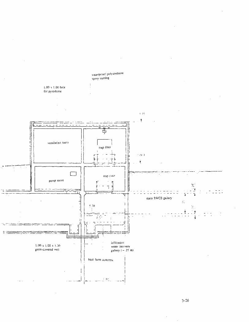
waterproof polyurethane spray coarine
1.00 x 1.00 hole for pyrodome
J .—i
ventilation room
^
trap Jour
—~f\
• pump room
— ^ r-trap door
r i -1
" ' F - - | r
1 \ i ... Lr~
,!!• F
main SWCS gallery 1 A
T f
infiltration water recovery gallery ( ~ 25 m)
3-26

Impermeability Impermeability between two prefabricated gallery sections is provided by a compressed
impermeable covering or by a special seal designed to absorb compression when the disposal vaults are filled. Each prefabricated section has one such seal every 24 m (or 78 ft, 9 in). The impermeability of the walls of the prefabricated sections is provided by the concrete materials of construction; the poured-in-place sections are made with water-repellent concrete and a waterproof sealant is applied to the exterior and to the underside of the section.
Water table Water does not drain out of the water table near the gallery, which is ordinarily watertight.
The sand surrounding the galleries is compacted to preserve original site characteristics.
Load from future structures Design basis loads include the weight of the vault, the weight of the waste packages and a
4-m- (13-ft-) thick layer of final cap (without excess load on the cap), for a total pressure of 0.32 MPa (or 46 PSI). For the secondary galleries, the design basis load configuration of the vault is assumed to be symmetrical in relation to the gallery. For the main galleries, two design basis load configurations are used:
symmetrical load configuration relative to the median vertical plane of the gallery, as in the preceding case; or asymmetrical load configuration, in which case the design basis load is a filled disposal vault without the disposal cap (it was determined that the load on the gallery would be evenly distributed after construction of me disposal cap because of the configuration of the disposal facility).
• Piping Water flows by gravity from the drain at the bottom of the disposal vault into the SWCS
in the secondary gallery and from there to the impoundment basin. The presence of water in the disposal vaults can be detected in the drainpipe in the main galleries and in the secondary galleries in each row of disposal vaults by inspecting a retention tank with a clear lid. Pipe supports are designed to accommodate differential settling between the disposal vaults and can be readjusted after settling if necessary.
Contract 1AK-EGJ68V, Task 1.1 3-27

• Impoundment basins
Concrete The impoundment basin walls, pad, slab, flooring and partitions are made of reinforced
concrete. For the below-grade portion of the impoundment basins, exterior walls are waterproofed with water-repelling concrete.
Impermeability The three-section impoundment basin is waterproofed by applying a sealant to the exterior
surfaces of the pad, walls, slab and partitions.
Water table For safety reasons, the design basis level of the water table is the mean level of the ground
at right angles to me structure.
Design basis loads The impoundment basins were assumed to be totally independent and different filling
scenarios were considered, including accidental filling up to the level of the closure slab.
• Special design criteria The SWCS was designed in compliance with the provisions of the decree authorizing CSA
construction. The design basis earthquake for disposal vaults was also used for the galleries and impoundment basins. However, piping was not verified, and is fastened with flexible, adjustable systems to the gallery walls. Design and construction were performed in accordance with quality level Q2, both for structural components and for pipe work.
Contract 1AK-EGJ68V, Task 1.1 3-28

3.3.2.2 Detailed description
• Galleries The main SWCS gallery comprises: a 774-m (or 846-yd-) section to the north of the central service road with inside dimensions of 1.375 m (or 4 ft, 6 in) x 2 m (or 6 ft, 6 in) and a wall thickness of 0.25 m (or 10 in);
a 520-m (or 569-yd-) section to the south of the CSA access road with the same inside dimensions; a 24-m (or 26-yd-) segment connecting the north and south sections at right angles to them with inside dimensions of 1.375 m x 2 m (or 4 ft, 6 in x 6 ft, 6 in); and
a 28-m (or 30-yd-) shared section parallel to the first two to the south of the central service road between the connecting segment and the collection basins into which it drains, with inside dimensions of 1.375 m (or 4 ft, 6 in) x 2.25 m (or 7 ft, 5 in).
The north and south sections have 32 and 22 feeders from the secondary galleries respectively, four and two of diem respectively initially connected with special structures with inside dimensions of 1.25 m (4 ft, 1 in) x 2.125 m (or 7 ft). Both ends of the north section of the main gallery have exits which can accommodate a stretcher. The south section of the main gallery has two emergency exits. In the center of the north section, there is an electric cable room. Both sections of the main gallery may be extended in the future if needed.
The secondary galleries beneath the disposal vaults are made of prefabricated elements, as is the main gallery. The length of secondary galleries varies and is die same as the length of the row of disposal vaults they service. These galleries are accessible through the main galleries from the north and have an emergency exit at their southern end.
Contract 1AK-EGJ68V, Task 1.1 3-29

• Piping Secondary gallery water collection system
The SWCS has two drainpipes set at a 1 % slope with valves to tap into floor drains for future disposal vaults. The entire system is made of PVC piping with an outside diameter of 75 mm (or 29 Vz in); the large diameter was selected to prevent blockage and deposits. Each valve in the drainpipe has a 5-1 sealed retention tank made of PVC with a clear inspection cover.
Main gallery water collection system The water collection system in the main galleries consists of two drainpipes with a 15 mm
(or 29 xh in) outside diameter set at a 1 % slope into which the drainpipes from the secondary galleries flow. The drainpipe has expansion seals every 18 m (or 59 ft) which facilitate disassembly. Drainpipes for rows of vaults north of the central service road flow into one main drainpipe, and drainpipes for rows of vaults south of the road flow into the other. Currently, only secondary drainpipes for rows of already constructed vaults are connected to the main drainpipes; capped valves are in place to accommodate additional drainpipes as rows of vaults are completely in the future. Each main drainpipe has a retention tank upstream of its connection point to the impoundment basins.
The collection systems in the secondary and main galleries form a closed system. Connections to floor drains in the disposal vaults are sealed, and the outlet into the impoundment basins is immersed in a tank of water which serves as a hydraulic trap.
• Impoundment basins The impoundment basins consist of two 250-m3- (or 66,000 gal-) recovery or dilution basins
made of reinforced concrete measuring 29-m- (or 95 ft-) long x 3.7-m- (or 12 ft-) wide x 2.4-m-(or 7 ft, 10 in-) deep, and one 34-m3 (or 1,200 ft3-) reinforced concrete basin measuring 4.4-m-(or 14 ft, 5-in) long x 7.7-m- (or 25 ft, 3 in-) wide x 1-m- (or 3 ft, 3 in-) deep to collect seepage water from the galleries. The basins have an entrance and stairs for access to a pump room, an electrical room, a ventilation room and the underground galleries, for which it serves as the normal access.
Contract 1AK-EGJ68V, Task 1.1 3-30

3.3.3 Operating Procedures
3.3.3.1 Water collection in SWCS galleries
During the construction phase and until operation of the disposal vaults begins, rainwater drains through the floor drain in each disposal vault and into a temporary rainwater drainpipe (one per row of disposal vaults). When operations begin, the disposal vault floor drains are connected to the permanent SWCS drainpipe by means of valves which are capped prior to that time.
The drainpipes from the secondary galleries beneath the disposal vaults are connected to the main drainpipe in the main gallery as construction of rows of disposal vaults progresses.
3.3.3.2 Storage and removal of water from the SWCS
• Impoundment basin Water which percolates through the cap into the disposal vaults and drains into the SWCS
passes through two retention tanks installed on each of the main drainpipes at the inlet to the impoundment basins. Electrical detectors warn of the presence of water in these retention tanks. Valves to one of the two 250-m3 (or 66,000-gal) recovery basins at the impoundment basins are opened and the water drains into the basin.
• Drainage of recovery basin into storm basin If sampling and analysis of water collected in the SWCS and routed to the impoundment
basins shows that its activity level is below the allowable threshold for release, the water is routed to the storm basin through the rainwater collection network by means of a portable pump.
• Dilution The contents of the recovery basin may also be transferred to the dilution basin with another
portable pump, where they are diluted to bring radioactive concentrations below the allowable threshold before release to the storm basin. Dilution water is drawn from the fire extinguishing water supply. The water is diluted in a mixing tank with tangential inlets. Radiation is measured prior to release.
Contract 1AK-EGJ68V, Task 1.1 3-31

• Drainage of recovery basin by pumping into tanker truck The contents of the recovery basin may also be taken to a treatment station outside CS A by
a specially designed tanker truck. The tanker is connected to the loading station at road level with a flexible hose and quick-release connectors. The water is transferred by creating a vacuum in the tank. Because of the difference in the level of the basin and the pumping level in the truck, the contents of the basin are first transferred into an intermediate tank with a portable pump, then pumped into the tanker by suction.
• Storage and collection of gallery seepage water
Water which seeps directly into the galleries from the water table—and which therefore has not come into contact with waste packages-is drained by gravity into a special collection tank, where operating personnel can perform the following using the pumping equipment provided:
monitor water seepage rate, take samples for analysis, and transfer water to the storm basin via the rainwater collection system.
In the case of slow infiltration, that is, low flowrates of seepage water through gallery walls, samples are taken and analyzed and the water is transferred by pumping. In the case of fast infiltration, signalling a seal failure between gallery sections, the water is drains into an overflow tank which flows into the rainwater collection system and drains into the storm basin.
• Flushing of basins All the basins may be flushed if needed with water from the fire extinguishing water supply
system. The intermediate reservoir may also be flushed by partially filling it with water from the fire extinguishing system and pumping out the rinse water into the tanker truck, if necessary.
Contract 1AK-EGJ68V, Task 1.1 3-32

• Monitoring Each basin has a water reserve tank of about 500 1 (or 132 gal); the water level is monitored
locally by opening or closing the electromagnetic control valve of the fire extinguishing system and monitoring high and low level thresholds in the tanks.
• Data transmission
Table 3.3-1. Water collection detection types
Basin Alarm Type To
Control Room
To
Pumping Station
To
Guard Post
RC 101 retention tank on main drainpipe
High Level (LAH) X
RC 102 retention tank on main drainpipe
High Level (LAH) X
1st 250m3 basin Level Indicator
(LI) Very High Level Alarm (LAHH)
X
X X
2nd 250m3 basin Level indicator (LI)
Very High Level Alarm (LAHH)
X
X
X
Intermediate reservoir Level Indicator (LI) X
Collection basin for gallery infiltration water
High Level (LAH) Very High Level Alarm (LAHH)
X
X
X
X
Contract 1AK-EGJ68V, Task 1.1 3-33

In addition to the above, the following measurements can be made at the impoundment basins:
low level in the 250-m3 (or 66,000-gal) tanks, high level in the 250-m3 (or 66,000-gal) tanks, volume of effluent to be diluted, volume of fire extinguishing water used for dilution, flowrate of fire extinguishing water used for dilution, volume drained from impoundment basins to storm basin, volume transferred to tanker truck, and volume released into rainwater collection system.
Contract 1AK-EGJ68V, Task 1.1 3-34

3.4 DISPOSAL CAP
3.4.1 Design Criteria
In designing a near-surface disposal facility for low- and medium-level radioactive waste which uses multiple barriers, the disposal cap placed over the disposal vaults is an essential component, for two reasons: • as a point of departure for safety analysis, it defines the average flowrate of seepage water
into the disposal vaults under normal operating conditions; and
• as a component of the secondary (engineered) barrier, it is one of the systems which regulates the interface between the disposal facility and the biosphere, regardless of the type or source of intrusion.
The fundamental safety objective for a waste disposal facility is to protect operating personnel, members of the public and the environment from potential radioactive releases within allowable limits. To meet this objective, design bases for the disposal facility rely on protecting the waste from outside intrusion, whether due to weather or to biological factors (water seepage, erosion, thermal cycling, water chemistry, micro- and macro- organisms, animals and plants). The disposal cap is the key component in meeting this objective. Moreover, the disposal cap must continue to provide these functions during the entire institutional control period. There are three primary design criteria for fulfilling these requirements: impermeability, long-term integrity and intrusion protection.
3.4.1.1 Impermeability Criterion
Impermeability is the fundamental design criterion. The amount of rainwater likely to seep through the disposal cap and come into contact with waste packages is a basic parameter in safety assessment. ANDRA's objective is to construct a disposal cap with an average seepage water flowrate of a few liters per square meter per year.
Contract 1AK-EGJ68V, Task 1.1 3-35

3.4.1.2 Long-term integrity criterion
The cap must retain its ability to control seepage water for three centuries at most. This can be accomplished by selecting suitable natural materials and applying them with appropriate techniques.
3.4.1.3 Intrusion Protection Criterion
The intrusion protection criterion pertains primarily to intrusion factors other than seepage (erosion, thermal cycling, water chemistry, living organisms) and to potential radiological impacts (release of radioactive gases and gamma radiation). Intrusion protection is the least restrictive criterion. In the French climate, a suitable thickness of evenly distributed ungraded material covered with a layer of vegetation provides adequate protection from such intrusions and provides an additional layer of shielding. Because its ability to withstand intrusion is directly related to its looseness, it must not be allowed to play a role in the impermeability of the cap.
3.4.2 Concept Description
3.4.2.1 Materials selection
A variety of materials meeting all or part of the first two criteria for the impermeable barrier were identified based on expert advice, laboratory and field testing, and ANDRA studies conducted since 1984, which specifically targeted clay and bitumen liners. Clay has the best long-term integrity, but can be used only if certain conditions are present at the site, with the most important being the availability of high-quality materials, the use of appropriate construction metfiods, and the stability of disposal vaults. Synthetic materials such as bituminous liners not only provide an adequate guarantee of impermeability, they offers the advantage of adapting well to differential settling in the base layer.
Contract 1AK-EGJ68V, Task 1.1 3-36

3.4.2.2 ANDRA concept
ANDRA's design concept for the disposal cap is based on the use of multiple layers made of impermeable materials described in the previous paragraph, that is, clay and the bituminous liner, and of drainage materials, as illustrated in Figure 3.4-1. The disposal cap layers are described below from top to bottom. • A protective layer which performs three functions:
regulation of water flowrate reaching the clay layer, . promotion of vegetation growth for evapotranspiration while minimizing deep-rooted
plants, and . protection of underlying impermeable layers against intrusion factors such as erosion,
freeze-thaw cycles, living organisms, etc.. • Drainage layer No. 1, designed to drain off water seeping through the protective layer and
to prevent the underlying clay layer from becoming saturated with water.
• Impermeable layer No. 1, consisting of compacted clay. • Drainage layer No. 2, designed to drain off any water which may have seeped through the
first clay layer to the outer perimeter of the disposal facility. • Impermeable layer No. 2, consisting of a bituminous liner. • Drainage layer No. 3, which also provides mechanical support for the bituminous liner.
3.4.3 Design Description
3.4.3.1 General design features
The general design concept for the disposal cap is based on two basic design principles: • regardless of precautions taken in materials selection and implementation, the integrity of
the cap cannot reasonably be guaranteed for 300 years without planning for maintenance operations; and
Contract 1AK-EGJ68V, Task 1.1 3-37

PRIMARY FUNCTION DESCRIPTION
shielding barrier
top soil
shielding barrier wet clay
drainage n° 1 crushed material
drainage n°. 1 clay
drainage N°. 2 sand \
impermeable barrier n°. 2 bitumenous liner
drainage n°. 3 sand /
base layer ungraded material
oo
M l
-t
O
f 8 a •a 3 s
>-i
o
S
T3

• it is much easier to repair the cap if the location of a failure can be pinpointed.
In accordance with these principles, the general design concept was based on construction of limited size cap sections to enable differentiation between individual sections in terms of their behavior.
The CSA consists of a series of identical and parallel rows of disposal vaults approximately 25-m- (or 82-ft-) wide, with each row separated from the next by a several-meter-wide strip which contains no radioactive materials. Designing a disposal cap around this geometric configuration naturally led to dividing the disposal cap into several sections, each consisting of two sloping "roof panels, similar to those constructed at the Centre de la Manche (CSM).
The boundary between rows is the lowest point between the sections of the cap; surface runoff and seepage water from the cap will be collected in this area. Because it is an area with a high concentration of water, the boundary is potentially the weakest part of the cap; it is important that it lie flush with the space between the rows of vaults to guarantee the long-term integrity of the system.
The finished disposal cap consists of a series of sections with double panels inclined at a 10 degree slope, and a width of approximately 50 m (or 164 ft) from one boundary to the other. Surface runoff and water drained off from the cap will be drained by gravity to the outer perimeter of CSA, where it will be collected in drains which surround the site before off-site release.
3.4.3.2 Detailed Design
The detailed design of the multiple-layer CSA cap is a function of locally available materials.
The protective layer will consist of a 1-m- (or 3 ft, 3 in-) thick layer of an uncompacted, locally available clay placed over a 50-cm- (or 19 M-in-) thick layer of ungraded material, such as crushed rock or gravel, the latter serving as drainage layer No. 1. In addition, a few feet of surface soil will be treated to promote the growth of vegetation, primarily by adding sand and organic matter.
Contract 1AK-EGJ68V, Task 1.1 3-39

The clay layer will consist of compacted Lower Aptian clay approximately 2-m- (or 6 ft, 6-in-X thick.
The bituminous liner will be placed between drainage layers No. 2 and 3 consisting of fine-grade local sand from the Upper Aptian.
The type of materials used for the disposal cap and the depth of each layer may be altered based on experience from construction of the CSM cap and on cap test results (see next paragraph).
3.4.4 Cap Tests
Cap tests will be conducted on a full-scale representative cap section to study hydraulic behavior for least ten years. The primary purpose of the tests is to confirm that the cap meets design criteria for impermeability. Specific objectives for test cap construction are: • construction of a homogeneous layer from locally available clay exhibiting good
impermeability properties;
• construction of a protective layer from locally available materials suitable for vegetation with appropriate root structures and designed to limit erosion; and
• construction of a full-scale seepage water collection system integral to the overall design of the test cap.
Specific objectives for testing the system's hydraulic behavior ares as follows: • quantify flowrates in each drainage layer;
• determine system hydrology to quantify: - evapotranspiration as a function of weather conditions, - clay impermeability and resaturation over time, and - water concentrations in cap layers at various points in time (day, month, year); and
• predict aging for various disposal cap materials over the mid-term under actual service conditions, that is, in order of importance: - changes in clay layer hydration (e.g. rate of seepage water progress), - fouling of drainage layers with fine particles or micro-organisms, and - changes in the various water collection systems (fouling of drains, clogging of grates,
etc.).
Contract 1AK-EGJ68V, Task 1.1 3-40

Specific test objects for other safety-related features of the cap include the following:
• develop a natural layer of vegetation to promote evapotranspiration, limit soil erosion and prevent the growth of deep-rooted vegetation; and
• describe and quantify mid-term soil erosion on the 10% slopes of the cap section and on the 50% slopes of the embankments.
At this stage, there are plans to construct a test cap consisting of two independent "roof" panels, which will provide two independent sets of measurements.
Contract 1AK-EGJ68V, Task 1.1 3-41

3.5 COMPACTION FACILITY
3.5.1 Functional description
The compaction facility in the center section of the Waste Treatment Building is designed to process certain metal drums of waste shipped to CSA in order to reduce their volume and prepare them for disposal. The design capacity of the compaction facility is 30,000 200-1 drums per year containing compactible dry active waste such as filters, gloves, vinyl bags, and the like. Compacted 200-1 drums are stacked in 400-1 drums which are grouted. This creates a new waste form which must meet CSA waste acceptance criteria, particularly in term so of mechanical stability, as well as criteria restricting specific activity and activity concentrations. A computerized system may be used by the site operator to ascertain compliance with acceptance limits and to determine which waste packages must undergo additional stabilization or immobilization pursuant to Fundamental Safety Rule 1.2. The layout of the compaction facility is illustrated in Figure 3.5-1.
Drums are shipped to the site by rail or by truck in special shipping containers. A 40-ft shipping container can accommodate about 150 200-1 drums, stacked side-by-side in several layers. Shipping containers are brought into one of three unloading bays in the Waste Treatment Building. The top of the shipping container is removed and drums are lifted out of the container with a bridge crane and placed on a roller conveyor. The drums are identified and monitored for radioactivity; non-conforming drums are placed in a section set aside for that purpose in the unloading area.
The drums are then conveyed either to the compaction unit directly or to an automated storage unit called the drum magazine. The drum magazine has a 456 drum capacity; drums enter the magazine in one of two "entry platforms," one for each unloading station, and exit the magazine for the compaction unit on an "exit platform". The drum magazine serves two purposes: 1) it provides buffer storage for drums to be compacted, and 2) it can "shuffle" drums for compaction to guarantee that the radioactivity of a newly created waste package remains below the CSA acceptance limit, thereby minimizing the number of waste packages requiring additional immobilization due to alpha radioactivity on the borderline of the immobilization threshold.
Contract 1AK-EGJ68V, Task 1.1 3-42

Figure 3.5-1. Layout of compaction facility

9. 10. 11. 12. 13. 14. 15. 16. 17. 18. 19. 20.
Unloading station 1 Unloading station 2 Unloading station 3 Shipping container being unloaded Top of shipping container Service bridges Handling crane for top of shipping container 200-L drums of compactible waste Roller conveyors for 200-L drums 200-L drum identification Non-conforming 200-L drums 200-L drum magazine Traveling forklift Airlock to containment area Compaction enclosure 200-L drum compactor Compacted drum loading into 400-L containers Primary filter for compaction effluent Compactor effluent decanting tank Compactor effluent retention tank
Roller conveyors for 400-L containers Container storage (Site Services Building) Airlock for 400-L containers 400-L container identification 400-L container grouting bay 400-L grout injection station Fresh grout preparation station Discarded grout recovery station Dry grout storage and make-up area Rinse water recovery station Airlock for grouted 400-L containers 400-L container handling area 400-L container drying area 400-L container load-out area Handling crane control room

The vertical compactor exerts a pressure of 10,000 kN in compacting drums one at a time along their vertical axis. The drums are held in place under the rammer during compaction by a protective skirt which prevents them from bursting and releasing their contents. In addition, the compactor support structure has a system to drain effluent from compaction operations, which is considered to be radioactive, through a primary filter, which traps solid particles, and into a decanting tank. The supernatant is pumped into two 20-m3- (or 5,280-gal) tanks and shipped by tanker truck to an off-site effluent treatment station.
The compacted drum is ejected from the compactor crosspiece by a hydraulic cylinder and drops into a 400-1 container through two horizontal sliding doors. Empty 400-1 containers are brought into position beneath the compactor on a roller conveyor; when the container has been filled with compacted drums, it is routed to the grouting station, where liquid grout is injected into the container until it is completely filled.
The container is routed by roller conveyors to a drying area, where it is weighed, labeled and set down by a handling crane. While the container is drying, the operator requests permission to transfer the 400-1 waste packages to the disposal vaults via the computer control system. After drying, the handling crane places the 400-1 container on a special truck, which takes it to a disposal vault.
Certain waste packages require additional stabilization; they are delivered to the box unloading station, where they are placed in 4-m3 metal boxes in groups of four. The waste is stabilized by grouting it inside the box in the grout injection unit.
Most of the operations just described are automated and computer-controlled, including monitoring and tracking of waste packages at all locations on site.
The compaction facility can be broken down into functional units, including both processing units and utilities. The processing units are the following: • handling crane to remove the tops of shipping containers, • bridge cranes to unload shipping containers, • 200-1 drum conveyor, • drum magazine, • compactor, • 400-1 container conveyor, • 400-1 container grouting bay, • drying area with its handling crane, and • grout equipment for waste packages requiring additional stabilization.
Contract 1AK-EGJ68V, Task 1.1 3-44

The functional utilities of the compaction facility are the following: computerized tracking and monitoring system, the compactor's hydraulic systems, "garage" area of drum magazine, radioactive effluent collection and storage system, ventilation system, radiation protection system, and fire detection and extinguishing equipment.
3.5.2 Compaction System
3.5.2.1 Description
The compactor exerts a force of 10,000 kN to volume reduce dry active waste contained in 200-1 metal drums. The compactor is in a contained area to prevent the release of radioactive particles into the room. Effluent from compacted drums drains through a primary filter into a decanting tank. Compacted drums are dropped into a 400-1 container under the lower crosspiece of the compactor.
The vertical compactor (see Figure 3.5-2) is supported by a frame which is mechanically welded to plates embedded in concrete. All compactor systems and equipment are located either in a controlled zone or in a monitored zone. Systems and equipment located in the controlled zone are the following: • conditioning corridor, • airlock for personnel access, • conditioning hall, • hydraulic ram cylinders, • airlock for drums to be compacted, • containment enclosure, and • pusher to eject compacted drums.
Contract 1AK-EGJ68V, Task 1.1 3-45

Systems and equipment located in monitored zones are the following: • automated control system cabinet, • central control room, • hydraulic power system, • auxiliary compactor systems, and • switch panels.
3.5.2.2 Operation
The principal functions of the compaction facility are listed hereafter and further described below: • positioning of drum to be compacted under the rammer, • containment of radioactive materials in a contained area, • drum compaction,
• collection of effluent released during compaction, and • ejection of the compacted drum into the overpack container.
The above functions entail certain auxiliary functions, listed hereafter and further described below.
• access into the contained area via an air lock, • measurement of the height of the compacted drums,
• measurement of the fill level of the overpack containers, and • heating and cooling of hydraulic oil.
Contract 1AK-EGJ68V, Task 1.1 3-46

Figure 3.5-2. Cross-section of compactor
Contract IAK-EGJ68V. Task l.l 3-47

• Drum positioning Positioning of drums beneath the rammer of the compactor involves the following sequence
of operations: opening of the air lock door, horizontal pushing of drum into the air lock, pusher retraction,
closing of air lock door, opening of containment area door, pushing of drum into containment area, pusher retraction, and closing of containment area door.
• Containment of radioactive materials Drums are compacted in a contained area featuring a ventilation and filtration system
designed to trap potential airborne radioactivity released from the drums. The top of the metal containment enclosure surrounds the central portion of the compactor, that is, the four columns, the head of the rammer cylinder, the skirt and the hydraulic cylinder shafts. The inverted piston compactor allows rigid attachment of the containment enclosure to the intermediate crosspiece of the compactor. Moving parts, that is, the rammer and the hydraulic cylinder shafts for the skirt, move through the top of the containment enclosure, which is at the level of the intermediate crosspiece; me enclosure seals around these moving parts with bellows. An opening at the bottom of the containment enclosure leading to the 400-1 overpack container for compacted drums is sealed with a double-door system. All of these systems are integral to the ventilation/filtration containment system for the enclosure, which is kept at a lower air pressure than adjacent areas.
• Drum compaction The compactor skirt is lowered around the drum and onto the die, where it exerts a slight
pressure. The rammer is then lowered onto the drum in two stages, a pre-compaction stage and a full compaction stage, during which the full 20,000 kN force of the rammer is applied. After drum compaction, rammer pressure is stopped, the skirt is partially raised, the rammer is
Contract 1AK-EGJ68V, Task 1.1 3-48

retracted, and the skirt is raised completely. Both the skirt and the rammer are returned to their initial position at the top of the compactor.
• Effluent collection
Compacted metal drums may break during compaction and release any liquid contents. After rammer pressure is stopped and the skirt is raised, any liquid drains onto the sloped floor of the containment enclosure, into a floor drain, through a primary metal filter, and ultimately into a decanting tank.
• Ejection of compacted drums
The compacted drum is transferred from the die to the ejection station on sliding trays, the double doors in the lower crosspiece are both opened, and the drum drops by gravity into an overpack container. Prior to ejection, a backup prevention system integral to the skirt is installed.
• Drum airlock Drums to be compacted enter the enclosure through a drum airlock in the following
sequence of operations: opening of airlock door, drum placement in the airlock, closing of airlock door, opening of containment enclosure door, positioning of drum in the enclosure, and closing of enclosure door.
Releases of airborne particulate into the service corridor and airlock when the doors are opened are prevented by the ventilation and filtration containment system. Personnel may access the containment enclosure for emergency repairs via a special airlock to the containment area. Small items are placed in and removed from die enclosure through conventional shield plugs. The enclosure walls have removable panels to install or remove large equipment after special precautions have been taken to prevent breaches of containment.
Contract 1AK-EGJ68V, Task 1.1 3-49

3.5.2.3 Equipment
The equipment is described below in order of use in the compaction cycle.
• 200-1 drum pushers The first pusher, located outside the containment area, consists of a hydraulic cylinder which
pushes the 200-1 drum into the airlock to the containment area, and positions it in front of the second pusher. The second pusher, also a hydraulic piston cylinder with a bellows seal, pushes the drum into the enclosure and places it on the compaction die.
• Airlock doors There are two "guillotine" type airlock doors made of sheet metal with reinforced edges,
a lateral track, an inflatable seal around the door opening, and a system to lock the door into open position. Each door is actuated by a dual-action pneumatic cylinder, and its position is identified by a transducer at the top and a transducer at the bottom of the door. A "door locked" transducer is actuated only when the door is properly locked. Transducer malfunctions are identified by correlation of "door locked" and "door up" data and of "cylinder under pressure" and "door lowered" data. The door seals can be inflated for 100 hours or approximately 4 days with reserve air supply in the event of a failure in the air delivery system.
• Containment enclosure Because of the various configurations in which the facility may be operated, two
classification levels were defined for containment in accordance with French standard NF M 62 200:
Class 5: during 200-1 drum transfer when the airlock doors are open and the ventilation system in operation, or when a 400-1 container is not docked at the compactor; and Class 3: the 400-1 container is docked, airlock doors are closed and door seals are inflated.
The enclosure is made of stainless steel plate with external reinforcement and a minimum number of interior angles to facilitate decontamination. The enclosure walls are fire-retardant for one half hour. Monitoring and equipment maintenance systems in the enclosure include
Contract 1AK-EGJ68V, Task 1.1 3-50

smoke detectors, sprinkler systems, inspection ports, removable panels, gloveholes for handling operations such as actuator adjustments.
• Drum compactor
The compactor consists of four vertical columns supported by a crosspiece at either end and a fixed crosspiece in the middle whose overall dimensions are 2 m x 2 m x 8 m (or 6 ft, 6-in x 6 ft, 6-in x 26 ft, 3-in) high. The main hydraulic cylinder for the rammer runs along the centeriine of the structure. A fixed cylinder shaft, or piston, is mounted on the upper crosspiece, while the hydraulic cylinder shaft, or rammer, is mobile. This so-called inverted piston arrangement provides for better control of oil leaks where the piston meets the rammer cylinder by preventing oil from flowing down the length of the piston. In addition, the seal for the hydraulic cylinder is located outside the containment enclosure and is therefore readily accessible. The rammer cylinder enters the containment enclosure through the intermediate crosspiece. Two auxiliary hydraulic cylinders also pass through sealed conduits in the enclosure to raise and lower the compactor skirt along columns in the framework and provide rapid action to the rammer for pre-compaction. The main components of the compactor are described below.
Four columns held together with crosspieces. An upper crosspiece consisting of a solid metal plate with recesses to fasten the shafts for the main hydraulic cylinder (rammer) and auxiliary hydraulic cylinders. An intermediate crosspiece to guide the rammer cylinder and the auxiliary hydraulic cylinders through bellows seals into the top of the sheet metal containment enclosure, which
is attached to the bottom of the intermediate crosspiece. A main hydraulic cylinder consisting of a piston mounted on the upper crosspiece and a hydraulically-actuated sliding cylinder (maximum pressure 300 bar, or 4,440 PSI) whose seal is readily accessible from the operating corridor. A shaft for the main hydraulic cylinder to guide the cylinder through a hole in the intermediate crosspiece into the containment enclosure. A skirt mold in the containment enclosure in which the drums of waste are compacted. Four auxiliary hydraulic cylinders, two for pre-compaction at a pressure of 210 bar (or 3,108 PSI) and two to raise and lower the skirt.
Contract 1AK-EGJ68V, Task 1.1 3-51

A lower crosspiece similar to the upper crosspiece. A system to eject compacted drums in the following sequence: . release of rammer pressure, . partial raising of the skirt to allow liquid effluent to flow to the bottom of the
containment enclosure, . rammer retraction to its highest position, . skirt retraction to its highest position, . transfer of compacted drum to the sliding doors, and . opening of sliding doors and fall of compacted drum into the 400-1 container. An effluent collection system consisting of the sloped floor of the containment enclosure, which drains effluent from the compacted drums or die rinse water into a retention tank. A system to measure compacted drum height and to stack drums in 400-1 overpack containers.
A removable decontamination pan to collect water sprayed into the enclosure to clean the die and floor before maintenance.
A hydraulic supply tank (5 m x 2.5 m x 2 m-, or 16-ft, 5-in x 8-ft, 3-in x 6-ft, 6-in-) high above the compactor which feeds oil to the main cylinder by gravity and which is insulated to limit heat release to a maximum of 30 kW.
Contract 1AK-EGJ68V, Task 1.1 3-52

3.5.3 Facility Performance
3.5.3.1 Capacity
The average capacity of the compaction facility is approximately 30,000 200-1 metal drums per year, 690 per week, or 138 per day, with a peak capacity of 165 drums per day. Nominal capacity is 20% and 10% higher, at 828 drums per week and 182 drums per day.
The 400-1 overpack containers can usually hold a maximum of 6 compacted drums, for an average of 5,200 400-1 containers per year. To accommodate fluctuations over time in the number of compacted drums one overpack container can hold, the nominal capacity of the facility is based on four compacted drums per container, that is, an annual rate of 7,940 containers.
The production rate of the facility is a function of the drum retrieval rate from the drum magazine, of the rate of supply of 400-1 containers, and of operating times for grout preparation, grout injection, and grouted waste package drying before transfer to the disposal vaults.
3.5.3.2 Airlock
Drums must travel 1 m to pass through the doors into and out of the airlock to the containment enclosure with dimensions of 0.968-m- (or 3 ft, 2-in-) high, and 0.68-m- (or 2-ft, 2-in-) wide.
3.5.3.3 Compactor
• Compaction force: 10,000 kN • Hydraulic compaction pressure: 210 bar, or 3,108 PSI (maximum 300 bar, or 4,440 PSI) • Diameter of compactor skirt: 650 mm (or 2 ft, 1 Vfe in) • Maximum height of drum to be compacted: 835 mm (or 2 ft, 9 in) • Footprint: 8 m x 8 m (or 26 ft, 3 in x 26 ft, 3 in) • Height: 10.7 m (or 35 ft, 1 % in) • Weight: 1001
Contract IAK-EGJ68V, Task 1.1 3-53

The compactor framework, hydraulic cylinders and skirt are designed to withstand a compaction force of 15,000 kN. During CSA operations, should it prove useful or necessary to increase compaction capacity, only the hydraulic system would need to be replaced.
3.5.3.4 Containment Enclosure
• Compactor airlock: 5.3 m x 2 m x 2.2 m (or 17 ft, 5 in x 6 ft, 6 in x 7 ft, 3 in-) high • Equipment airlock: 2 x 0.9 m x 2.5 m (or 6 ft, 6 in x 3 ft x 8 ft, 2 ¥tin-) high
3.5.3.5 Cycle duration
One compaction cycle, from compaction of one 200-1 metal drum to ejection into a 400-1 container, lasts about 100 seconds.
3.5.4 Operating Procedures and Facility Control Systems
3.5.4.1 Automatic control
Under normal operating conditions, the compaction unit is automated and controlled from the central control room, where a touch screen is used to display the cycle in progress and analog monitoring data. Operating malfunctions are signalled by alarms in the control room, and a printer generates date- and time-stamped readouts of malfunctions in the order in which they occur. Data relating to operation of the compaction facility are transmitted to die automated control system, which controls the automatic back-and-forth sequence controllers for the facility. The automated control system receives the following commands from the control room:
• automatic operating mode, • semiautomatic operating mode and sequence(s), • manual operating mode, • shutdown, and • emergency shutdown.
Contract 1AK-EGJ68V, Task 1.1 3-54

3.5.4.2 Semi-automatic control
There are six operating sequences for the compaction facility which can be actuated alone or in series in semiautomatic operating mode. The semiautomatic operating mode provides automated control over a subset of operations, and is used to test the facility and to bring it up to capacity, or in the event of a malfunction in one of the motor-pump units of the hydraulic system. The six operating sequences are:
1) start up and readying of the hydraulic system,
2) loading of drum to be compacted, 3) drum compaction, 4) lifting the skirt from the compacted drum, 5) measuring height of the compacted drum, and 6) ejection of the compacted drum.
3.5.4.3 Manual control
In manual operating mode, two local control panels independent of the central control room are used to manually control the compaction facility from the hydraulic system room and from the service corridor. The manual operating mode is used only during maintenance, or to complete an operating cycle if the system shuts down because of a malfunction. An intercom system is provided for communication between operators at different control stations.
3.5.4.4 Operating modes
There are three equipment operating modes: automatic operating mode, which has two status conditions—ready/waiting and operating-manual operating mode, and shutdown mode, which has two status conditions, normal shutdown and shutdown with oil kept at operating temperature. There are also emergency cutoff mechanisms which are triggered whenever a malfunction is detected in the pushers, hydraulic cylinders, airlocks, hydraulic system, ventilation system, compressed air supply, or electrical system, or in the event of improper positioning of the drum to be compacted, fire, improper drum and container supply sequence,
Contract 1AK-EGJ68V, Task 1.1 3-55

or intrusion through the access airlock. The automatic operating mode includes Sequence 1 in ready and waiting status, and the operating cycle, which performs Sequences 2 to 6 in succession and in order, if it detects the presence of a drum ready to be compacted. If there is no drum, the facility returns to the ready and waiting status.
3.5.5 400-1 Container Conveyors
The roller conveyors for 400-1 overpack containers are identical to the 200-1 drum conveyors.
3.5.5.1 Functions
The primary function of the roller conveyors and their auxiliary systems is to transfer 400-1 containers in a continuous line from the basement of the services building to the drying area. During transfer, the containers pass through the containment area and stop at the compacted drum filling station, the grouting station and the handling area under the handling crane. During transfer, the auxiliary equipment performs the following functions:
• rotation of the 400-1 container for bar code reader identification; • docking the 400-1 containers under the sliding doors; and • creating a buffer stock of 23 drums upstream from the compactor, 10 upstream from the
grouting station (filling of the hopper is triggered when 6 drums are present), and 11 upstream from the handling station, including 5 which are left empty to load out grouted containers in the event of an incident.
In addition to the above, the conveyors perform the secondary function of transfer of containers with miscellaneous non-compacted waste to the grouting station.
Contract 1AK-EGJ68V, Task 1.1 3-56

3.5.5.2 Description
Conveyors are laid end-to-end to form a continuous conveyor network. The rollers are driven in one or two operating directions by a drive chain. Lateral guard rails at either side of the conveyor guide the drums. Detectors at the entrance, at a reference position, and at the exit register and track containers on the conveyors. As for 200-1 drum conveyors, containers are prevented from turning over or falling off the conveyor with appropriate systems. The conveyor network forms a container supply line divided into three sections which perform the following functions:
• supplying empty containers to the compactor
• transfer of filled containers to the grouting station, and • transfer of grouted containers to the drying area.
• Transfer of empty containers to the compactor
The empty container supply section of the conveyor network consists of a loading station for empty containers, a pass-through to two airlocks to access the containment area, and a label scanning area. Empty 400-1 containers are stored in the basement of the service building on pallets near the loading conveyor with a manually operated forklift. A handling crane with a load equalizer and a drum clamp places containers on the first loading conveyor one at a time. The loading conveyor's automatic operating mode is switched off during loading operations.
The waste treatment area is a contained area requiring Class 3 containment, as defined by French standard NF 62 - 200, when the doors are closed and die container is docked. When the doors are open, containment is provided by the ventilation and filtration systems.
The container scanning station is located beneath the lower crosspiece of the compactor at the entrance to the waste treatment area and just before the container filling station. The bar coded container labels are scanned or, if the label cannot be scanned, a camera located near the bar code reader reads the code on the container in decoded form.
• Transfer of filled containers to the grouting station This section of the conveyor network consists of a container fill station and buffer conveyors
to provide an additional supply of containers upstream from the grouting station.
Contract 1AK-EGJ68V, Task 1.1 3-57

Container fill station The 400-1 overpack container is loaded onto a lifting platform by roller conveyors and
docked beneath the containment enclosure of the compactor in the center of the sliding doors for filling with compacted drums. When the magic eyes on the conveyor are covered and die limit switch is engaged on contact with the bottom of the containment enclosure, the control system indicates "container docked." The floating docking collar compensates for variations in height due to manufacturing tolerances and to platform position.
Buffer conveyors Six conveyors between the container fill station and the grouting station have a buffer
capacity of 10 containers. The first conveyor holds one container, the four following conveyors each hold two containers, and the last conveyor holds just one container.
Grouting The container filled with compacted drums remains on the last buffer conveyor during
grouting. Grout is freshly prepared on site in the grout preparation station located immediately downstream from the grouting station.
• Grouted container transfer to drying area Grouted 400-1 containers filled with compacted drums make up a new waste form to be
disposed of in CSA's disposal vaults. On leaving the grouting station, the waste packages are transferred two at a time to the drying area through two airlocks in succession. The waste packages can be removed from the containment area through the airlocks without compromising containment integrity by opening the doors at different times and by providing appropriate ventilation and filtration. Waste packages are loaded out of the facility on a section of the conveyor network with seven conveyors. The second roller conveyor is connected to a turntable which rotates the package so that the bar code label can be scanned. Containers full of waste are identified in the same manner as empty containers. The last two conveyors transfer waste packages to the handling crane in the drying area.
The six airlock doors-three upstream from the waste treatment area and three downstream-are made of a solid panel inside a moving frame which slides inside a fixed frame surrounded
Contract 1AK-EGJ68V, Task 1.1 3-58

by a seal and embedded m the concrete wall. The structure is mounted between two contiguous conveyors. Door positions are controlled by two end-of-travel transducers. A photoelectric cell, placed on the bias, prevents a container from being accidentally present when the door opens.
Four cameras, including one witii a zoom lens and turntable, are installed in the container scanning stations, near the docking equipment and in the grouting station.
There are local control panels connected to the central control room via an intercom system at the following stations:
empty container supply station, container scanning and docking areas, grouting station, and waste package scanning and load-out area.
The last access door to the waste treatment area and the two conveyors located upstream and downstream from this door, as well as the three exit doors and all the conveyors situated upstream and downstream from the grouting station and waste package load-out area, are connected to the emergency electric supply system. In the event of a power failure in the main power supply, container grouting and grout discard is completed in the automatic operating mode.
The conveyors and equipment are designed to facilitate maintenance. Maintenance systems and procedures must meet designated safety requirements and access conditions. Prior to performing maintenance in the waste treatment area, the air must first be filtered through the ventilation system and die health physics team must be called in to measure and monitor radioactivity levels.
With the exception of empty container handling and loading on the supply conveyors, me normal operating mode is automatic operations controlled from the central control room. In the semiautomatic operating mode, automatic operations of selected sequences can be controlled. The manual mode is engaged by throwing a switch in the control room.
Contract 1AK-EGJ68V, Task 1.1 3-59

3.6 DRUM STORAGE AND HANDLING EQUIPMENT
3.6.1 Functions
The drum magazine provides a storage capacity of 456 200-1 drums and performs the following major functions: • storage of 200-1 drums delivered by the unloading conveyors and not immediately
transferred to the compactor, • unloading of stored drums onto the compactor facility supply conveyor, and • sorting of drums in the storage area.
The magazine also serves as a buffer in the event of a malfunction in the main conveyor network.
3.6.2 Description
The drum magazine is located just off the drum unloading bays. The magazine measures 3.5 x 21.5 x 14 m- (or 11 ft, 6 in x 70 ft, 6 in x 46 ft-) high and consists of two rows of storage racks on either side of a central corridor. The storage platform for the drum magazine travels along the entire length of the corridor. The storage area of the magazine is connected to a maintenance area at the end of the corridor (4.5 x 5 x 14 m, or 14 ft, 9 in x 16 ft, 5 in x 46 ft). The principal components of the storage platform are:
• a platform on a crosspiece which rolls on rails at ground level and includes a column and a steering block on top;
• a lift which slides up and down on the column; • a forklift integral to the lift; and • a drive chain and on-board control panel.
Contract 1AK-EGJ68V, Task 1.1 3-60

3.6.2.1 Safety and design criteria
The storage and maintenance areas are "fire areas," that is, they are built with 40-cm- (or 15 34-in-) thick concrete walls and have fire doors rated for two hours of fire protection. The metal storage racks and die storage platform are designed to lift, transfer, unload, and hold 200-1 drums without special adjustments for any given drum. Necessary measures are taken to make it mechanically impossible for a drum to fall. Repair and maintenance of the storage platform when this platform cannot be transferred into the maintenance area are performed directly in the service corridor. Measures are taken to limit these procedures so that they last no longer than a maximum combined total period of 15 minutes. Hands-on equipment maintenance is performed in the maintenance area.
3.6.2.2 Storage racks
The storage racks are made of steel beams and bars which are arranged in 11 horizontal rows and 22 vertical columns and joined to form a rigid structure. The drum rests on four supporting plates in each storage bin which are attached to the structure. The supporting plates are designed to accommodate the forklift arms while loading and unloading drums.
3.6.2.3 Storage platform
The column of the storage platform is made of mechanically welded rectangular box beams that are tied into the crosspiece and it supports the lifting mechanism and the platform for the on-board control panel. The tracks for the lift are installed on the column, and two access ladders are mounted on either side of the lift along its entire height. The column contains a safety mechanism which stops the lift if the lifting equipment malfunctions.
Contract 1AK-EGJ68V, Task 1.1 3-61

3.6.2.4 Track
The storage platform moves along a rail built into the floor of the service corridor in the storage area and in the maintenance area. The position of the storage platform and travel are controlled by an incremental coder.
3.6.2.5 Lift
The lift consists of a mechanically welded frame supporting a forklift and a safety cradle which catches falling objects in either direction during travel. Control and safety systems are provided to detect the presence of a load, the centering of the load on the forklift arms, and whether or not the indexed rack is occupied.
3.6.2.6 Forklift
The forklift is used to load and unload a drum into the rack to which it is assigned and into the storage area entrance and exit bays. The top part of the arm is coated with an anti-skid material in the shape of an asymmetrical cross to compensate for inaccuracies in the centering of the drums.
3.6.2.7 Maintenance area
The maintenance area is located at the end of the service corridor in the storage area, and is protected by a 20-cm- (or 7 7/8-in-) thick concrete wall which covers two-thirds of the section of the area. The maintenance area has a 5 kN monorail and a calibration rack for adjustments to the forklift.
3.6.2.8 Electric system - control system - remote monitoring
Power is supplied to the drum magazine by power cables which terminate injunction boxes installed in the maintenance area. The local control panel is located in the control cab at the
Contract 1AK-EGJ68V, Task 1.1 3-62

bottom of the storage platform, which also has a connector for a pull-out test board. A camera with a turntable and zoom lens is installed on board the storage platform lift and focuses on the drum on the forklift. Two fixed cameras with turntables and zoom lenses are mounted at the top and at either end of the storage area corridor.
3.6.3 Principal Features
Storage
Approximately 250 200-1 drums are processed in the drum magazine per week on average. The storage platform can operate concurrently at both entrances storing drums from two unloading lines, or at one entrance storing drums from one unloading line and at the exit removing drums from storage to supply the compactor.
Travel • maximum travel: 18.8 m (or 61 ft, 8 in) • maximum speed: 90 m/mn (or 295 ft/mn) • low speed: 20 m/mn (or 65 ft/mn) • micro speed: 2 m/mn (or 6 ft, 6 in/mn) • maximum acceleration: 0.5 m/sec (or 19 in/sec).
Lifting • height of entrance and exit level: 3.15 m (or 10 ft, 4 in) • level 1 height: 1.06 m (or 3 ft, 6 in) • level 11 height: 10.785 m (or 35 ft, 5 in) • maximum acceleration: 0.6 m/sec (or 23 in/sec) • maximum speed: 40 m/mn (or 131 ft/mn) • low speed: 10 m/mn (or 33 ft/mn) • micro speed: 2.5 m/mn (or 8 ft/mn)
Contract 1AK-EGJ68V, Task 1.1 3-63

Forklift • travel: 875 mm (or 2 ft, 10 in)
• lifting or lowering cycles: 15 sec maximum
3.6.4 Operating and Control Systems
As for the conveyors, the normal operating mode is the automatic mode controlled from the central control room. Manual control mode is activated by a switch in the control room. It should be noted that the operator, using the control system, can identify the location and age of each waste package in storage and edit a text file showing the status of inventory. The drum magazine control system does not track drum labels, and information is exchanged on the basis of the rack location.
Contract 1AK-EGJ68V, Task 1.1 3-64

3.7 GROUTING FACILITY
3.7.1 Functions
Metal boxes with loose waste requiring stabilization are grouted in the grouting facility (see layout, Figure 3.7-1). Grout is supplied by an off-site cement plant and is delivered to CSA in cement mixers. In addition to grouting, the facility performs the following functions:
• box handling, • weighing before and after grouting,
• scanning of waste package labels and data entry into tracking system, • interim storage, and
drying after grouting.
3.7.2 Detailed Facility Description
The grouting equipment is described in the sequence in which it is used to process the boxes.
3.7.2.1 Box receiving
Boxes are generally shipped in 20 or 40 foot shipping containers attached to conventional trailers. A 350 kN crane is remotely controlled from the facility control room in the box receiving area to remove the top of the shipping containers (an operator-assisted operation) and to remove boxes in automatic control mode. The crane has a scale to weigh the packages.
3.7.2.2 Box handling and grouting
The boxes are placed one by one on a self-propelled cart next to the crane in the receiving area, the caps are removed from the lid openings, and the boxes are transferred to the grouting cell. The grouting equipment has two injection nozzles and a center vent nozzle connected to
Contract 1AK-EGJ68V, Task 1.1 3-65

the extracted air system, which keeps the box at low pressure and exhausts air vented from the box during the grouting process. The nozzles are mounted on a frame which moves vertically to dock them onto the box, then retracts them after grouting. The frame travels by lifting jacks. When the grout equipment is lowered onto the box, the nozzles perforate the lid openings in die lid and inject into the box.
The fill level is detected by high-level transducers installed inside die vent nozzle consisting of electrodes which come into contact witfi the grout: the first transducer slows down the pump, while the second transducer shuts down the pump completely before the grout equipment is raised. The transfer cart is dien removed from the cell and unloaded. The box is placed on the area reserved for drying. Every time a box is grouted, a removable pan is placed below the grout system. The nozzles are rinsed on the outside with high-pressure water. Containment systems are installed around the transfer drains to ensure mere is no breach of containment in the cell at the level of the grouting and vent nozzles and at the level of the cylinders which control the horizontal movement of the removable pan.
The grout piping is cleaned at the end of each shift, after each grouting campaign, or in the event of an incident. A video camera and associated lighting is used to monitor the transfer and grouting operations performed in the cell.
Box transfer cart The self-propelled box transfer cart travels along rails. Transducers and guard rails are
installed at the ends of the track. The position of the cart at the grouting station is determined by a fixed pin. The box carrier platform on the cart has centering channels to position the 4 and 5 m3 boxes on the cart, some of which can be removed to accommodate 10 m3 boxes, and a removable pan to collect grout drips or overflows.
Contract 1AK-EGJ68V, Task 1.1 3-66

Figure 3.7-1. Layout of grout injection facility
9. 10. 11. 12.
box receiving area Shipping container being unloaded Box handling crane 5-10 m' waste boxes to be grouted Box storage area before grouting Grout injection cell Box transfer can Box being grouted Grout injection equipment Grout injection nozzles Vent nozzle HEPA filters
13 14 15 16 17. IS 19 20 21 m
Removable pan for rinse water et'fluem Fresh grout feed mixer Fresh grout injection pumps Grout transfer piping Decanting system Drying area 5-10 m J boxes during drying Load-out trailer tor solidified boxes Control room Grout cell door

Contract 1AK-EGJ68V, Task 1.1

Grouting system The main components of the grout transfer and injection systems are the following:
• two peristaltic pumps with a maximum flowrate of 25 m3/hr (or 6,600 gal/hr), one for pumping during normal operations and one as a back-up in the event of a malfunction; and
• a three-way slide valve which transfers the grout directly for injection, or recirculates it in a closed loop, or ejects it. A removable drip pan is placed under the valve.
The rinse water for the vent nozzles and the drip pan, and rinse water effluent from the other drip pan and collection and well rinsing areas, are drained into the decanting system consisting of four 400-1 containers into which the water is decanted several times before it is temporarily stored in a 1-m3- (or 265-gal) tank.
At the end of each shift, the inside of the injection nozzles and piping are cleaned using foam balls which are inserted manually into the system and blown around with compressed air. The cleaning effluent and balls are recovered in the injection cell in a rinse water effluent tank.
3.7.2.3 Control systems
The box processing facility is controlled from a special control room separate from the central control room of the Waste Treatment Building.
Contract 1AK-EGJ68V, Task 1.1 3-68

4. IMPACT OF CSM OPERATING EXPERIENCE ON CSA DESIGN
4.1 CHANGES IN DISPOSAL CONCEPTS
4.1.1 Changes in Centre de la Manche Technology
4.1.1.1 Infratome period, 1969-1978
• Trenches Disposal operations began in November 1969. The first trench, located near a road, was
filled without incident. Operation of the second trench, which is parallel to the first, was abandoned because the ground was not stable enough to support vehicle traffic and because of flooding by rainwater; the trench was refilled. The third trench, also located near a road, was filled with waste during the first quarter of 1970. However, earthen trench disposal was determined to be industrially inviable at around this time, and this disposal method was abandoned.
• Platforms To facilitate access to vehicles and handling equipment, disposal units were constructed
at grade at a slight incline of 0.5 cm/m (or 5 xk in/100 ft) to allow rainwater to run off during waste package placement operations, which generally lasted from 6 to 12 months. During construction, the earth was compacted in successive layers and covered with a 20-cm (or 8 in-) layer of ungraded material, which was also compacted. The surface was then covered with a thin layer of fine gravel and sprayed with a bitumen emulsion. These preparations were intended to facilitate disposal operations.
Contract 1AK-EGJ68V, Task 1.1 4-1

Figure 4.1-1. Changes
M
1982 - 1988 1985-1988 1975 - 19(
MODERN STRUCTURE
TUMULUS ON MONOLITHS
CONNECTING STRUCTURE
TUMULUS ON MONOLITHS
Ot.n STRUCT!
TUMULUS Or-OR ON TREN<
I
i TUMULUS on concrete slab MONOLITH (P) on load-bearing pad MONOLITH (T) on load-bearing pad
^ ^ ^ ^ M T C K - T -
\
TUMULUS on compacted ear or partly on old ditch-type stn
- metal boxes on load-bearing concrete slab
- concrete overpaclcs on load-bearing pad
Contract 1AK-EGJ68V, Task 1.1

CSM disposal structures
5
1983-1988 19>0 - 1981
?TH •vrcH
MODERN STRUCTURE BETWEEN OLD STRUCTURES
TUMULUS ON MONOLITHS
OLD STRUCTURES, NORTHERN SECTION
TUMULUS ON TUWULUS OR ON EARTH
?
- TUMULUS: drums, overpacks on: - non-load-bearing concrete slab - polyane liner - earthen cover
^$$i&M*iV
TIMUUUS
W-
MONOUTH MONOLITH j $
bi'airaen ^WW 4
'&&!&& TUMULUS on compacted earth and bituminous liner
- TUMULUS: concrete bverpacks and boxes on load-bearing concrete slab
- MONOLITHS/COMPARTMENTS/ CONCRETE OVERPACKS poured in placed on load-bearing pad
- SWCS below structure
- TUMULUS beneadi intermediate slab on top of compacted earth and bitumen
- SWCS around borders with gravel fill
4-2

In the beginning, these disposal units were called "platforms." The first concrete overpack was placed on a platform in early March 1970. However, very shortly after the trench method was abandoned, metal drums previously destined for trench disposal were routed to the platforms, where they were disposed of in special areas whose walls were formed by concrete overpacks stacked three high at first and later four high. The outer perimeter of the platforms continued to be constituted of concrete overpacks or, later on, of metal boxes, which created the general architecture of the platform.
• Concrete compartments, concrete-lined trenches Several solutions were proposed for waste to be disposed of in concrete compartments,
which later evolved into metal boxes injected with cement. The solution that was ultimately selected was a trench with compartments made of prefabricated concrete panels assembled in situ. The bottom and side panels were sealed with a bitumen-coated kraft paper. Each of the first four trenches had two sections of 50 compartments built side-by-side. Drainage for the trenches was provided by the sand bed at the bottom of the trench; water which might be present in the sand bed could be sampled via a vertical tube made of fiber cement at either end of the trench next to the central service road.
The next disposal units, built in two phases in 1974 and 1976, had a slightly different design consisting of trenches with thicker walls (20 cm-, or 8-in-, thick at either end, 15-cm-, or 6-in-, thick footings and lateral walls) with a sand bed draining to a sump. Internal walls were constructed with a removable form set up during filling operations; the lengths are therefore no longer uniform. This type of structure constitutes the first generation of the "monolith" disposal structures. Nine such trenches were filled from April 1974 to May 1978.
The volume of waste to be disposed of increased from 6,063 m3 (or 214,000 ft3) in 1969 to 15,325 m3 (or 541,000 ft3) in 1978. This increase in waste volume led to changes in handling equipment to more industrial and automated equipment and changes in disposal methods.
Contract 1AK-EGJ68V, Task 1.1 4-3

4.1.1.2 Infratome/OGD/ANDRA period, 1976-1983
This period occurred between two other operating periods, with some overlap; it was characterized by a greater awareness of the potential environmental repercussions of early disposal practices.
• Disposal structures
Concrete-lined trenches Once the Office of Waste Management (OGD) took charge of the site, concrete-lined
trenches quickly evolved into the monolith system and the area below the disposal structures was systematically drained.
Platforms The platform approach continually evolved during this time frame towards complete
elimination of the initial concept of earthen disposal. The first platforms built during this period, in 1976, were identical to those of the previous period, except that their foundation consisted of a layer made entirely of concrete overpacks, with the interstitial area between overpacks filled with fine gravel. A new disposal structure was built on top of this structure, and concrete overpacks, boxes or metal drums were disposed of as before. Although the base of such disposal structures was more homogeneous, drainage was identical to earlier structures: a single drain was provided for a 100-meter- (or 109-yd-) wide compacted surface area with a 0.5 cm/m- (or 5 Vi/100 ft-) incline.
The next series of disposal structures was built on top of concrete-lined trenches on a hard surface consisting of either a concrete slab or bitumen paving. Extensions to old disposal structures made during this period were constructed in similar fashion, giving better drainage.
Changes continued with the subsequent disposal structures, which were constructed with a reinforced concrete platform surrounded by an integral drainage system. Therefore, by the end of the period, all disposal structures had good mechanical strength and an integral drainage system.
Contract 1AK-EGJ68V, Task 1.1 4-4

• Water collection systems Based on data gathered from one of the below-grade disposal structures pursuant to the
release of tritiated water, a decision was made in 1978 to collect rainwater and infiltration water separately. The internal separative water collection system consists of a series of conduits in fiber-cement connected to drains in the bottoms of the disposal units, with pumps provided for below-grade units. The design concept for the separative water collection system requires accessibility, inspectability and repairability; the system is therefore deployed on the surface.
With the start-up of this system, performance improved with respect to site releases. However, the fragility of the system quickly became apparent: its exposure to the elements and operating incidents associated with the system and with frequent pumping problems were such that the anticipated performance was not achieved.
Planning for construction of the CSM disposal cap and for site surveillance prompted ANDRA management to construct a water collection system that operated by gravity and was completely independent, and which therefore was connected to the lowest levels of the disposal structures. In addition, the system had to be protected from numerous mechanical incidents. It was therefore decided to construct an underground gallery which was to surround the site.
4.1.1.3 ANDRA period, 1982-1993
The beginning of the current period can be traced to die preparation of the new version of the Safety Analysis Report in 1982 and to the two meetings of the Standing Committee that reviewed it. This period had seen enhanced requirements for operation of the CSM pertaining to the waste packages themselves, to the engineered disposal structures and to drainage, and was marked by planning and requirements for the final disposal cap and for site monitoring after closure.
• Disposal structures The establishment of the Quality Assurance Program at this time strongly influenced the
development of the disposal facility. All disposal structures built since 1982 have a reinforced concrete pad which incorporates drainage, is designed for load and is constructed of materials specified in advance. Except for constructions connecting old and new disposal structures and
Contract 1AK-EGJ68V, Task 1.1 4-5

recently constructed units inserted between old units, me current disposal structures are characterized by a trench portion consisting of a first level of monoliths built on a concrete pad, an intermediate concrete pad which acts as a receiving area for monoliths or compartments making up the second level of the disposal structure, and a slab which is poured on top of the second level to facilitate traffic and provide a. receiving area for the third level tumulus. Today's structures are only remotely related to the site's first disposal structures.
• Water collection systems
The construction of the SWCS, which began in 1982, lasted for several years because of numerous conflicts with other construction activities. The SWCS wasn't truly operational until 1986, when the old pumping system was eliminated and new basins were built to replace the two decanting basins for the earlier separative and rainwater collection systems. The latter systems, already necessarily separate, were noticeably improved wim the start-up of the northern and eastern sections of the SWCS in 1987.
All of these new facilities were constructed with a drainage system located below the galleries of the SWCS and beneath the building with the basins. The drainage system empties into the rainwater system. Experience has shown that this system also collects infiltration water from the area around old platforms in certain sectors; the system was therefore later connected to the SWCS.
4.1.2 Technology Selection for the Centre de 1'Aube
4.1.2.1 Disposal structures To better control the quality of the design of the secondary containment barrier, the
disposal structures were standardized and designed to integrate, from the beginning, all of the requirements for operations, closure and site monitoring, particularly the following: • construction of underground water collection systems operating by gravity (separative and
rainwater systems); • construction of disposal vaults with a concrete pad and four side walls, wim the early
version having walls designed to transmit the combined load of the vault closure slab and the disposal cap;
Contract 1AK-EGJ68V, Task 1.1 4-6

• adaptation of the size of the disposal structure (25-m-, or 82-ft-wide) to the design of the disposal cap, which consists of several sections;
• protection of waste packages (automated handling, sheltered operations); and • traffic patterns and access for vehicles delivering waste packages.
The disposal structures assume the form of vaults with rigorously identical outside dimensions: 21.5-m-long x 25-m wide x approximately 8-m-high (or 70-ft, 6-in-long x 82-ft-wide x 26-ft-wide). The vaults are built in a special disposal zone which was selected and completely prepared before start-up of site operations. The disposal zone preparation entailed leveling of the soil (including hills and ditches) into a flat surface with a 1 %-slope.
At start-up, a series of 24 vaults representing two years of operations were constructed in six rows perpendicular to the central service road following a grid pattern. Waste is disposed of in one of two types of disposal vaults according to type and solidification process as follows: • gravel vaults for waste packages whose solidification process involves the use of long-lived
waste containers, such as concrete overpacks; and • grouted vaults for waste packages whose solidification process involves the use of short-lived
containers, such as metal boxes.
All disposal vaults in the disposal zone are rectilinear and identical and are constructed parallel to each other in a grid pattern to support the overall design of the disposal cap.
4.1.2.2 Operations
Operating experience from the CSM shows that the following must be avoided or reduced as much as possible: • interference between vault construction and vault operations; • machine traffic over water collection systems or in operating disposal vaults; • exposure of waste packages, disposal vaults and operating personnel to weather and
particularly to waste package leaching by rainwater; • visual identification and handling of waste packages with self-propelled carts; and
Contract 1AK-EGJ68V, Task 1.1 4-7

• instability and especially subsidence of disposal cap support provided by the earth, vaults, waste packages and base layer of the disposal cap.
Given CSM's operating experience and the activity range and predicted delivery rate of waste packages supplied by the waste generators, the following was undertaken during construction of the CSA:
• site preparations affecting groundwater flow patterns in the sand table before construction of the vaults and buildings (ditches, drainage);
• earth leveling to create a flat platform with a 1 % incline for the disposal zone; • complete construction of the main drainpipes of the rainwater collection system connected
to the storm basin;
• construction of the main drainpipes of the Separative Water Collection System connected to the impoundment and dilutions basins of the SWCS; and
• construction of the central service road and of its two embankments designed to service the disposal zone (40 m wide and approximately 1 km-long, 131 ft wide, approximately 0.6 mi long).
All of the disposal structures are built according to the same principles: • foundation located above the water table (operating and institutional control periods); • bottom of concrete pads placed on Aptian sands; and • construction of six movable buildings.
With respect to the latter, each movable building installed over the last vault at the end of a row covers it entirely as well as half of the vault contiguous to it where waste delivery trucks are unloaded. The movable buildings provide support for handling equipment and waste package identification systems. When the last vault at uie end of a row is filled, the movable building is moved over the preceding vault and so on down the row as operations dictate. At the head of a row of vaults, the movable building is moved to the next row by rails in the central service road.
Contract 1AK-EGJ68V, Task 1.1 4-8

4.1.2.3 Water collection systems
To meet fully the safety requirements contained in FSR 1.2 of June 19, 1984 pertaining to protection of the disposal facility from water intrusion, the following were constructed: • downstream from the disposal zone, buildings used in operations were constructed on 5 to
10% inclines;
• an overall incline of 1 % in the disposal zone; • surface gutters to collect run-off water; • two main galleries to shelter die principal drainpipes of the SWCS and the rainwater
drainpipes;
• underground "separative" and "rainwater" water collection systems, operating by gravity, with a 1 % incline consisting of the following: . two drainpipes under die embankments of the central service road which collects run-off
water and routes it to the storm basin; the two main drainpipes of the SWCS which collect any infiltration water present in the disposal vaults and routes it to two impoundment and dilution basins; and
. two drainpipes which collect rainwater from open disposal vaults; and • a water collection system in each disposal vault.
Contract 1AK-EGJ68V, Task 1.1 4-9

4.2 CHANGES JN WASTE HANDLING METHODS
Light waste packages are loaded onto CSM platforms or in tumuli with self-propelled vehicles if there is an access ramp, which is generally the case. Monoliths, on the other hand, always require the use of cranes for loading, which must be done from the top; the same is true for handling of overpacks.
4.2.1 Drum Handling
4.2.1.1 Handling for compaction
In the early years of operations, all necessary handling to feed the compaction unit with waste packages was done by hand by operating personnel from batches created inside the building in accordance with CSM's normal rules of operation. The only modification, although it was a major one, was accomplished from 1983 to 1985 with me installation of an automated conveyor feed system. With this system, operating personnel no longer worked close to waste packages, which were stored elsewhere.
In 1986, the handling system for filters, which were inserted in the compactor laterally, was modified with the addition of a special gripper so that operating personnel for this work station could perform their work remotely.
4.2.1.2 Site handling equipment
From the beginning, the site had its own elevating cart capable of handling loads of up to 4 MT. Whenever possible, drums were handled on palettes, but the latter were loaded manually. However, cement-solidified drums that were too heavy to be handled manually were handled by crane with drum-lifting chains early on; this solution is still used when relatively heavy, irradiating drums must be lifted one at a time.
When ANDRA took over responsibility for site operations, these handling methods were quickly changed. Already, shipping operations had been changed by the use of large-capacity vehicles modified with the addition of an access ramp for certain types of fork lifts so that the
Contract 1AK-EGJ68V, Task 1.1 4-10

latter could handle drums inside the shipping container without resorting to manual handling. ANDRA also began to use special water-tight shipping containers for drum transportation in 1985; the containers can be removed from the truck bed and placed on the ground with a special lifting beam and a 40-t crane; this gives all fork lifts easy access and is the most widely used method on site.
In addition, handling equipment was equipped with grippers which can easily pick up one or two drums vertically, handle them and stack them. Other types of grippers have also been successfully used. For heavy drums, such as drums with radium, a crane equipped with a pneumatic suction cup is routinely used, even today. It is more reliable than systems which grip by rubbing or locking onto the drum crown, although these systems have the advantage of being able to handle packages of any diameter.
4.2.2 Overpack Handling
Several types of overpacks with varying diameters are shipped to die Centre de la Manche, depending on the waste generator or facility, but they are all 1.3-m- (or 4 ft, 3 in-) high. From the beginning, they have been handled with a crane and specialized lifting beams. Originally, the lifting beam used for overpack handling had two metal tie bars requiring stay bars; this lifting beam could be adjusted to different diameters quickly. From 1971 on, a three-pronged bolted lifting beam was used to handle overpacks that had a circular parallelepipedic crown. All overpack handling operations were performed manually until 1980.
It was more difficult to develop overpacks with three lifting holes for a number of reasons: the fragility of the concrete, the difficulty of attaching the lifting beam, radiation leaks, etc. This system required development of a multi-purpose, automated, remote-controlled lifting beam which was suited not only to overpacks going into disposal units, but to overpacks entering the compactor as well. Moreover, such a lifting beam had to accommodate varying diameters.
One of the difficulties of automated overpack handling systems is the need to be able to rotate the load to position it properly before releasing the lifting pins.
Contract 1AK-EGJ68V, Task 1.1 4-11

4.2.3 Metal Box Handling
From the beginning, lightweight metal boxes (< 2 MT) were handled with fork lifts at the CSM. All other handling operations were done with cranes and slings. In fact, the design of a lifting beam for non-standard metal boxes was not a feasible solution for commercial operations. In numerous instances, road vehicles could not access disposal units in operation, requiring that metal boxes be transferred to a tray pulled by a tractor before being picked up by a crane.
The standardization of metal boxes imposed by ANDRA beginning in 1981 made it possible to design a standard lifting beam, but it wasn't fully operational until 1986, when the old types of metal boxes were no longer in use. These handling operations had to take into consideration the much greater weight of the metal boxes after they were filled widi grout. All metal box handling operations performed near the grouting station were done by fork lift.
4.2.4 Handling of Non-standard Waste Packages
All special handling operations for non-standard waste packages (non-standard in form, dimensions, weight, etc.) were contracted to specialized outside firms under the supervision of CSM safety officials. Monoliths for remote-handled waste were loaded with a transfer cask which was handled with a crane.
Nearly all waste was removed from storage with specially-designed systems cable of picking up and setting down waste packages while shielding operating personnel from exposure. The systems were adapted to each individual case.
4.2.5 CSM Vehicles
As a general rule, all handling vehicles and specialized lifting beams are ANDRA's property, while the slings, lifting beams and other apparatus are the property of the operator, which is responsible for their maintenance.
CSM has 11 fork lifts (1.5- to 16-MT capacity), 4 cranes (16- to 40-t capacity) and one handling vehicle for shipping containers (40-t capacity).
Contract 1AK-EGJ68V, Task 1.1 4-12

Ever since grout has been delivered to the CSM by mixing truck, there is no longer any vehicle on site to transport this type of product.
4.2.6 Summary: Impact on CSA
Modifications made by ANDRA to waste package handling resources at the CSM have significantly improved operating conditions by making them more rapid and more reliable. There is a very low rate of work-related accidents. The few vehicular accidents (cranes, other vehicles) that occurred had no repercussions for operating personnel. Radiological monitoring of CSM personnel indicated that integrated dose to operating personnel was divided approximately in half between the Infratome operating period and operations conducted since ANDRA assumed responsibility for site operations. Automation of compaction operations also had a favorable and perceptible effect. The finding obtained from CSM's operating experience that workers have more accidents and are subjected to most of their integrated dose rates during waste handling operations led to the change in the design of the CSA. The new design incorporated more automated and more remote-controlled handling equipment.
Contract 1AK-EGJ68V, Task 1.1 4-13

4.3 Environmental Protection Criteria
4.3.1 Site Selection Criteria
The physical criteria chosen for selection of the CSM site were primarily geologic, hydrologic and hydrogeologic in nature.
4.3.1.1 Geologic criteria
The Centre de la Manche (CSM) was built on a Hercynian formation on the northwestern tip of the Cotentin peninsula in Normandy. Characterized by a relatively complex geologic context, the subsurface of the CSM is composed of two distinct entities:
• superficial formations of the plioquaternary era, probably the result of periglacial alteration, covering the first pedogenic levels and reaching several meters in depth (1 m perpendicular to underlying hardened formations to 10 m in softer formations), in which CSM below-grade disposal structures (trenches, monoliths, etc.) are built;
• deep sedimentary formations composed of several levels (feldspathic Cambrian sandstone, Armorican sandstone, alternating schist and clay levels) which were deformed during the Hercynian orogenesis; CSM is located on a synclinorium cut in the middle by a major fault running N 120° materialized by a layer of soft clay (3- to 4-m-thick, or 9 ft, 9-in-thick, and over 30-m-deep, or over 98-ft-deep).
The geology of the host formation for the Centre de l'Aube (CSA) is much simpler. It is a sedimentary formation with very little deformation which has not undergone metamorphosis. With a light 1° slope to the northwest dating to the Cretacean, it is composed of the following formations: permeable sandy levels from the Lower and Mid Albian and Upper Aptian covering the impermeable clay formation of the Lower Aptian.
Contract 1AK-EGJ68V, Task 1.1 4-14

4.3.1.2 Hydrology and Hydrogeology
The hydrology and hydrogeology of the CSM are more complex that those of the CSA insofar as the water table has three outlets (to the west, northeast and north), materializing in three streams, the Sainte Helene, the Grand Bel and the Roteures. Each stream runs a very short course (4 km to the north) before emptying into the sea. Before CSM was constructed, nearly all surface water flowed into the Sainte Helene watershed. A small portion was drained underground by the Roteures watershed. From 1982 to 1990, water was commercially pumped from the aquifer a few meters away from the CSM host formation, modifying the piezometric levels of the water table. The piezometric levels and water flow trajectories have gradually recovered their initial status since pumping operations ceased. The crest line between watersheds was barely disturbed by the pumping.
Currently, the aquifer is returning to a state of equilibrium. Real concordance between me hydrographic and underground watersheds is observed. Almost all water from CSM is drained by the watersheds of the Sainte Helene and the Grand Bel after passage through a decanting and monitoring basin. There is very little water flow in the Roteures watershed. Ground water does not exit at the south of the CSM. However* it is not possible to simulate water circulation during the institutional control period with the current configuration. The reference conditions taken into account for modeling purposes correspond to the piezometric map of the "natural" aquifer before pumping operations (November 1969 water level), under the assumption that the morphology of the water table would not have been altered by the disposal cap and that no major modification will disturb groundwater flows in the CSM environment.
The CSA aquifer is well understood. It is located between the low-permeability silt-clay level of die Lower and Mid Albian at the summit and the clay level of the Lower Aptian at the base. It has a single outlet, at the top of the clays of the Lower Aptian, which is drained by the Noues d'Amance stream. Lower down, the underlying levels contain two captive aquifers (sand of the Upper Barremian and Hauterivian-Portlandian limestone). According to piezometric measurements, only a few exchanges are possible between the Barremian aquifer (underlying) and the Aptian aquifer (overlying) near the Noues d'Amance stream. Consequently, surface water from the CSA must exit at the level of the Noues d'Amance valley and in no event can it reach the levels below the Barremian sand.
Contract 1AK-EGJ68V, Task 1.1 4-15

4.3.2 Radiological Monitoring
The purpose of radiological monitoring is to protect members of the public and the environment from hazards caused by radioactive waste solidification and disposal. The goals of such monitoring are:
• to comply with safety requirements developed by regulatory authorities based on waste characteristics and potential radioelement pathways from the disposal site to members of the public; and
• to detect, analyze and correct any anomaly which could arise, whether in the radiological or non-radiological fields.
ANDRA is responsible for monitoring the CSM and CSA facilities and their environments. The Site Managers have health physics units known as Radiological Protection Units (RPU's), which consist of two sections, one in charge of site radiation protection and monitoring, and the other responsible for operation of the site analytical laboratory.
ANDRA's Division of the Environment, Safety and Quality (DESQ) dociimentsinitial site conditions and is responsible for follow-up of the radiological status of the disposal sites and of their respective environments in association with the RPU.
4.3.2.1 Personnel monitoring
A shift report describing the risks to which each worker is exposed is prepared and submitted to the Occupational Physician. Personnel are classified as Category A, B or public, based on criteria defined by Decree 66-450 of June 20, 1966, amended by Decree 88-521 of June 18, 1988. Medical supervision is provided by the Occupational Physician, assisted by a nurse present full time on site.
• Dosimetry Category A and B personnel wear dosimeter film badges which integrate doses on a monthly
basis. The French Atomic Energy Commission's Dosimetric Operations Laboratory reads the
Contract 1AK-EGJ68V, Task 1.1 4-16

dosimeter badges. Each worker spending time in a controlled area is given a portable integrator dosimeter which emits a signal when the pre-set dose and dose rate thresholds are exceeded. Dose readings are added up every day. Additional dosimetry readings may be set up if needed. Some personnel may have a hand-held dosimeter film.
The RPU coordinates film badge distribution, renews badges periodically, performs readings and analyzes the readings. The RPU also coordinates distribution of individual integrator dosimeters, ensures that they are in good working order and analyzes readings. In addition, the RPU notifies operations managers when dose thresholds have been exceeded for personnel, investigates the cause and recommends measures to be taken to return to normal integrated doses.
• Use of safety equipment Personnel working in controlled zones wear special clothing for normal work conditions.
The RPU checks that clothing, safety equipment and individual radiological monitoring equipment are properly worn. It is responsible for ensuring that workers undergo thorough contamination monitoring upon exiting controlled areas (clothing and human body). For certain operations, a waterproof suit and respirators must be worn. The RPU prepares and monitors special operations which represent particular hazards to personnel.
4.3.2.2 Facility monitoring
Necessary measures for prevention and surveillance are included in facility design and in site operations to minimize exposures to operating personnel and the public. External exposure is monitored on a site-wide basis using dosimeters installed in required zones throughout the site and along the site fence. Warning signs are posted with the dose rate equivalent in certain areas. In buildings where the potential for airborne contamination exists under normal operating conditions, ambient air is continuously monitored.
Contract 1AK-EGJ68V, Task 1.1 4-17

4.3.2.3 Site and environmental monitoring
Depending on the goals of the required site and environmental monitoring plan for disposal facilities, sampling, reporting and associated radiological measurements are taken to: • verify compliance with regulatory requirements and respond to requirements formulated by
the inspection authority;
• track the radiological impacts of the disposal facility on the site and the environment in order to verify that radioactive substances have not been released from the waste;
• detect, locate and identify the causes of any abnormal radioactive situation; • determine the quantities of radionuclides which might migrate from the disposal facility and
understand-the related pathways; and • update the boundaries of "controlled" zones, or zones under surveillance.
Radiological surveillance is based on the principle of identifying potential anomalies by surveillance beginning downstream and ending upstream. To this end, surveillance activities are carried out at three levels: overall site surveillance, surveillance by groups of disposal structures, and surveillance on a single specific disposal structure. Surveillance encompasses the following:
• run-off, infiltration, drainage, on-site and off-site ground waters and stream water; • dissolved solids, sediment and sludge in monitored water; • vegetation; • atmospheric air; and • ambient radiation (zone dosimetry).
• Centre de la Manche Since CSM was opened in 1969, a variety of site and environmental monitoring plans have
succeeded each other, all of which shared a common goal: to detect any releases of radioactivity rapidly, to locate the disposal structure at the source of the release, and to take necessary correction action. All of the monitoring plans were based on monitoring water activity. The first plan was finalized in 1973. The current plan is based on the measurement of radioactivity. Radiological monitoring for the CSM currently encompasses the following:
Contract 1AK-EGJ68V, Task 1.1 4-18

the three separate rainwater systems for site areas in operation, under construction and covered by the final disposal cap; infiltration water that has entered into contact with the waste packages and entered the SWCS, which is monitored in the separative basins; drainage water collected by the drainage system, which is monitored upstream from the separative basin, where it is retrieved by pumping and later released to the separative basin; subsurface groundwater, which is monitored by means of the piezometers; and the water in the Sainte Helene, Roteures and Grand Bel streams.
The waters are monitored for activity concentrations of alpha, beta and tritium as well as pH measurements and potassium assaying before being released to the Cogema-La Hague plant. In addition, radiological monitoring is performed on the following:
dissolved solids, sediments and sludges in the rainwater release basins and in the separative basins; vegetation (monthly sampling on a 1 m2 surface area); and air and rainwater samples taken at me CSM weather station.
Zone dosimetry is performed using photographic dosimeters, which are read monthly. They are located at the boundary of CSM as well as in the storage and disposal areas and close to service roads, so that work stations can be monitored. The location of the dosimeters changes as a function of the changes in site operations. In addition, activity measurements are taken of the air (halogens, aerosols), of grass, of crops, of cattle (milk and meat) and of sea water in the environment around CSM.
Contract 1AK-EGJ68V, Task 1.1 4-19

• Centre de l'Aube Radiological monitoring of the CSA is subject to a licensed radiological surveillance plan.
Among other things, the plan includes an analysis of initial site and environmental conditions (reference conditions) and an analysis of sfte impacts on the environment.
On-site monitoring activities Radiological monitoring activities pertaining to on-site water are as follows: run-off from the rainwater collection system into the storm basin; water which may be present in the SWCS; groundwater, by means of the network of piezometers; water from the biological purification station; and storm basin water.
Sampling and radiological measurements are taken. If the water has low levels of contamination, it is routed to the purification station. If contamination levels are too high, it is retrieved in a tanker truck and sent to an off-site effluent treatment station. In addition, radiological monitoring is performed on the following:
sediments and sludges which may be present in the SWCS and in the storm basin; air samples from the two CSA weather stations (located below the prevailing winds); vegetation along the road to the air sampling station; and the site fence (monthly readings of thermoluminescent dosimeters).
Off-site monitoring activities Radiological monitoring activities in the CSA environment encompass the following: rivers (3 water and sediment sampling locations); milk (monthly samples); vegetation (quarterly samples of grasses), with other vegetation to be sampled to be determined later; and groundwater (by means of off-site piezometers).
Contract 1AK-EGJ68V, Task 1.1 4-20

4.3.3 Public Information
ANDRA publishes documents about the site for the general public, some of which are included as appendices to this report.
Contract 1AK-EGJ68V, Task 1.1 4-21

4.4 COMPUTERIZED WASTE TRACKING SYSTEM
ANDRA uses bar codes to identify waste packages and track their movements. The bar codes are used to manage waste intended for near-surface disposal. This type of waste is received from several generators — Electricite de France (EDF), Cogema, the French Atomic Energy Commission (CEA), and other companies and research laboratories - and the bar codes have had to be integrated into the Agency's previous waste acceptance process, which had three steps, described hereafter and illustrated in Figure 4.4-1.
Waste acceptance: To have its waste certified for disposal, the waste generator must prepare a waste acceptance file to show that the waste form meets ANDRA's specifications. The file contains a technical description of the waste stabilization or immobilization process, a description of the radioactivity analysis, and the results of waste characterization testing. The waste generator must also set up a quality assurance system reviewed by ANDRA.
Product quality: To guarantee the quality of the final product, the waste generator must work within ANDRA's quality assurance rules. Each container of waste must have a unique and explicit identification number, and the generator must be able to demonstrate that the container can be traced through all stages of preparation. To check compliance with technical and quality assurance requirements, ANDRA performs audits and technical inspections at all generator sites.
Waste shipment: The generator must certify the waste type and its radionuclide concentrations, and that the waste form and type conform to the plans that were agreed. ANDRA verifies that the information in the file accurately describes the waste packages, and that the waste's characteristics and immobilization method meet the specifications. Using this information, ANDRA is able to track the cumulative activity of each radionuclide in the waste at each disposal facility.
The bar codes are part of a computer-based system developed by ANDRA to improve waste verification and radioactivity tracking. The generator sends waste certification forms to ANDRA for each container of waste, identifying each container with a standardized bar code label specified by ANDRA. Information provided by computer can then be correlated to an actual
Contract 1AK-EGJ68V, Task 1.1 4-22

waste package easily. The computerized tracking system, the bar code labels and the bar code scanners ensure that waste can be traced from the generator to ANDRA. The waste generator also sends data on various characteristics of each container of waste to ANDRA via modem. ANDRA uses this information to verify the waste compliance. It compares it to the waste forms and characteristics finalized during the original waste acceptance process, which are kept in a database. The radioactivity concentrations can also be calculated from this information.
The disposal facility sites communicate with ANDRA's main computer and use it to determine the types and quantities of waste certified for disposal. When the waste arrives at the disposal facility, it is easily identified using the bar code scanner, which is connected to the main computer for verification. The waste can be accepted in real time, without needing to re-enter data.
Label printing: The bar code label must be carefully printed, as its use affects the entire chain of waste processing and disposal operations. A single supplier was chosen to make the labels for all waste generators, and all labels must pass quality control.
Label material: It was important to choose the right material for the label. It must be water-resistant and unaffected by direct sunlight over a period of several years, since some containers are stored outdoors. The operator must be able to apply the label easily and quickly to a variety of materials, such as the concrete and metal alloys used for most waste containers.
Contract 1AK-EGJ68V, Task 1.1 4-23

Figure 4.4-1. Computerized waste tracking system
WASW&SmmATQR CREATION OF A
WASTE PACKAGE INITIATION OF
WASTE SHIPMENT
INFORMS OF SCHEOUIED
ARRIVALS j _
.ivwaCTiai.>.'t» r^-}
| •» y - tmii>ii»Hi*tim»**i j iAjCXUt
\nj&cuoL,
TRANSFERS THE LIST OF PACKAGE'S IDENTIFICATION
RECEIPT OF A SHIPMENT AND VERIFICATION FACILITY
Of SPOSAL
Contact 1AK-EGJ68V, Task 1.1
4 4-24

Personnel: For the bar code labels to be readable, their location on the container must be chosen carefully. This must be demonstrated to the operators who apply the labels, since they are not the ones who ultimately read them. Also, personnel must be alerted to the need to handle the waste packages carefully so as not to scratch or pull off the labels. However, since their introduction, bar code labels have become very useful tools for identification in radioactive environments. To get the most out of the system, however, bar code labels must be integrated into the overall management system for waste acceptance, QA and computerized control of operations. This can only be accomplished with experience and appropriated trained operators.
During disposal operations, the location of individual waste packages is tracked by scanners, which are mounted on the bridge crane so they can read labels on all the containers. The scanners are integrated with the computer control system for the facility, so the information on waste package location is automatically entered into the disposal database.
ANDRA decided to label all waste packages with bar codes and to equip its disposal facilities with bar code scanners in 1987. In the beginning, because not all waste generators had opted for this system, the labels on waste packages had to have both the bar code and an identification code that could be easily read by personnel. A special printer is used to make these labels, and compatible scanning equipment is required at all steps of the packages' movements.
Now the system is fully operational and ANDRA considers it is far better than its previous tracking methods. Computerized tracking eliminates many of the human errors associated with poorly written or misread labels. Another advantage is the reduction of personnel exposure during waste processing and monitoring, since the labels can be read remotely. There have also been some less obvious benefits, for example with the concrete overpacks used by the waste producer, Electricite de France (EDF). The overpacks receive their bar code labels at the supplier's plant during fabrication, and this makes verification easier because both production records and labels include the batch number.
Contract 1AK-EGJ68V, Task 1.1 4-25

4.5 CHANGES IN WASTE ACCEPTANCE CRITERIA
4.5.1 Centre de la Manche Operations
When the Centre de la Manche began operating in 1969, the design of the disposal structures was determined by technical specifications which were established by the June 19, 1969 decree authorizing creation of the facility. There were three types of disposal structures, each for a different type of waste:
• low-level drummed waste was disposed of in a trench whose cover included a plastic liner and which drained towards a ditch so that water from an unforeseen rise in the water table could be drained away and pumped out;
• low-level waste in concrete overpacks or cement-solidified drums was disposed of in earthen trenches covered with seeded earth; and
• uncontainerized waste or drums containing higher dian low-level waste were disposed of in concrete compartments into which grout was poured.
The decree specifies that wastes are "low-level if their activity concentrations in Ci/m3 are less than 1,000 times the maximum allowable concentration of radionuclides in water."
The information to be provided by the various waste generators pursuant to the technical requirements resulting from the decree proved to be inadequate; moreover, the generators' responsibilities were not very precise. In late 1975, the CEA therefore had specifications drawn up for the various types of waste packages (activity type and level, structure of the waste package and transportation requirements) which were to be imposed by Infratome on the waste generators. This work, which took into consideration several waste leaching studies, continued until 1976, incorporating the recommendations of the Central Commission on Atomic Facility Safety of the CEA dated March 11, 1976, and of the Standing Committee on Facilities dated February 3, 1977; it culminated in the creation of stricter thresholds for waste accepted for disposal, particularly for waste containing alpha emitters (1 Ci/m3 for long-lived waste) as well as for solidification requirements for different waste types (grouting of compacted drums, for example). These studies and analyses continued throughout this period, bringing some
Contract 1AK-EGJ68V, Task 1.1 4-26

modifications, but did not yet result in a veritable program of waste characterization and certification.
The beginning of the current period can be traced to the preparation of the revised Safety Analysis Report in 1982 and to the two meetings of the Standing Committee to review it. This period saw an improvement in the requirements for operation of the CSM (waste packages, disposal structures, drainage), but also took into account the recommendations and requirements linked to the final disposal cap and future site monitoring.
Prevailing thinking about the waste packages evolved the most. The OGD and, later, ANDRA arrived at the conclusion that precise technical specifications for the waste packages had to be imposed on the generators in order to safely manage a large-scale waste disposal facility. These recommendations and the corresponding studies culminated in ANDRA's definition of certifiable waste packages and in a definition of the physical and radioactive conditions to be met to obtain certification and guarantee quality.
These requirements were quickly reinforced by the establishment of new regulations. In particular, the average and maximum activity levels for alpha emitters contained in die waste were lowered significantly, to 0.01 and 0.1 Ci/t (or 3.7 E + 8 and 3.7 E9 Bq/t). Similarly, to improve the mechanical strengm of the disposal structures, all waste packages had to be stabilized with concrete. All of the requirements appeared in the revision to FSR 1.2 of June 21, 1984 and in FSR HI.2.e of October 31, 1986, which established "Conditions for Certification of Solid Immobilized Waste Packages to be Disposed of in a Near-surface Facility."
4.5.2 Centre de PAube Operations
The waste acceptance criteria for disposal at the Centre de 1'Aube were developed as a continuation of the rules applied to the Centre de la Manche. Certain criteria had evolved, particularly those concerning the specific activity of waste packages with respect to radionuclides with half-lives close to 30 years, such as Strontium 90 and Cesium 137, or long-lived beta/gamma or pure beta emitters. This change in acceptance criteria was accompanied by a greater attention to tiiese elements in the Safety Analysis Report.
Contract 1AK-EGJ68V, Task 1.1 4-27

At the same time, progress was made in calculations used to study pathways, resulting in a better understanding of the hazards associated with radon emissions and a corresponding reduction in the amounts of radium allowed in the disposal facility.
In addition to the requirements of FSR III.2.e of October 31, 1986, which supplements FSR 1.2 of June 19, 1984, waste packages must satisfy the following additional requirements to be accepted at the CSA: • they must be loaded in trucks, shipping containers or rail cars in a manner which allows for
remotely-controlled or handled systems to grapple, identify, unload and place the packages in the disposal vaults; and
• it must be feasible to stack them one on the other to a height of approximately 8 m (or 26 ft) for waste packages of the same type) with compatible tops and bottoms.
By fulfilling these criteria, the operator can meet two main objectives during handling: • achieve throughputs consistent with waste delivery rates; and • minimize integrated doses to operating personnel.
Remote identification and handling of waste packages calls for computerized and automated systems which facilitate quality assurance during operation of ANDRA's new disposal facility. These activities weigh heavily insofar as they require the use of "standardized" waste packages, tooling and disposal vaults as well as "formalized" operating methods. In this context, the operators of the Aube site have substantially improved work and occupational safety conditions. Nonetheless, circumstances can and should evolve with:
• the improvement of waste package activity measurement techniques, both qualitative and quantitative;
• the adoption of a standard size waste package; • the optimization of disposal vault filling operations; and • the ramp-up and 100% operation of the CSA to receive the entire production of waste
packages from French waste generators.
Contract 1AK-EGJ68V, Task 1.1 4-28

5. TECHNOLOGY SELECTION AND ASSESSMENT
The conceptual design of the Centre de FAube called for three types of disposal structures derived from concepts applied at the Centre de la Manche: • disposal platforms derived from the tumulus concept; • single-lined vaults derived from the monolith concept; and
• special vaults designed for more irradiating waste packages with dose rates on contact superior to 200 mRad/hr and requiring shielding for handling purposes.
Early on, it was decided that radioactive waste packages would not be shipped to the site, and special vaults were eliminated from the disposal facility design concept, leaving only the other two types of disposal structures, described in the following paragraphs.
Contract 1AK-EG68V, Task 1.1 5-1

5.1 DISPOSAL PLATFORMS
Each platform consists of a reinforced concrete slab covered with a movable building providing support to a rolling crane. To facilitate movement of the building to the next platform at the end of an operating sequence, the pads are contiguous and arranged in parallel rows. The dimensions of the foundation (25 m x 20 m, or 82 ft x 65 ft, 6 in) take into consideration restrictions pertaining to seismic load, crane reach limitations, and handling and maintenance operations. The movable building is equipped with handling equipment for each of the various types of waste packages.
In order to automate waste package handling as much as possible and to optimize the disposal unit fill coefficient, two types of platforms are distinguished, one for each of the two types of waste packages:
• concrete overpacks, and • concrete containers of various kinds.
This selection takes into account the annual delivery rates of these waste packages as well as their respective geometries. The platform is backfilled after stacking eight layers of waste packages.
Contract 1AK-EG68V, Task 1.1 5-2

5.2 DISPOSAL VAULTS
A single-lined disposal vault consists of a reinforced concrete slab and outside walls resting on a reinforced concrete pad and covered during die operating period with a movable building. The dimensions of each of the structures take into consideration constraints pertaining to seismic load, crane reach limitations, handling and maintenance operations, and the need to protect the operators from gamma radiation coming from the disposal units.
Given the different geometric characteristics of the three types of waste packages disposed of in single-lined vaults, as well as the automated operating methods employed, and to optimize the disposal structure fill coefficient, several types of single-lined vaults capable of receiving solidified waste in metal drums or boxes are distinguished.
The waste packages are grouted layer by layer; at the end of filling operations, the upper portion of the vault is closed with a reinforced concrete slab.
During studies of the stability of the 8-m (or 26-ft) vertical stacks of waste packages, it became apparent that stability could not be achieved in all cases, and that the platforms could be filled only in the form of a pyramid, reducing the width by two waste packages for each level. This resulted in a loss of useful volume associated with a lateral slope. To maintain site capacity and keep the disposal units in vertical stacks throughout the entire facility, the platform concept of disposal was abandoned.
Subsequently, it was decided to keep a single type of standardized vault in the final design which would be backfilled either with gravel (gravel vaults) or with grout (grouted vaults). The gravel vaults and the grouted vaults shared several features. Firstly, they are made of an identical receiving structure where waste packages and backfill are placed. When the site opened, mere were six special structures with a double-lined bottom. For reasons of simplification in the design concept, the design of these special structures was abandoned. The already existing structure with the double-lined bottom will be operated as a conventional vault. Secondly, each disposal structure has four outside walls measuring approximately 8 m-high and a pad with outer dimensions of 21.5 by 25 m. The walls are embedded in the concrete pad of the vaults. In the single-lined vaults, the double bottom lies on top of die pad and the walls are embedded in this slab.
Contract 1AK-EG68V, Task 1.1 5-3

To protect waste packages from ramwater during vault loading operations, a movable building covers the entire vault in operation and half of the contiguous vault, where the trucks are unloaded. This building supports handling equipment and was therefore designed to be moved following the sequence of operations. On either side of the rows of vaults are rail beams to move the building or to support it during handling. The building can be moved from one row to the next on rails running the length of the central service road.
The bottom of each of the disposal vaults is located close to a plane with a 1 % incline running southeast to northwest so as to achieve a single transfer plane for the movable buildings and to facilitate their movements. This slope facilitates run-off of surface water to the storm basin.
The loading of waste packages in the disposal vaults is accomplished with cranes installed inside the movable buildings and controlled either automatically or manually.
The waste packages are stabilized in the disposal vaults with a backfill material which is either grout or gravel. When grout is used, special attention is given to creating a minimal wall thickness around the inside walls of the vault to provide protection against infiltration water.
Contract 1AK-EG68V, Task 1.1 5A

APPENDIX 1
Centre de Stdckage de l'Aube 1992 Summary
Contract 1AK-EGJ68V, Task 1.1

ENTRE DE A
STOCKAGE DE L'/\UBE
Agence nationale pour la gestion des dechets radioactifs.
RoulB du Panorama Robert Scnuman B.P. 38
92266 FONTENAY-AUX-ROSES Cede*. Tel . : 16 (1)41.17.82.41
CENTRE DE L'AUBE
I0200SOULAJNES-OHUYS Tel. : 16 25.92.33.04
4M* ANDRA
BILAN 1992
ANDRA

UNE EXPLOITATION PROGRESSIVE DU CENTRE
Janvier 1992 : !es premiers colis
° 1 CI I \ !<•
l u r e l f T r n r 1 5 n f t be CI K D
T r rrt I i" T r If i - i r p p r - n
! t c!) -n K. n
t T\ spn ps { i p m f " 0 r I e e e p 1
M r s p H I n i
el 1 o n p r"CoL"\
\ rT s
p I p-F»p 1
Evpiniii.i'iii:Mi«asi-!W"ii.s^ |(i» i
Les priorifes des equipss ; mise en application des procedures et rodage dss installations
Dn fan (in prolpngcmem cic- I'aciiviir ;iu Cemrs- dt ia Mancbc. fa mist en txploita-Lion ttu Centre de r.-vube s'esi effective ile nranieTe progressive. • i.e ryltmif tits feTniwms s'e-sl accru IPEII-liereniew pour aiiefnclir flu dec-emore 37 % ties livraisMis me.riS«?iies tie VANDRA. • -.1 lignes tie slockage ont ele ouvertes sin les 6 disponibies. tm premier ouvrage entie-rwnero rempli a eie routine en tmonre • 1/tnslallnlion de condrtiormenienl (Its caissons mf mlliqucs est rnirer. en ronction-nrmem en flecemtirc. • A la m> tie l'anuee. les essais dp marclie senri-industrielle rte I'tmitS de compgetage fiaiem lermines r! ("installation eiait pre-le pour les dernieres inspections preambles a la mise en fonctionnemem df cede unite •3 mm'rer !iHl" : sina-n^e dt> na-miej- >-nl>s
Les efforts benefiques des producteurs de dechets
Us cffoi'is consemis par les produneurs 3G "t. d'es cnpaciies de sunUige dc i -\IWR.A at deltas- fflftiM.-Mfs rn rae rfc rfetoire Jes sur les 5 rfsrnieres annees. vr.mnies pmdniss om pennis decoiwiniser
,1'frmBff 189?.. mis? en wwice rte rmsia'.lniion d'inieciion ties, caissons meuilUq«.
IMPACT ECONOMIQUE LOCAL ET DONNEES BUDGETAIRES
D? 1968 a 1992 ieiiienlanl lolai des eludes. Les iravaiH d aiiienagemem represemnti marehes ei i-nrniuandes passes pour ia eons- 635 MP miction d>i Centre S'PIPVC ,i I -15?. millions 320 Ml-", sod 50 "i. environ, oni elfi aMrihues lie francs ;i der- em reprises de la *e?ion.
Le bndgf! d'explounnon !!W2 seleve a En 1992. 35 em reprises euiienl dees par 111.7 MF qui sr n'-niiriissen! sur les grands coni«il annuel avec le Centre pour un CIICKI-posies siiivam (ant de 30.7 MF riant.
Depenses d'exploitation : 31.2 MF FcrmeUired'onvrage.- B.5MF Eniretie.n/.Maintenance: S.I MF SfcurHe/Sureie/Radioprntectlon: 1.9 MF Fonclionnemenl general: 53.6 MF Taxes el assurances : 10.-! MF
Maintenance: 16 emreprises Logistique/Entreloen: 6 entre-prises Exploitation: 10 enlreprises ConirDles: 3 emreprises
9 emreprisrs soni. implantees en permanen- L'impaa tonomique dc Centre de I'Aube esi ne sur te sue rvalue a 193.1 MF

LE PERSONNEL DU CENTRE
Un effecfif jeune et diversifie
A la fin (IP I armee 1992. i'effeclif peroianefi: sur !e Cenire est de 127 personises reiianiCF [If la iacrm suivame: • 2-J al'feclet'h a la fin ;h: chanliei d'amena SfiRcra. • IBS affeciees a I'expioitatiun du Centir Sur rei effeetif. VA.NDRA reprfeente 3-1 personnel pour 69 ri'enireprrses parlenaires. 1.32? moveri esi de ?ti ans et le personnel feiniitiii reuresenie I/-I de "effecLif iota!
Une demarche de parfenariat
Des Ir debut du preiei. I'ANDRA s'esl orsa-;=6f de farnn a tavnriser la jiarlicipaiinp
f.i la creation d'enl reprises regiunaies. Chacune d'elles apporie be? competence; ptiur i'exfrulion des inches d'exploiiaiiou de mniiiienanre et demretien general du Centre. les principales entreprises repre-seniors son[.
• Sotifif: ties Technique;, en Milieu liniisaiv. iSTMli pour I'expioilation de? installation;.
" PKC.'TtiiCT.Ao ixiiir ia surveillance an Centre et I'imerveniion inrendie ei srrnurs • TRANSPORTS SPECIALS DC l-UJBE puur I'expluUalion (In terminal renwiain-et le transpori descoiis. • BERBERAT MONNOiEU:. CEC-Eia ei CI-NERC pour la maintenance • SHR |i<iui' ia restauratioii. • RKIA c< \GG\ :ETmim-!>m,-rf!?i>
Un recrutemenf essenfiellemenf local
Lu prioriie a ete donnee anx oersoimes dr. la region, en partictilier a (let jemier- a !;• recherche d'un premier eraploi 74 % fles employes (In site son! nes ciu uaiu-laienl dans la region au moment de leur entree wr le Cenlre.
• Perscmnes originaires de i'Aube : 55 V • Pcrsonnes originaires de ia Hnute-Marne
ID V • Personnes exierieures a la region : 26 '.';,. 62 % du personnel reside dans i'arrondisse-mrai de Bar-sur-Autie. '•> % dans l'arron-dissemenl tie Troves et 29 "c. de Saint-Dizier. Ainsi. le Centre, implamo clans I'Esi Aubnis. a-l-i) nussj des retombfes eGoi)omiqu?s ei sofialfs ilans ia Hnute-Maruc
1 MARNH
/'jl ST-DIEIER?
/ / «£» w . - \ Unnuc : ._^
5' ,,_-, y~-^~"
"^Ss^zl WBS \
ra/w£2 COTE- 1
\ Crop L~
Limits de ieoartenem l.lmite d'affondlsr-G Llmne ae canion 14 Nciincfc cTftO nif.
Residence dt; persannei
Un niveau eleve de qualificafion
65 % du personnel ANDRA possede un dlplfime Ingenleur. BTS oa DOT.
IngeYiie-urs Age-nls de 'fecimicien? Vdministrntifs st Cadres maitrlse
Repii-tiiici; de lerteeiir n't; Centre parqiisiineaun
Un effort confinu de formation
U raise en exploitation satisfaisante du Centre tie Mute est le rfeultat d'une bonne adaptation du personnel AN'DRA. recrute jtisqu'a 26 mois avani ia mise en service des installations U personnel a ainsi direete-ment participe a la redaction des documents (('exploitation (procedures, consignes et IIICJ-des operataires'i.
Par ailleurs. un error! important de formation profcssionnelle a He inilie en 1991 (en moyeiine 5.9 % de la masse salarialci
et poursuhi en 1992 quuique a un niveau moindre comjuc tenu des imperalifs de mise en exploitation et du programme precedent (•Id heures de formation/an en moyenne par ageni en lfif)2i. A res actions en faveui'ile lamelinrnilon des couimissances ct de ratiaptatiun aas posies de travail, il faut aiouter une formation spc-cinque et obliaatoire sur la radioproteciion et les procedures de securile auxquelles esi astreint I'ensemhie du personnel affecte sur le Centre.

LA SURVEILLANCE DU PERSONNEL ET DU SITE
Deux imperatifs : securite du travail et radioprotection L'obieclir zero accident a fie atteim en En revanche, -i accidents mineurs du tra IM2 ptinr ce qui r.onrerne ie oersonne! vail tivn nrrei anl louriu1 It personnel ries ANDK.-V er,!!-['[iru;e-, iiiie-vename:'
Dosimetrie du personnel les analyses realisees monlreni que le personnel (in Centre est ires fniolemem expose a i'irradiatior.. En 1P-92. I'exposilion supplemeniaire an,\ myonnemems (par rapport a un individu ne tr-ivaillam pas sur le Centre) mesuree par les 1.535 dosimetrcs portes par le POT-
ksonnei a tonjoiirs ete inrerieure an send tic Jjfileclion n«i est de 0.2 millisieveri Cela
reprcsente tint exposition interieure a rrsposilinn nauirelle moyeniic de ia population ffancaise en tin tnois.
Un controls rigoureux des installations et de I'environnement La misr en exploitation dn Centre a en: Vorrasitm tie visites ei "mspewions nombres-ses de In psn des autnriles de controls, rip 1992. 12 inspections em el.? effectives par les inspeeietirs de la Direction de Siircte des Installations Nneleaires (DSIN). tie la Direction Kegionale (ie Hmhislrie, tie la Ke-enercne et de I'EnvironnemeM Champagne-Anienne iDRIiRB) ct par le Service Central de Protection eontre les Rayonnemem.s iomsants (SCF'RI). Cos inspections tint parte attssi hien stir In COTtsiTMiWi et ramenagemem ties installations que surt'exploitalion tin Centre. Stir les 12 visiles ct inspections qui ont eu lien: • -l etaienl prealanlcs a ia mise en fonction-riemenl des installations ti'injoctinn des caissons fit de compartage des eolis de dex'hets.
• .' roncernaienl les ouvrascs de slQCkage el le bilfin d'exploita'J.oe. apres 10 mots d'activite
l«itic.rniolre de surveillance dr rcnvlronncmcnt
& n w n n*um>«an M »BMK»«S
Plan tie surveillance ;le tcrir.innt lerro'-'itifre
• 2 ourtaietH sue ;a pfjieciiuti p'lysique du Centre, le suivi et in eomptabilite des matieres mtcleaires. • 2 enneernyient la surveillance radioloei-que des tnstollniions et .ie ieiivironncmeiti • 2 etaient relatives a iprgaiiisaiioii qnol1-ie de i'exptoitntion et a !a surveillance de; uresiataires
tiles ont dunne" lieu ;i des modifieaiiims tie precede, des evaluations complenieni^ireit tie siirete. ties modifications el complements de procedure Par nilleurs. le Centre n fait rente! dune inspection Hygiene et ;teeuriie iiar la Caisse t!'.Assurance Mamdit Nnnl-Est Hie a conduit :'i des nineiinr.iliiins '<>:' certains posies de yowii!
O O K n J n w oe CLOTURE
P O T OS PTJCLEWEM5KT OEH VGCMMIX
Q pisiounnes lEAUi Tip. i > NAPK M S SAIB.E5 iWRC/C.
0 PUJVK)fclFIne& ^ POIKI riE rMLEVEWENT
0C3EAIJXPU.
•WHT R£jeT |XJ (WSSIN U-OfVuiC DWS ICS NOUES 0-*W*NCt eowT De pnci-KvEMCHi
POT nfi G^nte rewse »>n
- POT DE l>«0€ UTMNOC WSGE'E - POI UC CAROE TERU(M*1. WSUt
Plan ile surveillance ilu site

UNE POLIT1QUEACTIVE DE COMMUNICATION
Hes s;i creation i'AXPRA a pris I'itiiuattve ii'(iu\n:' ie Cca'.re an tuiWic rt diitfurrae;
larseun-vii ies ems ei la pop men; .-eiif riveratue (iu scie
Information des Pouvoirs Publics et des populations
• lies Minns irimcstnels (ie surveillance lie- i't-nvironnemeii' son; uispoiiiljies dans les inairirs des oimfmines ronce'iiees pa; lenqweir publique <•.'• son: ad-esses a ia Commission Locale d'lrJormation. !i? neu->e"; f ire vcmis a torn; rerjun-if qe; er, fait ia aetsaitde
• Un rapport crimes! fie! d'oC'viie esi diffuse nupres (It ia spits-prefecture. • Le journal ANHRA infos Ai,oe es; cistri twp flan? -i.fifiO foyers ni-nclifc n:i she kDes pio<|ue(U:5 ei clcs films d'infunnatiofi I r Its derhets radioactif; en aeaerai. leur
transport- le Centre do r-\ul)'.- sum a -i disposition ciu public. 'ID li priis j n ii t i
Information reguliere de la Commission Locale d'informafion
Cer.e conwdsfior- isdecendaute composee ileitis el cie represen'.nnls soein-eeonor.;H(iiPS sest reunie ic 21 iamicr a i'occosion tic ia laise en exploitation du Centre et ic 15 mai pour prendre connaissaocr du premier Pilar d'expioilauon Reunion ac la Cctr.mission locale d'lnfoemation
Informafion des medias
Tons Iff. evfuenienis uiarntiutiis de la vie (in Cenlre : raise en exploitation ties installations, inauguration offlcielle du Centre ont fail I'oblct d'unf larae inforrnaiion des medias reginnnuv el nnuonaii"
Locaicnteiit. ;.\.\'liRA sefldrce de rendrt eompte aupres des Imirnalistes (le la vie an site et (le ses efforts pour noursuivre son inicgroiioii
Un Centre ouverf au public
Le Centre propose des visiles guidecs ues installations En 1992. il a recti -1.516 per-sunite? donl 25 "n deieves ties colleges & lyrees. 35f; vlsiieiiis ei iana-s se sent ree-dtissialcsilc L'ict'ueil de usiieur; clraiige:\- Jiianoiwiiies de I'ANBRA a apptuu : un temi'ignase direct de IO maniere don! ie propieme des dectias raniiwtifs i.'jl awi'de siaas leaf pays et per-mis ile comparer le Centre de fAuue angles soiiii.i,jiiL. wises en <euvre a-Heurs. Uslte des on\ rases de -ir.-ckrts
Visites du Centre
Le Bailment d Arcueli (it; Ptiniic est oiiven sous les jour? du iunoi au venclredi dc H h a 12 h ei n> i-l !i a 17 It. Des visiter srniiiees des installations som oi'sanisees pai grottoes (ie !0 persounes Pour s'inscrire ,1 litre indMfiue; on pour organiser la vislte dun groups iusqu'a 30 persounes. ii stiffi; de ieleiphoner at; 25.92 33.rn (repoiideur en dehors ties lieu-res otivrables on leieeoplr- au 25 02 33.83! Orisine des cisiteurs etrsncei-s

LA PARTICIPATION
A LA VIE LOCALE
ie fonds de concours pour le developpemenf des collectivites locales
Lore de la crt-aiion do Centre:. VANDRA 8 mis en place uti fcnds de 3-i millions de francs pour permevVrc aux communes rive-raines de tfaltsev les menus de creation on d'nim'iinraltai dps equipfiments fl'accneil ainsi que des trcivaux a fiiian'le louristique 011 tTonmniqne.
Cent- dotation a ete eompieiee en IEISIJ J limneur de 1,8 million Oe francs.
Une grande parlie de cetie dotalion a eis utilises pour ia rehabilitation de I'etang de Ramerupt pres de Petit MestiiS. En 1992. 5,5 millions de francs onl ete verses dan? le cadre de cetie dolation pour des projets qui concerneni romelioration ties bailments euromimaiix. ramenagemem paysager. la voirie. la creation (requirements sportifs et la restaiiralion d'edifices el de monuments.
Lavoir dTlpothemom Egllse de Jraaiivigiiy
ies actions de mecenat
Par ailletire. I'ANDRA n participe uux Dames de fAbbaye de Clairvaux pour ia travmix de renovation tie I'Hostellerie des creati— J ' " " ' - - - ' J ' -~" il et d'exposition
Ulosicrlletie dec Dames de t'AWaye tie Ctairvnic
LANDRA et les expositions
Du 13 avril au 15 ititn. le Centre a preserue au Batiment tf'Aeeiieii dti Public une exposition sur "I'Au'oe el ses forets" realises en oartraariat uvcc rOftice National des Fo-rets et le Conseiller General du Canton de Snulaines. Cette exposition a ete suivie dun jeu-coneours destine aux classes '.if CM i el
CM2 de la resiou. leE "1 classes laureates um ainsi intuit* in voyage- d'une semairor dans fa voiles de la Tarcwaise en Savoie.
L'ANPRA a egairiin-m participe a leipusi lion iiinerame "Ltimieres d'aiomes" qui s>st icnur a Reims du 13 an 23 fiowtiita.
Remise rtcs mix du concours TAutie e: ses foreis"
Les actions en faveur de I'enseignement
L'ANDRA a apporle sa contribution a de nombreux prrnets scolaires ;
• Smitten des classes tic terminate du Lycfif fie Bnr-sur-Aube aux Olymoiades de physique, • Stibvention an groupement pedagogique de Souiaines-Dhuys / Tbil / ViUe-sur-Terre dans le cadre d'un projei d'ftcole 'Connais-sance de la foret", • l.e 17 (uiilet. I'ANDRA a sijjjc une convention de tmnelage avec le lycee Gaston Bachelard de Bar-sur-Aube an litre des arandes orientations definics par 1'Etat
pour la raise en place dc relations entre les eiablissemcnis d'enseignemem el les entreprises, Les nbjectifs qui ant Hi deTinis portent stir tme presentation de conferences dans le cadre des programmes de physique, chimie. sciences naturelles. des realisations de travanx pratiques. I'accuell de stagiaircs el ^organisation de visiles dans les installations. Le Centre a accueilli des siaglaires du cycle soperieur dans les domaincs dc la gestion. tie J'analyst el. de la maintenance industriel-le ainsi que des classes de 4' dans le cadre des operations "Decouvene it i'entreprise"

APPENDIX 2
Centre de l'Aube Environmental Monitoring:
Measurement Results (7 t h Edition, 3 r d Trimester 1993)
Contract 1AK-EGJ68V, Task 1.1

SSP93*.-
3eTRIMESTRE 1993
CENTRE DE L ' A U B E
L'ANDRA 1'ANDSA, Agence rationale pour la gestion des dechets radioaclifs, a concu et realise le Centre de I'Avbe, installation de stockage en surface des dechets radioactifs 6 vie courte. de foible ou moyenne activile. Plus de 1,500 mesures poriant sur la qualite de I'environnement on/ ele effectuees avant /'arrives sur le Centre du premier colis de dechets radiooctik. Ces mesures constituent le point zero de reference, dispo-nible aupres de I'ANDRA sur simple demands. Depuis le stockage du premier colis, des mesures regulieres sur le site el son environnement sonl effeclvees ei compares? au point de reference. Cetle brochure presente ks resultats de ces mesures qui son! publies chaque Irimestre
LA SURVEILLANCE m L'ENYIRONNEMINT
9
RESULTATS DES MESURES
Si vous desirez en savoir plus sur I'ANDRA, ecrivez-nous ou vsnes visiter noire Cenlre de Slockuge de I'Aube.
Agence nationale pour la gestion des dechets radioactifs.
Route du Panorama Robert Schuman 92260 FONTENAf-AUX-ROSES
Tel.: (1)41.17.82.41
CENTRE 0E L'AUBE 10200SOUIAINES-DHUYS Tel.: (16) 25.92.33.04
(16) 25.92.33.05
31...

Eaux de pluie 1 Mesures Unites Limite Reference 3' Trim. 93
1 Aciivite Alphc Bq / i IB : • ' .<o ,v i . t i i i i & i i ! AcliviJe 3Slo 1 Bq / \ 9i !'.'• • < O , I ' B . • MB&MW& j
j Tfiliym I Bci / i 270 000 1 <6,Q §:0*SM :
Eaux de surface Mesures 1 Unites Limite Reference 3 e Trim. 93
Active AlpHc ! Bq / ! ,8 < 0 , 1 ' ••
. ] 4cf'v:le 3etc 1 • 3c ,'' i 1 " 0.17 i l S l i i ; i 1 1 A * i J Poioss'sum 40 r.aiurel i Bq / ! • 0 . 1 6 , •. SSi^M 1 1 • 1 w ....
mltum
i 3q / 1 270.000 * , . - ' • . . 5 , 7 ' . ' . . >iW~: \ 1
Eaux souterraines Mesures Unites Limite Reference ! 3 e Trim. 93
Acfivite Alpha Bq / 1 18 m:mm p i i P i l i i
1 Acfivile Bela Bq / i 91 mmm fSmmm 1 dont Potassium <10 naturel B q / I 0.30 isnn I i
1 Trifsum Bq / 1 270.000 KfSsvK::; B U S ! 1
Reference : irmsure realiscc ovani ie demarrage des installations, habituellemenr appeJ&e "poini zktQ".
Les limlles corresponded a celles fixees pout las eaux de boissons IDecrel 66-450 dii 20 turn 1 9 6 6 -Deere! 88-5?) du 18avr i t 1988)
Gaz et poussieres afmospheriques i Mesurss Unites Limite I Reference 3 e Trim. 93
I i Irradialion nGy /' h 570 ! Ada B0 • ; ; ; v . . ; i ^ - ; > '
| i Aciivfls Alone j j m8c .-'' m-S ; 0 ! 0.15 {-.>::;-.'-<drQ5;:":.
| Aclmls 3 i l a | j m3c.'' m3 J 6 .000 0 .20 j - : : ' V ; P > 4 p / ;
s ; ~ • - ' ! ! aq .. m- I 80 .000 2,2 !•:•••'::;'*6,49':\-1 • i 1
J i g , Vegetaux j Mesures i Unifes Limite Reference 3 a Trim. 93
j Cssiym ! 3 T | Bq / 'tg sec 1 250 L _ . . . ' • *
<vg,:<A,&:r\
1 potassium 40 nalurel j 3c / kg sec i i j 475 | mv:\mrr:_:
I
Lait Mesures Unites Limire Reference | 3 " Trim. 93
1 Cesium 137 Bq / i 1.000 < 0 , 2 2 pm?m Poiassium AQ naturel Bq / 1 51 mmm
Le symbole ' " < " signifle ; inferieur a.
Pour les denrees aiimentaires. les limites soni fixees par lo reglement EURATQM W 2 2 1 8 / 8 9 du 19 juillef 19B9.

DECHET RADIOACTIF On appelie dechet radiaaclir" tout residu provenont de I'ulilisafion de matieres radioactive* donf aucun usage n'est prevu et, dont le niveau de radiaaciivile ne permet pas la decharge sans confrole dans I'environnement
La connaissance du dechef radioacfif repose sur trots caracteristiques prind-pales; • ia nature des elements qu'il comient e; done ie !ype de rayonnemeni qu'il ernei, - ia duree pendant laquclle cstte radio-aciivite subsislera. - sc composition chifnique. La:, dechefs regus par f'ANDRA soni pieces dans des smbaflages successifs, destines a assurer des barrieres de confinement pour prcteger I'envirannamenf
Le rayonnemenfr Le rayonnemeni d'un radioeiemeni esi produii por ia disintegration progressive de ses alomes en elements stobies. Csite "disintegration" libera de I'energie
sous la forme de parlicules plus ou moins grosses ef pius ou moins ropides, accom-pagnee en genera! de rayonnements electromagnetiques.
Le rayonnemen t a l pha C'est ('emission de parricuies composees de noyaux d'alomes d'heifum, ires ener-getiques mais peu penetrqntes, dont ia poriee dans l'air est de quelques centime-(res. Eiles sonf arretees par une simpie feuilfe de papiei.
Le r a y o n n e m e n t beta ii s'cgif d'clcctrons. de masse plus fatble que les parlicules alpno, mais bien plus penetrants, dont ia portse dans I'air est de queiques metres. II suffit d'line feuiHe d'aluminium pour ies atreier.
Le rayonnemeni " g a m m a C'est un rayonnement eiectromagneliqu? beaucoup plus penelrani. \\ peut traverser piusieurs centimetres de piornb.
UNITES DE MESURE DE LA RADIOACTiVlTE |^ur connaffre ies effets de la radioactivite
1 glemeni, il fqut conna?tre d'une part., le type el I'intensile de sa radioactivife et;
d'aufre part, la sensibilife du milieu qui la recoit Si on devait comparer la source radioaclive a un pommier parfant des fruits, il foudraii savoir: - Le nombre de pommes qui lambent de Yorhre. Dans le cadre de !o radioactivity on ies appelie des becquerels jBq) • L'energie transferee par ces pommes sur ie dormeur au pied de I'orbre. Dans le cadre de la ra d b a d i vile il s'agii de gray.
C'esf I'unite de mesure de la radioaclivite. Un bacquerel (Bq) correspond a la disintegration d'un aloms par seconde.
Pour situer I'ordce de grandeur : un gramme d'eau contient plus de quatrs-vingt-dbt mills milliards do milliards d'alomes.
Cast j'unile de me^ure de lo dose. La doss esi I'energie que cede le rayonnement a la matters qu'il traverse. Quand !es pommes tombeni, eiles acquierent plus ou moias de vita&se suivont la hauleur de leur chute. le phenomene qui en resulte s'exprime en grays [Gy) (1 joule par kilogramme). II faut un milliard de nanogray |nGy) pour avoir un gray |Gy). %&» •^U&f,
la surveillance de 1'atmosphere, La surveillance terrestre.
m^wmsm
?1G /
\^-cr.,..„„. ,-;
JjrSouUinus-Dhuys ->/,
_J! l*£&t—ii -S
LE SAVIEZ-VOUS ? Sur nofre pianefe, fous les maferiaux sent naturellement radioaefiFs, que ce soil la terre, les eaux ou I'air. L'homme a done toujours ete soumis a differentes sources de rayonnement nature! :
- Le rayonnement casmique emanani du soleil. - Les substances radioochves presenles dons les materioux Spar exemple ie radium et le thorium dans le granite). - Les substances radioactives presenter natureliement dans notre corps (potassium 40 essentieliement).
Le rayonnement moyen ombiant esi variable seion ies regions et les aaisons, par exemple. il est de I'ordre de -
- 60 nGv/heure en Champagne,
- }5Q nGy/heure en Breragne, - 200 nGy/heure dans le Massif Central
L'activite naturelle en potassium 40 est de I'ordre de :
- 1 a 3 Bq/lilre pour I'eau minerals, - 12 3q/litre pour I'eau do mer, - 50 Bq/lifre pour le fair, - B0 BqAg pour ur\ etre humain.
Pour les vegetaux aufour du Centre de I'Aube, une radioactivire naturefle de 570 becquerels par kg d'herbe seche a efe mesuree avant sa mise en service. Elle provienl du palassium 40 et du beryllium 7. Suivant les saisens el Ie type d'echantrlfon, les teneurs peuvent etre multipliees par 3 ou 4.

La surveillance de I'eou.
i£Kj«^ LOCALISATION DES POINTS DE MESURE
• en amant de I'elang de Viilemaheu, les echanHHons d'eau dans les - dans les Noues d'Amance au ponf du
ruisseaujc sont preleves : CD 24, • dans la laine au lisu-dif Boulancourt.
NATURE DE LA SURVEILLANCE las mesures qui correspondent a des - La surveillance des edux moyennes son! reparlies en Irois catega Obrenue par I'analyse des eaux de riviere ties : en surface el des eaux soulerraines au
moyen de forages. - La surveillance de ( 'atmosphere Obienue per la mesure des gos el des - La surveillance terresfre poussieres armospheriques ainsi que de Obrenue par I'anaiyie des N'egeraus et du f'eau a'e pluie. lair
RAPPEL DES RESULTATS PRECEDENTS
3 Eaux de pluie
Mesurqs Uniles j 4» Trim. 92 | 1" Trim. 93 2 ' Trim. 93 3« Trim. 93
AclivilB Afpha 3q / 1 i <0,2i i < 0,24 < 0,25 < 0,23
Activila Beta 3 q / i : < 0,23 j < 0,36 < 0 , 3 2 < 0,23
Tritium 8= / 1 i <3,4 i < B..8 •=3,9 <a,4
^ ^ ^ Eaux de surface
Mesures ] Unites &- Trim. 92 j i " Trim. 93 2' Trim. 93 3'Trim. 93
Aciivite Alpha 1 Bc / i <0,21 1 <0,2; '- 0 , 2 ! < 0,23
Activity Bate I 3q / : ' .0,29 | -=0,22 < 0 , 2 j < 0 , 2 4
dor.t Potassium 40 naturel | 3q / •
1 0,20 ! 0,10 0,13 0,22
Tririum 5 o / l <3,3 T < 6.8 <S.B <a.a
Eaux souterraines
| Mesures Unites i" Trim. 92 | !<" Trim. 93 2 1 Trim. 93 3" Trim. 93 j
Aclivile Alphc Ba / 1 - . 0 , 2 ' ! < 0 , 2 1 < 0.22 < 0.23
Activite Bslc Bq .•' I < 0 , 2 3 < 0 , 2 2 < 0,22 < 0 , I 9
dent Potassium 40 nalurel B q / I 0 ,10 o.n 0,10 0.1 I
Tritium r
Bq / 1 < B , 3 < 8 , 8 < 8 , 8 < 8 , 8
--'" Gaz et poussieres atmospheriques
Mesures Unfies 4" Trim. 92 '« ' Trim. 93 2" Trim, 93 | 3" Trim. 93 Irradiation nGy / K 90 79 103 ! 113
j Aclivile Alpha | mBq /' m^ < 0.05 0,06 ! O.OS 1 < 0,05
j Adivi le Beta mBq / m3 < 0.45 j 0.45 | 0,49 1 0,40
Tririum j Bq / nv L ''"22 1 < 1 , 1 7 i < 178 < 0.49
j | j | . Vegetaux
Mesures Uniles 4« Trim. 92 1" Trim. 93 2* Trim. 93 3° Trim. 93
Cesium 137 Bq / kg sec <5.5 <5,9 <6,3 <6.b
Potassium 40 nature! Bq / kg sec 889 720 1052 1155
La it
Mesures Unites 4 ' Trim. 92 | l » T n m . 93 2° Trim. 93 3" Trim. 93
Cesium 137 Bq / 1 < 1.0 < 0 , i < 0 . 3 4 < 0 , 5 7
Potassium 40 naturel Bq / 1 5 0 62 79 97
Related Documents