1 Suggested Design Projects – 2005-2006 1. Furfural and Methyl-tetrahydrofuran-based Biorefinery (recommended by John Wismer, Atochem North America) A growing number of experts are concerned that the recent increases in crude oil prices could presage the twilight of the age of oil 1 . The problem is that world demand keeps growing, but world production seems to be hitting a plateau. Current (2005) world consumption is about 84 million barrels per day (bpd), which is roughly in balance with world production. Much of the controversy about potential peak production surrounds the proven reserves and production capabilities of Saudi Arabia. The Saudis have been secretive about exploration and production data in recent years. Nonetheless, historical analyses of water injection rates into the major Saudi oil fields and past geological surveys are not encouraging 2 . Judging from the U.S. experience, once production rates peak, there will be a gradual decline over the next several decades. With oil declining as a North American energy source, substitutes will come from three main sources sources: alternative fossil fuels (shale oil, coal, tar sands, natural gas), nuclear, or biomass. The recent publicity surrounding the hydrogen economy avoids the issue of the source of the energy, which would ultimately come from one of the above. Biomass has always had the allure of being a renewable energy source. It has also been very controversial – in part because of the huge subsidy it enjoys through the excise tax forgiveness on motor fuels containing ethanol from biomass. Currently this subsidy amounts to $0.51/gal of ethanol, costing almost $2 billion per year as of 2004 4 . In addition, several states have subsidized capital for ethanol plant construction and passed laws mandating its use in the gasoline pool. Much of the criticism of this program concerns the alleged negative energy balance incurred in ethanol production; that is, that more energy is expended in growing, harvesting, transporting, and processing the raw material than is recovered in the form of ethanol 5 . The basis of this argument is that ethanol can never be competitive because as the cost of energy increases, ethanol processing costs increase as well. Ethanol proponents claim that increases in crop yields and process improvements have already overcome the negative energy balance. These arguments arouse skepticism in that they are made in support of keeping the ethanol subsidy, not phasing it out. Most of the ethanol produced from biomass comes from the fermentation of glucose contained in corn starch. Lignocellulosic biomass is another potential glucose source and has been the focus of much research in recent years. It is very plentiful in the form of timber and agricultural residues. The glucose in cellulose is polymerized in a form more difficult to ferment than starch-based material. Cellulose purity is another problem. Lignocellulosic biomass has three major components: cellulose, hemicellulose, and lignin. Cellulose is predominantly polymeric hexose (mostly glucose), hemicellulose is primarily pentosans or polymeric pentose (mostly xylose), and lignin is polymeric phenyl propane. Functionally, cellulose is the plant’s fibrous material, while lignin is the glue holding the fiber together. The pulping process in paper manufacture is a delignification process. Many researchers have focused on enzymatic conversion of the cellulosic pulp to ethanol. One of the big problems is that the pentosans in hemicellulose are hard to ferment

Welcome message from author
This document is posted to help you gain knowledge. Please leave a comment to let me know what you think about it! Share it to your friends and learn new things together.
Transcript
1
Suggested Design Projects – 2005-2006 1. Furfural and Methyl-tetrahydrofuran-based Biorefinery (recommended by John Wismer, Atochem North America)
A growing number of experts are concerned that the recent increases in crude oil prices could presage the twilight of the age of oil1. The problem is that world demand keeps growing, but world production seems to be hitting a plateau. Current (2005) world consumption is about 84 million barrels per day (bpd), which is roughly in balance with world production. Much of the controversy about potential peak production surrounds the proven reserves and production capabilities of Saudi Arabia. The Saudis have been secretive about exploration and production data in recent years. Nonetheless, historical analyses of water injection rates into the major Saudi oil fields and past geological surveys are not encouraging2. Judging from the U.S. experience, once production rates peak, there will be a gradual decline over the next several decades. With oil declining as a North American energy source, substitutes will come from three main sources sources: alternative fossil fuels (shale oil, coal, tar sands, natural gas), nuclear, or biomass. The recent publicity surrounding the hydrogen economy avoids the issue of the source of the energy, which would ultimately come from one of the above. Biomass has always had the allure of being a renewable energy source. It has also been very controversial – in part because of the huge subsidy it enjoys through the excise tax forgiveness on motor fuels containing ethanol from biomass. Currently this subsidy amounts to $0.51/gal of ethanol, costing almost $2 billion per year as of 20044. In addition, several states have subsidized capital for ethanol plant construction and passed laws mandating its use in the gasoline pool. Much of the criticism of this program concerns the alleged negative energy balance incurred in ethanol production; that is, that more energy is expended in growing, harvesting, transporting, and processing the raw material than is recovered in the form of ethanol5. The basis of this argument is that ethanol can never be competitive because as the cost of energy increases, ethanol processing costs increase as well. Ethanol proponents claim that increases in crop yields and process improvements have already overcome the negative energy balance. These arguments arouse skepticism in that they are made in support of keeping the ethanol subsidy, not phasing it out. Most of the ethanol produced from biomass comes from the fermentation of glucose contained in corn starch. Lignocellulosic biomass is another potential glucose source and has been the focus of much research in recent years. It is very plentiful in the form of timber and agricultural residues. The glucose in cellulose is polymerized in a form more difficult to ferment than starch-based material. Cellulose purity is another problem. Lignocellulosic biomass has three major components: cellulose, hemicellulose, and lignin. Cellulose is predominantly polymeric hexose (mostly glucose), hemicellulose is primarily pentosans or polymeric pentose (mostly xylose), and lignin is polymeric phenyl propane. Functionally, cellulose is the plant’s fibrous material, while lignin is the glue holding the fiber together. The pulping process in paper manufacture is a delignification process. Many researchers have focused on enzymatic conversion of the cellulosic pulp to ethanol. One of the big problems is that the pentosans in hemicellulose are hard to ferment
2
and produce a five-carbon cyclic aldehyde called furfural, which can inhibit fermentation. In the interest of producing ethanol and its subsidy, researchers have done creative work to co-ferment the two sugars. Much research funding is now targeted toward developing a “biorefinery”, a plant that processes all of the lignocellulosic biomass into fuels and useful chemicals3. For the most part, thus far, the production of ethanol has been the goal of biorefinery concepts proposed. A biorefinery that focuses on converting biomass pentosans to furfural, as a precursor to liquid fuels, appears in many ways to be superior to the ethanol-based concept. Whether or not the energy balance around ethanol is positive or negative, production of ethanol is clearly an inefficient vehicle for recovery of solar energy. The glucose molecule contains five energy-laden carbon-carbon bonds. In fermentation, the glucose molecule is converted to two molecules of ethanol and two molecules of CO2, and consequently, only two of the five carbon-carbon bonds are recovered as a source of energy in ethanol. By contrast, the reaction to make furfural retains all of the carbon-carbon bonds of the pentose, recovering more of its inherent energy value. Furfural is produced by first hydrolyzing the pentosans to pentose, then dehydrating the pentose. Furfural production from biomass feedstocks is not new. Quaker Oats made furfural from oat hulls, sugar cane bagasse, and rice hulls for years until the 1990’s. However, they shut down their plants as their process became relatively inefficient. Currently, most of the furfural consumed in the U.S. is imported from China, South Africa, and the Dominican Republic. One problem of the Quaker Oats process was its low yield based on pentose, because furfural forms non-selective compounds by reaction with xylose. In countries where the research funding is not skewed towards the production of ethanol, improvements on this process have been a priority. Researchers at the University of Tokyo have proposed a pervaporative membrane reactor to remove furfural as it is formed11. In addition, a group in South Africa has proposed a process in which the furfural is flashed into the vapor phase as it is formed12,13. Both groups claim yields of furfural close to 100% based on pentose. Like ethanol, furfural forms a binary azeotrope with water (65 wt% water). However, unlike ethanol, the azeotrope is partially immiscible with water, and consequently, it can be broken by liquid phase separation. The U.S. consumption of furfural is only about 40 million lb/yr. Currently, a new market in agriculture, as an environmentally-friendly nematicide, is being created. For the large volumes of furfural produced by a biorefinery, however, it is assumed that conversion to a motor fuel additive would be required. Furfural cannot be used directly as a motor fuel because it forms acid too readily. However, a patented process17 by the Pure Energy Corporation hydrogenates furfural to 2-Methyltetrahydrofurwn (2-MTHF), which has been approved by the DOE as an additive for fleet vehicle fuels16. Water is condensed off as a by-product in the reaction. Like furfural, water forms a heterogeneous azeotrope (at 10 wt%) with 2-MTHF, which can be broken by liquid phase separation. 2-MTHF has the potential to become a high-value fuel additive. It is partially oxygenated, giving it a high octane rating, and is cyclic, giving it a low vapor pressure relative to the other C5 species. Furthermore, it can act as a co-solvent for alcohols such as ethanol and methanol with gasoline.

3
Integration of 2-MTHF production into a biorefinery can be accomplished in one of two ways. First, the biomass can be processed directly to furfural with the lignin and cellulose residues separated afterwards14. A problem with this approach is the difficulty in removing the furfural from the lignocellulosic residues. The separation process can cause non-selective reactions and cellulose degradation. Alternatively, a new pulping technology, patented and marketed by PureVision, which claims to separate the cellulose, hemicellulose, and lignin components of biomass9, can be used. It apparently can work on any cellulosic feedstock. The cellulosic portion could be used to make ethanol, but is perhaps more valuable as a high quality pulp10. The hemicellulose portion is fed to the chemical process that makes furfural and then MTHF. The lignin portion is isolated and sold as a clean heavy fuel. One challenge in this process is heat integration. A large excess of hot water is used in the biomass fractionation. Heat recovery would be an essential part of any design. Your task is to evaluate the furfural-based biorefinery concept. You will need to select the capacity, with fuel additive plants usually large. However, you will need to be sure that your feedstock can be supplied all year. This can be a problem in biomass processing where feedstock availability tends to be seasonal. However, the PureVision pulping process appears to allow for any feedstock. So sugarcane bagasse or rice hulls (high hemicellulose contents) could be used in season, with wood chips used at any time. In this regard, you will need to demonstrate the heat and material balance with a couple of feedstocks. Also, because biomass contains much water, the transportation cost of the feedstock needs to be addressed. Furthermore, although the biomass feed can be assumed to be a residue, it has an opportunity cost. Most pulpers and food processors have installed equipment to recover fuel value from these residues, and consequently, it should be assumed to have the value of a low cost fuel. It is reasonable to assume that, given its unique properties, 2-MTHF will enjoy a premium over gasoline exceeding that realized by the defunct MTBE octane booster. Some qualitative comparison with competitive biorefinery concepts is needed to sell the concept to both investors and the DOE, which would be expected to provide funding for process development and possibly a demonstration plant. Any economic evaluation must take into account the steadily increasing oil prices that would be anticipated if oil production has indeed peaked. References: General 1. Deffeyes, K., Hubberts Peak: The Impending World Oil Shortage, Revised Edition,
Princeton University Press, 2003. 2. Drum, K., “Crude Awakening; …” Washington Monthly, June 2005. 3. National Renewable Energy Laboratory Publications (Div. of U.S. Depart. of Energy) Ethanol

4
4. Jaffe, J., “U.S. Should Reconsider Ethanol’s Excise Tax Exemption”, Oil and Gas Journal, June 13, 2005.
5. Pimentel, D. “Ethanol Fuels: Energy Balance, Economics, and Environmental Impacts are
Negative”, Natural Resources Research , Vol. 12, No. 2, June 2003. Biomass Feedstocks 6. Hettenhaus, J., “Ethanol Frementation Starins: Present and Future Requirements for Biomass
to Ethanol Commercialization,” sponsored by U.S. Dept. of Energy and Natl. Renewable Energy Lab. (paper available from NREL website), Dec. 16, 1998.
7. Sun, J. X. et al., “Fractional Extraction and Structural Characterization of Sugarcane Bagasse
Hemicelluloses” Carbohydrate Polymers, 56 (2004), 195-204. 8. Mosier, N., “Features of Promising Technologies for Pretreatment of Lignocellulosic
Biomass”, Bioresource Technology, 96 (2005), 673-686. 9. Wingerson, R., U.S. Patent 6,620,292 B2 Cellulose Prod. from Lignocellulosic Biomass. 10. Pure Vision Technology, Website: http://www.purevisiontechnology.com/technology Furfural Processing 11. Mochidzuki, K. (U. Tokyo), “Reactive Pervaporation Under Hydrothermal Condition to
Produce Biochemicals from Agricultural Byproducts,” AIChE 2005 Annual Meeting, T7005, Reactor Engineering for Biomass Feedstocks.
12. Arnols, D.R., and Buzzard, J.L., “A Novel Process for Furfural Production” Proceed. of the
South African Chemical Engineering Congress, September 2003. 13. Zeltsch, K.J., U.S. Patent 6,743,928 B1 Process for the Manufacture of Furfural 14. Gravitas, J. et al., “Furfural and Levoglucosan Production from Deciduous Wood and
Agricultural Wastes,” Chems. and Mat’ls from Renew. Res., ACS, New Orleans, 2000, p.110-122
15. Technical Brochure – Penn Specialty Chemicals 2-MTHF 16. Paul, S., U.S. Patent 6,712,866 B2 Alternative Fuel 17. Ahmed, I. , U.S. Patent 6,852,868 B2 Processes for the Preparation of 2-Methylfuran and 2-
Methyltetrahydrofuran 18. Technical Brochure – Penn Specialty Chemicals

5
2. Generating Electrical Energy by Revaporizing LNG (recommended by William B. Retallick, Consultant) When imported liquefied natural gas is brought ashore it must be revaporized to be transmitted by pipeline. The liquid natural gas is pumped up to pipeline pressure and then vaporized with warm ambient air, warm seawater, or by burning fuel. Most of the energy invested in the liquefaction step is lost. Your challenge is to design a revaporization cycle that consumes heat at ambient temperature and produces electrical energy.
The basis for the design is: 1. The plant is located on the Gulf Coast. Free heat at 300 K is available from the ambient. 2. The LNG is nearly pure methane. 3. The LNG is being vaporized at the rate of 40 metric ton per hr. 4. There are two cases:
a. The revaporized methane is delivered to an interstate pipeline at 1,200 psi. b. The revaporized methane is delivered to a branch pipeline at 500 psi.
The cycle works in this way: 1. The working medium is a refrigerant that condenses close to the boiling point of methane.
DuPont data for refrigerants is supplied. 2. Condensed refrigerant is pumped to some pressure, say, 4 MPa, where it is vaporized. 3. The vaporized refrigerant is expanded through a reaction turbine. Texas Turbine, Inc., advises
that, for any stage, when the pressure ratio is < 6, the efficiency can be 82-83%. 4. The turbine drives an electric generator. 5. The heat flux from condensing refrigerant to vaporizing methane must not exceed 40 kilowatts
per square meter.
Your report will include two graphs of return on investment as a function of the selling price of electrical energy, one for the gas output at 1,200 psi and one for 500 psi. References: 1. DuPont refrigerant data. 2. Total Turboexpander Involvement, Texas Turbine, Inc. – 3 booklets 3. Girous, C. D. L., “Fundamentals of Turboexpander Performance,” Texas Turbine, Inc.

6
3. Batch Pharmaceuticals Production (recommended by Ed Steve, CDI Corporation)
You work in the small engineering department of a company that manufactures ethical drugs. On the north side of the plant, “PainX1”, “PainX2” and “PainX3” are manufactured in multi-step organic syntheses by using 3-batch reactors that are cooled with 5ºC chilled water and heated with 45 psig plant steam. Unwanted solids, solid intermediates, and products are isolated with filter presses and the final products are dried in a vacuum tumble dryer. An acetone-water waste stream from the “PainX1” process is batch distilled for acetone recovery and recycle. To free up the north-side equipment to manufacture several new products, plant management would like to transfer the production of “PainX1”, “PainX2” and “PainX3” to existing equipment on the south side of the plant. Because the capacities of the south-side reactors are greater than the north-side units, the production per batch of “PainX1” and “PainX3” can increase by a factor of 1.7 while that of “PainX2” can increase by a factor of 1.2. However, liquid raw material storage tanks, appropriate filters and acetone recovery equipment are not available on the south side. Existing south-side centrifuges could possibly be used for one or more filtration operations. An existing south-side dryer must be evaluated to determine if it can operate at the temperature required for drying “PainX1”, “PainX2” and “PainX3”. The south-side reactors are cooled with –15ºC propylene glycol/water mixture (50:50); 45 psig steam on the shell side of heat exchangers in jacket circulation loops heats that fluid for use in heating operations. Because large quantities of methanol are used in the “PainX2” process, plant management would like to know if the acetone recovery system needed in the south plant could be used to recover methanol. Plant management also sees this proposed move as an opportunity to up-grade the south side facility to more closely conform to the Good Manufacturing Practice Guide for Active Pharmaceutical Ingredients (document “ICH Q7A”). They also expect the equipment train to meet time-weighted-average (TWA), etc., personnel exposure limits as published by the American Conference of Governmental Industrial Hygienists (ACGIH). However, plant management would also like the move to be profitable for the company: the expected increased production should generate sufficient revenue to provide an acceptable investors rate of return (IRR) after the company spends the capital for new equipment and facility up-grades. Your project team must determine how much more “PainX1”, “PainX2” and “PainX3” can be manufactured in the existing south-side equipment and if the resultant increased revenue supports the required investment. The engineering work includes: 1. Preparing a Design Basis document that outlines the scope of the work, the analysis plan, etc.

7
2. Preparing process flow diagrams (PFDs), including material and energy balance information, incremental cycle time data, etc., for the three processes and the solvent recovery operation(s). [Records are poor in the plant so you must first create PFDs for the north-side processes.]
3. Completion of unsteady state heat-transfer calculations to determine the expected
temperature adjustment times that contribute to the total batch cycle times. 4. Sizing equipment for the recovery of acetone from the “PainX1” waste stream using ASPEN
simulation. 5. Again applying the ASPEN simulator to determine if methanol can be recovered from the
“PainX2” waste stream by using the equipment sized for recovering acetone. 6. Sizing raw material, recycle, and waste tanks and associated transfer pumps for a new tank
farm. 7. Investigating the acquisition of more “operator friendly” (i.e., safer to operate) filtration
devices. 8. Reviewing the ICH Q7A and ACGIH documents for determining the basis for
recommending improvements to the existing south-side facility. 9. Completing an economic analysis (with a given selling price) to determine if moving the
“PainX1”, “PainX2” and “PainX3” processes to the south side is a sound investment. As routinely happens in a plant setting, word of your work “gets around” and so you’re tapped by the Director of Operations (DO) to “work in” the calculations required to solve two problems that have “popped up”: A. The production supervisor on the south side feels that the cooling from 122ºF to 57ºF in
reactor R-10S shouldn’t require almost four and a half hours. The DO asks your team to investigate and make a recommendation.
B. The replacement reactor for R-6N shows up on a flatbed delivery truck and is placed on the
grass in front of the production building. Because the window in the production supervisor’s north side office faces that lay-down area, he is reminded daily of his apprehension that no one has determined if the new unit will accomplish temperature changes in times less than or the same as those experienced in the existing unit. A week before the scheduled installation of the vessel, he finds out that his concern is justified! Nervously, the DO asks your team to hurriedly investigate.
Documentation available to your team includes:

8
1. Annual production requirements for the south-side production of “PainX1”, “PainX2” and “PainX3” for 2006, 2007 and 2008.
2. The times set aside for producing “PainX1”, “PainX2” and “PainX3” in south-side
equipment. 3. Operating information for the production of “PainX1”, “PainX2” and “PainX3” in the north-
side equipment. 4. A list of available south-side reactors, etc. 5. Vendor data for the existing south- and north-side equipment. 6. ICH Q7A document. 7. ACGIH data (1992-1993). 8. Heating and cooling data for the existing R-6N. 9. Vendor data for the existing and the new R-6N reactor.
4. New Route to Propylene Oxide and Propylene Glycol (recommended by Bruce M. Vrana, DuPont)
Propylene oxide (PO) is an important intermediate in the manufacture of propylene glycol (PG), polyether polyols, and many other products. PG is used to make unsaturated polyester resins, cosmetics, environmentally-friendly antifreezes, etc. The conventional PO processes have many drawbacks. The chlorohydrin process produces chlorinated byproducts, both organic compounds and inorganic salts, which must be disposed of. Other processes generally produce a second product, such as styrene, which can adversely affect the economics of producing PO. These drawbacks have prevented your company from expanding production of PO and PG. A chemist in your company has recently patented a process to produce PO and PG from propylene. Hydrogen and oxygen react in-situ to form hydrogen peroxide, which then oxidizes propylene to PO and PG. The process occurs in the liquid phase using a supported catalyst. The experimental results suggest a highly selective process that might be economical for your company.
H2 + O2 H2O2
C3H6OHOH
CH3
O
CH3and

9
Your company has assembled your team to develop a plant design and economic estimate to determine whether additional development work should be done on the process. Unfortunately, the only experimental data available is described in the patent referenced below, and it is incomplete. Scale-up beyond what is described in the patent is the next step in the R&D, and approval for the significant required expenditures will not be granted until your study is complete. So your job will be to make the best educated assumptions that you can, with input from industry consultants, develop a reasonable plant design, and recommend whether the development work should be funded. The patent describes two examples. The first example uses a buffered solution and gives nearly 92% selectivity to PO. The second example does not use the buffered solution and gives much more PG than PO. Since your company needs both compounds, this is not necessarily a disadvantage. You will need to determine which version of the process is most economical for your company’s situation. Your U. S. Gulf Coast plant currently sells 300MM lb/yr of chemical grade propylene (93% pure, balance propane) for $0.37/lb and 300MM lb/yr of polymer grade propylene (99.5% pure, balance propane) for $0.40/lb, which could be made available as feedstock for this project. Your marketing organization is willing to let your process have one or the other stream, sourcing your customers from another location, but not both, as the shipping costs would be too high. So you can select which feedstock is most economical for the process, and use all of it to make the most money for the company. Oxygen is available by pipeline for $0.03/lb. Hydrogen is also available on your site for $0.50/lb. Your marketing organization can sell whatever PO and PG you produce (as long as it meets current market specs). They currently estimate the selling price for PO as $0.80/lb and PG as $0.75/lb. All prices referenced here are in 2006 dollars. Since this evaluation is being performed before the development and pilot plant work has been done, your discounted cash flow analysis should reflect the cost of doing the development work and pilot plant, as well as the time delay from when the initial decision is made in April 2006. If you are so inclined, a “real options analysis” may be beneficial, to determine whether the development work should be funded. Obviously, you will have to estimate the cost to build and operate a pilot plant, as well as the time required; the guidance of industrial consultants should be helpful. The plant design should be as environmentally friendly as possible. Recover and recycle process materials to the maximum economic extent. Also, energy consumption should be minimized, to the extent economically justified. The plant design must also be controllable and safe to operate. Remember that you will be there for the start-up and will have to live with whatever design decisions you have made. Reference: U. S. Patent 6,441,204 to Arco Chemical Technology.

10
5. New Route to Phenol Without Acetone Coproduct (recommended by Bruce M. Vrana, DuPont)
Phenol is a major chemical intermediate used in a variety of other products. Phenolic resins are used in a variety of products, including printed circuit boards. Phenol is a raw material to make polycarbonate, used in CD and DVD discs. Phenol can be converted to caprolactam and ultimately nylon-6, or to adipic acid and ultimately nylon-6,6, used for fibers and engineering polymers. There are a wide variety of other applications for this versatile intermediate. Phenol is conventionally made from cumene using the following chemistry:
This route has several drawbacks. Growth in demand for propylene has exceeded the growth in supply, driving propylene prices higher. Also, one mole of acetone is made per mole of phenol. The acetone must be sold at a reasonable price to have reasonable economics on making the phenol. Although acetone has numerous uses, phenol producers often have difficulty selling the byproduct at an attractive price. Effectively, this process converts high value propylene into low value acetone. In fact, although you could sell more phenol, your company has decided to not expand phenol capacity if it produces acetone as a coproduct. A team of chemists in your company has recently patented a method to convert acetone to isopropanol, which can then react with benzene to form cumene. The cumene is then converted to phenol, using the conventional process, and the crude acetone is recycled. The net reaction, ignoring yield losses, is benzene reacts to phenol with no acetone byproduct. The experimental results suggest a highly selective process that might be economical for your company.
+ CH3 CH2
CH3 CH3
O OH
CH3 CH3
H+O2
OH
+
O
CH3 CH3
Cumene CHP (cumene
hydroperoxide)

11
Your company has assembled your team to develop a plant design and economic estimate to determine whether additional development work should be done on the process. Unfortunately, the only experimental data available is described in the patent referenced below, and it is incomplete. Scale-up beyond what is described in the patent is the next step in the R&D, and approval for the significant required expenditures will not be granted until your study is complete. So your job will be to make the best educated assumptions that you can, with input from industry consultants, develop a reasonable plant design, and recommend whether the development work should be funded. Use the new technology to design a 200 Kt (thousand metric tonne per year) phenol plant. Conventional cumene to phenol technology will be used; you will need to design that part of the process to produce phenol that meets normal specs, but you can produce crude acetone, which is then hydrogenated and recycled, rather than make a salable acetone byproduct. The patent gives a range of acceptable compositions for the crude acetone that can be converted to isopropanol. Your marketing organization believes that it could sell 200 Kt of phenol for $0.75/lb. They also have negotiated a long-term contract for benzene delivered to your U. S. Gulf Coast site for $2.00/gal, should the process prove attractive. Byproduct crude acetone, needed for make-up, is available from an existing phenol plant at another plant site at a net price of $0.13/lb. Hydrogen is available by pipeline on the Gulf Coast for $0.50/lb. All prices referenced here are in 2006 dollars. Since this evaluation is being performed before the development and pilot plant work has been done, your discounted cash flow analysis should reflect the cost of doing the development work and building the pilot plant, as well as the time delay from when the initial decision is made in April 2006. If you are so inclined, a “real options analysis” may be beneficial, to determine whether the development work should be funded. Obviously, you will have to estimate the cost to build and
+
CH3 CH3
O OH
CH3 CH3
H+O2
OH
+
O
CH3 CH3
Cumene CHP (cumene
hydroperoxide)
OH
CH3 CH3
H2
OH
CH3 CH3

12
operate a pilot plant, as well as the time required; the guidance of your industrial consultants should be helpful. The plant design should be as environmentally friendly as possible. Recover and recycle process materials to the maximum economic extent. Also, energy consumption should be minimized, to the extent economically justified. The plant design must also be controllable and safe to operate. Remember that you will be there for the start-up and will have to live with whatever design decisions you have made. Reference: U. S. Patent 6,841,704 to Ineos Phenol GmbH & Co. KG
6. New Phosgene-free Route to Polycarbonates (recommended by Bruce M. Vrana, DuPont)
Polycarbonates are particularly valued for their optical clarity and impact resistance, and are used in CD and DVD discs among many other applications. Polycarbonates have historically been made using highly toxic phosgene. Recently, they have been made via the transesterification of diphenyl carbonate (DPC) with bisphenol A. But the production of DPC has been problematic. The conventional route to DPC also uses phosgene, while other routes to DPC either have troublesome azeotropes or first make dimethyl carbonate which is then transesterified with phenol to make DPC in a two-step process. Phosgene routes also result in copious quantities of low value salt or HCl that must be sold or disposed of. A one-step phosgene-free process to make DPC from phenol would be more economical and environmentally acceptable. A team of chemists in your company has recently patented a process to produce DPC from phenol via oxidative carbonylation. Carbon monoxide and oxygen are bubbled through phenol dissolved in a solvent with catalyst. Selectivity to DPC was 93.8%, suggesting a highly selective process that might be economical for your company.
Your company has assembled your team to develop a plant design and economic estimate to determine whether additional development work should be done on the process. Unfortunately, the only experimental data available is described in the patent referenced below, and it is incomplete. Scale-up beyond what is described in the patent is the next step in the R&D, and
OH
2
OO
O
+ CO + 0.5 O2 + H2O

13
approval for the significant required expenditures will not be granted until your study is complete. So your job will be to make the best educated assumptions that you can, with input from your industry consultants, develop a reasonable plant design, and recommend whether the development work should be funded. Design a plant to produce 150MM lb/yr of DPC via this new route on the U. S. Gulf Coast. You currently purchase DPC for $1.50/lb to make polycarbonate, so this is the value of the DPC you should use. Your company makes phenol at this site, and has capacity available; the effective price of the phenol would be $0.65/lb. Oxygen is available at your site for $0.03/lb. Carbon monoxide is available for $0.15/lb. All prices referenced here are in 2006 dollars. Since this evaluation is being performed before the development and pilot plant work has been done, your discounted cash flow analysis should reflect the cost of doing the development work and building the pilot plant, as well as the time delay from when the initial decision is made in April 2006. If you are so inclined, a “real options analysis” may be beneficial, to determine whether the development work should be funded. Obviously, you will have to estimate the cost to build and operate a pilot plant, as well as the time required; the guidance of your industrial consultants should be helpful. The plant design should be as environmentally friendly as possible. Recover and recycle process materials to the maximum economic extent. Also, energy consumption should be minimized, to the extent economically justified. The plant design must also be controllable and safe to operate. Remember that you will be there for the start-up and will have to live with whatever design decisions you have made. Reference: U. S. Patent 6,852,872 to Bayer Aktiengesellschaft
7. Cheap Refrigeration Devices for Vaccine and Drug Storage in Developing Countries (recommended by Adam A. Brostow, Air Products)
Challenge The typical storage temperature of a vaccine, for example measles vaccine, is about 2ºC (36ºF). Transport and storage of vaccines is called the cold chain, which is quite a challenge in developing countries. For example, after the recent earthquake in Pakistan, the power grid is down while there is a serious threat of a measles epidemic, especially among children. As quoted from Village Research, “cold chain in most low-income countries is in an advanced state of decay. Old, kerosene-powered refrigerators experience frequent downtime due to lack of fuel and spare parts.” They propose a propane-fired refrigerator which also needs spare parts and can be quite expensive.

14
Here is a scenario. An African village needs 5 pounds of ice per day to store measles vaccine in a cold box. The average ambient temperature is 90°F, with the highest at 105°F. They have no access to energy grid (or it is unreliable). They need a simple, reliable device, easy to assemble (think IKEA), preferably without moving parts and without the external power source. They can only afford to spend $1,000. The device may be driven manually, by animal power, using cheap fuel, or by a renewable source of energy (solar, wind, water, etc.) Here are some of the options to look at in this project:
1. A Hilsch-Ranque vortex tube 2. A Peltier (Thermoelectric Effect) cooler 3. A kerosene, propane, or solar-powered conventional refrigerator 4. NASA’s (TASHE)-OPTR ((Thermo-Acoustic Sterling Heat Engine) Orifice Pulse Tube
Refrigerator) 5. ?
Your design team will compare cost, efficiency, and reliability of various devices with the main focus on the vortex tube. You will have the opportunity to:
1. learn more about refrigeration, heat integration, and reversibility 2. learn about different technologies, old and new 3. model the vortex tube thermodynamic cycle using ASPEN constrained optimization
(minimization of specific power) 4. use creativity and inventiveness in designing the device 5. possibly see the results of their efforts in a hands-on experimental setting 6. possibly contribute to an invention that saves human lives.
As a bonus, your team can try to design a beer freezer for camping trips. Figure 1 shows a Hilsch-Ranque vortex tube, a device that splits a high-pressure gas stream into two low-pressure streams, hot and cold, on the principle of kinetic energy conversion.
air
Tc
VT
Th
Figure 1. Hilsch-Ranque vortex tube

15
Air is compressed in a (reciprocating) compressor, optionally cooled to close-to-ambient temperature in an aftercooler (the aftercooler uses water or air as a utility), and expanded through a vortex tube to atmospheric pressure to produce hot and cold streams at temperatures Th and Tc. A hand-operated, specialized, bicycle pump can go to 160 psig. At 120 psig, Tc can be as low as -39°F. Figure 2 shows one possible configuration of a vortex tube to produce snow. Water is pumped, possibly by a hand-operated pump, and expanded through a nozzle into the cold air stream from the vortex tube. The dispersed phase should provide increased heat-transfer area.
air
snow
water Tc
VT
air
Th
Figure 2. Configuration to produce snow The injection process and equipment should be similar to a snowmaking machine on the ski slopes (existing solution). The temperature doesn’t have to be significantly below freezing to produce snow. Snow is collected in a drum which is periodically emptied. It can be compressed into ice. Any unfrozen water can be drained. Modeling this process will require some assumptions about particle size, residence time, and the freezing mechanism in the cold pipe and the separator drum. There are other ways of contacting water with cold air (to be discussed/explored). Figure 3 shows one possible heat integration scheme. The refrigeration is recovered in the economizer heat exchanger and used to pre-cool the air fed to the vortex tube, thus, improving the efficiency and/or eliminating some other equipment (to be discussed).

16
water
air
air
ECON
snow
VT
Tc
Th
Figure 3. Heat-integrated configuration The above scheme can be further simplified using inventive principles (to be discussed). There are other heat integration schemes that can be proposed and explored (if time permits). The cycle can be simulated and optimized in ASPEN by minimizing the compressor power and maximizing the refrigeration (quantity of ice). One of the constraints is the economizer’s UA or NTU. Your design report should include an economic analysis to project the profitability of manufacturing your most promising product. For a projected annual production rate, estimates of the rate of return on investment and the investor's rate of return should be included. References: 1. Van Ness, H. C., Understanding Thermodynamics, Dover, New York. 2. Gao, C.M. et al., Experimental Study on a Simple Ranque-Hilsch Vortex Tube, Elsevier,
2004. 3. Exair (including a vortex tube animation): http://www.exair.com/vortextube/vt_page.htm 4. Nivalis: http://dissigno.com/clients/index.html 5. Vaccine cold chain: http://www.who.int/vaccines-access/vacman/coldchain/the_cold_chain_.htm 6. Village Reach: http://www.villagereach.org/cold_chain.htm 7. Peltier cooler: http://www.heatsink-guide.com/peltier.htm 8. OPTR: http://irtek.arc.nasa.gov/WhatisOPT.html

17
8. Production of Silicon Photovoltaic (PV) Modules (recommended by Talid R. Sinno, U. Penn)
The photovoltaic (PV) solar energy market has exploded in the last decade and is expected to continue growing at an increasing rate in the near future due to international policy efforts such as the U.S. 1,000,000 and German 100,000 roof programs, as well as the current increases in oil prices and associated future uncertainty. The majority of PV modules in production today are based on silicon wafers in various forms (>90% of the total market) and there is strong current interest in further increasing the cost-efficiency of this technology to make it even more attractive. Almost every aspect of the production chain must be considered in this process, beginning with procurement of raw solar-grade (i.e. highly pure) silicon, fabrication of wafers, then functional solar cells, and finally the assembly into modules, which are the end commercial product (see Figure 1). PV modules are packaged assemblies of multiple solar cells that are connected electrically and are ready to install on rooftops or in specially designated areas for commercial scale use. The ability to link as many or as few modules together make PV energy highly scalable and attractive for a wide range of uses.
Figure 1. From left to right – schematic figures of a solar cell (one wafer),
module, and array. Rightmost figure is a photo of a solar array producing a peak power output of about 6.5 kW (Taken from DOE Website: http://www.eere.energy.gov/solar/silicon.html ).
There are several fundamentally different approaches for producing silicon wafers appropriate for use in PV modules (as opposed to microelectronic use, which requires higher material perfection and purity). One class of methods begin with the melting of high purity polycrystalline silicon chunks (“polysilicon”), which are generally produced using a vapor deposition process known as the Siemens process (see the 2003 Senior Design Project of Cusack, Takizawa and Tam [ref. 1] for details). After melting the polysilicon in a crucible, the liquid silicon (Tm = 1,685 K) is resolidified to form either a single crystal (mono-crystalline silicon) or a polycrystal (multicrystalline silicon) solid. The latter material consists of many small crystallites of varying orientations separated by boundaries called grain boundaries. Most monocrystalline silicon is produced using the Czochralski (CZ) crystal growth technique (described in detail in ref. [1]), which is also used to produce highly perfect material for microelectronic device fabrication. In the CZ process, a single crystal seed is dipped into a silicon

18
melt and then slowly pulled out at a carefully controlled rate to grow a single crystal as shown in Figure 2.
Figure 2. (a) Schematic outline of the Czochralski crystal growth process for
producing single-crystal silicon ingots. Taken from ref. [1]. (b) Actual 300 mm single crystal ingot grown at Wacker Siltronic.
The majority of multicrystalline silicon is produced by ingot casting (IC), in which a rectangular container is filled with molten silicon and then cooled until solidification is complete (see Figure 3 for examples of ingot casting approaches in current use). The distribution of impurities, as well as the size of the crystal grains and number of other defects, depends on the cooling history in these processes. While slower cooling leads to better material, it also results in slower throughput and therefore increased costs.
Figure 3. Ingot casting of multicrystalline silicon (taken from ref. [2])
19
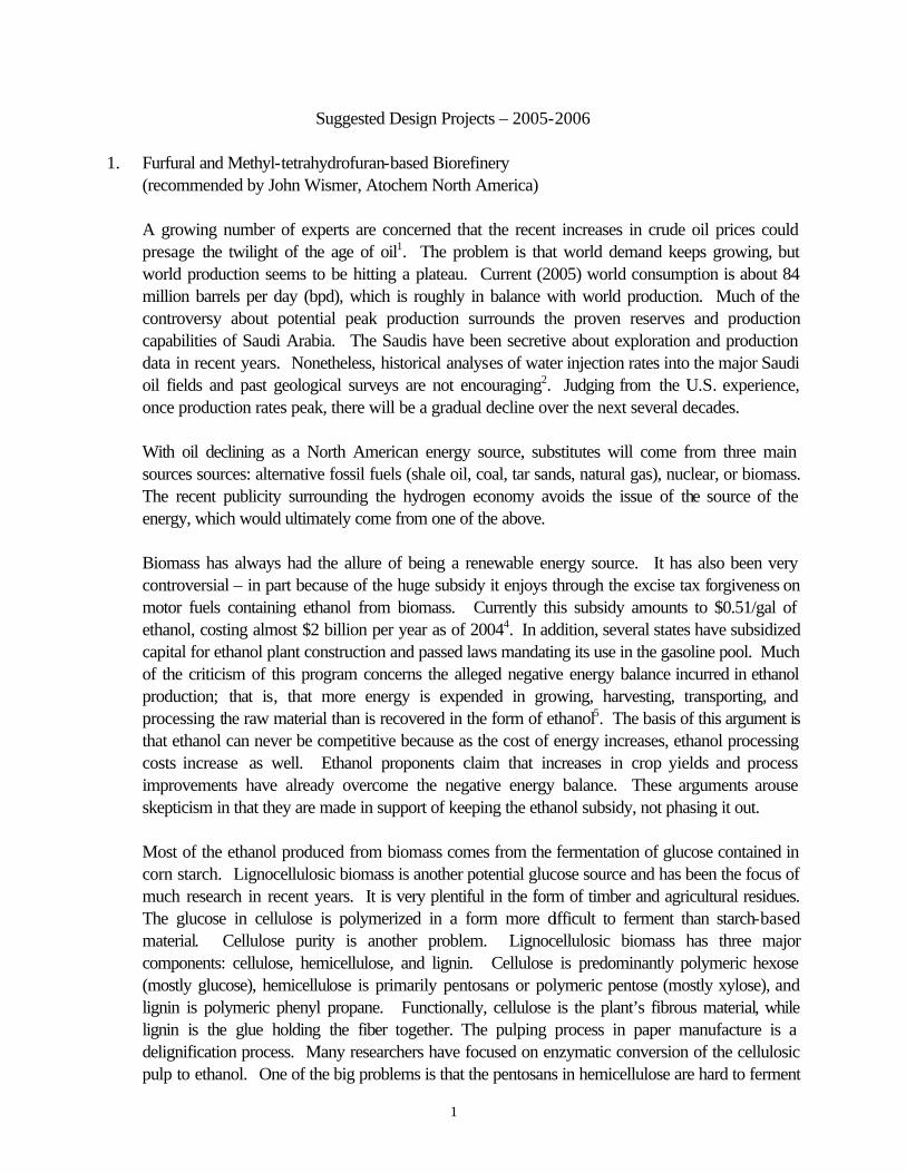
Recently, there has been increasing interest in an alternative class of methods for producing mutlicrystalline silicon wafers, known as Ribbon Growth-on Substrate (RGS) methods (Figure 4). The advantages of the RGS approach is that it is (in principle) a continuous process, it does not waste silicon material (due to sawing of ingots), and therefore could be competitive with ingot casting approaches.
Figure 4. RGS approach for growing silicon wafers [4].
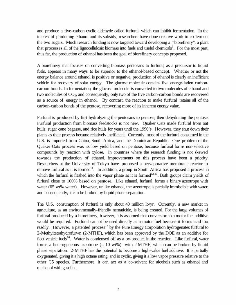
Finally, another class of solar-cell fabrication methods, the so-called thin-film approaches, involve the deposition of silicon either from the vapor phase or from solution directly onto a substrate without the need for melt-processing. As shown in Figure 5, thin-film approaches account for only a small part of the overall solar-cell market because they are not yet as well developed and will not be considered as part of this project. While RGS also currently represents a very small market share, it is increasingly likely that this will change soon as the process in Figure 4 is refined further.
Figure 2. World PV module shipments per technology. Taken from ref. [3].

20
One of the most critical metrics for determining how good a material is for PV applications is its efficiency (n), which is the fraction of impinging solar energy that can be converted into electricity. The theoretical upper limit for silicon is about 30%, and currently the highest practical values attainable are between 10% and 25%, depending strongly on the wafer growth method. While lower-efficiency solar silicon is generally cheaper and faster to manufacture, the fixed costs associated with the rest of PV module assembly, as well as the desire to limit real estate requirements, make higher-efficiency material more attractive. There are two major limitations to the solar efficiency of silicon: (1) crystal defects (grain boundaries and dislocations) and (2) impurities (mainly oxygen, carbon, and transition metals). The formation of crystal defects depends strongly on the growth method and in particular the cooling history of the material as it solidifies. In general, faster cooling leads to higher densities of defects but the absolute number is a complex function of the growth conditions. The impurity concentration is also closely related to the growth technique. For example, in both CZ and IC approaches, the crucible containing the silicon melt is lined with quartz, which dissolves during processing and introduces about 5-25 ppma oxygen impurity levels. Ref. [5] provides some information about the effects of impurities on solar cell efficiency. In general, the efficiency is a very complex function of these parameters and their interactions, but fortunately some empirical correlations exist in the literature which can be used to establish optimal process design guidelines.
Project Goals and Scope The objective of this design project is to perform a technological and economic analysis of the currently available technologies for the production of silicon-based PV modules and propose a design for a PV module plant, including the production of solar silicon wafers. Your primary focus will be to consider the competing processes for producing solar silicon wafers, which contribute about 30-45% to the total cost of a PV module. In particular your aims will be to:
a. Analyze the heat transfer characteristics in the Ingot Casting, Czochralski, and Ribbon Growth
processes using the FEMLAB software. In particular, you are to estimate feasible throughput rates as a function of equipment scale and operating conditions.
b. By performing an appropriate literature survey, find a way to empirically correlate the crystal quality (as defined by the number of defects and impurity concentration) to the growth conditions – these correlations will provide constraints on the allowable operating conditions for each process. Additional information on this aspect will be provided later. Pay special attention to the ingot casting approach because this technology is currently the most favorable for producing cost-effective solar silicon.
c. Using the results of your studies, design production plants for PV modules based on each of the various alternatives and perform an economic analysis for each. In addition to considering the solar silicon wafer fabrication methods outlined above, include analysis for the other steps required for making finished PV modules.
d. Current market demand for the raw polycrystalline material to make solar cells is so high that prices have been increasing and supply is limited. Investigate the economic feasability of

21
building an on-site polysilicon manufacturing facility to reduce (or eliminate) the dependence on external sources for the polysilicon. You can use the design report in ref. [1] to guide you in this part of the project.
References:
1. Cusack, S., E. Takizawa, and J. Tam, Silicon Wafers Through the Use of the Czochralski
Growth Process. Senior Design Project in Chemical Engineering, 2003. 2. Mueller, A., “High Throughput – High Yield Solar Silicon Ingot Production,” 1st International
Advanced Photovoltaic Manufacturing Technology Conference, Munich, 2005. [online] 3. Schönecker, A., L. J. Geerligs, and A. Mueller, “Casting Technologies for Solar Silicon
Wafers: Block Casting and Ribbon-Growth-on Substrate,” Solid State Phenomena, 95-96, 149 (2004). [online]
4. Schönecker, A., L. Laas, A. Gutjahr, M. Goris, and P. Wyers, “Ribbon-Growth-on-
Substrate: Status, Challenges and Promises of High Speed Silicon Wafer Manufacturing,” 12th Workshop on Crystalline Silicon Solar Cells, Materials and Processes, 2002. [online]
5. Ciszek, T.F., and T.H. Wang, “Silicon Float-Zone Crystal Growth as a Tool for the Study of
Defects and Impurities,” NREL Report (2000) [online at http://www.nrel.gov/docs/fy00osti/28569.pdf]
6. Websites for major silicon wafer manufacturers (solar and otherwise): Wacker Siltronic: www.wacker.com MEMC: www.memc.com DeutscheSolar: http://www.deutschesolar.de
9. Microfluidic Blood Coagulation Analyzer for High-speed, Point-of-care Diagnostics (recommended by John C. Crocker, U. Penn) The process of blood clotting in response to injury is a remarkably complex chemical process involving the rapid polymerization of fibrin filaments from monomeric fibrinogen precursors via the enzymatic activity of thrombin. The production of thrombin from its precursor prothrombin is regulated by numerous clotting factors and auxiliary proteins, resulting in thrombin’s essentially autocatalytic production at an injury site. Abnormalities of this ‘coagulation cascade’ reaction can lead to uncontrolled bleeding or, in the other extreme, undesirable clotting within the bloodstream; that is, thrombosis. Laboratory screening for common clotting abnormalities is frequently performed prior to elective surgical procedures, and additional screens for abnormal clotting function are performed periodically on those patients in post-surgical recovery, with major infections or receiving anti-thrombosis therapy (e.g., with heparin). While some clotting tests can be performed in a hospital laboratory in as little as 10 minutes using semi-automated ‘coagulation
22
analyzers’, these results are unavailable to patients in an ambulance or may be too slow for a patient in the middle of surgery. This project is to design a miniaturized, fully automated, high-speed coagulation analyzer suitable for use in operating rooms, trauma centers and ambulances. Existing coagulation analyzers are bench-top units with internal robotic fluid handling systems, reagent and buffer storage, heating and refrigeration systems, integrated centrifuges for blood separation, and optical sensors for reading out sample turbidity, color, or scattering properties, depending upon which assay is being performed. One common class of assays is performed on a blood sample in which coagulation has been suppressed by chelation of calcium ions (e.g., by using EDTA). The plasma fraction is physically separated, reagents and calcium are added to it to initiate the coagulation cascade, which is then generally monitored by turbidity of the sample. The time to the first significant change in turbidity is termed the prothrombin time (PT), which is typically of order 10 seconds. Many other assays are based upon changes to this measure of clotting speed in response to added cofactors, termed the Activated Partial Thromboplastin Time (APTT). One particularly important clotting assay detects insensitivity to a clotting co-factor called ‘protein C’. Activated Protein C Resistance (APCR) is highly correlated with the development of deep vein thrombosis (DVT), which is commonly (~20% of cases) caused by a familial mutation for clotting Factor V (FV). Obviously, diagnosis of APCR is especially important in patients undergoing major surgery or who have suffered a traumatic injury. Your designed miniaturized analyzer should determine diagnostically reliable PT, APTT and APCR data in at most 5 and preferably less than 2 minutes. It should be small and rugged enough to operate in a crowded ER or ambulance, but need not be hand-held. For a baseline design assumption, your team may assume that the instrument will consist of two parts, resembling an inkjet printer and its disposable ink cartridges. Like the printer, the ‘analyzer’ component will contain the fully reusable systems including power, temperature control, user interface, optical sources and detectors, and computing hardware for real-time analysis. Like an ink cartridge, the analyzer ‘cartridge’ will be disposable, easily swappable and contain all the reagents and microfluidic handling systems on a ‘lab-on-a-chip’, along the lines of the recently developed microfluidic platforms by Agilent or Fluidigm. Details regarding blood sampling and the patient interface are largely outside this project, as it can be assumed that the medically trained user will be familiar with blood drawing techniques, and will inject a small sample directly into the cartridge. Production costs for the reusable analyzer should be less than $20K at expected production volume, and per patient/per sample disposable cartridges should be priced at $100/unit or below. Economic and market size analysis should be performed on both the production of analyzers and disposables, but it is expected that the primary source of revenue will be the latter. The analyzers may be sold near or below cost. Coagulation assays are complicated multi-component reactions with non-linear kinetics, based on mixtures of costly, highly purified natural protein products, sera, synthetic reagents, and whole blood containing intact cells. The team can assume that all reagents are commercially available from existing coagulation analyzer manufacturers and reagent suppliers. Literature from those suppliers will provide useful information about reagent prices, storability, assay chemistry, and diagnostic utility.

23
A significant portion of this design project is to determine the best approach to realizing the above stated goals by the careful consideration of multiple alternative designs. The selection of the final implementation is up to the team and their advisor; design alternatives and selection criteria should be fully described in the final report. Design of the reusable instrument need not contain detailed component layouts, and may consist of component specifications and vendors as well as mass, volume, power and cost budgeting adequate to assess overall design feasibility and marketability. Detailed layouts, process flow diagrams, and engineering analyses of the microfluidic systems is expected. While the engineering approach to the design is unspecified, key design criteria are described below. A major design challenge is storability, as many reactants have short shelf-lives (< 1day) at ambient temperatures. One approach is to preload all required reactants into closed reservoirs on the microfluidic cartridge and to store the entire cartridges at 4°C (refrigerator/ice chest) in their hermetic packaging until use. While lower temperatures, such as –20°C (standard freezer) will extend the shelf-life of many reagents, many protein products can not be frozen without loss of activity. A minimum shelf-life of 45 days (at a specified storage temperature) should be an assumed goal, to allow for reasonable inventory procedures (at the manufacturer and user sites) and express shipping. If needed, protein reagents that unduly limit shelf-life may be lyophilized (freeze-dried) for long term storability, but the microfluidic system must then contain on-chip units for rapid reconstitution of the powder reagent, adding complexity. Reliability enhancement features for storability range from simple expiration date stamps, to positive/negative controls and calibrations built into the assay themselves, to passive color-change devices that indicate to the user that the cartridge has exceeded allowed safe storage temperatures prior to its’ insertion into the analyzer. Another major design challenge is the selection of an assay readout method. Existing coagulation assays detect fibrin polymerization via sample turbidity, optical scattering, conductivity or viscosity, while thrombin and fibrin production can be directly monitored by colorimetric and immunological methods (based on antibodies bound to a membrane or dispersed nano-particles). Many of these methods are slow, require physical separations, or are not well suited to implementation at the microfluidic scale (10-100 µm). Of particular interest, in colorimetric assays, a colorless substrate is cleaved into a light absorbing form by either: (1) the enzyme complex that produces thrombin, or (2) by thrombin itself. In these two types of assays, the amount of absorbed light versus time may be assumed to be proportional to, in the first case, thrombin (as it is produced at a proportional rate), or in the second case to fibrin (the result of thrombin’s enzymatic activity). While such assays are fast and relatively straightforward, they have two features that are undesirable in a microfluidic device: first, plasma must be separated to remove the absorption signal from the red blood cells, and second, the degree of absorption decreases linearly with the sample thickness, and could be undetectable for a 10 µm thick sample. Your design team may assume, as a baseline, a modified colorimetric assay, where the cleavable chromogenic reagent is replaced with a fluorogenic one; that is, once cleaved by the enzyme, a non-fluorescent pre-cursor becomes fluorescent (i.e., it absorbs light in one range of wavelengths

24
and re-emits the energy as light of a longer wavelength.) Thus, as with the colorimetric assay, thrombin of fibrin concentration may be followed in time by measuring fluorescent intensity. The resulting assay should have superior sensitivity in thin samples, and it may be possible to achieve acceptable results without red blood cell separation. If possible, excitation will be provided by diode-based light sources, and fluorescence will be detected by either a CCD detector or an array of discrete photodiodes. To derive useful PT, APTT and APCR data, several such fluorogenic measurements will need to be performed at different dilutions of blood, sera, and co-factors. Including controls and in situ calibrations, each cartridge will need to perform 20-50 separate batch reactions. In the interest of time, these reactions will likely need to be performed in parallel. This does not provide a major obstacle, however, as the cost of microfluidics (like microelectronics) scales with the die (chip) size more than the complexity of the circuitry within. Rather than 20 or more identical units in parallel, it may be advantageous to use a simple mixer/diluter to obtain a dilution series of a single co-factor, to reduce the number of units to one for each of the PT, APTT and APCR assays. Reference: "Microfluidic Large-Scale Integration," Science, Volume 298, Issue 5593, 18 October 2002, pp. 580-584 Vendors: Instrumentation Laboratory (coagulation analyzers and reagents): http://www.ilus.com Agilent (lab on a chip): http://www.chem.agilent.com/Scripts/PCol.asp?lPage=50 Fluidigm (integrated microfluidics): http://www.fluidigm.com/
Related Documents