WÄRTSILÄ RT-flex50 TECHNOLOGY REVIEW

Welcome message from author
This document is posted to help you gain knowledge. Please leave a comment to let me know what you think about it! Share it to your friends and learn new things together.
Transcript

WÄRTSILÄ RT-flex50 TECHNOLOGY REVIEW
2
INTRODUCTION ............................................................ 5
DEVELOPMENT BACKGROUND ..................................... 6
RT-flex: CONCEPT AND BENEFITS ................................. 7
RT-flex COMMON-RAIL SYSTEM APPLIED ...................... 8
RT-flex: REAL IN-SERVICE FUEL ECONOMY .................. 10
RT-flex: CLEANER IN THE ENVIRONMENT ..................... 10
ENGINE STRUCTURE .................................................. 11
RUNNING GEAR ......................................................... 13
COMBUSTION CHAMBER ............................................ 14
PISTON-RUNNING BEHAVIOUR .................................... 15
TURBOCHARGING AND SCAVENGE AIR SYSTEM .......... 16
INSTALLATION ARRANGEMENTS ................................. 17
MAINTENANCE .......................................................... 18
MAIN TECHNICAL DATA .............................................. 19
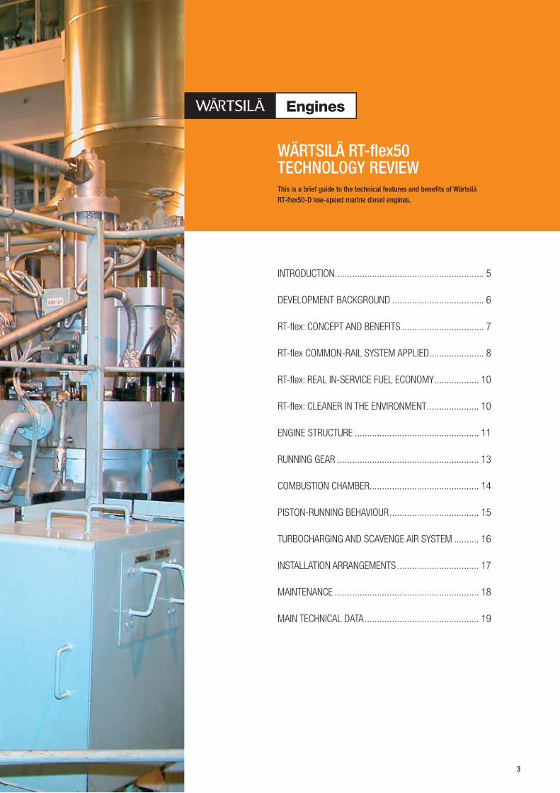
This is a brief guide to the technical features and benefits of Wärtsilä RT‑flex50‑D low‑speed marine diesel engines.
WÄRTSILÄ RT‑flex50 TECHNOLOGY REVIEW
3

Six‑cylinder Wärtsilä RT‑flex50 engine developing 9960 kW (13,560 bhp).
4

Output kW
80 000
60 000
50 000
40 000
30 000
20 000
10 000
8 000
6 000
4 000
rev/min
Output bhp
100 000
80 000
60 000
40 000
20 000
10 000
8 000
6 000
60 70 80 90 100 120 140
Engine speed
RTA72U-B
RT-flex84T-DRTA84T-D
RT-flex68-DRTA68-D
RT-flex58T-DRTA58T-D
RTA48T-D
RT-flex96CRTA96C
RT-flex60C-B
RT-flex50-DRTA50-D
RTA52U
RTA62U-B
RT-flex82TRTA82T
RT-flex82CRTA82C
INTRODUCTIONThe Wärtsilä RT-flex50 low-speed marine
diesel engines, with a power range of 6100 to
13,960 kW, are tailor-made for the economic,
reliable propulsion of a wide range of ship
types and sizes from handymax and panamax
bulk carriers to product tankers and feeder
container vessels.
They offer clear, substantial benefits:
High reliability •Three years’ operation between overhauls •Economical fuel consumption over the •whole operating range
Low cylinder oil feed rate •Low system oil losses •Low exhaust gas emissions •Capable of extremely low, stable running •speeds.
The Wärtsilä RT-flex50 two-stroke diesel
engine was introduced in March 2003 to
provide a competitive prime mover in its
power range for a broad range of ship types
and sizes. It combines the latest common-
rail technology for fuel injection and valve
actuation with fully-integrated electronic
control and the well-established Wärtsilä
low-speed engine principles. It thus brings
the same benefits of common-rail technology
to bulk carriers, tankers, feeder container
ships and medium-sized cargo ships as have
already been demonstrated in Wärtsilä low-
speed engines, of several sizes up to the most
powerful.
PRINCIPAL PARAMETERS OF WÄRTSILÄ RT‑flex50‑D ENGINES
Bore mm 500
Stroke mm 2050
Output MCR, R1 kW/cyl 1745
bhp/cyl 2375
Speed range, R1–R3 rpm 124–99
BMEP at R1 bar 21.0
Pmax bar 170
Mean piston speed at R1 m/s 8.5
Number of cylinders 5–8
BSFC: at full load, R1 g/kWh 169
g/bhph 124
5
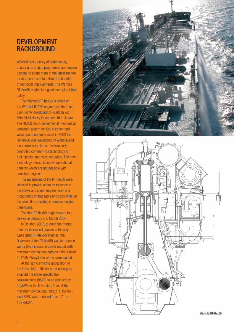
Wärtsilä RT‑flex50.
DEVELOPMENT BACKGROUND
Wärtsilä has a policy of continuously
updating its engine programme and engine
designs to adapt them to the latest market
requirements and to deliver the benefits
of technical improvements. The Wärtsilä
RT-flex50 engine is a good example of this
policy.
The Wärtsilä RT-flex50 is based on
the Wärtsilä RTA50 engine type that has
been jointly developed by Wärtsilä with
Mitsubishi Heavy Industries Ltd in Japan.
The RTA50 has a conventional mechanical
camshaft system for fuel injection and
valve operation. Introduced in 2003 the
RT-flex50 was developed by Wärtsilä and
incorporates the latest electronically-
controlled common-rail technology for
fuel injection and valve actuation. The new
technology offers distinctive operational
benefits which are not possible with
camshaft engines.
The parameters of the RT-flex50 were
selected to provide optimum matches to
the power and speed requirements of a
broad range of ship types and sizes while, at
the same time, leading to compact engine
dimensions.
The first RT-flex50 engines went into
service in January and March 2006.
In October 2007, to meet the market
need for increased powers in the ship
types using RT-flex50 engines, the
D version of the RT-flex50 was introduced
with a 5% increase in power output with
maximum continuous outputs being raised
to 1745 kW/cylinder at the same speed.
At the same time the application of
the latest, high-efficiency turbochargers
enabled the brake specific fuel
consumptions (BSFC) to be reduced by
2 g/kWh in the D version. Thus at the
maximum continuous rating R1, the full-
load BSFC was reduced from 171 to
169 g/kWh.
6

Volumetricfuel injectioncontrol unit
Fuelinjectors
Exhaust valveactuator
Exhaust valveactuating unit
Crankangle
sensor
WECScontrolsystem
30bar starting air
200bar servo oil
1000bar fuel HFO / MDO
Schematic of the Wärtsilä RT‑fl ex system with electronically‑controlled common‑rail systems for fuel injection and exhaust valve operation.
Wärtsilä 6RT‑fl ex50 with the principal elements of the RT‑fl ex system in yellow.
RT‑fl ex: CONCEPT AND BENEFITS
The Wärtsilä RT-fl ex system is the result of a
long project since the 1980s to develop low-
speed marine engines without the constraints
imposed by mechanical drive of fuel injection
pumps and valve actuation pumps but with
far greater fl exibility in engine setting to reach
future requirements. The objective is to deliver
operational benefi ts to the shipowners.
The Wärtsilä RT-fl ex50 is basically a
standard Wärtsilä low-speed two-stroke marine
diesel engine in which a common-rail system
for fuel injection and exhaust valve actuation,
and full electronic control of these engine
functions, is employed instead of the traditional
mechanical camshaft system.
The RT-fl ex engines offer a number of
interesting benefi ts to shipowners and
operators:
Smokeless operation at all operating speeds •Lower steady running speeds, in the range •of 10–15 per cent nominal speed, obtained
smokelessly through sequential shut-off
of injectors while continuing to run on all
cylinders
Reduced running costs through reduced •part-load fuel consumption and longer
times between overhauls
Reduced maintenance requirements, with •simpler setting of the engine. The ‘as-
new’ running settings are automatically
maintained
Reduced maintenance costs through precise •volumetric fuel injection control leading to
extendable times between overhauls. The
common-rail system with its volumetric
control gives excellent balance in engine
power developed between cylinders and
between cycles, with precise injection timing
and equalised thermal loads
Reliability is given by long-term testing of •common-rail hardware in component test rigs
Higher availability owing to the integrated •monitoring functions
High availability also given by the built-in •redundancy, provided by the ample capacity
and duplication in the supply pumps,
main delivery pipes, crank-angle sensors,
electronic control units and other key
elements.
7

Cylinder top level of the RT‑fl ex50 engine with the fuel injection and valve actuation pipes rising out of the rail unit under the platform.
Rail unit of the RT‑fl ex50 engine showing the fuel rail in orange and the servo oil rail in blue.
The common rail for fuel injection is a
single-piece pipe running the length of
the engine at just below the cylinder cover
level. The common rail and other related
pipe work are neatly arranged beneath the
top engine platform and readily accessible
from above.
The common rail is fed with heated fuel oil
at the usual high pressure (nominally 1000 bar)
ready for injection. The supply unit has a number
of high-pressure pumps actuated by cams
driven through gearing from the crankshaft.
Fuel is delivered from this common rail
through a separate injection control unit (ICU)
for each engine cylinder to the standard fuel
injection valves which are operated in the usual
way by the high-pressure fuel oil. The injection
control units are mounted directly on the fuel
rail. Using quick-acting Wärtsilä rail valves, they
regulate the timing of fuel injection, control
the volume of fuel injected, and set the shape
of the injection pattern. Each ICU serves the
two fuel injection valves in its corresponding
cylinder cover. Each injection valve is separately
controlled so that, although they normally act in
unison, they can also be programmed to operate
separately as necessary.
The key features of the Wärtsilä RT-fl ex
common-rail system are:
Precise volumetric control of fuel injection, •with integrated fl ow-out security
Variable injection rate shaping and free •selection of injection pressure
Stable pressure levels in common rail and •supply pipes
RT‑fl ex COMMON‑RAIL SYSTEM APPLIED
8
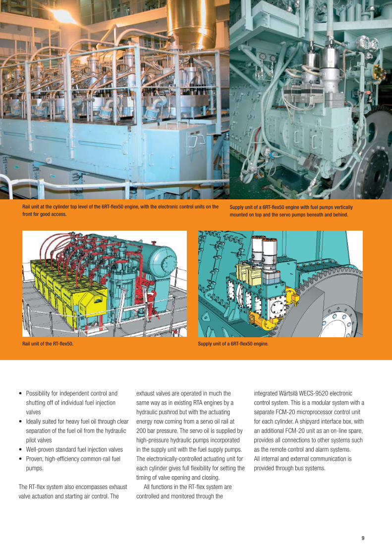
Supply unit of a 6RT‑flex50 engine with fuel pumps vertically mounted on top and the servo pumps beneath and behind.
Rail unit at the cylinder top level of the 6RT‑flex50 engine, with the electronic control units on the front for good access.
Supply unit of a 6RT‑flex50 engine.Rail unit of the RT‑flex50.
Possibility for independent control and •shutting off of individual fuel injection
valves
Ideally suited for heavy fuel oil through clear •separation of the fuel oil from the hydraulic
pilot valves
Well-proven standard fuel injection valves •Proven, high-efficiency common-rail fuel •pumps.
The RT-flex system also encompasses exhaust
valve actuation and starting air control. The
exhaust valves are operated in much the
same way as in existing RTA engines by a
hydraulic pushrod but with the actuating
energy now coming from a servo oil rail at
200 bar pressure. The servo oil is supplied by
high-pressure hydraulic pumps incorporated
in the supply unit with the fuel supply pumps.
The electronically-controlled actuating unit for
each cylinder gives full flexibility for setting the
timing of valve opening and closing.
All functions in the RT-flex system are
controlled and monitored through the
integrated Wärtsilä WECS-9520 electronic
control system. This is a modular system with a
separate FCM-20 microprocessor control unit
for each cylinder. A shipyard interface box, with
an additional FCM-20 unit as an on-line spare,
provides all connections to other systems such
as the remote control and alarm systems.
All internal and external communication is
provided through bus systems.
9
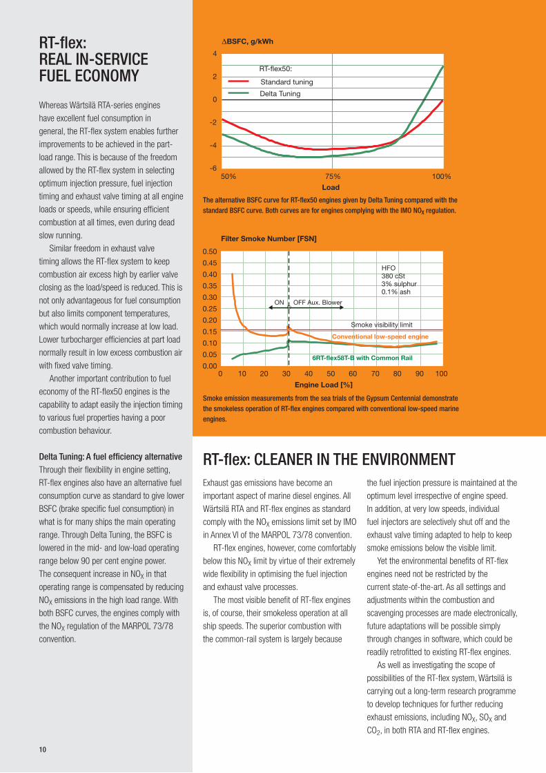
The alternative BSFC curve for RT‑flex50 engines given by Delta Tuning compared with the standard BSFC curve. Both curves are for engines complying with the IMO NOX regulation.
Smoke emission measurements from the sea trials of the Gypsum Centennial demonstrate the smokeless operation of RT‑flex engines compared with conventional low‑speed marine engines.
RT‑flex: REAL IN‑SERVICE FUEL ECONOMY
Whereas Wärtsilä RTA-series engines
have excellent fuel consumption in
general, the RT-flex system enables further
improvements to be achieved in the part-
load range. This is because of the freedom
allowed by the RT-flex system in selecting
optimum injection pressure, fuel injection
timing and exhaust valve timing at all engine
loads or speeds, while ensuring efficient
combustion at all times, even during dead
slow running.
Similar freedom in exhaust valve
timing allows the RT-flex system to keep
combustion air excess high by earlier valve
closing as the load/speed is reduced. This is
not only advantageous for fuel consumption
but also limits component temperatures,
which would normally increase at low load.
Lower turbocharger efficiencies at part load
normally result in low excess combustion air
with fixed valve timing.
Another important contribution to fuel
economy of the RT-flex50 engines is the
capability to adapt easily the injection timing
to various fuel properties having a poor
combustion behaviour.
Delta Tuning: A fuel efficiency alternativeThrough their flexibility in engine setting,
RT-flex engines also have an alternative fuel
consumption curve as standard to give lower
BSFC (brake specific fuel consumption) in
what is for many ships the main operating
range. Through Delta Tuning, the BSFC is
lowered in the mid- and low-load operating
range below 90 per cent engine power.
The consequent increase in NOX in that
operating range is compensated by reducing
NOX emissions in the high load range. With
both BSFC curves, the engines comply with
the NOX regulation of the MARPOL 73/78
convention.
Exhaust gas emissions have become an
important aspect of marine diesel engines. All
Wärtsilä RTA and RT-flex engines as standard
comply with the NOX emissions limit set by IMO
in Annex VI of the MARPOL 73/78 convention.
RT-flex engines, however, come comfortably
below this NOX limit by virtue of their extremely
wide flexibility in optimising the fuel injection
and exhaust valve processes.
The most visible benefit of RT-flex engines
is, of course, their smokeless operation at all
ship speeds. The superior combustion with
the common-rail system is largely because
the fuel injection pressure is maintained at the
optimum level irrespective of engine speed.
In addition, at very low speeds, individual
fuel injectors are selectively shut off and the
exhaust valve timing adapted to help to keep
smoke emissions below the visible limit.
Yet the environmental benefits of RT-flex
engines need not be restricted by the
current state-of-the-art. As all settings and
adjustments within the combustion and
scavenging processes are made electronically,
future adaptations will be possible simply
through changes in software, which could be
readily retrofitted to existing RT-flex engines.
As well as investigating the scope of
possibilities of the RT-flex system, Wärtsilä is
carrying out a long-term research programme
to develop techniques for further reducing
exhaust emissions, including NOX, SOX and
CO2, in both RTA and RT-flex engines.
RT‑flex: CLEANER IN THE ENVIRONMENT
50% 75% 100%
Load
-6
-4
-2
0
2
4
BSFC, g/kWh
RT-flex50:
Standard tuning
Delta Tuning
10
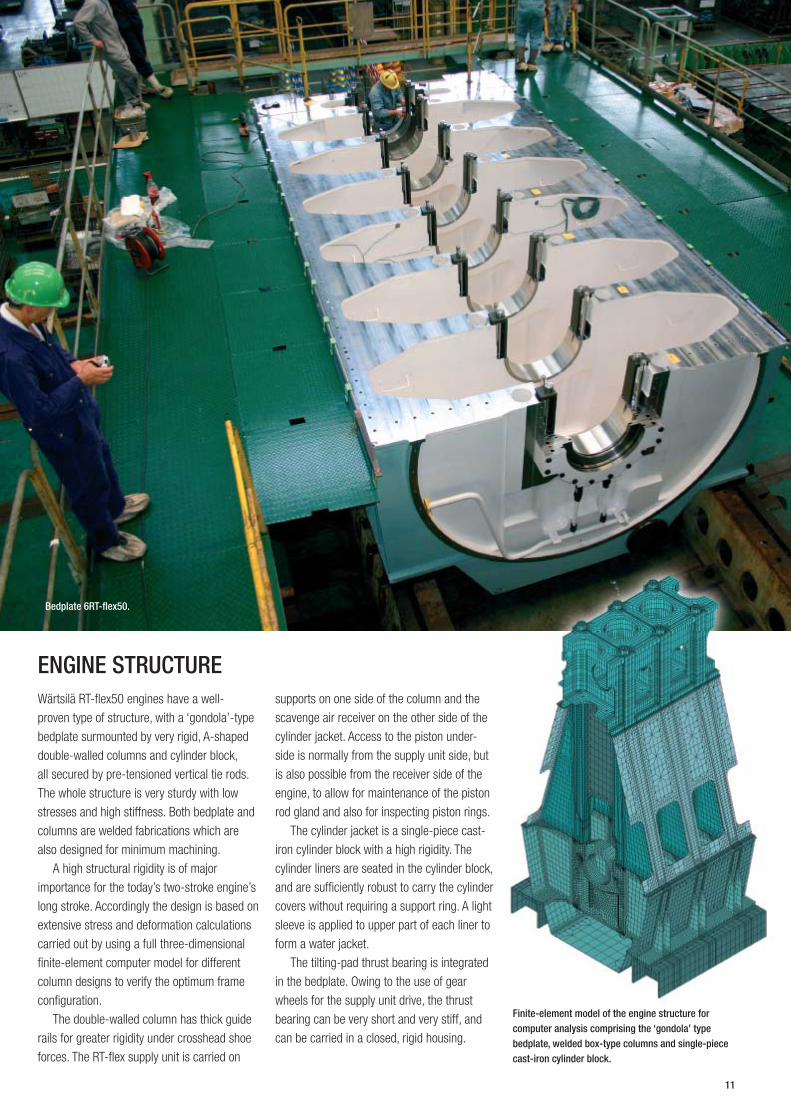
Finite‑element model of the engine structure for computer analysis comprising the ‘gondola’ type bedplate, welded box‑type columns and single‑piece cast‑iron cylinder block.
Bedplate 6RT‑fl ex50.
Wärtsilä RT-fl ex50 engines have a well-
proven type of structure, with a ‘gondola’-type
bedplate surmounted by very rigid, A-shaped
double-walled columns and cylinder block,
all secured by pre-tensioned vertical tie rods.
The whole structure is very sturdy with low
stresses and high stiffness. Both bedplate and
columns are welded fabrications which are
also designed for minimum machining.
A high structural rigidity is of major
importance for the today’s two-stroke engine’s
long stroke. Accordingly the design is based on
extensive stress and deformation calculations
carried out by using a full three-dimensional
fi nite-element computer model for different
column designs to verify the optimum frame
confi guration.
The double-walled column has thick guide
rails for greater rigidity under crosshead shoe
forces. The RT-fl ex supply unit is carried on
supports on one side of the column and the
scavenge air receiver on the other side of the
cylinder jacket. Access to the piston under-
side is normally from the supply unit side, but
is also possible from the receiver side of the
engine, to allow for maintenance of the piston
rod gland and also for inspecting piston rings.
The cylinder jacket is a single-piece cast-
iron cylinder block with a high rigidity. The
cylinder liners are seated in the cylinder block,
and are suffi ciently robust to carry the cylinder
covers without requiring a support ring. A light
sleeve is applied to upper part of each liner to
form a water jacket.
The tilting-pad thrust bearing is integrated
in the bedplate. Owing to the use of gear
wheels for the supply unit drive, the thrust
bearing can be very short and very stiff, and
can be carried in a closed, rigid housing.
ENGINE STRUCTURE
11
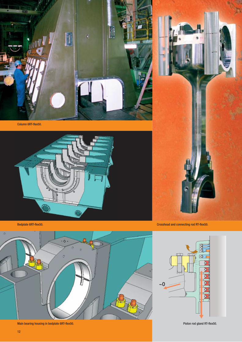
Main bearing housing in bedplate 6RT‑fl ex50.
Bedplate 6RT‑fl ex50.
Column 6RT‑fl ex50.
~0
Crosshead and connecting rod RT‑fl ex50.
Piston rod gland RT‑fl ex50.
12

Crosshead RT‑fl ex50.
Lowering the crankshaft into the bedplate, 6RT‑fl ex50.
Crosshead and connecting rod RT‑fl ex50.
RUNNING GEARThe running gear comprises the crankshaft,
connecting rods, pistons and piston rods,
together with their associated bearings and
piston rod glands.
The crankshaft is semi-built comprising
combined crank pin/web elements forged
from a solid ingot and the journal pins are then
shrunk into the crank webs.
The main bearings have white metal shells.
Each main bearing cap is held down by four
elastic holding down studs.
A better understanding of the main bearing
loads is obtained with today’s fi nite-element
analysis and elasto-hydrodynamic calculation
techniques as they take into account the
structure around the bearing and vibration
of the shaft. The FE model comprises the
complete shaft and its bearings together
with the surrounding structure. Boundary
conditions, including the crankshaft stiffness,
can thus be fed into the bearing calculation.
The crosshead bearing is designed to the
same principles as for all other RTA and RT-fl ex
engines. It also features a full-width lower
half bearing with the crosshead pin being of
uniform diameter. The crosshead bearings
have thin-walled shells of white metal for a
high load-bearing capacity.
Extensive development work has been
put into the piston rod gland because of
its importance in keeping crankcase oil
consumption down to a reasonable level and
maintaining the quality of the system oil.
The piston rod glands are of an improved
design with highly-effective dirt scraping
action in the top part and system oil scraping
in the lower part. The glands are provided
with large drain areas and channels. Losses
of system oil are minimised as all scraped-off
oil is recirculated internally to the crankcase.
Hardened piston rods are now standard
to ensure long-term stability in the gland
behaviour.
13
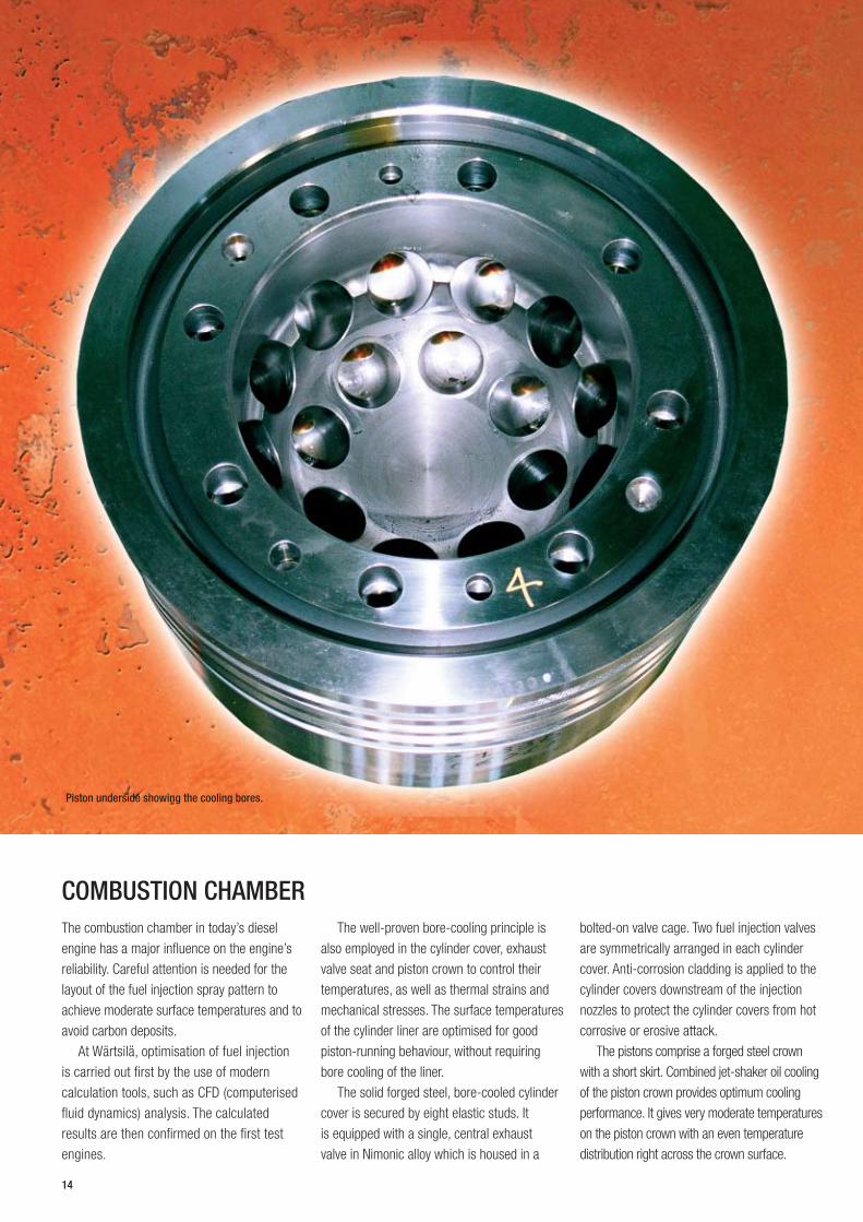
Piston underside showing the cooling bores.
The combustion chamber in today’s diesel
engine has a major influence on the engine’s
reliability. Careful attention is needed for the
layout of the fuel injection spray pattern to
achieve moderate surface temperatures and to
avoid carbon deposits.
At Wärtsilä, optimisation of fuel injection
is carried out first by the use of modern
calculation tools, such as CFD (computerised
fluid dynamics) analysis. The calculated
results are then confirmed on the first test
engines.
The well-proven bore-cooling principle is
also employed in the cylinder cover, exhaust
valve seat and piston crown to control their
temperatures, as well as thermal strains and
mechanical stresses. The surface temperatures
of the cylinder liner are optimised for good
piston-running behaviour, without requiring
bore cooling of the liner.
The solid forged steel, bore-cooled cylinder
cover is secured by eight elastic studs. It
is equipped with a single, central exhaust
valve in Nimonic alloy which is housed in a
bolted-on valve cage. Two fuel injection valves
are symmetrically arranged in each cylinder
cover. Anti-corrosion cladding is applied to the
cylinder covers downstream of the injection
nozzles to protect the cylinder covers from hot
corrosive or erosive attack.
The pistons comprise a forged steel crown
with a short skirt. Combined jet-shaker oil cooling
of the piston crown provides optimum cooling
performance. It gives very moderate temperatures
on the piston crown with an even temperature
distribution right across the crown surface.
COMBUSTION CHAMBER
14
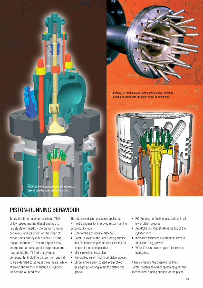
Piston of RT‑flex50 (below) with nozzles (above) directing cooling oil sprays into the piston crown cooling bores.
Detail of the combustion chamber with bore‑cooled cylinder cover and piston crown.
Today the time between overhaul (TBO)
of low-speed marine diesel engines is
largely determined by the piston-running
behaviour and its effect on the wear of
piston rings and cylinder liners. For this
reason, Wärtsilä RT-flex50 engines now
incorporate a package of design measures
that enable the TBO of the cylinder
components, including piston ring renewal,
to be extended to at least three years, while
allowing the further reduction of cylinder
lubricating oil feed rate.
The standard design measures applied to
RT-flex50 engines for improved piston-running
behaviour include:
Liner of the appropriate material •Careful turning of the liner running surface •and plateau honing of the liner over the full
length of the running surface
Mid-stroke liner insulation •Pre-profiled piston rings in all piston grooves •Chromium-ceramic coated, pre-profiled •gas-tight piston ring in the top piston ring
groove
RC (Running-in Coating) piston rings in all •lower piston grooves
Anti-Polishing Ring (APR) at the top of the •cylinder liner
Increased thickness of chromium layer in •the piston-ring grooves.
Wärtsilä accumulator system for cylinder •lubrication.
A key element is the deep-honed liner.
Careful machining and deep honing gives the
liner an ideal running surface for the piston
PISTON‑RUNNING BEHAVIOUR
15

Turbocharging and scavenge air system of the 6RT‑fl ex50.
Piston and piston rod of the RT‑fl ex50. The piston has a chromium‑ceramic coated gas‑tight ring in the top groove, and RC (Running‑in Coating) piston rings in all lower piston grooves.
rings, together with an optimum surface
microstructure.
The Anti-Polishing Ring prevents the build
up of deposits on the top land of the piston
which can damage the oil fi lm on the liner and
cause bore polishing.
It is also important that the liner wall
temperature is optimised to keep the liner
surface above the dew point temperature
throughout the piston stroke to avoid cold
corrosion. At the same time, the ‘underslung’
scavenge air receiver and the highly-effi cient
vane-type water separators with effective
water drainage arrangements ensure that as
much water as possible is taken out of the
scavenge air.
Load-dependent cylinder lubrication
is provided by the well-proven Wärtsilä
accumulator system which provides the
timely quantity of lubricating oil for good
piston-running. The lubricating oil feed rate
is controlled according to the engine load
and can also be adjusted according to engine
condition. The system allows feed rates down
to 1.1 g/kWh for engine loads of 50–100%
and all fuel sulphur contents above 1.5%,
though a feed rate of 0.9 g/kWh is possible
after analysis of engine performance.
TURBOCHARGING AND SCAVENGE AIR SYSTEMThe RT-fl ex50 engines are unifl ow scavenged
with air inlet ports in the lower part of the
cylinder and a single, central exhaust valve in
the cylinder cover. Scavenge air is delivered
by a constant-pressure turbocharging system
with one or more high-effi ciency exhaust gas
turbochargers depending on the numbers of
cylinders. For starting and during slow-running,
the scavenge air delivery is augmented by
electrically-driven auxiliary blowers.
The scavenge air receiver is of an
underslung design with integral non-return
fl aps, air cooler, water separator and the
auxiliary blowers. The turbochargers are
mounted on the scavenge air receiver which
also carries the support for the exhaust
manifold.
Immediately after the horizontal air cooler,
the scavenge air is swung round 180 degrees
to the engine cylinders, in the process
passing through the vertically-arranged
16
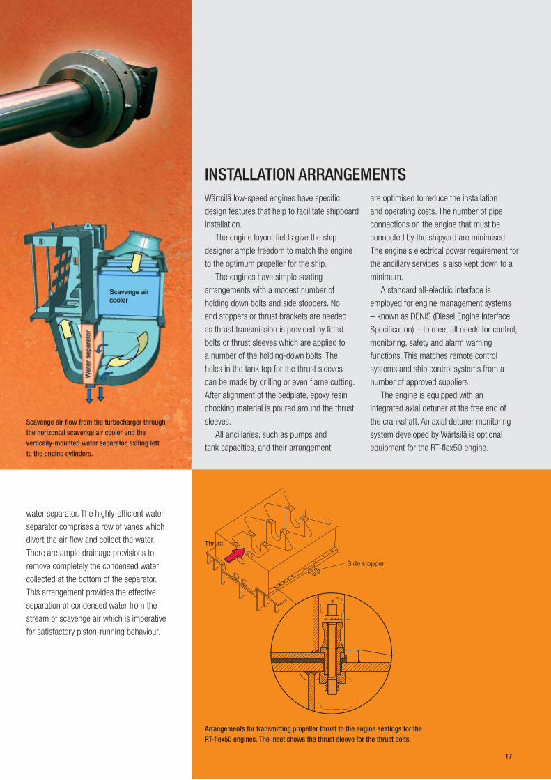
Side stopper
Thrust
Scavenge air fl ow from the turbocharger through the horizontal scavenge air cooler and the vertically‑mounted water separator, exiting left to the engine cylinders.
Arrangements for transmitting propeller thrust to the engine seatings for the RT‑fl ex50 engines. The inset shows the thrust sleeve for the thrust bolts.
water separator. The highly-effi cient water
separator comprises a row of vanes which
divert the air fl ow and collect the water.
There are ample drainage provisions to
remove completely the condensed water
collected at the bottom of the separator.
This arrangement provides the effective
separation of condensed water from the
stream of scavenge air which is imperative
for satisfactory piston-running behaviour.
Wärtsilä low-speed engines have specifi c
design features that help to facilitate shipboard
installation.
The engine layout fi elds give the ship
designer ample freedom to match the engine
to the optimum propeller for the ship.
The engines have simple seating
arrangements with a modest number of
holding down bolts and side stoppers. No
end stoppers or thrust brackets are needed
as thrust transmission is provided by fi tted
bolts or thrust sleeves which are applied to
a number of the holding-down bolts. The
holes in the tank top for the thrust sleeves
can be made by drilling or even fl ame cutting.
After alignment of the bedplate, epoxy resin
chocking material is poured around the thrust
sleeves.
All ancillaries, such as pumps and
tank capacities, and their arrangement
INSTALLATION ARRANGEMENTSare optimised to reduce the installation
and operating costs. The number of pipe
connections on the engine that must be
connected by the shipyard are minimised.
The engine’s electrical power requirement for
the ancillary services is also kept down to a
minimum.
A standard all-electric interface is
employed for engine management systems
– known as DENIS (Diesel Engine Interface
Specifi cation) – to meet all needs for control,
monitoring, safety and alarm warning
functions. This matches remote control
systems and ship control systems from a
number of approved suppliers.
The engine is equipped with an
integrated axial detuner at the free end of
the crankshaft. An axial detuner monitoring
system developed by Wärtsilä is optional
equipment for the RT-fl ex50 engine.
17
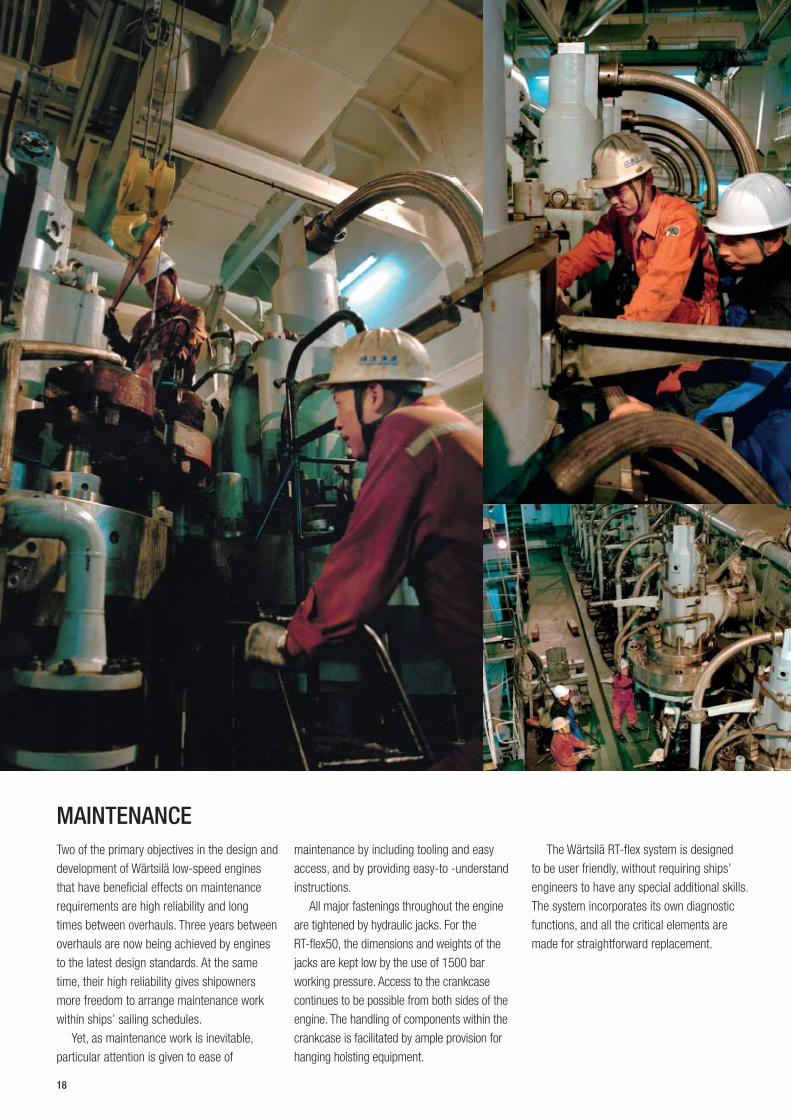
MAINTENANCETwo of the primary objectives in the design and
development of Wärtsilä low-speed engines
that have beneficial effects on maintenance
requirements are high reliability and long
times between overhauls. Three years between
overhauls are now being achieved by engines
to the latest design standards. At the same
time, their high reliability gives shipowners
more freedom to arrange maintenance work
within ships’ sailing schedules.
Yet, as maintenance work is inevitable,
particular attention is given to ease of
maintenance by including tooling and easy
access, and by providing easy-to -understand
instructions.
All major fastenings throughout the engine
are tightened by hydraulic jacks. For the
RT-flex50, the dimensions and weights of the
jacks are kept low by the use of 1500 bar
working pressure. Access to the crankcase
continues to be possible from both sides of the
engine. The handling of components within the
crankcase is facilitated by ample provision for
hanging hoisting equipment.
The Wärtsilä RT-flex system is designed
to be user friendly, without requiring ships’
engineers to have any special additional skills.
The system incorporates its own diagnostic
functions, and all the critical elements are
made for straightforward replacement.
18
C G
D
E
F
AK BI
MAIN TECHNICAL DATA
DEFINITIONS:Dimensions and weights: All dimensions are in millimetres and are •not binding. The engine weight is net in metric tonnes (t), without oil
and water, and is not binding.
R1, R2, R3, R4 = power/speed ratings at the four corners of the •engine layout field (see diagram).
R1 = engine Maximum Continuous Rating (MCR). •Contract-MCR (CMCR) = selected rating point for particular •installation. Any CMCR point can be selected within the engine
layout field.
BSFC = brake specific fuel consumptions (BSFC). All figures are •quoted for fuel of lower calorific value 42.7 MJ/kg, and for ISO
standard reference conditions (ISO 15550 and 3046). The BSFC
figures are given with a tolerance of +5%.
The values of power in kilowatts and fuel consumption in g/kWh •are the standard figures, and discrepancies occur between these
and the corresponding brake horsepower (bhp) values owing to the
rounding of numbers. For definitive values, please contact Wärtsilä
local offices.
ISO standard reference conditions •Total barometric pressure at R1 .........................................1.0 bar
Suction air temperature .......................................................25 °C
Relative humidity .................................................................. 30%
Scavenge air cooling water temperature:
– with sea water .................................................................25 °C
– with fresh water ...............................................................29 °C
Speed
Enginelayoutfield
Engine-MCRPower
R4
R3
R2
R1
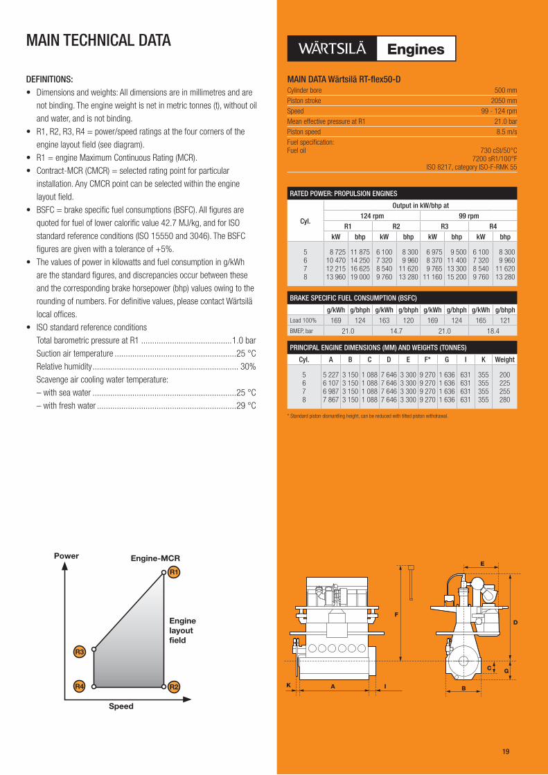
MAIN DATA Wärtsilä RT‑flex50‑DCylinder bore 500 mmPiston stroke 2050 mmSpeed 99 - 124 rpmMean effective pressure at R1 21.0 barPiston speed 8.5 m/sFuel specification: Fuel oil 730 cSt/50°C 7200 sR1/100°F ISO 8217, category ISO-F-RMK 55
RATED POWER: PROPULSION ENGINES
Cyl.
Output in kW/bhp at124 rpm 99 rpm
R1 R2 R3 R4kW bhp kW bhp kW bhp kW bhp
5 6 7 8
8 725 10 470 12 215 13 960
11 87514 25016 62519 000
6 1007 3208 5409 760
8 300 9 96011 62013 280
6 975 8 370 9 76511 160
9 50011 40013 30015 200
6 1007 3208 5409 760
8 300 9 96011 62013 280
BRAKE SPECIFIC FUEL CONSUMPTION (BSFC)
g/kWh g/bhph g/kWh g/bhph g/kWh g/bhph g/kWh g/bhphLoad 100% 169 124 163 120 169 124 165 121BMEP, bar 21.0 14.7 21.0 18.4
PRINCIPAL ENGINE DIMENSIONS (MM) AND WEIGHTS (TONNES)
Cyl. A B C D E F* G I K Weight
5 6 7 8
5 227 6 107 6 987 7 867
3 150 3 150 3 150 3 150
1 088 1 088 1 088 1 088
7 646 7 646 7 646 7 646
3 300 3 300 3 300 3 300
9 270 9 270 9 270 9 270
1 636 1 636 1 636 1 636
631 631 631 631
355 355 355 355
200 225 255 280
* Standard piston dismantling height, can be reduced with tilted piston withdrawal.
19
WÄRTSILÄ® is a registered trademark. Copyright © 2008 Wärtsilä Corporation.
Wärtsilä enhances the business of its customers by providing them
with complete lifecycle power solutions. When creating better and
environmentally compatible technologies, Wärtsilä focuses on the
marine and energy markets with products and solutions as well as
services. Through innovative products and services, Wärtsilä sets out
to be the most valued business partner of all its customers. This is
achieved by the dedication of more than 16,000 professionals manning
150 Wärtsilä locations in 70 countries around the world. Wärtsilä is
listed on The Nordic Exchange in Helsinki, Finland.
03.2
008
/ B
ock´
s O
ffice
/ W
aasa
Gra
phi
cs
Related Documents