ALLEN&HEATH WARNING – HIGH VOLTAGES Power Supply Unit (PSU) work should only be carried out by qualified personnel. We recommend that you use an approved Allen & Heath service centre for all power supply work. Please contact your local Allen & Heath distributor for more details. http://www.allen-heath.com/

Welcome message from author
This document is posted to help you gain knowledge. Please leave a comment to let me know what you think about it! Share it to your friends and learn new things together.
Transcript

ALLEN&HEATH
WARNING – HIGH VOLTAGES
Power Supply Unit (PSU) work should only
be carried out by qualified personnel.
We recommend that you use an approved Allen & Heath
service centre for all power supply work.
Please contact your local Allen & Heath distributor for more details.
http://www.allen-heath.com/

PUBLICATION AP2974
SERVICEMANUAL
DR12812 IN 8 OUT
24-BIT DIGITAL
MIX PROCESSOR
DR128 SERVICE MANUAL
copyright © 1997 ALLEN & HEATH. All rights reserved Publication ..................... AP2974 Issue 1
HOW TO USE THIS MANUAL
This service manual is published in two sections:
Section A: contains the INSTALLATION / USER GUIDE which includesdetails of INSTALLATION, CALIBRATION andOPERATION for the DR 128.
Section B: contains the SERVICE INFORMATION which includesdetails of SERVICE PROCEDURES, SPARE PARTS &ASSEMBLIES and CIRCUIT BOARD DIAGRAMS for theDR 128.
DR128 SERVICE MANUAL
SECTION A
DR 128 INSTALLATION / USER GUIDE
CAUTIONRefer all installation, calibration and service work
to qualified service personnel
A

� �������� � ����� �� ���� ����� ����� ���� � �
Limited One Year Warranty
���� ����� � � ���� � �� ���� �� ��� �� �� ����� � ����� � �� � �� ��� ���� ���� ���� ������ �� � ���� �� �� ����� ����� ��� ����� �� ��� �� � ���� ��� �� ������ �� �� ��� ������ � �����
�� ����� ��� ���� ��!�� �� ������� ��� � ���� ������ ��� ����� ���� �"������ � � ���������� � � �� ���� ��� �� �� ���� ���� #�� ������ ���� ����
$� ��� �!��� �� � ���� ������ � ����� ��� ������!� ��� �� ����� � ����� �� ��� ������� ���� � ���� � �������� ��� ��� �� ��� � �� ��� ��%��� �� ��� ������������������&
Conditions of Warranty��� ��� �"������ � � ���� ���� ��� � ���� �� �� ���� ��� ���� ��� ����������� �� ����
���� #��
��� ��� �"������ � � ��� ���� ��%��� �� ����� ������ ������ �� ������ �' �������' �� ���� ���� ����� �� � � ������� �� ��� ���� #�� �� (��!��� ) � �' �� ����!� ������� � �����
��� ��� ������ �� %������' ���� ���� �� ��� �� � � ���� � � �� ����� � ����� ����� ������� ����
��� ��� ������!� ��� �� �� �� ������' � ��� �� ���*� �' �� ����� � ����� �� ��� ������� ���� ���� ����� �� ���� ��
��� ����� �� �� ������ ���� �� � ��� �� !�� �� ���� � ��
����� ����� �� � �� ��� ���� �� �� � ��� $� ����� ����������� ��� ����� � � ! �� ��������� ��� � ��"�������� +���� ���� ��� ����� � ����� ���� ��� �� ����� �� �� ��� ����� � � ����
,-./0 ���� #�� �1/234 $��� 4 +�������� 5 .223 ����� � �� �� ��� ������ �����!�
���� ���������������������� ���������� ��������� ����������� � ��� ��!"#��$#���� ���� "�#��#���� ���� ���� ������ %��� &������� � ��� ��'�#��#��������"�#$!#����
(���)���� ������������
*%%�+�,�-�*�-.� ��/�0����� ������������ ���� �������1�2�"%3
���4##���������5�������
*�����,�-����*����4
Contents i
DR128 USER GUIDE
Full Contents
Section 1 - Introduction
����������� �� ��� ���� �������������� ���� ��������� ��� ������� �
����������� ����� ����� ������! � "���������� �#�� ���� ����$����� �� ���� "���� �����%������� � &'������ (
Section 2 - DR128 Overview
������������) ���# ���� ��)���������� ����� �)
*���������� ���+ ����� ���� �� ���
#�������� ��,����� ��#�������� � ��+ ������ ��,������"+ ������ � �&
Section 3 - Using the DR128
#�������� ��%������-.���/� �0 �-����� ��-#�������1 �� �2#�������1 ��3��� ��)#�������1 �������, � ��������� �)������� � �� ��������+ ���� ��
+ 4�� ��!��� ���+ 4�� ��!����'5�4�� � �������+ 4�� ��!��� � ��
ii Contents
DR128 USER GUIDE
Section 4 - Hardware Configuration
������, � ���&
�6,� ������� �(� ����� �6,� �������7���(� � ����� ����� �-������4���! � �-
,� ������� �2� �����,� �������7���2
*����� ��8��������� �����8������7����
Section 5 - Setup Menu
�������������'�� ����� ���� �� ��'�� ������ �� ����������!�����9���������� � ����"'5����� ���� �� �" ��� ���&
��/�+ �����������(��/���� ������ �(��/�9�4 �������-��/�9�4 ������������ � �-"�/�9�4 �8����������� ��2&�/�,4� ��� ����)(�/�%��0 ��� ��� ��-�/����������� ��2�/�8���������� ���)�/�������, � � �����/�8������, � ������/����������� ���5�, � �� �"���/�#�������1 ��� ��� �&���/�+ 4�� �1 ��� ��� �-�"�/�%�������� �� 0 �2�&�/�����0 ")�(�/�,�%��������� ")�-�/�9 !�����!��� ")�2�/�� ����� "�
Section 6 - Appendix
.���� ��:���� �������"�� ��������� ��������""���� �������%+"&+ � ������ �����!���&)
Introduction 1
DR128 USER GUIDE
Introduction
����������� �� ��� ���� �������������� ���� ��������� ��� ������� �
����������� ����� ������������ � !���������� �"�� ���������#����� �� ���� !���� �����$������� � %&������ '
1
2 Introduction
DR128 USER GUIDE
Introduction
�� �$()�*������� ��+�� ����, ���-�� ��..�. ��� �������� �����/������ ���� /��. ��� ��� � �����. ���� � 0������� /�� . ������������-�����������������1����������� � ��� ��� ������� ����.��� � � ���������������� ��� �� �� �������� ����� ��� ��� ��� �����.��������� ����������. ���������
������ ����� ��� � ��������� � ��� �� ��������2��������������� �������������� �� $()�*������ ������� /�� ���� .�� ���.��� �����1 ����� �� �������������+�� ���, ������$(����� �� �,� � ������ ����� ������������ �� ���� ������ �$()�*� �&32� 4�� �2� ��.�� �����2� �� �� � � ������ ��� ���� ��� �� ��.��� �� ��� �� � (�������� ��������������� ���$(����� �� �"���� ������������ ����������������$(�� �� �� � ������� �+�� ��0�� ����
"��� ����� �� ����.����� ��� �� � 1���� ������ �� ��� ����� ���� .� ����������� ��� ��� ���2��� �� �� � ������� ������ ��� ��������1�������������1�
������ � 1 � � � �� � ����.����� �� ���� ��� � ��� 1 � � ��1� � � ��� ���� ����. � �����1���� ���� �������� �� � � ����� � � �� � �� � ����� ��� .�5 � ����� �� �� �� �� � ����������� ����������� � ���. ��
Service & Technical Support6�� �����.����� ����������������� �$()�*��� ������� /�� ��� ��.��� ���� ������1��������� ����� ��5������ � �����������.���1 �� �� ���������� ��� ��������������������
To avoid damage to internal components by mishandling and/ormisconnection, only technically competent personnel shouldattempt service & installation work on this unit.
� � �� � �1� � ��� ��� �� ����� �� �������� �������� �������� ���� ���� � � � � ��5� �������� ��� �� ��� ���� � ��� � �� �������� ����������� � �� �.���� ��� ��� � ��� �� �� � ����� ���� 5 �� �� � ����� ��� �� � ���� � ���� ��.1 �2� �� � ��� � ���� ���� � ��������� �����/��� ��� � ���������..��������� ������������������
WARNING TO THE USER, INSTALLATION, SERVICE ENGINEER
Allen & Heath warns that any unauthorised changes ormodifications to the DR128 unit may invalidate the legalcompliance of the unit and could void the user's authority tooperate the equipment.
Introduction 3
DR128 USER GUIDE
SAFETY WARNING
Mains electricity is dangerous and can kill. Mains voltage ispresent within the DR128. Do not remove the top cover with themains connected. Do not carry out any work within the unit while itis powered except for installation calibration. High voltagecomponents are insulated for safety but should not be touchedwith power applied. The mains voltage setting is indicated on therear panel mains socket. Check that this matches your local mainssupply voltage. Check your mains wiring and earthing beforeswitching on.
DO NOT REMOVE THE MAINS EARTH CONNECTION
To ensure your safety the mains earth is connected to the chassisthrough the power lead. Do not remove this connection.
Precautions
�������� �� �5� �� � � ��� ��� �� ���� �� � ���� ��� +�� .���� ������ � � ����1 ��� �� ��������
������ 6� ���������� ������������1� ������� ���� �� �� �� �� �������� $������ ���� ��� ���� ����� ����+�����$���� �� ��� �� �$()�*-���������� ������$���������� ����� ������������� ���.��� ���� ���������� �$()�*
��������� $�� ���� ��� �� �� � ���� �� ���� ��� ������� �� � ���� �� �� ��� ����� �������������� ����5
������ +������ ��� ������ .����2��1���� ��������� ������ ���������� ���1 ����� �� �� ����������1��������������7�� ������
�������� ������������� ����
�� � ��� ��.�� � ��� �� � ���� ���� ��� ���. ���� 1�� ������� ���5������� 2� ��1����� ���2� �.�5 2� ���� 0����� � ��� ���� ������� ����������� ������.� 0� ��� ����2�����2�� ��������1�����
4 Introduction
DR128 USER GUIDE
Installation
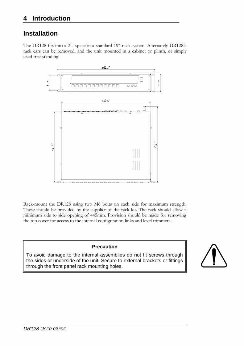
�� �$()�*������������6����� ��������������)8�����5����� .�+�� ���� ���$()�*-����5� ���� ����1 � � .�� �2� ���� �� � ����.���� �� �� �� ��1� �� ��� �����2� ��� �.����� ���� 7�������
(��57.����� �� �$()�*� ����� � ���%� 1����� ��� ���� �� � ����.�0.�.� ��� ������ � � �������1 ������ ��1�� �� � ����� ����� �� � ���5�5���� � ���5� ����������� ��.�.�.��� ������ ��� ���������!..����������������1 �.�� ����� � .������ �������� ��������� �������� ��� �������������������5������� � ����.. ��
Precaution
To avoid damage to the internal assemblies do not fit screws throughthe sides or underside of the unit. Secure to external brackets or fittingsthrough the front panel rack mounting holes.
Introduction 5
DR128 USER GUIDE
Connecting Mains Power( � �� ��� �� ���� ����������������� ��� ��������� ����6� ��4�� ��� �5� ����� �� ������ ������ �� ������ ������ ���. ������ �.�������������������� ���� �5�������� ���� ���.����� ��� ���.���� ��.��������������&������ ���������1 ������� � ��� ���������( ��� ���� ��� ������� �� � ������� ���� ����������� ���� ����� �� � ������ �
��� �� ���� �� ��� ��������� �� ���� ���.��� ����� ���������1 ��� � � ������ �� ��������������&���� � ����� �� � �&��.��������� ���� �� �� ������ ���� �� � � ������ ����5 ��1 ��� �� ��������
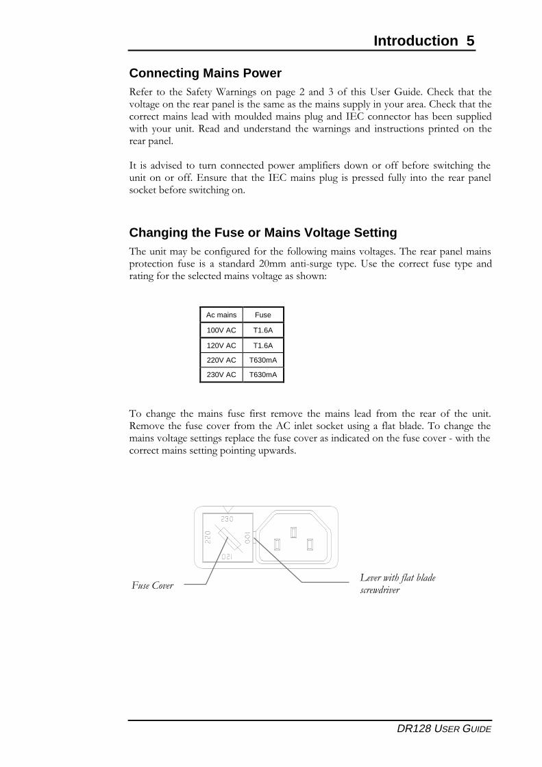
Changing the Fuse or Mains Voltage Setting�� �����.���1 �������� �������� ������ ���.���������� ���� �� ������ ��.������� ����� ��� � �� �� ��������� �9..����7���� � ��� �6� � �� � ���� ��� ��� � ��� � ��������������� �� � �� ��.���������� ������� �:
Ac mains Fuse
100V AC T1.6A
120V AC T1.6A
220V AC T630mA
230V AC T630mA
��� ����� � �� �.���� ��� � ����� � .�� � �� �.���� � ��� ���.� �� � � ��� ��� �� � ���( .�� ��� ���� ���� �� ���.��� �+�� �� �����5 ��������� �����1��� ��������� � �� .���������� �� ������� ���� ��� ���� ���� ���������� ������� ���� ���� ��7� ����� ���� ���.����� �������������� ����
�������������� �������������������������
6 Introduction
DR128 USER GUIDE
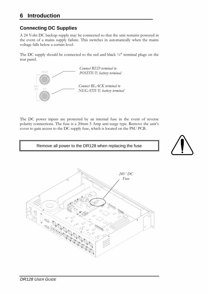
Connecting DC Supplies+����#�����$��1��5����������.���1 ����� �� ������������ ������ .������ � ����� � � ��������.����������� ����� ����� � ��� �� ������.�������� � �� �� �.��������� �������1 �� ���� ������ � �
�� �$����������������1 ����� �� ������� �� ������1���5�;��� �.��������������� � ������ �
�� � $�� �� �� ������ �� � ���� �� �� 1�� ��� �� ����� ��� � �� �� � � ��� ��� � � �� ������������ �������� ���� ������9..�!�+.�����7���� ���� �( .�� ��� ����-���� ������������ �������� �$������������ 2� ����������� ������� ���6���<
Remove all power to the DR128 when replacing the fuse
�������������������������������� ����� ���������
��������!�"�#������������$�%"����� ����� ���������
&'��������
Introduction 7
DR128 USER GUIDE
Earthing�� � ���� ����� ���.���� ����� =������>� �� ��� ����� ���� .� �� .�������� ���� � �� �����:
) ������� 7�������� ��� �� ��� ������ ���.������������� � ����5� ������� �� ��� �� +��.������������ ������ ����� .
� ���������������� 7����.�.� � �� � �� �������������� ������ ���� � ����� ����1� ���.�����1�??2���������� ����� ����������������.��� �� � ��
"������ ����� �� .����������������� /��. ��� �������� ����� �� �����.���� ������������ 0��� ��. ������������ ��� � �� �����.������������������� � ���������@�� ��� � ��5����� ��� ������������ ��.. �� ��������� ������������ ��� ���� �5��� ��������� ��� �� � ��� ��� ����� ���.� ���� ������ �� �� � ���� .� ��������.������� 1�� �2���1� ������ /��. ������ ��
�� ���. � �������������� ������� ����������1� �����.� 0� ������� �� � �� ���������� � ��.� � ���� ������� �� ��� �� �� ��������. ��2� ������� �.. �� 1�??2� �����.��� �� �������� ���1� .�� ��� � � �� �� � ������ � �� .�� � ����� �� � ����� ��.���� �����+�� ����������� ����������������� ��������� �1 � ���� ���� � ��� ��������������������������������� � �� �����.������ /� �������1� ���.����1�??
��� ���� ���� ���������1� 7�� ��� ������ �� ��.. ����� ������ ��:
����������������������������������������� !���� �"���#��� ������������ �$()�*������� �� �����.���� ��������������� ��� ����1� ���� ���� �������� ���+����9#������� �� ������� ���������� �������������1� .���� � ������ � � ��� ����� ������ �� ��� � �� � A������� ���-� � ��� �� ��� ���� �� �� /��. ������������2���������� ����� ���� ������.��� ����� ������������1� ������� � ��2������������� �� �������
������������������$�� ��%�������� ����"�����������������$�� ����� ����������� �.. �� ���� �� �� ������� ����� ��� �������1� 2� ������ �� � ��1� �� ��� �������� �
& �� ���� ��"����� ���� � ����� ��� %99�� ��� � ��� .������� �� ��� � ��� ���� ��1������� �� �� � �� ��� ������������ �� �$()�*��� �� ��� ������� ��� ���� ����� �.� ���� �����.�.� ��� �� � �� ����1� .�
& ��$����������� �������"� �$�������� � ������ ������ �� ..�����1����� ���������� �� � �� ������.���1 ���5 ���������������1� ������������� �������1����� ������� ������1����� ����BC� � ����� ��5��� ������ �����=DC(����>� ��9#� ����� =DC(� ��)>� ��� �� � ���� ��� ���� ��� �� 1����� �� C� � ������� ��� ����1����� ��� ����������5��� ����������������9#� ���������� �$()�*
& ��"���� �����'��������$�� ��������� ������� �5��������� ��� �������� ��1� ����� ��@����

8 Introduction
DR128 USER GUIDE
������������������ �� ���� ��
DR128 Overview 9
DR128 USER GUIDE
DR128 Overview
������������� ����������������������������� ��
����������������������������������
������������������ ��
����������� ������������� �������������� ��������!"��#����!�������$��� ���������������$��� ��%������������&"�'������ �������(����������$��� ��)�������*�&��� ��
�����!�����������������������
���������� �(������������������ �(��������+,���-���� �(#������+�#� �(����� �'�����������(%���� ��������� �((���������������� �()���������������(.��������-������ �(
2
10 DR128 Overview
DR128 USER GUIDE
Introduction
/0�� "���.� �� �� ��� ����1� .� ������� "����� 2���� 3� ���������� �������� 4����������� �������� /0�� ��5��4��� ���� �3����� ��� �������� ������ ���������� ��� ������0�������� ����������� ������� ��6����� 4���� ����3� �3��1� 7����� ���� ��������������������������8������
2�����9�:���0�;�"��������� ������1� ���� �����4��;���5��<%=�����������������������!���� ����������4��������������0��������1����4����������������������������4� �0��"���.�-���� ���4�����1� �0��"���.����4����� ��� �� �����+������������ 5�0���� �0�� ����� ��� ����;�"�� /0��"���.� ���� �� ����5���� ���������4�����0��4�������������������������������0��������������
�������������������� ������������3����� ��������������������+�������
Main Features
� .����������>��� �'����������5�0���������?�%@��0��������5��
� ��8� ���������?������+��������!2��0�������������
� .����������>����������
� .�����+��������������4�����������������
� ��+�#��4�����������������!������������A�������;�"�B
� ������������ ������3�.�!��������� ���3�5�0���������������������0�����
� �(�������������4������������0��������
� ��������� ���4�������������������$���
� .������������������������
� ������+�������"��*���4������������������������
� 2���+���*����������������������������������
� �0������������4������������������������������
� ����������������������5��6��*��������������� ��+�0������5�0����;�"�
� ����5�������������������������4��
� ����+/���!���*�4��������4����'�����������
� "��*��������8��<�����*+��������������
� ����������@�"!���������
Signal Processors���������������������4������������0��;�"����������������0���!����������������� �������4��0��4����5��C
� D���0��&E #��1�%�����)����� � ,����D���
� ����������&E (1������������� � !���������
DR128 Overview 11
DR128 USER GUIDE
Basic Principles
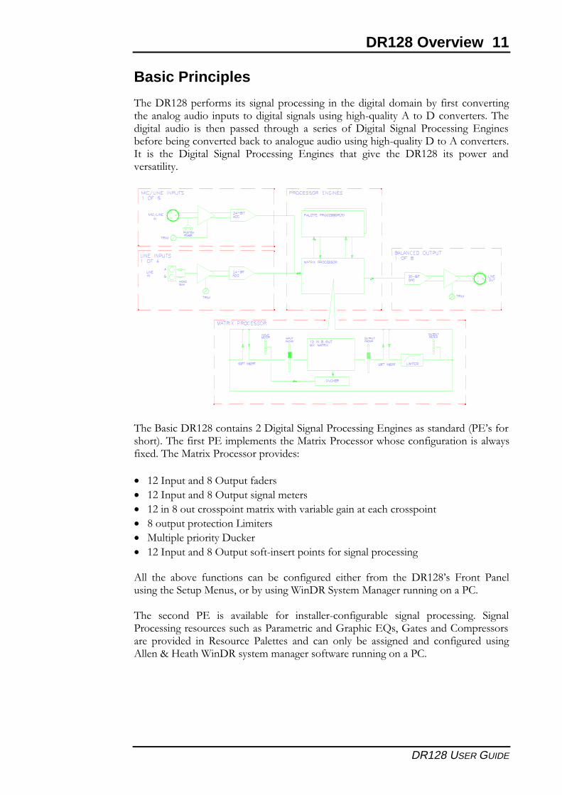
/0��"���.����4����� ������������������� �� �0�������������� ��4��������������0�������������� ���������������������������0�0+6������2����"������������/0������� ����� �� �0��� ������� �0����0� �� ������ �4� "����� ������ ���������� &����� �4���� �������������� ��*�����������������������0�0+6������"����2�������������� �� �0�� "����� ������ ���������� &������ �0��� ���� �0�� "���.� ��� ��5��� ������������
/0�������"���.�����������"���������������������&������������������A�&F��4���0���B�/0��4�����&������������0�� ���3�����������50�������4������������5���43���/0�� ���3������������������C
� �������������.�-������4�����
� �������������.�-������������������
� �����.�������������������3�5�0����� �������������0����������
� .������������������������
� ��������������"��*��
� �������������.�-��������4�+������������4������������������
2��� �0�� � ���� 4�������� ���� �� ���4������ ��0��� 4���� �0�� "���.F�� ������ �����������0�������� ����1���� �������;�"��������� ��������������������!
/0�� ������� �&� �� ����� ��� 4��� ��������+���4���� ��� ������ ���������� ����������������������������0������������������D���0��&E�1�D���������!�������������� �������� �� ��������� ��������� ���� ���� ����� �� �������� ���� ���4������ ����2�����9�:���0�;�"�������������������4�5�����������������!
12 DR128 Overview
DR128 USER GUIDE
������������ ����
����0����������������������� ��������������� ��� ��4�������������"��3�����+��&3�������������&��0�"��3���������������������������������&������/0��������(� ���������� &������ ���� �� 4����� �� ������ 5�0� %� �4� �0���� ����� ��� 4��� ������+���4���������������������
����������� ����
���������� ��� �0����"��3�&3�������������������������"����"�����-������������� ��4�����/0�����������������(���������A(����B��4�������������������0��������0�����
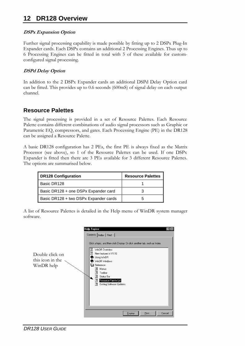
Resource Palettes/0�� ������ ���������� �� �������� �� �� ���� �4� ��������� ��������� &��0� �������������������������44��������� ��������4��������������������������0����D���0��������������&E1������������1�����������&��0�����������&�����A�&B����0��"���.���� ����������������������������
2� ����"���.����4��������0������&�1� �0�� 4�����&� �� ��5���� 43������ �0�� ���3���������� A���� � ���B1� ��� �� �4� �0�� ��������� ��������� ���� �� ����� �4� ���� "��3&3������� �� 4����� �0��� �0��������#��&������� ��� 4���#��44�����������������������/0����������������������� ���5
DR128 Configuration Resource Palettes
Basic DR128 1
Basic DR128 + one DSPx Expander card 3
Basic DR128 + two DSPx Expander cards 5
2������4��������������������������������0��:����������4�;�"������������������4�5���
"�� ������*����0���������0�;�"��0���
DR128 Overview 13
DR128 USER GUIDE
14 DR128 Overview
DR128 USER GUIDE
Front Panel
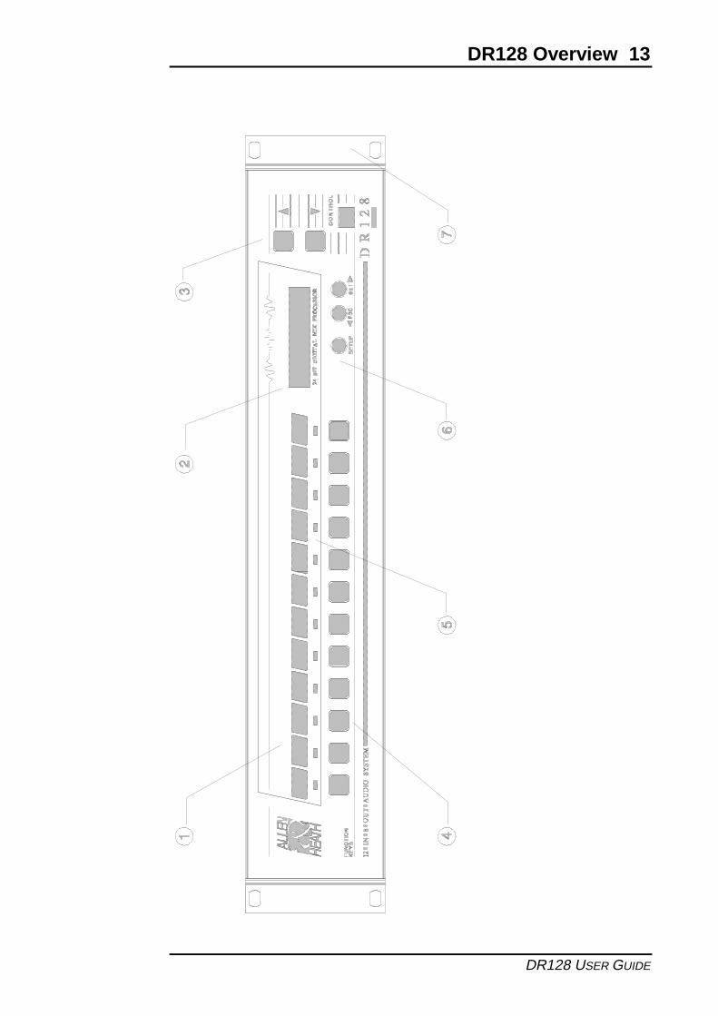
/0�� "���.F�� ������ ������ �� �������� ��� ������� ��0� ���3� ���������� ��������� �����4����0����������1�������4��3 ���������������4����4����0������������������0����������� 0��� ��6��� ��6��������1� ��� ������ ��� �������� $���� ���� �������/0����*���1������G�������5�0��0��#+��������&"������ ���������������������������4��� ����� ���� ������� �0������� 5�0� ���� ����H� ��� ����0� ������� ��� ������� �0�� �(����������������������0��
1 Removable Front Panel/0��������������4�������� �����������������5��0��������������4�������������� ���4����0����������$����/0���� ������������������ ���0��4����50���������4�����/0��������������������0��������0�3+���*�������5��4��������������4��
2 LCD2� �3�(� �0�������� ���������� �!"� ����5�� �0�� ���3� ���������� ��� �� ���4����������������1���������������8�����4������������������������
3 Control Keys ��
/0������� *���� ���� ����� ��� ��������'���������� ����������� ������ ������/0������ ���������� �� ���G�������5�0� �0����������$���� ��� �0����� ������� ��������0�����������������������
4 Function Keys�����������$����������������50����4����������� ����������������������&��0*������� ������������������������1�����0��0����1������4��������
5 Status LEDs/Signal Meters&��0���������$���0����������������#+��������&"����������4��0����������$������������ ��� �� @������ ���� �0�� �&"� ����� ��� �� �����'���*������� AD����'���B� �4������������������������0��0���&"����������������A2� ��B
6 Setup Keys ���
����������0�����0��������$������������������ ����/0������5���0�� ���3������������� ����G������5�0�����������������!�2����������0�������� ��������� ������5�������������/0��&�!� ���� �&/� *���� ���� ����� �� ���G�������5�0� �0����� �������*������������������������0�������� ����
7 Rack Ears/0�����*���������� ����������4��������������*�������
DR128 Overview 15
DR128 USER GUIDE
16 DR128 Overview
DR128 USER GUIDE
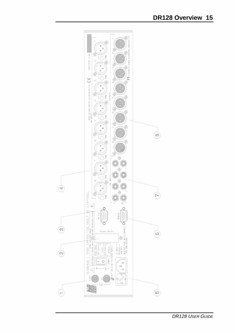
Rear Panel
1 Battery Input
���������I����������������������������4�����@�"!� ����������������/0������5������������������4����"���.�������������0���������4��������5���4�����
2 Sys-Net Option/0�����������������4���4��������������������������3�������������
3 RS-232<+��� ������� "+/���� 4��� ������ ���������� ��� �� �!� ������� ;�"�� ������ ������� ��4�5���� 2� <+5��� ����� ��� <+5��� ��� �%+5��� 4������ J��+��+��F� �� ��� ���6�����4�������������������!������������;�������������� ��������0������������0���#��4������� ������������"������������,���+ ������� ��
4 Mic/Line Inputs.���������� �'�������������������������4������>������������������������������ �������������� ������� (���� �4� ���� ��G�������� ��������� �0������ ��5��A?�%@B����������������������������������������������*�
5 Mains Input�������&!� �������*���4����0������������5���������
6 Remote Input<+;����������"+/���� �������� .� ����+�������� �5��0� �������� ������ /0�� �5��04��������������4�5�������4���� �������������4��0�������0���������������������$���
7 Line Inputs���� ��������������������������������������������!2��0���������������"��������� A2?�B� ���� �������� 4��� ����� ������� �4� ������� ������ -�������� ������4����+����@����?��������� ����G������������������������������������
8 Line Outputs.��������������-���������������������������>��������������-���������������������4������+����@����?�����������G���� ���������������������������������
Using the DR128 17
DR128 USER GUIDE
Using the DR128
Contents
������������ �������������������������������������������������������������������������������������������������������������������
�������� ��������������������������������������������������������������������������������������������������������������������������������
����� ��������������������������������������������������������������������������������������������������������������������������������������
����������� ���������������������������������������������������������������������������������������������������������������������������������������� ���������������������������������������������������������������������������������������������������������������������� ���� �!����� �������������������������������������������������������������������������������������������"�� �������������������������������������������������������������������������������������������������������������������������������#�� ������������������������������������������������������������������������������������������������������������������������$
#%���"&���� ��������������������������������������������������������������������������������������������������������������������$#%���"&�����'(�%� ������������������������������������������������������������������������������������������������$)����*�#%���"&���� ��������������������������������������������������������������������������������������������������$
3
18 Using the DR128
DR128 USER GUIDE
Front Panel Display
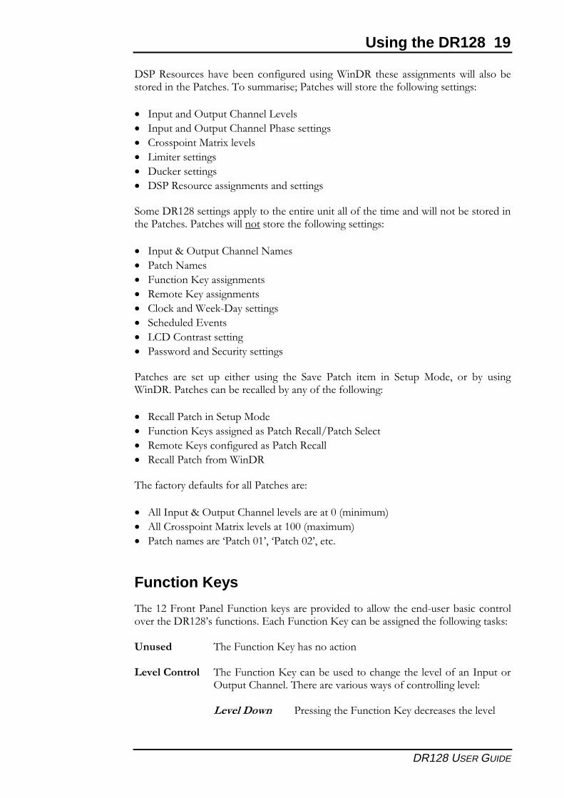
)���������*��������#��������!��&���� �������+��&��*�% �* �
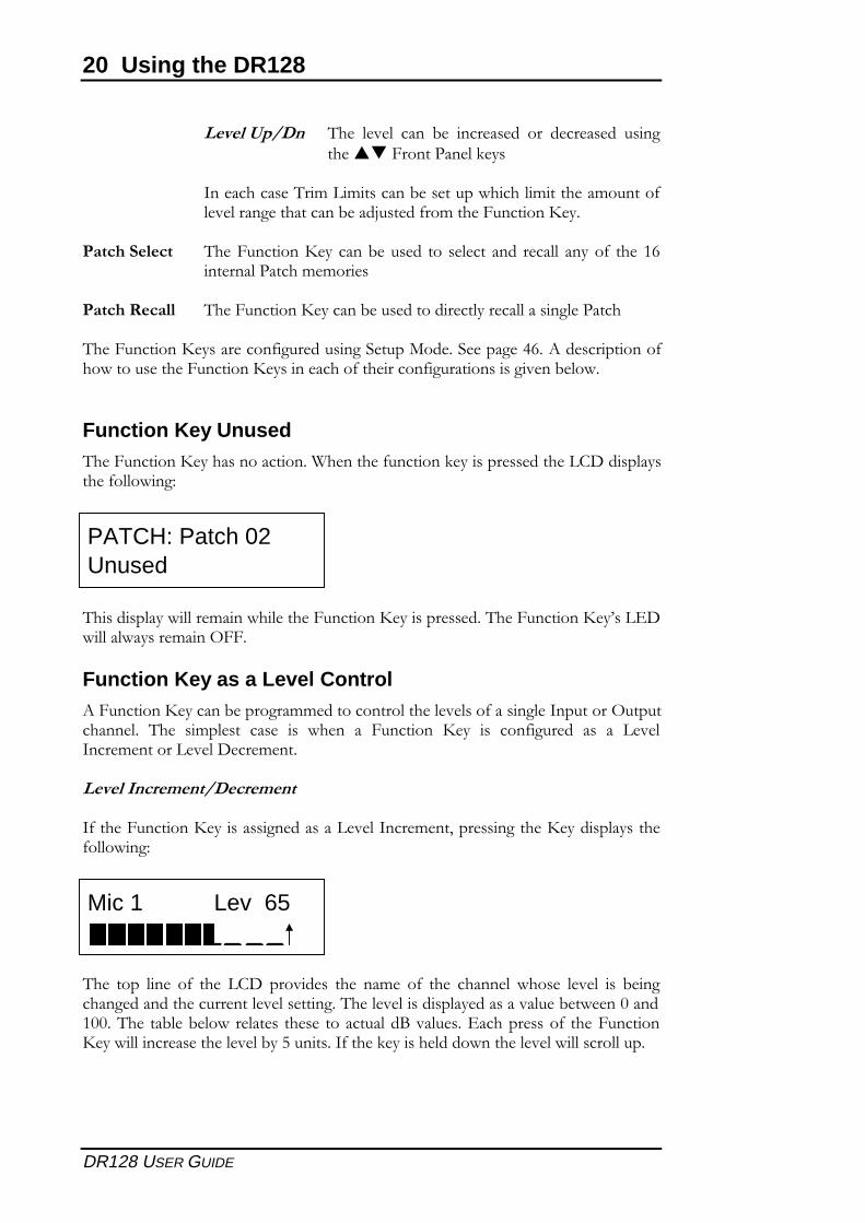
,�� ���� ������ �� � ��� +��%&��� � ������%-���,�� �&���� ���� +����-������ ���� �&�������#����� �������� ��*�������*�-����������+���������������� ���%�����)������������� ������� ���%�������!��&���� �������+��&��*�
,����������+�����!��&���� ����������������������%-������������.�%��,���������%-��&��-����� �������������-+�������#����&� ��������++��,�-����%����&���� ����������������������,�%�
Auto-Peak
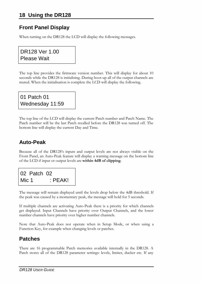
/��� � �� �+� ����#���0 � ����� � ���� ������� � ��� ���� �&�� � � �-� ��� �����������1�������������+�����&���� ������&�����*�% �*�������-����%����+�����!���+����������������� ����������������� �������
,��% �*�&���%������ ������������� ������-�&����2�/���� �����3+�������&� ���� ��-����%�%���������1����% �*�&������+���4� ���� �
3+�%���������� �������� ����*���������� ���� � ������������ +���&���������� *�� �� ������ 3����� !���� � �� � ��������� � ��5������ !���� 1� ���� ��� �&���%-������� ��� ����������� ����*�����%-������� �
.��� ����� ��������� �� � ���� ������ &��� ��� "���� 6��1� ��� &��� � ��*� ������������1�+���(�%��&�������*��*� ��������� �
Patches
,��� ��� �7� ���*��%%�-� ������%%��� � � ���-� �������� ��� ����#����� ������� ��� � �� �+� ����#��������%��� ����* 8� 1� �%���1� ������ ���� 3+� ���
02 Patch 02Mic 1 : PEAK!
DR128 Ver 1.00Please Wait
01 Patch 01Wednesday 11:59
Using the DR128 19
DR128 USER GUIDE
�"��# ���� ��� �-�����+�*����� ��*�)���#��� �� �*�%�� �&�� � ��- ���������������� ��,�� �%%��� 9������ �&�� �������+��&��*� ����* 8
� 3���������5������!������
� 3���������5������!�������� � ����*
� !�� ������6����(�
� ��%���� ����*
� ������ ����*
� �"��# ������ �*�%�� ����� ����*
"�%��#���� ����* �������������������������+������%�����&������-� ��������������� ������� �&������ �������+��&��*� ����* 8
� 3�����:�5������!�����.�%
� ������.�%
� ������������� �*�%��
� #%������� �*�%��
� !��������)������ ����*
� "������' ��
� �!��!����� �� ����*
� �� &��������"������� ����*
����� � ��� �� ��� ����� � ��*� ��� "� � ������ ��%� ��� "���� 6��1� ��� -�� � ��*)���#������� �����-������-�������+����+��&��*8
� #������������"����6��
� ����������� �� �*���� �������#��;������"��
� #%����� ����+�*����� �������#��
� #���������+��%�)���#
,��+��������+��� �+���������� ���8
� ��3�����:�5������!����� ���������<%���%�%=
� ��!�� ������6����(� ��������<%�(�%�%=
� ��������% ����>��������01�>��������01����
Function Keys
,�������������������������� ������� ���������&�������� ��-� ���������� ������#���0 �+������� ��'��������������������-�� �*������+��&��*��� � 8
������ ,���������������� ����������
���� ����� ,������������������-�� ���������*���� ��+����3�������5������!������,������ ����� �&�� ��+���������*� 8
��������� �� ��*�������������������� ����
20 Using the DR128
DR128 USER GUIDE
��������� ,�� � ���� -� ����� �� ��� ���� �� � ��*������������������
3�������� �,��%���%�� �����-� �����&������%�������%������+ ����*����������-���?� ���+��%����������������
�������� ��� ,������������������-�� �� ��� ��� ���� ���� �����+� ����7�������������%%���
���������� ,������������������-�� ������������������ ��*������
,������������� �������+�*����� ��*�"����6����"���*�27����� ����������+��&����� ��������������� ���������+���������+�*������� �� �*� ��-�&�
Function Key Unused,���������������� ������������)������+������������ ��� ������!���� ��� ���+��&��*8
,�� ��� ����&���%����&������������������� ��� ���,�������������0 ��'�&���&�� ��%����5���
Function Key as a Level Control������������������-����*��%%��������������� ��+��� ��*�3��������5������������ ,�� �%� �� �� � � � &��� �� ��������� ��� � � ���+�*���� � � �� � 3���%������� ����%���
������ ���������������
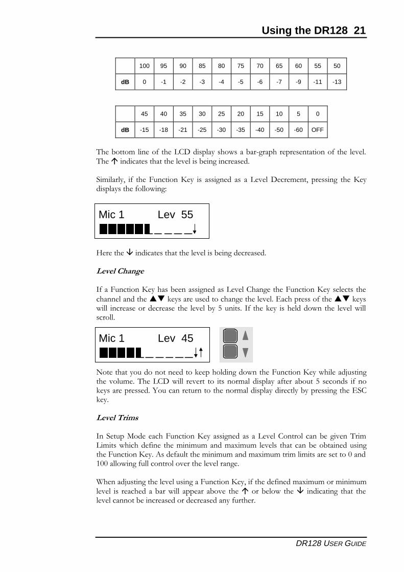
3+����������������� �� �*���� ���� �3���%��1��� ��*��������� ��� ���+��&��*8
,�� ���� ��� �+� ��� �!�� ��� �� � ��� ��%� �+� ��� ������ &�� � � � � -��*����*���������������� � ����*��,�� �� ��� ������ ��� ���-�&������������,�� ��-�-�&���� � �� � ����������/� �� ��'������ ��+� ��������������&������� ���� �-��4����� ��3+�������� ������&����� �&�� �������
Mic 1 Lev 65
PATCH: Patch 02Unused
Using the DR128 21
DR128 USER GUIDE
100 95 90 85 80 75 70 65 60 55 50
dB 0 -1 -2 -3 -4 -5 -6 -7 -9 -11 -13
45 40 35 30 25 20 15 10 5 0
dB -15 -18 -21 -25 -30 -35 -40 -50 -60 OFF
,��-����%�����+�����!���� ���� ��& ���-���*�������� ���������+���� �,����������� ��������� �� �-��*������ ��
"�%����1� �+� ��������������� � � � �*��� � � �� � ����%��1� �� ��*� ������� ��� ����+��&��*8
@�������������� ��������� �� �-��*����� ��
�����������
3+����������������� �-��� �*���� �� �!���*���������������� �� ��������������������� ����� ���������*���� ��'������ ��+��������� &�� ����� �������� � ��� �-��4����� �� 3+� ������ � ������&�� ��� �&� ����
.���������������������������������*���&�����������������&�����?� ���*��� ��%��,���!��&�� � ��� ��� �� ����%���� �����+��� �-����4� ���� � �+� ���� ������ ���A����������������������%���� �����������-���� ��*����'"!���
�����������
3��"����6�������������������� �*���� ���� �!������ ����-�*� ��,��%��%�� �&������+��� ���%���%�%�����%�(�%�%� � ����� ����-��-������� ��*����������������� ��+�������%���%�%�����%�(�%�%����%��%�� ���� ����������������&��*�+���������� ����� ����*�
)�����?� ���*���� �� ��*��������������1��+�����+����%�(�%�%����%���%�% � � � ��������-���&�� ������ �-� � ����� ���-�&� ����� ���������*� ����� �� ��������-������ ��������� ������+������
Mic 1 Lev 45
Mic 1 Lev 55
22 Using the DR128
DR128 USER GUIDE
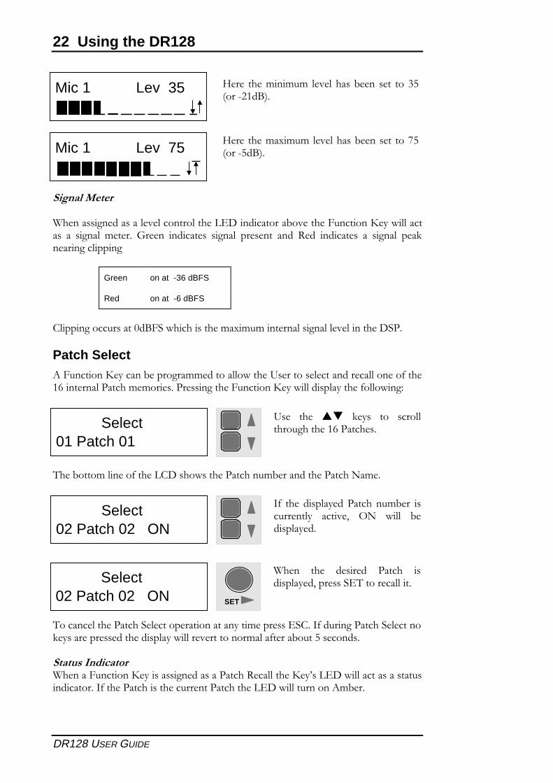
�����������
)���� �*���� ��� ������������'�������������-� ����������������&������ � �� �*��� %���� B��� ������� � �*��� �� ��� ���� #�� ������� � �� �*��� ��������*�������*
Green on at -36 dBFS
Red on at -6 dBFS
!�����*������ ������/�"�&������ ����%�(�%�%�������� �*��� ��������"��
Patch Select������������������-����*��%%�������&����� ����� ���������������+����7��������������%%��� ���� ��*����������������&���� �������+��&��*8
,��-����%�����+�����!�� ��& ������������%-���������������.�%�
,����������������"���������������������%��� �'"!��3+������*�������"������� ������ ������� ����&��� ���������%���+����-����4� ���� �
������� �������)������������������ �� �*���� ���������#��������0 ��'��&������� ��� ���� �����������3+����������� ���������������������'��&�����������%-��
@�� ���%���%�%� ��� �-�� �� ���$4<�������/=�
Select02 Patch 02 ON
)��� ��� � ���� ������ � �� ����1��� �"',�����������
SET
@�� ���%�(�%�%� ��� �-�� �� ���C4<����4�/=�
Mic 1 Lev 35
Mic 1 Lev 75
Select01 Patch 01
� � ��� ��� �� � ��� ��������*������7������ �
Select02 Patch 02 ON
3+� ��� �� �������������%-�� � �������� ���� 1� 5.� &�� -�� �����
Using the DR128 23
DR128 USER GUIDE
Patch Recall������������������-����*��%%��������������������+� ����7� ������������%%��� ������(�%���+���������������&� ����+�*������������������1��� ��*���������������&���� �������+��&��*8
�+���&���������!��&��� ���������%��
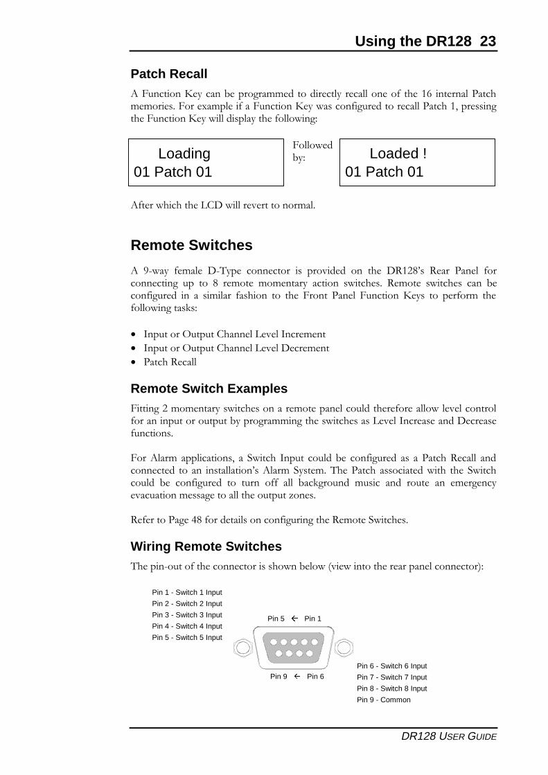
Remote Switches
�� ��&��� +%�� ��,��� ��������� � � ��� ���� ��� ��� �#���0 � #��� ���� +����������*� ��� ��� �� �%��� %�%������ ������� &���� �� #%��� &���� � ���� -���+�*���� ��� �� �%���� +� ����� ��� ��� ������ ���� ����������� � ��� ��+��%� ��+��&��*��� � 8
� 3��������5������!������ �3���%��
� 3��������5������!������ ����%��
� ������#��
Remote Switch Examples������*���%�%������ &���� �������%���������������+�����&� �������+����������������������-�����*��%%��*���� &���� �� �� �3���� ��������� +������� �
�������%����������� 1� �� "&����� 3����� �����-� ���+�*���� � � ��������#��� ����������� ������ �� �������0 ����%�"� �%��,�������� � �������&���� ���"&��������� -� ���+�*���� ��� ����� �++� �� -���*������ %� ��� ���� ����� ��� %�*��� ���������% �*����������������D�� �
#+�������*�2��+������� �������+�*����*����#%���"&���� �
Wiring Remote Switches,�����������+�������������� � ��&��-�&�< �&�������������������������=8
Loading01 Patch 01
���&�-�8 Loaded !
01 Patch 01
Pin 1 - Switch 1 Input
Pin 2 - Switch 2 Input
Pin 3 - Switch 3 Input
Pin 4 - Switch 4 Input
Pin 5 - Switch 5 Input
Pin 6 - Switch 6 Input
Pin 7 - Switch 7 Input
Pin 8 - Switch 8 Input
Pin 9 - Common
Pin 5 � Pin 1
Pin 9 � Pin 6
24 Using the DR128
DR128 USER GUIDE
Level
Up
DownPin 2 - Switch Input 2
Pin 1 - Switch Input 1
Pin 9 - Common
Level Up Level Down
Pin 1 - Switch Input 1
Pin 2 - Switch Input 2
Pin 3 - Switch Input 3
Pin 4 - Switch Input 4
Pin 9 - Common
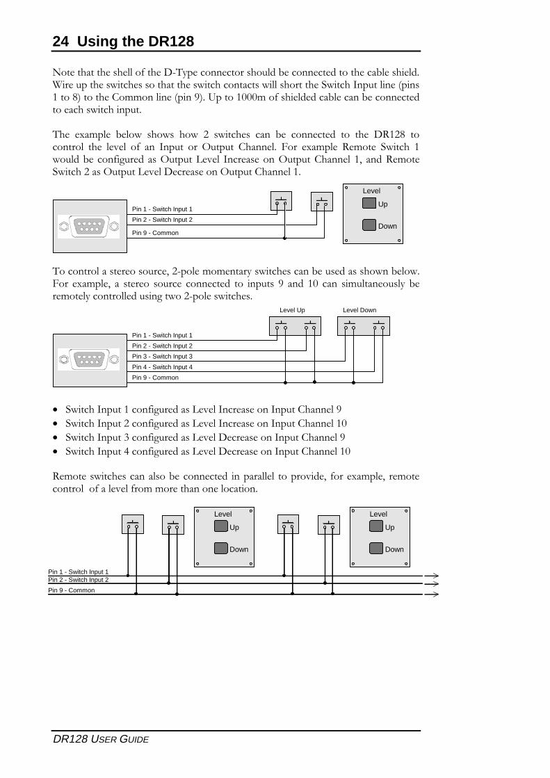
.����������� ���+������,������������ �����-�����������������-� ����)��������� &���� � ���������� &������������ �&�� ��������"&�����3��������<��� ������=�������!�%%������<�����=������������%��+� �������-�����-��������������� &�����������
,�� (�%�� -�&� ��& � ��&� �� &���� � ���� -� �������� ��� ��� �#���� ��������� ��� � �+� ��� 3����� ��� 5������ !������ ���� (�%�� #%��� "&����� �&����-����+�*����� �5������� � 3���� ����5������!����� �1� ����#%��"&�������� �5������� ����� ����5������!�������
,����������� ���� ����1������%�%������ &���� �����-�� ��� � ��&��-�&����� (�%�1� �� ���� ����� �������� ��� ����� � �� ���� ��� ���� �%������ �� -�%������������� ��*��&������� &���� �
� "&�����3����������+�*����� �� �3���� ����3�����!������
� "&�����3����������+�*����� �� �3���� ����3�����!�������
� "&�����3�����$����+�*����� �� ����� ����3�����!������
� "&�����3�����2����+�*����� �� ����� ����3�����!�������
#%��� &���� ������ ��-��������� �������� ������ ��1� +���(�%�1� �%�����������+��� �+��%�%�������������������
Level
Up
Down
Level
Up
Down
Pin 1 - Switch Input 1Pin 2 - Switch Input 2
Pin 9 - Common
Hardware Configuration 25
DR128 USER GUIDE
Hardware Configuration
���������� �������������������������������������������������������������������������������������������������������������������������� �
���������������������������������������������������������������������������������������������������������������������������������� �������������������������������������������������������������������������������������������������������������������� ���������������� ������������������������������������������������������������������������������������������������������������� ������������� ���������������������������������������������������������������������������������������������������������������� �
��������������������������������������������������������������������������������������������������������������������������������������� ������������������������������������������������������������������������������������������������������������������������
!�������"������������������������������������������������������������������������������������������������������������������������#$�������"�������������������������������������������������������������������������������������������������������������������#$
4
26 Hardware Configuration
DR128 USER GUIDE
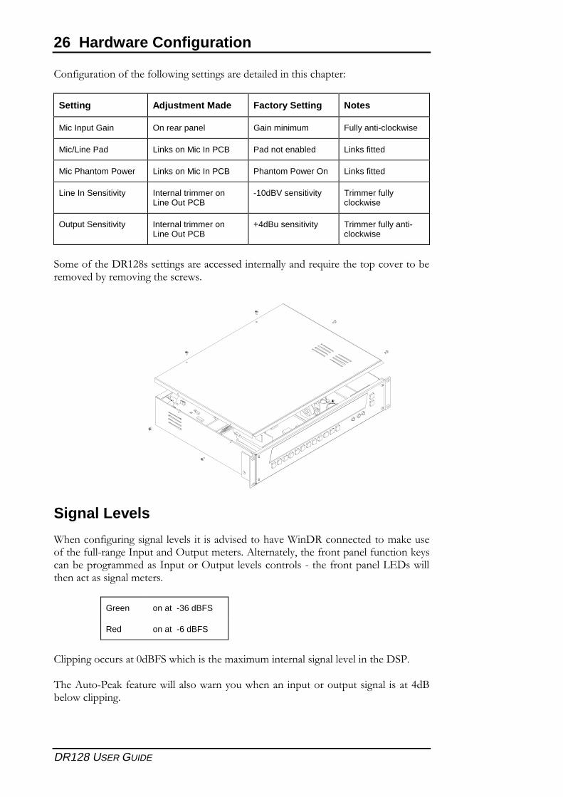
%��&�����������&����&�����������������������������������������'
Setting Adjustment Made Factory Setting Notes
Mic Input Gain On rear panel Gain minimum Fully anti-clockwise
Mic/Line Pad Links on Mic In PCB Pad not enabled Links fitted
Mic Phantom Power Links on Mic In PCB Phantom Power On Links fitted
Line In Sensitivity Internal trimmer onLine Out PCB
-10dBV sensitivity Trimmer fullyclockwise
Output Sensitivity Internal trimmer onLine Out PCB
+4dBu sensitivity Trimmer fully anti-clockwise
�����&����()$ �����������������������������*������+������������������,�����,*�����������������
Signal Levels
-������&�������������������������������������-��()��������������.����&����&���/���������������"������������0�������*1����&����������&��������.*�����,�����������������������"�������������������/����&�����������2(�����������������������������
Green on at -36 dBFS
Red on at -6 dBFS
%������������������3�!4����������������5�����������������������������(���
6��0���/��.�&��������������������*���������������������������������������7�!,�������������
Hardware Configuration 27
DR128 USER GUIDE
Mic/Line Inputs
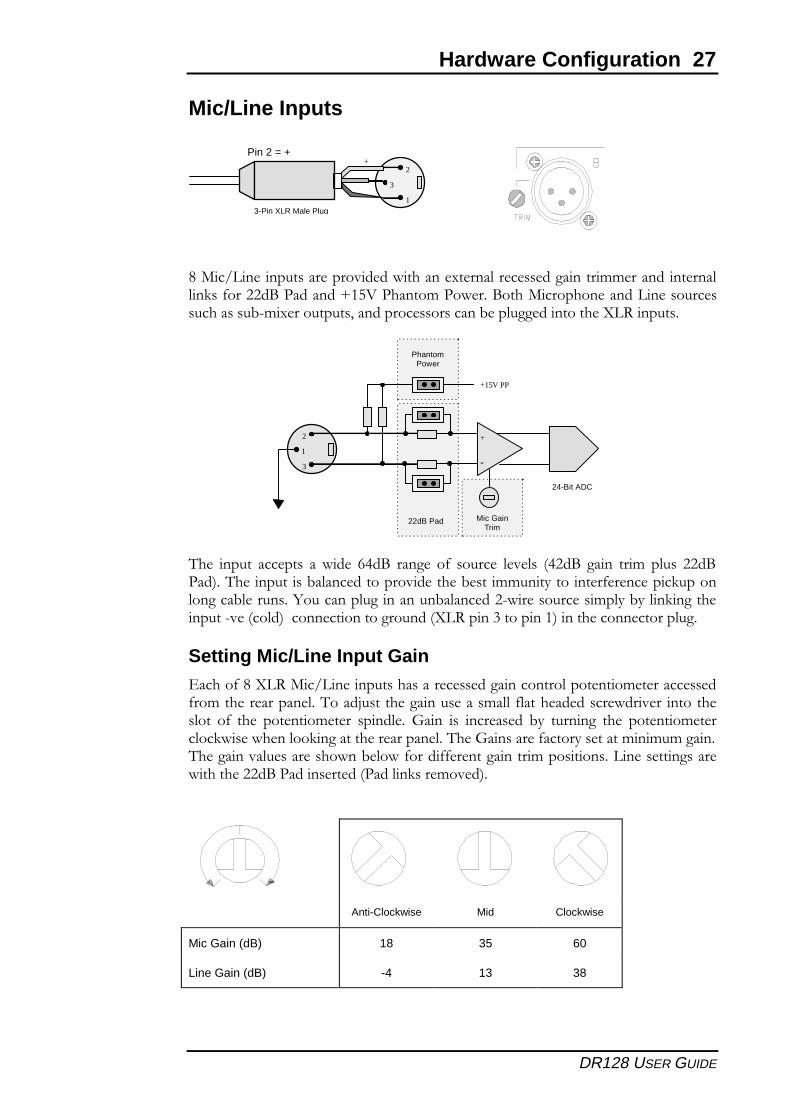
�����������������������������������5��������������������������������������.��&��� �!���������8$9:���������������!��������������������������������������,/��5���������1�������������������,����������������;�)��������
6�� ������ ������� �� ���� �7�!� ����� �&� ������ ���� <7 �!� ����� ����� ����� �!���=��6�����������,�������������������,����������*��������&�������.������������,��������>��������������������,������� /���������������*�,*����.������������/�<����=����������������������<;�)�����#��������$=���������������������
Setting Mic/Line Input Gain2�����&���;�)����������������������������������������������������������&�����������������6����?�����������������������&������������������ ������������ �&� ��� ����������� �������� ����� ��� �������� ,*� �������� ��� ��������������.�����������.��������������������6�����������&�����*��������������������6���������������������,����&�����&&����������������������������������������������� �!������������<�������.������=�
Anti-Clockwise Mid Clockwise
Mic Gain (dB) 18 35 60
Line Gain (dB) -4 13 38
1
2
1
3
+
3-Pin XLR Male Plug
Pin 2 = +
Mic GainTrim
1
2
3
1
+
-
22dB Pad
+15V PP
PhantomPower
24-Bit ADC
28 Hardware Configuration
DR128 USER GUIDE
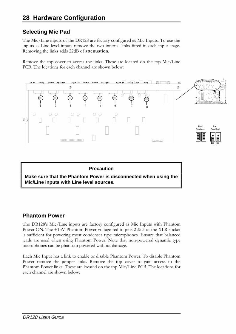
Selecting Mic Pad6������������������&����()$ �����&�����*����&���������������������6��������������������� ��� ������� ���� ��� ���� �������� ���.�� &����� ������� ������ �����)������������.������� �!��&�������������
)��� ��� ���� ���� ��� ������ ��� ���.���6��� ��� ���������� ��� ������������%!��6������������&�����������������������,���'
Precaution
Make sure that the Phantom Power is disconnected when using theMic/Line inputs with Line level sources.
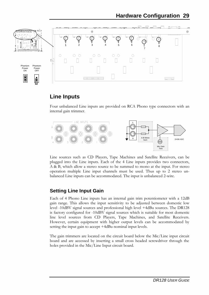
Phantom Power6��()$ �@���������� ������� ��� &�����*����&������������� ������������������������"A��6��8$9:��������������������&���������� �B�#��&����;�)����.������&&������ &������������������������ �*��������������2����� �����,����������� ��� ����������������������������A��� ����� ���/������ �*������ �*����������������,�����������������������������
2�����������������������.������,���������,����������������6������,�������������� ���� ��� ?����� ���.��� )��� ��� ���� ���� ��� ����� ������ ��� ������������������.���6��������������������������������%!��6������������&����������������������,���'
PadDisabled
PadEnabled
1 2 3 4 5 6 7 8
Hardware Configuration 29
DR128 USER GUIDE
Line Inputs
4������,�������������������������������)%0��������*���������������������������������������
���� ������� ����� ��� %(� ���*��1� 6��� �������� ���� �������� )����1� ���� ,������� ����� ������� ��������2�����&� ��� 7� ���� ������� ������� ���� ���������10�B�!1�����������������������������,����������������������������4���������������� �������� ���� ������ �������� ����� ,� ����� 6���� ��� ��� � ����� ��/,����������������������,��������������6�������������,������� /����
Setting Line Input Gain2�����&�7����������� �������������� ������������� ����������������������� $ �!����� ������ 6���� ������� ��� ������ ��������*� ��� ,� ��?����� ,���� �������� ������/$3�!:����������������������&����������������87�!����������6��()$ ����&�����*����&������&���/$3�!:�����������������������������,��&������������������� ��� ������� &���� %(� ���*��1� 6��� �������1� ���� �������� )�����C���1� ������� +������� ����� ������ ������� ���� ���� ,� ������������ ,*������������������������������87�!��������������������
6���������������������������������������,�����,����������������������������,����� ���� ��� ������� ,*� ��������� �� ������ ������ ����� ��������� �������� ������������������������������������������,�����
PhantomPower
ON
PhantomPowerOFF
Mic GainTrim
A
B
+
-
24-Bit ADCA-B Mono
Sum
1 2 3 4 5 67
8
30 Hardware Configuration
DR128 USER GUIDE
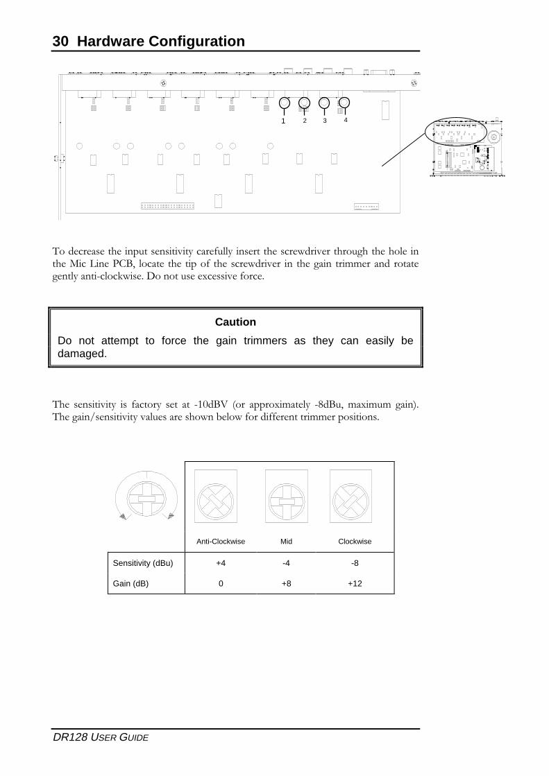
6�������������������������*����&���*������������������������������������������������%!1� ��������������&� ������������ ��� �������� ��������������������*�����/����.�����(���������5�����&����
Caution
Do not attempt to force the gain trimmers as they can easily bedamaged.
6�� ��������*� ��� &�����*� ��� ��� /$3�!:� <��� �����5�����*� /��!�1���5����� ����=�6���������������*���������������,����&�����&&���������������������
Anti-Clockwise Mid Clockwise
Sensitivity (dBu) +4 -4 -8
Gain (dB) 0 +8 +12
1 2 3 4
Hardware Configuration 31
DR128 USER GUIDE
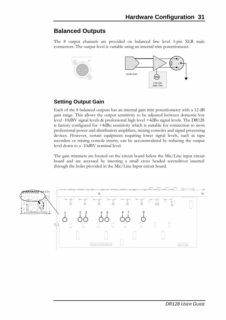
Balanced Outputs
6�� �� ������� �������� ��� ������� ��� ,������� ���� ��� #/���� ;�)� ��������������6�������������������,�����������������������������������
Setting Output Gain2�����&������,����������������������������������������������������������$ ��!����� ������6���� ������� ���������� ��������*� ���,���?�����,������������ ������/$3�!:������������B����&����������������87�!��������������6��()$ ����&�����*����&������&���87�!����������*���������������,��&�����������������������&�����������������������,�����������&���1���5�������������������������������������� C���1� ������� +������� �+������� ����� ������� ���1� ����� ��� ����������������5����������� ������1� ����,� ������������,*� �������� ����������������������/$3�!:������������
6���������������������������������������,�����,����������������������������,����� ���� ��� ������� ,*� ��������� �� ������ ������ ����� ��������� ���������������������������������������������������������,�����
1 2 3 4 5 6 7 8
Line OutGain Trim
1
2
3
1
+
-
20-Bit DAC
32 Hardware Configuration
DR128 USER GUIDE
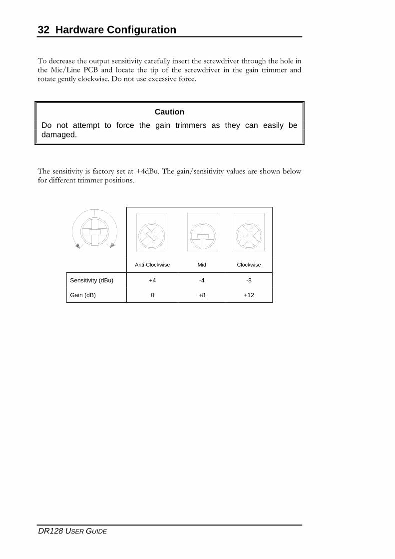
6��������������������������*����&���*����������������������������������������������� �%!� ���� ������ ��� ���� �&� ��� ��������� ��� ��� ����� ������� �������������*�����.�����(���������5�����&����
Caution
Do not attempt to force the gain trimmers as they can easily bedamaged.
6����������*����&�����*�������87�!���6���������������*���������������,���&�����&&���������������������
Anti-Clockwise Mid Clockwise
Sensitivity (dBu) +4 -4 -8
Gain (dB) 0 +8 +12
Setup Menu 33
DR128 USER GUIDE
Setup Menu
������������� ������������������� ��������������������������� ���������������������� ��������������� ���������� ��
�� �!���""�������#$� ����������� �#�� ���%��������&�� ���%��������'�����"�&�� ���%��(������'�����"�)�� �*%��������� �+#� �,��-�������� ��&� ������������ ��)� �(����������� ���+� �������*���"����� �(������*���"���$� �'���������������*���"������ �.�������/������������� �!�%����/�������� �&��� �,����0�����1��- �+��� �'"��-�+�#� �*',�'������� �+�&� ����������������)� �������� ��
5
34 Setup Menu
DR128 USER GUIDE
Introduction
2���.���������"�������������������� ���� ����""������� ��� %%�������� ���� ���"0������0�������������3"� ������������,!�$&4��3����0��������5���������������������������3���������������������0�����%��� ����0��
2������������������������������������0�""�����0�������6
� !���""����������������� � '����������� �����
� ��%���������7�����������(������������"� � .�������8�!�%����/��������
� *%���� � ,���8�2%��'"��-������
� ,��-�� � *',�'�������
� ����������(������*���"����������� � ���������������������5�����
����� ����� ���� ������� ���� ���� �0� ���� ,��� !�������� ��"�����7� ������ ���� ��"�� 3��������������1�,!��������������'�����������������!� $�$���3"�
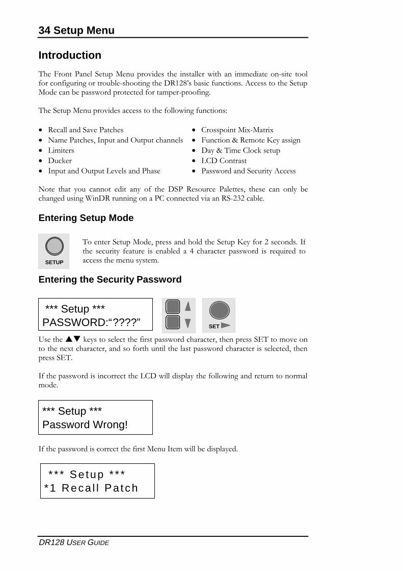
Entering Setup Mode
Entering the Security Password
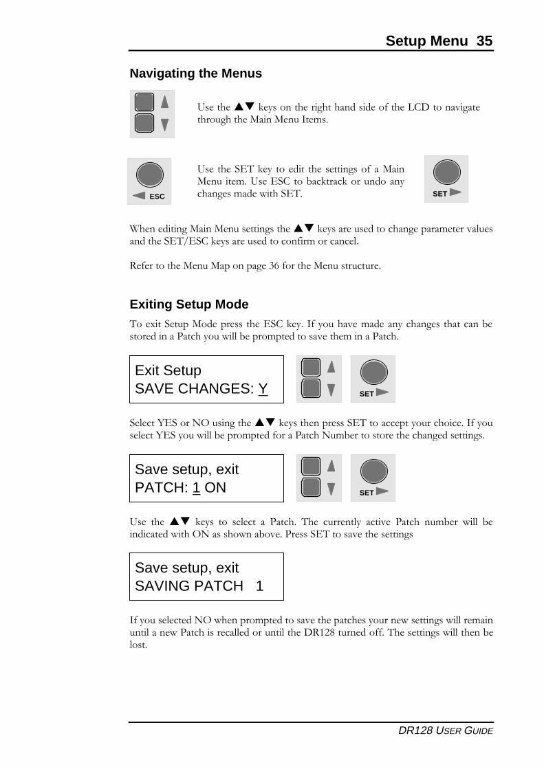
9����������-���������"��������0����������������������7������������� 2����%���������������������������7��������0��������"�����"���������������������������"�����7������������ 2
�0�����������������������������*',��""����"�������0�""����������������������%�"%���
�0����������������������������0������������%��""�3�����"����
SETUP
2������������������7�������������"������������/���0���$����������0���� �������� 0������� �� ���3"��� �� �� ���������� ��������� �� ��:����� �������������%���������%
SET
*** Setup ***PASSWORD:“????”
*** Setup ***Password Wrong!
* * * Se tup * * **1 Reca l l Pa tch
Setup Menu 35
DR128 USER GUIDE
Navigating the Menus
1����������������������������������-���������������������������%�������"������������ 2; �'�-�������������������0�%���������"
!�0������������������������������0���������������������
Exiting Setup Mode2��������������������������� �'�-����0����������%�������������������������3�����������������������""�3�����%����������������%����������
��"����< ������(�������������-���������������� 2�����������������������0������"����< �������""�3�����%�����0�������������%3�������������������������������
9��� ������� -���� ��� ��"���� �� ������ 2��� �������"�� ������ ������ ��%3��� �""� 3�������������(������������3����������� 2��������������������
�0�������"�������(���������%�������������������������������������������""���%�����"�������������������""���������"�����,!�$&���������00�2������������""������3�"���
9����������-��������������������������0�����*',�����������������������������������%�
ESC SET
9�������� 2�-��� ������� �������������0�������������%�9��� �'����3��-����-��������������������%��������� 2
SET
Exit SetupSAVE CHANGES: Y
SET
Save setup, exitPATCH: 1 ON
Save setup, exitSAVING PATCH 1
36 Setup Menu
DR128 USER GUIDE
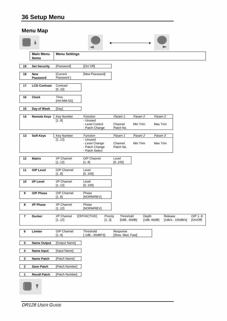
Menu Map
Main MenuItems
Menu Settings
19 Set Security [Password] [On/ Off]
18 NewPassword
[CurrentPassword ]
[New Password]
17 LCD Contrast Contrast[0..10]
16 Clock Time[HH:MM:SS]
15 Day of Week [Day]
14 Remote Keys Key Number Function Param 1 Param 2 Param 3[1..8] - Unused
- Level Control Channel Min Trim Max Trim- Patch Change Patch No.
13 Soft Keys Key Number Function Param 1 Param 2 Param 3[1..12] - Unused
- Level Change Channel Min Trim Max Trim- Patch Change Patch No.- Patch Select
12 Matrix I/P Channel O/P Channel Level[1..12] [1..8] [0..100]
11 O/P Level O/P Channel Level[1..8] [0..100]
10 I/P Level I/P Channel Level[1..12] [0..100]
9 O/P Phase O/P Channel Phase[1..8] [NORM/REV]
8 I/P Phase I/P Channel Phase[1..12] [NORM/REV]
7 Ducker I/P Channel [OFF/ACTIVE] Priority Threshold Depth Release O/P 1..8[1..12] [1..3] [0dB..-60dB] [1dB..60dB] [1db/s.. 100dB/s] [On/Off]
6 Limiter O/P Channel Threshold Response[1..8] [-1dB..-30dBFS] [Slow, Med, Fast]
5 Name Output [Output Name]
4 Name Input [Input Name]
3 Name Patch [Patch Name]
2 Save Patch [Patch Number]
1 Recall Patch [Patch Number]
Setup Menu 37
DR128 USER GUIDE
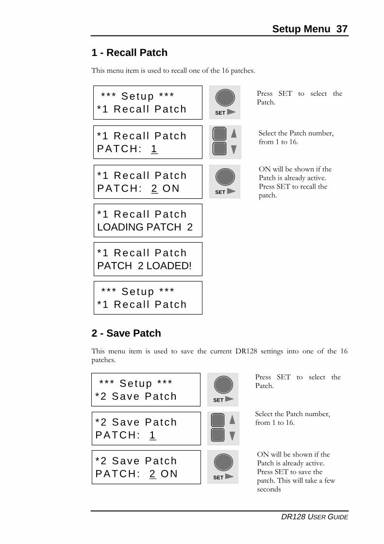
1 - Recall Patch
2���%������%���������������""������0���������������
2 - Save Patch
2��� %���� ��%� �� ����� ��� ����� ���� �������� ,!�$&� �������� ���� ���� �0� ���� ���������
* * * Se tup * * **1 Reca l l Pa tch
*2 Save Pa tchPATCH: 2 ON
(���""�3��������0�������������"������������������ 2������������������2����""���-����0���������
SET
SET
������ � 2� ��� ��"���� ��������
*1 Reca l l Pa tchPATCH: 1
��"����������������%3��70��%��������
*1 Reca l l Pa tchPATCH: 2 ON
(���""�3��������0�������������"������������������ 2��������""��������� SET
*1 Reca l l Pa tchLOADING PATCH 2
*1 Reca l l Pa tchPATCH 2 LOADED!
* * * Se tup * * **1 Reca l l Pa tch
* * * Se tup * * **2 Save Pa tch SET
������ � 2� ��� ��"���� ��������
*2 Save Pa tchPATCH: 1
��"����������������%3��70��%��������
38 Setup Menu
DR128 USER GUIDE
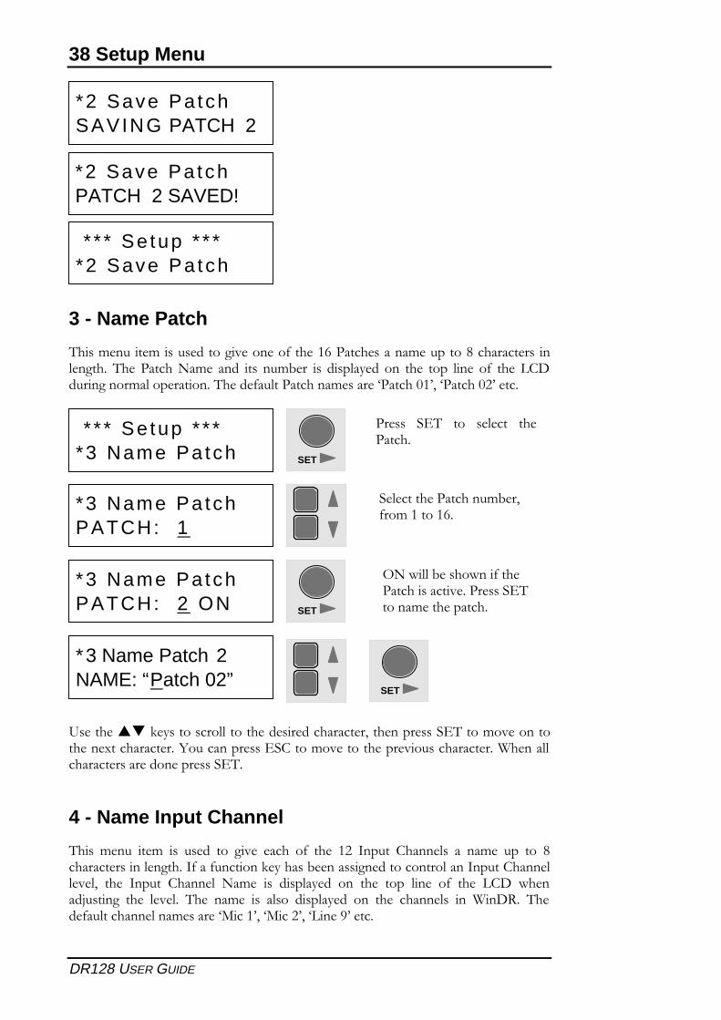
3 - Name Patch
2���%������%��������������������0��������������������%��������&�������������"������ 2�����������%�� ���� ��� ��%3��� �� ���"����� ��� ���� ���� "��� �0� ���� *',���������%�"����������2�����0��"����������%�������=������+�47�=������+$4����
9����������-�����������""������������������������7������������� 2����%����������������������������<������������� �'����%�����������������������������1�����""��������������������������� 2
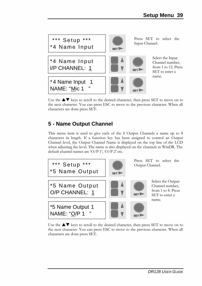
4 - Name Input Channel
2��� %���� ��%� �� ����� ��� ���� ����� �0� ���� �$� ������ '�����"�� �� ��%�� ��� ��� &�������������"�������0���0�������-�������3���������������������"����������'�����""���"7� ���� ������ '�����"� ��%�� �� ���"����� ��� ���� ���� "��� �0� ���� *',� ������>������ ���� "���"� 2��� ��%�� �� �"��� ���"����� ��� ���� ������"�� �� 1�,!� 2����0��"��������"���%�������=����47�=���$47�=*���)4����
*2 Save Pa tchSAVING PATCH 2
*2 Save Pa tchPATCH 2 SAVED!
* * * Se tup * * **2 Save Pa tch
* * * Se tup * * **3 Name Pa tch SET
������ � 2� ��� ��"���� ��������
*3 Name Pa tchPATCH: 1
��"����������������%3��70��%��������
*3 Name Pa tchPATCH: 2 ON
(���""�3��������0������������������������� 2�����%����������� SET
*3 Name Patch 2NAME: “Patch 02” SET
Setup Menu 39
DR128 USER GUIDE
9����������-�����������""������������������������7������������� 2����%����������������������������<������������� �'����%�����������������������������1�����""��������������������������� 2
5 - Name Output Channel
2��� %���� ��%� �� ����� ��� ���� ����� �0� ���� &� (������ '�����"�� �� ��%�� ��� ��� &����������� �� "������ �0� �� 0������� -��� ���� 3���� �������� ��� ������"� ��� (�����'�����"� "���"7� ����(������'�����"���%�� �����"�������� ���� ���� "����0� ����*',�������>����������"���"�2�����%�����"������"������������������"����1�,!�2����0��"��������"���%�������=(;���47�=(;��$4����
9����������-�����������""������������������������7������������� 2����%����������������������������<������������� �'����%�����������������������������1�����""��������������������������� 2
* * * Se tup * * **4 Name Inpu t
* * * Se tup * * **5 Name Outpu t
SET
SET
������ � 2� ��� ��"���� ���������'�����"
������ � 2� ��� ��"���� ���(������'�����"
*4 Name Inpu tI/P CHANNEL: 1
*5 Name Outpu tO/P CHANNEL: 1
��"�������������'�����"���%3��70��%�������$������� 2�������������%�
��"��������(�����'�����"���%3��70��%������&������� 2�������������%�
SET
SET
*4 Name Input 1NAME: “Mic 1 ”
*5 Name Output 1NAME: “O/P 1 ”
SET
SET
40 Setup Menu
DR128 USER GUIDE
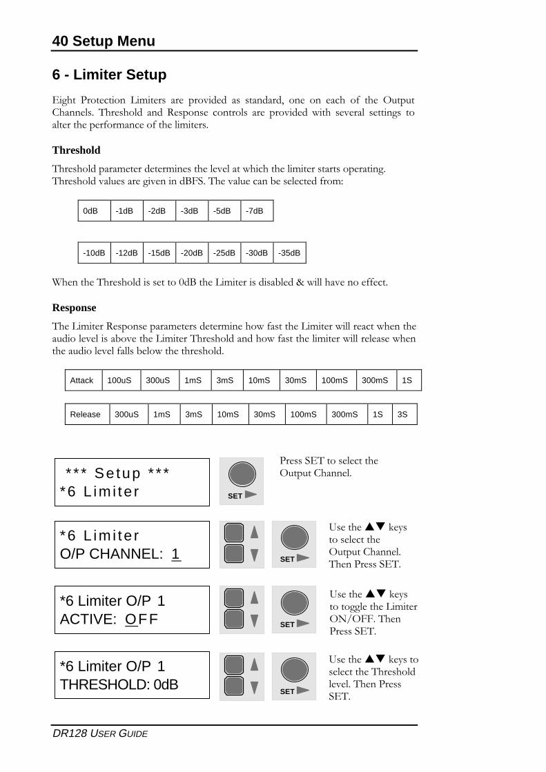
6 - Limiter Setup
���� ���������� *%����� ���� �������� ��� ��������7� ���� ��� ����� �0� ���� (�����'�����"�� 2������"�� ���� !�������� ������"�� ���� �������� ���� ������"� �������� ���"�����������0��%������0�����"%����
Threshold
2������"������%����������%��������"���"�������������"%�������������������2������"����"����������������?.��2�����"�������3����"������0��%6
0dB -1dB -2dB -3dB -5dB -7dB
-10dB -12dB -15dB -20dB -25dB -30dB -35dB
1��������2������"�����������+�?�����*%���������3"���8��""����������00���
Response
2���*%����!������������%�����������%�������0��������*%�����""��������������������"���"����3��������*%����2������"����������0��������"%�����""���"������������������"���"�0�""��3�"��������������"�
Attack 100uS 300uS 1mS 3mS 10mS 30mS 100mS 300mS 1S
Release 300uS 1mS 3mS 10mS 30mS 100mS 300mS 1S 3S
*6 Limiter O/P 1THRESHOLD: 0dB
9����������-��������"��������2������"�"���"�2���������� 2
SET
* * * Se tup * * **6 L im i te r
������� 2������"�������(������'�����"
SET
*6 L im i te rO/P CHANNEL: 1
9����������-��������"�������(������'�����"2����������� 2
SET
*6 Limiter O/P 1ACTIVE: OFF
9����������-����������"������*%���(�;(..�2���������� 2
SET
Setup Menu 41
DR128 USER GUIDE
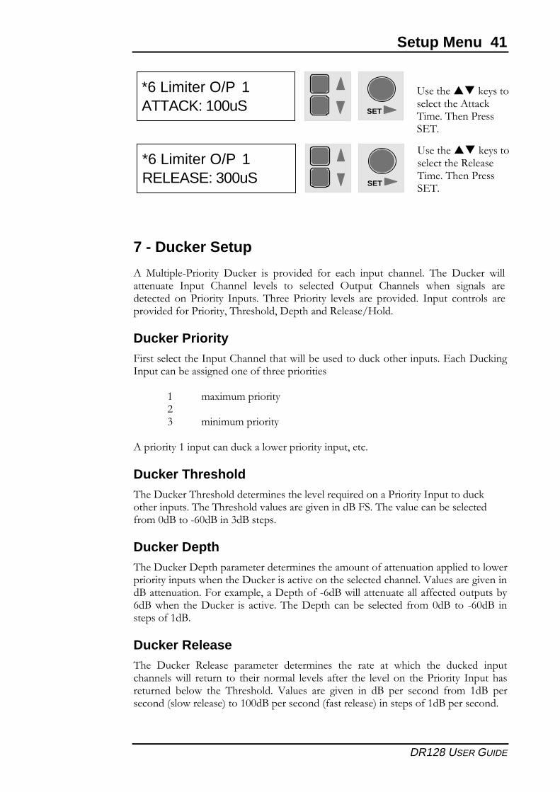
7 - Ducker Setup
5� ��"��"� ������� ,��-��� �� �������� 0��� ����� ����� ������"� 2��� ,��-��� �""���������� ������ '�����"� "���"�� ��� ��"������ (������ '�����"�� ����� ����"�� ������������ ���������� ������� 2����� ������� "���"�� ���� �������� ������ ������"�� �����������0���������7�2������"�7�,���������!�"����;@�"�
Ducker Priority.������"��������������'�����"�������""�3�������������-������������� ����,��-������������3���������������0��������������
� %��%�%�������$� %�%�%�������
5����������������������-���"����������������7����
Ducker Threshold2���,��-���2������"�������%��������"���"���:�����������������������������-������������2���2������"����"����������������?�.��2�����"�������3����"�����0��%�+�?���� �+�?�����?������
Ducker Depth2���,��-���,���������%����������%���������%������0���������������"������"��������������������������,��-��������������������"������������"�A�"���������������?������������.������%�"�7���,������0� ��?��""������������""��00��������������3���?������ ����,��-��� �� ������2���,���������3�� ��"������ 0��%�+�?� ��� �+�?� ��������0���?
Ducker Release2��� ,��-��� !�"����� ����%����� �����%���� ���� ����� ��� ����� ���� ���-��� ����������"���""� ������� ��� ��������%�"� "���"�� �0���� ���� "���"���� ����������� ������������������ 3�"��� ���� 2������"�� A�"���� ���� ����� �� �?� ���� ������� 0��%� ��?� ����������B�"�����"����C�����++�?������������B0������"����C����������0���?�����������
*6 Limiter O/P 1ATTACK: 100uS
9����������-��������"��������5����-2%��2���������� 2
SET
*6 Limiter O/P 1RELEASE: 300uS
9����������-��������"��������!�"����2%��2���������� 2
SET
42 Setup Menu
DR128 USER GUIDE
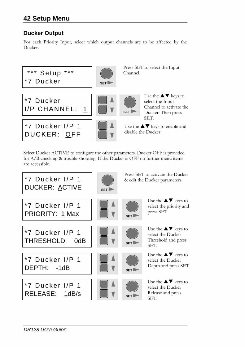
Ducker Output.��� ����� ������� �����7� ��"���� ����� ������� ������"�� ���� ��� 3�� �00������ 3�� ���,��-��
��"����,��-���5'2�A �������0�������������������%������,��-���(..����������0���5;?�����-���8�����3"� ���������0�����,��-�����(..����0�������%������%�����������3"�
* * * Se tup * * **7 Ducker
������� 2������"�������������'�����"
SET
*7 DuckerI /P CHANNEL: 1
9����������-��������"�������������'�����"���������������,��-���2���������� 2
SET
*7 Ducker I /P 1DUCKER: OFF
9����������-����������3"��������3"������,��-��
SET
*7 Ducker I /P 1DUCKER: ACTIVE
������� 2����������������,��-��8���������,��-�������%�����
SET
*7 Ducker I /P 1PRIORITY: 1 Max
9����������-��������"������������������������� 2
SET
*7 Ducker I /P 1THRESHOLD: 0dB
9����������-��������"��������,��-��2������"������������ 2
SET
*7 Ducker I /P 1DEPTH: -1dB
9����������-��������"��������,��-��,���������������� 2
SET
*7 Ducker I /P 1RELEASE: 1dB/s
9����������-��������"��������,��-��!�"��������������� 2
Setup Menu 43
DR128 USER GUIDE
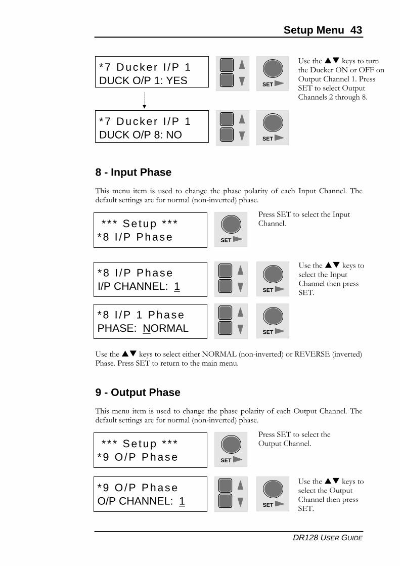
8 - Input Phase
2���%���� ��%� �� ����� ��� ������� ���� ������ ��"����� �0� ����� ������ '�����"� 2����0��"��������������0������%�"�B��� �������C������
9����������-���������"�����������(!�5*�B��� �������C����! A !� �B�������C������������� 2������������������%���%���
9 - Output Phase
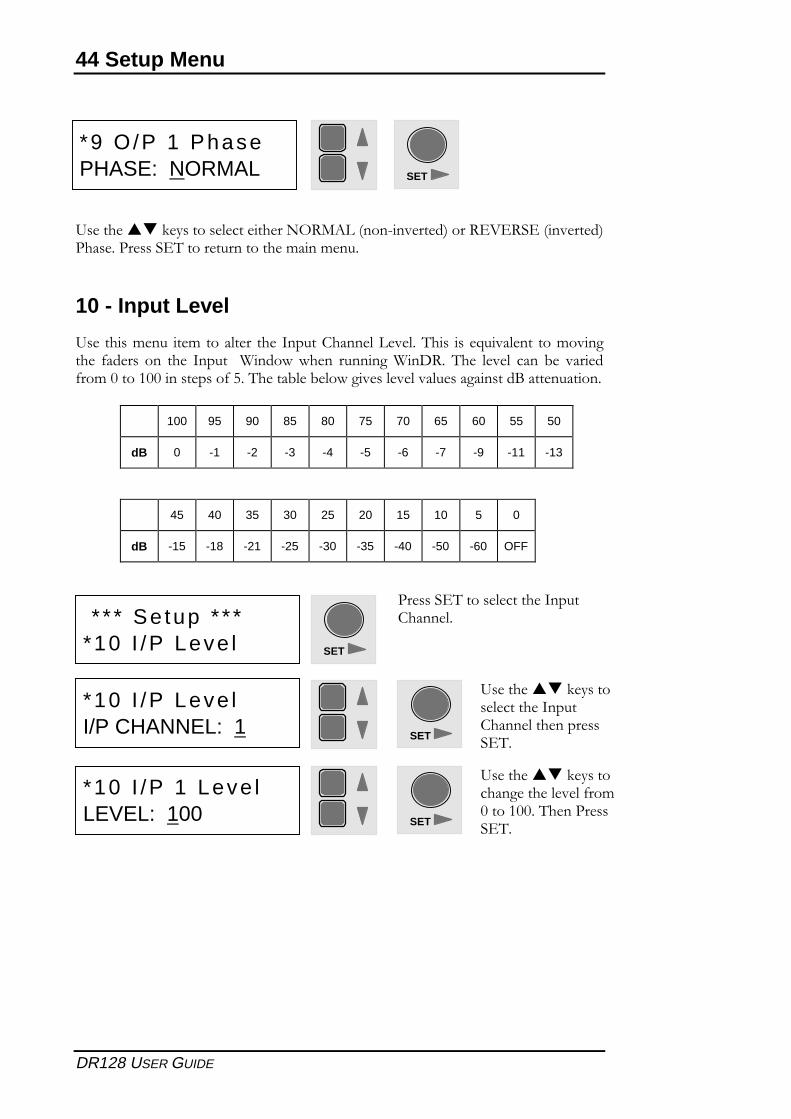
2���%������%������������������������������"������0������(������'�����"�2����0��"��������������0������%�"�B��� �������C������
* * * Se tup * * **8 I /P Phase
* * * Se tup * * **9 O/P Phase
������� 2������"�������������'�����"
������� 2������"�������(������'�����"
SET
SET
SET
SET
*8 I /P PhaseI/P CHANNEL: 1
*9 O/P PhaseO/P CHANNEL: 1
9����������-��������"�������������'�����"������������ 2
9����������-��������"��������(�����'�����"������������ 2
SET
*8 I /P 1 PhasePHASE: NORMAL
SET
*7 Ducker I /P 1DUCK O/P 1: YES
9����������-���������������,��-���(�����(..���(������'�����"��������� 2������"����(�����'�����"��$���������&
SET
*7 Ducker I /P 1DUCK O/P 8: NO
44 Setup Menu
DR128 USER GUIDE
9����������-���������"�����������(!�5*�B��� �������C����! A !� �B�������C������������� 2������������������%���%���
10 - Input Level
9�������%���� ��%�����"���� ����������'�����"�*���"�2��� ���:���"���� ���%�������� 0������ ��� ���� ������ �1���������� �������1�,!�2��� "���"� ���� 3�� �����0��%�+�����++����������0���2�����3"��3�"��������"���"���"������������?�����������
100 95 90 85 80 75 70 65 60 55 50
dB 0 -1 -2 -3 -4 -5 -6 -7 -9 -11 -13
45 40 35 30 25 20 15 10 5 0
dB -15 -18 -21 -25 -30 -35 -40 -50 -60 OFF
SET
*9 O /P 1 PhasePHASE: NORMAL
* * * Se tup * * **10 I /P Leve l
������� 2������"�������������'�����"
SET
SET
*10 I /P Leve lI/P CHANNEL: 1
9����������-��������"�������������'�����"������������ 2
SET
*10 I /P 1 Leve lLEVEL: 100
9����������-�����������������"���"�0��%+�����++�2���������� 2
Setup Menu 45
DR128 USER GUIDE
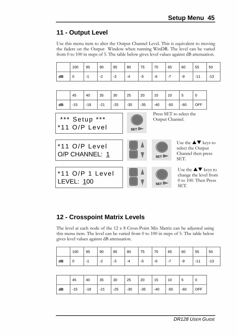
11 - Output Level
9�������%������%�����"��������(������'�����"�*���"�2������:���"�������%��������0�������������(������ �1�����������������1�,!�2��� "���"�����3�������0��%�+�����++����������0���2�����3"��3�"��������"���"���"������������?�����������
100 95 90 85 80 75 70 65 60 55 50
dB 0 -1 -2 -3 -4 -5 -6 -7 -9 -11 -13
45 40 35 30 25 20 15 10 5 0
dB -15 -18 -21 -25 -30 -35 -40 -50 -60 OFF
12 - Crosspoint Matrix Levels
2���"���"���������������0������$���&�'���� ������������������3����>��������������%������%�2���"���"�����3��������0��%�+�����++����������0���2�����3"��3�"�������"���"���"������������?�����������
100 95 90 85 80 75 70 65 60 55 50
dB 0 -1 -2 -3 -4 -5 -6 -7 -9 -11 -13
45 40 35 30 25 20 15 10 5 0
dB -15 -18 -21 -25 -30 -35 -40 -50 -60 OFF
* * * Se tup * * **11 O/P Leve l
������� 2������"�������(������'�����"
SET
SET
*11 O/P Leve lO/P CHANNEL: 1
9����������-��������"��������(�����'�����"������������ 2
SET
*11 O/P 1 Leve lLEVEL: 100
9����������-�����������������"���"�0��%+�����++�2���������� 2
46 Setup Menu
DR128 USER GUIDE
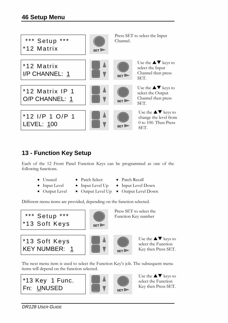
13 - Function Key Setup
���� �0� ���� �$� .����� ����"� .������� /���� ���� 3�� ������%%��� ��� ���� �0� ���0�""�����0�������
� 9����� � ��������"��� � ������!���""
� ������*���" � ������*���"�9� � ������*���"�,���
� (������*���" � (������*���"�9� � (������*���"�,���
,00������%������%�������������7�����������������0���������"�����
2��������%������%�������������"��������.�������/��4��>�3�2�����3��:�����%�����%���""���������������0���������"�����
* * * Se tup * * **13 So f t Keys
������� 2������"�������.�������/�����%3��
SET
SET
*13 So f t KeysKEY NUMBER: 1
9����������-��������"��������.������/��������������� 2
SET
*13 Key 1 Func.Fn: UNUSED
9����������-��������"��������.������/��������������� 2
* * * Se tup * * **12 Mat r i x
������� 2������"�������������'�����"
SET
SET
*12 Mat r i x IP 1O/P CHANNEL: 1
9����������-��������"��������(�����'�����"������������ 2
SET
*12 I /P 1 O/P 1LEVEL: 100
9����������-�����������������"���"�0��%+�����++�2���������� 2
SET
*12 Mat r i xI/P CHANNEL: 1
9����������-��������"�������������'�����"������������ 2
Setup Menu 47
DR128 USER GUIDE
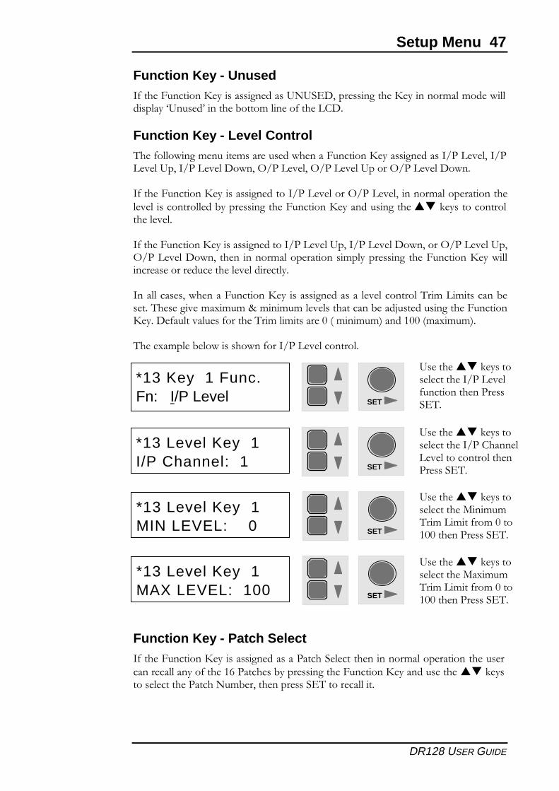
Function Key - Unused�0�����.�������/����������������9�9� ,7�������������/��������%�"�%�����""���"���=9�����4�������3����%�"����0�����*',
Function Key - Level Control2���0�""�����%������%������������������.�������/���������������;��*���"7��;�*���"�9�7��;��*���"�,���7�(;��*���"7�(;��*���"�9�����(;��*���"�,���
�0�����.�������/�����������������;��*���"����(;��*���"7������%�"�������������"���"���������""���3��������������.�������/�������������������-�������������"����"���"
�0�����.�������/�����������������;��*���"�9�7��;��*���"�,���7����(;��*���"�9�7(;��*���"�,���7������ �����%�"�����������%�"���������� ����.�������/����""����������������������"���"������"�
����""������7��������.�������/������������������"���"�������"�2�%�*%�������3�����2���������%��%�%�8�%�%�%�"���"�����������3����>���������������.������/���,�0��"����"����0�������2�%�"%�������+�B�%�%�%C������++�B%��%�%C
2������%�"��3�"�����������0����;��*���"�������"
Function Key - Patch Select�0�����.�������/��������������������������"��������������%�"��������������������������""������0����������������3��������������.�������/������������������-��������"����������������%3��7������������� 2��������""��
SET
*13 Level Key 1I/P Channel: 1
9����������-��������"���������;��'�����"*���"����������"������������ 2
SET
*13 Level Key 1MIN LEVEL: 0
9����������-��������"����������%�%2�%�*%��0��%�+����++������������� 2
SET
*13 Level Key 1MAX LEVEL: 100
9����������-��������"�����������%�%2�%�*%��0��%�+����++������������� 2
SET
*13 Key 1 Func.Fn: I/P Level
9����������-��������"���������;��*���"0������������������ 2
48 Setup Menu
DR128 USER GUIDE
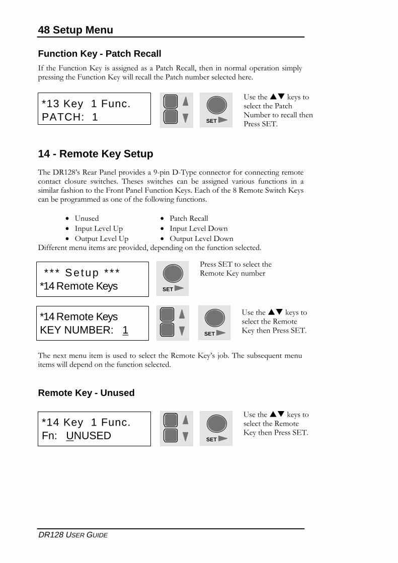
Function Key - Patch Recall�0�����.�������/������������������������!���""7� ����������%�"�����������%�"�������������.�������/����""�����""�������������%3�����"����������
14 - Remote Key Setup
2���,!�$&4��!��������"�����������) ���, 2��������������0���������������%����������� �"������ �������� 2������ �������� ���� 3�� �������� ������� 0�������� �� ��%"���0�������������.���������"�.�������/���� �����0�����&�!�%����������/�������3��������%%�����������0�����0�""�����0�������
� 9����� � ������!���""
� ������*���"�9� � ������*���"�,���
� (������*���"�9� � (������*���"�,���,00������%������%�������������7�����������������0���������"�����
2��������%������%�������������"��������!�%����/��4��>�3�2�����3��:�����%�����%���""���������������0���������"�����
Remote Key - Unused
* * * Se tup * * **14 Remote Keys
������� 2������"�������!�%����/�����%3��
SET
SET
*14 Remote KeysKEY NUMBER: 1
9����������-��������"��������!�%���/��������������� 2
SET
*14 Key 1 Func.Fn: UNUSED
9����������-��������"��������!�%���/��������������� 2
SET
*13 Key 1 Func.PATCH: 1
9����������-��������"���������������%3����������""������������ 2
Setup Menu 49
DR128 USER GUIDE
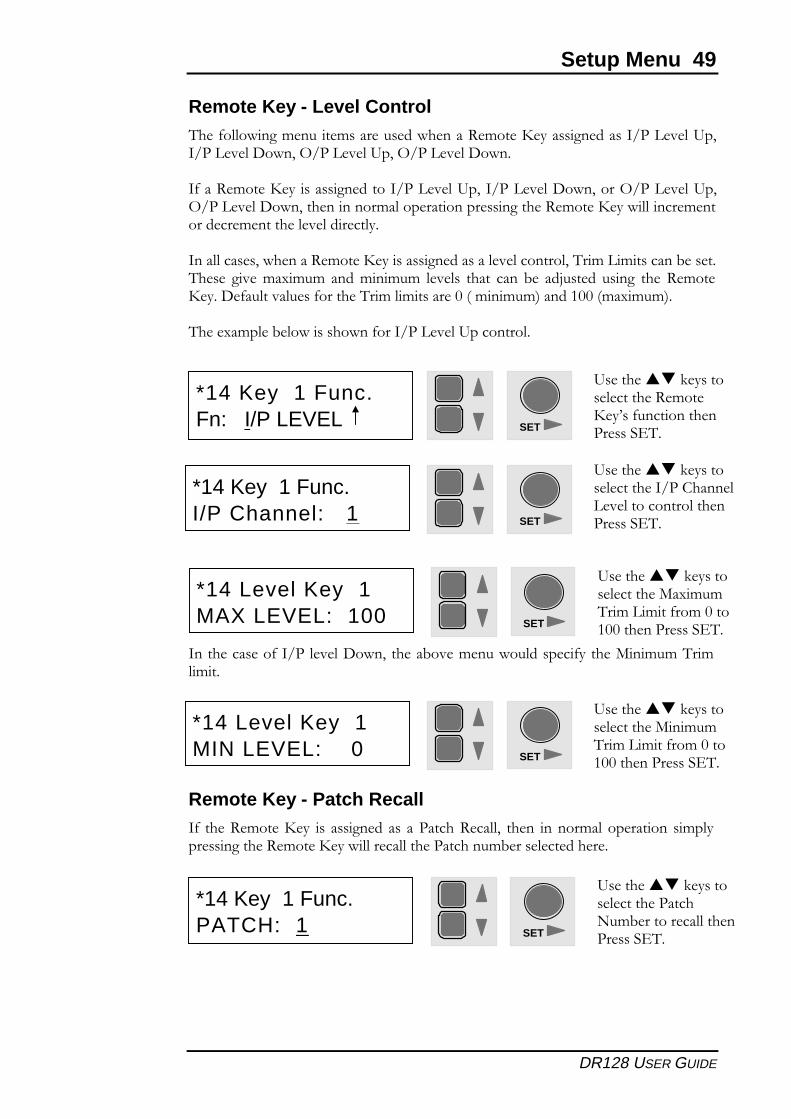
Remote Key - Level Control2���0�""�����%������%������������������!�%����/���������������;��*���"�9�7�;��*���"�,���7�(;��*���"�9�7�(;��*���"�,���
�0���!�%����/�����������������;��*���"�9�7��;��*���"�,���7����(;��*���"�9�7(;��*���"�,���7�����������%�"����������������������!�%����/����""�����%�����������%��������"���"������"�
����""������7��������!�%����/������������������"���"�������"7�2�%�*%�������3�����2����� ����%��%�%� ����%�%�%� "���"�� ����� ���� 3�� ��>������ ����� ���� !�%���/���,�0��"����"����0�������2�%�"%�������+�B�%�%�%C������++�B%��%�%C
2������%�"��3�"�����������0����;��*���"�9��������"
�������������0��;��"���"�,���7������3����%�������"������0��������%�%�2�%"%�
Remote Key - Patch Recall�0� ����!�%����/��� �� �������� ��� ��������!���""7� ����� �����%�"���������� �%�"�������������!�%����/����""�����""�������������%3�����"����������
SET
9����������-��������"��������!�%���/��4��0������������������ 2
*14 Key 1 Func.Fn: I/P LEVEL
SET
*14 Key 1 Func.I/P Channel: 1
9����������-��������"���������;��'�����"*���"����������"������������ 2
SET
*14 Level Key 1MAX LEVEL: 100
9����������-��������"�����������%�%2�%�*%��0��%�+����++������������� 2
SET
*14 Level Key 1MIN LEVEL: 0
9����������-��������"����������%�%2�%�*%��0��%�+����++������������� 2
SET
*14 Key 1 Func.PATCH: 1
9����������-��������"���������������%3����������""������������ 2
50 Setup Menu
DR128 USER GUIDE
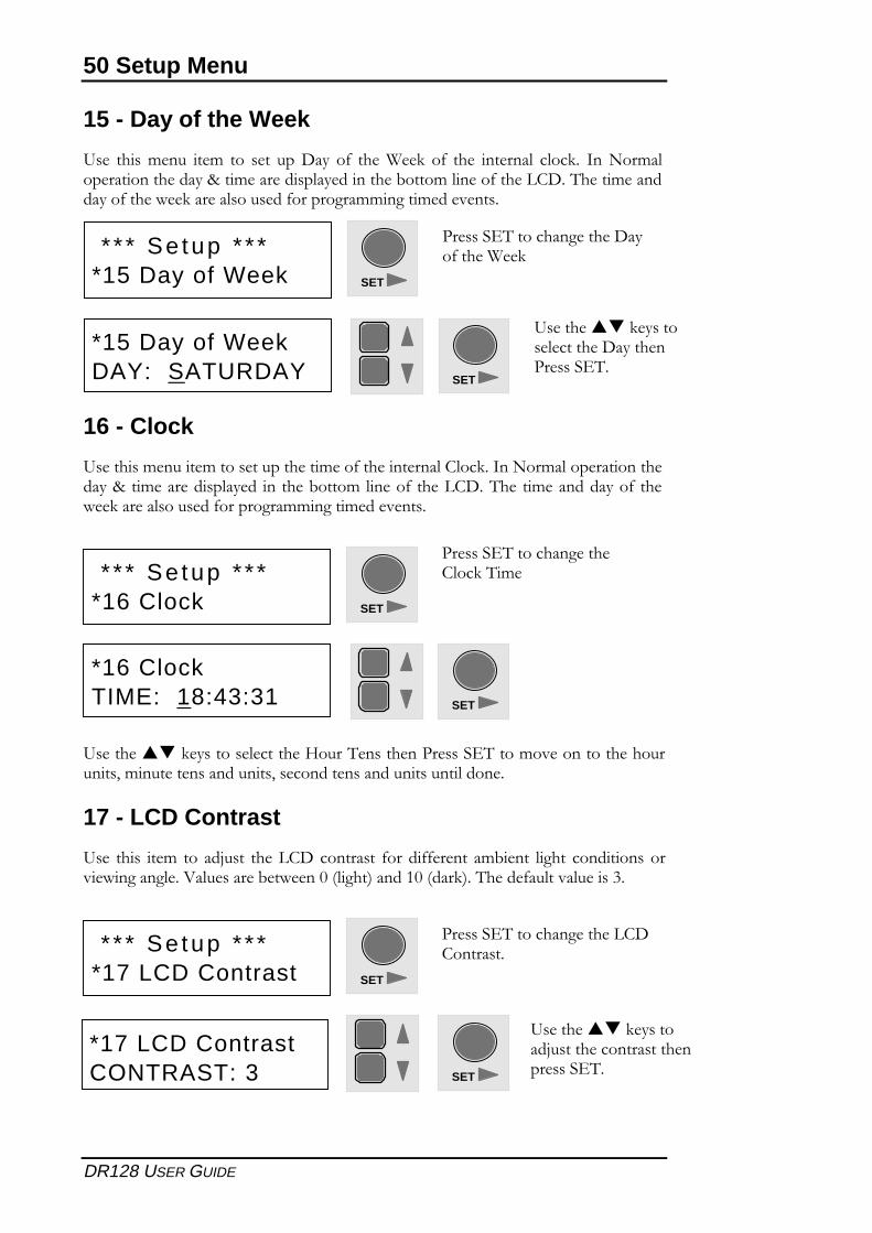
15 - Day of the Week
9��� ����%���� ��%� ��� ���� ���,��� �0� ����1��-� �0� ���� ������"� �"��-� ������%�"�����������������8��%���������"�����������3����%�"����0�����*',�2����%����������0��������-������"��������0���������%%����%���������
16 - Clock
9�������%������%����������������%���0�����������"�'"��-�������%�"�����������������8��%���������"����� ������3����%�"����0�����*',�2��� �%�����������0� ������-������"��������0���������%%����%���������
9����������-���������"��������@����2���������������� 2����%����������������������7�%������������������7�������������������������"�����
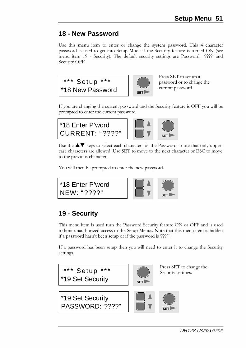
17 - LCD Contrast
9��� ���� ��%� ��� ��>���� ����*',���������� 0����00������ �%3���� "���� ��������� �����������"��A�"��������3�������+�B"���C������+�B���-C�2�����0��"����"������
* * * Se tup * * **15 Day of Week
* * * Se tup * * **16 Clock
������� 2���������������,���0�����1��-
������� 2��������������'"��-�2%�
SET
SET
SET
SET
*15 Day of WeekDAY: SATURDAY
*16 ClockTIME: 18:43:31
9����������-��������"��������,�������������� 2
* * * Se tup * * **17 LCD Contrast
������� 2���������������*','�������
SET
SET
*17 LCD ContrastCONTRAST: 3
9����������-��������>���������������������������� 2
Setup Menu 51
DR128 USER GUIDE
18 - New Password
9��� ���� %���� ��%� ��� ������ ��� ������� ���� �����%� ��������� 2��� �� ������������������ ������� ������� ��������������� 0� ������������ 0������� �� �������(�� B���%���� ��%� �)� � �������C� 2��� ��0��"�� �������� �������� ���� ��������� � =DDDD4� �����������(..
�0������������������������������������������������������0���������(..������""�3����%����������������������������������
9����������-���������"�������������������0���������������� �������������"������� ���������������������""�����9���� 2����%����������������������������� �'����%���������������������������
<����""������3�����%������������������������������
19 - Security
2���%������%����������������������������������0�������(�����(..��������������"%����������E�������������������������������������������%������%��������0����������������4��3�������������0����������������=DDDD4
�0����������������3���������� ����������""������ ��������� �� ���������� ������������������
* * * Se tup * * **18 New Password
������� 2�����������������������������������������������������
SET
SET
*18 Enter P’wordNEW: “ ????”
* * * Se tup * * **19 Set Security
������� 2�����������������������������
SET
SET
*19 Set SecurityPASSWORD:“????”
SET
*18 Enter P’wordCURRENT: “ ????”
52 Setup Menu
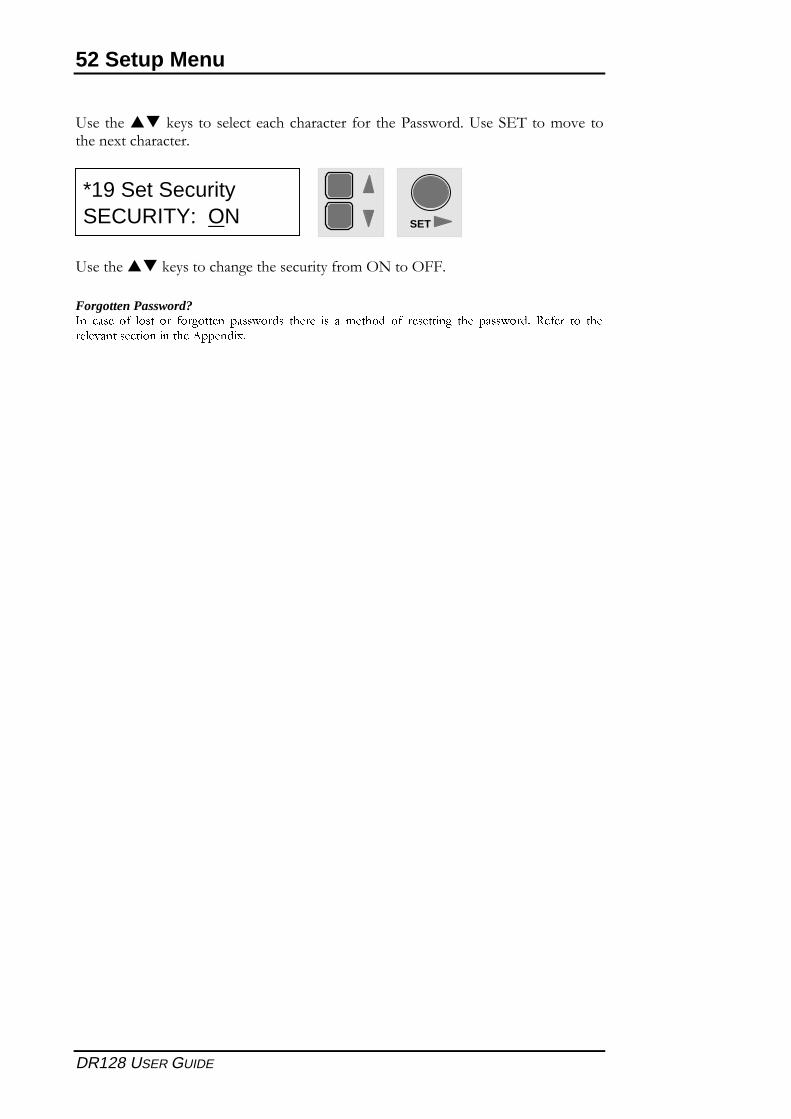
DR128 USER GUIDE
9����������-���������"������������������� 0��� �������������9���� 2����%���� ��������������������
9����������-��������������������������0��%�(�����(..
Forgotten Password?�� ���� � ��� �� �� ����� ��������� ����� �� � ������ � �������� ��� ��������� ���� �� ���������� ������� �� ��� ���������
SET
*19 Set SecuritySECURITY: ON
Appendix 53
DR128 USER GUIDE
Appendix
��������������� ������� ��������������������������������������������������������������������������������������������������������
�������������� ����������������������������������������������������������������������������������������������������������������
�������������������������������������������������������������������������������������������������������������������������������
����������������������������������������������������������������������������������������������������������������������������
6
54 Appendix
DR128 USER GUIDE
Architect’s Specification
The unit shall be a digital mix processor with 12 analogue inputs and 8 analogue outputs.The unit shall have a full crosspoint matrix, comprising 96 points, allowing any input, orcombination of inputs, to be routed to any output or combination of outputs. Allcrosspoints shall have a variable level. The 8 mic/line inputs and 8 line level outputsshall be on balanced XLRs with level trims. The 4 stereo line inputs shall sum to monoand be on RCA phono connectors with level trims. Comprehensive ducking capabilityshall be provided.
The mic/line inputs shall have internal jumpers for pad and phantom power selection.The mic/line gain range shall be 18dB to 60dB with input impedance of 2k� (no pad) or10k� (pad). The phono input gain sensitivity shall be internally adjustable from -10dBvto +4dBu with an impedance of 10k�. The inputs shall be converted using a 24 bitanalogue-to-digital converter.
The XLR outputs shall have a variable senitivity from -10dBV to +4dBu with an outputimpedance of 50�. The conversion shall be by a 20 bit digital-to-analogue converter.
The unit shall be configured over a standard RS232 port using a proprietary 32-bitWindows™ based software application with a Graphical User Interface. Configurationsshall be editable both on and off-line. The configuration shall determine the allocation ofinternal signal processing resources to input and output channels, as well as routing,passwords, levels and channel names. After configuration, the unit shall run standalone,without an external computer. Signal processing resources available shall includecompressors, gates, limiters, graphic equalisers, parametric equalisers and crossovers.Optional expander cards shall provide the facility for additional signal processingresources and/or supplementary delay resources. The unit shall use Flash memory topermit firmware upgrades via the RS232 port. An internal real-time clock shall allowscheduling of timed events.
The unit shall be compatible with BS5839 installation requirements. The hybridswitched/linear power supply shall allow emergency operation with a single 24V externalbattery and the unit shall interface with alarm systems. The total power consumptionshall be no more than 70VA and the permissible incoming mains voltage range shall beconfigurable to 100, 120, 220 or 230 VAC.
The front panel shall feature 12 installer-definable function keys for user control ofvolume levels and patches. A removable fascia shall enable custom labeling. There shallalso be a backlit LCD for indication of setup menus, peak conditions, patch status andchannel levels. Important system parameters, such as Patch Naming, Channel Naming,Limiter control, Ducking control, Phase reversal, Routing assignments, Date/Time, LCDcontrast and Soft Key definitions shall be password-protected from user adjustment.
Facilities for remote switching of unit parameters shall be provided.
The unit shall weigh no more than 10kg in a 2U rack-mount chassis. The chassis shall beconstructed from zintec steel and feature a removable top for configuration of internaljumpers and presets.
The unit shall be the Allen & Heath DR128 digital mix processor.
Appendix 55
DR128 USER GUIDE
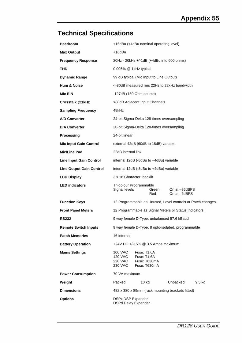
Technical Specifications
Headroom +16dBu (+4dBu nominal operating level)
Max Output +16dBu
Frequency Response 20Hz - 20kHz +/-1dB (+4dBu into 600 ohms)
THD 0.005% @ 1kHz typical
Dynamic Range 99 dB typical (Mic Input to Line Output)
Hum & Noise <-80dB measured rms 22Hz to 22kHz bandwidth
Mic EIN -127dB (150 Ohm source)
Crosstalk @1kHz >80dB Adjacent Input Channels
Sampling Frequency 48kHz
A/D Converter 24-bit Sigma-Delta 128-times oversampling
D/A Converter 20-bit Sigma-Delta 128-times oversampling
Processing 24-bit linear
Mic Input Gain Control external 42dB (60dB to 18dB) variable
Mic/Line Pad 22dB internal link
Line Input Gain Control internal 12dB (-8dBu to +4dBu) variable
Line Output Gain Control internal 12dB (-8dBu to +4dBu) variable
LCD Display 2 x 16 Character, backlit
Tri-colour ProgrammableSignal levels Green On at –36dBFS
LED indicators
Red On at –6dBFS
Function Keys 12 Programmable as Unused, Level controls or Patch changes
Front Panel Meters 12 Programmable as Signal Meters or Status Indicators
RS232 9 way female D-Type, unbalanced 57.6 kBaud
Remote Switch Inputs 9 way female D-Type, 8 opto-isolated, programmable
Patch Memories 16 internal
Battery Operation +24V DC +/-15% @ 3.5 Amps maximum
Mains Settings 100 VAC Fuse: T1.6A120 VAC Fuse: T1.6A220 VAC Fuse: T630mA230 VAC Fuse: T630mA
Power Consumption 70 VA maximum
Weight Packed 10 kg Unpacked 9.5 kg
Dimensions 482 x 380 x 89mm (rack mounting brackets fitted)
Options DSPx DSP ExpanderDSPd Delay Expander
56 Appendix
DR128 USER GUIDE
Connecting WinDR
�� ��� �� �� �����!"# ��$ � ��$����� ��������%&����������'��$(������� �������� ������������)���* ����+
System requirements:
Hardware����� $��)�����,����$����)������������)'�#�-.�/���������'0!�"�)'1�#����$$�����2!�(3��(!�(3&���������/� �������(� ������������������/���456 ����'��7���/���"4"�������$$ ������������
Software(����� �������8�9
Installing WinDR onto a PC.��������)��������� ��$���� ���� ���+
� :��$456 ����'��7�
� ���������� ��$��������%&������)����
IMPORTANTDO NOT INSTALL THIS SOFTWARE OVER A PREVIOUS VERSION.
������ � �����'����������������'��$(������������;�����������'��������/�� /������ ��������)��������������/�� /��������)� �<��������)' ��� ���Control Panel Add/Remove Programs ����������� ��$ ��� ������Start/Settings $�� �
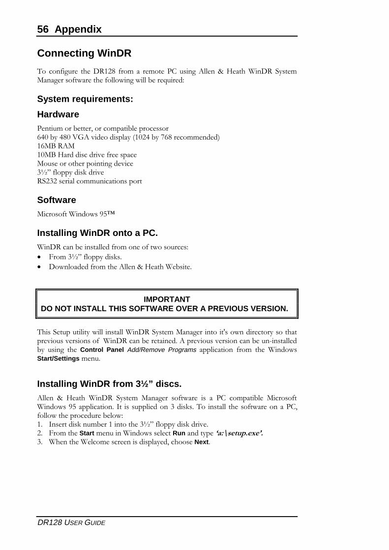
Installing WinDR from 3½” discs.����� % &���� ����� �'��$ (������ � ����� � � �� ��$����)�� (����� �������8�������������=� � ��������4��7��������� ���� ����������, �������������� ��)����+!� =������7� $)��!�������456 ����'��7���/��"� :��$���Start $�� �������������Run ����'��������������4� ������������$������������'��,�����Next �
Appendix 57
DR128 USER GUIDE
�� :����� ��� ���� ����� �����'�� �� ��� ����� ��� ����� ��� ��$������ ��7������* �����
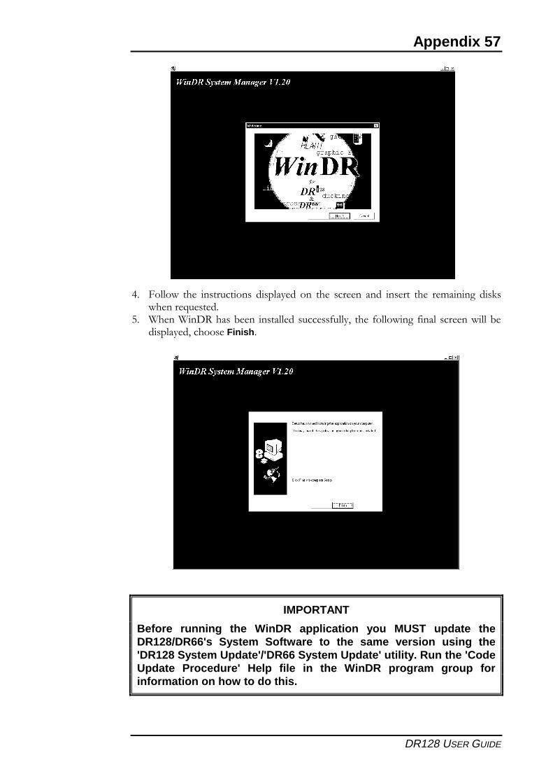
�� �����������)��� �������� ��� ��', ��� �������� ���� ���������)������'��,�����Finish �
IMPORTANT
Before running the WinDR application you MUST update theDR128/DR66's System Software to the same version using the'DR128 System Update'/'DR66 System Update' utility. Run the 'CodeUpdate Procedure' Help file in the WinDR program group forinformation on how to do this.
58 Appendix
DR128 USER GUIDE
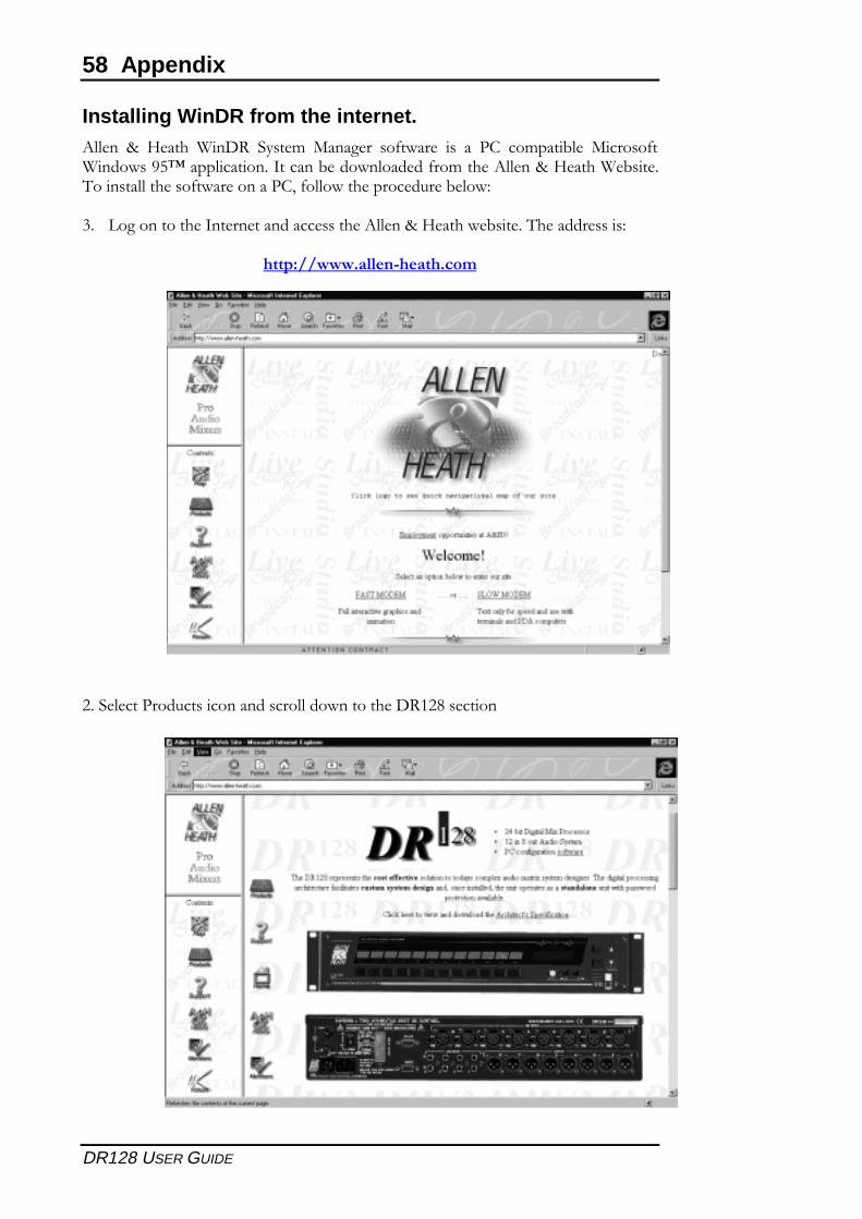
Installing WinDR from the internet.����� % &���� ����� �'��$ (������ � ����� � � �� ��$����)�� (����� �������8�9������������=����)����������� ��$��������%&������)���������������� ����������, �������������� ��)����+
4� >���������=����������������������%&������)�������������+
������������������� ��
"����������� �������������������������!"#������
Appendix 59
DR128 USER GUIDE
4� ����7����������������������/������ ��������� ��������������������� ����� ���������� �������!"# ����
IMPORTANT
Before running the WinDR application you MUST update theDR128/DR66's System Software to the same version using the'DR128 System Update'/'DR66 System Update' utility. Run the 'CodeUpdate Procedure' Help file in the WinDR program group forinformation on how to do this.
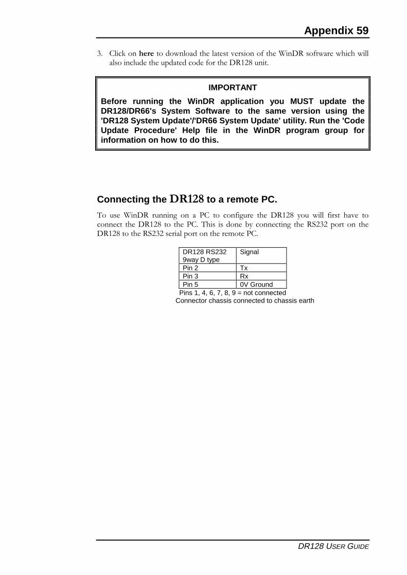
Connecting the ����� to a remote PC.
�� ������ � ����� �� � �� �� ��� �� �� ��� ��!"# '� ���� ��� ��/� ��������� �����!"# �� ��������� �����)' ���������� �����"4"������ �����!"#�������"4"����������������$������
DR128 RS2329way D type
Signal
Pin 2 TxPin 3 RxPin 5 0V Ground
Pins 1, 4, 6, 7, 8, 9 = not connectedConnector chassis connected to chassis earth
60 Appendix
DR128 USER GUIDE
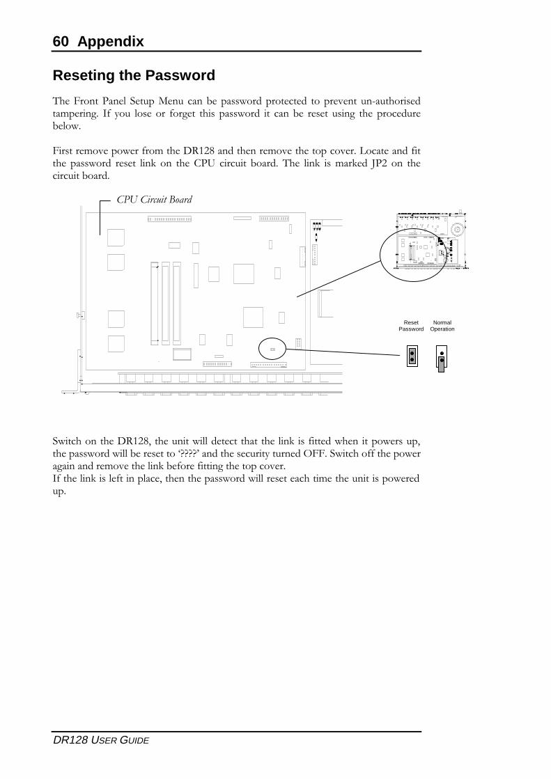
Reseting the Password
���:��������� ��� �(�� ���)���������������� �����/��� �<� ���������$������� = '� ��� �� ����� ��� ������ �� ���)� ���� ��� ��� ������ ��)�����
:�����$�/������ ��$�����!"#���������$�/���������/���>�������� ����� ������ ���� ���7 �� �����? ���� �� )����� ��� ���7 �$��7�� @�" �� ������� ��)�����
�������������!"#,��� �����������������������7� ���������������� �,�������������)�������ABBBB��������� ���'� ����C::�������� ������������������$�/�������7)� ��� ��������������/���= ������7��� ��������,���������������������������$���� ����������� ��
ResetPassword
NormalOperation
��������������
1
DR128 SERVICE MANUAL
SECTION B
DR 128 SERVICE INFORMATION
CAUTIONRefer all installation, calibration and service
work to qualified service personnel
Warning to the Service EngineerAllen & Heath warns that any unauthorised changes ormodifications to the DR 128 unit may invalidate the legalcompliance of the unit and could void the user's authority tooperate the equipment.
B
2
DR128 SERVICE MANUAL
CONTENTS
INTRODUCTION, SERVICE AND TECHNICAL SUPPORT..................................................... 3REMOVING A CONNECTOR CIRCUIT BOARD ASSEMBLY (upper & lower) ........................ 4REMOVING THE MICROPROCESSOR (CPU) CIRCUIT BOARD ASSEMBLY ...................... 5REMOVING THE FRONT PANEL CIRCUIT BOARD ASSEMBLY (inc LCD display) ............... 6REMOVING THE POWER SUPPLY CIRCUIT BOARD ASSEMBLY ....................................... 7ORDERING A DR128 UNIT, OPTIONS & SPARE ASSEMBLIES............................................ 8ORDERING SPARE PARTS .................................................................................................... 9 - 10TRANSFORMER & POWER WIRING ...................................................................................... 11PSU CIRCUIT BOARD COMPONENT IDENT ......................................................................... AG2605PSU CIRCUIT DIAGRAM sheet 1 of 2 (transformer & battery changover) .............................. C2605PSU CIRCUIT DIAGRAM sheet 2 of 2 (switching & linear regulators) ..................................... C2605MIC INPUT CONNECTOR CIRCUIT BOARD COMPONENT IDENT ...................................... AG2602MIC INPUT CONNECTOR CIRCUIT DIAGRAM sheet 2 of 8 (mic inputs 1 & 2) ..................... C2602MIC INPUT CONNECTOR CIRCUIT DIAGRAM sheet 3 of 8 (ADCs 1 & 2) ............................ C2602MIC INPUT CONNECTOR CIRCUIT DIAGRAM sheet 4 of 8 (mic inputs 3 & 4) ..................... C2602MIC INPUT CONNECTOR CIRCUIT DIAGRAM sheet 5 of 8 (mic inputs 5 & 6) ..................... C2602MIC INPUT CONNECTOR CIRCUIT DIAGRAM sheet 6 of 8 (mic inputs 7 & 8) ..................... C2602MIC INPUT CONNECTOR CIRCUIT DIAGRAM sheet 7 of 8 (ADCs 3 & 4) ............................ C2602MIC INPUT CONNECTOR CIRCUIT DIAGRAM sheet 8 of 8 (Connectors) ............................ C2602LINE OUTPUT CONNECTOR CIRCUIT BOARD COMPONENT IDENT ................................. AG2603LINE OUTPUT CONNECTOR CIRCUIT DIAGRAM sheet 2 of 8 (line inputs 1 & 2) ................. C2603LINE OUTPUT CONNECTOR CIRCUIT DIAGRAM sheet 3 of 8 (line inputs 3 & 4) ................. C2603LINE OUTPUT CONNECTOR CIRCUIT DIAGRAM sheet 4 of 8 (balanced outputs 3 & 4) ...... C2603LINE OUTPUT CONNECTOR CIRCUIT DIAGRAM sheet 5 of 8 (balanced outputs 1 & 2) ...... C2603LINE OUTPUT CONNECTOR CIRCUIT DIAGRAM sheet 6 of 8 (balanced outputs 7 & 8) ...... C2603LINE OUTPUT CONNECTOR CIRCUIT DIAGRAM sheet 7 of 8 (balanced outputs 5 & 6) ...... C2603LINE OUTPUT CONNECTOR CIRCUIT DIAGRAM sheet 8 of 8 (digital interface & conns) .... C2603MICROPROCESSOR CPU CIRCUIT BOARD COMPONENT IDENT ..................................... AG2604MICROPROCESSOR CPU CIRCUIT DIAGRAM sheet 2 of 6 (interface) ................................. C2604MICROPROCESSOR CPU CIRCUIT DIAGRAM sheet 3 of 6 (CPU & memory) ...................... C2604MICROPROCESSOR CPU CIRCUIT DIAGRAM sheet 4 of 6 (processing engine #1) ............. C2604MICROPROCESSOR CPU CIRCUIT DIAGRAM sheet 5 of 6 (processing engine #2) ............. C2604MICROPROCESSOR CPU CIRCUIT DIAGRAM sheet 6 of 6 (expander connectors) ............. C2604FRONT PANEL CIRCUIT BOARD COMPONENT IDENT ....................................................... AG2423FRONT PANEL CIRCUIT BOARD CIRCUIT DIAGRAM sheet 1 of 1 ....................................... C2423DSP EXPANDER CIRCUIT BOARD COMPONENT IDENT..................................................... AG2741DSP EXPANDER CIRCUIT DIAGRAM sheet 2 of 3 (processing engine #1 & conns) .............. C2741DSP EXPANDER CIRCUIT DIAGRAM sheet 3 of 3 (processing engine #2) ............................ C2741
Refer to SECTION A for information on installation, calibrationand operation of the DR128.
Section B

3
DR128 SERVICE MANUAL
INTRODUCTIONThe information presented in this section of the manual is intended for competent technical personnel to carryout service and product support for the DR 128. We assume that the reader is familiar with the related electronictheory and audio terminology, and is able to carry out basic servicing, fault-finding and repair of digital audioequipment of this type. Service personnel should also be familiar with audio systems, mains earthing and powerrequirements, as well as handling precautions.
For information on the installation, operation and application of the DR 128 please refer to sectionA of this manual.
Whilst we believe the information in this manual to be reliable we do not assume responsibility for inaccuracies.We also reserve the right to make changes in the interest of further product development.
SERVICE AND TECHNICAL SUPPORTUnder normal operating conditions the DR 128 does not require user maintenance or internal calibration. Anyservice work required should be carried out by qualified technical personnel only.
We are able to offer further product support through our worldwide distribution network. To help us provide anefficient service please quote the unit serial number, the date and place of purchase in any communicationregarding this product
SAFETY WARNING !Mains electricity is dangerous and can kill. Mains voltage is present within the unit. Except forInstallation and calibration, do not remove any covers with power connected. Do not carry out anywork within the unit while it is powered. High voltage components are insulated for safety but shouldnot be touched with power applied. The mains voltage setting is indicated on the AC mains inputsocket on the rear panel. Check that this matches your local mains supply. Check your mains wiringand earthing before switching on.
DO NOT REMOVE THE MAINS EARTH CONNECTION!The chassis is always connected to mains earth. Audio 0V connects to the chassis internally.Should problems be encountered with ground loops operate the audio ground lift switches on otherequipment connected to the unit or disconnect the cable screens at one end. Refer to the sectionon 'EARTHING' in the User Guide.
IMPORTANT STATIC ELECTRICITYPRECAUTIONS
Many of the components in the DR 128 are extremely sensitive to static electricity. The followingprocedures reduce the possibility of damaging components:
1.) Before handling any components or touching anything inside the unit, dischargeyour body's static electric charge by touching a grounded (earthed) surface.Wear a grounding wrist strap if one is available.
2.) Do not remove parts from their antistatic containers or bags until you are readyto install them. When removing circuit boards (PCBs) or chips from a unit,immediately place them in an antistatic bag.
3.) When handling (PCBs), hold them by their edges and avoid touching the circuitry.4.) Do not slide (PCBs) or ICs over any surface.5.) Avoid having plastic, vinyl and foam in your work area.6.) Limiting your movements during service work reduces static electricity.
WARNING: There is danger of explosion if the battery is incorrectly replaced.Replace the battery with an Allen & Heath recommended part. Using a different battery, recharging ordissassembling the battery may present a danger due to fire or explosion.
Dispose of used batteries promptly according to the manufacturer's instructions. Keep all batteries awayfrom childeren
Section B
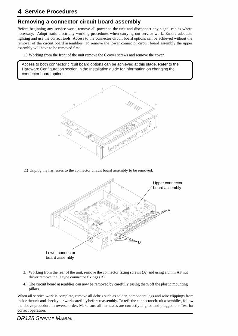
4
DR128 SERVICE MANUAL
Removing a connector circuit board assemblyBefore beginning any service work, remove all power to the unit and disconnect any signal cables wherenecessary. Adopt static electricity working procedures when carrying out service work. Ensure adequatelighting and use the correct tools. Access to the connector circuit board options can be achieved without theremoval of the circuit board assemblies. To remove the lower connector circuit board assembly the upperassembly will have to be removed first.
1.) Working from the front of the unit remove the 6 cover screws and remove the cover.
Access to both connector circuit board options can be achieved at this stage. Refer to theHardware Configuration section in the Installation guide for information on changing theconnector board options.
2.) Unplug the harnesses to the connector circuit board assembly to be removed.
3.) Working from the rear of the unit, remove the connector fixing screws (A) and using a 5mm AF nutdriver remove the D type connector fixings (B).
4.) The circuit board assemblies can now be removed by carefully easing them off the plastic mountingpillars.
When all service work is complete, remove all debris such as solder, component legs and wire clippings frominside the unit and check your work carefully before reassembly. To refit the connector circuit assemblies, followthe above procedure in reverse order. Make sure all harnesses are correctly aligned and plugged on. Test forcorrect operation.
A
B
Upper connectorboard assembly
Lower connectorboard assembly
Service Procedures
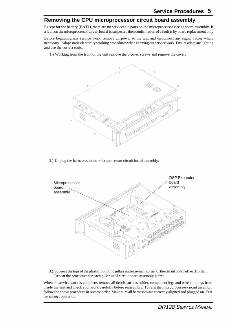
5
DR128 SERVICE MANUAL
Removing the CPU microprocessor circuit board assemblyExcept for the battery (BAT1), there are no serviceable parts on the microprocessor circuit board assembly. Ifa fault on the microprocessor circuit board is suspected then confirmation of a fault is by board replacement only
Before beginning any service work, remove all power to the unit and disconnect any signal cables wherenecessary. Adopt static electricity working procedures when carrying out service work. Ensure adequate lightingand use the correct tools.
1.) Working from the front of the unit remove the 6 cover screws and remove the cover.
2.) Unplug the harnesses to the microprocessor circuit board assembly.
3.) Squeeze the tops of the plastic mounting pillars and ease each corner of the circuit board off each pillar.Repeat the procedure for each pillar until circuit board assembly is free.
When all service work is complete, remove all debris such as solder, component legs and wire clippings frominside the unit and check your work carefully before reassembly. To refit the microprocessor circuit assemblyfollow the above procedure in reverse order. Make sure all harnesses are correctly aligned and plugged on. Testfor correct operation.
Microprocessorboardassembly
DSP Expanderboardassembly
Service Procedures
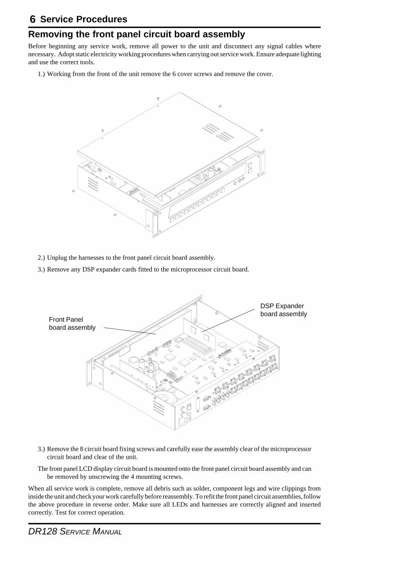
6
DR128 SERVICE MANUAL
Removing the front panel circuit board assemblyBefore beginning any service work, remove all power to the unit and disconnect any signal cables wherenecessary. Adopt static electricity working procedures when carrying out service work. Ensure adequate lightingand use the correct tools.
1.) Working from the front of the unit remove the 6 cover screws and remove the cover.
2.) Unplug the harnesses to the front panel circuit board assembly.
3.) Remove any DSP expander cards fitted to the microprocessor circuit board.
3.) Remove the 8 circuit board fixing screws and carefully ease the assembly clear of the microprocessorcircuit board and clear of the unit.
The front panel LCD display circuit board is mounted onto the front panel circuit board assembly and canbe removed by unscrewing the 4 mounting screws.
When all service work is complete, remove all debris such as solder, component legs and wire clippings frominside the unit and check your work carefully before reassembly. To refit the front panel circuit assemblies, followthe above procedure in reverse order. Make sure all LEDs and harnesses are correctly aligned and insertedcorrectly. Test for correct operation.
Front Panelboard assembly
DSP Expanderboard assembly
Service Procedures
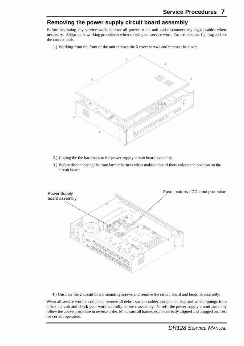
7
DR128 SERVICE MANUAL
Removing the power supply circuit board assemblyBefore beginning any service work, remove all power to the unit and disconnect any signal cables wherenecessary. Adopt static working procedures when carrying out service work. Ensure adequate lighting and usethe correct tools.
1.) Working from the front of the unit remove the 6 cover screws and remove the cover.
2.) Unplug the the harnesses to the power supply circuit board assembly.
3.) Before disconnecting the transformer harness wires make a note of there colour and position on thecircuit board.
4.) Unscrew the 2 circuit board mounting screws and remove the circuit board and heatsink assembly.
When all service work is complete, remove all debris such as solder, component legs and wire clippings frominside the unit and check your work carefully before reassembly. To refit the power supply circuit assemblyfollow the above procedure in reverse order. Make sure all harnesses are correctly aligned and plugged on. Testfor correct operation.
Power Supplyboard assembly
Fuse - external DC input protection
Service Procedures
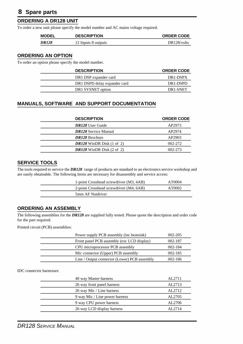
8
DR128 SERVICE MANUAL
ORDERING A DR128 UNITTo order a new unit please specify the model number and AC mains voltage required.
MODEL DESCRIPTION ORDER CODEDR128 12 Inputs 8 outputs DR128/volts
ORDERING AN OPTIONTo order an option please specify the model number.
DESCRIPTION ORDER CODEDR1 DSP expander card DR1-DSPXDR1 DSPD delay expander card DR1-DSPDDR1 SYSNET option DR1-SNET
MANUALS, SOFTWARE AND SUPPORT DOCUMENTATION
DESCRIPTION ORDER CODEDR128 User Guide AP2973DR128 Service Manual AP2974DR128 Brochure AP2903DR128 WinDR Disk (1 of 2) 002-272DR128 WinDR Disk (2 of 2) 002-273
SERVICE TOOLSThe tools required to service the DR128 range of products are standard to an electronics service workshop andare easily obtainable. The following items are necessary for disassembly and service access:
1-point Crosshead screwdriver (M3, 4AB) AT00042-point Crosshead screwdriver (M4, 6AB) AT00025mm AF Nutdriver
ORDERING AN ASSEMBLYThe following assemblies for the DR128 are supplied fully tested. Please quote the description and order codefor the part required.
Printed circuit (PCB) assemblies:
Power supply PCB assembly (inc heatsink) 002-205Front panel PCB assembly (exc LCD display) 002-187CPU microprocessor PCB assembly 002-184Mic connector (Upper) PCB assembly 002-185Line / Output connector (Lower) PCB assembly 002-186
IDC connector harnesses:
40 way Master harness AL271126 way front panel harness AL271326 way Mic / Line harness AL27129 way Mic / Line power harness AL27059 way CPU power harness AL270626 way LCD display harness AL2714
Spare parts
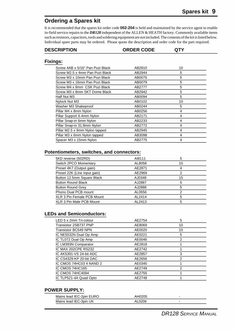
9
DR128 SERVICE MANUAL
Ordering a Spares kitIt is recommended that the spares kit order code 002-204 is held and maintained by the service agent to enablein-field service repairs to the DR128 independent of the ALLEN & HEATH factory. Commonly available itemssuch as resistors, capacitors, tools and soldering equipment are not included. The contents of the kit is listed below.Individual spare parts may be ordered. Please quote the description and order code for the part required.
DESCRIPTION ORDER CODE QTY
Fixings:Screw 4AB x 5/16" Pan Pozi Black AB2810 10Screw M2.5 x 4mm Pan Pozi Black AB2944 5Screw M3 x 10mm Pan Pozi Black AB0076 5Screw M3 x 16mm Pan Pozi Black AB0079 5Screw M4 x 8mm CSK Pozi Black AB2777 5Screw M3 x 8mm SKT Dome Black AB2942 5Half Nut M3 AB0094 5Nylock Nut M3 AB0102 10Washer M3 Shakeproof AB0244 5Pillar M4 x 8mm Nylon AB0256 4Pillar Support 6.4mm Nylon AB2171 4Pillar Snap-in 6mm Nylon AB2233 4Pillar Snap-in 31.8mm Nylon AB2772 4Pillar M2.5 x 9mm Nylon tapped AB2945 4Pillar M3 x 6mm Nylon tapped AB3098 4Spacer M3 x 15mm Nylon AB2775 4
Potentiometers, switches, and connectors:5KD reverse (502RD) AI8111 5Switch 2PCO Momentary AL8058 10Preset 4K7 (Output gain) AE2871 4Preset 22K (Line input gain) AE2969 2Button 12.5mm Square Black AJ0348 15Button Round Black AJ2887 5Button Round Grey AJ2888 5Phono Dual PCB mount AL0556 2XLR 3 Pin Female PCB Mount AL2414 5XLR 3 Pin Male PCB Mount AL2413 5
LEDs and Semiconductors:LED 5 x 2mm Tri-colour AE2754 5Transistor 2SB737 PNP AE8069 10Transistor BC549 NPN AE0020 10IC NE5532N Dual Op Amp AE0221 5IC TL072 Dual Op Amp AE0046 2IC LM393N Comparator AE2818 1IC MAX 202CPE RS232 AE2742 1IC AK5391-VS 24-bit ADC AE2857 3IC CS4329-KP 20-bit DAC AE2656 2IC CMOS 74HC03 4 NAND 2 AE0345 1IC CMOS 74HC165 AE2749 2IC CMOS 74HC4094 AE2755 1IC TLP521-4A Quad Opto AE2748 1
POWER SUPPLY:Mains lead IEC-2pin EURO AH0205 -Mains lead IEC-3pin UK AL0206 -
Spares kit
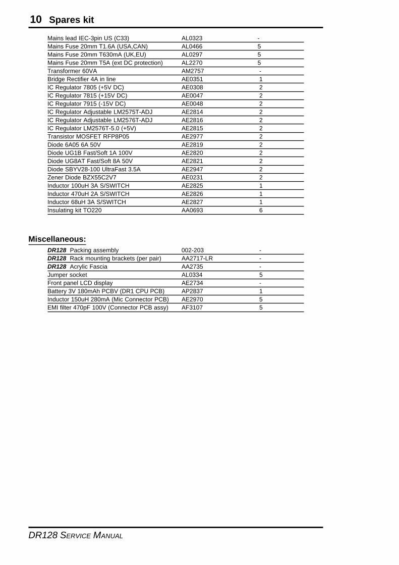
10
DR128 SERVICE MANUAL
Mains lead IEC-3pin US (C33) AL0323 -Mains Fuse 20mm T1.6A (USA,CAN) AL0466 5Mains Fuse 20mm T630mA (UK,EU) AL0297 5Mains Fuse 20mm T5A (ext DC protection) AL2270 5Transformer 60VA AM2757 -Bridge Rectifier 4A in line AE0351 1IC Regulator 7805 (+5V DC) AE0308 2IC Regulator 7815 (+15V DC) AE0047 2IC Regulator 7915 (-15V DC) AE0048 2IC Regulator Adjustable LM2575T-ADJ AE2814 2IC Regulator Adjustable LM2576T-ADJ AE2816 2IC Regulator LM2576T-5.0 (+5V) AE2815 2Transistor MOSFET RFP8P05 AE2977 2Diode 6A05 6A 50V AE2819 2Diode UG1B Fast/Soft 1A 100V AE2820 2Diode UG8AT Fast/Soft 8A 50V AE2821 2Diode SBYV28-100 UltraFast 3.5A AE2947 2Zener Diode BZX55C2V7 AE0231 2Inductor 100uH 3A S/SWITCH AE2825 1Inductor 470uH 2A S/SWITCH AE2826 1Inductor 68uH 3A S/SWITCH AE2827 1Insulating kit TO220 AA0693 6
Miscellaneous:DR128 Packing assembly 002-203 -DR128 Rack mounting brackets (per pair) AA2717-LR -DR128 Acrylic Fascia AA2735 -Jumper socket AL0334 5Front panel LCD display AE2734 -Battery 3V 180mAh PCBV (DR1 CPU PCB) AP2837 1Inductor 150uH 280mA (Mic Connector PCB) AE2970 5EMI filter 470pF 100V (Connector PCB assy) AF3107 5
Spares kit
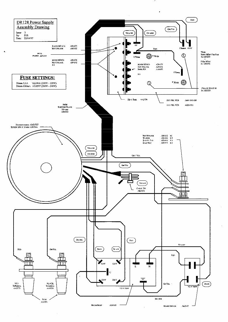
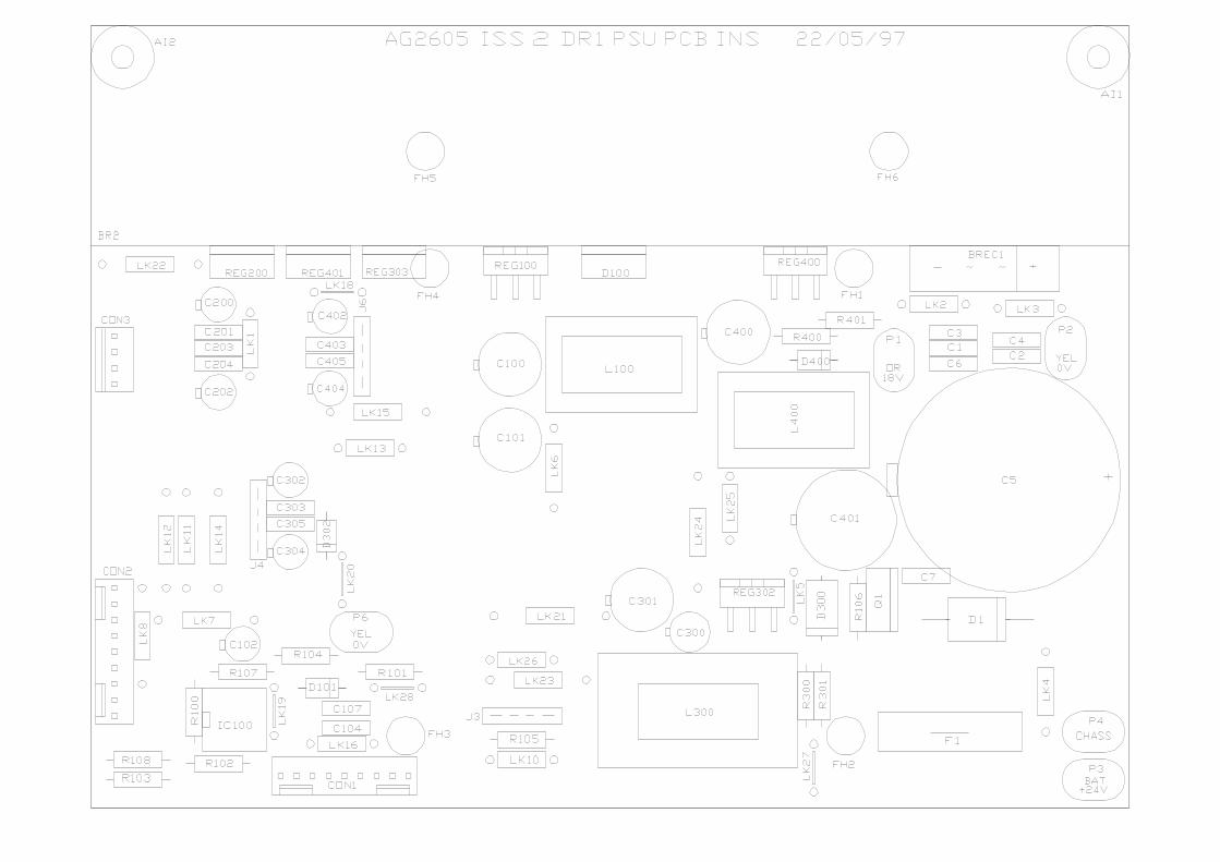
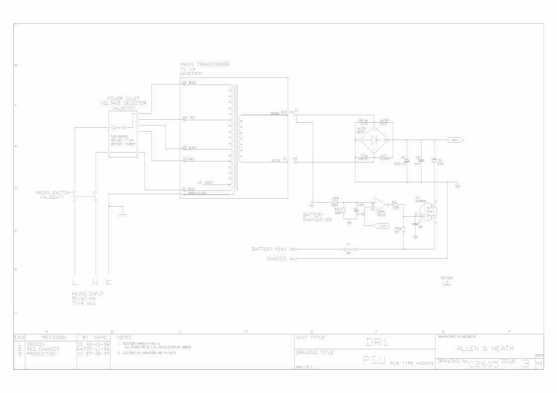
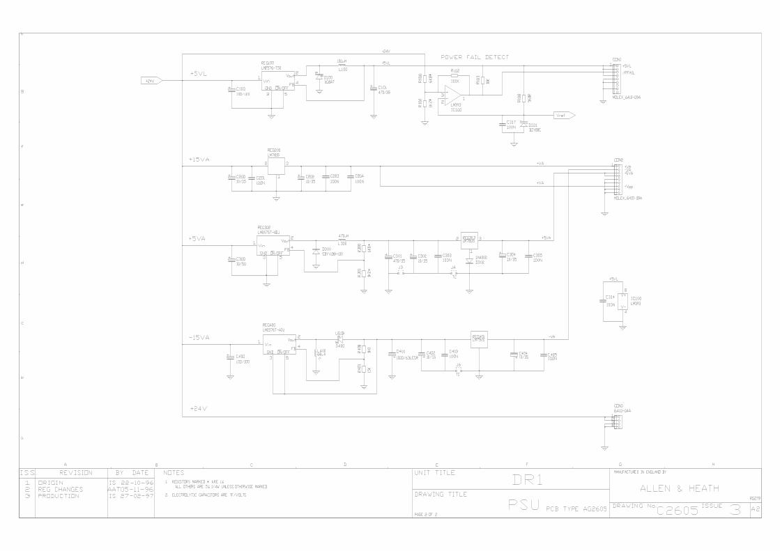
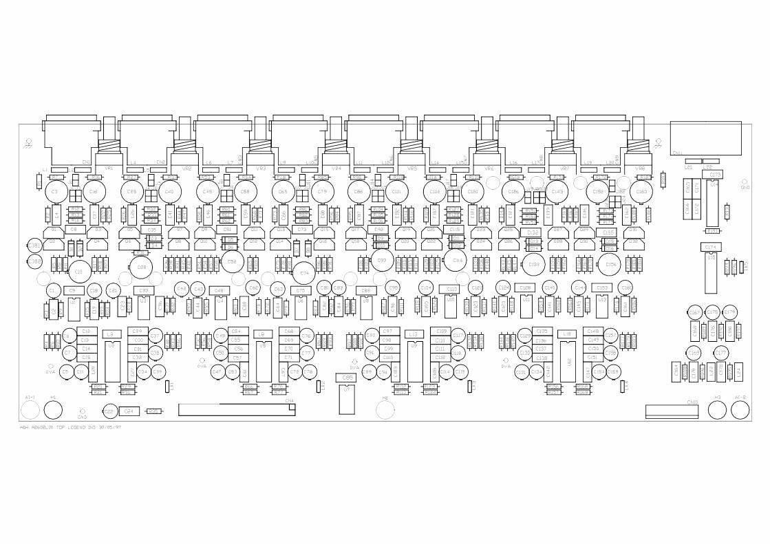
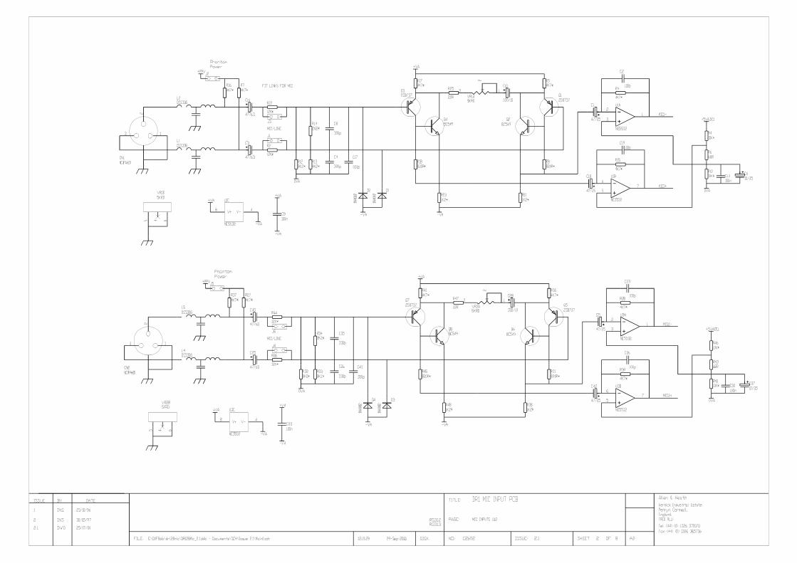


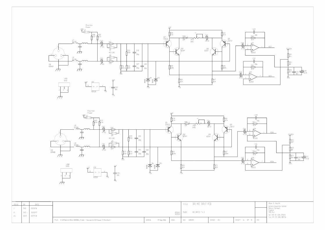

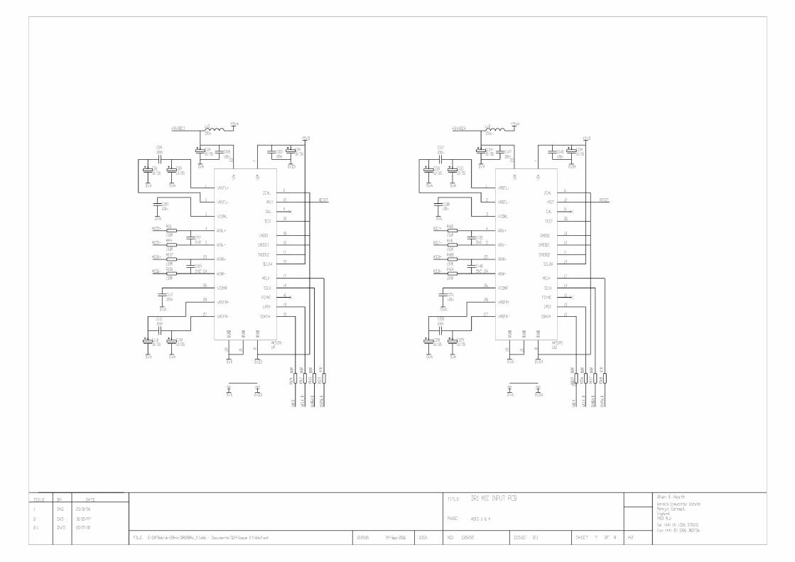
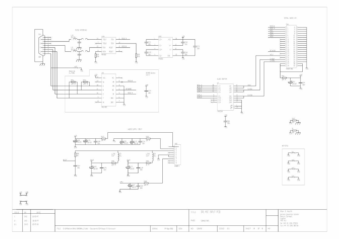
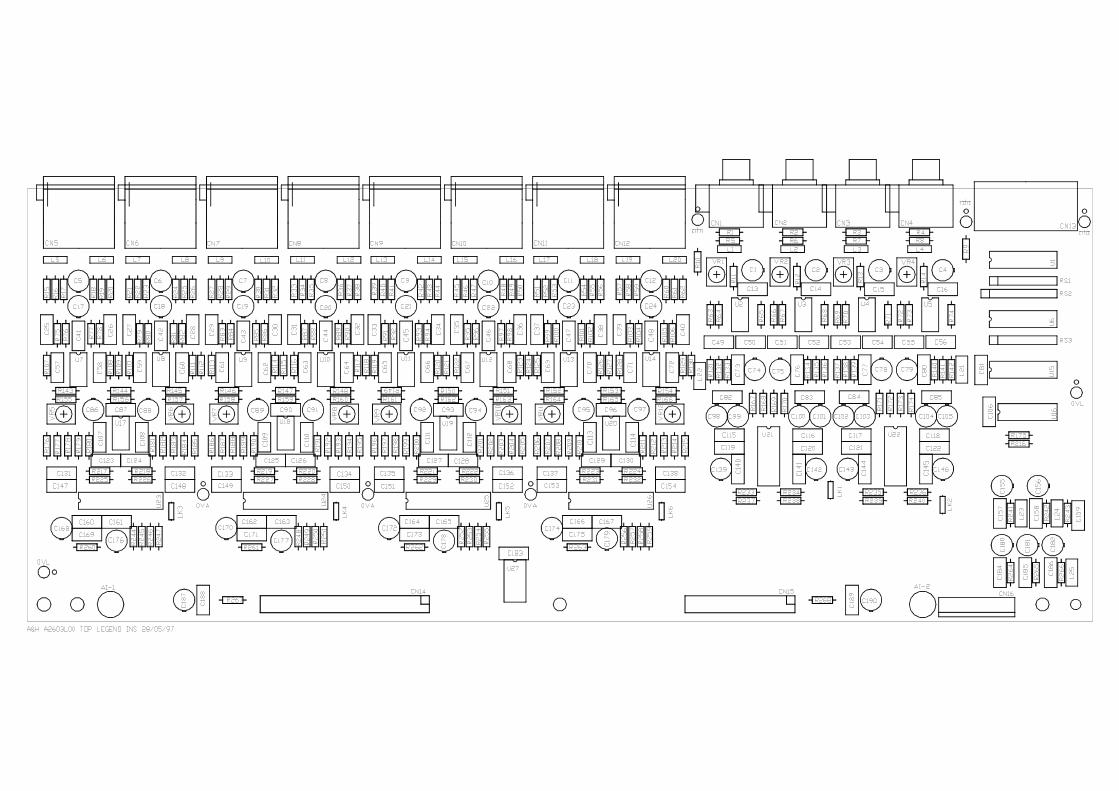
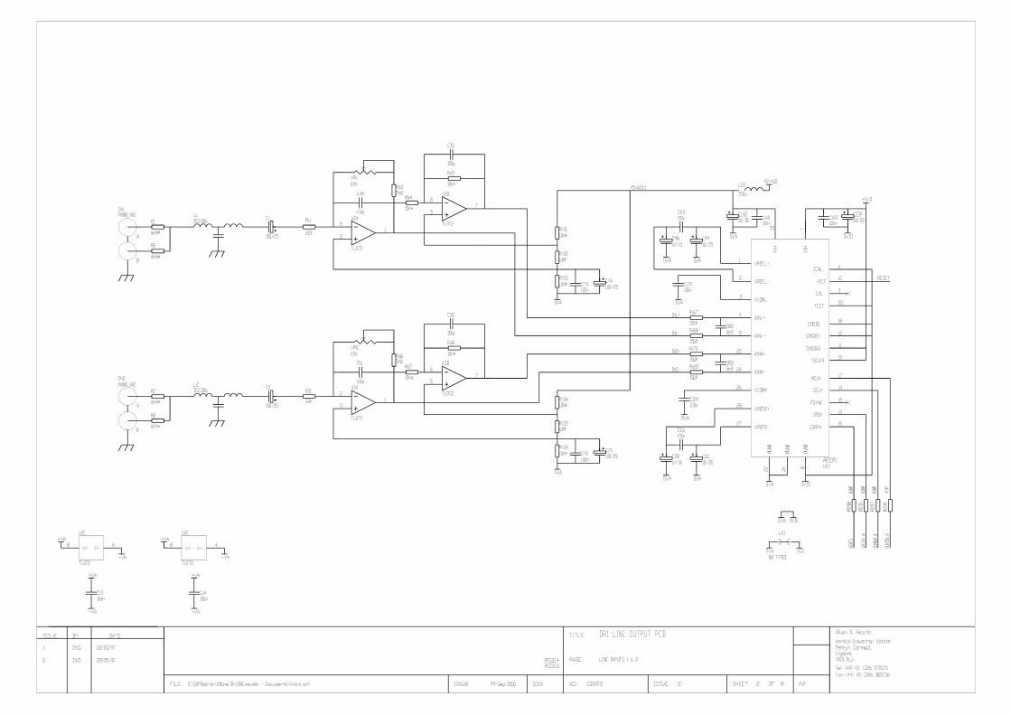
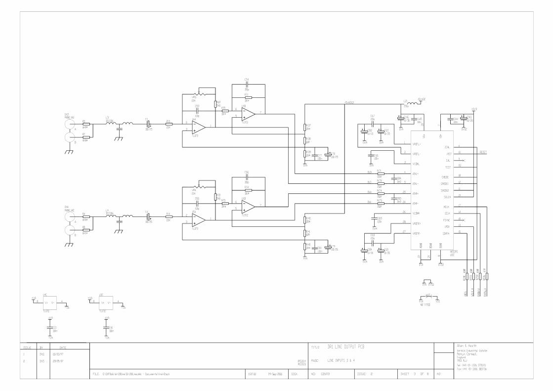
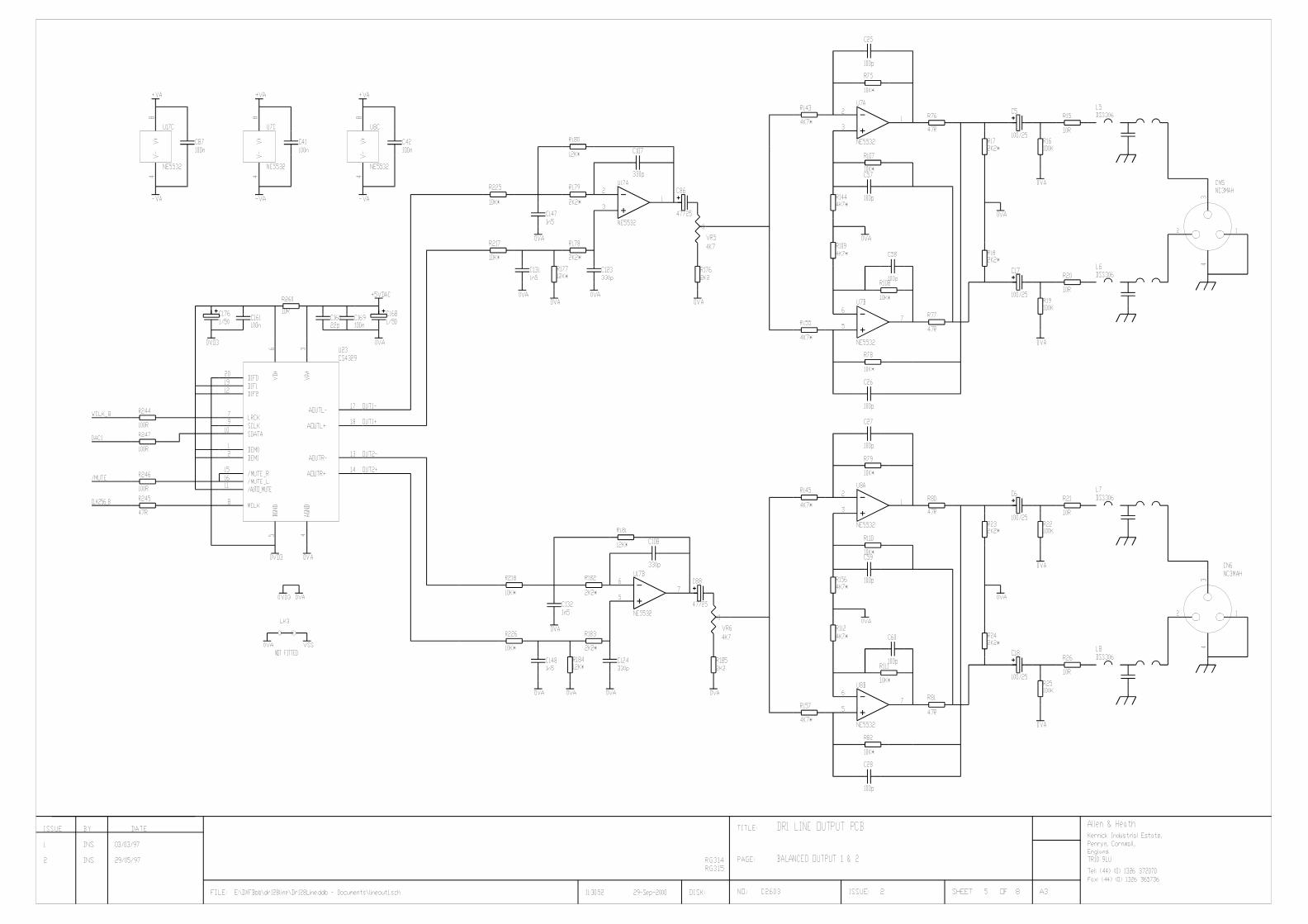
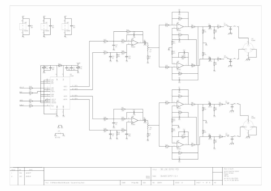
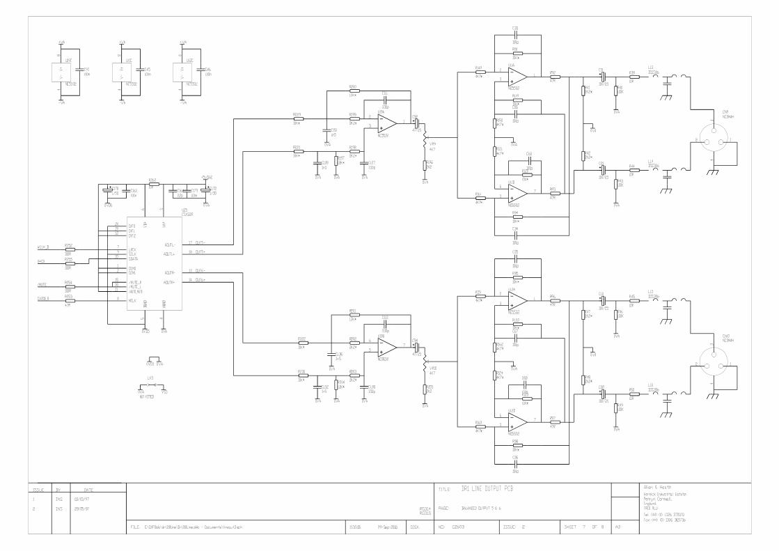
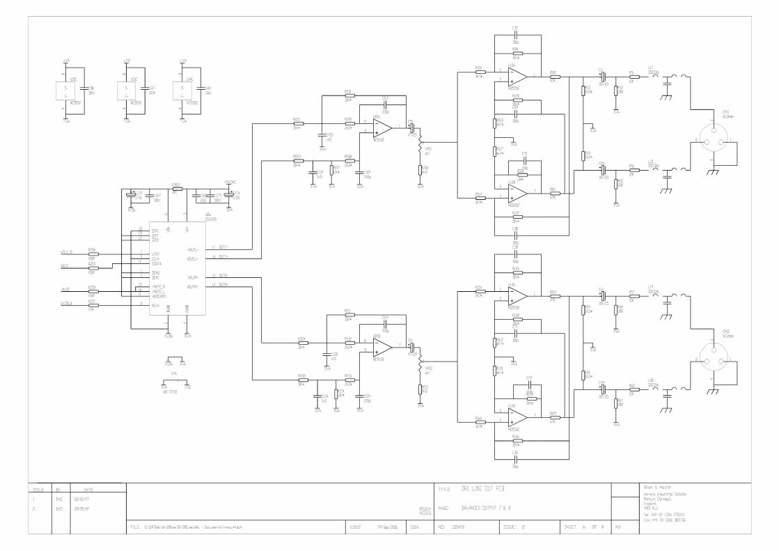
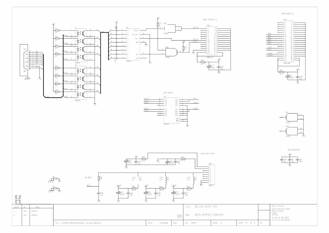
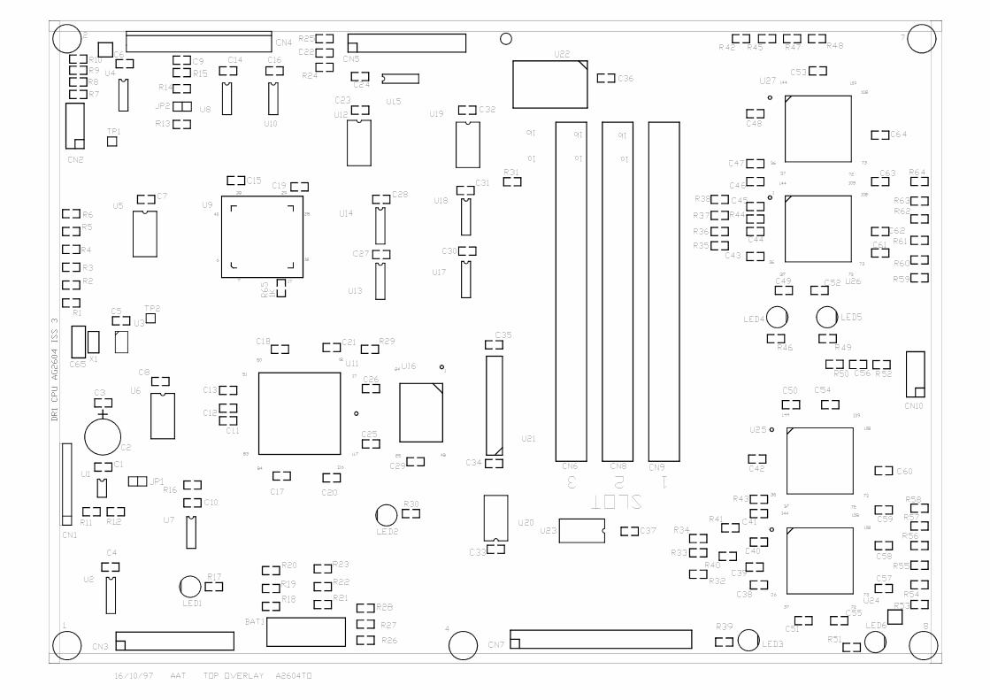
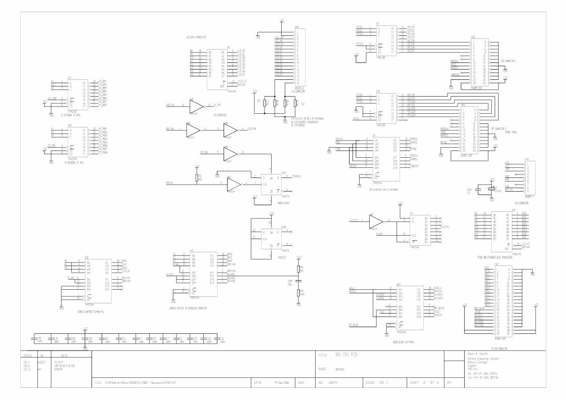
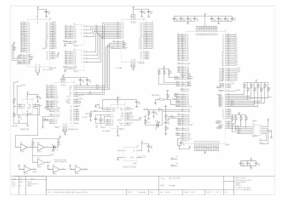
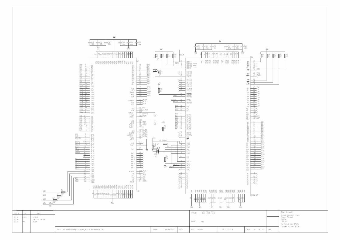
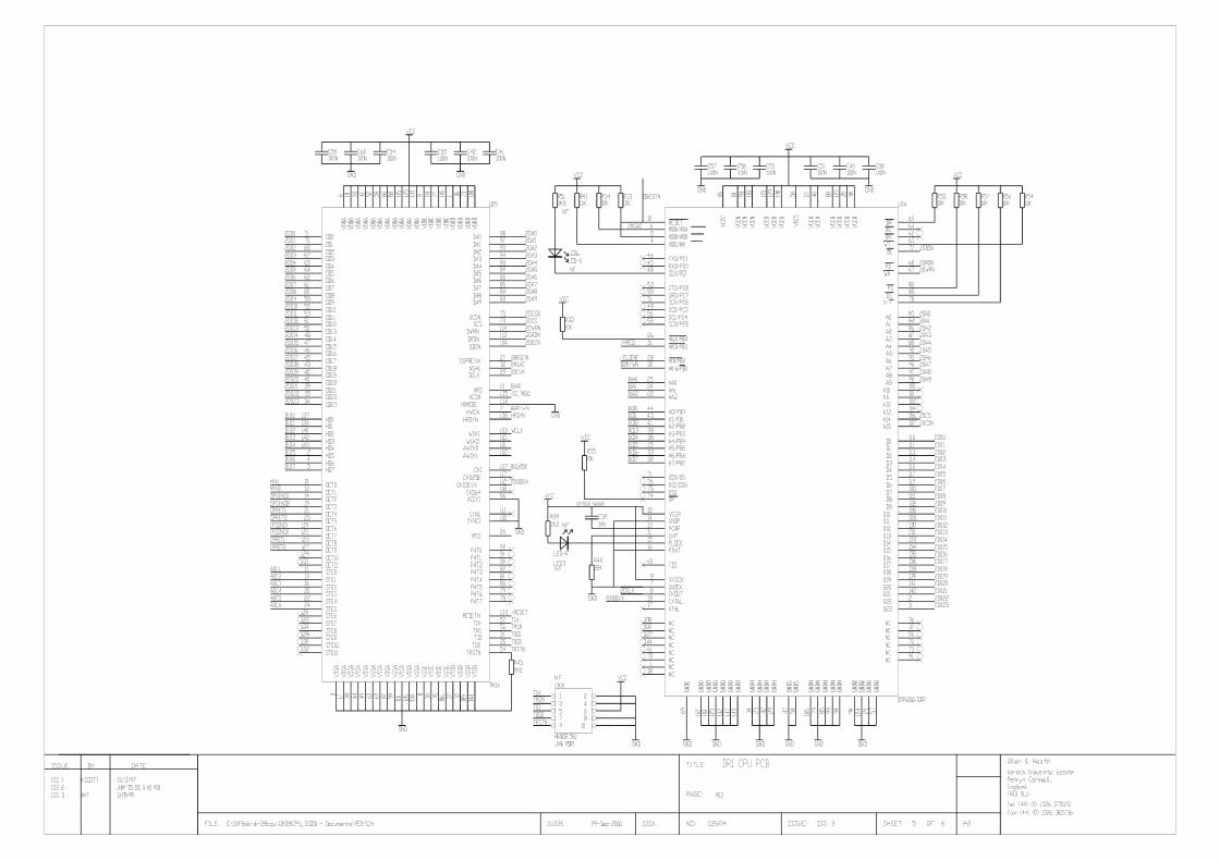
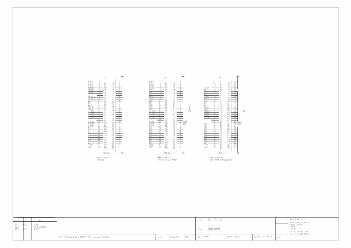
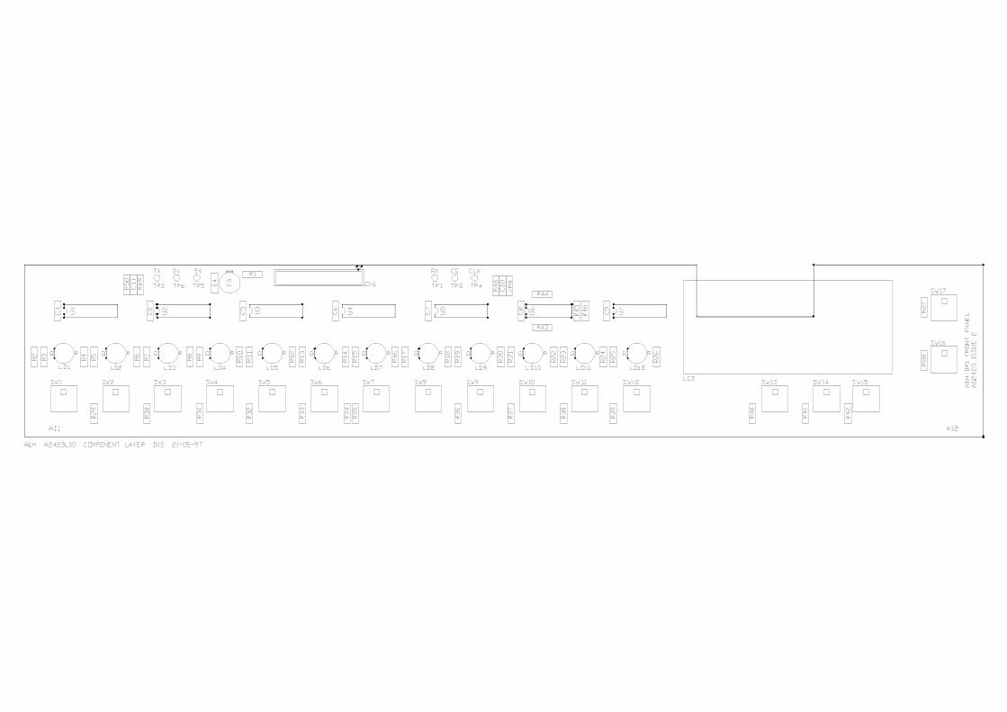
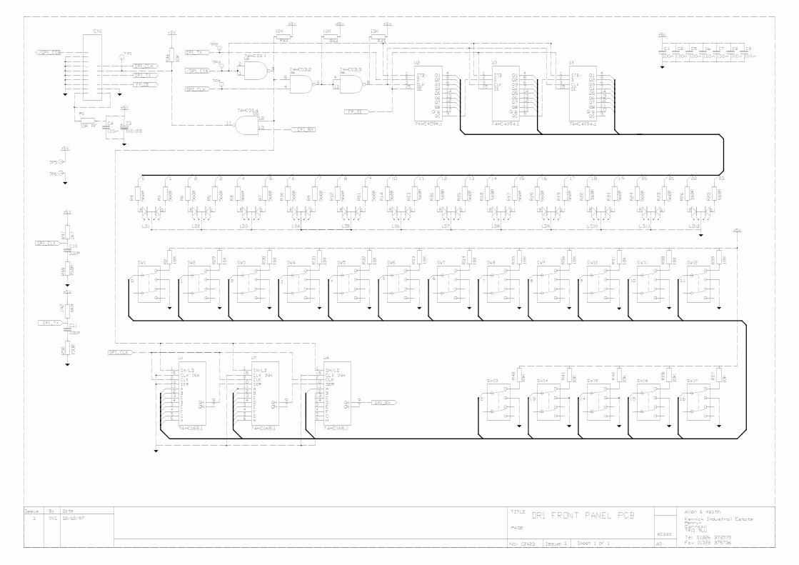
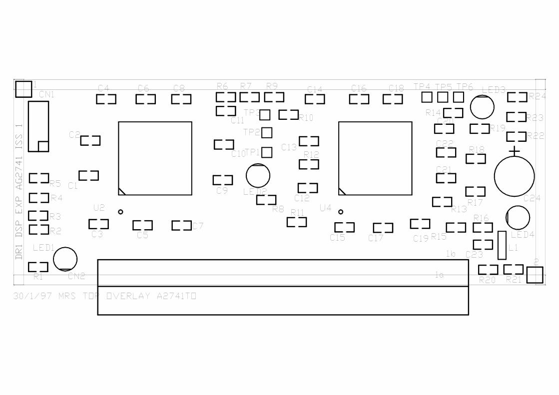
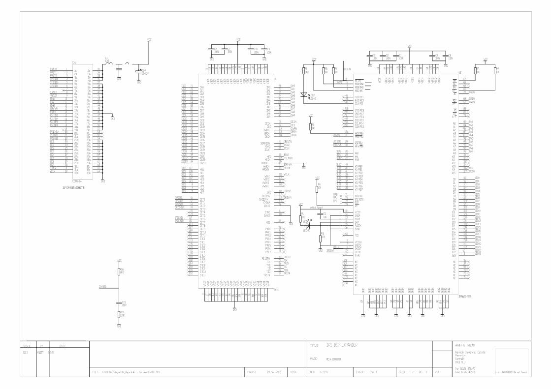
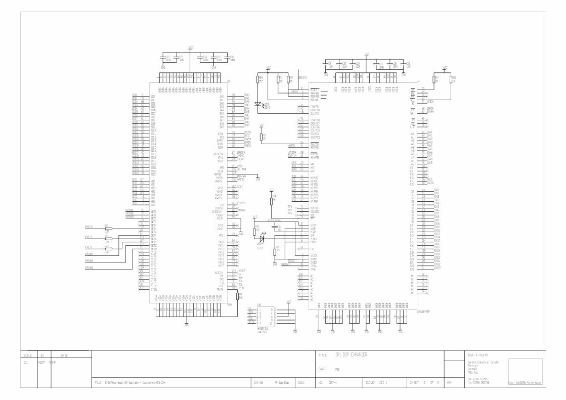
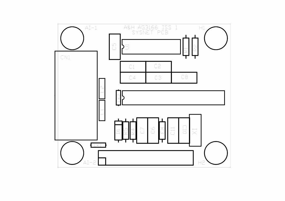
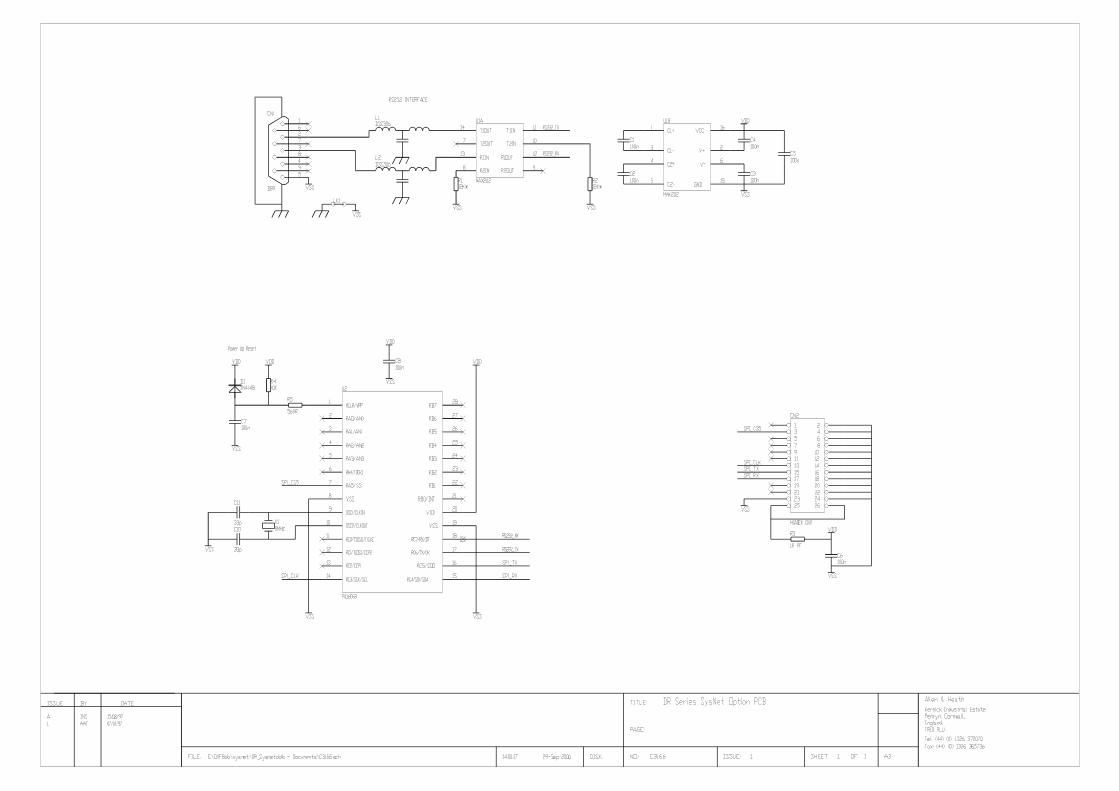
Related Documents


