INTERNATIONAL TELE 08-09 2006 26 th Year Nº 194 SATELLITE € 6,50 £ 4.95 EE: EEK 99,- LV: LVL 2,50 The World’s Largest Satellite Magazine B 9318 E ENG CD Promax Explorer Exclusive Test Reports DIY Project: A Combined C/Ku-Band Feed Technisat Digit 4S Measures Everything in Digital Satellite TV and Radio Small FTA receiver That Can Do It All Matrix Java A Slim Blind-Scan FTA Receiver T90 Antenna One Dish and Many Satellites AU: AU$ 9.50 incl GST ZA: R 39-95 Want More Satellites? NG: Naira 400 ID: Rp 35.000,- Just Open a Can of Vegetables!

Welcome message from author
This document is posted to help you gain knowledge. Please leave a comment to let me know what you think about it! Share it to your friends and learn new things together.
Transcript

INTERNATIONAL
TELE
08-092006 26
th Year Nº 194
SATELLITE€ 6,50£ 4.95
EE: EEK 99,-
LV: LVL 2,50
The World’s Largest Satellite MagazineB 9318 E
ENG CD
Promax Explorer
Exclusive Test Reports
DIY Project: A Combined
C/Ku-Band Feed
Technisat Digit 4S
Measures Everything in Digital Satellite TV and Radio
Small FTA receiver That Can Do It All
Matrix Java
A Slim Blind-Scan FTA Receiver
T90 Antenna
One Dish and Many Satellites
AU: AU$ 9.50 incl GST
ZA: R 39-95
Want More Satellites?NG: Naira 400
ID: Rp 35.000,-
Just Opena Can of Vegetables!
ADVERTISERS
CONTENT
Dear Readers
TECHNISAT DIGIT 4SDigital FTA satellite receiver .........14
MATRIX JAVA Blind Scan FTA receiver ..............18
PROMAX TV ExplorerProfessional Digital/Analog TV, Satellite, Cable Signal Analyzer ................20
WAVE FRONTIER TOROIDAL T90Multifeed dish ........24
DG-120 PLUSH-H mount motor ...28
“MINI ACTUATOR” from EDONDiSEqC motor ...................................36
Satellite Reception: Feed Made From a Vegetable Can .....30
Basic Functions: Basic manual for satellite receivers ....................... 10
Feature: The stronger, the better – it that always true? .......................................... 12
TELE-satellite Receiver Guide .......................32, 34
Satellite Reception: C-Band Reception in Europe with a 120cm Antenna .............................. 42
Satellite Technology: Video Quality in digital TV ..................................... 46Satellites over India ............................................. 48
Satellite Exhibition/EEBC 2006: Telecom & Broadcasting will build „City of the Future“ ............................................. 49
Yes, those were the days…in the analog age you could either receive something, or you couldn’t. And when there was something to receive, then it was only one TV signal, or it was nothing. Either yes or no, black or white, 1 or 0. That was the analog age.
In today’s digital age it is much more than just 1 and 0: there is an incredible variety. One TV signal is not necessarily the same as another; digital technology provides us with quite a few variants. As equipment users we may not notice this all that much, but as viewers it becomes much more evident, especially when the picture quality is something we may not have seen before.
In this issue of TELE-satellite, we will focus on picture resolution in the DVB-S standard. Instead of one defined norm like there wasin the analog days, DVB-S offers a variety like that found in a supermarket. But as equipment users we really don’t experience any of this. While most of the receivers on the market today can provide us the PIDs of a signal, there are (up until now) none that can display the picture resolution.
Picture resolution is what we as viewers actually see on the TV screen; the PIDs just make reception possible. Once the PIDs are entered, reception functions properly. But the picture that we would be looking at for years is not explained in any way. What the receiver does to present the picture to you is available in detail but what we see is kept a secret.
Programming providers are taking clear advantage of this. To save on transponder costs or to transmit more channels for the same amount of money, the picture resolution is simply reduced. The normal viewer has no idea that the providers can manipulate picture resolution. There is no hint of this given anywhere. The normal viewer just takes it as it comes and doesn’t realize that it could be different.
In our report on page 46 of this issue we highlight the different variants. It
is actually quite amazing: all satellite receivers can easily decode many of the different picture resolution variations. And in these same receivers there is no need to change a setting for this to work; they all produce a single video signal from these variants that every TV can correctly display. It doesn’t matter if the pixels are doubled, or even quadrupled, everything is handled automatically. Yes, the developers of these DVB norms know all the tricks on hiding the important data. Picture resolution is certainly the most important when it comes to a TV signal.
Recently, the SatcoDX channel lists have started including the picture resolution of a satellite channel. And as time goes by, more and more SatcoDX scanning stations will switch over so that eventually anyone who wants to know it will be able to findout what the picture resolution is of every channel.
This now gives you a new sorting capability: you can now search for programs that transmit in higher quality. You might then also be able to see that higher picture quality may go hand-in-hand with higher programming quality.
Enjoy your high-quality TV!
Alexander Wiese
P.S. My favorite radio station of the month is Love Radio (SIRIUS 5E, 11.766H, 27500, 6163), Ukrainian soft hit parade with a few news breaks and hardly any commercials.
ARION ................................................... 7ARIZA ...................................................26CHANGHONG .........................................15DIGITAL TELEMEDIA .............................17DOEBIS ............................................... 8,9DVB SHOP .............................................41EDON ....................................................11EMP .......................................................38FORTECSTAR .........................................39HORIZON ..............................................33
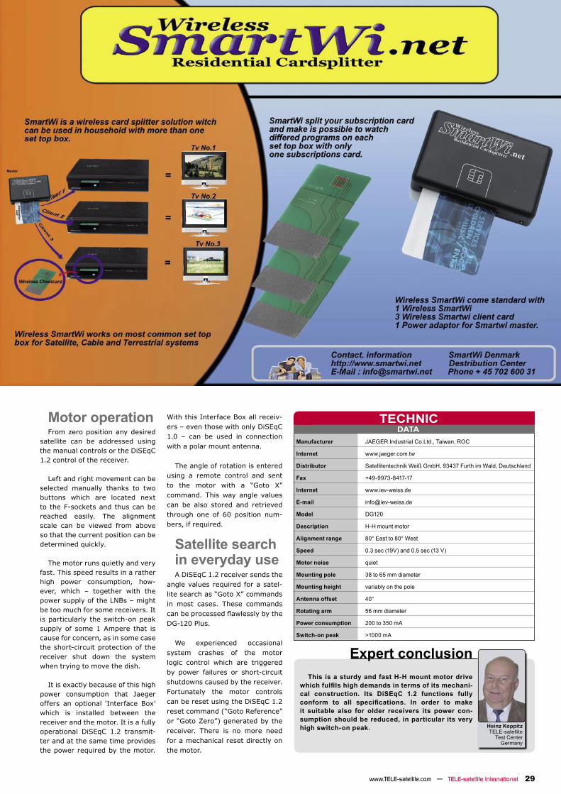
JAEGER/WEISS .....................................21KATHREIN .............................................49MOTECK ................................................31OPENTECH .............................................52PANSAT .................................................37PANSAT .................................................43PROMAX ................................................45SADOUN ................................................35SMARTWI ..............................................29SPACECOM ............................................23
SPAUN ...................................................47
STAB .....................................................51
STARSAT ............................................... 4
STATE MICRO TECHNOLOGY ..................19
TECHNISAT ........................................... 5
TELE-satellite CITY ...............................40
TOPFIELD .............................................. 2
VANTAGE ...............................................19
VANTAGE ...............................................31


BEGINNER SECTION
10 TELE-satellite International — www.TELE-satellite.com
This article will try to help you finding andusing the basic functions of your receiver. After that, you should be able to even use the more specific feature, by simple try and error.
Satellite receivers are designed for tel-evision signal reception, which means that they have to be connected to a TV set, which they can use as OSD (on screen display). As a matter of fact, the front sides are mainly very poorly equipped and just contain a few buttons and a segment display, only very few receivers can show channel names and other information via an alphanumeric display, sometimes a display is missing at all. So if you are a radio freak, you‘ll have to turn on your TV for most receivers to know which channel you are currently listening to.
The front sides aremainly very poorlyequippedSome receivers offer a few buttons to
operate the unit without remote control, but these buttons are just duplicates of the ones available on the remote, with one exception: Some of them contain a manual power on/off button, which sometimes can also be found on the back side. The other buttons are normally just channel up/down and maybe sometimes volume up/down. If a special button to enter the main menu is available, it‘s in most cases not very useful, because there are no numeric keys available on the receiver’s front and so you can‘t use most of the menu entries at all.
All available connectors are on the back sideLuckily there‘s one point, where all receiv-
ers are similar, they offer the available con-nectors (which are also standardized) on the back side. Normally, the receiver is even ready for use if there are just the signal input and the video output connected.
- The antenna cable has to be connected to the signal input, which is normally labelled IF Input or LNB-IN.
- Your TV gets connected via the Scart plug (in Europe)
- For all other regions, you can use the video output via the yellow RCA plug (e.g. USA)
- Some receivers also offer an RF output in the UHF range
- The audio signal e.g. for radio output can be taken from the white and red RCA plug (Stereo)
It happens very often that you buy a cheap receiver without a manual or that you simply loose the one that was attached and now you don‘t know how to operate your receiver. The dozens of emails we receive every day in our office speak a clear language and many users haveproblems to find out how to look for new programs, sort or delete them without the manual.
In general we recommend that you perform a complete new system setup, this helps you to setup the receiver correctly and get all the new available channels, but please be aware that you need your original remote control to use all the special features of your device.
To open the main menu, try to find a button,labelled with Menu or Setup on your remote. Sometimes the main menu also pops up if you press the OK button.
The installation procedure is basically the same with all receivers, but the necessary menu entries are some-times labelled in a different way.
1. Search (adjust satellites, select/enter transponders, channel search)
2. Edit (antenna, t r a n s p o n d e r s , group/sort/delete programs)
3. Basic settings (language, video output, time setup, PIN)
4. Information (status, factory reset, software upgrade, games)
First of all you
Basic manual for satellite receiversHeinz Koppitz
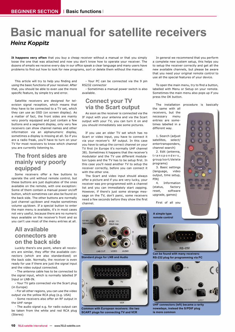
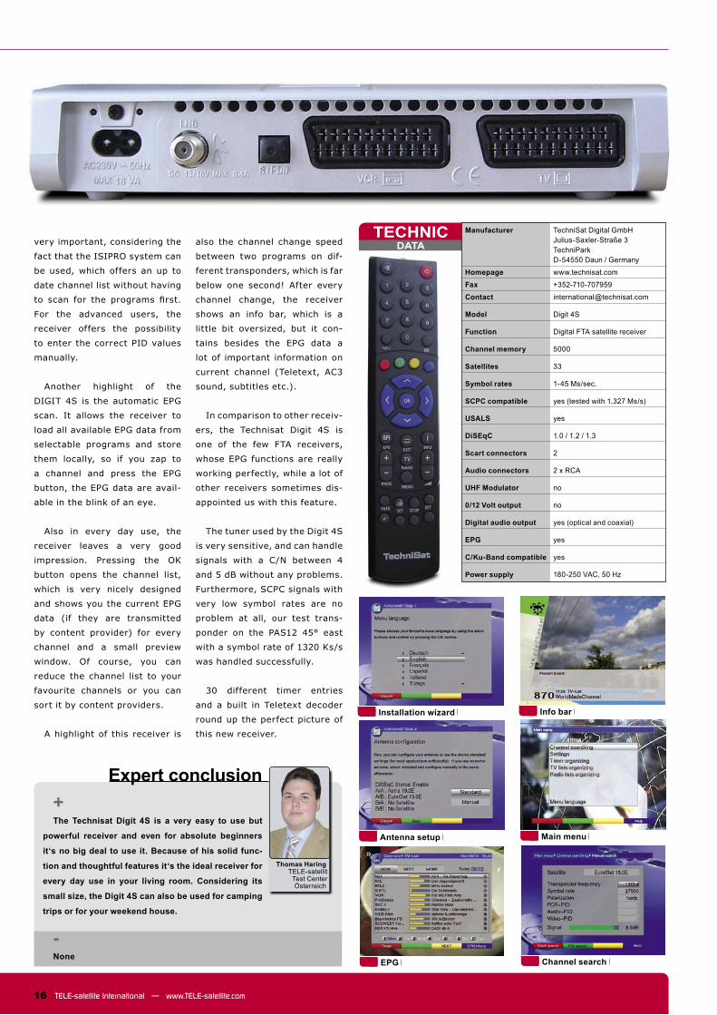
Standard plugs for LNB and Audio
Common with European receivers: the two SCART plugs for connecting TV and VCR
Can be found with many receivers: RS-232 plug for programming via PC
UHF connectors (left) became a rarity nowadays, instead the S/PDIF plug is more common
- Your PC can be connected via the 9 pin RS232 connector
- Sometimes a manual power switch is also available.
Connect your TV via the Scart outputAs soon as the receiver is connected via the
IF input with your antenna and via the Scart output with your TV, you can turn it on and you should immediately see some pictures.
If you use an older TV set which has no Scart or video input, you have to connect it via your receiver‘s RF output. In this case you have to setup the correct channel on your TV first (in Europe it‘s normally UHF channel38). Sometimes it happens that the receiver’s modulator and the TV use different modula-ton types and the TV has to be setup first. Inthis case you‘ll need another TV to setup the receiver correctly, before you can connect it with the other one.
The Scart and video input should always offer a picture and if you are very lucky, your receiver was pre-programmed with a channel list and you can immediately start zapping. However, if there‘s just some strange mes-sage on the TV, don‘t panic, some receivers need a few seconds before they show the firstchannel.
A simple type remote control
Basic functions
11www.TELE-satellite.com — TELE-satellite International
should setup the OSD language to English. This helps you to find the correct buttons on theremote control, which are normally labelled in English. Furthermore you can prevent some confusion, because it happens very often that translated menu entries contain strange and misunderstanding text. Also the manuals contain sometimes lots of translation errors, which can make it quite difficult for the begin-ner to understand their meaning.
After setting up the OSD language, some other basic settings like time setup or video output have to be adjusted. Some receivers prompt you to enter a pin code to access these menus, which is normally 0000 or 1234.
In the next step, it‘s time for cleaning up. If you bought a used receiver, there might be hundreds of old channels, but even a new receiver might contain some over aged data. In this case it‘s very useful to perform a com-plete factory reset.
The important factoryreset is normally available in every receiverThe factory reset can be found on nearly
every receiver and normally it does only reset channel data and some user settings, the so very important transponder and satellite data will not be deleted, because the receiver would be useless without them. However, consider-ing that the receiver was manufactured a few
months or even a few years ago, these trans-ponder data might not be very up to date and you will probably have to add new transpond-ers, which can be found in the SatcoDX lists at www.satcodx.com .
Enable the „FTA only“option during channel searchIf you own a FTA only receiver which has
no CI slots or card readers, it‘s very useful to reduce the channel search to free programs only. Normally this can be done in the search menu by selecting the option „FTA only“. This helps you to keep control of your channel list and if you scan a few different satellites, you might fill up the receivers channel memorywith hundreds of unwanted and encrypted channels and loose space for other free to air programs, because most receivers channel memory is limited to 3000 TV and 1000 radio channels.
Right now, the most important functions are setup and you can start fine-tuning yourreceiver.
Update your receivervia PC and the InternetIt‘s much more comfortable to setup the
receivers channel list on the PC than on the unit itself. Just connect your receiver and the PC via a RS232 cable (cross over cable) and use a PC program like SetEdit or some other
program offered by the manufacturer to do the job. Sometimes these programs are capable of directly importing new channel lists from e.g. SatcoDX.
Nearly every manufacturer offers a homepage on the internet and normally they are really worth a click. If you can‘t find theone of your receiver’s manufacturer, try some internet search engines and encyclopaedias like Google or Wikipedia, but normally you‘ll find the correct site by entering the manufac-turers name with .com or with the local coun-try extension.
Be careful when upgrading the receivers softwareFinally I have a very important warning for
you: Manufacturers offer from time to time new software updates to fix newly discoveredbugs or to enhance the receiver’s functionality. If you are lucky, your receiver can update its software automatically via satellite, but most of the older models don‘t offer that option. You have to visit the manufacturer’s website, download the software there and install it to your receiver via the RS232 connector and your PC. In this case, please read all the infor-mation provided by the manufacturer on the website and check if you are really using the exactly fitting software for your receiver. Ifyou install the wrong software, your receiver might get destroyed.
FEATURE Intermodulación
12 TELE-satellite International — www.TELE-satellite.com
The quality of signal is related to the so-
called signal-to-noise ratio S/N. For digital
signals, we more often use the carrier-to-
noise ratio C/N but its meaning is practically
the same. Every satellite signal except for
the useful data has some amount of noise.
We would like to have as much useful signal
and as little noise as possible. Probably you
know that to improve the signal to noise
ratio you may:
• increase the size of your dish
• replace your current LNB with a better
one of lower noise figure.
However, there is yet another trick that
may sometimes be used. It is relatively easy
to try and we will not have to spend a fortune
on that.
Those of our respected readers who have
some experience with the amateur radio
have probably already guessed what I aiming
at. This is about reducing the sensitivity of a
receiver. Ham radio receivers and transceiv-
ers quite often have buttons to either switch
off their front-end RF amplifier or switch
on the input signal attenuator. Sometimes,
both functions are available. We are speak-
ing here about reducing the input amplifier
sensitivity by 10-20 dB.
How that can be? When a number of
strong signals are present at the receiver
input, they interfere with one another and
produce extra noise. This phenomenon is
called intermodulation. Some receivers are
more immune to intermodulation, the others
are less immune. There are no electronic cir-
cuits that are absolutely protected against
this. Moreover, the more sensitive we make
the receiver, the less protective against
Probably all our readers are aware that in order to have a reli-able satellite reception, we need to have strong enough signal at the receiver input. Generally, the stronger the signal, the better its quality. Always?
intermodulation it becomes. Now, if among
the strong signals, there is a weak one, its
quality is decreased by the noise generated
by its stronger companions. What we can
do? Optimally, we would like to attenuate the
“strong bullies” and preserve the strength of
the “weak guy”. Unfortunately, this is very
difficult to do. What we can do very easily, is
to attenuate all signals by a few decibels in
hope that this will reduce the intermodula-
tion but not make the weak signal too weak
for reception.
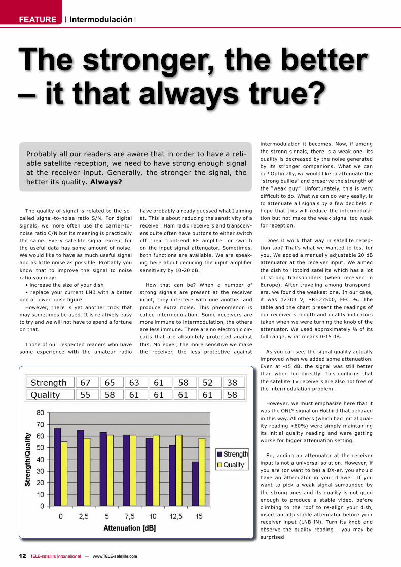
Does it work that way in satellite recep-
tion too? That’s what we wanted to test for
you. We added a manually adjustable 20 dB
attenuator at the receiver input. We aimed
the dish to Hotbird satellite which has a lot
of strong transponders (when received in
Europe). After traveling among transpond-
ers, we found the weakest one. In our case,
it was 12303 V, SR=27500, FEC ¾. The
table and the chart present the readings of
our receiver strength and quality indicators
taken when we were turning the knob of the
attenuator. We used approximately ¾ of its
full range, what means 0-15 dB.
As you can see, the signal quality actually
improved when we added some attenuation.
Even at -15 dB, the signal was still better
than when fed directly. This confirms that
the satellite TV receivers are also not free of
the intermodulation problem.
However, we must emphasize here that it
was the ONLY signal on Hotbird that behaved
in this way. All others (which had initial qual-
ity reading >60%) were simply maintaining
its initial quality reading and were getting
worse for bigger attenuation setting.
So, adding an attenuator at the receiver
input is not a universal solution. However, if
you are (or want to be) a DX-er, you should
have an attenuator in your drawer. If you
want to pick a weak signal surrounded by
the strong ones and its quality is not good
enough to produce a stable video, before
climbing to the roof to re-align your dish,
insert an adjustable attenuator before your
receiver input (LNB-IN). Turn its knob and
observe the quality reading - you may be
surprised!
The stronger, the better – it that always true?

TEST REPORT
14 TELE-satellite International — www.TELE-satellite.comTELE-satellite International — www.TELE-satellite.com
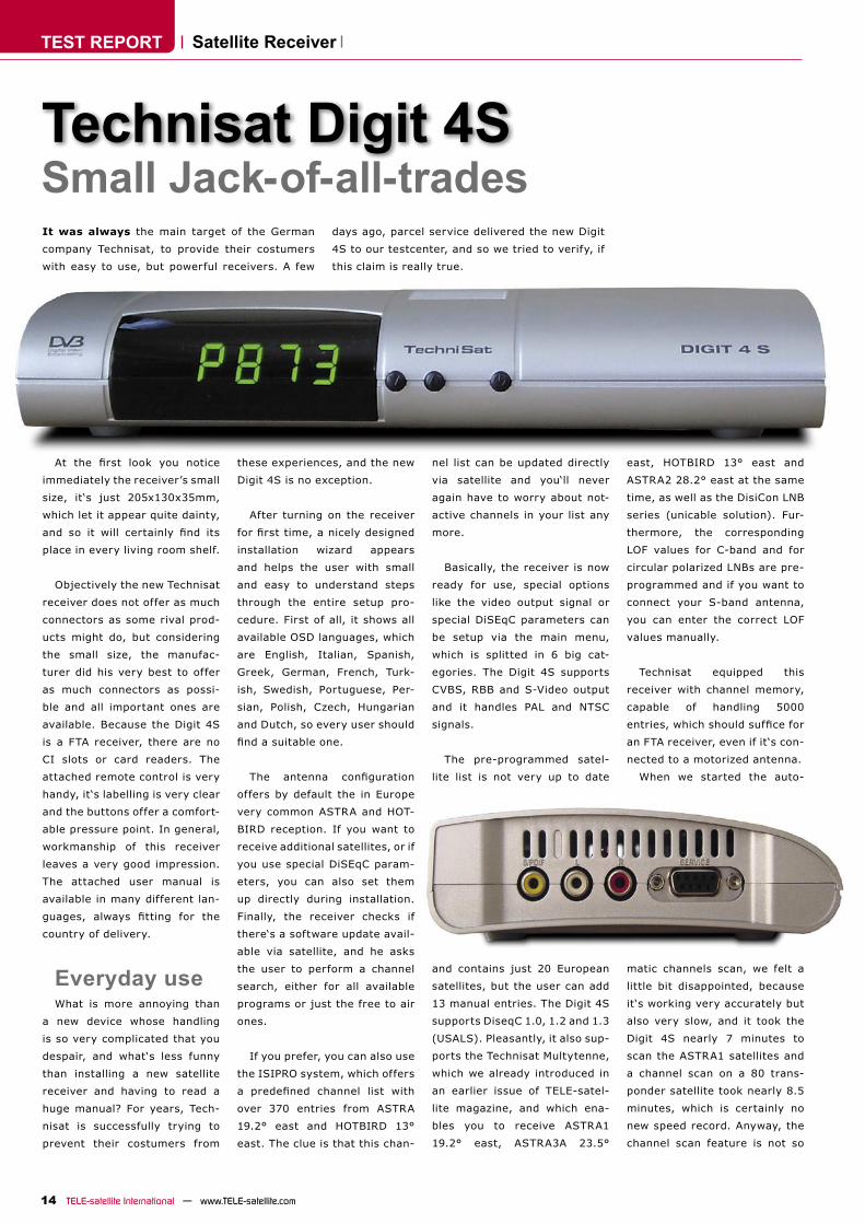
Small Jack-of-all-tradesIt was always the main target of the German
company Technisat, to provide their costumers
with easy to use, but powerful receivers. A few
days ago, parcel service delivered the new Digit
4S to our testcenter, and so we tried to verify, if
this claim is really true.
At the first look you notice
immediately the receiver’s small
size, it‘s just 205x130x35mm,
which let it appear quite dainty,
and so it will certainly find its
place in every living room shelf.
Objectively the new Technisat
receiver does not offer as much
connectors as some rival prod-
ucts might do, but considering
the small size, the manufac-
turer did his very best to offer
as much connectors as possi-
ble and all important ones are
available. Because the Digit 4S
is a FTA receiver, there are no
CI slots or card readers. The
attached remote control is very
handy, it‘s labelling is very clear
and the buttons offer a comfort-
able pressure point. In general,
workmanship of this receiver
leaves a very good impression.
The attached user manual is
available in many different lan-
guages, always fitting for the
country of delivery.
Everyday useWhat is more annoying than
a new device whose handling
is so very complicated that you
despair, and what‘s less funny
than installing a new satellite
receiver and having to read a
huge manual? For years, Tech-
nisat is successfully trying to
prevent their costumers from
these experiences, and the new
Digit 4S is no exception.
After turning on the receiver
for first time, a nicely designed
installation wizard appears
and helps the user with small
and easy to understand steps
through the entire setup pro-
cedure. First of all, it shows all
available OSD languages, which
are English, Italian, Spanish,
Greek, German, French, Turk-
ish, Swedish, Portuguese, Per-
sian, Polish, Czech, Hungarian
and Dutch, so every user should
find a suitable one.
The antenna configuration
offers by default the in Europe
very common ASTRA and HOT-
BIRD reception. If you want to
receive additional satellites, or if
you use special DiSEqC param-
eters, you can also set them
up directly during installation.
Finally, the receiver checks if
there‘s a software update avail-
able via satellite, and he asks
the user to perform a channel
search, either for all available
programs or just the free to air
ones.
If you prefer, you can also use
the ISIPRO system, which offers
a predefined channel list with
over 370 entries from ASTRA
19.2° east and HOTBIRD 13°
east. The clue is that this chan-
nel list can be updated directly
via satellite and you‘ll never
again have to worry about not-
active channels in your list any
more.
Basically, the receiver is now
ready for use, special options
like the video output signal or
special DiSEqC parameters can
be setup via the main menu,
which is splitted in 6 big cat-
egories. The Digit 4S supports
CVBS, RBB and S-Video output
and it handles PAL and NTSC
signals.
The pre-programmed satel-
lite list is not very up to date
and contains just 20 European
satellites, but the user can add
13 manual entries. The Digit 4S
supports DiseqC 1.0, 1.2 and 1.3
(USALS). Pleasantly, it also sup-
ports the Technisat Multytenne,
which we already introduced in
an earlier issue of TELE-satel-
lite magazine, and which ena-
bles you to receive ASTRA1
19.2° east, ASTRA3A 23.5°
east, HOTBIRD 13° east and
ASTRA2 28.2° east at the same
time, as well as the DisiCon LNB
series (unicable solution). Fur-
thermore, the corresponding
LOF values for C-band and for
circular polarized LNBs are pre-
programmed and if you want to
connect your S-band antenna,
you can enter the correct LOF
values manually.
Technisat equipped this
receiver with channel memory,
capable of handling 5000
entries, which should suffice for
an FTA receiver, even if it‘s con-
nected to a motorized antenna.
When we started the auto-
matic channels scan, we felt a
little bit disappointed, because
it‘s working very accurately but
also very slow, and it took the
Digit 4S nearly 7 minutes to
scan the ASTRA1 satellites and
a channel scan on a 80 trans-
ponder satellite took nearly 8.5
minutes, which is certainly no
new speed record. Anyway, the
channel scan feature is not so
Satellite Receiver
Technisat Digit 4S
DATATECHNIC
16 TELE-satellite International — www.TELE-satellite.com
Expert conclusion+The Technisat Digit 4S is a very easy to use but
powerful receiver and even for absolute beginners
it‘s no big deal to use it. Because of his solid func-
tion and thoughtful features it‘s the ideal receiver for
every day use in your living room. Considering its
small size, the Digit 4S can also be used for camping
trips or for your weekend house.
-None
very important, considering the
fact that the ISIPRO system can
be used, which offers an up to
date channel list without having
to scan for the programs first.
For the advanced users, the
receiver offers the possibility
to enter the correct PID values
manually.
Another highlight of the
DIGIT 4S is the automatic EPG
scan. It allows the receiver to
load all available EPG data from
selectable programs and store
them locally, so if you zap to
a channel and press the EPG
button, the EPG data are avail-
able in the blink of an eye.
Also in every day use, the
receiver leaves a very good
impression. Pressing the OK
button opens the channel list,
which is very nicely designed
and shows you the current EPG
data (if they are transmitted
by content provider) for every
channel and a small preview
window. Of course, you can
reduce the channel list to your
favourite channels or you can
sort it by content providers.
A highlight of this receiver is
also the channel change speed
between two programs on dif-
ferent transponders, which is far
below one second! After every
channel change, the receiver
shows an info bar, which is a
little bit oversized, but it con-
tains besides the EPG data a
lot of important information on
current channel (Teletext, AC3
sound, subtitles etc.).
In comparison to other receiv-
ers, the Technisat Digit 4S is
one of the few FTA receivers,
whose EPG functions are really
working perfectly, while a lot of
other receivers sometimes dis-
appointed us with this feature.
The tuner used by the Digit 4S
is very sensitive, and can handle
signals with a C/N between 4
and 5 dB without any problems.
Furthermore, SCPC signals with
very low symbol rates are no
problem at all, our test trans-
ponder on the PAS12 45° east
with a symbol rate of 1320 Ks/s
was handled successfully.
30 different timer entries
and a built in Teletext decoder
round up the perfect picture of
this new receiver.
Thomas HaringTELE-satellit
Test CenterÖsterreich
Main menu
Info bar
Channel search
Antenna setup
Installation wizard
EPG
Manufacturer TechniSat Digital GmbH Julius-Saxler-Straße 3 TechniPark D-54550 Daun / Germany
Homepage www.technisat.com
Fax +352-710-707959
Contact [email protected]
Model Digit 4S
Function Digital FTA satellite receiver
Channel memory 5000
Satellites 33
Symbol rates 1-45 Ms/sec.
SCPC compatible yes (tested with 1,327 Ms/s)
USALS yes
DiSEqC 1.0 / 1.2 / 1.3
Scart connectors 2
Audio connectors 2 x RCA
UHF Modulator no
0/12 Volt output no
Digital audio output yes (optical and coaxial)
EPG yes
C/Ku-Band compatible yes
Power supply 180-250 VAC, 50 Hz
TEST REPORT
DATATECHNIC
18 TELE-satellite International — www.TELE-satellite.comTELE-satellite International — www.TELE-satellite.com
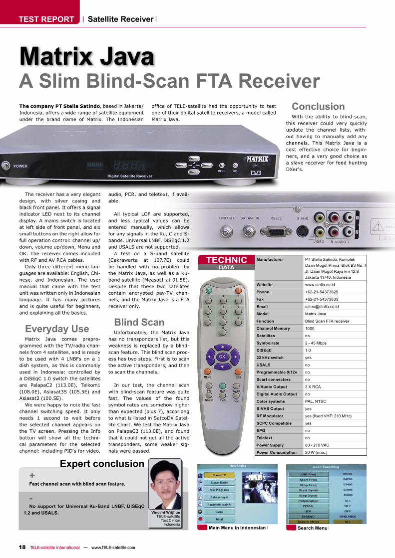
A Slim Blind-Scan FTA ReceiverThe company PT Stella Satindo, based in Jakarta/Indonesia, offers a wide range of satellite equipment under the brand name of Matrix. The Indonesian
office of TELE-satellite had the opportunity to testone of their digital satellite receivers, a model called Matrix Java.
The receiver has a very elegant design, with silver casing and black front panel. It offers a signal indicator LED next to its channel display. A mains switch is located at left side of front panel, and six small buttons on the right allow for full operation control: channel up/down, volume up/down, Menu and OK. The receiver comes included with RF and AV RCA cables.
Only three different menu lan-guages are available: English, Chi-nese, and Indonesian. The user manual that came with the test unit was written only in Indonesian language. It has many pictures and is quite useful for beginners, and explaining all the basics.
Everyday UseMatrix Java comes prepro-
grammed with the TV/radio chan-nels from 4 satellites, and is ready to be used with 4 LNBFs on a 1 dish system, as this is commonly used in Indonesia: controlled by a DiSEqC 1.0 switch the satellites are PalapaC2 (113.0E), Telkom1 (108.0E), Asiasat3S (105.5E) and Asiasat2 (100.5E).
We were happy to note the fast channel switching speed. It only needs 1 second to wait before the selected channel appears on the TV screen. Pressing the Info button will show all the techni-cal parameters for the selected channel: including PID‘s for video,
audio, PCR, and teletext, if avail-able.
All typical LOF are supported, and less typical values can be entered manually, which allows for any signals in the Ku, C and S-bands. Universal LNBF, DiSEqC 1.2 and USALS are not supported.
A test on a S-band satellite (Cakrawarta at 107.7E) could be handled with no problem by the Matrix Java, as well as a Ku-band satellite (Measat1 at 91.5E). Despite that these two satellites contain encrypted pay-TV chan-nels, and the Matrix Java is a FTA receiver only.
Blind ScanUnfortunately, the Matrix Java
has no transponders list, but this weakness is replaced by a blind-scan feature. This blind scan proc-ess has two steps. First is to scan the active transponders, and then to scan the channels.
In our test, the channel scan with blind-scan feature was quite fast. The values of the found symbol rates are somehow higher than expected (plus 7), accoridng to what is listed in SatcoDX Satel-lite Chart. We test the Matrix Java on PalapaC2 (113.0E), and found that it could not get all the active transponders, some weaker sig-nals were passed.
Satellite Receiver
Matrix Java
+Fast channel scan with blind scan feature.
-No support for Universal Ku-Band LNBF, DiSEqC
1.2 and USALS.
Manufacturer PT Stella Satindo, Komplek Daan Mogot Prima, Blok B3 No. 7 Jl. Daan Mogot Raya km 12,8 Jakarta 11740, Indonesia
Website www.stella.co.id
Phone +62-21-54373829
Fax +62-21-54373833
Email [email protected]
Model Matrix Java
Function Blind Scan FTA receiver
Channel Memory 1000
Satellites no
Symbolrate 2 - 45 Mbps
DiSEqC 1.0
22 kHz switch yes
USALS no
Programmable 0/12v no
Scart connectors no
V/Audio Output 3 X RCA
Digital Audio Output no
Color systems PAL, NTSC
S-VHS Output yes
RF Modulator yes (fixed VHF: 210 MHz)
SCPC Compatible yes
EPG no
Teletext no
Power Supply 80 - 270 VAC
Power Consumption 20 W (max.)
Search Menu Main Menu in Indonesian
Expert conclusion
Vincent WitjhunTELE-satellite
Test Center Indonesia
ConclusionWith the ability to blind-scan,
this receiver could very quickly update the channel lists, with-out having to manually add any channels. This Matrix Java is a cost effective choice for begin-ners, and a very good choice as a slave receiver for feed hunting DXer‘s.
TEST REPORT
20 TELE-satellite International — www.TELE-satellite.comTELE-satellite International — www.TELE-satellite.com
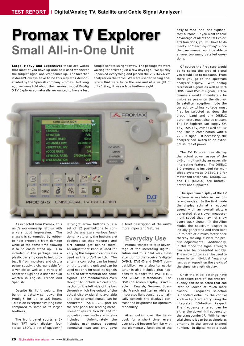
Small All-in-One UnitLarge, Heavy and Expensive: these are words that most of you have up until now used whenever the subject signal analyzer comes up. The fact that it doesn’t always have to be this way was demon-strated by the Spanish company Promax. Not long ago we were told about their newest model Prodig 5 TV Explorer so naturally we wanted to have a test
sample sent to us right away. The package we were waiting for arrived just a few days ago. We quickly unpacked everything and placed the 23x16x7.6 cm analyzer on the table. We were used to seeing ana-lyzers that were twice the size and at a weight of only 1.9 kg, it was a true featherweight.
As expected from Promax, this unit’s workmanship left us with a very good impression. The chassis is surrounded by rubber to help protect it from damage while at the same time allowing it to be easily stood up. Also included in the package was a plastic carrying case to help pro-tect it from moisture and dirt, a power supply, a charger cable for a vehicle as well as a variety of adapter plugs and a user manual written in English, French and Spanish.
Despite its light weight, the built-in Li battery can power the Prodig-5 for up to 3.5 hours. This is an exceptionally long time compared to some of its larger brothers.
The front panel sports a 5-inch TFT color display, four status LED’s, a set of up/down/
left/right arrow buttons plus a set of 12 pushbuttons to con-trol the analyzers various func-tions. Naturally, the buttons are designed so that moisture and dirt cannot get behind them. An adjustment knob is used for varying the frequency and is also used as the on/off switch. The antenna connector can be found on the top of the unit and can be used not only for satellite signals but also for terrestrial and cable signals. The manufacturer even thought to include a Scart con-nector on the left side of the box through which the output of the actual display signal is available and also external signals can be connected. An RS-232 port on the rear panel for sending meas-urement results to a PC and for uploading new software is also included. Unfortunately, the included user manual seemed somewhat lean and only gave
a brief description of the unit’s more important features.
Everyday UsePromax wanted to take advan-
tage of the increasing digitali-zation and thus paid very close attention to the receiver’s digital DVB-S, DVB-C and DVB-T com-patibility. An analog terrestrial tuner is also included that hap-pens to support the PAL, NTSC and SECAM TV standards. The OSD (on-screen display) is avail-able in English, German, Span-ish, French and Italian while an integrated light sensor automati-cally controls the displays con-trast and brightness for optimum readability.
After looking over the hand-book for a short time, every user should become familiar with the elementary functions of the
easy-to-read and self-explana-tory buttons. If you want to take advantage of all of the TV Explor-er’s functions, you will have to do plenty of “learn-by-doing” since the user manual won’t be able to answer too many detailed ques-tions.
Of course the first step wouldbe to select the type of signal you would like to measure. From there you go to the spectrum analyzer display. With analog terrestrial signals as well as with DVB-T and DVB-C signals, active channels would immediately be visible as peaks on the display. In satellite reception mode the correct switching voltage must first be selected as does theproper band and any DiSEqC parameters must also be chosen. The TV Explorer can supply 5V, 13V, 15V, 18V, 24V as well as 13V and 18V in combination with a 22 kHz signal. If necessary, the analyzer can switch to an exter-nal source of power.
The TV Explorer can display the actual power usage of the LNB or multiswitch; an especially interesting feature. The DiSEqC 1.0 protocol is included for mul-tifeed systems as DiSEqC 1.2 for motorized antennas. DiSEqC 1.1 and 1.3 (USALS) are unfortu-nately not supported.
The spectrum display of the TV Explorer is available in two dif-ferent modes. In the first modethe display acts at a reduced speed with an overall picture generated at a slower measure-ment speed that may not show every weak signal. In the Align Mode, the spectrum display is initially generated and then kept up to date at a much faster pace thereby making it ideal for pre-cise adjustments. Additionally, in this mode the signal strength can also be presented audibly. The arrow buttons can be used to zoom in on individual frequency ranges or reposition the y-axis of the signal strength display.
Once the initial settings have been taken care of, the first fre-quency can be selected that can later be looked at much more closely. Frequency selection is handled either by the control knob or by direct entry using the integrated 10-button keypad. The frequency entered can be either the downlink frequency or the transponder IF. With terres-trial signals it can be as simple as entering in the correct channel number. In digital mode a push
Digital/Analog TV, Satellite and Cable Signal Analyzer
Promax TV Explorer
DATATECHNIC
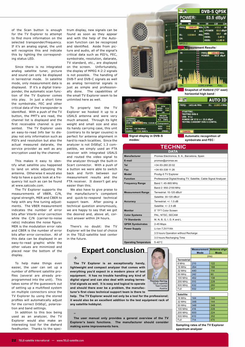
Measurement Mode
Antenna align Mode
(ms)Terrestrial8 MHz 210 12216 MHz 264 18832 MHz 440 11450 MHz 242 90100 MHz 462 138200 MHz 510 228500 MHz 632 280Full 932 257
Satellite16 MHz 144 14432 MHz 348 14450 MHz 348 348100 MHz 416 228200 MHz 600 224500 MHz 610 352Full 714 470
22 TELE-satellite International — www.TELE-satellite.com
Expert conclusion+The TV Explorer is an exceptionally handy,
lightweight and compact analyzer that comes with everything you’d expect in a modern piece of test equipment. It has no trouble handling any kind of digital signal and can also deal with analog terres-trial signals as well. It is easy and logical to operate and should there ever be a problem, the manufac-turer’s first class technical support team is there tohelp. The TV Explorer would not only be a tool for the professional; it would also be an excellent addition to the test equipment rack of any satellite hobbyist.
-The user manual only provides a general overview of the TV
Explorer’s basic functions. The manufacturer should consider making some improvements here.
of the Scan button is enough for the TV Explorer to attempt to find more information on theselected transponder/frequency. If it’s an analog signal, the unit will recognize this and indicate this by lighting the correspond-ing status LED.
Since there is no integrated analog satellite tuner, picture and sound can only be displayed in terrestrial mode. In satellite mode, only measurement data is displayed. If it’s a digital trans-ponder, the automatic scan func-tion of the TV Explorer comes into play. In just a short time the symbolrate, FEC and other critical data of the transponder is identified. With a push of the TVbutton, the PMT’s are read, the channel list is displayed and the first receivable channel is pre-sented. The TV Explorer uses an easy-to-read Info bar to dis-play not only information such as PID’s and resolution but also the actual measured datarate, the service provider as well as any encryption used by the channel.
This makes it easy to iden-tify what satellite you happened to land on while adjusting the antenna. Otherwise it would also help to have a quick look at a fre-quency list such as can be found at www.satcodx.com.
The TV Explorer supports the measurements of VBER, C/N, signal strength, MER and CBER to help with any fine tuning adjust-ments. The VBER measurement indicates the number of error bits after Viterbi error correction while the C/N (carrier-to-noise ratio) indicates the noise figure. MER is the modulation error rate and CBER is the number of error bits after error correction. All of this data can be displayed in an easy-to-read graphic while the other values are minimized and placed near the bottom of the display.
To help make things even easier, the user can set up a number of different satellite pro-files (several are already pre-programmed into the unit). This takes some of the guesswork out of setting up a multifeed system on multiple connectors since the TV Explorer by using the stored profiles will automatically adjustfor the correct DiSEqC, polariza-tion and band settings.
In addition to this box being used as an analyzer, the TV Explorer would also make an interesting tool for the diehard feedhunter. Thanks to the spec-
trum display, new signals can be found as soon as they appear and with the help of the Auto-scan function can be recognized and identified. Aside from pic-ture and audio, all of the signal’s critical data such as PID’s, FEC, symbolrate, resolution, datarate, TV standard, etc., are displayed on the screen. Unfortunately, the display of MPEG 4:2:2 signals is not possible. The handling of DVB-T and DVB-C signals as well as analog terrestrial signals is just as simple and profession-ally done. The capabilities of the small TV Explorer seem to be unlimited here as well.
To properly test the TV Explorer we hooked it up to a USALS antenna and were very much amazed. Through its light weight and small size and also its handy carrying case, this unit (contrary to its larger cousins) is perfect for antenna alignment in hard to reach localities. Since the analyzer is not DiSEqC 1.3 com-patible, we simply used an FTA receiver with integrated USALS and routed the video signal to the analyzer through the built-in Scart connector. With a push of a button we were able to switch back and forth between our measurement results and the FTA receiver. It doesn’t get any easier than this.
We also have to give praise to the manufacturer’s competent and quick-to-respond technical support team. After posing a technical question anonymously, we are happy to say that we got the desired and, above all, cor-rect answer within 24 hours.
There’s no doubt: the TV Explorer will be the tool of choice in the TELE-satellite test center in the future.
Thomas HaringTELE-satellite
Test CenterAustria
Manufacturer Promax Electronica, S. A., Barcelona, Spain
E-mail [email protected]
Tel +34-93-260 20 02
Fax +34-93-338 11 26
Model Prodig-5 TV Explorer
Function Professional Digital/Analog TV, Satellite, Cable Signal Analyzer
Frequency Range Band 1: 45-865 MHz
Band 2: 950-2150 MHz
Measurement Range Terrestrial: 10-120 dBuV
Satellite: 30-120 dBuV
Accuracy Terrestrial: +/- 1.5 dB
Satellite: +/- 2.5 dB
Monitor 5” TFT Color Screen
Color Systems PAL, NTSC, SECAM
TV Standards M, N, B, G, I, D, K and L
QPSK Symbolrates 2-45 Msps
Power Supply Li-Ion 7.2V/11Ah
3.5 hours Operation without Recharge
3.0 hours Recharging Time
Operating Temperature 5-40°C
Automatic recognition of symbolrate and FEC
Snapshot of Hotbird (13° east) horizontal high band
Measurement Results
Signal display in DVB-S modes
Sampling rates of the TV Explorer spectrum analyzer

TEST REPORT
24 TELE-satellite International — www.TELE-satellite.comTELE-satellite International — www.TELE-satellite.com
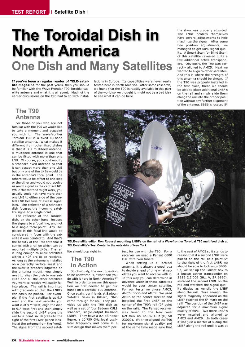
One Dish and Many SatellitesIf you’ve been a regular reader of TELE-satel-lite magazine for the past years, then you should be familiar with the Wave Frontier T90 Toroidal sat-ellite antenna and what it is all about. Much of the earlier discussions on the T90 had to do with instal-
lations in Europe. Its capabilities were never really tested here in North America. After some research, we found that the T90 is readily available in this part of the world so we thought it might not be a bad idea to see what it can do here.
The T90AntennaFor those of you who are not
familiar with the T90 we would like to take a moment and acquaint you with it. The WaveFrontier Toroidal T90 is a fixed Ku-bandsatellite antenna. What makes it different from other fixed dishesis that it is a multifeed antenna. A multifeed antenna is one that can be fitted with more than oneLNB. Of course, you could modify a standard fixed antenna so thatit can accept more than one LNB but only one of the LNBs would be in the antenna’s focal point. The others would be offset to one side or the other and would not receive as much signal as the central LNB. While this method might work, you usually could not have more than one LNB to either side of the cen-tral LNB because of excess signal loss. The reflector of a standarddish focuses the incoming satel-lite signal to a single point.
The reflector of the Toroidaldish, on the other hand, focuses the signals to a focal line, and not to a single focal point. Any LNB placed in this focal line would be considered in focus with the sat-ellite it was pointed to. And that’s the beauty of the T90 antenna: it comes with a rail on which can be mounted multiple LNBs. The rail is long enough to allow satellites within a 40° arc to be received. As long as the antenna is installed on a perfectly vertical mast and the skew is properly adjusted on the antenna mount, you simply need to align the dish to one sat-ellite and all the other satellites you want to receive will easily fall into place. The rail is imprinted with gradients so that the LNBFs can easily be placed. For exam-ple, if the first satellite is at 91°west and the next satellite you want is at 97° west, align the dish to 91° west first and then simplyslide the second LNBF along the rail to a point six degrees to the right of the first LNBF (when look-ing at the antenna from the front). The signal from the second satel-
lite should pop right in.
The T90 in ActionSo obviously, the next question
to be answered is, “what can you do with it here in North America?” Well, in order to answer this ques-tion we first needed to get ourhands on a Toroidal T90 antenna. Once again, our friends at Sadoun Satellite Sales in Hilliard, Ohio came through for us. They pro-vided us with the T90 dish as well as a set of four Sadoun KUL1 standard, single-output Ku-band LNBFs. They have a 0.4 dB noise figure, a 10.750 GHz local oscil-lator frequency and come in a slim design that makes them per-
the skew was properly adjusted. The LNBF holders themselves have several adjustments to help maximize the signal. After some fine position adjustments, wemanaged to get 60% signal qual-ity. A Smart Scan (or Blind Scan) of this satellite revealed quite a few additional active transpond-ers. Obviously, the T90 was cor-rectly aligned to AMC5. Next we wanted to align to other satellites. And this is where the strength of this antenna should be shown. If the T90 was properly installed in the first place, thean we shouldbe able to place additional LNBF’s on the rail and simply slide them along the rail into the proper posi-tion without any further alignment of the antenna. SBS6 is located 5°
Satellite Dish
The Toroidal Dish in North America
fect for use with the T90. For a receiver we used a Pansat 6000 HXC with twin tuners.
When setting up a Toroidal antenna, it is always a good idea to decide ahead of time what sat-ellites you want to receive with it. In this way you can determine in advance which of those satellites would be your center satellite. For our tests we chose AMC3, AMC5, SBS6 and AMC9. We used AMC5 as the center satellite and installed the first LNBF on thecenter of the T90’s rail (0° point on the rail). The Pansat receiver was tuned to the New York Net mux on 12.182 GHz (H, SR 23000). We then aligned the T90 for maximum signal quality and at the same time made sure that
TELE-satellite editor Ron Roessel mounting LNBFs on the rail of a Wavefrontier Toroidal T90 multifeed dish at TELE-satellite's Test Center in the outskirts of New York
to the east of AMC5 so it stands to reason that if a second LNBF were placed on the rail at a point 5° to the right of the first LNBF, weshould be able to lock onto SBS6. So, we set up the Pansat box to a known active transponder on SBS6 (12.006 GHz, V, SR 6890), installed the second LNBF on the rail and watched the signal qual-ity display as we slid the LNBF along the rail. Sure enough, the signal magically appeared as the LNBF reached the 5° mark on the rail! The position of the LNBF was adjusted for a maximum signal quality of 60%. Two more LNBF’s were installed and aligned to AMC3 and AMC9. In both cases it was just a matter of sliding the LNBF along the rail until it was at
DATATECHNIC
Echostar 1,2* 148.0° westIA7/Echostar 5* 129.0° westHorizons 1 127.0° westGalaxy 10R 123.0° westEchostar 9* 121.0° westAMC 16/Echostar 7*/DirecTV 7S* 119.0° westSatMex 5 116.8° westAnik F2 111.1° westDirecTV 5*/Echostar8*/Echostar 10* 110.0° westAnik F1R 107.3° westAMC 15 105.0° westAMC 1 103.0° westAMC 4/DirecTV 1R,4S,8* 101.0° westGalaxy 4R 99.0° west
IA5 97.0° westGalaxy 3C 95.0° westIA6 93.0° westGalaxy 11/Nimiq 1* 91.0° westIA8 89.0° westAMC 3 87.0° westAMC 2 85.0° westAMC 9 83.0° westNimiq 2* 82.0° westAMC 5 79.0° westSBS 6 74.0° westDirecTV 1* 72.5° westAMC 6/Nahuel 1 72.0° westEchostar 3* 61.5° westAmazonas 61.0° westPas 9 58.0° westPas 3R 43.0° westHispasat 30.0° westNSS 7 22.0° westTelstar 12 15.0° west
25www.TELE-satellite.com — TELE-satellite International
Expert conclusion+One dish, with very easy way to add several
LNBFs
-The frequently used 2° spacing in North America
can only be achieved by manipulating the LNBF hold-ers
its designated position. Strong signals were observed on both of these satellites.
Clearly the Wave Frontier T90 Toroidal antenna performs just as advertised. A single fixed dishwas used to lock onto four satel-lites at the same time with excep-tional signal quality from each of these satellites. The Pansat receiver easily jumped between these satellites via a DiSEqC 4X1 switch. However, this antenna is not limited to just four LNBF’s. The rail has plenty of room for more LNBF’s. So, if it’s more than four satellites that you want to receive, simply add more LNBF’s and position them correctly on the rail. One thing to keep in mind though: The width of the LNBF holders limits how close two satellites can be. As it turns out, the satellites must be 3° or more apart: the LNBF holders cannot be placed any closer than 3° apart. Unfortunately, many of the Ku-band satellites above the North American sky are spaced only 2° apart. The design of the LNBF holder will not let you receive two adjacent satellites. It is possible to modify the holder so that they
can be placed closer together on the rail but this would only work if the LNBFs themselves did not have a wide diameter feedhorn. The width of the feedhorn on the Sadoun KUL LNBFs that we used would prevent us from achieving 2° LNBF separation.
Currently, it would seem that the Toroidal T90 antenna has a market with the DishNetwork and DirecTV PayTV services. This is supported by the fact that there are LNBs especially designed for use with the T90 antenna (LOF=11.250 GHZ, circular polarization) that can receive these services. The standard DTH LNBFs that come with the minidish come in a differ-ently shaped housing that will not allow it to be installed on the T90 rail. The T90 will allow you receive a group of these PayTV satellites with just a single antenna while its larger size will give you extra pro-tection against bad weather signal fade. But the purpose of this test was to see how well it would stack up against standard Ku-band sat-ellites and we clearly showed that this versatile antenna can be used for much more than just PayTV signals.
Ron RoesselTELE-satellite
Test CenterNorth America
Model T90
Dimensions Main Reflector: 96.7cm (38.1”) W x 108.6cm (42.8”) H
Sub Reflector: 36.1cm (14.2”) W x 83.6cm (32.9”) H
Net Weight 14.1 Kg (31.0 LBS)
Operating Frequency 10.7 – 12.75 GHz
Polarization linear and circular
Reception Range 40° in orbital arc
Recommended Satellite Spacing 3 deg
Gain 39.65 dB +/- 0.45 dB at 12.5 GHz
Mount Type Elevation over azimuth
Wind Loading 80 km/h (50 mph) operational and 200 km/h (125 mph) survival
Acceptable Pole Diameter 60mm
LNBF TECHNICAL DATA
Model KUL1
Input Frequency 11.7 – 12.2 GHz
Output Frequency 950 – 1450 MHz
LOF 10.750 GHz
LOF Stability +/- 1 MHz
Noise Figure 0.4 dB
Conversion Gain 57 dB
Cross Polarization Isolation 22 dB
Feedhorn Diameter 40mm
NBC News Color Bars on AMC9
MSNBC Feed on SBS6
New York Net on AMC5
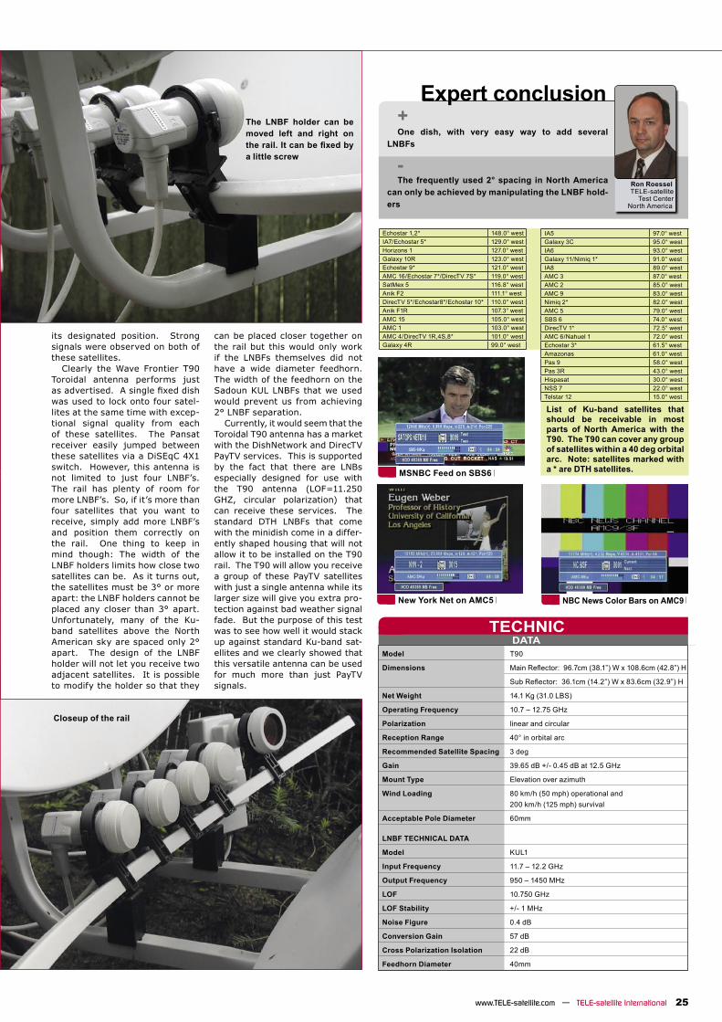
The LNBF holder can be moved left and right on the rail. It can be fixed bya little screw
Closeup of the rail
List of Ku-band satellites that should be receivable in most parts of North America with the T90. The T90 can cover any group of satellites within a 40 deg orbital arc. Note: satellites marked with a * are DTH satellites.
TEST REPORT
28 TELE-satellite International — www.TELE-satellite.comTELE-satellite International — www.TELE-satellite.com
H-H Mount
A sturdy H-H mountIt doesn’t happen every day that we receive a product for testing and are absolutely delighted by it. This H-H mount motor drive is one of these nota-
ble exceptions. It comes very close to its promise of ‘horizon to horizon’ and almost covers the complete orbital arc from 80° East to 80° West.
DG-120 Plus – Made by Jaeger
tion is fixing the motor with theantenna to the pole – luckily this can be achieved in a very simple and quick way. We particular appreciated the fact that the unit can be mounted on the pole at any desired height. The profileof the dual pole clip works like a crampon, which means that the height and the angle of rotation can be slightly adjusted without risking for the whole unit to slide downwards.
Antenna alignmentWith a polar mount system
there are more aspects to con-sider than for a fixed antenna.However, the basic steps are similar even though we have to take into account the tilted pivot. The pivot of a polar mount is aligned in parallel to the axis of the Earth and consequently is tilted by an angle which cor-
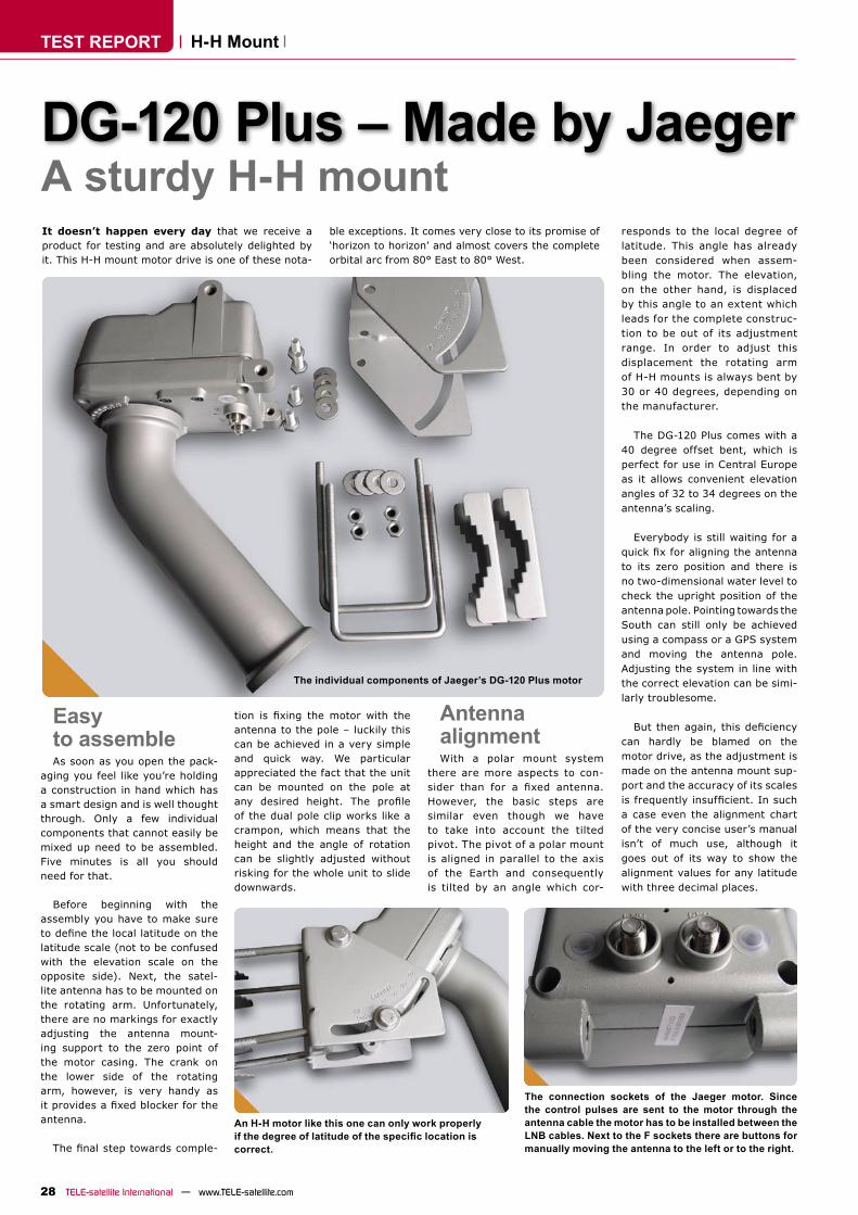
The individual components of Jaeger’s DG-120 Plus motor
responds to the local degree of latitude. This angle has already been considered when assem-bling the motor. The elevation, on the other hand, is displaced by this angle to an extent which leads for the complete construc-tion to be out of its adjustment range. In order to adjust this displacement the rotating arm of H-H mounts is always bent by 30 or 40 degrees, depending on the manufacturer.
The DG-120 Plus comes with a 40 degree offset bent, which is perfect for use in Central Europe as it allows convenient elevation angles of 32 to 34 degrees on the antenna’s scaling.
Everybody is still waiting for a quick fix for aligning the antennato its zero position and there is no two-dimensional water level to check the upright position of the antenna pole. Pointing towards the South can still only be achieved using a compass or a GPS system and moving the antenna pole. Adjusting the system in line with the correct elevation can be simi-larly troublesome.
But then again, this deficiencycan hardly be blamed on the motor drive, as the adjustment is made on the antenna mount sup-port and the accuracy of its scales is frequently insufficient. In sucha case even the alignment chart of the very concise user’s manual isn’t of much use, although it goes out of its way to show the alignment values for any latitude with three decimal places.
Easy to assembleAs soon as you open the pack-
aging you feel like you’re holding a construction in hand which has a smart design and is well thought through. Only a few individual components that cannot easily be mixed up need to be assembled. Five minutes is all you should need for that.
Before beginning with the assembly you have to make sure to define the local latitude on thelatitude scale (not to be confused with the elevation scale on the opposite side). Next, the satel-lite antenna has to be mounted on the rotating arm. Unfortunately, there are no markings for exactly adjusting the antenna mount-ing support to the zero point of the motor casing. The crank on the lower side of the rotating arm, however, is very handy as it provides a fixed blocker for theantenna.
The final step towards comple-
An H-H motor like this one can only work properly if the degree of latitude of the specific location iscorrect.
The connection sockets of the Jaeger motor. Since the control pulses are sent to the motor through the antenna cable the motor has to be installed between the LNB cables. Next to the F sockets there are buttons for manually moving the antenna to the left or to the right.
DATATECHNIC
29www.TELE-satellite.com — TELE-satellite International
Expert conclusionThis is a sturdy and fast H-H mount motor drive
which fulfils high demands in terms of its mechani-cal construction. Its DiSEqC 1.2 functions fully conform to all specifications. In order to makeit suitable also for older receivers its power con-sumption should be reduced, in particular its very high switch-on peak.
Manufacturer JAEGER Industrial Co.Ltd., Taiwan, ROC
Internet www.jaeger.com.tw
Distributor Satellitentechnik Weiß GmbH, 93437 Furth im Wald, Deutschland
Fax +49-9973-8417-17
Internet www.iev-weiss.de
E-mail [email protected]
Model DG120
Description H-H mount motor
Alignment range 80° East to 80° West
Speed 0.3 sec (19V) and 0.5 sec (13 V)
Motor noise quiet
Mounting pole 38 to 65 mm diameter
Mounting height variably on the pole
Antenna offset 40°
Rotating arm 56 mm diameter
Power consumption 200 to 350 mA
Switch-on peak >1000 mA
Heinz KoppitzTELE-satellite
Test CenterGermany
DG-120 Plus – Made by Jaeger
Motor operationFrom zero position any desired
satellite can be addressed using the manual controls or the DiSEqC 1.2 control of the receiver.
Left and right movement can be selected manually thanks to two buttons which are located next to the F-sockets and thus can be reached easily. The alignment scale can be viewed from above so that the current position can be determined quickly.
The motor runs quietly and very fast. This speed results in a rather high power consumption, how-ever, which – together with the power supply of the LNBs – might be too much for some receivers. It is particularly the switch-on peak supply of some 1 Ampere that is cause for concern, as in some case the short-circuit protection of the receiver shut down the system when trying to move the dish.
It is exactly because of this high power consumption that Jaeger offers an optional ‘Interface Box’ which is installed between the receiver and the motor. It is a fully operational DiSEqC 1.2 transmit-ter and at the same time provides the power required by the motor.
With this Interface Box all receiv-ers – even those with only DiSEqC 1.0 – can be used in connection with a polar mount antenna.
The angle of rotation is entered using a remote control and sent to the motor with a “Goto X” command. This way angle values can be also stored and retrieved through one of 60 position num-bers, if required.
Satellite search in everyday useA DiSEqC 1.2 receiver sends the
angle values required for a satel-lite search as “Goto X” commands in most cases. These commands can be processed flawlessly by theDG-120 Plus.
We experienced occasional system crashes of the motor logic control which are triggered by power failures or short-circuit shutdowns caused by the receiver. Fortunately the motor controls can be reset using the DiSEqC 1.2 reset command (“Goto Reference” or “Goto Zero”) generated by the receiver. There is no more need for a mechanical reset directly on the motor.
SATELLITE RECEPTION
30 TELE-satellite International — www.TELE-satellite.comTELE-satellite International — www.TELE-satellite.com
Praxis Tip
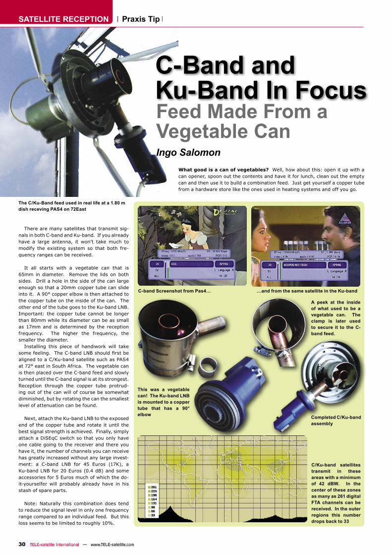
Feed Made From a Vegetable CanIngo Salomon
What good is a can of vegetables? Well, how about this: open it up with a can opener, spoon out the contents and have it for lunch, clean out the empty can and then use it to build a combination feed. Just get yourself a copper tube from a hardware store like the ones used in heating systems and off you go.
C-Band and Ku-Band In Focus
There are many satellites that transmit sig-nals in both C-band and Ku-band. If you already have a large antenna, it won’t take much to modify the existing system so that both fre-quency ranges can be received.
It all starts with a vegetable can that is 65mm in diameter. Remove the lids on both sides. Drill a hole in the side of the can large enough so that a 20mm copper tube can slide into it. A 90° copper elbow is then attached to the copper tube on the inside of the can. The other end of the tube goes to the Ku-band LNB. Important: the copper tube cannot be longer than 80mm while its diameter can be as small as 17mm and is determined by the reception frequency. The higher the frequency, the smaller the diameter.
Installing this piece of handiwork will take some feeling. The C-band LNB should first bealigned to a C/Ku-band satellite such as PAS4 at 72° east in South Africa. The vegetable can is then placed over the C-band feed and slowly turned until the C-band signal is at its strongest. Reception through the copper tube protrud-ing out of the can will of course be somewhat diminished, but by rotating the can the smallest level of attenuation can be found.
Next, attach the Ku-band LNB to the exposed end of the copper tube and rotate it until the best signal strength is achieved. Finally, simply attach a DiSEqC switch so that you only have one cable going to the receiver and there you have it, the number of channels you can receive has greatly increased without any large invest-ment: a C-band LNB for 45 Euros (17K), a Ku-band LNB for 20 Euros (0.4 dB) and some accessories for 5 Euros much of which the do-it-yourselfer will probably already have in his stash of spare parts.
Note: Naturally this combination does tend to reduce the signal level in only one frequency range compared to an individual feed. But this loss seems to be limited to roughly 10%.
Completed C/Ku-band assembly
C/Ku-band satellites transmit in these areas with a minimum of 42 dBW. In the center of these zones as many as 261 digital FTA channels can be received. In the outer regions this number drops back to 33
The C/Ku-Band feed used in real life at a 1.80 m dish receving PAS4 on 72East
C-band Screenshot from Pas4… …and from the same satellite in the Ku-band
This was a vegetable can! The Ku-band LNB is mounted to a copper tube that has a 90° elbow
A peek at the inside of what used to be a vegetable can. The clamp is later used to secure it to the C-band feed.
TVRadio
Ms/sec VoltHertz
RCA S-VHS V 0/12 GB Issue
ARION 9400 PV2R
8000 2-45 yes 1.0, 1.1, 1.2, 1.3
yes PAL D/K, B/G, I
yes, UHF
yes no 90-240V50/60Hz
yes yes yes, 2 yes yes no no yes yes,RS-232
yes, 2 no #1922006
ARION AF-9300PVR
8000 2-45 yes 1.0, 1.1, 1.2
yes NTSC/PAL
yes, UHF
yes no 100-240V50/60Hz
yes (optical)
yes yes, 2 yes yes no no yes yes,RS-232
yes no #1882005
BEETEL SD98
5000 2-40 yes 1.0, 1.1, 1.2
yes NTSC/PAL
yes yes no 80-300V yes(S/PDIF)
yes no no yes no no no no no no #1932006
BEL 5518
2000 2-40 yes 1.0, 1.1, 1.2
no PAL yes yes no 90-270V no yes no no no no no no no no no #1912006
BOTECH CA 9000 FTA/CI
4900 2-45 yes 1.2 yes yes yes,UHF
yes no 90-260 VAC
50/60Hz
yes yes yes, 2 no no no no no yes,RS-232
yes, 2 no #1892005
CHESS Digital 4000 FTA
3000 2-45 yes 1.0, 1.2 no NTSC/PAL
no yes no 230V50Hz
yes yes yes, 2 yes yes no no no yes,RS-232
no no #1862005
DGSTATION Relook 400S
10000 2-40 yes 1.0, 1.1, 1.2, 1.3
yes PAL D/K, B/G, I
yes yes yes 90-240V50/60Hz
yes (optical)
yes yes, 2 no no no no yes yes,RS-232
yes, 2 yes #1912006
DIGITAL EVERYWHERE Fire DTV External PC Set Top Box
unlimited 2-40 yes 1.0, 1.1, 1.2
no NTSC/PAL
no yes no 12 VDC no no no no no no no yes,in PC
no yes, 1 no #1872005
DSN-DIGITAL DEVICES GR 8300CI CU
5000 2-45 yes 1.0, 1.2, 1.3
yes NTSC/PAL
yes yes yes 90-260V50/60Hz
yes yes yes, 2 no yes no no no yes,RS-232
yes no #1862005
DSN-GR 7400 CI EXPLORER
5000 TV1600Radio
2-45 yes 1.0, 1.2, 1.3
yes NTSC/PAL/
SECAM
yes yes no 95-250V50/60Hz
yes (optical)
yes yes, 2 no yes no no no yes,RS-232
yes, 2 no #1882005
EDISON 2100 FTA
4000 1-45 yes 1.0, 1.2 no NTSC/PAL
yes yes no 90-250V50/60Hz
yes yes yes, 2 no yes no no no yes, RS-232
no no #1872005
EYCOS S30.12 CI
8000 2-45 yes 1.0, 1.1, 1.2, 1.3
yes NTSC/PAL
yes yes no 100-240 VAC
yes yes yes, 2 no no no no no yes, RS-232
yes, 2 no #1922006
EYCOS S50.12 PVR
8000 1-45 yes 1.0, 1.1, 1.2, 1.3
yes NTSC/PAL
yes yes no 90-250 VAC
yes (optical)
yes yes, 2 no no no no yes yes, RS-232
yes no #1912006
EYCOS S10.02F
4000 2-45 yes 1.0, 1.1, 1.2
yes NTSC/PAL
no yes no 90-250 VAC
yes (optical)
yes yes, 2 no no no no no yes, RS-232
no no #1892005
FORTEC STAR FSIR-5400 NA
4800 2-45 yes 1.0, 1.2 yes NTSC/PAL
yes yes no 90-240V50/60Hz
yes (optical)
yes no yes no no no no yes, RS-232
no yes,Irdeto
#1902005
FORTEC STAR Lifetime Diamond DVB-S & DVB-T
3000 1-45 yes 1.0, 1.2, 1.3
yes NTSC/PAL
yes yes no 90-250V50/60Hz
no yes yes, 2 no no no no no yes, RS-232
no no #1872005
GLOBAL TEQ 6000PVR
10000 1-45 yes 1.0, 1.2 yes NTSC/PAL
yes yes no 90-250V50/60Hz
yes (optical)
yes yes, 2 yes no no no yes yes, RS-232
yes no #1902005
GENERAL SATELLITE FTA-7001S
5000 2-45 yes 1.0, 1.2 no PAL/SECAM
yes yes no 190-250V50/60Hz
yes no yes, 1 yes no no no no yes,RS-232
no no #1892005
GOLDEN INTERSTAR 9000 CI PVR Premium
9000 1-45 yes 1.0, 1.1, 1.2
yes NTSC/PAL
yes yes no 100-250 VAC
yes (optical)
yes yes, 2 yes no no no yes yes,RS-232
yes, 2 yes, 2 #1902005
GOLDEN INTERSTAR DVB-T/S 8300 CI Premium
6000 1-45 yes 1.0, 1.1, 1.2
yes NTSC/PAL
yes yes no 100-250 VAC
yes (optical)
yes yes, 2 no yes no no no yes, RS-232
yes, 2 yes, 2 #1892005
Cha
nnel
Mem
ory
Sym
bolra
te
SCPC
Com
patib
le
DiS
EqC
USA
LSC
ompa
tible
NTS
C/P
AL
Mod
ulat
orO
utpu
t
Loop
ed-
Thro
ugh
IFSa
tcoD
XC
ompa
tible
Pow
erSu
pply
Dig
ital A
udio
Out
put
Aud
io/V
ideo
Out
put
Sca
rtO
utpu
t
S-VH
SO
utpu
t
Vol
t 0/1
2O
utpu
t
Posi
tione
rM
echa
nica
lPo
lariz
erH
ard
Dis
k(B
uilt-
in)
Seria
lIn
terf
ace
CI S
lots
Embe
dded
CA
TSI
Mag
azin
eDVBTELE-satellite Receiver Guide
Satellite Receivers
TVRadio
Ms/sec VoltHertz
RCA S-VHS V 0/12 GB Issue
HUMAX PR-HD1000
5000 1-45 yes 1.0, 1.2, 1.3
yes NTSC/PAL
no yes no 90-250 VAC
yes (optical)
yes yes, 2 no no no no no yes, RS-232
yes, 2 yes #1932006
KATHREIN UFS 821
4000 2-45 yes 1.0, 1.2, 1.3
yes NTSC/PAL
no yes yes 100-240 VAC
yes (optical)
yes yes, 2 yes no no no yes yes, RS-232
yes, 2 no #1912006
LEMON 030-CI
6000 starting at 1.8
yes 1.0, 1.1, 1.2
no NTSC/PAL
yes yes no 90-260V50/60Hz10.5-14DC
yes, optical &coax
yes yes, 2 no no no no no yes, RS-232
yes, 2 no #1872005
MATRIX Java
1000 2-45 yes 1.0 no NTSC/PAL
yesRF
yes no 80-270 VAC
no yes no yes no no no no yes, RS-232
no no #1942006
NEOTION 601 DVR
5000 2-45 yes 1.0, 1.2 no NTSC/PAL
no yes no 90-250V50/60Hz
yes yes yes, 2 no no no no yes, external
yes, RS-232
no yes #1882005
PANSAT 6000HXC
10000 1-45 yes 1.0, 1.2, 1.3
yes NTSC/PAL
yes, UHF
yes no 90-250V50/60Hz
yes (S/PDIF)
yes no yes yes no no yes yes,RS-232
yes, 2 no #1932006
PANSAT 3500S
5000 1-45 yes 1.0, 1.2 yes NTSC/PAL
yes, UHF
yes no 90-250V50/60Hz
yes (optical)
yes no yes yes no yes no yes,RS-232
no yes,Conax
#1902005
PANSAT 500HC PVR&CI
10000 1-45 yes 1.0, 1.2, 1.3
yes NTSC/PAL
yes yes, 2 no 90-250V50/60Hz
yes yes no yes no no no yes yes, RS-232
yes, 2 no #1872005
PIXX Event
10000 1-45 yes 1.0, 1.2 yes NTSC/PAL
yes, UHF
yes no 90-250V50/60Hz
yes (optical)
yes yes, 2 yes yes no no yes yes, RS-232
yes, 2 no #1902005
QUALI-TV QS 1080IRCI for HDTV and MPEG 4:2:2
unknown 2-40 yes 1.0, 1.2 no NTSC/PAL
no yes no 100-240V50/60Hz
yes yes yes, 2 no no no no no yes,RS-232
yes, 2 yes,Irdeto
#1872005
STAR SAT SR-X1400D
6500 1-45 yes 1.0, 1.2, 1.3
yes NTSC/PAL
yes yes no 100-250 VAC
50/60Hz
no yes yes, 2 no yes no no no yes, RS-232
no no #1932006
STAR SAT SR-X2500CUCI
4000 2-45 yes 1.0, 1.2, 1.3
yes NTSC/PAL
yes yes yes 90-250 VAC
50/60Hz
no yes yes, 2 no yes no no no yes, RS-232
yes, 2 yes,uni-
versal
#1912006
STAR SAT SR-X3500CUCI Ultra
6000 2-45 yes 1.0, 1.2 no NTSC/PAL
yes yes yes 90-250 VAC
50/60Hz
no yes yes, 2 yes yes no no no yes, RS-232
yes, 2 yes,uni-
versal
#1892005
TECHNISAT Digit 4S
5000 1-45 yes 1.0, 1.2, 1.3
yes NTSC/PAL
no no no 180-250 VAC50Hz
yes (optical &
coax)
yes yes, 2 no no no no no no no no #1942006
TECHNISAT Digit MF4-S CC
5000 1-45 yes 1.2 no NTSC/PAL
no no no 230VAC50Hz
yes (optical &
coax)
yes yes, 2 no no no no no no yes Conax, Crypto-works
#1932006
TECHNOMATE TM-7755 2VA 2CI
5000 2-45 yes 1.0, 1.2 yes PAL/NTSC/
SECAM
yes yes no 90-240 VAC
50/60Hz
yes (optical)
yes yes, 2 yes (via
scart)
no no no no yes, RS-232
yes, 2 yes, Viac-cess
#1892005
TOPFIELD TF6000PVR
5000 1-45 yes 1.0, 1.1, 1.2, 1.3
yes NTSC/PAL
no yes no 90-250V50/60Hz
yes (optical)
yes yes, 2 yes no no no yes yes,RS-232
yes, 2 no #1922006
TOPFIELD TF5000CIP
5000 1-45 yes 1.0, 1.1, 1.2, 1.3
yes NTSC/PAL
yes yes no 90-250V50/60Hz
yes (optical)
yes yes, 2 yes no yes no no yes,RS-232
yes, 2 no #1902005
TOPFIELD TF5000PVR Masterpiece
5000 1-45 yes 1.0, 1.1, 1.2, 1.3
yes NTSC/PAL
yes, UHF
yes no 90-250V50/60Hz
yes (optical)
yes yes, 2 yes no no no yes yes,RS-232
yes, 2 no #1882005
VANTAGE VT-X121SCI
4000 1-45 yes 1.0, 1.2, 1.3
yes NTSC/PAL
yes, UHF
yes no 90-250V50/60Hz
yes (S/PDIF)
yes yes, 2 no no no no no yes,RS-232
yes, 2 yes,Conax
#1932006
VANTAGE VT-X111SCX
4000 2-45 yes 1.0, 1.2, 1.3
yes NTSC/PAL
yes, UHF
yes yes 90-250V50/60Hz
no yes yes, 2 no no no no no yes,RS-232
no yes,Conax
#1912006
Cha
nnel
Mem
ory
Sym
bolra
te
SCPC
Com
patib
le
DiS
EqC
USA
LSC
ompa
tible
NTS
C/P
AL
Mod
ulat
orO
utpu
t
Loop
ed-
Thro
ugh
IFSa
tcoD
XC
ompa
tible
Pow
erSu
pply
Dig
ital A
udio
Out
put
Aud
io/V
ideo
Out
put
Sca
rtO
utpu
t
S-VH
SO
utpu
t
Vol
t 0/1
2O
utpu
t
Posi
tione
rM
echa
nica
lPo
lariz
erH
ard
Dis
k(B
uilt-
in)
Seria
lIn
terf
ace
CI S
lots
Embe
dded
CA
-TSI
Mag
azin
eDVB Satellite Receivers

TEST REPORT
36 TELE-satellite International — www.TELE-satellite.com
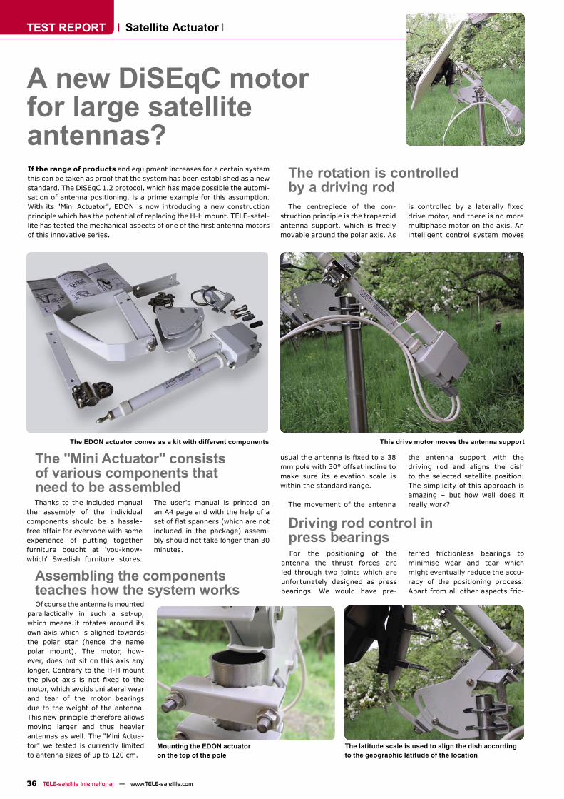
A new DiSEqC motor for large satellite antennas?If the range of products and equipment increases for a certain system this can be taken as proof that the system has been established as a new standard. The DiSEqC 1.2 protocol, which has made possible the automi-sation of antenna positioning, is a prime example for this assumption. With its "Mini Actuator", EDON is now introducing a new construction principle which has the potential of replacing the H-H mount. TELE-satel-lite has tested the mechanical aspects of one of the first antenna motorsof this innovative series.
Thanks to the included manual the assembly of the individual components should be a hassle-free affair for everyone with some experience of putting together furniture bought at 'you-know-which' Swedish furniture stores.
The user's manual is printed on an A4 page and with the help of a set of flat spanners (which are notincluded in the package) assem-bly should not take longer than 30 minutes.
The centrepiece of the con-struction principle is the trapezoid antenna support, which is freely movable around the polar axis. As
Satellite Actuator
The "Mini Actuator" consists of various components that need to be assembled
The EDON actuator comes as a kit with different components
Assembling the components teaches how the system worksOf course the antenna is mounted
parallactically in such a set-up, which means it rotates around its own axis which is aligned towards the polar star (hence the name polar mount). The motor, how-ever, does not sit on this axis any longer. Contrary to the H-H mount the pivot axis is not fixed to themotor, which avoids unilateral wear and tear of the motor bearings due to the weight of the antenna. This new principle therefore allows moving larger and thus heavier antennas as well. The "Mini Actua-tor" we tested is currently limited to antenna sizes of up to 120 cm.
The latitude scale is used to align the dish according to the geographic latitude of the location
Mounting the EDON actuator on the top of the pole
The rotation is controlled by a driving rod
usual the antenna is fixed to a 38mm pole with 30° offset incline to make sure its elevation scale is within the standard range.
The movement of the antenna
This drive motor moves the antenna support
is controlled by a laterally fixeddrive motor, and there is no more multiphase motor on the axis. An intelligent control system moves
the antenna support with the driving rod and aligns the dish to the selected satellite position. The simplicity of this approach is amazing – but how well does it really work?
Driving rod control in press bearingsFor the positioning of the
antenna the thrust forces are led through two joints which are unfortunately designed as press bearings. We would have pre-
ferred frictionless bearings to minimise wear and tear which might eventually reduce the accu-racy of the positioning process. Apart from all other aspects fric-
38 TELE-satellite International — www.TELE-satellite.com
Expert conclusion
An interesting concept which seems to be fit for thefuture. We should definitely keep an eye on it. Eventhough not all features were fully functional at the time of testing there should be no doubt that future upgrades will shortly be available.
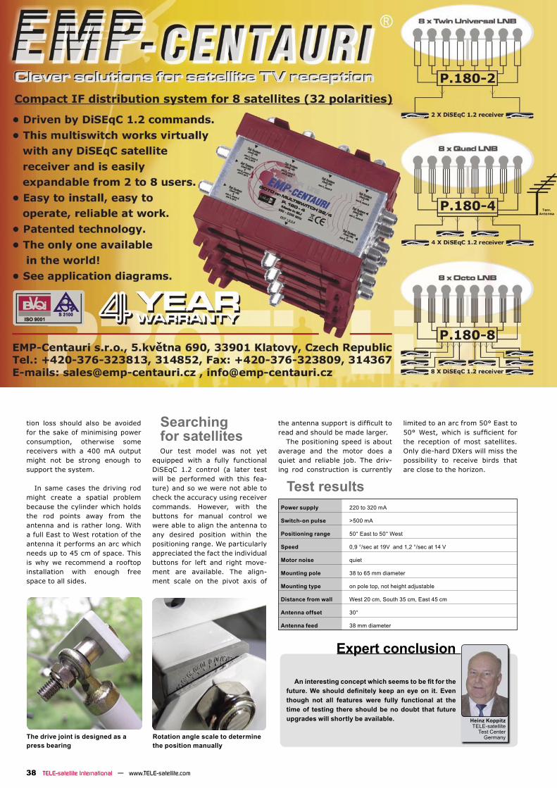
tion loss should also be avoided for the sake of minimising power consumption, otherwise some receivers with a 400 mA output might not be strong enough to support the system.
In same cases the driving rod might create a spatial problem because the cylinder which holds the rod points away from the antenna and is rather long. With a full East to West rotation of the antenna it performs an arc which needs up to 45 cm of space. This is why we recommend a rooftop installation with enough free space to all sides.
Searching for satellitesOur test model was not yet
equipped with a fully functional DiSEqC 1.2 control (a later test will be performed with this fea-ture) and so we were not able to check the accuracy using receiver commands. However, with the buttons for manual control we were able to align the antenna to any desired position within the positioning range. We particularly appreciated the fact the individual buttons for left and right move-ment are available. The align-ment scale on the pivot axis of
Power supply 220 to 320 mA
Switch-on pulse >500 mA
Positioning range 50° East to 50° West
Speed 0,9 °/sec at 19V and 1,2 °/sec at 14 V
Motor noise quiet
Mounting pole 38 to 65 mm diameter
Mounting type on pole top, not height adjustable
Distance from wall West 20 cm, South 35 cm, East 45 cm
Antenna offset 30°
Antenna feed 38 mm diameter
Heinz KoppitzTELE-satellite
Test CenterGermanyThe drive joint is designed as a
press bearingRotation angle scale to determine the position manually
the antenna support is difficult toread and should be made larger.
The positioning speed is about average and the motor does a quiet and reliable job. The driv-ing rod construction is currently
limited to an arc from 50° East to 50° West, which is sufficient forthe reception of most satellites. Only die-hard DXers will miss the possibility to receive birds that are close to the horizon.
Test results

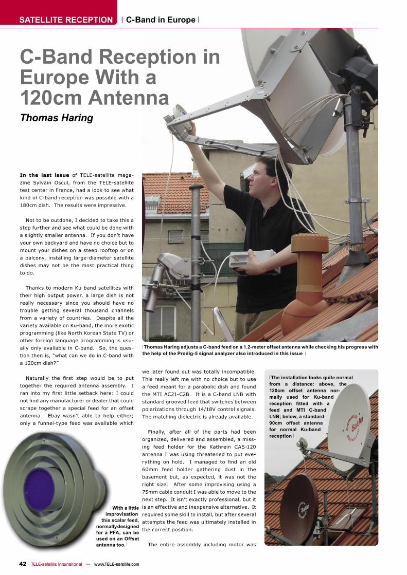
SATELLITE RECEPTION
42 TELE-satellite International — www.TELE-satellite.com
C-Band Reception in Europe With a 120cm AntennaThomas Haring
In the last issue of TELE-satellite maga-
zine Sylvain Oscul, from the TELE-satellite
test center in France, had a look to see what
kind of C-band reception was possible with a
180cm dish. The results were impressive.
Not to be outdone, I decided to take this a
step further and see what could be done with
a slightly smaller antenna. If you don’t have
your own backyard and have no choice but to
mount your dishes on a steep rooftop or on
a balcony, installing large-diameter satellite
dishes may not be the most practical thing
to do.
Thanks to modern Ku-band satellites with
their high output power, a large dish is not
really necessary since you should have no
trouble getting several thousand channels
from a variety of countries. Despite all the
variety available on Ku-band, the more exotic
programming (like North Korean State TV) or
other foreign language programming is usu-
ally only available in C-band. So, the ques-
tion then is, “what can we do in C-band with
a 120cm dish?”
Naturally the first step would be to put
together the required antenna assembly. I
ran into my first little setback here: I could
not find any manufacturer or dealer that could
scrape together a special feed for an offset
antenna. Ebay wasn’t able to help either;
only a funnel-type feed was available which
C-Band in Europe
we later found out was totally incompatible.
This really left me with no choice but to use
a feed meant for a parabolic dish and found
the MTI AC21-C2B. It is a C-band LNB with
standard grooved feed that switches between
polarizations through 14/18V control signals.
The matching dielectric is already available.
Finally, after all of the parts had been
organized, delivered and assembled, a miss-
ing feed holder for the Kathrein CAS-120
antenna I was using threatened to put eve-
rything on hold. I managed to find an old
60mm feed holder gathering dust in the
basement but, as expected, it was not the
right size. After some improvising using a
75mm cable conduit I was able to move to the
next step. It isn’t exactly professional, but it
is an effective and inexpensive alternative. It
required some skill to install, but after several
attempts the feed was ultimately installed in
the correct position.
The entire assembly including motor was
Thomas Haring adjusts a C-band feed on a 1.2-meter offset antenna while checking his progress with the help of the Prodig-5 signal analyzer also introduced in this issue
The installation looks quite normal from a distance: above, the 120cm offset antenna nor-mally used for Ku-band reception fitted with afeed and MTI C-band LNB; below, a standard 90cm offset antenna for normal Ku-band reception
With a little improvisation this scalar feed, normally designed for a PFA, can be used on an Offset antenna too.
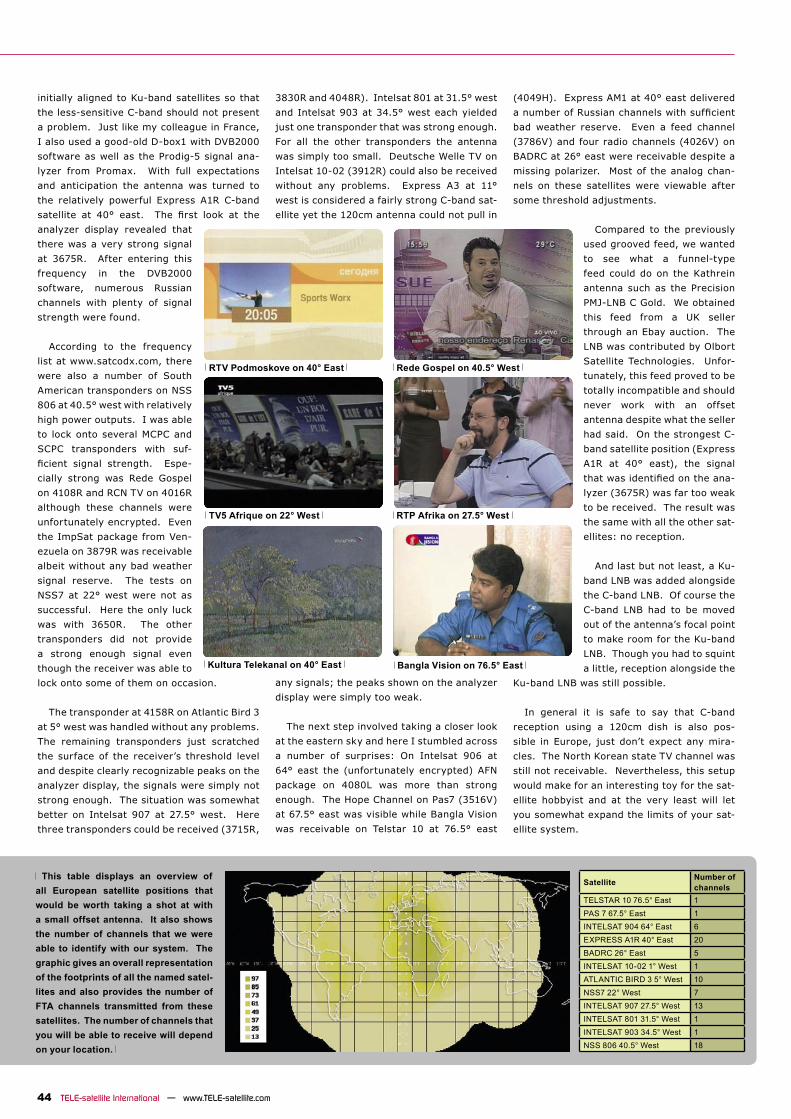
Satellite Number of channels
TELSTAR 10 76.5° East 1PAS 7 67.5° East 1INTELSAT 904 64° East 6EXPRESS A1R 40° East 20BADRC 26° East 5INTELSAT 10-02 1° West 1ATLANTIC BIRD 3 5° West 10NSS7 22° West 7INTELSAT 907 27.5° West 13INTELSAT 801 31.5° West 1INTELSAT 903 34.5° West 1NSS 806 40.5° West 18
44 TELE-satellite International — www.TELE-satellite.com
initially aligned to Ku-band satellites so that
the less-sensitive C-band should not present
a problem. Just like my colleague in France,
I also used a good-old D-box1 with DVB2000
software as well as the Prodig-5 signal ana-
lyzer from Promax. With full expectations
and anticipation the antenna was turned to
the relatively powerful Express A1R C-band
satellite at 40° east. The first look at the
analyzer display revealed that
there was a very strong signal
at 3675R. After entering this
frequency in the DVB2000
software, numerous Russian
channels with plenty of signal
strength were found.
According to the frequency
list at www.satcodx.com, there
were also a number of South
American transponders on NSS
806 at 40.5° west with relatively
high power outputs. I was able
to lock onto several MCPC and
SCPC transponders with suf-
ficient signal strength. Espe-
cially strong was Rede Gospel
on 4108R and RCN TV on 4016R
although these channels were
unfortunately encrypted. Even
the ImpSat package from Ven-
ezuela on 3879R was receivable
albeit without any bad weather
signal reserve. The tests on
NSS7 at 22° west were not as
successful. Here the only luck
was with 3650R. The other
transponders did not provide
a strong enough signal even
though the receiver was able to
lock onto some of them on occasion.
The transponder at 4158R on Atlantic Bird 3
at 5° west was handled without any problems.
The remaining transponders just scratched
the surface of the receiver’s threshold level
and despite clearly recognizable peaks on the
analyzer display, the signals were simply not
strong enough. The situation was somewhat
better on Intelsat 907 at 27.5° west. Here
three transponders could be received (3715R,
3830R and 4048R). Intelsat 801 at 31.5° west
and Intelsat 903 at 34.5° west each yielded
just one transponder that was strong enough.
For all the other transponders the antenna
was simply too small. Deutsche Welle TV on
Intelsat 10-02 (3912R) could also be received
without any problems. Express A3 at 11°
west is considered a fairly strong C-band sat-
ellite yet the 120cm antenna could not pull in
any signals; the peaks shown on the analyzer
display were simply too weak.
The next step involved taking a closer look
at the eastern sky and here I stumbled across
a number of surprises: On Intelsat 906 at
64° east the (unfortunately encrypted) AFN
package on 4080L was more than strong
enough. The Hope Channel on Pas7 (3516V)
at 67.5° east was visible while Bangla Vision
was receivable on Telstar 10 at 76.5° east
(4049H). Express AM1 at 40° east delivered
a number of Russian channels with sufficient
bad weather reserve. Even a feed channel
(3786V) and four radio channels (4026V) on
BADRC at 26° east were receivable despite a
missing polarizer. Most of the analog chan-
nels on these satellites were viewable after
some threshold adjustments.
Compared to the previously
used grooved feed, we wanted
to see what a funnel-type
feed could do on the Kathrein
antenna such as the Precision
PMJ-LNB C Gold. We obtained
this feed from a UK seller
through an Ebay auction. The
LNB was contributed by Olbort
Satellite Technologies. Unfor-
tunately, this feed proved to be
totally incompatible and should
never work with an offset
antenna despite what the seller
had said. On the strongest C-
band satellite position (Express
A1R at 40° east), the signal
that was identified on the ana-
lyzer (3675R) was far too weak
to be received. The result was
the same with all the other sat-
ellites: no reception.
And last but not least, a Ku-
band LNB was added alongside
the C-band LNB. Of course the
C-band LNB had to be moved
out of the antenna’s focal point
to make room for the Ku-band
LNB. Though you had to squint
a little, reception alongside the
Ku-band LNB was still possible.
In general it is safe to say that C-band
reception using a 120cm dish is also pos-
sible in Europe, just don’t expect any mira-
cles. The North Korean state TV channel was
still not receivable. Nevertheless, this setup
would make for an interesting toy for the sat-
ellite hobbyist and at the very least will let
you somewhat expand the limits of your sat-
ellite system.
This table displays an overview of all European satellite positions that would be worth taking a shot at with a small offset antenna. It also shows the number of channels that we were able to identify with our system. The graphic gives an overall representation of the footprints of all the named satel-lites and also provides the number of FTA channels transmitted from these satellites. The number of channels that you will be able to receive will depend on your location.
RTV Podmoskove on 40° East Rede Gospel on 40.5° West
Kultura Telekanal on 40° East
TV5 Afrique on 22° West RTP Afrika on 27.5° West
Bangla Vision on 76.5° East
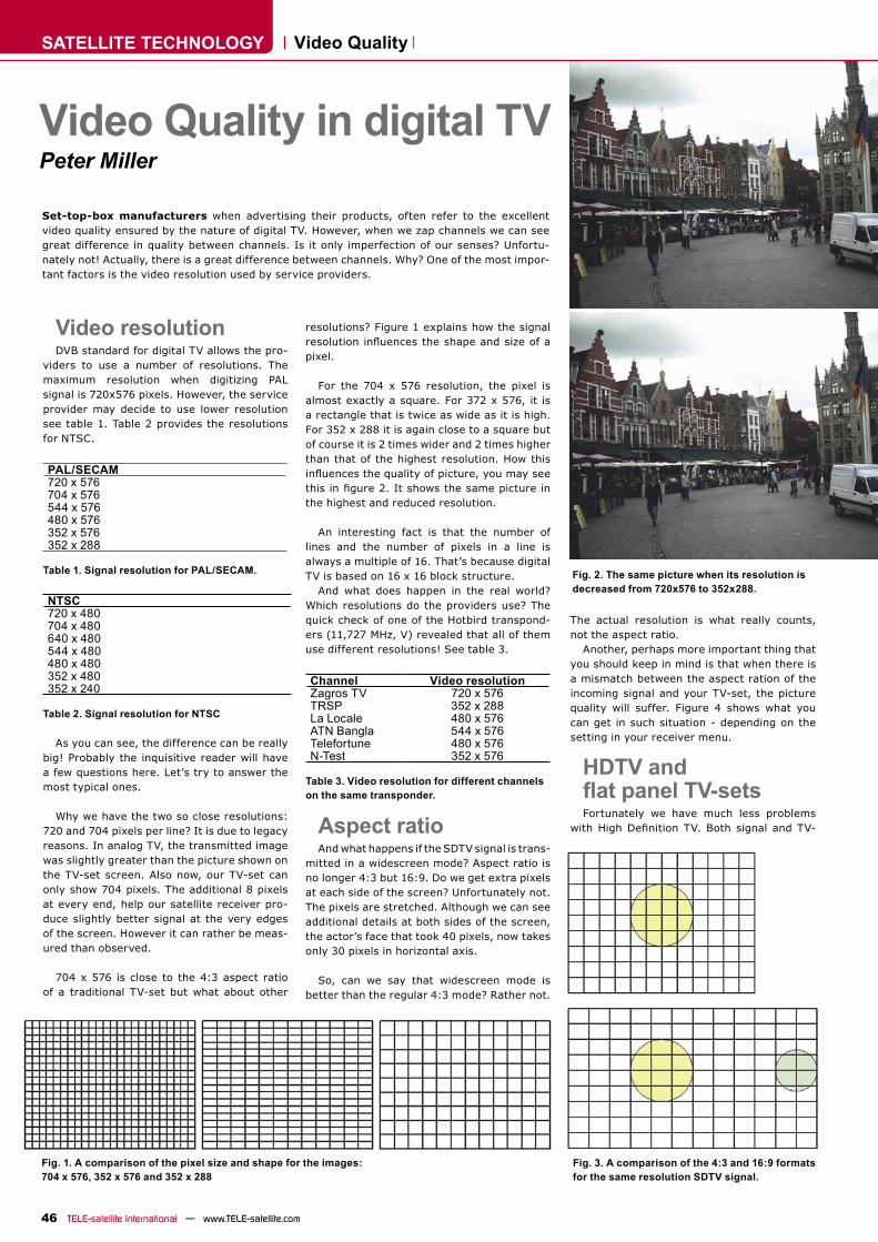
SATELLITE TECHNOLOGY
46 TELE-satellite International — www.TELE-satellite.com
Video resolutionDVB standard for digital TV allows the pro-
viders to use a number of resolutions. The maximum resolution when digitizing PAL signal is 720x576 pixels. However, the service provider may decide to use lower resolution see table 1. Table 2 provides the resolutions for NTSC.
PAL/SECAM720 x 576704 x 576544 x 576480 x 576352 x 576352 x 288
Table 1. Signal resolution for PAL/SECAM.
NTSC720 x 480704 x 480640 x 480544 x 480480 x 480352 x 480352 x 240
Table 2. Signal resolution for NTSC
As you can see, the difference can be really big! Probably the inquisitive reader will have a few questions here. Let’s try to answer the most typical ones.
Why we have the two so close resolutions: 720 and 704 pixels per line? It is due to legacy reasons. In analog TV, the transmitted image was slightly greater than the picture shown on the TV-set screen. Also now, our TV-set can only show 704 pixels. The additional 8 pixels at every end, help our satellite receiver pro-duce slightly better signal at the very edges of the screen. However it can rather be meas-ured than observed.
704 x 576 is close to the 4:3 aspect ratio of a traditional TV-set but what about other
resolutions? Figure 1 explains how the signal resolution influences the shape and size of apixel.
For the 704 x 576 resolution, the pixel is almost exactly a square. For 372 x 576, it is a rectangle that is twice as wide as it is high. For 352 x 288 it is again close to a square but of course it is 2 times wider and 2 times higher than that of the highest resolution. How this influences the quality of picture, you may seethis in figure 2. It shows the same picture inthe highest and reduced resolution.
An interesting fact is that the number of lines and the number of pixels in a line is always a multiple of 16. That’s because digital TV is based on 16 x 16 block structure.
And what does happen in the real world? Which resolutions do the providers use? The quick check of one of the Hotbird transpond-ers (11,727 MHz, V) revealed that all of them use different resolutions! See table 3.
Channel Video resolutionZagros TV 720 x 576TRSP 352 x 288La Locale 480 x 576ATN Bangla 544 x 576Telefortune 480 x 576N-Test 352 x 576
Table 3. Video resolution for different channels on the same transponder.
Aspect ratioAnd what happens if the SDTV signal is trans-
mitted in a widescreen mode? Aspect ratio is no longer 4:3 but 16:9. Do we get extra pixels at each side of the screen? Unfortunately not. The pixels are stretched. Although we can see additional details at both sides of the screen, the actor’s face that took 40 pixels, now takes only 30 pixels in horizontal axis.
So, can we say that widescreen mode is better than the regular 4:3 mode? Rather not.
Set-top-box manufacturers when advertising their products, often refer to the excellent video quality ensured by the nature of digital TV. However, when we zap channels we can see great difference in quality between channels. Is it only imperfection of our senses? Unfortu-nately not! Actually, there is a great difference between channels. Why? One of the most impor-tant factors is the video resolution used by service providers.
The actual resolution is what really counts, not the aspect ratio.
Another, perhaps more important thing that you should keep in mind is that when there is a mismatch between the aspect ration of the incoming signal and your TV-set, the picture quality will suffer. Figure 4 shows what you can get in such situation - depending on the setting in your receiver menu.
HDTV and flat panel TV-setsFortunately we have much less problems
with High Definition TV. Both signal and TV-
Video Quality in digital TVPeter Miller
Video Quality
Fig. 1. A comparison of the pixel size and shape for the images: 704 x 576, 352 x 576 and 352 x 288
Fig. 2. The same picture when its resolution is decreased from 720x576 to 352x288.
Fig. 3. A comparison of the 4:3 and 16:9 formats for the same resolution SDTV signal.
Programvariety ...
Multiswitch distribution system:• 16 SAT IF Signals (4 Orbit positions)• Terrestrial passive• return path• cascadable
sets have the 16:9 aspect ratio and there are only 2 resolutions in use: 1280 x 720p and 1920 x 1080i. Pixels are square. Although the authors of the H.264/AVC standard made it very versatile (e.g. they permitted many different aspect ratios), in the digital satellite TV, we should not encounter too many other variations than those mentioned above.
If now, you go to the shop to find a suitable TV-set for yourself, youwill probably be confused again. The resolution of the currently avail-able TV-sets (especially those cheaper ones) is quite often different from the values mentioned above. The popular values are: 1366 x 768 and 1024 x 768. Where are they from? They are taken from the PC monitors specifications. See table 4.
PC Monitor Resolutions640 × 400 VGA640 × 480 VGA854 × 480 SVGA800 × 600 SVGA1024 × 768 XGA1280 × 768 XGA1280 × 1024 SXGA1600 × 1200 UXGA
Table 4. Standardized resolutions for PC monitors.
WXGA (1366 x 768) is a derivation from XGA. It means that when we receive the HDTV signal, our TV-set must converted it to the so-called native resolution of the screen. It means that the quality of video will be reduced. But will this be really perceivable? It depends on the TV-set size and the distance you will be watching it. Because of the imperfection of our eyesight, for a 32” display, we must come to the screen closer than 1.3 meter to see all details of the 1920 x 1080 pixel picture. In other words, it makes sense to produce the full resolution TV-sets only if they are big enough. For example, the above mentioned distance increases to ca. 2 meters for 50” screen. It makes sense to watch the TV from 2-meter distance (but rather not from 1.3 m).
So, if you want to buy a really big flat panel screen, search for thefull HD resolution. If your living room is not that big and a smaller TV-set will do, 1366 x 768 or even 1024 x 768 will be a good enough choice. When making the decision, think of other aspects influencingthe video quality like contrast, brightness, reflections of light (theweak point of plasma devices!). Just avoid the cheapest models that have resolution of 852 x 480.
ConclusionsAmong the SDTV broadcasts we can easily find a signal of really
poor resolution and thus poor video quality. It can be as bad as the VHS tape. So, this is not always true that digital TV ensures better quality that analog one. However this is always true when we talk about HDTV. Only such signals, when seen on proper TV-set, secure high quality.
The resolution is not the only factor that influences the quality ofvideo. As you already know, the mismatch of the aspect ratio between signal and TV-set will also reduce it. But there are also other factors. We will write about them in the next issue of TELE-satellite.
Fig. 4. Converting the picture when there is a mismatch between its aspect ration and the aspect ratio of a TV-set.
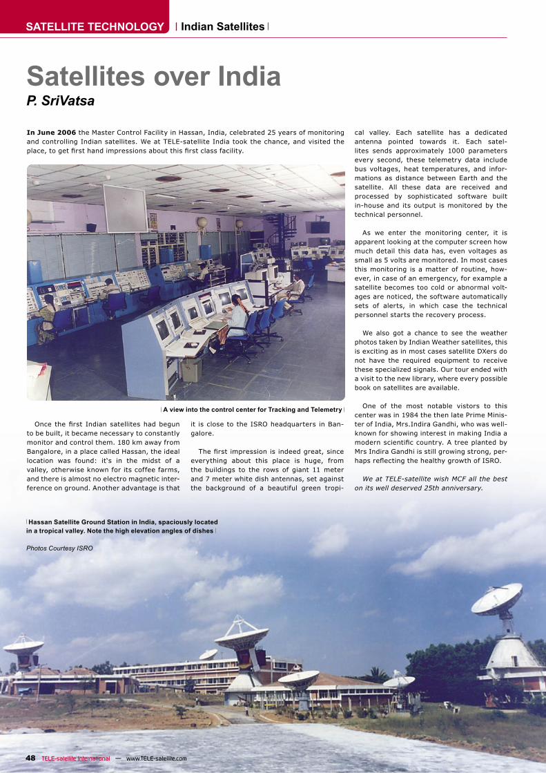
SATELLITE TECHNOLOGY
48 TELE-satellite International — www.TELE-satellite.com
Satellites over IndiaP. SriVatsa
Once the first Indian satellites had begunto be built, it became necessary to constantly monitor and control them. 180 km away from Bangalore, in a place called Hassan, the ideal location was found: it‘s in the midst of a valley, otherwise known for its coffee farms, and there is almost no electro magnetic inter-ference on ground. Another advantage is that
it is close to the ISRO headquarters in Ban-galore.
The first impression is indeed great, sinceeverything about this place is huge, from the buildings to the rows of giant 11 meter and 7 meter white dish antennas, set against the background of a beautiful green tropi-
Indian Satellites
A view into the control center for Tracking and Telemetry
In June 2006 the Master Control Facility in Hassan, India, celebrated 25 years of monitoring and controlling Indian satellites. We at TELE-satellite India took the chance, and visited the place, to get first hand impressions about this first class facility.
cal valley. Each satellite has a dedicated antenna pointed towards it. Each satel-lites sends approximately 1000 parameters every second, these telemetry data include bus voltages, heat temperatures, and infor-mations as distance between Earth and the satellite. All these data are received and processed by sophisticated software built in-house and its output is monitored by the technical personnel.
As we enter the monitoring center, it is apparent looking at the computer screen how much detail this data has, even voltages as small as 5 volts are monitored. In most cases this monitoring is a matter of routine, how-ever, in case of an emergency, for example a satellite becomes too cold or abnormal volt-ages are noticed, the software automatically sets of alerts, in which case the technical personnel starts the recovery process.
We also got a chance to see the weather photos taken by Indian Weather satellites, this is exciting as in most cases satellite DXers do not have the required equipment to receive these specialized signals. Our tour ended with a visit to the new library, where every possible book on satellites are available.
One of the most notable vistors to this center was in 1984 the then late Prime Minis-ter of India, Mrs.Indira Gandhi, who was well-known for showing interest in making India a modern scientific country. A tree planted byMrs Indira Gandhi is still growing strong, per-haps reflecting the healthy growth of ISRO.
We at TELE-satellite wish MCF all the best on its well deserved 25th anniversary.
Hassan Satellite Ground Station in India, spaciously located in a tropical valley. Note the high elevation angles of dishes
Photos Courtesy ISRO
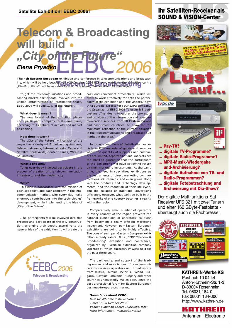
Telecom & Broadcasting will build „City of the Future“Elena Pryadko
To get the telecommunications and broad-casting market participants involved into the unified infrastructure of information space,EEBC 2006 will build „City of the Future“.
What does it mean?The new format of the exhibition places
each participant company to its own place, according to its sphere of activity and market positioning.
How does it work?The „City of the Future“ will consist of the
respectively designed Broadcasting Avenues, Telecom streams, Internet streets, Cable and Satellite Boulevards, Content Lanes, Wireless Squares etc.
What‘s the aim?To let everybody involved participate in the
process of creation of the telecommunication infrastructure of the modern city.
Why?This idea is concordant with the mission of
each specialist, and each company in the info-communication market, who every day make enormous contributions into the technologies‘ development, while implementing the idea of „City of the Future“.
„The participants will be involved into this process and participate in the city construc-tion, arranging their booths according to the general idea of the exhibition. It will create the
The 4th Eastern European exhibition and conference in telecommunications and broadcast-ing, which will be held between 18 - 20 October 2006 in Kiev, Ukraine, in the exhibition centre „KievExpoPlaza“, will have a new format: One event, One location, All converged.
Satellite Exhibition EEBC 2006
cozy and convenient atmosphere, which will allow to work effectively for both the partici-pants of the exhibition and the visitors,“ says Inna Burgela, Director of TECHEXPO company, the Organizer of EEBC 2006 Telecom & Broad-casting. „The idea is to gather the operators and providers of the information and telecom-munication services from all Eastern Europe and post-Soviet countries, to allow for the maximum reflection of the current situationin the telecommunications and broadcast B2B market in the area.“
In today‘s conditions of globalization, espe-cially in B2B markets of goods and services where the quantity of suppliers and custom-ers are limited, separate national markets are too small to guarantee that the participants of the exhibitions will have satisfying return on their marketing investments. At the same time, the need in specialized exhibitions as the instruments of direct marketing commu-nications still remains, and even grows along with the products and technology develop-ments, and the reduction of their life cycle, and the collapse of traditional advertising efficiency. However, what can‘t be built in theframeworks of one country becomes a reality within the region.
Comparatively small number of operators in every country of the region prevents the national exhibitions of operators‘ solutions from becoming a really efficient marketinginstrument. However, pan-Eastern European exhibitions are going to be highly effective. The core of such pan-Eastern European exhi-bition already exists. It is „EEBC:Telecom & Broadcasting“ exhibition and conference, organized by Ukrainian exhibition company „TechExpo“, which successfully were held for the past three years.
The partnership and support of the lead-ing unions and associations of telecommuni-cations services operators and broadcasters from Russia, Ukraine, Belarus, Poland, Bul-garia, Slovakia, Lithuania, Hungary and other countries undoubtedly makes EEBC 2006 the best professional forum for Eastern European business-to-operators market.
Some facts about EEBC:Held for 4th time in Kiev/UkraineTime: 18-20 October 2006Venue: Exhbition Centre „KievExpoPlaza“More Information: www.eebc.net.ua
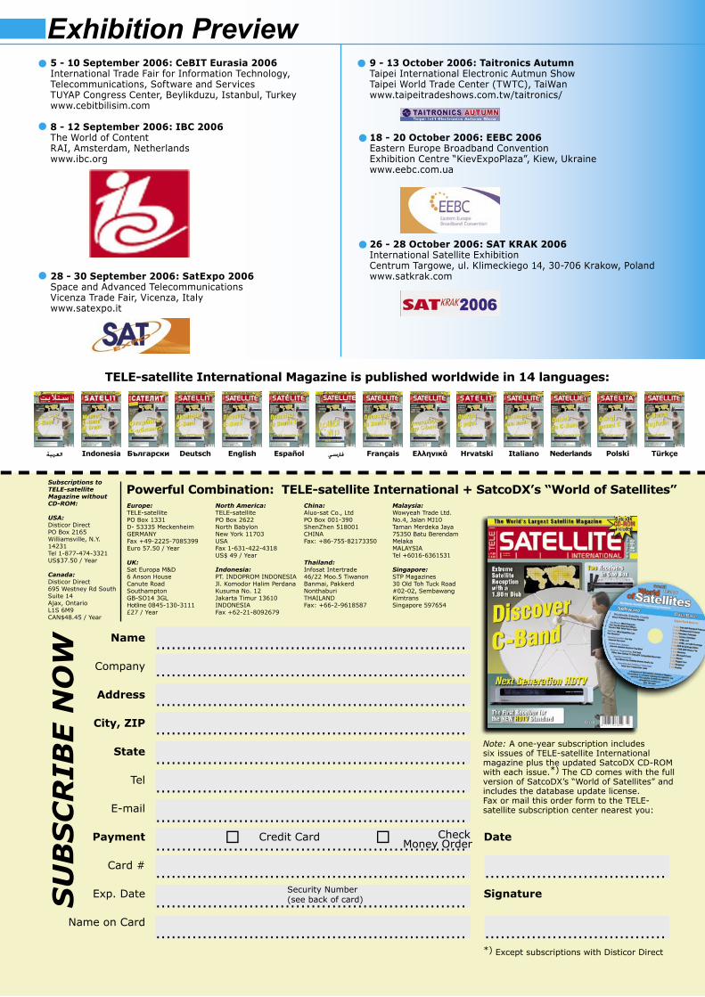
............................................................
............................................................
............................................................
............................................................
............................................................
............................................................
............................................................
............................................................
............................................................
...................................
............................................................
............................................................
...................................
العربية Indonesia Български Deutsch English Español فارسي Français Ελληνικά Hrvatski Italiano Nederlands Polski Türkçe
Powerful Combination: TELE-satellite International + SatcoDX’s “World of Satellites”Europe:TELE-satellitePO Box 1331D- 53335 MeckenheimGERMANYFax +49-2225-7085399Euro 57.50 / Year
UK:Sat Europa M&D6 Anson HouseCanute RoadSouthamptonGB-SO14 3GLHotline 0845-130-3111 £27 / Year
North America:TELE-satellitePO Box 2622North BabylonNew York 11703USAFax 1-631-422-4318US$ 49 / Year
Indonesia:PT. INDOPROM INDONESIAJl. Komodor Halim Perdana Kusuma No. 12Jakarta Timur 13610INDONESIAFax +62-21-8092679
China:Aluo-sat Co., LtdPO Box 001-390ShenZhen 518001CHINAFax: +86-755-82173350
Thailand:Infosat Intertrade46/22 Moo.5 TiwanonBanmai, PakkerdNonthaburiTHAILANDFax: +66-2-9618587
Malaysia:Wowyeah Trade Ltd.No.4, Jalan MJ10Taman Merdeka Jaya75350 Batu BerendamMelakaMALAYSIATel +6016-6361531
Singapore:STP Magazines30 Old Toh Tuck Road#02-02, SembawangKimtransSingapore 597654
Name
Company
Address
City, ZIP
State
Tel
Payment
Card #
Exp. Date
Name on Card
Note: A one-year subscription includes six issues of TELE-satellite International magazine plus the updated SatcoDX CD-ROM with each issue.*) The CD comes with the full version of SatcoDX’s “World of Satellites” and includes the database update license. Fax or mail this order form to the TELE-satellite subscription center nearest you:
Credit Card
Check Money Order
Date
Signature
SU
BS
CR
IBE N
OW
Security Number(see back of card)
Exhibition Preview5 - 10 September 2006: CeBIT Eurasia 2006International Trade Fair for Information Technology, Telecommunications, Software and ServicesTUYAP Congress Center, Beylikduzu, Istanbul, Turkeywww.cebitbilisim.com
8 - 12 September 2006: IBC 2006The World of ContentRAI, Amsterdam, Netherlandswww.ibc.org
28 - 30 September 2006: SatExpo 2006Space and Advanced TelecommunicationsVicenza Trade Fair, Vicenza, Italywww.satexpo.it
9 - 13 October 2006: Taitronics AutumnTaipei International Electronic Autmun ShowTaipei World Trade Center (TWTC), TaiWanwww.taipeitradeshows.com.tw/taitronics/
18 - 20 October 2006: EEBC 2006Eastern Europe Broadband ConventionExhibition Centre “KievExpoPlaza”, Kiew, Ukrainewww.eebc.com.ua
26 - 28 October 2006: SAT KRAK 2006International Satellite Exhibition Centrum Targowe, ul. Klimeckiego 14, 30-706 Krakow, Polandwww.satkrak.com
Subscriptions to TELE-satellite Magazine without CD-ROM:
USA:Disticor DirectPO Box 2165Williamsville, N.Y.14231Tel 1-877-474-3321US$37.50 / Year
Canada:Disticor Direct695 Westney Rd SouthSuite 14Ajax, OntarioL1S 6M9CAN$48.45 / Year
*) Except subscriptions with Disticor Direct
TELE-satellite International Magazine is published worldwide in 14 languages:

Related Documents