ref: ML18431 - Wangaratta Airport Infrastructure Development Plan Rev B Page 1 of 42 Wangaratta Airport Infrastructure Development Plan (Supplement to the Wangaratta Aerodrome Master Plan 2017) ML18431 Prepared for Rural City of Wangaratta Client representative Celeste Brockwell Date 22 May 2019 Rev B

Welcome message from author
This document is posted to help you gain knowledge. Please leave a comment to let me know what you think about it! Share it to your friends and learn new things together.
Transcript
ref: ML18431 - Wangaratta Airport Infrastructure Development Plan Rev B Page 1 of 42
Wangaratta Airport Infrastructure
Development Plan
(Supplement to the Wangaratta
Aerodrome Master Plan 2017)
ML18431
Prepared for
Rural City of Wangaratta
Client representative
Celeste Brockwell
Date
22 May 2019
Rev B
ref: ML18431 - Wangaratta Airport Infrastructure Development Plan Rev B
Table of Contents
1. Introduction ...............................................................................................................................................................................1 1.1 Background 1 1.2 Scope 1 1.3 Limitations 2 1.4 Stakeholder Consultation 2 1.5 References 3 1.6 RCoW Supplied Information 3
2. Basis of the Infrastructure Development Plan ...........................................................................................................................5 2.1 Planning Criteria 5 2.2 Aerodrome Reference Information 5 2.3 Aircraft for Planning Purposes at Wangaratta Airport 6 2.4 Geometric Design Criteria 7 2.5 Pavement Concept Design Criteria 9 2.6 Stormwater Drainage Concept Design Criteria 9 2.7 Utility Services Concept Design 9
3. Infrastructure and Airside Facilities ......................................................................................................................................... 10 3.1 Existing Infrastructure and Airside Facilities 10
3.1.1 Existing Runway 18/36 10 3.1.2 Existing Runway 09/27 10 3.1.3 Existing Taxiways 10 3.1.4 Existing RPT and GA Apron 10 3.1.5 Existing Navigational Aids 10 3.1.6 Existing Lighting 11 3.1.7 Aircraft Refuelling Facility 11 3.1.8 Existing Utility Services and Landside Infrastructure 11
3.2 Proposed Infrastructure and Airside Facility Development 11 3.2.1 General 11 3.2.2 Preliminary Horizontal Geometry 12 3.2.1 Preliminary Vertical Geometry 12 3.2.2 Demolition and Site Remediation 12 3.2.3 Basis of Concept Pavement Design 12 3.2.3.1 Existing Aircraft Traffic 12 3.2.3.2 Future Aircraft Traffic 13 3.2.3.1 Aircraft Traffic Scenarios for Concept Pavement Design 13 3.2.4 Code A/B Aircraft Concept Pavement 14 3.2.5 Code C Aircraft Concept Pavement 14 3.2.6 18/36 Runway Upgrade Concept Pavement 14 3.2.7 Pavement Materials 15 3.2.8 Road Concept Pavement 15 3.2.9 Master Grading Stage 1 15 3.2.10 Master Grading Stage 2 15 3.2.11 Stage 1 Works 16 3.2.11.1 New Code A/B Aircraft Pavement 16 3.2.11.2 New Large Commercial Hangar 16 3.2.11.3 Fuel Facility Relocation 16 3.2.12 Stage 2 Works 16 3.2.12.1 New Access Road 17 3.2.12.2 New Code A/B Aircraft Pavement 17 3.2.12.3 Relocation of Aeroclub 17 3.2.12.4 New Commercial Hangars 17
ref: ML18431 - Wangaratta Airport Infrastructure Development Plan Rev B
3.2.12.5 New Hobby Hangars 17 3.2.13 Stage 3 Works 17 3.2.13.1 New Code A/B Aircraft Pavement 17 3.2.13.2 New Code C Aircraft Taxiway and Apron Expansion 18 3.2.13.3 New Large Commercial Hangars 18 3.2.13.4 Demolition and Removal of Redundant NDB Infrastructure 18 3.2.14 Stage 4 Works 18 3.2.14.1 New Code A/B Aircraft Pavement 18 3.2.14.2 New Hobby Hangars 19 3.2.15 Stage 5 Works 19 3.2.15.1 New Code A/B Aircraft Pavement 19 3.2.15.2 New Commercial Hangars 19 3.2.15.3 New Hobby Hangars 19 3.2.15.4 New Hangar Extension 19 3.2.15.5 New Access Road 20 3.2.16 Existing Pavement Upgrades (Stage 6 Works) 20 3.2.16.1 Runway 18/36 Pavement Strengthening Overlay/Reconstruction 20 3.2.16.2 Taxiway Pavement Strengthening Overlay/Reconstruction 20 3.2.16.3 Apron Pavement Strengthening Overlay/Reconstruction 20 3.2.17 Utility Services Design 21 3.2.17.1 New Utility Services 21 3.2.17.2 Upgrade of Existing Utility Services 21 3.2.18 Terminal Building Upgrade Works (Provisional) 21 3.2.19 Concept Development 21
4. Indicative Budget Cost Estimates ........................................................................................................................................... 22 4.1 Basis of Costing 22 4.2 Indicative Budget Cost Estimates Summary 22 4.3 Accuracy of Indicative Budget Cost Estimates 24 4.4 Potential Works Cost Savings 24
5. Procurement Model Analysis .................................................................................................................................................. 25 5.1 Pre-Tender and Construction Activities 25 5.2 Procurement Models 25
5.2.1 Assessment Criteria 25 5.2.2 Procurement Model Assessment 26 5.2.2.1 Traditional/Conventional Lump Sum (LS) 26 5.2.2.2 Design and Construct (D&C) and Design, Construct, Maintain (DCM) 27
5.3 Procurement Model Recommendation 29 6. Preliminary Design, Tender and Construction Timelines ......................................................................................................... 30
6.1 Basis of Timelines 30 6.2 Preliminary Timeline Summary 30 6.3 Accuracy of Preliminary Timelines 32
List of figures
No table of figures entries found.
List of tables
Table 1 – RCoW Supplied Information................................................................................................................................................3 Table 2 – Aerodrome Reference Code (MOS Part 139)......................................................................................................................6 Table 3 – Example Aircraft Types by Reference Code........................................................................................................................7
ref: ML18431 - Wangaratta Airport Infrastructure Development Plan Rev B
Table 4 – Geometric Design Criteria (MOS Part 139) .........................................................................................................................8 Table 5 – Aerodrome Drainage Design Standards..............................................................................................................................9 Table 6 – Indicative Budget Cost Estimates Summary...................................................................................................................... 22 Table 7 – Preliminary Timeline Summary ......................................................................................................................................... 30
Appendices
Appendix A — Concept Drawings
Appendix B — Indicative Budget Cost Estimates
Appendix C — Concept Drawing Development (History)
Appendix D — Wangaratta Airport Master Plan
Appendix E — Historical Geotechnical Report
Prepared by — Cam Flack
Date — 22.05.2019
Reviewed by — Simon Oakley
Date — 22.05.2019
Authorised by — Matt Hyatt
Date — 22.05.2019
Revision History
Rev No. Description Prepared by Reviewed by Authorised by Date
A Preliminary Issue C.Flack S.Oakley M.Hyatt 23.04.19
B Preliminary Issue C.Flack S.Oakley M.Hyatt 22.05.19
2019 pitt&sherry
This document is and shall remain the property of pitt&sherry. The document may only be used for the purposes for which it was commissioned and in accordance with the Terms of Engagement for the commission. Unauthorised use of this document in any form is prohibited.
ref: ML18431 - Wangaratta Airport Infrastructure Development Plan Rev B/CF/SO Page 1
1. Introduction
1.1 Background
The Rural City of Wangaratta (RCoW) owns and operates Wangaratta Airport which currently serves General Aviation (GA) aircraft, emergency services aircraft and occasional visiting Royal Australian Air Force (RAAF) aircraft. Wangaratta Airport is located adjacent to the Hume Highway and is located approximately 4km south of the town centre.
The 18/36 Runway is sealed and 1,640m long and 30m wide. The 09/27 Runway is unsealed and 530m long and 18m wide, and is suitable for turbo-prop aircraft only. The existing 18/36 Runway is rated as Pavement Classification Number (PCN) 12 and has two sealed connecting taxiways to the Regular Public Transport (RPT) Apron and GA Apron. The existing 09/27 Runway is not rated in terms of pavement strength.
As Wangaratta Airport has been identified as critical infrastructure for the region, it is now necessary to assess the technical requirements for upgrading the airports infrastructure and facilities so that the airport can continue to support existing and future business operations, as well as emergency services.
The RCoW are therefore currently planning the future development of Wangaratta Airport, including all existing infrastructure and airside facilities in a manner that satisfies the strategic, operational and functional needs of the airport, based on the long term planning horizon, as detailed in the ‘Wangaratta Aerodrome Master Plan 2017’ (To70 in association with Michael Connell & Associates and Kneebush Planning dated August 2018).
pitt&sherry was engaged by the RCoW to undertake the Wangaratta Airport Infrastructure Development Plan as a supplement to the Master Plan, which has essentially taken the general concepts of the Master Plan and technically details how the existing infrastructure and airside facilities at Wangaratta Airport may be rationally upgraded based on sound airport engineering practices and the current rules and regulations applicable to airports, with consideration of likely future rules and regulations which may impact Wangaratta Airport in the short to medium term.
The Wangaratta Airport Infrastructure Development Plan should therefore be read in conjunction with the Wangaratta Aerodrome Master Plan 2017.
1.2 Scope
The scope of the Wangaratta Airport Infrastructure Development Plan includes:
Consideration of the existing Wangaratta Airport site in terms of aircraft operational requirements, functionality and potential future development;
Undertaking a desk top study relating to the planning and technical requirements for the future infrastructure and airside facilities at Wangaratta Airport, which includes:
o Preliminary demolition and site remediation requirements (based on existing RCoW records, environmental records/assessments and geotechnical investigations);
o Preliminary utility (water, sewer, electrical and communication) service upgrade requirements based on existing service location and capacity information (from existing RCoW records and as built information); and
o Preliminary airside pavement design to cater for the range of aircraft travelling from other Australian interstate locations (as identified in the current Master Plan – refer to Appendix D) to Wangaratta Airport (based on geotechnical data/information provided by RCoW relevant to the site).
Provide RCoW with concept drawings illustrating the general layout and proposed staging for the future infrastructure and airside facility upgrades;
Provide RCoW with Indicative Budget Cost Estimates (to a level of accuracy of +/- 30%) for the identified stages
ref: ML18431 - Wangaratta Airport Infrastructure Development Plan Rev B/CF/SO Page 2
of infrastructure and airside facility development;
Procurement model assessment for the proposed upgrade works; and
Preliminary design, tender and construction timelines for the proposed upgrade works.
The list of items below were specifically excluded in the development of this Wangaratta Airport Infrastructure Development Plan as they were deemed not necessary to fulfil the specific scope work of the commission, based on the assumption that a detailed design phase would follow after RCoW’s acceptance of the Wangaratta Airport Infrastructure Development Plan:
Detailed site investigations such as feature and level surveys, geotechnical investigations, drainage and flood investigations and assessments, environmental investigations and assessments;
Detailed design services;
Detailed consideration of other planning and proposed infrastructure development outside the airport boundary;
Detailed assessment of aircraft traffic assessments and forecasting;
Any additional CASA, statutory, regulatory, planning or environmental requirements not associated with the Wangaratta Airport Infrastructure Development Plan;
Airport operational aspects (unless specifically stated);
Navigational Aids (unless specifically stated);
Detailed Stage construction planning and works staging based on consultation with stakeholders and their operational restrictions; and
Project risk assessments.
1.3 Limitations
pitt&sherry have prepared the Wangaratta Airport Infrastructure Development Plan for the RCoW and it is therefore solely for their use.
pitt&sherry does not accept any legal liability or responsibility for the use of the Wangaratta Airport Infrastructure Development Plan other than that which is stated above and herein
In particular, the following specific limitations of this Wangaratta Airport Infrastructure Development Plan are to be noted:
Comments, conclusions and recommendations are provided strictly on the basis that pitt&sherry takes no responsibility and disclaims all liability whatsoever (including pursuant to the law of Tort or otherwise) for any loss or damage that the RCoW or others may suffer as a result of using or relying on any information given to pitt&sherry by the RCoW or other parties;
Information provided by third parties has not been verified; and
No detailed investigations relating to the site have been completed specifically for the Wangaratta Airport Infrastructure Development Plan (i.e. only existing information and historical information has been used).
Should RCoW become aware of any changes, inaccuracies or assumptions made in this Wangaratta Airport Infrastructure Development Plan that are incorrect, pitt&sherry should be notified and made aware so that the significance can be assessed and the opportunity is given to review the comments and recommendations herein.
1.4 Stakeholder Consultation
Stakeholder consultation was undertaken on 01 March 2019 and 15 March 2019 at Wangaratta Airport, with the following representation at one or both meetings:
ref: ML18431 - Wangaratta Airport Infrastructure Development Plan Rev B/CF/SO Page 3
RCoW – Celeste Brockwell, Stephen Swart and Travis Vincent
pitt&sherry – Simon Oakley and Cam Flack
Aeroclub and other stakeholder representatives – including Chris Balfour and Terry Vaughn, with more than 15 other stakeholders/existing airport businesses and aeroclub members across the two meetings
As part of the consultation process a range of amendments to the Concept Drawings were made between each meeting to address a range of stakeholder concerns. In principal consensus regarding the Concept Drawings was achieved by the conclusion of the second meeting, with only minor amendments proposed.
1.5 References
The following technical references have been used in the preparation of the Wangaratta Airport Infrastructure Development Plan:
Civil Aviation Safety Authority (CASA)
o Civil Aviation Safety Regulations (CASRs)
o Civil Aviation Regulations (CARs)
o Manual of Standards (MOS) Part 139 – Aerodromes
o Civil Aviation Orders (CAO)
o Civil Aviation Advisory Publications (CAAP’s)
o Advisory Circulars (ACs)
International Civil Aviation Organization (ICAO)
o Annex 14 Volume 1 – Aerodrome Design and Operations
International Air Transport Association (IATA)
o Airport Development Reference Manual
Federal Aviation Administration (FAA)
o Advisory Circulars
Australian Standards (various)
1.6 RCoW Supplied Information
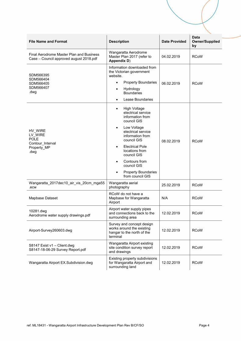
Table 1 – RCoW Supplied Information
File Name and Format Description Date Provided Data Owner/Supplied by
18.073.01 YWGT ANEC Report .pdf and .docx
Australian Noise Exposure Charts
04.02.2019 RCoW
4180161-1 Pavement – Wangaratta Aerodrome Pavement LACEBY.pdf
Soil Investigation and Pavement Design for Wangaratta Airport
04.02.2019 RCoW
D18 66937 Wangaratta Aerodrome Hangar Options Report .pdf and .docx
Wangaratta Airport concept hangar options, layouts and costing
04.02.2019 RCoW
Wangaratta Aerodrome Hangar Cost Estimates 29-10-2018.xlsx
Wangaratta Airport concept hangar cost estimates
04.02.2019 RCoW
ref: ML18431 - Wangaratta Airport Infrastructure Development Plan Rev B/CF/SO Page 4
File Name and Format Description Date Provided Data Owner/Supplied by
Final Aerodrome Master Plan and Business Case – Council approved august 2018.pdf
Wangaratta Aerodrome Master Plan 2017 (refer to Appendix D)
04.02.2019 RCoW
SDM566395 SDM566404 SDM566405 SDM566407 .dwg
Information downloaded from the Victorian government website.
Property Boundaries
Hydrology Boundaries
Lease Boundaries
06.02.2019 RCoW
HV_WIRE LV_WIRE POLE Contour_Interval Property_MP .dwg
High Voltage electrical service information from council GIS
Low Voltage electrical service information from council GIS
Electrical Pole locations from council GIS
Contours from council GIS
Property Boundaries from council GIS
08.02.2019 RCoW
Wangaratta_2017dec10_air_vis_20cm_mga55 .ecw
Wangaratta aerial photography
25.02.2019 RCoW
Mapbase Dataset RCoW do not have a Mapbase for Wangaratta Airport
N/A RCoW
10281.dwg Aerodrome water supply drawings.pdf
Airport water supply pipes and connections back to the surrounding area
12.02.2019 RCoW
Airport-Survey260603.dwg
Survey and concept design works around the existing hangar to the north of the terminal
12.02.2019 RCoW
S8147 Exist v1 – Client.dwg S8147-18-06-29 Survey Report.pdf
Wangaratta Airport existing site condition survey report and drawings
12.02.2019 RCoW
Wangaratta Airport EX.Subdivision.dwg Existing property subdivisions for Wangaratta Airport and surrounding land
12.02.2019 RCoW
ref: ML18431 - Wangaratta Airport Infrastructure Development Plan Rev B/CF/SO Page 5
2. Basis of the Infrastructure Development Plan
2.1 Planning Criteria
The planning criteria for the Wangaratta Airport Infrastructure Development Plan can be categorised into the three sections as follows:
International standards and recommended practices (ICAO);
National standards and advisory publications (CASA); and
Local standards and practices.
The international standards and recommended practices are formalised in Annex 14 to the Convention on International Civil Aviation adopted by the International Civil Aviation Organisation (ICAO) under the provisions of the Convention. In addition, ICAO publishes a number of Aerodrome Design Manuals and Airport Services Manuals.
National standards and advisory publications are published by the Australian Civil Aviation Safety Authority (CASA) which administers the Civil Aviation Act (1988) through the Civil Aviation Safety Regulations (CASRs) and the Manual of Standards (MOS).
The Manual of Standards Part 139 (MOS Part 139) is a CASA policy manual, this forms part of the Civil Aviation Safety Regulations CASR Part 139. CASR Part 139 sets out the regulatory regime of aerodromes used by aeroplanes conducting RPT, Charter and GA operations. The regulatory regime provides for aerodromes to be certified or registered.
MOS Part 139 sets out the standards and operating procedures for certified and registered aerodromes, as well as for other aerodromes used for RPT, Charter and GA operations.
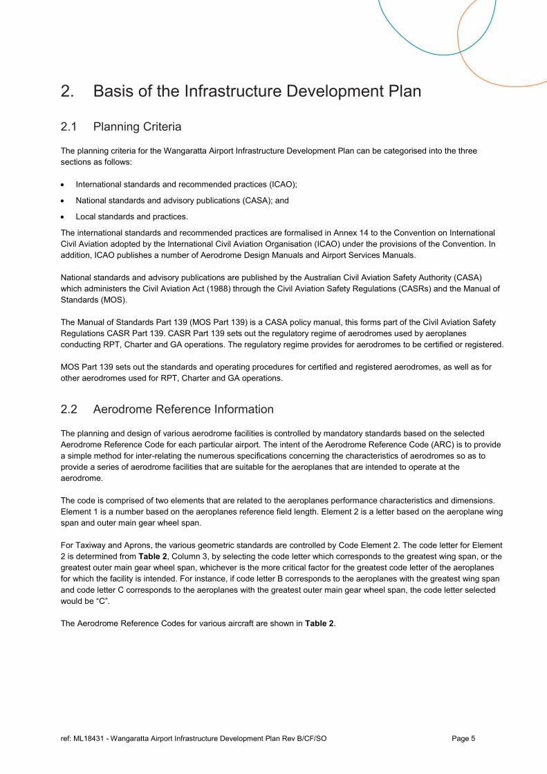
2.2 Aerodrome Reference Information
The planning and design of various aerodrome facilities is controlled by mandatory standards based on the selected Aerodrome Reference Code for each particular airport. The intent of the Aerodrome Reference Code (ARC) is to provide a simple method for inter-relating the numerous specifications concerning the characteristics of aerodromes so as to provide a series of aerodrome facilities that are suitable for the aeroplanes that are intended to operate at the aerodrome.
The code is comprised of two elements that are related to the aeroplanes performance characteristics and dimensions. Element 1 is a number based on the aeroplanes reference field length. Element 2 is a letter based on the aeroplane wing span and outer main gear wheel span.
For Taxiway and Aprons, the various geometric standards are controlled by Code Element 2. The code letter for Element 2 is determined from Table 2, Column 3, by selecting the code letter which corresponds to the greatest wing span, or the greatest outer main gear wheel span, whichever is the more critical factor for the greatest code letter of the aeroplanes for which the facility is intended. For instance, if code letter B corresponds to the aeroplanes with the greatest wing span and code letter C corresponds to the aeroplanes with the greatest outer main gear wheel span, the code letter selected would be “C”.
The Aerodrome Reference Codes for various aircraft are shown in Table 2.
ref: ML18431 - Wangaratta Airport Infrastructure Development Plan Rev B/CF/SO Page 6
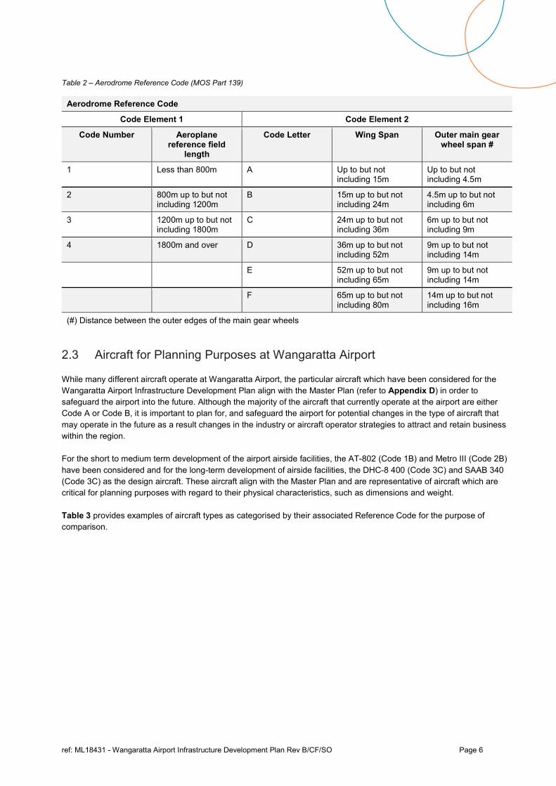
Table 2 – Aerodrome Reference Code (MOS Part 139)
Aerodrome Reference Code
Code Element 1 Code Element 2
Code Number Aeroplane reference field
length
Code Letter Wing Span Outer main gear wheel span #
1 Less than 800m A Up to but not including 15m
Up to but not including 4.5m
2 800m up to but not including 1200m
B 15m up to but not including 24m
4.5m up to but not including 6m
3 1200m up to but not including 1800m
C 24m up to but not including 36m
6m up to but not including 9m
4 1800m and over D 36m up to but not including 52m
9m up to but not including 14m
E 52m up to but not including 65m
9m up to but not including 14m
F 65m up to but not including 80m
14m up to but not including 16m
(#) Distance between the outer edges of the main gear wheels
2.3 Aircraft for Planning Purposes at Wangaratta Airport
While many different aircraft operate at Wangaratta Airport, the particular aircraft which have been considered for the Wangaratta Airport Infrastructure Development Plan align with the Master Plan (refer to Appendix D) in order to safeguard the airport into the future. Although the majority of the aircraft that currently operate at the airport are either Code A or Code B, it is important to plan for, and safeguard the airport for potential changes in the type of aircraft that may operate in the future as a result changes in the industry or aircraft operator strategies to attract and retain business within the region.
For the short to medium term development of the airport airside facilities, the AT-802 (Code 1B) and Metro III (Code 2B) have been considered and for the long-term development of airside facilities, the DHC-8 400 (Code 3C) and SAAB 340 (Code 3C) as the design aircraft. These aircraft align with the Master Plan and are representative of aircraft which are critical for planning purposes with regard to their physical characteristics, such as dimensions and weight.
Table 3 provides examples of aircraft types as categorised by their associated Reference Code for the purpose of comparison.
ref: ML18431 - Wangaratta Airport Infrastructure Development Plan Rev B/CF/SO Page 7
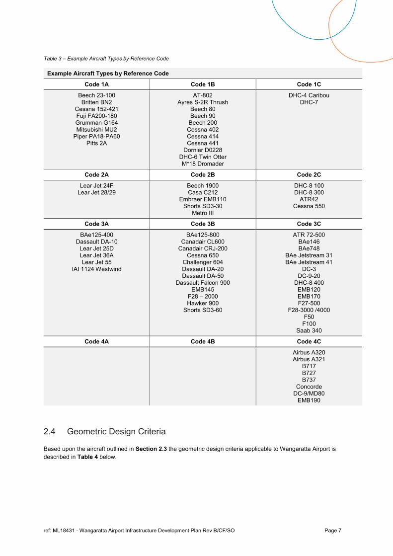
Table 3 – Example Aircraft Types by Reference Code
Example Aircraft Types by Reference Code
Code 1A Code 1B Code 1C
Beech 23-100 Britten BN2
Cessna 152-421 Fuji FA200-180 Grumman G164 Mitsubishi MU2
Piper PA18-PA60 Pitts 2A
AT-802 Ayres S-2R Thrush
Beech 80 Beech 90
Beech 200 Cessna 402 Cessna 414 Cessna 441
Dornier D0228 DHC-6 Twin Otter M*18 Dromader
DHC-4 Caribou DHC-7
Code 2A Code 2B Code 2C
Lear Jet 24F Lear Jet 28/29
Beech 1900 Casa C212
Embraer EMB110 Shorts SD3-30
Metro III
DHC-8 100 DHC-8 300
ATR42 Cessna 550
Code 3A Code 3B Code 3C
BAe125-400 Dassault DA-10
Lear Jet 25D Lear Jet 36A Lear Jet 55
IAI 1124 Westwind
BAe125-800 Canadair CL600
Canadair CRJ-200 Cessna 650
Challenger 604 Dassault DA-20 Dassault DA-50
Dassault Falcon 900 EMB145
F28 – 2000 Hawker 900
Shorts SD3-60
ATR 72-500 BAe146 BAe748
BAe Jetstream 31 BAe Jetstream 41
DC-3 DC-9-20
DHC-8 400 EMB120 EMB170 F27-500
F28-3000 /4000 F50
F100 Saab 340
Code 4A Code 4B Code 4C
Airbus A320 Airbus A321
B717 B727 B737
Concorde DC-9/MD80
EMB190
2.4 Geometric Design Criteria
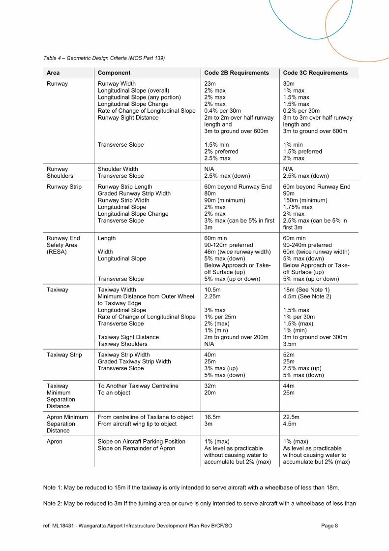
Based upon the aircraft outlined in Section 2.3 the geometric design criteria applicable to Wangaratta Airport is described in Table 4 below.
ref: ML18431 - Wangaratta Airport Infrastructure Development Plan Rev B/CF/SO Page 8
Table 4 – Geometric Design Criteria (MOS Part 139)
Area Component Code 2B Requirements Code 3C Requirements
Runway Runway Width Longitudinal Slope (overall) Longitudinal Slope (any portion) Longitudinal Slope Change Rate of Change of Longitudinal Slope Runway Sight Distance Transverse Slope
23m 2% max 2% max 2% max 0.4% per 30m 2m to 2m over half runway length and 3m to ground over 600m 1.5% min 2% preferred 2.5% max
30m 1% max 1.5% max 1.5% max 0.2% per 30m 3m to 3m over half runway length and 3m to ground over 600m 1% min 1.5% preferred 2% max
Runway Shoulders
Shoulder Width Transverse Slope
N/A 2.5% max (down)
N/A 2.5% max (down)
Runway Strip Runway Strip Length Graded Runway Strip Width Runway Strip Width Longitudinal Slope Longitudinal Slope Change Transverse Slope
60m beyond Runway End 80m 90m (minimum) 2% max 2% max 3% max (can be 5% in first 3m
60m beyond Runway End 90m 150m (minimum) 1.75% max 2% max 2.5% max (can be 5% in first 3m
Runway End Safety Area (RESA)
Length Width Longitudinal Slope Transverse Slope
60m min 90-120m preferred 46m (twice runway width) 5% max (down) Below Approach or Take-off Surface (up) 5% max (up or down)
60m min 90-240m preferred 60m (twice runway width) 5% max (down) Below Approach or Take-off Surface (up) 5% max (up or down)
Taxiway Taxiway Width Minimum Distance from Outer Wheel to Taxiway Edge Longitudinal Slope Rate of Change of Longitudinal Slope Transverse Slope Taxiway Sight Distance Taxiway Shoulders
10.5m 2.25m 3% max 1% per 25m 2% (max) 1% (min) 2m to ground over 200m N/A
18m (See Note 1) 4.5m (See Note 2) 1.5% max 1% per 30m 1.5% (max) 1% (min) 3m to ground over 300m 3.5m
Taxiway Strip Taxiway Strip Width Graded Taxiway Strip Width Transverse Slope
40m 25m 3% max (up) 5% max (down)
52m 25m 2.5% max (up) 5% max (down)
Taxiway Minimum Separation Distance
To Another Taxiway Centreline To an object
32m 20m
44m 26m
Apron Minimum Separation Distance
From centreline of Taxilane to object From aircraft wing tip to object
16.5m 3m
22.5m 4.5m
Apron Slope on Aircraft Parking Position Slope on Remainder of Apron
1% (max) As level as practicable without causing water to accumulate but 2% (max)
1% (max) As level as practicable without causing water to accumulate but 2% (max)
Note 1: May be reduced to 15m if the taxiway is only intended to serve aircraft with a wheelbase of less than 18m.
Note 2: May be reduced to 3m if the turning area or curve is only intended to serve aircraft with a wheelbase of less than
ref: ML18431 - Wangaratta Airport Infrastructure Development Plan Rev B/CF/SO Page 9
18m.
2.5 Pavement Concept Design Criteria pitt&sherry uses a combination of internally developed software and commercially developed software for pavement design. The internally developed programs for flexible and concrete pavements are based on the US Army Corps of Engineers (USACE) procedures as implemented by the Australian Department of Housing and Construction (DHC). For pavements comprising thick asphalt or bound layers, use is made of the Airport Pavement Structural Design System (APSDS) software.
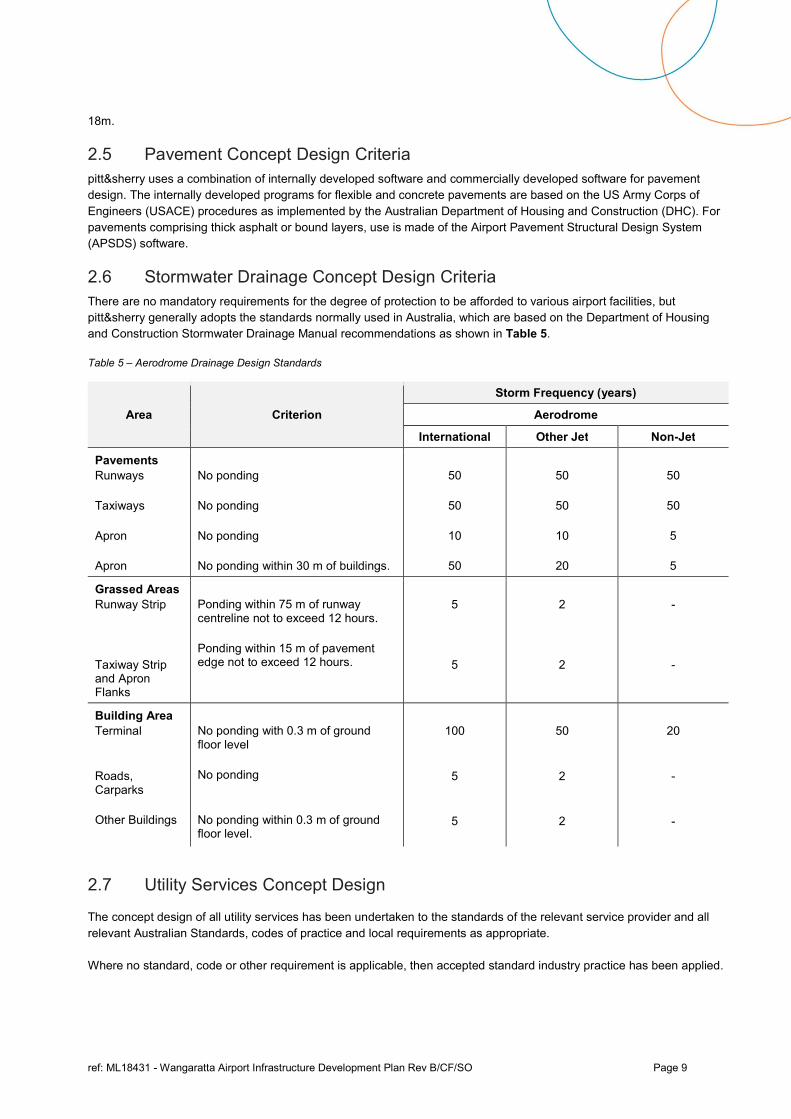
2.6 Stormwater Drainage Concept Design Criteria There are no mandatory requirements for the degree of protection to be afforded to various airport facilities, but pitt&sherry generally adopts the standards normally used in Australia, which are based on the Department of Housing and Construction Stormwater Drainage Manual recommendations as shown in Table 5.
Table 5 – Aerodrome Drainage Design Standards
Area Criterion
Storm Frequency (years)
Aerodrome
International Other Jet Non-Jet
Pavements Runways Taxiways Apron Apron
No ponding No ponding No ponding No ponding within 30 m of buildings.
50
50
10
50
50
50
10
20
50
50
5
5
Grassed Areas Runway Strip Taxiway Strip and Apron Flanks
Ponding within 75 m of runway centreline not to exceed 12 hours. Ponding within 15 m of pavement edge not to exceed 12 hours.
5
5
2
2
- -
Building Area Terminal Roads, Carparks Other Buildings
No ponding with 0.3 m of ground floor level No ponding No ponding within 0.3 m of ground floor level.
100
5
5
50
2
2
20 - -
2.7 Utility Services Concept Design
The concept design of all utility services has been undertaken to the standards of the relevant service provider and all relevant Australian Standards, codes of practice and local requirements as appropriate.
Where no standard, code or other requirement is applicable, then accepted standard industry practice has been applied.
ref: ML18431 - Wangaratta Airport Infrastructure Development Plan Rev B/CF/SO Page 10
3. Infrastructure and Airside Facilities
3.1 Existing Infrastructure and Airside Facilities
3.1.1 Existing Runway 18/36
Runway 18/36 is a 30m wide, 1640m long and classified as Code 3C. It is a non-instrument, non-precision approach runway and has an overall runway strip width of 150m as published in the En-Route Supplement Australia (ERSA).
The runway is sealed for the full 30m width, with a Pavement Classification Number (PCN) 12.
3.1.2 Existing Runway 09/27
Runway 09/27 is a 18m wide, 530m long and classified as Code 1B. It is a non-instrument, non-precision approach runway and has an overall runway strip width of 60m as published in the En-Route Supplement Australia (ERSA).
The runway is a grass runway and therefore has no pavement strength classification.
3.1.3 Existing Taxiways
There are two sealed taxiways that connect Runway 18/36 to the RPT Apron and GA Apron at the north and south ends. These taxiways are 15m wide and could be classified as Code C. The taxiways do not currently have designations.
There is no information available regarding the pavement strength classification of the taxiways.
3.1.4 Existing RPT and GA Apron
The apron typically accommodates GA aircraft operations and occasional emergency services aircraft. The apron area primarily functions as a parking area for aircraft or for movements between hangars and the runways. Aircraft parking in front of some of the existing hangars restricts other aircraft movements on the apron. There is currently no clear delineation or line marking provided on the apron for aircraft movements and operations.
Some areas of the existing apron are poorly graded and hold water, and the surface typically had loose aggregate across the entire area.
There is an area of the apron protected by a fuel resistant membrane in front of the airside refueling facility, however when aircraft are parked for refueling any access from the north side of the refueling facility is blocked by the parked aircraft.
The apron was resurfaced in 2015, no other information is available regarding the pavement strength classification.
3.1.5 Existing Navigational Aids
Runway 18/36 has Pilot Activated Lighting (PAL).
There is a single primary illuminated wind indicator to the west of runway 18/36 and to the south of the apron.
There are no existing Movement Area Guidance Signs (MAGSs) on the airport.
ref: ML18431 - Wangaratta Airport Infrastructure Development Plan Rev B/CF/SO Page 11
3.1.6 Existing Lighting
Runway 18/36 has low intensity runway approach, threshold and end lighting.
The taxiways have low intensity edge lighting.
There are five existing floodlight towers for the apron which are approximately 12m high with a single luminaire on each.
3.1.7 Aircraft Refuelling Facility
The refuelling facility was constructed in 2012 and is owned and operated by Skyfuel, providing Jet A1 fuel and Avgas.
The location of the refuelling facility is central and to the east of the existing hangars and GA Apron.
3.1.8 Existing Utility Services and Landside Infrastructure
There are existing utility services in potable water, telecommunications and electricity servicing the airport.
The potable water supply is installed approximately 680m to the north of the existing Terminal Building via Greta Road. It is understood that water is supplied via a 50mm diameter polypipe which is direct buried.
There is a combination of overhead and underground electrical and underground telecommunications which are installed down the northern side of Brian Higgins Drive. The National Broadband Network (NBN) currently services the airport.
All waste water and sewerage is contained and distributed in a below ground septic system.
The existing services information is based upon limited airport survey data and dial before you dig (DBYD) supplied information.
The airport is serviced by a range of sealed flexible pavement roads and unsealed roads and the main carpark is a sealed flexible pavement.
The airport is serviced by a range of drainage infrastructure including Open Unlined Drains (OUDs), direct buried UPVc and concrete stormwater pipes and concrete stormwater drainage pits of various sizes and dimensions.
The airside areas of the airport are generally enclosed by a standard strand wire fence.
The existing Terminal Building, hangars and Aeroclub are centrally located on the airport.
Redundant Non-Direction Beacon (NDB) infrastructure is still in place, however it is no longer operational.
3.2 Proposed Infrastructure and Airside Facility Development
3.2.1 General
The following sections describe the proposed infrastructure and airside facility development works based on Stages.
For Indicative Budget Cost Estimates for all stages, refer to Section 4.
For all Concept Drawings referenced in this section, refer to Appendix A.
ref: ML18431 - Wangaratta Airport Infrastructure Development Plan Rev B/CF/SO Page 12
3.2.2 Preliminary Horizontal Geometry
Plan geometry for the taxiways and aprons (aircraft parking layouts) and for all fillets and pavement edges have been based on approximate geometry determined by typical tracks from a range of aircraft preliminary centrelines in order to provide the prescribed wingtip and main gear clearances, and turning angles. All aircraft tracking was undertaken using Aviplan Airside Pro software, which is owned and operated by pitt&sherry.
For the proposed taxiways, and both the RPT and GA Apron aircraft parking layouts, all aircraft parking areas and taxiways have been maintained for Code B aircraft as a minimum, with specific areas Code C compliant. The space provided maintains free-moving operations (power-in and power-out) to the central aircraft parking area for Code A to C aircraft.
All hangar areas can be accessed by Code B aircraft with adequate space reserved for both small hobby hangars (15m length x 15m width) or larger commercial hangars (25m length x 35m width), providing the RCoW with the flexibility to develop hangar areas to suit demand.
3.2.1 Preliminary Vertical Geometry
Allowance for potential pavement finished surface levels and the associated pavement earthworks cut, fill, stockpiling and disposal quantities have been based on a visual inspection of the site, historical survey information for the site and hand-held GPS information. No detailed vertical geometric design for pavement finished surface levels has been completed as this was outside the scope of the Wangaratta Airport Infrastructure Development Plan.
3.2.2 Demolition and Site Remediation
Based on a review of the existing site information provided by RCoW there does not appear to be any specific land use (i.e. heritage, environmental etc) or contaminated site, infrastructure or building material issues which would inhibit the demolition and removal of existing materials in order for development to proceed. However, prior to construction commencing it is recommended that a detailed investigation of these issues is completed.
3.2.3 Basis of Concept Pavement Design
For the concept pavement design, pitt&sherry used a combination of internally developed software and commercially developed software. All software used are based on the US Army Corps of Engineers (USACE) procedures as implemented by the Australian Department of Housing and Construction (DHC).
pitt&sherry has primarily made use of the Airport Pavement Structural Design System (APSDS) software and the Federal Aviation Administrations (FAA) COMFAA software to complete the concept pavement designs on this occasion, based on the new pavements being flexible pavements due to the comparative cost of rigid pavement rendering this option infeasible from a budgetary perspective, and not justifiable in the short to medium term considering the anticipated low level of large and heavy aircraft movements.
The design subgrade CBR has been assumed to be 5% based on historical test results (refer to Appendix E)and historical geology information, as it is assumed there may be some variability in the existing subgrade material across the site.
3.2.3.1 Existing Aircraft Traffic
Wangaratta Airport does not maintain statistical records of aircraft activity, however it has been estimated by operator observations during the recent Master Plan (refer to Appendix D) process that approximately 10,000 movements per annum may occur.
It has been observed that the majority of the current aircraft traffic is GA aircraft operations, with emergency services operations making up a small number of the total aircraft movements.
ref: ML18431 - Wangaratta Airport Infrastructure Development Plan Rev B/CF/SO Page 13
The Master Plan projects that approximately 13,500 aircraft movements are anticipated by 2040, again with GA aircraft accounting for the majority of total aircraft movements.
3.2.3.2 Future Aircraft Traffic
For the medium to long term horizon it is considered prudent to safeguard the airside movement areas by ensuring the pavements that are designed and constructed in the short term, accommodate a range of potential future aircraft.
The opportunity to design and construct pavements on airports does not occur frequently, hence when the opportunity does present itself, constructing high quality pavements that provide good load bearing capacity for a range of aircraft, ensures that these pavements outlast their theoretical design life and minimises the risk of future operational disruptions relating to pavement upgrades or rectification of inadequate pavements (i.e. with regard to load bearing capacity or quality) which can result in significant costs.
3.2.3.1 Aircraft Traffic Scenarios for Concept Pavement Design
In the medium to long term horizon there is a possibility that emergency and agricultural activity may increase and small to medium aircraft operators may seek to operate charter operations (i.e. tour operators, freight etc).
For Code A and B pavements, based on a conservative approach, there is potential for up to 4 flights of a crop dusting or fire-fighting aircraft, or up to 50 passengers travelling by air each day. For the purposes of the Wangaratta Airport Infrastructure Development Plan, the following traffic scenario has therefore been adopted for the concept design of the Code A and B pavements.
Traffic Scenario – Concept Code A and B Pavements
SAAB 340: 2 arrivals per day at Maximum Landing Weight (12.9 tonnes)
SAAB 340: 2 departures per day at Maximum Take-off Weight (13.2 tonnes)
Based on the overall aircraft weight and landing gear configuration being most critical, the SAAB 340 has been adopted. Although the SAAB 340 is technically a Code C aircraft, its Aircraft Classification Number (ACN) aligns with the current 17/35 Runway Pavement Classification Number (PCN), so it could be an attractive option to aircraft operators.
As Wangaratta Airport has a Code 3C Runway and Code C connecting taxiways, there is a possibility in the medium to long term horizon that larger aircraft operators may seek to operate either charter operations (i.e. tour operators, freight etc), or seek to use Wangaratta Airport as an alternate to Albury Airport.
For Code C pavements, based on a conservative approach, there is potential for up to 100 passengers travelling by air each day. This demand could be met by 2 flights of a Dash 8–400 aircraft, or 3 flights of a Dash 8–300 aircraft, or 4 flights of a SAAB 340 aircraft. Based on the overall aircraft weight and landing gear configuration being most critical, the Dash 8-400 has been adopted. For the purposes of the Wangaratta Airport Infrastructure Development Plan, the following traffic scenario has therefore been adopted for the concept design of the Code C pavements.
Traffic Scenario – Concept Code C Pavements
Dash 8 – 400: 2 arrivals per day at Maximum Landing Weight (28.0 tonnes)
Dash 8 – 400: 2 departures per day at Maximum Take-Off Weight (29.3 tonnes)
For the 18/36 Runway pavements, based on a conservative approach, there is potential for up to 100 passengers travelling by air each day. This demand could be met by 2 flights of a Dash 8–400 aircraft, or 3 flights of a Dash 8–
ref: ML18431 - Wangaratta Airport Infrastructure Development Plan Rev B/CF/SO Page 14
300 aircraft, or 4 flights of a SAAB 340 aircraft. Based on the overall aircraft weight and landing gear configuration being most critical, the Dash 8-400 has been adopted in combination with the SAAB 340. For the purposes of the Wangaratta Airport Infrastructure Development Plan, the following traffic scenario has therefore been adopted for the concept design of the 18/36 Runway upgrade pavements.
Traffic Scenario – Concept 18/36 Runway Upgrade Pavements
SAAB 340: 2 arrivals per day at Maximum Landing Weight (12.9 tonnes)
SAAB 340: 2 departures per day at Maximum Take-off Weight (13.2 tonnes)
Dash 8 – 400: 2 arrivals per day at Maximum Landing Weight (28.0 tonnes)
Dash 8 – 400: 2 departures per day at Maximum Take-Off Weight (29.3 tonnes)
3.2.4 Code A/B Aircraft Concept Pavement
Based on a 20 year functional design life, the pavement thickness and composition to cater for the aircraft traffic scenario detailed in Section 3.2.3 with aircraft arriving at Maximum Landing Weight and departing at Maximum Take-off Weight has been determined for a design subgrade CBR 5%. The concept pavement composition is as follows:
50mm Asphalt (nominal 14mm size); on Prime Coat; on 100mm Fine Crushed Rock Base Course (VicRoads Class 1); on 150mm Crushed Rock Sub-Base Course (VicRoads Class 2), on Proof Rolled In-Situ Subgrade (CBR 5%).
3.2.5 Code C Aircraft Concept Pavement
Based on a 20 year functional design life, the pavement thickness and composition to cater for the aircraft traffic scenario detailed in Section 3.2.3 with aircraft arriving at Maximum Landing Weight and departing at Maximum Take-off Weight has been determined for a design subgrade CBR 5%. The concept pavement composition is as follows:
50mm Asphalt (nominal 14mm size); on Prime Coat; on 180mm Fine Crushed Rock Base Course (VicRoads Class 1); on 180mm Crushed Rock Sub-Base Course (VicRoads Class 2), on 100mm Cement Treated Crushed Rock (VicRoads Class 2); on Proof Rolled In-Situ Subgrade (CBR 5%).
3.2.6 18/36 Runway Upgrade Concept Pavement
Based on a 20 year functional design life, the pavement thickness and composition to cater for the aircraft traffic scenario detailed in Section 3.2.3 with aircraft arriving at Maximum Landing Weight and departing at Maximum Take-off Weight has been determined for a design subgrade CBR 5%. The concept pavement composition is as follows:
50mm Asphalt (nominal 14mm size); on Prime Coat; on 150mm Fine Crushed Rock Base Course (VicRoads Class 1); on Variable Thickness Proof Rolled In-Situ Pavement Base Course and Sub-Base Course; on In-Situ Subgrade (CBR 5%).
ref: ML18431 - Wangaratta Airport Infrastructure Development Plan Rev B/CF/SO Page 15
3.2.7 Pavement Materials
It has been assumed that the wearing course for any new pavement will be asphalt for indicative budget cost estimate purposes, however an airport specific two coat bituminous spray seal could be applied in the short to medium term considering the likely frequency of use, lower wheel loads and lower tyre pressures, and asphalt in the long term (should aircraft greater than 10,000kg such as the SAAB 340 commence regular operations, the potential aircraft safety risk is minimised with an asphalt wearing course when compared to a two coat bituminous spray seal), and that the base course and sub-base course will consist of good quality fine crushed rock.
3.2.8 Road Concept Pavement
Based on a 20 year functional design life, the pavement thickness and composition to cater for standard vehicle movements in a rural environment has been determined for a design subgrade CBR 5%. The concept pavement composition is as follows:
Two coat bituminous spray seal; on 300mm Fine Crushed Rock Sub-Base Course (VicRoads Class 2); on Proof Rolled In-Situ Subgrade (CBR 5%),
3.2.9 Master Grading Stage 1
Refer to Drawing ML18431-C105 in Appendix A.
The Master Grading Stage 1 Works are recommended to be undertaken in order to determine and prepare the design finished surface levels across the majority of the site, which encompasses the Stages 1 to 4 Works. The majority of the works required in the Master Grading Stage 1 is earthworks (i.e. the removal, stockpiling, replacement, grading and compaction of natural material), as well as the investigation of existing services and protection if required, provision of new services and the provision of a new airside security fence. The following is a summary of the proposed works:
Survey of existing surface levels and features, including existing services investigation;
Protection or relocation of existing services;
New electrical utilities, pits and connections;
New communications utilities, pits and connections;
New water supply and connections;
Realignment of the existing open unlined drain to the west;
Earthworks and grading to design finished surface levels;
Survey of as constructed surface levels and features; and
New airside security (intrusion and wildlife protection) fencing.
3.2.10 Master Grading Stage 2
Refer to Drawing ML18431-C106 in Appendix A.
The Master Grading Stage 2 Works are recommended to be undertaken in order to determine and prepare the design finished surface levels across the remainder of the site, which encompasses the Stage 5 Works. The majority of the works required in the Master Grading Stage 2 is earthworks (i.e. the removal, stockpiling, replacement, grading and compaction of natural material), as well as the investigation of existing services and protection if required, provision of new services. As there is a major stormwater drainage flow path through the Stage 5 Works area, the existing open unlined drain will need to be backfilled and an underground piped/culvert provided to maintain and improve the current stormwater system transfer capacity. The following is a summary of the proposed
ref: ML18431 - Wangaratta Airport Infrastructure Development Plan Rev B/CF/SO Page 16
works:
Survey of existing surface levels and features, including existing services investigation;
Removal of access road pavement (if Stage 2 has been constructed);
Protection or relocation of existing services;
Converting the existing open unlined drain to an underground pipe/culvert with headwalls and connections;
Earthworks and grading to design finished surface levels; and
Survey of as constructed surface levels and features.
3.2.11 Stage 1 Works
Refer to Drawing ML18431-C110 in Appendix A.
3.2.11.1 New Code A/B Aircraft Pavement
The following is a summary of the proposed works:
New pavement to be constructed at the southern end of the existing apron to facilitate a Code B aircraft parking location adjacent the new fuel facility location. This pavement provides connectivity for the Stage 2 and 3 pavement works;
Install Fuel Resistant Membrane (FRM) on the asphalt wearing course of the new fuel facility pavement;
New pavement to the east of the existing hobby hangars and north of the existing apron to provide additional movement area and an apron area for the new large commercial hangar; and
Install new line marking on existing and new pavements.
3.2.11.2 New Large Commercial Hangar
The following is a summary of the proposed works:
New large commercial hangar 25m x 30m to be constructed north of the existing hobby hangars;
New footings and concrete base slab for the new large commercial hangar; and
Install new electrical, communications and water utilities to the new large commercial hangar
3.2.11.3 Fuel Facility Relocation
The following is a summary of the proposed works:
Relocate the existing above ground fuel facility from east of the existing hobby hangars to be south of the apron including all interceptors, drainage, connections, bowsers, eye wash etc.;
Install new electrical, communications and water utilities to the fuel facility; and
Displace the Runway 09/27 threshold to allow ensure the relocated fuel facility does not encroach the Obstacle Limitation Surface (OLS)
3.2.12 Stage 2 Works
Refer to Drawing ML18431-C111 in Appendix A.
ref: ML18431 - Wangaratta Airport Infrastructure Development Plan Rev B/CF/SO Page 17
3.2.12.1 New Access Road
The following is a summary of the proposed works:
New access road pavement to be constructed along the western side of the airport from the existing carpark. The road is located on the eastern side of the existing open unlined drain and services the back of the new hobby hangars and the new Aeroclub carpark;
New pavement to be constructed for the Aeroclub carpark; and
Install new line marking for access road and carpark.
3.2.12.2 New Code A/B Aircraft Pavement
The following is a summary of the proposed works:
New pavement to be constructed to the east and north of the existing Aeroclub location to facilitate Code A and B aircraft movements between the apron, the new commercial hangars and new hobby hangars; and
Install new line marking on existing and new pavements.
3.2.12.3 Relocation of Aeroclub
The following is a summary of the proposed works:
Relocate the existing Aeroclub building towards the northern fence line approximately 600m north of the existing Terminal Building;
Install new electrical, communications and water utilities.
3.2.12.4 New Commercial Hangars
The following is a summary of the proposed works:
New commercial hangars 15m x 20m to be constructed to the north of the existing carpark;
Construct footings and concrete base slab for the new commercial hangars; and
Install new electrical, communications and water utilities.
3.2.12.5 New Hobby Hangars
The following is a summary of the proposed works:
New hobby hangars 15m x 15m to be constructed to the north of the existing hobby hangars;
Construct footings and concrete base slab for the new hobby hangars; and
Install new electrical and communications utilities.
3.2.13 Stage 3 Works
Refer to Drawing ML18431-C112 in Appendix A.
3.2.13.1 New Code A/B Aircraft Pavement
The following is a summary of the proposed works:
ref: ML18431 - Wangaratta Airport Infrastructure Development Plan Rev B/CF/SO Page 18
New pavement to be constructed north and east of the Stage 1 pavement works to facilitate Code A and B aircraft movements between the new Code C taxiway and the new large commercial hangars. This pavement provides dedicated apron areas for both new large commercial hangars as well as connectivity for the Stage 4 pavement works;
Install new line marking on existing and new pavements.
3.2.13.2 New Code C Aircraft Taxiway and Apron Expansion
The following is a summary of the proposed works:
New 800m long Code C taxiway to be constructed along the eastern edge of the existing apron between the southernmost existing taxiway towards the relocated Aeroclub, with a new connection to Runway 18/36. New pavement to be constructed in front of the existing Terminal Building and to the north of the existing apron. This new taxiway and apron pavement will allow for the following:
o Unrestricted Code C aircraft movements;
o Increased aircraft manoeuvrability within the apron areas;
o Code C aircraft parking positions (power in/power out) in front of the Terminal Building; and
o Connectivity to the new large commercial hangars and Stage 4.
Realign the existing open unlined drain and install new headwalls as part of the new Code C taxiways construction; and
Install new line marking on existing and new pavements including two Code C aircraft parking positions.
3.2.13.3 New Large Commercial Hangars
The following is a summary of the proposed works:
New large commercial hangars 25m x 30m to be constructed north of the Stage 1 large commercial hangar;
Construct footing and concrete base slab for the new large commercial hangars; and
Install new electrical, communications and water utilities.
3.2.13.4 Demolition and Removal of Redundant NDB Infrastructure
The following is a summary of the proposed works:
Site investigations as required prior to demolition and removal;
Demolish and remove all underground services (including capping as required);
Demolish and remove all above ground buildings and structures;
Legally dispose of all materials off site; and
Site remediation, including topsoiling and grassing as required.
3.2.14 Stage 4 Works
Refer to Drawing ML18431-C113 in Appendix A.
3.2.14.1 New Code A/B Aircraft Pavement
The following is a summary of the proposed works:
ref: ML18431 - Wangaratta Airport Infrastructure Development Plan Rev B/CF/SO Page 19
New pavement to be constructed to the north of the Stage 2 hobby hangars to facilitate Code A and B aircraft movements between the apron/taxiway and the new hobby hangars; and
Install new line marking on existing and new pavements.
3.2.14.2 New Hobby Hangars
The following is a summary of the proposed works:
New hobby hangars 15m x 15m to be constructed to the north of the Stage 2 hobby hangars;
Construct footings and concrete base slab for the new hobby hangars; and
Install new electrical and communications utilities.
3.2.15 Stage 5 Works
Refer to Drawing ML18431-C114 in Appendix A
3.2.15.1 New Code A/B Aircraft Pavement
The following is a summary of the proposed works:
New pavement to extend the taxilanes constructed as part of the Stage 2 and Stage 4 works. This will allow for Code A and B aircraft movements to the new commercial hangars and new hobby hangars; and
Install new line marking on existing and new pavements.
3.2.15.2 New Commercial Hangars
The following is a summary of the proposed works:
New commercial hangars 15m x 20m to be constructed to the west of the Stage 2 commercial hangars;
Construct footings and concrete base slab for the new commercial hangars; and
Install new electrical, communications and water utilities.
3.2.15.3 New Hobby Hangars
The following is a summary of the proposed works:
New hobby hangars 15m x 15m to be constructed to the west of the Stage 2 and Stage 4 hobby hangars;
Construct footings and concrete base slab for the new hobby hangars; and
Install new electrical and communications utilities.
3.2.15.4 New Hangar Extension
The following is a summary of the proposed works:
New hangar extension to the existing hobby hangars to be constructed to the west, approximately 20m x 65m;
Construct footings and concrete base slab for the new hangar extension; and
Install new electrical and communications utilities.
ref: ML18431 - Wangaratta Airport Infrastructure Development Plan Rev B/CF/SO Page 20
3.2.15.5 New Access Road
The following is a summary of the proposed works:
New access road pavement to be constructed from the end of Brian Higgins Drive to back of the new hobby hangars and provides connectivity to the Aeroclub carpark; and
Install new line marking for access road and carpark.
3.2.16 Existing Pavement Upgrades (Stage 6 Works)
Refer to Drawing ML18431-C115 in Appendix A
The existing pavement upgrade works are provided as a guide only. pitt&sherry recommends that further detailed investigation (i.e. geotechnical investigations, existing pavement strength investigations, feature and level survey etc) be undertaken prior to detailed design, should the RCoW wish to progress these elements of the development plan.
3.2.16.1 Runway 18/36 Pavement Strengthening Overlay/Reconstruction
The following is a summary of the proposed works:
Feature and level survey of the runway, taxiways and adjacent flank areas;
Texture, clean and proof roll the existing runway pavement;
Construction of nominal 200mm of new pavement (overlay) to improve the overall strength of the runway (Note: An unbound granular, nominal thickness pavement overlay has been assumed for the purposes of the Wangaratta Airport Infrastructure Development Plan, however based on the outcomes of the future detailed investigations and airport operational restrictions, pavement reconstruction or in-situ stabilisation may be more appropriate);
Grooving of the new runway asphalt wearing course;
Remove and replace existing runway lighting (to be installed at new finished surface levels);
Reinstatement of all runway line marking;
Excavation and construction of a new open unlined drain.
3.2.16.2 Taxiway Pavement Strengthening Overlay/Reconstruction
The following is a summary of the proposed works:
Demolition of the existing taxiway pavement to subgrade level;
Construct new Code C pavement;
Remove and replace existing taxiway lighting (to be installed at new finished surface levels); and
Reinstate all taxiway line marking.
3.2.16.3 Apron Pavement Strengthening Overlay/Reconstruction
The following is a summary of the proposed works:
Demolition of the existing apron pavement to subgrade level;
Construct new Code C pavement; and
Reinstate all apron line markings.
ref: ML18431 - Wangaratta Airport Infrastructure Development Plan Rev B/CF/SO Page 21
3.2.17 Utility Services Design
Refer to Drawing ML18431-C115 in Appendix A.
3.2.17.1 New Utility Services
The following is a summary of the proposed works:
Install new electrical conduits, cables and pits from the existing main line on Brian Higgins Drive;
Install new communications conduits, cables and pits from the existing main line on Brian Higgins Drive; and
Install new water pipes, valves and pits from the existing main line from the north.
3.2.17.2 Upgrade of Existing Utility Services
The following is a summary of the proposed works:
A provisional allowance has been included for the upgrade of approximately 1500m of existing water pipe which supplies Wangaratta Airport from Greta Road. It is understood that the existing water main is only a 50mm diameter supply.
3.2.18 Terminal Building Upgrade Works (Provisional)
Refer to the Drawings in Appendix C.
The following is a summary of the proposed works:
Refurbishment of the existing Terminal Building only by removing internal furnishings and fixings, installing new partition walls and doors and installing new internal furnishings and fixings as well as upgrading all utility connects as required.
3.2.19 Concept Development
Refer to the Drawings in Appendix C for a record of how the Concept Drawings developed during the course of the Wangaratta Airport Infrastructure Development Plan.
ref: ML18431 - Wangaratta Airport Infrastructure Development Plan Rev B/CF/SO Page 22
4. Indicative Budget Cost Estimates
4.1 Basis of Costing
Indicative Budget Cost Estimates should be only considered a first cost indication (at current prices at the date stated) and are provided based on an outline estimate of the RCoW needs; prepared by reference to concept sketches or assessed without sketches (in some instances) based on pitt&sherry’s knowledge of costs for similar projects. Often, Indicative Budget Cost Estimates will be prepared without the benefit of detailed design and without detailed consideration of survey, geometry, drainage, existing services or other local information.
An Indicative Budget Cost Estimate is intended only as a guide for a pre-feasibility and planning purposes, it is not an estimate and may not be quoted as such. Indicative Budget Cost Estimates are prepared using broad cost parameters (e.g. earthworks and pavements on a cost per square metre basis). Since pitt&sherry has no control over the cost of labour, materials, equipment or services furnished by others, or over Contractor’s methods of determining prices, or over competitive bidding or market conditions, Indicative Budget Cost Estimates are provided based only on our experience and represents pitt&sherry’s judgement as experienced and qualified professional engineers. pitt&sherry cannot and does not, however, guarantee that proposals, bids or actual construction costs will not vary from the Indicative Budget Cost Estimates stated.
4.2 Indicative Budget Cost Estimates Summary
The Indicative Budget Cost Estimates are based on a traditional procurement process as described in Section 5.
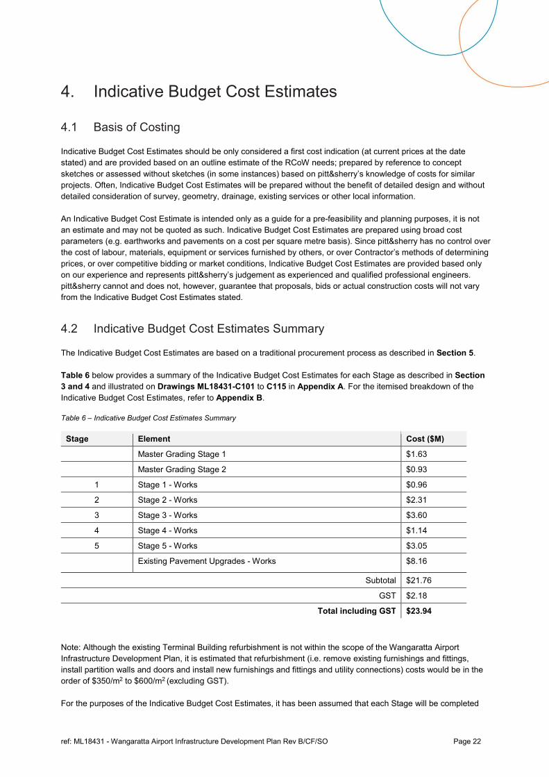
Table 6 below provides a summary of the Indicative Budget Cost Estimates for each Stage as described in Section 3 and 4 and illustrated on Drawings ML18431-C101 to C115 in Appendix A. For the itemised breakdown of the Indicative Budget Cost Estimates, refer to Appendix B.
Table 6 – Indicative Budget Cost Estimates Summary
Stage Element Cost ($M)
Master Grading Stage 1 $1.63
Master Grading Stage 2 $0.93
1 Stage 1 - Works $0.96
2 Stage 2 - Works $2.31
3 Stage 3 - Works $3.60
4 Stage 4 - Works $1.14
5 Stage 5 - Works $3.05
Existing Pavement Upgrades - Works $8.16
Subtotal $21.76
GST $2.18
Total including GST $23.94
Note: Although the existing Terminal Building refurbishment is not within the scope of the Wangaratta Airport Infrastructure Development Plan, it is estimated that refurbishment (i.e. remove existing furnishings and fittings, install partition walls and doors and install new furnishings and fittings and utility connections) costs would be in the order of $350/m2 to $600/m2 (excluding GST).
For the purposes of the Indicative Budget Cost Estimates, it has been assumed that each Stage will be completed
ref: ML18431 - Wangaratta Airport Infrastructure Development Plan Rev B/CF/SO Page 23
independently of all other Stages (i.e. all Stages are mutually exclusive which means that the Contractor tenders, establishes and disestablishes from site for each Stage).
The Indicative Budget Costs Estimates in Table 6 are based on capital construction costs and include an estimation of:
Preliminaries such as mobilisation of materials and equipment to site, Contractor site administration, Contractor QA and environmental management, maintenance of site access roads, surveying and supply of As-Built Drawings;
Airside pavement upgrades including excavation, earthworks and subgrade preparation with an allowance for cartage, compaction and proof rolling;
Runway, taxiway and apron pavement construction (based on locally sourced materials (i.e. within a 50km radius of the airport including bituminous spray seal, prime, base and sub-base course material);
Stormwater drainage (no allowance for sub-surface drainage);
Line marking;
Provisional items estimate such as subgrade replacement and topsoiling of disturbed areas;
New infrastructure and utility services (including building refurbishment, roads, electrical, communications, sewerage, water and fuel facilities); and
Airport boundary fencing
The Indicative Budget Cost Estimates in Table 6 specifically exclude an estimation of:
Preliminaries such as Contractor site establishment and disestablishment of plant (assumed to be locally based asphalt plant (unless otherwise stated) and will use their own Depot for equipment and materials storage)
Costs associated with excavation and earthworks to achieve compliant design longitudinal and transverse gradients (vertical geometry) for the proposed taxiways and apron areas to achieve Code 3C and Code 2B standards where applicable (assumed cut and fill will balance for taxiway and apron areas);
Costs associated with delays as a result of weather during construction;
Costs associated with upgrades to existing infrastructure and services (including buildings, roads, electrical, communications, sewerage, water, gas and fuel facilities);
Cost associated with upgrading the runway and taxiway lighting system;
Cost associated with upgrading the apron floodlighting;
Cost associated with the provision of a Visual Approach Slope Indicator System (PAPI);
Costs associated with future pavement, drainage, lighting or infrastructure expansion except where specifically stated;
Costs associated with a new Airport Lighting Equipment Room (ALER) or Powerhouse;
Costs associated with any airport security control;
Costs associated with any restrictions to airport operations during construction;
Costs associated with any aircraft operational matters including:
o Airspace;
o Take-off and approach tracks;
o GPS approaches;
o PANS-OPS surfaces;
o Noise and noise abatement procedures;
ref: ML18431 - Wangaratta Airport Infrastructure Development Plan Rev B/CF/SO Page 24
o Navigational aids (including signage, lighting and PAPI)
o Obstacle Limitation Surfaces (including vegetation removal and earthworks associated with OLS outside the existing airport boundary);
Costs associated with the potential development or redevelopment of airside areas into the future; and
Costs associated with any additional statutory, regulatory, planning, CASA or environmental requirements associated with the concept layout options.
4.3 Accuracy of Indicative Budget Cost Estimates
The accuracy of the Indicative Budget Cost Estimates is considered to be up to 30% too high to 30% too low.
The accuracy has been determined based upon the limitations identified in Section 4.1.
4.4 Potential Works Cost Savings
Once the RCoW progress to the detailed design phase and tender phase for the proposed development works, there is potential for overall project cost savings related to the following:
Detailed site investigations undertaken with the information gathered and used as the basis for the detailed design (potentially reducing earthworks, extent of services upgrade, reducing pavement thicknesses etc)
The assumed subgrade strength (potentially reducing the pavement thickness);
The assumed existing pavement strength and existing material quality (potentially reducing the pavement thickness);
Reuse of existing pavement materials (potentially reducing the need for imported pavement materials)
The assumed aircraft traffic is refined (potentially reducing the pavement thickness);
RCoW may negotiate the purchase of construction materials at rates cheaper than market rates;
RCoW may complete earthworks and other construction elements at rates cheaper than market rates; and
Construction of elements may be refined within each Stage, with the construction of non-critical elements delayed (this approach is dependent on anticipated short and long-term use, type of short and long-term aircraft, potential for future growth etc).
ref: ML18431 - Wangaratta Airport Infrastructure Development Plan Rev B/CF/SO Page 25
5. Procurement Model Analysis
5.1 Pre-Tender and Construction Activities
It is envisaged that there will be a need for some pre-tender and construction activities to take place prior to the commencement of the construction, following completion of the detailed design of the development works. Some of the necessary pre-commencement activities may include:
State Government approvals;
Local Government approvals; and
Utility Service Authority approvals.
Further investigation into the necessary pre-tender and construction activities is required.
5.2 Procurement Models
There are a number of common procurement options that may be applicable to the procurement of development works at Wangaratta Airport. The following provides a summary of the primary options, taking into account factors such as risk profiles, value for money and time constraints, and outlines the advantages and disadvantages in respect to the procurement models applicable to the development of Wangaratta Airport based on pitt&sherry’s experience with similar works in Australia.
The following procurement models are generally used to deliver airport projects worldwide:
Traditional/Conventional Lump Sum (LS);
Design and Construct (D&C) and Design, Construct, Maintain (DCM);
Engineering, Procurement and Construction Management (EPCM);
Construction Management (CM);
Managing Contractor (MC);
Design, Novate and Construct (DN&C); and
Early Contractor Involvement (ECI).
5.2.1 Assessment Criteria
In order to determine which of the procurement models is most appropriate for the RCoW and the development of Wangaratta Airport, it is necessary to consider the following criteria:
Time: The speed, or timeframe in which, each Stage of the project and the whole of the project is required to be completed.
Cost: Cost to RCoW, including the whole of life costs, considering the delivery time, quality of deliverables and allocation of risk.
Certainty: Certainty of project costs, cash flows and timing of each Stage over the whole of the project.
Quality of design and construction: The quality of deliverables produced in each Stage of the project, including the constructability and maintainability of the design, end user and stakeholder requirements.
Flexibility: The degree and necessity of flexibility in accommodating design changes during the project.
ref: ML18431 - Wangaratta Airport Infrastructure Development Plan Rev B/CF/SO Page 26
Complexity: The complexity of the project deliverables, the site or other RCoW requirements, including interface with existing systems and continuing airport operations.
Control: The level of control RCoW wants over the process and the project deliverables.
Risk allocation and responsibility: Appropriate risk allocation and the level of risk the RCoW will allow exposure to such as time and cost, but also including contract risks such as latent conditions.
Competition: Whether each tender or engagement is subject to competitive bidding.
Funding availability: The availability of funding to the RCoW to complete the project will impact upon certainty.
Local Labour Market: Consideration of the availability of Suppliers, Contractors, Consultants, Financiers and other relevant parties necessary to complete the project.
Commercial Terms: Within each of the above, a variety of commercial terms can be incorporated to suit the circumstances of the project.
5.2.2 Procurement Model Assessment
The following sections outline the key features of both Traditional/Lump Sum (LS) and Design and Construct (D&C) models, which in pitt&sherry’s experience are the most appropriate for airside development projects for achieving, on balance, good project outcomes with regard to risk, time, cost and quality.
5.2.2.1 Traditional/Conventional Lump Sum (LS)
Key Features
This form of procurement involves the Client in separate design and construction contracts.
Generally, the Client will prepare a Project Requirements Brief which is issued to a Design Consultant. The Design Consultant will provide a tender which the Client accepts, and then the Design Consultant undertakes the whole of the design including preparation of the construction documents.
Once design is complete to 100%, the Client will initiate a tender process to select a suitable construction Contractor. The tender process may begin before 100% completion of the design documentation if the level of detail in the documents is sufficient to go to tender, however this will increase the exposure of the Client to risks of variations. Expressions of interest may also be sought prior to tender to garner the interest of potential Contractors.
Applicability
The LS contract is appropriate:
When time is not a project constraint;
To reduce risk in construction pricing and time;
When the client requires full control over design; and
When the client wishes to manage the design/construction interface.
Advantages and Disadvantages
Time
This process can be quite time consuming. The method would be applicable when time is not a project constraint.
Costs and Value for Money
The main costs include
ref: ML18431 - Wangaratta Airport Infrastructure Development Plan Rev B/CF/SO Page 27
Design and construction costs;
Internal costs for managing the whole of the design, documentation and tender phase; and
Risk of cost variations from errors in design.
A competitive price results from the competitive tendering process because complete design lessens construction risk and encourages interest from Contractors. There may also be less likelihood of the Contractor pricing uncertainty into tender price.
Certainty
The cost and timeframes for construction will not be known until relatively late in the project, until construction tenders have been received.
Quality of Design and Construction
There is no incentive for value adding input from Contractors during the design stage. It is therefore important that the Client has the skills, knowledge and expertise to manage the design stage and with sufficient experience in constructability; and
Construction quality should not be compromised as the Contractor should build what is outlined in the construction documentation.
Flexibility and Control
The Client has complete control over the design stage of the project, but may not have an appreciation of how design changes will affect the construction process and programme. Changes to the design during construction will result in variations.
Complexity
Not well suited to complex projects unless the Client has the expertise to manage.
Risk Allocation
The Client and Design Consultant takes on all the design and documentation risks; and
Construction contractual risks as per agreement.
Competition
All construction costs will be competitively tendered.
5.2.2.2 Design and Construct (D&C) and Design, Construct, Maintain (DCM)
Key Features
The D&C form of procurement involves only one main Contractor who completes both the design and construction for the project for a set price and within a set timeframe. The DCM form of procurement is an extension of this and requires the Contractor to also maintain the constructed asset for a set period of between 10 and 25 years.
The concept behind the DCM method is that if the same team that is designing the project is also responsible for construction, then the designers and builders will work together to make sure they maximise their profits by ensuring the design will be the most practical, constructible and cost-efficient. With the same team also responsible for operation and maintenance of the completed project, the companies responsible will work together so that design and construction will result in more efficient and lower cost operation and maintenance.
The Client develops a comprehensive Project Requirements Brief which may include a concept design on which the project is competitively tendered.
The tender process is undertaken very early before detailed design is carried out. It can also be presented as a ‘design competition’ encouraging innovation by designers and builders.
ref: ML18431 - Wangaratta Airport Infrastructure Development Plan Rev B/CF/SO Page 28
Applicability
The D&C contract is appropriate when:
The project is simple and straight forward;
The Client wishes to allocate all the construction risks of the project to an external party;
The Client is looking for an innovative solution to the project;
The Clients end requirement and other relevant factors can be properly identified by the time it would be necessary to enter into a contract;
The Client wishes to avoid the interface between design and construct;
The Client has insufficient industry experience or project management capabilities;
The Client needs to minimise procurement time; and
DCM - The client wishes to allocate the responsibility and risk of initial asset maintenance to an external party.
Advantages and Disadvantages
Time
It is in the Contractor’s interest to complete the work as per the delivery schedule set by the Client or they may expose themselves to liquidated damages. The tender process may be quite drawn out but having the design and construction phases in one tender saves on separate procurement.
Costs and Value for Money
The internal costs may be less than for other forms of contracts as less Client involvement is required.
Unless the project is simple and straight forward, it may be difficult for Contractors to price on the limited information available during the tender phase therefore they will price for risk.
The cost of bidding for D&C projects is high, and Contractors will recover this in their price.
Certainty
The Client is aware of the final cost, cash flow and timing of the project from the commencement of the project.
Quality of Design and Construction
Control of design quality can be difficult and even apparent compliance with the brief could result in a need to vary the contract or have a dispute over interpretation;
However, the project may gain from the innovation in design of the Contractor;
Construction quality may be an issue as the Contractor tries to reduce expenditure; and
DCM - Quality is further ensured as the contractor must maintain the asset for a period once completed and it is in its interest to reduce these costs through good design and construction practices.
Flexibility and Control
The Client can outline their requirements in the contract brief and specifications, however following that, the Contractor has full control;
There is little scope for change of design once the contract has commenced without substantial cost to the Client; and
In contracting out the design and construction, the Client abrogates all control of the project. It is expected that the Client’s requirements are sufficiently outlined in the initial brief. As noted, changes will not be without considerable expense.
Complexity
ref: ML18431 - Wangaratta Airport Infrastructure Development Plan Rev B/CF/SO Page 29
May be suited to complex projects if the Client has the expertise to manage their requirements within the contract.
Risk Allocation
One of the advantages of this method of contracting is that all the cost and time risks in design and construction risks are allocated to the Contractor. However, there is a significant risk of exposure to cost and time variations if the Client’s requirements are not comprehensively and unambiguously set out.
With a DCM contract the risk of asset maintenance costs for the set maintenance period are allocated to the Contractor.
Competition
The cost for a Contractor to tender for a D&C contract is high and this may limit the number of bidders for the project.
5.3 Procurement Model Recommendation
Recent projects undertaken by pitt&sherry have confirmed that airport projects delivered under a Design and Construct (D&C) model offer no significant advantages in terms of time, quality or cost over Conventional/Lump Sum (LS) project delivery methods based on the preparation of tender documents and conventional tender procurement through public advertisements or through a selected tendering process.
Moreover, the design can be completed and approved in advance of calling tenders, and so all tenders are on a common basis. It has also been our experience that it takes almost as long to prepare briefings for the D&C tenders as it does to prepare the preliminary design and documentation for projects of this nature in complexity.
It is therefore recommended that project delivery in this instance, is by a conventional design and tendering process.
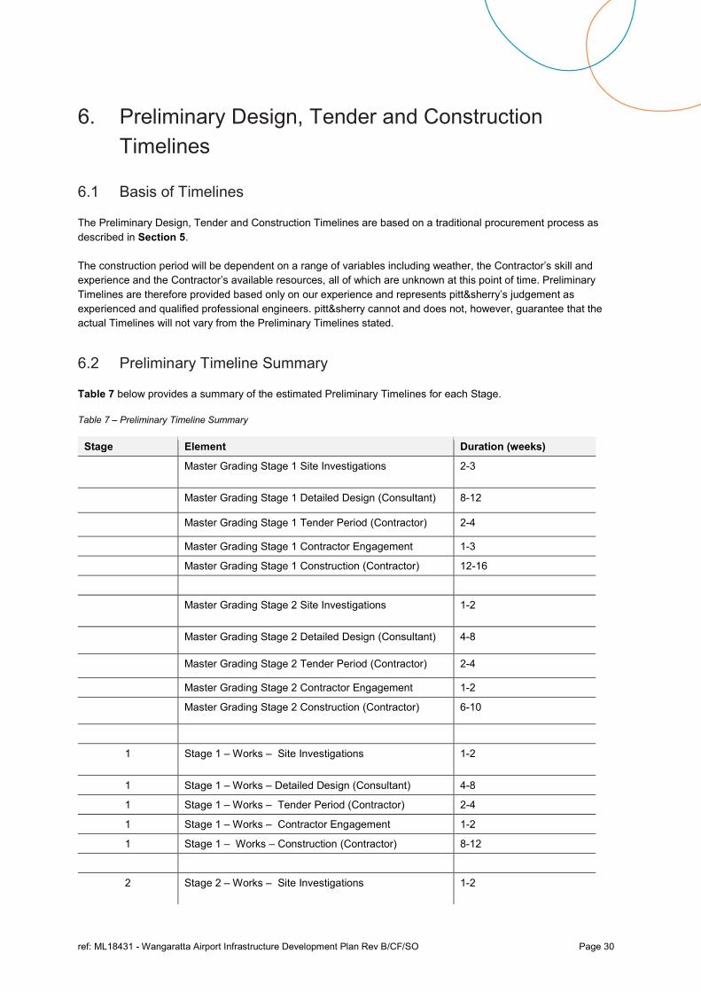
ref: ML18431 - Wangaratta Airport Infrastructure Development Plan Rev B/CF/SO Page 30
6. Preliminary Design, Tender and Construction Timelines
6.1 Basis of Timelines
The Preliminary Design, Tender and Construction Timelines are based on a traditional procurement process as described in Section 5.
The construction period will be dependent on a range of variables including weather, the Contractor’s skill and experience and the Contractor’s available resources, all of which are unknown at this point of time. Preliminary Timelines are therefore provided based only on our experience and represents pitt&sherry’s judgement as experienced and qualified professional engineers. pitt&sherry cannot and does not, however, guarantee that the actual Timelines will not vary from the Preliminary Timelines stated.
6.2 Preliminary Timeline Summary
Table 7 below provides a summary of the estimated Preliminary Timelines for each Stage.
Table 7 – Preliminary Timeline Summary
Stage Element Duration (weeks)
Master Grading Stage 1 Site Investigations
2-3
Master Grading Stage 1 Detailed Design (Consultant) 8-12
Master Grading Stage 1 Tender Period (Contractor) 2-4
Master Grading Stage 1 Contractor Engagement 1-3
Master Grading Stage 1 Construction (Contractor) 12-16
Master Grading Stage 2 Site Investigations
1-2
Master Grading Stage 2 Detailed Design (Consultant) 4-8
Master Grading Stage 2 Tender Period (Contractor) 2-4
Master Grading Stage 2 Contractor Engagement 1-2
Master Grading Stage 2 Construction (Contractor) 6-10
1 Stage 1 – Works – Site Investigations
1-2
1 Stage 1 – Works – Detailed Design (Consultant) 4-8
1 Stage 1 – Works – Tender Period (Contractor) 2-4
1 Stage 1 – Works – Contractor Engagement 1-2
1 Stage 1 – Works – Construction (Contractor) 8-12
2 Stage 2 – Works – Site Investigations
1-2
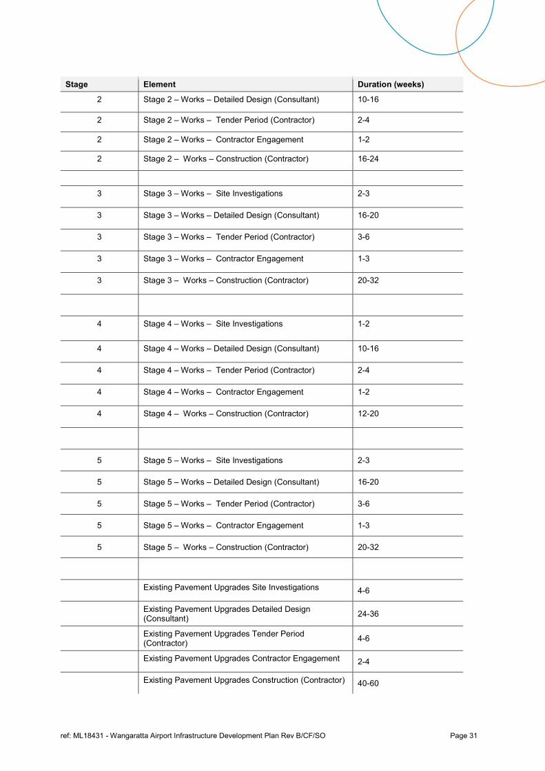
ref: ML18431 - Wangaratta Airport Infrastructure Development Plan Rev B/CF/SO Page 31
Stage Element Duration (weeks)
2 Stage 2 – Works – Detailed Design (Consultant) 10-16
2 Stage 2 – Works – Tender Period (Contractor) 2-4
2 Stage 2 – Works – Contractor Engagement 1-2
2 Stage 2 – Works – Construction (Contractor) 16-24
3 Stage 3 – Works – Site Investigations 2-3
3 Stage 3 – Works – Detailed Design (Consultant) 16-20
3 Stage 3 – Works – Tender Period (Contractor) 3-6
3 Stage 3 – Works – Contractor Engagement 1-3
3 Stage 3 – Works – Construction (Contractor) 20-32
4 Stage 4 – Works – Site Investigations
1-2
4 Stage 4 – Works – Detailed Design (Consultant) 10-16
4 Stage 4 – Works – Tender Period (Contractor) 2-4
4 Stage 4 – Works – Contractor Engagement 1-2
4 Stage 4 – Works – Construction (Contractor) 12-20
5 Stage 5 – Works – Site Investigations 2-3
5 Stage 5 – Works – Detailed Design (Consultant) 16-20
5 Stage 5 – Works – Tender Period (Contractor) 3-6
5 Stage 5 – Works – Contractor Engagement 1-3
5 Stage 5 – Works – Construction (Contractor) 20-32
Existing Pavement Upgrades Site Investigations 4-6
Existing Pavement Upgrades Detailed Design (Consultant)
24-36
Existing Pavement Upgrades Tender Period (Contractor)
4-6
Existing Pavement Upgrades Contractor Engagement 2-4
Existing Pavement Upgrades Construction (Contractor) 40-60
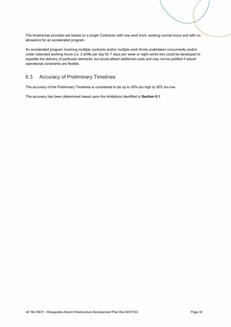
ref: ML18431 - Wangaratta Airport Infrastructure Development Plan Rev B/CF/SO Page 32
The timeframes provided are based on a single Contractor with one work front, working normal hours and with no allowance for an accelerated program.
An accelerated program involving multiple contracts and/or multiple work fronts undertaken concurrently and/or under extended working hours (i.e. 2 shifts per day for 7 days per week or night works etc) could be developed to expedite the delivery of particular elements, but would attract additional costs and may not be justified if airport operational constraints are flexible.
6.3 Accuracy of Preliminary Timelines
The accuracy of the Preliminary Timelines is considered to be up to 30% too high to 30% too low.
The accuracy has been determined based upon the limitations identified in Section 6.1.

ref: ML18431 - Wangaratta Airport Infrastructure Development Plan Rev B/CF/SO
Concept Drawings
Appendix A
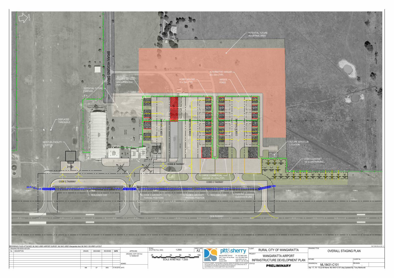
DDD
DA
M
GR
AS
S
BIT
UM
EN
BIT
UM
EN
BIT
UM
EN
CA
RP
AR
K
BIT
UM
EN
ME
TA
L
HA
NG
ER
ME
TA
L
HA
NG
ER
ME
TA
L
HA
NG
ER
BR
IC
K
AIR
PO
RT
LO
UN
GE
OF
FIC
E
CO
NT
AIN
ER
ME
TA
L
HA
NG
ER
FU
EL
TA
NK
FU
EL
BO
WS
ER
S
PO
ST
&
W
IR
E
PO
ST
&
W
IR
E
POST & WIRE
STEEL RAIL
PO
ST
&
W
IR
E
LOW PINE RAIL
LO
W P
IN
E R
AIL
GR
AS
S
GR
AS
S
GR
AS
S
G
RA
SS
GRAVEL
GA
RD
EN
BIT
UM
EN
GRAVEL
CONCRETE
GRAVEL
GRAVEL
G
R
A
V
E
L
SH
ED
SH
ED
WE
AT
HE
RB
OA
RD
AE
RO
C
LU
B
LO
UN
GE
GA
S
BO
TT
LE
S
1200x600
1200x500
1200x500
1800x1100
1800x1100
1800x1100
Ø1
50
Ø3
00
Ø1
00
Ø300
Ø300
Ø150
Ø1
50
Ø3
00
Ø
3
7
5
PO
ST
&
W
IR
E
W W W W W W W W W W W W W W W
WW
BR
IA
N H
IG
GIN
S D
RIV
E
CA
RA
VA
N P
AR
K
WW
WW
WW
WW
WW
W
WWWWWWWWWWW
WW
W
WWWWWWW
W
W W W
W
WWWWWW
WW
W
B100B100 B100 B100 B100 B100 B100B100 B100 B100
M
E
T
R
O
III
M
E
T
R
O
I
II
Q
4
0
0
Q
4
0
0
Q
4
0
0
Q
4
0
0
B100B100
B100B100
B100B100
B100
B100
www.pittsh.com.au
ABN 67 140 184 309
MELBOURNE OFFICE
HWT Tower 40 City Road
Southbank
Victoria 3006
Ph. (03) 9682 5290
Fax. (03) 9682 5292
DRAWING No.
DRAWING TITLE
STATUS
SCALEDRAWING REVISION HISTORY CLIENTA3
PROJECT
SHEET SIZE(PLOTTED FULL SIZE)
© 2016 PITT & SHERRY THIS DOCUMENT IS AND SHALL REMAIN THE PROPERTY OF PITT & SHERRY.THE DOCUMENT MAY ONLY BE USED FOR THE PURPOSE FOR WHICH IT WAS COMMISSIONED AND INACCORDANCE WITH THE TERMS OF ENGAGEMENT FOR THE COMMISSION.UNAUTHORISED USE OF THIS DOCUMENT IN ANY FORM IS PROHIBITED.
REFERENCE FILES ATTACHED: ML18431-XREF-AIRPORT-SURVEY; ML18431-XREF-Wangaratta Arial; ML18431-100-XREF-LAYOUT
DESCRIPTIONNo. DATE APPROVED
SIGNED
DATE
DATUMS: CLIENT No.
ORIGINAL COPY ON FILE"e" SIGNED BY
P&S FORM DRG-A3 REV - 8
REVISION
REVIEWED DATEDRAWN DESIGNED
Apr. 17, 19 - 15:22:49 Name: ML18431-C101.dwg Updated By: Tony Markovski
RURAL CITY OF WANGARATTA
WANGARATTA AIRPORTINFRASTRUCTURE DEVELOPMENT PLAN
OVERALL STAGING PLAN
ML18431-C101 -PRELIMINARY
1:2500
MN CF SRO 01.04.2019
0 10050
SCALE IN METRES - 1:2500
7525 25
NORTH
POTENTIAL FUTUREINDUSTRIAL AREA
FUTURE AEROCLUBLOCATION
CODE A AIRCRAFTTIE DOWN PARKING
REALIGNED OUD
COMMERCIALHANGAR 20 x 20m(TYP)
HOBBY HANGAR15 x 15m (TYP)
NEW FUEL FACILITYLOCATION
CODE C TAXIWAY
CODE
B T
AXILA
NE
CODE
B T
AXILA
NE
CODE
B T
AXILA
NE
CODE C TAXIWAY
CODE B TAXIWAY
CODE C AIRCRAFTPARKING POSITION
CODE C AIRCRAFTPARKING POSITIONS
REALIGNED OUD
AIRSIDEFENCE
18/36 RUNWAY
LARGE COMMERCIALHANGAR 25 x 30m (TYP)
PARKINGCLEARANCE LINE
POTENTIAL FUTURECARPARK
DISPLACEDTHRESHOLD
ALTERNATIVE HANGAR25 x 35m (TYP)
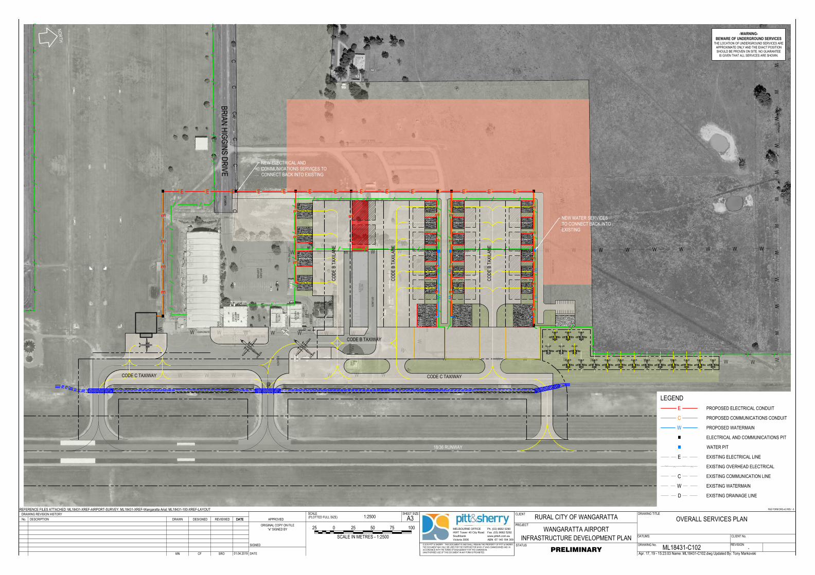
DDD
DA
M
GR
AS
S
BIT
UM
EN
BIT
UM
EN
BIT
UM
EN
CA
RP
AR
K
BIT
UM
EN
ME
TA
L
HA
NG
ER
ME
TA
L
HA
NG
ER
ME
TA
L
HA
NG
ER
BR
IC
K
AIR
PO
RT
LO
UN
GE
OF
FIC
E
CO
NT
AIN
ER
ME
TA
L
HA
NG
ER
FU
EL
TA
NK
FU
EL
BO
WS
ER
S
PO
ST
&
W
IR
E
PO
ST
&
W
IR
E
POST & WIRE
STEEL RAIL
PO
ST
&
W
IR
E
LOW PINE RAIL
LO
W P
IN
E R
AIL
GR
AS
S
GR
AS
S
GR
AS
S
G
RA
SS
GRAVEL
GA
RD
EN
BIT
UM
EN
GRAVEL
CONCRETE
GRAVEL
GRAVEL
G
R
A
V
E
L
SH
ED
SH
ED
WE
AT
HE
RB
OA
RD
AE
RO
C
LU
B
LO
UN
GE
GA
S
BO
TT
LE
S
1200x600
1200x500
1200x500
1800x1100
1800x1100
1800x1100
Ø1
50
Ø3
00
Ø1
00
Ø300
Ø300
Ø150
Ø1
50
Ø3
00
Ø
3
7
5
PO
ST
&
W
IR
E
W W W W W W W W W W W W W W W W W WW
W
BR
IA
N H
IG
GIN
S D
RIV
E
CA
RA
VA
N P
AR
K
WW
WW
WW
WW
WW
WW
W
WWWWWWWWWWWW
WW
WW
W
WWWWWWW
W
W W W W
W
WWWWWWWW
WW
W
WW
B100B100 B100 B100 B100 B100 B100B100 B100 B100
M
E
T
R
O
III
M
E
T
R
O
I
II
Q
4
0
0
Q
4
0
0
Q
4
0
0
Q
4
0
0
B100B100
B100B100
B100B100
B100
B100
CC
CC
C
CC
CC
C C C C C C C C C C C C C C
CC
CC
C
CC
CE
EE
CC
CC
EE
EECE
CC
CC
EE
EE
WW
WW
WW
C
EE
EE
E E E E E E E E E E E E E E
EE
EE
E
www.pittsh.com.au
ABN 67 140 184 309
MELBOURNE OFFICE
HWT Tower 40 City Road
Southbank
Victoria 3006
Ph. (03) 9682 5290
Fax. (03) 9682 5292
DRAWING No.
DRAWING TITLE
STATUS
SCALEDRAWING REVISION HISTORY CLIENTA3
PROJECT
SHEET SIZE(PLOTTED FULL SIZE)
© 2016 PITT & SHERRY THIS DOCUMENT IS AND SHALL REMAIN THE PROPERTY OF PITT & SHERRY.THE DOCUMENT MAY ONLY BE USED FOR THE PURPOSE FOR WHICH IT WAS COMMISSIONED AND INACCORDANCE WITH THE TERMS OF ENGAGEMENT FOR THE COMMISSION.UNAUTHORISED USE OF THIS DOCUMENT IN ANY FORM IS PROHIBITED.
REFERENCE FILES ATTACHED: ML18431-XREF-AIRPORT-SURVEY; ML18431-XREF-Wangaratta Arial; ML18431-100-XREF-LAYOUT
DESCRIPTIONNo. DATE APPROVED
SIGNED
DATE
DATUMS: CLIENT No.
ORIGINAL COPY ON FILE"e" SIGNED BY
P&S FORM DRG-A3 REV - 8
REVISION
REVIEWED DATEDRAWN DESIGNED
Apr. 17, 19 - 15:23:03 Name: ML18431-C102.dwg Updated By: Tony Markovski
RURAL CITY OF WANGARATTA
WANGARATTA AIRPORTINFRASTRUCTURE DEVELOPMENT PLAN
OVERALL SERVICES PLAN
ML18431-C102 -PRELIMINARY
1:2500
MN CF SRO 01.04.2019
0 10050
SCALE IN METRES - 1:2500
7525 25
NORTH
CODE C TAXIWAY
CODE
B T
AXILA
NE
CODE
B T
AXILA
NE
CODE
B T
AXILA
NE
CODE C TAXIWAY
CODE B TAXIWAY
18/36 RUNWAY
LEGENDE PROPOSED ELECTRICAL CONDUIT
C PROPOSED COMMUNICATIONS CONDUIT
W PROPOSED WATERMAIN
W
E
D
C
EXISTING WATERMAIN
EXISTING ELECTRICAL LINE
EXISTING OVERHEAD ELECTRICAL
EXISTING COMMUNICATION LINE
EXISTING DRAINAGE LINE
NEW WATER SERVICESTO CONNECT BACK INTOEXISTING
NEW ELECTRICAL ANDCOMMUNICATIONS SERVICES TOCONNECT BACK INTO EXISTING
-WARNING-BEWARE OF UNDERGROUND SERVICES
THE LOCATION OF UNDERGROUND SERVICES AREAPPROXIMATE ONLY AND THE EXACT POSITIONSHOULD BE PROVEN ON SITE. NO GUARANTEE
IS GIVEN THAT ALL SERVICES ARE SHOWN.
ELECTRICAL AND COMMUNICATIONS PIT
WATER PIT
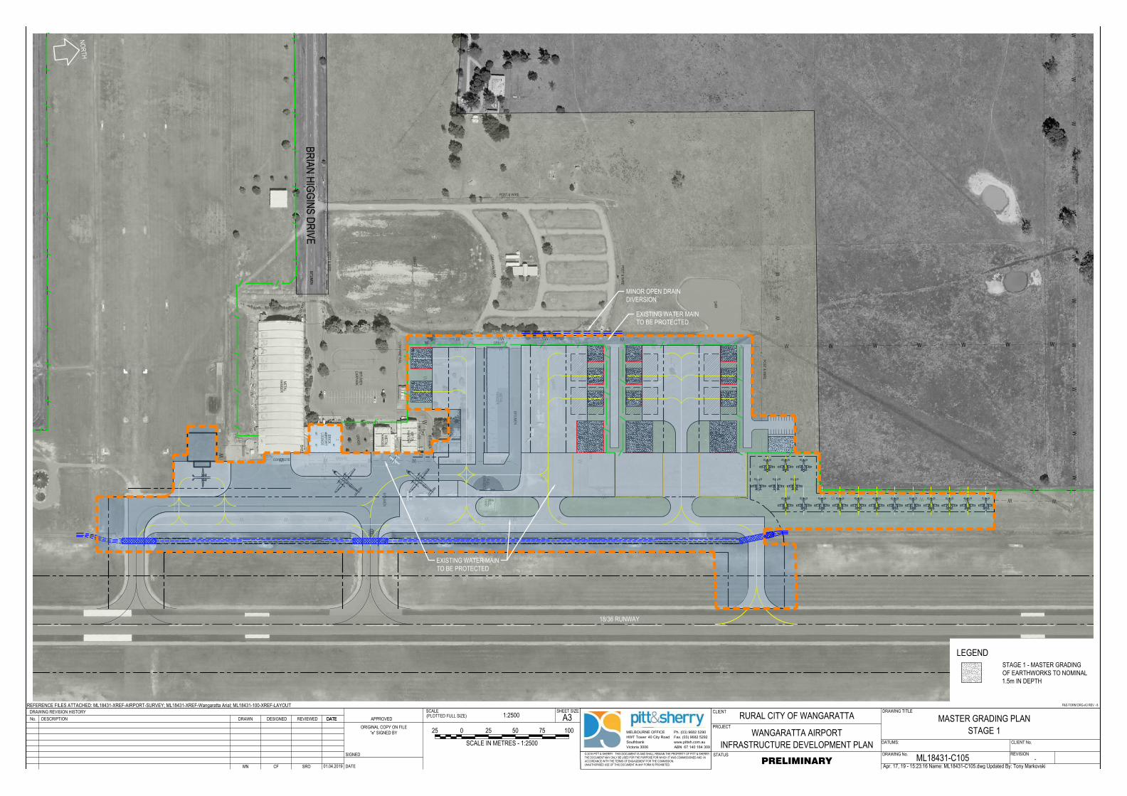
DDD
DA
M
GR
AS
S
BIT
UM
EN
BIT
UM
EN
BIT
UM
EN
CA
RP
AR
K
BIT
UM
EN
ME
TA
L
HA
NG
ER
ME
TA
L
HA
NG
ER
ME
TA
L
HA
NG
ER
BR
IC
K
AIR
PO
RT
LO
UN
GE
OF
FIC
E
CO
NT
AIN
ER
ME
TA
L
HA
NG
ER
FU
EL
TA
NK
FU
EL
BO
WS
ER
S
PO
ST
&
W
IR
E
PO
ST
&
W
IR
E
POST & WIRE
STEEL RAIL
PO
ST
&
W
IR
E
LOW PINE RAIL
LO
W P
IN
E R
AIL
GR
AS
S
GR
AS
S
GR
AS
S
G
RA
SS
GRAVEL
GA
RD
EN
BIT
UM
EN
GRAVEL
CONCRETE
GRAVEL
GRAVEL
G
R
A
V
E
L
SH
ED
SH
ED
WE
AT
HE
RB
OA
RD
AE
RO
C
LU
B
LO
UN
GE
GA
S
BO
TT
LE
S
1200x600
1200x500
1200x500
1800x1100
1800x1100
1800x1100
Ø1
50
Ø3
00
Ø1
00
Ø300
Ø300
Ø150
Ø1
50
Ø3
00
Ø
3
7
5
PO
ST
&
W
IR
E
W W W W W W W W W W W W W W W
WW
BR
IA
N H
IG
GIN
S D
RIV
E
CA
RA
VA
N P
AR
K
WW
WW
WW
WW
WW
W
WWWWWWWWWWW
WW
W
WWWWWWW
W
W W W
W
WWWWWW
WW
W
B100B100 B100 B100 B100 B100 B100B100 B100 B100
M
E
T
R
O
III
M
E
T
R
O
I
II
Q
4
0
0
Q
4
0
0
Q
4
0
0
Q
4
0
0
B100B100
B100B100
B100B100
B100
B100
www.pittsh.com.au
ABN 67 140 184 309
MELBOURNE OFFICE
HWT Tower 40 City Road
Southbank
Victoria 3006
Ph. (03) 9682 5290
Fax. (03) 9682 5292
DRAWING No.
DRAWING TITLE
STATUS
SCALEDRAWING REVISION HISTORY CLIENTA3
PROJECT
SHEET SIZE(PLOTTED FULL SIZE)
© 2016 PITT & SHERRY THIS DOCUMENT IS AND SHALL REMAIN THE PROPERTY OF PITT & SHERRY.THE DOCUMENT MAY ONLY BE USED FOR THE PURPOSE FOR WHICH IT WAS COMMISSIONED AND INACCORDANCE WITH THE TERMS OF ENGAGEMENT FOR THE COMMISSION.UNAUTHORISED USE OF THIS DOCUMENT IN ANY FORM IS PROHIBITED.
REFERENCE FILES ATTACHED: ML18431-XREF-AIRPORT-SURVEY; ML18431-XREF-Wangaratta Arial; ML18431-100-XREF-LAYOUT
DESCRIPTIONNo. DATE APPROVED
SIGNED
DATE
DATUMS: CLIENT No.
ORIGINAL COPY ON FILE"e" SIGNED BY
P&S FORM DRG-A3 REV - 8
REVISION
REVIEWED DATEDRAWN DESIGNED
Apr. 17, 19 - 15:23:16 Name: ML18431-C105.dwg Updated By: Tony Markovski
RURAL CITY OF WANGARATTA
WANGARATTA AIRPORTINFRASTRUCTURE DEVELOPMENT PLAN
MASTER GRADING PLANSTAGE 1
ML18431-C105 -PRELIMINARY
1:2500
MN CF SRO 01.04.2019
0 10050
SCALE IN METRES - 1:2500
7525 25
LEGENDSTAGE 1 - MASTER GRADINGOF EARTHWORKS TO NOMINAL1.5m IN DEPTH
NORTH
18/36 RUNWAY
EXISTING WATER MAINTO BE PROTECTED
EXISTING WATER MAINTO BE PROTECTED
MINOR OPEN DRAINDIVERSION
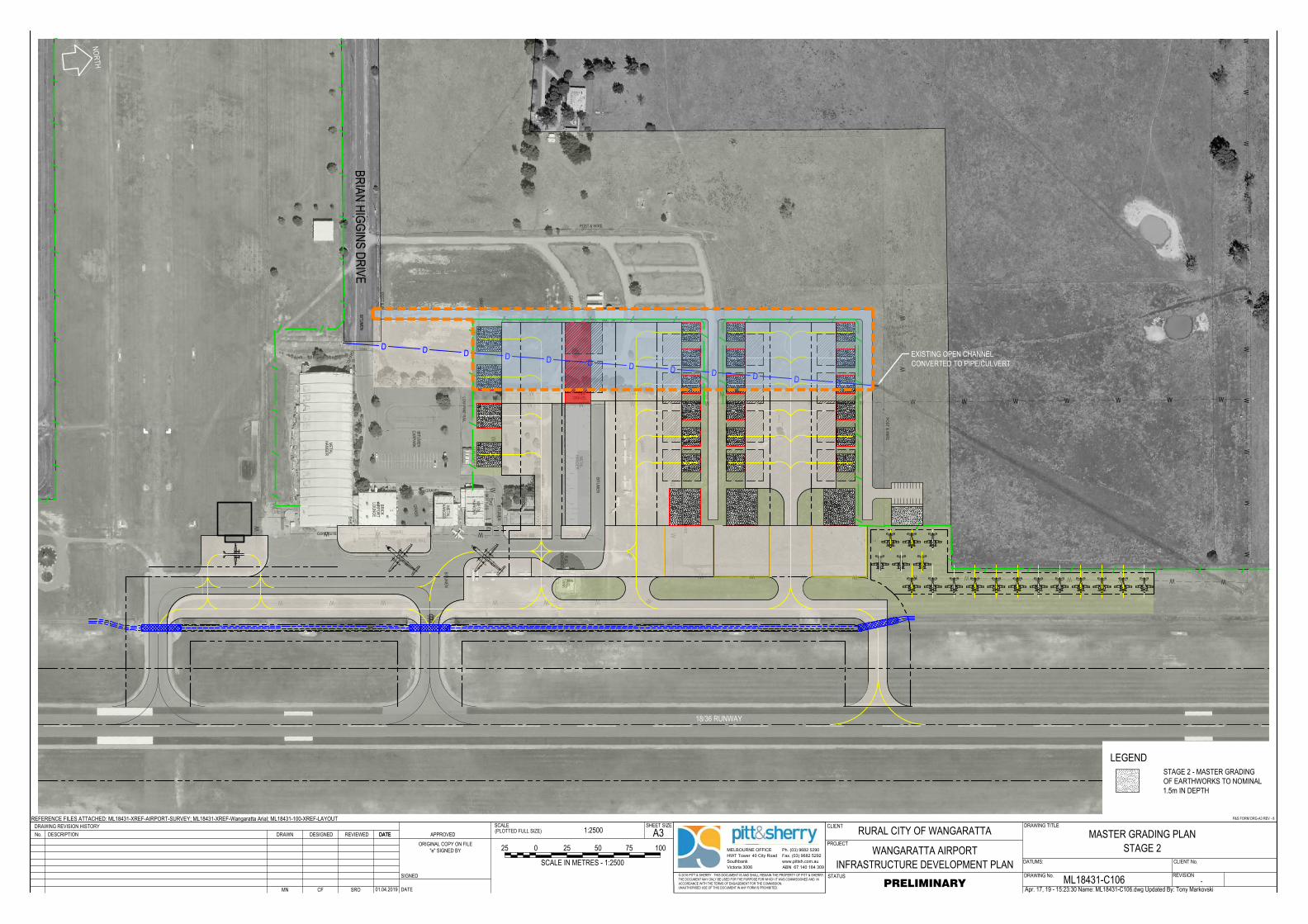
DDD
DA
M
GR
AS
S
BIT
UM
EN
BIT
UM
EN
BIT
UM
EN
CA
RP
AR
K
BIT
UM
EN
ME
TA
L
HA
NG
ER
ME
TA
L
HA
NG
ER
ME
TA
L
HA
NG
ER
BR
IC
K
AIR
PO
RT
LO
UN
GE
OF
FIC
E
CO
NT
AIN
ER
ME
TA
L
HA
NG
ER
FU
EL
TA
NK
FU
EL
BO
WS
ER
S
PO
ST
&
W
IR
E
PO
ST
&
W
IR
E
POST & WIRE
STEEL RAIL
PO
ST
&
W
IR
E
LOW PINE RAIL
LO
W P
IN
E R
AIL
GR
AS
S
GR
AS
S
GR
AS
S
G
RA
SS
GRAVEL
GA
RD
EN
BIT
UM
EN
GRAVEL
CONCRETE
GRAVEL
GRAVEL
G
R
A
V
E
L
SH
ED
SH
ED
WE
AT
HE
RB
OA
RD
AE
RO
C
LU
B
LO
UN
GE
GA
S
BO
TT
LE
S
1200x600
1200x500
1200x500
1800x1100
1800x1100
1800x1100
Ø1
50
Ø3
00
Ø1
00
Ø300
Ø300
Ø150
Ø1
50
Ø3
00
Ø
3
7
5
PO
ST
&
W
IR
E
W W W W W W W W W W W W W W W
WW
BR
IA
N H
IG
GIN
S D
RIV
E
CA
RA
VA
N P
AR
K
WW
WW
WW
WW
WW
W
WWWWWWWWWWW
WW
W
WWWWWWW
W
W W W
W
WWWWWW
WW
W
B100B100 B100 B100 B100 B100 B100B100 B100 B100
M
E
T
R
O
III
M
E
T
R
O
I
II
D D D D D D D D D D D D
Q
4
0
0
Q
4
0
0
Q
4
0
0
Q
4
0
0
B100B100
B100B100
B100B100
B100
B100
www.pittsh.com.au
ABN 67 140 184 309
MELBOURNE OFFICE
HWT Tower 40 City Road
Southbank
Victoria 3006
Ph. (03) 9682 5290
Fax. (03) 9682 5292
DRAWING No.
DRAWING TITLE
STATUS
SCALEDRAWING REVISION HISTORY CLIENTA3
PROJECT
SHEET SIZE(PLOTTED FULL SIZE)
© 2016 PITT & SHERRY THIS DOCUMENT IS AND SHALL REMAIN THE PROPERTY OF PITT & SHERRY.THE DOCUMENT MAY ONLY BE USED FOR THE PURPOSE FOR WHICH IT WAS COMMISSIONED AND INACCORDANCE WITH THE TERMS OF ENGAGEMENT FOR THE COMMISSION.UNAUTHORISED USE OF THIS DOCUMENT IN ANY FORM IS PROHIBITED.
REFERENCE FILES ATTACHED: ML18431-XREF-AIRPORT-SURVEY; ML18431-XREF-Wangaratta Arial; ML18431-100-XREF-LAYOUT
DESCRIPTIONNo. DATE APPROVED
SIGNED
DATE
DATUMS: CLIENT No.
ORIGINAL COPY ON FILE"e" SIGNED BY
P&S FORM DRG-A3 REV - 8
REVISION
REVIEWED DATEDRAWN DESIGNED
Apr. 17, 19 - 15:23:30 Name: ML18431-C106.dwg Updated By: Tony Markovski
RURAL CITY OF WANGARATTA
WANGARATTA AIRPORTINFRASTRUCTURE DEVELOPMENT PLAN
MASTER GRADING PLANSTAGE 2
ML18431-C106 -PRELIMINARY
1:2500
MN CF SRO 01.04.2019
0 10050
SCALE IN METRES - 1:2500
7525 25
LEGENDSTAGE 2 - MASTER GRADINGOF EARTHWORKS TO NOMINAL1.5m IN DEPTH
NORTH
18/36 RUNWAY
EXISTING OPEN CHANNELCONVERTED TO PIPE/CULVERT
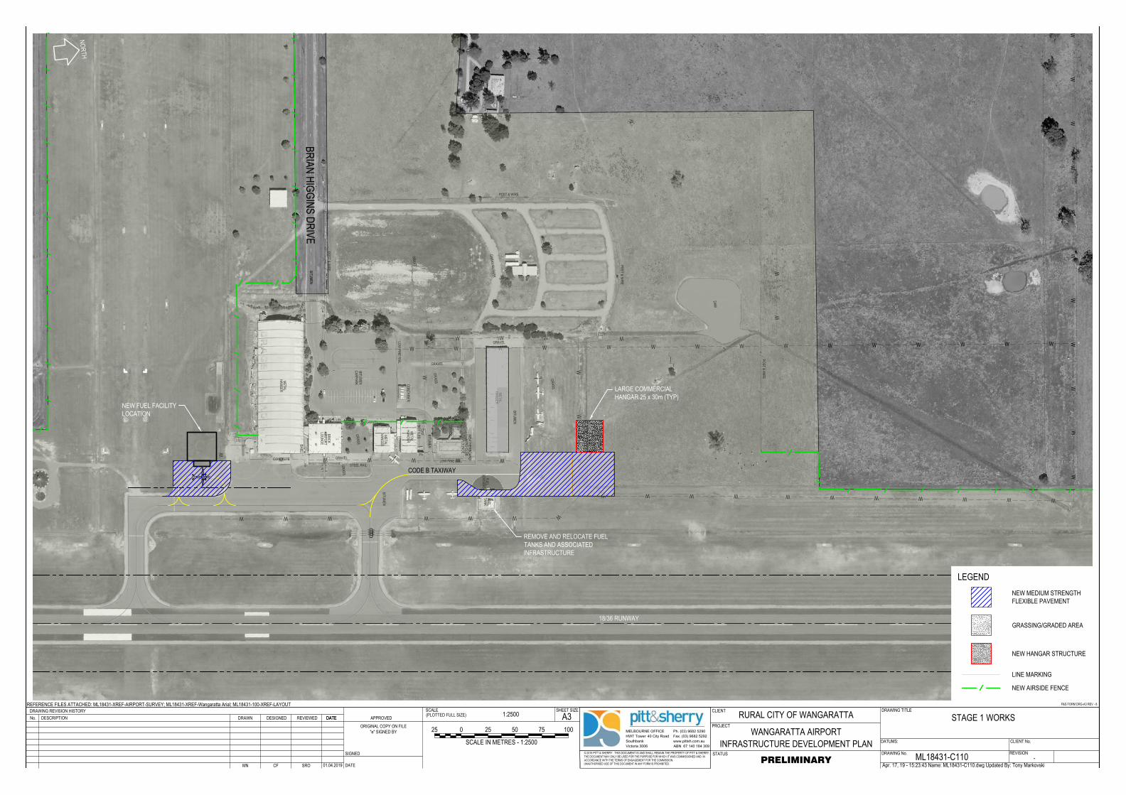
DDD
DA
M
GR
AS
S
BIT
UM
EN
BIT
UM
EN
BIT
UM
EN
CA
RP
AR
K
BIT
UM
EN
ME
TA
L
HA
NG
ER
ME
TA
L
HA
NG
ER
ME
TA
L
HA
NG
ER
BR
IC
K
AIR
PO
RT
LO
UN
GE
OF
FIC
E
CO
NT
AIN
ER
ME
TA
L
HA
NG
ER
FU
EL
TA
NK
FU
EL
BO
WS
ER
S
PO
ST
&
W
IR
E
PO
ST
&
W
IR
E
POST & WIRE
STEEL RAIL
PO
ST
&
W
IR
E
LOW PINE RAIL
LO
W P
IN
E R
AIL
GR
AS
S
GR
AS
S
GR
AS
S
G
RA
SS
GRAVEL
GA
RD
EN
BIT
UM
EN
GRAVEL
CONCRETE
GRAVEL
GRAVEL
G
R
A
V
E
L
SH
ED
SH
ED
WE
AT
HE
RB
OA
RD
AE
RO
C
LU
B
LO
UN
GE
GA
S
BO
TT
LE
S
1200x600
1200x500
1200x500
1800x1100
1800x1100
1800x1100
Ø1
50
Ø3
00
Ø1
00
Ø300
Ø300
Ø150
Ø1
50
Ø3
00
Ø
3
7
5
PO
ST
&
W
IR
E
W W W W W W W W W W W W W W W
WW
BR
IA
N H
IG
GIN
S D
RIV
E
CA
RA
VA
N P
AR
K
WW
WW
WW
WW
WW
W
WWWWWWWWWWW
WW
W
WWWWWWW
W
W W W
W
WWWWWW
WW
W
M
E
T
R
O
III
M
E
T
R
O
I
II
www.pittsh.com.au
ABN 67 140 184 309
MELBOURNE OFFICE
HWT Tower 40 City Road
Southbank
Victoria 3006
Ph. (03) 9682 5290
Fax. (03) 9682 5292
DRAWING No.
DRAWING TITLE
STATUS
SCALEDRAWING REVISION HISTORY CLIENTA3
PROJECT
SHEET SIZE(PLOTTED FULL SIZE)
© 2016 PITT & SHERRY THIS DOCUMENT IS AND SHALL REMAIN THE PROPERTY OF PITT & SHERRY.THE DOCUMENT MAY ONLY BE USED FOR THE PURPOSE FOR WHICH IT WAS COMMISSIONED AND INACCORDANCE WITH THE TERMS OF ENGAGEMENT FOR THE COMMISSION.UNAUTHORISED USE OF THIS DOCUMENT IN ANY FORM IS PROHIBITED.
REFERENCE FILES ATTACHED: ML18431-XREF-AIRPORT-SURVEY; ML18431-XREF-Wangaratta Arial; ML18431-100-XREF-LAYOUT
DESCRIPTIONNo. DATE APPROVED
SIGNED
DATE
DATUMS: CLIENT No.
ORIGINAL COPY ON FILE"e" SIGNED BY
P&S FORM DRG-A3 REV - 8
REVISION
REVIEWED DATEDRAWN DESIGNED
Apr. 17, 19 - 15:23:43 Name: ML18431-C110.dwg Updated By: Tony Markovski
RURAL CITY OF WANGARATTA
WANGARATTA AIRPORTINFRASTRUCTURE DEVELOPMENT PLAN
STAGE 1 WORKS
ML18431-C110 -PRELIMINARY
1:2500
MN CF SRO 01.04.2019
0 10050
SCALE IN METRES - 1:2500
7525 25
NORTH
NEW FUEL FACILITYLOCATION
CODE B TAXIWAY
18/36 RUNWAY
LARGE COMMERCIALHANGAR 25 x 30m (TYP)
REMOVE AND RELOCATE FUELTANKS AND ASSOCIATEDINFRASTRUCTURE
LEGENDNEW MEDIUM STRENGTHFLEXIBLE PAVEMENT
GRASSING/GRADED AREA
LINE MARKING
NEW HANGAR STRUCTURE
NEW AIRSIDE FENCE
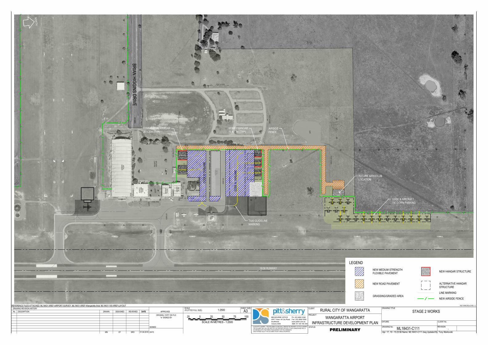
DDD
DA
M
GR
AS
S
BIT
UM
EN
BIT
UM
EN
BIT
UM
EN
CA
RP
AR
K
BIT
UM
EN
ME
TA
L
HA
NG
ER
ME
TA
L
HA
NG
ER
ME
TA
L
HA
NG
ER
BR
IC
K
AIR
PO
RT
LO
UN
GE
OF
FIC
E
CO
NT
AIN
ER
ME
TA
L
HA
NG
ER
FU
EL
TA
NK
FU
EL
BO
WS
ER
S
PO
ST
&
W
IR
E
PO
ST
&
W
IR
E
POST & WIRE
STEEL RAIL
PO
ST
&
W
IR
E
LOW PINE RAIL
LO
W P
IN
E R
AIL
GR
AS
S
GR
AS
S
GR
AS
S
G
RA
SS
GRAVEL
GA
RD
EN
BIT
UM
EN
GRAVEL
CONCRETE
GRAVEL
GRAVEL
G
R
A
V
E
L
SH
ED
SH
ED
WE
AT
HE
RB
OA
RD
AE
RO
C
LU
B
LO
UN
GE
GA
S
BO
TT
LE
S
1200x600
1200x500
1200x500
1800x1100
1800x1100
1800x1100
Ø1
50
Ø3
00
Ø1
00
Ø300
Ø300
Ø150
Ø1
50
Ø3
00
Ø
3
7
5
PO
ST
&
W
IR
E
W W W W W W W W W W W W W W W
WW
BR
IA
N H
IG
GIN
S D
RIV
E
CA
RA
VA
N P
AR
K
WW
WW
WW
WW
WW
W
WWWWWWWWWWW
WW
W
WWWWWWW
W
W W W
W
WWWWWW
WW
W
B100B100 B100 B100 B100 B100 B100B100 B100 B100
M
E
T
R
O
III
M
E
T
R
O
I
II
B100B100
B100B100
B100B100
B100
B100
www.pittsh.com.au
ABN 67 140 184 309
MELBOURNE OFFICE
HWT Tower 40 City Road
Southbank
Victoria 3006
Ph. (03) 9682 5290
Fax. (03) 9682 5292
DRAWING No.
DRAWING TITLE
STATUS
SCALEDRAWING REVISION HISTORY CLIENTA3
PROJECT
SHEET SIZE(PLOTTED FULL SIZE)
© 2016 PITT & SHERRY THIS DOCUMENT IS AND SHALL REMAIN THE PROPERTY OF PITT & SHERRY.THE DOCUMENT MAY ONLY BE USED FOR THE PURPOSE FOR WHICH IT WAS COMMISSIONED AND INACCORDANCE WITH THE TERMS OF ENGAGEMENT FOR THE COMMISSION.UNAUTHORISED USE OF THIS DOCUMENT IN ANY FORM IS PROHIBITED.
REFERENCE FILES ATTACHED: ML18431-XREF-AIRPORT-SURVEY; ML18431-XREF-Wangaratta Arial; ML18431-100-XREF-LAYOUT
DESCRIPTIONNo. DATE APPROVED
SIGNED
DATE
DATUMS: CLIENT No.
ORIGINAL COPY ON FILE"e" SIGNED BY
P&S FORM DRG-A3 REV - 8
REVISION
REVIEWED DATEDRAWN DESIGNED
Apr. 17, 19 - 15:23:56 Name: ML18431-C111.dwg Updated By: Tony Markovski
RURAL CITY OF WANGARATTA
WANGARATTA AIRPORTINFRASTRUCTURE DEVELOPMENT PLAN
STAGE 2 WORKS
ML18431-C111 -PRELIMINARY
1:2500
MN CF SRO 01.04.2019
0 10050
SCALE IN METRES - 1:2500
7525 25
NORTH
FUTURE AEROCLUBLOCATION
COMMERCIAL HANGAR20 x 20m (TYP)
HOBBY HANGAR15 X 15m (TYP)
CODE
B T
AXILA
NE
CODE
B T
AXILA
NE
AIRSIDEFENCE
18/36 RUNWAY
TAXI GUIDELINEMARKING
CODE A AIRCRAFTTIE DOWN PARKING
LEGENDNEW MEDIUM STRENGTHFLEXIBLE PAVEMENT
GRASSING/GRADED AREALINE MARKING
NEW HANGAR STRUCTURE
ALTERNATIVE HANGARSTRUCTURE
NEW AIRSIDE FENCE
NEW ROAD PAVEMENT
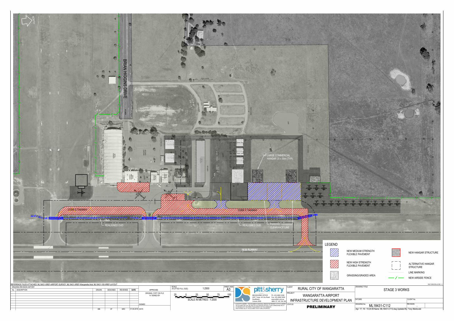
DDD
DA
M
GR
AS
S
BIT
UM
EN
BIT
UM
EN
BIT
UM
EN
CA
RP
AR
K
BIT
UM
EN
ME
TA
L
HA
NG
ER
ME
TA
L
HA
NG
ER
ME
TA
L
HA
NG
ER
BR
IC
K
AIR
PO
RT
LO
UN
GE
OF
FIC
E
CO
NT
AIN
ER
ME
TA
L
HA
NG
ER
FU
EL
TA
NK
FU
EL
BO
WS
ER
S
PO
ST
&
W
IR
E
PO
ST
&
W
IR
E
POST & WIRE
STEEL RAIL
PO
ST
&
W
IR
E
LOW PINE RAIL
LO
W P
IN
E R
AIL
GR
AS
S
GR
AS
S
GR
AS
S
G
RA
SS
GRAVEL
GA
RD
EN
BIT
UM
EN
GRAVEL
CONCRETE
GRAVEL
GRAVEL
G
R
A
V
E
L
SH
ED
SH
ED
WE
AT
HE
RB
OA
RD
AE
RO
C
LU
B
LO
UN
GE
GA
S
BO
TT
LE
S
1200x600
1200x500
1200x500
1800x1100
1800x1100
1800x1100
Ø1
50
Ø3
00
Ø1
00
Ø300
Ø300
Ø150
Ø1
50
Ø3
00
Ø
3
7
5
PO
ST
&
W
IR
E
W W W W W W W W W W W W W W W
WW
BR
IA
N H
IG
GIN
S D
RIV
E
CA
RA
VA
N P
AR
K
WW
WW
WW
WW
WW
W
WWWWWWWWWWW
WW
W
WWWWWWW
W
W W W
W
WWWWWW
WW
W
B100B100 B100 B100 B100 B100 B100B100 B100 B100
M
E
T
R
O
III
M
E
T
R
O
I
II
Q
4
0
0
Q
4
0
0
Q
4
0
0
Q
4
0
0
B100B100
B100B100
B100B100
B100
B100
www.pittsh.com.au
ABN 67 140 184 309
MELBOURNE OFFICE
HWT Tower 40 City Road
Southbank
Victoria 3006
Ph. (03) 9682 5290
Fax. (03) 9682 5292
DRAWING No.
DRAWING TITLE
STATUS
SCALEDRAWING REVISION HISTORY CLIENTA3
PROJECT
SHEET SIZE(PLOTTED FULL SIZE)
© 2016 PITT & SHERRY THIS DOCUMENT IS AND SHALL REMAIN THE PROPERTY OF PITT & SHERRY.THE DOCUMENT MAY ONLY BE USED FOR THE PURPOSE FOR WHICH IT WAS COMMISSIONED AND INACCORDANCE WITH THE TERMS OF ENGAGEMENT FOR THE COMMISSION.UNAUTHORISED USE OF THIS DOCUMENT IN ANY FORM IS PROHIBITED.
REFERENCE FILES ATTACHED: ML18431-XREF-AIRPORT-SURVEY; ML18431-XREF-Wangaratta Arial; ML18431-100-XREF-LAYOUT
DESCRIPTIONNo. DATE APPROVED
SIGNED
DATE
DATUMS: CLIENT No.
ORIGINAL COPY ON FILE"e" SIGNED BY
P&S FORM DRG-A3 REV - 8
REVISION
REVIEWED DATEDRAWN DESIGNED
Apr. 17, 19 - 15:24:09 Name: ML18431-C112.dwg Updated By: Tony Markovski
RURAL CITY OF WANGARATTA
WANGARATTA AIRPORTINFRASTRUCTURE DEVELOPMENT PLAN
STAGE 3 WORKS
ML18431-C112 -PRELIMINARY
1:2500
MN CF SRO 01.04.2019
0 10050
SCALE IN METRES - 1:2500
7525 25
NORTH
18/36 RUNWAY
REALIGNED OUD
CODE C TAXIWAYCODE C TAXIWAY
REALIGNED OUD
18/36 RUNWAY
LARGE COMMERCIALHANGAR 20 x 30m (TYP)
PARKINGCLEARANCE LINE
LEGENDNEW MEDIUM STRENGTHFLEXIBLE PAVEMENT
LINE MARKING
NEW HANGAR STRUCTURE
ALTERNATIVE HANGARSTRUCTURE
NEW AIRSIDE FENCE
NEW HIGH STRENGTHFLEXIBLE PAVEMENT
GRASSING/GRADED AREA
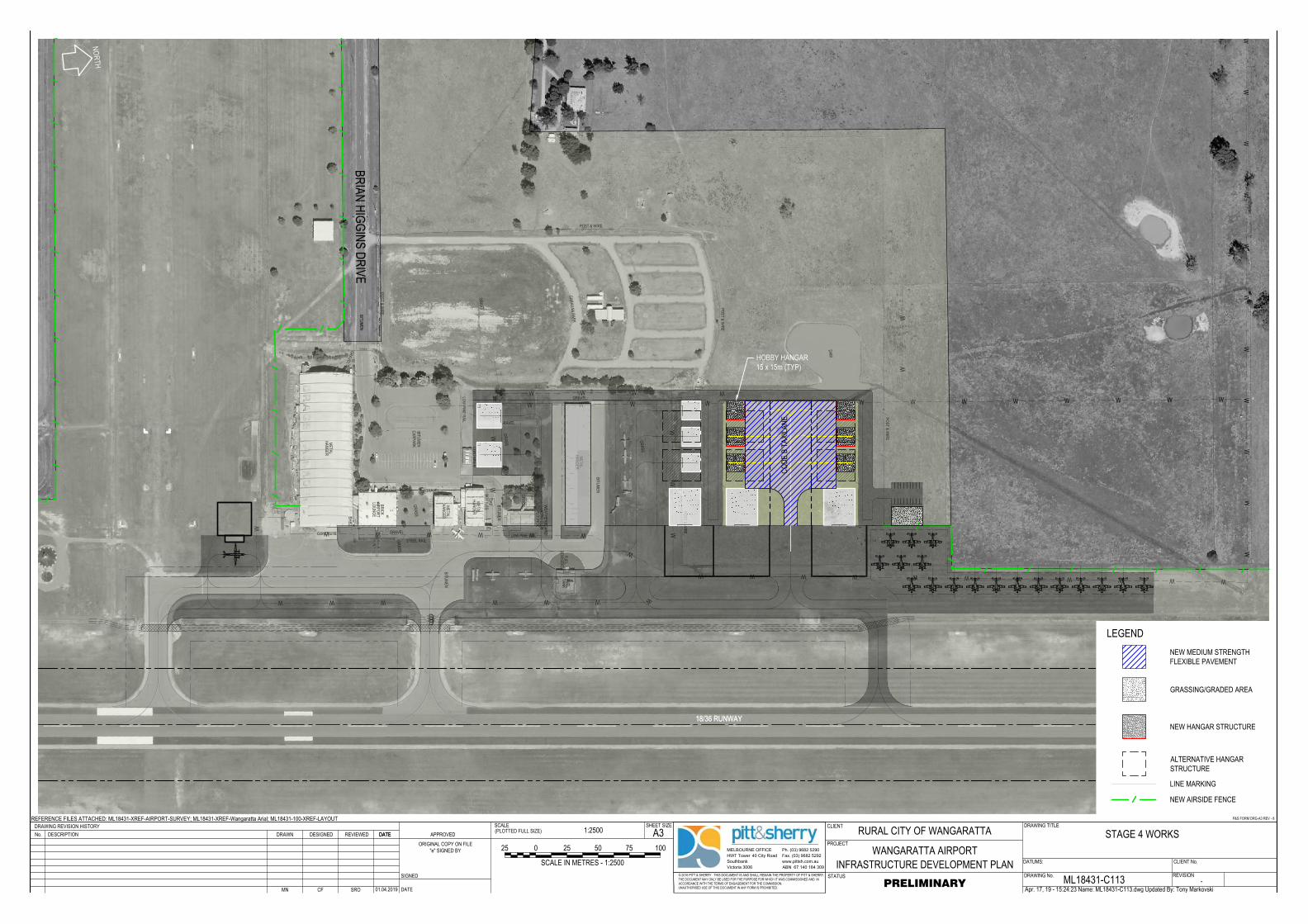
DDD
DA
M
GR
AS
S
BIT
UM
EN
BIT
UM
EN
BIT
UM
EN
CA
RP
AR
K
BIT
UM
EN
ME
TA
L
HA
NG
ER
ME
TA
L
HA
NG
ER
ME
TA
L
HA
NG
ER
BR
IC
K
AIR
PO
RT
LO
UN
GE
OF
FIC
E
CO
NT
AIN
ER
ME
TA
L
HA
NG
ER
FU
EL
TA
NK
FU
EL
BO
WS
ER
S
PO
ST
&
W
IR
E
PO
ST
&
W
IR
E
POST & WIRE
STEEL RAIL
PO
ST
&
W
IR
E
LOW PINE RAIL
LO
W P
IN
E R
AIL
GR
AS
S
GR
AS
S
GR
AS
S
G
RA
SS
GRAVEL
GA
RD
EN
BIT
UM
EN
GRAVEL
CONCRETE
GRAVEL
GRAVEL
G
R
A
V
E
L
SH
ED
SH
ED
WE
AT
HE
RB
OA
RD
AE
RO
C
LU
B
LO
UN
GE
GA
S
BO
TT
LE
S
1200x600
1200x500
1200x500
1800x1100
1800x1100
1800x1100
Ø1
50
Ø3
00
Ø1
00
Ø300
Ø300
Ø150
Ø1
50
Ø3
00
Ø
3
7
5
PO
ST
&
W
IR
E
W W W W W W W W W W W W W W W
WW
BR
IA
N H
IG
GIN
S D
RIV
E
CA
RA
VA
N P
AR
K
WW
WW
WW
WW
WW
W
WWWWWWWWWWW
WW
W
WWWWWWW
W
W W W
W
WWWWWW
WW
W
B100B100 B100 B100 B100 B100 B100B100 B100 B100
M
E
T
R
O
III
M
E
T
R
O
I
II
B100B100
B100B100
B100B100
B100
B100
www.pittsh.com.au
ABN 67 140 184 309
MELBOURNE OFFICE
HWT Tower 40 City Road
Southbank
Victoria 3006
Ph. (03) 9682 5290
Fax. (03) 9682 5292
DRAWING No.
DRAWING TITLE
STATUS
SCALEDRAWING REVISION HISTORY CLIENTA3
PROJECT
SHEET SIZE(PLOTTED FULL SIZE)
© 2016 PITT & SHERRY THIS DOCUMENT IS AND SHALL REMAIN THE PROPERTY OF PITT & SHERRY.THE DOCUMENT MAY ONLY BE USED FOR THE PURPOSE FOR WHICH IT WAS COMMISSIONED AND INACCORDANCE WITH THE TERMS OF ENGAGEMENT FOR THE COMMISSION.UNAUTHORISED USE OF THIS DOCUMENT IN ANY FORM IS PROHIBITED.
REFERENCE FILES ATTACHED: ML18431-XREF-AIRPORT-SURVEY; ML18431-XREF-Wangaratta Arial; ML18431-100-XREF-LAYOUT
DESCRIPTIONNo. DATE APPROVED
SIGNED
DATE
DATUMS: CLIENT No.
ORIGINAL COPY ON FILE"e" SIGNED BY
P&S FORM DRG-A3 REV - 8
REVISION
REVIEWED DATEDRAWN DESIGNED
Apr. 17, 19 - 15:24:23 Name: ML18431-C113.dwg Updated By: Tony Markovski
RURAL CITY OF WANGARATTA
WANGARATTA AIRPORTINFRASTRUCTURE DEVELOPMENT PLAN
STAGE 4 WORKS
ML18431-C113 -PRELIMINARY
1:2500
MN CF SRO 01.04.2019
0 10050
SCALE IN METRES - 1:2500
7525 25
NORTH
18/36 RUNWAY18/36 RUNWAY
HOBBY HANGAR15 x 15m (TYP)
CODE
B T
AXILA
NE
LEGENDNEW MEDIUM STRENGTHFLEXIBLE PAVEMENT
LINE MARKING
NEW HANGAR STRUCTURE
ALTERNATIVE HANGARSTRUCTURE
NEW AIRSIDE FENCE
GRASSING/GRADED AREA
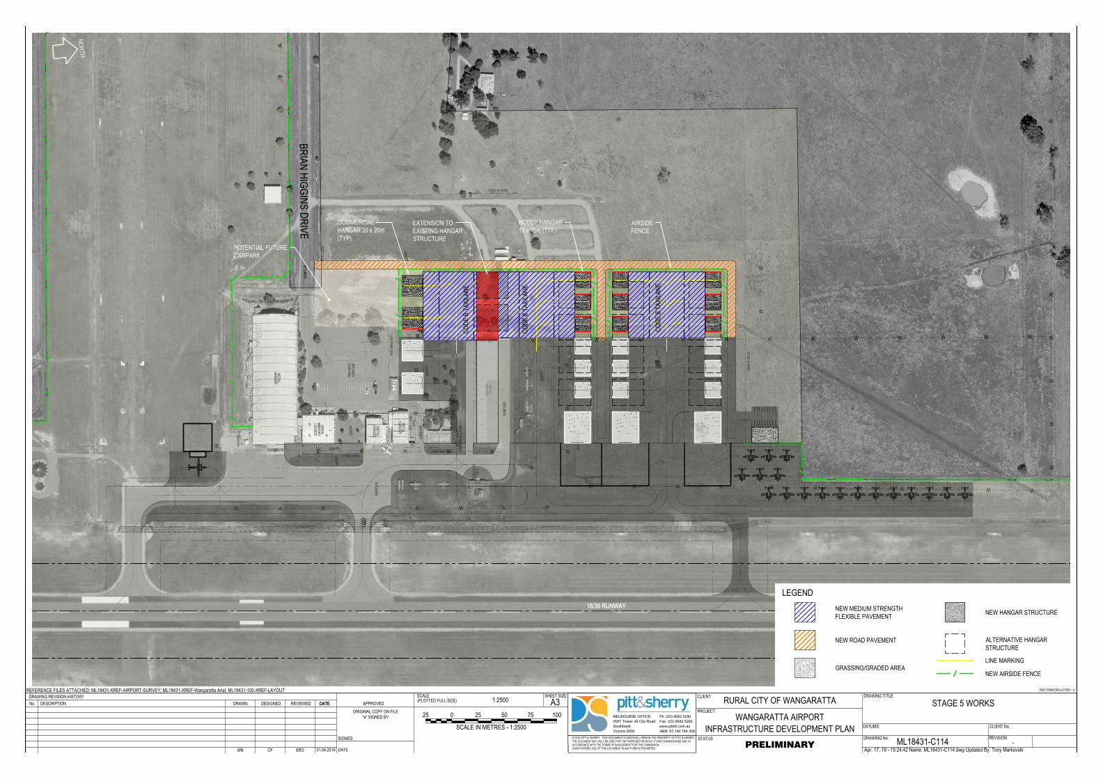
DDD
DA
M
GR
AS
S
BIT
UM
EN
BIT
UM
EN
BIT
UM
EN
CA
RP
AR
K
BIT
UM
EN
ME
TA
L
HA
NG
ER
ME
TA
L
HA
NG
ER
ME
TA
L
HA
NG
ER
BR
IC
K
AIR
PO
RT
LO
UN
GE
OF
FIC
E
CO
NT
AIN
ER
ME
TA
L
HA
NG
ER
FU
EL
TA
NK
FU
EL
BO
WS
ER
S
PO
ST
&
W
IR
E
PO
ST
&
W
IR
E
POST & WIRE
STEEL RAIL
PO
ST
&
W
IR
E
LOW PINE RAIL
LO
W P
IN
E R
AIL
GR
AS
S
GR
AS
S
GR
AS
S
G
RA
SS
GRAVEL
GA
RD
EN
BIT
UM
EN
GRAVEL
CONCRETE
GRAVEL
GRAVEL
G
R
A
V
E
L
SH
ED
SH
ED
WE
AT
HE
RB
OA
RD
AE
RO
C
LU
B
LO
UN
GE
GA
S
BO
TT
LE
S
1200x600
1200x500
1200x500
1800x1100
1800x1100
1800x1100
Ø1
50
Ø3
00
Ø1
00
Ø300
Ø300
Ø150
Ø1
50
Ø3
00
Ø
3
7
5
PO
ST
&
W
IR
E
W W W W W W W W W W W W W W W
WW
BR
IA
N H
IG
GIN
S D
RIV
E
CA
RA
VA
N P
AR
K
WW
WW
WW
WW
WW
W
WWWWWWWWWWW
WW
W
WWWWWWW
W
W W W
W
WWWWWW
WW
W
B100B100 B100 B100 B100 B100 B100B100 B100 B100
M
E
T
R
O
III
M
E
T
R
O
I
II
B100B100
B100B100
B100B100
B100
B100
www.pittsh.com.au
ABN 67 140 184 309
MELBOURNE OFFICE
HWT Tower 40 City Road
Southbank
Victoria 3006
Ph. (03) 9682 5290
Fax. (03) 9682 5292
DRAWING No.
DRAWING TITLE
STATUS
SCALEDRAWING REVISION HISTORY CLIENTA3
PROJECT
SHEET SIZE(PLOTTED FULL SIZE)
© 2016 PITT & SHERRY THIS DOCUMENT IS AND SHALL REMAIN THE PROPERTY OF PITT & SHERRY.THE DOCUMENT MAY ONLY BE USED FOR THE PURPOSE FOR WHICH IT WAS COMMISSIONED AND INACCORDANCE WITH THE TERMS OF ENGAGEMENT FOR THE COMMISSION.UNAUTHORISED USE OF THIS DOCUMENT IN ANY FORM IS PROHIBITED.
REFERENCE FILES ATTACHED: ML18431-XREF-AIRPORT-SURVEY; ML18431-XREF-Wangaratta Arial; ML18431-100-XREF-LAYOUT
DESCRIPTIONNo. DATE APPROVED
SIGNED
DATE
DATUMS: CLIENT No.
ORIGINAL COPY ON FILE"e" SIGNED BY
P&S FORM DRG-A3 REV - 8
REVISION
REVIEWED DATEDRAWN DESIGNED
Apr. 17, 19 - 15:24:42 Name: ML18431-C114.dwg Updated By: Tony Markovski
RURAL CITY OF WANGARATTA
WANGARATTA AIRPORTINFRASTRUCTURE DEVELOPMENT PLAN
STAGE 5 WORKS
ML18431-C114 -PRELIMINARY
1:2500
MN CF SRO 01.04.2019
0 10050
SCALE IN METRES - 1:2500
7525 25
NORTH
18/36 RUNWAY18/36 RUNWAY
COMMERCIALHANGAR 20 x 20m(TYP)
HOBBY HANGAR15 x 15m (TYP)
CODE
B T
AXILA
NE
CODE
B T
AXILA
NE
CODE
B T
AXILA
NE
AIRSIDEFENCE
POTENTIAL FUTURECARPARK
EXTENSION TOEXISTING HANGARSTRUCTURE
LEGENDNEW MEDIUM STRENGTHFLEXIBLE PAVEMENT
LINE MARKING
NEW HANGAR STRUCTURE
ALTERNATIVE HANGARSTRUCTURE
NEW AIRSIDE FENCEGRASSING/GRADED AREA
NEW ROAD PAVEMENT
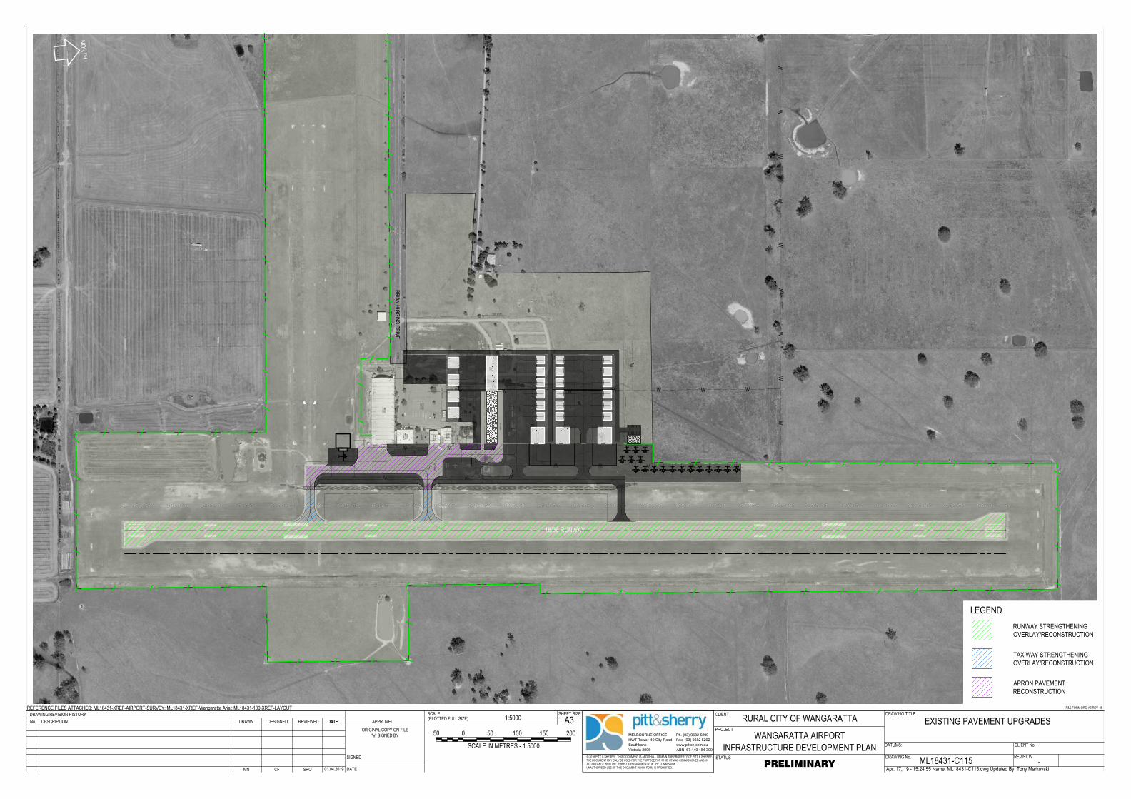
DA
M
G
RA
SS
BIT
UM
EN
BIT
UM
EN
BIT
UM
EN
CA
RP
AR
K
BIT
UM
EN
ME
TA
L
HA
NG
ER
ME
TA
L
HA
NG
ER
ME
TA
L
HA
NG
ER
BR
IC
K
AIR
PO
RT
LO
UN
GE
OF
FIC
E
CO
NT
AIN
ER
ME
TA
L
HA
NG
ER
FU
EL
TA
NK
FU
EL
BO
WS
ER
S
PO
ST
&
W
IR
E
PO
ST
&
W
IR
E
POST & WIRE
STEEL RAIL
PO
ST
&
W
IR
E
LOW PINE RAIL
LO
W P
IN
E R
AIL
G
RA
SS
G
RA
SS
GR
AS
S
G
RA
SS
GRAVEL
GA
RD
EN
BIT
UM
EN
GRAVEL
CONCRETE
GRAVEL
GRAVEL
G
R
A
V
E
L
SH
ED
SH
ED
WE
AT
HE
RB
OA
RD
AE
RO
C
LU
B
LO
UN
GE
GA
S
BO
TT
LE
S
1200x600
1200x500
1200x500
1800x1100
1800x1100
1800x1100
Ø150
Ø3
00
Ø1
00
Ø300
Ø300
Ø150
Ø1
50
Ø3
00
Ø
3
7
5
PO
ST
&
W
IR
E
W W W W W W W
W
BR
IA
N H
IG
GIN
S D
RIV
E
CA
RA
VA
N P
AR
K
WW
WW
WW
WW
WWWWWWW
W
WWW
W
WWW
W
B100B100 B100 B100 B100 B100 B100B100 B100 B100
M
ETRO III
MET
RO
III
B100B100
B100B100
B100B100
B100
B100
www.pittsh.com.au
ABN 67 140 184 309
MELBOURNE OFFICE
HWT Tower 40 City Road
Southbank
Victoria 3006
Ph. (03) 9682 5290
Fax. (03) 9682 5292
DRAWING No.
DRAWING TITLE
STATUS
SCALEDRAWING REVISION HISTORY CLIENTA3
PROJECT
SHEET SIZE(PLOTTED FULL SIZE)
© 2016 PITT & SHERRY THIS DOCUMENT IS AND SHALL REMAIN THE PROPERTY OF PITT & SHERRY.THE DOCUMENT MAY ONLY BE USED FOR THE PURPOSE FOR WHICH IT WAS COMMISSIONED AND INACCORDANCE WITH THE TERMS OF ENGAGEMENT FOR THE COMMISSION.UNAUTHORISED USE OF THIS DOCUMENT IN ANY FORM IS PROHIBITED.
REFERENCE FILES ATTACHED: ML18431-XREF-AIRPORT-SURVEY; ML18431-XREF-Wangaratta Arial; ML18431-100-XREF-LAYOUT
DESCRIPTIONNo. DATE APPROVED
SIGNED
DATE
DATUMS: CLIENT No.
ORIGINAL COPY ON FILE"e" SIGNED BY
P&S FORM DRG-A3 REV - 8
REVISION
REVIEWED DATEDRAWN DESIGNED
Apr. 17, 19 - 15:24:55 Name: ML18431-C115.dwg Updated By: Tony Markovski
RURAL CITY OF WANGARATTA
WANGARATTA AIRPORTINFRASTRUCTURE DEVELOPMENT PLAN
EXISTING PAVEMENT UPGRADES
ML18431-C115 -PRELIMINARY
1:5000
MN CF SRO 01.04.2019
0 200100
SCALE IN METRES - 1:5000
15050 50
NORTH
18/36 RUNWAY
LEGENDRUNWAY STRENGTHENINGOVERLAY/RECONSTRUCTION
APRON PAVEMENTRECONSTRUCTION
TAXIWAY STRENGTHENINGOVERLAY/RECONSTRUCTION
ref: ML18431 - Wangaratta Airport Infrastructure Development Plan Rev B/CF/SO
Indicative Budget Cost Estimates
Appendix B
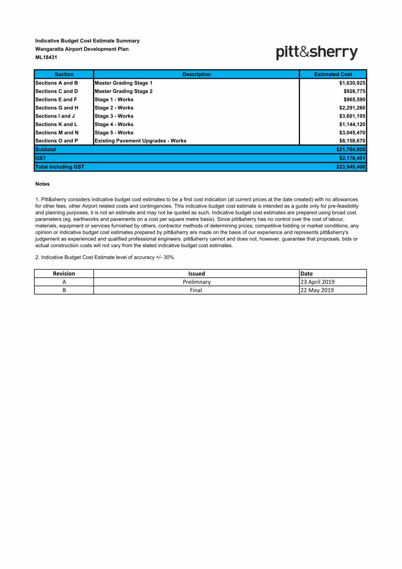
Section Description Estimated Cost
Sections A and B Master Grading Stage 1 $1,630,925
Sections C and D Master Grading Stage 2 $926,775
Sections E and F Stage 1 - Works $965,590
Sections G and H Stage 2 - Works $2,291,260
Sections I and J Stage 3 - Works $3,601,195
Sections K and L Stage 4 - Works $1,144,120
Sections M and N Stage 5 - Works $3,045,470
Sections O and P Existing Pavement Upgrades - Works $8,158,670
Subtotal $21,764,005
GST $2,176,401
Total including GST $23,940,406
Notes
Revision Issued Date
A Prelimnary 23 April 2019
B Final 22 May 2019
Indicative Budget Cost Estimate Summary
Wangaratta Airport Development Plan
ML18431
2. Indicative Budget Cost Estimate level of accuracy +/- 30%
1. Pitt&sherry considers indicative budget cost estimates to be a first cost indication (at current prices at the date created) with no allowances
for other fees, other Airport related costs and contingencies. This indicative budget cost estimate is intended as a guide only for pre-feasibility
and planning purposes, it is not an estimate and may not be quoted as such. Indicative budget cost estimates are prepared using broad cost
parameters (eg. earthworks and pavements on a cost per square metre basis). Since pitt&sherry has no control over the cost of labour,
materials, equipment or services furnished by others, contractor methods of determining prices, competitive bidding or market conditions, any
opinion or indicative budget cost estimates prepared by pitt&sherry are made on the basis of our experience and represents pitt&sherry's
judgement as experienced and qualified professional engineers. pitt&sherry cannot and does not, however, guarantee that proposals, bids or
actual construction costs will not vary from the stated indicative budget cost estimates.
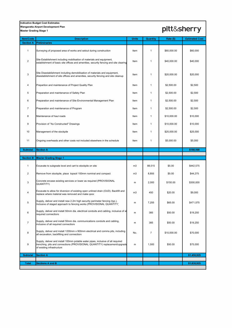
Indicative Budget Cost Estimates
Wangaratta Airport Development Plan
Master Grading Stage 1
Item/Code Description Units Quantity Rate ($) Estimated Cost
Section A Preliminaries
1 Surveying of proposed area of works and setout during construction Item 1 $60,000.00 $60,000
2Site Establishment including mobilisation of materials and equipment,
establishment of basic site offices and amenities, security fencing and site clearingItem 1 $40,000.00 $40,000
3Site Disestablishment including demobilisation of materials and equipment,
disestablishment of site offices and amenities, security fencing and site cleanupItem 1 $20,000.00 $20,000
4 Prepartion and maintenance of Project Quality Plan Item 1 $2,500.00 $2,500
5 Preparation and maintenance of Safety Plan Item 1 $2,500.00 $2,500
6 Preparation and maintenance of Site Environmental Management Plan Item 1 $2,500.00 $2,500
7 Preparation and maintenance of Program Item 1 $2,500.00 $2,500
8 Maintenance of haul roads Item 1 $10,000.00 $10,000
9 Provision of "As Constructed" Drawings Item 1 $10,000.00 $10,000
10 Management of the stockpile Item 1 $25,000.00 $25,000
11 Ongoing overheads and other costs not included elsewhere in the schedule Item 1 $5,000.00 $5,000
Subtotal Section A $180,000
Section B Master Grading Stage 1
1 Excavate to subgrade level and cart to stockpile on site m3 88,515 $5.00 $442,575
2 Remove from stockpile, place topsoil 100mm nominal and compact m3 8,855 $5.00 $44,275
3Concrete encase existing services or lower as required (PROVISIONAL
QUANTITY)m 2,000 $150.00 $300,000
4Excavate to allow for diversion of existing open unlined drain (OUD). Backfill and
replace where material was removed and make goodm3 450 $20.00 $9,000
5Supply, deliver and install new 2.2m high security perimeter fencing (typ.),
Inclusive of staged approach to fencing works (PROVISIONAL QUANTITY)m 7,255 $65.00 $471,575
6Supply, deliver and install 50mm dia. electrical conduits and cabling, inclusive of all
required connectionsm 385 $50.00 $19,250
7Supply, deliver and install 50mm dia. communications conduits and cabling,
inclusive of all required connectionsm 385 $50.00 $19,250
8Supply, deliver and install 1200mm x 900mm electrical and comms pits, including
all excavation, backfilling and connectionsNo. 7 $10,000.00 $70,000
9
Supply, deliver and install 100mm potable water pipes, inclusive of all required
trenching, pits and connections (PROVISIONAL QUANTITY) replacement/upgrade
of existing infrastructure
m 1,500 $50.00 $75,000
Subtotal Section A $1,450,925
Total Sections A and B $1,630,925
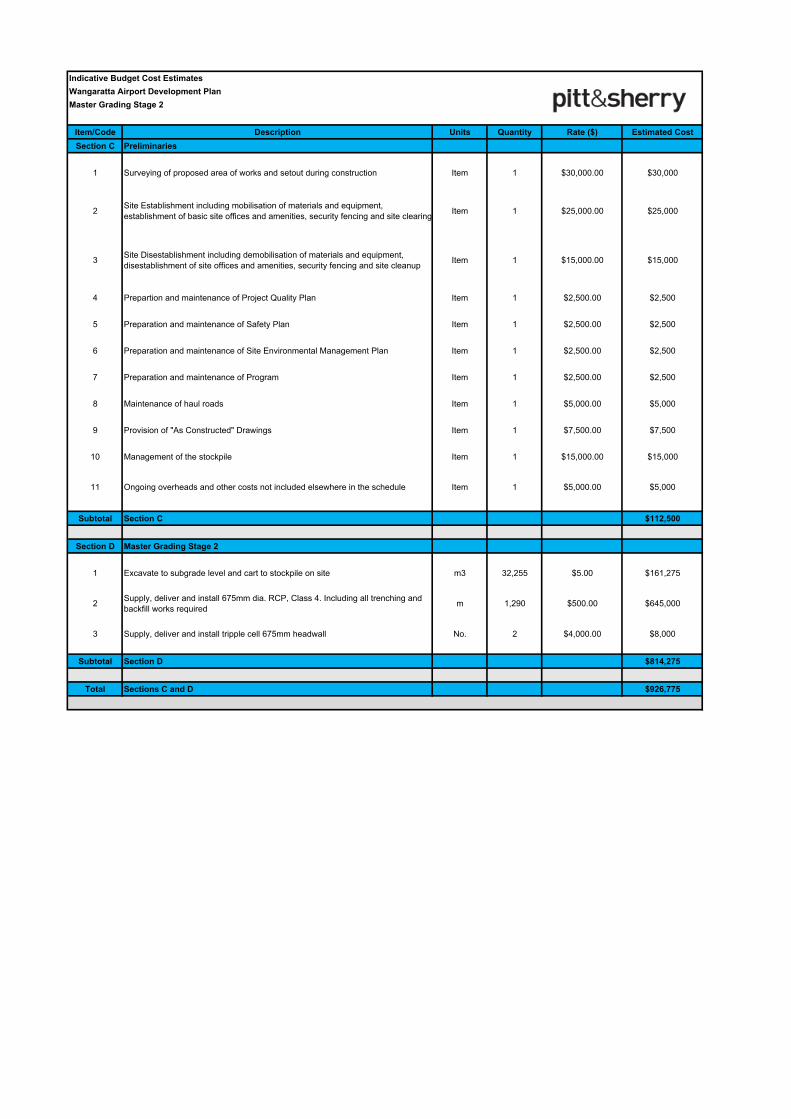
Indicative Budget Cost Estimates
Wangaratta Airport Development Plan
Master Grading Stage 2
Item/Code Description Units Quantity Rate ($) Estimated Cost
Section C Preliminaries
1 Surveying of proposed area of works and setout during construction Item 1 $30,000.00 $30,000
2Site Establishment including mobilisation of materials and equipment,
establishment of basic site offices and amenities, security fencing and site clearingItem 1 $25,000.00 $25,000
3Site Disestablishment including demobilisation of materials and equipment,
disestablishment of site offices and amenities, security fencing and site cleanupItem 1 $15,000.00 $15,000
4 Prepartion and maintenance of Project Quality Plan Item 1 $2,500.00 $2,500
5 Preparation and maintenance of Safety Plan Item 1 $2,500.00 $2,500
6 Preparation and maintenance of Site Environmental Management Plan Item 1 $2,500.00 $2,500
7 Preparation and maintenance of Program Item 1 $2,500.00 $2,500
8 Maintenance of haul roads Item 1 $5,000.00 $5,000
9 Provision of "As Constructed" Drawings Item 1 $7,500.00 $7,500
10 Management of the stockpile Item 1 $15,000.00 $15,000
11 Ongoing overheads and other costs not included elsewhere in the schedule Item 1 $5,000.00 $5,000
Subtotal Section C $112,500
Section D Master Grading Stage 2
1 Excavate to subgrade level and cart to stockpile on site m3 32,255 $5.00 $161,275
2Supply, deliver and install 675mm dia. RCP, Class 4. Including all trenching and
backfill works requiredm 1,290 $500.00 $645,000
3 Supply, deliver and install tripple cell 675mm headwall No. 2 $4,000.00 $8,000
Subtotal Section D $814,275
Total Sections C and D $926,775
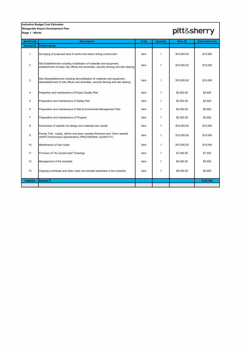
Indicative Budget Cost Estimates
Wangaratta Airport Development Plan
Stage 1 - Works
Item/Code Description Units Quantity Rate ($) Estimated Cost
Section E Preliminaries
1 Surveying of proposed area of works and setout during construction Item 1 $15,000.00 $15,000
2Site Establishment including mobilisation of materials and equipment,
establishment of basic site offices and amenities, security fencing and site clearingItem 1 $15,000.00 $15,000
3Site Disestablishment including demobilisation of materials and equipment,
disestablishment of site offices and amenities, security fencing and site cleanupItem 1 $10,000.00 $10,000
4 Prepartion and maintenance of Project Quality Plan Item 1 $2,500.00 $2,500
5 Preparation and maintenance of Safety Plan Item 1 $2,500.00 $2,500
6 Preparation and maintenance of Site Environmental Management Plan Item 1 $2,500.00 $2,500
7 Preparation and maintenance of Program Item 1 $2,500.00 $2,500
8 Submission of asphalt mix design and materials test results Item 1 $10,000.00 $10,000
9Paving Trial - supply, deliver and place variable thickness size 14mm asphalt
(AAPA Performance Specification) (PROVISIONAL QUANTITY)Item 1 $15,000.00 $15,000
10 Maintenance of haul roads Item 1 $10,000.00 $10,000
11 Provision of "As Constructed" Drawings Item 1 $7,500.00 $7,500
12 Management of the stockpile Item 1 $5,000.00 $5,000
13 Ongoing overheads and other costs not included elsewhere in the schedule Item 1 $5,000.00 $5,000
Subtotal Section E $102,500
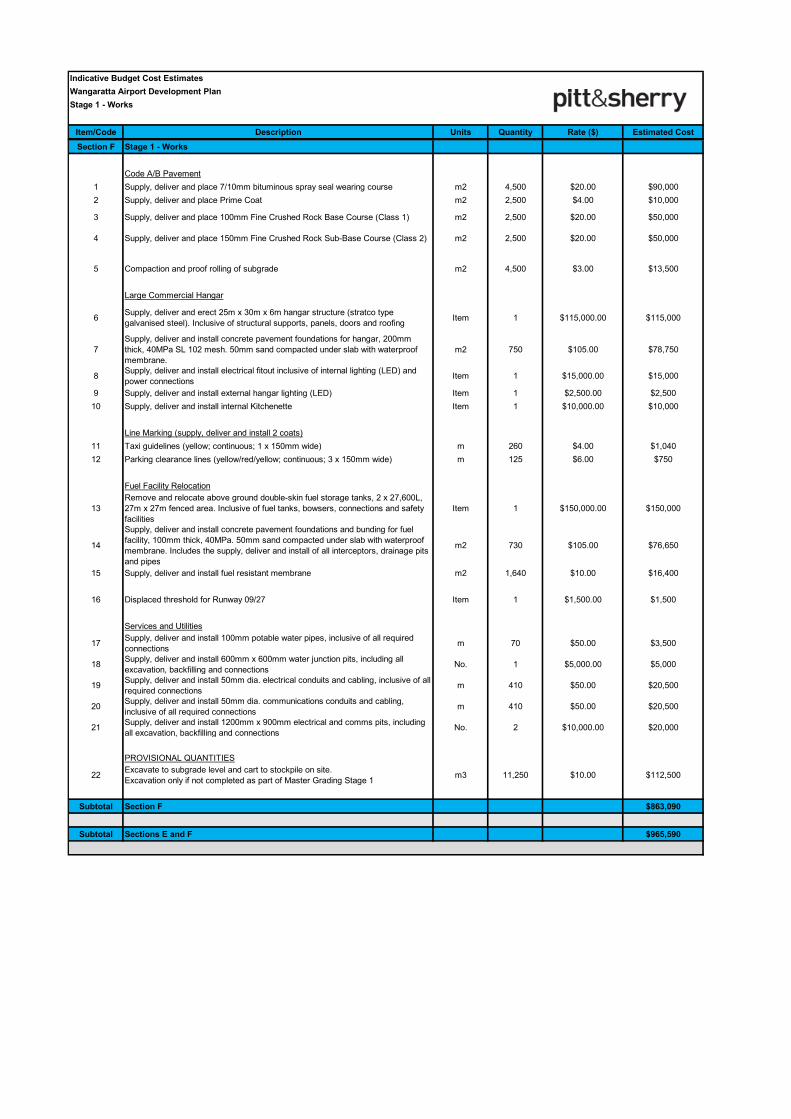
Indicative Budget Cost Estimates
Wangaratta Airport Development Plan
Stage 1 - Works
Item/Code Description Units Quantity Rate ($) Estimated Cost
Section F Stage 1 - Works
Code A/B Pavement
1 Supply, deliver and place 7/10mm bituminous spray seal wearing course m2 4,500 $20.00 $90,000
2 Supply, deliver and place Prime Coat m2 2,500 $4.00 $10,000
3 Supply, deliver and place 100mm Fine Crushed Rock Base Course (Class 1) m2 2,500 $20.00 $50,000
4 Supply, deliver and place 150mm Fine Crushed Rock Sub-Base Course (Class 2) m2 2,500 $20.00 $50,000
5 Compaction and proof rolling of subgrade m2 4,500 $3.00 $13,500
Large Commercial Hangar
6Supply, deliver and erect 25m x 30m x 6m hangar structure (stratco type
galvanised steel). Inclusive of structural supports, panels, doors and roofingItem 1 $115,000.00 $115,000
7
Supply, deliver and install concrete pavement foundations for hangar, 200mm
thick, 40MPa SL 102 mesh. 50mm sand compacted under slab with waterproof
membrane.
m2 750 $105.00 $78,750
8Supply, deliver and install electrical fitout inclusive of internal lighting (LED) and
power connectionsItem 1 $15,000.00 $15,000
9 Supply, deliver and install external hangar lighting (LED) Item 1 $2,500.00 $2,500
10 Supply, deliver and install internal Kitchenette Item 1 $10,000.00 $10,000
Line Marking (supply, deliver and install 2 coats)
11 Taxi guidelines (yellow; continuous; 1 x 150mm wide) m 260 $4.00 $1,040
12 Parking clearance lines (yellow/red/yellow; continuous; 3 x 150mm wide) m 125 $6.00 $750
Fuel Facility Relocation
13
Remove and relocate above ground double-skin fuel storage tanks, 2 x 27,600L,
27m x 27m fenced area. Inclusive of fuel tanks, bowsers, connections and safety
facilities
Item 1 $150,000.00 $150,000
14
Supply, deliver and install concrete pavement foundations and bunding for fuel
facility, 100mm thick, 40MPa. 50mm sand compacted under slab with waterproof
membrane. Includes the supply, deliver and install of all interceptors, drainage pits
and pipes
m2 730 $105.00 $76,650
15 Supply, deliver and install fuel resistant membrane m2 1,640 $10.00 $16,400
16 Displaced threshold for Runway 09/27 Item 1 $1,500.00 $1,500
Services and Utilities
17Supply, deliver and install 100mm potable water pipes, inclusive of all required
connectionsm 70 $50.00 $3,500
18Supply, deliver and install 600mm x 600mm water junction pits, including all
excavation, backfilling and connectionsNo. 1 $5,000.00 $5,000
19Supply, deliver and install 50mm dia. electrical conduits and cabling, inclusive of all
required connectionsm 410 $50.00 $20,500
20Supply, deliver and install 50mm dia. communications conduits and cabling,
inclusive of all required connectionsm 410 $50.00 $20,500
21Supply, deliver and install 1200mm x 900mm electrical and comms pits, including
all excavation, backfilling and connectionsNo. 2 $10,000.00 $20,000
PROVISIONAL QUANTITIES
22Excavate to subgrade level and cart to stockpile on site.
Excavation only if not completed as part of Master Grading Stage 1m3 11,250 $10.00 $112,500
Subtotal Section F $863,090
Subtotal Sections E and F $965,590
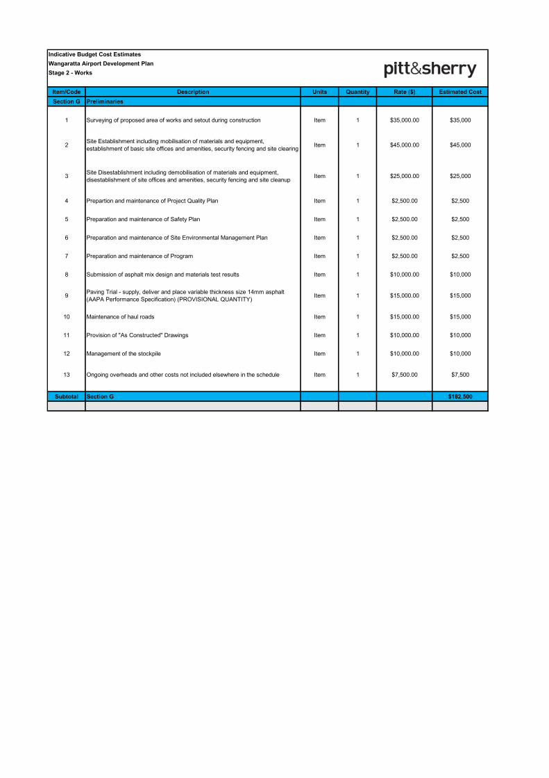
Indicative Budget Cost Estimates
Wangaratta Airport Development Plan
Stage 2 - Works
Item/Code Description Units Quantity Rate ($) Estimated Cost
Section G Preliminaries
1 Surveying of proposed area of works and setout during construction Item 1 $35,000.00 $35,000
2Site Establishment including mobilisation of materials and equipment,
establishment of basic site offices and amenities, security fencing and site clearingItem 1 $45,000.00 $45,000
3Site Disestablishment including demobilisation of materials and equipment,
disestablishment of site offices and amenities, security fencing and site cleanupItem 1 $25,000.00 $25,000
4 Prepartion and maintenance of Project Quality Plan Item 1 $2,500.00 $2,500
5 Preparation and maintenance of Safety Plan Item 1 $2,500.00 $2,500
6 Preparation and maintenance of Site Environmental Management Plan Item 1 $2,500.00 $2,500
7 Preparation and maintenance of Program Item 1 $2,500.00 $2,500
8 Submission of asphalt mix design and materials test results Item 1 $10,000.00 $10,000
9Paving Trial - supply, deliver and place variable thickness size 14mm asphalt
(AAPA Performance Specification) (PROVISIONAL QUANTITY)Item 1 $15,000.00 $15,000
10 Maintenance of haul roads Item 1 $15,000.00 $15,000
11 Provision of "As Constructed" Drawings Item 1 $10,000.00 $10,000
12 Management of the stockpile Item 1 $10,000.00 $10,000
13 Ongoing overheads and other costs not included elsewhere in the schedule Item 1 $7,500.00 $7,500
Subtotal Section G $182,500
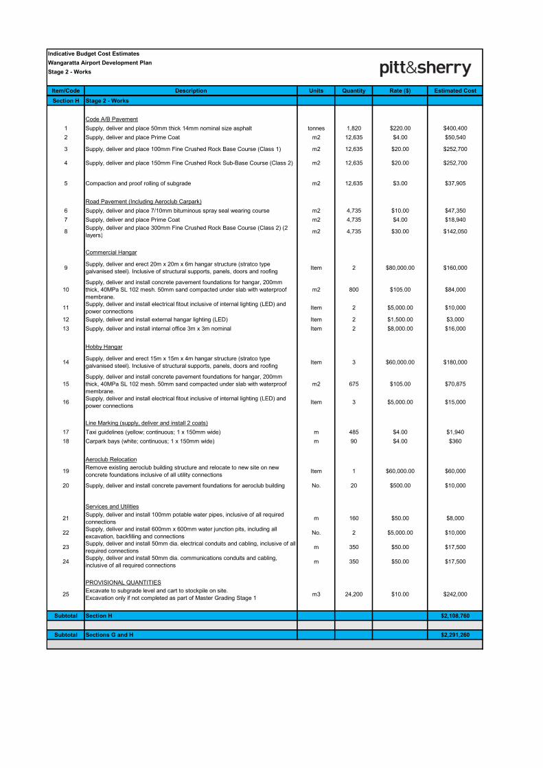
Indicative Budget Cost Estimates
Wangaratta Airport Development Plan
Stage 2 - Works
Item/Code Description Units Quantity Rate ($) Estimated Cost
Section H Stage 2 - Works
Code A/B Pavement
1 Supply, deliver and place 50mm thick 14mm nominal size asphalt tonnes 1,820 $220.00 $400,400
2 Supply, deliver and place Prime Coat m2 12,635 $4.00 $50,540
3 Supply, deliver and place 100mm Fine Crushed Rock Base Course (Class 1) m2 12,635 $20.00 $252,700
4 Supply, deliver and place 150mm Fine Crushed Rock Sub-Base Course (Class 2) m2 12,635 $20.00 $252,700
5 Compaction and proof rolling of subgrade m2 12,635 $3.00 $37,905
Road Pavement (Including Aeroclub Carpark)
6 Supply, deliver and place 7/10mm bituminous spray seal wearing course m2 4,735 $10.00 $47,350
7 Supply, deliver and place Prime Coat m2 4,735 $4.00 $18,940
8Supply, deliver and place 300mm Fine Crushed Rock Base Course (Class 2) (2
layers)m2 4,735 $30.00 $142,050
Commercial Hangar
9Supply, deliver and erect 20m x 20m x 6m hangar structure (stratco type
galvanised steel). Inclusive of structural supports, panels, doors and roofingItem 2 $80,000.00 $160,000
10
Supply, deliver and install concrete pavement foundations for hangar, 200mm
thick, 40MPa SL 102 mesh. 50mm sand compacted under slab with waterproof
membrane.
m2 800 $105.00 $84,000
11Supply, deliver and install electrical fitout inclusive of internal lighting (LED) and
power connectionsItem 2 $5,000.00 $10,000
12 Supply, deliver and install external hangar lighting (LED) Item 2 $1,500.00 $3,000
13 Supply, deliver and install internal office 3m x 3m nominal Item 2 $8,000.00 $16,000
Hobby Hangar
14Supply, deliver and erect 15m x 15m x 4m hangar structure (stratco type
galvanised steel). Inclusive of structural supports, panels, doors and roofingItem 3 $60,000.00 $180,000
15
Supply, deliver and install concrete pavement foundations for hangar, 200mm
thick, 40MPa SL 102 mesh. 50mm sand compacted under slab with waterproof
membrane.
m2 675 $105.00 $70,875
16Supply, deliver and install electrical fitout inclusive of internal lighting (LED) and
power connectionsItem 3 $5,000.00 $15,000
Line Marking (supply, deliver and install 2 coats)
17 Taxi guidelines (yellow; continuous; 1 x 150mm wide) m 485 $4.00 $1,940
18 Carpark bays (white; continuous; 1 x 150mm wide) m 90 $4.00 $360
Aeroclub Relocation
19Remove existing aeroclub building structure and relocate to new site on new
concrete foundations inclusive of all utility connectionsItem 1 $60,000.00 $60,000
20 Supply, deliver and install concrete pavement foundations for aeroclub building No. 20 $500.00 $10,000
Services and Utilities
21Supply, deliver and install 100mm potable water pipes, inclusive of all required
connectionsm 160 $50.00 $8,000
22Supply, deliver and install 600mm x 600mm water junction pits, including all
excavation, backfilling and connectionsNo. 2 $5,000.00 $10,000
23Supply, deliver and install 50mm dia. electrical conduits and cabling, inclusive of all
required connectionsm 350 $50.00 $17,500
24Supply, deliver and install 50mm dia. communications conduits and cabling,
inclusive of all required connectionsm 350 $50.00 $17,500
PROVISIONAL QUANTITIES
25Excavate to subgrade level and cart to stockpile on site.
Excavation only if not completed as part of Master Grading Stage 1m3 24,200 $10.00 $242,000
Subtotal Section H $2,108,760
Subtotal Sections G and H $2,291,260
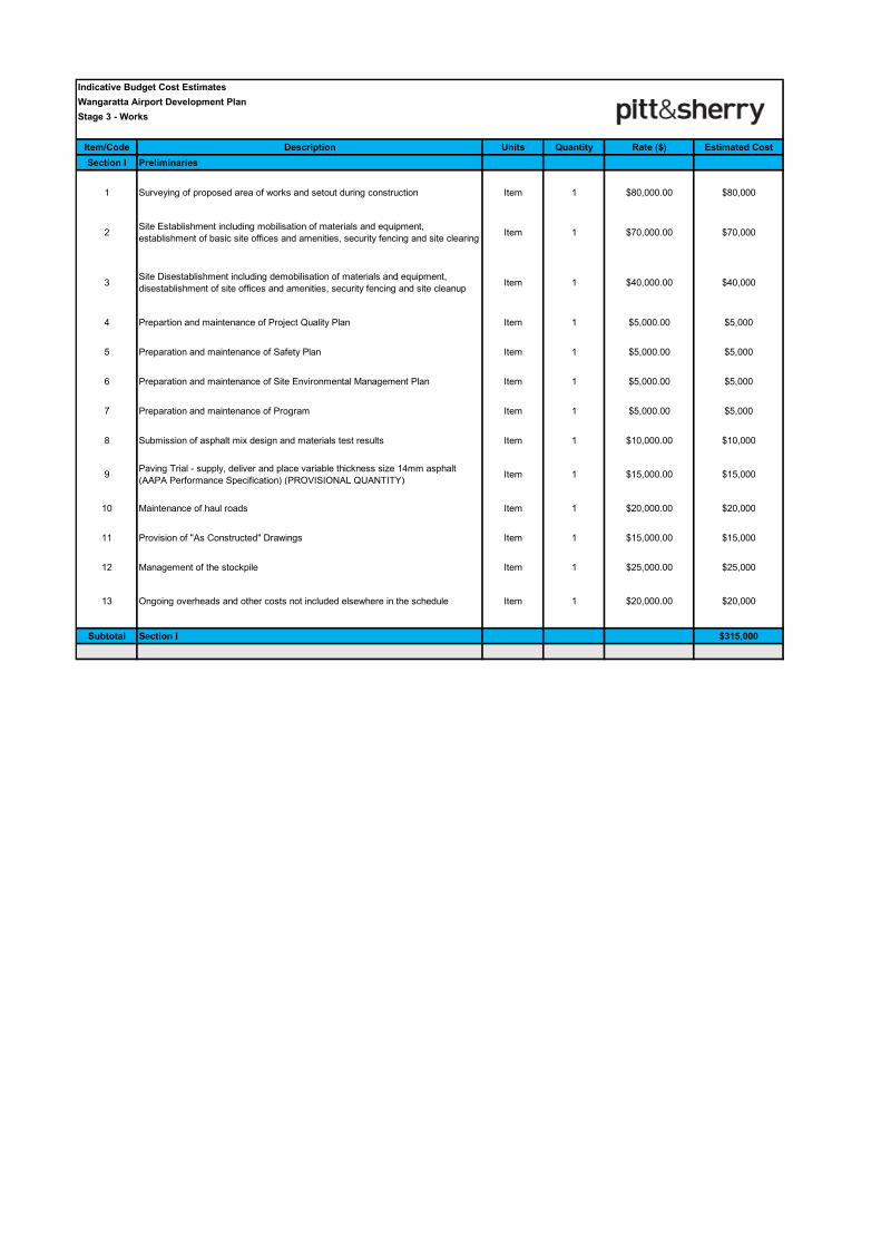
Indicative Budget Cost Estimates
Wangaratta Airport Development Plan
Stage 3 - Works
Item/Code Description Units Quantity Rate ($) Estimated Cost
Section I Preliminaries
1 Surveying of proposed area of works and setout during construction Item 1 $80,000.00 $80,000
2Site Establishment including mobilisation of materials and equipment,
establishment of basic site offices and amenities, security fencing and site clearingItem 1 $70,000.00 $70,000
3Site Disestablishment including demobilisation of materials and equipment,
disestablishment of site offices and amenities, security fencing and site cleanupItem 1 $40,000.00 $40,000
4 Prepartion and maintenance of Project Quality Plan Item 1 $5,000.00 $5,000
5 Preparation and maintenance of Safety Plan Item 1 $5,000.00 $5,000
6 Preparation and maintenance of Site Environmental Management Plan Item 1 $5,000.00 $5,000
7 Preparation and maintenance of Program Item 1 $5,000.00 $5,000
8 Submission of asphalt mix design and materials test results Item 1 $10,000.00 $10,000
9Paving Trial - supply, deliver and place variable thickness size 14mm asphalt
(AAPA Performance Specification) (PROVISIONAL QUANTITY)Item 1 $15,000.00 $15,000
10 Maintenance of haul roads Item 1 $20,000.00 $20,000
11 Provision of "As Constructed" Drawings Item 1 $15,000.00 $15,000
12 Management of the stockpile Item 1 $25,000.00 $25,000
13 Ongoing overheads and other costs not included elsewhere in the schedule Item 1 $20,000.00 $20,000
Subtotal Section I $315,000
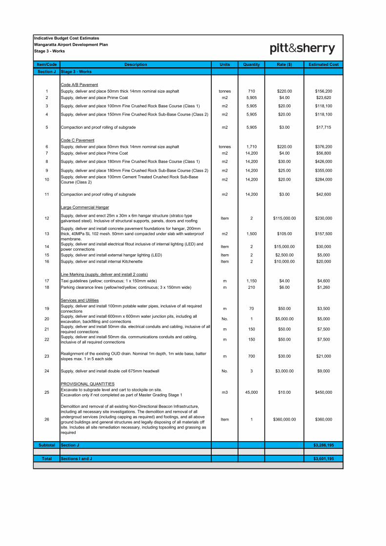
Indicative Budget Cost Estimates
Wangaratta Airport Development Plan
Stage 3 - Works
Item/Code Description Units Quantity Rate ($) Estimated Cost
Section J Stage 3 - Works
Code A/B Pavement
1 Supply, deliver and place 50mm thick 14mm nominal size asphalt tonnes 710 $220.00 $156,200
2 Supply, deliver and place Prime Coat m2 5,905 $4.00 $23,620
3 Supply, deliver and place 100mm Fine Crushed Rock Base Course (Class 1) m2 5,905 $20.00 $118,100
4 Supply, deliver and place 150mm Fine Crushed Rock Sub-Base Course (Class 2) m2 5,905 $20.00 $118,100
5 Compaction and proof rolling of subgrade m2 5,905 $3.00 $17,715
Code C Pavement
6 Supply, deliver and place 50mm thick 14mm nominal size asphalt tonnes 1,710 $220.00 $376,200
7 Supply, deliver and place Prime Coat m2 14,200 $4.00 $56,800
8 Supply, deliver and place 180mm Fine Crushed Rock Base Course (Class 1) m2 14,200 $30.00 $426,000
9 Supply, deliver and place 180mm Fine Crushed Rock Sub-Base Course (Class 2) m2 14,200 $25.00 $355,000
10Supply, deliver and place 100mm Cement Treated Crushed Rock Sub-Base
Course (Class 2)m2 14,200 $20.00 $284,000
11 Compaction and proof rolling of subgrade m2 14,200 $3.00 $42,600
Large Commercial Hangar
12Supply, deliver and erect 25m x 30m x 6m hangar structure (stratco type
galvanised steel). Inclusive of structural supports, panels, doors and roofingItem 2 $115,000.00 $230,000
13
Supply, deliver and install concrete pavement foundations for hangar, 200mm
thick, 40MPa SL 102 mesh. 50mm sand compacted under slab with waterproof
membrane.
m2 1,500 $105.00 $157,500
14Supply, deliver and install electrical fitout inclusive of internal lighting (LED) and
power connectionsItem 2 $15,000.00 $30,000
15 Supply, deliver and install external hangar lighting (LED) Item 2 $2,500.00 $5,000
16 Supply, deliver and install internal Kitchenette Item 2 $10,000.00 $20,000
Line Marking (supply, deliver and install 2 coats)
17 Taxi guidelines (yellow; continuous; 1 x 150mm wide) m 1,150 $4.00 $4,600
18 Parking clearance lines (yellow/red/yellow; continuous; 3 x 150mm wide) m 210 $6.00 $1,260
Services and Utilities
19Supply, deliver and install 100mm potable water pipes, inclusive of all required
connectionsm 70 $50.00 $3,500
20Supply, deliver and install 600mm x 600mm water junction pits, including all
excavation, backfilling and connectionsNo. 1 $5,000.00 $5,000
21Supply, deliver and install 50mm dia. electrical conduits and cabling, inclusive of all
required connectionsm 150 $50.00 $7,500
22Supply, deliver and install 50mm dia. communications conduits and cabling,
inclusive of all required connectionsm 150 $50.00 $7,500
23Realignment of the existing OUD drain. Nominal 1m depth, 1m wide base, batter
slopes max. 1 in 5 each sidem 700 $30.00 $21,000
24 Supply, deliver and install double cell 675mm headwall No. 3 $3,000.00 $9,000
PROVISIONAL QUANTITIES
25Excavate to subgrade level and cart to stockpile on site.
Excavation only if not completed as part of Master Grading Stage 1m3 45,000 $10.00 $450,000
26
Demolition and removal of all existing Non-Directional Beacon Infrastructure,
including all necessary site investigations. The demolition and removal of all
undergroud services (including capping as required) and footings, and all above
ground buildings and general structures and legally disposing of all materials off
site. Includes all site remediation necessary, including topsoiling and grassing as
required
Item 1 $360,000.00 $360,000
Subtotal Section J $3,286,195
Total Sections I and J $3,601,195
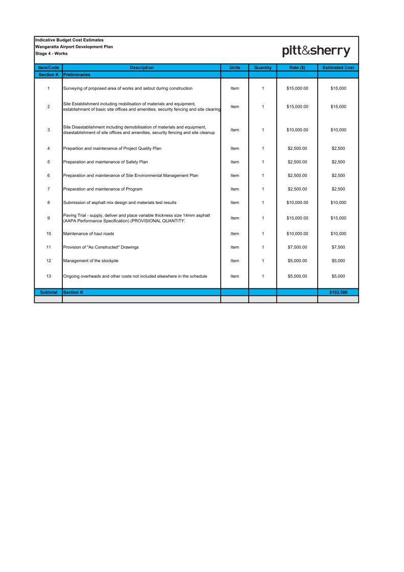
Indicative Budget Cost Estimates
Wangaratta Airport Development Plan
Stage 4 - Works
Item/Code Description Units Quantity Rate ($) Estimated Cost
Section K Preliminaries
1 Surveying of proposed area of works and setout during construction Item 1 $15,000.00 $15,000
2Site Establishment including mobilisation of materials and equipment,
establishment of basic site offices and amenities, security fencing and site clearingItem 1 $15,000.00 $15,000
3Site Disestablishment including demobilisation of materials and equipment,
disestablishment of site offices and amenities, security fencing and site cleanupItem 1 $10,000.00 $10,000
4 Prepartion and maintenance of Project Quality Plan Item 1 $2,500.00 $2,500
5 Preparation and maintenance of Safety Plan Item 1 $2,500.00 $2,500
6 Preparation and maintenance of Site Environmental Management Plan Item 1 $2,500.00 $2,500
7 Preparation and maintenance of Program Item 1 $2,500.00 $2,500
8 Submission of asphalt mix design and materials test results Item 1 $10,000.00 $10,000
9Paving Trial - supply, deliver and place variable thickness size 14mm asphalt
(AAPA Performance Specification) (PROVISIONAL QUANTITY)Item 1 $15,000.00 $15,000
10 Maintenance of haul roads Item 1 $10,000.00 $10,000
11 Provision of "As Constructed" Drawings Item 1 $7,500.00 $7,500
12 Management of the stockpile Item 1 $5,000.00 $5,000
13 Ongoing overheads and other costs not included elsewhere in the schedule Item 1 $5,000.00 $5,000
Subtotal Section K $102,500
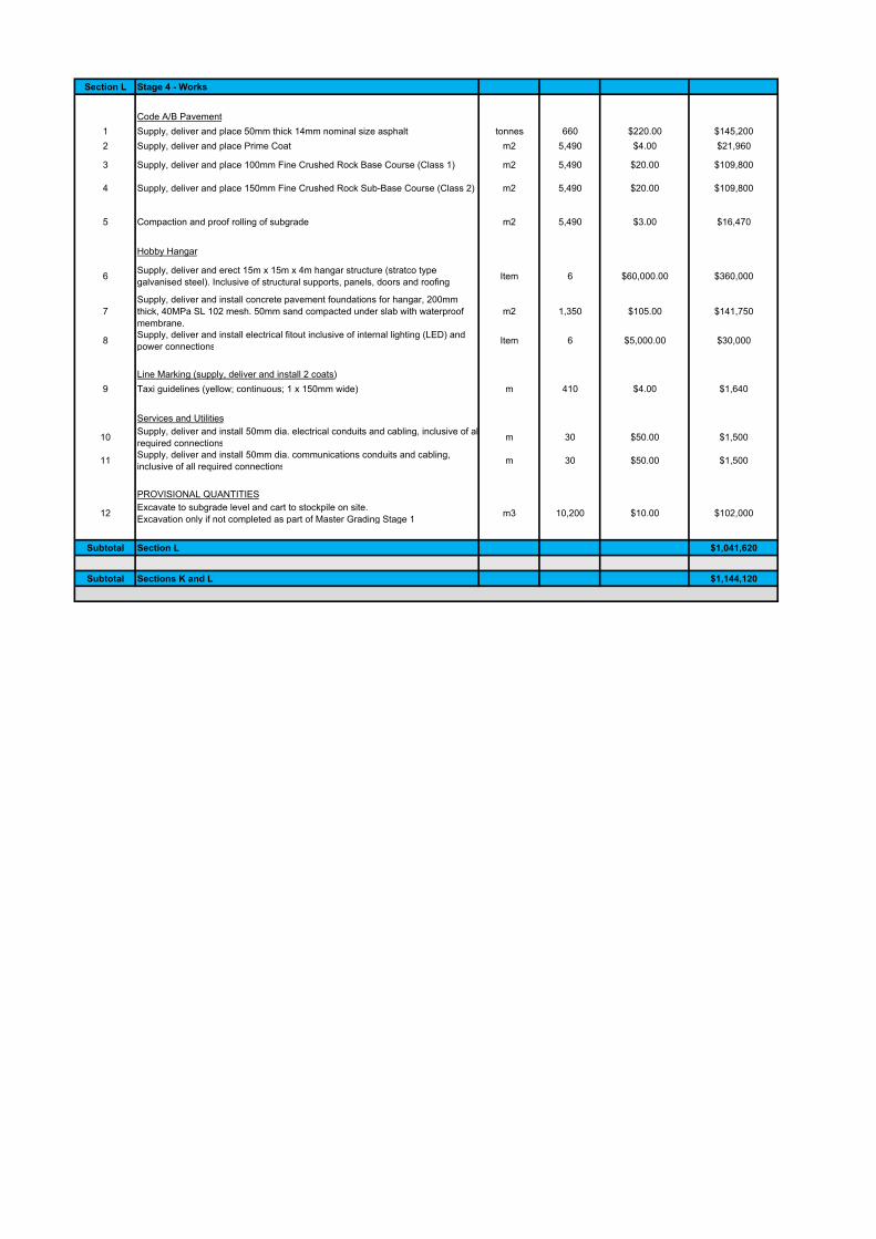
Section L Stage 4 - Works
Code A/B Pavement
1 Supply, deliver and place 50mm thick 14mm nominal size asphalt tonnes 660 $220.00 $145,200
2 Supply, deliver and place Prime Coat m2 5,490 $4.00 $21,960
3 Supply, deliver and place 100mm Fine Crushed Rock Base Course (Class 1) m2 5,490 $20.00 $109,800
4 Supply, deliver and place 150mm Fine Crushed Rock Sub-Base Course (Class 2) m2 5,490 $20.00 $109,800
5 Compaction and proof rolling of subgrade m2 5,490 $3.00 $16,470
Hobby Hangar
6Supply, deliver and erect 15m x 15m x 4m hangar structure (stratco type
galvanised steel). Inclusive of structural supports, panels, doors and roofingItem 6 $60,000.00 $360,000
7
Supply, deliver and install concrete pavement foundations for hangar, 200mm
thick, 40MPa SL 102 mesh. 50mm sand compacted under slab with waterproof
membrane.
m2 1,350 $105.00 $141,750
8Supply, deliver and install electrical fitout inclusive of internal lighting (LED) and
power connectionsItem 6 $5,000.00 $30,000
Line Marking (supply, deliver and install 2 coats)
9 Taxi guidelines (yellow; continuous; 1 x 150mm wide) m 410 $4.00 $1,640
Services and Utilities
10Supply, deliver and install 50mm dia. electrical conduits and cabling, inclusive of all
required connectionsm 30 $50.00 $1,500
11Supply, deliver and install 50mm dia. communications conduits and cabling,
inclusive of all required connectionsm 30 $50.00 $1,500
PROVISIONAL QUANTITIES
12Excavate to subgrade level and cart to stockpile on site.
Excavation only if not completed as part of Master Grading Stage 1m3 10,200 $10.00 $102,000
Subtotal Section L $1,041,620
Subtotal Sections K and L $1,144,120
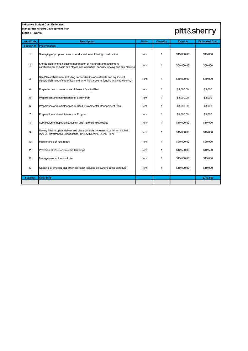
Indicative Budget Cost Estimates
Wangaratta Airport Development Plan
Stage 5 - Works
Item/Code Description Units Quantity Rate ($) Estimated Cost
Section M Preliminaries
1 Surveying of proposed area of works and setout during construction Item 1 $45,000.00 $45,000
2Site Establishment including mobilisation of materials and equipment,
establishment of basic site offices and amenities, security fencing and site clearingItem 1 $50,000.00 $50,000
3Site Disestablishment including demobilisation of materials and equipment,
disestablishment of site offices and amenities, security fencing and site cleanupItem 1 $30,000.00 $30,000
4 Prepartion and maintenance of Project Quality Plan Item 1 $3,000.00 $3,000
5 Preparation and maintenance of Safety Plan Item 1 $3,000.00 $3,000
6 Preparation and maintenance of Site Environmental Management Plan Item 1 $3,000.00 $3,000
7 Preparation and maintenance of Program Item 1 $3,000.00 $3,000
8 Submission of asphalt mix design and materials test results Item 1 $10,000.00 $10,000
9Paving Trial - supply, deliver and place variable thickness size 14mm asphalt
(AAPA Performance Specification) (PROVISIONAL QUANTITY)Item 1 $15,000.00 $15,000
10 Maintenance of haul roads Item 1 $20,000.00 $20,000
11 Provision of "As Constructed" Drawings Item 1 $12,500.00 $12,500
12 Management of the stockpile Item 1 $15,000.00 $15,000
13 Ongoing overheads and other costs not included elsewhere in the schedule Item 1 $10,000.00 $10,000
Subtotal Section M $219,500
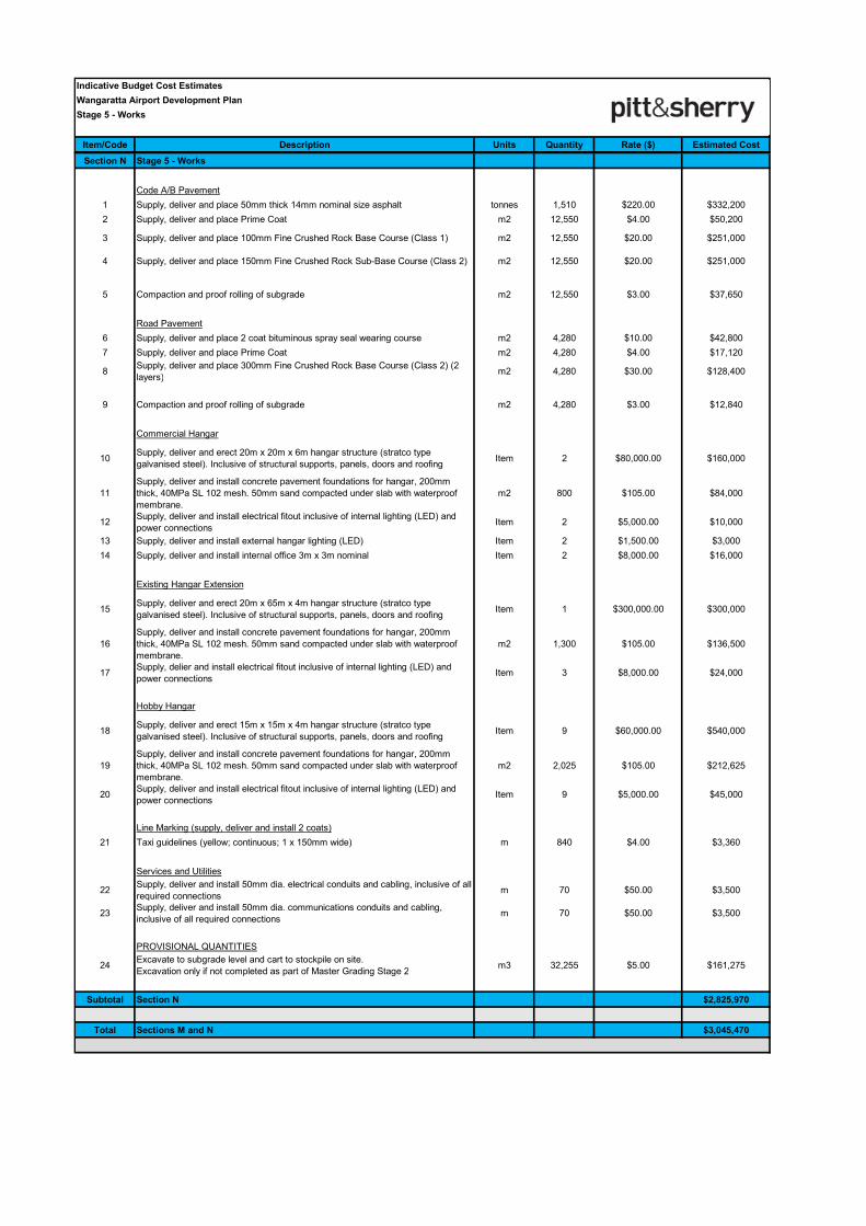
Indicative Budget Cost Estimates
Wangaratta Airport Development Plan
Stage 5 - Works
Item/Code Description Units Quantity Rate ($) Estimated Cost
Section N Stage 5 - Works
Code A/B Pavement
1 Supply, deliver and place 50mm thick 14mm nominal size asphalt tonnes 1,510 $220.00 $332,200
2 Supply, deliver and place Prime Coat m2 12,550 $4.00 $50,200
3 Supply, deliver and place 100mm Fine Crushed Rock Base Course (Class 1) m2 12,550 $20.00 $251,000
4 Supply, deliver and place 150mm Fine Crushed Rock Sub-Base Course (Class 2) m2 12,550 $20.00 $251,000
5 Compaction and proof rolling of subgrade m2 12,550 $3.00 $37,650
Road Pavement
6 Supply, deliver and place 2 coat bituminous spray seal wearing course m2 4,280 $10.00 $42,800
7 Supply, deliver and place Prime Coat m2 4,280 $4.00 $17,120
8Supply, deliver and place 300mm Fine Crushed Rock Base Course (Class 2) (2
layers)m2 4,280 $30.00 $128,400
9 Compaction and proof rolling of subgrade m2 4,280 $3.00 $12,840
Commercial Hangar
10Supply, deliver and erect 20m x 20m x 6m hangar structure (stratco type
galvanised steel). Inclusive of structural supports, panels, doors and roofingItem 2 $80,000.00 $160,000
11
Supply, deliver and install concrete pavement foundations for hangar, 200mm
thick, 40MPa SL 102 mesh. 50mm sand compacted under slab with waterproof
membrane.
m2 800 $105.00 $84,000
12Supply, deliver and install electrical fitout inclusive of internal lighting (LED) and
power connectionsItem 2 $5,000.00 $10,000
13 Supply, deliver and install external hangar lighting (LED) Item 2 $1,500.00 $3,000
14 Supply, deliver and install internal office 3m x 3m nominal Item 2 $8,000.00 $16,000
Existing Hangar Extension
15Supply, deliver and erect 20m x 65m x 4m hangar structure (stratco type
galvanised steel). Inclusive of structural supports, panels, doors and roofingItem 1 $300,000.00 $300,000
16
Supply, deliver and install concrete pavement foundations for hangar, 200mm
thick, 40MPa SL 102 mesh. 50mm sand compacted under slab with waterproof
membrane.
m2 1,300 $105.00 $136,500
17Supply, delier and install electrical fitout inclusive of internal lighting (LED) and
power connectionsItem 3 $8,000.00 $24,000
Hobby Hangar
18Supply, deliver and erect 15m x 15m x 4m hangar structure (stratco type
galvanised steel). Inclusive of structural supports, panels, doors and roofingItem 9 $60,000.00 $540,000
19
Supply, deliver and install concrete pavement foundations for hangar, 200mm
thick, 40MPa SL 102 mesh. 50mm sand compacted under slab with waterproof
membrane.
m2 2,025 $105.00 $212,625
20Supply, deliver and install electrical fitout inclusive of internal lighting (LED) and
power connectionsItem 9 $5,000.00 $45,000
Line Marking (supply, deliver and install 2 coats)
21 Taxi guidelines (yellow; continuous; 1 x 150mm wide) m 840 $4.00 $3,360
Services and Utilities
22Supply, deliver and install 50mm dia. electrical conduits and cabling, inclusive of all
required connectionsm 70 $50.00 $3,500
23Supply, deliver and install 50mm dia. communications conduits and cabling,
inclusive of all required connectionsm 70 $50.00 $3,500
PROVISIONAL QUANTITIES
24Excavate to subgrade level and cart to stockpile on site.
Excavation only if not completed as part of Master Grading Stage 2m3 32,255 $5.00 $161,275
Subtotal Section N $2,825,970
Total Sections M and N $3,045,470
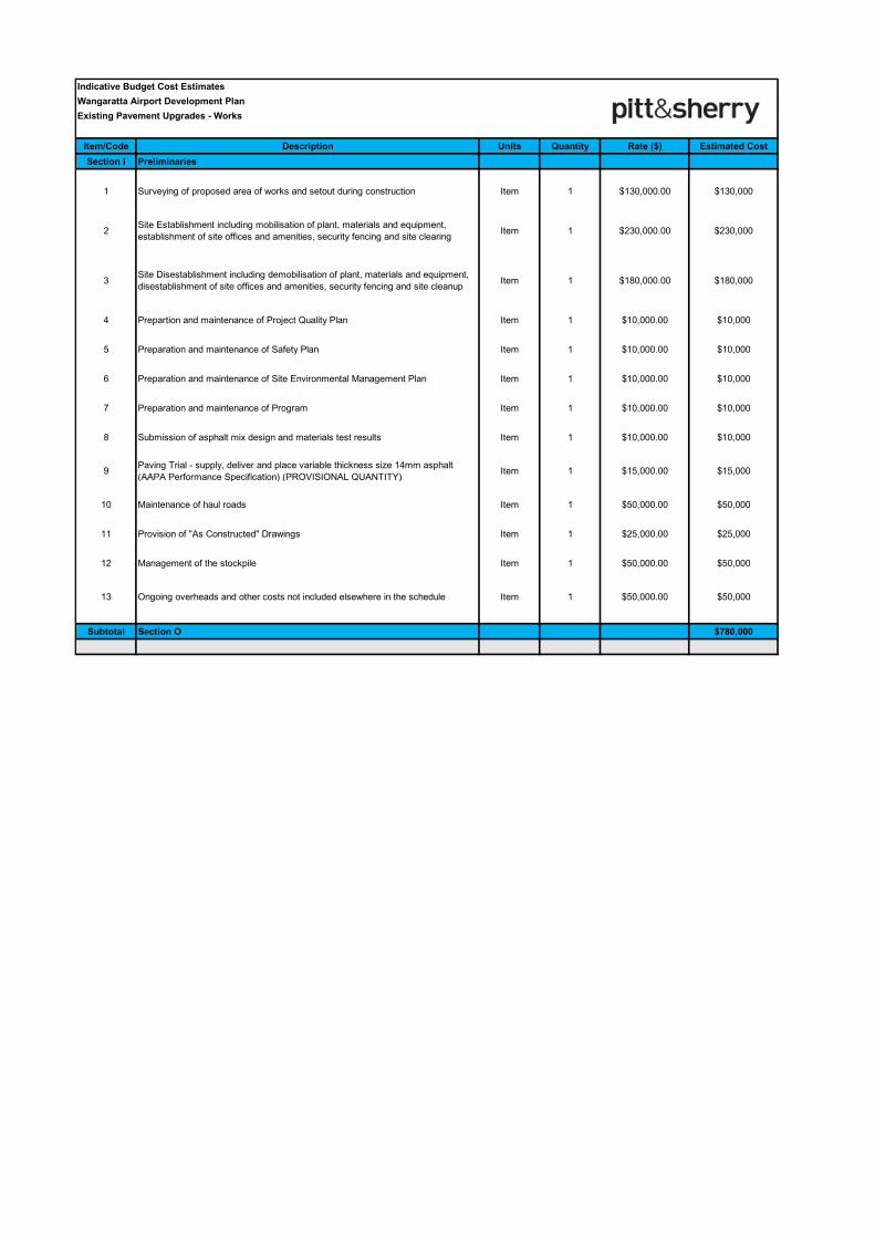
Indicative Budget Cost Estimates
Wangaratta Airport Development Plan
Existing Pavement Upgrades - Works
Item/Code Description Units Quantity Rate ($) Estimated Cost
Section I Preliminaries
1 Surveying of proposed area of works and setout during construction Item 1 $130,000.00 $130,000
2Site Establishment including mobilisation of plant, materials and equipment,
establishment of site offices and amenities, security fencing and site clearingItem 1 $230,000.00 $230,000
3Site Disestablishment including demobilisation of plant, materials and equipment,
disestablishment of site offices and amenities, security fencing and site cleanupItem 1 $180,000.00 $180,000
4 Prepartion and maintenance of Project Quality Plan Item 1 $10,000.00 $10,000
5 Preparation and maintenance of Safety Plan Item 1 $10,000.00 $10,000
6 Preparation and maintenance of Site Environmental Management Plan Item 1 $10,000.00 $10,000
7 Preparation and maintenance of Program Item 1 $10,000.00 $10,000
8 Submission of asphalt mix design and materials test results Item 1 $10,000.00 $10,000
9Paving Trial - supply, deliver and place variable thickness size 14mm asphalt
(AAPA Performance Specification) (PROVISIONAL QUANTITY)Item 1 $15,000.00 $15,000
10 Maintenance of haul roads Item 1 $50,000.00 $50,000
11 Provision of "As Constructed" Drawings Item 1 $25,000.00 $25,000
12 Management of the stockpile Item 1 $50,000.00 $50,000
13 Ongoing overheads and other costs not included elsewhere in the schedule Item 1 $50,000.00 $50,000
Subtotal Section O $780,000
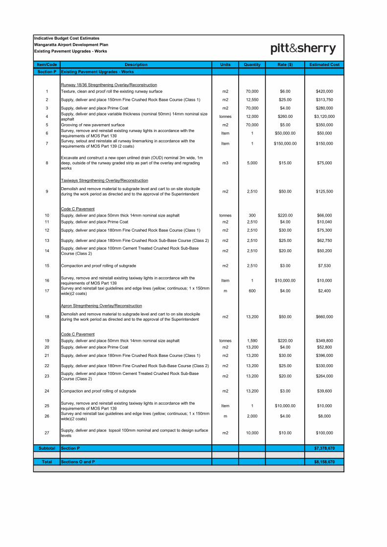
Indicative Budget Cost Estimates
Wangaratta Airport Development Plan
Existing Pavement Upgrades - Works
Item/Code Description Units Quantity Rate ($) Estimated Cost
Section P Existing Pavement Upgrades - Works
Runway 18/36 Stregnthening Overlay/Reconstruction
1 Texture, clean and proof roll the existing runway surface m2 70,000 $6.00 $420,000
2 Supply, deliver and place 150mm Fine Crushed Rock Base Course (Class 1) m2 12,550 $25.00 $313,750
3 Supply, deliver and place Prime Coat m2 70,000 $4.00 $280,000
4Supply, deliver and place variable thickness (nominal 50mm) 14mm nominal size
asphalttonnes 12,000 $260.00 $3,120,000
5 Grooving of new pavement surface m2 70,000 $5.00 $350,000
6Survey, remove and reinstall existing runway lights in accordance with the
requirements of MOS Part 139Item 1 $50,000.00 $50,000
7Survey, setout and reinstate all runway linemarking in accordance with the
requirements of MOS Part 139 (2 coats)Item 1 $150,000.00 $150,000
8
Excavate and construct a new open unlined drain (OUD) nominal 3m wide, 1m
deep, outside of the runway graded strip as part of the overlay and regrading
works
m3 5,000 $15.00 $75,000
Taxiways Stregnthening Overlay/Reconstruction
9Demolish and remove material to subgrade level and cart to on site stockpile
during the work period as directed and to the approval of the Superintendentm2 2,510 $50.00 $125,500
Code C Pavement
10 Supply, deliver and place 50mm thick 14mm nominal size asphalt tonnes 300 $220.00 $66,000
11 Supply, deliver and place Prime Coat m2 2,510 $4.00 $10,040
12 Supply, deliver and place 180mm Fine Crushed Rock Base Course (Class 1) m2 2,510 $30.00 $75,300
13 Supply, deliver and place 180mm Fine Crushed Rock Sub-Base Course (Class 2) m2 2,510 $25.00 $62,750
14Supply, deliver and place 100mm Cement Treated Crushed Rock Sub-Base
Course (Class 2)m2 2,510 $20.00 $50,200
15 Compaction and proof rolling of subgrade m2 2,510 $3.00 $7,530
16Survey, remove and reinstall existing taxiway lights in accordance with the
requirements of MOS Part 139Item 1 $10,000.00 $10,000
17Survey and reinstall taxi guidelines and edge lines (yellow; continuous; 1 x 150mm
wide)(2 coats)m 600 $4.00 $2,400
Apron Stregnthening Overlay/Reconstruction
18Demolish and remove material to subgrade level and cart to on site stockpile
during the work period as directed and to the approval of the Superintendentm2 13,200 $50.00 $660,000
Code C Pavement
19 Supply, deliver and place 50mm thick 14mm nominal size asphalt tonnes 1,590 $220.00 $349,800
20 Supply, deliver and place Prime Coat m2 13,200 $4.00 $52,800
21 Supply, deliver and place 180mm Fine Crushed Rock Base Course (Class 1) m2 13,200 $30.00 $396,000
22 Supply, deliver and place 180mm Fine Crushed Rock Sub-Base Course (Class 2) m2 13,200 $25.00 $330,000
23Supply, deliver and place 100mm Cement Treated Crushed Rock Sub-Base
Course (Class 2)m2 13,200 $20.00 $264,000
24 Compaction and proof rolling of subgrade m2 13,200 $3.00 $39,600
25Survey, remove and reinstall existing taxiway lights in accordance with the
requirements of MOS Part 139Item 1 $10,000.00 $10,000
26Survey and reinstall taxi guidelines and edge lines (yellow; continuous; 1 x 150mm
wide)(2 coats)m 2,000 $4.00 $8,000
27Supply, deliver and place topsoil 100mm nominal and compact to design surface
levelsm2 10,000 $10.00 $100,000
Subtotal Section P $7,378,670
Total Sections O and P $8,158,670
ref: ML18431 - Wangaratta Airport Infrastructure Development Plan Rev B/CF/SO
Concept Drawing
Development (History)
Appendix C
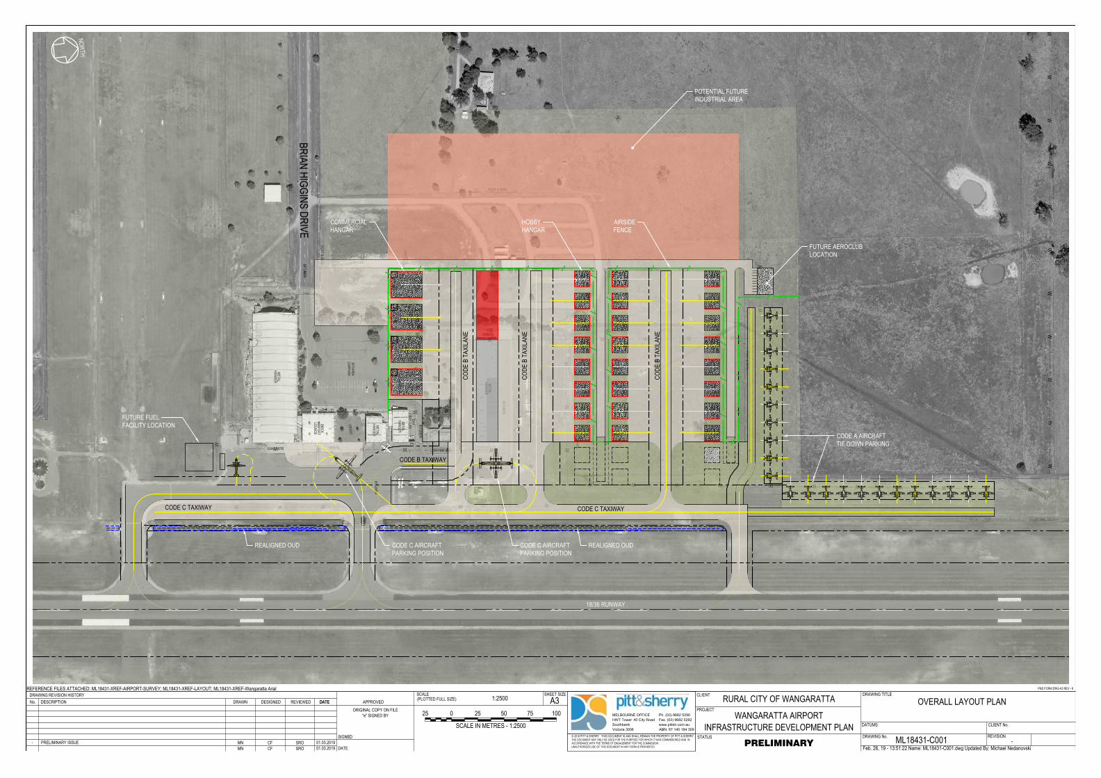
DDD
DA
M
GR
AS
S
BIT
UM
EN
BIT
UM
EN
BIT
UM
EN
CA
RP
AR
K
BIT
UM
EN
ME
TA
L
HA
NG
ER
ME
TA
L
HA
NG
ER
ME
TA
L
HA
NG
ER
BR
IC
K
AIR
PO
RT
LO
UN
GE
OF
FIC
E
CO
NT
AIN
ER
ME
TA
L
HA
NG
ER
FU
EL
TA
NK
FU
EL
BO
WS
ER
S
PO
ST
&
W
IR
E
PO
ST
&
W
IR
E
POST & WIRE
STEEL RAIL
PO
ST
&
W
IR
E
LOW PINE RAIL
LO
W P
IN
E R
AIL
G
RA
SS
G
RA
SS
GR
AS
S
GR
AS
S
GRAVEL
GA
RD
EN
BIT
UM
EN
GRAVEL
CONCRETE
GRAVEL
GRAVEL
G
R
A
V
E
L
SH
ED
SH
ED
WE
AT
HE
RB
OA
RD
AE
RO
C
LU
B
LO
UN
GE
GA
S
BO
TT
LE
S
1200x600
1200x500
1200x500
1800x1100
1800x1100
1800x1100
Ø150
Ø300
Ø100
Ø300
Ø300
Ø150
Ø150
Ø300
Ø
3
7
5
PO
ST
&
W
IR
E
W W W W W W W W
WW
BR
IA
N H
IG
GIN
S D
RIV
E
CA
RA
VA
N P
AR
K
WW
WW
WW
WW
WW
W
WWWWWWWWWWW
WW
W
WWWWWWW
W
W W W
W
WWWWWW
WW
W
B1
00
B1
00
B1
00
B1
00
B1
00
B1
00
B1
00
B1
00
B1
00
B1
00
Q4
00
Q4
00
Q4
00
Q4
00
B100B100 B100 B100 B100 B100 B100B100B100B100 B100 B100
Q
4
0
0
Q
4
0
0
METRO III
M
ETRO
II
I
www.pittsh.com.au
ABN 67 140 184 309
MELBOURNE OFFICE
HWT Tower 40 City Road
Southbank
Victoria 3006
Ph. (03) 9682 5290
Fax. (03) 9682 5292
DRAWING No.
DRAWING TITLE
STATUS
SCALEDRAWING REVISION HISTORY CLIENTA3
PROJECT
SHEET SIZE(PLOTTED FULL SIZE)
© 2016 PITT & SHERRY THIS DOCUMENT IS AND SHALL REMAIN THE PROPERTY OF PITT & SHERRY.THE DOCUMENT MAY ONLY BE USED FOR THE PURPOSE FOR WHICH IT WAS COMMISSIONED AND INACCORDANCE WITH THE TERMS OF ENGAGEMENT FOR THE COMMISSION.UNAUTHORISED USE OF THIS DOCUMENT IN ANY FORM IS PROHIBITED.
REFERENCE FILES ATTACHED: ML18431-XREF-AIRPORT-SURVEY; ML18431-XREF-LAYOUT; ML18431-XREF-Wangaratta Arial
DESCRIPTIONNo. DATE APPROVED
SIGNED
DATE
DATUMS: CLIENT No.
ORIGINAL COPY ON FILE"e" SIGNED BY
P&S FORM DRG-A3 REV - 8
REVISION
REVIEWED DATEDRAWN DESIGNED
Feb. 26, 19 - 13:51:22 Name: ML18431-C001.dwg Updated By: Michael Nedanovski
RURAL CITY OF WANGARATTA
WANGARATTA AIRPORTINFRASTRUCTURE DEVELOPMENT PLAN
OVERALL LAYOUT PLAN
ML18431-C001 -PRELIMINARY
1:2500
MN CF SRO 01.03.2019- PRELIMINARY ISSUE MN CF SRO 01.03.2019
0 10050
SCALE IN METRES - 1:2500
7525 25
NORTH
POTENTIAL FUTUREINDUSTRIAL AREA
FUTURE AEROCLUBLOCATION
CODE A AIRCRAFTTIE DOWN PARKING
REALIGNED OUD
COMMERCIALHANGAR
HOBBYHANGAR
FUTURE FUELFACILITY LOCATION
CODE C TAXIWAY
CODE
B T
AXILA
NE
CODE
B T
AXILA
NE
CODE
B T
AXILA
NE
CODE C TAXIWAY
CODE B TAXIWAY
CODE C AIRCRAFTPARKING POSITION
CODE C AIRCRAFTPARKING POSITION
REALIGNED OUD
AIRSIDEFENCE
18/36 RUNWAY
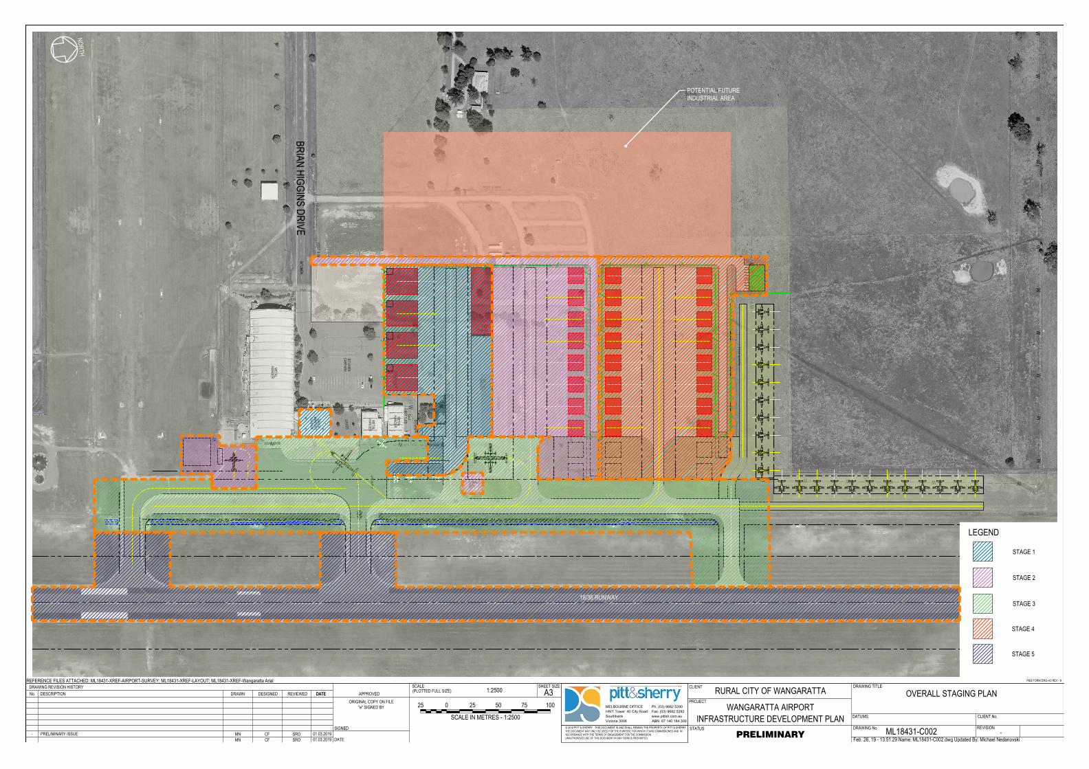
DDD
DA
M
GR
AS
S
BIT
UM
EN
BIT
UM
EN
BIT
UM
EN
CA
RP
AR
K
BIT
UM
EN
ME
TA
L
HA
NG
ER
ME
TA
L
HA
NG
ER
ME
TA
L
HA
NG
ER
BR
IC
K
AIR
PO
RT
LO
UN
GE
OF
FIC
E
CO
NT
AIN
ER
ME
TA
L
HA
NG
ER
FU
EL
TA
NK
FU
EL
BO
WS
ER
S
PO
ST
&
W
IR
E
PO
ST
&
W
IR
E
POST & WIRE
STEEL RAIL
PO
ST
&
W
IR
E
LOW PINE RAIL
LO
W P
IN
E R
AIL
G
RA
SS
G
RA
SS
GR
AS
S
GR
AS
S
GRAVEL
GA
RD
EN
BIT
UM
EN
GRAVEL
CONCRETE
GRAVEL
GRAVEL
G
R
A
V
E
L
SH
ED
SH
ED
WE
AT
HE
RB
OA
RD
AE
RO
C
LU
B
LO
UN
GE
GA
S
BO
TT
LE
S
1200x600
1200x500
1200x500
1800x1100
1800x1100
1800x1100
Ø150
Ø300
Ø100
Ø300
Ø300
Ø150
Ø150
Ø300
Ø
3
7
5
PO
ST
&
W
IR
E
W W W W W W W W
WW
BR
IA
N H
IG
GIN
S D
RIV
E
CA
RA
VA
N P
AR
K
WW
WW
WW
WW
WW
W
WWWWWWWWWWW
WW
W
WWWWWWW
W
W W W
W
WWWWWW
WW
W
B1
00
B1
00
B1
00
B1
00
B1
00
B1
00
B1
00
B1
00
B1
00
B1
00
Q4
00
Q4
00
Q4
00
Q4
00
B100B100 B100 B100 B100 B100 B100B100B100B100 B100 B100
Q
4
0
0
Q
4
0
0
METRO III
M
ETRO
II
I
www.pittsh.com.au
ABN 67 140 184 309
MELBOURNE OFFICE
HWT Tower 40 City Road
Southbank
Victoria 3006
Ph. (03) 9682 5290
Fax. (03) 9682 5292
DRAWING No.
DRAWING TITLE
STATUS
SCALEDRAWING REVISION HISTORY CLIENTA3
PROJECT
SHEET SIZE(PLOTTED FULL SIZE)
© 2016 PITT & SHERRY THIS DOCUMENT IS AND SHALL REMAIN THE PROPERTY OF PITT & SHERRY.THE DOCUMENT MAY ONLY BE USED FOR THE PURPOSE FOR WHICH IT WAS COMMISSIONED AND INACCORDANCE WITH THE TERMS OF ENGAGEMENT FOR THE COMMISSION.UNAUTHORISED USE OF THIS DOCUMENT IN ANY FORM IS PROHIBITED.
REFERENCE FILES ATTACHED: ML18431-XREF-AIRPORT-SURVEY; ML18431-XREF-LAYOUT; ML18431-XREF-Wangaratta Arial
DESCRIPTIONNo. DATE APPROVED
SIGNED
DATE
DATUMS: CLIENT No.
ORIGINAL COPY ON FILE"e" SIGNED BY
P&S FORM DRG-A3 REV - 8
REVISION
REVIEWED DATEDRAWN DESIGNED
Feb. 26, 19 - 13:51:29 Name: ML18431-C002.dwg Updated By: Michael Nedanovski
RURAL CITY OF WANGARATTA
WANGARATTA AIRPORTINFRASTRUCTURE DEVELOPMENT PLAN
OVERALL STAGING PLAN
ML18431-C002 -PRELIMINARY
1:2500
MN CF SRO 01.03.2019- PRELIMINARY ISSUE MN CF SRO 01.03.2019
0 10050
SCALE IN METRES - 1:2500
7525 25
LEGEND
STAGE 1
STAGE 2
STAGE 3
STAGE 4
STAGE 5
NORTH
18/36 RUNWAY
POTENTIAL FUTUREINDUSTRIAL AREA
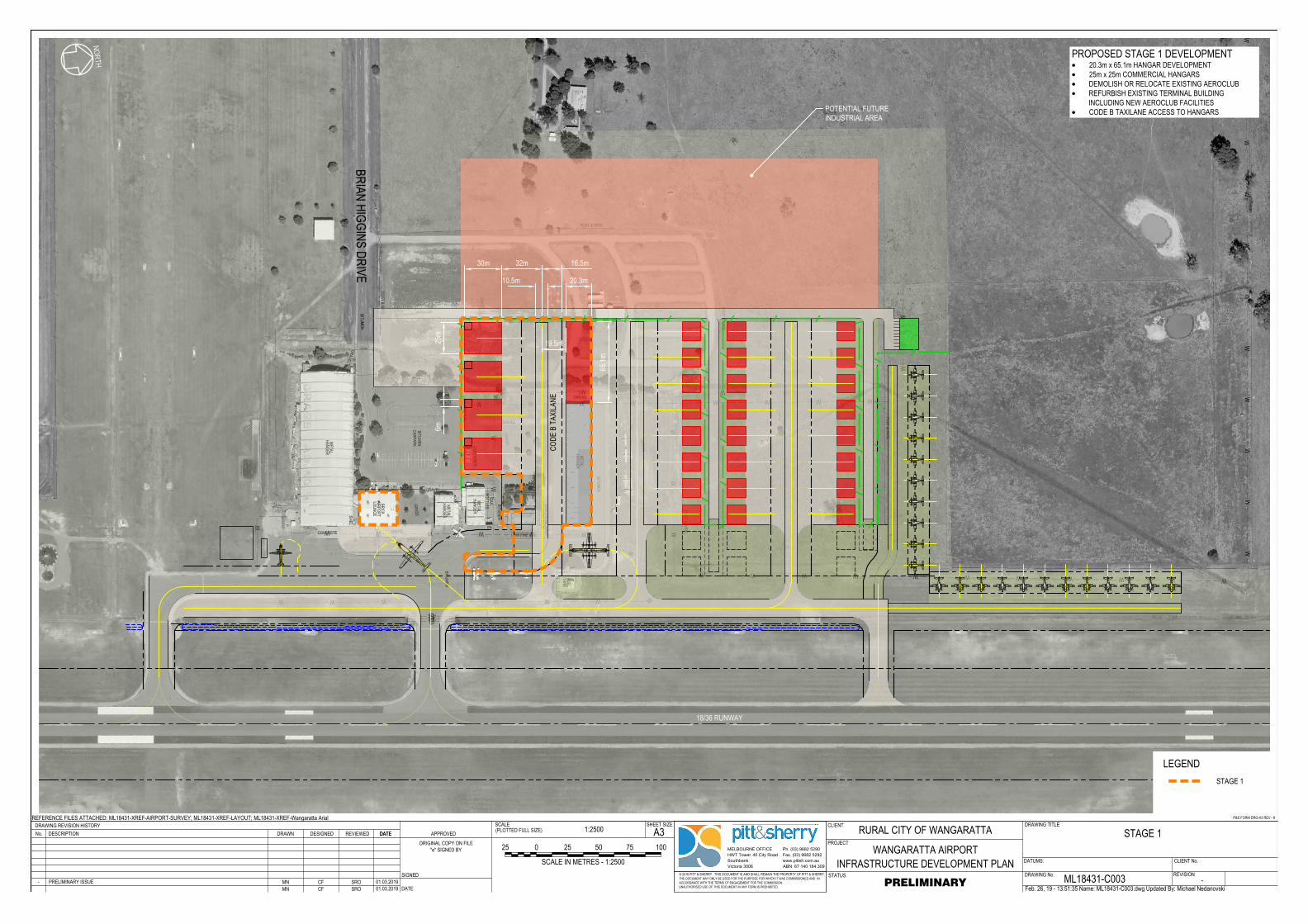
DDD
DA
M
GR
AS
S
BIT
UM
EN
BIT
UM
EN
BIT
UM
EN
CA
RP
AR
K
BIT
UM
EN
ME
TA
L
HA
NG
ER
ME
TA
L
HA
NG
ER
ME
TA
L
HA
NG
ER
BR
IC
K
AIR
PO
RT
LO
UN
GE
OF
FIC
E
CO
NT
AIN
ER
ME
TA
L
HA
NG
ER
FU
EL
TA
NK
FU
EL
BO
WS
ER
S
PO
ST
&
W
IR
E
PO
ST
&
W
IR
E
POST & WIRE
STEEL RAIL
PO
ST
&
W
IR
E
LOW PINE RAIL
LO
W P
IN
E R
AIL
GR
AS
S
GR
AS
S
GR
AS
S
G
RA
SS
GRAVEL
GA
RD
EN
BIT
UM
EN
GRAVEL
CONCRETE
GRAVEL
GRAVEL
G
R
A
V
E
L
SH
ED
SH
ED
WE
AT
HE
RB
OA
RD
AE
RO
C
LU
B
LO
UN
GE
GA
S
BO
TT
LE
S
1200x600
1200x500
1200x500
1800x1100
1800x1100
1800x1100
Ø1
50
Ø3
00
Ø1
00
Ø300
Ø300
Ø150
Ø1
50
Ø3
00
Ø
3
7
5
PO
ST
&
W
IR
E
W W W W W W W W
WW
BR
IA
N H
IG
GIN
S D
RIV
E
CA
RA
VA
N P
AR
K
WW
WW
WW
WW
WW
W
WWWWWWWWWWW
WW
W
WWWWWWW
W
W W W
W
WWWWWW
WW
W
B1
00
B10
0B
10
0B
10
0B
10
0B
10
0B
10
0B
10
0B
100
B1
00
Q4
00
Q4
00
Q4
00
Q4
00
B100B100 B100 B100 B100 B100 B100B100B100B100 B100 B100
Q
4
0
0
Q
4
0
0
METRO III
M
ETRO
II
I
www.pittsh.com.au
ABN 67 140 184 309
MELBOURNE OFFICE
HWT Tower 40 City Road
Southbank
Victoria 3006
Ph. (03) 9682 5290
Fax. (03) 9682 5292
DRAWING No.
DRAWING TITLE
STATUS
SCALEDRAWING REVISION HISTORY CLIENTA3
PROJECT
SHEET SIZE(PLOTTED FULL SIZE)
© 2016 PITT & SHERRY THIS DOCUMENT IS AND SHALL REMAIN THE PROPERTY OF PITT & SHERRY.THE DOCUMENT MAY ONLY BE USED FOR THE PURPOSE FOR WHICH IT WAS COMMISSIONED AND INACCORDANCE WITH THE TERMS OF ENGAGEMENT FOR THE COMMISSION.UNAUTHORISED USE OF THIS DOCUMENT IN ANY FORM IS PROHIBITED.
REFERENCE FILES ATTACHED: ML18431-XREF-AIRPORT-SURVEY; ML18431-XREF-LAYOUT; ML18431-XREF-Wangaratta Arial
DESCRIPTIONNo. DATE APPROVED
SIGNED
DATE
DATUMS: CLIENT No.
ORIGINAL COPY ON FILE"e" SIGNED BY
P&S FORM DRG-A3 REV - 8
REVISION
REVIEWED DATEDRAWN DESIGNED
Feb. 26, 19 - 13:51:35 Name: ML18431-C003.dwg Updated By: Michael Nedanovski
RURAL CITY OF WANGARATTA
WANGARATTA AIRPORTINFRASTRUCTURE DEVELOPMENT PLAN
STAGE 1
ML18431-C003 -PRELIMINARY
1:2500
MN CF SRO 01.03.2019- PRELIMINARY ISSUE MN CF SRO 01.03.2019
0 10050
SCALE IN METRES - 1:2500
7525 25
NORTH
LEGENDSTAGE 1
30m 32m 16.5m
25m
6m
10.5m
19.5m
18/36 RUNWAY
POTENTIAL FUTUREINDUSTRIAL AREA
CODE
B T
AXILA
NE
20.3m
65.1m
PROPOSED STAGE 1 DEVELOPMENT· 20.3m x 65.1m HANGAR DEVELOPMENT· 25m x 25m COMMERCIAL HANGARS· DEMOLISH OR RELOCATE EXISTING AEROCLUB· REFURBISH EXISTING TERMINAL BUILDING
INCLUDING NEW AEROCLUB FACILITIES· CODE B TAXILANE ACCESS TO HANGARS
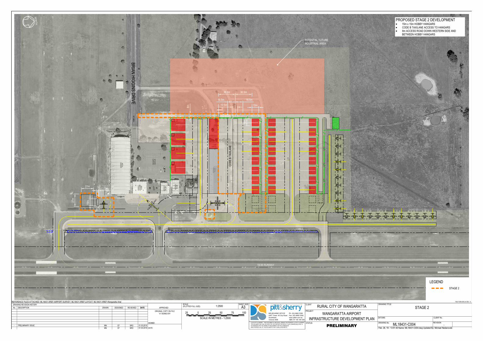
DDD
DA
M
GR
AS
S
BIT
UM
EN
BIT
UM
EN
BIT
UM
EN
CA
RP
AR
K
BIT
UM
EN
ME
TA
L
HA
NG
ER
ME
TA
L
HA
NG
ER
ME
TA
L
HA
NG
ER
BR
IC
K
AIR
PO
RT
LO
UN
GE
OF
FIC
E
CO
NT
AIN
ER
ME
TA
L
HA
NG
ER
FU
EL
TA
NK
FU
EL
BO
WS
ER
S
PO
ST
&
W
IR
E
PO
ST
&
W
IR
E
POST & WIRE
STEEL RAIL
PO
ST
&
W
IR
E
LOW PINE RAIL
LO
W P
IN
E R
AIL
GR
AS
S
GR
AS
S
GR
AS
S
G
RA
SS
GRAVEL
GA
RD
EN
BIT
UM
EN
GRAVEL
CONCRETE
GRAVEL
GRAVEL
G
R
A
V
E
L
SH
ED
SH
ED
WE
AT
HE
RB
OA
RD
AE
RO
C
LU
B
LO
UN
GE
GA
S
BO
TT
LE
S
1200x600
1200x500
1200x500
1800x1100
1800x1100
1800x1100
Ø1
50
Ø3
00
Ø1
00
Ø300
Ø300
Ø150
Ø1
50
Ø3
00
Ø
3
7
5
PO
ST
&
W
IR
E
W W W W W W W W
WW
BR
IA
N H
IG
GIN
S D
RIV
E
CA
RA
VA
N P
AR
K
WW
WW
WW
WW
WW
W
WWWWWWWWWWW
WW
W
WWWWWWW
W
W W W
W
WWWWWW
WW
W
B1
00
B10
0B
10
0B
10
0B
10
0B
10
0B
10
0B
10
0B
100
B1
00
Q4
00
Q4
00
Q4
00
Q4
00
B100B100 B100 B100 B100 B100 B100B100B100B100 B100 B100
Q
4
0
0
Q
4
0
0
METRO III
M
ETRO
II
I
www.pittsh.com.au
ABN 67 140 184 309
MELBOURNE OFFICE
HWT Tower 40 City Road
Southbank
Victoria 3006
Ph. (03) 9682 5290
Fax. (03) 9682 5292
DRAWING No.
DRAWING TITLE
STATUS
SCALEDRAWING REVISION HISTORY CLIENTA3
PROJECT
SHEET SIZE(PLOTTED FULL SIZE)
© 2016 PITT & SHERRY THIS DOCUMENT IS AND SHALL REMAIN THE PROPERTY OF PITT & SHERRY.THE DOCUMENT MAY ONLY BE USED FOR THE PURPOSE FOR WHICH IT WAS COMMISSIONED AND INACCORDANCE WITH THE TERMS OF ENGAGEMENT FOR THE COMMISSION.UNAUTHORISED USE OF THIS DOCUMENT IN ANY FORM IS PROHIBITED.
REFERENCE FILES ATTACHED: ML18431-XREF-AIRPORT-SURVEY; ML18431-XREF-LAYOUT; ML18431-XREF-Wangaratta Arial
DESCRIPTIONNo. DATE APPROVED
SIGNED
DATE
DATUMS: CLIENT No.
ORIGINAL COPY ON FILE"e" SIGNED BY
P&S FORM DRG-A3 REV - 8
REVISION
REVIEWED DATEDRAWN DESIGNED
Feb. 26, 19 - 13:51:40 Name: ML18431-C004.dwg Updated By: Michael Nedanovski
RURAL CITY OF WANGARATTA
WANGARATTA AIRPORTINFRASTRUCTURE DEVELOPMENT PLAN
STAGE 2
ML18431-C004 -PRELIMINARY
1:2500
MN CF SRO 01.03.2019- PRELIMINARY ISSUE MN CF SRO 01.03.2019
0 10050
SCALE IN METRES - 1:2500
7525 25
NORTH
LEGENDSTAGE 2
36.5m
10.5m
8m27m
27m
5m
15m
36.5m
16.5m16.5m
15m
15m
18/36 RUNWAY
POTENTIAL FUTUREINDUSTRIAL AREA
CODE
B T
AXILA
NE
PROPOSED STAGE 2 DEVELOPMENT· 15m x 15m HOBBY HANGARS· CODE B TAXILANE ACCESS TO HANGARS· 8m ACCESS ROAD DOWN WESTERN SIDE AND
BETWEEN HOBBY HANGARS
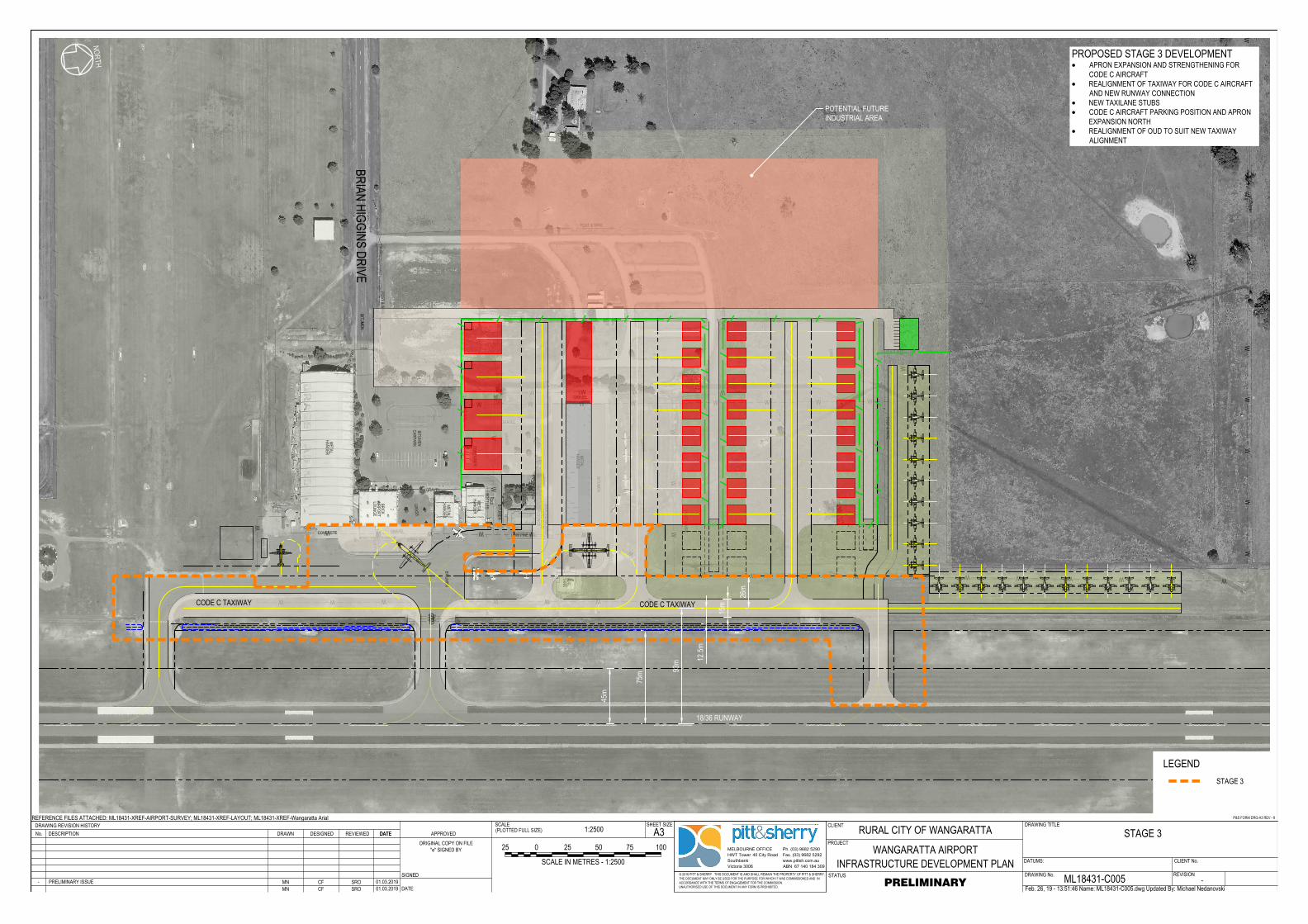
DDD
DA
M
GR
AS
S
BIT
UM
EN
BIT
UM
EN
BIT
UM
EN
CA
RP
AR
K
BIT
UM
EN
ME
TA
L
HA
NG
ER
ME
TA
L
HA
NG
ER
ME
TA
L
HA
NG
ER
BR
IC
K
AIR
PO
RT
LO
UN
GE
OF
FIC
E
CO
NT
AIN
ER
ME
TA
L
HA
NG
ER
FU
EL
TA
NK
FU
EL
BO
WS
ER
S
PO
ST
&
W
IR
E
PO
ST
&
W
IR
E
POST & WIRE
STEEL RAIL
PO
ST
&
W
IR
E
LOW PINE RAIL
LO
W P
IN
E R
AIL
GR
AS
S
GR
AS
S
GR
AS
S
G
RA
SS
GRAVEL
GA
RD
EN
BIT
UM
EN
GRAVEL
CONCRETE
GRAVEL
GRAVEL
G
R
A
V
E
L
SH
ED
SH
ED
WE
AT
HE
RB
OA
RD
AE
RO
C
LU
B
LO
UN
GE
GA
S
BO
TT
LE
S
1200x600
1200x500
1200x500
1800x1100
1800x1100
1800x1100
Ø1
50
Ø3
00
Ø1
00
Ø300
Ø300
Ø150
Ø1
50
Ø3
00
Ø
3
7
5
PO
ST
&
W
IR
E
W W W W W W W W
WW
BR
IA
N H
IG
GIN
S D
RIV
E
CA
RA
VA
N P
AR
K
WW
WW
WW
WW
WW
W
WWWWWWWWWWW
WW
W
WWWWWWW
W
W W W
W
WWWWWW
WW
W
B1
00
B10
0B
10
0B
10
0B
10
0B
10
0B
10
0B
10
0B
100
B1
00
Q4
00
Q4
00
Q4
00
Q4
00
B100B100 B100 B100 B100 B100 B100B100B100B100 B100 B100
Q
4
0
0
Q
4
0
0
METRO III
M
ETRO
II
I
www.pittsh.com.au
ABN 67 140 184 309
MELBOURNE OFFICE
HWT Tower 40 City Road
Southbank
Victoria 3006
Ph. (03) 9682 5290
Fax. (03) 9682 5292
DRAWING No.
DRAWING TITLE
STATUS
SCALEDRAWING REVISION HISTORY CLIENTA3
PROJECT
SHEET SIZE(PLOTTED FULL SIZE)
© 2016 PITT & SHERRY THIS DOCUMENT IS AND SHALL REMAIN THE PROPERTY OF PITT & SHERRY.THE DOCUMENT MAY ONLY BE USED FOR THE PURPOSE FOR WHICH IT WAS COMMISSIONED AND INACCORDANCE WITH THE TERMS OF ENGAGEMENT FOR THE COMMISSION.UNAUTHORISED USE OF THIS DOCUMENT IN ANY FORM IS PROHIBITED.
REFERENCE FILES ATTACHED: ML18431-XREF-AIRPORT-SURVEY; ML18431-XREF-LAYOUT; ML18431-XREF-Wangaratta Arial
DESCRIPTIONNo. DATE APPROVED
SIGNED
DATE
DATUMS: CLIENT No.
ORIGINAL COPY ON FILE"e" SIGNED BY
P&S FORM DRG-A3 REV - 8
REVISION
REVIEWED DATEDRAWN DESIGNED
Feb. 26, 19 - 13:51:46 Name: ML18431-C005.dwg Updated By: Michael Nedanovski
RURAL CITY OF WANGARATTA
WANGARATTA AIRPORTINFRASTRUCTURE DEVELOPMENT PLAN
STAGE 3
ML18431-C005 -PRELIMINARY
1:2500
MN CF SRO 01.03.2019- PRELIMINARY ISSUE MN CF SRO 01.03.2019
0 10050
SCALE IN METRES - 1:2500
7525 25
NORTH
LEGENDSTAGE 3
15m
93m
45m
75m
12.5m
26m
POTENTIAL FUTUREINDUSTRIAL AREA
CODE C TAXIWAYCODE C TAXIWAY
18/36 RUNWAY
PROPOSED STAGE 3 DEVELOPMENT· APRON EXPANSION AND STRENGTHENING FOR
CODE C AIRCRAFT· REALIGNMENT OF TAXIWAY FOR CODE C AIRCRAFT
AND NEW RUNWAY CONNECTION· NEW TAXILANE STUBS· CODE C AIRCRAFT PARKING POSITION AND APRON
EXPANSION NORTH· REALIGNMENT OF OUD TO SUIT NEW TAXIWAY
ALIGNMENT
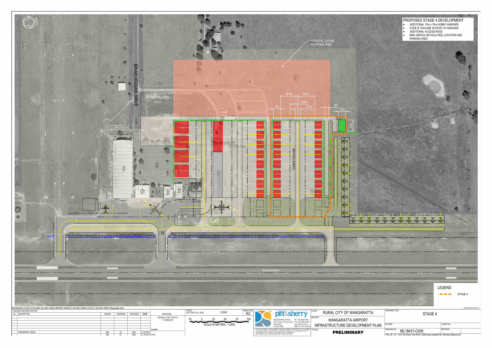
DDD
DA
M
GR
AS
S
BIT
UM
EN
BIT
UM
EN
BIT
UM
EN
CA
RP
AR
K
BIT
UM
EN
ME
TA
L
HA
NG
ER
ME
TA
L
HA
NG
ER
ME
TA
L
HA
NG
ER
BR
IC
K
AIR
PO
RT
LO
UN
GE
OF
FIC
E
CO
NT
AIN
ER
ME
TA
L
HA
NG
ER
FU
EL
TA
NK
FU
EL
BO
WS
ER
S
PO
ST
&
W
IR
E
PO
ST
&
W
IR
E
POST & WIRE
STEEL RAIL
PO
ST
&
W
IR
E
LOW PINE RAIL
LO
W P
IN
E R
AIL
GR
AS
S
GR
AS
S
GR
AS
S
G
RA
SS
GRAVEL
GA
RD
EN
BIT
UM
EN
GRAVEL
CONCRETE
GRAVEL
GRAVEL
G
R
A
V
E
L
SH
ED
SH
ED
WE
AT
HE
RB
OA
RD
AE
RO
C
LU
B
LO
UN
GE
GA
S
BO
TT
LE
S
1200x600
1200x500
1200x500
1800x1100
1800x1100
1800x1100
Ø1
50
Ø3
00
Ø1
00
Ø300
Ø300
Ø150
Ø1
50
Ø3
00
Ø
3
7
5
PO
ST
&
W
IR
E
W W W W W W W W
WW
BR
IA
N H
IG
GIN
S D
RIV
E
CA
RA
VA
N P
AR
K
WW
WW
WW
WW
WW
W
WWWWWWWWWWW
WW
W
WWWWWWW
W
W W W
W
WWWWWW
WW
W
B1
00
B10
0B
10
0B
10
0B
10
0B
10
0B
10
0B
10
0B
100
B1
00
Q4
00
Q4
00
Q4
00
Q4
00
B100B100 B100 B100 B100 B100 B100B100B100B100 B100 B100
Q
4
0
0
Q
4
0
0
METRO III
M
ETRO
II
I
www.pittsh.com.au
ABN 67 140 184 309
MELBOURNE OFFICE
HWT Tower 40 City Road
Southbank
Victoria 3006
Ph. (03) 9682 5290
Fax. (03) 9682 5292
DRAWING No.
DRAWING TITLE
STATUS
SCALEDRAWING REVISION HISTORY CLIENTA3
PROJECT
SHEET SIZE(PLOTTED FULL SIZE)
© 2016 PITT & SHERRY THIS DOCUMENT IS AND SHALL REMAIN THE PROPERTY OF PITT & SHERRY.THE DOCUMENT MAY ONLY BE USED FOR THE PURPOSE FOR WHICH IT WAS COMMISSIONED AND INACCORDANCE WITH THE TERMS OF ENGAGEMENT FOR THE COMMISSION.UNAUTHORISED USE OF THIS DOCUMENT IN ANY FORM IS PROHIBITED.
REFERENCE FILES ATTACHED: ML18431-XREF-AIRPORT-SURVEY; ML18431-XREF-LAYOUT; ML18431-XREF-Wangaratta Arial
DESCRIPTIONNo. DATE APPROVED
SIGNED
DATE
DATUMS: CLIENT No.
ORIGINAL COPY ON FILE"e" SIGNED BY
P&S FORM DRG-A3 REV - 8
REVISION
REVIEWED DATEDRAWN DESIGNED
Feb. 26, 19 - 13:51:52 Name: ML18431-C006.dwg Updated By: Michael Nedanovski
RURAL CITY OF WANGARATTA
WANGARATTA AIRPORTINFRASTRUCTURE DEVELOPMENT PLAN
STAGE 4
ML18431-C006 -PRELIMINARY
1:2500
MN CF SRO 01.03.2019- PRELIMINARY ISSUE MN CF SRO 01.03.2019
0 10050
SCALE IN METRES - 1:2500
7525 25
NORTH
LEGENDSTAGE 4
36.5m 36.5m
16.5m10.5m15m
15m
15m
25m
8m
POTENTIAL FUTUREINDUSTRIAL AREA
CODE
B T
AXILA
NE
18/36 RUNWAY
PROPOSED STAGE 4 DEVELOPMENT· ADDITIONAL 15m x 15m HOBBY HANGARS· CODE B TAXILANE ACCESS TO HANGARS· ADDITIONAL ACCESS ROAD· NEW AEROCLUB FACILITIES, LOCATION AND
PARKING AREA
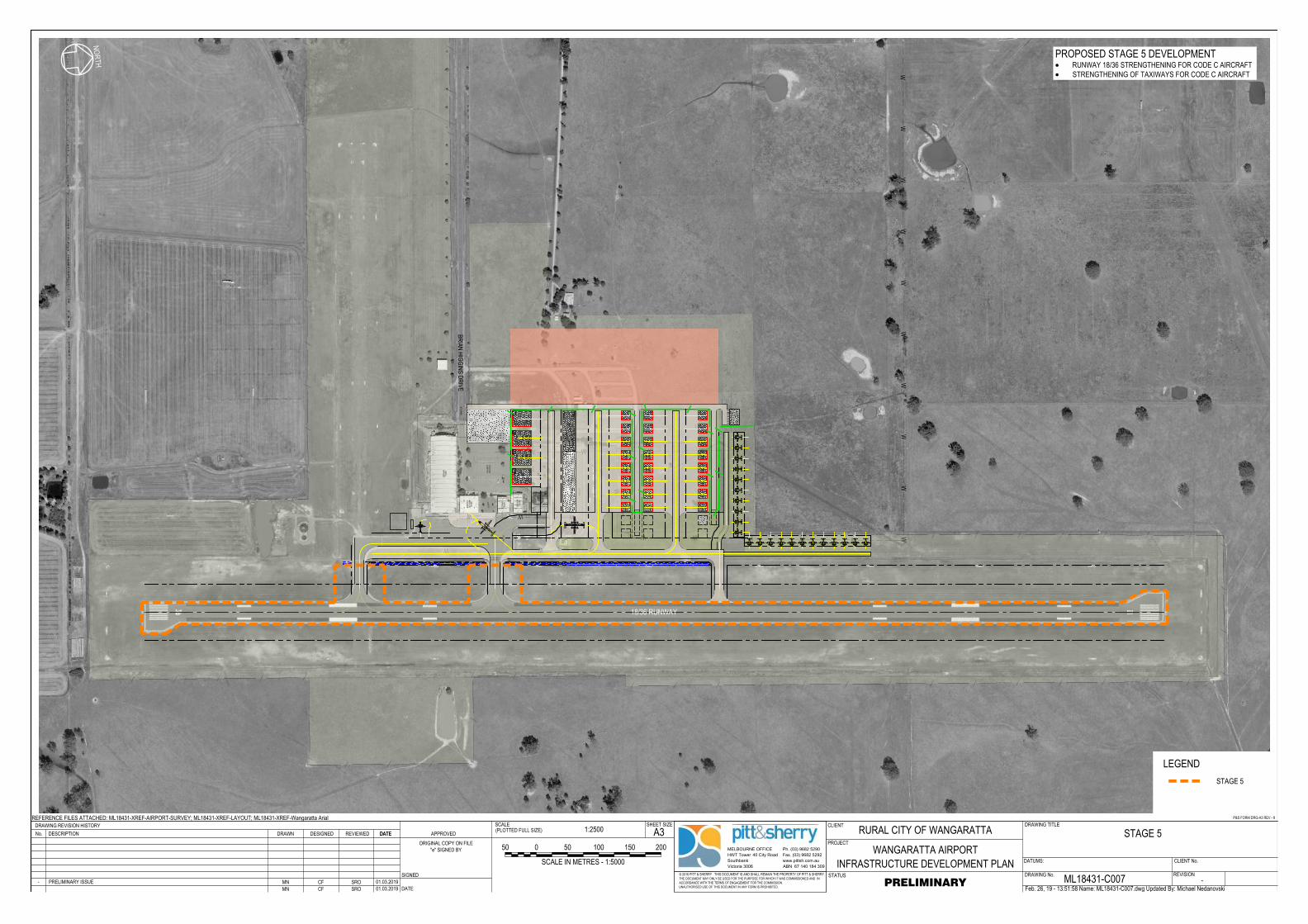
DA
M
G
RA
SS
BIT
UM
EN
BIT
UM
EN
BIT
UM
EN
CA
RP
AR
K
BIT
UM
EN
ME
TA
L
HA
NG
ER
ME
TA
L
HA
NG
ER
ME
TA
L
HA
NG
ER
BR
IC
K
AIR
PO
RT
LO
UN
GE
OF
FIC
E
CO
NT
AIN
ER
ME
TA
L
HA
NG
ER
FU
EL
TA
NK
FU
EL
BO
WS
ER
S
PO
ST
&
W
IR
E
PO
ST
&
W
IR
E
POST & WIRE
STEEL RAIL
PO
ST
&
W
IR
E
LOW PINE RAIL
LO
W P
IN
E R
AIL
G
RA
SS
G
RA
SS
GR
AS
S
G
RA
SS
GRAVEL
GA
RD
EN
BIT
UM
EN
GRAVEL
CONCRETE
GRAVEL
GRAVEL
G
R
A
V
E
L
SH
ED
SH
ED
WE
AT
HE
RB
OA
RD
AE
RO
C
LU
B
LO
UN
GE
GA
S
BO
TT
LE
S
1200x600
1200x500
1200x500
1800x1100
1800x1100
1800x1100
Ø1
50
Ø3
00
Ø1
00
Ø300
Ø300
Ø150
Ø1
50
Ø3
00
Ø
3
7
5
PO
ST
&
W
IR
E
W W W W
W
BR
IA
N H
IG
GIN
S D
RIV
E
CA
RA
VA
N P
AR
K
WW
WW
WW
WW
WWWWWWW
W
WWW
W
WWW
W
B100
B100
B100
B100
B100
B100
B100
B100
B100
B100
Q400
Q400
Q400
Q400
B100B100 B100 B100 B100 B100 B100B100B100B100 B100 B100
Q
4
0
0
Q
4
0
0
METRO III
METRO III
www.pittsh.com.au
ABN 67 140 184 309
MELBOURNE OFFICE
HWT Tower 40 City Road
Southbank
Victoria 3006
Ph. (03) 9682 5290
Fax. (03) 9682 5292
DRAWING No.
DRAWING TITLE
STATUS
SCALEDRAWING REVISION HISTORY CLIENTA3
PROJECT
SHEET SIZE(PLOTTED FULL SIZE)
© 2016 PITT & SHERRY THIS DOCUMENT IS AND SHALL REMAIN THE PROPERTY OF PITT & SHERRY.THE DOCUMENT MAY ONLY BE USED FOR THE PURPOSE FOR WHICH IT WAS COMMISSIONED AND INACCORDANCE WITH THE TERMS OF ENGAGEMENT FOR THE COMMISSION.UNAUTHORISED USE OF THIS DOCUMENT IN ANY FORM IS PROHIBITED.
REFERENCE FILES ATTACHED: ML18431-XREF-AIRPORT-SURVEY; ML18431-XREF-LAYOUT; ML18431-XREF-Wangaratta Arial
DESCRIPTIONNo. DATE APPROVED
SIGNED
DATE
DATUMS: CLIENT No.
ORIGINAL COPY ON FILE"e" SIGNED BY
P&S FORM DRG-A3 REV - 8
REVISION
REVIEWED DATEDRAWN DESIGNED
Feb. 26, 19 - 13:51:58 Name: ML18431-C007.dwg Updated By: Michael Nedanovski
RURAL CITY OF WANGARATTA
WANGARATTA AIRPORTINFRASTRUCTURE DEVELOPMENT PLAN
STAGE 5
ML18431-C007 -PRELIMINARY
1:2500
MN CF SRO 01.03.2019- PRELIMINARY ISSUE MN CF SRO 01.03.2019
0 200100
SCALE IN METRES - 1:5000
15050 50
NORTH
LEGENDSTAGE 5
18/36 RUNWAY
PROPOSED STAGE 5 DEVELOPMENT· RUNWAY 18/36 STRENGTHENING FOR CODE C AIRCRAFT· STRENGTHENING OF TAXIWAYS FOR CODE C AIRCRAFT
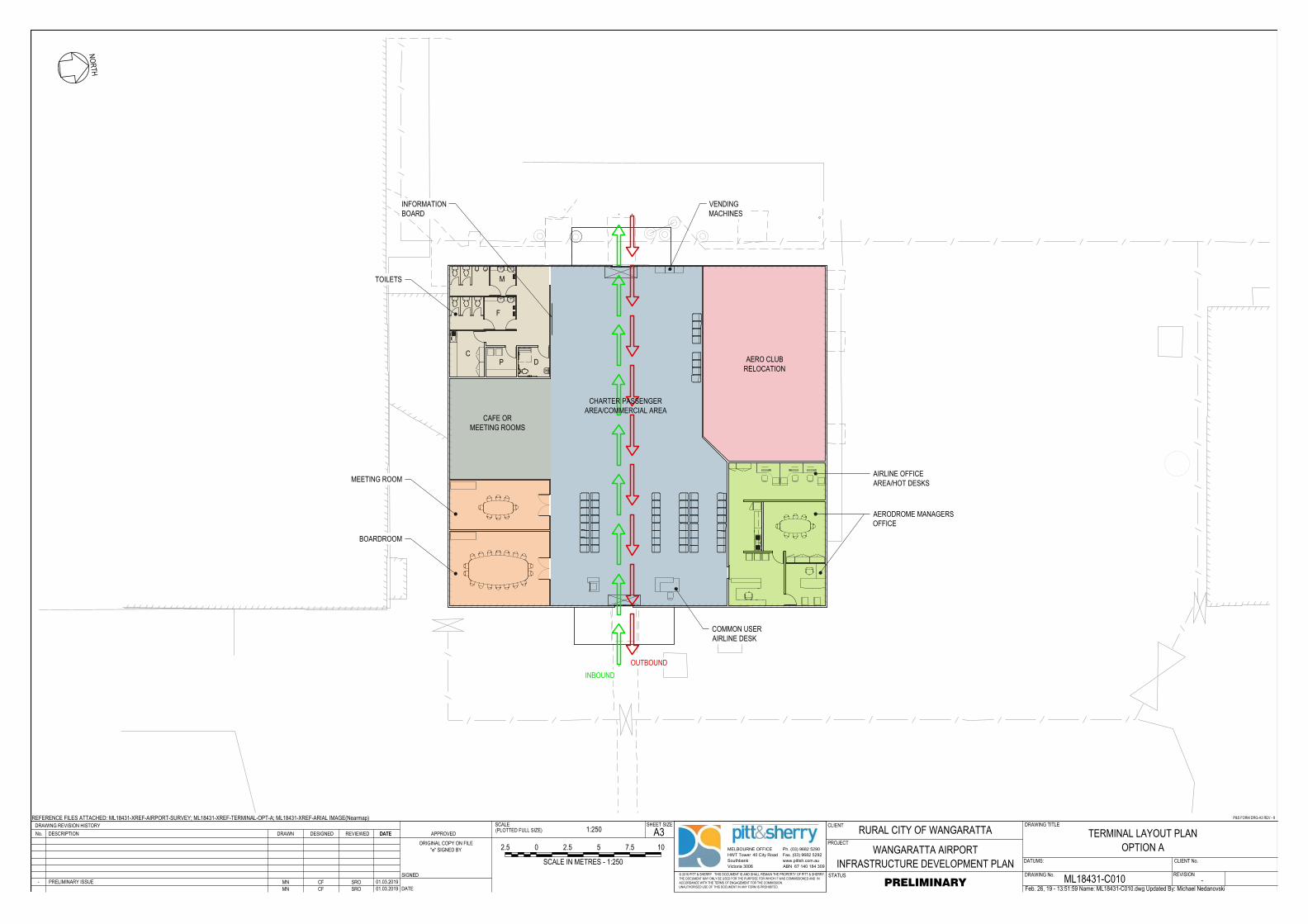
www.pittsh.com.au
ABN 67 140 184 309
MELBOURNE OFFICE
HWT Tower 40 City Road
Southbank
Victoria 3006
Ph. (03) 9682 5290
Fax. (03) 9682 5292
DRAWING No.
DRAWING TITLE
STATUS
SCALEDRAWING REVISION HISTORY CLIENTA3
PROJECT
SHEET SIZE(PLOTTED FULL SIZE)
© 2016 PITT & SHERRY THIS DOCUMENT IS AND SHALL REMAIN THE PROPERTY OF PITT & SHERRY.THE DOCUMENT MAY ONLY BE USED FOR THE PURPOSE FOR WHICH IT WAS COMMISSIONED AND INACCORDANCE WITH THE TERMS OF ENGAGEMENT FOR THE COMMISSION.UNAUTHORISED USE OF THIS DOCUMENT IN ANY FORM IS PROHIBITED.
REFERENCE FILES ATTACHED: ML18431-XREF-AIRPORT-SURVEY; ML18431-XREF-TERMINAL-OPT-A; ML18431-XREF-ARIAL IMAGE(Nearmap)
DESCRIPTIONNo. DATE APPROVED
SIGNED
DATE
DATUMS: CLIENT No.
ORIGINAL COPY ON FILE"e" SIGNED BY
P&S FORM DRG-A3 REV - 8
REVISION
REVIEWED DATEDRAWN DESIGNED
Feb. 26, 19 - 13:51:59 Name: ML18431-C010.dwg Updated By: Michael Nedanovski
RURAL CITY OF WANGARATTA
WANGARATTA AIRPORTINFRASTRUCTURE DEVELOPMENT PLAN
TERMINAL LAYOUT PLANOPTION A
ML18431-C010 -PRELIMINARY
1:250
MN CF SRO 01.03.2019- PRELIMINARY ISSUE MN CF SRO 01.03.2019
0 105
SCALE IN METRES - 1:250
7.52.5 2.5
NORTH
AERO CLUBRELOCATION
CAFE ORMEETING ROOMS
DPC
F
M
BOARDROOM
MEETING ROOM
TOILETS
AERODROME MANAGERSOFFICE
AIRLINE OFFICEAREA/HOT DESKS
COMMON USERAIRLINE DESK
VENDINGMACHINES
INBOUNDOUTBOUND
INFORMATIONBOARD
CHARTER PASSENGERAREA/COMMERCIAL AREA
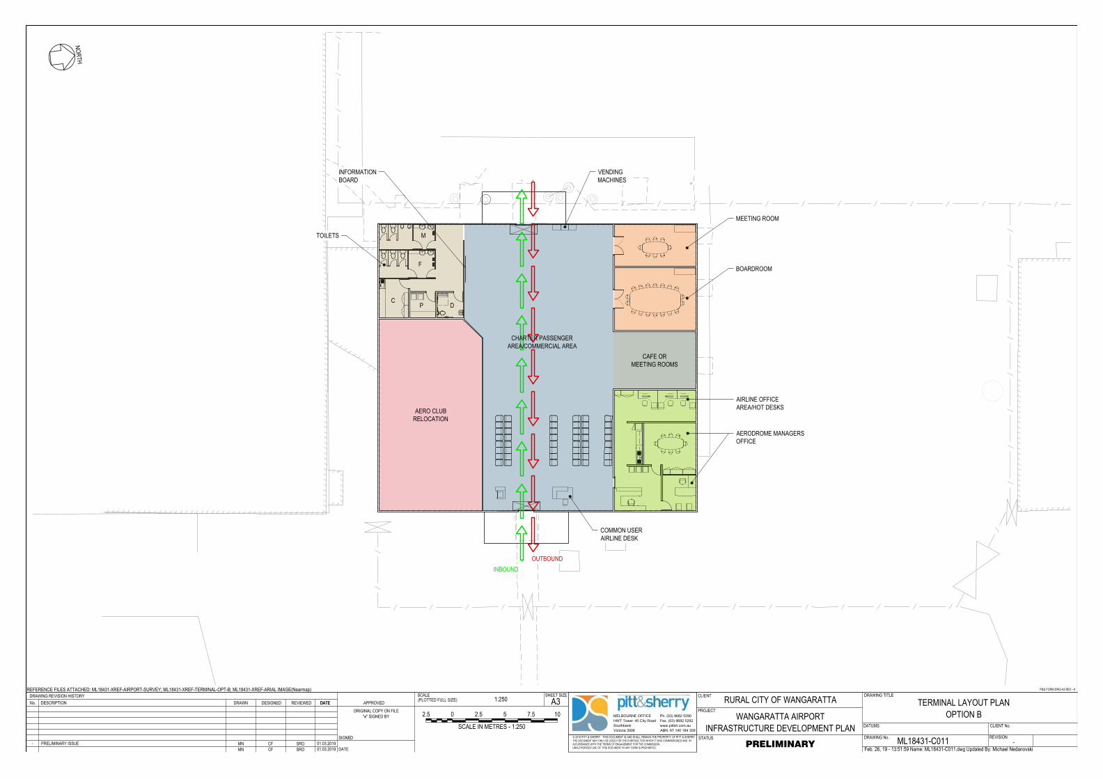
www.pittsh.com.au
ABN 67 140 184 309
MELBOURNE OFFICE
HWT Tower 40 City Road
Southbank
Victoria 3006
Ph. (03) 9682 5290
Fax. (03) 9682 5292
DRAWING No.
DRAWING TITLE
STATUS
SCALEDRAWING REVISION HISTORY CLIENTA3
PROJECT
SHEET SIZE(PLOTTED FULL SIZE)
© 2016 PITT & SHERRY THIS DOCUMENT IS AND SHALL REMAIN THE PROPERTY OF PITT & SHERRY.THE DOCUMENT MAY ONLY BE USED FOR THE PURPOSE FOR WHICH IT WAS COMMISSIONED AND INACCORDANCE WITH THE TERMS OF ENGAGEMENT FOR THE COMMISSION.UNAUTHORISED USE OF THIS DOCUMENT IN ANY FORM IS PROHIBITED.
REFERENCE FILES ATTACHED: ML18431-XREF-AIRPORT-SURVEY; ML18431-XREF-TERMINAL-OPT-B; ML18431-XREF-ARIAL IMAGE(Nearmap)
DESCRIPTIONNo. DATE APPROVED
SIGNED
DATE
DATUMS: CLIENT No.
ORIGINAL COPY ON FILE"e" SIGNED BY
P&S FORM DRG-A3 REV - 8
REVISION
REVIEWED DATEDRAWN DESIGNED
Feb. 26, 19 - 13:51:59 Name: ML18431-C011.dwg Updated By: Michael Nedanovski
RURAL CITY OF WANGARATTA
WANGARATTA AIRPORTINFRASTRUCTURE DEVELOPMENT PLAN
TERMINAL LAYOUT PLANOPTION B
ML18431-C011 -PRELIMINARY
1:250
MN CF SRO 01.03.2019- PRELIMINARY ISSUE MN CF SRO 01.03.2019
0 105
SCALE IN METRES - 1:250
7.52.5 2.5
NORTH
AERO CLUBRELOCATION
CAFE ORMEETING ROOMS
DPC
F
MTOILETS
AERODROME MANAGERSOFFICE
AIRLINE OFFICEAREA/HOT DESKS
COMMON USERAIRLINE DESK
VENDINGMACHINES
INBOUNDOUTBOUND
INFORMATIONBOARD
CHARTER PASSENGERAREA/COMMERCIAL AREA
BOARDROOM
MEETING ROOM
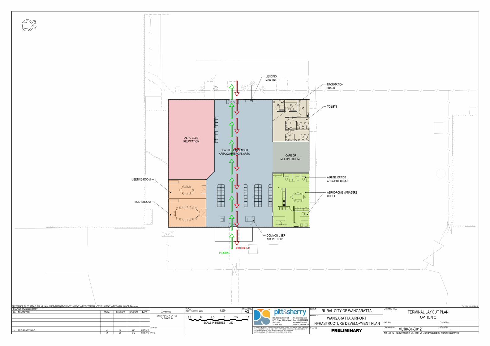
www.pittsh.com.au
ABN 67 140 184 309
MELBOURNE OFFICE
HWT Tower 40 City Road
Southbank
Victoria 3006
Ph. (03) 9682 5290
Fax. (03) 9682 5292
DRAWING No.
DRAWING TITLE
STATUS
SCALEDRAWING REVISION HISTORY CLIENTA3
PROJECT
SHEET SIZE(PLOTTED FULL SIZE)
© 2016 PITT & SHERRY THIS DOCUMENT IS AND SHALL REMAIN THE PROPERTY OF PITT & SHERRY.THE DOCUMENT MAY ONLY BE USED FOR THE PURPOSE FOR WHICH IT WAS COMMISSIONED AND INACCORDANCE WITH THE TERMS OF ENGAGEMENT FOR THE COMMISSION.UNAUTHORISED USE OF THIS DOCUMENT IN ANY FORM IS PROHIBITED.
REFERENCE FILES ATTACHED: ML18431-XREF-AIRPORT-SURVEY; ML18431-XREF-TERMINAL-OPT-C; ML18431-XREF-ARIAL IMAGE(Nearmap)
DESCRIPTIONNo. DATE APPROVED
SIGNED
DATE
DATUMS: CLIENT No.
ORIGINAL COPY ON FILE"e" SIGNED BY
P&S FORM DRG-A3 REV - 8
REVISION
REVIEWED DATEDRAWN DESIGNED
Feb. 26, 19 - 13:52:00 Name: ML18431-C012.dwg Updated By: Michael Nedanovski
RURAL CITY OF WANGARATTA
WANGARATTA AIRPORTINFRASTRUCTURE DEVELOPMENT PLAN
TERMINAL LAYOUT PLANOPTION C
ML18431-C012 -PRELIMINARY
1:250
MN CF SRO 01.03.2019- PRELIMINARY ISSUE MN CF SRO 01.03.2019
0 105
SCALE IN METRES - 1:250
7.52.5 2.5
NORTH
D PC
F
MAERO CLUB
RELOCATION
CAFE ORMEETING ROOMS
BOARDROOM
MEETING ROOM
TOILETS
AERODROME MANAGERSOFFICE
AIRLINE OFFICEAREA/HOT DESKS
COMMON USERAIRLINE DESK
VENDINGMACHINES
INBOUNDOUTBOUND
INFORMATIONBOARD
CHARTER PASSENGERAREA/COMMERCIAL AREA
Related Documents