IFCW2PV 0710 61487.01_01 TECHNICAL AND INSTALLATION MANUAL MANUAL TÉCNICO Y DE INSTALACIÓN WALL-MOUNTED FAN COIL CONVECTOR VENTILADOR DE INSTALACIÓN DE PARED FCW 21 - 31 - 41 Replace • Replace le n° • Ersetzt • Sustituye a: 6148701_00 / 0604

Welcome message from author
This document is posted to help you gain knowledge. Please leave a comment to let me know what you think about it! Share it to your friends and learn new things together.
Transcript

IFCW2PV0710
61487.01_01
TECHNICAL AND INSTALLATION MANUALMANUAL TÉCNICO Y DE INSTALACIÓN
WALL-MOUNTED FAN COILCONVECTOR VENTILADOR DE INSTALACIÓN DE PARED
FCW 21 - 31 - 41
������������� ����������
Replace • Replace le n° • Ersetzt • Sustituye a: 6148701_00 / 0604

AERMEC S.p.A.I-37040 Bevilacqua (VR) Italia – Via Roma, 44Tel. (+39) 0442 633111Telefax (+39) 0442 93730 – (+39) 0442 93566www .aermec. com - info @aermec. com
Bevilacqua, 01/10/2007 La Direzione Commerciale - Sales and Marketing Director LUIGI ZUCCHI
FCWDICHIARAZIONE DI CONFORMITÀ Noi, fi rmatari della presente, dichiariamo sotto la nostra esclusiva responsabilità, che il prodotto:VENTILCONVETTORE serie FCW
al quale questa dichiarazione si riferisce è conforme alle se-guenti norme armonizzate:- CEI EN 60335-2-40- CEI EN 55014-1- CEI EN 55014-2- CEI EN 61000-6-1- CEI EN 61000-6-2soddisfando così i requisiti essenziali delle seguenti direttive:- Direttiva LVD 2006/95/CE- Direttiva compatibilità elettromagnetica 2004/108/CE- Direttiva Macchine 98/37/CE
CONFORMITY DECLARATIONWe the undersigned declare, under our own exclusive re-sponsibility, that the product:FAN COIL FCW seriesto which this declaration refers, complies with the following standardised regulations:- EN 60335-2-40- EN 55014-1- EN 55014-2- EN 61000-6-1- EN 61000-6-2thus meeting the essential requisites of the following directives:- Directive LVD 2006/95/CE- EMC Electromagnetic Compatibility Directive 2004/108/CE- Machine Directive 98/37/CE
CERTIFICAT DE CONFORMITÉ Nous soussignés déclarons sous notre exclusive responsabi-lité que le produit :VENTILO-CONVECTEURS série FCWauquel cette déclaration fait référence, est conforme aux nor-mes harmonisées suivantes :- EN 60335-2-40- EN 55014-1- EN 55014-2- EN 61000-6-1- EN 61000-6-2satisfaisant ainsi aux conditions essentielles des directives suivantes:- Directive LVD 2006/95/CE- Directive compatibilité électromagnétique 2004/108/CE- Directive Machines 98/37/CE
KONFORMITÄTSERKLÄRUNG Wir, die hier Unterzeichnenden, erklären auf unsere aus-schließlich Verantwortung, dass das Produkt:GEBLÄSEKONVEKTOR der Serie FCW
auf das sich diese Erklärung bezieht, den folgenden harmoni-sierten Normen entspricht:- EN 60335-2-40- EN 55014-1- EN 55014-2- EN 61000-6-1- EN 61000-6-2womit die grundlegenden Anforderungen folgender Richtli-nien erfüllt werden:- Richtlinie LVD 2006/95/CE- Richtlinie zur elektromagnetischen Verträglichkeit 2004/108/CE- Maschinenrichtlinie 98/37/CE
DECLARACIÓN DE CONFORMIDAD Los que suscriben la presente declaran bajo la propia y exclusiva responsabilidad que el conjunto en objeto, defi nido como sigue:FAN COIL serie FCW
al que esta declaración se refi ere, está en conformidad a las siguientes normas armonizadas:- EN 60335-2-40- EN 55014-1- EN 55014-2- EN 61000-6-1- EN 61000-6-2al que esta declaración se refi ere, está en conformidad a las siguientes normas armonizadas:- Directiva LVD 2006/95/CE- Directiva compatibilidad electromagnétic 2004/108/CE- Directiva máquinas 98/37/CE

5
ObservationsTransport Safety symbols Maintenance Troubleshooting Description of the unitMain components Description of components General information Selection criteria Important information Operational limits Technical data Cooling capacity Heating capacity Coil pressure drops Correction factors using glycoled water Acoustic power levelSound pressure level Accessories Accessories compatibility table Size dataInstallation of the unit Installation of wired remote panel (accessory) Wiring diagrams
6 7
8
9 10 11 12 18 19 20
21
22
23 26 27
TABLE OF CONTENTS

6
TRANSPORT
123456
����
Do NOT wet
Do NOT leave loose packages during transport
Stacking: control the packing for the arrow position to know the number of machines that can be stacked
Do NOT trample
Das Gerät NICHT alleine tragen, wenn sein Gewicht 35 Kg überschreitet.
SAFETY SYMBOL
Danger: Danger: Danger!!! Power supply Movings parts
Store the manuals in a dry location to avoid deterioration, as they must be kept for at least 10 years for any future reference.
Carefully and thoroughly read all the information referred to in this manual. Pay particular attention to the usage regula-tions accompanied by the words “DANGER” or “WARNING” because, if they are not complied with, damage can be cau-sed to the machine and/or injury to persons or damage to property may result.
If any malfunctions are not included in this manual, contact the local After Sales Service immediately.
The apparatus must be installed in such a way that maintenance and/or repair operations are possible.The apparatus's warranty does not in any case cover costs due to automatic ladders, scaffolding or other lifting systems necessary for carrying out repairs under guarantee.
AERMEC S.p.A. declines all liability for any damage due to improper use of the machine or the partial or superficial reading of the information contained in this manual.
This manual contains the following number of pages: 56.
REMARKS
7
ORDINARY MAINTENANCEThe ordinary maintenance, it can also be done by the user, consists of a series of simple operations, thanks to which the fan coil can operate at full efficiency.Operations:- External cleaning, weekly, to be done with a damp cloth (soaked in water no hotter than 40 °C) and neutral soap; avoid using any other type of detergent or solvent.Do not splash water on interior or exterior surfaces of the fan coil (it could cause short circuits).- Fi l ter c leaning, every two weeks or weekly i f i n s t a l l e d i n v e r y d u s t y e n v i r o n m e n t s . Clean the fi lter with a vacuum cleaner and possibly with water and neutral detergent, do not use detergents or solvents of any kind.- Visual inspection of the state of the fan coil for every maintenance operation; every fault must be communicated to the After-Sales Service.
EXTRAORDINARY MAINTENANCEExtraordinary maintenance can only be performed by Aermec After-Sales Services or by people with the technical and professional requisites qualifying them to undertake installation, conversion, expansion and maintenance of the systems and are able to check them in terms of safety and functionality, in particular with regard to electrical connections the following tests are required relative to:- Measurement of the electrical system insulation resistance.- Continuity test of the protection wires. The extraordinary maintenance consists of a series of complex operations that involve the dismantling of the fan coil or its components thanks to which the condition of maximum fan coil functioning efficiency is restored.Operations:- Internal cleaning, annually or after long periods of non use; in environments where a high degree of air cleaning is required, cleaning can be more frequent; consists of the cleaning of the coil, ventilator fins, basin and all the parts in contact with the treated air.- Repairs and fine tuning, when faults arise look at the "TROUBLESHOOTING" chapter in this manual before calling the After-Sales Service.
MAINTENANCE
PROBLEM
Insufficient air flow at outlet
Unit does not heat
Unit does not cool
Fan not turning
Condensation forming on the external case of the unit
PROBABLE CAUSE
Incorrect speed setting on control panel
Blocked filter
Obstructed air flow (inlet and/or outlet)
No hot water
Incorrect control panel setting
T water > 90°C
No cold water
Incorrect control panel setting
No electrical power
Water has not reached operating temperature.
Temperature and humidity limits specified by “MINIMUM MEDIUM WATER TEMPERATURE” have been reached
SOLUTION
Select the correct speed on the control panel
Clean the filter
Remove the obstacle
Check the heaterCheck the heat pump
Set the control panel properly
Reduce the water temperature, then remo-ve and resupply the unit with voltage.
Check the chiller
Set the control panel
Check that there is electrical power
Check the boiler or the chiller and/or check the setting
Raise the water temperature to above the limits specified by “MINIMUM MEDIUM WATER TEMPERATURE”
For any problems not listed, contact the After-Sales Service immediately.
TROUBLESHOOTING
7

1 TLW1 (remote control unit) accessory 2 Support for the wall mounting of the TLW1 remote control unit3 PFW (wired remote panel) accessory4 Front panel5 Horizontal air delivery deflector fin6 Air filter
7 Heat exchanger battery 8 Three-way water valve9 Fan unit10 Receiver 11 Lit indicators (LED)12 Auxiliary emergency switch
��
FCW 21 - 31
TLW11
PFW3
4
5 116 108
12
7 9
2
MAIN COMPONENTS
The FCW fan coil for wall mounting is a concentration of top level technological and functional features that make it the ideal climate control unit for all environments.
The supply of climate controlled air is immediate and distributed throughout the room; FCW generates heat if included in heating system with boiler or heat pump but it may also be used in the summer as an air conditioner if the system has a water chiller.
MAIN CHARACTERISTICS:• Three-way water valve incorporated inside it• EUROVENT Certified • PANTONE colour Cool Grey 1C• Choice between two different control models (it is not possible to use the two models at the same time).
Infrared remote control unit (TLW1 accessory) with liquid crystal display and support for the wall mounting. The remote control unit enables all the unit's functions to be controlled.
Wired remote panel (PFW accessory) with liquid crystal display with supports to be affixed to the wall, four meter cable. The panel makes it possible to control the main functions of the unit.The response to the commands is immediate if the
environmental temperature and the temperature of the water in system so allow;- Three-speed cross flow fan• Very quiet operation•High-design appearance with rounded lines• Air delivery slats with horizontal adjustment facility• Motorised horizontal air delivery deflector that may be worked with both the remote control unit or the wired remote control unit for the vertical directioning of the output air with continuous or fixed oscillation that can be selected among the four pre-established positions or any other position as required • Microprocessor control• Timer for the programming of the turning on or off • Automatic functioning programme, cooling, heating, ventilation and dehumidification (only with TLW1 remote control unit)• Automatic season change• Automatic restart after power outage• Ease of installation with plumbing connections and condensate drain that can be pointed in several directions Routine maintenance is limited to periodic cleaning of the air filter. - Full compliance with safety regulations.
DESCRIPTION OF THE UNIT
8
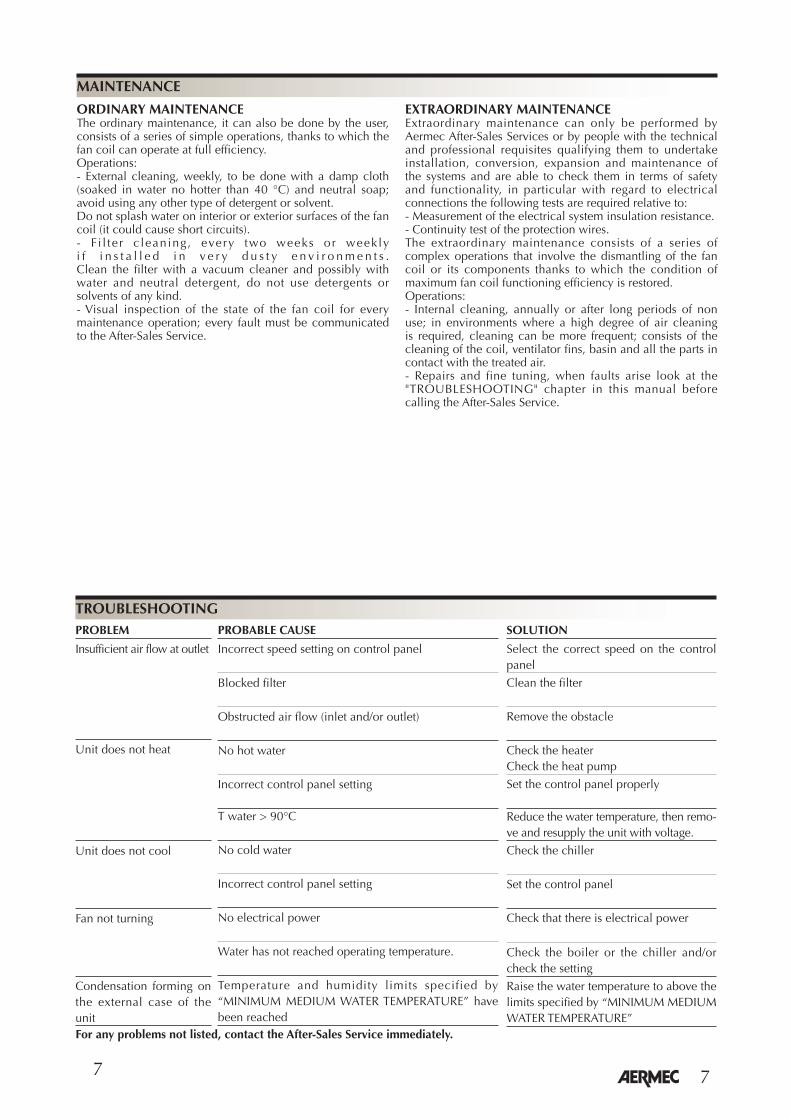
TLW1 (ACCESSORY) REMOTE CONTROL UNITAccessory essential for fan coil operation, alternative to the PFW wired remote panel.The TLW1 remote control unit is provided separately from the fan coil. A single remote control unit can control several fan coils.The remote control unit makes it possible to set all the operating parameters of the apparatus, these parameters are shown on a liquid crystal display thus making programming operations easier. The remote control unit is fitted with a support allowing it to be hung on the wall.
PFW WIRED REMOTE PANEL (ACCESSORY)Accessory essential for fan coil operation, alternative to the TLW1 remote control unitThe panel must be installed on the wall and connected to the fan coil with the cable provided. The panel cable is four meters long.The PFW makes it possible to set the MAIN operating parameters of the apparatus, these parameters are shown on a liquid crystal display thus making programming operations easier.A PFW panel is designed to control just one fan coil.
FRONT PANELThe air is sucked up by the slots. When raising the panel, one has access to the air filter and to the other internal parts.
RECEIVERInfra red signal receiver.
LIT INDICATORS (LED)These indicators show the current operating status.
AIR FILTERAir filters that can be regenerated are easy to extract for cleaning.
THERMAL EXCHANGE BATTERYThis made of a copper tube with turbulented type aluminium slats.
HORIZONTAL AIR DELIVERY DEFLECTORThe unit is fitted with a motorised air delivery deflector and vertical slats that can be directed manually in such a way as to optimally orient the air flow.
AUXILIARY EMERGENCY SWITCHThe auxiliary emergency switch makes it possible to turn the fan coil on or off in the absence of a wired remote panel or remote control unit. To access it, raise the front panel
FAN UNITThe fan unit consists of an extremely small, quiet tangential type fan.
THREE-WAY WATER VALVEThe FCW fan unit comes with a three-way water valve of the all or nothing type with electrothermal actuator controlled by the fan coil card in accordance with the water temperature and the temperature of the ambient air.
The two available command models (PFW and TLW1) provided as required as an obligatory accessory for the functioning allow the turning on, the turning off and all the fan coil control and programming operations.The two command models cannot be used at the same time on the same fan coil.The control system checks all the functioning parameters and carries out all the operations necessary to enable the required environmental conditions to be maintained.The control system also provides some automatic functions to increase comfort and make the most frequently repeated operations easier:- Minimum temperature sensor, in order to avoid cold air
blasts in the winter mode allows ventilation only if the water in the system is hot.
- Auto Restart mode, after a power outage the FCW unit starts again automatically with the same settings that it had at the time of the stop (with the exception of the Timer).
- Type of operation.- Programming of the timer for turning on or turning off.Fan speed- Activation of the motorised air delivery deflector.- Three-way water valve control. Turning the unit on and off.
DESCRIPTION OF COMPONENTS GENERAL INFORMATION
FCW is fi tted with a standard internal three-way valve.To function the FCW fan coil requires combination with the remote control (TLW1 accessory) or alternatively the wired remote panel (accessory PFW).
The tables in TAB 1 to 3 show the total chilling yield and sensible to the maximum speed in accordance with the inlet water temperature of its thermal change and air temperature with dry or wet bulb, performance at medium and minimum speeds are obtained by applying the relative correction coefficients.
The diagrams of the tables in TAB. 4 to 6 show the thermal capacity at top speed in accordance with the water flowrate and the inlet water and inlet air temperature difference, for lower speeds refer to the relative correction coefficients.
The diagram in TAB. 7 shows the coil pressure drop in function of the flow rate at a medium temperature of 10°C, for water circulating at different temperatures refer to the relative correction coefficients.
The diagrams in TAB. 8 show the correction factors for fan coils installed in systems with glycoled water.
Tables TAB. 9 and TAB. 10 show the level of sound power of the fan coils at different speeds.
SELECTION CRITERIA

10
MINIMUM AVERAGE WATER TEMPERATURE Dry bulb temperature °C 21 23 25 27 29 31 15 3 3 3 3 3 3 17 3 3 3 3 3 3Wet bulb temperature °C 19 3 3 3 3 3 3 21 6 5 4 3 3 3 23 - 8 7 6 5 5
Maximum water inlet temperature ........................... 70 °CMaximum working pressure .................................... 13 bar
Average minimum water temperatureTo prevent the formation of condensation on the exterior of the unit while the fan is operating, the average water temperatu-re should not drop beneath the limits shown in the table below, determined by the ambient conditions. These limits refer to unit operation with fan at minimum speed.
OPERATING LIMITS
WARNING: The fan coil is connected to the power supply and a water circuit. Operations performed by persons without the required technical skills can lead to personal injury to the operator or damage to the unit and surrounding objects.
MALFUNCTIONINGIn the case of malfunctioning remove the power to the unit then repower it and start the apparatus up again. If the problem occurs again, call your areas After-Sales Service promptly.
POWER THE FAN COIL ONLY WITH 230 VOLT, SINGLE PHASE, 50 HZUse of other power supplies could cause permanent damage to the fan coil.
USE THE (TLW1) REMOTE CONTROL UNIT OR THE WIRED REMOTE PANEL (PFW) TO TURN THE FAN COIL ON AND OFFDo not turn the fan coil on or off using the auxiliary switch unless it is an emergency.
DO NOT TUG THE ELECTRICAL CABLEIt is very dangerous to pull, tread on or crush the electrical power cable or fix it with nails or drawing pins.A damaged power cable can cause short circuits and personal injury.
DO NOT PUT ANYTHING IN THE AIR OUTLETSDo not put anything at all in the air outlet slots.This could cause injury to people and damage to the fan.
DO NOT USE THE FAN COIL IMPROPERLYDo not use the fan coil in animal husbandry applications (e.g. incubation).
AIRING THE ROOMPeriodically air the room in which the fan coil has been installed; this is particularly important if the room is occupied by many people, or if gas appliances or sources of odours are present.
CORRECTLY REGULATING THE TEMPERATUREThe room temperature should be regulated in order to provide maximum comfort to the people in the room, especially if they are elderly, children or ill, avoiding sudden changes in temperature between the outside and inside above 7 °C in summer. Careful choice of the room temperature will lead to energy savings.
CORRECTLY ADJUSTING THE AIR JETThe area coming out of the fan coil must not strike people directly; in fact, even if at a temperature that is higher than the room temperature, it could cause a cold sensation and resulting discomfort. Only adjust the vertical slats by hand.For the horizontal air delivery deflector, use the LOUVRE key of the remote control unit or SWING key on the wired remote panel.
DURING OPERATIONSAlways leave the filter on the fan coil during operation (otherwise dust in the air could soil the coil surface area).
WHAT IS NORMALDuring cooling function, water vapour may be present in the air delivery.In heating function it might be possible to hear a slight hiss around the fan coil. Sometimes the fan coil might give off unpleasant smells due to the accumulation of dirt in the air of the environment (especially if the room is not ventilated regularly, clean the filter more often).
IMPORTANT INFORMATION
The assembly site must be chosen in such a way that the maximum and minimum ambient temperature limits Ta are respected 0°C < Ta < 45°C ; R.H. < 85%.
The fan coils are powered with a voltage of 230 V monophase at 50 Hz and ground connection, in any case the power of the line must remain within the limit of ±10% with respect to the nominal value.
Water flow limits:
MOD. FCW 21 31 41Minimum water flow [l/h] 100 100 150Maximum water flow [l/h] 750 750 1100
10

11
Mod. FCW
max. [W]❊ Heating capacity med. [W] min. [W]❊ Water flow [l/h]❊ Water pressure drops (maximum speed) [kPa]❊❊ Heating capacity (water in 50°C) (E) [W]
max. (E) [W]❅ Total cooling capacity med. [W] min. [W] max. (E) [W]❅ Sensible cooling capacity med. [W] min. [W]❅ Water flow [l/h]❅ Water pressure drops (maximum speed) (E) [kPa]
max. [m3/h]Air flow med. [m3/h] min. [m3/h]Number of fans n
max. [dB (A)]� Sound pressure level med. [dB (A)] min. [dB (A)] max. (E) [dB (A)]Sound power level med. (E) [dB (A)] min. (E) [dB (A)]
Max. motor power (E) [W]Max. input current [A]Peak current [A]Valve input power [W]Maximum input power [W]
Water content [l]Coil connections (flat plate) ø
Height [mm]Dimensions
Width [mm]
Depth [mm]
Net weight [kg]Gross weight [kg]
Power supply = 230 V ~ 50 Hz (± 10 % ).
(E) = Eurovent Certifi ed Performance
TECHNICAL DATA
Performance values refer to the following conditions:– supply voltage 230 V ~ 50 Hz;� level of sound pressure (weighted A) measured in the
environment with volume V = 85 m3, reverberation time t = 0.5 s, direction factor Q = 2, distance r = 2.5 m.
❊ heating: Inlet Water temperature 70°C room air temperature = 20°C B.S.; • maximum ventilation speed: ∆t water= 10°C ; • medium and minimum ventilation speed: water flow rate as
maximum ventilation speed;
❊❊ heating (water inlet 50°C) water inlet temperature 50°C room air temperature = 20°C
B.S.; • maximum ventilation speed:water flow rate in cooling mode
at maximum ventilation speed;❅ cooling: inlet water temperature =7°C room air temperature = 27°C
B.S.; 19°C B.U.; • maximum ventilation speed: ∆t water= 5°C ; • medium and minimum ventilation speed: water flow rate as
maximum ventilation speed;
21 31 41
4000 5200 7600 3600 4600 6800 3000 3950 5700 344 447 654 18,5 23 23 2500 3300 4500 1900 2700 3800 1700 2200 3450 1450 1850 3000 1550 2150 2850 1350 1700 2500 1100 1400 2150 327 464 654 20 27 31,4 380 470 540 280 360 440 220 295 370 1 1 1
42,5 43,0 43,5 38,5 35,5 38,5 31,0 28,5 35,5 51,0 51,5 52 47,0 44,0 47 39,5 37,0 44 23 25 43,7 0,1 0,11 0,19 0,3 0,33 0,6 2,5 2,5 2,5 26 28 47
0,7 0,8 1,6 1/2” F 1/2” F 1/2” F 298 305 360 880 990 1170 180 180 210
9 10 19 10 11 22
12
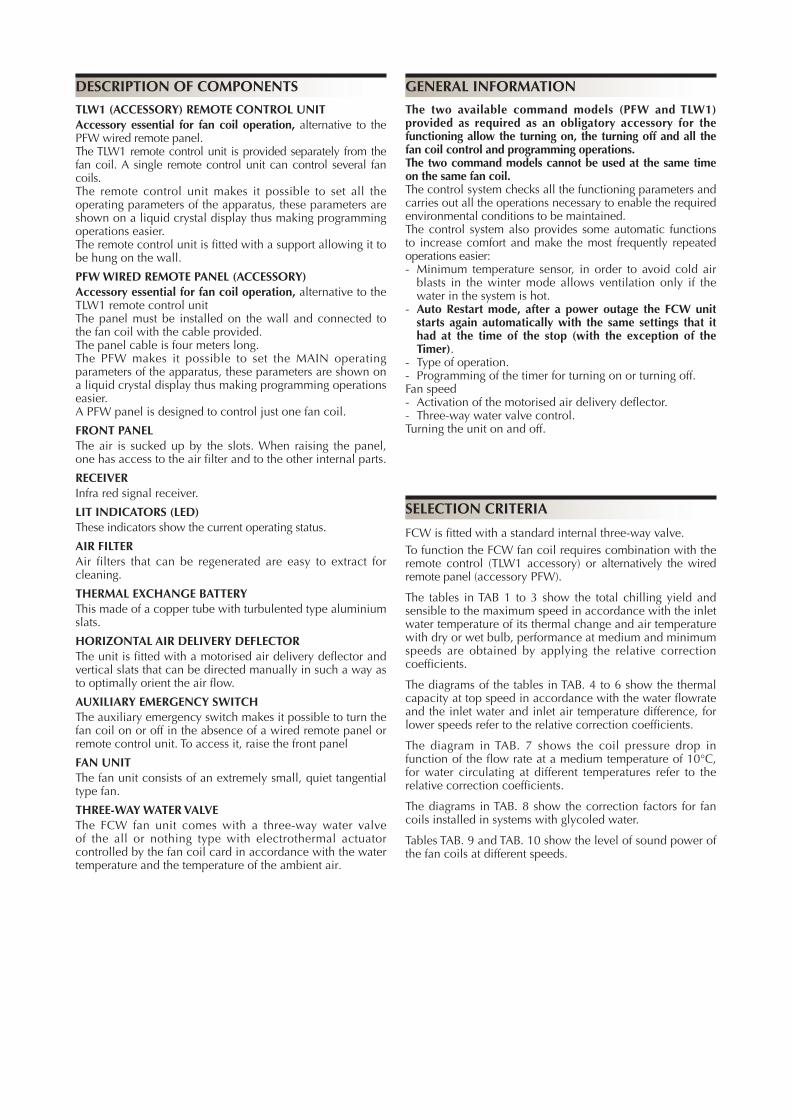
TAV.1 FCW 21
Tw [°C] ∆t Ta b.u. [°C] Pc Ps Pc Ps Pc Ps Pc Ps Pc Ps Pc Ps 21°C Ta b.s. 23°C Ta b.s. 25°C Ta b.s. 27°C Ta b.s. 29°C Ta b.s. 31°C Ta b.s.5 3 15 1386 1098 1870 1656 2038 1890 2284 2118 2526 2342 2768 2567 17 2479 1425 2453 1647 2457 1878 2505 2116 2582 2348 2772 2571 19 3217 1446 3204 1652 3192 1875 3179 2102 3160 2327 3167 2554 21 3990 1674 3971 1870 3958 2089 3939 2313 3927 2539 23 4800 1889 4781 2080 4762 2291 4750 2516 5 15 1200 1088 1375 1275 1598 1482 1900 1762 2176 2019 2441 2264 17 1464 997 1529 1233 1706 1501 1922 1767 2181 2023 2444 2267 19 2453 1115 2436 1329 2410 1549 2427 1780 2496 2022 2617 2272 21 3330 1389 3314 1595 3299 1816 3280 2039 3261 2260 23 4209 1635 4182 1828 4171 2047 4159 2272 7 15 1041 963 1230 1141 1420 1317 1611 1494 1805 1674 1999 1854 17 1200 881 1300 1110 1438 1320 1615 1498 1805 1674 2003 1858 19 1606 783 1598 1004 1641 1231 1736 1460 1852 1670 2008 1862 21 2185 942 2168 1160 2142 1377 2194 1611 2323 1865 23 3368 1303 3355 1511 3343 1734 3304 19487 3 15 1332 1182 1533 1422 1796 1665 2047 1898 2289 2123 2531 2347 17 1939 1194 1926 1419 1991 1661 2092 1899 2293 2127 2535 2351 19 2699 1217 2686 1430 2677 1659 2651 1880 2669 2111 2734 2353 21 3481 1451 3525 1656 3449 1877 3430 2100 3418 2325 23 4297 1672 4285 1903 4266 2085 4247 2309 5 15 987 915 1179 1093 1373 1273 1645 1526 1935 1794 2207 2047 17 1118 850 1226 1077 1377 1277 1649 1530 1939 1798 2211 2051 19 1744 834 1710 1048 1770 1291 1900 1550 2055 1805 2237 2033 21 2738 1150 2729 1365 2712 1588 2695 1810 2721 2040 23 2809 1090 3632 1613 3619 1834 3600 2057 7 15 844 783 1036 961 1228 1139 1418 1316 1611 1494 1801 1670 17 904 744 1053 960 1231 1141 1421 1317 1611 1494 1803 1672 19 1200 633 1240 864 1334 1093 1459 1308 1615 1497 1805 1674 21 1675 762 1667 983 1701 1209 1779 1434 1891 1654 23 2651 1041 2634 1256 2608 1475 2617 17019 3 15 1008 935 1291 1197 1555 1442 1805 1674 2051 1902 2293 2127 17 1321 942 1416 1191 1583 1445 1809 1678 2055 1906 2298 2131 19 2133 984 2120 1204 2099 1428 2129 1661 2211 1902 2336 1985 21 2928 1223 2915 1435 2903 1662 2884 1884 2878 2110 23 3757 1451 1386 613 3726 1875 3713 2101 5 15 883 819 984 913 1177 1091 1390 1289 1688 1566 1965 1822 17 831 712 984 913 1179 1093 1390 1289 1693 1570 1968 1825 19 1127 606 1157 834 1254 1062 1421 1296 1697 1574 1973 1830 21 2055 894 2045 1117 2030 1336 2099 1577 2211 1825 23 3035 1177 3016 1387 3003 1611 2984 1833 7 15 17 660 599 844 783 1036 961 1228 1139 1418 1316 1611 1494 19 821 495 926 731 1064 950 1231 1141 1421 1317 1611 1494 21 1250 617 1282 845 1369 1074 1490 1294 1632 1497 23 1762 744 1749 966 1788 1196 1874 142811 3 15 740 687 1030 955 1304 1209 1563 1449 1811 1680 2055 1906 17 762 682 1032 957 1308 1213 1565 1452 1814 1682 2060 1910 19 1490 737 1468 958 1537 1201 1649 1446 1818 1686 2064 1914 21 2328 993 2315 1212 2302 2077 2297 1663 2341 1894 23 3173 1226 3160 1437 3142 1660 3129 1884 5 15 17 598 554 792 735 984 913 1177 1091 1429 1326 1723 1598 19 743 468 848 700 993 912 1179 1093 1434 1330 1727 1602 21 1179 592 1200 818 1304 1055 1532 1327 1775 1607 23 2332 930 2315 1147 2289 1367 2332 1602 7 15 17 19 502 368 666 593 846 785 1036 961 1228 1139 1418 1316 21 846 482 948 716 1084 939 1235 1138 1421 1317 23 1308 602 1330 828 1408 1055 1520 1276
COOLING CAPACITY

13
Tw [°C] ∆t Ta b.u. [°C] Pc Ps Pc Ps Pc Ps Pc Ps Pc Ps Pc Ps 21°C Ta b.s. 23°C Ta b.s. 25°C Ta b.s. 27°C Ta b.s. 29°C Ta b.s. 31°C Ta b.s.13 3 15 17 540 501 745 691 1049 973 1317 1221 1572 1458 1818 1686 19 668 443 820 696 1071 977 1321 1225 1576 1462 1822 1690 21 1654 752 1632 973 1667 1206 1757 1449 1891 1691 23 2539 1000 2522 1216 2509 1440 2496 1662 5 15 17 19 434 342 601 509 792 735 984 913 1179 1093 1472 1365 21 770 457 868 688 1008 905 1181 1095 1477 1370 23 1356 615 1364 842 1492 1083 1710 1371 7 15 17 19 21 511 359 676 586 846 785 1036 961 1228 1139 23 876 470 971 701 1101 924 1252 113315 3 15 17 19 365 313 545 505 771 715 1066 989 1330 1233 1580 1466 21 704 436 915 717 1123 985 1332 1235 1585 1470 23 1822 761 1814 985 1814 1210 1878 1446 5 15 17 19 21 442 334 606 551 792 735 984 913 1196 1109 23 794 445 889 675 1023 895 1213 1118 7 15 17 19 21 23 521 350 684 577 853 781 1036 961
Cooling capacities are referred to high speed. To obtain values for other speed, multiply the values read by following factors:
MOD. FCW 21
Medium speed total capacity 0,89
sensible capacity 0,87
Minimum speed total capacity 0,76
sensible capacity 0,71
Water flow rate as at maximum ventilation speed;
Tw [°C] = Inlet water temperatureTa w.b. [°C] = Inlet wet bulbe air temperatureTa b.s. [°C] = Dry bulbe air temperaturePc [W] = Total cooling capacityPs [W] = Sensible cooling capacity
NOTE: Values of capacity in bold face refer to nominal value.Values of sensible capacity higher than values of total capacity mean that cooling is without dehumidification in this case consider only the values of sensible capacity.

14
TAV.2 FCW 31
Tw [°C] ∆t Ta b.u. [°C] Pc Ps Pc Ps Pc Ps Pc Ps Pc Ps Pc Ps 21°C Ta b.s. 23°C Ta b.s. 25°C Ta b.s. 27°C Ta b.s. 29°C Ta b.s. 31°C Ta b.s.5 3 15 1969 1524 2657 2297 2896 2621 3245 2938 3589 3249 3933 3561 17 3522 1976 3486 2285 3492 2606 3559 2935 3670 3256 3940 3567 19 4571 2005 4553 2292 4536 2601 4518 2916 4491 3228 4500 3543 21 5669 2322 5643 2593 5625 2897 5598 3209 5580 3521 23 6821 2621 6794 2885 6767 3178 6750 3490 5 15 1705 1509 1954 1769 2270 2055 2700 2444 3093 2800 3469 3141 17 2080 1383 2172 1710 2424 2081 2731 2451 3099 2805 3473 3144 19 3486 1546 3461 1843 3424 2149 3449 2470 3547 2804 3719 3151 21 4732 1926 4709 2212 4687 2518 4661 2828 4634 3135 23 5982 2268 5942 2535 5928 2839 5910 3152 7 15 1479 1335 1748 1582 2018 1827 2289 2072 2565 2322 2841 2572 17 1705 1223 1847 1540 2043 1831 2295 2078 2565 2322 2846 2577 19 2283 1087 2270 1392 2332 1708 2467 2025 2632 2316 2853 2583 21 3105 1307 3080 1609 3044 1910 3117 2235 3301 2587 23 4786 1807 4768 2096 4750 2405 4695 27037 3 15 1893 1640 2179 1973 2552 2310 2909 2633 3252 2944 3596 3256 17 2755 1656 2737 1968 2829 2304 2973 2635 3258 2950 3602 3261 19 3835 1687 3817 1983 3805 2301 3767 2607 3792 2928 3885 3264 21 4946 2013 5009 2297 4902 2604 4875 2914 4857 3225 23 6107 2319 6089 2640 6062 2893 6035 3202 5 15 1402 1269 1675 1516 1951 1766 2338 2116 2749 2489 3136 2839 17 1589 1179 1742 1494 1957 1772 2344 2122 2755 2494 3142 2844 19 2479 1156 2430 1453 2516 1791 2700 2150 2921 2504 3179 2820 21 3891 1595 3878 1894 3854 2203 3829 2511 3866 2830 23 3992 1511 5161 2237 5143 2544 5116 2853 7 15 1199 1086 1473 1333 1746 1580 2016 1825 2289 2072 2559 2316 17 1285 1032 1497 1332 1749 1583 2019 1827 2289 2072 2562 2319 19 1706 878 1762 1199 1896 1516 2074 1815 2294 2077 2565 2322 21 2381 1057 2368 1364 2418 1677 2528 1989 2688 2295 23 3767 1444 3743 1742 3706 2046 3719 23609 3 15 1433 1297 1835 1661 2209 2000 2565 2322 2915 2639 3258 2950 17 1878 1306 2013 1653 2249 2004 2571 2328 2921 2644 3265 2956 19 3031 1365 3013 1670 2982 1980 3025 2304 3142 2639 3320 2754 21 4160 1696 4143 1991 4125 2305 4098 2613 4089 2927 23 5339 2013 1970 850 5294 2601 5277 2914 5 15 1255 1136 1399 1266 1672 1514 1976 1789 2399 2172 2792 2528 17 1181 987 1399 1266 1675 1516 1976 1789 2405 2178 2797 2532 19 1601 841 1644 1157 1782 1473 2019 1797 2411 2183 2803 2538 21 2921 1240 2905 1549 2884 1853 2982 2188 3142 2531 23 4312 1633 4286 1924 4268 2235 4241 2542 7 15 17 938 831 1199 1086 1473 1333 1746 1580 2016 1825 2289 2072 19 1166 686 1316 1014 1512 1317 1749 1583 2019 1827 2289 2072 21 1776 856 1822 1172 1945 1490 2117 1796 2319 2076 23 2504 1032 2485 1339 2541 1659 2663 198111 3 15 1052 952 1463 1325 1853 1677 2220 2010 2574 2330 2921 2644 17 1083 945 1466 1327 1859 1683 2224 2014 2577 2333 2927 2650 19 2117 1023 2086 1329 2184 1666 2344 2006 2583 2339 2933 2655 21 3308 1377 3289 1681 3271 2881 3265 2306 3326 2627 23 4509 1701 4491 1993 4464 2303 4446 2613 5 15 17 849 769 1126 1019 1399 1266 1672 1514 2031 1839 2448 2216 19 1055 649 1206 971 1411 1265 1675 1516 2037 1844 2454 2222 21 1675 822 1706 1135 1853 1464 2178 1840 2522 2229 23 3314 1290 3289 1592 3252 1896 3314 2222 7 15 17 19 714 511 946 823 1202 1089 1473 1333 1746 1580 2016 1825 21 1202 668 1347 993 1540 1303 1755 1579 2019 1827 23 1859 835 1890 1148 2000 1464 2160 1770
COOLING CAPACITY

15
Cooling capacities are referred to high speed. To obtain values for other speed, multiply the values read by following factors:
MOD. FCW 31
Medium speed total capacity 0,81
sensible capacity 0,79
Minimum speed total capacity 0,68
sensible capacity 0,65
Water flow rate as at maximum ventilation speed;
Tw [°C] ∆t Ta b.u. [°C] Pc Ps Pc Ps Pc Ps Pc Ps Pc Ps Pc Ps 21°C Ta b.s. 23°C Ta b.s. 25°C Ta b.s. 27°C Ta b.s. 29°C Ta b.s. 31°C Ta b.s.13 3 15 17 768 695 1058 958 1491 1350 1871 1694 2234 2022 2583 2339 19 949 614 1166 966 1522 1355 1878 1700 2240 2028 2589 2344 21 2350 1043 2319 1349 2368 1674 2497 2009 2688 2346 23 3608 1387 3584 1687 3565 1998 3547 2305 5 15 17 19 617 474 854 706 1126 1019 1399 1266 1675 1516 2092 1894 21 1095 634 1233 954 1433 1256 1678 1519 2098 1900 23 1927 854 1939 1167 2121 1503 2430 1902 7 15 17 19 21 726 498 960 813 1202 1089 1473 1333 1746 1580 23 1245 651 1380 973 1565 1282 1779 157215 3 15 17 19 518 434 774 701 1095 991 1515 1372 1890 1711 2246 2033 21 1000 605 1301 994 1595 1366 1893 1714 2252 2039 23 2589 1056 2577 1366 2577 1678 2669 2006 5 15 17 19 21 629 464 862 765 1126 1019 1399 1266 1699 1539 23 1129 617 1264 937 1454 1241 1724 1551 7 15 17 19 21 23 740 486 972 800 1212 1084 1473 1333
Tw [°C] = Inlet water temperatureTa w.b. [°C] = Inlet wet bulbe air temperatureTa b.s. [°C] = Dry bulbe air temperaturePc [W] = Total cooling capacityPs [W] = Sensible cooling capacity
NOTE: Values of capacity in bold face refer to nominal value.Values of sensible capacity higher than values of total capacity mean that cooling is without dehumidification in this case consider only the values of sensible capacity.

16
TAV.3 FCW 41
COOLING CAPACITY
Tw [°C] ∆t Ta b.u. [°C] Pc Ps Pc Ps Pc Ps Pc Ps Pc Ps Pc Ps 21°C Ta b.s. 23°C Ta b.s. 25°C Ta b.s. 27°C Ta b.s. 29°C Ta b.s. 31°C Ta b.s.5 3 15 2772 2020 3739 3045 4075 3475 4567 3894 5051 4307 5536 4720 17 4957 2619 4906 3029 4914 3454 5009 3891 5165 4316 5545 4728 19 6434 2658 6409 3038 6384 3448 6358 3866 6321 4279 6333 4696 21 7979 3079 7942 3438 7916 3841 7879 4254 7853 4668 23 9600 3474 9562 3824 9525 4212 9500 4627 5 15 2400 2000 2750 2345 3195 2724 3800 3240 4353 3711 4883 4163 17 2928 1833 3057 2267 3411 2759 3843 3249 4361 3719 4888 4168 19 4906 2050 4871 2443 4819 2848 4854 3274 4992 3718 5234 4177 21 6660 2554 6628 2932 6597 3338 6559 3748 6522 4156 23 8419 3007 8363 3361 8343 3764 8318 4178 7 15 2081 1770 2460 2097 2840 2422 3221 2747 3610 3078 3999 3409 17 2400 1621 2599 2041 2876 2427 3230 2754 3610 3078 4006 3416 19 3213 1440 3195 1846 3282 2264 3472 2684 3705 3070 4015 3424 21 4370 1733 4335 2133 4284 2532 4387 2962 4646 3429 23 6735 2395 6710 2779 6685 3188 6608 35837 3 15 2664 2174 3067 2615 3591 3062 4094 3491 4577 3903 5061 4315 17 3878 2195 3852 2609 3981 3054 4184 3493 4586 3910 5070 4323 19 5398 2237 5372 2629 5355 3050 5302 3456 5338 3881 5468 4327 21 6961 2669 7049 3045 6899 3452 6861 3862 6836 4275 23 8595 3074 8570 3499 8532 3835 8494 4245 5 15 1973 1682 2357 2010 2746 2341 3290 2806 3869 3299 4413 3763 17 2237 1563 2452 1980 2755 2349 3299 2813 3878 3306 4422 3770 19 3489 1533 3420 1926 3541 2374 3800 2850 4111 3320 4474 3738 21 5476 2114 5458 2510 5424 2921 5389 3328 5441 3751 23 5618 2003 7263 2966 7238 3373 7200 3782 7 15 1688 1439 2072 1767 2457 2095 2837 2419 3221 2747 3601 3071 17 1809 1369 2107 1766 2461 2099 2841 2422 3221 2747 3606 3074 19 2401 1164 2480 1589 2668 2010 2919 2406 3229 2753 3610 3078 21 3351 1401 3333 1808 3403 2224 3558 2636 3783 3042 23 5302 1914 5268 2309 5217 2712 5234 31289 3 15 2016 1719 2582 2202 3109 2651 3610 3078 4102 3498 4586 3910 17 2642 1732 2833 2191 3165 2656 3619 3085 4111 3505 4596 3919 19 4266 1810 4240 2214 4197 2625 4258 3054 4422 3498 4672 3650 21 5855 2249 5831 2639 5806 3055 5768 3463 5755 3880 23 7514 2668 2772 1127 7451 3448 7426 3863 5 15 1766 1506 1969 1679 2353 2006 2781 2371 3377 2879 3930 3351 17 1662 1309 1969 1679 2357 2010 2781 2371 3385 2887 3937 3357 19 2254 1115 2314 1534 2509 1953 2841 2382 3394 2894 3946 3364 21 4111 1644 4089 2054 4059 2456 4197 2900 4422 3355 23 6069 2164 6032 2550 6007 2962 5969 3370 7 15 17 1319 1101 1688 1439 2072 1767 2457 2095 2837 2419 3221 2747 19 1641 909 1852 1344 2129 1746 2461 2099 2841 2422 3221 2747 21 2500 1135 2565 1554 2737 1975 2979 2380 3264 2752 23 3523 1368 3498 1775 3576 2199 3748 262611 3 15 1481 1263 2059 1756 2608 2224 3125 2665 3623 3089 4111 3505 17 1524 1253 2064 1760 2616 2231 3131 2669 3627 3093 4120 3513 19 2979 1356 2936 1761 3074 2209 3299 2660 3636 3100 4128 3520 21 4655 1825 4629 2228 4603 3819 4595 3057 4681 3483 23 6346 2255 6321 2642 6283 3053 6258 3464 5 15 17 1196 1019 1584 1351 1969 1679 2353 2006 2858 2437 3446 2938 19 1485 860 1697 1288 1986 1677 2357 2010 2867 2445 3454 2945 21 2357 1089 2401 1505 2608 1941 3065 2439 3550 2955 23 4664 1710 4629 2110 4577 2513 4664 2945 7 15 17 19 1005 677 1332 1091 1692 1443 2072 1767 2457 2095 2837 2419 21 1692 886 1895 1317 2167 1727 2470 2093 2841 2422 23 2616 1107 2660 1522 2815 1940 3040 2346

17
Cooling capacities are referred to high speed. To obtain values for other speed, multiply the values read by following factors:
MOD. FCW 41
Medium speed total capacity 0.91
sensible capacity 0.88
Minimum speed total capacity 0.79
sensible capacity 0.75
Water flow rate as at maximum ventilation speed;
Tw [°C] = Inlet water temperatureTa w.b. [°C] = Inlet wet bulbe air temperatureTa b.s. [°C] = Dry bulbe air temperaturePc [W] = Total cooling capacityPs [W] = Sensible cooling capacity
NOTE: Values of capacity in bold face refer to nominal value.Values of sensible capacity higher than values of total capacity mean that cooling is without dehumidification in this case consider only the values of sensible capacity.
Tw [°C] ∆t Ta b.u. [°C] Pc Ps Pc Ps Pc Ps Pc Ps Pc Ps Pc Ps 21°C Ta b.s. 23°C Ta b.s. 25°C Ta b.s. 27°C Ta b.s. 29°C Ta b.s. 31°C Ta b.s.13 3 15 17 1080 921 1489 1270 2098 1789 2634 2246 3144 2680 3636 3100 19 1336 814 1640 1280 2142 1796 2642 2253 3152 2688 3644 3108 21 3308 1383 3264 1788 3333 2218 3515 2664 3783 3110 23 5078 1838 5044 2236 5018 2648 4992 3056 5 15 17 19 868 628 1202 936 1584 1351 1969 1679 2357 2010 2944 2510 21 1541 840 1735 1265 2016 1665 2362 2014 2953 2518 23 2712 1131 2729 1547 2985 1992 3420 2521 7 15 17 19 21 1022 660 1351 1077 1692 1443 2072 1767 2457 2095 23 1753 864 1943 1290 2202 1699 2504 208415 3 15 17 19 730 575 1089 929 1541 1314 2133 1819 2660 2268 3161 2695 21 1407 802 1830 1318 2245 1811 2664 2271 3169 2702 23 3644 1399 3627 1811 3627 2224 3757 2659 5 15 17 19 21 885 615 1213 1014 1584 1351 1969 1679 2392 2039 23 1589 818 1779 1242 2046 1646 2427 2056 7 15 17 19 21 23 1042 644 1368 1061 1705 1437 2072 1767

18
���
���
���
���
���
���
���
���
���
���
���
���
���
���
���� ���� ���� ���� ���� ���� ���� ���� ���� ���� ���� ���� ����
�
�
�� �� �� �� ��
���� ���� ���� ���� ���� ���� ���� ���� ���� ����
�� �� �� �� ��
���
���
���
���
���
���
���
���
���
���
���
���
���
����
�
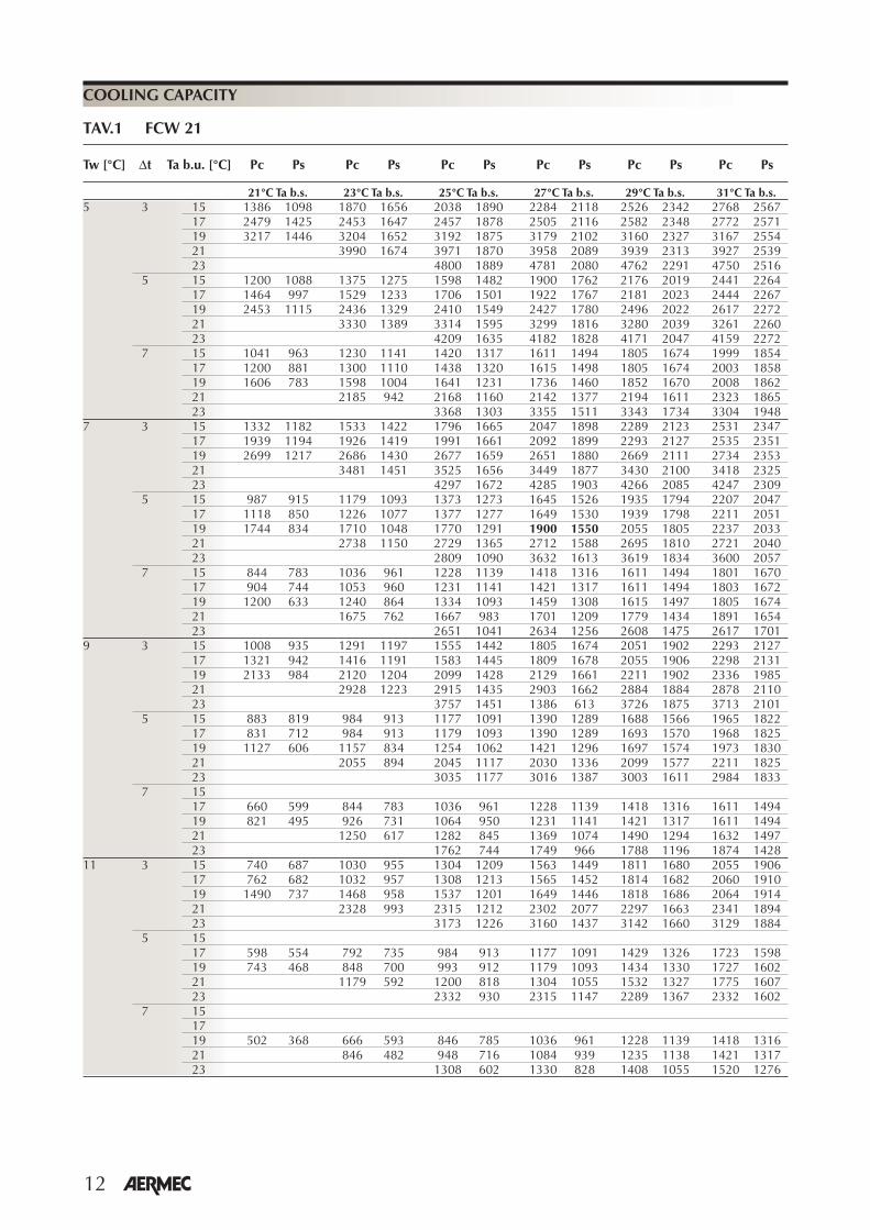
Heating capacity figures refer to maximum fan speed. Performance for other fan speeds can be obtained by multiplying these figures by the following correction factors:
MOD. FCW 21 Medium speed Minimum speed 0,90 0,75
∆t °C (water inlet temperature- air inlet temperature)
Heating capacity [W]
Heating capacity [W]
Wat
er fl
ow r
ate
[l/h
]
Heating capacity figures refer to maximum fan speed. Performance for other fan speeds can be obtained by multiplying these figures by the following correction factors:
MOD. FCW 31 Medium speed Minimum speed 0,88 0,76
TAV. 4 FCW 21
TAV. 5 FCW 31 ∆t °C (water inlet temperature- air inlet temperature)
HEATING CAPACITY
Wat
er fl
ow r
ate
[l/h
]

19
��� �� �� �� ��
���
���
���
���
���
���
���
��
���
����
����
���� ���� ���� ���� ���� ���� ���� ��� ���� ����� �
�
��
��������
��� �������
������������
������
��� �������Water flow rate [l/h]
The pressure drops in the diagram refer to the average water temperature of 10 °C. The following table shows the correction to apply to the pressure drops when the medium water temperature varies.
Medium water temperature °C 5 10 15 20 50 60 70Multiplicational coefficient 1,03 1 0,96 0,91 0,78 0,75 0,72
Pres
sure
dro
ps (k
Pa)
TAV. 7
COIL PRESSURE DROPS
Heating capacity figures refer to maximum fan speed. Performance for other fan speeds can be obtained by multiplying these figures by the following correction factors:
MOD. FCW 41 Medium speed Minimum speed 0,75 0,90
∆t °C (water inlet temperature- air inlet temperature)
Heating capacity [W]
TAV. 6 FCW 41
HEATING CAPACITY
Wat
er fl
ow r
ate
[l/h
]

20
��
���
���
���
���
� � � �� �� �� �� �� �� �� ������
Average temperature of the glycol water
Cor
rect
ion
fact
or
Pressure drops
Water flow
Capacity
GLYCOL WATER AT 10%
GLYCOL WATER AT 35%
GLYCOL WATER AT 20%
CORRECTION FACTORS WITH GLYCOL WATER
COOLING HEATING
���
���
��
���
���
���
���
� � � �� �� �� �� �� �� �� ������
Average temperature of the glycol water
Cor
rect
ion
fact
or
���
���
���
��
���
���
���
���
���
���
���
���
� � � �� �� �� �� �� �� �� �� � ����
Average temperature of the glycol water
Cor
rect
ion
fact
or
�� �� �� �� �� � ��������
���
���
���
���
���
���
Average temperature of the glycol water
Cor
rect
ion
fact
or
��
���
���
���
���
���
���
�� �� �� �� �� � ������
Average temperature of the glycol water
Cor
rect
ion
fact
or
��
���
���
���
���
���
���
�� �� �� �� �� � ������
Average temperature of the glycol water
Cor
rect
ion
fact
or
Reading key:
TAV. 8

AERMEC S.p.A.I-37040 Bevilacqua (VR) - ItaliaVia Roma, 44 - Tel. (+39) 0442 633111Telefax (+39) 0442 93730 - (+39) 0442 93566www .aermec. com - info @aermec. com
I dati tecnici riportati nella presente documentazione non sono impegnativi.AERMEC S.p.A. si riserva la facoltà di apportare in qualsiasi momento tutte le modifiche ritenute necessarie per il miglioramento del prodotto.Les données mentionnées dans ce manuel ne constituent aucun engagement de notre part. Aermec S.p.A. se réserve le droit de modifier à tous moments les données considérées nécessaires à l’amelioration du produit.Technical data shown in this booklet are not binding.Aermec S.p.A. shall have the right to introduce at any time whatever modifications deemed necessary to the improvement of the product.Im Sinne des technischen Fortsschrittes behält sich Aermec S.p.A. vor, in der Produktion Änderungen und Verbesserungen ohne Ankündigung dur-chzuführen.ILos datos técnicos indicados en la presente documentación no son vinculantes.Aermec S.p.A. se reserva el derecho de realizar en cualquier momento las modificaciones que estime necesarias para mejorar el producto.
Aermec partecipa al Programma di Certificazione EUROVENT. I prodotti interessati figurano nella Guida EUROVENT dei Prodotti Certificati.
Aermec is partecipating in the EUROVENT Certification Programme. Products are as listed in the EUROVENT Directory of Certified Products.
Aermec partecipe au Programme de Certification EUROVENT. Les produits figurent dans l’Annuaire EUROVENT des Produits Certifiés.
Aermec ist am Zertifikations - Programm EUROVENT beteiligt. Die entsprechend gekennzeichneten Produkte sind im EUROVENT - Jahrbuch aufgefürt.
AERMEC S.p.A. participa en el programa de certificación EUROVENT. Sus equipos aparecen en el directorio de productos certificados EUROVENT.
Related Documents