Z207937-0C Page 1 of 8 ©2020 Veris Industries USA 800.354.8556 or +1.503.598.4564 / [email protected] 0920 Alta Labs, Enercept, Enspector, Hawkeye, Trustat, Aerospond, Veris, and the Veris ‘V’ logo are trademarks or registered trademarks of Veris Industries, L.L.C. in the USA and/or other countries. Other companies’ trademarks are hereby acknowledged to belong to their respective owners. NOTICE • This product is not intended for life or safety applications. • Do not install this product in hazardous or classified locations. • Read and understand the instructions before installing this product. • Turn off all power supplying equipment before working on it. • The installer is responsible for conformance to all applicable codes. If this product is used in a manner not specified by the manufacturer, the protection provided by the product may be impaired. No responsibility is assumed by the manufacturer for any consequences arising out of the use of this material. Installation Guide Temperature Product Identification Product Overview The TW2 Series of temperature sensors for living space is a versatile sensor platform for use with BAS controllers designed to accept 4 to 20mA, 0 to 5Vdc or 0 to 10Vdc outputs. TW2 Series sensors are available with three user interface options: touchscreen, LCD with three buttons and blank. TW2 Series Wall Mount Temperature Sensors Specifications OPERATING ENVIRONMENT Input Power Class 2; 20 to 30 Vdc, 24 Vac, 50 to 60 Hz Analog Output Selectable 4 to 20 mA, 0 to 5 V, 0 to 10 V Operating Temp. Range 0 to 50 °C (32 to 122 °F) Operating Humidity Range 0 to 95% RH non-condensing Housing Material High-impact ABS plastic Terminal Block Torque 0.5 to 0.6 N-m (0.37 to 0.44 in-lbf) TEMPERATURE TRANSMITTER OPTION Sensor Type Solid state, integrated circuit Accuracy ±0.2 °C (±0.4 °F) typical Resolution 0.1 °C (0.1 °F) Range 0 to 50 °C (32 to 122 °F) DISPLAY MODELS Touchscreen 61 mm (2.4 in), color, backlit, capacitive, 240x300 px Setpoint: 0-10Vdc. Temperature or fan speed selectable Timeout override: Display timeout* Lockout override: Touchscreen/button lockout* LCD 52mm (2.05 in), segmented with 3 buttons Setpoint: 0-10Vdc. Temperature or fan speed selectable Timeout override: Display timeout* Lockout override: Touchscreen/button lockout* TW2 User Interface Output Temperature T = Color touchscreen L = 3-button LCD display X = None A = Analog output A = Transmitter only C = 1000 PT RTD D = 10K T2 thermistor H = 10K T3 thermistor K = 10K curve G/11K shunt M = 20K NTC thermistor N = 1.8K TAC thermistor TW2TAXx TW2LAXx TW2XAXx X

Welcome message from author
This document is posted to help you gain knowledge. Please leave a comment to let me know what you think about it! Share it to your friends and learn new things together.
Transcript
Z207937-0C Page 1 of 8 ©2020 Veris Industries USA 800.354.8556 or +1.503.598.4564 / [email protected] 0920 Alta Labs, Enercept, Enspector, Hawkeye, Trustat, Aerospond, Veris, and the Veris ‘V’ logo are trademarks or registered trademarks of Veris Industries, L.L.C. in the USA and/or other countries.
Other companies’ trademarks are hereby acknowledged to belong to their respective owners.
NOTICE• This product is not intended for life or safety applications.• Do not install this product in hazardous or classi�ed locations.• Read and understand the instructions before installing this product.• Turn o� all power supplying equipment before working on it.• The installer is responsible for conformance to all applicable codes.
If this product is used in a manner not speci�ed by the manufacturer, the protection provided by the product may be impaired. No responsibility is assumed by the manufacturer for any consequences arising out of the use of this material.
Installation GuideTemperature
Product Identification
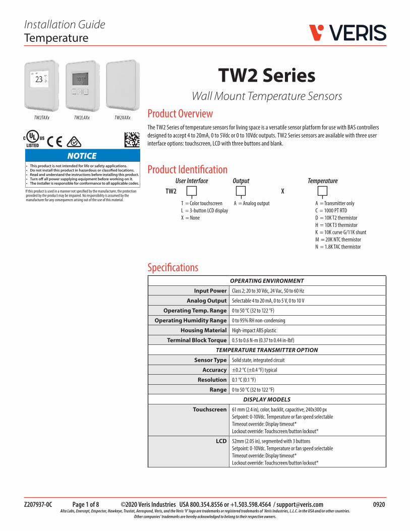
Product OverviewThe TW2 Series of temperature sensors for living space is a versatile sensor platform for use with BAS controllers designed to accept 4 to 20mA, 0 to 5Vdc or 0 to 10Vdc outputs. TW2 Series sensors are available with three user interface options: touchscreen, LCD with three buttons and blank.
TW2 SeriesWall Mount Temperature Sensors
SpecificationsOPERATING ENVIRONMENT
Input Power Class 2; 20 to 30 Vdc, 24 Vac, 50 to 60 Hz
Analog Output Selectable 4 to 20 mA, 0 to 5 V, 0 to 10 V
Operating Temp. Range 0 to 50 °C (32 to 122 °F)
Operating Humidity Range 0 to 95% RH non-condensing
Housing Material High-impact ABS plastic
Terminal Block Torque 0.5 to 0.6 N-m (0.37 to 0.44 in-lbf)
TEMPERATURE TRANSMITTER OPTION
Sensor Type Solid state, integrated circuit
Accuracy ±0.2 °C (±0.4 °F) typical
Resolution 0.1 °C (0.1 °F)
Range 0 to 50 °C (32 to 122 °F)
DISPLAY MODELS
Touchscreen 61 mm (2.4 in), color, backlit, capacitive, 240x300 px Setpoint: 0-10Vdc. Temperature or fan speed selectable Timeout override: Display timeout* Lockout override: Touchscreen/button lockout*
LCD 52mm (2.05 in), segmented with 3 buttons Setpoint: 0-10Vdc. Temperature or fan speed selectable Timeout override: Display timeout* Lockout override: Touchscreen/button lockout*
TW2User Interface Output Temperature
T = Color touchscreenL = 3-button LCD displayX = None
A = Analog output A = Transmitter onlyC = 1000 PT RTDD = 10K T2 thermistorH = 10K T3 thermistorK = 10K curve G/11K shuntM = 20K NTC thermistorN = 1.8K TAC thermistor
TW2TAXx TW2LAXx TW2XAXx
X

Z207937-0C Page 2 of 8 ©2020 Veris Industries USA 800.354.8556 or +1.503.598.4564 / [email protected] 0920 Alta Labs, Enercept, Enspector, Hawkeye, Trustat, Aerospond, Veris, and the Veris ‘V’ logo are trademarks or registered trademarks of Veris Industries, L.L.C. in the USA and/or other countries.
Other companies’ trademarks are hereby acknowledged to belong to their respective owners.
TW2 Series Installation Guide
Specifications (cont.) SETPOINTS**
Temperature Setpoint 0 to 10V output Scale: 10 to 35 °C (50 to 95 °F) / 0 to 50 °C (32 to 122 °F)
Fan Speed Setpoint 0 to 10V output Off 0V, Low 3.3V, Med. 6.7V, High 10.0V
WIRING TERMINALS
Terminal Blocks Screw terminals, 18-24 AWG
Screw Terminal Torque 0.2 N-m (2.0 in-lbF) max.
OVERRIDE
Override Button Display models feature a momentary-to-ground override button
WARRANTY
Limited Warranty 5 years
COMPLIANCE INFORMATION
Agency Approvals UL 916, European conformance CE: EN61000-6-2, EN61000-6-3, EN61000 Series - industrial immunity, EN 61326-1 FCC Part 15 Class B, REACH, RoHS, RCM (Australia), ICES-003 (Canada)
*DIP switch selectable. ** One setpoint type is selectable via DIP switch on display models only.
Dimensions
115(4.5)
85(3.3)
24(0.9)
Functions The TW2 Series sensor measures the temperature in a room and provides analog outputs to a controller.
1. Remove the cover from the base at the bottom of the device.
Installation

Z207937-0C Page 3 of 8 ©2020 Veris Industries USA 800.354.8556 or +1.503.598.4564 / [email protected] 0920 Alta Labs, Enercept, Enspector, Hawkeye, Trustat, Aerospond, Veris, and the Veris ‘V’ logo are trademarks or registered trademarks of Veris Industries, L.L.C. in the USA and/or other countries.
Other companies’ trademarks are hereby acknowledged to belong to their respective owners.
TW2 Series Installation Guide
2. Position the sensor base vertically on the wall 1.35 m (4.5 ft.) above the floor with the “UP” arrow facing upward. Locate away from windows, vents and other sources of draft. If possible, do not mount on an external wall, as this may cause inaccurate temperature readings.
3. Pull 18 or 22 AWG cable(s) through the hole in the backplate.
4. Mount the backplate onto the wall using the screws provided.
Six screw holes available. Use a minimum of two for secure mounting.
5. Connect the wires to the screw terminals. Do not over-tighten the screws.
Wiring for models with temperature transmitter:.
10 9 8 7 6 5 4 3 2 1
OVERRIDE*SETPOINT OUT**TEMP OUTCOMMON
POWER SUPPLY 20-30 Vdc, 24 Vac
CONTROL SYSTEM
COMMON+
-
POWER (+24)
Installation (cont.)
* Momentary to ground. ** 0-10V DIP switch selectable for temperature, RH or fan speed (off, 0V, Low 3.3V, Medium 6.7V or high 10V).

Z207937-0C Page 4 of 8 ©2020 Veris Industries USA 800.354.8556 or +1.503.598.4564 / [email protected] 0920 Alta Labs, Enercept, Enspector, Hawkeye, Trustat, Aerospond, Veris, and the Veris ‘V’ logo are trademarks or registered trademarks of Veris Industries, L.L.C. in the USA and/or other countries.
Other companies’ trademarks are hereby acknowledged to belong to their respective owners.
TW2 Series Installation Guide
Installation (cont.) Wiring for models with RTD/thermistor:
10 9 8 7 6 5 4 3 2 1
OVERRIDESETPOINT OUTRTD/THERMISTOR OUTRTD/THERMISTOR OUT
POWER SUPPLY 20-30 Vdc, 24 Vac
CONTROL SYSTEM
COMMON
COMMON
+
-
POWER (+24)
* Momentary to ground. ** 0-10V DIP switch selectable for temperature, RH or fan speed (off, 0V, Low 3.3V, Medium 6.7V or high 10V).
6. Set the DIP switches.
ON
1 2 3 4 5 6 7 8
Temp / Fan Setpoint
Temp R
ange 1 / 2
Screen Timeout O
n/Off
Touch-Button D
isable On/O
ff
mA
/ Voltage
5V / 10V
Unused
Unused
Switch Function Description
1 Output mode ON - 4-20mA output mode enabledOFF - Voltage output mode enabled
2 Voltage output range* ON - 0-5V output range enabledOFF 0-10V output range enabled
3 Unused Unused
4 Unused Unused
5 Setpoint output type ON - Temperature setpoint enabled (temp range selected on DIP switch 6)OFF - Fan Speed setpoint enabled
6 Setpoint output temperature range Temperature setpoint (must be enabled on DIP switch 5)ON - Temp range 1, 50 to 95 °F (10 to 35 °C) enabledOFF - Temp range 2, 32 to 122 °F (0 to 50 °C) enabled
7 Display times out and turns off after 6-10 seconds of touchscreen/button press
ON - Display Timeout enabledOFF - Display Timeout disabled
8 Touchscreen touch functions and buttons are disabled
ON - Touchscreen touch/button functions disabledOFF - Touchscreen touch/button functions enabled
* Only used with voltage output mode enabled.

Z207937-0C Page 5 of 8 ©2020 Veris Industries USA 800.354.8556 or +1.503.598.4564 / [email protected] 0920 Alta Labs, Enercept, Enspector, Hawkeye, Trustat, Aerospond, Veris, and the Veris ‘V’ logo are trademarks or registered trademarks of Veris Industries, L.L.C. in the USA and/or other countries.
Other companies’ trademarks are hereby acknowledged to belong to their respective owners.
TW2 Series Installation Guide
Installation (cont.) 7. With sensor base fully installed, align top of cover to mounting tabs on top of sensor base. Swing cover downward until it latches at the bottom.
8. Install locking screw to secure cover in closed position.
Main ScreenThe touchscreen user interface displays temperature sensor output values, setpoint value and menu button.
Setpoint value (temperature setpoint shown)
Fahrenheit/Celsius
Temperature value
Menu button
Menu ScreenThe menu screen opens when pressing the Menu button on the main screen. Integrator’s submenu, occupancy/override, Fahrenheit/Celsius, settings and setpoint submenu (temp or fan, determined by DIP switch settings) are displayed on the menu screen.
Temperature setpointDIP switch selected
Fan speed setpointDIP switch selected
Touchscreen Operation

Z207937-0C Page 6 of 8 ©2020 Veris Industries USA 800.354.8556 or +1.503.598.4564 / [email protected] 0920 Alta Labs, Enercept, Enspector, Hawkeye, Trustat, Aerospond, Veris, and the Veris ‘V’ logo are trademarks or registered trademarks of Veris Industries, L.L.C. in the USA and/or other countries.
Other companies’ trademarks are hereby acknowledged to belong to their respective owners.
TW2 Series Installation Guide
Menu Button Functions
Submenu Only
Selected
Fan SpeedClick this icon to access the fanspeed menu. Mutually exclusivewith humidity and fan speed. Setby DIP switch.
Submenu Only
Submenu Only
SettingsThis icon provides the ability to change the color scheme of the display.
Temp Setpoint AdjustmentClick this icon to access the setpointchange menu. Mutually exclusivewith fan speed, set by DIP switch.
Integrator’s SubmenuPress this icon to access the Integrator’s menu.
Submenu Only
Occupied Override ButtonPress this icon to providemomentary ground output tothe controller
Signals occupied/overridecall to controller.
Single Press Only
Fahrenheit/Celsius SwitchPress this icon to display either °C or °F.
Changes units toFahrenheit when pressed.Changes units toCelsius when pressed.
Single Press Only
Model TW2TA2ASerial Number 4E54F3B5
Touchscreen Operation (cont.)

Z207937-0C Page 7 of 8 ©2020 Veris Industries USA 800.354.8556 or +1.503.598.4564 / [email protected] 0920 Alta Labs, Enercept, Enspector, Hawkeye, Trustat, Aerospond, Veris, and the Veris ‘V’ logo are trademarks or registered trademarks of Veris Industries, L.L.C. in the USA and/or other countries.
Other companies’ trademarks are hereby acknowledged to belong to their respective owners.
TW2 Series Installation Guide
LCD Display Operation
Setpoint Function
Button Functions
Display IconsThe main screen displays sensor values for temperature and Celsius/Fahrenheit.
A single 0-10V setpoint (temperature or fan speed) can be selected via DIP switch.
Temperature Setpoint Adjustment
Change Values
Menu Advance
Change Values
Temperature Value
Override PressIndicator
Adjusts setpoint up
Adjusts setpoint down
et mode.
Press the Menu Advance button
After adjustment, wait 6 seconds or press the Menu Advance button.Setpoint is accepted and main screen appears.
Fan Speed Setpoint Adjustment
Adjusts setpoint up
Adjusts setpoint down
Press the Menu Advance button
After adjustment, wait 6 seconds or press the Menu Advance button.Setpoint is accepted and the main screen appears.
Low
Medium
HighNote: F .

Z207937-0C Page 8 of 8 ©2020 Veris Industries USA 800.354.8556 or +1.503.598.4564 / [email protected] 0920 Alta Labs, Enercept, Enspector, Hawkeye, Trustat, Aerospond, Veris, and the Veris ‘V’ logo are trademarks or registered trademarks of Veris Industries, L.L.C. in the USA and/or other countries.
Other companies’ trademarks are hereby acknowledged to belong to their respective owners.
TW2 Series Installation Guide
China RoHS Compliance Information
本表格依据SJ/T11364的规定编制。
O: 表示该有害物质在该部件所有均质材料中的含量均在GB/T 26572规定的限量要求以下。
X: 表示该有害物质至少在该部件的某一均质材料中的含量超出GB/T 26572规定的限量要求。
(企业可在此处,根据实际情况对上表中打 的技术原因进行进一步说明。)
This table is made according to SJ/T 11364.O: indicates that the concentration of hazardous substance in all of the homogeneous materials for this part is below the limit as stipulated in GB/T 26572.X: indicates that concentration of hazardous substance in at least one of the homogeneous
X O O O O O
materials used for this part is above the limit as stipulated in GB/T 26572
Z000057-0B
部件名称
Part Name有害物质 - Hazardous Substances
铅 (Pb) 汞 (Hg) 镉 (Cd) 六价铬 (Cr (VI)) 多溴联苯 (PBB) 多溴二苯醚 (PBDE)电子件
Electronic
Environment-Friendly Use Period (EFUP) Table
Changing Celsius and Fahrenheit ScalesSetpoint Function (cont.)
Occupied/Override Button
Adjusts from ºF to ºC
Adjusts from ºC to ºF
Press the Menu Advance button
After adjustment, wait 6 seconds or pressthe Menu Advance button to return to the main screen.
Note: ºF or ºC text .
Press and hold the Menu Advance button for 1 second
Override Press Indicator illuminates for 6 seconds.
Related Documents