Dissertation Walking in Virtual Reality: Perceptually-inspired Interaction Techniques for Locomotion in Immersive Environments Dissertation with the aim of achieving a doctoral degree at the Faculty of Mathematics, Informatics and Natural Sciences Eike Langbehn Human-Computer Interaction Department of Informatics Universität Hamburg 2019

Welcome message from author
This document is posted to help you gain knowledge. Please leave a comment to let me know what you think about it! Share it to your friends and learn new things together.
Transcript
Dissertation
Walking in Virtual Reality:
Perceptually-inspired Interaction Techniques
for Locomotion in Immersive Environments
Dissertation with the aim of achieving a doctoral degree at the Faculty ofMathematics, Informatics and Natural Sciences
Eike Langbehn
Human-Computer InteractionDepartment of Informatics
Universität Hamburg
2019

Supervisor & Reviewer: Prof. Dr. Frank SteinickeReviewer: Prof. Dr. Bernd FröhlichReviewer: Prof. Mary C. Whitton
Head of Examination Commission: Prof. Dr. Simone FrintropDeputy Head of Examination Commission: Prof. Dr.-Ing. Timo Gerkmann
Date of Thesis Defense: 17.10.2019
ABSTRACT
Natural walking is often considered one of the most advantageous locomotion techniques for virtualreality (VR). In comparison to other techniques, it reduces VR sickness, provides enhanced spatialknowledge, supports wayfinding, and increases the user’s sense of presence. However, naturalwalking in VR is limited by the available tracking space in the real world, which is only up to a fewsquare meters in common room-scale setups.
Locomotion techniques such as walking-in-place or redirected walking aim to combine theadvantages of natural walking with the unconstrained exploration of large-scale virtual environments(VEs). These techniques leverage human movements and exploit perceptual limitations to supportthe sensation of infinite walking. Because of this, we consider this kind of locomotion techniquesas perceptually-inspired in the scope of this work. For instance, it is possible to slightly rotatethe user’s view in one direction while she walks on a straight path in the virtual world. Mostlikely, she will subconsciously compensate for the rotation by walking on a circular arc to theopposite direction in the real world. So far, a circle with a radius of 10m - 25m is necessary in thephysical world for undetectable infinite straight walking in the virtual world. For most situations,this physical space is not available for tracking.
The main goal of this dissertation is to achieve natural unconstrained locomotion in VEs. Thisincludes a detailed understanding of perceptual aspects of locomotion and the design of novelperceptually-inspired locomotion techniques. Contributions of this work are (i) a deeper knowledgeabout spatial perception and its effects on locomotion, (ii) a better understanding of perceptualdetection thresholds for redirected walking, and (iii) evaluation of novel locomotion techniques,ranging from seated and standing to room-scale VR experiences.
For part (i), the effects of artificial visual blur particularly on distance and speed estimationwere evaluated, to understand how much of the perceptual discrepancies between real and virtualworlds might be explained by visual blur, and to find out if this can be leveraged for locomotion.Other aspects, such as the effects of the type of environment, existence of visual body feedback,and presence of other avatars on dominant scale estimation were investigated.
For part (ii), perceptual detection thresholds for redirected walking in different situations wereestimated that go beyond previous experiments. It was found that there only is a small difference indetection thresholds when redirection is performed with and without a visual self-representation.The type of environment still has a larger impact on thresholds. In the next step, it was shown thatsensitivity to bending of already curved paths is lower than for bending of straight paths. This resultwas extended in another experiment in which transcranial direct-current stimulation was applied toparticipants who were walking on curved paths. Additionally, it was shown that subtle repositioningand reorientation during eye blinks is a very effective method to further improve redirected walkingon curved paths.
For part (iii), novel locomotion techniques that are based on findings of the previous partswere built and evaluated regarding criteria such as usability, VR sickness, sense of presence,spatial knowledge, and effectiveness. A turning technique based on dynamic rotation gains, anovel approach to walking-in-place, a scale-based walking technique, and a redirected walkingtechnique based on curved paths were introduced. Additionally, this redirected walking techniquewas compared to virtual travel techniques and support for multiple users was designed. Finally,the combination of several subtle redirection techniques and their integration with gameplay andnarration of a VR experience was demonstrated.

ZUSAMMENFASSUNG
Natürliches Gehen wird oft als die vorteilhafteste Fortbewegungstechnik für Virtual Reality (VR)betrachtet. Im Vergleich zu anderen Techniken reduziert es die VR Krankheit, stellt erweitertesräumliches Wissen bereit, unterstützt die Wegfindung und erhöht das Präsenzgefühl der Benutzer*in.Natürliches Gehen in VR ist jedoch limitiert durch den zur Verfügung stehenden Trackingbereichin der realen Welt, welcher in üblichen VR Setups für Zimmergröße nur bis zu einige Quadratmetergroß ist.
Fortbewegungstechniken wie Walking-in-Place oder Redirected Walking zielen darauf ab dieVorteile von Natürlichem Gehen mit unbeschränktem Erkunden von sehr großen virtuellen Umge-bungen (VEs) zu kombinieren. Diese Techniken verwenden menschliche Bewegungen und nutzenLimitationen der menschlichen Wahrnehmung aus um den Eindruck von unendlichem Gehen zuvermitteln. Deswegen betrachten wir im Rahmen dieser Arbeit diese Art von Fortbewegungstech-niken als wahrnehmungs-inspiriert. Zum Beispiel ist es möglich, das Sichtfeld der Benutzer*inleicht in eine Richtung zu drehen, während sie auf einem geraden Pfad in der virtuellen Welt läuft.Daraufhin wird sie sehr wahrscheinlich unterbewusst die Rotation kompensieren, indem sie in derrealen Welt auf einem kreisförmigen Bogen in die entgegengesetzte Richtung läuft. Bisher ist einKreis mit einem Radius von 10m - 25m in der physischen Welt erforderlich, damit die Benutzer*inin der virtuellen Welt unendlich geradeaus läuft und die Manipulation nicht bemerkt. In den meistenSituationen ist ein so großer physischer Raum nicht verfügbar.
Das Hauptziel dieser Dissertation ist es, natürliche unbeschränkte Fortbewegung in virtuellenUmgebungen zu erreichen. Dies beinhaltet ein detailliertes Verständnis der Wahrnehmungsaspektevon Fortbewegung und das Design von neuartigen wahrnehmungs-inspirierten Fortbewegung-stechniken. Beiträge dieser Arbeit sind (i) ein tieferes Verständnis von räumlicher Wahrnehmungund ihrer Effekte auf Fortbewegung, (ii) ein besseres Verständnis von Wahrnehmungsschwellenfür Redirected Walking und (iii) die Evaluation von neuartigen Fortbewegungstechniken für VRErfahrungen im Sitzen, Stehen und auf Zimmergröße.
Für Teil (i) wurden die Effekte von visuellem Weichzeichnen auf Distanz- und Geschwindigkeit-seinschätzung evaluiert, um zu verstehen wieviel der Wahrnehmungsunterschiede zwischen realerund virtueller Welt durch visuelle Unschärfe erklärt werden können, und um heraus zu findenob dies für Fortbewegung genutzt werden kann. Andere Aspekte, wie die Effekte des Umge-bungstyps, der Existenz von visuellem Körperfeedback und der Präsenz von anderen Avataren aufdie Einschätzung des dominanten Maßstabs, wurden ebenfalls untersucht.
Für Teil (ii) wurden Wahrnehmungsschwellen für Redirected Walking in verschiedenen Sit-uationen ermittelt, die über frühere Experiment hinaus gehen. Es stellte sich heraus, dass es nureinen geringen Unterschied bei den Wahrnehmungsschwellen gibt in Abhängigkeit davon, ob einevisuelle Selbstrepräsentation vorhanden ist oder nicht. Der Umgebungstyp hat noch einen größerenEinfluss auf die Grenzwerte. Im nächsten Schritt wurde gezeigt, dass die Sensitivität für dasBiegen von bereits gekrümmten Pfaden geringer ist als für das Biegen von geraden Pfaden. DiesesErgebnis wurde in einem anderen Experiment erweitert, in welchem transkranielle Stimulationauf Versuchsteilnehmer*innen angewandt wurde, die auf gekrümmten Pfaden liefen. Zusätzlichwurde gezeigt, dass subtile Repositionierung und Reorientierung während des Blinzelns eine sehreffektive Methode ist um Redirected Walking auf gekrümmten Pfaden weiter zu verbessern.
Für Teil (iii) wurden neuartige Fortbewegungstechniken, die auf den Ergebnissen der vorherge-henden Teile basieren, entwickelt und bezüglich Kriterien wie Usability, VR Krankheit, Präsen-zgefühl, räumliches Wissen und Effektivität evaluiert. Eine Drehtechnik, die auf dynamischenRotationsverstärkungen basiert, ein neuartiger Ansatz für Walking-in-Place, eine skalierungs-

basierte Fortbewegungstechnik und eine Redirected Walking Technik, die auf gekrümmten Pfadenbasiert, wurden eingeführt. Zusätzlich wurde diese Redirected Walking Technik mit virtuellenFortbewegungstechniken verglichen und Mehrbenutzer*innen-Unterstützung wurde entworfen.Schließlich wurde eine Kombination von verschiedenen subtilen Redirection Techniken und derenIntegration mit Gameplay und Narration einer VR Erfahrung demonstriert.
CONTENTS
1 Introduction . . . . . . . . . . . . . . . . . . . . . . . . . . . . . . . . . . . . . . . . . . . . . . . . . . 13
1.1 Motivation 13
1.2 Research Goals 15
1.3 Outline 16
1.4 Publications 17
I FUNDAMENTALS
2 Perception . . . . . . . . . . . . . . . . . . . . . . . . . . . . . . . . . . . . . . . . . . . . . . . . . . . 23
2.1 The Human Perceptual System 23
2.1.1 Multisensory Integration . . . . . . . . . . . . . . . . . . . . . . . . . . . . . . . . . . . . . . . . . . . 24
2.1.2 VR Sickness . . . . . . . . . . . . . . . . . . . . . . . . . . . . . . . . . . . . . . . . . . . . . . . . . . . . . 26
2.1.3 Psychophysics . . . . . . . . . . . . . . . . . . . . . . . . . . . . . . . . . . . . . . . . . . . . . . . . . . 27
2.2 Immersion and Presence 28
2.3 Spatial Perception 29
2.3.1 Distance Perception . . . . . . . . . . . . . . . . . . . . . . . . . . . . . . . . . . . . . . . . . . . . . 29
2.3.2 Speed Perception . . . . . . . . . . . . . . . . . . . . . . . . . . . . . . . . . . . . . . . . . . . . . . . 31
2.3.3 Scale Perception . . . . . . . . . . . . . . . . . . . . . . . . . . . . . . . . . . . . . . . . . . . . . . . . 31
3 Locomotion . . . . . . . . . . . . . . . . . . . . . . . . . . . . . . . . . . . . . . . . . . . . . . . . . . 33
3.1 Overview 33
3.2 Virtual Travel Techniques 35
3.3 Walking-in-Place 36
3.4 Redirected Walking 37
3.4.1 Steering Algortihms . . . . . . . . . . . . . . . . . . . . . . . . . . . . . . . . . . . . . . . . . . . . . . 39
3.4.2 Resetting . . . . . . . . . . . . . . . . . . . . . . . . . . . . . . . . . . . . . . . . . . . . . . . . . . . . . . 40
3.4.3 Detection Thresholds . . . . . . . . . . . . . . . . . . . . . . . . . . . . . . . . . . . . . . . . . . . . . 40
3.4.4 Impossible Spaces . . . . . . . . . . . . . . . . . . . . . . . . . . . . . . . . . . . . . . . . . . . . . . . 42
3.5 Comparison of Techniques 43
II EGOCENTRIC SPATIAL PERCEPTION
4 Effects of DOF Blur on Distance Estimation . . . . . . . . . . . . . . . . . . . . . . 47
4.1 Motivation 47
4.2 Participants 48
4.3 Materials 49
4.4 Methods 50
4.5 Results 51
4.6 Discussion 52
4.7 Conclusion 53
5 Effects of Motion Blur on Speed Estimation . . . . . . . . . . . . . . . . . . . . . . 55
5.1 Motivation 55
5.2 Participants 55
5.3 Materials 56
5.4 Methods 57
5.5 Results 57
5.6 Discussion 58
5.7 Conclusion 58
6 Analysis of Dominant Scale Estimation . . . . . . . . . . . . . . . . . . . . . . . . . 59
6.1 Motivation 59
6.2 Pilot User Study 61
6.3 Experiment E1: Virtual Body and Environment 61
6.3.1 Participants . . . . . . . . . . . . . . . . . . . . . . . . . . . . . . . . . . . . . . . . . . . . . . . . . . . . 61
6.3.2 Materials . . . . . . . . . . . . . . . . . . . . . . . . . . . . . . . . . . . . . . . . . . . . . . . . . . . . . . 62
6.3.3 Methods . . . . . . . . . . . . . . . . . . . . . . . . . . . . . . . . . . . . . . . . . . . . . . . . . . . . . . . 63
6.3.4 Results . . . . . . . . . . . . . . . . . . . . . . . . . . . . . . . . . . . . . . . . . . . . . . . . . . . . . . . . 65
6.3.5 Discussion . . . . . . . . . . . . . . . . . . . . . . . . . . . . . . . . . . . . . . . . . . . . . . . . . . . . . . 67
6.4 Experiment E2: Group Effects 68
6.4.1 Participants . . . . . . . . . . . . . . . . . . . . . . . . . . . . . . . . . . . . . . . . . . . . . . . . . . . . 68
6.4.2 Materials . . . . . . . . . . . . . . . . . . . . . . . . . . . . . . . . . . . . . . . . . . . . . . . . . . . . . . 68
6.4.3 Methods . . . . . . . . . . . . . . . . . . . . . . . . . . . . . . . . . . . . . . . . . . . . . . . . . . . . . . . 69
6.4.4 Results . . . . . . . . . . . . . . . . . . . . . . . . . . . . . . . . . . . . . . . . . . . . . . . . . . . . . . . . 70
6.4.5 Discussion . . . . . . . . . . . . . . . . . . . . . . . . . . . . . . . . . . . . . . . . . . . . . . . . . . . . . . 72
6.5 General Discussion 73
6.6 Design Guidelines 73
6.7 Conclusion 74
III BEYOND DETECTION THRESHOLDS
7 Sensitivity to Redirection with Visible Feet . . . . . . . . . . . . . . . . . . . . . . 77
7.1 Motivation 77
7.2 Participants 78
7.3 Materials 79
7.4 Methods 79
7.4.1 Blocks . . . . . . . . . . . . . . . . . . . . . . . . . . . . . . . . . . . . . . . . . . . . . . . . . . . . . . . . . 79
7.4.2 Procedure . . . . . . . . . . . . . . . . . . . . . . . . . . . . . . . . . . . . . . . . . . . . . . . . . . . . . 80
7.5 Results 81
7.5.1 Detection Thresholds . . . . . . . . . . . . . . . . . . . . . . . . . . . . . . . . . . . . . . . . . . . . . 81
7.5.2 Presence . . . . . . . . . . . . . . . . . . . . . . . . . . . . . . . . . . . . . . . . . . . . . . . . . . . . . . 82
7.5.3 VR Sickness . . . . . . . . . . . . . . . . . . . . . . . . . . . . . . . . . . . . . . . . . . . . . . . . . . . . . 83
7.6 Discussion 83
7.7 Conclusion 84
8 Sensitivity to Bending of Curved Paths . . . . . . . . . . . . . . . . . . . . . . . . . . 85
8.1 Motivation 85
8.2 Bending Gains 86
8.3 Participants 87
8.4 Materials 88
8.5 Methods 88
8.5.1 Conditions . . . . . . . . . . . . . . . . . . . . . . . . . . . . . . . . . . . . . . . . . . . . . . . . . . . . . 89
8.5.2 Procedure . . . . . . . . . . . . . . . . . . . . . . . . . . . . . . . . . . . . . . . . . . . . . . . . . . . . . 89
8.6 Results 90
8.7 Conclusion 91
9 Sensitivity to Redirection with tDCS . . . . . . . . . . . . . . . . . . . . . . . . . . . . . 93
9.1 Motivation 93
9.2 Background 94
9.3 Experiment 94
9.3.1 Participants . . . . . . . . . . . . . . . . . . . . . . . . . . . . . . . . . . . . . . . . . . . . . . . . . . . . 94
9.3.2 Materials . . . . . . . . . . . . . . . . . . . . . . . . . . . . . . . . . . . . . . . . . . . . . . . . . . . . . . 96
9.3.3 Methods . . . . . . . . . . . . . . . . . . . . . . . . . . . . . . . . . . . . . . . . . . . . . . . . . . . . . . . 96
9.3.4 Results . . . . . . . . . . . . . . . . . . . . . . . . . . . . . . . . . . . . . . . . . . . . . . . . . . . . . . . . 98
9.4 Discussion 99
9.5 Conclusion 101
10 Sensitivity to Redirection during Eye Blinks . . . . . . . . . . . . . . . . . . . . . 103
10.1 Motivation 103
10.2 Background 104
10.2.1 Eye Blinks and Visual Suppression . . . . . . . . . . . . . . . . . . . . . . . . . . . . . . . . . . 104
10.2.2 Change Blindness . . . . . . . . . . . . . . . . . . . . . . . . . . . . . . . . . . . . . . . . . . . . . . 105
10.2.3 Orthogonal Approach to RDW . . . . . . . . . . . . . . . . . . . . . . . . . . . . . . . . . . . . 106
10.3 Psychophysical Experiments 106
10.3.1 Experimental Setup . . . . . . . . . . . . . . . . . . . . . . . . . . . . . . . . . . . . . . . . . . . . . 106
10.3.2 Procedure . . . . . . . . . . . . . . . . . . . . . . . . . . . . . . . . . . . . . . . . . . . . . . . . . . . . 107
10.3.3 Experiment 1: Reorientation during Eye Blinks . . . . . . . . . . . . . . . . . . . . . . . . . 108
10.3.4 Experiment 2: Repositioning during Eye Blinks . . . . . . . . . . . . . . . . . . . . . . . . . 110
10.4 Supplement for Redirection Gains 113
10.4.1 Translation Gain . . . . . . . . . . . . . . . . . . . . . . . . . . . . . . . . . . . . . . . . . . . . . . . . 113
10.4.2 Rotation Gain . . . . . . . . . . . . . . . . . . . . . . . . . . . . . . . . . . . . . . . . . . . . . . . . . 113
10.4.3 Curvature Gain . . . . . . . . . . . . . . . . . . . . . . . . . . . . . . . . . . . . . . . . . . . . . . . . 114
10.5 Confirmatory Study 114
10.5.1 Materials and Methods . . . . . . . . . . . . . . . . . . . . . . . . . . . . . . . . . . . . . . . . . . 114
10.5.2 Results . . . . . . . . . . . . . . . . . . . . . . . . . . . . . . . . . . . . . . . . . . . . . . . . . . . . . . . 115
10.6 General Discussion 115
10.7 Conclusion 116
IV LOCOMOTION TECHNIQUES
11 Turn Your Head Half Round . . . . . . . . . . . . . . . . . . . . . . . . . . . . . . . . . . . 119
11.1 Motivation 119
11.2 Rotation Techniques 120
11.2.1 Static Gains . . . . . . . . . . . . . . . . . . . . . . . . . . . . . . . . . . . . . . . . . . . . . . . . . . . 120
11.2.2 Dynamic Gains . . . . . . . . . . . . . . . . . . . . . . . . . . . . . . . . . . . . . . . . . . . . . . . . 121
11.2.3 Scrolling . . . . . . . . . . . . . . . . . . . . . . . . . . . . . . . . . . . . . . . . . . . . . . . . . . . . . . 122
11.3 Experiment 122
11.3.1 Participants . . . . . . . . . . . . . . . . . . . . . . . . . . . . . . . . . . . . . . . . . . . . . . . . . . . 122
11.3.2 Materials . . . . . . . . . . . . . . . . . . . . . . . . . . . . . . . . . . . . . . . . . . . . . . . . . . . . . 123
11.3.3 Methods . . . . . . . . . . . . . . . . . . . . . . . . . . . . . . . . . . . . . . . . . . . . . . . . . . . . . . 123
11.3.4 Results . . . . . . . . . . . . . . . . . . . . . . . . . . . . . . . . . . . . . . . . . . . . . . . . . . . . . . . 125
11.4 Discussion 127
11.5 Confirmatory Study 127
11.5.1 Materials and Methods . . . . . . . . . . . . . . . . . . . . . . . . . . . . . . . . . . . . . . . . . . 127
11.5.2 Participants . . . . . . . . . . . . . . . . . . . . . . . . . . . . . . . . . . . . . . . . . . . . . . . . . . . 128
11.5.3 Results . . . . . . . . . . . . . . . . . . . . . . . . . . . . . . . . . . . . . . . . . . . . . . . . . . . . . . . 128
11.6 Conclusion 129
12 Leaning-Amplified-Speed Walking-in-Place . . . . . . . . . . . . . . . . . . . 131
12.1 Motivation 131
12.2 Locomotion Technique 132
12.2.1 Step Detection . . . . . . . . . . . . . . . . . . . . . . . . . . . . . . . . . . . . . . . . . . . . . . . . . 132
12.2.2 Torso Leaning Angle . . . . . . . . . . . . . . . . . . . . . . . . . . . . . . . . . . . . . . . . . . . . 133
12.3 Experiment 133
12.3.1 Participants . . . . . . . . . . . . . . . . . . . . . . . . . . . . . . . . . . . . . . . . . . . . . . . . . . . 133
12.3.2 Materials and Methods . . . . . . . . . . . . . . . . . . . . . . . . . . . . . . . . . . . . . . . . . . 134
12.3.3 Results and Discussion . . . . . . . . . . . . . . . . . . . . . . . . . . . . . . . . . . . . . . . . . . . 134
12.4 Conclusion 136
13 Scale & Walk . . . . . . . . . . . . . . . . . . . . . . . . . . . . . . . . . . . . . . . . . . . . . . . . 137
13.1 Motivation 137
13.2 Locomotion Techniques 137
13.3 Experiment 138
13.3.1 Participants . . . . . . . . . . . . . . . . . . . . . . . . . . . . . . . . . . . . . . . . . . . . . . . . . . . 138
13.3.2 Materials . . . . . . . . . . . . . . . . . . . . . . . . . . . . . . . . . . . . . . . . . . . . . . . . . . . . . 138
13.3.3 Methods . . . . . . . . . . . . . . . . . . . . . . . . . . . . . . . . . . . . . . . . . . . . . . . . . . . . . . 139
13.3.4 Results . . . . . . . . . . . . . . . . . . . . . . . . . . . . . . . . . . . . . . . . . . . . . . . . . . . . . . . 139
13.4 Discussion 141
13.5 Conclusion 142
14 Curve-based Redirected Walking . . . . . . . . . . . . . . . . . . . . . . . . . . . . 143
14.1 Motivation 143
14.2 Real-World Walking Configuration 143
14.3 Virtual Path Layout 146
14.4 Confirmatory Study 148
14.4.1 Materials and Methods . . . . . . . . . . . . . . . . . . . . . . . . . . . . . . . . . . . . . . . . . . 148
14.4.2 Participants . . . . . . . . . . . . . . . . . . . . . . . . . . . . . . . . . . . . . . . . . . . . . . . . . . . 149
14.4.3 Results . . . . . . . . . . . . . . . . . . . . . . . . . . . . . . . . . . . . . . . . . . . . . . . . . . . . . . . 149
14.5 Discussion 150
14.6 Conclusion 151
15 Redirected Walking vs. Virtual Travel . . . . . . . . . . . . . . . . . . . . . . . . . . 153
15.1 Motivation 153
15.2 Techniques 154
15.3 Experiment 155
15.3.1 Participants . . . . . . . . . . . . . . . . . . . . . . . . . . . . . . . . . . . . . . . . . . . . . . . . . . . 155
15.3.2 Materials . . . . . . . . . . . . . . . . . . . . . . . . . . . . . . . . . . . . . . . . . . . . . . . . . . . . . 156
15.3.3 Methods . . . . . . . . . . . . . . . . . . . . . . . . . . . . . . . . . . . . . . . . . . . . . . . . . . . . . . 157
15.3.4 Results . . . . . . . . . . . . . . . . . . . . . . . . . . . . . . . . . . . . . . . . . . . . . . . . . . . . . . . 158
15.4 Discussion 161
15.5 Conclusion 162
16 Collision Avoidance with Shadow Avatars . . . . . . . . . . . . . . . . . . . . . 165
16.1 Motivation 165
16.2 Background 166
16.3 Experiment 166
16.3.1 Participants . . . . . . . . . . . . . . . . . . . . . . . . . . . . . . . . . . . . . . . . . . . . . . . . . . . 167
16.3.2 Materials . . . . . . . . . . . . . . . . . . . . . . . . . . . . . . . . . . . . . . . . . . . . . . . . . . . . . 167
16.3.3 Methods . . . . . . . . . . . . . . . . . . . . . . . . . . . . . . . . . . . . . . . . . . . . . . . . . . . . . . 168
16.3.4 Results . . . . . . . . . . . . . . . . . . . . . . . . . . . . . . . . . . . . . . . . . . . . . . . . . . . . . . . 169
16.3.5 Discussion . . . . . . . . . . . . . . . . . . . . . . . . . . . . . . . . . . . . . . . . . . . . . . . . . . . . . 170
16.4 Conclusion 171
17 Gameplay-integrated Redirection Techniques . . . . . . . . . . . . . . . . 173
17.1 Motivation 173
17.2 Experience 1: Redirected Spaces 174
17.3 Experience 2: Space Walk 175
17.4 Confirmatory Study 176
17.4.1 Materials and Methods . . . . . . . . . . . . . . . . . . . . . . . . . . . . . . . . . . . . . . . . . . 176
17.4.2 Participants . . . . . . . . . . . . . . . . . . . . . . . . . . . . . . . . . . . . . . . . . . . . . . . . . . . 176
17.4.3 Results . . . . . . . . . . . . . . . . . . . . . . . . . . . . . . . . . . . . . . . . . . . . . . . . . . . . . . . 177
17.5 Conclusion 178
V CONCLUSION
18 Summary . . . . . . . . . . . . . . . . . . . . . . . . . . . . . . . . . . . . . . . . . . . . . . . . . . . 181
19 Outlook . . . . . . . . . . . . . . . . . . . . . . . . . . . . . . . . . . . . . . . . . . . . . . . . . . . . . 183
Acknowledgments . . . . . . . . . . . . . . . . . . . . . . . . . . . . . . . . . . . . . . . . . . 184
Bibliography . . . . . . . . . . . . . . . . . . . . . . . . . . . . . . . . . . . . . . . . . . . . . . . . 185
APPENDIX
Experience Questionnaire . . . . . . . . . . . . . . . . . . . . . . . . . . . . . . . . . . . . 205
Simulator Sickness Questionnaire . . . . . . . . . . . . . . . . . . . . . . . . . . . . . 205
SUS Presence Questionnaire . . . . . . . . . . . . . . . . . . . . . . . . . . . . . . . . . . 207
Demographic Questionnaire . . . . . . . . . . . . . . . . . . . . . . . . . . . . . . . . . 210
1. INTRODUCTION
"With appropriate programming such a display
could literally be the Wonderland
into which Alice walked".
Ivan Sutherland, 1965
1.1 Motivation
Virtual reality (VR) has received enormous attention since its vision was first characterized in 1965by Ivan Sutherland. In his essay The Ultimate Display, Sutherland described VR as "a room within
which the computer can control the existence of matter. A chair displayed in such a room would
be good enough to sit in. Handcuffs displayed in such a room would be confining, and a bullet
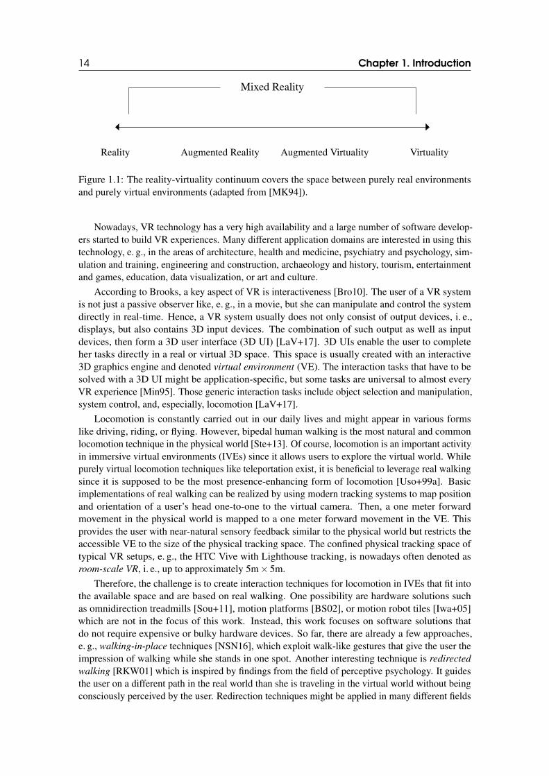
displayed in such a room would be fatal." [Sut65]. In a more formal way, VR can be defined as acomputer-generated digital environment that can be experienced and interacted with as if it werereal [Jer15], most often by using several displays for different senses, 3D tracking technology, andinteraction devices. Frederick Brooks, another pioneer of VR, named three requirements for VR:(i) real-time rendering according to head-tracking data, (ii) real space, i. e., a concrete or abstractvirtual environment, and (iii) real interactions [Bro10]. To distinguish VR from similar technologiessuch as augmented reality (AR), Milgram introduced the Reality-Virtuality Continuum [MK94] thatorders these realities on a continuous scale (see Figure 1.1). According to this, all worlds betweenthe purely real world and a purely virtual world can be called Mixed Reality.
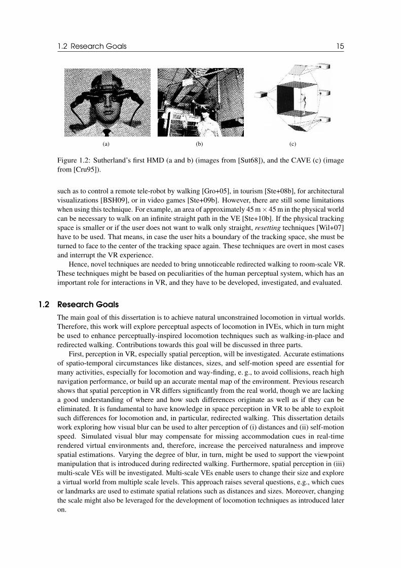
Three years after Sutherland published his essay, he built the first version of a mixed realityhead-mounted display (HMD) [Sut68] (see Figure 1.2 a and b). Later, other approaches to VRfollowed, for example, projection-based setups [Cru95] (see Figure 1.2 c). Those setups make useof displays or projection walls all around the user instead of mounting a display directly to thehead of the user. Until a few years ago, only very few people had access to VR devices, mainly inresearch labs. In recent years, VR technology made great advancements. Especially, novel HMDs,based on smartphone technology, were introduced [Ols+11]. These consumer devices set a newlevel of quality [Che+19; KCS17; NLL17] and price, and they quickly became successful.
14 Chapter 1. Introduction
Mixed Reality
Reality Augmented Reality Augmented Virtuality Virtuality
Figure 1.1: The reality-virtuality continuum covers the space between purely real environmentsand purely virtual environments (adapted from [MK94]).
Nowadays, VR technology has a very high availability and a large number of software develop-ers started to build VR experiences. Many different application domains are interested in using thistechnology, e. g., in the areas of architecture, health and medicine, psychiatry and psychology, sim-ulation and training, engineering and construction, archaeology and history, tourism, entertainmentand games, education, data visualization, or art and culture.
According to Brooks, a key aspect of VR is interactiveness [Bro10]. The user of a VR systemis not just a passive observer like, e. g., in a movie, but she can manipulate and control the systemdirectly in real-time. Hence, a VR system usually does not only consist of output devices, i. e.,displays, but also contains 3D input devices. The combination of such output as well as inputdevices, then form a 3D user interface (3D UI) [LaV+17]. 3D UIs enable the user to completeher tasks directly in a real or virtual 3D space. This space is usually created with an interactive3D graphics engine and denoted virtual environment (VE). The interaction tasks that have to besolved with a 3D UI might be application-specific, but some tasks are universal to almost everyVR experience [Min95]. Those generic interaction tasks include object selection and manipulation,system control, and, especially, locomotion [LaV+17].
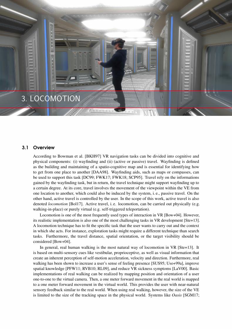
Locomotion is constantly carried out in our daily lives and might appear in various formslike driving, riding, or flying. However, bipedal human walking is the most natural and commonlocomotion technique in the physical world [Ste+13]. Of course, locomotion is an important activityin immersive virtual environments (IVEs) since it allows users to explore the virtual world. Whilepurely virtual locomotion techniques like teleportation exist, it is beneficial to leverage real walkingsince it is supposed to be the most presence-enhancing form of locomotion [Uso+99a]. Basicimplementations of real walking can be realized by using modern tracking systems to map positionand orientation of a user’s head one-to-one to the virtual camera. Then, a one meter forwardmovement in the physical world is mapped to a one meter forward movement in the VE. Thisprovides the user with near-natural sensory feedback similar to the physical world but restricts theaccessible VE to the size of the physical tracking space. The confined physical tracking space oftypical VR setups, e. g., the HTC Vive with Lighthouse tracking, is nowadays often denoted asroom-scale VR, i. e., up to approximately 5m× 5m.
Therefore, the challenge is to create interaction techniques for locomotion in IVEs that fit intothe available space and are based on real walking. One possibility are hardware solutions suchas omnidirection treadmills [Sou+11], motion platforms [BS02], or motion robot tiles [Iwa+05]which are not in the focus of this work. Instead, this work focuses on software solutions thatdo not require expensive or bulky hardware devices. So far, there are already a few approaches,e. g., walking-in-place techniques [NSN16], which exploit walk-like gestures that give the user theimpression of walking while she stands in one spot. Another interesting technique is redirected
walking [RKW01] which is inspired by findings from the field of perceptive psychology. It guidesthe user on a different path in the real world than she is traveling in the virtual world without beingconsciously perceived by the user. Redirection techniques might be applied in many different fields
1.2 Research Goals 15
(a) (b) (c)
Figure 1.2: Sutherland’s first HMD (a and b) (images from [Sut68]), and the CAVE (c) (imagefrom [Cru95]).
such as to control a remote tele-robot by walking [Gro+05], in tourism [Ste+08b], for architecturalvisualizations [BSH09], or in video games [Ste+09b]. However, there are still some limitationswhen using this technique. For example, an area of approximately 45 m× 45 m in the physical worldcan be necessary to walk on an infinite straight path in the VE [Ste+10b]. If the physical trackingspace is smaller or if the user does not want to walk only straight, resetting techniques [Wil+07]have to be used. That means, in case the user hits a boundary of the tracking space, she must beturned to face to the center of the tracking space again. These techniques are overt in most casesand interrupt the VR experience.
Hence, novel techniques are needed to bring unnoticeable redirected walking to room-scale VR.These techniques might be based on peculiarities of the human perceptual system, which has animportant role for interactions in VR, and they have to be developed, investigated, and evaluated.
1.2 Research Goals
The main goal of this dissertation is to achieve natural unconstrained locomotion in virtual worlds.Therefore, this work will explore perceptual aspects of locomotion in IVEs, which in turn mightbe used to enhance perceptually-inspired locomotion techniques such as walking-in-place andredirected walking. Contributions towards this goal will be discussed in three parts.
First, perception in VR, especially spatial perception, will be investigated. Accurate estimationsof spatio-temporal circumstances like distances, sizes, and self-motion speed are essential formany activities, especially for locomotion and way-finding, e. g., to avoid collisions, reach highnavigation performance, or build up an accurate mental map of the environment. Previous researchshows that spatial perception in VR differs significantly from the real world, though we are lackinga good understanding of where and how such differences originate as well as if they can beeliminated. It is fundamental to have knowledge in space perception in VR to be able to exploitsuch differences for locomotion and, in particular, redirected walking. This dissertation detailswork exploring how visual blur can be used to alter perception of (i) distances and (ii) self-motionspeed. Simulated visual blur may compensate for missing accommodation cues in real-timerendered virtual environments and, therefore, increase the perceived naturalness and improvespatial estimations. Varying the degree of blur, in turn, might be used to support the viewpointmanipulation that is introduced during redirected walking. Furthermore, spatial perception in (iii)multi-scale VEs will be investigated. Multi-scale VEs enable users to change their size and explorea virtual world from multiple scale levels. This approach raises several questions, e.g., which cuesor landmarks are used to estimate spatial relations such as distances and sizes. Moreover, changingthe scale might also be leveraged for the development of locomotion techniques as introduced lateron.
16 Chapter 1. Introduction
Second, detection thresholds for unnoticeable redirected walking will be estimated. Researchersput much effort on identifying such thresholds for translation, rotation, and curvature gains inpsychophysical experiments. However, the previously estimated thresholds mark conservativelower bounds. To further improve redirected walking, the need for a better understanding ofperceptual detection thresholds that go beyond previous experiments was identified. In this dis-sertation, detection thresholds will be estimated for situations in which (i) users are able to seetheir own feet in the VE, (ii) users are already walking on curves in the VE, and (iii) users areexposed to transcranial direct-current stimulation. While users are expected to be more sensitiveto redirected walking manipulations when seeing their feet, the other two situations might lead towider thresholds and, therefore, reduced space requirements for redirected walking. Furthermore,(iv) thresholds for position and orientation redirection during eye blinks will be estimated. This isan orthogonal approach in addition to previously introduced redirection techniques and can increasethe effectiveness of redirected walking significantly since it exploits situations in which visual inputof the user is suppressed.
Third, locomotion techniques for a variety of situations will be developed and, for this, theresults of the two previous parts will be leveraged. Locomotion can be carried out by purely virtualtravel techniques. However, to approximate real walking and exploit its benefits, there is a needfor novel perceptually-inspired locomotion techniques. Therefore, techniques for seated, standing,and, finally, room-scale VR experiences are covered. These techniques will be evaluated regardingcriteria like usability, VR sickness, sense of presence, spatial knowledge, and effectiveness. Inthis dissertation, (i) a turning technique based on dynamic rotation gains, (ii) a novel approach towalking-in-place, (iii) a scale-based walking technique, (iv) a novel technique to lay out curvedwalking paths for redirected walking, (v) a technique that shows how support for multiple usersin the same tracking space could be added to redirected walking, and finally, (vi) an approach ofcombining several subtle redirection techniques and integrating them with gameplay and narrationof the VR experience will be investigated.
To summarize, the contributions of this dissertation are• a deeper knowledge about spatial perception and its effects on locomotion,• a better understanding of perceptual detection thresholds for redirected walking,• and, novel locomotion techniques, ranging from seated and standing VR to room-scale
experiences.
1.3 Outline
The remainder of this dissertation is structured as follows. Part I focusses on fundamental back-ground information. Chapter 2 presents related work in the field of perception and Chapter 3summarizes previous work on locomotion in VR [E L16; E L19; ES18].
Part II reports several experiments that consider important aspects of spatio-temporal judgmentsin VR, i. e., on distance, speed, and size perception. Chapter 4 evaluates the influence of depthof field blur on distance estimation [E L+16]. Chapter 5 evaluates the influence of motion bluron speed estimation [E L+16]. And Chapter 6 analyzes dominant scale estimation in multi-scaleVEs [EBS15; EBS16a].
Part III presents several experiments that reveal sensitivities to redirection under differentconditions. Chapter 7 reports if the virtual self-representation of the user’s feet changes thedetection thresholds for translation gains [KEF18]. Chapter 8 introduces bending gains that definediscrepancies between physical and virtual paths in situations where both are bent and reports theuser’s sensitivity to these gains [E L+17b]. Chapter 9 investigates the influence of transcranial direct-current stimulation on bending gains [E L+19a]. Chapter 10 analyzes the amount of redirectionthat can be induced during eye blinks and discusses how this can be used to improve traditionalredirection approaches [BE17; EBS16b; E L+18].
1.4 Publications 17
Part IV presents perceptually-inspired locomotion techniques for VR experiences that are basedon the findings of the previous experiments, and evaluates and compares them. Chapter 11 reports ofseveral rotation techniques that help the user in cases when the possibilities of physical turning arelimited [E L+19b]. Chapter 12 introduces a novel walking-in-place technique with omnidirectionaltracking whose speed control is based on leaning [E L+15]. Chapter 13 presents a technique thatscales the size of the user while walking to cover larger distances [Boy+18]. Chapter 14 introducesa novel redirected walking approach that exploits bending gains to guide the user on paths whichwill never hit the boundaries of the tracking space [E L+17a; E L+17b]. Chapter 15 comparesthis redirected walking approach to teleportation and joystick locomotion [ELS18a]. Chapter 16explores the challenge of collision avoidance for this redirected walking approach when multipleusers are walking in the same physical space at the same time [EHS18; HES17]. Chapter 17 presentsVR experiences that combine this redirected walking approach with several other approaches suchas impossible spaces and align them with gameplay and narration [ELS18b; ES19].
Finally, Part V summarizes the results of this work and concludes the dissertation.
1.4 Publications
The main contributions of this dissertation have been published in peer-reviewed national andinternational venues.
Main Authorship
The following publications were mainly created by myself while co-authors contributed parts ofthe implementation, writing of paper sections, or supervision. These include 2 journal articles, 2book chapters, 9 conference papers, 2 posters, 3 research demonstrations and a doctoral consortiumextended abstract.
Journal Articles
[E L+17b] E. Langbehn, P. Lubos, G. Bruder, and F. Steinicke. “Bending the Curve: Sensitivityto Bending of Curved Paths and Application in Room-Scale VR”. In: IEEE Trans-
actions on Visualization and Computer Graphics (TVCG) 23.4 (2017), pages 1389–1398.
[E L+18] E. Langbehn, F. Steinicke, M. Lappe, G. F. Welch, and G. Bruder. “In the Blinkof an Eye - Leveraging Blink-Induced Suppression for Imperceptible Position andOrientation Redirection in Virtual Reality”. In: ACM Transactions on Graphics
(TOG), Special Issue on ACM SIGGRAPH 37.4 (2018), 66 (11 pages).
Book Chapters
[E L19] E. Langbehn. “Fortbewegung im virtuellen Raum”. In: Mit weit geschlossenen Au-
gen. Virtuelle Realitäten entwerfen. Edited by P. Reinfeld and C. Höfler. (Architekturder Medien - Medien der Architektur, ed. by K. Nakas and Ph. Reinfeld, Vol. 1.)Wilhelm Fink Verlag, 2019.
[ES18] E. Langbehn and F. Steinicke. “Redirected Walking in Virtual Reality”. In: En-
cyclopedia of Computer Graphics and Games. Edited by N. C. Nilsson. SpringerInternational Publishing, 2018.
18 Chapter 1. Introduction
Conference Papers
[Boy+18] Y. Boysen, M. Husung, T. Mantei, L. Müller, J. Schimmelpfennig, L. Uzolas, andE. Langbehn1. “Scale & Walk: Evaluation von skalierungsbasierten Interaktion-stechniken zur natürlichen Fortbewegung in VR”. In: Mensch und Computer. 2018,(12 pages).
[E L+16] E. Langbehn, B. Bolte, T. Raupp, G. Bruder, M. Lappe, and F. Steinicke. “VisualBlur in Immersive Virtual Environments: Does Depth of Field or Motion Blur AffectDistance and Speed Estimation?” In: ACM Symposium on Virtual Reality Software
and Technology (VRST). 2016, pages 241–250.
[EBS16a] E. Langbehn, G. Bruder, and F. Steinicke. “Scale Matters! Analysis of DominantScale Estimation in the Presence of Conflicting Cues in Multi-Scale CollaborativeVirtual Environments”. In: IEEE Symposium on 3D User Interfaces (3DUI). 2016,pages 211–220.
[E L+15] E. Langbehn, T. Eichler, S. Ghose, K. von Luck, G. Bruder, and F. Steinicke.“Evaluation of an Omnidirectional Walking-in-Place User Interface with VirtualLocomotion Speed Scaled by Forward Leaning Angle”. In: GI Workshop on Virtual
and Augmented Reality (GI VR/AR). 2015, pages 149–160.
[EHS18] E. Langbehn, E. Harting, and F. Steinicke. “Shadow-Avatars: A VisualizationMethod to Avoid Collisions of Physically Co-Located Users in Room-Scale VR”. In:IEEE Virtual Reality (VR) Workshop on Everyday Virtual Reality (WEVR). 2018, (4pages).
[ELS18a] E. Langbehn, P. Lubos, and F. Steinicke. “Evaluation of Locomotion Techniques forRoom-Scale VR: Joystick, Teleportation, and Redirected Walking”. In: ACM Virtual
Reality International Conference (VRIC). 2018, (9 pages).
[E L+19a] E. Langbehn, F. Steinicke, P. Koo-Poeggel, L. Marshall, and G. Bruder. “Stimulatingthe Brain in VR: Effects of Transcranial Direct-Current Stimulation on RedirectedWalking”. In: ACM Symposium on Applied Perception (SAP) (under review). 2019,(8 pages).
[E L+19b] E. Langbehn, J. Wittig, N. Katzakis, and F. Steinicke. “Turn Your Head Half Round:VR Rotation Techniques for Situations With Physically Limited Turning Angle”. In:Mensch und Computer (accepted). 2019, (9 pages).
[KEF18] L. Kruse, E. Langbehn, and F. Steinicke2. “I Can See on my Feet While Walking:Sensitivity to Translation Gains with Visible Feet”. In: IEEE Virtual Reality (VR).2018, pages 305–312.
Other
[E L16] E. Langbehn. “Development and Evaluation of Interactive Locomotion User Inter-faces”. In: IEEE Virtual Reality (VR) (Doctoral Consortium). 2016.
[EBS15] E. Langbehn, G. Bruder, and F. Steinicke. “Moving Towards Natural InteractionBetween Multiscale Avatars in Multi-User Virtual Environments3”. In: International
Conference on Artificial Reality and Telexistence, Eurographics Symposium on Vir-
tual Environments (ICAT-EGVE) (Poster). 2015.
1This publication is based on a bachelor project. The students implemented and ran the experiment under mysupervision. I designed the experiment and wrote the paper.
2This publication is based on a Bachelor thesis. The student implemented and ran the experiment under my supervision.I designed the experiment and wrote the paper.
3This publication received the Best Poster Award and the Best Poster Audience Award.
1.4 Publications 19
[EBS16b] E. Langbehn, G. Bruder, and F. Steinicke. “Subliminal Reorientation and Reposi-tioning in Virtual Reality During Eye Blinks4”. In: ACM Symposium on Spatial User
Interaction (SUI) (Poster). 2016, pages 213–213.
[E L+17a] E. Langbehn, P. Lubos, G. Bruder, and F. Steinicke. “Application of RedirectedWalking in Room-Scale VR”. In: IEEE Virtual Reality (VR) (Demo). 2017.
[ELS18b] E. Langbehn, P. Lubos, and F. Steinicke. “Redirected Spaces: Going Beyond Bor-ders”. In: IEEE Virtual Reality (VR) (Demo). 2018.
[ES19] E. Langbehn and F. Steinicke. “Space Walk: A Combination of Subtle RedirectedWalking Techniques Integrated with Gameplay and Narration”. In: ACM SIGGRAPH
Emerging Technologies. 2019.
Co-Authorship
The following publications were mainly created by someone else and are not part of this dissertation.However, I contributed critical parts of the implementation, experiment design, or paper writing.These include 2 journal articles, 2 conference papers, 3 posters, and an abstract for an oralpresentation.
Journal Articles
[Jan+17b] O. Janeh, E. Langbehn, F. Steinicke, G. Bruder, A. Gulberti, and M. Poetter-Nerger.“Walking in Virtual Reality: Effects of Manipulated Visual Self-Motion on WalkingBiomechanics”. In: ACM Transactions on Applied Perception (TAP) 14.2 (2017), 12(15 pages).
[Zha+18b] J. Zhang, E. Langbehn, D. Krupke, N. Katzakis, and F. Steinicke. “Detection Thresh-olds for Rotation and Translation Gains in 360 Video-based Telepresence System”.In: IEEE Transactions on Visualization and Computer Graphics (TVCG) 24.4 (2018),pages 1671–1680.
Conference Papers
[Rie+18] M. Rietzler, J. Gugenheimer, T. Hirzle, M. Deubzer, E. Langbehn, and E. Rukzio.“Rethinking Redirected Walking: On the Use of Curvature Gains Beyond PerceptualLimitations and Revisiting Bending Gains”. In: IEEE International Symposium on
Mixed and Augmented Reality (ISMAR). 2018, (8 pages).
[Zha+18a] J. Zhang, E. Langbehn, D. Krupke, N. Katzakis, and F. Steinicke. “A 360 Video-based Robot Platform for Telepresent Redirected Walking”. In: ACM Human-Robot
Interaction (HRI) Workshop on Virtual, Augmented and Mixed Reality for Human-
Robot Interaction. 2018, (5 pages).
Other
[BE17] G. Bruder and E. Langbehn. “Subliminal Rotations During Eye Blinks for Redi-rected Walking”. In: Journal of Vision (Talk) 17.10 (2017), pages 1266–1266.
[HES17] P. Heidicker, E. Langbehn, and F. Steinicke. “Influence of Avatar Appearance onPresence in Social VR”. In: IEEE Symposium on 3D User Interfaces (3DUI) (Poster).2017, pages 233–234.
[Jan+17a] O. Janeh, E. Langbehn, F. Steinicke, G. Bruder, A. Gulberti, and M. Poetter-Nerger.“Biomechanical Analysis of (Non-)Isometric Virtual Walking of Older Adults”. In:IEEE Virtual Reality (VR) (Poster). 2017, pages 217–218.
4This publication received the Honorable Mention for Best Poster.

20 Chapter 1. Introduction
[Kru+16] D. Krupke, L. Einig, E. Langbehn, J. Zhang, and F. Steinicke. “Immersive RemoteGrasping: Realtime Gripper Control by a Heterogenous Robot Control System”. In:ACM Symposium on Virtual Reality Software and Technology (VRST) (Poster). Nov.2016, pages 337–338.

I
2 Perception . . . . . . . . . . . . . . . . . . . . . . . . . . 23
2.1 The Human Perceptual System2.2 Immersion and Presence2.3 Spatial Perception
3 Locomotion . . . . . . . . . . . . . . . . . . . . . . . . . 33
3.1 Overview3.2 Virtual Travel Techniques3.3 Walking-in-Place3.4 Redirected Walking3.5 Comparison of Techniques
FUNDAMENTALS

2. PERCEPTION
2.1 The Human Perceptual System
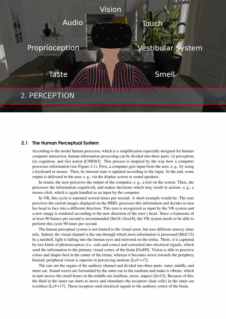
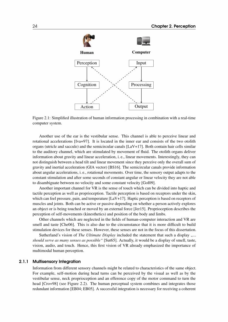
According to the model human processor, which is a simplification especially designed for human-computer interaction, human information processing can be divided into three parts: (i) perception,(ii) cognition, and (iii) action [CMN83]. This process is inspired by the way how a computerprocesses information (see Figure 2.1). First, a computer gets input from the user, e. g., by usinga keyboard or mouse. Then, its internal state is updated according to the input. In the end, someoutput is delivered to the user, e. g., via the display screen or sound speakers.
In return, the user perceives the output of the computer, e. g., a text on the screen. Then, sheprocesses the information cognitively and makes decisions which may result in actions, e. g., amouse click, which is again handled as an input by the computer.
In VR, this cycle is repeated several times per second. A short example would be: The userperceives the current images displayed on the HMD, processes this information and decides to turnher head to face into a different direction. This turn is recognized as input by the VR system anda new image is rendered according to the new direction of the user’s head. Since a framerate ofat least 90 frames per second is recommended [Int18; Ocu18], the VR system needs to be able toperform this cycle 90 times per second.
The human perceptual system is not limited to the visual sense, but uses different sensory chan-nels. Indeed, the visual channel is the one through which most information is processed [McC13].In a nutshell, light is falling into the human eyes and mirrored on the retina. There, it is capturedby two kinds of photoreceptors (i.e. rods and cones) and converted into electrical signals, whichsend the information to the primary visual cortex of the brain [Gol09]. Vision is able to perceivecolors and shapes best in the center of the retina, whereas it becomes worse towards the periphery.Instead, peripheral vision is superior in perceiving motions [LaV+17].
The ears are the organs of the auditory channel and divided into three parts: outer, middle, andinner ear. Sound waves are forwarded by the outer ear to the eardrum and make it vibrate, whichin turn moves the small bones in the middle ear (malleus, incus, stapes) [Jer15]. Because of this,the fluid in the inner ear starts to move and stimulates the receptors (hair cells) in the inner ear(cochlea) [LaV+17]. These receptors send electrical signals to the auditory cortex of the brain.
24 Chapter 2. Perception
Human
Perception
Cognition
Action
Computer
Input
Processing
Output
Figure 2.1: Simplified illustration of human information processing in combination with a real-timecomputer system.
Another use of the ear is the vestibular sense. This channel is able to perceive linear androtational accelerations [Iva+97]. It is located in the inner ear and consists of the two otolithorgans (utricle and saccule) and the semicircular canals [LaV+17]. Both contain hair cells similarto the auditory channel, which are stimulated by movement of fluid. The otolith organs deliverinformation about gravity and linear acceleration, i. e., linear movements. Interestingly, they cannot distinguish between a head tilt and linear movement since they perceive only the overall sum ofgravity and inertial acceleration (GIA vector) [BS16]. The semicircular canals provide informationabout angular accelerations, i. e., rotational movements. Over time, the sensory output adapts to theconstant stimulation and after some seconds of constant angular or linear velocity they are not ableto disambiguate between no velocity and some constant velocity [Gol09].
Another important channel for VR is the sense of touch which can be divided into haptic andtactile perception as well as proprioception. Tactile perception is based on receptors under the skin,which can feel pressure, pain, and temperature [LaV+17]. Haptic perception is based on receptors ofmuscles and joints. Both can be active or passive depending on whether a person actively exploresan object or is being touched or moved by an external force [Jer15]. Proprioception describes theperception of self-movements (kinesthetics) and position of the body and limbs.
Other channels which are neglected in the fields of human-computer interaction and VR aresmell and taste [Che06]. This is also due to the circumstance that it is more difficult to buildstimulation devices for these senses. However, these senses are not in the focus of this dissertation.
Sutherland’s vision of The Ultimate Display included the statement that such a display „...
should serve as many senses as possible“ [Sut65]. Actually, it would be a display of smell, taste,vision, audio, and touch. Hence, this first vision of VR already emphasized the importance ofmultimodal human perception.
2.1.1 Multisensory Integration
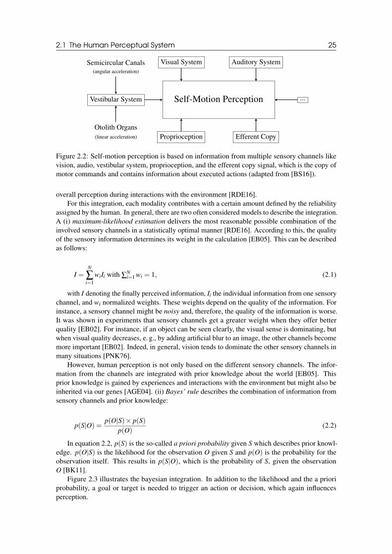
Information from different sensory channels might be related to characteristics of the same object.For example, self-motion during head turns can be perceived by the visual as well as by thevestibular sense, neck proprioception and an efference copy of the motor command to turn thehead [Cro+98] (see Figure 2.2). The human perceptual system combines and integrates thoseredundant information [EB04; EB05]. A successful integration is necessary for receiving a coherent
2.1 The Human Perceptual System 25
Self-Motion Perception
Visual System Auditory System
Proprioception Efferent Copy
Vestibular System ...
Semicircular Canals(angular acceleration)
Otolith Organs(linear acceleration)
Figure 2.2: Self-motion perception is based on information from multiple sensory channels likevision, audio, vestibular system, proprioception, and the efferent copy signal, which is the copy ofmotor commands and contains information about executed actions (adapted from [BS16]).
overall perception during interactions with the environment [RDE16].For this integration, each modality contributes with a certain amount defined by the reliability
assigned by the human. In general, there are two often considered models to describe the integration.A (i) maximum-likelihood estimation delivers the most reasonable possible combination of theinvolved sensory channels in a statistically optimal manner [RDE16]. According to this, the qualityof the sensory information determines its weight in the calculation [EB05]. This can be describedas follows:
I =N
∑i=1
wiIi with ∑Ni=1 wi = 1, (2.1)
with I denoting the finally perceived information, Ii the individual information from one sensorychannel, and wi normalized weights. These weights depend on the quality of the information. Forinstance, a sensory channel might be noisy and, therefore, the quality of the information is worse.It was shown in experiments that sensory channels get a greater weight when they offer betterquality [EB02]. For instance, if an object can be seen clearly, the visual sense is dominating, butwhen visual quality decreases, e. g., by adding artificial blur to an image, the other channels becomemore important [EB02]. Indeed, in general, vision tends to dominate the other sensory channels inmany situations [PNK76].
However, human perception is not only based on the different sensory channels. The infor-mation from the channels are integrated with prior knowledge about the world [EB05]. Thisprior knowledge is gained by experiences and interactions with the environment but might also beinherited via our genes [AGE04]. (ii) Bayes’ rule describes the combination of information fromsensory channels and prior knowledge:
p(S|O) =p(O|S)× p(S)
p(O)(2.2)
In equation 2.2, p(S) is the so-called a priori probability given S which describes prior knowl-edge. p(O|S) is the likelihood for the observation O given S and p(O) is the probability for theobservation itself. This results in p(S|O), which is the probability of S, given the observationO [BK11].
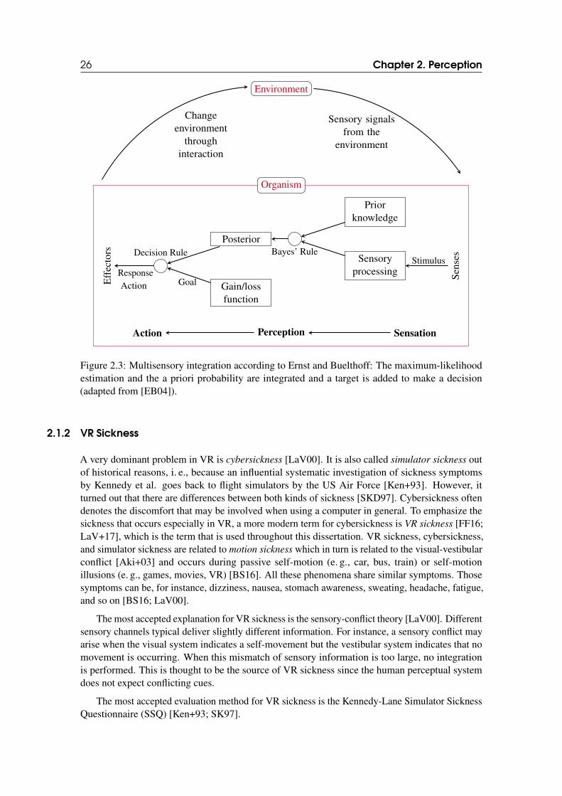
Figure 2.3 illustrates the bayesian integration. In addition to the likelihood and the a prioriprobability, a goal or target is needed to trigger an action or decision, which again influencesperception.
26 Chapter 2. Perception
Environment
Changeenvironment
throughinteraction
Sensory signalsfrom the
environment
Organism
Sen
ses
Eff
ecto
rs
Priorknowledge
Sensoryprocessing
Posterior
Gain/lossfunction
Bayes’ RuleDecision RuleStimulus
GoalResponseAction
SensationPerceptionAction
Figure 2.3: Multisensory integration according to Ernst and Buelthoff: The maximum-likelihoodestimation and the a priori probability are integrated and a target is added to make a decision(adapted from [EB04]).
2.1.2 VR Sickness
A very dominant problem in VR is cybersickness [LaV00]. It is also called simulator sickness outof historical reasons, i. e., because an influential systematic investigation of sickness symptomsby Kennedy et al. goes back to flight simulators by the US Air Force [Ken+93]. However, itturned out that there are differences between both kinds of sickness [SKD97]. Cybersickness oftendenotes the discomfort that may be involved when using a computer in general. To emphasize thesickness that occurs especially in VR, a more modern term for cybersickness is VR sickness [FF16;LaV+17], which is the term that is used throughout this dissertation. VR sickness, cybersickness,and simulator sickness are related to motion sickness which in turn is related to the visual-vestibularconflict [Aki+03] and occurs during passive self-motion (e. g., car, bus, train) or self-motionillusions (e. g., games, movies, VR) [BS16]. All these phenomena share similar symptoms. Thosesymptoms can be, for instance, dizziness, nausea, stomach awareness, sweating, headache, fatigue,and so on [BS16; LaV00].
The most accepted explanation for VR sickness is the sensory-conflict theory [LaV00]. Differentsensory channels typical deliver slightly different information. For instance, a sensory conflict mayarise when the visual system indicates a self-movement but the vestibular system indicates that nomovement is occurring. When this mismatch of sensory information is too large, no integrationis performed. This is thought to be the source of VR sickness since the human perceptual systemdoes not expect conflicting cues.
The most accepted evaluation method for VR sickness is the Kennedy-Lane Simulator SicknessQuestionnaire (SSQ) [Ken+93; SK97].
2.1 The Human Perceptual System 27
2.1.3 Psychophysics
Psychophysics describes the relationship of physically measurable stimuli and the subjectiveperception of those stimuli [Fec60]. The basic question of psychophysical experiments is how wella person can consciously detect the presence of a given stimulus [Raz05], e. g., a 200 Hz tone or a500 THz color. The stimulus can be of any sensory channel, e. g., visual, auditive, or proprioceptive.
According to Weber’s law [Web17], the relation k between the perceivable change of a stimulusintensity ∆S and the prior stimulus intensity S remains constant:
k =∆S
S(2.3)
This is the so-called just noticeable difference (JND). It means that the intensity change needsto be greater for a stimulus that already has a very high intensity. For instance, if a candle is putin a dark room, we perceive a change of the intensity of the light. However, if there are already100 candles in the room, putting in another one might not lead to a perceivable difference of theintensity anymore. Instead, one might need 100 additional candles to achieve a noticeable change.
Regarding the JND, the Weber-Fechner law states that the subjectively perceived sensorysensation is proprotional to the logarithm of the objectively measured intensity of the physicalstimulus [Web17]. Therefore, it describes the relation between stimulus intensity S and perceivedintensity E:
E = c · ln S
S0(2.4)
In equation 2.4, S0 is the threshold at which the intensity can just be perceived, while c is aconstant used for specific stimuli.
The absolute minimal intensity of a stimulus at which a person can detect it is called detection
threshold (DT) [Raz05]. For example, when a person hears a 200 Hz tone, the DT would be theloudness at which she can detect it. In an ideal world, all intensities below this threshold would beundetectable and all intensities above this threshold would be detectable. And this would be trueevery time the person would be exposed to this stimulus.
However, human perception is more complicated. Intensities at values close to thresholds willoften be detectable. Therefore, thresholds are considered to be the intensities at which the stimulusis detected only some proportion of the time. For instance, a person might detect a stimulus of acertain intensity only 25% of the time. It is assumed that the probability of detecting the stimulusincreases with the intensity of the stimulus [Raz05]. Therefore, the DT is usually considered to bethe intensity at which the person correctly detects the stimulus 75% of the time [SLH85].
Optimally, the factors that are involved when measuring DTs are the intensity of the stimulus andthe sensitivity of the person. However, in most situations there might be background noise, whichhas to be minimized for best experimental results. Additionally, the participants of a psychophysicalexperiment can be biased by a lot of different aspects, ranging from their prior knowledge to theexperiment design. For example, if a participant is forced to choose between answers like "I do notperceive the stimulus" and "I do perceive the stimulus", the answer can depend in part on her biasand prior experience [Raz05]. Some participants might tend to answer that they did not perceivethe stimulus in situations when they are unsure while others might answer that they perceived thestimulus.
There are several different methods for measuring detection thresholds through psychophysicalexperiments, e. g., the method of constant stimulus [Spe08], the staircase method [Cor62], or themethod of adjustment [Ste58]. In this work, we focused on the two-alternative forced-choice
task method [Bog+06] in all of the conducted psychophysical experiments to determine detectionthresholds.
28 Chapter 2. Perception
Two-Alternative Forced-Choice Task
In order to determine detection thresholds a standard psychophysical procedure called two-
alternative forced-choice (2AFC) task is used in the course of this work. Using this method,the participants of a psychphysical experiment are exposed to different intensities of a stimulus.Each time, they have to choose between one of two answer possibilities, for example, if the intensitywas smaller or greater than a predetermined reference intensity. Answers like “I don’t know” arenot allowed. Instead, the participants have to guess and will be correct in 50% of the cases onaverage.
Applied to redirected walking gains as done in this work (see Part III), e. g. to curvaturegains (see Chapter 3.4), this means participants walk a straight path in the VE, which is bent bya curvature gain either to the left or to the right in the real world. Then, they have to judge if thephysical path was bent either to the “left” or “right”. The gain at which the participants respond
“left” in 50% of the trials is taken as the point of subjective equality (PSE), at which the participantsestimate virtual and real movements as identical. As the gain decreases or increases from thisvalue the ability of the participant to detect the difference between physical and virtual movementincreases, resulting in measuring points, through which a psychometric curve will be fitted for thediscrimination performance. When the participant’s answers converge to 100% respectively the 0%chance level, it is more likely that they can detect the redirection reliably. As described above, theDT is the point of intensity at which participants can just detect a discrepancy between physicaland virtual motion.
Since the detection rate is often a smooth and gradually increasing function, in psychophysicalexperiments, usually the point at which the curve reaches the middle between the chance level and100% is taken as a threshold [Ste+10b]. Therefore, the DT for gains smaller than the PSE is thegain at which the participant has 75% probability of choosing the “left” response correctly and thedetection threshold for gains greater than the PSE is the gain at which the participant chooses the“left” response in only 25% of the trials (since the correct response “right” was then chosen in 75%of the trails).
2.2 Immersion and Presence
Immersion is defined as the degree to which a user’s senses can experience a VR system [SW97].The immersive nature of VR directly couples the human sensory channels to the supported technol-ogy. Immersion is limited by the objective capabilities of the VR technology, which are technicalfactors like, for instance, vision, tracking, field of view, resolution, or graphics quality. This means,a VR system that provides stereoscopic vision is more immersive than a VR system that providesonly monoscopic vision. A VR system that provides position and orientation tracking is moreimmersive than a VR system that provides only orientation tracking. A VR system that rendersreal-time shadows is more immersive than a system that does not support any shadows. Currenthead-mounted displays (like the Oculus Rift or HTC Vive) usually support stereoscopic vision,position and orientation tracking, high resolution (i. e., more than Full HD), low latency (below20ms), high frequency (90 Hz), and a wide field of view (circa 110◦). This already delivers arelatively high degree of immersion, but it does not address all capabilities of the human perceptualsystem. The human field of view is about 220◦ and the human eyes would need a resolution ofapproximately 116,000,000 pixels to guarantee that no distinction can be made between individualpixels while Rift and Vive offer only 2,592,000 pixels [Kod15].
Immersion is an objective metric, whereas presence is defined as the subjective estimation ofbeing there in an environment while actually being located in a different place [SUS94]. This isalso called place illusion (PI) [Sla09]. Users who experience a high sense of presence in a VRsystem tend to perceive the VE more like a place that they visited rather than images that they saw.
2.3 Spatial Perception 29
In addition to PI, plausibility illusion (Psi) is defined as the illusion that the scenario in the VEis actually occurring [Sla09]. To get users to respond realistically to a certain situation in VR, PIand Psi have to be induced. Since presence is a subjective perception, it depends on immersionand takes into account the psychological state of the user as well [Jer15]. Although, immersioncan be a limiting factor. A standard method for measuring presence is the use of questionnaireslike the Slater-Usoh-Steed Presence Questionnaire (SUS) [SU93; SUS94] or the Igroup PresenceQuestionnaire (IPQ) [SFR01].
Visual Self-Representation
In a VE, using a visual self-representation like a fully articulated avatar generally increasesthe degree of presence since additional modalities are provided to the user. The concept ofhaving a virtual body is an approach to decrease the contradiction between sensory data andproprioception [MS96; SU94], and, therefore, induce a sense of agency. A contradiction is causedwhen proprioception informs the user that her body is in one place, but the VE provides the userwith visual evidence of the absence of her body in that space.
Usoh et al. propose that association with the virtual body also increases the feeling of presenceand that, therefore, the avatar should be as realistic as possible [Uso+99a]. Implementing an avatarwith incorrect behaviour can dissociate the user from the virtual environment. Heeter et al. pointout that having an avatar increases the user’s sense of presence [Hee92] but only if that avatar issimilar to the real user. When implementing a VE, it is important to note that the virtual limbshould have similar physical appearence and anatomical orientation as the real one [Llo07]. Whena fake hand is seen in place of a real hand, cells in the premotor cortex fire, but they decrease theirfiring rate when similarity decreases [EHP05; ESP04; Gra99].
2.3 Spatial Perception
During walking in the real world, accurate estimations of distances, sizes, and self-motion speedare essential, e. g., to avoid collisions, reach high navigation performance, or build up an accuratemental map of an environment [Kla+98]. Spatial perception describes the ability of being aware ofsuch spatial characteristics and involves the integration of different cues that are extracted frommultiple senses [CV95]. Important visual cues are binocular disparity, convergence, accommodativefocus, linear perspective, aerial perspective, occlusion, shading, and motion parallax [Bow+04;How02; Loy18; RVH13].
Accurate judgements of spatial circumstances are important in the real world, and are oftenneeded in VEs as well. In particular, when walking in VR, one should achieve a similar perfor-mance as in the real world. Unfortunately, many studies report that there is a significant spatialmisperception in VR [LK03; WK98]. We will discuss reasons and possible improvements fordistance, speed, and scale perception in the following sections.
2.3.1 Distance Perception
A lot of empirical evidence has been collected over the last decade, which indicates that distanceperception in VEs significantly differs from the real world, with very close distances often beingoverestimated while distances in vista space tend to be underestimated [Bru+15; BYB18; Cre+05;Cre+15; Li+15; RGA95; Rou+15; Wil+08]. Renner et al. [RVH13] reviewed the extensive literatureon distance perception in VEs.
Several theories and approaches to improve spatial perception in VEs have been presented.For instance, some researchers suggest that feedback during interaction might be sufficient forthe highly adaptable human perceptual system to reduce spatial misperception given sufficienttime [RW07]. Other researchers suggest that the sense of presence in VEs has a direct effect on the
30 Chapter 2. Perception
3D Object
Eyes
Display ScreenV
erge
nce
Dis
tanc
e
Foca
lDis
tanc
e
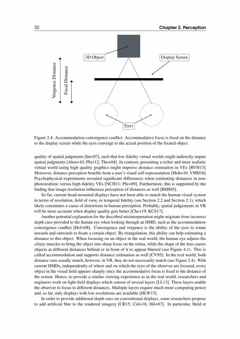
Figure 2.4: Accommodation-convergence conflict: Accommodative focus is fixed on the distanceto the display screen while the eyes converge to the actual position of the fixated object.
quality of spatial judgments [Int+07], such that low fidelity virtual worlds might indirectly impairspatial judgments [Ahm+10; Phi+12; Tho+04]. In contrast, presenting a richer and more realisticvirtual world using high quality graphics might improve distance estimation in VEs [RVH13].Moreover, distance perception benefits from a user’s visual self-representation [Moh+10; VMH16].Psychophysical experiments revealed significant differences when estimating distances in non-photorealistic versus high-fidelity VEs [NCH11; Phi+09]. Furthermore, this is supported by thefinding that image resolution influences perception of distances as well [RHS05].
So far, current head-mounted displays have not been able to match the human visual systemin terms of resolution, field of view, or temporal fidelity (see Section 2.2 and Section 2.1), whichlikely constitutes a cause of distortions in human perception. Probably, spatial judgements in VRwill be more accurate when display quality gets better [Che+19; KCS17].
Another potential explanation for the described misinterpretation might originate from incorrectdepth cues provided to the human eye when looking through an HMD, such as the accommodation-convergence conflict [Hof+08]. Convergence and vergence is the ability of the eyes to rotateinwards and outwards to fixate a certain object. By triangulation, this ability can help estimating adistance to this object. When focusing on an object in the real world, the human eye adjusts theciliary muscles to bring the object into sharp focus on the retina, while the shape of the lens causesobjects at different distances behind or in front of it to appear blurred (see Figure 4.1). This iscalled accommodation and supports distance estimation as well [CV95]. In the real world, bothdistance cues usually match, however, in VR, they do not necessarily match (see Figure 2.4). Withcurrent HMDs, independently of where and on which the eyes of the observer are focused, everyobject in the visual field appears sharply since the accommodative focus is fixed to the distance ofthe screen. Hence, to provide a similar viewing experience as in the real world, researchers andengineers work on light-field displays which consist of several layers [LL13]. These layers enablethe observer to focus to different distances. Multiple layers require much more computing powerand, so far, only displays with low resolutions are available [HLW15].
In order to provide additional depth cues on conventional displays, some researchers proposeto add artificial blur to the rendered imagery [CR15; Cid+16; Hil+07]. In particular, Held et
2.3 Spatial Perception 31
al. [Hel+10] found that visual blur plays a significant role in perceiving size and distance, at least innon-stereoscopic images. They presented a probabilistic model based on Bayes’ Law to explain howblur in combination with perspective cues can provide correct estimations of absolute egocentricdistances to objects in static images viewed on a CRT monitor. Blur effects like depth-of-field (DOF)are also known to mitigate the accommodation-convergence conflict in HMDs and therefore help toreduce visual discomfort like eye fatigue, headaches and nausea [CR15]. Moehring et al. [MGD09]state that DOF blur in HMD environments might additionally improve spatial perception.
2.3.2 Speed Perception
Research on speed perception in HMD environments indicate a general tendency to underestimateself-motion speed as well [NSN15]. Banton et al. [Ban+05] hypothesized that speed misperceptionmight originate from the small field of view (FOV) of HMDs, which does not reach into the farperiphery of the eyes [JSB13]. In particular, they assume that visual flow is necessary for a correctspeed perception and that this cue is cut off by a limited FOV because the user can not see theground while looking straight ahead. They found a significant effect showing that the display’s FOVwas inversely proportional to the underestimation of walking speed in a VE, while speed estimationwas more accurate when participants perceived visual flow [Moh+07b; NSN14]. Furthermore,motion blur has been suggested to improve speed estimation. Several studies have shown thathumans are generally able to gain information about the direction and speed of moving from motionblur [BR02; FK01; Ros04]. Furthermore, Kim and Francis [KF98] showed that motion lines havethe potential to change motion perception as well. In general, research on speed estimation in VEsas compared to the extensive literature on distance estimation is still underrepresented in this fieldof research.
2.3.3 Scale Perception
By adding several scale levels to an IVE, users have the chance to explore the VE from differentperspectives resulting in a more comprehensive viewing experience [Kop+06]. For example, theymight benefit from overviews, which could be perceived from a high scale level of the VE, orthey might look at every detail at a low scale level. VR setups in general, and multi-scale VEsin particular, have great potential to study different perceptual illusions. For instance, previouswork has shown that body scale illusions can be induced [Ehr+05]. Linkenauger et al. and Junget al. presented studies to investigate body-based scaling [Jun+18; Lin+13]. In their experiments,they focussed on the hand, which acts as a metric which individuals use to scale the apparent sizesof objects in the environment [Jun+18; Lin+13]. Gibson introduced the notion that individualsdo not perceive the environment, but rather perceive relationships between their body and theenvironment [Gib79]. Moreover, perceptual distortions of scale such as micropsia or macropsiaare even known to occur in persons in the real world in a rare disorienting neurological conditionknown as the Alice in Wonderland Syndrome or Todd’s Syndrome [Tod55].
Large differences in spatial perception between users reduce the ability to see the same artifactsin the scene and perceive the same affordances [Pol+12]. Furthermore, one needs to understandthat egocentric distances in VEs are often underestimated [Bru+15; RVH13] (see Section 2.3.1).In this context, Interrante et al. compared distance estimation between the real environment and ascaled VE that is a replica of the real environment [Int+07].
Scale perception is also an important factor for (social) presence and interaction betweenmultiple users in multi-scale VEs. Hall [Hal66] introduced proxemics, which describe spatialdistances between humans and their social impact. He differentiates between the intimate, personal,social and public distance. As described in [BM98], the proximity to other avatars (i. e., within theinter-personal distance) is highly relevant in VEs as well. However, when it comes to multi-scaleVEs there are some challenges with proxemics [ZF02]: Since the user can scale herself, a situation
32 Chapter 2. Perception
might occur in which there are “giant” and “mini” representations of collaborating users. In such asituation, the giant avatar might perceive the mini avatar (who is very small in the giant’s field ofvision) as not being in her intimate or personal distance. However, the mini avatar might perceivethe situation the other way around. Zhang and Furness have considered such effects for static, butnot fully articulated avatars [ZF02]. In a similar way, interpretations of the scale of the VE oroneself has also the potential to affect the perceived affordances in the VE [Nor99]. For instance,the perceived affordance of objects might change during a scale change of the VE in such a waythat an object, which was interpreted as moveable in a shrunk visualization, might be interpretedas unmovable in an enlarged level since the user might assume more weight to the object. Suchchanges in the perceived affordances might also apply to other affordances such as grabbing,pressing, lifting etc.
3. LOCOMOTION
3.1 Overview
According to Bowman et al. [BKH97] VR navigation tasks can be divided into cognitive andphysical components: (i) wayfinding and (ii) (active or passive) travel. Wayfinding is definedas the building and maintaining of a spatio-cognitive map and is essential for identifying howto get from one place to another [DAA98]. Wayfinding aids, such as maps or compasses, canbe used to support this task [DC99; FWK17; FWK18; SCP95]. Travel rely on the informationsgained by the wayfinding task, but in return, the travel technique might support wayfinding up toa certain degree. At its core, travel involves the movement of the viewpoint within the VE fromone location to another, which could also be induced by the system, i. e., passive travel. On theother hand, active travel is controlled by the user. In the scope of this work, active travel is alsodenoted locomotion [Bol17]. Active travel, i. e. locomotion, can be carried out physically (e.g.walking-in-place) or purely virtual (e.g. self-triggered teleportation).
Locomotion is one of the most frequently used types of interaction in VR [Bow+04]. However,its realistic implementation is also one of the most challenging tasks in VR development [Ste+13].A locomotion technique has to fit the specific task that the user wants to carry out and the contextin which she acts. For instance, exploration tasks might require a different technique than searchtasks. Furthermore, the travel distance, spatial orientation, or the target visibility should beconsidered [Bow+04].
In general, real human walking is the most natural way of locomotion in VR [Ste+13]. Itis based on multi-sensory cues like vestibular, proprioceptive, as well as visual information thatcreate an inherent perception of self-motion acceleration, velocity and direction. Furthermore, realwalking has been shown to increase a user’s sense of feeling presence [SUS95; Uso+99a], improvespatial knowledge [PFW11; RVB10; RL09], and reduce VR sickness symptoms [LaV00]. Basicimplementations of real walking can be realized by mapping position and orientation of a userone-to-one to the virtual camera. Then, a one meter forward movement in the real world is mappedto a one meter forward movement in the virtual world. This provides the user with near-naturalsensory feedback similar to the real world. When using real walking, however, the size of the VEis limited to the size of the tracking space in the physical world. Systems like Oasis [SGM17;
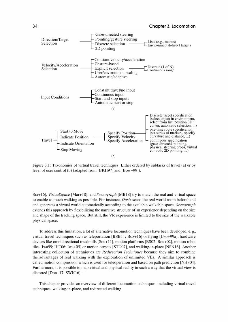
34 Chapter 3. Locomotion
Pointing/gesture steeringDirection/TargetSelection
Velocity/AccelerationSelection
Input Conditions
Gaze-directed steering
Discrete selection2D pointing
Lists (e.g., menus)Environmental/direct targets
Constant velocity/accelerationGesture-basedExplicit selection Discrete (1 of N)
Continuous rangeUser/environment scalingAutomatic/adaptive
Constant travel/no inputContinuous inputStart and stop inputsAutomatic start or stop
(a)
Start to Move
Indicate Position
Indicate Orientation
Specify PositionSpecify VelocitySpecify Acceleration
Discrete target specification(select object in environment,select from list, position 3Dcursor, automatic selection, ...)one-time route specification(set series of markers, specifycurvature and distance, ...)
Stop Moving
Travel continuous specification(gaze-directed, pointing,physical steering props, virtualcontrols, 2D pointing, ...)
(b)
Figure 3.1: Taxonomies of virtual travel techniques: Either ordered by subtasks of travel (a) or bylevel of user control (b) (adapted from [BKH97] and [Bow+99]).
Sra+16], VirtualSpace [Mar+18], and Scenograph [MB18] try to match the real and virtual spaceto enable as much walking as possible. For instance, Oasis scans the real world room beforehandand generates a virtual world automatically according to the available walkable space. Scenograph
extends this approach by flexibilizing the narrative structure of an experience depending on the sizeand shape of the tracking space. But still, the VR experience is limited to the size of the walkablephysical space.
To address this limitation, a lot of alternative locomotion techniques have been developed, e. g.,virtual travel techniques such as teleportation [BSB11; Boz+16] or flying [Uso+99a], hardwaredevices like omnidirectional treadmills [Sou+11], motion platforms [BS02; Bou+02], motion robottiles [Iwa99; IHT06; Iwa+05] or motion carpets [STU07], and walking-in-place [NSN16]. Anotherinteresting collection of techniques are Redirection Techniques because they aim to combinethe advantages of real walking with the exploration of unlimited VEs. A similar approach iscalled motion compression which is used for teleoperation and based on path prediction [NHS04].Furthermore, it is possible to map virtual and physical reality in such a way that the virtual view isdistorted [Don+17; SWK16].
This chapter provides an overview of different locomotion techniques, including virtual traveltechniques, walking-in-place, and redirected walking.
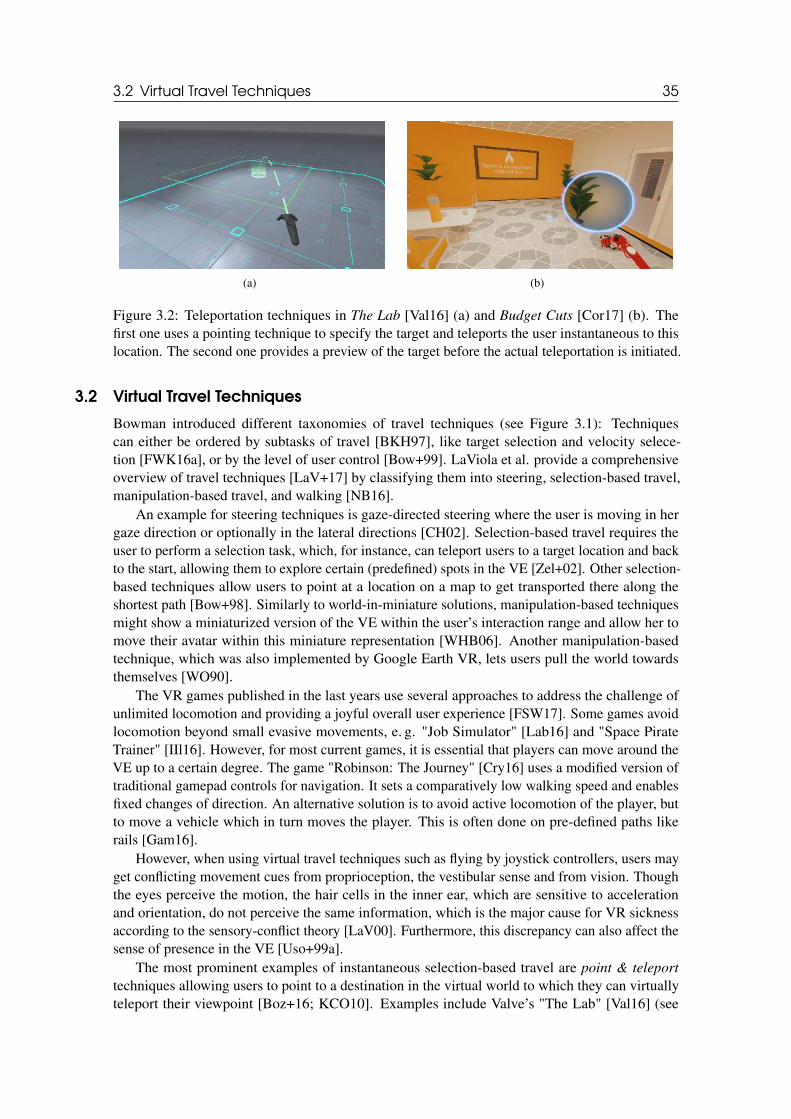
3.2 Virtual Travel Techniques 35
(a) (b)
Figure 3.2: Teleportation techniques in The Lab [Val16] (a) and Budget Cuts [Cor17] (b). Thefirst one uses a pointing technique to specify the target and teleports the user instantaneous to thislocation. The second one provides a preview of the target before the actual teleportation is initiated.
3.2 Virtual Travel Techniques
Bowman introduced different taxonomies of travel techniques (see Figure 3.1): Techniquescan either be ordered by subtasks of travel [BKH97], like target selection and velocity selece-tion [FWK16a], or by the level of user control [Bow+99]. LaViola et al. provide a comprehensiveoverview of travel techniques [LaV+17] by classifying them into steering, selection-based travel,manipulation-based travel, and walking [NB16].
An example for steering techniques is gaze-directed steering where the user is moving in hergaze direction or optionally in the lateral directions [CH02]. Selection-based travel requires theuser to perform a selection task, which, for instance, can teleport users to a target location and backto the start, allowing them to explore certain (predefined) spots in the VE [Zel+02]. Other selection-based techniques allow users to point at a location on a map to get transported there along theshortest path [Bow+98]. Similarly to world-in-miniature solutions, manipulation-based techniquesmight show a miniaturized version of the VE within the user’s interaction range and allow her tomove their avatar within this miniature representation [WHB06]. Another manipulation-basedtechnique, which was also implemented by Google Earth VR, lets users pull the world towardsthemselves [WO90].
The VR games published in the last years use several approaches to address the challenge ofunlimited locomotion and providing a joyful overall user experience [FSW17]. Some games avoidlocomotion beyond small evasive movements, e. g. "Job Simulator" [Lab16] and "Space PirateTrainer" [IIl16]. However, for most current games, it is essential that players can move around theVE up to a certain degree. The game "Robinson: The Journey" [Cry16] uses a modified version oftraditional gamepad controls for navigation. It sets a comparatively low walking speed and enablesfixed changes of direction. An alternative solution is to avoid active locomotion of the player, butto move a vehicle which in turn moves the player. This is often done on pre-defined paths likerails [Gam16].
However, when using virtual travel techniques such as flying by joystick controllers, users mayget conflicting movement cues from proprioception, the vestibular sense and from vision. Thoughthe eyes perceive the motion, the hair cells in the inner ear, which are sensitive to accelerationand orientation, do not perceive the same information, which is the major cause for VR sicknessaccording to the sensory-conflict theory [LaV00]. Furthermore, this discrepancy can also affect thesense of presence in the VE [Uso+99a].
The most prominent examples of instantaneous selection-based travel are point & teleport
techniques allowing users to point to a destination in the virtual world to which they can virtuallyteleport their viewpoint [Boz+16; KCO10]. Examples include Valve’s "The Lab" [Val16] (see
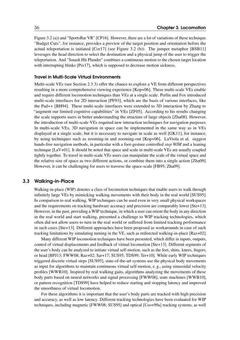
36 Chapter 3. Locomotion
Figure 3.2 (a)) and "SportsBar VR" [CP16]. However, there are a lot of variations of these technique."Budget Cuts", for instance, provides a preview of the target position and orientation before theactual teleportation is initiated [Cor17] (see Figure 3.2 (b)). The jumper metaphor [BSB11]leverages the head direction to select the destination and a physical jump of the user to trigger theteleportation. And "Smash Hit Plunder" combines a continuous motion to the chosen target locationwith interrupting blinks [Pix17], which is supposed to decrease motion sickness.
Travel in Multi-Scale Virtual Environments
Multi-scale VEs (see Section 2.3.3) offer the chance to explore a VE from different perspectivesresulting in a more comprehensive viewing experience [Kop+06]. These multi-scale VEs enableand require different locomotion techniques than VEs at a single scale. Perlin and Fox introducedmulti-scale interfaces for 2D interaction [PF93], which are the basis of various interfaces, likethe Pad++ [BH94]. These multi-scale interfaces were extended to 3D interaction by Zhang to“augment our limited cognitive capabilities” in VEs [ZF05]. According to his results changingthe scale supports users in better understanding the structure of large objects [Zha08]. However,the introduction of multi-scale VEs required new interaction techniques for navigation purposes.In multi-scale VEs, 3D navigation in space can be implemented in the same way as in VEsdisplayed at a single scale, but it is necessary to navigate in scale as well [GK11], for instance,by using techniques such as zooming-in and zooming-out [Kop+06]. LaViola et al. suggesthands-free navigation methods, in particular with a foot-gesture controlled step WIM and a leaningtechnique [LaV+01]. It should be noted that space and scale in multi-scale VEs are usually coupledtightly together. To travel in multi-scale VEs users can manipulate the scale of the virtual space andthe relative size of space as two different actions, or combine them into a single action [Zha09].However, it can be challenging for users to traverse the space-scale [FB95; Zha09].
3.3 Walking-in-Place
Walking-in-place (WIP) denotes a class of locomotion techniques that enable users to walk throughinfinitely large VEs by mimicking walking movements with their body in the real world [SUS95].In comparison to real walking, WIP techniques can be used even in very small physical workspacesand the requirements on tracking hardware accuracy and precision are comparably lower [Ste+13].However, in the past, providing a WIP technique, in which a user can orient the body in any directionin the real world and start walking, presented a challenge to WIP tracking technologies, whichoften did not allow users to turn in the real world or suffered from limited tracking performancein such cases [Ste+13]. Different approaches have been proposed as workarounds in case of suchtracking limitations by simulating turning in the VE, such as redirected walking-in-place [Raz+02].
Many different WIP locomotion techniques have been presented, which differ in inputs, outputs,control of virtual displacements and feedback of virtual locomotion [Ste+13]. Different segments ofthe user’s body can be analyzed to initiate virtual self-motion, such as the feet, shins, knees, fingers,or head [BPJ13; FWW08; Raz+02; Sar+17; SUS95; TDS99; Ter+10]. While early WIP techniquestriggered discrete virtual steps [SUS95], state-of-the-art systems use the physical body movementsas input for algorithms to maintain continuous virtual self-motion, e. g., using sinusoidal velocityprofiles [WWB10]. Inspired by real walking gaits, algorithms analyzing the movements of thesebody parts based on neural networks and signal processing [FWW08], state machines [WWB10],or pattern recognition [TDS99] have helped to reduce starting and stopping latency and improvedthe smoothness of virtual locomotion.
For these algorithms it is important that the user’s body parts are tracked with high precisionand accuracy, as well as low latency. Different tracking technologies have been evaluated for WIPtechniques, including magnetic [FWW08; SUS95] and optical [Uso+99a] tracking systems, as well
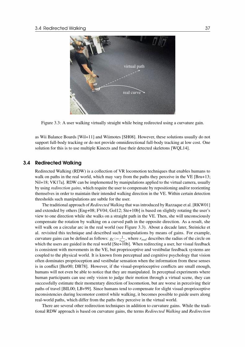
3.4 Redirected Walking 37
real curve
virtual path
Figure 3.3: A user walking virtually straight while being redirected using a curvature gain.
as Wii Balance Boards [Wil+11] and Wiimotes [SH08]. However, these solutions usually do notsupport full-body tracking or do not provide omnidirectional full-body tracking at low cost. Onesolution for this is to use multiple Kinects and fuse their detected skeletons [WQL14].
3.4 Redirected Walking
Redirected Walking (RDW) is a collection of VR locomotion techniques that enables humans towalk on paths in the real world, which may vary from the paths they perceive in the VE [Bru+13;Nil+18; VK17a]. RDW can be implemented by manipulations applied to the virtual camera, usuallyby using redirection gains, which require the user to compensate by repositioning and/or reorientingthemselves in order to maintain their intended walking direction in the VE. Within certain detectionthresholds such manipulations are subtle for the user.
The traditional approach of Redirected Walking that was introduced by Razzaque et al. [RKW01]and extended by others [Eng+08; FV04; Gol12; Ste+10b] is based on slightly rotating the user’sview to one direction while she walks on a straight path in the VE. Then, she will unconsciouslycompensate the rotation by walking on a curved path in the opposite direction. As a result, shewill walk on a circular arc in the real world (see Figure 3.3). About a decade later, Steinicke etal. revisited this technique and described such manipulations by means of gains. For example,curvature gains can be defined as follows: gC:= 1
rreal, where rreal describes the radius of the circle on
which the users are guided in the real world [Ste+10b]. When redirecting a user, her visual feedbackis consistent with movements in the VE, but proprioceptive and vestibular feedback systems arecoupled to the physical world. It is known from perceptual and cognitive psychology that visionoften dominates proprioception and vestibular sensation when the information from these sensesis in conflict [Ber00; DB78]. However, if the visual-proprioceptive conflicts are small enough,humans will not even be able to notice that they are manipulated. In perceptual experiments wherehuman participants can use only vision to judge their motion through a virtual scene, they cansuccessfully estimate their momentary direction of locomotion, but are worse in perceiving theirpaths of travel [BIL00; LBv99]. Since humans tend to compensate for slight visual-proprioceptiveinconsistencies during locomotor control while walking, it becomes possible to guide users alongreal-world paths, which differ from the paths they perceive in the virtual world.
There are several other redirection techniques in addition to curvature gains. While the tradi-tional RDW approach is based on curvature gains, the terms Redirected Walking and Redirection
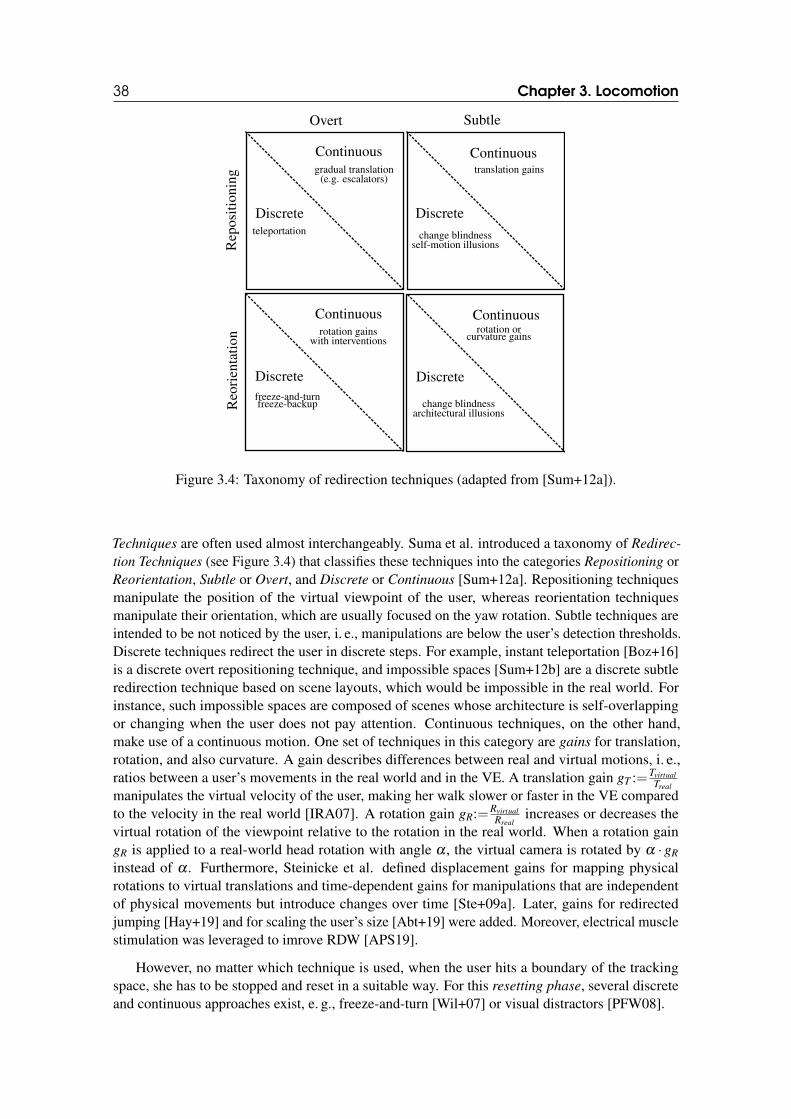
38 Chapter 3. Locomotion
Overt Subtle
Reo
rien
tati
onR
epos
itio
ning
Continuous
Discrete
Continuous
ContinuousContinuous
Discrete
DiscreteDiscrete
gradual translation(e.g. escalators)
teleportation
rotation gainswith interventions
freeze-and-turnfreeze-backup change blindness
architectural illusions
rotation orcurvature gains
change blindnessself-motion illusions
translation gains
Figure 3.4: Taxonomy of redirection techniques (adapted from [Sum+12a]).
Techniques are often used almost interchangeably. Suma et al. introduced a taxonomy of Redirec-
tion Techniques (see Figure 3.4) that classifies these techniques into the categories Repositioning orReorientation, Subtle or Overt, and Discrete or Continuous [Sum+12a]. Repositioning techniquesmanipulate the position of the virtual viewpoint of the user, whereas reorientation techniquesmanipulate their orientation, which are usually focused on the yaw rotation. Subtle techniques areintended to be not noticed by the user, i. e., manipulations are below the user’s detection thresholds.Discrete techniques redirect the user in discrete steps. For example, instant teleportation [Boz+16]is a discrete overt repositioning technique, and impossible spaces [Sum+12b] are a discrete subtleredirection technique based on scene layouts, which would be impossible in the real world. Forinstance, such impossible spaces are composed of scenes whose architecture is self-overlappingor changing when the user does not pay attention. Continuous techniques, on the other hand,make use of a continuous motion. One set of techniques in this category are gains for translation,rotation, and also curvature. A gain describes differences between real and virtual motions, i. e.,ratios between a user’s movements in the real world and in the VE. A translation gain gT :=Tvirtual
Treal
manipulates the virtual velocity of the user, making her walk slower or faster in the VE comparedto the velocity in the real world [IRA07]. A rotation gain gR:=Rvirtual
Rrealincreases or decreases the
virtual rotation of the viewpoint relative to the rotation in the real world. When a rotation gaingR is applied to a real-world head rotation with angle α , the virtual camera is rotated by α · gR
instead of α . Furthermore, Steinicke et al. defined displacement gains for mapping physicalrotations to virtual translations and time-dependent gains for manipulations that are independentof physical movements but introduce changes over time [Ste+09a]. Later, gains for redirectedjumping [Hay+19] and for scaling the user’s size [Abt+19] were added. Moreover, electrical musclestimulation was leveraged to imrove RDW [APS19].
However, no matter which technique is used, when the user hits a boundary of the trackingspace, she has to be stopped and reset in a suitable way. For this resetting phase, several discreteand continuous approaches exist, e. g., freeze-and-turn [Wil+07] or visual distractors [PFW08].
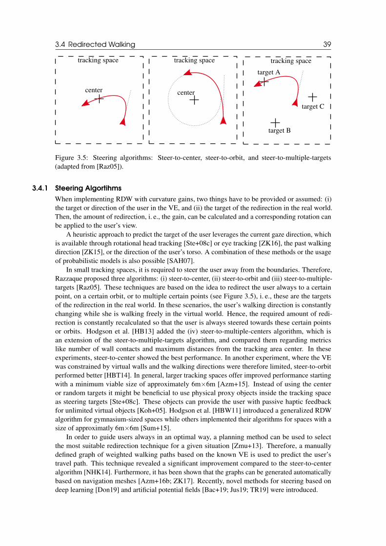
3.4 Redirected Walking 39
tracking space tracking space tracking space
center center
target A
target B
target C
Figure 3.5: Steering algorithms: Steer-to-center, steer-to-orbit, and steer-to-multiple-targets(adapted from [Raz05]).
3.4.1 Steering Algortihms
When implementing RDW with curvature gains, two things have to be provided or assumed: (i)the target or direction of the user in the VE, and (ii) the target of the redirection in the real world.Then, the amount of redirection, i. e., the gain, can be calculated and a corresponding rotation canbe applied to the user’s view.
A heuristic approach to predict the target of the user leverages the current gaze direction, whichis available through rotational head tracking [Ste+08c] or eye tracking [ZK16], the past walkingdirection [ZK15], or the direction of the user’s torso. A combination of these methods or the usageof probabilistic models is also possible [SAH07].
In small tracking spaces, it is required to steer the user away from the boundaries. Therefore,Razzaque proposed three algorithms: (i) steer-to-center, (ii) steer-to-orbit and (iii) steer-to-multiple-targets [Raz05]. These techniques are based on the idea to redirect the user always to a certainpoint, on a certain orbit, or to multiple certain points (see Figure 3.5), i. e., these are the targetsof the redirection in the real world. In these scenarios, the user’s walking direction is constantlychanging while she is walking freely in the virtual world. Hence, the required amount of redi-rection is constantly recalculated so that the user is always steered towards these certain pointsor orbits. Hodgson et al. [HB13] added the (iv) steer-to-multiple-centers algorithm, which isan extension of the steer-to-multiple-targets algorithm, and compared them regarding metricslike number of wall contacts and maximum distances from the tracking area center. In theseexperiments, steer-to-center showed the best performance. In another experiment, where the VEwas constrained by virtual walls and the walking directions were therefore limited, steer-to-orbitperformed better [HBT14]. In general, larger tracking spaces offer improved performance startingwith a minimum viable size of approximately 6m×6m [Azm+15]. Instead of using the centeror random targets it might be beneficial to use physical proxy objects inside the tracking spaceas steering targets [Ste+08c]. These objects can provide the user with passive haptic feedbackfor unlimited virtual objects [Koh+05]. Hodgson et al. [HBW11] introduced a generalized RDWalgorithm for gymnasium-sized spaces while others implemented their algorithms for spaces with asize of approximatly 6m×6m [Sum+15].
In order to guide users always in an optimal way, a planning method can be used to selectthe most suitable redirection technique for a given situation [Zmu+13]. Therefore, a manuallydefined graph of weighted walking paths based on the known VE is used to predict the user’stravel path. This technique revealed a significant improvement compared to the steer-to-centeralgorithm [NHK14]. Furthermore, it has been shown that the graphs can be generated automaticallybased on navigation meshes [Azm+16b; ZK17]. Recently, novel methods for steering based ondeep learning [Don19] and artificial potential fields [Bac+19; Jus19; TR19] were introduced.
40 Chapter 3. Locomotion
There were also approaches, which combined RDW algorithms with other travel techniques suchas portals [BSH09; FRK14; Ste+09b], teleportation [Liu+18], or redirection-free zones [LBS14].
3.4.2 Resetting
No matter which redirection technique or steering algorithm is used, it can still happen that theuser hits a boundary of the tracking space. In this case, she needs to be stopped and reset, i. e., theuser must be turned to face to the center of the tracking space again. For instance, most redirectionsolutions, e. g., the RDW toolkit [Azm+16a], make use of a stop-and-go approach. Using theseapproaches, the user walks until the boundary of the tracking space is reached, for example, while acurvature gain is applied. Then, she will be rotated until there are no obstacles in front of her newwalking direction. Afterwards, the user can continue walking in the desired direction.
For this resetting phase or reorientation phase, several techniques exist. Williams et al.introduced the three methods (i) Freeze-Backup, (ii) Freeze-Turn, and (iii) 2:1-Turn [Wil+07]. Inthe Freeze-Backup method, the position of the user in the VE is frozen and she can walk backwarduntil she has enough empty physical space in front of her. In the Freeze-Turn method, the orientationof the user in the VE is frozen and she can turn around until she has enough empty physical spacein front of her. In the 2:1-Turn method, the user turns around 180 degrees physically (so thatshe has enough empty physical space in front of her), while she turns 360 degrees virtually (andlooks in the same direction in the VE as before the turn). Such a manipulated turn is implementedusing a rotation gain gR=2. In this case, visual distractors can be used to make these manipulatedturns less obvious and to appear more natural [PFW11; PFW08]. The resetting phase can also beintegrated into the domain or the narration of the VR application [Sra+18; Yu+18] by using suitablemetaphors, e. g., a turning bookshelf [Yu+17].
To reduce the number of resetting phases in this stop-and-go approach, Zhang et al. [ZK13;ZWK15] developed heuristics to dynamically adjust RDW gains for guiding the user in the bestdirection. It turned out that the users walked a significantly longer distance between two resettingphases when using this method.
3.4.3 Detection Thresholds
Redirection techniques may be subtle under certain conditions. Therefore, detection thresholds fordifferent manipulations have been analyzed using a 2AFC task (see Section 2.1.3). We collectedseveral estimated detection thresholds for different gains and conditions in Table 3.11.
Steinicke et al. conducted several experiments to reveal detection thresholds for translation,rotation, and curvature gains [Ste+10b]2. The detection thresholds indicate just-noticeable differ-ences between vision and vestibular system. According to their results, a straight path in the VEcan be turned into a circular arc in the real world with a radius of at least 22m, for which usersare not able to consciously detect manipulations. This means, that a physical space of at least45m×45m would be necessary to enable infinite virtually straight walking. Furthermore, rotationscan be scaled by gains between 0.67 and 1.24 and translations can be scaled by gains between 0.78and 1.22 without that users are able to detect the manipulations. These experiments have beenreplicated with different settings and extended several times [Bru+09; Bru+12; FWK16b; KSB11;Ste+08b; Ste+09b]. For example, Grechkin et al. found that a radius of only 12m can be sufficientfor unlimited straight walking in a VE [Gre+16]. The differences in the results between thoseexperiments could be explained by the different hardware that was used in the experiments as wellas methodological and population differences. In general, current hardware appears to improveRDW techniques.
1In this table, we already added the results that we present in Part III.2While there most likely was a bias in the question of their first experiments [Ste+08a], they repeated them [Ste+10b].
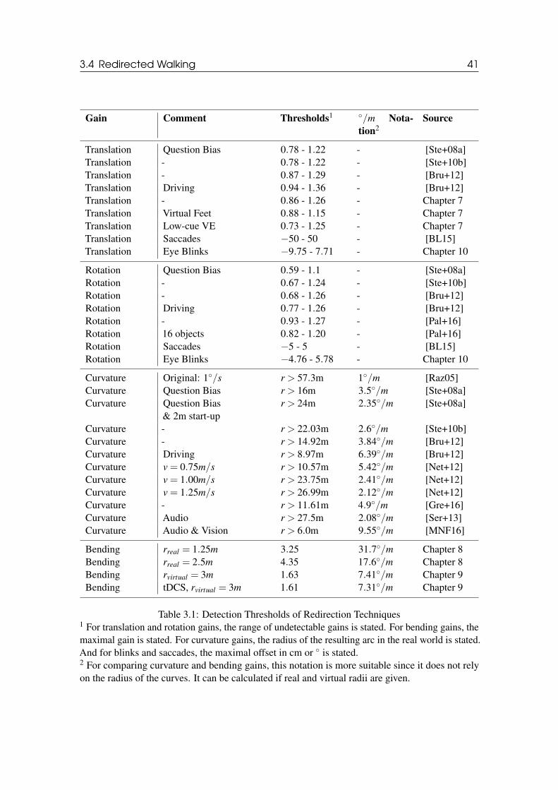
3.4 Redirected Walking 41
Gain Comment Thresholds1 ◦/m Nota-
tion2Source
Translation Question Bias 0.78 - 1.22 - [Ste+08a]Translation - 0.78 - 1.22 - [Ste+10b]Translation - 0.87 - 1.29 - [Bru+12]Translation Driving 0.94 - 1.36 - [Bru+12]Translation - 0.86 - 1.26 - Chapter 7Translation Virtual Feet 0.88 - 1.15 - Chapter 7Translation Low-cue VE 0.73 - 1.25 - Chapter 7Translation Saccades −50 - 50 - [BL15]Translation Eye Blinks −9.75 - 7.71 - Chapter 10
Rotation Question Bias 0.59 - 1.1 - [Ste+08a]Rotation - 0.67 - 1.24 - [Ste+10b]Rotation - 0.68 - 1.26 - [Bru+12]Rotation Driving 0.77 - 1.26 - [Bru+12]Rotation - 0.93 - 1.27 - [Pal+16]Rotation 16 objects 0.82 - 1.20 - [Pal+16]Rotation Saccades −5 - 5 - [BL15]Rotation Eye Blinks −4.76 - 5.78 - Chapter 10
Curvature Original: 1◦/s r > 57.3m 1◦/m [Raz05]Curvature Question Bias r > 16m 3.5◦/m [Ste+08a]Curvature Question Bias
& 2m start-upr > 24m 2.35◦/m [Ste+08a]
Curvature - r > 22.03m 2.6◦/m [Ste+10b]Curvature - r > 14.92m 3.84◦/m [Bru+12]Curvature Driving r > 8.97m 6.39◦/m [Bru+12]Curvature v = 0.75m/s r > 10.57m 5.42◦/m [Net+12]Curvature v = 1.00m/s r > 23.75m 2.41◦/m [Net+12]Curvature v = 1.25m/s r > 26.99m 2.12◦/m [Net+12]Curvature - r > 11.61m 4.9◦/m [Gre+16]Curvature Audio r > 27.5m 2.08◦/m [Ser+13]Curvature Audio & Vision r > 6.0m 9.55◦/m [MNF16]
Bending rreal = 1.25m 3.25 31.7◦/m Chapter 8Bending rreal = 2.5m 4.35 17.6◦/m Chapter 8Bending rvirtual = 3m 1.63 7.41◦/m Chapter 9Bending tDCS, rvirtual = 3m 1.61 7.31◦/m Chapter 9
Table 3.1: Detection Thresholds of Redirection Techniques1 For translation and rotation gains, the range of undetectable gains is stated. For bending gains, themaximal gain is stated. For curvature gains, the radius of the resulting arc in the real world is stated.And for blinks and saccades, the maximal offset in cm or ◦ is stated.2 For comparing curvature and bending gains, this notation is more suitable since it does not relyon the radius of the curves. It can be calculated if real and virtual radii are given.
42 Chapter 3. Locomotion
After being blindfolded and exposed to the rubber hand illusion for only 30 seconds, participantsfrom the study by Ehrsson et al. had to point to their right index finger with their left hand, whichresulted in a pointing error of 3 cm [EHP05]. Without visual feedback, perceived limb positioneven drifts over time [Bro02; WI92]. In general, strongest ratings for realness and presencewere given when the physical limb position and the virtual limb position are closest. Lloyd et al.claimed that ratings decayed significantly after a distance of 30cm from the virtual to the physicalposition [Llo07]. Burns et al. found a mean detection threshold of 0.4 in a study where theychanged the user’s hand position with a drift of 5mm/s for a movement faster than 5cm/s [Bur+05].
Furthermore, it was found that an isometric mapping is not always the most natural one. Geo-metrically correct optic flow appears to be too slow and users estimate a virtual walking velocity asmore natural when it is slightly increased compared to the user’s physical body movement [Ban+05;Jan+17b; NSN14]. Steinicke et al. found that virtual translation has to be increased by 7% toappear natural [Ste+08a; Ste+10b]. It was shown that rotation manipulations are less obvious todetect if the VE moves against head rotation compared to situations where the VE moves with headrotation [Jer+08]. It was found that sensitivity to curvature gains depends on walking velocity:a slower walking speed allows higher redirection gains [Net+11; Net+12]. Redirection can alsobe applied for driving simulations, for example, when applying curvature gains to a user sittingin an electric wheelchair, this resulted in greater possible redirection [Bru+12], which might berelated to the proprioceptive feedback users receive by walking, whereas this feedback is mostlymissing while driving in a wheelchair. When combining curvature gains and translation gains,curvature detection thresholds are not affected [Gre+16]. So far, curvature detection thresholds wereestimated when the users walk straight ahead in the VE. An effect of the visual density of the VE,i. e., the number of visual objects that were present in the VE, on the detection thresholds could notbe shown [Pal+16]. Subtle redirection techniques may not only be based on visual manipulationsof the VE, but also on audio [MNF16; Nil+16; NF16; Rew+19] or haptics [Mat+16b]. Whenusing passive haptic cues during RDW even more redirection is possible [Mat+16a]. Detectionthresholds may be different for individual users [Hut+18; Ngo+16] and increase during exposuretime [Böl+19].
Although, ideally RDW is a subconscious process, Bruder et al. have shown that cognitiveresources are required to compensate even subtle manipulations [BLS15]. In secondary verbal andspatial memory tasks, they have shown that performance decreased in the secondary task when theredirection gain increased. More precisely, correct answers decreased and answer time increased aswell.
3.4.4 Impossible Spaces
An alternative approach to implement RDW is to use impossible or flexible spaces [Vas+13], whichcan be based on self-overlapping or changing architectural layouts. In these spaces, the VE itselfis manipulated (in contrast to the user’s viewpoint) with the same goal of enlarging the virtualspace, which can be explored by real walking. Such manipulations can be realized, for example, bymoving walls or doors outside the user’s view [Sum+10], to exploit the same real-world space fordifferent virtual rooms. The phenomenon that users are unable to detect such changes is known aschange blindness [SL97]. It was shown that virtual rooms may overlap by more than 50% beforeusers detect the manipulation [Sum+12b]. Moreover, curved corridors between the overlappingrooms are more beneficial than right-angled corridors in terms of manipulation detection [VK17b],and a corridor with additional turns is more efficient than a longer corridor [VK15].
A similar approach of exploiting the available tracking space for real walking is used by theVR game Unseen Diplomacy [Pix16]. It arranges the (self-overlapping) rooms in such a way thatthe player does not recognize that she is only walking back and forth in a 3m×4m large area.
3.5 Comparison of Techniques 43
3.5 Comparison of Techniques
In previous work, several of the above mentioned navigation techniques have been comparedregarding different aspects. In general, these studies suggest that natural techniques are slightlyadvantageous to semi- or non-natural techniques when it comes to sense of presence [Uso+99a] oruser preferences [Boz+16].
For example, Usoh et al. compared real walking to walking-in-place and a joystick-likelocomotion technique and found that the sense of presence benefits from proprioceptive andvestibular feedback [Uso+99a]. Real walking, walking-in-place, and joystick were also comparedregarding task behaviour and task performance and the results suggest an ordering of locomotiontechniques by "naturalness" [Whi+05]. Real walking, the Virtusphere device, and a gamepad werecompared regarding user task performance and it was found that the Virtusphere technique wassignificantly slower and less accurate [Nab+15]. Teleportation was compared to walking-in-placeand joystick regarding usability [Boz+16]. The results show that teleportation was subjectivelypreferred as a user friendly locomotion technique. However, an extended version of this teleportationtechnique for which it was possible to set a certain target direction into which the user should faceafter the teleportation, showed a decrease of the user experience. Bolte et al. compared teleportationto real walking and to the jumper metapher [BSB11]. The result shows that teleportation and jumpermetapher are more effective techniques than real walking. Furthermore, in a CAVE, teleportationwas compared to joystick and real walking with portals that were used to reorient the user in thetracking space [FRK14]. Teleportation was faster than real walking, but led to an increased loss oforientation compared to joystick. They could not find any differences between teleportation andreal walking concerning motion sickness.
Peck et al. compared RDW to walking-in-place and joystick regarding navigational ability (i.e.,the performance during a search task) and reported that participants ‘traveled shorter distances,made fewer wrong turns, pointed to hidden targets more accurately and more quickly, and wereable to place and label targets on maps more accurately‘ when using RDW [PFW11]. It was alsofound that body-based informations like proprioception improved navigational performance as wellas the user’s cognitive maps [RVB10; RL09]. Though it is a very popular and easy solution fortravel, after teleporting, it takes some time for the user to understand her new surroundings, poten-tially leading to disorientation, which in turn can break the feeling of presence [FRK14; RVB10;Uso+99a]. Bowman et al. found that instant teleportation is correlated with decreased spatialorientation [Bow+99]. Similar results regarding spatial orientation and teleportation were found byBakker et al. [BPW03] and Cliburn et al. [Cli+09]. Nevertheless, teleportation is a comfortable andeasy technique, which is suitable for a lot of situations or application domains [FSW17].

II4 Effects of DOF Blur on Distance Estimation
474.1 Motivation4.2 Participants4.3 Materials4.4 Methods4.5 Results4.6 Discussion4.7 Conclusion
5 Effects of Motion Blur on Speed Estimation55
5.1 Motivation5.2 Participants5.3 Materials5.4 Methods5.5 Results5.6 Discussion5.7 Conclusion
6 Analysis of Dominant Scale Estimation 59
6.1 Motivation6.2 Pilot User Study6.3 Experiment E1: Virtual Body and Environment6.4 Experiment E2: Group Effects6.5 General Discussion6.6 Design Guidelines6.7 Conclusion
EGOCENTRIC SPATIAL PERCEPTION

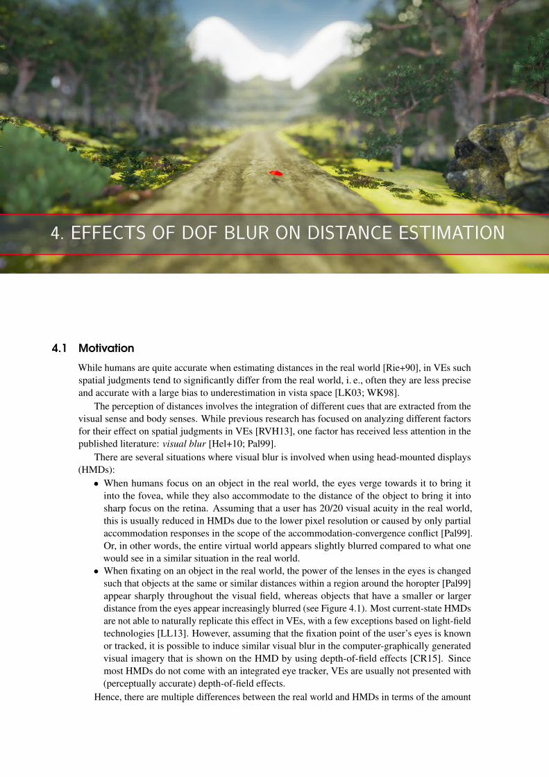
4. EFFECTS OF DOF BLUR ON DISTANCE ESTIMATION
4.1 Motivation
While humans are quite accurate when estimating distances in the real world [Rie+90], in VEs suchspatial judgments tend to significantly differ from the real world, i. e., often they are less preciseand accurate with a large bias to underestimation in vista space [LK03; WK98].
The perception of distances involves the integration of different cues that are extracted from thevisual sense and body senses. While previous research has focused on analyzing different factorsfor their effect on spatial judgments in VEs [RVH13], one factor has received less attention in thepublished literature: visual blur [Hel+10; Pal99].
There are several situations where visual blur is involved when using head-mounted displays(HMDs):
• When humans focus on an object in the real world, the eyes verge towards it to bring itinto the fovea, while they also accommodate to the distance of the object to bring it intosharp focus on the retina. Assuming that a user has 20/20 visual acuity in the real world,this is usually reduced in HMDs due to the lower pixel resolution or caused by only partialaccommodation responses in the scope of the accommodation-convergence conflict [Pal99].Or, in other words, the entire virtual world appears slightly blurred compared to what onewould see in a similar situation in the real world.
• When fixating on an object in the real world, the power of the lenses in the eyes is changedsuch that objects at the same or similar distances within a region around the horopter [Pal99]appear sharply throughout the visual field, whereas objects that have a smaller or largerdistance from the eyes appear increasingly blurred (see Figure 4.1). Most current-state HMDsare not able to naturally replicate this effect in VEs, with a few exceptions based on light-fieldtechnologies [LL13]. However, assuming that the fixation point of the user’s eyes is knownor tracked, it is possible to induce similar visual blur in the computer-graphically generatedvisual imagery that is shown on the HMD by using depth-of-field effects [CR15]. Sincemost HMDs do not come with an integrated eye tracker, VEs are usually not presented with(perceptually accurate) depth-of-field effects.
Hence, there are multiple differences between the real world and HMDs in terms of the amount
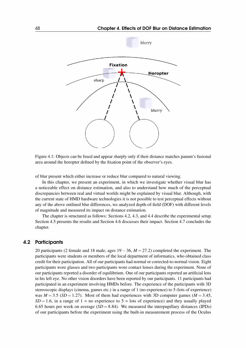
48 Chapter 4. Effects of DOF Blur on Distance Estimation
Figure 4.1: Objects can be fused and appear sharply only if their distance matches panum’s fusionalarea around the horopter defined by the fixation point of the observer’s eyes.
of blur present which either increase or reduce blur compared to natural viewing.In this chapter, we present an experiment, in which we investigate whether visual blur has
a noticeable effect on distance estimation, and also to understand how much of the perceptualdiscrepancies between real and virtual worlds might be explained by visual blur. Although, withthe current state of HMD hardware technologies it is not possible to test perceptual effects withoutany of the above outlined blur differences, we analyzed depth-of-field (DOF) with different levelsof magnitude and measured its impact on distance estimation.
The chapter is structured as follows: Sections 4.2, 4.3, and 4.4 describe the experimental setup.Section 4.5 presents the results and Section 4.6 discusses their impact. Section 4.7 concludes thechapter.
4.2 Participants
20 participants (2 female and 18 male, ages 19− 36, M = 27.2) completed the experiment. Theparticipants were students or members of the local department of informatics, who obtained classcredit for their participation. All of our participants had normal or corrected-to-normal vision. Eightparticipants wore glasses and two participants wore contact lenses during the experiment. None ofour participants reported a disorder of equilibrium. One of our participants reported an artificial lensin his left eye. No other vision disorders have been reported by our participants. 11 participants hadparticipated in an experiment involving HMDs before. The experience of the participants with 3Dstereoscopic displays (cinema, games etc.) in a range of 1 (no experience) to 5 (lots of experience)was M = 3.5 (SD= 1.27). Most of them had experiences with 3D computer games (M = 3.45,SD= 1.6, in a range of 1 = no experience to 5 = lots of experience) and they usually played6.65 hours per week on average (SD= 8.84). We measured the interpupillary distances (IPDs)of our participants before the experiment using the built-in measurement process of the Oculus
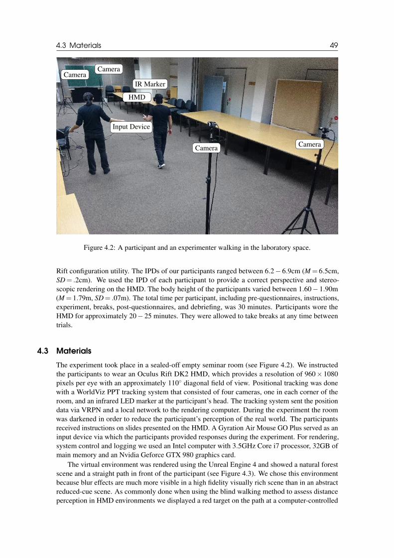
4.3 Materials 49
HMD
Input Device
IR MarkerCamera
Camera
Camera Camera
Figure 4.2: A participant and an experimenter walking in the laboratory space.
Rift configuration utility. The IPDs of our participants ranged between 6.2− 6.9cm (M = 6.5cm,SD= .2cm). We used the IPD of each participant to provide a correct perspective and stereo-scopic rendering on the HMD. The body height of the participants varied between 1.60− 1.90m(M = 1.79m, SD= .07m). The total time per participant, including pre-questionnaires, instructions,experiment, breaks, post-questionnaires, and debriefing, was 30 minutes. Participants wore theHMD for approximately 20− 25 minutes. They were allowed to take breaks at any time betweentrials.
4.3 Materials
The experiment took place in a sealed-off empty seminar room (see Figure 4.2). We instructedthe participants to wear an Oculus Rift DK2 HMD, which provides a resolution of 960× 1080pixels per eye with an approximately 110◦ diagonal field of view. Positional tracking was donewith a WorldViz PPT tracking system that consisted of four cameras, one in each corner of theroom, and an infrared LED marker at the participant’s head. The tracking system sent the positiondata via VRPN and a local network to the rendering computer. During the experiment the roomwas darkened in order to reduce the participant’s perception of the real world. The participantsreceived instructions on slides presented on the HMD. A Gyration Air Mouse GO Plus served as aninput device via which the participants provided responses during the experiment. For rendering,system control and logging we used an Intel computer with 3.5GHz Core i7 processor, 32GB ofmain memory and an Nvidia Geforce GTX 980 graphics card.
The virtual environment was rendered using the Unreal Engine 4 and showed a natural forestscene and a straight path in front of the participant (see Figure 4.3). We chose this environmentbecause blur effects are much more visible in a high fidelity visually rich scene than in an abstractreduced-cue scene. As commonly done when using the blind walking method to assess distanceperception in HMD environments we displayed a red target on the path at a computer-controlled
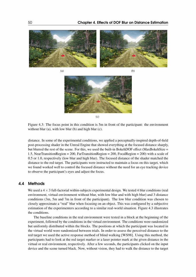
50 Chapter 4. Effects of DOF Blur on Distance Estimation
(a) (b)
(c)
Figure 4.3: The focus point in this condition is 5m in front of the participant: the environmentwithout blur (a), with low blur (b) and high blur (c).
distance. In some of the experimental conditions, we applied a perceptually-inspired depth-of-fieldpost-processing shader in the Unreal Engine that showed everything at the focused distance sharply,but blurred the rest of the scene. For this, we used the built-in BokehDOF effect (MaxBokehSize =1.5, NearTransitionRegion = 200, FarTransitionRegion = 200, FocalRegion = 200) with a scale of0.5 or 1.0, respectively (low blur and high blur). The focused distance of the shader matched thedistance to the red target. The participants were instructed to maintain a focus on this target, whichwe found worked well to control the focused distance without the need for an eye tracking deviceto observe the participant’s eyes and adjust the focus.
4.4 Methods
We used a 4× 3 full-factorial within-subjects experimental design. We tested 4 blur conditions (realenvironment, virtual environment without blur, with low blur and with high blur) and 3 distanceconditions (3m, 5m and 7m in front of the participant). The low blur condition was chosen toclosely approximate a “real" blur when focusing on an object. This was configured by a subjectiveestimation of the experimenters according to a similar real-world situation. Figure 4.3 illustratesthe conditions.
The baseline conditions in the real environment were tested in a block at the beginning of theexperiment, followed by the conditions in the virtual environment. The conditions were randomizedbut uniformly distributed within the blocks. The positions at which the participant was located inthe virtual world were randomized between trials. In order to assess the perceived distance to thered target we used the active response method of blind walking [WS98]. Using this method, theparticipants had to look at the red target marker or a laser pointer mark at the given distance in thevirtual or real environment, respectively. After a few seconds, the participants clicked on the inputdevice and the scene turned black. Now, without vision, they had to walk the distance to the target
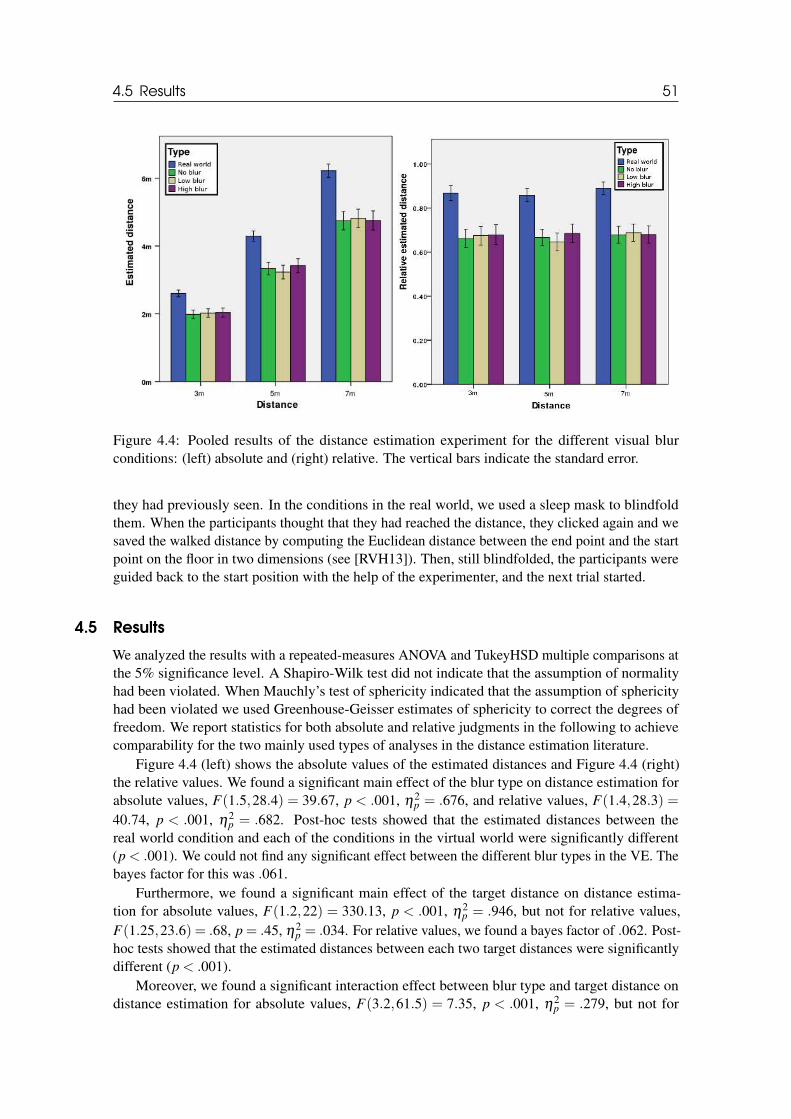
4.5 Results 51
Figure 4.4: Pooled results of the distance estimation experiment for the different visual blurconditions: (left) absolute and (right) relative. The vertical bars indicate the standard error.
they had previously seen. In the conditions in the real world, we used a sleep mask to blindfoldthem. When the participants thought that they had reached the distance, they clicked again and wesaved the walked distance by computing the Euclidean distance between the end point and the startpoint on the floor in two dimensions (see [RVH13]). Then, still blindfolded, the participants wereguided back to the start position with the help of the experimenter, and the next trial started.
4.5 Results
We analyzed the results with a repeated-measures ANOVA and TukeyHSD multiple comparisons atthe 5% significance level. A Shapiro-Wilk test did not indicate that the assumption of normalityhad been violated. When Mauchly’s test of sphericity indicated that the assumption of sphericityhad been violated we used Greenhouse-Geisser estimates of sphericity to correct the degrees offreedom. We report statistics for both absolute and relative judgments in the following to achievecomparability for the two mainly used types of analyses in the distance estimation literature.
Figure 4.4 (left) shows the absolute values of the estimated distances and Figure 4.4 (right)the relative values. We found a significant main effect of the blur type on distance estimation forabsolute values, F(1.5,28.4) = 39.67, p < .001, η2
p = .676, and relative values, F(1.4,28.3) =40.74, p < .001, η2
p = .682. Post-hoc tests showed that the estimated distances between thereal world condition and each of the conditions in the virtual world were significantly different(p < .001). We could not find any significant effect between the different blur types in the VE. Thebayes factor for this was .061.
Furthermore, we found a significant main effect of the target distance on distance estima-tion for absolute values, F(1.2,22) = 330.13, p < .001, η2
p = .946, but not for relative values,F(1.25,23.6) = .68, p = .45, η2
p = .034. For relative values, we found a bayes factor of .062. Post-hoc tests showed that the estimated distances between each two target distances were significantlydifferent (p < .001).
Moreover, we found a significant interaction effect between blur type and target distance ondistance estimation for absolute values, F(3.2,61.5) = 7.35, p < .001, η2
p = .279, but not for
52 Chapter 4. Effects of DOF Blur on Distance Estimation
relative values, F(6,114) = .52, p = .8, η2p = .026. For relative values, we found a bayes factor of
.003.
Questionnaires
We measured a mean SSQ-score [Ken+93] of 11.8 (SD = 16.7) before the experiment, and a meanSSQ-score of 31.8 (SD = 30.9) after the experiment. The mean SUS-score [Uso+99b] for the senseof feeling present in the VE was 4.46 (SD = 1.1).
4.6 Discussion
It is an interesting result that our experiment did not reveal a significant effect on distance estimationof the even quite large amount of blur that we added with DOF to the visual stimulus. It is reasonableto assume that the statistical effect size of such blur effects is relatively low. Additionally, therelatively small value of the bayes factor even suggests that there is an overwhelming support forthe null hypothesis. In fact, the different blur conditions could only explain a very small part of thevariance in the responses.
We believe that there are three potential explanations why we observed such small effect sizesand observed power in the blur conditions in the VE:
a) The tested distances were still in the range where convergence and motion parallax offergood distance cues, which might have dominated any effect from even large amounts of DOFblur. This might explain why related studies using monoscopic imagery have found an effectof blur on distance and size estimation [Hel+10].
b) Despite our perceptual calibration, the types and strengths of blur that we tested in thisexperiment based on DOF visual effects might not have been interpreted as a depth cue by thehuman perceptual system due to slight differences in magnitude or distribution (see Bayesiancue integration [Ern06]).
c) The resolution of the Oculus Rift DK2 HMD, which supports only 960× 1080 pixels pereye, limited the visual acuity. A potential explanation might be that the additional amountof blur had no noticeable additional effect on distance estimation, but that less blur mighthave had an effect. However, we should note that this explanation would conflict with resultsof related studies, which found that higher resolution did not improve distance estimation(e. g., [Bru+15]).
However, from the point of view of a practitioner in the field of VR, we believe that itis warranted to provide the guideline that for practical purposes the effect of blur on distancemisperception in the visual imagery can be neglected.
This also can be applied to the current questions how much resolution of visual displays isrequired by indicating that unless the resolution is largely improved to approximate the visualacuity of the human eyes, blur due to lower resolutions is likely not an important cause of spatialmisperception.
Furthermore, it is to take note of the fact, that we found a much higher underestimation inVE conditions than others who used similar hardware (e. g., [Cre+15; Li+15]). This might beexplained by slightly different tested distances, different VEs (indoor vs. outdoor) and differentcalibration. We measured and set the IPD of each participant individually while Creem-Regehr etal. set the IPD to 6.25cm for all participants. Additionally, we also set the height of the cameraaccording to the height of the participants.
We also found a slight underestimation in the real world condition. Since we do not know whatis the reason for this, we guess it is related to the construction of the room which had the form of atube.
4.7 Conclusion 53
4.7 Conclusion
In this chapter, we reported a psychophysical experiment that was conducted to investigate theinfluence of DOF blur on distance estimation. Because we found no significant effect and onlyvery low effect sizes, we draw the conclusion that there is–if at all–only a negligibly small effect.Even if this result is, technically, a null result we believe that it is an important finding that willprovide new insights to the research direction because there are important reasons why researchersmight assume an influence of blur, which, so far, has not been proven or disproven in the publishedliterature.
However, we have to consider that our findings are based on a snapshot of currently availableHMD technology. Once available in the (distant) future, we will have to revisit effects of blur usingan HMD with a field of view and resolution that match those of the human eyes. However, eventhen, blur might not prove to have much influence on distance estimation due to the availability ofstronger cues such as motion parallax and convergence.

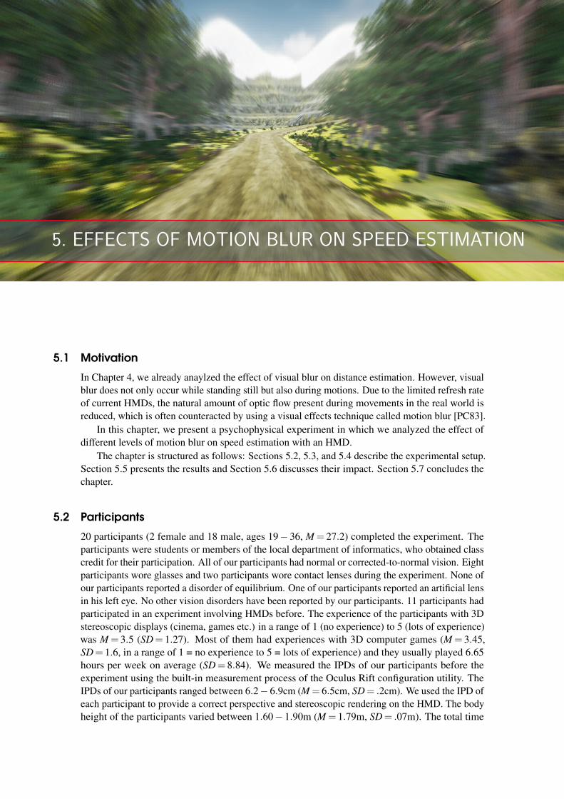
5. EFFECTS OF MOTION BLUR ON SPEED ESTIMATION
5.1 Motivation
In Chapter 4, we already anaylzed the effect of visual blur on distance estimation. However, visualblur does not only occur while standing still but also during motions. Due to the limited refresh rateof current HMDs, the natural amount of optic flow present during movements in the real world isreduced, which is often counteracted by using a visual effects technique called motion blur [PC83].
In this chapter, we present a psychophysical experiment in which we analyzed the effect ofdifferent levels of motion blur on speed estimation with an HMD.
The chapter is structured as follows: Sections 5.2, 5.3, and 5.4 describe the experimental setup.Section 5.5 presents the results and Section 5.6 discusses their impact. Section 5.7 concludes thechapter.
5.2 Participants
20 participants (2 female and 18 male, ages 19− 36, M = 27.2) completed the experiment. Theparticipants were students or members of the local department of informatics, who obtained classcredit for their participation. All of our participants had normal or corrected-to-normal vision. Eightparticipants wore glasses and two participants wore contact lenses during the experiment. None ofour participants reported a disorder of equilibrium. One of our participants reported an artificial lensin his left eye. No other vision disorders have been reported by our participants. 11 participants hadparticipated in an experiment involving HMDs before. The experience of the participants with 3Dstereoscopic displays (cinema, games etc.) in a range of 1 (no experience) to 5 (lots of experience)was M = 3.5 (SD= 1.27). Most of them had experiences with 3D computer games (M = 3.45,SD= 1.6, in a range of 1 = no experience to 5 = lots of experience) and they usually played 6.65hours per week on average (SD= 8.84). We measured the IPDs of our participants before theexperiment using the built-in measurement process of the Oculus Rift configuration utility. TheIPDs of our participants ranged between 6.2− 6.9cm (M = 6.5cm, SD= .2cm). We used the IPD ofeach participant to provide a correct perspective and stereoscopic rendering on the HMD. The bodyheight of the participants varied between 1.60− 1.90m (M = 1.79m, SD= .07m). The total time
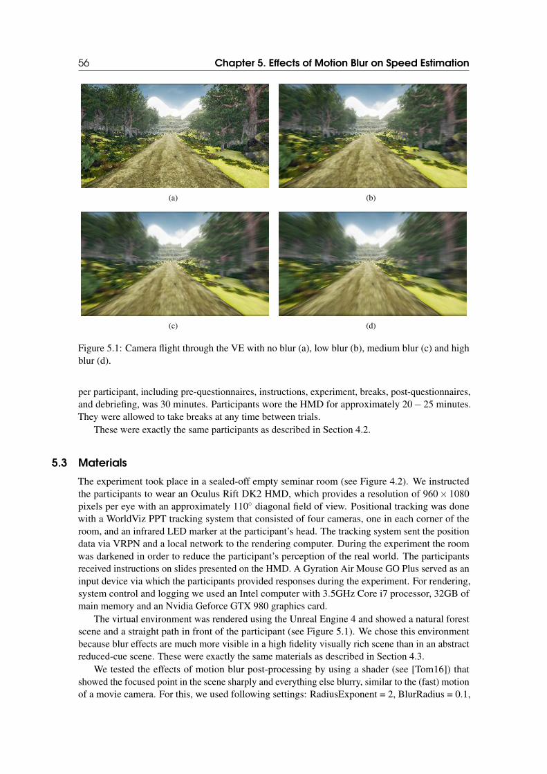
56 Chapter 5. Effects of Motion Blur on Speed Estimation
(a) (b)
(c) (d)
Figure 5.1: Camera flight through the VE with no blur (a), low blur (b), medium blur (c) and highblur (d).
per participant, including pre-questionnaires, instructions, experiment, breaks, post-questionnaires,and debriefing, was 30 minutes. Participants wore the HMD for approximately 20− 25 minutes.They were allowed to take breaks at any time between trials.
These were exactly the same participants as described in Section 4.2.
5.3 Materials
The experiment took place in a sealed-off empty seminar room (see Figure 4.2). We instructedthe participants to wear an Oculus Rift DK2 HMD, which provides a resolution of 960× 1080pixels per eye with an approximately 110◦ diagonal field of view. Positional tracking was donewith a WorldViz PPT tracking system that consisted of four cameras, one in each corner of theroom, and an infrared LED marker at the participant’s head. The tracking system sent the positiondata via VRPN and a local network to the rendering computer. During the experiment the roomwas darkened in order to reduce the participant’s perception of the real world. The participantsreceived instructions on slides presented on the HMD. A Gyration Air Mouse GO Plus served as aninput device via which the participants provided responses during the experiment. For rendering,system control and logging we used an Intel computer with 3.5GHz Core i7 processor, 32GB ofmain memory and an Nvidia Geforce GTX 980 graphics card.
The virtual environment was rendered using the Unreal Engine 4 and showed a natural forestscene and a straight path in front of the participant (see Figure 5.1). We chose this environmentbecause blur effects are much more visible in a high fidelity visually rich scene than in an abstractreduced-cue scene. These were exactly the same materials as described in Section 4.3.
We tested the effects of motion blur post-processing by using a shader (see [Tom16]) thatshowed the focused point in the scene sharply and everything else blurry, similar to the (fast) motionof a movie camera. For this, we used following settings: RadiusExponent = 2, BlurRadius = 0.1,
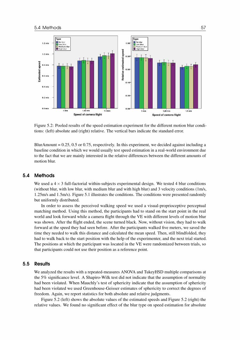
5.4 Methods 57
Figure 5.2: Pooled results of the speed estimation experiment for the different motion blur condi-tions: (left) absolute and (right) relative. The vertical bars indicate the standard error.
BlurAmount = 0.25, 0.5 or 0.75, respectively. In this experiment, we decided against including abaseline condition in which we would usually test speed estimation in a real-world environment dueto the fact that we are mainly interested in the relative differences between the different amounts ofmotion blur.
5.4 Methods
We used a 4× 3 full-factorial within-subjects experimental design. We tested 4 blur conditions(without blur, with low blur, with medium blur and with high blur) and 3 velocity conditions (1m/s,1.25m/s and 1.5m/s). Figure 5.1 illustrates the conditions. The conditions were presented randomlybut uniformly distributed.
In order to assess the perceived walking speed we used a visual-proprioceptive perceptualmatching method. Using this method, the participants had to stand on the start point in the realworld and look forward while a camera flight through the VE with different levels of motion blurwas shown. After the flight ended, the scene turned black. Now, without vision, they had to walkforward at the speed they had seen before. After the participants walked five meters, we saved thetime they needed to walk this distance and calculated the mean speed. Then, still blindfolded, theyhad to walk back to the start position with the help of the experimenter, and the next trial started.The positions at which the participant was located in the VE were randomized between trials, sothat participants could not use their position as a reference point.
5.5 Results
We analyzed the results with a repeated-measures ANOVA and TukeyHSD multiple comparisons atthe 5% significance level. A Shapiro-Wilk test did not indicate that the assumption of normalityhad been violated. When Mauchly’s test of sphericity indicate that the assumption of sphericityhad been violated we used Greenhouse-Geisser estimates of sphericity to correct the degrees offreedom. Again, we report statistics for both absolute and relative judgments.
Figure 5.2 (left) shows the absolute values of the estimated speeds and Figure 5.2 (right) therelative values. We found no significant effect of the blur type on speed estimation for absolute
58 Chapter 5. Effects of Motion Blur on Speed Estimation
values, F(3,57) = .39, p = .76, η2p = .02, and relative values, F(3,57) = .2, p = .89, η2
p = .01.We found a significant main effect of the target speed on speed estimation for absolute values,
F(2,38) = 70.05, p < .001, η2p = .787, and relative values, F(1.53,29) = 34.89, p < .001, η2
p =.647. Post-hoc tests showed that the estimated speeds between each two target speeds weresignificantly different (p ≤ .001).
Moreover, we found no significant interaction effect between blur type and target speed onspeed estimation for absolute values, F(6,114) = .91, p = .49, η2
p = .046, and relative values,F(6,114) = .67, p = .67, η2
p = .034.
5.6 Discussion
As in the experiment regarding distance estimation using DOF blur (see Chapter 4), our resultsin this experiment showed no significant effect of the different motion blur conditions on speedestimation. Again, the effect sizes indicate that motion blur can only explain a very small part ofthe variance in the responses.
As for potential explanations of this effect, we believe that those discussed in Section 4.6 mightalso apply to motion blur. These are: (i) convergence and motion parallax might offer sufficientdistance cues, (ii) types and strengths of blur that we tested might not have been interpreted as adepth cue, and (iii) the resolution of the HMD limited the visual acuity and the additional amountof blur had no noticeable additional effect on speed estimation. Moreover, most of the motionblur was visible in the periphery of the HMD, which, although it has a large field of view of 110◦
diagonally, might not be entirely the same as during real-world viewing, considering the humanvisual field spanning over about 200◦ horizontally into the far periphery of the eyes. Since theperiphery of the eyes is highly sensitive to motion, an additional explanation might be that an evenlarger field of view of HMDs is required for this stimulation with blur to take effect [NSN14].
5.7 Conclusion
In this chapter, we reported a psychophysical experiment that was conducted to investigate theinfluence of motion blur on speed estimation. Because we found no significant effect and onlyvery low effect sizes, we draw the conclusion that there is–if at all–only a negligibly small effect.Even if this result is, technically, a null result we believe that it is an important finding that willprovide new insights to the research direction because there are important reasons why researchersmight assume an influence of blur, which, so far, has not been proven or disproven in the publishedliterature.
However, we have to consider that our findings are based on a snapshot of currently availableHMD technology. Once available in the (distant) future, we will have to revisit effects of blur usingan HMD with a field of view and resolution that match those of the human eyes. However, eventhen, blur might not prove to have much influence on speed estimation due to the availability ofstronger cues such as motion parallax and convergence.
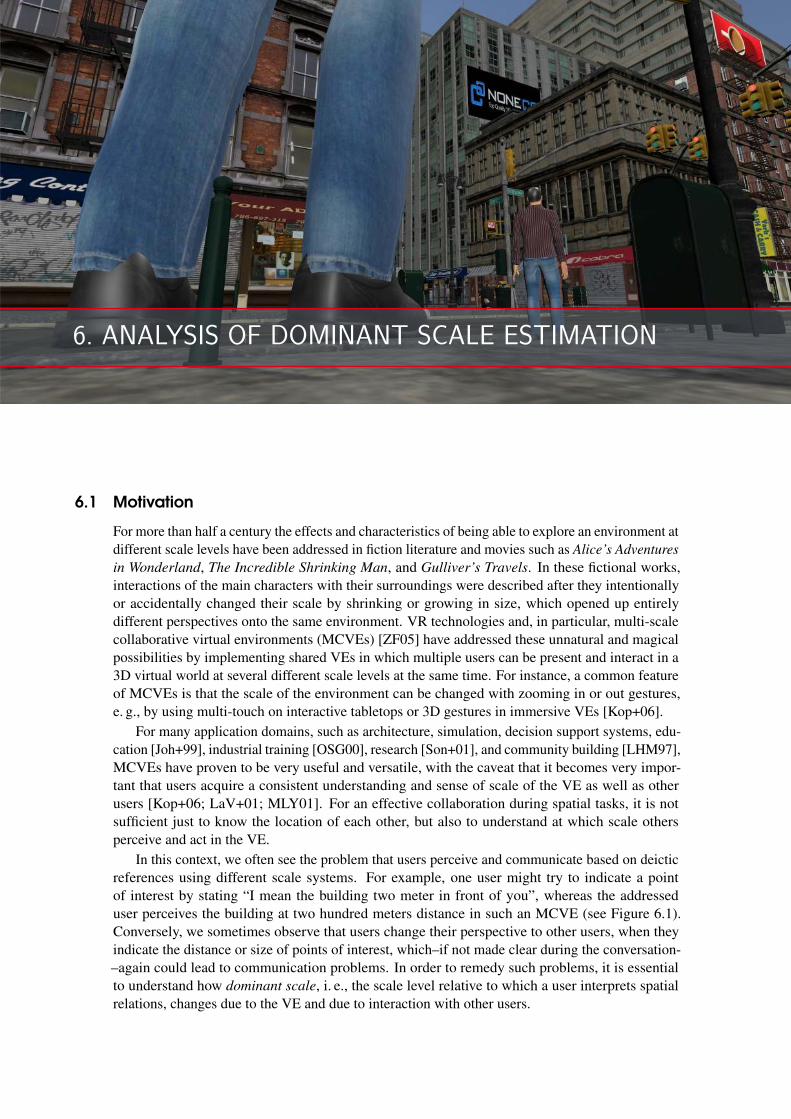
6. ANALYSIS OF DOMINANT SCALE ESTIMATION
6.1 Motivation
For more than half a century the effects and characteristics of being able to explore an environment atdifferent scale levels have been addressed in fiction literature and movies such as Alice’s Adventures
in Wonderland, The Incredible Shrinking Man, and Gulliver’s Travels. In these fictional works,interactions of the main characters with their surroundings were described after they intentionallyor accidentally changed their scale by shrinking or growing in size, which opened up entirelydifferent perspectives onto the same environment. VR technologies and, in particular, multi-scalecollaborative virtual environments (MCVEs) [ZF05] have addressed these unnatural and magicalpossibilities by implementing shared VEs in which multiple users can be present and interact in a3D virtual world at several different scale levels at the same time. For instance, a common featureof MCVEs is that the scale of the environment can be changed with zooming in or out gestures,e. g., by using multi-touch on interactive tabletops or 3D gestures in immersive VEs [Kop+06].
For many application domains, such as architecture, simulation, decision support systems, edu-cation [Joh+99], industrial training [OSG00], research [Son+01], and community building [LHM97],MCVEs have proven to be very useful and versatile, with the caveat that it becomes very impor-tant that users acquire a consistent understanding and sense of scale of the VE as well as otherusers [Kop+06; LaV+01; MLY01]. For an effective collaboration during spatial tasks, it is notsufficient just to know the location of each other, but also to understand at which scale othersperceive and act in the VE.
In this context, we often see the problem that users perceive and communicate based on deicticreferences using different scale systems. For example, one user might try to indicate a pointof interest by stating “I mean the building two meter in front of you”, whereas the addresseduser perceives the building at two hundred meters distance in such an MCVE (see Figure 6.1).Conversely, we sometimes observe that users change their perspective to other users, when theyindicate the distance or size of points of interest, which–if not made clear during the conversation-–again could lead to communication problems. In order to remedy such problems, it is essentialto understand how dominant scale, i. e., the scale level relative to which a user interprets spatialrelations, changes due to the VE and due to interaction with other users.
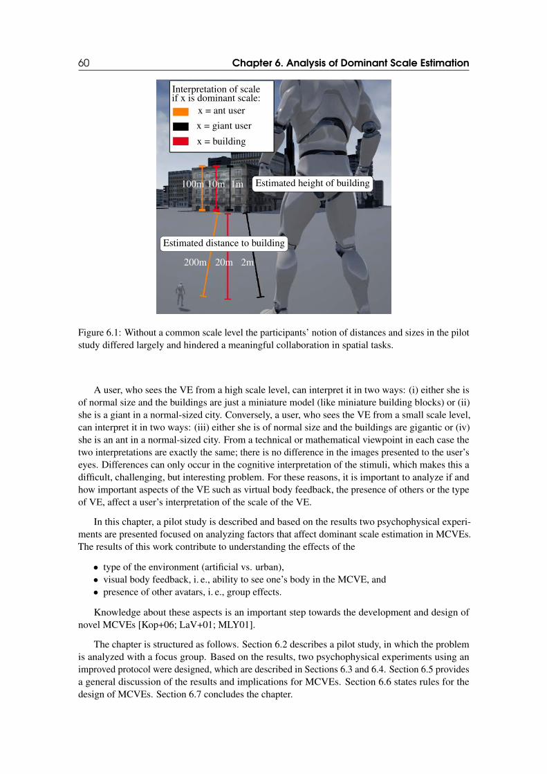
60 Chapter 6. Analysis of Dominant Scale Estimation
Interpretation of scaleif x is dominant scale:
x = ant user
x = giant user
x = building
Estimated height of building100m 10m 1m
Estimated distance to building
200m 20m 2m
Figure 6.1: Without a common scale level the participants’ notion of distances and sizes in the pilotstudy differed largely and hindered a meaningful collaboration in spatial tasks.
A user, who sees the VE from a high scale level, can interpret it in two ways: (i) either she isof normal size and the buildings are just a miniature model (like miniature building blocks) or (ii)she is a giant in a normal-sized city. Conversely, a user, who sees the VE from a small scale level,can interpret it in two ways: (iii) either she is of normal size and the buildings are gigantic or (iv)she is an ant in a normal-sized city. From a technical or mathematical viewpoint in each case thetwo interpretations are exactly the same; there is no difference in the images presented to the user’seyes. Differences can only occur in the cognitive interpretation of the stimuli, which makes this adifficult, challenging, but interesting problem. For these reasons, it is important to analyze if andhow important aspects of the VE such as virtual body feedback, the presence of others or the typeof VE, affect a user’s interpretation of the scale of the VE.
In this chapter, a pilot study is described and based on the results two psychophysical experi-ments are presented focused on analyzing factors that affect dominant scale estimation in MCVEs.The results of this work contribute to understanding the effects of the
• type of the environment (artificial vs. urban),• visual body feedback, i. e., ability to see one’s body in the MCVE, and• presence of other avatars, i. e., group effects.
Knowledge about these aspects is an important step towards the development and design ofnovel MCVEs [Kop+06; LaV+01; MLY01].
The chapter is structured as follows. Section 6.2 describes a pilot study, in which the problemis analyzed with a focus group. Based on the results, two psychophysical experiments using animproved protocol were designed, which are described in Sections 6.3 and 6.4. Section 6.5 providesa general discussion of the results and implications for MCVEs. Section 6.6 states rules for thedesign of MCVEs. Section 6.7 concludes the chapter.
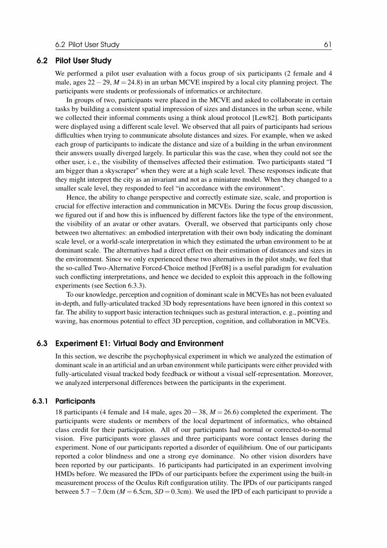
6.2 Pilot User Study 61
6.2 Pilot User Study
We performed a pilot user evaluation with a focus group of six participants (2 female and 4male, ages 22− 29, M = 24.8) in an urban MCVE inspired by a local city planning project. Theparticipants were students or professionals of informatics or architecture.
In groups of two, participants were placed in the MCVE and asked to collaborate in certaintasks by building a consistent spatial impression of sizes and distances in the urban scene, whilewe collected their informal comments using a think aloud protocol [Lew82]. Both participantswere displayed using a different scale level. We observed that all pairs of participants had seriousdifficulties when trying to communicate absolute distances and sizes. For example, when we askedeach group of participants to indicate the distance and size of a building in the urban environmenttheir answers usually diverged largely. In particular this was the case, when they could not see theother user, i. e., the visibility of themselves affected their estimation. Two participants stated “Iam bigger than a skyscraper" when they were at a high scale level. These responses indicate thatthey might interpret the city as an invariant and not as a miniature model. When they changed to asmaller scale level, they responded to feel “in accordance with the environment".
Hence, the ability to change perspective and correctly estimate size, scale, and proportion iscrucial for effective interaction and communication in MCVEs. During the focus group discussion,we figured out if and how this is influenced by different factors like the type of the environment,the visibility of an avatar or other avatars. Overall, we observed that participants only chosebetween two alternatives: an embodied interpretation with their own body indicating the dominantscale level, or a world-scale interpretation in which they estimated the urban environment to be atdominant scale. The alternatives had a direct effect on their estimation of distances and sizes inthe environment. Since we only experienced these two alternatives in the pilot study, we feel thatthe so-called Two-Alternative Forced-Choice method [Fer08] is a useful paradigm for evaluationsuch conflicting interpretations, and hence we decided to exploit this approach in the followingexperiments (see Section 6.3.3).
To our knowledge, perception and cognition of dominant scale in MCVEs has not been evaluatedin-depth, and fully-articulated tracked 3D body representations have been ignored in this context sofar. The ability to support basic interaction techniques such as gestural interaction, e. g., pointing andwaving, has enormous potential to effect 3D perception, cognition, and collaboration in MCVEs.
6.3 Experiment E1: Virtual Body and Environment
In this section, we describe the psychophysical experiment in which we analyzed the estimation ofdominant scale in an artificial and an urban environment while participants were either provided withfully-articulated visual tracked body feedback or without a visual self-representation. Moreover,we analyzed interpersonal differences between the participants in the experiment.
6.3.1 Participants
18 participants (4 female and 14 male, ages 20− 38, M = 26.6) completed the experiment. Theparticipants were students or members of the local department of informatics, who obtainedclass credit for their participation. All of our participants had normal or corrected-to-normalvision. Five participants wore glasses and three participants wore contact lenses during theexperiment. None of our participants reported a disorder of equilibrium. One of our participantsreported a color blindness and one a strong eye dominance. No other vision disorders havebeen reported by our participants. 16 participants had participated in an experiment involvingHMDs before. We measured the IPDs of our participants before the experiment using the built-inmeasurement process of the Oculus Rift configuration utility. The IPDs of our participants rangedbetween 5.7− 7.0cm (M = 6.5cm, SD= 0.3cm). We used the IPD of each participant to provide a
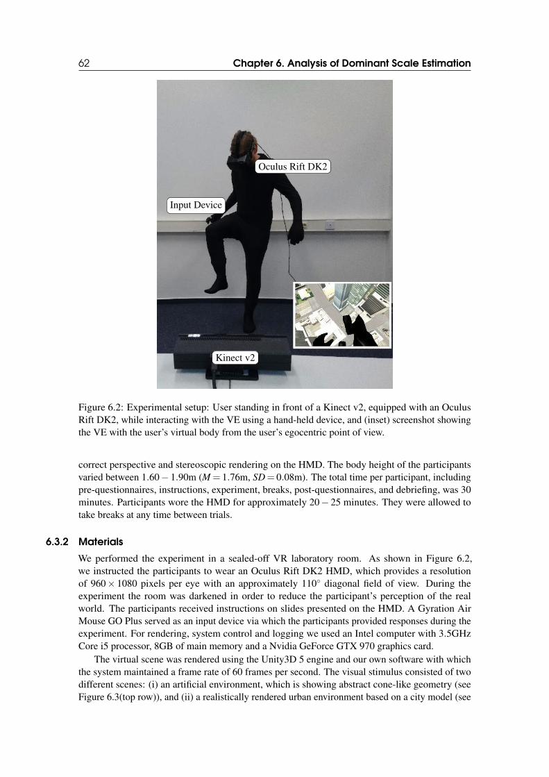
62 Chapter 6. Analysis of Dominant Scale Estimation
Oculus Rift DK2
Input Device
Kinect v2
Figure 6.2: Experimental setup: User standing in front of a Kinect v2, equipped with an OculusRift DK2, while interacting with the VE using a hand-held device, and (inset) screenshot showingthe VE with the user’s virtual body from the user’s egocentric point of view.
correct perspective and stereoscopic rendering on the HMD. The body height of the participantsvaried between 1.60− 1.90m (M = 1.76m, SD= 0.08m). The total time per participant, includingpre-questionnaires, instructions, experiment, breaks, post-questionnaires, and debriefing, was 30minutes. Participants wore the HMD for approximately 20− 25 minutes. They were allowed totake breaks at any time between trials.
6.3.2 Materials
We performed the experiment in a sealed-off VR laboratory room. As shown in Figure 6.2,we instructed the participants to wear an Oculus Rift DK2 HMD, which provides a resolutionof 960× 1080 pixels per eye with an approximately 110◦ diagonal field of view. During theexperiment the room was darkened in order to reduce the participant’s perception of the realworld. The participants received instructions on slides presented on the HMD. A Gyration AirMouse GO Plus served as an input device via which the participants provided responses during theexperiment. For rendering, system control and logging we used an Intel computer with 3.5GHzCore i5 processor, 8GB of main memory and a Nvidia GeForce GTX 970 graphics card.
The virtual scene was rendered using the Unity3D 5 engine and our own software with whichthe system maintained a frame rate of 60 frames per second. The visual stimulus consisted of twodifferent scenes: (i) an artificial environment, which is showing abstract cone-like geometry (seeFigure 6.3(top row)), and (ii) a realistically rendered urban environment based on a city model (see
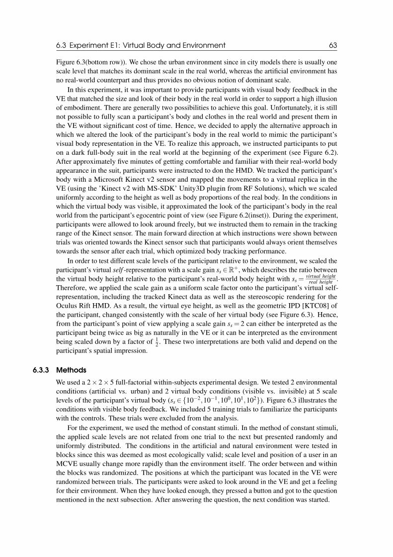
6.3 Experiment E1: Virtual Body and Environment 63
Figure 6.3(bottom row)). We chose the urban environment since in city models there is usually onescale level that matches its dominant scale in the real world, whereas the artificial environment hasno real-world counterpart and thus provides no obvious notion of dominant scale.
In this experiment, it was important to provide participants with visual body feedback in theVE that matched the size and look of their body in the real world in order to support a high illusionof embodiment. There are generally two possibilities to achieve this goal. Unfortunately, it is stillnot possible to fully scan a participant’s body and clothes in the real world and present them inthe VE without significant cost of time. Hence, we decided to apply the alternative approach inwhich we altered the look of the participant’s body in the real world to mimic the participant’svisual body representation in the VE. To realize this approach, we instructed participants to puton a dark full-body suit in the real world at the beginning of the experiment (see Figure 6.2).After approximately five minutes of getting comfortable and familiar with their real-world bodyappearance in the suit, participants were instructed to don the HMD. We tracked the participant’sbody with a Microsoft Kinect v2 sensor and mapped the movements to a virtual replica in theVE (using the ’Kinect v2 with MS-SDK’ Unity3D plugin from RF Solutions), which we scaleduniformly according to the height as well as body proportions of the real body. In the conditions inwhich the virtual body was visible, it approximated the look of the participant’s body in the realworld from the participant’s egocentric point of view (see Figure 6.2(inset)). During the experiment,participants were allowed to look around freely, but we instructed them to remain in the trackingrange of the Kinect sensor. The main forward direction at which instructions were shown betweentrials was oriented towards the Kinect sensor such that participants would always orient themselvestowards the sensor after each trial, which optimized body tracking performance.
In order to test different scale levels of the participant relative to the environment, we scaled theparticipant’s virtual self -representation with a scale gain ss ∈R
+, which describes the ratio betweenthe virtual body height relative to the participant’s real-world body height with ss =
virtual heightreal height
.Therefore, we applied the scale gain as a uniform scale factor onto the participant’s virtual self-representation, including the tracked Kinect data as well as the stereoscopic rendering for theOculus Rift HMD. As a result, the virtual eye height, as well as the geometric IPD [KTC08] ofthe participant, changed consistently with the scale of her virtual body (see Figure 6.3). Hence,from the participant’s point of view applying a scale gain ss = 2 can either be interpreted as theparticipant being twice as big as naturally in the VE or it can be interpreted as the environmentbeing scaled down by a factor of 1
2 . These two interpretations are both valid and depend on theparticipant’s spatial impression.
6.3.3 Methods
We used a 2× 2× 5 full-factorial within-subjects experimental design. We tested 2 environmentalconditions (artificial vs. urban) and 2 virtual body conditions (visible vs. invisible) at 5 scalelevels of the participant’s virtual body (ss ∈{10−2,10−1,100,101,102}). Figure 6.3 illustrates theconditions with visible body feedback. We included 5 training trials to familiarize the participantswith the controls. These trials were excluded from the analysis.
For the experiment, we used the method of constant stimuli. In the method of constant stimuli,the applied scale levels are not related from one trial to the next but presented randomly anduniformly distributed. The conditions in the artificial and natural environment were tested inblocks since this was deemed as most ecologically valid; scale level and position of a user in anMCVE usually change more rapidly than the environment itself. The order between and withinthe blocks was randomized. The positions at which the participant was located in the VE wererandomized between trials. The participants were asked to look around in the VE and get a feelingfor their environment. When they have looked enough, they pressed a button and got to the questionmentioned in the next subsection. After answering the question, the next condition was started.
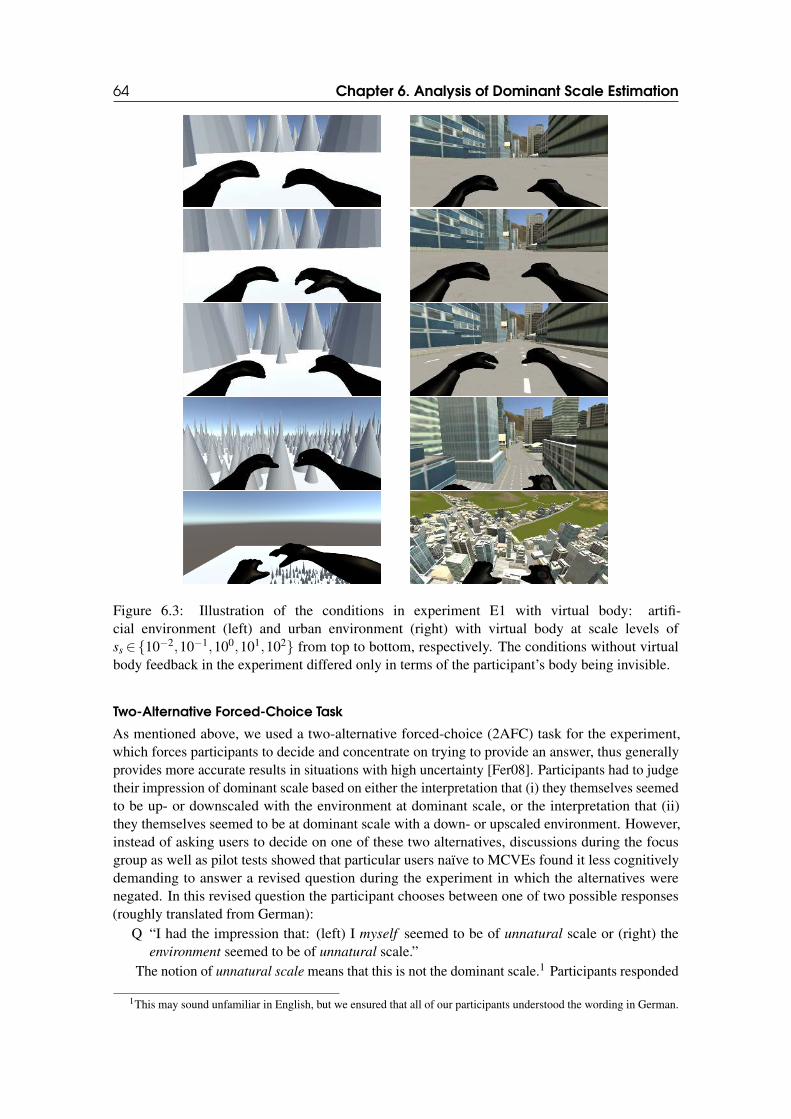
64 Chapter 6. Analysis of Dominant Scale Estimation
Figure 6.3: Illustration of the conditions in experiment E1 with virtual body: artifi-cial environment (left) and urban environment (right) with virtual body at scale levels ofss ∈{10−2,10−1,100,101,102} from top to bottom, respectively. The conditions without virtualbody feedback in the experiment differed only in terms of the participant’s body being invisible.
Two-Alternative Forced-Choice Task
As mentioned above, we used a two-alternative forced-choice (2AFC) task for the experiment,which forces participants to decide and concentrate on trying to provide an answer, thus generallyprovides more accurate results in situations with high uncertainty [Fer08]. Participants had to judgetheir impression of dominant scale based on either the interpretation that (i) they themselves seemedto be up- or downscaled with the environment at dominant scale, or the interpretation that (ii)they themselves seemed to be at dominant scale with a down- or upscaled environment. However,instead of asking users to decide on one of these two alternatives, discussions during the focusgroup as well as pilot tests showed that particular users naïve to MCVEs found it less cognitivelydemanding to answer a revised question during the experiment in which the alternatives werenegated. In this revised question the participant chooses between one of two possible responses(roughly translated from German):
Q “I had the impression that: (left) I myself seemed to be of unnatural scale or (right) theenvironment seemed to be of unnatural scale.”
The notion of unnatural scale means that this is not the dominant scale.1 Participants responded
1This may sound unfamiliar in English, but we ensured that all of our participants understood the wording in German.
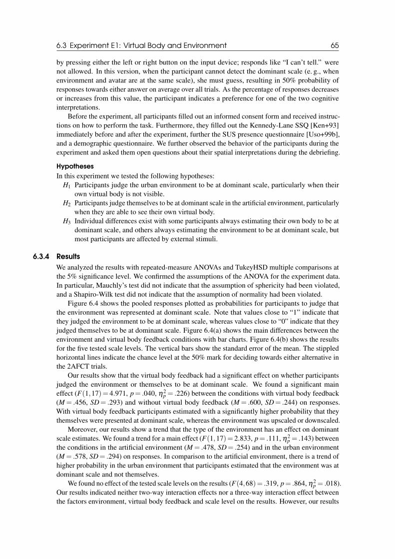
6.3 Experiment E1: Virtual Body and Environment 65
by pressing either the left or right button on the input device; responds like “I can’t tell.” werenot allowed. In this version, when the participant cannot detect the dominant scale (e. g., whenenvironment and avatar are at the same scale), she must guess, resulting in 50% probability ofresponses towards either answer on average over all trials. As the percentage of responses decreasesor increases from this value, the participant indicates a preference for one of the two cognitiveinterpretations.
Before the experiment, all participants filled out an informed consent form and received instruc-tions on how to perform the task. Furthermore, they filled out the Kennedy-Lane SSQ [Ken+93]immediately before and after the experiment, further the SUS presence questionnaire [Uso+99b],and a demographic questionnaire. We further observed the behavior of the participants during theexperiment and asked them open questions about their spatial interpretations during the debriefing.
Hypotheses
In this experiment we tested the following hypotheses:H1 Participants judge the urban environment to be at dominant scale, particularly when their
own virtual body is not visible.H2 Participants judge themselves to be at dominant scale in the artificial environment, particularly
when they are able to see their own virtual body.H3 Individual differences exist with some participants always estimating their own body to be at
dominant scale, and others always estimating the environment to be at dominant scale, butmost participants are affected by external stimuli.
6.3.4 Results
We analyzed the results with repeated-measure ANOVAs and TukeyHSD multiple comparisons atthe 5% significance level. We confirmed the assumptions of the ANOVA for the experiment data.In particular, Mauchly’s test did not indicate that the assumption of sphericity had been violated,and a Shapiro-Wilk test did not indicate that the assumption of normality had been violated.
Figure 6.4 shows the pooled responses plotted as probabilities for participants to judge thatthe environment was represented at dominant scale. Note that values close to “1” indicate thatthey judged the environment to be at dominant scale, whereas values close to “0” indicate that theyjudged themselves to be at dominant scale. Figure 6.4(a) shows the main differences between theenvironment and virtual body feedback conditions with bar charts. Figure 6.4(b) shows the resultsfor the five tested scale levels. The vertical bars show the standard error of the mean. The stippledhorizontal lines indicate the chance level at the 50% mark for deciding towards either alternative inthe 2AFCT trials.
Our results show that the virtual body feedback had a significant effect on whether participantsjudged the environment or themselves to be at dominant scale. We found a significant maineffect (F(1,17)= 4.971, p= .040, η2
p = .226) between the conditions with virtual body feedback(M = .456, SD= .293) and without virtual body feedback (M = .600, SD= .244) on responses.With virtual body feedback participants estimated with a significantly higher probability that theythemselves were presented at dominant scale, whereas the environment was upscaled or downscaled.
Moreover, our results show a trend that the type of the environment has an effect on dominantscale estimates. We found a trend for a main effect (F(1,17)= 2.833, p= .111, η2
p = .143) betweenthe conditions in the artificial environment (M = .478, SD= .254) and in the urban environment(M = .578, SD= .294) on responses. In comparison to the artificial environment, there is a trend ofhigher probability in the urban environment that participants estimated that the environment was atdominant scale and not themselves.
We found no effect of the tested scale levels on the results (F(4,68)= .319, p= .864, η2p = .018).
Our results indicated neither two-way interaction effects nor a three-way interaction effect betweenthe factors environment, virtual body feedback and scale level on the results. However, our results
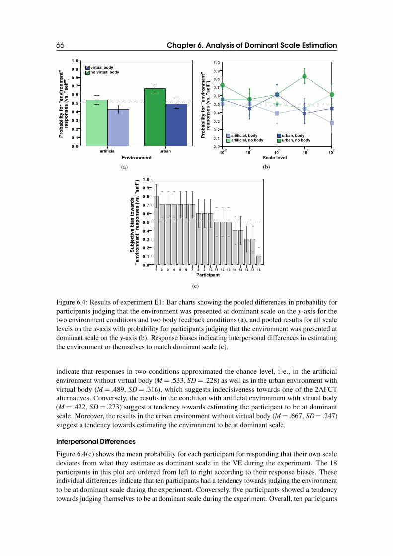
66 Chapter 6. Analysis of Dominant Scale Estimation
Environment
urbanartificial
Pro
bab
ilit
y f
or
"en
vir
on
men
t"re
sp
on
se
s (
vs. "self
")
1.0
0.9
0.8
0.7
0.6
0.5
0.4
0.3
0.2
0.1
0.0
no virtual body
virtual body
(a)
Scale level
-2 -1 0 1 210 10 10 10 10
artificial, no body
artificial, body
urban, no body
urban, bodyPro
ba
bilit
y f
or
"e
nv
iro
nm
en
t"
res
po
ns
es
(v
s. "s
elf
")
1.0
0.9
0.8
0.7
0.6
0.5
0.4
0.3
0.2
0.1
0.0
(b)
Su
bje
cti
ve
bia
s t
ow
ard
s"en
vir
on
men
t" r
esp
on
ses (
vs. "self
") 1.0
0.9
0.8
0.7
0.6
0.5
0.4
0.3
0.2
0.1
0.0
Participant
181716151413121110987654321
(c)
Figure 6.4: Results of experiment E1: Bar charts showing the pooled differences in probability forparticipants judging that the environment was presented at dominant scale on the y-axis for thetwo environment conditions and two body feedback conditions (a), and pooled results for all scalelevels on the x-axis with probability for participants judging that the environment was presented atdominant scale on the y-axis (b). Response biases indicating interpersonal differences in estimatingthe environment or themselves to match dominant scale (c).
indicate that responses in two conditions approximated the chance level, i. e., in the artificialenvironment without virtual body (M = .533, SD= .228) as well as in the urban environment withvirtual body (M = .489, SD= .316), which suggests indecisiveness towards one of the 2AFCTalternatives. Conversely, the results in the condition with artificial environment with virtual body(M = .422, SD= .273) suggest a tendency towards estimating the participant to be at dominantscale. Moreover, the results in the urban environment without virtual body (M = .667, SD= .247)suggest a tendency towards estimating the environment to be at dominant scale.
Interpersonal Differences
Figure 6.4(c) shows the mean probability for each participant for responding that their own scaledeviates from what they estimate as dominant scale in the VE during the experiment. The 18participants in this plot are ordered from left to right according to their response biases. Theseindividual differences indicate that ten participants had a tendency towards judging the environmentto be at dominant scale during the experiment. Conversely, five participants showed a tendencytowards judging themselves to be at dominant scale during the experiment. Overall, ten participants
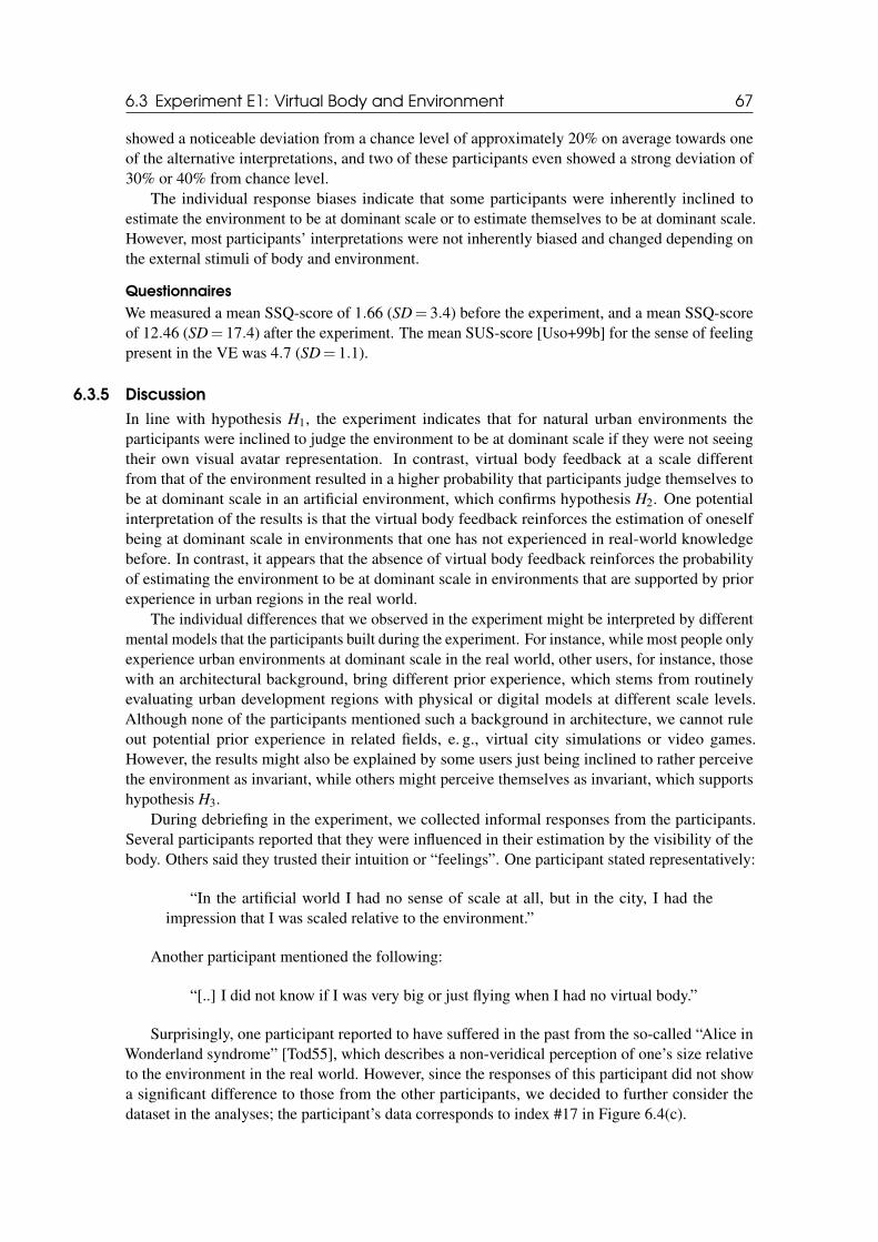
6.3 Experiment E1: Virtual Body and Environment 67
showed a noticeable deviation from a chance level of approximately 20% on average towards oneof the alternative interpretations, and two of these participants even showed a strong deviation of30% or 40% from chance level.
The individual response biases indicate that some participants were inherently inclined toestimate the environment to be at dominant scale or to estimate themselves to be at dominant scale.However, most participants’ interpretations were not inherently biased and changed depending onthe external stimuli of body and environment.
Questionnaires
We measured a mean SSQ-score of 1.66 (SD= 3.4) before the experiment, and a mean SSQ-scoreof 12.46 (SD= 17.4) after the experiment. The mean SUS-score [Uso+99b] for the sense of feelingpresent in the VE was 4.7 (SD= 1.1).
6.3.5 Discussion
In line with hypothesis H1, the experiment indicates that for natural urban environments theparticipants were inclined to judge the environment to be at dominant scale if they were not seeingtheir own visual avatar representation. In contrast, virtual body feedback at a scale differentfrom that of the environment resulted in a higher probability that participants judge themselves tobe at dominant scale in an artificial environment, which confirms hypothesis H2. One potentialinterpretation of the results is that the virtual body feedback reinforces the estimation of oneselfbeing at dominant scale in environments that one has not experienced in real-world knowledgebefore. In contrast, it appears that the absence of virtual body feedback reinforces the probabilityof estimating the environment to be at dominant scale in environments that are supported by priorexperience in urban regions in the real world.
The individual differences that we observed in the experiment might be interpreted by differentmental models that the participants built during the experiment. For instance, while most people onlyexperience urban environments at dominant scale in the real world, other users, for instance, thosewith an architectural background, bring different prior experience, which stems from routinelyevaluating urban development regions with physical or digital models at different scale levels.Although none of the participants mentioned such a background in architecture, we cannot ruleout potential prior experience in related fields, e. g., virtual city simulations or video games.However, the results might also be explained by some users just being inclined to rather perceivethe environment as invariant, while others might perceive themselves as invariant, which supportshypothesis H3.
During debriefing in the experiment, we collected informal responses from the participants.Several participants reported that they were influenced in their estimation by the visibility of thebody. Others said they trusted their intuition or “feelings”. One participant stated representatively:
“In the artificial world I had no sense of scale at all, but in the city, I had theimpression that I was scaled relative to the environment.”
Another participant mentioned the following:
“[..] I did not know if I was very big or just flying when I had no virtual body.”
Surprisingly, one participant reported to have suffered in the past from the so-called “Alice inWonderland syndrome” [Tod55], which describes a non-veridical perception of one’s size relativeto the environment in the real world. However, since the responses of this participant did not showa significant difference to those from the other participants, we decided to further consider thedataset in the analyses; the participant’s data corresponds to index #17 in Figure 6.4(c).
68 Chapter 6. Analysis of Dominant Scale Estimation
6.4 Experiment E2: Group Effects
In this section, we describe the second experiment in which we further analyzed the estimation ofdominant scale in MCVEs with a focus on the questions whether and how the visibility of otheravatars at a consistent scale level in an MCVE may affect a user’s dominant scale estimation. Thesequestions are particularly interesting considering that MCVEs are subject to group effects, which areknown to shape collaborative interaction [Pol+12] and may also affect dominant scale estimationsimilar to that of the urban environment in experiment E1. A group of avatars at a consistentscale level may thus help to provide a common dominant scale and thus ground collaboration andinteraction in MCVEs.
6.4.1 Participants
20 participants (4 female and 16 male, ages 20− 38, M = 26.9) participated in the experiment.18 of them also participated in experiment E1. The participants were students or members ofthe local department of computer science, who obtained class credit for their participation. Allof our participants had normal or corrected-to-normal vision. Six participants wore glasses andthree participants wore contact lenses during the experiment. None of our participants reporteda disorder of equilibrium. One of our participants reported a color blindness and one a strongeye dominance. No other vision disorders have been reported by our participants. We measuredthe IPDs of our participants before the experiment as in the first experiment. The IPDs of ourparticipants ranged between 5.7− 7.0cm (M = 6.4cm, SD= 0.3cm). The total time per participant,including pre-questionnaires, instructions, experiment, breaks, post-questionnaires, and debriefing,was 30 minutes. Participants wore the HMD for approximately 20− 25 minutes. They wereallowed to take breaks at any time between trials.
6.4.2 Materials
In this experiment, we used the same experimental setup as in experiment E1. Since the urbanenvironment provides an inherent concept of dominant scale, and since the results of the firstexperiment indicated no persistent bias in the urban environment with virtual body feedback, wehave chosen to focus on this condition in the experiment. Additionally, to simulate other avatars, wehave included six virtual agents in the virtual scene, which were displayed at randomized positionsin the visible range around the participant’s virtual location (see Figure 6.5). We applied an idleanimation to the six avatars.
The scale level of these avatars was set independently from the scale level of the participant inthe trials. However, all of these avatars were always presented at the same scale level in order to testfor group dominance effects. We scaled the participant’s virtual self -representation relative to theirreal-world body height with a scale gain ss =
virtual heightreal height
as in experiment E1. Additionally, in each
trial in the experiment the other avatars were all scaled with the same scale gain so =virtual height
re f erence height.
The reference height of the six avatars in the urban environment at dominant scale was 1.70m (seeFigure 6.5).
Hence, for instance, scaling both the participant and avatars with the scale gains ss = so = 2resulted in the participant seeing the avatars at the same scale as herself. In this case, the participantmight still interpret herself and the avatars as being twice as big as naturally in the VE or it can beinterpreted as the environment being scaled down by a factor of 1
2 . Moreover, for different scalegains between the participant and the avatars she might either interpret herself, the avatars or theenvironment to be at dominant scale. All three alternatives have to be considered valid spatialinterpretations.
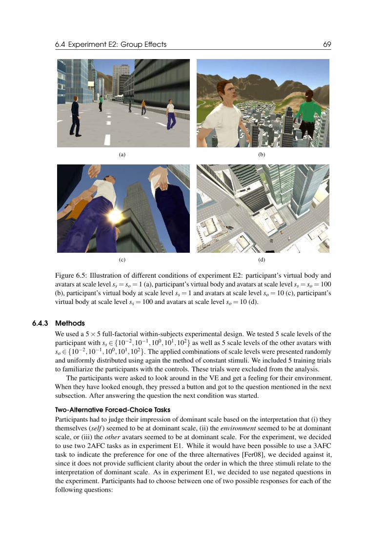
6.4 Experiment E2: Group Effects 69
(a) (b)
(c) (d)
Figure 6.5: Illustration of different conditions of experiment E2: participant’s virtual body andavatars at scale level ss = so = 1 (a), participant’s virtual body and avatars at scale level ss = so = 100(b), participant’s virtual body at scale level ss = 1 and avatars at scale level so = 10 (c), participant’svirtual body at scale level ss = 100 and avatars at scale level so = 10 (d).
6.4.3 Methods
We used a 5× 5 full-factorial within-subjects experimental design. We tested 5 scale levels of theparticipant with ss ∈{10−2,10−1,100,101,102} as well as 5 scale levels of the other avatars withso ∈{10−2,10−1,100,101,102}. The applied combinations of scale levels were presented randomlyand uniformly distributed using again the method of constant stimuli. We included 5 training trialsto familiarize the participants with the controls. These trials were excluded from the analysis.
The participants were asked to look around in the VE and get a feeling for their environment.When they have looked enough, they pressed a button and got to the question mentioned in the nextsubsection. After answering the question the next condition was started.
Two-Alternative Forced-Choice Tasks
Participants had to judge their impression of dominant scale based on the interpretation that (i) theythemselves (self ) seemed to be at dominant scale, (ii) the environment seemed to be at dominantscale, or (iii) the other avatars seemed to be at dominant scale. For the experiment, we decidedto use two 2AFC tasks as in experiment E1. While it would have been possible to use a 3AFCtask to indicate the preference for one of the three alternatives [Fer08], we decided against it,since it does not provide sufficient clarity about the order in which the three stimuli relate to theinterpretation of dominant scale. As in experiment E1, we decided to use negated questions inthe experiment. Participants had to choose between one of two possible responses for each of thefollowing questions:
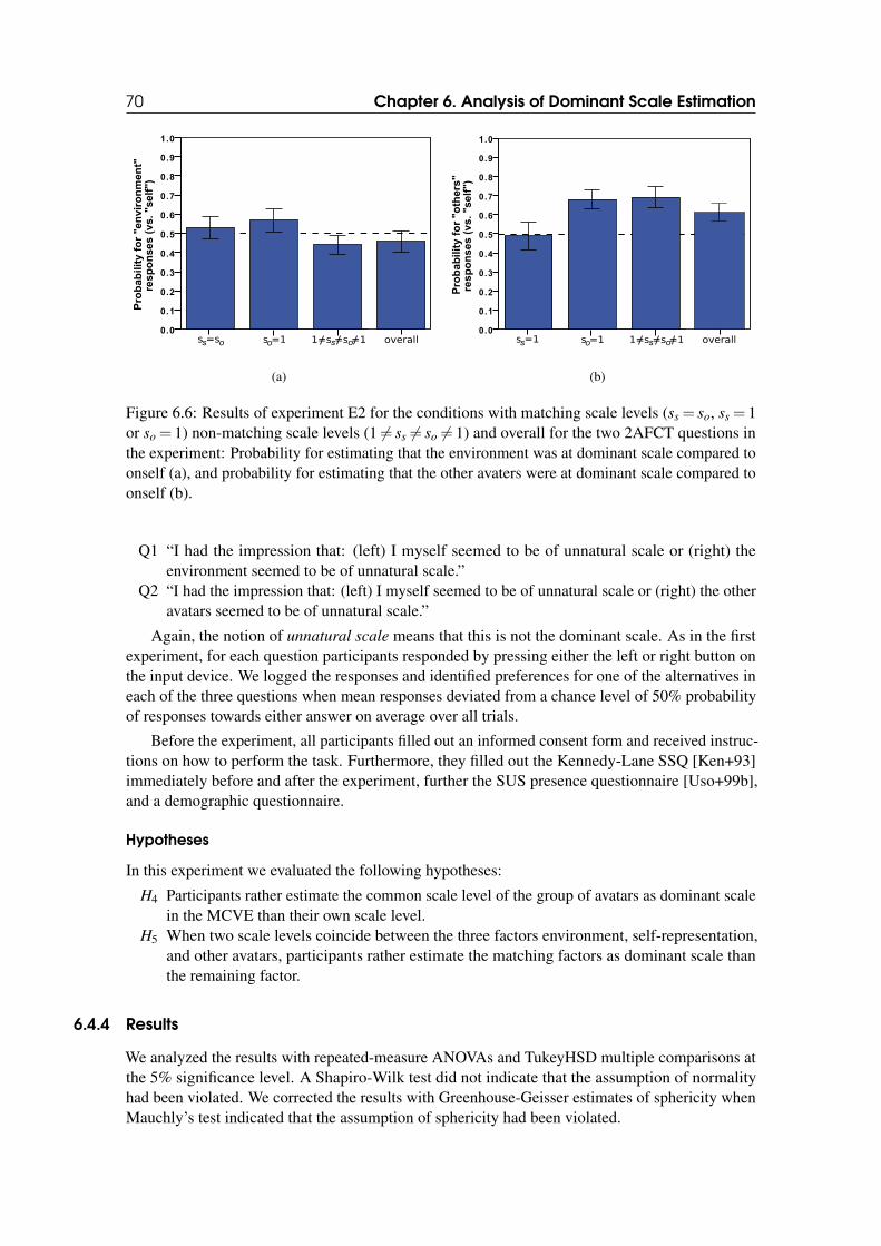
70 Chapter 6. Analysis of Dominant Scale Estimation
1.0
0.9
0.8
0.7
0.6
0.5
0.4
0.3
0.2
0.1
0.0
Pro
bab
ilit
y f
or
"en
vir
on
men
t"re
sp
on
se
s (
vs. "self
")
s o o s os =s s =1 1=s =s =1 overall
(a)
1.0
0.9
0.8
0.7
0.6
0.5
0.4
0.3
0.2
0.1
0.0
Pro
bab
ilit
y f
or
"o
thers
"re
sp
on
se
s (
vs. "self
")
s o s os =1 s =1 1=s =s =1 overall
(b)
Figure 6.6: Results of experiment E2 for the conditions with matching scale levels (ss = so, ss = 1or so = 1) non-matching scale levels (1 6= ss 6= so 6= 1) and overall for the two 2AFCT questions inthe experiment: Probability for estimating that the environment was at dominant scale compared toonself (a), and probability for estimating that the other avaters were at dominant scale compared toonself (b).
Q1 “I had the impression that: (left) I myself seemed to be of unnatural scale or (right) theenvironment seemed to be of unnatural scale.”
Q2 “I had the impression that: (left) I myself seemed to be of unnatural scale or (right) the otheravatars seemed to be of unnatural scale.”
Again, the notion of unnatural scale means that this is not the dominant scale. As in the firstexperiment, for each question participants responded by pressing either the left or right button onthe input device. We logged the responses and identified preferences for one of the alternatives ineach of the three questions when mean responses deviated from a chance level of 50% probabilityof responses towards either answer on average over all trials.
Before the experiment, all participants filled out an informed consent form and received instruc-tions on how to perform the task. Furthermore, they filled out the Kennedy-Lane SSQ [Ken+93]immediately before and after the experiment, further the SUS presence questionnaire [Uso+99b],and a demographic questionnaire.
Hypotheses
In this experiment we evaluated the following hypotheses:
H4 Participants rather estimate the common scale level of the group of avatars as dominant scalein the MCVE than their own scale level.
H5 When two scale levels coincide between the three factors environment, self-representation,and other avatars, participants rather estimate the matching factors as dominant scale thanthe remaining factor.
6.4.4 Results
We analyzed the results with repeated-measure ANOVAs and TukeyHSD multiple comparisons atthe 5% significance level. A Shapiro-Wilk test did not indicate that the assumption of normalityhad been violated. We corrected the results with Greenhouse-Geisser estimates of sphericity whenMauchly’s test indicated that the assumption of sphericity had been violated.
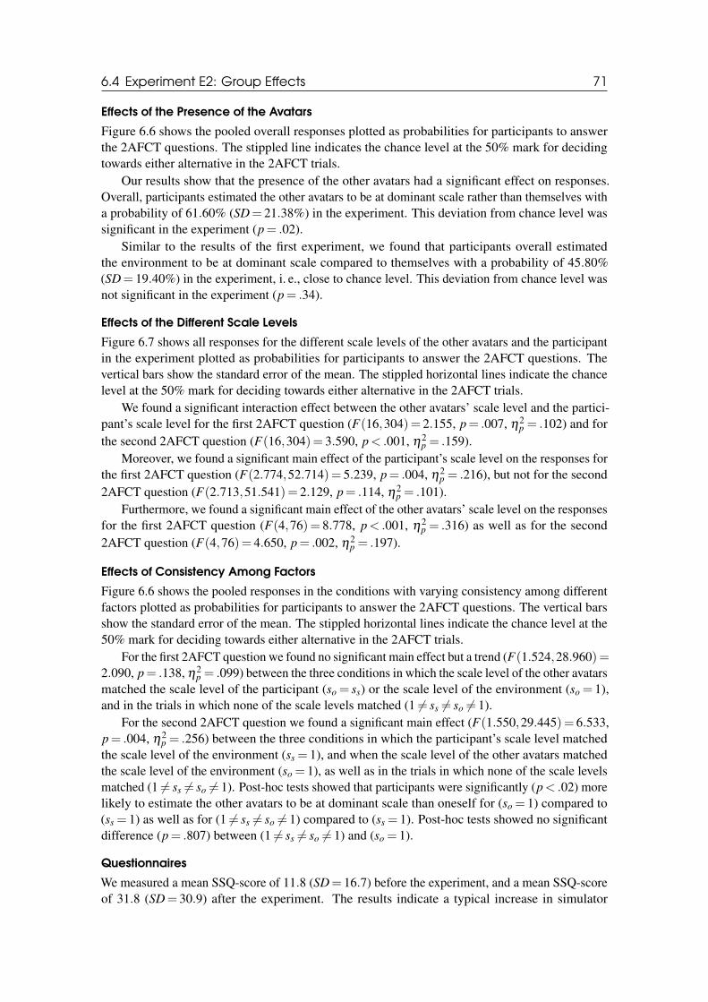
6.4 Experiment E2: Group Effects 71
Effects of the Presence of the Avatars
Figure 6.6 shows the pooled overall responses plotted as probabilities for participants to answerthe 2AFCT questions. The stippled line indicates the chance level at the 50% mark for decidingtowards either alternative in the 2AFCT trials.
Our results show that the presence of the other avatars had a significant effect on responses.Overall, participants estimated the other avatars to be at dominant scale rather than themselves witha probability of 61.60% (SD= 21.38%) in the experiment. This deviation from chance level wassignificant in the experiment (p= .02).
Similar to the results of the first experiment, we found that participants overall estimatedthe environment to be at dominant scale compared to themselves with a probability of 45.80%(SD= 19.40%) in the experiment, i. e., close to chance level. This deviation from chance level wasnot significant in the experiment (p= .34).
Effects of the Different Scale Levels
Figure 6.7 shows all responses for the different scale levels of the other avatars and the participantin the experiment plotted as probabilities for participants to answer the 2AFCT questions. Thevertical bars show the standard error of the mean. The stippled horizontal lines indicate the chancelevel at the 50% mark for deciding towards either alternative in the 2AFCT trials.
We found a significant interaction effect between the other avatars’ scale level and the partici-pant’s scale level for the first 2AFCT question (F(16,304)= 2.155, p= .007, η2
p = .102) and forthe second 2AFCT question (F(16,304)= 3.590, p< .001, η2
p = .159).Moreover, we found a significant main effect of the participant’s scale level on the responses for
the first 2AFCT question (F(2.774,52.714)= 5.239, p= .004, η2p = .216), but not for the second
2AFCT question (F(2.713,51.541)= 2.129, p= .114, η2p = .101).
Furthermore, we found a significant main effect of the other avatars’ scale level on the responsesfor the first 2AFCT question (F(4,76)= 8.778, p< .001, η2
p = .316) as well as for the second2AFCT question (F(4,76)= 4.650, p= .002, η2
p = .197).
Effects of Consistency Among Factors
Figure 6.6 shows the pooled responses in the conditions with varying consistency among differentfactors plotted as probabilities for participants to answer the 2AFCT questions. The vertical barsshow the standard error of the mean. The stippled horizontal lines indicate the chance level at the50% mark for deciding towards either alternative in the 2AFCT trials.
For the first 2AFCT question we found no significant main effect but a trend (F(1.524,28.960)=2.090, p= .138, η2
p = .099) between the three conditions in which the scale level of the other avatarsmatched the scale level of the participant (so = ss) or the scale level of the environment (so = 1),and in the trials in which none of the scale levels matched (1 6= ss 6= so 6= 1).
For the second 2AFCT question we found a significant main effect (F(1.550,29.445)= 6.533,p= .004, η2
p = .256) between the three conditions in which the participant’s scale level matchedthe scale level of the environment (ss = 1), and when the scale level of the other avatars matchedthe scale level of the environment (so = 1), as well as in the trials in which none of the scale levelsmatched (1 6= ss 6= so 6= 1). Post-hoc tests showed that participants were significantly (p< .02) morelikely to estimate the other avatars to be at dominant scale than oneself for (so = 1) compared to(ss = 1) as well as for (1 6= ss 6= so 6= 1) compared to (ss = 1). Post-hoc tests showed no significantdifference (p= .807) between (1 6= ss 6= so 6= 1) and (so = 1).
Questionnaires
We measured a mean SSQ-score of 11.8 (SD= 16.7) before the experiment, and a mean SSQ-scoreof 31.8 (SD= 30.9) after the experiment. The results indicate a typical increase in simulator
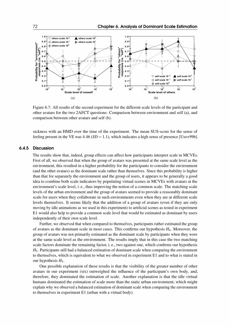
72 Chapter 6. Analysis of Dominant Scale Estimation
1.0
0.9
0.8
0.7
0.6
0.5
0.4
0.3
0.2
0.1
0.0
Scale level of oneself
-2 -1 0 1 210 10 10 10 10
Pro
ba
bilit
y f
or
"e
nv
iro
nm
en
t"re
sp
on
se
s (
vs
. "s
elf
")
others scale 10-2
others scale 10-1
others scale 102
others scale 101
others scale 100
(a)
1.0
0.9
0.8
0.7
0.6
0.5
0.4
0.3
0.2
0.1
0.0
Pro
ba
bilit
y f
or
"o
the
rs"
res
po
ns
es
(v
s. "s
elf
")
Scale level of others
-2 -1 0 1 210 10 10 10 10
self scale 10 -2
self scale 10 -1
self scale 10 2
self scale 10 1
self scale 100
(b)
Figure 6.7: All results of the second experiment for the different scale levels of the participant andother avatars for the two 2AFCT questions: Comparison between environment and self (a), andcomparison between other avatars and self (b).
sickness with an HMD over the time of the experiment. The mean SUS-score for the sense offeeling present in the VE was 4.46 (SD= 1.1), which indicates a high sense of presence [Uso+99b].
6.4.5 Discussion
The results show that, indeed, group effects can affect how participants interpret scale in MCVEs.First of all, we observed that when the group of avatars was presented at the same scale level as theenvironment, this resulted in a higher probability for the participants to consider the environment(and the other avatars) as the dominant scale rather than themselves. Since this probability is higherthan that for separately the environment and the group of users, it appears to be generally a goodidea to combine both scale indicators by populating virtual scenes in MCVEs with avatars at theenvironment’s scale level, i. e., thus improving the notion of a common scale. The matching scalelevels of the urban environment and the group of avatars seemed to provide a reasonably dominantscale for users when they collaborate in such environments even when they are at different scalelevels themselves. It seems likely that the addition of a group of avatars (even if they are onlymoving by idle animations as we used in this experiment) to artificial scenes as tested in experimentE1 would also help to provide a common scale level that would be estimated as dominant by usersindependently of their own scale level.
Further, we observed that when compared to themselves, participants rather estimated the groupof avatars as the dominant scale in most cases. This confirms our hypothesis H4. Moreover, thegroup of avatars was not primarily estimated as the dominant scale by participants when they wereat the same scale level as the environment. The results imply that in this case the two matchingscale factors dominate the remaining factor, i. e., two against one, which confirms our hypothesisH5. Participants still had a balanced estimation of dominant scale when comparing the environmentto themselves, which is equivalent to what we observed in experiment E1 and to what is stated inour hypothesis H3.
One possible explanation of these results is that the visibility of the greater number of otheravatars in our experiment (six) outweighed the influence of the participant’s own body, and,therefore, they dominated the estimation of scale. Another explanation is that the idle virtualhumans dominated the estimation of scale more than the static urban environment, which mightexplain why we observed a balanced estimation of dominant scale when comparing the environmentto themselves in experiment E1 (urban with a virtual body).
6.5 General Discussion 73
6.5 General Discussion
The results of our experiments provide valuable insights into scale estimation in MCVEs. We foundinteresting individual differences and overall a balanced estimation of dominant scale betweenoneself and the environment, when the environment is of a type that is known from real-worldexperience and when the virtual body is visible, potentially since both provide familiar artifacts andthus legitimate alternatives. However, when no visual body feedback was available, participantsshowed a tendency towards estimating that the environment was at dominant scale. This result wasindependent of the scale level and the presence of other avatars in the scene in our experiment.
The experiments revealed that artificial environments hinder scale estimation, especially whena user’s virtual body is not visible. Participants found it difficult to estimate whether themselves orthe environment was at dominant scale when there were few familiar points of reference that couldhelp them estimate scale. We observed a slight trend for them to estimate that themselves wereat dominant scale when the virtual body was visible, potentially since this is then the only visualartifact with a known size that they were familiar with from the real world.
Furthermore, we found a higher probability that the other avatars were estimated to be atdominant scale when users were asked to estimate dominant scale between themselves and theother avatars. This may be explained by the greater number of other avatars in our experiment,which might dominate the user’s impression of her own scale. It would be interesting to evaluatein future work if the estimation of scale changes with a fewer number of avatars or might even beincreased with more avatars.
When the scale of the participants was the same as that of the environment, the estimation ofscale between themselves and the other avatars was again balanced. We observed a majority effect:The results suggest that the other avatars would appear more consistent (i. e., resulting when oneselfis not at the same scale level as the environment), but it appears that two matching scale levels seemto dominate that of the third factor.
While the focus of our studies was on the influence of the type of the environment, the visibilityof an avatar and the presence of other avatars, we found no significant effect of the different scalelevels of the participants or other avatars on scale estimation in our experiments. Hence, severalquestion remains for future work. Moreover, our experiments were focused on scale estimationfrom an egocentric point of view, in which we compared scale estimation between oneself andanother element of the environment. In future work, it would be interesting to investigate how thesescale estimations change when considered from an allocentric point of view, e. g., comparing scalesbetween two visual artifacts, such as the other avatars and the environment.
6.6 Design Guidelines
The results of our experiments provide some important insights into perception, cognition, andaction in MCVEs. In particular, the findings of the experiments lead to the following design rulesand guidelines for implementing MCVEs:
1. Communicate dominant scale of the MCVE to all users. This is the motivation from the pilot
study: participants had serious difficulties when trying to communicate absolute distances
and sizes without having a common dominant scale.
2. If unnatural artificial MCVEs are displayed, use additional scale cues for all users, suchas a group of avatars at a consistent scale level. That is, because in artificial MCVEs the
participants could not detect a clear dominant scale (see figure 6.4a) and additional cues
can help (see hypotheses H2 as well as hypotheses H4 and H5).
3. Even natural urban MCVEs benefit from such additional scale cues at a consistent scale withthe environment by reinforcing its dominant scale. That is, because in urban MCVEs with
virtual body the participants could not detect a clear dominant scale (see figure 6.4a) and
74 Chapter 6. Analysis of Dominant Scale Estimation
additional cues can help (see hypotheses H4 and H5).
4. Visibility of one’s virtual avatar increases the probability that users use it as dominant scale(see hypotheses H1), which can be beneficial if collaborating users are at the same scale level,but leads to misunderstandings otherwise (see hypotheses H5).
Indeed, the guidelines provide a first step towards the development and design of novel MCVEs,in particular, in the area of application domains such as urban planning, interactive city visualization,or architectural exploration.
6.7 Conclusion
In this chapter, we analyzed the estimation of dominant scale in the presence of conflicting cues inMCVEs. Therefore, we presented a pilot study and two experiments in which we analyzed differentfactors and their effects on the participants’ estimation of dominant scale in an MCVE.
Our results suggest an interaction effect between the visibility of the participant’s virtual body,the type of the VE as well as the presence of a group of avatars and their relative scale levels. Wesummarized the results as guidelines for the design of MCVEs.
The scope of this work may seem limited, relative to the general problem of effective collab-oration in an MCVE. It is unclear at all, how many applications for MCVEs there are or will be.But the results provide insights into MCVEs, which have enormous potential to stimulate furtherresearch directions.
III7 Sensitivity to Redirection with Visible Feet
777.1 Motivation7.2 Participants7.3 Materials7.4 Methods7.5 Results7.6 Discussion7.7 Conclusion
8 Sensitivity to Bending of Curved Paths 85
8.1 Motivation8.2 Bending Gains8.3 Participants8.4 Materials8.5 Methods8.6 Results8.7 Conclusion
9 Sensitivity to Redirection with tDCS . . . 93
9.1 Motivation9.2 Background9.3 Experiment9.4 Discussion9.5 Conclusion
10 Sensitivity to Redirection during Eye Blinks103
10.1 Motivation10.2 Background10.3 Psychophysical Experiments10.4 Supplement for Redirection Gains10.5 Confirmatory Study10.6 General Discussion10.7 Conclusion
BEYOND DETECTION THRESHOLDS

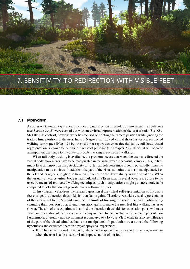
7. SENSITIVITY TO REDIRECTION WITH VISIBLE FEET
7.1 Motivation
As far as we know, all experiments for identifying detection thresholds of movement manipulations(see Section 3.4.3) were carried out without a virtual representation of the user’s body [Ste+08a;Ste+10b]. In contrast, previous work has focused on shifting the camera position while ignoring thetracked limb positions of the user. Indeed, Nagao et al. showed virtual shoes for vertical redirectedwalking techniques [Nag+17] but they did not report detection thresholds. A full-body visualrepresentation is known to increase the sense of presence (see Chapter 2.2). Hence, it will becomean important challenge to integrate full-body tracking in redirected walking.
When full body tracking is available, the problem occurs that when the user is redirected thevirtual body movements have to be manipulated in the same way as the virtual camera. This, in turn,might have an impact on the detectability of such manipulations since it could potentially make themanipulation more obvious. In addition, the part of the visual stimulus that is not manipulated, i. e.,the VE and its objects, might also have an influence on the detectability in such situations. Whenthe virtual camera or virtual body is manipulated in VEs in which several objects are close to theuser, by means of redirected walking techniques, such manipulations might get more noticeablecompared to VEs that do not provide many self-motion cues.
In this chapter, we address the research question if the virtual self-representation of the user’sfeet changes the detection thresholds for translation gains. Therefore, we add a visual representationof the user’s feet to the VE and examine the limits of tracking the user’s feet and unobtrusivelychanging their position by applying translation gains to make the user feel like walking faster orslower. The aim of this experiment is to find the detection thresholds for translation gains without avisual representation of the user’s feet and compare them to the thresholds with a feet representation.Furthermore, a visually rich environment is compared to a low cue VE to evaluate also the influenceof the part of the visual stimulus that is not manipulated. In particular, we assumed the followinghypotheses and evaluated them in a psychophysical experiment:
• H1: The range of translation gains, which can be applied unnoticeable for the user, is smallerwhen the user is able to see a visual representation of her feet.
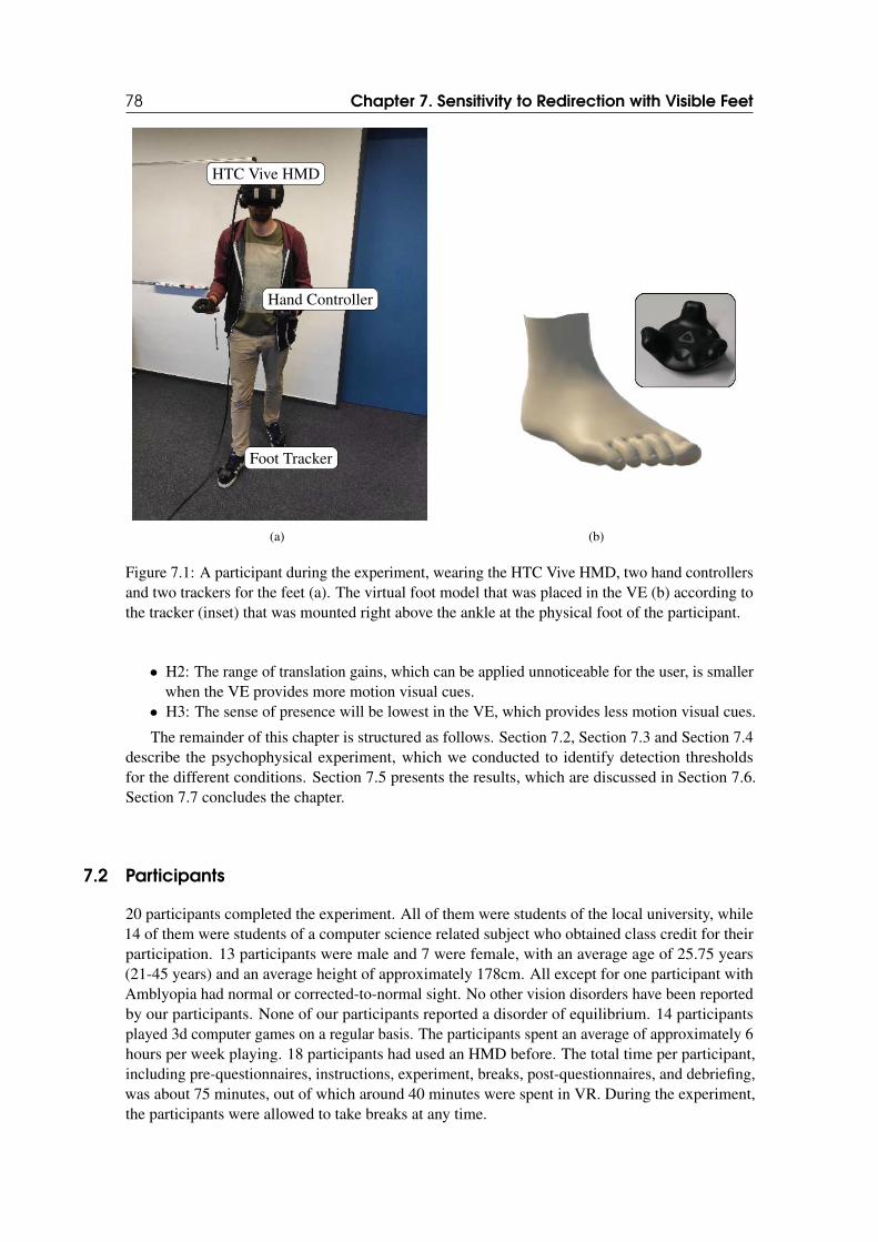
78 Chapter 7. Sensitivity to Redirection with Visible Feet
HTC Vive HMD
Hand Controller
Foot Tracker
(a) (b)
Figure 7.1: A participant during the experiment, wearing the HTC Vive HMD, two hand controllersand two trackers for the feet (a). The virtual foot model that was placed in the VE (b) according tothe tracker (inset) that was mounted right above the ankle at the physical foot of the participant.
• H2: The range of translation gains, which can be applied unnoticeable for the user, is smallerwhen the VE provides more motion visual cues.
• H3: The sense of presence will be lowest in the VE, which provides less motion visual cues.
The remainder of this chapter is structured as follows. Section 7.2, Section 7.3 and Section 7.4describe the psychophysical experiment, which we conducted to identify detection thresholdsfor the different conditions. Section 7.5 presents the results, which are discussed in Section 7.6.Section 7.7 concludes the chapter.
7.2 Participants
20 participants completed the experiment. All of them were students of the local university, while14 of them were students of a computer science related subject who obtained class credit for theirparticipation. 13 participants were male and 7 were female, with an average age of 25.75 years(21-45 years) and an average height of approximately 178cm. All except for one participant withAmblyopia had normal or corrected-to-normal sight. No other vision disorders have been reportedby our participants. None of our participants reported a disorder of equilibrium. 14 participantsplayed 3d computer games on a regular basis. The participants spent an average of approximately 6hours per week playing. 18 participants had used an HMD before. The total time per participant,including pre-questionnaires, instructions, experiment, breaks, post-questionnaires, and debriefing,was about 75 minutes, out of which around 40 minutes were spent in VR. During the experiment,the participants were allowed to take breaks at any time.
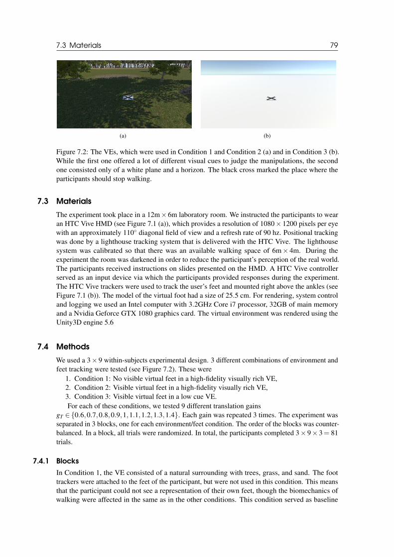
7.3 Materials 79
(a) (b)
Figure 7.2: The VEs, which were used in Condition 1 and Condition 2 (a) and in Condition 3 (b).While the first one offered a lot of different visual cues to judge the manipulations, the secondone consisted only of a white plane and a horizon. The black cross marked the place where theparticipants should stop walking.
7.3 Materials
The experiment took place in a 12m× 6m laboratory room. We instructed the participants to wearan HTC Vive HMD (see Figure 7.1 (a)), which provides a resolution of 1080× 1200 pixels per eyewith an approximately 110◦ diagonal field of view and a refresh rate of 90 hz. Positional trackingwas done by a lighthouse tracking system that is delivered with the HTC Vive. The lighthousesystem was calibrated so that there was an available walking space of 6m× 4m. During theexperiment the room was darkened in order to reduce the participant’s perception of the real world.The participants received instructions on slides presented on the HMD. A HTC Vive controllerserved as an input device via which the participants provided responses during the experiment.The HTC Vive trackers were used to track the user’s feet and mounted right above the ankles (seeFigure 7.1 (b)). The model of the virtual foot had a size of 25.5 cm. For rendering, system controland logging we used an Intel computer with 3.2GHz Core i7 processor, 32GB of main memoryand a Nvidia Geforce GTX 1080 graphics card. The virtual environment was rendered using theUnity3D engine 5.6
7.4 Methods
We used a 3× 9 within-subjects experimental design. 3 different combinations of environment andfeet tracking were tested (see Figure 7.2). These were
1. Condition 1: No visible virtual feet in a high-fidelity visually rich VE,2. Condition 2: Visible virtual feet in a high-fidelity visually rich VE,3. Condition 3: Visible virtual feet in a low cue VE.For each of these conditions, we tested 9 different translation gains
gT ∈{0.6,0.7,0.8,0.9,1,1.1,1.2,1.3,1.4}. Each gain was repeated 3 times. The experiment wasseparated in 3 blocks, one for each environment/feet condition. The order of the blocks was counter-balanced. In a block, all trials were randomized. In total, the participants completed 3× 9× 3= 81trials.
7.4.1 Blocks
In Condition 1, the VE consisted of a natural surrounding with trees, grass, and sand. The foottrackers were attached to the feet of the participant, but were not used in this condition. This meansthat the participant could not see a representation of their own feet, though the biomechanics ofwalking were affected in the same as in the other conditions. This condition served as baseline
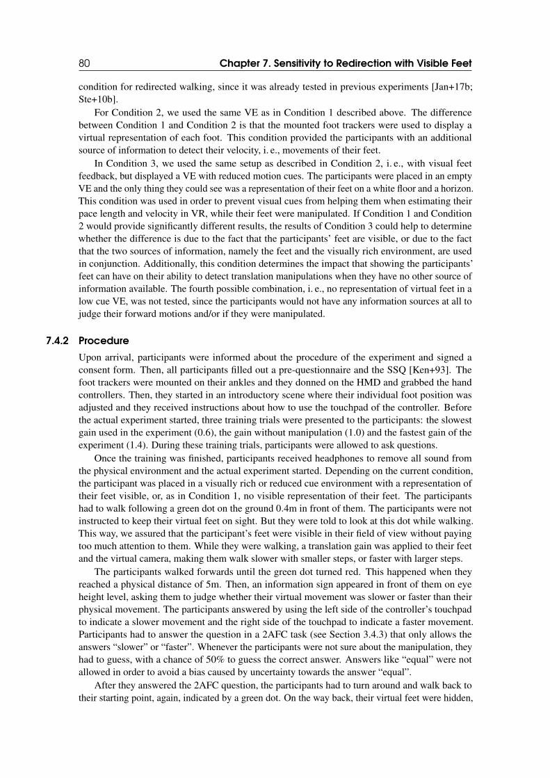
80 Chapter 7. Sensitivity to Redirection with Visible Feet
condition for redirected walking, since it was already tested in previous experiments [Jan+17b;Ste+10b].
For Condition 2, we used the same VE as in Condition 1 described above. The differencebetween Condition 1 and Condition 2 is that the mounted foot trackers were used to display avirtual representation of each foot. This condition provided the participants with an additionalsource of information to detect their velocity, i. e., movements of their feet.
In Condition 3, we used the same setup as described in Condition 2, i. e., with visual feetfeedback, but displayed a VE with reduced motion cues. The participants were placed in an emptyVE and the only thing they could see was a representation of their feet on a white floor and a horizon.This condition was used in order to prevent visual cues from helping them when estimating theirpace length and velocity in VR, while their feet were manipulated. If Condition 1 and Condition2 would provide significantly different results, the results of Condition 3 could help to determinewhether the difference is due to the fact that the participants’ feet are visible, or due to the factthat the two sources of information, namely the feet and the visually rich environment, are usedin conjunction. Additionally, this condition determines the impact that showing the participants’feet can have on their ability to detect translation manipulations when they have no other source ofinformation available. The fourth possible combination, i. e., no representation of virtual feet in alow cue VE, was not tested, since the participants would not have any information sources at all tojudge their forward motions and/or if they were manipulated.
7.4.2 Procedure
Upon arrival, participants were informed about the procedure of the experiment and signed aconsent form. Then, all participants filled out a pre-questionnaire and the SSQ [Ken+93]. Thefoot trackers were mounted on their ankles and they donned on the HMD and grabbed the handcontrollers. Then, they started in an introductory scene where their individual foot position wasadjusted and they received instructions about how to use the touchpad of the controller. Beforethe actual experiment started, three training trials were presented to the participants: the slowestgain used in the experiment (0.6), the gain without manipulation (1.0) and the fastest gain of theexperiment (1.4). During these training trials, participants were allowed to ask questions.
Once the training was finished, participants received headphones to remove all sound fromthe physical environment and the actual experiment started. Depending on the current condition,the participant was placed in a visually rich or reduced cue environment with a representation oftheir feet visible, or, as in Condition 1, no visible representation of their feet. The participantshad to walk following a green dot on the ground 0.4m in front of them. The participants were notinstructed to keep their virtual feet on sight. But they were told to look at this dot while walking.This way, we assured that the participant’s feet were visible in their field of view without payingtoo much attention to them. While they were walking, a translation gain was applied to their feetand the virtual camera, making them walk slower with smaller steps, or faster with larger steps.
The participants walked forwards until the green dot turned red. This happened when theyreached a physical distance of 5m. Then, an information sign appeared in front of them on eyeheight level, asking them to judge whether their virtual movement was slower or faster than theirphysical movement. The participants answered by using the left side of the controller’s touchpadto indicate a slower movement and the right side of the touchpad to indicate a faster movement.Participants had to answer the question in a 2AFC task (see Section 3.4.3) that only allows theanswers “slower” or “faster”. Whenever the participants were not sure about the manipulation, theyhad to guess, with a chance of 50% to guess the correct answer. Answers like “equal” were notallowed in order to avoid a bias caused by uncertainty towards the answer “equal”.
After they answered the 2AFC question, the participants had to turn around and walk back totheir starting point, again, indicated by a green dot. On the way back, their virtual feet were hidden,
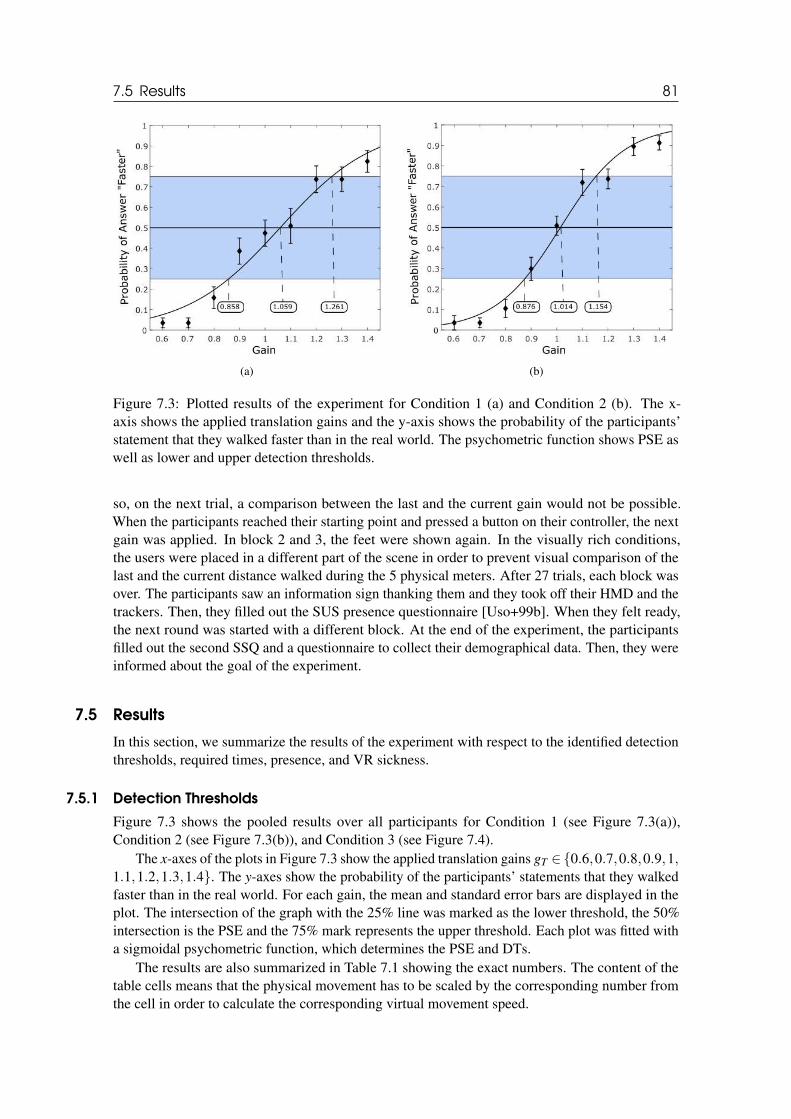
7.5 Results 81
(a) (b)
Figure 7.3: Plotted results of the experiment for Condition 1 (a) and Condition 2 (b). The x-axis shows the applied translation gains and the y-axis shows the probability of the participants’statement that they walked faster than in the real world. The psychometric function shows PSE aswell as lower and upper detection thresholds.
so, on the next trial, a comparison between the last and the current gain would not be possible.When the participants reached their starting point and pressed a button on their controller, the nextgain was applied. In block 2 and 3, the feet were shown again. In the visually rich conditions,the users were placed in a different part of the scene in order to prevent visual comparison of thelast and the current distance walked during the 5 physical meters. After 27 trials, each block wasover. The participants saw an information sign thanking them and they took off their HMD and thetrackers. Then, they filled out the SUS presence questionnaire [Uso+99b]. When they felt ready,the next round was started with a different block. At the end of the experiment, the participantsfilled out the second SSQ and a questionnaire to collect their demographical data. Then, they wereinformed about the goal of the experiment.
7.5 Results
In this section, we summarize the results of the experiment with respect to the identified detectionthresholds, required times, presence, and VR sickness.
7.5.1 Detection Thresholds
Figure 7.3 shows the pooled results over all participants for Condition 1 (see Figure 7.3(a)),Condition 2 (see Figure 7.3(b)), and Condition 3 (see Figure 7.4).
The x-axes of the plots in Figure 7.3 show the applied translation gains gT ∈{0.6,0.7,0.8,0.9,1,1.1,1.2,1.3,1.4}. The y-axes show the probability of the participants’ statements that they walkedfaster than in the real world. For each gain, the mean and standard error bars are displayed in theplot. The intersection of the graph with the 25% line was marked as the lower threshold, the 50%intersection is the PSE and the 75% mark represents the upper threshold. Each plot was fitted witha sigmoidal psychometric function, which determines the PSE and DTs.
The results are also summarized in Table 7.1 showing the exact numbers. The content of thetable cells means that the physical movement has to be scaled by the corresponding number fromthe cell in order to calculate the corresponding virtual movement speed.
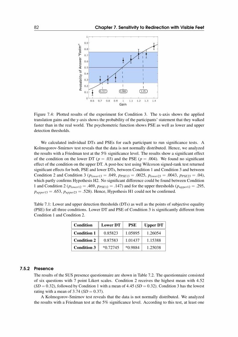
82 Chapter 7. Sensitivity to Redirection with Visible Feet
Figure 7.4: Plotted results of the experiment for Condition 3. The x-axis shows the appliedtranslation gains and the y-axis shows the probability of the participants’ statement that they walkedfaster than in the real world. The psychometric function shows PSE as well as lower and upperdetection thresholds.
We calculated individual DTs and PSEs for each participant to run significance tests. AKolmogorov-Smirnov test reveals that the data is not normally distributed. Hence, we analyzedthe results with a Friedman test at the 5% significance level. The results show a significant effectof the condition on the lower DT (p = .03) and the PSE (p = .004). We found no significanteffect of the condition on the upper DT. A post-hoc test using Wilcoxon signed-rank test returnedsignificant effects for both, PSE and lower DTs, between Condition 1 and Condition 3 and betweenCondition 2 and Condition 3 (plower13 = .049, pPSE13 = .0025, plower23 = .0043, pPSE23 = .04),which partly confirms Hypothesis H2. No significant difference could be found between Condition1 and Condition 2 (plower12 = .469, pPSE12 = .147) and for the upper thresholds (pupper12 = .295,pupper13 = .653, pupper23 = .528). Hence, Hypothesis H1 could not be confirmed.
Table 7.1: Lower and upper detection thresholds (DTs) as well as the points of subjective equality(PSE) for all three conditions. Lower DT and PSE of Condition 3 is significantly different fromCondition 1 and Condition 2.
Condition Lower DT PSE Upper DT
Condition 1 0.85823 1.05895 1.26054
Condition 2 0.87583 1.01437 1.15388
Condition 3 *0.72745 *0.9884 1.25038
7.5.2 Presence
The results of the SUS presence questionnaire are shown in Table 7.2. The questionnaire consistedof six questions with 7 point Likert scales. Condition 2 receives the highest mean with 4.52(SD = 0.32), followed by Condition 1 with a mean of 4.45 (SD = 0.32). Condition 3 has the lowestrating with a mean of 3.74 (SD = 0.37).
A Kolmogorov-Smirnov test reveals that the data is not normally distributed. We analyzedthe results with a Friedman test at the 5% significance level. According to this test, at least one
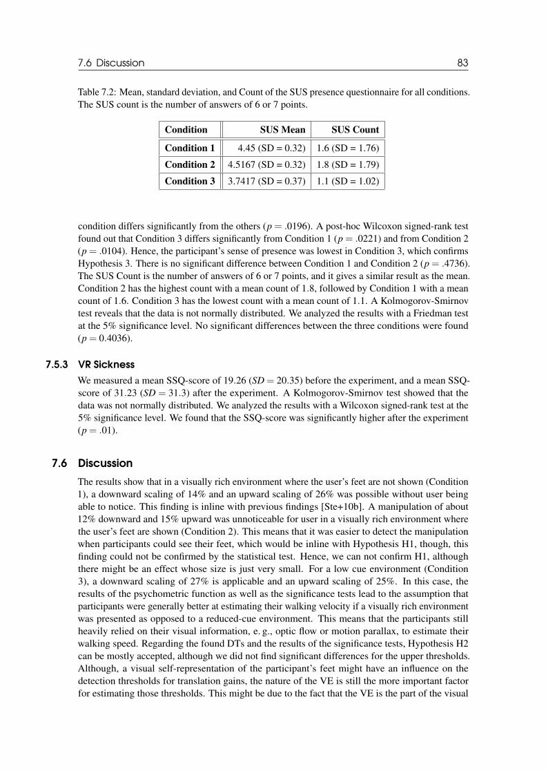
7.6 Discussion 83
Table 7.2: Mean, standard deviation, and Count of the SUS presence questionnaire for all conditions.The SUS count is the number of answers of 6 or 7 points.
Condition SUS Mean SUS Count
Condition 1 4.45 (SD = 0.32) 1.6 (SD = 1.76)
Condition 2 4.5167 (SD = 0.32) 1.8 (SD = 1.79)
Condition 3 3.7417 (SD = 0.37) 1.1 (SD = 1.02)
condition differs significantly from the others (p = .0196). A post-hoc Wilcoxon signed-rank testfound out that Condition 3 differs significantly from Condition 1 (p = .0221) and from Condition 2(p = .0104). Hence, the participant’s sense of presence was lowest in Condition 3, which confirmsHypothesis 3. There is no significant difference between Condition 1 and Condition 2 (p = .4736).The SUS Count is the number of answers of 6 or 7 points, and it gives a similar result as the mean.Condition 2 has the highest count with a mean count of 1.8, followed by Condition 1 with a meancount of 1.6. Condition 3 has the lowest count with a mean count of 1.1. A Kolmogorov-Smirnovtest reveals that the data is not normally distributed. We analyzed the results with a Friedman testat the 5% significance level. No significant differences between the three conditions were found(p = 0.4036).
7.5.3 VR Sickness
We measured a mean SSQ-score of 19.26 (SD = 20.35) before the experiment, and a mean SSQ-score of 31.23 (SD = 31.3) after the experiment. A Kolmogorov-Smirnov test showed that thedata was not normally distributed. We analyzed the results with a Wilcoxon signed-rank test at the5% significance level. We found that the SSQ-score was significantly higher after the experiment(p = .01).
7.6 Discussion
The results show that in a visually rich environment where the user’s feet are not shown (Condition1), a downward scaling of 14% and an upward scaling of 26% was possible without user beingable to notice. This finding is inline with previous findings [Ste+10b]. A manipulation of about12% downward and 15% upward was unnoticeable for user in a visually rich environment wherethe user’s feet are shown (Condition 2). This means that it was easier to detect the manipulationwhen participants could see their feet, which would be inline with Hypothesis H1, though, thisfinding could not be confirmed by the statistical test. Hence, we can not confirm H1, althoughthere might be an effect whose size is just very small. For a low cue environment (Condition3), a downward scaling of 27% is applicable and an upward scaling of 25%. In this case, theresults of the psychometric function as well as the significance tests lead to the assumption thatparticipants were generally better at estimating their walking velocity if a visually rich environmentwas presented as opposed to a reduced-cue environment. This means that the participants stillheavily relied on their visual information, e. g., optic flow or motion parallax, to estimate theirwalking speed. Regarding the found DTs and the results of the significance tests, Hypothesis H2can be mostly accepted, although we did not find significant differences for the upper thresholds.Although, a visual self-representation of the participant’s feet might have an influence on thedetection thresholds for translation gains, the nature of the VE is still the more important factorfor estimating those thresholds. This might be due to the fact that the VE is the part of the visual
84 Chapter 7. Sensitivity to Redirection with Visible Feet
stimulus that takes up more space of the field of view of the user than the feet. The feet arecomparatively small. But still, these findings are interesting, and they might get even more impactwhen a full avatar is used as a visual self-representation and when the field of view of HMDs willincrease in the future.
Furthermore, the results show that the movement has to be upscaled by 6% in Condition 1, inorder to appear natural to the participants, which is similar to the findings of Steinicke et al. thatmovements have to be upscaled by 7% to appear natural [Ste+10b]. The results for Condition 2and Condition 3 suggest that the participants were able to estimate their speed quite well with only1% upscaling in Condition 2 and 1% downscaling in Condition 3. This might be interpreted as atrend for the statement that virtual feet did help the participants to judge their natural walking speedsimilar to previous finding in which a virtual avatar helped to judge virtual distances [Moh+10].
Although, the environment where the user’s feet were shown (Condition 2) received highermeans for the user’s subjective sense of presence than the visually rich environment without feet(Condition 1), these differences were not significant. This is an indicator that having a visualself-representation of the feet did not have a significant impact on the sense of presence of theparticipants in the VE or that the effect was too small to be revealed with the considered numberof participants. Another limiting factor might be the appearance of the virtual feet. They werepresented barefoot in the VE while the participants wore shoes. A reduced-cue environment leadsto an even lower presence score compared to the visually rich environment without feet. This alsosupports the finding that the VE is much more important for the whole visual perception than theself-representation.
The significant increase of VR sickness during the experiment might be related to the strongergains that were obviously perceivable by the participants. Nevertheless, since we did not collectdata about VR sickness for each single gain, we can not confirm this assumption.
7.7 Conclusion
In this chapter, we evaluated the influence of a visual self-representation of the feet on translationgains. Therefore, we conducted a psychophysical experiment with three different conditions and 9different gains from the interval of 0.6 to 1.4 These three conditions were: presenting the gainsin a visually rich environment without tracking the user’s feet (Condition 1), showing the user’sfeet in a high fidelity visually rich environment (Condition 2) and showing the user’s feet in areduced-cue environment (Condition 3). The participants performed a 2AFC task to determine iftheir virtual movement was slower or faster than their physical movement. The results revealeddetection thresholds for translations gains, which cannot be detected by the user when the virtualfeet were visible. Nevertheless, the difference between visible and invisible feet was smaller thanexpected and the nature of the VE had still a bigger impact on the DTs.
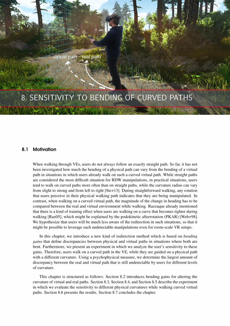
8. SENSITIVITY TO BENDING OF CURVED PATHS
8.1 Motivation
When walking through VEs, users do not always follow an exactly straight path. So far, it has notbeen investigated how much the bending of a physical path can vary from the bending of a virtualpath in situations in which users already walk on such a curved virtual path. While straight pathsare considered the most difficult situation for RDW manipulations, in practical situations, userstend to walk on curved paths more often than on straight paths, while the curvature radius can varyfrom slight to strong and from left to right [Ste+13]. During straightforward walking, any rotationthat users perceive in their physical walking path indicates that they are being manipulated. Incontrast, when walking on a curved virtual path, the magnitude of the change in heading has to becompared between the real and virtual environment while walking. Razzaque already mentionedthat there is a kind of training effect when users are walking on a curve that becomes tighter duringwalking [Raz05], which might be explained by the podokinetic afterrotation (PKAR) [Web+98].We hypothesize that users will be much less aware of the redirection in such situations, so that itmight be possible to leverage such undetectable manipulations even for room-scale VR setups.
In this chapter, we introduce a new kind of redirection method which is based on bending
gains that define discrepancies between physical and virtual paths in situations where both arebent. Furthermore, we present an experiment in which we analyze the user’s sensitivity to thesegains. Therefore, users walk on a curved path in the VE, while they are guided on a physical pathwith a different curvature. Using a psychophysical measure, we determine the largest amount ofdiscrepancy between the real and virtual path that is still undetectable by users for different levelsof curvature.
This chapter is structured as follows: Section 8.2 introduces bending gains for altering thecurvature of virtual and real paths. Section 8.3, Section 8.4, and Section 8.5 describe the experimentin which we evaluate the sensitivity to different physical curvatures while walking curved virtualpaths. Section 8.6 presents the results. Section 8.7 concludes the chapter.
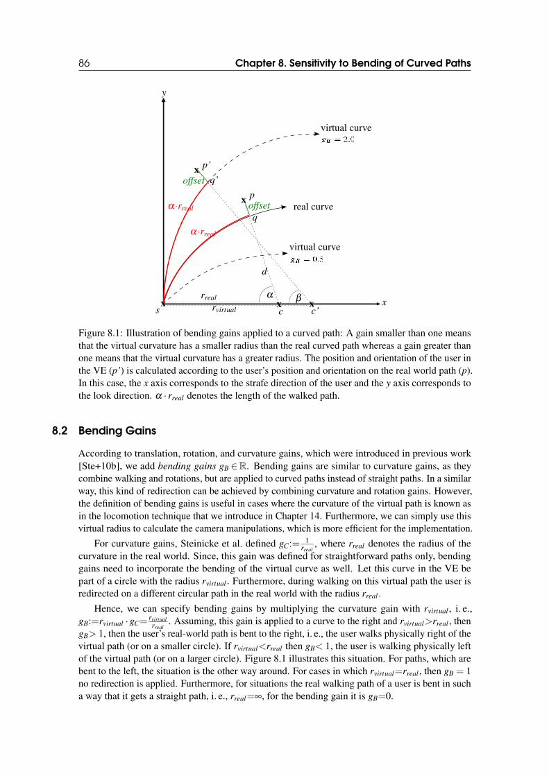
86 Chapter 8. Sensitivity to Bending of Curved Paths
real curvex
xxs c
p
d
αxc’
xp’
α·rreal
α·rreal
β
virtual curve
virtual curve
y
xrreal
rvirtual
offset
offset q’
q
Figure 8.1: Illustration of bending gains applied to a curved path: A gain smaller than one meansthat the virtual curvature has a smaller radius than the real curved path whereas a gain greater thanone means that the virtual curvature has a greater radius. The position and orientation of the user inthe VE (p’) is calculated according to the user’s position and orientation on the real world path (p).In this case, the x axis corresponds to the strafe direction of the user and the y axis corresponds tothe look direction. α · rreal denotes the length of the walked path.
8.2 Bending Gains
According to translation, rotation, and curvature gains, which were introduced in previous work[Ste+10b], we add bending gains gB ∈R. Bending gains are similar to curvature gains, as theycombine walking and rotations, but are applied to curved paths instead of straight paths. In a similarway, this kind of redirection can be achieved by combining curvature and rotation gains. However,the definition of bending gains is useful in cases where the curvature of the virtual path is known asin the locomotion technique that we introduce in Chapter 14. Furthermore, we can simply use thisvirtual radius to calculate the camera manipulations, which is more efficient for the implementation.
For curvature gains, Steinicke et al. defined gC:= 1rreal
, where rreal denotes the radius of thecurvature in the real world. Since, this gain was defined for straightforward paths only, bendinggains need to incorporate the bending of the virtual curve as well. Let this curve in the VE bepart of a circle with the radius rvirtual . Furthermore, during walking on this virtual path the user isredirected on a different circular path in the real world with the radius rreal .
Hence, we can specify bending gains by multiplying the curvature gain with rvirtual , i. e.,gB:=rvirtual ·gC=
rvirtual
rreal. Assuming, this gain is applied to a curve to the right and rvirtual>rreal , then
gB> 1, then the user’s real-world path is bent to the right, i. e., the user walks physically right of thevirtual path (or on a smaller circle). If rvirtual<rreal then gB< 1, the user is walking physically leftof the virtual path (or on a larger circle). Figure 8.1 illustrates this situation. For paths, which arebent to the left, the situation is the other way around. For cases in which rvirtual=rreal , then gB = 1no redirection is applied. Furthermore, for situations the real walking path of a user is bent in sucha way that it gets a straight path, i. e., rreal=∞, for the bending gain it is gB=0.
8.3 Participants 87
Implementation
Redirection by means of a bending gain is implemented by calculating position and orientation ofthe user in the VE according to the user’s position and orientation in the real world (see Figure 8.1).Let the radii rreal and rvirtual as well as the start position s be given as illustrated. That means, wehave to know how much the virtual path is bent and how much discrepancy between virtual and realpath is possible. The first part requires knowledge about the VE and the second part is evaluated inthe experiment. The current position p (as well as the orientation o) of the user in the real world isprovided by the tracking system.
With these data (s, p, o, rreal and rvirtual), it is possible to apply a bending gain and computethe position p′ (as well as the orientation o′) of the user in the virtual world. First, we calculatethe center points c (of the real world circle) and c′ (of the virtual world circle) by extending theorthogonal vector of the user’s view direction from start position s by rreal and rvirtual , respectively.We calculate also the distance d from c to p. Then, we can determine the offset, i. e., the deviationof the user’s position from the real world circle, by offset = d− rreal . If the user would stand exactlyon a point of the real world circle q (which means the distance from c to p is d = rreal), it would beoffset = d − rreal = 0.
The angle α can be calculated by using the dot product:
cos(α) =(c− s) · (c− p)
|c− s| · |c− p| (8.1)
The actual walked distance on the path is α · rreal according to the definition of radian. Thiscan be used to calculate the angle β of the virtual curvature (again according to the definition ofradian):
β = α · rreal
rvirtual
(8.2)
Now, the position on the virtual circle q′ can be determined by using sine and cosine:
q′x = (c′x + rvirtual · cos(β )),q′y = (c′y + rvirtual · sin(β )) (8.3)
In the end, to get the exact position p′, we have to add the calculated offset to q′.The virtual orientation of the user o′ is computed accordingly. It is composed by the tracked
orientation in the real world o and a corresponding shift of α −β .
8.3 Participants
15 participants (2 female and 13 male, ages 24− 39, M = 30.5) completed the experiment. Theparticipants were students or members of the local department of informatics, who obtained classcredit for their participation. All of our participants had normal or corrected-to-normal vision. Sixparticipants wore glasses during the experiment. None of our participants reported a disorder ofequilibrium. One of our participants reported a strong eye dominance. No other vision disordershave been reported by our participants. 14 participants had participated in an experiment involvingHMDs before. The experience of the participants with 3D stereoscopic displays (cinema, gamesetc.) in a range of 1 (no experience) to 5 (much experience) was M = 4.3 (SD= 1.03). Most of themhad experiences with 3D computer games (M = 4.3, SD= 1.25, in a range of 1 = no experience to 5= much experience) and they usually played 5.3 hours per week on average (SD= 6.54). The bodyheight of the participants varied between 1.60− 1.87m (M = 1.77m, SD= .07m). The total time
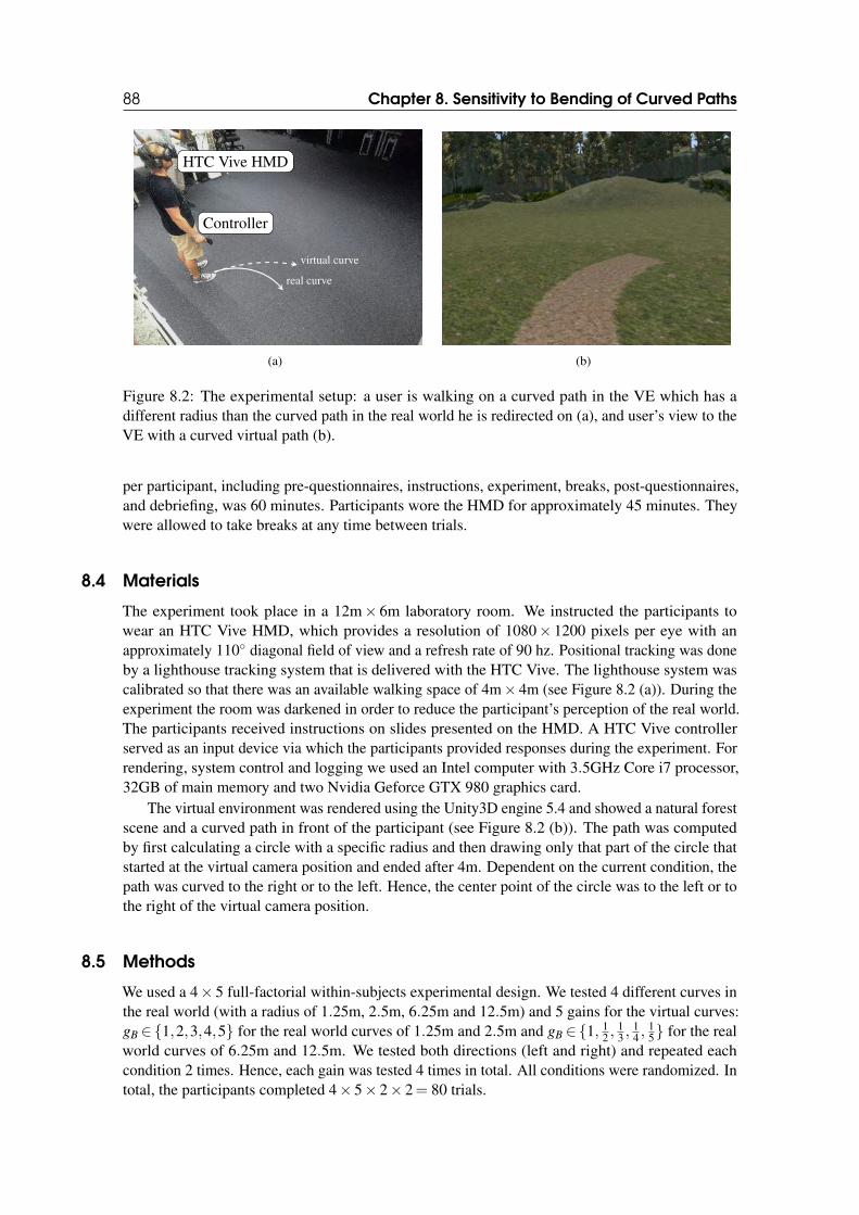
88 Chapter 8. Sensitivity to Bending of Curved Paths
HTC Vive HMD
Controller
real curve
virtual curve
(a) (b)
Figure 8.2: The experimental setup: a user is walking on a curved path in the VE which has adifferent radius than the curved path in the real world he is redirected on (a), and user’s view to theVE with a curved virtual path (b).
per participant, including pre-questionnaires, instructions, experiment, breaks, post-questionnaires,and debriefing, was 60 minutes. Participants wore the HMD for approximately 45 minutes. Theywere allowed to take breaks at any time between trials.
8.4 Materials
The experiment took place in a 12m× 6m laboratory room. We instructed the participants towear an HTC Vive HMD, which provides a resolution of 1080× 1200 pixels per eye with anapproximately 110◦ diagonal field of view and a refresh rate of 90 hz. Positional tracking was doneby a lighthouse tracking system that is delivered with the HTC Vive. The lighthouse system wascalibrated so that there was an available walking space of 4m× 4m (see Figure 8.2 (a)). During theexperiment the room was darkened in order to reduce the participant’s perception of the real world.The participants received instructions on slides presented on the HMD. A HTC Vive controllerserved as an input device via which the participants provided responses during the experiment. Forrendering, system control and logging we used an Intel computer with 3.5GHz Core i7 processor,32GB of main memory and two Nvidia Geforce GTX 980 graphics card.
The virtual environment was rendered using the Unity3D engine 5.4 and showed a natural forestscene and a curved path in front of the participant (see Figure 8.2 (b)). The path was computedby first calculating a circle with a specific radius and then drawing only that part of the circle thatstarted at the virtual camera position and ended after 4m. Dependent on the current condition, thepath was curved to the right or to the left. Hence, the center point of the circle was to the left or tothe right of the virtual camera position.
8.5 Methods
We used a 4× 5 full-factorial within-subjects experimental design. We tested 4 different curves inthe real world (with a radius of 1.25m, 2.5m, 6.25m and 12.5m) and 5 gains for the virtual curves:gB ∈{1,2,3,4,5} for the real world curves of 1.25m and 2.5m and gB ∈{1, 1
2 ,13 ,
14 ,
15} for the real
world curves of 6.25m and 12.5m. We tested both directions (left and right) and repeated eachcondition 2 times. Hence, each gain was tested 4 times in total. All conditions were randomized. Intotal, the participants completed 4× 5× 2× 2= 80 trials.
8.6 Results 89
8.5.1 Conditions
We decided to use these conditions because the curved paths with radii of 1.25m and 2.5m wouldfit into a room-scale VR setup. The considered curves provide two radii (one is twice as large asthe other one), which both could be used in the room-scale locomotion technique as introduced inChapter 14. Obviously, we are particularly interested in detection thresholds for bending a curvedvirtual path towards a curved real-world path that fits into the room-scale VR setup. The other case,i. e., how strong a curved virtual path can be straightened in the real-world before users notice, is ofless interest because one of the major goals of our approach is to decrease the space requirementsand to remain in a confined tracking space.
According to the results of several pre-tests, we identified that bending the real-world path witha gain of gB = 5 could be reliably detected in most cases. Hence, we applied gains gB ∈{1,2,3,4,5}to the real curves (with radii 1.25m, 2.5m), which resulted in virtual curves with radii of rvirtual ∈{1.25,2.5,3.75,5,6.25} meters and rvirtual ∈{2.5,5,7.5,10,12.5} meters, respectively.
While bending these virtual radii towards the real-world target radii of 1.25m and 2.5m makessense, a bending towards smaller radii does not make sense, since users could not follow thepaths if the radii are too small. However, in order to provide an equal number of increased anddecreased bending conditions, we added real-world curves with radii of 6.25m and 12.5m andapplied the corresponding smaller gains gB ∈{1, 1
2 ,13 ,
14 ,
15} to them. Using these conditions provide
virtual radii of rvirtual ∈{1.25,2.5,3.75,5,6.25} meters and rvirtual ∈{2.5,5,7.5,10,12.5} meters,respectively. As a result, participants would experience the same number of increased and decreasedbending conditions.
8.5.2 Procedure
Before the experiment, all participants filled out an informed consent form and received detailedinstructions on how to perform the experimental task. Furthermore, they filled out a demographicquestionnaire after the experiment. Participants completed 5 training trials before the experiment.
For each trial, participants were instructed to walk along the virtual path, which had a totaldistance of 4m. While participants were walking along the virtual path, we applied the differentbending gains as explained in Section 8.5. After the participant reached the end of the path, theypressed a button on the controller and the following 2AFC task question was displayed: "At which
side from the virtual path did you walk physically in the real world?". They had the two answeroptions "left" and "right" that could be chosen by using the touchpad of the controller. Afterwards,participants were guided to the next start position in the laboratory by displaying a 2D compass anddistance metrics on the HMD. By using this method, the participants were kept unaware of theirposition and orientation in the real world. So, they could not use this information to identify theamount of redirection that was applied. The next trial started once participants reached the newinitial position and indicated that they were ready to start by pressing a button on the controller.
In pre-tests of the experiment, we found that participants had serious problems in identifyingon which side of the virtual path they physically walked. During the pre-test, several participantsmentioned that they noticed a redirection in terms of “something strange happened”. However,they could not detect reliably at which side of the path they walked. The main reason was thatparticipants adapted to the redirection and walked on the virtual path, which made it hard for themto estimate on which side of the path they are located in the real world. Therefore, we explainedto them that they needed to focus on the direction in which the VE turned, which was easier toidentify, and provided us with more conservative detection thresholds.
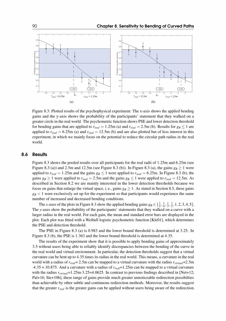
90 Chapter 8. Sensitivity to Bending of Curved Paths
1/5 1/4 1/3 1/2 1 2 3 4 50
0.1
0.2
0.3
0.4
0.5
0.6
0.7
0.8
0.9
1
0.983 3.250
g
Pro
ba
bili
ty o
f g
rea
ter
estim
atio
n
Brreal = 1.25mr
real = 6.25m
(a)
1/5 1/4 1/3 1/2 1 2 3 4 50
0.1
0.2
0.3
0.4
0.5
0.6
0.7
0.8
0.9
1
1.363 4.350
gB
Pro
ba
bili
ty o
f g
rea
ter
estim
atio
n
rreal = 2.5mrreal = 12.5m
(b)
Figure 8.3: Plotted results of the psychophysical experiment: The x-axis shows the applied bendinggains and the y-axis shows the probability of the participants’ statement that they walked on agreater circle in the real world. The psychometric function shows PSE and lower detection thresholdfor bending gains that are applied to rreal = 1.25m (a) and rreal = 2.5m (b). Results for gB ≤ 1 areapplied to rreal = 6.25m (a) and rreal = 12.5m (b) and are also plotted but of less interest in thisexperiment, in which we mainly focus on the potential to reduce the circular path radius in the realworld.
8.6 Results
Figure 8.3 shows the pooled results over all participants for the real radii of 1.25m and 6.25m (seeFigure 8.3 (a)) and 2.5m and 12.5m (see Figure 8.3 (b)). In Figure 8.3 (a), the gains gB ≥ 1 wereapplied to rreal = 1.25m and the gains gB ≤ 1 were applied to rreal = 6.25m. In Figure 8.3 (b), thegains gB ≥ 1 were applied to rreal = 2.5m and the gains gB ≤ 1 were applied to rreal = 12.5m. Asdescribed in Section 8.2 we are mainly interested in the lower detection thresholds because wefocus on gains that enlarge the virtual space, i. e., gains gB ≥ 1. As stated in Section 8.5, these gainsgB < 1 were exclusively set up for the experiment so that participants would experience the samenumber of increased and decreased bending conditions.
The x-axes of the plots in Figure 8.3 show the applied bending gains gB ∈{15 ,
14 ,
13 ,
12 ,1,2,3,4,5}.
The y-axes show the probability of the participants’ statements that they walked on a curve with alarger radius in the real world. For each gain, the mean and standard error bars are displayed in theplot. Each plot was fitted with a Weibull logistic psychometric function [Kle01], which determinesthe PSE and detection threshold.
The PSE in Figure 8.3 (a) is 0.983 and the lower bound threshold is determined at 3.25. InFigure 8.3 (b), the PSE is 1.363 and the lower bound threshold is determined at 4.35.
The results of the experiment show that it is possible to apply bending gains of approximately3.5 without users being able to reliably identify discrepancies between the bending of the curve inthe real world and virtual environment. In particular, the detection thresholds suggest that a virtualcurvature can be bent up to 4.35 times its radius in the real world. This means, a curvature in the realworld with a radius of rreal= 2.5m can be mapped to a virtual curvature with the radius rvirtual=2.5m·4.35 = 10.875. And a curvature with a radius of rreal=1.25m can be mapped to a virtual curvaturewith the radius rvirtual=1.25m·3.25=4.0625. In contrast to previous findings described in [Net+12;Pal+16; Ste+10b], these range of gains provide much greater unnoticeable redirection possibiltiesthan achievable by other subtle and continuous redirection methods. Moreover, the results suggestthat the greater rreal is the greater gains can be applied without users being aware of the redirection.

8.7 Conclusion 91
8.7 Conclusion
In this chapter, we defined bending gains and presented a psychophysical experiment in which weanalyzed the human sensitivity to discrepancies between the bending of curved paths in the realworld and a curved path in the virtual environment. We found that users are less aware of redirectionmanipulations while walking on curved paths in contrast to traditional redirected walking withcurvature gains, when users walk straight in the VE.

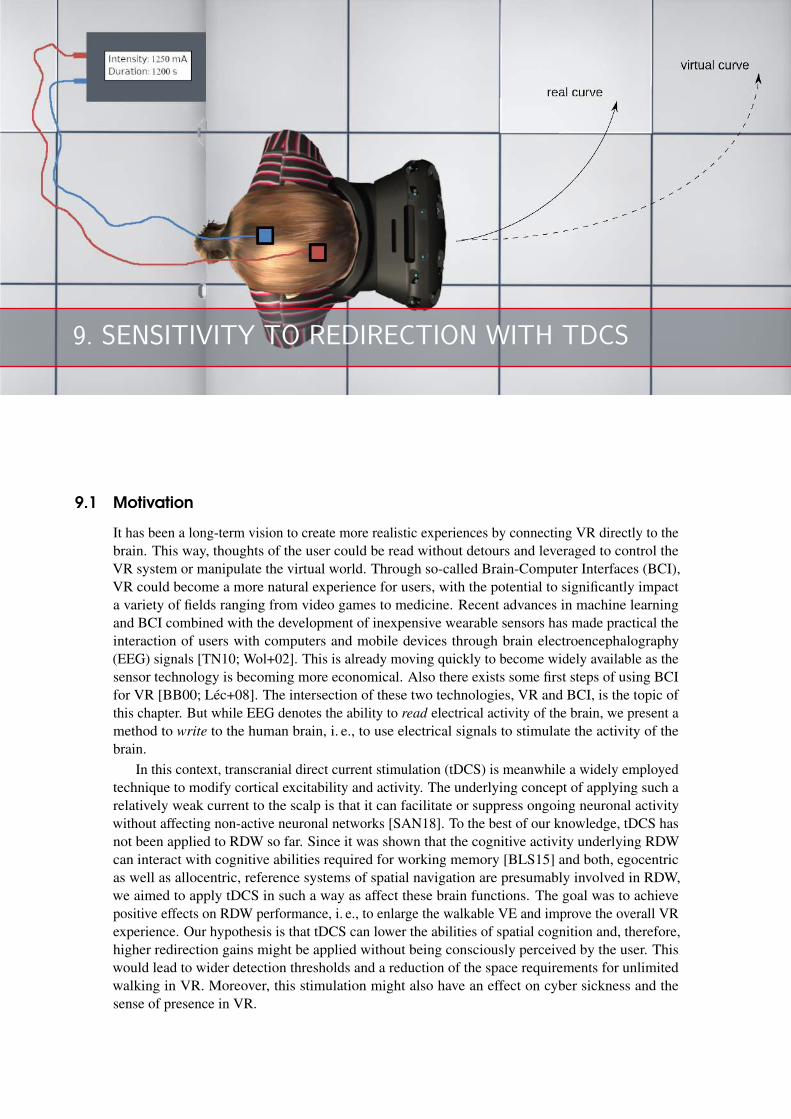
9. SENSITIVITY TO REDIRECTION WITH TDCS
9.1 Motivation
It has been a long-term vision to create more realistic experiences by connecting VR directly to thebrain. This way, thoughts of the user could be read without detours and leveraged to control theVR system or manipulate the virtual world. Through so-called Brain-Computer Interfaces (BCI),VR could become a more natural experience for users, with the potential to significantly impacta variety of fields ranging from video games to medicine. Recent advances in machine learningand BCI combined with the development of inexpensive wearable sensors has made practical theinteraction of users with computers and mobile devices through brain electroencephalography(EEG) signals [TN10; Wol+02]. This is already moving quickly to become widely available as thesensor technology is becoming more economical. Also there exists some first steps of using BCIfor VR [BB00; Léc+08]. The intersection of these two technologies, VR and BCI, is the topic ofthis chapter. But while EEG denotes the ability to read electrical activity of the brain, we present amethod to write to the human brain, i. e., to use electrical signals to stimulate the activity of thebrain.
In this context, transcranial direct current stimulation (tDCS) is meanwhile a widely employedtechnique to modify cortical excitability and activity. The underlying concept of applying such arelatively weak current to the scalp is that it can facilitate or suppress ongoing neuronal activitywithout affecting non-active neuronal networks [SAN18]. To the best of our knowledge, tDCS hasnot been applied to RDW so far. Since it was shown that the cognitive activity underlying RDWcan interact with cognitive abilities required for working memory [BLS15] and both, egocentricas well as allocentric, reference systems of spatial navigation are presumably involved in RDW,we aimed to apply tDCS in such a way as affect these brain functions. The goal was to achievepositive effects on RDW performance, i. e., to enlarge the walkable VE and improve the overall VRexperience. Our hypothesis is that tDCS can lower the abilities of spatial cognition and, therefore,higher redirection gains might be applied without being consciously perceived by the user. Thiswould lead to wider detection thresholds and a reduction of the space requirements for unlimitedwalking in VR. Moreover, this stimulation might also have an effect on cyber sickness and thesense of presence in VR.
94 Chapter 9. Sensitivity to Redirection with tDCS
The remainder of this chapter is structured as follows. Section 9.2 discusses backgroundinformation on RDW and tDCS. Section 9.3 presents the experimental procedure and methods ontDCS application during RDW in VR. Section 9.4 discusses our findings. Section 9.5 concludes thechapter and gives an outlook on future work.
9.2 Background
Using electrical stimulations for RDW is a promising approach. For example, galvanic vestibularstimulation is a technology that uses electrical stimulation via electrodes placed on the mastoidbones behind each ear to stimulate the vestibular system. Sra et al. implemented a VR game basedon galvanic vestibular stimulation for redirection of the players [SXM17].
TDCS is a non-invasive stimulation technique and its application to the respective corticalarea has been shown to modulate spontaneous brain excitability and activity, for example, anodalstimulation typically increases whereas cathodal stimulation decreases excitability [NP00]. Recentstudies have established that tDCS can affect not only the stimulated region but also functionalnetwork [Ant+12; Kee+11; Web+14]. The use of tDCS together with VR has been receivingincreased attention, primarily due to its potential therapeutic use in neurological disoders [Mas+17].However, the effect of tDCS on RDW is scarcely known. Previous studies have shown that awidespread parietal-prefrontocortical network underlies spatial navigation, whereby the prefrontalcortex is particularly relevant for information processing relative to the target of navigation [Bla+16;BBB07; Eps08; Ito+15; Spi08; SM06]. More specifically, spatial navigation can involve, to differentextents, egocentric and allocentric reference system components as well as higher cognitive limbicand cortical processes [BBB07; TVY13]. Thus, there is a wide range of brain regions, of whichstimulation may affect redirected walking. While a proper exploration of all regions is beyondthe scope of this investigation, here we placed the cathode over the right prefrontal cortex (AF4)and the anode over the parietal cortex (Pz). Stimulation at these regions has been shown toaffect spatial navigation, and modulate effective connectivity during spatial navigation [HBH14].Cathodal stimulation over the occipital region was not targeted here as this region is relevantfor the processing of large field motion, a function definitely required for movement within theVE [Dup+97].
9.3 Experiment
In this experiment, we evaluated the effect of tDCS on RDW as well as on other importantparameters like cyber sickness and presence. In particular, we analyzed bending gains for thisexperiment as presented in Chapter 8.
Due to the interdisciplinary nature of our approach combining neurostimulation and VR, theexperiment was approved by two ethics commissions: The ethics commission of Universität zuLübeck, which evaluated the use of tDCS and the ethics commission of Department of Informatics,Universität Hamburg, which evaluated the use of immersive technology.
9.3.1 Participants
Eligible for participation in the experiment were non-smoking and healthy subjects between 18 and40 years who were free of medication (except oral contraceptives). Females were only permittedto participate if they took oral contraceptives since it is reported that hormonal fluctuation couldimpact the effect of tDCS [Tom+14]. Furthermore, pregnant women, subjects with a pacemaker,any history of epileptic seizures, childhood absence epilepsy or migraine, and people with braininjuries or any known disorder of the central nervous or cardiovascular system were not permittedto take part in the experiment. Participants were instructed not to take caffeine, alcohol, drugs, ormedicine (except oral contraceptives) on the days of the experiment.
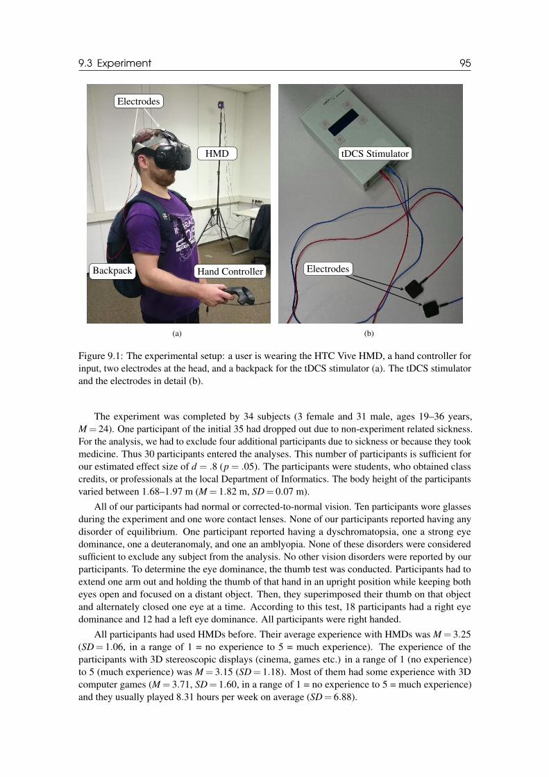
9.3 Experiment 95
HMD
Hand ControllerBackpack
Electrodes
(a)
tDCS Stimulator
Electrodes
(b)
Figure 9.1: The experimental setup: a user is wearing the HTC Vive HMD, a hand controller forinput, two electrodes at the head, and a backpack for the tDCS stimulator (a). The tDCS stimulatorand the electrodes in detail (b).
The experiment was completed by 34 subjects (3 female and 31 male, ages 19–36 years,M = 24). One participant of the initial 35 had dropped out due to non-experiment related sickness.For the analysis, we had to exclude four additional participants due to sickness or because they tookmedicine. Thus 30 participants entered the analyses. This number of participants is sufficient forour estimated effect size of d = .8 (p = .05). The participants were students, who obtained classcredits, or professionals at the local Department of Informatics. The body height of the participantsvaried between 1.68–1.97 m (M = 1.82 m, SD= 0.07 m).
All of our participants had normal or corrected-to-normal vision. Ten participants wore glassesduring the experiment and one wore contact lenses. None of our participants reported having anydisorder of equilibrium. One participant reported having a dyschromatopsia, one a strong eyedominance, one a deuteranomaly, and one an amblyopia. None of these disorders were consideredsufficient to exclude any subject from the analysis. No other vision disorders were reported by ourparticipants. To determine the eye dominance, the thumb test was conducted. Participants had toextend one arm out and holding the thumb of that hand in an upright position while keeping botheyes open and focused on a distant object. Then, they superimposed their thumb on that objectand alternately closed one eye at a time. According to this test, 18 participants had a right eyedominance and 12 had a left eye dominance. All participants were right handed.
All participants had used HMDs before. Their average experience with HMDs was M = 3.25(SD= 1.06, in a range of 1 = no experience to 5 = much experience). The experience of theparticipants with 3D stereoscopic displays (cinema, games etc.) in a range of 1 (no experience)to 5 (much experience) was M = 3.15 (SD= 1.18). Most of them had some experience with 3Dcomputer games (M = 3.71, SD= 1.60, in a range of 1 = no experience to 5 = much experience)and they usually played 8.31 hours per week on average (SD= 6.88).
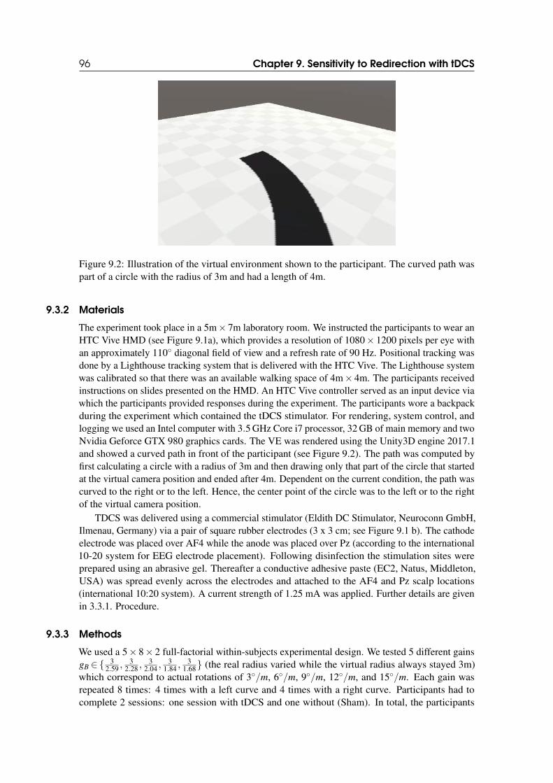
96 Chapter 9. Sensitivity to Redirection with tDCS
Figure 9.2: Illustration of the virtual environment shown to the participant. The curved path waspart of a circle with the radius of 3m and had a length of 4m.
9.3.2 Materials
The experiment took place in a 5m× 7m laboratory room. We instructed the participants to wear anHTC Vive HMD (see Figure 9.1a), which provides a resolution of 1080× 1200 pixels per eye withan approximately 110◦ diagonal field of view and a refresh rate of 90 Hz. Positional tracking wasdone by a Lighthouse tracking system that is delivered with the HTC Vive. The Lighthouse systemwas calibrated so that there was an available walking space of 4m× 4m. The participants receivedinstructions on slides presented on the HMD. An HTC Vive controller served as an input device viawhich the participants provided responses during the experiment. The participants wore a backpackduring the experiment which contained the tDCS stimulator. For rendering, system control, andlogging we used an Intel computer with 3.5 GHz Core i7 processor, 32 GB of main memory and twoNvidia Geforce GTX 980 graphics cards. The VE was rendered using the Unity3D engine 2017.1and showed a curved path in front of the participant (see Figure 9.2). The path was computed byfirst calculating a circle with a radius of 3m and then drawing only that part of the circle that startedat the virtual camera position and ended after 4m. Dependent on the current condition, the path wascurved to the right or to the left. Hence, the center point of the circle was to the left or to the rightof the virtual camera position.
TDCS was delivered using a commercial stimulator (Eldith DC Stimulator, Neuroconn GmbH,Ilmenau, Germany) via a pair of square rubber electrodes (3 x 3 cm; see Figure 9.1 b). The cathodeelectrode was placed over AF4 while the anode was placed over Pz (according to the international10-20 system for EEG electrode placement). Following disinfection the stimulation sites wereprepared using an abrasive gel. Thereafter a conductive adhesive paste (EC2, Natus, Middleton,USA) was spread evenly across the electrodes and attached to the AF4 and Pz scalp locations(international 10:20 system). A current strength of 1.25 mA was applied. Further details are givenin 3.3.1. Procedure.
9.3.3 Methods
We used a 5× 8× 2 full-factorial within-subjects experimental design. We tested 5 different gainsgB ∈{ 3
2.59 ,3
2.28 ,3
2.04 ,3
1.84 ,3
1.68} (the real radius varied while the virtual radius always stayed 3m)which correspond to actual rotations of 3◦/m, 6◦/m, 9◦/m, 12◦/m, and 15◦/m. Each gain wasrepeated 8 times: 4 times with a left curve and 4 times with a right curve. Participants had tocomplete 2 sessions: one session with tDCS and one without (Sham). In total, the participants
9.3 Experiment 97
completed 5× 8= 40 trials per session. All trials in one session were randomized.These gains were chosen based on previous work as described in Rietzler et al. who reported
detection thresholds around 5.5◦/m for bending gains and recommended to use gains that scale in alinear way with the perceived manipulation [Rie+18].
Procedure
The two sessions were carried out on different days separated by at least one week. On both dayssubjects participated at the identical time of day. The procedure of both sessions was the sameso that participants were blinded as to which session stimulation was conducted. The order ofconditions was counterbalanced across subjects, i. e., half of the participants started with the tDCScondition, the other half with sham.
Before the experiment, all participants filled out informed consent forms and received detailedinstructions about the experiment and on how to perform the experimental task. Furthermore, theyfilled out a questionnaire about their experiences with VR, stereoscopic displays, and games, ahandedness questionnaire, a questionnaire about vision impairments, and a general questionnaireabout diseases, medication, and sleeping habits.
Before each session, participants filled out the Simulator Sickness Questionnaire (SSQ) [Ken+93].Subsequently, in the tDCS as well as sham condition electrodes were applied using the gel andpaste.
Participants completed four training trials before the actual experimental trials. After thetraining trials and the subject had returned to the start position, the stimulation was turned on for1200s (20 minutes) in the tDCS condition, which included a 30 seconds ramp up and down periodat the beginning and end of the stimulation, respectively. In the sham condition, currents were onlyramped up and down for 30 seconds at the beginning of the session. After these 30 seconds nostimulation was applied.
For each trial, participants were instructed to walk along the virtual path shown in the VE.When they reached the end of the path, they had to press a button on the controller, turn around,and walk back to the beginning of the path. In one of these walking directions a bending gain wasapplied as explained in Section 9.3.3. After the participants reached the beginning of the path again,they pressed a button on the controller and had to answer the displayed question using the touchpadof the controller (see Section 9.3.3). Afterwards, participants were guided to the next start positionin the laboratory by displaying a 2D compass and distance metrics in the HMD. By using thismethod, the participants were kept unaware of their position and orientation in the real world. This,they could not use this information to identify the amount of redirection that was applied. The nexttrial started once participants reached the new initial position and indicated that they were ready tostart by pressing a button on the controller.
After the session, participants filled out the SSQ again, the Slater-Usoh-Steed (SUS) presencequestionnaire [Uso+99b], and a demographic questionnaire, and the electrodes were removed.
The total time per participant for each session, including pre-questionnaires, application oftDCS electrodes, instructions, experiment, breaks, post-questionnaires, and debriefing, was about120-150 minutes, out of which around 25 minutes were spent in VR.
Two-Alternative Forced-Choice Task
To measure the amount of deviation that is unnoticeable, we used a 2AFC task (see Chapter 2.1.3).In our case, using bending gains, previous experiments showed that participants had seriousproblems in identifying on which side of the virtual path they physically walked. For instance,participants mentioned that they noticed a redirection in terms of “something strange happened”but could not detect reliably at which side of the path they walked (see Chapter 8). This is becauseparticipants adapted to the redirection and walked on the virtual path, which made it hard forthem to estimate on which side of the path they are located in the real world. Another method
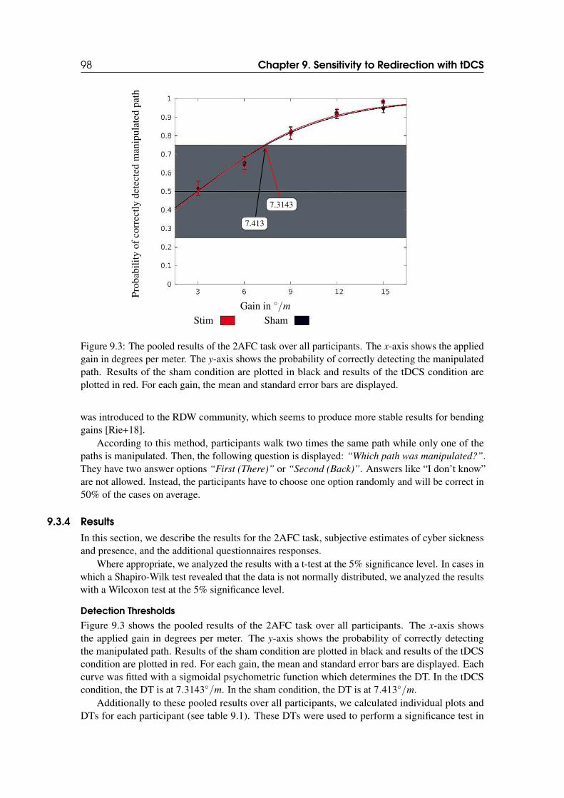
98 Chapter 9. Sensitivity to Redirection with tDCS
Gain in ◦/m
Pro
babi
lity
ofco
rrec
tly
dete
cted
man
ipul
ated
path
Stim Sham
7.413
7.3143
Figure 9.3: The pooled results of the 2AFC task over all participants. The x-axis shows the appliedgain in degrees per meter. The y-axis shows the probability of correctly detecting the manipulatedpath. Results of the sham condition are plotted in black and results of the tDCS condition areplotted in red. For each gain, the mean and standard error bars are displayed.
was introduced to the RDW community, which seems to produce more stable results for bendinggains [Rie+18].
According to this method, participants walk two times the same path while only one of thepaths is manipulated. Then, the following question is displayed: “Which path was manipulated?”.They have two answer options “First (There)” or “Second (Back)”. Answers like “I don’t know”are not allowed. Instead, the participants have to choose one option randomly and will be correct in50% of the cases on average.
9.3.4 Results
In this section, we describe the results for the 2AFC task, subjective estimates of cyber sicknessand presence, and the additional questionnaires responses.
Where appropriate, we analyzed the results with a t-test at the 5% significance level. In cases inwhich a Shapiro-Wilk test revealed that the data is not normally distributed, we analyzed the resultswith a Wilcoxon test at the 5% significance level.
Detection Thresholds
Figure 9.3 shows the pooled results of the 2AFC task over all participants. The x-axis showsthe applied gain in degrees per meter. The y-axis shows the probability of correctly detectingthe manipulated path. Results of the sham condition are plotted in black and results of the tDCScondition are plotted in red. For each gain, the mean and standard error bars are displayed. Eachcurve was fitted with a sigmoidal psychometric function which determines the DT. In the tDCScondition, the DT is at 7.3143◦/m. In the sham condition, the DT is at 7.413◦/m.
Additionally to these pooled results over all participants, we calculated individual plots andDTs for each participant (see table 9.1). These DTs were used to perform a significance test in
9.4 Discussion 99
order to compare the thresholds between sham and tDCS condition. We did not find any significantdifferences (p = .514).
Furthermore, we compared the mean probability for each gain between sham and tDCScondition. We did not find any significant differences for the 3◦/m gain (p = .927), the 6◦/m gain(p = .848), the 9◦/m gain (p = .812), or for the 12◦/m gain (p = .608). We found a significantdifference for the 15◦/m gain (p = .018), indicating that the mean probability of correctly detectingthe manipulated path was higher in the tDCS condition.
Cyber Sickness
In the sham condition, we measured a mean SSQ-score of 11.47 (SD= 11.98) before the experiment,and a mean SSQ-score of 17.83 (SD= 18.5) after the experiment. In the tDCS condition, wemeasured a mean SSQ-score of 19.2 (SD= 12.98) before the experiment, and a mean SSQ-scoreof 17.7 (SD= 19.44) after the experiment.
We did not find any significant differences between total SSQ-scores before and after theexperiment for the sham condition (p = .162) and the tDCS condition (p = .291). However,we also calculated the scores for the three subsections of the SSQ: oculomotor, nausea, anddisorientation. Results are shown in Figure 9.4 (a) and (b). We observed a significant increase ofdisorientation in the sham condition (p = .008) but not in the tDCS condition (p = .308). We founda significant decrease of oculomotor sickness symptoms in the tDCS condition (p = .016) but notin the sham condition (p = 1.0). We did not find any significant differences for nausea in the sham(p = .142) or tDCS conditions (p = .06).
Presence
The mean SUS-score for the sense of feeling present in the VE was 2.16 (SD= 1.84) on a five-pointLikert scale in the sham condition and 2.26 (SD= 1.6) in the tDCS condition. We did not find anysignificant differences of SUS-scores between sham and tDCS conditions (p = .729).
Additional Questionnaires
When the participants were asked “Did you feel a stimulation during this session?” at the endof each session, two participants answered yes after sham condition and three participants afterthe tDCS condition. Other than on these few sessions, subjects did not report on having felt thestimulation.
When the participants were asked “Do you think that this session was the session with stimula-
tion or without?” after the sham condition, 14 participants said “Sham” and 6 “Stimulation” (therest did not know). After the tDCS condition, 9 participants said “Sham” and 8 “Stimulation.”
On average participants spent 24.3 minutes (SD= 4.4) for all experiment trials. In the tDCS con-dition, it was 23.7 minutes (SD= 4.3), and, in the sham condition, it was 24.9 minutes (SD= 4.5).
We did not find any significant difference between the duration of sham and tDCS conditions(p = .295).
9.4 Discussion
The working hypothesis of the present experiment was that cathodal tDCS over the prefrontal cortexwould have a significant effect on RDW performance. Based on our power analysis, we designedthe experiment and 2AFC task accordingly. Unfortunately, this hypothesis was not supported byour results: Overall, the detection thresholds for the sham and tDCS conditions did not revealany significant differences. As discussed below one reason may be that our tDCS protocol didnot sufficiently target the involved brain regions. Although, it cannot be excluded that tDCSis inadequate to affect RDW performance, it would be premature at this stage to draw such aconclusion.
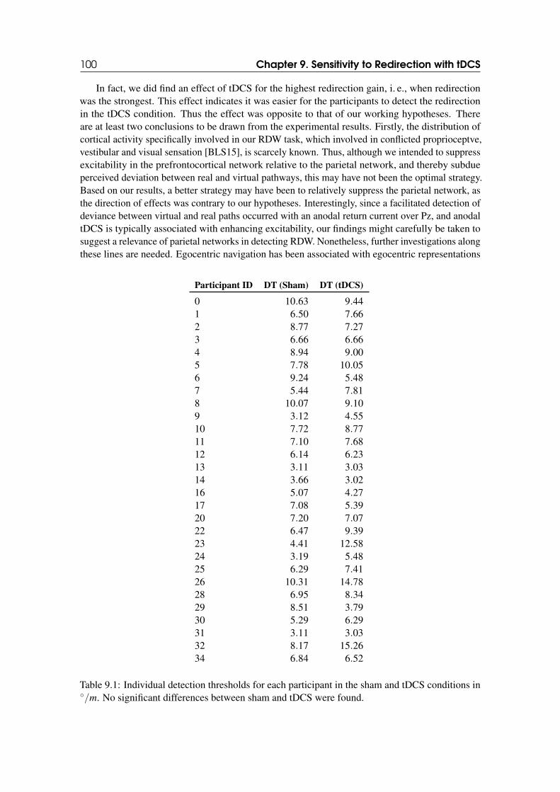
100 Chapter 9. Sensitivity to Redirection with tDCS
In fact, we did find an effect of tDCS for the highest redirection gain, i. e., when redirectionwas the strongest. This effect indicates it was easier for the participants to detect the redirectionin the tDCS condition. Thus the effect was opposite to that of our working hypotheses. Thereare at least two conclusions to be drawn from the experimental results. Firstly, the distribution ofcortical activity specifically involved in our RDW task, which involved in conflicted proprioceptve,vestibular and visual sensation [BLS15], is scarcely known. Thus, although we intended to suppressexcitability in the prefrontocortical network relative to the parietal network, and thereby subdueperceived deviation between real and virtual pathways, this may have not been the optimal strategy.Based on our results, a better strategy may have been to relatively suppress the parietal network, asthe direction of effects was contrary to our hypotheses. Interestingly, since a facilitated detection ofdeviance between virtual and real paths occurred with an anodal return current over Pz, and anodaltDCS is typically associated with enhancing excitability, our findings might carefully be taken tosuggest a relevance of parietal networks in detecting RDW. Nonetheless, further investigations alongthese lines are needed. Egocentric navigation has been associated with egocentric representations
Participant ID DT (Sham) DT (tDCS)
0 10.63 9.441 6.50 7.662 8.77 7.273 6.66 6.664 8.94 9.005 7.78 10.056 9.24 5.487 5.44 7.818 10.07 9.109 3.12 4.5510 7.72 8.7711 7.10 7.6812 6.14 6.2313 3.11 3.0314 3.66 3.0216 5.07 4.2717 7.08 5.3920 7.20 7.0722 6.47 9.3923 4.41 12.5824 3.19 5.4825 6.29 7.4126 10.31 14.7828 6.95 8.3429 8.51 3.7930 5.29 6.2931 3.11 3.0332 8.17 15.2634 6.84 6.52
Table 9.1: Individual detection thresholds for each participant in the sham and tDCS conditions in◦/m. No significant differences between sham and tDCS were found.
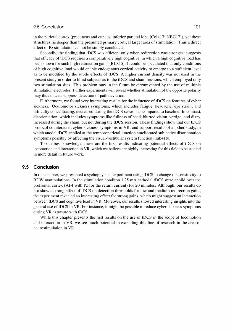
9.5 Conclusion 101
in the parietal cortex (precuneus and cuneus, inferior parietal lobe [Col+17; NBG17]), yet thesestructures lie deeper than the presumed primary cortical target area of stimulation. Thus a directeffect of Pz stimulation cannot be simply concluded.
Secondly, the finding that tDCS was efficient only when redirection was strongest suggeststhat efficacy of tDCS requires a comparatively high cognitive, in which a high cognitive load hasbeen shown for such high redirection gains [BLS15]. It could be speculated that only conditionsof high cognitive load would enable endogenous cortical activity to emerge to a sufficient levelas to be modified by the subtle effects of tDCS. A higher current density was not used in thepresent study in order to blind subjects as to the tDCS and sham sessions, which employed onlytwo stimulation sites. This problem may in the future be circumvented by the use of multiplestimulation electrodes. Further experiments will reveal whether stimulation of the opposite polaritymay thus indeed suppress detection of path deviation.
Furthermore, we found very interesting results for the influence of tDCS on features of cybersickness. Oculomotor sickness symptoms, which includes fatigue, headache, eye strain, anddifficulty concentrating, decreased during the tDCS session as compared to baseline. In contrast,disorientation, which includes symptoms like fullness of head, blurred vision, vertigo, and dizzy,increased during the sham, but not during the tDCS session. These findings show that our tDCSprotocol counteracted cyber sickness symptoms in VR, and support results of another study, inwhich anodal tDCS applied at the temporoparietal junction ameliorated subjective disorientationsymptoms possibly by affecting the visual-vestibular system function [Tak+18].
To our best knowledge, these are the first results indicating potential effects of tDCS onlocomotion and interaction in VR, which we believe are highly interesting for this field to be studiedin more detail in future work.
9.5 Conclusion
In this chapter, we presented a sychophysical experiment using tDCS to change the sensitivity toRDW manipulations. In the stimulation conditon 1.25 mA cathodal tDCS were applid over theprefrontal cortex (AF4 with Pz for the return current) for 20 minutes. Although, our results donot show a strong effect of tDCS on detection thresholds for low and medium redirection gains,the experiment revealed an interesting effect for strong gains, which might suggest an interactionbetween tDCS and cognitive load in VR. Moreover, our results showed interesting insights into thegeneral use of tDCS in VR. For instance, it might be possible to reduce cyber sickness symptomsduring VR exposure with tDCS.
While this chapter presents the first results on the use of tDCS in the scope of locomotionand interaction in VR, we see much potential in extending this line of research in the area ofneurostimulation in VR.
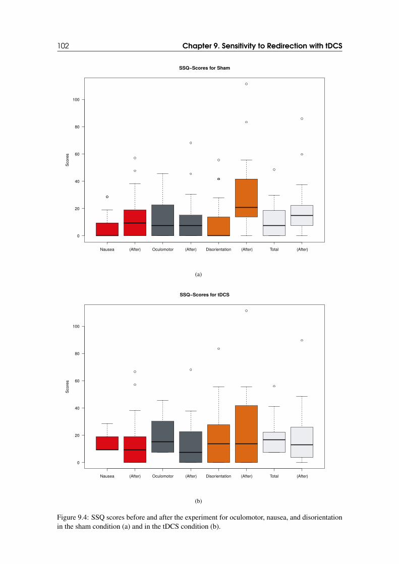
102 Chapter 9. Sensitivity to Redirection with tDCS
Nausea (After) Oculomotor (After) Disorientation (After) Total (After)
0
20
40
60
80
100
SSQ−Scores for ShamS
co
res
(a)
Nausea (After) Oculomotor (After) Disorientation (After) Total (After)
0
20
40
60
80
100
SSQ−Scores for tDCS
Score
s
(b)
Figure 9.4: SSQ scores before and after the experiment for oculomotor, nausea, and disorientationin the sham condition (a) and in the tDCS condition (b).
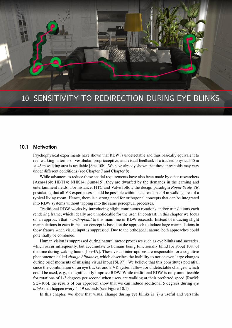
10. SENSITIVITY TO REDIRECTION DURING EYE BLINKS
10.1 Motivation
Psychophysical experiments have shown that RDW is undetectable and thus basically equivalent toreal walking in terms of vestibular, proprioceptive, and visual feedback if a tracked physical 45 m× 45 m walking area is available [Ste+10b]. We have already shown that these thresholds may varyunder different conditions (see Chapter 7 and Chapter 8).
While advances to reduce these spatial requirements have also been made by other researchers[Azm+16b; HBT14; NHK14; Sum+15], they are dwarfed by the demands in the gaming andentertainment fields. For instance, HTC and Valve follow the design paradigm Room-Scale VR,postulating that all VR experiences should be possible within the circa 4 m × 4 m walking area of atypical living room. Hence, there is a strong need for orthogonal concepts that can be integratedinto RDW systems without tapping into the same perceptual processes.
Traditional RDW works by introducing slight continuous rotations and/or translations eachrendering frame, which ideally are unnoticeable for the user. In contrast, in this chapter we focuson an approach that is orthogonal to this main line of RDW research. Instead of inducing slightmanipulations in each frame, our concept is based on the approach to induce large manipulations inthose frames when visual input is suppressed. Due to the orthogonal nature, both approaches couldpotentially be combined.
Human vision is suppressed during natural motor processes such as eye blinks and saccades,which occur infrequently, but accumulate to humans being functionally blind for about 10% ofthe time during waking hours [Joh+09]. These visual interruptions are responsible for a cognitivephenomenon called change blindness, which describes the inability to notice even large changesduring brief moments of missing visual input [SL97]. We believe that this constitutes potential,since the combination of an eye tracker and a VR system allow for undetectable changes, whichcould be used, e. g., to significantly improve RDW. While traditional RDW is only unnoticeablefor rotations of 1-3 degrees per second when users are walking at their preferred speed [Raz05;Ste+10b], the results of our approach show that we can induce additional 5 degrees during eye
blinks that happen every 4–19 seconds (see Figure 10.1).In this chapter, we show that visual change during eye blinks is (i) a useful and versatile
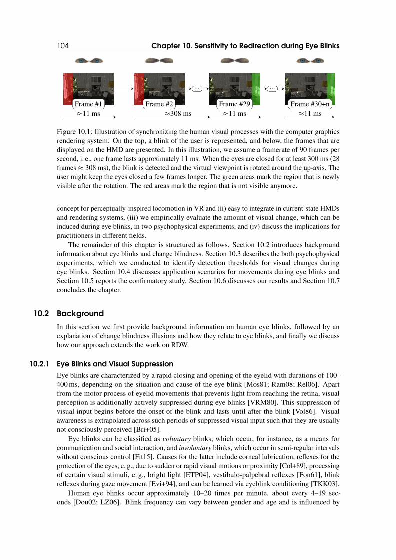
104 Chapter 10. Sensitivity to Redirection during Eye Blinks
... ...
Frame #1 Frame #2 Frame #29 Frame #30+n≈11 ms ≈308 ms ≈11 ms ≈11 ms
Figure 10.1: Illustration of synchronizing the human visual processes with the computer graphicsrendering system: On the top, a blink of the user is represented, and below, the frames that aredisplayed on the HMD are presented. In this illustration, we assume a framerate of 90 frames persecond, i. e., one frame lasts approximately 11 ms. When the eyes are closed for at least 300 ms (28frames ≈ 308 ms), the blink is detected and the virtual viewpoint is rotated around the up-axis. Theuser might keep the eyes closed a few frames longer. The green areas mark the region that is newlyvisible after the rotation. The red areas mark the region that is not visible anymore.
concept for perceptually-inspired locomotion in VR and (ii) easy to integrate in current-state HMDsand rendering systems, (iii) we empirically evaluate the amount of visual change, which can beinduced during eye blinks, in two psychophysical experiments, and (iv) discuss the implications forpractitioners in different fields.
The remainder of this chapter is structured as follows. Section 10.2 introduces backgroundinformation about eye blinks and change blindness. Section 10.3 describes the both psychophysicalexperiments, which we conducted to identify detection thresholds for visual changes duringeye blinks. Section 10.4 discusses application scenarios for movements during eye blinks andSection 10.5 reports the confirmatory study. Section 10.6 discusses our results and Section 10.7concludes the chapter.
10.2 Background
In this section we first provide background information on human eye blinks, followed by anexplanation of change blindness illusions and how they relate to eye blinks, and finally we discusshow our approach extends the work on RDW.
10.2.1 Eye Blinks and Visual Suppression
Eye blinks are characterized by a rapid closing and opening of the eyelid with durations of 100–400 ms, depending on the situation and cause of the eye blink [Mos81; Ram08; Rel06]. Apartfrom the motor process of eyelid movements that prevents light from reaching the retina, visualperception is additionally actively suppressed during eye blinks [VRM80]. This suppression ofvisual input begins before the onset of the blink and lasts until after the blink [Vol86]. Visualawareness is extrapolated across such periods of suppressed visual input such that they are usuallynot consciously perceived [Bri+05].
Eye blinks can be classified as voluntary blinks, which occur, for instance, as a means forcommunication and social interaction, and involuntary blinks, which occur in semi-regular intervalswithout conscious control [Fit15]. Causes for the latter include corneal lubrication, reflexes for theprotection of the eyes, e. g., due to sudden or rapid visual motions or proximity [Col+89], processingof certain visual stimuli, e. g., bright light [ETP04], vestibulo-palpebral reflexes [Fon61], blinkreflexes during gaze movement [Evi+94], and can be learned via eyeblink conditioning [TKK03].
Human eye blinks occur approximately 10–20 times per minute, about every 4–19 sec-onds [Dou02; LZ06]. Blink frequency can vary between gender and age and is influenced by
10.2 Background 105
the current activity. For instance, Sforza, Rango, Galante, Bresolin, and Ferrario found that womenblink more often than men, and older women more often than younger women. Hall found dif-ferences in blink frequency while reading, and Patel, Henderson, Bradley, Galloway, and Hunterfound that the frequency of blinks is greatly reduced when looking at a computer screen. Incontrast, Dennison, Wisti, and D’Zmura observed an increased blink frequency when wearing anHMD compared to a non-immersive computer screen, and they suggested that an increased blinkfrequency is correlated with and potentially caused by increased visual stress and fatigue in VR.
Overall, this rich body of literature on blinks shows that there is a high number of naturallyoccurring blinks in VR as well as the potential to induce additional blinks due to external stimuli ifneeded. This illustrates the usefulness and potential impact of the techniques introduced in thischapter.
10.2.2 Change Blindness
Change blindness denotes the inability of human observers to notice significant changes to visualscenes [Kev+00], in particular, during brief phases of visual interruptions such as eye blinks orsaccades [Ren02; ROC97]. These visual changes can be of various types and magnitudes. Earlierwork focused on artificial stimuli, showing that observers often fail to notice the displacement ofa prominent line-drawn object on a computer screen if the change occurs during an eye move-ment [BHV94]. More recent studies showed that these effects are even stronger with naturalisticand complex stimuli usually found in the real world, such as when a conversation partner is replacedby a different person [SL98] or when the walls and doors around us change position [Ste+11;Sum+10; Sum+12b]. This counter-intuitive result is of special interest; most people firmly (anderroneously) believe that they would notice such large changes of their surroundings [Lev+02;Lev+00].
Change blindness is made possible by a general limitation in the human ability to retain andcompare visual information from moment to moment. Early experiments by Rensink, KevinO’Regan, and Clark found a clear impact of the duration of visual interruptions (called inter-
stimulus intervals) between scene changes on detection rates, showing that rates were significantlyhigher for durations of 40 ms compared to 80 ms and 160 ms. This effect could be explained by abrief lapse in human short-term high-capacity iconic memory [Col80; Dic74], which includes afleeting visual representation of the raw sensory input. When the duration of inter-stimulus intervalsexceeds the duration for which the scene pertains in iconic memory, the ability to detect differencesin successive scenes is reduced [BPA00; PGM12].
Additionally to these theories about visual memory, change detection is influenced by oculomo-tor and suppression mechanisms during eye blinks and saccades. According to current theories, thehuman visual system uses a built-in prior assumption that the world is stable during eye movements.For instance, the perception of displacements of the scene during a saccade is suppressed or, moreprecisely, thresholds for the detection of a displacement of the current retinal image are elevatedwhen this displacement occurs during an eye movement [BHS75; NCT03].
In summary, eye blinks are a common and natural cause of change blindness. The limiteddurations of eye blinks (100–400 ms [Mos81; Ram08; Rel06]) require exact timing of visual changesto have a significant effect, which can happen in the real world, e. g., causing accidents whiledriving [Häk+99], but provide much higher potential in VR as eye blinks can be reliably trackedand registered with computer graphics changes. Moreover, the associated suppression mechanismsindicate large potential in VR as the underlying assumptions of human visual perception do nothave to be true in computer graphics virtual worlds.
106 Chapter 10. Sensitivity to Redirection during Eye Blinks
10.2.3 Orthogonal Approach to RDW
Instead of inducing continuous rotations or translations as in traditional RDW implementations,an orthogonal approach is to introduce discrete manipulations by leveraging change blindness asdescribed above. Early work by Wallis and Bulthoff has indicated that change blindness doesnot only pertain to changes of objects in the surroundings but can also apply to the observer’sown position, orientation, and movement, which suggests applications in RDW. Steinicke, Bruder,Hinrichs, and Willemsen introduced change blindness techniques for stereoscopic VR systems suchas projection systems and HMDs [Ste+11] with a focus on changing the position and appearanceof individual objects in the scene, whereas camera motions were not considered. Bruder, Pusch,and Steinicke have shown that change blindness can significantly change speed perception in VEsif inter-stimulus intervals are induced by blanking the view for 100 ms. Moreover, Bolte andLappe found that saccadic eye movements can mask changes in orientation and position. Theyinvestigated the sensitivity to rotations in the transverse plane and forward/backward translationsduring saccades. They found detection thresholds for rotations of ±5 degrees around the up axisand translations of ±50 cm along the forward axis. Recent work by Sun, Patney, Wei, Shapira, Lu,Asente, Zhu, McGuire, Luebke, and Kaufman leveraged saccadic eye movements to improve RDWwith GPU-based path planning algorithms. However, manipulations during saccades impose veryhigh demands on eye trackers with ultra-high performance eye tracking, rendering and display: it isnecessary to detect the saccade onset, predict its length, render a new image, display this image, andhope that the saccade has not ended earlier, which requires low-latency gaze data at circa 2000 Hzrefresh rate or more. Bolte and Lappe had to build a research prototype of an electrooculogram tofulfill some of these requirements.
A first attempt to using eye blinks for RDW was done by Ivleva. Eye blinks are much easier totrack than saccades (even with commercial off-the-shelf eye trackers integrated in HMDs), lessdependent on refresh rate due to the longer blink durations, less fallible to misclassification ofblinks, and useful due to both voluntary and involuntary blinks. In this chapter, we document thatblink-induced suppression is a useful and versatile method for RDW.
10.3 Psychophysical Experiments
This section describes the experiments we performed to analyze human sensitivity to subtletranslations and rotations induced during eye blinks. Both experiments shared a common procedureand a similar setup but they were conducted with different participants.
10.3.1 Experimental Setup
Hardware and Software
We instructed the participants to wear an HTC Vive HMD (see Figure 10.2), which provides aresolution of 1080× 1200 pixels per eye with an approximately 110◦ diagonal field of view and arefresh rate of 90 Hz. Positional and rotational tracking was done by a Lighthouse tracking systemthat is delivered with the HTC Vive. The participants received task instructions on slides presentedon the HMD. An HTC Vive controller served as an input device via which the participants providedresponses during the experiment.
The VE was rendered using the Unity3D engine 5.5 and showed an architectural visualizationof a living room to the participants of the experiment (see Figure 10.2).
We used an integration of the Pupil Labs eye-tracking device inside the HMD, which includestwo 120 Hz infrared cameras and infrared illuminators (see Figure 10.2). The eye-tracking devicewas connected to the graphics rendering computer via a USB cable and configured using Pupil
Capture v0.9.12, the software provided by Pupil Labs. During the experiment, eye and gaze data
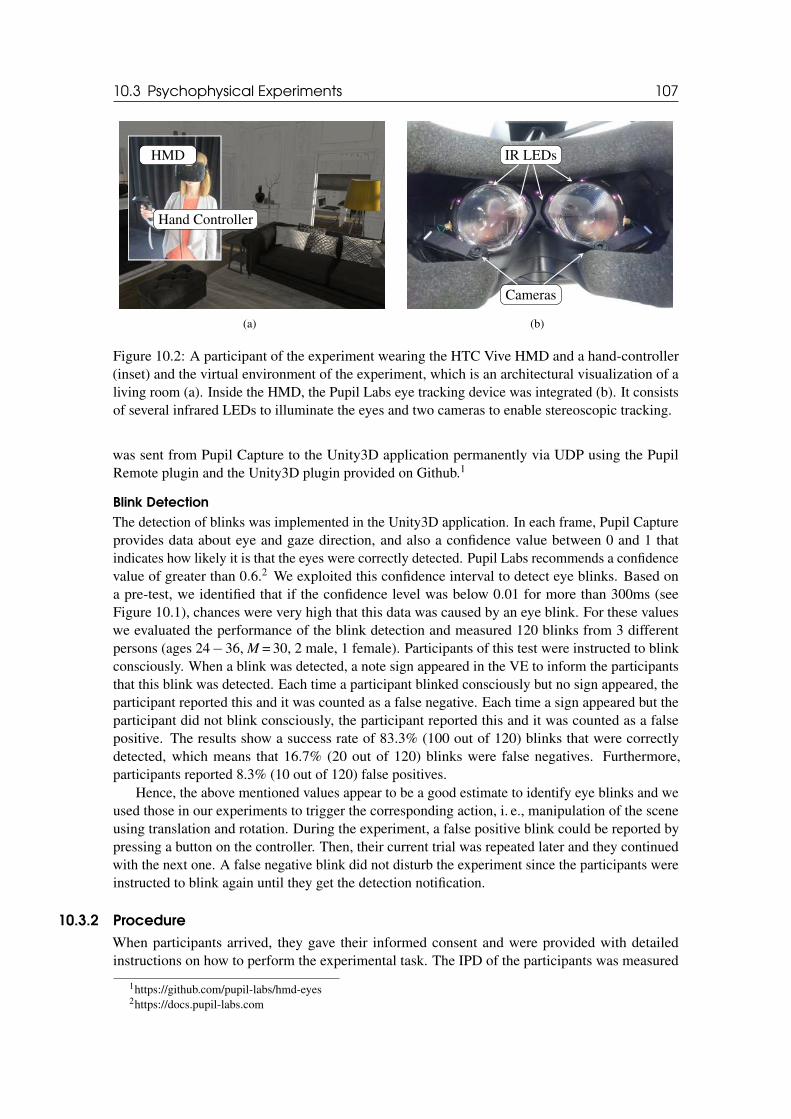
10.3 Psychophysical Experiments 107
HMD
Hand Controller
(a)
IR LEDs
Cameras
(b)
Figure 10.2: A participant of the experiment wearing the HTC Vive HMD and a hand-controller(inset) and the virtual environment of the experiment, which is an architectural visualization of aliving room (a). Inside the HMD, the Pupil Labs eye tracking device was integrated (b). It consistsof several infrared LEDs to illuminate the eyes and two cameras to enable stereoscopic tracking.
was sent from Pupil Capture to the Unity3D application permanently via UDP using the PupilRemote plugin and the Unity3D plugin provided on Github.1
Blink Detection
The detection of blinks was implemented in the Unity3D application. In each frame, Pupil Captureprovides data about eye and gaze direction, and also a confidence value between 0 and 1 thatindicates how likely it is that the eyes were correctly detected. Pupil Labs recommends a confidencevalue of greater than 0.6.2 We exploited this confidence interval to detect eye blinks. Based ona pre-test, we identified that if the confidence level was below 0.01 for more than 300ms (seeFigure 10.1), chances were very high that this data was caused by an eye blink. For these valueswe evaluated the performance of the blink detection and measured 120 blinks from 3 differentpersons (ages 24−36, M = 30, 2 male, 1 female). Participants of this test were instructed to blinkconsciously. When a blink was detected, a note sign appeared in the VE to inform the participantsthat this blink was detected. Each time a participant blinked consciously but no sign appeared, theparticipant reported this and it was counted as a false negative. Each time a sign appeared but theparticipant did not blink consciously, the participant reported this and it was counted as a falsepositive. The results show a success rate of 83.3% (100 out of 120) blinks that were correctlydetected, which means that 16.7% (20 out of 120) blinks were false negatives. Furthermore,participants reported 8.3% (10 out of 120) false positives.
Hence, the above mentioned values appear to be a good estimate to identify eye blinks and weused those in our experiments to trigger the corresponding action, i. e., manipulation of the sceneusing translation and rotation. During the experiment, a false positive blink could be reported bypressing a button on the controller. Then, their current trial was repeated later and they continuedwith the next one. A false negative blink did not disturb the experiment since the participants wereinstructed to blink again until they get the detection notification.
10.3.2 Procedure
When participants arrived, they gave their informed consent and were provided with detailedinstructions on how to perform the experimental task. The IPD of the participants was measured
1https://github.com/pupil-labs/hmd-eyes2https://docs.pupil-labs.com
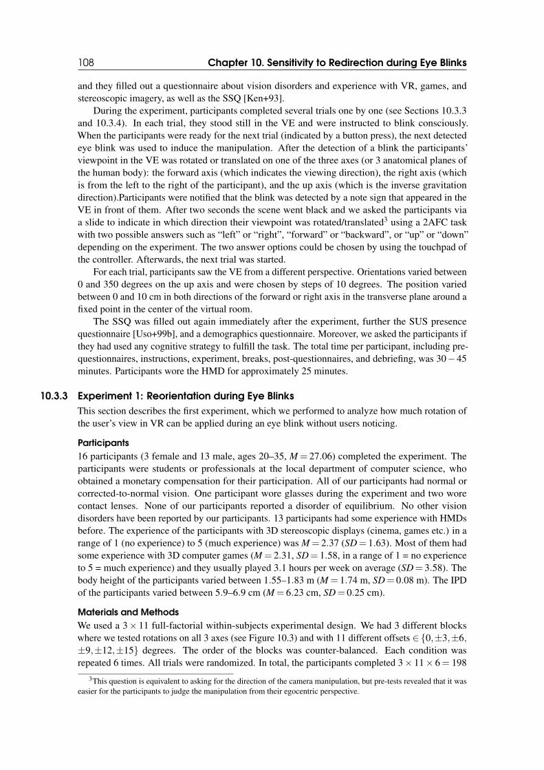
108 Chapter 10. Sensitivity to Redirection during Eye Blinks
and they filled out a questionnaire about vision disorders and experience with VR, games, andstereoscopic imagery, as well as the SSQ [Ken+93].
During the experiment, participants completed several trials one by one (see Sections 10.3.3and 10.3.4). In each trial, they stood still in the VE and were instructed to blink consciously.When the participants were ready for the next trial (indicated by a button press), the next detectedeye blink was used to induce the manipulation. After the detection of a blink the participants’viewpoint in the VE was rotated or translated on one of the three axes (or 3 anatomical planes ofthe human body): the forward axis (which indicates the viewing direction), the right axis (whichis from the left to the right of the participant), and the up axis (which is the inverse gravitationdirection).Participants were notified that the blink was detected by a note sign that appeared in theVE in front of them. After two seconds the scene went black and we asked the participants viaa slide to indicate in which direction their viewpoint was rotated/translated3 using a 2AFC taskwith two possible answers such as “left” or “right”, “forward” or “backward”, or “up” or “down”depending on the experiment. The two answer options could be chosen by using the touchpad ofthe controller. Afterwards, the next trial was started.
For each trial, participants saw the VE from a different perspective. Orientations varied between0 and 350 degrees on the up axis and were chosen by steps of 10 degrees. The position variedbetween 0 and 10 cm in both directions of the forward or right axis in the transverse plane around afixed point in the center of the virtual room.
The SSQ was filled out again immediately after the experiment, further the SUS presencequestionnaire [Uso+99b], and a demographics questionnaire. Moreover, we asked the participants ifthey had used any cognitive strategy to fulfill the task. The total time per participant, including pre-questionnaires, instructions, experiment, breaks, post-questionnaires, and debriefing, was 30−45minutes. Participants wore the HMD for approximately 25 minutes.
10.3.3 Experiment 1: Reorientation during Eye Blinks
This section describes the first experiment, which we performed to analyze how much rotation ofthe user’s view in VR can be applied during an eye blink without users noticing.
Participants
16 participants (3 female and 13 male, ages 20–35, M = 27.06) completed the experiment. Theparticipants were students or professionals at the local department of computer science, whoobtained a monetary compensation for their participation. All of our participants had normal orcorrected-to-normal vision. One participant wore glasses during the experiment and two worecontact lenses. None of our participants reported a disorder of equilibrium. No other visiondisorders have been reported by our participants. 13 participants had some experience with HMDsbefore. The experience of the participants with 3D stereoscopic displays (cinema, games etc.) in arange of 1 (no experience) to 5 (much experience) was M = 2.37 (SD= 1.63). Most of them hadsome experience with 3D computer games (M = 2.31, SD= 1.58, in a range of 1 = no experienceto 5 = much experience) and they usually played 3.1 hours per week on average (SD= 3.58). Thebody height of the participants varied between 1.55–1.83 m (M = 1.74 m, SD= 0.08 m). The IPDof the participants varied between 5.9–6.9 cm (M = 6.23 cm, SD= 0.25 cm).
Materials and Methods
We used a 3× 11 full-factorial within-subjects experimental design. We had 3 different blockswhere we tested rotations on all 3 axes (see Figure 10.3) and with 11 different offsets ∈{0,±3,±6,±9,±12,±15} degrees. The order of the blocks was counter-balanced. Each condition wasrepeated 6 times. All trials were randomized. In total, the participants completed 3× 11× 6= 198
3This question is equivalent to asking for the direction of the camera manipulation, but pre-tests revealed that it waseasier for the participants to judge the manipulation from their egocentric perspective.
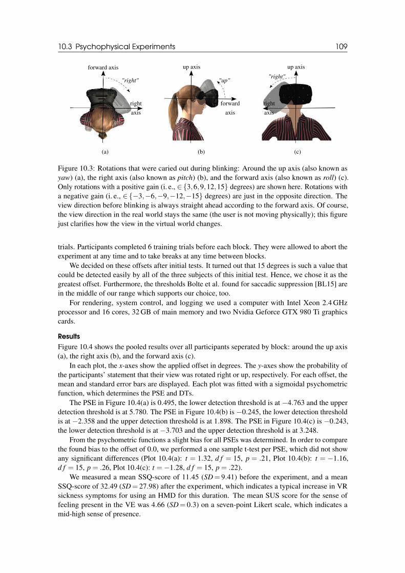
10.3 Psychophysical Experiments 109
forward axis
right
axis
"right"
(a)
up axis
forward
axis
"up"
(b)
up axis
right
axis
"right"
(c)
Figure 10.3: Rotations that were caried out during blinking: Around the up axis (also known asyaw) (a), the right axis (also known as pitch) (b), and the forward axis (also known as roll) (c).Only rotations with a positive gain (i. e., ∈{3,6,9,12,15} degrees) are shown here. Rotations witha negative gain (i. e., ∈{−3,−6,−9,−12,−15} degrees) are just in the opposite direction. Theview direction before blinking is always straight ahead according to the forward axis. Of course,the view direction in the real world stays the same (the user is not moving physically); this figurejust clarifies how the view in the virtual world changes.
trials. Participants completed 6 training trials before each block. They were allowed to abort theexperiment at any time and to take breaks at any time between blocks.
We decided on these offsets after initial tests. It turned out that 15 degrees is such a value thatcould be detected easily by all of the three subjects of this initial test. Hence, we chose it as thegreatest offset. Furthermore, the thresholds Bolte et al. found for saccadic suppression [BL15] arein the middle of our range which supports our choice, too.
For rendering, system control, and logging we used a computer with Intel Xeon 2.4 GHzprocessor and 16 cores, 32 GB of main memory and two Nvidia Geforce GTX 980 Ti graphicscards.
Results
Figure 10.4 shows the pooled results over all participants seperated by block: around the up axis(a), the right axis (b), and the forward axis (c).
In each plot, the x-axes show the applied offset in degrees. The y-axes show the probability ofthe participants’ statement that their view was rotated right or up, respectively. For each offset, themean and standard error bars are displayed. Each plot was fitted with a sigmoidal psychometricfunction, which determines the PSE and DTs.
The PSE in Figure 10.4(a) is 0.495, the lower detection threshold is at −4.763 and the upperdetection threshold is at 5.780. The PSE in Figure 10.4(b) is −0.245, the lower detection thresholdis at −2.358 and the upper detection threshold is at 1.898. The PSE in Figure 10.4(c) is −0.243,the lower detection threshold is at −3.703 and the upper detection threshold is at 3.248.
From the psychometric functions a slight bias for all PSEs was determined. In order to comparethe found bias to the offset of 0.0, we performed a one sample t-test per PSE, which did not showany significant differences (Plot 10.4(a): t = 1.32, d f = 15, p = .21, Plot 10.4(b): t = −1.16,d f = 15, p = .26, Plot 10.4(c): t =−1.28, d f = 15, p = .22).
We measured a mean SSQ-score of 11.45 (SD= 9.41) before the experiment, and a meanSSQ-score of 32.49 (SD= 27.98) after the experiment, which indicates a typical increase in VRsickness symptoms for using an HMD for this duration. The mean SUS score for the sense offeeling present in the VE was 4.66 (SD= 0.3) on a seven-point Likert scale, which indicates amid-high sense of presence.
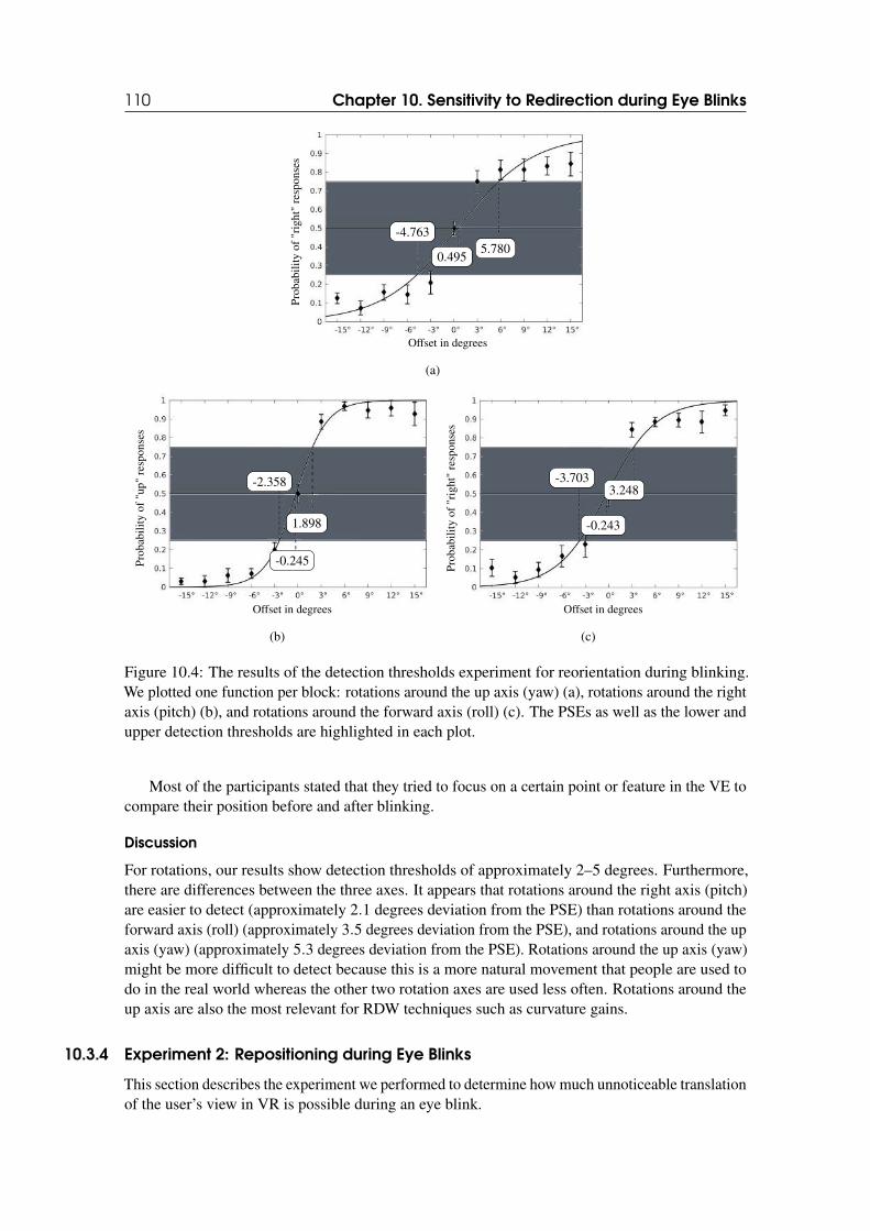
110 Chapter 10. Sensitivity to Redirection during Eye Blinks
Offset in degrees
Pro
babi
lity
of"r
ight
"re
spon
ses
0.4955.780
-4.763
(a)
Offset in degrees
Pro
babi
lity
of"u
p"re
spon
ses
-0.245
1.898
-2.358
(b)
Offset in degrees
Pro
babi
lity
of"r
ight
"re
spon
ses
-0.243
3.248-3.703
(c)
Figure 10.4: The results of the detection thresholds experiment for reorientation during blinking.We plotted one function per block: rotations around the up axis (yaw) (a), rotations around the rightaxis (pitch) (b), and rotations around the forward axis (roll) (c). The PSEs as well as the lower andupper detection thresholds are highlighted in each plot.
Most of the participants stated that they tried to focus on a certain point or feature in the VE tocompare their position before and after blinking.
Discussion
For rotations, our results show detection thresholds of approximately 2–5 degrees. Furthermore,there are differences between the three axes. It appears that rotations around the right axis (pitch)are easier to detect (approximately 2.1 degrees deviation from the PSE) than rotations around theforward axis (roll) (approximately 3.5 degrees deviation from the PSE), and rotations around the upaxis (yaw) (approximately 5.3 degrees deviation from the PSE). Rotations around the up axis (yaw)might be more difficult to detect because this is a more natural movement that people are used todo in the real world whereas the other two rotation axes are used less often. Rotations around theup axis are also the most relevant for RDW techniques such as curvature gains.
10.3.4 Experiment 2: Repositioning during Eye Blinks
This section describes the experiment we performed to determine how much unnoticeable translationof the user’s view in VR is possible during an eye blink.
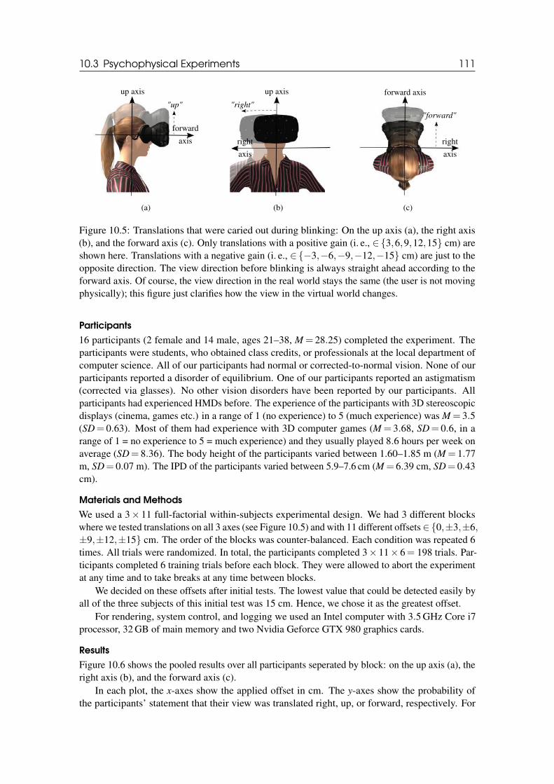
10.3 Psychophysical Experiments 111
up axis
forward
axis
"up"
(a)
up axis
right
axis
"right"
(b)
forward axis
right
axis
"forward"
(c)
Figure 10.5: Translations that were caried out during blinking: On the up axis (a), the right axis(b), and the forward axis (c). Only translations with a positive gain (i. e., ∈{3,6,9,12,15} cm) areshown here. Translations with a negative gain (i. e., ∈{−3,−6,−9,−12,−15} cm) are just to theopposite direction. The view direction before blinking is always straight ahead according to theforward axis. Of course, the view direction in the real world stays the same (the user is not movingphysically); this figure just clarifies how the view in the virtual world changes.
Participants
16 participants (2 female and 14 male, ages 21–38, M = 28.25) completed the experiment. Theparticipants were students, who obtained class credits, or professionals at the local department ofcomputer science. All of our participants had normal or corrected-to-normal vision. None of ourparticipants reported a disorder of equilibrium. One of our participants reported an astigmatism(corrected via glasses). No other vision disorders have been reported by our participants. Allparticipants had experienced HMDs before. The experience of the participants with 3D stereoscopicdisplays (cinema, games etc.) in a range of 1 (no experience) to 5 (much experience) was M = 3.5(SD= 0.63). Most of them had experience with 3D computer games (M = 3.68, SD= 0.6, in arange of 1 = no experience to 5 = much experience) and they usually played 8.6 hours per week onaverage (SD= 8.36). The body height of the participants varied between 1.60–1.85 m (M = 1.77m, SD= 0.07 m). The IPD of the participants varied between 5.9–7.6 cm (M = 6.39 cm, SD= 0.43cm).
Materials and Methods
We used a 3× 11 full-factorial within-subjects experimental design. We had 3 different blockswhere we tested translations on all 3 axes (see Figure 10.5) and with 11 different offsets ∈{0,±3,±6,±9,±12,±15} cm. The order of the blocks was counter-balanced. Each condition was repeated 6times. All trials were randomized. In total, the participants completed 3× 11× 6= 198 trials. Par-ticipants completed 6 training trials before each block. They were allowed to abort the experimentat any time and to take breaks at any time between blocks.
We decided on these offsets after initial tests. The lowest value that could be detected easily byall of the three subjects of this initial test was 15 cm. Hence, we chose it as the greatest offset.
For rendering, system control, and logging we used an Intel computer with 3.5 GHz Core i7processor, 32 GB of main memory and two Nvidia Geforce GTX 980 graphics cards.
Results
Figure 10.6 shows the pooled results over all participants seperated by block: on the up axis (a), theright axis (b), and the forward axis (c).
In each plot, the x-axes show the applied offset in cm. The y-axes show the probability ofthe participants’ statement that their view was translated right, up, or forward, respectively. For
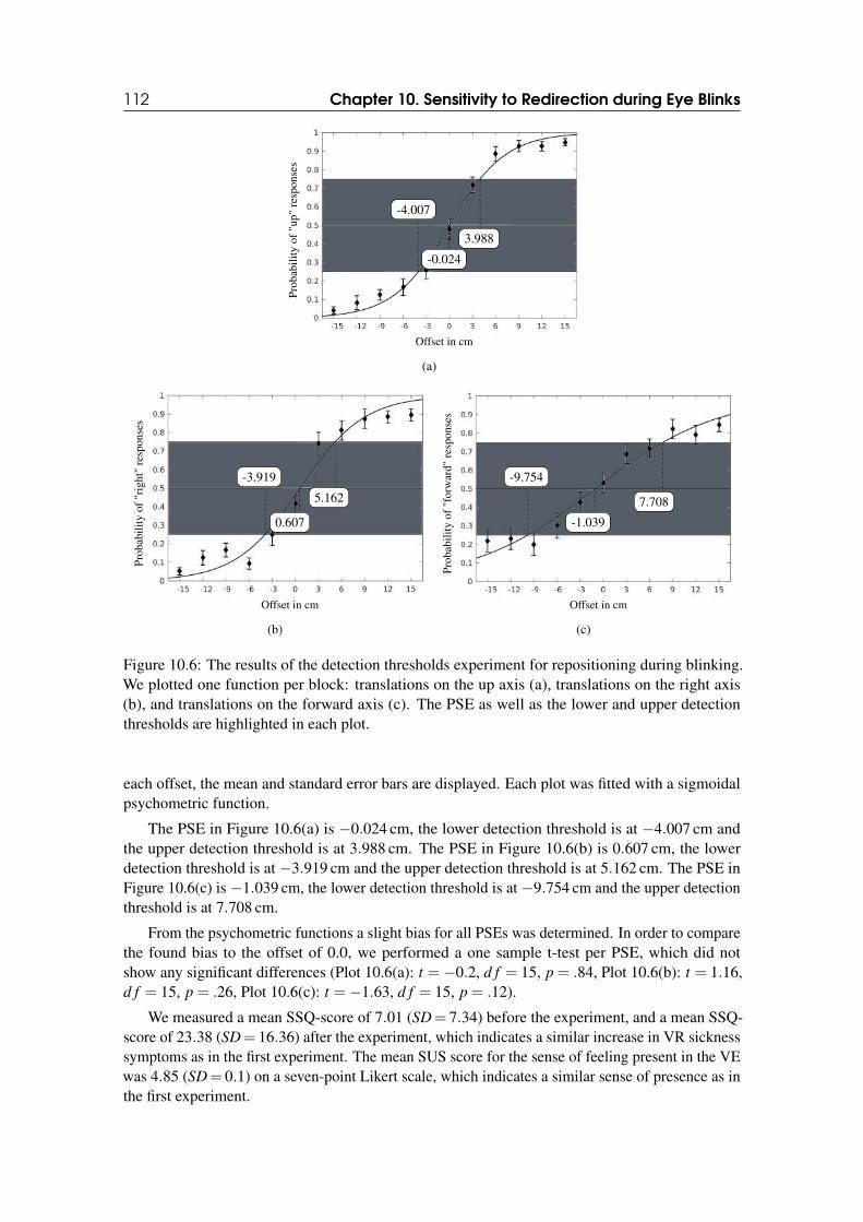
112 Chapter 10. Sensitivity to Redirection during Eye Blinks
Offset in cm
Pro
babi
lity
of"u
p"re
spon
ses
-0.024
3.988
-4.007
(a)
Offset in cm
Pro
babi
lity
of"r
ight
"re
spon
ses
0.607
5.162
-3.919
(b)
Offset in cm
Pro
babi
lity
of"f
orw
ard"
resp
onse
s
-1.039
7.708
-9.754
(c)
Figure 10.6: The results of the detection thresholds experiment for repositioning during blinking.We plotted one function per block: translations on the up axis (a), translations on the right axis(b), and translations on the forward axis (c). The PSE as well as the lower and upper detectionthresholds are highlighted in each plot.
each offset, the mean and standard error bars are displayed. Each plot was fitted with a sigmoidalpsychometric function.
The PSE in Figure 10.6(a) is −0.024 cm, the lower detection threshold is at −4.007 cm andthe upper detection threshold is at 3.988 cm. The PSE in Figure 10.6(b) is 0.607 cm, the lowerdetection threshold is at −3.919 cm and the upper detection threshold is at 5.162 cm. The PSE inFigure 10.6(c) is −1.039 cm, the lower detection threshold is at −9.754 cm and the upper detectionthreshold is at 7.708 cm.
From the psychometric functions a slight bias for all PSEs was determined. In order to comparethe found bias to the offset of 0.0, we performed a one sample t-test per PSE, which did notshow any significant differences (Plot 10.6(a): t =−0.2, d f = 15, p = .84, Plot 10.6(b): t = 1.16,d f = 15, p = .26, Plot 10.6(c): t =−1.63, d f = 15, p = .12).
We measured a mean SSQ-score of 7.01 (SD= 7.34) before the experiment, and a mean SSQ-score of 23.38 (SD= 16.36) after the experiment, which indicates a similar increase in VR sicknesssymptoms as in the first experiment. The mean SUS score for the sense of feeling present in the VEwas 4.85 (SD= 0.1) on a seven-point Likert scale, which indicates a similar sense of presence as inthe first experiment.
10.4 Supplement for Redirection Gains 113
Discussion
For translations, the results revealed detection thresholds of approximately 4–9 cm. Furthermore,there are differences between the three axes. It appears that translations on the up axis (approx-imately 4 cm deviation from the PSE) and translations on the right axis (approximately 4.5 cmdeviation from the PSE) are easier to detect than translations on the forward axis (approximately8.7 cm deviation from the PSE). The reason for this might be that we are used to walking forwardin viewing direction but a movement to the left or right or up or down is less often carried out. Thisresult does not match exactly the results of Bolte et al., who found a detection threshold of 50 cm fortranslations on the forward axis during saccades [BL15]. This is likely due to the difference betweensaccades and blinks and could also be affected by the different hardware, especially the HMD, thatwas used in the experiments. Furthermore, the VE might have an effect. In our experiment, thenumber of objects in the VE is greater and the distance from the user to some of these objects issmaller. This leads to stronger cues from the environment and more change in the retinal image.However, we also found the trend that translations on the forward axis are less obvious than on theother axes.
10.4 Supplement for Redirection Gains
Translations and rotations during unconscious eye blinks could be used to supplement translation,rotation, curvature or bending gains. The idea is that due to these gains additional unnoticeableredirection can be applied, and thus, redirection has potential to become more effective.
10.4.1 Translation Gain
Steinicke et al. found that a 5m virtual distance can be mapped unnoticeably to a physical distancebetween 3.96 and 5.81 m [Ste+10b]. If we assume an average walking velocity of a user with anHMD of approximately 1.2 m/s [Moh+07a], we get a total duration of the walk of 3.3 to 4.8 seconds.Again, with one blink every 4 seconds, it appears reasonable to assume that within a 5 m virtualdistance, at least one eye blink will occur. This blink can trigger an additional translation of around0.087 m, which cannot be detected reliably by the user (see Section 10.3). Hence, we can mapa 5 m virtual distance to a physical distance between 3.873 m (i. e., 3.96−0.087 m) and 5.897 m(i. e., 5.81+0.087 m), which corresponds to an increase of the range of applicable translations byapproximately 10 %.
10.4.2 Rotation Gain
Steinicke et al. found that users can be turned physically about 49% more or 20% less than aperceived virtual 90 degrees rotation without noticing the difference. Hence, a 90 degrees virtualrotation can be mapped unnoticeably to a physical rotation between 134 and 72 degrees [Ste+10b]. Ifwe assume 15 blinks per minute, we get approximately one blink every 4 seconds (see Section 10.1),which might be too low for a rapid head movement. However, it has been shown that saccadic eyemovements and rapid head movements tend to be accompanied by blinks [Evi+84]. Therefore, itappears reasonable to assume that if users either slowly or rapidly rotate their head by 90 degrees,chances are high that they will probably perform 1 blink [Evi+84].
This blink can be exploited to trigger another rotation of around 5 degrees, which cannot bedetected reliably by the user (see Section 10.3). Hence, we could map a 90 degrees virtual rotationto a physical rotation between 139 and 67 degrees, which corresponds to an increase of the rangeof applicable rotations by more than 16%.
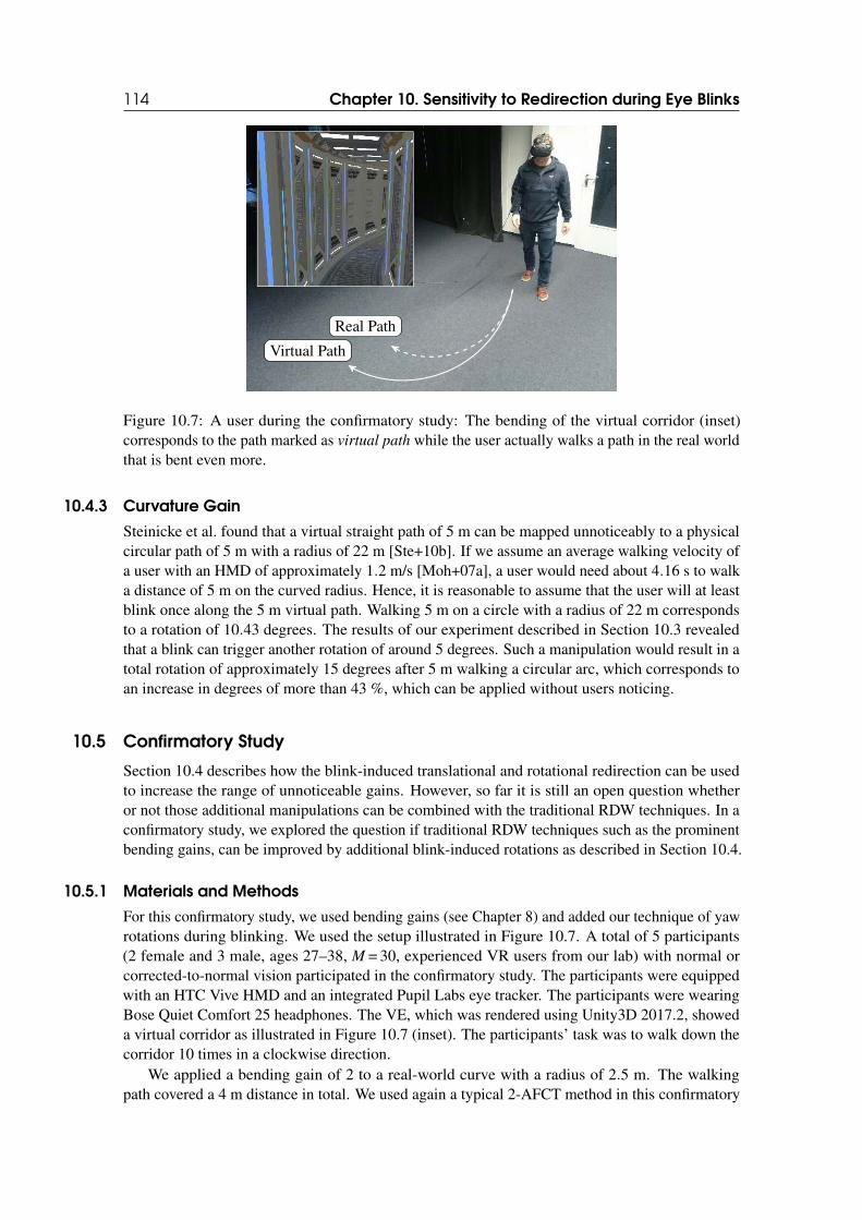
114 Chapter 10. Sensitivity to Redirection during Eye Blinks
Virtual Path
Real Path
Figure 10.7: A user during the confirmatory study: The bending of the virtual corridor (inset)corresponds to the path marked as virtual path while the user actually walks a path in the real worldthat is bent even more.
10.4.3 Curvature Gain
Steinicke et al. found that a virtual straight path of 5 m can be mapped unnoticeably to a physicalcircular path of 5 m with a radius of 22 m [Ste+10b]. If we assume an average walking velocity ofa user with an HMD of approximately 1.2 m/s [Moh+07a], a user would need about 4.16 s to walka distance of 5 m on the curved radius. Hence, it is reasonable to assume that the user will at leastblink once along the 5 m virtual path. Walking 5 m on a circle with a radius of 22 m correspondsto a rotation of 10.43 degrees. The results of our experiment described in Section 10.3 revealedthat a blink can trigger another rotation of around 5 degrees. Such a manipulation would result in atotal rotation of approximately 15 degrees after 5 m walking a circular arc, which corresponds toan increase in degrees of more than 43 %, which can be applied without users noticing.
10.5 Confirmatory Study
Section 10.4 describes how the blink-induced translational and rotational redirection can be usedto increase the range of unnoticeable gains. However, so far it is still an open question whetheror not those additional manipulations can be combined with the traditional RDW techniques. In aconfirmatory study, we explored the question if traditional RDW techniques such as the prominentbending gains, can be improved by additional blink-induced rotations as described in Section 10.4.
10.5.1 Materials and Methods
For this confirmatory study, we used bending gains (see Chapter 8) and added our technique of yawrotations during blinking. We used the setup illustrated in Figure 10.7. A total of 5 participants(2 female and 3 male, ages 27–38, M = 30, experienced VR users from our lab) with normal orcorrected-to-normal vision participated in the confirmatory study. The participants were equippedwith an HTC Vive HMD and an integrated Pupil Labs eye tracker. The participants were wearingBose Quiet Comfort 25 headphones. The VE, which was rendered using Unity3D 2017.2, showeda virtual corridor as illustrated in Figure 10.7 (inset). The participants’ task was to walk down thecorridor 10 times in a clockwise direction.
We applied a bending gain of 2 to a real-world curve with a radius of 2.5 m. The walkingpath covered a 4 m distance in total. We used again a typical 2-AFCT method in this confirmatory
10.6 General Discussion 115
study. Therefore, we asked the participants to perform a blink while walking when they heard a“beep” sound, which was displayed on their headphones. During the 4 m distance, we displayedthis sound twice. When an eye blink was successfully detected afterwards, we randomly applied ayaw rotation of 5 degrees either during the first or second blink, whereas there was no manipulationduring the other eye blink. The task of the participants was to identify the blink at which the scenerotation has been performed, i. e., the first or the second blink.
10.5.2 Results
The results show that participants indicated the blink correctly in half of the trials (M = 5, SD = 2,34).In total, 25 out of 50 answers indicated the blink that hid the rotation. Since we used a 2-AFCTparadigm, this means that the participants were not able to reliably detect the blink at which weadded the rotation, and could only guess, resulting in a 50-50 distribution at the chance level. Theseresults confirm that additional blink-induced rotations can be used successfully in concert withtraditional RDW techniques such as bending gains, thus validating our approach.
10.6 General Discussion
In this section, we discuss our approach, the experimental findings, and their application for RDWand other scenarios.
Our psychophysical experiments (see Section 10.3) revealed that imperceptible rotations of 2–5degrees and translations of 4–9 cm of the user’s viewpoint are possible during a blink without usersnoticing. In these experiments, the participants had to blink consciously while wearing an HMDand standing in a VE. Detection thresholds for conscious blinking might be different from naturalunconscious blinking. However, during a conscious blink, the participants were more focussed ondetecting the changes. Hence, our results provide conservative estimates that might even be relaxedby unconscious blinking, in which the user’s attention is on different tasks such as navigation orwayfinding.
Moreover, our results show that translations and rotations during eye blinks are able to supportRDW in general due to an orthogonal approach from common techniques in the literature. While thebenefits for rotation and translation gains are moderate in the range of 10–20 % (see Section 10.4),major improvements can be gained for curvature gains for which rotations can be increased around5 degrees, which corresponds to an improvement of approximately 50 % (see Section 10.4). Ourconfirmatory study validated that participants could not reliably detect in which of two blinks theirviewpoint was manipulated while walking a curved path. This result provides again a conservativeestimate since blink-induced redirection is independent from walking. Hence, it could be used atlower locomotor speeds, too, when a continuous gain is rather ineffective and a rotation of 2–5degrees might have much more impact. However, the task during the confirmatory study, i. e.,participants blink when they hear a beep, is not really a natural use case scenario. This might limitthe results and a revised test in an application scenario might be appropriate.
Of course, our blink-induced masking technique might also be applied for other use cases thanRDW. One promising scenario is a novel viewer guidance approach for storytelling in VR, e. g.,in immersive games or interactive 360-degree movies, which is a challenging domain since userscan freely decide on their own perspective in these environments in contrast to typical movies inwhich directors define their view [Nie+16; RHA17]. For these new paradigms of narratives, it isnecessary to find novel ways of guiding the user’s attention to specific regions or objects. Here,a subtle rotation of the virtual camera during a blink could attract the user’s attention towards anobject of interest in the story.
However, all of the examples presented so far relied on unconscious natural blinking, butredirections during blinking might also be carried out consciously. Intentionally triggering repo-
116 Chapter 10. Sensitivity to Redirection during Eye Blinks
sitioning or reorientation using a hands-free method such as an eye blink can be used in a smallphysical space, without bulky hardware and has potential to avoid VR sickness symptoms due toblink-masked optic flow [LaV00]. Since users can consciously blink numerous times per minutewithout effort, eye blinks provide great potential to be used as intential trigger. Because consciousblinking is required for this kind of repositioning and reorientation anyway, the detection thresholdscould be neglected and even greater distances could be covered, which is refered to as teleportation.
10.7 Conclusion
Our novel approach of imperceptible repositioning and reorientation in immersive computer-mediated environments during blink-induced visual suppression promises to improve perceptually-inspired locomotion techniques such as RDW significantly. Our psychophysical experimentsrevealed that users failed to reliably detect translations of approximately 4–9 cm and rotations ofapproximately 2–5 degrees that are carried out during blinking, which indicates a conservativeestimate that might even be relaxed by unconscious natural blinking. Differences in the amount ofredirection concern the three different axes. The application of these thresholds in the context ofRDW showed an improvement of around 50 %.
IV 11 Turn Your Head Half Round . . . . . . . . . . 119
11.1 Motivation11.2 Rotation Techniques11.3 Experiment11.4 Discussion11.5 Confirmatory Study11.6 Conclusion
12 Leaning-Amplified-Speed Walking-in-Place131
12.1 Motivation12.2 Locomotion Technique12.3 Experiment12.4 Conclusion
13 Scale & Walk . . . . . . . . . . . . . . . . . . . . . . . 137
13.1 Motivation13.2 Locomotion Techniques13.3 Experiment13.4 Discussion13.5 Conclusion
14 Curve-based Redirected Walking . . . 143
14.1 Motivation14.2 Real-World Walking Configuration14.3 Virtual Path Layout14.4 Confirmatory Study14.5 Discussion14.6 Conclusion
15 Redirected Walking vs. Virtual Travel . 153
15.1 Motivation15.2 Techniques15.3 Experiment15.4 Discussion15.5 Conclusion
16 Collision Avoidance with Shadow Avatars165
16.1 Motivation16.2 Background16.3 Experiment16.4 Conclusion
17 Gameplay-integrated Redirection Tech-niques . . . . . . . . . . . . . . . . . . . . . . . . . . . . . 173
17.1 Motivation17.2 Experience 1: Redirected Spaces17.3 Experience 2: Space Walk17.4 Confirmatory Study17.5 Conclusion
LOCOMOTION TECHNIQUES

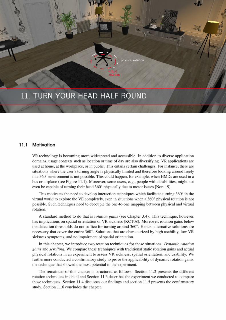
11. TURN YOUR HEAD HALF ROUND
11.1 Motivation
VR technology is becoming more widespread and accessible. In addition to diverse applicationdomains, usage contexts such as location or time of day are also diversifying. VR applications areused at home, at the workplace, or in public. This entails certain challenges. For instance, there aresituations where the user’s turning angle is physically limited and therefore looking around freelyin a 360◦ environment is not possible. This could happen, for example, when HMDs are used in abus or airplane (see Figure 11.1). Moreover, some users, e. g., people with disabilities, might noteven be capable of turning their head 360◦ physically due to motor issues [Nor+19].
This motivates the need to develop interaction techniques which facilitate turning 360◦ in thevirtual world to explore the VE completely, even in situations when a 360◦ physical rotation is notpossible. Such techniques need to decouple the one-to-one mapping between physical and virtualrotation.
A standard method to do that is rotation gains (see Chapter 3.4). This technique, however,has implications on spatial orientation or VR sickness [KCT08]. Moreover, rotation gains belowthe detection thresholds do not suffice for turning around 360◦. Hence, alternative solutions arenecessary that cover the entire 360◦. Solutions that are characterized by high usability, low VRsickness symptoms, and no impairment of spatial orientation.
In this chapter, we introduce two rotation techniques for these situations: Dynamic rotation
gains and scrolling. We compare these techniques with traditional static rotation gains and actualphysical rotations in an experiment to assess VR sickness, spatial orientation, and usability. Wefurthermore conducted a confirmatory study to prove the applicability of dynamic rotation gains,the technique that showed the most potential in the experiment.
The remainder of this chapter is structured as follows. Section 11.2 presents the differentrotation techniques in detail and Section 11.3 describes the experiment we conducted to comparethose techniques. Section 11.4 discusses our findings and section 11.5 presents the confirmatorystudy. Section 11.6 concludes the chapter.
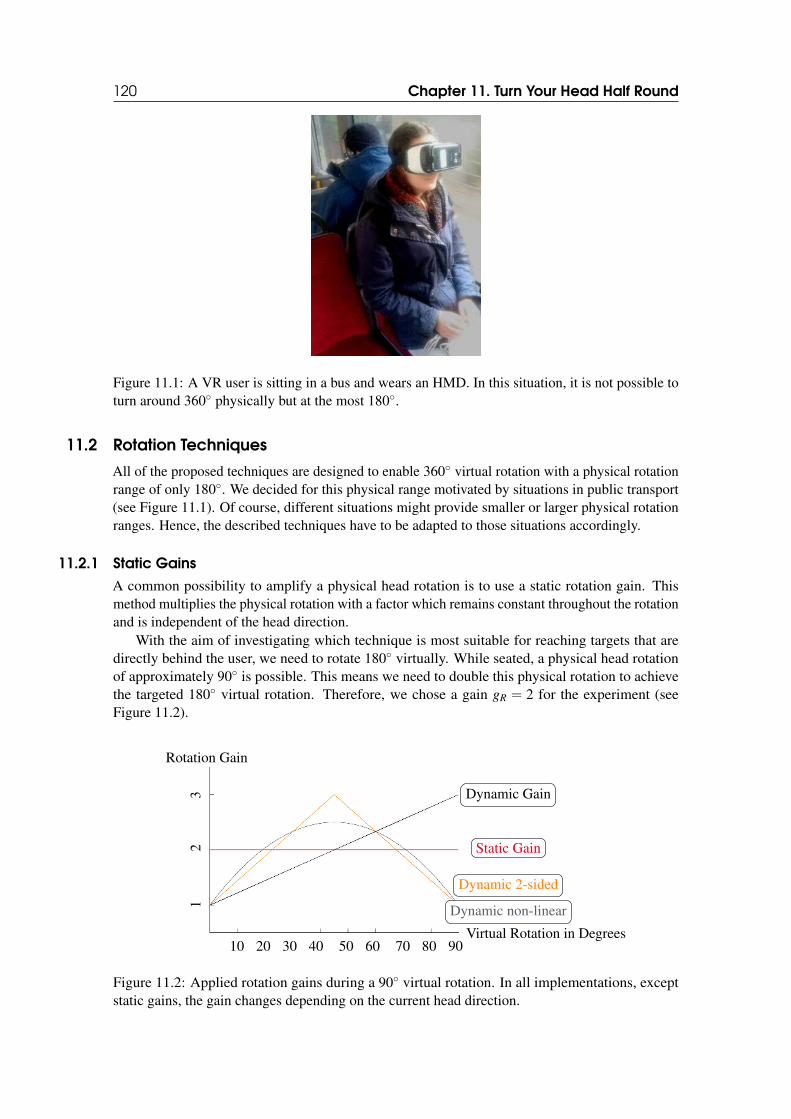
120 Chapter 11. Turn Your Head Half Round
Figure 11.1: A VR user is sitting in a bus and wears an HMD. In this situation, it is not possible toturn around 360◦ physically but at the most 180◦.
11.2 Rotation Techniques
All of the proposed techniques are designed to enable 360◦ virtual rotation with a physical rotationrange of only 180◦. We decided for this physical range motivated by situations in public transport(see Figure 11.1). Of course, different situations might provide smaller or larger physical rotationranges. Hence, the described techniques have to be adapted to those situations accordingly.
11.2.1 Static Gains
A common possibility to amplify a physical head rotation is to use a static rotation gain. Thismethod multiplies the physical rotation with a factor which remains constant throughout the rotationand is independent of the head direction.
With the aim of investigating which technique is most suitable for reaching targets that aredirectly behind the user, we need to rotate 180◦ virtually. While seated, a physical head rotationof approximately 90◦ is possible. This means we need to double this physical rotation to achievethe targeted 180◦ virtual rotation. Therefore, we chose a gain gR = 2 for the experiment (seeFigure 11.2).
10 20 30 40 50 60 70 80 90
Static Gain
Dynamic Gain
Dynamic 2-sided
Dynamic non-linear
Virtual Rotation in Degrees
Rotation Gain
12
3
Figure 11.2: Applied rotation gains during a 90◦ virtual rotation. In all implementations, exceptstatic gains, the gain changes depending on the current head direction.
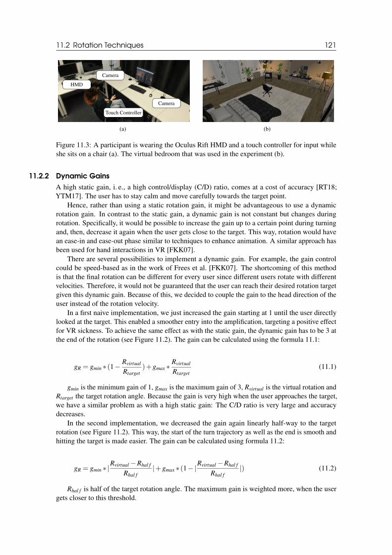
11.2 Rotation Techniques 121
HMD
Touch Controller
Camera
Camera
(a) (b)
Figure 11.3: A participant is wearing the Oculus Rift HMD and a touch controller for input whileshe sits on a chair (a). The virtual bedroom that was used in the experiment (b).
11.2.2 Dynamic Gains
A high static gain, i. e., a high control/display (C/D) ratio, comes at a cost of accuracy [RT18;YTM17]. The user has to stay calm and move carefully towards the target point.
Hence, rather than using a static rotation gain, it might be advantageous to use a dynamicrotation gain. In contrast to the static gain, a dynamic gain is not constant but changes duringrotation. Specifically, it would be possible to increase the gain up to a certain point during turningand, then, decrease it again when the user gets close to the target. This way, rotation would havean ease-in and ease-out phase similar to techniques to enhance animation. A similar approach hasbeen used for hand interactions in VR [FKK07].
There are several possibilities to implement a dynamic gain. For example, the gain controlcould be speed-based as in the work of Frees et al. [FKK07]. The shortcoming of this methodis that the final rotation can be different for every user since different users rotate with differentvelocities. Therefore, it would not be guaranteed that the user can reach their desired rotation targetgiven this dynamic gain. Because of this, we decided to couple the gain to the head direction of theuser instead of the rotation velocity.
In a first naive implementation, we just increased the gain starting at 1 until the user directlylooked at the target. This enabled a smoother entry into the amplification, targeting a positive effectfor VR sickness. To achieve the same effect as with the static gain, the dynamic gain has to be 3 atthe end of the rotation (see Figure 11.2). The gain can be calculated using the formula 11.1:
gR = gmin ∗ (1−Rvirtual
Rtarget
)+gmax ∗Rvirtual
Rtarget
(11.1)
gmin is the minimum gain of 1, gmax is the maximum gain of 3, Rvirtual is the virtual rotation andRtarget the target rotation angle. Because the gain is very high when the user approaches the target,we have a similar problem as with a high static gain: The C/D ratio is very large and accuracydecreases.
In the second implementation, we decreased the gain again linearly half-way to the targetrotation (see Figure 11.2). This way, the start of the turn trajectory as well as the end is smooth andhitting the target is made easier. The gain can be calculated using formula 11.2:
gR = gmin ∗ |Rvirtual −Rhal f
Rhal f
|+gmax ∗ (1−|Rvirtual −Rhal f
Rhal f
|) (11.2)
Rhal f is half of the target rotation angle. The maximum gain is weighted more, when the usergets closer to this threshold.
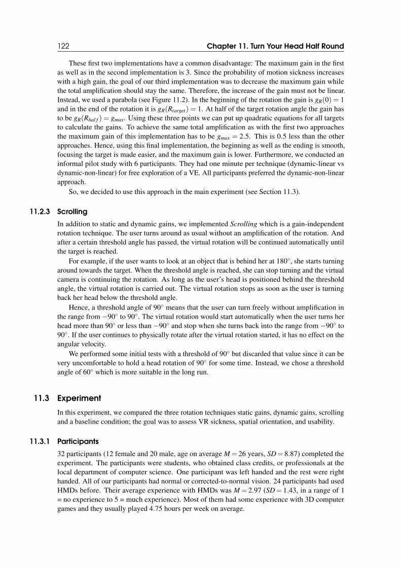
122 Chapter 11. Turn Your Head Half Round
These first two implementations have a common disadvantage: The maximum gain in the firstas well as in the second implementation is 3. Since the probability of motion sickness increaseswith a high gain, the goal of our third implementation was to decrease the maximum gain whilethe total amplification should stay the same. Therefore, the increase of the gain must not be linear.Instead, we used a parabola (see Figure 11.2). In the beginning of the rotation the gain is gR(0) = 1and in the end of the rotation it is gR(Rtarget) = 1. At half of the target rotation angle the gain hasto be gR(Rhal f ) = gmax. Using these three points we can put up quadratic equations for all targetsto calculate the gains. To achieve the same total amplification as with the first two approachesthe maximum gain of this implementation has to be gmax = 2.5. This is 0.5 less than the otherapproaches. Hence, using this final implementation, the beginning as well as the ending is smooth,focusing the target is made easier, and the maximum gain is lower. Furthermore, we conducted aninformal pilot study with 6 participants. They had one minute per technique (dynamic-linear vsdynamic-non-linear) for free exploration of a VE. All participants preferred the dynamic-non-linearapproach.
So, we decided to use this approach in the main experiment (see Section 11.3).
11.2.3 Scrolling
In addition to static and dynamic gains, we implemented Scrolling which is a gain-independentrotation technique. The user turns around as usual without an amplification of the rotation. Andafter a certain threshold angle has passed, the virtual rotation will be continued automatically untilthe target is reached.
For example, if the user wants to look at an object that is behind her at 180◦, she starts turningaround towards the target. When the threshold angle is reached, she can stop turning and the virtualcamera is continuing the rotation. As long as the user’s head is positioned behind the thresholdangle, the virtual rotation is carried out. The virtual rotation stops as soon as the user is turningback her head below the threshold angle.
Hence, a threshold angle of 90◦ means that the user can turn freely without amplification inthe range from −90◦ to 90◦. The virtual rotation would start automatically when the user turns herhead more than 90◦ or less than −90◦ and stop when she turns back into the range from −90◦ to90◦. If the user continues to physically rotate after the virtual rotation started, it has no effect on theangular velocity.
We performed some initial tests with a threshold of 90◦ but discarded that value since it can bevery uncomfortable to hold a head rotation of 90◦ for some time. Instead, we chose a thresholdangle of 60◦ which is more suitable in the long run.
11.3 Experiment
In this experiment, we compared the three rotation techniques static gains, dynamic gains, scrollingand a baseline condition; the goal was to assess VR sickness, spatial orientation, and usability.
11.3.1 Participants
32 participants (12 female and 20 male, age on average M = 26 years, SD= 8.87) completed theexperiment. The participants were students, who obtained class credits, or professionals at thelocal department of computer science. One participant was left handed and the rest were righthanded. All of our participants had normal or corrected-to-normal vision. 24 participants had usedHMDs before. Their average experience with HMDs was M = 2.97 (SD= 1.43, in a range of 1= no experience to 5 = much experience). Most of them had some experience with 3D computergames and they usually played 4.75 hours per week on average.
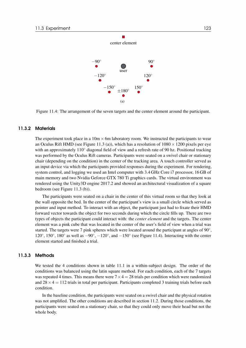
11.3 Experiment 123
user
center element
−90◦ 90◦
−120◦ 120◦
−150◦ 150◦±180◦
(a)
Figure 11.4: The arrangement of the seven targets and the center element around the participant.
11.3.2 Materials
The experiment took place in a 10m× 6m laboratory room. We instructed the participants to wearan Oculus Rift HMD (see Figure 11.3 (a)), which has a resolution of 1080× 1200 pixels per eyewith an approximately 110◦ diagonal field of view and a refresh rate of 90 hz. Positional trackingwas performed by the Oculus Rift cameras. Participants were seated on a swivel chair or stationarychair (depending on the condition) in the center of the tracking area. A touch controller served asan input device via which the participants provided responses during the experiment. For rendering,system control, and logging we used an Intel computer with 3.4 GHz Core i7 processor, 16 GB ofmain memory and two Nvidia Geforce GTX 780 Ti graphics cards. The virtual environment wasrendered using the Unity3D engine 2017.2 and showed an architectural visualization of a squarebedroom (see Figure 11.3 (b)).
The participants were seated on a chair in the center of this virtual room so that they look atthe wall opposite the bed. In the center of the participant’s view is a small circle which served aspointer and input method. To interact with an object, the participant just had to fixate their HMDforward vector towards the object for two seconds during which the circle fills up. There are twotypes of objects the participant could interact with: the center element and the targets. The centerelement was a pink cube that was located in the center of the user’s field of view when a trial wasstarted. The targets were 7 pink spheres which were located around the participant at angles of 90◦,120◦, 150◦, 180◦ as well as −90◦, −120◦, and −150◦ (see Figure 11.4). Interacting with the centerelement started and finished a trial.
11.3.3 Methods
We tested the 4 conditions shown in table 11.1 in a within-subject design. The order of theconditions was balanced using the latin square method. For each condition, each of the 7 targetswas repeated 4 times. This means there were 7×4 = 28 trials per condition which were randomizedand 28×4 = 112 trials in total per participant. Participants completed 3 training trials before eachcondition.
In the baseline condition, the participants were seated on a swivel chair and the physical rotationwas not amplified. The other conditions are described in section 11.2. During those conditions, theparticipants were seated on a stationary chair, so that they could only move their head but not thewhole body.
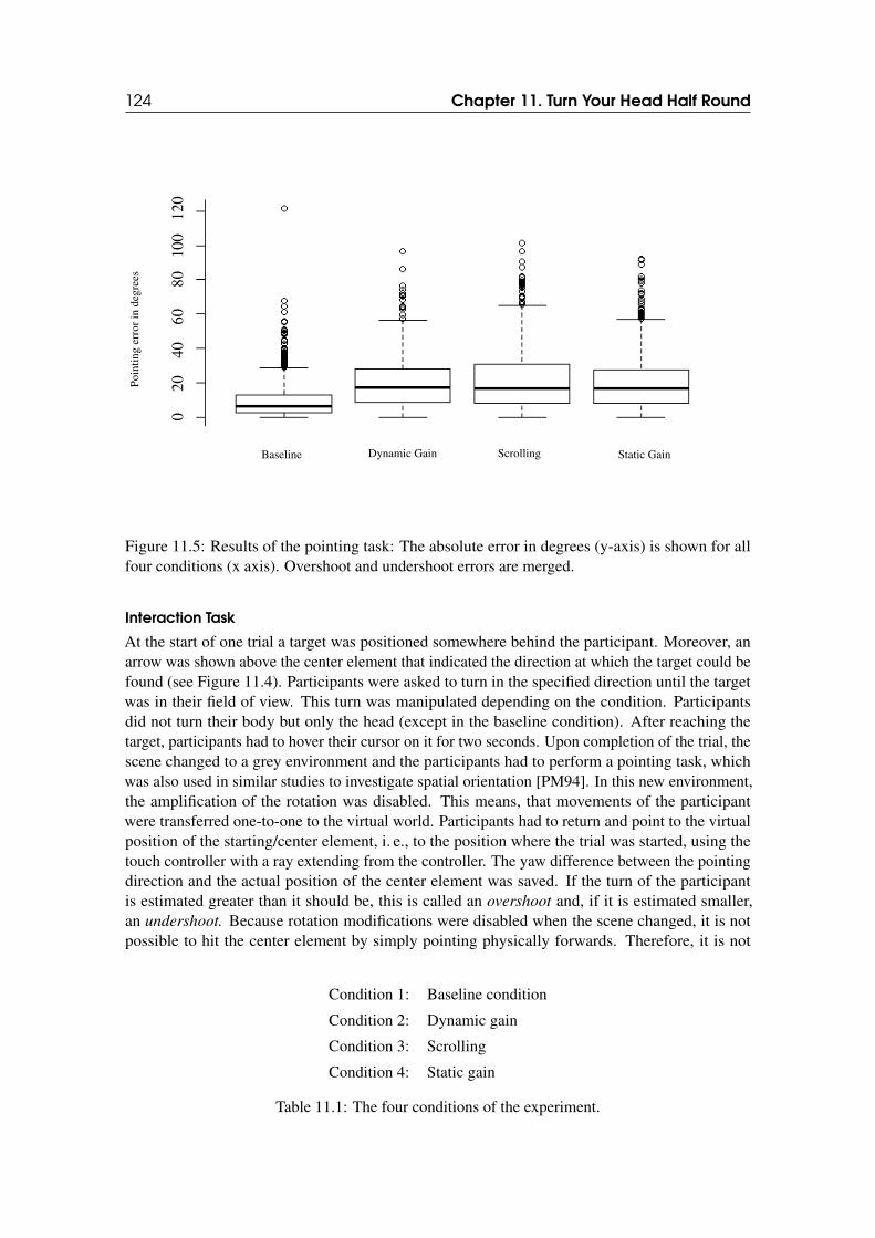
124 Chapter 11. Turn Your Head Half Round
Baseline Dynamic Gain Scrolling Static Gain
Poi
ntin
ger
ror
inde
gree
s
020
4060
8010
012
0
Figure 11.5: Results of the pointing task: The absolute error in degrees (y-axis) is shown for allfour conditions (x axis). Overshoot and undershoot errors are merged.
Interaction Task
At the start of one trial a target was positioned somewhere behind the participant. Moreover, anarrow was shown above the center element that indicated the direction at which the target could befound (see Figure 11.4). Participants were asked to turn in the specified direction until the targetwas in their field of view. This turn was manipulated depending on the condition. Participantsdid not turn their body but only the head (except in the baseline condition). After reaching thetarget, participants had to hover their cursor on it for two seconds. Upon completion of the trial, thescene changed to a grey environment and the participants had to perform a pointing task, whichwas also used in similar studies to investigate spatial orientation [PM94]. In this new environment,the amplification of the rotation was disabled. This means, that movements of the participantwere transferred one-to-one to the virtual world. Participants had to return and point to the virtualposition of the starting/center element, i. e., to the position where the trial was started, using thetouch controller with a ray extending from the controller. The yaw difference between the pointingdirection and the actual position of the center element was saved. If the turn of the participantis estimated greater than it should be, this is called an overshoot and, if it is estimated smaller,an undershoot. Because rotation modifications were disabled when the scene changed, it is notpossible to hit the center element by simply pointing physically forwards. Therefore, it is not
Condition 1: Baseline condition
Condition 2: Dynamic gain
Condition 3: Scrolling
Condition 4: Static gain
Table 11.1: The four conditions of the experiment.
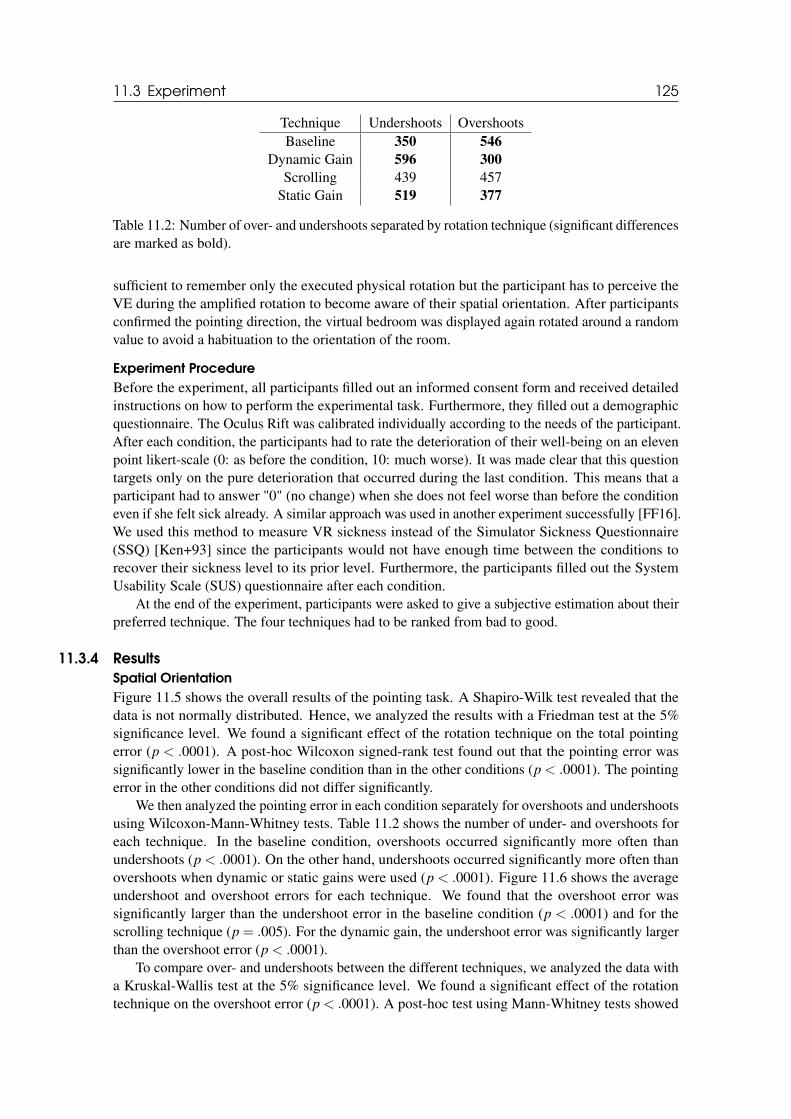
11.3 Experiment 125
Technique Undershoots OvershootsBaseline 350 546
Dynamic Gain 596 300
Scrolling 439 457Static Gain 519 377
Table 11.2: Number of over- and undershoots separated by rotation technique (significant differencesare marked as bold).
sufficient to remember only the executed physical rotation but the participant has to perceive theVE during the amplified rotation to become aware of their spatial orientation. After participantsconfirmed the pointing direction, the virtual bedroom was displayed again rotated around a randomvalue to avoid a habituation to the orientation of the room.
Experiment Procedure
Before the experiment, all participants filled out an informed consent form and received detailedinstructions on how to perform the experimental task. Furthermore, they filled out a demographicquestionnaire. The Oculus Rift was calibrated individually according to the needs of the participant.After each condition, the participants had to rate the deterioration of their well-being on an elevenpoint likert-scale (0: as before the condition, 10: much worse). It was made clear that this questiontargets only on the pure deterioration that occurred during the last condition. This means that aparticipant had to answer "0" (no change) when she does not feel worse than before the conditioneven if she felt sick already. A similar approach was used in another experiment successfully [FF16].We used this method to measure VR sickness instead of the Simulator Sickness Questionnaire(SSQ) [Ken+93] since the participants would not have enough time between the conditions torecover their sickness level to its prior level. Furthermore, the participants filled out the SystemUsability Scale (SUS) questionnaire after each condition.
At the end of the experiment, participants were asked to give a subjective estimation about theirpreferred technique. The four techniques had to be ranked from bad to good.
11.3.4 Results
Spatial Orientation
Figure 11.5 shows the overall results of the pointing task. A Shapiro-Wilk test revealed that thedata is not normally distributed. Hence, we analyzed the results with a Friedman test at the 5%significance level. We found a significant effect of the rotation technique on the total pointingerror (p < .0001). A post-hoc Wilcoxon signed-rank test found out that the pointing error wassignificantly lower in the baseline condition than in the other conditions (p < .0001). The pointingerror in the other conditions did not differ significantly.
We then analyzed the pointing error in each condition separately for overshoots and undershootsusing Wilcoxon-Mann-Whitney tests. Table 11.2 shows the number of under- and overshoots foreach technique. In the baseline condition, overshoots occurred significantly more often thanundershoots (p < .0001). On the other hand, undershoots occurred significantly more often thanovershoots when dynamic or static gains were used (p < .0001). Figure 11.6 shows the averageundershoot and overshoot errors for each technique. We found that the overshoot error wassignificantly larger than the undershoot error in the baseline condition (p < .0001) and for thescrolling technique (p = .005). For the dynamic gain, the undershoot error was significantly largerthan the overshoot error (p < .0001).
To compare over- and undershoots between the different techniques, we analyzed the data witha Kruskal-Wallis test at the 5% significance level. We found a significant effect of the rotationtechnique on the overshoot error (p < .0001). A post-hoc test using Mann-Whitney tests showed
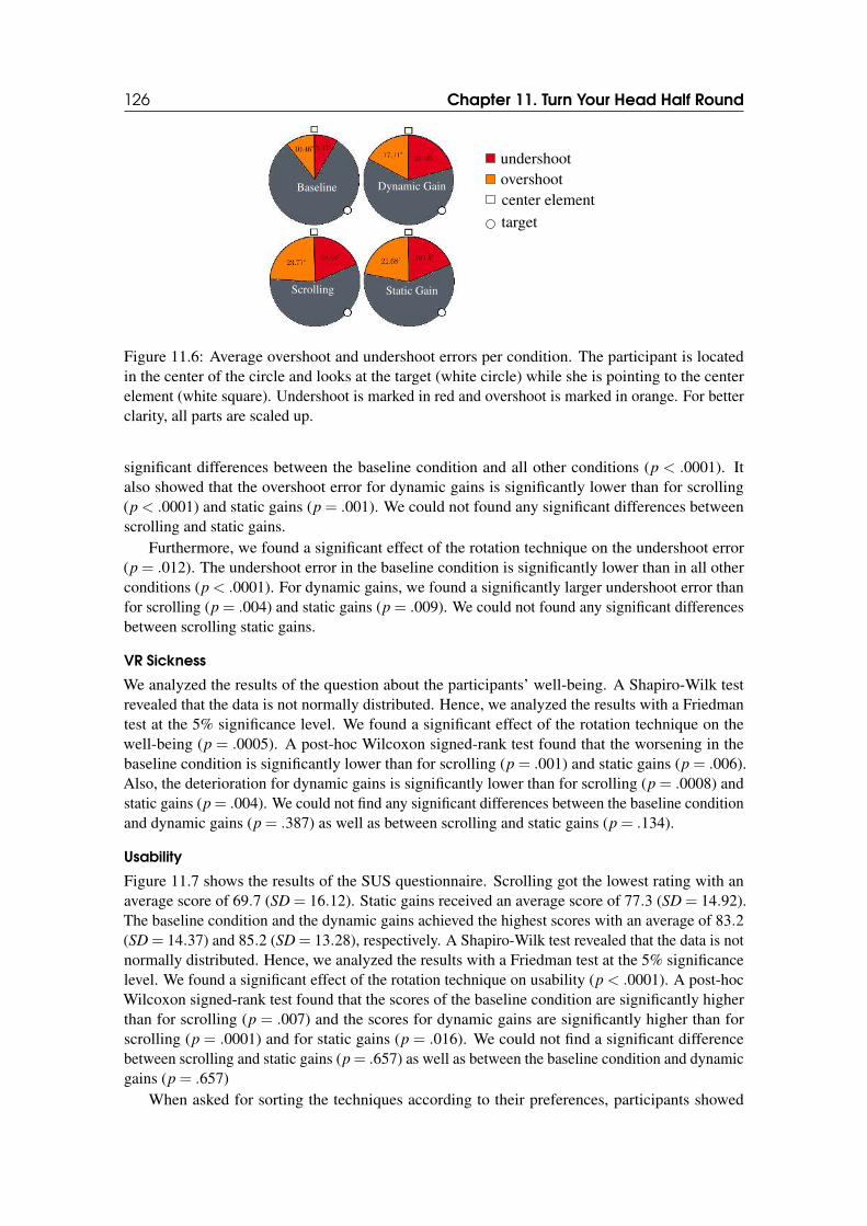
126 Chapter 11. Turn Your Head Half Round
Baseline Dynamic Gain
Scrolling Static Gain
undershootovershootcenter element
target
Figure 11.6: Average overshoot and undershoot errors per condition. The participant is locatedin the center of the circle and looks at the target (white circle) while she is pointing to the centerelement (white square). Undershoot is marked in red and overshoot is marked in orange. For betterclarity, all parts are scaled up.
significant differences between the baseline condition and all other conditions (p < .0001). Italso showed that the overshoot error for dynamic gains is significantly lower than for scrolling(p < .0001) and static gains (p = .001). We could not found any significant differences betweenscrolling and static gains.
Furthermore, we found a significant effect of the rotation technique on the undershoot error(p = .012). The undershoot error in the baseline condition is significantly lower than in all otherconditions (p < .0001). For dynamic gains, we found a significantly larger undershoot error thanfor scrolling (p = .004) and static gains (p = .009). We could not found any significant differencesbetween scrolling static gains.
VR Sickness
We analyzed the results of the question about the participants’ well-being. A Shapiro-Wilk testrevealed that the data is not normally distributed. Hence, we analyzed the results with a Friedmantest at the 5% significance level. We found a significant effect of the rotation technique on thewell-being (p = .0005). A post-hoc Wilcoxon signed-rank test found that the worsening in thebaseline condition is significantly lower than for scrolling (p = .001) and static gains (p = .006).Also, the deterioration for dynamic gains is significantly lower than for scrolling (p = .0008) andstatic gains (p = .004). We could not find any significant differences between the baseline conditionand dynamic gains (p = .387) as well as between scrolling and static gains (p = .134).
Usability
Figure 11.7 shows the results of the SUS questionnaire. Scrolling got the lowest rating with anaverage score of 69.7 (SD = 16.12). Static gains received an average score of 77.3 (SD = 14.92).The baseline condition and the dynamic gains achieved the highest scores with an average of 83.2(SD = 14.37) and 85.2 (SD = 13.28), respectively. A Shapiro-Wilk test revealed that the data is notnormally distributed. Hence, we analyzed the results with a Friedman test at the 5% significancelevel. We found a significant effect of the rotation technique on usability (p < .0001). A post-hocWilcoxon signed-rank test found that the scores of the baseline condition are significantly higherthan for scrolling (p = .007) and the scores for dynamic gains are significantly higher than forscrolling (p = .0001) and for static gains (p = .016). We could not find a significant differencebetween scrolling and static gains (p = .657) as well as between the baseline condition and dynamicgains (p = .657)
When asked for sorting the techniques according to their preferences, participants showed
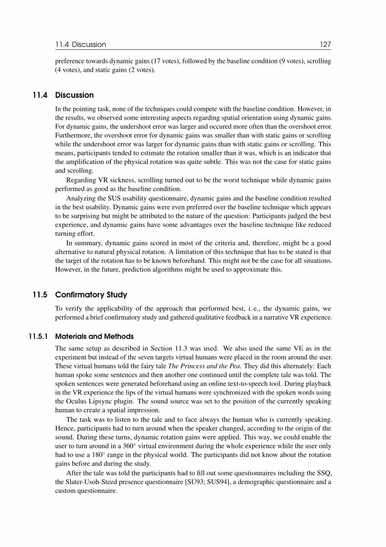
11.4 Discussion 127
preference towards dynamic gains (17 votes), followed by the baseline condition (9 votes), scrolling(4 votes), and static gains (2 votes).
11.4 Discussion
In the pointing task, none of the techniques could compete with the baseline condition. However, inthe results, we observed some interesting aspects regarding spatial orientation using dynamic gains.For dynamic gains, the undershoot error was larger and occured more often than the overshoot error.Furthermore, the overshoot error for dynamic gains was smaller than with static gains or scrollingwhile the undershoot error was larger for dynamic gains than with static gains or scrolling. Thismeans, participants tended to estimate the rotation smaller than it was, which is an indicator thatthe amplification of the physical rotation was quite subtle. This was not the case for static gainsand scrolling.
Regarding VR sickness, scrolling turned out to be the worst technique while dynamic gainsperformed as good as the baseline condition.
Analyzing the SUS usability questionnaire, dynamic gains and the baseline condition resultedin the best usability. Dynamic gains were even preferred over the baseline technique which appearsto be surprising but might be attributed to the nature of the question: Participants judged the bestexperience, and dynamic gains have some advantages over the baseline technique like reducedturning effort.
In summary, dynamic gains scored in most of the criteria and, therefore, might be a goodalternative to natural physical rotation. A limitation of this technique that has to be stated is thatthe target of the rotation has to be known beforehand. This might not be the case for all situations.However, in the future, prediction algorithms might be used to approximate this.
11.5 Confirmatory Study
To verify the applicability of the approach that performed best, i. e., the dynamic gains, weperformed a brief confirmatory study and gathered qualitative feedback in a narrative VR experience.
11.5.1 Materials and Methods
The same setup as described in Section 11.3 was used. We also used the same VE as in theexperiment but instead of the seven targets virtual humans were placed in the room around the user.These virtual humans told the fairy tale The Princess and the Pea. They did this alternately: Eachhuman spoke some sentences and then another one continued until the complete tale was told. Thespoken sentences were generated beforehand using an online text-to-speech tool. During playbackin the VR experience the lips of the virtual humans were synchronized with the spoken words usingthe Oculus Lipsync plugin. The sound source was set to the position of the currently speakinghuman to create a spatial impression.
The task was to listen to the tale and to face always the human who is currently speaking.Hence, participants had to turn around when the speaker changed, according to the origin of thesound. During these turns, dynamic rotation gains were applied. This way, we could enable theuser to turn around in a 360◦ virtual environment during the whole experience while the user onlyhad to use a 180◦ range in the physical world. The participants did not know about the rotationgains before and during the study.
After the tale was told the participants had to fill out some questionnaires including the SSQ,the Slater-Usoh-Steed presence questionnaire [SU93; SUS94], a demographic questionnaire and acustom questionnaire.
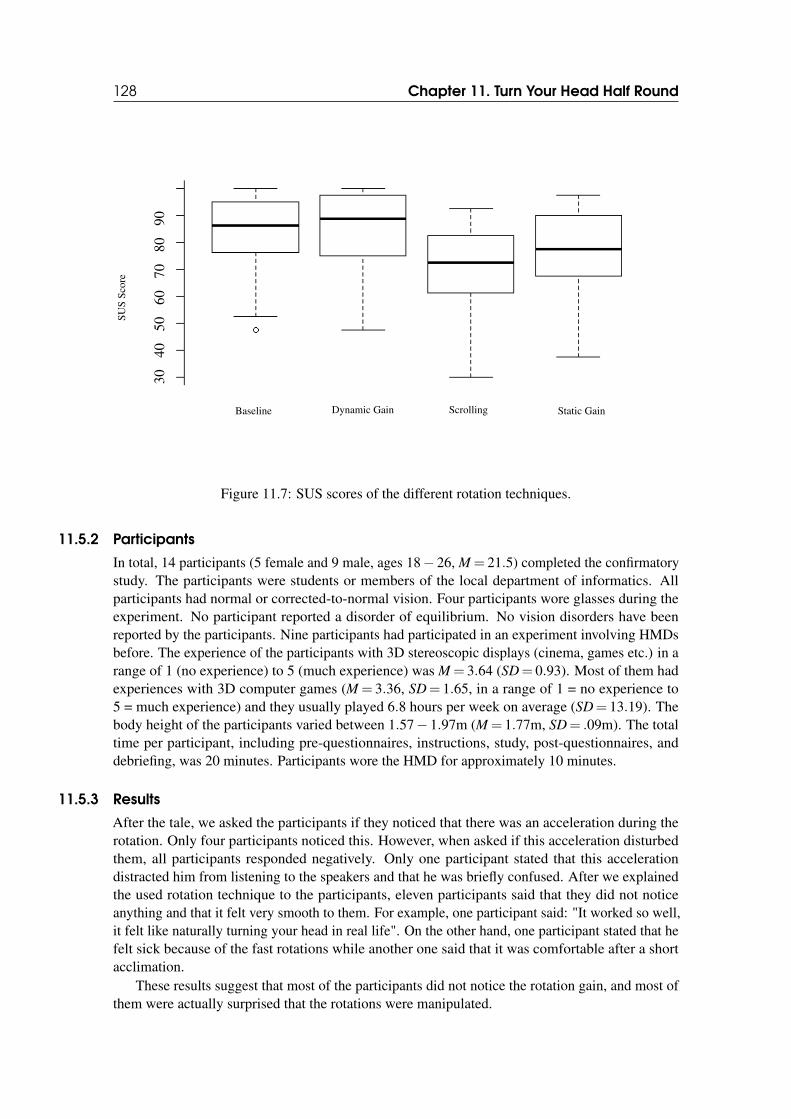
128 Chapter 11. Turn Your Head Half Round
Baseline Dynamic Gain Scrolling Static Gain
SU
SS
core
3040
5060
7080
90
Figure 11.7: SUS scores of the different rotation techniques.
11.5.2 Participants
In total, 14 participants (5 female and 9 male, ages 18− 26, M = 21.5) completed the confirmatorystudy. The participants were students or members of the local department of informatics. Allparticipants had normal or corrected-to-normal vision. Four participants wore glasses during theexperiment. No participant reported a disorder of equilibrium. No vision disorders have beenreported by the participants. Nine participants had participated in an experiment involving HMDsbefore. The experience of the participants with 3D stereoscopic displays (cinema, games etc.) in arange of 1 (no experience) to 5 (much experience) was M = 3.64 (SD= 0.93). Most of them hadexperiences with 3D computer games (M = 3.36, SD= 1.65, in a range of 1 = no experience to5 = much experience) and they usually played 6.8 hours per week on average (SD= 13.19). Thebody height of the participants varied between 1.57− 1.97m (M = 1.77m, SD= .09m). The totaltime per participant, including pre-questionnaires, instructions, study, post-questionnaires, anddebriefing, was 20 minutes. Participants wore the HMD for approximately 10 minutes.
11.5.3 Results
After the tale, we asked the participants if they noticed that there was an acceleration during therotation. Only four participants noticed this. However, when asked if this acceleration disturbedthem, all participants responded negatively. Only one participant stated that this accelerationdistracted him from listening to the speakers and that he was briefly confused. After we explainedthe used rotation technique to the participants, eleven participants said that they did not noticeanything and that it felt very smooth to them. For example, one participant said: "It worked so well,it felt like naturally turning your head in real life". On the other hand, one participant stated that hefelt sick because of the fast rotations while another one said that it was comfortable after a shortacclimation.
These results suggest that most of the participants did not notice the rotation gain, and most ofthem were actually surprised that the rotations were manipulated.

11.6 Conclusion 129
We measured a mean SSQ-score of 13.62 (SD= 19.71) before the experiment, and a meanSSQ-score of 16.83 (SD= 25.69) after the experiment. The mean score for the sense of feelingpresent in the VE was 2.14 (SD= 1.46) on a five-point likert scale.
11.6 Conclusion
We introduced a new technique based on dynamic rotation gains for rotating around in a VE whenin a situation where only a limited physical turning angle is available. Results suggest that thistechnique performs similar to natural rotation when it comes to spatial orientation, usability, andVR sickness, and better than other techniques like static gains or scrolling. This was evaluated inan experiment with 32 participants. Additionally, we demonstrated in a confirmatory study that thetechnique is appropriate for use in actual VR experiences.

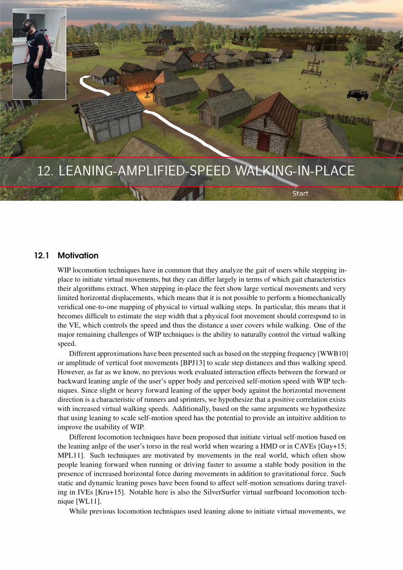
12. LEANING-AMPLIFIED-SPEED WALKING-IN-PLACE
12.1 Motivation
WIP locomotion techniques have in common that they analyze the gait of users while stepping in-place to initiate virtual movements, but they can differ largely in terms of which gait characteristicstheir algorithms extract. When stepping in-place the feet show large vertical movements and verylimited horizontal displacements, which means that it is not possible to perform a biomechanicallyveridical one-to-one mapping of physical to virtual walking steps. In particular, this means that itbecomes difficult to estimate the step width that a physical foot movement should correspond to inthe VE, which controls the speed and thus the distance a user covers while walking. One of themajor remaining challenges of WIP techniques is the ability to naturally control the virtual walkingspeed.
Different approximations have been presented such as based on the stepping frequency [WWB10]or amplitude of vertical foot movements [BPJ13] to scale step distances and thus walking speed.However, as far as we know, no previous work evaluated interaction effects between the forward orbackward leaning angle of the user’s upper body and perceived self-motion speed with WIP tech-niques. Since slight or heavy forward leaning of the upper body against the horizontal movementdirection is a characteristic of runners and sprinters, we hypothesize that a positive correlation existswith increased virtual walking speeds. Additionally, based on the same arguments we hypothesizethat using leaning to scale self-motion speed has the potential to provide an intuitive addition toimprove the usability of WIP.
Different locomotion techniques have been proposed that initiate virtual self-motion based onthe leaning anlge of the user’s torso in the real world when wearing a HMD or in CAVEs [Guy+15;MPL11]. Such techniques are motivated by movements in the real world, which often showpeople leaning forward when running or driving faster to assume a stable body position in thepresence of increased horizontal force during movements in addition to gravitational force. Suchstatic and dynamic leaning poses have been found to affect self-motion sensations during travel-ing in IVEs [Kru+15]. Notable here is also the SilverSurfer virtual surfboard locomotion tech-nique [WL11].
While previous locomotion techniques used leaning alone to initiate virtual movements, we
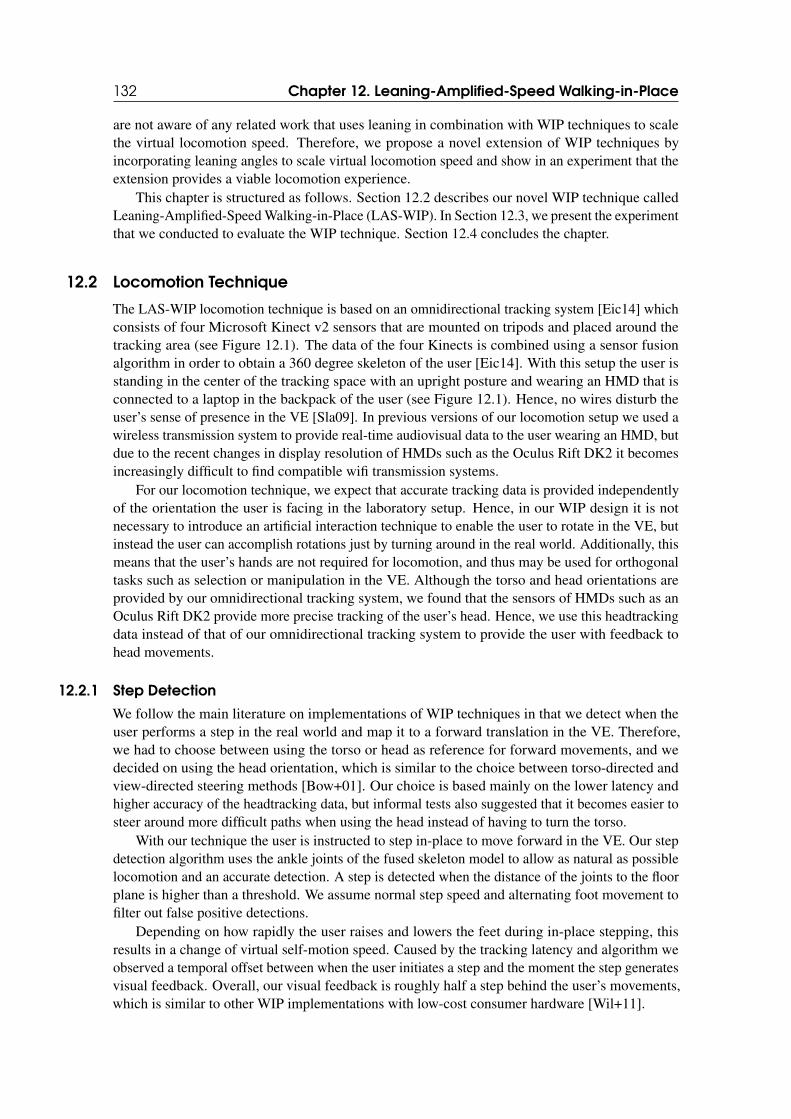
132 Chapter 12. Leaning-Amplified-Speed Walking-in-Place
are not aware of any related work that uses leaning in combination with WIP techniques to scalethe virtual locomotion speed. Therefore, we propose a novel extension of WIP techniques byincorporating leaning angles to scale virtual locomotion speed and show in an experiment that theextension provides a viable locomotion experience.
This chapter is structured as follows. Section 12.2 describes our novel WIP technique calledLeaning-Amplified-Speed Walking-in-Place (LAS-WIP). In Section 12.3, we present the experimentthat we conducted to evaluate the WIP technique. Section 12.4 concludes the chapter.
12.2 Locomotion Technique
The LAS-WIP locomotion technique is based on an omnidirectional tracking system [Eic14] whichconsists of four Microsoft Kinect v2 sensors that are mounted on tripods and placed around thetracking area (see Figure 12.1). The data of the four Kinects is combined using a sensor fusionalgorithm in order to obtain a 360 degree skeleton of the user [Eic14]. With this setup the user isstanding in the center of the tracking space with an upright posture and wearing an HMD that isconnected to a laptop in the backpack of the user (see Figure 12.1). Hence, no wires disturb theuser’s sense of presence in the VE [Sla09]. In previous versions of our locomotion setup we used awireless transmission system to provide real-time audiovisual data to the user wearing an HMD, butdue to the recent changes in display resolution of HMDs such as the Oculus Rift DK2 it becomesincreasingly difficult to find compatible wifi transmission systems.
For our locomotion technique, we expect that accurate tracking data is provided independentlyof the orientation the user is facing in the laboratory setup. Hence, in our WIP design it is notnecessary to introduce an artificial interaction technique to enable the user to rotate in the VE, butinstead the user can accomplish rotations just by turning around in the real world. Additionally, thismeans that the user’s hands are not required for locomotion, and thus may be used for orthogonaltasks such as selection or manipulation in the VE. Although the torso and head orientations areprovided by our omnidirectional tracking system, we found that the sensors of HMDs such as anOculus Rift DK2 provide more precise tracking of the user’s head. Hence, we use this headtrackingdata instead of that of our omnidirectional tracking system to provide the user with feedback tohead movements.
12.2.1 Step Detection
We follow the main literature on implementations of WIP techniques in that we detect when theuser performs a step in the real world and map it to a forward translation in the VE. Therefore,we had to choose between using the torso or head as reference for forward movements, and wedecided on using the head orientation, which is similar to the choice between torso-directed andview-directed steering methods [Bow+01]. Our choice is based mainly on the lower latency andhigher accuracy of the headtracking data, but informal tests also suggested that it becomes easier tosteer around more difficult paths when using the head instead of having to turn the torso.
With our technique the user is instructed to step in-place to move forward in the VE. Our stepdetection algorithm uses the ankle joints of the fused skeleton model to allow as natural as possiblelocomotion and an accurate detection. A step is detected when the distance of the joints to the floorplane is higher than a threshold. We assume normal step speed and alternating foot movement tofilter out false positive detections.
Depending on how rapidly the user raises and lowers the feet during in-place stepping, thisresults in a change of virtual self-motion speed. Caused by the tracking latency and algorithm weobserved a temporal offset between when the user initiates a step and the moment the step generatesvisual feedback. Overall, our visual feedback is roughly half a step behind the user’s movements,which is similar to other WIP implementations with low-cost consumer hardware [Wil+11].
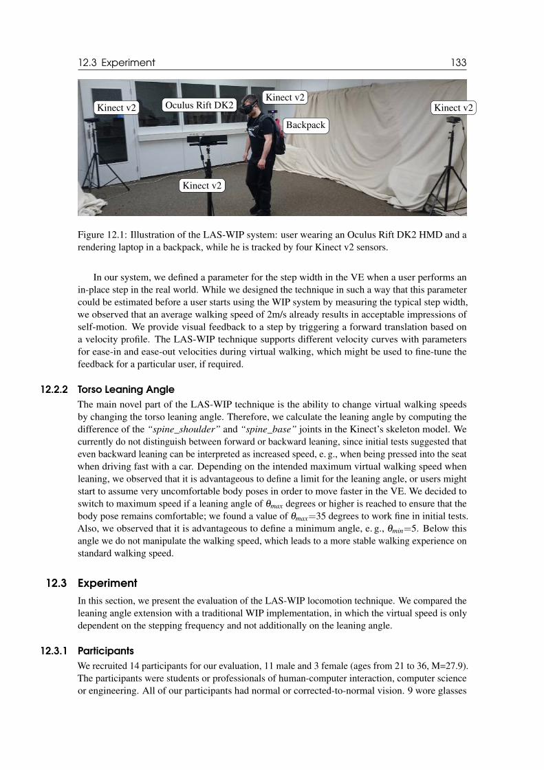
12.3 Experiment 133
Oculus Rift DK2
Backpack
Kinect v2
Kinect v2
Kinect v2Kinect v2
Figure 12.1: Illustration of the LAS-WIP system: user wearing an Oculus Rift DK2 HMD and arendering laptop in a backpack, while he is tracked by four Kinect v2 sensors.
In our system, we defined a parameter for the step width in the VE when a user performs anin-place step in the real world. While we designed the technique in such a way that this parametercould be estimated before a user starts using the WIP system by measuring the typical step width,we observed that an average walking speed of 2m/s already results in acceptable impressions ofself-motion. We provide visual feedback to a step by triggering a forward translation based ona velocity profile. The LAS-WIP technique supports different velocity curves with parametersfor ease-in and ease-out velocities during virtual walking, which might be used to fine-tune thefeedback for a particular user, if required.
12.2.2 Torso Leaning Angle
The main novel part of the LAS-WIP technique is the ability to change virtual walking speedsby changing the torso leaning angle. Therefore, we calculate the leaning angle by computing thedifference of the “spine_shoulder” and “spine_base” joints in the Kinect’s skeleton model. Wecurrently do not distinguish between forward or backward leaning, since initial tests suggested thateven backward leaning can be interpreted as increased speed, e. g., when being pressed into the seatwhen driving fast with a car. Depending on the intended maximum virtual walking speed whenleaning, we observed that it is advantageous to define a limit for the leaning angle, or users mightstart to assume very uncomfortable body poses in order to move faster in the VE. We decided toswitch to maximum speed if a leaning angle of θmax degrees or higher is reached to ensure that thebody pose remains comfortable; we found a value of θmax=35 degrees to work fine in initial tests.Also, we observed that it is advantageous to define a minimum angle, e. g., θmin=5. Below thisangle we do not manipulate the walking speed, which leads to a more stable walking experience onstandard walking speed.
12.3 Experiment
In this section, we present the evaluation of the LAS-WIP locomotion technique. We compared theleaning angle extension with a traditional WIP implementation, in which the virtual speed is onlydependent on the stepping frequency and not additionally on the leaning angle.
12.3.1 Participants
We recruited 14 participants for our evaluation, 11 male and 3 female (ages from 21 to 36, M=27.9).The participants were students or professionals of human-computer interaction, computer scienceor engineering. All of our participants had normal or corrected-to-normal vision. 9 wore glasses
134 Chapter 12. Leaning-Amplified-Speed Walking-in-Place
and 1 participant wore contact lenses during the experiment. None of our participants reporteda disorder of equilibrium or binocular vision disorders. 12 participants had experienced HMDsbefore. The total time per participant, including pre-questionnaires, instructions, experiment, breaks,post-questionnaires, and debriefing, was 30 minutes. Participants wore the HMD for approximately20 minutes. They were allowed to take breaks at any time.
12.3.2 Materials and Methods
We used a within-subjects design, in which we compared two WIP techniques: LAS-WIP andtraditional WIP implementation without leaning. The order of these tests was randomized andcounterbalanced. As dependent variables we measured VR sickness using the SSQ [Ken+93],presence using the SUS questionnaire [Uso+99b], as well as subjective estimates of preference andexperience in a custom questionnaire.
We performed the experiment in an 8m×5m laboratory room. As illustrated in Figure 12.1, weused a wireless setup. Participants wore an Oculus Rift DK2 HMD for the stimulus presentationand a rendering laptop in a backpack. We used a graphics laptop with an Intel i7 CPU, NvidiaGeForce GTX 970M and 16GB RAM for rendering the VE. The omnidirectional body trackingsystem was running with four Kinect v2 sensors, each connected to a graphics workstation withIntel i7 CPU, Nvidia GeForce GTX 970 and 16GB RAM. The workstations were connected viaGBit Ethernet. The rendering laptop received tracking data via wifi.
In the experiment we generated virtual step feedback based on a linear velocity function, whichconsisted of an ease-in and ease-out phase. Each phase lasted 0.5 seconds; the overall duration of astep was 1 second, which corresponds to a walking speed of 2m/s if a mean step frequency of onestep per second is assumed. When another step is received during this time, the first step is discardedand the speed is increased from the current level up to the maximum speed. Hence, stepping at theexpected frequency results in a uniform movement velocity. We used a velocity scaling factor of 5for maximum leaning angles, with constraints θmin=5 and θmax=35 (see Section 12.2).
The virtual world was rendered using the the Unreal Engine 4. The participants had to walk aperiodic path in the VE, which was indicated by a gravel road. The virtual path had a length of ca.1000m. The path consisted of multiple curvatures so the participants had to turn around and utilizethe full 360 degrees tracking range (see Figure 12.2). The VE was a 3D model of the medievalHammaburg, a castle and adjacent village of the 9th century in Hamburg, Germany. The castle is ofsignificant importance for archaeology, tourism and city marketing. In cooperation with the localarchaeological museum we are currently considering different possibilities to create interactiveexperiences for museum visitors. LAS-WIP with our omnidirectional tracking setup provides onepossibility to explore this virtual medieval world.
12.3.3 Results and Discussion
We measured VR sickness symptoms before and after each of the two WIP conditions, and wecomputed the change in VR sickness.
For the traditional WIP technique we measured an average increase in SSQ scores of 17.63(SD= 28.23) and for LAS-WIP an average increase of 9.88 (SD= 16.83), which both are inthe range of usual increases in symptoms with an Oculus Rift DK2 HMD over the time of theexperiment. We analyzed the questionnaire data with Wilcoxon signed rank tests. We found nosignificant difference in VR sickness symptoms between the LAS-WIP technique and the traditionaltechnique (Z = 1.22, p= .22). The apparent trend can be interpreted in light of the shorter timeparticipants spent in the VE for LAS-WIP (ca. 7min) compared to the traditional technique (ca.14min), since the LAS-WIP technique allowed participants to complete the path in the VE at anincreased speed.
We measured the participants’ sense of presence with the SUS questionnaire, which revealed
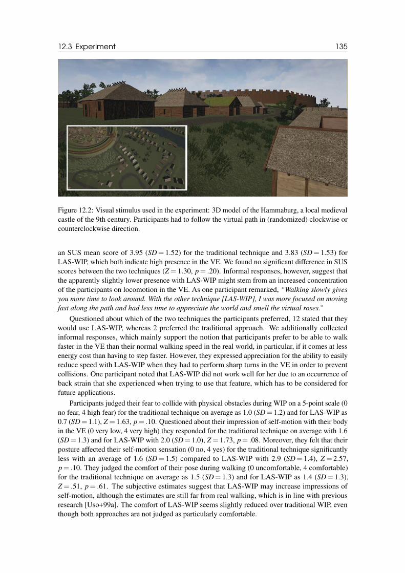
12.3 Experiment 135
Figure 12.2: Visual stimulus used in the experiment: 3D model of the Hammaburg, a local medievalcastle of the 9th century. Participants had to follow the virtual path in (randomized) clockwise orcounterclockwise direction.
an SUS mean score of 3.95 (SD= 1.52) for the traditional technique and 3.83 (SD= 1.53) forLAS-WIP, which both indicate high presence in the VE. We found no significant difference in SUSscores between the two techniques (Z = 1.30, p= .20). Informal responses, however, suggest thatthe apparently slightly lower presence with LAS-WIP might stem from an increased concentrationof the participants on locomotion in the VE. As one participant remarked, “Walking slowly gives
you more time to look around. With the other technique [LAS-WIP], I was more focused on moving
fast along the path and had less time to appreciate the world and smell the virtual roses.”
Questioned about which of the two techniques the participants preferred, 12 stated that theywould use LAS-WIP, whereas 2 preferred the traditional approach. We additionally collectedinformal responses, which mainly support the notion that participants prefer to be able to walkfaster in the VE than their normal walking speed in the real world, in particular, if it comes at lessenergy cost than having to step faster. However, they expressed appreciation for the ability to easilyreduce speed with LAS-WIP when they had to perform sharp turns in the VE in order to preventcollisions. One participant noted that LAS-WIP did not work well for her due to an occurrence ofback strain that she experienced when trying to use that feature, which has to be considered forfuture applications.
Participants judged their fear to collide with physical obstacles during WIP on a 5-point scale (0no fear, 4 high fear) for the traditional technique on average as 1.0 (SD= 1.2) and for LAS-WIP as0.7 (SD= 1.1), Z = 1.63, p= .10. Questioned about their impression of self-motion with their bodyin the VE (0 very low, 4 very high) they responded for the traditional technique on average with 1.6(SD= 1.3) and for LAS-WIP with 2.0 (SD= 1.0), Z = 1.73, p= .08. Moreover, they felt that theirposture affected their self-motion sensation (0 no, 4 yes) for the traditional technique significantlyless with an average of 1.6 (SD= 1.5) compared to LAS-WIP with 2.9 (SD= 1.4), Z = 2.57,p= .10. They judged the comfort of their pose during walking (0 uncomfortable, 4 comfortable)for the traditional technique on average as 1.5 (SD= 1.3) and for LAS-WIP as 1.4 (SD= 1.3),Z = .51, p= .61. The subjective estimates suggest that LAS-WIP may increase impressions ofself-motion, although the estimates are still far from real walking, which is in line with previousresearch [Uso+99a]. The comfort of LAS-WIP seems slightly reduced over traditional WIP, eventhough both approaches are not judged as particularly comfortable.
136 Chapter 12. Leaning-Amplified-Speed Walking-in-Place
12.4 Conclusion
In this chapter, we presented and evaluated a novel solution to WIP locomotion techniques. Usingan omnidirectional tracking setup based on multiple Kinects and a sensor fusion approach thatcombines the available skeleton data, we detailed our novel leaning extension for WIP, calledLAS-WIP, and presented an experiment, which indicates that the leaning extension can improve theusability of WIP and also has the potential to improve subjective self-motion estimation.
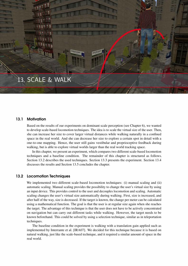
13. SCALE & WALK
13.1 Motivation
Based on the results of our experiments on dominant scale perception (see Chapter 6), we wantedto develop scale-based locomotion techniques. The idea is to scale the virtual size of the user. Then,she can increase her size to cover larger virtual distances while walking naturally in a confinedspace in the real world. And she can decrease her size to explore a certain spot in detail with aone-to-one mapping. Hence, the user still gains vestibular and proprioceptive feedback duringwalking, but is able to explore virtual worlds larger than the real world tracking space.
In this chapter, we present an experiment, which compares two different scale-based locomotiontechniques and a baseline condition. The remainder of this chapter is structured as follows.Section 13.2 describes the used techniques. Section 13.3 presents the experiment. Section 13.4discusses the results and Section 13.5 concludes the chapter.
13.2 Locomotion Techniques
We implemented two different scale-based locomotion techniques: (i) manual scaling and (ii)automatic scaling. Manual scaling provides the possibility to change the user’s virtual size by usingan input device. This provides control to the user and decouples locomotion and scaling. Automaticscaling changes the user’s virtual size automatically during walking. First, size is increased, andafter half of the way, size is decreased. If the target is known, the change per meter can be calculatedusing a mathematical function. The goal is that the user is at regular size again when she reachesthe target. The advantage of this technique is that the user does not have to be actively concentratedon navigation but can carry out different tasks while walking. However, the target needs to beknown beforehand. This could be solved by using a selection technique, similar as in teleportationtechniques.
The baseline condition in the experiment is walking with a translation gain applied such asimplemented by Interrante et al. [IRA07]. We decided for this technique because it is based onnatural walking, just like the scale-based technique, and it required a similar amount of space in thereal world.
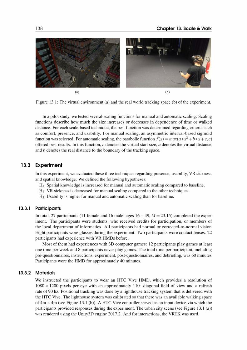
138 Chapter 13. Scale & Walk
(a) (b)
Figure 13.1: The virtual environment (a) and the real world tracking space (b) of the experiment.
In a pilot study, we tested several scaling functions for manual and automatic scaling. Scalingfunctions describe how much the size increases or decreases in dependence of time or walkeddistance. For each scale-based technique, the best function was determined regarding criteria suchas comfort, presence, and usability. For manual scaling, an asymmetric interval-based sigmoidfunction was selected. For automatic scaling, the parabolic function f (x) = max(a∗x2+b∗x+c,c)offered best results. In this function, c denotes the virtual start size, a denotes the virtual distance,and b denotes the real distance to the boundary of the tracking space.
13.3 Experiment
In this experiment, we evaluated these three techniques regarding presence, usability, VR sickness,and spatial knowledge. We defined the following hypotheses:
H1 Spatial knowledge is increased for manual and automatic scaling compared to baseline.H2 VR sickness is decreased for manual scaling compared to the other techniques.H3 Usability is higher for manual and automatic scaling than for baseline.
13.3.1 Participants
In total, 27 participants (11 female and 16 male, ages 16− 49, M = 23.15) completed the exper-iment. The participants were students, who received credits for participation, or members ofthe local department of informatics. All participants had normal or corrected-to-normal vision.Eight participants wore glasses during the experiment. Two participants wore contact lenses. 22participants had experience with VR HMDs before.
Most of them had experiences with 3D computer games: 12 participants play games at leastone time per week and 8 participants never play games. The total time per participant, includingpre-questionnaires, instructions, experiment, post-questionnaires, and debriefing, was 60 minutes.Participants wore the HMD for approximately 40 minutes.
13.3.2 Materials
We instructed the participants to wear an HTC Vive HMD, which provides a resolution of1080× 1200 pixels per eye with an approximately 110◦ diagonal field of view and a refreshrate of 90 hz. Positional tracking was done by a lighthouse tracking system that is delivered withthe HTC Vive. The lighthouse system was calibrated so that there was an available walking spaceof 4m× 4m (see Figure 13.1 (b)). A HTC Vive controller served as an input device via which theparticipants provided responses during the experiment. The urban city scene (see Figure 13.1 (a))was rendered using the Unity3D engine 2017.2. And for interactions, the VRTK was used.
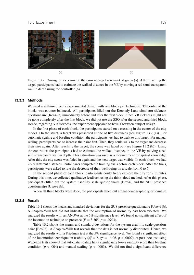
13.3 Experiment 139
(a) (b)
Figure 13.2: During the experiment, the current target was marked green (a). After reaching thetarget, participants had to estimate the walked distance in the VE by moving a red semi-transparentwall in depth using the controller (b).
13.3.3 Methods
We used a within-subjects experimental design with one block per technique. The order of theblocks was counter-balanced. All participants filled out the Kennedy-Lane simulator sicknessquestionnaire [Ken+93] immediately before and after the first block. Since VR sickness might notbe gone completely after the first block, we did not use the SSQ after the second and third block.Hence, regarding VR sickness, the experiment appeared to have a between-subject design.
In the first phase of each block, the participants started on a crossing in the center of the citymodel. On the street, a target was presented at one of five distances (see Figure 13.2 (a)). Forautomatic scaling and baseline condition, the participants just had to walk to this target. For manualscaling, participants had to increase their size first. Then, they could walk to the target and decreasetheir size again. After reaching the target, the scene was faded out (see Figure 13.2 (b)). Usingthe controller, the participants had to estimate the walked distance in the VE by moving a redsemi-transparent wall in depth. This estimation was used as a measurement for spatial knowledge.After this, the city scene was faded in again and the next target was visible. In each block, we had2×5 different distances. Participants completed 3 training trials before each block. After the trials,participants were asked to rate the decrease of their well-being on a scale from 0 to 6.
In the second phase of each block, participants could freely explore the city for 2 minutes.During this time, we collected qualitative feedback using the think-aloud method. After this phase,participants filled out the system usability scale questionnaire [Bro96] and the SUS presencequestionnaire [Uso+99b].
When all three blocks were done, the participants filled out a final demographic questionnaire.
13.3.4 Results
Table 13.1 shows the means and standard deviations for the SUS presence questionnaire [Uso+99b].A Shapiro-Wilk test did not indicate that the assumption of normality had been violated. Weanalyzed the results with an ANOVA at the 5% significance level. We found no significant effect ofthe locomotion technique on presence (F = 3.365, p = .0703).
Table 13.2 shows the means and standard deviations for the system usability scale question-naire [Bro96]. A Shapiro-Wilk test reveals that the data is not normally distributed. Hence, weanalyzed the results with a Friedman test at the 5% significance level. We found a significant effectof the locomotion technique on usability (df = 2, χ2 = 14.06, p < .0009). A post-hoc test usingWilcoxon tests showed that automatic scaling has a significantly lower usability score than baselinecondition (p < .004) and manual scaling (p < .0003). We did not find a significant difference
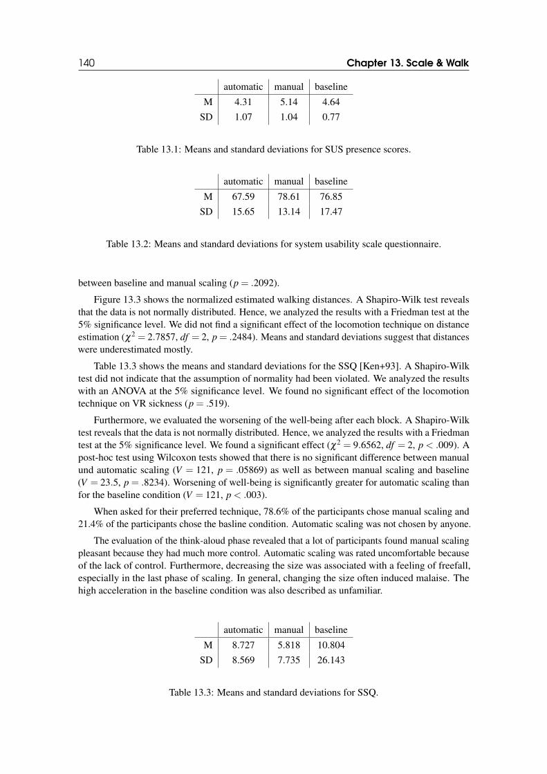
140 Chapter 13. Scale & Walk
automatic manual baseline
M 4.31 5.14 4.64
SD 1.07 1.04 0.77
Table 13.1: Means and standard deviations for SUS presence scores.
automatic manual baseline
M 67.59 78.61 76.85
SD 15.65 13.14 17.47
Table 13.2: Means and standard deviations for system usability scale questionnaire.
between baseline and manual scaling (p = .2092).
Figure 13.3 shows the normalized estimated walking distances. A Shapiro-Wilk test revealsthat the data is not normally distributed. Hence, we analyzed the results with a Friedman test at the5% significance level. We did not find a significant effect of the locomotion technique on distanceestimation (χ2 = 2.7857, df = 2, p = .2484). Means and standard deviations suggest that distanceswere underestimated mostly.
Table 13.3 shows the means and standard deviations for the SSQ [Ken+93]. A Shapiro-Wilktest did not indicate that the assumption of normality had been violated. We analyzed the resultswith an ANOVA at the 5% significance level. We found no significant effect of the locomotiontechnique on VR sickness (p = .519).
Furthermore, we evaluated the worsening of the well-being after each block. A Shapiro-Wilktest reveals that the data is not normally distributed. Hence, we analyzed the results with a Friedmantest at the 5% significance level. We found a significant effect (χ2 = 9.6562, df = 2, p < .009). Apost-hoc test using Wilcoxon tests showed that there is no significant difference between manualund automatic scaling (V = 121, p = .05869) as well as between manual scaling and baseline(V = 23.5, p = .8234). Worsening of well-being is significantly greater for automatic scaling thanfor the baseline condition (V = 121, p < .003).
When asked for their preferred technique, 78.6% of the participants chose manual scaling and21.4% of the participants chose the basline condition. Automatic scaling was not chosen by anyone.
The evaluation of the think-aloud phase revealed that a lot of participants found manual scalingpleasant because they had much more control. Automatic scaling was rated uncomfortable becauseof the lack of control. Furthermore, decreasing the size was associated with a feeling of freefall,especially in the last phase of scaling. In general, changing the size often induced malaise. Thehigh acceleration in the baseline condition was also described as unfamiliar.
automatic manual baseline
M 8.727 5.818 10.804
SD 8.569 7.735 26.143
Table 13.3: Means and standard deviations for SSQ.
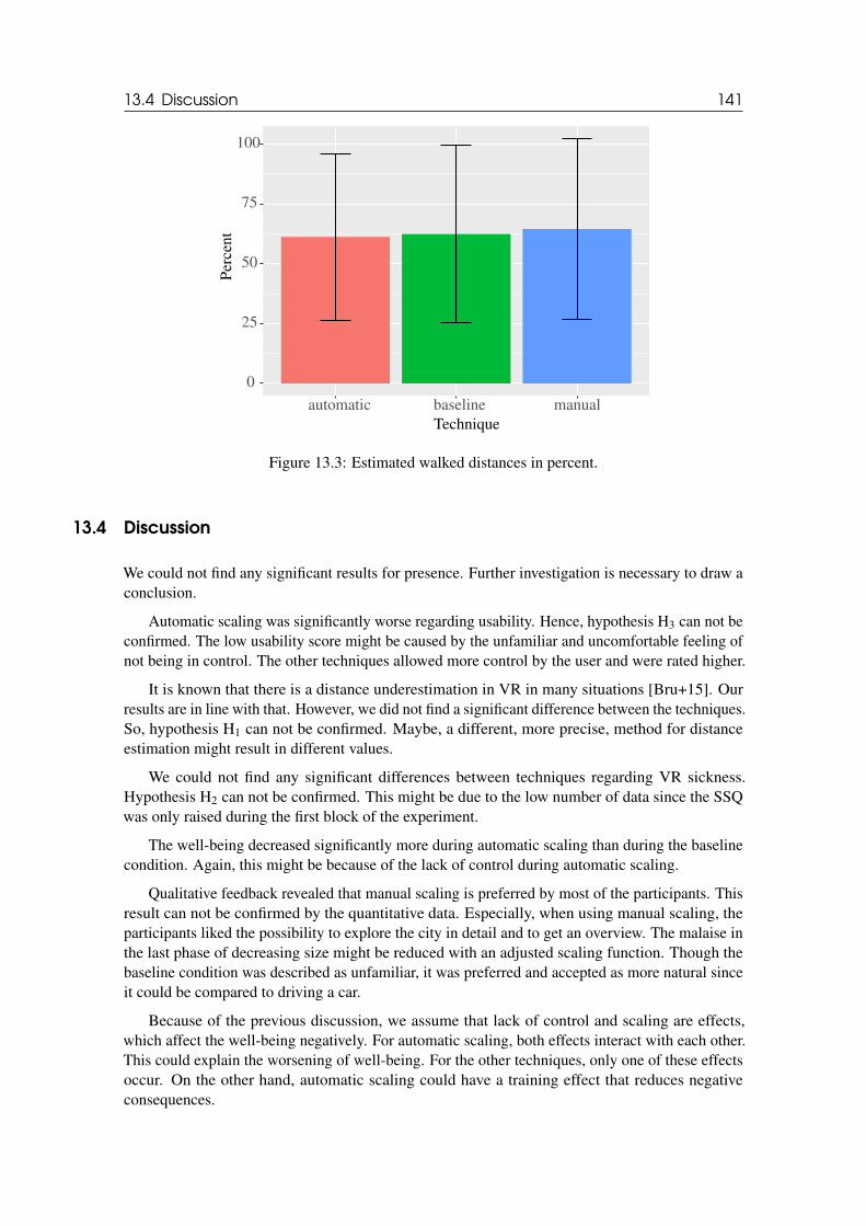
13.4 Discussion 141
0
25
50
75
100
automatic baseline manualTechnique
Per
cent
Figure 13.3: Estimated walked distances in percent.
13.4 Discussion
We could not find any significant results for presence. Further investigation is necessary to draw aconclusion.
Automatic scaling was significantly worse regarding usability. Hence, hypothesis H3 can not beconfirmed. The low usability score might be caused by the unfamiliar and uncomfortable feeling ofnot being in control. The other techniques allowed more control by the user and were rated higher.
It is known that there is a distance underestimation in VR in many situations [Bru+15]. Ourresults are in line with that. However, we did not find a significant difference between the techniques.So, hypothesis H1 can not be confirmed. Maybe, a different, more precise, method for distanceestimation might result in different values.
We could not find any significant differences between techniques regarding VR sickness.Hypothesis H2 can not be confirmed. This might be due to the low number of data since the SSQwas only raised during the first block of the experiment.
The well-being decreased significantly more during automatic scaling than during the baselinecondition. Again, this might be because of the lack of control during automatic scaling.
Qualitative feedback revealed that manual scaling is preferred by most of the participants. Thisresult can not be confirmed by the quantitative data. Especially, when using manual scaling, theparticipants liked the possibility to explore the city in detail and to get an overview. The malaise inthe last phase of decreasing size might be reduced with an adjusted scaling function. Though thebaseline condition was described as unfamiliar, it was preferred and accepted as more natural sinceit could be compared to driving a car.
Because of the previous discussion, we assume that lack of control and scaling are effects,which affect the well-being negatively. For automatic scaling, both effects interact with each other.This could explain the worsening of well-being. For the other techniques, only one of these effectsoccur. On the other hand, automatic scaling could have a training effect that reduces negativeconsequences.

142 Chapter 13. Scale & Walk
13.5 Conclusion
In this chapter, we presented an experiment, in which two scale-based locomotion techniques and abaseline condition were compared. The techniques were evaluated regarding usability, presence,VR sickness, and spatial knowledge. We did not find any significant differences between thetechniques regarding spatial knowledge. Automatic scaling induced significantly more VR sicknessto the participants than the baseline condition. Moreover, automatic scaling got significant worseratings for usability than manual scaling and the baseline condition. In summary, manual scalingappears to be an equivalent alternative to the baseline condition, but automatic scaling needs tobe further improved. A habituation phase or different mathematical functions for scaling mightproduce better results.
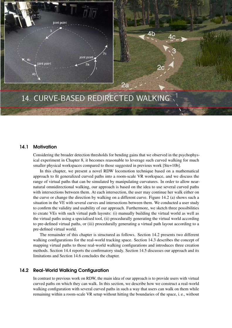
14. CURVE-BASED REDIRECTED WALKING
14.1 Motivation
Considering the broader detection thresholds for bending gains that we observed in the psychophys-ical experiment in Chapter 8, it becomes reasonable to leverage such curved walking for muchsmaller physical workspaces compared to those suggested in previous work [Ste+10b].
In this chapter, we present a novel RDW locomotion technique based on a mathematicalapproach to fit generalized curved paths into a room-scale VR workspace, and we discuss therange of virtual paths that can be simulated by manipulating curvatures. In order to allow near-natural omnidirectional walking, our approach is based on the idea to use several curved pathswith intersections between them. At each intersection, the user may continue her walk either onthe curve or change the direction by walking on a different curve. Figure 14.2 (a) shows such asituation in the VE with several curves and intersections between them. We conducted a user studyto confirm the validity and usability of our approach. Furthermore, we sketch three possibilitiesto create VEs with such virtual path layouts: (i) manually building the virtual world as well asthe virtual paths using a specialised tool, (ii) procedurally generating the virtual world accordingto pre-defined virtual paths, or (iii) procedurally generating a virtual path layout according to apre-defined virtual world.
The remainder of this chapter is structured as follows. Section 14.2 presents two differentwalking configurations for the real-world tracking space. Section 14.3 describes the concept ofmapping virtual paths to those real-world walking configurations and introduces three creationmethods. Section 14.4 reports the confirmatory study. Section 14.5 discusses our approach and itslimitations and Section 14.6 concludes the chapter.
14.2 Real-World Walking Configuration
In contrast to previous work on RDW, the main idea of our approach is to provide users with virtualcurved paths on which they can walk. In this section, we describe how we construct a real-worldwalking configuration with several curved paths in such a way that users can walk on them whileremaining within a room-scale VR setup without hitting the boundaries of the space, i. e., without
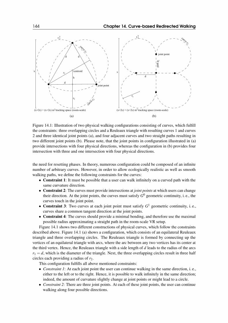
144 Chapter 14. Curve-based Redirected Walking
d
h
d
d
centroid
(x+2ε) × (x+2ε) m tracking space (room-scale)
r1
r2
curve c1
curve
c 2
joint point
2
x
ε
(a)
d
(x+2ε) × (x+2ε) m tracking space (room-scale)
r1
curve c1
path
p1
joint point
x
2
ε
(b)
Figure 14.1: Illustration of two physical walking configurations consisting of curves, which fulfillthe constraints: three overlapping circles and a Reuleaux triangle with resulting curves 1 and curves2 and three identical joint points (a), and four adjacent curves and two straight paths resulting intwo different joint points (b). Please note, that the joint points in configuration illustrated in (a)provide intersections with four physical directions, whereas the configuration in (b) provides fourintersection with three and one intersection with four physical directions.
the need for resetting phases. In theory, numerous configuration could be composed of an infinitenumber of arbitrary curves. However, in order to allow ecologically realistic as well as smoothwalking paths, we define the following constraints for the curves:
• Constraint 1: It must be possible that a user can walk infinitely on a curved path with thesame curvature direction.
• Constraint 2: The curves must provide intersections at joint points at which users can changetheir direction. At the joint points, the curves must satisfy G0 geometric continuity, i. e., thecurves touch in the joint point.
• Constraint 3: Two curves at each joint point must satisfy G1 geometric continuity, i. e.,curves share a common tangent direction at the joint points.
• Constraint 4: The curves should provide a minimal bending, and therefore use the maximalpossible radius approximating a straight path in the room-scale VR setup.
Figure 14.1 shows two different constructions of physical curves, which follow the constraintsdescribed above. Figure 14.1 (a) shows a configuration, which consists of an equilateral Reuleauxtriangle and three overlapping circles. The Reuleaux triangle is formed by connecting up thevertices of an equilateral triangle with arcs, where the arc between any two vertices has its center atthe third vertex. Hence, the Reuleaux triangle with a side length of d leads to the radius of the arcsr1 = d, which is the diameter of the triangle. Next, the three overlapping circles result in three halfcircles each providing a radius of r2.
This configuration fulfills all above mentioned constraints:• Constraint 1: At each joint point the user can continue walking in the same direction, i. e.,
either to the left or to the right. Hence, it is possible to walk infinitely in the same direction;indeed, the amount of curvature slightly change at joint points or might lead to a circle.
• Constraint 2: There are three joint points. At each of these joint points, the user can continuewalking along four possible directions.
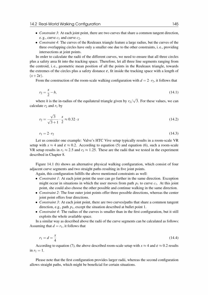
14.2 Real-World Walking Configuration 145
• Constraint 3: At each joint point, there are two curves that share a common tangent direction,e. g., curve c1 and curve c2.
• Constraint 4: The curves of the Reuleaux triangle feature a large radius, but the curves of thethree overlapping circles have only a smaller one due to the other constraints, i. e., providingintersections at joint points.
In order to calculate the radii of the different curves, we need to ensure that all three circlesplus a safety area fit into the tracking space. Therefore, let all three line segments ranging fromthe centroid, i. e., geometric mean position of all the points in the Reuleaux triangle, towardsthe extremes of the circles plus a safety distance ε , fit inside the tracking space with a length of(x+2ε).
From the construction of the room-scale walking configuration with d = 2 · r2, it follows that
r2 =x
2−h, (14.1)
where h is the in-radius of the equilateral triangle given by r2/√
3. For these values, we cancalculate r2 and r1 by
r2 =
√3√
3+1· x
2≈ 0.32 · x (14.2)
r1 = 2 · r2 (14.3)
Let us consider one example: Valve’s HTC Vive setup typically results in a room-scale VRsetup with x ≈ 4 and ε ≈ 0.2. According to equation (5) and equation (6), such a room-scaleVR setup results in r1 ≈ 2.5 and r2 ≈ 1.25. These are the radii that we tested in the experimentdescribed in Chapter 8.
Figure 14.1 (b) shows an alternative physical walking configuration, which consist of fouradjacent curve segments and two straight paths resulting in five joint points.
Again, this configuration fulfills the above mentioned constraints as well:• Constraint 1: At each joint point the user can go further in the same direction. Exception
might occur in situations in which the user moves from path p1 to curve c1. At this jointpoint, she could also choose the other possible and continue walking in the same direction.
• Constraint 2: The four outer joint points offer three possible directions, whereas the centerjoint point offers four directions.
• Constraint 3: At each joint point, there are two curves/paths that share a common tangentdirection, e.g., path p1, except the situation described at bullet point 1.
• Constraint 4: The radius of the curves is smaller than in the first configuration, but it stillexploits the whole available space.
In a similar way as described above the radii of the curve segments can be calculated as follows:Assuming that d = r1, it follows that
r1 = d =x
4(14.4)
According to equation (7), the above described room-scale setup with x ≈ 4 and ε ≈ 0.2 resultsin r1 = 1.
Please note that the first configuration provides larger radii, whereas the second configurationallows straight paths, which might be beneficial for certain situations.
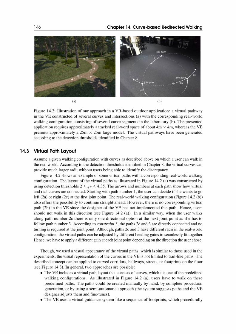
146 Chapter 14. Curve-based Redirected Walking
1
2a
2c
3
4c4b
(a)
1
2a
2c
3
4c
4b
joint point
joint point
joint point
(b)
Figure 14.2: Illustration of our approach in a VR-based outdoor application: a virtual pathwayin the VE constructed of several curves and intersections (a) with the corresponding real-worldwalking configuration consisting of several curve segments in the laboratory (b). The presentedapplication requires approximately a tracked real-word space of about 4m × 4m, whereas the VEpresents approximately a 25m × 25m large model. The virtual pathways have been generatedaccording to the detection thresholds identified in Chapter 8.
14.3 Virtual Path Layout
Assume a given walking configuration with curves as described above on which a user can walk inthe real world. According to the detection thresholds identified in Chapter 8, the virtual curves canprovide much larger radii without users being able to identify the discrepancy.
Figure 14.2 shows an example of some virtual paths with a corresponding real-world walkingconfiguration. The layout of the virtual paths as illustrated in Figure 14.2 (a) was constructed byusing detection thresholds 2 ≤ gB ≤ 4.35. The arrows and numbers at each path show how virtualand real curves are connected. Starting with path number 1, the user can decide if she wants to goleft (2a) or right (2c) at the first joint point. The real-world walking configuration (Figure 14.2 (b))also offers the possibility to continue straight ahead. However, there is no corresponding virtualpath (2b) in the VE since the designer of the VE has not implemented this path. Hence, usersshould not walk in this direction (see Figure 14.2 (a)). In a similar way, when the user walksalong path number 2c there is only one directional option at the next joint point as she has tofollow path number 3. According to constraint 3, the paths 2c and 3 are directly connected and noturning is required at the joint point. Although, paths 2c and 3 have different radii in the real-worldconfiguration, the virtual paths can be adjusted by different bending gains to seamlessly fit together.Hence, we have to apply a different gain at each joint point depending on the direction the user chose.
Though, we used a visual appearance of the virtual paths, which is similar to those used in theexperiments, the visual representation of the curves in the VE is not limited to trail-like paths. Thedescribed concept can be applied to curved corridors, hallways, streets, or footprints on the floor(see Figure 14.3). In general, two approaches are possible:
• The VE includes a virtual path layout that consists of curves, which fits one of the predefinedwalking configurations. As illustrated in Figure 14.2 (a), users have to walk on thesepredefined paths. The paths could be created manually by hand, by complete proceduralgeneration, or by using a semi-automatic approach (the system suggests paths and the VEdesigner adjusts them and fine-tunes).
• The VE uses a virtual guidance system like a sequence of footprints, which procedurally
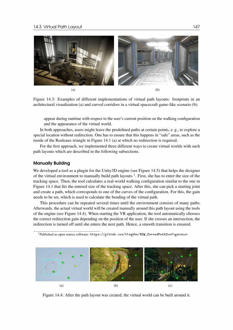
14.3 Virtual Path Layout 147
(a) (b)
Figure 14.3: Examples of different implementations of virtual path layouts: footprints in anarchitectural visualization (a) and curved corridors in a virtual spacecraft game-like scenario (b).
appear during runtime with respect to the user’s current position on the walking configurationand the appearance of the virtual world.
In both approaches, users might leave the predefined paths at certain points, e. g., to explore aspecial location without redirection. One has to ensure that this happens in “safe” areas, such as theinside of the Reuleaux triangle in Figure 14.1 (a) at which no redirection is required.
For the first approach, we implemented three different ways to create virtual worlds with suchpath layouts which are described in the following subsections.
Manually Building
We developed a tool as a plugin for the Unity3D engine (see Figure 14.5) that helps the designerof the virtual environment to manually build path layouts 1. First, she has to enter the size of thetracking space. Then, the tool calculates a real-world walking configuration similar to the one inFigure 14.1 that fits the entered size of the tracking space. After this, she can pick a starting jointand create a path, which corresponds to one of the curves of the configuration. For this, the gainneeds to be set, which is used to calculate the bending of the virtual path.
This procedure can be repeated several times until the environment consists of many paths.Afterwards, the actual virtual world will be created manually around this path layout using the toolsof the engine (see Figure 14.4). When starting the VR application, the tool automatically choosesthe correct redirection gain depending on the position of the user. If she crosses an intersection, theredirection is turned off until she enters the next path. Hence, a smooth transition is ensured.
1Published as open source software: ❤tt♣s✿✴✴❣✐t❤✉❜✳❝♦♠✴❦❧♥❣❜❤♥✴❘❉❲❴❈✉r✈❡❞P❛t❤❈♦♥❢✐❣✉r❛t♦r
(a) (b) (c)
Figure 14.4: After the path layout was created, the virtual world can be built around it.
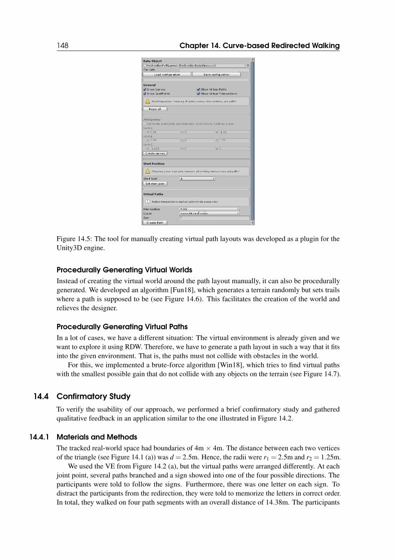
148 Chapter 14. Curve-based Redirected Walking
Figure 14.5: The tool for manually creating virtual path layouts was developed as a plugin for theUnity3D engine.
Procedurally Generating Virtual Worlds
Instead of creating the virtual world around the path layout manually, it can also be procedurallygenerated. We developed an algorithm [Fun18], which generates a terrain randomly but sets trailswhere a path is supposed to be (see Figure 14.6). This facilitates the creation of the world andrelieves the designer.
Procedurally Generating Virtual Paths
In a lot of cases, we have a different situation: The virtual environment is already given and wewant to explore it using RDW. Therefore, we have to generate a path layout in such a way that it fitsinto the given environment. That is, the paths must not collide with obstacles in the world.
For this, we implemented a brute-force algorithm [Win18], which tries to find virtual pathswith the smallest possible gain that do not collide with any objects on the terrain (see Figure 14.7).
14.4 Confirmatory Study
To verify the usability of our approach, we performed a brief confirmatory study and gatheredqualitative feedback in an application similar to the one illustrated in Figure 14.2.
14.4.1 Materials and Methods
The tracked real-world space had boundaries of 4m × 4m. The distance between each two verticesof the triangle (see Figure 14.1 (a)) was d = 2.5m. Hence, the radii were r1 = 2.5m and r2 = 1.25m.
We used the VE from Figure 14.2 (a), but the virtual paths were arranged differently. At eachjoint point, several paths branched and a sign showed into one of the four possible directions. Theparticipants were told to follow the signs. Furthermore, there was one letter on each sign. Todistract the participants from the redirection, they were told to memorize the letters in correct order.In total, they walked on four path segments with an overall distance of 14.38m. The participants
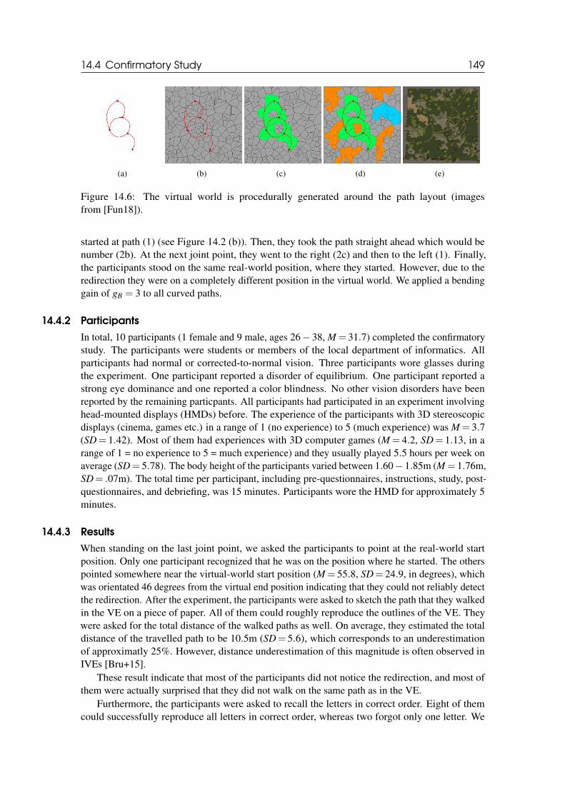
14.4 Confirmatory Study 149
(a) (b) (c) (d) (e)
Figure 14.6: The virtual world is procedurally generated around the path layout (imagesfrom [Fun18]).
started at path (1) (see Figure 14.2 (b)). Then, they took the path straight ahead which would benumber (2b). At the next joint point, they went to the right (2c) and then to the left (1). Finally,the participants stood on the same real-world position, where they started. However, due to theredirection they were on a completely different position in the virtual world. We applied a bendinggain of gB = 3 to all curved paths.
14.4.2 Participants
In total, 10 participants (1 female and 9 male, ages 26− 38, M = 31.7) completed the confirmatorystudy. The participants were students or members of the local department of informatics. Allparticipants had normal or corrected-to-normal vision. Three participants wore glasses duringthe experiment. One participant reported a disorder of equilibrium. One participant reported astrong eye dominance and one reported a color blindness. No other vision disorders have beenreported by the remaining particpants. All participants had participated in an experiment involvinghead-mounted displays (HMDs) before. The experience of the participants with 3D stereoscopicdisplays (cinema, games etc.) in a range of 1 (no experience) to 5 (much experience) was M = 3.7(SD= 1.42). Most of them had experiences with 3D computer games (M = 4.2, SD= 1.13, in arange of 1 = no experience to 5 = much experience) and they usually played 5.5 hours per week onaverage (SD= 5.78). The body height of the participants varied between 1.60− 1.85m (M = 1.76m,SD= .07m). The total time per participant, including pre-questionnaires, instructions, study, post-questionnaires, and debriefing, was 15 minutes. Participants wore the HMD for approximately 5minutes.
14.4.3 Results
When standing on the last joint point, we asked the participants to point at the real-world startposition. Only one participant recognized that he was on the position where he started. The otherspointed somewhere near the virtual-world start position (M = 55.8, SD= 24.9, in degrees), whichwas orientated 46 degrees from the virtual end position indicating that they could not reliably detectthe redirection. After the experiment, the participants were asked to sketch the path that they walkedin the VE on a piece of paper. All of them could roughly reproduce the outlines of the VE. Theywere asked for the total distance of the walked paths as well. On average, they estimated the totaldistance of the travelled path to be 10.5m (SD= 5.6), which corresponds to an underestimationof approximatly 25%. However, distance underestimation of this magnitude is often observed inIVEs [Bru+15].
These result indicate that most of the participants did not notice the redirection, and most ofthem were actually surprised that they did not walk on the same path as in the VE.
Furthermore, the participants were asked to recall the letters in correct order. Eight of themcould successfully reproduce all letters in correct order, whereas two forgot only one letter. We
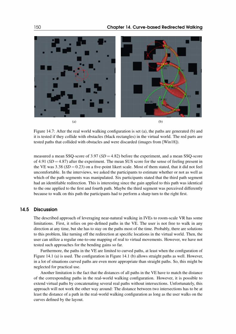
150 Chapter 14. Curve-based Redirected Walking
(a) (b)
Figure 14.7: After the real world walking configuration is set (a), the paths are generated (b) andit is tested if they collide with obstacles (black rectangles) in the virtual world. The red parts aretested paths that collided with obstacles and were discarded (images from [Win18]).
measured a mean SSQ-score of 3.97 (SD= 4.82) before the experiment, and a mean SSQ-scoreof 4.91 (SD= 4.87) after the experiment. The mean SUS score for the sense of feeling present inthe VE was 3.38 (SD= 0.23) on a five-point likert scale. Most of them stated, that it did not feeluncomfortable. In the interviews, we asked the participants to estimate whether or not as well aswhich of the path segments was manipulated. Six participants stated that the third path segmenthad an identifiable redirection. This is interesting since the gain applied to this path was identicalto the one applied to the first and fourth path. Maybe the third segment was perceived differentlybecause to walk on this path the participants had to perform a sharp turn to the right first.
14.5 Discussion
The described approach of leveraging near-natural walking in IVEs to room-scale VR has somelimitations. First, it relies on pre-defined paths in the VE. The user is not free to walk in anydirection at any time, but she has to stay on the paths most of the time. Probably, there are solutionsto this problem, like turning off the redirection at specific locations in the virtual world. Then, theuser can utilize a regular one-to-one mapping of real to virtual movements. However, we have nottested such approaches for the bending gains so far.
Furthermore, the paths in the VE are limited to curved paths, at least when the configuration ofFigure 14.1 (a) is used. The configuration in Figure 14.1 (b) allows straight paths as well. However,in a lot of situations curved paths are even more appropriate than straight paths. So, this might beneglected for practical use.
Another limitation is the fact that the distances of all paths in the VE have to match the distanceof the corresponding paths in the real-world walking configuration. However, it is possible toextend virtual paths by concatenating several real paths without intersections. Unfortunately, thisapproach will not work the other way around: The distance between two intersections has to be atleast the distance of a path in the real-world walking configuration as long as the user walks on thecurves defined by the layout.
14.6 Conclusion 151
14.6 Conclusion
In this chapter, we introduced a novel RDW locomotion technique, which is based on guiding usersto walk on curved paths. For this purpose, we used bending gains on virtual paths that are mappedto a walking configuration in a room-scale VR setup. As we have shown it is possible to construct awalking configuration in a reasonably small tracking space in such a way that users are able to walkinfinitely on a curved path with the same curvature direction or change their direction at definedintersections. As a proof of concept, we derived two different layouts, which fulfill these constraints.The confirmatory study showed that the approach allows to use RDW in room-scale VR withoutusing interruptions or overt resetting phases. Indeed, the approach induces some limitations to thedesign of a VE as we outlined.

15. REDIRECTED WALKING VS. VIRTUAL TRAVEL
15.1 Motivation
When the users main task is to explore a VE, it is essential that they get a reasonable spatialknowledge of the VE. In this context, the task to acquiring spatial knowledge is called cognitivemap building [Bow+04]. To own such a cognitive map is essential for many tasks such as training,architecture, or real estate. Therefore, an important question is if and how a locomotion techniquemight influence the cognitive map building of the user.
Nowadays, a lot of VR applications make use of some kind of teleportation (TP) technique.With TP techniques, a user can travel over large distances by specifying the travel destination,for example, using an input device such as a wand. After the TP has been initiated, for instance,with a button press, the user’s viewpoint is transferred to the corresponding target position eitherin a discrete jump or using a smooth viewpoint animation. Varying qualities of multimodalfeedback provided by different locomotion techniques may evoke or provide different levels ofVR sickness, sense of presence, usability as well as spatial knowledge, which in turn might affecttask performance, effectiveness, and efficiency. TP does not offer the same quality of multimodalfeedback as a walking-based locomotion technique such as RDW. Therefore, an interesting questionis how TP performs comparing to RDW.
There is a vast body of literature comparing the performance of different locomotion techniquesin VR (see Chapter 3). For instance, it is known that TP causes spatial disorientation [Bow+99],which could be reduced by continuous joystick-based movements, which in turn often lead to VRsickness [LaV00]. And it is known that RDW improves cognitive map building [PFW11]. However,RDW and TP have not been directly compared in typical room-scale VR setups for exploring indoorVEs with a focus on cognitive map building. For these reasons, in this chapter, we present anexperiment that compares three different locomotion techniques, mainly with a focus on cognitivemap building. In addition, other aspects such as VR sickness, presence, effectiveness, and userpreferences are also considered. These techniques are:
1. JS: joystick-based,2. TP: teleportation, and3. RDW: redirected walking.
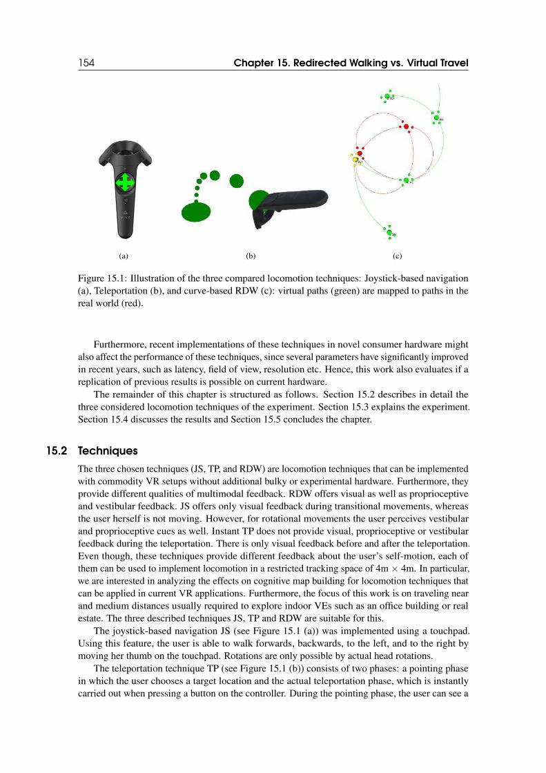
154 Chapter 15. Redirected Walking vs. Virtual Travel
(a) (b) (c)
Figure 15.1: Illustration of the three compared locomotion techniques: Joystick-based navigation(a), Teleportation (b), and curve-based RDW (c): virtual paths (green) are mapped to paths in thereal world (red).
Furthermore, recent implementations of these techniques in novel consumer hardware mightalso affect the performance of these techniques, since several parameters have significantly improvedin recent years, such as latency, field of view, resolution etc. Hence, this work also evaluates if areplication of previous results is possible on current hardware.
The remainder of this chapter is structured as follows. Section 15.2 describes in detail thethree considered locomotion techniques of the experiment. Section 15.3 explains the experiment.Section 15.4 discusses the results and Section 15.5 concludes the chapter.
15.2 Techniques
The three chosen techniques (JS, TP, and RDW) are locomotion techniques that can be implementedwith commodity VR setups without additional bulky or experimental hardware. Furthermore, theyprovide different qualities of multimodal feedback. RDW offers visual as well as proprioceptiveand vestibular feedback. JS offers only visual feedback during transitional movements, whereasthe user herself is not moving. However, for rotational movements the user perceives vestibularand proprioceptive cues as well. Instant TP does not provide visual, proprioceptive or vestibularfeedback during the teleportation. There is only visual feedback before and after the teleportation.Even though, these techniques provide different feedback about the user’s self-motion, each ofthem can be used to implement locomotion in a restricted tracking space of 4m × 4m. In particular,we are interested in analyzing the effects on cognitive map building for locomotion techniques thatcan be applied in current VR applications. Furthermore, the focus of this work is on traveling nearand medium distances usually required to explore indoor VEs such as an office building or realestate. The three described techniques JS, TP and RDW are suitable for this.
The joystick-based navigation JS (see Figure 15.1 (a)) was implemented using a touchpad.Using this feature, the user is able to walk forwards, backwards, to the left, and to the right bymoving her thumb on the touchpad. Rotations are only possible by actual head rotations.
The teleportation technique TP (see Figure 15.1 (b)) consists of two phases: a pointing phasein which the user chooses a target location and the actual teleportation phase, which is instantlycarried out when pressing a button on the controller. During the pointing phase, the user can see a
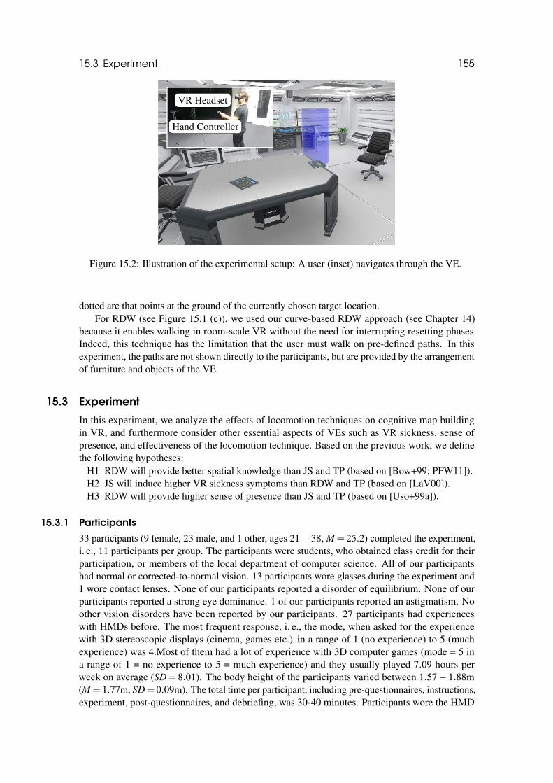
15.3 Experiment 155
VR Headset
Hand Controller
Figure 15.2: Illustration of the experimental setup: A user (inset) navigates through the VE.
dotted arc that points at the ground of the currently chosen target location.For RDW (see Figure 15.1 (c)), we used our curve-based RDW approach (see Chapter 14)
because it enables walking in room-scale VR without the need for interrupting resetting phases.Indeed, this technique has the limitation that the user must walk on pre-defined paths. In thisexperiment, the paths are not shown directly to the participants, but are provided by the arrangementof furniture and objects of the VE.
15.3 Experiment
In this experiment, we analyze the effects of locomotion techniques on cognitive map buildingin VR, and furthermore consider other essential aspects of VEs such as VR sickness, sense ofpresence, and effectiveness of the locomotion technique. Based on the previous work, we definethe following hypotheses:
H1 RDW will provide better spatial knowledge than JS and TP (based on [Bow+99; PFW11]).H2 JS will induce higher VR sickness symptoms than RDW and TP (based on [LaV00]).H3 RDW will provide higher sense of presence than JS and TP (based on [Uso+99a]).
15.3.1 Participants
33 participants (9 female, 23 male, and 1 other, ages 21− 38, M = 25.2) completed the experiment,i. e., 11 participants per group. The participants were students, who obtained class credit for theirparticipation, or members of the local department of computer science. All of our participantshad normal or corrected-to-normal vision. 13 participants wore glasses during the experiment and1 wore contact lenses. None of our participants reported a disorder of equilibrium. None of ourparticipants reported a strong eye dominance. 1 of our participants reported an astigmatism. Noother vision disorders have been reported by our participants. 27 participants had experienceswith HMDs before. The most frequent response, i. e., the mode, when asked for the experiencewith 3D stereoscopic displays (cinema, games etc.) in a range of 1 (no experience) to 5 (muchexperience) was 4.Most of them had a lot of experience with 3D computer games (mode = 5 ina range of 1 = no experience to 5 = much experience) and they usually played 7.09 hours perweek on average (SD= 8.01). The body height of the participants varied between 1.57− 1.88m(M = 1.77m, SD= 0.09m). The total time per participant, including pre-questionnaires, instructions,experiment, post-questionnaires, and debriefing, was 30-40 minutes. Participants wore the HMD
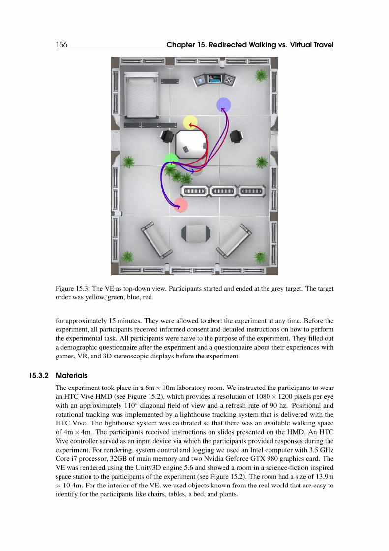
156 Chapter 15. Redirected Walking vs. Virtual Travel
Figure 15.3: The VE as top-down view. Participants started and ended at the grey target. The targetorder was yellow, green, blue, red.
for approximately 15 minutes. They were allowed to abort the experiment at any time. Before theexperiment, all participants received informed consent and detailed instructions on how to performthe experimental task. All participants were naive to the purpose of the experiment. They filled outa demographic questionnaire after the experiment and a questionnaire about their experiences withgames, VR, and 3D stereoscopic displays before the experiment.
15.3.2 Materials
The experiment took place in a 6m× 10m laboratory room. We instructed the participants to wearan HTC Vive HMD (see Figure 15.2), which provides a resolution of 1080× 1200 pixels per eyewith an approximately 110◦ diagonal field of view and a refresh rate of 90 hz. Positional androtational tracking was implemented by a lighthouse tracking system that is delivered with theHTC Vive. The lighthouse system was calibrated so that there was an available walking spaceof 4m× 4m. The participants received instructions on slides presented on the HMD. An HTCVive controller served as an input device via which the participants provided responses during theexperiment. For rendering, system control and logging we used an Intel computer with 3.5 GHzCore i7 processor, 32GB of main memory and two Nvidia Geforce GTX 980 graphics card. TheVE was rendered using the Unity3D engine 5.6 and showed a room in a science-fiction inspiredspace station to the participants of the experiment (see Figure 15.2). The room had a size of 13.9m× 10.4m. For the interior of the VE, we used objects known from the real world that are easy toidentify for the participants like chairs, tables, a bed, and plants.
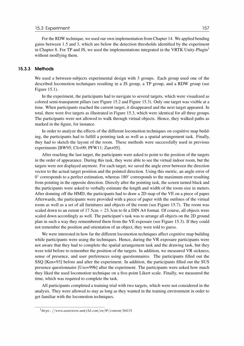
15.3 Experiment 157
For the RDW technique, we used our own implementation from Chapter 14. We applied bendinggains between 1.5 and 3, which are below the detection thresholds identified by the experimentin Chapter 8. For TP and JS, we used the implementations integrated in the VRTK Unity-Plugin1
without modfying them.
15.3.3 Methods
We used a between-subjects experimental design with 3 groups. Each group used one of thedescribed locomotion techniques resulting in a JS group, a TP group, and a RDW group (seeFigure 15.1).
In the experiment, the participants had to navigate to several targets, which were visualized ascolored semi-transparent pillars (see Figure 15.2 and Figure 15.3). Only one target was visible at atime. When participants reached the current target, it disappeared and the next target appeared. Intotal, there were five targets as illustrated in Figure 15.3, which were identical for all three groups.The participants were not allowed to walk through virtual objects. Hence, they walked paths asmarked in the figure, for instance.
In order to analyze the effects of the different locomotion techniques on cognitive map build-ing, the participants had to fulfill a pointing task as well as a spatial arrangement task. Finally,they had to sketch the layout of the room. These methods were successfully used in previousexperiments [BW95; Cli+09; PFW11; Zan+05].
After reaching the last target, the participants were asked to point to the position of the targetsin the order of appearance. During this task, they were able to see the virtual indoor room, but thetargets were not displayed anymore. For each target, we saved the angle error between the directionvector to the actual target position and the pointed direction. Using this metric, an angle error of0◦ corresponds to a perfect estimation, whereas 180◦ corresponds to the maximum error resultingfrom pointing in the opposite direction. Directly after the pointing task, the screen turned black andthe participants were asked to verbally estimate the length and width of the room size in meters.After donning off the HMD, the participants had to draw a 2D map of the VE on a piece of paper.Afterwards, the participants were provided with a piece of paper with the outlines of the virtualroom as well as a set of all furnitures and objects of the room (see Figure 15.7). The room wasscaled down to an extent of 17.5cm × 23.3cm to fit a DIN A4 format. Of course, all objects werescaled down accordingly as well. The participant’s task was to arrange all objects on the 2D groundplan in such a way they remembered them from the VE exposure (see Figure 15.3). If they couldnot remember the position and orientation of an object, they were told to guess.
We were interested in how far the different locomotion techniques affect cognitive map buildingwhile participants were using the techniques. Hence, during the VR exposure participants werenot aware that they had to complete the spatial arrangement task and the drawing task, but theywere told before to remember the position of the targets. In addition, we measured VR sickness,sense of presence, and user preferences using questionnaires. The participants filled out theSSQ [Ken+93] before and after the experiment. In addition, the participants filled out the SUSpresence questionnaire [Uso+99b] after the experiment. The participants were asked how muchthey liked the used locomotion technique on a five-point Likert scale. Finally, we measured thetime, which was required to complete the task.
All participants completed a training trial with two targets, which were not considered in theanalysis. They were allowed to stay as long as they wanted in the training environment in order toget familiar with the locomotion techniques.
1htt ps : //www.assetstore.unity3d.com/en/#!/content/64131
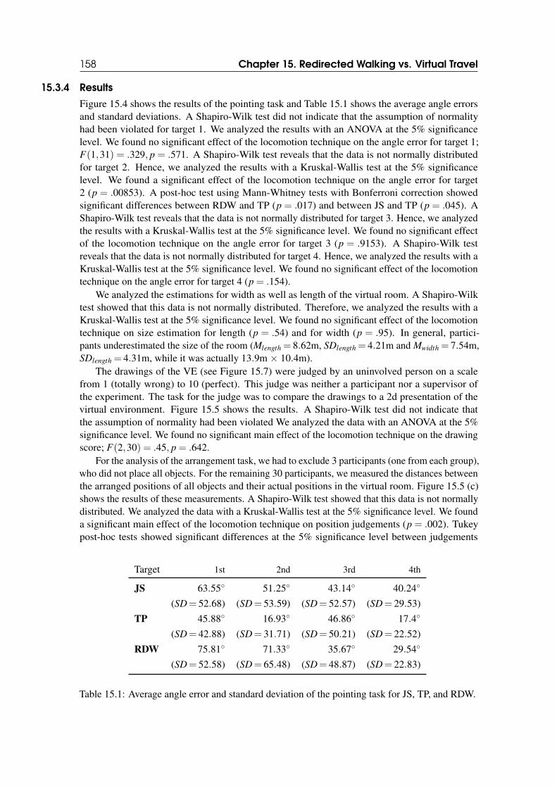
158 Chapter 15. Redirected Walking vs. Virtual Travel
15.3.4 Results
Figure 15.4 shows the results of the pointing task and Table 15.1 shows the average angle errorsand standard deviations. A Shapiro-Wilk test did not indicate that the assumption of normalityhad been violated for target 1. We analyzed the results with an ANOVA at the 5% significancelevel. We found no significant effect of the locomotion technique on the angle error for target 1;F(1,31) = .329, p = .571. A Shapiro-Wilk test reveals that the data is not normally distributedfor target 2. Hence, we analyzed the results with a Kruskal-Wallis test at the 5% significancelevel. We found a significant effect of the locomotion technique on the angle error for target2 (p = .00853). A post-hoc test using Mann-Whitney tests with Bonferroni correction showedsignificant differences between RDW and TP (p = .017) and between JS and TP (p = .045). AShapiro-Wilk test reveals that the data is not normally distributed for target 3. Hence, we analyzedthe results with a Kruskal-Wallis test at the 5% significance level. We found no significant effectof the locomotion technique on the angle error for target 3 (p = .9153). A Shapiro-Wilk testreveals that the data is not normally distributed for target 4. Hence, we analyzed the results with aKruskal-Wallis test at the 5% significance level. We found no significant effect of the locomotiontechnique on the angle error for target 4 (p = .154).
We analyzed the estimations for width as well as length of the virtual room. A Shapiro-Wilktest showed that this data is not normally distributed. Therefore, we analyzed the results with aKruskal-Wallis test at the 5% significance level. We found no significant effect of the locomotiontechnique on size estimation for length (p = .54) and for width (p = .95). In general, partici-pants underestimated the size of the room (Mlength = 8.62m, SDlength = 4.21m and Mwidth = 7.54m,SDlength = 4.31m, while it was actually 13.9m × 10.4m).
The drawings of the VE (see Figure 15.7) were judged by an uninvolved person on a scalefrom 1 (totally wrong) to 10 (perfect). This judge was neither a participant nor a supervisor ofthe experiment. The task for the judge was to compare the drawings to a 2d presentation of thevirtual environment. Figure 15.5 shows the results. A Shapiro-Wilk test did not indicate thatthe assumption of normality had been violated We analyzed the data with an ANOVA at the 5%significance level. We found no significant main effect of the locomotion technique on the drawingscore; F(2,30) = .45, p = .642.
For the analysis of the arrangement task, we had to exclude 3 participants (one from each group),who did not place all objects. For the remaining 30 participants, we measured the distances betweenthe arranged positions of all objects and their actual positions in the virtual room. Figure 15.5 (c)shows the results of these measurements. A Shapiro-Wilk test showed that this data is not normallydistributed. We analyzed the data with a Kruskal-Wallis test at the 5% significance level. We founda significant main effect of the locomotion technique on position judgements (p = .002). Tukeypost-hoc tests showed significant differences at the 5% significance level between judgements
Target 1st 2nd 3rd 4th
JS 63.55◦ 51.25◦ 43.14◦ 40.24◦
(SD= 52.68) (SD= 53.59) (SD= 52.57) (SD= 29.53)
TP 45.88◦ 16.93◦ 46.86◦ 17.4◦
(SD= 42.88) (SD= 31.71) (SD= 50.21) (SD= 22.52)
RDW 75.81◦ 71.33◦ 35.67◦ 29.54◦
(SD= 52.58) (SD= 65.48) (SD= 48.87) (SD= 22.83)
Table 15.1: Average angle error and standard deviation of the pointing task for JS, TP, and RDW.
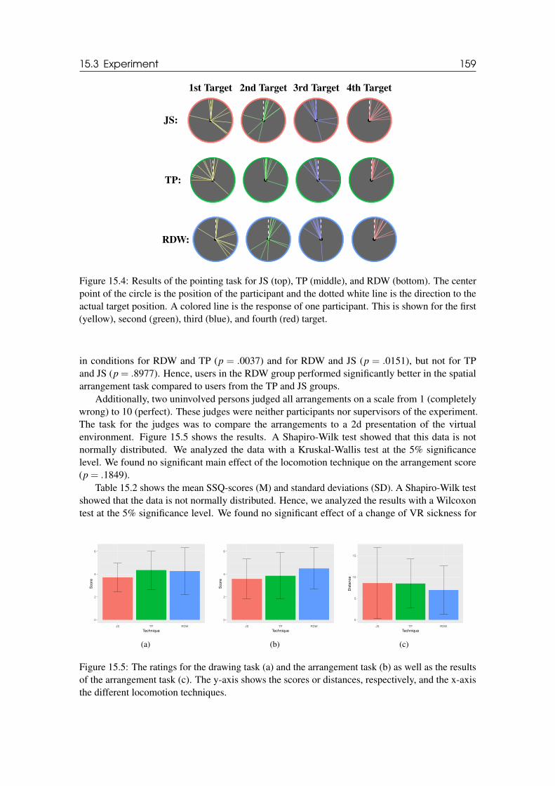
15.3 Experiment 159
JS:
1st Target 2nd Target 3rd Target 4th Target
TP:
RDW:
Figure 15.4: Results of the pointing task for JS (top), TP (middle), and RDW (bottom). The centerpoint of the circle is the position of the participant and the dotted white line is the direction to theactual target position. A colored line is the response of one participant. This is shown for the first(yellow), second (green), third (blue), and fourth (red) target.
in conditions for RDW and TP (p = .0037) and for RDW and JS (p = .0151), but not for TPand JS (p = .8977). Hence, users in the RDW group performed significantly better in the spatialarrangement task compared to users from the TP and JS groups.
Additionally, two uninvolved persons judged all arrangements on a scale from 1 (completelywrong) to 10 (perfect). These judges were neither participants nor supervisors of the experiment.The task for the judges was to compare the arrangements to a 2d presentation of the virtualenvironment. Figure 15.5 shows the results. A Shapiro-Wilk test showed that this data is notnormally distributed. We analyzed the data with a Kruskal-Wallis test at the 5% significancelevel. We found no significant main effect of the locomotion technique on the arrangement score(p = .1849).
Table 15.2 shows the mean SSQ-scores (M) and standard deviations (SD). A Shapiro-Wilk testshowed that the data is not normally distributed. Hence, we analyzed the results with a Wilcoxontest at the 5% significance level. We found no significant effect of a change of VR sickness for
0
2
4
6
JS TP RDW
Technique
Score
(a)
0
2
4
6
JS TP RDW
Technique
Score
(b)
0
5
10
15
JS TP RDW
Technique
Dis
tance
(c)
Figure 15.5: The ratings for the drawing task (a) and the arrangement task (b) as well as the resultsof the arrangement task (c). The y-axis shows the scores or distances, respectively, and the x-axisthe different locomotion techniques.
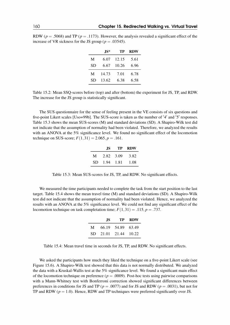
160 Chapter 15. Redirected Walking vs. Virtual Travel
RDW (p = .5068) and TP (p = .1173). However, the analysis revealed a significant effect of theincrease of VR sickness for the JS group (p = .03545).
JS* TP RDW
M 6.07 12.15 5.61
SD 6.67 10.26 6.96
M 14.73 7.01 6.78
SD 13.62 6.38 6.58
Table 15.2: Mean SSQ-scores before (top) and after (bottom) the experiment for JS, TP, and RDW.The increase for the JS group is statistically significant.
The SUS questionnaire for the sense of feeling present in the VE consists of six questions andfive-point Likert scales [Uso+99b]. The SUS-score is taken as the number of ′4′ and ′5′ responses.Table 15.3 shows the mean SUS-scores (M) and standard deviations (SD). A Shapiro-Wilk test didnot indicate that the assumption of normality had been violated. Therefore, we analyzed the resultswith an ANOVA at the 5% significance level. We found no significant effect of the locomotiontechnique on SUS-score; F(1,31) = 2.065, p = .161.
JS TP RDW
M 2.82 3.09 3.82
SD 1.94 1.81 1.08
Table 15.3: Mean SUS-scores for JS, TP, and RDW. No significant effects.
We measured the time participants needed to complete the task from the start position to the lasttarget. Table 15.4 shows the mean travel time (M) and standard deviations (SD). A Shapiro-Wilktest did not indicate that the assumption of normality had been violated. Hence, we analyzed theresults with an ANOVA at the 5% significance level. We could not find any significant effect of thelocomotion technique on task completation time; F(1,31) = .115, p = .737.
JS TP RDW
M 66.19 54.89 63.49
SD 21.01 21.44 10.22
Table 15.4: Mean travel time in seconds for JS, TP, and RDW. No significant effects.
We asked the participants how much they liked the technique on a five-point Likert scale (seeFigure 15.6). A Shapiro-Wilk test showed that this data is not normally distributed. We analyzedthe data with a Kruskal-Wallis test at the 5% significance level. We found a significant main effectof the locomotion technique on preference (p = .0009). Post-hoc tests using pairwise comparisonswith a Mann-Whitney test with Bonferroni correction showed significant differences betweenpreferences in conditions for JS and TP (p = .0077) and for JS and RDW (p = .0031), but not forTP and RDW (p = 1.0). Hence, RDW and TP techniques were preferred significantly over JS.
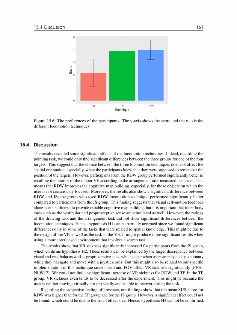
15.4 Discussion 161
0
1
2
3
4
5
JS TP RDW
Technique
Score
Figure 15.6: The preferences of the participants. The y-axis shows the score and the x-axis thedifferent locomotion techniques.
15.4 Discussion
The results revealed some significant effects of the locomotion techniques. Indeed, regarding thepointing task, we could only find significant differences between the three groups for one of the fourtargets. This suggest that the choice between the three locomotion techniques does not affect thespatial orientation, especially, when the participants knew that they were supposed to remember theposition of the targets. However, participants from the RDW group performed significantly better inrecalling the interior of the indoor VE according to the arrangement task measured distances. Thismeans that RDW improves the cognitive map building, especially, for those objects on which theuser is not consciously focused. Moreover, the results also show a significant difference betweenRDW and JS; the group who used RDW locomotion technique performed significantly bettercompared to participants from the JS group. This finding suggests that visual self-motion feedbackalone is not sufficient to provide reliable cognitive map building, but it is important that inner bodycues such as the vestibular and proprioceptive sense are stimulated as well. However, the ratingsof the drawing task and the arrangement task did not show significant differences between thelocomotion techniques. Hence, hypothesis H1 can be partially accepted since we found significantdifferences only in some of the tasks that were related to spatial knowledge. This might be due tothe design of the VE as well as the task in the VE. It might produce more significant results whenusing a more interleaved environment that involves a search task.
The results show that VR sickness significantly increased for participants from the JS group,which confirms hypothesis H2. These results can be explained by the larger discrepancy betweenvisual and vestibular as well as proprioceptive cues, which occur when users are physically stationarywhile they navigate and move with a joystick only. But this might also be related to our specificimplementation of this technique since speed and FOV affect VR sickness significantly [FF16;NLW17]. We could not find any significant increase of VR sickness for RDW and TP. In the TPgroup, VR sickness even tends to be decreased after the experiment. This might be because theuser is neither moving virtually nor physically and is able to recover during the task.
Regarding the subjective feeling of presence, our findings show that the mean SUS-score forRDW was higher than for the TP group and for the JS group. However, a significant effect could notbe found, which could be due to the small effect size. Hence, hypothesis H3 cannot be confirmed.
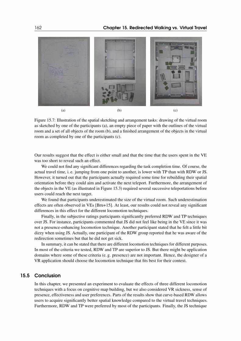
162 Chapter 15. Redirected Walking vs. Virtual Travel
(a) (b) (c)
Figure 15.7: Illustration of the spatial sketching and arrangement tasks: drawing of the virtual roomas sketched by one of the participants (a), an empty piece of paper with the outlines of the virtualroom and a set of all objects of the room (b), and a finished arrangement of the objects in the virtualroom as completed by one of the participants (c).
Our results suggest that the effect is either small and that the time that the users spent in the VEwas too short to reveal such an effect.
We could not find any significant differences regarding the task completion time. Of course, theactual travel time, i. e. jumping from one point to another, is lower with TP than with RDW or JS.However, it turned out that the participants actually required some time for rebuilding their spatialorientation before they could aim and activate the next teleport. Furthermore, the arrangement ofthe objects in the VE (as illustrated in Figure 15.3) required several successive teleportations beforeusers could reach the next target.
We found that participants underestimated the size of the virtual room. Such underestimationeffects are often observed in VEs [Bru+15]. At least, our results could not reveal any significantdifferences in this effect for the different locomotion techniques.
Finally, in the subjective ratings participants significantly preferred RDW and TP techniquesover JS. For instance, participants commented that JS did not feel like being in the VE since it wasnot a presence-enhancing locomotion technique. Another participant stated that he felt a little bitdizzy when using JS. Actually, one participant of the RDW group reported that he was aware of theredirection sometimes but that he did not get sick.
In summary, it can be stated that there are different locomotion techniques for different purposes.In most of the criteria we tested, RDW and TP are superior to JS. But there might be applicationdomains where some of these criteria (e. g. presence) are not important. Hence, the designer of aVR application should choose the locomotion technique that fits best for their context.
15.5 Conclusion
In this chapter, we presented an experiment to evaluate the effects of three different locomotiontechniques with a focus on cognitive map building, but we also considered VR sickness, sense ofpresence, effectiveness and user preferences. Parts of the results show that curve-based RDW allowsusers to acquire significantly better spatial knowledge compared to the virtual travel techniques.Furthermore, RDW and TP were preferred by most of the participants. Finally, the JS technique

15.5 Conclusion 163
lead to a significant increase of VR sickness compared to the other locomotion techniques. However,we could not find any significant effects of the locomotion technique on the user’s sense of presenceor the effectiveness regarding the required completion time. Summarized, our results suggest thatRDW and TP are techniques with different benefits and drawbacks and should be preferred over JS.

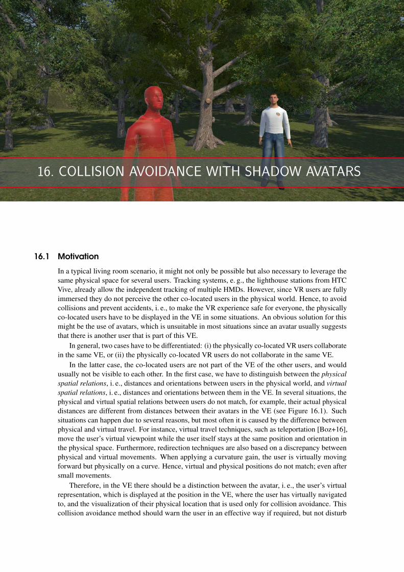
16. COLLISION AVOIDANCE WITH SHADOW AVATARS
16.1 Motivation
In a typical living room scenario, it might not only be possible but also necessary to leverage thesame physical space for several users. Tracking systems, e. g., the lighthouse stations from HTCVive, already allow the independent tracking of multiple HMDs. However, since VR users are fullyimmersed they do not perceive the other co-located users in the physical world. Hence, to avoidcollisions and prevent accidents, i. e., to make the VR experience safe for everyone, the physicallyco-located users have to be displayed in the VE in some situations. An obvious solution for thismight be the use of avatars, which is unsuitable in most situations since an avatar usually suggeststhat there is another user that is part of this VE.
In general, two cases have to be differentiated: (i) the physically co-located VR users collaboratein the same VE, or (ii) the physically co-located VR users do not collaborate in the same VE.
In the latter case, the co-located users are not part of the VE of the other users, and wouldusually not be visible to each other. In the first case, we have to distinguish between the physical
spatial relations, i. e., distances and orientations between users in the physical world, and virtual
spatial relations, i. e., distances and orientations between them in the VE. In several situations, thephysical and virtual spatial relations between users do not match, for example, their actual physicaldistances are different from distances between their avatars in the VE (see Figure 16.1). Suchsituations can happen due to several reasons, but most often it is caused by the difference betweenphysical and virtual travel. For instance, virtual travel techniques, such as teleportation [Boz+16],move the user’s virtual viewpoint while the user itself stays at the same position and orientation inthe physical space. Furthermore, redirection techniques are also based on a discrepancy betweenphysical and virtual movements. When applying a curvature gain, the user is virtually movingforward but physically on a curve. Hence, virtual and physical positions do not match; even aftersmall movements.
Therefore, in the VE there should be a distinction between the avatar, i. e., the user’s virtualrepresentation, which is displayed at the position in the VE, where the user has virtually navigatedto, and the visualization of their physical location that is used only for collision avoidance. Thiscollision avoidance method should warn the user in an effective way if required, but not disturb
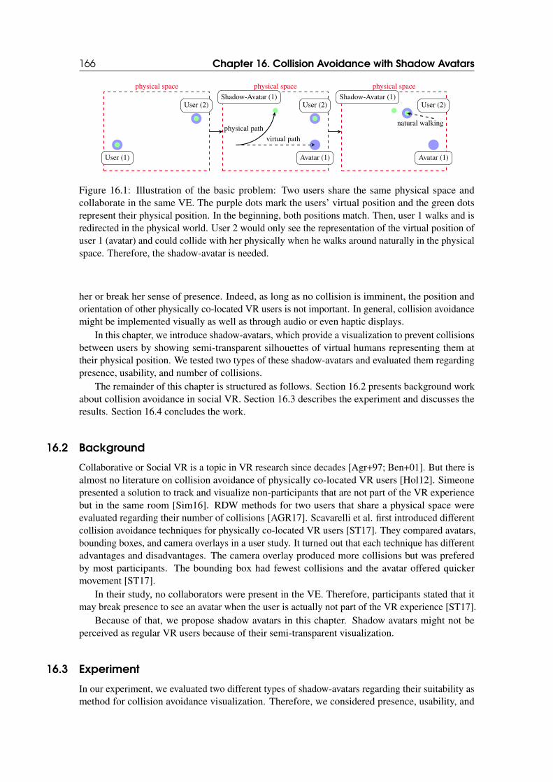
166 Chapter 16. Collision Avoidance with Shadow Avatars
physical space
User (1)
User (2)
physical space
Shadow-Avatar (1)User (2)
Avatar (1)
virtual path
physical path
physical space
Shadow-Avatar (1)User (2)
Avatar (1)
natural walking
Figure 16.1: Illustration of the basic problem: Two users share the same physical space andcollaborate in the same VE. The purple dots mark the users’ virtual position and the green dotsrepresent their physical position. In the beginning, both positions match. Then, user 1 walks and isredirected in the physical world. User 2 would only see the representation of the virtual position ofuser 1 (avatar) and could collide with her physically when he walks around naturally in the physicalspace. Therefore, the shadow-avatar is needed.
her or break her sense of presence. Indeed, as long as no collision is imminent, the position andorientation of other physically co-located VR users is not important. In general, collision avoidancemight be implemented visually as well as through audio or even haptic displays.
In this chapter, we introduce shadow-avatars, which provide a visualization to prevent collisionsbetween users by showing semi-transparent silhouettes of virtual humans representing them attheir physical position. We tested two types of these shadow-avatars and evaluated them regardingpresence, usability, and number of collisions.
The remainder of this chapter is structured as follows. Section 16.2 presents background workabout collision avoidance in social VR. Section 16.3 describes the experiment and discusses theresults. Section 16.4 concludes the work.
16.2 Background
Collaborative or Social VR is a topic in VR research since decades [Agr+97; Ben+01]. But there isalmost no literature on collision avoidance of physically co-located VR users [Hol12]. Simeonepresented a solution to track and visualize non-participants that are not part of the VR experiencebut in the same room [Sim16]. RDW methods for two users that share a physical space wereevaluated regarding their number of collisions [AGR17]. Scavarelli et al. first introduced differentcollision avoidance techniques for physically co-located VR users [ST17]. They compared avatars,bounding boxes, and camera overlays in a user study. It turned out that each technique has differentadvantages and disadvantages. The camera overlay produced more collisions but was preferedby most participants. The bounding box had fewest collisions and the avatar offered quickermovement [ST17].
In their study, no collaborators were present in the VE. Therefore, participants stated that itmay break presence to see an avatar when the user is actually not part of the VR experience [ST17].
Because of that, we propose shadow avatars in this chapter. Shadow avatars might not beperceived as regular VR users because of their semi-transparent visualization.
16.3 Experiment
In our experiment, we evaluated two different types of shadow-avatars regarding their suitability asmethod for collision avoidance visualization. Therefore, we considered presence, usability, and
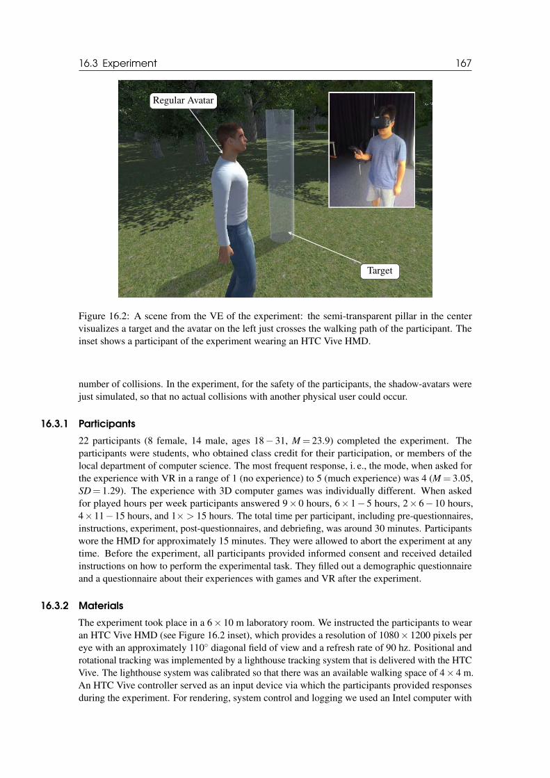
16.3 Experiment 167
Regular Avatar
Target
Figure 16.2: A scene from the VE of the experiment: the semi-transparent pillar in the centervisualizes a target and the avatar on the left just crosses the walking path of the participant. Theinset shows a participant of the experiment wearing an HTC Vive HMD.
number of collisions. In the experiment, for the safety of the participants, the shadow-avatars werejust simulated, so that no actual collisions with another physical user could occur.
16.3.1 Participants
22 participants (8 female, 14 male, ages 18− 31, M = 23.9) completed the experiment. Theparticipants were students, who obtained class credit for their participation, or members of thelocal department of computer science. The most frequent response, i. e., the mode, when asked forthe experience with VR in a range of 1 (no experience) to 5 (much experience) was 4 (M = 3.05,SD= 1.29). The experience with 3D computer games was individually different. When askedfor played hours per week participants answered 9× 0 hours, 6× 1− 5 hours, 2× 6− 10 hours,4×11−15 hours, and 1×> 15 hours. The total time per participant, including pre-questionnaires,instructions, experiment, post-questionnaires, and debriefing, was around 30 minutes. Participantswore the HMD for approximately 15 minutes. They were allowed to abort the experiment at anytime. Before the experiment, all participants provided informed consent and received detailedinstructions on how to perform the experimental task. They filled out a demographic questionnaireand a questionnaire about their experiences with games and VR after the experiment.
16.3.2 Materials
The experiment took place in a 6× 10 m laboratory room. We instructed the participants to wearan HTC Vive HMD (see Figure 16.2 inset), which provides a resolution of 1080× 1200 pixels pereye with an approximately 110◦ diagonal field of view and a refresh rate of 90 hz. Positional androtational tracking was implemented by a lighthouse tracking system that is delivered with the HTCVive. The lighthouse system was calibrated so that there was an available walking space of 4× 4 m.An HTC Vive controller served as an input device via which the participants provided responsesduring the experiment. For rendering, system control and logging we used an Intel computer with
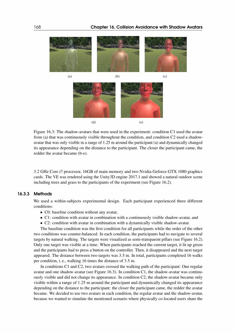
168 Chapter 16. Collision Avoidance with Shadow Avatars
(a) (b) (c)
(d) (e)
Figure 16.3: The shadow-avatars that were used in the experiment: condition C1 used the avatarfrom (a) that was continuously visible throughout the condition, and condition C2 used a shadow-avatar that was only visible in a range of 1.25 m around the participant (a) and dynamically changedits appearance depending on the distance to the participant. The closer the participant came, theredder the avatar became (b-e).
3.2 GHz Core i7 processor, 16GB of main memory and two Nvidia Geforce GTX 1080 graphicscards. The VE was rendered using the Unity3D engine 2017.1 and showed a natural outdoor sceneincluding trees and grass to the participants of the experiment (see Figure 16.2).
16.3.3 Methods
We used a within-subjects experimental design. Each participant experienced three differentconditions:
• C0: baseline condition without any avatar,• C1: condition with avatar in combination with a continuously visible shadow-avatar, and• C2: condition with avatar in combination with a dynamically visible shadow-avatar.The baseline condition was the first condition for all participants while the order of the other
two conditions was counter-balanced. In each condition, the participants had to navigate to severaltargets by natural walking. The targets were visualized as semi-transparent pillars (see Figure 16.2).Only one target was visible at a time. When participants reached the current target, it lit up greenand the participants had to press a button on the controller. Then, it disappeared and the next targetappeared. The distance between two targets was 3.5 m. In total, participants completed 16 walksper condition, i. e., walking 16 times the distance of 3.5 m.
In conditions C1 and C2, two avatars crossed the walking path of the participant: One regularavatar and one shadow-avatar (see Figure 16.3). In condition C1, the shadow-avatar was continu-ously visible and did not change its appearance. In condition C2, the shadow-avatar became onlyvisible within a range of 1.25 m around the participant and dynamically changed its appearancedepending on the distance to the participant: the closer the participant came, the redder the avatarbecame. We decided to use two avatars in each condition, the regular avatar and the shadow-avatar,because we wanted to simulate the mentioned scenario where physically co-located users share the
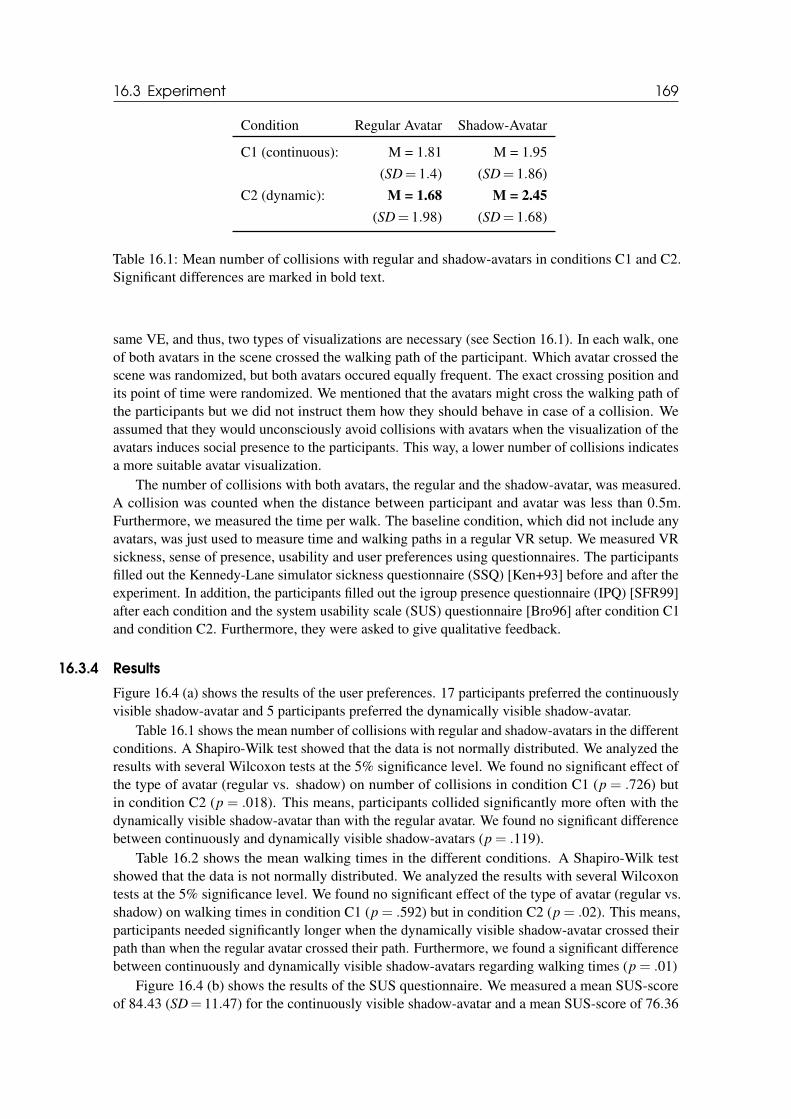
16.3 Experiment 169
Condition Regular Avatar Shadow-Avatar
C1 (continuous): M = 1.81 M = 1.95
(SD= 1.4) (SD= 1.86)
C2 (dynamic): M = 1.68 M = 2.45
(SD= 1.98) (SD= 1.68)
Table 16.1: Mean number of collisions with regular and shadow-avatars in conditions C1 and C2.Significant differences are marked in bold text.
same VE, and thus, two types of visualizations are necessary (see Section 16.1). In each walk, oneof both avatars in the scene crossed the walking path of the participant. Which avatar crossed thescene was randomized, but both avatars occured equally frequent. The exact crossing position andits point of time were randomized. We mentioned that the avatars might cross the walking path ofthe participants but we did not instruct them how they should behave in case of a collision. Weassumed that they would unconsciously avoid collisions with avatars when the visualization of theavatars induces social presence to the participants. This way, a lower number of collisions indicatesa more suitable avatar visualization.
The number of collisions with both avatars, the regular and the shadow-avatar, was measured.A collision was counted when the distance between participant and avatar was less than 0.5m.Furthermore, we measured the time per walk. The baseline condition, which did not include anyavatars, was just used to measure time and walking paths in a regular VR setup. We measured VRsickness, sense of presence, usability and user preferences using questionnaires. The participantsfilled out the Kennedy-Lane simulator sickness questionnaire (SSQ) [Ken+93] before and after theexperiment. In addition, the participants filled out the igroup presence questionnaire (IPQ) [SFR99]after each condition and the system usability scale (SUS) questionnaire [Bro96] after condition C1and condition C2. Furthermore, they were asked to give qualitative feedback.
16.3.4 Results
Figure 16.4 (a) shows the results of the user preferences. 17 participants preferred the continuouslyvisible shadow-avatar and 5 participants preferred the dynamically visible shadow-avatar.
Table 16.1 shows the mean number of collisions with regular and shadow-avatars in the differentconditions. A Shapiro-Wilk test showed that the data is not normally distributed. We analyzed theresults with several Wilcoxon tests at the 5% significance level. We found no significant effect ofthe type of avatar (regular vs. shadow) on number of collisions in condition C1 (p = .726) butin condition C2 (p = .018). This means, participants collided significantly more often with thedynamically visible shadow-avatar than with the regular avatar. We found no significant differencebetween continuously and dynamically visible shadow-avatars (p = .119).
Table 16.2 shows the mean walking times in the different conditions. A Shapiro-Wilk testshowed that the data is not normally distributed. We analyzed the results with several Wilcoxontests at the 5% significance level. We found no significant effect of the type of avatar (regular vs.shadow) on walking times in condition C1 (p = .592) but in condition C2 (p = .02). This means,participants needed significantly longer when the dynamically visible shadow-avatar crossed theirpath than when the regular avatar crossed their path. Furthermore, we found a significant differencebetween continuously and dynamically visible shadow-avatars regarding walking times (p = .01)
Figure 16.4 (b) shows the results of the SUS questionnaire. We measured a mean SUS-scoreof 84.43 (SD= 11.47) for the continuously visible shadow-avatar and a mean SUS-score of 76.36
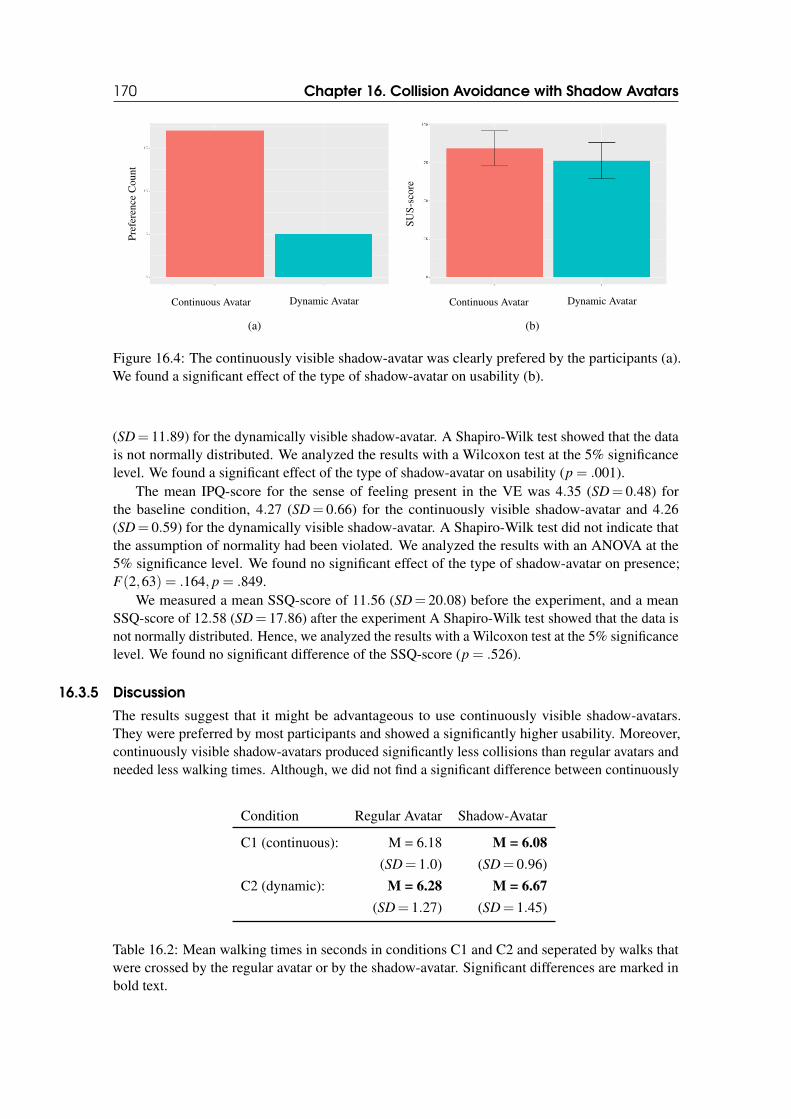
170 Chapter 16. Collision Avoidance with Shadow Avatars
Continuous Avatar Dynamic Avatar
Pre
fere
nce
Cou
nt
(a)
Continuous Avatar Dynamic Avatar
SU
S-s
core
(b)
Figure 16.4: The continuously visible shadow-avatar was clearly prefered by the participants (a).We found a significant effect of the type of shadow-avatar on usability (b).
(SD= 11.89) for the dynamically visible shadow-avatar. A Shapiro-Wilk test showed that the datais not normally distributed. We analyzed the results with a Wilcoxon test at the 5% significancelevel. We found a significant effect of the type of shadow-avatar on usability (p = .001).
The mean IPQ-score for the sense of feeling present in the VE was 4.35 (SD= 0.48) forthe baseline condition, 4.27 (SD= 0.66) for the continuously visible shadow-avatar and 4.26(SD= 0.59) for the dynamically visible shadow-avatar. A Shapiro-Wilk test did not indicate thatthe assumption of normality had been violated. We analyzed the results with an ANOVA at the5% significance level. We found no significant effect of the type of shadow-avatar on presence;F(2,63) = .164, p = .849.
We measured a mean SSQ-score of 11.56 (SD= 20.08) before the experiment, and a meanSSQ-score of 12.58 (SD= 17.86) after the experiment A Shapiro-Wilk test showed that the data isnot normally distributed. Hence, we analyzed the results with a Wilcoxon test at the 5% significancelevel. We found no significant difference of the SSQ-score (p = .526).
16.3.5 Discussion
The results suggest that it might be advantageous to use continuously visible shadow-avatars.They were preferred by most participants and showed a significantly higher usability. Moreover,continuously visible shadow-avatars produced significantly less collisions than regular avatars andneeded less walking times. Although, we did not find a significant difference between continuously
Condition Regular Avatar Shadow-Avatar
C1 (continuous): M = 6.18 M = 6.08
(SD= 1.0) (SD= 0.96)
C2 (dynamic): M = 6.28 M = 6.67
(SD= 1.27) (SD= 1.45)
Table 16.2: Mean walking times in seconds in conditions C1 and C2 and seperated by walks thatwere crossed by the regular avatar or by the shadow-avatar. Significant differences are marked inbold text.
16.4 Conclusion 171
and dynamically visible shadow-avatars, we could not observe an effect between dynamicallyvisible shadow-avatars and regular avatars as well. The better performance of continuously visibleshadow-avatars might be due to the better predictability. The participants could see the shadow-avatar all the time and did not have to fear a spontaneously appearing obstacle. This might also bethe reason why they walked slower in the condition with dynamically visible shadow-avatars.
However, we did not find any significant difference between the conditions regarding the senseof presence. Hence, it seems as if the continuously visible shadow-avatar did not disturb theparticipants’ feeling of being in a virtual environment.
During the qualitative feedback session after the experiment, multiple participants stated thatthey liked the color adjustments of the dynamically visible shadow-avatar. But they just felt moresafe when they could see the potential obstacle the whole time. Probably, a combination of thesetwo types of shadow-avatars might be an appropriate approach: The shadow-avatar should becontinuously but faintly visible and increase its intensity when a user comes closer.
16.4 Conclusion
In this chapter, we introduced shadow-avatars as visualization method for avoiding human collisionswhen physically co-located VR users are redirected in the same VE. Two different types of shadow-avatars were compared in a user study and results suggest that these shadow-avatars should becontinuously visible to the VR users.

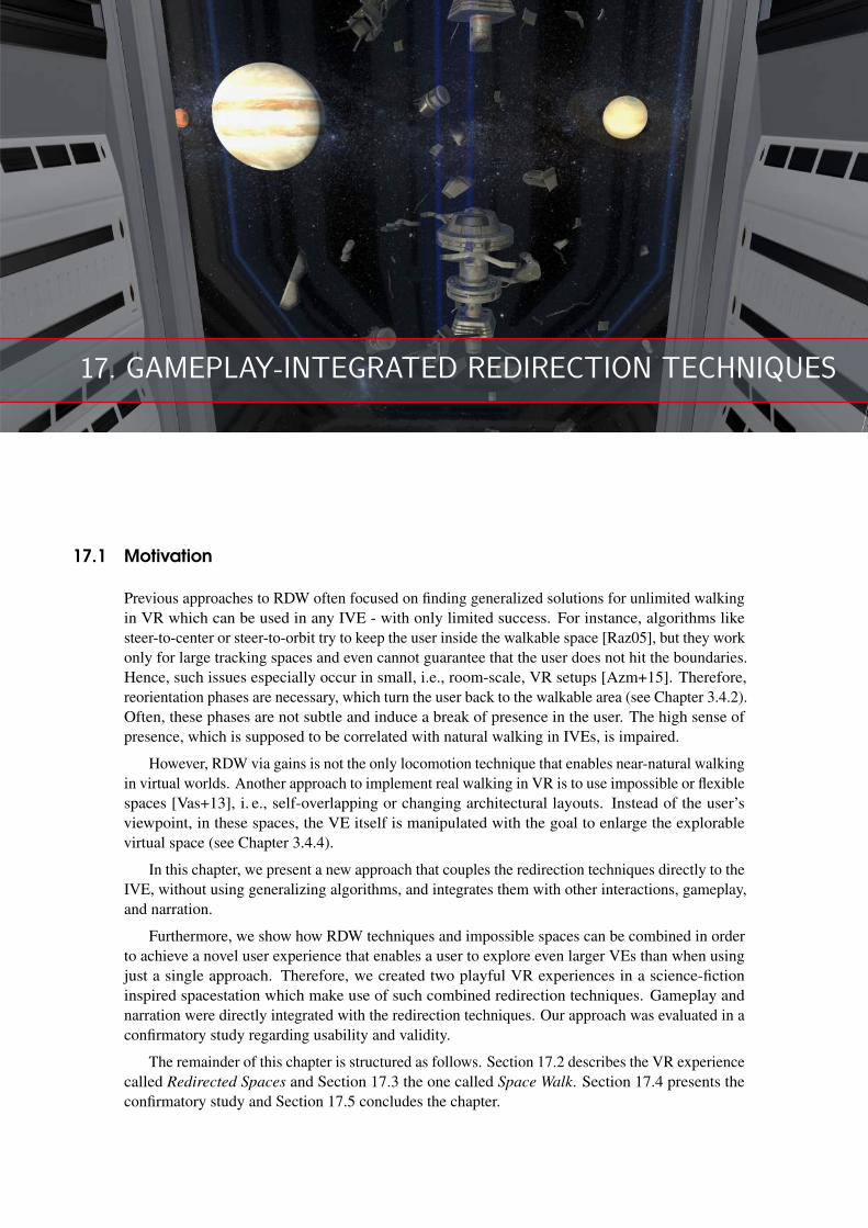
17. GAMEPLAY-INTEGRATED REDIRECTION TECHNIQUES
17.1 Motivation
Previous approaches to RDW often focused on finding generalized solutions for unlimited walkingin VR which can be used in any IVE - with only limited success. For instance, algorithms likesteer-to-center or steer-to-orbit try to keep the user inside the walkable space [Raz05], but they workonly for large tracking spaces and even cannot guarantee that the user does not hit the boundaries.Hence, such issues especially occur in small, i.e., room-scale, VR setups [Azm+15]. Therefore,reorientation phases are necessary, which turn the user back to the walkable area (see Chapter 3.4.2).Often, these phases are not subtle and induce a break of presence in the user. The high sense ofpresence, which is supposed to be correlated with natural walking in IVEs, is impaired.
However, RDW via gains is not the only locomotion technique that enables near-natural walkingin virtual worlds. Another approach to implement real walking in VR is to use impossible or flexiblespaces [Vas+13], i. e., self-overlapping or changing architectural layouts. Instead of the user’sviewpoint, in these spaces, the VE itself is manipulated with the goal to enlarge the explorablevirtual space (see Chapter 3.4.4).
In this chapter, we present a new approach that couples the redirection techniques directly to theIVE, without using generalizing algorithms, and integrates them with other interactions, gameplay,and narration.
Furthermore, we show how RDW techniques and impossible spaces can be combined in orderto achieve a novel user experience that enables a user to explore even larger VEs than when usingjust a single approach. Therefore, we created two playful VR experiences in a science-fictioninspired spacestation which make use of such combined redirection techniques. Gameplay andnarration were directly integrated with the redirection techniques. Our approach was evaluated in aconfirmatory study regarding usability and validity.
The remainder of this chapter is structured as follows. Section 17.2 describes the VR experiencecalled Redirected Spaces and Section 17.3 the one called Space Walk. Section 17.4 presents theconfirmatory study and Section 17.5 concludes the chapter.
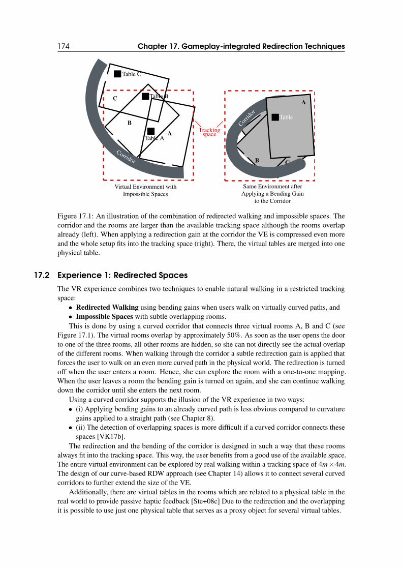
174 Chapter 17. Gameplay-integrated Redirection Techniques
A
B
Trackingspace
Corridor
Corridor
C
C
A
B
Corrid
or
Table
Table A
Table B
Table C
Virtual Environment withImpossible Spaces
Same Environment afterApplying a Bending Gain
to the Corridor
Figure 17.1: An illustration of the combination of redirected walking and impossible spaces. Thecorridor and the rooms are larger than the available tracking space although the rooms overlapalready (left). When applying a redirection gain at the corridor the VE is compressed even moreand the whole setup fits into the tracking space (right). There, the virtual tables are merged into onephysical table.
17.2 Experience 1: Redirected Spaces
The VR experience combines two techniques to enable natural walking in a restricted trackingspace:
• Redirected Walking using bending gains when users walk on virtually curved paths, and• Impossible Spaces with subtle overlapping rooms.This is done by using a curved corridor that connects three virtual rooms A, B and C (see
Figure 17.1). The virtual rooms overlap by approximately 50%. As soon as the user opens the doorto one of the three rooms, all other rooms are hidden, so she can not directly see the actual overlapof the different rooms. When walking through the corridor a subtle redirection gain is applied thatforces the user to walk on an even more curved path in the physical world. The redirection is turnedoff when the user enters a room. Hence, she can explore the room with a one-to-one mapping.When the user leaves a room the bending gain is turned on again, and she can continue walkingdown the corridor until she enters the next room.
Using a curved corridor supports the illusion of the VR experience in two ways:• (i) Applying bending gains to an already curved path is less obvious compared to curvature
gains applied to a straight path (see Chapter 8).• (ii) The detection of overlapping spaces is more difficult if a curved corridor connects these
spaces [VK17b].The redirection and the bending of the corridor is designed in such a way that these rooms
always fit into the tracking space. This way, the user benefits from a good use of the available space.The entire virtual environment can be explored by real walking within a tracking space of 4m×4m.The design of our curve-based RDW approach (see Chapter 14) allows it to connect several curvedcorridors to further extend the size of the VE.
Additionally, there are virtual tables in the rooms which are related to a physical table in thereal world to provide passive haptic feedback [Ste+08c] Due to the redirection and the overlappingit is possible to use just one physical table that serves as a proxy object for several virtual tables.
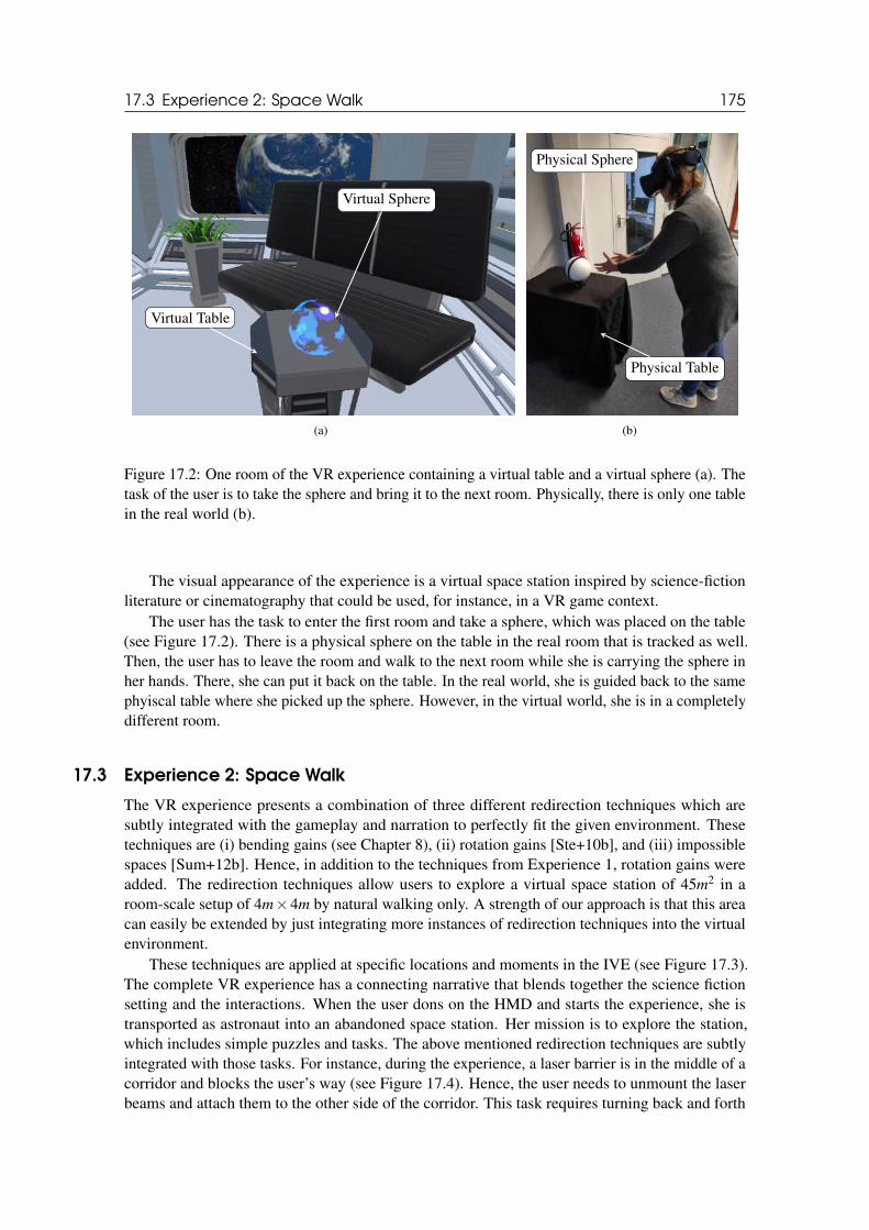
17.3 Experience 2: Space Walk 175
Virtual Sphere
Virtual Table
(a)
Physical Sphere
Physical Table
(b)
Figure 17.2: One room of the VR experience containing a virtual table and a virtual sphere (a). Thetask of the user is to take the sphere and bring it to the next room. Physically, there is only one tablein the real world (b).
The visual appearance of the experience is a virtual space station inspired by science-fictionliterature or cinematography that could be used, for instance, in a VR game context.
The user has the task to enter the first room and take a sphere, which was placed on the table(see Figure 17.2). There is a physical sphere on the table in the real room that is tracked as well.Then, the user has to leave the room and walk to the next room while she is carrying the sphere inher hands. There, she can put it back on the table. In the real world, she is guided back to the samephyiscal table where she picked up the sphere. However, in the virtual world, she is in a completelydifferent room.
17.3 Experience 2: Space Walk
The VR experience presents a combination of three different redirection techniques which aresubtly integrated with the gameplay and narration to perfectly fit the given environment. Thesetechniques are (i) bending gains (see Chapter 8), (ii) rotation gains [Ste+10b], and (iii) impossiblespaces [Sum+12b]. Hence, in addition to the techniques from Experience 1, rotation gains wereadded. The redirection techniques allow users to explore a virtual space station of 45m2 in aroom-scale setup of 4m×4m by natural walking only. A strength of our approach is that this areacan easily be extended by just integrating more instances of redirection techniques into the virtualenvironment.
These techniques are applied at specific locations and moments in the IVE (see Figure 17.3).The complete VR experience has a connecting narrative that blends together the science fictionsetting and the interactions. When the user dons on the HMD and starts the experience, she istransported as astronaut into an abandoned space station. Her mission is to explore the station,which includes simple puzzles and tasks. The above mentioned redirection techniques are subtlyintegrated with those tasks. For instance, during the experience, a laser barrier is in the middle of acorridor and blocks the user’s way (see Figure 17.4). Hence, the user needs to unmount the laserbeams and attach them to the other side of the corridor. This task requires turning back and forth
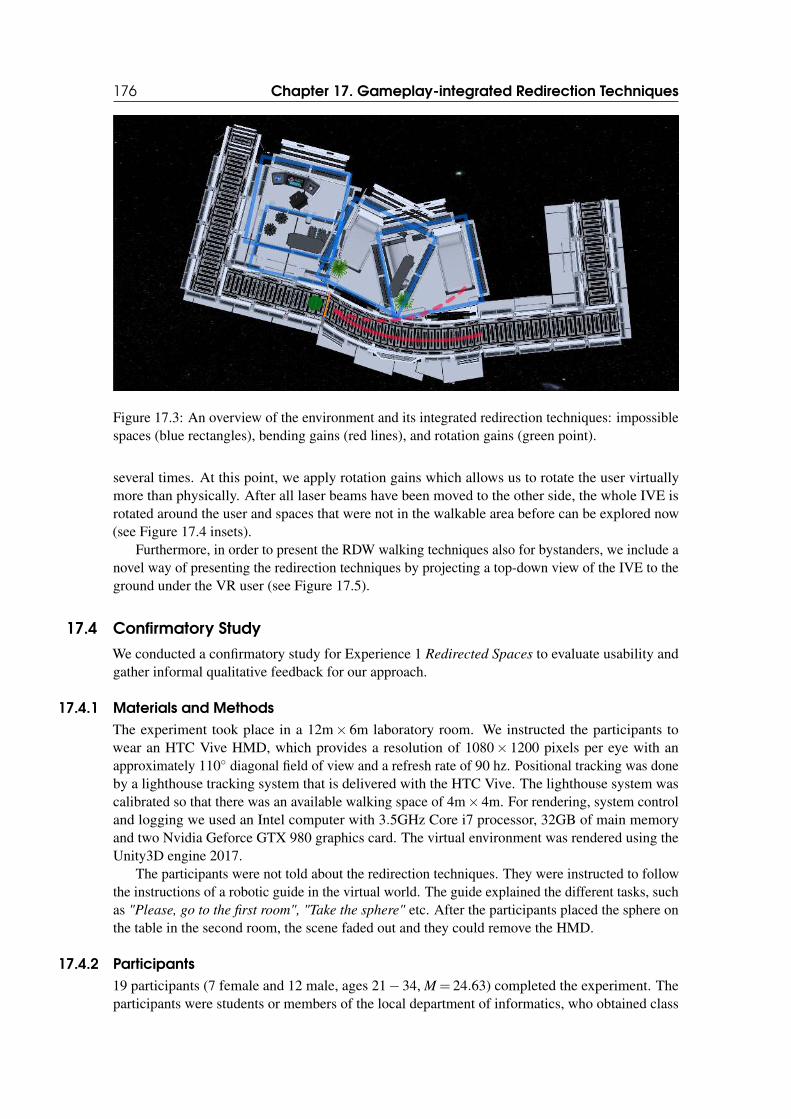
176 Chapter 17. Gameplay-integrated Redirection Techniques
Figure 17.3: An overview of the environment and its integrated redirection techniques: impossiblespaces (blue rectangles), bending gains (red lines), and rotation gains (green point).
several times. At this point, we apply rotation gains which allows us to rotate the user virtuallymore than physically. After all laser beams have been moved to the other side, the whole IVE isrotated around the user and spaces that were not in the walkable area before can be explored now(see Figure 17.4 insets).
Furthermore, in order to present the RDW walking techniques also for bystanders, we include anovel way of presenting the redirection techniques by projecting a top-down view of the IVE to theground under the VR user (see Figure 17.5).
17.4 Confirmatory Study
We conducted a confirmatory study for Experience 1 Redirected Spaces to evaluate usability andgather informal qualitative feedback for our approach.
17.4.1 Materials and Methods
The experiment took place in a 12m× 6m laboratory room. We instructed the participants towear an HTC Vive HMD, which provides a resolution of 1080× 1200 pixels per eye with anapproximately 110◦ diagonal field of view and a refresh rate of 90 hz. Positional tracking was doneby a lighthouse tracking system that is delivered with the HTC Vive. The lighthouse system wascalibrated so that there was an available walking space of 4m× 4m. For rendering, system controland logging we used an Intel computer with 3.5GHz Core i7 processor, 32GB of main memoryand two Nvidia Geforce GTX 980 graphics card. The virtual environment was rendered using theUnity3D engine 2017.
The participants were not told about the redirection techniques. They were instructed to followthe instructions of a robotic guide in the virtual world. The guide explained the different tasks, suchas "Please, go to the first room", "Take the sphere" etc. After the participants placed the sphere onthe table in the second room, the scene faded out and they could remove the HMD.
17.4.2 Participants
19 participants (7 female and 12 male, ages 21− 34, M = 24.63) completed the experiment. Theparticipants were students or members of the local department of informatics, who obtained class
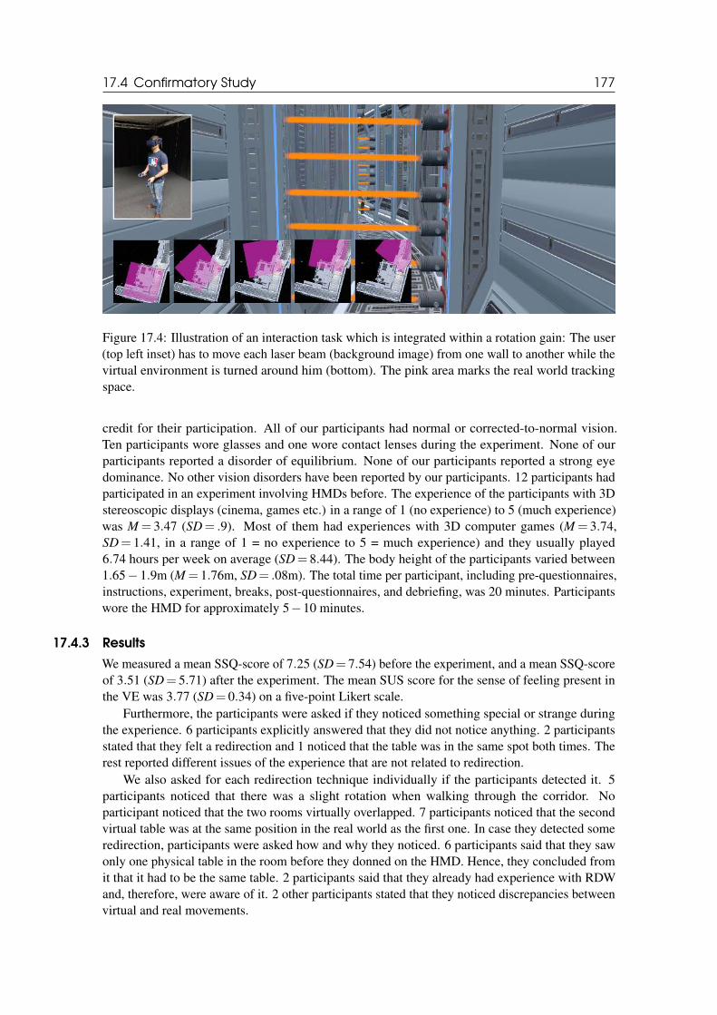
17.4 Confirmatory Study 177
Figure 17.4: Illustration of an interaction task which is integrated within a rotation gain: The user(top left inset) has to move each laser beam (background image) from one wall to another while thevirtual environment is turned around him (bottom). The pink area marks the real world trackingspace.
credit for their participation. All of our participants had normal or corrected-to-normal vision.Ten participants wore glasses and one wore contact lenses during the experiment. None of ourparticipants reported a disorder of equilibrium. None of our participants reported a strong eyedominance. No other vision disorders have been reported by our participants. 12 participants hadparticipated in an experiment involving HMDs before. The experience of the participants with 3Dstereoscopic displays (cinema, games etc.) in a range of 1 (no experience) to 5 (much experience)was M = 3.47 (SD= .9). Most of them had experiences with 3D computer games (M = 3.74,SD= 1.41, in a range of 1 = no experience to 5 = much experience) and they usually played6.74 hours per week on average (SD= 8.44). The body height of the participants varied between1.65− 1.9m (M = 1.76m, SD= .08m). The total time per participant, including pre-questionnaires,instructions, experiment, breaks, post-questionnaires, and debriefing, was 20 minutes. Participantswore the HMD for approximately 5−10 minutes.
17.4.3 Results
We measured a mean SSQ-score of 7.25 (SD= 7.54) before the experiment, and a mean SSQ-scoreof 3.51 (SD= 5.71) after the experiment. The mean SUS score for the sense of feeling present inthe VE was 3.77 (SD= 0.34) on a five-point Likert scale.
Furthermore, the participants were asked if they noticed something special or strange duringthe experience. 6 participants explicitly answered that they did not notice anything. 2 participantsstated that they felt a redirection and 1 noticed that the table was in the same spot both times. Therest reported different issues of the experience that are not related to redirection.
We also asked for each redirection technique individually if the participants detected it. 5participants noticed that there was a slight rotation when walking through the corridor. Noparticipant noticed that the two rooms virtually overlapped. 7 participants noticed that the secondvirtual table was at the same position in the real world as the first one. In case they detected someredirection, participants were asked how and why they noticed. 6 participants said that they sawonly one physical table in the room before they donned on the HMD. Hence, they concluded fromit that it had to be the same table. 2 participants said that they already had experience with RDWand, therefore, were aware of it. 2 other participants stated that they noticed discrepancies betweenvirtual and real movements.
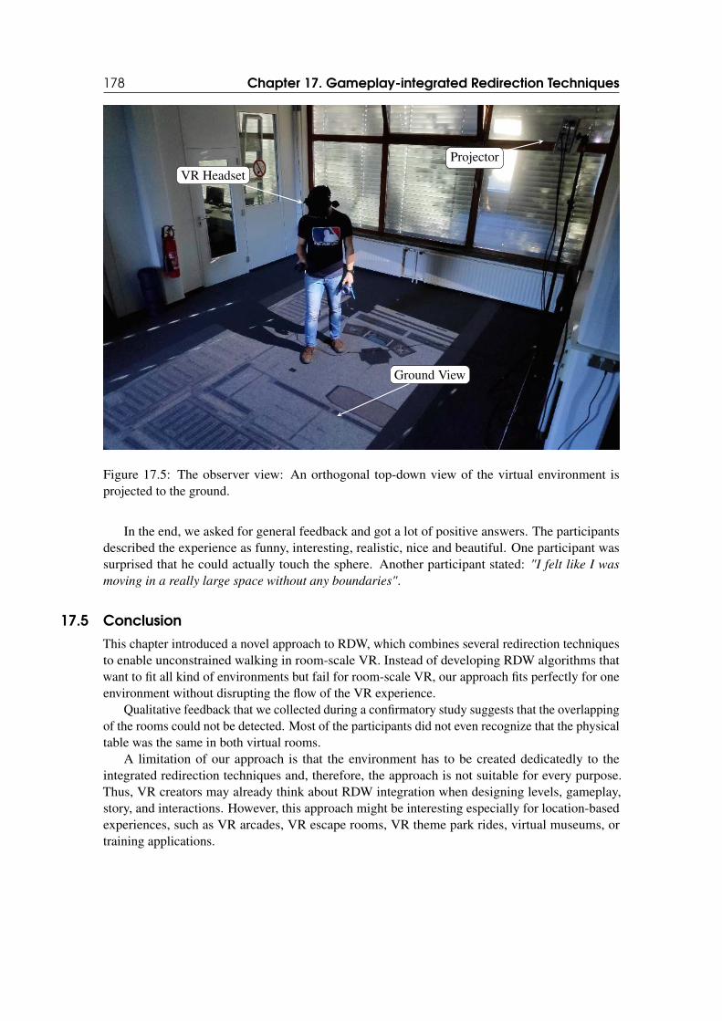
178 Chapter 17. Gameplay-integrated Redirection Techniques
VR Headset
Ground View
Projector
Figure 17.5: The observer view: An orthogonal top-down view of the virtual environment isprojected to the ground.
In the end, we asked for general feedback and got a lot of positive answers. The participantsdescribed the experience as funny, interesting, realistic, nice and beautiful. One participant wassurprised that he could actually touch the sphere. Another participant stated: "I felt like I was
moving in a really large space without any boundaries".
17.5 Conclusion
This chapter introduced a novel approach to RDW, which combines several redirection techniquesto enable unconstrained walking in room-scale VR. Instead of developing RDW algorithms thatwant to fit all kind of environments but fail for room-scale VR, our approach fits perfectly for oneenvironment without disrupting the flow of the VR experience.
Qualitative feedback that we collected during a confirmatory study suggests that the overlappingof the rooms could not be detected. Most of the participants did not even recognize that the physicaltable was the same in both virtual rooms.
A limitation of our approach is that the environment has to be created dedicatedly to theintegrated redirection techniques and, therefore, the approach is not suitable for every purpose.Thus, VR creators may already think about RDW integration when designing levels, gameplay,story, and interactions. However, this approach might be interesting especially for location-basedexperiences, such as VR arcades, VR escape rooms, VR theme park rides, virtual museums, ortraining applications.
V
18 Summary . . . . . . . . . . . . . . . . . . . . . . . . . . 181
19 Outlook . . . . . . . . . . . . . . . . . . . . . . . . . . . . 183
Acknowledgments . . . . . . . . . . . . . . . . . 184
Bibliography . . . . . . . . . . . . . . . . . . . . . . . . 185
CONCLUSION

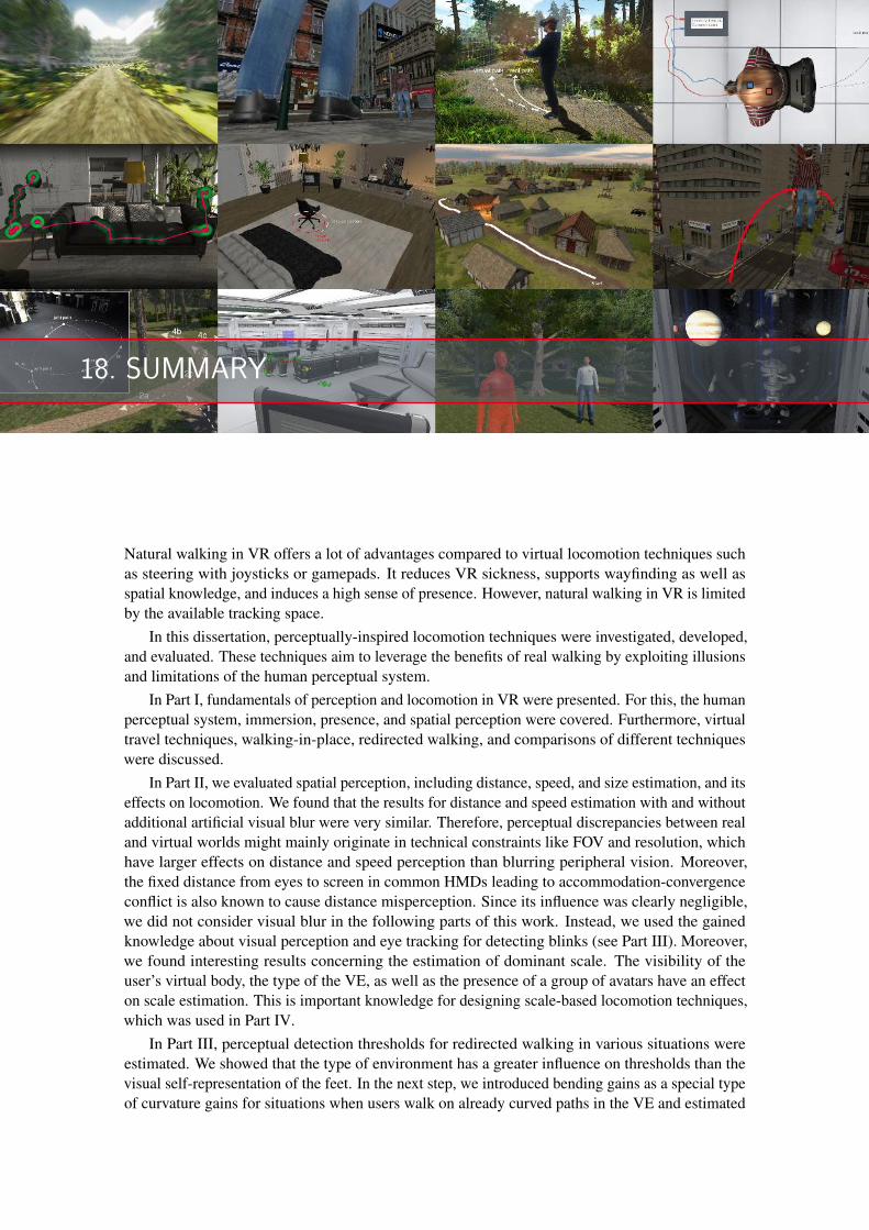
18. SUMMARY
Natural walking in VR offers a lot of advantages compared to virtual locomotion techniques suchas steering with joysticks or gamepads. It reduces VR sickness, supports wayfinding as well asspatial knowledge, and induces a high sense of presence. However, natural walking in VR is limitedby the available tracking space.
In this dissertation, perceptually-inspired locomotion techniques were investigated, developed,and evaluated. These techniques aim to leverage the benefits of real walking by exploiting illusionsand limitations of the human perceptual system.
In Part I, fundamentals of perception and locomotion in VR were presented. For this, the humanperceptual system, immersion, presence, and spatial perception were covered. Furthermore, virtualtravel techniques, walking-in-place, redirected walking, and comparisons of different techniqueswere discussed.
In Part II, we evaluated spatial perception, including distance, speed, and size estimation, and itseffects on locomotion. We found that the results for distance and speed estimation with and withoutadditional artificial visual blur were very similar. Therefore, perceptual discrepancies between realand virtual worlds might mainly originate in technical constraints like FOV and resolution, whichhave larger effects on distance and speed perception than blurring peripheral vision. Moreover,the fixed distance from eyes to screen in common HMDs leading to accommodation-convergenceconflict is also known to cause distance misperception. Since its influence was clearly negligible,we did not consider visual blur in the following parts of this work. Instead, we used the gainedknowledge about visual perception and eye tracking for detecting blinks (see Part III). Moreover,we found interesting results concerning the estimation of dominant scale. The visibility of theuser’s virtual body, the type of the VE, as well as the presence of a group of avatars have an effecton scale estimation. This is important knowledge for designing scale-based locomotion techniques,which was used in Part IV.
In Part III, perceptual detection thresholds for redirected walking in various situations wereestimated. We showed that the type of environment has a greater influence on thresholds than thevisual self-representation of the feet. In the next step, we introduced bending gains as a special typeof curvature gains for situations when users walk on already curved paths in the VE and estimated
182 Chapter 18. Summary
thresholds for these gains. These bending gains were used in Part IV to develop a novel approachto RDW that is based on curved path layouts. Bending gains were also used when we investigatedhow thresholds change when transcranial direct-current stimulation is applied to the brain of theuser. Interestingly, it did only show an effect for the highest tested gain. However, VR sicknesscould be reduced significantly. As an orthogonal concept to previous RDW approaches such asbending gains, we presented reorientation and repositioning techniques that are executed duringeye blinks. These techniques showed a potential to improve RDW for around 50%.
In Part IV, we developed perceptually-inspired locomotion techniques for seated, standing, androom-scale VR, which are based on the results of the previous two parts. These new techniqueshave been evaluated in several user studies. Dynamic rotation gains were compared with static gainsand scrolling in a seated VR experience and achieved better results for usability, VR sickness, andspatial knowledge. Scale-based walking techniques were evaluated regarding usability, presence,VR sickness, and spatial knowledge, and manual scaling was superior for most of the criteria.Furthermore, we presented a curve-based approach to RDW that relies on previously introducedbending gains. Several configurations were discussed and one configuration was implemented asan informative example. A tool for easily integrating these configurations with the VR engine wasdeveloped including algorithms for procedural generation. In a user study, this RDW approach wascompared to joystick-based locomotion and teleportation. We found that it performed significantlybetter regarding cognitive map building. Furthermore, the curve-based RDW approach as wellas teleportation were preferred by most participants. There were no effects on presence andeffectiveness. Then, a main problem was discussed which may occur when applying RDWtechniques in a multi-user scenario: Users can collide physically since virtual and real position donot match necessarily. In order to address this issue, we introduced shadow avatars as a solutionund evaluated different types of these avatars in a user study. Finally, it was demonstrated howdifferent redirection techniques, such as rotation gains, bending gains, and impossible spaces, canbe combined and integrated with gameplay and narration of a VR experience.
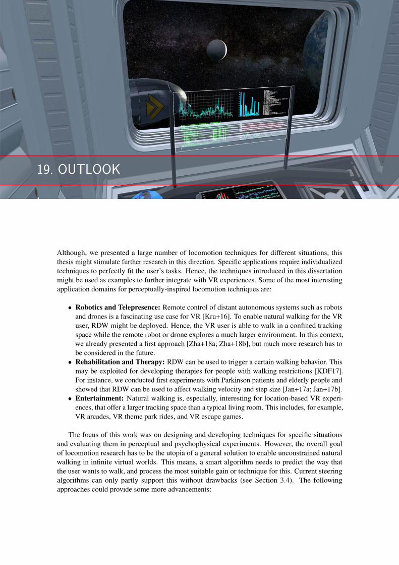
19. OUTLOOK
Although, we presented a large number of locomotion techniques for different situations, thisthesis might stimulate further research in this direction. Specific applications require individualizedtechniques to perfectly fit the user’s tasks. Hence, the techniques introduced in this dissertationmight be used as examples to further integrate with VR experiences. Some of the most interestingapplication domains for perceptually-inspired locomotion techniques are:
• Robotics and Telepresence: Remote control of distant autonomous systems such as robotsand drones is a fascinating use case for VR [Kru+16]. To enable natural walking for the VRuser, RDW might be deployed. Hence, the VR user is able to walk in a confined trackingspace while the remote robot or drone explores a much larger environment. In this context,we already presented a first approach [Zha+18a; Zha+18b], but much more research has tobe considered in the future.
• Rehabilitation and Therapy: RDW can be used to trigger a certain walking behavior. Thismay be exploited for developing therapies for people with walking restrictions [KDF17].For instance, we conducted first experiments with Parkinson patients and elderly people andshowed that RDW can be used to affect walking velocity and step size [Jan+17a; Jan+17b].
• Entertainment: Natural walking is, especially, interesting for location-based VR experi-ences, that offer a larger tracking space than a typical living room. This includes, for example,VR arcades, VR theme park rides, and VR escape games.
The focus of this work was on designing and developing techniques for specific situationsand evaluating them in perceptual and psychophysical experiments. However, the overall goalof locomotion research has to be the utopia of a general solution to enable unconstrained naturalwalking in infinite virtual worlds. This means, a smart algorithm needs to predict the way thatthe user wants to walk, and process the most suitable gain or technique for this. Current steeringalgorithms can only partly support this without drawbacks (see Section 3.4). The followingapproaches could provide some more advancements:
• Beyond Perceptual Thresholds: So far, all RDW techniques are limited by the humanperceptual detection thresholds. Recently, we showed that much wider thresholds areaccepted by VR users [Rie+18]. This means that it is possible to even use perceivable gains,at least for some amount of time.
• Eye Tracking: In this work, we showed how tracking of eye blinks can improve RDWtechniques (see Chapter 10). This work was extended by Nguyen and Kunz [NK18]. Incombination with redirections during saccades, it might even be more powerful. Moreover,eye tracking might also be very interesting to gain information about the environment andpredict walking paths. This could open up completely new possibilities for redirection.
• Brain Stimulation: BCIs are a promising approach for future interactions with a computersystem. In this work, we conducted first experiments with tDCS applied during naturalwalking. This method might be extended to improve the overall user experience as well asperceptually-inspired locomotion techniques.
ACKNOWLEDGMENTS
First of all, I would like to thank my supervisor Prof. Dr. Frank Steinicke and my former colleagueand advisor Prof. Dr. Gerd Bruder for introducing me to the world of Virtual Reality. I have learneda lot from them since I joined the Human-Computer Interaction group as a student co-workerin 2014 and I am very grateful for this. It was a great chance to have two advisors who areinternationally renowned experts in the field of redirected walking. Franks support and guidancewas very helpful during the work on this dissertation. His input stimulated my thoughts andenriched my research. Gerd always had time for my many questions, especially in the beginning,and encouraged me to continue when I did not know how. I would also like to thank Prof. Dr. GregWelch for welcoming me at the Synthetic Reality Lab and teaching me how to write a SIGGRAPHpaper. I had a great time in Florida, and not just because of disney world.
Furthermore, I would like to thank the researchers who agreed to review this thesis! Specialthanks go to all my co-authors, without whom this work would not have been possible. Especially,I would like to thank my collaborators in the DFG project "interactive Locomotion User Interfaces(iLUI)", Prof. Dr. Markus Lappe and Benjamin Bolte, and all the people in our HCI research groupfor providing valuable feedback and a nice company. There was always a pleasant atmosphere inour lab. I appreciate the voluntary participation in the many experiments conducted throughout thework on this dissertation. Thanks go to all the students that worked with me on projects or theirtheses. And I am thankful to everyone who took the time to proofread this dissertation.
Moreover, I thank my friends and family for helping and supporting me, especially, my parentsKarsten and Erika as well as my sister Lisa and my brother Holger. They have been a great supportin the last 32 years.
Finally, I am very pleased to thank my wife Silja and our son Bela for being there and I am verymuch looking forward to the birth of our daughter. Silja always supported me with my work andhelped to keep my patience, especially in stressful times. I will never forget the evenings when wetinkered materials for my experiments. Bela reminded me which things in life are really important.


BIBLIOGRAPHY
[Abt+19] P. Abtahi, M. Gonzalez-Franco, E. Ofek, and A. Steed. “I’m a Giant: Walking in Large Virtual Environments atHigh Speed Gains”. In: ACM Conference on Human Factors in Computing Systems (CHI). 2019, page 522.
[AGE04] W. J. Adams, E. W. Graf, and M. O. Ernst. “Experience can Change the ’light-from-above’ Prior”. In: Nature
Neuroscience 7.10 (2004), page 1057.
[Agr+97] M. Agrawala, A. C. Beers, I. McDowall, B. Fröhlich, M. Bolas, and P. Hanrahan. “The Two-User ResponsiveWorkbench: Support for Collaboration Through Individual Views of a Shared Space”. In: Computer Graphics and
Interactive Techniques. ACM Press/Addison-Wesley Publishing Co. 1997, pages 327–332.
[Ahm+10] F. Ahmed, J. D. Cohen, K. S. Binder, and C. L. Fennema. “Influence of Tactile Feedback and Presence on Egocen-tric Distance Perception in Virtual Environments”. In: IEEE Virtual Reality (VR). 2010, pages 195–202.
[Aki+03] H. Akiduki, S. Nishiike, H. Watanabe, K. Matsuoka, T. Kubo, and N. Takeda. “Visual-Vestibular Conflict Inducedby Virtual Reality in Humans”. In: Neuroscience Letters 340.3 (2003), pages 197–200.
[Ant+12] A. Antal, G. Kovacs, L. Chaieb, C. Cziraki, W. Paulus, and M. W. Greenlee. “Cathodal Stimulation of Human MT+Leads to Elevated fMRI Signal: A tDCS-fMRI Study”. In: Restorative Neurology and Neuroscience 30.3 (2012),pages 255–263.
[APS19] J. Auda, M. Pascher, and S. Schneegass. “Around the (Virtual) World: Infinite Walking in Virtual Reality Us-ing Electrical Muscle Stimulation”. In: ACM Conference on Human Factors in Computing Systems (CHI). 2019,page 431.
[Azm+16a] M. Azmandian, T. Grechkin, M. Bolas, and E. Suma. “The Redirected Walking Toolkit: A Unified Developmentand Deployment Platform for Exploring Large Virtual Environments”. In: Everyday VR Workshop, IEEE VR. 2016.
[Azm+15] M. Azmandian, T. Grechkin, M. Bolas, and E. Suma. “Physical Space Requirements for Redirected Walking:How Size and Shape Affect Performance”. In: Proceedings of International Conference on Artificial Reality and
Telexistence and Eurographics Symposium on Virtual Environments (ICAT-EGVE). 2015, pages 93–100.
[Azm+16b] M. Azmandian, T. Grechkin, M. Bolas, and E. Suma. “Automated Path Prediction for Redirected Walking UsingNavigation Meshes”. In: IEEE Symposium on 3D User Interfaces (3DUI). 2016, pages 63–66.
[AGR17] M. Azmandian, T. Grechkin, and E. S. Rosenberg. “An Evaluation of Strategies for Two-User Redirected Walkingin Shared Physical Spaces”. In: IEEE Virtual Reality (VR). 2017, pages 91–98.
[Bac+19] E. R. Bachmann, E. Hodgson, C. Hoffbauer, and J. Messinger. “Multi-User Redirected Walking and ResettingUsing Artificial Potential Fields”. In: IEEE Transactions on Visualization and Computer Graphics (TVCG) (2019).
[BPW03] N. H. Bakker, P. O. Passenier, and P. J. Werkhoven. “Effects of Head-Slaved Navigation and the Use of Teleportson Spatial Orientation in Virtual Environments”. In: Human factors 45.1 (2003), pages 160–169.
[Ban+05] T. Banton, J. Stefanucci, F. Durgin, A. Fass, and D. Proffitt. “The Perception of Walking Speed in a Virtual Envi-ronment”. In: Presence: Teleoperators & Virtual Environments 14.4 (2005), pages 394–406.
[BB00] J. D. Bayliss and D. H. Ballard. “A Virtual Reality Testbed for Brain-Computer Interface Research”. In: IEEE
Transactions on Rehabilitation Engineering 8.2 (2000), pages 188–190.
[BM98] B. Becker and G. Mark. “Social Conventions in Collaborative Virtual Environments”. In: ACM International Con-
ference on Collaborative Virtual Environments (CVE). 1998, pages 17–19.
[BPA00] M. W. Becker, H. Pashler, and S. M. Anstis. “The Role of Iconic Memory in Change-Detection Tasks”. In: Percep-
tion 29.3 (2000), pages 273–286.
[BH94] B. B. Bederson and J. D. Hollan. “Pad++: A Zooming Graphical Interface for Exploring Alternate InterfacePhysics”. In: ACM Symposium on User Interface Software and Technology (UIST). ACM. 1994, pages 17–26.
[Ben+01] S. Benford, C. Greenhalgh, T. Rodden, and J. Pycock. “Collaborative Virtual Environments”. In: Communications
of the ACM 44.7 (2001), pages 79–85.
[BK11] M. Berniker and K. Kording. “Bayesian Approaches to Sensory Integration for Motor Control”. In: Wiley Interdis-
ciplinary Reviews: Cognitive Science 2.4 (2011), pages 419–428.
[Ber00] A. Berthoz. The Brain’s Sense of Movement. Cambridge, Massachusetts: Harvard University Press, 2000.
[BIL00] R. J. Bertin, I. Israël, and M. Lappe. “Perception of two-dimensional, simulated ego-motion trajectories from opticflow”. In: Vision Research 40.21 (2000), pages 2951–2971.
[BS16] G. Bertolini and D. Straumann. “Moving in a Moving World: A Review on Vestibular Motion Sickness”. In: Fron-
tiers in Neurology 7 (2016), page 14.
[BW95] M. Billinghurst and S. Weghorst. “The Use of Sketch Maps to Measure Cognitive Maps of Virtual Environments”.In: IEEE Virtual Reality Annual International Symposium. 1995.
[Bla+16] P. A. Blankenship, S. L. Stuebing, S. S. Winter, J. L. Cheatwood, J. D. Benson, I. Q. Whishaw, and D. G. Wallace.“The Medial Frontal Cortex Contributes to but does not Organize Rat Exploratory Behavior”. In: Neuroscience 336(2016), pages 1–11.

[Bog+06] R. Bogacz, E. Brown, J. Moehlis, P. Holmes, and J. D. Cohen. “The Physics of Optimal Decision Making: AFormal Analysis of Models of Performance in Two-Alternative Forced-Choice Tasks.” In: Psychological review
113.4 (2006), page 700.
[Bol17] C. Boletsis. “The New Era of Virtual Reality Locomotion: A Systematic Literature Review of Techniques and aProposed Typology”. In: Multimodal Technologies and Interaction 1.4 (2017), page 24.
[Böl+19] L. Bölling, N. Stein, F. Steinicke, and M. Lappe. “Shrinking Circles: Adaptation to Increased Curvature Gain inRedirected Walking”. In: IEEE Transactions on Visualization and Computer Graphics (TVCG) (2019).
[BL15] B. Bolte and M. Lappe. “Subliminal Reorientation and Repositioning in Immersive Virtual Environments usingSaccadic Suppression”. In: IEEE Transactions on Visualization and Computer Graphics (TVCG) 21.4 (2015),pages 545–552.
[BSB11] B. Bolte, F. Steinicke, and G. Bruder. “The Jumper Metaphor: an Effective Navigation Technique for ImmersiveDisplay Setups”. In: Proceedings of Virtual Reality International Conference (VRIC). 2011.
[BS02] L. Bouguila and M. Sato. “Virtual Locomotion System for Large-Scale Virtual Environment”. In: Proceedings of
IEEE Virtual Reality (VR). 2002, pages 291–292.
[Bou+02] L. Bouguila, M. Sato, S. Hasegawa, H. Naoki, N. Matsumoto, A. Toyama, J. Ezzine, and D. Maghrebi. “A NewStep-in-Place Locomotion Interface for Virtual Environment with Large Display System”. In: Proceedings of ACM
SIGGRAPH. 2002, pages 197–207.
[Bow+01] D. A. Bowman, E. Kruijff, J. J. LaViola, and I. Poupyrev. “An Introduction to 3-D User Interface Design”. In:Presence: Teleoperators & Virtual Environments 10.1 (2001), pages 96–108.
[BKH97] D. Bowman, D. Koller, and L. Hodges. “Travel in Immersive Virtual Environments: An Evaluation of ViewpointMotion Control Techniques”. In: Proceedings of IEEE Virtual Reality Annual International Symposium (VRAIS).Volume 7. IEEE, 1997, pages 45–52.
[Bow+04] D. Bowman, E. Kruijff, J. LaViola, Jr., and I. Poupyrev. 3D User Interfaces: Theory and Practice. Addison-WesleyProfessional, 2004.
[Bow+99] D. A. Bowman, E. T. Davis, L. F. Hodges, and A. N. Badre. “Maintaining Spatial Orientation During Travel inan Immersive Virtual Environment”. In: Presence: Teleoperators and Virtual Environments 8.6 (1999), pages 618–631.
[Bow+98] D. A. Bowman, J. Wineman, L. F. Hodges, and D. Allison. “Designing Animal Habitats within an Immersive VE”.In: IEEE Computer Graphics and Applications 18.5 (1998), pages 9–13.
[Boy+18] Y. Boysen, M. Husung, T. Mantei, L. Müller, J. Schimmelpfennig, L. Uzolas, and E. Langbehn1. “Scale & Walk:Evaluation von skalierungsbasierten Interaktionstechniken zur natürlichen Fortbewegung in VR”. In: Mensch und
Computer. 2018, (12 pages).
[Boz+16] E. Bozgeyikli, A. Raij, S. Katkoori, and R. Dubey. “Point & Teleport Locomotion Technique for Virtual Reality”.In: Proceedings of ACM Symposium on Computer-Human Interaction in Play (CHI Play). 2016, pages 205–216.
[BHV94] B. Bridgeman, A. H. C. van der Heijden, and B. M. Velichkovsky. “A Theory of Visual Stability Across SaccadicEye Movements”. In: Behav. Brain Sci. 17 (1994), pages 247–292.
[BHS75] B. Bridgeman, D. Hendry, and L. Stark. “Failure to Detect Displacement of the Visual World During Saccadic EyeMovements”. In: Vision Research 15.6 (1975), pages 719–722.
[Bri+05] D. Bristow, J.-D. Haynes, R. Sylvester, C. D. Frith, and G. Rees. “Blinking Suppresses the Neural Response toUnchanging Retinal Stimulation”. In: Current Biology 15.14 (2005), pages 1296–1300.
[Bro96] J. Brooke. “SUS-A Quick and Dirty Usability Scale”. In: Usability Evaluation in Industry 189.194 (1996), pages 4–7.
[Bro10] F. Brooks. TVCG Technical Achievement Award Talk. 2010.
[Bro02] L. E. Brown. “Limb Position Drift and its Implications for Movement and Position Control”. PhD thesis. Pennsyl-vania State University, 2002.
[Bru+09] G. Bruder, F. Steinicke, K. Hinrichs, and M. Lappe. “Reorientation During Body Turns”. In: Joint Virtual Reality
Eurographics Conference on Virtual Environments. Eurographics Association. 2009, pages 145–152.
[BSH09] G. Bruder, F. Steinicke, and K. Hinrichs. “Arch-Explore: A Natural User Interface for Immersive ArchitecturalWalkthroughs”. In: Proceedings of IEEE Symposium on 3D User Interfaces (3DUI). 2009, pages 75–82.
[BE17] G. Bruder and E. Langbehn. “Subliminal Rotations During Eye Blinks for Redirected Walking”. In: Journal of
Vision (Talk) 17.10 (2017), pages 1266–1266.
[Bru+12] G. Bruder, V. Interrante, L. Phillips, and F. Steinicke. “Redirecting Walking and Driving for Natural Navigation inImmersive Virtual Environments”. In: IEEE Transactions on Visualization and Computer Graphics (TVCG) 18.4(2012), pages 538–545.
[BLS15] G. Bruder, P. Lubos, and F. Steinicke. “Cognitive Resource Demands of Redirected Walking”. In: IEEE Transac-
tions on Visualization and Computer Graphics (TVCG) 21.4 (2015), pages 539–544.
1This publication is based on a bachelor project. The students implemented and ran the experiment under mysupervision. I designed the experiment and wrote the paper.

[BPS12] G. Bruder, A. Pusch, and F. Steinicke. “Analyzing Effects of Geometric Rendering Parameters on Size and DistanceEstimation in On-Axis Stereographics”. In: Proceedings of ACM Symposium on Applied Perception (SAP). ACM,2012, pages 111–118.
[Bru+15] G. Bruder, F. A. Sanz, A.-H. Olivier, and A. Lécuyer. “Distance Estimation in Large Immersive Projection Systems,Revisited”. In: IEEE Virtual Reality (VR). 2015, pages 27–32.
[Bru+13] G. Bruder, F. Steinicke, B. Bolte, P. Wieland, H. Frenz, and M. Lappe. “Exploiting Perceptual Limitations and Illu-sions to Support Walking Through Virtual Environments in Confined Physical Spaces”. In: Displays 34.2 (2013),pages 132–141.
[BPJ13] L. Bruno, J. Pereira, and J. Jorge. “A New Approach to Walking in Place”. In: INTERACT. 2013, pages 370–387.
[BYB18] L. E. Buck, M. K. Young, and B. Bodenheimer. “A Comparison of Distance Estimation in HMD-based VirtualEnvironments With Different HMD-based Conditions”. In: ACM Transactions on Applied Perception (TAP) 15.3(2018), page 21.
[Bur+05] E. Burns, S. Razzaque, A. Panter, M. Whitton, M. McCallus, and F. Brooks. “The Hand is Slower than the Eye:A quantitative exploration of visual dominance over proprioception”. In: IEEE Proceedings of the Virtual Reality
(VR). IEEE, 2005, pages 3–10.
[BR02] D. C. Burr and J. Ross. “Direct Evidence that Influence Motion Mechanisms”. In: The Journal of Neuroscience
22.19 (2002), pages 8661–8664.
[BBB07] P. Byrne, S. Becker, and N. Burgess. “Remembering the Past and Imagining the Future: A Neural Model of SpatialMemory and Imagery”. In: Psychological Review 114.2 (2007), page 340.
[CMN83] S. Card, T. Moran, and A. Newell. The Psychology of Human-Computer Interaction. Edited by N. Hillsdale.Lawrence Erlbaum Associates, 1983.
[CR15] K. Carnegie and T. Rhee. “Reducing Visual Discomfort with HMDs Using Dynamic Depth of Field”. In: IEEE
Computer Graphics and Applications 35.5 (2015), pages 34–41.
[CH02] Y. S. Chee and C. M. Hooi. “C-VISions: Socialized Learning Through Collaborative, Virtual, Interactive Simu-lations”. In: Proceedings of the Conference on Computer Support for Collaborative Learning: Foundations for a
CSCL Community. CSCL ’02. Boulder, Colorado: International Society of the Learning Sciences, 2002, pages 687–696. URL: ❤tt♣✿✴✴❞❧✳❛❝♠✳♦r❣✴❝✐t❛t✐♦♥✳❝❢♠❄✐❞❂✶✻✺✽✻✶✻✳✶✻✺✽✼✽✾.
[Che06] Y. Chen. “Olfactory Display: Development and Application in Virtual Reality Therapy”. In: IEEE International
Conference on Artificial Reality and Telexistence (ICAT). 2006, pages 580–584.
[CP16] Cherry Pop Games and Perilous Orbit. SportsBar VR. Game [HTC Vive]. Cherry Pop Games and Perilous Orbit.Played December 2016. June 2016.
[Che+19] M. Chessa, G. Maiello, A. Borsari, and P. J. Bex. “The Perceptual Quality of the Oculus Rift for Immersive VirtualReality”. In: Human–Computer Interaction 34.1 (2019), pages 51–82.
[Cid+16] M. A. Cidota, R. M. Clifford, S. G. Lukosch, and M. Billinghurst. “Using Visual Effects to Facilitate Depth Per-ception for Spatial Tasks in Virtual and Augmented Reality”. In: IEEE International Symposium on Mixed and
Augmented Reality (ISMAR). 2016, pages 172–177.
[Cli+09] D. Cliburn, S. Rilea, D. Parsons, P. Surya, and J. Semler. “The Effects of Teleportation on Recollection of the Struc-ture of a Virtual World”. In: Proceedings of Joint Virtual Reality Eurographics Conference on Virtual Environments
(JVRC). 2009, pages 117–120.
[Col+89] M. Collins, R. Seeto, L. Campbell, and M. Ross. “Blinking and Corneal Sensitivity”. In: Acta ophthalmologica
67.5 (1989), pages 525–531.
[Col+17] D. Colombo, S. Serino, C. Tuena, E. Pedroli, A. Dakanalis, P. Cipresso, and G. Riva. “Egocentric and AllocentricSpatial Reference Frames in Aging: A Systematic Review”. In: Neuroscience & Biobehavioral Reviews 80 (2017),pages 605–621.
[Col80] M. Coltheart. “Iconic Memory and Visible Persistence”. In: Perception & Psychophysics 27.3 (1980), pages 183–228.
[Cor62] T. N. Cornsweet. “The Staircase-Method in Psychophysics”. In: The American Journal of Psychology 75.3 (1962),pages 485–491.
[Cor17] N. Corporation. Budget Cuts. Game [HTC Vive]. Neat Corporation. Played -. 2017.
[Cre+05] S. H. Creem-Regehr, P. Willemsen, A. A. Gooch, and W. B. Thompson. “The Influcences of Restricted ViewingConditions on Egocentric Perception: Implications for Real and Virtual Environments”. In: Perception 34.2 (2005),pages 191–204.
[Cre+15] S. H. Creem-Regehr, J. K. Stefanucci, W. B. Thompson, N. Nash, and M. McCardell. “Egocentric Distance Percep-tion in the Oculus Rift (DK2)”. In: ACM SIGGRAPH Symposium on Applied Perception (SAP). 2015, pages 47–50.
[Cro+98] J. A. Crowell, M. S. Banks, K. V. Shenoy, and R. A. Andersen. “Visual Self-Motion Perception During HeadTurns”. In: Nature Neuroscience 1.8 (1998), page 732.
[Cru95] C. Cruz-Neira. “Virtual Reality based on Multiple Projection Screens: The CAVE and Its Applications to Compu-tational Science and Engineering”. PhD thesis. University of Illinois at Chicago, 1995, pages 89–96.

[Cry16] Crytek. Robinson: The Journey. Game [PSVR]. Crytek. Played November 2016. Nov. 2016.
[CV95] J. E. Cutting and P. M. Vishton. “Perceiving Layout and Knowing Distances: The Integration, Relative Potency,and Contextual Use of Different Information About Depth”. In: Perception of Space and Motion. Elsevier, 1995,pages 69–117.
[DAA98] R. P. Darken, T. Allard, and L. B. Achille. “Spatial Orientation and Wayfinding in Large-scale Virtual Spaces: AnIntroduction”. In: Presence 7.2 (1998), pages 101–107.
[DC99] R. P. Darken and H. Cevik. “Map Usage in Virtual Environments: Orientation Issues”. In: IEEE Virtual Reality
(VR). 1999, pages 133–140.
[DWD16] M. S. Dennison, A. Z. Wisti, and M. D’Zmura. “Use of Physiological Signals to Predict Cybersickness”. In: Dis-
plays 44 (2016), pages 42–52.
[DB78] J. Dichgans and T. Brandt. “Visual Vestibular Interaction: Effects on Self-Motion Perception and Postural Control”.In: Perception. Handbook of Sensory Physiology. Edited by R. Held, H. Leibowitz, and H. Teuber. Volume 8. Berlin,Heidelberg, New York: Springer, 1978, pages 755–804.
[Dic74] A. Dick. “Iconic Memory and its Relation to Perceptual Processing and Other Memory Mechanisms”. In: Attention,
Perception, & Psychophysics 16.3 (1974), pages 575–596.
[Don19] I.-K. L. Dong-Yong Lee Yong-Hun Cho. “Real-time Optimal Planning for Redirected Walking Using Deep Q-Learning”. In: IEEE Virtual Reality (VR). 2019.
[Don+17] Z.-C. Dong, X.-M. Fu, C. Zhang, K. Wu, and L. Liu. “Smooth Assembled Mappings for Large-Scale Real Walking”.In: ACM Transactions on Graphics (TOG) 36.6 (2017), page 211.
[Dou02] M. J. Doughty. “Further Assessment of Gender-and Blink Pattern-related Differences in the Spontaneous EyeblinkActivity in Primary Gaze in Young Adult Humans”. In: Optometry & Vision Science 79.7 (2002), pages 439–447.
[Dup+97] P. Dupont, B. De Bruyn, R. Vandenberghe, A.-M. Rosier, J. Michiels, G. Marchal, L. Mortelmans, and G. Orban.“The Kinetic Occipital Region in Human Visual Cortex”. In: Cerebral Cortex (New York, NY: 1991) 7.3 (1997),pages 283–292.
[E L16] E. Langbehn. “Development and Evaluation of Interactive Locomotion User Interfaces”. In: IEEE Virtual Reality
(VR) (Doctoral Consortium). 2016.
[E L19] E. Langbehn. “Fortbewegung im virtuellen Raum”. In: Mit weit geschlossenen Augen. Virtuelle Realitäten entwer-
fen. Edited by P. Reinfeld and C. Höfler. (Architektur der Medien - Medien der Architektur, ed. by K. Nakas andPh. Reinfeld, Vol. 1.) Wilhelm Fink Verlag, 2019.
[E L+16] E. Langbehn, B. Bolte, T. Raupp, G. Bruder, M. Lappe, and F. Steinicke. “Visual Blur in Immersive VirtualEnvironments: Does Depth of Field or Motion Blur Affect Distance and Speed Estimation?” In: ACM Symposium
on Virtual Reality Software and Technology (VRST). 2016, pages 241–250.
[EBS15] E. Langbehn, G. Bruder, and F. Steinicke. “Moving Towards Natural Interaction Between Multiscale Avatars inMulti-User Virtual Environments2”. In: International Conference on Artificial Reality and Telexistence, Eurograph-
ics Symposium on Virtual Environments (ICAT-EGVE) (Poster). 2015.
[EBS16a] E. Langbehn, G. Bruder, and F. Steinicke. “Scale Matters! Analysis of Dominant Scale Estimation in the Pres-ence of Conflicting Cues in Multi-Scale Collaborative Virtual Environments”. In: IEEE Symposium on 3D User
Interfaces (3DUI). 2016, pages 211–220.
[EBS16b] E. Langbehn, G. Bruder, and F. Steinicke. “Subliminal Reorientation and Repositioning in Virtual Reality DuringEye Blinks3”. In: ACM Symposium on Spatial User Interaction (SUI) (Poster). 2016, pages 213–213.
[E L+15] E. Langbehn, T. Eichler, S. Ghose, K. von Luck, G. Bruder, and F. Steinicke. “Evaluation of an OmnidirectionalWalking-in-Place User Interface with Virtual Locomotion Speed Scaled by Forward Leaning Angle”. In: GI Work-
shop on Virtual and Augmented Reality (GI VR/AR). 2015, pages 149–160.
[EHS18] E. Langbehn, E. Harting, and F. Steinicke. “Shadow-Avatars: A Visualization Method to Avoid Collisions ofPhysically Co-Located Users in Room-Scale VR”. In: IEEE Virtual Reality (VR) Workshop on Everyday Virtual
Reality (WEVR). 2018, (4 pages).
[E L+17a] E. Langbehn, P. Lubos, G. Bruder, and F. Steinicke. “Application of Redirected Walking in Room-Scale VR”. In:IEEE Virtual Reality (VR) (Demo). 2017.
[E L+17b] E. Langbehn, P. Lubos, G. Bruder, and F. Steinicke. “Bending the Curve: Sensitivity to Bending of Curved Pathsand Application in Room-Scale VR”. In: IEEE Transactions on Visualization and Computer Graphics (TVCG)
23.4 (2017), pages 1389–1398.
[ELS18a] E. Langbehn, P. Lubos, and F. Steinicke. “Evaluation of Locomotion Techniques for Room-Scale VR: Joystick,Teleportation, and Redirected Walking”. In: ACM Virtual Reality International Conference (VRIC). 2018, (9 pages).
[ELS18b] E. Langbehn, P. Lubos, and F. Steinicke. “Redirected Spaces: Going Beyond Borders”. In: IEEE Virtual Reality
(VR) (Demo). 2018.
[ES18] E. Langbehn and F. Steinicke. “Redirected Walking in Virtual Reality”. In: Encyclopedia of Computer Graphics
and Games. Edited by N. C. Nilsson. Springer International Publishing, 2018.
2This publication received the Best Poster Award and the Best Poster Audience Award.3This publication received the Honorable Mention for Best Poster.

[ES19] E. Langbehn and F. Steinicke. “Space Walk: A Combination of Subtle Redirected Walking Techniques Integratedwith Gameplay and Narration”. In: ACM SIGGRAPH Emerging Technologies. 2019.
[E L+19a] E. Langbehn, F. Steinicke, P. Koo-Poeggel, L. Marshall, and G. Bruder. “Stimulating the Brain in VR: Effectsof Transcranial Direct-Current Stimulation on Redirected Walking”. In: ACM Symposium on Applied Perception
(SAP) (under review). 2019, (8 pages).
[E L+18] E. Langbehn, F. Steinicke, M. Lappe, G. F. Welch, and G. Bruder. “In the Blink of an Eye - Leveraging Blink-Induced Suppression for Imperceptible Position and Orientation Redirection in Virtual Reality”. In: ACM Transac-
tions on Graphics (TOG), Special Issue on ACM SIGGRAPH 37.4 (2018), 66 (11 pages).
[E L+19b] E. Langbehn, J. Wittig, N. Katzakis, and F. Steinicke. “Turn Your Head Half Round: VR Rotation Techniques forSituations With Physically Limited Turning Angle”. In: Mensch und Computer (accepted). 2019, (9 pages).
[EHP05] H. H. Ehrsson, N. P. Holmes, and R. E. Passingham. “Touching a Rubber Hand: Feeling of Body Ownership isAssociated with Activity in Multisensory Brain Areas”. In: Journal of Neuroscience 25.45 (2005), pages 10564–10573.
[Ehr+05] H. H. Ehrsson, T. Kito, N. Sadato, R. E. Passingham, and E. Naito. “Neural Substrate of Body Size: Illusory Feelingof Shrinking of the Waist”. In: PLoS biology 3.12 (2005), page 2200.
[ESP04] H. H. Ehrsson, C. Spence, and R. E. Passingham. “That’s my Hand! Activity in Premotor Cortex Reflects Feelingof Ownership of a Limb”. In: Science 305.5685 (2004), pages 875–877.
[Eic14] T. Eichler. Master Thesis: Agent-based Middleware for Supporting Developers in a Smart Home Laboratory. 2014.
[Eng+08] D. Engel, C. Curio, L. Tcheang, B. Mohler, and H. Bülthoff. “A Psychophysically Calibrated Controller for Nav-igating Through Large Environments in a Limited Free-Walking Space”. In: ACM Symposium on Virtual Reality
Software and Technology (VRST). 2008, pages 157–164.
[Eps08] R. A. Epstein. “Parahippocampal and Retrosplenial Contributions to Human Spatial Navigation”. In: Trends in
Cognitive Sciences 12.10 (2008), pages 388–396.
[Ern06] M. Ernst. “A Bayesian View on Multimodal Cue Integration”. In: Human Body Perception From The Inside Out.Edited by G. Knoblich, I. Thornton, M. Grosjean, and M. Shiffrar. Oxford University Press, 2006, pages 105–131.
[EB02] M. O. Ernst and M. S. Banks. “Humans Iintegrate Visual and Haptic Information in a Statistically Optimal Fashion”.In: Nature 415.6870 (2002), page 429.
[EB04] M. O. Ernst and H. H. Bülthoff. “Merging the Senses into a Robust Percept”. In: Trends in Cognitive Sciences 8.4(2004), pages 162–169.
[EB05] M. O. Ernst and H. H. Bülthoff. “Multisensorische Wahrnehmung des Menschen”. In: Jahrbuch der Max-Planck-
Gesellschaft 2005 (2005), page 127.
[ETP04] Á. Esteban, A. Traba, and J. Prieto. “Eyelid Movements in Health and Disease. The Supranuclear Impairment ofthe Palpebral Motility”. In: Neurophysiologie Clinique/Clinical Neurophysiology 34.1 (2004), pages 3–15.
[Evi+94] C. Evinger, K. A. Manning, J. J. Pellegrini, M. A. Basso, A. S. Powers, and P. A. Sibony. “Not Looking WhileLeaping: The Linkage of Blinking and Saccadic Gaze Shifts”. In: Experimental Brain Research 100.2 (1994),pages 337–344.
[Evi+84] C. Evinger, M. Shaw, C. Peck, K. Manning, and R. Baker. “Blinking and Associated Eye Movements in Humans,Guinea Pigs, and Rabbits”. In: Journal of Neurophysiology 52.2 (1984), pages 323–339.
[FWW08] J. Feasel, M. Whitton, and J. Wendt. “LLCM-WIP: Low-Latency, Continuous-Motion Walking-in-Place”. In: Pro-
ceedings of IEEE Symposium on 3D User Interfaces. IEEE, 2008, pages 97–104.
[Fec60] G. Fechner. Elemente der Psychophysik. Holt, Rinehart & Winston, New York, 1860.
[FF16] A. S. Fernandes and S. K. Feiner. “Combating VR Sickness Through Subtle Dynamic Field-of-View Modification”.In: IEEE Symposium on 3D User Interfaces (3DUI). 2016.
[Fer08] J. Ferwerda. “Psychophysics 101: How to run perception experiments in computer graphics”. In: Proceedings of
ACM SIGGRAPH. 87. ACM, 2008.
[FV04] T. Field and P. Vamplew. “Generalised Algorithms for Redirected Walking in Virtual Environments”. In: (2004).
[Fit15] J. Fitzakerley. Eyelid Movements. ❤tt♣✿✴✴✇✇✇✳❞✳✉♠♥✳❡❞✉✴⑦❥❢✐t③❛❦❡✴▲❡❝t✉r❡s✴❉▼❊❉✴❱✐s✐♦♥✴❖♣t✐❝s✴❇❧✐♥❦✐♥❣✳❤t♠❧. [Online; accessed 28-Feb-2017]. 2015.
[Fon61] A. M. Fonarev. “A Vestibulo-Palpebral Reflex”. In: Bulletin of Experimental Biology and Medicine 50.6 (June1961), pages 1249–1251. ISSN: 1573-8221. DOI: ✶✵✳✶✵✵✼✴❇❋✵✵✼✽✺✸✼✽. URL: ❤tt♣s✿✴✴❞♦✐✳♦r❣✴✶✵✳✶✵✵✼✴❇❋✵✵✼✽✺✸✼✽.
[FK01] G. Francis and H. Kim. “Perceived Motion in Orientational Afterimages: Direction and Speed”. In: Vision research
41.2 (2001), pages 161–172.
[FKK07] S. Frees, G. D. Kessler, and E. Kay. “PRISM Interaction for Enhancing Control in Immersive Virtual Environ-ments”. In: ACM Transactions on Computer-Human Interaction (TOCHI) 14.1 (2007), page 2.
[FRK14] S. Freitag, D. Rausch, and T. Kuhlen. “Reorientation in Virtual Environments Using Interactive Portals”. In: IEEE
Symposium on 3D User Interfaces (3DUI). 2014, pages 119–122.

[FWK16a] S. Freitag, B. Weyers, and T. W. Kuhlen. “Automatic Speed Adjustment for Travel Through Immersive VirtualEnvironments Based on Viewpoint Quality”. In: IEEE Symposium on 3D User Interfaces (3DUI). 2016, pages 67–70.
[FWK16b] S. Freitag, B. Weyers, and T. W. Kuhlen. “Examining Rotation Gain in CAVE-like Virtual Environments”. In: IEEE
Transactions on Visualization and Computer Graphics (TVCG) 22.4 (2016), pages 1462–1471.
[FWK17] S. Freitag, B. Weyers, and T. W. Kuhlen. “Efficient Approximate Computation of Scene Visibility Based on Navi-gation Meshes and Applications for Navigation and Scene Analysis”. In: IEEE Symposium on 3D User Interfaces
(3DUI). 2017, pages 134–143.
[FWK18] S. Freitag, B. Weyers, and T. W. Kuhlen. “Interactive Exploration Assistance for Immersive Virtual EnvironmentsBased on Object Visibility and Viewpoint Quality”. In: IEEE Virtual Reality and 3D User Interfaces (VR). 2018,pages 355–362.
[FSW17] J. Frommel, S. Sonntag, and M. Weber. “Effects of Controller-based Locomotion on Player Experience in a VirtualReality Exploration Game”. In: ACM Foundations of Digital Games. 2017, page 30.
[Fun18] S. Funck. Bachelor Thesis: Prozedurale Level Generierung mit vordefinierten Pfaden. 2018.
[FB95] G. W. Furnas and B. B. Bederson. “Space-Scale Diagrams: Understanding Multiscale Interfaces”. In: ACM Con-
ference on Human Factors in Computing Systems (CHI). 1995, pages 234–241.
[Gam16] S. Games. Until Dawn: Rush of Blood. Game [PSVR]. SIEE. Played December 2016. Oct. 2016.
[Gib79] J. Gibson. “The Ecological Approach to Visual Perception”. PhD thesis. Boston, Houghton Mifflin, 1979.
[GK11] M. Glueck and A. Khan. “Considering Multiscale Scenes to Elucidate Problems Encumbering Three-DimensionalIntellection and Navigation”. In: Artificial Intelligence for Engineering Design, Analysis and Manufacturing 25.04(2011), pages 393–407.
[Gol12] J. Goldfeather. “Adaptive Redirected Walking in a Virtual World”. In: IEEE VR Workshop on Perceptual Illusions
in Virtual Environments (PIVE). 2012, pages 17–20.
[Gol09] E. Goldstein. Sensation and Perception. Cengage Learning, 2009.
[Gra99] M. S. Graziano. “Where is my Arm? The Relative Role of Vision and Proprioception in the Neuronal Representa-tion of Limb Position”. In: Proceedings of the National Academy of Sciences 96.18 (1999), pages 10418–10421.
[Gre+16] T. Grechkin, J. Thomas, M. Azmandian, M. Bolas, and E. Suma. “Revisiting Detection Thresholds for RedirectedWalking: Combining Translation and Curvature Gains”. In: Proceedings of ACM Symposium on Applied Perception
(SAP). 2016, pages 113–120.
[Gro+05] H. Groenda, F. Nowak, P. Rößler, and U. Hanebeck. “Telepresence Techniques for Controlling Avatar Motion inFirst Person Games”. In: Intelligent Technologies for Interactive Entertainment (INTETAIN 2005). 2005, pages 44–53.
[Guy+15] E. Guy, P. Punpongsanon, D. Iwai, K. Sato, and T. Boubekeur. “LazyNav: 3D Ground Navigation with Non-CriticalBody Parts”. In: IEEE Symposium on 3D User Interfaces (3DUI). 2015, pages 1–8.
[Häk+99] H. Häkkänen, H. Summala, M. Partinen, M. Tiihonen, and J. Silvo. “Blink Duration as an Indicator of DriverSleepiness in Professional Bus Drivers”. In: Sleep 22.6 (1999), pages 798–802.
[Hal45] A. Hall. “The Origin and Purposes of Blinking”. In: The British Journal of Ophthalmology 29.9 (1945), page 445.
[Hal66] E. T. Hall. The Hidden Dimension. Volume 609. Garden City, NY: Doubleday, 1966.
[HBH14] B. M. Hampstead, G. S. Brown, and J. F. Hartley. “Transcranial Direct Current Stimulation Modulates Activationand Effective Connectivity During Spatial Navigation”. In: Brain Stimulation 7.2 (2014), pages 314–324.
[Hay+19] D. Hayashi, K. Fujita, K. Takashima, R. W. Lindeman, and Y. Kitamura. “Redirected Jumping: ImperceptiblyManipulating Jump Motions in Virtual Reality”. In: IEEE Virtual Reality (VR). 2019.
[Hee92] C. Heeter. “Being There: The Subjective Experience of Presence”. In: Presence: Teleoperators & Virtual Environ-
ments 1.2 (1992), pages 262–271.
[HES17] P. Heidicker, E. Langbehn, and F. Steinicke. “Influence of Avatar Appearance on Presence in Social VR”. In:IEEE Symposium on 3D User Interfaces (3DUI) (Poster). 2017, pages 233–234.
[Hel+10] R. T. Held, E. A. Cooper, J. F. O’Brien, and M. S. Banks. “Using Blur to Affect Perceived Distance and Size”. In:ACM Transactions on Graphics (TOG) 29.2 (2010).
[Hil+07] S. Hillaire, A. Lécuyer, R. Cozot, and G. Casiez. “Depth-of-Field Blur Effects for First-Person Navigation inVirtual Environments”. In: ACM Symposium on Virtual Reality Software and Technology (VRST). ACM. 2007,pages 203–206.
[HB13] E. Hodgson and E. Bachmann. “Comparing four approaches to generalized redirected walking: Simulation and liveuser data”. In: IEEE transactions on visualization and computer graphics (TVCG) 19.4 (2013), pages 634–643.
[HBT14] E. Hodgson, E. Bachmann, and T. Thrash. “Performance of Redirected Walking Algorithms in a ConstrainedVirtual World”. In: IEEE transactions on visualization and computer graphics (TVCG) 20.4 (2014), pages 579–587.
[HBW11] E. Hodgson, E. Bachmann, and D. Waller. “Redirected walking to explore virtual environments: Assessing thepotential for spatial interference”. In: ACM Transactions on Applied Perception (TAP) 8.4 (2011), page 22.

[Hof+08] D. M. Hoffman, A. R. Girshick, K. Akeley, and M. S. Banks. “Vergence–Accommodation Conflicts Hinder VisualPerformance and Cause Visual Fatigue”. In: Journal of vision 8.3 (2008), pages 33–33.
[Hol12] J. E. Holm. “Collision Prediction and Prevention in a Simultaneous Multi-User Immersive Virtual Environment”.PhD thesis. Miami University, 2012.
[How02] I. P. Howard. Seeing in Depth, Vol. 1: Basic Mechanisms. University of Toronto Press, 2002.
[HLW15] F.-C. Huang, D. P. Luebke, and G. Wetzstein. “The Light Field Stereoscope”. In: ACM SIGGRAPH Emerging
Technologies. 2015, pages 24–1.
[Hut+18] C. Hutton, S. Ziccardi, J. Medina, and E. S. Rosenberg. “Individualized Calibration of Rotation Gain Thresholdsfor Redirected Walking”. In: ICAT-EGVE. The Eurographics Association, 2018.
[IIl16] I-Illusions. Space Pirate Trainer. Game [HTC Vive]. I-Illusions. Played December 2016. Apr. 2016.
[Int18] Intel. VR Content Developer Guide. ❤tt♣s✿✴✴s♦❢t✇❛r❡✳✐♥t❡❧✳❝♦♠✴❡♥✲ ✉s✴❛rt✐❝❧❡s✴✈r✲ ❝♦♥t❡♥t✲❞❡✈❡❧♦♣❡r✲❣✉✐❞❡. [Online; accessed 19-December-2018]. 2018.
[Int+07] V. Interrante, B. Ries, J. Lindquist, and L. Anderson. “Elucidating the Factors that can Facilitate Veridical SpatialPerception in Immersive Virtual Environments”. In: IEEE Virtual Reality (VR). IEEE, 2007, pages 11–18.
[IRA07] V. Interrante, B. Riesand, and L. Anderson. “Seven League Boots: A New Metaphor for Augmented Locomotionthrough Moderately Large Scale Immersive Virtual Environments”. In: Proceedings of IEEE Symposium on 3D
User Interfaces. IEEE, 2007, pages 167–170.
[Ito+15] H. T. Ito, S.-J. Zhang, M. P. Witter, E. I. Moser, and M.-B. Moser. “A Prefrontal–Thalamo–Hippocampal Circuitfor Goal-directed Spatial Navigation”. In: Nature 522.7554 (2015), page 50.
[Iva+97] Y. Ivanenko, R. Grasso, I. Israël, and A. Berthoz. “The Contribution of Otoliths and Semicircular Canals to thePerception of Two-Dimensional Passive Whole-Body Motion in Humans”. In: The Journal of Physiology 502.1(1997), pages 223–233.
[Ivl16] V. Ivleva. “Redirected Walking in Virtual Reality during Eye Blinking”. Master’s thesis. University of Bremen,2016.
[Iwa99] H. Iwata. “The Torus Treadmill: Realizing Locomotion in VEs”. In: IEEE Computer Graphics and Applications
19.6 (1999), pages 30–35.
[IHT06] H. Iwata, Y. Hiroaki, and H. Tomioka. “Powered Shoes”. In: International Conference on Computer Graphics and
Interactive Techniques. 28. ACM, 2006.
[Iwa+05] H. Iwata, H. Yano, H. Fukushima, and H. Noma. “CirculaFloor”. In: IEEE Computer Graphics and Applications
25.1 (2005), pages 64–67.
[Jan+17a] O. Janeh, E. Langbehn, F. Steinicke, G. Bruder, A. Gulberti, and M. Poetter-Nerger. “Biomechanical Analysis of(Non-)Isometric Virtual Walking of Older Adults”. In: IEEE Virtual Reality (VR) (Poster). 2017, pages 217–218.
[Jan+17b] O. Janeh, E. Langbehn, F. Steinicke, G. Bruder, A. Gulberti, and M. Poetter-Nerger. “Walking in Virtual Re-ality: Effects of Manipulated Visual Self-Motion on Walking Biomechanics”. In: ACM Transactions on Applied
Perception (TAP) 14.2 (2017), 12 (15 pages).
[Jer+08] J. Jerald, T. Peck, F. Steinicke, and M. Whitton. “Sensitivity to Scene Motion for Phases of Head Yaws”. In:Proceedings of Applied Perception in Graphics and Visualization. ACM, 2008, pages 155–162.
[Jer15] J. Jerald. The VR Book: Human-Centered Design for Virtual Reality. Morgan & Claypool, 2015.
[Joh+09] M. Johns, K. Crowley, R. Chapman, A. Tucker, and C. Hocking. “The Effect of Blinks and Saccadic Eye Move-ments on Visual Reaction Times”. In: Attention, Perception, & Psychophysics 71.4 (2009), pages 783–788.
[Joh+99] A. Johnson, T. Moher, S. Ohlsson, and M. Gillingham. “The Round Earth Project-Collaborative VR for ConceptualLearning”. In: IEEE Computer Graphics and Applications 19.6 (1999), pages 60–69.
[JSB13] J. Jones, J. E. Swan II, and M. Bolas. “Peripheral Stimulation and its Effect on Perceived Spatial Scale in VirtualEnvironments”. In: IEEE Transactions on Visualization and Computer Graphics (TVCG) 19.4 (2013), pages 701–710.
[Jun+18] S. Jung, G. Bruder, P. J. Wisniewski, C. Sandor, and C. E. Hughes. “Over My Hand: Using a Personalized Handin VR to Improve Object Size Estimation, Body Ownership, and Presence”. In: ACM Symposium on Spatial User
Interaction (SUI). 2018, pages 60–68.
[Jus19] E. R. B. Justin Messinger Eric Hodgson. “Effects of Tracking Area Shape and Size on Artificial Potential FieldRedirected Walking”. In: IEEE Virtual Reality (VR). 2019.
[Kee+11] D. Keeser, T. Meindl, J. Bor, U. Palm, O. Pogarell, C. Mulert, J. Brunelin, H.-J. Möller, M. Reiser, and F. Pad-berg. “Prefrontal Transcranial Direct Current Stimulation Changes Connectivity of Resting-State Networks DuringfMRI”. In: Journal of Neuroscience 31.43 (2011), pages 15284–15293.
[KCS17] J. W. Kelly, L. A. Cherep, and Z. D. Siegel. “Perceived Space in the HTC Vive”. In: ACM Transactions on Applied
Perception (TAP) 15.1 (2017), page 2.
[Ken+93] R. S. Kennedy, N. E. Lane, K. S. Berbaum, and M. G. Lilienthal. “Simulator Sickness Questionnaire: An EnhancedMethod for Quantifying Simulator Sickness”. In: The International Journal of Aviation Psychology 3.3 (1993),pages 203–220.

[KCO10] S. Kerns, D. Cliburn, and M. O’Rourke. “Teleporting in Virtual Worlds While Learning Real World Places”. In:International Conference on Artificial Reality and Telexistence (ICAT). 2010, pages 126–130.
[Kev+00] J. Kevin O’Regan, H. Deubel, J. J. Clark, and R. A. Rensink. “Picture Changes during Blinks: Looking WithoutSeeing and Seeing Without Looking”. In: Visual Cognition 7.1-3 (2000), pages 191–211.
[KDF17] A. Kim, N. Darakjian, and J. M. Finley. “Walking in Fully Immersive Virtual Environments: An Evaluation of Po-tential Adverse Effects in Older Adults and Individuals with Parkinson’s Disease”. In: Journal of Neuroengineering
and Rehabilitation 14.1 (2017), page 16.
[KF98] H. Kim and G. Francis. “A Computational and Perceptual Account of Motion Lines”. In: Perception 27.7 (1998),pages 785–797.
[Kla+98] R. L. Klatzky, J. M. Loomis, A. C. Beall, S. S. Chance, and R. G. Golledge. “Spatial Updating of Self-position andOrientation During Real, Imagined, and Virtual Locomotion”. In: Psychological science 9.4 (1998), pages 293–298.
[Kle01] S. Klein. “Measuring, Estimating, and Understanding the Psychometric Function: A Commentary”. In: Perception
and Psychophysics 63.8 (2001), pages 1421–1455.
[Kod15] R. Koduri. In Pursuit of Presence and True Immersion. 2015.
[Koh+05] L. Kohli, E. Burns, D. Miller, and H. Fuchs. “Combining Passive Haptics with Redirected Walking”. In: Proceed-
ings of Conference on Augmented Tele-Existence. Volume 157. ACM, 2005, pages 253–254.
[Kop+06] R. Kopper, T. Ni, D. Bowman, and M. Pinho. “Design and Evaluation of Navigation Techniques for MultiscaleVirtual Environments”. In: IEEE Virtual Reality (VR). 2006, pages 175–182.
[KSB11] R. Kopper, C. Stinson, and D. Bowman. “Towards an Understanding of the Effects of Amplified Head Rotations”.In: IEEE VR Workshop on Perceptual Illusions in Virtual Environments. Volume 2. 2011.
[Kru+15] E. Kruijff, B. Riecke, C. Trepkowski, and A. Kitson. “Upper Body Leaning can Affect Forward Self-Motion Per-ception in Virtual Environments”. In: ACM Symposium on Spatial User Interaction (SUI). 2015.
[Kru+16] D. Krupke, L. Einig, E. Langbehn, J. Zhang, and F. Steinicke. “Immersive Remote Grasping: Realtime GripperControl by a Heterogenous Robot Control System”. In: ACM Symposium on Virtual Reality Software and Technol-
ogy (VRST) (Poster). Nov. 2016, pages 337–338.
[KEF18] L. Kruse, E. Langbehn, and F. Steinicke4. “I Can See on my Feet While Walking: Sensitivity to Translation Gainswith Visible Feet”. In: IEEE Virtual Reality (VR). 2018, pages 305–312.
[KTC08] S. Kuhl, W. Thompson, and S. Creem-Regehr. “HMD calibration and its effects on distance judgments”. In: Pro-
ceedings of Symposium on Applied Perception in Graphics and Visualization (APGV). 2008, pages 15–22.
[KCT08] S. A. Kuhl, S. H. Creem-Regehr, and W. B. Thompson. “Recalibration of Rotational Locomotion in ImmersiveVirtual Environments”. In: ACM Transactions on Applied Perception (TAP) 5.3 (2008), page 17.
[Lab16] O. Labs. Job Simulator. Game [HTC Vive]. Owlchemy Labs. Played October 2016. Apr. 2016.
[LL13] D. Lanman and D. Luebke. “Near-Eye Light Field Displays”. In: ACM Transactions on Graphics (TOG) 32.6(2013), page 220.
[LBv99] M. Lappe, F. Bremmer, and A. V. van den Berg. “Perception of self-motion from visual flow”. In: Trends in
Cognitive Sciences 3.9 (1999), pages 329–336.
[LaV00] J. J. LaViola Jr. “A Discussion of Cybersickness in Virtual Environments”. In: ACM SIGCHI Bulletin 32.1 (2000),pages 47–56.
[LaV+01] J. J. LaViola Jr., D. A. Feliz, D. F. Keefe, and R. C. Zeleznik. “Hands-Free Multi-Scale Navigation in VirtualEnvironments”. In: ACM Symposium on Interactive 3D Graphics. 2001, pages 9–15.
[LaV+17] J. LaViola, E. Kruijff, R. McMahan, D. Bowman, and I. Poupyrev. 3D User Interfaces: Theory and Practice Second
Edition. Usability. Pearson Education, 2017. ISBN: 9780134034461.
[LHM97] R. Lea, Y. Honda, and K. Matsuda. “Virtual Society: Collaboration in 3D Spaces on the Internet”. In: Computer
Supported Cooperative Work (CSCW) 6.2-3 (1997), pages 227–250.
[Léc+08] A. Lécuyer, F. Lotte, R. B. Reilly, R. Leeb, M. Hirose, and M. Slater. “Brain-Computer Interfaces, Virtual Reality,and Videogames”. In: Computer 41.10 (2008).
[LZ06] R. J. Leigh and D. S. Zee. The Neurology of Eye Movements, edition 4 (contemporary neurology series). 2006.
[Lev+02] D. T. Levin, S. B. Drivdahl, N. Momen, and M. R. Beck. “False Predictions About the Detectability of VisualChanges: The Role of Beliefs About Attention, Memory, and the Continuity of Attended Objects in CausingChange Blindness Blindness”. In: Consciousness and Cognition 11.4 (2002), pages 507–527.
[Lev+00] D. T. Levin, N. Momen, S. B. Drivdahl IV, and D. J. Simons. “Change Blindness Blindness: The MetacognitiveError of Overestimating Change-Detection Ability”. In: Visual Cognition 7.1-3 (2000), pages 397–412.
[Lew82] C. Lewis. Using the ’Thinking-Aloud’ Method in Cognitive Interface Design. Technical report RC-9265. IBM,1982.
4This publication is based on a Bachelor thesis. The student implemented and ran the experiment under my supervision.I designed the experiment and wrote the paper.

[Li+15] B. Li, R. Zhang, A. Nordman, and S. A. Kuhl. “The Effects of Minification and Display Field of View on DistanceJudgments in Real and HMD-based Environments”. In: ACM SIGGRAPH Symposium on Applied Perception (SAP).2015, pages 55–58.
[Lin+13] S. A. Linkenauger, M. Leyrer, H. H. Bülthoff, and B. J. Mohler. “Welcome to Wonderland: The Influence of theSize and Shape of a Virtual Hand on the Perceived Size and Shape of Virtual Objects”. In: PloS one 8.7 (2013),pages 1–16.
[Liu+18] J. Liu, H. Parekh, M. Al-Zayer, and E. Folmer. “Increasing Walking in VR using Redirected Teleportation”. In:ACM Symposium on User Interface Software and Technology (UIST). 2018, pages 521–529.
[Llo07] D. M. Lloyd. “Spatial Limits on Referred Touch to an Alien Limb May Reflect Boundaries of Visuo-Tactile Periper-sonal Space Surrounding the Hand”. In: Brain and Cognition 64.1 (2007), pages 104–109.
[LK03] J. Loomis and J. Knapp. “Visual Perception of Egocentric Distance in Real and Virtual Environments”. In: Virtual
and Adaptive Environments. Edited by L. Hettinger and M. Haas. Erlbaum, 2003, pages 21–46.
[Loy18] M. Loyola. “The Influence of the Availability of Visual Cues on the Accurate Perception of Spatial Dimensions inArchitectural Virtual Environments”. In: Virtual Reality 22.3 (2018), pages 235–243.
[LBS14] P. Lubos, G. Bruder, and F. Steinicke. “Safe-&-Round: Bringing Redirected Walking to Small Virtual RealityLaboratories”. In: Proceedings of ACM Symposium on Spatial User Interaction (SUI). 2014, pages 154–154.
[MPL11] M. Marchal, J. Pettre, and A. Lécuyer. “Joyman: A human-scale joystick for navigating in virtual worlds”. In:Proceedings of IEEE 3D User Interfaces (3DUI). 2011, pages 19–26.
[MS96] C. A. Martin Usoh and M. Slater. Presence: Experiments in the Psychology of Virtual Environments. 1996.
[MB18] S. Marwecki and P. Baudisch. “Scenograph: Fitting Real-Walking VR Experiences into Various Tracking Volumes”.In: ACM Symposium on User Interface Software and Technology (UIST). 2018, pages 511–520.
[Mar+18] S. Marwecki, M. Brehm, L. Wagner, L.-P. Cheng, F. Mueller, and P. Baudisch. “VirtualSpace - Overloading Phys-ical Space with Multiple Virtual Reality Users”. In: ACM Conference on Human Factors in Computing Systems
(CHI). 2018, page 241.
[Mas+17] T. Massetti, T. B. Crocetta, T. D. d. Silva, I. L. Trevizan, C. Arab, F. A. Caromano, and C. B. d. M. Monteiro.“Application and Outcomes of Therapy Combining Transcranial Direct Current Stimulation and Virtual Reality: ASystematic Review”. In: Disability and Rehabilitation: Assistive Technology 12.6 (2017), pages 551–559.
[Mat+16a] K. Matsumoto, Y. Ban, T. Narumi, T. Tanikawa, and M. Hirose. “Curvature Manipulation Techniques in Redirec-tion Using Haptic Cues”. In: IEEE Symposium on 3D User Interfaces (3DUI). 2016, pages 105–108.
[Mat+16b] K. Matsumoto, Y. Ban, T. Narumi, Y. Yanase, T. Tanikawa, and M. Hirose. “Unlimited Corridor: Redirected Walk-ing Techniques Using Visuo Haptic Interaction”. In: ACM SIGGRAPH Emerging Technologies. 2016, page 20.
[McC13] D. McCandless. The beauty of data visualization. TED Talk. 2013.
[MNF16] F. Meyer, M. Nogalski, and W. Fohl. “Detection Thresholds In Audio-Visual Redirected Walking”. In: Proceedings
of Sound and Music Composition Conference (SMC). Volume 16. 1. 2016, pages 17–27.
[MK94] P. Milgram and F. Kishino. “A Taxonomy of Mixed Reality Visual Displays”. In: IEICE Transactions on Informa-
tion and Systems, Special issue on Networked Reality. 1994.
[Min95] M. R. Mine. “Virtual Environment Interaction Techniques”. In: UNC Chapel Hill CS Dept (1995).
[MLY01] R. Mintz, S. Litvak, and Y. Yair. “3D-Virtual Reality in Science Education: An Implication for Astronomy Teach-ing”. In: Journal of Computers in Mathematics and Science Teaching 20.3 (2001), pages 293–305.
[MGD09] M. Moehring, A. Gloystein, and R. Doerner. “Issues With Virtual Space Perception Within Reaching Distance:Mitigating Adverse Effects on Applications Using HMDs in the Automotive Industry”. In: IEEE Virtual Reality
(VR). 2009, pages 223–226.
[Moh+07a] B. J. Mohler, J. L. Campos, M. Weyel, and H. H. Bülthoff. “Gait Parameters While Walking in a Head-MountedDisplay Virtual Environment and the Real World”. In: Proceedings of Eurographics Symposium on Virtual Envi-
ronments. 2007, pages 85–88.
[Moh+10] B. J. Mohler, S. H. Creem-Regehr, W. B. Thompson, and H. H. Bülthoff. “The Effect of Viewing a Self-Avataron Distance Judgments in an HMD-based Virtual Environment”. In: Presence: Teleoperators and Virtual Environ-
ments 19.3 (2010), pages 230–242.
[Moh+07b] B. J. Mohler, W. B. Thompson, S. H. Creem-Regehr, H. L. Pick, and W. H. Warren. “Visual Flow Influences GaitTransition Speed and Preferred Walking Speed”. In: Experimental Brain Research 181.2 (2007), pages 221–228.
[Mos81] R. A. Moses. Adler’s Physiology of the Eye. Mosby, 1981.
[NB16] M. Nabiyouni and D. A. Bowman. “A Taxonomy for Designing Walking-based Locomotion Techniques for VirtualReality”. In: ACM Companion on Interactive Surfaces and Spaces (ISS). 2016, pages 115–121.
[Nab+15] M. Nabiyouni, A. Saktheeswaran, D. A. Bowman, and A. Karanth. “Comparing the performance of natural, semi-natural, and non-natural locomotion techniques in virtual reality”. In: 3D User Interfaces (3DUI), 2015 IEEE
Symposium on. IEEE. 2015, pages 3–10.
[NCH11] A. Naceri, R. Chellali, and T. Hoinville. “Depth Perception Within Peripersonal Space Using Head-Mounted Dis-play”. In: Presence: Teleoperators and Virtual Environments 20.3 (2011), pages 254–272.

[Nag+17] R. Nagao, K. Matsumoto, T. Narumi, T. Tanikawa, and M. Hirose. “Infinite Stairs: Simulating Stairs in VirtualReality Based on Visuo-Haptic Interaction”. In: ACM SIGGRAPH Emerging Technologies. 2017, page 14.
[NBG17] F. Nemmi, M. Boccia, and C. Guariglia. “Does Aging Affect the Formation of new Topographical Memories?Evidence From an Extensive Spatial Training”. In: Aging, Neuropsychology, and Cognition 24.1 (2017), pages 29–44.
[NHK14] T. Nescher, Y.-Y. Huang, and A. Kunz. “Planning Redirection Techniques for Optimal Free Walking ExperienceUsing Model Predictive Control”. In: IEEE Symposium on 3D User Interfaces (3DUI). 2014.
[Net+11] C. T. Neth, J. L. Souman, D. Engel, U. Kloos, H. Bülthoff, and B. J. Mohler. “Velocity-dependent dynamic curva-ture gain for redirected walking”. In: Proceedings of IEEE Virtual Reality (VR). 2011, pages 151–158.
[Net+12] C. T. Neth, J. L. Souman, D. Engel, U. Kloos, H. H. Bulthoff, and B. J. Mohler. “Velocity-Dependent DynamicCurvature Gain for Redirected Walking”. In: IEEE Transactions on Visualization and Computer Graphics (TVCG)
18.7 (2012), pages 1041–1052.
[Ngo+16] N. T. A. Ngoc, Y. Rothacher, P. Brugger, B. Lenggenhager, and A. Kunz. “Estimation of Individual RedirectedWalking Thresholds Using Standard Perception Tests”. In: Proceedings of ACM Conference on Virtual Reality
Software and Technology (VRST). 2016, pages 329–330.
[NK18] A. Nguyen and A. Kunz. “Discrete Scene Rotation During Blinks and its Effect on Redirected Walking Algo-rithms”. In: ACM Symposium on Virtual Reality Software and Technology (VRST). 2018, page 29.
[NLW17] G. Nie, Y. Liu, and Y. Wang. “Prevention of Visually Induced Motion Sickness Based on Dynamic Real-TimeContent-Aware Non-salient Area Blurring”. In: IEEE International Symposium on Mixed and Augmented Reality
(ISMAR). 2017, pages 75–78.
[NLL17] D. C. Niehorster, L. Li, and M. Lappe. “The Accuracy and Precision of Position and Orientation Tracking in theHTC Vive Virtual Reality System for Scientific Research”. In: i-Perception 8.3 (2017), page 2041669517708205.
[Nie+16] L. T. Nielsen, M. B. Møller, S. D. Hartmeyer, T. C. M. Ljung, N. C. Nilsson, R. Nordahl, and S. Serafin. “Missingthe Point: An Exploration of How to Guide Users’ Attention During Cinematic Virtual Reality”. In: Proceedings
of ACM Virtual Reality Software and Technology (VRST). VRST ’16. Munich, Germany: ACM, 2016, pages 229–232. ISBN: 978-1-4503-4491-3. DOI: ✶✵✳✶✶✹✺✴✷✾✾✸✸✻✾✳✷✾✾✸✹✵✺. URL: ❤tt♣✿✴✴❞♦✐✳❛❝♠✳♦r❣✴✶✵✳✶✶✹✺✴✷✾✾✸✸✻✾✳✷✾✾✸✹✵✺.
[NCT03] M. Niemeier, J. Crawford, and D. B. Tweed. “Optimal Transsaccadic Integration Explains Distorted Spatial Per-ception”. In: Nature 422.6927 (2003), pages 76–80.
[NSN14] N. C. Nilsson, S. Serafin, and R. Nordahl. “Establishing the Range of Perceptually Natural Visual Walking Speedsfor Virtual Walking-In-Place Locomotion”. In: IEEE Transactions on Visualization and Computer Graphics (TVCG)
20.4 (2014), pages 569–578.
[NSN15] N. C. Nilsson, S. Serafin, and R. Nordahl. “The Effect of Head Mounted Display Weight and Locomotion Methodon the Perceived Naturalness of Virtual Walking Speeds”. In: IEEE Virtual Reality (VR). 2015, pages 249–250.
[NSN16] N. C. Nilsson, S. Serafin, and R. Nordahl. “Walking in Place Through Virtual Worlds”. In: International Conference
on Human-Computer Interaction. Springer. 2016, pages 37–48.
[Nil+16] N. C. Nilsson, E. Suma, R. Nordahl, M. Bolas, and S. Serafin. “Estimation of Detection Thresholds for AudiovisualRotation Gains”. In: IEEE Virtual Reality (VR). 2016, pages 241–242.
[Nil+18] N. Nilsson, T. Peck, G. Bruder, E. Hodgson, S. Serafin, E. Suma, M. Whitton, and F. Steinicke. “15 Years of Re-search on Redirected Walking in Immersive Virtual Environments”. In: IEEE Computer Graphics and Applications
PP.99 (2018), pages 1–1.
[NP00] M. A. Nitsche and W. Paulus. “Excitability Changes Induced in the Human Motor Cortex by Weak TranscranialDirect Current Stimulation”. In: The Journal of Physiology 527.3 (2000), pages 633–639.
[NHS04] N. Nitzsche, U. Hanebeck, and G. Schmidt. “Motion Compression for Telepresent Walking in Large Target Envi-ronments”. In: Presence. Volume 13. 1. 2004, pages 44–60.
[NF16] M. Nogalski and W. Fohl. “Acoustic Redirected Walking with Auditory Cues by Means of Wave Field Synthesis”.In: IEEE Virtual Reality (VR). 2016, pages 245–246.
[Nor99] D. Norman. “Affordance, Conventions and Design”. In: ACM Interactions 6.3 (1999), pages 38–42.
[Nor+19] N. Norouzi, L. Bölling, G. Bruder, and G. Welch. “Augmented Rotations in Virtual Reality for Users With a Re-duced Range of Head Movement”. In: Journal of Rehabilitation and Assistive Technologies Engineering 6 (2019),page 2055668319841309.
[Ocu18] Oculus. Guidelines for VR Performance Optimization. ❤tt♣s✿✴✴❞❡✈❡❧♦♣❡r✳♦❝✉❧✉s✳❝♦♠✴❞♦❝✉♠❡♥t❛t✐♦♥✴♣❝s❞❦✴❧❛t❡st✴❝♦♥❝❡♣ts✴❞❣✲♣❡r❢♦r♠❛♥❝❡✲❣✉✐❞❡❧✐♥❡s✴. [Online; accessed 19-December-2018]. 2018.
[OSG00] J. C. Oliveira, X. Shen, and N. D. Georganas. “Collaborative Virtual Environment for Industrial Training ande-Commerce”. In: IEEE VRTS 288 (2000).
[Ols+11] J. L. Olson, D. M. Krum, E. A. Suma, and M. Bolas. “A Design for a Smartphone-Based Head Mounted Display”.In: IEEE Virtual Reality (VR). 2011, pages 233–234.
[Pal99] S. Palmer. Vision Science: Photons to Phenomenology. A Bradford Book, 1999.

[Pal+16] A. G. Paludan, J. Elbaek, M. Mortensen, M. Zobbe, N. C. Nilsson, R. Nordahl, L. Reng, and S. Serafin. “DisguisingRotational Gain for Redirected Walking in Virtual Reality: Effect of Visual Density”. In: Proceedings of IEEE
Virtual Reality (VR) (2016).
[Pat+91] S. Patel, R. Henderson, L. Bradley, B. Galloway, and L. Hunter. “Effect of Visual Display Unit Use on Blink Rateand Tear Stability.” In: Optometry & Vision Science 68.11 (1991), pages 888–892.
[PFW11] T. Peck, H. Fuchs, and M. Whitton. “An Evaluation of Navigational Ability Comparing Redirected Free Explo-ration with Distractors to Walking-in-Place and Joystick Locomotion Interfaces”. In: Proceedings of IEEE Virtual
Reality (VR). IEEE, 2011, pages 56–62.
[PFW08] T. C. Peck, H. Fuchs, and M. C. Whitton. “Evaluation of Reorientation Techniques for Walking in Large VirtualEnvironments”. In: Proceedings of IEEE Virtual Reality (VR). IEEE, 2008, pages 121–128.
[PF93] K. Perlin and D. Fox. “Pad: An Alternative Approach to the Computer Interface”. In: ACM Conference on Com-
puter Graphics and Interactive Techniques (SIGGRAPH). 1993, pages 57–64.
[PGM12] M. Persuh, B. Genzer, and R. D. Melara. “Iconic Memory Requires Attention”. In: Frontiers in Human Neuro-
science 6 (2012).
[Phi+12] L. Phillips, V. Interrante, M. Kaeding, B. Ries, and L. Anderson. “Correlations Between Physiological Response,Gait, Personality, and Presence in Immersive Virtual Environments”. In: Presence: Teleoperators and Virtual Envi-
ronments 21.2 (2012), pages 119–141.
[Phi+09] L. Phillips, B. Ries, V. Interrante, M. Kaeding, and L. Anderson. “Distance Perception in NPR Immersive VirtualEnvironments, Revisited”. In: Symposium on Applied Perception in Graphics and Visualization (APGV). ACM.2009, pages 11–14.
[Pix16] T. Pixels. Unseen Diplomacy. Game [HTC Vive]. Triangular Pixels. Played November 2016. Apr. 2016.
[Pix17] T. Pixels. Smash Hit Plunder. Game [GearVR]. Triangular Pixels. Played -. 2017.
[Pol+12] B. Pollock, M. Burton, J. W. Kelly, S. Gilbert, and E. Winer. “The Right View From the Wrong Location: DepthPerception in Stereoscopic Multi-User Virtual Environments”. In: IEEE Transactions on Visualization and Com-
puter Graphics (TVCG) 18.4 (2012), pages 581–588.
[PNK76] M. I. Posner, M. J. Nissen, and R. M. Klein. “Visual Dominance: An Information-processing Account of its Originsand Significance”. In: Psychological Review 83.2 (1976), page 157.
[PC83] M. Potmesil and I. Chakravarty. “Modeling Motion Blur in Computer-Generated Images”. In: ACM SIGGRAPH
Computer Graphics and Interactive Techniques 17.3 (1983), pages 389–399.
[PM94] C. C. Presson and D. R. Montello. “Updating After Rotational and Translational Body Movements: CoordinateStructure of Perspective Space”. In: Perception 23.12 (1994), pages 1447–1455.
[RT18] A. Ramcharitar and R. J. Teather. “EZCursorVR: 2D Selection with Virtual Reality Head-Mounted Displays”. In:(2018).
[Ram08] D. Ramot. Average Duration of a Single Eye Blink. ❤tt♣✿✴✴❜✐♦♥✉♠❜❡rs✳❤♠s✳❤❛r✈❛r❞✳❡❞✉✴❜✐♦♥✉♠❜❡r✳❛s♣①❄s❂②✫✐❞❂✶✵✵✼✵✻✫✈❡r❂✵. [Online; accessed 28-Feb-2017]. 2008.
[Raz+02] S. Razzaque, D. Swapp, M. Slater, M. Whitton, A. Steed, and Z. Kohn. “Redirected Walking in Place”. In: Euro-
graphics Workshop on Virtual Environments (EGVE). 2002, pages 123–130.
[Raz05] S. Razzaque. “Redirected Walking”. PhD thesis. University of North Carolina, Chapel Hill, 2005.
[RKW01] S. Razzaque, Z. Kohn, and M. Whitton. “Redirected Walking”. In: Proceedings of Eurographics. ACM, 2001,pages 289–294.
[Rel06] U. M. Relations. Blink and You Miss It! ❤tt♣✿✴✴✇✇✇✳✉❝❧✳❛❝✳✉❦✴♠❡❞✐❛✴❧✐❜r❛r②✴❜❧✐♥❦✐♥❣. [Online;accessed 28-Feb-2017]. 2006.
[RVH13] R. S. Renner, B. M. Velichkovsky, and J. R. Helmert. “The Perception of Egocentric Distances in Virtual Environ-ments - a Review”. In: ACM Computing Surveys (CSUR) 46.2 (2013), page 23.
[Ren02] R. A. Rensink. “Change Detection”. In: Annual Review of Psychology 53 (2002), pages 245–277.
[ROC97] R. A. Rensink, J. O’Regan, and J. J. Clark. “To See or Not to See: The Need for Attention to Perceive Changes inScenes”. In: Psychological Science 8.5 (1997), pages 368–373.
[RKC00] R. A. Rensink, J. Kevin O’Regan, and J. J. Clark. “On the Failure to Detect Changes in Scenes Across BriefInterruptions”. In: Visual Cognition 7.1-3 (2000), pages 127–145.
[Rew+19] N. Rewkowski, A. Rungta, M. C. Whitton, and M. C. Lin. “Evaluating the Effectiveness of Redirected Walkingwith Auditory Distractors for Navigation in Virtual Environments”. In: IEEE Virtual Reality (VR). 2019.
[RW07] A. R. Richardson and D. Waller. “Interaction With an Immersive Virtual Environment Corrects Users’ DistanceEstimates”. In: Human Factors: The Journal of the Human Factors and Ergonomics Society 49.3 (2007), pages 507–517.
[Rie+90] J. Rieser, D. Ashmead, C. Taylor, and G. Youngquist. “Visual Perception and the Guidance of Locomotion WithoutVision to Previously Seen Targets”. In: Perception 19.5 (1990), pages 675–689.
[Rie+18] M. Rietzler, J. Gugenheimer, T. Hirzle, M. Deubzer, E. Langbehn, and E. Rukzio. “Rethinking Redirected Walk-ing: On the Use of Curvature Gains Beyond Perceptual Limitations and Revisiting Bending Gains”. In: IEEE
International Symposium on Mixed and Augmented Reality (ISMAR). 2018, (8 pages).
[RDE16] M. Rohde, L. C. van Dam, and M. O. Ernst. “Statistically Optimal Multisensory Cue Integration: A PracticalTutorial”. In: Multisensory research 29.4-5 (2016), pages 279–317.
[RGA95] J. P. Rolland, W. Gibson, and D. Ariely. “Towards Quantifying Depth and Size Perception in Virtual Environments”.In: Presence: Teleoperators & Virtual Environments 4.1 (1995), pages 24–49.
[Ros04] J. Ross. “The Perceived Direction and Speed of Global Motion in Glass Pattern Sequences”. In: Vision research
44.5 (2004), pages 441–448.
[RHA17] S. Rothe, H. Hussmann, and M. Allary. “Diegetic Cues for Guiding the Viewer in Cinematic Virtual Reality”. In:Proceedings of ACM Virtual Reality Software and Technology (VRST). VRST ’17. Gothenburg, Sweden: ACM,2017, 54:1–54:2. ISBN: 978-1-4503-5548-3. DOI: ✶✵✳✶✶✹✺✴✸✶✸✾✶✸✶✳✸✶✹✸✹✷✶. URL: ❤tt♣✿✴✴❞♦✐✳❛❝♠✳♦r❣✴✶✵✳✶✶✹✺✴✸✶✸✾✶✸✶✳✸✶✹✸✹✷✶.
[Rou+15] T. Rousset, C. Bourdin, C. Goulon, J. Monnoyer, and J.-L. Vercher. “Does Virtual Reality Affect Visual Perceptionof Egocentric Distance?” In: IEEE Virtual Reality (VR). 2015, pages 277–278.
[RVB10] R. A. Ruddle, E. P. Volkova, and H. H. Bülthoff. “Walking improves your cognitive map in environments that arelarge-scale and large in extent”. In: ACM Transactions on Computer-Human Interaction 18.2 (2010), 10:1–10:22.
[RL09] R. Ruddle and S. Lessels. “The Benefits of Using a Walking Interface to Navigate Virtual Environments”. In: ACM
Transactions on Computer-Human Interaction (TOCHI) 16.1 (2009), 5:1–5:18.
[RHS05] J. Ryu, N. Hashimoto, and M. Sato. “Influence of Resolution Degradation on Distance Estimation in Virtual SpaceDisplaying Static and Dynamic Image”. In: Proceedings of CyberWorlds. 2005, 8–pp.
[Sar+17] B. Sarupuri, S. Hoermann, F. Steinicke, and R. W. Lindeman. “Triggerwalking: A Biomechanically-inspired Lo-comotion User Interface for Efficient Realistic Virtual Walking”. In: ACM Symposium on Spatial User Interaction
(SUI). 2017, pages 138–147.
[ST17] A. Scavarelli and R. J. Teather. “VR Collide! Comparing Collision-Avoidance Methods Between Co-located Vir-tual Reality Users”. In: ACM Conference on Human Factors in Computing Systems (CHI) (Extended Abstracts).CHI EA ’17. Denver, Colorado, USA: ACM, 2017, pages 2915–2921. ISBN: 978-1-4503-4656-6. DOI: ✶✵✳✶✶✹✺✴✸✵✷✼✵✻✸✳✸✵✺✸✶✽✵. URL: ❤tt♣✿✴✴❞♦✐✳❛❝♠✳♦r❣✴✶✵✳✶✶✹✺✴✸✵✷✼✵✻✸✳✸✵✺✸✶✽✵.
[SAH07] O. C. Schrempf, D. Albrecht, and U. D. Hanebeck. “Tractable Probabilistic Models for Intention RecognitionBased on Expert Knowledge”. In: IEEE/RSJ Intelligent Robots and Systems (IROS). 2007, pages 1429–1434.
[SFR01] T. Schubert, F. Friedmann, and H. Regenbrecht. Igroup Presence Questionnaire. 2001.
[SFR99] T. Schubert, F. Friedmann, and H. Regenbrecht. “Embodied Presence in Virtual Environments”. In: Visual Repre-
sentations and Interpretations. Springer, 1999, pages 269–278.
[STU07] M. Schwaiger, T. Thümmel, and H. Ulbrich. “Cyberwalk: Implementation of a Ball Bearing Platform for Humans”.In: Proceedings of HCI. 2007, pages 926–935.
[Ser+13] S. Serafin, N. C. Nilsson, E. Sikstrom, A. De Goetzen, and R. Nordahl. “Estimation of Detection Thresholds forAcoustic Based Redirected Walking Techniques”. In: IEEE Virtual Reality (VR). 2013, pages 161–162.
[Sfo+08] C. Sforza, M. Rango, D. Galante, N. Bresolin, and V. F. Ferrario. “Spontaneous Blinking in Healthy Persons: anOptoelectronic Study of Eyelid Motion”. In: Ophthalmic and Physiological Optics 28.4 (2008), pages 345–353.
[SH08] T. Shiratori and J. Hodgins. “Accelerometer-based User Interfaces for the Control of a Physically Simulated Char-acter”. In: ACM Transactions on Graphics (TOG) 27.5 (2008), pages 1–9.
[Sim16] A. L. Simeone. “The VR Motion Tracker: Visualising Movement of Non-Participants in Desktop Virtual RealityExperiences”. In: IEEE Virtual Reality (VR) Workshop on Everyday Virtual Reality (WEVR). 2016, pages 1–4.
[SL97] D. J. Simons and D. T. Levin. “Change Blindness”. In: Trends in Cognitive Sciences 1.7 (1997), pages 261–267.
[SL98] D. J. Simons and D. T. Levin. “Failure to Detect Changes to People During a Real-World Interaction”. In: Psycho-
nomic Bulletin and Review 5 (1998), pages 644–649.
[Sla09] M. Slater. “Place Illusion and Plausibility Can Lead to Realistic Behaviour in Immersive Virtual Environments”. In:Philosophical Transactions of the Royal Society of London B: Biological Sciences 364.1535 (2009), pages 3549–3557.
[SU93] M. Slater and M. Usoh. “Presence in Immersive Virtual Environments”. In: Virtual Reality Annual International
Symposium. IEEE. 1993, pages 90–96.
[SU94] M. Slater and M. Usoh. “Body Centred Interaction in Immersive Virtual Environments”. In: Artificial Life and
Virtual Reality 1.1994 (1994), pages 125–148.
[SUS94] M. Slater, M. Usoh, and A. Steed. “Depth of Presence in Virtual Environments”. In: Presence: Teleoperators &
Virtual Environments 3.2 (1994), pages 130–144.
[SUS95] M. Slater, M. Usoh, and A. Steed. “Taking Steps: The Influence of a Walking Technique on Presence in VirtualReality”. In: ACM Transactions on Computer-Human Interaction (TOCHI) 2.3 (1995), pages 201–219.
[SW97] M. Slater and S. Wilbur. “A Framework for Immersive Virtual Environments (FIVE): Speculations on the Roleof Presence in Virtual Environments”. In: Presence: Teleoperators & Virtual Environments 6.6 (1997), pages 603–616.
[SLH85] J. G. Snodgrass, G. Levy-Berger, and M. Haydon. Human Experimental Psychology. Volume 395. Oxford Univer-sity Press New York, 1985.

[Son+01] D. H. Sonnenwald, R. E. Bergquist, K. L. Maglaughlin, E. Kupstas-Soo, and M. C. Whitton. “Designing to SupportCollaborative Scientific Research Across Distances: The nanoManipulator Environment”. In: ACM Collaborative
Virtual Environments (CVE). Springer. 2001, pages 202–224.
[Sou+11] J. Souman, P. Robuffo Giordano, M. Schwaiger, I. Frissen, T. Thümmel, H. Ulbrich, A. De Luca, H. Bülthoff, andM. Ernst. “CyberWalk: Enabling unconstrained omnidirectional walking through virtual environments”. In: ACM
Transactions on Applied Perception (TAP) 8.4 (2011), pages 1–22.
[Spe08] C. Spearman. “The Method of ‘right and wrong cases’(‘constant stimuli’) without Gauss’s Formulae”. In: British
Journal of Psychology 2.3 (1908), pages 227–242.
[Spi08] H. J. Spiers. “Keeping the Goal in Mind: Prefrontal Contributions to Spatial Navigation”. In: Neuropsychologia
46.7 (2008), page 2106.
[SM06] H. J. Spiers and E. A. Maguire. “Thoughts, Behaviour, and Brain Dynamics During Navigation in the Real World”.In: Neuroimage 31.4 (2006), pages 1826–1840.
[SGM17] M. Sra, S. Garrido-Jurado, and P. Maes. “Oasis: Procedurally Generated Social Virtual Spaces from 3D ScannedReal Spaces”. In: IEEE Transactions on Visualization and Computer Graphics (TVCG) (2017).
[Sra+16] M. Sra, S. Garrido-Jurado, C. Schmandt, and P. Maes. “Procedurally Generated Virtual Reality from 3D Recon-structed Physical Space”. In: ACM Virtual Reality Software and Technology (VRST). 2016, pages 191–200.
[SXM17] M. Sra, X. Xu, and P. Maes. “GalVR: A Novel Collaboration Interface Using GVS”. In: ACM Symposium on
Virtual Reality Software and Technology (VRST). 2017, page 61.
[Sra+18] M. Sra, X. Xu, A. Mottelson, and P. Maes. “VMotion: Designing a Seamless Walking Experience in VR”. In: ACM
Designing Interactive Systems (DIS). 2018, pages 59–70.
[SAN18] C. J. Stagg, A. Antal, and M. A. Nitsche. “Physiology of Transcranial Direct Current Stimulation”. In: The Journal
of ECT 34.3 (2018), pages 144–152.
[SK97] K. M. Stanney and R. S. Kennedy. “The Psychometrics of Cybersickness”. In: Communications of the ACM 40.8(1997), pages 66–68.
[SKD97] K. M. Stanney, R. S. Kennedy, and J. M. Drexler. “Cybersickness is not Simulator Sickness”. In: Proceedings of
the Human Factors and Ergonomics Society Annual Meeting. Volume 41. 2. SAGE Publications Sage CA: LosAngeles, CA. 1997, pages 1138–1142.
[Ste+09a] F. Steinicke, G. Bruder, K. Hinrichs, J. Jerald, H. Frenz, and M. Lappe. “Real Walking Through Virtual Environ-ments by Redirection Techniques”. In: Journal of Virtual Reality and Broadcasting (JVRB) 6.2 (2009).
[Ste+08a] F. Steinicke, G. Bruder, J. Jerald, H. Frenz, and M. Lappe. “Analyses of Human Sensitivity to Redirected Walking”.In: 15th ACM Symposium on Virtual Reality Software and Technology. 2008, pages 149–156.
[Ste+08b] F. Steinicke, G. Bruder, T. Ropinski, and K. Hinrichs. “Moving Towards Generally Applicable Redirected Walk-ing”. In: Proceedings of the Virtual Reality International Conference (VRIC). IEEE Press, 2008, pages 15–24.
[Ste+09b] F. Steinicke, G. Bruder, K. Hinrichs, and A. Steed. “Presence-enhancing Real Walking User Interface for First-Person Video Games”. In: Proceedings of ACM SIGGRAPH Symposium on Video Games. 2009, pages 111–118.
[Ste+10a] F. Steinicke, G. Bruder, K. Hinrichs, and P. Willemsen. “Change Blindness Phenomena for Stereoscopic ProjectionSystems”. In: Proceedings of IEEE Virtual Reality (VR). 2010, pages 187–194.
[Ste+11] F. Steinicke, G. Bruder, K. Hinrichs, and P. Willemsen. “Change Blindness Phenomena for Virtual Reality DisplaySystems”. In: IEEE Transactions on Visualization and Computer Graphics (TVCG) 17.9 (2011), pages 1223–1233.
[Ste+10b] F. Steinicke, G. Bruder, J. Jerald, H. Fenz, and M. Lappe. “Estimation of Detection Thresholds for Redirected Walk-ing Techniques”. In: IEEE Transactions on Visualization and Computer Graphics (TVCG) 16.1 (2010), pages 17–27.
[Ste+08c] F. Steinicke, G. Bruder, L. Kohli, J. Jerald, and K. Hinrichs. “Taxonomy and Implementation of Redirection Tech-niques for Ubiquitous Passive Haptic Feedback”. In: IEEE Cyberworlds. 2008, pages 217–223.
[Ste+13] F. Steinicke, Y. Visell, J. Campos, and A. Lécuyer. Human Walking in Virtual Environments: Perception, Technol-
ogy, and Applications. Springer Verlag, 2013.
[Ste58] S. S. Stevens. “Problems and Methods of Psychophysics”. In: Psychological Bulletin 55.4 (1958), page 177.
[SCP95] R. Stoakley, M. J. Conway, and R. Pausch. “Virtual Reality on a WIM: Interactive Worlds in Miniature”. In: ACM
Conference on Human Factors in Computing Systems (CHI). Volume 95. 1995, pages 265–272.
[Sum+15] E. A. Suma, M. Azmandian, T. Grechkin, T. Phan, and M. Bolas. “Making Small Spaces Feel Large: InfiniteWalking in Virtual Reality”. In: ACM SIGGRAPH 2015 Emerging Technologies. ACM. 2015, page 16.
[Sum+12a] E. A. Suma, G. Bruder, F. Steinicke, D. M. Krum, and M. Bolas. “A Taxonomy for Deploying Redirection Tech-niques in Immersive Virtual Environments”. In: Proceedings of IEEE Virtual Reality (VR). 2012, pages 43–46.
[Sum+10] E. A. Suma, S. Clark, S. L. Finkelstein, and Z. Wartell. “Exploiting Change Blindness to Expand Walkable Spacein a Virtual Environment”. In: Proceedings of IEEE Virtual Reality (VR). 2010, pages 305–306.
[Sum+12b] E. A. Suma, Z. Lipps, S. Finkelstein, D. M. Krum, and M. Bolas. “Impossible Spaces: Maximizing Natural Walk-ing in Virtual Environments with Self-Overlapping Architecture”. In: IEEE Transactions on Visualization and
Computer Graphics (TVCG) 18.4 (2012), pages 555–564.

[Sun+18] Q. Sun, A. Patney, L.-Y. Wei, O. Shapira, J. Lu, P. Asente, S. Zhu, M. McGuire, D. Luebke, and A. Kaufman.“Towards Virtual Reality Infinite Walking: Dynamic Saccadic Redirection”. In: ACM Transactions on Graphics
(TOG) 37.4 (2018), page 67.
[SWK16] Q. Sun, L.-Y. Wei, and A. Kaufman. “Mapping Virtual and Physical Reality”. In: ACM Transactions on Graphics
(TOG) 35.4 (2016), page 64.
[Sut65] I. E. Sutherland. “The Ultimate Display”. In: Proceedings of IFIP Congress 2. 1965, pages 506–509.
[Sut68] I. E. Sutherland. “A Head-Mounted Three Dimensional Display”. In: Proceedings of the AFIPS Fall Joint Com-
puter Conference. Volume 33. 1968, pages 757–764.
[TKK03] K. Takehara, S. Kawahara, and Y. Kirino. “Time-Dependent Reorganization of the Brain Components UnderlyingMemory Retention in Trace Eyeblink Conditioning”. In: Journal of Neuroscience 23.30 (2003), pages 9897–9905.ISSN: 0270-6474. eprint: ❤tt♣✿✴✴✇✇✇✳❥♥❡✉r♦s❝✐✳♦r❣✴❝♦♥t❡♥t✴✷✸✴✸✵✴✾✽✾✼✳❢✉❧❧✳♣❞❢. URL: ❤tt♣✿✴✴✇✇✇✳❥♥❡✉r♦s❝✐✳♦r❣✴❝♦♥t❡♥t✴✷✸✴✸✵✴✾✽✾✼.
[Tak+18] N. Takeuchi, T. Mori, Y. Suzukamo, and S.-I. Izumi. “Modulation of Excitability in the Temporoparietal JunctionRelieves Virtual Reality Sickness”. In: Cyberpsychology, Behavior, and Social Networking (2018).
[TN10] D. Tan and A. Nijholt. “Brain-Computer Interfaces and Human-Computer Interaction”. In: Brain-Computer Inter-
faces. Springer, 2010, pages 3–19.
[TVY13] J. S. Taube, S. Valerio, and R. M. Yoder. “Is Navigation in Virtual Reality with FMRI Really Navigation?” In:Journal of Cognitive Neuroscience 25.7 (2013), pages 1008–1019.
[TDS99] J. Templeman, P. Denbrook, and L. Sibert. “Virtual Locomotion: Walking in Place Through Virtual Environments”.In: Presence. 1999, pages 598–617.
[Ter+10] L. Terziman, M. Marchal, M. Emily, and F. Multon. “Shake-Your-Head: Revisiting Walking-in-Place for DesktopVirtual Reality”. In: ACM Virtual Reality Software and Technology (VRST). 2010, pages 27–34.
[TR19] J. Thomas and E. S. Rosenberg. “A General Reactive Algorithm for Redirected Walking using Artificial PotentialFunctions”. In: IEEE Virtual Reality (VR). 2019.
[Tho+04] W. Thompson, P. Willemsen, A. Gooch, S. Creem-Regehr, J. Loomis, and A. Beall. “Does the Quality of the Com-puter Graphics Matter When Judging Distances in Visually Immersive Environments?” In: Presence: Teleoperators
& Virtual Environments 13.5 (2004), pages 560–571.
[Tod55] J. Todd. “The Syndrome of Alice in Wonderland”. In: Canadian Medical Association Journal 73.9 (1955), pages 701–704.
[Tom+14] M. de Tommaso, S. Invitto, K. Ricci, V. Lucchese, M. Delussi, P. Quattromini, S. Bettocchi, V. Pinto, G. Lancioni,P. Livrea, et al. “Effects of Anodal TDCS Stimulation of Left Parietal Cortex on Visual Spatial Attention Tasks inMen and Women Across Menstrual Cycle”. In: Neuroscience Letters 574 (2014), pages 21–25.
[Tom16] Tomura. Radial Blur PostProcess Effect. https://www.unrealengine4.de/index.php?thread/ 176-radial-blur-postprocess-effect/ &s=f0b6a81826ce3268b7bc9671804fafd8b82f8a6b. 2016. URL: ❤tt♣s✿✴✴✇✇✇✳✉♥r❡❛❧❡♥❣✐♥❡✹✳❞❡✴✐♥❞❡①✳♣❤♣❄t❤r❡❛❞✴✪✷✵✶✼✻✲r❛❞✐❛❧✲❜❧✉r✲♣♦st♣r♦❝❡ss✲❡❢❢❡❝t✴✪✷✵✫s❂❢✵❜✻❛✽✶✽✷✻❝❡✸✷✻✽❜✼❜❝✾✻✼✶✪
✷✵✽✵✹❢❛❢❞✽❜✽✷❢✽❛✻❜.
[Uso+99a] M. Usoh, K. Arthur, M. C. Whitton, R. Bastos, A. Steed, M. Slater, and F. P. Brooks, Jr. “Walking > Walking-in-Place > Flying, in Virtual Environments”. In: Proceedings of ACM SIGGRAPH. 1999, pages 359–364.
[Uso+99b] M. Usoh, E. Catena, S. Arman, and M. Slater. “Using Presence Questionaires in Reality”. In: Presence: Teleoper-
ators & Virtual Environments 9.5 (1999), pages 497–503.
[VMH16] D. Valkov, J. Martens, and K. Hinrichs. “Evaluation of the Effect of a Virtual Avatar’s Representation on DistancePerception in Immersive Virtual Environments”. In: IEEE Virtual Reality (VR). 2016, pages 305–306.
[Val16] Valve. The Lab. Game [HTC Vive]. Valve. Played July 2016. Apr. 2016.
[VK15] K. Vasylevska and H. Kaufmann. “Influence of path complexity on spatial overlap perception in virtual environ-ments”. In: Proceedings of the 25th International Conference on Artificial Reality and Telexistence and 20th Euro-
graphics Symposium on Virtual Environments. Eurographics Association. 2015, pages 159–166.
[VK17a] K. Vasylevska and H. Kaufmann. “Compressing VR: Fitting Large Virtual Environments Within Limited PhysicalSpace”. In: IEEE Computer Graphics and Applications 37.5 (2017), pages 85–91.
[VK17b] K. Vasylevska and H. Kaufmann. “Towards Efficient Spatial Compression in Self-Overlapping Virtual Environ-ments”. In: Symposium on 3D User Interfaces (3DUI). 2017.
[Vas+13] K. Vasylevska, H. Kaufmann, M. Bolas, and E. A. Suma. “Flexible spaces: Dynamic layout generation for infinitewalking in virtual environments”. In: 3D User Interfaces (3DUI), 2013 IEEE Symposium on. IEEE. 2013, pages 39–42.
[Vol86] F. C. Volkmann. “Human Visual Suppression”. In: Vision Research 26.9 (1986), pages 1401–1416.
[VRM80] F. C. Volkmann, L. A. Riggs, and R. K. Moore. “Eyeblinks and Visual Suppression”. In: Science 207.4433 (1980),pages 900–902.
[WB00] G. Wallis and H. Bulthoff. “What’s Scene and not Seen: Influences of Movement and Task Upon What We See”.In: Visual Cognition 7.1-3 (2000), pages 175–190.

[WL11] J. Wang and R. Lindeman. “Silver Surfer: A System to Compare Isometric and Elastic Board Interfaces for Loco-motion in VR”. In: IEEE Symposium on 3D User Interfaces (3DUI). 2011, pages 121–122.
[WI92] J. P. Wann and S. F. Ibrahim. “Does Limb Proprioception Drift?” In: Experimental Brain Research 91.1 (1992),pages 162–166.
[WO90] C. Ware and S. Osborne. “Exploration and Virtual Camera Control in Virtual Three Dimensional Environments”.In: ACM SIGGRAPH Computer Graphics. Volume 24. 2. ACM. 1990, pages 175–183.
[Web17] E. H. Weber. Anatomia comparata nervi sympathici. 1817.
[Web+98] K. Weber, W. Fletcher, C. Gordon, G. M. Jones, and E. Block. “Motor learning in the “podokinetic” system and itsrole in spatial orientation during locomotion”. In: Experimental brain research 120.3 (1998), pages 377–385.
[Web+14] M. J. Weber, S. B. Messing, H. Rao, J. A. Detre, and S. L. Thompson-Schill. “Prefrontal Transcranial Direct CurrentStimulation Alters Activation and Connectivity in Cortical and Subcortical Reward Systems: A tDCS-fMRI Study”.In: Human Brain Mapping 35.8 (2014), pages 3673–3686.
[WQL14] T. Wei, Y. Qiao, and B. Lee. “Kinect Skeleton Coordinate Calibration for Remote Physical Training”. In: Interna-
tional Conference on Advances in Multimedia (MMEDIA). 2014, pages 23–27.
[WWB10] J. D. Wendt, M. Whitton, and F. Brooks. “GUD-WIP: Gait-Understanding-Driven Walking-in-Place”. In: IEEE
Virtual Reality (VR). 2010, pages 51–58.
[Whi+05] M. Whitton, J. Cohn, P. Feasel, S. Zimmons, S. Razzaque, S. Poulton, and B. M. und F.P. Brooks, Jr. “ComparingVE Locomotion Interfaces”. In: IEEE Proceedings of the Virtual Reality (VR). IEEE, 2005, pages 123–130.
[Wil+08] P. Willemsen, A. Gooch, W. Thompson, and S. Creem-Regehr. “Effects of Stereo Viewing Conditions on DistancePerception in Virtual Environments”. In: Presence: Teleoperators & Virtual Environments 17.1 (2008), pages 91–101.
[Wil+11] B. Williams, S. Bailey, G. Narasimham, M. Li, and B. Bodenheimer. “Evaluation of Walking in Place on a WiiBalance Board to Explore a Virtual Environment”. In: ACM Transactions on Applied Perception (TAP) 8.19 (2011),pages 1–14.
[Wil+07] B. Williams, G. Narasimham, B. Rump, T. P. McNamara, T. H. Carr, J. Rieser, and B. Bodenheimer. “ExploringLarge Virtual Environments with an HMD when Physical Space is Limited”. In: Proceedings of ACM Symposium
on Applied Perception in Graphics and Visualization (APGV). 2007, pages 41–48.
[WHB06] C. A. Wingrave, Y. Haciahmetoglu, and D. A. Bowman. “Overcoming World in Miniature Limitations by a Scaledand Scrolling WIM”. In: 3D User Interfaces (3DUI’06). Mar. 2006, pages 11–16. DOI: ✶✵✳✶✶✵✾✴❱❘✳✷✵✵✻✳✶✵✻.
[Win18] N. Winkemann. Bachelor Thesis: Automatisierte Pfadgenerierung für virtuelle Umgebungen. 2018.
[WK98] B. Witmer and P. Kline. “Judging Perceived and Traversed Distance in Virtual Environments”. In: Presence: Tele-
operators & Virtual Environments 7.2 (1998), pages 144–167.
[WS98] B. Witmer and J. Sadowski, Jr. “Nonvisually Guided Locomotion to a Previously Viewed Target in Real andVirtual Environments”. In: Human Factors: The Journal of the Human Factors and Ergonomics Society 40.3 (1998),pages 489–484.
[Wol+02] J. R. Wolpaw, N. Birbaumer, D. J. McFarland, G. Pfurtscheller, and T. M. Vaughan. “Brain-Computer Interfacesfor Communication and Control”. In: Clinical neurophysiology 113.6 (2002), pages 767–791.
[YTM17] T. S. Young, R. J. Teather, and I. S. MacKenzie. “An Arm-Mounted Inertial Controller for 6DOF Input: Designand Evaluation”. In: IEEE Symposium on 3D User Interfaces (3DUI). 2017, pages 26–35.
[Yu+18] R. Yu, Z. Duer, T. Ogle, D. A. Bowman, T. Tucker, D. Hicks, D. Choi, Z. Bush, H. Ngo, P. Nguyen, et al. “Experi-encing an Invisible World War I Battlefield Through Narrative-Driven Redirected Walking in Virtual Reality”. In:IEEE Virtual Reality and 3D User Interfaces (VR). 2018, pages 313–319.
[Yu+17] R. Yu, W. S. Lages, M. Nabiyouni, B. Ray, N. Kondur, V. Chandrashekar, and D. A. Bowman. “Bookshelf andBird: Enabling Real Walking in Large VR Spaces”. In: IEEE Symposium on3D User Interfaces (3DUI). 2017,pages 116–119.
[Zan+05] C. A. Zanbaka, B. C. Lok, S. V. Babu, A. C. Ulinski, and L. F. Hodges. “Comparison of Path Visualizations andCognitive Measures Relative to Travel Technique in a Virtual Environment”. In: IEEE Transactions on Visualiza-
tion and Computer Graphics (TVCG) 11.6 (2005), pages 694–705.
[ZK15] M. Zank and A. Kunz. “Using Locomotion Models for Estimating Walking Targets in Immersive Virtual Environ-ments”. In: IEEE International Conference on Cyberworlds (CW). 2015.
[ZK16] M. Zank and A. Kunz. “Eye Tracking for Locomotion Prediction in Redirected Walking”. In: IEEE Symposium on
3D User Interfaces (3DUI). 2016.
[ZK17] M. Zank and A. Kunz. “Optimized Graph Extraction and Locomotion Prediction for Redirected Walking”. In:IEEE Symposium on 3D User Interfaces (3DUI). 2017.
[Zel+02] R. C. Zeleznik, J. J. LaViola, D. A. Feliz, and D. F. Keefe. “Pop through button devices for VE navigation andinteraction”. In: Virtual Reality, 2002. Proceedings. IEEE. IEEE. 2002, pages 127–134.
[Zha+18a] J. Zhang, E. Langbehn, D. Krupke, N. Katzakis, and F. Steinicke. “A 360 Video-based Robot Platform for Telepre-sent Redirected Walking”. In: ACM Human-Robot Interaction (HRI) Workshop on Virtual, Augmented and Mixed
Reality for Human-Robot Interaction. 2018, (5 pages).
[Zha+18b] J. Zhang, E. Langbehn, D. Krupke, N. Katzakis, and F. Steinicke. “Detection Thresholds for Rotation and Trans-lation Gains in 360 Video-based Telepresence System”. In: IEEE Transactions on Visualization and Computer
Graphics (TVCG) 24.4 (2018), pages 1671–1680.
[ZK13] R. Zhang and S. A. Kuhl. “Flexible and general redirected walking for head-mounted displays”. In: IEEE Virtual
Reality (VR). 2013, pages 127–128.
[ZWK15] R. Zhang, J. Walker, and S. A. Kuhl. “Improving redirection with dynamic reorientations and gains”. In: ACM
SIGGRAPH Symposium on Applied Perception (SAP). 2015, pages 136–136.
[ZF02] X. Zhang and G. W. Furnas. “Social Interactions in Multiscale CVEs”. In: ACM Collaborative Virtual Environments
(CVE). 2002, pages 31–38.
[Zha08] X. Zhang. “A Multiscale Progressive Model on Virtual Navigation”. In: International Journal of Human-Computer
Studies 66.4 (2008), pages 243–256.
[Zha09] X. L. Zhang. “Multiscale Traveling: Crossing the Boundary Between Space and Scale”. In: Virtual Reality 13.2(2009), pages 101–115.
[ZF05] X. Zhang and G. W. Furnas. “mCVEs: Using Cross-Scale Collaboration to Support User Interaction with Multi-scale Structures”. In: Presence 14.1 (2005), pages 31–46.
[Zmu+13] M. A. Zmuda, J. L. Wonser, E. R. Bachmann, and E. Hodgson. “Optimizing constrained-environment redirectedwalking instructions using search techniques”. In: IEEE transactions on visualization and computer graphics
(TVCG) 19.11 (2013), pages 1872–1884.

APPENDIX


EXPERIENCE QUESTIONNAIRE
Have you used a head-mounted-display like the Oculus Rift / HTC Vive before?
Please choose only one of the following:
Yes
No
How much experience do you have with head-mounted displays?
Please choose only one of the following:
1
2
3
4
5
1 = no experience, 5 = much experience
Do you have experience with 3d computer games?
Please choose only one of the following:
1
2
3
4
5
1 = no experience, 5 = much experience
How many hours do you play per week?
Please write your answer here:
Do you have experience with 3D stereoscopic displays (e.g. 3d cinema)?
Please choose only one of the following:
1
2
3
4
5
1 = no experience, 5 = much experience

SIMULATOR SICKNESS QUESTIONNAIRE
0 (None) 1 2 3 (Severe)
General discomfort // Allg.Unwohlsein
Fatigue // Erschöpfung
Headache // Kopfschmerzen
Eyestrain // Überanstrengungder Augen
Difficulty focusing // Problemebei der Fokussierung
Increased salivation // ErhöhteSpeichelbildung
Sweating // Schweißbildung
Nausea // Übelkeit
Difficulty concentrating //Konzentrationsschwierigkeiten
Fullness of head // Kopf vollerGedanken
Blurred vision // UnscharfeSicht
Dizzy (eyes open) //Schwindelig o. Duselig beioffenen Augen
Dizzy (eyes closed) //Schwindelig o. Duselig beigeschlossenen Augen
Vertigo //Gleichgewichtsstörung
Stomach awareness // DenBauch wahrnehmen
Burping // Aufstoßen

SUS PRESENCE QUESTIONNAIRE
Please rate your sense of being in the virtual environment, on a scale of 1 to 5,where 5 represents your normal experience of being in a place.
I had a sense of “being there“...
Please choose only one of the following:
1
2
3
4
5
1 = not at all, 5 = very much
To what extent were there times during the experience when the virtualenvironment was the reality for you?
There were times when the virtual environment was the reality for me...
Please choose only one of the following:
1
2
3
4
5
1 = not at all, 5 = almost all the time
When you think back to the experience, do you think of the virtual environmentmore as images that you saw or more as somewhere that you visited?
The virtual environment seems to me to be more like...
Please choose only one of the following:
1
2
3
4
5
1 = images that I saw, 5 = somewhere that I visited
During the time of the experience, which was the strongest on the whole, yoursense of being in the virtual environment or of being elsewhere?
I had a stronger sense of...
Please choose only one of the following:
1
2
3
4
5
1 = being elsewhere, 5 = being in the virtual environment
During the time of your experience, did you often think to yourself that youwere actually in the virtual environment?
During the experiment I often thought that I was really standing in the virtualenvironment...
Please choose only one of the following:
1
2
3
4
5
1 = not very often, 5 = very much so
Consider your memory of being in the virtual environment. How similar interms of the structure of the memory is this to the structure of the memory ofother places you have been today? By ‘structure of the memory’ consider thingslike the extent to which you have a visual memory of the virtual environment,whether that memory is in colour, the extent to which the memory seems vividor realistic, its size, location in your imagination, the extent to which it ispanoramic in your imagination, and other such structural elements.
I think of the virtual environment as a place in a way similar to other placesthat I have been today...
Please choose only one of the following:
1
2
3
4
5
1 = not at all, 5 = very much so

DEMOGRAPHIC QUESTIONNAIRE
Height // Körpergröße
Please write your answer here:
Enter a number in meters in the 1.82 format.
Age
Please write your answer here:
Profession / field of study (Beruf / Studiengang)
Please write your answer here:
Gender
Please choose only one of the following:
Female
Male
Other
Additional comments
Please write your answer here:
Vision correction
Please choose only one of the following:
None
Glasses
Contact Lenses
Do you suffer from a displacement of equilibrium or similar?(Gleichgewichtsstörung)
Please choose only one of the following:
Yes
No
Do you have a known eye disorder?
Please choose all that apply:
Color blindness
Night blindness
Dyschromatopsia (red-green color weakness)
Strong eye Dominance
Other:
Note: This does not include disorders such as near-sightedness or far-sightedness that you correct by wearing glassesor contact lenses


Hiermit erkläre ich an Eides statt, dass ich die vorliegende Dissertationsschrift selbst verfasst undkeine anderen als die angegebenen Quellen und Hilfsmittel benutzt habe.
Hamburg, November 7, 2019(Eike Langbehn)
Related Documents