NOTE: The City of This waiver submission may include references to proprietary items and brand name products. These references have been retained in order to SAN DIEGO~ Public Utilities Department April 12, 2022 Mr. Taetaye Shimeles Portfolio Manager, Credit Analysis Branch WIFIA Management Division Office of Wastewater Management U.S. Environmental Protection Agency provide context for the wa i ver submission. EPA does not evaluate a waiver based on a propriet ary item but reviews the performa nee-based specificat ions for the project /products. As such, any references to brand or proprietary items are reviewed on an "or equal" basis by EPA. Items and pages may have been intent ionally redacted or excluded by the EPA. Contact [email protected] for more information if necessary. Subject: Request for Waiver of AIS Provisions for Flow Control Globe Valves (V214) for the Pure Water San Diego Program Phase 1: North City Project Water Infrastructure Finance and Innovations Act (WIFIA) Project No. N17125CA Dear Mr. Shimeles: The City of San Diego (City) is requesting a product-specific project waiver of AIS provisions be issued for the Pure Water San Diego Program Phase 1: North City Project due to lack of availability for: • Flow Control Globe Valves (V214) In accordance with the United States Environmental Protection Agency (USEPA) memorandum, Implementation of American Iron and Steel provisions of P.L. 113-76, Consolidated Appropriations Ac t, 2014, the information required for a waiver to be processed is included below and in the attached documents. The City believes the State has received other waiver requests for the materials described in the waiver request, for comparable projects. We look forward to hearing from you soon regarding your approval of this waiver request. Please feel free to contact me at ( 619) 318 - 2658 if you have any questions or need additional information on this project. Sincerely, Jeff Soriano, P.E. Senior Civil Engineer Engineering & Capital Project Department 9192 Topaz W ay, M.S. 901A T ( 858) 292-6300 San D iego, CA 92123 sandI ego.gov wwwsandiego. g<l'll/publicutilitles

Welcome message from author
This document is posted to help you gain knowledge. Please leave a comment to let me know what you think about it! Share it to your friends and learn new things together.
Transcript
NOTE: The City of This waiver submission may include references to
proprietary items and brand name products. These references have been retained in order toSAN DIEGO~
Public Utilities Department
April 12, 2022
Mr. Taetaye Shimeles Portfolio Manager, Credit Analysis Branch WIFIA Management Division Office of Wastewater Management U.S. Environmental Protection Agency
provide context for the wa iver submission. EPA does not evaluate a waiver based on a proprietary item but reviews the performanee-based specificat ions for the project /products. As such, any references to brand or proprietary items are reviewed on an "or equal" basis by EPA.
Items and pages may have been intent ionally redacted or excluded by the EPA. Contact [email protected] for more information if necessary.
Subject: Request for Waiver of AIS Provisions for Flow Control Globe Valves (V214) for the Pure Water San Diego Program Phase 1: North City Project Water Infrastructure Finance and Innovations Act (WIFIA) Project No. N17125CA
Dear Mr. Shimeles:
The City of San Diego (City) is requesting a product-specific project waiver of AIS provisions be issued for the Pure Water San Diego Program Phase 1: North City Project due to lack of availability for:
• Flow Control Globe Valves (V214)
In accordance with the United States Environmental Protection Agency (USEPA) memorandum, Implementation of American Iron and Steel provisions ofP.L. 113-76, Consolidated Appropriations Act, 2014, the information required for a waiver to be processed is included below and in the attached documents.
The City believes the State has received other waiver requests for the materials described in the waiver request, for comparable projects. We look forward to hearing from you soon regarding your approval of this waiver request. Please feel free to contact me at ( 619) 318- 2658 if you have any questions or need additional information on this project.
Sincerely,
Jeff Soriano, P.E. Senior Civil Engineer Engineering & Capital Project Department
9192 TopazWay, M.S. 901A T (858) 292-6300 San Diego, CA92123 sandIego.gov wwwsandiego.g<l'll/publicutilitles
Mr. Shimeles April 12, 2022
cc: Michael Marks, Senior Civil Engineer, Engineering & Capital Project Department Jeff Soriano, Senior Civil Engineer, Engineering & Capital Projects Department Monika Smoczynski, Associate Engineer–Civil, Public Utilities Department Daniel Lottermoser, Associate Engineer-Civil, Engineering & Capital Project Department Nicole George, Senior Civil Engineer, Engineering & Capital Project Department Gregg Degen, Deputy Project Construction Manager, Parsons-Black & Veatch JV Joshua Fergurgur, SRF Loan Program, [email protected] Forrest Petrich, P.E., Environmental Engineer, US EPA, [email protected] Taetaye Shimeles, Portfolio Manager, US EPA, [email protected] [email protected]
2 9192 Topaz Way, M.S. 901A T (858) 292-6300 San Diego, CA 92123 sandiego.gov www.sandiego.gov/publicutilities
Mr. Shim el es April 12, 2022
Program Background
The San Diego Pure Water San Diego Program Phase 1: North City Project will clean recycled water to produce 30 million gallons per day(mgd) of high-quality purified water, reducing the City' s dependence on imported water. The Pure Water San Diego Phase 1 program will provide nearly one-half of San Diego's water supply locally by 2035. The Pure Water Program will include a system of treatment facilities, pump stations, and pipelines to be constructed in multiple phases and will offer a cost-effective investment for San Diego's water demand.
The Project is funded by a loan through WIFIA and the State Water Resources Control Board under the California Water State Revolving Fund (CASRF) program. The Consolidated Appropriations Act of 2014 includes an "American Iron and Steel" (AIS) provision that requires recipients of CASRF assistance to use iron and steel products produced in the United States.
The Project is an important step toward securing a local, drought-resilient water supply for San Diegans for generations to come. Construction of major water infrastructure including pipelines, pump stations, and treatment facilities is taking place in the Morena, Bay Park, Clairemont, University City, Miramar, and Scripps Ranch communities.
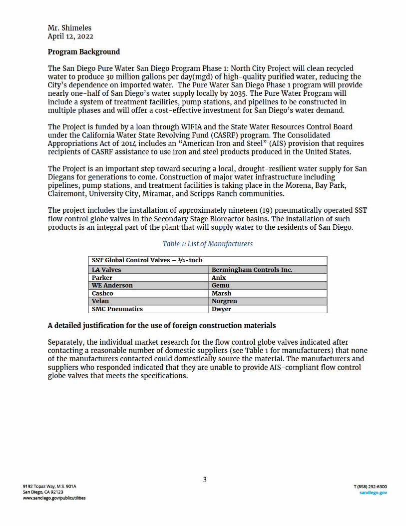
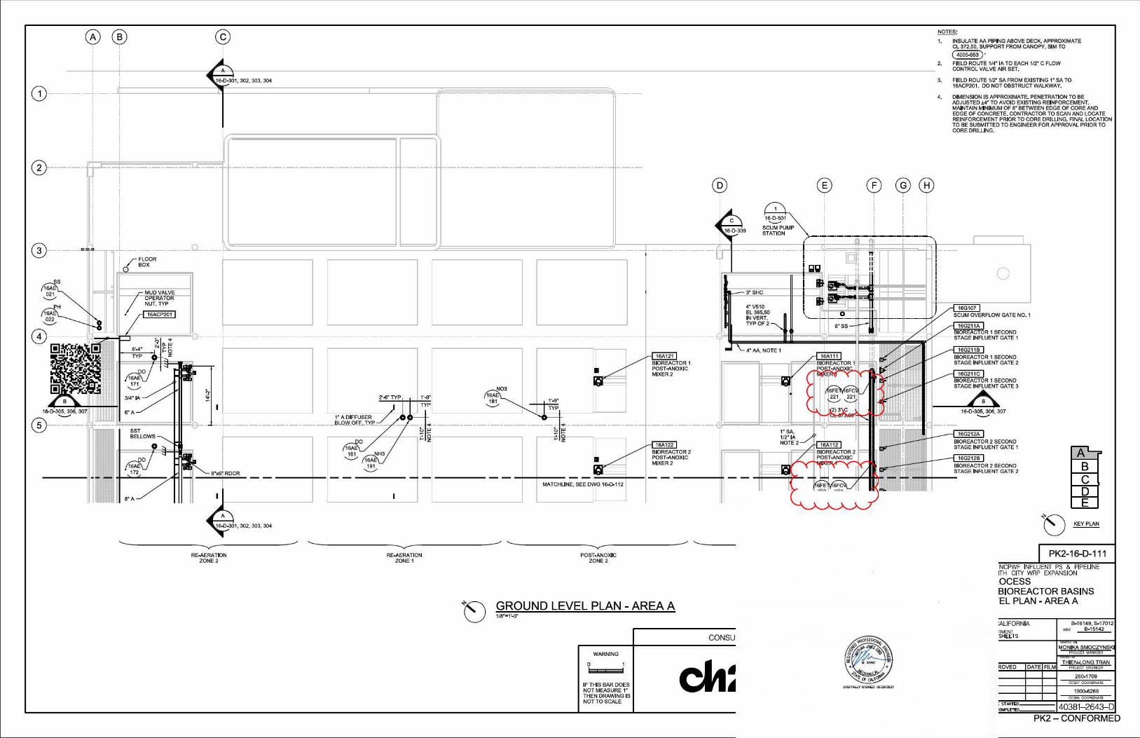
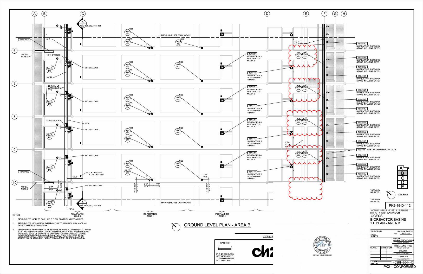
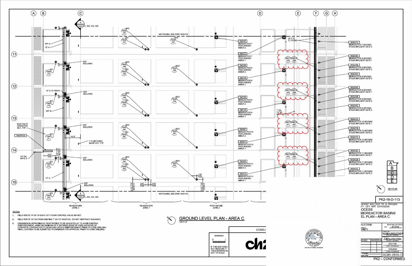
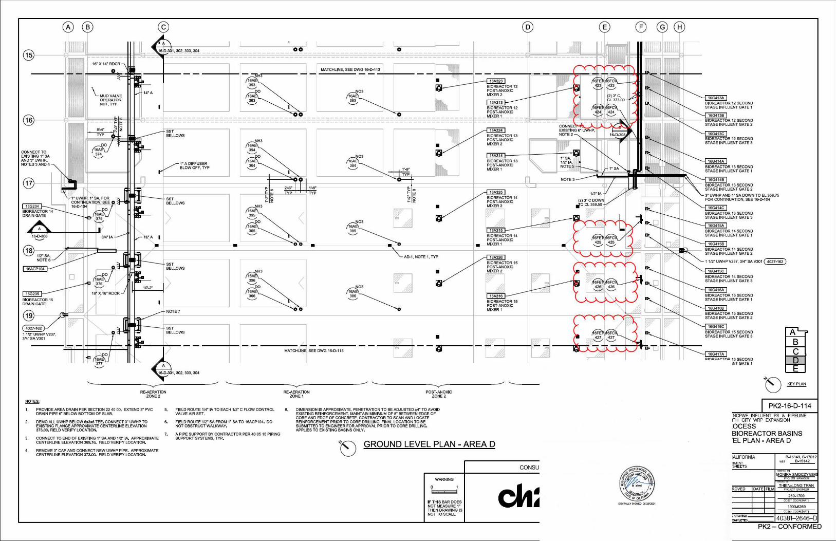
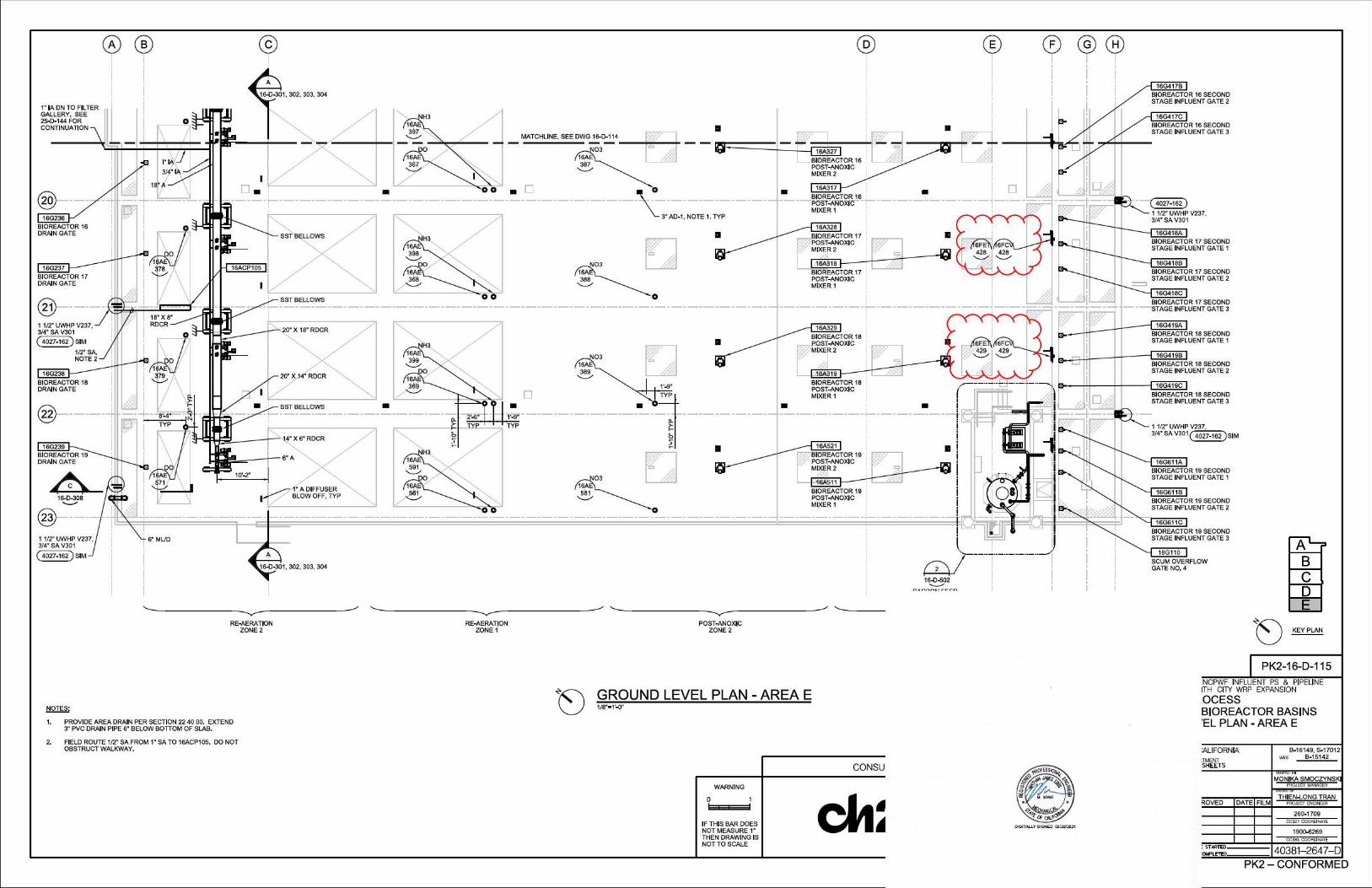
The project includes the installation of approximately nineteen (19) pneumatically operated SST flow control globe valves in the Secondary Stage Bioreactor basins. The installation of such products is an integral part of the plant that will supply water to the residents of San Diego.
Table 1: List ofManufacturers
SST Global Control Valves - ¼-inch
LA Valves Bermingham Controls Inc. Parker Anix WE Anderson Gemu Cashco Marsh Velan Norgren SMC Pneumatics Dwyer
A detailed justification for the use of foreign construction materials
Separately, the individual market research for the flow control globe valves indicated after contacting a reasonable number of domestic suppliers (see Table 1 for manufacturers) that none of the manufacturers contacted could domestically source the material. The manufacturers and suppliers who responded indicated that they are unable to provide AIS-compliant flow control globe valves that meets the specifications.
3 9192 Topaz Way, M.S. 901A T (858) 292-6300 San Diego, CA 92123 sandiego.gov www.sandiego.gov/publicutilities
Mr. Shimeles April 12, 2022
General
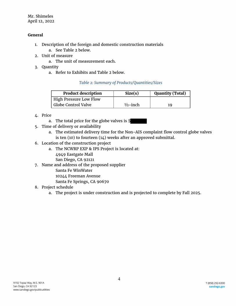
1. Description of the foreign and domestic construction materials a. See Table 2 below.
2. Unit of measure a. The unit of measurement each.
3. Quantity a. Refer to Exhibits and Table 2 below.
Table 2: Summary of Products/Quantities/Sizes
Product description Size(s) Quantity (Total) High Pressure Low Flow Globe Control Valve ½-inch 19
4. Price a. The total price for the globe valves is $
5. Time of delivery or availability a. The estimated delivery time for the Non-AIS complaint flow control globe valves
is ten (10) to fourteen (14) weeks after an approved submittal. 6. Location of the construction project
a. The NCWRP EXP & IPS Project is located at: 4949 Eastgate Mall San Diego, CA 92121
7. Name and address of the proposed supplier Santa Fe WinWater 10244 Freeman Avenue Santa Fe Springs, CA 90670
8. Project schedule a. The project is under construction and is projected to complete by Fall 2025.
4 9192 Topaz Way, M.S. 901A T (858) 292-6300 San Diego, CA 92123 sandiego.gov www.sandiego.gov/publicutilities
Mr. Shimeles April 12, 2022
Attachments:
Exhibit A- NCWRP EXP & IPS Project Section 40 27 02 and Contract Drawings Exhibit B- Kiewit Letter dated March 14, 2022 Exhibit C- List of Materials and Prices from Kiewit (WinWater)
5 9192 Topaz Way, M.S. 901A T (858) 292-6300 San Diego, CA 92123 sandiego.gov www.sandiego.gov/publicutilities
EXHIBIT A
NCWRP EXP & IPS Project Section 40 27 02 and Contract Drawings
2073 | Page
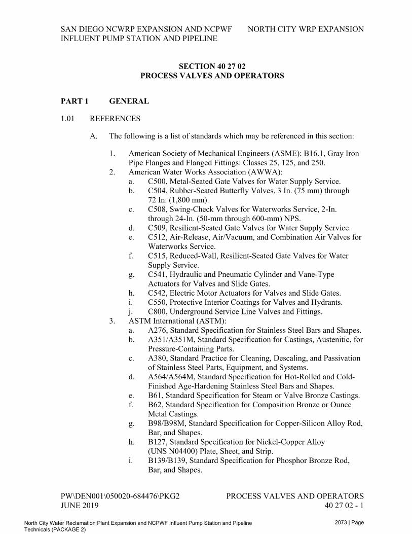
SAN DIEGO NCWRP EXPANSION AND NCPWF NORTH CITY WRP EXPANSION INFLUENT PUMP STATION AND PIPELINE
SECTION 40 27 02 PROCESS VALVES AND OPERATORS
PART 1 GENERAL
1.01 REFERENCES
A. The following is a list of standards which may be referenced in this section:
1. American Society of Mechanical Engineers (ASME): B16.1, Gray Iron Pipe Flanges and Flanged Fittings: Classes 25, 125, and 250.
2. American Water Works Association (AWWA): a. C500, Metal-Seated Gate Valves for Water Supply Service. b. C504, Rubber-Seated Butterfly Valves, 3 In. (75 mm) through
72 In. (1,800 mm). c. C508, Swing-Check Valves for Waterworks Service, 2-In.
through 24-In. (50-mm through 600-mm) NPS. d. C509, Resilient-Seated Gate Valves for Water Supply Service. e. C512, Air-Release, Air/Vacuum, and Combination Air Valves for
Waterworks Service. f. C515, Reduced-Wall, Resilient-Seated Gate Valves for Water
Supply Service. g. C541, Hydraulic and Pneumatic Cylinder and Vane-Type
Actuators for Valves and Slide Gates. h. C542, Electric Motor Actuators for Valves and Slide Gates. i. C550, Protective Interior Coatings for Valves and Hydrants. j. C800, Underground Service Line Valves and Fittings.
3. ASTM International (ASTM): a. A276, Standard Specification for Stainless Steel Bars and Shapes. b. A351/A351M, Standard Specification for Castings, Austenitic, for
Pressure-Containing Parts. c. A380, Standard Practice for Cleaning, Descaling, and Passivation
of Stainless Steel Parts, Equipment, and Systems. d. A564/A564M, Standard Specification for Hot-Rolled and Cold-
Finished Age-Hardening Stainless Steel Bars and Shapes. e. B61, Standard Specification for Steam or Valve Bronze Castings. f. B62, Standard Specification for Composition Bronze or Ounce
Metal Castings. g. B98/B98M, Standard Specification for Copper-Silicon Alloy Rod,
Bar, and Shapes. h. B127, Standard Specification for Nickel-Copper Alloy
(UNS N04400) Plate, Sheet, and Strip. i. B139/B139, Standard Specification for Phosphor Bronze Rod,
Bar, and Shapes.
PW\DEN001\050020-684476\PKG2 PROCESS VALVES AND OPERATORS JUNE 2019 40 27 02 - 1
North City Water Reclamation Plant Expansion and NCPWF Influent Pump Station and Pipeline Technicals (PACKAGE 2)
2074 | Page
NORTH CITY WRP EXPANSION SAN DIEGO NCWRP EXPANSION AND NCPWF INFLUENT PUMP STATION AND PIPELINE
j. B164, Standard Specification for Nickel-Copper Alloy Rod, Bar, and Wire.
k. B194, Standard Specification for Copper-Beryllium Alloy Plate, Sheet, Strip, and Rolled Bar.
l. B584, Standard Specification for Copper Alloy Sand Castings for General Applications.
m. D1784, Standard Specification for Rigid Poly(Vinyl Chloride) (PVC) Compounds and Chlorinated Poly(Vinyl Chloride) (CPVC) Compounds.
4. FM Global (FM). 5. International Association of Plumbing and Mechanical Officials
(IAPMO). 6. Manufacturers Standardization Society (MSS):
a. SP-80, Bronze Gate, Globe, Angle, and Check Valves. b. SP-81, Stainless Steel, Bonnetless, Flanged Knife Gate Valves. c. SP-85, Gray Iron Globe and Angle Valves, Flanged and Threaded
Ends. d. SP-88, Diaphragm Valves. e. SP-110, Ball Valves Threaded, Socket-Welding, Solder Joint,
Grooved and Flared Ends. 7. National Electrical Manufacturers Association (NEMA): 250,
Enclosures for Electrical Equipment (1000 Volts Maximum). 8. NSF International (NSF):
a. NSF/ANSI 61, Drinking Water System Components - Health Effects.
b. NSF/ANSI 372, Drinking Water System Components - Lead Content.
9. UL. 10. USC Foundation for Cross-Connection Control and Hydraulic Research.
1.02 SUBMITTALS
A. Action Submittals:
1. Shop Drawings: a. Product data sheets for each make and model. Indicate valve Type
Number, applicable Tag Number, and facility name/number or service where used. 1) Where applicable, coordinate tag numbers with owner, such
that no conflicts with existing valve tags occur. b. Complete system description for hydraulically operated valves to
show that new components match existing and are compatible with the existing hydraulically operated system.
c. Complete catalog information, descriptive literature, specifications, and identification of materials of construction.
PROCESS VALVES AND OPERATORS PW\DEN001\050020-684476\PKG2 40 27 02 - 2 JUNE 2019
North City Water Reclamation Plant Expansion and NCPWF Influent Pump Station and Pipeline Technicals (PACKAGE 2)
2075 | Page
SAN DIEGO NCWRP EXPANSION AND NCPWF NORTH CITY WRP EXPANSION INFLUENT PUMP STATION AND PIPELINE
d. Certification for compliance to NSF/ANSI 61 for valves used for drinking water service.
e. Power and control wiring diagrams, including terminals and numbers.
f. For each power actuator provided, manufacturer’s standard data sheet, with application specific features and options clearly identified.
g. Sizing calculations for open-close/throttle and modulating valves. h. Anchorage and bracing drawings and cut sheets, as required by
Section 01 88 15, Anchorage and Bracing.
B. Informational Submittals:
1. Anchorage and bracing calculations as required by Section 01 88 15, Anchorage and Bracing.
2. Manufacturer’s Certificate of Compliance, in accordance with Section 01 61 00, Common Product Requirements, for: a. Electric actuators; full compliance with AWWA C542. b. Butterfly valves; full compliance with AWWA C504.
3. Component and attachment testing seismic certificate of compliance as required by Section 01 45 33, Special Inspection, Observation, and Testing.
4. Tests and inspection data. 5. Operation and Maintenance Data as specified in Section 01 78 23,
Operation and Maintenance Data. 6. Manufacturer’s Certificate of Proper Installation, in accordance with
Section 01 43 33, Manufacturers’ Field Services.
PART 2 PRODUCTS
2.01 GENERAL
A. Valves to include operator, actuator, handwheel, chain wheel, extension stem, floor stand, operating nut, chain, wrench, and accessories to allow a complete operation from the intended operating level.
B. Valve to be suitable for intended service. Renewable parts not to be of a lower quality than specified.
C. Valve same size as adjoining pipe, unless otherwise called out on Drawings or in Supplements.
D. Valve ends to suit adjacent piping.
PW\DEN001\050020-684476\PKG2 PROCESS VALVES AND OPERATORS JUNE 2019 40 27 02 - 3
North City Water Reclamation Plant Expansion and NCPWF Influent Pump Station and Pipeline Technicals (PACKAGE 2)
2076 | Page
NORTH CITY WRP EXPANSION SAN DIEGO NCWRP EXPANSION AND NCPWF INFLUENT PUMP STATION AND PIPELINE
E. Resilient seated valves shall have no leakage (drip-tight) in either direction at valve rated design pressure. All other valves shall have no leakage (drip-tight) in either direction at valve rated design pressure, unless otherwise allowed for in this section or in stated valve standard.
F. Size operators and actuators to operate valve for full range of pressures and velocities.
G. Valve to open by turning counterclockwise, unless otherwise specified.
H. Factory mount operator, actuator, and accessories.
I. Cast valves to have manufacturers name and working pressure cast-in-place in raised letters on valve body.
2.02 VALVE SCHEDULES
A. Additional requirements relative to this section are shown on Drawings.
2.03 MATERIALS
A. Bronze and brass valve components and accessories that have surfaces in contact with water to be alloys containing less than 16 percent zinc and 2 percent aluminum.
1. Approved alloys are of the following ASTM designations: a. B61, B62, B98/B98M (Alloy UNS No. C65100, C65500, or
C66100), B139/B139M (Alloy UNS No. C51000), B584 (Alloy UNS No. C90300 or C94700), B164, B194, and B127.
2. Stainless steel Alloy 18-8 may be substituted for bronze.
B. Valve materials in contact with or intended for drinking water service to meet the following requirements:
1. Materials to comply with requirements of the Safe Drinking Water Act and other applicable federal, state, and local requirements.
2. Coatings materials to be formulated from materials deemed acceptable to NSF/ANSI 61.
3. Supply certification product is certified as suitable for contact with drinking water by an accredited certification organization in accordance with NSF/ANSI 61. Provide certification for each valve type used for drinking water service.
PROCESS VALVES AND OPERATORS PW\DEN001\050020-684476\PKG2 40 27 02 - 4 JUNE 2019
North City Water Reclamation Plant Expansion and NCPWF Influent Pump Station and Pipeline Technicals (PACKAGE 2)
2077 | Page
SAN DIEGO NCWRP EXPANSION AND NCPWF NORTH CITY WRP EXPANSION INFLUENT PUMP STATION AND PIPELINE
2.04 FACTORY FINISHING
A. General:
1. Interior coatings for valves and hydrants shall be in accordance with AWWA C550, unless otherwise specified.
2. Exterior coating for valves and hydrants shall be in accordance with Section 09 90 00, Painting and Coating.
3. Material in contact with potable water shall conform to NSF/ANSI 61. 4. Exposed safety isolation valves and lockout valves with handles,
handwheels, or chain wheels shall be “safety yellow.”
B. Where epoxy lining and coating are specified, factory finishing shall be as follows:
1. In accordance with AWWA C550. 2. Either two-part liquid material or heat-activated (fusion) material except
only heat-activated material if specified as “fusion” or “fusion bonded” epoxy.
3. Minimum 7-mil dry film thickness except where limited by valve operating tolerances.
2.05 VALVES
A. Gate Valves:
1. General: a. AWWA gate valves to be in full compliance with stated AWWA
standard and the following requirements: 1) Provide 2-inch operating nut and handwheel for AWWA
gate valves 12 inches and smaller. 2) Provide totally enclosed spur or bevel gear operator with
indicator for AWWA gate valves 14 inches and larger. 3) Provide Affidavit of Compliance per the applicable AWWA
standard for AWWA gate valves. 4) Mark AWWA gate valves with manufacturer’s name or
mark, year of valve casting, valve size, and working water pressure.
5) Repaired AWWA gate valves shall not be submitted or supplied.
6) AWWA C509 and AWWA C515 valves may be substituted for each other.
2. Type V100 Gate Valve 3 Inches and Smaller: a. All-bronze, screwed bonnet, packed gland, single solid wedge
gate, nonrising stem, Class 125 rated 200 psi CWP, complies with MSS SP-80 Type 1.
PW\DEN001\050020-684476\PKG2 PROCESS VALVES AND OPERATORS JUNE 2019 40 27 02 - 5
North City Water Reclamation Plant Expansion and NCPWF Influent Pump Station and Pipeline Technicals (PACKAGE 2)
2081 | Page
SAN DIEGO NCWRP EXPANSION AND NCPWF NORTH CITY WRP EXPANSION INFLUENT PUMP STATION AND PIPELINE
b. Manufacturers and Products: 1) Stockham; Figure B-274. 2) Crane; Figure 384P. 3) Or approved equal.
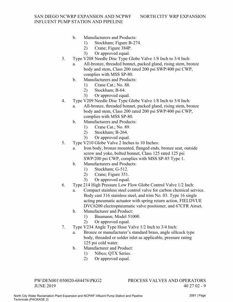
3. Type V208 Needle Disc Type Globe Valve 1/8 Inch to 3/4 Inch: a. All-bronze, threaded bonnet, packed gland, rising stem, bronze
body and stem, Class 200 rated 200 psi SWP/400 psi CWP, complies with MSS SP-80.
b. Manufacturers and Products: 1) Crane Cat.; No. 88. 2) Stockham; B-64. 3) Or approved equal.
4. Type V209 Needle Disc Type Globe Valve 1/8 Inch to 3/4 Inch: a. All-bronze, threaded bonnet, packed gland, rising stem, bronze
body and stem, Class 200 rated 200 psi SWP/400 psi CWP, complies with MSS SP-80.
b. Manufacturers and Products: 1) Crane Cat.; No. 89. 2) Stockham; B-264. 3) Or approved equal.
5. Type V210 Globe Valve 2 Inches to 10 Inches: a. Iron body, bronze mounted, flanged ends, bronze seat, outside
screw and yoke, bolted bonnet, Class 125 rated 125 psi SWP/200 psi CWP, complies with MSS SP-85 Type 1.
b. Manufacturers and Products: 1) Stockham; G-512. 2) Crane; Figure 351. 3) Or approved equal.
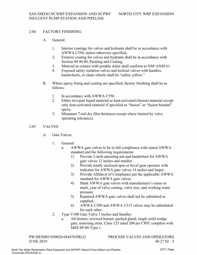
6. Type 214 High Pressure Low Flow Globe Control Valve 1/2 Inch: a. Compact stainless steel control valve for carbon chemical service.
Body cast 316 stainless steel, and trim No. 03. Type 16 single acting pneumatic actuator with spring return action, FIELDVUE DVC6200 electropneumatic valve positioner, and 67CFR Airset.
b. Manufacturer and Product: 1) Baumann; Model 51000. 2) Or approved equal.
7. Type V234 Angle Type Hose Valve 1/2 Inch to 3/4 Inch: a. Bronze or manufacturer’s standard brass, angle sillcock type
body, threaded or solder inlet as applicable, pressure rating 125 psi cold water.
b. Manufacturer and Product: 1) Nibco; QTX Series. 2) Or approved equal.
PW\DEN001\050020-684476\PKG2 PROCESS VALVES AND OPERATORS JUNE 2019 40 27 02 - 9
North City Water Reclamation Plant Expansion and NCPWF Influent Pump Station and Pipeline Technicals (PACKAGE 2)
2103 | Page
SAN DIEGO NCWRP EXPANSION AND NCPWF NORTH CITY WRP EXPANSION INFLUENT PUMP STATION AND PIPELINE
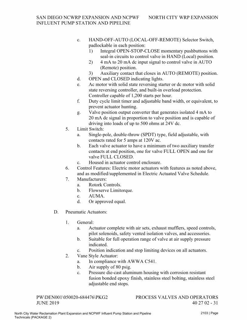
c. HAND-OFF-AUTO (LOCAL-OFF-REMOTE) Selector Switch, padlockable in each position: 1) Integral OPEN-STOP-CLOSE momentary pushbuttons with
seal-in circuits to control valve in HAND (Local) position. 2) 4 mA to 20 mA dc input signal to control valve in AUTO
(Remote) position. 3) Auxiliary contact that closes in AUTO (REMOTE) position.
d. OPEN and CLOSED indicating lights. e. Ac motor with solid state reversing starter or dc motor with solid
state reversing controller, and built-in overload protection. Controller capable of 1,200 starts per hour.
f. Duty cycle limit timer and adjustable band width, or equivalent, to prevent actuator hunting.
g. Valve position output converter that generates isolated 4 mA to 20 mA dc signal in proportion to valve position and is capable of driving into loads of up to 500 ohms at 24V dc.
5. Limit Switch: a. Single-pole, double-throw (SPDT) type, field adjustable, with
contacts rated for 5 amps at 120V ac. b. Each valve actuator to have a minimum of two auxiliary transfer
contacts at end position, one for valve FULL OPEN and one for valve FULL CLOSED.
c. Housed in actuator control enclosure. 6. Control Features: Electric motor actuators with features as noted above,
and as modified/supplemented in Electric Actuated Valve Schedule. 7. Manufacturers:
a. Rotork Controls. b. Flowserve Limitorque. c. AUMA. d. Or approved equal.
D. Pneumatic Actuators:
1. General: a. Actuator complete with air sets, exhaust mufflers, speed controls,
pilot solenoids, safety vented isolation valves, and accessories. b. Suitable for full operation range of valve at air supply pressure
indicated. c. Position indication and stop limiting devices on all actuators.
2. Vane Style Actuator: a. In compliance with AWWA C541. b. Air supply of 80 psig. c. Pressure die-cast aluminum housing with corrosion resistant
fusion bonded epoxy finish, stainless steel bolting, stainless steel adjustable end stops.
PW\DEN001\050020-684476\PKG2 PROCESS VALVES AND OPERATORS JUNE 2019 40 27 02 - 31
North City Water Reclamation Plant Expansion and NCPWF Influent Pump Station and Pipeline Technicals (PACKAGE 2)
2105 | Page
SAN DIEGO NCWRP EXPANSION AND NCPWF NORTH CITY WRP EXPANSION INFLUENT PUMP STATION AND PIPELINE
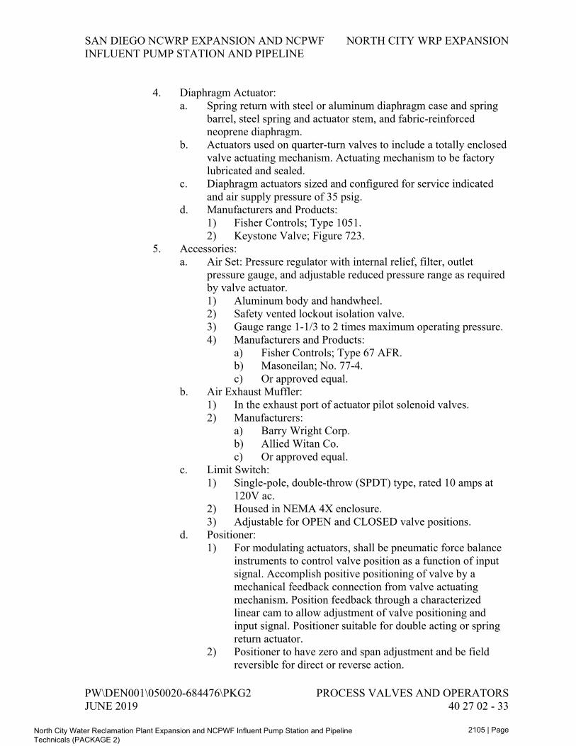
4. Diaphragm Actuator: a. Spring return with steel or aluminum diaphragm case and spring
barrel, steel spring and actuator stem, and fabric-reinforced neoprene diaphragm.
b. Actuators used on quarter-turn valves to include a totally enclosed valve actuating mechanism. Actuating mechanism to be factory lubricated and sealed.
c. Diaphragm actuators sized and configured for service indicated and air supply pressure of 35 psig.
d. Manufacturers and Products: 1) Fisher Controls; Type 1051. 2) Keystone Valve; Figure 723.
5. Accessories: a. Air Set: Pressure regulator with internal relief, filter, outlet
pressure gauge, and adjustable reduced pressure range as required by valve actuator. 1) Aluminum body and handwheel. 2) Safety vented lockout isolation valve. 3) Gauge range 1-1/3 to 2 times maximum operating pressure. 4) Manufacturers and Products:
a) Fisher Controls; Type 67 AFR. b) Masoneilan; No. 77-4. c) Or approved equal.
b. Air Exhaust Muffler: 1) In the exhaust port of actuator pilot solenoid valves. 2) Manufacturers:
a) Barry Wright Corp. b) Allied Witan Co. c) Or approved equal.
c. Limit Switch: 1) Single-pole, double-throw (SPDT) type, rated 10 amps at
120V ac. 2) Housed in NEMA 4X enclosure. 3) Adjustable for OPEN and CLOSED valve positions.
d. Positioner: 1) For modulating actuators, shall be pneumatic force balance
instruments to control valve position as a function of input signal. Accomplish positive positioning of valve by a mechanical feedback connection from valve actuating mechanism. Position feedback through a characterized linear cam to allow adjustment of valve positioning and input signal. Positioner suitable for double acting or spring return actuator.
2) Positioner to have zero and span adjustment and be field reversible for direct or reverse action.
PW\DEN001\050020-684476\PKG2 PROCESS VALVES AND OPERATORS JUNE 2019 40 27 02 - 33
North City Water Reclamation Plant Expansion and NCPWF Influent Pump Station and Pipeline Technicals (PACKAGE 2)
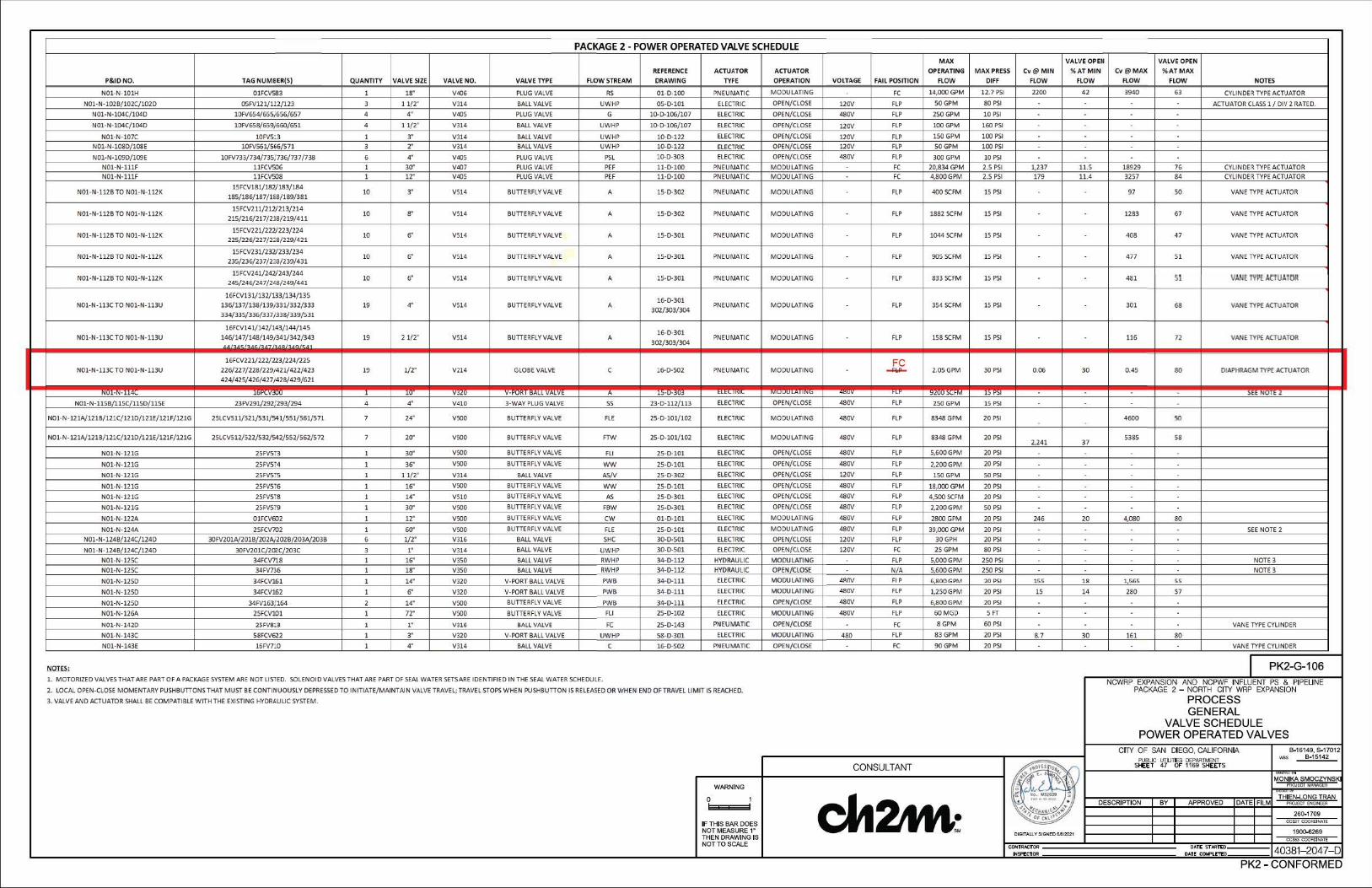
PACKAGE 2 - POWER OPERATED VALVE SCHEDULE MAX VALVE OPEii VALVE OPEN
REFERENCE ACTUATOR ACTUATOR OPERATING MAX PRESS Cv@MIN %ATMIN Cv@MAX %AT MAX P&IDNO. TAG NUMBER(S) QUANTITY VALVE SIZE VALVE NO. VALVE TYPE FLOW STREAM DRAWING TYPE OPERATION VO LTAGE FAIL POSITION FtOW DIFF FLOW FLOW FLOW FLOW NOTES
N01•N•101H 01FCVS83 1 18" V◄06 PLUG VALVE RS 01-C>-100 PNEUMATIC MODULATING FC 14,000 GPM 12.7 PSI 2200 42 3940 63 CYLINDER TYPEACTUATOR
N0l· N·102B/102C/102D 05FV121/ ll2/ 123 3 11/ 2" Vll4 BALL VALVE UWHP 05-C>-101 ELECTRIC OPEN/CLOSE 120V FLP 50GPM 80 PSI ACTUATOR CLASS 1 / DIV 2 RATED.
N01•N•l04C/104D 10FV654/655j656/657 4 4" V◄05 PLUG VALVE G 10-C>-106/107 ELEClRIC OPEN/CLOSE 480V FLP 250 GPM 10 PSI
N01·N·104C/ 104D 10FV658/659j 660/ 651 4 11/ 2" Vll4 BALL VALVE UWHP 10-C>-106/107 ELEClRIC OPEN/ CLOSE 120V FLP lOOGPM l!iO PSI
N01·N·107C 10FV513 1 3" Vl14 BALL VALVE UWHP 10-D-122 ELEClRIC OPEN/CLOSE 120V FLP 150GPM 100 PSI
N01•N•l08D/108E l0FV561/566/S71 3 2" Vll4 BALL VALVE UWHP 10-C>-122 ELEClRIC OPEN/CLOSE 120V FLP 50GPM 100 PSI
N0l•N•l09D/109E 10FV733/734/735/736/737/ 7'38 6 4" V405 PLUG VALVE PSL 10-0·303 ELEClRIC OPEN/CLOSE 480V FLP 300GPM 10 PSI
NOl·N·lllF 11FCV506 1 30" V407 PLUG VALVE PEF ll·D-100 PNEUMATIC MODULATING FC 20,834GPM 2.5 PSI 1,237 11.5 18929 76 CYLINDERTYPE ACTUATOR NOl•N•lllF 11FCV508 1 12" V405 PLUG VALVE PEF ll·C>-100 PNEUMATIC MODULATING FC 4,800GPM 2.5 PSI 179 11.4 3257 84 CYLINDER TYPE ACTUATOR
N01-N-112B TO N01-N-112K 15FCV181/182/183/184
10 3" V514 BUTTERFLY VALVE A 15-0-302 PNEUMATIC MODULATING FLP 400 SCFM 15 PSI 97 so VANE TYPEACTUATOR 185/186/187/188/189/381
N01•N•112B TO NOl•N•112K 1SFCV211/212/213/214
10 8" VS14 BUTTERFLY VALVE A 15-0-302 PNEUMATIC MODULATING FLP 1882 SCFM 15 PSI 1283 67 VANE TYPE ACTUATOR 215/216/ 217/ 218/ 219/411
ND1·N·112B TO NOl·N·llZK 15FCV221/222/223/224
10 6" V514 BUTTERFLY VALVE A 15·0-301 PNEUMATIC MODULATING FLP 1044 SCFM 15 PSI 408 47 VANE TYPEACTUATOR 225/226/227/2;8/229/421
ND1·N·112B TO NOl·N·112K 15FCV231/232/233/234
10 6" V514 BUTTERFLY VALVE A 15·0-301 PNEUMATIC MODULATING FLP 905SCFM 15 PSI 477 51 VANE TYPEACTUATOR 235/236/237/2'!,8/239/431
N01•N•l12B TO N01•N•l12K 15FCV241/242/243/244
10 6" VS14 BUTTERFLYVALVE A 15·C>-301 PNEUMATIC MODULATING FLP 833 SCFM 15 PSI 481 Sl VAN£f'll't AeTUATOft 245/246/247/2La/249/441 -l6FCV131/132/133/134/135
16·0-301N01-N-113CTO N01-N-113U l36/l37/138/ll9i331/332/333 19 4" V514 BUTTERFLY VALVE A
302/303/304 PNEUMATIC MODULATING FLP 354 SCFM 15 PSI 301 68 VANETYPE ACTUATOR
334/335/336/337j338/339/531
16FCV141/142/143/ 144/ 145 16-C>-301
N01•N•113C TO N01•N•ll3U 146/147/148/149i341/342/343 19 21/2" VS14 BUTTERFLYVALVE A PNEUMATIC MODULATING FLP 158SCFM 15 PSI 116 72 VANE TYPE ACTUATOR .. ... .,.,,, .. 302/303/304
16FCV221/ 222/223/224/ 225 FC NOl•N•lllCTO N0l•N•113U 226/227/228/229i421/422/423 19 1/2" V214 GLOBE VALVE C 16-0-502 PNEUMATIC MODULATING ~ 2.05GPM 30 PSI 0.06 30 0.45 80 DIAPHRAGM TYPE ACTUATOR
424/425/426/427j428/429/621
NUl• N• 14l '""'·· ·" ' l ,v yu, V•r-v" KAL v,,u v~ A l)•IJ-"'' <LC\. ""~ ,.,vvv•~""" ~v .., ~"• " ,,M l) ~~I .>ct Nv1c.Z
N01·N·115B/ l 15C/115D/ 115E 23FV291/ 292/ 293/ 294 4 4" V410 3·WAY PLUG VALVE ss 23·0·112/113 ELEClRIC OPEN/CLOSE 480V FLP 250GPM 15 PSI
NOl·N·121A/121B/121C/ 121D/121E/121F/ 121G 25LCVSll/521/S31/541/55l/ 561/571 7 24" VSDO BUTTERFLY VALVE FLE 25·0·101/102 ELEClRIC MODULATING 480V FLP 8348 GPM 20 PSI 4600 so
NOl•N •l2lA/121B/121C/1210/12lE/l21F/121G 2SLCV512/522/S32/542/552/562/572 7 20" vsoo BUTTERFLYVALVE FTW 25-D-101/102 ELEClRIC MODULATING 480V FLP 8348 GPM 20 PSI 2.241 37
5385 58
N01·N·121G 25FVS73 1 30" vsoo BUTTERFLYVALVE FLI 25·0-101 ELEClRIC OPEN/CLOSE 480V FLP 5,GOOGPM 20 PSI
N01·N·121G 25FVS14 1 36" VSOO BUTTERFLYVALVE WW 25-D-101 ELEClRIC OPEN/CLOSE 480V FLP 2,200GPM 20 PSI
N01·N·121G 25FVS75 1 11/ 2" Vll4 BALL VALVE AS/V 25·0-302 ELEClRIC OPEN/CLOSE 120V FLP 150GPM 50 PSI
N01·N·121G 25FV516 1 16" VSOO BUTTERFLYVALVE WW 25-D-101 ELEClRIC OPEN/CLOSE 480V FLP 18,000GPM 20 PSI
NOl•N•l2lG 25FV518 l 14" V510 BUTTERFLYVALVE AS 25-0-301 ELEClRIC OPEN/ CLOSE 480V FLP 4,500SCFM 20 PSI
N01•N•121G 25FV519 1 30" vsoo BUTTERFLYVALVE FBW 25-C>-301 ELEClRIC OPEN/CLOSE 480V FLP 2,200GPM 50 PSI
NOl•N•122A 01FCV602 1 12" VSOO BUTTERFLY VALVE CW Ol·C>-101 ELEClRIC MODULATING 480V FLP 2800GPM 20PSI 246 20 4080 80
N01·N·124A 2SFCVi02 1 60" vsoo BUTTERFLY VALVE FLE 25·0-101 ELEClRIC MODULATING 480V FLP 39,000GPM 20 PSI SEE NOTE 2 NOl •N •124B/124C/124D 30FV201A/201B/202Ai202B/203A/203B 6 1/2" Vll6 BALL VALVE SHC 30-C>-501 ELEClRIC OPEN/CLOSE 120V FLP 30GPH 20 PSI
N01· N·124B/124C/124D 30FV201C/202C/203C 3 1" Vll4 BALL VALVE UWHP 30-0-501 ELEClRIC OPtN/ClOSE 120V FC 25 GPM 80 PSI .
N01·N·12SC 34FCV718 1 16" VJSO BALL VALVE Rl'/HP 34-D-ll2 HYDRAULIC MODULATING FLP 5,000GPM 250 PSI NOTE3
N0l•N•l25C 34FV736 l 18" V350 BALL VALVE Rl'IHP 34-0-112 HYDRAULIC OPEN/CLOSE N/A 5,600GPM 250 PSI NOTE 3
N01•N•125D 34FCV161 1 14" VJ20 V•PORT BALL VALVE PWB 34-C>-111 ELECTRIC MOruLATING llllOV Fl P 6.,800GPM 20 PSI 155 1 8 1,565 55
NOl•N•125D 34FCV162 1 6" Vl20 V•PORT BALL VALVE P'WB 34-0-111 ELECTRIC MOruLATING 480V FLP l,250GPM 20 PSI 15 14 280 57
N01·N·125D 34FV163/ 164 2 14" vsoo BUTTERFLYVALVE P'l'/8 34-C>-lll ELECTRIC OPEN/CLOSE 480V FLP 6,SOO GPM 20 PSI
NOl•N•126A 25FCV101 1 72" VSOO BUTTERFLYVALVE FLI 25-C>-102 ELECTRIC MODULATING 480V FLP 60MGD 5 FT
N01·N·1420 2SFV8l 3 1 1" V316 8ALLVALVE FC 25-D-143 PNEUMATIC OPEN/CLOSE FC SGPM 60 PSI VANE TYPE CYLINDER
N01•N•143C 58FCV622 1 3" V320 V-PORT BALL VALVE U\VHP 58-0-301 ELECTRIC MOruLATING 480 FLP 83GPM 20 PSI 8.7 30 161 80
N0l•N•l43E 16FV7l 0 l 4" V314 BALL VALVE C 16-0-502 PNEUMATIC OPEN/CLOSE FC 90GPM 20 PSI VANE TYPE CYLINDER
t!QI£S.; I PK2-G-106 1. MOTORIZED VALVESTHATAREPARTOFA PACKAGESYSTEM ARE NOT LISlED. SOLENOID VALVESTHAT AREPART OF SEAL WATERSETSAREIDENTIFIED IN THESEAL WATERSCHEDULE. NCWRP EXPANSION AND NCPWF INFLUENT PS & PIPELINE 2. LOCAL OPEN-CLOSE MOMENTARY PUSHBUTTONS THAT MUST BE CONTINUOUSLY DEPRESSED TO INITIATE/MAINTAIN VALVE TRAVEL;TRAVEL STOPS WHEN PUSHBUTTON IS RELEASED OR WHEN END OF TRAVEL LIMIT IS REACHED. PACKAGE 2 - NORTH CITY WRP EXPANSION
3. VALVEANO ACTUATOR SHALL BE COMPATIBLE WITHTHE EXJSTING HYDRAULIC SYSTEM. PROCESS GENERAL
VALVE SCHEDULE POWER OPERATED VALVES
CITY OF SAN DIEGO, CALIFORNIA B-16149, S-17012
~ PUBLIC UTILI TES DEPARTMENT - B-15142
CONSULTANT g s.E:El 47 OF' 1169 SHEETS
' -!IWl't
MONIKA SMOCZVNSK WARNING ~~I MA~ l:;R
0 1 c112m1,~ ~ ~ THIEN~ ONG TRAN. DESCRIPTION BY APPROVED DATE FILM f'f\M.Cf fNOINfER,~ • 260-1709
OCS27 OOOAOIMATEIF THIS BAR DOES ~
NOT MEASURE 1• DIGITALLY SIGNED 6.e/2021 1900-6269
THEN DRAWINGIS OCS63 OC()RolNA.TE NOTTO SCALE CONTRACTOR OAU: STARn:D 40381- 2047- 0frrf~C10R OATt COMPl.t'l'IX>
PK2 - CONFORMED
0------~------1t:==========:i..~==============r=====~-~-~-~-~-~-~-~-~-~-~-~-~-' I ' I I ' I '0------ -----------1
I ' I ' I ' '
® I ~~ . . I I. . I I
.. i.._.._.._.._.._..1.._.._.._:_.._..~ ' ..
NOTES:
1. INSULATE AA PIPING ABOVE DECK. APPROXIMATE CL 372.50. SUPPORT FROM CANOPY, SIM TO
( 4005-<553 ) •
2. FIELD ROUTE 1/4" IA TO EACH 1/2" C FLOW CONTROL VALVE AIR SET.
3. FIELD ROUTE 1/2" SA FROM EXISTING 1" SA TO 16ACP201. OONOT OBSTRUCTWALKWAY.
4. DIMENSION IS APPROXIMATE. PENETRATION TO BE ADJUSTED .l:4" TO AVOID EXISTING REINFORCEMENT. MAINTAIN MINIMUM OF 8" BETWEEN EDGE OF CORE ANO EDGE OF CONCRETE. CONTRACTOR TO SCAN AND LOCATE REINFORCEMENT PRIOR TO CORE DRILLING. FINAL LOCATION TO BE SUBMITTED TO ENGINEER FOR APPROVAL PRIOR TO CORE DRILLING.
0-----<=·=·_f-,11---n--a1J___________Q____~============---===~======================~~==r-=-=-=-=-~01=====r-~k::::;~~~~~*[l;;:=~~~~~;;:_:::x.,-~-1-t=:=-~---7 I / FLOOR i i · o _ BOX ! '
1~ !!!!!!!!!!!!!!!!!!!!!!!!!!!!!!!!!!!!!!!!!!!!!""""'=-'!!!!!!c
MUD VALVE OPERATOR NUT, TYP
16ACP201
e-----r--------------------------------------------------------------
RE-AERATION ZONE2
RE-AERATION ZONE 1
-+- 1---- - - I MATCHLINE, SEE DWG 16-0-11 2
POST-ANOXIC ZONE2
----------
' ! = ~ ;;;:==3~•~s ~HC~ =====~:- l----:ail:
510 5.50
ERT, OF 2
OTE 1
'r;::::====i.---~i==::::;zI I I ' I '
iI
GROUND LEVEL PLAN - AREA A 1/8·~1·-o·
WARNING
0
IF THIS BAR DOES NOT MEASURE 1• THEN DRAWING IS NOTTO SCALE
CONSU
0
16G107 SCUM OVERFLOW GATE NO. 1
16G211A BIOREACTOR 1 SECOND
- - sTAGE INFLUENT GATE 1
16G211B BIOREACTOR 1 SECOND STAGE INFLUENT GATE 2
16G211C BIOREACTOR 1 SECOND STAGE INFLUENT GATE 3
/;\.16-0-305, 306, 307 ~
16G212A
BIOREACTOR 2 SECOND STAGE INFLUENT GATE 1
16G212B
BIOREACTOR 2 SECOND STAGE INFLUENT GATE 2
K\u KEY PLAN
PK2-16-D-11 1 NCPWF INFLUENT PS & PIPELINE 1TH CITY WRP EXPANSION
.OCESS BIOREACTOR BASINS E L PLAN - AREA A
:ALIFORNIA
~t'rrs
ROVED
: STAR1'IXI :OMPI.ETfO
B0 16149, S-17012 ""S ll-1 5142
260-1709 OC$27 OOOAOlkATE
1900-6269 OCs«> OOOflOi~ATE
40381- 2643-D PK2 - CONFORMED
©
SST BELLOWS
SST BELLOWS
SST BELLOWS
SST BELLOWS
1" A DIFFUSER BLOW OFF, TYP
RE-AERATION ZONE2
1. FIELD ROUTE 114"IA TO EACH 112" C FLOW CONTROL VALVE AIR SET.
2. FIELD ROUTE 112" SA FROM EXISTING 1" SA TO 16ACP101 AND 16ACP102. DO NOT OBSTRUCT W~AY.
3. DIMENSION IS APPROXIMATE. PENETRATION TO BE ADJUSTED t.4" TO AVOID EXISTING REINFORCEMENT. MAINTAIN MINIMUM OF 8" BETWEEN EDGE OF CORE AND EDGE OF CONCRETE. CONTRACTOR TO SCAN AND LOCATE REINFORCEMENT PRIOR TO CORE DRILLING. FINAL LOCATION TO BE SUBMITTED TO ENGINEER FOR APPROVAL PRIOR TO CORE DRILLING.
MATCHLINE, SEE DWG 16-0-11 1
03 1 184.____,,
0 0
HJ 16A 195
165.____,,~ 0
TYP~---------~
MATCHLINE, SEE DWG 16-0-1 13
• I
RE•AERATION POST•ANOXIC ZONE1 ZONE2
GROUND LEVEL PLAN - AREA B
D ®
16G212C
16G213A BIOREACTOR 3 SECOND STAGE INFLUENT GATE 1
16G213B BIOREACTOR 3 SECOND STAGE INFLUENT GATE 2
16G213C BIOREACTOR 3 SECOND STAGE INFLUENT GATE 3
16G214A BIOREACTOR 4 SECOND STAGE INFLUENT GATE 1
16G214B BIOREACTOR 4 SECOND STAGE INFLUENT GATE 2
16G214C BIOREACTOR 4 SECOND STAGE INFLUENT GATE 3
16G215A BIOREACTOR 5 SECOND STAGE INFLUENT GATE 1
16G215B BIOREACTOR 5 SECOND STAGE INFLUENT GATE 2
16G216B BIOREACTOR 6 SECOND STAGE INFLUENTGATE 2
16G216C BIOREACTOR 6 SECOND STAGE INFLUENT GATE 3
'SECOND NT GATE 1
'SECOND NTGATE2
K\u KEY PLAN
PK2-16-D-112 NCPWF INFLUENT PS & PIPELINE 1TH CITY WRP EXPANSION
.OCESS BIOREACTOR BASINS 'EL PLAN - AREA B
:ALIFORNIA :J'MENT SHEETS
ROVED
: STAR1'IXI :OMPI.ETfO
B-16149, S.17012 \\@$ B-15142
260-1709 OC$27 OOOAOlkATE
1900-6269 OCs«> OOOflOi~ATE
40381- 2644-D PK2 - CONFORMED
CONSU
WARNING
0
IF THIS BAR DOES NOT MEASURE 1• THEN DRAWING IS NOTTO SCALE
SST BELLOWS
1" A DIFFUSER BLOW OFF, TYP
MATCHLINE, SEE DWG 16-0-11 2 1 I
.._____~ ~ --------
16A 188
'--../
16A 189
'--../
16A 382
'--../
03
03
03
0
0
0
SST BELLOWS ---,1,,,..-p ~l!!o"'z"--~~ - ] , ~"9; ___ I:::;;
--+---+---=-~ ~ - - ID,,.MATCHLINE, SEE DWG 16-D-114 ~
RE-AERATION ZONE2
~ 1, FIELD ROUTE 1/4" IA TO EACH 112" C FLOW CONTROL VALVE AIR SET.
2, FIELD ROUTE 112" SA FROM EXISTING 1" SA TO 16ACP103, DO NOT OBSTRUCT WALKWAY,
3, DIMENSION IS APPROXIMATE, PENETRATION TO BE ADJUSTED ;t4" TO AVOID EXISTING REINFORCEMENT, MAINTAIN MINIMUM OF 8" BETWEEN EDGE OF CORE AND EDGE OF CONCRETE, CONTRACTOR TO SCAN AND LOCATE REINFORCEMENT PRIOR TO CORE DRILLING, FINAL LOCATION TO BE SUBMITTED TO ENGINEER FOR APPROVAL PRIOR TO CORE DRILLING,
RE-AERATION ZONE 1
POST-ANOXIC ZONE2
GROUND LEVEL PLAN - AREA C 1/8·~1·-o·
WARNING
0
IF THIS BAR DOES NOT MEASURE 1" THEN DRAWING IS NOTTO SCALE
D
CONSU
16G217C BIOREACTOR 7 SECOND STAGE INFLUENT GATE 3
16G218A BIOREACTOR 8 SECOND STAGE INFLUENT GATE 1
16G218B BIOREACTOR 8 SECOND STAGE INFLUENT GATE 2
16G218C BIOREACTOR 8 SECOND STAGE INFLUENT GATE 3
16G219A BIOREACTOR 9 SECOND STAGE INFLUENT GATE 1
16G219B BIOREACTOR 9 SECOND STAGE INFLUENT GATE 2
16G219C
BIOREACTOR 9 SECOND STAGE INFLUENT GATE 3
16G411 A BIOREACTOR 10 SECOND STAGE INFLUENT GATE 1
16G41 1B BIOREACTOR 10 SECOND STAGE INFLUENT GATE 2
16G411C
BIOREACTOR 10 SECOND STAGE INFLUENT GATE 3
16G412A BIOREACTOR 11 SECOND STAGE INFLUENT GATE 1
16G412B BIOREACTOR 11 SECOND STAGE INFLUENT GATE 2
16G412C
BIOREACTOR 11 SECOND STAGE INFLUENT GATE 3
K\u KEY PLAN
PK2-16-D-11 3 NCPWF INFLUENT PS & PIPELINE 1TH CITY WRP EXPANSION
.OCESS BIOREACTOR BASINS EL PLAN - AREA C
:ALIFORNIA :J'MENT SHEETS
ROVED DATE FILM
: STAR1'IXI :OMPt.ETfO
B0 16 149, S-17012 ""S ll-15142
260-1709 OC$27 OOOAOlkATE
1900-6269 OCs«> OOOflOi~ATE
40381- 2645-D PK2 - CONFORMED
© \.-----~==::...i;======-tl: __I :: _ ~~=~·~o::~:: :: :: :: :: :: :: :: :: :_~~:: :: :: :: :: :: :: :: :: :: ~-==:: :: :: :: ::::
H 16A
~~ ~ 0
MATCHLINE, SEEDWG 16-0-113
0
16G413A BIOREACTOR 12 SECOND STAGE INFLUENT GATE 1
16G413B
;NT GATE 1
E
K"'\u KEY PLAN
PK2-16-D-114 NCPWF INFLUENT PS & PIPELINE 1TH CITY WRP EXPANSION
.OCESS BIOREACTOR BASINS 'EL PLAN - AREA D
:ALIFORNIA :J'MENT SHEETS
B-16149, S-17012 ""S ll-15142
MONIKA SMOCZVNSK l-'A6Jbc1 MA"Afil;;R
THIEN~ONG TRAN FRQ.E;1" ENCINfER ROVED DATE FILM
260-1709 OC$27 OOOAOlkATE
1900-6269 OCs«> OOOflOiNATE
: STAR1'IXI :OMPUTfO 40381- 2646--D
BIOREACTOR 12 SECOND STAGE INFLUENT GATE 2
SST BEUOWS 16G413C
BIOREACTOR 12 SECOND STAGE INFLUENT GATE 3
CONNECT TO EXISTING 1" SA AND3"UWHP. 16G414A
1° A DIFFUSER BLOW OFF, TYP
NOTES3AND4 BIOREACTOR 13 SECOND STAGE INFLUENT GATE 1
16G414B
BIOREACTOR 13 SECOND STAGE INFLUENT GATE 2
3" UWHP AND 1• SA DOWN TO EL 358,75 SST FOR CONTINUATION, SEE 16-0-104 BEUOWS
16G414C
I BIOREACTOR 13 SECOND STAGE INFLUENT GATE 3
16G415A
BIOREACTOR 14 SECOND STAGE INFLUENT GATE 1
16G415B
BIOREACTOR 14 SECOND STAGE INFLUENT GATE 2
A0-1, NOTE 1, TYP 11/2" UWHP V237, 3/4" SA V301 ( 4027-162)BIOREACTOR 15 SST
BEUOWS POST-ANOXIC H3 MIXER2 16G415C
' '
'
BIOREACTOR 15 POST-ANOXIC MIXER1
• BIOREACTOR 14 SECOND 16A <396 STAGE INFLUENT GATE 3 '-....,/
¾ 16G416A
BIOREACTOR 15 SECOND STAGE INFLUENT GATE 1
16G416B NOTE7 BIOREACTOR 15 SECOND
STAGE INFLUENT GATE 2
16G416CSST BEUOWS BIOREACTOR 15 SECOND
STAGE INFLUENT GATE 3
MATCH,,;;DWG 16-0-11 5 16G417A
Rl ()E;IS:lLt":.TOQ 1 6 SECOND1111
RE-AERATION RE-AERATION POST0 ANOXIC ZONE2 ZONE 1 ZONE2
NOTES•
1. PROVIDE AREA DRAIN PER SECTION 22 40 00. EXTEND 3" PVC 5. FIELD ROUTE 114" IATO EACH 112" C FLOW CONTROL 8. DIMENSION IS APPROXIMATE. PENETRATION TO BE ADJUSTED .t.4" TO AVOID DRAIN PIPE 6" BELOW BOTTOM OF SLAB. VALVE AIR SET. EXISTING REINFORCEMENT. MAINTAIN MINIMUM OF 8" BETWEEN EDGE OF
CORE AND EDGE OF CONCRETE. CONTRACTOR TO SCAN AND LOCATE 2, DEMO ALL UWHP BELOW 6x3x6 TEE. CONNECT 3" UWHP TO 6, FIELD ROUTE 112" SA FROM 1" SA TO 16ACP104, DO REINFORCEMENT PRIOR TO CORE DRILLING, FINAL LOCATION TO BE
EXISTING FLANGE APPROXIMATE CENTERLINE ELEVATION NOT OBSTRUCT WALKWAY, SUBMITTED TO ENGINEER FOR APPROVAL PRIOR TO CORE DRIU ING, 373,00, FIELD VERIFY LOCATION, APPLIES TO EXISTING BASINS ONLY,
7, A PIPE SUPPORT BY CONTRACTOR PER 40 05 15 PIPING 3, CONNECT TO END OF EXISTING 1" SA AND 112" IA. APPROXIMATE SUPPORT SYSTEMS, TYP.
CENTERLINE ELEVATION 369,16, FIELD VERIFY LOCATION, GROUND LEVEL PLAN - AREA D 4, REMOVE 3" CAP AND CONNECT NEW UWHP PIPE, APPROXIMATE
CENTERLINE ELEVATION 373,00, FIELD VERIFY LOCATION,
WARNING
0
IF THIS BAR DOES NOT MEASURE 1• THEN DRAWING IS NOTTO SCALE
CONSU
PK2 - CONFORMED
~ ~ ~~ I ' i .i .i
16G417B I I I I BIOREACTOR 16 SECOND . . STAGE INFLUENT GATE 2 I I
' ' 16G417C BIOREACTOR 16 SECOND I■ I STAGE INFLUENT GATE 3
MATCHLINE, SEE DWG 16-0-114---a '/r:,-;/
- -;-3- I!:, ,:; - - n=::=::==.w-16A ,.,~t387 BIOREACTOR 16 ,
...._, ~~~R1ox1c I
• 6 •
·-· POST• re-· ·-·-· MIXER 1
16G418A BIOREACTOR 17 SECOND STAGE INFLUENT GATE 1
16G418B BIOREACTOR 17 SECOND STAGE INFLUENT GATE 2 = ~ 16;::::-:-:-;~G418C,-,
SST BELLOWS BIOREACTOR 17 SECOND - • --sTAGE INFLUENT GATE 3
20• X 18" RDCR "/ • ~ ./ 16G419B
BIOREACTOR 18 SECOND STAGE INFLUENT GATE 2
2o·x 1/4cR
16G419C
0 TYP BIOREACTOR 18 SECOND STAGE INFLUENT GATE 3
ST BELLOWS • •
~ -------·-·-------·-·-;;: 1'9"·-·-·-·-·-·-·-·-·-·--------·-·-·
~----El-i:tE:!:!:!iTYrYPP ~ 1 112" UWHP V237, !:, 314" SA V301 ( 4027-1 62 )SIM ,14• X 6" RDCR ~ " i ,, ~~ •6" A
/ 16A ~
□ 16G61 1A '-./ 591 ...._, BIOREACTOR 19 SECOND
STAGE INFLUENT GATE 1
/4FUSER 16G611B BLOW OFF, TYP BIOREACTOR 19 SECOND STAGE INFLUENT GATE 2 "- ~
16G611C
BIOREACTOR 19 SECOND 1 1/2" UWHP V237, STAGE INFLUENT GATE 3 314" SAV301
18G110( 4027-162 )SIM
SCUM OVERFLOW GATE N0. 4
RE-AERATION RE-AERATION POST•ANOXIC ZONE 2 ZONE 1 ZONE2
PK2-1 6-D-115 NCPWF INFLUENT PS & PIPELINE 1TH CITY WRP EXPANSIONGROUND LEVEL PLAN - AREA E .OCESS
~ BIOREACTOR BASINS 1. PROVIDE AREA DRAIN PER SECTION 22 40 00. EXTEND 'EL PLAN - AREA E
3" PVC DRAIN PIPE 6" BELOW BOTTOM OF SLAB.
2. FIELD ROl/TE 112" SA FROM 1" SA TO 16ACP105. DO NOT OBSTRUCT WALl<Y'IAY. :ALIFORNIA B-16149, S-17012
""S ll-1 5142 ~t'rTsCONSU
WARNING
0 ROVED
260-1709 OC$27 OOOAOlkATEIF THIS BAR DOES
NOT MEASURE 1• 1900-6269 THEN DRAWING IS OCs«> OOOflOi~ATE NOTTO SCALE : STAR1'IXI
:OMPI.E'l'fO 40381- 264 7- 0 PK2 - CONFORMED
FROM FACIUTY58
4"C 1
OVERFLOW!
4"C
CL369.21
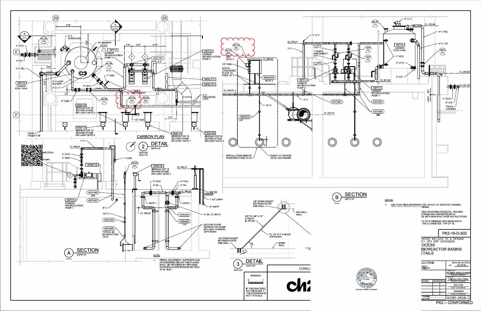
CARBON PLAN
0~ 1"V306
16-0,.100 16-0,.115
16G611B
16PNL713
16PNL714
'~~ ·~.---........v..:•'' \\
~······~I I
3"C DISCHARGE LOOP
~ I BIOREACTOR 18 SECOND STAGE INFLUENT GATE 3
CL 365.37,---1..la:il!III
4005-¢05
TYP
(Q)..----INSTALLATION SIMILAR7IN BIOREACTORS 14-19
SST PL 318" X 12" XREQ'D IE 357.00
118" EPDM GASKET BETWEEN PLATE
INJECT AT CENTER GATE, EACH BASIN
PL 1/4" X 3" X RE 'D STIFFENER
BASIN WALL
WETWELL WALL
f'RO.ECTENOINEER
BIOREACTOR 19 SECOND STAGE INFLUENT GATE 2
!:iQli;
1. PIPING, EQUIPMENT, SUPPORTS AND ACCESSORIES BELOW THIS FLANGE SHALL BE PROVIDED BY DIFFUSER SUPPLIER AS SPECIFIED IN SECTION 44 45 16.02.
3" UWHP
4" AA, CL 360.00
SECOND STAGE BIOREACTOR BASIN INFLUENT CHANNEL DIFFUSERS
AND WALL
~ 15-0_ 101 -------'________c_o_N_s_u
WARNING
0
IF THIS BAR DOES NOT MEASURE 1" THEN DRAWING IS NOTTO SCALE
(Q)
~
1. SEE PLAN VIEW DRAWINGS FOR LAYOUT OF AERATED CHANNEL ~,--..~-~ ~"~~-.. • "~ • • PIPING.
!VICE MOUNTING PEDESTAL. PROVIDE STREAM AND DOWNSTREAM OF CE WITH MANUFACTURER INSTRUCTIONS.
,TH OF 6" MINIMUM UPSTREAM AND 3" . THE FLOWMETER. TYP O F 19.
PK2-16-D-502 NCPWF INFLUENT PS & PIPELINE 1TH CITY WRP EXPANSION
.OCESS BIOREACTOR BASINS =TAILS
B-16149, S-17012 \\OS ll-15142
:ALIFORNIA :J'MENT SHEETS
ROVED DATE FILM
260-1709 OC$27 OOOAOlkATE
1900-6269 OCs«> OOOflOiNATE
: STAR1'IXI 40381- 2658--D:OMPUTfO
PK2 - CONFORMED
EXHIBIT B
Kiewit Letter dated March 14, 2022
@Kiewit
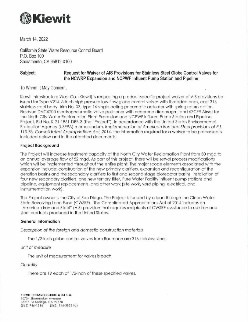
March 14, 2022
California State Water Resource Control Board P.O. Box 100 Sacramento, CA 95812-0100
Subject: Request for Waiver of AIS Provisions for Stainless Steel Globe Control Valves for the NCWRP Expansion and NCPWF Influent Pump Station and Pipeline
To Whom It May Concern,
Kiewit Infrastruc ture West Co. (Kiewit) is requesting a produc t-specific projec t waiver of AISprovisions be issued for Type V214 ½-inc h high pressure low flow globe control valves with threaded ends, cast 31 6 stainless steel body, trim No. 03, type 16 single ac ting pneumatic ac tuator with spring return action, Fieldvue DVC6200 electropneumatic valve positioner with neoprene diaphragm, and 67CFR Airset for the North City Water Reclamation Plant Expansion and NCPWF Influent Pump Station and Pipe line Projec t, Bid No . K-21-1861 -DBB-3 (the "Project"). In accordance with the United States Environmental Protection Agency (USEPA) memorandum, Implementation of American Iron and Steel provisions of P.L. 113-76, Consolidated Appropriations Ac t, 2014, the information required for a waiver to be processed is included below and in the attached documents.
Project Background
The Project will inc rease treatment capac ity of the North City Water Reclamation Plant from 30 mgd to an annual average flow of 52 mgd. As part of this project, there will be serval process modific ations whic h will be implemented throughout the entire plant. The major sc ope elements associated with the expansion include: construction of the new primary clarifiers, expansion and reconfiguration of the aeration basins and the secondary clarifiers to first and second stage bioreac tor basins, installation of four new sec ondary clarifiers, one new tertiary filter, Pure Water Facility influent pump stations and pipeline, equipment replacements, and other work (site work, yard piping, electrica l, and instrumentation work).
The Project owner is the City of San Diego. The Project is funded by a loan through the Clean Water State Revolving Loan Fund ( CWSRF). The Consolidated Appropriations Act of 2014 includes an "American Iron a nd Steel" (AIS) provision that requires recipients of CWSRF assistance to use iron and steel produc ts produced in the United States.
General Information
Description of the foreign and d omestic construc tion materials
The 1 /2-inc h g lobe control valves from Baumann are 316 stainless steel.
Unit of measure
The unit of measurement for valves is eac h.
Quantity
There are 19 eac h of 1 / 2-inc h of these specified valves.
KIEWIT INFRASTRU CTURE WE ST CO. 10704 Shoemaker Avenue Santo Fe Springs, CA 90670 (562) 946-18 16 (562) 946-3823 tax
@Kiewit Price
The total price for the 1/2-inch globe control valves is approximately $283,043.
Time of delivery for availability
The estimated delivery time is approximately ten ( l 0) to fourteen ( 14) weeks after an approved submittal.
Location of the construction project
The Project is located at: 4949 East Gate Mall San Diego, CA 92121
Name and address of the proposed supplier
Santa Fe WinWater l 0244 Freeman A venue Santa Fe Springs, CA 90670
Detailed justification for the use of foreign construction materials
These valves are specified for the use in carbon chemical lines-1 /2" high pressure low flow globe control valves with threaded ends, 316 stainless steel body, trim No. 03, type 16 single acting pneumatic actuator with spring return action, Fieldvue DVC6200 electropneumatic valve positioner, and 67CFR Airset are not produced meeting the AIS requirements.
Assistance recipient made a good faith effort to solicit bids for domestic iron and steel products, as demonstrated by language in requests for proposals, contracts, and communications with prime contractor.
See Attachment A, Letter from Santa Fe Win Water listing manufacturers contacted. In addition to the manufacturers contacted by Santa Fe WinWater, the prime contractor also contacted the following manufacturers and suppliers and inquired about the availability of the specified globe control valves.
• LA Valves • Bermingham Controls Inc.
Availability Waiver Request
Supplier information for pricing information from a reasonable number of domestic suppliers indicating availability /delivery date for construction materials
Santa Fe Win Water contacted numerous manufacturers about the availability of the stainless steel globe control valves. None of the manufacturers contacted could domestically source the material. Refer to Attachment A, letter from Santa Fe Win Water.
Doc umentation of the assistance recipient's efforts to find available domestic sources, such as description of the process for identifying suppliers and a list of contacted suppliers.
Refer to Attachment A, for a list of the manufacturers contac ted by Santa Fe Win Water and their response.
KIEWIT INFR ASTRU CTURE WEST CO. 10704 Shoemoker Avenue Sonto Fe Springs, CA 90670 (562) 946-1816 (562) 946-3823 fox
@Kiewit Project Schedule
The anticipated schedule for the Project as it relates to the stainless steel globe control valves is summarized as follows:
• Stainless Steel Globe Control Valve Submittal Review and Approval: As soon as AIS waiver is granted
• Procurement and Delivery: l 0-14 weeks after approval submittal • Project Completion: March 2025
Relevant excerpts from project plans, specifications, and permits indicating the required quantity and quality of construction materials
The technical specification for the Process Valves and Operator is included in Attachment B (stainless steel high pressure low flow globe control valves 40 27 02-2.05-B-6 can be seen on page 10 and pneumatic diaphragm actuator with accessories 40 27 02-2.06-D can be seen on pages 33 and 35). Select plans and sections of the NSWRP project detailing the Stainless Steel Globe Control Valves are presented in Attachment C.
Waiver request includes a statement from the prime contractor and/or supplier confirming the nonavailability of domestic construction materials for which the waiver is sought.
See Attachment A, letter from the Santa Fe Win Water.
If you have any questions, please contact Sepideh Aria, Project Engineer, at 310-924-0888.
KIEWIT IN FRA STRU CTUR E WEST CO. 10704 Shoemoker Avenue Sonto Fe Springs, CA 90670 (562) 946-1816 (562) 946-3823 fox

EXHIBIT C
List of Materials and Prices from Kiewit (WinWater)
10244 Freeman Avenue Santa Fe Springs, CA 90670
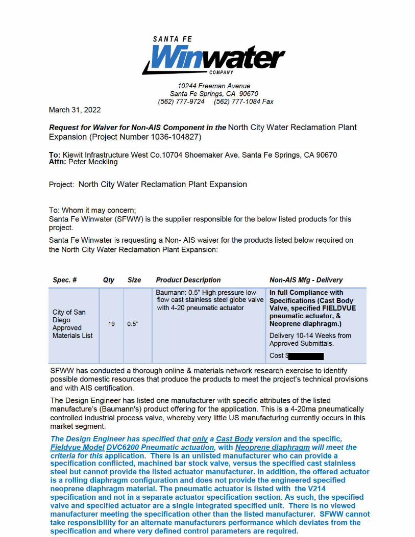
(562) 777-9724 (562) 777-1084 Fax March 31 , 2022
Request for Waiver for Non-AIS Component in the North City Water Reclamation Plant Expansion (Project Number 1036-104827)
To: Kiewit Infrastructure West Co. 10704 Shoemaker Ave. Santa Fe Springs, CA 90670 Attn: Peter Meckling
Project: North City Water Reclamation Plant Expansion
To: Whom it may concern; Santa Fe Winwater (SFWW) is the supplier responsible for the below listed products for this project.
Santa Fe Winwater is requesting a Non- AIS waiver for the products listed below required on the North City Water Reclamation Plant Expansion:
Spec.# Qty Size Product Description Non-AIS Mfg - Delivery
City of San
Baumann: 0.5" High pressure low flow cast stainless steel globe valve with 4-20 pneumatic actuator
In full Compliance with Specifications (Cast Body Valve, specified FIELDVUE
Diego 19 0.5"
Approved Materials List
pneumatic actuator, & Neoprene diaphragm.)
Delivery 10-14 Weeks from Approved Submittals.
Cost
SFWW has conducted a thorough online & materials network research exercise to identify possible domestic resources that produce the products to meet the project's technical provisions and with AIS certification.
The Design Engineer has listed one manufacturer with specific attributes of the listed manufacture's (Baumann's) product offering for the application. Th is is a 4-20ma pneumatically controlled industrial process valve, whereby very little US manufacturing currently occurs in this market segment.
The Design Engineer has specified that only a Cast Body version and the specific, Fieldvue Model DVC6200 Pneumatic actuation, with Neoprene diaphragm will meet the criteria for this application. There is an unlisted manufacturer who can provide a specification conflicted, machined bar stock valve, versus the specified cast stainless steel but cannot provide the listed actuator manufacturer. In addition, the offered actuator is a rolling diaphragm configuration and does not provide the engineered specified neoprene diaphragm material. The pneumatic actuator is listed with the V214 specification and not in a separate actuator specification section. As such, the specified valve and specified actuator are a single integrated specified unit. There is no viewed manufacturer meeting the specification other than the listed manufacturer. SFWW cannot take responsibility for an alternate manufacturers performance which deviates from the specification and where very defined control parameters are required.
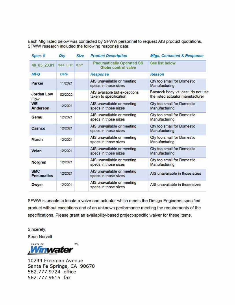
Each Mfg listed below was contacted by SFWW personnel to request AIS product quotations. SFWW research included the following response data:
Spec.# Qty Size Product Description Mfgs. Contacted & Response
40_05_23.01 [ See List I Pneumatically Operated SS[ 0.5" Globe control valve
[ See list below
MFG Date Response Reason
Parker 11 /2021 AIS unavailable or meeting specs in those sizes
Qty too small for Domestic Manufacturing
Jordan Low Flow
02/2022 AIS available but exceptions taken to specification
Barstock body vs. cast, do not us the listed actuator manufacturer
WE 12/2021 Anderson
AIS unavailable or meeting specs 1n those sizes
Qty too small for Domestic Manufacturing
Gemu 12/2021 AIS unavailable or meeting specs in those sizes
Qty too small for Domestic Manufacturing
Cashco 12/2021 AIS unavailable or meeting specs 1n those sizes
Qty too small for Domestic Manufacturing
Marsh 12/2021 AIS unavailable or meeting specs in those sizes
Qty too small for Domestic Manufacturing
Velan 12/2021 AIS unavailable or meeting specs 1n those sizes
Qty too small for Domestic Manufacturing
Norgren 12/2021 AIS unavailable or meeting specs in those sizes
Qty too small for Domestic Manufacturing
SMC 12/2021 Pneumatics
AIS unavailable or meeting specs 1n those sizes
AIS unavailable in those sizes
Dwyer 12/2021 AIS unavailable or meeting specs in those sizes
AIS unavailable in those sizes
SFWW is unable to locate a valve and actuator which meets the Design Engineers specified
product without exceptions and of an unknown performance meeting the requirements of the
specifications. Please grant an availability-based project-specific waiver for these items.
Sincerely,
Sean Norvell
SANTA Ft es
Winwater' ,.,.,,.., 10244 Freeman Avenue Santa Fe Springs, CA 90670 562.777.9724 office 562.777.9615 fax
e

Related Documents