ServoFeed Interface for: SmartPAC SmartPAC 2 ProCam 1500 DiPro 1500 1102700 Rev. C December 2014 Tech Support Hotline 800-586-8324 8-5 EST www.wintriss.com ® Waddington Wintriss SFI ® ® ® ® ® Wintriss Controls Group, LLC 100 Discovery Way Unit 110 Acton MA 01720 USA Phone (800) 586-8324 Fax (978) 263-2048 PRINTED IN USA DA46032 ®

Welcome message from author
This document is posted to help you gain knowledge. Please leave a comment to let me know what you think about it! Share it to your friends and learn new things together.
Transcript

ServoFeed Interface for:
SmartPAC
SmartPAC 2
ProCam 1500
DiPro 15001102700Rev. C December 2014
Tech Support Hotline 800-586-8324 8-5 EST
www.wintriss.com
®
Waddington Wintriss SFI®
®
®
®
®
Wintriss Controls Group, LLC100 Discovery WayUnit 110Acton MA 01720 USAPhone (800) 586-8324Fax (978) 263-2048
PRINTED IN USA DA46032
®

Changes for Revision C of the
Waddington Wintriss SFI User Manual
(1102700)
Revision C of the Waddington Wintriss SFI User Manual covers all Waddington
Wintriss SFI versions, except where noted.
The changes for Revision C include:
• Added to the cover of the installation manual the URL and QR code user needs to
download the user manual.
PROVIDE IMPORTANT INFO
DURING TROUBLESHOOTING WITH WINTRISS TECH SUPPORT!
Whenever you need to contact Wintriss Controls Group for technical assistance, be ready to provide some important information to expedite a resolution to the problem. Please supply: product name (e.g. SmartPAC, ProCam 1500, or DiPro 1500); installed options (e.g. 8-channel cam.); and firmware version number (e.g. Vs. 2.00). You can determine firmware version number from the chip on the processor board (see "location of components" in Chapter 2).

Thank you for purchasing a Wintriss Product. We appreciate your business and want to do whatever we can to ensure your satisfaction. Wintriss products are built to stay on the job day after day, and are backed by an ironclad guarantee, international standards approvals, and unbeatable support. Whenever you need assistance or service, we back all our products with excellent spare parts inventories, training programs, and prompt repair service. We would like to share with you a list of service options–probably the largest number of service options offered in the industry.
• Technical Assistance
We offer a toll-free line for technical assistance. Call our Wintriss Technical Support Hotline at 1-800-586-TECH (8324) should you have any questions about your equipment. Our technical staff is ready to assist you Monday through Friday, 8 a.m. to 5 p.m. EST. In many cases our experienced technical staff can resolve your inquiry right over the phone.
• Return Authorization
Please call our “800” number for a return authorization (RMA) number to return a product for repair. Returned goods must arrive freight prepaid. In order to process your return quickly, we ask that you provide us with the following pertinent information when you call: purchase order number, shipping address, contact name and telephone number, and product type. The assigned RMA number should appear on all packages returned to Wintriss Controls Group to ensure prompt service.
At the time of requesting an RMA, you will be quoted a flat-rate repair price for the product you are returning. We ask that you either fax us a PO for that amount or enclose the PO with the returned item. This will enable us to ship the item back to you as soon as the repair has been completed. If the item cannot be repaired or there are additional charges, you will be contacted for approval.
Please be sure to carefully pack all returned items and ship to our Acton, MA location.
• Expedited Repair Program
Rush service providing 48 hour turnaround is available for most products upon request. An Expedite Fee will be applied to our standard repair rate.
• Board Exchange Program
If your needs are urgent, you can take advantage of out Board Exchange (EX) program. Call our “800” number between 8 a.m. to 5 p.m. EST and we will send a replacement to you overnight. A fee does apply to this service. Contact Wintriss Technical Support at 800-586-8324 for details.
• Service Center
Our Service Center for product service is located at our headquarters in Acton, MA. If your equipment requires repair, please contact us at 800-586-8324 to obtain a return authorization number.
Nationwide field service is also available. Contact the Wintriss Technical Support group at 800-586-8324.
• Product Training
We also offer both product training and maintenance/troubleshooting courses at our Acton, MA and Chicago-area facilities. On-site training is available from the factory or through your local Wintriss representative.
• Restocking Charge
Returned goods are subject to a 20% restocking charge if returned for credit. The minimum charge is $50, not to exceed $250 per item.
Whatever the product, we are committed to satisfying you with innovative engineering, quality construction, reliable performance, and ongoing, helpful support. Call us whenever you need assistance.

Table of Contents
Waddington Wintriss SFI Manual i TOC 1102700
Chapter 1 - Waddington Servo Feed Interface SFI................................................ 1
About Wintriss Servo Feed Interfaces...............................................................................................................1
How SFI works..................................................................................................................................................2
What you can do with the Waddington SFI ......................................................................................................3
Chapter 2 - Installing Waddington SFI ................................................................... 5
Section 1 SmartPAC.........................................................................................................................................6
Installing the SmartPAC SFI .............................................................................................................................6
Upgrading SmartPAC firmware....................................................................................................................6
Wiring Connections ......................................................................................................................................9
Wiring for your feed model .....................................................................................................................9
Section 2 "1500 series"...................................................................................................................................12
Installing the "1500 series" Servo Feed Interface............................................................................................12
Installing SFI firmware ...............................................................................................................................12
Installing the Chip..................................................................................................................................12
Wiring Connections ....................................................................................................................................15
About Wiring .........................................................................................................................................15
Chapter 3 - Initialization mode for Waddington SFI ............................................ 19
Section 1 SmartPAC.......................................................................................................................................19
Entering Initialization Mode............................................................................................................................20
Setting Security Access ...................................................................................................................................21
Initializing Waddington MiniFeed ..................................................................................................................22
Change Group 1 ..........................................................................................................................................22
Check Setup ................................................................................................................................................25
Initializing Waddington SMS Servo Feed.......................................................................................................26
Changing Tune Values...........................................................................................................................26
Setting Servo Pilot .................................................................................................................................27
Setting Job Mode ...................................................................................................................................27
Set Number of Decimal Places...............................................................................................................28
Changing Calibration ..................................................................................................................................28
Checking Setup Values ..........................................................................................................................28
Section 2 1500 Series .....................................................................................................................................30
Initialization menu...........................................................................................................................................30
Feed Parameters 1............................................................................................................................................30
Change Groups ...........................................................................................................................................31
Check Setup ................................................................................................................................................33
Feed Parameters 2............................................................................................................................................34
Security Access ...............................................................................................................................................35
Locking Adjust Feed at ProCam 1500........................................................................................................35
Locking Adjust feed at DiPro 1500 ............................................................................................................36
Auto Advance and Slow RPM in DiPro 1500.................................................................................................36
Determining the Advance Constant for DiPro 1500's Channel 1 Automatic Speed Compensation ...........36

Table of Contents
Waddington Wintriss SFI Manual ii TOC 1102700
Chapter 4 - Program mode for Waddington SFI ..................................................39
Section 1 SmartPAC.......................................................................................................................................40
About Tool Number ....................................................................................................................................40
Program Menu.............................................................................................................................................40
Programming the SmartPAC/Waddington MiniFeed Servofeed.....................................................................41
Feed parameters ..........................................................................................................................................41
Using Feed Advisor ....................................................................................................................................42
How to use Feed Advisor .......................................................................................................................42
Load by tool number ...................................................................................................................................45
Programming SmartPAC/Waddington SMS Servofeed ..................................................................................46
Load by Tool Number.................................................................................................................................48
Section 2 1500 Series .....................................................................................................................................49
Program menu .............................................................................................................................................49
Feed settings ....................................................................................................................................................50
Feed Advisor ...................................................................................................................................................51
Load by tool number........................................................................................................................................54
Chapter 5 - Run Mode for Waddington SFI ..........................................................55
Section 1 SmartPAC.......................................................................................................................................56
About Tool numbers ...................................................................................................................................56
Entering Run Mode.....................................................................................................................................56
Using MiniFeed in Run Mode.....................................................................................................................57
Using the SMS Servo Feed in Run Mode ...................................................................................................58
Section 2 1500 Series .....................................................................................................................................59
About Tool Numbers ..................................................................................................................................59
Run menu ....................................................................................................................................................59
Chapter 6 - Troubleshooting Waddington SFI .....................................................61
SmartPAC Troubleshooting.............................................................................................................................61
Terminal Mode Screen Appears at Startup (Waddington SMS).................................................................61
Cannot Read SmartPAC Screens on Powering Up (Waddington SMS)....................................................61
Cannot Read SmartPAC Feed Control Menu (Waddington SMS) .............................................................61
Lost Communications Between SmartPAC and Feed Control....................................................................62
Viewing Communications Between Feed Control and SmartPAC.............................................................62
1500 Series Troubleshooting ...........................................................................................................................65
Wintriss Manuals

Table of Contents
Waddington Wintriss SFI Manual iii TOC 1102700
Figures at End of Manual
Figure 1. SmartPAC to Waddington MiniFeed Pac Scl 450 with Servo Roll Release Wiring
Figure 2. SmartPAC to Waddington MiniFeed Pac Scl 450 Wiring
Figure 3. SmartPAC to Waddington SMS Feed Control Wiring Diagram
Figure 4. SmartPAC to Waddington CR Feed Control Wiring Diagram
Figure 5. SmartPAC 2 Loopback Wiring Connections
List of Figures
Figure 2-1. Location of Components on SmartPAC Processor Board ..................................................................8 Figure 2-2. Attaching a Wire to a Connector ......................................................................................................10 Figure 2-3. Waddington SMS Terminal Mode Screen........................................................................................11 Figure 2-4. Location of Components on ProCam 1500 Processor Board ...........................................................13 Figure 2-5. Location of Components on DiPro 1500 Processor Board...............................................................14 Figure 3-1. Main Initialization Menu (SmartPAC) .............................................................................................20 Figure 3-2. Security Access Menu ......................................................................................................................21 Figure 3-3. Feed Control Menu...........................................................................................................................22 Figure 3-4. Change Group 1 Display ..................................................................................................................22 Figure 3-5. Setting "Jog Speed High" in Superimposed Number Display ..........................................................23 Figure 3-6. Illustrations of Change Groups 2 Through 4 ....................................................................................24 Figure 3-7. Check Setup Display ........................................................................................................................25 Figure 3-8. Main Initialization Menu ..................................................................................................................26 Figure 3-9. Feed Initialization Menu...................................................................................................................26 Figure 3-10. Change Tune Values........................................................................................................................27 Figure 3-11. Change Calibration Screen .............................................................................................................28 Figure 3-12. Check Setup Values Screen ..........................................................................................................29* Figure 3-13. Selecting "FEED PARAMETERS 1" from Initialization Menu.....................................................30 Figure 3-14. Feed Initialize Menu.......................................................................................................................31 Figure 3-15. Change Group 1 Display ................................................................................................................31 Figure 3-16. Setting "Jog Speed High" ...............................................................................................................32 Figure 3-17. Illustrations of Change Groups 2 Through 4 ..................................................................................33 Figure 3-18. Check Setup Display ......................................................................................................................34 Figure 3-19. Selecting "Feed parameters 2" from the Initialization Menu..........................................................34 Figure 3-20. Security Access Display .................................................................................................................35 Figure 3-21. Locking out "Adjust Feed" .............................................................................................................35 Figure 3-22. Feed Parameter 2 Display Featuring Feed Security........................................................................36 Figure 3-23. Setting Advance Constant at Channel 1 .........................................................................................38 Figure 4-1. Selecting "Feed Control" in Program Mode .....................................................................................40 Figure 4-2. Feed Settings.....................................................................................................................................41 Figure 4-3. Feed Parameters Displaying Showing "Feed Advisor" ....................................................................43 Figure 4-4. "Servo Feed Advisor" Display..........................................................................................................43 Figure 4-5. Selecting "Calculate" on the Servo Feed Advisor Display...............................................................44 Figure 4-6. New Feed Parameters Created by Feed Advisor ..............................................................................45 Figure 4-7. Feed Parameters Displays.................................................................................................................46 Figure 4-8. Waddington SMS Terminal Mode Screen........................................................................................47 Figure 4-9. Selecting "Set feed" in Program Mode .............................................................................................49 Figure 4-10. Feed Settings...................................................................................................................................49 Figure 4-11. Setting Feed Length........................................................................................................................50 Figure 4-12. Setting Other Feed Parameters .......................................................................................................51

Table of Contents
Waddington Wintriss SFI Manual iv TOC 1102700
Figure 4-13. Setting Feed Length in Feed Advisor .............................................................................................52 Figure 4-14. Feed Advisor Display ....................................................................................................................52 Figure 4-15. New Feed Parameters Created by Feed Advisor ............................................................................53 Figure 5-1. Run Menu .........................................................................................................................................56 Figure 5-2. Adjusting Feed Length .....................................................................................................................57 Figure 5-3. Run Menu .........................................................................................................................................58 Figure 5-4. Feed Control Display in Run Mode..................................................................................................58 Figure 5-5. Run Menu .........................................................................................................................................59 Figure 5-6. Adjusting Feed Length .....................................................................................................................59 Figure 6-1. Communications Fault Message .......................................................................................................62 Figure 6-2. Position Sensor Screen .....................................................................................................................63 Figure 6-3. Communication Data Viewer Screen................................................................................................63 Figure 6-4. Actual Communications....................................................................................................................63 Figure 6-5. Communications Fault Message .......................................................................................................65
List of Tables
Table 2-1. Wiring ProCam 1500 TB103 to Waddington MiniFeed....................................................................17 Table 2-2. Wiring DiPro 1500 TB103 to Waddington MiniFeed .......................................................................17 Table 4-1. Feed Parameters Menu Items .............................................................................................................47

Table of Contents
Waddington Wintriss SFI Manual v TOC 1102700
How to use this manual
Chapter 1 introduces you to the Waddington Servo Feed Interface (SFI). It explains what a servo feed interface is, and how it relates to Wintriss products. And it talks about what you can do with your Waddington SFI.
Installation is discussed in Chapter 2. The Waddington Servo Feed Interface (SFI) installation is basically the same for all Wintriss products mentioned in this manual. There are two sections which provide detail on connecting the Wintriss product to the Waddington servo feed. Section 1 deals with SmartPAC. Any related wiring schematics for SmartPAC are provided at the very end of the manual after the index. Section 2 covers the 1500 series Wintriss products, specifically ProCam 1500 and DiPro 1500. Related wiring tables are provided in that section. Follow the steps in Chapter 2 to install SFI.
The next three chapters of the manual explains how to use SFI in all three SmartPAC operating modes -- Initialization (covered in Chapter 3), Program (Chapter 4), and Run (Chapter 5). Each of these chapters is broken down into two sections: Section 1 SmartPAC and Section 2 1500 series, to provide specifics on using your Waddington SFI. These chapters mention specific parameters that you can initialize and/or modify at your Waddington servo feed. They do not, however, explain these parameters in any detail. Refer to your Waddington servo feed manual for more information.
Troubleshooting is discussed in Chapter 6. This chapter does not include any Waddington error conditions specific to the feed controller. For that information, consult your Waddington servo feed user manual.
Using Wintriss Product User Manuals
Each of these sections provides you with detail on initializing parameters for the Waddington servo feed with the applicable Wintriss control. If you need more assistance in installing or using the Wintriss product, refer to its user manual:
• SmartPAC: 1107500
• SmartPAC with WPC: 1107600
• ProCam 1500: 1095000
• DiPro 1500: 1092000.

Table of Contents
Waddington Wintriss SFI Manual vi TOC 1102700
Warranty
Wintriss Controls warrants that Wintriss electronic controls are free from defects in
material and workmanship under normal use and service for a period of one year (two
years for Shadow light curtains) from date of shipment. All software products
(LETS/SFC and SBR), electro-mechanical assemblies, and sensors are warranted to be
free from defects in material and workmanship under normal use and service for a period
of 90 days from date of shipment. Wintriss’s obligations under this warranty are limited
to repairing or replacing, at its discretion and at its factory or facility, any products which
shall, within the applicable period after shipment, be returned to Wintriss Controls
freight prepaid, and which are, after examination, disclosed to the satisfaction of
Wintriss to be defective. This warranty shall not apply to any equipment which has
been subjected to improper installation, misuse, misapplication, negligence, accident,
or unauthorized modification. The provisions of this warranty do not extend the
original warranty of any product which has either been repaired or replaced by
Wintriss Controls. No other warranty is expressed or implied. Wintriss accepts no
liability for damages, including any anticipated or lost profits, incidental damages,
consequential damages, costs, time charges, or other losses incurred in connection
with the purchase, installation, repair or operation of our products, or any part thereof.
Please note:
It is solely the user’s responsibility to properly install and maintain Wintriss controls
and equipment. Wintriss Controls manufactures its products to meet stringent
specifications and cannot assume responsibility for consequences arising from their
misuse.
Wintriss Controls Group, LLC WADDINGTON /WINTRISS SFI 100 Discovery Way USER MANUAL Unit 110 1102700 Acton, MA 01720 ©2014 Wintriss Controls Group, LLC Telephone: (800) 586-TECH (8324) (978) 268-2700 Fax: (978) 263-2048 Internet: www.wintriss.com

Waddington Wintriss SFI Manual 1 Ch 1 1102700
Chapter 1 - Waddington Servo Feed Interface SFI
About Wintriss Servo Feed Interfaces
Servo Feed Interface (SFI) is an option available with Wintriss products: SmartPAC, ProCam 1500, and DiPro 1500 with Cam. SFI, which is a combination of hardware and software, is available for most servo-driven feeds. SFI can be integrated with an existing system, or can be ordered with a new one. SFI means that the micro-processor-based Wintriss product is “interfaced” with the feed’s controller, so that the tool’s feed settings are stored in the Wintriss “Tool Number Memory”. The Wintriss control will automatically transmit the settings to the servo feed every time a tool is changed. Typically, there is only one operator interface, or control panel, to use and only one tool number to load when setting a die. With some feeds the Wintriss product becomes the feed’s panel. With other feeds, the feed panel remains but may be rarely, if ever, used.
Although SFI is similar from one feed to the next, there are differences that are feed manufacturer- or feed controller-specific. Remember that SFI is communicating with the feed controller and is not performing the functions of the feed controller. Some feeds will not accept certain information via a communications port or the controller only communicates during certain modes. This may be a controller issue, or a decision on the part of the feed manufacturer. SFI cannot change this, but rather can only "talk/work" within the controller’s communications capabilities or as requested by the feed manufacturer. However, SFI works like the Wintriss product within which it is installed. So, if you are accustomed to the Wintriss product – the SFI programs, adjusts, and loads using similar menus and expected key strokes.
To use the Servo Feed Interface, you must have or install the appropriate firmware chip into the appropriate Wintriss control. Then you simply connect the unit to your servo feed using a cable that plugs into your servo feed's RS-232 port. See Chapter 2 for installation instructions for the appropriate product.
The Waddington Servo Feed Interface allows several user-defined choices, as well as feed adjustments while running. It also includes "Feed Advisor". Feed Advisor determines the optimum (slowest) feed speed for your feed setup. You program the parameters (press speed, feed arc/degrees available to feed, and length) and it calculates the feed speed. If it is impossible, Feed Advisor will offer a suggested solution.
With SFI, the feed is set and its parameters stored at the Wintriss product. There are three modes: Initialization, Program, Run/Adjust. Depending on the product, there may be different titled subheadings in these modes. However, the features are basically similar.
In Initialization mode, you set the major parameters – basically configuring how the feed/SFI works. Here is where you also zero the resolver, determine the system’s security, and configure cam “auto advance” parameters, plus more…. See Chapter 3.

Waddington Servo Feed Interface (SFI)
Waddington Wintriss SFI Manual 2 Ch 1 1102700
In Program mode, you program a tool number, make major changes to a setup, use the Feed Advisor (if applicable), and load the Tool Number that you want to run. See Chapter 4.
In Run or Adjust mode, you can load a Tool Number and fine-tune the loaded Tool Number – if allowed by your security settings (Initialization Mode). See Chapter 5.
The "1500" series products have 8-line displays, while the SmartPAC has a 20-line display. The ProCam 1500, DiPro 1500, and SmartPAC have similar menus, displays (except size), style, and ease of use.
Refer to the Wintriss product's user manual
If you need additional assistance in using any of the Wintriss products, please keep the appropriate user manual handy. These manuals explain in detail how to use all of the operating modes mentioned above. They also explain how to use the keypads on each system. The user manuals are as follows:
SmartPAC: #1107500
SmartPAC with WPC: #1107600
ProCam 1500: 1095000
DiPro 1500: 1092000
How SFI works
You do not need to know any of the following information, but here is a little background about how your SFI works. Your Waddington Servo Feed Interface (SFI) is actually an RS-232 interface. The RS-232 interface does not just consist of cables and connectors. Like ANSI standards that govern how your press must operate, the RS-232 interface requires specific circuits and software instructions for the transmission of signals and data between your servo feed and your Wintriss control. Transmission of data is handled by software in the Wintriss product and by the software built into your servo feed. Your servo feed came with all the RS-232 circuitry and software already in place.
Wintriss Controls Group worked in conjunction with your servo feed manufacturer to design the proper hardware and software that will automatically interface with your Waddington servo feed. That is why all you have to do is install the firmware chip and connect a cable from the Wintriss control to your servo feed's RS-232 port. Everything else is automatic. You can then make SFI settings at the Wintriss product's keypad just as you would if you used the interface on the servo feed itself.

Waddington Servo Feed Interface (SFI)
Waddington Wintriss SFI Manual 3 Ch 1 1102700
What you can do with the Waddington SFI
Using the Wintriss control menus, you can:
• Set feed length, percent acceleration, and possibly some other parameters for your servo feed
• Save these settings under the tool number and recall them automatically when you load setups by tool number
• Modify or change setups
• Use Feed Advisor to check your settings. If you key in feed angle and press speed, Feed advisor warns you if your settings are not right for that job.
• Adjust feed length and percent acceleration while the press is running
• Lock SFI settings in Adjust Mode to prevent unauthorized tampering
IMPORTANT
For more detailed information regarding your Waddington servo feed controller, consult the user manual.

Waddington Servo Feed Interface (SFI)
Waddington Wintriss SFI Manual 4 Ch 1 1102700

Waddington Wintriss SFI Manual 5 Ch 2 1102700
Chapter 2 - Installing Waddington SFI
Installing the components that allow your Wintriss control to operate your servo feed is quite simple, and requires these tasks:
• Installation of SFI firmware into Wintriss control
• Wiring connections from the Wintriss control SFI-communications terminal block to the RS-232 port of your Waddington servo feed controller. The location of the wiring diagrams (or tables) for each Wintriss product will be noted in the appropriate installation section.
If you need more assistance in installing the Wintriss product, refer to its user manual.

Installation for Waddington SFI
Waddington Wintriss SFI Manual 6 Ch 2 1102700
Section 1 SmartPAC
Installing the SmartPAC SFI
This section explains how to perform the installation for SFI with SmartPAC. For SmartPAC to be compatible with the Waddington servo feed, your kit would consist of the following ordered items:
• SFI firmware (unless factory-installed at time of order)
• 20-foot 2-conductor shielded cable with a DB25 connector attached on one end (Wintriss cable #4199104)
• 10-pin connector
WARNING!
ELECTRICAL HAZARD!
Dangerous voltages are present. Verify that the power to SmartPAC and to the Waddington feed have been turned OFF before servicing any components! Servicing must be performed by qualified personnel.
Upgrading SmartPAC firmware
You will need to upgrade SmartPAC for SFI™ ServoFeed Interface capability. Follow these steps:
1. Turn power off to SmartPAC. The LCD on the front panel should be blank and the angle/RPM display should be unlit.
CAUTION!
Always verify that power has been turned off to SmartPAC!
2. Before you proceed, you should ground yourself by touching any large metal object. This will remove any static electricity that you may be carrying around. A static electricity "zap" will destroy the components.
CAUTION
The SmartPAC firmware board location is also not interchangeable. It must be installed on the main processor board as illustrated in Figure 2-1 of this chapter.
3. Look inside SmartPAC and locate the firmware board, which is located toward the bottom left of the main processor board (Figure 2-1). Take note of its orientation.
4. Remove the four screws which hold the board to the standoffs under the board, and put them aside for now.

Installation for Waddington SFI
Waddington Wintriss SFI Manual 7 Ch 2 1102700
5. Unplug and remove the board. Be sure not to confuse the old firmware board with the new one you will be installing. If necessary, jot down the version number that is found on the firmware chip's white label.
6. Verify that you are still "grounded", and then remove the new board from the package.
7. Plug the board in. The connectors on the underside of the board are keyed; so they can only be plugged in one way. These connectors will connect correctly with the mating pins on the main SmartPAC processor board.
8. Once the board is properly seated, screw the four corners down again (reverse of step 4).
9. Turn the power on and verify the normal operation of the unit. If the unit powers up with a garbled display or "rolling" LEDs, turn the power off and check that the board is properly seated.
NOTE
If yours is a SMS servo feed, the Terminal Mode screen (Figure 2-3) appears when you power up the SmartPAC. Press RESET to go to normal SmartPAC operation.
When you are ready to proceed to the next section, shut off the power to the unit.
NOTE
After you perform this SmartPAC may generate a tool number checksum error the first time you try to reload each setup. SmartPAC creates a checksum for a tool number to check that the data stored in memory for the tool is the same as the data that comes out of memory when you load the tool number. To correct this problem, go to Program mode and review the currently loaded tool number setup. Check your counters for accuracy; then reload this tool number again. If the unit is still malfunctioning, call Wintriss Tech Support.
Refer to your SmartPAC manual (Wintriss P/N 1107500) or SmartPAC with WPC manual (Wintriss P/N 1107600) for an explanation of checksum errors.

Installation for Waddington SFI
Waddington Wintriss SFI Manual 8 Ch 2 1102700
Power TB101
E-Stop Relays
TOP
STO
P
LIN
E C
HE
CK
RAMChip
ProCamPACsocket
DiProPACsocket
Top StopRelay
Sparecomms
LED
PACNetLED
SFITB102AutosetPACSpare PACNet
TB103
E-S
TOP
INP
UT
CH
EC
K
Fuses
Input checkLED
SW 101Input check
switch
TB106 Resolver
TB104WPC*
WPC*LED
Positionsensor
LEDPositionsensorTB107
LO HIJ112
Speedsetting
SFILED
AutoSetPACLED
12-60 60-250
EPROMboard
sockets
* Refers toSmartPAC with
WPC only
Figure 2-1. Location of Components on SmartPAC Processor Board (important components shown and labeled)

Installation for Waddington SFI
Waddington Wintriss SFI Manual 9 Ch 2 1102700
Wiring Connections Wiring for your feed model
These instruction explain how to wire your SmartPAC to the Waddington feed. For additional information, refer to the Waddington feed controller manual. In particular, refer to the appropriate wiring diagram at the end of this manual:
Figure 1. SmartPAC to Waddington MiniFeed Pac Scl 450 with Servo Roll Release Figure 2. SmartPAC to Waddington MiniFeed Pac Scl 450 Figure 3. SmartPAC to Waddington SMS Feed Control Figure 4. SmartPAC to Waddington CR Feed Control
1. Verify that SmartPAC and your feed are still turned OFF! You are now ready to connect your servo feed to SmartPAC. Locate the 10-pin connector and the black round cable with a large 25-pin connector on one end. The other end of the cable has three unattached wires (red, black, and shield). Check to make sure that you have the female connector as described in the wiring diagram illustration at the end of this manual.
2. Locate terminal TB102 on the SmartPAC processor board (see Figure 2-1). Next, find the RS-232 port at the bottom of the feed controller.
3. If you have the optional second servo-driven roll release controller which replaces Waddington's mechanical cam, you should also locate terminal TB103 at SmartPAC as well as the communications port at the bottom of the roll release controller. Refer to the wiring diagram at the end of the manual.
Only with SmartPAC
The second servo-driven roll release mechanism, which replaces Waddington's mechanical cam, is an option that is only available with SmartPAC. It is not available with the 1500 series products.
4. Run the cabling through dedicated, flexible liquid-tight conduit from your feed to SmartPAC. SmartPAC is rated NEMA 12 (protected against dust and oil). You must use conduit of the same rating and make proper connections to ensure NEMA 12 protection.
5. Go to the RS-232 port on your feed first. Plug the DB25 connector which is attached to the cable from SmartPAC into the feed's RS-232 port. It can only go in one way. Tighten the screws on the connector to hold it firmly in its socket. Also tighten all conduit connections. If you have the optional roll release, connect that DB25 connector as per the wiring diagram.
6. Now go to SmartPAC. The end with the unattached wires goes to SmartPAC. Cut off any extra cable if necessary, and carefully remove the outer insulation and inner shielding on the cable in order to expose the wires. Strip insulation back 1/4" on each wire.
7. You will be connecting the two wires (with shield) to the 10-pin connector which you will attach to terminal TB102 on the SmartPAC processor board. Remember to refer to the wiring diagram at the end of this manual. Again, if you have the optional roll release, connect the other end to terminal TB103 at SmartPAC.
Installation for Waddington SFI
Waddington Wintriss SFI Manual 10 Ch 2 1102700
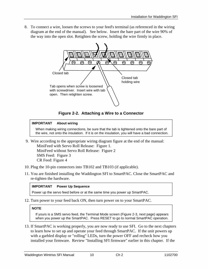
8. To connect a wire, loosen the screws to your feed's terminal (as referenced in the wiring diagram at the end of the manual). See below. Insert the bare part of the wire 90% of the way into the open slot. Retighten the screw, holding the wire firmly in place.
Closed tab
Tab opens when screw is loosenedwith screwdriver. Insert wire with tabopen. Then retighten screw.
Closed tabholding wire
Figure 2-2. Attaching a Wire to a Connector
IMPORTANT About wiring
When making wiring connections, be sure that the tab is tightened onto the bare part of the wire, not onto the insulation. If it is on the insulation, you will have a bad connection.
9. Wire according to the appropriate wiring diagram figure at the end of the manual: MiniFeed with Servo Roll Release: Figure 1. MiniFeed without Servo Roll Release: Figure 2 SMS Feed: Figure 3 CR Feed: Figure 4
10. Plug the 10-pin connectors into TB102 and TB103 (if applicable).
11. You are finished installing the Waddington SFI to SmartPAC. Close the SmartPAC and re-tighten the hardware.
IMPORTANT Power Up Sequence
Power up the servo feed before or at the same time you power up SmartPAC.
12. Turn power to your feed back ON, then turn power on to your SmartPAC.
NOTE
If yours is a SMS servo feed, the Terminal Mode screen (Figure 2-3, next page) appears when you power up the SmartPAC. Press RESET to go to normal SmartPAC operation.
13. If SmartPAC is working properly, you are now ready to use SFI. Go to the next chapters to learn how to set up and operate your feed through SmartPAC. If the unit powers up with a garbled display or "rolling" LEDs, turn the power OFF and recheck how you installed your firmware. Review "Installing SFI firmware" earlier in this chapter. If the

Installation for Waddington SFI
Waddington Wintriss SFI Manual 11 Ch 2 1102700
unit is still malfunctioning and you cannot find the reason for the problem, call Wintriss Tech Support for assistance.
MESSAGE WINDOW FROM FEED
JOB EDIT MODE
WADDINGTON SMS MANUAL MODETERMINAL MODE
JOB NUMBER
= KEY
- KEY F6
F5
F4
F3
F2
F1
Figure 2-3. Waddington SMS Terminal Mode Screen
Installation for Waddington SFI
Waddington Wintriss SFI Manual 12 Ch 2 1102700
Section 2 "1500 series"
Installing the "1500 series" Servo Feed Interface
This section explains how to perform the installation for SFI with the 1500 series Wintriss products. These include ProCam 1500 and DiPro 1500. Before starting, make sure that you have all these components in your kit:
• SFI firmware chip (EPROM) (unless factory-installed at time of order)
• 20-foot 2-conductor shielded cable with a large DB25 connector attached on one end (Wintriss part no. 4199104)
• 10-pin phoenix connector
Follow these steps to install the components:
WARNING!
ELECTRICAL HAZARD!
Dangerous voltages are present. Verify that the power to ProCam 1500 and to your feed have been turned OFF before servicing any components. Servicing must be performed by qualified personnel.
Installing SFI firmware
To upgrade the 1500 unit to communicate with your servo feed, follow these instructions:
1. With power to the 1500 unit turned off, notice that the LCD display on the front panel is blank and the angle/RPM display unlit.
2. Carefully remove the front panel assembly from your enclosure by loosening the hardware and temporarily propping the unit on a flat surface.
3. Locate the firmware chip for that product, located at U104 on either the ProCam 1500 or DiPro 1500 processor boards (refer to Figure 2-4 or Figure 2-5 respectively). Notice that this firmware chip has a label on it.
Installing the Chip
Be sure to note the exact orientation of the firmware chip. Notice in particular the semi-circular notch on the bottom of the chip. When you replace the chip, the notch on the new chip MUST also be face down. If you plug the chip in backwards, it will be destroyed!
4. Insert a small screwdriver between the bottom of the chip and the socket and carefully pry the chip out of its socket. Be careful not to get the screwdriver under the socket itself. Put the chip aside.
5. Open the package containing your new SFI firmware chip. Before you remove the chip from the package, you should ground yourself by touching any large metal object (the

Installation for Waddington SFI
Waddington Wintriss SFI Manual 13 Ch 2 1102700
press will do nicely). This will remove any static electricity that you may be carrying around. A static electricity "zap" will destroy the chip.
TRANSFORMERUSE
CAUTION
POWERTB104
VOLTAGESELECTOR
S102
INPUT CHECK SWITCHS101
PO
WE
R
INP
UT
CH
K.
T-S
TO
P
E-S
TO
P
SPEED SELECT.J101
LEDBLOCK
COMMUNICATIONSTB103 CAM OUTPUT
TB102
RESOLVERTB105
MASTER/SLAVEJUMPER
J102
RA
M
FIR
MW
AR
E
TB101
U105 U104
SP-1
POSITION SENSORREMOTE RESET
SP-2
INPUT CHECKDIAG.
PACNET
Figure 2-4. Location of Components on ProCam 1500 Processor Board

Installation for Waddington SFI
Waddington Wintriss SFI Manual 14 Ch 2 1102700
PACNET
PACNET/SFI
TRANSFORMERUSE
CAUTION
RA
M
FIR
MW
AR
E
PO
WE
R
INP
UT
CH
K.
T-S
TO
P
E-S
TO
P
POWERTB104
VOLTAGESELECTOR
S102
INPUT CHECK SWITCHS103
SENS. PWR.
INPUT CHECK LED
LEDBLOCK
COMMUNICATIONSTB103
CAM OUTPUTTB102
RESOLVERTB105
MASTER/SLAVEJUMPER
J102
TB101
SPEED SELECT.J101
SENSORS 1-3 LOW IMP.SENSORS 4-6 HIGH IMP.
U105 U104
Figure 2-5. Location of Components on DiPro 1500 Processor Board
6. Once you are "grounded", remove the chip from its holder. REMEMBER to orient the chip so that the notch faces downward.
7. Plug the chip into its socket by first plugging in the left row of pins and then aligning the right row of pins over the socket and pushing straight in.

Installation for Waddington SFI
Waddington Wintriss SFI Manual 15 Ch 2 1102700
8. If the two rows of pins are spread too far apart to plug easily into the socket:
a. Hold the chip on its side on a desk or a flat surface with the pins pointing towards you.
b. Being careful NOT to overbend the pins, gently flex the top of the chip towards you. Turn the chip over so that the other row of pins is now on the desk pointing towards you. Flex it again, thus bending the other row of pins towards each other. Pins should be parallel.
c. Try plugging the chip into the socket again, as in step 7. If necessary, repeat Steps 8A and 8B.
9. Make sure that the notch in the chip is at the bottom and that all of the pins are in the socket.
10. Turn the power ON to the 1500 unit without re-connecting the panel to your enclosure. Verify the normal operation of the unit.
If the unit powers up with a garbled display or "rolling" LEDs, turn the power OFF and repeat step 9. Sometimes one or more pins are bent and not plugged in properly. If the unit is still malfunctioning, call Wintriss Tech Support for assistance. Turn the 1500 unit and your feed controller OFF before proceeding to the next step.
Wiring Connections
About Wiring
Be sure to refer to Table 2-1 (for ProCam 1500) or Table 2-2 (for DiPro 1500) for specific wiring specifications mentioned in these steps. These tables can be found at the end of the "1500 series" section.
1. Verify that the 1500 unit and your feed are still turned OFF! You are now ready to connect the unit to your servo feed controller. Find the 10-pin phoenix connector and the black round cable with a large connector (DB25 connector ) on one end. The other end of the cable has three unattached wires (red, black, and shield). Check to make sure that you have the female connector for your feed as indicated at the end of this section.
2. Locate terminal TB103 on the 1500 unit's processor board (see Figure 2-4 for ProCam 1500 or Figure 2-5 for DiPro 1500).
Also find the RS-232 port on your feed. Refer to your feed manual if necessary.
3. Refer to step 3a for ProCam 1500 or 3b for DiPro 1500 below.
a. For ProCam 1500: If ProCam 1500 and your servo feed controller have been installed inside two separate enclosures, run the cable through flexible liquid-tight conduit from your feed to ProCam 1500. ProCam 1500 is rated NEMA 12 (protected against dust and oil). You must use conduit of the same rating and make proper connections to ensure NEMA 12 protection.
b. For DiPro 1500: Run the cable through flexible liquid-tight conduit from your feed to DiPro 1500. DiPro 1500 is rated NEMA 12 (protected against dust and oil). You

Installation for Waddington SFI
Waddington Wintriss SFI Manual 16 Ch 2 1102700
must use conduit of the same rating and make proper connections to ensure NEMA 12 protection.
4. Go to the RS-232 port on your feed.
5. Plug the DB25 connector which is attached to the cable from ProCam 1500 into the feed's RS-232 port. It can only go in one way. Tighten the screws on the connector to hold it firmly in its socket. Also tighten all conduit connections.
6. Now go to the 1500 unit. The end with the unattached wires goes to it. Cut off any extra cable if necessary, and carefully remove the outer insulation and inner shielding on the cable in order to expose the wires. Strip insulation back 1/4" on each wire.
7. You will be connecting the two wires (with shield) to the 10-pin phoenix connector which you will attach to terminal TB103 on the 1500 unit's processor board. Remember to refer to the tables at the end of this section for the RS-232 configuration.
8. To connect a wire, loosen the screws that correspond to the appropriate terminal, so that the corresponding slot to the right will open. See Figure 2-2 earlier in this chapter. Insert the bare part of the wire 90% of the way into the open slot. Retighten the screw, holding the wire firmly in place.
Avoiding a Bad Wiring Connection
When making wiring connections, be sure that the tab is tightened onto the bare part of the wire, not onto the insulation. If on the insulation, you will have a bad connection.
9. Repeat step 8 when connecting the other two wires. Make sure you add the jumper between terminals 3 and 6 on TB103 at ProCam 1500, or between terminals 3 and 10 at DiPro 1500.
10. Look at TB103. There may be a plastic plug over pin 5 on this terminal block. If so, remove the pin using needle-nose pliers. Plug the 10-pin connector into TB103.
11. You are finished installing the 1500 SFI. For ProCam 1500, re-connect the panel to your enclosure and re-tighten the hardware. For DiPro 1500, close the DiPro 1500 and re-tighten the hardware. Turn power back ON to both the 1500 unit and to your feed controller.
12. Check that the 1500 unit is operating normally. If it is working properly, you are now ready to use SFI. Go to the following chapters to learn how to initialize, program, and operate your feed using the Wintriss 1500 products. If the unit powers up with a garbled display or "rolling" LEDs, turn the power OFF and recheck how you installed your firmware. Review "Installing SFI firmware" earlier in this chapter. If the unit is still malfunctioning and you cannot find the reason for the problem, call Wintriss Tech Support for assistance.

Installation for Waddington SFI
Waddington Wintriss SFI Manual 17 Ch 2 1102700
Table 2-1. Wiring ProCam 1500 TB103 to Waddington MiniFeed
Directionof data
flow
#3 Red
#2 Black
#7 Groundshield
TYPE OFCONNECTOR
requires female DB25 connector
WaddingtonMiniFeed
Feed ControllerRS232 Port
ProCam 1500TB103
#4 -RXD
#5 TXD OUT
#6 GROUND
#3 +RXD
Table 2-2. Wiring DiPro 1500 TB103 to Waddington MiniFeed
#3 Red
#2 Black
#7 Groundshield
requires female DB25 connector
Directionof data
flow
TYPE OFCONNECTOR
WaddingtonMiniFeed
Feed ControllerRS232 Port
DiPro 1500TB103
#4 -RXD
#5 TXD OUT
#10 GROUND
#3 +RXD

Installation for Waddington SFI
Waddington Wintriss SFI Manual 18 Ch 2 1102700

Waddington Wintriss SFI Manual 19 Ch 3 1102700
Chapter 3 - Initialization mode for Waddington SFI
In this chapter you will learn how to use the Waddington SFI menus. Specifically you will set several feed initialization parameters. This chapter is divided into two sections:
• Section 1: SmartPAC (MiniFeed and SMS), next section
• Section 2: 1500 series products, including ProCam 1500 and DiPro 1500 (MiniFeed only), page 30
Each of these sections provides you with detail on initializing parameters for the Waddington servo feed with the applicable Wintriss control. Refer to your Wintriss control manual and your servo feed manual as necessary.
IMPORTANT
Refer to Waddington Servo Feed Manual
This manual mentions certain parameters that you can modify at your Waddington servo feed control. It does not, however, explain these parameters in great detail. Refer to your Waddington servo feed manual for more information.
Section 1 SmartPAC
IMPORTANT Power Up Sequence
Power up the servo feed before or at the same time you power up SmartPAC.
NOTE
If yours is an SMS servo feed, the Terminal Mode screen (Figure 2-3) appears when you power up the SmartPAC. Press RESET to go to normal SmartPAC operation.
This section contains instructions for the following procedures for initializing your Waddington servo feed connected to a SmartPAC control:
• Entering Initialization Mode, page 20
• Setting Security Access for Servo Feed, page 21
• Initializing Waddington MiniFeed, page 22
• Initializing Waddington SMS Servo Feed, page 26
Refer to your SmartPAC manual and your servo feed manual as necessary.

Initialization mode for Waddington SFI
Waddington Wintriss SFI Manual 20 Ch 3 1102700
Entering Initialization Mode
IMPORTANT
SMS Servo Feed must be homed and AUTO/MAN/JTL switch must be set to MAN
Be sure you have homed the feed and set the AUTO/MAN/JTL switch to MAN. Otherwise, you cannot read any feed information under the feed control menu. See your servo feed manual.
To enter Initialization mode, turn the Program/Run key to PROG and then press both the "1" and "CLEAR" keys at the same time for one second. (See "Using the Keyboard" in Chapter 3 of the SmartPAC user manual)
NOTE
Before changing modes (for instance -- from Initialization to Program), make sure your screen shows the first display in the mode you are in. If that display is not shown, nothing will happen when you turn the Program /Run key. In that case, keep pressing the RESET key. When the first display in the mode is reached, you will instantly switch to the new mode.
SELECT = HIGHLIGHT + ENTER
When this manual says “select,” it means “use the cursor keys to highlight the item and then press ENTER.“
Here is the first display in Initialization mode.
MAIN INITIALIZATION MENU
USE CURSOR KEYS TOCHOOSE MENU ITEMS.PRESS THE ENTERKEY TO SELECT.SWITCH TO RUN WHENDONE.
RESOLVER ZEROPOSITION SENSORINSTALLED OPTIONSPRESS NAMEBRAKE MONITORSELECT CAM NAMESCUSTOM SENSOR NAMESSENSOR ENABLE MODESECURITY ACCESSAUTO ADVANCESET BRAKE MONITORFEED CONTROLFEED CONTROL
Figure 3-1. Main Initialization Menu (SmartPAC)
If you want to set security access, proceed to the next section.
Otherwise, proceed to the feed-specific instructions to complete the initialization process.
• Initializing Waddington MiniFeed, page 22
• Initializing Waddington SMS Servo Feed, page 26
Initialization mode for Waddington SFI
Waddington Wintriss SFI Manual 21 Ch 3 1102700
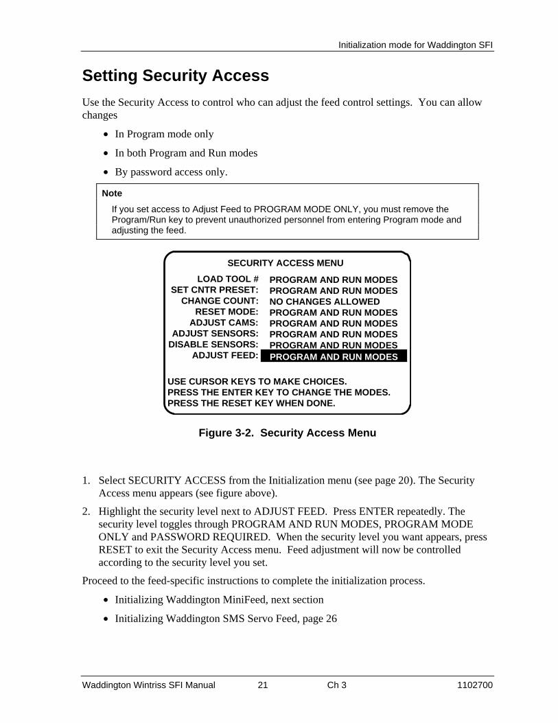
Setting Security Access
Use the Security Access to control who can adjust the feed control settings. You can allow changes
• In Program mode only
• In both Program and Run modes
• By password access only.
Note
If you set access to Adjust Feed to PROGRAM MODE ONLY, you must remove the Program/Run key to prevent unauthorized personnel from entering Program mode and adjusting the feed.
SECURITY ACCESS MENU
USE CURSOR KEYS TO MAKE CHOICES.PRESS THE ENTER KEY TO CHANGE THE MODES.PRESS THE RESET KEY WHEN DONE.
LOAD TOOL #SET CNTR PRESET:
CHANGE COUNT:RESET MODE:
ADJUST CAMS:ADJUST SENSORS:
DISABLE SENSORS:ADJUST FEED:
PROGRAM AND RUN MODESPROGRAM AND RUN MODESNO CHANGES ALLOWEDPROGRAM AND RUN MODESPROGRAM AND RUN MODESPROGRAM AND RUN MODESPROGRAM AND RUN MODESPROGRAM AND RUN MODESPROGRAM AND RUN MODES
Figure 3-2. Security Access Menu
1. Select SECURITY ACCESS from the Initialization menu (see page 20). The Security Access menu appears (see figure above).
2. Highlight the security level next to ADJUST FEED. Press ENTER repeatedly. The security level toggles through PROGRAM AND RUN MODES, PROGRAM MODE ONLY and PASSWORD REQUIRED. When the security level you want appears, press RESET to exit the Security Access menu. Feed adjustment will now be controlled according to the security level you set.
Proceed to the feed-specific instructions to complete the initialization process.
• Initializing Waddington MiniFeed, next section
• Initializing Waddington SMS Servo Feed, page 26
Initialization mode for Waddington SFI
Waddington Wintriss SFI Manual 22 Ch 3 1102700
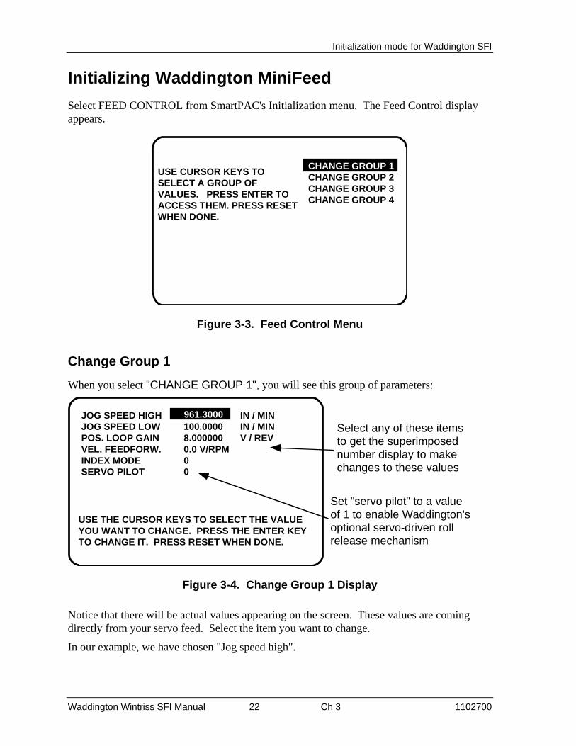
Initializing Waddington MiniFeed
Select FEED CONTROL from SmartPAC's Initialization menu. The Feed Control display appears.
CHANGE GROUP 1CHANGE GROUP 2CHANGE GROUP 3CHANGE GROUP 4
USE CURSOR KEYS TOSELECT A GROUP OFVALUES. PRESS ENTER TOACCESS THEM. PRESS RESETWHEN DONE.
CHANGE GROUP 1
Figure 3-3. Feed Control Menu
Change Group 1
When you select "CHANGE GROUP 1", you will see this group of parameters:
JOG SPEED HIGHJOG SPEED LOWPOS. LOOP GAINVEL. FEEDFORW.INDEX MODESERVO PILOT
961.3000100.00008.0000000.0 V/RPM00
IN / MININ / MINV / REV
USE THE CURSOR KEYS TO SELECT THE VALUEYOU WANT TO CHANGE. PRESS THE ENTER KEYTO CHANGE IT. PRESS RESET WHEN DONE.
Select any of these itemsto get the superimposednumber display to makechanges to these values
961.3000
Set "servo pilot" to a valueof 1 to enable Waddington'soptional servo-driven rollrelease mechanism
Figure 3-4. Change Group 1 Display
Notice that there will be actual values appearing on the screen. These values are coming directly from your servo feed. Select the item you want to change.
In our example, we have chosen "Jog speed high".

Initialization mode for Waddington SFI
Waddington Wintriss SFI Manual 23 Ch 3 1102700
USE THE KEYPAD TO ENTER NUMBERS.USE THE UP/DOWN CURSOR KEYS TOINCREMENT/DECREMENT. PRESS ENTERWHEN DONE. PRESS RESET TO CANCEL.
961.3000
Figure 3-5. Setting "Jog Speed High" in Superimposed Number Display
You use the number keys to input numeric values for SFI parameters. You will see a display similar to the illustration above, which guides you on how to use the number keys, as well as the cursor keys. When you are done entering a number using the number keypad, press ENTER. SmartPAC will accept the number and move on to the next display. SmartPAC accepts numbers up to seven digits in length. Go to Chapter 3 of the SmartPAC user manual if you are not sure how to use the number display.
A Special Note About "Servo Pilot"
This is an option available with the Waddington feed controller, only when you interface with SmartPAC (option not available with the 1500 series products). You can optionally obtain a second servo-driven roll release mechanism which replaces Waddington's mechanical cam. By entering "1", this feature is enabled at SmartPAC Initialization. A value of "0" disables this option. If enabled, you will be able to program the corresponding "Pilot Angle" in the Program mode (refer to a discussion of "Pilot Angle" in Chapter 4).
When you are done with all the parameters on the "Change Group 1" display, press RESET to return to the Feed Control menu.
If you want to change any of the other groups (2 through 4), select that item on the Feed Control menu and then follow the previous steps. The next illustration shows how each of these displays look.

Initialization mode for Waddington SFI
Waddington Wintriss SFI Manual 24 Ch 3 1102700
ENG. UNITSPOS. TORQUENEG. TORQUEACCEL. LIMITDECEL. LIMIT
0.981200100.000100.000300000.0300000.0
IN / MIN / SECIN / MIN / SEC
USE THE CURSOR KEYS TO SELECT THE VALUEYOU WANT TO CHANGE. PRESS THE ENTER KEYTO CHANGE IT. PRESS RESET WHEN DONE.
CHANGEGROUP 2
EQ. AC / DECBASES SPEEDADVANCE RATE
19812.0000.0 DEG / IN / MIN
USE THE CURSOR KEYS TO SELECT THE VALUEYOU WANT TO CHANGE. PRESS THE ENTER KEYTO CHANGE IT. PRESS RESET WHEN DONE.
CHANGEGROUP3
DECEL. RATEREG. SPEEDINDEX COMPLETEFOLLOWING ERRORDISTANCE FROM END
100.00004.9060000.0049050.9812000.009999
USE THE CURSOR KEYS TO SELECT THE VALUEYOU WANT TO CHANGE. PRESS THE ENTER KEYTO CHANGE IT. PRESS RESET WHEN DONE.
%IN / MININCHESINCHESINCHES CHANGE
GROUP 4
0.981200
1
100.0000
Figure 3-6. Illustrations of Change Groups 2 Through 4
Remember that when you are done changing parameters on any of these displays, press RESET to return to the Feed Control menu.

Initialization mode for Waddington SFI
Waddington Wintriss SFI Manual 25 Ch 3 1102700
The next section will explain how to use "Check setup", which is also listed on the Feed Control menu.
Check Setup
When you select "Check setup", you will see this display.
FEED LENGTHACCELERATIONMAX RUN SPEED
2.50000010.000003970.000
PRESS RESET WHEN DONE.
INCHES%INCHES / MIN
2.500000
Figure 3-7. Check Setup Display
"Check setup" is a diagnostic tool available in SFI which allows you to view the feed parameters in your servo feed. It gives you an opportunity to make sure that these parameters match your currently loaded setup.
Notice that you cannot change any of these items. This display is for viewing purposes only.
When you are done looking at the information on the screen, press RESET to return to the Feed Control menu, and then one more time to go back to the main Initialization menu.

Initialization mode for Waddington SFI
Waddington Wintriss SFI Manual 26 Ch 3 1102700
Initializing Waddington SMS Servo Feed
IMPORTANT
SMS Servo Feed must be homed and AUTO/MAN/JTL switch must be set to MAN
Be sure you have homed the feed and set the AUTO/MAN/JTL switch to MAN. Otherwise, you cannot read any feed information under the feed control menu. See your servo feed manual.
Home your feed and turn the AUTO/MAN/JTL switch to MAN (See your SMS feed manual). Enter Initialization mode as described on page 20.
MAIN INITIALIZATION MENU
USE THE CURSOR RESOLVER ZEROKEYS TO CHOOSE POSITION SENSORMENU ITEMS. PRESS INSTALLED OPTIONSTHE ENTER KEY TO SELECT CAM NAMESSELECT. SWITCH TO AUTO ADVANCERUN WHEN DONE. CUSTOM SENSOR NAMES
SENSOR ENABLE MODE FEED CONTROL TOOL INFORMATION RAMPAC INIT PRESS CONTROL SECURITY ACCESS
FEED CONTROL
Figure 3-8. Main Initialization Menu
Select FEED CONTROL from the Initialization menu. The Feed Initialization menu appears.
FEED INITIALIZATION MENU
USE CURSOR KEYS TO CHANGE TUNE VALUESSELECT A GROUP OF CHANGE CALIBRATIONVALUES. PRESS ENTER CHECK SETUP VALUESTO ACCESS THEM.PRESS RESET WHEN DONE
CHANGE TUNE VALUES
Figure 3-9. Feed Initialization Menu
Changing Tune Values
IMPORTANT
Change these values only when instructed to by Waddington Tech Support.
Initialization mode for Waddington SFI
Waddington Wintriss SFI Manual 27 Ch 3 1102700
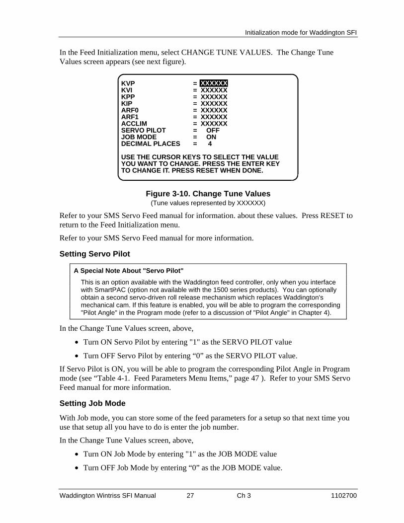
In the Feed Initialization menu, select CHANGE TUNE VALUES. The Change Tune Values screen appears (see next figure).
KVP = 321593KVI = XXXXXXKPP = XXXXXXKIP = XXXXXXARF0 = XXXXXXARF1 = XXXXXXACCLIM = XXXXXXSERVO PILOT = OFFJOB MODE = ONDECIMAL PLACES = 4
USE THE CURSOR KEYS TO SELECT THE VALUEYOU WANT TO CHANGE. PRESS THE ENTER KEYTO CHANGE IT. PRESS RESET WHEN DONE.
XXXXXX
Figure 3-10. Change Tune Values (Tune values represented by XXXXXX)
Refer to your SMS Servo Feed manual for information. about these values. Press RESET to return to the Feed Initialization menu.
Refer to your SMS Servo Feed manual for more information.
Setting Servo Pilot
A Special Note About "Servo Pilot"
This is an option available with the Waddington feed controller, only when you interface with SmartPAC (option not available with the 1500 series products). You can optionally obtain a second servo-driven roll release mechanism which replaces Waddington's mechanical cam. If this feature is enabled, you will be able to program the corresponding "Pilot Angle" in the Program mode (refer to a discussion of "Pilot Angle" in Chapter 4).
In the Change Tune Values screen, above,
• Turn ON Servo Pilot by entering "1" as the SERVO PILOT value
• Turn OFF Servo Pilot by entering “0” as the SERVO PILOT value.
If Servo Pilot is ON, you will be able to program the corresponding Pilot Angle in Program mode (see “Table 4-1. Feed Parameters Menu Items,” page 47 ). Refer to your SMS Servo Feed manual for more information.
Setting Job Mode
With Job mode, you can store some of the feed parameters for a setup so that next time you use that setup all you have to do is enter the job number.
In the Change Tune Values screen, above,
• Turn ON Job Mode by entering "1" as the JOB MODE value
• Turn OFF Job Mode by entering “0” as the JOB MODE value.

Initialization mode for Waddington SFI
Waddington Wintriss SFI Manual 28 Ch 3 1102700
Refer to your SMS Servo Feed manual for more information.
Set Number of Decimal Places
To set the number of decimal places for feed parameters, in the Change Tune Values screen, select the value next to DECIMAL PLACES. A value entry screen appears. Use the up and down cursor keys or the keypad to enter the number of decimal places, to a maximum of four. Press ENTER to accept the value and return to the Change Tune Values screen. Press RESET to return to the Change Tune Values screen.
Refer to your SMS Servo Feed manual for more information.
Changing Calibration
In the Feed Initialization menu, select CHANGE CALIBRATION. The Change Calibration screen appears:
MASTER ENG. UNITS = 6.2831SLAVE ENG. UNITS = XXXXXXJOG SPEED = XXX RPM
USE THE CURSOR KEYS TO SELECT THE VALUEYOU WANT TO CHANGE. PRESS THE ENTER KEYTO CHANGE IT. PRESS RESET WHEN DONE.
X.XXXX
Figure 3-11. Change Calibration Screen
(Values represented by “X”s)
To adjust these parameters, select the value you want to change.
In the entry box that appears, use the keypad to enter numbers. Press ENTER when you are done. Press RESET to leave the value unchanged. Refer to your SMS Servo Feed manual for more information.
Checking Setup Values
"Check setup" is a diagnostic tool available in SFI which allows you to view the feed parameters in your servo feed. It gives you an opportunity to make sure that these parameters match your currently loaded setup.
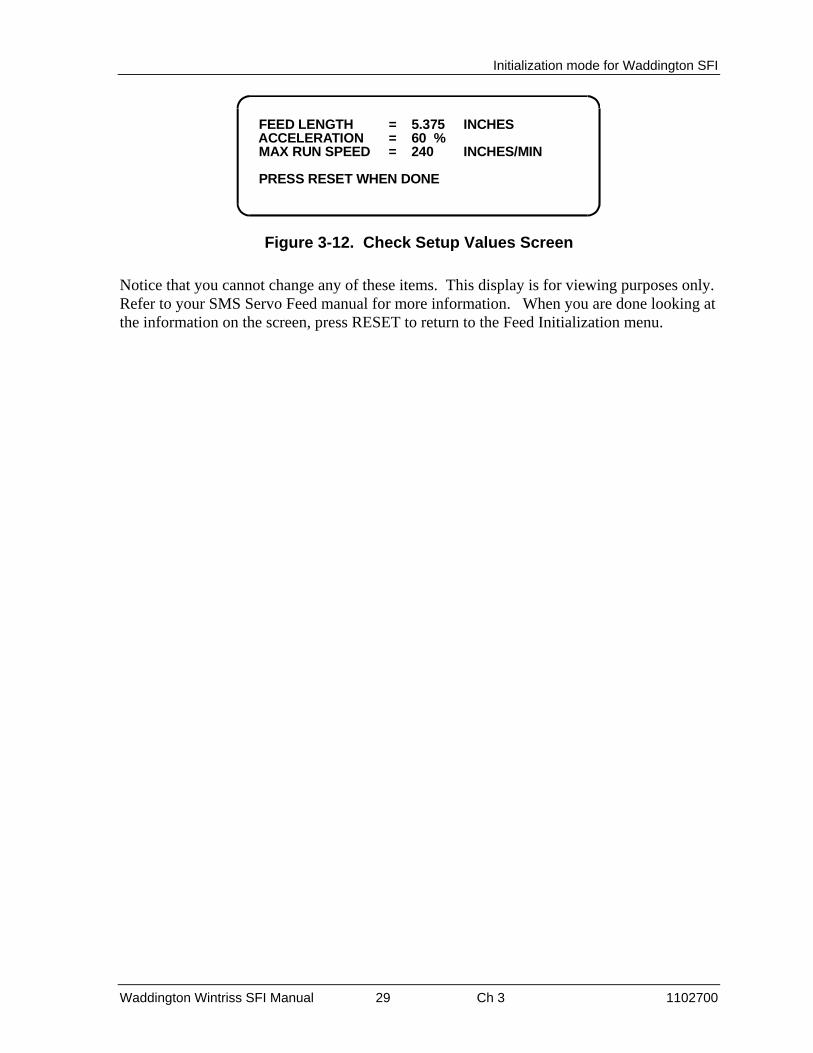
In the Feed Initialization menu (see page 20), select CHECK SETUP VALUES. The Setup Values screen appears.
Initialization mode for Waddington SFI
Waddington Wintriss SFI Manual 29 Ch 3 1102700
FEED LENGTH = 5.375 INCHES ACCELERATION = 60 % MAX RUN SPEED = 240 INCHES/MIN
PRESS RESET WHEN DONE
Figure 3-12. Check Setup Values Screen
Notice that you cannot change any of these items. This display is for viewing purposes only. Refer to your SMS Servo Feed manual for more information. When you are done looking at the information on the screen, press RESET to return to the Feed Initialization menu.

Initialization mode for Waddington SFI
Waddington Wintriss SFI Manual 30 Ch 3 1102700
Section 2 1500 Series
NOTE
Waddington SMS Servo Feed cannot be used with 1500 series controls.
About the DiPro 1500's Auto Advance and Security
With DiPro 1500, “Auto advance” and Adjust Feed "security" are not main Initialization choices. SFI was not originally offered with DiPro 1500. Therefore feed-specific selections are grouped together as a part of the Feed Initialization. “Auto Advance” and “Adjust Feed” are a sub-choice under “Feed Parameters 2”. Only DiPro 1500”s Channel 1 can be an auto channel with SFI.
Initialization menu
IMPORTANT
This manual mentions certain parameters that you can initialize at your feed. It does not, however, explain these parameters in any detail. Refer to your servo feed manual for more information.
To get into Initialization mode, turn the Program/Run key to "PROGRAM" and then press both the left and right "ANGLE-OFF" keys at the same time for one second. (See "Using the keyboard" in Chapter 3 of the applicable 1500 unit's user manual.)
NOTE
Before changing modes (for instance -- from Initialization to Program), make sure your screen shows the first display in the mode you are in. If that display is not shown, nothing will happen when you turn the Program /Run key. In that case, keep hitting the RESET key. When the first display in the mode is reached, you will instantly switch to the new mode. See your Wintriss product manual.
Feed Parameters 1
Here is the first display in Initialization mode. From this display, select "Feed parameters 1".
INITIALIZATIONMENU
RESOLVER ZEROPOSITION SENSORSELECT CAM NAMESSECURITY ACCESSFEED PARAMETERS 1FEED PARAMETERS 2
USE CURSOR KEYS TO SELECT, ENTER TOSET, SWITCH TO RUN WHEN DONE
Figure 3-13. Selecting "FEED PARAMETERS 1" from Initialization Menu

Initialization mode for Waddington SFI
Waddington Wintriss SFI Manual 31 Ch 3 1102700
SELECT = HIGHLIGHT + ENTER
When this manual says “select,” it means “use the cursor keys to highlight the item and then press ENTER.“
Once you have selected "FEED PARAMETERS 1", here is the display you will see:
FEED INITIALIZEMENU CHANGE GROUP 1
CHANGE GROUP 2CHANGE GROUP 3CHANGE GROUP 4CHECK SETUP
USE CURSOR KEYS TOSELECT, ENTER TOACCESS, PRESSRESET WHEN DONE
Figure 3-14. Feed Initialize Menu
Change Groups
When you select "CHANGE GROUP 1", you will see this group of parameters:
JOG SPEED HIGH
JOG SPEED LOW
POS. LOOP GAIN
VEL. FEED FORW.
INDEX MODE
6000.00070.000005.0000000.0 V/RPM0
USE CURSOR KEYS TO MAKE SELECTIONPRESS ENTER TO SELECT, RESET WHEN DONE
IN/MININ/MINV/REV
Figure 3-15. Change Group 1 Display
Notice that there will be actual values appearing on the screen. These values are coming directly from your servo feed. Select the item you want to change.
In our example, we have chosen "Jog speed high".

Initialization mode for Waddington SFI
Waddington Wintriss SFI Manual 32 Ch 3 1102700
6000.000
USE LEFT / RIGHT CURSORS TO SELECT DIGITSUSE UP / DOWN CURSORS TO CHANGE VALUESPRESS ENTER WHEN DONE, RESET TO CHANGE
Figure 3-16. Setting "Jog Speed High"
As the display indicates, use your left or right CURSOR keys to position the triangular-shaped pointer over the digit you wish to change. Then use the up or down CURSOR keys to increase or decrease that value. Go to Chapter 3 of the applicable 1500 unit's user manual if you are not sure how to use the CURSOR keys. When you are done, press RESET to return to the Feed Initialize menu.
If you want to change any of the other groups (2 through 4), select that item on the Feed Initialize menu and then follow the previous steps. The next illustration shows how each of these displays look.

Initialization mode for Waddington SFI
Waddington Wintriss SFI Manual 33 Ch 3 1102700
ENG. UNITS
POS. TORQUE
NEG. TORQUE
ACCEL LIMIT
DECEL LIMIT
6.283812100.0000100.0000100000.0100000.0
USE CURSOR KEYS TO MAKE SELECTIONPRESS ENTER TO SELECT, RESET WHEN DONE
%%IN/MIN/SECIN/MIN/SEC
CHANGE GROUP 2
EQ. AC / DEC
BASE SPEED
ADVANCE RATE
162838.120.0 DEG / IN / MIN
USE CURSOR KEYS TO MAKE SELECTIONPRESS ENTER TO SELECT, RESET WHEN DONE
INCHES/MIN
CHANGE GROUP 3
DECEL RATE
REG. SPEED
INDEX COMPLETE
FOLLOWING ERROR
DISTANCE FROM END
100.000031.419060.0314196.2000000.009999
USE CURSOR KEYS TO MAKE SELECTIONPRESS ENTER TO SELECT, RESET WHEN DONE
%IN/MININCHESINCHESINCHES
CHANGE GROUP 4
Figure 3-17. Illustrations of Change Groups 2 Through 4
Remember that when you are done changing parameters on any of these displays, press RESET to return to the Feed Initialize menu.
The next section will explain how to use "Check setup", which is also listed on the Feed Initialize menu.
Check Setup
When you select "Check setup", you will see this display.

Initialization mode for Waddington SFI
Waddington Wintriss SFI Manual 34 Ch 3 1102700
PRESS RESET WHEN DONE
FEED LENGTH
ACCELERATION
MAX RUN SPEED
2.25200040.000004000.000
INCHES%INCHES/MIN
Figure 3-18. Check Setup Display
"Check setup" is a diagnostic tool available in SFI which lets you view the feed parameters in your servo feed. It gives you an opportunity to make sure that these parameters match your currently loaded setup.
Notice that you cannot change any of these items. This display is for viewing purposes only.
When you are done looking at the information on the screen, press RESET to return to the Feed Initialize menu, and then one more time to go back to the main Initialization menu.
Feed Parameters 2
From the first Initialization menu display, select "Feed Parameters 2".
INITIALIZATIONMENU
RESOLVER ZEROPOSITION SENSORSELECT CAM NAMESSECURITY ACCESSFEED PARAMETERS 1FEED PARAMETERS 2
USE CURSOR KEYS TO SELECT, ENTER TOSET, SWITCH TO RUN WHEN DONE
Figure 3-19. Selecting "Feed parameters 2" from the Initialization Menu
You can use this choice to lock out "Adjust feed" so that unauthorized personnel cannot perform adjust feed settings in Run mode. You can also use it to set the advance constant and slow RPM at channel 1.

Initialization mode for Waddington SFI
Waddington Wintriss SFI Manual 35 Ch 3 1102700
Security Access
Locking Adjust Feed at ProCam 1500
To prevent unauthorized personnel from unlocking "adjust feed", you must remove the Program/Run key once ProCam is switched to Run mode. This will prevent unauthorized access into the Initialization or Program modes, so that feed settings cannot be unlocked or altered. The key has to be positioned at "PROGRAM" to get into these modes.
Select "Security access" from the Initialization menu. Select "Program and Run modes" shown to the right of the action "Adjust feed", as illustrated below. The default settings (settings made at the factory) allow this action to be made in Program and Run modes.
USE CURSOR KEYS TO CHANGE SELECTIONPRESS ENTER TO CHANGE, RESET WHEN DONE
LOAD TOOL #: ADJUST CAMS:ADJUST COUNTERS: RESET MODE: ADJUST FEED:
PROGRAM AND RUN MODESPROGRAM AND RUN MODESPROGRAM AND RUN MODESPROGRAM AND RUN MODESPROGRAM AND RUN MODES
Figure 3-20. Security Access Display
To lock out the action so it cannot be taken in Run mode, press the ENTER key. The setting is now locked out. You will see the words "Program mode only" next to the action.
You will now see this display.
USE CURSOR KEYS TO CHANGE SELECTIONPRESS ENTER TO CHANGE, RESET WHEN DONE
LOAD TOOL #: ADJUST CAMS:ADJUST COUNTERS: RESET MODE: ADJUST FEED:
PROGRAM AND RUN MODESPROGRAM AND RUN MODESPROGRAM AND RUN MODESPROGRAM AND RUN MODESPROGRAM MODE ONLY
Figure 3-21. Locking out "Adjust Feed"
The feed controller can now be adjusted in the Program mode only. If you do not want to make a change, press RESET to go back to the Initialization menu.

Initialization mode for Waddington SFI
Waddington Wintriss SFI Manual 36 Ch 3 1102700
About the DiPro 1500's Auto Advance and Security
With DiPro 1500, “Auto advance” and Adjust Feed "security" are not main Initialization choices. SFI was not originally offered with DiPro 1500. Therefore feed-specific selections are grouped together as a part of the Feed Initialization. “Auto Advance” and “Adjust Feed” are a sub-choice under “Feed Parameters 2”. Only DiPro 1500"s Channel 1 can be an auto channel with SFI.
Locking Adjust feed at DiPro 1500
To prevent unauthorized personnel from unlocking "adjust feed", you must remove the Program/Run key once DiPro is switched to Run mode. This will prevent unauthorized access into the Initialization or Program modes, so that feed settings cannot be unlocked or altered. The key has to be positioned at "program" to get into these modes. over "Program and Run Modes" shown to the right of the action "Adjust feed", as illustrated below. The default settings (settings made at the factory) allow this action to be made in Program and Run modes.
USE CURSOR KEYS TO MAKE SELECTIONPRESS ENTER TO CHANGE. RESET WHEN DONE
ADJUST FEED:ADV. CONST. CH 1: SLOW RPM:
PROGRAM AND RUN MODES0 DEG / 100 SPM100
Figure 3-22. Feed Parameter 2 Display Featuring Feed Security
To lock out the action so it cannot be taken in Run mode, press ENTER. The setting is now locked out. You will see the words "Program mode only" next to the action.
The feed controller can now be adjusted in the Program mode only. If you do not want to make a change, simply press RESET to go back to the Initialization menu.
Auto Advance and Slow RPM in DiPro 1500
Determining the Advance Constant for DiPro 1500's Channel 1 Automatic Speed Compensation
You use this choice in the Initialization menu to set an auto advance constant for the press auto advance function for cam channel 1. Some cam functions that may use auto advance are feed advance or pilot release. This feature works best on presses that have speed ranges of several hundred to over a thousand strokes per minute. Advance constant is equal to the number of degrees of advance per 100 RPM increase in press speed

Initialization mode for Waddington SFI
Waddington Wintriss SFI Manual 37 Ch 3 1102700
A.C. = # °/100 RPM
To calculate the auto advance constant for pilot release, follow these steps:
1. Determine the fastest press speed (RPMa) and the optimum angle at which the pilot release cam should turn on at this speed (Aa).
2. Determine the slowest press speed (RPMb) and the optimum angle at which the pilot release cam should turn on at this speed (Ab).
3. Subtract the two angle values. We will call this result "Ac".
Aa - Ab = Ac
4. Subtract the two press speeds. We will call this result "RPMc".
RPMa - RPMb = RPMc
5. Divide Ac (the difference between the angles) by RPMc (the difference between the press speeds), and multiply that value by 100. That is the number of degrees per 100 RPM.
Ac x 100 = # ° / 100 RPM
RPMc
Example for calculating the auto advance setting:
Your fastest speed is 100 RPM and the pilot release angle is at 75°.
Your slowest speed is 50 RPM and the pilot release angle is at 100°.
Subtract 100 RPM from 50 RPM.
100 - 50 = 50
Subtract 100° from 75°.
100 - 75 = 25
Divide the difference in angles by the difference in RPM, and multiply this by 100. 50° is your advance constant.
25 x 100 = 50.00 ==> 50° / 100 RPM
50

Initialization mode for Waddington SFI
Waddington Wintriss SFI Manual 38 Ch 3 1102700
MORE ON ADVANCE CONSTANT SETTINGS
You can make only one advance constant setting. This advance constant that you set in Initialization will automatically affect channel 1, but it will not be displayed as an "auto" setting in Program or Run modes.
If you do not wish to use the Auto Advance feature function, you must leave the "advance constant" value equal to zero (0).
Auto Advance does not function if channel 1 had been programmed as a "timed output".
See Chapter 5 in the DiPro 1500 user manual for more information about making cam channel settings.
IMPORTANT TO SET SLOW RPM
When you determine the correct auto advance constant, you also need to identify the "Slow RPM", or the slowest speed at which you will run your press. DiPro uses that value as a starting point to begin the auto advance process. If an incorrect number had been entered in "slow RPM", DiPro will not begin to auto advance at the right time. In our example, slow RPM should be set to 50.
Setting the advance constant and slow RPM for DiPro 1500
Select "ADV. CONST. CH 1" by moving the highlight bar to the second line of the "Feed parameters 2" display and then pressing ENTER (see below). Notice that the prompt at the bottom of the screen has changed.
USE CURSOR KEYS TO CHANGE ADVANCE CONST.PRESS RESET WHEN DONE
ADJUST FEED:ADV. CONST. CH 1: SLOW RPM:
PROGRAM AND RUN MODES0 DEG / 100 SPM0
Figure 3-23. Setting Advance Constant at Channel 1
To set "ADV. CONST. CH. 1", simply use the up or down CURSOR keys on your DiPro 1500 keypad. The range for this value is from 0-500.
To set "SLOW RPM", move the highlight bar to the third line of the "FEED PARAMETERS 2" display, and then press ENTER. Here again, the prompt at the bottom of the screen has changed and now reads: "USE CURSOR KEYS TO CHANGE SLOW RPM. PRESS RESET WHEN DONE". As before, use the up or down CURSOR keys on your DiPro 1500 keypad. The range for this value is from 0-2000. Notice that the number increases or decreases in multiples of 5.

Waddington Wintriss SFI Manual 39 Ch 4 1102700
Chapter 4 - Program mode for Waddington SFI
In this chapter you will learn how to use the Waddington SFI menus in Program mode. These functions include:
• Setting feed length
• Setting percent acceleration
• Setting maximum run speed
• Setting pilot angle (optional)
• Using the Feed Advisor
• Loading feed settings
The chapter is divided into two sections, one for SmartPAC (next page), the other for 1500 series Wintriss controls (page 49). Refer also to the manual of your Wintriss product.
IMPORTANT
Refer to Waddington Servo Feed Manual
This manual mentions certain parameters that you can modify at your Waddington servo feed control. It does not, however, explain these parameters in great detail. Refer to your Waddington servo feed manual for more information.
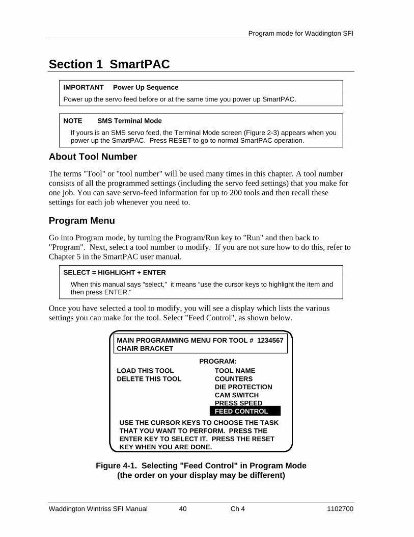
Program mode for Waddington SFI
Waddington Wintriss SFI Manual 40 Ch 4 1102700
Section 1 SmartPAC
IMPORTANT Power Up Sequence
Power up the servo feed before or at the same time you power up SmartPAC.
NOTE SMS Terminal Mode
If yours is an SMS servo feed, the Terminal Mode screen (Figure 2-3) appears when you power up the SmartPAC. Press RESET to go to normal SmartPAC operation.
About Tool Number
The terms "Tool" or "tool number" will be used many times in this chapter. A tool number consists of all the programmed settings (including the servo feed settings) that you make for one job. You can save servo-feed information for up to 200 tools and then recall these settings for each job whenever you need to.
Program Menu
Go into Program mode, by turning the Program/Run key to "Run" and then back to "Program". Next, select a tool number to modify. If you are not sure how to do this, refer to Chapter 5 in the SmartPAC user manual.
SELECT = HIGHLIGHT + ENTER
When this manual says “select,” it means “use the cursor keys to highlight the item and then press ENTER.“
Once you have selected a tool to modify, you will see a display which lists the various settings you can make for the tool. Select "Feed Control", as shown below.
USE THE CURSOR KEYS TO CHOOSE THE TASKTHAT YOU WANT TO PERFORM. PRESS THEENTER KEY TO SELECT IT. PRESS THE RESETKEY WHEN YOU ARE DONE.
TOOL NAMECOUNTERSDIE PROTECTIONCAM SWITCHPRESS SPEEDFEED CONTROLFEED CONTROL
LOAD THIS TOOLDELETE THIS TOOL
PROGRAM:
MAIN PROGRAMMING MENU FOR TOOL # 1234567CHAIR BRACKET
Figure 4-1. Selecting "Feed Control" in Program Mode (the order on your display may be different)

Program mode for Waddington SFI
Waddington Wintriss SFI Manual 41 Ch 4 1102700
If you have a MiniFeed servo feed, follow the instructions in the next section.
If you have an SMS servo feed, follow the instructions that start on page 46.
Programming the SmartPAC/Waddington MiniFeed Servofeed
Here is the "Feed Parameters" display. You have up to five choices. Note that the optional "Pilot angle" ONLY appears if you have enabled "servo pilot" in SmartPAC Initialization mode. See Chapter 3 for details. If you have this option, enter the angle at which the pilots for the optional servo-driven roll release will actuate. Refer to your Waddington manual for specifics.
FEED PARAMETERS
FEED LENGTHACCELERATIONMAX RUN SPEEDPILOT ANGLEFEED ADVISOR
2.25210
2,70095
INCHES%IN / MINDEGREES
USE THE CURSOR KEYS TO SELECT THE VALUEYOU WANT TO CHANGE. PRESS THE ENTER KEYTO CHANGE IT. PRESS RESET WHEN DONE.
Select any of these itemsto get the superimposednumber display to makechanges to these values2.252
This option appears ONLYwhen you have enabled"servo pilot" in SmartPACInitialization mode(see Chapter 3)
Figure 4-2. Feed Settings
Read your servo feed manual first
Consult the Waddington servo feed manual for any requirements you must meet for feed length and other settings. Remember, SmartPAC does not change the way the servo feed operates or any parameters or limitations built into your servo feed. Be sure you have read the manual and understand how your servo feed works before making any settings.
Feed parameters
When you select "Feed length", a number display appears over the Feed Parameters screen that allows you to set this value. This display is similar to Figure 4-4.
As explained previously, use the number keys to input numeric values for SFI parameters. When you are done entering a number using the number keypad, press ENTER. SmartPAC will accept the number and move on to the next display. SmartPAC accepts numbers up to seven digits in length. Go to Chapter 3 of the SmartPAC user manual if you are not sure how to use the number display.

Program mode for Waddington SFI
Waddington Wintriss SFI Manual 42 Ch 4 1102700
If you wish to leave this screen without making a change, press Reset.
When you select any of the remaining feed parameters, the same number display will appear. If you have and plan to use Feed Advisor, you do not need to set acceleration rate and maximum run speed. Be sure to read your servo feed manual before making feed settings.
MORE ABOUT YOUR SERVO FEED SETTINGS
The acceleration rate governs how fast the servo feed will accelerate to its set run speed. Your servo feed has a built-in maximum acceleration. The acceleration rate is a percentage of this maximum. For instance, a setting of 80% means the servo feed will accelerate to run speed at 80% of its maximum capability. Refer to your servo feed manual for more information about the acceleration rate. Follow all guidelines given there when making acceleration rate settings.
Maximum Run speed is usually stated as inches/min. Follow all guidelines in the servo feed manual to make proper settings for run speed.
Keep in mind that you can optionally use the Feed Advisor (see below) to automatically calculate the acceleration rate for you.
Using Feed Advisor
Select "Feed Advisor" when you want SmartPAC SFI to figure out the acceleration rate and maximum run speed for you.
Feed Advisor is a convenience which saves you the time of calculating the acceleration rate yourself. You need to enter feed length, feed arc (number of crankshaft degrees available to fully feed the material), and press speed when using Feed Advisor. The acceleration rate and run speed is calculated assuming the lowest acceleration rate to fully feed the material by the end of the feed arc. When determining this rate, take into consideration the feed initiate angle, which may be programmed as one of the cam timings in SmartPAC (not SFI).
Here is an example of a situation to avoid. If a 225 degree feed arc is assumed in the Feed Advisor but only 220 degrees is truly available to be fed up, punch engagement may occur before the feed is complete and a die crash may occur. Make sure that you know the actual number of degrees needed to feed up the material and that the feed initiate angle is correctly set.
Here is how Feed Advisor works with the information that you provided to it. Let's say your feed length is 2.252 inches. Also, let's say the number of degrees you have to feed in is 225° with the feed initiate ON angle set at 260°, and the press speed is 150 SPM. You want Feed Advisor to figure out the acceleration rate based upon these values.
How to use Feed Advisor
Select "Feed Advisor" on the "Feed Control" display (see below). Select each item on the screen — Feed length, acceleration, and maximum run speed (and Pilot angle if available); then enter new values. The number display looks similar to that which is pictured at Figure
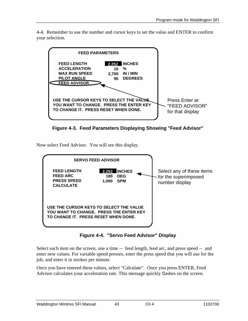
Program mode for Waddington SFI
Waddington Wintriss SFI Manual 43 Ch 4 1102700
4-4. Remember to use the number and cursor keys to set the value and ENTER to confirm your selection.
FEED PARAMETERS
FEED LENGTHACCELERATIONMAX RUN SPEEDPILOT ANGLEFEED ADVISOR
2.25210
2,70095
INCHES%IN / MINDEGREES
USE THE CURSOR KEYS TO SELECT THE VALUEYOU WANT TO CHANGE. PRESS THE ENTER KEYTO CHANGE IT. PRESS RESET WHEN DONE.
Press Enter at"FEED ADVISOR"for that display
2.252
Figure 4-3. Feed Parameters Displaying Showing "Feed Advisor"
Now select Feed Advisor. You will see this display.
SERVO FEED ADVISOR
FEED LENGTHFEED ARCPRESS SPEEDCALCULATE
2.252180
1,000
INCHESDEGSPM
USE THE CURSOR KEYS TO SELECT THE VALUEYOU WANT TO CHANGE. PRESS THE ENTER KEYTO CHANGE IT. PRESS RESET WHEN DONE.
Select any of these itemsfor the superimposednumber display
2.252
Figure 4-4. "Servo Feed Advisor" Display
Select each item on the screen, one a time -- feed length, feed arc, and press speed -- and enter new values. For variable speed presses, enter the press speed that you will use for the job, and enter it in strokes per minute.
Once you have entered these values, select "Calculate". Once you press ENTER, Feed Advisor calculates your acceleration rate. This message quickly flashes on the screen.

Program mode for Waddington SFI
Waddington Wintriss SFI Manual 44 Ch 4 1102700
SERVO FEED ADVISOR
FEED LENGTHFEED ARCPRESS SPEEDCALCULATE
0.000180
1,000
INCHESDEGSPM
USE THE CURSOR KEYS TO SELECT THE VALUEYOU WANT TO CHANGE. PRESS THE ENTER KEYTO CHANGE IT. PRESS RESET WHEN DONE.
Press Enter at"CALCULATE"for SmartPACto compute theseservo feedparametersautomatically
PLEASE WAIT… CALCULATING VALUES
Figure 4-5. Selecting "Calculate" on the Servo Feed Advisor Display
Then Feed Advisor tells you if the feed length and feed arc you entered are valid for that press speed. For instance, if Feed Advisor determines that the feed has plenty of time to complete based on the values entered, you will see this message at the bottom of the "Feed Advisor" screen:
THE MATERIAL WILL BE FED UP WELL BEFORE THE FEED ARC IS COMPLETED.
This means that the feed will end well before the end of the feed arc you have entered even when it was operating at the lowest speed specified in Initialization.
If you see this message:
THE MATERIAL WILL BE FED UP JUST AS THE FEED ARC IS COMPLETED.
… this means that the feed will end just as the feed arc is completed. This is the optimum condition because feed never had to reach the maximum speed specified in Initialization.
If you entered values that will not allow the feed to complete before the end of the feed arc, you see this message:
THE MATERIAL CANNOT BE FED UP IN TIME. MORE TIME MUST BE ALLOWED.
In this case, recheck your values. It might just be a matter of lengthening the feed arc if that will not affect other actions, such as part transfer or part cut off. If you choose to lengthen the arc, make sure that you reprogram the cam angle to initiate the feed earlier. If you cannot do that, your other option is decreasing press speed. In any case, revise your figures if SmartPAC gives you a warning. Then "calculate" Feed Advisor again.
When you get a good calculation, press RESET. You will see the acceleration rate and maximum run speed for your feed setup are automatically revised by Feed Advisor. In our

Program mode for Waddington SFI
Waddington Wintriss SFI Manual 45 Ch 4 1102700
example, the acceleration rate is 40%. This means that the feed is comfortably within an acceptable acceleration range and maximum run speed.
FEED PARAMETERS
FEED LENGTHACCELERATIONMAX RUN SPEEDPILOT ANGLEFEED ADVISOR
2.25240
5,31395
INCHES%IN / MINDEGREES
USE THE CURSOR KEYS TO SELECT THE VALUEYOU WANT TO CHANGE. PRESS THE ENTER KEYTO CHANGE IT. PRESS RESET WHEN DONE.
2.252
Figure 4-6. New Feed Parameters Created by Feed Advisor
ABOUT USING FEED ADVISOR
You can use Feed Advisor any time that you want SmartPAC to calculate the acceleration rate and maximum run speed for you. If you want to manually enter your own feed parameters, select "Acceleration" and "Max run speed" on the "Feed Parameters" screen.
Remember to program the "Feed Initiate angle" as the "on" angle of the "Feed Advance" cam in SmartPAC ProCamPAC!
Load by tool number
You can automatically load feed settings in SmartPAC by tool number. To load a tool number, press Reset twice, the first time to exit from the "Feed parameters" display and then again to get to the "Load tool number" screen. Press ENTER to load (or Reset to back out). You will get a message like this one which confirms that you have successfully loaded the tool (your tool number may be different):
PLEASE WAIT … LOADING TOOL 1
How to load by tool numbers is covered in detail in Chapter 5 (Program mode) and Chapter 6 (Run mode) of the SmartPAC user manual.

Program mode for Waddington SFI
Waddington Wintriss SFI Manual 46 Ch 4 1102700
Programming SmartPAC/Waddington SMS Servofeed
In Program mode (see your SmartPAC manual) select PROGRAM OR LOAD TOOL NUMBER. The Tool List screen appears. Select the tool number you want to program. The Main Programming menu for that tool appears. Select FEED CONTROL. A display appears, similar to one of the displays in the next figure, depending on the settings you made in Initialization for Job Mode and Servo Pilot.
FEED PARAMETERS
FEED LENGTH 0.000 INCHESACCELERATION 0 %MAX RUN SPEED 0 IN/MINFEED ADVISORTERMINAL MODE
USE THE CURSOR KEYS TO SELECT THE VALUEYOU WANT TO CHANGE. PRESS THE ENTER KEYTO CHANGE IT. PRESS RESET WHEN DONE.
0.000
JOB MODE OFFSERVO PILOT ON
JOB MODE ONSERVO PILOT OFF
JOB MODE OFFSERVO PILOT OFF
FEED PARAMETERS
JOB NUMBER 0TERMINAL MODE
USE THE CURSOR KEYS TO SELECT THE VALUEYOU WANT TO CHANGE. PRESS THE ENTER KEYTO CHANGE IT. PRESS RESET WHEN DONE.
0
FEED PARAMETERS
FEED LENGTH 0.000 INCHESACCELERATION 0 %PILOT ANGLE 0 DEGREESMAX RUN SPEED 0 IN/MINFEED ADVISORTERMINAL MODE
USE THE CURSOR KEYS TO SELECT THE VALUEYOU WANT TO CHANGE. PRESS THE ENTER KEYTO CHANGE IT. PRESS RESET WHEN DONE.
0.000
FEED PARAMETERS
JOB NUMBER 2 INCHESPILOT ANGLE 0 DEGREESTERMINAL MODE
USE THE CURSOR KEYS TO SELECT THE VALUEYOU WANT TO CHANGE. PRESS THE ENTER KEYTO CHANGE IT. PRESS RESET WHEN DONE.
2 JOB MODE ONSERVO PILOT ON
Figure 4-7. SMS Feed Parameters Displays (SmartPAC)
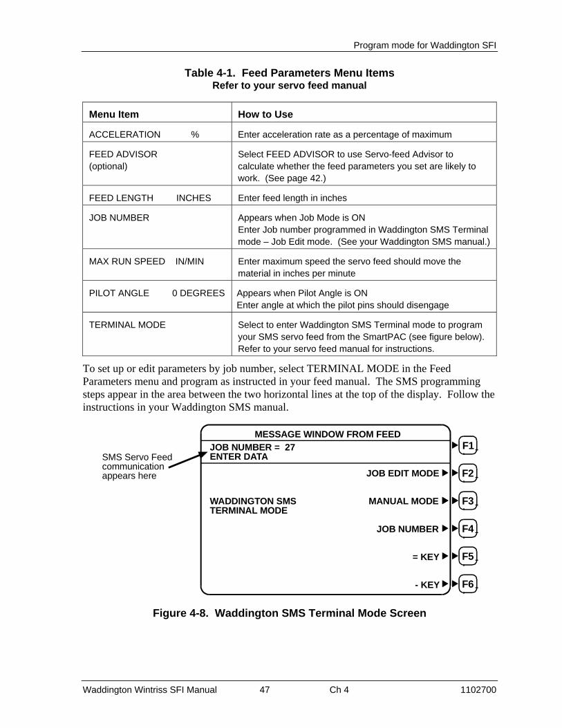
Program mode for Waddington SFI
Waddington Wintriss SFI Manual 47 Ch 4 1102700
Table 4-1. Feed Parameters Menu Items Refer to your servo feed manual
Menu Item How to Use
ACCELERATION % Enter acceleration rate as a percentage of maximum
FEED ADVISOR (optional)
Select FEED ADVISOR to use Servo-feed Advisor to calculate whether the feed parameters you set are likely to work. (See page 42.)
FEED LENGTH INCHES Enter feed length in inches
JOB NUMBER Appears when Job Mode is ON Enter Job number programmed in Waddington SMS Terminal mode – Job Edit mode. (See your Waddington SMS manual.)
MAX RUN SPEED IN/MIN Enter maximum speed the servo feed should move the material in inches per minute
PILOT ANGLE 0 DEGREES Appears when Pilot Angle is ON Enter angle at which the pilot pins should disengage
TERMINAL MODE Select to enter Waddington SMS Terminal mode to program your SMS servo feed from the SmartPAC (see figure below). Refer to your servo feed manual for instructions.
To set up or edit parameters by job number, select TERMINAL MODE in the Feed Parameters menu and program as instructed in your feed manual. The SMS programming steps appear in the area between the two horizontal lines at the top of the display. Follow the instructions in your Waddington SMS manual.
MESSAGE WINDOW FROM FEED
JOB NUMBER = 27ENTER DATA
JOB EDIT MODE
WADDINGTON SMS MANUAL MODETERMINAL MODE
JOB NUMBER
= KEY
- KEY F6
F5
F4
F3
F2
F1SMS Servo Feedcommunicationappears here
Figure 4-8. Waddington SMS Terminal Mode Screen

Program mode for Waddington SFI
Waddington Wintriss SFI Manual 48 Ch 4 1102700
Load by Tool Number
You can automatically load feed settings in SmartPAC by tool number. To load a tool number, press Reset twice, the first time to exit from the "Feed parameters" display and then again to get to the "Load tool number" screen. Press ENTER to load (or RESET to back out). You will get a message like this one which confirms that you have successfully loaded the tool (your tool number may be different):
PLEASE WAIT … LOADING TOOL 1
How to load by tool numbers is covered in detail in Chapter 5 (Program mode) and Chapter 6 (Run mode) of the SmartPAC user manual.

Program mode for Waddington SFI
Waddington Wintriss SFI Manual 49 Ch 4 1102700
Section 2 1500 Series
About Tool Number
The terms "Tool" or "tool number" will be used many times in this chapter. A tool number consists of all the programmed settings (including the servo feed settings) that you make for one job. You can save servo-feed information for up to 200 tools and then recall these settings for each job whenever you need to.
Program menu
Go into Program mode, by turning the Program/Run key to "Run" and then back to "Program". Next, select a tool number to modify, and then select "Modify the tool number information". If you are not sure how to do this, refer to Chapter 5 in the applicable 1500 unit's user manual.
SELECT = HIGHLIGHT + ENTER
When this manual says “select,” it means “use the cursor keys to highlight the item and then press ENTER.“
Once you have selected a tool to modify, you will see a display which lists the various settings you can make for the tool. Select "Set feed", as shown below.
TOOL #1 SET COUNTERSSET CAMSSET FEEDSET BATCH MODESET COUNTER ANGLE
USE CURSOR KEYS TO CHANGE SELECTIONPRESS ENTER TO SELECT, RESET WHEN DONE
Figure 4-9. Selecting "Set feed" in Program Mode
Here is the "SET FEED" display (below). You have up to four choices.
FEED LENGTH
ACCELERATION
MAX RUN SPEED
FEED ADVISOR
2.25210
1,155
USE CURSOR KEYS TO MAKE SELECTIONPRESS ENTER TO SELECT, RESET WHEN DONE
INCHES%IN/MIN
FEED PARAMETERS FOR TOOL #1
Figure 4-10. Feed Settings

Program mode for Waddington SFI
Waddington Wintriss SFI Manual 50 Ch 4 1102700
Feed settings
When you select "Feed length", a new display appears that allows you to set this value. See the next illustration.
0002.252
USE LEFT / RIGHT CURSORS TO SELECT DIGITSUSE UP / DOWN CURSORS TO CHANGE VALUESPRESS ENTER WHEN DONE, RESET TO CANCEL
FEED LENGTH
Figure 4-11. Setting Feed Length
As the display indicates, use the left and right, as well as the up and down CURSOR keys. Press the left and right CURSOR keys to position the triangular-shaped pointer over the desired digit, and then press the up and down CURSOR keys to increase or decrease the value, one step at a time. If you need assistance, Chapter 3 in the applicable 1500 unit's user manual explains how to use these keys. When you are satisfied with the value, press ENTER. However, if you wish to leave this screen without making a change, press RESET.
When you select either of the other two feed parameters - - "Acceleration" or "Maximum run speed", the display is similar to "Set Feed length", and the instructions at the bottom of the screen are identical. The next illustration shows the other two screens. If you have and plan to use Feed Advisor (see page 42.), you do not need to set acceleration rate and maximum run speed. Remember! Read your servo feed manual before making feed settings!
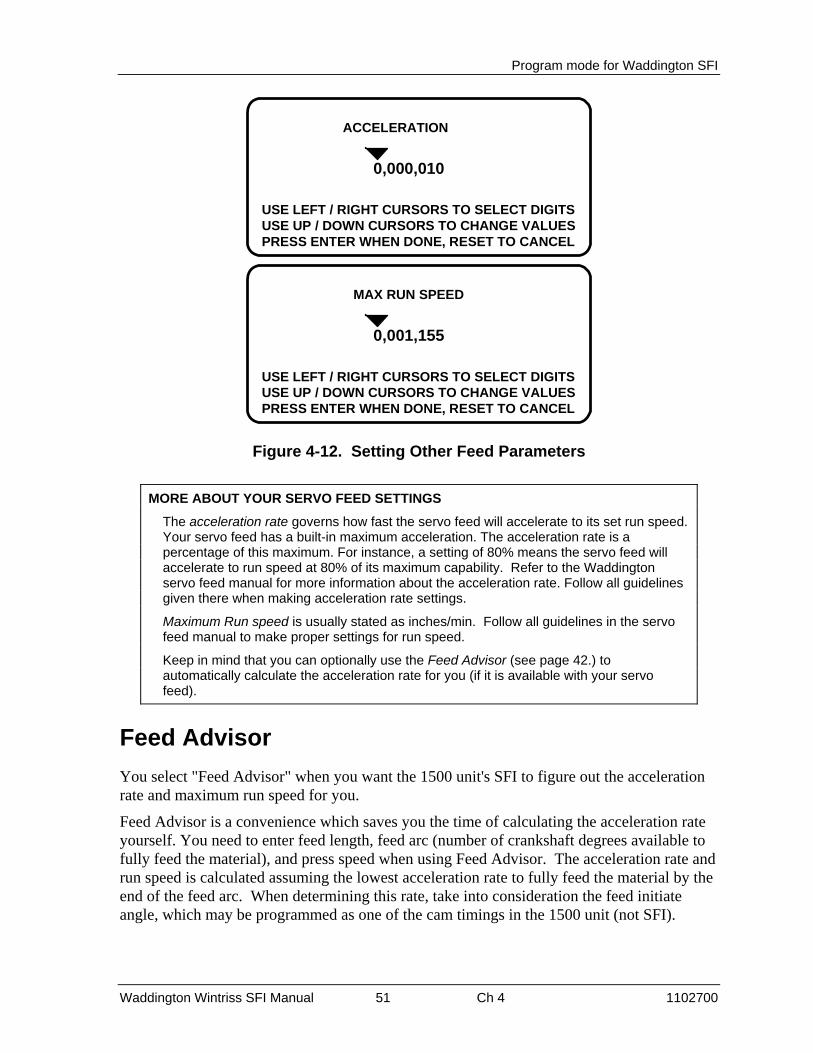
Program mode for Waddington SFI
Waddington Wintriss SFI Manual 51 Ch 4 1102700
0,000,010
USE LEFT / RIGHT CURSORS TO SELECT DIGITSUSE UP / DOWN CURSORS TO CHANGE VALUESPRESS ENTER WHEN DONE, RESET TO CANCEL
ACCELERATION
0,001,155
USE LEFT / RIGHT CURSORS TO SELECT DIGITSUSE UP / DOWN CURSORS TO CHANGE VALUESPRESS ENTER WHEN DONE, RESET TO CANCEL
MAX RUN SPEED
Figure 4-12. Setting Other Feed Parameters
MORE ABOUT YOUR SERVO FEED SETTINGS
The acceleration rate governs how fast the servo feed will accelerate to its set run speed. Your servo feed has a built-in maximum acceleration. The acceleration rate is a percentage of this maximum. For instance, a setting of 80% means the servo feed will accelerate to run speed at 80% of its maximum capability. Refer to the Waddington servo feed manual for more information about the acceleration rate. Follow all guidelines given there when making acceleration rate settings.
Maximum Run speed is usually stated as inches/min. Follow all guidelines in the servo feed manual to make proper settings for run speed.
Keep in mind that you can optionally use the Feed Advisor (see page 42.) to automatically calculate the acceleration rate for you (if it is available with your servo feed).
Feed Advisor
You select "Feed Advisor" when you want the 1500 unit's SFI to figure out the acceleration rate and maximum run speed for you.
Feed Advisor is a convenience which saves you the time of calculating the acceleration rate yourself. You need to enter feed length, feed arc (number of crankshaft degrees available to fully feed the material), and press speed when using Feed Advisor. The acceleration rate and run speed is calculated assuming the lowest acceleration rate to fully feed the material by the end of the feed arc. When determining this rate, take into consideration the feed initiate angle, which may be programmed as one of the cam timings in the 1500 unit (not SFI).

Program mode for Waddington SFI
Waddington Wintriss SFI Manual 52 Ch 4 1102700
Here is an example of a situation to avoid. If a 225 degree feed arc is assumed in the Feed Advisor but only 220 degrees is truly available to be fed up, punch engagement may occur before the feed is complete and a die crash may occur. Make sure that you know the actual number of degrees needed to feed up the material and that the feed initiate angle is correctly set.
Here is how Feed Advisor works with the information that you provided to it. Let's say your feed length is 2.252 inches. Also, let's say the number of degrees you have to feed in is 225° with the feed initiate ON angle set at 260°, and the press speed is 150 SPM. You want Feed Advisor to figure out the acceleration rate based upon these values.
How to use Feed Advisor
Select "Feed Advisor" on the "Set feed" display. Select each item on the screen, one a time -- feed length, feed arc, and press speed -- and enter new values. For instance, when you select "Feed length" and enter 2.252, here is how the screen will look (below). Remember to use your left/right and up/down CURSOR keys to set the value and ENTER to enter it.
0002.252
USE LEFT / RIGHT CURSORS TO SELECT DIGITSUSE UP / DOWN CURSORS TO CHANGE VALUESPRESS ENTER WHEN DONE, RESET TO CANCEL
FEED LENGTH
Figure 4-13. Setting Feed Length in Feed Advisor
Now do the same for "Feed arc" and "Press speed". Select "Feed arc", and enter 225. Then select "Press speed" and enter 150. Keep in mind for variable speed presses, enter the press speed that you will use for the job, and enter it in strokes per minute.
Once you have entered these values, here is how the "Feed Advisor" will display them:
FEED LENGTHFEED ARC
PRESS SPEED
CALCULATE
2.252 INCHESDEGREESSPM
SERVO-FEED ADVISOR
225150
Figure 4-14. Feed Advisor Display

Program mode for Waddington SFI
Waddington Wintriss SFI Manual 53 Ch 4 1102700
Now select "Calculate". Once you press ENTER, Feed Advisor calculates your acceleration rate. This message quickly flashes on the screen.
PLEASE WAIT … CALCULATING PARAMETERS
Then Feed Advisor tells you if the feed length and feed arc you entered are valid for that press speed. For instance, if Feed Advisor determines that the feed has plenty of time to complete based on the values entered, you will see this message at the bottom of the "Feed Advisor" screen:
THE MATERIAL WILL BE FED UP WELL BEFORE THE FEED ARC IS COMPLETED.
This means that the feed will end well before the end of the feed arc you have entered.
If you see this message:
THE MATERIAL WILL BE FED UP JUST AS THE FEED ARC IS COMPLETED.
… this means that the feed will end just as the feed arc is completed. This is the optimum condition. If you entered values that will not allow the feed to complete before the end of the feed arc, you see this message:
THE MATERIAL CANNOT BE FED UP IN TIME. MORE TIME MUST BE ALLOWED.
In this case, recheck your values. It might just be a matter of lengthening the feed arc if that will not affect other actions, such as part transfer or part cut off. If you cannot do that, your other option is decreasing press speed. In any case, revise your figures if the 1500 unit gives you a warning. Then "calculate" Feed Advisor again.
When you get a good calculation, press RESET. You will see the acceleration rate and maximum run speed for your feed setup are automatically revised by Feed Advisor. In our example below, the acceleration rate is 40%. This means that the feed is comfortably within an acceptable acceleration range and maximum run speed.
FEED LENGTHACCELERATION
MAX RUN SPEED
FEED ADVISOR
2.252
USE CURSOR KEYS TO MAKE SELECTIONPRESS ENTER TO SELECT, RESET WHEN DONE
INCHES%IN/MIN
FEED PARAMETERS FOR TOOL #1
405,313
Figure 4-15. New Feed Parameters Created by Feed Advisor

Program mode for Waddington SFI
Waddington Wintriss SFI Manual 54 Ch 4 1102700
ABOUT USING FEED ADVISOR
You can use Feed Advisor any time that you want the 1500 unit to calculate the acceleration rate and maximum run speed for you. If you want to manually enter your own feed parameters, select "Acceleration" and "Max run speed" on the "Feed Parameters" screen.
Remember to program the "Feed Initiate angle" as the "on" angle of the "Feed Advance" cam in the 1500 unit!
Load by tool number
You can automatically load feed settings:1500 by tool number. To load a tool number, press RESET twice, the first time to exit from the "Feed parameters" display and then again to get to the "Load tool number" screen. Press ENTER to load (or RESET to back out). You will get a message like this one which confirms that you have successfully loaded the tool (your tool number may be different):
PLEASE WAIT … LOADING TOOL 1
How to load by tool numbers is covered in Chapters 5 (Program mode) and 6 (Run mode) of the applicable 1500 unit's user manual.

Waddington Wintriss SFI Manual 55 Ch 5 1102700
Chapter 5 - Run Mode for Waddington SFI
In this chapter you will learn how to use the Waddington SFI menus in Run mode. Specifically you will adjust feed parameters while operating the press.
Each of these sections provides you with detail on operating the Waddington servo feed with the applicable Wintriss control. If you need more assistance in using the Wintriss product, refer to its user manual.
Read your servo feed manual first
Consult your servo feed manual for any requirements you must meet for feed length and other settings. Remember, the Wintriss control does not change the way your servo feed operates or any parameters or limitations built into your servo feed. Be sure you have read your servo feed manual and understand how your servo feed works before making any settings.
The chapter is divided into two sections, one for SmartPAC (next page), the other for 1500 series Wintriss controls (page 59). Refer also to the manual of your Wintriss product.

Run mode for Waddington SFI
Waddington Wintriss SFI Manual 56 Ch 5 1102700
Section 1 SmartPAC
About Tool numbers
The terms "Tool" or "tool number" will be used many times in this chapter. A tool number consists of all of the settings (including the servo feed settings) that you make for one job. You can save servo feed information for up to 200 tools and then recall the settings for each job whenever you need to.
Entering Run Mode
To use Run mode, turn the Program/Run key to "Run", and you will see the following screen.
USE CURSOR KEYS TOMAKE SELECTIONS.PRESS ENTER TO ACCESSSELECTION.
DISABLE SENSORSCOUNTERSBRAKE MONITORDIE PROTECTIONCAM SWITCHPRESS SPEEDFEED CONTROLLOAD NEW TOOL
TOOL NUMBER 1234567CHAIR BRACKETCRITICAL ANGLE 0
SENSOR 1PART EJECTIONGREEN ESTOP
FEED CONTROL
Figure 5-1. Run Menu (The order of items may be different, depending on which options you have)
• Operate the MiniFeed servo feed according to the instructions below.
• Operate the SMS servo feed according to the instructions on page 58.
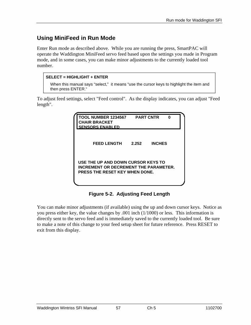
Run mode for Waddington SFI
Waddington Wintriss SFI Manual 57 Ch 5 1102700
Using MiniFeed in Run Mode
Enter Run mode as described above. While you are running the press, SmartPAC will operate the Waddington MiniFeed servo feed based upon the settings you made in Program mode, and in some cases, you can make minor adjustments to the currently loaded tool number.
SELECT = HIGHLIGHT + ENTER
When this manual says “select,” it means “use the cursor keys to highlight the item and then press ENTER.“
To adjust feed settings, select "Feed control". As the display indicates, you can adjust "Feed length".
FEED LENGTH INCHES
USE THE UP AND DOWN CURSOR KEYS TOINCREMENT OR DECREMENT THE PARAMETER.PRESS THE RESET KEY WHEN DONE.
TOOL NUMBER 1234567 PART CNTR 0CHAIR BRACKETSENSORS ENABLED
2.252
Figure 5-2. Adjusting Feed Length
You can make minor adjustments (if available) using the up and down cursor keys. Notice as you press either key, the value changes by .001 inch (1/1000) or less. This information is directly sent to the servo feed and is immediately saved to the currently loaded tool. Be sure to make a note of this change to your feed setup sheet for future reference. Press RESET to exit from this display.

Run mode for Waddington SFI
Waddington Wintriss SFI Manual 58 Ch 5 1102700
Using the SMS Servo Feed in Run Mode
While you are running the press, SmartPAC will operate with the SMS servo feed based upon the settings you made in Program mode, and in some cases, you can make minor adjustments to the currently loaded tool number.
Enter Run mode as described on page 56. A screen similar to following appears.
USE CURSOR KEYS TOMAKE SELECTIONS.PRESS ENTER TO ACCESSSELECTION.
DISABLE SENSORSCOUNTERSBRAKE MONITORDIE PROTECTIONCAM SWITCHPRESS SPEEDFEED CONTROLLOAD NEW TOOL
TOOL NUMBER 1234567CHAIR BRACKETCRITICAL ANGLE 0
SENSOR 1PART EJECTIONGREEN ESTOP
FEED CONTROL
Figure 5-3. Run Menu (The items and their order may be different, depending on which options you have)
To adjust feed settings, select "Feed control". Depending on your settings, you can then adjust one or more of the parameters shown.
TOOL NUMBER 750 PART CNTR 0CHAIR BRACKET TWO HANDSENSORS ENABLED
FEED LENGTH 321593 INCHESPILOT ANGLE 109 DEGREESINDEX NUMBER 1
USE THE UP AND DOWN CURSOR KEYS TOCHOOSE THE PARAMETER YOU WISH TO ADJUST.PRESS THE ENTER KEY TO SELECT IT.PRESS THE RESET KEY WHEN DONE.
6
Figure 5-4. Feed Control Display in Run Mode
(Your display may look different, depending on your feed control settings.)
Select the parameter value you want to change. Follow the instructions on the display for changing the value, either using the up and down cursor keys or keying in the new value. This information is sent directly to the servo feed and is immediately saved to the currently loaded tool. Be sure to make a note of this change on your feed setup sheet for future reference. Press RESET to exit from this display.

Run mode for Waddington SFI
Waddington Wintriss SFI Manual 59 Ch 5 1102700
Section 2 1500 Series
About Tool Numbers
The terms "Tool" or "tool number" will be used many times in this chapter. A tool number consists of all of the settings (including the servo feed settings) that you make for one job. You can save servo feed information for up to 200 tools and then recall the settings for each job whenever you need to.
Run menu
While you are running the press, the 1500 unit will operate the servo feed based upon the settings you made in Program mode, and in some cases, you can make minor adjustments to the currently loaded tool number.
To use Run mode, turn the Program/Run key to "Run". Here is the screen that you will see.
TOOL NUMBER 1 COUNTERSADJUST CAMSADJUST FEEDSTOP TIMESHOW TIMINGLOAD TOOL #USE CURSOR KEYS TO
MAKE SELECTIONS.PRESS ENTER TO ACCESSSELECTION.
Figure 5-5. Run Menu
To adjust feed settings, select "Adjust feed". As the display indicates, you can adjust "Feed length".
USE THE UP AND DOWN CURSOR KEYS TOINCREMENT OR DECREMENT THE FEED LENGTHPRESS RESET WHEN DONE.
9.250 INCHESFEED LENGTH
Figure 5-6. Adjusting Feed Length
Using the up and down cursor keys, you can make minor adjustments (if available). Notice as you press either key, the value changes by .001 inch (1/1000) or less. This information is directly sent to the servo feed and is immediately saved to the currently loaded tool. Be sure to make a note of this change to your feed setup sheet for future reference. Press RESET to exit from this display.

Run mode for Waddington SFI
Waddington Wintriss SFI Manual 60 Ch 5 1102700
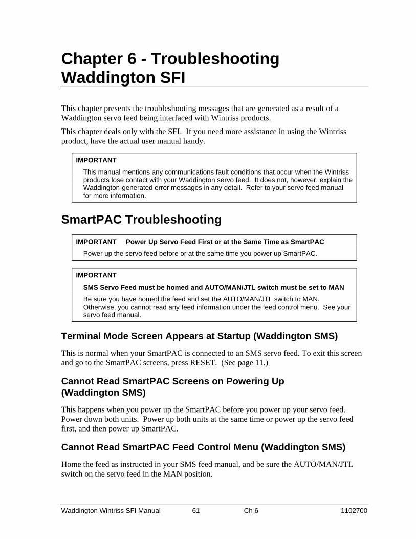
Waddington Wintriss SFI Manual 61 Ch 6 1102700
Chapter 6 - Troubleshooting Waddington SFI
This chapter presents the troubleshooting messages that are generated as a result of a Waddington servo feed being interfaced with Wintriss products.
This chapter deals only with the SFI. If you need more assistance in using the Wintriss product, have the actual user manual handy.
IMPORTANT
This manual mentions any communications fault conditions that occur when the Wintriss products lose contact with your Waddington servo feed. It does not, however, explain the Waddington-generated error messages in any detail. Refer to your servo feed manual for more information.
SmartPAC Troubleshooting
IMPORTANT Power Up Servo Feed First or at the Same Time as SmartPAC
Power up the servo feed before or at the same time you power up SmartPAC.
IMPORTANT
SMS Servo Feed must be homed and AUTO/MAN/JTL switch must be set to MAN
Be sure you have homed the feed and set the AUTO/MAN/JTL switch to MAN. Otherwise, you cannot read any feed information under the feed control menu. See your servo feed manual.
Terminal Mode Screen Appears at Startup (Waddington SMS)
This is normal when your SmartPAC is connected to an SMS servo feed. To exit this screen and go to the SmartPAC screens, press RESET. (See page 11.)
Cannot Read SmartPAC Screens on Powering Up (Waddington SMS)
This happens when you power up the SmartPAC before you power up your servo feed. Power down both units. Power up both units at the same time or power up the servo feed first, and then power up SmartPAC.
Cannot Read SmartPAC Feed Control Menu (Waddington SMS)
Home the feed as instructed in your SMS feed manual, and be sure the AUTO/MAN/JTL switch on the servo feed in the MAN position.

Troubleshooting
Waddington Wintriss SFI Manual 62 Ch 6 1102700
Lost Communications Between SmartPAC and Feed Control
Whenever SmartPAC and the feed control unit are not successfully communicating, the following message will appear on the LCD.
The SmartPAC and feed control arenot communicating properly. Checkall the connections.
COMMUNICATIONS LOST WITH THEFEED CONTROL UNIT
Figure 6-1. Communications Fault Message
Check that all wiring connections are intact. Refer to Chapter 2 to verify correct installation if necessary. Also refer to the next section, “Viewing Communications Between Feed Control and SmartPAC,” to look at communications. Contact Wintriss Tech Support for troubleshooting assistance. Once communications is restored, you will no longer see this fault message.
Viewing Communications Between Feed Control and SmartPAC
To look at the communications between SmartPAC and your servo feed, follow these steps:
1. Select POSITION SENSOR from the Main Initialization menu (see page 20). The Position Sensor screen appears (see top figure on page 63).
2. Press F4 (VIEW COMMUNICATIONS). The Communication Data Viewer screen appears (see center figure on page 63).
3. Select PORTR 1 (SFI). The Communications screen appears (see bottom figure on page 63).

Troubleshooting
Waddington Wintriss SFI Manual 63 Ch 6 1102700
POSITION SENSOR INPUT OPEN
PRESS THE CURSOR KEYS TO SELECT THE MODEYOU WANT TO CHANGE. PRESS THE ENTER KEY TOCHANGE IT. PRESS THE RESET KEY WHEN YOUARE DONE.
SORT TOOL TABLE F5
POSITION SENSOR MODE DISABLED
COUNTER SETUP MODE IS ALWAYS INCREMENTED
SHOW CHECKSUMS F6
VIEW COMMUNICATIONS F4
Figure 6-2. Position Sensor Screen
PORT 1 (SFI)PORT 2 (MODULE)PORT 3 (SPECIAL)PORT 4 (PACNET)PORT 5 (WPC)
USE THE CURSOR KEYS TO CHOOSE THE PORTYOU WISH TO VIEW. PRESS THE ENTER KEY TOVIEW IT. PRESS THE RESET KEY WHEN DONE.
COMMUNICATION DATA VIEWER
PORT 1 (SFI)
NOTE: When viewing the port data you canperform a loop back test by jumpering the TXD andRXD lines together and then pressing the F1 key.
Figure 6-3. Communication Data Viewer Screen
TRANSMIT BUFFERdata that appearshere is beingtransmitted fromSmartPAC
data that appearshere is beingtransmitted from theservofeed controller
RECEIVE BUFFER
Figure 6-4. Actual Communications

Troubleshooting
Waddington Wintriss SFI Manual 64 Ch 6 1102700
If communications are operating normally between SmartPAC and the servofeed controller, you should see some text (data) in both the "transmit buffer" and "receive buffer" locations on the above screen. If you do not see any data (or only partial data), this means that SmartPAC and the servofeed controller are not communicating properly.
In this case, a problem exists and you can perform a loop-back test to check communications, as follows:
1. Connect (jumper) the TXD (transmit) and RXD (receive) lines together. Refer to the Figure 5 wiring diagram at the end of this manual for loop-back wiring.
2. Press F1 to check communications. This causes SmartPAC to receive the data it is transmitting. This test is useful when verifying the accuracy of the transmit and receive hardware and wiring.
For assistance, contact Wintriss Tech Support.

Troubleshooting
Waddington Wintriss SFI Manual 65 Ch 6 1102700
1500 Series Troubleshooting
Whenever either ProCam 1500 or DiPro 1500 and the feed control unit are not successfully communicating, the following message will appear on the LCD. Check that all wiring connections are intact. Refer to Chapter 2 if necessary. Once communications is restored, you will no longer see this fault message.
THE PROCAM 1500 AND SERVO FEED CONTROLARE NOT COMMUNICATING. CHECKTHE CONNECTIONS AND BAUD RATES.
COMMUNICATIONS LOST WITH FEEDERor DiPro1500,dependingon which1500 unitis connectedto SFI
Figure 6-5. Communications Fault Message
NOTE
If yours is a SMS servo feed, the Terminal Mode screen (Figure 2-3) appears when you power up the SmartPAC. Press RESET to go to normal SmartPAC operation.

Troubleshooting
Waddington Wintriss SFI Manual 66 Ch 6 1102700

Index
Waddington Wintriss SFI Manual 67 1102700
1
1500 units
adjust feed, 60
calculate, 54
change groups, 32
check setup, 34
Feed Advisor, 52
feed arc, 53
feed length, 53, 60
locking adjust feed, 34, 35
press speed, 53
security access, 36
A
acceleration, 42, 43, 44, 45, 51
adjust feed, locking in 1500 units, 35
advance constant, DiPro 1500, 37, 38
auto advance, 37
AUTO/MAN/JTL switch, SMS, 26
C
calculation, 44
change group, 22, 31
changing calibration, SMS, 28
check setup, 25, 33
checksum, 7
communications, viewing SmartPAC, 63
connector, 6, 9, 10
D
DB25 connector, 6, 9, 12, 16
decimal places, setting number of, 28
E
EPROM, 12
error
checksum, 7
communications lost, 1500 units, 66
communications lost, SmartPAC, 63
F
Feed Advisor, 3, 42, 44, 45, 52
calculation, 44
SmartPAC, 43
feed control, 41
feed length, 1500, 51
feed length, SmartPAC, MiniFeed, 41
feed parameters, 22
feed settings
loading with SmartPAC, 49
loading, 1500 units, 55
loading, SmartPAC, MiniFeed, 45
loading, SmartPAC, SMS, 49
feed settings, 1500, 51
firmware, SFI, chip, 12
I
Initialization mode, 1500. See also 1500 units
advance constant, DiPro, 37
feed parameters, 30, 34
Initialization mode, SmartPAC
change group 1, MiniFeed, 22
change groups 2-4, MiniFeed, 24
changing calibration, SMS, 28
changing tune values, SMS, 27
check setup, MiniFeed, 25
checking setup values, SMS, 29
decimal places, SMS, 28
job mode, SMS, 28
MiniFeed, 22
servo pilot, MiniFeed, 22
servo pilot, SMS, 27
SMS, 26
J
job mode, 28
job number, SMS, 48
jog speed, 23
M
maximum run speed, 42, 45, 51
N
NEMA 12 protection, 9, 15, 16
P
phoenix connector, 12
pilot release, 37
Program mode
Index
Waddington Wintriss SFI Manual 68 1102700
acceleration, 42
Program mode, 1500 units, 50
acceleration, 51
Feed Advisor, 52
feed length, 51
maximum run speed, 51
Program mode, SmartPAC, 40
Feed Advisor, 42
feed control, 41
feed length, 41
feed length, SMS, 48
job number, SMS, 48
maximum run speed, 42
pilot angle, SMS, 48
speed, maximum run, SMS, 48
terminal mode screeen, SMS, 48
Program/Run key, 20, 30, 40, 50, 57, 60
R
RPM, slow, DiPro 1500, 38
RS-232 interface, 2, 5, 9, 15, 16
RS-485, 65
Run mode
1500 units, 60
SmartPAC, 57, 59
S
security access
1500 units, 35
SmartPAC, 21
servo pilot, 23, 27
SMS, 27
Servofeed Advisor. See Feed Advisor
set feed, 50
setup values, checking SMS, 29
SFI firmware, 6, 12
slow RPM, DiPro 1500, 38
SmartPAC
adjust feed length, MiniFeed, 58
feed control, 59
SMS
AUTO/MAN/JTL switch, 26
SMS feed. See troubleshooting. See Run mode,
SmartPAC. See Program mode, SmartPAC. See
Initialization mode, SmartPAC
speed, maximum run, 42
T
terminal mode screen
entering, 48
exiting, 62
using, 48
tool number, 40, 45, 49, 50, 55, 57, 58, 59, 60, 61
troubleshooting
1500 units, 66
feed control menu, cannot read, 63
lost communications, 63
SmartPAC on power up, 62
SMS, SmartPAC, 62
tune values, 27

Wintriss Manuals
Wintriss Manuals
Wintriss Product
Installation Manual
Doc. No.
User Manual/CD
Doc. No.
AutoSet (1500, 1500 Plus, 1504, 1504 Plus) DA71747 DA71447
AutoSetPAC (Tonnage Monitor) DA71413 DA71443
Die Protection Handbook N.A. * 1130300 *
DiPro 1500 DA71428 DA71447
DSI 2 Sensor Interface N.A. * DA66970 *
LETS Machine Interface (LMI) N.A. ** DA71974 **
MultiPAC Types 1 and 2 DA71409 DA71443
MultiPAC Types 4 and 5 DA71410 DA71443
ProCam 1500 DA71430 DA71447
ProPAC (Process Monitor – In-die Measurement) DA71411 DA71443 RamPAC (Shut Height, Counterbalance & Cushion Control)
DA71412 DA71443
Servofeed Interface – Coe/Wintriss DA71415 DA71443
Servofeed Interface – CWP/Wintriss DA71416 DA71443
Servofeed Interface – DiPro DA71429 DA71447
Servofeed Interface – Electrocraft/Wintriss DA71417 DA71443
Servofeed Interface – Indramat/Wintriss DA71418 DA71443
Servofeed Interface – ProCam DA71431 DA71447
Servofeed Interface – SmartPAC DA71420 DA71443
Servofeed Interface – Waddington/Wintriss DA71419 DA71443
SFC Machine Interface (SMI) N.A. ** 1040800 **
Shadow V Safety Light Curtain DA71433 DA71449
Shadow VI Safety Light Curtain DA71422 DA71445
Shadow VII Safety Light Curtain N. A. * 1129400 *
Shadow 8 Safety Light Curtain N. A. * 1139300 *
SmartPAC (w/ DiProPAC & ProCamPAC) DA71439 DA71454
SmartPAC Hydraulic DA71435 DA71451
SmartPAC Run Mode (Spanish) N. A. * DA71443
SmartPAC w/ WPC II Integration DA71440 DA71455
SmartPAC 2 (w/ DiProPAC & ProCamPAC) DA71406 DA71441
SmartPAC 2 Hydraulic DA71436 DA71451
SmartPAC 2 Servo DA71437 DA71452
SmartPAC 2 w/ WPC 2000 Integration DA71407 DA71442
SmartPAC 2 w/WPC 2000 Run Mode (Spanish) N. A. * DA71443
WaveFormPAC (Advanced Load Analyzer) DA71414 DA71443
Wintriss Brake Monitor DA71432 DA71448
Wintriss Clock Display N. A. * DA67206 *
WPC II Wintriss Press Control DA71438 DA71453
WPC 1000 Wintriss Press Control DA71423 DA71446
WPC 2000 Wintriss Press Control DA71421 DA71444
WPC 2000 Option 2 DA71408 DA71442
* Installation Manual not available; User Manual available in hard copy only. Die Protection Handbook
available in hard copy (1102400) and on CD (1130300).
* Installation Manual not available. User Manual available on CD only.


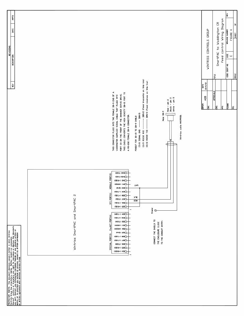
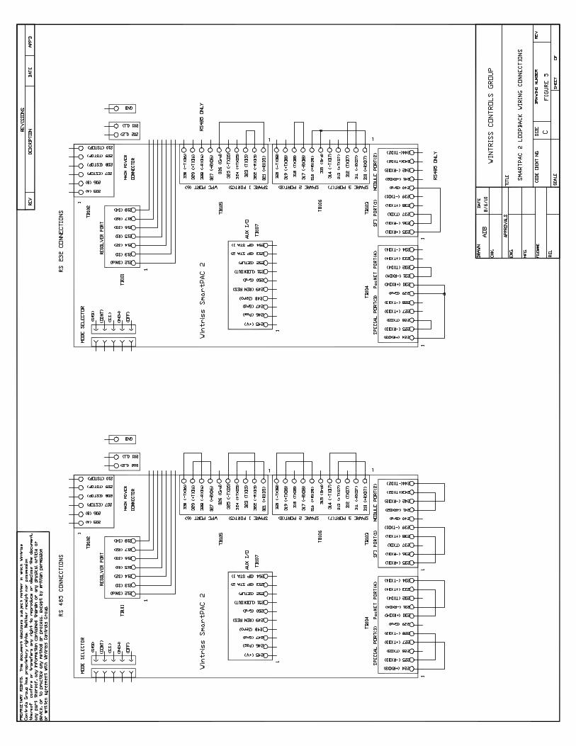
Related Documents