WA CHU SETT INT AKE AND POWER PLANT WACHUSETT INTAKE AND POWER PLANT BY CHESTER J. GINDER* GENERAL DESCRIPTION 183 The Wachusett Intake and Power Plant is a facility of the Boston Metropolitan Water Supply System located on the easterly shore of the Wachusett Reservoir in Clinton about 1800 feet south of the main dam built about 1900 to form the reservoir. Its purpose is to provide a controlled means of introducing water from the reservoir to the recently completed Wachusett-Marlborough Tunnel which is the first section of the pressure aqueduct built to carry water from the sources of supply to N orumbega Reservoir in Weston and to the District distribution lines. The Wachusett-Marlborough Tunnel is a deep rock tunnel 14 feet in diameter extending from Clinton to Marlborough a distance of 8 miles where it connects with section 2 of the pressure aqueduct. Fig. 1 shows the location of Wachusett Reservoir with respect to the system as a whole. The intake structure contains the usual features of control and operation such as coarse and fine screens, stop shutters, sluice gates and control valves. In addition the structure will house two turbines and two generators which will furnish plant power and power for sale to the New England Electric System on a contract basis. A second function of the power generation equipment will be to use up excess hydraulic head which exists with Wachusett Reservoir at the spillway elevation of 395 on Boston City Base. The pressure aqueduct discharges into Norumbega Reservoir at elevation 274.5. The head available is more than required for the flow requirements and somewhat in excess of the design pressure allowed for certain sections of the pressure aqueduct and certain valve installations along the line. Bypass lines are provided for use when the turbines may be shut down or for use when the de- mand exceeds the capacity of the turbines. These bypass lines will be equipped with head dissipating valves of the Howell-Bunger type. Tail water for the turbines and the Howell-Bunger valves will vary from ele- vation 315 for low discharge conditions to elevation 338 for maximum * Designing Engineer M.D.C. Construction Division, Retired.

Welcome message from author
This document is posted to help you gain knowledge. Please leave a comment to let me know what you think about it! Share it to your friends and learn new things together.
Transcript

WA CHU SETT INT AKE AND POWER PLANT
WACHUSETT INTAKE AND POWER PLANT BY CHESTER J. GINDER*
GENERAL DESCRIPTION
183
The Wachusett Intake and Power Plant is a facility of the Boston Metropolitan Water Supply System located on the easterly shore of the Wachusett Reservoir in Clinton about 1800 feet south of the main dam built about 1900 to form the reservoir. Its purpose is to provide a controlled means of introducing water from the reservoir to the recently completed Wachusett-Marlborough Tunnel which is the first section of the pressure aqueduct built to carry water from the sources of supply to N orumbega Reservoir in Weston and to the District distribution lines. The Wachusett-Marlborough Tunnel is a deep rock tunnel 14 feet in diameter extending from Clinton to Marlborough a distance of 8 miles where it connects with section 2 of the pressure aqueduct. Fig. 1 shows the location of Wachusett Reservoir with respect to the system as a whole.
The intake structure contains the usual features of control and operation such as coarse and fine screens, stop shutters, sluice gates and control valves. In addition the structure will house two turbines and two generators which will furnish plant power and power for sale to the New England Electric System on a contract basis. A second function of the power generation equipment will be to use up excess hydraulic head which exists with Wachusett Reservoir at the spillway elevation of 395 on Boston City Base. The pressure aqueduct discharges into Norumbega Reservoir at elevation 274.5. The head available is more than required for the flow requirements and somewhat in excess of the design pressure allowed for certain sections of the pressure aqueduct and certain valve installations along the line. Bypass lines are provided for use when the turbines may be shut down or for use when the demand exceeds the capacity of the turbines. These bypass lines will be equipped with head dissipating valves of the Howell-Bunger type. Tail water for the turbines and the Howell-Bunger valves will vary from elevation 315 for low discharge conditions to elevation 338 for maximum
* Designing Engineer M.D.C. Construction Division, Retired.

......
(X) ...
FIG
, 1
.-E
NT
IRE
SY
ST
EM
-

WACHUSETT INTAKE AND POWER PLANT 185
flow. Maximum flow in the remote future is considered as being 600 mgd and the intake structure is designed on this basis. However, the maximum capacity of the present single pressure aqueduct from Shaft 4 to Norumbega under permissible maximum gradients is limited to 312 mgd. A second pressure aqueduct will be needed between these points to meet future demand.
The safe yield of present sources is estimated to be 330 mgd. The safe yield under the proposed future use of the Millers River is estimated at 519 mgd.
CONSTRUCTION SEQUENCE
The entire project has involved construction under three stages. Stage I is the Wachusett-Marlborough Tunnel previously mentioned. Stage II is tke site preparation for the intake structure and Stage III the intake and power plant.
Stage II, the site preparation, was completed under a previous contract at a cost of about $1,200,000. The work of this contract included the construction of a sheet pile cofferdam composed of six sand-filled cells 60 feet in diameter and five connecting cells having a maximum depth to rock of about 65 feet. The cell cofferdam and end dikes permitted unwatering an area of the reservoir about 350 feet square in which the intake structure will be located.
Arrangements were made to maintain Wachusett Reservoir at elevation 380 during the construction period in order to reduce the depth of the cofferdam cells. Emergency spillways through the cofferdam we provided at elevation 380 with stop logs to allow controlled flooding of the site if a rise in the reservoir level could not be prevented. This stage was completed without the necessity of using these spillways. The extent of this work is indicated in Fig. 2. Rock excavation for the structure amounted to about 50,000 cu. yds. with side slopes on the land side of the excavation about 95 feet deep from elevation 393 at the top to elevation 298 at the bottom of the foundation. The rock consisted mostly of Worcester Phylite of rather poor quality and was subject to weathering. Since the side slope called for was 8 on 1, it was necessary to protect the slopes with wire mesh and some mortar covering as a safety measure. Figs. 3, 4 and 5 show work involved in the cofferdam and site preparation contract, Stage II.
Elaborate provisions were made for grouting under the cofferdam and the building foundation to prevent leakage into the area but very little grouting was actually done as the leakage was negligible.

186 BOSTON SOCIETY OF CIVIL ENGINEERS

WA CHU SETT INT AKE AND POWER PLANT 187
Fm, 3.-COFFERDAM AND EXCAVATION,

188 BOSTON SOCIETY OF CIVIL ENGINEERS
FIG. 4.-COFFERDAM AND EXCAVATION.
This contract also included a 12 foot diameter connecting tunnel from the bottom of the excavation to Shaft A of the Wachusett-Marlborough Tunnel, a distance of 340 feet, and the installation in this section of tunnel of a steel bulkhead to protect the Wachusett-Marlborough Tunnel from being flooded and the Wachusett Reservoir from being drained should the cofferdam fail.
Sanitary protection of the reservoir required all drainage from the shore areas occupied by the contractor and pumpage from the excavation to be chlorinated and filtered in a settling basin adjacent to the site.
Stage III construction comprises the concrete substructure with intake channels to carry water from the reservoir through water wheels and through bypass lines into the Wachusett-Marlborough Tunnel. It also includes the construction of the superstructure which provides control centers and service areas. Figs. 6, 7 and 8 show the general design of the structure and the location of equipment. The water wheels, governors, and generators were purchased by the Commission for installation by the general contractor.

WA CHU SETT INT AKE AND POWER PLANT 189
FIG. 5.-COFFERDA:M AND EXCAVATION.

.... \0 0
frc;;. 6.-POWER PLANT ELEV. 357.0
405,0,

.... '° ....
FIG
. 7.
-PO
WE
R P
LAN
T EL
EV.
343.
0 32
5.0.

-'-0 t'-.)
)!'IG
, l;
l.-P
OW
E)l
. P
LA
NT
C
RO
SS
SE
CT
ION
S.

WACHUSETT INTAKE AND POWER PLANT 193
Downstream from the by-pass lines and the water wheels a stilling basin is provided wherein the tailwater elevations will vary with changes in the discharge through the structure. Under minimum discharge conditions the draft tube seal is provided by a low weir at the entrance to the connecting tunnel to Shaft A. Under minimum discharge conditions the connecting tunnel will be flowing less than full depth and a free fall will occur at Shaft A. Since this condition will exist at times for many years, a cast iron lining has been placed in Shaft A where turbulence would tend to erode the concrete lining of the Shaft. Fig. 9 shows a portion of the cast iron lining which will protect the
FIG. 9.-CAST IRON LINING.
throat at the tunnel and shaft intersection and twenty feet of the shaft below the throat.
The substructure provides for a generator room at elevation 3 5 7 which is above the expected high tailwater elevation but below the reservoir spillway elevation, which is at elevation 395. The facing consists of granite panels having a thermal finish and polished granite trim combined with glass panels with stainless steel trim.
Landscaping of the grounds adjacent to the intake structure is

194 BOSTON SOCIETY OF CIVIL ENGINEERS
provided with the expectation that an administration building will later be built nearby.
DESIGN
The intake structure is located on the shore adjacent to Shaft A of the tunnel. In this structure there are six intake channels, two for the water wheels and four for the bypass lines. These channels are grooved for stop shutters and for screens. The channels extend full height from elevation 335 to elevation 405 with 4 foot by 6 foot sluice gates at elevations 340 and 360 in each channel. Additional sluice gates 8 feet square are provided to control flow to the water wheels. The screens are to be made in sections about 5' -6" high and 4' -3" wide with stainless steel screening. For one set the screening is to be 14 ga. ¼ inch mesh, and for the other set the screening is to be 10 ga. 1 inch mesh. Lifting devices operated from a crane in the screen room at elevation 405 will be used for the installation and removal of the screens and shutters. The sluice gates will be motor operated on gate stands in the screen room.
Four bypass lines are provided of which two are to be completed under the present construction contract and two at a later date. The completed lines will each include a 54 inch flow tube and a 36 inch Howell-Bunger type of discharge valve set at elevation 332. The Howell-Bunger valves will operate under free discharge conditions with a maximum head of 68 feet for low tailwater conditions and will discharge submerged under high tailwater conditions. The maximum capacity of each bypass line will be about 240 mgd.
Two waterwheels with Woodward Company governors are being furnished by the James Leffel Company. These turbines will be vertical shaft Kaplan type with adjustable blades having a rated output of 2240 horsepower under an effective head of 80 feet at a speed of 450 revolutions per minute. The wheels will be set at elevation 325. The spiral cases will be steel plate and these will be embedded in the concrete substructure of the building. The two turbines will be capable of discharging about 380 mgd total to supply the district demand. Generally speaking, the operation of the turbines and the bypass lines together or separately will be such as to match as nearly as possible the water demand by the District in order to keep wastage of water to a minimum.
The generators are being furnished by Electric Machinery Com-

WACHUSETT INTAKE AND POWER PLANT 195
pany. Each is to be the vertical shaft, waterwheel driven type having a rated capacity of 200 kva. The exciters will be direct connected. The generator room at elevation 357 is approximately 44 feet by 100 feet. It is open to the roof of the superstructure at elevation 43 7 .2 3 and is served by a 10 ton traveling crane located in the superstructure. Flow through the bypass lines and through the turbines will be measured and recorded on indicating and totalizing charts.
The stilling basin downstream of the generator room performs the functions of sealing the draft tubes, dissipating the remaining discharge head and establishing a free water surface gradient for the tunnel under high flow conditions.
Halfway along the tunnel at Shaft B an overflow weir will be built with the crest at elevation 325 as indicated on Fig. 10. This overflow, which is to be built at the top of the former tunnel construction shaft, will serve as an overflow relief for the system should some operation failure cause the gradient to exceed the safe limit. Under planned operating procedures no overflows at Shaft B are expected.
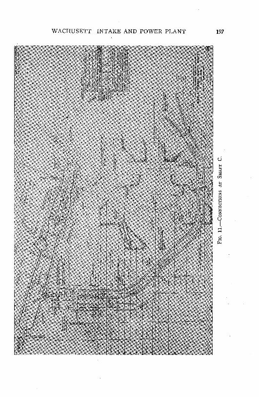
At the downstream end of the tunnel at Shaft C, which is about eight miles from the intake structure, a connection to the previously constructed pressure aqueduct will be made, as shown on Fig. 11. At this point two 72 inch butterfly valves in the main aqueduct line will permit control of the flow through the tunnel. Normally, however, the control of flow through the tunnel will be done at the intake structure by varying the discharge through the water wheels and the bypass lines.
Part of the construction at Shaft C includes a 66 inch by-pass line controlled by a 48 inch butterfly valve. This valve will be motorized and actuated by signals from N orumbega Reservoir in Weston, and will be called upon to prevent an uncontrolled rise in N orumbega Reservoir by helping to match the flow through the pressure aqueduct with the water demand of the District. This bypass line will be equipped with pressure relief valves sensitive to the effects of surges in the aqueduct line. Flows through this bypass line will be lost to the high service lines of the system, but through Sudbury Reservoir and Weston Reservoir will be available to the low service lines. Normal operation calls for discharges through the bypass line at Shaft C to be kept to a minimum.
Presently the pressure aqueduct begins at Shaft C, taking water from the adjacent forebay at elevation 278.5. This gradient will not

196 BOSTON SOCIETY OF CIVIL ENGINEERS
WA CHU SETT INT AKE AND POWER PLANT 197
u
~ U)
!;;
I 0 u 1.
,-; ,-;

198 BOSTON SOCIETY OF CIVIL ENGINEERS
permit Norumbega Reservoir to be maintained at elevation 274.5, where it should be to satisfy the requirements of the District. Eventually a second pressure aqueduct will be required between Shaft C and N orumbega Reservoir. In the meantime, the gradient at Shaft C will be raised from elevation 278.5 to about elevation 310 or 312, which will greatly increase the flow to N orumbega Reservoir and relieve the difficulty caused by a low gradient at N orumbega.
The work required to make the pressure aqueduct operative includes the installation of a control system based on maintaining Norumbega Reservoir within close limits. Compared with Wachusett Reservoir, which is backed up by Quabbin Reservoir, Norumbega Reservoir is very small. The top foot of Norumbega has a capacity of only 13.6 million gallons and the spillway capacity is so small that overflows at N orumbega must be prevented. Therefore, the controls are set up to maintain Norumbega Reservoir within the top foot. Signals from Norumbega Reservoir will automatically adjust the discharge of the turbines or bypass valves at the intake structure to meet the demand on N orumbega Reservoir and will tend to keep the elevation at elevation 273.9. Such signals will also control the bypass valves at Shaft C. A high water alarm in the stilling basin will call for shutting off flow through the intake should the signals from N orumbega fail to properly regulate the flow.
A contract not yet awarded for miscellaneous electrical equipment and control equipment will include flow and pressure transmitters and receivers, power transformer, substation, main control board, motor control centers and turbine control board. The control system will be fully automatic except for the manual operation required to add or remove one turbine from the system.
When water is being released through the bypass valves, the valves will be automatically controlled in a manner similar to the turbines by the float control at N orumbega. The automatic control on the bypass valves may be switched over to manual control at any time and then be operated by push-button control by the station operator.
The construction contract was awarded in November, 1964, to Wes-Julian Company on the basis of a bid price of $5,239,557.00.
The design was done by the Construction Division of the Metropolitan District Commission, under the supervision of Mr. Frederick W. Gow, Chief Engineer. Chas. T. Main, Inc. acted as consultant and prepared the detailed drawings and specifications.
Related Documents