Introduction This Project Guide provides engine data and system proposals for the early design phase of marine engine installations. For contracted projects specific instructions for planning the installation are always delivered. Any data and information herein is subject to revision without notice. This 1/2003 issue replaces all previous issues of the Wärtsilä 20 Project Guides. This revision contains minor technical updates and modifications on texts. Wärtsilä Finland Oy Marine Application Technology Vaasa, November 2003 Marine Project Guide W20 - 1/2003 i THIS PUBLICATION IS DESIGNED TO PROVIDE AS ACCURATE AND AUTHORITIVE INFORMATION REGARDING THE SUBJECTS COVERED AS WAS AVAILABLE AT THE TIME OF WRITING. HOWEVER, THE PUBLICATION DEALS WITH COMPLICATED TECHNICAL MATTERS AND THE DESIGN OF THE SUBJECT AND PRODUCTS IS SUBJECT TO REGULAR IMPROVEMENTS, MODIFICATIONS AND CHANGES. CONSEQUENTLY, THE PUBLISHER AND COPYRIGHT OWNER OF THIS PUBLICATION CANNOT TAKE ANY RESPONSIBILITY OR LIABILITY FOR ANY ERRORS OR OMISSIONS IN THIS PUBLICATION OR FOR DISCREPANCIES ARISING FROM THE FEATURES OF ANY ACTUAL ITEM IN THE RESPECTIVE PRODUCT BEING DIFFERENT FROM THOSE SHOWN IN THIS PUBLICATION. THE PUBLISHER AND COPYRIGHT OWNER SHALL NOT BE LIABLE UNDER ANY CIRCUMSTANCES, FOR ANY CONSEQUENTIAL, SPECIAL, CONTINGENT, OR INCIDENTAL DAMAGES OR INJURY, FINANCIAL OR OTHERWISE, SUFFERED BY ANY PART ARISING OUT OF, CONNECTED WITH, OR RESULTING FROM THE USE OF THIS PUBLICATION OR THE INFORMATION CONTAINED THEREIN. COPYRIGHT © 2002 BY WÄRTSILÄ FINLAND OY ALL RIGHTS RESERVED. NO PART OF THIS PUBLICATION MAY BE REPRODUCED OR COPIED IN ANY FORM OR BY ANY MEANS, WITHOUT PRIOR WRITTEN PERMISSION OF THE COPYRIGHT OWNER.

Welcome message from author
This document is posted to help you gain knowledge. Please leave a comment to let me know what you think about it! Share it to your friends and learn new things together.
Transcript

Introduction
This Project Guide provides engine data and system proposals for the early design phase of marine engineinstallations. For contracted projects specific instructions for planning the installation are always delivered.Any data and information herein is subject to revision without notice.This 1/2003 issue replaces all previous issues of the Wärtsilä 20 Project Guides. This revision contains minortechnical updates and modifications on texts.
Wärtsilä Finland Oy
Marine
Application Technology
Vaasa, November 2003
Marine Project Guide W20 - 1/2003 i
THIS PUBLICATION IS DESIGNED TO PROVIDE AS ACCURATE AND AUTHORITIVE INFORMATION REGARDING THE SUBJECTS COVERED AS WASAVAILABLE AT THE TIME OF WRITING. HOWEVER, THE PUBLICATION DEALS WITH COMPLICATED TECHNICAL MATTERS AND THE DESIGN OFTHE SUBJECT AND PRODUCTS IS SUBJECT TO REGULAR IMPROVEMENTS, MODIFICATIONS AND CHANGES. CONSEQUENTLY, THE PUBLISHERAND COPYRIGHT OWNER OF THIS PUBLICATION CANNOT TAKE ANY RESPONSIBILITY OR LIABILITY FOR ANY ERRORS OR OMISSIONS IN THISPUBLICATION OR FOR DISCREPANCIES ARISING FROM THE FEATURES OF ANY ACTUAL ITEM IN THE RESPECTIVE PRODUCT BEING DIFFERENTFROM THOSE SHOWN IN THIS PUBLICATION. THE PUBLISHER AND COPYRIGHT OWNER SHALL NOT BE LIABLE UNDER ANY CIRCUMSTANCES,FOR ANY CONSEQUENTIAL, SPECIAL, CONTINGENT, OR INCIDENTAL DAMAGES OR INJURY, FINANCIAL OR OTHERWISE, SUFFERED BY ANYPART ARISING OUT OF, CONNECTED WITH, OR RESULTING FROM THE USE OF THIS PUBLICATION OR THE INFORMATION CONTAINEDTHEREIN.
COPYRIGHT © 2002 BY WÄRTSILÄ FINLAND OYALL RIGHTS RESERVED. NO PART OF THIS PUBLICATION MAY BE REPRODUCED OR COPIED IN ANY FORM OR BY ANY MEANS, WITHOUT PRIORWRITTEN PERMISSION OF THE COPYRIGHT OWNER.

Table of Contents1 General data and outputs . . . . . . . . . . . . . . . . . . . 11.1. Technical main data . . . . . . . . . . . . . . . . . . . . . . . . . 11.2. Maximum continuous output . . . . . . . . . . . . . . . . . . 11.3. Reference conditions . . . . . . . . . . . . . . . . . . . . . . . . 11.4. Principal dimensions and weights . . . . . . . . . . . . . . 4
2 Operating ranges . . . . . . . . . . . . . . . . . . . . . . . . . . 62.1. General . . . . . . . . . . . . . . . . . . . . . . . . . . . . . . . . . . . 62.2. Matching the engines with driven equipment . . . . . 72.3. Loading capacity . . . . . . . . . . . . . . . . . . . . . . . . . . 122.4. Ambient conditions . . . . . . . . . . . . . . . . . . . . . . . . 12
3 Technical data tables. . . . . . . . . . . . . . . . . . . . . . 14
4 Description of the engine . . . . . . . . . . . . . . . . . . 244.1. Definitions. . . . . . . . . . . . . . . . . . . . . . . . . . . . . . . . 244.2. Main components . . . . . . . . . . . . . . . . . . . . . . . . . 244.3. Cross sections of the engine . . . . . . . . . . . . . . . . . 264.4. Overhaul intervals and expected life times . . . . . . 27
5 Piping design, treatment and installation . . . . . 285.1. General . . . . . . . . . . . . . . . . . . . . . . . . . . . . . . . . . . 285.2. Pipe dimensions. . . . . . . . . . . . . . . . . . . . . . . . . . . 295.3. Trace heating . . . . . . . . . . . . . . . . . . . . . . . . . . . . . 305.4. Pressure class . . . . . . . . . . . . . . . . . . . . . . . . . . . . 305.5. Pipe class . . . . . . . . . . . . . . . . . . . . . . . . . . . . . . . . 305.6. Insulation . . . . . . . . . . . . . . . . . . . . . . . . . . . . . . . . 315.7. Local gauges . . . . . . . . . . . . . . . . . . . . . . . . . . . . . 315.8. Cleaning procedures . . . . . . . . . . . . . . . . . . . . . . . 315.9. Flexible pipe connections . . . . . . . . . . . . . . . . . . . 31
6 Fuel oil system . . . . . . . . . . . . . . . . . . . . . . . . . . . 336.1. General . . . . . . . . . . . . . . . . . . . . . . . . . . . . . . . . . . 336.2. MDF installations . . . . . . . . . . . . . . . . . . . . . . . . . . 336.3. HFO installations . . . . . . . . . . . . . . . . . . . . . . . . . . 39
7 Lubricating oil system . . . . . . . . . . . . . . . . . . . . . 497.1. General . . . . . . . . . . . . . . . . . . . . . . . . . . . . . . . . . . 497.2. Lubricating oil quality . . . . . . . . . . . . . . . . . . . . . . . 497.3. Internal lubricating oil system. . . . . . . . . . . . . . . . . 527.4. External lubricating oil system . . . . . . . . . . . . . . . . 537.5. Separation system . . . . . . . . . . . . . . . . . . . . . . . . . 547.6. Filling, transfer and storage . . . . . . . . . . . . . . . . . . 547.7. Crankcase ventilation system . . . . . . . . . . . . . . . . 547.8. Flushing instructions . . . . . . . . . . . . . . . . . . . . . . . 557.9. System diagrams . . . . . . . . . . . . . . . . . . . . . . . . . . 56
8 Compressed air system. . . . . . . . . . . . . . . . . . . . 588.1. General . . . . . . . . . . . . . . . . . . . . . . . . . . . . . . . . . . 588.2. Compressed air quality . . . . . . . . . . . . . . . . . . . . . 588.3. Internal starting air system . . . . . . . . . . . . . . . . . . . 588.4. External starting air system . . . . . . . . . . . . . . . . . . 59
9 Cooling water system . . . . . . . . . . . . . . . . . . . . . 629.1. General . . . . . . . . . . . . . . . . . . . . . . . . . . . . . . . . . . 629.2. Internal cooling water system . . . . . . . . . . . . . . . . 639.3. External cooling water system . . . . . . . . . . . . . . . . 669.4. Example system diagrams . . . . . . . . . . . . . . . . . . . 71
10 Combustion air system . . . . . . . . . . . . . . . . . . . . 7610.1. Engine room ventilation . . . . . . . . . . . . . . . . . . . . . 7610.2. Combustion air system design. . . . . . . . . . . . . . . . 76
11 Exhaust gas system . . . . . . . . . . . . . . . . . . . . . . . 7811.1. Internal exhaust gas system. . . . . . . . . . . . . . . . . . 7811.2. External exhaust gas system . . . . . . . . . . . . . . . . . 78
12 Turbocharger cleaning. . . . . . . . . . . . . . . . . . . . . 8012.1. Turbine cleaning system (5Z03) . . . . . . . . . . . . . . . 80
13 Exhaust emissions . . . . . . . . . . . . . . . . . . . . . . . . 8113.1. General . . . . . . . . . . . . . . . . . . . . . . . . . . . . . . . . . . 8113.2. Diesel engine exhaust components . . . . . . . . . . . . 8113.3. Marine exhaust emissions legislation. . . . . . . . . . . 8213.4. Methods to reduce exhaust emissions . . . . . . . . . 83
14 Automation system . . . . . . . . . . . . . . . . . . . . . . . 8514.1. General . . . . . . . . . . . . . . . . . . . . . . . . . . . . . . . . . . 8514.2. Power supply . . . . . . . . . . . . . . . . . . . . . . . . . . . . . 8514.3. Safety System . . . . . . . . . . . . . . . . . . . . . . . . . . . . 8514.4. Speed Measuring (8N03) . . . . . . . . . . . . . . . . . . . . 8614.5. Sensors & signals . . . . . . . . . . . . . . . . . . . . . . . . . . 8714.6. Local instrumentation. . . . . . . . . . . . . . . . . . . . . . . 8914.7. Control of auxiliary equipment . . . . . . . . . . . . . . . . 8914.8. Speed control (8I03) . . . . . . . . . . . . . . . . . . . . . . . . 9014.9. Microprocessor based engine control system (WECS)
(8N01) . . . . . . . . . . . . . . . . . . . . . . . . . . . . . . . . . . . 91
15 Electrical power generation and management 10615.1. General . . . . . . . . . . . . . . . . . . . . . . . . . . . . . . . . . 10615.2. Electric power generation . . . . . . . . . . . . . . . . . . 10715.3. Electric power management system (PMS) . . . . . 10915.4. Typical one line main diagrams . . . . . . . . . . . . . . 112
16 Foundation . . . . . . . . . . . . . . . . . . . . . . . . . . . . . 11416.1. General . . . . . . . . . . . . . . . . . . . . . . . . . . . . . . . . . 11416.2. Steel structure design . . . . . . . . . . . . . . . . . . . . . 11416.3. Mounting of main engines . . . . . . . . . . . . . . . . . . 11416.4. Mounting of generating sets . . . . . . . . . . . . . . . . 12016.5. Reduction gear foundations. . . . . . . . . . . . . . . . . 12416.6. Free end PTO driven equipment foundations . . . 12416.7. Flexible pipe connections . . . . . . . . . . . . . . . . . . 124
17 Vibration and noise . . . . . . . . . . . . . . . . . . . . . . 12517.1. General . . . . . . . . . . . . . . . . . . . . . . . . . . . . . . . . . 12517.2. External forces and couples. . . . . . . . . . . . . . . . . 12517.3. Mass moments of inertia . . . . . . . . . . . . . . . . . . . 12617.4. Air borne noise . . . . . . . . . . . . . . . . . . . . . . . . . . . 126
18 Power transmission . . . . . . . . . . . . . . . . . . . . . . 12718.1. General . . . . . . . . . . . . . . . . . . . . . . . . . . . . . . . . . 12718.2. Connection to alternator . . . . . . . . . . . . . . . . . . . 12718.3. Flexible coupling . . . . . . . . . . . . . . . . . . . . . . . . . 12818.4. Clutch . . . . . . . . . . . . . . . . . . . . . . . . . . . . . . . . . . 12818.5. Shaftline locking device and brake . . . . . . . . . . . 12818.6. Power-take-off from the free end. . . . . . . . . . . . . 12918.7. Torsional vibration calculations . . . . . . . . . . . . . . 13018.8. Turning gear . . . . . . . . . . . . . . . . . . . . . . . . . . . . . 130
19 Engine room layout . . . . . . . . . . . . . . . . . . . . . . 13119.1. Crankshaft distances . . . . . . . . . . . . . . . . . . . . . . 13119.2. Space requirements for maintenance . . . . . . . . . 13419.3. Handling of spare parts and tools . . . . . . . . . . . . 13419.4. Required deck area for service work . . . . . . . . . . 134
20 Transport dimensions and weights . . . . . . . . . 13520.1. Lifting of engines . . . . . . . . . . . . . . . . . . . . . . . . . 13520.2. Engine components . . . . . . . . . . . . . . . . . . . . . . . 136
21 Dimensional drawings . . . . . . . . . . . . . . . . . . . . 13821.1. Notes for the CD-ROM. . . . . . . . . . . . . . . . . . . . . 138
22 ANNEX. . . . . . . . . . . . . . . . . . . . . . . . . . . . . . . . . 13922.1. Ship inclination angles . . . . . . . . . . . . . . . . . . . . . 13922.2. Unit conversion tables . . . . . . . . . . . . . . . . . . . . . 14022.3. Collection of drawing symbols used in drawings. 143
ii Marine Project Guide W20 - 1/2003
Table of Contents
1. General data and outputs
1.1. Technical main data
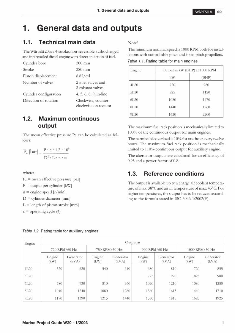
The Wärtsilä 20 is a 4-stroke, non-reversible, turbochargedand intercooled diesel engine with direct injection of fuel.
Cylinder bore 200 mm
Stroke 280 mm
Piston displacement 8.8 l/cyl
Number of valves 2 inlet valves and2 exhaust valves
Cylinder configuration 4, 5, 6, 8, 9, in-line
Direction of rotation Clockwise, counter-clockwise on request
1.2. Maximum continuous
output
The mean effective pressure Pe can be calculated as fol-lows:
where:
Pe = mean effective pressure [bar]
P = output per cylinder [kW]
n = engine speed [r/min]
D = cylinder diameter [mm]
L = length of piston stroke [mm]
c = operating cycle (4)
Note!
The minimum nominal speed is 1000 RPM both for instal-lations with controllable pitch and fixed pitch propellers.
Table 1.1. Rating table for main engines
The maximum fuel rack position is mechanically limited to100% of the continuous output for main engines.
The permissible overload is 10% for one hour every twelvehours. The maximum fuel rack position is mechanicallylimited to 110% continuous output for auxiliary engine.
The alternator outputs are calculated for an efficiency of0.95 and a power factor of 0.8.
1.3. Reference conditions
The output is available up to a charge air coolant tempera-ture of max. 38°C and an air temperature of max. 45°C. Forhigher temperatures, the output has to be reduced accord-ing to the formula stated in ISO 3046-1:2002(E).
Table 1.2. Rating table for auxiliary engines
1. General data and outputs
Marine Project Guide W20 - 1/2003 1
P c 1 0· · ·.2 1 9P [bar]e =
D n2 · · ·L �
Engine Output in kW (BHP) at 1000 RPM
kW (BHP)
4L20 720 980
5L20 825 1120
6L20 1080 1470
8L20 1440 1960
9L20 1620 2200
Engine Output at
720 RPM/60 Hz 750 RPM/50 Hz 900 RPM/60 Hz 1000 RPM/50 Hz
Engine(kW)
Generator(kVA)
Engine(kW)
Generator(kVA)
Engine(kW)
Generator(kVA)
Engine(kW)
Generator(kVA)
4L20 520 620 540 640 680 810 720 855
5L20 775 920 825 980
6L20 780 930 810 960 1020 1210 1080 1280
8L20 1040 1240 1080 1280 1360 1615 1440 1710
9L20 1170 1390 1215 1440 1530 1815 1620 1925

The specific fuel consumption is stated in the chapter forTechnical data with the reference for the engine drivenequipment and the effect they have on the specific fuelconsumption. The statement applies to engines operatingin ambient conditions according to ISO.
• total barometric pressure 100 kPa
• air temperature 25°C
• relative humidity 30%
• charge air coolant temperature 25°C
For other than ISO 3046-1 conditions the same standardgives correction factors on the fuel oil consumption.
1.3.1 Fuel characteristics
Table 1.3. MDF Specifications
1) Use of ISO-F-DMC category fuel is allowed provided that the fuel treatment system is equipped with a fuel centrifuge.
2) Additional properties specified by the engine manufacturer, which are not included in the ISO specification or differ fromthe ISO specification.
3) In some geographical areas there may be a maximum limit.
4) Different limits specified for winter and summer qualities.
2 Marine Project Guide W20 - 1/2003
1. General data and outputs
Property Unit ISO-F-DMX ISO-F-DMA ISO-F-DMB ISO-F-DMC 1) Test method ref.
Viscosity, min., before injection pumps 2) cSt 1.8 1.8 1.8 1.8 ISO 3104
Viscosity, max. cSt at 40°C 5.5 6 11 14 ISO 3104
Viscosity, max, before injection pumps 2) 24 24 24 24 ISO 3104
Density, max.kg/m³ at
15°C3) 890 900 920
ISO 3675 or12185
Cetane number 45 40 35 —ISO 5165 or
4264
Water, max. % volume — — 0.3 0.3 ISO 3733
Sulphur, max. % mass 1 1.5 2 2 ISO 8574
Ash, max. % mass 0.01 0.01 0.01 0.05 ISO 6245
Vanadium, max. mg/kg — — — 100 ISO 14597
Sodium before engine, max. 2) mg/kg — — — 30 ISO 10478
Aluminium + Silicon, max. mg/kg — — — 25 ISO 10478
Aluminium + Silicon before engine, max. 2) mg/kg — — — 15 ISO 10478
Carbon residue (micro method, 10 % voldist.bottoms), max.
% mass 0.30 0.30 — — ISO 10370
Carbon residue (micro method), max. % mass — — 0.30 2.50 ISO 10370
Flash point (PMCC), min. 2) °C 60 60 60 60 ISO 2719
Pour point, max. 4) °C — -6 - 0 0–6 0–6 ISO 3016
Sediment % mass — — 0.07 — ISO 3735
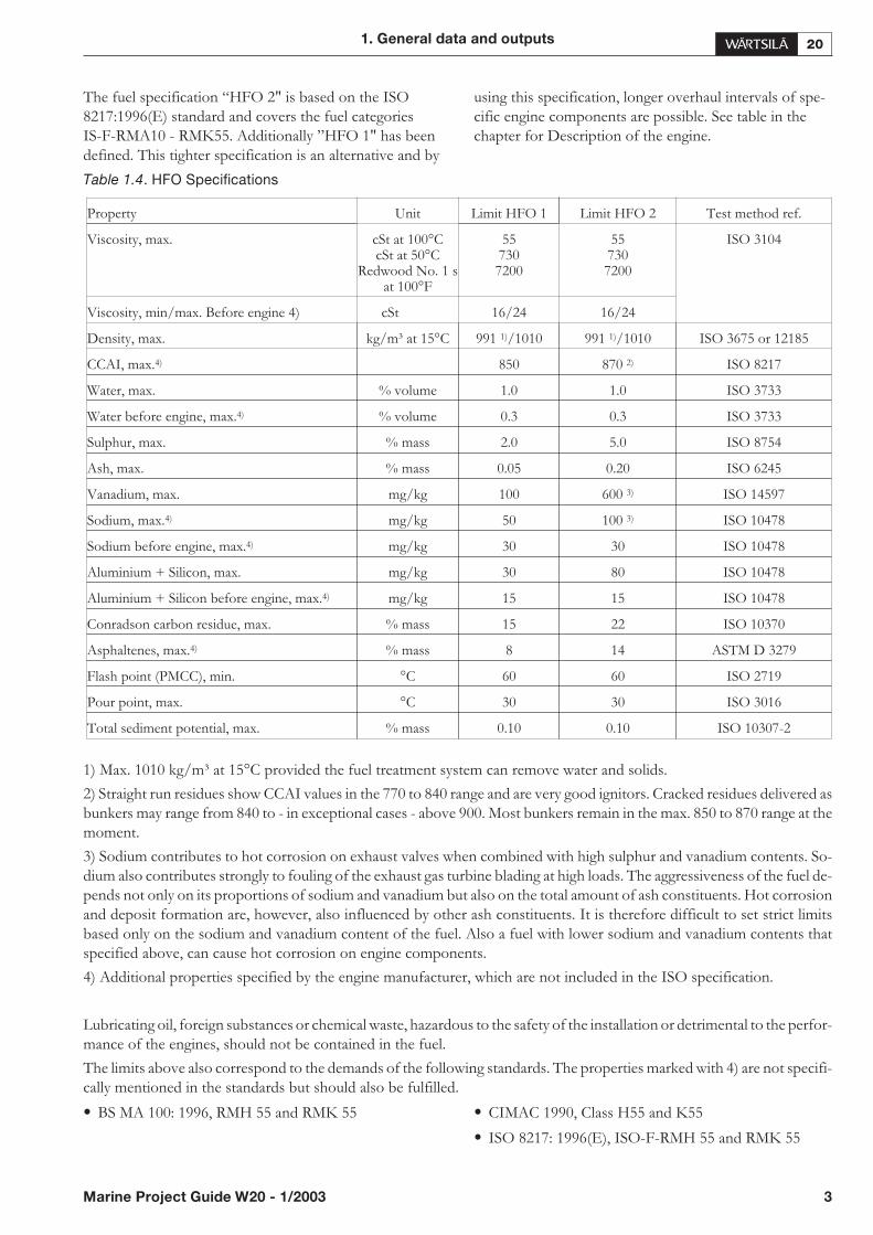
The fuel specification “HFO 2" is based on the ISO8217:1996(E) standard and covers the fuel categoriesIS-F-RMA10 - RMK55. Additionally ”HFO 1" has beendefined. This tighter specification is an alternative and by
using this specification, longer overhaul intervals of spe-cific engine components are possible. See table in thechapter for Description of the engine.
Table 1.4. HFO Specifications
1) Max. 1010 kg/m³ at 15°C provided the fuel treatment system can remove water and solids.
2) Straight run residues show CCAI values in the 770 to 840 range and are very good ignitors. Cracked residues delivered asbunkers may range from 840 to - in exceptional cases - above 900. Most bunkers remain in the max. 850 to 870 range at themoment.
3) Sodium contributes to hot corrosion on exhaust valves when combined with high sulphur and vanadium contents. So-dium also contributes strongly to fouling of the exhaust gas turbine blading at high loads. The aggressiveness of the fuel de-pends not only on its proportions of sodium and vanadium but also on the total amount of ash constituents. Hot corrosionand deposit formation are, however, also influenced by other ash constituents. It is therefore difficult to set strict limitsbased only on the sodium and vanadium content of the fuel. Also a fuel with lower sodium and vanadium contents thatspecified above, can cause hot corrosion on engine components.
4) Additional properties specified by the engine manufacturer, which are not included in the ISO specification.
Lubricating oil, foreign substances or chemical waste, hazardous to the safety of the installation or detrimental to the perfor-mance of the engines, should not be contained in the fuel.
The limits above also correspond to the demands of the following standards. The properties marked with 4) are not specifi-cally mentioned in the standards but should also be fulfilled.
• BS MA 100: 1996, RMH 55 and RMK 55 • CIMAC 1990, Class H55 and K55
• ISO 8217: 1996(E), ISO-F-RMH 55 and RMK 55
1. General data and outputs
Marine Project Guide W20 - 1/2003 3
Property Unit Limit HFO 1 Limit HFO 2 Test method ref.
Viscosity, max. cSt at 100°CcSt at 50°C
Redwood No. 1 sat 100°F
557307200
557307200
ISO 3104
Viscosity, min/max. Before engine 4) cSt 16/24 16/24
Density, max. kg/m³ at 15°C 991 1)/1010 991 1)/1010 ISO 3675 or 12185
CCAI, max.4) 850 870 2) ISO 8217
Water, max. % volume 1.0 1.0 ISO 3733
Water before engine, max.4) % volume 0.3 0.3 ISO 3733
Sulphur, max. % mass 2.0 5.0 ISO 8754
Ash, max. % mass 0.05 0.20 ISO 6245
Vanadium, max. mg/kg 100 600 3) ISO 14597
Sodium, max.4) mg/kg 50 100 3) ISO 10478
Sodium before engine, max.4) mg/kg 30 30 ISO 10478
Aluminium + Silicon, max. mg/kg 30 80 ISO 10478
Aluminium + Silicon before engine, max.4) mg/kg 15 15 ISO 10478
Conradson carbon residue, max. % mass 15 22 ISO 10370
Asphaltenes, max.4) % mass 8 14 ASTM D 3279
Flash point (PMCC), min. °C 60 60 ISO 2719
Pour point, max. °C 30 30 ISO 3016
Total sediment potential, max. % mass 0.10 0.10 ISO 10307-2
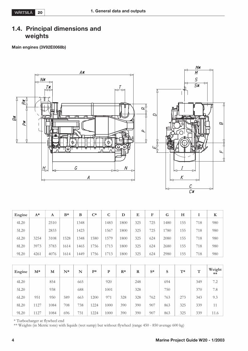
1.4. Principal dimensions and
weights
Main engines (3V92E0068b)
4 Marine Project Guide W20 - 1/2003
1. General data and outputs
Engine A* A B* B C* C D E F G H I K
4L20 2510 1348 1483 1800 325 725 1480 155 718 980
5L20 2833 1423 1567 1800 325 725 1780 155 718 980
6L20 3254 3108 1528 1348 1580 1579 1800 325 624 2080 155 718 980
8L20 3973 3783 1614 1465 1756 1713 1800 325 624 2680 155 718 980
9L20 4261 4076 1614 1449 1756 1713 1800 325 624 2980 155 718 980
Engine M* M N* N P* P R* R S* S T* T Weight**
4L20 854 665 920 248 694 349 7.2
5L20 938 688 1001 328 750 370 7.8
6L20 951 950 589 663 1200 971 328 328 762 763 273 343 9.3
8L20 1127 1084 708 738 1224 1000 390 390 907 863 325 339 11
9L20 1127 1084 696 731 1224 1000 390 390 907 863 325 339 11.6
* Turbocharger at flywheel end** Weights (in Metric tons) with liquids (wet sump) but without flywheel (range 450 - 850 average 600 kg)
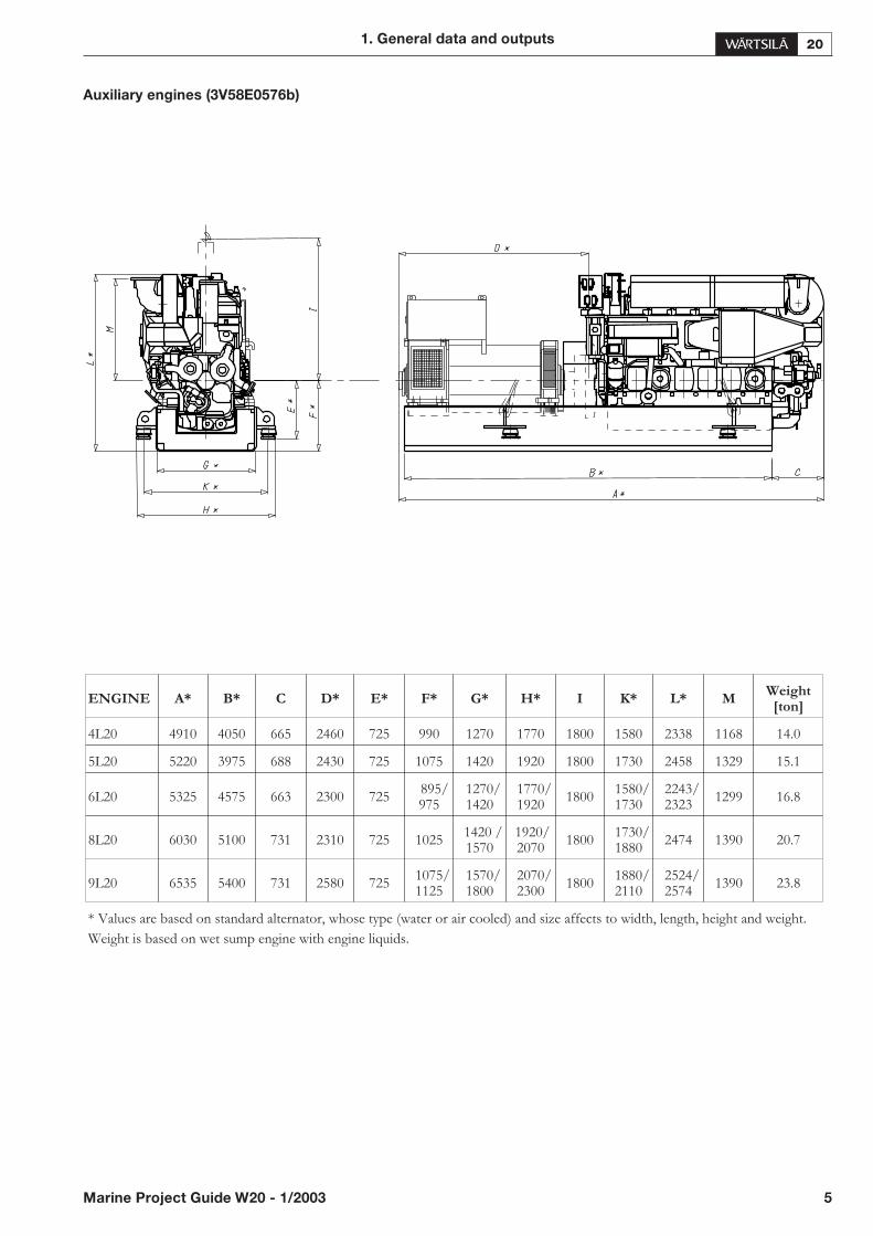
Auxiliary engines (3V58E0576b)
1. General data and outputs
Marine Project Guide W20 - 1/2003 5
ENGINE A* B* C D* E* F* G* H* I K* L* M Weight[ton]
4L20 4910 4050 665 2460 725 990 1270 1770 1800 1580 2338 1168 14.0
5L20 5220 3975 688 2430 725 1075 1420 1920 1800 1730 2458 1329 15.1
6L20 5325 4575 663 2300 725895/975
1270/1420
1770/1920
18001580/1730
2243/2323
1299 16.8
8L20 6030 5100 731 2310 725 10251420 /1570
1920/2070
18001730/1880
2474 1390 20.7
9L20 6535 5400 731 2580 7251075/1125
1570/1800
2070/2300
18001880/2110
2524/2574
1390 23.8
* Values are based on standard alternator, whose type (water or air cooled) and size affects to width, length, height and weight.
Weight is based on wet sump engine with engine liquids.
2. Operating ranges
2.1. General
The operating field of the engine depends on the requiredoutput, and these should therefore be determined together.This applies to both FPP and CPP applications. Concern-ing FPP applications also the propeller matching must beclarified.
A diesel engine can deliver its full output only at full enginespeed. At lower speeds the available output and also theavailable torque are limited to avoid thermal overload andturbocharger surging. This is because the turbocharger isless efficient and the amount of scavenge air supplied to theengine is low. Often e.g. the exhaust valve temperature canbe higher at low load (when running according to the pro-peller law) than at full load. Furthermore, the smallest dis-tance to the so-called surge limit of the compressortypically occurs at part load. Margin is required to permitreasonable wear and fouling of the turbocharging systemand different ambient conditions (e.g. suction air tempera-ture).
As a rule, the higher the specified mean effective pressurethe narrower is the permitted engine operating range. Thisis the reason why separate operating fields may be specifiedfor different output stages, and the available output forFP-propellers may be lower than for CP-propellers. To-day’s development towards lower emis-
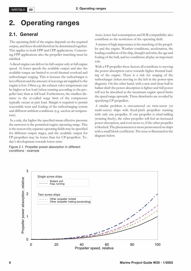
Figure 2.1. Propeller power absorption in differentconditions - example
sions, lower fuel consumption and SCR compatibility alsocontribute to the restriction of the operating field.
A matter of high importance is the matching of the propel-ler and the engine. Weather conditions, acceleration, theloading condition of the ship, draught and trim, the age andfouling of the hull, and ice conditions all play an importantrole.
With a FP propeller these factors all contribute to movingthe power absorption curve towards higher thermal load-ing of the engine. There is a risk for surging of theturbocharger (when moving to the left in the power-rpmdiagram). On the other hand, with a new and clean hull inballast draft the power absorption is lighter and full powerwill not be absorbed as the maximum engine speed limitsthe speed range upwards. These drawbacks are avoided byspecifying CP-propellers.
A similar problem is encountered on twin-screw (ormulti-screw) ships with fixed-pitch propellers runningwith only one propeller. If one propeller is wind-milling(rotating freely), the other propeller will feel an increasedpower absorption, and even more so, if the other propelleris blocked. The phenomenon is more pronounced on shipswith a small block coefficient. The issue is illustrated in thediagram below.
6 Marine Project Guide W20 - 1/2003
2. Operating ranges
0
1
2
3
0 20 40 60 80 100Propeller speed, relative
Pro
pe
ller
po
we
ra
bso
rptio
n,
rela
tive Single screw ships
Twin screw ships
Bollard pull
Other propeller lockedOther propeller trailing (windmilling)
Free running

The figure also indicates the magnitude of the so-calledbollard pull curve, which means the propeller power ab-sorption curve at zero ship speed. It is a relevant conditionfor some ship types, such as tugs, trawlers and icebreakers.This diagram is valid for open propellers. Propellers run-ning in nozzles are less sensitive to the speed of advance ofthe ship.
The bollard pull curve is also relevant for all FPP applica-tions since the power absorption during acceleration is al-ways somewhere between the free running curve and thebollard pull curve! If the free sailing curve is very close tothe 100% engine power curve and the bollard pull curve atthe same time is considerably higher than the 100% enginepower curve, then the acceleration from zero ship speedwill be very difficult. This is because the propeller will re-quire such a high torque at low speed that the engine is notcapable of increasing the speed. As a consequence the pro-peller will not develop enough thrust to accelerate the ship.
Heavy overload will also occur on a twin-screw vessel withFP propellers during manoeuvring, when one propeller isreversed and the other one is operating forward. Whendimensioning FP propellers for a twin screw vessel, thepower absorption with only one propeller in operationshould be max. 90% of the engine power curve, or alterna-tively the bollard pull curve should be max 120% of the en-gine power curve. Otherwise the engine must be de-rated20-30% from the normal output for FPP applications. Thiswill involve extra costs for non-standard design and sepa-rate EIAPP certification. For this reason it is recom-mended to select CP-propellers for twin-screw ships withmechanical propulsion.
FP-propeller should never be specified for a twin-in/sin-gle-out reduction gear as one engine is not capable of driv-ing a propeller designed for the power of two engines.
For ships intended for operation in heavy ice, the addi-tional torque of the ice should furthermore be considered.
For selecting the machinery, typically a sea margin of10…15 % is applied, sometimes even 25…30 %. Thismeans the relative increase in shaft power from trial condi-tions to typical service conditions (a margin covering in-crease in ships resistance due to fouling of hull andpropeller, rough seas, wind, shallow water depth etc). Fur-thermore, an engine margin of 10…15 % is often applied,meaning that the ship’s specified service speed should beachieved with 85…90 % of the MCR. These two inde-pendent parameters should be selected on a project spe-cific basis.
The minimum speed of the engine is a project specific is-sue, involving torsional vibrations, elastic mounting,built-on pumps etc.
In projects where the standard operating field, standardoutput, or standard nominal speed do not satisfy all projectspecific demands, the engine maker should be contacted.
2.2. Matching the engines with
driven equipment
2.2.1 CP-propeller
Controllable pitch propellers are normally dimensionedand classified to match the Maximum Continuous Ratingof the prime mover(s). In case two (or several) engines areconnected to the same propeller it is normally dimensionedcorresponding to the total power of all connected primemovers. This is also the case if the propeller is driven byprime movers of different types, as e.g. one diesel engineand one electric motor (which may work as a shaft genera-tor in some operating modes). In case the total power of allconnected prime movers will never be utilised, classifica-tion societies can approve a dimensioning for a lowerpower in case the plant is equipped with an automatic over-load protection system. The rated power of the propellerwill affect the blade thickness, hub size and shafting dimen-sions.
Designing a CP-propeller is a complex issue, requiringcompromises between efficiency, cavitation, pressurepulses, and limitations imposed by the engine and a possi-ble shaft generator, all factors affecting the blade geometry.Generally speaking the point of optimisation (an optimumpitch distribution) should correspond to the service speedand service power of the ship, but the issue may be compli-cated in case the ship is intended to sail with various shipspeeds, and even with different operating modes. Shaftgenerators or generators (or any other equipment) con-nected to the free end of the engine should be consideredin case these will be used at sea.
The propeller efficiency is typically highest when runningalong the propeller curve defined by the design pitch, inother word requiring the engine at part load to run slowlyand heavily. Typically also the efficiency of a diesel enginerunning at part load is somewhat higher when running at alower speed than the nominal.
Pressure side cavitation may easily occur when running athigh propeller speed and low pitch. This is a noisy type ofcavitation and it may also be erosive. However the pressureside cavitation behaviour can be improved a lot by a suit-able propeller blade design. Also cavitation at high powermay cause increased pressure pulses, which can be reducedby increased skew angle and optimized blade geometry.
It is of outmost importance that the propeller designer hasinformation about all the actual operation conditions forthe vessel. Often the main objective is to minimise the ex-tent and fluctuation of the suction side cavitation to reducepropeller-induced hull vibrations and noise at high power,while simultaneously avoiding noisy pressure side cavita-tion and a large drop in efficiency at reduced propellerpitch and power.
2. Operating ranges
Marine Project Guide W20 - 1/2003 7

The propeller may enter the pressure side cavitation areaalready when reducing the power to less than half, main-taining nominal speed. In twin-in/single-out installationsthe plant cannot be operated continuously with one engineand a shaft generator connected, if the shaft generator re-quires operation at nominal propeller speed.
Many solutions are possible to solve this problem:
• The shaft generator (connected to the secondary side ofthe clutch) is used only when sailing with high power.
• The shaft generator (connected to the secondary side ofthe clutch) is used only when manoeuvring with low ormoderate power, the transmission ratio being selected togive nominal frequency at reduced propeller speed.
• The shaft generator is connected to the primary side ofthe clutch of one of the engines, and can be used inde-pendently from the propeller, e.g. to produce power forthrusters during manoeuvring.
• No shaft generator is installed.
This type of issues are not only operational of nature, theyhave to be considered at an early stage when selecting themachinery configuration. For all these reasons it is essentialto know the ship’s operating profile when designing thepropeller and defining the operating modes.
In normal applications no more than two engines shouldbe connected to the same propeller.
CP-propellers typically have the option of being operatedat variable speed. To avoid the above mentioned pressureside cavitation the propeller speed should be kept suffi-ciently below the cavitation limit, but not lower than neces-sary. On the other hand, there are also limitations on theengine’s side, such as avoiding thermal overload at lowerspeeds.
To optimise the operating performance considering theselimitations CP-propellers are typically operating along apreset combinator curve, combining optimum speed andpitch throughout the whole power range, controlled byone single control lever on the bridge. Applications withtwo engines connected to the same propeller must haveseparate combinator curves for one engine operation andtwin engine operation. This applies similarly to twin-screwvessels. Two or several combinator curves may be foreseenin complicated installations for different operating modes(one-engine, two-engines, manoeuvring, free running etc).
At a given propeller speed and pitch, the ship’s speed af-fects the power absorption of the propeller. This effect isto some extent ship-type specific, being more pronouncedon ships with a small block coefficient. The power absorp-tion of the propeller can sometimes be almost twice as highduring acceleration than during free steady-state running.Navigation in ice can also add to the torque absorption ofthe propeller.
An engine can deliver power also to other equipment like apump, which can overload the engine if used without priorload reduction of the propeller.
For the above mentioned reasons an automatic load con-trol system is required in all installations running at variablespeed. The purpose of this system is to protect the enginefrom thermal load and surging of the turbocharger. Withthis system the propeller pitch is automatically reducedwhen a pre-programmed load versus speed curve (the“load curve”) is exceeded, overriding the combinatorcurve if necessary. The load information must be derivedfrom the actual fuel rack position and the speed should bethe actual speed (and not the demand). A so-called over-load protection, which is active only at full fuel pump set-tings, is not sufficient in variable speed applications.
The diagrams below show the operating ranges forCP-propeller installations. The design range for thecombinator curve should be on the right hand side of thenominal propeller curve. Operation in the shaded area ispermitted only temporarily during transients.
8 Marine Project Guide W20 - 1/2003
2. Operating ranges
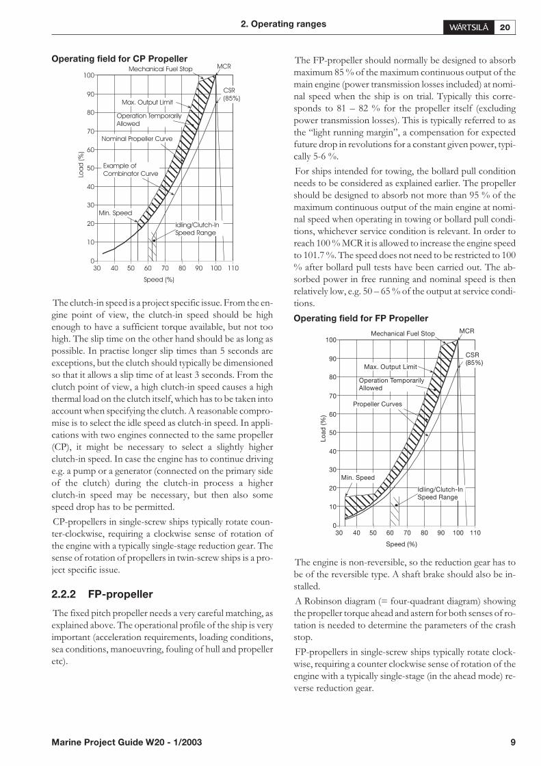
Operating field for CP Propeller
The clutch-in speed is a project specific issue. From the en-gine point of view, the clutch-in speed should be highenough to have a sufficient torque available, but not toohigh. The slip time on the other hand should be as long aspossible. In practise longer slip times than 5 seconds areexceptions, but the clutch should typically be dimensionedso that it allows a slip time of at least 3 seconds. From theclutch point of view, a high clutch-in speed causes a highthermal load on the clutch itself, which has to be taken intoaccount when specifying the clutch. A reasonable compro-mise is to select the idle speed as clutch-in speed. In appli-cations with two engines connected to the same propeller(CP), it might be necessary to select a slightly higherclutch-in speed. In case the engine has to continue drivinge.g. a pump or a generator (connected on the primary sideof the clutch) during the clutch-in process a higherclutch-in speed may be necessary, but then also somespeed drop has to be permitted.
CP-propellers in single-screw ships typically rotate coun-ter-clockwise, requiring a clockwise sense of rotation ofthe engine with a typically single-stage reduction gear. Thesense of rotation of propellers in twin-screw ships is a pro-ject specific issue.
2.2.2 FP-propeller
The fixed pitch propeller needs a very careful matching, asexplained above. The operational profile of the ship is veryimportant (acceleration requirements, loading conditions,sea conditions, manoeuvring, fouling of hull and propelleretc).
The FP-propeller should normally be designed to absorbmaximum 85 % of the maximum continuous output of themain engine (power transmission losses included) at nomi-nal speed when the ship is on trial. Typically this corre-sponds to 81 – 82 % for the propeller itself (excludingpower transmission losses). This is typically referred to asthe “light running margin”, a compensation for expectedfuture drop in revolutions for a constant given power, typi-cally 5-6 %.
For ships intended for towing, the bollard pull conditionneeds to be considered as explained earlier. The propellershould be designed to absorb not more than 95 % of themaximum continuous output of the main engine at nomi-nal speed when operating in towing or bollard pull condi-tions, whichever service condition is relevant. In order toreach 100 % MCR it is allowed to increase the engine speedto 101.7 %. The speed does not need to be restricted to 100% after bollard pull tests have been carried out. The ab-sorbed power in free running and nominal speed is thenrelatively low, e.g. 50 – 65 % of the output at service condi-tions.
Operating field for FP Propeller
The engine is non-reversible, so the reduction gear has tobe of the reversible type. A shaft brake should also be in-stalled.
A Robinson diagram (= four-quadrant diagram) showingthe propeller torque ahead and astern for both senses of ro-tation is needed to determine the parameters of the crashstop.
FP-propellers in single-screw ships typically rotate clock-wise, requiring a counter clockwise sense of rotation of theengine with a typically single-stage (in the ahead mode) re-verse reduction gear.
2. Operating ranges
Marine Project Guide W20 - 1/2003 9
Idling/Clutch-In
Speed Range
Example of
Combinator Curve
Operation Temporarily
Allowed
Mechanical Fuel Stop
Max. Output Limit
Nominal Propeller Curve
Min. Speed
MCR
CSR
(85%)
Speed (%)
Loa
d(%
)
0
10
20
70605040
30
80 90 100 110
70
60
50
40
30
80
90
100
Idling/Clutch-InSpeed Range
Operation TemporarilyAllowed
Mechanical Fuel Stop
Max. Output Limit
Propeller Curves
Min. Speed
MCR
CSR(85%)
Speed (%)
Lo
ad
(%)
0
10
20
70605040
30
80 90 100 110
70
60
50
40
30
80
90
100
2.2.3 Water jets
Water jets also require a careful matching with the engine,similar to that of the fixed pitched propeller. However,there are some distinctive differences between thedimensioning of a water jet compared to that of a fixedpitch propeller.
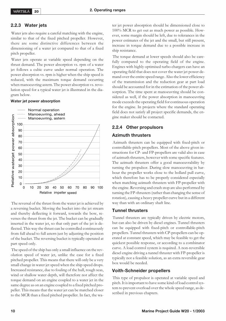
Water jets operate at variable speed depending on thethrust demand. The power absorption vs. rpm of a waterjet follows a cubic curve under normal operation. Thepower absorption vs. rpm is higher when the ship speed isreduced, with the maximum torque demand occurringwhen manoeuvring astern. The power absorption vs. revo-lution speed for a typical water jet is illustrated in the dia-gram below.
Water jet power absorption
The reversal of the thrust from the water jet is achieved bya reversing bucket. Moving the bucket into the jet streamand thereby deflecting it forward, towards the bow, re-verses the thrust from the jet. The bucket can be graduallyinserted in the water jet, so that only part of the jet is de-flected. This way the thrust can be controlled continuouslyfrom full ahead to full astern just by adjusting the positionof the bucket. The reversing bucket is typically operated atpart speed only.
The speed of the ship has only a small influence on the rev-olution speed of water jet, unlike the case for a fixedpitched propeller. This means that there will only be a verysmall change in water jet speed when the ship speed drops.Increased resistance, due to fouling of the hull, rough seas,wind or shallow water depth, will therefore not affect thetorque demand on an engine coupled to a water jet in thesame degree as on an engine coupled to a fixed pitched pro-peller. This means that the water jet can be matched closerto the MCR than a fixed pitched propeller. In fact, the wa-
ter jet power absorption should be dimensioned close to100% MCR to get out as much power as possible. How-ever, some margin should be left, due to tolerances in thepower estimates of the jet and the small, but still present,increase in torque demand due to a possible increase inship resistance.
The torque demand at lower speeds should also be care-fully compared to the operating field of the engine.Engines with highly optimised turbo chargers can have anoperating field that does not cover the water jet power de-mand over the entire speed range. Also the lower efficiencyof the transmission and the reduction gear at part loadshould be accounted for in the estimation of the power ab-sorption. The time spent at manoeuvring should be con-sidered as well, if the power absorption in manoeuvringmode exceeds the operating field for continuous operationfor the engine. In projects where the standard operatingfield does not satisfy all project specific demands, the en-gine maker should be contacted.
2.2.4 Other propulsors
Azimuth thrusters
Azimuth thrusters can be equipped with fixed-pitch orcontrollable-pitch propellers. Most of the above given in-structions for CP- and FP-propellers are valid also in caseof azimuth thrusters, however with some specific features.The azimuth thrusters offer a good manoeuvrability byturning the propulsor. During slow manoeuvring in har-bour the propeller works close to the bollard pull curve,which therefore has to be properly considered especiallywhen matching azimuth thrusters with FP-propeller withthe engine. Reversing and crash stop are also performed byturning the FP-thrusters (rather than changing the sense ofrotation), causing a heavy propeller curve but in a differentway than with an ordinary shaft line.
Tunnel thrusters
Tunnel thrusters are typically driven by electric motors,but can also be driven by diesel engines. Tunnel thrusterscan be equipped with fixed-pitch or controllable-pitchpropellers. Tunnel thrusters with CP-propellers can be op-erated at constant speed, which may be feasible to get thequickest possible response, or according to a combinatorcurve. A load control system is required. A non-reversiblediesel engine driving a tunnel thruster with FP-propeller istypically not a feasible solution, as an extra reversible gearbox would be needed.
Voith-Schneider propellers
This type of propulsor is operated at variable speed andpitch. It is important to have some kind of load control sys-tem to prevent overload over the whole speed range, as de-scribed in previous chapters.
10 Marine Project Guide W20 - 1/2003
2. Operating ranges
0
10
20
30
40
50
60
70
80
90
100
Relative impeller speed
Rela
tive
wate
rjet
po
wer
ab
so
rptio
n
Normal operation
Manoeuvring, aheadManoeuvring, astern
0 10 20 30 40 50 60 70 80 90 100
2.2.5 Dredgers
The power generation plant of a dredger can be of differ-ent configurations:
• Diesel-electric. Propulsors and dredging pumps are elec-trically driven. This is a good and flexible solution, butalso the most expensive.
• Mechanically driven main propellers, and electricallydriven dredging pumps and thrusters. The main enginesand generators driven e.g. from the free end of thecrankshaft are running at constant speed, and the dredg-ing pumps can be operated at variable speed with a fre-quency converter. This is a good, flexible andcost-effective solution.
The configuration with the main engine running at con-stant speed has proved to be a good solution, also capableof taking the typical load transients coming from thedredging pumps.
• Mechanically driven main propellers and dredgingpumps. The main engines have to operate at variablespeed. This may appear to be the cheapest solution, butit has operational limitations.
In this configuration, when the dredging pumps are me-chanically driven, dredging requires a capability to run aconstant torque down to 70 or 80 % of the nominal speed.This kind of torque requirement results in normally signifi-cant de-rating of the main engines.
2.2.6 Generators
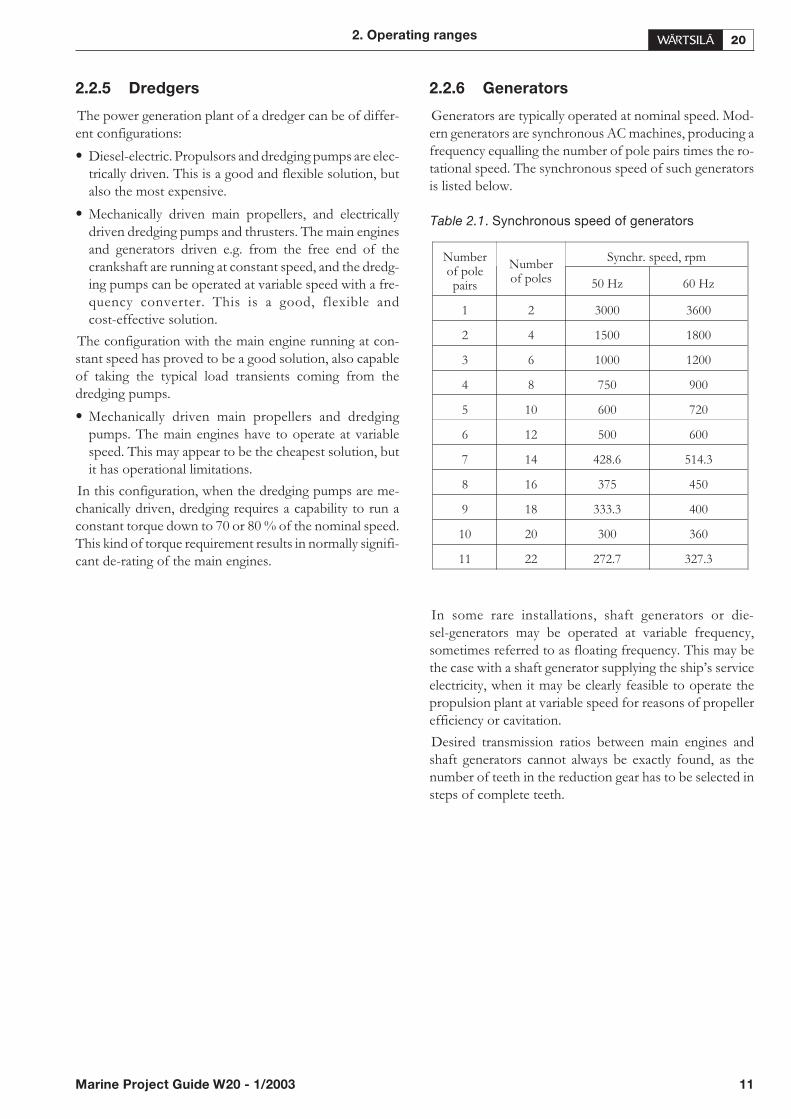
Generators are typically operated at nominal speed. Mod-ern generators are synchronous AC machines, producing afrequency equalling the number of pole pairs times the ro-tational speed. The synchronous speed of such generatorsis listed below.
In some rare installations, shaft generators or die-sel-generators may be operated at variable frequency,sometimes referred to as floating frequency. This may bethe case with a shaft generator supplying the ship’s serviceelectricity, when it may be clearly feasible to operate thepropulsion plant at variable speed for reasons of propellerefficiency or cavitation.
Desired transmission ratios between main engines andshaft generators cannot always be exactly found, as thenumber of teeth in the reduction gear has to be selected insteps of complete teeth.
2. Operating ranges
Marine Project Guide W20 - 1/2003 11
Table 2.1. Synchronous speed of generators
Numberof polepairs
Numberof poles
Synchr. speed, rpm
50 Hz 60 Hz
1 2 3000 3600
2 4 1500 1800
3 6 1000 1200
4 8 750 900
5 10 600 720
6 12 500 600
7 14 428.6 514.3
8 16 375 450
9 18 333.3 400
10 20 300 360
11 22 272.7 327.3
This is also the case when the generator nominal speed is amultiple of the nominal speed of the engine. The numberof teeth is selected to permit all teeth being in contact withall teeth of the other gear wheel, to avoid uneven wear. Toachieve this target, gear wheels with a multiple number ofteeth compared with its smaller pair should be avoided.This is valid for the main power transmission from the en-gine to the propeller, as well as for PTOs for shaft genera-tors. In other words cases where a combination of toothnumbers giving exactly the desired transmission ratio canbe found, it is not feasible to use them.
The maximum output of diesel engines driving auxiliarygenerators and diesel engines driving generators for pro-pulsion is 110 % of the MCR.
2.3. Loading capacity
The loading rate of a highly supercharged diesel enginemust be controlled, because the turbocharger needs time toaccelerate before it can deliver the required amount of air.However in normal operation the load should always beapplied gradually.
2.3.1 Diesel-mechanical propulsion
The loading is to be controlled by a load increaseprogramme, which is included in the propeller control sys-tem.
2.3.2 Diesel-electric propulsion
Class rules regarding load acceptance capability should notbe interpreted as guidelines on how to apply load on the en-gine in normal operation. The class rules only determinewhat the engine must be capable of, if an emergency situa-tion occurs.
The electrical system onboard the ship must be designedso that the diesel generators are protected from load stepsthat exceed the limit. Normally system specifications mustbe sent to the classification society for approval and thefunctionality of the system is to be demonstrated duringthe ship’s trial.
The loading performance is affected by the rotational iner-tia of the whole generating set, the speed governor adjust-ment and behaviour, generator design, alternatorexcitation system, voltage regulator behaviour and nominaloutput.
Loading capacity and overload specifications are to be de-veloped in co-operation between the plant designer, enginemanufacturer and classification society at an early stage ofthe project. Features to be incorporated in the power man-agement systems are presented in the Chapter for electricalpower generation.
2.3.3 Auxiliary engines driving generators
The load should always be applied gradually in normal op-eration. This will prolong the lifetime of engine compo-nents. The class rules only determine what the engine mustbe capable of, if an emergency situation occurs. Providedthat the engine is preheated to a HT-water temperature of60…70ºC the engine can be loaded immediately after start.
The fastest loading is achieved with a successive gradualincrease in load from 0 to 100 %. It is recommended thatthe switchboards and the power management system aredesigned to increase the load as smoothly as possible.
The electrical system onboard the ship must be designedso that the diesel generators are protected from load stepsthat exceed the limit. Normally system specifications mustbe sent to the classification society for approval and thefunctionality of the system is to be demonstrated duringthe ship’s trial.
2.4. Ambient conditions
2.4.1 High air temperature
The maximum inlet air temperature is + 45ºC. Higher tem-peratures would cause an excessive thermal load on the en-gine, and can be permitted only by de-rating the engine(permanently lowering the MCR) 0.35 % for each 1ºCabove + 45ºC.
2.4.2 Low air temperature
When designing ships for low temperatures the followingminimum inlet air temperature shall be taken into consid-eration:
• For starting + 5ºC.
• For idling: - 5ºC.
• At high load: - 10ºC.
At high load, cold suction air with a high density causeshigh firing pressures. The given limit is valid for a standardengine.
For temperatures below 0ºC special provisions may benecessary on the engine or ventilation arrangement.
Other guidelines for low suction air temperatures are givenin the chapter for Combustion air system.
12 Marine Project Guide W20 - 1/2003
2. Operating ranges

2.4.3 High water temperature
The maximum inlet LT-water temperature is + 38ºC.Higher temperatures would cause an excessive thermalload on the engine, and can be permitted only if de-ratingthe engine (permanently lowering the MCR) 0.3 % for each1ºC above + 38ºC.
2.4.4 Operation at low load and idling
The engine can be started, stopped and operated on heavyfuel under all operating conditions. Continuous operationon heavy fuel is preferred rather than changing over to die-sel fuel at low load operation and manoeuvring. The fol-lowing recommendations apply:
Absolute idling (declutched main engine,
disconnected generator)
Maximum 5 minutes (recommended about 1 min for postcooling), if the engine is to be stopped after the idling.
Operation at < 20 % load on HFO or < 10
% on MDF
Maximum 100 hours continuous operation. At intervals of100 operating hours the engine must be loaded to mini-mum 70 % of the rated load.
Operation at > 20 % load on HFO or > 10
% on MDF
No restrictions.
2. Operating ranges
Marine Project Guide W20 - 1/2003 13

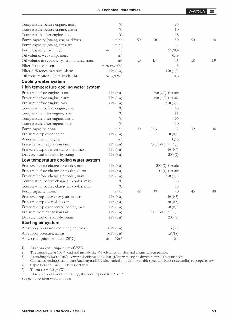
3. Technical data tables
Diesel engine Wärtsilä 4L20 ME AE AE AE AE
Engine speed rpm 720 750 900 10001000
Engine output kW 520 540 680 720720
Engine output hp 710 730 920 980980
Cylinder bore mm 200
Stroke mm 280
Swept volume dm³ 35,2
Compression ratio 15
Compression pressure, max. bar 150 150 167 167167
Firing pressure, max. bar 180 180 190 190190
Charge air pressure at 100% load MPa 0,3
Mean effective pressure bar 24,6 24,6 25,8 24,624,6
Mean piston speed m/s 6,7 7 8,4 9,39,3
Minimum speed (FPP installations) hp 350
Combustion air system
Flow of air at 100% load kg/s 0,94 0,99 1,25 1,421,42
Ambient air temperature, max. °C 45
Air temperature after air cooler °C 45…60
Air temperature after air cooler, alarm °C 75
Exhaust gas system
Exhaust gas flow (100% load) 3) kg/s 0,97 1,02 1,39 1,461,46
Exhaust gas flow ( 85% load) 3) kg/s 0,84 0,89 1,21 1,281,25
Exhaust gas flow ( 75% load) 3) kg/s 0,76 0,81 1,08 1,151,1
Exhaust gas flow ( 25% load) 3) kg/s 0,55 0,59 0,77 0,840,73
Exhaust gas temp. after turbocharger (100% load) 1) 3) °C 360 360 340 350350
Exhaust gas temp. after turbocharger ( 85% load) 1) 3) °C 360 360 340 350365
Exhaust gas temp. after turbocharger ( 75% load) 1) 3) °C 360 365 340 350370
Exhaust gas temp. after turbocharger ( 50% load) 1) 3) °C 370 370 350 360390
Exhaust gas back pressure drop, max. kPa 3
Diameter of turbocharger connection mm 200
Exhaust gas pipe diameter, min. mm 250 250 300 300300
Calculated dia for 35 m/s mm 251 257 295 305305
Heat balance 2) 3)
Jacket water kW 127 132 149 161161
Charge air kW 157 161 206 220220
Lubricating oil kW 67 69 78 8585
Exhaust gases kW 356 374 490 523523
Radiation kW 31 31 37 4242
Fuel system
Pressure before injection pumps kPa (bar) 600(6)
Pump capacity, MDF, engine driven m³/h 0,87 0,9 0,41 0,410,41
Fuel consumption (100% load) 3) g/kWh 195 195 194 196196
Fuel consumption ( 85% load) 3) g/kWh 196 196 194 196193
Fuel consumption ( 75% load) 3) g/kWh 198 198 195 197194
Fuel consumption ( 50% load) 3) g/kWh 204 204 201 201201
Leak fuel quantity, clean MDF fuel (100% load) kg/h 0,4 0,4 0,5 0,50,5
Fuel flow/consumption ratio 4:1
Lubricating oil system
Pressure before engine, nom. kPa (bar) 450 (4,5)
Pressure before engine, alarm kPa (bar) 300 (3)
14 Marine Project Guide W20 - 1/2003
3. Technical data tables
Pressure before engine, stop kPa (bar) 200 (2)
Priming pressure, nom. kPa (bar) 80 (0,8)
Priming pressure, alarm kPa (bar) 50 (0,5)
Temperature before engine, nom. °C 63
Temperature before engine, alarm °C 80
Temperature after engine, abt. °C 78
Pump capacity (main), engine driven m³/h 28
Pump capacity (main), separate m³/h 18
Pump capacity (priming) 4) m³/h 6,9/8,4
Oil volume, wet sump, nom. m³ 0,27
Oil volume in separate system oil tank, nom. m³ 0,7 0,7 0,9 11
Filter fineness, nom. microns/60% 15
Filter difference pressure, alarm kPa (bar) 150 (1,5)
Oil consumption (100% load), abt. 5) g/kWh 0,6
Cooling water system
High temperature cooling water system
Pressure before engine, nom. kPa (bar) 200 (2,0) + static
Pressure before engine, alarm kPa (bar) 100 (1,0) + static
Pressure before engine, max. kPa (bar) 350 (3,5)
Temperature before engine, abt. °C 83
Temperature after engine, nom. °C 91
Temperature after engine, alarm °C 105
Temperature after engine, stop °C 110
Pump capacity, nom. m³/h 18 18,5 19,5 2020
Pressure drop over engine kPa (bar) 50 (0,5)
Water volume in engine m³ 0,09
Pressure from expansion tank kPa (bar) 70…150 (0,7…1,5)
Pressure drop over central cooler, max. kPa (bar) 60 (0,6)
Delivery head of stand-by pump kPa (bar) 200 (2)
Low temperature cooling water system
Pressure before charge air cooler, nom. kPa (bar) 200 (2) + static
Pressure before charge air cooler, alarm kPa (bar) 100 (1) + static
Pressure before charge air cooler, max. kPa (bar) 350 (3,5)
Temperature before charge air cooler, max. °C 38
Temperature before charge air cooler, min. °C 25
Pump capacity, nom. m³/h 19 20 22,5 2424
Pressure drop over charge air cooler kPa (bar) 30 (0,3)
Pressure drop over oil cooler kPa (bar) 30 (0,3)
Pressure drop over central cooler, max. kPa (bar) 60 (0,6)
Pressure from expansion tank kPa (bar) 70…150 (0,7…1,5)
Delivery head of stand-by pump kPa (bar) 200 (2)
Starting air system
Air supply pressure before engine (max.) MPa (bar) 3 (30)
Air supply pressure, alarm MPa (bar) 1,8 (18)
Air consumption per start (20°C) 6) Nm³ 0,41) At an ambient temperature of 25°C.2) The figures are at 100% load and include the 5% tolerance on sfoc and engine driven pumps.3) According to ISO 3046/1, lower calorific value 42 700 kJ/kg, with engine driven pumps. Tolerance 5%.
Constant speed applications are Auxiliary and DE. Mechanical propulsion variable speed applications according to propeller law.4) Capacities at 50 and 60 Hz respectively.5) Tolerance + 0.3 g/kWh6) At remote and automatic starting, the consumption is 1.2 Nm³Subject to revision without notice.
Marine Project Guide W20 - 1/2003 15
3. Technical data tables
Diesel engine Wärtsilä 5L20 ME AE AE
Engine speed rpm 900 10001000
Engine output kW 775 825825
Engine output hp 1050 11201120
Cylinder bore mm 200
Stroke mm 280
Swept volume dm³ 44
Compression ratio 15
Compression pressure, max. bar 155
Firing pressure, max. bar 190
Charge air pressure at 100% load MPa 0,3
Mean effective pressure bar 23,5 22,522,5
Mean piston speed m/s 8,4 9,39,3
Minimum speed (FPP installations) rpm 350
Combustion air system
Flow of air at 100% load kg/s 1,42 1,51,5
Ambient air temperature, max. °C 45
Air temperature after air cooler °C 45…60
Air temperature after air cooler, alarm °C 75
Exhaust gas system
Exhaust gas flow (100% load) 3) kg/s 1,55 1,551,55
Exhaust gas flow ( 85% load) 3) kg/s 1,37 1,371,33
Exhaust gas flow ( 75% load) 3) kg/s 1,25 1,251,19
Exhaust gas flow ( 25% load) 3) kg/s 0,94 0,940,82
Exhaust gas temp. after turbocharger (100% load) 1) 3) °C 360 360360
Exhaust gas temp. after turbocharger ( 85% load) 1) 3) °C 350 350365
Exhaust gas temp. after turbocharger ( 75% load) 1) 3) °C 360 360385
Exhaust gas temp. after turbocharger ( 50% load) 1) 3) °C 360 360395
Exhaust gas back pressure drop, max. kPa 3
Diameter of turbocharger connection mm 250
Exhaust gas pipe diameter, min. mm 350
Calculated dia for 35 m/s mm 317 317317
Heat balance 2) 3)
Jacket water kW 173 189189
Charge air kW 226 240240
Lubricating oil kW 91 101101
Exhaust gases kW 558 602602
Radiation kW 43 4949
Fuel system
Pressure before injection pumps kPa (bar) 600(6)
Pump capacity, MDF, engine driven m³/h 0,57 0,570,57
Fuel consumption (100% load) 3) g/kWh 196 196196
Fuel consumption ( 85% load) 3) g/kWh 195 195 195
Fuel consumption ( 75% load) 3) g/kWh 197 197196
Fuel consumption ( 50% load) 3) g/kWh 208 208202
Leak fuel quantity, clean MDF fuel (100% load) kg/h 0,7 0,70,7
Fuel flow/consumption ratio 4:1
Lubricating oil system
Pressure before engine, nom. kPa (bar) 450 (4,5) 450 (4,5)450 (4,5)
Pressure before engine, alarm kPa (bar) 300 (3) 300 (3)300 (3)
Pressure before engine, stop kPa (bar) 200 (2) 200 (2)200 (2)
Priming pressure, nom. kPa (bar) 80 (0,8) 80 (0,8)80 (0,8)
Priming pressure, alarm kPa (bar) 50 (0,5) 50 (0,5)50 (0,5)
16 Marine Project Guide W20 - 1/2003
3. Technical data tables

Temperature before engine, nom. °C 63
Temperature before engine, alarm °C 80
Temperature after engine, abt. °C 78
Pump capacity (main), engine driven m³/h 28
Pump capacity (main), separate m³/h 19,5
Pump capacity (priming) 4) m³/h 6,9/8,4
Oil volume, wet sump, nom. m³ 0,32
Oil volume in separate system oil tank, nom. m³ 1 1,11,1
Filter fineness, nom. microns/60% 15
Filter difference pressure, alarm kPa (bar) 150 (1,5) 150 (1,5)150 (1,5)
Oil consumption (100% load), abt. 5) g/kWh 0,6
Cooling water system
High temperature cooling water system
Pressure before engine, nom. kPa (bar) 200 (2,0) + static
Pressure before engine, alarm kPa (bar) 100 (1,0) + static
Pressure before engine, max. kPa (bar) 350 (3,5)
Temperature before engine, abt. °C 83
Temperature after engine, nom. °C 91
Temperature after engine, alarm °C 105
Temperature after engine, stop °C 110
Pump capacity, nom. m³/h 24 2525
Pressure drop over engine kPa (bar) 50 (0,5)
Water volume in engine m³ 0,09 0,090,105
Pressure from expansion tank kPa (bar) 70…150 (0,7…1,5)
Pressure drop over central cooler, max. kPa (bar) 60 (0,6)
Delivery head of stand-by pump kPa (bar) 200 (2)
Low temperature cooling water system
Pressure before charge air cooler, nom. kPa (bar) 200 (2) + static
Pressure before charge air cooler, alarm kPa (bar) 100 (1) + static
Pressure before charge air cooler, max. kPa (bar) 350 (3,5)
Temperature before charge air cooler, max. °C 38
Temperature before charge air cooler, min. °C 25
Pump capacity, nom. m³/h 28 3030
Pressure drop over charge air cooler kPa (bar) 30 (0,3)
Pressure drop over oil cooler kPa (bar) 30 (0,3)
Pressure drop over central cooler, max. kPa (bar) 60 (0,6)
Pressure from expansion tank kPa (bar) 70…150 (0,7…1,5)
Delivery head of stand-by pump kPa (bar) 200 (2)
Starting air system
Air supply pressure before engine (max.) MPa (bar) 3 (30)
Air supply pressure, alarm MPa (bar) 1,8 (18)
Air consumption per start (20°C) 6) Nm³ 0,4
1) At an ambient temperature of 25°C.2) The figures are at 100% load and include the 5% tolerance on sfoc and engine driven pumps.3) According to ISO 3046/1, lower calorific value 42 700 kJ/kg, with engine driven pumps. Tolerance 5%.
Constant speed applications are Auxiliary and DE. Mechanical propulsion variable speed applications according to propeller law.4) Capacities at 50 and 60 Hz respectively.5) Tolerance + 0.3 g/kWh6) At remote and automatic starting, the consumption is 1.2 Nm³Subject to revision without notice.
3. Technical data tables
Marine Project Guide W20 - 1/2003 17
Diesel engine Wärtsilä 6L20 ME AE AE AE AE
Engine speed rpm 720 750 900 10001000
Engine output kW 780 810 1020 10801080
Engine output hp 1060 1100 1390 14701470
Cylinder bore mm 200
Stroke mm 280
Swept volume dm³ 52,8
Compression ratio 15
Compression pressure, max. bar 150 150 167 167167
Firing pressure, max. bar 180 180 190 190190
Charge air pressure at 100% load MPa 0,3
Mean effective pressure bar 24,6 24,6 25,8 24,624,6
Mean piston speed m/s 6,7 7 8,4 9,39,3
Minimum speed (FPP installations) rpm 350
Combustion air system
Flow of air at 100% load kg/s 1,36 1,43 2,1 2,22,2
Ambient air temperature, max. °C 45
Air temperature after air cooler °C 45…60
Air temperature after air cooler, alarm °C 75
Exhaust gas system
Exhaust gas flow (100% load) 3) kg/s 1,4 1,48 2,16 2,262,26
Exhaust gas flow ( 85% load) 3) kg/s 1,21 1,29 1,86 1,971,93
Exhaust gas flow ( 75% load) 3) kg/s 1,09 1,16 1,68 1,781,69
Exhaust gas flow ( 25% load) 3) kg/s 0,79 0,84 1,2 1,291,11
Exhaust gas temp. after turbocharger (100% load) 1) 3) °C 370 370 330 330330
Exhaust gas temp. after turbocharger ( 85% load) 1) 3) °C 380 380 330 330335
Exhaust gas temp. after turbocharger ( 75% load) 1) 3) °C 380 380 330 330345
Exhaust gas temp. after turbocharger ( 50% load) 1) 3) °C 390 390 340 330385
Exhaust gas back pressure drop, max. kPa 3
Diameter of turbocharger connection mm 250
Exhaust gas pipe diameter, min. mm 300 300 350 350350
Calculated dia for 35 m/s mm 304 312 365 374374
Heat balance 2) 3)
Jacket water kW 189 194 212 226226
Charge air kW 201 223 305 327327
Lubricating oil kW 106 108 133 143143
Exhaust gases kW 530 549 685 727727
Radiation kW 44 47 53 5959
Fuel system
Pressure before injection pumps kPa (bar) 600(6)
Pump capacity, MDF, engine driven m³/h 0,86 0,89 1,33 1,481,48
Fuel consumption (100% load) 3) g/kWh 191 192 190 191191
Fuel consumption ( 85% load) 3) g/kWh 192 193 189 190188
Fuel consumption ( 75% load) 3) g/kWh 194 194 190 190188
Fuel consumption ( 50% load) 3) g/kWh 203 203 198 198196
Leak fuel quantity, clean MDF fuel (100% load) kg/h 0,6 0,7 0,7 0,90,9
Fuel flow/consumption ratio 4:1
Lubricating oil system
Pressure before engine, nom. kPa (bar) 450 (4,5)
Pressure before engine, alarm kPa (bar) 300 (3)
Pressure before engine, stop kPa (bar) 200 (2)
Priming pressure, nom. kPa (bar) 80 (0,8)
Priming pressure, alarm kPa (bar) 50 (0,5)
18 Marine Project Guide W20 - 1/2003
3. Technical data tables

Temperature before engine, nom. °C 63
Temperature before engine, alarm °C 80
Temperature after engine, abt. °C 78
Pump capacity (main), engine driven m³/h 35 35 35 3535
Pump capacity (main), separate m³/h 21
Pump capacity (priming) 4) m³/h 6,9/8,4
Oil volume, wet sump, nom. m³ 0,38
Oil volume in separate system oil tank, nom. m³ 1,1 1,1 1,4 1,51,5
Filter fineness, nom. microns/60% 15
Filter difference pressure, alarm kPa (bar) 150 (1,5)
Oil consumption (100% load), abt. 5) g/kWh 0,6
Cooling water system
High temperature cooling water system
Pressure before engine, nom. kPa (bar) 200 (2,0) + static
Pressure before engine, alarm kPa (bar) 100 (1,0) + static
Pressure before engine, max. kPa (bar) 350 (3,5)
Temperature before engine, abt. °C 83
Temperature after engine, nom. °C 91
Temperature after engine, alarm °C 105
Temperature after engine, stop °C 110
Pump capacity, nom. m³/h 27 28 29 3030
Pressure drop over engine kPa (bar) 50 (0,5)
Water volume in engine m³ 0,12
Pressure from expansion tank kPa (bar) 70…150 (0,7…1,5)
Pressure drop over central cooler, max. kPa (bar) 60 (0,6)
Delivery head of stand-by pump kPa (bar) 200 (2)
Low temperature cooling water system
Pressure before charge air cooler, nom. kPa (bar) 200 (2) + static
Pressure before charge air cooler, alarm kPa (bar) 100 (1) + static
Pressure before charge air cooler, max. kPa (bar) 350 (3,5)28
Temperature before charge air cooler, max. °C 38
Temperature before charge air cooler, min. °C 25
Pump capacity, nom. m³/h 29 30 34 3636
Pressure drop over charge air cooler kPa (bar) 30 (0,3)
Pressure drop over oil cooler kPa (bar) 30 (0,3)
Pressure drop over central cooler, max. kPa (bar) 60 (0,6)
Pressure from expansion tank kPa (bar) 70…150 (0,7…1,5)
Delivery head of stand-by pump kPa (bar) 200 (2)
Starting air system
Air supply pressure before engine (max.) MPa (bar) 3 (30)
Air supply pressure, alarm MPa (bar) 1,8 (18)
Air consumption per start (20°C) 6) Nm³ 0,4
1) At an ambient temperature of 25°C.2) The figures are at 100% load and include the 5% tolerance on sfoc and engine driven pumps.3) According to ISO 3046/1, lower calorific value 42 700 kJ/kg, with engine driven pumps. Tolerance 5%.
Constant speed applications are Auxiliary and DE. Mechanical propulsion variable speed applications according to propeller law.4) Capacities at 50 and 60 Hz respectively.5) Tolerance + 0.3 g/kWh6) At remote and automatic starting, the consumption is 1.2 Nm³Subject to revision without notice.
3. Technical data tables
Marine Project Guide W20 - 1/2003 19

Diesel engine Wärtsilä 8L20 ME AE AE AE AE
Engine speed rpm 720 750 900 10001000
Engine output kW 1040 1080 1360 14401440
Engine output hp 1410 1470 1850 19601960
Cylinder bore mm 200
Stroke mm 280
Swept volume dm³ 70,4
Compression ratio 15
Compression pressure, max. bar 150 150 167 167167
Firing pressure, max. bar 180 180 190 190190
Charge air pressure at 100% load MPa 0,3
Mean effective pressure bar 24,6 24,6 25,8 24,624,6
Mean piston speed m/s 6,7 7 8,4 9,39,3
Minimum speed (FPP installations) rpm 350
Combustion air system
Flow of air at 100% load kg/s 1,96 2,04 2,79 2,852,85
Ambient air temperature, max. °C 45
Air temperature after air cooler °C 45…60
Air temperature after air cooler, alarm °C 75
Exhaust gas system
Exhaust gas flow (100% load) 3) kg/s 2,02 2,1 2,87 2,932,94
Exhaust gas flow ( 85% load) 3) kg/s 1,74 1,81 2,48 2,532,5
Exhaust gas flow ( 75% load) 3) kg/s 1,57 1,62 2,24 2,292,18
Exhaust gas flow ( 25% load) 3) kg/s 1,11 1,15 1,61 1,641,44
Exhaust gas temp. after turbocharger (100% load) 1) 3) °C 360 360 350 340350
Exhaust gas temp. after turbocharger ( 85% load) 1) 3) °C 360 360 340 340355
Exhaust gas temp. after turbocharger ( 75% load) 1) 3) °C 360 360 340 340360
Exhaust gas temp. after turbocharger ( 50% load) 1) 3) °C 370 370 350 350390
Exhaust gas back pressure drop, max. kPa 3
Diameter of turbocharger connection mm 300
Exhaust gas pipe diameter, min. mm 350 350 400 400400
Calculated dia for 35 m/s mm 362 369 428 429433
Heat balance 2) 3)
Jacket water kW 244 254 307 330330
Charge air kW 306 322 407 442434
Lubricating oil kW 162 167 204 219219
Exhaust gases kW 684 708 890 9691003
Radiation kW 55 57 74 7676
Fuel system
Pressure before injection pumps kPa (bar) 600(6)
Pump capacity, MDF, engine driven m³/h 1,47 1,53 1,72 1,911,91
Fuel consumption (100% load) 3) g/kWh 193 193 192 193196
Fuel consumption ( 85% load) 3) g/kWh 194 194 191 192195
Fuel consumption ( 75% load) 3) g/kWh 195 195 191 193195
Fuel consumption ( 50% load) 3) g/kWh 202 202 200 200201
Leak fuel quantity, clean MDF fuel (100% load) kg/h 0,8 0,9 1,1 1,21,2
Fuel flow/consumption ratio 4:1
Lubricating oil system
Pressure before engine, nom. kPa (bar) 450 (4,5)
Pressure before engine, alarm kPa (bar) 300 (3)
Pressure before engine, stop kPa (bar) 200 (2)
Priming pressure, nom. kPa (bar) 80 (0,8)
Priming pressure, alarm kPa (bar) 50 (0,5)
20 Marine Project Guide W20 - 1/2003
3. Technical data tables
Temperature before engine, nom. °C 63
Temperature before engine, alarm °C 80
Temperature after engine, abt. °C 78
Pump capacity (main), engine driven m³/h 50 50 50 5050
Pump capacity (main), separate m³/h 27
Pump capacity (priming) 4) m³/h 6,9/8,4
Oil volume, wet sump, nom. m³ 0,49
Oil volume in separate system oil tank, nom. m³ 1,4 1,5 1,8 1,91,9
Filter fineness, nom. microns/60% 15
Filter difference pressure, alarm kPa (bar) 150 (1,5)
Oil consumption (100% load), abt. 5) g/kWh 0,6
Cooling water system
High temperature cooling water system
Pressure before engine, nom. kPa (bar) 200 (2,0) + static
Pressure before engine, alarm kPa (bar) 100 (1,0) + static
Pressure before engine, max. kPa (bar) 350 (3,5)
Temperature before engine, abt. °C 83
Temperature after engine, nom. °C 91
Temperature after engine, alarm °C 105
Temperature after engine, stop °C 110
Pump capacity, nom. m³/h 35,5 37 39 4040
Pressure drop over engine kPa (bar) 50 (0,5)
Water volume in engine m³ 0,15
Pressure from expansion tank kPa (bar) 70…150 (0,7…1,5)
Pressure drop over central cooler, max. kPa (bar) 60 (0,6)
Delivery head of stand-by pump kPa (bar) 200 (2)
Low temperature cooling water system
Pressure before charge air cooler, nom. kPa (bar) 200 (2) + static
Pressure before charge air cooler, alarm kPa (bar) 100 (1) + static
Pressure before charge air cooler, max. kPa (bar) 350 (3,5)
Temperature before charge air cooler, max. °C 38
Temperature before charge air cooler, min. °C 25
Pump capacity, nom. m³/h 38 40 45 4848
Pressure drop over charge air cooler kPa (bar) 30 (0,3)
Pressure drop over oil cooler kPa (bar) 30 (0,3)
Pressure drop over central cooler, max. kPa (bar) 60 (0,6)
Pressure from expansion tank kPa (bar) 70…150 (0,7…1,5)
Delivery head of stand-by pump kPa (bar) 200 (2)
Starting air system
Air supply pressure before engine (max.) MPa (bar) 3 (30)
Air supply pressure, alarm MPa (bar) 1,8 (18)
Air consumption per start (20°C) 6) Nm³ 0,4
1) At an ambient temperature of 25°C.2) The figures are at 100% load and include the 5% tolerance on sfoc and engine driven pumps.3) According to ISO 3046/1, lower calorific value 42 700 kJ/kg, with engine driven pumps. Tolerance 5%.
Constant speed applications are Auxiliary and DE. Mechanical propulsion variable speed applications according to propeller law.4) Capacities at 50 and 60 Hz respectively.5) Tolerance + 0.3 g/kWh6) At remote and automatic starting, the consumption is 1.2 Nm³Subject to revision without notice.
3. Technical data tables
Marine Project Guide W20 - 1/2003 21

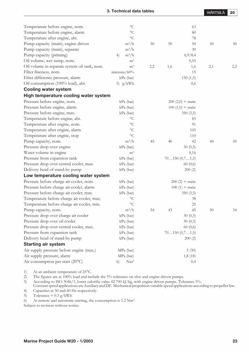
Diesel engine Wärtsilä 9L20 ME AE AE AE AE
Engine speed rpm 720 750 900 10001000
Engine output kW 1170 1215 1530 16201620
Engine output hp 1590 1650 2080 22002200
Cylinder bore mm 200
Stroke mm 280
Swept volume dm³ 79,2
Compression ratio 15
Compression pressure, max. bar 150 150 167 167167
Firing pressure, max. bar 180 180 190 190190
Charge air pressure at 100% load MPa 0,3
Mean effective pressure bar 24,6 24,6 25,8 24,624,6
Mean piston speed m/s 6,7 7 8,4 9,39,3
Minimum speed (FPP installations) rpm 350
Combustion air system
Flow of air at 100% load kg/s 1,98 2,11 3,09 3,193,19
Ambient air temperature, max. °C 45
Air temperature after air cooler °C 45…60
Air temperature after air cooler, alarm °C 75
Exhaust gas system
Exhaust gas flow (100% load) 3) kg/s 2,05 2,18 3,17 3,283,28
Exhaust gas flow ( 85% load) 3) kg/s 1,79 1,91 2,76 2,892,85
Exhaust gas flow ( 75% load) 3) kg/s 1,62 1,73 2,47 2,592,54
Exhaust gas flow ( 25% load) 3) kg/s 1,18 1,27 1,76 1,861,65
Exhaust gas temp. after turbocharger (100% load) 1) 3) °C 360 360 340 340340
Exhaust gas temp. after turbocharger ( 85% load) 1) 3) °C 360 360 340 340340
Exhaust gas temp. after turbocharger ( 75% load) 1) 3) °C 370 370 340 340350
Exhaust gas temp. after turbocharger ( 50% load) 1) 3) °C 380 380 350 330380
Exhaust gas back pressure drop, max. kPa 3
Diameter of turbocharger connection mm 300
Exhaust gas pipe diameter, min. mm 350 350 450 450450
Calculated dia for 35 m/s mm 365 376 446 470470
Heat balance 2) 3)
Jacket water kW 280 291 353 380380
Charge air kW 342 355 458 495495
Lubricating oil kW 177 183 229 244244
Exhaust gases kW 771 800 985 10851085
Radiation kW 63 66 75 7979
Fuel system
Pressure before injection pumps kPa (bar) 600(6)
Pump capacity, MDF, engine driven m³/h 1,47 1,53 1,72 1,911,91
Fuel consumption (100% load) 3) g/kWh 193 193 191 192192
Fuel consumption ( 85% load) 3) g/kWh 193 193 190 191189
Fuel consumption ( 75% load) 3) g/kWh 194 194 191 192190
Fuel consumption ( 50% load) 3) g/kWh 202 202 199 200196
Leak fuel quantity, clean MDF fuel (100% load) kg/h 0,9 1 1,2 1,31,3
Fuel flow/consumption ratio 4:1
Lubricating oil system
Pressure before engine, nom. kPa (bar) 450 (4,5)
Pressure before engine, alarm kPa (bar) 300 (3)
Pressure before engine, stop kPa (bar) 200 (2)
Priming pressure, nom. kPa (bar) 80 (0,8)
Priming pressure, alarm kPa (bar) 50 (0,5)
22 Marine Project Guide W20 - 1/2003
3. Technical data tables
Temperature before engine, nom. °C 63
Temperature before engine, alarm °C 80
Temperature after engine, abt. °C 78
Pump capacity (main), engine driven m³/h 50 50 50 5050
Pump capacity (main), separate m³/h 30
Pump capacity (priming) 4) m³/h 6,9/8,4
Oil volume, wet sump, nom. m³ 0,55
Oil volume in separate system oil tank, nom. m³ 1,6 1,6 2,1 2,22,2
Filter fineness, nom. microns/60% 15
Filter difference pressure, alarm kPa (bar) 150 (1,5)
Oil consumption (100% load), abt. 5) g/kWh 0,6
Cooling water system
High temperature cooling water system
Pressure before engine, nom. kPa (bar) 200 (2,0) + static
Pressure before engine, alarm kPa (bar) 100 (1,0) + static
Pressure before engine, max. kPa (bar) 350 (3,5)
Temperature before engine, abt. °C 83
Temperature after engine, nom. °C 91
Temperature after engine, alarm °C 105
Temperature after engine, stop °C 110
Pump capacity, nom. m³/h 40 42 44 4545
Pressure drop over engine kPa (bar) 50 (0,5)
Water volume in engine m³ 0,16
Pressure from expansion tank kPa (bar) 70…150 (0,7…1,5)
Pressure drop over central cooler, max. kPa (bar) 60 (0,6)
Delivery head of stand-by pump kPa (bar) 200 (2)
Low temperature cooling water system
Pressure before charge air cooler, nom. kPa (bar) 200 (2) + static
Pressure before charge air cooler, alarm kPa (bar) 100 (1) + static
Pressure before charge air cooler, max. kPa (bar) 350 (3,5)
Temperature before charge air cooler, max. °C 38
Temperature before charge air cooler, min. °C 25
Pump capacity, nom. m³/h 43 45 50 5454
Pressure drop over charge air cooler kPa (bar) 30 (0,3)
Pressure drop over oil cooler kPa (bar) 30 (0,3)
Pressure drop over central cooler, max. kPa (bar) 60 (0,6)
Pressure from expansion tank kPa (bar) 70…150 (0,7…1,5)
Delivery head of stand-by pump kPa (bar) 200 (2)
Starting air system
Air supply pressure before engine (max.) MPa (bar) 3 (30)
Air supply pressure, alarm MPa (bar) 1,8 (18)
Air consumption per start (20°C) 6) Nm³ 0,4
1) At an ambient temperature of 25°C.2) The figures are at 100% load and include the 5% tolerance on sfoc and engine driven pumps.3) According to ISO 3046/1, lower calorific value 42 700 kJ/kg, with engine driven pumps. Tolerance 5%.
Constant speed applications are Auxiliary and DE. Mechanical propulsion variable speed applications according to propeller law.4) Capacities at 50 and 60 Hz respectively.5) Tolerance + 0.3 g/kWh6) At remote and automatic starting, the consumption is 1.2 Nm³Subject to revision without notice.
3. Technical data tables
Marine Project Guide W20 - 1/2003 23
4. Description of the engine
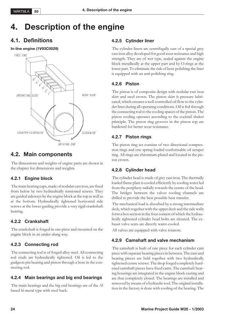
4.1. Definitions
In-line engine (1V93C0029)
4.2. Main components
The dimensions and weights of engine parts are shown inthe chapter for dimensions and weights.
4.2.1 Engine block
The main bearing caps, made of nodular cast iron, are fixedfrom below by two hydraulically tensioned screws. Theyare guided sideways by the engine block at the top as well asat the bottom. Hydraulically tightened horizontal sidescrews at the lower guiding provide a very rigid crankshaftbearing.
4.2.2 Crankshaft
The crankshaft is forged in one piece and mounted on theengine block in an under-slung way.
4.2.3 Connecting rod
The connecting rod is of forged alloy steel. All connectingrod studs are hydraulically tightened. Oil is led to thegudgeon pin bearing and piston through a bore in the con-necting rod.
4.2.4 Main bearings and big end bearings
The main bearings and the big end bearings are of the Albased bi-metal type with steel back.
4.2.5 Cylinder liner
The cylinder liners are centrifugally cast of a special greycast iron alloy developed for good wear resistance and highstrength. They are of wet type, sealed against the engineblock metallically at the upper part and by O-rings at thelower part. To eliminate the risk of bore polishing the lineris equipped with an anti-polishing ring.
4.2.6 Piston
The piston is of composite design with nodular cast ironskirt and steel crown. The piston skirt is pressure lubri-cated, which ensures a well-controlled oil flow to the cylin-der liner during all operating conditions. Oil is fed throughthe connecting rod to the cooling spaces of the piston. Thepiston cooling operates according to the cocktail shakerprinciple. The piston ring grooves in the piston top arehardened for better wear resistance.
4.2.7 Piston rings
The piston ring set consists of two directional compres-sion rings and one spring-loaded conformable oil scraperring. All rings are chromium-plated and located in the pis-ton crown.
4.2.8 Cylinder head
The cylinder head is made of grey cast iron. The thermallyloaded flame plate is cooled efficiently by cooling water ledfrom the periphery radially towards the centre of the head.The bridges between the valves cooling channels aredrilled to provide the best possible heat transfer.
The mechanical load is absorbed by a strong intermediatedeck, which together with the upper deck and the side wallsform a box section in the four corners of which the hydrau-lically tightened cylinder head bolts are situated. The ex-haust valve seats are directly water-cooled.
All valves are equipped with valve rotators.
4.2.9 Camshaft and valve mechanism
The camshaft is built of one piece for each cylinder campiece with separate bearing pieces in between. The cam andbearing pieces are held together with two hydraulicallytightened centre screws. The drop forged completely hard-ened camshaft pieces have fixed cams. The camshaft bear-ing housings are integrated in the engine block casting andare thus completely closed. The bearings are installed andremoved by means of a hydraulic tool. The original installa-tion in the factory is done with cooling of the bearing. The
24 Marine Project Guide W20 - 1/2003
4. Description of the engine
camshaft covers, one for each cylinder, seal against the en-gine block with a closed O-ring profile.
The valve tappets are of piston type with self-adjustmentof roller against cam to give an even distribution of thecontact pressure. The valve springs make the valve mecha-nism dynamically stable.
4.2.10 Camshaft drive
The camshafts are driven by the crankshaft through a geartrain.
4.2.11 Turbocharging and charge air
cooling
The charge air cooler is single stage type and cooled byLT-water.
4.2.12 Injection equipment
The injection pumps are one-cylinder pumps located inthe “multi-housing”, which has the following functions:
• housing for the injection pump element
• fuel supply channel along the whole engine
• fuel return channel from each injection pump
• lubricating oil supply to the valve mechanism
• guiding for the valve tappets
The injection pumps have built-in roller tappets and arethrough-flow type to enable heavy fuel operation. They arealso equipped with a stop cylinder, which is connected tothe electro-pneumatic overspeed protection system.
The injection valve is centrally located in the cylinder headand the fuel is admitted sideways through a high pressureconnection screwed in the nozzle holder. The injectionpipe between the injection pump and the high pressureconnection is well protected inside the hot box. The highpressure side of the injection system is completely sepa-rated from the hot parts of the exhaust gas components.
4.2.13 Exhaust pipes
The exhaust manifold pipes are made of special heat resis-tant nodular cast iron alloy.
The complete exhaust gas system is enclosed in an insulat-ing box consisting of easily removable panels. Mineralwool is used as insulating material.
4. Description of the engine
Marine Project Guide W20 - 1/2003 25

4.3. Cross sections of the engine
26 Marine Project Guide W20 - 1/2003
4. Description of the engine
3 04 0

4.4. Overhaul intervals and
expected life times
The following overhaul intervals and lifetimes are for guid-ance only. Actual figures will be different depending onservice conditions. Expected component lifetimes havebeen adjusted to match overhaul intervals.
In this list HFO is based on HFO2 specification stated inthe chapter for general data and outputs.
4. Description of the engine
Marine Project Guide W20 - 1/2003 27
Table 4.1. Time between overhauls and expected component lifetimes
HFO MDF HFO MDF
Time betweenoverhauls (h)
Time betweenoverhauls (h)
Expected comp.lifetimes (h)
Expected comp.lifetimes (h)
Main bearing 12000 16000 36000 48000
Big end bearing 12000 16000 24000 32000
Gudgeon pin bearing 12000 16000 48000 48000
Camshaft bearing bush 16000 16000 32000 32000
Camshaft intermed. gear bearing 16000 16000 32000 32000
Balancing shaft bearing, 4L20 12000 16000 24000 32000
Cylinder head 12000 16000
Inlet valve 12000 16000 36000 32000
Inlet valve seat 12000 16000 36000 32000
Exhaust valve 12000 16000 24000 32000
Exhaust valve seat 12000 16000 36000 32000
Valve guide, EX 12000 16000 24000 32000
Valve guide, IN 12000 16000 36000 48000
Piston crown 12000 16000 24000 48000
Piston rings 12000 16000 12000 16000
Cylinder liner 12000 16000 48000 64000
Antipolishing ring 12000 16000 24000 32000
Connecting rod 12000 16000
Connecting rod screws 12000 16000 24000 32000
Valve tappet and roller 24000 32000
Injection pump tappet and roller 24000 32000
Injection element 12000 16000 24000 32000
Injection valve 6000 8000
Injection nozzle 6000 8000 6000 8000
Water pump shaft seal 12000 12000 12000 12000
Water pump bearing 24000 24000
Turbocharger 24000 24000
Governor 12000 12000
Vibration damper Acc. to manuf. Acc. to manuf.

5. Piping design, treatment and installation
5.1. General
This chapter provides general guidelines for the design,construction and installation of piping systems, however,not excluding other solutions of at least equal standard.
Fuel, lubricating oil, fresh water and compressed air pipingis usually made in seamless carbon steel (DIN 2448) andseamless precision tubes in carbon or stainless steel (DIN2391), exhaust gas piping in welded pipes of corten or car-bon steel (DIN 2458). The pipes in the freshwater side ofthe cooling water system must not be galvanized. Sea-waterpiping should be in Cunifer or hot dip galvanized steel.
Attention shall be given to the fire risk aspects. The fuelsupply and return lines shall be designed so that they can befitted without tension. When flexible hoses are used, theyshall be of class approved type. If flexible hoses are used inthe compressed air system an outlet valve shall be fitted infront of the hose(s).
It is recommended to make a fitting order plan prior toconstruction. The following aspects shall be taken intoconsideration:
• in the tank top sections ( blocks) larger pipes shall be in-stalled prior to smaller and if/when the deck sections areupside down the large pipes comes closer to the under-side of the deck.
• the main lines shall be installed before the branches
• technically more difficult systems to be built before sim-pler systems
• the plan shall include the time schedule and manpowerneeded
• pockets shall be avoided and when not possibleequipped with drain plugs and air vents
• leak fuel drain pipes shall have continuous slope
• vent pipes shall be continuously rising
• flanged connections shall be used, cutting ring joints forprecision tubes
Maintenance access and dismounting space of valves,coolers and other devices shall be taken into consideration.Flange connections and other joints shall be located so thatdismounting of the equipments can be made with reason-able effort.
28 Marine Project Guide W20 - 1/2003
5. Piping design, treatment and installation
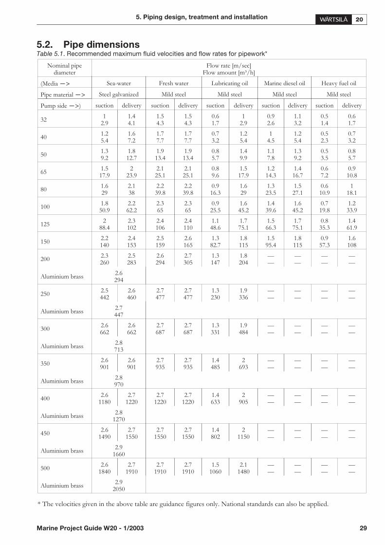
5.2. Pipe dimensions
* The velocities given in the above table are guidance figures only. National standards can also be applied.
5. Piping design, treatment and installation
Marine Project Guide W20 - 1/2003 29
Table 5.1. Recommended maximum fluid velocities and flow rates for pipework*
Nominal pipediameter
Flow rate [m/sec]Flow amount [m³/h]
(Media —> Sea-water Fresh water Lubricating oil Marine diesel oil Heavy fuel oil
Pipe material —> Steel galvanized Mild steel Mild steel Mild steel Mild steel
Pump side —>) suction delivery suction delivery suction delivery suction delivery suction delivery
321
2.91.44.1
1.54.3
1.54.3
0.61.7
12.9
0.92.6
1.13.2
0.51.4
0.61.7
401.25.4
1.67.2
1.77.7
1.77.7
0.73.2
1.25.4
14.5
1.25.4
0.52.3
0.73.2
501.39.2
1.812.7
1.913.4
1.913.4
0.85.7
1.49.9
1.17.8
1.39.2
0.53.5
0.85.7
651.517.9
223.9
2.125.1
2.125.1
0.89.6
1.517.9
1.214.3
1.416.7
0.67.2
0.910.8
801.629
2.138
2.239.8
2.239.8
0.916.3
1.629
1.323.5
1.527.1
0.610.9
118.1
1001.850.9
2.262.2
2.365
2.365
0.925.5
1.645.2
1.439.6
1.645.2
0.719.8
1.233.9
1252
88.42.3102
2.4106
2.4110
1.148.6
1.775.1
1.566.3
1.775.1
0.835.3
1.461.9
1502.2140
2.4153
2.5159
2.6165
1.382.7
1.8115
1.595.4
1.8115
0.957.3
1.6108
2002.3260
2.5283
2.6294
2.7305
1.3147
1.8204
——
——
——
——
Aluminium brass2.6294
2502.5442
2.6460
2.7477
2.7477
1.3230
1.9336
——
——
——
——
Aluminium brass2.7447
3002.6662
2.6662
2.7687
2.7687
1.3331
1.9484
——
——
——
——
Aluminium brass2.8713
3502.6901
2.6901
2.7935
2.7935
1.4485
2693
——
——
——
——
Aluminium brass2.8970
4002.6
11802.7
12202.7
12202.7
12201.4633
2905
——
——
——
——
Aluminium brass2.8
1270
4502.6
14902.7
15502.7
15502.7
15501.4802
21150
——
——
——
——
Aluminium brass2.9
1660
5002.6
18402.7
19102.7
19102.7
19101.5
10602.1
1480——
——
——
——
Aluminium brass2.9
2050
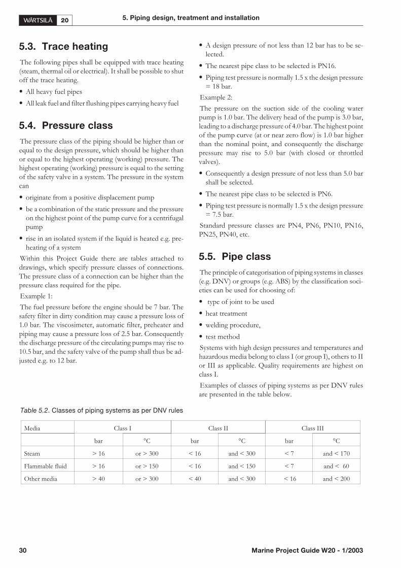
30 Marine Project Guide W20 - 1/2003
5. Piping design, treatment and installation
5.3. Trace heating
The following pipes shall be equipped with trace heating(steam, thermal oil or electrical). It shall be possible to shutoff the trace heating.
• All heavy fuel pipes
• All leak fuel and filter flushing pipes carrying heavy fuel
5.4. Pressure class
The pressure class of the piping should be higher than orequal to the design pressure, which should be higher thanor equal to the highest operating (working) pressure. Thehighest operating (working) pressure is equal to the settingof the safety valve in a system. The pressure in the systemcan
• originate from a positive displacement pump
• be a combination of the static pressure and the pressureon the highest point of the pump curve for a centrifugalpump
• rise in an isolated system if the liquid is heated e.g. pre-heating of a system
Within this Project Guide there are tables attached todrawings, which specify pressure classes of connections.The pressure class of a connection can be higher than thepressure class required for the pipe.
Example 1:
The fuel pressure before the engine should be 7 bar. Thesafety filter in dirty condition may cause a pressure loss of1.0 bar. The viscosimeter, automatic filter, preheater andpiping may cause a pressure loss of 2.5 bar. Consequentlythe discharge pressure of the circulating pumps may rise to10.5 bar, and the safety valve of the pump shall thus be ad-justed e.g. to 12 bar.
• A design pressure of not less than 12 bar has to be se-lected.
• The nearest pipe class to be selected is PN16.
• Piping test pressure is normally 1.5 x the design pressure= 18 bar.
Example 2:
The pressure on the suction side of the cooling waterpump is 1.0 bar. The delivery head of the pump is 3.0 bar,leading to a discharge pressure of 4.0 bar. The highest pointof the pump curve (at or near zero flow) is 1.0 bar higherthan the nominal point, and consequently the dischargepressure may rise to 5.0 bar (with closed or throttledvalves).
• Consequently a design pressure of not less than 5.0 barshall be selected.
• The nearest pipe class to be selected is PN6.
• Piping test pressure is normally 1.5 x the design pressure= 7.5 bar.
Standard pressure classes are PN4, PN6, PN10, PN16,PN25, PN40, etc.
5.5. Pipe class
The principle of categorisation of piping systems in classes(e.g. DNV) or groups (e.g. ABS) by the classification soci-eties can be used for choosing of:
• type of joint to be used
• heat treatment
• welding procedure,
• test method
Systems with high design pressures and temperatures andhazardous media belong to class I (or group I), others to IIor III as applicable. Quality requirements are highest onclass I.
Examples of classes of piping systems as per DNV rulesare presented in the table below.
Table 5.2. Classes of piping systems as per DNV rules
Media Class I Class II Class III
bar °C bar °C bar °C
Steam > 16 or > 300 < 16 and < 300 < 7 and < 170
Flammable fluid > 16 or > 150 < 16 and < 150 < 7 and < 60
Other media > 40 or > 300 < 40 and < 300 < 16 and < 200

5.6. Insulation
The following pipes shall be insulated
• All trace heated pipes
• Exhaust gas pipes
Insulation is also recommended for:
• Pipes between engine or system oil tank and lubricatingoil separator
• Pipes between engine and jacket water preheater
• For personnel protection work safety any exposed partsof pipes at walkways, etc., to be insulated to avoid exces-sive temperatures and risks for personnel injury.
In addition to the operational aspects of the different pip-ing systems requiring insulation the risks of fire and per-sonnel injury due to hot surfaces shall be given attention byinsulating and/or shielding of hot surfaces.
5.7. Local gauges
Local thermometers should be installed wherever a newtemperature occurs, i.e. before and after heat exchangers,etc.
Pressure gauges should be installed on the suction and dis-charge side of each pump.
5.8. Cleaning procedures
Instructions shall be given to manufacturers and/or fittersof how different piping systems shall be treated, cleanedand protected before and during transportation and beforeblock assembly or assembly in the hull. All piping shouldbe checked to be clean from debris before installation andjoining. All piping should be cleaned according to the pro-cedures listed below.
A Washing with alkaline solution in hot water at 80°C fordegreasing (only if pipes have been greased)
B Removal of rust and scale with steel brush (not requiredfor seamless precision tubes)
C Purging with compressed air
D Pickling
F Flushing
5.8.1 Pickling
Pipes are pickled in an acid solution of 10% hydrochloricacid and 10% formaline inhibitor for 4-5 hours, rinsed withhot water and blown dry with compressed air.
After the acid treatment the pipes are treated with a neu-tralizing solution of 10% caustic soda and 50 grams oftrisodiumphosphate per litre of water for 20 minutes at40...50°C, rinsed with hot water and blown dry with com-pressed air.
5.8.2 Flushing
More detailed recommendations on flushing proceduresare when necessary described under the relevant chaptersconcerning the fuel oil system and the lubricating oil sys-tem. Provisions are to be made to ensure that necessarytemporary bypasses can be arranged and that flushinghoses, filters and pumps will be available when required.
5.9. Flexible pipe connections
Great care must be taken to ensure the proper installationof flexible pipe connections between resiliently mountedengines and ship’s piping.
• Flexible pipe connections must not be twisted
• Installation length of flexible pipe connections must becorrect
• Minimum bending radius must respected
• Piping must be concentrically aligned
• When specified the flow direction must be observed
• Mating flanges shall be clean from rust, burrs andanticorrosion coatings
• Bolts are to be tightened crosswise in several stages
• Flexible elements must not be painted
• Rubber bellows must be kept clean from oil and fuel
• The piping must be rigidly supported close to the flexiblepiping connections.
5. Piping design, treatment and installation
Marine Project Guide W20 - 1/2003 31
Table 5.3. Pipe cleaning
System Methods
Fuel oil A, B, C, D, F
Lubricating oil A, B, C, D, F
Starting air A, B, C
Cooling water A, B, C
Exhaust gas A, B, C
Charge air A, B, C

Flexible hoses (4V60B0100)
32 Marine Project Guide W20 - 1/2003
5. Piping design, treatment and installation
Bending radius
Radially not aligned
Too short inst. length
Stretched
Twisted
Correctly installed
6. Fuel oil system
6.1. General
Fuel characteristics of the fuels are presented under head-ing Fuel characteristics in the Chapter for General data andoutputs.
6.1.1 Operating principals
The engine needs regulated fuel system before and afterthe engine to control viscosity and temperature of the fuel.Fuel systems are recommended to be closed due to bettercontrol of viscosity and temperature and conservation ofthe heating energy.
Fuel heating and cooling
The fuel temperature has to be controlled so that the vis-cosity of the fuel before injection pumps is stable and ac-cording to the limits specified in chapter General data andoutputs.
6.1.2 Black out starting
For stand-by generating set engines sufficient fuel pres-sure for a safe start must be ensured in a case of a black out.This can be done with:
• a gravity tank min. 15 m above the engine centerline
• a pneumatic emergency pump (1P11)
• an electric motor driven pump (1P11) fed from an emer-gency supply
If the engines are equipped with engine driven fuel feedpumps, see heading for MDF installations.
6.1.3 Number of engines
In multi-engine installations, the following main principlesshould be followed when dimensioning the fuel system:
• A separate fuel feed circuit is recommended for eachpropeller shaft (two-engine installations); in four- engineinstallations so that one engine from each shaft is fedfrom the same circuit.
• Main and auxiliary engines are recommended to be con-nected to separate fuel feed circuits.
6.2. MDF installations
6.2.1 General
When running on MDF the fuel oil inlet temperatureshould be kept at maximum of +45°C. When running longperiods with low load this requires an external MDF cooler(1E04) to be installed.
6.2.2 Internal fuel system
The standard system comprises the following built-onequipment:
• fuel injection pumps
• injection valves
• pressure control valve in the outlet pipe
Controlled leak fuel from the injection valves and the in-jection pumps is drained to atmospheric pressure (Cleanleak fuel system). The clean leak fuel can be reconducted tothe system without treatment. The quantity of leak fuel isgiven in chapter for Technical data. Possible uncontrolledleak fuel and spilled water and oil is separately drained fromthe hot-box and shall be led to a sludge tank (“Dirty” leakfuel system).
6. Fuel oil system
Marine Project Guide W20 - 1/2003 33

Internal fuel system, MDF (4V76F5881b)
34 Marine Project Guide W20 - 1/2003
6. Fuel oil system
Dimensions of fuel pipe connections on the engine
Code Description Size Pressure class Standard
101 Fuel inlet, HFO OD18 PN160 DIN 2353
101 Fuel inlet, MDF OD28 PN100 DIN 2353
102 Fuel outlet, HFO OD18 PN160 DIN 2353
102 Fuel outlet, MDF OD28 PN100 DIN 2353
103 Leak fuel drain, clean fuel OD18 - ISO 3304
1041 Leak fuel drain, dirty fuel OD22 - ISO 3304
1043 Leak fuel drain, dirty fuel OD18 - ISO 3304
105 Fuel stand-by connection OD22 PN160 DIN 2353
System components
01 Injection pump
02 Injection valve
03Level alarm for leak fuel oil from injectionpipes
04 Duplex fine filter
05Engine driven fuel feed pump
06 Pressure regulating valve
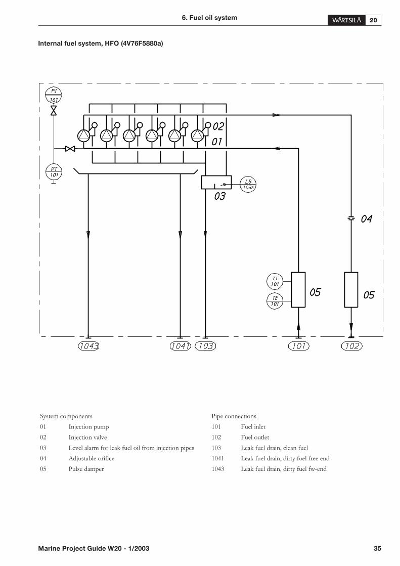
Internal fuel system, HFO (4V76F5880a)
6. Fuel oil system
Marine Project Guide W20 - 1/2003 35
System components Pipe connections
01 Injection pump 101 Fuel inlet
02 Injection valve 102 Fuel outlet
03 Level alarm for leak fuel oil from injection pipes 103 Leak fuel drain, clean fuel
04 Adjustable orifice 1041 Leak fuel drain, dirty fuel free end
05 Pulse damper 1043 Leak fuel drain, dirty fuel fw-end
Engine driven fuel feed pump
If the engine is equipped with an engine driven gear typefuel feed pump, the day tank shall be arranged so that theminimum level always remains above the top of the engine.This arrangement enables deaeration of the circuit andminimizes the risk of sucking air into the system, if there isa leakage e.g. in a pipe joint. Special measures for black-outstart are not required.
6.2.3 External fuel system
General
The design of the external fuel system may vary from shipto ship but every system should provide well cleaned fuelwith the correct temperature and pressure to each engine.
Filling, transfer and storage
The ship must have means to transfer the fuel from bunkertanks to settling tanks and between the bunker tanks in or-der to balance the ship.
The amount of fuel in the bunker tanks depends on the to-tal fuel consumption of all consumers onboard, maximumtime between bunkering and the decided margin.
Separation
Even if the fuel to be used is marine diesel fuel or gas oilonly, it is recommended to install a separator as thereshould be some means of separating water from the fuel.
Settling tank, MDF (1T10)
In case where MDF is the only fuel onboard the settlingtank should normally be dimensioned to ensure fuel supplyfor min. 24 operating hours when filled to maximum. Thetank should be designed to provide the most efficientsludge and condensed water rejecting effect. The bottomof the tank should have slope to ensure good drainage. TheMDF settling tank does not need heating coils or insula-tion.
The temperature in the MDF settling tank should be be-tween 20 - 40°C.
Separator unit, MDF (1N05)
Suction strainer for separator feed pump (1F02)
A suction filter shall be fitted to protect the feed pump.
• fineness 0.5 mm
Feed pump, separator (1P02)
The use of a screw pump is recommended. The pumpshould be separate from the separator and electricallydriven.
Design data:
The pump should be dimensioned for the actual fuel qual-ity and recommended throughput through the separator.The flow rate through the separator should not exceed themaximum fuel consumption by more than 10%. No con-trol valve should be used to reduce the flow of the pump.
Operating pressure, max. 0.5 MPa (5 bar)
Operating temperature 40°C
Preheater, separator (1E01)
Fuels having a viscosity higher than 5 mm²/s (cSt) at 50°Cneed preheating before the separator. For MDF the pre-heating temperature should be according to the separatorsupplier.
MDF separator (1S02)
The fuel oil separator should be sized according to the rec-ommendations of the separator supplier.
Sludge tank, separator (1T05)
The sludge tank should be placed below the separators andas close as possible. The sludge pipe should be continu-ously falling without any horizontal parts.
Fuel feed system
General
For marine diesel fuel (MDF) and fuels having a viscosityof less than 11.5 mm²/s(cSt)/50°C and if the tanks can belocated high enough to prevent cavitation in the fuel feedpump, a system with an open de-aeration tank may be in-stalled.
Day tank, MDF (1T06)
The diesel fuel day tank is dimensioned to ensure fuel sup-ply for 12...14 operating hours when filled to maximum*.
*Note that according to SOLAS 1974 Chapter II-1 Part CRegulation 26.11 (as amended in 1981 and 1996), ships areto be fitted with two separate service tanks for fuel to pro-pulsion and vital systems such as main engines (ME), auxil-iary engines (AE) and auxiliary boilers (AB). Settling tanksmust not be considered en lieu of service tanks.
36 Marine Project Guide W20 - 1/2003
6. Fuel oil system

Acceptable arrangements acc. to SOLAS are:
Suction strainer, MDF (1F07)
A suction strainer with a fineness of 0.5 mm should be in-stalled for protecting the feed pumps.
Circulation pump, MDF (1P03)
The circulation pump maintains the pressure before theengine. It is recommended to use a screw pump as circula-tion pump.
Design data:
• capacity to cover the total consumption of the enginesand the flush quantity of a possible automatic filter
• the pumps should be placed so that a positive static pres-sure of about 30 kPa is obtained on the suction side ofthe pumps.
Pressure control (overflow) valve, MDF (1V02)
The pressure control valve maintains the pressure in thefeed line directing the surplus flow to the suction side ofthe feed pump.
set point 0.4 MPa (4 bar)
Fuel consumption meter
If a totalizer fuel consumption meter is required, it shouldbe fitted in the day tank feed line. In case of a continousengine fuel consumption indication is required, two metersper engine need to be installed.
Cooler/Heater
Since the viscosity before the engine must stay between theallowed limits stated in the Chapter for General data andoutputs, a heater might be necessary in case the day tanktemperature is low. Cooler is needed where long periods oflow load operation is expected since fuel gets heated in theengine during the circulation. The cooler is located in thereturn line after the engine(s). LT-water is normally used ascooling medium.
Leak fuel tank, clean fuel (1T04)
Clean leak fuel drained from the injection pumps can be re-used without repeated treatment. The fuel should be col-lected in a separate clean leak fuel tank and, from there, bepumped to the settling tank. The pipes from the engine tothe drain tank should be arranged continuously sloping.
Leak fuel tank, dirty fuel (1T07)
Under normal operation no fuel should leak out of thedirty system. Fuel, water and oil is drained only in the eventof unattended leaks or during maintenance. Dirty leak fuelpipes shall be led to a sludge tank.
Fuel feed unit
Fuel feed equipment can also be combined to form a unit.
6. Fuel oil system
Marine Project Guide W20 - 1/2003 37
For MDO operation: For HFO operation:
TANK CAPACITY FOR TANK CAPACITY FOR
MDO 1 service ME+AE+AB 8 hours HFO 1 service ME+AE+AB 8 hours
MDO 2 service ME+AE+AB 8 hours HFO 2 service ME+AE+AB 8 hours
MDO service cold start and repairs
or
HFO service ME+AE+AB 8 hours
MDO service ME+AE+AB 8 hours
For ME and AB operating on HFO and AE operating on MDO:
TANK CAPACITY FOR
HFO 1 service ME+AB 8 hours
HFO 2 service ME+AB 8 hours
MDO 1 service AE 8 hours
MDO 2 service AE 8 hours
or
HFO service ME+AB 8 hours
MDO 1 service The greater of ME+AE+AB 4 hours or ME+AB 8 hours
MDO 2 service The greater of ME+AE+AB 4 hours or ME+AB 8 hours
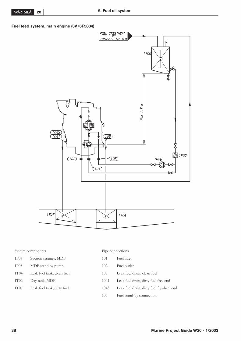
Fuel feed system, main engine (3V76F5884)
38 Marine Project Guide W20 - 1/2003
6. Fuel oil system
System components Pipe connections
1F07 Suction strainer, MDF 101 Fuel inlet
1P08 MDF stand by pump 102 Fuel outlet
1T04 Leak fuel tank, clean fuel 103 Leak fuel drain, clean fuel
1T06 Day tank, MDF 1041 Leak fuel drain, dirty fuel free end
1T07 Leak fuel tank, dirty fuel 1043 Leak fuel drain, dirty fuel flywheel end
105 Fuel stand-by connection

6.3. HFO installations
6.3.1 General
For pumping, the temperature of fuel storage tanks mustalways be maintained 5 - 10°C above the pour point - typi-cally at 40 - 50°C. The heating coils can be designed for atemperature of 60°C.
The design of the external fuel system may vary from shipto ship, but every system should provide well cleaned fuelwith the correct temperature and pressure to each engine.When using heavy fuel it is most important that the fuel isproperly cleaned from solid particles and water. In additionto the harm poorly centrifuged fuel will do to the engine, ahigh content of water may cause damage to the heavy fuelfeed system. For the feed system, well-proven componentsshould be used.
The fuel treatment system should comprise at least onesettling tank and two (or several) separators to supply theengine(s) with sufficiently clean fuel. Dimensioning ofHFO separators is of greatest importance and thereforethe recommendations of the separator designer should beclosely followed.
The vent pipes of all tanks containing heavy fuel oil mustbe continuously upward sloping.
Remarks:
When dimensioning the pipes of the fuel oil system com-mon known rules for recommended fluid velocities mustbe followed.
The fuel oil pipe connections on the engine can be smallerthan the pipe diameter on the installation side.
Fuel heating
In ships intended for operation on heavy fuel, steam orthermal oil heating coils must be installed in all tanks.
All heat consumers should be considered:
• bunker tanks
• day and settling tanks
• trace heating
• fuel separators
• fuel booster modules
The heating requirement of tanks is calculated from themaximum heat losses from the tank and from the require-ment of raising the temperature by typically 1°C/h. Theheat loss can be assumed to be 15 W/m²°C between tanksand shell plating against the sea and 3 W/m²°C betweentanks and cofferdams. The heat capacity of fuel oil can betaken as 2 kJ/kg°C.
The day and settling tank temperatures are usually in therange 50 - 80°C. A typical heating capacity is 12 kW each.
Trace heating of insulated fuel pipes requires about 1.5W/m²°C. The area to be used is the total external area ofthe fuel steel pipe.
Fuel separators require typically 7 kW/installed engineMW and booster units 30 kW/installed engine MW. Seealso formulas presented later in this chapter.
6. Fuel oil system
Marine Project Guide W20 - 1/2003 39
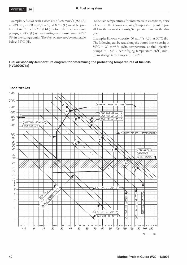
Example: A fuel oil with a viscosity of 380 mm²/s (cSt) (A)at 50°C (B) or 80 mm²/s (cSt) at 80°C (C) must be pre-heated to 115 - 130°C (D-E) before the fuel injectionpumps, to 98°C (F) at the centrifuge and to minimum 40°C(G) in the storage tanks. The fuel oil may not be pumpablebelow 36°C (H).
To obtain temperatures for intermediate viscosities, drawa line from the known viscosity/temperature point in par-allel to the nearest viscosity/temperature line in the dia-gram.
Example: Known viscosity 60 mm²/s (cSt) at 50°C (K).The following can be read along the dotted line: viscosity at80°C = 20 mm²/s (cSt), temperature at fuel injectionpumps 74 - 87°C, centrifuging temperature 86°C, mini-mum storage tank temperature 28°C.
Fuel oil viscosity-temperature diagram for determining the preheating temperatures of fuel oils
(4V92G0071a)
40 Marine Project Guide W20 - 1/2003
6. Fuel oil system
6.3.2 Internal fuel system
The standard system comprises the following built-onequipment:
• heavy fuel injection pumps
• injection valves
• inlet and outlet fuel damper with pressure control valveon the outlet damper
Leak fuel from the injection valves and the injectionpumps is drained to atmospheric pressure (Clean leak fuelsystem). The clean leak fuel can be reconducted to the sys-tem without treatment. The quantity of leak fuel is given inchapter for Technical data. Possible uncontrolled leak fueland spilled water and oil is separately drained from thehot-box and shall be led to a sludge tank (“Dirty” leak fuelsystem).
Pressure control valve adjustment
For auxiliary engines installed in parallel, the pressure dropdifferences around engines shall be compensated with thecontrol valve on the outlet pulse damper. It is recom-mended to install pressure gauges at suitable places to beable to verify the pressure drop. If pressures can not bemeasured onboard, the temperatures can be used for arough estimation.
The adjustment on the control valves should be carriedout after the pressure regulating valve in the fuel system hasbeen adjusted to approximately 6-7 bar with all controlvalves fully open. The adjustment must be tested in differ-ent loading situations including the cases with one or moreof the engines being in stand by mode. If the main engine isconnected to the same fuel booster unit the circula-tion/temperatures must also be checked with and withoutthe main engine being in operation.
Matters other than piping geometry that can influence onthe circulation/temperatures are:
• overflow valve adjustment
• fuel pipe insulation
• trace heating efficiency
• booster pump and/or heater sizing
• set point on the feeder and/or booster pump safetyvalve
6.3.3 External fuel system
General
The engine is designed for continuous heavy fuel opera-tion. It is, however, possible to operate the engine on dieselfuel without making any alterations.
The engine can be started and stopped on heavy fuel pro-vided that the engine and the fuel system are preheated tooperating temperature. Switch-over from HFO to MDFfor start and stop is not recommended.
6. Fuel oil system
Marine Project Guide W20 - 1/2003 41
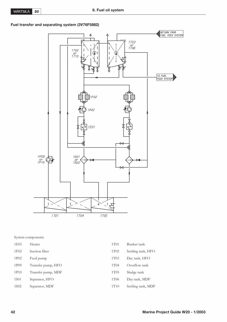
Fuel transfer and separating system (3V76F5882)
42 Marine Project Guide W20 - 1/2003
6. Fuel oil system
System components
1E01 Heater 1T01 Bunker tank
1F02 Suction filter 1T02 Settling tank, HFO
1P02 Feed pump 1T03 Day tank, HFO
1P09 Transfer pump, HFO 1T04 Overflow tank
1P10 Transfer pump, MDF 1T05 Sludge tank
1S01 Separator, HFO 1T06 Day tank, MDF
1S02 Separator, MDF 1T10 Settling tank, MDF

Note that settling and day tanks have been drawn separatein order to show overflow pipe. They normally have com-mon intermediate wall and insulation.
Filling, transfer and storage
The ship must have means to transfer the fuel frombunker tanks to settling tanks and between the bunkertanks in order to balance the ship.
The amount of fuel in the bunker tanks depends on the to-tal fuel consumption of all consumers onboard, maximumtime between bunkering and the decided margin.
Separation
Heavy fuel (residual, and mixtures of residuals and distil-lates) must be cleaned in an efficient centrifugal separatorbefore entering the day tank.
Separator mode of operation
Two separators, both of the same size, should be installed.The capacity of one separator to be sufficient for the totalfuel consumption. The other (stand-by) separator shouldalso be in operation all the time.
It is recommended that conventional separators with grav-ity disc are arranged for operation in series, the first as a pu-rifier and the second as a clarifier. This arrangement can beused for fuels with a density up to max. abt. 991 kg/m³ at15°C.
Separators with controlled discharge of sludge (withoutgravity disc) operating on a continuous basis can handle fu-els with densities exceeding 991 kg/m³ at 15°C. In this casethe main and stand-by separators should be run in parallel.
Settling tank, HFO (1T02)
The settling tank should normally be dimensioned to en-sure fuel supply for min. 24 operating hours when filled tomaximum. The tank should be designed to provide themost efficient sludge and water rejecting effect. The bot-tom of the tank should have slope to ensure good drainage.The tank is to be provided with a heating coil and should bewell insulated.
To ensure constant fuel temperature at the separator, thesettling tank temperature should be kept stable. The tem-perature in the settling tank should be between 50...70°C.
The min. level in the settling tank should be kept as high aspossible. In this way the temperature will not decrease toomuch when filling up with cold bunker.
Separator unit (1N02)
Suction strainer for separator feed pump (1F02)
A suction strainer shall be fitted to protect the feed pump.The strainer should be equipped with a heating jacket incase the installation place is cold.
• fineness 0.5 mm
Feed pump, separator (1P02)
The pump should be dimensioned for the actual fuel qual-ity and recommended throughput through the separator.The flow rate through the separator should not exceed themaximum fuel consumption by more than 10%. No con-trol valve should be used to reduce the flow of the pump.
Design data:
• delivery pressure (max.) 0.2 MPa (2 bar)
• operating temperature 100°C
viscosity for dimensioning electric motor1000 mm²/s (cSt)
Preheater, separator (1E01)
The preheater is normally dimensioned according to thefeed pump capacity and a given settling tank temperature.The heater surface temperature must not be too high in or-der to avoid cracking of the fuel.
The heater should be controlled to maintain the fuel tem-perature within ± 2°C. The recommended preheating tem-perature for heavy fuel is 98°C.
Design data:
The required minimum capacity of the heater is:
P(kW) = m(l/h) �t(°C) / 1700
P(kW) = heater capacity
m = capacity of the separator feed pump
�t = temperature rise in heater
For heavy fuels �t = 48°C can be used, i.e. a settling tanktemperature of 50°C.
Fuels having a viscosity higher than 5 mm²/s (cSt) at 50°Cneed preheating before the separator.
The heaters to be provided with safety valves with escapepipes to a leakage tank ( so that the possible leakage can beseen).
6. Fuel oil system
Marine Project Guide W20 - 1/2003 43
HFO separator (1S01)
The fuel oil separator should be sized according to the rec-ommendations of the separator supplier.
Based on a separation time of 23 or 23.5 h/day, the nomi-nal capacity of the separator can be estimated acc. to thefollowing formula:
where:
P = max. continuous rating of the diesel engine
b = specific fuel consumption + 15% safety margin
� = density of the fuel
t = daily separating time for selfcleaning separator (usually= 23 h or 23.5 h)
The flow rates recommended for the separator and thegrade of fuel in use must not be exceeded. The lower theflow rate the better the separation efficiency.
Sludge tank, separator (1T05)
The sludge tank should be placed below the separators andas close as possible. The sludge pipe should be continu-ously falling without any horizontal parts.
Fuel feed system
General
The fuel feed system for HFO shall be of the pressurizedtype in order to prevent foaming in the return lines and cav-itation in the circulation pumps.
The heavy fuel pipes shall be properly insulated andequipped with trace heating, if the viscosity of the fuel is180 mm²/s (cSt)/50°C or higher. It shall be possible toshut-off the heating of the pipes when running MDF (thetracing pipes to be grouped together according to theiruse).
Any provision to change the type of fuel during operationshould be designed to obtain a smooth change in fuel tem-perature and viscosity, e.g. via a mixing tank. When chang-ing from HFO to MDF, the viscosity at the engine shouldbe above 2.8 mm²/s(cSt) and not drop below 2.0mm²/s(cSt) even during short transient conditions. In cer-tain applications a cooler may be necessary.
Day tank, HFO (1T03)
The heavy fuel day tank is usually dimensioned to ensurefuel supply for about 24 operating hours when filled tomaximum (see note for MDF day tanks). The design of thetank should be such that water and dirt particles do not ac-cumulate in the suction pipe. The tank has to be providedwith a heating coil and should be well insulated.
Maximum recommended viscosity in the day tank is 140mm²/s (cSt). Due to the risk of wax formation, fuels with aviscosity lower than 50 mm²/s (cSt)/50°C must be kept athigher temperatures than what the viscosity would require.
Fuel viscosity Minimum day tank
(mm²/s (cSt) at 100°C) temperature (°C)
55 80
35 70
25 60
Feeder/booster unit (1N01)
A completely assembled fuel feed unit can be supplied asan option.
This unit normally comprises the following equipment:
• two suction strainers
• two booster pumps of screw type, equipped withbuilt-on safety valves and electric motors
• one pressure control/overflow valve
• one pressurized de-aeration tank, equipped with a levelswitch operated vent valve
• two circulation pumps, same type as above
• two heaters, steam, electric or thermal oil (one in opera-tion, the other as spare)
• one automatic back-flushing filter with by-pass filter
• one viscosimeter for the control of the heaters
• one steam or thermal oil control valve or control cabinetfor electric heaters
• one thermostat for emergency control of the heaters
• one control cabinet with starters for pumps, automaticfilter and viscosimeter
• one alarm panel
The above equipment is built on a steel frame, which canbe welded or bolted to its foundation in the ship. All heavyfuel pipes are insulated and provided with trace heating.
When installing the unit, only power supply, group alarmsand fuel, steam and air pipes have to be connected.
44 Marine Project Guide W20 - 1/2003
6. Fuel oil system
P[kW] · b · 24[h]Q [l/h] =
� ·t[h]

Fuel feed unit, example (4V76F5613)
Suction strainer HFO (1F06)
A suction strainer with a fineness of 0.5 mm should be in-stalled for protecting the feed pumps. The strainer shouldbe equipped with a heating jacket.
6. Fuel oil system
Marine Project Guide W20 - 1/2003 45
3120
1200
Feed pump, HFO (1P04)
The feed pump maintains the pressure in the fuel feed sys-tem. It is recommended to use a high temperature resistantscrew pump as feed pump.
Design data:
• capacity to cover the total consumption of the enginesand the flush quantity of a possible automatic filter
• The pumps should be placed so that a positive staticpressure of about 30 kPa is obtained on the suction sideof the pumps.
- delivery pressure 0.6 MPa (6 bar)
- operating temperature 100°C
- viscosity for dimensioning electric motor1000 mm²/s (cSt)
Pressure control (overflow) valve HFO
The pressure control valve maintains the pressure in thede-aeration tank directing the surplus flow to the suctionside of the feed pump.
• set point 0.3…0.5 MPa (3...5 bar)
Automatically cleaned fine filter, HFO (1F08)
The use of automatic back-flushing filters is recom-mended, installed between the feeder pumps and thedeaeration tank in parallel with an insert filter as thestand-by half.
For back-flushing filters the feed pump capacity should besufficient to prevent pressure drop during the flushing op-eration.
Design data:
• fuel oil according to spec.
• operating temperature 0...100°C
• preheating from 25 mm²/s(cSt)/100°C
• flow feed pump capacity
• operating pressure 1 MPa (10 bar)
• design pressure 1.6 MPa (16 bar)
• test pressure fuel side 2 MPa(20 bar)heating jacket 1 Mpa(10 bar)
• fineness:
- back-flushing filter 35 �m (absolute meshsize)
- insert filter 35 �m (absolute meshsize)
• Maximum recommended pressure drop for normalfilters at 14 mm²/s (cSt):
- clean filter 20 kPa (0.2 bar)
- dirty filter 60 kPa (0.6 bar)
- alarm 80 kPa (0.8 bar)
Fuel consumption meter (1I01)
If a fuel consumption meter is required, it should be fittedbetween the feed pumps and the de-aeration tank. An au-tomatically opening by-pass line around the consumptionmeter is recommended in case of possible clogging.
De-aeration tank (1T08)
The volume of the tank should be about 50 l. It shall beequipped with a vent valve, controlled by a level switch. Itshall also be insulated and equipped with a heating coil.The vent pipe should, if possible, be led downwards, e.g. tothe overflow tank.
Circulation pump, HFO (1P06)
The purpose of this pump is to circulate the fuel in the sys-tem and to maintain the pressure stated in the chapter forTechnical data at the injection pumps. It also circulates thefuel in the system to maintain the viscosity, and keeps thepiping and injection pumps at operating temperature.
The feed pump capacity should be sufficient to preventpressure drop during the flushing of the automatic filter ifinstalled on the pressure side of this pump.
Design data:
• capacity constant (see below) times the total consump-tion of the engines and the flushing of the automatic fil-ter
• capacity constant 4
- pressure 1 MPa (10 bar)
- temperature 150°C
- viscosity (for dimensioningthe el. motor) 500 mm²/s (cSt)
Heater (1E02)
The heater(s) is normally dimensioned to maintain an in-jection viscosity of 14 mm²/s (cSt) according to the maxi-mum fuel consumption and a given day tank temperature.
To avoid cracking of the fuel the surface temperature inthe heater must not be too high. The surface power of elec-tric heaters must not be higher than 1.5 W/cm2. The out-put of the heater shall be controlled by a viscosimeter. As areserve a thermostat control may be fitted.
The set point of the viscosimeter shall be somewhat lowerthan the required viscosity at the injection pumps to com-pensate for heat losses in the pipes.
Design data:
The required minimum capacity of the heater is:
P(kW) = m(l/h) �t(°C) / 1700
P(kW) = heater capacity
m = evaluated by multiplying the specific fuel consump-tion of the engines by the total max. output of the engines
46 Marine Project Guide W20 - 1/2003
6. Fuel oil system
�t = temperature rise, higher with increased fuel viscosity
To compensate for heat losses due to radiation the abovepower should be increased with 10% + 5 kW.
The following values can be used:
Fuel viscosity Temperature rise
(mm²/s (cSt) at 100°C) in heater (°C)
55 65 (80 in day tank)
35 65 (70 in day tank)
25 60 (60 in day tank)
Viscosimeter (1I02)
For the control of the heater(s) a viscosimeter has to be in-stalled. A thermostatic control shall be fitted, to be used assafety when the viscosimeter is out of order. Theviscosimeter should be of a design, which stands the pres-sure peaks caused by the injection pumps of the diesel en-gine.
Design data:
• operation range 0...50 mm²/s (cSt)
• temperature 180°C
• pressure 4 MPa (40 bar)
Safety filter (1F03)
Since no fuel filters are built on the engine, one duplex typesafety filter with an alarm contact for high differential pres-sure is installed between the booster module and the en-gine. The filter should be located as close to the engine aspossible. A common filter can be used for all engines aftereach booster module.
• min. fineness 50 �m
Overflow valve (1V05)
This valve limits the maximum pressure in fuel line to theengine by relieving the pressure to the return line.
Pressure control valve on the return line
(1V04)
This valve controls the pressure in the return line from theengine.
Leak fuel tank, clean fuel (1T04)
Clean leak fuel drained from the injection pumps can be re-used without repeated treatment. The fuel should be col-lected in a separate clean leak fuel tank and, from there, bepumped to the settling tank. The pipes from the engine tothe drain tank should be arranged continuously sloping andshould be provided with heating and insulation.
Leak fuel tank, dirty fuel (1T07)
Under normal operation no fuel should leak out of thedirty system. Fuel, water and oil is drained only in the eventof unattended leaks or during maintenance. Dirty leak fuelpipes shall be led to a sludge tank and be trace heated andinsulated.
6. Fuel oil system
Marine Project Guide W20 - 2/2002 47
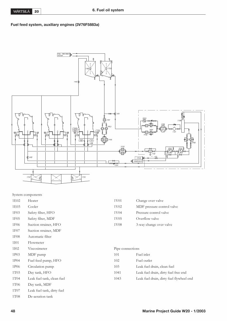
Fuel feed system, auxiliary engines (3V76F5883a)
48 Marine Project Guide W20 - 1/2003
6. Fuel oil system
System components
1E02 Heater 1V01 Change over valve
1E03 Cooler 1V02 MDF pressure control valve
1F03 Safety filter, HFO 1V04 Pressure control valve
1F05 Safety filter, MDF 1V05 Overflow valve
1F06 Suction strainer, HFO 1V08 3-way change over valve
1F07 Suction strainer, MDF
1F08 Automatic filter
1I01 Flowmeter
1I02 Viscosimeter Pipe connections
1P03 MDF pump 101 Fuel inlet
1P04 Fuel feed pump, HFO 102 Fuel outlet
1P06 Circulation pump 103 Leak fuel drain, clean fuel
1T03 Day tank, HFO 1041 Leak fuel drain, dirty fuel free end
1T04 Leak fuel tank, clean fuel 1043 Leak fuel drain, dirty fuel flywheel end
1T06 Day tank, MDF
1T07 Leak fuel tank, dirty fuel
1T08 De-aeration tank
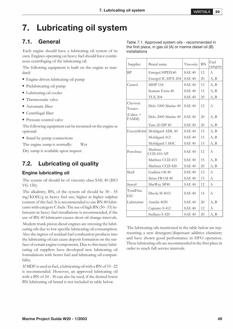
7. Lubricating oil system
7.1. General
Each engine should have a lubricating oil system of itsown. Engines operating on heavy fuel should have contin-uous centrifuging of the lubricating oil.
The following equipment is built on the engine as stan-dard:
• Engine driven lubricating oil pump
• Prelubricating oil pump
• Lubricating oil cooler
• Thermostatic valve
• Automatic filter
• Centrifugal filter
• Pressure control valve
The following equipment can be mounted on the engine asoptional:
• Stand by pump connections
The engine sump is normally: Wet
Dry sump is available upon request.
7.2. Lubricating oil quality
Engine lubricating oil
The system oil should be of viscosity class SAE 40 (ISOVG 150).
The alkalinity, BN, of the system oil should be 30 - 55mg/KOH/g in heavy fuel use; higher at higher sulphurcontent of the fuel. It is recommended to use BN 40 lubri-cants with category C fuels. The use of high BN (50 - 55) lu-bricants in heavy fuel installations is recommended, if theuse of BN 40 lubricants causes short oil change intervals.
Modern trunk piston diesel engines are stressing the lubri-cating oils due to low specific lubricating oil consumption.Also the ingress of residual fuel combustion products intothe lubricating oil can cause deposit formation on the sur-face of certain engine components. Due to this many lubri-cating oil suppliers have developed new lubricating oilformulations with better fuel and lubricating oil compati-bility.
If MDF is used as fuel, a lubricating oil with a BN of 10 - 22is recommended. However, an approved lubricating oilwith a BN of 24 - 30 can also be used, if the desired lowerBN lubricating oil brand is not included in table below.
Table 7.1. Approved system oils - recommended inthe first place, in gas oil (A) or marine diesel oil (B)installations
The lubricating oils mentioned in the table below are rep-resenting a new detergent/dispersant additive chemistryand have shown good performance in HFO operation.These lubricating oils are recommended in the first place inorder to reach full service intervals.
7. Lubricating oil system
Marine Project Guide W20 - 1/2003 49
Supplier Brand name Viscosity BNFuelcategory
BP Energol HPDX40 SAE 40 12 A
Energol IC-HFX 204 SAE 40 20 A, B
Castrol MHP 154 SAE 40 15 A, B
Seamax Extra 40 SAE 40 15 A, B
TLX 204 SAE 40 20 A, B
Chevron
TexacoDelo 1000 Marine 40 SAE 40 12 A
(Caltex +FAMM)
Delo 2000 Marine 40 SAE 40 20 A, B
Taro 20 DP 40 SAE 40 20 A, B
ExxonMobil Mobilgard ADL 40 SAE 40 15 A, B
Mobilgard 412 SAE 40 15 A, B
Mobilgard 1 SHC SAE 40 15 A, B
PetrobrasMarbraxCCD-410-AP
SAE 40 12 A
Marbrax CCD-415 SAE 40 15 A, B
Marbrax CCD-420 SAE 40 20 A, B
Shell Gadinia Oil 40 SAE 40 12 A
Sirius FB Oil 40 SAE 40 13 A
Statoil MarWay SP40 SAE 40 12 A
TotalFina
Elf/Disola M 4015 SAE 40 14 A
Lubmarine Aurelia 4020 SAE 40 20 A, B
Caprano S 412 SAE 40 12 A
Stellano S 420 SAE 40 20 A, B
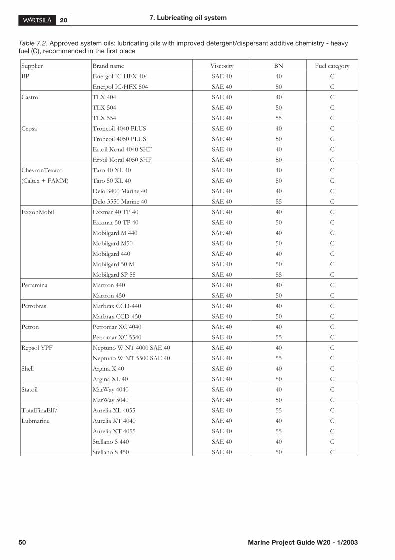
Table 7.2. Approved system oils: lubricating oils with improved detergent/dispersant additive chemistry - heavyfuel (C), recommended in the first place
50 Marine Project Guide W20 - 1/2003
7. Lubricating oil system
Supplier Brand name Viscosity BN Fuel category
BP Energol IC-HFX 404 SAE 40 40 C
Energol IC-HFX 504 SAE 40 50 C
Castrol TLX 404 SAE 40 40 C
TLX 504 SAE 40 50 C
TLX 554 SAE 40 55 C
Cepsa Troncoil 4040 PLUS SAE 40 40 C
Troncoil 4050 PLUS SAE 40 50 C
Ertoil Koral 4040 SHF SAE 40 40 C
Ertoil Koral 4050 SHF SAE 40 50 C
ChevronTexaco Taro 40 XL 40 SAE 40 40 C
(Caltex + FAMM) Taro 50 XL 40 SAE 40 50 C
Delo 3400 Marine 40 SAE 40 40 C
Delo 3550 Marine 40 SAE 40 55 C
ExxonMobil Exxmar 40 TP 40 SAE 40 40 C
Exxmar 50 TP 40 SAE 40 50 C
Mobilgard M 440 SAE 40 40 C
Mobilgard M50 SAE 40 50 C
Mobilgard 440 SAE 40 40 C
Mobilgard 50 M SAE 40 50 C
Mobilgard SP 55 SAE 40 55 C
Pertamina Martron 440 SAE 40 40 C
Martron 450 SAE 40 50 C
Petrobras Marbrax CCD-440 SAE 40 40 C
Marbrax CCD-450 SAE 40 50 C
Petron Petromar XC 4040 SAE 40 40 C
Petromar XC 5540 SAE 40 55 C
Repsol YPF Neptuno W NT 4000 SAE 40 SAE 40 40 C
Neptuno W NT 5500 SAE 40 SAE 40 55 C
Shell Argina X 40 SAE 40 40 C
Argina XL 40 SAE 40 50 C
Statoil MarWay 4040 SAE 40 40 C
MarWay 5040 SAE 40 50 C
TotalFinaElf/ Aurelia XL 4055 SAE 40 55 C
Lubmarine Aurelia XT 4040 SAE 40 40 C
Aurelia XT 4055 SAE 40 55 C
Stellano S 440 SAE 40 40 C
Stellano S 450 SAE 40 50 C
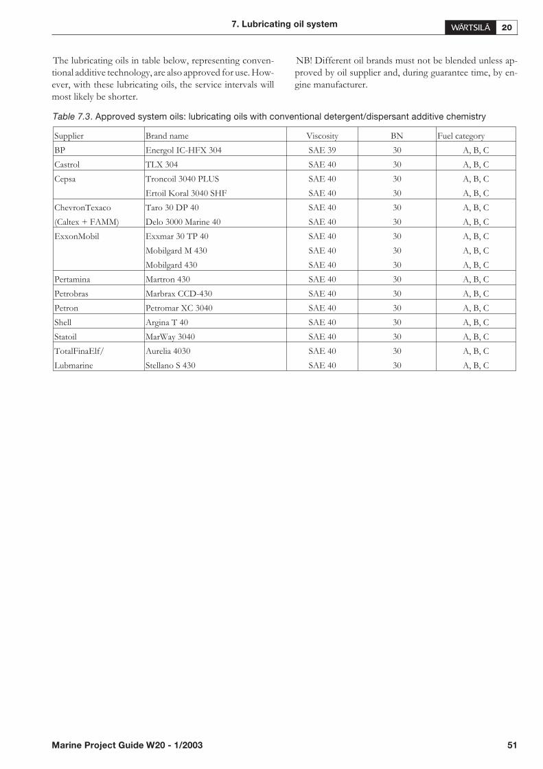
The lubricating oils in table below, representing conven-tional additive technology, are also approved for use. How-ever, with these lubricating oils, the service intervals willmost likely be shorter.
NB! Different oil brands must not be blended unless ap-proved by oil supplier and, during guarantee time, by en-gine manufacturer.
7. Lubricating oil system
Marine Project Guide W20 - 1/2003 51
Supplier Brand name Viscosity BN Fuel category
BP Energol IC-HFX 304 SAE 39 30 A, B, C
Castrol TLX 304 SAE 40 30 A, B, C
Cepsa Troncoil 3040 PLUS SAE 40 30 A, B, C
Ertoil Koral 3040 SHF SAE 40 30 A, B, C
ChevronTexaco Taro 30 DP 40 SAE 40 30 A, B, C
(Caltex + FAMM) Delo 3000 Marine 40 SAE 40 30 A, B, C
ExxonMobil Exxmar 30 TP 40 SAE 40 30 A, B, C
Mobilgard M 430 SAE 40 30 A, B, C
Mobilgard 430 SAE 40 30 A, B, C
Pertamina Martron 430 SAE 40 30 A, B, C
Petrobras Marbrax CCD-430 SAE 40 30 A, B, C
Petron Petromar XC 3040 SAE 40 30 A, B, C
Shell Argina T 40 SAE 40 30 A, B, C
Statoil MarWay 3040 SAE 40 30 A, B, C
TotalFinaElf/ Aurelia 4030 SAE 40 30 A, B, C
Lubmarine Stellano S 430 SAE 40 30 A, B, C
Table 7.3. Approved system oils: lubricating oils with conventional detergent/dispersant additive chemistry
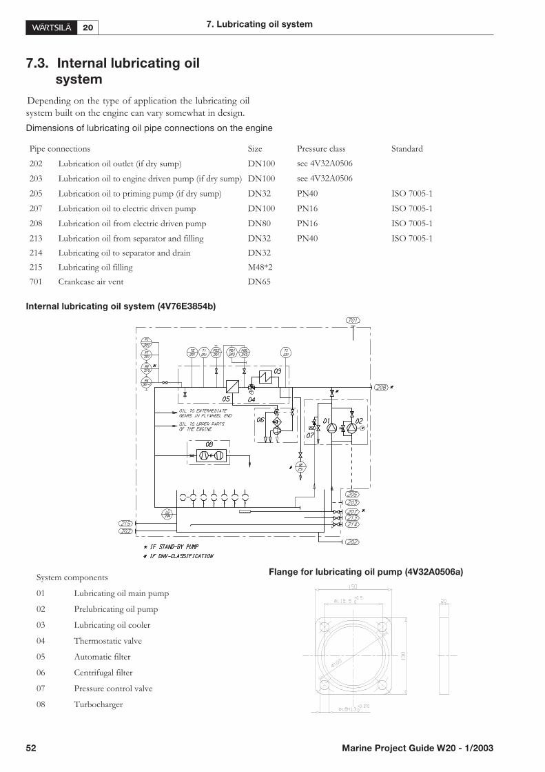
7.3. Internal lubricating oil
system
Depending on the type of application the lubricating oilsystem built on the engine can vary somewhat in design.
Dimensions of lubricating oil pipe connections on the engine
Internal lubricating oil system (4V76E3854b)
52 Marine Project Guide W20 - 1/2003
7. Lubricating oil system
Pipe connections Size Pressure class Standard
202 Lubrication oil outlet (if dry sump) DN100 see 4V32A0506
203 Lubrication oil to engine driven pump (if dry sump) DN100 see 4V32A0506
205 Lubrication oil to priming pump (if dry sump) DN32 PN40 ISO 7005-1
207 Lubrication oil to electric driven pump DN100 PN16 ISO 7005-1
208 Lubrication oil from electric driven pump DN80 PN16 ISO 7005-1
213 Lubrication oil from separator and filling DN32 PN40 ISO 7005-1
214 Lubricating oil to separator and drain DN32
215 Lubricating oil filling M48*2
701 Crankcase air vent DN65
System components
01 Lubricating oil main pump
02 Prelubricating oil pump
03 Lubricating oil cooler
04 Thermostatic valve
05 Automatic filter
06 Centrifugal filter
07 Pressure control valve
08 Turbocharger
Flange for lubricating oil pump (4V32A0506a)
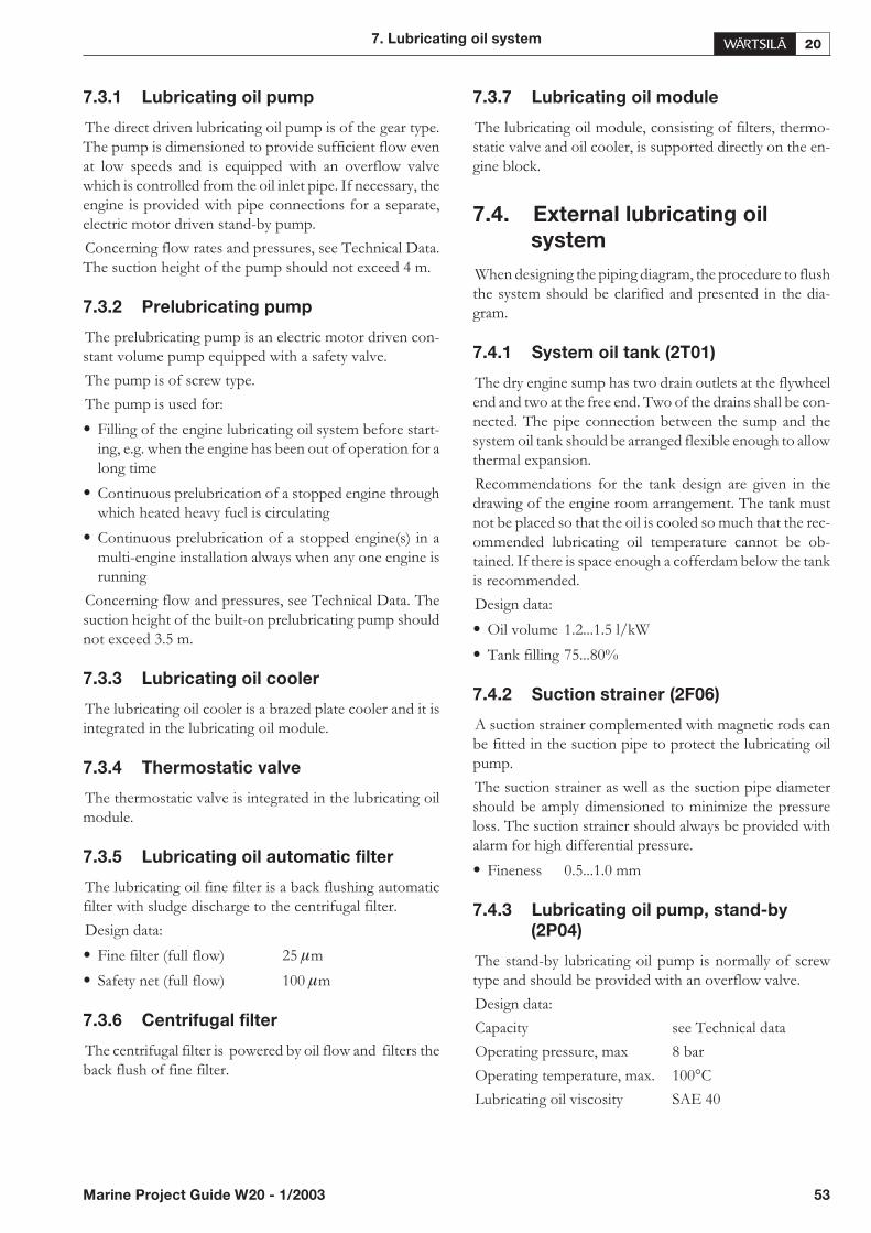
7.3.1 Lubricating oil pump
The direct driven lubricating oil pump is of the gear type.The pump is dimensioned to provide sufficient flow evenat low speeds and is equipped with an overflow valvewhich is controlled from the oil inlet pipe. If necessary, theengine is provided with pipe connections for a separate,electric motor driven stand-by pump.
Concerning flow rates and pressures, see Technical Data.The suction height of the pump should not exceed 4 m.
7.3.2 Prelubricating pump
The prelubricating pump is an electric motor driven con-stant volume pump equipped with a safety valve.
The pump is of screw type.
The pump is used for:
• Filling of the engine lubricating oil system before start-ing, e.g. when the engine has been out of operation for along time
• Continuous prelubrication of a stopped engine throughwhich heated heavy fuel is circulating
• Continuous prelubrication of a stopped engine(s) in amulti-engine installation always when any one engine isrunning
Concerning flow and pressures, see Technical Data. Thesuction height of the built-on prelubricating pump shouldnot exceed 3.5 m.
7.3.3 Lubricating oil cooler
The lubricating oil cooler is a brazed plate cooler and it isintegrated in the lubricating oil module.
7.3.4 Thermostatic valve
The thermostatic valve is integrated in the lubricating oilmodule.
7.3.5 Lubricating oil automatic filter
The lubricating oil fine filter is a back flushing automaticfilter with sludge discharge to the centrifugal filter.
Design data:
• Fine filter (full flow) 25 �m
• Safety net (full flow) 100 �m
7.3.6 Centrifugal filter
The centrifugal filter is powered by oil flow and filters theback flush of fine filter.
7.3.7 Lubricating oil module
The lubricating oil module, consisting of filters, thermo-static valve and oil cooler, is supported directly on the en-gine block.
7.4. External lubricating oil
system
When designing the piping diagram, the procedure to flushthe system should be clarified and presented in the dia-gram.
7.4.1 System oil tank (2T01)
The dry engine sump has two drain outlets at the flywheelend and two at the free end. Two of the drains shall be con-nected. The pipe connection between the sump and thesystem oil tank should be arranged flexible enough to allowthermal expansion.
Recommendations for the tank design are given in thedrawing of the engine room arrangement. The tank mustnot be placed so that the oil is cooled so much that the rec-ommended lubricating oil temperature cannot be ob-tained. If there is space enough a cofferdam below the tankis recommended.
Design data:
• Oil volume 1.2...1.5 l/kW
• Tank filling 75...80%
7.4.2 Suction strainer (2F06)
A suction strainer complemented with magnetic rods canbe fitted in the suction pipe to protect the lubricating oilpump.
The suction strainer as well as the suction pipe diametershould be amply dimensioned to minimize the pressureloss. The suction strainer should always be provided withalarm for high differential pressure.
• Fineness 0.5...1.0 mm
7.4.3 Lubricating oil pump, stand-by
(2P04)
The stand-by lubricating oil pump is normally of screwtype and should be provided with an overflow valve.
Design data:
Capacity see Technical data
Operating pressure, max 8 bar
Operating temperature, max. 100°C
Lubricating oil viscosity SAE 40
7. Lubricating oil system
Marine Project Guide W20 - 1/2003 53

7.5. Separation system
7.5.1 Separator (2N01)
For HFO operation the lubrication oil separator should bedimensioned for continuous centrifuging. For MDF inter-mittent centrifuging might be sufficient. Each lubricatingoil system should have a separator unit of its own.
Each main engine operating on heavy fuel shall have a ded-icated separator.
Auxiliary engines operating on a fuel having a viscosity ofmax. 35 mm²/s (cSt) / 100°C may have a common separa-tor. In installations with four or more auxiliary engines twoseparators should be installed.
The separators should preferably be of a type with con-trolled discharge of the bowl to minimize the lubricating oillosses.
The separators should be dimensioned for continuous op-eration.
Design data:
• Centrifuging temperature 90 - 95°C
Capacity:
Q = 1.36 P n / t
Where:
Q = volume flow [l / h]
P = total engine output
n = number of through-flows of dry sump system oiltank volume n/day: 5 for HFO, 4 for MDF
t = operating time [h / day]: 24 for continuos separatoroperation, 23 for normal dimensioning
Note!
Det Norske Veritas states in their class rules of July 2001that come into force 1.1.2002 the following:
(Pt.4 Ch.6 Sec.5 C 203) “For diesel engines burning resid-ual oil fuel, cleaning of the lubrication oil by means of puri-fiers are to be arranged. These means are additional tofilters.”
7.5.2 Separator pump (2P03)
The separator pump can be directly driven by the separatoror separately driven by an electric motor. The flow shouldbe adapted to achieve the above mentioned optimal flow.
7.5.3 Separator preheater (2E02)
The preheater can be a steam, thermal oil or an electricheater. The surface temperature of the heater must notexceed 150°C in order to avoid coking of the oil.
Design data
• For engines with centrifuging during operation, theheater should be dimensioned for this operating condi-tion. The temperature in the separate system oil tank inthe ship’s bottom is normally 65 - 75°C.
• For engines with centrifuging stopped engine, the heatershould be large enough to allow centrifuging at optimalrate of the separator without heat supply from the dieselengine.
Note!
The heaters are to be provided with safety valves with es-cape pipes to a leakage tank so that the possible leakage canbe seen.
7.5.4 Renovating oil tank (2T04)
In case of wet sump engines the oil sump content isdrained to this tank prior to separation.
7.5.5 Renovated oil tank (2T05)
This tank contains renovated oil ready to be used as a re-placement of the oil drained for separation.
7.6. Filling, transfer and storage
7.6.1 New oil tank (2T03)
In engines with wet sump, the lubricating oil may be filledinto the engine, using a hose or an oil can, through thecrankcase cover or through the separator pipe. The systemshould be arranged so that it is possible to measure thefilled oil volume.
7.7. Crankcase ventilation
system
A crankcase vent pipe shall be provided for each engine. Ifthe engine has a dry sump and there is a system oil tank, thistank shall have its own vent pipe. Vent pipes of several en-gines and vent pipes of engine crankcases and tanks shouldnot be joined together.
The connection between the engine and the vent pipe is tobe flexible.
A condensate trap shall be fitted on all vent pipes within 1 -2 meters of the engine, see drawing 4V76E2522.
Recommended size of the vent pipe after the condensatetrap is DN 80
Pipe connection engine:
701 Crankcase air vent DN65, ISO 7005-1, NP16
54 Marine Project Guide W20 - 1/2003
7. Lubricating oil system
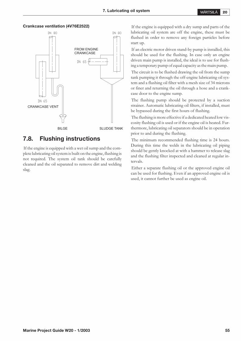
Crankcase ventilation (4V76E2522)
7.8. Flushing instructions
If the engine is equipped with a wet oil sump and the com-plete lubricating oil system is built on the engine, flushing isnot required. The system oil tank should be carefullycleaned and the oil separated to remove dirt and weldingslag.
If the engine is equipped with a dry sump and parts of thelubricating oil system are off the engine, these must beflushed in order to remove any foreign particles beforestart up.
If an electric motor driven stand-by pump is installed, thisshould be used for the flushing. In case only an enginedriven main pump is installed, the ideal is to use for flush-ing a temporary pump of equal capacity as the main pump.
The circuit is to be flushed drawing the oil from the sumptank pumping it through the off-engine lubricating oil sys-tem and a flushing oil filter with a mesh size of 34 micronsor finer and returning the oil through a hose and a crank-case door to the engine sump.
The flushing pump should be protected by a suctionstrainer. Automatic lubricating oil filters, if installed, mustbe bypassed during the first hours of flushing.
The flushing is more effective if a dedicated heated low vis-cosity flushing oil is used or if the engine oil is heated. Fur-thermore, lubricating oil separators should be in operationprior to and during the flushing.
The minimum recommended flushing time is 24 hours.During this time the welds in the lubricating oil pipingshould be gently knocked at with a hammer to release slagand the flushing filter inspected and cleaned at regular in-tervals.
Either a separate flushing oil or the approved engine oilcan be used for flushing. Even if an approved engine oil isused, it cannot further be used as engine oil.
7. Lubricating oil system
Marine Project Guide W20 - 1/2003 55
BILGE SLUDGE TANK
FROM ENGINECRANKCASE
CRANKCASE VENT
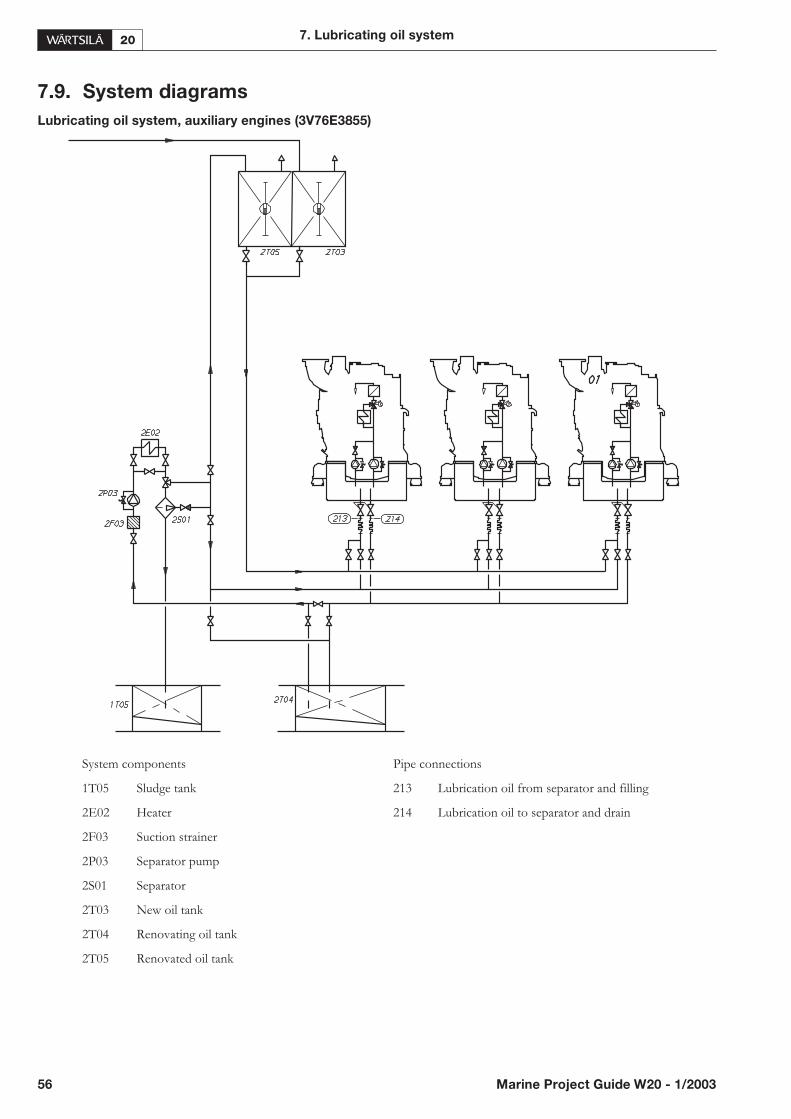
7.9. System diagrams
Lubricating oil system, auxiliary engines (3V76E3855)
56 Marine Project Guide W20 - 1/2003
7. Lubricating oil system
System components Pipe connections
1T05 Sludge tank 213 Lubrication oil from separator and filling
2E02 Heater 214 Lubrication oil to separator and drain
2F03 Suction strainer
2P03 Separator pump
2S01 Separator
2T03 New oil tank
2T04 Renovating oil tank
2T05 Renovated oil tank
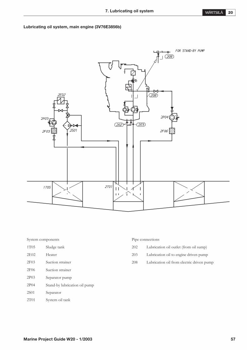
Lubricating oil system, main engine (3V76E3856b)
7. Lubricating oil system
Marine Project Guide W20 - 1/2003 57
System components Pipe connections
1T05 Sludge tank 202 Lubrication oil outlet (from oil sump)
2E02 Heater 203 Lubrication oil to engine driven pump
2F03 Suction strainer 208 Lubrication oil from electric driven pump
2F06 Suction strainer
2P03 Separator pump
2P04 Stand-by lubrication oil pump
2S01 Separator
2T01 System oil tank

8. Compressed air system
8.1. General
Compressed air is used to start engines and to provide ac-tuating energy for safety and control devices. Compressedair is used onboard also for other purposes with differentpressures. The use of starting air supply for these otherpurposes is limited in the classication regulations.
8.2. Compressed air quality
To ensure the functionality of the components in the com-pressed air system, the compressed air has to be dry andclean from solid particles and oil.
8.3. Internal starting air system
The engine is equipped with a pneumatic starting motordriving the engine through a gear rim on the flywheel.
Table 8.1. Dimensions of starting air pipe connections
on the engine
The nominal starting air pressure of 30 bar is reduced to 10bar with a pressure regulator mounted on the engine.
Internal starting air system (4V76H3460b)
58 Marine Project Guide W20 - 1/2003
8. Compressed air system
Code Description SizePressure
classStandard
301Starting air
inletOD28 PN100
DIN2353
System components Pipe connections Pipe dimensions
01 Turbine starter with pneumatic actuator 301 Starting air inlet OD28
02 Blocking valve, turning gear engaged
03 Pneumatic cylinder at each injection pump
04 Pressure regulator
05 Air container
06
07
Solenoid valve
Safety valve

The compressed air system of the electro- pneumaticoverspeed trip is connected to the starting air system. Forthis reason, the air supply to the engine must not be closedduring operation.
8.4. External starting air system
The design of the starting air system is partly determinedby the rules of the classification societies. Most classifica-tion societies require the total capacity to be divided overtwo roughly equally sized starting air receivers and startingair compressors.
If the inertia of the directly coupled equipment is muchlarger than the normal reference equipment used on test-bed the starting air consumption per start value has to beincreased in relation to total (engine included) inertialmasses involved.
External starting air system (3V76H3461)
It should be noted that the minimum pressures stated inthe chapter for technical data assume that this pressure isavailable at engine inlet.
The rule requirements of some classification societies arenot precise for multiple engine installations.
Starting air filter
Condense formation after the water separator (betweenstarting air compressor and starting air receivers) has beenexperienced in tropical areas. This can, depending of thematerials and surface treatments used, create and loosenabbrasive rust from the piping, fittings and receivers.
Therefore it might be needed to install a filter in the exter-nal starting air system just before the engine to prevent par-ticles to enter the starting air equipment if a high condenseformation is expected.
Starting air receiver (3T01)
The starting air receiver should be dimensioned for a nom-inal pressure of 30 bar.
The number and the capacity of the air receivers for pro-pulsion engines depend on the requirements of the classifi-cation societies and the type of installation.
8. Compressed air system
Marine Project Guide W20 - 1/2003 59
System components Pipe connections
3T01 Starting air vessel 301 Starting air inlet
3S01 Oil and water separator
3N02 Starting air compressor
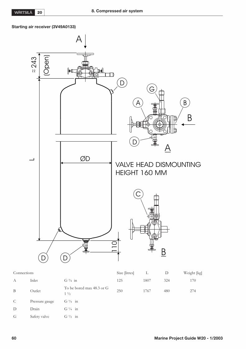
Starting air receiver (3V49A0133)
60 Marine Project Guide W20 - 1/2003
8. Compressed air system
A B
C
D
G
VALVE HEAD DISMOUNTING
HEIGHT 160 MM
24
3L
~ ~ (Op
en
)
11
0
OD
D D
D
A
B
A
B
Connections Size [litres] L D Weight [kg]
A Inlet G ¾ in 125 1807 324 170
B OutletTo be bored max 48.3 or G
1 ½250 1767 480 274
C Pressure gauge G ¼ in
D Drain G ¼ in
G Safety valve G ½ in

The starting air receivers are to be equipped with at least amanual valve for condensate drainage. If the air receiversare mounted horizontally, there must be an inclination of3-5° towards drain valve to ensure efficient draining
Recommended min. volumes of starting air vessels are:
• Single main engine 2 x 125 l
• Multiple main engines 2 x 250 l
• 1 - 3 auxiliary engines 2 x 125 l
• > 3 auxiliary engines 2 x 250 l
Oil and water separator (3S01)
An oil and water separator should always be installed in thepipe between the compressor and the air receiver. De-pending on the operation conditions of the installation, anoil and water separator may be needed in the pipe betweenthe air receiver and the engine.
The starting air pipes should always be drawn with slopeand be arranged with manual or automatic draining at thelowest points.
Starting air compressor (3N02)
At least two starting air compressors must be installed. It isrecommended that the compressors are capable of fillingthe starting air receiver from minimum to maximum pres-sure in 15 - 30 minutes. For exact determination of the min-imum capacity, the rules of the classification societies mustbe followed.
61 Marine Project Guide W20 - 1/2003
8. Compressed air system

9. Cooling water system
9.1. General
Only treated fresh water may be used for cooling the en-gines.
To allow start on heavy fuel, the cooling water system hasto be preheated to a temperature as near to the operatingtemperature as possible.
9.1.1 Water quality
The cylinder, turbocharger, charge air and oil are all cooledwith fresh water. The pH-value and hardness of the watershould be within normal values (hardness < 10°dH, pH >6.5). The chloride and sulphate contents should be as lowas possible (chlorides < 80 mg/l). To prevent rust forma-tion in the cooling water system, the use of corrosion inhib-itors is mandatory. See the instructions in the InstructionManual.
Shore water is not always suitable. The hardness of shorewater may be too low, which can be compensated by addi-tives, or too high, causing scale deposits even with addi-tives.
Fresh water generated by a reverse osmosis plant onboardoften has a high chloride content (higher than the permit-ted 80 mg/l) causing corrosion.
For ships with a wide sailing area a safe solution is to usefresh water produced by an evaporator (onboard), usingadditives according to the Instruction Manual (important).
Sea-water will cause severe corrosion and deposits forma-tion even in small amounts.
Rain water is unsuitable as cooling water due to a high oxy-gen and carbon dioxide content, causing a great risk forcorrosion.
9.1.2 Approved cooling water treatment
products
Product Supplier
Drewgard 4109 Drew Ameroid Marine
Maxigard Division, Ashland
DEWT-NC powder Chemical Company
Liquidewt Boonton, USA
Vecom CWT Diesel QC-2
CorrShield NT 4293
CorrShield NT 4200
GE Betz Europe, Belgium
GE Betz, Trevose, USA
Q8 Corrosion InhibitorLong-Life
Kuwait Petroleum (Danmark)AS
Cooltreat 651 Houseman Ltd. Burnham,
Slough, U.K.
Marisol CW Maritech AB,
Kristianstad, Sweden
Nalco 39 L Nalco Chemical Company
Nalcool 2000 Naperville, Illinois, USA
Nalfleet EWT 9-108 Nalfleet Marine Chemicals
Nalfleet CWT 9-131C Nortwich, Cheshire, U.K.
Nalcool 2000
RD11 Rohm & Haas
RD11M Paris, France
RD25
Havoline XLi S.A. Arteco N.V. Belgium
Havoline XliTexaco Global Products,LLC Houston, USA
Korrostop KV RRS-Yhtiöt, Jäppilä, Finland
Ruostop XMTampereen Prosessi-Insinöörit
Pirkkala, Finland
Dieselguard NB Unitor ASA, Oslo
Rocor NB liquid
Cooltreat AL
Norway
Vecom CWT Diesel QC-2 Vecom Holding B.V.
Maassluis, Holland
W T Supra TotalFinaElf, Paris, France
Glycol
Use of glycol in the cooling water is not recommended. Itis however possible to use up to 10% glycol without enginederating. For higher concentrations the engine shall be de-rated 0.67% for each percentage unit exceeding 10.
62 Marine Project Guide W20 - 1/2003
9. Cooling water system
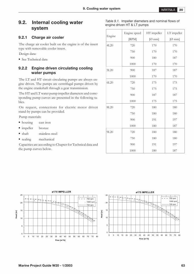
9.2. Internal cooling water
system
9.2.1 Charge air cooler
The charge air cooler built on the engine is of the inserttype with removable cooler insert.
Design data:
• See Technical data
9.2.2 Engine driven circulating cooling
water pumps
The LT and HT circuit circulating pumps are always en-gine driven. The pumps are centrifugal pumps driven bythe engine crankshaft through a gear transmission.
The HT and LT water pump impeller diameters and corre-sponding pump curves are presented in the following ta-bles.
On request, connections for electric motor drivenstand-by pumps can be provided.
Pump materials:
• housing cast iron
• impeller bronze
• shaft stainless steel
• sealing mechanical
Capacities are according to Chapter for Technical data andthe pump curves below.
Table 9.1. Impeller diameters and nominal flows ofengine driven HT & LT pumps
9. Cooling water system
Marine Project Guide W20 - 1/2003 63
EngineEngine speed HT impeller LT impeller
[RPM] [Ø mm] [Ø mm]
4L20 720 170 170
750 170 170
900 180 187
1000 170 170
5L20 900 187 187
1000 170 170
6L20 720 175 175
750 175 175
900 187 187
1000 175 175
8L20 720 180 180
750 180 180
900 191 197
1000 180 187
9L20 720 180 180
750 180 180
900 191 197
1000 180 187
ø175 IMPELLER
0
5
10
15
20
25
0 5 10 15 20 25 30 35 40 45 50 55 60 65 70 75 80
Flow [m³/h]
He
ad
[m]
750 rpm
1000 rpm
720 rpm
ø170 IMPELLER
0
5
10
15
20
25
0 5 10 15 20 25 30 35 40 45 50 55 60 65 70 75 80
Flow [m³/h]
He
ad
[m]
750 rpm
1000 rpm
720 rpm
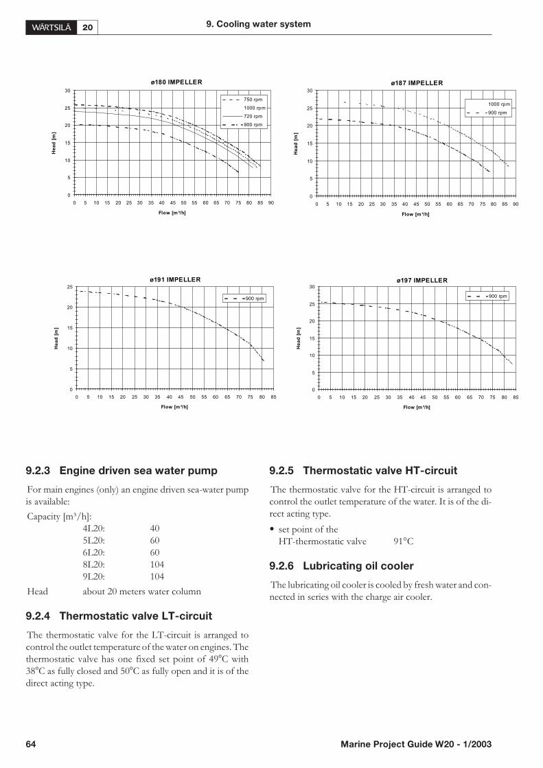
9.2.3 Engine driven sea water pump
For main engines (only) an engine driven sea-water pumpis available:
Capacity [m³/h]:4L20: 405L20: 606L20: 608L20: 1049L20: 104
Head about 20 meters water column
9.2.4 Thermostatic valve LT-circuit
The thermostatic valve for the LT-circuit is arranged tocontrol the outlet temperature of the water on engines. Thethermostatic valve has one fixed set point of 49�C with38�C as fully closed and 50�C as fully open and it is of thedirect acting type.
9.2.5 Thermostatic valve HT-circuit
The thermostatic valve for the HT-circuit is arranged tocontrol the outlet temperature of the water. It is of the di-rect acting type.
• set point of theHT-thermostatic valve 91°C
9.2.6 Lubricating oil cooler
The lubricating oil cooler is cooled by fresh water and con-nected in series with the charge air cooler.
64 Marine Project Guide W20 - 1/2003
9. Cooling water system
ø180 IMPELLER
0
5
10
15
20
25
30
0 5 10 15 20 25 30 35 40 45 50 55 60 65 70 75 80 85 90
Flow [m³/h]
He
ad
[m]
750 rpm
1000 rpm
720 rpm
900 rpm
ø191 IMPELLER
0
5
10
15
20
25
0 5 10 15 20 25 30 35 40 45 50 55 60 65 70 75 80 85
Flow [m³/h]
He
ad
[m]
900 rpm
ø197 IMPELLER
0
5
10
15
20
25
30
0 5 10 15 20 25 30 35 40 45 50 55 60 65 70 75 80 85
Flow [m³/h]
He
ad
[m]
900 rpm
ø187 IMPELLER
0
5
10
15
20
25
30
0 5 10 15 20 25 30 35 40 45 50 55 60 65 70 75 80 85 90
Flow [m³/h]
He
ad
[m]
1000 rpm
900 rpm
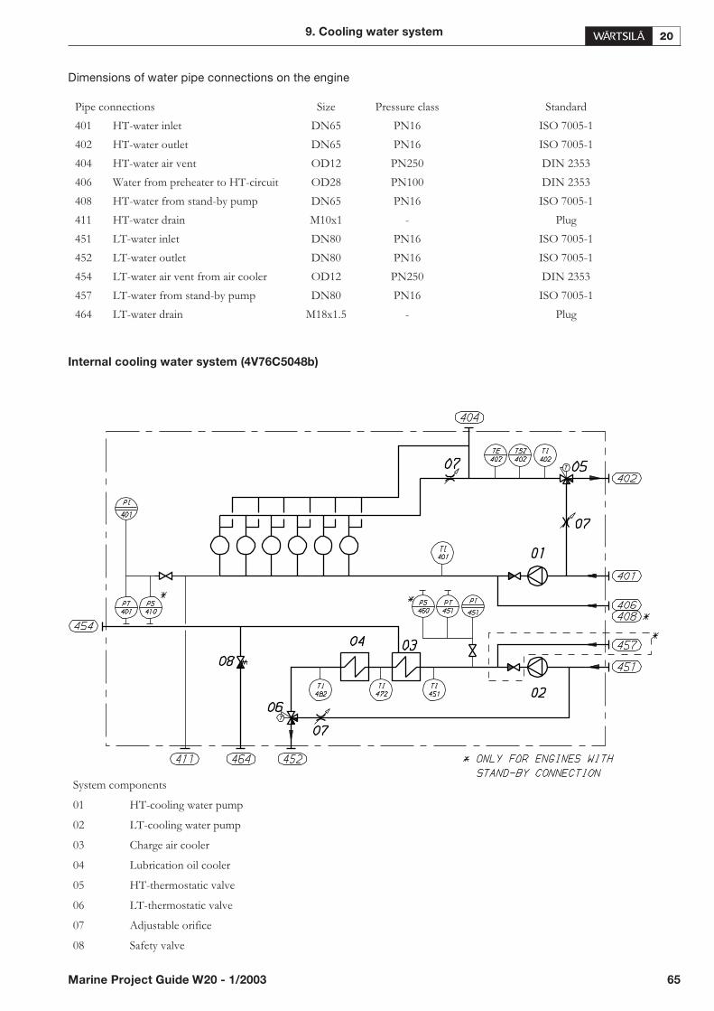
Dimensions of water pipe connections on the engine
Internal cooling water system (4V76C5048b)
9. Cooling water system
Marine Project Guide W20 - 1/2003 65
Pipe connections Size Pressure class Standard
401 HT-water inlet DN65 PN16 ISO 7005-1
402 HT-water outlet DN65 PN16 ISO 7005-1
404 HT-water air vent OD12 PN250 DIN 2353
406 Water from preheater to HT-circuit OD28 PN100 DIN 2353
408 HT-water from stand-by pump DN65 PN16 ISO 7005-1
411 HT-water drain M10x1 - Plug
451 LT-water inlet DN80 PN16 ISO 7005-1
452 LT-water outlet DN80 PN16 ISO 7005-1
454 LT-water air vent from air cooler OD12 PN250 DIN 2353
457 LT-water from stand-by pump DN80 PN16 ISO 7005-1
464 LT-water drain M18x1.5 - Plug
System components
01 HT-cooling water pump
02 LT-cooling water pump
03 Charge air cooler
04 Lubrication oil cooler
05 HT-thermostatic valve
06 LT-thermostatic valve
07 Adjustable orifice
08 Safety valve
9.3. External cooling water
system
The fresh water pipes should be designed to minimize theflow resistance in the external piping. Galvanized pipesshould not be used for fresh water.
Ships (with ice class) designed for cold sea-water shouldhave temperature regulation with a recirculation back tothe sea chest:
• for heating of the sea chest to melt ice and slush, to avoidclogging the sea-water strainer
• to increase the sea-water temperature to enhance thetemperature regulation of the LT-water
9.3.1 Sea water pump (4P11)
The sea-water pumps are usually electrically driven. Thecapacity of the pumps is determined by the type of coolersused and the heat to be dissipated.
9.3.2 Fresh water central cooler (4E08)
The fresh water cooler can be of either tube or plate type.Due to the smaller dimensions the plate cooler is normallyused. The fresh water cooler can be common for severalengines, also one independent cooler per engine is used.
Design data:
• Fresh water flow see Technical Data
In case of fresh water central cooler is used for combinedLT and HT water flows in a parallel system the total flowcan be calculated with the following formula:
where:
q[m³/h]= total fresh water flow
qLT[m³/h]= nominal LT pump capacity
� [kW]= heat dissipated to HT water
Tout= HT water temperature after engine (91°C)
Tin= HT water temperature after cooler (38°C)
• Pressure drop on fresh water side, max.60 kPa (0.6 bar)
If the flow resistance in the external pipes is high it shouldbe observed when designing the cooler.
• Sea-water flow acc. to cooler manufac-turer, normally 1.2 - 1.5x the fresh water flow
• Pressure drop on sea-water side, norm.80-140 kPa (0.8 - 1.4
bar)
• Fresh water temperature after cooler (before engine),max. 38°C.
see Technical Data
• Safety margin to be added 15% + margin forfouling
See also the table showing example coolers with calcula-tion data.
66 Marine Project Guide W20 - 1/2003
9. Cooling water system
q =4.19 · (T - T )out in
3.6 · �q +LT

Central cooler, main dimensions (4V47E0188b)
9. Cooling water system
Marine Project Guide W20 - 1/2003 67
Engine Cooling water Sea-water Measures Weight
TypeEng.speed[rpm]
Flow[m³/h]
Tcw, in[°C]
Tcw, out[°C]
Flow[m³/h]
Tsw,in [°C]
Tsw, out[°C]
A[mm]
B[mm]
C[mm]
Dry[kg]
Wet [kg]
4L20750 22 52.1 38 30 32 42.6 80 505 695 270 287
1000 27 54.3 38 36 32 44.3 106 505 695 275 298
5L20 1000 33 52.9 38 44 32 43.2 121 655 845 280 306
6L20750 33 52 38 44 32 42.6 121 655 845 280 306
1000 40 53.3 38 53 32 43.5 150 655 845 288 321
8L20750 44 52 38 59 32 42.6 156 655 845 289 323
1000 53 53.6 38 71 32 43.8 198 655 845 298 341
9L20750 49 52.1 38 67 32 42.7 186 655 845 293 336
1000 59 53.7 38 80 32 43.8 221 905 1095 305 354
9.3.3 Stand-by circulating cooling water
pumps
The pumps should be centrifugal pumps driven by an elec-tric motor. Capacities according to Chapter for Technicaldata.
9.3.4 Expansion tank (4T05)
The expansion tank should compensate for volumechanges in the cooling water system, serve as venting ar-rangement and provide sufficient static pressure for thecooling water circulating pumps.
Design data:
• pressure from the expansion tank0.7...1.5 bar
• volume min. 10% of the system
Concerning engine water volumes, see Chapter for Tech-nical data.
The tank should be equipped so that it is possible to dosewater treatment agents.
The vent pipe of each engine should be drawn to the tankseparately, continuously rising, and so that mixing of airinto the water cannot occur (the outlet should be below thewater level).
The expansion tank is to be provided with inspection de-vices.
9.3.5 Drain tank (4T04)
It is recommended to provide a drain tank to which the en-gines and coolers can be drained for maintenance so thatthe water and cooling water treatment can be collected andreused. For the water volume in the engine, see Technicaldata (HT-circuit).
Most of the cooling water in the engine can be recoveredfrom the HT-circuit, whereas the amount of water in theLT circuit is small.
9.3.6 Preheating
Engines started and stopped on heavy fuel and all engineson which high load will be applied immediately after start(stand-by generating sets) have to be preheated as close tothe actual operating temperature as possible, or minimum60°C. Preheating is however, recommended for all en-gines, also main engines running on MDF only.
The energy required for heating of the HT-cooling waterin the main and auxiliary engines can be taken from a run-ning engine or a separate source. In both cases a separatecirculating pump should be used to ensure the circulation.If the cooling water systems of the main and auxiliary en-gines are separated from each other in other respects, theenergy is recommended to be transmitted through heatexchangers.
For installations with several engines the preheater unitcan be chosen for heating up two engines. The heat from arunning engine can be used and therefore the power con-sumption of the heater will be less than the nominal capac-ity.
Heater (4E05)
Steam, electrical or thermal oil heaters can be used.
Design data:
• preheating temperature min. 60°C
• required heating power 2 kW/cyl.
Preheating pump (4P04)
Design data of the pump:
• capacity 0.3 m³/h x cyl.
• pressure abt. 80 kPa (0.8 bar)
Preheating unit (4N01)
A complete preheating unit can be supplied as option. Theunit comprises:
• electric or steam heaters
• circulating pump
• control cabinet for heaters and pump
• one set of thermometers
68 Marine Project Guide W20 - 1/2003
9. Cooling water system

Preheating unit, electric (3V60L0653a)
9. Cooling water system
Marine Project Guide W20 - 1/2003 69
Heatercapacity
Pumpcapacity Weight Pipe conn. Dimensions
kW m3/h kg In / Outlet A B C D E
7.5 3 75 DN40 1050 720 610 790 425
12 3 93 DN40 1050 550 660 240 450
15 3 93 DN40 1050 720 660 240 450
18 3 95 DN40 1250 900 660 240 450
22.5 8 100 DN40 1050 720 700 290 475
27 8 103 DN40 1250 900 700 290 475
30 8 105 DN40 1050 720 700 290 475
36 8 125 DN40 1250 900 700 290 475
45 8 145 DN40 1250 720 755 350 505
54 8 150 DN40 1250 900 755 350 505

9.3.7 Air venting (4S01)
Air and gas may be entrained in the piping after overhaul,centrifugal pump seals may leak, or air or gas may leak fromin any equipment connected the HT- or LT-circuit, such asdiesel engine, water cooled starting air compressor etc.
As presented in the external cooling diagrams, it is recom-mended that either of the following air venting equipmentis installed:.
1. At the HT-outlet from the engine. This is necessary for aquick venting after starting the engine, especially afteroverhaul when entrained air may remain in the system, andespecially at departures at low load, when the HT thermo-static valve recirculates all water. At higher load when a partof the HT-water goes to the cooler, any possible air or gasbubbles may still be recirculated depending on the geome-try and position of the HT thermostatic valve. If the branchto the cooler is vertically down the bubbles may be con-ducted to the by-pass line and back into circulation.
2. One in the LT system line for venting of any entrainedair.
9.3.8 Orifices
Orifices must be mounted after the HT outlet, after lubri-cating oil cooler and in all by-pass lines in order to adjustthe circulations pumps and to balance the pressure dropwhen the water is not flowing through the cooler.
9.3.9 Waste heat recovery
The waste heat of the HT-circuit may be used for fresh wa-ter production, central heating, tank heating etc. In suchcases the piping system should permit by-passing of thecentral cooler. With this arrangement the HT-water flowthrough the heat recovery can be increased.
70 Marine Project Guide W20 - 1/2003
9. Cooling water system
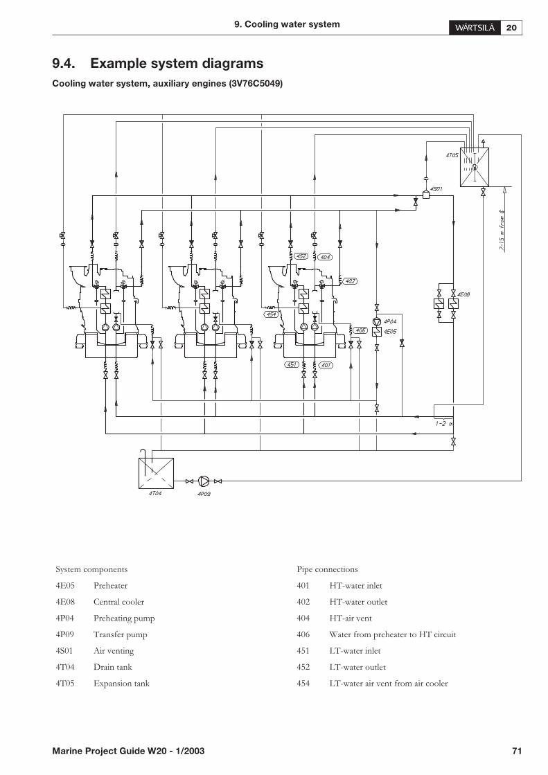
9.4. Example system diagrams
Cooling water system, auxiliary engines (3V76C5049)
9. Cooling water system
Marine Project Guide W20 - 1/2003 71
System components Pipe connections
4E05 Preheater 401 HT-water inlet
4E08 Central cooler 402 HT-water outlet
4P04 Preheating pump 404 HT-air vent
4P09 Transfer pump 406 Water from preheater to HT circuit
4S01 Air venting 451 LT-water inlet
4T04 Drain tank 452 LT-water outlet
4T05 Expansion tank 454 LT-water air vent from air cooler
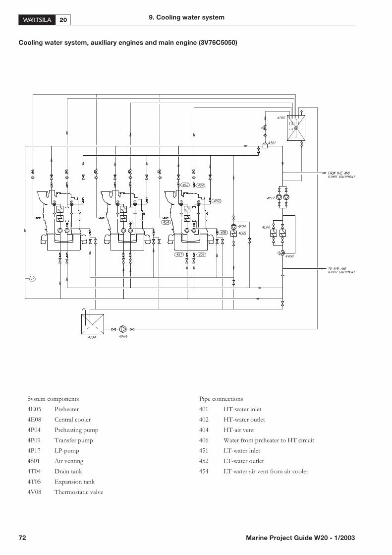
Cooling water system, auxiliary engines and main engine (3V76C5050)
72 Marine Project Guide W20 - 1/2003
9. Cooling water system
System components Pipe connections
4E05 Preheater 401 HT-water inlet
4E08 Central cooler 402 HT-water outlet
4P04 Preheating pump 404 HT-air vent
4P09 Transfer pump 406 Water from preheater to HT circuit
4P17 LP-pump 451 LT-water inlet
4S01 Air venting 452 LT-water outlet
4T04 Drain tank 454 LT-water air vent from air cooler
4T05 Expansion tank
4V08 Thermostatic valve
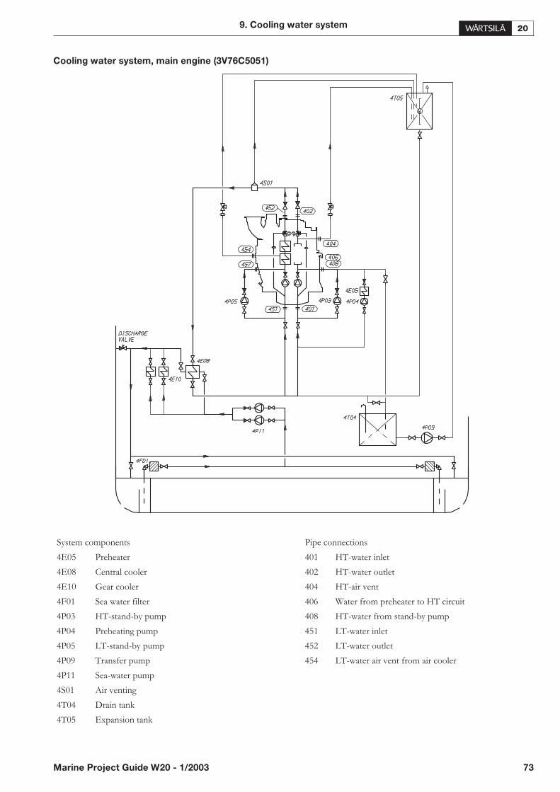
Cooling water system, main engine (3V76C5051)
9. Cooling water system
Marine Project Guide W20 - 1/2003 73
System components Pipe connections
4E05 Preheater 401 HT-water inlet
4E08 Central cooler 402 HT-water outlet
4E10 Gear cooler 404 HT-air vent
4F01 Sea water filter 406 Water from preheater to HT circuit
4P03 HT-stand-by pump 408 HT-water from stand-by pump
4P04 Preheating pump 451 LT-water inlet
4P05 LT-stand-by pump 452 LT-water outlet
4P09 Transfer pump 454 LT-water air vent from air cooler
4P11 Sea-water pump
4S01 Air venting
4T04 Drain tank
4T05 Expansion tank

Cooling water system, HFO engines with evaporator (3V76C5052b)
74 Marine Project Guide W20 - 1/2003
9. Cooling water system
System components Pipe connections
4E05 Preheater 401 HT-water inlet
4E08 Central cooler 402 HT-water outlet
4N02 Evaporator 404 HT-air vent
4P04 Preheating pump 406 Water from preheater to HT circuit
4P09 Transfer pump 451 LT-water inlet
4S01 Air venting 452 LT-water outlet
4T04 Drain tank 454 LT-water air vent from air cooler
4T05 Expansion tank
4V02 Thermostatic valve

Cooling water system, MDO engines with evaporator (3V76C5053)
9. Cooling water system
Marine Project Guide W20 - 1/2003 75
System components Pipe connections
4E05 Preheater 401 HT-water inlet
4E08 Central cooler 402 HT-water outlet
4N02 Evaporator 404 HT-air vent
4P04 Preheating pump 406 Water from preheater to HT circuit
4P09 Transfer pump 451 LT-water inlet
4S01 Air venting 452 LT-water outlet
4T04 Drain tank 454 LT-water air vent from air cooler
4T05 Expansion tank
4V02 Thermostatic valve
4V03 LT-thermostatic valve
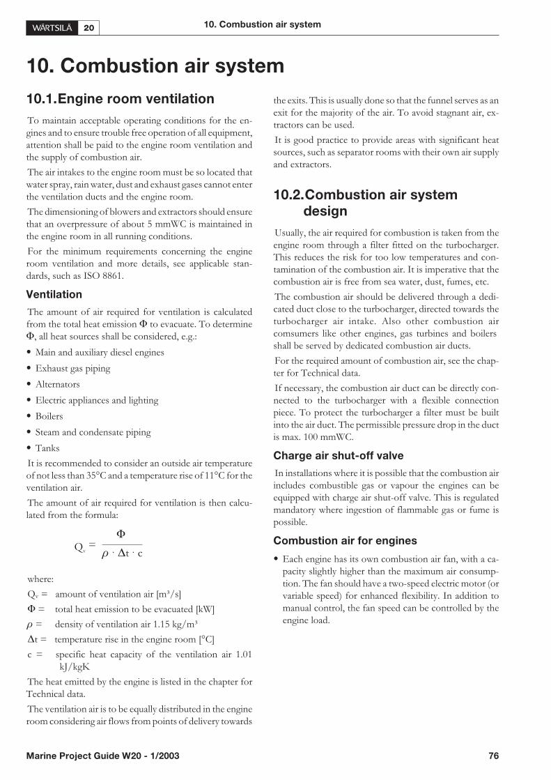
10. Combustion air system
10.1.Engine room ventilation
To maintain acceptable operating conditions for the en-gines and to ensure trouble free operation of all equipment,attention shall be paid to the engine room ventilation andthe supply of combustion air.
The air intakes to the engine room must be so located thatwater spray, rain water, dust and exhaust gases cannot enterthe ventilation ducts and the engine room.
The dimensioning of blowers and extractors should ensurethat an overpressure of about 5 mmWC is maintained inthe engine room in all running conditions.
For the minimum requirements concerning the engineroom ventilation and more details, see applicable stan-dards, such as ISO 8861.
Ventilation
The amount of air required for ventilation is calculatedfrom the total heat emission � to evacuate. To determine�, all heat sources shall be considered, e.g.:
• Main and auxiliary diesel engines
• Exhaust gas piping
• Alternators
• Electric appliances and lighting
• Boilers
• Steam and condensate piping
• Tanks
It is recommended to consider an outside air temperatureof not less than 35°C and a temperature rise of 11°C for theventilation air.
The amount of air required for ventilation is then calcu-lated from the formula:
where:
Qv = amount of ventilation air [m³/s]
� = total heat emission to be evacuated [kW]
� = density of ventilation air 1.15 kg/m³
�t = temperature rise in the engine room [°C]
c = specific heat capacity of the ventilation air 1.01kJ/kgK
The heat emitted by the engine is listed in the chapter forTechnical data.
The ventilation air is to be equally distributed in the engineroom considering air flows from points of delivery towards
the exits. This is usually done so that the funnel serves as anexit for the majority of the air. To avoid stagnant air, ex-tractors can be used.
It is good practice to provide areas with significant heatsources, such as separator rooms with their own air supplyand extractors.
10.2.Combustion air system
design
Usually, the air required for combustion is taken from theengine room through a filter fitted on the turbocharger.This reduces the risk for too low temperatures and con-tamination of the combustion air. It is imperative that thecombustion air is free from sea water, dust, fumes, etc.
The combustion air should be delivered through a dedi-cated duct close to the turbocharger, directed towards theturbocharger air intake. Also other combustion aircomsumers like other engines, gas turbines and boilersshall be served by dedicated combustion air ducts.
For the required amount of combustion air, see the chap-ter for Technical data.
If necessary, the combustion air duct can be directly con-nected to the turbocharger with a flexible connectionpiece. To protect the turbocharger a filter must be builtinto the air duct. The permissible pressure drop in the ductis max. 100 mmWC.
Charge air shut-off valve
In installations where it is possible that the combustion airincludes combustible gas or vapour the engines can beequipped with charge air shut-off valve. This is regulatedmandatory where ingestion of flammable gas or fume ispossible.
Combustion air for engines
• Each engine has its own combustion air fan, with a ca-pacity slightly higher than the maximum air consump-tion. The fan should have a two-speed electric motor (orvariable speed) for enhanced flexibility. In addition tomanual control, the fan speed can be controlled by theengine load.
10. Combustion air system
Marine Project Guide W20 - 1/2003 76
�Q =
v � �t c· ·
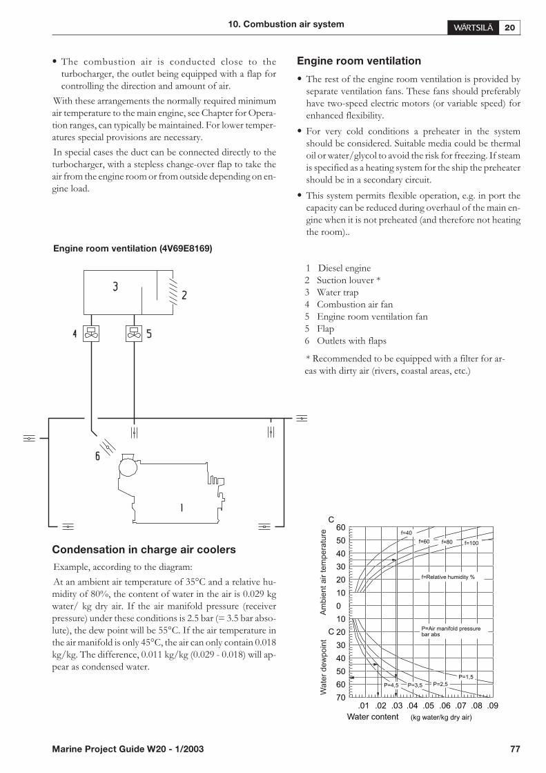
• The combustion air is conducted close to theturbocharger, the outlet being equipped with a flap forcontrolling the direction and amount of air.
With these arrangements the normally required minimumair temperature to the main engine, see Chapter for Opera-tion ranges, can typically be maintained. For lower temper-atures special provisions are necessary.
In special cases the duct can be connected directly to theturbocharger, with a stepless change-over flap to take theair from the engine room or from outside depending on en-gine load.
Engine room ventilation (4V69E8169)
Condensation in charge air coolers
Example, according to the diagram:
At an ambient air temperature of 35°C and a relative hu-midity of 80%, the content of water in the air is 0.029 kgwater/ kg dry air. If the air manifold pressure (receiverpressure) under these conditions is 2.5 bar (= 3.5 bar abso-lute), the dew point will be 55°C. If the air temperature inthe air manifold is only 45°C, the air can only contain 0.018kg/kg. The difference, 0.011 kg/kg (0.029 - 0.018) will ap-pear as condensed water.
Engine room ventilation
• The rest of the engine room ventilation is provided byseparate ventilation fans. These fans should preferablyhave two-speed electric motors (or variable speed) forenhanced flexibility.
• For very cold conditions a preheater in the systemshould be considered. Suitable media could be thermaloil or water/glycol to avoid the risk for freezing. If steamis specified as a heating system for the ship the preheatershould be in a secondary circuit.
• This system permits flexible operation, e.g. in port thecapacity can be reduced during overhaul of the main en-gine when it is not preheated (and therefore not heatingthe room)..
10. Combustion air system
Marine Project Guide W20 - 1/2003 77
Am
bie
nt
air
tem
pe
ratu
reW
ate
rd
ew
po
int
1 Diesel engine2 Suction louver *3 Water trap4 Combustion air fan5 Engine room ventilation fan5 Flap6 Outlets with flaps
* Recommended to be equipped with a filter for ar-eas with dirty air (rivers, coastal areas, etc.)

11. Exhaust gas system
11.1.Internal exhaust gas system
11.1.1 Exhaust gas outlet
Exhaust gas outlet (4V76A2679)
The exhaust gas outlet from the turbocharger can berotated to several positions, the positions depending on thenumber of cylinders. Other directions can be arranged bymeans of the adapter at the turbocharger outlet.
11.2.External exhaust gas system
Each engine should have its own exhaust pipe into openair. Flexible bellows have to be mounted directly to theturbocharger outlet, to compensate for thermal expansionand prevent damages on the turbocharger due to vibra-tions.
It is very important that the exhaust pipe is properly fixedto a rigid support directly after the bellows. Resilientmounts are acceptable at the fixing points between the ex-haust pipe and the rigid support. The mounts must how-
ever be stiff enough to prevent dynamic deflections in ex-cess of 1 mm peak to peak. Conical rubber mounts similarto the mounts that are installed under generating sets canbe used. Adequate thermal insulation must be provided toprotect the rubber mounts from high exhaust gas tempera-tures.
The piping should be as short and straight as possible.
The bends should be made with the largest possible bend-ing radius, minimum radius used should be 1.5 D. The ex-haust pipe must be insulated all the way from theturbocharger and the insulation is to be protected by a cov-ering plate or similar to keep the insulation intact. Closestto the turbocharger the insulation should consist of a hookon padding to facilitate maintenance. It is especially impor-tant to prevent the airstream to the turbocharger detachinginsulation, which will then clog the filters.
The exhaust gas pipes and/or silencers should be providedwith water separating pockets and drainage.
Recommended flow velocity is 35...40 m/s. Lower veloci-ties might be needed with long piping or if there are manyresistance factors in the piping.
The exhaust gas mass flow given in the Chapter for Tech-nical data can be translated to velocity using the formula:
Where:
v [m/s] = gas velocity
m [kg/s] = exhaust gas mass flow
t [°C] = exhaust gas temperature
D [m] = exhaust gas pipe diameter
11.2.1 Exhaust gas silencer (5R01)
When included in the scope of supply, the standard si-lencer is of the absorption type, equipped with a spark ar-rester. It is also provided with a soot collector and a waterdrain, but is without mounting brackets and insulation.The silencer can be mounted either horizontally or verti-cally.
The noise attenuation of the standard silencer is either 25or 35 dB(A).
78 Marine Project Guide W20 - 1/2003
11. Exhaust gas system
EngineBellows A Piping B
(inner dia) (inner dia)
4L20 200 250-300
5L20 250 300-350
6L20 250 300-350
8, 9L20 300 350-450
v [m/s] =——————
4 m·
1.3 ·273
273 + t· ·� D²
——————
)(
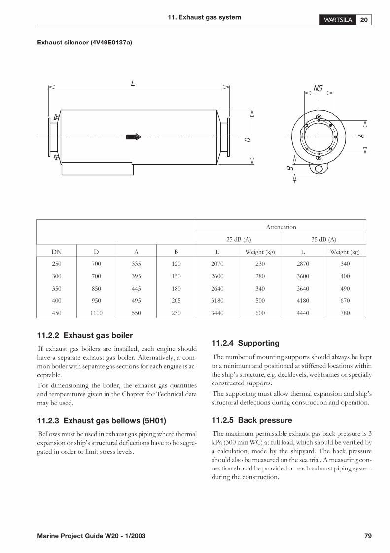
Exhaust silencer (4V49E0137a)
11.2.2 Exhaust gas boiler
If exhaust gas boilers are installed, each engine shouldhave a separate exhaust gas boiler. Alternatively, a com-mon boiler with separate gas sections for each engine is ac-ceptable.
For dimensioning the boiler, the exhaust gas quantitiesand temperatures given in the Chapter for Technical datamay be used.
11.2.3 Exhaust gas bellows (5H01)
Bellows must be used in exhaust gas piping where thermalexpansion or ship’s structural deflections have to be segre-gated in order to limit stress levels.
11.2.4 Supporting
The number of mounting supports should always be keptto a minimum and positioned at stiffened locations withinthe ship’s structure, e.g. decklevels, webframes or speciallyconstructed supports.
The supporting must allow thermal expansion and ship’sstructural deflections during construction and operation.
11.2.5 Back pressure
The maximum permissible exhaust gas back pressure is 3kPa (300 mm WC) at full load, which should be verified bya calculation, made by the shipyard. The back pressureshould also be measured on the sea trial. A measuring con-nection should be provided on each exhaust piping systemduring the construction.
11. Exhaust gas system
Marine Project Guide W20 - 1/2003 79
Attenuation
25 dB (A) 35 dB (A)
DN D A B L Weight (kg) L Weight (kg)
250 700 335 120 2070 230 2870 340
300 700 395 150 2600 280 3600 400
350 850 445 180 2640 340 3640 490
400 950 495 205 3180 500 4180 670
450 1100 550 230 3440 600 4440 780
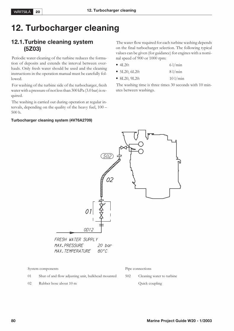
80 Marine Project Guide W20 - 1/2003
12. Turbocharger cleaning
12. Turbocharger cleaning
12.1.Turbine cleaning system
(5Z03)
Periodic water cleaning of the turbine reduces the forma-tion of deposits and extends the interval between over-hauls. Only fresh water should be used and the cleaninginstructions in the operation manual must be carefully fol-lowed.
For washing of the turbine side of the turbocharger, freshwater with a pressure of not less than 300 kPa (3.0 bar) is re-quired.
The washing is carried out during operation at regular in-tervals, depending on the quality of the heavy fuel, 100 –500 h.
The water flow required for each turbine washing dependson the final turbocharger selection. The following typicalvalues can be given (for guidance) for engines with a nomi-nal speed of 900 or 1000 rpm:
• 4L20: 6 l/min
• 5L20, 6L20: 8 l/min
• 8L20, 9L20: 10 l/min
The washing time is three times 30 seconds with 10 min-utes between washings.
Turbocharger cleaning system (4V76A2709)
System components Pipe connections
01 Shut of and flow adjusting unit, bulkhead mounted 502 Cleaning water to turbine
02 Rubber hose about 10 m Quick coupling
13. Exhaust emissions
13.1. General
Exhaust emissions from the diesel engine mainly consist ofnitrogen, carbon dioxide (CO2) and water vapour withsmaller quantities of carbon monoxide (CO), sulphur ox-ides (SOx) and nitrogen oxides (NOx), partially reactedand non-combusted hydrocarbons and particulates. Emis-sion control of large diesel engines means primarily thecontrol of the NOx emissions.
13.2. Diesel engine exhaust
components
Due to the high efficiency of the diesel engines, the emis-sions of carbon dioxide (CO2), carbon monoxide (CO) andhydrocarbons (HC) are low. The same high combustiontemperatures that give thermal efficiency in the diesel en-gine also cause high emissions of nitrogen oxides (NOx).The emissions of sulphur oxides (SOx) and particulates areformed in the combustion process out of the sulphur, ashand asphaltenes that are always present in heavy fuel oil.
13.2.1 Nitrogen oxides (NOx)
Nitric oxide (NO) and Nitrogen dioxide (NO2) are usuallygrouped together as NOx emissions. Predominant oxideof nitrogen found inside the diesel engine cylinder is NO,which forms mainly in the oxidation of atmospheric (mo-lecular) nitrogen in the high temperature gas regions. NOcan also be formed through oxidation of the nitrogen infuel and through chemical reactions with fuel radicals. Theamount of NO2 emissions is approximately 5 %.
All standard Wärtsilä engines meet the NOx emission levelset by the IMO (International Maritime Organisation) andmost of the local emission levels without any modifica-tions. Wärtsilä has also developed solutions to significantlyreduce NOx emissions when it is required. For Wärtsilä 20,the Selective Catalytic Reduction (SCR) is an optional NOxreduction method.
13.2.2 Sulphur Oxides (SOx)
Sulphur oxides (SOx) are direct result of the sulphur con-tent of the fuel oil. During the combustion process the fuelbound sulphur is rapidly oxidised to sulphur dioxide (SO2).A small fraction of SO2 may be further oxidised to sulphurtrioxide (SO3). The SOx emission controls are directedmainly at limiting the sulphur content of the fuel.
13.2.3 Particulates
The particulate fraction of the exhaust emissions repre-sents a complex mixture of inorganic and organic sub-stances mainly comprising soot (elemental carbon), fuel oilash (together with sulphates and associated water), ni-trates, carbonates and a variety of non or partiallycombusted hydrocarbon components of the fuel and lubri-cating oil.
The main parameters affecting the particulate emissionsare the fuel oil injection and fuel oil parameters. The use offuel oil with good ignition and combustion properties andlow content of ash and sulphur will reduce the formationof particulates. For marine diesel engines the particulate re-moval systems, because of their size and high cost, are notfor the time being economically or practically potential so-lutions.
13.2.4 Smoke
Although smoke is usually the visible indication ofparticulates in the exhaust, the correlations between par-ticulate emissions and smoke is not fixed. The lighter andmore volatile hydrocarbons will not be visible nor will theparticulates emitted from a well maintained and operateddiesel engine.
Smoke can be black, blue, white, yellow or brown in ap-pearance. Black smoke is mainly comprised of carbonparticulates (soot). Blue smoke indicates the presence ofthe products of the incomplete combustion of the fuel orlubricating oil. White smoke is usually condensed watervapour. Yellow smoke is caused by NOx emissions. Whenthe exhaust gas is cooled significantly prior to discharge tothe atmosphere, the condensed NO2 component can havea brown appearance.
Marine Project Guide W20 - 1/2003 81
13. Exhaust emissions
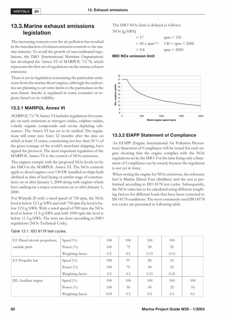
13.3.Marine exhaust emissions
legislation
The increasing concern over the air pollution has resultedin the introduction of exhaust emission controls to the ma-rine industry. To avoid the growth of uncoordinated regu-lations, the IMO (International Maritime Organisation)has developed the Annex VI of MARPOL 73/78, whichrepresents the first set of regulations on the marine exhaustemissions.
There is yet no legislation concerning the particulate emis-sions from the marine diesel engines, although the authori-ties are planning to set strict limits to the particulates in thenear future. Smoke is regulated in some countries or re-gions based on its visibility.
13.3.1 MARPOL Annex VI
MARPOL 73/78 Annex VI includes regulations for exam-ple on such emissions as nitrogen oxides, sulphur oxides,volatile organic compounds and ozone depleting sub-stances. The Annex VI has yet to be ratified. The regula-tions will enter into force 12 months after the date onwhich at least 15 states, constituting not less than 50 % ofthe gross tonnage of the world’s merchant shipping, havesigned the protocol. The most important regulation of theMARPOL Annex VI is the control of NOx emissions.
The engines comply with the proposed NOx levels set bythe IMO in the MARPOL Annex VI. The NOx controlsapply to diesel engines over 130 kW installed on ships built(defined as date of keel laying or similar stage of construc-tion) on or after January 1, 2000 along with engines whichhave undergone a major conversion on or after January 1,2000.
For Wärtsilä 20 with a rated speed of 720 rpm, the NOxlevel is below 12.1 g/kWh and with 750 rpm the level is be-low 12.0 g/kWh. With a rated speed of 900 rpm the NOxlevel is below 11.5 g/kWh and with 1000 rpm the level isbelow 11.3 g/kWh. The tests are done according to IMOregulations (NOx Technical Code).
The IMO NOx limit is defined as follows:
NOx [g/kWh]
= 17 rpm < 130
= 45 x rpm-0.2 130 < rpm < 2000
= 9.8 rpm > 2000
IMO NOx emission limit
13.3.2 EIAPP Statement of Compliance
An EIAPP (Engine International Air Pollution Preven-tion) Statement of Compliance will be issued for each en-gine showing that the engine complies with the NOxregulations set by the IMO. For the time being only a State-ment of Compliance can be issued, because the regulationis not yet in force.
When testing the engine for NOx emissions, the referencefuel is Marine Diesel Fuel (distillate) and the test is per-formed according to ISO 8178 test cycles. Subsequently,the NOx value has to be calculated using different weight-ing factors for different loads that have been corrected toISO 8178 conditions. The most commonly used ISO 8178test cycles are presented in following table.
Table 13.1. ISO 8178 test cycles.
82 Marine Project Guide W20 - 1/2003
13. Exhaust emissions
8
9
10
11
12
13
14
15
16
17
18
0 500 1000 1500 2000
Rated engine speed (rpm)
NO
x,
weig
hte
d(g
/kW
h)
E2: Diesel electric propulsion, Speed (%) 100 100 100 100
variable pitch Power (%) 100 75 50 25
Weighting factor 0.2 0.5 0.15 0.15
E3: Propeller law Speed (%) 100 91 80 63
Power (%) 100 75 50 25
Weighting factor 0.2 0.5 0.15 0.15
D2: Auxiliary engine Speed (%) 100 100 100 100 100
Power (%) 100 50 50 25 10
Weighting factor 0.05 0.3 0.3 0.3 0.1
For EIAPP certification, the “engine family” or the “en-gine group” concepts may be applied. This has been donefor the Wärtsilä 20 diesel engine. The engine families arerepresented by their parent engines and the certificationemission testing is only necessary for these parent engines.Further engines can be certified by checking documents,components, settings etc., which have to show correspon-dence with those of the parent engine.
All non-standard engines, for instance over-rated engines,non-standard-speed engines etc. have to be certified indi-vidually, i.e. “engine family” or “engine group” conceptsdo not apply.
According to the IMO regulations, a Technical File shallbe made for each engine. This Technical File contains in-formation about the components affecting NOx emis-sions, and each critical component is marked with a specialIMO number. Such critical components are injection noz-zle, injection pump, camshaft, cylinder head, piston, con-necting rod, charge air cooler and turbocharger. Theallowable setting values and parameters for running the en-gine are also specified in the Technical File.
The marked components can later, on-board the ship, beidentified by the surveyor and thus an IAPP (InternationalAir Pollution Prevention) Statement of Compliance for theship can be issued on basis of the EIAPP Statement ofCompliance and the on-board inspection.
13.4. Methods to reduce exhaust
emissions
Diesel engine exhaust emissions can be reduced eitherwith primary or secondary methods. The primary methodslimit the formation of specific emissions during the com-bustion process. The secondary methods reduce emissioncomponents after formation as they pass through the ex-haust gas system.
13.4.1 Selective Catalytic Reduction (SCR)
Selective Catalytic Reduction (SCR) is the only way toreach a NOx reduction level of 85-95%.
General system description
The reducing agent, aqueous solution of urea (40 wt-%), isinjected into the exhaust gas directly after the turbocharger.Urea decays immediately to ammonia (NH3) and carbondioxide. The mixture is passed through the catalyst whereNOx is converted to harmless nitrogen and water, whichare normally found in the air that we breathe. The catalystelements are of honeycomb type and are typically of a ce-ramic structure with the active catalytic material spreadover the catalyst surface.
The injection of urea is controlled by feedback from aNOx measuring device after the catalyst. The rate of NOxreduction depends on the amount of urea added, which canbe expressed as NH3/NOx ratio. The increase of the cata-lyst volume can also increase the reduction rate.
When operating on HFO, the exhaust gas temperature be-fore the SCR must be at least 330°C, depending on the sul-phur content of the fuel. When operating on MDF, theexhaust gas temperature can be lower. If an exhaust gasboiler is specified, it should be installed after the SCR.
13. Exhaust emissions
Marine Project Guide W20 - 1/2003 83
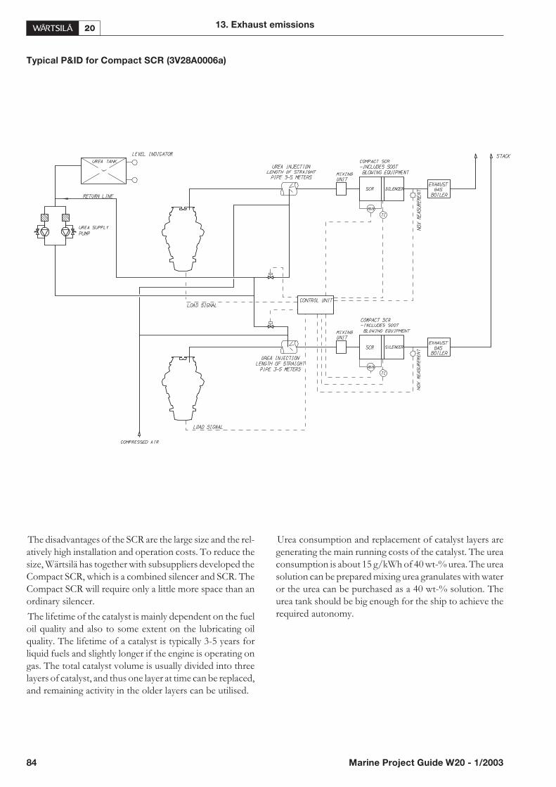
Typical P&ID for Compact SCR (3V28A0006a)
The disadvantages of the SCR are the large size and the rel-atively high installation and operation costs. To reduce thesize, Wärtsilä has together with subsuppliers developed theCompact SCR, which is a combined silencer and SCR. TheCompact SCR will require only a little more space than anordinary silencer.
The lifetime of the catalyst is mainly dependent on the fueloil quality and also to some extent on the lubricating oilquality. The lifetime of a catalyst is typically 3-5 years forliquid fuels and slightly longer if the engine is operating ongas. The total catalyst volume is usually divided into threelayers of catalyst, and thus one layer at time can be replaced,and remaining activity in the older layers can be utilised.
Urea consumption and replacement of catalyst layers aregenerating the main running costs of the catalyst. The ureaconsumption is about 15 g/kWh of 40 wt-% urea. The ureasolution can be prepared mixing urea granulates with wateror the urea can be purchased as a 40 wt-% solution. Theurea tank should be big enough for the ship to achieve therequired autonomy.
84 Marine Project Guide W20 - 1/2003
13. Exhaust emissions
14. Automation system
14.1. General
The engine automation system consists of local and re-mote control of the running parameters, local and remotemonitoring of the sensors and automatic safety operations.
14.2. Power supply
The power requirement of the automation system is about150 W (24 V DC).
14.3. Safety System
14.3.1 General
The safety system can be split into five major parts: start-ing, stopping, start blocking, shutdowns and load reduc-tion requests.
14.3.2 Starting (8N08)
Start of an auxiliary engine
The principle diagram of a start/stop system is shown indrawing 4V50G3472.
The described relay automation is usually not included inthe scope of supply, but can as an option be supplied in aseparate cabinet. The control, safety and sequencing func-tions of this system can also be incorporated in the powermanagement or automation system of the vessel.
Start sequence
The engine is equipped with a pneumatic starting motor,which drives the engine through a gear rim on the flywheel.The starting motor is controlled by a solenoid valve. Theengine can be started by activating the solenoid valve, lo-cally by a start button on the engine or remotely e.g. fromthe diesel automation system.
A generating set reaches the nominal speed in 6...8 secondsafter the starting solenoid has been activated.
Start blocking (8N08)
Starting shall be inhibited by the following functions:
• Turning device engaged
• Prelubricating pressure low. In case of black-out, start-ing is allowed within 5 minutes after the pressure hasdropped below the set point of 0.5 bar.
• Engine start blocking selector switch turned into“Blocked” position
• Engine running (300 rpm)
• Stop signal to engine activated (safety shut-down, emer-gency stop, normal stop)
• Stop lever on stop position
In an emergency case, the engine can always be started bymanually operating the main starting valve. This by-passesstart blocking due to low prelubricating pressure.
Starting air cut off
The start signal to be cut off by:
• Speed switch in SPEMOS (115 RPM)
• A time relay function, which allows the start signal to beactivated about 5 seconds. The time between consecu-tive starting attempts shall be about 30 seconds.
• Stop signal to engine activated.
Start fuel limiter
The speed governor is provided with a start fuel limiterfunction in order to optimize the fuel injection during theacceleration period. This is controlled by a speed switch inthe speed measuring system.
Override of lubricating oil pressure shut-down
To enable start of the engine, the automatic shut-down forlow lubricating oil pressure must be disabled during thestarting sequence. This is most conveniently done usingthe “engine running” contact. Further, a time delay ofabout 10 seconds is to be arranged in order to allow the en-gine driven lubricating oil pump to establish sufficientpressure.
Start of a main engine
The principle diagram of a start/stop system is shown indrawing 4V50G3619.
A main engine can be started and stopped in the same wayas an auxiliary engine. Some minor differences should,however, be noted:
• The 5 min. time delay of prelubricating pressure de-scribed for black-out start is not recommended.
• For some installations start blocking may be requiredfrom clutch position, pitch NOT zero and reductiongear lubricating oil pressure. Autostop of the engine canalso be required for low lubricating oil pressure in the re-duction gear.
14. Automation system
Marine Project Guide W20 - 1/2003 85

14.3.3 Stopping (8N08)
Normal stop of the engine
The engine is stopped remotely via the ‘remote stop’ inputor in local control by the stop button on the engine.
Manual stop can also be done by turning the stop lever intothe stop position.
There are two stop solenoids on the engine. One is builtinto the speed governor. The other one is controlling com-pressed air, which is fed to pneumatic cylinders at each fuelinjection pump, forcing the pumps to no-fuel when acti-vated. This system is independent of the governor. The en-gine can be stopped by activating one or both of thesolenoids for at least 60 seconds. Emergency and safetyshut-down should activate both.
When two engines are connected to a common reductiongear it is recommended that the clutches are blocked in the“OUT” position when the engine is not running. When anengine is stopped, the clutch should open to prevent theengine from being driven through the gear. At anoverspeed shutdown signal the clutch should remainclosed.
‘Engine stop/shutdown' output contact is always closedwhen the stop signal is active.
14.3.4 Shutdowns (8N08)
The engine shall be automatically shut down in the follow-ing cases:
• Lubricating oil pressure low (pressure switch)
• Cooling water temperature high (temperature switch)
• Overspeed (speed switch in SPEMOS)
The shutdown is latching, and a shutdown reset has to begiven before it is possible to re-start. Naturally, before thisthe reason of the shutdown must be investigated.
For a single main engine installation it might be necessaryto arrange a 5 sec delay on the autostop functions (exceptfor overspeed) to give the possibility of overriding theautostop signal from the bridge and prevent the enginefrom stopping in a critical manoeuvring situation.
Overspeed protection
A main engine is equipped with two independently adjust-able switches for overspeed.
• The speed switch with the lower set point (nom. RPM +15%) can be connected for momentary activation of theelectro-pneumatic stop solenoid. The speed switch is ac-tivated and the stop solenoid is energized only as long asthe speed is above the set point. When the speed has de-creased, the stop solenoid is de-energized and the speedis again controlled by the governor.
• The speed switch with the higher set point (nom. RPM +18%) shall be connected with latching function in orderto ensure shut-down of the engine.
14.3.5 Charge air shut-off valve
If gas detector senses combustible gas or vapour in the en-gine room the charge air shut-off valve must be automati-cally closed and engine shutdown activated. Alsooverspeed of the engine should automatically close thisvalve and activate shutdown. Since this is optional equip-ment most commonly used in offshore installations theconstruction varies with engine type and installation andthe instructions in manuals must be followed.
14.4.Speed Measuring (8N03)
An electronic speed measuring and monitoring system(SPEMOS) is built into the engine junction box.
The system monitors the engine speed with two pick-upsand the turbocharger speed with a single pick-up. A 24 VDC power supply is required for the SPEMOS.
Table 14.1. Speed measuring & monitoring system signals
86 Marine Project Guide W20 - 1/2003
14. Automation system
Function Signal Usage Remark
Start fuel limiter contact internal 100 RPM below idling speed
Starting air cut off contact internal 115 RPM
Engine running volt. free contact external 300 RPM
Overspeed volt. free contact external nominal + 15% speed
Engine speed 0 - 10 V DC internal & external 0 - 1500 RPM
Turbocharger speed 0 - 10 V DC internal & external 0 - 60000 RPM
Power/tacho failure volt. free contact external
14.5. Sensors & signals
Drawing 4V50L5692 shows a typical engine wiring dia-gram with a standard set of sensors for monitoring, alarmand safety.
Table 14.2. Standard sensors for remote monitoring and alarm
14. Automation system
Marine Project Guide W20 - 1/2003 87
Sensor Code Signal Alarm Remark
Fuel oil pressure PT101 4 - 20 mA 0.4 MPa (4 bar) HFO
Lubricating oil pressure PT201 4 - 20 mA 0.3 MPa (3 bar)
Starting air pressure PT301 4 - 20 mA 0.8 MPa (8 bar)
HT water pressure PT401 4 - 20 mA 0.2 MPa (2 bar) installation specific
LT water pressure PT451 4 - 20 mA 0.2 MPa (2 bar) installation specific
Exhaust gas temperature after eachcylinder and turbocharger
TE501 4 - 20 mA 500°C NiCrNi + amplifier
Lubricating oil temperature TE201 Pt 100 80°C
HT water temperature TE402 Pt 100 105°C
Charge air temperature TE622 Pt 100 75°C
Injection pipe leakage LS103A volt. free contact —
Lubricating oil level in wet oil sump low LS204 volt. free contact —
Lubricating oil filter pressure drop PDS243 volt. free contact 0.15 MPa (1.5 bar)
Pneumatic overspeed trip pressure low PS311 volt. free contact 1.8 MPa (18 bar)
Overload GS166 volt. free contact — main engines only
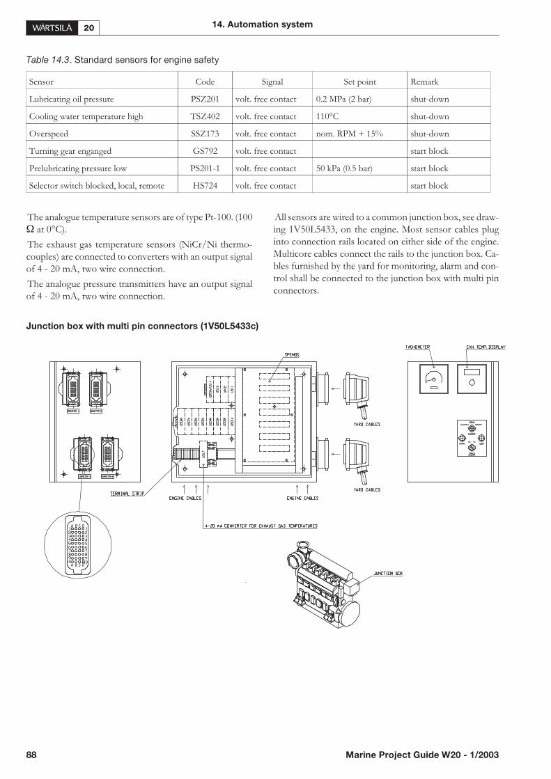
Table 14.3. Standard sensors for engine safety
The analogue temperature sensors are of type Pt-100. (100� at 0°C).
The exhaust gas temperature sensors (NiCr/Ni thermo-couples) are connected to converters with an output signalof 4 - 20 mA, two wire connection.
The analogue pressure transmitters have an output signalof 4 - 20 mA, two wire connection.
All sensors are wired to a common junction box, see draw-ing 1V50L5433, on the engine. Most sensor cables pluginto connection rails located on either side of the engine.Multicore cables connect the rails to the junction box. Ca-bles furnished by the yard for monitoring, alarm and con-trol shall be connected to the junction box with multi pinconnectors.
Junction box with multi pin connectors (1V50L5433c)
88 Marine Project Guide W20 - 1/2003
14. Automation system
Sensor Code Signal Set point Remark
Lubricating oil pressure PSZ201 volt. free contact 0.2 MPa (2 bar) shut-down
Cooling water temperature high TSZ402 volt. free contact 110°C shut-down
Overspeed SSZ173 volt. free contact nom. RPM + 15% shut-down
Turning gear enganged GS792 volt. free contact start block
Prelubricating pressure low PS201-1 volt. free contact 50 kPa (0.5 bar) start block
Selector switch blocked, local, remote HS724 volt. free contact start block
14.6. Local instrumentation
The engine is equipped with the following set of instru-ments for local reading of pressures, temperatures andother parameters.
Pressure gauges in panel on engine
• Lubricating oil pressure
• Fuel oil pressure
• Cooling water pressure (HT)
• Cooling water pressure (LT)
• Charge air pressure
• Starting air pressure
Thermometers
• Fuel oil before engine
• Lubricating oil before lubricating oil cooler
• Lubricating oil after lubricating oil cooler
• Cooling water (HT) before engine
• Cooling water (HT) after engine
• Cooling water (LT) before charge air cooler
• Cooling water (LT) after charge air cooler
• Cooling water (LT) after lubricating oil cooler
• Charge air after charge air cooler
Electrical instruments
• Tachometer for engine speed and turbocharger speed
• Running hour counter
• Digital display for exhaust gas temperature with selectorswitch for temperature after each cylinder and afterturbocharger
14.7. Control of auxiliary
equipment
14.7.1 Stand-by pumps
Stand-by pumps are required for single main engine.
If the pressure drops below a pre-set level when the engineis running, the stand-by pump should be started. Thestand-by pump starter shall include an interposing relaycontrolling the main contactor.
Latching must be done in the standby starter and alarmsystem respectively. The reason for the pressure dropshould be investigated as soon as possible.
Stop of the standby pump should always be a manual oper-ation. Before stopping the standby pump, the reason forthe pressure drop must have been investigated and recti-fied.
Monitoring signals can be used to initiate the start ofstand-by pumps.
14.7.2 Pre-lubricating oil pump (9N03)
The engine is equipped with an electric pre-lubricatingpump.
The pre-lubricating pump is used for filling of the lubricat-ing oil system, pre-lubricate a stopped engine before startand for preheating by circulating warm lubricating oil. Thecolder the engine is, the earlier the pump should be startedbefore the engine is started.
The pump may also be run continuously when the engineis stopped and must run in multiple engine installationswhen other engines are running.
For continuous prelubrication of a stopped engine,through which heavy fuel is circulating.
To ensure continuous prelubrication of a stopped engine,automatic starting and stopping of the prelubricatingpump is recommended. This can be achieved using the 300RPM speed switch.
For dimensioning the pre-lubricating pump starter, thevalues indicated below can be used. For different voltages,the values may differ slightly. The starter is not included inthe standard delivery of the engine.
• 400V / 50Hz 2.2kW, In=4.7A
• 440V / 60Hz 2.5kW In=4.7A
14.7.3 Cooling water pre-heater &
circulation pump
In order to get the engine up to and maintain a cooling wa-ter temperature >70°C, preheating has to be arranged forthe engine. Preheating is preferably done by an electricpreheater with a required heating power depending of theengine type. The preheater is not included in the standarddelivery of the engine.
The temperature control should be automatic.
For automatic starting and stopping of the circulatingpump to circulate cooling water through the stopped en-gine(s), the ‘Engine running’ signal can be used as refer-ence.
In some main engine installations the circulating pumpneeds to be running at prolonged idling. For these casesspecial instructions are given.
14. Automation system
Marine Project Guide W20 - 1/2003 89
14.8.Speed control (8I03)
14.8.1 Main engine speed control
Mechanical-hydraulic governors
The engines have hydraulic-mechanical governors withpneumatic speed setting. These governors are usually pro-vided with a shut-down solenoid as the only electricalequipment.
The idling speed is selected for each installation based oncalculations, for CP-propeller installations at 55 - 65% ofthe nominal speed and for FP-propeller installations atabout 35%.
The standard control air pressure for pneumatically con-trolled governors is:
p = 0.514 * n - 14.3
p = control air pressure [kPa]
n = engine speed [RPM]
Governors for engines in FP-propeller installations areprovided with a smoke limiting function, which limits thefuel injection as a function of the charge air pressure.
Governors for engines connected to a common reductiongear are specially adapted and adjusted for the same speeddroop, normally about 4%, to obtain basic load sharing. Inaddition, it is recommended to arrange external load shar-ing based on the fuel rack position transducer.
Governors are, as standard, equipped with a built-in delayof the speed change rate so that the time for speed accelera-tion from idle to rated speed and vice versa is preset.
In special cases speed governors of the electronic type canbe used.
14.8.2 Generating set speed control
Mechanical-hydraulic governors
Auxiliary generator sets are normally provided with me-chanical-hydraulic governors for remote electric speed set-ting from e.g. a Power Management System (PMS).
The governor is equipped with a speed setting motor forsynchronizing, load sharing and frequency control.
The governor is also equipped with a shutdown solenoidand an electrically controlled start fuel limiter. The syn-chronizing is operated by ON/OFF control as “increase”or “decrease” by polarity switching. Normal speed changerate is about 0.3 Hz/s.
Engines, which are to be run in parallel have governorsspecially adapted for the same speed droop, about 4%, toobtain basic load sharing. During load sharing and fre-quency control, the external load sharing system (PMS)must have a control deadband implemented, allowing foran uneven load or frequency drift of 1 - 2%.
14.8.3 Electronic speed governor
An Electronic speed control, comprising a separatelymounted electronic speed control unit and a built-on actu-ator, offers efficient tools for filtering speed and load sig-nals. This is often required in order to achieve goodstability without sacrificing the transient response. Furtherthe dynamic response can be adjusted and optimised forthe particular installation, or even for different operatingmodes of the same engine. An electronic speed control isalso capable of isochronous load sharing. In isochronousmode, there is no need for external load sharing, frequencyadjustment, or engine loading/unloading control in the ex-ternal control system. Both isochronous load sharing andtraditional speed droop are standard features in all elec-tronic speed controllers and either mode can be selected.
Speed droop means that the governor speed reference au-tomatically decreases as the engine load increases. Thespeed droop is normally adjusted to about 4%. This is toensure proper load sharing between parallelling units. Tocompensate for the speed decrease of the plant when theload increases, and vice versa when the load decreases, thePMS must in an outer (cascade) loop correct for the fre-quency drift.
Isochronous load sharing means that the governor speedreference stays the same, regardless of the load level. Ashielded twisted pair cable between the speed controllers isnecessary for isochronous load sharing. If the ship has twoor more switchboard sections, which can be either con-nected or separated, there must be a breaker also for theload sharing lines between each speed control.
Electronic speed control for Main Engines
An electronic speed control is recommended for more de-manding installations, e.g. main engine installations withtwo engines connected to the same reduction gear, in par-ticular if there is a shaft generator on the reduction gear.
The remote speed setting can be either an increase/de-crease signal, or an analog 4-20mA speed reference, bothfrom e.g. a propulsion control system. The rate at whichthe speed changes is adjustable in the speed controller.
Actuators with mechanical backup are only recommendedfor single main engines. The actuator should in case of asingle main engine be reverse acting, so that the changeover to the mechanical backup takes place automatically.
Electronic speed control for Diesel
electric/Generator set
An electronic speed control is always recommended fordiesel electric installations due to the sometimes stronglyfluctuating power demand from the dominant consumer(propulsion).
For an auxiliary generating set, an electronic speed controlcan be specified as an option.
90 Marine Project Guide W20 - 1/2003
14. Automation system

Actuators with mechanical backup are not recommendedfor multi-engine installations.
14.9. Microprocessor based
engine control system
(WECS) (8N01)
As an alternative to the conventional way of cabling thesensor signals wire by wire from the engine to the externalalarm, monitoring and control systems, an Engine ControlSystem (WECS) can be provided. The WECS is a micro-processor based monitoring and control system.
14.9.1 Components
The system for one engine consists of one main controlunit (MCU) and several distributed control units (DCU) orsensor multiplexer units (SMU) depending on the amountof sensors which are connected to the DCU:s and SMU:s.The SMU is used only to collect sensor data, while theDCU also is used for distributing processing power fromthe MCU.
14.9.2 Functions of the MCU
The MCU collects measuring data from the sensors on theengine, converts the information into digital form andcommunicates by serial link with the external monitoring,alarm and control systems. The MCU also handles thefunctions described in the previous paragraphs, i.e. speedmeasuring, start/stop sequences and automaticshut-downs. Vital functions, such as lubricating oil pres-sure and overspeed shut-down, are also handled by exter-nal switches independent of the MCU.
14.9.3 Communications
By having field bus connection via multi-standardRS-ports for communication with external systems, ca-bling work furnished by the yard will be minimized. In ad-dition, installation work, service and maintenance will beeasier.
The RS-interface is 4-wire RS485. The communicationfollows the Modbus RTU protocol specifications with theMCU as a slave in the Modbus network. A typical setup is amonitoring and alarm system functioning as a master andeach MCU (one per engine) functioning as slaves.
14. Automation system
Marine Project Guide W20 - 1/2003 91

Typical wiring diagram (4V50L5692-1a)
92 Marine Project Guide W20 - 1/2003
14. Automation system
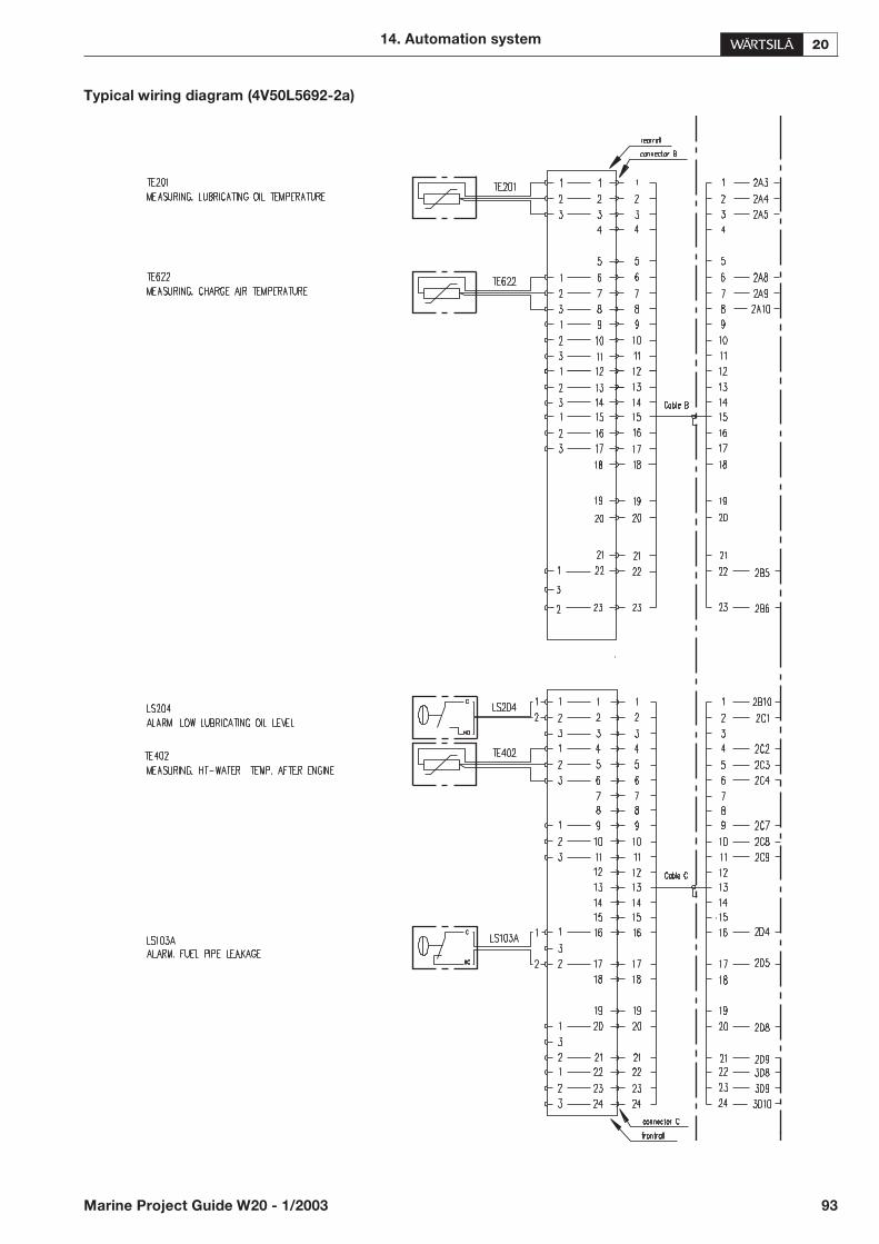
Typical wiring diagram (4V50L5692-2a)
14. Automation system
Marine Project Guide W20 - 1/2003 93

Typical wiring diagram (4V50L5692-3a)
94 Marine Project Guide W20 - 1/2003
14. Automation system
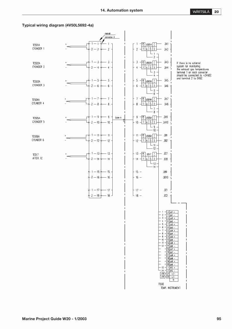
Typical wiring diagram (4V50L5692-4a)
14. Automation system
Marine Project Guide W20 - 1/2003 95
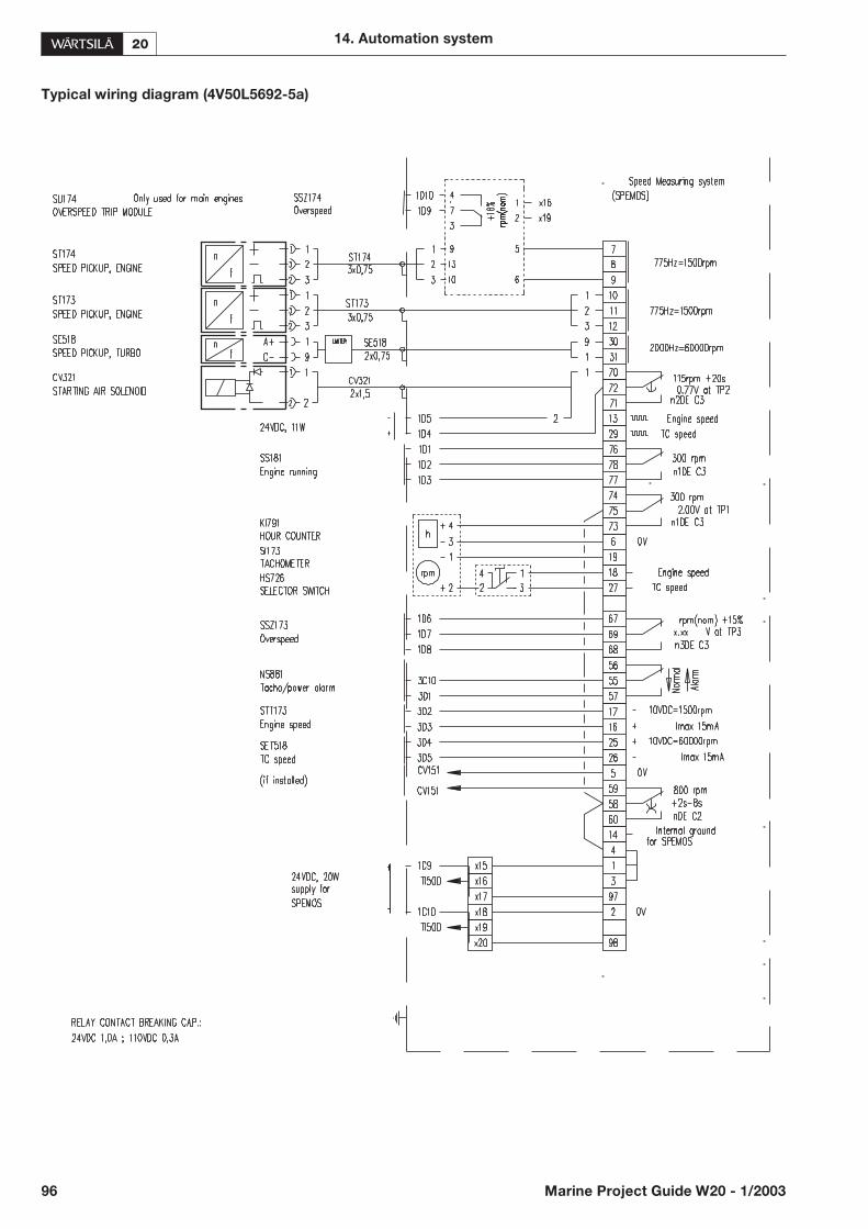
Typical wiring diagram (4V50L5692-5a)
96 Marine Project Guide W20 - 1/2003
14. Automation system

Start stop system for an auxiliary engine (4V50G3472-1d)
14. Automation system
Marine Project Guide W20 - 1/2003 97
Indication lamps Pushbuttons and selectors
H1 Power on S1 Emergency stop
H2 Ready for start S2 Stop
H3 Engine running S3 Start
H4 Cooling water temperature high S4 Reset
H5 Lubrication oil pressure low S5 Lamp test
H6 Overspeed S6 Local / Remote mode of start
H7 Start failure

Start stop system for an auxiliary engine (4V50G3472-2d)
98 Marine Project Guide W20 - 1/2003
14. Automation system

Start stop system for an auxiliary engine (4V50G3472-3d)
14. Automation system
Marine Project Guide W20 - 1/2003 99
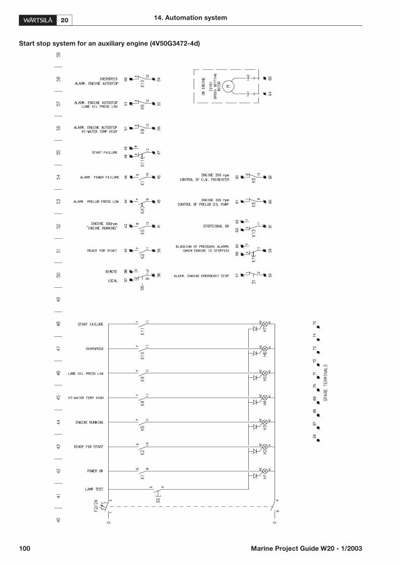
Start stop system for an auxiliary engine (4V50G3472-4d)
100 Marine Project Guide W20 - 1/2003
14. Automation system

Start/stop system for a main engine (4V50G3619-1a)
14. Automation system
Marine Project Guide W20 - 1/2003 101
Indication lamps Pushbuttons and selectors
H1 Power on S1 Emergency stop
H2 Ready for start S2 Stop
H3 Engine running S3 Start
H4 Overload S4 Reset
H5 Cooling water temperature high S5 Lamp test
H6 Lubrication oil pressure low S6 Local / Remote mode of start
H7 Overspeed
H8 Reduction gear lubrication pressure low
H9 Start failure
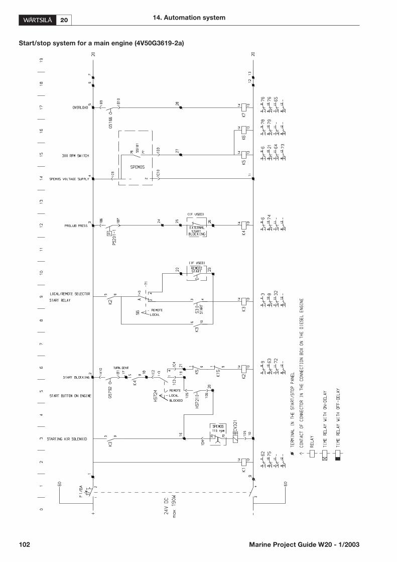
Start/stop system for a main engine (4V50G3619-2a)
102 Marine Project Guide W20 - 1/2003
14. Automation system
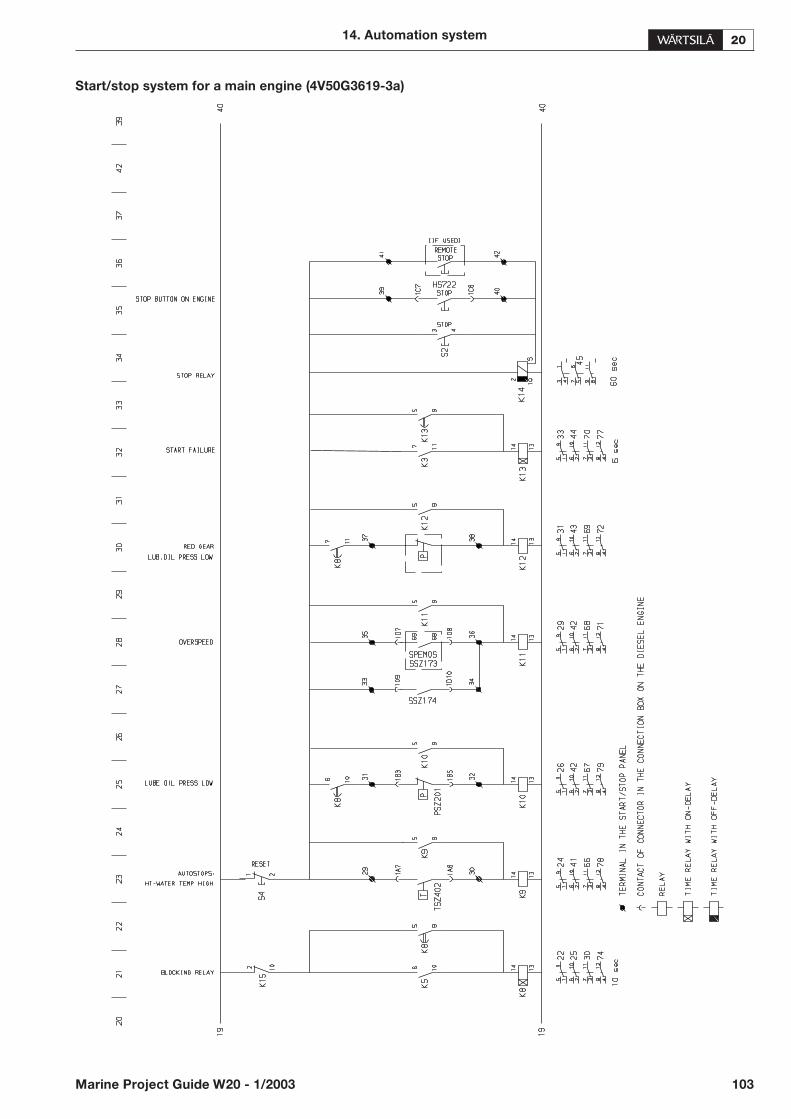
Start/stop system for a main engine (4V50G3619-3a)
14. Automation system
Marine Project Guide W20 - 1/2003 103
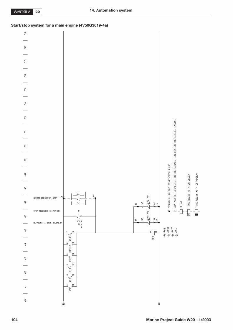
Start/stop system for a main engine (4V50G3619-4a)
104 Marine Project Guide W20 - 1/2003
14. Automation system

Start/stop system for a main engine (4V50G3619-5a)
14. Automation system
Marine Project Guide W20 - 1/2003 105

15. Electrical power generation and manage-ment
15.1.General
The electrical concept design, either performed by theShip Owner, Consultant, Yard or Wärtsilä as ‘The ShipPower Supplier’, is the basis for a co-ordination and opti-misation of the electric power generation and managementbeing supplemented by these general guidelines.
15.1.1 Definitions
The marine vessel’s electric supply system is an alternatingcurrent (a.c.) three-phase, three–wire insulated. The engineproduced mechanical energy is converted into electricalenergy by a generator, which usually is of the synchronoustype and intended for continuous operation.
The voltage of the network and generator is low voltage(LV) up to 1000 V and medium voltage (MV) from 1 kV.
Ordinary low voltages are 400 V (50 Hz), 450 V (60 Hz)and 690 V (50 or 60 Hz).
Nominal medium system voltages are 3 kV, 3,3 kV, 6 kV,6,6 kV, 10 kV and 11 kV for 50 Hz or 60 Hz.
Low voltage is normally used in installations with totalpower up to about 10 MVA due to short circuit current re-strictions in the switchgear.
The common network frequency (f) is 50 Hz or 60 Hz andthe generator synchronous rated speed nrG [rpm] is calcu-lated from:
nrG = 60 * f/p
where p = pole pairs, and subsequently the number ofpoles = 2 * p
Generator power definitions:
Sr = rated output, rated apparent power in kilo-volt-amperes kVA
Sr = Pr/cos �r
Pr = rated active power in kilowatts kW
cos �r = rated power factor
cos �r = Pr/Sr
The generator rated active power limit Pr should matchwith the diesel rated output power PDIESEL taking into ac-count the efficiency �GEN of the generator.
Pr = �GEN * PDIESEL
Generator �GEN is typically 95…97 % at full load and cos�0,8
15.1.2 Electric load demand at consumers
and generators
The load demand analysis (electric load balance) listing thevarious loads and modes onboard ship is usually evaluatedin the concept design phase and made available to the gen-erator set supplier as the basis for dimensioning the genera-tor sets.
The generator feeds power to the consumers in the net-work including all electrical transmission losses. If only theconsumer power consumption is advised, the total re-quired power supplied by the generator shall be increasedwith the network losses, which typically could be 5…9 %depending on type, size and quality of electrical compo-nents.
15.1.3 Operation modes
The generators shall be capable of operating in parallel.
The operation modes of the vessel have different demandsof electric power and number of generating sets in opera-tion. Important factors are:
• operation profile
• actual operation mode and maximum expected load
• operational practice (e.g. at least 2 generating sets run-ning)
• redundancy requirements
• accepted loading practice of the generating sets (e.g. 90% of Pr)
15.1.4 Basic requirements
For a.c. generating sets used onboard ships and offshoreinstallations which have to comply with rules of classifica-tion society (Class), the specific requirements of the Classshall be observed.
The main source of electrical power consists of at least twogenerating sets, and a shaft generator may be considered tobe one of the required generators if capable of operating inparallel. The capacity of the generating sets shall be suchthat in the event of any one set being stopped it will still bepossible to supply those services necessary to provide nor-mal operational conditions of propulsion, safety and mini-mum comfortable conditions of habitability.
In the following there are some common basic require-ments of the generating set performance.
Frequency and voltage variations in a.c. installations:
106 Marine Project Guide W20 - 1/2003
15. Electrical power generation and management

Although the Class sets requirements for sudden loadchanges, the general recommendation is to apply electricalloads in a ramp function rather than in sudden load steps.Reference is also made to Chapter for Operating Ranges.
15.2. Electric power generation
15.2.1 General dimensioning criteria
The generator voltage, capacity and number of units arebasically defined from the operation mode with the highestexpected electric load. The most demanding operationmode is usually manoeuvring or cargo handling, while maxspeed at sea in a diesel-electric ship may require morepower.
It should be considered that at least one generating setshould be stand-by offering flexibility to perform mainte-nance work on any other generating set.
For example, in an uncomplicated vessel the generator ca-pacity could be selected in a way that one unit is suitable forport and sea conditions, and two units for manoeuvringconditions having a 3rd unit as a stand-by.
General dimensioning criteria with respect to power,among others:
• type of vessel
• operation mode and application
• requirements of the connected load
• load power factor cos �
• cost efficient loading level, optimum specific fuel con-sumption
• redundancy requirements
• starting characteristics of high power motors
Due consideration is to be given to the transient frequencyand voltage characteristics of the generating set during andafter a sudden load change. Any particular requirement ofthe load acceptance shall be subject to agreement betweenthe customer and Wärtsilä.
15.2.2 Power factor
Rated power factor cos �r of the generator shall be se-lected in accordance with the network load cos �, whichusually is 0,8 … 0,85.
In a diesel electric drive vessel e.g.: with cyclo convertersand/or low loading of propulsors, the power factor isusually 0,7…0,8 and the generators are to be dimensionedaccordingly.
The most common power factor for generators is 0,8.
15.2.3 Generator reactances
An important issue with regard to short circuit figures andstarting capacity in the network is the generators’subtransient reactance xd”. The xd” is typically 15…20 (upto 25) %.
Generally a high xd” causes a lower short circuit currentbut reduces the starting capacity of high power motors inthe network due to an excessive voltage drop.
A very low xd” increases the generator size in comparisonto a high xd”, but the possibility to choose a specific xd” issomewhat restricted.
A compromise between high starting capacity and lowshort circuit level of the network, and low distortion levelof the distorted voltage waveform in a ‘polluted’ vessel, isto be done when deciding the generator reactances.
15.2.4 Generator protection and
switchgear
Generator set switchgear, control gear and monitoringequipment is usually mounted off the generating set. Allcomponents incorporated in the switchgear shall be ade-quately rated to suit the generating set and the specifiedmains operation, including the prospective fault current.
The generator is basically protected by the generatorbreaker and protection devices, usually being tripped bythe following protection functions:
• short circuit
• overload
• time delayed over-current
• reverse-power
• differential-current
• voltage protections (over and under voltage release)
• earth fault
• stator RTD temperature HI/HI
Generating set protection systems mainly related to the en-gine are set in the chapter for Automation System, andcomprise among others:
• load shedding
15. Electrical power generation and management
Marine Project Guide W20 - 1/2003 107
Table 15.1.
Load condition: Steady state Transient state
Freq./speedregulation
95 – 105 % 90 – 110 %
A.c. voltageregulation
97,5 – 102,5 % 85 – 120 %
• overspeed
• engine shutdown
• emergency stop
• major alarm from the speed governor.
15.2.5 Motor starting capacity of the
network
The starting capacity of the electrical network dependsmainly on the connected spare generator capacity, genera-tor xd”, xd’ and allowed voltage drop. The maximum al-lowed transient voltage drop is 15 %, which in some casesis too much for sensitive equipment.
The starting characteristics of the most power consumingmotor or consumer is to be carefully checked. The genera-tor manufacturer is to be informed (preferably at the offer-ing stage) on the motor characteristics, operation andstarting method in order to evaluate the expected voltagedrop.
An excessive voltage drop causes generator dimensioningadjustments and/or means of alternative motor startingmethods, e.g. soft starting device.
15.2.6 Speed Governor
The speed governor is a device, which senses the speed ofthe engine and controls the fuel flow to the engine to main-tain the speed at the desired level to meet changes in loadoutput. Governor types are mainly hydraulic/mechanicalor electronic, which are used in more complex projects.
In electrical terms, the speed governor controls the genera-tor’s and network’s frequency and the active load sharingby speed droop feedback or an ‘isochronous’ (zero droop)mode.
The steady state frequency characteristics depend mainlyon the performance of the engine speed governor, whilethe transient frequency characteristics depend on the com-bined behaviour of all engine system components.
Basic definition of speed droop:
A decrease in speed reference for an increase in load, i.e.the % of the current speed reference by which the speedreference is drooped (decreased) from zero to full load.
An external speed setting from the power managementsystem compensates the speed droop effect keeping thefrequency stable in long term steady state conditions.
Speed droop based load sharing is possible with both a hy-draulic/mechanical and an electronic governor. For mostapplications a droop of 3…5 % is recommended. Thedroop setting, as well as the dynamical performances of thegovernor, shall be equal for all parallelling generators in or-der to have a proportional load sharing.
An isochronous load sharing for parallelling generators ispossible with an electronic governor. All parallelling gener-ators are to have the same maker and type of electronicgovernor. The isochronous mode governor will maintain aconstant speed up to 100 % load.
15.2.7 Automatic Voltage Regulator (AVR)
The AVR controls the generator voltage and the reactiveload sharing. The brushless exciter-AVR system is to de-tect changes in terminal voltage (e.g. caused by a suddenload change) and to vary the field excitation as required torestore the terminal voltage of the generator.
The AVR, including the spare AVR where applicable, shallbe tested and approved by the Class together with the gen-erator forming a unit.
The exciter and AVR are normally supplied from the gen-erator (shunt excitation) or sometimes from ashaft-mounted external Permanent Magnet Generator(PMG), which is used on generators, e.g. in a network withnotable voltage distortion.
In order to maintain a possible network short-circuit cur-rent, high enough (at least 3 * IN) to trip the generator orachieve selectivity in the distribution, a booster(short-circuit excitation) circuit is provided for the shuntexcitation.
The reactive load sharing of parallelling generators is pro-vided by the AVR using parallelling compensation circuitscalled:
• voltage droop compensation
• crosscurrent compensation
The droop compensation is the most commonly used cir-cuit for reactive load sharing and is possible with an ana-logue or a digital AVR. The voltage droop depends on thereactive load, i.e. a decrease in voltage for an increase in re-active load.
The crosscurrent compensation is a more complexmethod for reactive load sharing. The voltage is main-tained constant without ‘droop’, and the reactive load isbalanced.
Manual voltage control in the main switchboard as aback-up is generally provided only on the request of thecustomer.
15.2.8 Shaft generators
A shaft generator (SG) is driven by a main propulsion unit,which usually is intended to operate at constant speed in aCPP installation.
Shaft generators are normally connected to:
• a secondary PTO from a step-up gear (generator runsparallel to the propeller shaft)
108 Marine Project Guide W20 - 1/2003
15. Electrical power generation and management

• a primary PTO from a step-up gear (generator runs par-allel to the engine)
• an engine free end
A constant frequency shaft generator may be an alternativein a vessel with a diesel driving a FPP.
It is recommended to provide the main engines with elec-tronic speed governors when shaft generator installationsare applied in multi engine installations (twin-in/sin-gle-out).
The SG is dimensioned with regard to the operating mode,electric load at sea and thruster (or other high power con-sumer) sizes.
In the case with secondary PTO the shaft generator speednrG and the gear ratio is to correspond to a suitable highspeed of the main engine, in order to have power enoughto run both shaft generator and CPP at a constant speed atsea. In the manoeuvring mode the propeller cavitation canbe reduced, by selecting a 2-stage (speed) PTO gear en-abling a lower main engine and propeller speed.
15.2.9 Earthed neutral
The vessels’ generation and distribution systems are ordi-narily insulated in low voltage installations as well as fortankers.
The network in medium voltage installations is mostlyearthed via a high resistance connected to the generators’neutral. The rating of the earthed neutral system shall bedefined taking into account the ratings of all componentsof electrical equipment in the generation circuit.
Earthed neutral options are e.g. a separate earthing trans-former with a resistance, a low resistance earthed neutral ora direct earthed neutral.
The earthed neutral cabinet is normally delivered by theswitchgear supplier and co-ordinated with the generatorsupplier.
15.2.10 Emergency diesel generator
The emergency source of electrical power shall beself-contained independently from engine room systemswith more stringent requirements as to operability whenheeling and listing as well as location, starting arrange-ments and load acceptance.
The emergency diesel generator (EDG), supplying theemergency consumers required by statutory requirements,is basically dimensioned according to worst loading case offire fighting, flooding and blackout start.
The starting capacity of the emergency network shall bespecially considered, as the most power consuming emer-gency electrical consumer (motor) often determines thesize of EDG. Allowance is also recommended for possiblefuture additional emergency loads.
The emergency consumers comprises e.g.: emergencylighting, navigational and communication equipment, firealarm systems, fire and sprinkler pumps, bilge pump, wa-ter-tight doors, person lifts, steering gear.
Many shipowners have additional requirements with re-gard to EDG-supplied services as precautionary measuresagainst blackout, e.g.: essential (non-emergency) auxiliariesfor electric power generation and propulsion. This furtherloading of EDG shall of course be reflected in the EDGsize, and a shedding system for non-emergency consumersto be provided and trip, in case the EDG should be over-loaded.
It is not recommended to use the EDG as a harbour gener-ator, ref. Solas Ch. II-1 Part D Reg. 42. 1.4 and Reg. 43. 1.4.
15.3. Electric power management
system (PMS)
15.3.1 General
The main task of an electric power management (PMS) isto control the generation plant and to ensure the availabil-ity of electrical power in the network as well as to avoidblackout situations.
The PMS controls the starting/stopping and synchronis-ing of a generator to the network, frequency monitoring,steady state load sharing between on-line generators,blackout starting, shaft generator, gear clutches and exe-cutes load tripping when the power plant is overloaded(load shedding).
The main busbar is normally subdivided into at least twoparts connected by bus tie breakers, and the connection ofgenerating sets and other duplicated equipment shall beequally divided between the parts.
15.3.2 Control modes
The PMS is to have redundant hierarchy of control modes,the following provisions being typical:
• automatic, independently derived signals without man-ual intervention
• remote control, manually initiated
• local control, e.g. hand or electric
The automatic mode is the normal operation mode. It isrecommended that means are provided to start an enginelocally and to synchronise manually at the main switch-board in case of PMS failure. The back-up system is recom-mended to be an independent operating system, hard wiredand with galvanic isolation to the main system.
Monitoring of the generating set operation to verify cor-rect functioning by measurement or protection and super-
15. Electrical power generation and management
Marine Project Guide W20 - 1/2003 109

visory control parameters in accordance to Class andrequirements are set in the chapter for Automation System.
15.3.3 Main breaker control
The following main breakers in the main switchboard aretypically controlled from the PMS:
• diesel generator
• shaft generator
• bus tie breaker
• shore connection
• high power consumers , e .g . : bow thruster ,AC-compressor,
• emergency switchboard connection
15.3.4 Blackout start and precautionary
measures
In case of blackout in the main switchboard (MSB) the re-lated generating sets get a starting order and the first avail-able generating set to ‘run up’ will connect to the MSB. Thefollowing units are to be automatically synchronised.
Precautions against failing blackout start are:
• booster and fuel supply pumps connected to emergencyswitchboard (ES)
• pre lubricating pump connected to ES
• sequential re-start of essential pumps, fans and heavyconsumers to achieve a loading ramp rather than bigloading steps
Precautions against total loss of propulsion (diesel me-chanical concepts) in a blackout situation could be follow-ing measures:
• essential ME pumps are engine driven
• essential propulsion train pumps are gear driven
• essential electrical pumps and fans for propulsion areconnected to ES
• operate with split network
15.3.5 Parallelling of generators, load
sharing
The PMS provides automatic synchronising of auxiliarydiesel generators i.e. frequency adjustment to bring the in-coming set into synchronism and phase with the existingsystem, considering possible restrictions (e.g.: short circuitlevel) regarding max number of generators allowed to beconnected to the MSB.
The PMS controls the active (kW) load sharing over thespeed governor:
• droop control, characteristics about 4 %
• isochronous load sharing, possible by means of an elec-tronic speed governor taking care of ramping up, loadsharing and ramping down; PMS only connects the setand after allowance by the governor disconnects the set.
Active load sharing between diesel generators is normallyproportional (balanced). The droop setting shall be equalfor all parallelling generators in order to have a propor-tional load sharing.
Some feature mode options could promote an economicaland environment-friendly operation of the engines, e.g.:
• master-topping up, i.e. master(s) with constant optimalload and a topping up set taking care of the load varia-tions
• sequencing of the master-topping up units
15.3.6 Shaft generator load transfer
The PMS controls the main engine in shaft generator (SG)applications giving priority to the electric generation, in-cluding possible propulsion load reduction where applica-ble.
Operating with SG supplying the main switchboard(MSB) in parallel with the connected propulsion line, thefrequency may be unstable in rough sea, etc. It is recom-mended to use the SG independently supplying the MSBor part of it. If 2 SG are available e.g. in a twin-screw vessel,the MSB should be split into 2 parts, each part being sup-plied by a dedicated SG.
The load transfer from/to the auxiliary diesel generator(s)should normally be on a short time basis, i.e. parallellingonly for the time of unloading the generator(s) followed bygenerator breaker opening.
The shaft generator is typically supplying thruster(s) in aseparate network during the manoeuvring mode.
In the following a typical example of load transfer at sea toa running shaft generator when the thrusters have been dis-connected:
• assure that the main engine load is stable and that theconstant speed mode is selected
• synchronise the SG-section and the MSB (i.e. the auxil-iary diesel engine(s) are usually synchronised to the mainengine) and close the SG-section bustie breaker
• transfer load to SG by unloading the auxiliary diesel gen-erator(s) according to unloading rate
• open the auxiliary diesel generator’s breaker(s) when un-loading trip level is reached
• stop the auxiliary diesel engine(s)
110 Marine Project Guide W20 - 1/2003
15. Electrical power generation and management
15.3.7 Load dependent start/stop
The PMS includes functions for automatic load dependentstart/stop of diesel generation sets.
The start/stop limits and start order in an installation withseveral parallelling generating sets are set to achieve an op-timal loading of the engines in the specific operation modeof the vessel. The PMS calculates the network’s nominalpower and total generator load over a defined period oftime and compares that against the load dependentautostart/autostop limits. The objective is to ensure thatthe actual load is supplied by an appropriate number ofgenerating sets to achieve best possible energy efficiencyand fuel economy.
15.3.8 Power reservation for heavy
consumers
Heavy consumers may be connected to a power reserva-tion system in the PMS, which checks if there is enough re-serve power capacity in the network upon a start requestfrom the heavy consumer. If necessary the PMS will startand synchronise the next standby unit, and gives the startpermission to the heavy consumer when the needed start-ing capacity is available.
15.3.9 Load shedding (preference
tripping)
Auto start function is not fast enough as blackout preven-tion after rapid and large loss of power generating capacity,e.g. after tripping of a generator.
In order to protect the generator(s) against sustained over-load, and to ensure the integrity of supplies to services re-quired for propulsion and steering as well as the safety ofthe ship, suitable load shedding arrangements shall be ar-ranged.
Typical consumers that may be tripped are:
• galley consumers
• AC-compressors
• accommodation ventilation
• reduction of propulsion power
15.3.10 Special applications, e.g.:
Auxiliary Propulsion Drive (APD)
A special application providing limited redundancy withrespect to increased availability of the vessel’s propulsionsystem is the so-called Auxiliary Propulsion Drive (APD).The principle idea of this solution is that the ship can bepropelled by the auxiliary generating sets, by using the shaftgenerator as an electric motor, in case the main engine(ME) is not available.
The benefit of the combined shaft generator and APD isan increase of safety when it is used as back-up propulsionin e. g. following operating modes:
• booster mode, both ME and PTO are driving the pro-peller
• standby mode, ME disconnected for maintenance andAPD is connected if manoeuvring is required
• emergency mode (take me home), APD is used to propelthe ship if ME fails
15. Electrical power generation and management
Marine Project Guide W20 - 1/2003 111
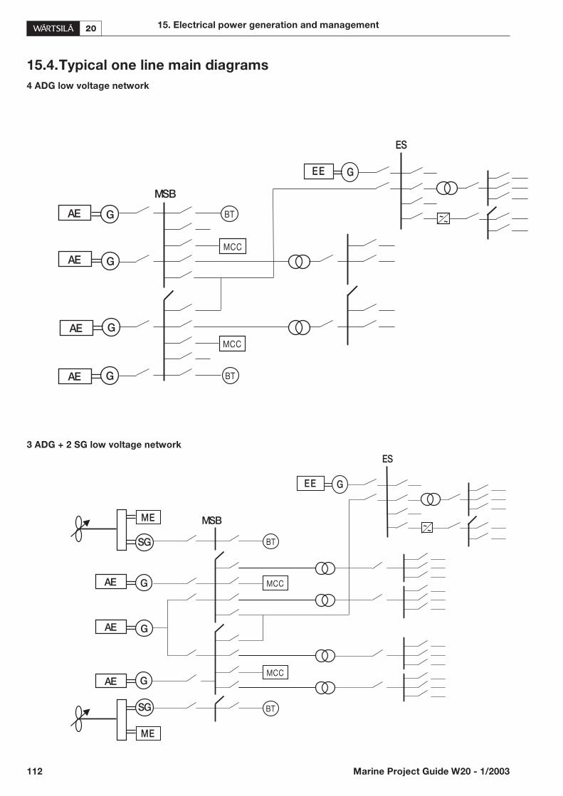
15.4.Typical one line main diagrams
4 ADG low voltage network
3 ADG + 2 SG low voltage network
112 Marine Project Guide W20 - 1/2003
15. Electrical power generation and management
SG
GAE
MSB~
~
EE G
ES
MCC
MCC
BT
BT
ME
ME
AE
AE
SG
G
G
GAE
MSB
~~
EE G
ES
MCC
MCC
BT
BT
AE
AE
G
G
AE G
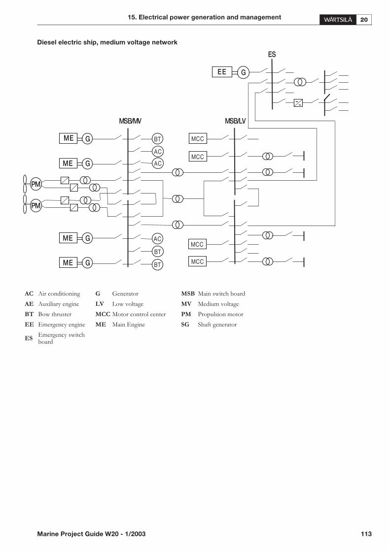
Diesel electric ship, medium voltage network
15. Electrical power generation and management
Marine Project Guide W20 - 1/2003 113
ME G BT
PM
PM
G
ACG
G
MCC
MSB/MV MSB/LV
ES
EE G
~~
ME
ME
ME MCC
MCC
MCC
BT
BT
AC
AC
AC Air conditioning G Generator MSB Main switch board
AE Auxiliary engine LV Low voltage MV Medium voltage
BT Bow thruster MCC Motor control center PM Propulsion motor
EE Emergency engine ME Main Engine SG Shaft generator
ES Emergency switchboard

16. Foundation
16.1.General
Engines can be either rigidly mounted on chocks, or resil-iently mounted on rubber elements.
Wärtsilä should be informed about existing excitations(other than Wärtsilä supplied engine excitations) and natu-ral hull frequencies, especially if resilient mounting is con-sidered.
Dynamic forces caused by the engine are shown in theChapter for Vibration and noise.
16.2.Steel structure design
The system oil tank should not extend under the reductiongear, if the engine is of dry sump type and the oil tank is lo-cated beneath the engine foundation. Neither should thetank extend under the support bearing, in case there is aPTO arrangement in the free end. The oil tank must also besymmetrically located in transverse direction under the en-gine.
16.3.Mounting of main engines
The foundation and the double bottom should be as stiffas possible in all directions to absorb the dynamic forcescaused by the engine, reduction gear and thrust bearing.
The foundation should be dimensioned and designed sothat harmful deformations are avoided.
16.3.1 Rigid mounting
Main engines are normally rigidly mounted on the seating,either on steel or resin chocks.
The engine has 4 mounting brackets cast to the engineblock. Each bracket has a threaded hole for an M16 jackingscrew and two Ø22 holes for M20 holding down bolts.
The bolt closest to the flywheel at either side of the engineshall be made as a Ø23H7/m6 fitted bolt. All other boltsare clearance bolts.
The clearance bolts shall be through bolts with lock nuts atboth the lower and upper ends. Ø22 holes can be drilledinto the seating through the holes in the mounting brack-ets.
In order to avoid bending stress in the bolts and ensurethat the bolts remain tight the contact face of the nut underthe seating top plate shall be counterbored.
The elongation of holding down bolts can be calculatedfrom the formula:
�L = bolt elongation [mm]
F = tensile force in bolt [N]
L i= part length of bolt with diameter Di [mm]
Di = part diameter of bolt with length Li [mm]
Lateral supports as shown in 2V69A0236 shall be fittedagainst the engine block. The wedge type supports shall belightly knocked into position when the engine is hot andsecured with a tack weld. Minimum bearing surface on thewedges is 80%.
The chocking arrangement shall be sent to the classifica-tion society and Wärtsilä for approval.
Steel chocks
The top plates of the engine girders are normally inclinedoutwards with regard to the centre line of the engine. Theinclination of the supporting surface should be 1/100. Theseating top plate should be designed so that the wedge-typesteel chocks can easily be fitted into their positions. Thewedge-type chocks also have an inclination of 1/100 tomatch the inclination of the seating. If the top plate of theengine girder is fully horizontal, a chock is welded to eachpoint of support. The chocks should be welded around theperiphery as well as through holes drilled for this purposeat regular intervals to avoid possible relative movement inthe surface layer. The welded chocks are then face-milledto an inclination of 1/100. The surfaces of the weldedchocks should be large enough to fully cover thewedge-type chocks.
The supporting surface of the seating top plate should bemachined so that a bearing surface of at least 75% is ob-tained.
The cutout in the chocks for the clearance bolts should beabout 2 mm larger than the bolt diameter. The maximumcut out area is 20%. Holes are to be drilled and reamed tothe correct tolerance for the fitted bolts after the couplingalignment has been checked and the chocks have beenlightly knocked into position.
In order to assure proper fastening and to avoid bendingstress in the bolts, the contact face of the nut underneaththe seating top plate should be counterbored.
Holding down bolts shall be long enough to ensure suffi-cient elongation when tightened.
114 Marine Project Guide W20 - 1/2003
16. Foundation
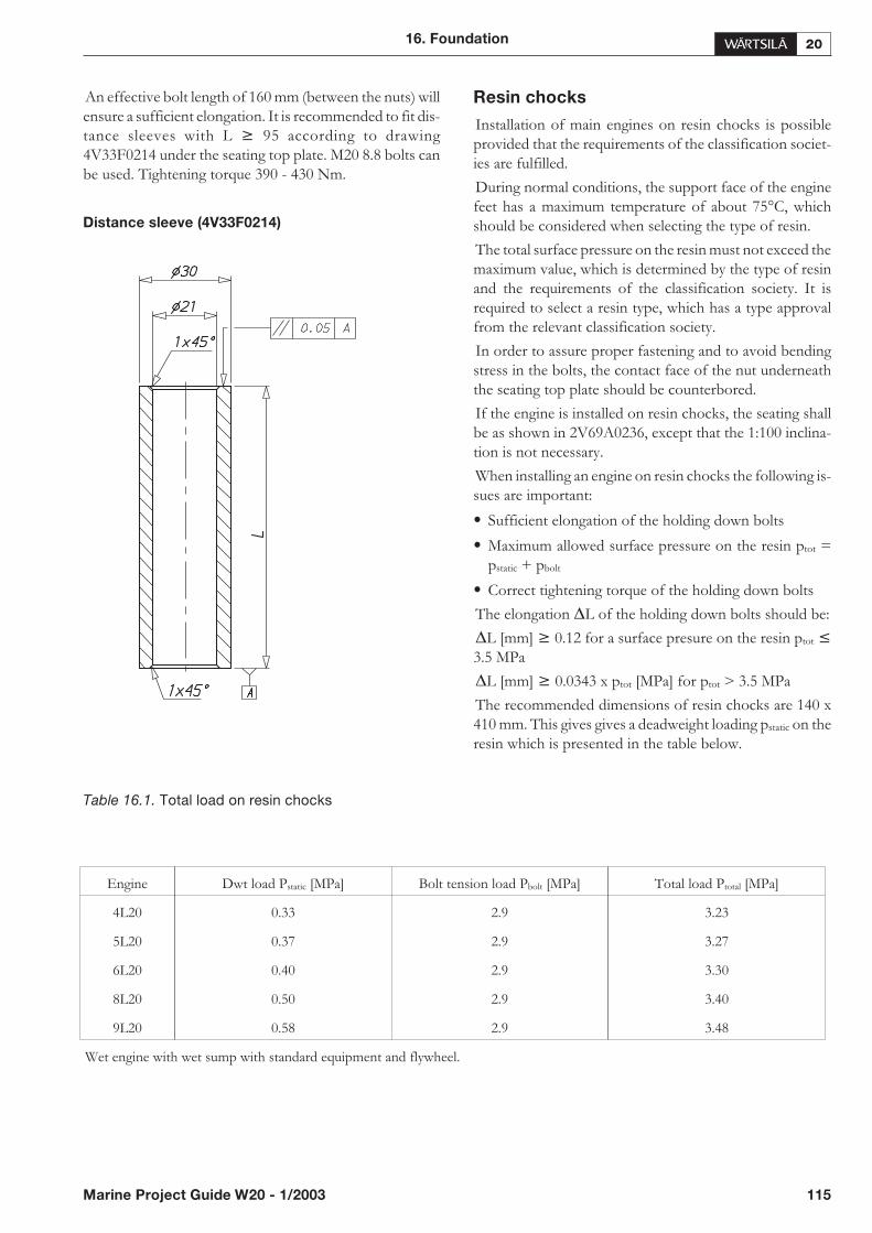
An effective bolt length of 160 mm (between the nuts) willensure a sufficient elongation. It is recommended to fit dis-tance sleeves with L 95 according to drawing4V33F0214 under the seating top plate. M20 8.8 bolts canbe used. Tightening torque 390 - 430 Nm.
Distance sleeve (4V33F0214)
Resin chocks
Installation of main engines on resin chocks is possibleprovided that the requirements of the classification societ-ies are fulfilled.
During normal conditions, the support face of the enginefeet has a maximum temperature of about 75°C, whichshould be considered when selecting the type of resin.
The total surface pressure on the resin must not exceed themaximum value, which is determined by the type of resinand the requirements of the classification society. It isrequired to select a resin type, which has a type approvalfrom the relevant classification society.
In order to assure proper fastening and to avoid bendingstress in the bolts, the contact face of the nut underneaththe seating top plate should be counterbored.
If the engine is installed on resin chocks, the seating shallbe as shown in 2V69A0236, except that the 1:100 inclina-tion is not necessary.
When installing an engine on resin chocks the following is-sues are important:
• Sufficient elongation of the holding down bolts
• Maximum allowed surface pressure on the resin ptot =pstatic + pbolt
• Correct tightening torque of the holding down bolts
The elongation �L of the holding down bolts should be:
�L [mm] 0.12 for a surface presure on the resin ptot 3.5 MPa
�L [mm] 0.0343 x ptot [MPa] for ptot > 3.5 MPa
The recommended dimensions of resin chocks are 140 x410 mm. This gives gives a deadweight loading pstatic on theresin which is presented in the table below.
Table 16.1. Total load on resin chocks
16. Foundation
Marine Project Guide W20 - 1/2003 115
Engine Dwt load Pstatic [MPa] Bolt tension load Pbolt [MPa] Total load Ptotal [MPa]
4L20 0.33 2.9 3.23
5L20 0.37 2.9 3.27
6L20 0.40 2.9 3.30
8L20 0.50 2.9 3.40
9L20 0.58 2.9 3.48
Wet engine with wet sump with standard equipment and flywheel.

Most resin types can take at least 3.5 MPa and the boltholding down force (pbolt) can be chosen to produce 3 MPaon the resin. This corresponds to a bolt tension of 83 000 N(with recommended chock dimensions) and a tighteningtorque of about 305 Nm tightening the bolts to 53% ofyield, assuming M20 8.8 bolts.
To ensure sufficient elongation a distance sleeve accordingto drawing 4V33F0214 with L 45 mm shall be fitted un-der the seating top plate
Main engine seating (2V69A0236a)
View from above
116 Marine Project Guide W20 - 1/2003
16. Foundation
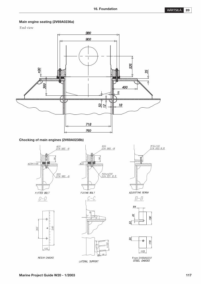
Main engine seating (2V69A0236a)
End view
Chocking of main engines (2V69A0238b)
16. Foundation
Marine Project Guide W20 - 1/2003 117
From 2V69A0237
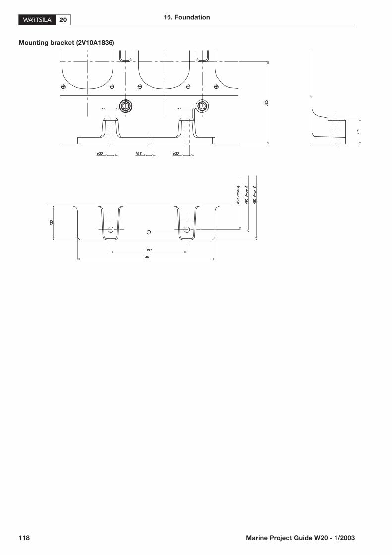
Mounting bracket (2V10A1836)
118 Marine Project Guide W20 - 1/2003
16. Foundation
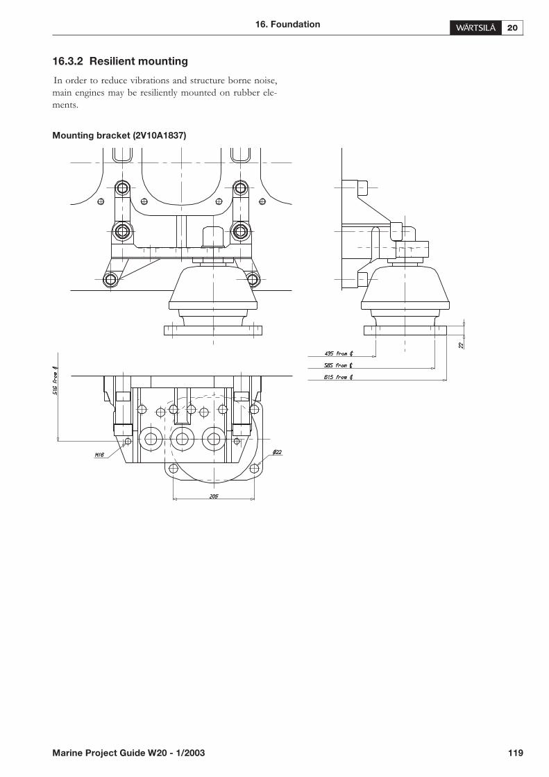
16.3.2 Resilient mounting
In order to reduce vibrations and structure borne noise,main engines may be resiliently mounted on rubber ele-ments.
Mounting bracket (2V10A1837)
16. Foundation
Marine Project Guide W20 - 1/2003 119

16.4.Mounting of generating sets
16.4.1 Alternator feet design
Instructions for designing the feet of the alternator and the distance between its holding down bolts
(4V92F0134c)
120 Marine Project Guide W20 - 1/2003
16. Foundation
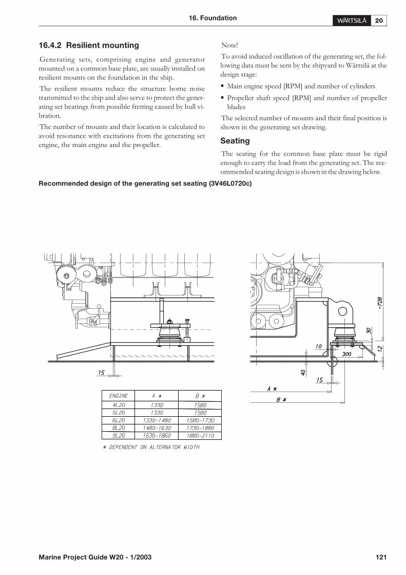
16.4.2 Resilient mounting
Generating sets, comprising engine and generatormounted on a common base plate, are usually installed onresilient mounts on the foundation in the ship.
The resilient mounts reduce the structure borne noisetransmitted to the ship and also serve to protect the gener-ating set bearings from possible fretting caused by hull vi-bration.
The number of mounts and their location is calculated toavoid resonance with excitations from the generating setengine, the main engine and the propeller.
Note!
To avoid induced oscillation of the generating set, the fol-lowing data must be sent by the shipyard to Wärtsilä at thedesign stage:
• Main engine speed [RPM] and number of cylinders
• Propeller shaft speed [RPM] and number of propellerblades
The selected number of mounts and their final position isshown in the generating set drawing.
Seating
The seating for the common base plate must be rigidenough to carry the load from the generating set. The rec-ommended seating design is shown in the drawing below.
Recommended design of the generating set seating (3V46L0720c)
16. Foundation
Marine Project Guide W20 - 1/2003 121
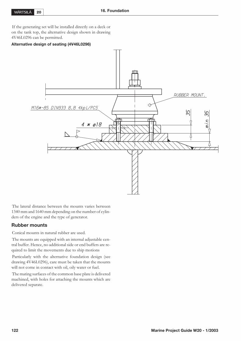
If the generating set will be installed directly on a deck oron the tank top, the alternative design shown in drawing4V46L0296 can be permitted.
Alternative design of seating (4V46L0296)
The lateral distance between the mounts varies between1340 mm and 1640 mm depending on the number of cylin-ders of the engine and the type of generator.
Rubber mounts
Conical mounts in natural rubber are used.
The mounts are equipped with an internal adjustable cen-tral buffer. Hence, no additional side or end buffers are re-quired to limit the movements due to ship motions
Particularly with the alternative foundation design (seedrawing 4V46L0296), care must be taken that the mountswill not come in contact with oil, oily water or fuel.
The mating surfaces of the common base plate is deliveredmachined, with holes for attaching the mounts which aredelivered separate.
122 Marine Project Guide W20 - 1/2003
16. Foundation
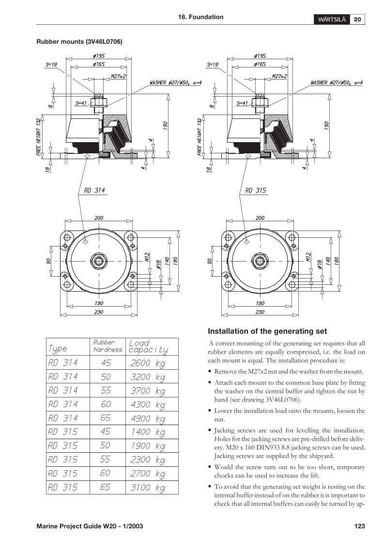
Rubber mounts (3V46L0706)
Installation of the generating set
A correct mounting of the generating set requires that allrubber elements are equally compressed, i.e. the load oneach mount is equal. The installation procedure is:
• Remove the M27x2 nut and the washer from the mount.
• Attach each mount to the common base plate by fittingthe washer on the central buffer and tighten the nut byhand (see drawing 3V46L0706).
• Lower the installation load onto the mounts, loosen thenut.
• Jacking screws are used for levelling the installation.Holes for the jacking screws are pre-drilled before deliv-ery. M20 x 160 DIN933 8.8 jacking screws can be used.Jacking screws are supplied by the shipyard.
• Would the screw turn out to be too short, temporarychocks can be used to increase the lift.
• To avoid that the generating set weight is resting on theinternal buffer instead of on the rubber it is important tocheck that all internal buffers can easily be turned by ap-
16. Foundation
Marine Project Guide W20 - 1/2003 123

plying a spanner to the top hexagon (S = 19). If this is notpossible, remove the installation load progressively untilall buffers can be turned freely. Turn the internal buffercounter clockwise (upwards) and re-lower the installa-tion onto the mounts. Repeat the above procedure untilall buffers can be rotated freely with the full installationload applied.
• The correct deflection of the mounts is between 4 and 10mm depending on the weight of the generating set andthe selected quality of the rubber. The calculated com-pressed height of the mounts is shown in the generatingset drawing.
• Check that the mounts are evenly compressed. Thecompressed height of all mounts must be within 2.0 mm.Adjustments in height shall be made using machinedchocks. If shims are used the minimum thickness of ashim is 0.5 mm and only one shim per mount is permit-ted.
• Check that the seating of each mount is horizontal. Thisis done by measuring the compressed height of eachmount on all sides. The difference must not exceed 0.5mm.
Adjustments are made with wedge type chocks.
• Set the internal buffer working clearance for eachmount:
• Turn the internal buffer counter clockwise (upwards) tothe maximum upper position.
• Turn the internal buffer two full turns clockwise (down-wards).
• Finally, tighten the nut with a torque of 300 Nm. Whiledoing this the top hexagon must be secured with a span-ner
The mounts should preferably be allowed to settle for aminimum of 48 hours, due to initial creeping, before liningup pipework, etc.
The transmission of forces emitted by the engine is10...30% when using rubber mountings compared to rigidmounting.
16.5.Reduction gear foundations
The engine and the reduction gear must have commonfoundation girders.
16.6.Free end PTO driven
equipment foundations
The foundation of the driven equipment must be inte-grated with the engine foundation.
16.7.Flexible pipe connections
When the engine or generating set is resiliently installed, allconnections must be flexible and no grating nor laddersmay be fixed to the engine or generating set. When install-ing the flexible pipe connections, unnecessary bending orstretching should be avoided. The external pipe must beprecisely aligned to the fitting or flange on the engine. It isvery important that the pipe clamps for the pipe outsidethe flexible connection must be very rigid and welded tothe steel structure of the foundation to prevent vibrations,which could damage the flexible connection.
124 Marine Project Guide W20 - 1/2003
16. Foundation

17. Vibration and noise
17.1. General
Dynamic forces and moments caused by the engine appearfrom the table. Due to manufacturing tolerances somevariation of these values may occur.
Coordinate system of the external torques
17.2. External forces and couples
Table 17.1. External forces Table 17.2. External couples
17. Vibration and noise
Marine Project Guide W20 - 1/2003 125
FZ = 0, FY = 0 and FX = 0 for 5, 6 and 9 cylinder engines
Engine Speed Frequency Fz
[rpm] [Hz] [kN]
720 48 0.7
4L20 750 50 0.8
900 60 1.1
1000 66.7 1.4
720 48 1.4
8L20 750 50 1.5
900 60 2.2
1000 66.7 2.7
MZ = 0, MY = 0 for 4, 6 and 8 cylinder engines
Engine Speed Frequency MY MZ
[RPM] [Hz] [kNm] [kNm]
900 15 3.4 3.4
5L20 30 21 —
1000 16.7 4.2 4.2
33.3 26 —
720 12 4.5 4.5
24 3.1 —
750 12.5 4.9 4.9
9L20 25 3.3 —
900 15 7 7
30 4.8 —
1000 16.7 8.6 8.6
33.3 5.9 —
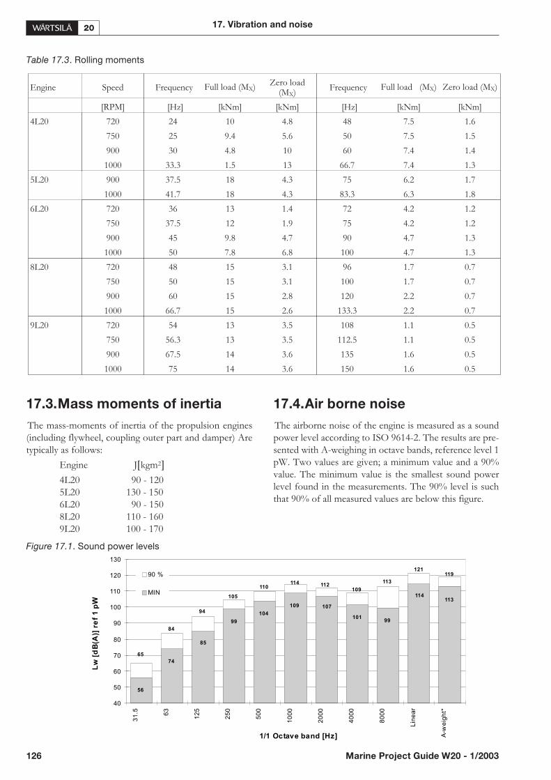
Table 17.3. Rolling moments
17.3.Mass moments of inertia
The mass-moments of inertia of the propulsion engines(including flywheel, coupling outer part and damper) Aretypically as follows:
Engine J�kgm2�
4L20 90 - 1205L20 130 - 1506L20 90 - 1508L20 110 - 1609L20 100 - 170
17.4.Air borne noise
The airborne noise of the engine is measured as a soundpower level according to ISO 9614-2. The results are pre-sented with A-weighing in octave bands, reference level 1pW. Two values are given; a minimum value and a 90%value. The minimum value is the smallest sound powerlevel found in the measurements. The 90% level is suchthat 90% of all measured values are below this figure.
Figure 17.1. Sound power levels
126 Marine Project Guide W20 - 1/2003
17. Vibration and noise
Engine Speed Frequency Full load (MX) Zero load(MX)
Frequency Full load (MX) Zero load (MX)
[RPM] [Hz] [kNm] [kNm] [Hz] [kNm] [kNm]
4L20 720 24 10 4.8 48 7.5 1.6
750 25 9.4 5.6 50 7.5 1.5
900 30 4.8 10 60 7.4 1.4
1000 33.3 1.5 13 66.7 7.4 1.3
5L20 900 37.5 18 4.3 75 6.2 1.7
1000 41.7 18 4.3 83.3 6.3 1.8
6L20 720 36 13 1.4 72 4.2 1.2
750 37.5 12 1.9 75 4.2 1.2
900 45 9.8 4.7 90 4.7 1.3
1000 50 7.8 6.8 100 4.7 1.3
8L20 720 48 15 3.1 96 1.7 0.7
750 50 15 3.1 100 1.7 0.7
900 60 15 2.8 120 2.2 0.7
1000 66.7 15 2.6 133.3 2.2 0.7
9L20 720 54 13 3.5 108 1.1 0.5
750 56.3 13 3.5 112.5 1.1 0.5
900 67.5 14 3.6 135 1.6 0.5
1000 75 14 3.6 150 1.6 0.5
65
84
94
105
110 112
119121
113
109
114
101
113
107
99
114
109
104
99
85
74
56
40
50
60
70
80
90
100
110
120
130
31
.5 63
12
5
25
0
50
0
10
00
20
00
40
00
80
00
Lin
ea
r
A-w
eig
ht*
1/1 Octave band [Hz]
Lw
[dB
(A)]
ref
1p
W
90 %
MIN

18. Power transmission
18.1. General
The full engine power can be taken from both ends of theengine. At the flywheel end there is always a flywheel forthe management of the torsional vibration characteristicsof the system and to facilitate manual turning of the engine.The flywheel creates a natural flange connection. At thefree end a shaft connection as a power take off can be pro-vided.
18.2. Connection to alternator
Connection engine/single bearing alternator (2V64L0071)
18. Power transmission
Marine Project Guide W20 - 1/2003 127

Connection engine/two-bearing alternator (4V64F0001a)
18.3.Flexible coupling
The power transmission of propulsion engines is accom-plished through a flexible coupling or a combined flexiblecoupling and clutch mounted on the flywheel. The crank-shaft is equipped with an additional shield bearing at theflywheel end. Therefore also a rather heavy coupling can bemounted on the flywheel without intermediate bearings.
The type of flexible coupling to be used has to be decidedseparately in each case on the basis of the torsional vibra-tion calculations.
In case of two bearing type alternator installations a flexi-ble coupling between the engine and the generator is re-quired.
18.4.Clutch
In many installations the propeller shaft can be separatedfrom the diesel engine using a clutch. The use of multipleplate hydraulically actuated clutches built into the reduc-tion gear is recommended.
A clutch is required when two or more engines are con-nected to the same driven machinery such as a reductiongear.
To permit maintenance of a stopped engine clutches mustbe installed in twin screw vessels which can operate on oneshaft line only. A shaft line locking device should also befitted to be able to secure a propeller shaft in position sothat windmilling is avoided as also an open hydraulic clutchcan transmit a small torque.
18.5.Shaftline locking device and
brake
18.5.1 Locking device
• A shaftline locking device is needed when the operationof the ship makes it possible to turn the shafting by thewater flow in the propeller.
18.5.2 Brake
• A shaftline brake is needed when the shaftline needs tobe actively stopped. This is the case when the directionof rotation needs to be reversed.
128 Marine Project Guide W20 - 1/2003
18. Power transmission
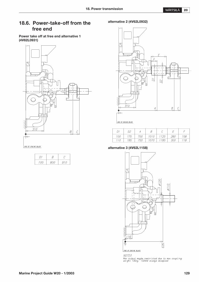
18.6. Power-take-off from the
free end
Power take off at free end alternative 1
(4V62L0931)
alternative 2 (4V62L0932)
alternative 3 (4V62L1158)
18. Power transmission
Marine Project Guide W20 - 1/2003 129
18.7.Torsional vibration
calculations
A torsional vibration calculation is made for each installa-tion. For this purpose exact data of all components in-cluded in the shaft system are required. See the list below.
General
• Classification
• Ice class
• Operating modes
Data of reduction gear
A mass elastic diagram showing:
• all clutching possibilities
• sense of rotation of all shafts
• dimensions of all shafts
• mass moment of inertia of all rotating parts includingshafts and flanges
• torsional stiffness of shafts between rotating masses
• material of shafts including tensile strength and modulusof rigidity
• gear ratios
• drawing number of the diagram
Data of propeller and shafting
A mass-elastic diagram or propeller shaft drawing show-ing:
• mass moment of inertia of all rotating parts including therotating part of the OD-box, SKF couplings and rotat-ing parts of the bearings
• mass moment of inertia of the propeller at full/zeropitch in water
• torsional stiffness or dimensions of the shaft
• material of the shaft including tensile strength andmodulus of rigidity
• drawing number of the diagram or drawing
Data of main alternator or shaft alternator
A mass-elastic diagram or an alternator shaft drawingshowing:
• alternator output, speed and sense of rotation
• mass moment of inertia of all rotating parts or a total in-ertia value of the rotor, including the shaft
• torsional stiffness or dimensions of the shaft
• material of the shaft including tensile strength andmodulus of rigidity
• drawing number of the diagram or drawing
Data of flexible coupling/clutch
If a certain make of flexible coupling has to be used, thefollowing data of it must be informed:
• mass moment of inertia of all parts of the coupling
• number of flexible elements
• linear, progressive or degressive torsional stiffness perelement
• dynamic magnification or relative damping
• nominal torque, permissible vibratory torque and per-missible power loss
• drawing of the coupling showing make, type and draw-ing number
18.8.Turning gear
• A manual turning tool is provided with the engine.
130 Marine Project Guide W20 - 1/2003
18. Power transmission

19. Engine room layout
19.1. Crankshaft distances
Minimum crankshaft distances have to be followed in or-der to provide sufficient space between engines for main-tenance and operation.
19.1.1 In-line engines
Engine room arrangement, generating sets (2V69C0278d)
19. Engine room layout
Marine Project Guide W20 - 1/2003 131
ENGINE A B C D E F
4L20 1800 700 1200 845 1970 1270
5L20 1800 700 1200 845 1970 1270
6L20 1800 1000 1200 845 1970 / 2020 1270 / 1420
8L20 1800 1300 1200 845 2020 / 2170 1420 / 1570
9L20 1800 1300 1200 845 2170/2400 1570/1800
A = Minimum height when removing a pistonB = Camshaft overhaul distanceC = Charge air cooler overhaul distanceD = Length for the door in the connecting box, from engine blockE = Min. distance of engines dependent on common base plateF = Width of the common base plate dependent on width of the alternator

Engine room arrangement, main engines TC in free end (2V69C0275b)
132 Marine Project Guide W20 - 1/2003
19. Engine room layout
Engine A B C D
4L20 1800 700 1200 845
5L20 1800 700 1200 845
6L20 1800 1000 1200 845
8L20 1800 1300 1200 845
9L20 1800 1300 1200 845
A = Minimum height when removing a pistonB = Camshaft overhaul distanceC = Charge air cooler overhaul distanceD = Length for the door on the connecting box, from engine block
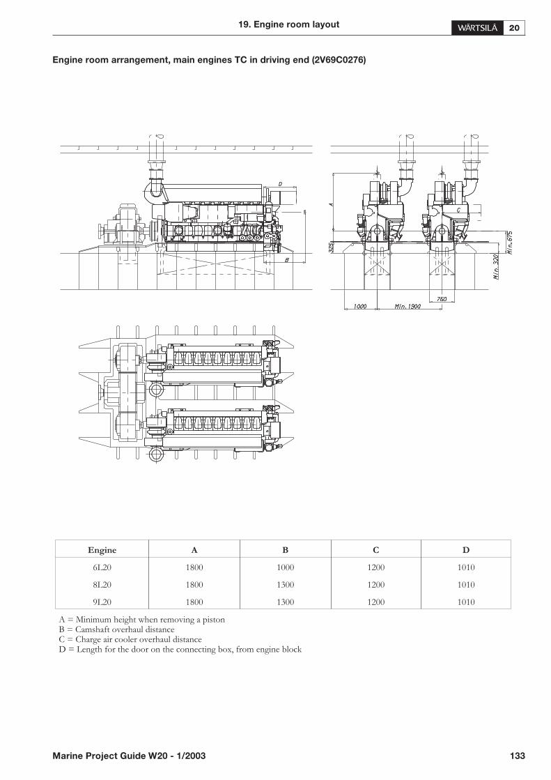
Engine room arrangement, main engines TC in driving end (2V69C0276)
19. Engine room layout
Marine Project Guide W20 - 1/2003 133
Engine A B C D
6L20 1800 1000 1200 1010
8L20 1800 1300 1200 1010
9L20 1800 1300 1200 1010
A = Minimum height when removing a pistonB = Camshaft overhaul distanceC = Charge air cooler overhaul distanceD = Length for the door on the connecting box, from engine block

19.2.Space requirements for
maintenance
19.2.1 Working space around the engine
The required working space around the engine is mainlydetermined by the dismounting dimensions of some en-gine components, as well as space requirement of somespecial tools. It is especially important that no obstructivestructures are built next to engine driven pumps, as well ascamshaft and crankcase doors.
However, also at locations where no space is required forany engine part dismounting, a minimum of 1000 mm freespace everywhere around the engine is recommended to bereserved for maintenance operations.
19.2.2 Engine room height and lifting
equipment
It is essential for efficient and safe working conditions thatthe lifting equipment are applicable for the job and they arecorrectly dimensioned and located.
The required engine room height depends on space reser-vation of the lifting equipment and also on the lifting andtransportation arrangement. The minimum engine roomheight can be achieved if there is enough transversal andlongitudinal space, so that there is no need to transportparts over insulation box or rocker covers.
Separate lifting arrangement for overhauling turbochargeris required (unless overhead travelling crane, which alsocovers the turbocharger is used). Turbocharger lifting ar-rangement is usually best handled with a chain block on arail located above the turbocharger axis.
See Chapter for General data and outputs for the necessaryhook heights.
19.3.Handling of spare parts and
tools
Transportation arrangement from engine room to storageand workshop has to be prepared for heavy engine compo-nents. This can be done with several chain blocks on railsor alternatively utilising pallet truck or trolley. If transpor-tation must be carried out using several lifting equipment,coverage areas of adjacent cranes should be as close as pos-sible to each other.
Engine room maintenance hatch has to be large enough toallow transportation of main components to/from engineroom.
It is recommended to store heavy engine components onslightly elevated adaptable surface e.g. wooden pallets. Allengine spare parts should be protected from corrosion andexcessive vibration.
On single main engine installations it is important to storeheavy engine parts close to the engine to make overhaul asquick as possible in an emergency situation.
19.4.Required deck area for
service work
During engine overhaul some deck area is required forcleaning and storing dismantled components. Size of theservice area is dependent of the overhauling strategy cho-sen, e.g. one cylinder at time, one bank at time or the wholeengine at time. Service area should be plain steel deckdimensioned to carry the weight of engine parts.
134 Marine Project Guide W20 - 1/2003
19. Engine room layout
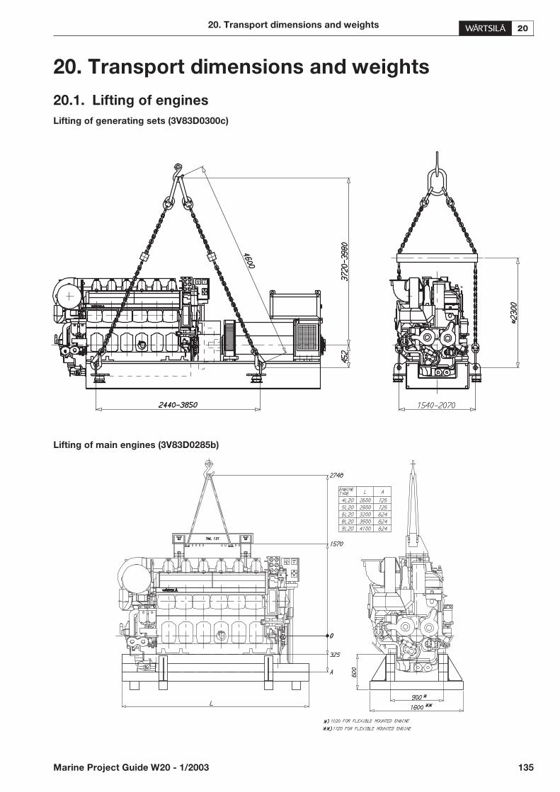
20. Transport dimensions and weights
20.1. Lifting of engines
Lifting of generating sets (3V83D0300c)
Lifting of main engines (3V83D0285b)
20. Transport dimensions and weights
Marine Project Guide W20 - 1/2003 135

20.2.Engine components
Turbocharger and cooler inserts (4V92L1282)
136 Marine Project Guide W20 - 1/2003
20. Transport dimensions and weights
Abbreviations used:
LD TC in driving end PC Pulse-converter
LF TC in free end 2P Pulse charging
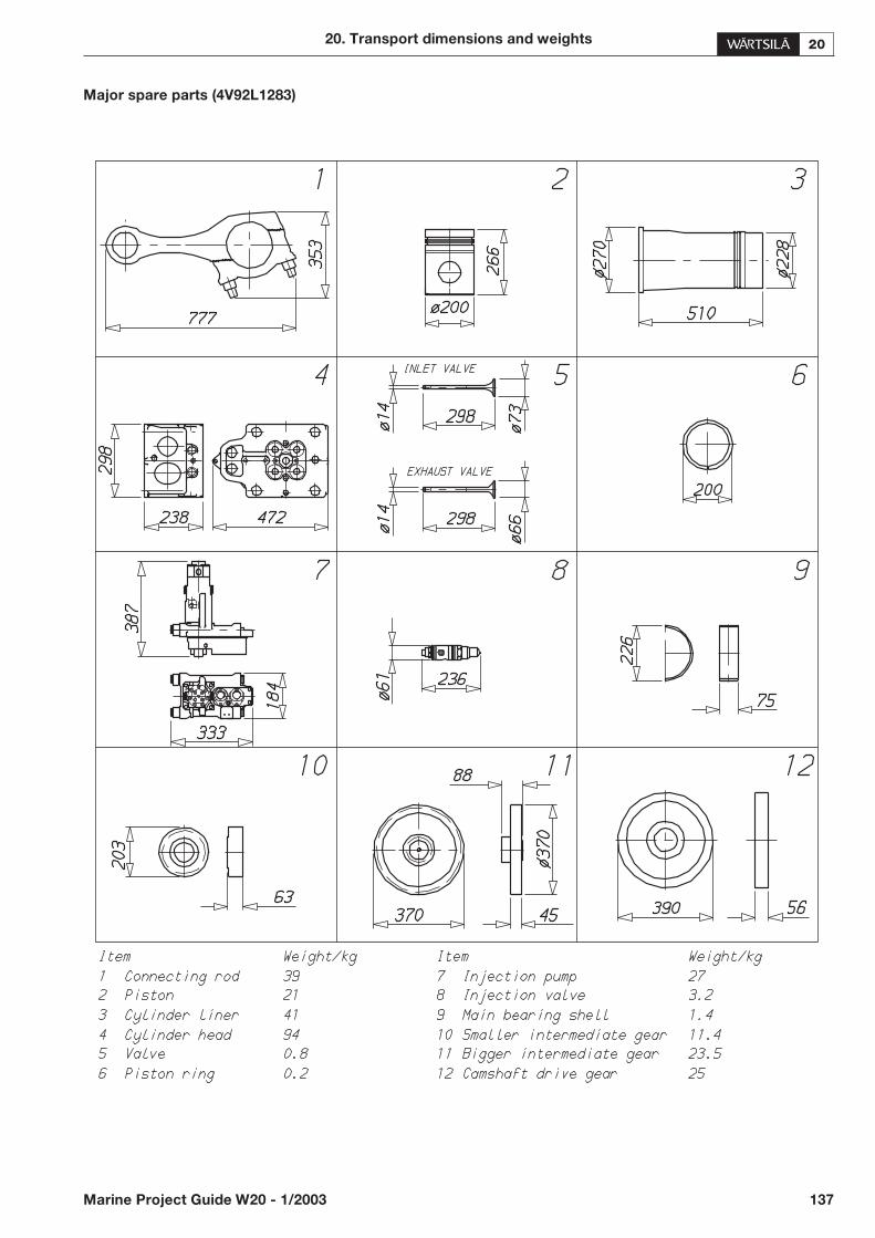
Major spare parts (4V92L1283)
20. Transport dimensions and weights
Marine Project Guide W20 - 1/2003 137

21. Dimensional drawings
Dimensional drawings can be found in the CD-ROM in-cluded in the back cover pocket of this project guide. Thedrawing formats are Adobe portable document file (.pdf)and AutoCAD (.dxf).
List of the drawings:
3V58E0584a 4L20 Diesel alternator set LF
3V58E0580b 5L20 Diesel alternator set LF
3V58E0553c 6L20 Diesel alternator set LF
3V58E0552c 8L20 Diesel alternator set LF
3V58E0549c 9L20 Diesel alternator set LF
4V58E0541e 6L20 Diesel engine LD
4V58E0533c 8L20 Diesel engine LD
4V58E0534d 9L20 Diesel engine LD
4V58E0564 4L20 Diesel engine LF
4V58E0568a 5L20 Diesel engine LF
4V58E0560b 6L20 Diesel engine LF
4V58E0559b 8L20 Diesel engine LF
4V58E0561a 9L20 Diesel engine LF
21.1.Notes for the CD-ROM
Hardware requirements:
• CD-ROM drive
Software requirements:
• Adobe Acrobat Reader 4.0 or later or other applicationcapable of reading the files
• AutoCAD 13 or later or other application capable ofreading the files.
The files are organized in folders according to the enginetypes.
138 Marine Project Guide W20 - 1/2003
21. Dimensional drawings
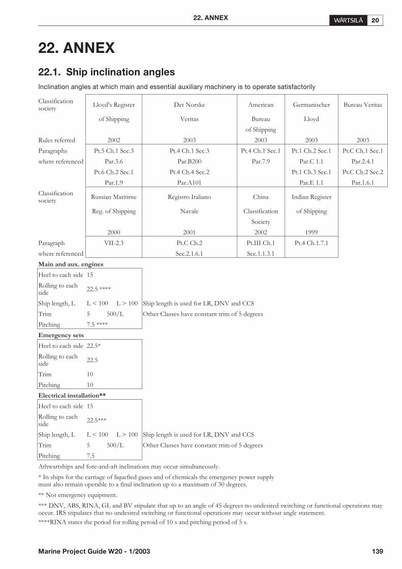
22. ANNEX
22.1. Ship inclination angles
Inclination angles at which main and essential auxiliary machinery is to operate satisfactorily
22. ANNEX
Marine Project Guide W20 - 1/2003 139
Classificationsociety
Lloyd’s Register Det Norske American Germanischer Bureau Veritas
of Shipping Veritas Bureau Lloyd
of Shipping
Rules referred 2002 2003 2003 2003 2003
Paragraphs Pt.5 Ch.1 Sec.3 Pt.4 Ch.1 Sec.3 Pt.4 Ch.1 Sec.1 Pt.1 Ch.2 Sec.1 Pt.C Ch.1 Sec.1
where referenced Par.3.6 Par.B200 Par.7.9 Par.C 1.1 Par.2.4.1
Pt.6 Ch.2 Sec.1 Pt.4 Ch.4 Sec.2 Pt.1 Ch.3 Sec.1 Pt.C Ch.2 Sec.2
Par.1.9 Par.A101 Par.E 1.1 Par.1.6.1
Classificationsociety
Russian Maritime Registro Italiano China Indian Register
Reg. of Shipping Navale Classification of Shipping
Society
2000 2001 2002 1999
Paragraph VII-2.3 Pt.C Ch.2 Pt.III Ch.1 Pt.4 Ch.1.7.1
where referenced Sec.2.1.6.1 Sec.1.1.3.1
Main and aux. engines
Heel to each side 15
Rolling to eachside
22.5 ****
Ship length, L L < 100 L > 100 Ship length is used for LR, DNV and CCS
Trim 5 500/L Other Classes have constant trim of 5 degrees
Pitching 7.5 ****
Emergency sets
Heel to each side 22.5*
Rolling to eachside
22.5
Trim 10
Pitching 10
Electrical installation**
Heel to each side 15
Rolling to eachside
22.5***
Ship length, L L < 100 L > 100 Ship length is used for LR, DNV and CCS
Trim 5 500/L Other Classes have constant trim of 5 degrees
Pitching 7.5
Athwartships and fore-and-aft inclinations may occur simultaneously.
* In ships for the carriage of liquefied gases and of chemicals the emergency power supplymust also remain operable to a final inclination up to a maximum of 30 degrees.
** Not emergency equipment.
*** DNV, ABS, RINA, GL and BV stipulate that up to an angle of 45 degrees no undesired switching or functional operations mayoccur. IRS stipulates that no undesired switching or functional operations may occur without angle statement.
****RINA states the period for rolling peroid of 10 s and pitching period of 5 s.
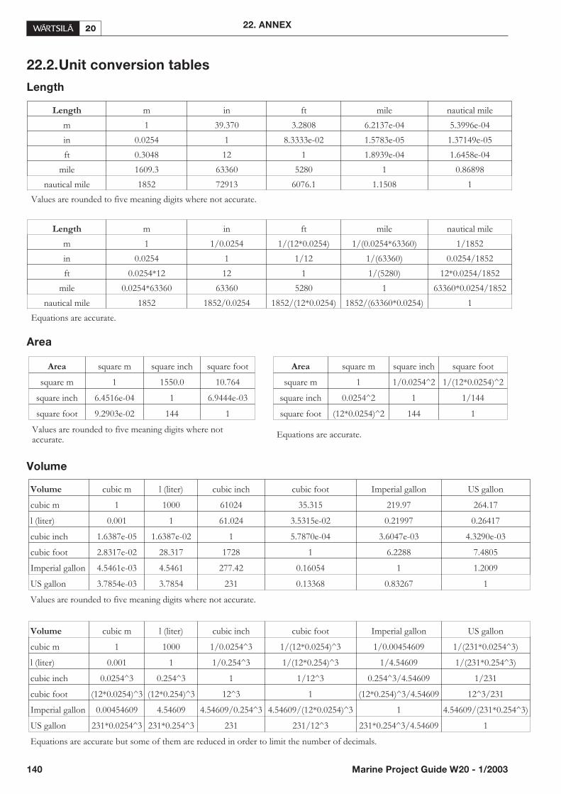
22.2.Unit conversion tables
Length
Area
Volume
140 Marine Project Guide W20 - 1/2003
22. ANNEX
Length m in ft mile nautical mile
m 1 39.370 3.2808 6.2137e-04 5.3996e-04
in 0.0254 1 8.3333e-02 1.5783e-05 1.37149e-05
ft 0.3048 12 1 1.8939e-04 1.6458e-04
mile 1609.3 63360 5280 1 0.86898
nautical mile 1852 72913 6076.1 1.1508 1
Values are rounded to five meaning digits where not accurate.
Length m in ft mile nautical mile
m 1 1/0.0254 1/(12*0.0254) 1/(0.0254*63360) 1/1852
in 0.0254 1 1/12 1/(63360) 0.0254/1852
ft 0.0254*12 12 1 1/(5280) 12*0.0254/1852
mile 0.0254*63360 63360 5280 1 63360*0.0254/1852
nautical mile 1852 1852/0.0254 1852/(12*0.0254) 1852/(63360*0.0254) 1
Equations are accurate.
Area square m square inch square foot Area square m square inch square foot
square m 1 1550.0 10.764 square m 1 1/0.0254^2 1/(12*0.0254)^2
square inch 6.4516e-04 1 6.9444e-03 square inch 0.0254^2 1 1/144
square foot 9.2903e-02 144 1 square foot (12*0.0254)^2 144 1
Values are rounded to five meaning digits where notaccurate.
Equations are accurate.
Volume cubic m l (liter) cubic inch cubic foot Imperial gallon US gallon
cubic m 1 1000 61024 35.315 219.97 264.17
l (liter) 0.001 1 61.024 3.5315e-02 0.21997 0.26417
cubic inch 1.6387e-05 1.6387e-02 1 5.7870e-04 3.6047e-03 4.3290e-03
cubic foot 2.8317e-02 28.317 1728 1 6.2288 7.4805
Imperial gallon 4.5461e-03 4.5461 277.42 0.16054 1 1.2009
US gallon 3.7854e-03 3.7854 231 0.13368 0.83267 1
Values are rounded to five meaning digits where not accurate.
Volume cubic m l (liter) cubic inch cubic foot Imperial gallon US gallon
cubic m 1 1000 1/0.0254^3 1/(12*0.0254)^3 1/0.00454609 1/(231*0.0254^3)
l (liter) 0.001 1 1/0.254^3 1/(12*0.254)^3 1/4.54609 1/(231*0.254^3)
cubic inch 0.0254^3 0.254^3 1 1/12^3 0.254^3/4.54609 1/231
cubic foot (12*0.0254)^3 (12*0.254)^3 12^3 1 (12*0.254)^3/4.54609 12^3/231
Imperial gallon 0.00454609 4.54609 4.54609/0.254^3 4.54609/(12*0.0254)^3 1 4.54609/(231*0.254^3)
US gallon 231*0.0254^3 231*0.254^3 231 231/12^3 231*0.254^3/4.54609 1
Equations are accurate but some of them are reduced in order to limit the number of decimals.
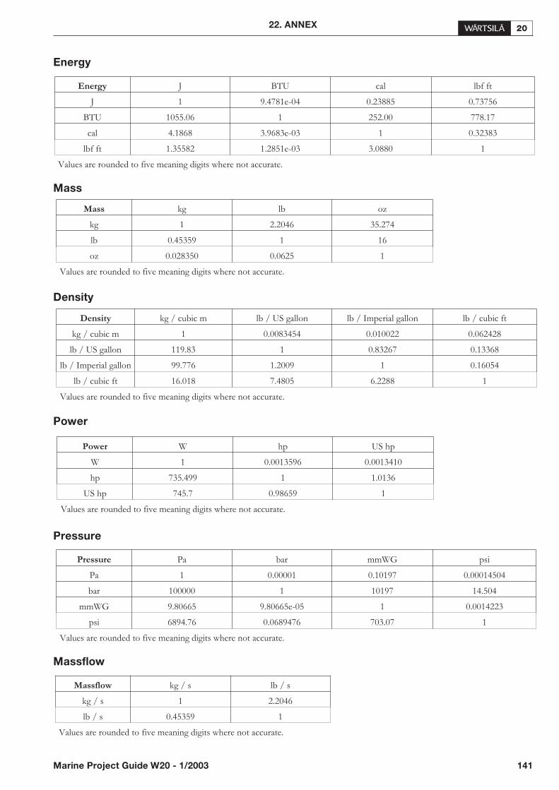
Energy
Mass
Density
Power
Pressure
Massflow
22. ANNEX
Marine Project Guide W20 - 1/2003 141
Energy J BTU cal lbf ft
J 1 9.4781e-04 0.23885 0.73756
BTU 1055.06 1 252.00 778.17
cal 4.1868 3.9683e-03 1 0.32383
lbf ft 1.35582 1.2851e-03 3.0880 1
Values are rounded to five meaning digits where not accurate.
Mass kg lb oz
kg 1 2.2046 35.274
lb 0.45359 1 16
oz 0.028350 0.0625 1
Values are rounded to five meaning digits where not accurate.
Density kg / cubic m lb / US gallon lb / Imperial gallon lb / cubic ft
kg / cubic m 1 0.0083454 0.010022 0.062428
lb / US gallon 119.83 1 0.83267 0.13368
lb / Imperial gallon 99.776 1.2009 1 0.16054
lb / cubic ft 16.018 7.4805 6.2288 1
Values are rounded to five meaning digits where not accurate.
Power W hp US hp
W 1 0.0013596 0.0013410
hp 735.499 1 1.0136
US hp 745.7 0.98659 1
Values are rounded to five meaning digits where not accurate.
Pressure Pa bar mmWG psi
Pa 1 0.00001 0.10197 0.00014504
bar 100000 1 10197 14.504
mmWG 9.80665 9.80665e-05 1 0.0014223
psi 6894.76 0.0689476 703.07 1
Values are rounded to five meaning digits where not accurate.
Massflow kg / s lb / s
kg / s 1 2.2046
lb / s 0.45359 1
Values are rounded to five meaning digits where not accurate.
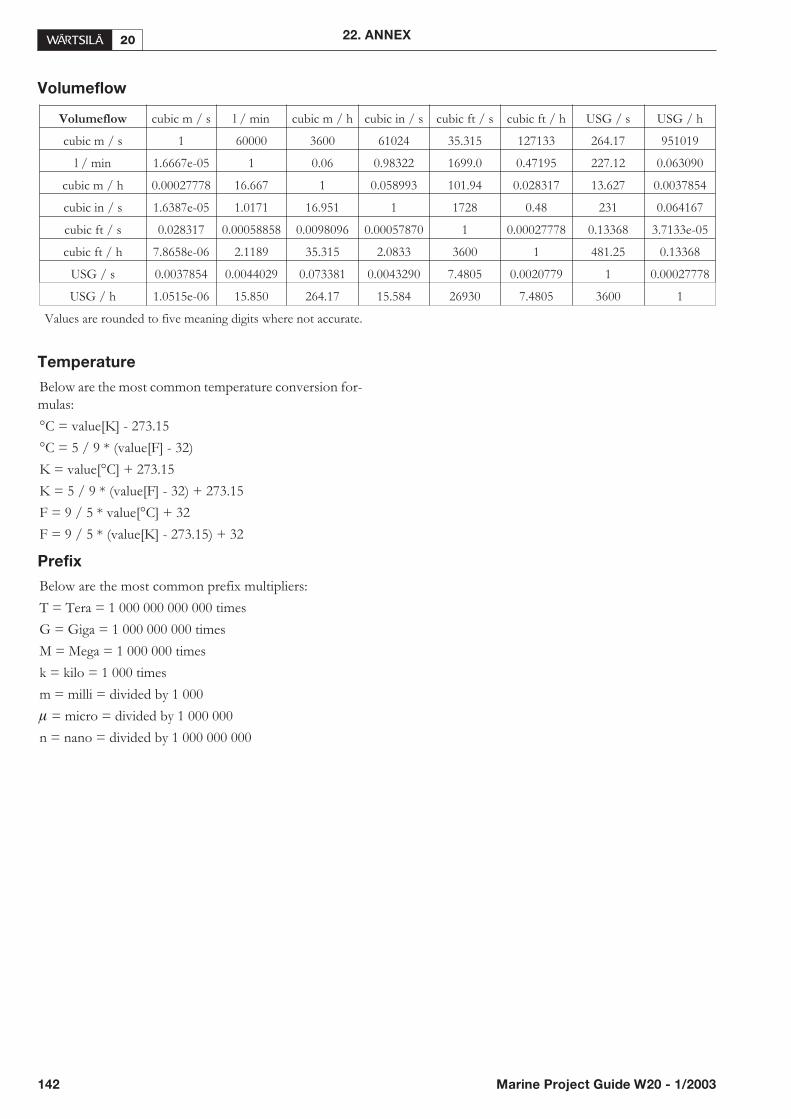
Volumeflow
Temperature
Below are the most common temperature conversion for-mulas:
°C = value[K] - 273.15
°C = 5 / 9 * (value[F] - 32)
K = value[°C] + 273.15
K = 5 / 9 * (value[F] - 32) + 273.15
F = 9 / 5 * value[°C] + 32
F = 9 / 5 * (value[K] - 273.15) + 32
Prefix
Below are the most common prefix multipliers:
T = Tera = 1 000 000 000 000 times
G = Giga = 1 000 000 000 times
M = Mega = 1 000 000 times
k = kilo = 1 000 times
m = milli = divided by 1 000
� = micro = divided by 1 000 000
n = nano = divided by 1 000 000 000
142 Marine Project Guide W20 - 1/2003
22. ANNEX
Volumeflow cubic m / s l / min cubic m / h cubic in / s cubic ft / s cubic ft / h USG / s USG / h
cubic m / s 1 60000 3600 61024 35.315 127133 264.17 951019
l / min 1.6667e-05 1 0.06 0.98322 1699.0 0.47195 227.12 0.063090
cubic m / h 0.00027778 16.667 1 0.058993 101.94 0.028317 13.627 0.0037854
cubic in / s 1.6387e-05 1.0171 16.951 1 1728 0.48 231 0.064167
cubic ft / s 0.028317 0.00058858 0.0098096 0.00057870 1 0.00027778 0.13368 3.7133e-05
cubic ft / h 7.8658e-06 2.1189 35.315 2.0833 3600 1 481.25 0.13368
USG / s 0.0037854 0.0044029 0.073381 0.0043290 7.4805 0.0020779 1 0.00027778
USG / h 1.0515e-06 15.850 264.17 15.584 26930 7.4805 3600 1
Values are rounded to five meaning digits where not accurate.

22.3. Collection of drawing
symbols used in drawings
22. ANNEX
Marine Project Guide W20 - 1/2003 143

Project guide
W12
03 /
Boc
k´s
Offi
ce /
Pro
do
Wärtsilä 20 - P
roject g
uide
Wärtsilä Finland Oy
P.O.Box 25265101 Vaasa, Finland
Tel: +358 10 709 0000Fax: +358 6 356 7188